© 2008 Microchip Technology Inc. DS01162A-page 1 AN1162 INTRODUCTION The requirement of low-cost, low-maintenance, robust electrical motors has resulted in the emergence of the AC Induction Motor (ACIM) as the industry leader. Typical applications requiring the use of an induction motor drive range from consumer to automotive applications, with a variety of power and sizes. Where efficiency, low cost, and control of the induction motor drive is a concern, the sensorless Field Oriented Control (FOC), also known as vector control, provides the best solution. The term “sensorless” does not represent the lack of sensors entirely, but the fact that in comparison with other drives from the same category of field oriented control, it denotes that the speed and/or position sensor is missing. This feature decreases the cost of the drive system, which is always desired, but this is not the only reason for this approach, as some applications have requirements concerning the size, and the lack of additional wiring for sensors or devices mounted on the shaft (due to hostile environments such as high temperature, corrosive contacts, etc.). The intent of this application note is to present one solution for sensorless Field Oriented Control (FOC) of induction motors using a dsPIC ® Digital Signal Controller (DSC). OVERVIEW AC Induction Motor The AC Induction Motor (ACIM) is the workhorse of industrial and residential motor applications due to its simple construction and durability. These motors have no brushes to wear out or magnets to add to the cost. The rotor assembly is a simple steel cage. ACIMs are designed to operate at a constant input voltage and frequency, but you can effectively control an ACIM in an open loop variable speed application if the frequency of the motor input voltage is varied. If the motor is not mechanically overloaded, the motor will operate at a speed that is roughly proportional to the input frequency. As you decrease the frequency of the drive voltage, you also need to decrease the amplitude by a proportional amount. Otherwise, the motor will consume excessive current at low input frequencies. This control method is called Volts-Hertz control. The benefits of field oriented control can be directly realized as lower energy consumption. This provides higher efficiency, lower operating costs and reduces the cost of drive components. In sensorless field oriented control, the speed and/or position are not directly measurable; their values are estimated using other parameters such as phase voltages and current, that are directly measured. For additional information on the ACIM modeling equation and other induction motor topologies, see “References” for a complete list of related documentation available from Microchip. Control Strategy Traditional control methods, such as the Volts-Hertz control method described above, control the frequency and amplitude of the motor drive voltage. In contrast, field oriented control methods control the frequency, amplitude and phase of the motor drive voltage. The key to field oriented control is to generate a 3-phase voltage as a phasor to control the 3-phase stator current as a phasor that controls the rotor flux vector and finally the rotor current phasor. The key to understanding how field oriented control works is to form a mental picture of the coordinate reference transformation process. If you picture how an AC motor works, you might imagine the operation from the perspective of the stator. From this perspective, a sinusoidal input current is applied to the stator. This time variant signal causes a rotating magnetic flux to be generated. The speed of the rotor is going to be a function of the rotating flux vector. From a stationary perspective, the stator currents and the rotating flux vector look like AC quantities. Now, instead of the previous perspective, imagine that you could climb inside the motor. Once you are inside the motor, picture yourself running alongside the spinning rotor at the same speed as the rotating flux vector that is generated by the stator currents. Looking at the motor from this perspective during steady state conditions, the stator currents look like constant values, Author: Mihai Cheles Microchip Technology Inc. Co-Author: Dr.-Ing. Hafedh Sammoud APPCON Technologies SUARL Sensorless Field Oriented Control (FOC) of an AC Induction Motor (ACIM)

Welcome message from author
This document is posted to help you gain knowledge. Please leave a comment to let me know what you think about it! Share it to your friends and learn new things together.
Transcript

AN1162Sensorless Field Oriented Control (FOC) of an
AC Induction Motor (ACIM)
INTRODUCTIONThe requirement of low-cost, low-maintenance, robustelectrical motors has resulted in the emergence of theAC Induction Motor (ACIM) as the industry leader.Typical applications requiring the use of an inductionmotor drive range from consumer to automotiveapplications, with a variety of power and sizes.
Where efficiency, low cost, and control of the inductionmotor drive is a concern, the sensorless Field OrientedControl (FOC), also known as vector control, providesthe best solution. The term “sensorless” does notrepresent the lack of sensors entirely, but the fact thatin comparison with other drives from the same categoryof field oriented control, it denotes that the speedand/or position sensor is missing. This featuredecreases the cost of the drive system, which is alwaysdesired, but this is not the only reason for thisapproach, as some applications have requirementsconcerning the size, and the lack of additional wiring forsensors or devices mounted on the shaft (due to hostileenvironments such as high temperature, corrosivecontacts, etc.).
The intent of this application note is to present onesolution for sensorless Field Oriented Control (FOC) ofinduction motors using a dsPIC® Digital SignalController (DSC).
OVERVIEW
AC Induction MotorThe AC Induction Motor (ACIM) is the workhorse ofindustrial and residential motor applications due to itssimple construction and durability. These motors haveno brushes to wear out or magnets to add to the cost.The rotor assembly is a simple steel cage.
ACIMs are designed to operate at a constant inputvoltage and frequency, but you can effectively controlan ACIM in an open loop variable speed application ifthe frequency of the motor input voltage is varied. If themotor is not mechanically overloaded, the motor will
operate at a speed that is roughly proportional to theinput frequency. As you decrease the frequency of thedrive voltage, you also need to decrease the amplitudeby a proportional amount. Otherwise, the motor willconsume excessive current at low input frequencies.This control method is called Volts-Hertz control.
The benefits of field oriented control can be directlyrealized as lower energy consumption. This provideshigher efficiency, lower operating costs and reducesthe cost of drive components.
In sensorless field oriented control, the speed and/orposition are not directly measurable; their values areestimated using other parameters such as phasevoltages and current, that are directly measured.
For additional information on the ACIM modelingequation and other induction motor topologies, see“References” for a complete list of relateddocumentation available from Microchip.
Control StrategyTraditional control methods, such as the Volts-Hertzcontrol method described above, control the frequencyand amplitude of the motor drive voltage. In contrast,field oriented control methods control the frequency,amplitude and phase of the motor drive voltage. Thekey to field oriented control is to generate a 3-phasevoltage as a phasor to control the 3-phase statorcurrent as a phasor that controls the rotor flux vectorand finally the rotor current phasor.
The key to understanding how field oriented controlworks is to form a mental picture of the coordinatereference transformation process. If you picture how anAC motor works, you might imagine the operation fromthe perspective of the stator. From this perspective, asinusoidal input current is applied to the stator. Thistime variant signal causes a rotating magnetic flux to begenerated. The speed of the rotor is going to be afunction of the rotating flux vector. From a stationaryperspective, the stator currents and the rotating fluxvector look like AC quantities.
Now, instead of the previous perspective, imagine thatyou could climb inside the motor. Once you are insidethe motor, picture yourself running alongside thespinning rotor at the same speed as the rotating fluxvector that is generated by the stator currents. Lookingat the motor from this perspective during steady stateconditions, the stator currents look like constant values,
Author: Mihai ChelesMicrochip Technology Inc.
Co-Author: Dr.-Ing. Hafedh SammoudAPPCON Technologies SUARL
© 2008 Microchip Technology Inc. DS01162A-page 1
AN1162
and the rotating flux vector is stationary! Ultimately, youwant to control the stator currents to get the desiredrotor currents (which cannot be measured directly).With the coordinate transformation, the stator currentscan be controlled like DC values using standard controlloops.The transition of coordinates is usually calleddecoupling. This strategy is based on the inductionmotor’s equations written in the rotating coordinate axisof the rotor. To transition from the stator fixed-frame tothe rotor rotating frame, the position of the rotor needsto be determined. This can be done throughmeasurement or can be estimated using other methodsavailable such as sensorless control.
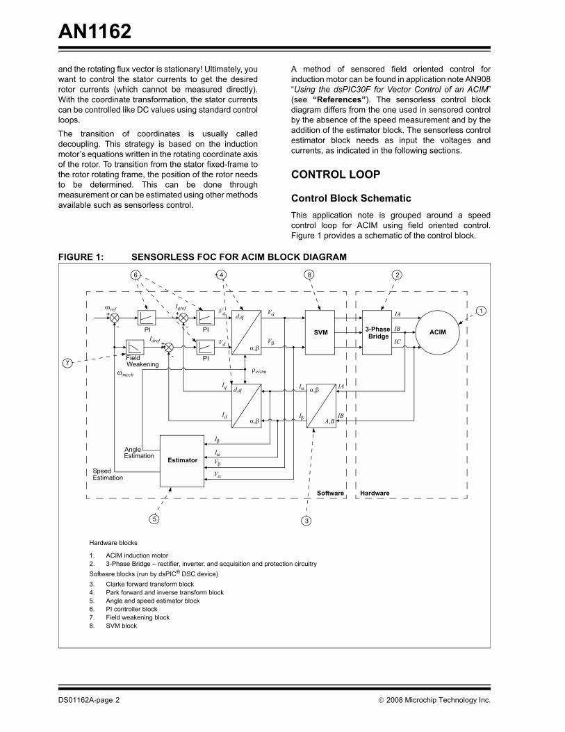
A method of sensored field oriented control forinduction motor can be found in application note AN908“Using the dsPIC30F for Vector Control of an ACIM”(see “References”). The sensorless control blockdiagram differs from the one used in sensored controlby the absence of the speed measurement and by theaddition of the estimator block. The sensorless controlestimator block needs as input the voltages andcurrents, as indicated in the following sections.
CONTROL LOOP
Control Block SchematicThis application note is grouped around a speedcontrol loop for ACIM using field oriented control.Figure 1 provides a schematic of the control block.
FIGURE 1: SENSORLESS FOC FOR ACIM BLOCK DIAGRAM
d,q
α,β
3-PhaseBridge ACIM
A,B
α,βd,q
α,β
Estimator
ωref Iqref
Idref
PI PI
PIFieldWeakening
Vq
Vd
Vα
Vβ
SVM
AngleEstimation
SpeedEstimation
Iα
Iβ
IA
IB
Software Hardware
-
-
-
ρestimωmech
Iα
Iβ
Vβ
Vα
+
IA
IB
IC
Iq
Id
1
2
3
4
5
6
7
8
+ +
Hardware blocks
1. ACIM induction motor2. 3-Phase Bridge – rectifier, inverter, and acquisition and protection circuitrySoftware blocks (run by dsPIC® DSC device)3. Clarke forward transform block4. Park forward and inverse transform block5. Angle and speed estimator block6. PI controller block7. Field weakening block8. SVM block
DS01162A-page 2 © 2008 Microchip Technology Inc.

AN1162
CURRENT DECOUPLINGThe decoupling block (shaded area in Figure 2)comprises a set of blocks: Clarke and Park transform.The Clarke forward transform block is responsible fortranslating three axes, two-dimensional coordinatessystem attached to the stator to two axes systemreference to the stator. The Park forward block isresponsible for translating two axes from the statorfixed frame to the rotating rotor frame. Refer to AN908“Using the dsPIC30F for Vector Control of an ACIM”(see “References”) for more details.
FIGURE 2: COORDINATE TRANSITION (DECOUPLING) BLOCK DIAGRAM
d,q
α,β
3-PhaseBridge ACIM
A,B
α,βd,q
α,β
Estimator
ωref Iqref
Idref
PI PI
PIFieldWeakening
Vq
Vd
Vα
Vβ
AngleEstimation
SpeedEstimation
Iα
Iβ
IA
IB
Software Hardware
-
-
-
ρestimωmech
Iα
Iβ
Vβ
Vα
+
IA
IB
IC
Iq
Id
+ +
SVM
© 2008 Microchip Technology Inc. DS01162A-page 3
AN1162
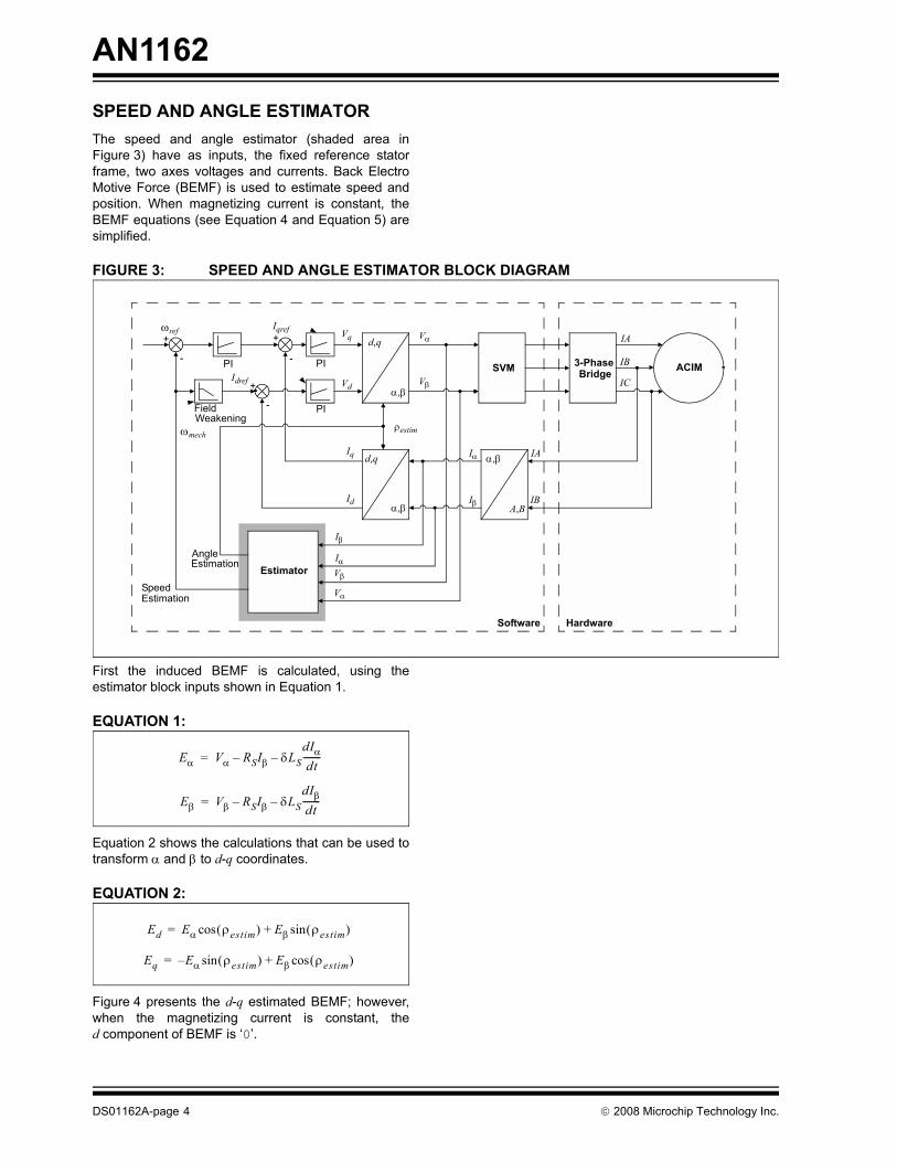
SPEED AND ANGLE ESTIMATORThe speed and angle estimator (shaded area inFigure 3) have as inputs, the fixed reference statorframe, two axes voltages and currents. Back ElectroMotive Force (BEMF) is used to estimate speed andposition. When magnetizing current is constant, theBEMF equations (see Equation 4 and Equation 5) aresimplified.
FIGURE 3: SPEED AND ANGLE ESTIMATOR BLOCK DIAGRAM
First the induced BEMF is calculated, using theestimator block inputs shown in Equation 1.
EQUATION 1:
Equation 2 shows the calculations that can be used totransform α and β to d-q coordinates.
EQUATION 2:
Figure 4 presents the d-q estimated BEMF; however,when the magnetizing current is constant, thed component of BEMF is ‘0’.
d,q
α,β
3-PhaseBridge ACIM
A,B
α,βd,q
α,β
Estimator
ωref Iqref
Idref
PI PI
PIFieldWeakening
Vq
Vd
Vα
VβSVM
AngleEstimation
SpeedEstimation
Iα
Iβ
IA
IB
Software Hardware
-
-
-
ρestimωmech
Iα
Iβ
Vβ
Vα
+
IA
IB
IC
Iq
Id
+ +
Eα Vα RSIβ δLSdIαdt
--------––=
Eβ Vβ RSIβ δLSdIβdt
--------––=
Eq E– α ρestim( )sin Eβ ρestim( )cos+=
Ed Eα ρestim( )cos Eβ ρestim( )sin+=
DS01162A-page 4 © 2008 Microchip Technology Inc.

AN1162
FIGURE 4: BEMF VECTOR COMPONENTS: α-β AND d-qα
β
Eq
Es
Ed
Eβ
Eα
qestim destim
ρestim
Positive Speed
© 2008 Microchip Technology Inc. DS01162A-page 5
AN1162
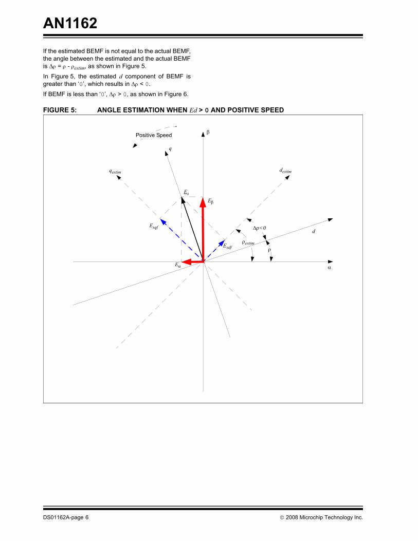
If the estimated BEMF is not equal to the actual BEMF,the angle between the estimated and the actual BEMFis Δρ = ρ - ρestim, as shown in Figure 5.In Figure 5, the estimated d component of BEMF isgreater than ‘0’, which results in Δρ < 0.
If BEMF is less than ‘0’, Δρ > 0, as shown in Figure 6.
FIGURE 5: ANGLE ESTIMATION WHEN Ed > 0 AND POSITIVE SPEED
α
β
Esqf
Es
Esdf
Eβ
Eα
d
q
destimqestim
ρestim
Δρ<0
Positive Speed
ρ
DS01162A-page 6 © 2008 Microchip Technology Inc.

AN1162
FIGURE 6: ANGLE ESTIMATION WHEN Ed < 0 AND POSITIVE SPEEDA simple way to correct the error between estimatedBEMF and actual BEMF would be to subtract from theestimated angle ρestim, the error, Δρ. However, thiscould lead to numeric instabilities.
A solution to the angle estimation correction is to usethe speed instead of angle. Since the angle is theintegral of speed, the numeric instabilities are avoided.
BEMF is proportional with magnetizing flux variation.Equation 3 shows the results of splitting the d-q axes.
EQUATION 3:
Equation 4 and Equation 5 (the rotor flux is consideredconstant) shows the decomposition on the d-q axes.
EQUATION 4:
EQUATION 5:
Therefore, the rotor speed can now be written asEquation 6.
EQUATION 6:
α
β
qestim
Esqf
Es
Esdf
Eβ
Eα
dq
ρestimρ
Positive Speed
Δρ>0
destim
E 11 δR+---------------
dΨmRdt
--------------=
Ed1
1 δR+---------------
dΨmRdt
-------------- 0→=
Eq1
1 δR+---------------ωmRΨmR=
ωmR1 δR+ΨmR
---------------Eq=
© 2008 Microchip Technology Inc. DS01162A-page 7

AN1162
An error in estimation generates a non-zero Ed. Also,the larger Ed is, the larger the error, which leads to thecorrection term for the rotor estimated speed, as shownin Equation 7.EQUATION 7:
Depending on the direction of rotation, the followingcorrective action can be taken, as shown in Table 1.
TABLE 1:
As shown in Equation 8, the angle is the speed integral.
EQUATION 8:
The scheme of the estimator’s “PLL” correction block isshown in Figure 7.
FIGURE 7: ESTIMATED SPEED AND ANGLE AS A FUNCTION OF BEMF AND CONSTANT MAGNETIZING FLUX
Condition Action on ωmR
Correction Term
Positive speed, Ed > 0 Decrease - EdPositive speed, Ed < 0 Increase - EdNegative speed, Ed > 0 Increase + EdNegative speed, Ed < 0 Decrease + Ed
ωmR1 δR+ΨmR
--------------- Eq Eq( ) Ed⋅sgn–=
correction
ρ ωmR∫ dt=
d,q
α,β
1s
Eα
Eβ
Ed
Eq
Edf
Eqf
ω
ΨmR
LPF
LPF Sign
+
+
ρestimmR
DS01162A-page 8 © 2008 Microchip Technology Inc.

AN1162
Figure 8 shows the inclusion of the correction block intothe global scheme of the estimator to obtain theinputs/outputs presented in the sensorless FOC blockdiagram (Figure 1).The estimated BEMF is determined by low-passfiltering the value obtained from the Parktransformation. The first order filter is used to reducethe noise due to the currents derivation. The filter’sconstants should be chosen so that the noise on thesignal is significantly reduced and at the same time sothat the filter not to introduce a dynamic changes for theestimated BEMF.
FIGURE 8: SPEED AND ANGLE ESTIMATOR BLOCK DIAGRAM
d,q
α,β
1s
1s1s
d,q
α,β
σLs
Rs
Rs
σLs
Vα
Vβ
Iβ
IαEd
EqEqf
Edf
ωmR
Iq
Id
ω2ωmech
ImR
-
Magnetizing curve
LPF
LPF
LPF
Sign
SWITCH ΨmRref
+
+
-
-
+
--
+
+
ρestim
Eα
Eβ
RR/1 σR
+
© 2008 Microchip Technology Inc. DS01162A-page 9

AN1162
PI CONTROLLERThe PI controller is the control loop feedbackmechanism that corrects the error between themeasured process variable and its reference value, itoutput adjusting the process. In the case of inductionmotor control process three PI controllers are used,one for each current component corresponding tomagnetizing flux and to torque generation and one forthe speed control loop.
More information concerning the PI controller can befound in application note AN908 “Using the dsPIC30Ffor Vector Control of an ACIM” (see “References”).
FIELD WEAKENINGWhen exceeding the nominal motor speed, the rotorflux must be weakened. A mechanical speed increasewill require an increase of the stator currents frequency,but this must be done with respect to the simpleequation, V/Hz = ct. Since the voltage cannot beincreased over the nominal value, the increase ofspeed must be done in detriment of torque produced,keeping the constant power curve.
In closed loop field oriented control, when exceedingthe nominal motor speed, the Id and Iq control loopssaturate, limiting the motor flux. The field weakeningalgorithm will decrease the Id current as the motorspeed is increase thus removing saturation of thecontrol loops.
Space Vector ModulationThe voltages produced by Clarke transformation blockfeed the SVM module, which creates command signalsfor the inverter’s gates. The principles of functioning ofthe SVM are explained in application note AN908“Using the dsPIC30F for Vector Control of an ACIM”(see “References”).
The main advantages of SVM with respect to sinePWM are:
• Increased line to line voltage (15% more) in the linear operating range - this leads to smaller current ratings for the same power rating; a lower current implies lower costs for the power inverter on one hand, smaller power loss in commutation on the other hand;
• Since the input of the module is a vector defined in the fixed stator frame, this enables the controls of the 3-phase sine waves generation using only one quantity, thus reducing computation power needs.
HIGH LEVEL SYSTEM DECOMPOSITIONThe application’s design has the advantage of usingsome already existing hardware block components pro-vided by Microchip for supporting the demos for motorcontrol. Also, the use of Microchip’s development boardsand their special adapted enhancement boards ease thedevelopment process, shortening the time to output forany system.
HARDWARE
Component BlocksThe system components are:
3-PHASE ACIMThe recommended 3-Phase ACIM is Lesson ACIM thatcan be obtained from Microchip or from an electricmotor distributor. If another motor is used than themotor parameters and the PI controller coefficientsmust be modified inside the software.
The motor parameters as they are indicated by themanufacturer need to be normalized in order to fit theactual software implementation. To support theparameters normalization, inside the applicationsoftware archive it is available a conversion table(EstimParameters.xls file) which produces thenormalized parameters needed by the applicationsoftware.
MICROCHIP dsPICDEM™ MC1H 3-PHASE HIGH VOLTAGE MODULEThe 3-Phase High Voltage Module contains: the powerelectronics gate drive stages, fault detection andlatching circuitry, isolated Hall Effect currenttransducers. A detailed description of the module canbe found in the DS70096 “dsPICDEM™ MC1H3-Phase High Voltage Power Module User’s Guide”(see “References”).
MICROCHIP DEVELOPMENT BOARDThere are several options for the control developmentboard, depending on the dsPIC chose. As an example,for dsPIC30F the Development Board is dsPICDEM™
MC1 as for dsPIC33F the Development Board isExplorer 16. These boards provide connectors to thedsPICDEM™ MC1H, directly or using an adaptor boardsuch as PICtail™ Plus Motor Control Daughter Card forExplorer 16. Refer to “References” for information onrelated documentation for the development boardspreviously mentioned. The software archives providedwith the application note cover several dsPIC solutionsfor implementation. Within the software archive thehardware components are enumerated for eachrecommended setup (Readme.doc file).
DS01162A-page 10 © 2008 Microchip Technology Inc.

AN1162
Application dsPICThe dsPIC devices contain extensive DSP functionalitywith high-performance 16-bit digital signal controllerarchitecture (modified RISC CPU).• High-Performance CPU Features:- Modified Harvard architecture- C compiler optimized instruction set architecture
with flexible addressing modes- 24-bit wide instructions, 16-bit wide data path- 83 base instructions- Up to 40 MIPS operation- 44 interrupt sources- 16 x 16-bit working register array
• DSP Engine Features:- Single-cycle multiply and accumulate- Modulo and Bit-Reversed Addressing modes- Two, 40-bit wide accumulators with optional
saturation logic- ± 16-bit single-cycle shift
• Motor Control PWM Module Features:- 8 PWM output channels- Complementary or Independent Output
modes- Edge and Center-Aligned modes- 4 duty cycle generators- Dedicated time base- Programmable output polarity- Dead-time control for Complementary mode- Manual output control- Trigger for A/D conversions
• Quadrature Encoder Interface Module Features:- Phase A, Phase B and Index Pulse input- 16-bit up/down position counter- Count direction status- Position Measurement (x2 and x4) mode- Programmable digital noise filters on inputs- Alternate 16-bit Timer/Counter mode- Interrupt on position counter rollover/underflow
SOFTWAREComponent ModulesThe software project components have a modulardesign, each function being contained by its own file.The control algorithm consists of an interrupt serviceroutine triggered by control measures sampling and atask on which the user interference and control ishandled together with the control state machine.
The control algorithm was developed by adapting thesensored vector control for ACIM application note,AN908 “Using the dsPIC30F for Vector Control of anACIM” (see “References”) to the sensorless control
requirements, the modifications referring only to theestimator part module and to the adaptation ofpreviously existing modules to the estimator. Thus,details about the existing software components canalso be found in this same application note.
Table 2 lists the most important software modules:
TABLE 2:
Associated to the source files enumerated abovestands the header files, an important header being theuser parameters configuration header(UserParams.h file). The user parameters comprisethe motor and the inverter parameters. The motorparameters are to be normalized to fit the software con-trol algorithm - in order to support the ease of actualcontrol solution porting for other system componentswithin the software archive it may be found a conver-sion utility from physical measures to their normalizedvalues (EstimParameters.xls file).
Debug Capabilities and DMCIMicrochip’s MPLAB® IDE provides all in onedevelopment environment for its dsPIC products.Besides the enhanced code editor, the IDE provides anefficient C code compiler and a debugger that supportsingle-stepping with enhanced breakpoints and tracingcapabilities. All these features are available under oneeasy-to-use unified GUI.
DMCI is a tool which provides a graphical interface thatenables a quick and dynamic yet easy to useinteraction with the system’s key variables. Theintuitive representation of the system variables throughsliders and on/off buttons, the dynamically assignablegraph windows for program generated data analysisshortens the development and calibration/tuning time.Moreover, DMCI provides project-aware navigation ofprogram variables for their easy selection andassignation to the interface’s dedicated controls andvisualization features.
Module Description
acim.c ISR and user interference and control task. Contains the control algorithm, the user interface, and control states handling.
estim.c Estimator for speed and angle of the rotor.pi.s Proportional-integral controller.trig.s Sinus computation.svgen.s SVM generation.clkpark.s Clarke-Park direct transformation.invclark.s Inverse Clark transformation.invpark.s Inverse Park transformation.curmodel.s Magnetizing current and angle computation.fdweak.s Field weakening algorithm.
© 2008 Microchip Technology Inc. DS01162A-page 11

AN1162
Execution and Data FlowThe software program execution consists of two maintasks: the sensorless control of the ACIM and theuser’s commands and information handling.The sensorless control cannot be achieved startingfrom zero speed; therefore the application must bestarted in open loop, using a simple Volt per Hertzcontrol. Once the motor is spinning the BEMF can beused for sensorless control - the user’s touch of a but-ton switching between open loop to closed loop fieldoriented vector control. For PI controller parameter tun-ing purpose there is the option of doubling the refer-ence speed, getting the system response to stepexcitation.
The major control loop is controlling the motor’s speed;therefore the reference speed is one of the algorithminputs - it is read from a potentiometer. Table 3 showsthe states included in the control state machine.
TABLE 3:
The stepping through these states is done by pressingcertain buttons available on the development board.The hardware setup description available in eachsoftware archive (Readme.doc file) will indicate pre-cisely which potentiometer and which buttons are used.
As input for the sensorless field oriented vector controlthe measured current is needed. The control outputsare the three PWM module signals for controlling theinverters’ gates.
The reference rotor flux can be calculated using themotor’s parameters or if the flux weakening is used it isdetermined as a function of the speed of the rotor.
FIGURE 9: SOFTWARE STATE MACHINE
State Description
Stop The motor is stopped.Open Loop To start the motor, it must be passed
through this state, which determines the rotor position.
Closed Loop The actual sensorless field oriented control SVM is executed.
Closed Loop Double Speed
Closed loop algorithm doubling the reference speed. Necessary for PI Controller parameters tuning and for data acquisition.
STOP
OPEN LOOP
CLOSED LOOP
CLOSED LOOPDOUBLE SPEED
BUTTON COMMAND
SENSORLESS FOC SVMALGORITHM
DATA ACQUISITION ISR
USER COMMAND AND INTERFACE TASK
LCD DISPLAY AND LED STATUS
INFINITE LOOP
INTERRUPT
DS01162A-page 12 © 2008 Microchip Technology Inc.
AN1162
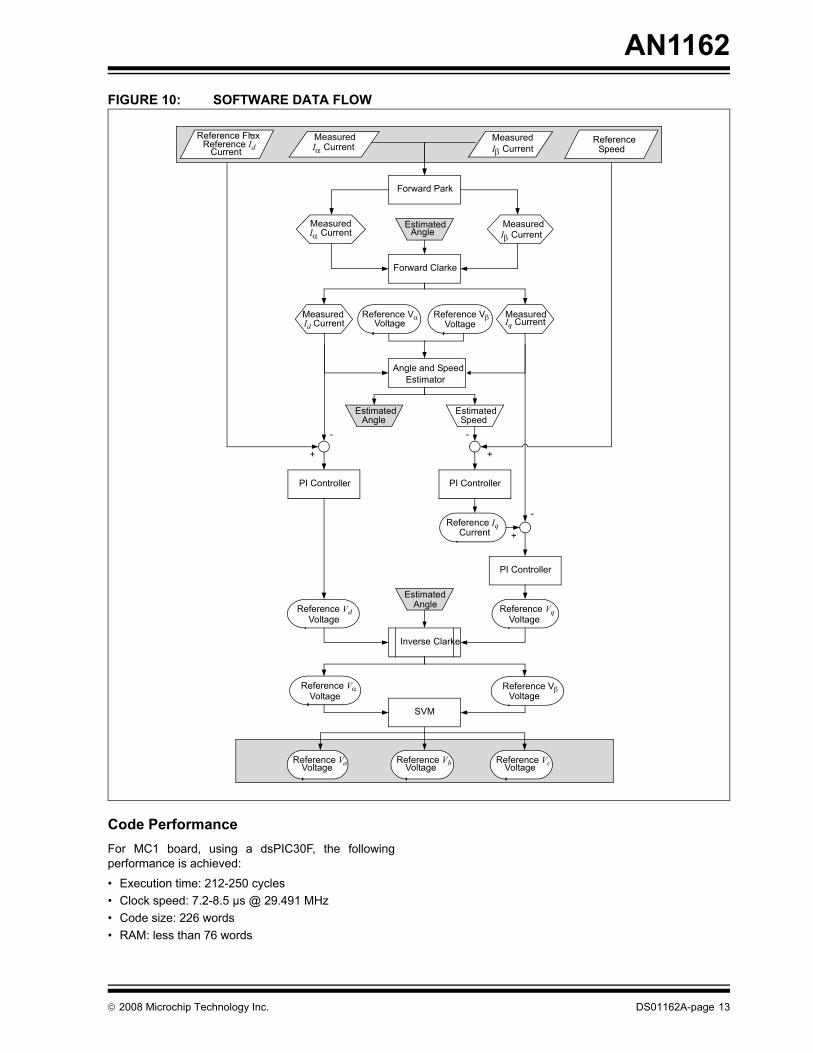
FIGURE 10: SOFTWARE DATA FLOWCode PerformanceFor MC1 board, using a dsPIC30F, the followingperformance is achieved:
• Execution time: 212-250 cycles• Clock speed: 7.2-8.5 µs @ 29.491 MHz• Code size: 226 words• RAM: less than 76 words
Forward Park
Reference VαVoltage
Forward Clarke
Measured Id Current
Measured Iq Current
Estimated Angle
Reference VβVoltage
Angle and Speed Estimator
Estimated Angle
Estimated Speed
Reference Flux Reference Id
CurrentReference
Speed
PI ControllerPI Controller
Reference Iq Current
PI Controller
Reference Vq Voltage
Reference Vd Voltage
Inverse Clarke
Reference VαVoltage
Reference VβVoltage
SVM
Reference Va Voltage
Reference Vb VoltageReference Vc Voltage
Estimated Angle
+
-
-
+
-
+
~ Measured Iα Current
Measured
Iβ Current
Iα CurrentMeasuredIβ Current
Measured
© 2008 Microchip Technology Inc. DS01162A-page 13

AN1162
IMPLEMENTATION AND RESULTS
Speed and Angle EstimatorThe estimator block has as inputs the currents andvoltages obtained after Park transform (see Figure 3).The estimator equations implemented in theapplication software are described below.
The BEMF voltages are calculated as shown inEquation 9.
EQUATION 9:
As shown in Figure 11, the shaded area representsEquation 9.
FIGURE 11: SPEED AND ANGLE ESTIMATOR BLOCK DIAGRAM
Figure 12 shows the resulting waveform of theinductive BEMF.
EstimParm.qVIndalpha = ((long)MotorEstimParm.qLsDt * (long)(EstimParm.qDIalpha))>>10;
where MotorEstimParm.qLsDt is 210 δ LsIo
Uo 8 Tsample⋅ ⋅( )------------------------------------------⋅ ⋅
d,q
α,β
1s
1s1s
d,q
α,β
σLs
Rs
Rs
σLs
Vα
Vβ
Iβ
IαEd
EqEqf
Edf
ωmR
Iq
Id
ω2ωmech
ImR
-
Magnetizing curve
LPF
LPF
LPF
Sign
SWITCH ΨmRref
+
+
-
-
+
--
+
+
ρestim
Eα
Eβ
RR/1 σR
+
DS01162A-page 14 © 2008 Microchip Technology Inc.

AN1162
FIGURE 12: INDUCTIVE BEMF RESULTS© 2008 Microchip Technology Inc. DS01162A-page 15

AN1162
To reduce noise, the derivation of the current is madeevery eight interrupt cycles. SinceMotorEstimParm.qLsDt is scaled with 210 it isnecessary to limit EstimParm.qDIalpha andEstimParm.qDIbeta between -1023 and 1023.Equation 10 shows how the α component of the BEMFis calculated.EQUATION 10:
As shown in Figure 13, the shaded area representsEquation 10.
FIGURE 13: SPEED AND ANGLE ESTIMATOR BLOCK DIAGRAM
Figure 14 shows the resulting waveform of the α BEMF.
EstimParm.qEsa = ParkParm.qValpha-(((long)MotorEstimParm.qRs * (long)ParkParm.qIalpha) >>15)- EstimParm.qVIndalpha;
where MotorEstimParm.qRs is Rs 215 IoUo------⋅ ⋅
d,q
α,β
1s
1s1s
d,q
α,β
σLs
Rs
Rs
σLs
Vα
Vβ
Iβ
IαEd
EqEqf
Edf
ωmR
Iq
Id
ω2ωmech
ImR
-
Magnetizing curve
LPF
LPF
LPF
Sign
SWITCH ΨmRref
+
+
-
-
+
--
+
+
ρestim
Eα
Eβ
RR/1 σR
+
DS01162A-page 16 © 2008 Microchip Technology Inc.

AN1162
FIGURE 14: α BEMF RESULTS© 2008 Microchip Technology Inc. DS01162A-page 17
AN1162
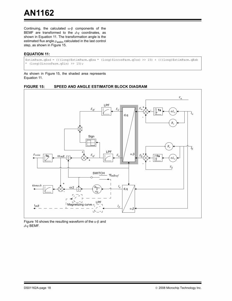
Continuing, the calculated α-β components of theBEMF are transformed to the d-q coordinates, asshown in Equation 11. The transformation angle is theestimated flux angle ρestim calculated in the last controlstep, as shown in Figure 15.EQUATION 11:
As shown in Figure 15, the shaded area representsEquation 11.
FIGURE 15: SPEED AND ANGLE ESTIMATOR BLOCK DIAGRAM
Figure 16 shows the resulting waveform of the α-β andd-q BEMF.
EstimParm.qEsd = (((long)EstimParm.qEsa * (long)SincosParm.qCos) >> 15) + (((long)EstimParm.qEsb * (long)SincosParm.qSin) >> 15);
d,q
α,β
1s
1s1s
d,q
α,β
σLs
Rs
Rs
σLs
Vα
Vβ
Iβ
IαEd
EqEqf
Edf
ωmR
Iq
Id
ω2ωmech
ImR
-
Magnetizing curve
LPF
LPF
LPF
Sign
SWITCH ΨmRref
+
+
-
-
+
--
+
+
ρestim
Eα
Eβ
RR/1 σR
+
DS01162A-page 18 © 2008 Microchip Technology Inc.

AN1162
FIGURE 16: α-β, AND d-q BEMF RESULTS© 2008 Microchip Technology Inc. DS01162A-page 19
AN1162
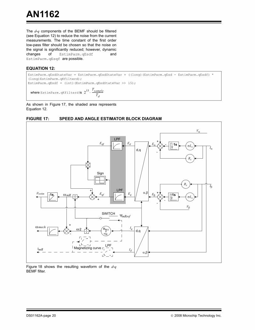
The d-q components of the BEMF should be filtered(see Equation 12) to reduce the noise from the currentmeasurements. The time constant of the first orderlow-pass filter should be chosen so that the noise onthe signal is significantly reduced; however, dynamicchanges of EstimParm.qEsdf andEstimParm.qEsqf are possible.EQUATION 12:
As shown in Figure 17, the shaded area representsEquation 12.
FIGURE 17: SPEED AND ANGLE ESTIMATOR BLOCK DIAGRAM
Figure 18 shows the resulting waveform of the d-qBEMF filter.
EstimParm.qEsdStateVar = EstimParm.qEsdStateVar + ((long)(EstimParm.qEsd - EstimParm.qEsdf) * (long)EstimParm.qKfilterd);EstimParm.qEsdf = (int)(EstimParm.qEsdStateVar >> 15);
where EstimParm.qKfilterd is 215 TsampleTd
------------------⋅
d,q
α,β
1s
1s1s
d,q
α,β
σLs
Rs
Rs
σLs
Vα
Vβ
Iβ
IαEd
EqEqf
Edf
ωmR
Iq
Id
ω2ωmech
ImR
-
Magnetizing curve
LPF
LPF
LPF
Sign
SWITCH ΨmRref
+
+
-
-
+
--
+
+
ρestim
Eα
Eβ
RR/1 σR
+
DS01162A-page 20 © 2008 Microchip Technology Inc.

AN1162
FIGURE 18: d-q BEMF FILTER RESULTS© 2008 Microchip Technology Inc. DS01162A-page 21

AN1162
The correction of the estimated angular speed iscorrected with the BEMF on the d-axis added orsubtracted depending on the sign of BEMF on theq-axis.EQUATION 13:
As shown in Figure 19, the shaded area representsEquation 13.
FIGURE 19: SPEED AND ANGLE ESTIMATOR BLOCK DIAGRAM
if(EstimParm.qEsqf>0){EstimParm.qOmegaMr = (((long)MotorEstimParm.qInvPsi*(long)EstimParm.qEsqf) >> 15) - EstimParm.qEsdf;} else{EstimParm.qOmegaMr = (((long)MotorEstimParm.qInvPsi * (long)EstimParm.qEsqf) >> 15) + EstimParm.qEsdf}
where MotorEstimParm.qInvPsi is equal to 1 δR+( ) U0 215⋅ ⋅
Ψref ω 0⋅--------------------------------------------
d,q
α,β
1s
1s1s
d,q
α,β
σLs
Rs
Rs
σLs
Vα
Vβ
Iβ
IαEd
EqEqf
Edf
ωmR
Iq
Id
ω2ωmech
ImR
-
Magnetizing curve
LPF
LPF
LPF
Sign
SWITCH ΨmRref
+
+
-
-
+
--
+
+
ρestim
Eα
Eβ
RR/1 σR
+
DS01162A-page 22 © 2008 Microchip Technology Inc.

AN1162
As shown in Equation 14, the flux frequency is thenlimited to augment the stability and convergence of theestimator.EQUATION 14:
Figure 20 shows the resulting waveform of theestimated angular speed.
FIGURE 20: ESTIMATED ANGULAR SPEED RESULTS
if(EstimParm.qOmegaMr>EstimParm.qOmegaMrMax){EstimParm.qOmegaMr=EstimParm.qOmegaMrMax;}if(EstimParm.qOmegaMr<EstimParm.qOmegaMrMin){EstimParm.qOmegaMr=EstimParm.qOmegaMrMin;}
© 2008 Microchip Technology Inc. DS01162A-page 23

AN1162
The angle of the magnetizing current is calculated byintegrating the flux frequency.EQUATION 15:
As shown in Figure 21, the shaded area representsEquation 15.
FIGURE 21: SPEED AND ANGLE ESTIMATOR BLOCK DIAGRAM
Figure 22 shows the results of the estimated rotorangle.
EstimParm.qRhoStateVar = EstimParm.qRhoStateVar + (long)(EstimParm.qOmegaMr) * (long)(EstimParm.qDeltaT);EstimParm.qRho = (int) (EstimParm.qRhoStateVar>>15);
where EstimParm.qDeltaT is 215 Tsampleω 0ε0------⋅ ⋅
d,q
α,β
1s
1s1s
d,q
α,β
σLs
Rs
Rs
σLs
Vα
Vβ
Iβ
IαEd
EqEqf
Edf
ωmR
Iq
Id
ω2ωmech
ImR
-
Magnetizing curve
LPF
LPF
LPF
Sign
SWITCH ΨmRref
+
+
-
-
+
--
+
+
ρestim
Eα
Eβ
RR/1 σR
+
DS01162A-page 24 © 2008 Microchip Technology Inc.

AN1162
FIGURE 22: ESTIMATED ANGLE RESULTS© 2008 Microchip Technology Inc. DS01162A-page 25

AN1162
The current model software module (curmodel.s),calculates the magnetizing current value, which is notrequired for the estimator. It is possible to avoid thisrequirement by ensuring that the magnetizing current isset to a constant reference value at all times.EQUATION 16:
As shown in Figure 23, the shaded area representsEquation 16.
FIGURE 23: SPEED AND ANGLE ESTIMATOR BLOCK DIAGRAM
EstimParm.qImrStateVar=EstimParm.qImrStateVar+( (long)(ParkParm.qId - EstimParm.qImr) * (long)MotorEstimParm.qInvTr) ;EstimParm.qImr = (int)(EstimParm.qImrStateVar>>15);
where MotorEstimParm.qInvTr is 215 TsampleTr
------------------⋅
d,q
α,β
1s
1s1s
d,q
α,β
σLs
Rs
Rs
σLs
Vα
Vβ
Iβ
IαEd
EqEqf
Edf
ωmR
Iq
Id
ω2ωmech
ImR
-
Magnetizing curve
LPF
LPF
LPF
Sign
SWITCH ΨmRref
+
+
-
-
+
--
+
+
ρestim
Eα
Eβ
RR/1 σR
+
DS01162A-page 26 © 2008 Microchip Technology Inc.

AN1162
The mechanical speed is calculated in two steps. Thefirst step is calculate the slip velocity assuming that thecurrent model is not executed, as shown inEquation 17.EQUATION 17:
The second step is to subtract the slip velocity from therotor flux velocity and filter, as shown in Equation 18.
EQUATION 18:
As shown in Figure 24, the shaded area representsEquation 17 and Equation 18.
EstimParm.qOmeg2Estim = ((long)ParkParm.qIq*(long)MotorEstimParm.qRrInvTr)>>15;
where MotorEstimParm.qRInvTr is 215 I0ω 0 Tr Idref⋅ ⋅-------------------------------⋅
EstimParm.qVelEstimStateVar=EstimParm.qVelEstimStateVar+( (long)(EstimParm.qOmegaMr-EstimParm.qOmeg2Estim-EstimParm.qVelEstim)*(long)EstimParm.qVelEstimFilterK );EstimParm.qVelEstim = (int)(EstimParm.qVelEstimStateVar>>15);EstimParm.qVelEstim= (int) ((long)EstimParm.qVelEstim*(long)Polpair)>>15);
where EstimParm.qVelEstimFilterK is and Polpair is 215 TsampleTω
------------------⋅215
Ppol---------- 1–
© 2008 Microchip Technology Inc. DS01162A-page 27

AN1162
FIGURE 24: SPEED AND ANGLE ESTIMATOR BLOCK DIAGRAMFigure 25 shows the results of the estimatedmechanical speed.
FIGURE 25: MECHANICAL SPEED ESTIMATION RESULTS
d,q
α,β
1s
1s1s
d,q
α,β
σLs
Rs
Rs
σLs
Vα
Vβ
Iβ
IαEd
EqEqf
Edf
ωmR
Iq
Id
ω2ωmech
ImR
-
Magnetizing curve
LPF
LPF
LPF
Sign
SWITCH ΨmRref
+
+
-
-
+
--
+
+
ρestim
Eα
Eβ
RR/1 σR
+
DS01162A-page 28 © 2008 Microchip Technology Inc.

AN1162
Sensorless versus SensoredThe experimental results prove that there is nosignificant difference between the step response of thesensorless control and the sensored control (seeFigure 26). The estimator can replace the sensorwithout reduction of the dynamic of the control.As shown in Figure 27, the results prove that theestimated speed at steady state condition has a goodaccuracy, which can be compared with the speedinformation from the sensor.
FIGURE 26: EXPERIMENTAL RESULTS: SENSORED (LEFT) VS. SENSORLESS (RIGHT)
FIGURE 27: SPEED ESTIMATION ACCURACY
© 2008 Microchip Technology Inc. DS01162A-page 29

AN1162
STARTUP AND TUNINGTo increase the stability of the sensorless control ofACIM, the following startup strategy is employed, whichlimits the lowest allowed reference speed and allowssafe startup from a standstill.
• When the motor is running and the analog reference value (CtrlParm.qVelRef) is below the minimum limit set by software (qVelMinContrOff/2), the control speed reference value (PIParmQref.qInRef) is set to ‘0’. Speed control is deactivated.
• When the motor is running and the analog reference value (CtrlParm.qVelRef) is greater than the minimum limit set by software (qVelMinContrOff/2), the speed controller reference value (PIParmQref.qInRef) is set to the analog reference value (CtrlParm.qVelRef).
• When the motor is at a standstill and the analog reference value (CtrlParm.qVelRef) is greater than the minimum limit set by software (qVelMinContrOff), the control speed reference value(PIParmQref.qInRef) is set to the analog reference value (CtrlParm.qVelRef).
To make tuning the PI Controller parameters easier, theTorque mode can be used. In Torque mode, the speedcontroller remains inactive and the torque referencevalue is set directly, bypassing the PI speed controller.Torque mode is also possible at low speeds and at astandstill. No startup or limitation algorithm is usedwhen this control mode is selected.
To select the Torque mode, simply define it within theacim.c file, as follows:#define TORQUE_MODE
Figure 28 shows the high-dynamic torque responseduring the change in reference value. The magnetizingcurrent remains unchanged while the motor continuesto accelerate until the voltage source limit is reachedand the torque falls to zero.
FIGURE 28: SPEED RESPONSE
DS01162A-page 30 © 2008 Microchip Technology Inc.

AN1162
CONCLUSIONThis application note presents a solution forimplementing a sensorless field oriented control of anACIM using Microchip’s dsPIC30F and dsPIC33Fdigital signal controllers. The obtained results do notdiffer significantly from the sensored version of the fieldoriented control from the dynamics perspective, but itsignificantly reduces the cost of the system.
REFERENCES• AN887 “AC Induction Motor Fundamentals”
(DS00887), Microchip Technology Inc., 2003• AN908 “Using the dsPIC30F for Vector Control of
an ACIM” (DS00908), Microchip Technology Inc., 2007
• dsPICDEM™ MC1 Motor Control Development Board User’s Guide (DS70098), Microchip Technology Inc., 2003
• dsPICDEM™ MC1H 3-Phase High Voltage Power Module User’s Guide (DS70096), Microchip Technology Inc., 2004
• Explorer 16 Development Board User’s Guide (DS51589), Microchip Technology Inc., 2005
• Motor Control Interface PICtail™ Plus Daughter Board User’s Guide (DS51674), Microchip Technology Inc., 2007
© 2008 Microchip Technology Inc. DS01162A-page 31

AN1162
NOTES:DS01162A-page 32 © 2008 Microchip Technology Inc.

Note the following details of the code protection feature on Microchip devices:• Microchip products meet the specification contained in their particular Microchip Data Sheet.
• Microchip believes that its family of products is one of the most secure families of its kind on the market today, when used in the intended manner and under normal conditions.
• There are dishonest and possibly illegal methods used to breach the code protection feature. All of these methods, to our knowledge, require using the Microchip products in a manner outside the operating specifications contained in Microchip’s Data Sheets. Most likely, the person doing so is engaged in theft of intellectual property.
• Microchip is willing to work with the customer who is concerned about the integrity of their code.
• Neither Microchip nor any other semiconductor manufacturer can guarantee the security of their code. Code protection does not mean that we are guaranteeing the product as “unbreakable.”
Code protection is constantly evolving. We at Microchip are committed to continuously improving the code protection features of ourproducts. Attempts to break Microchip’s code protection feature may be a violation of the Digital Millennium Copyright Act. If such actsallow unauthorized access to your software or other copyrighted work, you may have a right to sue for relief under that Act.
Information contained in this publication regarding deviceapplications and the like is provided only for your convenienceand may be superseded by updates. It is your responsibility toensure that your application meets with your specifications.MICROCHIP MAKES NO REPRESENTATIONS ORWARRANTIES OF ANY KIND WHETHER EXPRESS ORIMPLIED, WRITTEN OR ORAL, STATUTORY OROTHERWISE, RELATED TO THE INFORMATION,INCLUDING BUT NOT LIMITED TO ITS CONDITION,QUALITY, PERFORMANCE, MERCHANTABILITY ORFITNESS FOR PURPOSE. Microchip disclaims all liabilityarising from this information and its use. Use of Microchipdevices in life support and/or safety applications is entirely atthe buyer’s risk, and the buyer agrees to defend, indemnify andhold harmless Microchip from any and all damages, claims,suits, or expenses resulting from such use. No licenses areconveyed, implicitly or otherwise, under any Microchipintellectual property rights.
© 2008 Microchip Technology Inc.
Trademarks
The Microchip name and logo, the Microchip logo, Accuron, dsPIC, KEELOQ, KEELOQ logo, MPLAB, PIC, PICmicro, PICSTART, PRO MATE, rfPIC and SmartShunt are registered trademarks of Microchip Technology Incorporated in the U.S.A. and other countries.
AmpLab, FilterLab, Linear Active Thermistor, MXDEV, MXLAB, SEEVAL, SmartSensor and The Embedded Control Solutions Company are registered trademarks of Microchip Technology Incorporated in the U.S.A.
Analog-for-the-Digital Age, Application Maestro, CodeGuard, dsPICDEM, dsPICDEM.net, dsPICworks, dsSPEAK, ECAN, ECONOMONITOR, FanSense, In-Circuit Serial Programming, ICSP, ICEPIC, Mindi, MiWi, MPASM, MPLAB Certified logo, MPLIB, MPLINK, mTouch, PICkit, PICDEM, PICDEM.net, PICtail, PowerCal, PowerInfo, PowerMate, PowerTool, REAL ICE, rfLAB, Select Mode, Total Endurance, UNI/O, WiperLock and ZENA are trademarks of Microchip Technology Incorporated in the U.S.A. and other countries.
SQTP is a service mark of Microchip Technology Incorporated in the U.S.A.
All other trademarks mentioned herein are property of their respective companies.
© 2008, Microchip Technology Incorporated, Printed in the U.S.A., All Rights Reserved.
Printed on recycled paper.
DS01162A-page 33
Microchip received ISO/TS-16949:2002 certification for its worldwide headquarters, design and wafer fabrication facilities in Chandler and Tempe, Arizona; Gresham, Oregon and design centers in California and India. The Company’s quality system processes and procedures are for its PIC® MCUs and dsPIC® DSCs, KEELOQ® code hopping devices, Serial EEPROMs, microperipherals, nonvolatile memory and analog products. In addition, Microchip’s quality system for the design and manufacture of development systems is ISO 9001:2000 certified.

DS01162A-page 34 © 2008 Microchip Technology Inc.
AMERICASCorporate Office2355 West Chandler Blvd.Chandler, AZ 85224-6199Tel: 480-792-7200 Fax: 480-792-7277Technical Support: http://support.microchip.comWeb Address: www.microchip.comAtlantaDuluth, GA Tel: 678-957-9614 Fax: 678-957-1455BostonWestborough, MA Tel: 774-760-0087 Fax: 774-760-0088ChicagoItasca, IL Tel: 630-285-0071 Fax: 630-285-0075DallasAddison, TX Tel: 972-818-7423 Fax: 972-818-2924DetroitFarmington Hills, MI Tel: 248-538-2250Fax: 248-538-2260KokomoKokomo, IN Tel: 765-864-8360Fax: 765-864-8387Los AngelesMission Viejo, CA Tel: 949-462-9523 Fax: 949-462-9608Santa ClaraSanta Clara, CA Tel: 408-961-6444Fax: 408-961-6445TorontoMississauga, Ontario, CanadaTel: 905-673-0699 Fax: 905-673-6509
ASIA/PACIFICAsia Pacific OfficeSuites 3707-14, 37th FloorTower 6, The GatewayHarbour City, KowloonHong KongTel: 852-2401-1200Fax: 852-2401-3431Australia - SydneyTel: 61-2-9868-6733Fax: 61-2-9868-6755China - BeijingTel: 86-10-8528-2100 Fax: 86-10-8528-2104China - ChengduTel: 86-28-8665-5511Fax: 86-28-8665-7889China - Hong Kong SARTel: 852-2401-1200 Fax: 852-2401-3431China - NanjingTel: 86-25-8473-2460Fax: 86-25-8473-2470China - QingdaoTel: 86-532-8502-7355Fax: 86-532-8502-7205China - ShanghaiTel: 86-21-5407-5533 Fax: 86-21-5407-5066China - ShenyangTel: 86-24-2334-2829Fax: 86-24-2334-2393China - ShenzhenTel: 86-755-8203-2660 Fax: 86-755-8203-1760China - WuhanTel: 86-27-5980-5300Fax: 86-27-5980-5118China - XiamenTel: 86-592-2388138 Fax: 86-592-2388130China - XianTel: 86-29-8833-7252Fax: 86-29-8833-7256China - ZhuhaiTel: 86-756-3210040 Fax: 86-756-3210049
ASIA/PACIFICIndia - BangaloreTel: 91-80-4182-8400 Fax: 91-80-4182-8422India - New DelhiTel: 91-11-4160-8631Fax: 91-11-4160-8632India - PuneTel: 91-20-2566-1512Fax: 91-20-2566-1513Japan - YokohamaTel: 81-45-471- 6166 Fax: 81-45-471-6122Korea - DaeguTel: 82-53-744-4301Fax: 82-53-744-4302Korea - SeoulTel: 82-2-554-7200Fax: 82-2-558-5932 or 82-2-558-5934Malaysia - Kuala LumpurTel: 60-3-6201-9857Fax: 60-3-6201-9859Malaysia - PenangTel: 60-4-227-8870Fax: 60-4-227-4068Philippines - ManilaTel: 63-2-634-9065Fax: 63-2-634-9069SingaporeTel: 65-6334-8870Fax: 65-6334-8850Taiwan - Hsin ChuTel: 886-3-572-9526Fax: 886-3-572-6459Taiwan - KaohsiungTel: 886-7-536-4818Fax: 886-7-536-4803Taiwan - TaipeiTel: 886-2-2500-6610 Fax: 886-2-2508-0102Thailand - BangkokTel: 66-2-694-1351Fax: 66-2-694-1350
EUROPEAustria - WelsTel: 43-7242-2244-39Fax: 43-7242-2244-393Denmark - CopenhagenTel: 45-4450-2828 Fax: 45-4485-2829France - ParisTel: 33-1-69-53-63-20 Fax: 33-1-69-30-90-79Germany - MunichTel: 49-89-627-144-0 Fax: 49-89-627-144-44Italy - Milan Tel: 39-0331-742611 Fax: 39-0331-466781Netherlands - DrunenTel: 31-416-690399 Fax: 31-416-690340Spain - MadridTel: 34-91-708-08-90Fax: 34-91-708-08-91UK - WokinghamTel: 44-118-921-5869Fax: 44-118-921-5820
WORLDWIDE SALES AND SERVICE
01/02/08
Related Documents