WebSeminar Sensorless FOC for AC Induction Motors © 2008 Microchip Technology Inc. Page 1 © 2008 Microchip Technology Incorporated. All Rights Reserved. Sensorless FOC for ACIM Slide 1 Sensorless Field Oriented Control (FOC) for AC Induction Motors (ACIM) Welcome to the Sensorless Field Oriented Control for AC Induction Motors Web Seminar. Hi, my name is Jorge Zambada, I am an applications engineer for the Digital Signal Controller Division at Microchip.

Welcome message from author
This document is posted to help you gain knowledge. Please leave a comment to let me know what you think about it! Share it to your friends and learn new things together.
Transcript
WebSeminarSensorless FOC for AC Induction Motors
© 2008 Microchip Technology Inc. Page 1
© 2008 Microchip Technology Incorporated. All Rights Reserved. Sensorless FOC for ACIM Slide 1
Sensorless Field Oriented Control (FOC) for
AC Induction Motors (ACIM)
Welcome to the Sensorless Field Oriented Control for AC Induction Motors Web Seminar.
Hi, my name is Jorge Zambada, I am an applications engineer for the Digital Signal Controller Division at Microchip.

WebSeminarSensorless FOC for AC Induction Motors
© 2008 Microchip Technology Inc. Page 2
© 2008 Microchip Technology Incorporated. All Rights Reserved. Sensorless FOC for ACIM Slide 2
Web Seminar Agenda
ACIM introductionSensorless Field Oriented Control for ACIMConclusions
Here is the agenda for the today’s seminar: we will briefly talk about the induction motor’s role in the industry, covering its main characteristics, then we will talk about sensorless field oriented control (FOC) with a description of its functional blocks. We will conclude showing a side to side comparison of sensored versus sensorless results.
WebSeminarSensorless FOC for AC Induction Motors
© 2008 Microchip Technology Inc. Page 3
© 2008 Microchip Technology Incorporated. All Rights Reserved. Sensorless FOC for ACIM Slide 3
Web Seminar Agenda
ACIM introductionSensorless Field Oriented Control for ACIMConclusions
In this section will briefly talk about ACIMs and their role in the industry.

WebSeminarSensorless FOC for AC Induction Motors
© 2008 Microchip Technology Inc. Page 4
© 2008 Microchip Technology Incorporated. All Rights Reserved. Sensorless FOC for ACIM Slide 4
Other motors
AC Induction motor90%
•Pumps
•Blowers
•Compressors
•Automation
ACIM Introduction
At least 90% of industrial drives have induction motors; this is a result of its robustness and low cost. Another important aspect is the low maintenance cost which is a consequence of its simple and reliable design. An additional key factor is that the rotor does not have any moving contacts, which eliminates sparking.
Some of the applications where we find ACIMs are pumps, fans, blowers, compressors and in industrial automation. In most cases, induction motors are used with drives that have little or no electronics at all. In the case of no electronics, the motor is directly connected to the power line or through a mechanical relay.

WebSeminarSensorless FOC for AC Induction Motors
© 2008 Microchip Technology Inc. Page 5
© 2008 Microchip Technology Incorporated. All Rights Reserved. Sensorless FOC for ACIM Slide 5
ACIM Introduction
From now on we will narrow the field of induction motor type to the squirrel cage model.One of the main characteristic of this type of induction motor is the slip of the rotor speed with respect to the stator rotating flux speed. For this reason, this motor type is also known as asynchronous motor.A demonstration of its operating principle is highlighted in the figure. As it can be seen, a conductor being part of the rotor is moving with speed omega 1 through the electromagnetic field moving with speed omega 3 with the directions indicated by the speed arrow. The resulting conductor speed relative to the magnetic field speed is omega 2 which is equal to omega 3 minus omega 1. A Back electromagnetic force (also known as Back EMF, BEMF) will be induced with the direction of the blue arrow indicated in the figure. If the relative speed of the conductor with respect to the magnetic field speed is zero, no BEMF will be induced, and therefore no current will appear inside the conductor. The interaction of the current with the magnetic field will produce the electro-dynamic force F, shown with a green arrow.The rotating stator flux induces a back EMF in the rotor squirrel cage, which generates the rotor flux. The motor starts spinning as the rotor flux is trying to catch the rotating stator flux. The rotor will never be synchronous with the stator rotating currents, because if they are synchronous, no BEMF will be inducted in the rotor cage and no rotor flux is generated.

WebSeminarSensorless FOC for AC Induction Motors
© 2008 Microchip Technology Inc. Page 6
© 2008 Microchip Technology Incorporated. All Rights Reserved. Sensorless FOC for ACIM Slide 6
Web Seminar Agenda
ACIM introductionSensorless Field Oriented Control for ACIMConclusions
In this section we will talk about sensorless field oriented control of an AC induction motor. First of all, we will have a brief description of the control system, and secondly we will have a detailed description of sensorless field oriented control.

WebSeminarSensorless FOC for AC Induction Motors
© 2008 Microchip Technology Inc. Page 7
© 2008 Microchip Technology Incorporated. All Rights Reserved. Sensorless FOC for ACIM Slide 7
3 PhaseInverter
andSignal
Conditioning
dsPIC®
ControlAlgorithm ACIM
Reference
Speed
Sensorless FOC ACIM
Commandsignals
Feedbacksignals
Power
This is the general control scheme for sensorless FOC of an AC induction motor. Its 2 main blocks are: one, the dsPIC® control algorithm block and two, the 3 phase inverter and signal conditioning block. The purpose of the system is to control the speed of an induction motor using field oriented control without any position or speed sensor.

WebSeminarSensorless FOC for AC Induction Motors
© 2008 Microchip Technology Inc. Page 8
© 2008 Microchip Technology Incorporated. All Rights Reserved. Sensorless FOC for ACIM Slide 8
3 PhaseInverter
andSignal
Conditioning
dsPIC®
ControlAlgorithm ACIM
Reference
Speed
Sensorless FOC ACIM
Commandsignals
Feedbacksignals
Power
In the following slides, we will briefly describe the 3 phase inverter block.
WebSeminarSensorless FOC for AC Induction Motors
© 2008 Microchip Technology Inc. Page 9
© 2008 Microchip Technology Incorporated. All Rights Reserved. Sensorless FOC for ACIM Slide 9
Power Electronics Gate Drive Stages
Fault detection circuitry
Conditioning of Feedback Signals
Optocouplers Drive Isolated Hall-EffectCurrent Transducer
Signals from/to development board with dsPIC® DSC
Fault signals
Currents measured
IsolatedSwitchingSignals
Switchingsignals
Phase voltagesPhase voltages
Sensorless FOC ACIM
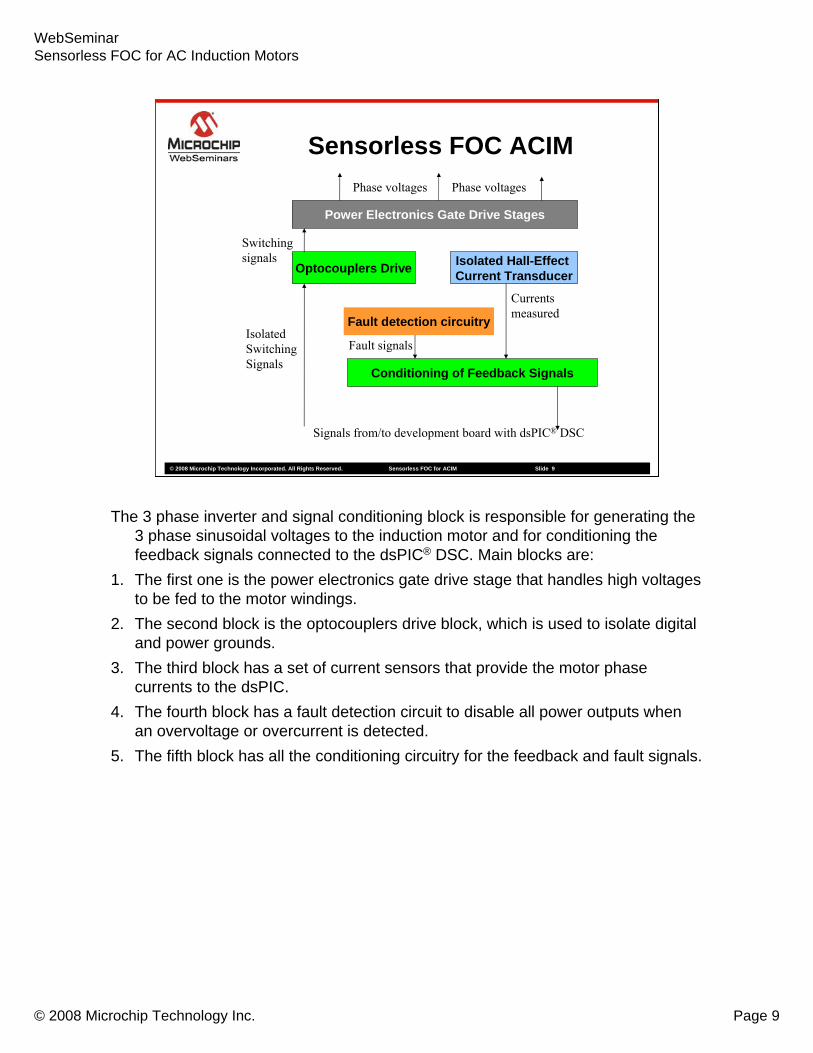
The 3 phase inverter and signal conditioning block is responsible for generating the 3 phase sinusoidal voltages to the induction motor and for conditioning the feedback signals connected to the dsPIC® DSC. Main blocks are:
1. The first one is the power electronics gate drive stage that handles high voltages to be fed to the motor windings.
2. The second block is the optocouplers drive block, which is used to isolate digital and power grounds.
3. The third block has a set of current sensors that provide the motor phase currents to the dsPIC.
4. The fourth block has a fault detection circuit to disable all power outputs when an overvoltage or overcurrent is detected.
5. The fifth block has all the conditioning circuitry for the feedback and fault signals.

WebSeminarSensorless FOC for AC Induction Motors
© 2008 Microchip Technology Inc. Page 10
© 2008 Microchip Technology Incorporated. All Rights Reserved. Sensorless FOC for ACIM Slide 10
3 PhaseInverter
andSignal
Conditioning
dsPIC®
ControlAlgorithm
ACIMReference
Speed
Commandsignals
Feedbacksignals
Sensorless FOC ACIM
Power
We will now describe…

WebSeminarSensorless FOC for AC Induction Motors
© 2008 Microchip Technology Inc. Page 11
© 2008 Microchip Technology Incorporated. All Rights Reserved. Sensorless FOC for ACIM Slide 11
3 PhaseInverter
andSignal
Conditioning
dsPIC®
ControlAlgorithm
ACIMReference
Speed
Commandsignals
Feedbacksignals
Sensorless FOC ACIM
Power
… the sensorless field oriented control algorithm.

WebSeminarSensorless FOC for AC Induction Motors
© 2008 Microchip Technology Inc. Page 12
© 2008 Microchip Technology Incorporated. All Rights Reserved. Sensorless FOC for ACIM Slide 12
ACIM3 ~InverterSVM
αβ
dq
PI
PI
Estimator
PI
αβ
dq
AB
αβ
+
++
-
-
-
Ia
Ib
Σ
Σ
ΣUa
Ub
Uc
Uα
Uβ
Iα
Iβ
Uq
Ud
Id
Iq
Iqref
Idref
ωref
ωestim
Θestim
Θestim
UαUβIαIβ
ωestim
Sensorless FOC ACIM
The key to understanding how field oriented control works is to form a mental picture of the coordinate reference transformation process. If you picture how an AC motor works, you might imagine the operation from the perspective of the stator. From this perspective, a sinusoidal input current is applied to the stator. This time variant signal causes a rotating magnetic flux to be generated. The speed of the rotor is going to be a function of the rotating flux vector. From a stationary perspective, the stator currents and the rotating flux vector look like AC quantities.
Now, instead of the previous perspective, imagine that you could climb inside the motor. Once you are inside the motor, picture yourself running alongside the spinning rotor at the same speed as the rotating flux vector that is generated by the stator currents. Looking at the motor from this perspective during steady state conditions, the stator currents look like constant values, and the rotating flux vector is stationary! Ultimately, you want to control the stator currents to get the desired rotor currents (which cannot be measured directly). With the coordinate transformation, the stator currents can be controlled like DC values using standard control loops

WebSeminarSensorless FOC for AC Induction Motors
© 2008 Microchip Technology Inc. Page 13
© 2008 Microchip Technology Incorporated. All Rights Reserved. Sensorless FOC for ACIM Slide 13
Sensorless FOC ACIM
Let’s take a look at the different components of field oriented control.

WebSeminarSensorless FOC for AC Induction Motors
© 2008 Microchip Technology Inc. Page 14
© 2008 Microchip Technology Incorporated. All Rights Reserved. Sensorless FOC for ACIM Slide 14
ACIM3 ~InverterSVM
Ua
Ub
Uc
Sensorless FOC ACIM
• The transition of coordinates separates the current component responsible for the magnetizing flux of the motor (Id) and the component responsible for motor torque (Iq). In order to transition from the fixed reference frame (alpha-beta) to the rotating frame (d-q), the position of the rotor is required. In sensorless control, the position is estimated as shown in the figure.
WebSeminarSensorless FOC for AC Induction Motors
© 2008 Microchip Technology Inc. Page 15
© 2008 Microchip Technology Incorporated. All Rights Reserved. Sensorless FOC for ACIM Slide 15
Ia
Ib
ACIM3 ~InverterSVM
Ua
Ub
Uc
Sensorless FOC ACIM
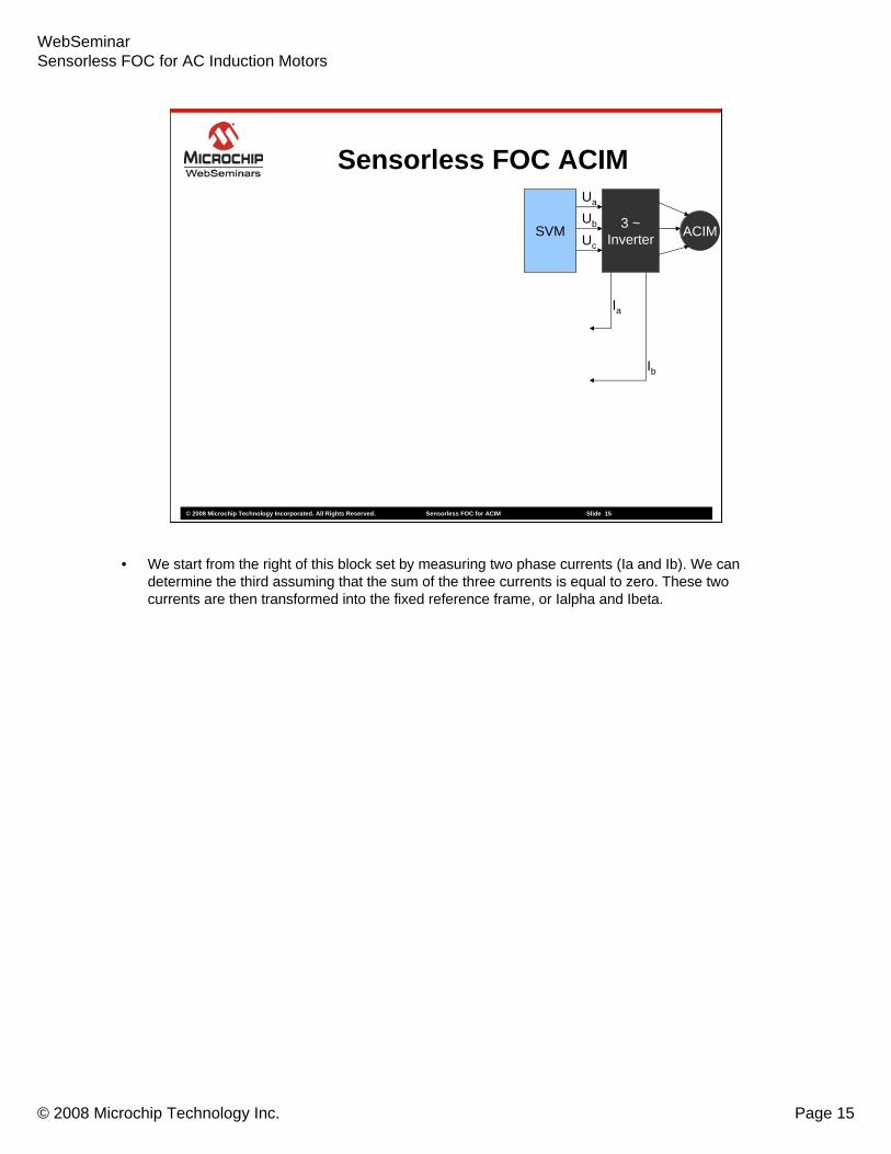
• We start from the right of this block set by measuring two phase currents (Ia and Ib). We can determine the third assuming that the sum of the three currents is equal to zero. These two currents are then transformed into the fixed reference frame, or Ialpha and Ibeta.

WebSeminarSensorless FOC for AC Induction Motors
© 2008 Microchip Technology Inc. Page 16
© 2008 Microchip Technology Incorporated. All Rights Reserved. Sensorless FOC for ACIM Slide 16
ACIM3 ~InverterSVM
AB
αβ
Ia
Ib
Ua
Ub
Uc
Estimator
αβ
dq
Uα
Uβ
Iα
Iβ
Id
Iq
ωestim
Θestim
Θestim
UαUβIαIβ
Sensorless FOC ACIM
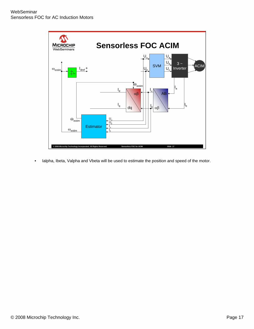
• Now, the rotor flux angle is needed for the transformation of the currents from the fixed reference frame (Ialpha and Ibeta) to the rotating rotor reference frame (Id and Iq). The resulting transformed currents will be responsible for magnetizing flux generation – id and torque – iq. The transformation from the fixed to rotating reference frame is called Park transform and will be described later in the web seminar.
WebSeminarSensorless FOC for AC Induction Motors
© 2008 Microchip Technology Inc. Page 17
© 2008 Microchip Technology Incorporated. All Rights Reserved. Sensorless FOC for ACIM Slide 17
ACIM3 ~InverterSVM
Estimator
αβ
dq
AB
αβ
+
Ia
Ib
Ua
Ub
Uc
Uα
Uβ
Iα
Iβ
Id
Iq
Idref
ωestim
Θestim
Θestim
UαUβIαIβ
ωestim
Sensorless FOC ACIM
• Ialpha, Ibeta, Valpha and Vbeta will be used to estimate the position and speed of the motor.

WebSeminarSensorless FOC for AC Induction Motors
© 2008 Microchip Technology Inc. Page 18
© 2008 Microchip Technology Incorporated. All Rights Reserved. Sensorless FOC for ACIM Slide 18
ACIM3 ~InverterSVM
Estimator
PI
αβ
dq
AB
αβ
+
++
-
Ia
Ib
ΣUa
Ub
Uc
Uα
Uβ
Iα
Iβ
Id
Iq
Iqref
Idref
ωref
ωestim
Θestim
Θestim
UαUβIαIβ
ωestim
Sensorless FOC ACIM
• The speed error between the reference speed and the estimated speed is fed to a PI controller. The output of the PI controller will be the reference Iq which is responsible for torque generation.

WebSeminarSensorless FOC for AC Induction Motors
© 2008 Microchip Technology Inc. Page 19
© 2008 Microchip Technology Incorporated. All Rights Reserved. Sensorless FOC for ACIM Slide 19
ACIM3 ~InverterSVM
PI
Estimator
PI
αβ
dq
AB
αβ
+
++
-
-
Ia
Ib
Σ
ΣUa
Ub
Uc
Uα
Uβ
Iα
Iβ
Ud
Id
Iq
Iqref
Idref
ωref
ωestim
Θestim
Θestim
UαUβIαIβ
ωestim
Sensorless FOC ACIM
• Torque and Flux are also compensated by PI controllers.

WebSeminarSensorless FOC for AC Induction Motors
© 2008 Microchip Technology Inc. Page 20
© 2008 Microchip Technology Incorporated. All Rights Reserved. Sensorless FOC for ACIM Slide 20
ACIM3 ~InverterSVM
PI
PI
Estimator
PI
αβ
dq
AB
αβ
+
++
-
-
-
Ia
Ib
Σ
Σ
ΣUa
Ub
Uc
Uα
Uβ
Iα
Iβ
Uq
Ud
Id
Iq
Iqref
Idref
ωref
ωestim
Θestim
Θestim
UαUβIαIβ
ωestim
Sensorless FOC ACIM
• D and Q voltages which are computed in the rotating reference frame are transformed back to the fixed reference frame using the Inverse Park transformation block producing Valpha and Vbeta.

WebSeminarSensorless FOC for AC Induction Motors
© 2008 Microchip Technology Inc. Page 21
© 2008 Microchip Technology Incorporated. All Rights Reserved. Sensorless FOC for ACIM Slide 21
ACIM3 ~InverterSVM
αβ
dq
PI
PI
Estimator
PI
αβ
dq
AB
αβ
+
++
-
-
-
Ia
Ib
Σ
Σ
ΣUa
Ub
Uc
Uα
Uβ
Iα
Iβ
Uq
Ud
Id
Iq
Iqref
Idref
ωref
ωestim
Θestim
Θestim
UαUβIαIβ
ωestim
Sensorless FOC ACIM
• From Valpha and Beta, a modulation technique called Space Vector Modulation is used. SVM transforms the fixed stator reference frame voltages to signals that drive the power inverter.

WebSeminarSensorless FOC for AC Induction Motors
© 2008 Microchip Technology Inc. Page 22
© 2008 Microchip Technology Incorporated. All Rights Reserved. Sensorless FOC for ACIM Slide 22
ACIM3 ~InverterSVM
αβ
dq
PI
PI
Estimator
PI
αβ
dq
AB
αβ
+
++
-
-
-
Ia
Ib
Σ
Σ
ΣUa
Ub
Uc
Uα
Uβ
Iα
Iβ
Uq
Ud
Id
Iq
Iqref
Idref
ωref
ωestim
Θestim
Θestim
UαUβIαIβ
ωestim
Sensorless FOC ACIM
The first block to be described is the Clarke transform.
WebSeminarSensorless FOC for AC Induction Motors
© 2008 Microchip Technology Inc. Page 23
© 2008 Microchip Technology Incorporated. All Rights Reserved. Sensorless FOC for ACIM Slide 23
Direct Clarke Transform
3I2II
II0III
BAβ
Aα
CBA
⋅+=
==++
AB
αβ
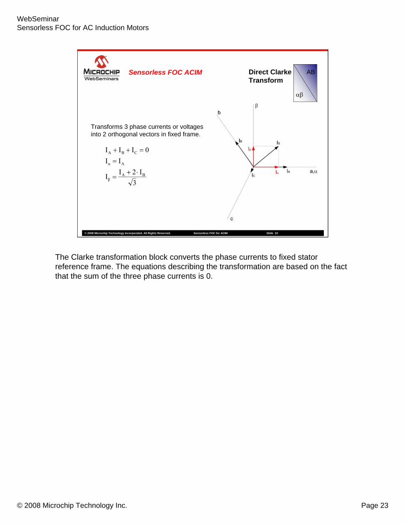
Transforms 3 phase currents or voltages into 2 orthogonal vectors in fixed frame.
Sensorless FOC ACIM
The Clarke transformation block converts the phase currents to fixed stator reference frame. The equations describing the transformation are based on the fact that the sum of the three phase currents is 0.

WebSeminarSensorless FOC for AC Induction Motors
© 2008 Microchip Technology Inc. Page 24
© 2008 Microchip Technology Incorporated. All Rights Reserved. Sensorless FOC for ACIM Slide 24
ACIM3 ~InverterSVM
αβ
dq
PI
PI
Estimator
PI
αβ
dq
AB
αβ
+
++
-
-
-
Ia
Ib
Σ
Σ
ΣUa
Ub
Uc
Uα
Uβ
Iα
Iβ
Uq
Ud
Id
Iq
Iqref
Idref
ωref
ωestim
Θestim
Θestim
UαUβIαIβ
ωestim
Sensorless FOC ACIM
The next block to be described is the Park transformation block.

WebSeminarSensorless FOC for AC Induction Motors
© 2008 Microchip Technology Inc. Page 25
© 2008 Microchip Technology Incorporated. All Rights Reserved. Sensorless FOC for ACIM Slide 25
ACIM3 ~InverterSVM
αβ
dq
PI
PI
Estimator
PI
αβ
dq
AB
αβ
+
++
-
-
-
Ia
Ib
Σ
Σ
ΣUa
Ub
Uc
Uα
Uβ
Iα
Iβ
Uq
Ud
Id
Iq
Iqref
Idref
ωref
ωestim
Θestim
Θestim
UαUβIαIβ
ωestim
Sensorless FOC ACIM
In this control topology, a direct and inverse Park transformation blocks are needed. Inputs to this block are the outputs of the Clarke transformation block and the angle of the rotor.

WebSeminarSensorless FOC for AC Induction Motors
© 2008 Microchip Technology Inc. Page 26
© 2008 Microchip Technology Incorporated. All Rights Reserved. Sensorless FOC for ACIM Slide 26
Direct and InversePark Transform αβ
dq
sinΘIcosΘII
sinΘIcosΘII
βαq
βαd
⋅+⋅−=
⋅+⋅=
sinΘUcosΘUU
sinΘUcosΘUU
qdβ
qdα
⋅+⋅=
⋅−⋅=
Transforms 2 orthogonal vectors on a fixed reference frame into a 2 orthogonal vectors on a rotating reference frame.
Direct Park
Inverse Park
Sensorless FOC ACIM
There are two directions of this transformation block: Direct: from fixed reference frame to rotating reference frame, and Inverse: from rotating to fixed. The equations indicated are simple trigonometric transformations from one reference frame to another. Direct Park transformation outputs (D and Q) are time invariant in steady state conditions. D component is proportional to the flux, while the Q component is proportional to the torque. The inverse Park calculates the equivalent of input voltages from rotating reference frame to a fixed reference frame.
WebSeminarSensorless FOC for AC Induction Motors
© 2008 Microchip Technology Inc. Page 27
© 2008 Microchip Technology Incorporated. All Rights Reserved. Sensorless FOC for ACIM Slide 27
ACIM3 ~InverterSVM
αβ
dq
PI
PI
Estimator
PI
αβ
dq
AB
αβ
+
++
-
-
-
Ia
Ib
Σ
Σ
ΣUa
Ub
Uc
Uα
Uβ
Iα
Iβ
Uq
Ud
Id
Iq
Iqref
Idref
ωref
ωestim
Θestim
Θestim
UαUβIαIβ
ωestim
Sensorless FOC ACIM
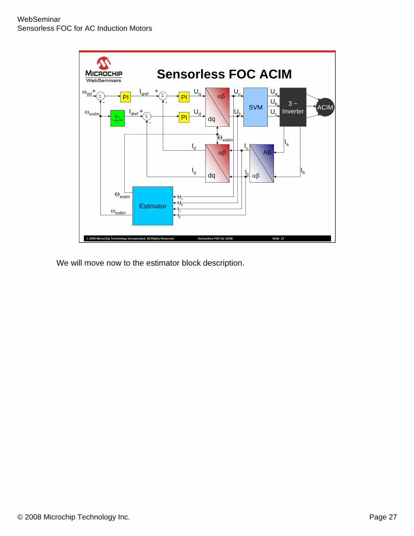
We will move now to the estimator block description.

WebSeminarSensorless FOC for AC Induction Motors
© 2008 Microchip Technology Inc. Page 28
© 2008 Microchip Technology Incorporated. All Rights Reserved. Sensorless FOC for ACIM Slide 28
ACIM3 ~InverterSVM
αβ
dq
PI
PI
Estimator
PI
αβ
dq
AB
αβ
+
++
-
-
-
Ia
Ib
Σ
Σ
ΣUa
Ub
Uc
Uα
Uβ
Iα
Iβ
Uq
Ud
Id
Iq
Iqref
Idref
ωref
ωestim
Θestim
Θestim
UαUβIαIβ
ωestim
Sensorless FOC ACIM
The estimator’s inputs are alpha – beta currents and voltages and its outputs are the estimated rotor angle and the mechanical speed of the motor.

WebSeminarSensorless FOC for AC Induction Motors
© 2008 Microchip Technology Inc. Page 29
© 2008 Microchip Technology Incorporated. All Rights Reserved. Sensorless FOC for ACIM Slide 29
Calculate the induced BEMF using output voltages of the inverter and measured phase currents
When the magnetising current is constant, the direct component of the BEMF is = 0 (Ed = 0).
dtdI
LσIRUE
dtdILσIRUE
βSβSββ
αSαSαα
⋅−−=
⋅−−=
EstimatorAngle and Speed Estimation
Sensorless FOC ACIM
The speed and angle estimator has as inputs the fixed reference stator frame, two axes voltages and currents. BEMF is used to estimate speed and position. First of all, the induced BEMF is calculated. As it can be seen from these equations, Ealpha and Ebeta calculation is done.

WebSeminarSensorless FOC for AC Induction Motors
© 2008 Microchip Technology Inc. Page 30
© 2008 Microchip Technology Incorporated. All Rights Reserved. Sensorless FOC for ACIM Slide 30
estimestimq
estimestimd
EEEEEE
Θ⋅+Θ⋅−=
Θ⋅+Θ⋅=
sincossincos
βα
βα
EstimatorAngle and Speed Estimation
Sensorless FOC ACIM
Since the estimation principle is based on the fact that the D component of the BEMF is zero when the magnetizing current is zero, we need to calculate the D component of the BEMF to know the estimation error.This figure shows the d-q components of the estimated BEMF. The d-q components are obtained using the direct Park transformation block previously described. Since the angle is produced by the estimator itself, we will have an internal loop inside the estimator which will adjust the angle with a Phase Locked Loop.
WebSeminarSensorless FOC for AC Induction Motors
© 2008 Microchip Technology Inc. Page 31
© 2008 Microchip Technology Incorporated. All Rights Reserved. Sensorless FOC for ACIM Slide 31
mRmRR
q
mR
Rd
Ψωσ1
1E
dtdΨ
σ11E
⋅⋅+
=
+=
Variation of flux (d/dt)Ymr is 0, since:
0⎯⎯ →⎯ =Ψ ctd
mRE
dtΨd
σ11E mR
RS +=
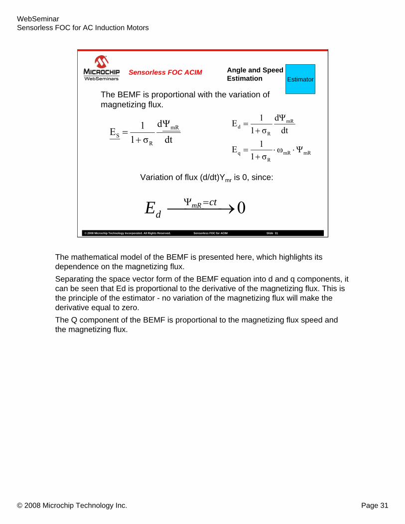
The BEMF is proportional with the variation of magnetizing flux.
EstimatorAngle and Speed Estimation
Sensorless FOC ACIM
The mathematical model of the BEMF is presented here, which highlights its dependence on the magnetizing flux. Separating the space vector form of the BEMF equation into d and q components, it can be seen that Ed is proportional to the derivative of the magnetizing flux. This is the principle of the estimator - no variation of the magnetizing flux will make the derivative equal to zero.The Q component of the BEMF is proportional to the magnetizing flux speed and the magnetizing flux.

WebSeminarSensorless FOC for AC Induction Motors
© 2008 Microchip Technology Inc. Page 32
© 2008 Microchip Technology Incorporated. All Rights Reserved. Sensorless FOC for ACIM Slide 32
d component of BEMF is greater than 0
EstimatorAngle and Speed Estimation
Sensorless FOC ACIM
0ΔΘ0E
ΘΘΔΘ
d
estim
<⇔>−=
If the estimated BEMF is not equal to the actual BEMF, the angle between the estimated and the actual BEMF is delta theta, as shown.
The figure shows the d-q estimated BEMF. If the estimated BEMF is not equal to the actual one, the angle between the estimated and the actual BEMF (delta theta) is not zero as shown in the animation. The estimator will correct the error in such a way that the estimated Eq is equal to the measured Eq. It can be seen that delta theta is decreased. In fact, the smaller this delta is, the closer to estimated value to the actual value is.
This slide shows how the error is corrected when the D component of the BEMF is greater than zero.

WebSeminarSensorless FOC for AC Induction Motors
© 2008 Microchip Technology Inc. Page 33
© 2008 Microchip Technology Incorporated. All Rights Reserved. Sensorless FOC for ACIM Slide 33
d component of BEMF is less than 0
0ΔΘ0E
ΘΘΔΘ
d
estim
>⇔<−=
EstimatorAngle and Speed Estimation
Sensorless FOC ACIM
On the other hand, when the d component of BEMF is less than 0, the angle error between the actual rotor angle and the estimated one is greater than 0. The estimator has to decrease the error in order to get the d component of the BEMF back to zero.

WebSeminarSensorless FOC for AC Induction Motors
© 2008 Microchip Technology Inc. Page 34
© 2008 Microchip Technology Incorporated. All Rights Reserved. Sensorless FOC for ACIM Slide 34
Correction error ⎟⎟⎠
⎞⎜⎜⎝
⎛=
q
d
EEarctanΔΘ
Experimental results show that correcting the estimated angle directly using the back EMF leads to numerical instability.
Correcting the integral of the angle, which is the speed of the motor, ensures numerical stability.
qmR
RmR E⋅
Ψ+
=σω 1
EstimatorAngle and Speed Estimation
Sensorless FOC ACIM
A simple way to correct the error between estimated BEMF and actual BEMF would be to subtract the error (delta theta) from the estimated angle. However, correcting the angle directly could lead to numeric instabilities.On the other hand, correcting the speed instead of the angle produces more stable results. Once the speed has been corrected, the angle is calculated by integrating the speed.

WebSeminarSensorless FOC for AC Induction Motors
© 2008 Microchip Technology Inc. Page 35
© 2008 Microchip Technology Incorporated. All Rights Reserved. Sensorless FOC for ACIM Slide 35
+EdDecreaseNegative speed, Ed<0
+EdIncreaseNegative speed, Ed>0
-EdIncreasePositive speed, Ed<0
-EdDecreasePositive speed, Ed>0
Correction termAction on ωmRCondition
⎟⎟
⎠
⎞
⎜⎜
⎝
⎛⋅−
Ψ+
=43421
correction
dqqmR
RmR EEE )sgn(1 σω
EstimatorAngle and Speed Estimation
Sensorless FOC ACIM
When there is an error on the estimation, the D component of the BEMF will be different than zero. In fact, the bigger the D component of the BEMF is, the bigger the speed error is. This is the reason why we use the D component of the BEMF as the correction factor of the estimated speed. The sign of the q component of the BEMF indicates the sign of the correction term. A positive Eq value corresponds to a positive speed, and a negative Eq value corresponds to a negative speed. The table shows a summary of the correction factor used depending on the speed direction.
WebSeminarSensorless FOC for AC Induction Motors
© 2008 Microchip Technology Inc. Page 36
© 2008 Microchip Technology Incorporated. All Rights Reserved. Sensorless FOC for ACIM Slide 36
EstimatorAngle and Speed Estimation
Sensorless FOC ACIM
⎟⎟
⎠
⎞
⎜⎜
⎝
⎛⋅−
Ψ+
=43421
correction
dqqmR
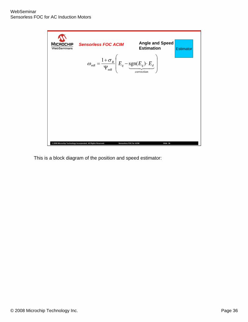
RmR EEE )sgn(1 σω
This is a block diagram of the position and speed estimator:
WebSeminarSensorless FOC for AC Induction Motors
© 2008 Microchip Technology Inc. Page 37
© 2008 Microchip Technology Incorporated. All Rights Reserved. Sensorless FOC for ACIM Slide 37
Eα
Eβ
EstimatorAngle and Speed Estimation
Sensorless FOC ACIM
⎟⎟
⎠
⎞
⎜⎜
⎝
⎛⋅−
Ψ+
=43421
correction
dqqmR
RmR EEE )sgn(1 σω
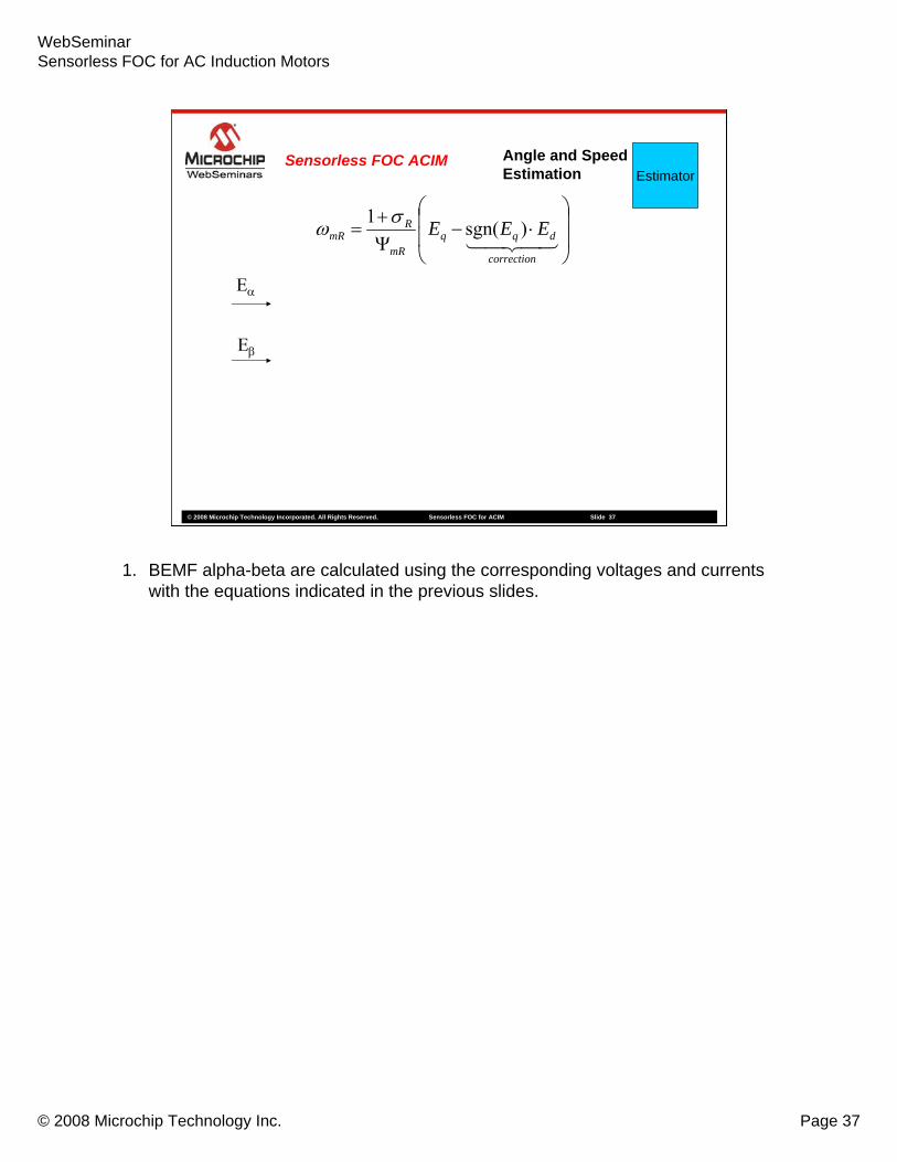
1. BEMF alpha-beta are calculated using the corresponding voltages and currents with the equations indicated in the previous slides.
WebSeminarSensorless FOC for AC Induction Motors
© 2008 Microchip Technology Inc. Page 38
© 2008 Microchip Technology Incorporated. All Rights Reserved. Sensorless FOC for ACIM Slide 38
dq
αβ
Eα
Eβ
Ed
Eq
Θestim
EstimatorAngle and Speed Estimation
Sensorless FOC ACIM
⎟⎟
⎠
⎞
⎜⎜
⎝
⎛⋅−
Ψ+
=43421
correction
dqqmR
RmR EEE )sgn(1 σω
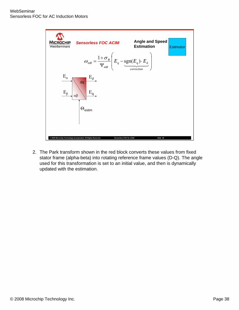
2. The Park transform shown in the red block converts these values from fixed stator frame (alpha-beta) into rotating reference frame values (D-Q). The angle used for this transformation is set to an initial value, and then is dynamically updated with the estimation.

WebSeminarSensorless FOC for AC Induction Motors
© 2008 Microchip Technology Inc. Page 39
© 2008 Microchip Technology Incorporated. All Rights Reserved. Sensorless FOC for ACIM Slide 39
dq
αβ
LPF
LPF
Eα
Eβ
Ed
Eq Eqfilter
Θestim
EstimatorAngle and Speed Estimation
Sensorless FOC ACIM
Edfilter
⎟⎟
⎠
⎞
⎜⎜
⎝
⎛⋅−
Ψ+
=43421
correction
dqqmR
RmR EEE )sgn(1 σω
3. The d-q component outputs are filtered because they are computed from the current measurement, which can be noisy. The first order filter used should be fast enough to allow dynamic changes.

WebSeminarSensorless FOC for AC Induction Motors
© 2008 Microchip Technology Inc. Page 40
© 2008 Microchip Technology Incorporated. All Rights Reserved. Sensorless FOC for ACIM Slide 40
dq
αβ
LPF
LPF SIGN MULSUM
Eα
Eβ
Ed
Eq Eqfilter
Θestim
EstimatorAngle and Speed Estimation
Sensorless FOC ACIM
Edfilter
⎟⎟
⎠
⎞
⎜⎜
⎝
⎛⋅−
Ψ+
=43421
correction
dqqmR
RmR EEE )sgn(1 σω
4. The sign of the q component of the BEMF is extracted and multiplied by the d component of BEMF. Then these two components are added to obtain the speed error correction.

WebSeminarSensorless FOC for AC Induction Motors
© 2008 Microchip Technology Inc. Page 41
© 2008 Microchip Technology Incorporated. All Rights Reserved. Sensorless FOC for ACIM Slide 41
dq
αβ
LPF
LPF SIGN MUL
DIV
SUM
INTEG
ΨmR
Eα
Eβ
Ed
Eq Eqfilter
ωmR
Θestim
EstimatorAngle and Speed Estimation
Sensorless FOC ACIM
Edfilter
⎟⎟
⎠
⎞
⎜⎜
⎝
⎛⋅−
Ψ+
=43421
correction
dqqmR
RmR EEE )sgn(1 σω
4. (continued) The result of the sum is divided by the magnetizing flux and the result is the magnetizing flux speed. The integral of speed is the angle of the rotor flux, which is feedback to the Park transformation block, which closes the estimator’s internal loop.
The magnetizing flux value can be considered constant if the mechanical speed does not exceed the nominal value. If field weakening is to be used to operate the motor above rated speed, the magnetizing current needs to be dynamic instead of a constant.

WebSeminarSensorless FOC for AC Induction Motors
© 2008 Microchip Technology Inc. Page 42
© 2008 Microchip Technology Incorporated. All Rights Reserved. Sensorless FOC for ACIM Slide 42
dq
αβ
LPF
LPF SIGN MUL
DIV
SUM
INTEG
ΨmR
Eα
Eβ
Ed
Eq Eqfilter
ωmR
Θestim
EstimatorAngle and Speed Estimation
Sensorless FOC ACIM
Edfilter
⎟⎟
⎠
⎞
⎜⎜
⎝
⎛⋅−
Ψ+
=43421
correction
dqqmR
RmR EEE )sgn(1 σω
4. (continued) The result of the sum is divided by the magnetizing flux and the result is the magnetizing flux speed. The integral of speed is the angle of the rotor flux, which is feedback to the Park transformation block, which closes the estimator’s internal loop.
The magnetizing flux value can be considered constant if the mechanical speed does not exceed the nominal value. If field weakening is to be used to operate the motor above rated speed, the magnetizing current needs to be dynamic instead of a constant.

WebSeminarSensorless FOC for AC Induction Motors
© 2008 Microchip Technology Inc. Page 43
© 2008 Microchip Technology Incorporated. All Rights Reserved. Sensorless FOC for ACIM Slide 43
ACIM3 ~InverterSVM
αβ
dq
PI
PI
Estimator
PI
αβ
dq
AB
αβ
+
++
-
-
-
Ia
Ib
Σ
Σ
ΣUa
Ub
Uc
Uα
Uβ
Iα
Iβ
Uq
Ud
Id
Iq
Iqref
Idref
ωref
ωestim
Θestim
Θestim
UαUβIαIβ
ωestim
Sensorless FOC ACIM
The next block to be described is the field weakening.

WebSeminarSensorless FOC for AC Induction Motors
© 2008 Microchip Technology Inc. Page 44
© 2008 Microchip Technology Incorporated. All Rights Reserved. Sensorless FOC for ACIM Slide 44
ACIM3 ~InverterSVM
αβ
dq
PI
PI
Estimator
PI
αβ
dq
AB
αβ
+
++
-
-
-
Ia
Ib
Σ
Σ
ΣUa
Ub
Uc
Uα
Uβ
Iα
Iβ
Uq
Ud
Id
Iq
Iqref
Idref
ωref
ωestim
Θestim
Θestim
UαUβIαIβ
ωestim
Sensorless FOC ACIM
This block is needed when motor operation above the rated speed is a requirement. In applications where the maximum speed does not exceed the nominal speed of the motor, this block can be replaced by a simple constant equal to the d-axis current requirement, which is proportional to the magnetizing flux requirement.

WebSeminarSensorless FOC for AC Induction Motors
© 2008 Microchip Technology Inc. Page 45
© 2008 Microchip Technology Incorporated. All Rights Reserved. Sensorless FOC for ACIM Slide 45
• Motor and inverter’s power ratings cannot be exceeded
• The torque is decreased by reducing the magnetizing current and concurrently its counterpart the magnetizing flux
Field WeakeningSensorless FOC ACIM
When exceeding the nominal motor speed, the rotor flux must be weakened. A mechanical speed increase will require a frequency increase of the stator currents, but this must be done with respect to the simple V/Hz equation. Since the voltage cannot be increased over the nominal value, the increase of speed must be done sacrificing the overall torque produced, keeping a constant power curve.
WebSeminarSensorless FOC for AC Induction Motors
© 2008 Microchip Technology Inc. Page 46
© 2008 Microchip Technology Incorporated. All Rights Reserved. Sensorless FOC for ACIM Slide 46
ACIM3 ~Inverter
αβ
dq
SVMPI
PI
Estimator
PI
αβ
dq
AB
αβ
+
++
-
-
-
Ia
Ib
Σ
Σ
ΣUa
Ub
Uc
Uα
Uβ
Iα
Iβ
Uq
Ud
Id
Iq
Iqref
Idref
ωref
ωestim
Θestim
Θestim
UαUβIαIβ
ωestim
Sensorless FOC ACIM
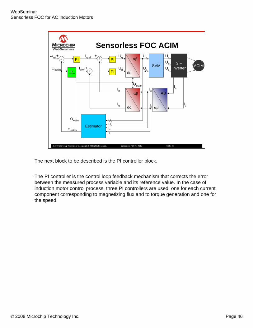
The next block to be described is the PI controller block.
The PI controller is the control loop feedback mechanism that corrects the error between the measured process variable and its reference value. In the case of induction motor control process, three PI controllers are used, one for each current component corresponding to magnetizing flux and to torque generation and one for the speed.

WebSeminarSensorless FOC for AC Induction Motors
© 2008 Microchip Technology Inc. Page 47
© 2008 Microchip Technology Incorporated. All Rights Reserved. Sensorless FOC for ACIM Slide 47
ACIM3 ~Inverter
αβ
dq
SVMPI
PI
Estimator
PI
αβ
dq
AB
αβ
+
++
-
-
-
Ia
Ib
Σ
Σ
ΣUa
Ub
Uc
Uα
Uβ
Iα
Iβ
Uq
Ud
Id
Iq
Iqref
Idref
ωref
ωestim
Θestim
Θestim
UαUβIαIβ
ωestim
Sensorless FOC ACIM
The next block to be described is the PI controller block.
The PI controller is the control loop feedback mechanism that corrects the error between the measured process variable and its reference value. In the case of induction motor control process, three PI controllers are used, one for each current component corresponding to magnetizing flux and to torque generation and one for the speed.

WebSeminarSensorless FOC for AC Induction Motors
© 2008 Microchip Technology Inc. Page 48
© 2008 Microchip Technology Incorporated. All Rights Reserved. Sensorless FOC for ACIM Slide 48
PI
•Proportional term reduces the overall error to 0
•Integral term eliminate the steady state errors
PI ControllerSensorless FOC ACIM
The proportional term reduces the overall error to 0, but in most cases of control a steady state error will remain and this error is removed with the integral term.

WebSeminarSensorless FOC for AC Induction Motors
© 2008 Microchip Technology Inc. Page 49
© 2008 Microchip Technology Incorporated. All Rights Reserved. Sensorless FOC for ACIM Slide 49
ACIM3 ~Inverter
αβ
dq
SVMPI
PI
Estimator
PI
αβ
dq
AB
αβ
+
++
-
-
-
Ia
Ib
Σ
Σ
ΣUa
Ub
Uc
Uα
Uβ
Iα
Iβ
Uq
Ud
Id
Iq
Iqref
Idref
ωref
ωestim
Θestim
Θestim
UαUβIαIβ
ωestim
Sensorless FOC ACIM
The last block to be discussed in the space vector modulation block, …

WebSeminarSensorless FOC for AC Induction Motors
© 2008 Microchip Technology Inc. Page 50
© 2008 Microchip Technology Incorporated. All Rights Reserved. Sensorless FOC for ACIM Slide 50
ACIM3 ~Inverter
αβ
dq
SVMPI
PI
Estimator
PI
αβ
dq
AB
αβ
+
++
-
-
-
Ia
Ib
Σ
Σ
ΣUa
Ub
Uc
Uα
Uβ
Iα
Iβ
Uq
Ud
Id
Iq
Iqref
Idref
ωref
ωestim
Θestim
Θestim
UαUβIαIβ
ωestim
Sensorless FOC ACIM
… or SVM.

WebSeminarSensorless FOC for AC Induction Motors
© 2008 Microchip Technology Inc. Page 51
© 2008 Microchip Technology Incorporated. All Rights Reserved. Sensorless FOC for ACIM Slide 51
SVMSpace Vector ModulationSensorless FOC ACIM
UOUT = T1/T*U0 + T2/T*U60
The SVM block generates PWM signals to the 3 phases of the motor. As indicated in the animation, each of the three inverter outputs can be in one of the two states, which allow a total of 8 possible states that the outputs can be in. When all three outputs are connected to + or – voltage, the state is considered null, because they do not generate line-to-line voltage. The other generated states are separated 60 degrees from each other, as shown in the animation. The SVM produces all the other voltage vectors as a sum of two adjacent vectors. The linear combination of the two vectors is reflected in the duty cycles for the generated PWMs for each phase.
WebSeminarSensorless FOC for AC Induction Motors
© 2008 Microchip Technology Inc. Page 52
© 2008 Microchip Technology Incorporated. All Rights Reserved. Sensorless FOC for ACIM Slide 52
Web Seminar Agenda
ACIM IntroductionSensorless Field Oriented Control for ACIM
Conclusions
In summary, we have discussed basic characteristics of an AC Induction Motor. We’ve discussed each of the Field Oriented Control blocks, including a more detailed discussion of the angle and speed estimator.
WebSeminarSensorless FOC for AC Induction Motors
© 2008 Microchip Technology Inc. Page 53
© 2008 Microchip Technology Incorporated. All Rights Reserved. Sensorless FOC for ACIM Slide 53
Conclusions
Sensored Sensorless
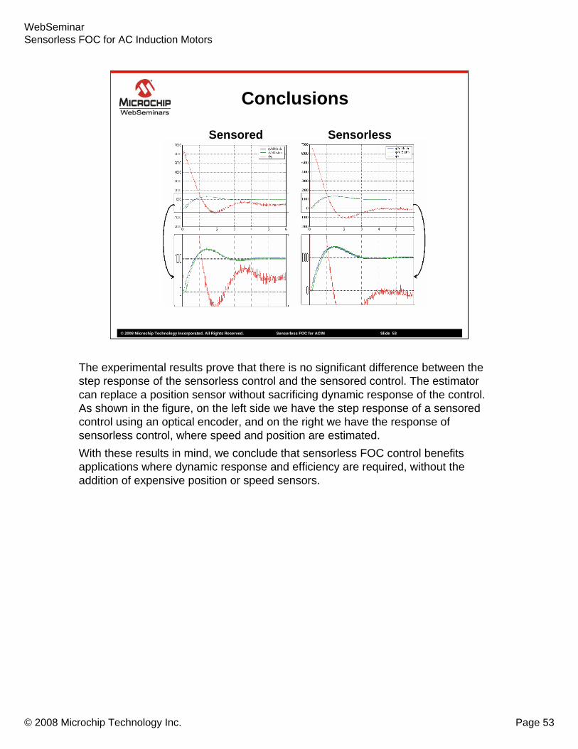
The experimental results prove that there is no significant difference between the step response of the sensorless control and the sensored control. The estimator can replace a position sensor without sacrificing dynamic response of the control. As shown in the figure, on the left side we have the step response of a sensored control using an optical encoder, and on the right we have the response of sensorless control, where speed and position are estimated.With these results in mind, we conclude that sensorless FOC control benefits applications where dynamic response and efficiency are required, without the addition of expensive position or speed sensors.

WebSeminarSensorless FOC for AC Induction Motors
© 2008 Microchip Technology Inc. Page 54
© 2008 Microchip Technology Incorporated. All Rights Reserved. Sensorless FOC for ACIM Slide 54
• For resources and information for motor-control applications, visit Microchip’s motor control design center at: www.microchip.com/motor
• Microchip Application Notes for Motor-Control Applications:• Using the dsPIC30F for Sensorless BLDC Control AN901• Using the dsPIC30F for Vector Control of an ACIM AN908• Sensored BLDC Motor Control Using dsPIC30F2010 AN957• An Introduction to ACIM Control Using the dsPIC30F AN984• Using the dsPIC30F2010 for Sensorless BLDC Control AN992• Sinusoidal Control of PMSM Motors with dsPIC30F AN1017• Sensorless FOC for PMSM using dsPIC AN1078• Sensorless BLDC using BEMF IIR Filtering AN1083• Getting Started with the BLDC Motors and dsPIC30F GS001• Measuring Speed and Position with the QEI Module GS002• Driving ACIM with the dsPIC® DSC MCPWM Module GS004• Using the dsPIC30F Sensorless Motor Tuning Interface GS005
Resources
We have application notes on motor control. These documents can be obtained from Microchip’s web site, by clicking on the “dsPIC® Digital Signal Controllers” or “Technical Documentation” link. We also have a motor control design center at www.microchip.com/motor.
This wraps up the seminar on Sensorless Field Oriented Control of AC Induction Motors. Thank you for your interest in the dsPIC Digital Signal Controllers.
Related Documents