1A 1B 2A 2B PWM-1 TMS320F28027F CPU 32 bit A B PWM-2 A B PWM-3 A B ADC1 12 bit 3A 3B ECAP Va UART HALL DC bus 1A 1B 2A 2B 3A 3B Ia Ib Ic BLDC Vdc VDC GPIO Vb Vc Throttle TZ Torque Gate Driver UCC27211 Gate Driver UCC27211 Gate Driver UCC27211 Va Vdc Vb Vc OPA4374 Ia Ib Ic CSD19506KCS*6 TPS54360 LM2940-5.0 TPS73533 VDC 12 V 12 V 5 V 5 V 3.3 V GUI Lamp Brake Locker OCP Copyright © 2017, Texas Instruments Incorporated 1 TIDUD29 – June 2017 Submit Documentation Feedback Copyright © 2017, Texas Instruments Incorporated Low-Voltage, 50-A Sensorless FOC for Brushless DC or Permanent-Magnet Synchronous Motors Reference Design TI Designs: TIDM-1003 Low-Voltage, 50-A Sensorless FOC for Brushless DC or Permanent-Magnet Synchronous Motors Reference Design Description The TIDM-1003 design is a 30- to 54-V brushless DC motor (BLDC) or permanent-magnet synchronous motors (PMSM) controller for low-voltage, high-current, high-power e-bike, power tool, fan, and pump applications. This TI Design uses the Texas Instruments’ UCC27211D MOSFET drivers, CSD19506KCS 80-V NexFET™ power MOSFETs, TMS320F28027F MCU with InstaSPIN™ technology, TPS54360 buck converter, and LDOs. The design uses InstaSPIN-FOC™ technology to identify and tune PMSM or BLDC motor parameters, as well as control motor speed through an external throttle. Overall, the design focuses on demonstrating highly efficient control of high-power, low-voltage BLDC motors or PMSMs. Resources TIDM-1003 Design Folder TMS320F28027F Product Folder UCC27211 Product Folder TPS54360 Product Folder CSD19506KCS Product Folder OPA4374 Product Folder InstaSPIN-FOC Tools Folder MotorWare™ Tools Folder ASK Our E2E Experts Features • Up to 500-W Power Stage With Sensorless FOC Based InstaSPIN for BLDC Motors and PMSMs, Efficiency > 90% Over Full Input Range • 30-V to 54-V Input Voltage Range, 50-A Peak Output Current Capability • Small Form Factor (L × W): 80 mm × 45 mm, Wide Environment Temperature Test: –40ºC to 55ºC • Protects Against Overcurrent, Over and Undervoltage, Over- and Underload, Lost Phase, Phase Unbalance, Stall, Motor Overtemperature, Power Module Overtemperature, Lost Communication • High-Performance Speed Control Includes High Trajectory Changes and Speed Reversal Capability Using InstaSPIN-FOC • Automatic Motor Parameter Identification, Flying Start Capability to Synchronize to Already Moving Motor Applications • E-Bikes and E-Scooters • Power Tools • Low-Voltage, High-Power Fans, and Pumps

Welcome message from author
This document is posted to help you gain knowledge. Please leave a comment to let me know what you think about it! Share it to your friends and learn new things together.
Transcript

1A
1B
2A
2B
PWM-1
TMS320F28027F
CPU
32 bit
A
B
PWM-2 A
B
PWM-3 A
B
ADC1
12 bit
3A
3B
ECAP
Va
UART
HALL
DC bus
1A
1B
2A
2B
3A
3B
Ia Ib Ic
BLDC
Vdc
VDC
GPIO
VbVc
Throttle
TZTorque
Gate DriverUCC27211
Gate DriverUCC27211
Gate DriverUCC27211
Va
Vdc
Vb Vc
OPA4374IaIbIc
CSD19506KCS*6
TPS54360
LM2940-5.0
TPS73533
VDC 12 V
12 V
5 V
5 V
3.3 V
GUI
LampBrakeLocker
OCP
Copyright © 2017, Texas Instruments Incorporated
1TIDUD29–June 2017Submit Documentation Feedback
Copyright © 2017, Texas Instruments Incorporated
Low-Voltage, 50-A Sensorless FOC for Brushless DC or Permanent-MagnetSynchronous Motors Reference Design
TI Designs: TIDM-1003Low-Voltage, 50-A Sensorless FOC for Brushless DC orPermanent-Magnet Synchronous Motors ReferenceDesign
DescriptionThe TIDM-1003 design is a 30- to 54-V brushless DCmotor (BLDC) or permanent-magnet synchronousmotors (PMSM) controller for low-voltage, high-current,high-power e-bike, power tool, fan, and pumpapplications. This TI Design uses the TexasInstruments’ UCC27211D MOSFET drivers,CSD19506KCS 80-V NexFET™ power MOSFETs,TMS320F28027F MCU with InstaSPIN™ technology,TPS54360 buck converter, and LDOs. The designuses InstaSPIN-FOC™ technology to identify and tunePMSM or BLDC motor parameters, as well as controlmotor speed through an external throttle. Overall, thedesign focuses on demonstrating highly efficientcontrol of high-power, low-voltage BLDC motors orPMSMs.
Resources
TIDM-1003 Design FolderTMS320F28027F Product FolderUCC27211 Product FolderTPS54360 Product FolderCSD19506KCS Product FolderOPA4374 Product FolderInstaSPIN-FOC Tools FolderMotorWare™ Tools Folder
ASK Our E2E Experts
Features• Up to 500-W Power Stage With Sensorless FOC
Based InstaSPIN for BLDC Motors and PMSMs,Efficiency > 90% Over Full Input Range
• 30-V to 54-V Input Voltage Range, 50-A PeakOutput Current Capability
• Small Form Factor (L × W): 80 mm × 45 mm, WideEnvironment Temperature Test: –40ºC to 55ºC
• Protects Against Overcurrent, Over andUndervoltage, Over- and Underload, Lost Phase,Phase Unbalance, Stall, Motor Overtemperature,Power Module Overtemperature, LostCommunication
• High-Performance Speed Control Includes HighTrajectory Changes and Speed Reversal CapabilityUsing InstaSPIN-FOC
• Automatic Motor Parameter Identification, FlyingStart Capability to Synchronize to Already MovingMotor
Applications• E-Bikes and E-Scooters• Power Tools• Low-Voltage, High-Power Fans, and Pumps

System Description www.ti.com
2 TIDUD29–June 2017Submit Documentation Feedback
Copyright © 2017, Texas Instruments Incorporated
Low-Voltage, 50-A Sensorless FOC for Brushless DC or Permanent-MagnetSynchronous Motors Reference Design
An IMPORTANT NOTICE at the end of this TI reference design addresses authorized use, intellectual property matters and otherimportant disclaimers and information.
1 System DescriptionThe TIDM-1003 reference design is an InstaSPIN-FOC solution implemented on a high-power stage forbrushless motor control intended for power tools, e-bikes, e-scooters, and similar applications. Comparedto conventional brushed motors, permanent magnet brushless motors exhibit advantages such as highefficiency, high torque-to-weight ratio, low maintenance, high reliability, and low rotor inertia. A brushlesspermanent-magnet synchronous motor (PMSM) has a wound stator and a permanent magnet rotorassembly. These motors generally use internal or external devices to sense the rotor position. Thesensing devices provide position information for electronically switching the stator windings in the propersequence to maintain rotation of the magnet assembly. The sensor-based solution requires accuratemechanical assembly of sensors. The rotor position can also be estimated using sensorless algorithmsimplemented in microcontroller units (MCUs).
An electronic drive is required to control the stator currents in a brushless permanent magnet motor. Theelectronic drive has the following parts:• Power stage with a three-phase inverter• Gate driver for driving the three-phase inverter• MCU to implement the motor control algorithm• Position sensor for accurate motor rotor angle to implement current commutation• Power supply to power the MCU
Permanent magnet motors can be classified based on Back-EMF (BEMF) profiles: brushless direct current(BLDC) motor and permanent magnet synchronous motor (PMSM). Both BLDC motors and PMSMs havepermanent magnets on the rotor but differ in the flux distributions and BEMF profiles. In a BLDC motor,the BEMF induced in the stator is trapezoidal, and in a PMSM, the BEMF induced in the stator issinusoidal. Implementing an appropriate control strategy is required to obtain the maximum performancefrom each type of motor.
1.1 Key System Specifications
Table 1. Key System Specifications
PARAMETER SPECIFICATIONSDC input voltage 48-V nominal (30-V minimum, 54-V maximum)Maximum input DC current 10 AMaximum peak output current 50 ARated power capacity 500 WInverter switching frequency 20 kHzInverter efficiency ≥ 95% (theoretical) at rated loadPower supply for MCU 3.3 V ± 5%Protection Overcurrent, overtemperature, overvoltage, undervoltagePCB size (L × W) 80 mm × 45 mm

PWM
I_Park
Clark
2
2
2
3
Park
2
2
Speed Regulator
SPM/SVPWM
ADC
Position Observer
(Sensorless)
Speed Calculate
VoltageRestructure
Current Regulator
Current Regulator
Field Weakening
spd_fdb
spd_ref
Ua
Ub
Uc
VDC
Ua
Ub
Uc
idiqUd
Uq
rT
rT
iQ
iD id
iq
iaibic
iaibVdc
ud
uqrT
uO
uD
www.ti.com System Overview
3TIDUD29–June 2017Submit Documentation Feedback
Copyright © 2017, Texas Instruments Incorporated
Low-Voltage, 50-A Sensorless FOC for Brushless DC or Permanent-MagnetSynchronous Motors Reference Design
2 System Overview
2.1 Traditional FOC for PMSMThe PMSM has a sinusoidal BEMF. The sinusoidal BEMF motor offers its best performances when drivenby sinusoidal currents and constant torque will be produced. In sinusoidal current control, three phases ofthe motor are ON at the same time.
Field oriented control (FOC) is used to control the permanent magnet motor. FOC achieves betterdynamic performance. The goal of FOC (also called vector control) on the synchronous or asynchronousmachine is to separately control the torque producing flux and magnetizing flux components. Severalmathematical transforms are required to decouple the torque and magnetizing flux components of thestator current as Figure 1. The processing capability provided by the MCUs enables these mathematicaltransformations to be carried out very quickly. These transformations in turn imply that the entire algorithmcontrolling the motor can be executed at a fast rate, enabling a higher dynamic performance.
The FOC algorithm enables real-time control of torque and rotation speed. As this control is accurate inevery mode of operation (steady state and transient), no oversize of the power transistors is necessary.The transient currents are constantly controlled in amplitude. Moreover, no torque ripple appears whendriving this sinusoidal BEMF motor with sinusoidal currents.
Figure 1. Block Diagram of FOC

SVM
IqPI
SpeedPI
INVPARK
CLARKE
CLARKE
PARK
IdPI
TrajRamp
)$67��(VWLPDWRU
Flux, Angle, Speed, Torque Motor Parameters ID
PWMDriver
ADCDriver
DRV_run
++
User_SpdRef
User_IqRef
User_IdRef
Vq
Vd
V._out
V�_out
Ta
Tb
Tc
Ia
Ib
Ic
Va
Vb
Vc
Vbus
V._in
V�_in
Iq_ref
Iq
Id_ref
Id
wref
Id
Iq
I._in
I�_in
Angle
Speed
Flux
Torque
Enable Motor Identification
(QDEOH�3RZHU:DUS��
Motor Type
Enable Rs Online Recalibration
EST_run
ROM FLASH/RAM
FLASH/RAM
Rs~
Rr~
Irated~yrated~
Lsd~
Lsq~
q~
w~
t~
y~
t~
w~
y~
Irated~
q~ q
~
q~
w~
Spdout
Enable Force Angle Startup
Torque Mode
FLASH/RAMDRV_readAdcData
DRV_acqAdcInt
CTRL_run
CTRL_setup
System Overview www.ti.com
4 TIDUD29–June 2017Submit Documentation Feedback
Copyright © 2017, Texas Instruments Incorporated
Low-Voltage, 50-A Sensorless FOC for Brushless DC or Permanent-MagnetSynchronous Motors Reference Design
2.2 InstaSPIN-FOC for PMSMTI's InstaSPIN-FOC technology enables designers to identify, tune, and fully control any type of three-phase, variable speed, sensorless synchronous, or asynchronous motor control system. This newtechnology removes the need for a mechanical motor rotor sensor to reduce system costs and improveoperation using TI's new software encoder (sensorless observer) software algorithm, FAST™ (flux, angle,speed, and torque), embedded in the read-only memory (ROM) of Piccolo™ devices. This ROM enablespremium solutions that improve motor efficiency, performance, and reliability in all variable-speed andvariable-torque applications. Figure 2 shows the block diagram of the InstaSPIN-FOC.
Figure 2. Block Diagram of InstaSPIN-FOC
InstaSPIN-FOC benefits include the following:• FAST estimator to measure rotor flux magnitude, rotor flux angle, motor shaft speed, and torque in a
sensorless FOC system• Automatic torque (current) loop tuning with option for user adjustments• Automatic configuration of speed loop gains (Kp and Ki) provides stable operation for most applications
and user adjustments required for optimum transient response• Automatic or manual field weakening and field boosting• Bus voltage compensation• Automatic offset calibration ensures quality samples of feedback signals

1A
1B
2A
2B
PWM-1
TMS320F28027F
CPU
32 bit
A
B
PWM-2 A
B
PWM-3 A
B
ADC1
12 bit
3A
3B
ECAP
Va
UART
HALL
DC bus
1A
1B
2A
2B
3A
3B
Ia Ib Ic
BLDC
Vdc
VDC
GPIO
VbVc
Throttle
TZTorque
Gate DriverUCC27211
Gate DriverUCC27211
Gate DriverUCC27211
Va
Vdc
Vb Vc
OPA4374IaIbIc
CSD19506KCS*6
TPS54360
LM2940-5.0
TPS73533
VDC 12 V
12 V
5 V
5 V
3.3 V
GUI
LampBrakeLocker
OCP
Copyright © 2017, Texas Instruments Incorporated
www.ti.com System Overview
5TIDUD29–June 2017Submit Documentation Feedback
Copyright © 2017, Texas Instruments Incorporated
Low-Voltage, 50-A Sensorless FOC for Brushless DC or Permanent-MagnetSynchronous Motors Reference Design
2.3 Drive Controller Block DiagramFigure 3 shows the block diagram of the motor drive controller. The main parts of the power stageconsists of the InstaSPIN-FOC controller TMS320F28027F, the three-phase MOSFET bridge, the gatedriver UCC27211, a 3.3-V step-down DC-DC converter, ESD protection, overtemperature protection, andthe current and voltage sense feedback circuits.
Figure 3. Drive Controller Block Diagram
2.4 Highlighted Products
2.4.1 TMS320F28027FThe TMS320F28027F microcontroller is the C28x core coupled with highly integrated control peripheralsin low pin-count devices, as shown in Figure 4. An internal voltage regulator allows for single-railoperation. Analog comparators with internal 10-bit references have been added and can be routed directlyto control the PWM outputs. The ADC converts from 0- to 3.3-V fixed full-scale range and supports ratio-metric VREFHI/VREFLO references. The ADC interface has been optimized for low overhead and latency.The device also supports advanced emulation features such as analysis and breakpoint functions andreal-time debug through hardware.

3 External Interrupts
16-Bit Peripheral Bus
SCI
(4L FIFO)
ePWMSPI
(4L FIFO)
I2C
(4L FIFO)HRPWM
eCAP
32-Bit Peripheral Bus
CodeSecurityModule
GPIO MUX
C28x32-Bit CPU
A7:0
B7:0
PIE
CPU Timer 0
CPU Timer 1
CPU Timer 2
TCK
TDITMS
TDO
TRST
OSC1,
OSC2,
Ext,
PLL,
LPM,
WD
XCLKIN
X2
XRS
32-Bit Peripheral Bus
EC
AP
x
EP
WM
xA
EP
WM
SY
NC
I
SD
Ax
SP
IST
Ex
SC
Lx
SP
ISIM
Ox
SP
ICL
Kx
COMP1OUT
SC
IRX
Dx
GPIOMux
LPM Wakeup
AIO
MUX
ADC
PSWD
FLASH8K/16K/32K × 16
Secure
OTP 1K × 16Secure
OTP/Flash
Wrapper
M0
SARAM 1K × 16
(0-wait)
M1
SARAM 1K × 16
(0-wait)
Boot-ROM
8K × 16
(0-wait)
SARAM
1K/3K/4K × 16
(0-wait)
Secure
COMPCOMP1A
COMP1BCOMP2A
COMP2B
COMP2OUT
X1
GPIO
MUX
VREG
FromCOMP1OUT,COMP2OUT
POR/BOR
Mem
ory
Bu
s
Memory Bus
Memory Bus
TZ
x
SC
ITX
Dx
SP
ISO
MIx
EP
WM
xB
EP
WM
SY
NC
O
Copyright © 2017, Texas Instruments Incorporated
32-B
it P
eri
ph
era
l B
us
System Overview www.ti.com
6 TIDUD29–June 2017Submit Documentation Feedback
Copyright © 2017, Texas Instruments Incorporated
Low-Voltage, 50-A Sensorless FOC for Brushless DC or Permanent-MagnetSynchronous Motors Reference Design
The TMS320F28027F includes the FAST estimator and additional motor control functions needed forcascaded speed and torque loops for efficient three-phase FOC. TMS320F28027F peripheral drivers inuser code enable a sensorless InstaSPIN-FOC solution that can identify, tune the torque controller, andefficiently control a motor in minutes without the use of any mechanical rotor sensors. This entire packageis called InstaSPIN-FOC. The FAST estimator is called from protected ROM, while the rest of thefunctions required for InstaSPIN-FOC reside in user memory (flash and RAM). InstaSPIN-FOC wasdesigned for flexibility to accommodate a range of system software architectures and customizations.
The InstaSPIN sensorless, three-phase motor solutions makes designing motor control applications easierwhether it is a simple application or a complex design.
Figure 4. TMS320F28027F Functional Block Diagram
UVLO
UVLO
5
3
8
4
6 7
2
1
HI
LI
VDD
HB
HO
HS
LO
VSS
LevelShift
Copyright © 2016, Texas Instruments Incorporated
www.ti.com System Overview
7TIDUD29–June 2017Submit Documentation Feedback
Copyright © 2017, Texas Instruments Incorporated
Low-Voltage, 50-A Sensorless FOC for Brushless DC or Permanent-MagnetSynchronous Motors Reference Design
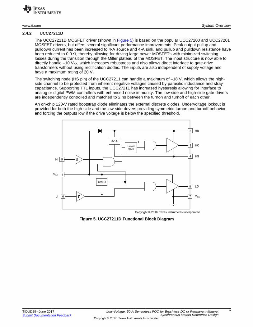
2.4.2 UCC27211DThe UCC27211D MOSFET driver (shown in Figure 5) is based on the popular UCC27200 and UCC27201MOSFET drivers, but offers several significant performance improvements. Peak output pullup andpulldown current has been increased to 4-A source and 4-A sink, and pullup and pulldown resistance havebeen reduced to 0.9 Ω, thereby allowing for driving large power MOSFETs with minimized switchinglosses during the transition through the Miller plateau of the MOSFET. The input structure is now able todirectly handle –10 VDC, which increases robustness and also allows direct interface to gate-drivetransformers without using rectification diodes. The inputs are also independent of supply voltage andhave a maximum rating of 20 V.
The switching node (HS pin) of the UCC27211 can handle a maximum of –18 V, which allows the high-side channel to be protected from inherent negative voltages caused by parasitic inductance and straycapacitance. Supporting TTL inputs, the UCC27211 has increased hysteresis allowing for interface toanalog or digital PWM controllers with enhanced noise immunity. The low-side and high-side gate driversare independently controlled and matched to 2 ns between the turnon and turnoff of each other.
An on-chip 120-V rated bootstrap diode eliminates the external discrete diodes. Undervoltage lockout isprovided for both the high-side and the low-side drivers providing symmetric turnon and turnoff behaviorand forcing the outputs low if the drive voltage is below the specified threshold.
Figure 5. UCC27211D Functional Block Diagram
Error
Amplifier
Boot
Charge
Boot
UVLO
UVLO
CurrentSense
Oscillator
with PLL
Frequency
Foldback
Logic
Slope
Compensation
PWM
Comparator
Minimum
Clamp
Pulse
Skip
MaximumClamp
Voltage
Reference
ReferenceDAC for
Soft- Start
FB
COMP
RT/CLK
SW
BOOT
VIN
GND
ThermalShutdown
EN
Enable
Comparator
ShutdownLogic
Shutdown
Enable
Threshold
6
8/8/ 2012A 0192789
POWERPAD
Shutdown
OV
Copyright © 2016, Texas Instruments Incorporated
System Overview www.ti.com
8 TIDUD29–June 2017Submit Documentation Feedback
Copyright © 2017, Texas Instruments Incorporated
Low-Voltage, 50-A Sensorless FOC for Brushless DC or Permanent-MagnetSynchronous Motors Reference Design
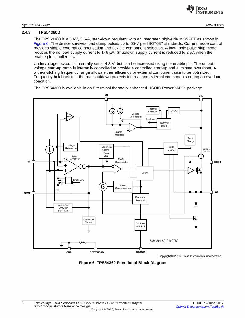
2.4.3 TPS54360DThe TPS54360 is a 60-V, 3.5-A, step-down regulator with an integrated high-side MOSFET as shown inFigure 6. The device survives load dump pulses up to 65-V per ISO7637 standards. Current mode controlprovides simple external compensation and flexible component selection. A low-ripple pulse skip modereduces the no-load supply current to 146 µA. Shutdown supply current is reduced to 2 µA when theenable pin is pulled low.
Undervoltage lockout is internally set at 4.3 V, but can be increased using the enable pin. The outputvoltage start-up ramp is internally controlled to provide a controlled start-up and eliminate overshoot. Awide-switching frequency range allows either efficiency or external component size to be optimized.Frequency holdback and thermal shutdown protects internal and external components during an overloadcondition.
The TPS54360 is available in an 8-terminal thermally enhanced HSOIC PowerPAD™ package.
Figure 6. TPS54360 Functional Block Diagram
VCC_12V
47uFC43
VCC_5V
GNDGND GND
IN1 OUT 3
GND2
TAB4
U8
LM2940IMP-5.0/NOPB
OUT1
NR 2
3
EN4
NC 5
IN6
7
GND
U9
TPS73533DRVR
2.2uFC46
GND GND
VCC_3V3
0.010uF
C45
GND
2.2uFC44
GND
VCC_5V
GND
2.2uFC39
Copyright © 2017, Texas Instruments Incorporated
0.1uF
C37
1800pFC40
56pFC42
3.3uFC38
47uFC41
B370-13-F
D3
33uH
L3
32.4kR48
8.45k
R51
118kR50
178kR49
TPS54360DDAR
BOOT1
VIN2
EN3
RT/CLK4
FB5
COMP6
GND7
SW8
PAD9
U7
VCC_DC+
VCC_12V
GND
GND GND
GND
GND
GND GND
Copyright © 2017, Texas Instruments Incorporated
www.ti.com System Overview
9TIDUD29–June 2017Submit Documentation Feedback
Copyright © 2017, Texas Instruments Incorporated
Low-Voltage, 50-A Sensorless FOC for Brushless DC or Permanent-MagnetSynchronous Motors Reference Design
2.4.4 OPA4374The OPA374 operational amplifier is low power and low cost with excellent bandwidth (6.5 MHz) and slewrate (5 V/µs). The input range extends 200 mV beyond the rails, and the output range is within 25 mV ofthe rails. The speed-power ratio and small size make them ideal for portable and battery-poweredapplications.
The OPA4374 includes a shutdown mode. Under logic control, the amplifiers can be switched from normaloperation to a standby current that is less than 1 µA. The OPA4374 operational amplifier is specified forsingle or dual power supplies of 2.7 to 5.5 V, with operation from 2.3 to 5.5 V. All models are specified for–40°C to 125°C.
2.5 System Design TheoryThe motor drive controller is composed of two main components. The first component is theTMS320F28027F MCU, which accepts the speed or torque reference from an external signal, measuresthe phase voltage and current signals of the motor, and generates the appropriate control signals for thepower stage. The second component is the power inverter stage, which consists of the gate driver andpower MOSFETs. The power stage amplifies the control signals from the MCU to the motor.
The motor drive controller uses InstaSPIN-FOC, a sensorless FOC algorithm for BLDC motors. FOCallows for optimal efficiency and noise performance from the motor being driven by the controller.InstaSPIN-FOC uses the signals from the motor BEMF and phase currents to interpolate where the motorrotor is located and send the correct drive patterns. Power is supplied to the motor controller from themain power input through a switching buck converter and two LDOs.
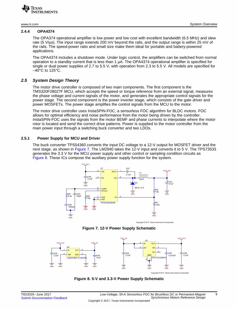
2.5.1 Power Supply for MCU and DriverThe buck converter TPS54360 converts the input DC voltage to a 12-V output for MOSFET driver and thenext stage, as shown in Figure 7. The LM2940 takes the 12-V input and converts it to 5 V. The TPS73533generates the 3.3 V for the MCU power supply and other control or sampling condition circuits asFigure 8. These ICs compose the auxiliary power supply function for the system.
Figure 7. 12-V Power Supply Schematic
Figure 8. 5-V and 3.3-V Power Supply Schematic

GND
4.99kR26
86.6kR19
GND
0.1uFC31
GND
2.2uF
100V
C22
GND
VCC_DC+
GND
4.99kR27
86.6kR20
GND
0.1uFC32
GND
2.2uF
100V
C23
GND
VCC_DC+
GND
4.99kR28
86.6kR21
GND
0.1uFC33
GND
2.2uF
100V
C24
GND
VCC_DC+
IADIFF_N
IADIFF_P
IBDIFF_N
IBDIFF_P
ICDIFF_N
ICDIFF_P
1
32
Q2CSD19506KCS
1%2W0.002
R30
NT1
NT4
1%2W0.002
R31
NT2
NT5
1%2W0.002
R32
NT3
NT6
VCC_12V
0.1uF
C27 10.0R18
10.0
R25
VCC_12V
0.1uF
C26 10.0R17
10.0
R24
GND GND
VCC_12V
0.1uF
C25
GND
10.0R16
10.0
R23
GND
2.2uFC28
2.2uFC29
2.2uFC30
GND GND
VDD1
HB2
HO3
HS 4HI5
LI6
VSS7
LO 8
U3
UCC27211D
VDD1
HB2
HO3
HS 4HI5
LI6
VSS7
LO 8
U4
UCC27211D
VDD1
HB2
HO3
HS 4HI5
LI6
VSS7
LO 8
U5
UCC27211D
1
32
Q1CSD19506KCS
1
32
Q4
CSD19506KCS1
32
Q5
CSD19506KCS
1
32
Q3CSD19506KCS
1
32
Q6
CSD19506KCS
Copyright © 2017, Texas Instruments Incorporated
System Overview www.ti.com
10 TIDUD29–June 2017Submit Documentation Feedback
Copyright © 2017, Texas Instruments Incorporated
Low-Voltage, 50-A Sensorless FOC for Brushless DC or Permanent-MagnetSynchronous Motors Reference Design
2.5.2 Three-Phase Inverter and MOSFET Gate DriverThe power circuit shown in Figure 9 consists of a three-leg MOSFET bridge. The leg currents aremeasured using three current shunt sensors: R30, R31, and R32. The sensed currents are fed to theMCU through the current amplifiers. A gate resistance of 10 Ω is used at the input of all MOSFET gates.C22, C23, and C24 are the decoupling capacitors connected across each inverter leg.
NOTE: For better decoupling, connect these decoupling capacitors very near to the correspondingMOSFET legs.
Figure 9. Three-Phase Inverter and MOSFET Gate Driver Schematic
2.5.2.1 Power MOSFET SelectionThe board is designed for voltage ranging from 30 to 54 V, which means the maximum input DC voltage inthe application is 54 V. Considering the safety factor and switching spikes, the MOSFET with a voltagerating of 1.5 times the maximum input voltage can be selected. A MOSFET with a voltage rating greaterthan or equal to 80 V is suitable for this application.
The current rating of the MOSFET depends on the peak winding current. The power stage has to providea 15-ARMS nominal current to the motor winding, so the peak value of the winding current will be15 × √2 = 21.2 A. Considering an overloading of 200% for startup with a full load, the peak winding currentwill be 45 A.
For better thermal performance, MOSFETs with very low RDS(ON) are better for high current applications. Inthe reference design, the MOSFET CSD19506 is selected, which is a 80V N-Channel NexFET powerMOSFET with a RDS(ON) of 2.0 mΩ and features a very low requirement for the total gate charge. TheCSD19506 has a continuous drain current capacity (package limited) of 150 A and a peak current capacityof 400 A.
2.5.2.2 Gate Driver SelectionThe UCC27211D is used as the gate driver IC for the three-phase motor drive; as such, it is capable ofdriving two N-channel MOSFETs in high-side and low-side configuration with independent inputs, up to4-A sink and source output currents, and a 120-VDC maximum boot voltage. Figure 9 shows the schematicof the gate driver section as well.

2 2
SHUNTRMSI R 15 0.002 0.45 W´ = ´ =
GND
GND GND
VCC_3V3
VCC_3V3
0.1uFC36
GND
VCC_1V65
4.99kR26
86.6kR19
GND
0.1uFC31
GND
2.2uF
100V
C22
GND
VCC_DC+
GND
VCC_3V3
1.00k
R36
1.00k
R39
VCC_1V65
4.99kR29
86.6kR22
GND
0.1uFC34
GND
VCC_DC+
ICDIFF_N
ICDIFF_P
33.0k
R33
33.0kR42
330
R45
330
R46
5
6
7
411
U6BOPA4374AIPWT
12
13
14
411
U6DOPA4374AIPWT
1%2W0.002
R30
NT1
NT4
1
32
Q1CSD19506KCS
1
32
Q4
CSD19506KCS
V_SENSE_DCBUS
PHASEC
V_SENSE_C
I_SENSE_C
Copyright © 2017, Texas Instruments Incorporated
www.ti.com System Overview
11TIDUD29–June 2017Submit Documentation Feedback
Copyright © 2017, Texas Instruments Incorporated
Low-Voltage, 50-A Sensorless FOC for Brushless DC or Permanent-MagnetSynchronous Motors Reference Design
2.5.3 Three-Phase Current and Voltage Sampling CircuitThe InstaSPIN-FOC algorithm for controlling the motor makes use of sampled measurements of the DCbus power supply voltage, the voltage of each motor phase, and the current of each motor phase, asshown in Figure 10.
Figure 10. Phase Current and Voltage Sampling Circuit Schematic
2.5.3.1 Current Shunt Resistor SelectionPower dissipation in shunt resistors is important when selecting the shunt resistance values. The nominalRMS winding current in a motor is 15 A. By selecting a 2-mΩ resistor as the shunt resistor, the power lossin the resistor at 15 ARMS is:
(1)
Equation 1 shows that it is sufficient to select a standard 2-W, 2512-package resistor.
2.5.3.2 Motor Current Feedback Sampling CircuitDuring each PWM cycle, the current through the motor is sampled by the microcontroller ADC as part ofthe motor control algorithm. The circuit shown in Figure 10 shows how the motor current is represented asa voltage signal, with filtering, amplification, and offset to the center of the ADC input range. This circuit isused for each of the three motor phases. The low-side current through phase A flows through shuntresistor (R30), giving a scale factor of 1 mV per amp.
The differential gain amplifier circuit (U6B and surrounding components) has a differential gain of 33, withan offset of approximately 1.65 V provided by the VCC_1V65 voltage. After the gain provided by the opamp circuit, the motor current scale factor at the input to the ADC is 20 mV/A, with a voltage of 1.65 Vrepresenting zero motor current. Thus, with a range of 0 to 3.3 V at the input of the ADC, motor currentsof (1.65 ÷ 33) / 0.002 = ±25 A can be measured.

( )MAXMAX
ADC
86.6 4.99V V Gain 3.3 60.5 V
4.99
+= ´ = ´ =
System Overview www.ti.com
12 TIDUD29–June 2017Submit Documentation Feedback
Copyright © 2017, Texas Instruments Incorporated
Low-Voltage, 50-A Sensorless FOC for Brushless DC or Permanent-MagnetSynchronous Motors Reference Design
2.5.3.3 Motor Voltage Feedback Sampling CircuitThe voltage divider circuit shown in Figure 10 is used to measure the BEMF of the un-energized winding.BEMF feedback is needed for sensorless control to estimate the position of the rotor for accuratecommutation. The maximum phase voltage feedback measurable by the MCU can be calculated asfollows, considering the maximum voltage for the ADC input is 3.3 V:
(2)
Considering a 15% headroom for this value, the maximum voltage input to the system is recommended tobe 60.5 × 0.85 = 52 V.
DC PowerSupply Input
Motor Lines
SCI JTAGTHROTTLE
www.ti.com Getting Started Hardware and Software
13TIDUD29–June 2017Submit Documentation Feedback
Copyright © 2017, Texas Instruments Incorporated
Low-Voltage, 50-A Sensorless FOC for Brushless DC or Permanent-MagnetSynchronous Motors Reference Design
3 Getting Started Hardware and Software
3.1 Hardware
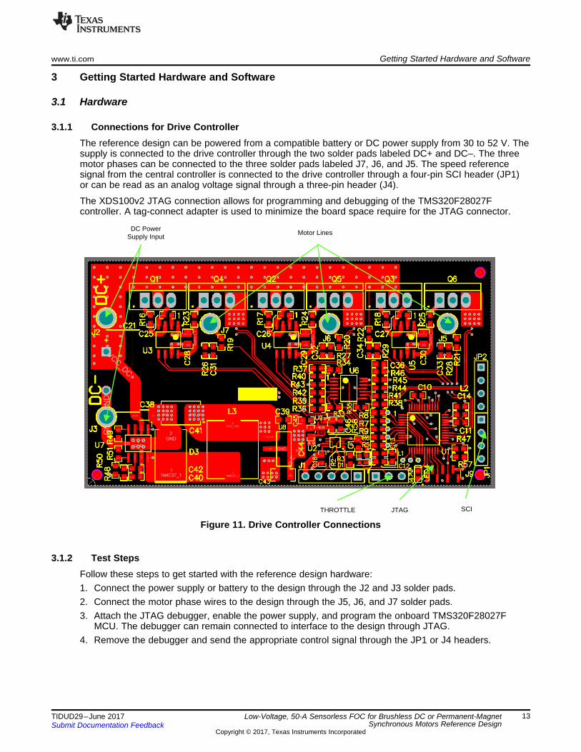
3.1.1 Connections for Drive ControllerThe reference design can be powered from a compatible battery or DC power supply from 30 to 52 V. Thesupply is connected to the drive controller through the two solder pads labeled DC+ and DC–. The threemotor phases can be connected to the three solder pads labeled J7, J6, and J5. The speed referencesignal from the central controller is connected to the drive controller through a four-pin SCI header (JP1)or can be read as an analog voltage signal through a three-pin header (J4).
The XDS100v2 JTAG connection allows for programming and debugging of the TMS320F28027Fcontroller. A tag-connect adapter is used to minimize the board space require for the JTAG connector.
Figure 11. Drive Controller Connections
3.1.2 Test StepsFollow these steps to get started with the reference design hardware:1. Connect the power supply or battery to the design through the J2 and J3 solder pads.2. Connect the motor phase wires to the design through the J5, J6, and J7 solder pads.3. Attach the JTAG debugger, enable the power supply, and program the onboard TMS320F28027F
MCU. The debugger can remain connected to interface to the design through JTAG.4. Remove the debugger and send the appropriate control signal through the JP1 or J4 headers.
Getting Started Hardware and Software www.ti.com
14 TIDUD29–June 2017Submit Documentation Feedback
Copyright © 2017, Texas Instruments Incorporated
Low-Voltage, 50-A Sensorless FOC for Brushless DC or Permanent-MagnetSynchronous Motors Reference Design
3.2 Firmware
3.2.1 Download and Install CCS and MotorWareThis TI Design uses MotorWare for the BLDC motor control and system controllers. To get started, go anddownload the latest version from www.TI.com. See the Code Composer Studio™ (CCS) web page athttp://www.ti.com/tool/ccstudio for information on downloading the integrated development environment forthe C2000™ code.
The MotorWare software can be downloaded from the Texas Instruments web site athttp://www.ti.com/tool/MOTORWARE. Follow the installation instructions to install on a local computer.
3.2.2 Add Custom Hardware to MotorWareAfter installing the MotorWare and CCS software, follow these steps to add the files necessary to useMotorWare with the TIDM-1003 board:1. Navigate to C:/ti/motorware/motorware_1_01_00_17/sw. All changes made for this TI Design are
completed in "sw" subfolders.2. Create a new HAL directory to hold the contents of the zip folder labeled "TIDM-
1003_sw_modules_hal_boards.zip," and copy the directory to "sw/modules/hal/boards." The foldershould be named C:\ti\motorware\motorware_1_01_00_17\sw\modules\hal\boards\TIDM_1003.
3. Create a new project directory to hold the contents of the zip folder labeled "TIDM-1003_sw_solutions_instaspin_foc_boards.zip", and copy the directory to"sw/solutions/instaspin_foc/boards." The folder should be namedC:\ti\motorware\motorware_1_01_00_17\sw\solutions\instaspin_foc\boards\TIDM_1003.
4. Add a new project source files directory to hold the project source code files, and name the directoryC:\ti\motorware\motorware_1_01_00_17\sw\solutions\instaspin_foc\src.
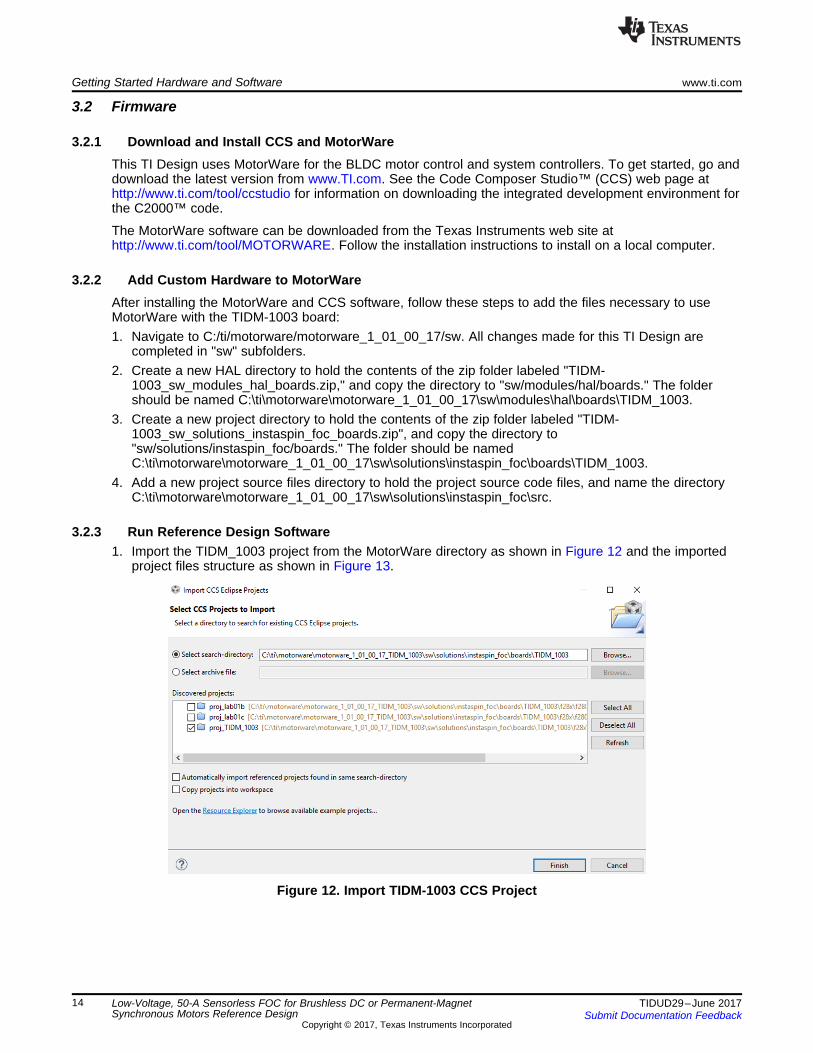
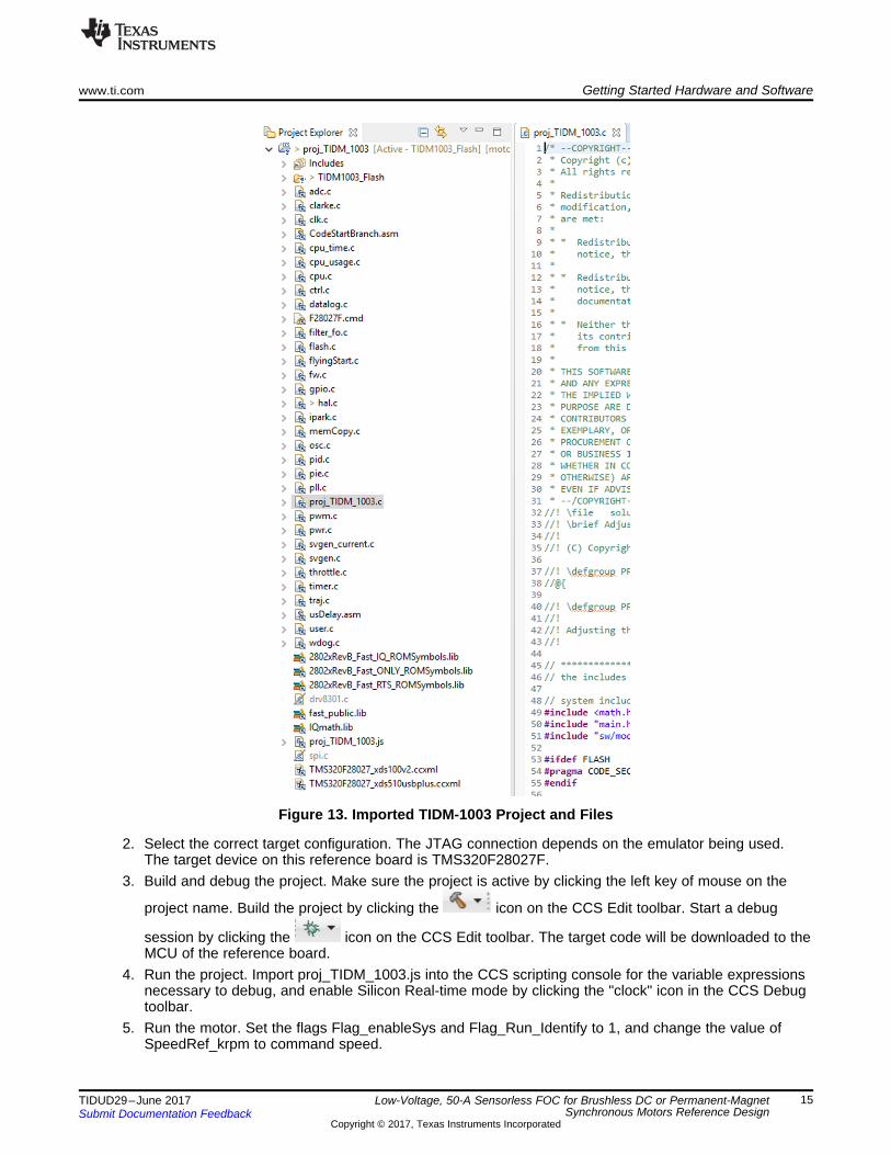
3.2.3 Run Reference Design Software1. Import the TIDM_1003 project from the MotorWare directory as shown in Figure 12 and the imported
project files structure as shown in Figure 13.
Figure 12. Import TIDM-1003 CCS Project
www.ti.com Getting Started Hardware and Software
15TIDUD29–June 2017Submit Documentation Feedback
Copyright © 2017, Texas Instruments Incorporated
Low-Voltage, 50-A Sensorless FOC for Brushless DC or Permanent-MagnetSynchronous Motors Reference Design
Figure 13. Imported TIDM-1003 Project and Files
2. Select the correct target configuration. The JTAG connection depends on the emulator being used.The target device on this reference board is TMS320F28027F.
3. Build and debug the project. Make sure the project is active by clicking the left key of mouse on the
project name. Build the project by clicking the icon on the CCS Edit toolbar. Start a debug
session by clicking the icon on the CCS Edit toolbar. The target code will be downloaded to theMCU of the reference board.
4. Run the project. Import proj_TIDM_1003.js into the CCS scripting console for the variable expressionsnecessary to debug, and enable Silicon Real-time mode by clicking the "clock" icon in the CCS Debugtoolbar.
5. Run the motor. Set the flags Flag_enableSys and Flag_Run_Identify to 1, and change the value ofSpeedRef_krpm to command speed.

Testing and Results www.ti.com
16 TIDUD29–June 2017Submit Documentation Feedback
Copyright © 2017, Texas Instruments Incorporated
Low-Voltage, 50-A Sensorless FOC for Brushless DC or Permanent-MagnetSynchronous Motors Reference Design
4 Testing and Results
4.1 Test Setup
Table 2. Test Equipment
EQUIPMENT NAMEDC power supply Agilent, N5769A
Oscilloscope Agilent, DSO-X 3024AMultimeter Fluke, 189
Motor Anaheim, BLY341S-48V-3200Dynamometer Magtrol, HD-705-6N
Dynamometer controller Magtrol, DSP6001
4.2 Test ResultsThe following tests are performed to characterize each individual functional block as well as the entireboard:• Functional tests include power supply output and gate drive• Motor parameter identification• Motor running with load
4.2.1 Power Supply and Gate Drive Tests
Figure 14. 12-, 5- and 3.3-V Power Supply Output at 36-V Power Input
• CH1 (blue): 12-V power supply for gate driver• CH2 (red): 5-V power supply for interface• CH3 (green): 3.3-V power supply for MCU

www.ti.com Testing and Results
17TIDUD29–June 2017Submit Documentation Feedback
Copyright © 2017, Texas Instruments Incorporated
Low-Voltage, 50-A Sensorless FOC for Brushless DC or Permanent-MagnetSynchronous Motors Reference Design
Figure 15. High-Side and Low-Side Gate With Dead Band From MCU
4.2.2 Motor Parameters Identification Without LoadOpen user.h from the directory of the project. The user.h file has definitions of motor parameters. A fewvalues can already be put into the user.h motor parameters, which need to be set for the actual motorparameters:• USER_MOTOR_TYPE: The motor type, ACI, or PMSM• USER_MOTOR_NUM_POLE_PAIRS: The number of pole pairs of the motor• USER_MOTOR_MAX_CURRENT: The maximum nameplate current of the motor• USER_MOTOR_RES_EST_CURRENT: The motor will have to initially be started in open loop during
identification. This value sets the peak of the current used during initial startup of the motor. If themotor has high-cogging torque or some kind of load, increase this current value until the motor willstart spinning. After motor identification, this value is never used.
• USER_MOTOR_IND_EST_CURRENT: For PMSMs, this value can be set to the negative of thecurrent used for USER_MOTOR_RES_EST_CURRENT.
• USER_MOTOR_NUM_POLE_PAIRS: The number of pole pairs of the motor• USER_MOTOR_RATED_FLUX: The motor flux linkage between the rotor and the stator

Testing and Results www.ti.com
18 TIDUD29–June 2017Submit Documentation Feedback
Copyright © 2017, Texas Instruments Incorporated
Low-Voltage, 50-A Sensorless FOC for Brushless DC or Permanent-MagnetSynchronous Motors Reference Design
Figure 16. RoverL and Rs Identification State
Figure 17. Rampup and Flux Identification State
www.ti.com Testing and Results
19TIDUD29–June 2017Submit Documentation Feedback
Copyright © 2017, Texas Instruments Incorporated
Low-Voltage, 50-A Sensorless FOC for Brushless DC or Permanent-MagnetSynchronous Motors Reference Design
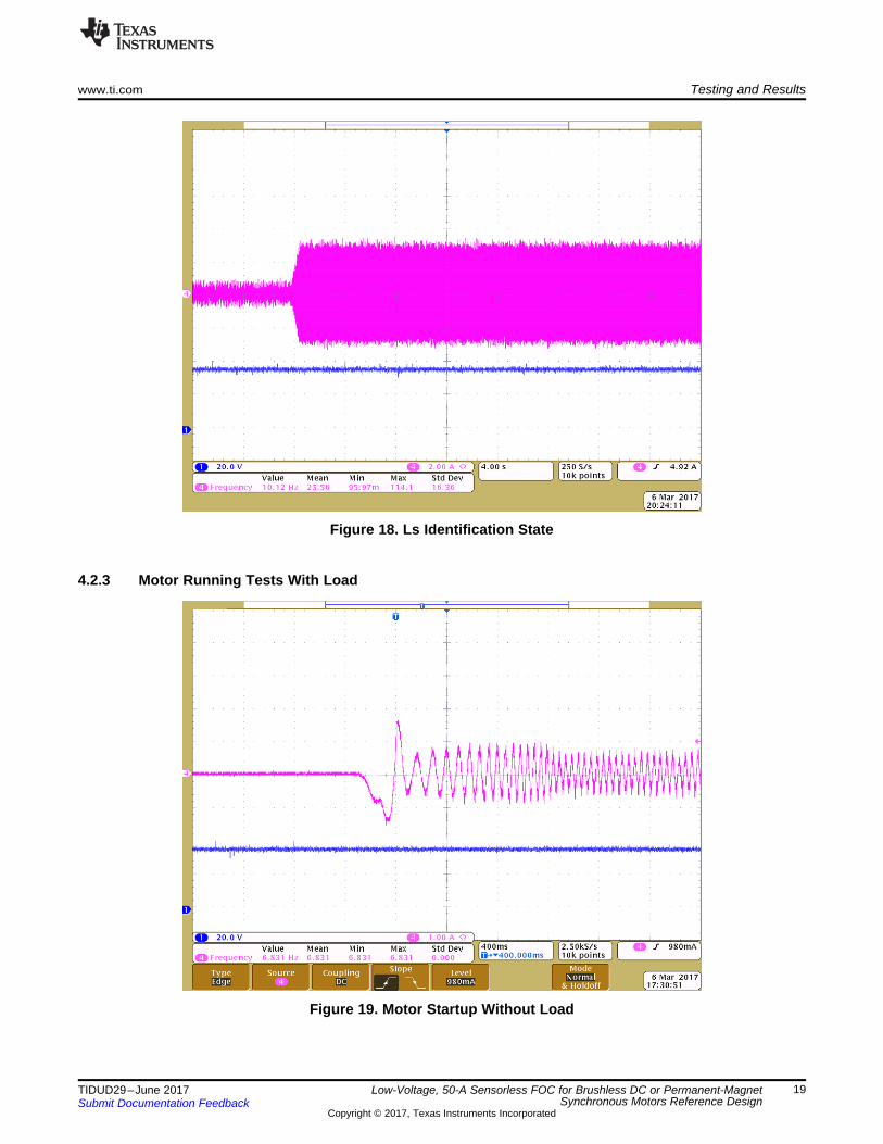
Figure 18. Ls Identification State
4.2.3 Motor Running Tests With Load
Figure 19. Motor Startup Without Load

Testing and Results www.ti.com
20 TIDUD29–June 2017Submit Documentation Feedback
Copyright © 2017, Texas Instruments Incorporated
Low-Voltage, 50-A Sensorless FOC for Brushless DC or Permanent-MagnetSynchronous Motors Reference Design
Figure 20. Motor Startup With Light Load
Figure 21. Motor Running at 900 rpm With Light Load

www.ti.com Testing and Results
21TIDUD29–June 2017Submit Documentation Feedback
Copyright © 2017, Texas Instruments Incorporated
Low-Voltage, 50-A Sensorless FOC for Brushless DC or Permanent-MagnetSynchronous Motors Reference Design
4.2.4 Test SummaryThis TI Design shows how to adapt InstaSPIN-FOC to enable low-voltage, high-current motor controlusing TI provided software. This control is done by using the special capabilities of the C2000 processorfamily for advanced system debug capabilities. This can supplement the simulation effort of the engineersto avoid developing the perfect simulation tool for the system and simply use the actual hardware to debugthe control algorithm issue. This hardware removes the need to build complex simulation algorithms todefine specific motor or PCB parasitic effects to the system.

GND PAD
RT/CLK(R49)
COMP (R48,C42,C40)
Input(C38)
Output (C41,D3,L3)
Power PAD
Design Files www.ti.com
22 TIDUD29–June 2017Submit Documentation Feedback
Copyright © 2017, Texas Instruments Incorporated
Low-Voltage, 50-A Sensorless FOC for Brushless DC or Permanent-MagnetSynchronous Motors Reference Design
5 Design Files
5.1 SchematicsTo download the schematics for each board, see the design files at TIDM-1003.
5.2 Bill of MaterialsTo download the Bill of Materials for each board, see the design files at TIDM-1003.
5.3 PCB Layout Recommendations
5.3.1 Layout PrintsTo download the layer plots, see the design files at TIDM-1003.
5.3.2 Power Supply RecommendationsLayout is a critical portion of a good power supply design. There are several signal paths that conduct fastchanging currents or voltages that can interact with stray inductance or parasitic capacitance to generatenoise or degrade performance.1. To reduce the parasitic effects, C38 was placed near VIN as a bypass capacitor, with care taken to
minimize the loop area formed by the bypass capacitor (C38) connections and the VIN.2. The GND terminal should be tied directly to the PowerPad under the TPS54360. The PowerPAD
should be connected to internal PCB ground planes using multiple vias directly under the TPS54360.3. The SW terminal should be routed to the cathode of the catch diode (D3) and to the output inductor
(L3). The output filter capacitor (C41), catch diode (D3) and output inductor (L3) should be locatedclose to the SW terminals, and the area of the PCB conductor minimized to prevent excessivecapacitive coupling.
4. The RT/CLK terminal is sensitive to noise so the RT resistor (R49) should be located as close aspossible to the TPS54360 and routed with minimal lengths of trace.
Figure 22. TPS54360 PCB Layout Recommendations

Bootstrap Capacitor(C25)
HO and LO Signal
HI and LI Signal
Decoupling Capacitor(C25)
VDD
GND
www.ti.com Design Files
23TIDUD29–June 2017Submit Documentation Feedback
Copyright © 2017, Texas Instruments Incorporated
Low-Voltage, 50-A Sensorless FOC for Brushless DC or Permanent-MagnetSynchronous Motors Reference Design
5.3.3 MOSFET Gate Drivers RecommendationsTo improve the switching characteristics and efficiency of a design, follow these layout recommendations:1. Locate the driver as close as possible to the MOSFETs.2. Locate the bootstrap capacitor (C25) between VHB and VHS as close as possible to the UCC27211.3. Locate the decoupling capacitor (C28) between VDD and VSS as close as possible to the UCC27211.4. Avoid VDD traces being close to LO, HS, and HO signals.5. Use wide traces for LO and HO closely following the associated GND or HS traces. A 60- to 100-mils
width is preferable where possible.6. Use as least two or more vias for VDD and GND were routed from one layer to another.7. Avoid LI and HI (driver input) being too close to the HS node.
Figure 23. UCC27211 PCB Layout Recommendations
5.3.4 Motor Current and Voltage Signals Sampling Recommendations1. Place the external components as close to the OPA4374 as possible, keeping RF (R34) and RG (R37)
close to the inverting input of OPA4374 to minimize parasitic capacitance.2. Use low-ESR, ceramic bypass capacitor (C35) and place it close to the OPA4374.3. For differential signals for the motor current feedback across the current sense resistors, use symmetry
to ensure that any noise picked up on one line is also picked up approximately equally on the otherline. Keep the length of input traces as short as possible and run the input traces as far away from thesupply lines as possible.
4. Separate grounding for analog and digital portions of circuitry is one of the simplest and most effectivemethods of noise suppression.
5. Keep the input filter resistors (R7) and capacitor (C4) of the anti-aliasing filter as close together andnear to the inputs of the microcontroller ADC to minimize the loop area.

Shunt Resistor(R31)
I_P
I_P
Feedback Resistor(R34)
Gain Resistor(R37, R40, R43)
Bypass Capacitor(C35)
MCU ADC Pin
ADC Filter(R7,C4)
Design Files www.ti.com
24 TIDUD29–June 2017Submit Documentation Feedback
Copyright © 2017, Texas Instruments Incorporated
Low-Voltage, 50-A Sensorless FOC for Brushless DC or Permanent-MagnetSynchronous Motors Reference Design
Figure 24. PCB Layout Recommendations for Motor Current and Voltage Sampling
5.4 Altium ProjectTo download the Altium project files for each board, see the design files at TIDM-1003.
5.5 Gerber FilesTo download the Gerber files for each board, see the design files at TIDM-1003.
5.6 Assembly DrawingsTo download the assembly drawings for each board, see the design files at TIDM-1003.
6 Software FilesTo download the software files for this reference design, see the design files at TIDM-1003.

www.ti.com Related Documentation
25TIDUD29–June 2017Submit Documentation Feedback
Copyright © 2017, Texas Instruments Incorporated
Low-Voltage, 50-A Sensorless FOC for Brushless DC or Permanent-MagnetSynchronous Motors Reference Design
7 Related Documentation1. Texas Instruments, TI InstaSPIN™ Motor Control Solutions2. Texas Instruments, Texas Instruments WEBENCH® Design Center3. Texas Instruments, TMS320F2802x Piccolo™ Microcontrollers, TMS320F28027F Datasheet
(SPRS523)4. Texas Instruments, UCC2721x 120-V Boot, 4-A Peak, High-Frequency High-Side and Low-Side Driver,
UCC27211 Datasheet (SLUSAT7)5. Texas Instruments, TPS54360 60 V Input, 3.5 A, Step Down DC-DC Converter with Eco-mode™,
TPS54360 Datasheet (SLVSBB4)6. Texas Instruments, CSD19506KCS 80 V N-Channel NexFET™ Power MOSFET, CSD19506KCS
(SLPS481)7. Texas Instruments, InstaSPIN-FOC™ and InstaSPIN-MOTION™ User's Guide (SPRUHJ1)
7.1 TrademarksNexFET, InstaSPIN, InstaSPIN-FOC, MotorWare, FAST, Piccolo, PowerPAD, Code Composer Studio,C2000 are trademarks of Texas Instruments.All other trademarks are the property of their respective owners.
8 TerminologyFOC— Field oriented control
PMSM— Permanent magnet synchronous motor
BLDC— Brushless DC motor
MCU— Microcontroller unit
FETs, MOSFETs—Metal-oxide-semiconductor field-effect transistor
PWM— Pulse width modulation
ESD— Electrostatic discharge
TVS— Transient voltage suppressors
RPM— Rotation per minute
9 About the AuthorsYANMING LUO is a systems application engineer in the system solutions team of C2000 at TexasInstruments, where he is responsible for developing reference design solutions for motor control-basedC2000 controllers. Yanming has been with TI since 2003 and earned an M.S. degree from NortheasternUniversity, China in 1998.
BIGLEY SEAN is a systems application engineer in the system solutions team of C2000 at TexasInstruments, where he is responsible for developing reference design solutions for motor control-basedC2000 controllers.

IMPORTANT NOTICE FOR TI DESIGN INFORMATION AND RESOURCES
Texas Instruments Incorporated (‘TI”) technical, application or other design advice, services or information, including, but not limited to,reference designs and materials relating to evaluation modules, (collectively, “TI Resources”) are intended to assist designers who aredeveloping applications that incorporate TI products; by downloading, accessing or using any particular TI Resource in any way, you(individually or, if you are acting on behalf of a company, your company) agree to use it solely for this purpose and subject to the terms ofthis Notice.TI’s provision of TI Resources does not expand or otherwise alter TI’s applicable published warranties or warranty disclaimers for TIproducts, and no additional obligations or liabilities arise from TI providing such TI Resources. TI reserves the right to make corrections,enhancements, improvements and other changes to its TI Resources.You understand and agree that you remain responsible for using your independent analysis, evaluation and judgment in designing yourapplications and that you have full and exclusive responsibility to assure the safety of your applications and compliance of your applications(and of all TI products used in or for your applications) with all applicable regulations, laws and other applicable requirements. Yourepresent that, with respect to your applications, you have all the necessary expertise to create and implement safeguards that (1)anticipate dangerous consequences of failures, (2) monitor failures and their consequences, and (3) lessen the likelihood of failures thatmight cause harm and take appropriate actions. You agree that prior to using or distributing any applications that include TI products, youwill thoroughly test such applications and the functionality of such TI products as used in such applications. TI has not conducted anytesting other than that specifically described in the published documentation for a particular TI Resource.You are authorized to use, copy and modify any individual TI Resource only in connection with the development of applications that includethe TI product(s) identified in such TI Resource. NO OTHER LICENSE, EXPRESS OR IMPLIED, BY ESTOPPEL OR OTHERWISE TOANY OTHER TI INTELLECTUAL PROPERTY RIGHT, AND NO LICENSE TO ANY TECHNOLOGY OR INTELLECTUAL PROPERTYRIGHT OF TI OR ANY THIRD PARTY IS GRANTED HEREIN, including but not limited to any patent right, copyright, mask work right, orother intellectual property right relating to any combination, machine, or process in which TI products or services are used. Informationregarding or referencing third-party products or services does not constitute a license to use such products or services, or a warranty orendorsement thereof. Use of TI Resources may require a license from a third party under the patents or other intellectual property of thethird party, or a license from TI under the patents or other intellectual property of TI.TI RESOURCES ARE PROVIDED “AS IS” AND WITH ALL FAULTS. TI DISCLAIMS ALL OTHER WARRANTIES ORREPRESENTATIONS, EXPRESS OR IMPLIED, REGARDING TI RESOURCES OR USE THEREOF, INCLUDING BUT NOT LIMITED TOACCURACY OR COMPLETENESS, TITLE, ANY EPIDEMIC FAILURE WARRANTY AND ANY IMPLIED WARRANTIES OFMERCHANTABILITY, FITNESS FOR A PARTICULAR PURPOSE, AND NON-INFRINGEMENT OF ANY THIRD PARTY INTELLECTUALPROPERTY RIGHTS.TI SHALL NOT BE LIABLE FOR AND SHALL NOT DEFEND OR INDEMNIFY YOU AGAINST ANY CLAIM, INCLUDING BUT NOTLIMITED TO ANY INFRINGEMENT CLAIM THAT RELATES TO OR IS BASED ON ANY COMBINATION OF PRODUCTS EVEN IFDESCRIBED IN TI RESOURCES OR OTHERWISE. IN NO EVENT SHALL TI BE LIABLE FOR ANY ACTUAL, DIRECT, SPECIAL,COLLATERAL, INDIRECT, PUNITIVE, INCIDENTAL, CONSEQUENTIAL OR EXEMPLARY DAMAGES IN CONNECTION WITH ORARISING OUT OF TI RESOURCES OR USE THEREOF, AND REGARDLESS OF WHETHER TI HAS BEEN ADVISED OF THEPOSSIBILITY OF SUCH DAMAGES.You agree to fully indemnify TI and its representatives against any damages, costs, losses, and/or liabilities arising out of your non-compliance with the terms and provisions of this Notice.This Notice applies to TI Resources. Additional terms apply to the use and purchase of certain types of materials, TI products and services.These include; without limitation, TI’s standard terms for semiconductor products http://www.ti.com/sc/docs/stdterms.htm), evaluationmodules, and samples (http://www.ti.com/sc/docs/sampterms.htm).
Mailing Address: Texas Instruments, Post Office Box 655303, Dallas, Texas 75265Copyright © 2017, Texas Instruments Incorporated
Related Documents