Optical amplifiers and their applications Ref: Optical Fiber Communications by: G. Keiser; 3 rd edition Depend on Source of Losses:

Welcome message from author
This document is posted to help you gain knowledge. Please leave a comment to let me know what you think about it! Share it to your friends and learn new things together.
Transcript
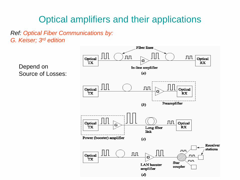
Optical amplifiers and their applications
Ref: Optical Fiber Communications by:
G. Keiser; 3rd edition
Depend on
Source of Losses:
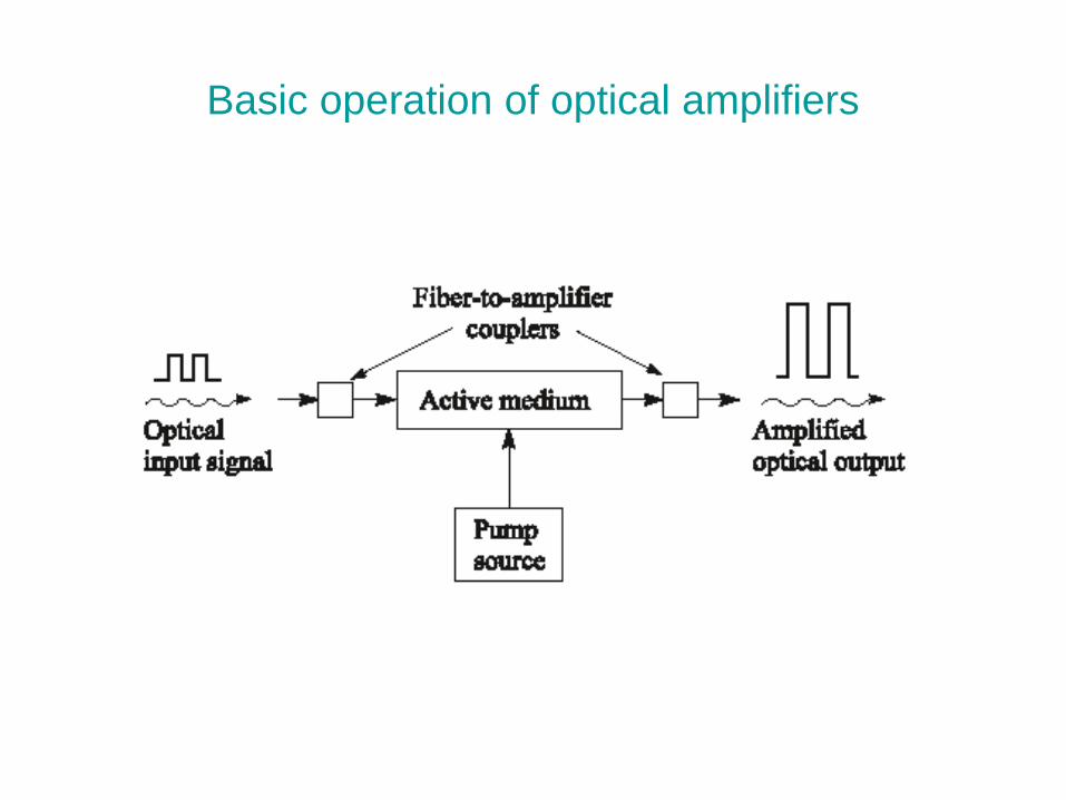
Basic operation of optical amplifiers
Optical Amplifiers
Two main classes of optical amplifiers include:
Semiconductor Optical Amplifiers (SOA)
Doped Fiber Amplifiers (DFA)
Semiconductor Optical Amplifiers
There are two types of SOAs:
--- Fabry- Perot amplifiers (FPA)
When the light enters FPA it gets amplified as it reflects back and forth
between the mirrors until emitted at a higher intensity.
It is sensitive to temperature and input optical frequency.
---Non-resonant traveling-wave amplifiers (TWA)
It is the same as FPA except that the end facets are either
antireflection coated or cleaved at an angle so that internal reflection
does not take place and the input signal gets amplified only once
during a single pass through the device. They widely used because
they have a large optical bandwidth, and low polarization sensitivity.
Ref: Optical Fiber Communications by:
G. Keiser; 3rd edition
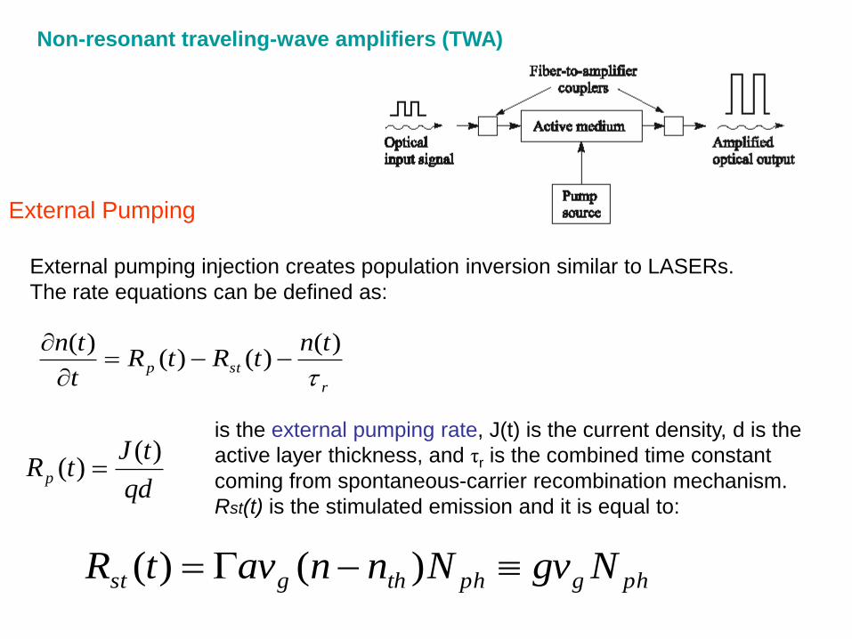
External Pumping
External pumping injection creates population inversion similar to LASERs.
The rate equations can be defined as:
r
stp
tntRtR
t
tn
)()()(
)(
qd
tJtRp
)()(
is the external pumping rate, J(t) is the current density, d is the
active layer thickness, and τr is the combined time constant
coming from spontaneous-carrier recombination mechanism.
Rst(t) is the stimulated emission and it is equal to:
phgphthgst NgvNnnavtR )()(
Non-resonant traveling-wave amplifiers (TWA)
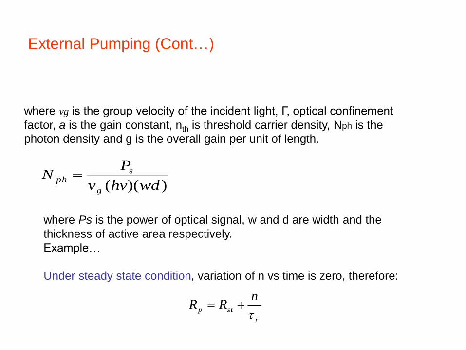
External Pumping (Cont…)
))(( wdhvv
PN
g
sph
where vg is the group velocity of the incident light, Г, optical confinement
factor, a is the gain constant, nth is threshold carrier density, Nph is the
photon density and g is the overall gain per unit of length.
where Ps is the power of optical signal, w and d are width and the
thickness of active area respectively.
Example…
Under steady state condition, variation of n vs time is zero, therefore:
r
stp
nRR
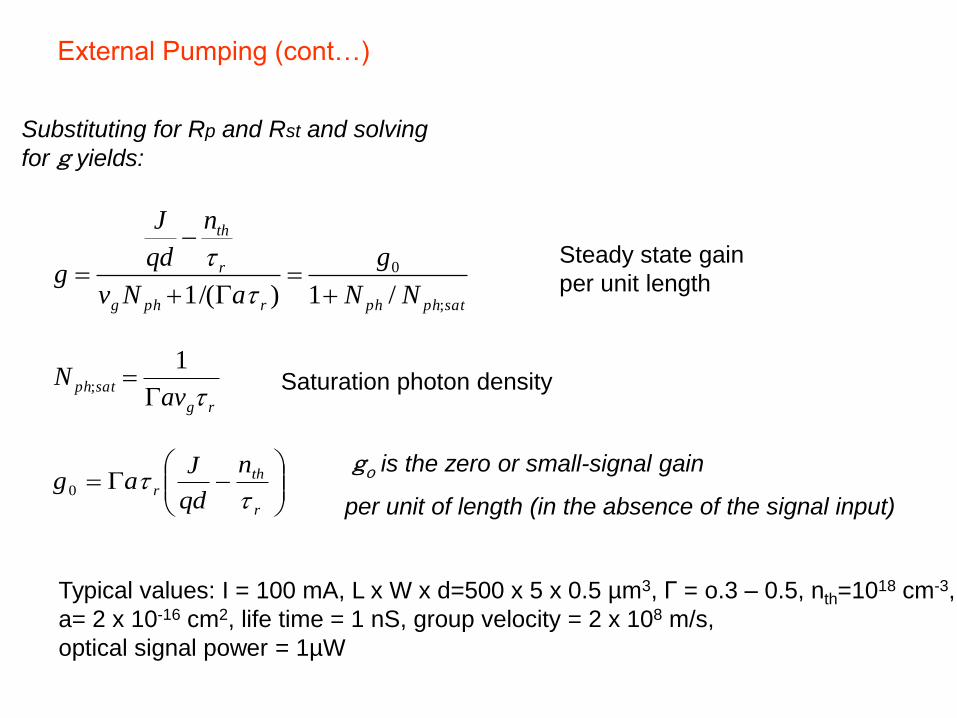
External Pumping (cont…)
Substituting for Rp and Rst and solving
for g yields:
satphphrphg
r
th
NN
g
aNv
n
qd
J
g;
0
/1)/(1
rg
satphav
N
1
;
r
th
r
n
qd
Jag
0
Saturation photon density
go is the zero or small-signal gain
per unit of length (in the absence of the signal input)
Steady state gain
per unit length
Typical values: I = 100 mA, L x W x d=500 x 5 x 0.5 µm3, Γ = o.3 – 0.5, nth=1018 cm-3,
a= 2 x 10-16 cm2, life time = 1 nS, group velocity = 2 x 10⁸ m/s,
optical signal power = 1µW
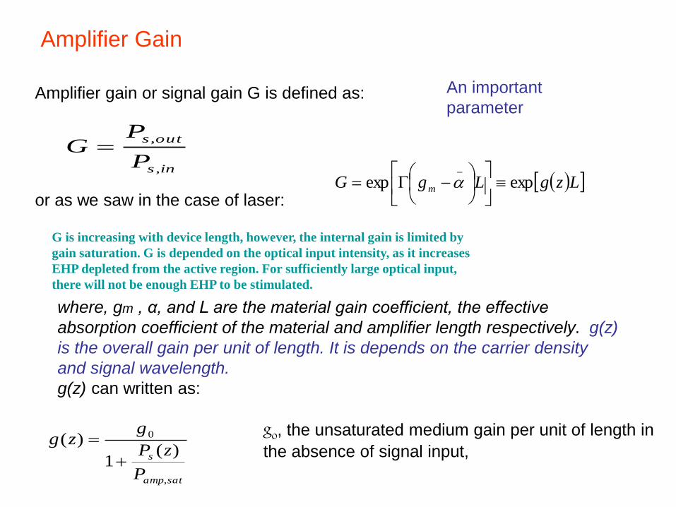
Amplifier Gain
Amplifier gain or signal gain G is defined as:
ins
outs
P
PG
,
,
LzgLgG m expexp_
or as we saw in the case of laser:
where, gm , α, and L are the material gain coefficient, the effective
absorption coefficient of the material and amplifier length respectively. g(z)
is the overall gain per unit of length. It is depends on the carrier density
and signal wavelength.
g(z) can written as:
satamp
s
P
zP
gzg
,
0
)(1
)(
go, the unsaturated medium gain per unit of length in
the absence of signal input,
An important
parameter
G is increasing with device length, however, the internal gain is limited by
gain saturation. G is depended on the optical input intensity, as it increases
EHP depleted from the active region. For sufficiently large optical input,
there will not be enough EHP to be stimulated.
Amplifier Gain
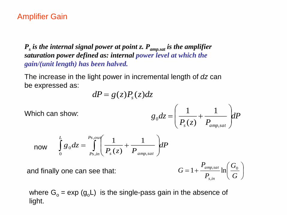
Ps is the internal signal power at point z. Pamp.sat is the amplifier
saturation power defined as: internal power level at which the
gain/(unit length) has been halved.
The increase in the light power in incremental length of dz can
be expressed as:
dzzPzgdP s )()(
dPPzP
dzgsatamps
,
0
1
)(
1
outPs
inPs satamps
L
dPPzP
dzg
,
, ,0
0
1
)(
1
G
G
P
PG
ins
satamp 0
,
,ln1
Which can show:
now
and finally one can see that:
where Go = exp (goL) is the single-pass gain in the absence of
light.
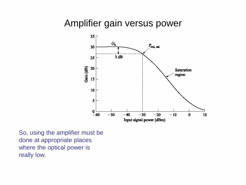
Amplifier gain versus power
So, using the amplifier must be
done at appropriate places
where the optical power is
really low.
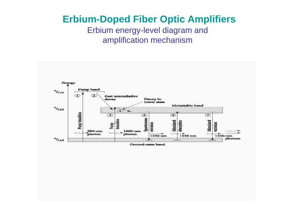
Erbium-Doped Fiber Optic AmplifiersErbium energy-level diagram and
amplification mechanism
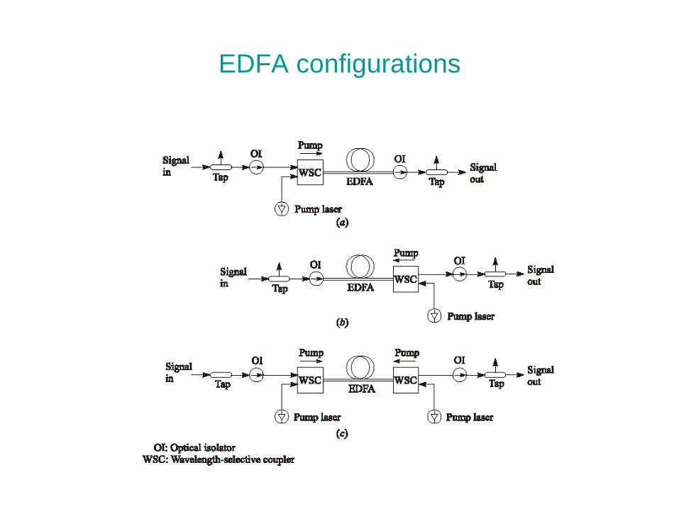
EDFA configurations
EDFA Power-Conversion Efficiency (PCE) and Gain
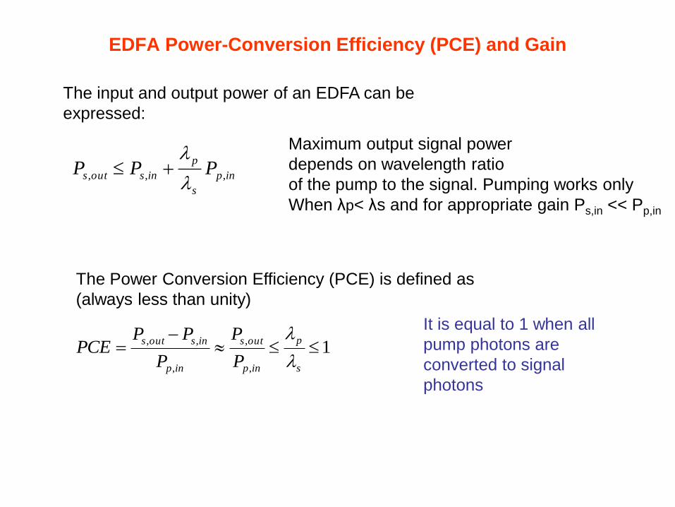
The input and output power of an EDFA can be
expressed:
inp
s
p
insouts PPP ,,,
1,
,
,
,,
s
p
inp
outs
inp
insouts
P
P
P
PPPCE
The Power Conversion Efficiency (PCE) is defined as
(always less than unity)
Maximum output signal power
depends on wavelength ratio
of the pump to the signal. Pumping works only
When λp< λs and for appropriate gain Ps,in << Pp,in
It is equal to 1 when all
pump photons are
converted to signal
photons
Optical Amplifiers
1
,
,
G
P
P
inp
s
p
ins
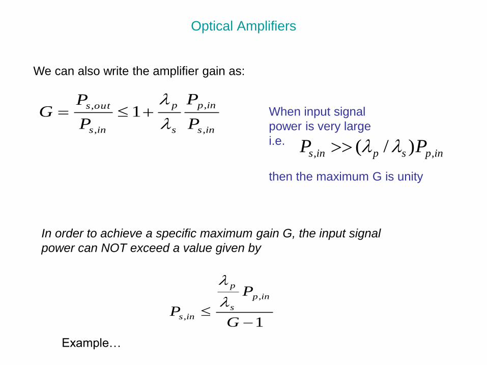
In order to achieve a specific maximum gain G, the input signal
power can NOT exceed a value given by
Example…
We can also write the amplifier gain as:
ins
inp
s
p
ins
outs
P
P
P
PG
,
,
,
,1
inpspins PP ,, )/(
When input signal
power is very large
i.e.
then the maximum G is unity
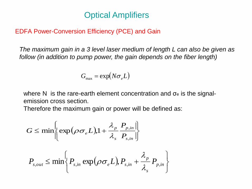
EDFA Power-Conversion Efficiency (PCE) and Gain
LNG eexpmax
where N is the rare-earth element concentration and σe is the signal-
emission cross section.
Therefore the maximum gain or power will be defined as:
ins
inp
s
p
eP
PLG
,
,1,expmin
inp
s
p
inseinsouts PPLPP ,,,, ,expmin
Optical Amplifiers
The maximum gain in a 3 level laser medium of length L can also be given as
follow (in addition to pump power, the gain depends on the fiber length)
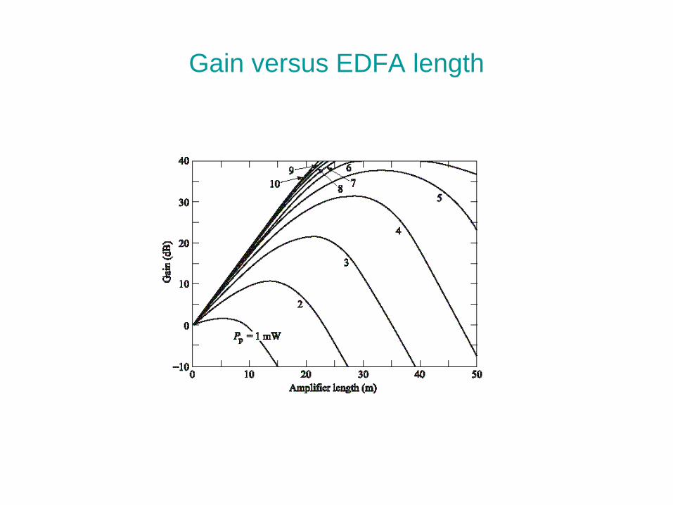
Gain versus EDFA length
Absorption and Emission Cross-Sections in EDFA
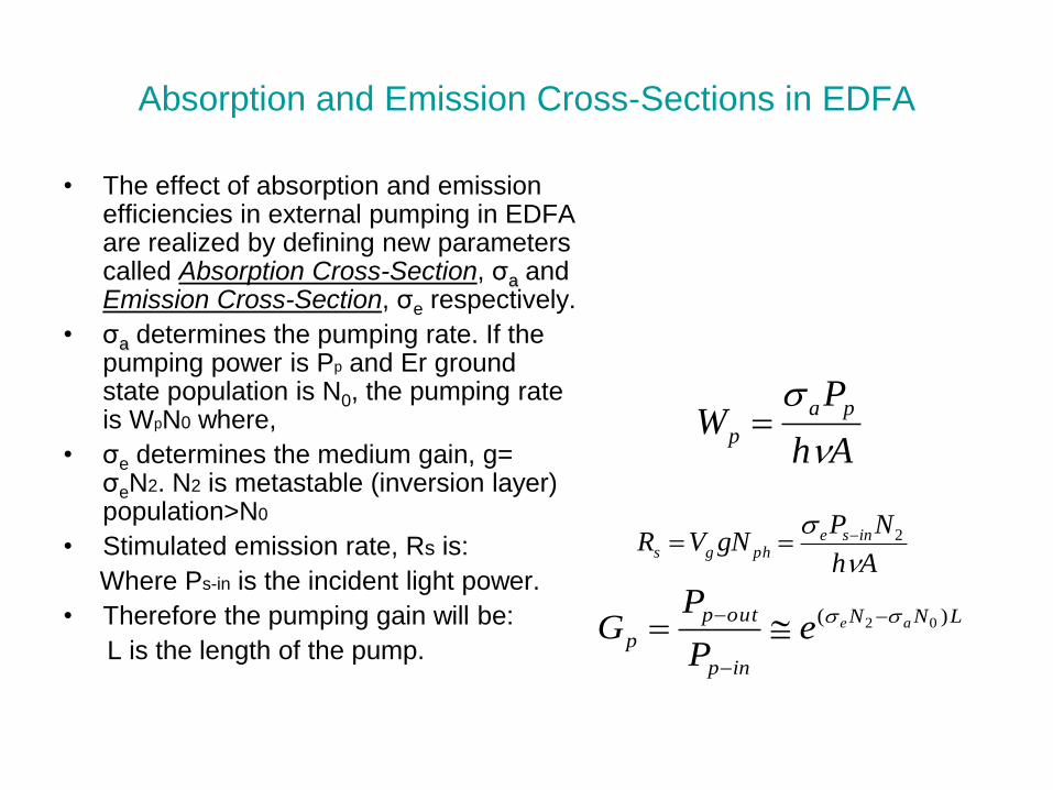
• The effect of absorption and emission efficiencies in external pumping in EDFA are realized by defining new parameters called Absorption Cross-Section, σa and Emission Cross-Section, σe respectively.
• σa determines the pumping rate. If the pumping power is Pp and Er ground state population is N0, the pumping rate is WpN0 where,
• σe determines the medium gain, g= σeN2. N2 is metastable (inversion layer) population>N0
• Stimulated emission rate, Rs is:
Where Ps-in is the incident light power.
• Therefore the pumping gain will be:
L is the length of the pump.
Ah
PW
pa
p
Ah
NPgNVR inse
phgs
2
LNN
inp
outp
paee
P
PG
)( 02
Example
Let’s calculate the pump power needed per unit
length of Er –doped optical fiber to establish a small-
signal optical gain of 0.4 dB/m at 1.55 micron.
Assume that the confinement factor is =0.7. Er3+ is
doped at the center with a 2 micron diameter with
concentration of 1018 ions/ cm3. Assume a pump
wavelength of 1.48 micron is used. The
spontaneous emission lifetime is 10 msec.

Components for Optical Communications
• Passive Components
Couplers,
Attenuators
Equalizers,
Isolators
WDM
• Active Components
Modulators,
Diodes,
Switches,
Routers
Materials for self-studies
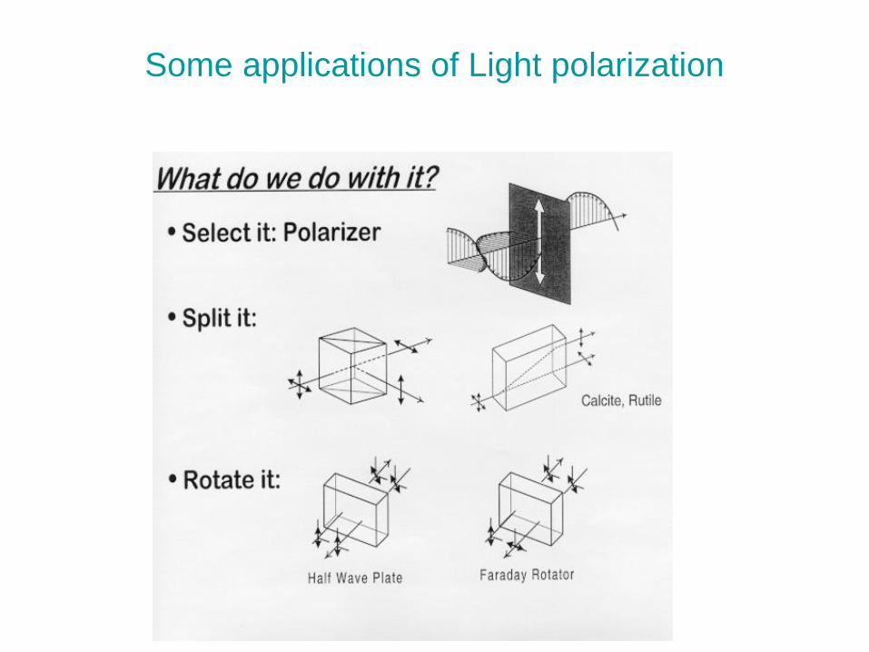
Some applications of Light polarization
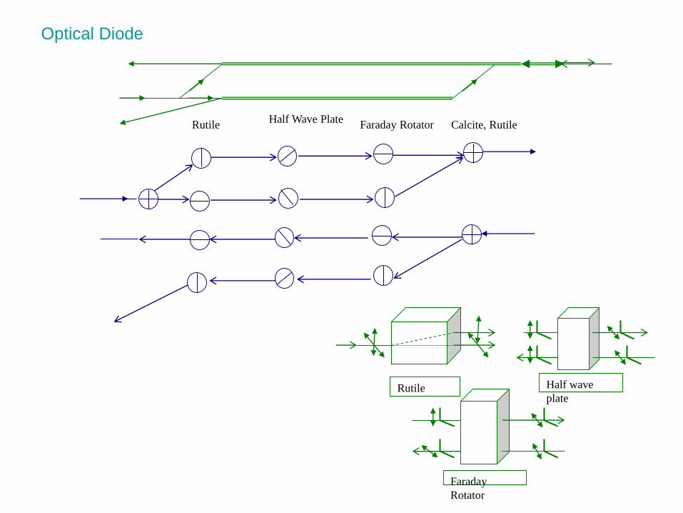
Optical Diode
Rutile Half wave
plate
Faraday
Rotator
RutileHalf Wave Plate
Faraday Rotator Calcite, Rutile
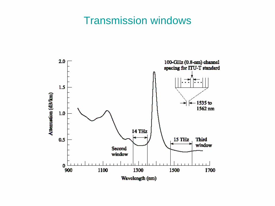
Transmission windows
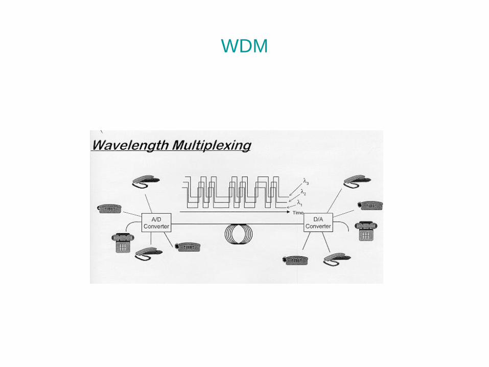
WDM
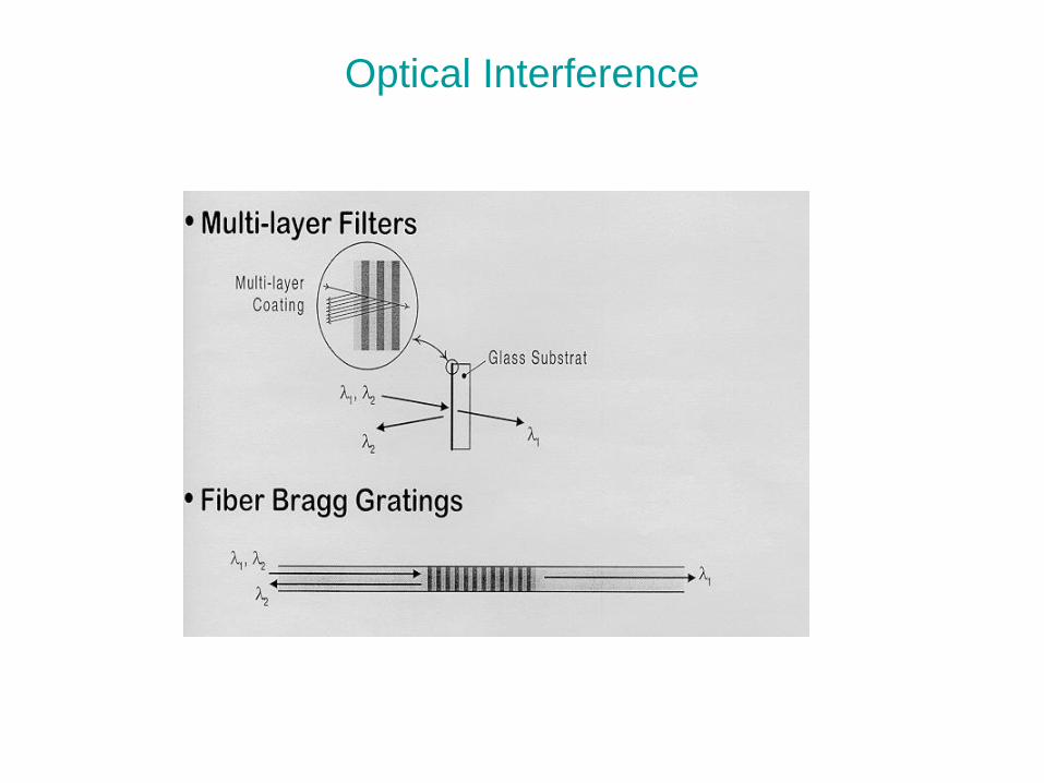
Optical Interference
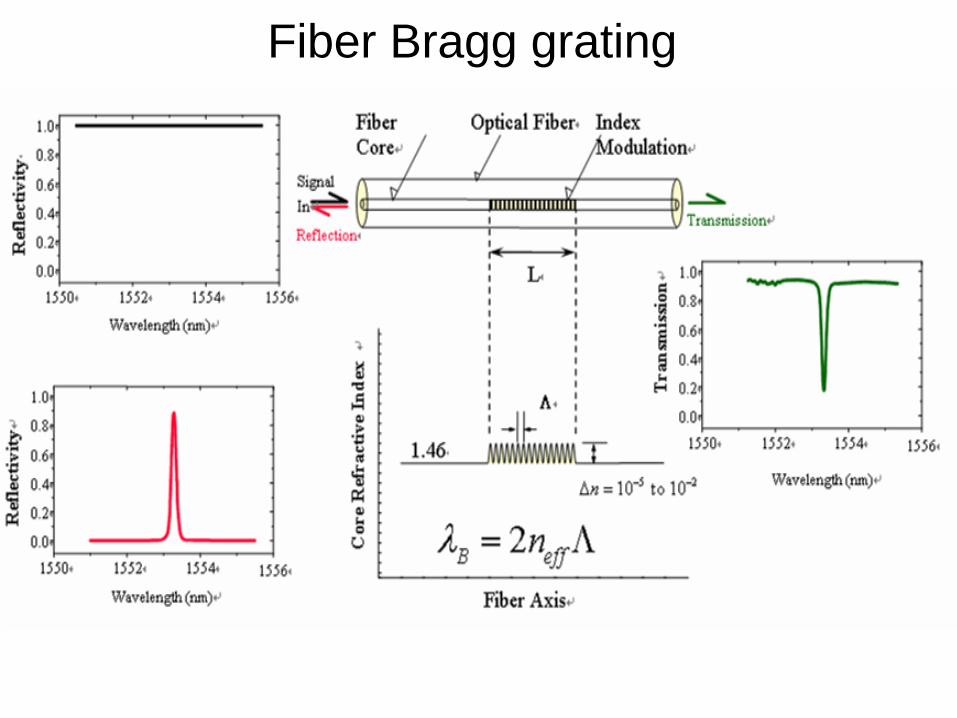
Fiber Bragg grating
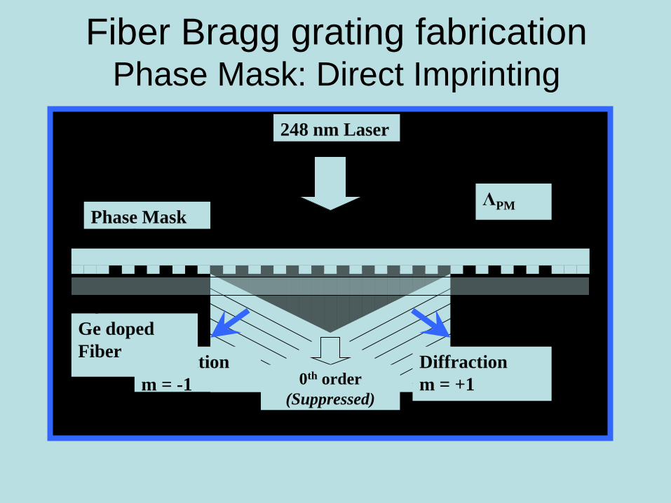
Fiber Bragg grating fabricationPhase Mask: Direct Imprinting
0th order
(Suppressed)
Diffraction
m = -1
Diffraction
m = +1
Phase MaskΛPM
Ge doped
Fiber
248 nm Laser
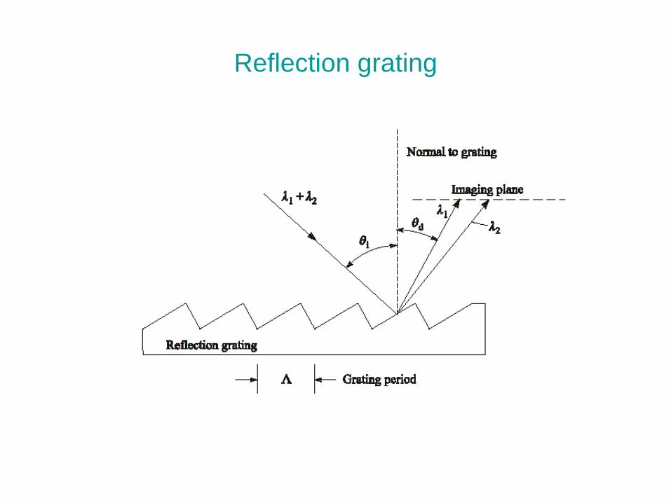
Reflection grating
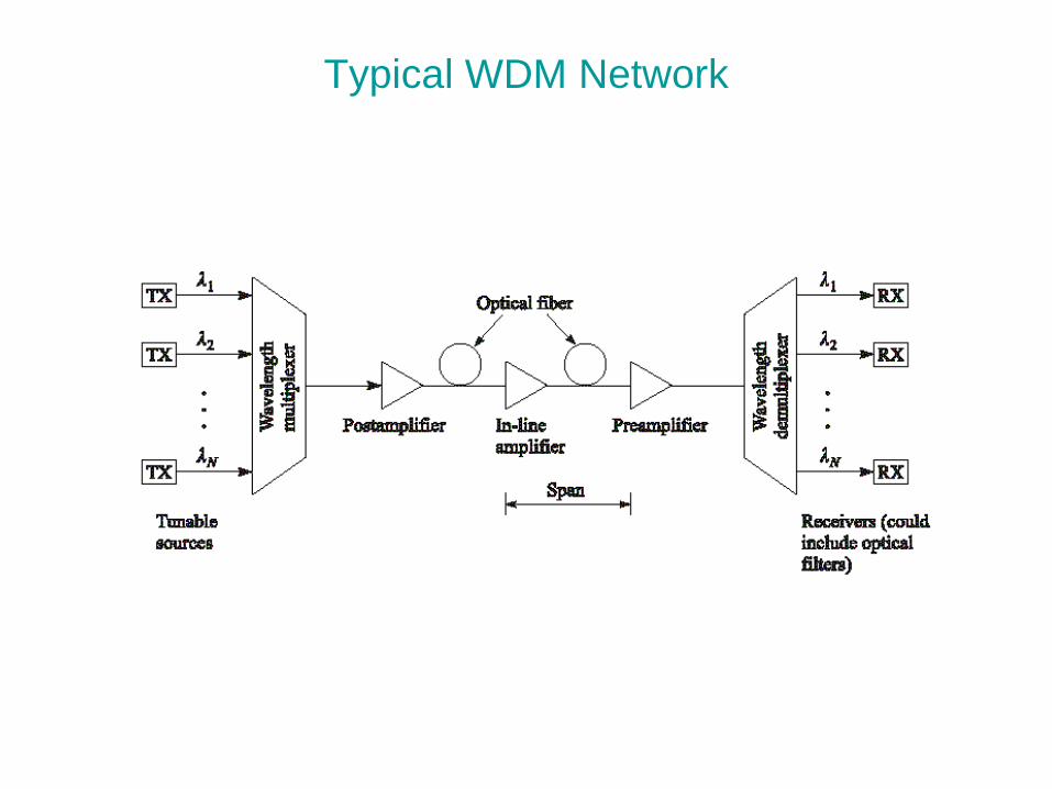
Typical WDM Network
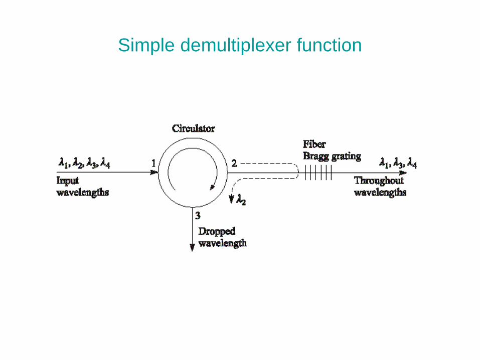
Simple demultiplexer function
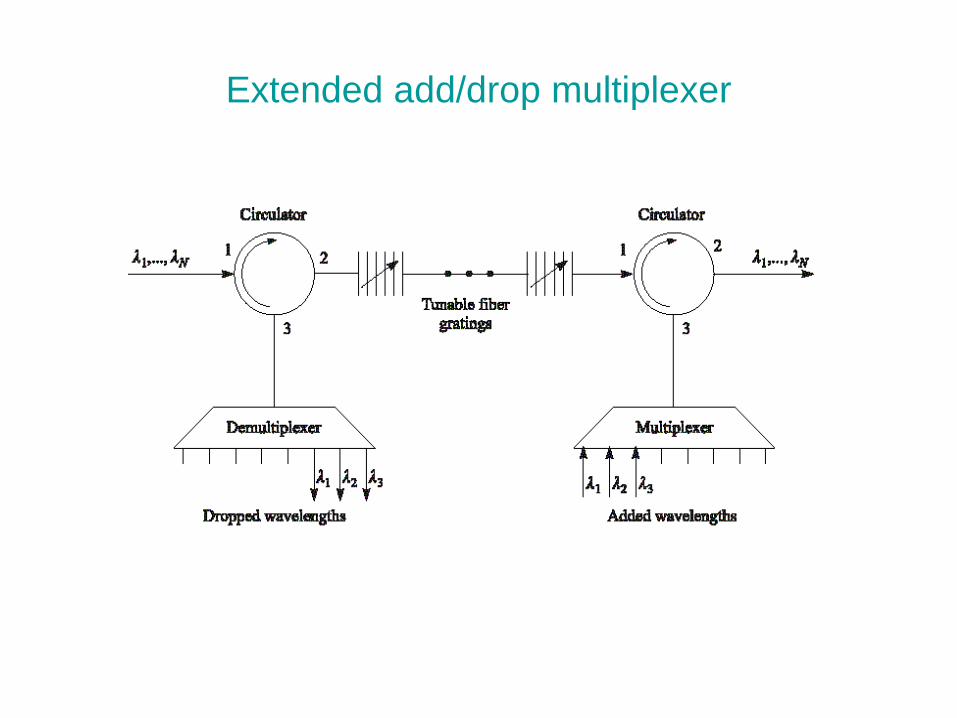
Extended add/drop multiplexer
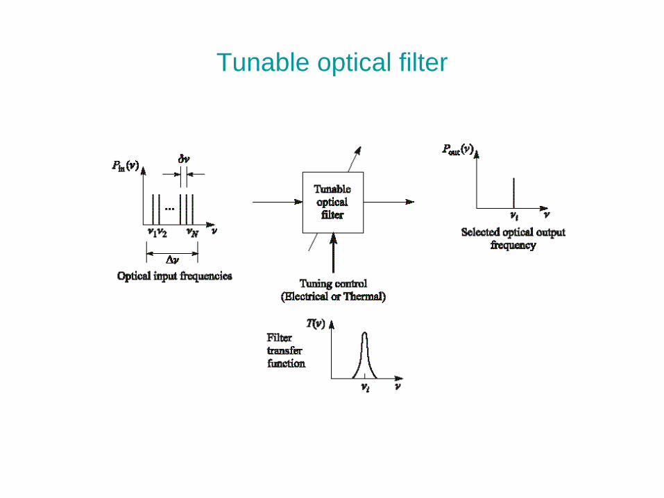
Tunable optical filter

Related Documents