LASER & PHOTONICS REVIEWS Laser Photonics Rev. 9, No. 1, 50–74 (2015) / DOI 10.1002/lpor.201400087 REVIEW ARTICLE Abstract The prospects for using fiber optical parametric am- plifiers (OPAs) in optical communication systems are reviewed. Phase-insensitive amplifiers (PIAs) and phase-sensitive am- plifiers (PSAs) are considered. Low-penalty amplification at/or near 1 Tb/s has been achieved, for both wavelength- and time- division multiplexed formats. High-quality mid-span spectral in- version has been demonstrated at 0.64 Tb/s, avoiding electronic dispersion compensation. All-optical amplitude regeneration of amplitude-modulated signals has been performed, while PSAs have been used to demonstrate phase regeneration of phase- modulated signals. A PSA with 1.1-dB noise figure has been demonstrated, and preliminary wavelength-division multiplexing experiments have been performed with PSAs. 512 Gb/s have been transmitted over 6,000 km by periodic phase conjugation. Simulations indicate that PIAs could reach data rate x reach products in excess of 14,000 Tb/s × km in realistic wavelength- division multiplexed long-haul networks. Technical challenges remaining to be addressed in order for fiber OPAs to become useful for long-haul communication networks are discussed. Fiber optical parametric amplifiers in optical communication systems Michel E. Marhic (†) 1,8 , Peter A. Andrekson 2,∗ , Periklis Petropoulos 3 , Stojan Radic 4 , Christophe Peucheret 5,6 , and Mahmoud Jazayerifar 7 1. Introduction In 1975 Stolen reported the first demonstration of op- tical parametric amplification (OPA) in low-loss optical fibers [1]. The introduction of erbium-doped fiber ampli- fiers (EDFAs) in optical communication systems in the late 1980s sparked interest in the possible development of fiber OPAs for communication systems. Fiber OPA research was greatly facilitated by the development of dispersion-shifted fiber (DSF) with zero-dispersion wavelength (ZDW) in the C-band around 1550 nm. This made it possible to use various fiber components being developed for communi- cation systems. In 1995 DSF with nonlinearity increased by about a factor of 10 was developed [2], by reducing the core diameter and increasing its germania concentra- 1 College of Engineering, Swansea University, Swansea, Wales, UK 2 Department of Microtechnology and Nanoscience, Chalmers University of Technology, Gothenburg, Sweden 3 Optoelectronics Research Centre, University of Southampton, Southampton, SO17 1BJ, UK 4 Department of Electrical and Computer Engineering, Jacobs School of Engineering, University of California San Diego, 9500 Gilman Dr, La Jolla, CA, 92093-0407, USA 5 FOTON Laboratory, CNRS UMR 6082, ENSSAT, University of Rennes 1, Lannion, France 6 Department of Photonics Engineering, Technical University of Denmark, Kgs., Lyngby, Denmark 7 Technische Universit¨ at Berlin, Fachgebiet Hochfrequenztechnik-Photonics, 10587, Berlin, Germany 8 In memory of Professor Michel E. Marhic, a pioneer in the research of fiber optical parametric amplifiers, who passed away unexpectedly during the preparation of this paper. ∗ Corresponding author: e-mail: [email protected] This is an open access article under the terms of the Creative Commons Attribution License, which permits use, distribution and reproduction in any medium, provided the original work is properly cited. tion. Because of their high figure of merit (ratio of non- linearity coefficient γ to attenuation coefficient α), these highly-nonlinear DSFs (HNL-DSFs, or simply HNLFs) have since then remained the preferred medium for per- forming communication-oriented experimental work with fiber OPAs. In fact all the experiments reported in this re- view are based on such fibers. Today EDFAs and distributed Raman amplifiers (DRAs) remain the two families of optical amplifiers de- ployed in communication systems. Hence this is an appro- priate time to survey the state-of-the-art of recent research on fiber OPAs for communication systems, to assess their prospects for eventual penetration into future communica- tion systems. C 2014 The Authors. Laser & Photonics Reviews published by Wiley-VCH Verlag GmbH & Co. KGaA Weinheim

Welcome message from author
This document is posted to help you gain knowledge. Please leave a comment to let me know what you think about it! Share it to your friends and learn new things together.
Transcript
LASER& PHOTONICSREVIEWS
Laser Photonics Rev. 9, No. 1, 50–74 (2015) / DOI 10.1002/lpor.201400087
REV
IEW
AR
TICL
E
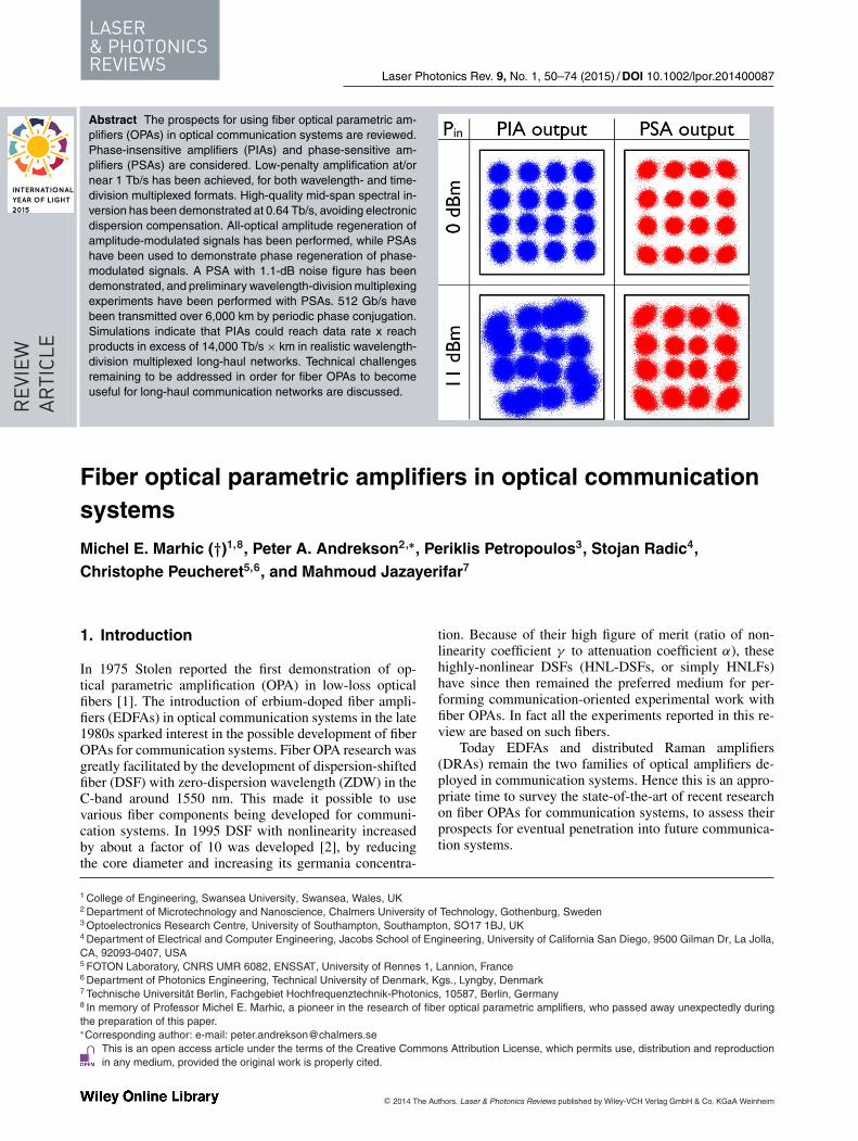
Abstract The prospects for using fiber optical parametric am-plifiers (OPAs) in optical communication systems are reviewed.Phase-insensitive amplifiers (PIAs) and phase-sensitive am-plifiers (PSAs) are considered. Low-penalty amplification at/ornear 1 Tb/s has been achieved, for both wavelength- and time-division multiplexed formats. High-quality mid-span spectral in-version has been demonstrated at 0.64 Tb/s, avoiding electronicdispersion compensation. All-optical amplitude regeneration ofamplitude-modulated signals has been performed, while PSAshave been used to demonstrate phase regeneration of phase-modulated signals. A PSA with 1.1-dB noise figure has beendemonstrated, and preliminary wavelength-division multiplexingexperiments have been performed with PSAs. 512 Gb/s havebeen transmitted over 6,000 km by periodic phase conjugation.Simulations indicate that PIAs could reach data rate x reachproducts in excess of 14,000 Tb/s × km in realistic wavelength-division multiplexed long-haul networks. Technical challengesremaining to be addressed in order for fiber OPAs to becomeuseful for long-haul communication networks are discussed.
Fiber optical parametric amplifiers in optical communicationsystems
Michel E. Marhic (†)1,8, Peter A. Andrekson2,∗, Periklis Petropoulos3, Stojan Radic4,Christophe Peucheret5,6, and Mahmoud Jazayerifar7
1. Introduction
In 1975 Stolen reported the first demonstration of op-tical parametric amplification (OPA) in low-loss opticalfibers [1]. The introduction of erbium-doped fiber ampli-fiers (EDFAs) in optical communication systems in the late1980s sparked interest in the possible development of fiberOPAs for communication systems. Fiber OPA research wasgreatly facilitated by the development of dispersion-shiftedfiber (DSF) with zero-dispersion wavelength (ZDW) in theC-band around 1550 nm. This made it possible to usevarious fiber components being developed for communi-cation systems. In 1995 DSF with nonlinearity increasedby about a factor of 10 was developed [2], by reducingthe core diameter and increasing its germania concentra-
1 College of Engineering, Swansea University, Swansea, Wales, UK2 Department of Microtechnology and Nanoscience, Chalmers University of Technology, Gothenburg, Sweden3 Optoelectronics Research Centre, University of Southampton, Southampton, SO17 1BJ, UK4 Department of Electrical and Computer Engineering, Jacobs School of Engineering, University of California San Diego, 9500 Gilman Dr, La Jolla,CA, 92093-0407, USA5 FOTON Laboratory, CNRS UMR 6082, ENSSAT, University of Rennes 1, Lannion, France6 Department of Photonics Engineering, Technical University of Denmark, Kgs., Lyngby, Denmark7 Technische Universitat Berlin, Fachgebiet Hochfrequenztechnik-Photonics, 10587, Berlin, Germany8 In memory of Professor Michel E. Marhic, a pioneer in the research of fiber optical parametric amplifiers, who passed away unexpectedly duringthe preparation of this paper.∗Corresponding author: e-mail: [email protected]
This is an open access article under the terms of the Creative Commons Attribution License, which permits use, distribution and reproductionin any medium, provided the original work is properly cited.
tion. Because of their high figure of merit (ratio of non-linearity coefficient γ to attenuation coefficient α), thesehighly-nonlinear DSFs (HNL-DSFs, or simply HNLFs)have since then remained the preferred medium for per-forming communication-oriented experimental work withfiber OPAs. In fact all the experiments reported in this re-view are based on such fibers.
Today EDFAs and distributed Raman amplifiers(DRAs) remain the two families of optical amplifiers de-ployed in communication systems. Hence this is an appro-priate time to survey the state-of-the-art of recent researchon fiber OPAs for communication systems, to assess theirprospects for eventual penetration into future communica-tion systems.
C© 2014 The Authors. Laser & Photonics Reviews published by Wiley-VCH Verlag GmbH & Co. KGaA Weinheim
REVIEWARTICLE
Laser Photonics Rev. 9, No. 1 (2015) 51
As their name indicates, fiber OPAs can in principleamplify optical communication signals. Just as EDFAs andDRAs, they can handle any modulation format, from binarymodulation (on-off keying and binary phase-shift keying) tohigh-order amplitude and phase modulation formats, suchas quadrature amplitude modulation (QAM), and amplifywavelength division multiplexed (WDM) signals. Whilethe simplest OPA designs are polarization-sensitive, theycan be modified to become polarization-insensitive. Whenoperated as phase-insensitive amplifiers (PIAs), they canhave noise figures (NF) of the order of 3 dB, similar tothose of the current amplifiers. So in principle fiber OPAscan perform the same functions as these amplifiers. How-ever, eventual substitution of fiber OPA for these amplifierswould require that they become competitive on a cost basis.
But fiber OPAs offer more than the possibility of astraightforward replacement of existing fiber amplifiers.Because they are based on significantly different physi-cal principles, they can exhibit some characteristics whichexceed those of current amplifiers, and they can also per-form useful functions, which are not currently available.Some of these functions present unique advantages thatcould potentially be exploited for boosting the capability ofoptical communication systems beyond their current limits.Specifically these distinguishing features are:
(a) Adjustable gain spectra. The shape of the optical gainspectrum is determined primarily by the fiber disper-sion properties, and it becomes wider as pump power isincreased. Bandwidths of several hundreds of nanome-ters have been demonstrated, far exceeding the typicalEDFA 35-nm bandwidth.
(b) Adjustable center frequency. Because the Kerr nonlin-earity varies only slowly with wavelength, paramet-ric gain can in principle be obtained around arbitrarypump wavelengths. This is only limited by the abilityto design and manufacture fibers with correspondingdispersion properties.
(c) Wavelength conversion. Parametric amplification isbased on four-wave mixing (FWM) associated withthe third-order Kerr nonlinear susceptibility χ (3) offibers. FWM implies that if one or two high-powercontinuous-wave (CW) pumps are used, and a weaksignal is introduced at the input, a new wave, the idler,will grow together with the signal within the OPA. Thisidler will carry the same information as the signal, andwill therefore constitute a duplicate, but at a differentfrequency. This clearly has potential applications inwavelength routing, etc.
(d) Phase conjugation. The idler also exhibits a reversalof the optical phase compared to the signal. This phe-nomenon can be exploited for compensating the effectof fiber dispersion in transmission fibers, as well as formitigating some detrimental nonlinear effects occur-ring in such fibers.
(e) Pulsed operation for signal processing. The Kerr non-linearity has a response time of just a few femtosec-onds. Thus the OPA properties can be varied at very
high rates, up to the teraherz range. Potential applica-tions are switching, sampling, format conversion, shortpulse generation, etc.
(f) 0-dB noise figure (NF). OPAs can be operated as phase-sensitive amplifiers (PSAs), which require that bothsignal and idler with equal amplitude be present at theinput, with a specific phase relationship. In theory suchdevices can exhibit an NF approaching 0 dB, i.e. about3 dB better than current amplifiers. When used forperiodic amplification in transmission links consistingof lossy fibers, degenerate (non-degenerate) fiber OPAscan exhibit a 3 (6) dB advantage in system noise figure,compared to EDFA-based systems [3,4], This remark-able improvement could be exploited for increasingthe transmission range, to accommodate higher-ordermodulation formats, etc.
In this paper we review recent progress in the field offiber OPAs, which could have a significant impact on futureoptical communication systems. In Section 2 we review thebasic physical principles of fiber OPAs, and their uniqueattributes which distinguish them from EDFAs and DRAs.In Section 3 we present two signal processing applications:Time domain demultiplexing, and all-optical amplitude andphase regeneration. In Section 4 we describe the use ofOPAs for broadband and phase-sensitive amplification. InSection 5 we discuss technical issues that limit the cur-rent performance of OPAs, and desirable developments formaking further progress. We conclude in Section 6 by com-menting on the progress achieved to date, and discussingprospects for a possible future role for OPAs in opticalcommunication systems.
2. Review of fiber OPAs
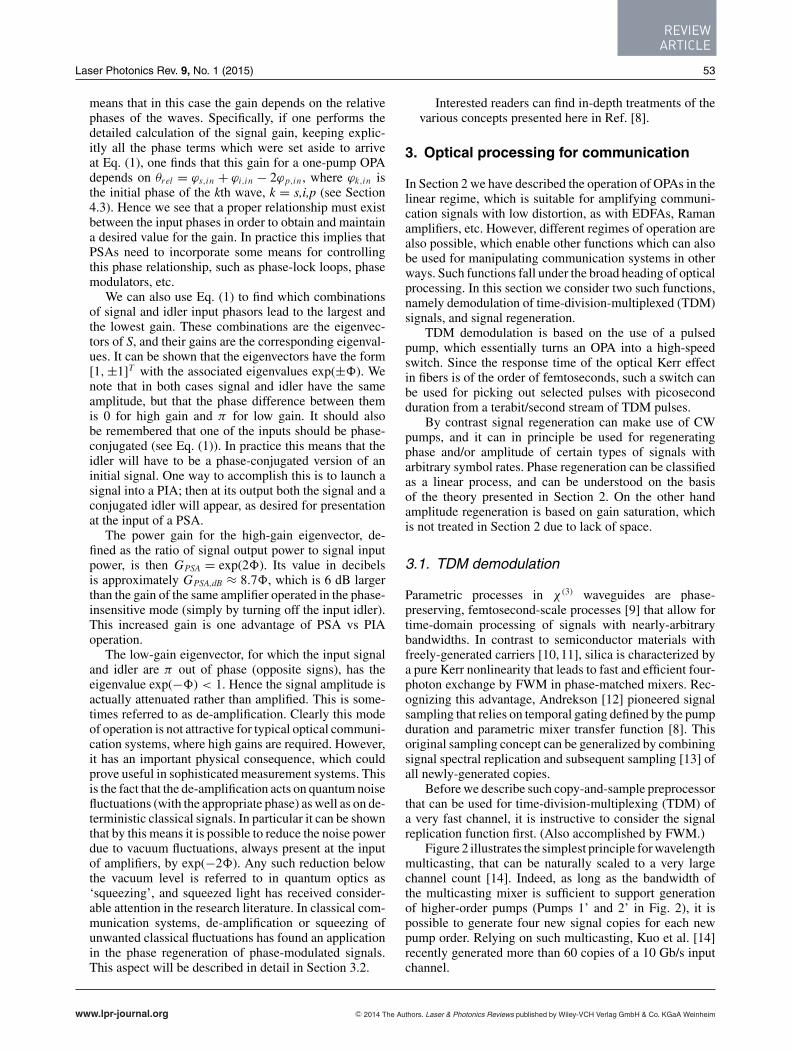
Fiber OPAs are based on the third-order Kerr nonlinearityof optical fibers. The fiber nonlinearity coefficient γ is ofthe order of 10 W−1km−1 for silica-based HNLFs. One ortwo high-power waves at the angular frequencies ωp1 andωp2 serve as pumps. If a weak signal at ωs is injected at theinput, co-propagating with the pumps, it generates a newwave at ωi which grows along with it. The idler spectrum is amirror image of that of the signal with respect to the centerfrequency ωc = (ωp1+ωp2)/2 (which is halfway betweenthe pumps); this means that ωs+ωi = 2ωc. The spectrumof the idler is inverted, and it is complex-conjugated. Thisis illustrated in Figs. 1(a) and 1(b) which show the two-and one-pump cases, respectively. The signal consists ofa carrier represented by an arrow, and a single-sidebandmodulation spectrum represented by a triangle on the high-frequency side. The spectral shape of the idler is a faithfulreplica of that of the signal, with the addition of a mirrorreflection, which corresponds to spectral inversion.
The most general mode of operation of an OPA is whenboth signal and idler are present at the input, possibly withdifferent amplitudes. We let the indices s(i) denote the sig-nal(idler). In a lossless fiber (power attenuation coefficientα = 0) the relationship between the two input fields Ak,in
www.lpr-journal.org C© 2014 The Authors. Laser & Photonics Reviews published by Wiley-VCH Verlag GmbH & Co. KGaA Weinheim
LASER& PHOTONICSREVIEWS
52 M. E. Marhic et al.: Fiber OPAs
Figure 1 Sketches of the output spectra of fiber OPAs. (a) two-pump version; (b) one-pump version.
and output fields Ak,out , k = s,i, of such an OPA can beexpressed as
[As,out
A∗i,out
]= S
[As,in
A∗i,in
],
where S =[
cosh(δ) sinh(δ)sinh(δ) cosh(δ)
]=
[c ss c
](1)
is the transfer matrix, and * represents complex conjuga-tion. (To obtain this form it is necessary to introduce suit-able phase shifts in the inputs and outputs.) c and s satisfyc2 − s2 = 1 and c ± s = e±δ . δ is given by
δ = sinh−1
[γ P0
gsinh(gL)
](2)
It is a function of the OPA parameters, which are: thefiber nonlinearity coefficient γ ; the fiber length L; the totalpump power P0 (in the case of two pumps, we assume thatthey have equal powers P0/2); the small-signal paramet-ric gain coefficient g, given by g2 = (γ P0)2 − (κ/2)2; thetotal wavevector mismatch κ given by κ = �β + γ P0 fortwo pumps and by κ = �β + 2γ P0 for one pump; �β =β(ωs) + β(ωi ) − β(ωp1) − β(ωp2) is the linear wavevec-tor mismatch, which depends only on the fiber dispersionproperties and the frequencies of the four waves; β(ω) isthe wavevector at the frequency ω.
When κ = 0, which corresponds to an ideal balance be-tween linear and nonlinear phase-mismatch terms, the gaincoefficient g has the maximal value γ P0, and δ has themaximal value = γ P0L . This is generally a desirableoperating point, which can often be achieved in practiceby choosing the frequencies so as to adjust �β. In opticalcommunication we often seek to obtain nearly-maximumgain over as large a bandwidth as possible, and the de-sign of suitable gain spectra is heavily influenced by thedispersion properties of the fiber used. In particular it is
necessary to operate with ωc close to the zero-dispersionwavelength (ZDW), where the chromatic dispersion D van-ishes, i.e. to have β(2)(ωc) ≈ 0, where β(n)(ω) denotes thenth derivative of β(ω). Then the fourth-order dispersion co-efficient β(4)(ωc) determines how wide the gain spectrumcan be. It can be shown that for a well-optimized design,the bandwidth scales like [γ P0/β
(4)(ωc)]1/4[5]. This showsthe importance of having a fiber with a low β(4)(ωc) anda large γ . We also see that using a high pump power willincrease the bandwidth. Experiments with CW pumps inthe C-band routinely lead to bandwidths of several tensof nanometers, and several hundred nanometers have alsobeen demonstrated with low-β(4) fibers.
Most fiber OPA work uses one of two following mainmodes of operation:
(i) Phase-insensitive amplifier (PIA).In this case the only waves injected at the input are thepump(s) and the signal. The only input electromagneticfield at the idler frequency is that due to vacuum fluctua-tions, which contribute to OPA noise. In this case it canbe shown that the OPA gain is independent of the relativephase of the signal with respect to the pump(s). For thisreason, this is referred to as a phase-insensitive amplifier(PIA). In this mode, a parametric PIA operates very muchlike an EDFA (which is of course phase-insensitive).
For a well-optimized PIA the signal power gain, de-fined as the ratio of signal output power to signal inputpower, is equal to GPIA = c2 = cosh2(), and when itis large its value in decibels is well approximated byGPIA,dB ≈ 8.7 − 6. It is a fairly simple matter to ob-tain experimentally gains of tens of dBs. For example, if = 3, the maximum gain is approximately 20 dB; thiscould be achieved with a 1-km long DSF with γ ≈ 2W−1 km−1, and a 1-W pump, or equivalently with a100-m long HNL-DSF with γ ≈ 20 W−1 km−1, and thesame pump power. The record gain for one-pump CWoperation is 70 dB [6].
We can calculate the NF of a PIA in a semi-classicalmanner, as follows [7]. We assume that the input sig-nal is in a coherent state (CS), while the idler is in avacuum state (VS). A property of CSs is that they haveexactly the same level of quantum fluctuations as a VS(this is because a VS is a CS with zero mean field). If theinput VS did not contribute to the output signal noise,the optical signal-to-noise ratio (OSNR) of the signalwould not be degraded and the NF would be 0 dB. How-ever, the input VS introduces the same level of noiseat the output as the signal itself, and therefore the NF ofthe PIA is multiplied by 2 (3 dB). We note that this isthe same as for an EDFA. (Of course in practice NFs aregenerally somewhat higher due to inevitable losses andother practical considerations.)
(ii) Phase-sensitive amplifier (PSA).In this case the conditions at the input are the same asfor PIA, with the crucial difference that now an addi-tional finite-amplitude wave is introduced at the idlerfrequency. In general, signal and idler input amplitudesare about the same. The name ‘phase-sensitive amplifier’
C© 2014 The Authors. Laser & Photonics Reviews published by Wiley-VCH Verlag GmbH & Co. KGaA Weinheim www.lpr-journal.org
REVIEWARTICLE
Laser Photonics Rev. 9, No. 1 (2015) 53
means that in this case the gain depends on the relativephases of the waves. Specifically, if one performs thedetailed calculation of the signal gain, keeping explic-itly all the phase terms which were set aside to arriveat Eq. (1), one finds that this gain for a one-pump OPAdepends on θrel = ϕs,in + ϕi,in − 2ϕp,in , where ϕk,in isthe initial phase of the kth wave, k = s,i,p (see Section4.3). Hence we see that a proper relationship must existbetween the input phases in order to obtain and maintaina desired value for the gain. In practice this implies thatPSAs need to incorporate some means for controllingthis phase relationship, such as phase-lock loops, phasemodulators, etc.
We can also use Eq. (1) to find which combinationsof signal and idler input phasors lead to the largest andthe lowest gain. These combinations are the eigenvec-tors of S, and their gains are the corresponding eigenval-ues. It can be shown that the eigenvectors have the form[1,±1]T with the associated eigenvalues exp(±). Wenote that in both cases signal and idler have the sameamplitude, but that the phase difference between themis 0 for high gain and π for low gain. It should alsobe remembered that one of the inputs should be phase-conjugated (see Eq. (1)). In practice this means that theidler will have to be a phase-conjugated version of aninitial signal. One way to accomplish this is to launch asignal into a PIA; then at its output both the signal and aconjugated idler will appear, as desired for presentationat the input of a PSA.
The power gain for the high-gain eigenvector, de-fined as the ratio of signal output power to signal inputpower, is then GPSA = exp(2). Its value in decibelsis approximately GPSA,dB ≈ 8.7, which is 6 dB largerthan the gain of the same amplifier operated in the phase-insensitive mode (simply by turning off the input idler).This increased gain is one advantage of PSA vs PIAoperation.
The low-gain eigenvector, for which the input signaland idler are π out of phase (opposite signs), has theeigenvalue exp(−) < 1. Hence the signal amplitude isactually attenuated rather than amplified. This is some-times referred to as de-amplification. Clearly this modeof operation is not attractive for typical optical communi-cation systems, where high gains are required. However,it has an important physical consequence, which couldprove useful in sophisticated measurement systems. Thisis the fact that the de-amplification acts on quantum noisefluctuations (with the appropriate phase) as well as on de-terministic classical signals. In particular it can be shownthat by this means it is possible to reduce the noise powerdue to vacuum fluctuations, always present at the inputof amplifiers, by exp(−2). Any such reduction belowthe vacuum level is referred to in quantum optics as‘squeezing’, and squeezed light has received consider-able attention in the research literature. In classical com-munication systems, de-amplification or squeezing ofunwanted classical fluctuations has found an applicationin the phase regeneration of phase-modulated signals.This aspect will be described in detail in Section 3.2.
Interested readers can find in-depth treatments of thevarious concepts presented here in Ref. [8].
3. Optical processing for communication
In Section 2 we have described the operation of OPAs in thelinear regime, which is suitable for amplifying communi-cation signals with low distortion, as with EDFAs, Ramanamplifiers, etc. However, different regimes of operation arealso possible, which enable other functions which can alsobe used for manipulating communication systems in otherways. Such functions fall under the broad heading of opticalprocessing. In this section we consider two such functions,namely demodulation of time-division-multiplexed (TDM)signals, and signal regeneration.
TDM demodulation is based on the use of a pulsedpump, which essentially turns an OPA into a high-speedswitch. Since the response time of the optical Kerr effectin fibers is of the order of femtoseconds, such a switch canbe used for picking out selected pulses with picosecondduration from a terabit/second stream of TDM pulses.
By contrast signal regeneration can make use of CWpumps, and it can in principle be used for regeneratingphase and/or amplitude of certain types of signals witharbitrary symbol rates. Phase regeneration can be classifiedas a linear process, and can be understood on the basisof the theory presented in Section 2. On the other handamplitude regeneration is based on gain saturation, whichis not treated in Section 2 due to lack of space.
3.1. TDM demodulation
Parametric processes in χ (3) waveguides are phase-preserving, femtosecond-scale processes [9] that allow fortime-domain processing of signals with nearly-arbitrarybandwidths. In contrast to semiconductor materials withfreely-generated carriers [10,11], silica is characterized bya pure Kerr nonlinearity that leads to fast and efficient four-photon exchange by FWM in phase-matched mixers. Rec-ognizing this advantage, Andrekson [12] pioneered signalsampling that relies on temporal gating defined by the pumpduration and parametric mixer transfer function [8]. Thisoriginal sampling concept can be generalized by combiningsignal spectral replication and subsequent sampling [13] ofall newly-generated copies.
Before we describe such copy-and-sample preprocessorthat can be used for time-division-multiplexing (TDM) ofa very fast channel, it is instructive to consider the signalreplication function first. (Also accomplished by FWM.)
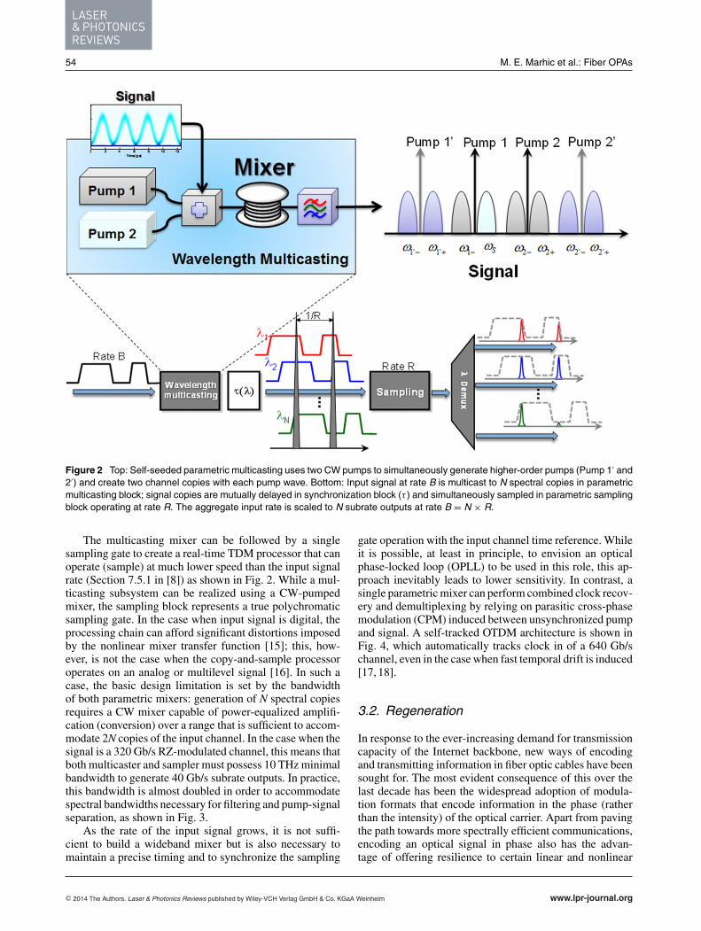
Figure 2 illustrates the simplest principle for wavelengthmulticasting, that can be naturally scaled to a very largechannel count [14]. Indeed, as long as the bandwidth ofthe multicasting mixer is sufficient to support generationof higher-order pumps (Pumps 1’ and 2’ in Fig. 2), it ispossible to generate four new signal copies for each newpump order. Relying on such multicasting, Kuo et al. [14]recently generated more than 60 copies of a 10 Gb/s inputchannel.
www.lpr-journal.org C© 2014 The Authors. Laser & Photonics Reviews published by Wiley-VCH Verlag GmbH & Co. KGaA Weinheim
LASER& PHOTONICSREVIEWS
54 M. E. Marhic et al.: Fiber OPAs
Figure 2 Top: Self-seeded parametric multicasting uses two CW pumps to simultaneously generate higher-order pumps (Pump 1′ and2′) and create two channel copies with each pump wave. Bottom: Input signal at rate B is multicast to N spectral copies in parametricmulticasting block; signal copies are mutually delayed in synchronization block (τ ) and simultaneously sampled in parametric samplingblock operating at rate R. The aggregate input rate is scaled to N subrate outputs at rate B = N × R.
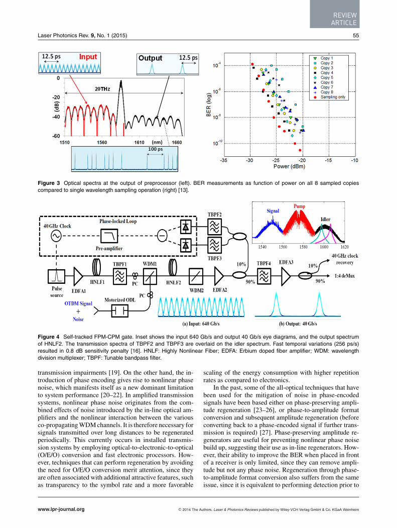
The multicasting mixer can be followed by a singlesampling gate to create a real-time TDM processor that canoperate (sample) at much lower speed than the input signalrate (Section 7.5.1 in [8]) as shown in Fig. 2. While a mul-ticasting subsystem can be realized using a CW-pumpedmixer, the sampling block represents a true polychromaticsampling gate. In the case when input signal is digital, theprocessing chain can afford significant distortions imposedby the nonlinear mixer transfer function [15]; this, how-ever, is not the case when the copy-and-sample processoroperates on an analog or multilevel signal [16]. In such acase, the basic design limitation is set by the bandwidthof both parametric mixers: generation of N spectral copiesrequires a CW mixer capable of power-equalized amplifi-cation (conversion) over a range that is sufficient to accom-modate 2N copies of the input channel. In the case when thesignal is a 320 Gb/s RZ-modulated channel, this means thatboth multicaster and sampler must possess 10 THz minimalbandwidth to generate 40 Gb/s subrate outputs. In practice,this bandwidth is almost doubled in order to accommodatespectral bandwidths necessary for filtering and pump-signalseparation, as shown in Fig. 3.
As the rate of the input signal grows, it is not suffi-cient to build a wideband mixer but is also necessary tomaintain a precise timing and to synchronize the sampling
gate operation with the input channel time reference. Whileit is possible, at least in principle, to envision an opticalphase-locked loop (OPLL) to be used in this role, this ap-proach inevitably leads to lower sensitivity. In contrast, asingle parametric mixer can perform combined clock recov-ery and demultiplexing by relying on parasitic cross-phasemodulation (CPM) induced between unsynchronized pumpand signal. A self-tracked OTDM architecture is shown inFig. 4, which automatically tracks clock in of a 640 Gb/schannel, even in the case when fast temporal drift is induced[17, 18].
3.2. Regeneration
In response to the ever-increasing demand for transmissioncapacity of the Internet backbone, new ways of encodingand transmitting information in fiber optic cables have beensought for. The most evident consequence of this over thelast decade has been the widespread adoption of modula-tion formats that encode information in the phase (ratherthan the intensity) of the optical carrier. Apart from pavingthe path towards more spectrally efficient communications,encoding an optical signal in phase also has the advan-tage of offering resilience to certain linear and nonlinear
C© 2014 The Authors. Laser & Photonics Reviews published by Wiley-VCH Verlag GmbH & Co. KGaA Weinheim www.lpr-journal.org
REVIEWARTICLE
Laser Photonics Rev. 9, No. 1 (2015) 55
Figure 3 Optical spectra at the output of preprocessor (left). BER measurements as function of power on all 8 sampled copiescompared to single wavelength sampling operation (right) [13].
Figure 4 Self-tracked FPM-CPM gate. Inset shows the input 640 Gb/s and output 40 Gb/s eye diagrams, and the output spectrumof HNLF2. The transmission spectra of TBPF2 and TBPF3 are overlaid on the idler spectrum. Fast temporal variations (256 ps/s)resulted in 0.8 dB sensitivity penalty [16]. HNLF: Highly Nonlinear Fiber; EDFA: Erbium doped fiber amplifier; WDM: wavelengthdivision multiplexer; TBPF: Tunable bandpass filter.
transmission impairments [19]. On the other hand, the in-troduction of phase encoding gives rise to nonlinear phasenoise, which manifests itself as a new dominant limitationto system performance [20–22]. In amplified transmissionsystems, nonlinear phase noise originates from the com-bined effects of noise introduced by the in-line optical am-plifiers and the nonlinear interaction between the variousco-propagating WDM channels. It is therefore necessary forsignals transmitted over long distances to be regeneratedperiodically. This currently occurs in installed transmis-sion systems by employing optical-to-electronic-to-optical(O/E/O) conversion and fast electronic processors. How-ever, techniques that can perform regeneration by avoidingthe need for O/E/O conversion merit attention, since theyare often associated with additional attractive features, suchas transparency to the symbol rate and a more favorable
scaling of the energy consumption with higher repetitionrates as compared to electronics.
In the past, some of the all-optical techniques that havebeen used for the mitigation of noise in phase-encodedsignals have been based either on phase-preserving ampli-tude regeneration [23–26], or phase-to-amplitude formatconversion and subsequent amplitude regeneration (beforeconverting back to a phase-encoded signal if further trans-mission is required) [27]. Phase-preserving amplitude re-generators are useful for preventing nonlinear phase noisebuild up, suggesting their use as in-line regenerators. How-ever, their ability to improve the BER when placed in frontof a receiver is only limited, since they can remove ampli-tude but not any phase noise. Regeneration through phase-to-amplitude format conversion also suffers from the sameissue, since it is equivalent to performing detection prior to
www.lpr-journal.org C© 2014 The Authors. Laser & Photonics Reviews published by Wiley-VCH Verlag GmbH & Co. KGaA Weinheim

LASER& PHOTONICSREVIEWS
56 M. E. Marhic et al.: Fiber OPAs
Figure 5 A comparison between phase-insensitive (a) and phase-sensitive amplification (b), as depicted in the complex plane.
regeneration [28]. In addition, because this scheme oper-ates on the intensity rather than directly on the electric fieldof the demodulated signal, it may have a lower tolerance tophase noise.
Counter to the aforementioned approaches, an imple-mentation based on phase-sensitive amplification alleviatesthese issues, since it operates directly on the phase. In or-der to understand how a PSA can regenerate the phase ofthe optical carrier, it is useful to refer to the diagrams pre-sented in Fig. 5. In a PIA, such as an EDFA (Fig. 5a),the in-phase and quadrature signal components experienceidentical gain, and as a result the field amplitude is amplifiedwith its phase unaffected. In a PSA on the other hand, thetwo quadrature components experience a different amountof gain (Fig. 5b). For example, in a PSA based on degener-ate FWM [29], the in-phase component of the electric fieldexperiences gain G, while the quadrature component is de-amplified by 1/G. Consequently, the output phase of the am-plified signal is more closely aligned towards the amplifier’sin-phase axis, as shown in Fig. 5b. This phase modificationeffect, known as ‘phase squeezing’, is inherently suitablefor the regeneration of binary phase-encoded signals, as the‘phase-squeezed’ data bits are forced to adopt a phase ofeither 0 or π , thus restoring the fidelity of the signal prior totransmission. However, Fig. 5b also shows that a side-effectof the PSA action is the introduction of unwanted amplitudevariations; the larger the phase error the PSA corrects for,the larger the amplitude variations at its output. This canbe avoided by operating the PSA in saturation. Then anyamplitude noise present in the phase-encoded signal canalso be reduced, thereby enabling simultaneous phase andamplitude regeneration.
We also note that when a two-pump PSA is driven intosaturation, higher-order sidebands are generated by FWM,and these can be exploited to improve the extinction ratioof phase regeneration [30].
The implementation of a PSA based on parametric pro-cesses has its own challenges: In order to achieve phase-
sensitive amplification, the phase relationship between thePSA pump(s), signal and any idlers present needs to bemaintained, that is all the waves participating in the para-metric process need to be phase-locked [31]. This is chal-lenging in practice due to two main reasons: (i) phase-encoded signals often have the carrier field suppressed (i.e.they are ‘carrier-less’) and (ii) even if the carrier were ex-tractable, it would generally contain a part of the phase andamplitude noise of the transmitted data. Proof-of-principlePSA demonstrations have overcome this problem by ensur-ing that both the signal and the pump(s) originate from acommon laser source, e.g. through the generation of an opti-cal frequency comb. This would not be possible in a systemconsidered for a real transmission link, in which case anypumps would have to be generated locally in the regenerat-ing node, i.e. they would have to be truly independent fromthe data signal.
An additional challenge, which is nevertheless commonin several OPA configurations, is that strong CW signalsneed to be used as the PSA pumps. When the nonlinearelement used for the implementation of the PSA is an opticalfiber (which is arguably the most mature technology for theobservation of this type of nonlinear effects today), a stronglimitation to the amount of power that can be launched to thefiber is determined by the onset of any stimulated Brillouinscattering (SBS) effects. Typically, this issue is tackled byphase-dithering the CW pump with a frequency spectrumthat is broader than the SBS gain bandwidth. However, thistechnique can obviously not be directly applied in a PSA,since it would disturb the phase relationship between thevarious waves.
In the remaining part of this section and through thedescription of the experimental demonstration of a PSA-based phase and amplitude regenerator for binary phase-shift keyed (BPSK) signals [28, 32], we will show howthese challenges can be overcome to result in a regener-ating system suitable for use in transmission links. Subse-quently, we will show how this basic operating principle can
C© 2014 The Authors. Laser & Photonics Reviews published by Wiley-VCH Verlag GmbH & Co. KGaA Weinheim www.lpr-journal.org
REVIEWARTICLE
Laser Photonics Rev. 9, No. 1 (2015) 57
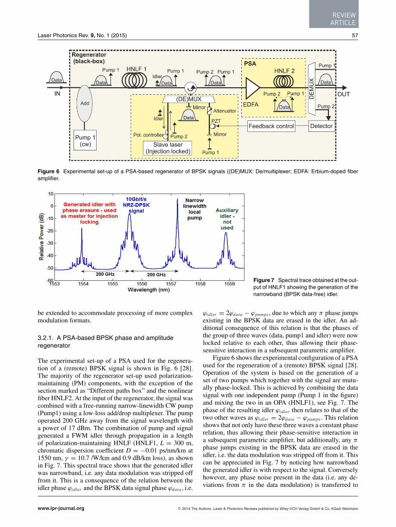
Figure 6 Experimental set-up of a PSA-based regenerator of BPSK signals ((DE)MUX: De/multiplexer; EDFA: Erbium-doped fiberamplifier.
Figure 7 Spectral trace obtained at the out-put of HNLF1 showing the generation of thenarrowband (BPSK data-free) idler.
be extended to accommodate processing of more complexmodulation formats.
3.2.1. A PSA-based BPSK phase and amplituderegenerator
The experimental set-up of a PSA used for the regenera-tion of a (remote) BPSK signal is shown in Fig. 6 [28].The majority of the regenerator set-up used polarization-maintaining (PM) components, with the exception of thesection marked as “Different paths box” and the nonlinearfiber HNLF2. At the input of the regenerator, the signal wascombined with a free-running narrow-linewidth CW pump(Pump1) using a low-loss add/drop multiplexer. The pumpoperated 200 GHz away from the signal wavelength witha power of 17 dBm. The combination of pump and signalgenerated a FWM idler through propagation in a lengthof polarization-maintaining HNLF (HNLF1, L = 300 m,chromatic dispersion coefficient D = −0.01 ps/nm/km at1550 nm, γ = 10.7 /W/km and 0.9 dB/km loss), as shownin Fig. 7. This spectral trace shows that the generated idlerwas narrowband, i.e. any data modulation was stripped offfrom it. This is a consequence of the relation between theidler phase ϕidler and the BPSK data signal phase ϕdata , i.e.
ϕidler = 2ϕdata − ϕpumps , due to which any π phase jumpsexisting in the BPSK data are erased in the idler. An ad-ditional consequence of this relation is that the phases ofthe group of three waves (data, pump1 and idler) were nowlocked relative to each other, thus allowing their phase-sensitive interaction in a subsequent parametric amplifier.
Figure 6 shows the experimental configuration of a PSAused for the regeneration of a (remote) BPSK signal [28].Operation of the system is based on the generation of aset of two pumps which together with the signal are mutu-ally phase-locked. This is achieved by combining the datasignal with one independent pump (Pump 1 in the figure)and mixing the two in an OPA (HNLF1), see Fig. 7. Thephase of the resulting idler ϕidler then relates to that of thetwo other waves as ϕidler = 2ϕdata − ϕpumps . This relationshows that not only have these three waves a constant phaserelation, thus allowing their phase-sensitive interaction ina subsequent parametric amplifier, but additionally, any π
phase jumps existing in the BPSK data are erased in theidler, i.e. the data modulation was stripped off from it. Thiscan be appreciated in Fig. 7 by noticing how narrowbandthe generated idler is with respect to the signal. Converselyhowever, any phase noise present in the data (i.e. any de-viations from π in the data modulation) is transferred to
www.lpr-journal.org C© 2014 The Authors. Laser & Photonics Reviews published by Wiley-VCH Verlag GmbH & Co. KGaA Weinheim
LASER& PHOTONICSREVIEWS
58 M. E. Marhic et al.: Fiber OPAs
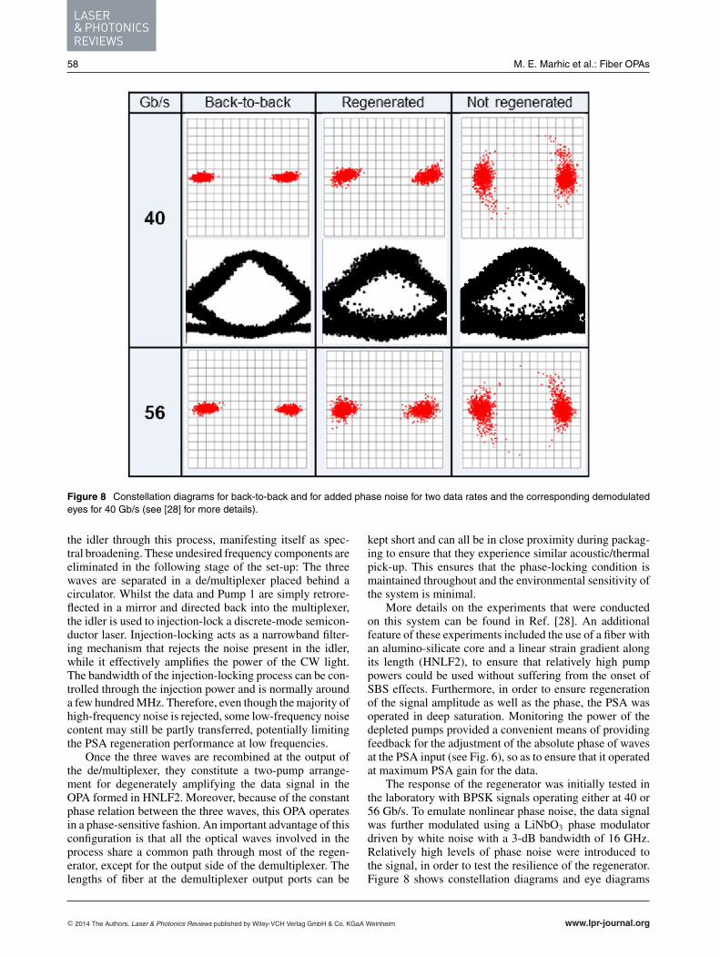
Figure 8 Constellation diagrams for back-to-back and for added phase noise for two data rates and the corresponding demodulatedeyes for 40 Gb/s (see [28] for more details).
the idler through this process, manifesting itself as spec-tral broadening. These undesired frequency components areeliminated in the following stage of the set-up: The threewaves are separated in a de/multiplexer placed behind acirculator. Whilst the data and Pump 1 are simply retrore-flected in a mirror and directed back into the multiplexer,the idler is used to injection-lock a discrete-mode semicon-ductor laser. Injection-locking acts as a narrowband filter-ing mechanism that rejects the noise present in the idler,while it effectively amplifies the power of the CW light.The bandwidth of the injection-locking process can be con-trolled through the injection power and is normally arounda few hundred MHz. Therefore, even though the majority ofhigh-frequency noise is rejected, some low-frequency noisecontent may still be partly transferred, potentially limitingthe PSA regeneration performance at low frequencies.
Once the three waves are recombined at the output ofthe de/multiplexer, they constitute a two-pump arrange-ment for degenerately amplifying the data signal in theOPA formed in HNLF2. Moreover, because of the constantphase relation between the three waves, this OPA operatesin a phase-sensitive fashion. An important advantage of thisconfiguration is that all the optical waves involved in theprocess share a common path through most of the regen-erator, except for the output side of the demultiplexer. Thelengths of fiber at the demultiplexer output ports can be
kept short and can all be in close proximity during packag-ing to ensure that they experience similar acoustic/thermalpick-up. This ensures that the phase-locking condition ismaintained throughout and the environmental sensitivity ofthe system is minimal.
More details on the experiments that were conductedon this system can be found in Ref. [28]. An additionalfeature of these experiments included the use of a fiber withan alumino-silicate core and a linear strain gradient alongits length (HNLF2), to ensure that relatively high pumppowers could be used without suffering from the onset ofSBS effects. Furthermore, in order to ensure regenerationof the signal amplitude as well as the phase, the PSA wasoperated in deep saturation. Monitoring the power of thedepleted pumps provided a convenient means of providingfeedback for the adjustment of the absolute phase of wavesat the PSA input (see Fig. 6), so as to ensure that it operatedat maximum PSA gain for the data.
The response of the regenerator was initially tested inthe laboratory with BPSK signals operating either at 40 or56 Gb/s. To emulate nonlinear phase noise, the data signalwas further modulated using a LiNbO3 phase modulatordriven by white noise with a 3-dB bandwidth of 16 GHz.Relatively high levels of phase noise were introduced tothe signal, in order to test the resilience of the regenerator.Figure 8 shows constellation diagrams and eye diagrams
C© 2014 The Authors. Laser & Photonics Reviews published by Wiley-VCH Verlag GmbH & Co. KGaA Weinheim www.lpr-journal.org
REVIEWARTICLE
Laser Photonics Rev. 9, No. 1 (2015) 59
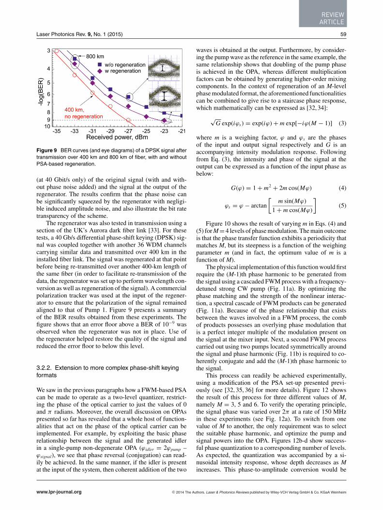
Figure 9 BER curves (and eye diagrams) of a DPSK signal aftertransmission over 400 km and 800 km of fiber, with and withoutPSA-based regeneration.
(at 40 Gbit/s only) of the original signal (with and with-out phase noise added) and the signal at the output of theregenerator. The results confirm that the phase noise canbe significantly squeezed by the regenerator with negligi-ble induced amplitude noise, and also illustrate the bit ratetransparency of the scheme.
The regenerator was also tested in transmission using asection of the UK’s Aurora dark fiber link [33]. For thesetests, a 40 Gb/s differential phase-shift keying (DPSK) sig-nal was coupled together with another 36 WDM channelscarrying similar data and transmitted over 400 km in theinstalled fiber link. The signal was regenerated at that pointbefore being re-transmitted over another 400-km length ofthe same fiber (in order to facilitate re-transmission of thedata, the regenerator was set up to perform wavelength con-version as well as regeneration of the signal). A commercialpolarization tracker was used at the input of the regener-ator to ensure that the polarization of the signal remainedaligned to that of Pump 1. Figure 9 presents a summaryof the BER results obtained from these experiments. Thefigure shows that an error floor above a BER of 10−9 wasobserved when the regenerator was not in place. Use ofthe regenerator helped restore the quality of the signal andreduced the error floor to below this level.
3.2.2. Extension to more complex phase-shift keyingformats
We saw in the previous paragraphs how a FWM-based PSAcan be made to operate as a two-level quantizer, restrict-ing the phase of the optical carrier to just the values of 0and π radians. Moreover, the overall discussion on OPAspresented so far has revealed that a whole host of function-alities that act on the phase of the optical carrier can beimplemented. For example, by exploiting the basic phaserelationship between the signal and the generated idlerin a single-pump non-degenerate OPA (ϕidler = 2ϕpump –ϕsignal), we see that phase reversal (conjugation) can read-ily be achieved. In the same manner, if the idler is presentat the input of the system, then coherent addition of the two
waves is obtained at the output. Furthermore, by consider-ing the pump wave as the reference in the same example, thesame relationship shows that doubling of the pump phaseis achieved in the OPA, whereas different multiplicationfactors can be obtained by generating higher-order mixingcomponents. In the context of regeneration of an M-levelphase modulated format, the aforementioned functionalitiescan be combined to give rise to a staircase phase response,which mathematically can be expressed as [32, 34]:
√G exp(iϕs) = exp(iϕ) + m exp[−iϕ(M − 1)] (3)
where m is a weighing factor, ϕ and ϕs are the phasesof the input and output signal respectively and G is anaccompanying intensity modulation response. Followingfrom Eq. (3), the intensity and phase of the signal at theoutput can be expressed as a function of the input phase asbelow:
G(ϕ) = 1 + m2 + 2m cos(Mϕ) (4)
ϕs = ϕ − arctan
[m sin(Mϕ)
1 + m cos(Mϕ)
](5)
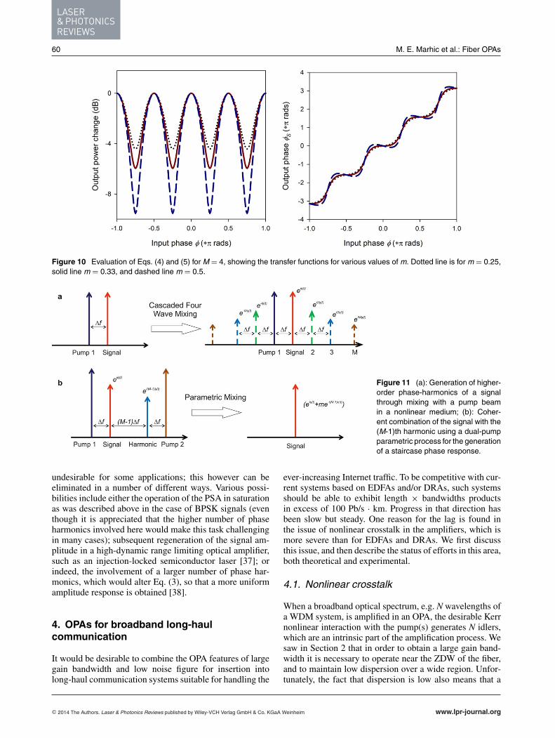
Figure 10 shows the result of varying m in Eqs. (4) and(5) for M = 4 levels of phase modulation. The main outcomeis that the phase transfer function exhibits a periodicity thatmatches M, but its steepness is a function of the weighingparameter m (and in fact, the optimum value of m is afunction of M).
The physical implementation of this function would firstrequire the (M-1)th phase harmonic to be generated fromthe signal using a cascaded FWM process with a frequency-detuned strong CW pump (Fig. 11a). By optimizing thephase matching and the strength of the nonlinear interac-tion, a spectral cascade of FWM products can be generated(Fig. 11a). Because of the phase relationship that existsbetween the waves involved in a FWM process, the combof products possesses an overlying phase modulation thatis a perfect integer multiple of the modulation present onthe signal at the mixer input. Next, a second FWM processcarried out using two pumps located symmetrically aroundthe signal and phase harmonic (Fig. 11b) is required to co-herently conjugate and add the (M-1)th phase harmonic tothe signal.
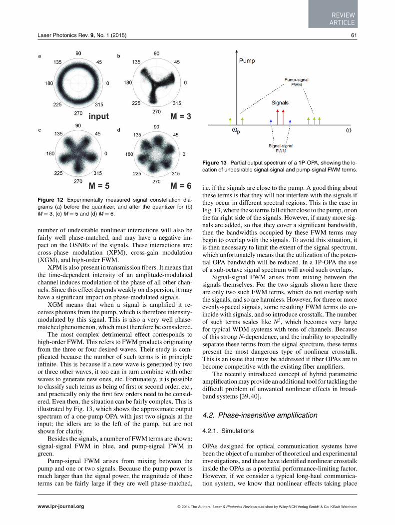
This process can readily be achieved experimentally,using a modification of the PSA set-up presented previ-ously (see [32, 35, 36] for more details). Figure 12 showsthe result of this process for three different values of M,namely M = 3, 5 and 6. To verify the operating principle,the signal phase was varied over 2π at a rate of 150 MHzin these experiments (see Fig. 12a). To switch from onevalue of M to another, the only requirement was to selectthe suitable phase harmonic, and optimize the pump andsignal powers into the OPA. Figures 12b-d show success-ful phase quantization to a corresponding number of levels.As expected, the quantization was accompanied by a si-nusoidal intensity response, whose depth decreases as Mincreases. This phase-to-amplitude conversion would be
www.lpr-journal.org C© 2014 The Authors. Laser & Photonics Reviews published by Wiley-VCH Verlag GmbH & Co. KGaA Weinheim
LASER& PHOTONICSREVIEWS
60 M. E. Marhic et al.: Fiber OPAs
Figure 10 Evaluation of Eqs. (4) and (5) for M = 4, showing the transfer functions for various values of m. Dotted line is for m = 0.25,solid line m = 0.33, and dashed line m = 0.5.
Figure 11 (a): Generation of higher-order phase-harmonics of a signalthrough mixing with a pump beamin a nonlinear medium; (b): Coher-ent combination of the signal with the(M-1)th harmonic using a dual-pumpparametric process for the generationof a staircase phase response.
undesirable for some applications; this however can beeliminated in a number of different ways. Various possi-bilities include either the operation of the PSA in saturationas was described above in the case of BPSK signals (eventhough it is appreciated that the higher number of phaseharmonics involved here would make this task challengingin many cases); subsequent regeneration of the signal am-plitude in a high-dynamic range limiting optical amplifier,such as an injection-locked semiconductor laser [37]; orindeed, the involvement of a larger number of phase har-monics, which would alter Eq. (3), so that a more uniformamplitude response is obtained [38].
4. OPAs for broadband long-haulcommunication
It would be desirable to combine the OPA features of largegain bandwidth and low noise figure for insertion intolong-haul communication systems suitable for handling the
ever-increasing Internet traffic. To be competitive with cur-rent systems based on EDFAs and/or DRAs, such systemsshould be able to exhibit length × bandwidths productsin excess of 100 Pb/s · km. Progress in that direction hasbeen slow but steady. One reason for the lag is found inthe issue of nonlinear crosstalk in the amplifiers, which ismore severe than for EDFAs and DRAs. We first discussthis issue, and then describe the status of efforts in this area,both theoretical and experimental.
4.1. Nonlinear crosstalk
When a broadband optical spectrum, e.g. N wavelengths ofa WDM system, is amplified in an OPA, the desirable Kerrnonlinear interaction with the pump(s) generates N idlers,which are an intrinsic part of the amplification process. Wesaw in Section 2 that in order to obtain a large gain band-width it is necessary to operate near the ZDW of the fiber,and to maintain low dispersion over a wide region. Unfor-tunately, the fact that dispersion is low also means that a
C© 2014 The Authors. Laser & Photonics Reviews published by Wiley-VCH Verlag GmbH & Co. KGaA Weinheim www.lpr-journal.org
REVIEWARTICLE
Laser Photonics Rev. 9, No. 1 (2015) 61
Figure 12 Experimentally measured signal constellation dia-grams (a) before the quantizer, and after the quantizer for (b)M = 3, (c) M = 5 and (d) M = 6.
number of undesirable nonlinear interactions will also befairly well phase-matched, and may have a negative im-pact on the OSNRs of the signals. These interactions are:cross-phase modulation (XPM), cross-gain modulation(XGM), and high-order FWM.
XPM is also present in transmission fibers. It means thatthe time-dependent intensity of an amplitude-modulatedchannel induces modulation of the phase of all other chan-nels. Since this effect depends weakly on dispersion, it mayhave a significant impact on phase-modulated signals.
XGM means that when a signal is amplified it re-ceives photons from the pump, which is therefore intensity-modulated by this signal. This is also a very well phase-matched phenomenon, which must therefore be considered.
The most complex detrimental effect corresponds tohigh-order FWM. This refers to FWM products originatingfrom the three or four desired waves. Their study is com-plicated because the number of such terms is in principleinfinite. This is because if a new wave is generated by twoor three other waves, it too can in turn combine with otherwaves to generate new ones, etc. Fortunately, it is possibleto classify such terms as being of first or second order, etc.,and practically only the first few orders need to be consid-ered. Even then, the situation can be fairly complex. This isillustrated by Fig. 13, which shows the approximate outputspectrum of a one-pump OPA with just two signals at theinput; the idlers are to the left of the pump, but are notshown for clarity.
Besides the signals, a number of FWM terms are shown:signal-signal FWM in blue, and pump-signal FWM ingreen.
Pump-signal FWM arises from mixing between thepump and one or two signals. Because the pump power ismuch larger than the signal power, the magnitude of theseterms can be fairly large if they are well phase-matched,
Figure 13 Partial output spectrum of a 1P-OPA, showing the lo-cation of undesirable signal-signal and pump-signal FWM terms.
i.e. if the signals are close to the pump. A good thing aboutthese terms is that they will not interfere with the signals ifthey occur in different spectral regions. This is the case inFig. 13, where these terms fall either close to the pump, or onthe far right side of the signals. However, if many more sig-nals are added, so that they cover a significant bandwidth,then the bandwidths occupied by these FWM terms maybegin to overlap with the signals. To avoid this situation, itis then necessary to limit the extent of the signal spectrum,which unfortunately means that the utilization of the poten-tial OPA bandwidth will be reduced. In a 1P-OPA the useof a sub-octave signal spectrum will avoid such overlaps.
Signal-signal FWM arises from mixing between thesignals themselves. For the two signals shown here thereare only two such FWM terms, which do not overlap withthe signals, and so are harmless. However, for three or moreevenly-spaced signals, some resulting FWM terms do co-incide with signals, and so introduce crosstalk. The numberof such terms scales like N3, which becomes very largefor typical WDM systems with tens of channels. Becauseof this strong N-dependence, and the inability to spectrallyseparate these terms from the signal spectrum, these termspresent the most dangerous type of nonlinear crosstalk.This is an issue that must be addressed if fiber OPAs are tobecome competitive with the existing fiber amplifiers.
The recently introduced concept of hybrid parametricamplification may provide an additional tool for tackling thedifficult problem of unwanted nonlinear effects in broad-band systems [39, 40].
4.2. Phase-insensitive amplification
4.2.1. Simulations
OPAs designed for optical communication systems havebeen the object of a number of theoretical and experimentalinvestigations, and these have identified nonlinear crosstalkinside the OPAs as a potential performance-limiting factor.However, if we consider a typical long-haul communica-tion system, we know that nonlinear effects taking place
www.lpr-journal.org C© 2014 The Authors. Laser & Photonics Reviews published by Wiley-VCH Verlag GmbH & Co. KGaA Weinheim
LASER& PHOTONICSREVIEWS
62 M. E. Marhic et al.: Fiber OPAs
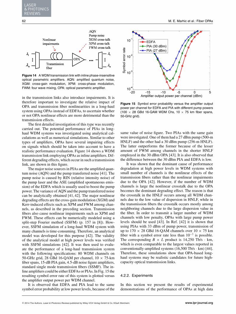
Figure 14 A WDM transmission link with inline phase-insensitiveoptical parametric amplifiers. AQN: amplified quantum noise,XGM: cross-gain modulation, XPM: cross-phase modulation,FWM: four wave mixing, OPA: optical parametric amplifier.
in the transmission links also introduce impairments. It istherefore important to investigate the relative impact ofOPA and transmission fiber nonlinearities in a long-haulsystem using OPAs instead of EDFAs, to ascertain whetheror not OPA nonlinear effects are more detrimental than thetransmission effects.
The first detailed investigation of this type was recentlycarried out. The potential performance of PIAs in long-haul WDM systems was investigated using analytical cal-culations as well as numerical simulations. Similar to othertypes of amplifiers, OPAs have several impairing effectson signals which should be taken into account to have arealistic performance evaluation. Figure 14 shows a WDMtransmission link employing OPAs as inline amplifiers. Dif-ferent degrading effects, which occur in such a transmissionlink, are shown in this figure.
The major noise sources in PIAs are the amplified quan-tum noise (AQN) and the pump transferred noise [41]. Thepump noise is caused by RIN (relative intensity noise) ofthe pump laser and the ASE (amplified spontaneous emis-sion) of the EDFA which is usually used to boost the pumppower. The variance of AQN and the pump transferred noisecan be analytically obtained [41, 42]. The major nonlineardegrading effects are the cross-gain modulation (XGM) andKerr-induced effects such as XPM and FWM among chan-nels, as described in the preceding section. Transmissionfibers also cause nonlinear impairments such as XPM andFWM. These effects can be numerically modeled using asplit-step Fourier method (SSFM) (p. 157 in [8]). How-ever, SSFM simulation of a long-haul WDM system withmany channels is time-consuming. Therefore, an analyticalmodel was developed for this purpose [42]. The validityof the analytical model at high power levels was verifiedwith SSFM simulations [42]. It was then used to evalu-ate the performance of a long-haul transmission systemwith the following specifications: 80 WDM channels on50-GHz grid, 28 GBd 16-QAM per channel, 10 × 75-kmfiber spans, 15-dB PIA gain, 4.5-dB noise figure amplifiers,standard single mode transmission fibers (SSMF). The in-line amplifiers could be either EDFAs or PIAs. In Fig. 15 theresulting symbol error rate of this system is plotted versusthe amplifier output power per WDM channel.
It is observed that EDFA and PIA lead to the samesymbol error probability at low power levels, because of the
Figure 15 Symbol error probability versus the amplifier outputpower per channel for EDFA and PIA with different pump powers(100 × 28 GBd 16-QAM WDM Chs, 10 × 75 km fiber spans,50-GHz grid).
same value of noise figure. Two PIAs with the same gainwere investigated. One of them had a 27 dBm pump (500-mHNLF) and the other had a 30 dBm pump (256-m HNLF).The latter outperforms the former because of the lesseramount of FWM among channels in the shorter HNLFemployed in the 30 dBm OPA [43]. It is also observed thatthe difference between the 30 dBm PIA and EDFA is low.
It was shown that the dominant cause of performancedegradation at high power levels in WDM systems withsmall number of channels is the nonlinear effects of thetransmission fibers rather than the nonlinear impairmentsdue to the OPA [42]. However, if the number of WDMchannels is large the nonlinear crosstalk due to the OPAbecomes the dominant degrading effect. The reason is thatthe crosstalk in the HNLF occurs among all WDM chan-nels due to the low value of dispersion in HNLF, while inthe transmission fibers the crosstalk occurs mostly amongneighboring channels due to the large dispersion value inthe fiber. In order to transmit a larger number of WDMchannels with low penalty, OPAs with large pump powerlevels should be used [43]. In Ref. [42] it is shown thatusing PIAs with 33 dBm of pump power, transmission ofup to 170 × 28 GBd 16-QAM channels over 10 × 75 kmfiber with a symbol error rate less than 10−3 is possible.The corresponding B × L product is 14,250 Tb/s · km,which is even comparable to the largest values reported inconventionally-amplified systems (16,500 Tb/s · km) [44].Therefore, these simulations show that OPA-based long-haul systems may be realistic candidates for future high-capacity optical transmission links.
4.2.2. Experiments
In this section we present the results of experimentaldemonstrations of the performance of OPAs at high data
C© 2014 The Authors. Laser & Photonics Reviews published by Wiley-VCH Verlag GmbH & Co. KGaA Weinheim www.lpr-journal.org
REVIEWARTICLE
Laser Photonics Rev. 9, No. 1 (2015) 63
rates, as well as in a recirculating loop to test repeatedamplification as required in long-haul systems.
A. 1 Tb/s WDM. This experiment was performed to am-plify as many WDM channels as possible in a PIA, and tocompare its performance to that of an EDFA [45].
The OPA was first evaluated in a back-to-back config-uration. It was placed between the transmitter and receiverof a DWDM testbed and its performance was comparedwith a single-stage EDFA. The testbed contained 26 chan-nels on the ITU grid with 100-GHz channel spacing start-ing from 1531.11 nm; the channels at 1537.40 nm and1538.19 nm were missing. After multiplexing, the chan-nels were modulated at 43.7 Gb/s by two LiNbO3 Mach-Zehnder modulators. The first modulator was driven by a231–1 pseudo-random binary sequence (PRBS) to generatea DPSK signal. The second was driven by a half-rate clockcreating RZ-DPSK modulation with 67% duty cycle. Thechannels were decorrelated through 1.5-km of SSMF, andthen launched into the EDFA or OPA.
The OPA used a single 35-dBm pump at 1572.5 nm. ItsRIN at the HNLF output, measured with a 3 MHz resolutionbandwidth, was −63 dB. Pump phase modulation by fourRF tones was used for suppressing pump-induced SBS inthe HNLF. The gain medium was a HNLF with L = 114 m,γ = 15 W−1km−1 and dispersion slope Dλ = 0.023 psnm−2 km−1. The OPA was compared with an EDFA witha flat gain of 17 dB, NF = 5 dB and a maximum outputpower of 25 dBm.
The channel powers were leveled at the output of theamplifiers by adjusting the input channel powers. The totalpower at the OPA (EDFA) input was 1.5 dBm (−4.8 dBm).The signals were received using a tunable flat-top filterwith a bandwidth of 0.6 nm to de-multiplex the selectedchannel, followed by a Mach-Zehnder delay interferometerand balanced photodiodes.
The performance of the OPA was evaluated by mea-suring BER versus power and OSNR at the receiver input.A 0.5-nm resolution bandwidth was used throughout formeasuring OSNR, to ensure that the entire signal spectrumwas included in the resolution bandwidth.
The normalized optical spectra of the transmitted chan-nels at the output of the OPA and EDFA were measured. Itwas found that the noise level was different on either sidesof the spectrum. This tilt in noise was the same for OPA andEDFA, and increased for increased total power or numberof channels for the OPA. The tilt in the noise level for theEDFA is caused by the non-flat gain when it is used outsideit optimum gain level. Also, by turning off channels in pairsacross the band, e.g. 4 and 5, 16 and 17, different levels ofnoise were measured. Part of the OPA-induced noise is gen-erated by nonlinear crosstalk due to FWM, which is greaterat short wavelengths because of stronger phase-matching.
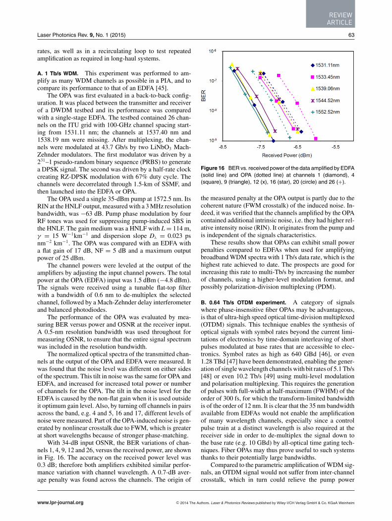
With 34-dB input OSNR, the BER variations of chan-nels 1, 4, 9, 12 and 26, versus the received power, are shownin Fig. 16. The accuracy on the received power level was0.3 dB; therefore both amplifiers exhibited similar perfor-mance variation with channel wavelength. A 0.7-dB aver-age penalty was found across the channels. The origin of
Figure 16 BER vs. received power of the data amplified by EDFA(solid line) and OPA (dotted line) at channels 1 (diamond), 4(square), 9 (triangle), 12 (x), 16 (star), 20 (circle) and 26 (+).
the measured penalty at the OPA output is partly due to thecoherent nature (FWM crosstalk) of the induced noise. In-deed, it was verified that the channels amplified by the OPAcontained additional intrinsic noise, i.e. they had higher rel-ative intensity noise (RIN). It originates from the pump andis independent of the signals characteristics.
These results show that OPAs can exhibit small powerpenalties compared to EDFAs when used for amplifyingbroadband WDM spectra with 1 Tb/s data rate, which is thehighest rate achieved to date. The prospects are good forincreasing this rate to multi-Tb/s by increasing the numberof channels, using a higher-level modulation format, andpossibly polarization-division multiplexing (PDM).
B. 0.64 Tb/s OTDM experiment. A category of signalswhere phase-insensitive fiber OPAs may be advantageous,is that of ultra-high speed optical time-division multiplexed(OTDM) signals. This technique enables the synthesis ofoptical signals with symbol rates beyond the current limi-tations of electronics by time-domain interleaving of shortpulses modulated at base rates that are accessible to elec-tronics. Symbol rates as high as 640 GBd [46], or even1.28 TBd [47] have been demonstrated, enabling the gener-ation of single wavelength channels with bit rates of 5.1 Tb/s[48] or even 10.2 Tb/s [49] using multi-level modulationand polarisation multiplexing. This requires the generationof pulses with full-width at half-maximum (FWHM) of theorder of 300 fs, for which the transform-limited bandwidthis of the order of 12 nm. It is clear that the 35 nm bandwidthavailable from EDFAs would not enable the amplificationof many wavelength channels, especially since a controlpulse train at a distinct wavelength is also required at thereceiver side in order to de-multiplex the signal down tothe base rate (e.g. 10 GBd) by all-optical time gating tech-niques. Fiber OPAs may thus prove useful to such systemsthanks to their potentially large bandwidths.
Compared to the parametric amplification of WDM sig-nals, an OTDM signal would not suffer from inter-channelcrosstalk, which in turn could relieve the pump power
www.lpr-journal.org C© 2014 The Authors. Laser & Photonics Reviews published by Wiley-VCH Verlag GmbH & Co. KGaA Weinheim
LASER& PHOTONICSREVIEWS
64 M. E. Marhic et al.: Fiber OPAs
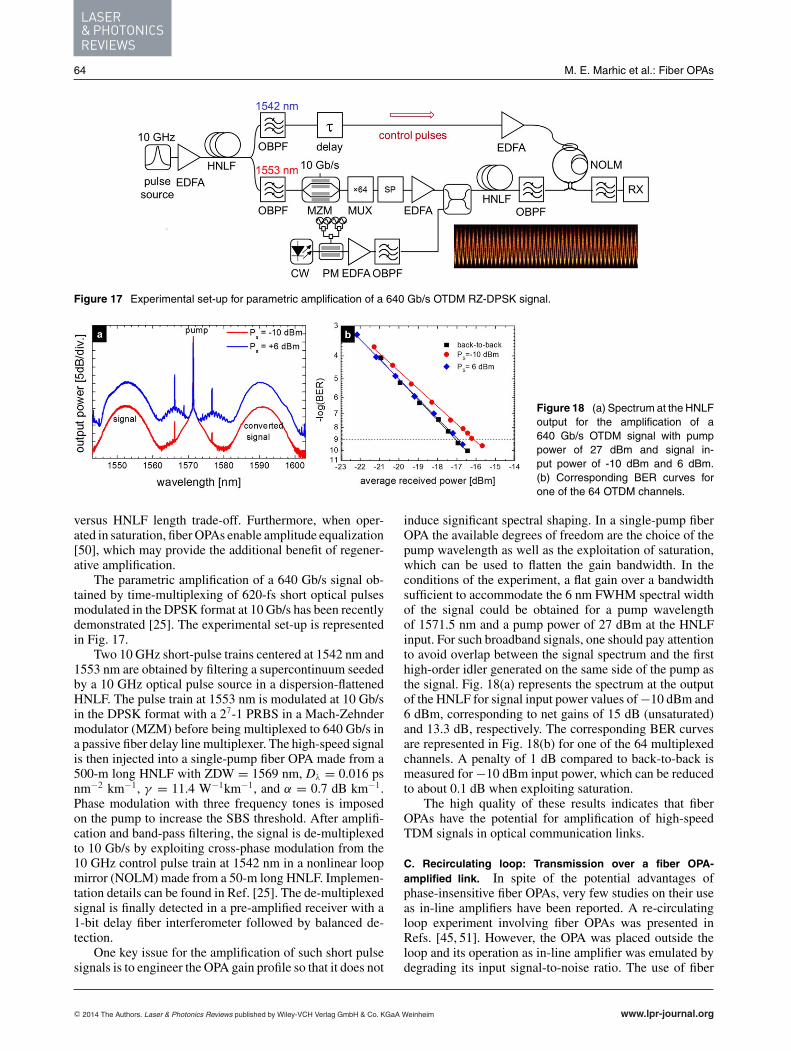
Figure 17 Experimental set-up for parametric amplification of a 640 Gb/s OTDM RZ-DPSK signal.
Figure 18 (a) Spectrum at the HNLFoutput for the amplification of a640 Gb/s OTDM signal with pumppower of 27 dBm and signal in-put power of -10 dBm and 6 dBm.(b) Corresponding BER curves forone of the 64 OTDM channels.
versus HNLF length trade-off. Furthermore, when oper-ated in saturation, fiber OPAs enable amplitude equalization[50], which may provide the additional benefit of regener-ative amplification.
The parametric amplification of a 640 Gb/s signal ob-tained by time-multiplexing of 620-fs short optical pulsesmodulated in the DPSK format at 10 Gb/s has been recentlydemonstrated [25]. The experimental set-up is representedin Fig. 17.
Two 10 GHz short-pulse trains centered at 1542 nm and1553 nm are obtained by filtering a supercontinuum seededby a 10 GHz optical pulse source in a dispersion-flattenedHNLF. The pulse train at 1553 nm is modulated at 10 Gb/sin the DPSK format with a 27-1 PRBS in a Mach-Zehndermodulator (MZM) before being multiplexed to 640 Gb/s ina passive fiber delay line multiplexer. The high-speed signalis then injected into a single-pump fiber OPA made from a500-m long HNLF with ZDW = 1569 nm, Dλ = 0.016 psnm−2 km−1, γ = 11.4 W−1km−1, and α = 0.7 dB km−1.Phase modulation with three frequency tones is imposedon the pump to increase the SBS threshold. After amplifi-cation and band-pass filtering, the signal is de-multiplexedto 10 Gb/s by exploiting cross-phase modulation from the10 GHz control pulse train at 1542 nm in a nonlinear loopmirror (NOLM) made from a 50-m long HNLF. Implemen-tation details can be found in Ref. [25]. The de-multiplexedsignal is finally detected in a pre-amplified receiver with a1-bit delay fiber interferometer followed by balanced de-tection.
One key issue for the amplification of such short pulsesignals is to engineer the OPA gain profile so that it does not
induce significant spectral shaping. In a single-pump fiberOPA the available degrees of freedom are the choice of thepump wavelength as well as the exploitation of saturation,which can be used to flatten the gain bandwidth. In theconditions of the experiment, a flat gain over a bandwidthsufficient to accommodate the 6 nm FWHM spectral widthof the signal could be obtained for a pump wavelengthof 1571.5 nm and a pump power of 27 dBm at the HNLFinput. For such broadband signals, one should pay attentionto avoid overlap between the signal spectrum and the firsthigh-order idler generated on the same side of the pump asthe signal. Fig. 18(a) represents the spectrum at the outputof the HNLF for signal input power values of −10 dBm and6 dBm, corresponding to net gains of 15 dB (unsaturated)and 13.3 dB, respectively. The corresponding BER curvesare represented in Fig. 18(b) for one of the 64 multiplexedchannels. A penalty of 1 dB compared to back-to-back ismeasured for −10 dBm input power, which can be reducedto about 0.1 dB when exploiting saturation.
The high quality of these results indicates that fiberOPAs have the potential for amplification of high-speedTDM signals in optical communication links.
C. Recirculating loop: Transmission over a fiber OPA-amplified link. In spite of the potential advantages ofphase-insensitive fiber OPAs, very few studies on their useas in-line amplifiers have been reported. A re-circulatingloop experiment involving fiber OPAs was presented inRefs. [45, 51]. However, the OPA was placed outside theloop and its operation as in-line amplifier was emulated bydegrading its input signal-to-noise ratio. The use of fiber
C© 2014 The Authors. Laser & Photonics Reviews published by Wiley-VCH Verlag GmbH & Co. KGaA Weinheim www.lpr-journal.org
REVIEWARTICLE
Laser Photonics Rev. 9, No. 1 (2015) 65
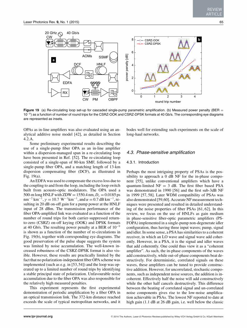
Figure 19 (a) Re-circulating loop set-up for cascaded single-pump parametric amplification. (b) Measured power penalty (BER =10−9) as a function of number of round trips for the CSRZ-OOK and CSRZ-DPSK formats at 40 Gb/s. The corresponding eye diagramsare represented as insets.
OPAs as in-line amplifiers was also evaluated using an an-alytical additive noise model [42], as detailed in Section4.2.A.
Some preliminary experimental results describing theuse of a single-pump fiber OPA as an in-line amplifierwithin a dispersion-managed span in a re-circulating loophave been presented in Ref. [52]. The re-circulating loopconsisted of a single-span of 80-km SMF, followed by asingle-pump fiber OPA, and a matching length of 13-kmdispersion compensating fiber (DCF), as illustrated inFig. 19(a).
An EDFA was used to compensate the excess loss due tothe coupling to and from the loop, including the loop switchbuilt from acousto-optic modulators. The OPA used a500-m long HNLF with ZDW = 1550.4 nm, Dλ = 0.0185 psnm−2 km−1, γ = 10.7 W−1km−1, and α = 0.7 dB km−1, re-sulting in 20 dB on-off gain for a pump power at the HNLFinput of 28 dBm. The transmission performance of thefiber OPA-amplified link was evaluated as a function of thenumber of round trips for both carrier-suppressed return-to-zero (CSRZ) on-off keying (OOK) and DPSK formatsat 40 Gb/s. The resulting power penalty at a BER of 10−9
is shown as a function of the number of re-circulations inFig. 19(b), together with corresponding eye diagrams. Thegood preservation of the pulse shape suggests the systemwas limited by noise accumulation. The well-known in-creased robustness of the CSRZ-DPSK format is also vis-ible. However, these results are practically limited by thefact that no polarization-independent fiber OPA scheme wasimplemented (such as e.g. in [53,54]) and the loop was op-erated up to a limited number of round trips by identifyinga stable principal state of polarization. Unfavourable noiseaccumulation due to the fiber OPA was also responsible forthe relatively high measured penalties.
This experiment represents the first experimentaldemonstration of periodic amplification by a fiber OPA inan optical transmission link. The 372-km distance reachedexceeds the scale of typical metropolitan networks, and it
bodes well for extending such experiments on the scale oflong-haul networks.
4.3. Phase-sensitive amplification
4.3.1. Introduction
Perhaps the most intriguing property of PSAs is the pos-sibility to approach a 0 dB NF for the in-phase compo-nent [55], unlike conventional amplifiers which have aquantum-limited NF = 3 dB. The first fiber based PSAwas demonstrated in 1990 [56] and the first sub-3dB NFin 1999 [57, 58]. Later WDM compatibility of PSAs wasalso demonstrated [59,60]. Accurate NF measurement tech-niques were presented and resulted in detailed understand-ing of the noise properties of fiber PSAs [61, 62]. In thisreview, we focus on the use of HNLFs as gain mediumin phase-sensitive fiber-optic parametric amplifiers (PS-FOPA) implemented in a single-pump non-degenerate idlerconfiguration, thus having three input waves; pump, signaland idler. In some sense, a PSA has similarities to a coherentreceiver, in which an LO wave and signal wave add coher-ently. However, in a PSA, it is the signal and idler wavesthat add coherently. One could thus view it as a “coherentamplifier”. As such, the in-phase components of the wavesadd constructively, while out-of-phase components beat de-structively. For deterministic, correlated signals on thesewaves, these amplifiers can be tuned to provide construc-tive addition. However, for uncorrelated, stochastic compo-nents, such as independent noise sources, the addition is in-coherent. Effectively half the noise will add constructivelywhile the other half cancels destructively. This differencebetween the beating of correlated signal and un-correlatednoise components gives rise to the low-noise amplifica-tion achievable in PSAs. The lowest NF reported to date athigh gain (1.1 dB at 26 dB gain, i.e. well below the classic
www.lpr-journal.org C© 2014 The Authors. Laser & Photonics Reviews published by Wiley-VCH Verlag GmbH & Co. KGaA Weinheim
LASER& PHOTONICSREVIEWS
66 M. E. Marhic et al.: Fiber OPAs
3-dB quantum limit) of any high-gain optical amplifier wasdemonstrated in Ref. [63].
Here we review some basic properties of PSAs and, inparticular review recent progress toward practical use inreal transmission systems. While challenges remain, recentresults show clear performance improvement when com-paring to systems utilizing EDFAs as amplifiers.
4.3.2. PSA concepts
Key building blocks of any fiber OPAs are: (i) thespecifically-designed HLNF that should not only have lowdispersion near the operating wavelength, but also low at-tenuation and be easy to splice to other types of fibers;(ii) the high-power single-frequency pump laser with lowintensity noise. In addition, for PS-FOPAs idler(s) satisfy-ing appropriate phase conditions have to be generated and,in practice, phase-locked loops (PLL) are often needed tomaintain optimal conditions in the presence of environmen-tal disturbances.
In the single-pump, non-degenerate idler configuration,which has been the focus of this work, the signal and idlerwavelengths are symmetrically located around the pump.Multiple signal-idler pairs can interact with the pump mak-ing the scheme compatible with the use of several DWDMchannels. Idler waves must not only have the correct opti-cal phase but also contain the encoded data from the cor-responding signal. If an idler contains a phase-conjugatedcopy of the signal data, the PSA will operate with anymodulation format, while if not, it will only amplify onequadrature [64]. This is suitable for e.g. binary PSK signals,which would then not only be amplified but also phase-regenerated. In our case, we simply use a PI fiber FOPAto generate a stable idler (which we call ‘copier’, see e.g.Fig. 21). The control of the relative phase relation among thedifferent waves can be implemented with a feedback controlloop (by e.g. maximizing the PS gain). The phase-sensitiveamplification is dictated by the relative phase among theinteracting waves. The input/output optical field relation ofa PS-FOPA at perfect phase matching is given by [65]:
[As,out
A∗i,out
]=
[cosh(γ PLeff) i sinh(γ PLeff)
−i sinh(γ PLeff) cosh(γ PLeff)
]
×[
As,in
A∗i,in
]. (6)
Here Leff is the effective length of the fiber, given by
Leff = 1 − e−αL
α, (7)
where α is the fiber power attenuation coefficient. As,in andAi,in (As,out and Ai,out ) are the signal and idler phasors atthe input (output). Clearly, in the case of no idler presentat the input, one will be generated, and the signal phase isconserved.
In the case of PS amplification, we assume thatthe signal and idler input powers are equal, and so
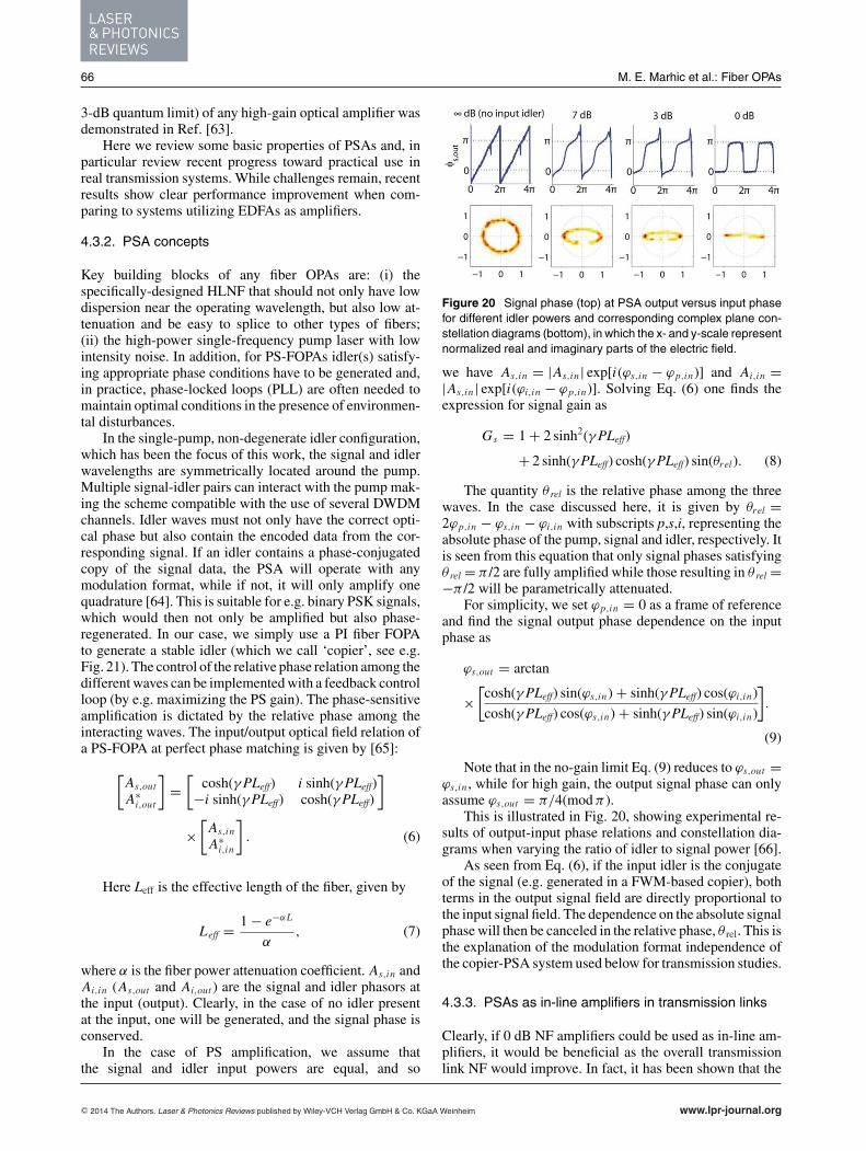
Figure 20 Signal phase (top) at PSA output versus input phasefor different idler powers and corresponding complex plane con-stellation diagrams (bottom), in which the x- and y-scale representnormalized real and imaginary parts of the electric field.
we have As,in = |As,in| exp[i(ϕs,in − ϕp,in)] and Ai,in =|As,in| exp[i(ϕi,in − ϕp,in)]. Solving Eq. (6) one finds theexpression for signal gain as
Gs = 1 + 2 sinh2(γ PLeff)
+ 2 sinh(γ PLeff) cosh(γ PLeff) sin(θrel). (8)
The quantity θ rel is the relative phase among the threewaves. In the case discussed here, it is given by θrel =2ϕp,in − ϕs,in − ϕi,in with subscripts p,s,i, representing theabsolute phase of the pump, signal and idler, respectively. Itis seen from this equation that only signal phases satisfyingθ rel = π /2 are fully amplified while those resulting in θ rel =−π /2 will be parametrically attenuated.
For simplicity, we set ϕp,in = 0 as a frame of referenceand find the signal output phase dependence on the inputphase as
ϕs,out = arctan
×[cosh(γ PLeff) sin(ϕs,in) + sinh(γ PLeff) cos(ϕi,in)
cosh(γ PLeff) cos(ϕs,in) + sinh(γ PLeff) sin(ϕi,in)
].
(9)
Note that in the no-gain limit Eq. (9) reduces to ϕs,out =ϕs,in , while for high gain, the output signal phase can onlyassume ϕs,out = π/4(mod π ).
This is illustrated in Fig. 20, showing experimental re-sults of output-input phase relations and constellation dia-grams when varying the ratio of idler to signal power [66].
As seen from Eq. (6), if the input idler is the conjugateof the signal (e.g. generated in a FWM-based copier), bothterms in the output signal field are directly proportional tothe input signal field. The dependence on the absolute signalphase will then be canceled in the relative phase, θ rel. This isthe explanation of the modulation format independence ofthe copier-PSA system used below for transmission studies.
4.3.3. PSAs as in-line amplifiers in transmission links
Clearly, if 0 dB NF amplifiers could be used as in-line am-plifiers, it would be beneficial as the overall transmissionlink NF would improve. In fact, it has been shown that the
C© 2014 The Authors. Laser & Photonics Reviews published by Wiley-VCH Verlag GmbH & Co. KGaA Weinheim www.lpr-journal.org
REVIEWARTICLE
Laser Photonics Rev. 9, No. 1 (2015) 67
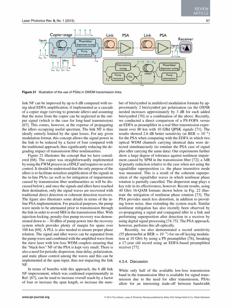
Figure 21 Illustration of the use of PSAs in DWDM transmission links.
link NF can be improved by up to 6 dB compared with us-ing ideal EDFA amplification, if implemented as a cascadeof a copier stage (serving to generate idlers) and assumingthat the noise from the copier can be neglected in the out-put signal (which is the case for long-haul transmission)[67]. This comes, however, at the expense of propagatingthe idlers occupying useful spectrum. The link NF is thusideally entirely limited by the span losses. For any givenmodulation format, this concept allows the signal power inthe link to be reduced by a factor of four compared withthe traditional approach, thus significantly reducing the de-grading impact of transmission fiber nonlinearities.
Figure 21 illustrates the concept that we have consid-ered [68]. The copier was straightforwardly implementedby using the FWM process in a HNLF and requires no activecontrol. It should be understood that the only purpose of theidlers is to facilitate noiseless amplification of the signals inthe in-line PSAs (as well as for mitigation of impairmentscaused by transmission fiber nonlinearities as will be dis-cussed below), and once the signals and idlers have reachedtheir destination, only the signal waves are recovered withtraditional direct detection or coherent detection receivers.The figure also illustrates some details in terms of the in-line PSA implementation. For practical purposes, the pumpwave needs to be attenuated prior to transmission throughthe link in order to avoid SBS in the transmission fiber. Withinjection-locking, penalty-free pump recovery was demon-strated down to −30 dBm of pump power into the recoverysystem which provides plenty of margin for spans over100 km [69]. A PLL is also needed to ensure proper phaserelation. The signal and idler waves can be separated fromthe pump wave and combined with the amplified wave fromthe slave laser with low-loss WDM couplers ensuring thatthe “black-box” NF of the PSA is kept very small. There isalso a need for periodic dispersion, time delay, polarization,and static phase control among the waves and this can beimplemented at the span input, thus not impacting the linkNF.
In terms of benefits with this approach, the 6 dB linkNF improvement, which was confirmed experimentally inRef. [67], can be used to increase overall reach by a factorof four or increase the span length, or increase the num-
ber of bits/symbol in multilevel modulation formats by ap-proximately 2 bits/symbol per polarisation (as the OSNRneeded increases approximately by 3 dB for each addedbits/symbol [70] or a combination of the above. Recently,we conducted a direct comparison of a PS-FOPA versusan EDFA as preamplifier in a real fiber transmission exper-iment over 80 km with 10 GBd QPSK signals [71]. Theresults showed 2.6 dB better sensitivity (at BER = 10−4)for the PSA when comparing with the EDFA in which twooptical WDM channels carrying identical data were de-tected simultaneously (to emulate the PSA case of signalplus idler carrying the same data). Our experiments furthershow a large degree of tolerance against nonlinear impair-ment caused by SPM in the transmission fiber [72]; a 3dBQ-penalty reduction relative to the case when not using thesignal/idler superposition i.e. the phase insensitive modewas measured. This is a result of the coherent superpo-sition of the signal/idler waves in which nonlinear phaserotation is partially cancelled. The dispersion map plays akey role in its effectiveness, however. Recent results, using40 Gb/s 16-QAM formats shown below in Fig. 22 illus-trate the mitigation of nonlinear phase rotation [73]. ThePSA provides much less distortion, in addition to provid-ing lower noise, thus extending the system reach. Similarnonlinear mitigation has also recently been observed byco-propagating a signal and conjugated idler in a link andperforming superposition after detection in a receiver byusing digital signal processing [74,75]. The PSA approach,however, performs this all-optically.
Recently, we also demonstrated a record sensitivity(55 photons/bit at BER = 10−9) for on-off keying modula-tion at 10 Gb/s by using a PS preamplifier [76], breakinga 17-year old record using an EDFA-based preamplifiedreceiver [77].
4.3.4. Discussion
While only half of the available low-loss transmissionband in the transmission fiber is available for signal trans-mission due to the need for idler transmission, PSAsallow for an interesting trade-off between bandwidth
www.lpr-journal.org C© 2014 The Authors. Laser & Photonics Reviews published by Wiley-VCH Verlag GmbH & Co. KGaA Weinheim
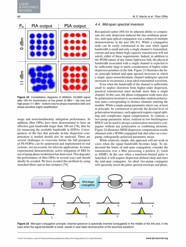
LASER& PHOTONICSREVIEWS
68 M. E. Marhic et al.: Fiber OPAs
Figure 22 Constellation diagrams of 40Gbit/s 16-QAM signalafter 105 km transmission at low power (0 dBm – top row) andhigh power (11 dBm – bottom row) for phase-insensitive (left) andphase-sensitive (right) amplification.
usage and noise/nonlinearity mitigation performance. Inaddition, fiber OPAs have been demonstrated to have aneffective gain bandwidth larger than 100 nm [78], thus byfar surpassing the available bandwidth in EDFAs. Conse-quences of the fact that periodic in-line dispersion com-pensation is needed should also be analysed. There areseveral challenges to overcome before the full prospectsof PS-FOPAs can be understood and implemented in realsystems, not necessarily for telecom applications. In manyexperimental demonstrations, active mitigation of SBS byuse of pump phase modulation has been used. This degradesthe performance of fiber OPAs in several ways and shouldideally be avoided. We have avoided this problem by usingstretched fibers and in-line isolators [79].
4.4. Mid-span spectral inversion
Recognized earlier [80] for its inherent ability to compen-sate not only dispersion-induced but also nonlinear penal-ties, mid-span optical conjugation was a subject of multipledemonstrations in the past [80, 81]. While a conjugationnode can be easily constructed in the case when signalbandwidth is small and only a single channel is transmitted,current and near-future high-capacity transmission will notsatisfy either of these requirements. Indeed, in addition tothe WDM nature of any future lightwave link, the physicalbandwidth associated with a single channel is expected tobe sufficiently large to merit consideration of higher-orderdispersion penalties in the link. Figure 23 illustrates the ba-sic principle behind mid-span spectral inversion in whicha single, quasi-monochromatic channel undergoes spectralinversion to reconstruct a near-ideal transmitted waveform.
Even when the bandwidth of the channel is sufficientlysmall to neglect distortion from higher-order dispersion,practical transmission must include more than a singlechannel. In this case, the phase conjugation node must alsobe polarization invariant to accommodate random polariza-tion states corresponding to distinct channels entering themodule. While a single-pump parametric mixer can, at leastin principle, be constructed to provide the desired level ofpolarization invariance, such approach requires signal split-ting and complicates signal compensation. In contrast, atwo-pump parametric mixer, realized in low-birefringenceHNLF can be used to design a polarization-insensitive con-jugator without any polarization or combining elements.Figure 24 illustrates MSSI dispersion-compensation resultsobtained with a WDM conjugated link that relies on a two-pump, orthogonally-polarized parametric mixer.
While relatively simple, this approach will not work incases when the signal bandwidth becomes large. To un-derstand the limits of mid-span conjugation, consider thetransmission over a fiber possessing a positive β3 (suchas SSMF). In the case when a transform-limited pulse islaunched, it will acquire dispersion-defined chirp and enterthe mid-span conjugator. An ideal, two-pump conjugatorwill spectrally invert the pulse spectral envelope and phase,
Figure 23 Mid-span conjugation principle: channel spectrum is spectrally inverted (conjugated) in the middle of the link and, in thecase when the signal bandwidth is small, results in near-ideal reconstruction of the launched waveform.
C© 2014 The Authors. Laser & Photonics Reviews published by Wiley-VCH Verlag GmbH & Co. KGaA Weinheim www.lpr-journal.org

REVIEWARTICLE
Laser Photonics Rev. 9, No. 1 (2015) 69
Figure 24 WDM transmission compensated by polarization-invariant mid-link compensator: typical channel waveform (10Gb/s) atlaunch, and interim spans of the link [81].
Figure 25 (Left) Polarization-invariant, frequency-degenerate conjugator constructed with orthogonally multiplexed pumps; (Right)640 Gb/s RZ-OOK channel compensated by the conjugation node and received after 100-km SSMF link: top- launched; middle-mid-span; bottom- received [82].
perfectly compensating all even-order dispersion terms, butallowing odd-order dispersion to accumulate further in thesecond half of the link: at the end of the span, the accu-mulated phase rotation is 2 × β3ω
3/2. As a consequence,when pulse duration is sufficiently short, third-order disper-sion will induce non-negligible penalty that scales with thechannel rate. In the case of a 640 Gb/s TDM channel, thecharacteristic length corresponding to third-order disper-sion penalty in SSMF is only 1.5 km, thus eliminating suchconjugation scheme from practical consideration. To ad-dress this limitation, it is necessary to compensate odd-orderdispersive terms outside the conjugator node, by adding afiber segment that has an opposite sign for the higher-order(odd) dispersive term. The first half of the link needs tobe designed specifically to cancel odd-order dispersion bycombining SSMF and DCF types and guarantee that thephase rotation in SSMF, β2,SM Fω2/2 + β3ω
3/6, is beingmatched by the phase evolution in DCF, β2,DC Fω2/2 −β3ω
3/6. Mid-span conjugation will invert the quadratic ro-tation and result in cancellation at the end of the link; theodd-orders between SSMF and DCF will cancel even incase when conjugation is not performed.
This approach was recently demonstrated by transmis-sion of a 640 Gb/s signal possessing optical bandwidthof 15 nm [82]. The channel was sent over a 100-km SSMFlink, and a two-pump polarization-invariant conjugator wasplaced mid-span. The use of a two-pump conjugator archi-tecture has an additional advantage as it also results in afrequency-degenerate idler (i.e. the idler has the same fre-quency as the signal) that eliminates any need for additional
compensating steps that would be necessary due to finitefiber slope. The architecture of the conjugator, shown inFig. 25, relied on orthogonally-polarized pumps separatedby 31 nm, and allowed direct polarization stripping of thepower-equalized idler wave. Remarkably, the entire com-pensation scheme resulted in a low-error (BER < 10−9)640 Gb/s link without any need for electronic correction(FEC).
5. Challenges
While fiber OPAs present a number of features of inter-est for optical communication, optimizing these featuressimultaneously in a single device has proved difficult, for avariety of reasons. In Section 4.1 we discussed the subjectof nonlinear crosstalk in broadband networks. Here we dis-cuss some of the main challenges for fiber OPAs, and whatdevelopments are desirable for addressing them.
5.1. Stimulated Brillouin scattering
SBS is a nonlinear acousto-optical effect, which is presentin all materials. It is mediated by the excitation of acous-tic waves. The backscattered light is downshifted by about10 GHz from the pump. SBS has a high gain coefficient,approximately 100 times larger than the Kerr coefficient.Hence if it is not modified in some way, it will reflect
www.lpr-journal.org C© 2014 The Authors. Laser & Photonics Reviews published by Wiley-VCH Verlag GmbH & Co. KGaA Weinheim
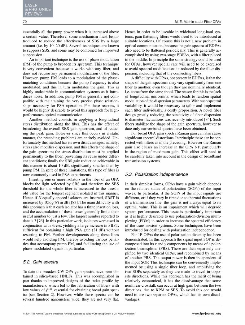
LASER& PHOTONICSREVIEWS
70 M. E. Marhic et al.: Fiber OPAs
essentially all the pump power when it is increased abovea certain value. Therefore, some mechanism must be in-troduced to reduce the effectiveness of SBS by a largeamount (i.e. by 10–20 dB). Several techniques are knownto suppress SBS, and some may be combined for improvedsuppression.
An important technique is the use of phase modulation(PM) of the pump to broaden its spectrum. This techniqueis very convenient because it works with any fiber, anddoes not require any permanent modification of the fiber.However, pump PM leads to a modulation of the phase-matching conditions because the pump frequency is alsomodulated, and this in turn modulates the gain. This ishighly undesirable in communication systems as it intro-duces noise. In addition, pump PM is generally not com-patible with maintaining the very precise phase relation-ships necessary for PSA operation. For these reasons, itwould be highly desirable to avoid this approach for high-performance optical communication.
Another method consists in applying a longitudinalstress distribution along the fiber. This has the effect ofbroadening the overall SBS gain spectrum, and of reduc-ing the peak gain. However since this occurs in a staticmanner, the preceding problems are entirely avoided. Un-fortunately this method has its own disadvantages, namely:stress also modifies dispersion, and this affects the shape ofthe gain spectrum; the stress distribution must be appliedpermanently to the fiber, preventing its reuse under differ-ent conditions; finally the SBS gain reduction achievable inthis manner is about 10 dB, significantly smaller than bypump PM. In spite of these limitations, this type of fiber isnow commonly used in PSA experiments.
Inserting one or more isolators in the fiber of an OPAblocks the light reflected by SBS and therefore the SBSthreshold for the whole fiber is increased to the thresh-old value for the longest segment isolated in this manner.Hence if N equally-spaced isolators are inserted, SBST isincreased by 10log(N) in dBs [83]. The main difficulty withthis approach is that each isolator has a finite insertion loss,and the accumulation of these losses generally limits theiruseful number to just a few. The largest number reported todate is 3 [76]. In this particular work, isolators were used inconjunction with stress, yielding a large increase in SBST,sufficient for obtaining a high PSA gain (21 dB) withoutresorting to PM. Further developments along these lineswould help avoiding PM, thereby avoiding various penal-ties that accompany pump PM, and facilitating the use ofphase-modulated signals in particular.
5.2. Gain spectra
To date the broadest CW OPA gain spectra have been ob-tained in silica-based HNLFs. This was accomplished inpart thanks to improved designs of the index profile bymanufacturers, which led to the fabrication of fibers withlow values of β(4), essential for obtaining broad gain spec-tra (see Section 2). However, while these spectra can beseveral hundred nanometers wide, they are not very flat.
Hence in order to be useable in wideband long-haul sys-tems, gain flattening filters would need to be introduced atsuitable locations. Of course this is not a new problem inoptical communication, because the gain spectra of EDFAsalso need to be flattened periodically. This is generally ac-complished by using two-stage EDFAs, with a filter placedin the middle. In principle the same strategy could be usedfor OPAs, however special care will need to be exercisedto avoid spectral modifications introduced by the filter dis-persion, including that of the connecting fibers.
A difficulty with OPAs, not present in EDFAs, is that theshape of the gain spectrum may vary significantly from onefiber to another, even though they are nominally identical,i.e. come from the same spool. The reason for this is the lackof longitudinal uniformity, which leads to random spatialmodulation of the dispersion parameters. With such spectralvariability, it would be necessary to tailor and implementeach filter individually, a costly proposition. A novel fiberdesign greatly reducing the sensitivity of fiber dispersionto diameter fluctuations was recently introduced [84]. Suchfibers stabilize the shape of the gain spectrum, however todate only narrowband spectra have been obtained.
For broad OPA gain spectra Raman gain can also causesignificant spectral distortions. In principle these can be cor-rected with filters as in the preceding. However the Ramangain also causes an increase in the OPA NF, particularlyin the region of maximum gain. This effect will need tobe carefully taken into account in the design of broadbandtransmission systems.
5.3. Polarization independence
In their simplest forms, OPAs have a gain which dependson the relative states of polarization (SOPs) of the inputwaves. In particular, if the SOPs of the input signals aredifferent, or if they vary in time due to thermal fluctuationsof a transmission line, the gain is not always equal to itsoptimal value. This is an impairment which will degradesystem performance. This issue is particularly importantas it is highly desirable to use polarization-division multi-plexing (PDM) in order to increase the spectral efficiencyof the transmission systems. Some techniques have beenintroduced for dealing with polarization independence.
For 1P-OPAs the use of polarization diversity has beendemonstrated. In this approach the signal input SOP is de-composed into its x and y components by means of a polar-ization beamsplitter (PBS). These are then separately am-plified by two identical OPAs, and recombined by meansof another PBS. The output power is then independent ofthe input SOP. This technique can be conveniently imple-mented by using a single fiber loop, and amplifying thetwo SOPs separately as they are made to travel in oppo-site directions. While this approach has the merit of beingrelatively economical, it has the disadvantage that somenonlinear crosstalk can occur at high gain between the twodirections, due to XPM or SBS. To avoid this one wouldneed to use two separate OPAs, which has its own disad-vantages.
C© 2014 The Authors. Laser & Photonics Reviews published by Wiley-VCH Verlag GmbH & Co. KGaA Weinheim www.lpr-journal.org
REVIEWARTICLE
Laser Photonics Rev. 9, No. 1 (2015) 71
For 2P-OPAs, it is also possible to use the same polar-ization diversity approach as above. But another possibilityarises due to the presence of two pumps. If their SOPs areorthogonal, then the signal gain is polarization-independent[54]. This approach also has the advantage that it can resultin a gain spectrum which is flatter than for a 1P-OPA. Adrawback is that the total pump power required for a givengain is about three times larger than if the pump SOPs areparallel; this in turn makes SBS suppression more difficult.Nevertheless, in spite of these difficulties this techniqueoffers a fairly straightforward way of achieving the polar-ization independence required for practical systems. (SeeSection 4.4 for an example of implementation.)
While silica-based HNLFs are currently the best plat-form for fabricating high-performance OPAs, future devel-opments in the area of highly-nonlinear non-silica fiberscould eventually lead to improved OPA systems. Fiberswith γ ’s 1000 times larger than HNLFs have been demon-strated, however to date their relatively high losses andlow damage thresholds have prevented them from beinguseful for CW fiber OPAs. Improvements of these parame-ters could eventually lead to more compact OPAs with lowpump powers, and possibly to the development of pumpresonators and their associated benefits [85].
Finally, the development of high-power high-OSNRpumps would be highly desirable. Currently high-powerpumps are obtained by amplifying a high-OSNR seed byEDFAs. Such amplification degrades the optical OSNR, be-cause it is very difficult to filter out the ASE generated by theEDFAs in a very narrow band about the high-power pump.This residual ASE in turns leads to signal degradation viaFWM. To improve this situation, one would need to do oneof the following: (i) develop narrowband filters that canoperate at high power, and with low loss; (ii) develop nar-rowband lasers which directly generate a high output power,without requiring further amplification. While some of theissues presented above are more pressing, this problem ofpump quality should eventually be addressed as well.
The challenges presented in this section are in principleprobably amenable to individual engineering solutions. Ofcourse an additional challenge will remain, which is that offinding solutions that are mutually compatible, so that theycan be integrated into practical system designs suitable fortesting in communication systems.
6. Conclusion
A major driver for the development of fiber OPAs has al-ways been the possibility of eventually utilizing their uniqueproperties to improve the performance of fiber optic com-munication systems. After early work in the 1980s, a goodtheoretical understanding of their capabilities and limita-tions was developed in the 1990s. The late 1990s and early2000s saw a number of experiments performed to verifytheir capabilities, with respect to basic features such as gainbandwidth, polarization dependence, noise figure, etc., asall these aspects are essential for the design of communica-
tion systems. From the mid-2000s until now, the focus hasturned increasingly toward sub-system and system studies,incorporating a few of these basic features to attack engi-neering problems directly relevant to communication sys-tems. A major example of this is the European research pro-gram PHASORS, which concentrated on the use of PSAsfor signal regeneration, as well as for low-noise amplifica-tion. In parallel, the issue of nonlinear crosstalk was tackledto permit the amplification of a large number of channelsthrough a single OPA.
It is interesting to note that the current status of fiberOPAs is such that it would probably be possible to usethem today to handle the capacity of long-haul fiber opticsystems of a decade ago. However the capacity of thesesystems has increased in a Moore’s-law-type fashion, andso the requirements for OPAs to be competitive with to-day’s leading-edge systems have become very challeng-ing. The recently-demonstrated ability of OPAs to amplifyhigh-order modulation formats with little penalty is encour-aging. However, other developments are more problematic.For example, coherent detection (CD) and digital signalprocessing (DSP) are now becoming major attributes ofcommercial systems. One reason for this is that this com-bination can be used for combating nonlinear effects in thetransmission lines, and greatly reduce the need for opti-cal dispersion compensation in the network. This poses achallenge for the insertion of PSAs in such networks, be-cause the currently-envisioned architecture for PSA-basedsystems assumes perfect optical dispersion compensationbefore every PSA. Other emerging trends, such as multiple-core or multimode amplification, and polarization-divisionmultiplexing (PDM) could pose additional challenges.
Hence we see that research work on fiber OPAs needsto steadily progress in order to have a chance of catch-ing up with the ever-moving target presented by the re-quirements of state-of-the-art fiber optical communicationsystems. The recent demonstration of transmission of an 8-channel WDM 32-GBd PDM QPSK signal over 6,000-kmby periodic phase conjugation with phase-insensitive OPAsis an excellent demonstration of the potential of fiber OPAsin communication systems [86].
Acknowledgements. PP gratefully acknowledges the contri-butions of Dr Joseph Kakande, Dr Radan Slavik, Dr FrancescaParmigiani and Prof David J. Richardson. The Southamptonwork described here was supported by the European Communi-ties Seventh Framework Programme FP/2007-2013 under Grant224547 (PHASORS) and the UK’s Engineering and Physical Sci-ences Research Council under grant EP/I01196X: Transform-ing the Future Internet: The Photonics Hyperhighway. PP ac-knowledges JANET, the UK’s research and education network,for gratefully providing the installed fiber link used during theseexperiments.
C. Lundstrom, B, Corcoran, S.L.I. Olsson, R. Malik have con-tributed substantially to the Chalmers work presented here. PAis grateful to Sumitomo Electric Industries, Japan and OFS Den-mark for providing highly nonlinear fibers used in the experiments.This work is supported by the Swedish Research Council, by theEuropean Research Council under grant agreement ERC-2011-AdG - 291618 PSOPA and by the K.A. Wallenberg Foundation.
www.lpr-journal.org C© 2014 The Authors. Laser & Photonics Reviews published by Wiley-VCH Verlag GmbH & Co. KGaA Weinheim
LASER& PHOTONICSREVIEWS
72 M. E. Marhic et al.: Fiber OPAs
MM was supported by grant EP/J009709/2 from the UK’s EP-SRC. He gratefully acknowledges the help of Dr. Gordon K. P. Leiwho read the manuscript and commented on it.
The results on 640 Gbit/s amplification and re-circulatingloop experiments were made possible thanks to Dr. Zohreh Lali-Dastjerdi and colleagues at DTU Fotonik, including Dr. MichaelGalili, Dr. Hao Hu, Dr. Hans Christian Hansen Mulvad, Prof.Karsten Rottwitt, Dr. Valentina Cristofori, and Dr. Oskars Ozolins.This work was supported by the Danish Research Council forTechnology and Production Sciences under project 09-066562.OFS Fitel Denmark is acknowledged for kindly providing theHNLFs.
Received: 5 April 2014, Revised: 29 July 2014,Accepted: 5 August 2014
Published online: 30 September 2014
Key words: parametric amplifiers, fiber optic communication,fiber nonlinearities, phase-sensitive amplification, signal regen-eration, phase regeneration, mid-span spectral inversion.
Michel E. Marhic received a Ph.D inEE from UCLA. He was on the fac-ulty of Northwestern University (1974–1998), and Consulting Professor at Stan-ford University (1998–2006). From 2006on, he was chair professor with the Col-lege of Engineering, Swansea University,Wales, U.K. Over the past 25 years, hisresearch emphasis was on optical com-munication systems, and on nonlinear
optical interactions in fibers. He wrote the first book on fiberoptical parametric amplifiers (2008). He was the author orcoauthor of over 350 journal and conference papers and wasa fellow of OSA. Professor Marhic passed away in August2014, shortly before the publishing of this article.
Peter A. Andrekson is Professor ofPhotonics and previously spent severalyears in the US (Bell Labs, Cenix Inc.,Lehigh University). His research interestsinclude amplifiers, all-optical functional-ities, and high spectral efficiency trans-mission. He co-founded Picosolve, nowpart of EXFO. Andrekson is a Fellow ofthe OSA and the IEEE and author of four-hundred scientific publications. He was
member of the Board of Governors for the IEEE PhotonicsSociety (2011–2013) and has served as an expert for theevaluation of the Nobel Prize in Physics. Currently he holdsan ERC Advanced Grant for work on phase-sensitive opticalamplifiers.
Periklis Petropoulos graduated from theDepartment of Electrical Engineering andInformation Technology, University of Pa-tras, Greece, received the MSc degreein Communications Engineering from theUniversity of Manchester Institute of Sci-ence and Technology, and the PhD de-gree in Optical Telecommunications fromthe Optoelectronics Research Centre,University of Southampton, where he is
currently a Professor. His research interests lie in the fields ofoptical communications, all-optical signal processing and non-linear fibre technology. His research has produced more than350 papers in technical journals and conference proceedings,including several invited and post-deadline papers in majorinternational conferences.
Stojan Radic graduated from The Insti-tute of Optics in 1995 and has subse-quently served in Corning and Bell Lab-oratories. He is presently a Professorand a Director of Systems Laboratory atUniversity of California San Diegoand California Institute for Telecommu-nications and Information Technology.
Dr. Radic is a Fellow of the Optical Society of America andhas served as editor with IEEE Photonics Technology Let-ters and Optics Express Journals. He serves or has servedwith Parametric Processing (IEEE), OFC (OSA/IEEE), OAA(OSA), APOC (OSA) and ECOC conferences.
Christophe Peucheret received thegraduate engineering degree fromTelecom Bretagne, Brest, France,the M.Sc. degree in microwaves andoptoelectronics from University CollegeLondon, U.K., and the Ph.D. degree fromthe Technical University of Denmark(DTU). He has been with the Departmentof Photonics Engineering at the Tech-nical University of Denmark between
1997 and 2013. Since September 2013 he is with the FotonLaboratory (CNRS UMR 6082), ENSSAT, University ofRennes 1, France. His research interests are in the field ofoptical fiber communication systems with an emphasis onall-optical signal processing and parametric processes inhighly nonlinear fibers and waveguides.
Mahmoud Jazayerifar has received hisBS and MS degrees from Sharif Uni-versity of Technology, Tehran, Iran, andhe has finished his PhD studies in In-stitut National Polytechnique de Greno-ble (INPG), France in 2009. He iscurrently a post-doc researcher at Tech-nische Universitat Berlin. His researchinterests include optical communication
systems, microwave photonics, and nonlinear effects in opti-cal fibers.
References
[1] R. H. Stolen, IEEE J. Quantum Electron. QE-11, 100–103(1975).
[2] M. J. Holmes, D. L. Williams, and R. J. Manning, IEEEPhoton. Technol. Lett. 7, 1045–1047 (1995).
[3] C. J. McKinstrie, M. Yu, M. G. Raymer and S. Radic, Opt.Express 13, 4986–5012 (2005).
[4] C. J. McKinstrie, M. Karlsson, and Z. Tong, Opt. Express18, 19792–19823 (2010)
C© 2014 The Authors. Laser & Photonics Reviews published by Wiley-VCH Verlag GmbH & Co. KGaA Weinheim www.lpr-journal.org
REVIEWARTICLE
Laser Photonics Rev. 9, No. 1 (2015) 73
[5] M. E. Marhic, N. Kagi, T.-K. Chiang, and L. G. Kazovsky,Opt. Lett. 21, 573–575 (1996).
[6] T. Torounidis, P. A. Andrekson, and B. A. Olsson, IEEEPhoton. Technol. Lett. 18, 1194–1196 (2006).
[7] M. E. Marhic, JOSA B 30, 1462–1472 (2013).[8] M. E. Marhic, Fiber Optical Parametric Amplifiers, Oscilla-
tors and Related Devices (Cambridge University Press, NewYork, 2008).
[9] R. H. Stolen and J. E. Bjorkholm, IEEE J. Quantum Electron.QE-18, 1062–1072 (1982).
[10] M. A. Foster, A. C. Turner, J. E. Sharping, B. S. Schmidt,M. Lipson, and A. Gaeta, Nature 441, 960–963 (2006).
[11] T. Akiyama, H. Kuwatsuka, N. Hatori, Y. Nakata, H. Ebe,and M. Sugawara, IEEE Photon. Technol. Lett. 14, 1139–1141 (2002).
[12] P. A. Andrekson, in: Tech. Digest of ECOC 2008, paperTu.B.3.1, Brussels, Belgium, September 2008.
[13] A. O. J. Wiberg, C.-S. Bres, B. P.-P. Kuo, J. M. ChavezBoggio, N. Alic, and S. Radic, IEEE Photon. Technol. Lett.21, 1612–1614 (2009).
[14] B. P.-P. Kuo, E. Myslivets, N. Alic, and S. Radic, J. Light-wave Technol. 29, 3515–3522 (2011).
[15] C.-S. Bres, A. O. J. Wiberg, B. P.-P. Kuo, J. M. ChavezBoggio, C. F. Marki, N. Alic and S. Radic, IEEE J. LightwaveTechnol. 28, 434–442 (2010).
[16] A. O. J. Wiberg, C.-S. Bres, A. Danicic, E. Myslivets, and S.Radic, IEEE Photon. Technol. Lett. 23, 1570–1572 (2011).
[17] A. O. J. Wiberg, C.-S. Bres, B. P.-P. Kuo, E. Myslivets, N.Alic, and S. Radic, in: Tech. Digest of OFC 2011, paperOWL1, Los Angeles, March 2011.
[18] A. O. J. Wiberg, B. P.-P. Kuo, C.-S. Bres, N. Alic,and S. Radic, IEEE Photon. Technol. Lett. 23, 507–509(2011).
[19] C. Xu, X. Liu, L. F. Mollenauer, and X. Wei, IEEE Photon.Technol. Lett. 15, 617–619 (2003).
[20] A. Demir, J. Lightwave Technol. 25, 2002–2032 (2007).[21] J. P. Gordon and L. F. Mollenauer, Opt. Lett. 15, 1351–1353
(1990).[22] H. Kim and A. H. Gnauck, IEEE Photon. Technol. Lett. 15,
320–322 (2003).[23] K. Cvecek, K. Sponsel, C. Stephan, G. Onishchukov, R.
Ludwig, C. Schubert, B. Schmauss, and G. Leuchs, Opt.Express 16, 1923–1928 (2008).
[24] M. Matsumoto and K. Sanuki, Opt. Express 15, 8094–8103(2007).
[25] Z. Lali-Dastjerdi, M. Galili, H. C. H. Mulvad, H. Hu, L. K.Oxenløwe, K. Rottwitt, and C. Peucheret, Opt. Express 21,25944–25953 (2013).
[26] M. Gao, J. Kurumida, and S. Namiki, Opt. Express 19,23258–23270 (2011).
[27] M. Matsumoto and H. Sakaguchi, Opt. Express 16, 11169–11175 (2008).
[28] R. Slavik, A. Bogris, F. Parmigiani, J. Kakande, M. West-lund, M. Skold, L. Gruner-Nielsen, R. Phelan, D. Syvridis,P. Petropoulos, and D. J. Richardson, IEEE J. Select. TopicsQuantum Electron. 18, 859–869 (2012).
[29] K. Croussore and G. Li, IEEE Photon. Technol. Lett. 19,864–866 (2007).
[30] M. Gao, T. Kurosu, T. Inoue, and S. Namiki, Electron. Lett49, 140–141 (2013).
[31] R. Tang, J. Lasri, P. S. Devgan, V. Grigoryan, P. Kumar, andM. Vasilyev, Opt. Express 13, 10483–10493 (2005).
[32] J. Kakande, R. Slavik, F. Parmigiani, A. Bogris, D. Syvridis,L. Gruner-Nielsen, R. Phelan, P. Petropoulos, and D. J.Richardson, Nat. Photon. 5, 748–752 (2011).
[33] R. Slavik, A. Bogris, J. Kakande, F. Parmigiani, L. Gruner-Nielsen, R. Phelan, J. Vojtech, P. Petropoulos, D. Syvridis,and D. J. Richardson, J. Lightwave Technol. 30, 512–520(2012).
[34] J. Kakande, R. Slavik, F. Parmigiani, P. Petropoulos, and D.J. Richardson, All-optical Regeneration of Phase EncodedSignals, in: I. Kaminow, T. Li, A. E. Willner (Eds.), OpticalFiber Telecommunications Volume VIA: Components andSubsystems, (Academic Press, 2013), chap.16.
[35] J. Kakande, A. Bogris, R. Slavik, F. Parmigiani, D. Syvridis,P. Petropoulos, and D. J. Richardson, in Tech. Digest ofECOC 2010, paper PD3.3, Turin, Italy, September 2010.
[36] J. Kakande, A. Bogris, R. Slavik, F. Parmigiani, D. Syvridis,P. Petropoulos, D. J. Richardson, M. Westlund, and M. Skold,in Tech. Digest of OFC 2011, paper OMT4, Los Angeles,March 2011.
[37] A. Fragkos, A. Bogris, D. Syvridis, and R. Phelan, J. Light-wave Technol. 30, 764–771 (2012).
[38] K. Bottrill, G. Hesketh, F. Parmigiani, P. Horak, D. Richard-son, and P. Petropoulos, in: Tech. Digest of OFC 2014, paperW3F.7, San Francisco, March 2014.
[39] M. E. Marhic, Opt. Express 20, 28752–28757 (2012).[40] G. K. P. Lei and M. E. Marhic, Opt. Express 21, 21932–
21940 (2013).[41] P. Kylemark, P. Hedekvist, H. Sunnerud, M. Karlsson, and
P. Andrekson, J. Lightwave Technol. 22, 409–416 (2004).[42] M. Jazayerifar, S. Warm, R. Elschner, D. Kroushkov, I.
Sackey, C. Meuer, C. Schubert, and K. Petermann, J. Light-wave Technol. 31, 1454–1461 (2013).
[43] M. Jamshidifar, A. Vedadi, and M. Marhic, IEEE Photon.Technol. Lett. 21, 1244–1246 (2009.
[44] D. Qian, M.-F. Huang, E. Ip, Y.-K. Huang, Y. Shao, J. Hu,and T. Wang, in: Tech. Digest of OFC 2011, paper PDPB5,Los Angeles, March 2011.
[45] N. El Dahdah, D. S. Govan, M. Jamshidifar, N. J. Doran,and M. E. Marhic, IEEE J. Sel. Topics Quantum Electron.18, 950–957 (2012).
[46] M. Nakazawa, E. Yoshida, T. Yamamoto, E. Yamada, and A.Sahara, Electron. Lett. 34, 907–908 (1998).
[47] H. C. Hansen Mulvad, L. K. Oxenløwe, M. Galili, A. T.Clausen, L. Gruner-Nielsen, and P. Jeppesen, Electron. Lett.45, 280–281 (2009).
[48] H. C. Hansen Mulvad, M. Galili, L. K. Oxenløwe, H. Hu, A.T. Clausen, J. B. Jensen, C. Peucheret, and P. Jeppesen, Opt.Express 18, 1438–1443 (2010).
[49] T. Richter, E. Palushani, C. Schmidt-Langhorst, R. Ludwig,L. Molle, M. Nolle, and C. Schubert, J. Lightwave Technol.30, 504–511 (2012).
[50] K. Inoue, Electron. Lett. 36, 1016–1017 (2000).[51] N. El Dahdah, D. S. Govan, M. Jamshidifar, N. J. Doran, and
M. E. Marhic, IEEE Photon. Technol. Lett. 22, 1171–1173(2010).
[52] Z. Lali-Dastjerdi, O. Ozolins, Y. An, V. Cristofori, F. DaRos, N. Kang, H. Hu, H. C. Hansen Mulvad, K. Rottwitt, M.Galili, and C. Peucheret, in: Tech. Digest of ECOC 2012,
www.lpr-journal.org C© 2014 The Authors. Laser & Photonics Reviews published by Wiley-VCH Verlag GmbH & Co. KGaA Weinheim
LASER& PHOTONICSREVIEWS
74 M. E. Marhic et al.: Fiber OPAs
Amsterdam, The Netherlands, paper Mo.2.C.5, September2012.
[53] K. K.-Y. Wong, M. E. Marhic, K. Uesaka, and L. G. Ka-zovsky, IEEE Photon. Technol. Lett. 14, 1506–1508 (2002).
[54] K. K.-Y. Wong, M. E. Marhic, K. Uesaka, and L. G. Ka-zovsky, IEEE Photon. Technol. Lett. 14, 911–913 (2002).
[55] C. M. Caves, Phys. Rev. D 26, 1817–1839 (1982).[56] M. E. Marhic, C. H. Hsia, J.-M. Jeong, Electronics Letters
27, 210–211 (1991).[57] W. Imajuku, A. Takada, Y. Yamabayashi, Electronics Letters
35, 1954–1955 (1999).[58] D. Levandovsky, M. Vasilyev, P. Kumar, Optics Letters 24,
984–986 (1999).[59] R. Tang, P. S. Devgan, V. S. Grigoryan, P. Kumar, M. Vasi-
lyev, Optics Express, 16, 9046–9053 (2008).[60] Z. Tong, C. Lundstrom, E. Tipsuwannakul, M. Karlsson and
P. A. Andrekson, in: Tech. Digest of European Conferenceon Optical Communication, pp. 1–3, September 2010 (post-deadline paper). DOI:10.1109/ECOC.2010.5621349
[61] Z. Tong, A. Bogris, C. Lundstrom, C. J. McKinstrie, M.Vasilyev, M. Karlsson, Magnus, P. A. Andrekson, OpticsExpress 18, 14820–14835 (2010).
[62] Z. Tong, C. Lundstrom, M. Karlsson, M. Vasilyev, P. A.Andrekson, Optics Letters 36, 722–724 (2011).
[63] Z. Tong, C. Lundstrom, P. A. Andrekson, C. J. McKinstrie,M. Karlsson, D. J. Blessing, E. Tipsuwannakul, B. J. Put-tnam, H. Toda, and L. Gruner-Nielsen, Nat. Photon. 5, 430–436 (2011)
[64] Z. Tong and S. Radic, Adv. Opt. Photon. 5, 318–384 (2013).[65] M. Vasilyev, Opt. Express 13, 7563–7561 (2005).[66] C. Lundstrom, Z. Tong, M. Karlsson, and P. A. Andrekson,
Opt. Lett. 36, 4356–4358 (2011)[67] Z. Tong, C. J. McKinstrie, C. Lundstrom, M. Karlsson, and
P. A. Andrekson, Opt. Express 18, 15426–15439 (2010).[68] Z. Tong, C. Lundstrom, P. A. Andrekson, M. Karlsson, and
A. Bogris, IEEE J. Select. Topics Quantum Electron. 18,1016–1032 (2012).
[69] S. L. I. Olsson, B. Corcoran, C. Lundstrom, E. Tipsuwan-nakul, S. Sygletos, A. D. Ellis, Z. Tong, M. Karlsson, and P.A. Andrekson, Opt. Express 21, 14512–14529 (2013).
[70] R. J. Essiambre, G. Kramer, P. Winzer, G. J. Foschini, andB. Goebel, IEEE J. Lightwave Technol. 28, 662–701 (2010).
[71] B. Corcoran, S. L. I. Olsson, C. Lundstrom, M. Karlsson,and P. A. Andrekson, in: Tech. Digest of OFC 2012, paperPDP5A.4, Los Angeles, March 2012.
[72] B. Corcoran, S. L. I. Olsson, C. Lundstrom, M. Karlsson,and P. A. Andrekson, in: Tech. Digest of ECOC 2013, paperWe.3.A.1, London, September 2013.
[73] S. L. I. Olsson, T. Eriksson, C. Lundstrom, M. Karlsson,and P. A. Andrekson, in: Tech. Digest of OFC 2014, paperTh1H.3, San Francisco, March 2014.
[74] Y. Tian, Y.-K. Huang, S. Zhang, P. R. Prucnal, T. Wang,Optics Express 21, 5099–5106 (2013).
[75] X. Liu, A. R. Chraplyvy, P. J. Winzer, R. W. Tkach, S.Chandrasekhar, Nature Photonics 7, 560–568 (2013).
[76] R. Malik, S. L. I. Olsson, C. Lundstrom, M. Karlsson, andP. A. Andrekson, in: Tech. Digest of OFC 2014, paperTh2A.54, San Francisco, March 2014.
[77] J. C. Livas, in: Tech. Digest of OFC 1996, post-deadlinepaper PD4–2, San Jose, March 1996.
[78] M. Jamshidifar, A. Vedadi, and M. E. Marhic, in: Tech.Digest of 37th ECOC 2009, paper Mo1.1.4, Vienna, 2009.
[79] C. Lundstrom, R. Malik, L. Gruner-Nielsen, B. Corcoran,S. L. I. Olsson, M. Karlsson, and P. A. Andrekson, Photon.Technol. Lett. 25, 234–237 (2013).
[80] R. M. Jopson and R. E. Tench, Electron. Lett. 29, 2216–2217(1993).
[81] S. Radic, R. M. Jopson, C. J. McKinstrie, A. H. Gnauck, S.Chandrasekhar, and J. C. Centanni, in: Tech. Digest of OFC2003, paper PD12–1, Atlanta, March 2003.
[82] B. P.-P. Kuo, E. Myslivets, A. O. J. Wiberg, S. Zlatanovic,C.-S. Bres, S. Moro, F. Gholami, A. Peric, N. Alic, and S.Radic, J. Lightwave Technol. 29, 516–523 (2011).
[83] K. K. Y. Wong, K. Shimizu, K. Uesaka, G. Kalogerakis,M. E. Marhic, and L. G. Kazovsky, IEEE Photon. Lett. 15,1707–1709 (2003).
[84] B. P.-P. Kuo and S. Radic, Opt. Express 20, 7716–7725(2012).
[85] H. Lu and M. E. Marhic, Opt. Comm. 283, 1155–1160(2010).
[86] H. Hu, R. M. Jopson, A. Gnauck, M. Dinu, S. Chandrasekhar,X. Liu, C. Xie, M. Montoliu, S. Randel, and C. McKinstrie,in: Tech. Digest of OFC 2014, paper M3C.2, San Francisco,California, March 9–13, 2014.
C© 2014 The Authors. Laser & Photonics Reviews published by Wiley-VCH Verlag GmbH & Co. KGaA Weinheim www.lpr-journal.org
Related Documents