SEISMIC ANALYSIS USING LUMPED MASS METHOD Create the Geometry of the model and give member property. Provide all beam and column junctions as hinged and create a load case [i.e. DL+50%LL or 25%LL as per Code IS 1893 (Part 1) -2002] Then run analysis and view the result w.r.t the already created load case. Go to reaction tab and copy the reactions to the excel sheet. Delete the all the unwanted columns [ Fx, Fz, Mx, My…] Let nodes, load case and Fy column retained Replace the load case column fully by Joint weight. Copy and paste it in the staad editor. Done… Detailed Procedure : STEPS INVOLVED: 1. Creation of Geometry 2. Giving Member Property 3. Support Condition 4. Giving Loads : Load 1 Dead Load Load 2 Live Load Load Comb 3 5. Specifying Analysis Type 6. Post Analysis Print 7. Design 8. Analysis. (1) In this complete steps 1 to 6. Then follow the further steps for Lumped Mass. There are two parts. Part 1 : Finding Joint Loads for Earth quake analysis. Part 2: Applying Earthquake analysis. Before Proceeding take a copy of Model created from step 1 to 6. Part 1: To find Joint Loads: 1.To give pinned supports at all column nodes : Main menu ‡ Select ‡ Beams parallel to ‡Y

Welcome message from author
This document is posted to help you gain knowledge. Please leave a comment to let me know what you think about it! Share it to your friends and learn new things together.
Transcript
SEISMIC ANALYSIS USING LUMPED MASS METHOD
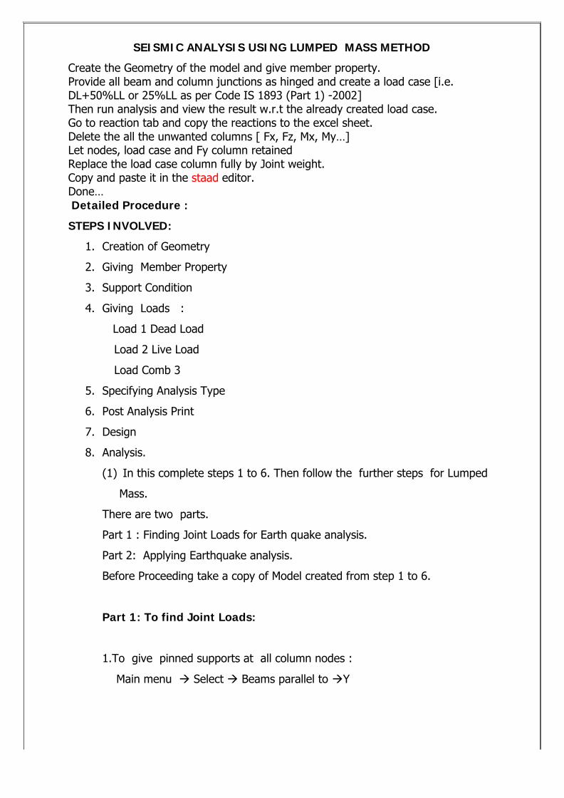
Create the Geometry of the model and give member property.Provide all beam and column junctions as hinged and create a load case [i.e. DL+50%LL or 25%LL as per Code IS 1893 (Part 1) -2002]Then run analysis and view the result w.r.t the already created load case.Go to reaction tab and copy the reactions to the excel sheet.Delete the all the unwanted columns [ Fx, Fz, Mx, My…]Let nodes, load case and Fy column retainedReplace the load case column fully by Joint weight.Copy and paste it in the staad editor.Done…Detailed Procedure :
STEPS INVOLVED:
1. Creation of Geometry
2. Giving Member Property
3. Support Condition
4. Giving Loads :
Load 1 Dead Load
Load 2 Live Load
Load Comb 3
5. Specifying Analysis Type
6. Post Analysis Print
7. Design
8. Analysis.
(1) In this complete steps 1 to 6. Then follow the further steps for Lumped
Mass.
There are two parts.
Part 1 : Finding Joint Loads for Earth quake analysis.
Part 2: Applying Earthquake analysis.
Before Proceeding take a copy of Model created from step 1 to 6.
Part 1: To find Joint Loads:
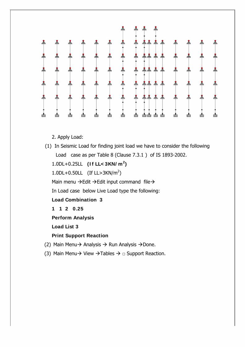
1.To give pinned supports at all column nodes :
Main menu ‡ Select ‡ Beams parallel to ‡Y
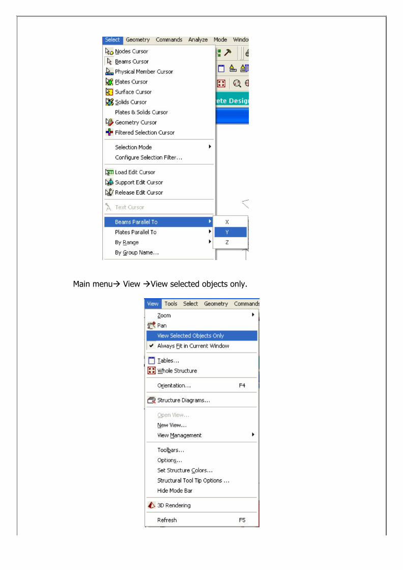
Main menu‡ View ‡View selected objects only.
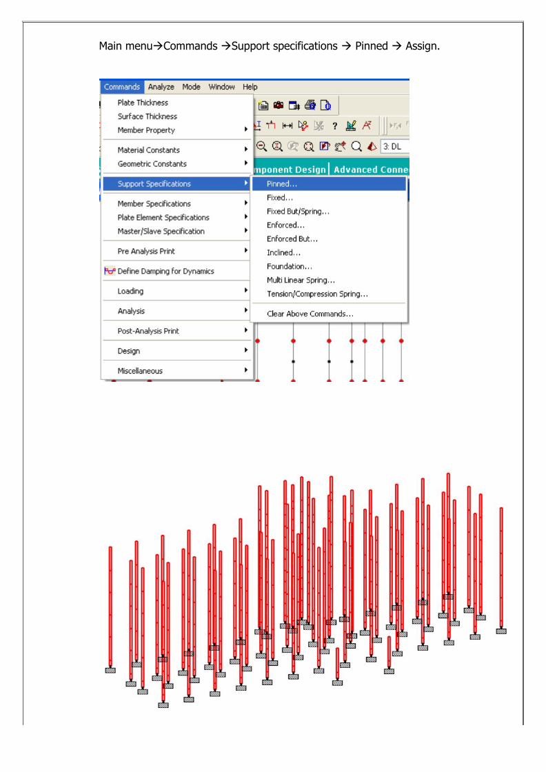
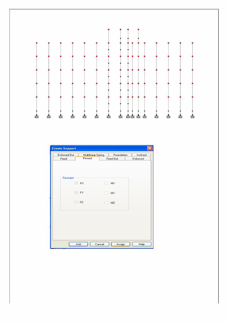
Main menu‡Commands ‡Support specifications ‡ Pinned ‡ Assign.
2. Apply Load:
(1) In Seismic Load for finding joint load we have to consider the following
Load case as per Table 8 (Clause 7.3.1 ) of IS 1893-2002.
1.0DL+0.25LL (If LL<3KN/m2)
1.0DL+0.50LL (If LL>3KN/m2)
Main menu ‡Edit ‡Edit input command file‡
In Load case below Live Load type the following:
Load Combination 3
1 1 2 0.25
Perform Analysis
Load List 3
Print Support Reaction
(2) Main Menu‡ Analysis ‡ Run Analysis ‡Done.
(3) Main Menu‡ View ‡Tables ‡ □ Support Reaction.
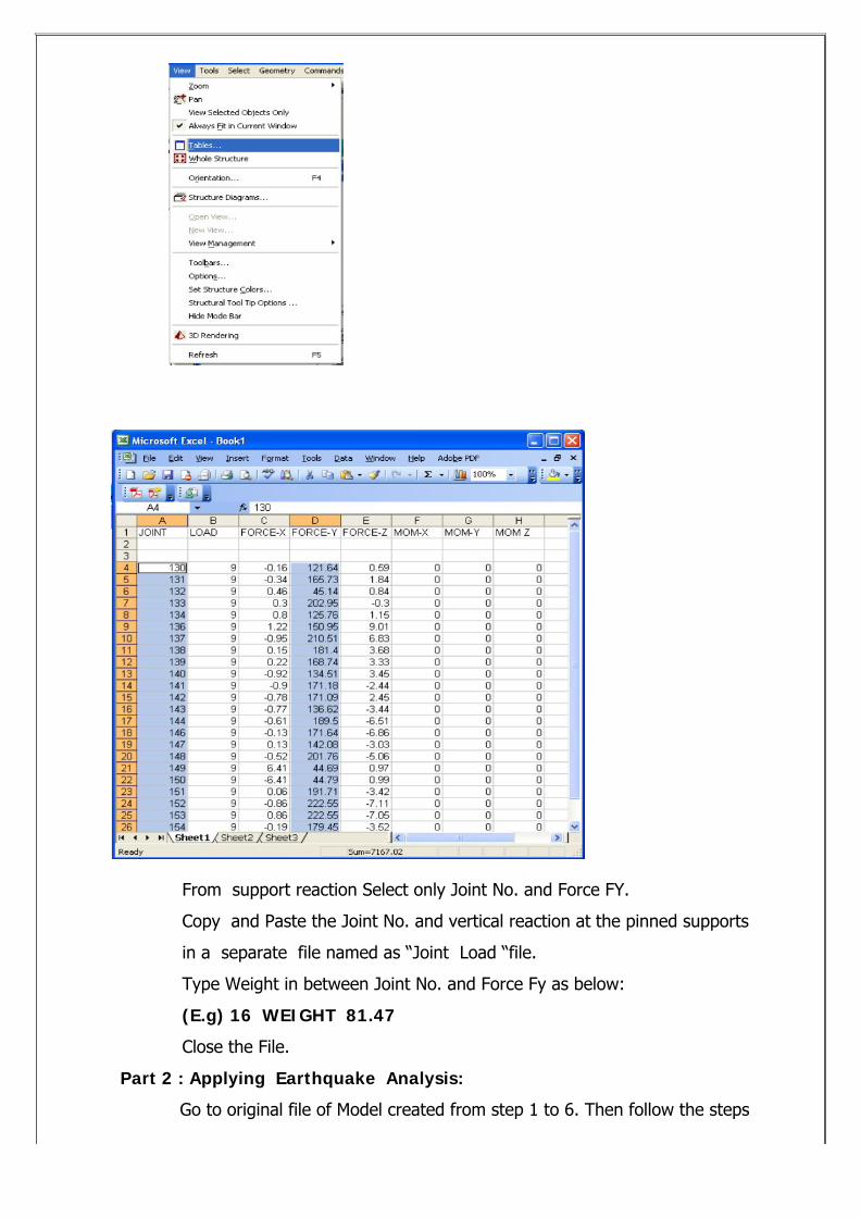
From support reaction Select only Joint No. and Force FY.
Copy and Paste the Joint No. and vertical reaction at the pinned supports
in a separate file named as “Joint Load “file.
Type Weight in between Joint No. and Force Fy as below:
(E.g) 16 WEIGHT 81.47
Close the File.
Part 2 : Applying Earthquake Analysis:
Go to original file of Model created from step 1 to 6. Then follow the steps
below:
DEFINING SEISMIC LOAD:
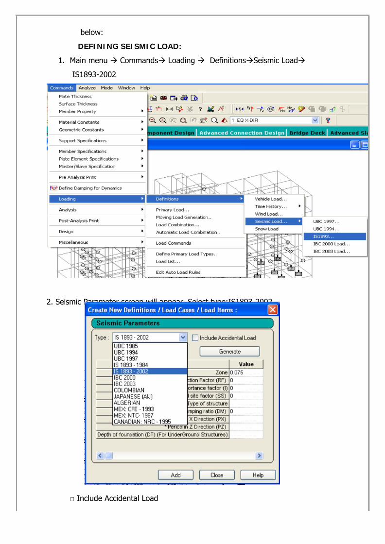
1. Main menu ‡ Commands‡ Loading ‡ Definitions‡Seismic Load‡
IS1893-2002
2. Seismic Parameter screen will appear. Select type:IS1893-2002.
□ Include Accidental Load
□ Generate .
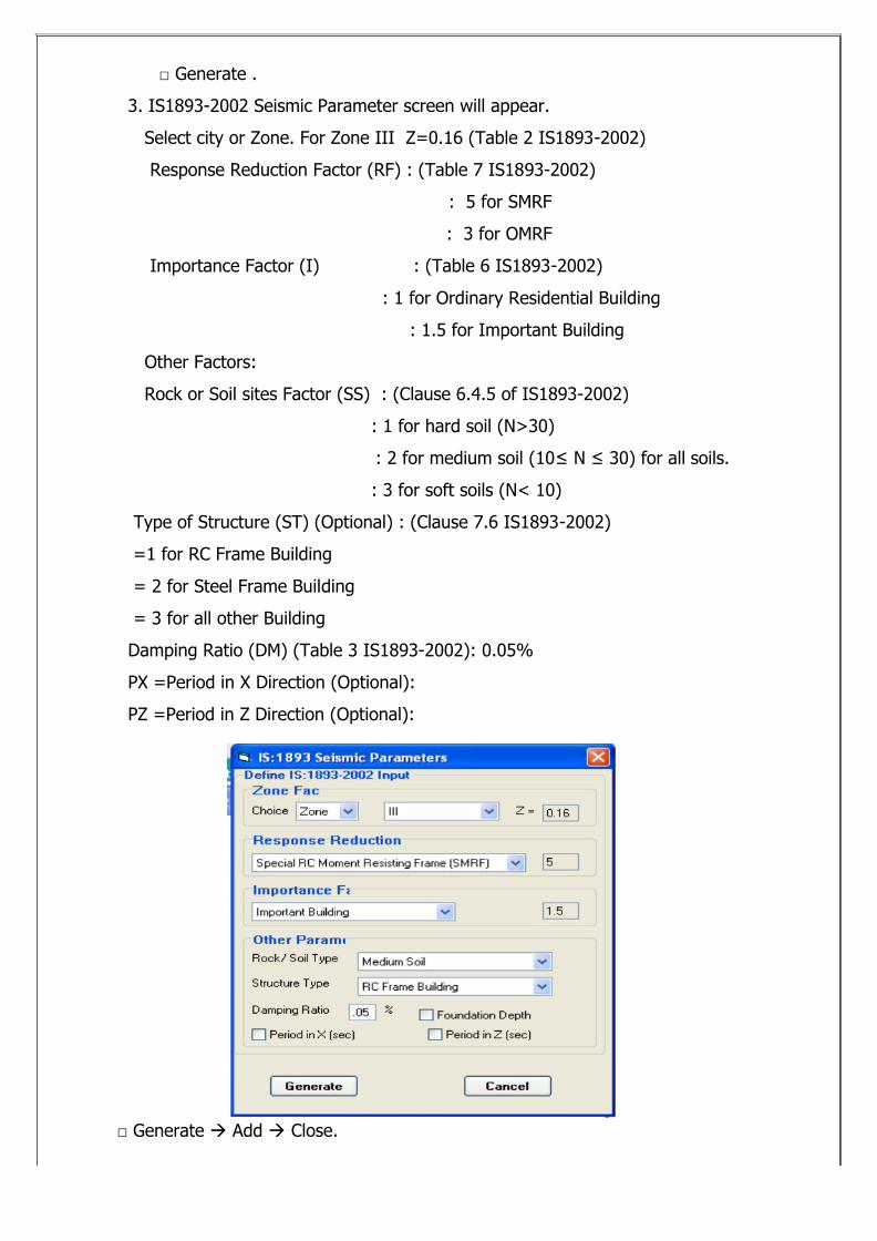
3. IS1893-2002 Seismic Parameter screen will appear.
Select city or Zone. For Zone III Z=0.16 (Table 2 IS1893-2002)
Response Reduction Factor (RF) : (Table 7 IS1893-2002)
: 5 for SMRF
: 3 for OMRF
Importance Factor (I) : (Table 6 IS1893-2002)
: 1 for Ordinary Residential Building
: 1.5 for Important Building
Other Factors:
Rock or Soil sites Factor (SS) : (Clause 6.4.5 of IS1893-2002)
: 1 for hard soil (N>30)
: 2 for medium soil (10≤ N ≤ 30) for all soils.
: 3 for soft soils (N< 10)
Type of Structure (ST) (Optional) : (Clause 7.6 IS1893-2002)
=1 for RC Frame Building
= 2 for Steel Frame Building
= 3 for all other Building
Damping Ratio (DM) (Table 3 IS1893-2002): 0.05%
PX =Period in X Direction (Optional):
PZ =Period in Z Direction (Optional):
□ Generate ‡ Add ‡ Close.
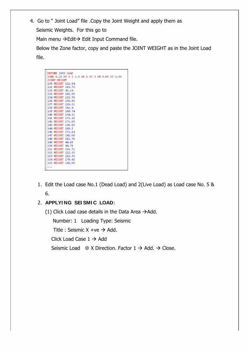
4. Go to “ Joint Load” file .Copy the Joint Weight and apply them as
Seismic Weights. For this go to
Main menu ‡Edit‡ Edit Input Command file.
Below the Zone factor, copy and paste the JOINT WEIGHT as in the Joint Load
file.
1. Edit the Load case No.1 (Dead Load) and 2(Live Load) as Load case No. 5 &
6.
2. APPLYING SEISMIC LOAD:
(1) Click Load case details in the Data Area ‡Add.
Number: 1 Loading Type: Seismic
Title : Seismic X +ve ‡ Add.
Click Load Case 1 ‡ Add
Seismic Load § X Direction. Factor 1 ‡ Add. ‡ Close.
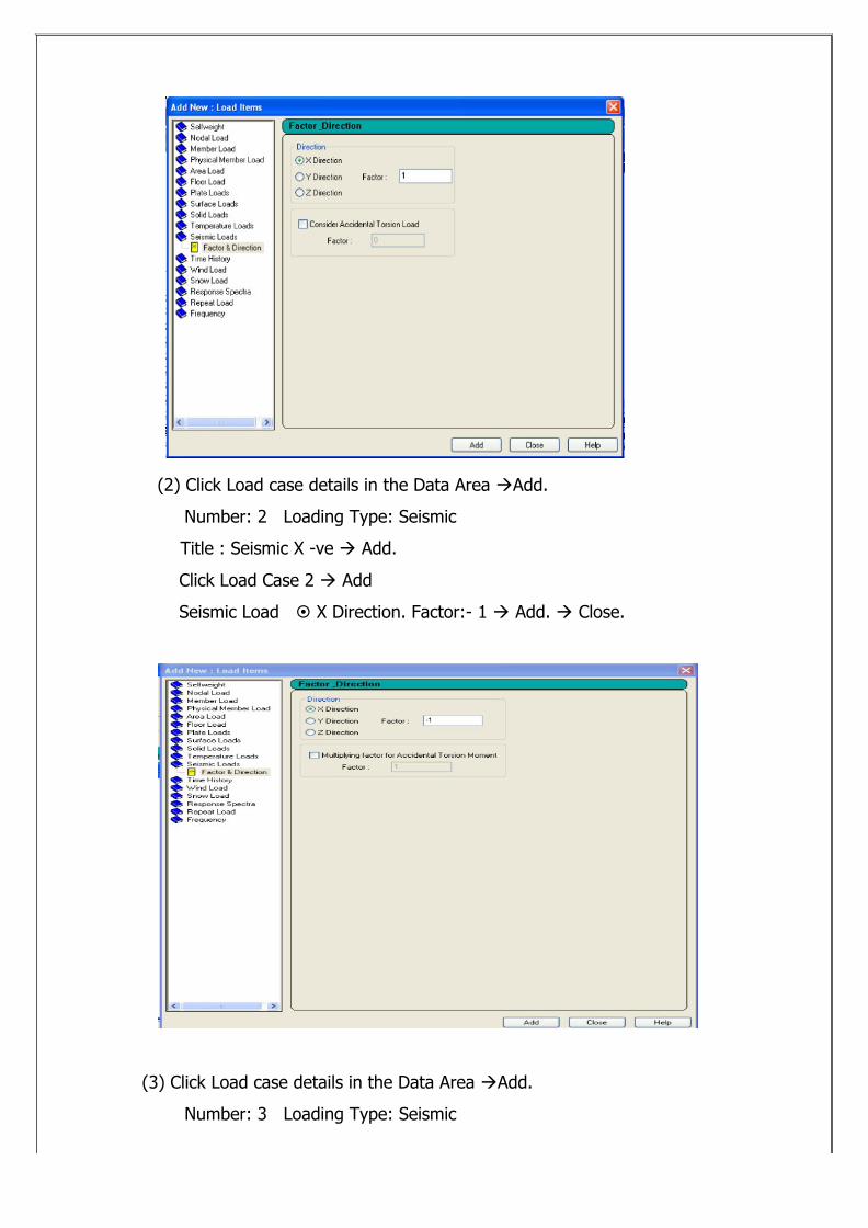
(2) Click Load case details in the Data Area ‡Add.
Number: 2 Loading Type: Seismic
Title : Seismic X -ve ‡ Add.
Click Load Case 2 ‡ Add
Seismic Load § X Direction. Factor:- 1 ‡ Add. ‡ Close.
(3) Click Load case details in the Data Area ‡Add.
Number: 3 Loading Type: Seismic
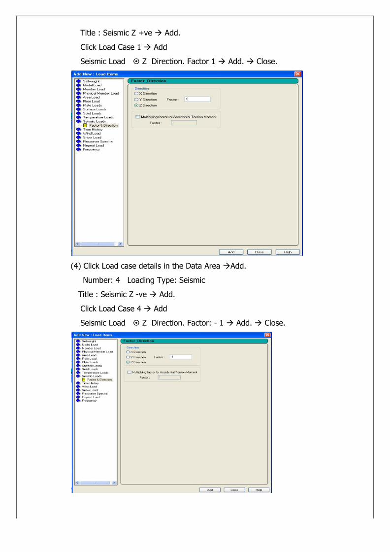
Title : Seismic Z +ve ‡ Add.
Click Load Case 1 ‡ Add
Seismic Load § Z Direction. Factor 1 ‡ Add. ‡ Close.
(4) Click Load case details in the Data Area ‡Add.
Number: 4 Loading Type: Seismic
Title : Seismic Z -ve ‡ Add.
Click Load Case 4 ‡ Add
Seismic Load § Z Direction. Factor: - 1 ‡ Add. ‡ Close.
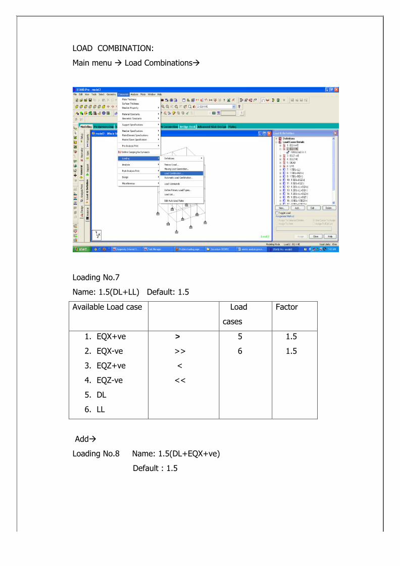
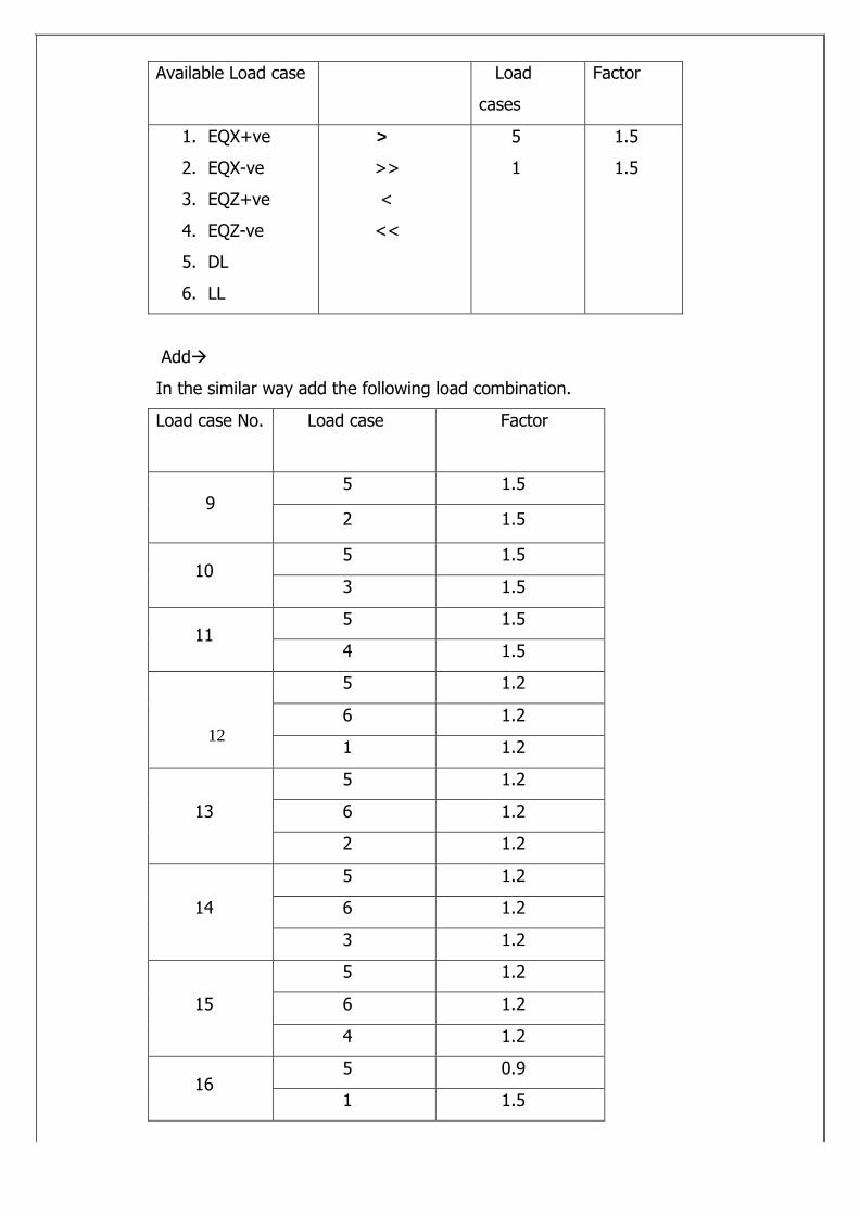
LOAD COMBINATION:
Main menu ‡ Load Combinations‡
Loading No.7
Name: 1.5(DL+LL) Default: 1.5
Available Load case Load
cases
Factor
1. EQX+ve
2. EQX-ve
3. EQZ+ve
4. EQZ-ve
5. DL
6. LL
>
>>
<
<<
5
6
1.5
1.5
Add‡
Loading No.8 Name: 1.5(DL+EQX+ve)
Default : 1.5
Available Load case Load
cases
Factor
1. EQX+ve
2. EQX-ve
3. EQZ+ve
4. EQZ-ve
5. DL
6. LL
>
>>
<
<<
5
1
1.5
1.5
Add‡
In the similar way add the following load combination.
Load case No. Load case Factor
95 1.5
2 1.5
105 1.5
3 1.5
115 1.5
4 1.5
12
5 1.2
6 1.2
1 1.2
13
5 1.2
6 1.2
2 1.2
14
5 1.2
6 1.2
3 1.2
15
5 1.2
6 1.2
4 1.2
165 0.9
1 1.5
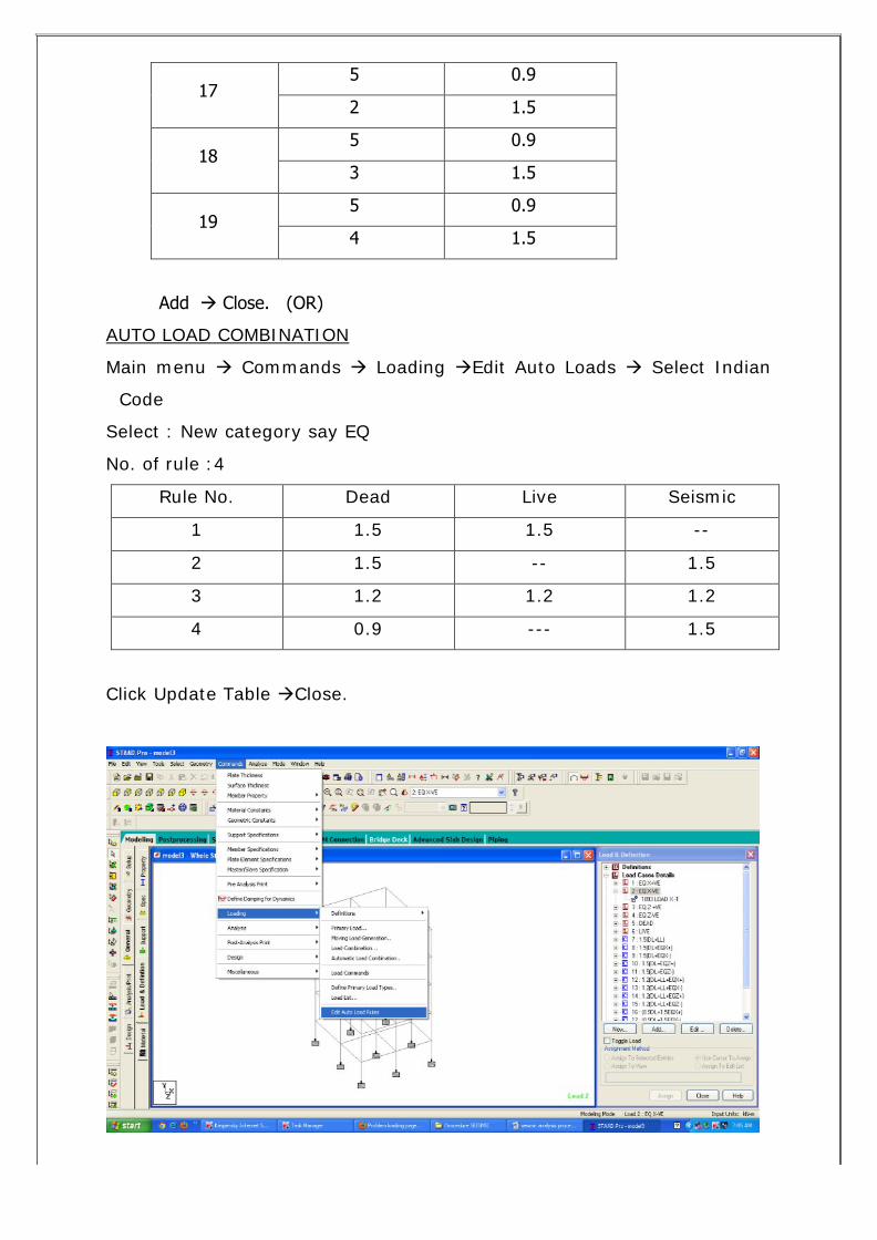
175 0.9
2 1.5
185 0.9
3 1.5
195 0.9
4 1.5
Add ‡ Close. (OR)
AUTO LOAD COMBINATION
Main menu ‡ Commands ‡ Loading ‡Edit Auto Loads ‡ Select Indian
Code
Select : New category say EQ
No. of rule :4
Rule No. Dead Live Seismic
1 1.5 1.5 --
2 1.5 -- 1.5
3 1.2 1.2 1.2
4 0.9 --- 1.5
Click Update Table ‡Close.
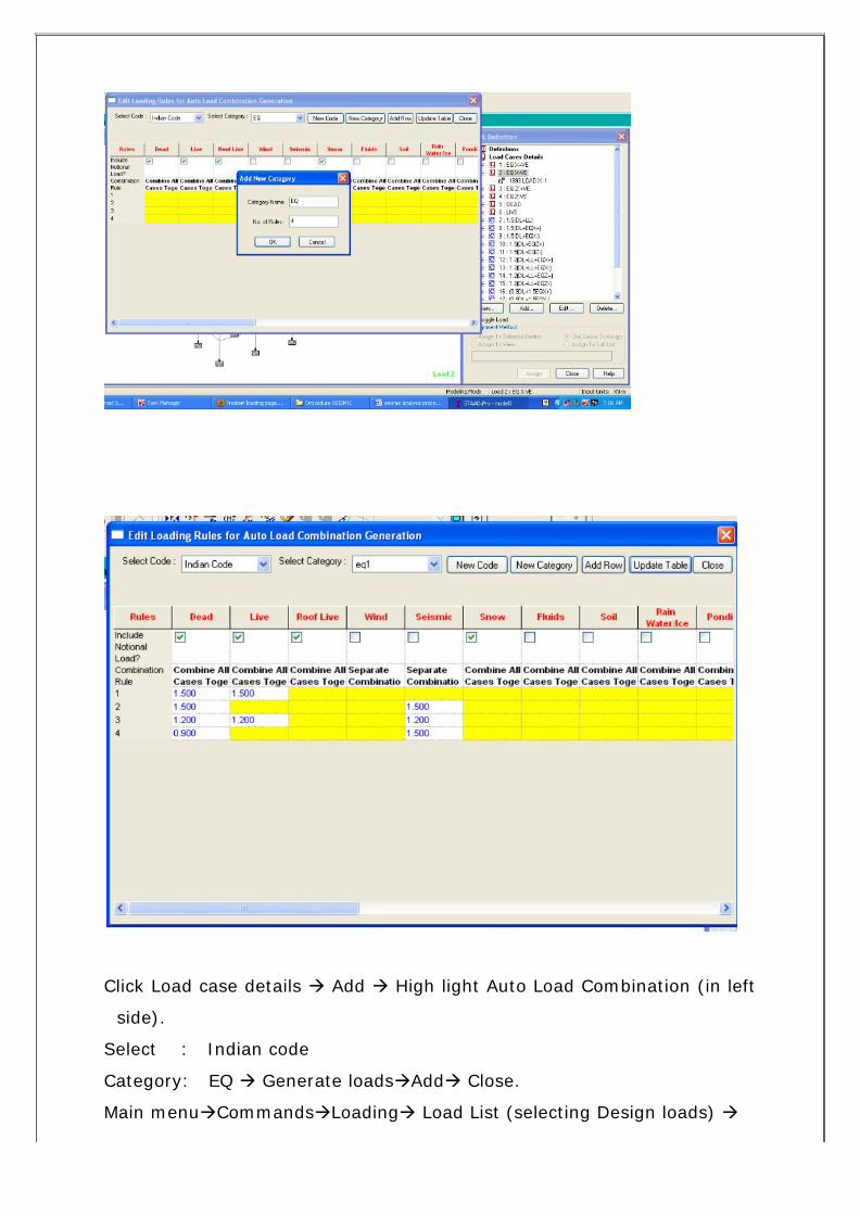
Click Load case details ‡ Add ‡ High light Auto Load Combination (in left
side).
Select : Indian code
Category: EQ ‡ Generate loads‡Add‡ Close.
Main menu‡Commands‡Loading‡ Load List (selecting Design loads) ‡
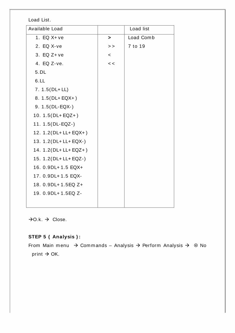
Load List.
Available Load Load list
1. EQ X+ve
2. EQ X-ve
3. EQ Z+ve
4. EQ Z-ve.
5.DL
6.LL
7. 1.5(DL+LL)
8. 1.5(DL+EQX+)
9. 1.5(DL-EQX-)
10. 1.5(DL+EQZ+)
11. 1.5(DL-EQZ-)
12. 1.2(DL+LL+EQX+)
13. 1.2(DL+LL+EQX-)
14. 1.2(DL+LL+EQZ+)
15. 1.2(DL+LL+EQZ-)
16. 0.9DL+1.5 EQX+
17. 0.9DL+1.5 EQX-
18. 0.9DL+1.5EQ Z+
19. 0.9DL+1.5EQ Z-
>
>>
<
<<
Load Comb
7 to 19
‡O.k. ‡ Close.
STEP 5 ( Analysis ):
From Main menu ‡ Commands – Analysis ‡ Perform Analysis ‡ § No
print ‡ OK.
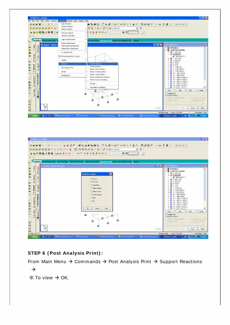
STEP 6 (Post Analysis Print):
From Main Menu ‡ Commands ‡ Post Analysis Print ‡ Support Reactions
‡
§ To view ‡ OK.
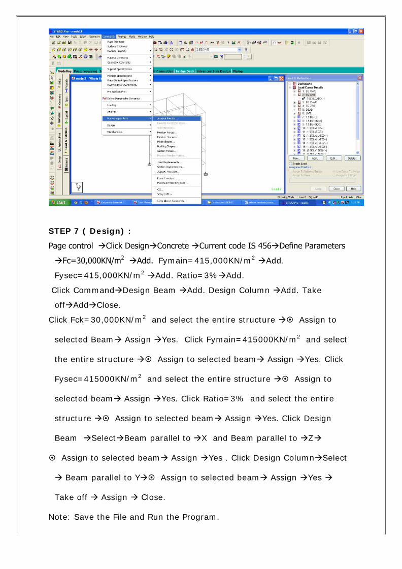
STEP 7 ( Design) :
Page control ‡Click Design‡Concrete ‡Current code IS 456‡Define Parameters
‡Fc=30,000KN/m2 ‡Add. Fymain=415,000KN/m2 ‡Add.
Fysec=415,000KN/m2 ‡Add. Ratio=3%‡Add.
Click Command‡Design Beam ‡Add. Design Column ‡Add. Take
off‡Add‡Close.
Click Fck=30,000KN/m2 and select the entire structure ठAssign to
selected Beam‡ Assign ‡Yes. Click Fymain=415000KN/m2 and select
the entire structure ‡§ Assign to selected beam‡ Assign ‡Yes. Click
Fysec=415000KN/m2 and select the entire structure ठAssign to
selected beam‡ Assign ‡Yes. Click Ratio=3% and select the entire
structure ‡§ Assign to selected beam‡ Assign ‡Yes. Click Design
Beam ‡Select‡Beam parallel to ‡X and Beam parallel to ‡Z‡
§ Assign to selected beam‡ Assign ‡Yes . Click Design Column‡Select
‡ Beam parallel to Y‡§ Assign to selected beam‡ Assign ‡Yes ‡
Take off ‡ Assign ‡ Close.
Note: Save the File and Run the Program.
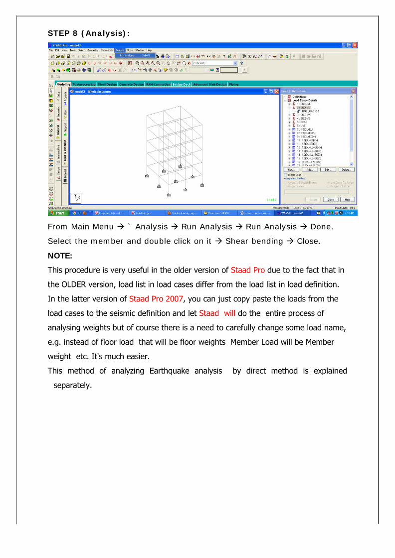
STEP 8 (Analysis):
From Main Menu ‡ ` Analysis ‡ Run Analysis ‡ Run Analysis ‡ Done.
Select the member and double click on it ‡ Shear bending ‡ Close.
NOTE:
This procedure is very useful in the older version of Staad Pro due to the fact that in
the OLDER version, load list in load cases differ from the load list in load definition.
In the latter version of Staad Pro 2007, you can just copy paste the loads from the
load cases to the seismic definition and let Staad will do the entire process of
analysing weights but of course there is a need to carefully change some load name,
e.g. instead of floor load that will be floor weights Member Load will be Member
weight etc. It's much easier.
This method of analyzing Earthquake analysis by direct method is explained
separately.
Related Documents