Lecture 7 Acoustics of Speech & Hearing 6.551 - HST 714J Lecture 7: Lumped Elements I. What is a lumped element? Lumped elements are physical structures that act and move as a unit when subjected to controlled forces. Imagine a two-dimensional block of lead on a one- dimensional frictionless surface. x mass=M FORCE Acceleration When a force is imposed on the block, the block moves as a unit in a direction described by the difference in force acting on its two surfaces, or analytically: dV dt = Net Force Mass (5.1) The key features is that a gradient of a physical parameter produces a uniform physical response throughout the lump. Another example of a lumped element is an electrical resistor where a difference in the Voltage (E) across the resistive element produces a current (I) that is uniform throughout the resistor: I E 1 E 2 a resistor of value R where: I = E 1 − E 2 ( ) / R (5.2) 30 Sept -2004 page 1

Welcome message from author
This document is posted to help you gain knowledge. Please leave a comment to let me know what you think about it! Share it to your friends and learn new things together.
Transcript
Lecture 7 Acoustics of Speech & Hearing 6.551 - HST 714J
Lecture 7: Lumped Elements
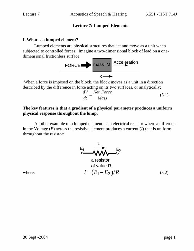
I. What is a lumped element? Lumped elements are physical structures that act and move as a unit when subjected to controlled forces. Imagine a two-dimensional block of lead on a one-dimensional frictionless surface.
x
mass=MFORCEAcceleration
When a force is imposed on the block, the block moves as a unit in a direction described by the difference in force acting on its two surfaces, or analytically:
dVdt
=Net Force
Mass (5.1)
The key features is that a gradient of a physical parameter produces a uniform physical response throughout the lump. Another example of a lumped element is an electrical resistor where a difference in the Voltage (E) across the resistive element produces a current (I) that is uniform throughout the resistor:
IE1 E2
a resistorof value R
where: I = E1 − E2( )/R (5.2)
30 Sept -2004 page 1

Lecture 7 Acoustics of Speech & Hearing 6.551 - HST 714J
II. Lumped Acoustic Elements
A. Elements: A lumped element is a representation of a structure by one or two physical quantities that are homogenous or varying linearly throughout the structure
Standing Waves in P and V in a long tube with a rigid termination at x=0. The spatial variation in the sound pressure magnitude and phase P(x) is defined by a cosine function. The spatial variation in particle velocity magnitude and phase V(x) is defined by a sine function. The region where the tube can act as a lumped element is the region where the pressure amplitude is nearly constant and the ‘volume velocity’ (v x tube cross-section) varies linear with x.
B. An example of a lumped acoustic element is a short open tube of moderate diameter, where length l and radius a are <0.1 λ.
u(t)
p1(t) p
2(t)
length l
A SHORT CIRCULAR TUBE
OF RADIUS a
Under these circumstances particle velocity V and the sound pressures are simply related by:
dVdt
=P1 − P2( )
ρ0l (5.3)
30 Sept -2004 page 2
Lecture 7 Acoustics of Speech & Hearing 6.551 - HST 714J
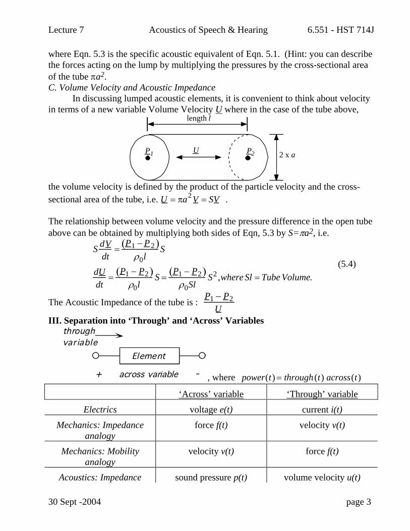
where Eqn. 5.3 is the specific acoustic equivalent of Eqn. 5.1. (Hint: you can describe the forces acting on the lump by multiplying the pressures by the cross-sectional area of the tube πa2. C. Volume Velocity and Acoustic Impedance In discussing lumped acoustic elements, it is convenient to think about velocity in terms of a new variable Volume Velocity U where in the case of the tube above,
UP1
length l
P2 2 x a
the volume velocity is defined by the product of the particle velocity and the cross-sectional area of the tube, i.e. U = πa2 V = SV . The relationship between volume velocity and the pressure difference in the open tube above can be obtained by multiplying both sides of Eqn, 5.3 by S=πa2, i.e.
S dV
dt=
P1 − P2( )ρ0l
S
dUdt
=P1 − P2( )
ρ0lS =
P1 − P2( )ρ0Sl
S2 ,where Sl = Tube Volume. (5.4)
The Acoustic Impedance of the tube is : P1 − P2U
III. Separation into ‘Through’ and ‘Across’ Variables
, where power(t) = through (t) across(t)
‘Across’ variable ‘Through’ variable
Electrics voltage e(t) current i(t)
Mechanics: Impedance analogy
force f(t) velocity v(t)
Mechanics: Mobility analogy
velocity v(t) force f(t)
Acoustics: Impedance sound pressure p(t) volume velocity u(t)
30 Sept -2004 page 3
Lecture 7 Acoustics of Speech & Hearing 6.551 - HST 714J
analogy Acoustics: Mobility
analogy volume velocity u(t) sound pressure p(t)
In all of the above analogies, power(t) = through (t) across(t) has units of watts.
IV. Two Terminal Elements
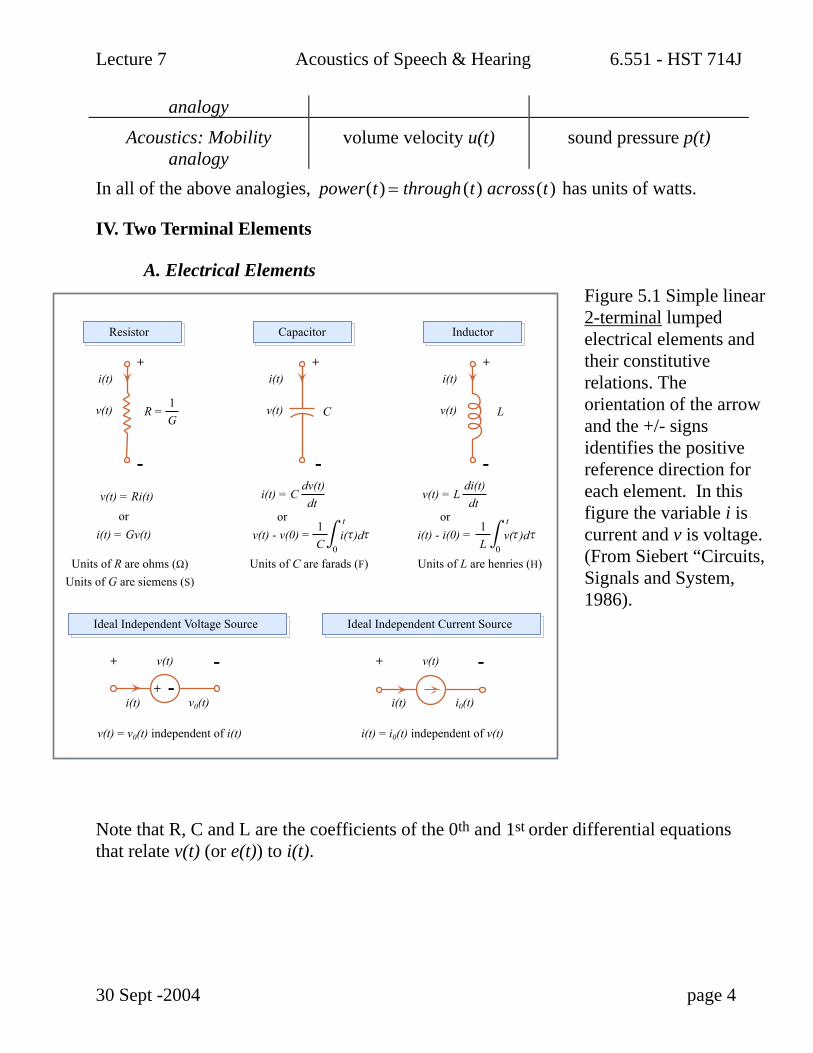
A. Electrical Elements Figure 5.1 Simple linear 2-terminal lumped electrical elements and their constitutive relations. The orientation of the arrow and the +/- signs identifies the positive reference direction for each element. In this figure the variable i is current and v is voltage. (From Siebert “Circuits, Signals and System, 1986).
Note that R, C and L are the coefficients of the 0th and 1st order differential equations that relate v(t) (or e(t)) to i(t).
30 Sept -2004 page 4
Units of R are ohms (Ω)Units of G are siemens (S)
v(t) = v0(t) independent of i(t) i(t) = i0(t) independent of v(t)
Units of C are farads (F) Units of L are henries (H)
LC v(t)v(t)
v(t)
i(t)i(t)
v0(t)i(t)
v(t)
i0(t)i(t)
+
-
+
+
- + --
+
-
v(t)
v(t) = Ri(t)
i(t)+
-i(t) = C
dv(t)dt
v(t) = Ldi(t)dt
R =1G
t t
0
1C
orv(t) - v(0) = i( )d
0
1L
ori(t) - i(0) = v( )d
ori(t) = Gv(t)
Resistor Capacitor Inductor
Ideal Independent Voltage Source Ideal Independent Current Source
m mτ τ ττ
Lecture 7 Acoustics of Speech & Hearing 6.551 - HST 714J
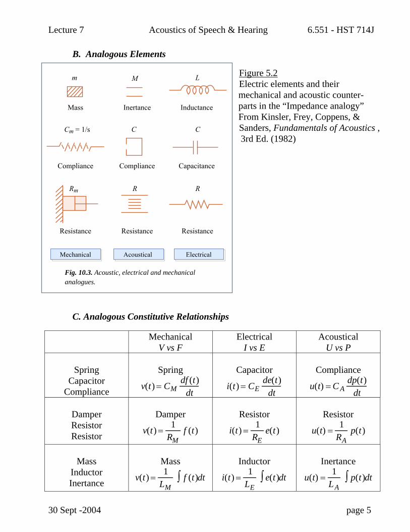
B. Analogous Elements
Figure 5.2 Electric elements and their mechanical and acoustic counter- parts in the “Impedance analogy” From Kinsler, Frey, Coppens, & Sanders, Fundamentals of Acoustics , 3rd Ed. (1982)
C. Analogous Constitutive Relationships
Mechanical V vs F
Electrical I vs E
Acoustical U vs P
Spring
Capacitor Compliance
Spring
v(t) = CMdf (t)
dt
Capacitor
i(t) = CEde(t)
dt
Compliance
u(t) = C Adp(t)
dt
Damper Resistor Resistor
Damper
v(t) =1
RMf (t)
Resistor
i(t) =1
REe(t)
Resistor
u(t) =1
RAp(t)
Mass
Inductor Inertance
Mass
v(t) =1
LMf (t)∫ dt
Inductor
i(t) =1
LEe(t)∫ dt
Inertance
u(t) =1
LAp(t)∫ dt
30 Sept -2004 page 5
Mass
m
Cm = 1/s
Rm R R
C C
M L
Inertance Inductance
Compliance Compliance
Resistance
Fig. 10.3. Acoustic, electrical and mechanicalanalogues.
Resistance Resistance
Capacitance
ElectricalMechanical Acoustical
Lecture 7 Acoustics of Speech & Hearing 6.551 - HST 714J
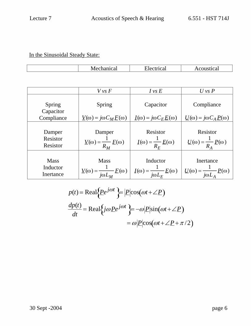
V vs F I vs E U vs P
Spring Capacitor
Compliance
Spring
V(ω) = jωCM F(ω)
Capacitor
I(ω) = jωCE E(ω)
Compliance
U (ω) = jωCA P(ω)
Damper Resistor Resistor
Damper
V (ω) =1
RMF(ω)
Resistor
I(ω) =1
REE(ω)
Resistor
U (ω) =1
RAP(ω)
Mass
Inductor Inertance
Mass
V (ω) =1
jωLMF (ω )
Inductor
I(ω) =1
jωLEE (ω )
Inertance
U (ω) =1
jωLAP(ω)
p(t) = Real Pe jωt = P cos ωt +∠P( )dp(t)
dt= Real jωPe jωt = −ω P sin ωt +∠P( )
= ω P cos ωt +∠P +π /2( )
30 Sept -2004 page 6
In the Sinusoidal Steady State:
Mechanical Electrical Acoustical
Lecture 7 Acoustics of Speech & Hearing 6.551 - HST 714J
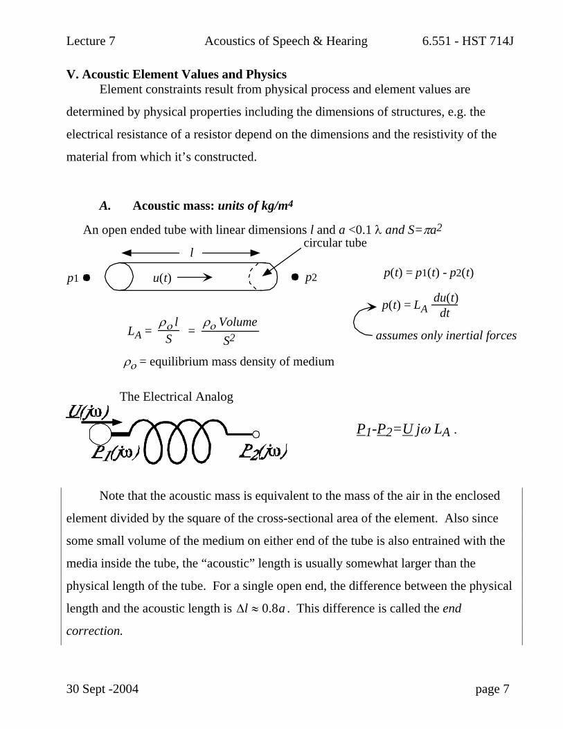
V. Acoustic Element Values and Physics Element constraints result from physical process and element values are
determined by physical properties including the dimensions of structures, e.g. the
electrical resistance of a resistor depend on the dimensions and the resistivity of the
material from which it’s constructed.
A. Acoustic mass: units of kg/m4
An open ended tube with linear dimensions l and a <0.1 λ and S=πa2
l
p1 p2u(t)
circular tube
p(t) = p1(t) - p2(t)
p(t) = LAdu(t)dt
assumes only inertial forcesLA =ρο l
Sρο Volume
S2=
ρο = equilibrium mass density of medium
The Electrical Analog
P1-P2=U jω LA .
Note that the acoustic mass is equivalent to the mass of the air in the enclosed
element divided by the square of the cross-sectional area of the element. Also since
some small volume of the medium on either end of the tube is also entrained with the
media inside the tube, the “acoustic” length is usually somewhat larger than the
physical length of the tube. For a single open end, the difference between the physical
length and the acoustic length is ∆l ≈ 0.8a . This difference is called the end
correction.
30 Sept -2004 page 7
Lecture 7 Acoustics of Speech & Hearing 6.551 - HST 714J
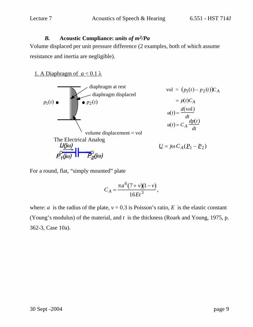
B. Acoustic Compliance: units of m3/Pa Volume displaced per unit pressure difference (2 examples, both of which assume
resistance and inertia are negligible).
1. A Diaphragm of a < 0.1 λ
vol = p1 t( ) − p2 t( )( )C A
= p t( )CA
u t( ) =d vol( )
dtu t( ) = C A
dp t( )dt
diaphragm at rest diaphragm displaced
volume displacement = vol
p1 t( ) p2 t( )
The Electrical Analog
U = jωCA(P1 − P2)
For a round, flat, “simply mounted” plate
C A =πa6 7 + v( ) 1 − v( )
16Et 3 ,
where: a is the radius of the plate, v = 0.3 is Poisson’s ratio, E is the elastic constant
(Young’s modulus) of the material, and t is the thickness (Roark and Young, 1975, p.
362-3, Case 10a).
30 Sept -2004 page 9

Lecture 7 Acoustics of Speech & Hearing 6.551 - HST 714J
2. Enclosed volume of air with linear dimensions <0.1 λ
u(t)p(t)
P(jω)
U(jω)
Another structure that may be well approximated by an acoustic compliance.
C =Volume
Adiabatic Bulk modulus
U = jωCAP
The variations in sound pressure within an enclosed air volume generally occur about
the steady-state atmospheric pressure, the ground potential in acoustics. Therefore,
one terminal of an electrical-analog of a volume-determined acoustic compliance
should always be grounded.
C. Acoustic Resistance: units of Acoustic Ohms (Pa-s/m3)
1. A narrow tube or radius a << 0.001 λ
lcircular (radius = a) rigid tube --filled with acoustic medium
p1 t( ) p2 t( )u t( )
p t( ) = p1 t( )− p2 t( ) = RAu t( )← assumption; only viscous forces
RA =8ηlπa4 ⇒
p1(t) − p2 (t)u(t)
η = viscosity of medium
Because of the viscous forces, relative motions of fluid at one radial position with
respect to an adjacent position exerts a force opposing the motion that is proportional
to the spatial derivative of the velocity and the fluid’s coefficient of shear viscosity η.
30 Sept -2004 page 10
Lecture 7 Acoustics of Speech & Hearing 6.551 - HST 714J
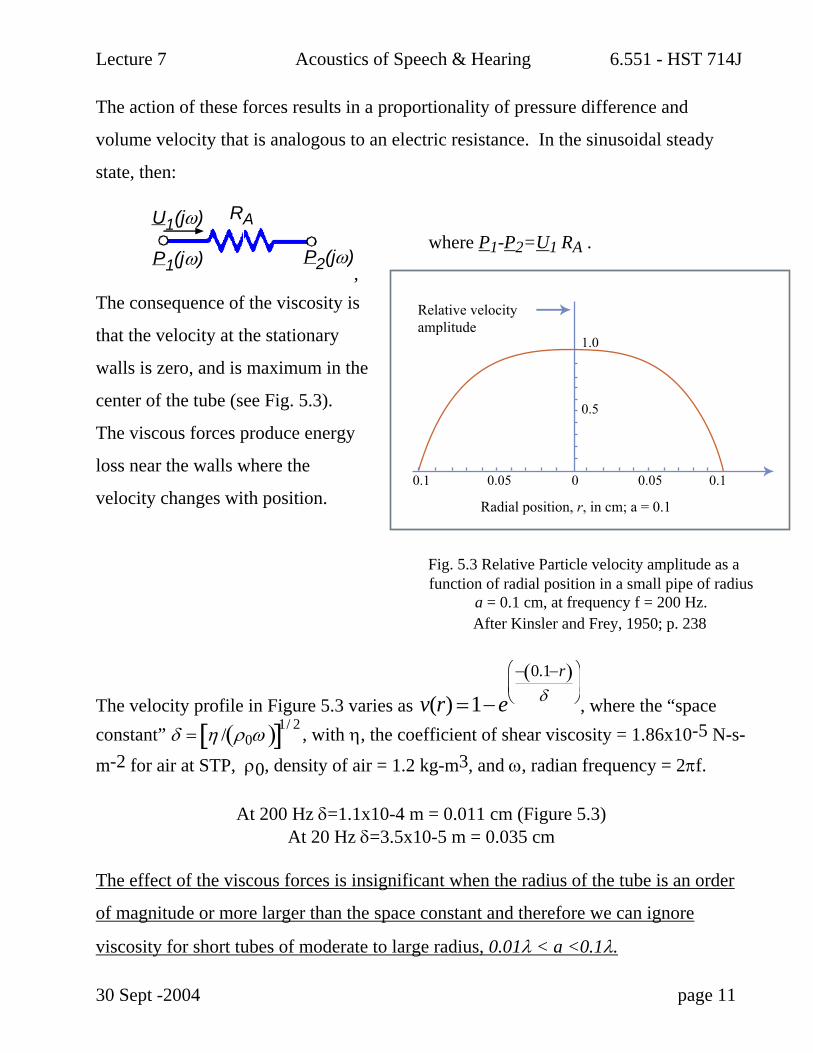
The action of these forces results in a proportionality of pressure difference and
volume velocity that is analogous to an electric resistance. In the sinusoidal steady
state, then:
P1(jω) P2(jω)
U1(jω) RA
,
where P1-P2=U1 RA .
The consequence of the viscosity is
that the velocity at the stationary
walls is zero, and is maximum in the
center of the tube (see Fig. 5.3).
The viscous forces produce energy
loss near the walls where the
velocity changes with position.
Fig. 5.3 Relative Particle velocity amplitude as a function of radial position in a small pipe of radius
a = 0.1 cm, at frequency f = 200 Hz. After Kinsler and Frey, 1950; p. 238
The velocity profile in Figure 5.3 varies as v(r) =1−e− 0.1−r( )
δ⎛
⎝ ⎜
⎞
⎠ ⎟ , where the “space
constant” , with η, the coefficient of shear viscosity = 1.86x10⁻⁵ N-s-
m-2 for air at STP, ρ0, density of air = 1.2 kg-m3, and ω, radian frequency = 2πf.
δ = η / ρ0ω( )[ 1/ 2]
At 200 Hz δ=1.1x10⁻⁴ m = 0.011 cm (Figure 5.3)
At 20 Hz δ=3.5x10⁻⁵ m = 0.035 cm The effect of the viscous forces is insignificant when the radius of the tube is an order
of magnitude or more larger than the space constant and therefore we can ignore
viscosity for short tubes of moderate to large radius, 0.01λ < a <0.1λ.
30 Sept -2004 page 11
Radial position, r, in cm; a = 0.1
Relative velocity amplitude
0.1 0.05 0
0.5
1.0
0.05 0.1

Lecture 7 Acoustics of Speech & Hearing 6.551 - HST 714J
type of acoustic resistance can be constructed from a long tube of moderate cross-
sectional dimensions (0.01 λ < a < 0.2 λ). Such a construction can conduct sound
power away from a system and can be treated as an acoustic resistance where:
R =
ρ0 cπa2 .
30 Sept -2004 page 12
2. An infinitely long tube
The action of an acoustic resistor is to absorb sound power. The viscous forces
within a narrow tube convert the sound power into heat that dissipates away. A second

Lecture 7 Acoustics of Speech & Hearing 6.551 - HST 714J
There is a catch, however, in that
this lumped element always has
one end coupled to ground and
therefore can only be used to
either terminate acoustic circuits
or be placed in parallel with other
elements. There are ways of
dealing with long tubes as a
collection of series and parallel
elements that have already been
discussed in Lecture 2.
l is effectively infinitep(t)
u(t)P0
P1(jω)
U1(jω) RA
D. Two Mixed mass-resistance acoustic loads
1. A tube of intermediate radius (neither wide nor narrow) has an impedance
determined by the combination of an acoustic mass or inertance (associated with
accelerating the fluid mass within the tube) and a resistance (associated with
overcoming viscous drag at the stationary walls of the tube). Since the pressure
drop across the resistance and the mass elements add, we think of these as an R
and L in series.
u(t)p
1(t) p
2(t)
length l
An intermediate tube
∆P = P2 − P1 = U jωρol S + R( )
30 Sept -2004 page 13
Lecture 7 Acoustics of Speech & Hearing 6.551 - HST 714J
LE RE
where S is the cross-sectional area of the tube and R is the resistance.
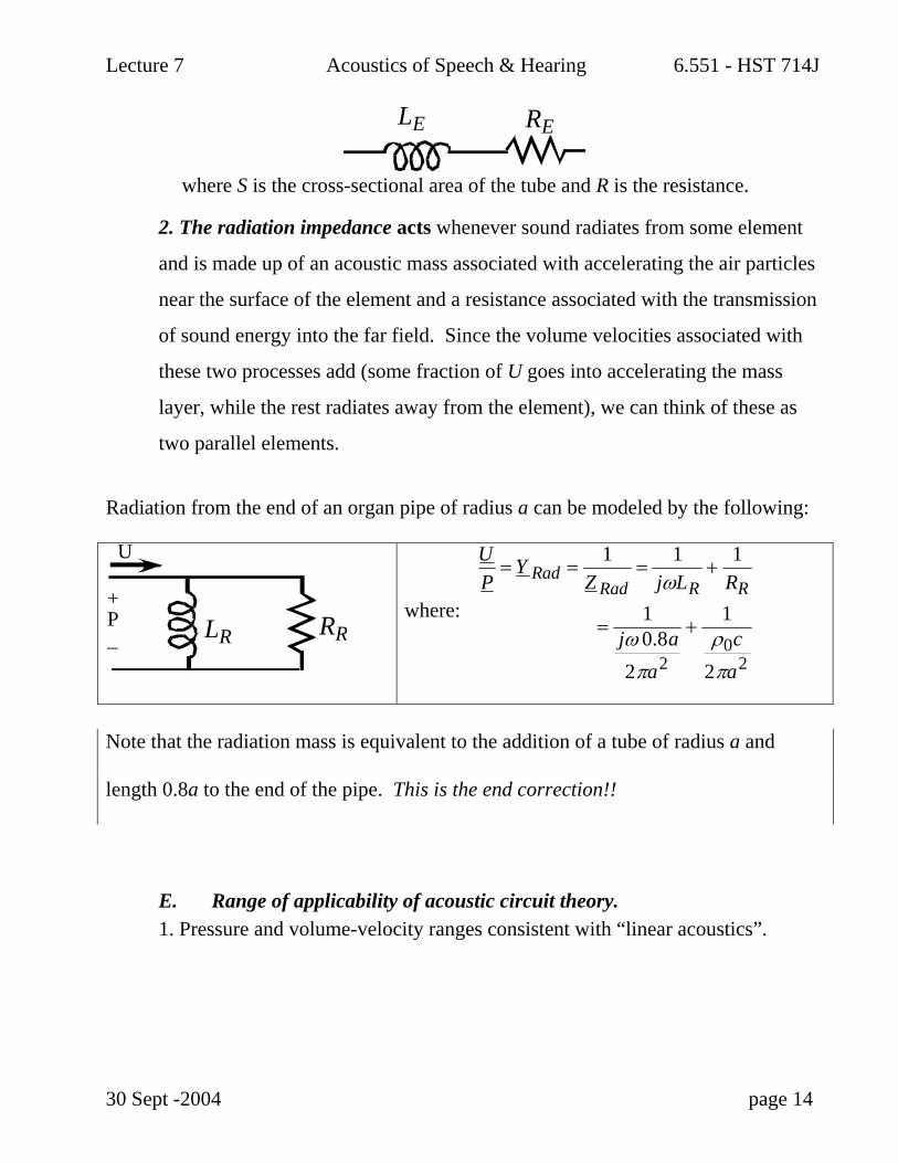
2. The radiation impedance acts whenever sound radiates from some element
and is made up of an acoustic mass associated with accelerating the air particles
near the surface of the element and a resistance associated with the transmission
of sound energy into the far field. Since the volume velocities associated with
these two processes add (some fraction of U goes into accelerating the mass
layer, while the rest radiates away from the element), we can think of these as
two parallel elements.
Radiation from the end of an organ pipe of radius a can be modeled by the following:
LR RR
U
+P_
where:
UP
= Y Rad =1
Z Rad=
1jωLR
+1
RR
=1
jω 0.8a2πa2
+1
ρ0c2πa2
Note that the radiation mass is equivalent to the addition of a tube of radius a and
length 0.8a to the end of the pipe. This is the end correction!!
E. Range of applicability of acoustic circuit theory. 1. Pressure and volume-velocity ranges consistent with “linear acoustics”.
30 Sept -2004 page 14

Lecture 7 Acoustics of Speech & Hearing 6.551 - HST 714J
2. Frequency range limited by the assumption of “lumped” elements, i.e. the
dimensions of the structures need to be small compared to a wavelength:
a and l < 0.1 λ.
30 Sept -2004 page 15
Lecture 7 Acoustics of Speech & Hearing 6.551 - HST 714J
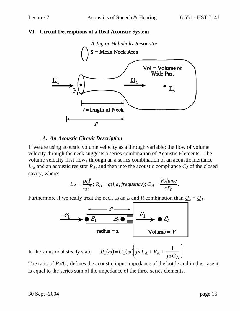
VI. Circuit Descriptions of a Real Acoustic System
A Jug or Helmholtz Resonator
A. An Acoustic Circuit Description If we are using acoustic volume velocity as a through variable; the flow of volume velocity through the neck suggests a series combination of Acoustic Elements. The volume velocity first flows through an a series combination of an acoustic inertance LA, and an acoustic resistor RA, and then into the acoustic compliance CA of the closed cavity, where:
LA =ρ0 ′ l πa2 ; RA = g(l,a, frequency); C A =
VolumeγP0
.
Furthermore if we really treat the neck as an L and R combination than U2 = U1.
In the sinusoidal steady state: P1 ω( ) =U1 ω( ) jωLA + RA +1
jωC A
⎛
⎝ ⎜ ⎜
⎞
⎠ ⎟ ⎟
The ratio of P1/U1 defines the acoustic input impedance of the bottle and in this case it is equal to the series sum of the impedance of the three series elements.
30 Sept -2004 page 16
Lecture 7 Acoustics of Speech & Hearing 6.551 - HST 714J
Z IN ω( )= jωLA + RA +1
jωCA
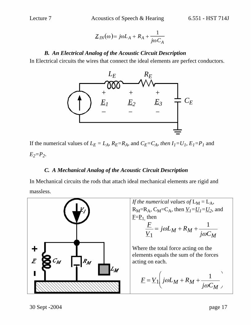
B. An Electrical Analog of the Acoustic Circuit Description In Electrical circuits the wires that connect the ideal elements are perfect conductors.
LE RE
CEE1 E2 E3
+ + +
If the numerical values of LE = LA, RE=RA, and CE=CA, then I1=U1, E1=P1 and
E2=P2.
C. A Mechanical Analog of the Acoustic Circuit Description
In Mechanical circuits the rods that attach ideal mechanical elements are rigid and
massless.
30 Sept -2004 page 17
If the numerical values of LM = LA, RM=RA, CM=CA, then V1=U1=U2, and F=P1, then
FV1
= jωLM + RM + 1jωCM
Where the total force acting on the elements equals the sum of the forces acting on each.
F = V1 jωLM + RM + 1jωCM
⎛
⎝ ⎜
⎞
⎠
Related Documents