Proceedings of Heap Leach Mining Solutions, 2016 October 18- 20, 2016, Lima, Peru Published by InfoMine, © 2016 InfoMine, ISBN: 978-1-988185-03-3 1 Seismic analysis of a valley-fill heap leach pad Miguel Regalado, Anddes, Peru Keith Pérez, Anddes, Peru Andrés Reyes, Anddes, Peru and The University of British Columbia, Canada Roy Marroquín, Tahoe Resources, Peru Juan Rodríguez, Tahoe Resources, Peru Abstract For a long time, in highly active seismic zones such as Peru and Chile, the seismic design of heap leach pads has been performed mostly by using a pseudo static approach. However, recent researches highlight the calculation of seismic-induced permanent displacements as a more rational concept for seismic design of earth structures. A range of allowable displacements for the structure can be used as design criteria, which should be selected to prevent the tearing of the liner system geomembrane during seismic events. The range of displacements for heap leach pads is usually narrower than for other earth mining structures such as tailings storage facilities or mine waste dumps. Failure of the pad’s liner system can lead to environmental damage, losses of lives and economical detriment. Additionally, in Peru, heap leach pads are usually built within narrow valleys where its three-dimensional nature can influence their seismic behavior. This paper presents a case study of a valley-fill heap leach pad of a Peruvian mining project where its overall design was defined by its seismic behaviour. A large set of geotechnical information was used for the analyses which included state-of-the-art characterization of static and dynamic properties of leached ore and interface (liner system). The seismic analysis included one-dimensional nonlinear seismic response analysis, the use of simplified procedures to calculate seismic induced permanent displacements and two and three-dimensional dynamic analyses. Several comparisons between the results of multi- dimensional analyses were made to show the influence of the foundation soils, geometry of the valley, geotechnical parameters, among other details. The results allowed to authors to compare different approaches to calculate seismic induced permanent displacements for a valley-fill heap leach pad. Differences between the methods used was addressed. Also, the seismic response of the heap was evaluated comparing one, two and three- dimensional analysis.

Welcome message from author
This document is posted to help you gain knowledge. Please leave a comment to let me know what you think about it! Share it to your friends and learn new things together.
Transcript

Proceedings of Heap Leach Mining Solutions, 2016
October 18- 20, 2016, Lima, Peru
Published by InfoMine, © 2016 InfoMine, ISBN: 978-1-988185-03-3
1
Seismic analysis of a valley-fill heap leach pad
Miguel Regalado, Anddes, Peru
Keith Pérez, Anddes, Peru
Andrés Reyes, Anddes, Peru and The University of British Columbia, Canada
Roy Marroquín, Tahoe Resources, Peru
Juan Rodríguez, Tahoe Resources, Peru
Abstract
For a long time, in highly active seismic zones such as Peru and Chile, the seismic design of heap leach
pads has been performed mostly by using a pseudo static approach. However, recent researches highlight
the calculation of seismic-induced permanent displacements as a more rational concept for seismic design
of earth structures. A range of allowable displacements for the structure can be used as design criteria,
which should be selected to prevent the tearing of the liner system geomembrane during seismic events.
The range of displacements for heap leach pads is usually narrower than for other earth mining structures
such as tailings storage facilities or mine waste dumps. Failure of the pad’s liner system can lead to
environmental damage, losses of lives and economical detriment. Additionally, in Peru, heap leach pads
are usually built within narrow valleys where its three-dimensional nature can influence their seismic
behavior.
This paper presents a case study of a valley-fill heap leach pad of a Peruvian mining project where
its overall design was defined by its seismic behaviour. A large set of geotechnical information was used
for the analyses which included state-of-the-art characterization of static and dynamic properties of
leached ore and interface (liner system). The seismic analysis included one-dimensional nonlinear seismic
response analysis, the use of simplified procedures to calculate seismic induced permanent displacements
and two and three-dimensional dynamic analyses. Several comparisons between the results of multi-
dimensional analyses were made to show the influence of the foundation soils, geometry of the valley,
geotechnical parameters, among other details.
The results allowed to authors to compare different approaches to calculate seismic induced
permanent displacements for a valley-fill heap leach pad. Differences between the methods used was
addressed. Also, the seismic response of the heap was evaluated comparing one, two and three-
dimensional analysis.

HEAP LEACH MINING SOLUTIONS, 2016 ● LIMA, PERU
2
Introduction
The Peruvian mining industry operates at high altitude in the Andes, where its topography is very
aggressive and unfavorable for heap leach pad (HLP) design and construction. A standard project can
operate at altitudes higher than 3,000 meters above sea level, where the only place available for earth
mining structures is usually narrow valleys. The design of earthworks, liner systems, solution collection
systems and first lift stacking usually involve special and specific design criteria that differs significantly
from the ones used in conventional HLP constructed in almost ideal conditions, such as flat terrains at
much lower altitudes.
In countries such as Peru and Chile, which are subjected to strong seismic events, seismic stability
analysis of HLP is paramount during design stages and is regularly performed through pseudo-static
analysis and less often by the calculation of seismic-induced permanent displacements (SIPD). The
approach for SIPD calculation varies from simplified methodologies to fully coupled dynamic analysis
(Reyes and Pérez, 2015) and is focused on determining the magnitude of displacements induced by
seismic forces in the soil-geomembrane interface of the HLP liner system. The analysis methodologies
are whether from one-dimensional (1D) or two-dimensional (2D) nature; however, no previous study has
assessed the influence of the three-dimensional nature of valleys for HLP on both the heap and interface
dynamic response.
Based on geotechnical site investigations, advance laboratory testing and previous studies related to
seismic analyses of HLP, this paper presents the seismic analysis of a valley-fill heap leach pad located in
northern Peru. The analysis included 1D seismic response analysis, simplified procedures for the
calculation of SIPD and 2D and 3D fully coupled dynamic analyses. The results of the evaluation were
compared in order to understand the limitations and advantages of the simplified procedures and the 3D
effect associated with valley-fill HLP.
Background and current practice
The process of subduction of the Nazca plate beneath the South American plate is responsible for the high
seismicity that Peru experiments. Therefore, most civil and mining structures built in this country are
design to endure the strong seismic loads produced by this phenomenon. In Peru, there are regional
seismic studies such as the ones developed by Castillo and Alva (1993) and Gamarra and Aguilar (2009),
which show the high probability of occurrence of strong seismic events, leading as a consequence to a
strongly seismic-influenced overall design. These studies present isoacceleration maps for different soil
types and return periods that can be used for seismic design. However, nowadays Peruvian mining

HEAP LEACH MINING SOLUTIONS, 2016 ● LIMA, PERU
3
authorities demand to perform a specific seismic hazard assessment for each site, so that this literature is
used as reference for conceptual design.
Up until a few years ago, pseudo-static analysis was considered as an standard to evaluate the
seismic behavior of HLP design by considering a horizontal seismic coefficient ranging from a third to a
half of the peak ground acceleration (PGA), as proposed by Hynes-Griffin (1984). However, this criterion
was suggested for earth dams (Newmark, 1965), which are structures less sensible to SIPD than HLP or
tailings storage facilities. To overcome this clear limitation, several methods to whether select an
appropriate value of pseudo-static coefficient (e.g. Bray and Travasarou, 2009) or to calculate SIPD (e.g.
(Makdisi and Seed, 1978; Houston et al., 1987; Bray and Travasarou, 2007) developed in the interface
system were summarized and further evaluated by Reyes and Pérez (2015). Based on this study and
several others, the current state-of-practice of seismic design of HLP in Peru is currently shifting towards
defining a maximum allowable level of SIPD rather than using a simple qualitative pseudo-static factor of
safety. SIPD are important for HLP since they tend to develop along its liner system. Recent studies
performed by Kavazanjian et al. (2011, 2012) in landfills, which also have a liner system, indicate that the
maximum allowable SIPD may vary from 15 to 30 cm, which would be the trigger level of displacements
before geomembrane tearing , and subsequent economic and environmental damage, occurs.
While the calculation of SIPD seems a more rational and practical tool for the seismic design of
HLP, it is important to understand the difference between the several existing methodologies of analysis,
their limitations, advantages, influence of dynamic properties of the materials involved in the evaluations
and the limitations of simplifying a 3D structure to 1D or 2D models.
Case study
The case study presented in this paper is a 120-m high HLP located at a mine site in northern Peru with a
maximum capacity of almost 55 Mt. While the HLP was already been stacked with a capacity of 6 Mt, the
authors were in charge of its stability verification, focusing on its seismic stability condition. In order to
accomplish this, a large set of geotechnical field investigations and laboratory tests was carried out to
characterize both the static and cyclic behaviour of the materials involved in the HLP design such as the
soil foundation, soil-geomembrane interface of the liner system and the leached ore.
To evaluate the seismic stability of this HLP, the authors performed several analysis which included
preliminary pseudo-static slope stability analysis, 1D seismic response analysis (SRA), simplified
calculations of SIPD and 2D and 3D dynamic analysis; the latter of this is described in detail by Reyes et
al. (2016). The following sections describe all of these analyses as well as the reasoning behind them.
Figure 1 presents the plan view of the HLP and two cross-sections (1-1’ and 2-2’) which were used for all
the analyses.

HEAP LEACH MINING SOLUTIONS, 2016 ● LIMA, PERU
4
Figure 1: Plan view and cross-sections 1-1’ and 2-2’ of the heap leach pad
Field investigation and laboratory testing
The field work was focused on characterizing the foundations soils, soil-geomembrane interface and
leached ore. Several samples of soil liner and geomembrane were collected in situ by removing part of the
leached ore at the toe of the heap and cutting the geomembrane. On the other hand, leached ore samples
were collected directly from the operating heap and their global of field particle-size distribution (PSD)
curves, which included particles larger 3 in, were determined through several excavations along existing
heap slopes. Additionally, several boreholes were executed at the toe of the heap to evaluate the
foundation over-consolidated clayey soils. Standard penetration tests (SPT) were executed and
undisturbed samples were collected. No phreatic level was detected. Finally, a complete geophysical
survey was completed along the heap and foundation soils.
Using the samples collected from the operating heap, a relatively large set laboratory tests were
carried out. Regarding the clayey foundation soils, drained triaxial tests were carried out on undisturbed
samples which, in conjunction with geophysical tests results, provide the information necessary for the
analysis.
Leached ore was subjected to additional tests, since no database is available particularly for its
dynamic properties. The samples collected were reconstituted in laboratory using the parallel gradation
technique. This method scaled the field PSD curve to a parallel one considering the maximum particle
size allowed by the testing device, which is usually between 10 to 15 times smaller the maximum particle
size of standard LO and MW. This technique was first developed by Lowe (1964) and then extensively
used by Marachi et al. (1969), Thiers and Donovan (1981) and Varadarajan et al. (2003) to perform
drained monotonic triaxial tests on rockfill, crushed rock and alluvial soils, respectively. The PSD curve
2-2’
1-1’
C
A
B
200 m
200 m

HEAP LEACH MINING SOLUTIONS, 2016 ● LIMA, PERU
5
of the materials tested in the laboratory maintained the same coefficient of uniformity (CU), PSD shape
and relative density as the materials in the field but limiting the fines content to a maximum of 10%.
Using this technique, monotonic drained triaxial tests were performed in a local laboratory in Lima, Peru.
Additionally, the laboratory program included sets of special tests performed at the University of Texas at
Austin using resonant column-torsional shear (RCTS) and cyclic-triaxial (CTX). The RCTS tests were
performed in a sequential series on the same specimen with isotropic confining pressures (σ’0) ranging
from 200 kPa to 800 kPa. For each specimen, nonlinear RCTS tests were conducted at two or three σ’0
over a shearing strain (γ) range from about 10-6
% to slightly more than 0.1%. CTX tests were conducted
on these specimens at a single σ’0 of 700 kPa for each specimen and over an estimated shearing strain
range from about 0.01% to 1.4%. Further detail on these cyclic tests and others performed exclusively on
leached ore and rock mine waste materials are presented by Parra et al. (2016).
Finally, two sets of large scale direct shear (LSDS) tests were performed on the low permeability
soil-textured geomembrane interface: all of them tested on remoulded soil samples considering an
interface consisting of the textured side an LLDPE 2.0 mm geomembrane in contact with a low
permeability soil. One test was performed under normal stresses ranging from 100 to 800 kPa in a local
laboratory and the other one was carried out at the TRI Environmental laboratory at Austin, Texas using
normal stresses up to 2000 kPa, since most of the interface in the leach pad is subjected to normal stresses
from 1000 to 2000 kPa. Along with the tests above described, a detailed review of all previous field and
laboratory tests was executed that allowed to properly define both static and dynamic properties of all
materials involved in the geotechnical design.
Static analyses
The HLP studied is located over an over-consolidated, unsaturated clayey soil foundation. Hence, only
translational failures were of concern, which provided lower factor of security (FOS) than the rotational
ones. Thus the foundation soil was represented in all the analyses as a cluster with much higher strength
than the interface or leached ore. The following sections briefly describe the geotechnical properties for
the static evaluations which were performed before the seismic analyses.
Static properties
The CD triaxial tests on leached ore provided nonlinear shear strength envelopes since it was considered
cohesionless with a reducing friction angle as confining pressure increases. The logarithmic tendency of
developed by Leps (1970) for coarse granular materials was consistent with the results of CD triaxial
tests, with a friction angle ranging from 35 to 39°. On the other hand, the nonlinear monotonic stress-
strain behavior was modeled using the Hardening Soil (HS) formulation (Brinkgreve et al., 2014). The
HS is an advanced model for simulating the behaviour of different types of soil, both soft and stiff

HEAP LEACH MINING SOLUTIONS, 2016 ● LIMA, PERU
6
(Schanz, 1998). The HS formulation was calibrated with the resulting stress-strain curves of the CD
triaxial tests. Another nonlinear shear strength envelope was defined for the interface. The studies
published by Ayala and Huallanca (2014) and Parra et al. (2012) evidence the influence of the nonlinear
behaviour of the interface for the stability analyses. The LSDS results at high normal stresses
demonstrated the shear strength is nonlinear at high stresses. The Figure 2 shows the nonlinear shear
strength envelopes for leached ore and interface.
Figure 2: Nonlinear shear resistance envelope for leached ore and interface
Static analysis
The 2D static analysis consisted initially on limit equilibrium method evaluations using the Spencer
(1967) procedure on the 5 cross-sections shown in Figure 1. The resulting 2D FOS of the design cross-
sections showed stability conditions lower than the permissible (minimum FOS=1.3) for translational
failures, as can be seen in the Table 1.
In order to evaluate the static slope stability under a rigorous criterion, the structure was analysed
with the computer program FLAC (Itasca, 2011) using cross-sections 1-1’and 2-2’, which were chosen
due to their low FOS and representativeness of the HLP. The heap conformation was simulated by 5
stages consisting of several lifts until the crest is reached. Figure 1 shows the stages defined for each
cross-section. The initial stresses (horizontal and vertical) were calculated and then used in the subsequent
dynamic analysis. The resulting 2D FOS obtained was very similar to ones calculated by the limit
equilibrium evaluation, as can be seen in the Table 1. Figure 3 displays the resemblance of the 2D
translation failure surfaces obtained from both limit equilibrium and finite difference analyses. To
overcome this apparent static instability, a 3D limit equilibrium slope stability analysis was carried out
which allowed the authors to determine that the 3D effect of the valley was favourable for the HLP
stability. The obtained 3D FOS were higher than the minimum required for those conditions (1.40-145).
Further details on this 3D evaluation are presented by Reyes et al. (2015).

HEAP LEACH MINING SOLUTIONS, 2016 ● LIMA, PERU
7
Table 1: 2D FOS calculated by limit equilibrium and finite difference methods
Cross-section Method
Factor of safety
Static Pseudo-static
(Tr =100 years)
0-0’ Limit equilibrium 1.19 0.90
1-1’ Limit equilibrium 1.21 0.91
Finite difference 1.22 0.93
2-2’ Limit equilibrium 1.12 0.86
Finite difference 1.12 0.88
3-3’ Limit equilibrium 1.12 0.88
4-4’ Limit equilibrium 1.39 1.07
Figure 3: Maximum shear strain-rate for the cross-section 1-1’ (above) and 2-2’ (below)
Seismic analyses
The seismic analyses of HLP initially consisted on limit equilibrium pseudo-static analysis. However, due
to the instability suggested by its results, 1D SRA and simplified calculation of SIPD were completed to
determine the effect of the seismic forces on the liner system. Additionally, to verify these calculations
and include the effect of the HLP valley in the seismic stability, dynamic analysis in 2D and in 3D using
FLAC and FLAC 3D (Itasca, 2012), respectively, were performed. Below, it is described the dynamic
parameters of the materials involved, details and results of each type of analysis.
FLAC (Version 7.00)
LEGEND
2-Aug-16 19:43
step 121751
-6.109E+01 <x< 1.161E+03
-4.034E+02 <y< 8.184E+02
Factor of Safety 1.12
Max. shear strain-rate
0.00E+00
1.00E-08
2.00E-08
3.00E-08
4.00E-08
5.00E-08
Contour interval= 1.00E-08
Extrap. by averaging
Boundary plot
0 2E 2
Water Table
-3.000
-1.000
1.000
3.000
5.000
7.000
(*10 2̂)
0.100 0.300 0.500 0.700 0.900 1.100
(*10 3̂)
JOB TITLE : .
Anddes
Lima
Limit equilibrium failure surface
Limit equilibrium failure surface

HEAP LEACH MINING SOLUTIONS, 2016 ● LIMA, PERU
8
Seismicity
The seismic analysis used the uniform hazard response spectrum for 100 years return period and defined
for Class B soil (rock) as a design criterion. Seismic records from both horizontal components used as
input for site response analysis were obtained from published motions from Peruvian subduction
earthquakes recorded in Peru. The earthquake motions from the 1970 Lima and 2001 Atico were chosen
to perform the dynamic the 2D and 3D analyses. It is important to mention that the both Lima and Atico
earthquake motions were recorded near the epicenter of the event, capturing their high energy content. No
other earthquake motions were selected due to the limited database available for Peru. These two seismic
records were rotated to the most critical direction before any processing was done. Then, they were
spectral matched to the 100 years return period uniform hazard response spectrum using the SeismoMatch
software, which is based in the pulse wave algorithm proposed by Abrahamson (1992) and Hancock et al.
(2006).
Dynamic properties
First, based on the curves obtained by the both RCTS and CTX tests on leached ore, the normalized shear
modulus and damping ratio curves for this material were determined for confining pressures of 200 and
700 kPa. These proposed curves were compared with the Menq (2003) formulation, observing a good
agreement from the small-strain range up to 0.01% of shear strain. Detailed discussion of these tests
results is presented by Parra et al. (2016). Additionally, geophysics survey results, performed above
leached ore, were compared with RCTS report test obtaining a good agreement between the in-situ
measurements and the predictions of the RCTS device. Figure 4 present the dynamic properties of the
leached ore as tested in laboratory and as proposed curves for the seismic analysis.
Figure 4: Normalized modulus reduction and damping ratio curves for leached ore.
The dynamic properties of the interface were defined by reviewing existing information on this
matter. The backbone curve for the interface was modeled based on its static shear strength, according to

HEAP LEACH MINING SOLUTIONS, 2016 ● LIMA, PERU
9
the conclusion of Kavazanjian and Matasovic (1995) and Arab (2011). The damping ratio was modeled
based on the cyclic shear tests on interfaces performed by Arab (2011) which show a relatively constant
damping ratio value. This constant nature of the interface damping ratio is similar to the findings of
Yegian et al. (1998), which only was used to determine the maximum shear modulus (Gmax). It is
important to mention that no cyclic shear test on the interface was developed for this paper; however,
sensibility SRA analyses were carried out to analyse the inherent uncertainties of this modelling; these
evaluations showed similar results for all cases.
For the foundation soil, the modulus reduction and damping ratio curves were represented by means
of the Darendeli (2001) formulation, which use several parameters such as plasticity index (PI), over-
consolidation ratio (OCR) and confining stress, among others. The Darendeli (2001) formulation was
proposed by clayey and silty soils with a low percent of coarse grained soil. Additionally, the geophysical
survey’s shear wave velocity profiles of the foundation were used in the seismic analysis.
Finally, the dynamic properties of the bedrock were assigned considering an elastic material and
only as a medium to broadcast waves. Because of the translational failure does not occur through this
material, the shear strains induced by the earthquake were not of importance. Table 2 presents the main
properties used in the seismic analysis.
Table 2: Main geotechnical parameters for seismic analysis
Material
Static properties Dynamic properties
Cohesion (kPa)
Friction angle (°)
Shear modulus (MPa)
Maximum shear modulus (MPa)
Modulus reduction and damping ratio curves
Leached ore Nonlinear
envelope
Defined based on HS model calibration
Based on RCTS and geophysical tests
Based on RCTS and CTX tests
Soil-
geomembrane interface
Nonlinear
envelope Nonlinear envelope
Based on Yegian et
al. (1998)
Based on Kavazanjian and Matasovic (1995),
Yegian et al. (1998) and Arab (2011)
Foundation soil 150 32 Defined based on HS
model calibration Based on
geophysical tests Darendeli (2001)
1D seismic response analysis
In order to determine a seismic response spectrum in free field conditions for the HLP, a 1D equivalent
linear SRA was carried out using several soil columns and the spectral matched seismic records defined
before. The computer program DeepSoil (Hashash et al., 2016) was used to perform the SRA. The
analyses were performed in three different zones of HLP such as the crest, the intermediate bench and the
toe identified as Zone A, B and C in Figure 1. The resulting seismic response spectra were used for the
calculation of seismic coefficients and SIPD and as comparison for the dynamic analysis. Figure 5 shows
the seismic spectra obtained from the 1D SRA, 2D and 3D dynamic analysis for the Lima seismic record.

HEAP LEACH MINING SOLUTIONS, 2016 ● LIMA, PERU
10
Figure 5: Response spectra’s of (a) Zone A (b) Zone B and (c) Zone C for the 1970 Lima seismic record from 1D SRA, 2D and 3D dynamic analyses.
Pseudo-static analyses
Using the resulting seismic response spectrum from the SRA and maximum allowable displacement of
30 cm, a horizontal seismic coefficient of 0.07 was calculated using the Bray and Travasarou (2009). The
calculated FOS from the pseudo-static analysis result are shown in the Table 1. These results suggest that
SIPD higher the 30 cm are likely to develop along the liner system for almost all cross-sections. It is
important to remark that, although the static 3D limit equilibrium verified that the 3D effect of the valley
had an important effect of its static stability, no such conclusion can be made for a pseudo-static analysis.
The reason behind this is because the seismic coefficient is defined in 2D conditions and cannot be
directly use in a 3D analysis. Hence, the calculation of SIPD in a 2D fashion was mandatory in order to
verify these assumptions. Only a 3D dynamic analysis, such as the performed by Reyes et al. (2016) and
included in this paper, could evaluate the seismic effect of the 3D geometry of the valley.
Seismic induced displacements by simplified methods
The calculation of SIPD for operation conditions, associated with a 100 years return period seismic event,
was performed using the Makdisi and Seed (1978), Houston et al. (1987) and Bray and Travasarou (2007)

HEAP LEACH MINING SOLUTIONS, 2016 ● LIMA, PERU
11
methods. For the calculation, it was necessary to know the seismic response in the foundation and heap
itself. For that reason, for Makdisi and Seed (1978) and Houston et al. (1987) methods, 1D SRA using
linear equivalent method were performed using DeepSoil (Hashash et al., 2016) using the synthetics
motions mentioned earlier. Three soil columns per section were built for section 1-1’ and 2-2’, which
were composed by leached ore of 30 to 100 m, foundation soil of 45 to 80 m and bedrock of 5 m
thickness. For the specific case of the Houston et al. (1987) method, the computer program D-MOD
(Matasovic, 1993) was used to calculate the SIPD. Finally, the Bray and Travasarou (2007) method used
the resulting seismic response spectrum in free field conditions described in previous sections. The Table
3 presents the range and average values of horizontal displacements developed along the interface.
2D dynamic analysis
In order to verify the displacements developed along the interface, a 2D dynamic analysis as carried in the
software FLAC (Itasca, 2011) for cross-sections 1-1’ and 2-2’. The analyses simulated the construction
process of the HLP with a 5-stage sequence until the crest is reached, as can be seen in Figure 1. The
models and zones satisfy the seismic wave transmission requirements given by Kuhlemeyer and Lysmer
(1973) which recommend that maximum zone dimension should be less than one tenth to one eight of the
maximum shear wave length associated with the highest frequency component of the input wave for any
material.
Special care was taken when modeling both the static and dynamic properties of the HLP. For the
leached ore static properties, its shear strength was modeled as a nonlinear envelope and its elastic
modulus were based on the HS model hyperbolic relationship of modulus and confining pressure.
Regarding its dynamic properties, the Mohr-Coulomb model was used and a hysteretic behavior was
included. The modeled dynamic curves are presented in Figure 4. A similar approach was followed for
the foundation soils, except no nonlinear envelope was used for its shear resistance. Finally, the soil-
geomembrane interface was modeled as an interface element in FLAC with a shear strength resembling
the nonlinear envelope defined in Figure 2. Similarly, it shear modulus was defined using a nonlinear
envelope. Regarding its dynamic properties, the Mohr-Coulomb model for the interface managed to
closely represent the dynamic properties discussed earlier in the paper for soil-geomembrane contacts. No
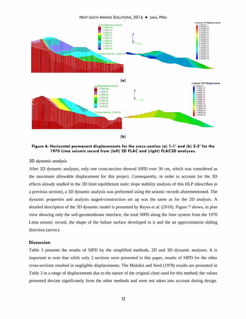
additional hysteretic damping was added. Figure 6 shows the horizontal displacements for cross-sections
1-1’ and 2-2’ resulting from the 2D dynamic analysis and Table 3 presents the results in terms of
displacements along interface
HEAP LEACH MINING SOLUTIONS, 2016 ● LIMA, PERU
12
(a)
(b)
Figure 6: Horizontal permanent displacements for the cross-section (a) 1-1’ and (b) 2-2’ for the 1970 Lima seismic record from (left) 2D FLAC and (right) FLAC3D analyses.
3D dynamic analysis
After 2D dynamic analyses, only one cross-section showed SIPD over 30 cm, which was considered as
the maximum allowable displacement for this project. Consequently, in order to account for the 3D
effects already studied in the 3D limit equilibrium static slope stability analysis of this HLP (describes in
a previous section), a 3D dynamic analysis was performed using the seismic records aforementioned. The
dynamic properties and analysis staged-construction set up was the same as for the 2D analysis. A
detailed description of the 3D dynamic model is presented by Reyes et al. (2016). Figure 7 shows, in plan
view showing only the soil-geomembrane interface, the total SIPD along the liner system from the 1970
Lima seismic record, the shape of the failure surface developed in it and the an approximation sliding
direction (arrow).
Discussion
Table 3 presents the results of SIPD by the simplified methods, 2D and 3D dynamic analyses. It is
important to note that while only 2 sections were presented in this paper, results of SIPD for the other
cross-sections resulted in negligible displacements. The Makdisi and Seed (1978) results are presented in
Table 3 in a range of displacements due to the nature of the original chart used for this method; the values
presented deviate significantly form the other methods and were not taken into account during design.
FLAC (Version 7.00)
LEGEND
1-Aug-16 20:20
step 1862780
Dynamic Time 3.9060E+01
-7.344E+01 <x< 1.395E+03
-5.347E+02 <y< 9.338E+02
X-displacement contours
0.00E+00
2.50E-02
5.00E-02
7.50E-02
1.00E-01
1.25E-01
1.50E-01
1.75E-01
2.00E-01
Contour interval= 2.50E-02
-4.000
-2.000
0.000
2.000
4.000
6.000
8.000
(*10 2̂)
0.100 0.300 0.500 0.700 0.900 1.100 1.300
(*10 3̂)
JOB TITLE : .
Anddes
Lima
FLAC (Version 7.00)
LEGEND
1-Aug-16 19:44
step 743300
Dynamic Time 3.9060E+01
-4.284E+01 <x< 1.245E+03
-3.770E+02 <y< 9.113E+02
X-displacement contours
0.00E+00
1.00E-01
2.00E-01
3.00E-01
4.00E-01
5.00E-01
6.00E-01
Contour interval= 1.00E-01
-2.000
0.000
2.000
4.000
6.000
8.000
(*10 2̂)
0.100 0.300 0.500 0.700 0.900 1.100
(*10 3̂)
JOB TITLE : .
Anddes
Lima
FLAC (Version 7.00)
LEGEND
13-Aug-16 17:23
step 1862780
Dynamic Time 3.9060E+01
-7.344E+01 <x< 1.395E+03
-5.347E+02 <y< 9.338E+02
X-displacement contours
0.00E+00
2.50E-02
5.00E-02
7.50E-02
1.00E-01
1.25E-01
1.50E-01
1.75E-01
2.00E-01
Contour interval= 2.50E-02
-4.000
-2.000
0.000
2.000
4.000
6.000
8.000
(*10 2̂)
0.100 0.300 0.500 0.700 0.900 1.100 1.300
(*10 3̂)
JOB TITLE : .
Anddes
Lima
FLAC (Version 7.00)
LEGEND
13-Aug-16 17:23
step 743300
Dynamic Time 3.9060E+01
-6.109E+01 <x< 1.161E+03
-4.034E+02 <y< 8.185E+02
X-displacement contours
0.00E+00
1.00E-01
2.00E-01
3.00E-01
4.00E-01
5.00E-01
6.00E-01
Contour interval= 1.00E-01
-3.000
-1.000
1.000
3.000
5.000
7.000
(*10 2̂)
0.100 0.300 0.500 0.700 0.900 1.100
(*10 3̂)
JOB TITLE : .
Anddes
Lima

HEAP LEACH MINING SOLUTIONS, 2016 ● LIMA, PERU
13
The Houston et al. (1987) results are presented as average values of the soil columns used during
calculation. On the other hand, a range of displacements is predicted by the Bray and Travasarou (2007)
technique, which is a characteristic of its formulation. Finally, the FLAC 2D and 3D results are presented
both a range and average values of displacements: the ranges show the maximum and minimum
displacements developed along the interface and within the failure surface while the average values are
representative of the whole failure.
Figure 7: Interface shear displacements for the 1970 Lima seismic record
Table 3: SIPD values for 100 year return-period
Cross-section
Seismic record
SIPD (cm)
Makdisi and Seed (1978)
Houston et al. (1987)
Bray and Travasarou (2007)
FLAC 2D
Range Average Range Range Average
1-1’ Lima
0.4-5.0 20.7
6.0-24.0 1.2-19.2 11.1
Atico 10.1 4.2-18.1 10.3
2-2’ Lima
3.0-25.0 47.3
14.3-57.2 11.0-59.0 43.0
Atico 28.9 12.0-63.1 46.3
3D model
Lima Range
5.0-30.0 Average
~20.0
Atico 5.0-30.0 ~20.0
The FLAC 2D model results in an average displacement of 10.7 cm, ranging from 1.2 and 19.2 cm
for the section 1-1’, while for section 2-2’ results in an average displacement of 44.7 cm, ranging from
11.0 and 63.1 cm. The Bray and Travasarou (2007) analysis resulted in ranges of SIPD for each cross-
section that were consistent with the average values from the FLAC 2D analyses. Regarding the Houston

HEAP LEACH MINING SOLUTIONS, 2016 ● LIMA, PERU
14
et al. (1987) method, it yields relatively similar giving displacements to the Bray and Travasarou (2007)
and FLAC analysis. However, it is clear that the Bray and Travasarou (2007) results are more consistent
and reliable in comparison with the other simplified methods.
The results of the 3D analysis show that the average displacements in the interface within the failure
surface are lower than the minimum required and in general lower than the maximums estimated by the
other approaches. This can be interpreted as an indicative of the 3D effect of the valley, which is similar
to the one evaluated in the 3D static limit equilibrium slope stability analysis of Reyes et al. (2015). Also,
the analysis 3D shows that some sectors of the interface exhibit displacements very close to 30 cm,
particularly when the interface is confined by only one or two lifts of leached ore at the toe of the heap.
Also, this sectors match the ones where the ore exhibits also relatively high horizontal displacements,
hence, influencing relative displacements in the interface. The low damping ratio of the ore may induce
these displacements as well. Figure 6 shows SIPD in the leached ore, where it can be seen that the largest
displacements in both the 2D and 3D occur near the toe of the heap in low-confinement areas. Both the
localized interface and leached ore high displacement are consistent with the findings of Reyes and Pérez
(2015).
Finally, the comparison of the 1D, 2D and 3D seismic response of the leached ore in the heap
surface, as shown in Figure 5, show an evident difference between the methods that showcase the
influence of the valley geometry. First of all, Figure 5c shows the response of Zone C, which is an area at
the toe of the heap; there the seismic response for short periods is different for each method, with an
important amplification for the 2D and 3D cases. This amplification occurs around the natural period of
the leached ore in that area. Figure 5b shows a similar trend for Zone B, with a relatively similar response
for the 1D, 2D and 3D methods for large period (>0.5s); however, for short periods (<0.5s) the influence
slope of the heap influences a difference between the 1D and 2D responses. Also, the 3D response
exhibits a larger difference, probably due to the influence of valley. On the other hand, Figure 5a (Zone
A) shows a more clear difference between the response yielded by the 1D, 2D and 3D analysis. While the
response between the 1D and 2D analysis for short periods is somewhat close, the 3D response resulted in
a significant amplification. For long periods (>0.5s) the results of the 1D, 2D and 3D are different
particularly around the periods of 0.75 to 1.5s, probably influenced by the leached ore response as well as
the valley’s.
Conclusions
A case study was presented of a seismic analysis of a valley-fill heap leach pad, in which the
calculation of SIPD was the key to guarantee its stability. The authors employed a large set of
geotechnical information and state of art characterization of static and dynamic properties of leached ore.

HEAP LEACH MINING SOLUTIONS, 2016 ● LIMA, PERU
15
The parallel gradation technique was used to scale the leached ore large size particle to fit standard-size
laboratory equipment and to test crushed leached ore on resonant columns, torsional shear and cyclic
triaxial devices. Large scale direct shear tests were performed on low permeability soil-textured
geomembrane interface with normal pressures ranging from 100 to 2000 kPa. The results of these tests
allowed modelling the dynamic properties of materials such as leached ore and foundation soil. Non-
linear shear strength envelopes were used to characterize the shear strength of both leached ore and
interface.
The seismic analysis focused only in translational failures; hence, the integrity of the geomembrane
of the liner system was of concern. Initially, the static stability was overcome using a 3D limit
equilibrium slope stability analysis (Reyes et al., 2015) since the 2D analysis showed an apparent
instability. Then, pseudo-static analyses were carried out in several cross-sections showing, again, an
apparent instability. As a consequence, the analysis focused on determining seismic induced permanent
displacements on the soil-geomembrane interface. One-dimensional seismic response analysis and
calculation of seismic induced permanent displacements by simplified methods and two and three-
dimensional dynamic analysis were carried out. The amount of geotechnical information available, the
use of nonlinear shear strength envelopes and advanced constitutive models were crucial to complete all
of these evaluations and to allow their comparison. The Makdisi and Seed (1978), Houston et al. (1987)
and Bray and Travasarou (2007) method were used as well as two and three-dimensional analysis in
FLAC and FLAC 3D, respectively.
The simplified calculation and two-dimensional analysis showed that only one cross-section yielded
displacements higher than the maximum allowed. In particular the Bray and Travasarou (2007) method
yielded similar results to the ones calculated by FLAC 2D. The Houston et al. (1987) were also similar
but with a larger variability, as can be seen in Table 3. On the other hand, the Makdisi and Seed (1978)
results were not consistent with the other methods. Since only one cross-section showed an apparent
instability, a 3D dynamic analysis was performed in FLAC 3D which showed a significant decrease in the
displacements within the estimated failure surface. It can be concluded that, for the studied case, the
valley decreases the seismic induced displacements in the interface. A similar effect is encountered for the
static conditions, as evaluated by Reyes et al. (2015). On the other hand, in general, the two and three-
dimensional analysis results on an increased seismic response of the heap leach pad, probably influenced
by the heap slope and valley geometry. Figure 5 shows how the response varies in different sectors of the
heap and for the different approaches. Then, for the evaluated heap, it can be concluded that the valley
tends to increase the seismic response of the heap in surface. However, due to time limitations when
performing the 3D analysis, no comparisons could be completed in other sectors of the heap to properly
evaluate the response of the heap near the side valley slopes.

HEAP LEACH MINING SOLUTIONS, 2016 ● LIMA, PERU
16
The authors recommend the use of upper bound results of the Bray and Travasarou (2007)
formulation to calculate seismic induced permanent displacements of heap leach pads. Also, it is
important that the mining industry shifts the design criterion of seismic design of heaps towards defining
a maximum level of allowable displacements for the liner system’s geomembrane. Additionally, more
research is needed to assess the seismic response of leached ore, which directly influence the seismic
response of the heap and particularly its closure seismic design.
References
Abrahamson, N.A. 1992. Non-stationary Spectral Matching, Seismological Research Letters, 63: 1, 30.
Arab M. 2011. The Integrity of Geosynthetic Elements of Waste Containment Barrier Systems Subject to Seismic Loading, Ph.
D. Dissertation thesis, Arizona State University.
Ayala R. and Huallanca, W. 2014. Interface Shear Strength Non-linearity and its Effects on Heap Leach Pad Block Failure
Stability, Proceedings of Heap Leach Solutions 2014 Conference, Lima, Peru.
Bray, J.D. and Travasarou, T. 2007. Simplified Procedure for Estimating Earthquake-induced Deviatory Slope Displacements,
Journal of Geotechnical and Geoenvironmental Engineering ASCE, 133 (4): 381-392.
Bray, J.D. and Travasarou, T. 2009. Pseudo-static Coefficient for Use in Simplified Seismic Slope Stability Evaluation, Journal
of Geotechnical and Geoenvironmental Engineering ASCE, 135 (9): 1336-1340.
Brinkgreve, R.B.J., Engin, E. and Swolfs, W.M. 2014. PLAXIS 2014 Material Models Manual, Plaxis bv, Netherlands.
Castillo, J. and Alva, J. 1993. Peligro sísmico en el Perú, tesis de grado, Universidad Nacional de Ingeniería, Lima, Perú.
Darendeli, M. B. 2001. Development of a New Family of Normalized Modulus Reduction and Material Damping Curves, Ph. D.
Dissertation thesis, University of Texas at Austin, Austin, Texas.
Gamarra, C. and Aguilar, Z. 2009. Nuevas Fuentes Sismogénicas para la Evaluación del Peligro Sísmico y Generación de
Espectros de Peligro Uniforme en el Perú, tesis de grado, Facultad de Ingeniería Civil, Universidad Nacional de
Ingeniería, Lima.
Hancock, J., Watson-Lamprey, J.A., Abrahamson, N.A., Bommer, J.J., Markatis, A., McCoy, E. and Mendis, R. 2006. An
Improved Method of Matching Response Spectra of Recorded Earthquake Ground Motion Using Wavelets, Journal of
Earthquake Engineering ASCE, 10: Special Issue 1: 67-89.
Hashash, Y.M.A., Musgrove, M.I., Harmon, J.A., Groholski, D.R., Phillips, C.A., and Park, D. 2016. DEEPSOIL 6.1, User
Manual”. Urbana, Illinois, Board of Trustees of University of Illinois at Urbana-Champaign.
Houston, S.L., Houston, W.N. and Padilla, J.M. 1987. Microcomputer-aided Evaluation of Earthquake-induced Permanent Slope
Displacements, Microcomputers in Civil Engineering: 207-222.
Hynes-Griffin, M.E. and Franklin, A.G. 1984. Rationalizing the Seismic Coefficient Method. Rep. Np. GL-84-13, U.S. Army
Engineers Waterways Experiment Station, Vicksburg, Miss.
Itasca Consulting Group, Inc. 2012. Fast Lagrangian Analysis of Continua (FLAC3D), Version 5.0., Minneapolis: Itasca.
Itasca Consulting Group Inc. 2011. Fast Lagrangian Analysis of Continua (FLAC), Version 7.0., Minneapolis: Itasca.
Kavazanjian, E.J.R. and Matasovic, N. 1995. Seismic Analysis of Solid Waste Landfills, Geoenvironment 2000, ASCE
Geotechnical Special Publication, 46(2): pp. 1066–1080.
Kavazanjian, E.JR., Mohamed, G.A. and Matasovic, N. 2011. Seismic Analysis of Heap Leach Pad Liner Systems, 5th
International Conference on Earthquake Geotechnical Engineering, Chile.

HEAP LEACH MINING SOLUTIONS, 2016 ● LIMA, PERU
17
Kavazanjian E.JR., Mohamed G.A., Matasovic, N. 2012. Performance Based Design for Seismic Design of Geosynthetics-Lined
Waste Containment Systems, Second International Conference on Performance-Based Design in Earthquake
Geotechnical Engineering, Italy.
Leps, 1970. Review of Shearing Strength of Rockfill, Journal of the Soil Mechanics and Foundations Division, ASCE, Vol. 96,
No 4, pp. 1159-1170.
Kuhlemeyer, R.L. and Lysmer J. 1973. Finite Element Method Accuracy for Wave Propagation Problems, Technical Notes, May,
421-427.
Makdisi, F. and Seed, H. 1978. Simplified Procedure for Estimating Dam and Embankment Earthquake-induced Deformations, J.
Geotech. Engrg. Div., 104 (7), 849-867.
Marachi, N.D., Chan, C.K., Seed, H.B. and Duncan, J.M. 1969. Strength and Deformation Characteristics of Rockfill Materials,
Report No. TE-69-5, Department of Civil Engineering, University of California, Berkeley.
Matasovic, N. 1993. D-MOD2000 - A Computer Program for Seismic Response Analysis of Horizontally Layered Soil Deposits,
Earth Fill Dams and Solid Waste Landfills, User’s manual GeoMotions (www.GeoMotions.com), Washington.
Menq, F. Y. 2003. Dynamic Properties of Sandy and Gravelly Soils, Ph. D. dissertation, University of Texas at Austin, Austin,
Texas.
Newmark, N.M. 1965. Effects of Earthquakes on Dams and Embankments, Geotechnique London, 15 (2): 139-160.
Parra, D., Valdivia R. and Soto C. 2012. Analysis of Shear Strength Non-linear Envelopes of Soil-geomembrane Interface and its
Influence in the Heap Leach Pad Stability, Proceedings of the Second Pan American Geosynthetics Conference &
Exhibition Geo Americas 2012, Lima, Peru.
Parra, D., Reyes, A., Ayala, R., Keene , A., Stokoe, K., Jaffal , H. and El Mohtar, C. 2016. On the Dynamic Properties of
Leached Ore, to be submitted on Proceedings of Heap Leach Mining Solutions 2016, Infomine, October 18-20, Lima,
Peru.
Reyes, A., Garma, P. and Parra, D. 2015. 3D Slope Stability Analysis of Valley-fill Heap Leach Pads. In Proceedings of the 3rd
International Conference on Heap Leach Solutions 2015, M. Evatz, Mark E. Smith & D. van Zyl, 14-16 September 2015,
Reno, Nevada, USA, InfoMine Inc., Reno, pp. 161-178.
Reyes, A. and Pérez, K. 2015. Procedures for Estimating Seismic Iinduced Permanent Displacements on Heap Leach Pads. In
Proceedings of the 3rd International Conference on Heap Leach Solutions 2015, M. Evatz, Mark E. Smith & D. van Zyl,
14-16 September 2015, Reno, Nevada, USA, InfoMine Inc., Reno, pp. 195-212.
Reyes, A., Ayala R., Cañabi, L., Zuta J., Marroquín R., Rodriguez, J. 2016. 3D Dynamic Analysis of a Valley-fill Heap Leach
Pad, to be submitted on Proceedings of Heap Leach MiningSolutions 2016, Infomine, October 18-20, Lima, Peru.
Schanz, T. 1998. Zur Modellierung des Mechanischen Verhaltens von Reibungsmaterialen, Habilitation, Stuttgart Universitat.
Spencer, E. 1967. A Method of Analysis of Stability of Embankments Assuming Parallell-slice Forces. Geotechnique 17(1), pp.
11-26.
Thiers, G.R. and Donovan, T.D. 1981. Field Density, Gradation and Triaxial Testing of Large-size Rockfill for Little Blue Run
Dam, Laboratory Shear Strength of Soil, ASTM STP 740, R.N. Yong and F.C. Townsend, Eds., American Society for
Testing Materials, 1981, pp: 315-325.
Varadarajan, A., Sharma, K.,Venkatachalam, K. and Gupta, K. 2003.Testing and Modeling Two Rockfill Materials, Journal of
Geotechnical and Geoenviromental Engineering ASCE, Vol. 129, No. 3, pp: 206-218.
Yegian, M.K., Harb, J.N. and Kadakal, U. 1998. Dynamic Response Analysis Procedure for Landfills with Geosynthetic Liners,
Journal of Geotechnical and Geoenvironmental Engineering ASCE, 124(10), 1027-1033.
Related Documents