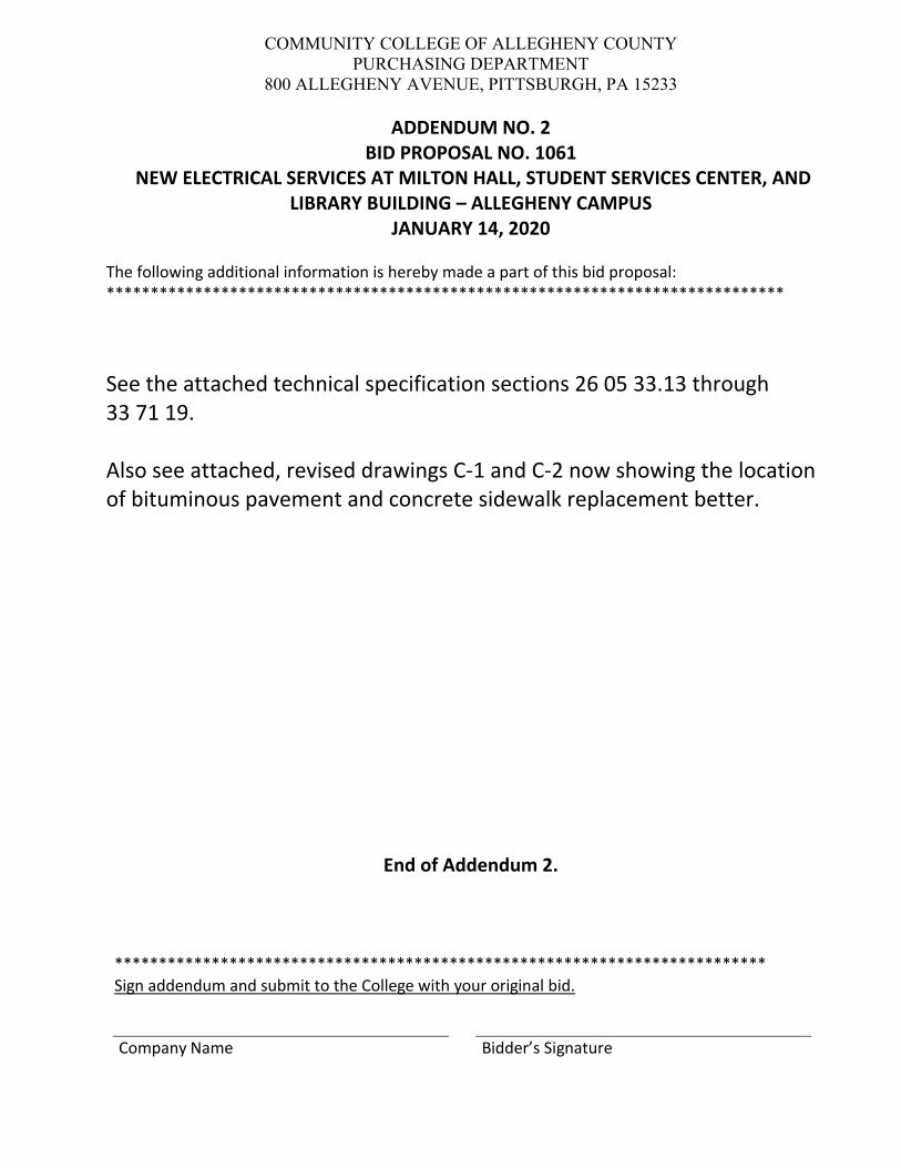
COMMUNITY COLLEGE OF ALLEGHENY COUNTY PURCHASING DEPARTMENT 800 ALLEGHENY AVENUE, PITTSBURGH, PA 15233 ADDENDUM NO. 2 BID PROPOSAL NO. 1061 NEW ELECTRICAL SERVICES AT MILTON HALL, STUDENT SERVICES CENTER, AND LIBRARY BUILDING – ALLEGHENY CAMPUS JANUARY 14, 2020 The following additional information is hereby made a part of this bid proposal: ***************************************************************************** See the attached technical specification sections 26 05 33.13 through 33 71 19. Also see attached, revised drawings C‐1 and C‐2 now showing the location of bituminous pavement and concrete sidewalk replacement better. End of Addendum 2. ************************************************************************** Sign addendum and submit to the College with your original bid. Company Name Bidder’s Signature

Welcome message from author
This document is posted to help you gain knowledge. Please leave a comment to let me know what you think about it! Share it to your friends and learn new things together.
Transcript
COMMUNITY COLLEGE OF ALLEGHENY COUNTY PURCHASING DEPARTMENT
800 ALLEGHENY AVENUE, PITTSBURGH, PA 15233
ADDENDUM NO. 2 BID PROPOSAL NO. 1061
NEW ELECTRICAL SERVICES AT MILTON HALL, STUDENT SERVICES CENTER, AND LIBRARY BUILDING – ALLEGHENY CAMPUS
JANUARY 14, 2020
The following additional information is hereby made a part of this bid proposal: *****************************************************************************
See the attached technical specification sections 26 05 33.13 through 33 71 19. Also see attached, revised drawings C‐1 and C‐2 now showing the location of bituminous pavement and concrete sidewalk replacement better.
End of Addendum 2.
************************************************************************** Sign addendum and submit to the College with your original bid.
Company Name Bidder’s Signature
Community College of Allegheny County, Allegheny Campus 26 05 33.13 - 1New Electrical Service at Milton Hall, SSC & Library CONDUIT FOR ELECTRICAL SYSTEMS
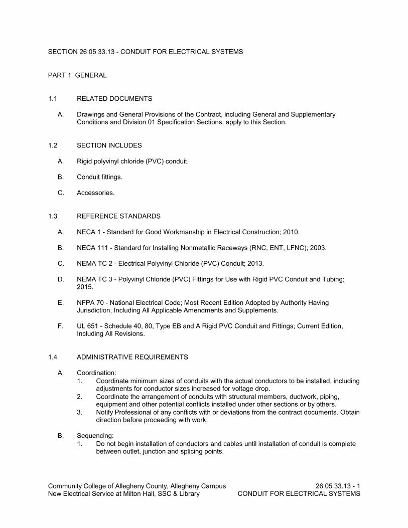
SECTION 26 05 33.13 - CONDUIT FOR ELECTRICAL SYSTEMS
PART 1 GENERAL
1.1 RELATED DOCUMENTS
A. Drawings and General Provisions of the Contract, including General and SupplementaryConditions and Division 01 Specification Sections, apply to this Section.
1.2 SECTION INCLUDES
A. Rigid polyvinyl chloride (PVC) conduit.
B. Conduit fittings.
C. Accessories.
1.3 REFERENCE STANDARDS
A. NECA 1 - Standard for Good Workmanship in Electrical Construction; 2010.
B. NECA 111 - Standard for Installing Nonmetallic Raceways (RNC, ENT, LFNC); 2003.
C. NEMA TC 2 - Electrical Polyvinyl Chloride (PVC) Conduit; 2013.
D. NEMA TC 3 - Polyvinyl Chloride (PVC) Fittings for Use with Rigid PVC Conduit and Tubing;2015.
E. NFPA 70 - National Electrical Code; Most Recent Edition Adopted by Authority HavingJurisdiction, Including All Applicable Amendments and Supplements.
F. UL 651 - Schedule 40, 80, Type EB and A Rigid PVC Conduit and Fittings; Current Edition,Including All Revisions.
1.4 ADMINISTRATIVE REQUIREMENTS
A. Coordination:1. Coordinate minimum sizes of conduits with the actual conductors to be installed, including
adjustments for conductor sizes increased for voltage drop.2. Coordinate the arrangement of conduits with structural members, ductwork, piping,
equipment and other potential conflicts installed under other sections or by others.3. Notify Professional of any conflicts with or deviations from the contract documents. Obtain
direction before proceeding with work.
B. Sequencing:1. Do not begin installation of conductors and cables until installation of conduit is complete
between outlet, junction and splicing points.
Community College of Allegheny County, Allegheny Campus 26 05 33.13 - 2New Electrical Services at Milton Hall, SSC & Library CONDUIT FOR ELECTRICAL SYSTEMS
1.5 SUBMITTALS
A. Product Data: Provide manufacturer's standard catalog pages and data sheets for conduits andfittings.
B. Project Record Documents: Record actual routing for conduits installed underground, conduitsembedded within concrete slabs, and conduits 2 inch (53 mm) trade size and larger.
PART 2 PRODUCTS
2.1 CONDUIT APPLICATIONS
A. Do not use conduit and associated fittings for applications other than as permitted by NFPA 70and product listing.
B. Unless otherwise indicated and where not otherwise restricted, use the conduit types indicatedfor the specified applications. Where more than one listed application applies, comply with themost restrictive requirements. Where conduit type for a particular application is not specified,use galvanized steel rigid metal conduit.
C. Underground:1. Exterior, Embedded Within Concrete: Use rigid PVC conduit.2. Where rigid polyvinyl (PVC) conduit is provided, transition to galvanized steel rigid metal
conduit where emerging from underground.
2.2 CONDUIT REQUIREMENTS
A. Provide all conduit, fittings, supports, and accessories required for a complete raceway system.
B. Provide products listed, classified, and labeled as suitable for the purpose intended.
C. Where conduit size is not indicated, size to comply with NFPA 70 but not less than applicableminimum size requirements specified.
2.3 RIGID POLYVINYL CHLORIDE (PVC) CONDUIT
A. Description: NFPA 70, Type PVC rigid polyvinyl chloride conduit complying with NEMA TC 2and listed and labeled as complying with UL 651; Schedule 40 unless otherwise indicated,Schedule 80 where subject to physical damage; rated for use with conductors rated 90 degreesC.
B. Fittings:1. Manufacturer: Same as manufacturer of conduit to be connected.2. Description: Fittings complying with NEMA TC 3 and listed and labeled as complying with
UL 651; material to match conduit.
Community College of Allegheny County, Allegheny Campus 26 05 33.13 - 3New Electrical Services at Milton Hall, SSC & Library CONDUIT FOR ELECTRICAL SYSTEMS
2.4 ACCESSORIES
A. Solvent Cement for PVC Conduit and Fittings: As recommended by manufacturer of conduitand fittings to be installed.
B. Pull Strings: Use nylon cord with average breaking strength of not less than 200 pound-force.
PART 3 EXECUTION
3.1 EXAMINATION
A. Verify that conditions are satisfactory for installation prior to starting work.
3.2 INSTALLATION
A. Install products in accordance with manufacturer's instructions.
B. Perform work in accordance with NECA 1 (general workmanship).
C. Install rigid polyvinyl chloride (PVC) conduit in accordance with NECA 111.
D. Conduit Routing:1. Unless dimensioned, conduit routing indicated is diagrammatic.2. When conduit destination is indicated without specific routing, determine exact routing
required.3. Conduits installed underground or embedded in concrete may be routed in the shortest
possible manner unless otherwise indicated. Route all other conduits parallel orperpendicular to building structure and surfaces, following surface contours wherepractical.
E. Connections and Terminations:1. Use suitable adapters where required to transition from one type of conduit to another.2. Provide insulating bushings or insulated throats at all conduit terminations to protect
conductors.3. Secure joints and connections to provide maximum mechanical strength and electrical
continuity.
F. Underground Installation:1. Minimum Cover, Unless Otherwise Indicated or Required:
a. Underground, Exterior: 24 inches.2. Provide underground warning tape in accordance with Section 26 05 53 along entire
conduit length for service entrance where not concrete-encased.
G. Conduit Movement Provisions: Where conduits are subject to movement, provide expansionand expansion/deflection fittings to prevent damage to enclosed conductors or connectedequipment. This includes, but is not limited to:1. Where conduits cross structural joints intended for expansion, contraction, or deflection.2. Where calculated in accordance with NFPA 70 for rigid polyvinyl chloride (PVC) conduit
installed above ground to compensate for thermal expansion and contraction.3. Where conduits are subject to earth movement by settlement or frost.
Community College of Allegheny County, Allegheny Campus 26 05 33.13 - 4New Electrical Services at Milton Hall, SSC & Library CONDUIT FOR ELECTRICAL SYSTEMS
3.3 FIELD QUALITY CONTROL
A. Correct deficiencies and replace damaged or defective conduits.
3.4 CLEANING
A. Clean interior of conduits to remove moisture and foreign matter.
3.5 PROTECTION
A. Immediately after installation of conduit, use suitable manufactured plugs to provide protectionfrom entry of moisture and foreign material and do not remove until ready for installation ofconductors.
END OF SECTION
Community College of Allegheny County, Allegheny Campus 31 23 16.13 - 1New Electrical Service at Milton Hall, SSC & Library TRENCHING
SECTION 31 23 16.13 - TRENCHING
PART 1 GENERAL
1.1 RELATED DOCUMENTS
A. Drawings and General Provisions of the Contract, including General and SupplementaryConditions and Division 01 Specification Sections, apply to this Section.
1.2 SECTION INCLUDES
A. Backfilling and compacting for utilities outside the building to utility main connections.
B. Trenching, backfilling and compacting for sanitary sewer and stormwater management.
1.3 RELATED REQUIREMENTS
A. Section 31 22 00 - GRADING: Site grading.
B. Section 31 23 16 - Excavation: Excavation for stormwater management.
C. Section 31 23 23 - Fill and Backfill: Backfilling at building and foundations.
D. Section 33 41 00 - Subdrainage: Filter aggregate and filter fabric for foundation drainagesystems.
1.4 DEFINITIONS
A. Finish Grade Elevations: Indicated on drawings.
B. Bedding Material: Aggregate materials placed on the trench subgrade to uniformly support thepipe barrel and material place above the pipe.
C. Cover Material: Aggregate material placed from top of bedding to bottom of the backfill coveringthe pipe.
D. Backfill: Fill material used above the cover material and below the lower of the subgrade,finished grade or the ordinal ground elevations.
1.5 REFERENCE STANDARDS
A. AASHTO T 180 - Standard Specification for Moisture-Density Relations of Soils Using a 4.54 kg(10-lb) Rammer and a 457 mm (18 in.) Drop; 2010.
B. ASTM D698 - Standard Test Methods for Laboratory Compaction Characteristics of Soil UsingStandard Effort (12,400 ft-lbf/ft3 (600 kN-m/m3)); 2012.
Community College of Allegheny County, Allegheny Campus 31 23 16.13 - 2New Electrical Services at Milton Hall, SSC & Library TRENCHING
C. ASTM D1556 - Standard Test Method for Density and Unit Weight of Soil in Place by theSand-Cone Method; 2007.
D. ASTM D1557 - Standard Test Methods for Laboratory Compaction Characteristics of Soil UsingModified Effort (56,000 ft-lbf/ft3 (2,700 kN m/m3)); 2012.
E. ASTM D2167 - Standard Test Method for Density and Unit Weight of Soil in Place by the RubberBalloon Method; 2008.
F. ASTM D2487 - Standard Practice for Classification of Soils for Engineering Purposes (UnifiedSoil Classification System); 2011.
G. ASTM D6938 - Standard Test Method for In-Place Density and Water Content of Soil andSoil-Aggregate by Nuclear Methods (Shallow Depth); 2010.
1.6 SUBMITTALS
A. Compaction Density Test Reports.
1.7 DELIVERY, STORAGE, AND HANDLING
A. When necessary, store materials on site in advance of need.
B. When fill materials need to be stored on site, locate stockpiles where designated.1. Separate differing materials with dividers or stockpile separately to prevent intermixing.2. Prevent contamination.3. Protect stockpiles from erosion and deterioration of materials.
PART 2 PRODUCTS
2.1 BACKFILL MATERIALS
A. General Backfill: Subsoil excavated on-site.1. Graded.2. Free of lumps larger than 3 inches, rocks larger than 2 inches, and debris.3. Conforming to ASTM D2487 Group Symbol CL.
B. Structural backfill: Coarse Aggregate - Type 2A1. Per Pennsylvania Department of Transportation, Publication 408, Section 703 Aggregate.2. Provided per Pennsylvania Department of Transportation, Publication 35, Bulletin 15.
C. Drainage backfill: Coarse Aggregate - AASHTO #57 or AASHTO #8.1. Per Pennsylvania Department of Transportation, Publication 408, Section 703 Aggregate.2. Provided per Pennsylvania Department of Transportation, Publication 35, Bulletin 15.
2.2 BEDDING AND COVER MATERIALS
A. Subsurface Drains, pipe culverts and Sanitary Sewer Trench:
Community College of Allegheny County, Allegheny Campus 31 23 16.13 - 3New Electrical Services at Milton Hall, SSC & Library TRENCHING
1. Coarse Aggregate: Type 2Aa. Per Pennsylvania Department of Transportation, Publication 408, Section 703
Aggregate.b. Provided per Pennsylvania Department of Transportation, Publication 35, Bulletin
15.
B. Drainage Trench:1. Coarse Aggregate: AASHTO #57 or AASHTO #8
a. Per Pennsylvania Department of Transportation, Publication 408, Section 703Aggregate.
b. Provided per Pennsylvania Department of Transportation, Publication 35, Bulletin15.
C. Other Trench:1. Coarse Aggregate: Type 2A
a. Per Pennsylvania Department of Transportation, Publication 408, Section 703Aggregate.
b. Provided per Pennsylvania Department of Transportation, Publication 35, Bulletin15.
D. Topsoil: Topsoil excavated on-site.1. Graded.2. Free of roots, rocks larger than 1 inch, subsoil, debris, large weeds and foreign matter.
2.3 ACCESSORIES
A. Geotextile Fabric: Non-biodegradable, woven.
PART 3 EXECUTION
3.1 EXAMINATION
A. Verify that survey bench marks and intended elevations for the work are as indicated.
3.2 PREPARATION
A. Identify required lines, levels, contours, and datum locations.
B. See Section 31 22 00 Grading for additional requirements.
C. Grade top perimeter of trenching area to prevent surface water from draining into trench. Provide temporary means and methods, as required, to maintain surface water diversion until nolonger needed, or as directed by the Professional.
3.3 TRENCHING
A. Notify Professional of unexpected subsurface conditions and discontinue affected Work in areauntil notified to resume work.
B. Slope banks of excavations deeper than 4 feet to angle of repose or less until shored.
Community College of Allegheny County, Allegheny Campus 31 23 16.13 - 4New Electrical Services at Milton Hall, SSC & Library TRENCHING
C. Do not interfere with 45 degree bearing splay of foundations.
D. Cut trenches wide enough to allow inspection of installed utilities.
E. Hand trim excavations. Remove loose matter.
F. Remove large stones and other hard matter that could damage piping or impede consistentbackfilling or compaction.
G. Remove lumped subsoil, boulders, and rock up to 1/3 cubic yard measured by volume. SeeSection 31 23 16.26 for removal of larger material.
H. Remove excavated material that is unsuitable for re-use from site.
I. Stockpile excavated material to be re-used in area designated in Section 31 22 00.
J. Remove excess excavated material from site.
K. Provide temporary means and methods, as required, to remove all water from trenching untildirected by the Professional. Remove and replace soils deemed unsuitable by classification andwhich are excessively moist due to lack of dewatering or surface water control.
L. Determine the prevailing groundwater level prior to trenching. If the proposed trench extendsless than 1 foot into the prevailing groundwater, control groundwater intrusion with perimeterdrains routed to sump pumps, or as directed by the Professional.
3.4 PREPARATION FOR UTILITY PLACEMENT
A. Cut out soft areas of subgrade not capable of compaction in place. Backfill with structural fill.
B. Compact subgrade to density equal to or greater than requirements for subsequent fill material.
C. Until ready to backfill, maintain excavations and prevent loose soil from falling into excavation.
3.5 BACKFILLING
A. Backfill to contours and elevations indicated using unfrozen materials.
B. Fill up to subgrade elevations unless otherwise indicated.
C. Employ a placement method that does not disturb or damage other work.
D. Systematically fill to allow maximum time for natural settlement. Do not fill over porous, wet,frozen or spongy subgrade surfaces.
E. Maintain optimum moisture content of fill materials to attain required compaction density.
F. Granular Fill: Place and compact materials in equal continuous layers not exceeding 6 inchescompacted depth.
G. Soil Fill: Place and compact material in equal continuous layers not exceeding 8 inchescompacted depth.
Community College of Allegheny County, Allegheny Campus 31 23 16.13 - 5New Electrical Services at Milton Hall, SSC & Library TRENCHING
H. Slope grade away from building minimum 2 inches in 10 feet, unless noted otherwise. Makegradual grade changes. Blend slope into level areas.
I. Correct areas that are over-excavated.1. Thrust bearing surfaces: Fill with concrete.2. Other areas: Use structural fill, flush to required elevation, compacted to minimum 97
percent of maximum dry density based on Modified Proctor or relative density.
J. Compaction Density Unless Otherwise Specified or Indicated:1. Under paving, slabs-on-grade, and similar construction: 97 percent of maximum dry
density based on Modified Proctor.2. At other locations: 95 percent of maximum dry density based on Modified Proctor.
K. Reshape and re-compact fills subjected to vehicular traffic.
3.6 BEDDING AND FILL AT SPECIFIC LOCATIONS
A. Use general fill unless otherwise specified or indicated.
B. Subsurface Drains, pipe culverts and Sanitary Sewer Trench:1. Bedding and Cover: Use Fill Type 2A.2. Place filter fabric specified in Section 33 05 13 over compacted bedding.3. Cover with general fill or Structural Fill.4. Backfill up to subgrade elevation. Use General or Structural Fill.5. Compact in maximum 8 inch lifts to 95 percent of maximum dry density based on
Modified Proctor.
C. Utility Piping, Conduits, Duct Bank, and ______ and _____:1. Bedding: Use structural fill.2. Cover with material shown in the details on the Drawings..3. Fill up to subgrade elevation.4. Compact in maximum 8 inch lifts to 95 percent of maximum dry density based on
Modified Proctor.
3.7 TOLERANCES
A. Top Surface of General Backfilling: Plus or minus 1 inch from required elevations.
B. Top Surface of Backfilling Under Paved Areas: Plus or minus 1 inch from required elevations.
3.8 FIELD QUALITY CONTROL
A. Perform compaction density testing on compacted fill in accordance with ASTM D1556, ASTMD2167, or ASTM D6938.
B. Evaluate results in relation to compaction curve determined by testing uncompacted material inaccordance with ASTM D1557 ("modified Proctor"), AASHTO T 180, or ASTM D698 ("standardProctor").
C. If tests indicate work does not meet specified requirements, remove work, replace and retest.
Community College of Allegheny County, Allegheny Campus 31 23 16.13 - 6New Electrical Services at Milton Hall, SSC & Library TRENCHING
3.9 CLEANING
A. Leave unused materials in a neat, compact stockpile.
B. Remove unused stockpiled materials, leave area in a clean and neat condition. Grade stockpilearea to prevent standing surface water.
C. Leave borrow areas in a clean and neat condition. Grade to prevent standing surface water.
END OF SECTION
Community College of Allegheny County, Allegheny Campus 31 23 23 - 1New Electrical Service at Milton Hall, SSC & Library FILL AND BACKFILL
SECTION 31 23 23 - FILL AND BACKFILL
PART 1 GENERAL
1.1 RELATED DOCUMENTS
A. Drawings and General Provisions of the Contract, including General and SupplementaryConditions and Division 01 Specification Sections, apply to this Section.
1.2 SECTION INCLUDES
A. Filling, backfilling, and compacting for paving.
B. Backfilling and compacting for utilities outside the building to utility main connections.
1.3 RELATED REQUIREMENTS
A. Section 31 2501 - Temporary Erosion and Sedimentation Control: Inlet protection and erosioncontrol.
B. Section 31 23 16.13 - Trenching: Excavating for utility trenches outside the building to utilitymain connections.
1.4 DEFINITIONS
A. Finish Grade Elevations: Indicated on drawings.
1.5 REFERENCE STANDARDS
A. AASHTO T 180 - Standard Specification for Moisture-Density Relations of Soils Using a 4.54 kg(10-lb) Rammer and a 457 mm (18 in.) Drop; 2010.
B. ASTM D698 - Standard Test Methods for Laboratory Compaction Characteristics of Soil UsingStandard Effort (12,400 ft-lbf/ft3 (600 kN-m/m3)); 2012.
C. ASTM D1557 - Standard Test Methods for Laboratory Compaction Characteristics of Soil UsingModified Effort (56,000 ft-lbf/ft3 (2,700 kN m/m3)); 2012.
D. ASTM D2167 - Standard Test Method for Density and Unit Weight of Soil in Place by the RubberBalloon Method; 2008.
E. ASTM D4318 - Standard Test Methods for Liquid Limit, Plastic Limit, and Plasticity Index ofSoils; 2010.
1.6 SUBMITTALS
A. Compaction Density Test Reports.
Community College of Allegheny County, Allegheny Campus 31 23 23 - 2New Electrical Services at Milton Hall, SSC & Library FILL AND BACKFILL
1.7 DELIVERY, STORAGE, AND HANDLING
A. When necessary, store materials on site in advance of need.
B. When fill materials need to be stored on site, locate stockpiles where designated.1. Separate differing materials with dividers or stockpile separately to prevent intermixing.2. Prevent contamination.3. Protect stockpiles from erosion and deterioration of materials.
PART 2 PRODUCTS
2.1 FILL MATERIALS
A. General Fill: Subsoil excavated on-site.1. Graded.2. Free of lumps larger than 3 inches, rocks larger than 2 inches, and debris.
B. Granular Fill: Coarse Aggregate - AASHTO #571. Per Pennsylvania Department of Transportation, Publication 408, Section 703 Aggregate.2. Provided per Pennsylvania Department of Transportation, Publication 35, Bulletin 15.
C. Drainage Fill: Coarse Aggregate - AASHTO #57 or AASHTO #81. Per Pennsylvania Department of Transportation, Publication 408, Section 703 Aggregate.2. Provided per Pennsylvania Department of Transportation, Publication 35, Bulletin 15.
D. Topsoil: Topsoil excavated on-site.1. Select.2. Graded.3. Free of roots, rocks larger than 1 inch, subsoil, debris, large weeds and foreign matter.
2.2 SOURCE QUALITY CONTROL
A. If tests indicate materials do not meet specified requirements, change material and retest.
B. Provide materials of each type from same source throughout the Work.
PART 3 EXECUTION
3.1 EXAMINATION
A. Verify that survey bench marks and intended elevations for the Work are as indicated.
B. Identify required lines, levels, contours, and datum locations.
C. Verify subdrainage, dampproofing, or waterproofing installation has been inspected.
D. Verify areas to be filled are not compromised with surface or ground water.
Community College of Allegheny County, Allegheny Campus 31 23 23 - 3New Electrical Services at Milton Hall, SSC & Library FILL AND BACKFILL
3.2 PREPARATION
A. Scarify and proof roll subgrade surface to a depth of 6 inches to identify soft spots.
B. Cut out soft areas of subgrade not capable of compaction in place. Backfill with structural fill.
C. Compact subgrade to density equal to or greater than requirements for subsequent fill material.
D. Until ready to fill, maintain excavations and prevent loose soil from falling into excavation.
3.3 FILLING
A. Fill up to subgrade elevations unless otherwise indicated.
B. Employ a placement method that does not disturb or damage other work.
C. Systematically fill to allow maximum time for natural settlement. Do not fill over porous, wet,frozen or spongy subgrade surfaces.
D. Maintain optimum moisture content of fill materials to attain required compaction density.
E. Granular Fill: Place and compact materials in equal continuous layers not exceeding 6 inchescompacted depth.
F. Soil Fill: Place and compact material in equal continuous layers not exceeding 8 inchescompacted depth.
G. Correct areas that are over-excavated.1. Other areas: Use structural fill, flush to required elevation, compacted to minimum 97
percent of maximum dry density based on Modified Proctor or relative density.
H. Compaction Density Unless Otherwise Specified or Indicated:1. Under asphalt or concrete paving, slabs on grade or similar construction: 97 percent of
maximum dry density, based on Modified Proctor or relative density.2. At other locations: 95 percent of maximum dry density based on Modified Protor or
relaive density.
I. Reshape and re-compact fills subjected to vehicular traffic.
J. Maintain temporary means and methods, as required, to remove all water while fill is beingplaced as required, or until directed by the Professional. Remove and replace soils deemedunsuitable by classification and which are excessively moist due to lack of dewatering or surfacewater control.
3.4 FILL AT SPECIFIC LOCATIONS
A. Use general fill unless otherwise specified or indicated.
B. Over Buried Utility Piping, Conduits, and Duct Bank in Trenches 1. Bedding: Use granular fill.2. Cover with general fill.
Community College of Allegheny County, Allegheny Campus 31 23 23 - 4New Electrical Services at Milton Hall, SSC & Library FILL AND BACKFILL
3. Compact in maximum 8 inch lifts to 95 percent of maximum dry density based onModified Proctor or relative density.
C. At Lawn Areas:1. Use general fill.2. Compact to 95 percent of maximum dry density based on Modified Proctor.
3.5 TOLERANCES
A. Top Surface of General Filling: Plus or minus 1 inch from required elevations.
B. Top Surface of Filling Under Paved Areas: Plus or minus 1 inch from required elevations.
3.6 FIELD QUALITY CONTROL
A. Evaluate results in relation to compaction curve determined by testing uncompacted material inaccordance with ASTM D698 ("standard Proctor"), ASTM D1557 ("modified Proctor"), orAASHTO T 180.
B. If tests indicate work does not meet specified requirements, remove work, replace and retest.
C. Proof roll compacted fill at surfaces that will be under slabs-on-grade.
3.7 CLEANING
A. See Section 01 74 19 - Construction Waste Management and Disposal, for additionalrequirements.
B. Remove unused stockpiled materials, leave area in a clean and neat condition. Grade stockpilearea to prevent standing surface water.
C. Leave borrow areas in a clean and neat condition. Grade to prevent standing surface water.
END OF SECTION
Community College of Allegheny County, Allegheny Campus 31 25 01 - 1New Electrical Service at Milton Hall, SSC & Library TEMPORARY EROSION AND SEDIMENTATIONCONTROL
SECTION 31 25 01 - TEMPORARY EROSION AND SEDIMENTATION CONTROL
Drawings and general provisions of the Contract, including General and Supplementary Conditions andDivision 01 Specification Sections, apply to this Section.
1.1 SUMMARY
A. This Section includes the following:1. Temporary inlet protection.2. Pumped water filtration3. Temporary and Permanent seeding and mulching of all earthwork areas.
1.2 REFERENCE STANDARDS
A. Commonwealth of Pennsylvania Department of Transportation (PaDOT):1. PA DOT Publication 408, latest edition.
1.3 PennDOT Section 735 - Geotextiles.
1.4 PennDOT Section 804 - Seeding and Soil Supplements
1.5 PennDOT Section 805 - Mulching
PART 2 - PRODUCTS
2.1 SILT SACK
2.2 Silt sack manufactured by ACF Environmental Inc.; (800) 448-3636 or approved equal.
2.3 INLET PROTECTION - consists of coconut fiber mat placed on top of inlet grate and held inplace with magnets.
2.4 SEED MIXTURES
A. Temporary seed mixture for all earthwork areas:
Community College of Allegheny County, Allegheny Campus 31 25 01 - 2New Electrical Services at Milton Hall, SSC & Library TEMPORARY EROSION AND SEDIMENTATIONCONTROL
2.5 PennDOT Publication 408, Section 804 – Formula E [L].
2.6 Permanent Seed Mixture: Refer to Section 02900 - Landscaping
A. Permanent seed mixture for all earthwork areas:
2.7 PennDOT Publication 408, Section 804 – Formula B.
2.8 MULCH
A. Mulch shall be applied to all permanently seeded areas; applied as per PennDOT Publication408, Section 805.1. Oat or wheat straw shall be unrotted small grain free of all kinds of weeds and prohibited
noxious weeds such as: thistles, johnsongrass and quackgrass.
PART 3 - EXECUTION
3.1 INLET FILTER MAT
A. Install inlet filter mats with attached magnets and serrated edging that prevents sediment fromentering the storm drain and aids in keeping the mat in position.
3.2 TEMPORARY and PERMANENT SEEDING
A. Within 5 days following grading activities, seed all earthwork areas with seed mixture to preventerosion; maintain until “final grading and seeding” is performed.
B. Site Preparation1. Install needed surface water control measures. Perform all cultural operations at right
angles to the slope. Apply ground limestone uniformly at 800 lbs. per 1000 square yards.2. Apply uniformly a 10-20-10 analysis fertilizer at the rate of 140 pounds per 1,000 square
yards. Work in lime and fertilizer to a depth of 4 inches using any suitable equipment.
C. Apply grass seed at a rate of 10 lbs. per 1,000 square yards. Cover annual rye grass with about½ inch of soil
D. Additional seeding will be required until substantial catch of grass can be acquired andmaintained.
3.3 MULCHING
A. Place mulch, within 48 hours after permanent seeding.
B. Place straw uniformly, in a continuous blanket, at a minimum rate of 1,200 pounds per 1,000square yards, or as otherwise indicated. If directed, increase the rate of application, depending
Community College of Allegheny County, Allegheny Campus 31 25 01 - 3New Electrical Services at Milton Hall, SSC & Library TEMPORARY EROSION AND SEDIMENTATIONCONTROL
upon the material used, season, soil conditions, or method of application. An acceptablemechanical blower may be used to apply mulch. Machines which cut mulch into short pieceswill not be permitted. Anchor with acceptable materials at the following rates.1. Wood Cellulose, 160 pounds per 1,000 square yards.2. Non-asphaltic Emulsion, at manufacturer’s recommended rates.3. Chemical Mulch Binders, at manufacturer’s recommended rates.
C. Hydraulically apply mulch fiber. It may be incorporated as an integral part of the slurry after theseed and soil supplements have been thoroughly mixed. Apply uniformly at the rate of 320pounds per 1,000 square yards, unless otherwise indicated.
3.4 MAINTENANCE
A. General:1. The Contractor shall monitor performance of sediment control measures. The Contractor
shall inspect at weekly or following a rainfall, whichever is sooner. The Contractor shallremove all silt accumulation in the sediment control structures.
2. Lawn and critical slope areas shall be monitored at weekly intervals. Any bare or erodedareas will be re-established as required. Should isolated areas repeatedly resiststabilization, Contractor shall contact local County Conservation District for assistance.
3.5 The Contractor shall follow the maintenance schedule as shown on the erosion and sedimentpollution control detail sheet.
3.6 EROSION AND SEDIMENT POLLUTION CONTROL
A. Construction operations shall be carried out in such a manner so that erosion, air and waterpollution will be minimized. State and local laws concerning pollution abatement shall befollowed.
END OF SECTION
Community College of Allegheny County, Allegheny Campus 32 11 23 - 1New Electrical Service at Milton Hall, SSC & Library AGGREGATE BASE COURSES
SECTION 32 11 23 - AGGREGATE BASE COURSES
PART 1 GENERAL
1.1 RELATED DOCUMENTS
A. Drawings and General Provisions of the Contract, including General and SupplementaryConditions and Division 01 Specification Sections, apply to this Section.
1.2 SECTION INCLUDES
A. Aggregate base course.
B. Paving aggregates.
1.3 RELATED REQUIREMENTS
A. Section 31 22 00 - GRADING: Preparation of site for base course.
B. Section 31 23 16.13 - Trenching: Compacted fill over utility trenches under base course.
C. Section 31 23 23 - Fill and Backfill: Compacted fill under base course.
D. Section 32 12 16 - Asphalt Paving: Finish and binder asphalt courses.
E. Section 32 13 13 - Concrete Paving: Finish concrete surface course.
F. Section 32 17 13 - Parking Bumpers: Timber bumpers.
G. Section 33 05 13 - Manholes and Structures: Manholes including frames.
H. Section 33 41 00 - Subdrainage: Filter aggregate and filter fabric for foundation drainagesystems.
I. Specifications - Pennsylvania Department of Transportation, Publication 408; current edition;Section 350 – Subbase.
1.4 REFERENCE STANDARDS
A. AASHTO M 147 - Standard Specification for Materials for Aggregate and Soil-AggregateSubbase, Base and Surface Courses; 1965 (2012).
B. ASTM C136/C136M - Standard Test Method for Sieve Analysis of Fine and Coarse Aggregates;2014.
C. ASTM D698 - Standard Test Methods for Laboratory Compaction Characteristics of Soil UsingStandard Effort (12,400 ft-lbf/ft3 (600 kN-m/m3)); 2012.
Community College of Allegheny County, Allegheny Campus 32 11 23 - 2New Electrical Services at Milton Hall, SSC & Library AGGREGATE BASE COURSES
D. ASTM D1556 - Standard Test Method for Density and Unit Weight of Soil in Place by theSand-Cone Method; 2007.
E. ASTM D1557 - Standard Test Methods for Laboratory Compaction Characteristics of Soil UsingModified Effort (56,000 ft-lbf/ft3 (2,700 kN m/m3)); 2012.
F. ASTM D2167 - Standard Test Method for Density and Unit Weight of Soil in Place by the RubberBalloon Method; 2008.
G. ASTM D2487 - Standard Practice for Classification of Soils for Engineering Purposes (UnifiedSoil Classification System); 2011.
H. ASTM D6938 - Standard Test Method for In-Place Density and Water Content of Soil andSoil-Aggregate by Nuclear Methods (Shallow Depth); 2010.
1.5 SUBMITTALS
A. Materials Sources: Submit name of imported materials source.1. Pennsylvania Department of Transportation, Publication 35, Bulletin 15.
B. Aggregate Composition Test Reports: Results of laboratory tests on proposed and actualmaterials used.
C. Compaction Density Test Reports.
1.6 DELIVERY, STORAGE, AND HANDLING
A. When necessary, store materials on site in advance of need.
B. Aggregate Storage, General:1. Separate differing materials with dividers or stockpile separately to prevent intermixing.2. Prevent contamination.3. Protect stockpiles from erosion and deterioration of materials.
PART 2 PRODUCTS
2.1 MATERIALS
A. Coarse Aggregate: Type 2A:1. Per Pennsylvania Department of Transportation, Publication 408, Section 703 Aggregate.2. Provided per Pennsylvania Department of Transportation, Publication 35, Bulletin 15.3. Depths:
a. For Asphalt Pavement: As shown on the Contract Drawings.b. For Concrete Pavement - Sidewalk: As shown on the Contract Drawings.
Community College of Allegheny County, Allegheny Campus 32 11 23 - 3New Electrical Services at Milton Hall, SSC & Library AGGREGATE BASE COURSES
PART 3 EXECUTION
3.1 GENERAL
A. Pennsylvania Department of Transportation, Publication 408, Section 350 Subbase.
3.2 EXAMINATION
A. Verify that survey bench marks and intended elevations for the work are as indicated.
3.3 PREPARATION
A. Correct irregularities in substrate gradient and elevation by scarifying, reshaping, andre-compacting.
B. Do not place aggregate on soft, muddy, or frozen surfaces.
3.4 INSTALLATION
A. Under Bituminous Concrete Paving:1. Compact to 95 percent of maximum dry density based on Modified Proctor or relative
density.
B. Under Portland Cement Concrete Paving:1. Compact to 95 percent of maximum dry density based on Modified Proctor or relative
density.
C. Place aggregate in maximum 4 inch layers and ____ compact to specified density.
D. Level and contour surfaces to elevations and gradients indicated.
E. Add small quantities of fine aggregate to coarse aggregate as appropriate to assist compaction.
F. Add water to assist compaction. If excess water is apparent, remove aggregate and aerate toreduce moisture content.
G. Use mechanical tamping equipment in areas inaccessible to compaction equipment.
3.5 TOLERANCES
A. Flatness: Maximum variation of 1/4 inch measured with 10 foot straight edge.
B. Scheduled Compacted Thickness: Within 1/4 inch.
C. Variation From Design Elevation: Within 1/2 inch.
Community College of Allegheny County, Allegheny Campus 32 11 23 - 4New Electrical Services at Milton Hall, SSC & Library AGGREGATE BASE COURSES
3.6 FIELD QUALITY CONTROL
A. Compaction density testing will be performed on compacted aggregate base course inaccordance with ASTM D1556, ASTM D2167, or ASTM D6938.1. At each density test location and after completing the density test, carefully dig one test
hole to the full depth of the completed subbase and measure the depth of the finishedbase course.
B. Results will be evaluated in relation to compaction curve determined by testing uncompactedmaterial in accordance with ASTM D1557 ("modified Proctor").
C. If tests indicate work does not meet specified requirements, remove work, replace and retest.
D. If the subbase depth is deficient by 1/2 inch or more from the depth indicated, the base course isdefective and may require additional test holes to determine the limits of the defective area.1. Scarify the base to a depth of 3 inches, blend in additional material, and recompact. After
recompacting, retesting may be required to verify the base course depth is within 1/2 inchof the indicated depth.
E. Backfill the test holes with base course material and compact.
F. Proof roll compacted aggregate at surfaces that will be under asphalt or concrete paving..
3.7 CLEANING
A. Leave unused materials in a neat, compact stockpile.
B. Leave borrow areas in a clean and neat condition. Grade to prevent standing surface water.
END OF SECTION
Community College of Allegheny County, Allegheny Campus 32 12 16 - 1New Electrical Service at Milton Hall, SSC & Library ASPHALT PAVING
SECTION 32 12 16 - ASPHALT PAVING
PART 1 GENERAL
1.1 RELATED DOCUMENTS
A. Drawings and General Provisions of the Contract, including General and SupplementaryConditions and Division 01 Specification Sections, apply to this Section.
1.2 SECTION INCLUDES
A. Double course bituminous concrete paving.
1.3 RELATED REQUIREMENTS
A. Section 31 22 00 - GRADING: Preparation of site for paving and base.
B. Section 31 23 23 - Fill and Backfill: Compacted subgrade for paving.
C. Section 32 11 23 - Aggregate Base Courses: Aggregate base course.
D. Section 32 13 13 - Concrete Paving: Concrete curbs.
E. Section 32 17 13 - Parking Bumpers: Concrete bumpers.
F. Section 32 17 23.13 - PAINTED PAVEMENT MARKINGS: Concrete bumpers.
G. Section 33 05 13 - Manholes and Structures: Manholes, including frames; gutter drainagegrilles, covers, and frames for placement by this section.
H. Specifications - Pennsylvania Department of Transportation, Publication 408; current edition;Section 409 – Superpave Mixture Design, Standard and RPS Construction of Plant-Mixed HMACourses.
I. Specifications - Pennsylvania Department of Transportation, Publication 408; current edition;Section 460 – Bituminous Tack Coat.
1.4 REFERENCE STANDARDS
A. AI MS-2 - Mix Design Methods for Asphalt Concrete and Other Hot-Mix Types; 1997.
1.5 QUALITY ASSURANCE
A. Perform Work in accordance with Pennsylvania Department of Transportation.
B. Mixing Plant: Conform to Pennsylvania Department of Transportation Specifications.
C. Obtain materials from same source throughout.
Community College of Allegheny County, Allegheny Campus 32 12 16 - 2New Electrical Services at Milton Hall, SSC & Library ASPHALT PAVING
1.6 SUBMITTALS
A. Materials Sources: Submit name of materials source.1. Pennsylvania Department of Transportation, Publication 35, Bulletin 15.
1.7 FIELD CONDITIONS
A. Do not place asphalt when ambient air or base surface temperature is less than 40 degrees F,or surface is wet or frozen.
PART 2 PRODUCTS
2.1 MATERIALS
A. Bituminous Binder Course: Superpave Asphalt Mixture Design, HMA Base Course, PG 64-22,<0.3 Million ESALS, 19 MM Mix1. Depth: 4.0 Inches or as shown on the Contract Drawings.2. Per Pennsylvania Department of Transportation, Publication 408, Section 409 –
Superpave Mixture Design, Standard and RPS Construction of Plant-Mixed HMACourses.
3. Provided per Pennsylvania Department of Transportation, Publication 35, Bulletin 15.
B. Bituminous Wearing Course: Superpave Asphalt Mixture Design, HMA Wearing Course, PG64-22, <0.3 Million ESALS, 9.5 MM Mix1. Depth: 1.5 Inches or as shown on the Contract Drawings.2. SRL Type: SRL-M3. Per Pennsylvania Department of Transportation, Publication 408, Section 409 –
Superpave Mixture Design, Standard and RPS Construction of Plant-Mixed HMACourses.
4. Provided per Pennsylvania Department of Transportation, Publication 35, Bulletin 15.
C. Bituminous Tack Coat: Emulsified Asphalt, Class AE-T1. Per Pennsylvania Department of Transportation, Publication 408, Section 460 –
Bituminous Tack Coat.2. Provided per Pennsylvania Department of Transportation, Publication 35, Bulletin 15.
PART 3 EXECUTION
3.1 GENERAL
A. Pennsylvania Department of Transportation, Publication 408, Section 409 – Superpave MixtureDesign, Standard and RPS Construction of Plant-Mixed HMA Courses.
B. Pennsylvania Department of Transportation, Publication 408, Section 460 – Bituminous TackCoat.
Community College of Allegheny County, Allegheny Campus 32 12 16 - 3New Electrical Services at Milton Hall, SSC & Library ASPHALT PAVING
3.2 EXAMINATION
A. Verify that compacted subgrade is dry and ready to support paving and imposed loads.
B. Verify gradients and elevations of base are correct.
3.3 BASE COURSE
A. See Section 32 11 23.
3.4 PREPARATION - TACK COAT
A. Apply tack coat in accordance with manufacturer's instructions.
B. Apply tack coat on asphalt or concrete surfaces over subgrade surface at uniform rate of 1/3gal/sq yd.
3.5 PLACING ASPHALT PAVEMENT - DOUBLE COURSE
A. Place asphalt binder course within 24 hours of applying primer or tack coat.
B. Place binder course to four (4) inch compacted thickness.
C. Place wearing course to one and one-half (1-1/2) inch compacted thickness.
D. Compact pavement by rolling to specified density. Do not displace or extrude pavement fromposition. Hand compact in areas inaccessible to rolling equipment.
E. Perform rolling with consecutive passes to achieve even and smooth finish, without roller marks.
3.6 TOLERANCES
A. Flatness: Maximum variation of 1/4 inch measured with 10 foot straight edge.
B. Compacted Thickness: Within 1/4 inch of specified or indicated thickness.
C. Variation from True Elevation: Within 1/2 inch.
3.7 FIELD QUALITY CONTROL
A. Provide field inspection and testing. Take samples and perform tests in accordance with AIMS-2.
Community College of Allegheny County, Allegheny Campus 32 12 16 - 4New Electrical Services at Milton Hall, SSC & Library ASPHALT PAVING
3.8 PROTECTION
A. Immediately after placement, protect pavement from vehicular traffic or loads for one day or untilsurface temperature is less than 140 degrees F.
END OF SECTION
Community College of Allegheny County, Allegheny Campus 32 13 13 - 1New Electrical Service at Milton Hall, SSC & Library CONCRETE PAVING
SECTION 32 13 13 - CONCRETE PAVING
PART 1 GENERAL
1.1 RELATED DOCUMENTS
A. Drawings and General Provisions of the Contract, including General and SupplementaryConditions and Division 01 Specification Sections, apply to this Section.
1.2 SECTION INCLUDES
A. Concrete landings, sidewalks, accessible parking spaces and curbs .
1.3 RELATED REQUIREMENTS
A. Section 03 10 00 - Concrete Forming and Accessories.
B. Section 31 23 23 - Fill and Backfill: Compacted subbase for paving.
C. Section 32 11 23 - Aggregate Base Courses32 11 23: 4" Inch base course.
D. Section 32 12 16 - Asphalt Paving: Asphalt wearing course.
1.4 REFERENCE STANDARDS
A. ACI 301 - Specifications for Structural Concrete; 2010 (Errata 2012).
B. ACI 304R - Guide for Measuring, Mixing, Transporting, and Placing Concrete; 2000.
C. ACI 305R - Hot Weather Concreting; 2010.
D. ACI 306R - Cold Weather Concreting; 2010.
E. ASTM A615/A615M - Standard Specification for Deformed and Plain Carbon Steel Bars forConcrete Reinforcement; 2015.
F. ASTM A1064/A1064M - Standard Specification for Carbon-Steel Wire and Welded WireReinforcement, Plain and Deformed, for Concrete; 2015.
G. ASTM C33/C33M - Standard Specification for Concrete Aggregates; 2013.
H. ASTM C39/C39M - Standard Test Method for Compressive Strength of Cylindrical ConcreteSpecimens; 2015a.
I. ASTM C94/C94M - Standard Specification for Ready-Mixed Concrete; 2015.
J. ASTM C150/C150M - Standard Specification for Portland Cement; 2015.
Community College of Allegheny County, Allegheny Campus 32 13 13 - 2New Electrical Services at Milton Hall, SSC & Library CONCRETE PAVING
K. ASTM C173/C173M - Standard Test Method for Air Content of Freshly Mixed Concrete by theVolumetric Method; 2014.
L. ASTM C260/C260M - Standard Specification for Air-Entraining Admixtures for Concrete; 2010a.
M. ASTM C309 - Standard Specification for Liquid Membrane-Forming Compounds for CuringConcrete; 2011.
N. ASTM C494/C494M - Standard Specification for Chemical Admixtures for Concrete; 2013.
O. ASTM D1751 - Standard Specification for Preformed Expansion Joint Filler for Concrete Pavingand Structural Construction (Nonextruding and Resilient Bituminous Types); 2004 (Reapproved2013).
P. ASTM D1752 - Standard Specification for Preformed Sponge Rubber Cork and Recycled PVCExpansion Joint Fillers for Concrete Paving and Structural Construction; 2004a (Reapproved2013).
1.5 SUBMITTALS
A. Product Data: Provide data on joint filler, admixtures, and curing compound.
B. Design Mixes: For each concrete pavement mix.1. Include alternate mix designs when characteristics of materials, project conditions,
weather, test results, or other circumstances warrant adjustments.
C. Laboratory test reports for concrete mix design tests.
D. Material certificates signed by manufacturer and Contractor, certifying that each material item complies with, or exceeds, specified requirements. Provide certification from admixturemanufacturers that chloride content complies with specification requirements.
1.6 QUALITY ASSURANCE
A. Perform work in accordance with ACI 301.
B. Follow recommendations of ACI 305R when concreting during hot weather.
C. Follow recommendations of ACI 306R when concreting during cold weather.
D. Concrete Testing Service: Engage an acceptable testing agency to to perform materialevaluation tests and to design concrete mixes.1. Testing Agency Qualifications: An independent testing agency, acceptable to authorities
having jurisdiction, qualified according to ASTM C 1077 and ASTM E 329 to conduct thetesting indicated, as documented according to ASTM E 548.
E. Source Limitations: Obtain each type or class of cementitious material of the same brand fromthe same manufacturer's plant, each aggregate from one source, and each admixture from thesame manufacturer.
F. Welding: Qualify procedures and personnel according to AWS D1.4, "Structural WeldingCode--Reinforcing Steel."
Community College of Allegheny County, Allegheny Campus 32 13 13 - 3New Electrical Services at Milton Hall, SSC & Library CONCRETE PAVING
G. Materials and installed work may require testing and retesting at any time during progress ofWork. Tests shall be done at Housing Authority of the County of 's expense. Retesting ofrejected materials for installed Work shall be done at Contractor's expense.
H. Installer Qualifications: An experienced installer who has completed concrete Work similar inmaterial, design, and extent to that indicated for this Project and whose work has resulted inconstruction with a record of successful in-service performance.1. Remove and replace concrete related work which does not conform to specified
requirements including strength, tolerances and finishes.2. Contractor shall bear cost of corrections and delays to other work affected by, or resulting
from, corrections to concrete work.
I. Manufacturer Qualifications: A firm experienced in manufacturing ready-mixed concreteproducts complying with ASTM C 94 requirements for production facilities and equipment.
1.7 ENVIRONMENTAL REQUIREMENTS
A. Do not place concrete when base surface temperature is less than 40 degrees F, or surface iswet or frozen.
1.8 DELIVERY, STORAGE, AND HANDLING
A. Deliver, store, and handle steel reinforcement to prevent bending and damage.1. Reinforcement shall be stored above the ground on platforms, skids or other supports
and shall be protected from mechanical injury and surface deterioration caused byexposure to conditions producing rust.
B. Store admixtures in manner to prevent contamination and in accordance with manufacturer'srecommendations. Protect admixtures from extreme temperatures which would adversely affecttheir characteristics.
1.9 WARRANTY
A. Special Warranty for Lifting/Cracking: Submit, for acceptance, a warranty document executed byauthorized company official. Warranty is in addition to, and not a limitation of, other rights Ownermay have under Contract Documents.1. Special Warranty Period: Two (2) year limited warranty commencing on Date of
Substantial Completion.
PART 2 PRODUCTS
2.1 CEMENT CONCRETE
A. Class AA Cement Concrete1. Depth: As shown on the drawings2. Per Pennsylvania Department of Transportation, Publication 408, Section 704 - Cement
Concrete.3. Provided per Pennsylvania Department of Transportation, Publication 35, Bulletin 15.
Community College of Allegheny County, Allegheny Campus 32 13 13 - 4New Electrical Services at Milton Hall, SSC & Library CONCRETE PAVING
2.2 PAVING ASSEMBLIES
A. Concrete Sidewalks: 4,000 psi, 28 day concrete, 5 inches thick, 6x6 - W1.4 x W1.4 welded wirereinforcement (unless noted otherwise) with dowel expansion joints of 1/2? diameter x 12"galvanized steel sliip dowel, 24" on center.
B. Parking Area Pavement: 4,000 psi 28 day concrete, 5 inches thick, 6 by 6 - W2.9 by W2.9 meshreinforcement, wood float finish.
C. Concrete Curb: 4,000 psi 28 day concrete.
2.3 FORM MATERIALS
A. Form Materials: As specified in Section 03 10 00, conform to ACI 301.1. Forms for Exposed Finish Concrete: Steel, wood, or other suitable material of size and
strength to resist movement during concrete placement and to retain horizontal andvertical alignment until removal. Use straight forms, free of distortion and defects toprovide continuous, straight, smooth, exposed surfaces.a. Use flexible spring steel forms or laminated boards to form radius bends as
required.b. Use plywood complying with U.S. Product Standard PS-1 "B-B (Concrete Form)
Plywood," Class I, Exterior Grade or better, mill-oiled and edge-sealed, with eachpiece bearing legible inspection trademark.
2. Forms for Unexposed Finish Concrete: Plywood, lumber, metal, or another acceptablematerial. Provide lumber dressed on at least two edges and one side for tight fit.
3. Form Release Agent: Provide commercial formulation form release agent with amaximum of 350 g/L volatile organic compounds (VOCs) that will not bond with, stain, oradversely affect concrete surfaces and will not impair subsequent treatments of concretesurfaces.a. Formulate form-release agent with rust inhibitor for steel form-facing materials.
B. Joint Filler: Preformed; non-extruding bituminous type (ASTM D1751) or sponge rubber or cork(ASTM D1752).1. Thickness: 1/2 inch.2. Provide removable plastic void cap strip that forms 1/2 inch deep joint for sealant
installation.
C. Joint Devices: Combination keyed joint form and screed, galvanized steel slip dowel withminimum 1/2 inch diameter, holes for conduit or rebars to pass through at 12 inches on center;ribbed steel stakes for setting.1. Height: To suit slab thickness.2. Composition and Materials: Design is based on the use of Key-Loc Joint System
manufactured by Form-A-Key Products Division, and the terminology used may includereference to proprietary products of that company. Construe such reference asestablishing only the minimum quality of workmanship and materials to be provided underthis Section, and not as limiting competition.a. Provide removable plastic cap strip that forms wedge-shaped joint for sealant
installation.b. Construct keyed joint form from minimum 24 gauge galvanized steel with dowel
knockouts and shaped to form a constant tongue and groove key between adjacentconcrete slab sections.
Community College of Allegheny County, Allegheny Campus 32 13 13 - 5New Electrical Services at Milton Hall, SSC & Library CONCRETE PAVING
c. Steel Stakes: Construct of minimum 13 gauge HRPO steel installed at 2 footintervals.
1) Stake clip: Clip is used only when pour is on stake side first and asrecommended by manufacturer.
2.4 REINFORCEMENT
A. Reinforcing Steel: ASTM A615/A615M Grade 60 (60,000 psi); deformed billet steel bars;unfinished finish.
B. Steel Welded Wire Reinforcement: Plain type, ASTM A1064/A1064M; in flat sheets; unfinished.
C. Dowels: ASTM A615/A615M, Grade 40 - 40,000 psi yield strength; deformed billet steel bars;unfinished finish.
D. Supports for Reinforcement: Chairs, spacers, dowel bar supports and other devices forspacing, supporting, and fastening reinforcing bars, welded wire fabric, and dowels in place. Use plastic or wire bar-type supports, such as chairs and bolsters, conforming to industrypractice as described in the WRI "WWR-500, Manual of Standard Practice" (most currentversion) or "TF 702 - Supporting WWR" (most current version).1. For slabs-on-grade, use supports with sand plates or horizontal runners where base
material will not support chair legs.a. Properly size foot of bar supports or similar devices to prevent settlement on base
materials and prevent puncture of geotextiles.2. All metal bolsters or chairs which bear against the forms for exposed surfaces shall be
equipped with snug fitting, high density, polyethylene tips which provide one half inch(1/2") minimum clearance between the metal and any exposed surface.
3. Do not use wood, clay brick, and other devices that can expand due to moisture gain.
E. Fabricate reinforcement according to Concrete Reinforcing Steel Institute's "Manual of StandardPractice."
2.5 JOINT MATERIAL
A. Traverse and Longitudinal Joints.1. Min 1.25" x 18" long dowel bars.2. Per Pennsylvania Department of Transportation, Publication 408, Section 705 - Joint
Material.3. Provided per Pennsylvania Department of Transportation, Publication 35, Bulletin 15.
B. Expansion Joint Filler Material1. Per Pennsylvania Department of Transportation, Publication 408, Section 705 - Joint
Material.2. Provided per Pennsylvania Department of Transportation, Publication 35, Bulletin 15.
C. Joint Sealing material1. Silicone Joint Sealing Material2. Per Pennsylvania Department of Transportation, Publication 408, Section 705 - Joint
Material.3. Provided per Pennsylvania Department of Transportation, Publication 35, Bulletin 15.
Community College of Allegheny County, Allegheny Campus 32 13 13 - 6New Electrical Services at Milton Hall, SSC & Library CONCRETE PAVING
2.6 CONCRETE MATERIALS
A. Concrete Curing materials1. Per Pennsylvania Department of Transportation, Publication 408, Section 711 - Concrete
Curing Material and Admixtures.2. Provided per Pennsylvania Department of Transportation, Publication 35, Bulletin 15.
B. Concrete Admixtures1. Per Pennsylvania Department of Transportation, Publication 408, Section 711 - Concrete
Curing Material and Admixtures.2. Provided per Pennsylvania Department of Transportation, Publication 35, Bulletin 15.
C. Mortar1. Per Pennsylvania Department of Transportation, Publication 408, Section 705 - Joint
Material.2. Provided per Pennsylvania Department of Transportation, Publication 35, Bulletin 15.
D. Obtain cementitious materials from same source throughout.
E. Water: Clean, and not detrimental to concrete.
2.7 ACCESSORIES
A. Liquid Surface Sealer: Euco-Guard 100 weatherproofing siloxane sealer by The EuclidChemical Company or equal products of W.R. Meadows and Sonneborn as approved.
B. Concrete Paving Joint Sealant: Polyurethane, self-leveling; ASTM C 920, Class 25, Uses T, I, Mand A; single or two component.1. Backup Material: As recommended by joint sealant manufacturer for compatibility and
width to depth ratio for joint sealant.
2.8 MIXING
A. Transit Mixers: Comply with ASTM C94/C94M.1. The mixing agitation shall begin within 30 minutes, and shall be discharged from the
truck within one hour after the water has been added to the concrete mix.a. Provide batch ticket information including the following:
1) Name of project2) Date of delivery3) Supplier of concrete4) Brand of cement5) Truck identity & ticket serial6) Cement content number7) Strength classification8) Batching time9) Admixture content10) Point of deposit11) Name of Contractor12) Total amount of water13) Name of driver
Community College of Allegheny County, Allegheny Campus 32 13 13 - 7New Electrical Services at Milton Hall, SSC & Library CONCRETE PAVING
14) Weight of aggregate15) Time loaded16) Daily temperature mixing of concrete17) Number of cubic yards in load reading of revolution counter
b. Quantity of water used for each batch shall be accurately measured and recorded.
PART 3 EXECUTION
3.1 GENERAL
A. Pennsylvania Department of Transportation, Publication 408, Section 501 Reinforced or PlainCement Concrete Pavements.
3.2 EXAMINATION
A. Verify compacted subgrade is acceptable and ready to support paving and imposed loads.
B. Verify gradients and elevations of base are correct.
3.3 SUBBASE
A. See Section 32 11 23 for construction of base course for work of this Section.
3.4 PREPARATION
A. Moisten base to minimize absorption of water from fresh concrete.
B. Coat surfaces of manhole frames with oil to prevent bond with concrete pavement.
C. Verify anchors, seats, plates, reinforcement and other items to be cast into concrete areaccurately placed, held securely and shall not cause difficulty in placing concrete.
3.5 FORMING
A. Place and secure forms to correct location, dimension, profile, and gradient.
B. Form Preparation:1. Clean formwork.2. Remove rust from steel formwork.
C. Place and secure forms to correct location, dimension, profile, and gradient.1. Provide slab side forms such that by placing a 10-foot straight edge, form does not
exceed 1/8 inch variation.a. Vertical face: Longitudinal axis not more than ¼" in 10 feet.
2. Do not use forms with dents, holes or patches.3. Individual formwork elements shall be as large as possible.4. Position individual formwork elements in regular, uniform pattern with joints aligned.5. Butt joints and provide backup splice at joints to prevent faulting at form.
Community College of Allegheny County, Allegheny Campus 32 13 13 - 8New Electrical Services at Milton Hall, SSC & Library CONCRETE PAVING
6. Do not tape formwork joints.7. Just before placing concrete, clean forms and adjacent surfaces; remove wood, sawdust,
chips, dirt and other debris.
D. Assemble formwork to permit easy stripping and dismantling without damaging concrete.1. Form Release Agent:
a. Before placing reinforcing steel, thoroughly coat contact surfaces of forms withform release agent.
b. Apply form release agent evenly without excess drip.c. Do not allow form release agent to come in contact with concrete surfaces or any
other surfaces that would be detrimental to the finish Work.d. Comply with manufacturers recommendations and instructions.
2. Form Removal:a. Do not remove forms until concrete has hardened sufficiently to support its own
weight and imposed construction loads.1) Formwork not supporting vertical load of concrete may be removed as soon as
concrete has hardened sufficiently to resist damage from removal operations butin no case sooner than 12 hours.
b. Removed forms in a manner to avoid damage to concrete.c. Remove forms without hammering or prying against concrete.
E. Place joint devices and fillers vertical in position, in straight lines. Secure during concreteplacement.
3.6 REINFORCEMENT
A. Place reinforcement in accordance with the most stringent requirements of ACI 301 and CRSIManual of Standard Practice and Placing Reinforcing Bars.
B. Accurately place and secure reinforcement against displacement by firmly wiring at intersectionsand splices with not less than No. 18 U.S. Standard Gauge annealed wire.
C. Turn wire ends away from concrete exterior.
D. Ensure reinforcing is clean, free from defects and kinks, loose mill or rust scale or coatings thatshall reduce bond.
E. Place welded wire reinforcement as follows unless noted otherwise.1. Where one layer of reinforcement is indicated:
a. Place welded wire reinforcement such that the overall depth of the slab divided byfour shall be the depth, in inches from the top of the slab, of the welded wirereinforcement; do not allow contraction joints to expose reinforcement. Wherecontraction joint depth would expose reinforcement, lower reinforcement depth to1/3 the thickness of the slab.
1) As an example: Concrete sidewalk with a depth of four inches (4") shall havethe welded wire reinforcing located one inch (1") below the top of the slab.
2) As an example: Parking area pavement with an overall depth of six inches (6")shall have the welded wire reinforcing located one and one half inches (1.5")below the top of the slab.
2. Where two layers of reinforcement are indicated:a. Place the upper layer of welded wire reinforcement according to method outlined
for one layer of reinforcement (above).b. Place the lower layer of welded wire reinforcement such that there is one and one
half inches (1.5") of clear cover below the welded wire reinforcement.
Community College of Allegheny County, Allegheny Campus 32 13 13 - 9New Electrical Services at Milton Hall, SSC & Library CONCRETE PAVING
3. Comply with Concrete Reinforcing Steel Institute's recommended practice for "PlacingReinforcing Bars," for details and methods of reinforcement placement and supports andas specified.a. Maximum welded wire reinforcement support spacings as follow unless more
restrictive spacings are recommended by Wire Reinforcing Institute or ConcreteReinforcing Institute.
4. Clean reinforcement of loose rust and mill scale, earth, ice, mortar, paint, grease, oil, andother materials that reduce or destroy bond with concrete. Reinforcement shall be freefrom cracks and laminations. Bonded rust, surface irregularities, or mill scale shall not because from rejection, provided the minimum dimensions, cross sectional area, and tensileproperties of the reinforcement meet the physical requirements for the size and grade ofsteel specified.
5. Accurately position, support, and secure reinforcement against displacement. Locate andsupport reinforcing by metal chairs, runners, bolsters, and spacers.
6. Place reinforcement to maintain minimum coverages for concrete protection. Arrange,space, and securely tie bars and bar supports to hold reinforcement securely in positionduring concrete placement operations. Set wire ties so ends are directed into concrete,not toward exposed concrete surfaces.
7. Install welded wire fabric in lengths as long as practicable. Lap adjoining pieces at leastone full mesh and lace splices with wire. Offset laps of adjoining widths to preventcontinuous laps in either direction.a. Sheets at lap splices shall be placed in contact and tied together in such a manner
as to maintain the minimum distance to the surface of the concrete.8. Interrupt welded wire reinforcement at expansion and construction joints.
3.7 COLD AND HOT WEATHER CONCRETING
A. Follow recommendations of ACI 305R when concreting during hot weather.
B. Follow recommendations of ACI 306R when concreting during cold weather.
C. Do not place concrete when base surface temperature is less than 40 degrees F, or surface iswet or frozen.
3.8 PLACING CONCRETE
A. Place concrete in accordance with ACI 304R.
B. The General Contractor and concrete supplier shall have a quality control representative on siteduring placement of concrete.
C. Do not place concrete until subbase and forms have been checked for line and grade. Do notplace concrete around manholes or other structures until they are at required finish elevationand alignment.
D. Conveying of concrete:1. Handle concrete from mixer to place of final deposit as rapidly as practicable and in a
manner which shall ensure obtaining specified quality of concrete.2. Re-tempering: Discard concrete which has already begun to set. Do not re-temper with
water.3. Equipment: Provide mixing and conveying equipment of proper size and design to ensure
continuous flow of concrete to delivery end. Do not use aluminum pipe or equipment incontact with concrete.
Community College of Allegheny County, Allegheny Campus 32 13 13 - 10New Electrical Services at Milton Hall, SSC & Library CONCRETE PAVING
a. Mixers, agitators and non-agitating units: Conform to ASTM C94 and currentcertification requirements of Pennsylvania Department of Transportation.
b. Belt Conveyors:1) Use only types which shall not cause segregation.2) Discharge runs over 30 feet into hopper.
c. Chutes: Metal or metal lined not to be installed at slopes greater than 1 vertical to3 horizontal.
d. Runways:1) Provide runways or other means above finished concrete level for wheeled
conveying equipment.2) Do not support runways on reinforcing.3) Do not wheel equipment directly over reinforcing or metal deck.
e. Pumps:1) Submit to Testing Agency for review, changes to concrete mix to necessitate
pumping.2) Use pump hoses and other slickline components with 5 inch minimum inside
diameter.3) For slickline reducers, reduction in diameter shall not exceed 1 inch over a 5 foot
length.
E. Depositing of concrete:1. Do not deposit concrete which has partially hardened or has been contaminated by
foreign matter.2. Deposit concrete continuously in layers of such thickness that no concrete shall be
deposited on concrete which has hardened sufficiently to cause seams or planes ofweakness.
3. Between construction joints, place concrete in a continuous operation such that concreteis plastic at all times and flows readily into spaces between reinforcement.
4. Use placement procedures to avoid segregation.5. Deposit concrete as near as possible to its final position.6. Do not place concrete over standing water, mud, frost, ice or snow.7. Do not use wet screeds or garden style rakes.
F. Do not place concrete when base surface is wet.
G. Consolidation of concrete:1. Consolidate concrete complying with ACI 301 by vibrating, spading or rodding so that
concrete is thoroughly worked around reinforcing, embedded items and into the cornersof forms.
2. Consolidate each layer of concrete with previously placed layers in a manner that willeliminate air or stone pockets which may cause honeycombing, pitting, or places ofweakness.
3. Do not insert vibrator into portions of concrete that have begun to set.4. Do not use vibrators to transport concrete.5. Keep spare vibrator on job site during concrete operations.6. Do not over-vibrate concrete.7. Use internal vibrator for formed elements; do not use form vibrators.8. Keep vibrator away from joint assemblies, reinforcement, or side forms.
H. Ensure reinforcement, inserts, embedded parts, and formed joints are not disturbed duringconcrete placement.
Community College of Allegheny County, Allegheny Campus 32 13 13 - 11New Electrical Services at Milton Hall, SSC & Library CONCRETE PAVING
I. Place concrete continuously over the full width and depth of the panel and betweenpredetermined construction joints. Do not break or interrupt successive pours such that coldjoints occur.1. If a section cannot be placed continuously or if interrupted for more than 1/2 hour, provide
construction joints.
J. After concrete placement, adjust forms and bracing to maintain proper alignment and eliminateleakage of cement paste.
K. Apply surface retarder to all exposed surfaces in accordance with manufacturer's instructions.
3.9 JOINTS
A. Place joints as indicated on contract drawings.
B. Align curb, gutter, and sidewalk joints.
C. Construct isolation, contraction (weakened-plane), and construction joints true to line with faceperpendicular to surface of concrete. Construct transverse joints at right angles to thecenterline, unless otherwise indicated.
D. When joining existing structures, place transverse joints to align with previously placed joints,unless otherwise indicated.
E. Place joints to allow one continuous placement between bulkheads.
F. Unless otherwise shown on drawings or indicated, maximum spacing between contraction,construction or isolation joints in slabs on grade shall be lesser of the following:1. 36 times the slab thickness in inches.2. Panel length to width ratio of maximum 1-1/2:1.
G. Place construction joints at end of placements and at locations where placement operations arestopped for more than 1/2 hour, except where such placements terminate at isolation joints.1. Construction joints shall be planned and installed in accordance with the overall joint plan
where the construction joint shall also function as a contraction joint, maintaining thespacings indicated for contraction joints.a. Where construction joints are located where a contraction joint was not planned or
indicated, the associated concrete sections shall be removed and replaced in orderto maintain a consistent joint pattern at no additional cost.
H. Construct joints using standard metal keyway-section forms.1. Form joints with joint device extending from bottom of pavement to within 1/2 inch of
finished surface.2. Secure to resist movement by wet concrete.3. Protect top edge of joint device during concrete placement with cap of temporary material.
Remove protection after concrete has been placed on both sides of joint.4. Provide joint sealer at all construction joints.
I. Where load transfer-slip dowel devices are indicated for slabs, install so that one end of eachdowel bar is free to move.
J. Saw cutting shall not be an acceptable means of providing isolation and keyed joints.
Community College of Allegheny County, Allegheny Campus 32 13 13 - 12New Electrical Services at Milton Hall, SSC & Library CONCRETE PAVING
K. Place 1/2 inch wide isolation joints to separate paving from all vertical surface and othercomponents.1. Form joints with joint filler extending from bottom of pavement to within 1/2 inch of
finished surface.2. Secure to resist movement by wet concrete.3. Protect top edge of joint filler during concrete placement with cap of temporary material.
Remove protection after concrete has been placed on both sides of joint.4. Provide joint sealer at all isolation joints and locations where joint filler is installed.
L. Provide contraction joints as follows unless noted otherwise:1. Minimum depth of 1/4 the thickness of the slab, but not less than 1 inch.
a. Adjust the depth of welded wire reinforcing and other reinforcing in order not toexpose reinforcement.
2. For paving up to and including eight feet in width, locate joints such that the distancebetween tooled contraction joints equals the width of the slab.
3. For paving greater than eight feet in width, locate joints such that he maximum jointspacing does not exceed 36 times the slab thickness in inches.a. As an example, a four inch (4") thick pavement, joints would have joints located not to
exceed twelve feet (12').4. All panels should be square or nearly so with the length never to exceed 1.5 times the
width.5. Sawed Joints: Saw cut joints shall be made within 4 hours of concrete placement;
excessive spalling or ravelling of concrete surface at saw cuts shall be reason forreplacement of concrete as outlined herein at no additional cost.a. Employ sufficient number of saws and skilled workers to complete cutting saw
joints before shrinkage produces cracking.b. Saw cut to minimum width of 1/8 inch; width shall be consistent throughout joint.c. Start cutting sawed joints as soon as concrete has hardened sufficiently to prevent
ravelling or dislodging of aggregates.d. Saw cut joints shall be made within 4 hours of concrete placement and after
completing finishing of slab in that joint location.e. Remove all saw debris, either loose or compacted, from slab surface and joints
prior to curing installation.
3.10 FINISHING
A. General:1. Do not add water to any slab surface during finishing operations.2. Do not add cement to any slab surface during finishing operations.3. Perform no finishing operations while water is present on slab surface.
B. After striking-off and consolidating concrete, smooth surface by screeding and floating. Usehand methods only where mechanical floating is not possible. Adjust floating to compact surfaceand produce uniform texture.
C. After floating, test surface for trueness with a 10-ft. straightedge. Distribute concrete as requiredto remove surface irregularities, and refloat repaired areas to provide a continuous smoothfinish.
D. Sidewalk. landing, dumpster pad and accessible parking spaces paving: Light broom, textureperpendicular to direction of travel with troweled and radiused edge 1/4 inch radius.1. Where new portland cement concrete paving abutts existing concrete paving, match
existing concrete paving finishing.
Community College of Allegheny County, Allegheny Campus 32 13 13 - 13New Electrical Services at Milton Hall, SSC & Library CONCRETE PAVING
2. Remove all tool and trowel marks.
E. Curbs: Light broom, texture parallel to pavement direction.
F. Curing General:1. Cure concrete in accordance with ACI 301 and ACI 308R unless noted otherwise.2. Start curing as soon as concrete surface shall not be damaged by curing operations.3. Continuously cure concrete for at least 7 consecutive days.4. During curing period, do not allow any part of the concrete to become dry.
G. Place curing compound on exposed concrete surfaces immediately after finishing. Apply inaccordance with manufacturer's instructions.1. Do not use liquid curing compound on surface against which additional concrete, other
finishing materials, or coatings are to be bonded if the bond shall be affected by the curingcompound.
2. Immediately recoat surfaces subjected to rainfall within 3 hours after compound has beenapplied or surfaces damaged by subsequent construction operations within the curingperiod.
3. Barricade concrete surfaces immediately after application of curing compound.4. Do not allow traffic on concrete surfaces sooner than 3 days after placement or as
recommended by curing compound manufacturer; comply with the more stringentrequirement.
H. Concrete Sealer: Apply sealer uniformly to all new portland cement concrete paving incontinuous operation according to manufacturer's written instructions.
3.11 JOINT SEALING
A. Pennsylvania Department of Transportation, Publication 408, Section 501 Reinforced or PlainCement Concrete Pavements.
3.12 TOLERANCES
A. Maximum Variation of Surface Flatness: 1/4 inch in 10 ft.
B. Maximum Variation From True Position: 1/4 inch.
3.13 BACKFILLING
A. After curing, debris shall be removed and the areas adjoining shall be backfilled, graded andcompacted to conform to the surrounding area in accordance with the lines and gradesindicated.
3.14 FIELD QUALITY CONTROL
A. Compressive Strength Tests: ASTM C39/C39M; for each test, mold and cure three concretetest cylinders. Obtain test samples for every 100 cu yd or less of each class of concrete placed.1. Take one additional test cylinder during cold weather concreting, cured on job site under
same conditions as concrete it represents.2. Perform one slump test for each set of test cylinders taken.
Community College of Allegheny County, Allegheny Campus 32 13 13 - 14New Electrical Services at Milton Hall, SSC & Library CONCRETE PAVING
B. Maintain records of placed concrete items. Record date, location of pour, quantity, airtemperature, and test samples taken.
3.15 PROTECTION AND REPLACEMENT
A. Immediately after placement, protect pavement from premature drying, excessive hot or coldtemperatures, and mechanical injury.
B. Remove and replace concrete paving that is broken, damaged, or defective, or does not meetthe requirements of this Section. Defects include color and texture irregularities, crazing andcracks in excess of 0.01 inch wide or that penetrate to the reinforcement or completely throughnonreinforced sections regardless of width, spalls, air bubbles, honeycomb, rock pockets, finsand other projections on the surface, and stains and other discolorations that cannot beremoved by cleaning.1. Area for removal and replacement shall be defined by a perimeter determined by
isolation, contraction, and construction joints that completely contain within theirprescribed border the break, damage, defect or otherwise unacceptable concrete paving. In no case shall additional joints, saw cuts, etc. be permitted without the expresspermission.a. Remove defective areas with clean, square cuts.b. Mix replacement concrete of same materials to provide concrete of same type or
class as original concrete. Prepare, place, reinforce, consolidate, and finish tomatch adjacent finished concrete. Cure and seal in same manner as adjacentconcrete.
c. Where possible, portions of the work cast or set integrally may be salvaged forre-use provided that each item be re-installed according to original ContractDocuments requirements.
2. In the case of ramps and stairs, the entire run incorporating all intermediate landings ofthe ramp and/or stair shall be removed and replaced.a. Remove defective areas with clean, square cuts.b. Mix replacement concrete of same materials to provide concrete of same type or
class as original concrete. Place, compact, and finish to match adjacent finishedconcrete. Cure in same manner as adjacent concrete.
c. Where possible, portions of the work cast or set integrally may be salvaged forre-use provided that each item be re-installed according to original ContractDocuments requirements.
C. Drill test cores where directed when necessary to determine magnitude of cracks or defectiveareas. Fill drilled core holes in satisfactory pavement areas with portland cement concretebonded to paving with epoxy adhesive.
D. Do not permit pedestrian or vehicular traffic over pavement for 28 days minimum after finishing.1. When construction traffic is permitted, maintain paving as clean as possible by removing
surface stains and spillage of materials as they occur.2. Provide access ramps along exposed concrete edges to prevent equipment and
machinery from impacting edges; barricade all other exposed edges to machinery andvehicular traffic which may damage edges.
E. Maintain concrete paving free of stains, discoloration, dirt, and other foreign material. Sweepconcrete paving not more than 2 days prior to date scheduled for Substantial Completioninspections.

Community College of Allegheny County, Allegheny Campus 32 13 13 - 15New Electrical Services at Milton Hall, SSC & Library CONCRETE PAVING
END OF SECTION
Community College of Allegheny County, Allegheny Campus 32 17 23.13 - 1New Electrical Service at Milton Hall, SSC & Library PAINTED PAVEMENT MARKINGS
SECTION 32 17 23.13 - PAINTED PAVEMENT MARKINGS
PART 1 GENERAL
1.1 RELATED DOCUMENTS
A. Drawings and General Provisions of the contract, including General and SupplementaryConditions and Division 01 Specification Sections, apply to this Section.
1.2 SECTION INCLUDES
A. Parking lot markings, including parking stalls, high visibility crosswalks, ADA accessible parkingstalls, and accessible aisle.
B. Roadway lane markings and crosswalk markings.
1.3 RELATED REQUIREMENTS
A. Section 32 12 16 - Asphalt Paving.
B. Section 32 13 13 - Concrete Paving.
1.4 REFERENCE STANDARDS
A. FS TT-B-1325 - Beads (Glass Spheres); Retro-Reflective; Rev. D, 2007.
B. FS TT-P-1952 - Paint, Traffic Black, and Airfield Marking, Waterborne; Rev. E, 2007.
C. FHWA MUTCD - Manual on Uniform Traffic Control Devices for Streets and Highways; U.S.Department of Transportation, Federal Highway Administration; Current Edition.
1.5 SUBMITTALS
A. Product Data: Manufacturer's data sheets on each product to be used, including:1. Preparation instructions and recommendations.2. Storage and handling requirements and recommendations.3. Installation methods.
B. Certificates: Submit for each batch of paint stating compliance with specified requirements.
1.6 DELIVERY, STORAGE, AND HANDLING
A. Deliver paint in containers of at least 5 gallons accompanied by batch certificate.
B. Deliver glass beads in containers suitable for handling and strong enough to prevent loss duringshipment accompanied by batch certificate.
Community College of Allegheny County, Allegheny Campus 32 17 23.13 - 2New Electrical Services at Milton Hall, SSC & Library PAINTED PAVEMENT MARKINGS
C. Store products in manufacturer's unopened packaging until ready for installation.
D. Store and dispose of solvent-based materials, and materials used with solvent-based materials,in accordance with requirements of local authorities having jurisdiction.
1.7 FIELD CONDITIONS
A. Do not install products under environmental conditions outside manufacturer's absolute limits.
PART 2 PRODUCTS
2.1 MATERIALS
A. Line and Zone Marking Paint:1. Per Pennsylvania Department of Transportation, Publication 408, Section 962 Waterborne
Pavement Markings.2. Provided per Pennsylvania Department of Transportation, Publication 35, Bulletin 15.3. Color as indicated on the drawings:
a. Parking Lots: White parking spaces, accessible parking spaces shall be blue.b. Handicapped Symbols: Blue with glass beads.c. Crosswalks: White with glass beads.d. Accessible Crosswalk/Walkway: Blue.
B. Reflective Glass Beads:1. Per Pennsylvania Department of Transportation, Publication 408, Section 962
Waterborne Pavement Markings.2. Provided per Pennsylvania Department of Transportation, Publication 35, Bulletin 15.
PART 3 EXECUTION
3.1 EXAMINATION
A. Do not begin installation until substrates have been properly prepared.
B. If substrate preparation is the responsibility of another installer, notify Professional ofunsatisfactory preparation before proceeding.
3.2 PREPARATION
A. Allow new pavement surfaces to cure for a period of not less than 14 days before application ofmarking materials.
B. Prepare surfaces using the methods recommended by the manufacturer for achieving the bestresult for the substrate under the project conditions.
C. Obliteration of existing markings using paint is acceptable in lieu of removal; apply the blackpaint in as many coats as necessary to completely obliterate the existing markings.
Community College of Allegheny County, Allegheny Campus 32 17 23.13 - 3New Electrical Services at Milton Hall, SSC & Library PAINTED PAVEMENT MARKINGS
D. Clean surfaces thoroughly prior to installation.1. Remove dust, dirt, and other granular surface deposits by sweeping, blowing with
compressed air, rinsing with water, or a combination of these methods. 2. Completely remove rubber deposits, existing paint markings, and other coatings adhering
to the pavement, by scraping, wire brushing, sandblasting, mechanical abrasion, orapproved chemicals.
E. Where oil or grease are present, scrub affected areas with several applications of trisodiumphosphate solution or other approved detergent or degreaser, and rinse thoroughly after eachapplication; after cleaning, seal oil-soaked areas with cut shellac to prevent bleeding through thenew paint.
F. Establish survey control points to determine locations and dimensions of markings; providetemplates to control paint application by type and color at necessary intervals.
3.3 INSTALLATION
A. Begin pavement marking as soon as practicable after surface has been cleaned and dried.
B. Do not apply paint if temperature of surface to be painted or the atmosphere is less than 50degrees F or more than 95 degrees F.
C. Apply in accordance with manufacturer's instructions using an experienced technician that isthoroughly familiar with equipment, materials, and marking layouts.
D. Comply with FHWA MUTCD manual (http://mutcd.fhwa.dot.gov) for details not shown.
E. Apply markings in locations determined by measurement from survey control points; preservecontrol points until after markings have been accepted.
F. Apply uniformly painted markings of color(s), lengths, and widths as indicated on drawings true,sharp edges and ends.1. Apply paint in one coat only.2. Wet Film Thickness: 0.015 inch, minimum.3. Length Tolerance: Plus or minus 3 inches.4. Width Tolerance: Plus or minus 1/8 inch.
G. Parking Lots: Apply parking space lines, crosswalks, painted curbs, and other markingsindicated on drawings.1. Mark the International Handicapped Symbol at indicated parking spaces.2. Hand application by pneumatic spray is acceptable.
H. Distribute glass beads uniformly on the paint lines. If the marking equipment does not have aglass bead dispenser, use a separate piece of equipment adjusted and synchronized with thepaint applicator. Remove and replace markings having faulty distribution of beads.
I. Symbols: Use a suitable template that will provide a pavement marking with true, sharp edgesand ends, of the design and size indicated.
3.4 DRYING, PROTECTION, AND REPLACEMENT
A. Protect newly painted markings so that paint is not picked up by tires, smeared, or tracked.
Community College of Allegheny County, Allegheny Campus 32 17 23.13 - 4New Electrical Services at Milton Hall, SSC & Library PAINTED PAVEMENT MARKINGS
B. Provide barricades, warning signs, and flags as necessary to prevent traffic crossing newlypainted markings.
C. Allow paint to dry at least the minimum time specified by the applicable paint standard and notless than that recommended by the manufacturer.
D. Remove and replace markings that are applied at less than minimum material rates; deviatefrom true alignment; exceed length and width tolerances; or show light spots, smears, or otherdeficiencies or irregularities.
E. Remove markings in manner to avoid damage to the surface to which the marking was applied,using carefully controlled sand blasting, approved grinding equipment, or other approvedmethod.
F. Replace removed markings at no additional cost to Architect.
END OF SECTION
Community College of Allegheny County, Allegheny Campus 32 39 13 - 1New Electrical Service at Milton Hall, SSC & Library BOLLARDS
SECTION 32 39 13 - BOLLARDSPART 1 GENERAL1.1 RELATED DOCUMENTS
A. Drawings and General Provisions of the Contract, including General andSupplementary Conditions and Division 01 Specification Sections, apply to thisSection.
1.2 SECTION INCLUDESA. Stationary Embedded Steel Bollards.B. Removable Steel Bollards.
1.3 RELATED REQUIREMENTSA. Section 03 30 00 - Cast-in-Place Concrete. Concrete filled. Placement of bollard in
concrete.1.4 SUBMITTALS
A. Product Data: Provide Manufacturer's product data, including installation instructions..B. Shop Drawings: Indicate materials, dimensions, tolerances, welding, fasteners,
hardware, mounting, finish and accessories..C. Samples: Submit manufacturer’s standard color samples.D. E.Warranty: Submit manufacturer’s standard warranty.
1.5 DELIVERY, STORAGE, AND HANDLINGA. Storage: Store materials in a clean, dry area indoors in accordance with
manufacturer’s instructions. Keep temporary protective coverings in place.B. Handling: Protect materials and finish from damage during handling and installation.
PART 2 PRODUCTS2.1 Steel pipe, concrete filled, crowned cap, as detailed; prime paint finish.
A. Cover bollards with polyethylene plastic sleeve for covering steel pipe bollards, 1/8inch thick.1. Provide two (2) white recessed reflective strips at top of cover.2. Provide for securing of cover to bollard.3. Colors shall be selected from manufacturer's full range; allow a minimum of 2
colors.B. Fabrication:
1. Fabricate pipe bollards from Schedule 80 steel pipe.2. As detailed.
C. Mounting: Embedded MountD. Finish:
1. Cover bollards with polyethylene plastic sleeve for covering steel pipe bollards,1/8 inch thick.1. Provide two (2) white recessed reflective strips at top of cover.2. Provide for securing of cover to bollard.
E. Color: Colors shall be selected from manufacturer's full range; allow a minimum of 2colors.
Community College of Allegheny County, Allegheny Campus 32 39 13 - 2New Electrical Services at Milton Hall, SSC & Library BOLLARDS
PART 3 EXECUTION3.1 EXAMINATION
A. Verify that field conditions are acceptable and are ready to receive work.B. Verify field measurements and adjust installation, as required.C. Starting erection constitutes acceptance of the existing conditions and the Contractor
shall be responsible for any and all delays or changes required to existing conditionsat the Contractor's expense.
3.2 INSTALLATIONA. Install bollards bollards with polyethylene plastic sleeve in accordance with
manufacturer's instructions at locations indicated on the drawings.B. Install bollards level, plumb, square, accurately aligned, correctly located, and without
warp.C. Embedded Mount: Embed bollard as detailed.Anchor bollards in place with concrete
footings. Support and brace bollards in position in footing excavations until concretehas been placed and cured.
D. Use hardware and fasteners in accordance with manufacturer's instructions.E. Install cover as recommended by the manufacturer.
3.3 PROTECTIONA. Protect installed bollards from subsequent construction operations.
END OF SECTION
Community College of Allegheny County, Allegheny Campus 33 71 19 - 1New Electrical Service at Milton Hall, SSC & Library ELECTRICAL UNDERGROUND DUCTS,DUCTBANKS, AND MANHOLES
SECTION 33 71 19 - ELECTRICAL UNDERGROUND DUCTS, DUCTBANKS, AND MANHOLES
PART 1 GENERAL
1.1 RELATED DOCUMENTS
A. Drawings and General Provisions of the Contract, including General and SupplementaryConditions and Division 01 Specification Sections, apply to this Section.
1.2 SECTION INCLUDES
A. Conduit and duct:1. Rigid polyvinyl chloride (PVC) conduit.2. Reinforced thermosetting resin conduit (RTRC).
B. Accessories:1. Underground warning tape.
1.3 RELATED REQUIREMENTS
A. Section 31 23 16.13 - Trenching: Excavating, bedding, and backfilling.
1.4 REFERENCE STANDARDS
A. ASTM C857 - Standard Practice for Minimum Structural Design Loading for UndergroundPrecast Concrete Utility Structures; 2014.
B. IEEE C2 - National Electrical Safety Code; 2012.
C. NEMA FB 1 - Fittings, Cast Metal Boxes, and Conduit Bodies for Conduit, Electrical MetallicTubing, and Cable; 2012.
D. NEMA TC 2 - Electrical Polyvinyl Chloride (PVC) Conduit; 2013.
E. NEMA TC 3 - Polyvinyl Chloride (PVC) Fittings for Use with Rigid PVC Conduit and Tubing;2015.
F. NEMA TC 6&8 - Polyvinyl Chloride (PVC) Plastic Utilities for Underground Installations; 2013.
G. NEMA TC 9 - Fittings for Polyvinyl Chloride (PVC) Plastic Utilities Duct for UndergroundInstallation; 2004.
H. NFPA 70 - National Electrical Code; Most Recent Edition Adopted by Authority HavingJurisdiction, Including All Applicable Amendments and Supplements.
I. UL 651 - Schedule 40, 80, Type EB and A Rigid PVC Conduit and Fittings; Current Edition,Including All Revisions.
Community College of Allegheny County, Allegheny Campus 33 71 19 - 2New Electrical Services at Milton Hall, SSC & Library ELECTRICAL UNDERGROUND DUCTS,DUCTBANKS, AND MANHOLES
1.5 SUBMITTALS
A. Product Data: Provide for nonmetallic conduit.
B. Shop Drawings: Indicate dimensions, reinforcement, size and locations of openings, andaccessory locations for precast manholes.
C. Project Record Documents: Record actual routing and elevations of underground conduit andduct, and locations and sizes of manholes.
1.6 QUALITY ASSURANCE
A. Conform to requirements of NFPA 70.
PART 2 PRODUCTS
2.1 CONDUIT AND DUCT
A. Rigid Polyvinyl Chloride (PVC) Conduit: NFPA 70, Type PVC; comply with NEMA TC 2 and listand label as complying with UL 651; Schedule 40 unless otherwise indicated; rated for use withconductors rated 90 degrees C.1. Fittings: Comply with NEMA TC 3 and list and label as complying with UL 651.
a. Manufacturer: Same as manufacturer of conduit to be connected.
2.2 ACCESSORIES
A. Underground Warning Tape: Polyethylene tape suitable for direct burial.1. Legend: Type of service, continuously repeated over full length of tape.2. Color:
PART 3 EXECUTION
3.1 EXAMINATION
A. Verify that field measurements are as indicated.
B. Verify routing and termination locations of duct bank prior to excavation for rough-in.
C. Verify locations of manholes prior to excavating for installation.
D. Duct bank routing is shown in approximate locations unless dimensions are indicated. Route asrequired to complete duct system.
E. Manhole locations are shown in approximate locations unless dimensions are indicated. Locateas required to complete ductbank system.

Community College of Allegheny County, Allegheny Campus 33 71 19 - 3New Electrical Services at Milton Hall, SSC & Library ELECTRICAL UNDERGROUND DUCTS,DUCTBANKS, AND MANHOLES
3.2 DUCT BANK INSTALLATION
A. Install duct with minimum slope of 4 inches per 100 feet (0.33 percent). Slope duct away frombuilding entrances.
B. Cut duct square using saw or pipe cutter; de-burr cut ends.
C. Insert duct to shoulder of fittings; fasten securely.
D. Join nonmetallic duct using adhesive as recommended by manufacturer.
E. Install no more than equivalent of three 90-degree bends between pull points.
F. Provide suitable fittings to accommodate expansion and deflection where required.
G. Terminate duct at manhole entries using end bell.
H. Stagger duct joints vertically in concrete encasement 6 inches minimum.
I. Use suitable separators and chairs installed not greater than 4 feet on centers.
J. Band ducts together before backfilling.
K. Securely anchor duct to prevent movement during concrete placement.
L. Provide minimum 3 inch concrete cover at bottom, top, and sides of ductbank.
M. Provide two No. 4 steel reinforcing bars in top, sides and bottom of bank under paved areas perthe detail shown on the drawings.
N. Connect to existing concrete encasement using dowels.
O. Provide suitable pull string in each empty duct except sleeves and nipples.
P. Swab duct. Use suitable caps to protect installed duct against entrance of dirt and moisture.
Q. Interface installation of underground warning tape with backfilling. Install tape 6 inches belowfinished surface.
END OF SECTION
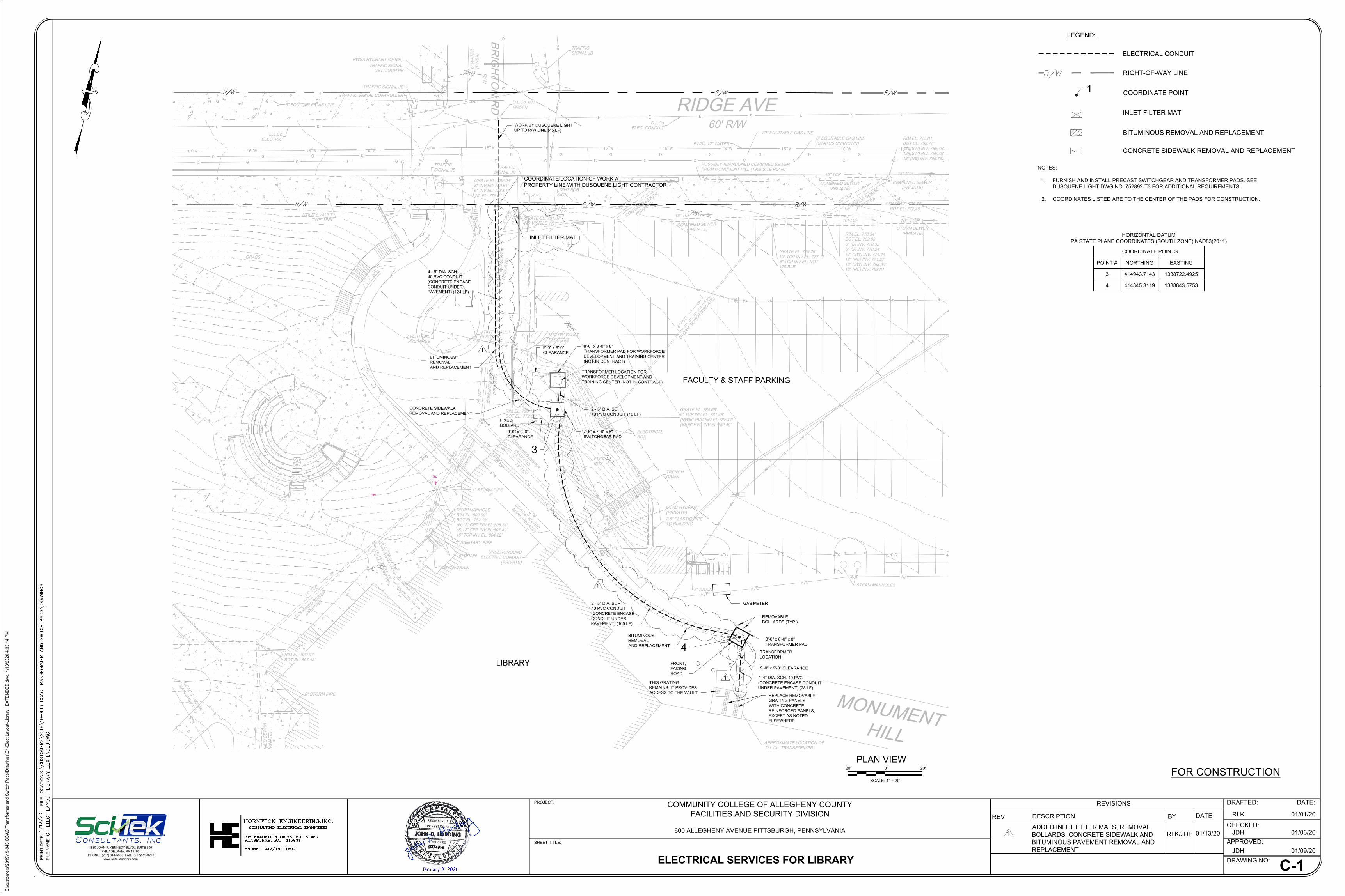
BR
IG
HT
ON
R
D
R/W
GRASS
RIDGE AVE
60' R/W
M
O
N
U
M
E
N
T
H
IL
L
1
5
"
T
C
P
C
O
M
B
I
N
E
D
S
E
W
E
R
(
P
R
I
V
A
T
E
)
15" T
CP
CO
MB
IN
ED
S
EW
ER
(P
RIV
AT
E)
1
5
"
T
C
P
C
O
M
B
I
N
E
D
S
E
W
E
R
(
P
R
I
V
A
T
E
)
15" T
CP
CO
MB
IN
ED
S
EW
ER
(P
RIV
AT
E)
15" T
CP
CO
MB
IN
ED
S
EW
ER
(P
RIV
AT
E)
1
5
"
T
C
P
C
O
M
B
I
N
E
D
S
E
W
E
R
(
P
R
I
V
A
T
E
)
18" TCP
COMBINED SEWER
(PRIVATE)
1
8
"
T
C
P
C
O
M
B
I
N
E
D
S
E
W
E
R
(
P
R
I
V
A
T
E
)
POSSIBLY ABANDONED COMBINED SEWER
FROM MONUMENT HILL (1968 SITE PLAN)
1
5
"
T
C
P
C
O
M
B
I
N
E
D
S
E
W
E
R
(
P
R
I
V
A
T
E
)
18" TCP
COMBINED SEWER
(PRIVATE)
RIM EL: 822.97'
BOT EL: 807.43'
DROP MANHOLE
RIM EL: 809.99'
BOT EL: 782.19'
(N)12" CPP INV EL:805.34'
(S)12" CPP INV EL:807.49'
15" TCP INV EL: 804.22'
RIM EL: 790.15'
BOT EL: 772.65'
GRATE EL: 781.87'
NO VISIBLE WL
GRATE EL: 784.68'
8" TCP INV EL: 781.48'
(NW)6" PVC INV EL:782.41'
(SE)6" PVC INV EL:782.49'
GRATE EL: 779.26'
10" TCP INV EL: 777.17 '
8" TCP INV EL: NOT
VISIBLE
GRATE EL: 776.50'
BOT EL: 772.49 '
GRATE EL: 782.04'
8" INV EL: 779.61'
6" INV EL: 778.91'
WL EL: 778.61'
8
"
P
I
P
E
6" P
IPE
X
"
P
I
P
E
8
"
P
V
C
S
T
O
R
M
S
E
W
E
R
(
P
R
I
V
A
T
E
)
6" DRAIN
6
"
P
V
C
6
"
P
V
C
TRENCH
DRAIN
1
2
"
C
P
P
2 - 6" DRAIN
TRENCH DRAIN
4" STORM PIPE
2" SANITARY PIPE
6
"
S
T
O
R
M
P
I
P
E
6
"
S
A
N
I
T
A
R
Y
P
I
P
E
6" STORM PIPE
STORM SEWER
(PRIVATE)
10" TCP
15" TCP
COMBINED SEWER
(PRIVATE)
RIM EL: 775.81'
BOT EL: 769.77'
18" (SW) INV: 769.78'
18" (SW) INV: 769.78'
18" (NE) INV: 769.76'
RIM EL: 778.34'
BOT EL: 769.83'
6" (S) INV: 770.33'
6" (S) INV: 770.24'
12" (SW) INV: 774.44'
12" (NE) INV: 771.27'
18" (SW) INV: 769.85'
18" (NE) INV: 769.81'
10" TCP
C
C
A
C
8
"
W
A
T
E
R
M
A
I
N
(
P
R
I
V
A
T
E
)
6" W
AT
ER
(P
WS
A)
C
C
A
C
8
"
W
A
T
E
R
M
A
I
N
(
P
R
I
V
A
T
E
)
PWSA HYDRANT (#F105)
PWSA 12" WATER
CCAC HYDRANT
(PRIVATE)
TRAFFIC
SIGNAL JB
LIGHT FOR
SIGN
UTILITY VAULT
ELECTRIC
2 VERTICAL
PVC PIPES
UTILITY VAULT
ELECTRIC
ELEC
BOX
ELEC
BOX
ELECTRICAL
BOX
TRAFFIC
SIGNAL JB
TRAFFIC SIGNAL JB
TRAFFIC
SIGNAL JB
TRAFFIC SIGNAL
DET. LOOP PB
TRAFFIC SIGNAL CONTROLLER
2.5" PLASTIC PIPE
TO BUILDING
UTILITY VAULT
TYPE UNK
APPROXIMATE LOCATION OF
D.L.Co. TRANSFORMER
6" EQUITABLE GAS LINE
20" EQUITABLE GAS LINE
6" EQUITABLE GAS LINE
(STATUS UNKNOWN)
STEAM MANHOLES
D.L.Co
ELEC. CONDUIT
D.L.Co
ELECTRIC
UNDERGROUND
ELECTRIC CONDUIT
(PRIVATE)
D.L.Co. MH
(#2543)
2 - 5" DIA. SCH.
40 PVC CONDUIT
(CONCRETE ENCASE
CONDUIT UNDER
PAVEMENT) (165 LF)
TRANSFORMER
LOCATION
THIS GRATING
REMAINS. IT PROVIDES
ACCESS TO THE VAULT
8'-0" x 8'-0" x 8"
TRANSFORMER PAD
9'-0" x 9'-0" CLEARANCE
GAS METER
REPLACE REMOVABLE
GRATING PANELS
WITH CONCRETE
REINFORCED PANELS,
EXCEPT AS NOTED
ELSEWHERE
REMOVABLE
BOLLARDS (TYP.)
FRONT,
FACING
ROAD
4'-4" DIA. SCH. 40 PVC
(CONCRETE ENCASE CONDUIT
UNDER PAVEMENT) (28 LF)
7'-6" x 7'-6" x 8"
SWITCHGEAR PAD
9'-0" x 9'-0"
CLEARANCE
8'-0" x 8'-0" x 8"
TRANSFORMER PAD FOR WORKFORCE
DEVELOPMENT AND TRAINING CENTER
(NOT IN CONTRACT)
TRANSFORMER LOCATION FOR
WORKFORCE DEVELOPMENT AND
TRAINING CENTER (NOT IN CONTRACT)
WORK BY DUSQUENE LIGHT
UP TO R/W LINE (45 LF)
4 - 5" DIA. SCH.
40 PVC CONDUIT
(CONCRETE ENCASE
CONDUIT UNDER
PAVEMENT) (124 LF)
9'-0" x 9'-0"
CLEARANCE
2 - 5" DIA. SCH.
40 PVC CONDUIT (10 LF)
LIBRARY
FACULTY & STAFF PARKING
FIXED
BOLLARD
BITUMINOUS
REMOVAL
AND REPLACEMENT
BITUMINOUS
REMOVAL
AND REPLACEMENT
CONCRETE SIDEWALK
REMOVAL AND REPLACEMENT
PR
IN
T D
AT
E:
FILE
N
AM
E:
FILE
LO
CA
TIO
N:
PROJECT:
SHEET TITLE:
COMMUNITY COLLEGE OF ALLEGHENY COUNTY
FACILITIES AND SECURITY DIVISION
800 ALLEGHENY AVENUE PITTSBURGH, PENNSYLVANIA
ELECTRICAL SERVICES FOR LIBRARY
C-1
1880 JOHN F. KENNEDY BLVD., SUITE 600
PHILADELPHIA, PA 19103
PHONE: (267) 341-5385 FAX: (267)519-0273
www.scitekanswers.com
DRAWING NO:
RLK
DATE:DRAFTED:
CHECKED:
APPROVED:
01/01/20
JDH
JDH
01/06/20
01/09/20
COORDINATE LOCATION OF WORK AT
PROPERTY LINE WITH DUSQUENE LIGHT CONTRACTOR
4
ELECTRICAL CONDUIT
LEGEND:
RIGHT-OF-WAY LINE
NOTES:
1. FURNISH AND INSTALL PRECAST SWITCHGEAR AND TRANSFORMER PADS. SEE
DUSQUENE LIGHT DWG NO. 752892-T3 FOR ADDITIONAL REQUIREMENTS.
2. COORDINATES LISTED ARE TO THE CENTER OF THE PADS FOR CONSTRUCTION.
COORDINATE POINTS
POINT #
3
4
NORTHING
414943.7143
414845.3119
EASTING
1338722.4925
1338843.5753
COORDINATE POINT
1
3
PLAN VIEW
0'20' 20'
SCALE: 1" = 20'
FOR CONSTRUCTION
HORIZONTAL DATUM
PA STATE PLANE COORDINATES (SOUTH ZONE) NAD83(2011)
INLET FILTER MAT
BITUMINOUS REMOVAL AND REPLACEMENT
INLET FILTER MAT
DESCRIPTION BYREV
REVISIONS
DATE
01/13/201
1
1
1
ADDED INLET FILTER MATS, REMOVAL
BOLLARDS, CONCRETE SIDEWALK AND
BITUMINOUS PAVEMENT REMOVAL AND
REPLACEMENT
RLK/JDH
CONCRETE SIDEWALK REMOVAL AND REPLACEMENT
S:\custom
ers\2019\19-943 C
CA
C T
ransform
er and S
witch P
ads\D
raw
ings\C
1-E
lect Layout-Library _E
XT
EN
DE
D.dw
g, 1/13/2020 4:35:14 P
M
AutoCAD SHX Text
815
AutoCAD SHX Text
780
AutoCAD SHX Text
785
AutoCAD SHX Text
780
AutoCAD SHX Text
790
AutoCAD SHX Text
795
AutoCAD SHX Text
S
AutoCAD SHX Text
S
AutoCAD SHX Text
S
AutoCAD SHX Text
S
AutoCAD SHX Text
S
AutoCAD SHX Text
WV
AutoCAD SHX Text
WV
AutoCAD SHX Text
D
AutoCAD SHX Text
Y
AutoCAD SHX Text
H
AutoCAD SHX Text
D
AutoCAD SHX Text
Y
AutoCAD SHX Text
H
AutoCAD SHX Text
GV
AutoCAD SHX Text
E
AutoCAD SHX Text
S
AutoCAD SHX Text
T
AutoCAD SHX Text
C1-ELECT LAYOUT-LIBRARY _EXTENDED.DWG
AutoCAD SHX Text
S:\CUSTOMERS\2019\19-943 CCAC TRANSFORMER AND SWITCH PADS\DRAWINGS
AutoCAD SHX Text
1/13/20
AutoCAD SHX Text
PHONE: 412/781-1500
AutoCAD SHX Text
105 BRAUNLICH DRIVE, SUITE 450
AutoCAD SHX Text
PITTSBURGH, PA. 115237
AutoCAD SHX Text
CONSULTING ELECTRICAL ENGINEERS
AutoCAD SHX Text
HORNFECK ENGINEERING,INC.
AutoCAD SHX Text
CONSULTANTS, INC.ONSULTANTS, INC., INC. INC.INC.NC.C..
AutoCAD SHX Text
R/W
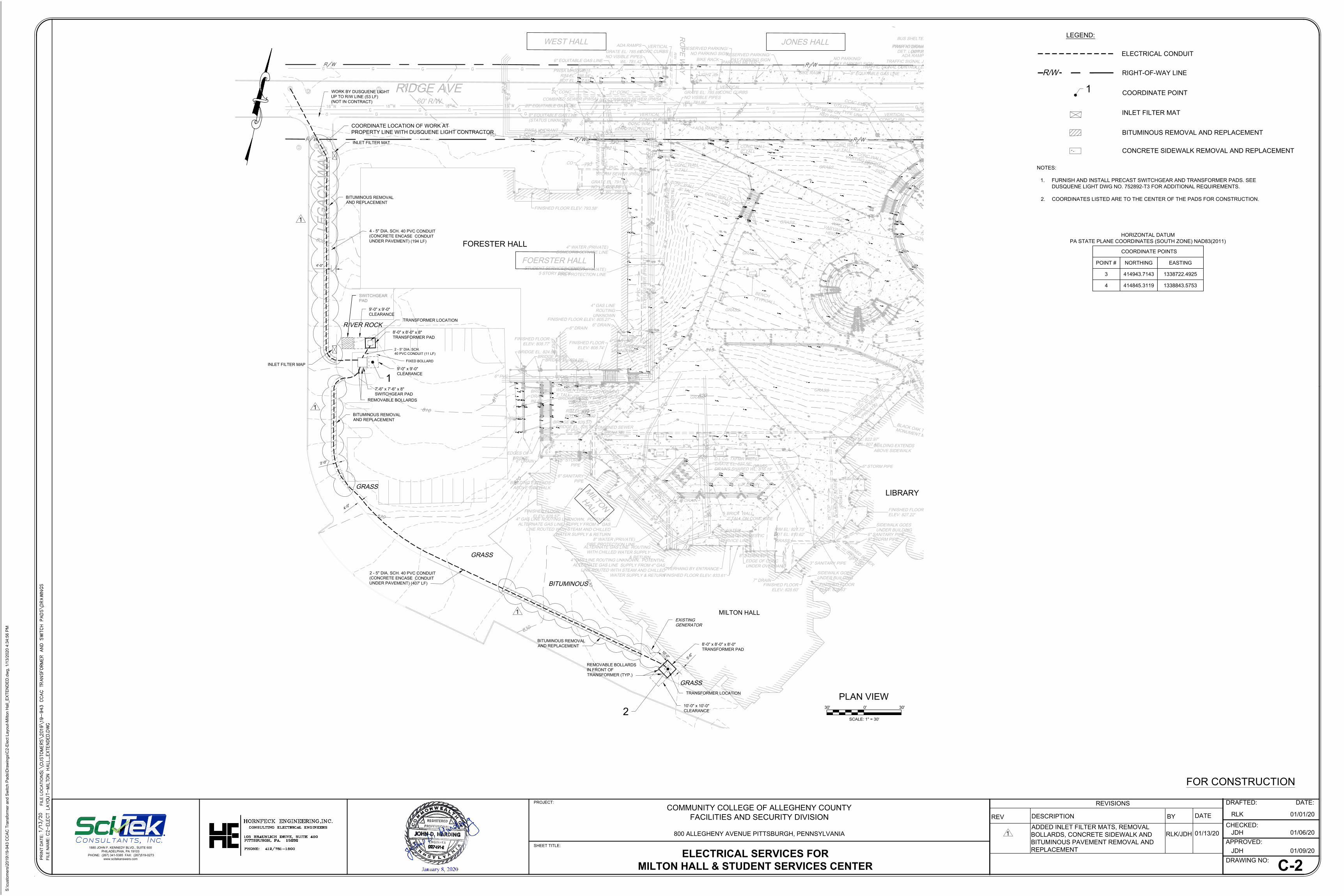
15" TCP
COMBINED SEWER
(PRIVATE)
15" T
CP
CO
MB
IN
ED
S
EW
ER
(P
RIV
AT
E)
1
5
"
T
C
P
C
O
M
B
I
N
E
D
S
E
W
E
R
(
P
R
I
V
A
T
E
)
1
5
"
T
C
P
C
O
M
B
I
N
E
D
S
E
W
E
R
(
P
R
I
V
A
T
E
)
RIM EL: 827.73'
BOT EL: 810.62'
RIM EL: 822.97'
BOT EL: 807.43'
RIM EL: 823.15'
BOT EL: 810.00'
PWSA MH008A015
RIM EL: 786.94'
BOT EL: 777.51'
GRATE EL: 791.58'
NO VISIBLE PIPES
WL: 786.57'
GRATE EL: 785.69'
NO VISIBLE PIPES
WL: 781.90'
GRATE EL: 785.69'
NO VISIBLE PIPES
WL: 781.42'
6" P
VC
ST
OR
M S
EW
ER
(P
RIV
AT
E)
8" PVC
STORM SEWER (PRIVATE)
1
5
" S
T
E
E
L
6" P
VC
SA
NIT
AR
Y S
EW
ER
(P
RIV
AT
E)
21" CONC
COMBINED SEWER (PWSA)
21" CONC
COMBINED SEWER (PWSA)
1
0
"
T
C
P
8" P
VC
8" DRAIN
8" DRAIN
7" DRAIN
6" DRAIN
CO
6" DRAIN
CO
6" DRAIN
6" DRAIN
6" DRAIN
CO
6" PVC
6
"
P
V
C
6" PVC
6" P
VC
6" PVC
6" PVC
6
"
S
T
O
R
M
P
I
P
E
6
"
S
A
N
I
T
A
R
Y
P
I
P
E
6" STORM PIPE
6" SANITARY PIPE
8" STORM PIPE
3" SANITARY PIPE
8" STORM PIPE
6
"
S
A
N
I
T
A
R
Y
P
I
P
E
6
"
S
T
O
R
M
P
I
P
E
6" STORM
PIPE
6" SANITARY
PIPE
BRIDGE
DRAIN
INLET
STUDENT SERVICES CENTER
5 STORY BRICK
RIDGE AVE
60' R/W
B
L
A
C
K
O
A
K
T
R
E
E
M
O
N
U
M
E
N
T
M
L
K
B
E
N
C
H
(T
Y
P
IC
A
L
)
ADA RAMPS
ADA RAMPS
C
C
A
C
S
IG
N
ADA RAMP
BIKE RACK
BIKE RACK
BUS SHELTER
NO PARKING/
PAY PARKING SIGN
RESERVED PARKING/
PAY PARKING SIGN
RESERVED PARKING/
NO PARKING SIGN
BRIDGE PIERS
PARKING METER
GR
AS
S
GR
AS
S
GRASS
GR
AS
S
C
O
N
C
W
A
L
L
V
A
R
Y
IN
G
H
E
IG
H
T
GR
AS
S
GR
AS
S
GRASS
GRASS
GRASS
GR
AS
S
G
R
A
V
E
L
GR
AS
S
K
E
E
P
R
IG
H
T
S
IG
N
SIDEWALK GOES
UNDER BUILDING
BUILDING EXTENDS
ABOVE SIDEWALK
BUILDING EXTENDS
ABOVE SIDEWALK
OVERHANG BY ENTRANCE
EDGES OF
BRIDGE
FINISHED FLOOR ELEV: 793.58'
FINISHED FLOOR
ELEV: 808.74'
FINISHED FLOOR
ELEV: 828.57'
2
' T
A
L
L
C
O
N
C
W
A
L
L
S
C
O
N
C
W
A
L
L
V
A
R
Y
IN
G
H
E
IG
H
T
VERTICAL
CONC CURB
2' TALL
CONC WALL
CONC WALL
1.5' TALL
CONC WALL
6" TALL
C
O
N
C
W
A
L
L
8
" T
A
L
L
C
O
N
C
W
A
L
L
S
3
' T
A
L
L
VERTICAL
CONC CURBS
CONC WALL
3' TALL
CONC WALL
VARYING HEIGHT
BRIDGE PIERS
BRIDGE EL: 824.22'
BRIDGE EL: 824.05'
WOODEN WALL
VARYING HEIGHT
BRIDGE EL: 826.57'
BRIDGE EL: 826.74'
WOODEN WALL
3' TALL
BRICK WALL
2' TALL ON CONC SIDE
FINISHED FLOOR
ELEV: 808.77'
FINISHED FLOOR ELEV: 833.61'
FINISHED FLOOR ELEV: 805.27'
FINISHED FLOOR
ELEV: 828.60'
FINISHED FLOOR
ELEV: 828.63'
FINISHED FLOOR
ELEV: 827.22'
EDGE OF CONC
UNDER OVERHANG
VERTICAL
CONC CURBS
ADA RAMPS
SIDEWALK GOES
UNDER BUILDING
VERTICAL
CONC CURBS
S
T
O
P
H
E
R
E
O
NR
E
D
S
IG
N
FOERSTER HALL
M
I
L
T
O
N
H
A
L
L
CONCRETE
PAD
RO
PE
W
AY
R/W
JONES HALLWEST HALL
PARKING
LE
GA
CY
W
AY
PWSA 12" WATER
CC
AC
8
" W
AT
ER
MA
IN
(P
RIV
AT
E)
C
C
A
C
8
"
W
A
T
E
R
M
A
I
N
(
P
R
I
V
A
T
E
)
PWSA HYDRANT
(#F127)
PWSA HYDRANT
(#F105)
CCAC HYDRANT
(PRIVATE)
8" WATER (PRIVATE)
FIRE PROTECTION LINE
8" WATER
(PRIVATE) DOMESTIC
SERVICE LINE
4" WATER (PRIVATE)
DOMESTIC SERVICE LINE
8" WATER (PRIVATE)
FIRE PROTECTION LINE
LIGHT JB
2 VERTICAL
PVC PIPES
TRAFFIC SIGNAL JB
TRAFFIC SIGNAL
DET. LOOP PB
TRAFFIC SIGNAL CONTROLLER
U
T
IL
IT
Y
V
A
U
L
TT
Y
P
E
U
N
K
6" EQUITABLE GAS LINE
6" EQUITABLE GAS LINE
20" EQUITABLE GAS LINE
6" EQUITABLE GAS LINE
(STATUS UNKNOWN)
4" GAS LINE
ROUTING
UNKNOWN
ALTERNATE GAS LINE ROUTING
WITH CHILLED WATER SUPPLY
& RETURN
4" GAS LINE ROUTING UNKNOWN, POTENTIAL
ALTERNATE GAS LINE SUPPLY FROM 4" GAS
LINE ROUTED WITH STEAM AND CHILLED
WATER SUPPLY & RETURN
4" GAS LINE ROUTING UNKNOWN, POTENTIAL
ALTERNATE GAS LINE SUPPLY FROM 4" GAS
LINE ROUTED WITH STEAM AND CHILLED
WATER SUPPLY & RETURN
4" GAS LINE
ROUTING
UNKNOWN
SWITCHGEAR
PAD
D.L.Co. TXFMR #40763
GRATE EL: 827.56'
DRAINS SHARED WL: 816.19'
2 - 5" DIA. SCH. 40 PVC CONDUIT
(CONCRETE ENCASE CONDUIT
UNDER PAVEMENT) (407' LF)
LIBRARY
MILTON HALL
FORESTER HALL
4
'
-
0
"
1
0
'
-
0
"
5
'
-
6
"
TRANSFORMER LOCATION
10'-0" x 10'-0"
CLEARANCE
2
'-0
"
REMOVABLE BOLLARDS
IN FRONT OF
TRANSFORMER (TYP.)
GRASS
GRASS
GRASS
BITUMINOUS
EXISTING
GENERATOR
7'-6" x 7'-6" x 8"
SWITCHGEAR PAD
9'-0" x 9'-0"
CLEARANCE
TRANSFORMER LOCATION
8'-0" x 8'-0" x 8"
TRANSFORMER PAD
8'-0" x 8'-0" x 8'-0"
TRANSFORMER PAD
REMOVABLE BOLLARDS
4'-0"
4 - 5" DIA. SCH. 40 PVC CONDUIT
(CONCRETE ENCASE CONDUIT
UNDER PAVEMENT) (194 LF)
2 - 5" DIA. SCH.
40 PVC CONDUIT (11 LF)
WORK BY DUSQUENE LIGHT
UP TO R/W LINE (53 LF)
(NOT IN CONTRACT)
9'-0" x 9'-0"
CLEARANCE
FIXED BOLLARD
BITUMINOUS REMOVAL
AND REPLACEMENT
BITUMINOUS REMOVAL
AND REPLACEMENT
BITUMINOUS REMOVAL
AND REPLACEMENT
INLET FILTER MAT
INLET FILTER MAP
RIVER ROCK
PR
IN
T D
AT
E:
FILE
N
AM
E:
FILE
LO
CA
TIO
N:
PROJECT:
SHEET TITLE:
1880 JOHN F. KENNEDY BLVD., SUITE 600
PHILADELPHIA, PA 19103
PHONE: (267) 341-5385 FAX: (267)519-0273
www.scitekanswers.com
0'30' 30'
SCALE: 1" = 30'
C-2
DRAWING NO:
RLK
DATE:DRAFTED:
CHECKED:
APPROVED:
JDH
JDH
COMMUNITY COLLEGE OF ALLEGHENY COUNTY
FACILITIES AND SECURITY DIVISION
800 ALLEGHENY AVENUE PITTSBURGH, PENNSYLVANIA
ELECTRICAL SERVICES FOR
MILTON HALL & STUDENT SERVICES CENTER
01/01/20
01/06/20
01/09/20
PLAN VIEW
COORDINATE LOCATION OF WORK AT
PROPERTY LINE WITH DUSQUENE LIGHT CONTRACTOR
2
1
FOR CONSTRUCTION
1
1
1
ELECTRICAL CONDUIT
LEGEND:
RIGHT-OF-WAY LINER/W
NOTES:
1. FURNISH AND INSTALL PRECAST SWITCHGEAR AND TRANSFORMER PADS. SEE
DUSQUENE LIGHT DWG NO. 752892-T3 FOR ADDITIONAL REQUIREMENTS.
2. COORDINATES LISTED ARE TO THE CENTER OF THE PADS FOR CONSTRUCTION.
COORDINATE POINTS
POINT #
3
4
NORTHING
414943.7143
414845.3119
EASTING
1338722.4925
1338843.5753
COORDINATE POINT
1
HORIZONTAL DATUM
PA STATE PLANE COORDINATES (SOUTH ZONE) NAD83(2011)
INLET FILTER MAT
BITUMINOUS REMOVAL AND REPLACEMENT
DESCRIPTION BYREV
REVISIONS
DATE
01/13/201
ADDED INLET FILTER MATS, REMOVAL
BOLLARDS, CONCRETE SIDEWALK AND
BITUMINOUS PAVEMENT REMOVAL AND
REPLACEMENT
RLK/JDH
CONCRETE SIDEWALK REMOVAL AND REPLACEMENT
S:\custom
ers\2019\19-943 C
CA
C T
ransform
er and S
witch P
ads\D
raw
ings\C
2-E
lect Layout-M
ilton H
all_E
XT
EN
DE
D.dw
g, 1/13/2020 4:34:56 P
M
AutoCAD SHX Text
S
AutoCAD SHX Text
S
AutoCAD SHX Text
S
AutoCAD SHX Text
S
AutoCAD SHX Text
D
AutoCAD SHX Text
790
AutoCAD SHX Text
800
AutoCAD SHX Text
810
AutoCAD SHX Text
820
AutoCAD SHX Text
830
AutoCAD SHX Text
790
AutoCAD SHX Text
820
AutoCAD SHX Text
815
AutoCAD SHX Text
825
AutoCAD SHX Text
820
AutoCAD SHX Text
815
AutoCAD SHX Text
815
AutoCAD SHX Text
785
AutoCAD SHX Text
830
AutoCAD SHX Text
810
AutoCAD SHX Text
820
AutoCAD SHX Text
830
AutoCAD SHX Text
D
AutoCAD SHX Text
D
AutoCAD SHX Text
D
AutoCAD SHX Text
D
AutoCAD SHX Text
D
AutoCAD SHX Text
WV
AutoCAD SHX Text
WV
AutoCAD SHX Text
WV
AutoCAD SHX Text
D
AutoCAD SHX Text
Y
AutoCAD SHX Text
H
AutoCAD SHX Text
D
AutoCAD SHX Text
Y
AutoCAD SHX Text
H
AutoCAD SHX Text
~
AutoCAD SHX Text
~
AutoCAD SHX Text
~
AutoCAD SHX Text
~
AutoCAD SHX Text
~
AutoCAD SHX Text
~
AutoCAD SHX Text
~
AutoCAD SHX Text
~
AutoCAD SHX Text
~
AutoCAD SHX Text
~
AutoCAD SHX Text
GV
AutoCAD SHX Text
GV
AutoCAD SHX Text
GV
AutoCAD SHX Text
GV
AutoCAD SHX Text
792
AutoCAD SHX Text
793
AutoCAD SHX Text
788
AutoCAD SHX Text
E
AutoCAD SHX Text
C2-ELECT LAYOUT-MILTON HALL_EXTENDED.DWG
AutoCAD SHX Text
S:\CUSTOMERS\2019\19-943 CCAC TRANSFORMER AND SWITCH PADS\DRAWINGS
AutoCAD SHX Text
1/13/20
AutoCAD SHX Text
PHONE: 412/781-1500
AutoCAD SHX Text
105 BRAUNLICH DRIVE, SUITE 450
AutoCAD SHX Text
PITTSBURGH, PA. 15232
AutoCAD SHX Text
CONSULTING ELECTRICAL ENGINEERS
AutoCAD SHX Text
HORNFECK ENGINEERING,INC.
AutoCAD SHX Text
CONSULTANTS, INC.ONSULTANTS, INC., INC. INC.INC.NC.C..
Related Documents