PROJECT NARRATIVE The Central Cooling and Heating Plant is a (+/-)7,924 S.F. structure containing equipment to serve chillers, cooling towers and boilers to serve hot and cold water supply to campus facilities. Support offices and maintenance spaces are included in the facility construction. TABLE 5-1: FLOOR HAZARD INFORMATION and FLOOR LOADS FLOOD HAZARD AREA Base Flood Elevation _______________ MSL NGVD or FIRM Design Floor Elevation _______________ MSL IBC 1612.3 and ASCE 24 NON-HIGH VELOCITY WAVE ACTION Elevation of Lowest Proposed Floor _______________ MSL Meet ASCE 24 Section 2.6.2.1 Dry flood proofing _____ no _____ yes per ASCE 24 HIGH-VELOCITY WAVE ACTION Elevation of bottom of Lowest Horizontal Structural Member of lowest floor __________________ MSL Flotation resistant _____ no _____ yes per ASCE 24 Breakaway wall _____ no _____ yes per ASCE 24 IBC 1612 and SE-900, as applicable N/A 43.0 Zone X, Community # 450104, Panel # 0517 43.0 40.67 TABLE 5-2: SOILS & SITE SOILS INVESTIGATION (If available) SOILS CLASSIFICATION Site Class (seismic class) Classes Soil of Materials (UCS System) Allowable Footing Bearing Pressure ___________________ ___________________ ___________________ psf per IBC 1613.5.2 per IBC 1802.3 Class 4 (SP, SC, SM) Seismic Site Class E 2,000 MINIMUM DESIGN SOIL BEARING LOAD ______________ psf per IBC table 1804.2.1 1633-09-237 Dated 10-9-09 (per IBC table 1804.2.1) no yes COMPACTION Subgrade _____________ % ASTM D698 ASTM D1557 AASHTO (only for paving & roads) Base _____________ % ASTM D698 ASTM D1557 AASHTO (only for paving & roads) Other _____________ % ASTM D698 ASTM D1557 AASHTO (only for paving & roads) MINIMUM DESIGN SOIL LATERAL LOAD ____________________ psf per IBC table 1610.1 FOOTINGS Undisturbed Footings Compacted Fill Material ELEVATIONS Elevation of Water Table Elevation of lowest footing Elevation of lowest floor or basement no yes per IBC table 1803.5 no yes 2,000 98 100 NA 80 (Active Lateral) ______________ MSL ______________ MSL ______________ MSL 41.67 (TOF) 36.7 43.0 ____________________ psf 720 (Passive Lateral) Water at 4'-4" to 5'-4" below exist. ground surface (4.8' Average). TABLE 5-4: BUILDING AREA AREA LIMIT BY TABLE 503 OF IBC (Do not indicate increases for sprinklers & street frontage.) AREA MODIFICATION FROM EQUATIONS 5-1 OF IBC (Insert equation from IBC 506.1 with completed calculations in this Box) (Equation 5-1) Aa = At + [ At x If] + [At x Is] Aa = Allowable area per floor (square feet). At = Tabular area per floor in accordance with Table 503 If = Area increase factor due to frontage (percent as calculated in accordance with Section 506.2 Is = Area increase due to sprinkler protection as calculated in accordance with Section 506.3 Aa = Total Allowed Area of Building (summary of all stories) AREA AS DESIGNED PER STORY (Repeat for each story) Total Designed Area of Building ________________ SF ________________ SF (FIRST FLOOR) ________________ SF ________________ SF (maximum area per story) ________________ SF (maximum modified area per story) ________________ SF (area limitation per story) 15,500 27,125 27,125 54,250 6,273 7,916 ________________ SF (SECOND FLOOR) 1,643 TABLE 5-5: BUILDING HEIGHT In Feet In Stories In Feet AS DESIGNED AS DESIGNED AS DESIGNED AS DESIGNED AS ALLOWED BY IBC AS ALLOWED BY IBC AS ALLOWED BY IBC AS ALLOWED BY IBC Without any Allowable Increase (per IBC Table 503) Allowable Height Increase (per IBC 504.2) 32'-0" Total Height including any Allowable Increase 2 55'-0" 2 N/A N/A 0 0 32'-0" 2 55'-0" 2 In Stories TABLE 5-6 BUILDING DESIGN OCCUPANT LOAD FIRST FLOOR Floor Area Gross/Net Sq. Ft. Max. Area allowed per Occupant (NSF/GSF) Occupants on this Floor for this Function Design Occupant Load Function of Space Factory (F) Floor or Level Total Building Design Occupant Load: 100 gross 57 5,620 gross Industrial Areas Subtotal Design Occupant Load for This Story: 64 70 100 gross 7 653 gross Business Areas MEZZA- NINES Factory (F) 100 gross 0 0 gross Industrial Areas Subtotal Design Occupant Load for This Story: 6 300 gross 6 1,643 gross Storage & Mechanical 100 gross 0 0 gross Business Areas TABLE 5-8: FIRE RESISTANCE RATING OF BUILDING ELEMENTS BUILDING ELEMENT Structural Frame (per IBC Table 601) Rating As Provided (in hours) Testing Agency & Design No. (UL, FM, etc) -- -- Bearing Walls Exterior Interior (per IBC Table 601) Rating As Required (in hours) Designers Wall/Partition Key Code Nonbearing Walls & Partitions Exterior Interior (per IBC Table 601 & 602) Floor Construction including supporting beams & joists (per IBC Table 601) Roof Construction including supporting beams & joists (per IBC Table 601) Fire Walls (per IBC Section 705) Fire Barriers (per IBC Section 706) Shaft Enclosures (per IBC Section 707) Fire Partitions (per IBC Section 708) Opening & Protective Listing by Category (fire shutters, doors, etc. per IBC Section 715) -- -- -- 0 0 -- -- -- -- -- -- 0 0 -- -- 0 -- -- -- 0 -- -- 0 N/A -- -- -- 1 Hour 1 Hour -- -- N/A -- -- -- N/A -- -- -- N/A -- -- -- TABLE 5-9: STRUCTURAL DESIGN INFORMATION OCCUPANCY CATEGORY (IES) OCCUPANCY CATEGORY (IES) OCCUPANCY CATEGORY (IES) OCCUPANCY CATEGORY (IES) IBC Table 1604.5 LIVE LOADS LIVE LOADS LIVE LOADS LIVE LOADS Floor Live Load F ________________PSF List the F for each occupancy Roof Live Load R ________________PSF Ground Snow Load P ________________PSF IBC (Figure 1608.2) ll ll g 20 150 WIND LOADS Analysis Procedure _______________________ASCE 7 Basic Wind Speed V = _______________________3 sec gust IBC Fig 1609 Exposure Category _______________________ Wind Importance Factor I = _______________________ASCE 7 (Table 6.1) Internal Pressure Coefficient GC = _______________________ASCE 7 External Pressure Coefficient GC = _______________________ASCE 7 p pi w 3s 130 MPH ANALYTICAL PROCEDURE C 7.2 PSF 1.15 39.8 PSF SEISMIC LOADS Seismic Importance Factor I = ________ASCE 7 Soil Class ________IBC 1613.5.2 Mapped Spectral Response Accelerations S = ________ S = _________ Design Spectral Response Acceleration Parameters S = ________ S = _________ Seismic Use Group ________ASCE 7 (Seismic Occupancy Category IBC) Seismic Design Category ________IBC Tables 1613.5.6(1) & 1613.5.6(2) Basic Seismic Force Resisting System _______________________________________________ Design Base Shear ________KIPS Seismic Response Coefficient(s) C = ________ASCE 7 Response Modification Factor(s) R = ________ASCE 7 Analysis Procedure ___________________________ 10 s DS l Dl S D 1.5 0.55 3 0.557 D 153 SPECIAL REINFORCED CMU SHEAR WALLS 0.285 5.0 0.166 0.251 ARCHITECTURAL-MECHANICAL-ETC. LOADS ARCHITECTURAL-MECHANICAL-ETC. LOADS ARCHITECTURAL-MECHANICAL-ETC. LOADS ARCHITECTURAL-MECHANICAL-ETC. LOADS Provide as applicable: architectural items, mechanical, plumbing, etc. per ASCE 7 SPECIAL LOADS SPECIAL LOADS SPECIAL LOADS SPECIAL LOADS Provide as applicable: architectural items, mechanical, plumbing, etc. per ASCE 7 *per IBC Chapter 16 and ASCE 7 - Information may be shown on initial Structural Sheet of the drawings or on Sheet with other code information. List floor design loads on structural plans Equivalent Lateral Force TABLE 5-12 MECHANICAL INFORMATION AIR COMFORT SYSTEMS AIR COMFORT SYSTEMS AIR COMFORT SYSTEMS AIR COMFORT SYSTEMS Overall Thermal Transfer Value (OTTV): ____________________ Heating Load: ____________________BTU/S.F. Cooling Load: ____________________S.F./Ton OTHER LOADING FEATURES OTHER LOADING FEATURES OTHER LOADING FEATURES OTHER LOADING FEATURES Glass: U-Factor: _____________ Window-to-Wall Ratio ______________ Insulation Value: Roof: _____________ Exterior Walls: ______________ N/A 39 0.6 15.2 15.74 0.6 Outside Air minimum while occupied ________ CFM _____________ Occupants *Actual Occupant Load 800 2* MECHANICAL SYSTEMS, SERVICE SYSTEMS & EQUIPMENT MECHANICAL SYSTEMS, SERVICE SYSTEMS & EQUIPMENT MECHANICAL SYSTEMS, SERVICE SYSTEMS & EQUIPMENT MECHANICAL SYSTEMS, SERVICE SYSTEMS & EQUIPMENT Chilled water air handling unit with hot water reheat. Ventilation Fans with Unit Heaters for main plant area. Fan Coil Units with electric heat for office areas. 3.84 TABLE 5-13: ELECTRICAL INFORMATION SERVICE TRANSFORMER: ________By Utility ________By Agency _________KVA Primary _________Voltage/Phase NA ELECTRICAL SERVICE INFORMATION ELECTRICAL SERVICE INFORMATION ELECTRICAL SERVICE INFORMATION ELECTRICAL SERVICE INFORMATION: Service Voltage/Phase _________________________Amperes Service Entrance Conductors Size: _________________________Quantity per Phase Total Connected Load: _________________________KVA Estimated Maximum Demand: _________________________KVA Fault Current Rating of Overcurrent Device: _________________________ Available Fault Current At The Service Disconnecting Means: _________________________ Interrupting Capacity of Service Overcurrent Device: _________________________ Grounding Electrode System Components: _________________________per NEC 250-C _________________________ _________________________ _________________________ _________________________ NA EMERGENCY SERVICE INFORMATION Emergency Generator: ____No ____Yes ____KVA Voltage/Phase __________ __________Fuel Exit/ Emergency Lights Backup Power: ____Integral Battery _____Generator Fire Alarm System: ____Manual ____Automatic ____Addressable ____Class A ____Class B 4,000 10 3,640 3,276 65,000 A 4,000 A a) Ground Rod Cluster LIGHTNING PROTECTION PROVIDED LIGHTNING PROTECTION PROVIDED LIGHTNING PROTECTION PROVIDED LIGHTNING PROTECTION PROVIDED ____No ____Yes COMMUNICATIONS COORDINATED COMMUNICATIONS COORDINATED COMMUNICATIONS COORDINATED COMMUNICATIONS COORDINATED Contact Chief Information Office for applicability, (803) 898-8121 _____Not Required _____Yes b) Metal Building Frame 480/227V, 3-phase, 4-wire 600 MCM c) Metal Water Pipes d) Metal Gas Pipes e) Rebar in Concrete Slab f) Lighting Protection System 52,298 A 5.1.3 CODES AND STANDARDS A. International Building Code (IBC), 2006 Edition. B. International Existing Building Code (IEBC), 2006 Edition C. International Fire Code (IFC), 2006 Edition. D. International Energy Conservation Code (IECC), 2006 Edition. E. International Fuel Gas Code (IFGC), 2006 Edition. F. International Mechanical Code (IMC), 2006 Edition. G. International Plumbing Code (IPC), 2006 Edition. 1. Section 305.6.1, insert "24" and insert "24" 2. Section 904.1, insert "8" H. International Private Sewage Disposal Code (IPSDC), 2006 Edition. I. International Property Maintenance Code (IPMC), 2006 Edition. J. International Residential Code for One and Two Family Dwellings (IRC), 2006 Edition with the following insertions: 1. P2603.1, insert "12" and insert "24" K. International Wildland - Urban Interface Code (IUWIC), 2006 Edition, Note: The IUWIC does not supersede existing stationary requirements L. International Code Council Electric Code, 2006 Edition M. National Electrical Code (NEC) [NFPA 70], 2008 Edition N. National Electrical Safety Code, ANSI-C2-2002 Edition O. Latest edition of the American National Standards Institute, Inc. (ANSI) document A117.1, Accessible and Useable Buildings and Facilities. Note that this standard is the standard adopted by the South Carolina Accessibility Act but this requirement does not relieve the Agency or the design professional from the Federal Statutory requirements that design and construction comply with the Americans With Disabilities Act Accessibility Guidelines for Buildings and Facilities. See http://www.access-board.gov./adaag/html/adaag.htm P. State Fire Marshal rules, regulations, and policies. See http://www.llr.state.sc.us/firemarshall.asp Q. South Carolina Elevator Code & Regulations. See http://www.llr.state.sc.us/Labor/index.aspfile=elevatorsindex.htm R. State of SC Telephone Equipment Room and Communications/Data Systems Policies as formulated by the Office of Information Resources (OIR) Telecommunications. S. International Code Council Performance Code (ICCPC), 2006 Edition, upon State Engineer's written approval. T. Governors executive Order No. 82-19 (April 1982) - State of SC Building Standards in Floodplain Areas. U. The South Carolina Modular Buildings Construction Act S.C. Code 23-43-10 et. Seq. TABLE 5-10: PLUMBING INFORMATION FIRST FLOOR: FACTORY OCCUPANCY: 70 Persons (35 Male and 35 Female)* Water Closets Req'd.: Male: 1 (1 per 100* per IPC 419.2 - no more than 66.7% of required water closets may be substituted with urinals) Female: 1 (1 per 100) Lavatories Req'd.: Male: 1 (1 per 100) Female: 1 (1 per 100) Drinking Fountains Req'd.: 1 (1 per 100) Water Closets MALE REQUIRED. Lavatories: WATER SYSTEM WATER SYSTEM WATER SYSTEM WATER SYSTEM Service Line Size ____________Inches Peak ____________GPM 4 150 Total Demand ____________No. Fixture Units 38.25 SANITARY SEWER SYSTEM SANITARY SEWER SYSTEM SANITARY SEWER SYSTEM SANITARY SEWER SYSTEM Loading __________________________________________________GPD __________________________________________________ Service Line Size _______________________________Inches Slope _______________________________min inches/ft. MINIMUM PLUMBING FIXTURES REQUIRED/PROVIDED MINIMUM PLUMBING FIXTURES REQUIRED/PROVIDED MINIMUM PLUMBING FIXTURES REQUIRED/PROVIDED MINIMUM PLUMBING FIXTURES REQUIRED/PROVIDED per IBC Section 403 & Table 403.1 per IBC Section 403 & Table 403.1 per IBC Section 403 & Table 403.1 per IBC Section 403 & Table 403.1 Urinals: OTHER FIXTURES: Unisex Toilet Service Sink MALE PROVIDED FEMALE REQUIRED: FEMALE PROVIDED: REQUIRED. PROVIDED Drinking Fountains 1 2 per IBC Section 403 & Table 403.1 0 1 1* 1 1 1* 1 1* 1 1* 1 1* 0 0 N/A N/A * Toilet and Lavatories provided at Unisex Toilet Room Per IBC 2902.2 Exception 2 - Separate facilities shall not be required in structures or tenant spaces with a total occupant load, including both employees and customers of 15 or less. 6" Building, 8" Cooling Towers 1/8" per 1'-0" 150 (excludes Cooling Tower bleed off); Cooling Tower bleed off = 16,000 GPD at peak TABLE 5-7: GENERAL FIRE PROTECTION REQUIREMENTS Fireblocking Required SEPARATIONS Draftstopping Required Smoke Control System Required Smoke Barriers Required Fire Partition Required Fire Barrier Required Smoke Partitions Required SEPARATIONS SUPPRESSION Fire Alarm System Required Emergency Alarm System Required Standpipes Required Sprinklers Required Sprinklers Provided Portable extinguishers required Other suppression systems required Smoke & heat vents required Other: (Indicate other provided fire and life safety features not listed above if any) per IBC Section 717 per IBC Section 717 per IBC Section 909 per IBC Section 407 & 408 per IBC Section 407 per IBC Section 419 per IBC Section 706 per IBC Section 907 per IFC 908 per IFC Section 905 per IFC Section 903 per IFC 906 per IFC 904 per IFC 910 no yes no yes no yes no yes no yes no yes no yes no yes no yes no yes no yes no yes no yes no yes no yes TABLE 5-3: BASIC BUILDING CODE INFORMATION CONSTRUCTION CLASSIFICATION OCCUPANCY GROUP (indicate all) (Note IBC 506.4.1) OCCUPANCY GROUP (indicate most restrictive) Does building require Incidental Use Area Separation? Does building have Accessory Occupancy (ies)? What percent of story is accessory occupancy? Mixed Occupancy Non separation Separation OTHER FIRE PROTECTION SYSTEMS, DEVICES OR FEATURES If the building has any special or notable fire protection or safety feature of hazard the designers should list them here, describe the performance characteristics and refer to locations in construction documents. (e.g. fire extinguishers, smoke-evacuation/control/compartments. Note IBC 414.1.3) (IBC 508.3) (IBC 508.3.1) (IBC 508.2.2) (IBC 508.3.2) (IBC 508.3) (IBC 506.4.1) __________ SF __________ % no yes _______________________________ (IBC Table 503) _______________________________ (IBC Table 302) Type _______________________________ (IBC Table 602) IIB F-1 (FACTORY); B (BUSINESS) F-1 FACTORY 646 9.6 no yes no yes no yes no yes CENTRAL COOLING AND HEATING PLANT CONSULTANT: SHEET NUMBER CHECK BY: DRAWN BY: DATE: DWG JOB NO.: PLOT DATE: 09107 HORRY COUNTY, SOUTH CAROLINA DATE REV: STATE PROJECT NO.: H17-9569-LC Watson Tate Savory Liollio A R C H I T E C T U R E Charleston Asheville Charlotte Columbia RRF CME A0.1 CODE INFORMATION 07/05/11 REV. DATE DESCRIPTION

Welcome message from author
This document is posted to help you gain knowledge. Please leave a comment to let me know what you think about it! Share it to your friends and learn new things together.
Transcript

PROJECT NARRATIVE
The Central Cooling and Heating Plant is a (+/-)7,924 S.F. structure containing equipment to serve chillers,cooling towers and boilers to serve hot and cold water supply to campus facilities. Support offices andmaintenance spaces are included in the facility construction.
TABLE 5-1: FLOOR HAZARD INFORMATION and FLOOR LOADS
FLOOD HAZARD AREA
Base Flood Elevation _______________ MSL NGVD or FIRMDesign Floor Elevation _______________ MSL IBC 1612.3 and ASCE 24
NON-HIGH VELOCITY WAVE ACTION
Elevation of Lowest Proposed Floor _______________ MSL Meet ASCE 24 Section 2.6.2.1Dry flood proofing _____ no _____ yes per ASCE 24
HIGH-VELOCITY WAVE ACTION
Elevation of bottom of Lowest Horizontal Structural Member of lowest floor __________________ MSLFlotation resistant _____ no _____ yes per ASCE 24Breakaway wall _____ no _____ yes per ASCE 24
IBC 1612 and SE-900, as applicable
N/A
43.0
Zone X,Community # 450104,Panel # 0517
43.0
40.67
TABLE 5-2: SOILS & SITE
SOILS INVESTIGATION (If available)
SOILS CLASSIFICATION
Site Class (seismic class)Classes Soil of Materials (UCS System)Allowable Footing Bearing Pressure
_________________________________________________________ psf
per IBC 1613.5.2per IBC 1802.3Class 4 (SP, SC, SM)
Seismic Site Class E
2,000
MINIMUM DESIGN SOIL BEARING LOAD______________ psf per IBC table 1804.2.1
1633-09-237 Dated 10-9-09(per IBC table 1804.2.1)
no yes
COMPACTION
Subgrade _____________ % ASTM D698 ASTM D1557AASHTO (only for paving & roads)
Base _____________ % ASTM D698 ASTM D1557AASHTO (only for paving & roads)
Other _____________ % ASTM D698 ASTM D1557AASHTO (only for paving & roads)
MINIMUM DESIGN SOIL LATERAL LOAD____________________ psf per IBC table 1610.1
FOOTINGS
Undisturbed FootingsCompacted Fill Material
ELEVATIONS
Elevation of Water Table
Elevation of lowest footingElevation of lowest floor or basement
no yes
per IBC table 1803.5no yes
2,000
98
100
NA
80 (Active Lateral)
______________ MSL
______________ MSL______________ MSL
41.67 (TOF)
36.7
43.0
____________________ psf720 (Passive Lateral)
Water at 4'-4" to 5'-4" below exist.ground surface (4.8' Average).
TABLE 5-4: BUILDING AREA
AREA LIMIT BY TABLE 503 OF IBC(Do not indicate increases for sprinklers & street frontage.)
AREA MODIFICATION FROM EQUATIONS 5-1 OF IBC(Insert equation from IBC 506.1 with completed calculations in this Box)(Equation 5-1)
Aa = At + [ At x If] + [At x Is]
Aa = Allowable area per floor (square feet).At = Tabular area per floor in accordance with Table 503If = Area increase factor due to frontage (percent as calculated
in accordance with Section 506.2Is = Area increase due to sprinkler protection as calculated
in accordance with Section 506.3
Aa =
Total Allowed Area of Building(summary of all stories)
AREA AS DESIGNED PER STORY(Repeat for each story)
Total Designed Area of Building
________________ SF
________________ SF(FIRST FLOOR)
________________ SF
________________ SF(maximum area per story)
________________ SF(maximum modified area per story)
________________ SF(area limitation per story)
15,500
27,125
27,125
54,250
6,273
7,916
________________ SF(SECOND FLOOR)
1,643
TABLE 5-5: BUILDING HEIGHT
In Feet In Stories In Feet
AS DESIGNEDAS DESIGNEDAS DESIGNEDAS DESIGNED AS ALLOWED BY IBCAS ALLOWED BY IBCAS ALLOWED BY IBCAS ALLOWED BY IBC
Without any Allowable Increase(per IBC Table 503)
Allowable Height Increase(per IBC 504.2)
32'-0"
Total Height including anyAllowable Increase
2 55'-0" 2
N/A N/A 0 0
32'-0" 2 55'-0" 2
In Stories
TABLE 5-6 BUILDING DESIGN OCCUPANT LOAD
FIRSTFLOOR
Floor AreaGross/Net Sq. Ft.
Max. Area allowedper Occupant
(NSF/GSF)
Occupants onthis Floor for
this Function
Design OccupantLoadFunction of Space
Factory (F)
Floor orLevel
Total Building Design Occupant Load:
100 gross 575,620 gross Industrial Areas
Subtotal Design Occupant Load for This Story: 64
70
100 gross 7653 gross Business Areas
MEZZA-NINES
Factory (F)
100 gross 00 gross Industrial Areas
Subtotal Design Occupant Load for This Story: 6
300 gross 61,643 gross Storage & Mechanical
100 gross 00 gross Business Areas
TABLE 5-8: FIRE RESISTANCE RATING OF BUILDING ELEMENTS
BUILDING ELEMENT
Structural Frame(per IBC Table 601)
Rating As Provided(in hours)
Testing Agency & Design No.(UL, FM, etc)
----
Bearing WallsExteriorInterior
(per IBC Table 601)
Rating As Required(in hours)
Designers Wall/PartitionKey Code
Nonbearing Walls & PartitionsExteriorInterior
(per IBC Table 601 & 602)
Floor Construction including supportingbeams & joists(per IBC Table 601)
Roof Construction including supportingbeams & joists(per IBC Table 601)
Fire Walls(per IBC Section 705)
Fire Barriers(per IBC Section 706)
Shaft Enclosures(per IBC Section 707)
Fire Partitions(per IBC Section 708)
Opening & Protective Listing byCategory (fire shutters, doors, etc. perIBC Section 715)
--
----
00
----
----
----
00
----
0 -- --
--0
----0
N/A -- -- --
1 Hour 1 Hour -- --
N/A -- -- --
N/A -- -- --
N/A -- -- --
TABLE 5-9: STRUCTURAL DESIGN INFORMATION
OCCUPANCY CATEGORY (IES)OCCUPANCY CATEGORY (IES)OCCUPANCY CATEGORY (IES)OCCUPANCY CATEGORY (IES)IBC Table 1604.5
LIVE LOADSLIVE LOADSLIVE LOADSLIVE LOADS
Floor Live Load F ________________PSF List the F for each occupancyRoof Live Load R ________________PSFGround Snow Load P ________________PSF IBC (Figure 1608.2)
ll
llg 20
150
WIND LOADS
Analysis Procedure _______________________ASCE 7Basic Wind Speed V = _______________________3 sec gust IBC Fig 1609Exposure Category _______________________Wind Importance Factor I = _______________________ASCE 7 (Table 6.1)Internal Pressure Coefficient GC = _______________________ASCE 7External Pressure Coefficient GC = _______________________ASCE 7p
pi
w
3s130 MPH
ANALYTICAL PROCEDURE
C
7.2 PSF1.15
39.8 PSF
SEISMIC LOADS
Seismic Importance Factor I = ________ASCE 7Soil Class ________IBC 1613.5.2Mapped Spectral Response Accelerations S = ________ S = _________Design Spectral Response Acceleration Parameters S = ________ S = _________Seismic Use Group ________ASCE 7 (Seismic Occupancy Category IBC)Seismic Design Category ________IBC Tables 1613.5.6(1) & 1613.5.6(2)Basic Seismic Force Resisting System _______________________________________________Design Base Shear ________KIPSSeismic Response Coefficient(s) C = ________ASCE 7Response Modification Factor(s) R = ________ASCE 7Analysis Procedure ___________________________
10
s
DS
l
Dl
S
D1.5
0.55
30.557
D
153
SPECIAL REINFORCED CMU SHEAR WALLS
0.285
5.0
0.166
0.251
ARCHITECTURAL-MECHANICAL-ETC. LOADSARCHITECTURAL-MECHANICAL-ETC. LOADSARCHITECTURAL-MECHANICAL-ETC. LOADSARCHITECTURAL-MECHANICAL-ETC. LOADS Provide as applicable: architectural items,mechanical, plumbing, etc. per ASCE 7
SPECIAL LOADSSPECIAL LOADSSPECIAL LOADSSPECIAL LOADS Provide as applicable: architectural items,mechanical, plumbing, etc. per ASCE 7
*per IBC Chapter 16 and ASCE 7 - Information may be shown on initial Structural Sheet of the drawings or on Sheet withother code information. List floor design loads on structural plans
Equivalent Lateral Force
TABLE 5-12 MECHANICAL INFORMATION
AIR COMFORT SYSTEMSAIR COMFORT SYSTEMSAIR COMFORT SYSTEMSAIR COMFORT SYSTEMSOverall Thermal Transfer Value (OTTV): ____________________Heating Load: ____________________BTU/S.F.Cooling Load: ____________________S.F./Ton
OTHER LOADING FEATURESOTHER LOADING FEATURESOTHER LOADING FEATURESOTHER LOADING FEATURESGlass: U-Factor: _____________ Window-to-Wall Ratio ______________Insulation Value: Roof: _____________ Exterior Walls: ______________
N/A39
0.615.2 15.74
0.6
Outside Air minimum while occupied ________ CFM _____________ Occupants *Actual Occupant Load800 2*
MECHANICAL SYSTEMS, SERVICE SYSTEMS & EQUIPMENTMECHANICAL SYSTEMS, SERVICE SYSTEMS & EQUIPMENTMECHANICAL SYSTEMS, SERVICE SYSTEMS & EQUIPMENTMECHANICAL SYSTEMS, SERVICE SYSTEMS & EQUIPMENTChilled water air handling unit with hot water reheat.Ventilation Fans with Unit Heaters for main plant area.Fan Coil Units with electric heat for office areas.
3.84
TABLE 5-13: ELECTRICAL INFORMATION
SERVICE TRANSFORMER: ________By Utility ________By Agency_________KVA Primary _________Voltage/PhaseNA
ELECTRICAL SERVICE INFORMATIONELECTRICAL SERVICE INFORMATIONELECTRICAL SERVICE INFORMATIONELECTRICAL SERVICE INFORMATION:Service Voltage/Phase _________________________Amperes
Service Entrance Conductors Size: _________________________Quantity per Phase
Total Connected Load: _________________________KVAEstimated Maximum Demand: _________________________KVAFault Current Rating of Overcurrent Device: _________________________Available Fault Current At The Service Disconnecting Means: _________________________
Interrupting Capacity of Service Overcurrent Device: _________________________
Grounding Electrode System Components: _________________________per NEC 250-C
_________________________
_________________________
_________________________
_________________________
NA
EMERGENCY SERVICE INFORMATIONEmergency Generator: ____No ____Yes ____KVA Voltage/Phase __________ __________Fuel
Exit/ Emergency Lights Backup Power: ____Integral Battery _____Generator
Fire Alarm System: ____Manual ____Automatic ____Addressable ____Class A ____Class B
4,000
10
3,640
3,27665,000 A
4,000 A
a) Ground Rod Cluster
LIGHTNING PROTECTION PROVIDEDLIGHTNING PROTECTION PROVIDEDLIGHTNING PROTECTION PROVIDEDLIGHTNING PROTECTION PROVIDED ____No ____Yes
COMMUNICATIONS COORDINATED COMMUNICATIONS COORDINATED COMMUNICATIONS COORDINATED COMMUNICATIONS COORDINATED Contact Chief Information Office for applicability, (803) 898-8121_____Not Required _____Yes
b) Metal Building Frame
480/227V, 3-phase, 4-wire
600 MCM
c) Metal Water Pipes
d) Metal Gas Pipes
e) Rebar in Concrete Slab
f) Lighting Protection System
52,298 A
5.1.3 CODES AND STANDARDS
A. International Building Code (IBC), 2006 Edition.B. International Existing Building Code (IEBC), 2006 EditionC. International Fire Code (IFC), 2006 Edition.D. International Energy Conservation Code (IECC), 2006 Edition.E. International Fuel Gas Code (IFGC), 2006 Edition.F. International Mechanical Code (IMC), 2006 Edition.G. International Plumbing Code (IPC), 2006 Edition.
1. Section 305.6.1, insert "24" and insert "24"2. Section 904.1, insert "8"
H. International Private Sewage Disposal Code (IPSDC), 2006 Edition.I. International Property Maintenance Code (IPMC), 2006 Edition.J. International Residential Code for One and Two Family Dwellings (IRC), 2006 Edition with the following
insertions:1. P2603.1, insert "12" and insert "24"
K. International Wildland - Urban Interface Code (IUWIC), 2006 Edition,Note: The IUWIC does not supersede existing stationary requirements
L. International Code Council Electric Code, 2006 EditionM. National Electrical Code (NEC) [NFPA 70], 2008 EditionN. National Electrical Safety Code, ANSI-C2-2002 EditionO. Latest edition of the American National Standards Institute, Inc. (ANSI) document A117.1, Accessible and
Useable Buildings and Facilities. Note that this standard is the standard adopted by the South CarolinaAccessibility Act but this requirement does not relieve the Agency or the design professional from the FederalStatutory requirements that design and construction comply with the Americans With Disabilities Act AccessibilityGuidelines for Buildings and Facilities. See http://www.access-board.gov./adaag/html/adaag.htm
P. State Fire Marshal rules, regulations, and policies. See http://www.llr.state.sc.us/firemarshall.aspQ. South Carolina Elevator Code & Regulations. See http://www.llr.state.sc.us/Labor/index.aspfile=elevatorsindex.htmR. State of SC Telephone Equipment Room and Communications/Data Systems Policies as formulated by the Office of
Information Resources (OIR) Telecommunications.S. International Code Council Performance Code (ICCPC), 2006 Edition, upon State Engineer's written approval.T. Governors executive Order No. 82-19 (April 1982) - State of SC Building Standards in Floodplain Areas.U. The South Carolina Modular Buildings Construction Act S.C. Code 23-43-10 et. Seq.
TABLE 5-10: PLUMBING INFORMATION
FIRST FLOOR:FACTORY OCCUPANCY: 70 Persons (35 Male and 35 Female)*
Water Closets Req'd.: Male: 1 (1 per 100* per IPC 419.2 - no more than 66.7% of required water closets may be substituted with urinals)
Female: 1 (1 per 100)Lavatories Req'd.: Male: 1 (1 per 100)
Female: 1 (1 per 100)Drinking Fountains Req'd.: 1 (1 per 100)
Water Closets
MALE REQUIRED.
Lavatories:
WATER SYSTEMWATER SYSTEMWATER SYSTEMWATER SYSTEM
Service Line Size ____________Inches
Peak ____________GPM
4
150
Total Demand ____________No. Fixture Units38.25
SANITARY SEWER SYSTEMSANITARY SEWER SYSTEMSANITARY SEWER SYSTEMSANITARY SEWER SYSTEM
Loading __________________________________________________GPD__________________________________________________
Service Line Size _______________________________InchesSlope _______________________________min inches/ft.
MINIMUM PLUMBING FIXTURES REQUIRED/PROVIDEDMINIMUM PLUMBING FIXTURES REQUIRED/PROVIDEDMINIMUM PLUMBING FIXTURES REQUIRED/PROVIDEDMINIMUM PLUMBING FIXTURES REQUIRED/PROVIDED per IBC Section 403 & Table 403.1per IBC Section 403 & Table 403.1per IBC Section 403 & Table 403.1per IBC Section 403 & Table 403.1
Urinals:
OTHER FIXTURES:
Unisex ToiletService Sink
MALE PROVIDED FEMALE REQUIRED: FEMALE PROVIDED:
REQUIRED. PROVIDED
Drinking Fountains 1 2
per IBC Section 403 & Table 403.1
01
1*1
1 1* 1 1*
1 1* 1 1*
0 0 N/A N/A
* Toilet and Lavatories provided at Unisex Toilet Room Per IBC 2902.2 Exception 2 - Separate facilities shall notbe required in structures or tenant spaces with a total occupant load, including both employees and customersof 15 or less.
6" Building, 8" Cooling Towers1/8" per 1'-0"
150 (excludes Cooling Tower bleed off);Cooling Tower bleed off = 16,000 GPD at peak
TABLE 5-7: GENERAL FIRE PROTECTION REQUIREMENTS
Fireblocking Required
SEPARATIONS
Draftstopping Required
Smoke Control System Required
Smoke Barriers Required
Fire Partition Required
Fire Barrier Required
Smoke Partitions Required
SEPARATIONS
SUPPRESSION
Fire Alarm System Required
Emergency Alarm System Required
Standpipes Required
Sprinklers Required
Sprinklers Provided
Portable extinguishers required
Other suppression systems required
Smoke & heat vents required
Other: (Indicate other provided fire and life safety features not listed above if any)
per IBC Section 717
per IBC Section 717
per IBC Section 909
per IBC Section 407 & 408
per IBC Section 407
per IBC Section 419
per IBC Section 706
per IBC Section 907
per IFC 908
per IFC Section 905
per IFC Section 903
per IFC 906
per IFC 904
per IFC 910
no yes
no yes
no yes
no yes
no yes
no yes
no yes
no yes
no yes
no yes
no yes
no yes
no yes
no yes
no yes
TABLE 5-3: BASIC BUILDING CODE INFORMATION
CONSTRUCTION CLASSIFICATION
OCCUPANCY GROUP (indicate all)(Note IBC 506.4.1)
OCCUPANCY GROUP (indicate most restrictive)
Does building require Incidental Use Area Separation?
Does building have Accessory Occupancy (ies)?What percent of story is accessory occupancy?
Mixed Occupancy
Non separation
Separation
OTHER FIRE PROTECTION SYSTEMS, DEVICES OR FEATURESIf the building has any special or notable fire protection or safety feature of hazard the designers should list themhere, describe the performance characteristics and refer to locations in construction documents. (e.g. fireextinguishers, smoke-evacuation/control/compartments. Note IBC 414.1.3)
(IBC 508.3)
(IBC 508.3.1)
(IBC 508.2.2)
(IBC 508.3.2)
(IBC 508.3)(IBC 506.4.1)
__________ SF__________ %
no yes
_______________________________ (IBC Table 503)
_______________________________ (IBC Table 302)
Type _______________________________ (IBC Table 602)IIB
F-1 (FACTORY); B (BUSINESS)
F-1 FACTORY
6469.6
no yes
no yes
no yes
no yes
CE
NT
RA
L C
OO
LIN
G A
ND
HE
AT
ING
PLA
NT
CONSULTANT:
SHEET NUMBER
CHECK BY:
DRAWN BY:
DATE:
DWG JOB NO.:
PLOT DATE:
09107
HO
RR
Y C
OU
NT
Y, S
OU
TH
CA
RO
LIN
A
DATE
REV:
STATE PROJECT NO.:
H17-9569-LC
Watson Tate Savory LiollioA R C H I T E C T U R E
Charleston Asheville Charlotte Columbia
RRF
CME
A0.1
CO
DE
IN
FO
RM
AT
ION
07/05/11
REV. DATE DESCRIPTION

5620 SF
FACTORY
418 SF
BUSINESS
EQUIPMENTEQUIPMENTEQUIPMENTEQUIPMENT
PLANTPLANTPLANTPLANT
101101101101
CHEMICALCHEMICALCHEMICALCHEMICAL
TREATMENTTREATMENTTREATMENTTREATMENT
104104104104
ELECTRICALELECTRICALELECTRICALELECTRICAL
ROOMROOMROOMROOM
103103103103
CONTROLCONTROLCONTROLCONTROL
ROOMROOMROOMROOM
111111111111
OFFICEOFFICEOFFICEOFFICE
112112112112
IT CLOSETIT CLOSETIT CLOSETIT CLOSET
105105105105
LOCKER ROOMLOCKER ROOMLOCKER ROOMLOCKER ROOM
106106106106
UNISEX TOILETUNISEX TOILETUNISEX TOILETUNISEX TOILET
107107107107
SHOWERSHOWERSHOWERSHOWER
108108108108
CORR.CORR.CORR.CORR.
110110110110
TRAVEL DISTANCE = 52' - 0"
EXIT EXIT EXIT
EXIT
FE
FE FE FE
FE
FE
235 SF
BUSINESS
SERVICE YARDSERVICE YARDSERVICE YARDSERVICE YARD
113113113113
TRAVEL DISTANCE = 60' - 4"
FUTUREFUTUREFUTUREFUTURE
CHILLERSCHILLERSCHILLERSCHILLERS
102102102102
EXIT
EXIT
TRAVEL DISTANCE = 38' - 1"
TRAVEL DISTANCE = 38' - 1"
TRAVEL DISTANCE = 100' - 0"
EGRESS WIDTH
FIRST FLOOR OCCUPANT LOAD:FIRST FLOOR OCCUPANT LOAD:FIRST FLOOR OCCUPANT LOAD:FIRST FLOOR OCCUPANT LOAD: 64 PERSONS64 PERSONS64 PERSONS64 PERSONSREQUIRED EXIT WIDTH: 0' - 10"64 x 0.15 inches per occupant = 9.6"
PROVIDED EXIT WIDTH: 30' - 0"4 Double Doors at 72" clear each = 288"2 Single Doors at 36" clear each = 72"
Total Provided Exit = 360" (30' - 0")
MEZZANINE 1 OCCUPANT LOAD:MEZZANINE 1 OCCUPANT LOAD:MEZZANINE 1 OCCUPANT LOAD:MEZZANINE 1 OCCUPANT LOAD: 4 PERSONS4 PERSONS4 PERSONS4 PERSONSREQUIRED EXIT WIDTH AT STAIRS: 0' - 1"4 x 0.2 inches per occupant = .8"
PROVIDED EXIT WIDTH AT STAIRS: 3'-0"1 Stair at 36" clear = 36"
MEZZANINE 2 OCCUPANT LOAD:MEZZANINE 2 OCCUPANT LOAD:MEZZANINE 2 OCCUPANT LOAD:MEZZANINE 2 OCCUPANT LOAD: 3 PERSONS3 PERSONS3 PERSONS3 PERSONSREQUIRED EXIT WIDTH: 0 - 1"3 x 0.2 inches per occupant = .6"
PROVIDED EXIT WIDTH: 2'-0"1 Wall Mounted Ladder at 24" clear = 24"
711 SF
STOR./MECH.
932 SF
STOR./MECH.
TRAVEL DISTANCE = 74'-1"
WALLMOUNTED
LADDER
TRAVEL DISTANCE = 72'-3"
FE
FESERVICE YARDSERVICE YARDSERVICE YARDSERVICE YARD
113113113113 MEZZANINE 2MEZZANINE 2MEZZANINE 2MEZZANINE 2
202202202202
MEZZANINE 1MEZZANINE 1MEZZANINE 1MEZZANINE 1
201201201201
FIRST FLOOR EXIT
FIRSTFLOOR
EXIT
RAILINGLOCATION AT
MEZZANINE(AT PERIMETER
OF AREA
WITHOUT LOWBEAMS)
CODE LEGEND:
BUSINESS OCCUPANCY
FACTORY OCCUPANCY
STORAGE/MECHANICALOCCUPANCY
EXIT SIGN
FIRE EXTINGUISHERFE
CE
NT
RA
L C
OO
LIN
G A
ND
HE
AT
ING
PLA
NT
CONSULTANT:
SHEET NUMBER
CHECK BY:
DRAWN BY:
DATE:
DWG JOB NO.:
PLOT DATE:
09107
HO
RR
Y C
OU
NT
Y, S
OU
TH
CA
RO
LIN
A
DATE
REV:
STATE PROJECT NO.:
H17-9569-LC
Watson Tate Savory LiollioA R C H I T E C T U R E
Charleston Asheville Charlotte Columbia
RRF
CME
A0.2
LIF
E S
AF
ET
Y P
LA
NS
07/05/11
3/32" = 1'-0"A0.2
1 FIRST FLOOR LIFE SAFETY PLAN
3/32" = 1'-0"A0.2
2 MEZZANINE LIFE SAFETY PLAN
REV. DATE DESCRIPTION

B C D E
2
3
A3.2 2
A3.21
A3.1
1
A3.1
2
CHEMICALCHEMICALCHEMICALCHEMICAL
TREATMENTTREATMENTTREATMENTTREATMENT
104 ELECTRICALELECTRICALELECTRICALELECTRICAL
ROOMROOMROOMROOM
103
OFFICEOFFICEOFFICEOFFICE
112
IT CLOSETIT CLOSETIT CLOSETIT CLOSET
105
CONTROL ROOMCONTROL ROOMCONTROL ROOMCONTROL ROOM
111
UNISEX TOILETUNISEX TOILETUNISEX TOILETUNISEX TOILET
107
SHOWERSHOWERSHOWERSHOWER
108
1' - 10" 19' - 8" 19' - 10" 24' - 4" 16' - 0" 19' - 10"1' - 10"
1
A3.3
1
A3.3
2
A3.3
2
A3.3
F
104B
EWC
103' - 4"
111
112A
108
106
103B
EQUIPMENTEQUIPMENTEQUIPMENTEQUIPMENT
PLANTPLANTPLANTPLANT
101
1
1
1
11
4" 3' - 8" 8' - 8" 4' - 0"
1' - 10"
39' - 2" 16' - 8" 7' - 8" 16' - 8"
29' - 0"
8"
8"
3' - 0"
1' - 0"8" 5' - 8" 8" 8" 14' - 4"
1' - 0"4"
4"
19
' - 8
"3
' - 4
"1
1' -
0"
25
' - 4
"
1' -
10
"
23
' - 0
"1
1' -
0"
5' -
8"
7' -
8"
12
' - 0
"1
' - 1
0"
1' -
10
"2
' - 8
"4
' - 0
"4
' - 8
"8
"8
' - 0
"5
' - 4
"
103' - 4"
1
1
1
1
63
' - 0
"
8' -
4"
7' -
8"
17
' - 8
"7
' - 8
"5
' - 8
"7
' - 8
"8
' - 4
"
C
D
B
A
1' -
10
"
9' -
8"
8"
15
' - 0
"
A7.4
1
CORR.CORR.CORR.CORR.
110
7' -
3" 5
"5
"
5' -
3"
A7.14
A7.2
1
A7.11
A7.13
A7.12
2
101A
103A104A101B
WALL-MOUNTEDSTEEL LADDER
FOR MEZZANINEACCESS, SEE
DWG. 5/A5.1
L2
L1
L1
A7.3
3
4
1
4
A
A3.2
1
A4.32
A4.3
3
A4.3
FUTURECOOLING
TOWERS ANDPLATFORMS
COOLING TOWERSAND PLATFORMS,
SEE MECHANICAL
3' - 4"
4"
3' - 0"
3
0.5
1.5
2.2
2.5
3.1
3.8
I J H
105
1
1
LOCKER ROOMLOCKER ROOMLOCKER ROOMLOCKER ROOM
106
107
STAIR 1STAIR 1STAIR 1STAIR 1
109
23
' - 0
"
4" 16' - 0" 4"
A5.1
1
A7.32
SEE TOILETACCESSORY
SCHEDULE ATDRAWING A7.4
A7.31
CJCJ
CJCJ
CJ
CJCJ
CJ
CJ
CJCJCJCJ
CJ
CJCJ
CJ
CJ
THIS WALL EXTENDS TOUNDERSIDE OF ROOF DECK,
SEE STRUCTURAL.
FE
FEFE FE
FE
FE
A4.1
3
A4.2
3
SERVICE YARDSERVICE YARDSERVICE YARDSERVICE YARD
113
5
A5.1
102A
SELF-CONTAINEDBREATHING APPARATUS,
SEE MECHANICAL
63
' - 0
"
FUTUREFUTUREFUTUREFUTURE
CHILLERSCHILLERSCHILLERSCHILLERS
102
1' -
10
"1
9' -
8"
20
' - 0
"1
9' -
8"
1' -
10
"
4' -
4"
4"
4' -
8"
2' -
8"
4"
2' -
8"
14
' - 8
"4
"2
' - 8
"
3' - 0"
4"
2' - 8"3' - 4"
4"
3' - 0" 2' - 8"
4"
3' - 0" 2' - 8"
4"
2' - 8"3' - 0"4"3' - 4" 3' - 0"
4"
3' - 4"
3' - 4" 4" 3' - 0" 2' - 8" 4" 2' - 8" 3' - 8" 4" 3' - 8" 2' - 4" 4" 2' - 4" 2' - 4" 4" 2' - 4"
5' -
0"
4"
4' -
4"
3' - 8" 4" 3' - 8" 3' - 0" 4" 3' - 4"
S1 S1 S1
S1
112B
101C
S1
S1
2
A4.4
1
A4.4
A4.1
4
7' -
4"
2' -
0"
13
' - 8
"
S1
52' - 0"
(5 EQUAL SPACES)
43' - 8" 8' - 0" GATE
4"
8"
(10
EQ
UA
L S
PA
CE
S)
74
' - 1
"8' - 0" GATE
(5 EQUAL SPACES)
44' - 0"
8"
52' - 0"
(2 E
QU
AL
SP
AC
ES
)
11
' - 5
"4
"
109
VINYL COATED CHAIN LINKFENCE
VINYL COATED CHAIN LINKFENCE GATE
14
' - 0
"5
' - 0
"8
"5
' - 8
"1
' - 1
0"
6' - 8" 12' - 0" 6' - 8" 12' - 0" 6' - 8" 7' - 8" 6' - 0" 7' - 8" 6' - 0" 7' - 8" 5' - 8" 12' - 0" 6' - 8"
16
' - 0
"9
' - 4
"1
2' -
0"
9' -
8"
9' -
0"
7' -
0"
6' - 8" 12' - 0" 5' - 8" 12' - 0" 7' - 8" 7' - 8" 5' - 0" 7' - 8" 5' - 0" 7' - 8" 7' - 8" 12' - 0" 6' - 8"
102B
2' -
11
"5"
5"
19
' - 3
"
14
' - 4
"8
"7
' - 4
"
2' -
3"
5"
5"
4' -
3"
FUTURECHILLER
FUTURECHILLER
102D
L2
1
PARTITION TYPE 1:8" REINFORCED FULL HEIGHT CMU
WALL (SEE STRUCTURAL)
PARTITION TYPE LEGEND:
2
PARTITION TYPE 2:8" REINFORCED PARTIAL HEIGHT
CMU WALL (SEE STRUCTURAL)
3
PARTITION TYPE 3:4" FULL HEIGHT CMU WALL
(SEE STRUCTURAL)
4
PARTITION TYPE 4:6" FULL HEIGHT REINFORCED
CMU WALL (SEE STRUCTURAL)
ROOM NAMEROOM NAMEROOM NAMEROOM NAME
101
A
ROOM NAME
ROOM NUMBER
INTERIOR GLAZING
S1EXTERIOR STOREFRONT
1PARTITION TYPE
AA.2COLUMN GRID LINE
SECTION NUMBER
1
A101SHEET NUMBER
SECTION
ELEVATION NUMBER
SHEET NUMBER
INTERIOR ELEVATION
A6.4
4
3ELEVATION NUMBER
SHEET NUMBER
ELEVATION NUMBER
EXTERIOR ELEVATION
888ADOOR NUMBER
3
A6.4
SYMBOLS:
CJ
BRICK CONTROL JOINT, SEEDETAILS 4/A4.1 AND 5/A4.1.
WALL-MOUNTED FIRE EXTINGUISHER W/BRACKET
FE
L1EXTERIOR LOUVER
ABBREVIATIONS
@ AT& AND
# NUMBERCENTERLINE
ACT ACOUSTICAL CEILING TILE
AESS ARCHITECTURAL EXPOSED STRUCTURAL STEELA.F.F. ABOVE FINISH FLOOR
AWI AMERICAN WOOD INSTITUTE
CF COLD FORMEDCJ CONTROL JOINT
CONC CONCRETE
CPT CARPETDIA DIAMETER
DS DOWNSPOUT
EF EACH FACEEIFS EXTERIOR INSULATION FINISH SYSTEMS
EJ EXPANSION JOINTEQ EQUAL
EWC ELECTRICAL WATER COOLER
EXST EXISTINGFE FIRE EXTINGUISHER
FEC FIRE EXTINGUISHER CABINET
FLU FLUOROPOLYMER FINISHGA GAUGE
GWB GYPSUM WALLBOARD
HGT HEIGHTHVAC HEATING VENTILATION AIR CONDITIONING
MATL MATERIALMAX MAXIMUM
MFG MANUFACTURER
MIN MINIMUMMTL METAL
N.I.C. NOT IN CONTRACT
NO NUMBERO.C. ON CENTER
OD OVERFLOW DRAIN
O.D. OUTSIDE DIAMETEROH OPPOSITE HAND
PNT PAINT
RCP REFLECTED CEILING PLANRD ROOF DRAIN
SIM SIMILARSPNK SPRINKLERED
TBD TO BE DETERMINED
TEMP TEMPORARYTYP TYPICAL
U.N.O. UNLESS NOTED OTHERWISE
VCT VINYL COMPOSITE TILEW/ WITH
WD WOOD
GENERAL NOTES
1. ROOF RIDGE HEIGHTS GIVEN FOR REFERENCE
ONLY. HEIGHT COULD VARY +/- FROM HEIGHT
GIVEN AT THESE DOCUMENTS. HEIGHT OF ROOF
RIDGES TO BE DETERMINED BY TRUSS BEARING
ELEVATION.
2. SEE FIRST FLOOR PLAN FOR BRICK CONTROL
JOINT LOCATION DIMENSIONS.
3. EXTERIOR LIGHT FIXTURES TO BE CENTERED ON
BRICK REVEALS, UNLESS NOTED OTHERWISE.
4. REFRIGERANT MONITOR/HORN STROBE TO BE
CENTERED ON BRICK REVEALS, UNLESS NOTED
OTHERWISE.
5. SEE EXTERIOR ELEVATIONS AT DRAWINGS A3.1 AND
A3.2 FOR LOCATION OF EXTERIOR SIGNAGE.
CE
NT
RA
L C
OO
LIN
G A
ND
HE
AT
ING
PLA
NT
CONSULTANT:
SHEET NUMBER
CHECK BY:
DRAWN BY:
DATE:
DWG JOB NO.:
PLOT DATE:
09107
HO
RR
Y C
OU
NT
Y, S
OU
TH
CA
RO
LIN
A
DATE
REV:
STATE PROJECT NO.:
H17-9569-LC
Watson Tate Savory LiollioA R C H I T E C T U R E
Charleston Asheville Charlotte Columbia
RRF
CME
A1.1
FIR
ST
FLO
OR
PLA
N
07/05/11
3/16" = 1'-0"A1.1
1 FIRST FLOOR
N
REV. DATE DESCRIPTION
B C D E
2
3
A3.2 2
A3.21
A3.1
2
1
A3.3
1
A3.3
2
A3.3
2
A3.3
F
4"
24' - 8" 2' - 8" 13' - 4"
102' - 8"
1' - 6" 19' - 8" 19' - 10" 24' - 4" 16' - 0" 19' - 10" 1' - 6"
1' -
6"
25
' - 4
"1
1' -
0"
3' -
4"
19
' - 8
"1
' - 6
"
5' -
8"
41' - 0"
28' - 4"
1' -
6"
19
' - 8
"2
0' -
0"
19
' - 8
"
1' -
6"
62
' - 4
"
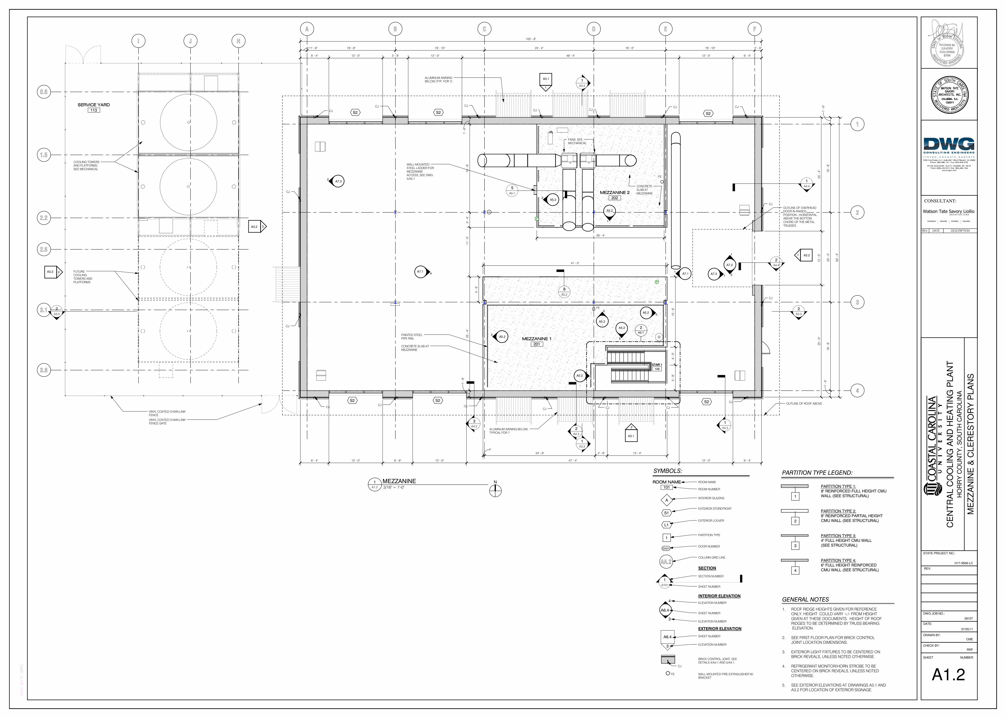
ALUMINUM AWNINGBELOW (TYP. FOR 7)
MEZZANINE 1MEZZANINE 1MEZZANINE 1MEZZANINE 1
201
MEZZANINE 2MEZZANINE 2MEZZANINE 2MEZZANINE 2
202
A7.14
A7.2
1
A7.11
2
15
' - 8
"4
' - 0
"5
' - 8
"
WALL-MOUNTEDSTEEL LADDER FOR
MEZZANINEACCESS, SEE DWG.
5/A5.1
OUTLINE OF OVERHEADDOOR IN RAISED
POSITION - HORIZONTALABOVE THE BOTTOM
CHORD OF THE METAL
TRUSSES
1
4
A
A3.2
1
A4.32
A4.3
3
A4.3
3
CONCRETE SLAB ATMEZZANINE
OUTLINE OF ROOF ABOVE
PAINTED STEELPIPE RAIL
FANS, SEEMECHANICAL
CONCRETESLAB AT
MEZZANINE
0.5
1.5
2.2
2.5
3.1
3.8
I J H
STAIR 1STAIR 1STAIR 1STAIR 1
109
A3.1
1
A5.1
2
A7.32
A5.23
A5.2
4A5.2
5
A5.2
6
A5.27
A5.2
1
A5.22
A7.31
ALUMINUM AWNING BELOW,TYPICAL FOR 7
CJCJCJCJ
CJCJ
CJ
CJ
CJ
CJ
CJCJCJCJCJ
CJ
CJ
8
A5.2
FE
FE
SERVICE YARDSERVICE YARDSERVICE YARDSERVICE YARD
113
5
A5.1CJ
2
A4.4
1
A4.4
VINYL COATED CHAIN LINKFENCE
VINYL COATED CHAIN LINKFENCE GATE
FUTURECOOLING
TOWERS ANDPLATFORMS
COOLING TOWERSAND PLATFORMS,
SEE MECHANICAL
S2
S2 S2 S2
S2S2
6' - 4" 12' - 0" 5' - 8" 12' - 0" 48' - 4" 12' - 0" 6' - 4"
25
' - 4
"1
2' -
0"
25
' - 0
"
6' - 4" 12' - 0" 6' - 8" 12' - 0" 47' - 4" 12' - 0" 6' - 4"
ROOM NAMEROOM NAMEROOM NAMEROOM NAME
101
A
ROOM NAME
ROOM NUMBER
INTERIOR GLAZING
S1EXTERIOR STOREFRONT
1PARTITION TYPE
AA.2COLUMN GRID LINE
SECTION NUMBER
1
A101SHEET NUMBER
SECTION
ELEVATION NUMBER
SHEET NUMBER
INTERIOR ELEVATION
A6.4
4
3ELEVATION NUMBER
SHEET NUMBER
ELEVATION NUMBER
EXTERIOR ELEVATION
888ADOOR NUMBER
3
A6.4
SYMBOLS:
CJ
BRICK CONTROL JOINT, SEEDETAILS 4/A4.1 AND 5/A4.1.
WALL-MOUNTED FIRE EXTINGUISHER W/BRACKET
FE
L1EXTERIOR LOUVER
GENERAL NOTES
1. ROOF RIDGE HEIGHTS GIVEN FOR REFERENCE
ONLY. HEIGHT COULD VARY +/- FROM HEIGHT
GIVEN AT THESE DOCUMENTS. HEIGHT OF ROOF
RIDGES TO BE DETERMINED BY TRUSS BEARING
ELEVATION.
2. SEE FIRST FLOOR PLAN FOR BRICK CONTROL
JOINT LOCATION DIMENSIONS.
3. EXTERIOR LIGHT FIXTURES TO BE CENTERED ON
BRICK REVEALS, UNLESS NOTED OTHERWISE.
4. REFRIGERANT MONITOR/HORN STROBE TO BE
CENTERED ON BRICK REVEALS, UNLESS NOTED
OTHERWISE.
5. SEE EXTERIOR ELEVATIONS AT DRAWINGS A3.1 AND
A3.2 FOR LOCATION OF EXTERIOR SIGNAGE.
1
PARTITION TYPE 1:8" REINFORCED FULL HEIGHT CMU
WALL (SEE STRUCTURAL)
PARTITION TYPE LEGEND:
2
PARTITION TYPE 2:8" REINFORCED PARTIAL HEIGHT
CMU WALL (SEE STRUCTURAL)
3
PARTITION TYPE 3:4" FULL HEIGHT CMU WALL
(SEE STRUCTURAL)
4
PARTITION TYPE 4:6" FULL HEIGHT REINFORCED
CMU WALL (SEE STRUCTURAL)
CE
NT
RA
L C
OO
LIN
G A
ND
HE
AT
ING
PLA
NT
CONSULTANT:
SHEET NUMBER
CHECK BY:
DRAWN BY:
DATE:
DWG JOB NO.:
PLOT DATE:
09107
HO
RR
Y C
OU
NT
Y, S
OU
TH
CA
RO
LIN
A
DATE
REV:
STATE PROJECT NO.:
H17-9569-LC
Watson Tate Savory LiollioA R C H I T E C T U R E
Charleston Asheville Charlotte Columbia
RRF
CME
A1.2
ME
ZZ
AN
INE
& C
LE
RE
ST
OR
Y P
LA
NS
07/05/11
3/16" = 1'-0"A1.2
1 MEZZANINE N
REV. DATE DESCRIPTION
B C D E
2
3
A3.2 2
A3.21
A3.1
2
1
A3.3
1
A3.3
2
A3.3
2
A3.3
F
1
4
A
SLO
PE
5:1
2
SLO
PE
5:1
2
SLO
PE
5:1
2
SLO
PE
5:1
2
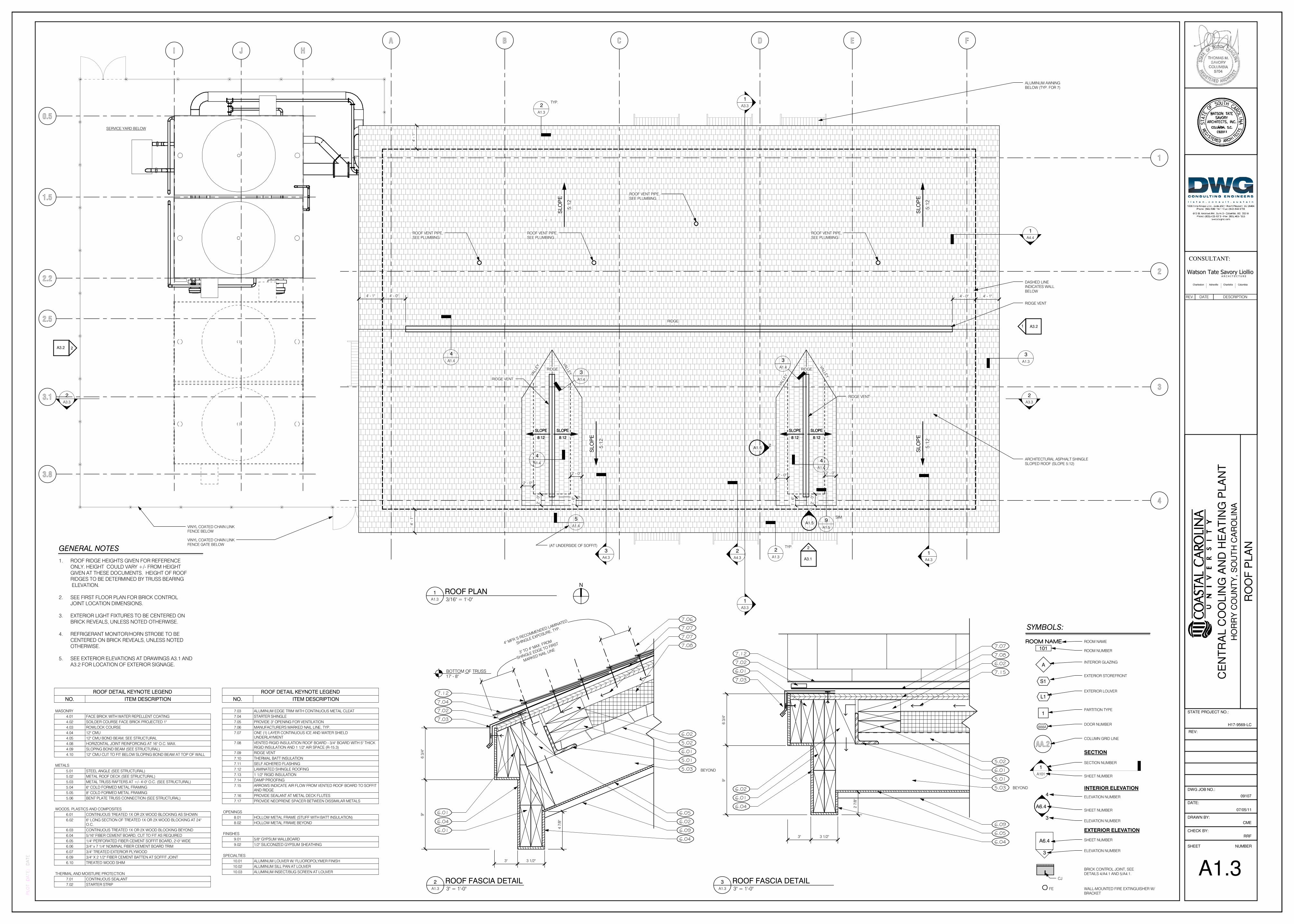
RIDGE VENT
DASHED LINEINDICATES WALL
BELOW
ALUMINUM AWNINGBELOW (TYP. FOR 7)
1
A4.3
2
A4.3
3
A4.3
SERVICE YARD BELOW
ARCHITECTURAL ASPHALT SHINGLESLOPED ROOF (SLOPE 5:12)
0.5
1.5
2.2
2.5
3.1
3.8
I J H
2
A1.3
TYP.
2
A1.3
TYP.
5
A1.4VINYL COATED CHAIN LINKFENCE BELOW
(AT UNDERSIDE OF SOFFIT)
A1.5
1
A1.52
1
A4.4
4' - 0" 4' - 1"4' - 1" 4' - 0"
RIDGE
VALL
EY
VA
LLEY
VA
LLEY
VALL
EY
4' -
1"
4' -
1"
VINYL COATED CHAIN LINKFENCE GATE BELOW
SLOPESLOPESLOPESLOPE
8:128:128:128:12
SLOPESLOPESLOPESLOPE
8:128:128:128:12
SLOPESLOPESLOPESLOPE
8:128:128:128:12
SLOPESLOPESLOPESLOPE
8:128:128:128:12
4
A1.4
9
A1.5
SIM
3
A1.4
3
A1.4
4
A1.44
A1.4
RIDGE VENT
RIDGE VENT
3
A1.3
RIDGE RIDGE
2' - 0"
2' -
0"
2' - 0"
2' -
0"
2' - 0"2' - 0"
1' -
6"
1' -
6"
ROOF VENT PIPE,SEE PLUMBING
ROOF VENT PIPE,SEE PLUMBING
ROOF VENT PIPE,SEE PLUMBING
ROOF VENT PIPE,SEE PLUMBING
ROOM NAMEROOM NAMEROOM NAMEROOM NAME
101
A
ROOM NAME
ROOM NUMBER
INTERIOR GLAZING
S1EXTERIOR STOREFRONT
1PARTITION TYPE
AA.2COLUMN GRID LINE
SECTION NUMBER
1
A101SHEET NUMBER
SECTION
ELEVATION NUMBER
SHEET NUMBER
INTERIOR ELEVATION
A6.4
4
3ELEVATION NUMBER
SHEET NUMBER
ELEVATION NUMBER
EXTERIOR ELEVATION
888ADOOR NUMBER
3
A6.4
SYMBOLS:
CJ
BRICK CONTROL JOINT, SEEDETAILS 4/A4.1 AND 5/A4.1.
WALL-MOUNTED FIRE EXTINGUISHER W/BRACKET
FE
L1EXTERIOR LOUVER
GENERAL NOTES
1. ROOF RIDGE HEIGHTS GIVEN FOR REFERENCE
ONLY. HEIGHT COULD VARY +/- FROM HEIGHT
GIVEN AT THESE DOCUMENTS. HEIGHT OF ROOF
RIDGES TO BE DETERMINED BY TRUSS BEARING
ELEVATION.
2. SEE FIRST FLOOR PLAN FOR BRICK CONTROL
JOINT LOCATION DIMENSIONS.
3. EXTERIOR LIGHT FIXTURES TO BE CENTERED ON
BRICK REVEALS, UNLESS NOTED OTHERWISE.
4. REFRIGERANT MONITOR/HORN STROBE TO BE
CENTERED ON BRICK REVEALS, UNLESS NOTED
OTHERWISE.
5. SEE EXTERIOR ELEVATIONS AT DRAWINGS A3.1 AND
A3.2 FOR LOCATION OF EXTERIOR SIGNAGE.
BOTTOM OF TRUSS17' - 8"
SHINGLE EXPOSURE, TYP.
4" MFR.'S RECOMMENDED LAMINATED
MARKED NAIL LINE3" TO 4" MAX. FROM
SHINGLE EDGE TO FIRST 7.08
5.02
5.03
6.01
5.01
6.05
7.12
7.04
7.02
6.04
6.01
7.06
6.04
3" 3 1/2"
9"
6 3
/4"
7.03
6.01
7.07
4 7
/8"
6.02
6.02
BEYOND
6.09
7.07
9"
6 3
/4"
7.08
5.02
5.03
6.01
5.01
6.05
7.12
7.02
6.01
6.04
6.04
7.03
6.01
7.07
3" 3 1/2"
2 7
/8"
6.02
6.09
6.02
7.15
BEYOND
CE
NT
RA
L C
OO
LIN
G A
ND
HE
AT
ING
PLA
NT
CONSULTANT:
SHEET NUMBER
CHECK BY:
DRAWN BY:
DATE:
DWG JOB NO.:
PLOT DATE:
09107
HO
RR
Y C
OU
NT
Y, S
OU
TH
CA
RO
LIN
A
DATE
REV:
STATE PROJECT NO.:
H17-9569-LC
Watson Tate Savory LiollioA R C H I T E C T U R E
Charleston Asheville Charlotte Columbia
RRF
CME
A1.3
RO
OF
PLA
N
07/05/11
3/16" = 1'-0"A1.3
1 ROOF PLANN
ROOF DETAIL KEYNOTE LEGEND
NO. ITEM DESCRIPTION
7.03 ALUMINUM EDGE TRIM WITH CONTINUOUS METAL CLEAT
7.04 STARTER SHINGLE
7.05 PROVIDE 3" OPENING FOR VENTILATION
7.06 MANUFACTURER'S MARKED NAIL LINE, TYP.
7.07 ONE (1) LAYER CONTINUOUS ICE AND WATER SHIELDUNDERLAYMENT
7.08 VENTED RIGID INSULATION ROOF BOARD - 3/4" BOARD WITH 5" THICKRIGID INSULATION AND 1 1/2" AIR SPACE (R-15.3)
7.09 RIDGE VENT
7.10 THERMAL BATT INSULATION
7.11 SELF ADHERED FLASHING
7.12 LAMINATED SHINGLE ROOFING
7.13 1 1/2" RIGID INSULATION
7.14 DAMP PROOFING
7.15 ARROWS INDICATE AIR FLOW FROM VENTED ROOF BOARD TO SOFFITAND RIDGE
7.16 PROVIDE SEALANT AT METAL DECK FLUTES
7.17 PROVIDE NEOPRENE SPACER BETWEEN DISSIMILAR METALS
OPENINGS
8.01 HOLLOW METAL FRAME (STUFF WITH BATT INSULATION)
8.02 HOLLOW METAL FRAME BEYOND
FINISHES
9.01 5/8" GYPSUM WALLBOARD
9.02 1/2" SILICONIZED GYPSUM SHEATHING
SPECIALTIES
10.01 ALUMINUM LOUVER W/ FLUOROPOLYMER FINISH
10.02 ALUMINUM SILL PAN AT LOUVER
10.03 ALUMINUM INSECT/BUG SCREEN AT LOUVER
ROOF DETAIL KEYNOTE LEGEND
NO. ITEM DESCRIPTION
MASONRY
4.01 FACE BRICK WITH WATER REPELLENT COATING
4.02 SOILDER COURSE FACE BRICK PROJECTED 1"
4.03 ROWLOCK COURSE
4.04 12" CMU
4.05 12" CMU BOND BEAM, SEE STRUCTURAL
4.08 HORIZONTAL JOINT REINFORCING AT 16" O.C. MAX.
4.09 SLOPING BOND BEAM (SEE STRUCTURAL)
4.10 12" CMU CUT TO FIT BELOW SLOPING BOND BEAM AT TOP OF WALL
METALS
5.01 STEEL ANGLE (SEE STRUCTURAL)
5.02 METAL ROOF DECK (SEE STRUCTURAL)
5.03 METAL TRUSS RAFTERS AT +/- 4'-0" O.C. (SEE STRUCTURAL)
5.04 6" COLD FORMED METAL FRAMING
5.05 8" COLD FORMED METAL FRAMING
5.06 BENT PLATE TRUSS CONNECTION (SEE STRUCTURAL)
WOODS, PLASTICS AND COMPOSITES
6.01 CONTINUOUS TREATED 1X OR 2X WOOD BLOCKING AS SHOWN
6.02 6" LONG SECTION OF TREATED 1X OR 2X WOOD BLOCKING AT 24"O.C.
6.03 CONTINUOUS TREATED 1X OR 2X WOOD BLOCKING BEYOND
6.04 5/16" FIBER CEMENT BOARD, CUT TO FIT AS REQUIRED
6.05 1/4" PERFORATED FIBER CEMENT SOFFIT BOARD, 2'-0" WIDE
6.06 3/4" x 7 1/4" NOMINAL FIBER CEMENT BOARD TRIM
6.07 3/4" TREATED EXTERIOR PLYWOOD
6.09 3/4" X 2 1/2" FIBER CEMENT BATTEN AT SOFFIT JOINT
6.10 TREATED WOOD SHIM
THERMAL AND MOISTURE PROTECTION
7.01 CONTINUOUS SEALANT
7.02 STARTER STRIP 3" = 1'-0"A1.3
2 ROOF FASCIA DETAIL 3" = 1'-0"A1.3
3 ROOF FASCIA DETAIL
REV. DATE DESCRIPTION

BOTTOM OF TRUSS17' - 8"
4
7.10
9.01
5.05
4.05
4.08
4.04
7.06
7.12
7.07
7.08
5.02
5.03
6.01
9.02
7.07
7.03
4.03
7.14
4.01
7.01
6.09
7.01
5.06
6.05
1" 1' - 6"
1' -
0"
1' -
4"
1"
1 1
/2"
6.01
7.13
4.02
5.01
5.03
7.15
6.09
GENERAL NOTES
1. ROOF RIDGE HEIGHTS GIVEN FOR REFERENCE
ONLY. HEIGHT COULD VARY +/- FROM HEIGHT
GIVEN AT THESE DOCUMENTS. HEIGHT OF ROOF
RIDGES TO BE DETERMINED BY TRUSS BEARING
ELEVATION.
2. SEE FIRST FLOOR PLAN FOR BRICK CONTROL
JOINT LOCATION DIMENSIONS.
3. EXTERIOR LIGHT FIXTURES TO BE CENTERED ON
BRICK REVEALS, UNLESS NOTED OTHERWISE.
4. REFRIGERANT MONITOR/HORN STROBE TO BE
CENTERED ON BRICK REVEALS, UNLESS NOTED
OTHERWISE.
5. SEE EXTERIOR ELEVATIONS AT DRAWINGS A3.1 AND
A3.2 FOR LOCATION OF EXTERIOR SIGNAGE.
BOTTOM OF TRUSS17' - 8"
6.04
6.03
5.02
7.12
7.07
7.08
8 7
/8"
7.15
6.09
5" MIN.
5" MIN.
5.02
7.08
7.07
7.11
WHERE ROOFING FELTS ARE ON VALLEYFLASHING, SET EDGE OF ROOFING
FELTS IN CONTINUOUS ROOFINGCEMENT
8"
MIN
. O
VE
RL
AP
7.12
F
1' -
0"
1' -
6"
1' - 6"1"
7/8
"
1 3
/8"
7.10
4.09
7.12
7.07
7.08
5.02
5.03
6.01
7.07
7.03
4.03
4.02
5.01
7.16
6.01
4.04
4.10
6.05
7.16
6.09
7.13
7.14
4.01
24' - 6 1/2"TOP OF CMU (VARIES)
6.09
7.15
ROOF RIDGE31' - 11"
7.05
7.09
6.02
7.07
7.08
5.02
7.123"
7.15
CE
NT
RA
L C
OO
LIN
G A
ND
HE
AT
ING
PLA
NT
CONSULTANT:
SHEET NUMBER
CHECK BY:
DRAWN BY:
DATE:
DWG JOB NO.:
PLOT DATE:
09107
HO
RR
Y C
OU
NT
Y, S
OU
TH
CA
RO
LIN
A
DATE
REV:
STATE PROJECT NO.:
H17-9569-LC
Watson Tate Savory LiollioA R C H I T E C T U R E
Charleston Asheville Charlotte Columbia
RRF
CME
A1.4
RO
OF
DE
TA
ILS
07/05/11
3" = 1'-0"A1.4
1 ENLARGED PANEL EAVE DETAIL
ROOF DETAIL KEYNOTE LEGEND
NO. ITEM DESCRIPTION
7.03 ALUMINUM EDGE TRIM WITH CONTINUOUS METAL CLEAT
7.04 STARTER SHINGLE
7.05 PROVIDE 3" OPENING FOR VENTILATION
7.06 MANUFACTURER'S MARKED NAIL LINE, TYP.
7.07 ONE (1) LAYER CONTINUOUS ICE AND WATER SHIELDUNDERLAYMENT
7.08 VENTED RIGID INSULATION ROOF BOARD - 3/4" BOARD WITH 5" THICKRIGID INSULATION AND 1 1/2" AIR SPACE (R-15.3)
7.09 RIDGE VENT
7.10 THERMAL BATT INSULATION
7.11 SELF ADHERED FLASHING
7.12 LAMINATED SHINGLE ROOFING
7.13 1 1/2" RIGID INSULATION
7.14 DAMP PROOFING
7.15 ARROWS INDICATE AIR FLOW FROM VENTED ROOF BOARD TO SOFFITAND RIDGE
7.16 PROVIDE SEALANT AT METAL DECK FLUTES
7.17 PROVIDE NEOPRENE SPACER BETWEEN DISSIMILAR METALS
OPENINGS
8.01 HOLLOW METAL FRAME (STUFF WITH BATT INSULATION)
8.02 HOLLOW METAL FRAME BEYOND
FINISHES
9.01 5/8" GYPSUM WALLBOARD
9.02 1/2" SILICONIZED GYPSUM SHEATHING
SPECIALTIES
10.01 ALUMINUM LOUVER W/ FLUOROPOLYMER FINISH
10.02 ALUMINUM SILL PAN AT LOUVER
10.03 ALUMINUM INSECT/BUG SCREEN AT LOUVER
ROOF DETAIL KEYNOTE LEGEND
NO. ITEM DESCRIPTION
MASONRY
4.01 FACE BRICK WITH WATER REPELLENT COATING
4.02 SOILDER COURSE FACE BRICK PROJECTED 1"
4.03 ROWLOCK COURSE
4.04 12" CMU
4.05 12" CMU BOND BEAM, SEE STRUCTURAL
4.08 HORIZONTAL JOINT REINFORCING AT 16" O.C. MAX.
4.09 SLOPING BOND BEAM (SEE STRUCTURAL)
4.10 12" CMU CUT TO FIT BELOW SLOPING BOND BEAM AT TOP OF WALL
METALS
5.01 STEEL ANGLE (SEE STRUCTURAL)
5.02 METAL ROOF DECK (SEE STRUCTURAL)
5.03 METAL TRUSS RAFTERS AT +/- 4'-0" O.C. (SEE STRUCTURAL)
5.04 6" COLD FORMED METAL FRAMING
5.05 8" COLD FORMED METAL FRAMING
5.06 BENT PLATE TRUSS CONNECTION (SEE STRUCTURAL)
WOODS, PLASTICS AND COMPOSITES
6.01 CONTINUOUS TREATED 1X OR 2X WOOD BLOCKING AS SHOWN
6.02 6" LONG SECTION OF TREATED 1X OR 2X WOOD BLOCKING AT 24"O.C.
6.03 CONTINUOUS TREATED 1X OR 2X WOOD BLOCKING BEYOND
6.04 5/16" FIBER CEMENT BOARD, CUT TO FIT AS REQUIRED
6.05 1/4" PERFORATED FIBER CEMENT SOFFIT BOARD, 2'-0" WIDE
6.06 3/4" x 7 1/4" NOMINAL FIBER CEMENT BOARD TRIM
6.07 3/4" TREATED EXTERIOR PLYWOOD
6.09 3/4" X 2 1/2" FIBER CEMENT BATTEN AT SOFFIT JOINT
6.10 TREATED WOOD SHIM
THERMAL AND MOISTURE PROTECTION
7.01 CONTINUOUS SEALANT
7.02 STARTER STRIP
3" = 1'-0"A1.4
5 TRUSS/EAVE DETAIL
1 1/2" = 1'-0"A1.4
3 VALLEY FLASHING
3" = 1'-0"A1.4
2 ENLARGED PANEL EAVE DETAIL
3" = 1'-0"A1.4
4 RIDGE VENT
REV. DATE DESCRIPTION

GENERAL NOTES
1. ROOF RIDGE HEIGHTS GIVEN FOR REFERENCE
ONLY. HEIGHT COULD VARY +/- FROM HEIGHT
GIVEN AT THESE DOCUMENTS. HEIGHT OF ROOF
RIDGES TO BE DETERMINED BY TRUSS BEARING
ELEVATION.
2. SEE FIRST FLOOR PLAN FOR BRICK CONTROL
JOINT LOCATION DIMENSIONS.
3. EXTERIOR LIGHT FIXTURES TO BE CENTERED ON
BRICK REVEALS, UNLESS NOTED OTHERWISE.
4. REFRIGERANT MONITOR/HORN STROBE TO BE
CENTERED ON BRICK REVEALS, UNLESS NOTED
OTHERWISE.
5. SEE EXTERIOR ELEVATIONS AT DRAWINGS A3.1 AND
A3.2 FOR LOCATION OF EXTERIOR SIGNAGE.
3 4
8
A1.5
4
A1.5
5/16" X 4'-0" WIDEFIBER CEMENT
BOARD
3/4" x 7 1/4" FIBERCEMENT BOARD
9
A1.5
SIM
3/4" X 2 1/2" WIDEFIBER CEMENT
BATTEN BOARD,TYPICAL
ROOF RIDGE VENT
DORMER RIDGE30' - 5"
3
A1.5ROOF RIDGE
31' - 11"
8
A1.5
L3
12
8
7 1/4"
5' - 2"
7 1/4"
+/-
1' -
6"
10
' - 4
3/4
"
1' -
6 1
/4"
8' -
2 1
/2"
8"
1' -
8 5
/8"
6' -
5 7
/8"
DORMER RIDGE30' - 5"
4
A1.5
6
A1.5
5
ALUMINUMLOUVER SET IN
HOLLOW METALFRAME
TYPICAL ROOF:TYPICAL ROOF:TYPICAL ROOF:TYPICAL ROOF:LAMINATED SHINGLE ROOFING
ON (1) LAYER OF ICE AND WATERSHIELD OVER 5" VENTED
INSULATION BOARD (R=15.3)
OVER STRUCTURAL ROOF DECKON METAL TRUSSES, SEE
STRUCTURAL
A1.5
9
8"
3"
VA
RIE
S2
3/8
"4
1/4
"1
1 1
/2"
2' - 0" 8"
1' - 2 5/8"
A1.5
7
TYPICAL ROOF:TYPICAL ROOF:TYPICAL ROOF:TYPICAL ROOF:LAMINATED SHINGLE ROOFING ON
(1) LAYER OF ICE AND WATERSHIELD OVER 5" VENTED
INSULATION BOARD (R=15.3) OVER
STRUCTURAL ROOF DECK ONMETAL TRUSSES, SEE STRUCTURAL
TRUSS, SEE STRUCTURAL
5/16" FIBER CEMENT BOARD
CONTINUOUS ICE AND WATER SHIELDBEHIND FIBER CEMENT BOARDS
6" COLD-FORMED METALFRAMING AT 12" O.C.
6" THERMAL BATTINSULATION (R-21 MIN.)
1/2" SILICONIZEDGYPSUM SHEATHING
5/16" FIBER CEMENT BOARD
TYPICAL ROOF:TYPICAL ROOF:TYPICAL ROOF:TYPICAL ROOF:LAMINATED SHINGLE ROOFING
ON (1) LAYER OF ICE AND WATERSHIELD OVER 5" VENTED
INSULATION BOARD (R=15.3)
OVER STRUCTURAL ROOF DECKON METAL TRUSSES, SEE
STRUCTURAL
A1.5
9 SIM
2' - 0" 6 7/8"
7.07
6.10
8.01
6.01
7.10
5.04
7.01
6.06
9.02
7.08
10.01
8.02
7.01
7.07
6.05
6.01
5.02
7.12
2"
3/8
"7
1/4
"
7.17
10.03
7.12
7.07
7.08
5.02
7.11
7.07
9.02
7.10
5.04
6.01
7.03
7.01
8.01
7.01
10.01
8.02
7.01
8"
2 7
/8"
5/8
"
8"
6.07
7.01
7.17
5.03
6.10
10.02
10.03
6.01
7.01
8.01
7.01
10.02
6.01
7.017 1/4"
3/8"
2"
6.06
7.10
5.04
9.02
8"
7.07
6.04
6.10
7.01
10.01
10.03
AT CORNER
BELOW
7.17
7.08
5.02
5.01
7.07
6.01
7.12
6.07
7.15
7.07
9.02
7.10
5.04
5.03
8"
4
7.08
5.02
6.05
6.01
5.01
7.12
7.02
7.03
7.07
6.02
TOP OF ROOF AT DORMER (VARIES)
3" 3 1/2"
6.017 1
/2"
4"
11
1/2
"
2 7
/8"
6.04
6.09
CE
NT
RA
L C
OO
LIN
G A
ND
HE
AT
ING
PLA
NT
CONSULTANT:
SHEET NUMBER
CHECK BY:
DRAWN BY:
DATE:
DWG JOB NO.:
PLOT DATE:
09107
HO
RR
Y C
OU
NT
Y, S
OU
TH
CA
RO
LIN
A
DATE
REV:
STATE PROJECT NO.:
H17-9569-LC
Watson Tate Savory LiollioA R C H I T E C T U R E
Charleston Asheville Charlotte Columbia
RRF
CME
A1.5
RO
OF
DE
TA
ILS
07/05/11
1/2" = 1'-0"A1.5
2 DORMER ELEVATION 1/2" = 1'-0"A1.5
1 DORMER ELEVATION
1 1/2" = 1'-0"A1.5
3 DOMER-SECTION 1 1/2" = 1'-0"A1.5
4 DORMER SECTION
3" = 1'-0"A1.5
6 HEAD
3" = 1'-0"A1.5
5 SILL
3" = 1'-0"A1.5
8 JAMB
ROOF DETAIL KEYNOTE LEGEND
NO. ITEM DESCRIPTION
7.03 ALUMINUM EDGE TRIM WITH CONTINUOUS METAL CLEAT
7.04 STARTER SHINGLE
7.05 PROVIDE 3" OPENING FOR VENTILATION
7.06 MANUFACTURER'S MARKED NAIL LINE, TYP.
7.07 ONE (1) LAYER CONTINUOUS ICE AND WATER SHIELDUNDERLAYMENT
7.08 VENTED RIGID INSULATION ROOF BOARD - 3/4" BOARD WITH 5" THICKRIGID INSULATION AND 1 1/2" AIR SPACE (R-15.3)
7.09 RIDGE VENT
7.10 THERMAL BATT INSULATION
7.11 SELF ADHERED FLASHING
7.12 LAMINATED SHINGLE ROOFING
7.13 1 1/2" RIGID INSULATION
7.14 DAMP PROOFING
7.15 ARROWS INDICATE AIR FLOW FROM VENTED ROOF BOARD TO SOFFITAND RIDGE
7.16 PROVIDE SEALANT AT METAL DECK FLUTES
7.17 PROVIDE NEOPRENE SPACER BETWEEN DISSIMILAR METALS
OPENINGS
8.01 HOLLOW METAL FRAME (STUFF WITH BATT INSULATION)
8.02 HOLLOW METAL FRAME BEYOND
FINISHES
9.01 5/8" GYPSUM WALLBOARD
9.02 1/2" SILICONIZED GYPSUM SHEATHING
SPECIALTIES
10.01 ALUMINUM LOUVER W/ FLUOROPOLYMER FINISH
10.02 ALUMINUM SILL PAN AT LOUVER
10.03 ALUMINUM INSECT/BUG SCREEN AT LOUVER
ROOF DETAIL KEYNOTE LEGEND
NO. ITEM DESCRIPTION
MASONRY
4.01 FACE BRICK WITH WATER REPELLENT COATING
4.02 SOILDER COURSE FACE BRICK PROJECTED 1"
4.03 ROWLOCK COURSE
4.04 12" CMU
4.05 12" CMU BOND BEAM, SEE STRUCTURAL
4.08 HORIZONTAL JOINT REINFORCING AT 16" O.C. MAX.
4.09 SLOPING BOND BEAM (SEE STRUCTURAL)
4.10 12" CMU CUT TO FIT BELOW SLOPING BOND BEAM AT TOP OF WALL
METALS
5.01 STEEL ANGLE (SEE STRUCTURAL)
5.02 METAL ROOF DECK (SEE STRUCTURAL)
5.03 METAL TRUSS RAFTERS AT +/- 4'-0" O.C. (SEE STRUCTURAL)
5.04 6" COLD FORMED METAL FRAMING
5.05 8" COLD FORMED METAL FRAMING
5.06 BENT PLATE TRUSS CONNECTION (SEE STRUCTURAL)
WOODS, PLASTICS AND COMPOSITES
6.01 CONTINUOUS TREATED 1X OR 2X WOOD BLOCKING AS SHOWN
6.02 6" LONG SECTION OF TREATED 1X OR 2X WOOD BLOCKING AT 24"O.C.
6.03 CONTINUOUS TREATED 1X OR 2X WOOD BLOCKING BEYOND
6.04 5/16" FIBER CEMENT BOARD, CUT TO FIT AS REQUIRED
6.05 1/4" PERFORATED FIBER CEMENT SOFFIT BOARD, 2'-0" WIDE
6.06 3/4" x 7 1/4" NOMINAL FIBER CEMENT BOARD TRIM
6.07 3/4" TREATED EXTERIOR PLYWOOD
6.09 3/4" X 2 1/2" FIBER CEMENT BATTEN AT SOFFIT JOINT
6.10 TREATED WOOD SHIM
THERMAL AND MOISTURE PROTECTION
7.01 CONTINUOUS SEALANT
7.02 STARTER STRIP
3" = 1'-0"A1.5
7 ROOF DETAIL
3" = 1'-0"A1.5
9 ROOF FASCIA DETAIL
REV. DATE DESCRIPTION
B C D E
2
3
1
A3.3
1
A3.3
2
A3.3
2
A3.3
F
1
4
A
1
A4.3
2
A4.3
3
A4.3
2
A2.1
2
A2.1
SIM
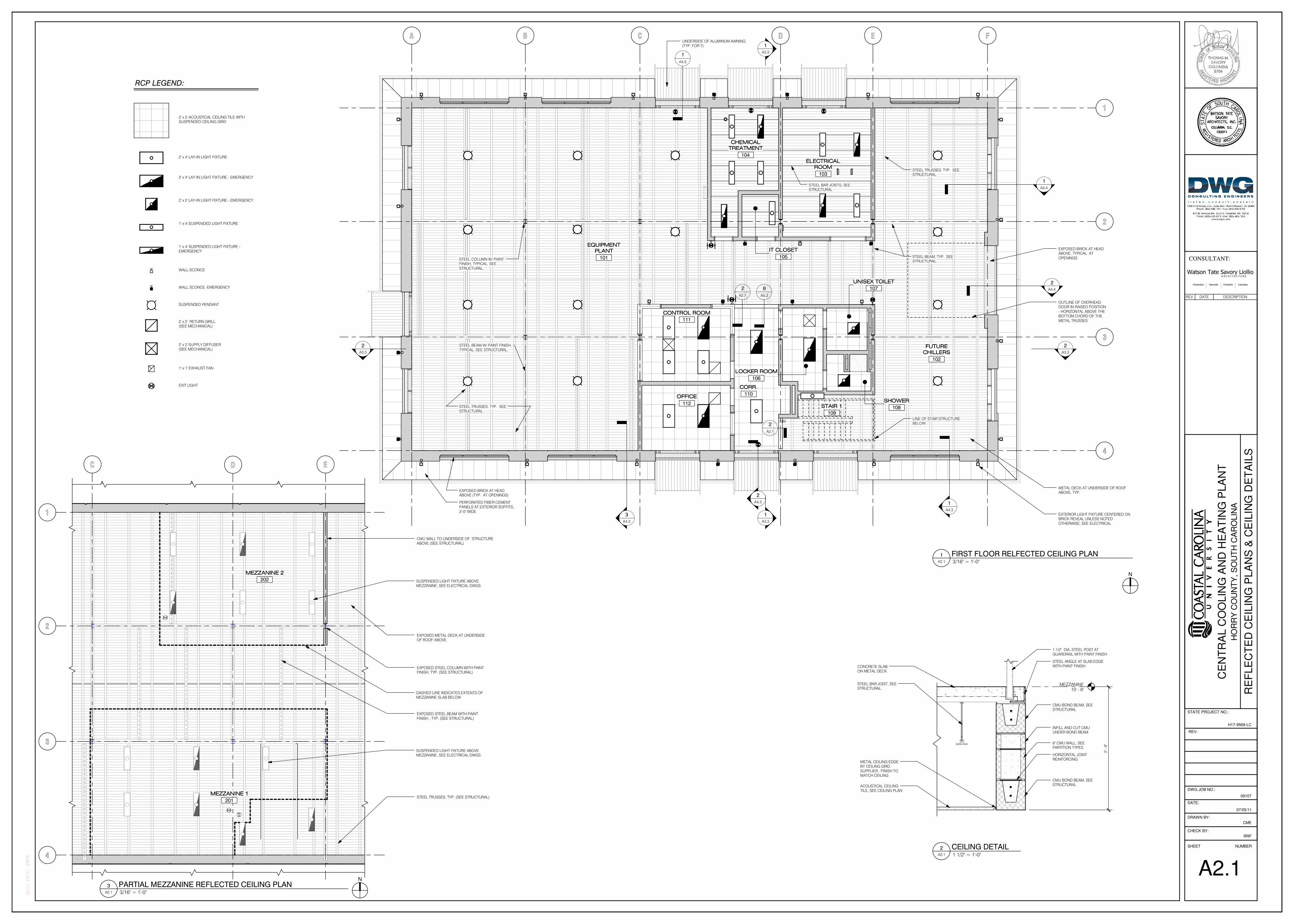
EXPOSED BRICK AT HEADABOVE (TYP. AT OPENINGS)
STEEL BAR JOISTS, SEESTRUCTURAL
UNDERSIDE OF ALUMINUM AWNING(TYP. FOR 7)
METAL DECK AT UNDERSIDE OF ROOFABOVE, TYP.
EXPOSED BRICK AT HEADABOVE, TYPICAL AT
OPENINGS
PERFORATED FIBER CEMENTPANELS AT EXTERIOR SOFFITS,
2'-0" WIDE
EQUIPMENTEQUIPMENTEQUIPMENTEQUIPMENT
PLANTPLANTPLANTPLANT
101
EXTERIOR LIGHT FIXTURE CENTERED ONBRICK REVEAL UNLESS NOTED
OTHERWISE, SEE ELECTRICAL
8
A5.2
1
A4.5
2
A4.4
1
A4.4
STEEL TRUSSES, TYP. SEESTRUCTURAL.
STEEL BEAM W/ PAINT FINISH,TYPICAL. SEE STRUCTURAL.
CHEMICALCHEMICALCHEMICALCHEMICAL
TREATMENTTREATMENTTREATMENTTREATMENT
104
ELECTRICALELECTRICALELECTRICALELECTRICAL
ROOMROOMROOMROOM
103
IT CLOSETIT CLOSETIT CLOSETIT CLOSET
105
CONTROL ROOMCONTROL ROOMCONTROL ROOMCONTROL ROOM
111
OFFICEOFFICEOFFICEOFFICE
112
CORR.CORR.CORR.CORR.
110
LOCKER ROOMLOCKER ROOMLOCKER ROOMLOCKER ROOM
106
SHOWERSHOWERSHOWERSHOWER
108
UNISEX TOILETUNISEX TOILETUNISEX TOILETUNISEX TOILET
107
STAIR 1STAIR 1STAIR 1STAIR 1
109
FUTUREFUTUREFUTUREFUTURE
CHILLERSCHILLERSCHILLERSCHILLERS
102
STEEL TRUSSES, TYP. SEESTRUCTURAL.
STEEL BEAM, TYP. SEESTRUCTURAL.
LINE OF STAIR STRUCTUREBELOW
STEEL COLUMN W/ PAINTFINISH, TYPICAL. SEE
STRUCTURAL.
OUTLINE OF OVERHEADDOOR IN RAISED POSITION
- HORIZONTAL ABOVE THEBOTTOM CHORD OF THE
METAL TRUSSES
MEZZANINE10' - 8"
2' - 8"
CMU BOND BEAM, SEESTRUCTURAL
8" CMU WALL, SEEPARTITION TYPES
ACOUSTICAL CEILINGTILE, SEE CEILING PLAN
METAL CEILING EDGEBY CEILING GRID
SUPPLIER, FINISH TOMATCH CEILING
CONCRETE SLABON METAL DECK
STEEL ANGLE AT SLAB EDGEWITH PAINT FINISH
CMU BOND BEAM, SEESTRUCTURAL
1 1/2" DIA. STEEL POST ATGUARDRAIL WITH PAINT FINISH
HORIZONTAL JOINTREINFORCING
STEEL BAR JOIST, SEESTRUCTURAL.
INFILL AND CUT CMUUNDER BOND BEAM
2' x 2' ACOUSTICAL CEILING TILE WITHSUSPENDED CEILING GRID
RCP LEGEND:
2' x 4' LAY-IN LIGHT FIXTURE
2' x 2' LAY-IN LIGHT FIXTURE - EMERGENCY
EXIT LIGHT
2' x 4' LAY-IN LIGHT FIXTURE - EMERGENCY
1' x 4' SUSPENDED LIGHT FIXTURE
1' x 4' SUSPENDED LIGHT FIXTURE -EMERGENCY
WALL SCONCE
SUSPENDED PENDANT
2' x 2' RETURN GRILL(SEE MECHANICAL)
2' x 2' SUPPLY DIFFUSER(SEE MECHANICAL)
1' x 1' EXHAUST FAN
WALL SCONCE -EMERGENCY
C D E
2
3
1
4
MEZZANINE 2MEZZANINE 2MEZZANINE 2MEZZANINE 2
202
MEZZANINE 1MEZZANINE 1MEZZANINE 1MEZZANINE 1
201
DASHED LINE INDICATES EXTENTS OFMEZZANINE SLAB BELOW
SUSPENDED LIGHT FIXTURE ABOVEMEZZANINE, SEE ELECTRICAL DWGS.
SUSPENDED LIGHT FIXTURE ABOVEMEZZANINE, SEE ELECTRICAL DWGS.
CMU WALL TO UNDERSIDE OF STRUCTUREABOVE (SEE STRUCTURAL)
EXPOSED METAL DECK AT UNDERSIDEOF ROOF ABOVE
EXPOSED STEEL COLUMN WITH PAINTFINISH, TYP. (SEE STRUCTURAL)
EXPOSED STEEL BEAM WITH PAINTFINISH , TYP. (SEE STRUCTURAL)
STEEL TRUSSES, TYP. (SEE STRUCTURAL)
CE
NT
RA
L C
OO
LIN
G A
ND
HE
AT
ING
PLA
NT
CONSULTANT:
SHEET NUMBER
CHECK BY:
DRAWN BY:
DATE:
DWG JOB NO.:
PLOT DATE:
09107
HO
RR
Y C
OU
NT
Y, S
OU
TH
CA
RO
LIN
A
DATE
REV:
STATE PROJECT NO.:
H17-9569-LC
Watson Tate Savory LiollioA R C H I T E C T U R E
Charleston Asheville Charlotte Columbia
RRF
CME
A2.1
RE
FLE
CT
ED
CE
ILIN
G P
LA
NS
& C
EIL
ING
DE
TA
ILS
07/05/11
3/16" = 1'-0"A2.1
1 FIRST FLOOR RELFECTED CEILING PLAN
N
1 1/2" = 1'-0"A2.1
2 CEILING DETAIL
3/16" = 1'-0"A2.1
3 PARTIAL MEZZANINE REFLECTED CEILING PLANN
REV. DATE DESCRIPTION

BCDE
BOTTOM OF TRUSS17' - 8"
MEZZANINE10' - 8"
FIRST FLOOR0' - 0"
NOTE:NOTE:NOTE:NOTE:SEE DETAIL 2 THIS SHEET
FOR TYPICAL NOTES
1
A3.3
1
A3.3
F A
1
A4.32
A4.3
3
A4.3
ALUMINUM AWNING WITHFLUOROPOLYMER FINISH, TYP.
FOR 7. SEE DWG. A4.5
103A 104A 101B
S2 S2S2
IJH
TOP OF EXTERIOR
OPENING13' - 4"
1
A4.5
CJ CJCJ CJ CJ CJ
REFRIGERANT MONITOR/HORNSTROBE CENTERED ON BRICK
REVEAL, SEE ELECTRICALTHROUGH-WALL EXHAUST, SEEMECHANICAL
REFRIGERANT WARNING SIGNCENTERED ON BRICK REVEAL
A3.2
4
CJ
ROOF RIDGE31' - 11"
COOLING TOWER,SEE MECHANICAL
4' - 0"
4' - 0"
4' - 0"
4
A1.4
A4.1
1 SIM
B C D E
BOTTOM OF TRUSS17' - 8"
MEZZANINE10' - 8"
FIRST FLOOR0' - 0"
ARCHITECTURAL ASPHALT SHINGLE SLOPEDROOF (SLOPE 5:12)
DORMER WITH LOUVER, SEE DWG. A1.5
ALUMINUM STOREFRONT DOOR W/1/2" LAMINATED GLASS &
FLUOROPOLYMER FINISH
BRICK WATER TABLE ROWLOCK COURSE ANDONE ROWLOCK COURSE
BRICK HEADER ABOVEMASONRY OPENING,
PROJECTED 1"
BRICK VENEER EXTERIORFINISH
ALUMINUM CANOPY W/FLUOROPOLYMER FINISH,
TYPICAL FOR 7
1
A3.3
1
A3.3
F
A4.1
1
A
1
A4.3
2
A4.3
3
A4.3
S2S2
I J H
TOP OF EXTERIOR
OPENING13' - 4"
VINYL COATED CHAINLINK FENCE
CJ CJ CJ CJ CJ CJ CJ
EXTERIOR LIGHT FIXTURE CENTERED ONBRICK REVEAL UNLESS DIMENSIONED
OTHERWISE, SEE ELECTRICAL
REFRIGERANT MONITOR/HORNSTROBE CENTERED ON BRICK
REVEAL, SEE ELECTRICAL
REFRIGERANT WARNING SIGNCENTERED ON BRICK REVEAL
VINYL COATED CHAINLINK FENCE GATE
FIXED ALUMINUM STOREFRONTDOOR W/ 1/2" LAMINATED GLASS
& FLUOROPOLYMER FINISH
5/16" FIBER CEMENTBOARD
EXTERIOR STOREFRONTSYSTEM
3/4" X 7 1/4" FIBER CEMENT BOARDLAID IN 45 DEGREE PATTERN
112B 101C
S2
109
L3L3
ROOF RIDGE31' - 11"
FUTURE COOLING TOWER,SEE MECH.
A1.5
23
A1.5
4' - 0"
4' - 0"
4' - 0"
4
A1.4
ROOF RIDGE VENT
VERTICAL BRICKREVEAL (4" WIDE)
5
A4.1
4
A4.1
GENERAL NOTES
1. ROOF RIDGE HEIGHTS GIVEN FOR REFERENCE
ONLY. HEIGHT COULD VARY +/- FROM HEIGHT
GIVEN AT THESE DOCUMENTS. HEIGHT OF ROOF
RIDGES TO BE DETERMINED BY TRUSS BEARING
ELEVATION.
2. SEE FIRST FLOOR PLAN FOR BRICK CONTROL
JOINT LOCATION DIMENSIONS.
3. EXTERIOR LIGHT FIXTURES TO BE CENTERED ON
BRICK REVEALS, UNLESS NOTED OTHERWISE.
4. REFRIGERANT MONITOR/HORN STROBE TO BE
CENTERED ON BRICK REVEALS, UNLESS NOTED
OTHERWISE.
5. SEE EXTERIOR ELEVATIONS AT DRAWINGS A3.1 AND
A3.2 FOR LOCATION OF EXTERIOR SIGNAGE.
CE
NT
RA
L C
OO
LIN
G A
ND
HE
AT
ING
PLA
NT
CONSULTANT:
SHEET NUMBER
CHECK BY:
DRAWN BY:
DATE:
DWG JOB NO.:
PLOT DATE:
09107
HO
RR
Y C
OU
NT
Y, S
OU
TH
CA
RO
LIN
A
DATE
REV:
STATE PROJECT NO.:
H17-9569-LC
Watson Tate Savory LiollioA R C H I T E C T U R E
Charleston Asheville Charlotte Columbia
RRF
CME
A3.1
NO
RT
H &
SO
UT
H E
XT
ER
IOR
ELE
VA
TIO
NS
07/05/11
3/16" = 1'-0"A3.1
1 NORTH ELEVATION
3/16" = 1'-0"A3.1
2 SOUTH ELEVATION
REV. DATE DESCRIPTION

23
BOTTOM OF TRUSS17' - 8"
MEZZANINE10' - 8"
FIRST FLOOR0' - 0"
ARCHITECTURAL ASPHALT SHINGLESLOPED ROOF (SLOPE - 5:12)
5/16" FIBER CEMENT BOARD
ALUMINUM AND GLASS SEGMENTEDOVERHEAD GARAGE DOOR (12'-0"
WIDE x 13'-4" TALL)
BRICK WATER TABLEROWLOCK COURSE AND
ONE ROWLOCK COURSE
ALUMINUM LOUVERS W/FLUOROPOLYMER FINISH
SET IN HOLLOW METALFRAMING
2
A3.3
2
A3.3
FIXED ALUMINUM STOREFRONTSYSTEM WITH FLUOROPOLYMER
FINISH & INSULATED GLASS ATCIRCULAR OPENING
14
A4.2
1
L2
BRICK SOLDIER COURSE AROUNDCIRCULAR MASONRY OPENING,
PROJECTED 1"
0.51.52.22.53.13.8
TOP OF EXTERIOR
OPENING13' - 4"
12
5
12
5
CJ CJ
ALUMINUM LOUVERS W/FLUOROPOLYMER FINISH SET IN
HOLLOW METAL FRAMING
VINYL COATED CHAINLINK FENCE
EXTERIOR LIGHT FIXTURE CENTERED ON BRICK REVEALUNLESS DIMENSIONED OTHERWISE, SEE ELECTRICAL
REFRIGERANT MONITOR/HORNSTROBE CENTERED ON BRICK
REVEAL, SEE ELECTRICALREFRIGERANT MONITOR/HORN STROBECENTERED ON BRICK REVEAL, SEE ELECTRICAL
102A
REFRIGERANT WARNING SIGNCENTERED ON BRICK
REVEAL, SEE DWG. 4/A3.2
REFRIGERANT WARNING SIGN CENTERED ONBRICK REVEAL, SEE DWG. 4/A3.2
2
A4.4
1
A4.4
S3
ROOF RIDGE31' - 11"
3' - 6" 3' - 6"
4' - 0"
4' - 0"
4' - 0"
4
A4.1
5
A4.1
DORMER WITH LOUVER, SEEDWG. A1.5
2
A1.4
CJCJ
102B
5/16" X 4'-0" WIDE FIBER CEMENT BOARD, CUT TOFIT WITH JOINTS AT 4'-0" O.C. AND 3/4" X 2 1/2"
FIBER CEMENT BATTENS AT JOINT LOCATIONS
102D L2
2 3
BOTTOM OF TRUSS17' - 8"
MEZZANINE10' - 8"
FIRST FLOOR0' - 0"
NOTE:NOTE:NOTE:NOTE:SEE DETAIL 1 THIS SHEET FOR TYPICAL
NOTES
2
A3.3
2
A3.3
1 40.5 1.5 2.2 2.5 3.1 3.8
TOP OF EXTERIOR
OPENING13' - 4"
12
5
5
A5.1
2
A4.4
1
A4.4
S3
ROOF RIDGE31' - 11"
4' - 0"
4' - 0"
4' - 0"
2
A1.4
CJCJ
12
5
2 3
BOTTOM OF TRUSS17' - 8"
MEZZANINE10' - 8"
FIRST FLOOR0' - 0"
2
A3.3
2
A3.3
1 4
L1
L1
NOTE:NOTE:NOTE:NOTE:SEE DETAIL 1 THIS SHEET FOR TYPICAL
NOTES
TOP OF EXTERIOR
OPENING13' - 4"
5
A1.4
12
5
101A
ALUMINUM LOUVERS W/FLUOROPOLYMER FINISH SET
IN HOLLOW METAL FRAMING
ALUMINUM AWNING ATENTRANCE DOORS,
TYPICAL FOR 7
CJCJ
THROUGH- WALL PIPING,SEE MECHANICAL
REFRIGERANT MONITOR/HORNSTROBE CENTERED ON BRICK
REVEAL, SEE ELECTRICAL
SELF-CONTAINEDBREATHING APPARATUS,
SEE MECHANICAL
REFRIGERANT WARNING SIGNCENTERED ON BRICK REVEAL,
SEE DWG. 4/A3.2
BREATHINGAPPARATUS WARNING
SIGN, SEE DWG. 5/A3.2
A3.2
5
ROOF RIDGE31' - 11"
A1.5
2
4' - 0"
4' - 0"
4' - 0"
3' - 6"
3' - 6"
4
A4.1
5
A4.1
2
A1.4
S3
VERTICAL BRICKREVEAL (4" WIDE)
GENERAL NOTES
1. ROOF RIDGE HEIGHTS GIVEN FOR REFERENCE
ONLY. HEIGHT COULD VARY +/- FROM HEIGHT
GIVEN AT THESE DOCUMENTS. HEIGHT OF ROOF
RIDGES TO BE DETERMINED BY TRUSS BEARING
ELEVATION.
2. SEE FIRST FLOOR PLAN FOR BRICK CONTROL
JOINT LOCATION DIMENSIONS.
3. EXTERIOR LIGHT FIXTURES TO BE CENTERED ON
BRICK REVEALS, UNLESS NOTED OTHERWISE.
4. REFRIGERANT MONITOR/HORN STROBE TO BE
CENTERED ON BRICK REVEALS, UNLESS NOTED
OTHERWISE.
5. SEE EXTERIOR ELEVATIONS AT DRAWINGS A3.1 AND
A3.2 FOR LOCATION OF EXTERIOR SIGNAGE.
1' - 0"
2' - 0"
STAY OUT WHEN
REFRIGERANT ALARM SOUNDS
REFRIGERANT WARNINGSIGN - ALUMINUM SIGN
WITH FRAME
1" TALL PAINTED LETTERS"BLACK"
2 1/4"
2 1/4"
3"
2 1/4"
2 1/4"
MACHINERY ROOM - AUTHORIZED
PERSONNEL ONLY
SELF-CONTAINED
BREATHING APPARATUS
2 1/4"
2 1/4"
3"
2 1/4"
2 1/4"
2' - 0"
BREATHINGAPPARATUS SIGN -
ALUMINUM SIGNWITH FRAME
1" TALL PAINTED LETTERS"BLACK"
1' - 0"
CE
NT
RA
L C
OO
LIN
G A
ND
HE
AT
ING
PLA
NT
CONSULTANT:
SHEET NUMBER
CHECK BY:
DRAWN BY:
DATE:
DWG JOB NO.:
PLOT DATE:
09107
HO
RR
Y C
OU
NT
Y, S
OU
TH
CA
RO
LIN
A
DATE
REV:
STATE PROJECT NO.:
H17-9569-LC
Watson Tate Savory LiollioA R C H I T E C T U R E
Charleston Asheville Charlotte Columbia
RRF
CME
A3.2
EA
ST
& W
ES
T E
XT
ER
IOR
ELE
VA
TIO
NS
07/05/11
3/16" = 1'-0"A3.2
1 EAST ELEVATION 3/16" = 1'-0"A3.2
2 WEST ELEVATION
3/16" = 1'-0"A3.2
3 WEST ELEVATION 2
3" = 1'-0"A3.2
4 REFRIGERANT SIGN
3" = 1'-0"A3.2
5 BREATHING APPARATUS SIGN
REV. DATE DESCRIPTION
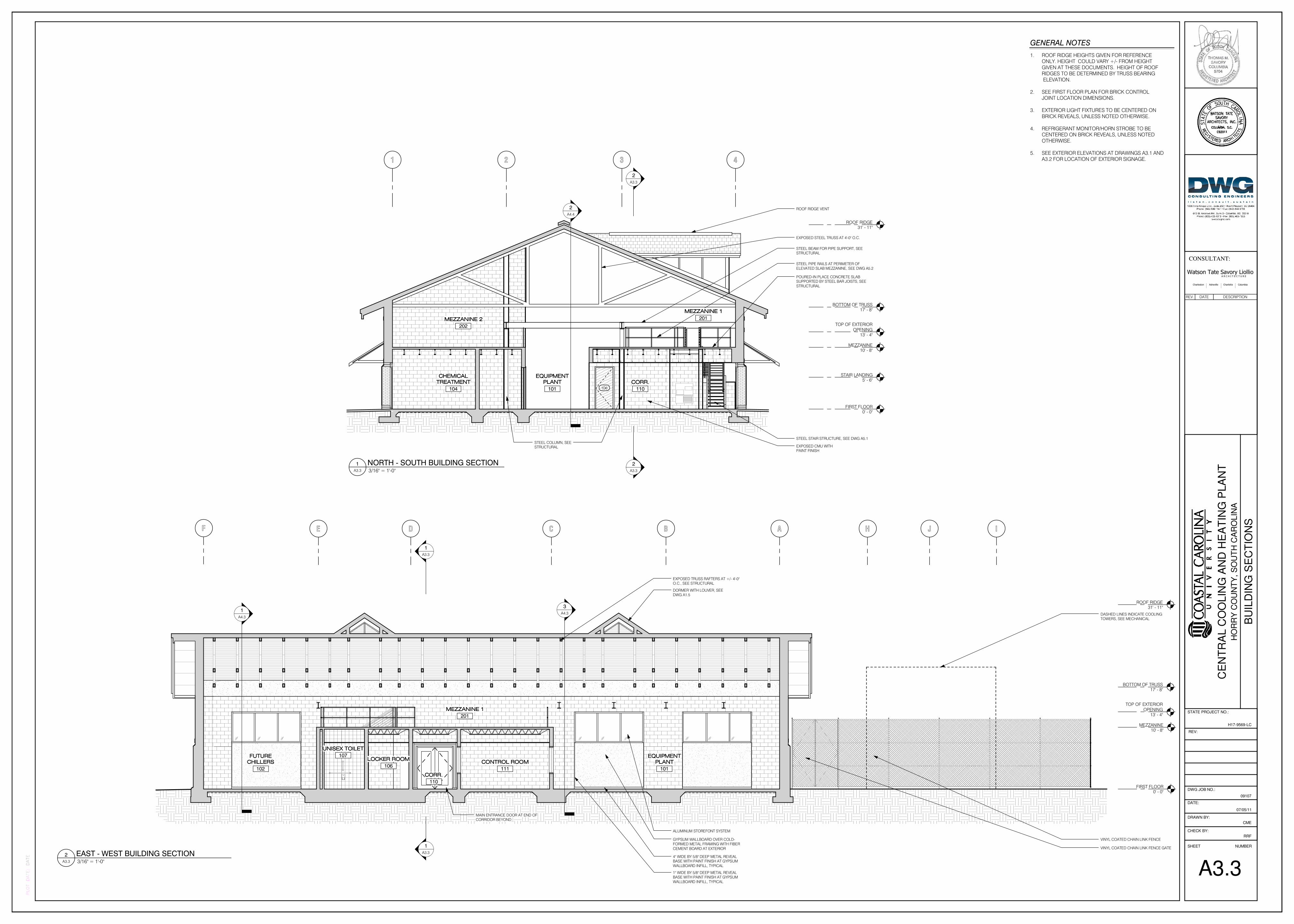
2 3
BOTTOM OF TRUSS17' - 8"
MEZZANINE10' - 8"
FIRST FLOOR0' - 0"
2
A3.3
2
A3.3
STEEL PIPE RAILS AT PERIMETER OFELEVATED SLAB MEZZANINE, SEE DWG A5.2
STEEL BEAM FOR PIPE SUPPORT, SEESTRUCTURAL
EXPOSED STEEL TRUSS AT 4'-0" O.C.
1 4
CHEMICALCHEMICALCHEMICALCHEMICAL
TREATMENTTREATMENTTREATMENTTREATMENT
104
EQUIPMENTEQUIPMENTEQUIPMENTEQUIPMENT
PLANTPLANTPLANTPLANT
101
CORR.CORR.CORR.CORR.
110
MEZZANINE 1MEZZANINE 1MEZZANINE 1MEZZANINE 1
201MEZZANINE 2MEZZANINE 2MEZZANINE 2MEZZANINE 2
202
STAIR LANDING5' - 6"
TOP OF EXTERIOR
OPENING13' - 4"
STEEL COLUMN, SEESTRUCTURAL EXPOSED CMU WITH
PAINT FINISH
POURED-IN PLACE CONCRETE SLABSUPPORTED BY STEEL BAR JOISTS, SEE
STRUCTURAL
STEEL STAIR STRUCTURE, SEE DWG A5.1
2
A4.4
ROOF RIDGE31' - 11"
106
ROOF RIDGE VENT
BCDE
BOTTOM OF TRUSS17' - 8"
MEZZANINE10' - 8"
FIRST FLOOR0' - 0"
1
A3.3
1
A3.3
F
EXPOSED TRUSS RAFTERS AT +/- 4'-0"O.C., SEE STRUCTURAL
MAIN ENTRANCE DOOR AT END OFCORRIDOR BEYOND
A
1
A4.3
3
A4.3
CONTROL ROOMCONTROL ROOMCONTROL ROOMCONTROL ROOM
111
EQUIPMENTEQUIPMENTEQUIPMENTEQUIPMENT
PLANTPLANTPLANTPLANT
101
CORR.CORR.CORR.CORR.
110
MEZZANINE 1MEZZANINE 1MEZZANINE 1MEZZANINE 1
201
IJH
TOP OF EXTERIOR
OPENING13' - 4"
DASHED LINES INDICATE COOLINGTOWERS, SEE MECHANICAL
ROOF RIDGE31' - 11"
FUTUREFUTUREFUTUREFUTURE
CHILLERSCHILLERSCHILLERSCHILLERS
102
UNISEX TOILETUNISEX TOILETUNISEX TOILETUNISEX TOILET
107LOCKER ROOMLOCKER ROOMLOCKER ROOMLOCKER ROOM
106
DORMER WITH LOUVER, SEEDWG A1.5
VINYL COATED CHAIN LINK FENCE
VINYL COATED CHAIN LINK FENCE GATE
ALUMINUM STOREFONT SYSTEM
GYPSUM WALLBOARD OVER COLD-FORMED METAL FRAMING WITH FIBER
CEMENT BOARD AT EXTERIOR
4" WIDE BY 5/8" DEEP METAL REVEALBASE WITH PAINT FINISH AT GYPSUM
WALLBOARD INFILL, TYPICAL
1" WIDE BY 5/8" DEEP METAL REVEALBASE WITH PAINT FINISH AT GYPSUM
WALLBOARD INFILL, TYPICAL
GENERAL NOTES
1. ROOF RIDGE HEIGHTS GIVEN FOR REFERENCE
ONLY. HEIGHT COULD VARY +/- FROM HEIGHT
GIVEN AT THESE DOCUMENTS. HEIGHT OF ROOF
RIDGES TO BE DETERMINED BY TRUSS BEARING
ELEVATION.
2. SEE FIRST FLOOR PLAN FOR BRICK CONTROL
JOINT LOCATION DIMENSIONS.
3. EXTERIOR LIGHT FIXTURES TO BE CENTERED ON
BRICK REVEALS, UNLESS NOTED OTHERWISE.
4. REFRIGERANT MONITOR/HORN STROBE TO BE
CENTERED ON BRICK REVEALS, UNLESS NOTED
OTHERWISE.
5. SEE EXTERIOR ELEVATIONS AT DRAWINGS A3.1 AND
A3.2 FOR LOCATION OF EXTERIOR SIGNAGE.
CE
NT
RA
L C
OO
LIN
G A
ND
HE
AT
ING
PLA
NT
CONSULTANT:
SHEET NUMBER
CHECK BY:
DRAWN BY:
DATE:
DWG JOB NO.:
PLOT DATE:
09107
HO
RR
Y C
OU
NT
Y, S
OU
TH
CA
RO
LIN
A
DATE
REV:
STATE PROJECT NO.:
H17-9569-LC
Watson Tate Savory LiollioA R C H I T E C T U R E
Charleston Asheville Charlotte Columbia
RRF
CME
A3.3
BU
ILD
ING
SE
CT
ION
S
07/05/11
3/16" = 1'-0"A3.3
1 NORTH - SOUTH BUILDING SECTION
3/16" = 1'-0"A3.3
2 EAST - WEST BUILDING SECTION
REV. DATE DESCRIPTION

E
BOTTOM OF TRUSS17' - 8"
MEZZANINE10' - 8"
FIRST FLOOR0' - 0"
1
A4.3
4' - 4"
13' - 4"
2' - 8"
EXTERIOR FIBER CEMENTBOARD SYSTEM
SOLDIER COURSE,PROJECTED 1"
EXTERIOR STOREFRONTSYSTEM
FACE BRICK
TOP OF EXTERIOR
OPENING13' - 4"
2
A4.1
3
A4.1
3/4" X 7 1/4" FIBER CEMENT BOARDLAID IN 45 DEGREE PATTERN
STANDING SEAMALUMINUM AWNING W/
FLUOROPOLYMER FINISH
ALUMINUM STOREFRONT DOORW/ 1/2" LAMINATED GLASS &
FLUOROPOLYMER FINISH
TWO ROWLOCK COURSESABOVE FLOOR LINE AND TWO
ROWLOCK COURSES BELOW FLOORLINE
4
A4.1
5
A4.1
S2
INSULATED METAL PANEL SETIN STOREFRONT FRAME
EXTERIOR LIGHT FIXTURECENTERED ON BRICK REVEAL,
SEE ELECTRICAL
VERTICAL BRICK REVEAL WITHROCK-FACE TEXTURED BRICK
AT CONTROL JOINTLOCATIONS
1" X 7 1/4" FIBER CEMENT BOARDTRIM
E
4
1
A4.3
1 1/2" RIGID INSULATION
DAMP PROOFING
FACE BRICK
ALUMINUM STOREFRONT SYSTEMWITH FLUOROPOLYMER FINISH
8" SOLID CMU, SEE STRUCTURAL
WATER TABLE ROWLOCK COURSEBELOW
BRICK CONTROL JOINT ATVERTICAL REVEAL
4"
1' - 1"
5"
4" 2' - 8"
3' - 0" 12' - 0"
12" CMU, SEE STRUCTURAL
4" SOLID CMU, SEE STRUCTURAL
A6.2
9
1' - 6"
A4.1
5
E
4
4"
EXPANDABLE FILLER
SEALANT AND BACKER ROD
1' - 6"
4"
ROCK-FACE BRICK
FACE BRICK, TYP.
1' - 10"
E
4
4"
1' - 5"
1"
EXPANDABLE FILLER
SEALANT AND BACKER ROD
ROCK-FACE BRICK
FACE BRICK, TYP.
1' - 6"
E
4
1
A4.3
A6.2
6
A4.1
4
2
A4.32' - 8" 4" 2' - 8"
5' - 8" 12' - 0"
1' - 5"
5"
4" CMU, SEESTRUCTURAL
EXTERIOR FIBERCEMENT BOARD
SYSTEM
CONTINUOUS ICE ANDWATER SHIELD BEHIND
FIBER CEMENT BOARDSEXTERIORSTOREFRONT
SYSTEM
BRICKCONTROL JOINT
AT VERTICALREVEAL
5/8" GYPSUM WALLBOARD
6" COLD-FORMED METALFRAMING AT 12" O.C.
6" THERMAL BATTINSULATION (R-21 MIN.)
1/2" SILICONIZED GYPSUMSHEATHING
10 7/8"
2 1/4"
1"
7 7/8"
2 1/2"
7 1/4" 2' - 5 3/4" 7 1/4"
2 1/2"
7 1/4" 2' - 7" 7 1/4"
2 1/2"
7 1/4" 2' - 5 3/4" 7 1/4"
2 1/2"
1" WIDE BY 5/8" DEEP METAL REVEALBASE WITH PAINT FINISH AT GYPSUM
WALLBOARD INFILL, TYPICAL
1' - 10"
A4.1
6
A4.1
7
EDGE OF SLAB BELOW
1' - 10"
NOTE:NOTE:NOTE:NOTE:SEE DETAIL 2 THIS DRAWING FOR
TYPICAL NOTES
4
7 1/4" 2 1/2" 7 1/4"
7 7/8"
1"
2 1/4"
3/4" x 7 1/4" FIBER CEMENTPLANKS LAID IN 45 DEGREE
PATTERN
5/8" GYPSUM WALLBOARD
6" COLD-FORMED METALFRAMING AT 12" O.C. MIN.
6" THERMAL BATTINSULATION (R-21 MIN.)
1/2" SILICONIZED GYPSUMSHEATHING
3/4" FIBER CEMENT BOARD
1" X 7 1/4" FIBER CEMENTBOARD TRIM
2X TREATED WOODBLOCKING
CONTINUOUS LAYER ICE ANDWATER SHIELD SELF-ADHERED
FLASHING OVER SHEATHING
4
10 7/8"
2 1/4"
1"
7 7/8"
1' - 10"
2 1/2" 7 1/4"
1" WIDE BY 5/8" DEEP METAL REVEALWITH PAINT FINISH AT JAMB OF GYPSUM
WALLBOARD INFILL, TYPICAL
4" SOLID CMU, SEE STRUCTURAL
12" CMU, SEE STRUCTURAL
3/4" x 7 1/4" FIBERCEMENT PLANKS LAID
IN 45 DEGREE PATTERN
5/8" GYPSUM WALLBOARD
6" COLD-FORMED METALFRAMING AT 12" O.C. MIN.
6" THERMAL BATTINSULATION (R-21 MIN.)
1/2" SILICONIZED GYPSUMSHEATHING
1 1/2" RIGID INSULATION
DAMPPROOFING
FACE BRICK
8" SOLID CMU, SEE STRUCTURAL
3/4" FIBER CEMENTBOARD
1" X 7 1/4" FIBER CEMENTBOARD TRIM
2X TREATED WOODBLOCKING
4" CMU, SEESTRUCTURAL
CONTINUOUS LAYER ICE AND WATERSHIELD SELF-ADHERED FLASHING
OVER SHEATHING
CE
NT
RA
L C
OO
LIN
G A
ND
HE
AT
ING
PLA
NT
CONSULTANT:
SHEET NUMBER
CHECK BY:
DRAWN BY:
DATE:
DWG JOB NO.:
PLOT DATE:
09107
HO
RR
Y C
OU
NT
Y, S
OU
TH
CA
RO
LIN
A
DATE
REV:
STATE PROJECT NO.:
H17-9569-LC
Watson Tate Savory LiollioA R C H I T E C T U R E
Charleston Asheville Charlotte Columbia
RRF
CME
A4.1
EN
LA
RG
ED
ELE
VA
TIO
NS
& W
ALL S
EC
TIO
NS
07/05/11
1/2" = 1'-0"A4.1
1 PARTIAL SOUTH ELEVATION
1" = 1'-0"A4.1
2 PARTIAL PLAN (BELOW MEZZANINE, ABOVE CEILING)
3" = 1'-0"A4.1
4 BRICK REVEAL/CONTROL JOINT
3" = 1'-0"A4.1
5 BRICK REVEAL/CONTROL JOINT
1" = 1'-0"A4.1
3 PARTIAL FIRST FLOOR PLAN
REV. DATE DESCRIPTION
1 1/2" = 1'-0"A4.1
6 MULLION 1 1/2" = 1'-0"A4.1
7 JAMB

2
BOTTOM OF TRUSS17' - 8"
MEZZANINE10' - 8"
FIRST FLOOR0' - 0"
ALUMINUM AND GLASS SEGMENTEDOVERHEAD GARAGE DOOR (12'-0" WIDE
x 13'-4" TALL)
6' - 0"
7' - 4"
2' - 8"
2.22.5
BRICK SOLDIER COURSE ABOVEMASONRY OPENING,
PROJECTED 1"
FACE BRICK
TOP OF EXTERIOR
OPENING13' - 4"
3
A4.2
2
A4.2
17' - 8"
WATER TABLE ROWLOCKCOURSE AND ONE ROWLOCK
COURSE
TWO ROWLOCK COURSESABOVE FLOOR LINE AND TWO ROWLOCK
COURSES BELOW FLOOR LINE
CJ
EXTERIOR LIGHT FIXTURECENTERED ON BRICK REVEAL,
SEE ELECTRICAL
REFRIGERANT MONITOR/HORNSTROBE CENTERED ON BRICK
REVEAL, SEE ELECTRICAL
REFRIGERANT WARNING SIGN,SEE 4/A3.2
Machinery Room-Authorized
Personnel Only
Stay Out When
Refrigerant Alarm Sounds
2
A4.4
2
F
A6.1
J5
NOTE:NOTE:NOTE:NOTE:SEE DETAIL 2 THIS DRAWING FOR
TYPICAL NOTES
4" CMU, SEE STRUCTURAL.
BRICK CONTROL JOINT ATVERTICAL REVEAL
16' - 8"
2' - 4"12' - 0"2' - 4"
12' - 0" 4' - 2" 2" 4"
6"
1' - 10"2' - 4"
A4.1
4
2
F
BRICK CONTROL JOINT ATVERTICAL REVEAL
12" CMU, SEE STRUCTURAL FORHORIZONTAL AND VERTICAL REINFORCING
1 1/2" RIGID INSULATION
DAMP PROOFING
FACE BRICK
6" CMU, SURROUND AT OVERHEADDOOR OPENING, SEE STRUCTURAL
WATER TABLE ROWLOCK COURSEBELOW
ALUMINUM & GLASS HINGED OVERHEADGARAGE DOOR (12'-0" x 13'-4" TALL)
12' - 0" 4' - 2" 2" 4"
2' - 4"12' - 0"2' - 4"
6"
1' - 6"2' - 0"
4"
A6.1
J4
16' - 8"
A4.1
5
A4.2
9
5' - 0 3/4"
3/4" 4' - 11 1/4" 3/4"
5"
PAINT REVEALS COLOR 3
2x4 WOOD BLOCKING
3/4" EXTERIOR GRADEPLYWOOD
CONTINUOUS 4x4 WOODPOST
2x4 WOOD BLOCKING
3/4" EXTERIOR GRADEPLYWOOD
10' - 0"
6"
9' - 6"
3/4"
3' - 10 1/2"
3/4"
2' - 10 3/4"
3/4"
6"
3/4"
1' - 11"
3/4"
5"
3/4"3 1/2"
3/4"
7
A4.2
4' - 0" DEPTH
10' - 0"
6"
9' - 6"
3/4"
3' - 10 1/2"
3/4"
2' - 10 3/4"
3/4"
6"
3/4"
1' - 11"
3/4"
5' - 0 3/4"
3/4" 4' - 11 1/4" 3/4"
RENDERING TO BE PROVIDED BYARCHITECT
4 1/2"2"
6 1/2"
1 1/8"
4 5/8"3 1/2"
8 5/8"
4"
2"
4"
3"
2"
2"
2"
2"
2"
4"
CONTRACTOR NAMESUBCONTRACTORSUBCONTRACTORSUBCONTRACTORSUBCONTRACTOR SUBCONTRACTORSUBCONTRACTORSUBCONTRACTORSUBCONTRACTOR
SUBCONTRACTORSUBCONTRACTORSUBCONTRACTORSUBCONTRACTOR SUBCONTRACTORSUBCONTRACTORSUBCONTRACTORSUBCONTRACTOR
SUBCONTRACTORSUBCONTRACTORSUBCONTRACTORSUBCONTRACTOR SUBCONTRACTORSUBCONTRACTORSUBCONTRACTORSUBCONTRACTOR
4x4 WOOD POST SUPPORTS PAINTEDCOLOR 3. EXTEND BELOW GRADE AS
REQUIRED
PAINT COLOR 2
PAINT REVEALS COLOR 3
PAINT COLOR 1
PAINT COLOR 1
PAINT 2x4 BLOCKING COLOR 3
NOTE:NOTE:NOTE:NOTE:PAINT COLORS 1, 2 & 3 TO BE
SELECTED BY ARCHITECT
3" 3"
12" DIAMETER CONCRETE COLLAR
Watson Tate Savory LiollioA R C H I T E C T U R E
PAINT COLOR 2
PAINT REVEALS COLOR 3
PAINT REVEALS COLOR 3
7
A4.2
4
A4.2
6"
3/4"
1' - 11"
3/4"
6"
3/4"
2' - 10 3/4"
3/4"
3' - 10 1/2"
3/4"
10' - 0"
A4.2
8
3/4" EXTERIOR GRADEPLYWOOD AT EACH SIDE
OF WOOD FRAMING
2x4 WOOD FRAMING
4x4 WOOD POST BEYOND
2x4 WOOD FRAMING, PAINTCOLOR 3
CE
NT
RA
L C
OO
LIN
G A
ND
HE
AT
ING
PLA
NT
CONSULTANT:
SHEET NUMBER
CHECK BY:
DRAWN BY:
DATE:
DWG JOB NO.:
PLOT DATE:
09107
HO
RR
Y C
OU
NT
Y, S
OU
TH
CA
RO
LIN
A
DATE
REV:
STATE PROJECT NO.:
H17-9569-LC
Watson Tate Savory LiollioA R C H I T E C T U R E
Charleston Asheville Charlotte Columbia
RRF
CME
A4.2
EN
LA
RG
ED
ELE
VA
TIO
NS
& W
ALL S
EC
TIO
NS
07/05/11
1/2" = 1'-0"A4.2
1 PARTIAL EAST ELEVATION
1" = 1'-0"A4.2
3 PARTIAL FIRST FLOOR PLAN
1" = 1'-0"A4.2
2 PARTIAL MEZZANINE PLAN
1" = 1'-0"A4.2
7 JOB SIGN PLAN
3" = 1'-0"A4.2
8 DETAIL 3" = 1'-0"A4.2
9 DETAIL
1" = 1'-0"A4.2
5 JOB SIGN SIDE ELEVATION
1" = 1'-0"A4.2
6 JOB SIGN ELEVATION
1" = 1'-0"A4.2
4 JOB SIGN SECTION
REV. DATE DESCRIPTION

BOTTOM OF TRUSS17' - 8"
MEZZANINE10' - 8"
FIRST FLOOR0' - 0"
2
A4.1
3
A4.1
4
A6.2
7
3/4" X 7 1/4" FIBER CEMENT BOARD LAID IN 45 DEGREEPATTERN
BRICK HEADER ABOVE MASONRYOPENING, PROJECTED 1"
TYPICAL ROOF:TYPICAL ROOF:TYPICAL ROOF:TYPICAL ROOF:LAMINATED SHINGLE ROOFING ON (1) LAYER OF
ICE AND WATER SHIELD OVER 5" VENTEDINSULATION BOARD (R=15.3) OVER STRUCTURAL
ROOF DECK ON METAL TRUSSES, SEE
STRUCTURAL
REINFORCED CONCRETE FLOOR SLABON GRADE, SEE STRUCTURAL
COMPACTED EARTH
VAPOR BARRIER
POROUS FILL
CMU FOUNDATION WALL, SEESTRUCTURAL.
THRU WALL FLASHING WITH WEEP AT24" O.C. MIN.
7' - 0"
10' - 8"
1' - 4"
1' - 0"
2' - 0"
2' - 8"
2' - 8"
8' - 0"
TOP OF EXTERIOR
OPENING13' - 4"
A1.4
1
17' - 8"
12
5
TYPICAL 1'-6" EXTERIOR WALL:TYPICAL 1'-6" EXTERIOR WALL:TYPICAL 1'-6" EXTERIOR WALL:TYPICAL 1'-6" EXTERIOR WALL:FACE BRICK, AIR SPACE, 1 1/2" RIGID INSULATION
AND 12" CMU. PROVIDE DAMPPROOFING ATCAVITY SIDE OF CMU & WATER REPELLENT
COATING AT EXTERIOR SIDE OF BRICK. SEE
STRUCTURAL DRAWINGS FOR VERTICAL &HORIZONTAL REINFORCING.
A1.3
2 TYP.
ROWLOCK COURSE AND 1" PROJECTEDSOLDIER COURSE
WATER TABLE ROWLOCK COURSE AND ONEROWLOCK COURSE
HORIZONTAL JOINT REINFORCEMENT , SEESTRUCTURAL.
BENT PLATE TRUSS CONNECTION, SEESTRUCTURAL.
CONCRETE FOOTING, SEESTRUCTURAL.
1/4" FIBER CEMENT PERFORATEDSOFFIT PANELS - 2'-0" WIDE WITH 3/4" X
2 1/2" FIBER CEMENT BATTENS AT JOINTLOCATIONS
THERMAL BATT INSULATION (R-19 MIN.)
8" COLD-FORMED METAL FRAMING
5/8" GYPSUM WALLBOARD
EXTERIOR STOREFRONT SYSTEM
1' - 1"
A6.2
8
5/8" GYPSUM WALLBOARD
6" COLD-FORMED METAL FRAMING AT 12" O.C.
6" THERMAL BATT INSULATION (R-21 MIN.)
1/2" SILICONIZED GYPSUM SHEATHING
FIBER CEMENT BOARD TRIM BEYOND
CONTINUOUS ICE AND WATER SHIELD SELF-ADHERED FLASHING OVER 1/2" SILICONIZED
GYPSUM SHEATHING BEHIND FIBER-CEMENTBOARD TRIM
PREFABRICATED LINTEL SYSTEM FORSUPPORT OF BRICK RETURN AT HEAD OF
OPENING, SEE STRUCTURAL
REINFORCED CONCRETE SLAB,SEE STRUCTURAL
5 1/2" 7 7/8"
4" X 5/8" DEEP METAL REVEALWITH PAINT FINISH BASE AT GWB
INFILL, TYPICAL
5/16" FIBER CEMENT SIDING - CUT TO FIT
BATTEN BEYOND (2'-0" O.C. AT JOINT LOCATIONS)
BOTTOM OF TRUSS17' - 8"
MEZZANINE10' - 8"
FIRST FLOOR0' - 0"
4
A6.2
4
1' - 4"
5' - 8"
2' - 8"
8' - 0"
NOTE:NOTE:NOTE:NOTE:SEE DETAIL 1 THIS SHEET FOR TYPICAL
NOTES.
ALUMINUM STOREFRONT DOOR W/ 1/2"LAMINATED GLASS & FLUOROPOLYMER FINISH
CONCRETE PAVING, SEE CIVIL.
1' - 6"
A6.1
S3
TOP OF EXTERIOR
OPENING13' - 4"
TYPICAL 1'-6" EXTERIOR WALL:TYPICAL 1'-6" EXTERIOR WALL:TYPICAL 1'-6" EXTERIOR WALL:TYPICAL 1'-6" EXTERIOR WALL:FACE BRICK, AIR SPACE, 1 1/2" RIGID INSULATION AND 12" CMU.
PROVIDE DAMPPROOFING AT CAVITY SIDE OF CMU & WATERREPELLENT COATING AT EXTERIOR SIDE OF BRICK. SEE STRUCTURAL
DRAWINGS FOR VERTICAL & HORIZONTAL REINFORCING.
ALUMINUM STANDING SEAMAWNING W/ FLUOROPOLYMER
FINISH
A1.4
1 TYP.
A1.3
2 TYP.
12
5
A4.5
1
CMU WALL BEYOND
CONCRETE SLAB ATMEZZANINE, SEE
STRUCTURAL
WATER TABLE ROWLOCK COURSE AND ONEROWLOCK COURSE
ROWLOCK COURSE AND 1" PROJECTEDSOLDIER COURSE
THRU WALL FLASHING WITH WEEP AT 24"O.C. MIN.
CONT. THRU WALL FLASHING WITHCAVITY MESH
7' - 0"
10' - 8"
17' - 8"
WEEP AT 24" O.C.
BOTTOM OF TRUSS17' - 8"
MEZZANINE10' - 8"
FIRST FLOOR0' - 0"
4
NOTE:NOTE:NOTE:NOTE:SEE DETAIL 1 THIS SHEET FOR TYPICAL
NOTES.
7' - 0"
10' - 8"
7' - 0"
2' - 8"
8"
6' - 8"
8"
TYPICAL 1'-10" EXTERIOR WALL:TYPICAL 1'-10" EXTERIOR WALL:TYPICAL 1'-10" EXTERIOR WALL:TYPICAL 1'-10" EXTERIOR WALL:FACE BRICK, 4" CMU, AIR SPACE, 1 1/2" RIGID
INSULATION AND 12" CMU. PROVIDEDAMPPROOFING AT CAVITY SIDE OF CMU &
WATER REPELLENT COATING AT EXTERIOR SIDE
OF BRICK. SEE STRUCTURAL DRAWINGS FORVERTICAL & HORIZONTAL REINFORCING.
1' - 10"
TYPICAL 1'-6" EXTERIOR WALL:TYPICAL 1'-6" EXTERIOR WALL:TYPICAL 1'-6" EXTERIOR WALL:TYPICAL 1'-6" EXTERIOR WALL:FACE BRICK, AIR SPACE, 1 1/2" RIGID INSULATION
AND 12" CMU. PROVIDE DAMPPROOFING AT CAVITYSIDE OF CMU & WATER REPELLENT COATING AT
EXTERIOR SIDE OF BRICK. SEE STRUCTURAL
DRAWINGS FOR VERTICAL & HORIZONTALREINFORCING.
A1.3
2 TYP.
17' - 8" 4" 1' - 6"
12
5
A1.4
1 TYP.
TWO ROWLOCK COURSESABOVE FLOOR LINE AND TWO ROWLOCK
COURSES BELOW FLOOR LINE
WATER TABLE ROWLOCK COURSEAND ONE ROWLOCK COURSE
ROWLOCK COURSE AND 1"PROJECTED SOLDIER COURSE
CONT. THRU WALL FLASHINGWITH CAVITY MESH
THRU WALL FLASHING WITHCAVITY MESH
WEEP AT 24" O.C.
WEEP AT 24" O.C.
GROUT CAVITY SOLID BELOWGRADE
1/2" EXPANSION JOINT
CE
NT
RA
L C
OO
LIN
G A
ND
HE
AT
ING
PLA
NT
CONSULTANT:
SHEET NUMBER
CHECK BY:
DRAWN BY:
DATE:
DWG JOB NO.:
PLOT DATE:
09107
HO
RR
Y C
OU
NT
Y, S
OU
TH
CA
RO
LIN
A
DATE
REV:
STATE PROJECT NO.:
H17-9569-LC
Watson Tate Savory LiollioA R C H I T E C T U R E
Charleston Asheville Charlotte Columbia
RRF
CME
A4.3
WA
LL S
EC
TIO
NS
& D
ET
AIL
S
07/05/11
1" = 1'-0"A4.3
1 SOUTH WALL SECTION THRU STOREFRONT 1" = 1'-0"A4.3
2 SOUTH WALL SECTION THRU STOREFRONT ENTRY 1" = 1'-0"A4.3
3 TYPICAL SOUTH WALL SECTION
REV. DATE DESCRIPTION

BOTTOM OF TRUSS17' - 8"
MEZZANINE10' - 8"
FIRST FLOOR0' - 0"
F
TYPICAL 1'-6" EXTERIOR WALL:TYPICAL 1'-6" EXTERIOR WALL:TYPICAL 1'-6" EXTERIOR WALL:TYPICAL 1'-6" EXTERIOR WALL:FACE BRICK, AIR SPACE, 1 1/2" RIGID
INSULATION AND 12" CMU. PROVIDEDAMPPROOFING AT CAVITY SIDE OF CMU
& WATER REPELLENT COATING AT
EXTERIOR SIDE OF BRICK. SEESTRUCTURAL DRAWINGS FOR VERTICAL
& HORIZONTAL REINFORCING.
TWO ROWLOCK COURSES ABOVE FLOORLINE AND TWO ROWLOCK COURSES BELOW
FLOOR LINE
5/16" FIBER CEMENT SIDING - CUT TO FIT
ALUMINUM LOUVER SET INHOLLOW METAL FRAME
TYPICAL ROOF:TYPICAL ROOF:TYPICAL ROOF:TYPICAL ROOF:LAMINATED SHINGLE ROOFING ON (1)
LAYER OF ICE AND WATER SHIELDUNDERLAYMENT OVER 5" VENTED
INSULATION BOARD (R=15.3) OVER
STRUCTURAL ROOF DECK ON METALTRUSSES (SEE STRUCTURAL)
REINFORCED CONCRETEFLOOR SLAB ON GRADE,
SEE STRUCTURAL.
COMPACTED EARTH
VAPOR BARRIER
POROUS FILL
CMU FOUNDATION WALL, SEE STRUCTURAL.
CONT. THRU WALL FLASHING WITHCAVITY MESH
BRICK HEADER ABOVE MASONRYOPENING, PROJECTED 1"
WATER TABLE ROWLOCK COURSE ANDONE ROWLOCK COURSE
REINFORCED CONCRETE FOOTING,SEE STRUCTURAL.
1/4" FIBER CEMENT PERFORATED SOFFIT PANELS -2'-0" WIDE WITH 3/4" X 2 1/2" FIBER CEMENT BATTENS
AT JOINT LOCATIONS
TOP OF ROOF
VARIES
SOLDIER COURSE AROUND MASONRYOPENING, PROJECTED 1"
8' - 0 3/8"
2' - 7 5/8"
7' - 0"
VARIES
1' - 3"
1' - 3 3/4"
10' - 8"
7' - 0"
7' - 2 3/4"
A6.2
13
PROVIDE FULL BOND BEAMALONG SLOPE AT TOP OF
EAST AND WEST CMUWALLS, SEE STRUCTURAL
CUT CMU COURSE BELOWBOND BEAM AT EAST AND
WEST EXTERIOR WALLS, SEESTRUCTURAL
A1.4
2
A1.3
3
WEEP AT 24" O.C.
PREFABRICATED LINTEL SYSTEM FORSUPPORT OF BRICK RETURN AT HEAD
OF OPENING, SEE STRUCTURAL
A6.2
12
1' - 6"
1' - 0"
1' - 6"
BATTEN BEYOND (2'-0" O.C. AT JOINT LOCATIONS)
BOTTOM OF TRUSS17' - 8"
MEZZANINE10' - 8"
FIRST FLOOR0' - 0"
F
2
A4.2
CONCRETE PAVING,SEE CIVIL.
NOTE:NOTE:NOTE:NOTE:SEE DETAIL 1 THIS SHEET FOR TYPICAL
NOTES
ALUMINUM & GLASS HINGEDOVERHEAD GARAGE DOOR
(12'-0" WIDE X 13'-4" TALL)
SOLDIER COURSE AROUND MASONRYOPENING BEYOND
INFILL AND CUT CMU, SEE STRUCTURAL.
FIXED ALUMINUM STOREFRONTSYSTEM WITH FLUOROPOLYMER
FINISH & INSULATED GLASS ATCIRCULAR OPENING
SOLDIER COURSE AROUND MASONRYOPENING, PROJECTED 1"
TWO ROWLOCK COURSESABOVE FLOOR LINE AND TWO
ROWLOCK COURSES BELOWFLOOR LINE
WATER TABLE ROWLOCK COURSE ANDONE ROWLOCK COURSE
CONT. THROUGH WALL FLASHING WITHCAVITY MESH & WEEP AT 24" O.C.
PRE-FABRICATED LINTEL SYSTEM FORSUPPORT OF BRICK RETURN AT HEAD OF
OPENING, SEE STRUCTURAL
A6.1
H3
A6.1
S4
10' - 8"
2' - 8 3/8"
4' - 3 5/8"
2' - 0"
6'-8" DIAMETER
VARIES
1' - 3"
1' - 3 3/4"
10' - 8"
7' - 0"
13' - 7"
A6.2
11
A6.2
10
3
A4.2
ROWLOCK COURSE AND 1" PROJECTEDSOLDIER COURSE
POURED IN PLACE CONCRETEARCH, SEE STRUCTURAL
A1.4
2
A1.3
3
6"1' - 6"
1' - 0"
1' - 6"
HORIZONTAL PORTION OF OVERHEADDOOR TRACK TO BE MOUNTED ABOVE
THE BOTTOM TRUSS CHORD ANDSUSPENDED FROM STRUCTURE
ABOVE.
CE
NT
RA
L C
OO
LIN
G A
ND
HE
AT
ING
PLA
NT
CONSULTANT:
SHEET NUMBER
CHECK BY:
DRAWN BY:
DATE:
DWG JOB NO.:
PLOT DATE:
09107
HO
RR
Y C
OU
NT
Y, S
OU
TH
CA
RO
LIN
A
DATE
REV:
STATE PROJECT NO.:
H17-9569-LC
Watson Tate Savory LiollioA R C H I T E C T U R E
Charleston Asheville Charlotte Columbia
RRF
CME
A4.4
WA
LL S
EC
TIO
NS
& D
ET
AIL
S
07/05/11
1" = 1'-0"A4.4
1 EAST WALL SECTION 1" = 1'-0"A4.4
2 EAST WALL SECTION
REV. DATE DESCRIPTION

4
1/2" STAINLESS STEELMASONRY ANCHORS
2" ALUMINUM PIPE, TYP.
1/2" STAINLESS STEELMASONRY ANCHORS
A4.5
3
A4.5
2
NOTES:NOTES:NOTES:NOTES:1. PROVIDE FLUOROPOLYMER FINISH AT ALL
EXPOSED ALUMINUM.
2. ALL FASTENERS TO BE STAINLESS STEEL.
12
+/- 6 5/8
5" ALUMINUM CHANNEL WITH 2"FLANGE BOLTED INTO MASONRY AT
EACH JAMB. ALIGN TOP OFCHANNEL WITH TOP OF OPENING
5" ALUMINUMCHANNEL WITH 2"
FLANGE
CAVITY DRAINAGE MESH
WEEP AT 24" O.C. MAX.
TRIM TOP AND BOTTOM FLANGES ATCHANNEL AT FACE OF MASONRY AT
EACH SIDE OF RECESS
12" CMU BOND BEAM, SEESTRUCTURAL
PRE-FABRICATED LINTEL SYSTEMFOR BRICK ATTACHMENT AT HEAD
OF OPENING, SEE STRUCTURAL
4" CMU INFILL AT HEAD OF OPENING
SEALANT & BACKER ROD AT ENTIREPERIMETER OF EXT. STOREFRONT
EXTERIOR ALUMINUM STOREFRONT& DOOR SYSTEM
THRU-WALL FLASHING
2 1/2"
1' - 0" 5' - 1" 6"
2 1/4"
1' - 1"
5' - 5 1/2" (5 EQUAL SPACES)
11' - 1 3/8" TOP OF AWNING
4
A4.5
MEZZANINE10' - 8"
REGLET TRIM BY METAL ROOFPANEL MANUFACTURER
"Z " CLOSURE TRIM BY METALROOF MANUFACTURER,
SEALED @ ENDS
5" ALUMINUM CHANNELWITH 2" FLANGE
STANDING SEAM METALROOF PANEL
THRU WALL FLASHING
2" ALUMINUM PIPE
CONTINUOUS 3/8" THICKALUMINUM BENT PLATE
1/2" STAINLESS STEELMASONRY ANCHORS
CAVITY MESH
WEEP AT 24" O.C. MAX.
2" ALUMINUM PIPE
5" ALUMINUM CHANNEL WITH 2"FLANGE
2" ALUMINUM PIPE
5" ALUMINUM CHANNEL WITH 2" FLANGEBOLTED INTO MASONRY AT EACH JAMB
STANDING SEAM METAL ROOF PANEL
4
A4.5
2 1/4"
1' - 1"
2 1/2"
2 1/2"
8' - 0 3/8"
5"
1' - 0"
3' - 10"
LINE OF MASONRY WALL ATRECESS
2" ALUMINUM PIPE BEYOND
5" ALUMINUM CHANNEL WITH 2" FLANGE
STANDING SEAM METAL ROOFPANEL
5" ALUMINUM CHANNEL WITH 2"FLANGE BOLTED INTO MASONRY AT
EACH JAMB (ALIGN EXTERIOR FACE OFWEB W/ FACE OF MASONRY AT
RECESSED OPENING)
1" 3' - 9"
EQ 2' - 0" EQ
EQ EQ
4' - 0"
EQ
1' - 4"
EQ
3' - 4"
EQ
EQ
FIRE DEPARTMENTCONNECTION SUPPLY PIPE
(SEE CIVIL FOR SIZE)
FOOTING BELOW
CONCRETE REINFORCING,INFILL WITH 4x8 CMU
FACE BRICK
(2) - #4 DOWELS,TYPICAL OF (2)
GROUT SOLID
7
A4.5
8
A4.5
1 1/2"
4"
8"
3' - 4"
8"
10"
(4) - #4's
FACE BRICK
FIRE DEPARTMENT SUPPLYPIPE
CMU
CMU GROUTED SOLID
TWO ROWLOCKCOURSES
SLOPED GROUT
SHAPED ROWLOCK COURSE
6
A4.5
1"
1 1/2"
4' - 4"
8"
10"
FDC CONNECTION
2' - 0"
1' - 4"
1' - 0"
5
A4.5
6
A4.5
1"
8
A4.5
1" 2' - 0" 1"
2" 1' - 8" 2"
1' - 6"
1"
1' - 4"
1"
2"
1' - 0"
2"
SPECIAL SHAPE BRICKBELOW
SLOPED GROUT BELOW
LINE INDICATES FACEBRICK BELOW
CE
NT
RA
L C
OO
LIN
G A
ND
HE
AT
ING
PLA
NT
CONSULTANT:
SHEET NUMBER
CHECK BY:
DRAWN BY:
DATE:
DWG JOB NO.:
PLOT DATE:
09107
HO
RR
Y C
OU
NT
Y, S
OU
TH
CA
RO
LIN
A
DATE
REV:
STATE PROJECT NO.:
H17-9569-LC
Watson Tate Savory LiollioA R C H I T E C T U R E
Charleston Asheville Charlotte Columbia
RRF
CME
A4.5
EX
TE
RIO
R D
ET
AIL
S
07/05/11
1 1/2" = 1'-0"A4.5
1 AWNING SECTION
3" = 1'-0"A4.5
3 SECTION DETAIL
3" = 1'-0"A4.5
2 SECTION DETAIL
3" = 1'-0"A4.5
4 SECTION DETAIL
1" = 1'-0"A4.5
6 FDC PIER PLAN
1" = 1'-0"A4.5
8 FDC PIER SECTION 1" = 1'-0"A4.5
7 FDC PIER ELEVATION
1" = 1'-0"A4.5
5 FDC PIER CAP PLAN
REV. DATE DESCRIPTION

D E
BOTTOM OF TRUSS17' - 8"
MEZZANINE10' - 8"
FIRST FLOOR0' - 0"
STAIR LANDING5' - 6"
5' - 2" (9 RISERS AT 6 7/8")
5' - 6" (10 RISERS AT 6 19/32")
7' - 0"
10' - 8"
5' - 6"
A5.1
6
A5.1
7
A5.1
8
8
A5.1
SIM
ROOF TRUSSES(SEE STRUCTURAL)
STEEL BEAM W/ PAINT FINISH(SEE STRUCTURAL)
STEEL PIPE RAIL SYSTEM WITH PAINTFINISH
8" CMU WALL WITH PAINTFINISH
CONCRETE SLAB(SEE STRUCTURAL)
STEEL STAIR STRUCTURE W/ GALVANIZEDSTEEL GRATING AT TREADS AND LANDING
SIM.
NOTE:MEZZANINE BEYOND NOT
SHOWN FOR CLARITY.SEE DETAIL 4, THIS DWG
D E
BOTTOM OF TRUSS17' - 8"
MEZZANINE10' - 8"
FIRST FLOOR0' - 0"
STAIR LANDING5' - 6"
7' - 0"
10' - 8"
A5.1
7
EQEQEQEQ
ROOF TRUSSES(SEE STRUCTURAL)
STEEL BEAM W/ PAINT FINISH(SEE STRUCTURAL)
STEEL PIPE RAIL SYSTEM WITHPAINT FINISH
8" CMU WALL WITHPAINT FINISH
REINFORCED CONCRETE SLAB(SEE STRUCTURAL)
STEEL STAIR STRUCTURE W/GALVANIZED STEEL GRATING
AT TREADS AND LANDING
STEEL PIPE RAILS W/PAINT FINISH
MEZZANINE SLAB(SEE STRUCTURAL)
8
A5.1
SIM
8" SOLID CMU UNIT WITHPAINT FINISH
EXPOSED CMU WITHPAINT FINISH
5' - 2"
5' - 6"
D E
4
3
A5.1
4
A5.1
5' - 0"
8"
4" 16' - 0" 4"
16' - 8"
9' - 8"
STAIR 1STAIR 1STAIR 1STAIR 1
109
16' - 4"
5' - 0"
11' - 4"
13
4
1
1
2
OPEN
OPEN
OPEN
STEEL STAIR STRUCTURE WITHGALVANIZED STEEL GRATING
AT TREADS & LANDING
4' - 3" 8' - 3" (9 TREADS AT 0'-11") 4' - 2"
S1
1' - 8"
3' - 4"
8"
5' - 8"
1' - 8"
3' - 4"
8"
3' - 4"
1' - 8"
7' - 4"
8"
UP
D E
4
3
A5.1
4
A5.1
9' - 8"
1' - 8"
7' - 4"
8"
4" 16' - 0"
15' - 8" 4"
3' - 7" 8' - 3" (9 TREADS AT 0'-11") 4' - 2"
3' - 6" 8"
4" 15' - 8" 4"
2' - 8" 11" 7' - 4" (8 TREADS AT 0'-11") 5' - 1"
2' - 8" 13' - 4"
2' - 7" 1' - 0"
A5.2
6
A5.25
A5.27
4"STEEL STAIR STRUCTURE WITHGALVANIZED STEEL GRATING AT
TREADS AND LANDING
PARTIAL HEIGHT WALLBELOW STAIR
STAIR 1STAIR 1STAIR 1STAIR 1
109
MEZZANINE 1MEZZANINE 1MEZZANINE 1MEZZANINE 1
201
DN
3' - 4"
8"
3' - 4"
2"
1' - 0"
1"11"
12" STEEL CHANNEL STRINGERWITH PAINT FINISH
2" x 2" x 2" LONG STEEL ANGLESUPPORT WITH PAINT FINISH
1 1/4" GALVANIZED STEEL BARGRATING
STAIR LANDING5' - 6"
3' - 4"
1' - 0"
2"
10"
5 1/2"
5"
5"
5"
5"
5"
5"
4 1/2"
STEEL STRINGERBEYOND
CONTINUOUS 2" x 2" STEELANGLE WELD TO STRINGER
1 1/4" GALVANIZEDSTEEL BAR
GRATING
8" CMU WITH PAINTFINISH GROUTED
SOLID
CMU BOND BEAM, SEESTRUCTURAL
1" DIAMETERSTEEL PIPE
RAIL
1 1/2" DIAMETERSTEEL POST
1 1/2" DIAMETERSTEEL PIPE RAIL
NOTE:NOTE:NOTE:NOTE:PAINT ALL STEEL NOT NOTED AS
EXCEPT GRADING
STEEL STRINGER
HORIZONTAL JOINT REINFORCING,SEE STRUCTURAL
3' - 4"
1' - 0"
2"
10"
5 1/2"
5"
5"
5"
5"
5"
5"
4 1/2"
2' - 10"
2"
3' - 0"
1 1/2" DIAMETER STEELPIPE RAIL W/ 3/8"
DIAMETER STEEL RODSUPPORT
NOTE:NOTE:NOTE:NOTE:SEE DETAIL 7 THIS DRAWING FOR TYPICAL
NOTES
5' - 6"TREAD HEIGHT
MEZZANINE10' - 8"
FIRST FLOOR0' - 0"
3' - 6"
1' - 3"
1' - 0"
9' - 0" (9 EQ. SPACES)
8"
6" 6"
1/4" x 3" BENT STL. PLATEWELDED TO CHANNEL &
BOLT TO CONC. SLAB ATEACH SIDE OF LADDER
CONT. 3" x 5" STEEL CHANNELAT EACH SIDE OF LADDER
1/4" x 3" BENT STL. PLATEWELDED TO CHANNEL AT EA.
SIDE OF LADDER @ 3'-0" O.C.MAX. VERTICALLY & BOLTED
TO CMU WALL
1" DIA. STEEL BAR, 2'-0" LONG,AT 1'-0" O.C. VERTICALLY -
WELD TO CHANNELS ATEACH SIDE
10' - 8"
1' - 6"
3' - 0"
3' - 0"
2' - 8"
6"
NOTE:ALL STEEL AT LADDER TO BE GALVANIZED
AND RECEIVE PAINT FINISH.
GUARDRAIL/STAIRS NOTES
1. PAINT ALL EXPOSED STEEL, EXCEPT
GALVANIZED STEEL GRATING AT STAIR
TREADS AND LANDING.
2. FIELD VERIFY ALL DIMENSIONS FOR RAILINGS.
CE
NT
RA
L C
OO
LIN
G A
ND
HE
AT
ING
PLA
NT
CONSULTANT:
SHEET NUMBER
CHECK BY:
DRAWN BY:
DATE:
DWG JOB NO.:
PLOT DATE:
09107
HO
RR
Y C
OU
NT
Y, S
OU
TH
CA
RO
LIN
A
DATE
REV:
STATE PROJECT NO.:
H17-9569-LC
Watson Tate Savory LiollioA R C H I T E C T U R E
Charleston Asheville Charlotte Columbia
RRF
CME
A5.1
ST
AIR
PLA
NS
& S
EC
TIO
NS
07/05/11
1/2" = 1'-0"A5.1
3 STAIR SECTION 1/2" = 1'-0"A5.1
4 STAIR SECTION
1/2" = 1'-0"A5.1
1 ENLARGED FIRST FLOOR STAIR PLAN 1/2" = 1'-0"A5.1
2 ENLARGED MEZZANINE STAIR PLANN N
1 1/2" = 1'-0"A5.1
6 TREAD DETAIL
1 1/2" = 1'-0"A5.1
7 GUARDRAIL DETAIL
1 1/2" = 1'-0"A5.1
8 GUARDRAIL DETAIL
1" = 1'-0"A5.1
5 LADDER SECTION
REV. DATE DESCRIPTION

DE
MEZZANINE10' - 8"
1' - 1 1/2"
8" 4" 4" 6' - 4" 1' - 4" 7' - 0" 8" 8" 6' - 9 3/8" 8" 8" 3' - 6 5/8"
4" TO EDGE OF SLAB
EQEQ EQEQ 3' - 4 3/8"3' - 5"
8
A5.2
2" STEEL TOE PLATE
TYP.
3' - 6"
STEEL BEAM WITH PAINT FINISH, TYP.SEE STRUCTURAL
2
MEZZANINE10' - 8"
1
4" TO EDGE OF SLAB 2' - 4" 8" 8" 3' - 0" 2' - 8 3/4" 3' - 0" 2' - 2" 1' - 10" 5' - 11 1/4" 4"
STEEL BEAM WITH PAINT FINISH, TYP.(SEE STRUCTURAL)
3' - 6"
8
A5.2MECHANICAL DUCT, SEE MECHANICAL DWGS.
WALL-MOUNTED STEEL LADDER FORMEZZANINE ACCESS, SEE DWG. 5/A5.1
3
MEZZANINE10' - 8"
4
18' - 1 1/2" 8"
EQ EQ EQ EQ
8
A5.2
3' - 6"
C D E
MEZZANINE10' - 8"
4" TO SLAB EDGE 8" 39' - 0" 8"
EQEQEQEQEQEQEQEQEQEQ
STEEL BEAM AND COLUMN BEYONDWITH PAINT FINISH, SEE STRUCTURAL
8
A5.2
3' - 6"
3
MEZZANINE10' - 8"
EQ EQ
STEEL COLUMN BEYOND WITH PAINT FINISH
STEEL BEAM BEYOND WITH PAINT FINISH
8" 9' - 0" 4" FROM SLAB EDGE
8
A5.2
3' - 6"
DE
MEZZANINE10' - 8"
12' - 8"8"
STEEL BEAM WITH PAINTFINISH (SEE STRUCTURAL)
3' - 6"
8
A5.2
EQ.EQ.EQ.
MEZZANINE10' - 8"
4
EQ EQ
5' - 8"
8
A5.2
3' - 6 1/8"
4"
MEZZANINE10' - 8"
8" CMU WALL, SEE PARTITIONTYPES
CONCRETE SLAB ON METALDECK
STEEL ANGLE AT SLAB EDGE W/PAINT FINISH
CMU BOND BEAM, SEESTRUCTURAL
GROUT CELL SOLID
1 1/2" DIA. STEEL POST ATGUARDRAIL W/ PAINT FINISH
HORIZONTAL JOINTREINFORCING, SEE STRUCTURAL
STEEL BAR JOIST, SEESTRUCTURAL
4"
3' - 6"
1' - 9"
1' - 9"
1 1/2" DIAMETER STEEL PIPE RAIL
1 1/2" DIAMETER STEEL PIPE RAIL
2" x 1/4" STEEL PLATE (CONT.)WELDED TO POST
2" 1/4"
GUARDRAIL/STAIRS NOTES
1. PAINT ALL EXPOSED STEEL, EXCEPT
GALVANIZED STEEL GRATING AT STAIR
TREADS AND LANDING.
2. FIELD VERIFY ALL DIMENSIONS FOR RAILINGS.
CE
NT
RA
L C
OO
LIN
G A
ND
HE
AT
ING
PLA
NT
CONSULTANT:
SHEET NUMBER
CHECK BY:
DRAWN BY:
DATE:
DWG JOB NO.:
PLOT DATE:
09107
HO
RR
Y C
OU
NT
Y, S
OU
TH
CA
RO
LIN
A
DATE
REV:
STATE PROJECT NO.:
H17-9569-LC
Watson Tate Savory LiollioA R C H I T E C T U R E
Charleston Asheville Charlotte Columbia
RRF
CME
A5.2
ST
AIR
DE
TA
ILS
AN
D H
AN
DR
AIL
ELE
VA
TIO
NS
07/05/11
1/2" = 1'-0"A5.2
1 MEZZANINE 2 - SOUTH ELEVATION 1/2" = 1'-0"A5.2
2 MEZZANINE 2 - WEST ELEVATION
1/2" = 1'-0"A5.2
3 MEZZANINE 1 - WEST ELEVATION
1/2" = 1'-0"A5.2
4 MEZZANINE 1 - NORTH ELEVATION
1/2" = 1'-0"A5.2
5 MEZZANINE 1 - EAST ELEVATION
1/2" = 1'-0"A5.2
6 MEZZANINE 1 - SOUTH ELEVATION 1/2" = 1'-0"A5.2
7 MEZZANINE 1 - EAST ELEVATION
1 1/2" = 1'-0"A5.2
8 MEZZANINE GUARDRAIL
REV. DATE DESCRIPTION

FIRST FLOOR0' - 0"
A
7' - 4"
2' - 8"
4' - 8"
2"
4' - 4"
2"
4' - 0"
2" 3' - 8" 2"
H2
A6.1
S5
A6.1
J2
A6.1
J2
A6.1
2' - 8"
4' - 8"
2"
4' - 4"
2"
4' - 0 3/8"
2"3' - 10 3/8"
B
H2
A6.1
J2
A6.1
S5
A6.1
BUTTGLAZED
CORNER
2' - 8"
4' - 8"
2"
4' - 4"
2"
+/- 5' - 4 3/8"
2" 5' - 2 3/8"
B
H2
A6.1
J2
A6.1
S5
A6.1 2' - 8"
4' - 8"
2"
4' - 4"
2"
C
4' - 0 3/8"
2" 3' - 10 3/8"
H2
A6.1
J2
A6.1
S5
A6.1
BUTTGLAZED
CORNER
4' - 8"
2' - 8"2"
4' - 4"
2"
C
+/- 5' - 1 3/8" 2"
H2
A6.1
S5
A6.1
+/- 5' - 3 3/8"
J3
A6.1
D
+/- 7' - 3"
4' - 8"
2' - 8"2"
4' - 4"
2"
2" +/- 6' - 11" 2"
H2
A6.1
S5
A6.1
J2
A6.1
J3
A6.1
A/AAHOLLOW METAL OR SOLID
WOODSINGLE/DOUBLE
C/CCALUMINUM
SINGLE/DOUBLE
DOOR HEIGHT
WIDTH
DOOR
WIDTH
DOOR
8" 8"
WIDTH
DOOR
8"
DOOR HEIGHT
8"
8" 10"
WIDTH
DOOR
8"
1' - 8"
DOOR HEIGHT
BSOLID WOOD
SINGLE DOOR
1HOLLOW METAL
2"
2" 2"
WIDTH
DOOR
DOOR HEIGHT
FIRST FLOOR0' - 0"
DOVERHEAD DOOR
J5
A6.1
13' - 4"
EQ
EQ
EQ
EQ
EQ
TOP OF EXTERIOR
OPENING13' - 4"
J4
A6.1
H3
A6.1
S4
A6.1
F
4.01
8.08
4.01
4.11
8.12
8.13
4.07
7.02
7.05
4.07
2' - 4"
6"
1' - 10"
4.10
5.01
2' - 4"
8 3/4"
2"
9/16" 7 5/8" 9/16"
4.12
7.01
8.01
4.08
8 3/4"
2"
9/16" 7 5/8" 9/16"
4.08
4.14
7.01
8.01
8.05
8 3/4"
2"
9/16" 7 5/8" 9/16"
4.12
7.01
8.01
4.08
7.01
8.01
8.04
8.07
8.028.02
8 3/4"
2"
9/16" 7 5/8" 9/16"
4.08
4.14
7.01
8.01
8.05
8.028.02
8.07
8.04
7.01
7.01
4.08
7.01
8.01
8.04
8.07
8.02
8 3/4"
9.013.01
8.02 9.05
8.03
1/2" MAX.
3.01
8.02
8.06
9.04
9.02
8.02
FIRST FLOOR0' - 0"
4
4.02
4.16
7.07
8.10
8.11
3.02
3.03
7.04
3.04
7.06
1' - 5" 5"
1' - 10"
2.01
8 3/4"
2"
10"
7.01
8.01
8.05
8.028.02
8.07
8.04
7.01
2"
8.02
8.07
8.04
7.01
8.02
8.05
7.01
5.02
EQUIPMENTPLANT
CONTROLROOM
F
4.01
7.02
7.05
8.08 8.12
8.13
4.11
4.07
4.07
5.01
4.01
4.03
7.05
7.02
2' - 0"
4"
2' - 4"
2' - 4"
F
TOP OF EXTERIOR
OPENING13' - 4"
6"1' - 6"
2' - 0"
1"
4.07
4.09
7.02
7.05
4.01
7.03
4.05
4.06
4.15
4.17
4.02
4.12
4.15
4.11
8.09
8.08
FIRST FLOOR0' - 0"
F
3.03
7.04
3.04
1' - 10" 6"
4.02
4.16
2.01
8.09
8.08
3.02
4.13
2' - 4"
7.07
CE
NT
RA
L C
OO
LIN
G A
ND
HE
AT
ING
PLA
NT
CONSULTANT:
SHEET NUMBER
CHECK BY:
DRAWN BY:
DATE:
DWG JOB NO.:
PLOT DATE:
09107
HO
RR
Y C
OU
NT
Y, S
OU
TH
CA
RO
LIN
A
DATE
REV:
STATE PROJECT NO.:
H17-9569-LC
Watson Tate Savory LiollioA R C H I T E C T U R E
Charleston Asheville Charlotte Columbia
RRF
CME
A6.1
DO
OR
SC
HE
DU
LE
S, E
LE
VA
TIO
NS
& D
ET
AIL
S
07/05/11
DOOR SCHEDULE
DOOR
MARK
DOOR SIZE DOOR
TYPES DOOR THK.
DOOR
MATL.
DOOR
FINISH RATING
FRAME
TYPE
DOOR DETAILS
REMARKSWIDTH HEIGHT HEAD JAMB SILL
101A 6' - 0" 7' - 2" CC 0' - 1 3/4" ALUM. FLU. --- * * * S3 * SEE EXTERIOR STOREFRONT ELEVATION AT DETAIL 1, DRAWING A6.2
101B 6' - 0" 7' - 2" CC 0' - 1 3/4" ALUM. FLU. --- * * * S3 * SEE EXTERIOR STOREFRONT ELEVATION AT DETAIL 1, DRAWING A6.2
101C 6' - 0" 7' - 2" CC 0' - 1 3/4" ALUM. FLU. --- * * * S3 * SEE EXTERIOR STOREFRONT ELEVATION AT DETAIL 1, DRAWING A6.2
102A 12' - 0" 13' - 4" D 0' - 1 3/4" ALUM. FLU. --- --- H3 J4/J5 S4
102B 3' - 0" 7' - 10" A 0' - 1 3/4" HM PAINT --- * 18/A6.2 17/A6.2 19/A6.2 * SEE EXTERIOR LOUVER ELEVATION L2 AT DETAIL 3, DRAWING A6.2
102D 3' - 0" 7' - 10" A 0' - 1 3/4" HM PAINT --- * 18/A6.2 17/A6.2 19/A6.2 * SEE EXTERIOR LOUVER ELEVATION L2 AT DETAIL 3, DRAWING A6.2
103A 6' - 0" 7' - 2" CC 0' - 1 3/4" ALUM. FLU. --- * * * S3 * SEE EXTERIOR STOREFRONT ELEVATION AT DETAIL 1, DRAWING A6.2
103B 6' - 0" 7' - 2" AA 0' - 1 3/4" HM PAINT --- 1 H1 J1 --
104A 6' - 0" 7' - 2" CC 0' - 1 3/4" ALUM. FLU. --- * * * S3 * SEE EXTERIOR STOREFRONT ELEVATION AT DETAIL 1, DRAWING A6.2
104B 3' - 0" 7' - 2" A 0' - 1 3/4" HM PAINT --- 1 H1 J1 -- * 3/4" UNDERCUT
105 3' - 0" 7' - 2" A 0' - 1 3/4" HM PAINT --- 1 H1 J1 -- * 3/4" UNDERCUT
106 3' - 0" 7' - 2" A 0' - 1 3/4" SCW STAIN --- 1 H1 J1 --
107 3' - 0" 7' - 2" A 0' - 1 3/4" SCW STAIN --- 1 H1 J1 S2
108 3' - 0" 7' - 2" A 0' - 1 3/4" SCW STAIN --- 1 H1 J1 S2
109 6' - 0" 7' - 2" CC 0' - 1 3/4" ALUM. FLU. --- * * * S5 * FIXED DOOR - SEE EXTERIOR STOREFRONT ELEVATION AT DETAIL 1, DRAWING A6.2
111 3' - 0" 7' - 2" B 0' - 1 3/4" SCW STAIN --- 1 H1 J1 S1
112A 3' - 0" 7' - 2" B 0' - 1 3/4" SCW STAIN --- 1 H1 J1 S1
112B 6' - 0" 7' - 2" CC 0' - 1 3/4" ALUM. FLU. --- * * * S5 * FIXED DOOR - SEE EXTERIOR STOREFRONT ELEVATION AT DETAIL 1, DRAWING A6.2
1/4" = 1'-0"A6.1
3 HOLLOW METAL BORROWED LITE
1/4" = 1'-0"A6.1
1 DOOR TYPES
1/4" = 1'-0"A6.1
2 DOOR FRAME TYPES
DOOR & HOLLOW METAL KEYNOTE LEGEND
ITEM NO. ITEM DESCRIPTION
SITE
2.01 PAVING ON GRADE, SEE CIVIL
CONCRETE
3.01 CONCRETE FLOOR WITH SEALER (SEE FINISH SCHEDULE)
3.02 CONCRETE SLAB ON GRADE (SEE STRUCTURAL)
3.03 POROUS FILL
3.04 COMPACTED EARTH
MASONRY
4.01 FACE BRICK
4.02 FACE BRICK AT JAMB BEYOND
4.03 SPECIAL SHAPE BRICK AT SILL BELOW
4.05 CAVITY DRAINAGE MESH
4.06 WEEP AT 24" O.C. MAX.
4.07 12" CONCRETE MASONRY UNIT (SEE STRUCTURAL)
4.08 8" CONCRETE MASONRY UNIT (SEE STRUCTURAL)
4.09 6" CONCRETE MASONRY UNIT (SEE STRUCTURAL)
4.10 4" CONCRETE MASONRY UNIT (SEE STRUCTURAL)
4.11 SOLID CMU SET ABOVE BRICK ARCH (SEE STRUCTURAL)
4.12 CMU BOND BEAM (SEE STRUCTURAL)
4.13 CMU FOUNDATION (SEE STRUCTURAL)
4.14 GROUT CELLS SOLID AT JAMB
4.15 PRE-FABRICATED LINTEL SYSTEM AT MASONRY ARCH (SEESTRUCTURAL)
4.16 BRICK ROWLOCK COURSE BEYOND
4.17 BRICK HEADER COURSE, PROJECTED
METALS
5.01 GALVANIZED STEEL ANGLE BRICK LINTEL, SEE STRUCTURAL. WRAPIN BREAK METAL FLASHING TO MATCH METAL WALL PANEL AS
SHOWN
5.02 STEEL COLUMN, SEE STRUCTURAL
THERMAL AND MOISTURE PROTECTION
7.01 SEALANT (AT ENTIRE FRAME PERIMETER)
7.02 DAMP PROOFING
7.03 SELF-ADHERED FLASHING TO COVER WOOD BLOCKING
7.04 VAPOR BARRIER
7.05 1 1/2" RIGID INSULATION
7.06 FULL SEALANT BED
7.07 COMPRESSIBLE FILLER
OPENINGS
8.01 HOLLOW METAL FRAME (STUFF WITH BATT INSULATION)
8.02 HOLLOW METAL FRAME BEYOND
8.03 DOOR
8.04 HOLLOW METAL STOP
8.05 JAMB ANCHOR ( 3 PER JAMB TO 7'-0", 4 PER JAMB ABOVE 7'-0")
8.06 DOOR (SEE SCHEDULE)
8.07 GLAZING, SEE FRAME ELEVATIONS FOR TYPE
8.08 ALUMINUM & GLASS HINGED OVERHEAD GARAGE DOOR
8.09 OVERHEAD GARAGE DOOR TRACK (SHOWN DASHED). HORIZONTALPORTION OF DOOR TRACK WILL BE LOCATED ABOVE BOTTOM
CHORD OF METAL TRUSSES - SEE WALL SECTION 2, DRAWING A4.4FOR CONFIGURATION.
8.10 ALUMINUM STOREFRONT DOOR
8.11 ALUMINUM THRESHOLD
8.12 OVERHEAD GARAGE DOOR TRACK ANCHORED TO SOLID CMU WALL
8.13 BOLT
FINISHES
9.01 VINYL COMPOSITION TILE
9.02 CERAMIC FLOOR TILE
9.03 CONTINUOUS FLOOR FINISH UNDER DOOR (SEE FINISH SCHEDULE)
9.04 MARBLE THRESHOLD
9.05 RUBBER REDUCER STRIP
1 1/2" = 1'-0"J5J A M B
1 1/2" = 1'-0"H1H E A D
1 1/2" = 1'-0"J1J A M B
1 1/2" = 1'-0"H2H E A D
1 1/2" = 1'-0"J2J A M B
1 1/2" = 1'-0"S5S I L L
3" = 1'-0"S1S I L L
3" = 1'-0"S2S I L L
1 1/2" = 1'-0"S3S I L L
1 1/2" = 1'-0"J3J A M B 1 1/2" = 1'-0"J4
J A M B
1 1/2" = 1'-0"H3HEAD
1 1/2" = 1'-0"S4S I L L
REV. DATE DESCRIPTION

FIRST FLOOR0' - 0"
12' - 0"
2 1/2"
3' - 8 1/4"
2 1/2"
3' - 9 1/2"
2 1/2"
3' - 8 1/4"
2 1/2"
S2
8
A6.2
7
A6.2
8' - 0"
2 1/2"
4' - 11"
2 1/2"
13' - 4"
15
A6.2 9
A6.2
7' - 2"
10"
10" 6' - 0" 10"
7' - 8"
2 1/2" 5" 2 1/2" 6' - 0" 2 1/2" 5" 2 1/2"
8' - 0"
2 1/2"
5"
2 1/2"
3' - 2"
3' - 9 1/2"
2 1/2"
S1
T T
4
A6.2
6
A6.2
6
A6.2
5
A6.2
GLAZING LEGEND:
1 5/16" IMPACT RESISTANT CLEAR LOW "E"
EXTERIOR INSULATED GLAZING
NOTE:NOTE:NOTE:NOTE:
PROVIDE LOW "E" GLAZING AT EAST, WEST & SOUTH
FACING ELEVATIONS
1/2" IMPACT RESISTANT LAMINATED CLEAR LOW "E"
GLAZINGT
1" INSULATED METAL PANEL SET IN STOREFRONT
FRAME
4
TOP OF EXTERIOR
OPENING13' - 4"
4.01
8.06
8.04
7.01
8.01
4.17
4.02
7.01
7.04
4.09
7.05
4.07
7.06
4.19
4.18
4.10
5.01
1' - 1" 5"
1" 1' - 6"
7.03
6.02
4
4.01
4.16
7.04
7.01
7.06
4.13
6.02
8.04
8.01
4.12
4"
1' - 1"
5"
7.01
4.04
4"
1' - 6"
4.08
7.03
STOREFRONT/LOUVER GENERAL NOTES
1. FIELD VERIFY ALL OPENINGS FOR STOREFRONT AND
LOUVER DIMENSIONS.
FIRST FLOOR0' - 0"
L1
2" 3' - 7"2"
3' - 7"
2"
7' - 8"
14
A6.2
16
A6.2 8' - 0"
13
A6.2
12
A6.2
2"
7' - 8"
2"
HOLLOW METALFRAME
ALUMINUMLOUVER
BOTTOM OF TRUSS17' - 8"
L3
8
A1.5
6
A1.5
5
A1.5
16
A6.2
2"2' - 4"
2"
2' - 4"2"
5' - 2"
1' - 8 5/8"
6' - 5 7/8"
3' - 0 1/4"
8' - 2 1/2"
HOLLOW METALFRAME
ALUMINUMLOUVER
BOTTOM OF TRUSS17' - 8"
11
A6.2
10
A6.2
DIAMETER
6' - 8"
2' - 0"
S3
15
A6.2
F
1' - 6"1"
4"5"10"
4.01
4.068.01
7.01
8.06
5.04
3.03
4.16
4.05
4.08
4.01
7.13
8.04
7.03
7.04
6.02
F
4.01
8.06
4.06
7.01
7.04
4.01
8.01
4.16
3.03
10" 5" 4 1/8"
7.01
7.13
5.04
4.05
8.04
1' - 6"1"
7.03
6.02
F
4.01
4.16
7.06
7.04
6.01
4.128.07
4.08
7.01
8"
1' - 2"
7.01
4.11
4.13
7.03
8.08
10.01
1' - 10"
10.03
7.12
7.11
7.10
7.13
7.12
4.03
1' - 1" 5"
1' - 6"4"
6.01
7.08
8'-0" A.F.F.
1' - 10"
8.01
8.06
7.01
6.02
5.02
7.09
5.05
9.01
9.02
8.04
7.01
6.01
10 7/8"1 3/4" 1 1/2"
7 7/8"
7.06
FIRST FLOOR0' - 0"
F
8"1' - 2"
8.07
7.01
10.02
4.02
8.08
7.14
7.01
2.01
3.01
2.03
7.07
2.02
1' - 10" 10.03
10.01
4.20
3.04
A
8.07
7.02
10.03
4.02
8.08
7.14
7.02
4.01
4.10
7.04
4.09
4.01
5.01
4.17
7.05
4.19
4.16
4.18
1' - 6"1"
4.07
7.01
7.01
1' - 2" 8"
1' - 10"
10.01
4
4.01
7.04
4.12
4.08
4.08
4.11
7.06
8.02
8.05
8.06
7.01
7.01
1' - 10"
4.13
4.16
4.01
5"
1' - 5"
7.03
6.02
8.06
8.01
8.04
8.04
8.01
MEZZANINE10' - 8"
41"
1' - 6"
4.01
8.06
8.04
8.02
7.01
4.18
4.174.16
4.10
7.01
7.04
4.09
4.15
7.03
7.05
8.05
4.03
4.02
9.03
9.04
5.03
4.19
1/2" MIN.
5.01
4.07
1' - 5" 5"
4.01
8.06
6.02
3.02
FIRST FLOOR0' - 0"
14
A6.2
L2
8' - 0"
2" 2' - 8"2"3' - 0"
2"2' - 8"
2"
9' - 0"
2"
7' - 8"
2"
13
A6.2
12
A6.2
17
A6.2
18
A6.2
19
A6.2
HOLLOW METALFRAME
ALUMINUMLOUVER
HOLLOW METALDOOR, SEE DWG. A6.1
FIRST FLOOR0' - 0"
A
8.04
8.06
7.01
4.02
4.14
2.04
1' - 5" 5"
3.01
2.03
7.07
2.02
7.01
2.05
1' - 10"
8.06
6.02
4.20
3.04
8.08
10.01
7.14
7.01
7.01
8.07
8.08
10.01
7.14
7.01
7.01
10.02
10.03
10.03
10.02
8.088.03
10.01
8.07
7.14
7.01
7.01
F
8.07
7.02
8.084.02
8.08
8.03
7.02
4.01
4.10
7.04
4.09
4.01
5.01
4.17
7.05
4.19
4.16
4.18
4.07
1" 1' - 6"
1' - 2" 8"
1' - 10"
FIRST FLOOR0' - 0"
F
4.02
8.08
2.05
2.04
3.01
2.03
7.07
2.02
4.20
3.04
1' - 2" 8"
1' - 10"
8.09
CE
NT
RA
L C
OO
LIN
G A
ND
HE
AT
ING
PLA
NT
CONSULTANT:
SHEET NUMBER
CHECK BY:
DRAWN BY:
DATE:
DWG JOB NO.:
PLOT DATE:
09107
HO
RR
Y C
OU
NT
Y, S
OU
TH
CA
RO
LIN
A
DATE
REV:
STATE PROJECT NO.:
H17-9569-LC
Watson Tate Savory LiollioA R C H I T E C T U R E
Charleston Asheville Charlotte Columbia
RRF
CME
A6.2
ST
OR
EF
RO
NT
& L
OU
VE
R D
ET
AIL
S
07/05/11
1/4" = 1'-0"A6.2
2 STOREFRONT ELEVATIONS 1/2" = 1'-0"A6.2
1 STOREFRONT ELEVATIONS
EXTERIOR STOREFRONT KEYNOTE LEGEND
ITEM NO. ITEM DESCRIPTION
SITE WORK
2.01 GRADE, SEE CIVIL
2.02 COMPACTED EARTH
2.03 POROUS FILL
2.04 EXTERIOR PAVING, SEE CIVIL AND STRUCTURAL
2.05 1/2" COMPRESSIBLE FILLER
CONCRETE
3.01 REINFORCED CONCRETE SLAB ON GRADE, SEE STRUCTURAL
3.02 REINFORCED CONCRETE SLAB AT MEZZANINE
3.03 REINFORCED CONCRETE SURROUND AT CIRCULAR STOREFRONT SYSTEM, SEESTRUCTURAL
3.04 REINFORCED CONCRETE FOOTING, SEE STRUCTURAL
MASONRY
4.01 FACE BRICK
4.02 FACE BRICK AT JAMB BEYOND
4.03 SPECIAL SHAPE BRICK BEYOND
4.04 SPECIAL SHAPE BRICK BELOW
4.05 SOLDIER BRICK - PROJECTED 1" - AT CIRCULAR OPENING
4.06 CIRCULAR SOLDIER COURSE BEYOND
4.07 SOLDIER BRICK - PROJECTED 1"
4.08 MASONRY WALL TIES AT 24" O.C. MAX. VERTICALLY & 16" O.C. MAX. HORIZONTALLY
4.09 WEEP AT 24" O.C. MAX.
4.10 CAVITY DRAINAGE MESH
4.11 4" CONCRETE MASONRY UNIT, SEE STRUCTURAL
4.12 4" SOLID CONCRETE MASONRY UNIT, SEE STRUCTURAL
4.13 8" SOLID CONCRETE MASONRY UNIT, SEE STRUCTURAL
4.14 ROWLOCK BRICK BEYOND
4.15 HORIZONTAL JOINT REINFORCING AT 16" O.C. MAX. VERTICALLY (SEE STRUCTURAL)
4.16 12" CONCRETE MASONRY UNIT, SEE STRUCTURAL
4.17 12" CMU BOND BEAM, SEE STRUCTURAL
4.18 4" CMU BOND BEAM, SEE STRUCTURAL
4.19 PREFABRICATED LINTEL SYSTEM AT HEAD OF MASONRY OPENING
4.20 CMU FOUNDATION WALL, SEE STRUCTURAL
METALS
5.01 STEEL ANGLE, SEE STRUCTURAL
5.02 STEEL TUBE, SEE STRUCTURAL
5.03 METAL DECK, SEE STRUCTURAL
5.04 CURVED STEEL LINTEL ANGLE AT CIRCULAR OPENING, SEE STRUCTURAL
5.05 6" COLD FORMED METAL STUD FRAMING
WOODS, PLASTICS AND COMPOSITES
6.01 TREATED 1X OR 2X WOOD BLOCKING AS SHOWN
6.02 TREATED WOOD SHIM
THERMAL AND MOISTURE PROTECTION
7.01 SEALANT AND BACKER ROD
7.02 FULL SEALANT BED
7.03 DAMPPROOFING
7.04 1 1/2" RIGID INSULATION
7.05 THRU-WALL METAL FLASHING
7.06 SELF-ADHERED FLASHING
7.07 VAPOR BARRIER
7.08 CONTINUOUS LAYER OF ICE & WATER SHIELD OVER SHEATHING
7.09 THERMAL BATT INSULATION (R-21 MIN.)
7.10 3/4 x 7 1/4 FIBER CEMENT BOARD PLANK INSTALLED OVER SHEATHING - BUTT TIGHTAT 45 DEGREE ANGLE
7.11 1 1/2 x 7 1/4 FIBER CEMENT BOARD PLANK
7.12 1/4" FIBER CEMENT BOARD PANEL
7.13 ICE & WATER SHIELD
7.14 PROVIDE NEOPRENE SEPARATION SHEET BETWEEN DISSIMILAR METALS
OPENINGS
8.01 GLAZING, SEE STOREFRONT ELEVATIONS FOR TYPE
8.02 1" INSULATED METAL PANEL W/ FLUOROPOLYMER FINISH GLAZED INTOSTOREFRONT SYSTEM
8.03 HOLLOW METAL FRAME DOOR
8.04 ALUMINUM STOREFRONT FRAME BEYOND
8.05 ALUMINUM STOREFRONT ENTRANCE DOOR
8.06 ALUMINUM STOREFRONT SYSTEM
8.07 HOLLOW METAL FRAME (STUFF WITH BATT INSULATION)
8.08 HOLLOW METAL FRAME BEYOND
8.09 ALUMINUM THRESHOLD IN FULL SEALANT BED
FINISHES
9.01 5/8" GYPSUM WALLBOARD
9.02 1/2" SILICONIZED GYPSUM SHEATHING
9.03 ACOUSTICAL TILE CEILING SYSTEM
9.04 METAL CEILING EDGE BY CEILING GRID SUPPLIER
SPECIALTIES
10.01 ALUMINUM LOUVER W/ FLUOROPOLYMER FINISH - SET IN HOLLOW METAL FRAME
10.02 ALUMINUM SILL PAN AT LOUVER
10.03 ALUMINUM INSECT/BUG SCREEN AT LOUVER
1 1/2" = 1'-0"7H E A D
1 1/2" = 1'-0"9J A M B
1/4" = 1'-0"A6.2
3 LOUVER ELEVATIONS
1 1/2" = 1'-0"11S I L L
1 1/2" = 1'-0"10H E A D
1 1/2" = 1'-0"14J A M B
1 1/2" = 1'-0"8S I L L
1 1/2" = 1'-0"13S I L L
1 1/2" = 1'-0"12H E A D
1 1/2" = 1'-0"6J A M B
1 1/2" = 1'-0"15M U L L I O N
1 1/2" = 1'-0"4H E A D
REV. DATE DESCRIPTION
1 1/2" = 1'-0"5S I L L
1 1/2" = 1'-0"16M U L L I O N
1 1/2" = 1'-0"17M U L L I O N
1 1/2" = 1'-0"18H E A D
1 1/2" = 1'-0"19S I L L

23
BOTTOM OF TRUSS17' - 8"
MEZZANINE10' - 8"
FIRST FLOOR0' - 0"
14
MEZZANINE 2MEZZANINE 2MEZZANINE 2MEZZANINE 2
202
STAIR LANDING5' - 6"
STEEL COLUMN WITH PAINT FINISH, SEE STRUCTURAL
STEEL STAIR,SEE DWG. A5.1
PARTIAL HEIGHTCMU WALL
BELOW LANDING
STEEL BEAM WITH PAINT FINISH, SEESTRUCTURAL
EXPOSED CMUWITH PAINT FINISH
FUTUREFUTUREFUTUREFUTURE
CHILLERSCHILLERSCHILLERSCHILLERS
102
23
BOTTOM OF TRUSS17' - 8"
MEZZANINE10' - 8"
FIRST FLOOR0' - 0"
CHEMICALCHEMICALCHEMICALCHEMICAL
TREATMENTTREATMENTTREATMENTTREATMENT
104
EQUIPMENTEQUIPMENTEQUIPMENTEQUIPMENT
PLANTPLANTPLANTPLANT
101
CORR.CORR.CORR.CORR.
110
MEZZANINE 1MEZZANINE 1MEZZANINE 1MEZZANINE 1
201
MEZZANINE 2MEZZANINE 2MEZZANINE 2MEZZANINE 2
202
14
A2.1
2
CONTROL ROOM WINDOW
111112A
MOP AND BROOMHOLDER, SEE TOILET
ACCESSORYSCHEDULE AT A7.4
STEEL BEAM WITHPAINT FINISH, SEE
STRUCTURAL
STEEL PIPE RAIL WITHPAINT FINISH
EXPOSED CMUWITH PAINT
FINISH
STEEL PIPE RAIL
BA
2 3
BOTTOM OF TRUSS17' - 8"
MEZZANINE10' - 8"
FIRST FLOOR0' - 0"
CHEMICALCHEMICALCHEMICALCHEMICAL
TREATMENTTREATMENTTREATMENTTREATMENT
104
EQUIPMENTEQUIPMENTEQUIPMENTEQUIPMENT
PLANTPLANTPLANTPLANT
101CORR.CORR.CORR.CORR.
110
MEZZANINE 1MEZZANINE 1MEZZANINE 1MEZZANINE 1
201
MEZZANINE 2MEZZANINE 2MEZZANINE 2MEZZANINE 2
202
1 4
A2.1
2 SIM
106107
STAIR LANDING5' - 6"IT CLOSETIT CLOSETIT CLOSETIT CLOSET
105
ELECTRIC WATERCOOLER, SEE
PLUMBING
STEEL STAIR, SEEDWG, A5.1
METAL TRUSSES, SEESTRUCTURAL
STEEL BEAM WITHPAINT FINISH, SEE
STRUCTURAL
STEEL PIPE RAIL WITHPAINT FINISH
STEEL COLUMN, SEESTRUCTURAL
EXPOSED CMU W/PAINT FINISH
2 3
BOTTOM OF TRUSS17' - 8"
MEZZANINE10' - 8"
FIRST FLOOR0' - 0"
EQUIPMENTEQUIPMENTEQUIPMENTEQUIPMENT
PLANTPLANTPLANTPLANT
101
BOTTOM OF TRUSS
1 4
CONTROL ROOM WINDOW, SEE DWG. A6.1
STEEL PIPE RAIL WITHPAINT FINISH
STEEL COLUMN WITH PAINT FINISH, SEE STRUCTURAL
STEEL BEAM WITH PAINTFINISH, SEE STRUCTURAL
EXPOSED CMU W/ PAINT FINISH
WALL-MOUNTED STEELLADDER FOR MEZZANINE
ACCESS, SEE DWG.5/A5.1
DC
FINISH ABBREVIATIONS
ACT ACOUSTICAL CEILING TILE
CMU CONCRETE MASONRY UNIT
CT CERAMIC TILE
PNT PAINT
VCT VINYL COMPOSITE TILE
GENERAL NOTES
1. ROOF RIDGE HEIGHTS GIVEN FOR REFERENCE
ONLY. HEIGHT COULD VARY +/- FROM HEIGHT
GIVEN AT THESE DOCUMENTS. HEIGHT OF ROOF
RIDGES TO BE DETERMINED BY TRUSS BEARING
ELEVATION.
2. SEE FIRST FLOOR PLAN FOR BRICK CONTROL
JOINT LOCATION DIMENSIONS.
3. EXTERIOR LIGHT FIXTURES TO BE CENTERED ON
BRICK REVEALS, UNLESS NOTED OTHERWISE.
4. REFRIGERANT MONITOR/HORN STROBE TO BE
CENTERED ON BRICK REVEALS, UNLESS NOTED
OTHERWISE.
5. SEE EXTERIOR ELEVATIONS AT DRAWINGS A3.1 AND
A3.2 FOR LOCATION OF EXTERIOR SIGNAGE.
FINISH SCHEDULE NOTES
1. STEEL BEAMS & COLUMNS TO HAVE PAINT
FINISH. ALL BEAMS & COLUMNS WILL BE ONE
COLOR.
2. ALL STEEL STRUCTURE, STAIR MEMBERS &
RAILINGS TO HAVE PAINT FINISH EXCEPT
GALVANIZED STEEL GRATING AT STAIR TREADS
AND LANDINGS.
3. ALL STEEL RAILINGS TO BE PAINTED ONE
COLOR.
4. PAINTING IS NOT REQUIRED AT UNDERSIDE OF
EXPOSED METAL DECK.
5. ALL WALL PAINT COLOR CHANGES WILL OCCUR
AT CORNERS.
CE
NT
RA
L C
OO
LIN
G A
ND
HE
AT
ING
PLA
NT
CONSULTANT:
SHEET NUMBER
CHECK BY:
DRAWN BY:
DATE:
DWG JOB NO.:
PLOT DATE:
09107
HO
RR
Y C
OU
NT
Y, S
OU
TH
CA
RO
LIN
A
DATE
REV:
STATE PROJECT NO.:
H17-9569-LC
Watson Tate Savory LiollioA R C H I T E C T U R E
Charleston Asheville Charlotte Columbia
RRF
CME
A7.1
FIN
ISH
SC
HE
DU
LE
& IN
TE
RIO
R E
LE
VA
TIO
NS
07/05/11
FINISH SCHEDULE
ROOMNUMBER ROOM NAME FLOOR FINISH BASE FINISH
NORTH WALL EAST WALL SOUTH WALL WEST WALL CEILING
REMARKSMATL. FINISH MATL. FINISH MATL. FINISH MATL. FINISH MATL. HEIGHT
FIRST FLOOR
101 EQUIPMENT PLANT STAINED CONCRETE W/ EPOXY SEALER -- GWB/CMU PNT 1/PNT 2 * CMU PNT 3 ** GWB/CMU PNT 1/PNT 2 CMU PNT 4 EXPOSED STRUCTURE -- * CMU- PNT 1 & GWB - PNT 2
** 10'-8" TALL WALLS SUPPORTING MEZZANINES WILL BE PAINT
COLOR #3
102 FUTURE CHILLERS STAINED CONCRETE W/ EPOXY SEALER -- GWB/CMU PNT 1/PNT 2 * CMU PNT 4 GWB/CMU PNT 1/PNT 2 CMU PNT 3 ** EXPOSED STRUCTURE -- * CMU- PNT 1 & GWB - PNT 2
** 10'-8" TALL WALLS SUPPORTING MEZZANINES WILL BE PAINT
COLOR #3
103 ELECTRICAL ROOM STAINED CONCRETE W/ EPOXY SEALER -- CMU PNT 1 CMU PNT 4 CMU PNT 4 CMU PNT 4 EXPOSED STRUCTURE --
104 CHEMICAL TREATMENT STAINED CONCRETE W/ EPOXY SEALER -- CMU PNT 1 CMU PNT 4 CMU PNT 4 CMU PNT 4 EXPOSED STRUCTURE --
105 IT CLOSET STAINED CONCRETE W/ EPOXY SEALER -- CMU PNT 4 CMU PNT 4 CMU PNT 4 CMU PNT 4 EXPOSED STRUCTURE --
106 LOCKER ROOM STAINED CONCRETE W/ EPOXY SEALER -- CMU PNT 5 CMU PNT 6 CMU PNT 5 CMU PNT 5 ACT 8'-8"
107 UNISEX TOILET CT CT CT -- CT -- CT -- CT -- ACT 8'-8"
108 SHOWER CT CT CT -- CT -- CT -- CT -- ACT 8'-8"
109 STAIR 1 STAINED CONCRETE W/ EPOXYSEALER* -- CMU PNT 3 CMU PNT 3 CMU PNT 1 CMU PNT 3 EXPOSED STRUCTURE * METAL GRATING AT STEPS & LANDING
110 CORR. STAINED CONCRETE W/ EPOXY SEALER -- CMU PNT 3 CMU PNT 6 CMU PNT 1 CMU PNT 6 ACT 8'-8"
111 CONTROL ROOM VCT RUBBER CMU PNT 5 CMU PNT 5 CMU PNT 6 CMU PNT 5 ACT 8'-8"
112 OFFICE VCT RUBBER CMU PNT 6 CMU PNT 5 CMU PNT 5 CMU PNT 5 ACT 8'-8"
113 SERVICE YARD * * * * * * * * * * * * * EXTERIOR SPACE, NO FINISHES
MEZZANINE
201 MEZZANINE 1 CONCRETE W/ EPOXY SEALER -- -- -- -- -- CMU PNT 1 -- -- EXPOSED STRUCTURE --
202 MEZZANINE 2 CONCRETE W/ EPOXY SEALER -- CMU PNT 1 -- -- -- -- -- -- EXPOSED STRUCTURE --
1/4" = 1'-0"A7.1
1 EQUIPMENT PLANT - WEST VIEW
1/4" = 1'-0"A7.1
2 CORRIDOR 110 - WEST ELEVATION 1/4" = 1'-0"A7.1
3 CORRIDOR 110 - EAST ELEVATION
1/4" = 1'-0"A7.1
4 EQUIPMENT PLANT - EAST VIEW
REV. DATE DESCRIPTION

B C D E
BOTTOM OF TRUSS17' - 8"
MEZZANINE10' - 8"
FIRST FLOOR0' - 0"
F
EQUIPMENTEQUIPMENTEQUIPMENTEQUIPMENT
PLANTPLANTPLANTPLANT
101
A
104B 103B105
TOP OF EXTERIOR
OPENING13' - 4"
STEEL TRUSSES AT4'-0" O.C. ,SEE
STRUCTURAL
ALUMINUMSTOREFRONT SYSTEM
STEEL COLUMN ANDBEAM PIPE SUPPORT,
SEE STRUCTURAL. ALLCOLUMNS AND BEAMS
TO HAVE PAINT FINISH
EXTERIOR ALUMINUM STOREFRONT
STEEL COLUMN, SEESTRUCTURAL
WALL-MOUNTED STEELLADDER FOR MEZZANINE
ACCESS, SEE 5/A5.1
EXPOSED UNDERSIDEOF METAL DECK
STEEL TRUSSES AT 4'-0" O.C.
FUTUREFUTUREFUTUREFUTURE
CHILLERSCHILLERSCHILLERSCHILLERS
102
ALUMINUM STOREFRONTSYSTEM
GYPSUM WALLBOARD OVER COLD-FORMED METAL FRAMING AT
EXTERIOR WALL WITH FIBER CEMENTBOARD AT EXTERIOR
1" WIDE X 5/8" DEEP METAL REVEALWITH PAINT FINISH AT GWB/CMU
INTERSECTION, TYPICAL
4" X 5/8" DEEP METAL REVEAL WITHPAINT FINISH AT GWB INFILL,
TYPICAL
BCDE
BOTTOM OF TRUSS17' - 8"
MEZZANINE10' - 8"
FIRST FLOOR0' - 0"
F
EQUIPMENTEQUIPMENTEQUIPMENTEQUIPMENT
PLANTPLANTPLANTPLANT
101
A
STEEL PIPE RAIL W/PAINT FINISH
TOP OF EXTERIOR
OPENING13' - 4"
STEEL COLUMN AND BEAMPIPE SUPPORT, SEE
STRUCTURAL. ALLCOLUMNS AND BEAMS TO
HAVE PAINT FINISH
EXTERIOR ALUMINUMSTOREFRONT
HOLLOW METAL FRAMEW/ 1/4" CLEAR TEMPERED
GLASS
STEEL TRUSSES AT 4'-0"O.C. , SEE STRUCTURAL
ALUMINUM STOREFRONTSYSTEM
EXPOSED UNDERSIDE OFMETAL DECK
FUTUREFUTUREFUTUREFUTURE
CHILLERSCHILLERSCHILLERSCHILLERS
102
GYPSUM WALLBOARD OVER COLD-FORMED METAL FRAMING AT
EXTERIOR WALL WITH FIBER CEMENTBOARD AT EXTERIORCB
1" WIDE X 5/8" DEEP METAL REVEALWITH PAINT FINISH AT GWB/CMU
INTERSECTION, TYPICAL
4" X 5/8" DEEP METAL REVEAL WITHPAINT FINISH AT GWB INFILL, TYPICAL
CE
NT
RA
L C
OO
LIN
G A
ND
HE
AT
ING
PLA
NT
CONSULTANT:
SHEET NUMBER
CHECK BY:
DRAWN BY:
DATE:
DWG JOB NO.:
PLOT DATE:
09107
HO
RR
Y C
OU
NT
Y, S
OU
TH
CA
RO
LIN
A
DATE
REV:
STATE PROJECT NO.:
H17-9569-LC
Watson Tate Savory LiollioA R C H I T E C T U R E
Charleston Asheville Charlotte Columbia
RRF
CME
A7.2
INT
ER
IOR
ELE
VA
TIO
NS
07/05/11
1/4" = 1'-0"A7.2
1 EQUIPMENT PLANT - NORTH ELEVATION
1/4" = 1'-0"A7.2
2 EQUIPMENT PLANT - SOUTH ELEVATION
REV. DATE DESCRIPTION
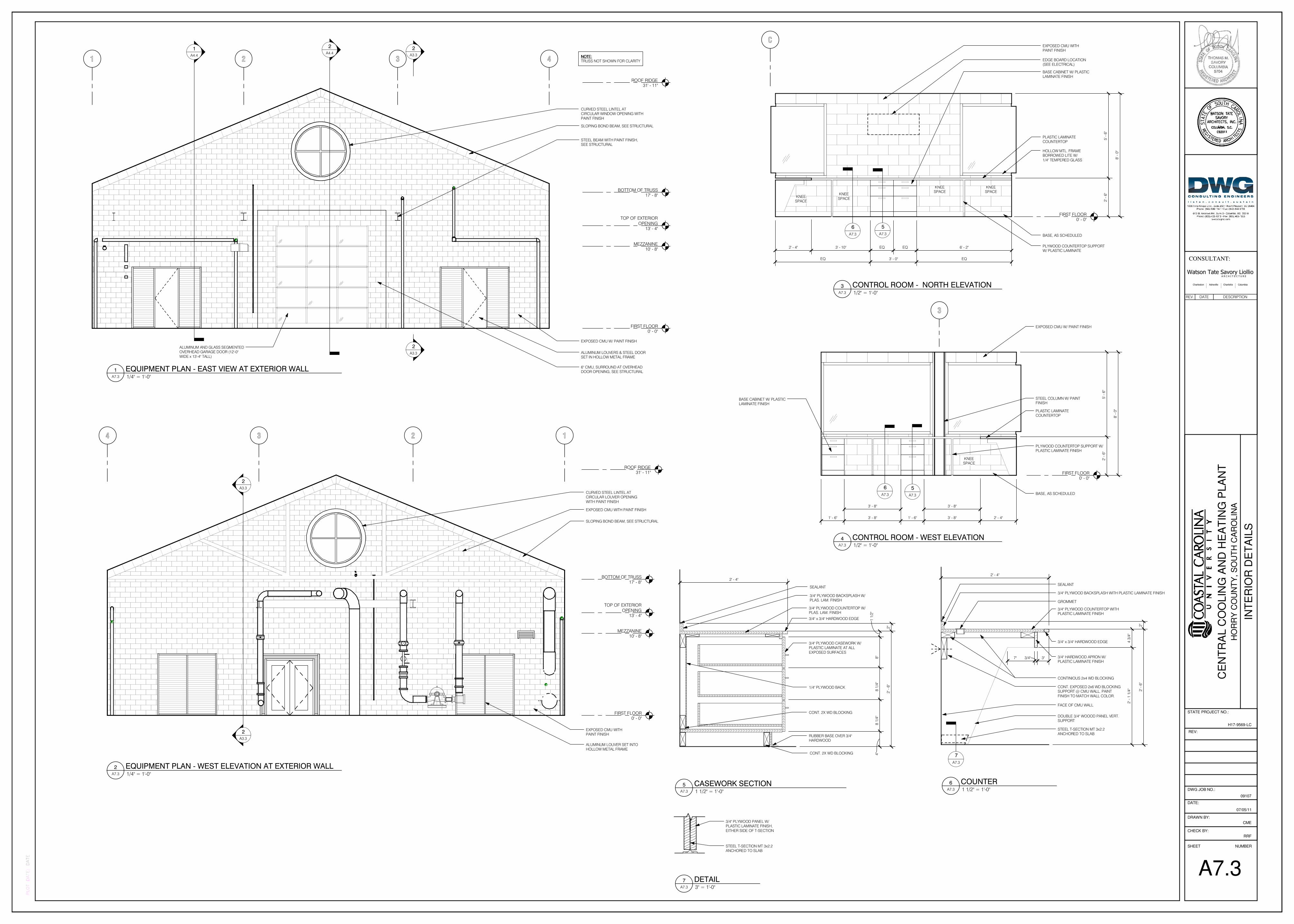
C
FIRST FLOOR0' - 0"
KNEESPACE
KNEESPACE
EQ3' - 0"EQ
EQ EQ3' - 10"2' - 4"
5' -
6"
2' -
6"
8' -
0"
PLASTIC LAMINATECOUNTERTOP
6' - 2"
KNEESPACE
KNEESPACE
PLYWOOD COUNTERTOP SUPPORTW/ PLASTIC LAMINATE
BASE CABINET W/ PLASTICLAMINATE FINISH
BASE, AS SCHEDULED
6
A7.3
5
A7.3
HOLLOW MTL. FRAMEBORROWED LITE W/
1/4" TEMPERED GLASS
EDGE BOARD LOCATION(SEE ELECTRICAL)
EXPOSED CMU WITHPAINT FINISH
3
FIRST FLOOR0' - 0"
1' - 6" 3' - 8" 1' - 6" 3' - 8"
KNEESPACE
3' - 8" 3' - 8"
5' -
6"
2' -
6"
8' -
0"
PLASTIC LAMINATECOUNTERTOP
BASE CABINET W/ PLASTICLAMINATE FINISH
PLYWOOD COUNTERTOP SUPPORT W/PLASTIC LAMINATE FINISH
BASE, AS SCHEDULED
STEEL COLUMN W/ PAINTFINISH
5
A7.3
2' - 4"
6
A7.3
EXPOSED CMU W/ PAINT FINISH
STEEL T-SECTION MT 3x2.2ANCHORED TO SLAB
3/4" PLYWOOD PANEL W/PLASTIC LAMINATE FINISH,
EITHER SIDE OF T-SECTION
7
A7.3
SEALANT
3/4" PLYWOOD BACKSPLASH WITH PLASTIC LAMINATE FINISH
GROMMET
3/4" PLYWOOD COUNTERTOP WITHPLASTIC LAMINATE FINISH
FACE OF CMU WALL
DOUBLE 3/4" WOOOD PANEL VERT.SUPPORT
CONT. EXPOSED 2x6 WD BLOCKINGSUPPORT @ CMU WALL. PAINT
FINISH TO MATCH WALL COLOR.
STEEL T-SECTION MT 3x2.2ANCHORED TO SLAB
7" 3/4" 3"
2' -
6"
2"
2' -
1 1
/4"
4 3
/4"
2' - 4"
CONTINIOUS 2x4 WD BLOCKING
3/4" HARDWOOD APRON W/PLASTIC LAMINATE FINISH
3/4" x 3/4" HARDWOOD EDGE3/4" PLYWOOD CASEWORK W/PLASTIC LAMINATE AT ALL
EXPOSED SURFACES
4"
8 1
/4"
8 1
/4"
8"
1 1
/2"
2' - 4"
3/4" PLYWOOD COUNTERTOP W/PLAS. LAM. FINISH
3/4" PLYWOOD BACKSPLASH W/PLAS. LAM. FINISH
SEALANT
1/4" PLYWOOD BACK
3/4" x 3/4" HARDWOOD EDGE
CONT. 2X WD BLOCKING
RUBBER BASE OVER 3/4"HARDWOOD
CONT. 2X WD BLOCKING
2"
2' -
6"
2 3
BOTTOM OF TRUSS17' - 8"
MEZZANINE10' - 8"
FIRST FLOOR0' - 0"
2
A3.3
2
A3.3
1 4
TOP OF EXTERIOR
OPENING13' - 4"
NOTE:NOTE:NOTE:NOTE:TRUSS NOT SHOWN FOR CLARITY
CURVED STEEL LINTEL ATCIRCULAR WINDOW OPENING WITH
PAINT FINISH
ALUMINUM AND GLASS SEGMENTEDOVERHEAD GARAGE DOOR (12'-0"
WIDE x 13'-4" TALL)ALUMINUM LOUVERS & STEEL DOORSET IN HOLLOW METAL FRAME
SLOPING BOND BEAM, SEE STRUCTURAL
EXPOSED CMU W/ PAINT FINISH
2
A4.41
A4.4
ROOF RIDGE31' - 11"
STEEL BEAM WITH PAINT FINISH,SEE STRUCTURAL
6" CMU, SURROUND AT OVERHEADDOOR OPENING, SEE STRUCTURAL
23
BOTTOM OF TRUSS17' - 8"
MEZZANINE10' - 8"
FIRST FLOOR0' - 0"
2
A3.3
2
A3.3
14
TOP OF EXTERIOR
OPENING13' - 4"
CURVED STEEL LINTEL ATCIRCULAR LOUVER OPENING
WITH PAINT FINISH
SLOPING BOND BEAM, SEE STRUCTURAL
EXPOSED CMU WITHPAINT FINISH
EXPOSED CMU WITH PAINT FINISH
ALUMINUM LOUVER SET INTOHOLLOW METAL FRAME
ROOF RIDGE31' - 11"
CE
NT
RA
L C
OO
LIN
G A
ND
HE
AT
ING
PLA
NT
CONSULTANT:
SHEET NUMBER
CHECK BY:
DRAWN BY:
DATE:
DWG JOB NO.:
PLOT DATE:
09107
HO
RR
Y C
OU
NT
Y, S
OU
TH
CA
RO
LIN
A
DATE
REV:
STATE PROJECT NO.:
H17-9569-LC
Watson Tate Savory LiollioA R C H I T E C T U R E
Charleston Asheville Charlotte Columbia
RRF
CME
A7.3
INT
ER
IOR
DE
TA
ILS
07/05/11
1/2" = 1'-0"A7.3
3 CONTROL ROOM - NORTH ELEVATION
1/2" = 1'-0"A7.3
4 CONTROL ROOM - WEST ELEVATION
3" = 1'-0"A7.3
7 DETAIL
1 1/2" = 1'-0"A7.3
6 COUNTER 1 1/2" = 1'-0"A7.3
5 CASEWORK SECTION
1/4" = 1'-0"A7.3
1 EQUIPMENT PLAN - EAST VIEW AT EXTERIOR WALL
1/4" = 1'-0"A7.3
2 EQUIPMENT PLAN - WEST ELEVATION AT EXTERIOR WALL
REV. DATE DESCRIPTION
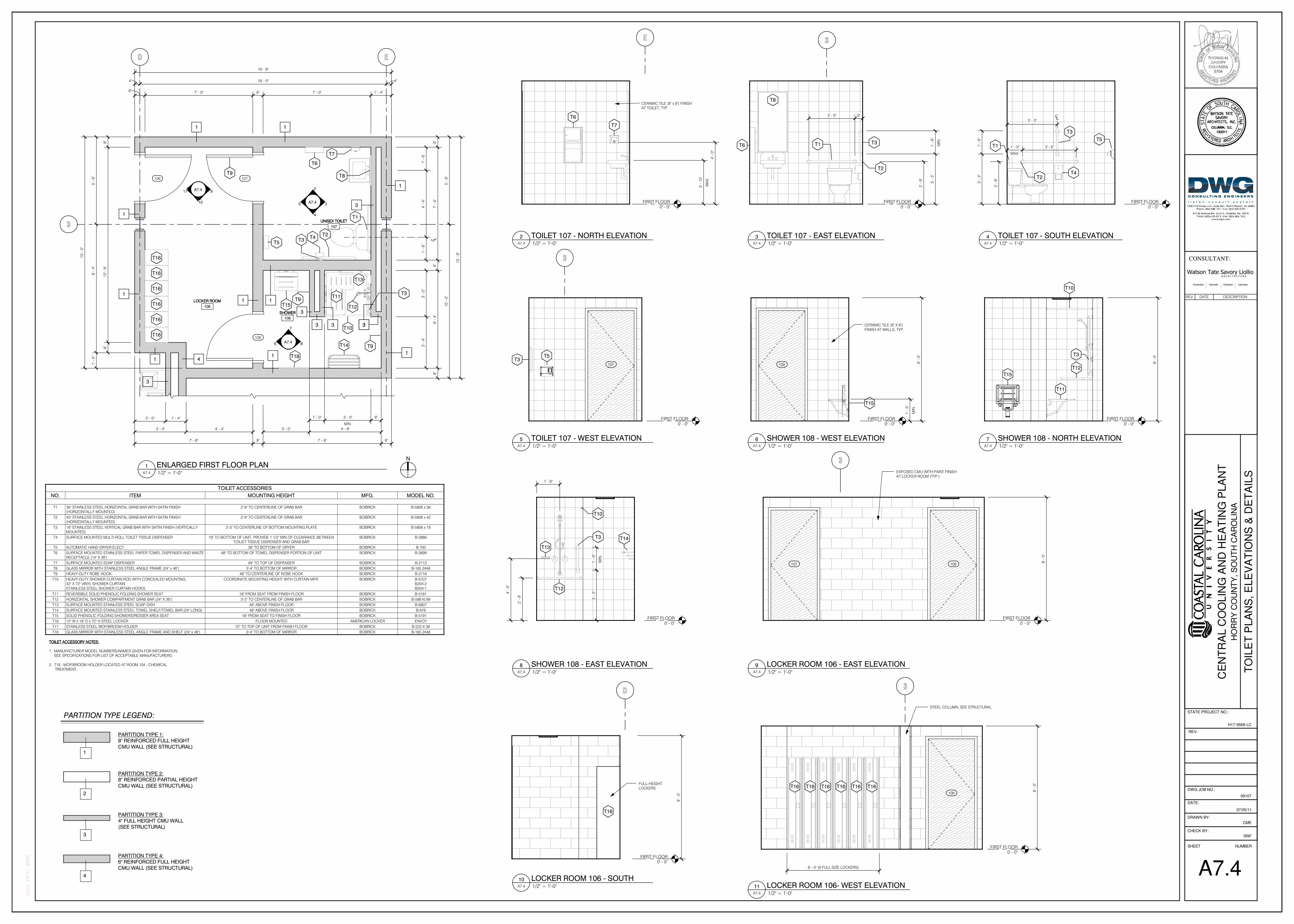
D E
3
1
1
UNISEX TOILETUNISEX TOILETUNISEX TOILETUNISEX TOILET
107
SHOWERSHOWERSHOWERSHOWER
108
LOCKER ROOMLOCKER ROOMLOCKER ROOMLOCKER ROOM
106
108
106
8"
7' -
4"
8"
6' -
4"
8"
16' - 8"
4" 16' - 0" 4"
8"
12
' - 8
"8
"
5' -
8"
8' -
4"
1' -
0"
A7.4
2
4
5
1
T16T16
T16
T16
T16
T16
T16
T9
A7.46
8" 7' - 0" 8" 7' - 0" 1' - 4"
A7.411
10
9
1
T2T3
T4
T7
T5
T6
T12
T11
T8107
15
' - 0
"
7' - 8" 8" 7' - 8" 8"
3' - 4" 4' - 4" 3' - 0" 4' - 8"
2' - 0" 1' - 4"
7
8
3
1
3
1
3
1
1
1
10
' - 0
"5
' - 8
"
T15
T1
T9
T10
T14
T13
1' - 0"
MIN.
3' - 0" 8"
15
' - 8
"
1
3
3
33
3
4
3' -
0"
3' -
4"
1' -
6"
4' -
4"
1' -
6"
T3T9
T18
E
FIRST FLOOR0' - 0"
CERAMIC TILE (8" x 8") FINISHAT TOILET, TYP.
MA
X.
2' -
10
"
T6
T7
4' -
0"
FIRST FLOOR0' - 0"
3' - 3"
MAX.
1' - 0" 3' - 6"
2' -
9"
3' -
3"
1' -
6"
T3
T2
T1
T4
T5
3
FIRST FLOOR0' - 0"
107
T3T5
FIRST FLOOR0' - 0"
8' -
0"
108
T15
MIN
.
1' -
5"
CERAMIC TILE (8" X 8")FINISH AT WALLS, TYP.
3
FIRST FLOOR0' - 0"
8' -
0"
108107
EXPOSED CMU WITH PAINT FINISHAT LOCKER ROOM (TYP.)
D
FIRST FLOOR0' - 0"
T16
FULL-HEIGHTLOCKERS
8' -
0"
3
FIRST FLOOR0' - 0"
6' - 0" (6 FULL SIZE LOCKERS)
8' -
0"
106
T16 T16 T16 T16 T16 T16
STEEL COLUMN, SEE STRUCTURAL
3
FIRST FLOOR0' - 0"
MIN
.
1' -
6"
3' -
3"
2' -
9"
T1
T2
T3T6
T8
3' - 0" 6"
FIRST FLOOR0' - 0"
T10
T12
T11
T15
8' -
0"T3
FIRST FLOOR0' - 0"
4' -
0"
2' -
9"
3' -
3"
MIN
.
1' -
6"
1' - 6"
T10
T3
T13
T12
T14
1
PARTITION TYPE 1:8" REINFORCED FULL HEIGHT
CMU WALL (SEE STRUCTURAL)
PARTITION TYPE 2:8" REINFORCED PARTIAL HEIGHT
CMU WALL (SEE STRUCTURAL)
PARTITION TYPE LEGEND:
2
PARTITION TYPE 3:4" FULL HEIGHT CMU WALL
(SEE STRUCTURAL)
3
PARTITION TYPE 4:6" REINFORCED FULL HEIGHT
CMU WALL (SEE STRUCTURAL)
4
CE
NT
RA
L C
OO
LIN
G A
ND
HE
AT
ING
PLA
NT
CONSULTANT:
SHEET NUMBER
CHECK BY:
DRAWN BY:
DATE:
DWG JOB NO.:
PLOT DATE:
09107
HO
RR
Y C
OU
NT
Y, S
OU
TH
CA
RO
LIN
A
DATE
REV:
STATE PROJECT NO.:
H17-9569-LC
Watson Tate Savory LiollioA R C H I T E C T U R E
Charleston Asheville Charlotte Columbia
RRF
CME
A7.4
TO
ILE
T P
LA
NS
, E
LE
VA
TIO
NS
& D
ET
AIL
S
07/05/11
1/2" = 1'-0"A7.4
1 ENLARGED FIRST FLOOR PLAN
1/2" = 1'-0"A7.4
2 TOILET 107 - NORTH ELEVATION 1/2" = 1'-0"A7.4
4 TOILET 107 - SOUTH ELEVATION
1/2" = 1'-0"A7.4
5 TOILET 107 - WEST ELEVATION
N
TOILET ACCESSORIES
NO. ITEM MOUNTING HEIGHT MFG. MODEL NO.
T1 36" STAINLESS STEEL HORIZONTAL GRAB BAR WITH SATIN FINISH(HORIZONTALLY MOUNTED)
2'-9" TO CENTERLINE OF GRAB BAR BOBRICK B-5806 x 36
T2 42" STAINLESS STEEL HORIZONTAL GRAB BAR WITH SATIN FINISH(HORIZONTALLY MOUNTED)
2'-9" TO CENTERLINE OF GRAB BAR BOBRICK B-5806 x 42
T3 18" STAINLESS STEEL VERTICAL GRAB BAR WITH SATIN FINISH (VERTICALLYMOUNTED)
3'-3" TO CENTERLINE OF BOTTOM MOUNTING PLATE BOBRICK B-5806 x 18
T4 SURFACE MOUNTED MULTI-ROLL TOILET TISSUE DISPENSER 19" TO BOTTOM OF UNIT, PROVIDE 1 1/2" MIN OF CLEARANCE BETWEENTOILIET TISSUE DISPENSER AND GRAB BAR
BOBRICK B-2888
T5 AUTOMATIC HAND DRYER ELECT. 38" TO BOTTOM OF DRYER BOBRICK B-700
T6 SURFACE MOUNTED STAINLESS STEEL PAPER TOWEL DISPENSER AND WASTERECEPTACLE (14" X 28")
48" TO BOTTOM OF TOWEL DISPENSER PORTION OF UNIT BOBRICK B-3699
T7 SURFACE MOUNTED SOAP DISPENSER 49" TO TOP OF DISPENSER BOBRICK B-2112
T8 GLASS MIRROR WITH STAINLESS STEEL ANGLE FRAME (24" x 48") 3'-4" TO BOTTOM OF MIRROR BOBRICK B-165 2448
T9 HEAVY-DUTY ROBE HOOK 48" TO CENTERLINE OF ROBE HOOK BOBRICK B-2116
T10 HEAVY-DUTY SHOWER CURTAIN ROD WITH CONCEALED MOUNTING,42" X 72" VINYL SHOWER CURTAIN
STAINLESS STEEL SHOWER CURTAIN HOOKS
COORDINATE MOUNTING HEIGHT WITH CURTAIN MFR. BOBRICK B-6107B204-2
B204-1
T11 REVERSIBLE SOLID PHENOLIC FOLDING SHOWER SEAT 18" FROM SEAT FROM FINISH FLOOR BOBRICK B-5181
T12 HORIZONTAL SHOWER COMPARTMENT GRAB BAR (24" X 36") 3'-2" TO CENTERLINE OF GRAB BAR BOBRICK B-58616.99
T13 SURFACE MOUNTED STAINLESS STEEL SOAP DISH 48" ABOVE FINISH FLOOR BOBRICK B-6807
T14 SURFACE MOUNTED STAINLESS STEEL TOWEL SHELF/TOWEL BAR (24" LONG) 48" ABOVE FINISH FLOOR BOBRICK B-676
T15 SOLID PHENOLIC FOLDING SHOWER/DRESSER AREA SEAT 18" FROM SEAT TO FINISH FLOOR BOBRICK B-5191
T16 12" W x 18" D x 72" H STEEL LOCKER FLOOR MOUNTED AMERICAN LOCKER ENVOY
T17 STAINLESS STEEL MOP/BROOM HOLDER 72" TO TOP OF UNIT FROM FINISH FLOOR BOBRICK B-223 X 36
T18 GLASS MIRROR WITH STAINLESS STEEL ANGLE FRAME AND SHELF (24" x 48") 3'-4" TO BOTTOM OF MIRROR BOBRICK B-165 2448
TOILET ACCESSORY NOTES:TOILET ACCESSORY NOTES:TOILET ACCESSORY NOTES:TOILET ACCESSORY NOTES:
1. MANUFACTURER MODEL NUMBERS/NAMES GIVEN FOR INFORMATION. SEE SPECIFICATIONS FOR LIST OF ACCEPTABLE MANUFACTURERS.
2. T18 - MOP/BROOM HOLDER LOCATED AT ROOM 104 - CHEMICAL TREATMENT.
1/2" = 1'-0"A7.4
6 SHOWER 108 - WEST ELEVATION
1/2" = 1'-0"A7.4
9 LOCKER ROOM 106 - EAST ELEVATION
1/2" = 1'-0"A7.4
10 LOCKER ROOM 106 - SOUTH
1/2" = 1'-0"A7.4
11 LOCKER ROOM 106- WEST ELEVATION
1/2" = 1'-0"A7.4
3 TOILET 107 - EAST ELEVATION
1/2" = 1'-0"A7.4
7 SHOWER 108 - NORTH ELEVATION
1/2" = 1'-0"A7.4
8 SHOWER 108 - EAST ELEVATION
REV. DATE DESCRIPTION
Related Documents