Section 3.5 – Drafts & Fillets are Cool! IE 1225 R. Lindeke

Section 3.5 – Drafts & Fillets are Cool! IE 1225 R. Lindeke.
Dec 20, 2015
Welcome message from author
This document is posted to help you gain knowledge. Please leave a comment to let me know what you think about it! Share it to your friends and learn new things together.
Transcript

Section 3.5 – Drafts & Fillets are Cool!
IE 1225
R. Lindeke

Draft – A tool for Making “Patterns and Dies”
Drafted surfaces allow objects to be “withdrawn from a certain direction”
They are needed if we are designing tooling for forging and casting
We often use filleted edges to guarantee that metal from parts or sand will not stick in sharp corners – in forging and casting
Chamfers also help to release too!

Use the Profile tool – build using data entry as much as possible!
Profile this side:

Select Rt. Face of Part – Select Draft – Fill as suggested!
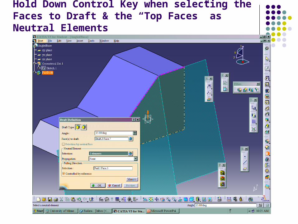
Hold Down Control Key when selecting the Faces to Draft & the “Top Faces” as Neutral Elements

Which Becomes this when only the Lowest “Top Face” is Specified as a Neutral Element!

In Casting when we produce Patterns, we need a parting Plane to allow easy withdrawal
– We would likely Draft in Opposite Directions: both above and below this plane if we are building a real Matchplate

Notice the Effected of Limited Draft on Front Face – and the Pre-pocketed Rectangle
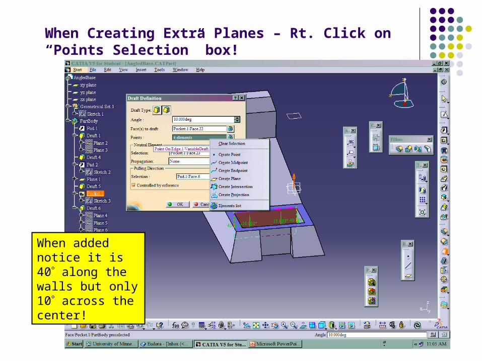
When Creating Extra Planes – Rt. Click on “Points Selection” box!
When added notice it is 40 along the walls but only 10 across the center!

The sizes in the Tutorial were High – I found 22.048 from Left/6.426 from Top Edges to be a better centering! When considering the Filleted edges!

Make Sure the Rectangle are Coincident with the construction edges! Retain the Upper edge of the top step
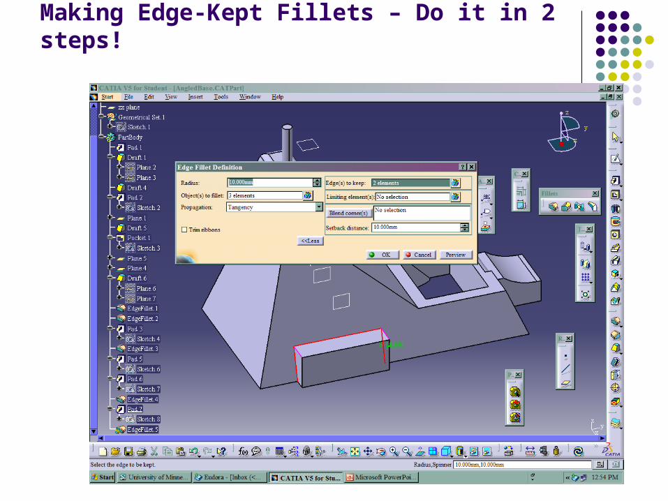
Making Edge-Kept Fillets – Do it in 2 steps!
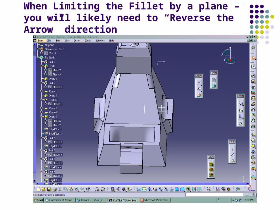
When Limiting the Fillet by a plane – you will likely need to “Reverse the Arrow” direction

After Deleting Inside Draft and Then Pocket – Sketch and Constrain the 2 Circles shown below:

Step 1: Make 2 Pads; Step 2: Draft the Cyl. Pads; Step 3: Face-to-Face Fillet the two “Cones”

Finally a Variable Radius Fillet on the 2 Edges – From 10 to 30 mm; And a Chamfered edge on the lower step!
Related Documents


![SULIT 1225/1 1225/1 NOMBOR KAD PENGENALAN Ogos ANGKA ... Sembilan... · SULIT 1225/1 [Lihat halaman sebelah] 1225/1 © 2011 Hak Cipta MPSM Cawangan Negeri Sembilan SULIT 1225/1 Pendidikan](https://static.cupdf.com/doc/110x72/6083556b7020e86f450d0274/sulit-12251-12251-nombor-kad-pengenalan-ogos-angka-sembilan-sulit-12251.jpg)