IE 1225 – Intro. To Manufacturing Engineering Fall 2007 Dr. R. Lindeke

Welcome message from author
This document is posted to help you gain knowledge. Please leave a comment to let me know what you think about it! Share it to your friends and learn new things together.
Transcript

IE 1225 – Intro. To Manufacturing Engineering
Fall 2007Dr. R. Lindeke
Engineering Design Process1 is a series of iterative steps that engineers and designers take to solve a problem.
• Step 1: Identify the Need or Problem• Step 2: Research the Need or Problem• Step 3: Develop Possible Solutions• Step 4: Select the Best Possible Solution• Step 5: Construct a Prototype• Step 6: Test and Evaluate the Solutions• Step 7: Communicate the Solutions• Step 8: Redesign
1See reference materials: Engineering Design Graphic, J.H. Earle (in library reference section)
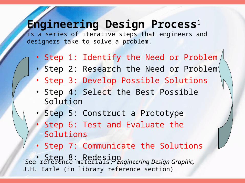
Engineering Design
• As an iterative process ED:– a) Starts with an idea – or a customer’s desired
solution– b) Starts with a competitor’s product– Leads through may potential solutions– Chooses from among the potential solutions by
“Fair” tests– A prototype of the chosen solution(s) is produced
for assuring correctness of concept– Design models are finalized, manufactured and
introduced– Product Refinement continues the process
At each step the process can cycle back!
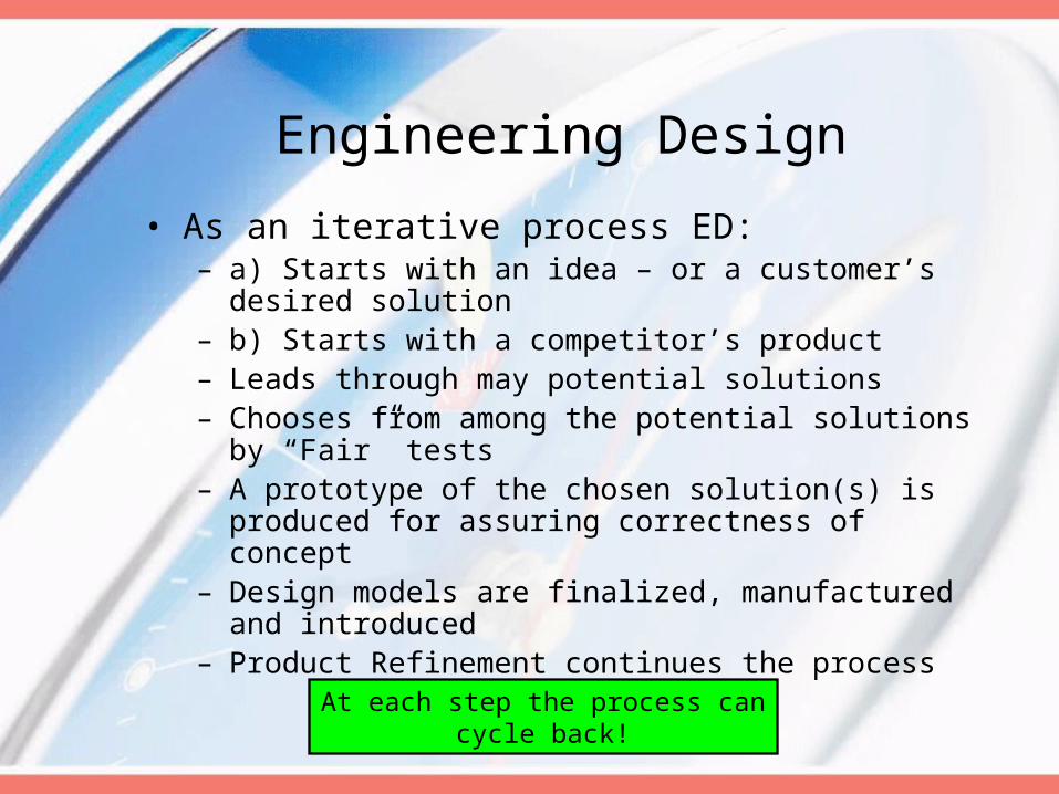
Engineering Graphics
• The communication tools of Engineering Design
• Our “drawings” are used to make clear our solutions to:– Customers– Other Designers (who must interface
with our ‘parts’)– Manufacturing Engineers – Shop Floor Personnel
The purpose of a technical drawing is to DOCUMENT THE DESIGN PORCESS!!!

Role of Drawings
• They are a way to communicate all necessary information about an abstractions an idea or concept
• They are a visual representation of a real entity (in 2- or 3-D) such as a machine part, tool, house, etc.
Specific Need of a Technical Drawing
• They must indicate scale of the entity
• They must indicate dimensions of the Entity (and any applicable tolerable variations from these desired dimensions)
• They should (must!) conform to well established standards of design (and drafting) as developed by ANSI and ISO
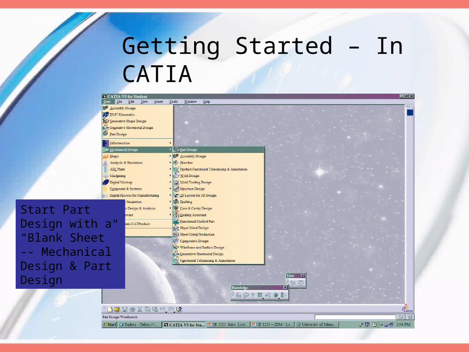
Getting Started – In CATIA
Start Part Design with a “Blank Sheet” -- Mechanical Design & Part Design

After we start: Pick a Logical Name Type it in as “New Part”

Tools … Customize … Get the toolbars!

Next: Using “Options” in Tools menu, Set up Parameters/Measure: Units
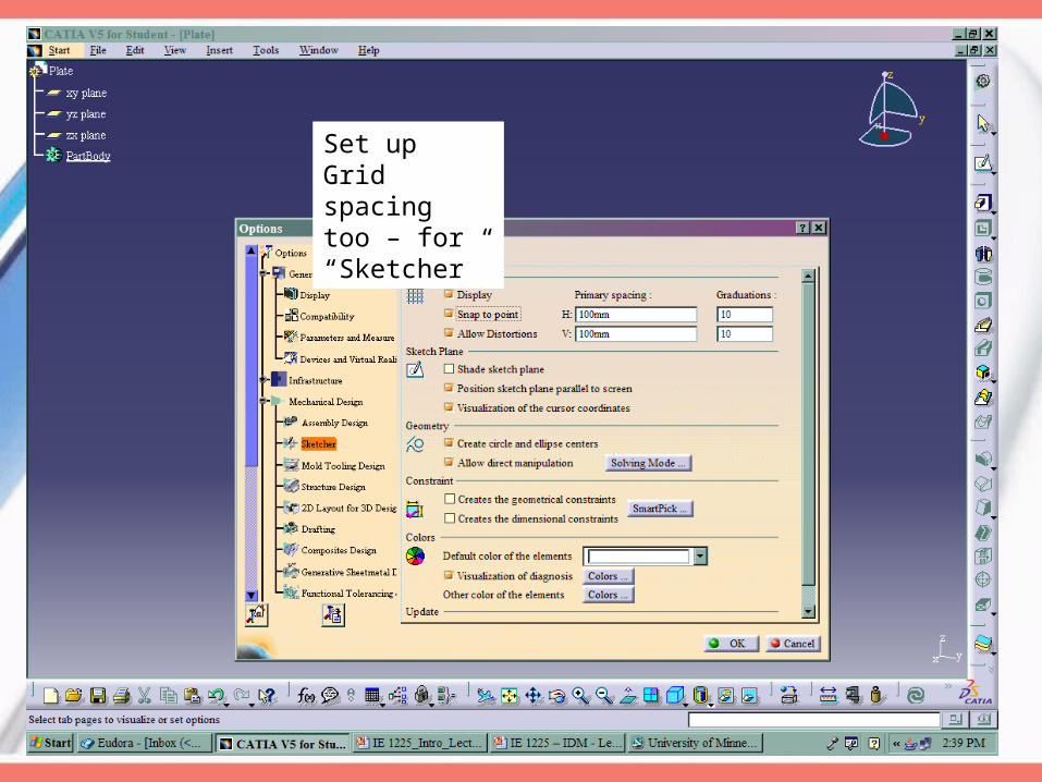
Set up Grid spacing too – for “Sketcher”
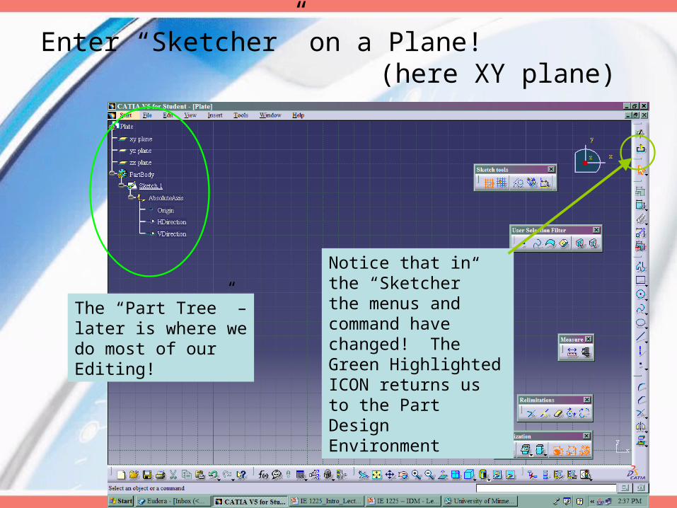
Enter “Sketcher” on a Plane! (here XY plane)
The “Part Tree” – later is where we do most of our Editing!
Notice that in the “Sketcher” the menus and command have changed! The Green Highlighted ICON returns us to the Part Design Environment
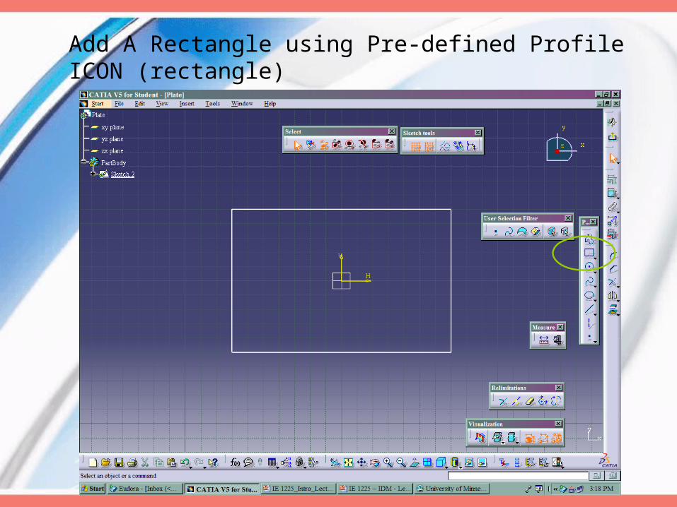
Add A Rectangle using Pre-defined Profile ICON (rectangle)
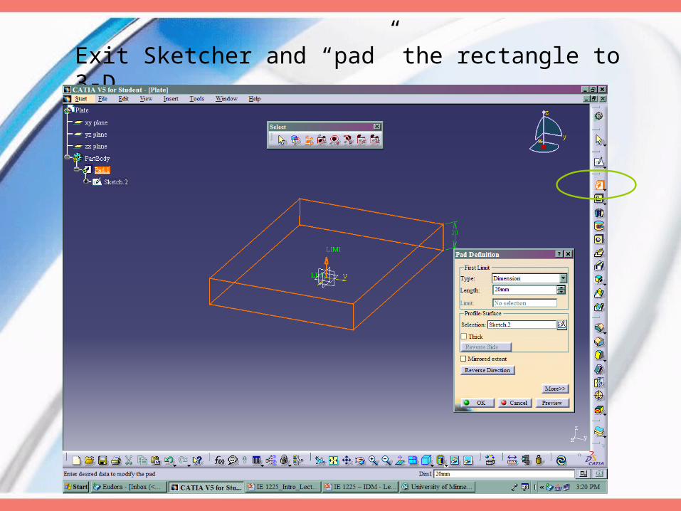
Exit Sketcher and “pad” the rectangle to 3-D
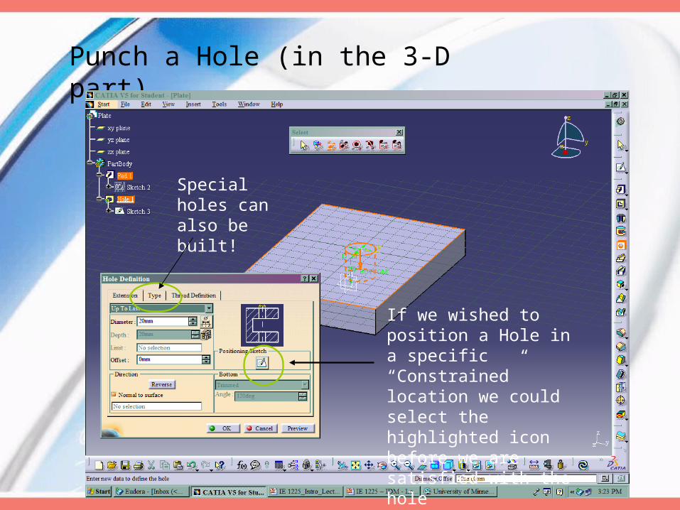
Punch a Hole (in the 3-D part)
If we wished to position a Hole in a specific “Constrained” location we could select the highlighted icon before we are satisfied with the hole
Special holes can also be built!

Manipulating the Design Product Tree
If our part is “Dark Gray” then all the editing tools apply to the product tree – not the part!
We usually get here by accident – reclick on a vertical link in the Tree to get back to the part editor!

Select “Top Face” of part and Re-enter Sketcher
Draw Another Rectangle!
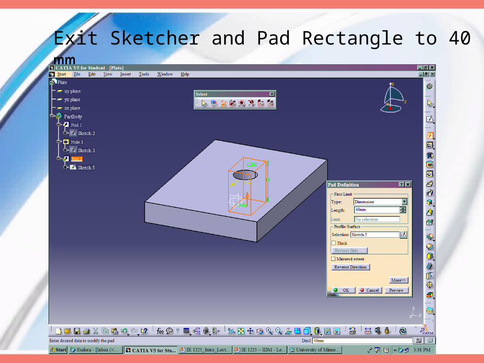
Exit Sketcher and Pad Rectangle to 40 mm
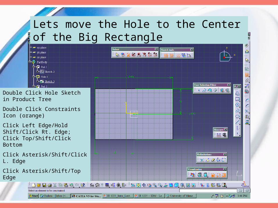
Lets move the Hole to the Center of the Big Rectangle
Double Click Hole Sketch in Product Tree
Double Click Constraints Icon (orange)
Click Left Edge/Hold Shift/Click Rt. Edge; Click Top/Shift/Click Bottom
Click Asterisk/Shift/Click L. Edge
Click Asterisk/Shift/Top Edge
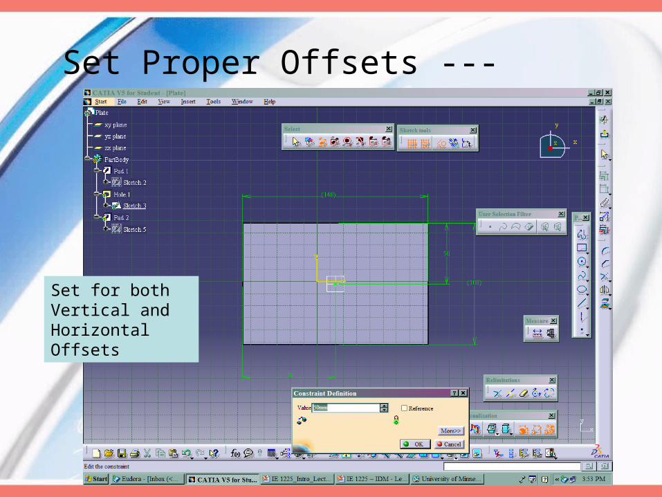
Set Proper Offsets ---
Set for both Vertical and Horizontal Offsets

Set Views with Icon
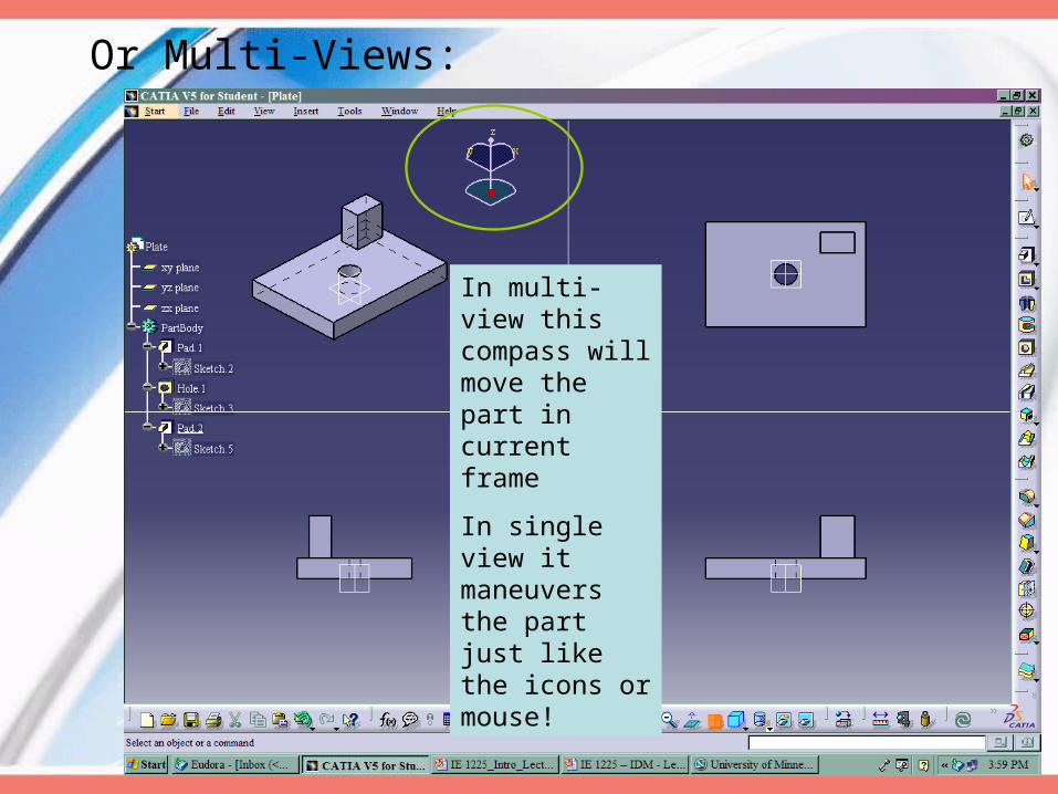
Or Multi-Views:
In multi-view this compass will move the part in current frame
In single view it maneuvers the part just like the icons or mouse!
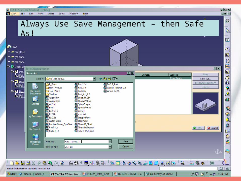
Always Use Save Management – then Safe As!
Related Documents


![SULIT 1225/1 1225/1 NOMBOR KAD PENGENALAN Ogos ANGKA ... Sembilan... · SULIT 1225/1 [Lihat halaman sebelah] 1225/1 © 2011 Hak Cipta MPSM Cawangan Negeri Sembilan SULIT 1225/1 Pendidikan](https://static.cupdf.com/doc/110x72/6083556b7020e86f450d0274/sulit-12251-12251-nombor-kad-pengenalan-ogos-angka-sembilan-sulit-12251.jpg)