PROJECT ENGINEERING Preliminary Design Report Job ID: P1902-3829/04/01 Job Name: Scatec solar 132kV DCt Lines Author: Trans-Africa Projects Date: July 2015 Revision: 0

Welcome message from author
This document is posted to help you gain knowledge. Please leave a comment to let me know what you think about it! Share it to your friends and learn new things together.
Transcript
PROJECT
ENGINEERING
Preliminary Design Report
Job ID: P1902-3829/04/01
Job Name: Scatec solar 132kV DCt Lines
Author: Trans-Africa Projects
Date: July 2015
Revision: 0
1
Scatec Solar 132kV Line
Preliminary design Document
Document Number Revision No Date
P1902-3829/04/01 0 July 2015
Table of Contents
1. INTRODUCTION ............................................................................................................................................ 4
1.1 GEOGRAPHICAL LOCATION.................................................................................................................................. 5 1.2 ROUTE PLANS .................................................................................................................................................. 6
2 DESIGN PHILOSOPHY .................................................................................................................................... 7
2.1 SALIENT ASPECTS OF THE LINE ............................................................................................................................. 8 2.2 ENVIRONMENTAL CONSIDERATIONS ..................................................................................................................... 9
2.2.1 Structure Types ........................................................................................................................................ 9 2.2.3 Enviromental Impact ............................................................................................................................. 10
2.3 ACCESS ......................................................................................................................................................... 11 2.4 LIST OF CROSSINGS ......................................................................................................................................... 12
3 STATUTORY REQUIREMENTS ....................................................................................................................... 13
4 CONDUCTORS .............................................................................................................................................. 13
4.1 CONDUCTOR SELECTION ................................................................................................................................... 13 4.2 PHASE CONDUCTORS ....................................................................................................................................... 14 4.3 SHIELD WIRE .................................................................................................................................................. 14
5 INSULATION AND HARDWARE ..................................................................................................................... 15
5.1 PHASE CONDUCTOR ........................................................................................................................................ 15 5.2 B.I.L ............................................................................................................................................................ 15 5.3 OPGW FIBRE OPTIC DESIGN ............................................................................................................................. 15 5.4 HARDWARE ................................................................................................................................................... 17 5.5 STRAIN ASSEMBLY .......................................................................................................................................... 17 5.6 CLOSING SPAN ASSEMBLY ................................................................................................................................ 17 5.7 SHIELD WIRE HARDWARE .................................................................................................................................. 18 5.8 VIBRATION CONTROL ...................................................................................................................................... 18 5.9 POSITION OF VIBRATION DAMPERS ON THE PHASE CONDUCTOR .............................................................................. 18
6 DESIGN LOADS ............................................................................................................................................. 18
6.1 WIND PRESSURE ............................................................................................................................................ 18 6.2 CONDUCTOR TENSION CRITERIA ........................................................................................................................ 19
7 TOWER TYPES .............................................................................................................................................. 19
8 FOUNDATIONS ............................................................................................................................................. 23
8.1 SOIL RESISTIVITY / EARTHING ................................................................................................................................... 24
9 LABELLING ................................................................................................................................................... 25
9.1 LINE DESIGNATION.......................................................................................................................................... 25
10 DESIGN RELATED MAPS ............................................................................................................................... 26
10.1 ICE LOADING IN SOUTH AFRICA .......................................................................................................................... 26 10.2 VULTURE ELECTROCUTION ................................................................................................................................ 26 10.3 LIGHTINING FLASH DENSITY .............................................................................................................................. 27 10.4 RAINFALL ...................................................................................................................................................... 27 10.5 CORROSION ................................................................................................................................................... 28
2

Scatec Solar 132kV Line
Preliminary design Document
Document Number Revision No Date
P1902-3829/04/01 0 July 2015
1. INTRODUCTION
Scatec Solar has been awarded three solar PV (Photovoltaic) projects as part of round 4 group of renewable energy
projects in Siyanda District within the jurisdiction area of Khai Garib Local Municipality in the Northern Cape. All
the three farms are located approximately 22km south west of Upington and 15km north of Keimos. Each plant
will have a generation capacity of 75MW. The total power that will be evacuated from the three solar farms will be
225MW. The three solar farms shall be called Dyasonsklip 1, Dyasonsklip 2 and Sirius 1.
Dyasonsklip 1 and 2 will share a substation, called Dyasonsklip Substation and evacuated generated power to Sirius
substation by means of a single circuit (SCt) Twin Tern line. From Sirius substation the power shall be evacuated by
means of a SCt Twin Tern line to the new Upington MTS. Eskom planning has opted for the use of Twin Tern to
accommodate future generating plants planned in the area*.
Trans Africa Projects (Pty) Ltd has been commissioned for the design of both 132kV single circuit lines to facilitate
the connection of Dyasonsklip 1, Dyasonsklip 2 and Sirius 1 to the Eskom grid through the new Upington MTS
substation. Two options are considered in this design, the first being a Twin Tern SCt guyed monopole solution and
the second option, a SCt Twin Tern self-supporting solution.
The guyed solution shows a considerable cost saving. However, the Northern Cape Operating Unit (NCOU) has
expressed slight reservation over the use of guyed structures. The following report aims to address these as well
and other design constraints and considerations for both options.
*This heavy configuration was agreed to by the developer in lieu of a lighter fit for purpose solution involving the use of single Kingbird and
twin Chicadee line. The developer has stated an intention to construct the solution with guyed structures to accommodate the increased cost
of this heavy configuration.
3
Scatec Solar 132kV Line
Preliminary design Document
Document Number Revision No Date
P1902-3829/04/01 0 July 2015
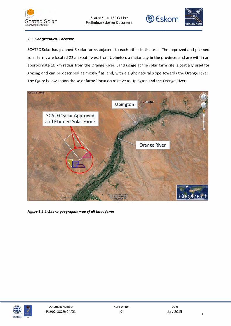
1.1 Geographical Location
SCATEC Solar has planned 5 solar farms adjacent to each other in the area. The approved and planned
solar farms are located 22km south west from Upington, a major city in the province, and are within an
approximate 10 km radius from the Orange River. Land usage at the solar farm site is partially used for
grazing and can be described as mostly flat land, with a slight natural slope towards the Orange River.
The figure below shows the solar farms’ location relative to Upington and the Orange River.
Figure 1.1.1: Shows geographic map of all three farms
4
Scatec Solar 132kV Line
Preliminary design Document
Document Number Revision No Date
P1902-3829/04/01 0 July 2015
1.2 Route Plans
Two routes have been proposed for the line connections between the three substations. The figure
1.2.1 shows the preferred route in green. The route follow Dyasonsklip 1 and 2 and Sirius 2 solar farm
boundaries, crossing over a dirt access road, to connect to Sirius substation. From Sirius substation it
follows a straight trajectory towards McTaggerts 132kV Line where it makes an underpass crossing. The
line then bends in a south-east direction towards the existing Oranje-Oasis 132kV wood pole line where
it crosses over at approximately midsapn and heads towards its final bend before termination at the
new Upington MTS.
The corridor adjacent to McTaggerts 132kV Turn-in Lines has been earmarked as a 400kV line crorridor
to the new Upington MTS. In addition to this, the corridor will host a planned access road to the planned
Eskom CSP plant located on the eastern side of !Khi Solar CSP Plant. The underpass crossing at the
McTaggerts 132kV Turn-in Line will be made such that clearance to the planned 400kV line and access
road is maintained.
The second route option, marked in yellow in the image below, also follows the solar farm boundaries of
Dyasonsklip 1 and 2 and bends toward the existing Oranje-Oasis 132kV line where is runs parallel until
turning into Sirius 1 substation. The line exists Sirius 1 substation in a southernly direction towards the
existing wood pole line, where it crosses over at approximately midspan and bends to again follow
parallel to the existing 132kV line. The last two bends allows it to turn and terminate at the new
Upington MTS.
5

Scatec Solar 132kV Line
Preliminary design Document
Document Number Revision No Date
P1902-3829/04/01 0 July 2015
Figure 1.2.1: Line location relative to major suburbs and land features (Google Earth Imagery).
2 DESIGN PHILOSOPHY
Self-supporting steel monopoles and guyed steel monopoles were considered in obtaining a
recommended concept for the Dyasonsklip - Sirius 132kV line and Sirius - Upington MTS 132kV Line. The
design philosophy adopted in generating each option incorporated a balance between performance
optimisation and cost. As recommended by design standard SANS 10280: 2013-01, a reliability level of 1
was used to model each design. A reliability level of 1 implies a wind load factor of 1 which in turn
corresponds to a return period of 50 years. SANS 10280: 2013 - 01, in accordance with IEC60826,
stipulates a minimum reliability level of 1 for lines up to 132kV.
6
Scatec Solar 132kV Line
Preliminary design Document
Document Number Revision No Date
P1902-3829/04/01 0 July 2015
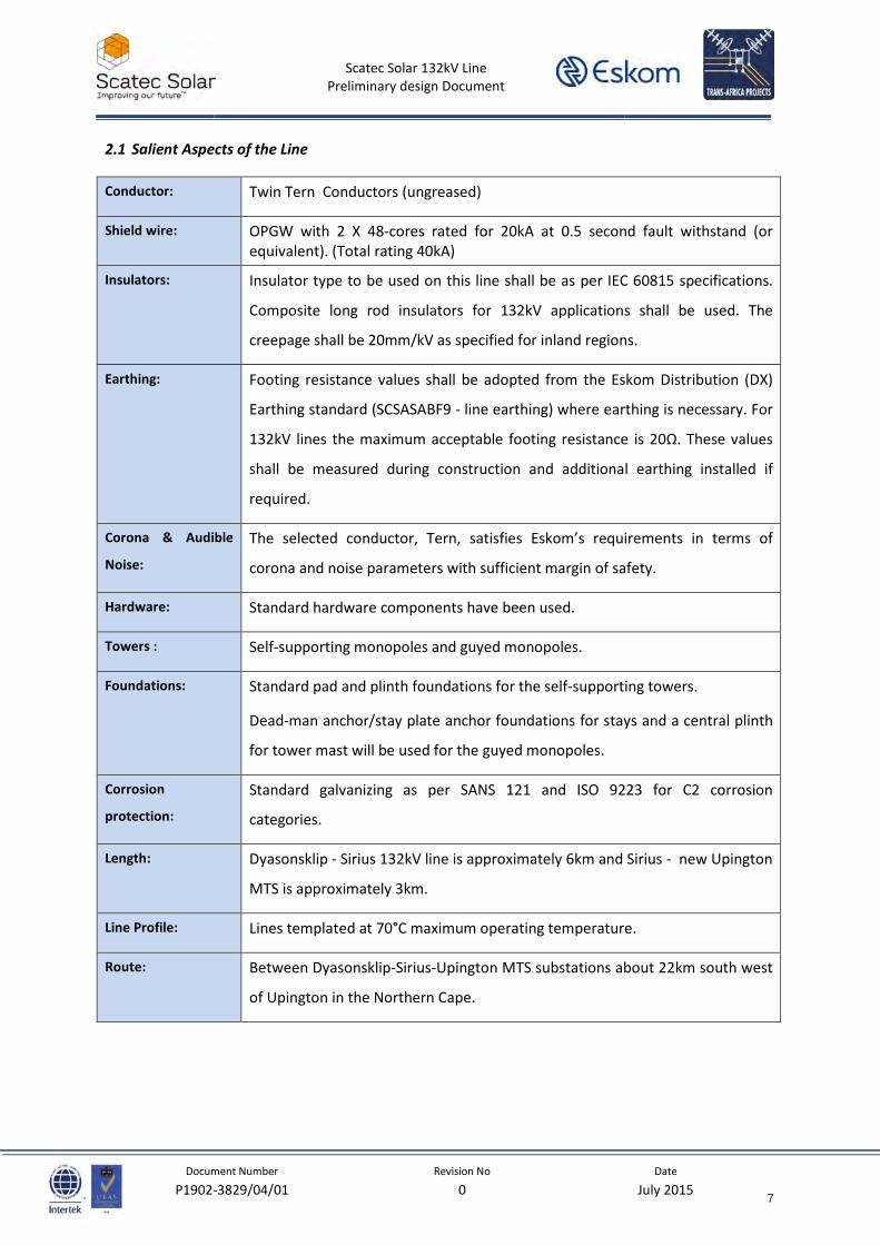
2.1 Salient Aspects of the Line
Conductor: Twin Tern Conductors (ungreased)
Shield wire: OPGW with 2 X 48-cores rated for 20kA at 0.5 second fault withstand (or
equivalent). (Total rating 40kA)
Insulators: Insulator type to be used on this line shall be as per IEC 60815 specifications.
Composite long rod insulators for 132kV applications shall be used. The
creepage shall be 20mm/kV as specified for inland regions.
Earthing: Footing resistance values shall be adopted from the Eskom Distribution (DX)
Earthing standard (SCSASABF9 - line earthing) where earthing is necessary. For
132kV lines the maximum acceptable footing resistance is 20Ω. These values
shall be measured during construction and additional earthing installed if
required.
Corona & Audible
Noise:
The selected conductor, Tern, satisfies Eskom’s requirements in terms of
corona and noise parameters with sufficient margin of safety.
Hardware: Standard hardware components have been used.
Towers : Self-supporting monopoles and guyed monopoles.
Foundations: Standard pad and plinth foundations for the self-supporting towers.
Dead-man anchor/stay plate anchor foundations for stays and a central plinth
for tower mast will be used for the guyed monopoles.
Corrosion
protection:
Standard galvanizing as per SANS 121 and ISO 9223 for C2 corrosion
categories.
Length: Dyasonsklip - Sirius 132kV line is approximately 6km and Sirius - new Upington
MTS is approximately 3km.
Line Profile: Lines templated at 70°C maximum operating temperature.
Route: Between Dyasonsklip-Sirius-Upington MTS substations about 22km south west
of Upington in the Northern Cape.
7
Scatec Solar 132kV Line
Preliminary design Document
Document Number Revision No Date
P1902-3829/04/01 0 July 2015
2.2 Environmental Considerations
2.2.1 Structure Types
The EA (Environmental Assessment) stipulates that poles to be used as support structures, therefore
lattice structures were not considered as a support option.
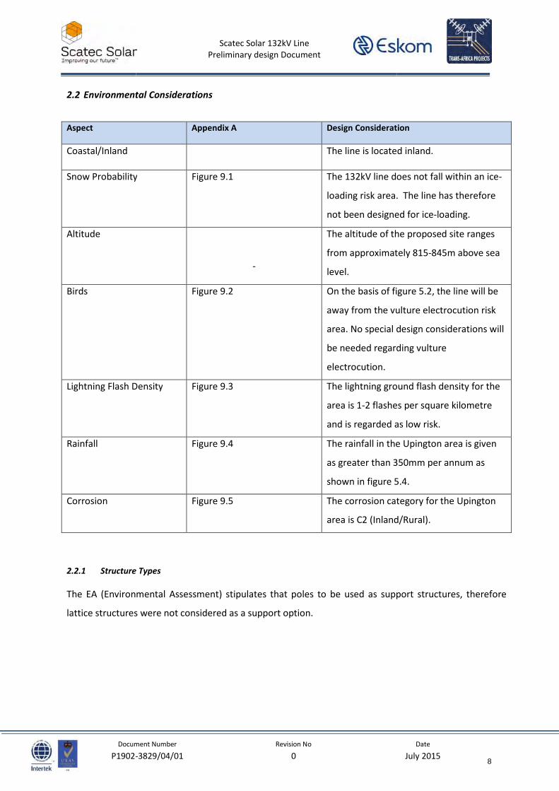
Aspect Appendix A Design Consideration
Coastal/Inland The line is located inland.
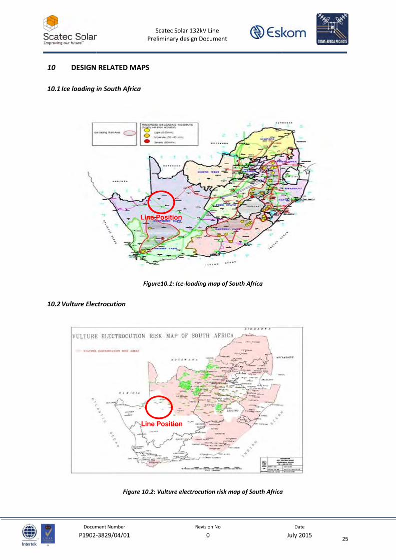
Snow Probability Figure 9.1 The 132kV line does not fall within an ice-
loading risk area. The line has therefore
not been designed for ice-loading.
Altitude
-
The altitude of the proposed site ranges
from approximately 815-845m above sea
level.
Birds
Figure 9.2 On the basis of figure 5.2, the line will be
away from the vulture electrocution risk
area. No special design considerations will
be needed regarding vulture
electrocution.
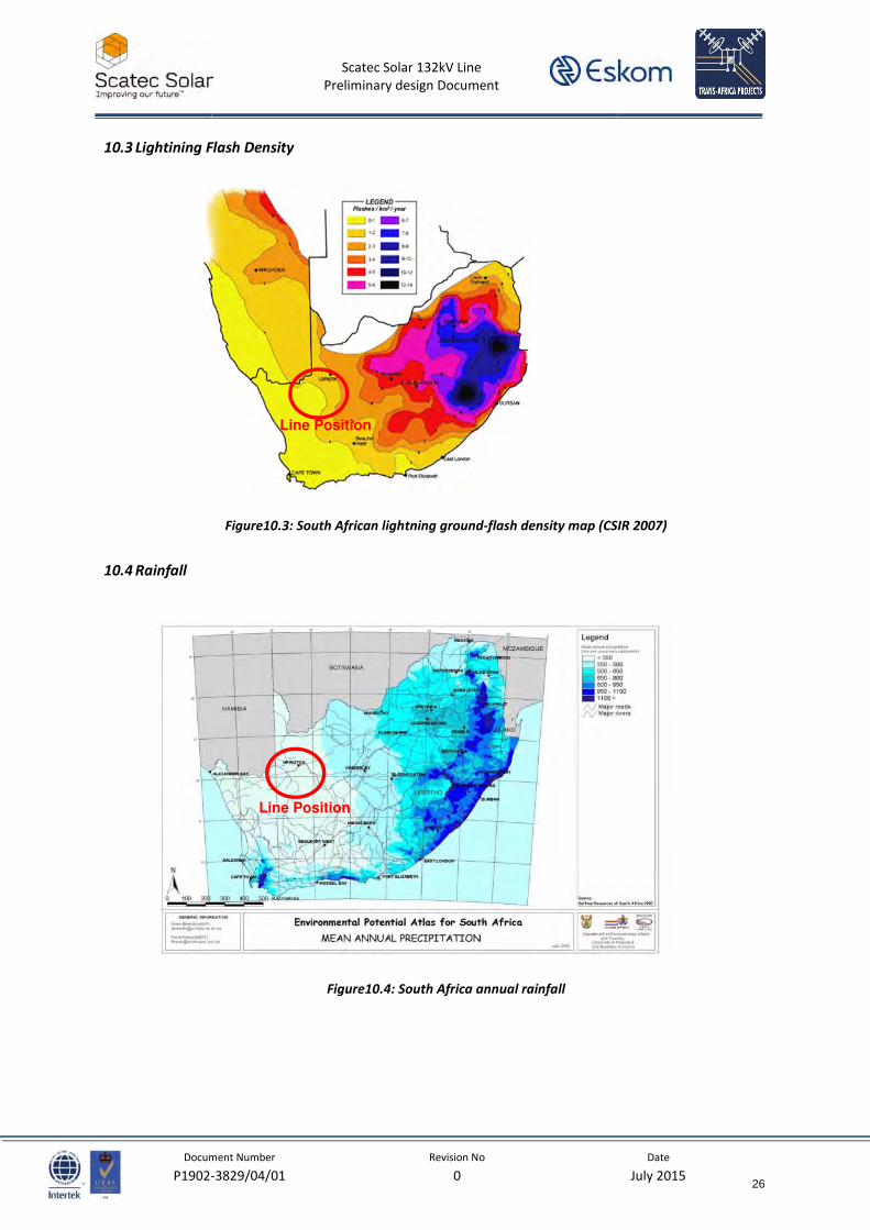
Lightning Flash Density
Figure 9.3 The lightning ground flash density for the
area is 1-2 flashes per square kilometre
and is regarded as low risk.
Rainfall Figure 9.4 The rainfall in the Upington area is given
as greater than 350mm per annum as
shown in figure 5.4.
Corrosion Figure 9.5 The corrosion category for the Upington
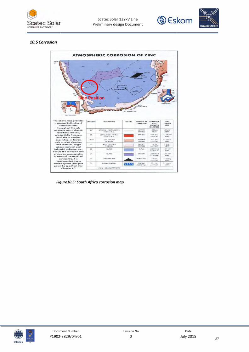
area is C2 (Inland/Rural).
8
Scatec Solar 132kV Line
Preliminary design Document
Document Number Revision No Date
P1902-3829/04/01 0 July 2015
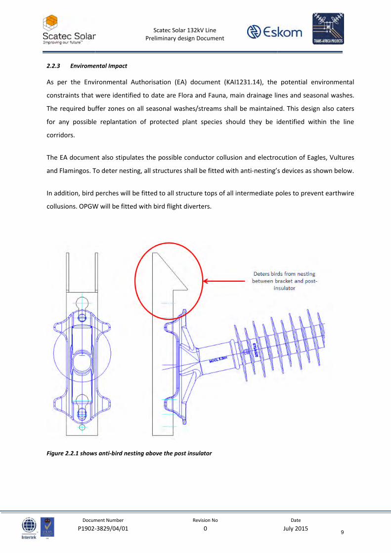
2.2.3 Enviromental Impact
As per the Environmental Authorisation (EA) document (KAI1231.14), the potential environmental
constraints that were identified to date are Flora and Fauna, main drainage lines and seasonal washes.
The required buffer zones on all seasonal washes/streams shall be maintained. This design also caters
for any possible replantation of protected plant species should they be identified within the line
corridors.
The EA document also stipulates the possible conductor collusion and electrocution of Eagles, Vultures
and Flamingos. To deter nesting, all structures shall be fitted with anti-nesting’s devices as shown below.
In addition, bird perches will be fitted to all structure tops of all intermediate poles to prevent earthwire
collusions. OPGW will be fitted with bird flight diverters.
Figure 2.2.1 shows anti-bird nesting above the post insulator
9
Scatec Solar 132kV Line
Preliminary design Document
Document Number Revision No Date
P1902-3829/04/01 0 July 2015
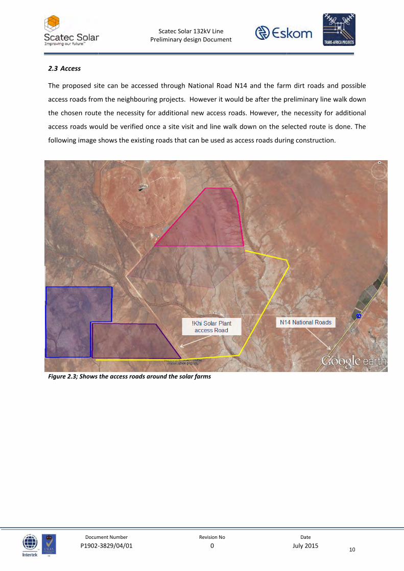
2.3 Access
The proposed site can be accessed through National Road N14 and the farm dirt roads and possible
access roads from the neighbouring projects. However it would be after the preliminary line walk down
the chosen route the necessity for additional new access roads. However, the necessity for additional
access roads would be verified once a site visit and line walk down on the selected route is done. The
following image shows the existing roads that can be used as access roads during construction.
Figure 2.3; Shows the access roads around the solar farms
10
Scatec Solar 132kV Line
Preliminary design Document
Document Number Revision No Date
P1902-3829/04/01 0 July 2015
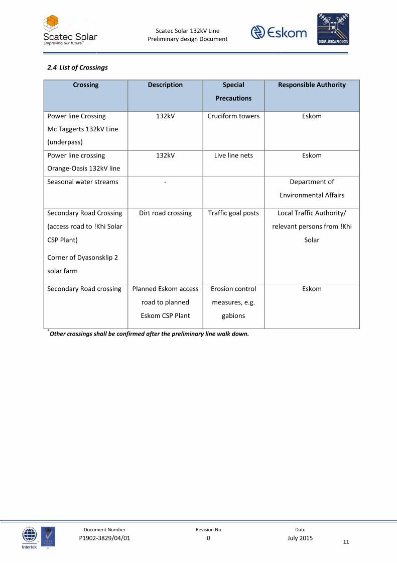
2.4 List of Crossings
Crossing Description Special
Precautions
Responsible Authority
Power line Crossing
Mc Taggerts 132kV Line
(underpass)
132kV Cruciform towers Eskom
Power line crossing
Orange-Oasis 132kV line
132kV Live line nets Eskom
Seasonal water streams - Department of
Environmental Affairs
Secondary Road Crossing
(access road to !Khi Solar
CSP Plant)
Corner of Dyasonsklip 2
solar farm
Dirt road crossing Traffic goal posts Local Traffic Authority/
relevant persons from !Khi
Solar
Secondary Road crossing Planned Eskom access
road to planned
Eskom CSP Plant
Erosion control
measures, e.g.
gabions
Eskom
*Other crossings shall be confirmed after the preliminary line walk down.
11
Scatec Solar 132kV Line
Preliminary design Document
Document Number Revision No Date
P1902-3829/04/01 0 July 2015
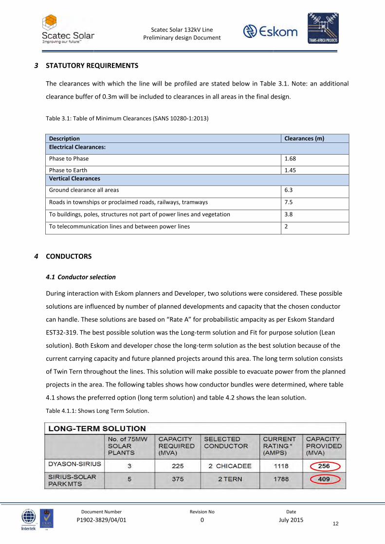
3 STATUTORY REQUIREMENTS
The clearances with which the line will be profiled are stated below in Table 3.1. Note: an additional
clearance buffer of 0.3m will be included to clearances in all areas in the final design.
Table 3.1: Table of Minimum Clearances (SANS 10280-1:2013)
Description Clearances (m)
Electrical Clearances:
Phase to Phase 1.68
Phase to Earth 1.45
Vertical Clearances
Ground clearance all areas 6.3
Roads in townships or proclaimed roads, railways, tramways 7.5
To buildings, poles, structures not part of power lines and vegetation 3.8
To telecommunication lines and between power lines 2
4 CONDUCTORS
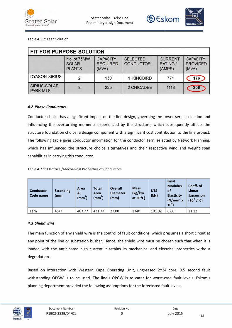
4.1 Conductor selection
During interaction with Eskom planners and Developer, two solutions were considered. These possible
solutions are influenced by number of planned developments and capacity that the chosen conductor
can handle. These solutions are based on “Rate A” for probabilistic ampacity as per Eskom Standard
EST32-319. The best possible solution was the Long-term solution and Fit for purpose solution (Lean
solution). Both Eskom and developer chose the long-term solution as the best solution because of the
current carrying capacity and future planned projects around this area. The long term solution consists
of Twin Tern throughout the lines. This solution will make possible to evacuate power from the planned
projects in the area. The following tables shows how conductor bundles were determined, where table
4.1 shows the preferred option (long term solution) and table 4.2 shows the lean solution.
Table 4.1.1: Shows Long Term Solution.
12
Scatec Solar 132kV Line
Preliminary design Document
Document Number Revision No Date
P1902-3829/04/01 0 July 2015
Table 4.1.2: Lean Solution
4.2 Phase Conductors
Conductor choice has a significant impact on the line design, governing the tower series selection and
influencing the overturning moments experienced by the structure, which subsequently affects the
structure foundation choice; a design component with a significant cost contribution to the line project.
The following table gives conductor information for the conductor Tern, selected by Network Planning,
which has influenced the structure choice alternatives and their respective wind and weight span
capabilities in carrying this conductor.
Table 4.2.1: Electrical/Mechanical Properties of Conductors
Conductor
Code name
Stranding
(mm)
Area
Al.
(mm2)
Total
Area
(mm2)
Overall
Diameter
(mm)
Mass
(kg/km
at 20°°°°C)
UTS
(kN)
Final
Modulus
of
Elasticity
(N/mm2 x
104)
Coeff. of
Linear
Expansion
(10-6
/°°°°C)
Tern 45/7 403.77 431.77 27.00 1340 101.92 6.66 21.12
4.3 Shield wire
The main function of any shield wire is the control of fault conditions, which presumes a short circuit at
any point of the line or substation busbar. Hence, the shield wire must be chosen such that when it is
loaded with the anticipated high current it retains its mechanical and electrical properties without
degradation.
Based on interaction with Western Cape Operating Unit, ungreased 2*24 core, 0.5 second fault
withstanding OPGW is to be used. The line’s OPGW is to cater for worst-case fault levels. Eskom’s
planning department provided the following assumptions for the forecasted fault levels.
13
Scatec Solar 132kV Line
Preliminary design Document
Document Number Revision No Date
P1902-3829/04/01 0 July 2015
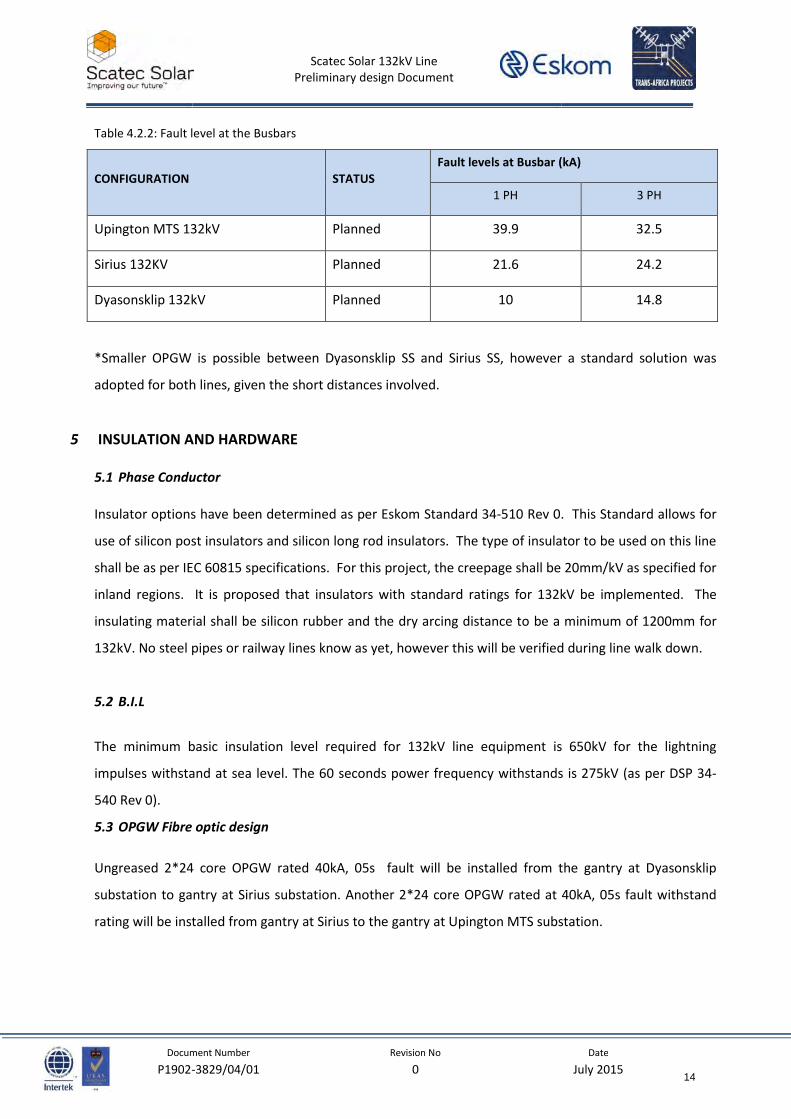
Table 4.2.2: Fault level at the Busbars
CONFIGURATION STATUS
Fault levels at Busbar (kA)
1 PH 3 PH
Upington MTS 132kV Planned 39.9 32.5
Sirius 132KV Planned 21.6 24.2
Dyasonsklip 132kV Planned 10 14.8
*Smaller OPGW is possible between Dyasonsklip SS and Sirius SS, however a standard solution was
adopted for both lines, given the short distances involved.
5 INSULATION AND HARDWARE
5.1 Phase Conductor
Insulator options have been determined as per Eskom Standard 34-510 Rev 0. This Standard allows for
use of silicon post insulators and silicon long rod insulators. The type of insulator to be used on this line
shall be as per IEC 60815 specifications. For this project, the creepage shall be 20mm/kV as specified for
inland regions. It is proposed that insulators with standard ratings for 132kV be implemented. The
insulating material shall be silicon rubber and the dry arcing distance to be a minimum of 1200mm for
132kV. No steel pipes or railway lines know as yet, however this will be verified during line walk down.
5.2 B.I.L
The minimum basic insulation level required for 132kV line equipment is 650kV for the lightning
impulses withstand at sea level. The 60 seconds power frequency withstands is 275kV (as per DSP 34-
540 Rev 0).
5.3 OPGW Fibre optic design
Ungreased 2*24 core OPGW rated 40kA, 05s fault will be installed from the gantry at Dyasonsklip
substation to gantry at Sirius substation. Another 2*24 core OPGW rated at 40kA, 05s fault withstand
rating will be installed from gantry at Sirius to the gantry at Upington MTS substation.
14

Scatec Solar 132kV Line
Preliminary design Document
Document Number Revision No Date
P1902-3829/04/01 0 July 2015
5.4 OPGW Schematic diagram
Figure 5.4.1: OPGW schematic diagram
15
Scatec Solar 132kV Line
Preliminary design Document
Document Number Revision No Date
P1902-3829/04/01 0 July 2015
5.5 Hardware
Assemblies must comply with the Code of Practice for overhead power lines for conductors prevailing in
South Africa, SANS 10280-1: 2013. Insulated shield wire assemblies have been catered for on terminal
towers. Standard hardware based on Eskom DX standards was chosen as far as possible. All OPGW
hardware shall conform to the provided specification. All OPGW hardware shall conform to the NRS 061-
2:2004.
5.6 Strain Assembly
According to SANS 10280-1:2013, the strain assembly should have a strength value of at least the
breaking point of the conductor or the shield wire. For Tern conductor (98.7kN) this means that a
strength rating of 120kN is sufficient.
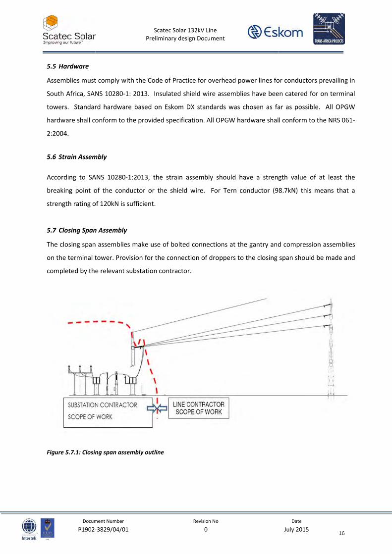
5.7 Closing Span Assembly
The closing span assemblies make use of bolted connections at the gantry and compression assemblies
on the terminal tower. Provision for the connection of droppers to the closing span should be made and
completed by the relevant substation contractor.
Figure 5.7.1: Closing span assembly outline
16
Scatec Solar 132kV Line
Preliminary design Document
Document Number Revision No Date
P1902-3829/04/01 0 July 2015
5.8 Shield wire hardware
Standard OPGW hardware, including those needed for insulated towers, will be used on the line. OPGW
hardware with spare parts and material available on the National Contract for Eskom should be used.
5.9 Vibration Control
To minimize vibration on the phase conductors, multi-frequency vibration dampers will be installed on
the line according to Distribution standard DSP 34-1204 Rev 0. Note, no vibration dampers are required
on the closing/slack spans. Non-bolted dampers must be used on the OPGW, as per supplier’s
instructions.
5.10 Position of Vibration Dampers on the Phase Conductor
The number and position of the vibration dampers on the phase conductor is determined by making use
of the following table (extracted from Eskom Distribution Specification: 34-1204).
Table 5.10.1 Number and Placing of Dampers on a Span
Conductor Span
(m)
NO of dampers
per span per
conductor
Arrangement of dampers
per conductor
Damper placement*
Tern 0 to 369 4 2 damper at each end 0.97m from ends
* To be confirmed by supplier
6 DESIGN LOADS
6.1 Wind Pressure
The wind pressure used for this line was calculated based on the SANS 10280-1:2013 loading philosophy
and is based on several factors as shown below:
Line Reliability Level: 1
Reference (10min) wind speed at 10m of height: 29m/s
Return period for maximum wind speed: 50 year
Terrain Category: B
Topography Type: General
17
Scatec Solar 132kV Line
Preliminary design Document
Document Number Revision No Date
P1902-3829/04/01 0 July 2015
6.2 Conductor Tension Criteria
All conductor tensions were calculated based on the formula C = T/M, where C = 1800m for the
Conductor and 2100m for the OPGW shield wire at EDT creep condition.
M is the mass of the conductor in kg/m.
T is the horizontal tension in kg.
In addition, the tensions are limited to the following values from the table below.
Table 6.2.1 Cable Tension Limits - Damped conductors
Conductor condition Phase conductor Shield wire
After creep condition at -5 °C C limit: 2 450 m C limit: 2 750 m
After creep at EDT C limit: 1 800 m C limit: 2 100 m
Ultimate wind/Ice load 70% of UTS
7 TOWER TYPES
The design has considered self-supporting and guyed monopoles as structure options to carry the
selected conductor Twin Tern. Lattice options were excluded in the analysis as the EA stipulated
monopoles should be used. In addition, lattice structures are not preferred in the region as bird nesting
poses a serious maintenance and operational problem.
The 2-WT/1294 and 2-WT/1295 structure series considered was designed for Twin Bearsfort and Tiger
EW (Earth Wire). The series allows for planted self-supporting suspension structures and guyed strain
structures. To present a fully self-supporting and fully guyed option, the design team has conceptually
designed and estimated structural capacities and steel weights for a guyed heavy suspension to carry
Twin Tern as well as self-supporting strain structures for the bend points and terminal positions at the
substation.
The probability of theft of stays, the need for re-tensioning of stays and corrosion of stay anchors,
possibly leading to the collapse of structures, are some of the larger concerns highlighted by the region.
Self-supporting structures in this regard, provides an option which requires fewer maintenance and
operational effort.
Where guyed structures may pose a potentially more costly maintenance option, the cost saving on the
capital investment still remains large. An approximate 27% cost saving may be achieved with the use of
18
Scatec Solar 132kV Line
Preliminary design Document
Document Number Revision No Date
P1902-3829/04/01 0 July 2015
guyed structures as opposed to self-supporting towers. This compared to the projected maintenance
costs and probability of structure collapse in the life time of the asset, remains a greater advantage.
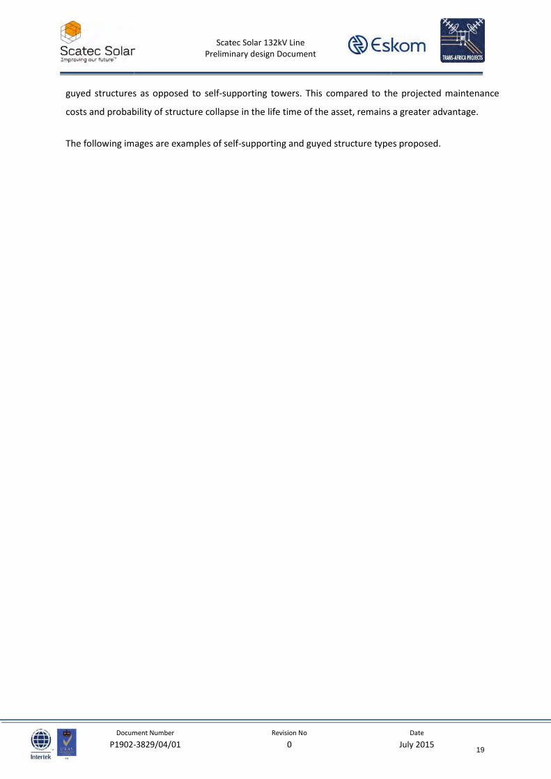
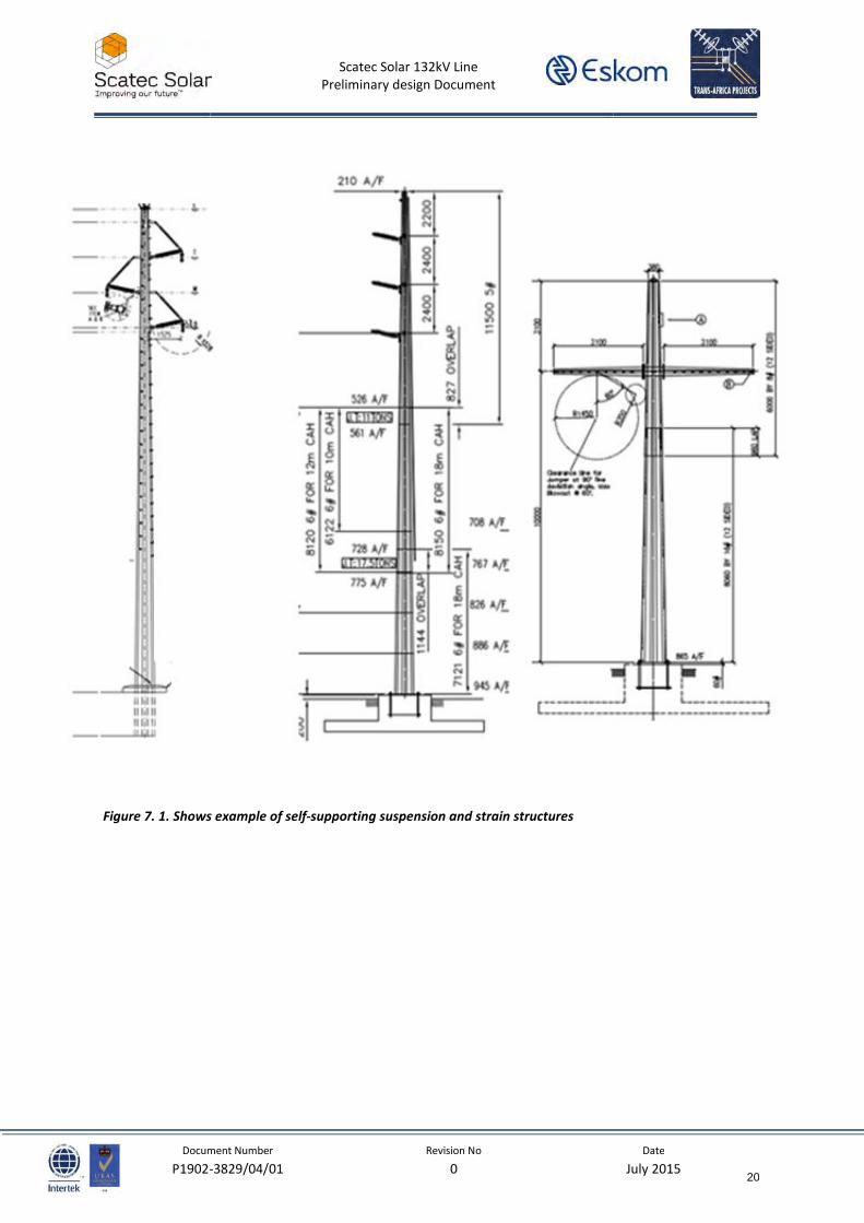
The following images are examples of self-supporting and guyed structure types proposed.
19
Scatec Solar 132kV Line
Preliminary design Document
Document Number Revision No Date
P1902-3829/04/01 0 July 2015
Figure 7. 1. Shows example of self-supporting suspension and strain structures
20
Scatec Solar 132kV Line
Preliminary design Document
Document Number Revision No Date
P1902-3829/04/01 0 July 2015
Figure 7.2. Shows example of guyed suspension and strain structures
21
Scatec Solar 132kV Line
Preliminary design Document
Document Number Revision No Date
P1902-3829/04/01 0 July 2015
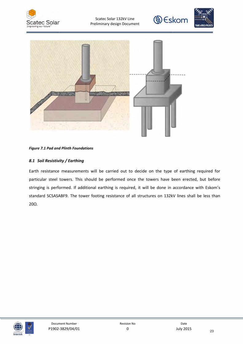
8 FOUNDATIONS
A geotechnical test will be done all accessible structure positions to evaluate the soil strata. The results
are useful in determining the foundation type structures that will need to be used. The results are also
useful in deciding on any soil stabilising (e.g. gabions) and appropriate foundation types (e.g Drilled
foundations). Experience has shown that both soil stabilising and blasting can have significant cost
implications if not catered for early in the design stages. Soil nomination shall be performed by TLB to
ascertain the soil profile.
Foundations have been designed according to the following geotechnical classification:
Type 1 – Hard engineering strong granular soil
Type 2 – Less competent soil, stiff clay or dense sand
Type 3 – Very incompetent soil i.e. loose sand or soft clay
Type 4 – Saturated or submerged soft ground below the seasonal water table
Hard rock – Solid continuous moderately fractured
Soft rock – Very fractured, weathered or decomposed rock
Load safety factors have been incorporated for the designs allowing for variations in geotechnical
conditions, construction inconsistencies and long-term performance
The contractor however, must perform a soil investigation exercise during construction, at which point
the prevailing sol or rock type classification is performed, and a suitable foundation system is selected
for various type of structures.
Should stay plates be used for guyed monopole solution, and should it be declared that the soil of the
selected corridor be acidic or aggressive, bitumastic tape shall be used to wrap the stay plates to
prevent the plates from corroding.
All stay rods shall be encased with PVC pipe up to 100mm above the ground level to prevent any
possible contact with the soil.
22
Scatec Solar 132kV Line
Preliminary design Document
Document Number Revision No Date
P1902-3829/04/01 0 July 2015
Figure 7.1 Pad and Plinth Foundations
8.1 Soil Resistivity / Earthing
Earth resistance measurements will be carried out to decide on the type of earthing required for
particular steel towers. This should be performed once the towers have been erected, but before
stringing is performed. If additional earthing is required, it will be done in accordance with Eskom’s
standard SCSASABF9. The tower footing resistance of all structures on 132kV lines shall be less than
20Ω.
23
Scatec Solar 132kV Line
Preliminary design Document
Document Number Revision No Date
P1902-3829/04/01 0 July 2015
9 LABELLING
9.1 Line Designation
The designation labels for the Dyasonsklip-Sirius lines will be (CIRCUIT #) DYS-SIR # and for Sirius-
Upington MTS will be (CIRCUIT #) SIR-ESP #. Labelling on both lines will be according to the Standard for
the labelling of Substations and Networks (DISAAN0 Rev 2).
24
Scatec Solar 132kV Line
Preliminary design Document
Document Number Revision No Date
P1902-3829/04/01 0 July 2015
10 DESIGN RELATED MAPS
10.1 Ice loading in South Africa
Figure10.1: Ice-loading map of South Africa
10.2 Vulture Electrocution
Figure 10.2: Vulture electrocution risk map of South Africa
Line Position
Line Position
25
Scatec Solar 132kV Line
Preliminary design Document
Document Number Revision No Date
P1902-3829/04/01 0 July 2015
10.3 Lightining Flash Density
Figure10.3: South African lightning ground-flash density map (CSIR 2007)
10.4 Rainfall
Figure10.4: South Africa annual rainfall
Line Position
Line Position
26
Scatec Solar 132kV Line
Preliminary design Document
Document Number Revision No Date
P1902-3829/04/01 0 July 2015
10.5 Corrosion
Figure10.5: South Africa corrosion map
Line Position
27
Related Documents