90-892133002 JANUARY 2006 2006 Mercury Marine Operation Manual System View Version 3.45 SC5000

SC5000 System View Manual
Sep 04, 2014
Welcome message from author
This document is posted to help you gain knowledge. Please leave a comment to let me know what you think about it! Share it to your friends and learn new things together.
Transcript

90-892133002 JANUARY 20062006 Mercury Marine
Operation Manual
System ViewVersion 3.45
SC5000

INTRODUCTION 1GETTING STARTED 2PROPULSION 3VESSEL 4NAVIGATION/FUEL 5SETTINGS 6SYSTEMS 7INSTALLATION 8
A to Z INDEX 9
90-892133002 JANUARY 20062006 Mercury Marine
CONTENTS
Section 1 - IntroductionSection 2 - Getting Started
• Starting Up the System View• Display Screens
Section 3 - Propulsion• Troll Control• Trim Position• Engine Data Screens• Engine RPM and Speed• Peak Speed at RPM• Engine RPM Synchronizer – Twin Engines• Supercharger Boost
Section 4 - Vessel• Steering Position• Fuel, Oil, Water, and Waste Tank Level Status• Vessel Status Data• Estimated Fuel Range
Section 5 - Navigation• Vessel Course• Next Waypoint• Trip History• Depth• Air Temperature• Seawater Temperature
Section 6 - Settings• Contrast/Lighting/Clock• Preferences• Units/Language/Offsets• Home Page Data• Favorites/Page Status• Sensors
Section 7 - Systems• Maintenance Log• Active Alarms• Alarm History• System Calibration
Section 8 - Installation• System View Installation• Wiring Information
Section 9 - Index

1INTRODUCTION
90-892133002 JANUARY 2006 Page 1-1
IntroductionThe SC5000 System View Display is a comprehensive boat information center. SystemView allows the boat operator to receive critical operational information, displayed clearlyand instantly at the helm on the LCD display. The System View continuously monitors andreports information ranging from basic operating data to detailed vessel environmentinformation. The System View covers water temperature and depth, engine trim status,boat speed, steering angle, system preventive maintenance reminders, and systemdiagnostics. The System View also can be fully integrated with the boat’s GPS, ifequipped, to provide up to the minute course, speed, and fuel to destination information.
System View Displays Detailed Information in These Important Categories:NOTE: The detailed information listed which is standard on some models may beoptional on others, or may not be available on some models based on engine and systemconfiguration.
Propulsion Information Section 3
• Troll control
• Trim position
• Engine data screens
• Engine RPM combined with boat speed
• Peak boat speed in conjunction with peak engine RPM
• Twin engine synchronizer display
• Supercharger boost
Vessel Information Section 4
• Steering angle display
• Fuel tank, oil tank, water tank, and waste water tank level display
• Vessel status
• Estimated fuel range
Navigation Section 5
• Direction to target waypoint information shows present course and current speed ona graphic compass rose
• Shows distance, time, speed, and fuel to next waypoint
• Resettable trip history shows miles per hour, miles per gallon, elapsed drive time, andamount of fuel consumed on current trip
• Water depth with depth history graph
• Seawater temperature with temperature history graph
Alarm, Diagnostic, and Maintenance Information Section 7
• Displays alarms and helpful information concerning alarm causes
• Log recorder for periodic propulsion maintenance

INTRODUCTION
Page 1-2 90-892133002 JANUARY 2006
Keypad UsageSYSTEM VIEW
• Arrow trackpad – Can be used to operate the up, down, and side to side movement forSystem View on-screen function prompts.
• “SELECT” key – Is used to select screen options and confirm data entry. Use of the“SELECT” button can also emulate the “HOME” button. Holding the “SELECT” buttonfor two seconds will pause the Slide Show if selected in “FAVORITES”. Holding the“SELECT” button for three seconds will activate the reset data function (except when inthe Slide Show function). Holding the “SELECT” button for five seconds or more willbring up the home page, depending on what screen the user is viewing.
• “HOME” key – The “HOME (POWER)” key has two different functions:
a. Pressing the “HOME” key will return the System View display back to the home pagedirectory.
b. The “HOME” key can be used to power-up or turn off the System View. Pressing andholding in the “HOME” key for three seconds with the key switch turned off willpower-up or turn off the System View.
a
b
c
a - Arrow trackpadb - “SELECT” keyc - “HOME” key
REMOTE CONTROL FUNCTIONS – DIGITAL THROTTLE AND SHIFT (DTS) MODELS
NOTE: The trackpad on the DTS single console, dual console, and shadow mode remotecontrols may also be used to interact with the System View.
• Arrow trackpad – Can be used to operate the up, down, and side to side movement forSystem View on-screen function prompts.
• “SELECT” key – Is used to select screen options and confirm data entry. Use of the“SELECT” button can also emulate the “HOME” button. Holding the “SELECT” buttonfor two seconds will pause the Slide Show if selected in “FAVORITES”. Holding the“SELECT” button for three seconds will activate the reset data function (except when inthe Slide Show function). Holding the “SELECT” button for five seconds or more willbring up the home page, depending on what screen the user is viewing.

2
GETTING STARTED
90-892133002 JANUARY 2006 Page 2-1
GETTING STARTEDSection 2
Table of Contents
Starting up the System View 2-2. . . . . . . . . . . . . . . . . . . . . . . . . . . . . . . . . . . . . . . . . . . . . . . . . Display Screens 2-2. . . . . . . . . . . . . . . . . . . . . . . . . . . . . . . . . . . . . . . . . . . . . . . . . . . . . . . . . . . .
Start-up Screens 2-2. . . . . . . . . . . . . . . . . . . . . . . . . . . . . . . . . . . . . . . . . . . . . . . . . . . . . . . . Home Page Screen 2-3. . . . . . . . . . . . . . . . . . . . . . . . . . . . . . . . . . . . . . . . . . . . . . . . . . . . . . Data Display Screens 2-5. . . . . . . . . . . . . . . . . . . . . . . . . . . . . . . . . . . . . . . . . . . . . . . . . . . . Alarm Message Screens 2-9. . . . . . . . . . . . . . . . . . . . . . . . . . . . . . . . . . . . . . . . . . . . . . . . . .

GETTING STARTED
Page 2-2 90-892133002 JANUARY 2006
Starting Up the System View
To power-up the System View, turn on the ignition key switch. The System View will movethrough a sequence of start-up screens. Press and hold the “SELECT” button to pause thescreen.
Display Screens
Start-Up ScreensThe start-up screens can be set to display the home page, or the last screen shown beforepower-off. To select or change the start-up screen setting, refer to Section 6.
a
b c d
e f
DTS V3.45
a - System View start-up screenb - Start-up screen sequence ending at home pagec - Start-up screen sequence ending at last viewed screend - Calibration screene - Home pagef - Last screen viewed before powering down

GETTING STARTED
90-892133002 JANUARY 2006 Page 2-3
Display Screens
Start-Up Screens (Continued)The Calibration screen will only appear if initial setup calibration has not been performed.Press the “SELECT” button to perform calibration procedures. Refer to the installationinstructions provided with the System View or Section 7 – System Calibration forcalibration information.
IMPORTANT: This system view is to be set up as a display only. The electronic throttleand shift control has already been adapted by the Original Equipment Manufacturer(OEM) or dealer. DO NOT attempt to re–adapt this control using the System View.When first installing the 3.45 System View, select “NO” when asked if this is anelectronic throttle and shift system. This will make the System View a display only.Attempting to re–adapt the control may cause system errors to occur.
ac
d
b
DTS V3.45
e
a - Start-up screen sequence ending at last viewed screenb - Calibration screenc - Station (or helm) identification screend - Engine configuration screene - DTS system selection screen – BE SURE TO SELECT “NO” AT THIS
SCREEN
GETTING STARTED
Page 2-4 90-892133002 JANUARY 2006
Display Screens
Home Page ScreenThe bottom half of the home page contains six main directory selections. Use the trackpadto highlight the directory choice. Press the “SELECT” button to accept the choice and openthe directory screen.
• Engine RPM combined with boat speed• Twin engine synchronizer display• Peak boat speed in conjunction with
peak engine RPM• Troll control• Trim position• Engine data including engine tempera-
ture, water pressure, fuel flow, and bat-tery check
• Supercharger boost
• Steering angle display (sensor on Sterndrivemodels only)
• Fuel tank, oil tank, water tank, and waste watertank level display
• Vessel information• Estimated fuel range, miles per gallon, gallons
per hour, and estimated gallons remaining• Graphic display of fuel and oil tank levels and
gallons remaining
• Direction to target waypoint information showspresent course and current speed on a graphiccompass rose
• Shows distance, time, bearing, and fuel to nextwaypoint
• Resettable trip history shows miles per gallon,miles per hour, elapsed drive time, distance,and amount of fuel consumed on current trip
• Water depth with depth history graph• Water depth combined with boat speed, air
temperature, and seawater temperature• Seawater temperature with temperature
history graph
• Collection of screens selected bythe user
• Maintenance Log• Active Alarms• Alarm History• System Calibration
• Contrast/Lighting/Clock• Preferences• Units/Language/Offsets• Home page data• Favorites/Page Status• Sensors
NAVIGATION (See Section 5)
VESSEL (See Section 4) SETTINGS (See Section 6)
PROPULSION (See Section 3)
FAVORITES (See Section 6) SYSTEM (See Section 7)

GETTING STARTED
90-892133002 JANUARY 2006 Page 2-5
Display Screens
Home Page Screen (Continued)The top half of the home page displays engine data and vessel data. The engine data isreceived from sensors on the engine and the vessel data is received by vessel sensors.
The initial screen layout takes one of two forms depending on whether one or two enginesare installed. Defaults for the engine data include engine RPM and engine temperature.Default for vessel data is water depth.
The data displays can be selected by the user to display the functions. Refer to theSettings/Preferences/Home Page Data menu in Section 6.
SINGLE ENGINE DISPLAY TWIN ENGINE DISPLAY
RPMH20 PSIENG TEMPOIL PSIOIL TEMPFUEL FLOW
VOLTSSPEEDDEPTHFUEL LEVELRANGEAIR TEMPSEA TEMPDTWCOGSOGBTWCOG/BTW
RPMH20 PSIENG TEMPOIL PSIOIL TEMPFUEL FLOW
a
b
c d ef
g
a
a
b
b
c
c
d e
a - Engine line 1 – Refer to Section 6 for selectionb - Engine line 2 – Refer to Section 6 for selectionc - Vessel data – Refer to Section 6 for selectiond - Engine gear position or run arrowe - Clock – Refer to Section 6 for settingf - Flashing bell icon – Warning alarm is activatedg - Flashing fuel icon – Low fuel alarm

GETTING STARTED
Page 2-6 90-892133002 JANUARY 2006
Display Screens
Data Display ScreensThe data display screens can be selected from the main directory menu choices which areselected from the home page.
The current directory menu selection icon is displayed in top-left of the display.
The presentation of information on-screen will be shown in the information window locatedat the bottom on the screen.
Alarm Notice – When a problem is detected, the name of the offending alarm will appearin the information window and a bell symbol at the bottom of the screen flashes. The bellsymbol will continue to flash as long as the alarm condition is still present. If there aremultiple alarms, these will cycle on the display screen.
Navigation/Fuel
Propulsion
Vessel
Settings
System
Directory MenuIndicator Icon
Alarm Notice
Alarm Notice
Normal Operation
Home
a
b
c
d
a - Directory identification iconb - Alarm windowc - Information windowd - Display screen
GETTING STARTED
90-892133002 JANUARY 2006 Page 2-7
Display Screens
Data Display ScreensGlossary
Data Screen Directory Location
Navigation Screen 1Displays a compass, and shows the directionto a targeted waypoint.
Navigation Screen 2Displays navigating data to a waypoint.
Trip History LogDisplays average fuel economy, average boatspeed, total drive time, along with a correspond-ing distance traveled, and fuel used.
DepthDisplays the depth of the water.
Depth Plot LineDisplays a plot line of depth vs. time as recordedover the last 16 seconds.
EnvironmentDisplays speed, depth, air temperature, andseawater temperature.

GETTING STARTED
Page 2-8 90-892133002 JANUARY 2006
Display Screens
Data Display ScreensGlossary
Data Screen Directory Location
Seawater Temperature Plot LIneDisplays a plot line of seawater temperature vs.time as recorded over the last 80 seconds. Alsodisplays the current water temperature.
Engine RPM and SpeedDisplays engine RPM and boat speed.
Peak Speed at RPMThis screen records the top speed the boatreached, and associated engine RPM asmeasured since the last reset.
Troll ControlMaintain a trolling speed without using thethrottle.
Trim PositionDisplay indicates the propulsion unit positionachieved by setting trim and trailer position.
Engine Data ScreensEngine data screens are a group of displaysshowing various engine data.
Engine RPM SynchronizerTwin Engines – Displays the difference in enginespeed (RPM) between the port and starboardengines.

GETTING STARTED
90-892133002 JANUARY 2006 Page 2-9
Display Screens
Data Display ScreensGlossary
Data Screen Directory Location
Supercharger BoostDisplays the supercharge boost of super-charged engines.
Steering PositionDisplays steering position in degrees.
Tank StatusShows level of the vessel’s tanks.
EE F F
Vessel StatusDisplays engine run timeTotal fuel remainingAdditional tank levelsAir temperature
Estimated Fuel RangeDisplays estimated range and fuel remaining,as well as current total fuel flow and usage.
FUEL MANAGEMENT
RANGE REMAINING
INSTANT FLOW
MI GAL
MPG GPH
– – – – – –
– – – – – –
Fuel Tank LevelsDisplays the level of each tank.
Oil Tank LevelsDisplays the level of each tank. OIL

GETTING STARTED
Page 2-10 90-892133002 JANUARY 2006
Display Screens
Alarm Message ScreensWhen a problem is detected, the System View will alert the operator. Use the following stepsto determine the cause of the problem:
1
2
3
1. A pop-up screen will appear displaying an alarm message. If there are multiple alarms,the display will show the last alarm activated.
2. Press “SELECT” to clear the pop-up screens and return back to the display screen thatwas being viewed. The bell icon will now be flashing and the alarm message will bedisplayed on the bottom of the screen.
3. A number of different problems may be grouped together under one alarm message.To determine the exact cause of the problem, return back to the home page and accessthe “SYSTEM” directory. The “SYSTEM” directory will show the active alarms causingthe problem.
4. Refer to Active Alarms in Section 7 or the engine Operation, Maintenance Manualfor further explanation of the problem and the correct action to take.
If the problem can cause immediate engine damage, the engine guardian system will respondto the problem by limiting engine power.

PROPULSION
90-892133002 JANUARY 2006 Page 3-1
PROPULSIONSection 3
Table of Contents
Propulsion Information 3-2. . . . . . . . . . . . . . . . . . . . . . . . . . . . . . . . . . . . . . . . . . . . . . . . . . . . . . Entering the Propulsion Directory 3-2. . . . . . . . . . . . . . . . . . . . . . . . . . . . . . . . . . . . . . . . . . . . . Propulsion Data Screens 3-3. . . . . . . . . . . . . . . . . . . . . . . . . . . . . . . . . . . . . . . . . . . . . . . . . . . .
Troll Control 3-3. . . . . . . . . . . . . . . . . . . . . . . . . . . . . . . . . . . . . . . . . . . . . . . . . . . . . . . . . . . . . Trim Position 3-4. . . . . . . . . . . . . . . . . . . . . . . . . . . . . . . . . . . . . . . . . . . . . . . . . . . . . . . . . . . Engine Data Screens 3-4. . . . . . . . . . . . . . . . . . . . . . . . . . . . . . . . . . . . . . . . . . . . . . . . . . . . Engine RPM/Speed 3-5. . . . . . . . . . . . . . . . . . . . . . . . . . . . . . . . . . . . . . . . . . . . . . . . . . . . . . Peak Speed at RPM 3-5. . . . . . . . . . . . . . . . . . . . . . . . . . . . . . . . . . . . . . . . . . . . . . . . . . . . . Engine RPM Synchronizer – Twin Engines 3-6. . . . . . . . . . . . . . . . . . . . . . . . . . . . . . . . . . Supercharger Boost 3-6. . . . . . . . . . . . . . . . . . . . . . . . . . . . . . . . . . . . . . . . . . . . . . . . . . . . . .
3

PROPULSION
Page 3-2 90-892133002 JANUARY 2006
Propulsion Information
This section will give a complete description of the display screens in the “PROPULSION”directory of the System View.
Some of the propulsion functions are:
• Troll control
• Trim position
• Engine data screens
• Engine RPM combined with boat speed
• Peak boat speed in conjunction with peak engine RPM
• Twin engine synchronizer display
• Supercharger boost
Entering the Propulsion Directory
To access the “PROPULSION” directory, use the trackpad to highlight the “PROPULSION”directory from the menu choice. Press “SELECT” to accept and to open the directory.

PROPULSION
90-892133002 JANUARY 2006 Page 3-3
Propulsion Data Screens
Troll ControlNOTE: Depending on your type of engine, this feature may not be available.
SINGLE ENGINETWIN ENGINE
BASIC OPERATION
IMPORTANT: User must maintain constant helm control while using troll control toavoid obstacles.
With troll control, you can maintain a trolling speed within a range specific to the engine typewithout using the throttle.
You must stay in the troll control screen while using troll control. If you leave the troll controlscreen, troll will automatically disengage.
You can shut off troll control anytime by pushing “SELECT,” moving the throttle, or shiftingengine into neutral.
NOTE: Avoid using a very low RPM trolling speed for an extended period of time. Doing socould result in a low-battery voltage condition.
SETTING TROLL CONTROL
1. Press �� to display the “TROLL CONTROL” display screen.
2. With the engine running, shift engine into gear.
3. Set engine speed at idle.
4. Single Engine – Press “SELECT” to engage (turn on) the troll control. Twin Engine – Press “SELECT” to choose which engine is to be in troll control. Press �� to select STBD, PORT, or BOTH. Flashing “Selected” indicates chosenengine. Press “SELECT” a second time to engage troll control.
5. Press �� to set desired RPM.
NOTE: On dual station installations (2 System Views), you can hand-off the current trollcontrol configuration from the troll control screen from one unit to the other by pressing“SELECT” to engage on the opposite unit.
TURNING OFF TROLL CONTROL
There are three ways to turn off the troll control:
• Press “SELECT”• Move the throttle to a different speed• Shift engine into neutral

PROPULSION
Page 3-4 90-892133002 JANUARY 2006
Propulsion Data Screens
Trim PositionDisplay indicates the propulsion unit position achieved by setting trim and trailer position.
SINGLE ENGINE
TWIN ENGINE
Engine Data ScreensEngine data screens are a group of displays showing various engine data.
NOTE: Not all screens listed may be available for your type of engine.
1
2
3
4
5
1. ENGINE TEMP (Temperature) – Displays engine temperature. The temperature willvary with air temperature, water temperature, and operating conditions.
2. H20 PRESSURE (Water) – Displays engine water pressure when engine is running.
3. BATTERY – Displays battery voltage level (condition) of battery.
4. FUEL FLOW – Displays current estimated engine fuel consumption in U.S. Gallons perhour (Gal/hr) or Liters per hours (Ltr/hr).
5. OIL PRESSURE – Displays engine oil pressure when the engine is running. The oilpressure may vary with engine speed, outside temperature, and oil viscosity. While theengine is warming up, the oil pressure will be higher than when the engine is at normaloperating temperature.

PROPULSION
90-892133002 JANUARY 2006 Page 3-5
Propulsion Data Screens
Engine RPM/SpeedThis screen displays engine speed (RPM) and boat speed.
SINGLE ENGINE TWIN ENGINE
a
a - Speed Sensors – This window shows the sensor that is currently sending thespeed signal. The speed sensor is automatically displayed based on whichsensors are available.
Peak Speed at RPMThis screen records the top speed the boat reached, and associated engine RPM asmeasured since the last reset.
To reset the “PEAK SPEED” and corresponding RPM, press and hold the “SELECT” buttonmomentarily.
SINGLE ENGINE TWIN ENGINE
a
a - Speed Sensors – This window shows the sensor that is currently sending thespeed signal. The speed sensor is automatically displayed based on whichsensors are available.

PROPULSION
Page 3-6 90-892133002 JANUARY 2006
Propulsion Data Screens
Engine RPM Synchronizer – Twin EnginesThis screen displays the difference in engine speed (RPM) between the port and starboardengines. Allows throttle adjustments to keep each engine running uniformly.
StarboardEngine
Port Engine
Supercharger BoostDisplays the supercharger boost of supercharged engines.
SINGLE ENGINE TWIN ENGINE
4
VESSEL
90-892133002 JANUARY 2006 Page 4-1
VESSELSection 4
Table of Contents
Vessel Information 4-2. . . . . . . . . . . . . . . . . . . . . . . . . . . . . . . . . . . . . . . . . . . . . . . . . . . . . . . . . . Entering the Vessel Directory 4-2. . . . . . . . . . . . . . . . . . . . . . . . . . . . . . . . . . . . . . . . . . . . . . . . Vessel Data Screens 4-3. . . . . . . . . . . . . . . . . . . . . . . . . . . . . . . . . . . . . . . . . . . . . . . . . . . . . . .
Steering Position 4-3. . . . . . . . . . . . . . . . . . . . . . . . . . . . . . . . . . . . . . . . . . . . . . . . . . . . . . . . Tank Status 4-3. . . . . . . . . . . . . . . . . . . . . . . . . . . . . . . . . . . . . . . . . . . . . . . . . . . . . . . . . . . . . Fuel Tanks 4-4. . . . . . . . . . . . . . . . . . . . . . . . . . . . . . . . . . . . . . . . . . . . . . . . . . . . . . . . . . . . . . Oil Tank 4-4. . . . . . . . . . . . . . . . . . . . . . . . . . . . . . . . . . . . . . . . . . . . . . . . . . . . . . . . . . . . . . . . Water and Waste Tanks 4-4. . . . . . . . . . . . . . . . . . . . . . . . . . . . . . . . . . . . . . . . . . . . . . . . . . Vessel Status 4-5. . . . . . . . . . . . . . . . . . . . . . . . . . . . . . . . . . . . . . . . . . . . . . . . . . . . . . . . . . . Estimated Fuel Range 4-5. . . . . . . . . . . . . . . . . . . . . . . . . . . . . . . . . . . . . . . . . . . . . . . . . . . .

VESSEL
Page 4-2 90-892133002 JANUARY 2006
Vessel Information
This section will give a complete description of the display screens in the “VESSEL”directory of the System View.
Some of the vessel functions are:
• Steering angle position
• Tank status for fuel, oil, waste, and water
• Fuel tanks
• Oil tank
• Vessel status
• Estimated fuel range
Entering the Vessel Directory
To access the “VESSEL” directory, use the trackpad to highlight the “VESSEL” directoryfrom the menu choice. Press “SELECT” to accept and to open the directory.

VESSEL
90-892133002 JANUARY 2006 Page 4-3
Vessel Data Screens
Steering PositionThis screen displays steering position in degrees.
NOTE: Depending on your type of engine, this feature may not be available.
NOTE: If the steering angle position is opposite the direction that it should be, it can bereversed so it is displayed properly. Refer to the Settings/Sensors/Invert Steering menuin Section 6.
Tank StatusNOTE: If your vessel installation includes tank level sensors, System View will displayfullness level that is provided by the sensors.
The display screens show the level of the vessels tanks. The bar gauges and digitalreadouts indicate the level of fullness of each tank.
SCREEN 1 SCREEN 2

VESSEL
Page 4-4 90-892133002 JANUARY 2006
Vessel Data Screens
Fuel TanksDisplays the level of each tank.
Oil TankDisplays the level of the tank.
OIL
Water and Waste TanksDisplays the level of each tank.

VESSEL
90-892133002 JANUARY 2006 Page 4-5
Vessel Data Screens
Vessel StatusDisplays the current vessel information.
a
b
c
d
a - Displays run time in hoursb - Displays the total fuel remainingc - Displays additional tank levels (Fresh water and waste water, if connected)d - Displays air temperature at sensor
Estimated Fuel RangeThis screen displays estimated range and fuel remaining, as well as current fuel flow.
RANGE REMAINING
INSTANT FLOW
MI GAL
MPG GPH
– – – – – –
– – – – – –
1
2
3
4
1. The estimated fuel range is based on boat speed, fuel consumption, and fuel remaining inthe tank. The number displayed indicates an estimate of the distance you can travel on theremaining fuel. Speed input required (paddle wheel, pitot pressure, or GPS).
2. Displays the current vessel fuel consumption in U.S. gallons per hour or liters per hour.
3. Displays amount of fuel remaining.
4. Displays current fuel flow.
NOTE: Do not solely rely on fuel used or amount remaining. These are estimations only.

5
NAVIGATION
90-892133002 JANUARY 2006 Page 5-1
NAVIGATIONSection 5
Table of Contents
Navigation Information 5-2. . . . . . . . . . . . . . . . . . . . . . . . . . . . . . . . . . . . . . . . . . . . . . . . . . . . . . Entering the Navigation Directory 5-2. . . . . . . . . . . . . . . . . . . . . . . . . . . . . . . . . . . . . . . . . . . . . Navigation Data Screens 5-3. . . . . . . . . . . . . . . . . . . . . . . . . . . . . . . . . . . . . . . . . . . . . . . . . . . .
Vessel Course – Course Up 5-3. . . . . . . . . . . . . . . . . . . . . . . . . . . . . . . . . . . . . . . . . . . . . . . Next Waypoint Data 5-4. . . . . . . . . . . . . . . . . . . . . . . . . . . . . . . . . . . . . . . . . . . . . . . . . . . . . . Trip History Log 5-4. . . . . . . . . . . . . . . . . . . . . . . . . . . . . . . . . . . . . . . . . . . . . . . . . . . . . . . . . Depth 5-5. . . . . . . . . . . . . . . . . . . . . . . . . . . . . . . . . . . . . . . . . . . . . . . . . . . . . . . . . . . . . . . . . . Depth Plot Line 5-5. . . . . . . . . . . . . . . . . . . . . . . . . . . . . . . . . . . . . . . . . . . . . . . . . . . . . . . . . . Environment – Speed, Depth, Air, and Seawater Temperature 5-6. . . . . . . . . . . . . . . . . Seawater Temperature Plot 5-6. . . . . . . . . . . . . . . . . . . . . . . . . . . . . . . . . . . . . . . . . . . . . . .

NAVIGATION
Page 5-2 90-892133002 JANUARY 2006
Navigation Information
This section will give a complete description of the display screens in the “NAVIGATION”directory of the System View.
Some of the navigation functions are:
• Navigation screens• Next waypoint data• Trip history log• Depth• Depth plot line• Depth, speed, air temperature, and water temperature• Seawater temperature plot
Entering the Navigation Directory
To access the “NAVIGATION” directory, use the trackpad to highlight the “NAVIGATION”directory from the menu choice. Press “SELECT” to accept and to open the directory.

NAVIGATION
90-892133002 JANUARY 2006 Page 5-3
Navigation Data Screens
Navigation ScreensIMPORTANT: This device is intended as a navigation aid and should not take theplace of paper charts. A careful navigator never relies on one method to obtainposition information.
NOTE: For use of the navigation screens, your vessel must include a GPS receiver withNMEA 0183 V3.01 output and be connected to the System View.
The System View features two different navigation screens: Vessel Course and NextWaypoint Data. Next Waypoint Data provides course guidance to a destination waypoint,if programmed into your GPS navigation electronics.
SCREEN # 1 – VESSEL COURSE – COURSE UP
This vessel course – course up screen has a rotating compass ring that not only shows yourdirection of travel, but also the direction to a targeted waypoint. When you are not navigatingto a waypoint, the compass will show your direction of travel. The boat pointer in the centerof the compass ring shows current direction.
When a waypoint is set using a separate GPS unit, an X mark will appear on the compassring. This X mark will indicate your waypoint. For instance, if the X mark lines up with thecenter of the boat pointer, you are going directly to the waypoint. If the boat pointer does notline up with the X mark, steer toward the X mark until it lines up with the center of the boatpointer – then continue in this direction until you reach your current target waypoint.
The middle of the compass shows the current cross track error (XTE). This is the distanceyou are off-course relative to the desired course.
Anytime a compatible GPS is connected, the current Speed Over Ground (SOG) as well asthe Course Over Ground (COG) are displayed on the screen.
1
2
3
45
7
6
1 - Compass ring2 - Boat pointer3 - X mark (Gives the direction to steer)4 - Cross track error5 - Course Over Ground (COG)6 - Speed Over Ground (SOG)7 - GPS Heading – True or Magnetic – Refer to Settings/Preference/GPS Heading menu
in Section 6

NAVIGATION
Page 5-4 90-892133002 JANUARY 2006
Navigation Data Screens
Navigation ScreensSCREEN # 2 – NEXT WAYPOINT DATA
When navigating to a waypoint, this screen will give you the navigation information.
1 2
43
1 - “DIST TO GO” – Remaining distance to the next waypoint2 - “TIME TO GO” – Is the time that it will take to reach your waypoint at your present
speed3 - “FUEL TO GO” – Is the fuel it will take to get to your waypoint4 - “BRG TO WPT” – Bearing towards your waypoint
Trip History LogThis screen tracks your boat’s progress since the unit was last reset. It displays theaverage fuel economy, average boat speed, total drive time, along with a correspondingdistance traveled, and fuel used.
To reset the trip history log, press and hold down “SELECT” for five seconds.
1
2
4
3
5
1 - Displays the average distance per U.S. gallon or liter of fuel since the unit was lastreset
2 - Displays the average speed of the boat since the unit was last reset3 - Displays the time in hours of the engine usage since the unit was last reset4 - Displays the total distance traveled since the unit was last reset5 - Displays the total fuel used since the unit was last reset

NAVIGATION
90-892133002 JANUARY 2006 Page 5-5
Navigation Data Screens
DepthThis screen displays the depth of the water.
NOTE: To set depth and shallow water alarm levels, refer to the Settings/Sensors menuin Section 6.
Depth Plot LineThis screen displays a plot of depth vs. time as recorded over the last 16 seconds.
NOTE: To set depth and shallow water alarm levels, refer to the Settings/Sensors menuin Section 6.
1
23
1 - Displays depth plot line2 - Displays current water depth3 - Displays low water alarm setting

NAVIGATION
Page 5-6 90-892133002 JANUARY 2006
Navigation Data Screens
EnvironmentThis screen displays speed, depth, air, and seawater temperature.
1
2
3 4
1 - Displays depth of water2 - Displays speed of the boat3 - Displays the air temperature4 - Displays the seawater temperature
Seawater Temperature PlotThis screen displays a plot of seawater temperature vs. time as recorded over the last 80seconds. Also displays the current water temperature.
1
2
1 - Displays seawater plot line2 - Displays current water temperature

6
SETTINGS
90-892133002 JANUARY 2006 Page 6-1
SETTINGSSection 6
Table of Contents
Settings Information 6-2. . . . . . . . . . . . . . . . . . . . . . . . . . . . . . . . . . . . . . . . . . . . . . . . . . . . . . . . Entering the Settings Directory 6-2. . . . . . . . . . . . . . . . . . . . . . . . . . . . . . . . . . . . . . . . . . . . . . . Settings Directory 6-2. . . . . . . . . . . . . . . . . . . . . . . . . . . . . . . . . . . . . . . . . . . . . . . . . . . . . . . . . . Settings Options 6-3. . . . . . . . . . . . . . . . . . . . . . . . . . . . . . . . . . . . . . . . . . . . . . . . . . . . . . . . . . .
Contrast/Lighting/Clock 6-3. . . . . . . . . . . . . . . . . . . . . . . . . . . . . . . . . . . . . . . . . . . . . . . . . . . Preferences 6-4. . . . . . . . . . . . . . . . . . . . . . . . . . . . . . . . . . . . . . . . . . . . . . . . . . . . . . . . . . . . . Units/Language/Offsets 6-5. . . . . . . . . . . . . . . . . . . . . . . . . . . . . . . . . . . . . . . . . . . . . . . . . . Home Page Data 6-7. . . . . . . . . . . . . . . . . . . . . . . . . . . . . . . . . . . . . . . . . . . . . . . . . . . . . . . . Favorites/Page Status 6-8. . . . . . . . . . . . . . . . . . . . . . . . . . . . . . . . . . . . . . . . . . . . . . . . . . . . Sensors 6-9. . . . . . . . . . . . . . . . . . . . . . . . . . . . . . . . . . . . . . . . . . . . . . . . . . . . . . . . . . . . . . . .

SETTINGS
Page 6-2 90-892133002 JANUARY 2006
Settings Information
This section will give a complete description of the screens in the “SETTINGS” directory ofthe System View.
In this section you can configure your System View to display the information the way youprefer.
Some of the functions are:
• Contrast/Lighting/Clock• Setting your preferences• Units/Language/Offsets• Customizing the home page data• Favorites/Page Status• Sensors
Entering the Settings Directory
To access the “SETTINGS” directory, use the trackpad to highlight the “SETTINGS”directory from the menu choice. Press “SELECT” to accept and to open the directory screen.
Settings Directory
Settings Directory Screen

SETTINGS
90-892133002 JANUARY 2006 Page 6-3
Settings Options
Contrast/Lighting/ClockTo adjust a setting:
1. Press �� to highlight the desired menu selection.
2. Press �� to edit the menu box.
3. Press “SELECT” to accept settings.
CONTRAST – Provides a slide bar to adjust the display screen contrast to compensate for changes intemperature or lighting conditions.
BRIGHTNESS – Provides a slide bar to adjust the display screen lighting level.
TIME – If no GPS is connected, press the horizontal arrows to set the current time. If GPS is connected,follow time zone setting below.
TIME ZONE – Time zone setting is how many hours you are behind or ahead of Greenwich Mean Time(GMT). The chart below gives approximate GMT time zone settings for various longitudinal zones. Addone hour to the setting for daylight savings time.
CLOCK MODE – Select 12 hour or 24 hour clock set.
Longitudinal ZoneTime Zone
Setting
DayLightSaving TimeZone Setting
Longitudinal ZoneTime Zone
Setting
DayLightSaving TimeZone Setting
W180.0° to W172.5° –12 –11 E007.5° to E022.5° +1 +2
W172.5° to W157.5° –11 –10 E022.5° to E037.5° +2 +3
W157.5° to W142.5° –10 –9 E037.5° to E052.5° +3 +4
W142.5° to W127.5° –9 –8 E052.5° to E067.5° +4 +5
W127.5° to W112.5° (Pacific Standard Time) –8 –7 E067.5° to E083.5° +5 +6
W112.5° to W097.5° (Mountain Standard Time) –7 –6 E082.5° to E097.5° +6 +7
W097.5° to W082.5° (Central Standard Time) –6 –5 E097.5° to E112.5° +7 +8
W082.5° to W067.5° (Eastern Standard Time) –5 –4 E112.5° to E127.5° +8 +9
W067.5° to W052.5° –4 –3 E127.5° to E142.5° +9 +10
W052.5° to W037.5° –3 –2 E142.5° to E157.5° +10 +11
W037.5° to W022.5° –2 –1 E157.5° to E172.5° +11 +12
W022.5° to W007.5° –1 0 E172.5° to E180.0° +12 +13
W007.5° to E007.5° 0 +1

SETTINGS
Page 6-4 90-892133002 JANUARY 2006
Settings Options
PreferencesTo adjust a setting:
1. Press �� to highlight the desired menu selection.
2. Press �� to edit the menu box.
3. Press “SELECT” to accept settings.
WARNING HORN – The System View has a warning horn alarm. The warning horn is always “ON” atkey up. The horn can be shut off, but it will only be “OFF” for that key cycle. This is to allow the user toshut off the horn if it is a nuisance for one key cycle. Once the key is turned off and back on the hornwill be enabled.
START-UP PAGE – You have two options for what start-up page you want to view. You can select thehome page, or you can select the last page that’s showing at power off. Press the right arrow to select“HOME” or “LAST USED.”
FAVORITE SLIDE SHOW – This feature, if desired, will automatically scroll through your selection offavorite screens. This allows the user to view each screen for the pause time selected below. Hold the“SELECT” button for 3 seconds to pause the scrolling.
FAVORITE SLIDE PAUSE – Select the pause time you would prefer for viewing each favorite screenin the “FAVORITE SLIDE SHOW.” Select between “5” and “30” seconds.
GPS HEADING – Choose “TRUE” or “MAGNETIC” for the “GPS HEADING” display.
NOTE: To receive BTW in both “TRUE” and “MAGNETIC,” System View must see a valid BWC sentence.If System View sees an RMB sentence, System View will display “TRUE BTW” only.
TRIM POPUP TIME – Set the length of time you want the trim pop-up window to be displayed.
POP-UP WARNINGS – Select whether you would like the alarm message pop-up screen to appear ifan alarm is activated.

SETTINGS
90-892133002 JANUARY 2006 Page 6-5
Settings Options
Units/Language/OffsetsTo adjust a setting:
1. Press �� to highlight the desired menu selection.
2. Press �� to edit the menu box.
3. Press “SELECT” to accept settings.
UNITS ENG – Lets you select English or metric format for unit measurements.
UNITS SPD – Lets you select the units at which speed is displayed. You may select from MPH (MilesPer Hour), KM/H (Kilometers Per Hour) or Knots.
LANGUAGE – System View displays only English at this time.
SEA TEMP OFFSET – The seawater temperature sensor can be calibrated to match actual seawatertemperature. Calculate the difference in degrees that the seawater temperature is off, and enter it into themenu window.
STEERING OFFSET – The steering sensor can be calibrated to compensate for inaccuracies.Calculate the difference in degrees that the steering sensor is off, and enter it into the menu window.
DEPTH OFFSET TO – Normally, this unit measures water depth from the face of the transducer(sensor). Since the transducer is below the water, this distance is not the exact water depth. You canchange the depth reading using this depth offset feature. You have three depth offsets selections:1. SENSOR – Will measure water depth from the face of the transducer. No setting to depth offset is
necessary.2. WATERLINE – Will give water depth from the surface of the water. You will need to change the
depth offset setting below. Measure the distance between the face of the transducer and the waterline. Add this measurement into depth offset menu box below.
3. KEEL – Will give water depth from the keel of the boat. You will need to change the depth offset setting below. Measure the distance between the transducer and the lowest part of the boat. Place this measurement into the depth offset menu box below. This offset will be a negative value.
DEPTH OFFSET – Activate the depth offset feature by adding the measurement taken above tocompensate for waterline or keel offset.
SHALLOW ALARM – The shallow water alarm can be set to sound a warning at a depth determined bythe user. Activate the shallow water alarm by inputting the desired depth into the menu box. The depthrange can be from 0.0 - 650.0 feet. Deactivate the shallow alarm by setting the shallow alarm to “0”.Horn is defaulted to “ON” at key up.
DEPTH ALARM – The deep water alarm can be set to sound a warning at a depth determined by theuser. Activate the depth alarm by inputting the desired depth into the menu box. The depth range canbe from 0.0 - 650.0 feet. Deactivate the depth alarm by setting the depth alarm to “0”. Horn is defaultedto “ON” at key up.
FUEL OFFSET – If the fuel tank level does not read ’“0” when the fuel tank is completely empty, thefuel offset can be calibrated to correct the reading. When the tank is completely empty, enter the fuelamount that is shown on the fuel tank status screen. This amount will be subtracted from the screenreading. This should change the tank level screen so it reads “0”.
SETTINGS
Page 6-6 90-892133002 JANUARY 2006
Settings Options
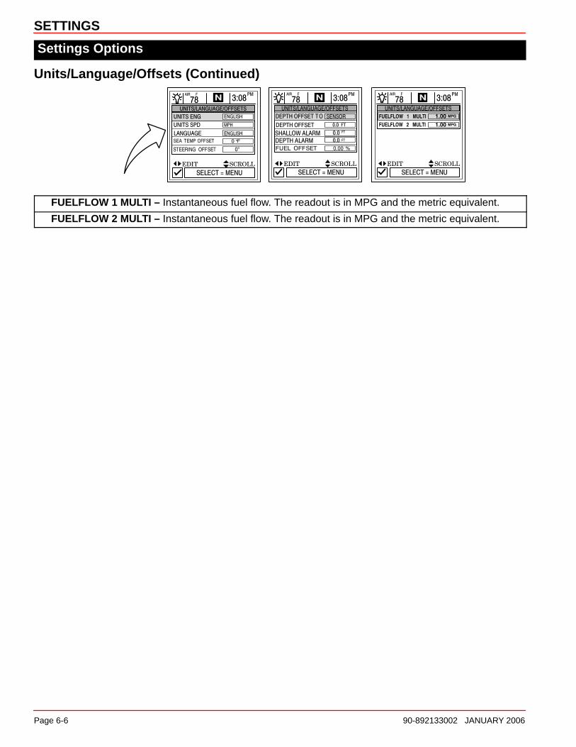
Units/Language/Offsets (Continued)
FUELFLOW 1 MULTI – Instantaneous fuel flow. The readout is in MPG and the metric equivalent.
FUELFLOW 2 MULTI – Instantaneous fuel flow. The readout is in MPG and the metric equivalent.

SETTINGS
90-892133002 JANUARY 2006 Page 6-7
Settings Options
Home Page Data1. Look at the “HOME PAGE DATA” and determine if there is any data that you would like
to change. Press �� to select function. Press �� to edit the function.
SINGLE ENGINE TWIN ENGINE
RPMH20 PSIOIL PSIOIL TEMPFUEL FLOW
H20 PSIENG TEMPOIL PSIOIL TEMPFUEL FLOW
VOLTSSPEEDDEPTHFUEL LEVELRANGEAIR TEMPSEA TEMPDTWCOGSOGBTWCOG/BTW

SETTINGS
Page 6-8 90-892133002 JANUARY 2006
Settings Options
Favorites/Page StatusThe favorites/page status allows you to select one of the two following options:
1. Allows you to choose your preferences screens and place them into the “FAVORITES”directory for quick viewing. Screens will still be shown in their respective menus.
2. Allows you to turn off any unwanted screens from all directories in System View.
To adjust a setting:
1. Press �� to scroll through the list of screens.
2. Press �� to edit the setting as follows:
� Flagging the selected screen with a heart will add the screen to the “FAVORITES” directory. It will also be available in its directory.
� Flagging the screen selection with a check mark will turn the screen on in its directoryand off in the “FAVORITES” directory.
X Flagging the screen selection with a “X” mark will turn the screen off in its directory andalso off in the “FAVORITES” directory.
RPM AND SPEED
PEAK SPEED AT RPM
TROLL CONTROL
PROP TRIM
SUPERCHARGER BOOST
ENGINE DATA
STEERING POSITION
TANK STATUS
VESSEL STATUS
FUEL MANAGEMENT
GENSET STATUS
GENSET 2 STATUS
GENSET ENG DATA
GENSET 2 ENG DATA
FUEL
OIL
VESSEL COURSE
NEXT WAYPOINT
TRIP HISTORY LOG
DEPTH
DEPTH PLOT
ENVIRONMENT
SEAWATER TEMP PLOT

SETTINGS
90-892133002 JANUARY 2006 Page 6-9
Settings Options
SensorsTo adjust a setting:
1. Press �� to highlight the desired menu selection.
2. Press �� to edit the menu box.
3. Press “SELECT” to accept settings.
PITOT SENSOR – Select the PSI input of the Pitot water pressure sensor on the engine.NOTE: The standard speed input on production Mercury engines is 100 PSI. Certain highperformance applications may require a 200 PSI input.
PITOT MULT (Multiplier) – The pitot pressure sensor can be calibrated for correcting display readingsthat read too high/low. Calculate the percentage that the speed is off, and enter it into the menu window.
PADDLE FREQ – Frequency can be changed to match requirements of different sensors. 4.9 Hz permile or 5.7 Hz per knot is the frequency of the paddle wheel speed sensor provided by Mercury Marine.
TRANSITION SPD – Transition speed is the boat speed at which System View stops looking at thepaddle wheel and starts using the pitot, or GPS (GPS is priority for high speed if connected) tomeasure boat speed. Default setting is 25 MPH. If desired, this transition speed can be changed.
INVERT STEERING – If steering angle displayed is opposite of the direction that it should, the signalcan be inverted so the steering angle can be displayed properly.


7
SYSTEM
90-892133002 JANUARY 2006 Page 7-1
SYSTEMSection 7
Table of Contents
System Information 7-2. . . . . . . . . . . . . . . . . . . . . . . . . . . . . . . . . . . . . . . . . . . . . . . . . . . . . . . . . Entering the System Directory 7-2. . . . . . . . . . . . . . . . . . . . . . . . . . . . . . . . . . . . . . . . . . . . . . . System Directory 7-2. . . . . . . . . . . . . . . . . . . . . . . . . . . . . . . . . . . . . . . . . . . . . . . . . . . . . . . . . . . Maintenance Log 7-3. . . . . . . . . . . . . . . . . . . . . . . . . . . . . . . . . . . . . . . . . . . . . . . . . . . . . . . . . . .
Recording Run Time 7-3. . . . . . . . . . . . . . . . . . . . . . . . . . . . . . . . . . . . . . . . . . . . . . . . . . . . . Active Alarms 7-4. . . . . . . . . . . . . . . . . . . . . . . . . . . . . . . . . . . . . . . . . . . . . . . . . . . . . . . . . . . . . .
Active Alarms 7-4. . . . . . . . . . . . . . . . . . . . . . . . . . . . . . . . . . . . . . . . . . . . . . . . . . . . . . . . . . . Alarm History 7-9. . . . . . . . . . . . . . . . . . . . . . . . . . . . . . . . . . . . . . . . . . . . . . . . . . . . . . . . . . . . . .
Alarm History 7-9. . . . . . . . . . . . . . . . . . . . . . . . . . . . . . . . . . . . . . . . . . . . . . . . . . . . . . . . . . . System Calibration 7-10. . . . . . . . . . . . . . . . . . . . . . . . . . . . . . . . . . . . . . . . . . . . . . . . . . . . . . . .
Tank Configuration 7-11. . . . . . . . . . . . . . . . . . . . . . . . . . . . . . . . . . . . . . . . . . . . . . . . . . . . . . Trim Calibration 7-13. . . . . . . . . . . . . . . . . . . . . . . . . . . . . . . . . . . . . . . . . . . . . . . . . . . . . . . . Factory Defaults 7-14. . . . . . . . . . . . . . . . . . . . . . . . . . . . . . . . . . . . . . . . . . . . . . . . . . . . . . . .

SYSTEM
Page 7-2 90-892133002 JANUARY 2006
System Information
This section will give a complete description of the screen settings in the “SYSTEM”directory of the System View.
Some of the system functions are:
• Maintenance log
• Active alarms
• Alarm history
• System calibration
Entering the System Directory
To access the “SYSTEM” directory, use the trackpad to highlight the “SYSTEM” directoryfrom the menu choice. Press “SELECT” to accept and to open the directory.
System Directory
System Directory Screen

SYSTEM
90-892133002 JANUARY 2006 Page 7-3
Maintenance Log
Maintenance Log
RECORDING RUN-TIME
The maintenance log is used to record the current engine run-time at each service interval.Service intervals should be performed at the time periods specified in your engineOperation, Maintenance Manual.
Recording engine run-time at maintenance intervals:
1 2
1. Open the “MAINTENANCE LOG” directory.
2. Use the trackpad to select the desired “RUN-TIME” interval box. The engine run-timein the box you selected will be blinking. If this is the desired interval to record currentengine run-time, press “SELECT” to save. When trying to overwrite a previouslyrecorded interval, confirmation is required before proceeding.

SYSTEM
Page 7-4 90-892133002 JANUARY 2006
Active Alarms
Active AlarmsThe “ACTIVE ALARMS” screen displays all active alarms. The active alarm message willalert the operator to the potential problem.
When a problem is detected with the system, the System View will alert the operator to thepotential problem by displaying the alarm data in the information window, located at thebottom of the view screen. Refer to the engine Operation, Maintenance Manual forexplanation of the problem and the correct action to take.
If problem can cause immediate engine damage, the Engine Guardian System will respond tothe problem by limiting engine power. Immediately reduce throttle speed to idle. Refer to theengine Operation, Maintenance Manual or alarm messages following, for furtherexplanation of the problem and the correct action to take.
To view active alarms:
1
1. Open the “ACTIVE ALARMS” directory. The directory will displays all active alarms.
Active AlarmsNOTE: Not all active alarms listed may be available for your type of engine.
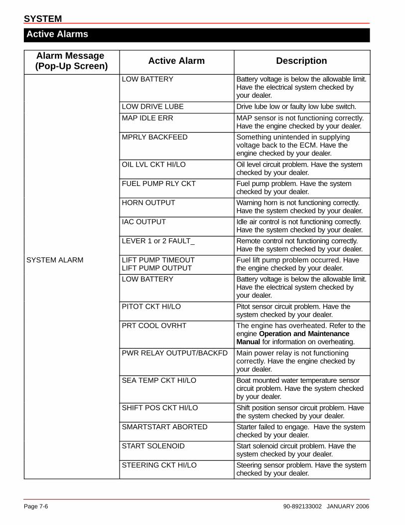
Alarm Message (Pop-Up Screen) Active Alarm Description
PUMP ALARM OIL PUMP OUTPUT The oil pump has stopped functioningelectrically (2-cycle outboards). Nolubricating oil is being supplied to theengine.
INJECTOR ALARM DINJ 1–6 OPEN/SHORTFINJ 1–6 OPEN/SHORT
Engine problem occurred. Have theengine checked by your dealer.
SENSOR ALARM Active alarm will display thesensor that is at fault
Engine problem occurred. Have theengine checked by your dealer.
IGNITION ALARM Active alarm will display theignition component that is at fault
Engine problem occurred. Have theengine checked by your dealer.

SYSTEM
90-892133002 JANUARY 2006 Page 7-5
Active Alarms
Alarm Message (Pop-Up Screen) Active Alarm Description
PORT HEAD OVRHTSTBD HEAD OVRHTCOMPRESS OVRHTHEAD OVRHTBLOCK OVRHT
The engine has overheated. Refer to theengine Operation and MaintenanceManual for information on overheating.
ALL TPS ERR TPI problem occurred. Have the enginechecked by your dealer.
BATTERY VOLT HI Battery voltage is above the allowablelimit. Have the electrical system checkedby your dealer.
BATTERY VOLT LO Battery voltage is below the allowable limit.Have the electrical system checked byyour dealer.
BLOCK PRESSURE IS LOW The water pressure in the engine is low.Failed water pump. Check for blockage atthe water intake holes in the gearcase.Have the engine checked by your dealer.
BOOST VALVE ERR Supercharger problem occurred. Have theengine checked by your dealer.
SYSTEM ALARMCAN ERR_CAN _ FAULT
CAN system circuit problem. Have thesystem checked by your dealer.
DRIVER POWER LOW Possible faulty or low battery condition.Have the system checked by your dealer.
ESC-NS POS DIFFESC-ERC POS DIFF
Electronic remote control circuit problem.Have the system checked by your dealer.
ESC CONTROL LOST Electronic remote control problemoccurred. Have the system checked byyour dealer.
ETC CONTROLETC STICKING
Engine problem occurred. Have theengine checked by your dealer.
FUEL IN VENT Vent canister switch is activated. Have theengine checked by your dealer.
FUEL LVL CKT HI/LO Fuel level circuit problem. Have thesystem checked by your dealer.
FUEL PUMP RLY CKT Fuel pump problem. Have the systemchecked by your dealer.
HORN OUTPUT Warning horn is not functioning correctly.Have the system checked by your dealer.
IAC OUTPUT Idle air control is not functioning correctly.Have the system checked by your dealer.
LEVER 1 or 2 FAULT_ Remote control not functioning correctly.Have the system checked by your dealer.
LIFT PUMP TIMEOUTLIFT PUMP OUTPUT
Fuel lift pump problem occurred. Havethe engine checked by your dealer.
SYSTEM
Page 7-6 90-892133002 JANUARY 2006
Active Alarms
Alarm Message (Pop-Up Screen) Active Alarm Description
LOW BATTERY Battery voltage is below the allowable limit.Have the electrical system checked byyour dealer.
LOW DRIVE LUBE Drive lube low or faulty low lube switch.
MAP IDLE ERR MAP sensor is not functioning correctly.Have the engine checked by your dealer.
MPRLY BACKFEED Something unintended in supplyingvoltage back to the ECM. Have theengine checked by your dealer.
OIL LVL CKT HI/LO Oil level circuit problem. Have the systemchecked by your dealer.
FUEL PUMP RLY CKT Fuel pump problem. Have the systemchecked by your dealer.
HORN OUTPUT Warning horn is not functioning correctly.Have the system checked by your dealer.
IAC OUTPUT Idle air control is not functioning correctly.Have the system checked by your dealer.
LEVER 1 or 2 FAULT_ Remote control not functioning correctly.Have the system checked by your dealer.
SYSTEM ALARM LIFT PUMP TIMEOUTLIFT PUMP OUTPUT
Fuel lift pump problem occurred. Havethe engine checked by your dealer.
LOW BATTERY Battery voltage is below the allowable limit.Have the electrical system checked byyour dealer.
PITOT CKT HI/LO Pitot sensor circuit problem. Have thesystem checked by your dealer.
PRT COOL OVRHT The engine has overheated. Refer to theengine Operation and MaintenanceManual for information on overheating.
PWR RELAY OUTPUT/BACKFD Main power relay is not functioningcorrectly. Have the engine checked byyour dealer.
SEA TEMP CKT HI/LO Boat mounted water temperature sensorcircuit problem. Have the system checkedby your dealer.
SHIFT POS CKT HI/LO Shift position sensor circuit problem. Havethe system checked by your dealer.
SMARTSTART ABORTED Starter failed to engage. Have the systemchecked by your dealer.
START SOLENOID Start solenoid circuit problem. Have thesystem checked by your dealer.
STEERING CKT HI/LO Steering sensor problem. Have the systemchecked by your dealer.

SYSTEM
90-892133002 JANUARY 2006 Page 7-7
Active Alarms
Active Alarms
Alarm Message (Pop-Up Screen) Active Alarm Description
TPI ALL ERRTPI _ DIFF ERR
Throttle position sensor circuit problem.Have the system checked by your dealer.
TRIM CKT HI/LO Power trim sensor circuit problem. Havethe system checked by your dealer.
SYSTEM ALARMTHERMOSTAT FAULT Failure to reach engine operating
temperature. Have the engine checked byyour dealer.
WATER IN FUEL Water in the engine water-separating fuelfilter reached the full level. Water can beremoved from the filter. Refer to theengine Operation and MaintenanceManual.
5 VDC PWR LO Sensor circuit problem. Have the systemchecked by your dealer.
OIL LVL ENG LO Oil level is critically low in the enginemounted oil reservoir tank (2-cycleengines). The engine mounted oilreservoir tank along with the remote oiltank will have to be refilled. Refer to theengine Operation and MaintenanceManual.
OIL LVL BOAT LO Oil level is low in the boat mounted oiltank (2-cycle engines). The oil tank willhave to be refilled. Refer to the engineOperation and Maintenance Manual.
ESC-ERC POS DIFF Electronic shift control is not functioningcorrectly. Have the engine checked byyour dealer.
SWITCH ACTIVITYESC-NS POS DIFF Neutral switch is not functioning
correctly. Have the engine checked byyour dealer.
HSHIFT PRESS _ Hydraulic shift problem occurred. Have thesystem checked by your dealer.
SHIFT POS MISMATCH Hydraulic shift problem occurred. Have thesystem checked by your dealer.
SHIFT NO ADAPT Shift actuator problem. Have the enginechecked by your dealer.
BLK PSI CKT HI/LO Block pressure sensor circuit problem.Have the engine checked by your dealer.
CAN _ FAULTCAN ERR_
CAN system circuit problem. Have thesystem checked by your dealer.
ESC TIMEOUT Shift actuator problem. Have the systemchecked by your dealer.

SYSTEM
Page 7-8 90-892133002 JANUARY 2006
Active Alarms
Alarm Message (Pop-Up Screen) Active Alarm Description
ECT OVRHT Water temperature in engine is too hot.Cooling problem. Have the enginechecked by your dealer.
SWITCH ACTIVITY GUARDIAN Guardian is trying to protect the engine byreducing engine speed.
MAP DIFF ERR MAP INPUT HI/LO
MAP sensor is not functioning correctly.Have the engine checked by your dealer.
NEUTRAL OVERSPEED Recommended engine overspeed inneutral has been exceeded.
OVERSPEED Recommended engine RPM range hasbeen exceeded.
ENGINE POWER LIMITEDPRT EMCT OVRHT Port exhaust manifold is overheating.
Cooling problem. Have the enginechecked by your dealer.
REVERSE OVERSPEED Recommended engine overspeed inreverse has been exceeded.
STB EMCT OVRHT Starboard exhaust manifold isoverheating. Cooling problem. Have theengine checked by your dealer.
LOST COMMUNICATIONTO THE ENGINE
STBD MED SPD DATA LOST
STBD BACKUP ETCESC DATA
STSD ETCESC DATA LOST
STBD LOW SPD DATA LOSTDUAL CAN ERR
System View does not see the enginecomputer. Usually indicates that no data isbeing transferred from the engine’scomputer to System View. Check wiring,also make sure both terminator resistorsare installed in the bus.
BREAK-IN __MINREMAINING
BREAKIN STR Engine break-in oiling period has not yetbeen completed.
DTS MODULE ALARM &SYSTEM ALARM
PRIMARY CTRL SOHCROSSCHECK SOH
Problem in the SmartCraft wiring system.
COMMUNICATION LOSTTO ENGINE & DTSMODULE ALARM
STBD MED SPD DATA LOSTSTBD LOW SPD DATA LOST
Problem in the SmartCraft wiring system.

SYSTEM
90-892133002 JANUARY 2006 Page 7-9
Alarm History
Alarm HistoryThe “ALARM HISTORY” displays all alarms that are, or have been active since the lastengine key-up.
To view the alarm history:
1
1. Open the “ALARM HISTORY” directory. The directory will display the alarm history.

SYSTEM
Page 7-10 90-892133002 JANUARY 2006
System Calibration
System Calibration
The system calibration consists of the following menus:
• Tank configuration
• Trim calibration
• Factory defaults
Entering into System CalibrationIMPORTANT: Entering into the system calibration menus will require the engine to beshut down in order to reactivate the System View.
SYSTEM
90-892133002 JANUARY 2006 Page 7-11
System Calibration
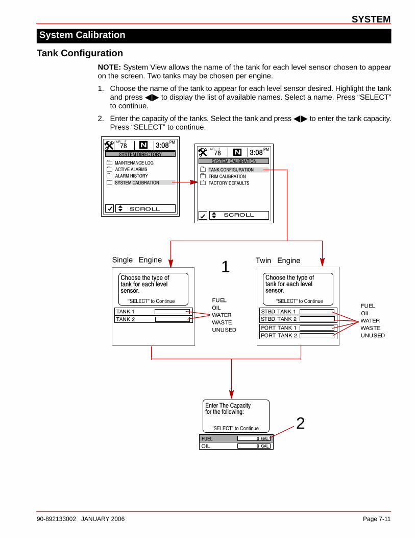
Tank ConfigurationNOTE: System View allows the name of the tank for each level sensor chosen to appearon the screen. Two tanks may be chosen per engine.
1. Choose the name of the tank to appear for each level sensor desired. Highlight the tankand press �� to display the list of available names. Select a name. Press “SELECT”to continue.
2. Enter the capacity of the tanks. Select the tank and press �� to enter the tank capacity.Press “SELECT” to continue.
1
2

SYSTEM
Page 7-12 90-892133002 JANUARY 2006
System Calibration
Tank Configuration (Continued)NOTE: The fuel tank will have to be calibrated in order for System View to display fuel range.
3. There are two methods for calibrating fuel tank level:
a. Method 1 – Select “DEFAULT” – The System View will automatically supply anestimated range value based on default sensor values. This mode does not factorin irregular tank shapes. Press “SELECT” to save.
b. Method 2 – Select “ADD FUEL” – This method requires adding fuel at certaincalibration points. System View will display an estimated range value that factors inthe tank shape.
NOTE: When using Method 2, start with an empty fuel tank and manually fill the tank to thevalues given per instruction.
4. If using Method 2, add fuel as shown in the illustration below.
Method 1Method 2
3
4

SYSTEM
90-892133002 JANUARY 2006 Page 7-13
System Calibration
Trim Calibration
CALIBRATING THE TRIM SCREEN
To calibrate trim:
1. Open the “TRIM CALIBRATION” menu.
2. TRIM ENG DOWN: Press the “SELECT” key to open the “DOWN” screen. Trim theengine all the way down. Press “SELECT” to save and move to the next screen.
3. TRIM ENG UP: The “TRIM ENG UP” screen should be open. Trim the engine all the wayup. Press “SELECT” to save and move to the next screen.
4. TRIM ENG MAX TRAILER: The “TRIM ENG MAX TRAILER” screen should be open.Trim the engine to maximum trailer position. Press “SELECT” to save.
NOTE: If trim calibration is correct, trim range should be displayed in units from 0.0 to 10.0and 10.1 to 25.0 will correspond to the trailer range.
1
2 3
10.0
4

SYSTEM
Page 7-14 90-892133002 JANUARY 2006
System Calibration
Factory Defaults
RESET SETTINGS DIRECTORY
Restores all settings back to System View’s original setup values.
To restore settings back to original setup values:
1. Open “FACTORY DEFAULTS” menu.
2. Press �� to highlight “RESET SETTINGS DIRECTORY” selection.
3. Select “YES” to reset or “NO” if you want to cancel.
RESET SENSOR DETECTION
At first power up, the System View will automatically detect all the sensors connected to it.Use the following procedure to re-start the sensor detection process again.
To reset sensor detection:
4. Open “FACTORY DEFAULTS” menu.
5. Press �� to highlight “RESET SENSOR DETECTION” selection.
6. Select “YES” to reset or “NO” to cancel.
1-4
2
5
3
6

8
INSTALLATION
90-892133002 JANUARY 2006 Page 8-1
INSTALLATIONSection 8
Table of Contents
Components 8-2. . . . . . . . . . . . . . . . . . . . . . . . . . . . . . . . . . . . . . . . . . . . . . . . . . . . . . . . . . . . . . . Special Instructions 8-3. . . . . . . . . . . . . . . . . . . . . . . . . . . . . . . . . . . . . . . . . . . . . . . . . . . . . . . . . Installation Information 8-3. . . . . . . . . . . . . . . . . . . . . . . . . . . . . . . . . . . . . . . . . . . . . . . . . . . . . . System View Installation 8-3. . . . . . . . . . . . . . . . . . . . . . . . . . . . . . . . . . . . . . . . . . . . . . . . . . . . Wiring Connections 8-5. . . . . . . . . . . . . . . . . . . . . . . . . . . . . . . . . . . . . . . . . . . . . . . . . . . . . . . . . Connecting Optional GPS Unit to the System View 8-8. . . . . . . . . . . . . . . . . . . . . . . . . . . . .

INSTALLATION
Page 8-2 90-892133002 JANUARY 2006
Components:
2453
1
2
3
4
5
7
6
89 10
12 11
13
14
REF. QTY. DESCRIPTION PART NUMBER
–1 System View Kit 79-888923K08
–1 System View Kit 79-888923K10
11 Cover (Gray) 879948T04
11 Cover (White) 879948T03
2 1 Bezel (Black/Silver) 879947T033 1 System View NSS4 1 Seal NSS5 4 Screw (#10-32 x 1.50) 10-666876 4 Washer (.203 x .500 x .032) 12-566817 4 Wing nut (#10-32) 11-8168748 1 Temp sensor mounting adapter 859021
9 1 Washer 12-85902910 1 Nylon nut 11-85902211 1 Temperature sensor assembly 88534200112 1 O-ring (.351 x .072) 25-88881413 1 Harness assembly, Instrument only 84-882755T0214 1 Harness assembly (500 Ohm adapter) 84-889515A02

INSTALLATION
90-892133002 JANUARY 2006 Page 8-3
Special InstructionsClean lens with water only.
Installation Information
WARNINGDisconnect both battery cables at battery before attempting to install gauges.
Before cutting any holes, check area behind the dashboard for obstructions (braces, cables,wiring, etc.).
CUTTING TIPS:
a. Fiberglass – Apply masking tape to the area to be cut to prevent dashboard fromcracking.
b. Vinyl Covered – Remove vinyl from the area to be cut with a razor blade to keepvinyl from tearing.
System View Installation
1. Select a location for the System View that affords good visibility and accessibility frombehind the dashboard.
2. Cut out mounting hole to the given dimensions.

INSTALLATION
Page 8-4 90-892133002 JANUARY 2006
3. Place System View along with the seal into the dashboard, and secure with four screws.
a
b
c
a - Screw (4)b - Flat washer (4)c - Wing nut (4)
4. Install the outside air temperature sensor as follows:
a. Mount sensor where it will be exposed to outside air, and will not be in direct sunlight.
b. Select a location, and drill a 19.0 mm (3/4 in.) mounting hole.
c. Install the mounting adapter as shown.
d. Thread the air temperature sensor into the mounting adapter.
ab c d
a - Mounting adapterb - Gasket
c - Nylon nutd - Air temperature sensor

INSTALLATION
90-892133002 JANUARY 2006 Page 8-5
Wiring ConnectionsMODELS WITHOUT ELECTRONIC THROTTLE/SHIFT
NOTE: Extension wiring harnesses for the System Link gauges are available from 152 mm(6 in.) to 9.14 m (30 ft.) lengths.
a
b
c
d
g
e
f
h
ij
k
l
a - System Viewb - Display harnessc - System Link gauge connection (Starboard)d - System Link gauge connection (Port)e - GPS connection (Optional)f - Horn (Provided with display harness)g - Terminatorh - Weather coveri - Junction boxj - SC data cable (From engine)k - Air temperature sensor (Provided with display harness)l - Not used (Seal connection with weather cap)

INSTALLATION
Page 8-6 90-892133002 JANUARY 2006
MODELS WITH ELECTRONIC THROTTLE/SHIFT MODELS – SINGLE ENGINE
NOTE: Extension wiring harnesses for the System Link gauges are available from 152 mm(6 in.) to 9.14 m (30 ft.) lengths.
a
b
d
e
f
g
c
h
a - System Viewb - System Link gaugesc - Air temperature sensord - GPS connectione - Display harnessf - Weather capsg - Junction boxh - To foot throttle “Hot Foot” optional
INSTALLATION
90-892133002 JANUARY 2006 Page 8-7
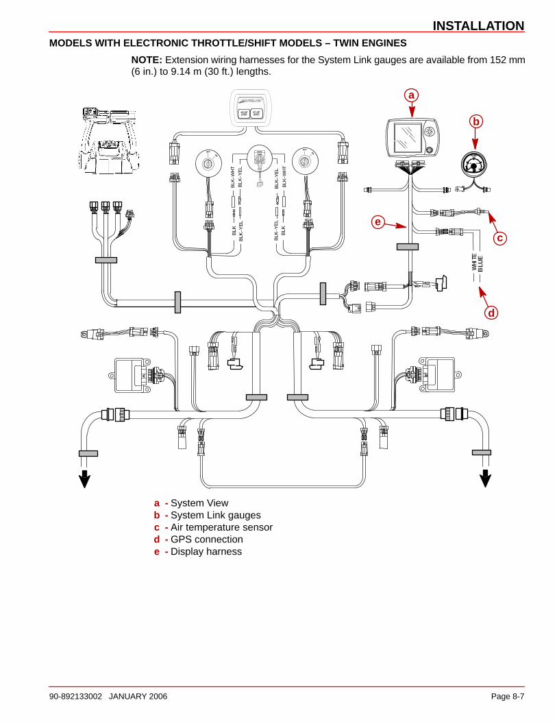
MODELS WITH ELECTRONIC THROTTLE/SHIFT MODELS – TWIN ENGINES
NOTE: Extension wiring harnesses for the System Link gauges are available from 152 mm(6 in.) to 9.14 m (30 ft.) lengths.
a
b
d
ce
a - System Viewb - System Link gaugesc - Air temperature sensord - GPS connectione - Display harness

INSTALLATION
Page 8-8 90-892133002 JANUARY 2006
Connecting Optional GPS Unit to the System ViewNOTE: The GPS unit must comply to the National Marine Electronic Association NMEA0183 Interface Standard v3.01 or later compatible version.
Look at the GPS wiring diagram to determine what two leads are the GPS output leads.Locate the white and blue wires coming from the System View wiring harness. Connect theGPS output leads to the white and blue wires. If no data is received, switch the wireconnections around. If no data is still received, refer to the GPS owner’s manual and seeif the GPS has to be calibrated to turn on the output signal, or needs to be groundeddifferently.

9
INDEX
90-892133002 JANUARY 2006 Page 9-1
INDEXSection 9
AActive Alarms 7-4. . . . . . . . . . . . . . . . . .
Air Temperature 5-6. . . . . . . . . . . . . . . .
Alarm History 7-9. . . . . . . . . . . . . . . . . .
Alarm Message Screens 2-9. . . . . . . . .
BBoat Speed 5-6. . . . . . . . . . . . . . . . . . . .
Brightness 6-3. . . . . . . . . . . . . . . . . . . . .
CClock Settings 6-3. . . . . . . . . . . . . . . . . .
Connecting Optional GPS Unit to the System View 8-8. . . . . . . . . . . . .
Contrast 6-3. . . . . . . . . . . . . . . . . . . . . . .
DData Display Screen 2-5. . . . . . . . . . . .
Depth 5-5. . . . . . . . . . . . . . . . . . . . . . . . .
Depth Alarm 6-5. . . . . . . . . . . . . . . . . . .
Depth Offset 6-5. . . . . . . . . . . . . . . . . . .
Depth Plot LIne 5-5. . . . . . . . . . . . . . . . .
Display Screens 2-2. . . . . . . . . . . . . . . .
EEngine Data Screens 3-4. . . . . . . . . . . .
Engine RPM Synchronizer 3-6. . . . . . .
Engine RPM/Speed 3-5. . . . . . . . . . . . .
Environment 5-6. . . . . . . . . . . . . . . . . . .
FFactory Defaults 7-14. . . . . . . . . . . . . . . .
Favorite Page Screen Selection 6-8. .
Favorite Page Status 6-8. . . . . . . . . . . .
Favorite Slide Pause Setting 6-4. . . . .
Favorite Slide Show Option 6-4. . . . . .
Fuel Flow 4-5. . . . . . . . . . . . . . . . . . . . . .
Fuel Offset 6-5. . . . . . . . . . . . . . . . . . . . .
Fuel Range 4-5. . . . . . . . . . . . . . . . . . . .
Fuel Remaining 4-5. . . . . . . . . . . . . . . .
Fuel Tanks 4-4. . . . . . . . . . . . . . . . . . . . .
GGPS Heading Selection 6-4. . . . . . . . .
HHome Page Data 6-7. . . . . . . . . . . . . . .
Home Page Screens 2-3. . . . . . . . . . . .
IInstallation Information 8-3. . . . . . . . . .
Invert Steering 6-9. . . . . . . . . . . . . . . . .
KKeypad Usage 1-2. . . . . . . . . . . . . . . . .
LLanguage 6-5. . . . . . . . . . . . . . . . . . . . . .
Lighting 6-3. . . . . . . . . . . . . . . . . . . . . . .
MMaintenance Log 7-3. . . . . . . . . . . . . . .
NNavigation Screens 5-3. . . . . . . . . . . . .
Navigation Directory 5-2. . . . . . . . . . . .
Next Waypoint Data 5-4. . . . . . . . . . . . .
OOffsets 6-5. . . . . . . . . . . . . . . . . . . . . . . .
Oil Tank 4-4. . . . . . . . . . . . . . . . . . . . . . .
PPaddle Frequency 6-9. . . . . . . . . . . . . .
Peak Speed at RPM 3-5. . . . . . . . . . . .
Pitot Multiplier 6-9. . . . . . . . . . . . . . . . . .
Pitot Sensor 6-9. . . . . . . . . . . . . . . . . . . .
Pop-up Warnings 6-4. . . . . . . . . . . . . . . .
Preference Settings 6-4. . . . . . . . . . . . .
Propulsion Directory 3-2. . . . . . . . . . . .
RResetting Sensor Detection 7-14. . . . . . .
Restoring Factory Settings 7-14. . . . . . .

INDEX
Page 9-2 90-892133002 JANUARY 2006
SSeawater Temperature Offset 6-5. . . .
Seawater Temperature Plot 5-6. . . . . .
Sensors 6-9. . . . . . . . . . . . . . . . . . . . . . .
Setting Directory 6-2. . . . . . . . . . . . . . . .
Settings Information 6-2. . . . . . . . . . . . .
Shallow Alarm 6-5. . . . . . . . . . . . . . . . . .
Start-up Page Preference 6-4. . . . . . . .
Start-up Screens 2-2. . . . . . . . . . . . . . .
Starting Up the System View 2-2. . . . . .
Steering Offset 6-5. . . . . . . . . . . . . . . . .
Steering Position 4-3. . . . . . . . . . . . . . .
Supercharger Boost 3-6. . . . . . . . . . . . .
System Calibration 7-10. . . . . . . . . . . . . .
System Directory 7-2. . . . . . . . . . . . . . .
System Information 7-2. . . . . . . . . . . . . .
System View Installation 8-3. . . . . . . . .
TTank Configuration 7-11. . . . . . . . . . . . . .
Tank Status 4-3. . . . . . . . . . . . . . . . . . . .
Time Settings 6-3. . . . . . . . . . . . . . . . . .
Transition Speed 6-9. . . . . . . . . . . . . . .
Trim Calibration 7-13. . . . . . . . . . . . . . . . .
Trim Popup Time 6-4. . . . . . . . . . . . . . . .
Trim Position 3-4. . . . . . . . . . . . . . . . . . .
Trip History Log 5-4. . . . . . . . . . . . . . . .
Troll Control 3-3. . . . . . . . . . . . . . . . . . . .
Turning Off Troll Control 3-3. . . . . . . . .
Troll Control Setting 3-3. . . . . . . . . . . . .
UUnits (English or Metric) 6-5. . . . . . . . .
VVessel Course 5-3. . . . . . . . . . . . . . . . . .
Vessel Directory, 4-2. . . . . . . . . . . . . . . .
Vessel Status 4-5. . . . . . . . . . . . . . . . . .
WWarning Horn 6-4. . . . . . . . . . . . . . . . . .
Water and Waste Tanks 4-4. . . . . . . . .
Water Temperature 5-6. . . . . . . . . . . . .
Wiring Connections 8-5. . . . . . . . . . . . .
Related Documents