1 Document Number: DSP1108 2 Date: 2012-11-12 3 Version: 1.0.0i 4 Physical Computer System View Profile 5 Document Type: Specification 6 Document Status: Work in Progress 7 Document Language: en-US 8 9 Information for Work-in-Progress version: IMPORTANT: This document is not a standard. It does not necessarily reflect the views of the DMTF or all of its members. Because this document is a Work in Progress, it may still change, perhaps profoundly. This document is available for public review and comment until the stated expiration date. It expires on: 2013-05-15 Provide any comments through the DMTF Feedback Portal: http://www.dmtf.org/standards/feedback

Welcome message from author
This document is posted to help you gain knowledge. Please leave a comment to let me know what you think about it! Share it to your friends and learn new things together.
Transcript
1
Document Number: DSP1108 2
Date: 2012-11-12 3
Version: 1.0.0i 4
Physical Computer System View Profile 5
Document Type: Specification 6
Document Status: Work in Progress 7
Document Language: en-US 8
9
Information for Work-in-Progress version:
IMPORTANT: This document is not a standard. It does not necessarily reflect the views of the DMTF or all of its members. Because this document is a Work in Progress, it may still change, perhaps profoundly. This document is available for public review and comment until the stated expiration date.
It expires on: 2013-05-15
Provide any comments through the DMTF Feedback Portal:
http://www.dmtf.org/standards/feedback
Physical Computer System View Profile DSP1108
2 Work in Progress Specification - not a DMTF Standard Version 1.0.0i
Copyright Notice 10
Copyright © 2012 Distributed Management Task Force, Inc. (DMTF). All rights reserved. 11
DMTF is a not-for-profit association of industry members dedicated to promoting enterprise and systems 12 management and interoperability. Members and non-members may reproduce DMTF specifications and 13 documents, provided that correct attribution is given. As DMTF specifications may be revised from time to 14 time, the particular version and release date should always be noted. 15
Implementation of certain elements of this standard or proposed standard may be subject to third party 16 patent rights, including provisional patent rights (herein "patent rights"). DMTF makes no representations 17 to users of the standard as to the existence of such rights, and is not responsible to recognize, disclose, 18 or identify any or all such third party patent right, owners or claimants, nor for any incomplete or 19 inaccurate identification or disclosure of such rights, owners or claimants. DMTF shall have no liability to 20 any party, in any manner or circumstance, under any legal theory whatsoever, for failure to recognize, 21 disclose, or identify any such third party patent rights, or for such party’s reliance on the standard or 22 incorporation thereof in its product, protocols or testing procedures. DMTF shall have no liability to any 23 party implementing such standard, whether such implementation is foreseeable or not, nor to any patent 24 owner or claimant, and shall have no liability or responsibility for costs or losses incurred if a standard is 25 withdrawn or modified after publication, and shall be indemnified and held harmless by any party 26 implementing the standard from any and all claims of infringement by a patent owner for such 27 implementations. 28
For information about patents held by third-parties which have notified the DMTF that, in their opinion, 29 such patent may relate to or impact implementations of DMTF standards, visit 30 http://www.dmtf.org/about/policies/disclosures.php. 31
32
DSP1108 Physical Computer System View Profile
Version 1.0.0i Work in Progress Specification - not a DMTF Standard 3
CONTENTS 33
Foreword ....................................................................................................................................................... 5 34
Introduction.................................................................................................................................................... 6 35
1 Scope .................................................................................................................................................... 7 36
2 Normative references ............................................................................................................................ 7 37
3 Terms and definitions ............................................................................................................................ 8 38
4 Symbols and abbreviated terms ............................................................................................................ 9 39
5 Synopsis .............................................................................................................................................. 10 40
6 Description .......................................................................................................................................... 11 41
7 Implementation .................................................................................................................................... 11 42 7.1 Representing a physical computer system view ....................................................................... 11 43
8 Methods ............................................................................................................................................... 22 44 8.1 CIM_PhysicalComputerSystemView.RequestStateChange( ) ................................................. 22 45 8.2 CIM_PhysicalComputerSystemView.ClearLog( ) ..................................................................... 23 46 8.3 CIM_PhysicalComputerSystemView.InstallSoftwareFromURI( ) ............................................. 23 47 8.4 CIM_PhysicalComputerSystemView.ModifyPersistentBootConfigOrder( ) .............................. 24 48 8.5 CIM_PhysicalComputerSystemView.SetOneTimeBootSource( ) ............................................ 25 49 8.6 Profile conventions for operations ............................................................................................ 25 50 8.7 CIM_PhysicalComputerSystemView ........................................................................................ 26 51 8.8 CIM_ElementView .................................................................................................................... 26 52
9 Use cases ............................................................................................................................................ 27 53 9.1 Miscellaneous object diagrams ................................................................................................. 27 54 9.2 Small footprint managed computer system with additional CIM Schema implemented ........... 27 55 9.3 Large managed computer system with additional CIM Profiles implemented .......................... 28 56 9.4 Managed system exposing multiple temperature sensors ....................................................... 29 57 9.5 Determine the power state of the physical computer system ................................................... 31 58 9.6 Change the power state of the physical computer system ....................................................... 31 59 9.7 Get properties of a specific record log of the physical computer system ................................. 31 60 9.8 Browse the records of a log of the physical computer system ................................................. 31 61 9.9 Monitor temperate sensor readings of the physical computer system ..................................... 32 62 9.10 Modify persisted boot order of the physical computer system.................................................. 32 63 9.11 Configure a source of the physical computer system for next reboot only ............................... 32 64 9.12 Update the BIOS firmware of the physical computer system ................................................... 32 65
10 CIM Elements ...................................................................................................................................... 33 66 10.1 CIM_PhysicalComputerSystemView ........................................................................................ 33 67 10.2 CIM_RegisteredProfile .............................................................................................................. 35 68 10.3 CIM_ElementView .................................................................................................................... 36 69
ANNEX A (informative) Change log ........................................................................................................... 37 70
71
Figures 72
Figure 1 – Physical Computer System View Profile: Class diagram .......................................................... 11 73
Figure 2 – Simple PhysicalComputerSystemView implementation ............................................................ 27 74
Figure 3 – Small footprint PhysicalComputerSystemView implementation ................................................ 28 75
Figure 4 – Rich PhysicalComputerSystemView implementation ................................................................ 29 76
Figure 5 – PhysicalComputerSystemView implementation of multiple temperature sensors .................... 30 77
78 79
Physical Computer System View Profile DSP1108
4 Work in Progress Specification - not a DMTF Standard Version 1.0.0i
80
Tables 81
Table 1 – Referenced profiles ..................................................................................................................... 10 82
Table 2 – CIM_PhysicalComputerSystemView property model correspondence ...................................... 13 83
Table 3 – Property origins for processor ..................................................................................................... 17 84
Table 4 – Property origins for memory ........................................................................................................ 17 85
Table 5 – Property origins for current BIOS or EFI firmware ...................................................................... 17 86
Table 6 – Property origins for current management firmware .................................................................... 18 87
Table 7– Property origins for the operating system .................................................................................... 18 88
Table 8 – Property origins for the power allocation limit ............................................................................. 19 89
Table 9 – Property origins for numeric sensors .......................................................................................... 20 90
Table 10 – Property origins for record logs ................................................................................................. 21 91
Table 11 – Property origin for boot sources ................................................................................................ 21 92
Table 12 – CIM_PhysicalComputerSystemView.RequestStateChange( ) method: Return code values ... 22 93
Table 13 – CIM_PhysicalComputerSystemView.RequestStateChange( ) method: Parameters ............... 23 94
Table 14 – CIM_PhysicalComputerSystemView.ClearLog( ) method: Return code values ....................... 23 95
Table 15 – CIM_PhysicalComputerSystemView.ClearLog( ) method: Parameters ................................... 23 96
Table 16 – CIM_PhysicalComputerSystemView.InstallSoftwareFromURI( ) method: Return code values 24 97
Table 17 – CIM_PhysicalComputerSystemView.InstallSoftwareFromURI( ) method: Parameters ............ 24 98
Table 18 – CIM_PhysicalComputerSystemView.ModifyPersistentBootConfigOrder( ) method: Return code 99 values ................................................................................................................................ 24 100
Table 19 – CIM_PhysicalComputerSystemView.ModifyPersistentBootConfigOrder( ) method: Parameters25 101
Table 20 – CIM_PhysicalComputerSystemView.SetOneTimeBootSource( ) method: Return code values25 102
Table 21 – CIM_PhysicalComputerSystemView.SetOneTimeBootSource( ) method: Parameters ........... 25 103
Table 22 – Operations: CIM_PhysicalComputerSystemView ..................................................................... 26 104
Table 23 – CIM Elements: Physical Computer System View Profile .......................................................... 33 105
Table 24 – Class: CIM_PhysicalComputerSystemView ............................................................................. 33 106
Table 25 – Class: CIM_RegisteredProfile ................................................................................................... 35 107
Table 26 – Class: CIM_ElementView ......................................................................................................... 36 108
Table 27 – Class: CIM_ElementView ......................................................................................................... 36 109
110
DSP1108 Physical Computer System View Profile
Version 1.0.0i Work in Progress Specification - not a DMTF Standard 5
Foreword 111
The Physical Computer System View Profile (DSP1108) was prepared by the Server Desktop Mobile 112 Platforms Working Group of the DMTF. 113
DMTF is a not-for-profit association of industry members dedicated to promoting enterprise and systems 114 management and interoperability. For information about the DMTF, see http://www.dmtf.org. 115
Acknowledgments 116
The DMTF acknowledges the following individuals for their contributions to this document: 117
Editors: 118
Steve Lee – Microsoft Corporation 119
Contributors: 120
Jeff Hilland – Hewlett-Packard Company 121
John Leung – Intel Corporation 122
Hemal Shah – Broadcom Corporation 123
Satheesh Thomas – AMI 124
Perry Vincent – Intel Corporation 125
126
Physical Computer System View Profile DSP1108
6 Work in Progress Specification - not a DMTF Standard Version 1.0.0i
Introduction 127
The information in this specification should be sufficient for a provider or consumer of this data to identify 128 unambiguously the classes, properties, methods, and values that shall be instantiated and manipulated to 129 represent and manage a physical computer system and its associated management information. 130
The target audience for this specification is implementers who are writing CIM-based providers or 131 consumers of management interfaces that represent the components described in this document. 132
Document conventions 133
Typographical conventions 134
The following typographical conventions are used in this document: 135
Document titles are marked in italics. 136
Important terms that are used for the first time are marked in italics. 137
Terms include a link to the term definition in the "Terms and definitions" clause, enabling easy 138 navigation to the term definition. 139
ABNF rules are in monospaced font. 140
ABNF usage conventions 141
Format definitions in this document are specified using ABNF (see RFC5234), with the following 142 deviations: 143
Literal strings are to be interpreted as case-sensitive Unicode characters, as opposed to the 144 definition in RFC5234 that interprets literal strings as case-insensitive US-ASCII characters. 145
DSP1108 Physical Computer System View Profile
Version 1.0.0i Work in Progress Specification - not a DMTF Standard 7
Physical Computer System View Profile 146
1 Scope 147
The Physical Computer System View Profile describes a view of the management capability of 148 referencing profiles by adding the capability to represent a physical computer system view of a managed 149 computer system. This profile includes a specification of the physical computer system view, extrinsic 150 methods for management operations, and its associated relationships to referencing profiles. This profile 151 is not intended to provide all details of referenced profiles. 152
2 Normative references 153
The following referenced documents are indispensable for the application of this document. For dated or 154 versioned references, only the edition cited (including any corrigenda or DMTF update versions) applies. 155 For references without a date or version, the latest published edition of the referenced document 156 (including any corrigenda or DMTF update versions) applies. 157
DMTF DSP0004, CIM Infrastructure Specification 2.6, 158 http://www.dmtf.org/standards/published_documents/DSP0004_2.6.pdf 159
DMTF DSP0200, CIM Operations over HTTP 1.3, 160 http://www.dmtf.org/standards/published_documents/DSP0200_1.3.pdf 161
DMTF DSP0223, Generic Operations 1.0, 162 http://www.dmtf.org/standards/published_documents/DSP0223_1.0.pdf 163
DMTF DSP1001, Management Profile Specification Usage Guide 1.0, 164 http://www.dmtf.org/standards/published_documents/DSP1001_1.0.pdf 165
DMTF DSP1009, Sensors Profile 1.0, 166 http://dmtf.org/sites/default/files/standards/documents/DSP1009_1.0.pdf 167
DMTF DSP1009, Sensors Profile 1.1, 168 http://dmtf.org/sites/default/files/standards/documents/DSP1009_1.1.pdf 169
DMTF DSP1010, Record Log Profile 1.0, 170 http://www.dmtf.org/sites/default/files/standards/documents/DSP1010_1.0.pdf 171
DMTF DSP1010, Record Log Profile 2.0, 172 http://www.dmtf.org/sites/default/files/standards/documents/DSP1010_2.0.pdf 173
DMTF DSP1011, Physical Asset Profile 1.0, 174 http://www.dmtf.org/sites/default/files/standards/documents/DSP1011_1.0.pdf 175
DMTF DSP1012, Boot Control Profile 1.0, 176 http://dmtf.org/sites/default/files/standards/documents/DSP1012_1.0.pdf 177
DMTF DSP1022, CPU Profile 1.0, 178 http://dmtf.org/sites/default/files/standards/documents/DSP1022_1.0.pdf 179
DMTF DSP1023, Software Inventory Profile 1.0, 180 http://dmtf.org/sites/default/files/standards/documents/DSP1023_1.0.pdf 181
DMTF DSP1025, Software Update Profile 1.0, 182 http://dmtf.org/sites/default/files/standards/documents/DSP1025_1.0.pdf 183
Physical Computer System View Profile DSP1108
8 Work in Progress Specification - not a DMTF Standard Version 1.0.0i
DMTF DSP1026, System Memory Profile 1.0, 184 http://dmtf.org/sites/default/files/standards/documents/DSP1026_1.0.pdf 185
DMTF DSP1029, OS Status Profile 1.0, 186 http://dmtf.org/sites/default/files/standards/documents/DSP1029_1.0.pdf 187
DMTF DSP1029, OS Status Profile 1.1, 188 http://dmtf.org/sites/default/files/standards/documents/DSP1029_1.1.pdf 189
DMTF DSP1033, Profile Registration Profile 1.0, 190 http://www.dmtf.org/standards/published_documents/DSP1033_1.0.pdf 191
DMTF DSP1052, Computer System Profile 1.0, 192 http://www.dmtf.org/sites/default/files/standards/documents/DSP1052_1.0.pdf 193
DMTF DSP1052, Computer System Profile 1.1, 194 http://www.dmtf.org/sites/default/files/standards/documents/DSP1052_1.1.pdf 195
DMTF DSP1085, Power Utilization Management Profile 1.0, 196 http://dmtf.org/sites/default/files/standards/documents/DSP1085_1.0.pdf 197
IETF RFC5234, ABNF: Augmented BNF for Syntax Specifications, January 2008, 198 http://tools.ietf.org/html/rfc5234 199
ISO/IEC Directives, Part 2, Rules for the structure and drafting of International Standards, 200 http://isotc.iso.org/livelink/livelink.exe?func=ll&objId=4230456&objAction=browse&sort=subtype 201
202
3 Terms and definitions 203
In this document, some terms have a specific meaning beyond the normal English meaning. Those terms 204 are defined in this clause. 205
The terms "shall" ("required"), "shall not," "should" ("recommended"), "should not" ("not recommended"), 206 "may," "need not" ("not required"), "can" and "cannot" in this document are to be interpreted as described 207 in ISO/IEC Directives, Part 2, Annex H. The terms in parenthesis are alternatives for the preceding term, 208 for use in exceptional cases when the preceding term cannot be used for linguistic reasons. Note that 209 ISO/IEC Directives, Part 2, Annex H specifies additional alternatives. Occurrences of such additional 210 alternatives shall be interpreted in their normal English meaning. 211
The terms "clause," "subclause," "paragraph," and "annex" in this document are to be interpreted as 212 described in ISO/IEC Directives, Part 2, Clause 5. 213
The terms "normative" and "informative" in this document are to be interpreted as described in ISO/IEC 214 Directives, Part 2, Clause 3. In this document, clauses, subclauses, or annexes labeled "(informative)" do 215 not contain normative content. Notes and examples are always informative elements. 216
The terms defined in DSP0004, DSP0223, DSP1001, and DSP1033 apply to this document. The 217 following additional terms are used in this document.. 218
3.1 219
can 220
used for statements of possibility and capability, whether material, physical, or causal 221
3.2 222
cannot 223
used for statements of possibility and capability, whether material, physical, or causal 224
DSP1108 Physical Computer System View Profile
Version 1.0.0i Work in Progress Specification - not a DMTF Standard 9
3.3 225
conditional 226
indicates requirements to be followed strictly to conform to the document when the specified conditions 227 are met 228
3.4 229
mandatory 230
indicates requirements to be followed strictly to conform to the document and from which no deviation is 231 permitted 232
3.5 233
may 234
indicates a course of action permissible within the limits of the document 235
3.6 236
need not 237
indicates a course of action permissible within the limits of the document 238
3.7 239
optional 240
indicates a course of action permissible within the limits of the document 241
3.8 242
referencing profile 243
indicates a profile that owns the definition of this class and can include a reference to this profile in its 244 “Referenced Profiles” table 245
3.9 246
shall 247
indicates requirements to be followed strictly to conform to the document and from which no deviation is 248 permitted 249
3.10 250
shall not 251
indicates requirements to be followed strictly to conform to the document and from which no deviation is 252 permitted 253
3.11 254
should 255
indicates that among several possibilities, one is recommended as particularly suitable, without 256 mentioning or excluding others, or that a certain course of action is preferred but not necessarily required 257
3.12 258
should not 259
indicates that a certain possibility or course of action is deprecated but not prohibited 260
3.13 261
unspecified 262
indicates that this profile does not define any constraints for the referenced CIM element or operation 263
4 Symbols and abbreviated terms 264
The abbreviations defined in DSP0004, DSP0223, and DSP1001 apply to this document. The following 265 additional abbreviations are used in this document. 266
Physical Computer System View Profile DSP1108
10 Work in Progress Specification - not a DMTF Standard Version 1.0.0i
4.1 267
BIOS 268
Basic Input Output System 269
4.2 270
EFI 271
Extensible Firmware Interface 272
4.3 273
FRU 274
Field Replaceable Unit 275
4.4 276
SKU 277
Stock Keeping Unit 278
5 Synopsis 279
Profile name: Physical Computer System View 280
Version: 1.0.0 281
Organization: DMTF 282
CIM schema version: 2.33 283
Central class: CIM_PhysicalComputerSystemView 284
Scoping class: CIM_ComputerSystem 285
The Physical Computer System View Profile extends the management capability of referencing profiles 286 by adding the capability to represent a physical computer system view of a managed computer system. 287 This profile includes a specification of the physical computer system view, extrinsic methods for 288 management operations, and its associated relationships to referencing profiles 289
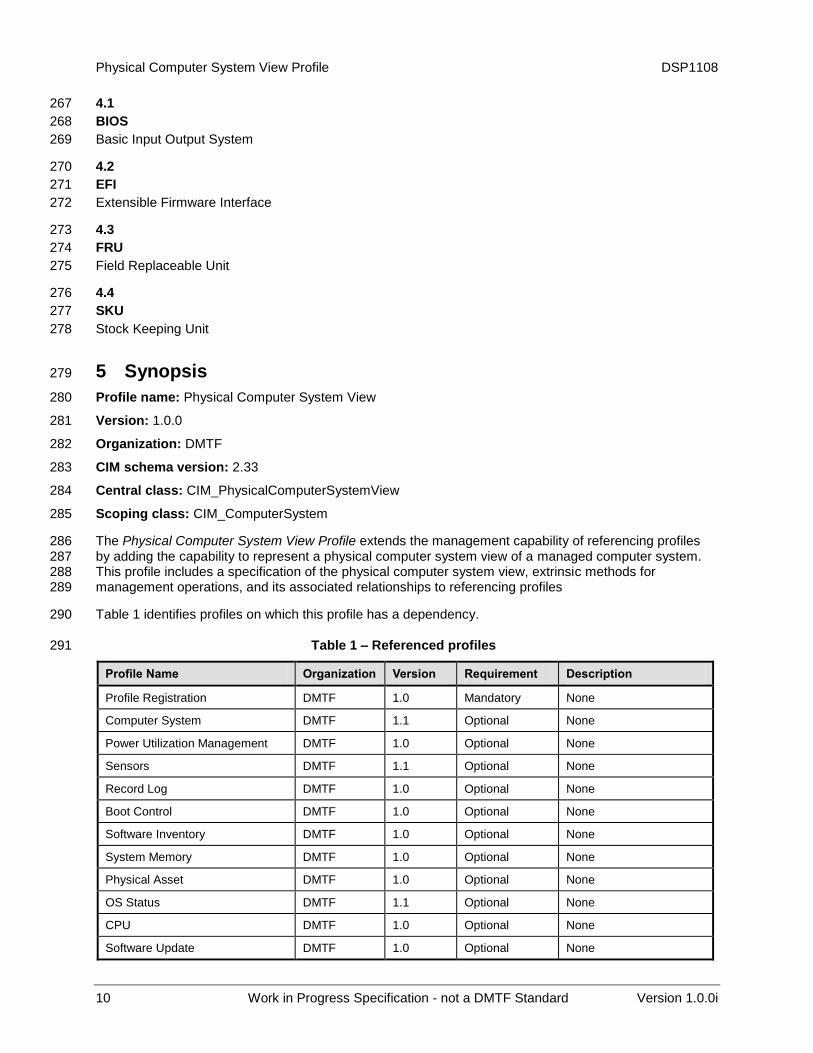
Table 1 identifies profiles on which this profile has a dependency. 290
Table 1 – Referenced profiles 291
Profile Name Organization Version Requirement Description
Profile Registration DMTF 1.0 Mandatory None
Computer System DMTF 1.1 Optional None
Power Utilization Management DMTF 1.0 Optional None
Sensors DMTF 1.1 Optional None
Record Log DMTF 1.0 Optional None
Boot Control DMTF 1.0 Optional None
Software Inventory DMTF 1.0 Optional None
System Memory DMTF 1.0 Optional None
Physical Asset DMTF 1.0 Optional None
OS Status DMTF 1.1 Optional None
CPU DMTF 1.0 Optional None
Software Update DMTF 1.0 Optional None
DSP1108 Physical Computer System View Profile
Version 1.0.0i Work in Progress Specification - not a DMTF Standard 11
6 Description 292
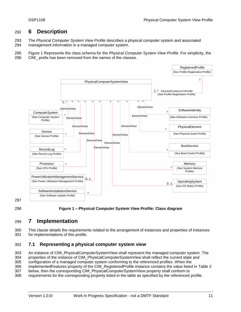
The Physical Computer System View Profile describes a physical computer system and associated 293 management information in a managed computer system. 294
Figure 1 Represents the class schema for the Physical Computer System View Profile. For simplicity, the 295 CIM_ prefix has been removed from the names of the classes. 296
ElementConformsToProfile
(See Profile Registration Profile)
PhysicalComputerSystemView
RegisteredProfile
(See Profile Registration Profile)
1..*
1
ElementView
SoftwareIdentity
(See Software Inventory Profile)
ElementView
*
*
RecordLog
(See Record Log Profile)
ElementView
*
BootService
(See Boot Control Profile)
ElementView
*
ComputerSystem
(See Computer System
Profile)
ElementView
1..*
*
Processor
(See CPU Profile)
ElementView
*
*
*
*
*
Sensor
(See Sensor Profile)
PhysicalElement
(See Physical Asset Profile)
ElementView
*
Memory
(See System Memory
Profile)
ElementView
*
*
PowerUtilizationManagementService
(See Power Utilization Management Profile)
ElementView
*
0..1OperatingSystem
(See OS Status Profile)
ElementView
0..1
SoftwareInstallationService
(See Software Update Profile)
ElementView
*
* ***
297
Figure 1 – Physical Computer System View Profile: Class diagram 298
7 Implementation 299
This clause details the requirements related to the arrangement of instances and properties of instances 300 for implementations of this profile. 301
7.1 Representing a physical computer system view 302
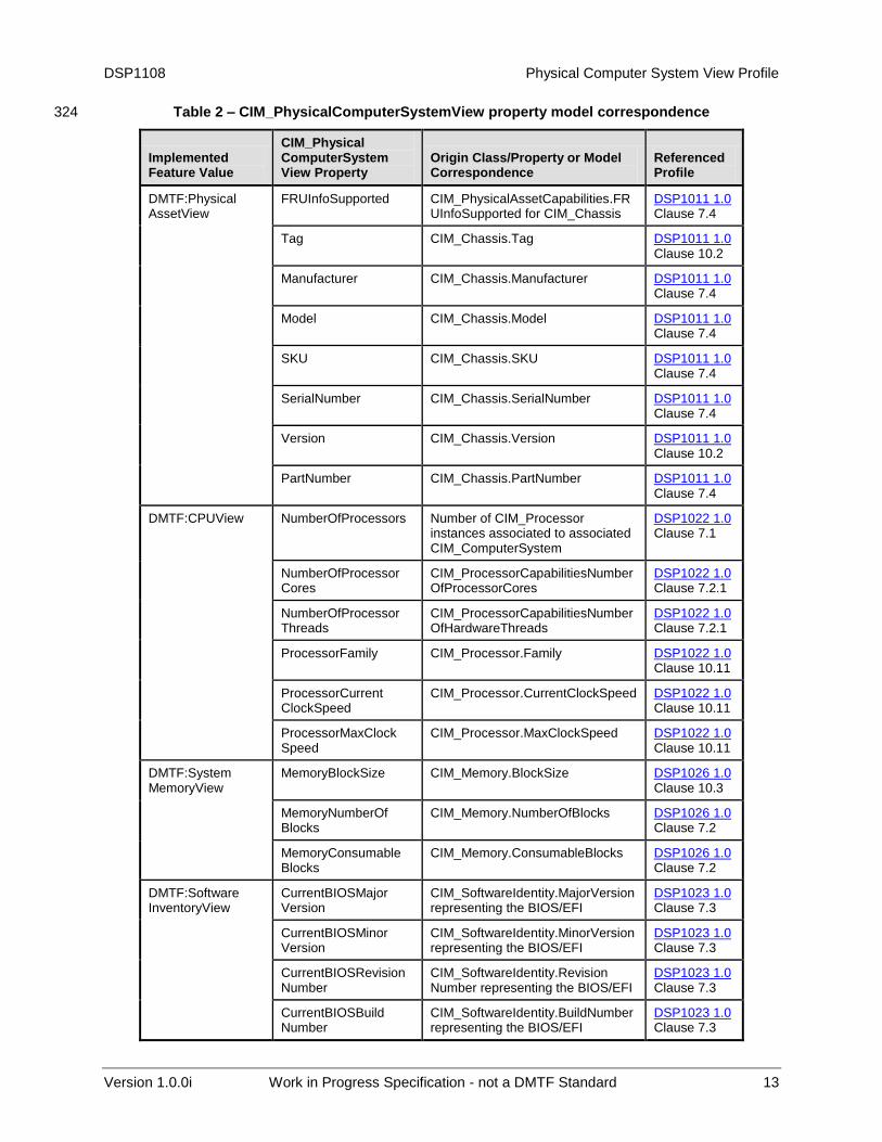
An instance of CIM_PhysicalComputerSystemView shall represent the managed computer system. The 303 properties of the instance of CIM_PhysicalComputerSystemView shall reflect the current state and 304 configuration of a managed computer system conforming to the referenced profiles. When the 305 ImplementedFeatures property of the CIM_RegisteredProfile instance contains the value listed in Table 2 306 below, then the corresponding CIM_PhysicalComputerSystemView property shall conform to 307 requirements for the corresponding property listed in the table as specified by the referenced profile. 308
Physical Computer System View Profile DSP1108
12 Work in Progress Specification - not a DMTF Standard Version 1.0.0i
7.1.1 Representing information from multiple instances of the same class. 309
A subset of properties CIM_PhysicalComputerSystemView may represent information from multiple 310 instances of same class. Indexed Arrays are used in CIM_PhysicalComputerSystemView for such 311 properties. The value in the array correspondence column in 312
Table , identifies the class whose multiple instances are represented by the corresponding array property 313 in CIM_PhysicalComputerSystemView. 314
7.1.1.1 Properties of each instance 315
The same index in properties with array correspondence with the same class shall represent a view of a 316 single instance of that class. 317
7.1.1.2 Property correspondence 318
The elements of properties with array correspondence with a class shall correspond to the respective 319 properties of the corresponding instance of that class as in Table 2. 320
7.1.1.3 Matching property values to normalized instances 321
For all properties with array correspondence with a class as in Table 2, the value at each index shall 322 match the value of the corresponding property of the corresponding instance of the that class. 323
DSP1108 Physical Computer System View Profile
Version 1.0.0i Work in Progress Specification - not a DMTF Standard 13
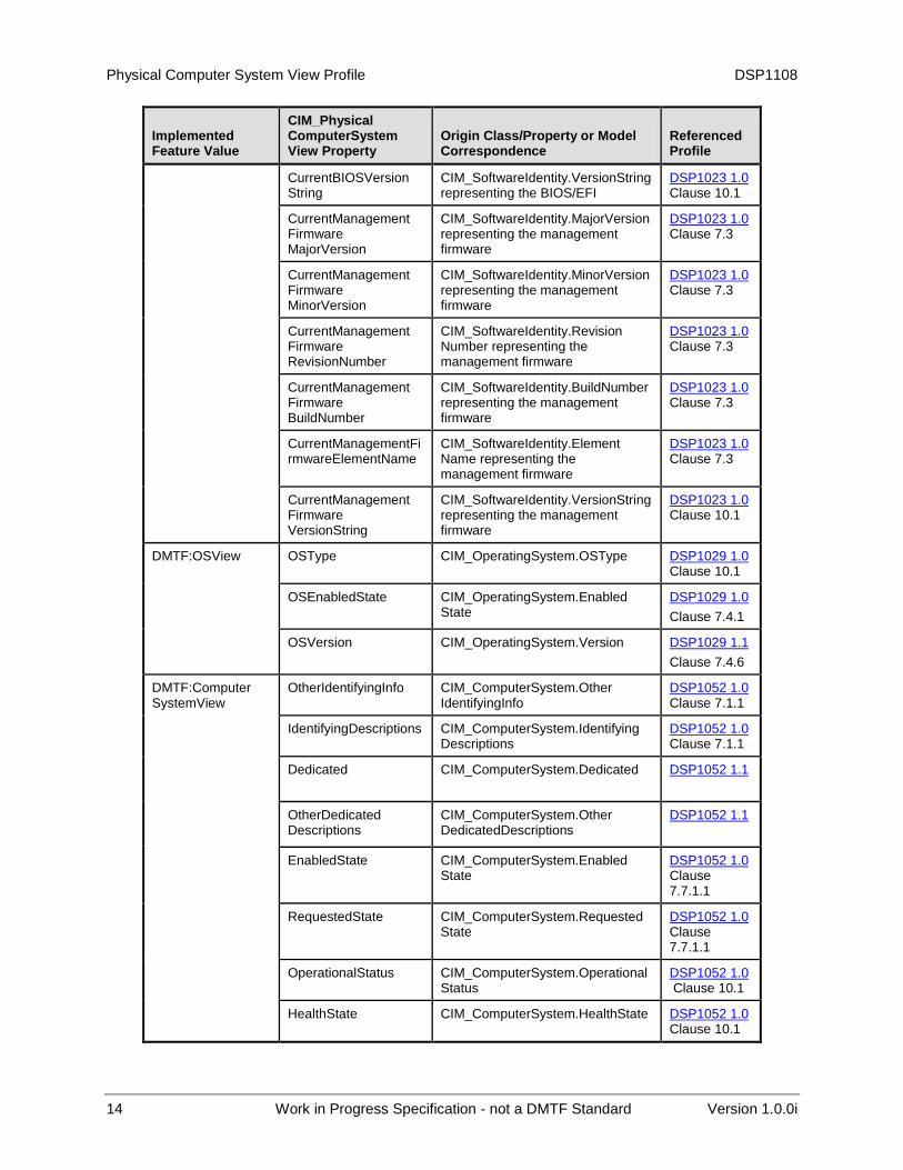
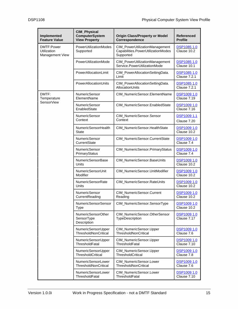
Table 2 – CIM_PhysicalComputerSystemView property model correspondence 324
Implemented Feature Value
CIM_Physical ComputerSystem View Property
Origin Class/Property or Model Correspondence
Referenced Profile
DMTF:Physical AssetView
FRUInfoSupported CIM_PhysicalAssetCapabilities.FRUInfoSupported for CIM_Chassis
DSP1011 1.0 Clause 7.4
Tag CIM_Chassis.Tag DSP1011 1.0 Clause 10.2
Manufacturer CIM_Chassis.Manufacturer DSP1011 1.0 Clause 7.4
Model CIM_Chassis.Model DSP1011 1.0 Clause 7.4
SKU CIM_Chassis.SKU DSP1011 1.0 Clause 7.4
SerialNumber CIM_Chassis.SerialNumber DSP1011 1.0 Clause 7.4
Version CIM_Chassis.Version DSP1011 1.0 Clause 10.2
PartNumber CIM_Chassis.PartNumber DSP1011 1.0 Clause 7.4
DMTF:CPUView
NumberOfProcessors Number of CIM_Processor instances associated to associated CIM_ComputerSystem
DSP1022 1.0 Clause 7.1
NumberOfProcessor Cores
CIM_ProcessorCapabilitiesNumberOfProcessorCores
DSP1022 1.0 Clause 7.2.1
NumberOfProcessor Threads
CIM_ProcessorCapabilitiesNumberOfHardwareThreads
DSP1022 1.0 Clause 7.2.1
ProcessorFamily CIM_Processor.Family DSP1022 1.0 Clause 10.11
ProcessorCurrent ClockSpeed
CIM_Processor.CurrentClockSpeed DSP1022 1.0 Clause 10.11
ProcessorMaxClock Speed
CIM_Processor.MaxClockSpeed DSP1022 1.0 Clause 10.11
DMTF:System MemoryView
MemoryBlockSize CIM_Memory.BlockSize DSP1026 1.0 Clause 10.3
MemoryNumberOf Blocks
CIM_Memory.NumberOfBlocks DSP1026 1.0 Clause 7.2
MemoryConsumable Blocks
CIM_Memory.ConsumableBlocks DSP1026 1.0 Clause 7.2
DMTF:Software InventoryView
CurrentBIOSMajor Version
CIM_SoftwareIdentity.MajorVersion representing the BIOS/EFI
DSP1023 1.0 Clause 7.3
CurrentBIOSMinor Version
CIM_SoftwareIdentity.MinorVersion representing the BIOS/EFI
DSP1023 1.0 Clause 7.3
CurrentBIOSRevisionNumber
CIM_SoftwareIdentity.Revision Number representing the BIOS/EFI
DSP1023 1.0 Clause 7.3
CurrentBIOSBuild Number
CIM_SoftwareIdentity.BuildNumber representing the BIOS/EFI
DSP1023 1.0 Clause 7.3
Physical Computer System View Profile DSP1108
14 Work in Progress Specification - not a DMTF Standard Version 1.0.0i
Implemented Feature Value
CIM_Physical ComputerSystem View Property
Origin Class/Property or Model Correspondence
Referenced Profile
CurrentBIOSVersion String
CIM_SoftwareIdentity.VersionString representing the BIOS/EFI
DSP1023 1.0 Clause 10.1
CurrentManagement Firmware MajorVersion
CIM_SoftwareIdentity.MajorVersion representing the management firmware
DSP1023 1.0 Clause 7.3
CurrentManagement Firmware MinorVersion
CIM_SoftwareIdentity.MinorVersion representing the management firmware
DSP1023 1.0 Clause 7.3
CurrentManagement Firmware RevisionNumber
CIM_SoftwareIdentity.Revision Number representing the management firmware
DSP1023 1.0 Clause 7.3
CurrentManagement Firmware BuildNumber
CIM_SoftwareIdentity.BuildNumber representing the management firmware
DSP1023 1.0 Clause 7.3
CurrentManagementFirmwareElementName
CIM_SoftwareIdentity.Element Name representing the management firmware
DSP1023 1.0 Clause 7.3
CurrentManagement Firmware VersionString
CIM_SoftwareIdentity.VersionString representing the management firmware
DSP1023 1.0 Clause 10.1
DMTF:OSView
OSType CIM_OperatingSystem.OSType DSP1029 1.0 Clause 10.1
OSEnabledState CIM_OperatingSystem.Enabled State
DSP1029 1.0
Clause 7.4.1
OSVersion CIM_OperatingSystem.Version DSP1029 1.1
Clause 7.4.6
DMTF:Computer SystemView
OtherIdentifyingInfo CIM_ComputerSystem.Other IdentifyingInfo
DSP1052 1.0 Clause 7.1.1
IdentifyingDescriptions CIM_ComputerSystem.Identifying Descriptions
DSP1052 1.0 Clause 7.1.1
Dedicated CIM_ComputerSystem.Dedicated DSP1052 1.1
OtherDedicated Descriptions
CIM_ComputerSystem.Other DedicatedDescriptions
DSP1052 1.1
EnabledState CIM_ComputerSystem.Enabled State
DSP1052 1.0 Clause 7.7.1.1
RequestedState CIM_ComputerSystem.Requested State
DSP1052 1.0 Clause 7.7.1.1
OperationalStatus CIM_ComputerSystem.Operational Status
DSP1052 1.0 Clause 10.1
HealthState CIM_ComputerSystem.HealthState DSP1052 1.0 Clause 10.1
DSP1108 Physical Computer System View Profile
Version 1.0.0i Work in Progress Specification - not a DMTF Standard 15
Implemented Feature Value
CIM_Physical ComputerSystem View Property
Origin Class/Property or Model Correspondence
Referenced Profile
DMTF:Power Utilization Management View
PowerUtilizationModesSupported
CIM_PowerUtilizationManagement Capabilities.PowerUtilizationModes Supported
DSP1085 1.0 Clause 10.2
PowerUtilizationMode CIM_PowerUtilizationManagement Service.PowerUtilizationMode
DSP1085 1.0 Clause 10.1
PowerAllocationLimit CIM_PowerAllocationSettingData. Limit
DSP1085 1.0 Clause 7.2.1
PowerAllocationUnits CIM_PowerAllocationSettingData. AllocationUnits
DSP1085 1.0 Clause 7.2.1
DMTF: Temperature SensorView
NumericSensor ElementName
CIM_NumericSensor.ElementName DSP1009 1.0 Clause 7.19
NumericSensor EnabledState
CIM_NumericSensor.EnabledState DSP1009 1.0 Clause 7.16
NumericSensor Context
CIM_NumericSensor.Sensor Context
DSP1009 1.1
Clause 7.20
NumericSensorHealthState
CIM_NumericSensor.HealthState DSP1009 1.0 Clause 10.2
NumericSensor CurrentState
CIM_NumericSensor.CurrentState DSP1009 1.0 Clause 7.4
NumericSensor PrimaryStatus
CIM_NumericSensor.PrimaryStatus DSP1009 1.0 Clause 7.4
NumericSensorBase Units
CIM_NumericSensor.BaseUnits DSP1009 1.0 Clause 10.2
NumericSensorUnit Modifier
CIM_NumericSensor.UnitModifier DSP1009 1.0 Clause 10.2
NumericSensorRate Units
CIM_NumericSensor.RateUnits DSP1009 1.0 Clause 10.2
NumericSensor CurrentReading
CIM_NumericSensor.Current Reading
DSP1009 1.0 Clause 10.2
NumericSensorSensorType
CIM_NumericSensor.SensorType DSP1009 1.0 Clause 10.2
NumericSensorOther SensorType Description
CIM_NumericSensor.OtherSensor TypeDescription
DSP1009 1.0 Clause 7.17
NumericSensorUpperThresholdNonCritical
CIM_NumericSensor.Upper ThresholdNonCritical
DSP1009 1.0 Clause 7.6
NumericSensorUpperThresholdFatal
CIM_NumericSensor.Upper ThresholdFatal
DSP1009 1.0 Clause 7.10
NumericSensorUpperThresholdCritical
CIM_NumericSensor.Upper ThresholdCritical
DSP1009 1.0 Clause 7.8
NumericSensorLowerThresholdNonCritical
CIM_NumericSensor.Lower ThresholdNonCritical
DSP1009 1.0 Clause 7.6
NumericSensorLowerThresholdFatal
CIM_NumericSensor.Lower ThresholdFatal
DSP1009 1.0 Clause 7.10
Physical Computer System View Profile DSP1108
16 Work in Progress Specification - not a DMTF Standard Version 1.0.0i
Implemented Feature Value
CIM_Physical ComputerSystem View Property
Origin Class/Property or Model Correspondence
Referenced Profile
NumericSensorLowerThresholdCritical
CIM_NumericSensor.Lower ThresholdCritical
DSP1009 1.0 Clause 7.8
DMTF:Record LogView
LogInstanceID CIM_RecordLog.InstanceID DSP1010 1.0 Clause 10.5
LogMaxNumberOf Records
CIM_RecordLog.MaxNumberOf Records
DSP1010 1.0 Clause 10.5
LogCurrentNumberOfRecords
CIM_RecordLog.CurrentNumberOf Records
DSP1010 1.0 Clause 10.5
LogOverWritePolicy CIM_RecordLog.OverwritePolicy DSP1010 1.0 Clause 7.8
LogState CIM_RecordLog.LogState DSP1010 1.0 Clause 7.5.2
DMTF:Boot ControlView
OneTimeBootSource CIM_BootSourceSetting.StructuredBootString
DSP1108 Clause 7.1.2.9.1
PersistentBootConfig Order
CIM_BootSourceSetting.StructuredBootString
DSP1108 Clause 7.1.2.9.2
325
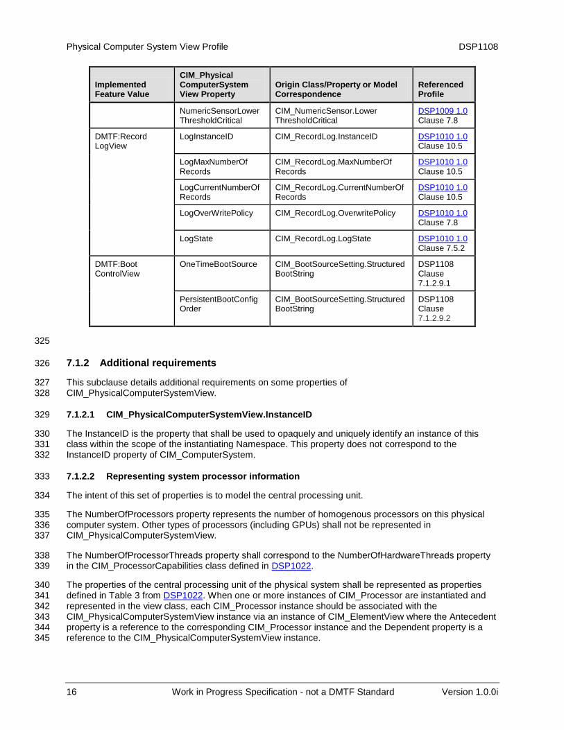
7.1.2 Additional requirements 326
This subclause details additional requirements on some properties of 327 CIM_PhysicalComputerSystemView. 328
7.1.2.1 CIM_PhysicalComputerSystemView.InstanceID 329
The InstanceID is the property that shall be used to opaquely and uniquely identify an instance of this 330 class within the scope of the instantiating Namespace. This property does not correspond to the 331 InstanceID property of CIM_ComputerSystem. 332
7.1.2.2 Representing system processor information 333
The intent of this set of properties is to model the central processing unit. 334
The NumberOfProcessors property represents the number of homogenous processors on this physical 335 computer system. Other types of processors (including GPUs) shall not be represented in 336 CIM_PhysicalComputerSystemView. 337
The NumberOfProcessorThreads property shall correspond to the NumberOfHardwareThreads property 338 in the CIM_ProcessorCapabilities class defined in DSP1022. 339
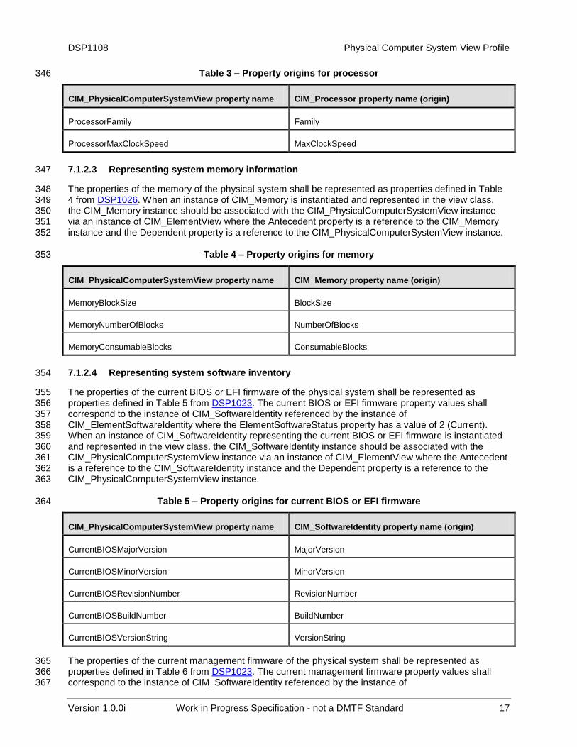
The properties of the central processing unit of the physical system shall be represented as properties 340 defined in Table 3 from DSP1022. When one or more instances of CIM_Processor are instantiated and 341 represented in the view class, each CIM_Processor instance should be associated with the 342 CIM_PhysicalComputerSystemView instance via an instance of CIM_ElementView where the Antecedent 343 property is a reference to the corresponding CIM_Processor instance and the Dependent property is a 344 reference to the CIM_PhysicalComputerSystemView instance. 345
DSP1108 Physical Computer System View Profile
Version 1.0.0i Work in Progress Specification - not a DMTF Standard 17
Table 3 – Property origins for processor 346
CIM_PhysicalComputerSystemView property name CIM_Processor property name (origin)
ProcessorFamily Family
ProcessorMaxClockSpeed MaxClockSpeed
7.1.2.3 Representing system memory information 347
The properties of the memory of the physical system shall be represented as properties defined in Table 348 4 from DSP1026. When an instance of CIM_Memory is instantiated and represented in the view class, 349 the CIM_Memory instance should be associated with the CIM_PhysicalComputerSystemView instance 350 via an instance of CIM_ElementView where the Antecedent property is a reference to the CIM_Memory 351 instance and the Dependent property is a reference to the CIM_PhysicalComputerSystemView instance. 352
Table 4 – Property origins for memory 353
CIM_PhysicalComputerSystemView property name CIM_Memory property name (origin)
MemoryBlockSize BlockSize
MemoryNumberOfBlocks NumberOfBlocks
MemoryConsumableBlocks ConsumableBlocks
7.1.2.4 Representing system software inventory 354
The properties of the current BIOS or EFI firmware of the physical system shall be represented as 355 properties defined in Table 5 from DSP1023. The current BIOS or EFI firmware property values shall 356 correspond to the instance of CIM_SoftwareIdentity referenced by the instance of 357 CIM_ElementSoftwareIdentity where the ElementSoftwareStatus property has a value of 2 (Current). 358 When an instance of CIM_SoftwareIdentity representing the current BIOS or EFI firmware is instantiated 359 and represented in the view class, the CIM_SoftwareIdentity instance should be associated with the 360 CIM_PhysicalComputerSystemView instance via an instance of CIM_ElementView where the Antecedent 361 is a reference to the CIM_SoftwareIdentity instance and the Dependent property is a reference to the 362 CIM_PhysicalComputerSystemView instance. 363
Table 5 – Property origins for current BIOS or EFI firmware 364
CIM_PhysicalComputerSystemView property name CIM_SoftwareIdentity property name (origin)
CurrentBIOSMajorVersion MajorVersion
CurrentBIOSMinorVersion MinorVersion
CurrentBIOSRevisionNumber RevisionNumber
CurrentBIOSBuildNumber BuildNumber
CurrentBIOSVersionString VersionString
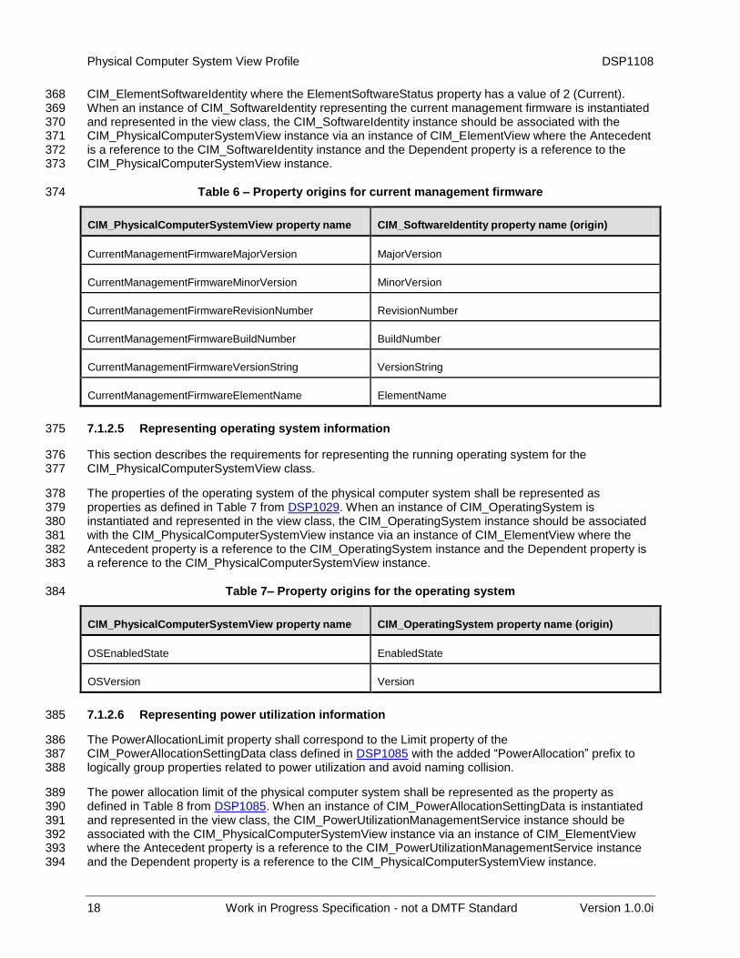
The properties of the current management firmware of the physical system shall be represented as 365 properties defined in Table 6 from DSP1023. The current management firmware property values shall 366 correspond to the instance of CIM_SoftwareIdentity referenced by the instance of 367
Physical Computer System View Profile DSP1108
18 Work in Progress Specification - not a DMTF Standard Version 1.0.0i
CIM_ElementSoftwareIdentity where the ElementSoftwareStatus property has a value of 2 (Current). 368 When an instance of CIM_SoftwareIdentity representing the current management firmware is instantiated 369 and represented in the view class, the CIM_SoftwareIdentity instance should be associated with the 370 CIM_PhysicalComputerSystemView instance via an instance of CIM_ElementView where the Antecedent 371 is a reference to the CIM_SoftwareIdentity instance and the Dependent property is a reference to the 372 CIM_PhysicalComputerSystemView instance. 373
Table 6 – Property origins for current management firmware 374
CIM_PhysicalComputerSystemView property name CIM_SoftwareIdentity property name (origin)
CurrentManagementFirmwareMajorVersion MajorVersion
CurrentManagementFirmwareMinorVersion MinorVersion
CurrentManagementFirmwareRevisionNumber RevisionNumber
CurrentManagementFirmwareBuildNumber BuildNumber
CurrentManagementFirmwareVersionString VersionString
CurrentManagementFirmwareElementName ElementName
7.1.2.5 Representing operating system information 375
This section describes the requirements for representing the running operating system for the 376 CIM_PhysicalComputerSystemView class. 377
The properties of the operating system of the physical computer system shall be represented as 378 properties as defined in Table 7 from DSP1029. When an instance of CIM_OperatingSystem is 379 instantiated and represented in the view class, the CIM_OperatingSystem instance should be associated 380 with the CIM_PhysicalComputerSystemView instance via an instance of CIM_ElementView where the 381 Antecedent property is a reference to the CIM_OperatingSystem instance and the Dependent property is 382 a reference to the CIM_PhysicalComputerSystemView instance. 383
Table 7– Property origins for the operating system 384
CIM_PhysicalComputerSystemView property name CIM_OperatingSystem property name (origin)
OSEnabledState EnabledState
OSVersion Version
7.1.2.6 Representing power utilization information 385
The PowerAllocationLimit property shall correspond to the Limit property of the 386 CIM_PowerAllocationSettingData class defined in DSP1085 with the added “PowerAllocation” prefix to 387 logically group properties related to power utilization and avoid naming collision. 388
The power allocation limit of the physical computer system shall be represented as the property as 389 defined in Table 8 from DSP1085. When an instance of CIM_PowerAllocationSettingData is instantiated 390 and represented in the view class, the CIM_PowerUtilizationManagementService instance should be 391 associated with the CIM_PhysicalComputerSystemView instance via an instance of CIM_ElementView 392 where the Antecedent property is a reference to the CIM_PowerUtilizationManagementService instance 393 and the Dependent property is a reference to the CIM_PhysicalComputerSystemView instance. 394
DSP1108 Physical Computer System View Profile
Version 1.0.0i Work in Progress Specification - not a DMTF Standard 19
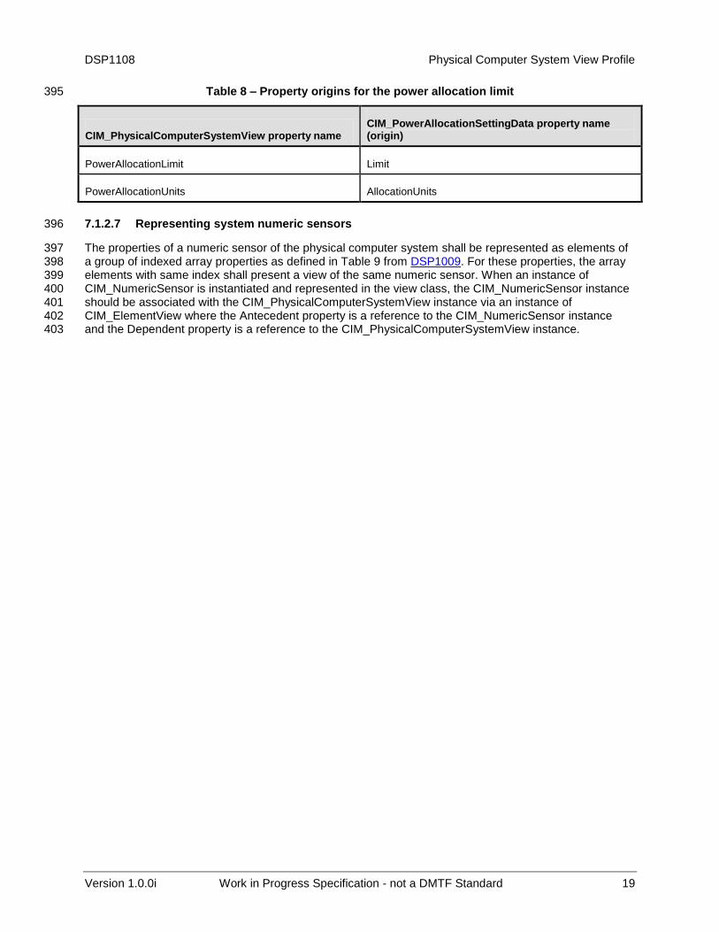
Table 8 – Property origins for the power allocation limit 395
CIM_PhysicalComputerSystemView property name CIM_PowerAllocationSettingData property name (origin)
PowerAllocationLimit Limit
PowerAllocationUnits AllocationUnits
7.1.2.7 Representing system numeric sensors 396
The properties of a numeric sensor of the physical computer system shall be represented as elements of 397 a group of indexed array properties as defined in Table 9 from DSP1009. For these properties, the array 398 elements with same index shall present a view of the same numeric sensor. When an instance of 399 CIM_NumericSensor is instantiated and represented in the view class, the CIM_NumericSensor instance 400 should be associated with the CIM_PhysicalComputerSystemView instance via an instance of 401 CIM_ElementView where the Antecedent property is a reference to the CIM_NumericSensor instance 402 and the Dependent property is a reference to the CIM_PhysicalComputerSystemView instance. 403
Physical Computer System View Profile DSP1108
20 Work in Progress Specification - not a DMTF Standard Version 1.0.0i
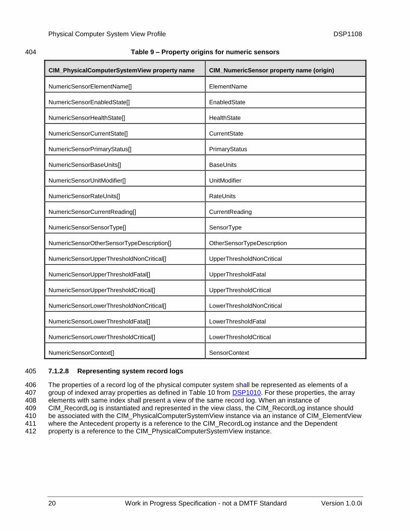
Table 9 – Property origins for numeric sensors 404
CIM_PhysicalComputerSystemView property name CIM_NumericSensor property name (origin)
NumericSensorElementName[] ElementName
NumericSensorEnabledState[] EnabledState
NumericSensorHealthState[] HealthState
NumericSensorCurrentState[] CurrentState
NumericSensorPrimaryStatus[] PrimaryStatus
NumericSensorBaseUnits[] BaseUnits
NumericSensorUnitModifier[] UnitModifier
NumericSensorRateUnits[] RateUnits
NumericSensorCurrentReading[] CurrentReading
NumericSensorSensorType[] SensorType
NumericSensorOtherSensorTypeDescription[] OtherSensorTypeDescription
NumericSensorUpperThresholdNonCritical[] UpperThresholdNonCritical
NumericSensorUpperThresholdFatal[] UpperThresholdFatal
NumericSensorUpperThresholdCritical[] UpperThresholdCritical
NumericSensorLowerThresholdNonCritical[] LowerThresholdNonCritical
NumericSensorLowerThresholdFatal[] LowerThresholdFatal
NumericSensorLowerThresholdCritical[] LowerThresholdCritical
NumericSensorContext[] SensorContext
7.1.2.8 Representing system record logs 405
The properties of a record log of the physical computer system shall be represented as elements of a 406 group of indexed array properties as defined in Table 10 from DSP1010. For these properties, the array 407 elements with same index shall present a view of the same record log. When an instance of 408 CIM_RecordLog is instantiated and represented in the view class, the CIM_RecordLog instance should 409 be associated with the CIM_PhysicalComputerSystemView instance via an instance of CIM_ElementView 410 where the Antecedent property is a reference to the CIM_RecordLog instance and the Dependent 411 property is a reference to the CIM_PhysicalComputerSystemView instance. 412
DSP1108 Physical Computer System View Profile
Version 1.0.0i Work in Progress Specification - not a DMTF Standard 21
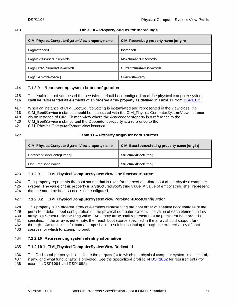
Table 10 – Property origins for record logs 413
CIM_PhysicalComputerSystemView property name CIM_RecordLog property name (origin)
LogInstanceID[] InstanceID
LogMaxNumberOfRecords[] MaxNumberOfRecords
LogCurrentNumberOfRecords[] CurrentNumberOfRecords
LogOverWritePolicy[] OverwritePolicy
7.1.2.9 Representing system boot configuration 414
The enabled boot sources of the persistent default boot configuration of the physical computer system 415 shall be represented as elements of an ordered array property as defined in Table 11 from DSP1012. 416
When an instance of CIM_BootSourceSetting is instantiated and represented in the view class, the 417 CIM_BootService instance should be associated with the CIM_PhysicalComputerSystemView instance 418 via an instance of CIM_ElementView where the Antecedent property is a reference to the 419 CIM_BootService instance and the Dependent property is a reference to the 420 CIM_PhysicalComputerSystemView instance. 421
Table 11 – Property origin for boot sources 422
CIM_PhysicalComputerSystemView property name CIM_BootSourceSetting property name (origin)
PersistentBootConfigOrder[] StructuredBootString
OneTimeBootSource StructuredBootString
7.1.2.9.1 CIM_PhysicalComputerSystemView.OneTimeBootSource 423
This property represents the boot source that is used for the next one-time boot of the physical computer 424 system. The value of this property is a StructuredBootString value. A value of empty string shall represent 425 that the one-time boot source is not configured. 426
7.1.2.9.2 CIM_PhysicalComputerSystemView.PersistentBootConfigOrder 427
This property is an ordered array of elements representing the boot order of enabled boot sources of the 428 persistent default boot configuration on the physical computer system. The value of each element in this 429 array is a StructuredBootString value. An empty array shall represent that no persistent boot order is 430 specified. If the array is not empty, then each boot source specified in the array should support fail-431 through. An unsuccessful boot attempt should result in continuing through the ordered array of boot 432 sources for which to attempt to boot. 433
7.1.2.10 Representing system identity information 434
7.1.2.10.1 CIM_PhysicalComputerSystemView.Dedicated 435
The Dedicated property shall indicate the purpose(s) to which the physical computer system is dedicated, 436 if any, and what functionality is provided. See the specialized profiles of DSP1052 for requirements (for 437 example DSP1004 and DSP1058). 438
Physical Computer System View Profile DSP1108
22 Work in Progress Specification - not a DMTF Standard Version 1.0.0i
7.1.2.10.2 CIM_PhysicalComputerSystemView.OtherDedicatedDescriptions 439
The OtherDedicatedDescriptions property shall contain strings describing how or why the system is 440 dedicated when the Dedicated property includes “Other” (value=2). See the specialized profiles of 441 DSP1052 for requirements (for example DSP1004 and DSP1058). 442
7.1.2.11 Representing system FRU information 443
7.1.2.11.1 CIM_PhysicalComputerSystemView.FRUInfoSupported 444
The FRUInfoSupported property shall correspond to the value of the 445 CIM_PhysicalAssetCapabilities.FRUInfoSupported property value associated to the CIM_Chassis 446 instance. 447
8 Methods 448
This clause details the requirements for supporting intrinsic operations and extrinsic methods for the CIM 449 elements defined by this profile. 450
8.1 CIM_PhysicalComputerSystemView.RequestStateChange( ) 451
When the ImplementedFeatures property of the CIM_RegisteredProfile instance contains 452 “DMTF:ComputerSystemView”, then RequestStateChange( ) shall be implemented. 453
Invocation of the RequestStateChange( ) method changes the physical computer system’s state to the 454 value specified in the RequestedState parameter. A return code value of zero shall indicate that the 455 requested state change was successfully initiated. 456
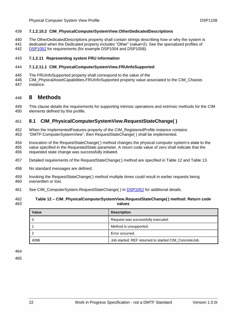
Detailed requirements of the RequestStateChange( ) method are specified in Table 12 and Table 13. 457
No standard messages are defined. 458
Invoking the RequestStateChange( ) method multiple times could result in earlier requests being 459 overwritten or lost. 460
See CIM_ComputerSystem.RequestStateChange( ) in DSP1052 for additional details. 461
Table 12 – CIM_PhysicalComputerSystemView.RequestStateChange( ) method: Return code 462 values 463
Value Description
0 Request was successfully executed.
1 Method is unsupported.
2 Error occurred.
4096 Job started: REF returned to started CIM_ConcreteJob.
464
465
DSP1108 Physical Computer System View Profile
Version 1.0.0i Work in Progress Specification - not a DMTF Standard 23
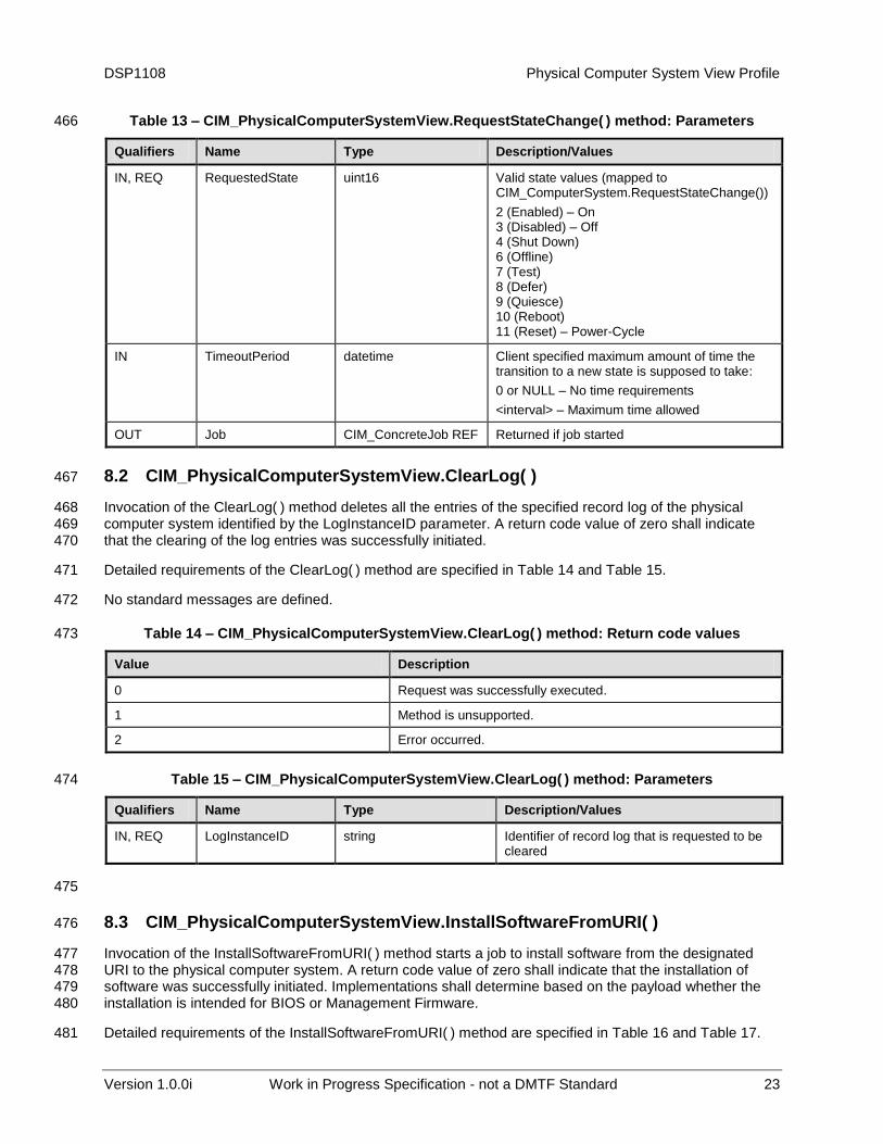
Table 13 – CIM_PhysicalComputerSystemView.RequestStateChange( ) method: Parameters 466
Qualifiers Name Type Description/Values
IN, REQ RequestedState uint16 Valid state values (mapped to CIM_ComputerSystem.RequestStateChange())
2 (Enabled) – On 3 (Disabled) – Off 4 (Shut Down) 6 (Offline) 7 (Test) 8 (Defer) 9 (Quiesce) 10 (Reboot) 11 (Reset) – Power-Cycle
IN TimeoutPeriod datetime Client specified maximum amount of time the transition to a new state is supposed to take:
0 or NULL – No time requirements
<interval> – Maximum time allowed
OUT Job CIM_ConcreteJob REF Returned if job started
8.2 CIM_PhysicalComputerSystemView.ClearLog( ) 467
Invocation of the ClearLog( ) method deletes all the entries of the specified record log of the physical 468 computer system identified by the LogInstanceID parameter. A return code value of zero shall indicate 469 that the clearing of the log entries was successfully initiated. 470
Detailed requirements of the ClearLog( ) method are specified in Table 14 and Table 15. 471
No standard messages are defined. 472
Table 14 – CIM_PhysicalComputerSystemView.ClearLog( ) method: Return code values 473
Value Description
0 Request was successfully executed.
1 Method is unsupported.
2 Error occurred.
Table 15 – CIM_PhysicalComputerSystemView.ClearLog( ) method: Parameters 474
Qualifiers Name Type Description/Values
IN, REQ LogInstanceID string Identifier of record log that is requested to be cleared
475
8.3 CIM_PhysicalComputerSystemView.InstallSoftwareFromURI( ) 476
Invocation of the InstallSoftwareFromURI( ) method starts a job to install software from the designated 477 URI to the physical computer system. A return code value of zero shall indicate that the installation of 478 software was successfully initiated. Implementations shall determine based on the payload whether the 479 installation is intended for BIOS or Management Firmware. 480
Detailed requirements of the InstallSoftwareFromURI( ) method are specified in Table 16 and Table 17. 481
Physical Computer System View Profile DSP1108
24 Work in Progress Specification - not a DMTF Standard Version 1.0.0i
No standard messages are defined. 482
See CIM_SoftwareInstallationService.InstallFromURI( ) in DSP1025 for additional details. 483
Table 16 – CIM_PhysicalComputerSystemView.InstallSoftwareFromURI( ) method: Return code 484 values 485
Value Description
0 Job completed with no error.
1 Method is unsupported.
2 Error occurred.
4096 Job started: REF returned to started CIM_ConcreteJob.
Table 17 – CIM_PhysicalComputerSystemView.InstallSoftwareFromURI( ) method: Parameters 486
Qualifiers Name Type Description/Values
IN, REQ URI string A URI for the software.
IN InstallOptions uint16 Options to control the install process. See CIM_SoftwareInstallationService.InstallFrom URI( ) in DSP1025 for additional details.
IN Classifications[] uint16 Identify the classification of software to install. See CIM_SoftwareIdentity.Classifications in DSP1023 for additional details.
IN InstallOptionValues string InstallOptionsValues is an array of strings providing additional information to InstallOptions for the method to install the software. See CIM_SoftwareInstallationService.InstallFrom URI( ) in DSP1025 for additional details.
OUT Job CIM_ConcreteJob REF Returned if job started
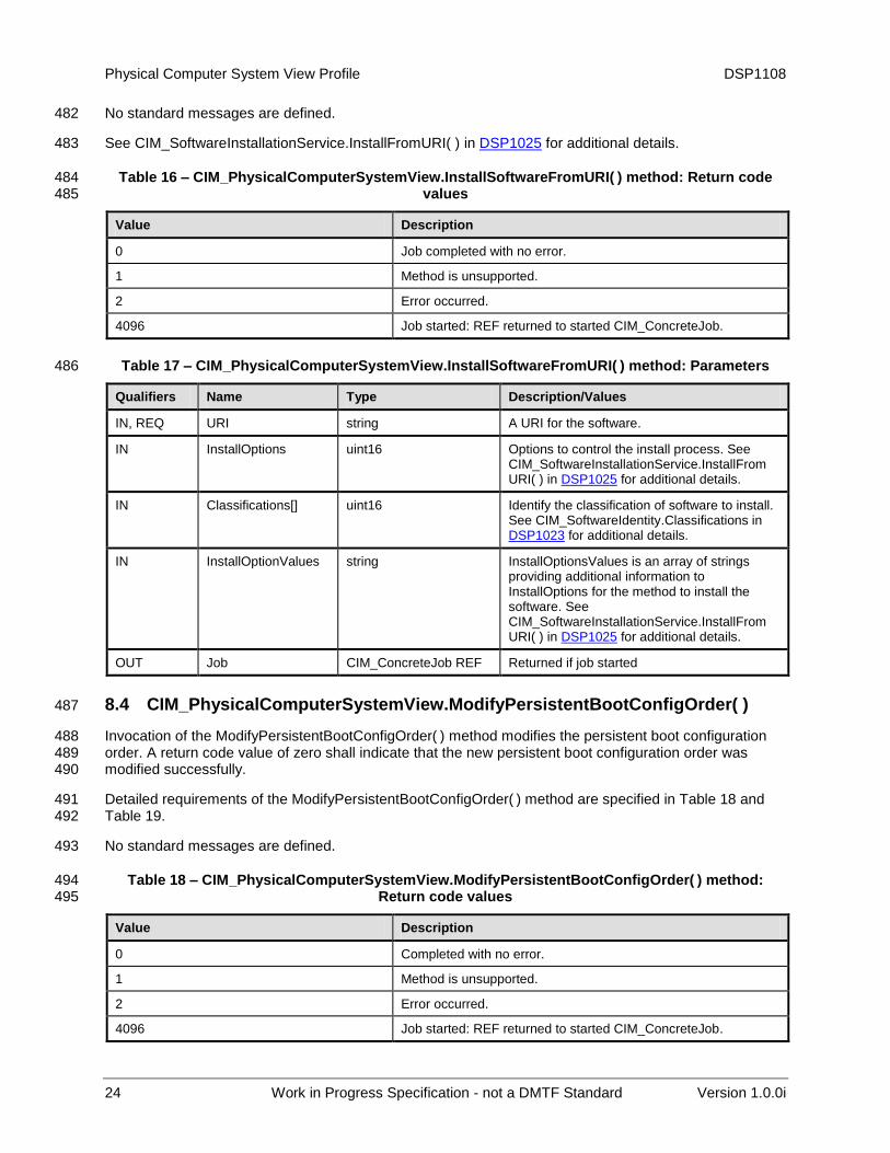
8.4 CIM_PhysicalComputerSystemView.ModifyPersistentBootConfigOrder( ) 487
Invocation of the ModifyPersistentBootConfigOrder( ) method modifies the persistent boot configuration 488 order. A return code value of zero shall indicate that the new persistent boot configuration order was 489 modified successfully. 490
Detailed requirements of the ModifyPersistentBootConfigOrder( ) method are specified in Table 18 and 491 Table 19. 492
No standard messages are defined. 493
Table 18 – CIM_PhysicalComputerSystemView.ModifyPersistentBootConfigOrder( ) method: 494 Return code values 495
Value Description
0 Completed with no error.
1 Method is unsupported.
2 Error occurred.
4096 Job started: REF returned to started CIM_ConcreteJob.
DSP1108 Physical Computer System View Profile
Version 1.0.0i Work in Progress Specification - not a DMTF Standard 25
Table 19 – CIM_PhysicalComputerSystemView.ModifyPersistentBootConfigOrder( ) method: 496 Parameters 497
Qualifiers Name Type Description/Values
IN, REQ StructuredBootString string array An array of StructuredBootString values
OUT Job CIM_ConcreteJob REF Returned if job started
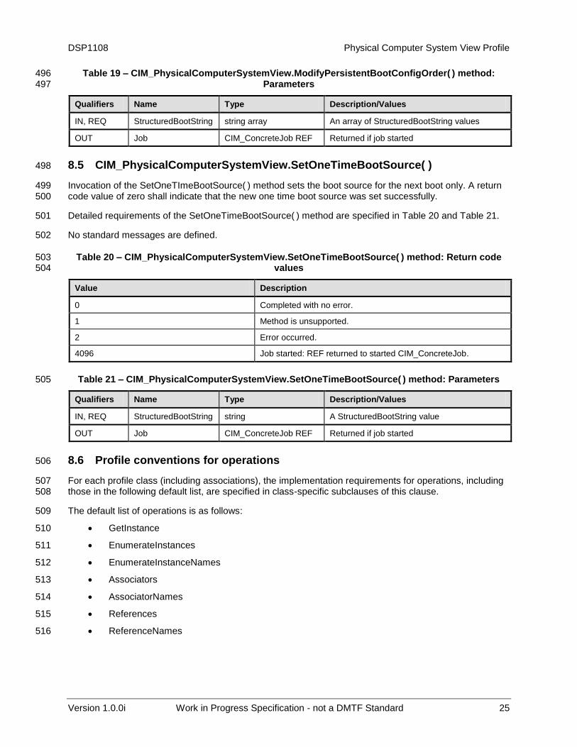
8.5 CIM_PhysicalComputerSystemView.SetOneTimeBootSource( ) 498
Invocation of the SetOneTImeBootSource( ) method sets the boot source for the next boot only. A return 499 code value of zero shall indicate that the new one time boot source was set successfully. 500
Detailed requirements of the SetOneTimeBootSource( ) method are specified in Table 20 and Table 21. 501
No standard messages are defined. 502
Table 20 – CIM_PhysicalComputerSystemView.SetOneTimeBootSource( ) method: Return code 503 values 504
Value Description
0 Completed with no error.
1 Method is unsupported.
2 Error occurred.
4096 Job started: REF returned to started CIM_ConcreteJob.
Table 21 – CIM_PhysicalComputerSystemView.SetOneTimeBootSource( ) method: Parameters 505
Qualifiers Name Type Description/Values
IN, REQ StructuredBootString string A StructuredBootString value
OUT Job CIM_ConcreteJob REF Returned if job started
8.6 Profile conventions for operations 506
For each profile class (including associations), the implementation requirements for operations, including 507 those in the following default list, are specified in class-specific subclauses of this clause. 508
The default list of operations is as follows: 509
GetInstance 510
EnumerateInstances 511
EnumerateInstanceNames 512
Associators 513
AssociatorNames 514
References 515
ReferenceNames 516

Physical Computer System View Profile DSP1108
26 Work in Progress Specification - not a DMTF Standard Version 1.0.0i
8.7 CIM_PhysicalComputerSystemView 517
Table 22 lists operations that either have special requirements beyond those from DSP0200 or shall not 518 be supported. 519
Table 22 – Operations: CIM_PhysicalComputerSystemView 520
Operation Requirement Description
InvokeMethod Conditional If “DMTF:ComputerSystemView”, “DMTF:RecordLogView”, “DMTF:BootControlView”, or “DMTF:SoftwareUpdateView” is an implemented feature, this operation shall be supported. See 8.
8.8 CIM_ElementView 521
All operations in the default list in 8.2 shall be implemented as defined in DSP0200. 522
DSP1108 Physical Computer System View Profile
Version 1.0.0i Work in Progress Specification - not a DMTF Standard 27
9 Use cases 523
This clause contains object diagrams and use cases for the Physical Computer System View Profile. 524
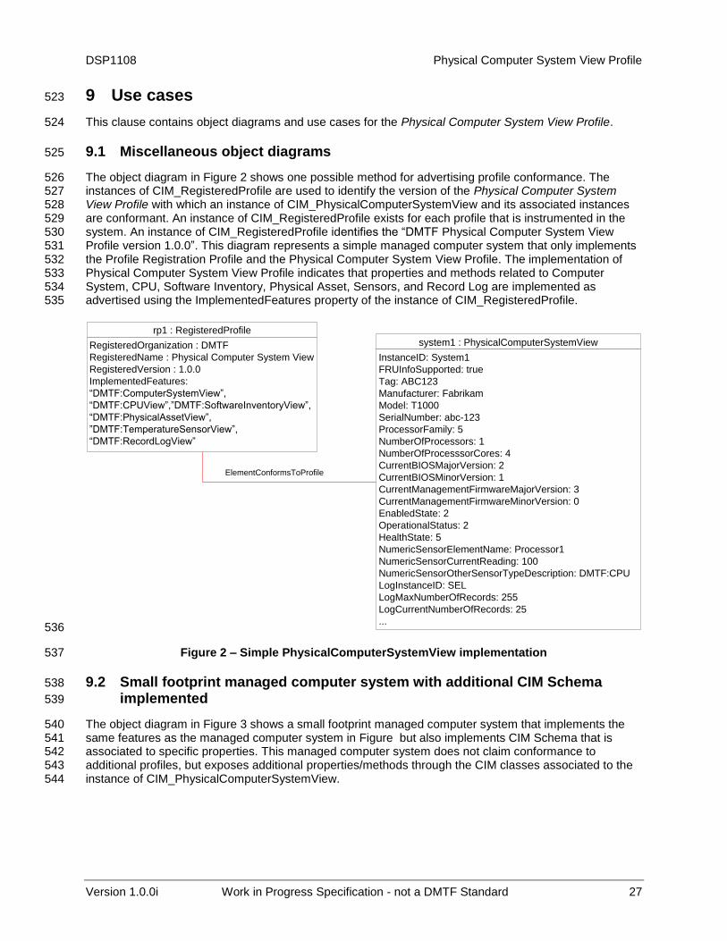
9.1 Miscellaneous object diagrams 525
The object diagram in Figure 2 shows one possible method for advertising profile conformance. The 526 instances of CIM_RegisteredProfile are used to identify the version of the Physical Computer System 527 View Profile with which an instance of CIM_PhysicalComputerSystemView and its associated instances 528 are conformant. An instance of CIM_RegisteredProfile exists for each profile that is instrumented in the 529 system. An instance of CIM_RegisteredProfile identifies the “DMTF Physical Computer System View 530 Profile version 1.0.0”. This diagram represents a simple managed computer system that only implements 531 the Profile Registration Profile and the Physical Computer System View Profile. The implementation of 532 Physical Computer System View Profile indicates that properties and methods related to Computer 533 System, CPU, Software Inventory, Physical Asset, Sensors, and Record Log are implemented as 534 advertised using the ImplementedFeatures property of the instance of CIM_RegisteredProfile. 535
rp1 : RegisteredProfile
RegisteredOrganization : DMTF
RegisteredName : Physical Computer System View
RegisteredVersion : 1.0.0
ImplementedFeatures:
“DMTF:ComputerSystemView”,
“DMTF:CPUView”,”DMTF:SoftwareInventoryView”,
“DMTF:PhysicalAssetView”,
”DMTF:TemperatureSensorView”,
“DMTF:RecordLogView”
ElementConformsToProfile
system1 : PhysicalComputerSystemView
InstanceID: System1
FRUInfoSupported: true
Tag: ABC123
Manufacturer: Fabrikam
Model: T1000
SerialNumber: abc-123
ProcessorFamily: 5
NumberOfProcessors: 1
NumberOfProcesssorCores: 4
CurrentBIOSMajorVersion: 2
CurrentBIOSMinorVersion: 1
CurrentManagementFirmwareMajorVersion: 3
CurrentManagementFirmwareMinorVersion: 0
EnabledState: 2
OperationalStatus: 2
HealthState: 5
NumericSensorElementName: Processor1
NumericSensorCurrentReading: 100
NumericSensorOtherSensorTypeDescription: DMTF:CPU
LogInstanceID: SEL
LogMaxNumberOfRecords: 255
LogCurrentNumberOfRecords: 25
... 536
Figure 2 – Simple PhysicalComputerSystemView implementation 537
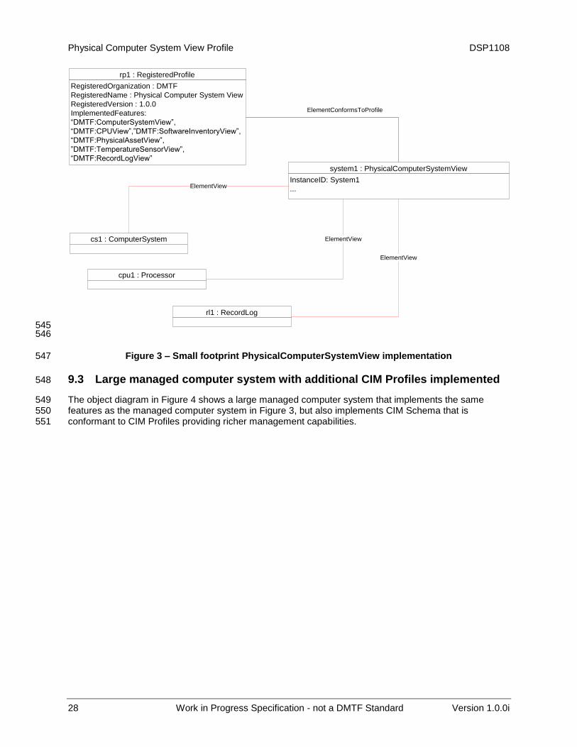
9.2 Small footprint managed computer system with additional CIM Schema 538
implemented 539
The object diagram in Figure 3 shows a small footprint managed computer system that implements the 540 same features as the managed computer system in Figure but also implements CIM Schema that is 541 associated to specific properties. This managed computer system does not claim conformance to 542 additional profiles, but exposes additional properties/methods through the CIM classes associated to the 543 instance of CIM_PhysicalComputerSystemView. 544
Physical Computer System View Profile DSP1108
28 Work in Progress Specification - not a DMTF Standard Version 1.0.0i
ElementConformsToProfile
system1 : PhysicalComputerSystemView
InstanceID: System1
...
cpu1 : Processor
ElementViewcs1 : ComputerSystem
ElementView
rl1 : RecordLog
ElementView
rp1 : RegisteredProfile
RegisteredOrganization : DMTF
RegisteredName : Physical Computer System View
RegisteredVersion : 1.0.0
ImplementedFeatures:
“DMTF:ComputerSystemView”,
“DMTF:CPUView”,”DMTF:SoftwareInventoryView”,
“DMTF:PhysicalAssetView”,
”DMTF:TemperatureSensorView”,
“DMTF:RecordLogView”
545 546
Figure 3 – Small footprint PhysicalComputerSystemView implementation 547
9.3 Large managed computer system with additional CIM Profiles implemented 548
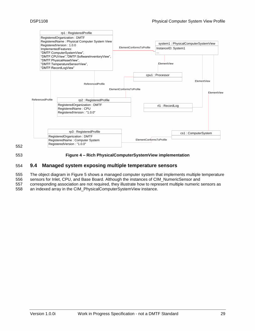
The object diagram in Figure 4 shows a large managed computer system that implements the same 549 features as the managed computer system in Figure 3, but also implements CIM Schema that is 550 conformant to CIM Profiles providing richer management capabilities. 551
DSP1108 Physical Computer System View Profile
Version 1.0.0i Work in Progress Specification - not a DMTF Standard 29
ElementConformsToProfile
system1 : PhysicalComputerSystemView
InstanceID: System1
...
rp2 : RegisteredProfile
RegisteredOrganization : DMTF
RegisteredName : CPU
RegisteredVersion : "1.0.0"
ReferencedProfile
cpu1 : Processor
ElementView
rp3 : RegisteredProfile
RegisteredOrganization : DMTF
RegisteredName : Computer System
RegisteredVersion : "1.0.0"
cs1 : ComputerSystem
ReferencedProfile
ElementView
rl1 : RecordLog
ElementView
ElementConformsToProfile
ElementConformsToProfile
rp1 : RegisteredProfile
RegisteredOrganization : DMTF
RegisteredName : Physical Computer System View
RegisteredVersion : 1.0.0
ImplementedFeatures:
“DMTF:ComputerSystemView”,
“DMTF:CPUView”,”DMTF:SoftwareInventoryView”,
“DMTF:PhysicalAssetView”,
”DMTF:TemperatureSensorView”,
“DMTF:RecordLogView”
552
Figure 4 – Rich PhysicalComputerSystemView implementation 553
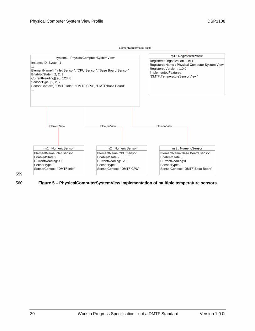
9.4 Managed system exposing multiple temperature sensors 554
The object diagram in Figure 5 shows a managed computer system that implements multiple temperature 555 sensors for Inlet, CPU, and Base Board. Although the instances of CIM_NumericSensor and 556 corresponding association are not required, they illustrate how to represent multiple numeric sensors as 557 an indexed array in the CIM_PhysicalComputerSystemView instance. 558
Physical Computer System View Profile DSP1108
30 Work in Progress Specification - not a DMTF Standard Version 1.0.0i
ElementConformsToProfile
system1 : PhysicalComputerSystemView
InstanceID: System1
...
ElementName[]: “Inlet Sensor”, “CPU Sensor”, “Base Board Sensor”
EnabledState[]: 2, 2, 3
CurrentReading[]:90, 120, 0
SensorType[]:2, 2, 2
SensorContext[]:”DMTF:Inlet”, “DMTF:CPU”, “DMTF:Base Board”
...
ElementView
rp1 : RegisteredProfile
RegisteredOrganization : DMTF
RegisteredName : Physical Computer System View
RegisteredVersion : 1.0.0
ImplementedFeatures:
”DMTF:TemperatureSensorView”
ElementView
ns1 : NumericSensor
ElementName:Inlet Sensor
EnabledState:2
CurrentReading:90
SensorType:2
SensorContext: “DMTF:Inlet”
ElementView
ns2 : NumericSensor
ElementName:CPU Sensor
EnabledState:2
CurrentReading:120
SensorType:2
SensorContext: “DMTF:CPU”
ns3 : NumericSensor
ElementName:Base Board Sensor
EnabledState:3
CurrentReading:0
SensorType:2
SensorContext: “DMTF:Base Board”
559
Figure 5 – PhysicalComputerSystemView implementation of multiple temperature sensors 560
DSP1108 Physical Computer System View Profile
Version 1.0.0i Work in Progress Specification - not a DMTF Standard 31
9.5 Determine the power state of the physical computer system 561
To determine the power state: 562
1) Verify that the managed computer system implements the DMTF:ComputerSystemView feature 563 by reading ImplementedFeatures property of the CIM_RegisteredProfile instance. 564
2) Read the EnabledState property of the instance of CIM_PhysicalComputerSystemView. 565
3) See Table 12 for the mapping of power states to the EnabledState property. 566
9.6 Change the power state of the physical computer system 567
To change the power state: 568
1) Verify that the managed computer system implements the DMTF:ComputerSystemView feature 569 by reading the ImplementedFeatures property of the CIM_RegisteredProfile instance. 570
2) Invoke the RequestStateChange() method of the instance of CIM_PhysicalComputerSystemView 571 providing the new requested state. 572
3) See Table 12 for the mapping of power states to the EnabledState property. 573
9.7 Get properties of a specific record log of the physical computer system 574
To get the properties of a specific record log: 575
1) Verify that the managed computer system implements the DMTF:RecordLogView feature by 576 reading the ImplementedFeatures property of the CIM_RegisteredProfile instance. 577
2) Identify the index to the specific log that matches the LogInstanceID. 578
3) Use this index to read the ordered arrays MaxNumberOfRecords, CurrentNumberOfRecords, 579 OverWritePolicy, and LogState for that specific record log. 580
9.8 Browse the records of a log of the physical computer system 581
To browse log entries: 582
1) Verify that the managed computer system implements the DMTF:RecordLogView feature by 583 reading the ImplementedFeatures property of the CIM_RegisteredProfile instance. 584
2) Verify that an instance of CIM_RegisteredProfile for Record Log Profile exists. 585
3) Traverse the association to the CIM_RecordLog instance with the LogInstanceID using the 586 CIM_ElementView association class. 587
4) Enumerate instances of CIM_LogEntry that are associated through the CIM_LogManagesRecord 588 association to the given instance of CIM_RecordLog. 589
590
Physical Computer System View Profile DSP1108
32 Work in Progress Specification - not a DMTF Standard Version 1.0.0i
9.9 Monitor temperate sensor readings of the physical computer system 591
To monitor CPU temperature sensor readings: 592
1) Verify that the managed computer system implements the DMTF:TemperatureSensorView 593 feature by reading the ImplementedFeatures property of the CIM_RegisteredProfile instance. 594
2) Identify the index to a specific sensor that contains “DMTF:CPU” as the value for 595 NumericSensorContext. 596
3) Use this index to read the ordered arrays NumericSensorBaseUnits, NumericSensorUnitModifier, 597 NumericSensorRateUnits, and NumericSensorCurrentReading to compute the reading value for 598 that specific sensor. 599
9.10 Modify persisted boot order of the physical computer system 600
To modify the persisted boot order: 601
1) Verify that the managed computer system implements the DMTF:BootControlView feature by 602 reading the ImplementedFeatures property of the CIM_RegisteredProfile instance. 603
2) Invoke the ModifyPersistentBootOrder() method of the instance of 604 CIM_PhysicalComputerSystemView to reflect the desired boot order based on index values of 605 StructedBootString array. 606
3) To exclude boot sources from the boot order exclude indexes for those boot sources from the 607 StructuredBootStringIndex parameter array value. 608
9.11 Configure a source of the physical computer system for next reboot only 609
To configure the boot source for next reboot only: 610
1) Verify that the managed computer system implements the DMTF:BootControlView feature by 611 reading the ImplementedFeatures property of the CIM_RegisteredProfile instance. 612
2) Invoke the SetOneTimeBootSource() method of the instance of 613 CIM_PhysicalComputerSystemView to reflect the desired boot source based on an index value 614 from the StructedBootString array. 615
9.12 Update the BIOS firmware of the physical computer system 616
To update the BIOS firmware: 617
1) Verify that the managed computer system implements the DMTF:SoftwareUpdateView feature by 618 reading the ImplementedFeatures property of the CIM_RegisteredProfile instance. 619
2) Invoke the InstallSoftwareFromURI( ) method of the instance of 620 CIM_PhysicalComputerSystemView providing the classification value of 6 (Firmware/BIOS), 621 location of the software and required options. 622
623
DSP1108 Physical Computer System View Profile
Version 1.0.0i Work in Progress Specification - not a DMTF Standard 33
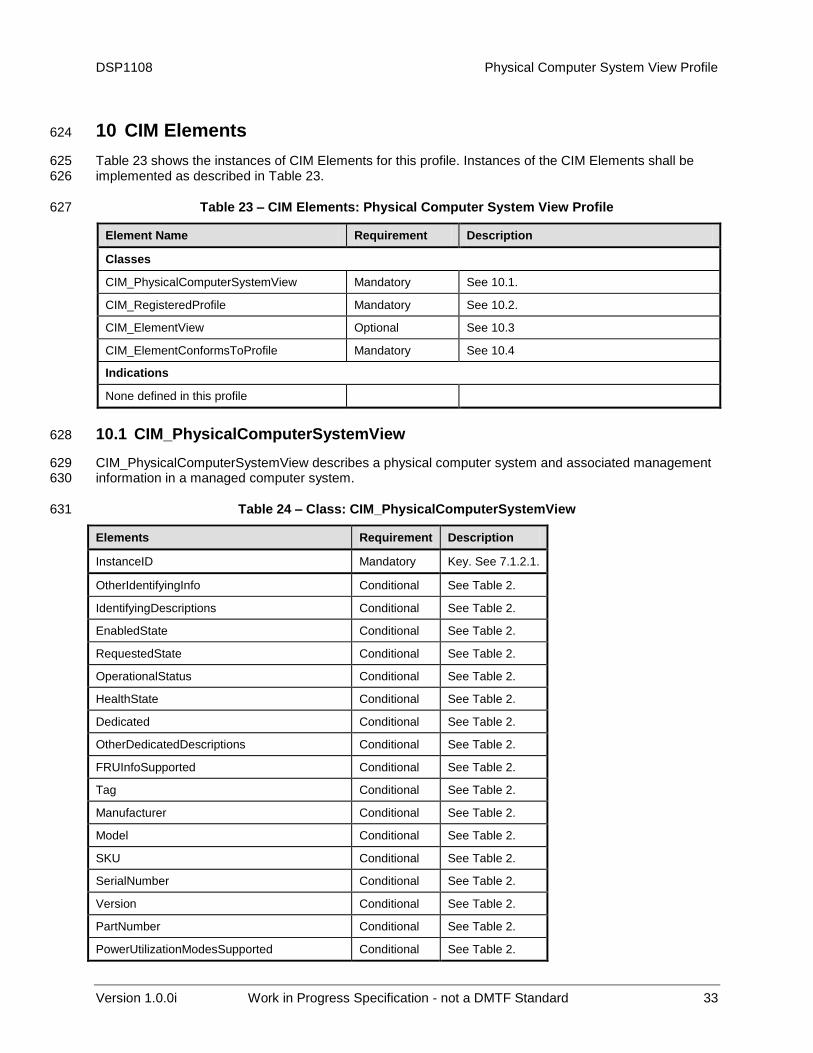
10 CIM Elements 624
Table 23 shows the instances of CIM Elements for this profile. Instances of the CIM Elements shall be 625 implemented as described in Table 23. 626
Table 23 – CIM Elements: Physical Computer System View Profile 627
Element Name Requirement Description
Classes
CIM_PhysicalComputerSystemView Mandatory See 10.1.
CIM_RegisteredProfile Mandatory See 10.2.
CIM_ElementView Optional See 10.3
CIM_ElementConformsToProfile Mandatory See 10.4
Indications
None defined in this profile
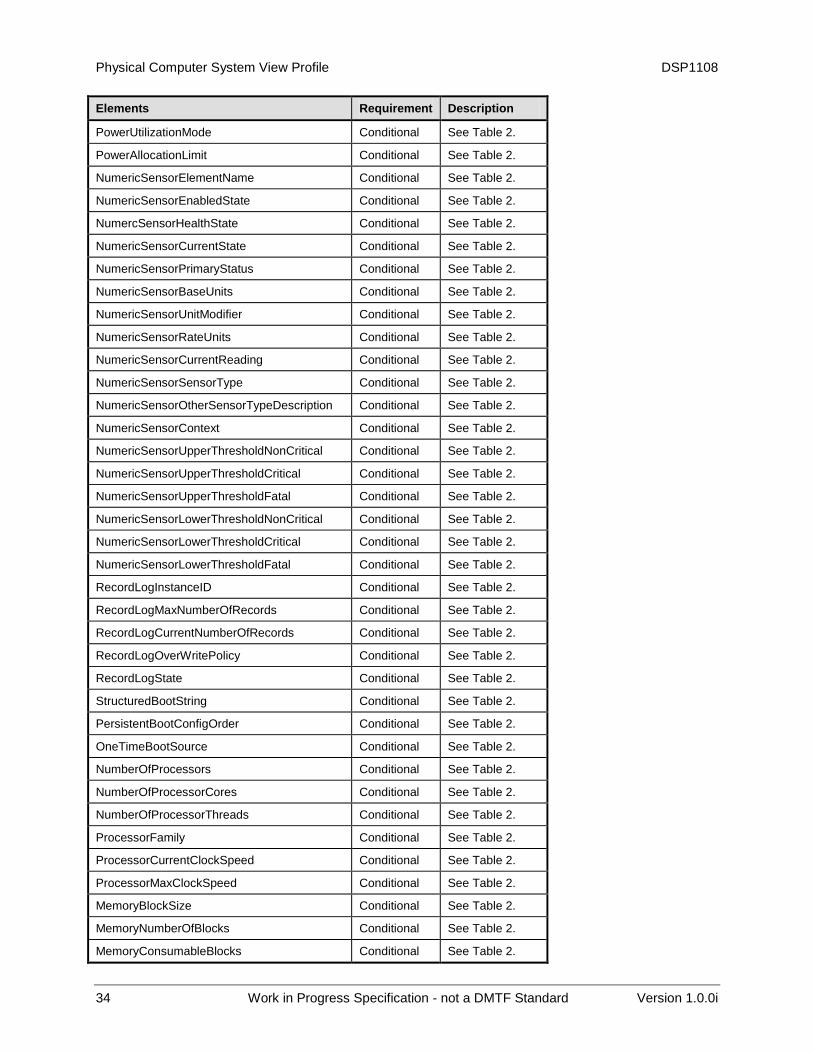
10.1 CIM_PhysicalComputerSystemView 628
CIM_PhysicalComputerSystemView describes a physical computer system and associated management 629 information in a managed computer system. 630
Table 24 – Class: CIM_PhysicalComputerSystemView 631
Elements Requirement Description
InstanceID Mandatory Key. See 7.1.2.1.
OtherIdentifyingInfo Conditional See Table 2.
IdentifyingDescriptions Conditional See Table 2.
EnabledState Conditional See Table 2.
RequestedState Conditional See Table 2.
OperationalStatus Conditional See Table 2.
HealthState Conditional See Table 2.
Dedicated Conditional See Table 2.
OtherDedicatedDescriptions Conditional See Table 2.
FRUInfoSupported Conditional See Table 2.
Tag Conditional See Table 2.
Manufacturer Conditional See Table 2.
Model Conditional See Table 2.
SKU Conditional See Table 2.
SerialNumber Conditional See Table 2.
Version Conditional See Table 2.
PartNumber Conditional See Table 2.
PowerUtilizationModesSupported Conditional See Table 2.
Physical Computer System View Profile DSP1108
34 Work in Progress Specification - not a DMTF Standard Version 1.0.0i
Elements Requirement Description
PowerUtilizationMode Conditional See Table 2.
PowerAllocationLimit Conditional See Table 2.
NumericSensorElementName Conditional See Table 2.
NumericSensorEnabledState Conditional See Table 2.
NumercSensorHealthState Conditional See Table 2.
NumericSensorCurrentState Conditional See Table 2.
NumericSensorPrimaryStatus Conditional See Table 2.
NumericSensorBaseUnits Conditional See Table 2.
NumericSensorUnitModifier Conditional See Table 2.
NumericSensorRateUnits Conditional See Table 2.
NumericSensorCurrentReading Conditional See Table 2.
NumericSensorSensorType Conditional See Table 2.
NumericSensorOtherSensorTypeDescription Conditional See Table 2.
NumericSensorContext Conditional See Table 2.
NumericSensorUpperThresholdNonCritical Conditional See Table 2.
NumericSensorUpperThresholdCritical Conditional See Table 2.
NumericSensorUpperThresholdFatal Conditional See Table 2.
NumericSensorLowerThresholdNonCritical Conditional See Table 2.
NumericSensorLowerThresholdCritical Conditional See Table 2.
NumericSensorLowerThresholdFatal Conditional See Table 2.
RecordLogInstanceID Conditional See Table 2.
RecordLogMaxNumberOfRecords Conditional See Table 2.
RecordLogCurrentNumberOfRecords Conditional See Table 2.
RecordLogOverWritePolicy Conditional See Table 2.
RecordLogState Conditional See Table 2.
StructuredBootString Conditional See Table 2.
PersistentBootConfigOrder Conditional See Table 2.
OneTimeBootSource Conditional See Table 2.
NumberOfProcessors Conditional See Table 2.
NumberOfProcessorCores Conditional See Table 2.
NumberOfProcessorThreads Conditional See Table 2.
ProcessorFamily Conditional See Table 2.
ProcessorCurrentClockSpeed Conditional See Table 2.
ProcessorMaxClockSpeed Conditional See Table 2.
MemoryBlockSize Conditional See Table 2.
MemoryNumberOfBlocks Conditional See Table 2.
MemoryConsumableBlocks Conditional See Table 2.
DSP1108 Physical Computer System View Profile
Version 1.0.0i Work in Progress Specification - not a DMTF Standard 35
Elements Requirement Description
CurrentBIOSMajorVersion Conditional See Table 2.
CurrentBIOSMinorVersion Conditional See Table 2.
CurrentBIOSRevisionNumber Conditional See Table 2.
CurrentBIOSBuildNumber Conditional See Table 2.
CurrentBIOSVersionString Conditional See Table 2.
CurrentManagementFirmwareMajorVersion Conditional See Table 2.
CurrentManagementFirmwareMinorVersion Conditional See Table 2.
CurrentManagementFirmwareRevisionNumber Conditional See Table 2.
CurrentManagementFirmwareBuildNumber Conditional See Table 2.
CurrentManagementFirmwareElementName Conditional See Table 2.
CurrentManagementFirmwareVersionString Conditional See Table 2.
OSType Conditional See Table 2.
OSVersion Conditional See Table 2.
OSEnabledState Conditional See Table 2.
RequestStateChange() Optional See 8.1.
ClearLog() Optional See 8.2.
InstallSoftwareFromURI() Optional See 8.3.
ModifyPersistentBootConfigOrder() Optional See 8.4.
SetOneTimeBootSource() Optional See 8.5.
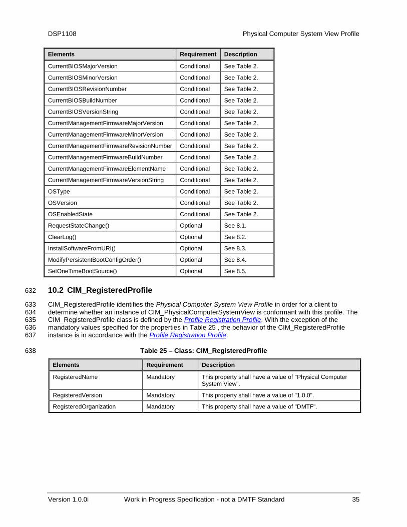
10.2 CIM_RegisteredProfile 632
CIM_RegisteredProfile identifies the Physical Computer System View Profile in order for a client to 633 determine whether an instance of CIM_PhysicalComputerSystemView is conformant with this profile. The 634 CIM_RegisteredProfile class is defined by the Profile Registration Profile. With the exception of the 635 mandatory values specified for the properties in Table 25 , the behavior of the CIM_RegisteredProfile 636 instance is in accordance with the Profile Registration Profile. 637
Table 25 – Class: CIM_RegisteredProfile 638
Elements Requirement Description
RegisteredName Mandatory This property shall have a value of "Physical Computer System View".
RegisteredVersion Mandatory This property shall have a value of "1.0.0".
RegisteredOrganization Mandatory This property shall have a value of "DMTF".
Physical Computer System View Profile DSP1108
36 Work in Progress Specification - not a DMTF Standard Version 1.0.0i
Elements Requirement Description
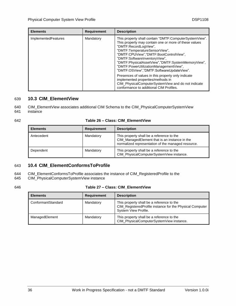
ImplementedFeatures Mandatory This property shall contain “DMTF:ComputerSystemView”. This property may contain one or more of these values “DMTF:RecordLogView”, “DMTF:TemperatureSensorView”, “DMTF:CPUView”,“DMTF:BootControlView”, ”DMTF:SoftwareInventoryView”, ”DMTF:PhysicalAssetView”,”DMTF:SystemMemoryView”, ”DMTF:PowerUtilizationManagementView”, ”DMTF:OSView”,”DMTF:SoftwareUpdateView”.
Presences of values in this property only indicate implemented properties/methods in CIM_PhysicalComputerSystemView and do not indicate conformance to additional CIM Profiles.
10.3 CIM_ElementView 639
CIM_ElementView associates additional CIM Schema to the CIM_PhysicalComputerSystemView 640 instance 641
Table 26 – Class: CIM_ElementView 642
Elements Requirement Description
Antecedent Mandatory This property shall be a reference to the CIM_ManagedElement that is an instance in the normalized representation of the managed resource.
Dependent Mandatory This property shall be a reference to the CIM_PhysicalComputerSystemView instance.
10.4 CIM_ElementConformsToProfile 643
CIM_ElementConformsToProfile associates the instance of CIM_RegisteredProfile to the 644 CIM_PhysicalComputerSystemView instance 645
Table 27 – Class: CIM_ElementView 646
Elements Requirement Description
ConformantStandard Mandatory This property shall be a reference to the CIM_RegisteredProfile instance for the Physical Computer System View Profile.
ManagedElement Mandatory This property shall be a reference to the CIM_PhysicalComputerSystemView instance.
DSP1108 Physical Computer System View Profile
Version 1.0.0i Work in Progress Specification - not a DMTF Standard 37
ANNEX A 647
(informative) 648
649
Change log 650
Version Date Description
1.0.0a 2012-07-05 DMTF Work In Progress
1.0.0i 2012-11-12 DMTF Work In Progress Update
651 652
Related Documents