SBC3000 Session Border Controller User Manual V1.0 Shenzhen Dinstar Co., Ltd. Address: Floor 18, Building 7A, Vanke Cloud City Phase 1, Xingke 1st Street, Xili Sub-district, Nanshan District, Shenzhen. Postal Code: 518052 Telephone: +86 755 61919966 Fax: +86 755 26456659 Emails: [email protected], [email protected]

Welcome message from author
This document is posted to help you gain knowledge. Please leave a comment to let me know what you think about it! Share it to your friends and learn new things together.
Transcript
SBC3000 Session Border Controller
User Manual V1.0
Shenzhen Dinstar Co., Ltd.
Address: Floor 18, Building 7A, Vanke Cloud City Phase 1, Xingke 1st Street, Xili Sub-district, Nanshan District,
Shenzhen.
Postal Code: 518052
Telephone: +86 755 61919966
Fax: +86 755 26456659
Emails: [email protected], [email protected]

Website: www.dinstar.com
SBC3000 Session Border Controller Copyright©2011-2018 Dinstar I
Preface
Welcome
Thanks for choosing SBC3000 Session Border Controller! We hope you will make full use of this rich-feature
device. Contact us if you need any technical support: 86-755-26456110/112.
About This Manual
This manual gives introduction to the SBC3000 device, and provides information about how to install, configure or
use it. Please read the manual carefully before installing it.
Intended Audience
This manual is primarily aimed at the following people:
Users
Engineers who install, configure and maintain SBC3000 device
Revision Record
Document Name Document Version Firmware Version
SBC3000 Session Border Controller User Manual V1.0 (2018/09/09) 1.91.1.5
Conventions
Device mentioned in this document refers to the SBC3000 Session Border Controller. Those words specially noted
in the document are the contents that users need to pay attention to.

SBC3000 Session Border Controller Copyright©2011-2018 Dinstar III
Contents
1 Production Introduction ......................................................................................................... 1
1.1 Overview .................................................................................................................................................. 1
1.2 Application Scenario ................................................................................................................................ 1
1.3 Product Appearance .................................................................................................................................. 2
1.4 Desciption of LED Indicators ................................................................................................................... 2
1.5 Functions and Featurres............................................................................................................................ 2
Key Features ................................................................................................................................... 2
Physical Interfaces .......................................................................................................................... 3
Capabilities ..................................................................................................................................... 3
VoIP ................................................................................................................................................. 4
Voice ................................................................................................................................................ 4
Security ........................................................................................................................................... 5
Call Control ..................................................................................................................................... 5
Maintenance .................................................................................................................................... 5
Environmental ................................................................................................................................. 6
2 Installation ............................................................................................................................... 7
2.1 Preparations before Installation ................................................................................................................ 7
Attentions for Installation ................................................................................................................ 7
Preparations about Installation Site ................................................................................................. 7
Installation Tools ............................................................................................................................. 8
Unpacking ....................................................................................................................................... 8
2.2 Installtion of SBC3000 ............................................................................................................................. 8
Put SBC3000 into Shelf .................................................................................................................. 8
Connect Ground Cable to MTG3000 .............................................................................................. 8
Connect SBC3000 to Network ........................................................................................................ 9
How to make RJ45 Network Cable ................................................................................................. 9
Troubleshooting about Network Connection ................................................................................ 10
3 Configurations on Web Interface ........................................................................................ 11
3.1 How to Log in Web Interface ................................................................................................................. 11
Preparations for Login................................................................................................................... 11
Log in Web Interface ..................................................................................................................... 12
SBC3000 Session Border Controller Copyright©2011-2018 Dinstar IV
3.2 Introduction to Web Interface ................................................................................................................. 13
3.3 Configuration Flows ............................................................................................................................... 14
System Status ................................................................................................................................ 14
Access Network Status .................................................................................................................. 16
Access Trunk Status ...................................................................................................................... 17
Core Trunk Status .......................................................................................................................... 18
Calls Status .................................................................................................................................... 19
Register Status............................................................................................................................... 20
Attack List ..................................................................................................................................... 21
3.4 Service .................................................................................................................................................... 22
Media Detection ............................................................................................................................ 22
CDR .............................................................................................................................................. 22
Number Profile .............................................................................................................................. 23
Time Profile .................................................................................................................................. 24
Rate Limit ..................................................................................................................................... 25
Black & White List ....................................................................................................................... 25
Codec Profile................................................................................................................................. 27
Number Manipulation ................................................................................................................... 28
Number Pool ................................................................................................................................. 29
SIP Header Manipulation ............................................................................................................ 30
SIP Header Passthrough .............................................................................................................. 32
Access Network ........................................................................................................................... 33
Access SIP Trunk ........................................................................................................................ 37
Core SIP Trunk ............................................................................................................................ 41
Routing Profile ............................................................................................................................ 46
3.5 Security .................................................................................................................................................. 49
System ........................................................................................................................................... 49
Access Control .............................................................................................................................. 50
Security Policy .............................................................................................................................. 51
3.6 System .................................................................................................................................................... 53
Device Name ................................................................................................................................. 53
Web Configuration ........................................................................................................................ 53
Network ......................................................................................................................................... 54
Port Mapping................................................................................................................................. 55
Static Route ................................................................................................................................... 56
User Manager ................................................................................................................................ 57
Date & Time .................................................................................................................................. 59
Upgrade ......................................................................................................................................... 60
SBC3000 Session Border Controller Copyright©2011-2018 Dinstar V
Backup & Restore ......................................................................................................................... 60
Double-device Hot Standby ........................................................................................................ 61
License ........................................................................................................................................ 61
Certificate .................................................................................................................................... 62
3.7 Maintenance ........................................................................................................................................... 62
Login Log ...................................................................................................................................... 62
Operation Log ............................................................................................................................... 63
Security Log .................................................................................................................................. 63
Log Management .......................................................................................................................... 64
Tools .............................................................................................................................................. 64
4 Abbreviation ........................................................................................................................ 65
5 Command Lines .................................................................................................................. 67
1 Production Introduction
SBC3000 Session Border Controller Copyright©2011-2018 Dinstar 1
1 Production Introduction
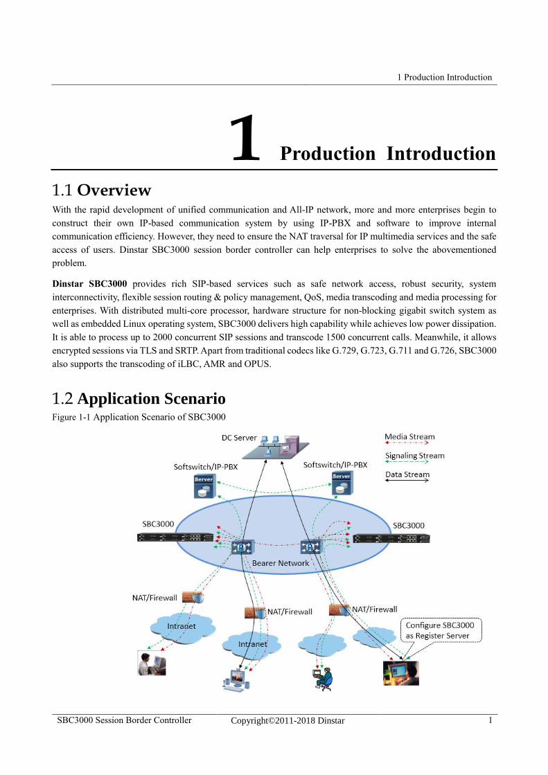
1.1 Overview With the rapid development of unified communication and All-IP network, more and more enterprises begin to
construct their own IP-based communication system by using IP-PBX and software to improve internal
communication efficiency. However, they need to ensure the NAT traversal for IP multimedia services and the safe
access of users. Dinstar SBC3000 session border controller can help enterprises to solve the abovementioned
problem.
Dinstar SBC3000 provides rich SIP-based services such as safe network access, robust security, system
interconnectivity, flexible session routing & policy management, QoS, media transcoding and media processing for
enterprises. With distributed multi-core processor, hardware structure for non-blocking gigabit switch system as
well as embedded Linux operating system, SBC3000 delivers high capability while achieves low power dissipation.
It is able to process up to 2000 concurrent SIP sessions and transcode 1500 concurrent calls. Meanwhile, it allows
encrypted sessions via TLS and SRTP. Apart from traditional codecs like G.729, G.723, G.711 and G.726, SBC3000
also supports the transcoding of iLBC, AMR and OPUS.
1.2 Application Scenario Figure 1-1 Application Scenario of SBC3000
1 Production Introduction
SBC3000 Session Border Controller Copyright©2011-2018 Dinstar 2
1.3 Product Appearance
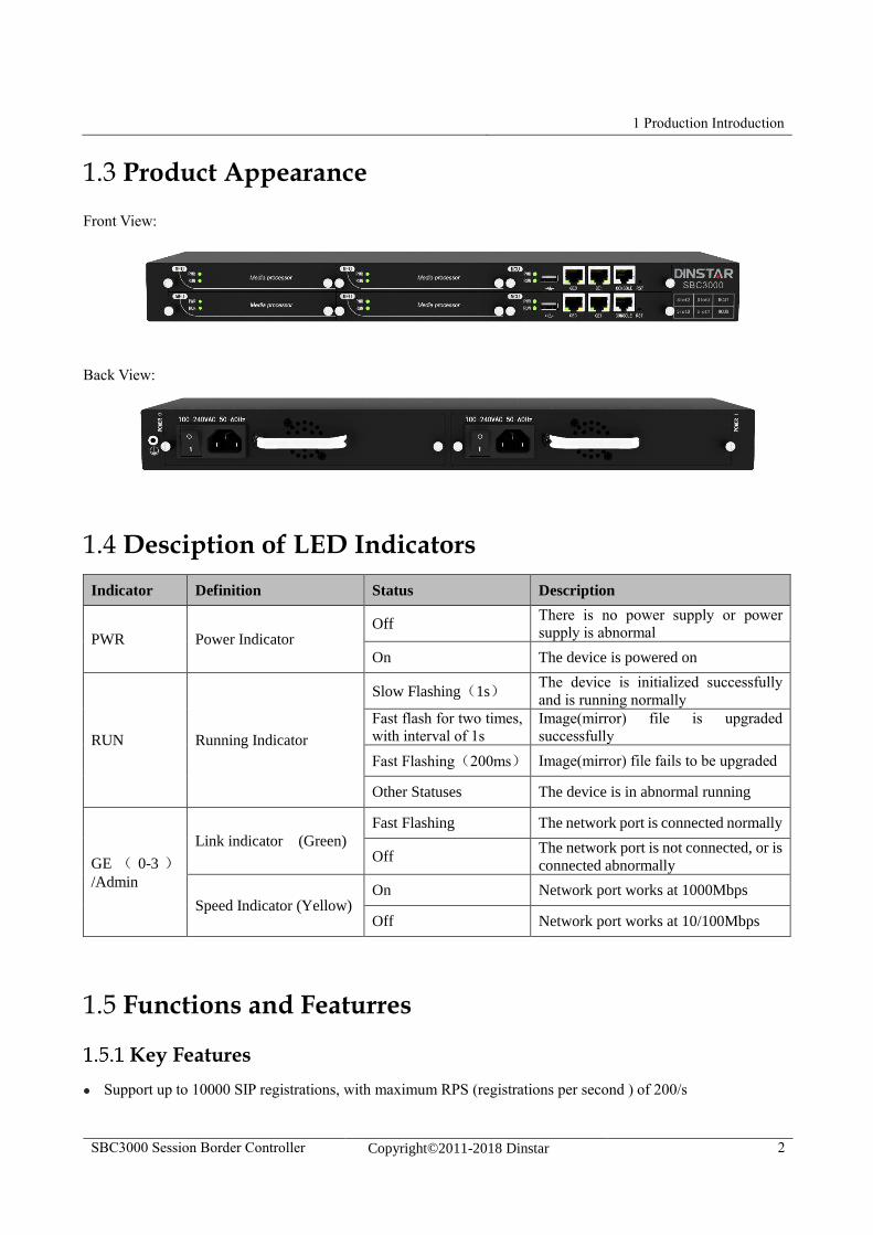
Front View:
Back View:
1.4 Desciption of LED Indicators
Indicator Definition Status Description
PWR Power Indicator Off
There is no power supply or power
supply is abnormal
On The device is powered on
RUN Running Indicator
Slow Flashing(1s) The device is initialized successfully
and is running normally
Fast flash for two times,
with interval of 1s
Image(mirror) file is upgraded
successfully
Fast Flashing(200ms) Image(mirror) file fails to be upgraded
Other Statuses The device is in abnormal running
GE ( 0-3 )/Admin
Link indicator (Green)
Fast Flashing The network port is connected normally
Off The network port is not connected, or is
connected abnormally
Speed Indicator (Yellow) On Network port works at 1000Mbps
Off Network port works at 10/100Mbps
1.5 Functions and Featurres
Key Features
Support up to 10000 SIP registrations, with maximum RPS (registrations per second ) of 200/s
1 Production Introduction
SBC3000 Session Border Controller Copyright©2011-2018 Dinstar 3
Forward up to 5000 media calls, with maximum forwarding rate of 200/s
Transcode 1024 media calls or faxes
Encrypted sessions through SRTP and ‘SIP over TLS’
Support multiple softswitches, anti-blocking and topology hiding
SIP trunks & flexible routing rules for accessing IMS
Support regular expression and black/white list
Embedded VoIP firewall, prevention of DoS and DDoS attacks
Prevention of address spoofing, prevention of illegal SIP/RTP packages
Bandwidth limitation and dynamic white list & black list
VLAN, QoS, static route, NAT traversal
Master/slave MCU for backup, dual power supply for back up, double-device hot standby
Hierarchical management of users, import & export of remote upgrade and configuration data
User-friendly web interface, multiple management ways
Support SIP protocols including UDP, TCP and TLS
Support multiple codecs : G.711A/U,G.723.1,G.729A/B, iLBC,AMR, OPUS
WebRTC gateway(to do)
Video service(to do)
Physical Interfaces
MCU (Main Control Unit): 2
MFU (Main Function Unit): 4
Ethernet Ports:
2* 10/100/1000M Base-T Ethernet ports on each MCU
1* USB on each MCU
Serial Console
1* RS232, 115200bps, RJ45
E1/T1 Ports (to do):
2* E1/T1, RJ48C
1* SIM Card Slot (to do)
LTE Uplink ( to do)
Capabilities
Concurrent Calls
1 Production Introduction
SBC3000 Session Border Controller Copyright©2011-2018 Dinstar 4
Support 2000 SIP sessions at maximum
Transcoding
Supports 1500 transcoding calls
CPS for call
200 calls per second at maximum
Registrations
Maximum SIP registrations: 10000
CPS for Registration
200 registrations per second
SIP Trunks
128 SIP trunks at maximum
VoIP
SIP 2.0 compliant, UDP, TCP, TLS,
SIP trunk (Peer to peer)
SIP trunk (Access)
SIP registrations
B2BUA (Back-to-Back User Agent)
SIP Request rate limiting
SIP registration rate limiting
SIP registration scan attack detection
SIP call scan attack detection
SIP anti-attack
SIP Header manipulation
SIP malformed packet protection
Multiple Soft-switches supported
QoS (ToS, DSCP)
NAT Traversal
Voice
Codecs: G.711a/μ,G.723, G.729A/B,iLBC,G.726, AMR,OPUS
RTP Transcoding
Fax: T.38 and Pass-through
1 Production Introduction
SBC3000 Session Border Controller Copyright©2011-2018 Dinstar 5
No RTP detection
One-way audio detection
RTP/RTCP
RTCP statistics reports
DTMF: RFC2833, SIP Info, INBAND
Silence Suppression
Comfort Noise
Voice Activity Detection (VAD)
Echo Cancellation(G.168, 128ms)
Adaptive Dynamic Buffer
Security
Prevention of DoS and DDos Attacks
Control of Access Policies
Policy-based Anti-attacks
Call Security with TLS/SRTP
White List & Black List
Access Rule List
Embedded VoIP Firewall
Call Control
Dynamic load balancing and call routing
Flexible routing engine
Call routing based on prefixes
Call routing based on caller/called number
Regular Expression
Call routing based on time profile
Call routing based on SIP URI
Call routing based on SIP method
Call routing based on endpoint
Caller/called number manipulation
Maintenance
Web-based GUI for Configurations
1 Production Introduction
SBC3000 Session Border Controller Copyright©2011-2018 Dinstar 6
Configurations Restore/Backup
HTTP Firmware Upgrade
CDR Report and CDR Export
Ping and Tracert
Network Capture
System Logs
Statistics and Reports
Multiple Languages
Centralized Management System
Remote Web and Telnet
Environmental
Redundant Power Supply: 100-240VAC, 50-60 Hz
Power Consumption: 15w
Operating Temperature: 0 ℃ ~ 45 ℃
Storage Temperature: -20 ℃ ~80 ℃
Humidity: 10%-90% Non-Condensing
Dimensions (W/D/H): 436×320×44.5mm (1U)
Unit Weight: 4.5 kg
Compliance: CE, FCC
2 Installation
SBC3000 Session Border Controller Copyright©2011-2018 Dinstar 7
2 Installation
2.1 Preparations before Installation
Attentions for Installation
Before you install the SBC3000 device, please read the following safety guidelines:
To guarantee SBC3000 works normally and to lengthen the service life of the device, the humidity of the
equipment room where SBC3000 is installed should be maintained at 10%-90% (non-condensing), and temperature
should be 0 ℃ ~ 45 ℃;
Ensure the equipment room is well-ventilated and clean;
Power supply of SBC3000 should be 100 ~ 240V AC, and its socket is a three-pin socket which should be
grounded well;
It’s suggested that personnel who has experience or who has received related training be responsible for
installing and maintaining SBC3000;
Please wear ESD wrist strap when installing SBC3000;
Please do not hot plug cables;
It’s advised to adopt uninterruptible power supply (UPS).
Preparations about Installation Site
Equipment Cabinet
Ensure the cabinet is well-ventilated and strong enough to bear the weight of SBC3000.
Trunk
Ensure telecom operator has approved to open a trunk.
IP Network
Ensure router under IP network has been prepared, since SBC3000 is connected to the IP network through the
standard 10/100/1000M Ethernet port.
Power Supply
Ensure the socket of SBC3000 is a three-pin socket and power supply is grounded well.
2 Installation
SBC3000 Session Border Controller Copyright©2011-2018 Dinstar 8
Installation Tools
Screwdriver
ESD wrist strap
Ethernet cables, power wires, telephone wires
Hub, telephone set, fax, and small PBX
Terminal (can be a PC which is equipped with hyperterminal software)
Unpacking
Open the packing container to check whether the SBC3000 device and all accessories have been in it:
One SBC3000 device
One 1.8-meter-long of power wire (AC 250V/4A)
Two network cables
One grounding cable
One serial console cable
Mounting ears and screws
2.2 Installtion of SBC3000
Put SBC3000 into Shelf
1. Put the SBC3000 device on the shelf or cabinet horizontally, or fix the mounting ears s of SBC3000 on the
cabinet by using screws (before that, you need to use screws to fix mounting ears on the left and the right of
SBC3000 repectively).
Connect Ground Cable to MTG3000
Connect one end of the ground cable to the grounding port on the back of SBC3000 and then connect the other
end to the grounding bar of the cabinet.
2 Installation
SBC3000 Session Border Controller Copyright©2011-2018 Dinstar 9
Connect SBC3000 to Network
SBC3000 has two network ports on each MCU (Main Control Unit), namely GE1 and GE0. By default, the GE1
port is used to log in the SBC3000 device.
Both GE1 and GE0 can be used to carry out management on SBC3000, but only GE1 is put in use generally.
How to make RJ45 Network Cable
Step1. Prepare a twisted-pair cable with a length of at least 0.6 meters, and then remove the shuck of the network
cable;
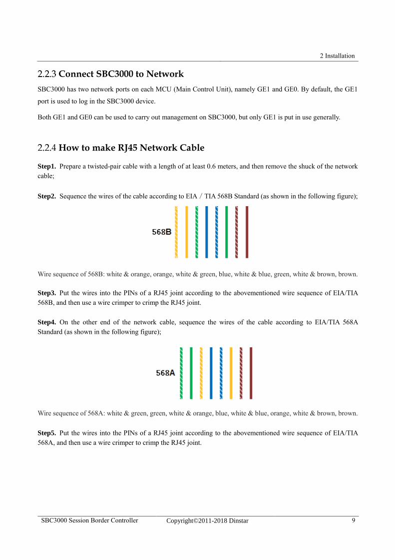
Step2. Sequence the wires of the cable according to EIA/TIA 568B Standard (as shown in the following figure);
Wire sequence of 568B: white & orange, orange, white & green, blue, white & blue, green, white & brown, brown.
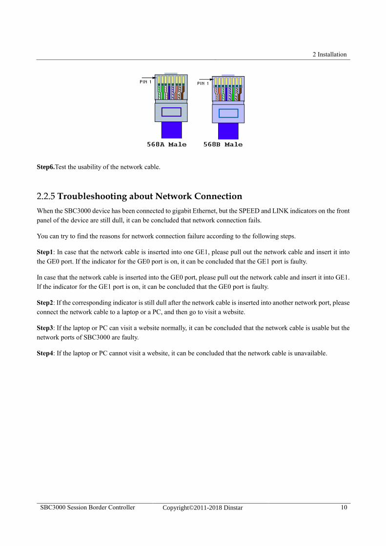
Step3. Put the wires into the PINs of a RJ45 joint according to the abovementioned wire sequence of EIA/TIA
568B, and then use a wire crimper to crimp the RJ45 joint.
Step4. On the other end of the network cable, sequence the wires of the cable according to EIA/TIA 568A
Standard (as shown in the following figure);
Wire sequence of 568A: white & green, green, white & orange, blue, white & blue, orange, white & brown, brown.
Step5. Put the wires into the PINs of a RJ45 joint according to the abovementioned wire sequence of EIA/TIA
568A, and then use a wire crimper to crimp the RJ45 joint.
2 Installation
SBC3000 Session Border Controller Copyright©2011-2018 Dinstar 10
Step6.Test the usability of the network cable.
Troubleshooting about Network Connection
When the SBC3000 device has been connected to gigabit Ethernet, but the SPEED and LINK indicators on the front
panel of the device are still dull, it can be concluded that network connection fails.
You can try to find the reasons for network connection failure according to the following steps.
Step1: In case that the network cable is inserted into one GE1, please pull out the network cable and insert it into
the GE0 port. If the indicator for the GE0 port is on, it can be concluded that the GE1 port is faulty.
In case that the network cable is inserted into the GE0 port, please pull out the network cable and insert it into GE1.
If the indicator for the GE1 port is on, it can be concluded that the GE0 port is faulty.
Step2: If the corresponding indicator is still dull after the network cable is inserted into another network port, please
connect the network cable to a laptop or a PC, and then go to visit a website.
Step3: If the laptop or PC can visit a website normally, it can be concluded that the network cable is usable but the
network ports of SBC3000 are faulty.
Step4: If the laptop or PC cannot visit a website, it can be concluded that the network cable is unavailable.
3 Configurations on Web Interface
SBC3000 Session Border Controller Copyright©2011-2018 Dinstar 11
3 Configurations on Web Interface
3.1 How to Log in Web Interface
Preparations for Login
SBC3000 has two network ports on each MCU (Main Control Unit), namely GE0 and GE1. The network ports of
the active MCU is prior to those on the standby MCU.
The default IP address of GE0 is 192.168.12.1, while that of GE1 is 192.168.11.1.
First Use
At the first time that the SBC3000 device is put in use, please connect the device’s GE1 port to a PC by using a
network cable, and then modify the IP address of the PC to make it at the same network segment with of the default
IP address of the GE1 port. The format of PC IP address is 192.168.11.XXX, since the default IP of GE1 port is
192.168.11.1
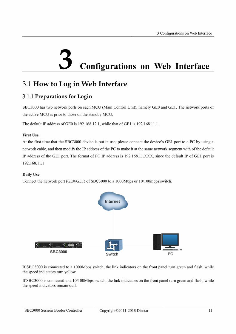
Daily Use
Connect the network port (GE0/GE1) of SBC3000 to a 1000Mbps or 10/100mbps switch.
If SBC3000 is connected to a 1000Mbps switch, the link indicators on the front panel turn green and flash, while
the speed indicators turn yellow.
If SBC3000 is connected to a 10/100Mbps switch, the link indicators on the front panel turn green and flash, while
the speed indicators remain dull.
SBC3000Switch PC
Internet
3 Configurations on Web Interface
SBC3000 Session Border Controller Copyright©2011-2018 Dinstar 12
Note:
At the first time that the SBC3000 device is used, only the GE1 port is allowed to visit the Web interface (the GE0
port is disabled). If you want to connect the SBC3000 device through GE0, please connect the GE1 port to a PC
and log into the Web interface of the device, and then enable GE0 on the SecurityAccess Control page.
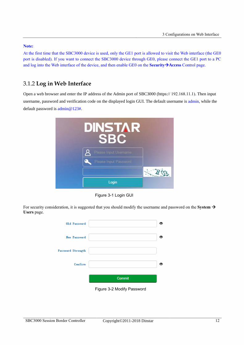
Log in Web Interface
Open a web browser and enter the IP address of the Admin port of SBC3000 (https:// 192.168.11.1). Then input
username, password and verification code on the displayed login GUI. The default username is admin, while the
default password is admin@123#.
Figure 3-1 Login GUI
For security consideration, it is suggested that you should modify the username and password on the System
Users page.
Figure 3-2 Modify Password
3 Configurations on Web Interface
SBC3000 Session Border Controller Copyright©2011-2018 Dinstar 13
Note:
If you forget the IP address after modification and cannot log in the Web interface, please use a serial cable to
connect the Console port of SBC3000 with a PC. Enter the ‘en’ mode and input ‘show interface’ to query the IP
address.
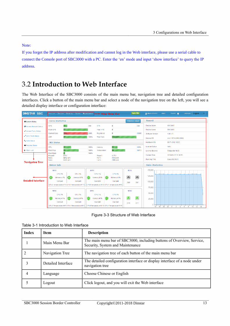
3.2 Introduction to Web Interface
The Web Interface of the SBC3000 consists of the main menu bar, navigation tree and detailed configuration
interfaces. Click a button of the main menu bar and select a node of the navigation tree on the left, you will see a
detailed display interface or configuration interface:
Figure 3-3 Structure of Web Interface
Table 3-1 Introduction to Web Interface
Index Item Description
1 Main Menu Bar The main menu bar of SBC3000, including buttons of Overview, Service,
Security, System and Maintenance
2 Navigation Tree The navigation tree of each button of the main menu bar
3 Detailed Interface The detailed configuration interface or display interface of a node under
navigation tree
4 Language Choose Chinese or English
5 Logout Click logout, and you will exit the Web interface
3 Configurations on Web Interface
SBC3000 Session Border Controller Copyright©2011-2018 Dinstar 14
6
To add configurations
7
To edit/modify configurations
8
To delete configurations
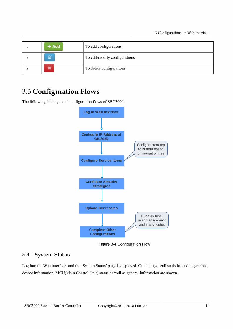
3.3 Configuration Flows
The following is the general configuration flows of SBC3000:
Figure 3-4 Configuration Flow
System Status
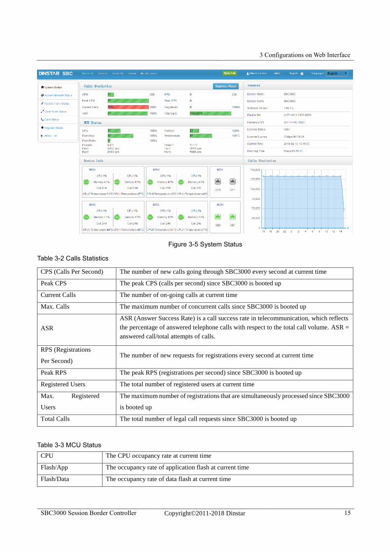
Log into the Web interface, and the ‘System Status’ page is displayed. On the page, call statistics and its graphic,
device information, MCU(Main Control Unit) status as well as general information are shown.
Log in Web Interface
Configure IP Address of
GE1/GE0
Configure Service Items
Configure Security
Strategies
Upload Certificates
Configure from top
to buttom based
on navigation tree
Complete Other
Configurations
Such as time,
user management
and static routes
3 Configurations on Web Interface
SBC3000 Session Border Controller Copyright©2011-2018 Dinstar 15
Figure 3-5 System Status
Table 3-2 Calls Statistics
CPS (Calls Per Second) The number of new calls going through SBC3000 every second at current time
Peak CPS The peak CPS (calls per second) since SBC3000 is booted up
Current Calls The number of on-going calls at current time
Max. Calls The maximum number of concurrent calls since SBC3000 is booted up
ASR
ASR (Answer Success Rate) is a call success rate in telecommunication, which reflects
the percentage of answered telephone calls with respect to the total call volume. ASR =
answered call/total attempts of calls.
RPS (Registrations
Per Second) The number of new requests for registrations every second at current time
Peak RPS The peak RPS (registrations per second) since SBC3000 is booted up
Registered Users The total number of registered users at current time
Max. Registered
Users
The maximum number of registrations that are simultaneously processed since SBC3000
is booted up
Total Calls The total number of legal call requests since SBC3000 is booted up
Table 3-3 MCU Status
CPU The CPU occupancy rate at current time
Flash/App The occupancy rate of application flash at current time
Flash/Data The occupancy rate of data flash at current time
3 Configurations on Web Interface
SBC3000 Session Border Controller Copyright©2011-2018 Dinstar 16
Memory The occupancy rate of memory at current time
Temperature The temperature of the CPU for MCU (Main Control Unit)
Table 3-4 Device Information
MFU
(Main Function Unit)
CPU The CPU occupancy rate of MFU at current time
Memory The memory occupancy rate of MFU at current time
Call The number of current calls that are being processed by
MFU’s CPU
Temperature The temperature of the CPU for MFU
MCU
(Main Control Unit) Network Ports
(GE0/GE1)
All the network ports on the MCU, among which green
ones refer to those network ports in use, while gray ones
are idle.
Table 3-5 General Information
Device Model SBC3000
Device Name The name of the device, which can be modified on the ‘System System Management’ page
Software
Version The current software version No. running on SBC100
License Status If the license is in its validity period, “Valid” will be displayed. If the license has expired,
“Invalid” is shown
License Expires The remaining time of license validity
Current Time The current time of SBC3000, which can be modified or synchronized on the ‘System Date
& Time’ page
Running time The running time of the device since it is booted up
Note:
If the current time is still wrong after the system time has been synchronized or the device is restarted, it means the
battery inside the device runs low and you need to replace the battery with a new one. Besides, only the GE1 port
can be used to synchronize time with NTP.
Access Network Status
Terminal users are registered to SBC3000 through access network. The status of access network is always “true”,
which means the access network is normal and available.
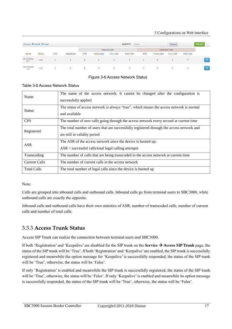
On the OverviewAccess Network Status page, detailed information about access network, including the status,
name, CPS(Calls Per Second), number of registered users, ASR(Answered Success Ratio), number of calls that are
being transcoded, number of current calls as well as number of total calls, are shown.
3 Configurations on Web Interface
SBC3000 Session Border Controller Copyright©2011-2018 Dinstar 17
Figure 3-6 Access Network Status
Table 3-6 Access Network Status
Name The name of the access network. It cannot be changed after the configuration is
successfully applied
Status The status of access network is always “true”, which means the access network is normal
and available
CPS The number of new calls going through the access network every second at current time
Registered The total number of users that are successfully registered through the access network and
are still in validity period
ASR The ASR of the access network since the device is booted up;
ASR = successful calls/total legal calling attempts
Transcoding The number of calls that are being transcoded in the access network at current time
Current Calls The number of current calls in the access network
Total Calls The total number of legal calls since the device is booted up
Note:
Calls are grouped into inbound calls and outbound calls. Inbound calls go from terminal users to SBC3000, while
outbound calls are exactly the opposite.
Inbound calls and outbound calls have their own statistics of ASR, number of transcoded calls, number of current
calls and number of total calls.
Access Trunk Status
Access SIP Trunk can realize the connection between terminal users and SBC3000.
If both ‘Registration’ and ‘Keepalive’ are disabled for the SIP trunk on the Service Access SIP Trunk page, the
status of the SIP trunk will be ‘True’. If both ‘Registration’ and ‘Keepalive’ are enabled, the SIP trunk is successfully
registered and meanwhile the option message for ‘Keepalive’ is successfully responded, the status of the SIP trunk
will be ‘True’, otherwise, the status will be ‘False’.
If only ‘Registration’ is enabled and meanwhile the SIP trunk is successfully registered, the status of the SIP trunk
will be ‘True’, otherwise, the status will be ‘False’. If only ‘Keepalive’ is enabled and meanwhile its option message
is successfully responded, the status of the SIP trunk will be ‘True’, otherwise, the status will be ‘False’.
3 Configurations on Web Interface
SBC3000 Session Border Controller Copyright©2011-2018 Dinstar 18
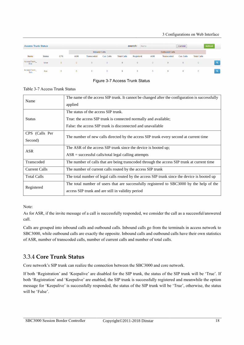
Figure 3-7 Access Trunk Status
Table 3-7 Access Trunk Status
Name The name of the access SIP trunk. It cannot be changed after the configuration is successfully
applied
Status
The status of the access SIP trunk.
True: the access SIP trunk is connected normally and available;
False: the access SIP trunk is disconnected and unavailable
CPS (Calls Per
Second) The number of new calls directed by the access SIP trunk every second at current time
ASR The ASR of the access SIP trunk since the device is booted up;
ASR = successful calls/total legal calling attempts
Transcoded The number of calls that are being transcoded through the access SIP trunk at current time
Current Calls The number of current calls routed by the access SIP trunk
Total Calls The total number of legal calls routed by the access SIP trunk since the device is booted up
Registered The total number of users that are successfully registered to SBC3000 by the help of the
access SIP trunk and are still in validity period
Note:
As for ASR, if the invite message of a call is successfully responded, we consider the call as a successful/answered
call.
Calls are grouped into inbound calls and outbound calls. Inbound calls go from the terminals in access network to
SBC3000, while outbound calls are exactly the opposite. Inbound calls and outbound calls have their own statistics
of ASR, number of transcoded calls, number of current calls and number of total calls.
Core Trunk Status
Core network’s SIP trunk can realize the connection between the SBC3000 and core network.
If both ‘Registration’ and ‘Keepalive’ are disabled for the SIP trunk, the status of the SIP trunk will be ‘True’. If
both ‘Registration’ and ‘Keepalive’ are enabled, the SIP trunk is successfully registered and meanwhile the option
message for ‘Keepalive’ is successfully responded, the status of the SIP trunk will be ‘True’, otherwise, the status
will be ‘False’.
3 Configurations on Web Interface
SBC3000 Session Border Controller Copyright©2011-2018 Dinstar 19
If only ‘Registration’ is enabled and meanwhile the SIP trunk is successfully registered, the status of the SIP trunk
will be ‘True’, otherwise, the status will be ‘False’. If only ‘Keepalive’ is enabled and meanwhile its option message
is successfully responded, the status of the SIP trunk will be ‘True’, otherwise, the status will be ‘False’.
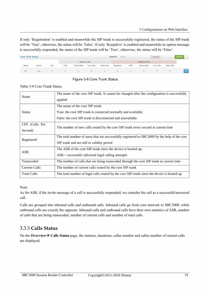
Figure 3-8 Core Trunk Status
Table 3-8 Core Trunk Status
Name The name of the core SIP trunk. It cannot be changed after the configuration is successfully
applied
Status
The status of the core SIP trunk.
True: the core SIP trunk is connected normally and available;
False: the core SIP trunk is disconnected and unavailable
CPS (Calls Per
Second) The number of new calls routed by the core SIP trunk every second at current time
Registered The total number of users that are successfully registered to SBC3000 by the help of the core
SIP trunk and are still in validity period
ASR The ASR of the core SIP trunk since the device is booted up;
ASR = successful calls/total legal calling attempts
Transcoded The number of calls that are being transcoded through the core SIP trunk at current time
Current Calls The number of current calls routed by the core SIP trunk
Total Calls The total number of legal calls routed by the core SIP trunk since the device is booted up
Note:
As for ASR, if the invite message of a call is successfully responded, we consider the call as a successful/answered
call.
Calls are grouped into inbound calls and outbound calls. Inbound calls go from core network to SBC3000, while
outbound calls are exactly the opposite. Inbound calls and outbound calls have their own statistics of ASR, number
of calls that are being transcoded, number of current calls and number of total calls.
Calls Status
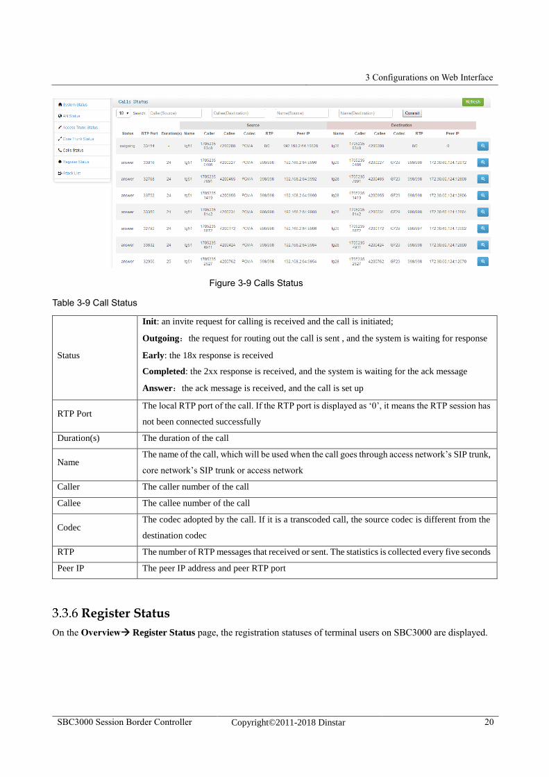
On the Overview Calls Status page, the statuses, durations, caller number and callee number of current calls
are displayed.
3 Configurations on Web Interface
SBC3000 Session Border Controller Copyright©2011-2018 Dinstar 20
Figure 3-9 Calls Status
Table 3-9 Call Status
Status
Init: an invite request for calling is received and the call is initiated;
Outgoing:the request for routing out the call is sent , and the system is waiting for response
Early: the 18x response is received
Completed: the 2xx response is received, and the system is waiting for the ack message
Answer:the ack message is received, and the call is set up
RTP Port The local RTP port of the call. If the RTP port is displayed as ‘0’, it means the RTP session has
not been connected successfully
Duration(s) The duration of the call
Name The name of the call, which will be used when the call goes through access network’s SIP trunk,
core network’s SIP trunk or access network
Caller The caller number of the call
Callee The callee number of the call
Codec The codec adopted by the call. If it is a transcoded call, the source codec is different from the
destination codec
RTP The number of RTP messages that received or sent. The statistics is collected every five seconds
Peer IP The peer IP address and peer RTP port
Register Status
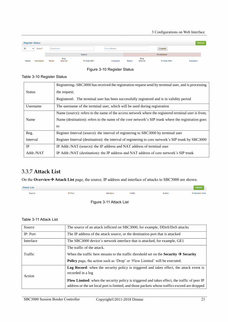
On the Overview Register Status page, the registration statuses of terminal users on SBC3000 are displayed.
3 Configurations on Web Interface
SBC3000 Session Border Controller Copyright©2011-2018 Dinstar 21
Figure 3-10 Register Status
Table 3-10 Register Status
Status
Registering:SBC3000 has received the registration request send by terminal user, and is processing
the request;
Registered:The terminal user has been successfully registered and is in validity period
Username The username of the terminal user, which will be used during registration
Name
Name (source): refers to the name of the access network where the registered terminal user is from;
Name (destination): refers to the name of the core network’s SIP trunk where the registration goes
to
Reg.
Interval
Register Interval (source): the interval of registering to SBC3000 by terminal user
Register Interval (destination): the interval of registering to core network’s SIP trunk by SBC3000
IP
Addr./NAT
IP Addr./NAT (source): the IP address and NAT address of terminal user
IP Addr./NAT (destination): the IP address and NAT address of core network’s SIP trunk
Attack List
On the Overview Attack List page, the source, IP address and interface of attacks to SBC3000 are shown.
Figure 3-11 Attack List
Table 3-11 Attack List
Source The source of an attack inflicted on SBC3000, for example, DDoS/DoS attacks
IP: Port The IP address of the attack source, or the destination port that is attacked
Interface The SBC3000 device’s network interface that is attacked, for example, GE1
Traffic
The traffic of the attack.
When the traffic here mounts to the traffic threshold set on the Security Security
Policy page, the action such as ‘Drop’ or ‘Flow Limited’ will be executed.
Action
Log Record: when the security policy is triggered and takes effect, the attack event is
recorded in a log
Flow Limited: when the security policy is triggered and takes effect, the traffic of peer IP
address or the set local port is limited, and those packets whose traffics exceed are dropped
3 Configurations on Web Interface
SBC3000 Session Border Controller Copyright©2011-2018 Dinstar 22
during the protection time.
Packet Rate Limited: when the security policy is triggered and takes effect, the packet
rate of peer IP address or the set local port is limited, and those packets with exceeding
transmission rate are dropped during the protection time.
Drop: when the security policy is triggered and takes effect, all the packets from peer IP
address and those received by the set local port are dropped during the protection time.
Protection Time The duration of the action conducted on attack source
3.4 Service
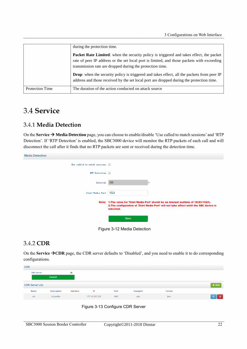
Media Detection
On the Service Media Detection page, you can choose to enable/disable ‘Use called to match sessions’ and ‘RTP
Detection’. If ‘RTP Detection’ is enabled, the SBC3000 device will monitor the RTP packets of each call and will
disconnect the call after it finds that no RTP packets are sent or received during the detection time.
Figure 3-12 Media Detection
CDR
On the Service CDR page, the CDR server defaults to ‘Disabled’, and you need to enable it to do corresponding
configurations.
Figure 3-13 Configure CDR Server
3 Configurations on Web Interface
SBC3000 Session Border Controller Copyright©2011-2018 Dinstar 23
Table 3-12 CDR
Name The name of the CDR server. It cannot be modified after the CDR server has been
successfully added
Description The description of the CDR server
Interface The interface through which the CDR server receives CDRs
IP The IP address of the CDR server
Port The SIP port through which the CDR server receives CDRs
Transport The transport protocol adopted to transport CDRs, which can be UDP or TCP
Format The coded format of CDRs, which only supports json currently
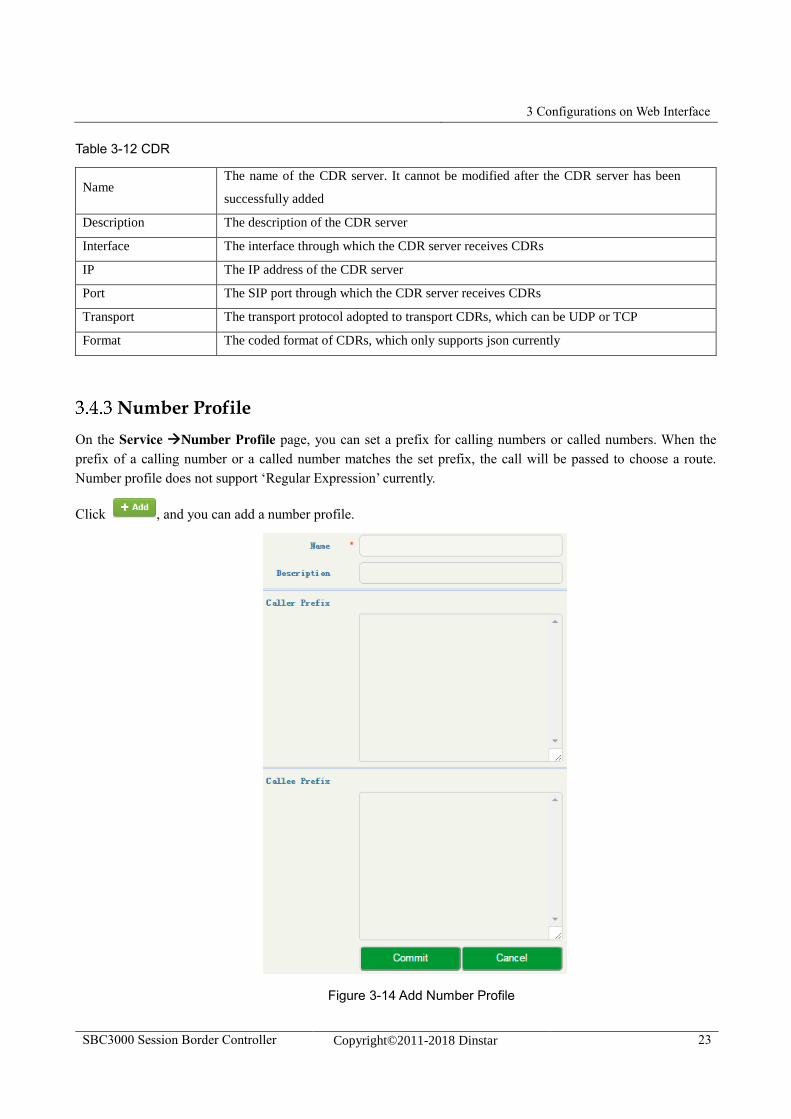
Number Profile
On the Service Number Profile page, you can set a prefix for calling numbers or called numbers. When the
prefix of a calling number or a called number matches the set prefix, the call will be passed to choose a route.
Number profile does not support ‘Regular Expression’ currently.
Click , and you can add a number profile.
Figure 3-14 Add Number Profile
3 Configurations on Web Interface
SBC3000 Session Border Controller Copyright©2011-2018 Dinstar 24
Table 3-13 Number Profile
Name The name of the number profile. It cannot be modified after the number profile is added
successfully
Description The description of the number profile
Caller
Prefix
The prefix set for caller numbers. It does not support regular expression.
When the prefix of a caller number matches the set prefix, the call will be passed to choose a
specific route.
Callee
Prefix
The prefix set for callee numbers. It does not support regular expression.
When the prefix of a callee number matches the set prefix, the call will be passed to choose a
specific route.
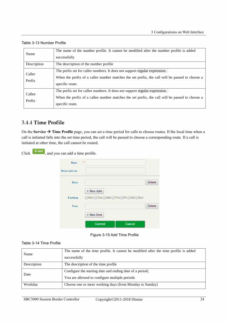
Time Profile
On the Service Time Profile page, you can set a time period for calls to choose routes. If the local time when a
call is initiated falls into the set time period, the call will be passed to choose a corresponding route. If a call is
initiated at other time, the call cannot be routed.
Click , and you can add a time profile.
Figure 3-15 Add Time Profile
Table 3-14 Time Profile
Name The name of the time profile. It cannot be modified after the time profile is added
successfully
Description The description of the time profile
Date Configure the starting date and ending date of a period;
You are allowed to configure multiple periods
Workday Choose one or more working days (from Monday to Sunday)
3 Configurations on Web Interface
SBC3000 Session Border Controller Copyright©2011-2018 Dinstar 25
Time Choose the starting time and ending time of a day
You are allowed to configure multiple time periods
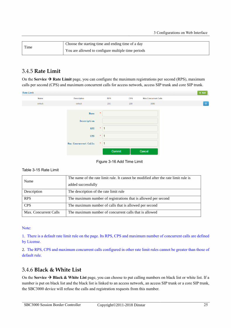
Rate Limit
On the Service Rate Limit page, you can configure the maximum registrations per second (RPS), maximum
calls per second (CPS) and maximum concurrent calls for access network, access SIP trunk and core SIP trunk.
Figure 3-16 Add Time Limit
Table 3-15 Rate Limit
Name The name of the rate limit rule. It cannot be modified after the rate limit rule is
added successfully
Description The description of the rate limit rule
RPS The maximum number of registrations that is allowed per second
CPS The maximum number of calls that is allowed per second
Max. Concurrent Calls The maximum number of concurrent calls that is allowed
Note:
1. There is a default rate limit rule on the page. Its RPS, CPS and maximum number of concurrent calls are defined
by License.
2. The RPS, CPS and maximum concurrent calls configured in other rate limit rules cannot be greater than those of
default rule.
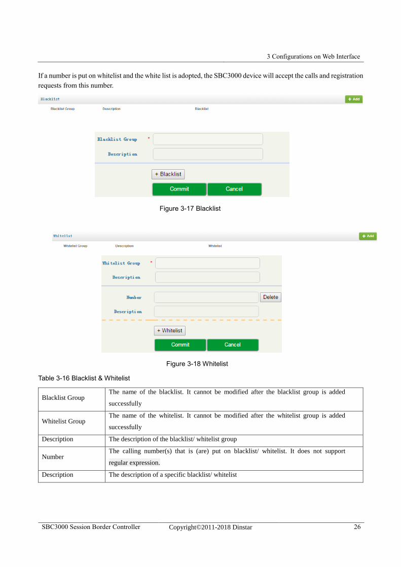
Black & White List
On the Service Black & White List page, you can choose to put calling numbers on black list or white list. If a
number is put on black list and the black list is linked to an access network, an access SIP trunk or a core SIP trunk,
the SBC3000 device will refuse the calls and registration requests from this number.
3 Configurations on Web Interface
SBC3000 Session Border Controller Copyright©2011-2018 Dinstar 26
If a number is put on whitelist and the white list is adopted, the SBC3000 device will accept the calls and registration
requests from this number.
Figure 3-17 Blacklist
Figure 3-18 Whitelist
Table 3-16 Blacklist & Whitelist
Blacklist Group The name of the blacklist. It cannot be modified after the blacklist group is added
successfully
Whitelist Group The name of the whitelist. It cannot be modified after the whitelist group is added
successfully
Description The description of the blacklist/ whitelist group
Number The calling number(s) that is (are) put on blacklist/ whitelist. It does not support
regular expression.
Description The description of a specific blacklist/ whitelist
3 Configurations on Web Interface
SBC3000 Session Border Controller Copyright©2011-2018 Dinstar 27
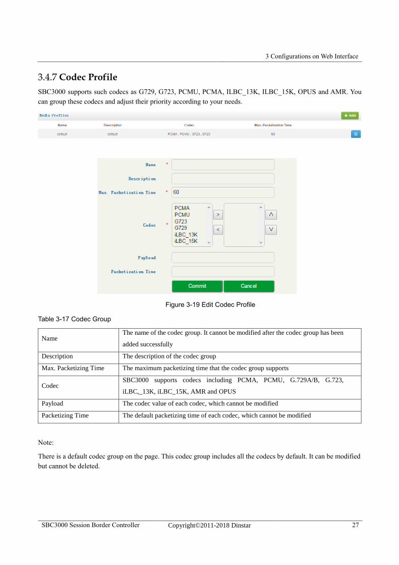
Codec Profile
SBC3000 supports such codecs as G729, G723, PCMU, PCMA, ILBC_13K, ILBC_15K, OPUS and AMR. You
can group these codecs and adjust their priority according to your needs.
Figure 3-19 Edit Codec Profile
Table 3-17 Codec Group
Name The name of the codec group. It cannot be modified after the codec group has been
added successfully
Description The description of the codec group
Max. Packetizing Time The maximum packetizing time that the codec group supports
Codec SBC3000 supports codecs including PCMA, PCMU, G.729A/B, G.723,
iLBC,_13K, iLBC_15K, AMR and OPUS
Payload The codec value of each codec, which cannot be modified
Packetizing Time The default packetizing time of each codec, which cannot be modified
Note:
There is a default codec group on the page. This codec group includes all the codecs by default. It can be modified
but cannot be deleted.
3 Configurations on Web Interface
SBC3000 Session Border Controller Copyright©2011-2018 Dinstar 28
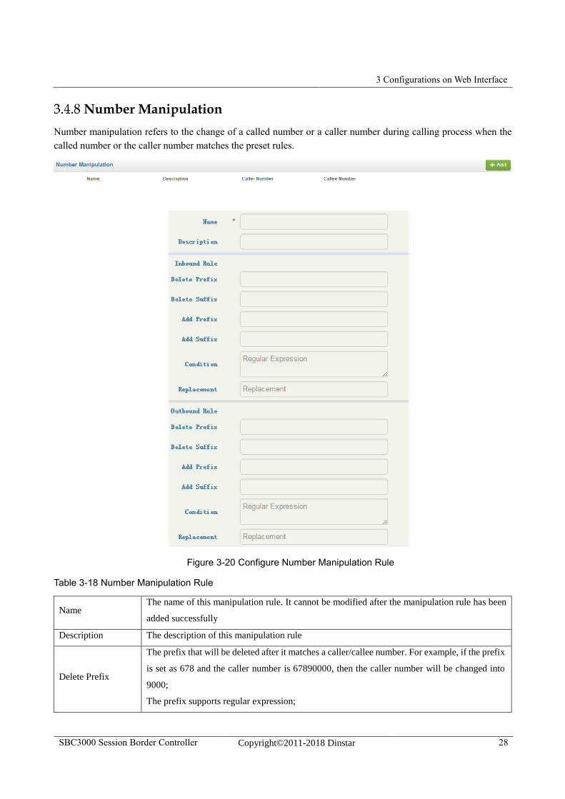
Number Manipulation
Number manipulation refers to the change of a called number or a caller number during calling process when the
called number or the caller number matches the preset rules.
Figure 3-20 Configure Number Manipulation Rule
Table 3-18 Number Manipulation Rule
Name The name of this manipulation rule. It cannot be modified after the manipulation rule has been
added successfully
Description The description of this manipulation rule
Delete Prefix
The prefix that will be deleted after it matches a caller/callee number. For example, if the prefix
is set as 678 and the caller number is 67890000, then the caller number will be changed into
9000;
The prefix supports regular expression;
3 Configurations on Web Interface
SBC3000 Session Border Controller Copyright©2011-2018 Dinstar 29
Multiple prefixes can be set for one manipulation rule.
Delete Suffix
The suffix that will be deleted after it matches a caller/callee number. For example, if the suffix
is set as 123 and the caller number is 8000123, then the caller number will be changed into
8000;
The suffix supports regular expression;
Multiple suffixes can be set for one manipulation rule.
Add Prefix
The prefix added to the caller/callee number. For example, if the prefix is set as 678 and the
caller number is 9000, then the caller number will be changed into 6789000 after the
manipulation rule is matched;
The prefix does not support regular expression;
Add Suffix
The suffix added to the caller/callee number For example, if the suffix is set as 678 and the
caller number is 9000, then the caller number will be changed into 9000678 after the
manipulation rule is matched;
The suffix does not support regular expression;
Condition
The condition supports regular expression.
If a caller/callee number can match one of the rules set in the ‘Condition’ parameter, the original
number will be changed into the one set in the ‘Replaced By’ parameter.
Replaced By
If a caller/callee number can match one of the rules set in the ‘Condition’ parameter, the original
number will be changed into the one set in the ‘Replaced By’ parameter.
The value of the ‘Replaced By’ parameter does not support regular expression.
Note:
During number manipulation, ‘Delete Prefix’ and ‘Delete Suffix’ are carried out first, followed by ‘Add Prefix’
and ‘Add Suffix’. If ‘Condition’ is also set, SBC3000 will match the condition based on the result of the
abovementioned rules.
If a number manipulation rule is used on the Service Access Network page, the Service Access SIP Trunk
page or the Service Core SIP Trunk page, it means the caller/callee number will be manipulated before the call
chooses a route;
If a number manipulation rule is used on the Service Routing Profiles page, it means the caller/callee number
will be manipulated after the call has chosen a specific route.
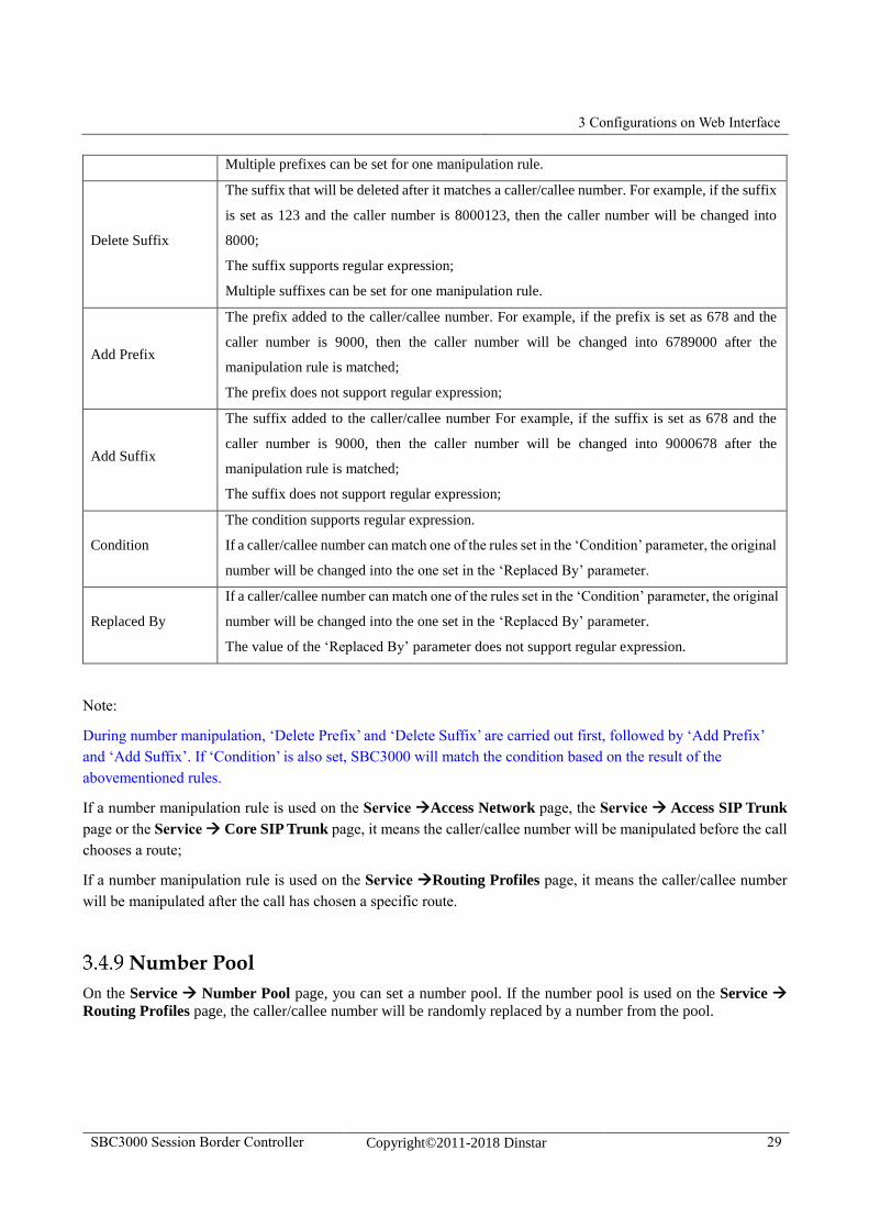
Number Pool
On the Service Number Pool page, you can set a number pool. If the number pool is used on the Service
Routing Profiles page, the caller/callee number will be randomly replaced by a number from the pool.
3 Configurations on Web Interface
SBC3000 Session Border Controller Copyright©2011-2018 Dinstar 30
Figure 3-21 Configure Number Pool
Table 3-19 Number Pool
Name The name of this number pool. It cannot be modified after the number pool has
been added successfully
Description The description of this manipulation rule
Caller/Callee Number
Prefix:If the prefix here is matched with a caller/callee number, the caller/callee
number will be randomly replaced by a number from the pool;
Start Number:The starting number of the number pool
End Number: The ending number of the number pool
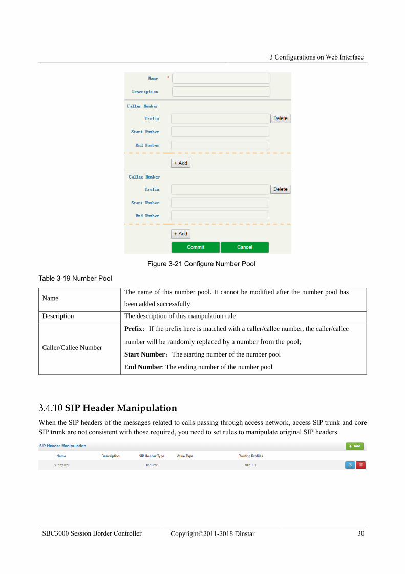
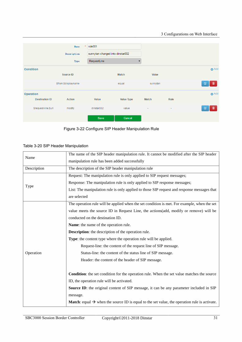
SIP Header Manipulation
When the SIP headers of the messages related to calls passing through access network, access SIP trunk and core
SIP trunk are not consistent with those required, you need to set rules to manipulate original SIP headers.
3 Configurations on Web Interface
SBC3000 Session Border Controller Copyright©2011-2018 Dinstar 31
Figure 3-22 Configure SIP Header Manipulation Rule
Table 3-20 SIP Header Manipulation
Name The name of the SIP header manipulation rule. It cannot be modified after the SIP header
manipulation rule has been added successfully
Description The description of the SIP header manipulation rule
Type
Request: The manipulation rule is only applied to SIP request messages;
Response: The manipulation rule is only applied to SIP response messages;
List: The manipulation rule is only applied to those SIP request and response messages that
are selected
Operation
The operation rule will be applied when the set condition is met. For example, when the set
value meets the source ID in Request Line, the actions(add, modify or remove) will be
conducted on the destination ID.
Name: the name of the operation rule.
Description: the description of the operation rule.
Type: the content type where the operation rule will be applied.
Request-line: the content of the request line of SIP message.
Status-line: the content of the status line of SIP message.
Header: the content of the header of SIP message.
Condition: the set condition for the operation rule. When the set value matches the source
ID, the operation rule will be activated.
Source ID: the original content of SIP message, it can be any parameter included in SIP
message.
Match: equal when the source ID is equal to the set value, the operation rule is activate.
3 Configurations on Web Interface
SBC3000 Session Border Controller Copyright©2011-2018 Dinstar 32
Regex when the source ID matches the set regular expression, the operation rule will be
activated.
Value: the value set to match the source ID.
Destination ID: the designated header to be modified.
Action: The actions (add, modify or remove) to manipulate SIP header after the preset
conditions is matched.
Value Type: Token In the ‘Value’ field, the content with $ is the content which is
from the designated header of original SIP message.
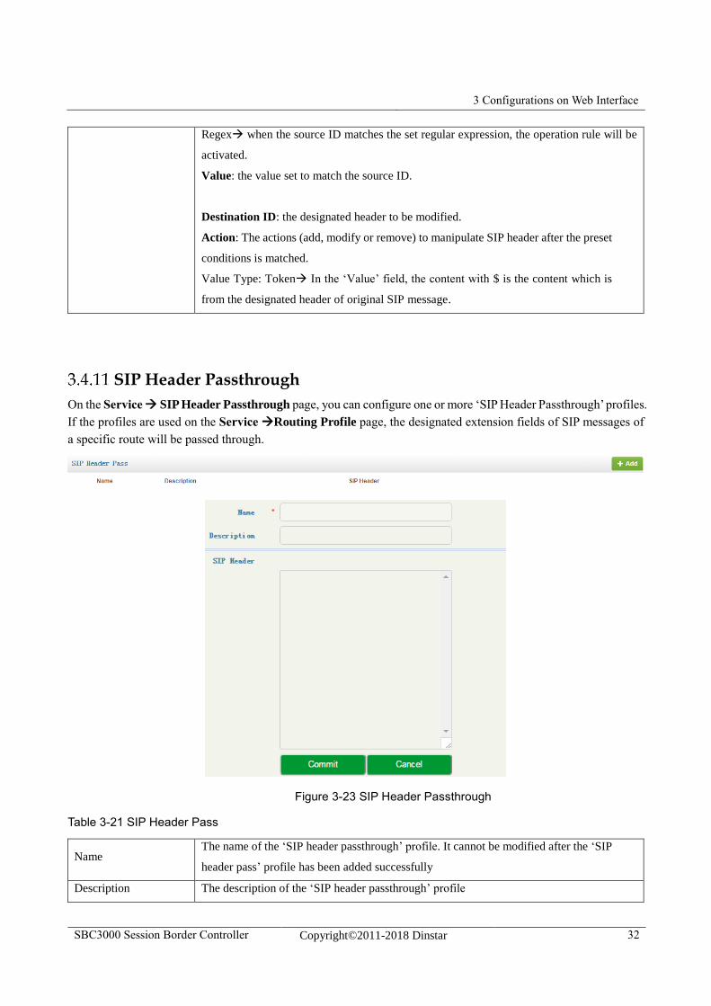
SIP Header Passthrough
On the Service SIP Header Passthrough page, you can configure one or more ‘SIP Header Passthrough’ profiles.
If the profiles are used on the Service Routing Profile page, the designated extension fields of SIP messages of
a specific route will be passed through.
Figure 3-23 SIP Header Passthrough
Table 3-21 SIP Header Pass
Name The name of the ‘SIP header passthrough’ profile. It cannot be modified after the ‘SIP
header pass’ profile has been added successfully
Description The description of the ‘SIP header passthrough’ profile
3 Configurations on Web Interface
SBC3000 Session Border Controller Copyright©2011-2018 Dinstar 33
SIP The SIP headers that are passed through.
A SIP header in a row, case-sensitive, without any extra punctuation marks
Note:
1.The ‘Allow’ and ‘Supported’ SIP headers can only be passed through during registration. That is to say, they
cannot be passed through during calling. Please think carefully before passing through these two SIP headers, as
they might conflict with the configurations of SBC3000.
2.The following SIP heads are not allowed to be passed through:
Network, To, From, Contact, Cseq, Max-Forwards, Content-Length, Content-Type, Via, Require, Proxy-Require,
Unsupported, Authorization, Proxy-Authorization, Www-Authenticate, Proxy-Authenticate, Accept, Route,
Record-Route, Refer-To, Referred-By, Auto-Defined。
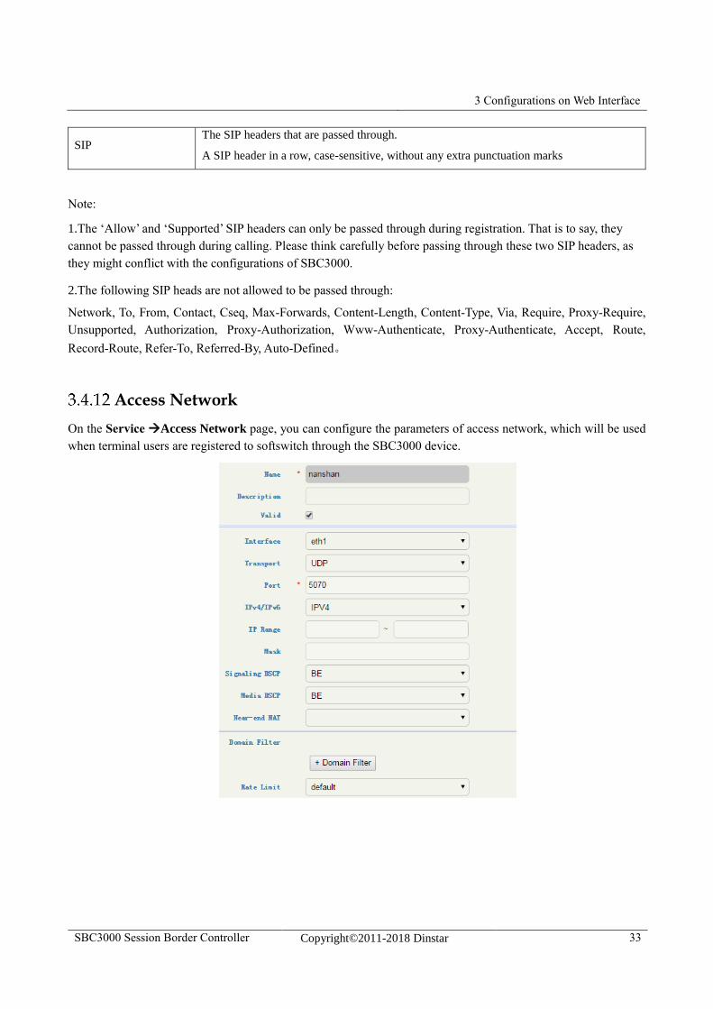
Access Network
On the Service Access Network page, you can configure the parameters of access network, which will be used
when terminal users are registered to softswitch through the SBC3000 device.
3 Configurations on Web Interface
SBC3000 Session Border Controller Copyright©2011-2018 Dinstar 34
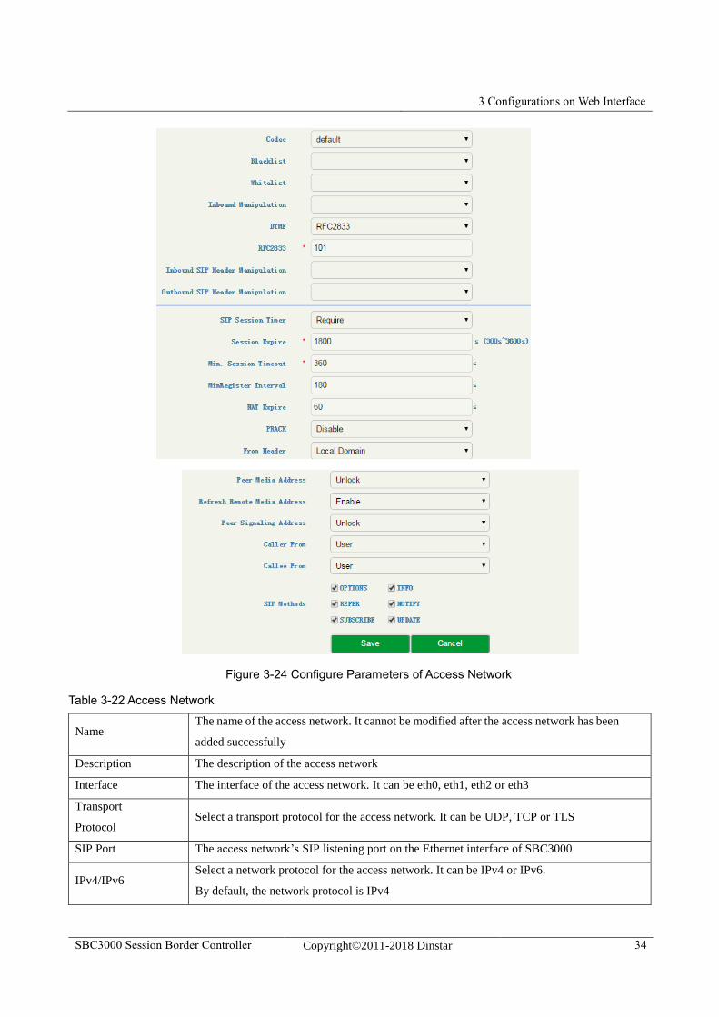
Figure 3-24 Configure Parameters of Access Network
Table 3-22 Access Network
Name The name of the access network. It cannot be modified after the access network has been
added successfully
Description The description of the access network
Interface The interface of the access network. It can be eth0, eth1, eth2 or eth3
Transport
Protocol Select a transport protocol for the access network. It can be UDP, TCP or TLS
SIP Port The access network’s SIP listening port on the Ethernet interface of SBC3000
IPv4/IPv6 Select a network protocol for the access network. It can be IPv4 or IPv6.
By default, the network protocol is IPv4
3 Configurations on Web Interface
SBC3000 Session Border Controller Copyright©2011-2018 Dinstar 35
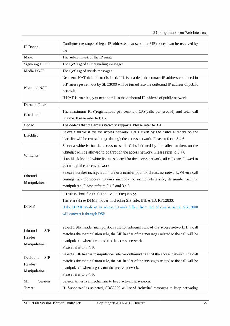
IP Range Configure the range of legal IP addresses that send out SIP request can be received by
the
Mask The subnet mask of the IP range
Signaling DSCP The QoS tag of SIP signaling messages
Media DSCP The QoS tag of meida messages
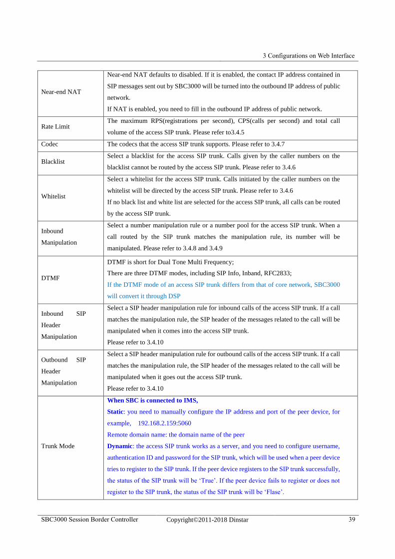
Near-end NAT
Near-end NAT defaults to disabled. If it is enabled, the contact IP address contained in
SIP messages sent out by SBC3000 will be turned into the outbound IP address of public
network.
If NAT is enabled, you need to fill in the outbound IP address of public network.
Domain Filter
Rate Limit The maximum RPS(registrations per second), CPS(calls per second) and total call
volume. Please refer to3.4.5
Codec The codecs that the access network supports. Please refer to 3.4.7
Blacklist Select a blacklist for the access network. Calls given by the caller numbers on the
blacklist will be refused to go through the access network. Please refer to 3.4.6
Whitelist
Select a whitelist for the access network. Calls initiated by the caller numbers on the
whitelist will be allowed to go through the access network. Please refer to 3.4.6
If no black list and white list are selected for the access network, all calls are allowed to
go through the access network
Inbound
Manipulation
Select a number manipulation rule or a number pool for the access network. When a call
coming into the access network matches the manipulation rule, its number will be
manipulated. Please refer to 3.4.8 and 3.4.9
DTMF
DTMF is short for Dual Tone Multi Frequency;
There are three DTMF modes, including SIP Info, INBAND, RFC2833;
If the DTMF mode of an access network differs from that of core network, SBC3000
will convert it through DSP
Inbound SIP
Header
Manipulation
Select a SIP header manipulation rule for inbound calls of the access network. If a call
matches the manipulation rule, the SIP header of the messages related to the call will be
manipulated when it comes into the access network.
Please refer to 3.4.10
Outbound SIP
Header
Manipulation
Select a SIP header manipulation rule for outbound calls of the access network. If a call
matches the manipulation rule, the SIP header of the messages related to the call will be
manipulated when it goes out the access network.
Please refer to 3.4.10
SIP Session
Timer
Session timer is a mechanism to keep activating sessions.
If ‘Supported’ is selected, SBC3000 will send ‘reinvite’ messages to keep activating
3 Configurations on Web Interface
SBC3000 Session Border Controller Copyright©2011-2018 Dinstar 36
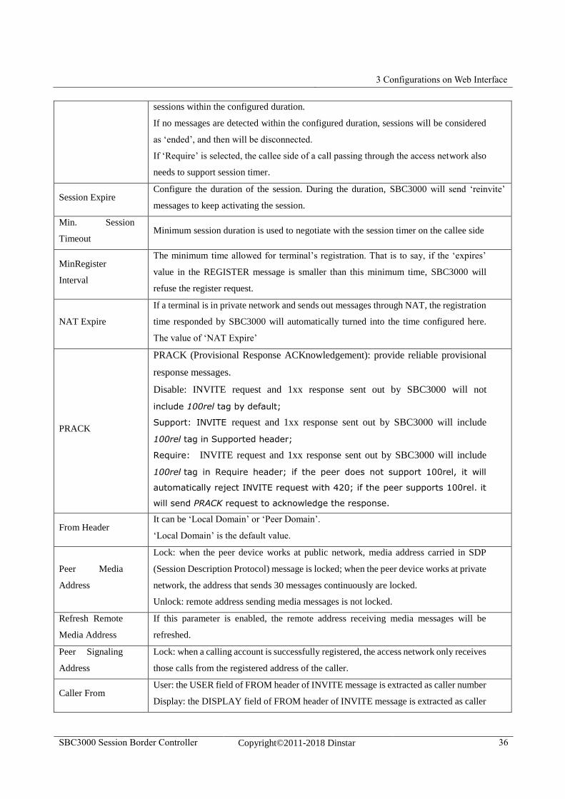
sessions within the configured duration.
If no messages are detected within the configured duration, sessions will be considered
as ‘ended’, and then will be disconnected.
If ‘Require’ is selected, the callee side of a call passing through the access network also
needs to support session timer.
Session Expire Configure the duration of the session. During the duration, SBC3000 will send ‘reinvite’
messages to keep activating the session.
Min. Session
Timeout Minimum session duration is used to negotiate with the session timer on the callee side
MinRegister
Interval
The minimum time allowed for terminal’s registration. That is to say, if the ‘expires’
value in the REGISTER message is smaller than this minimum time, SBC3000 will
refuse the register request.
NAT Expire
If a terminal is in private network and sends out messages through NAT, the registration
time responded by SBC3000 will automatically turned into the time configured here.
The value of ‘NAT Expire’
PRACK
PRACK (Provisional Response ACKnowledgement): provide reliable provisional
response messages.
Disable: INVITE request and 1xx response sent out by SBC3000 will not
include 100rel tag by default;
Support: INVITE request and 1xx response sent out by SBC3000 will include
100rel tag in Supported header;
Require: INVITE request and 1xx response sent out by SBC3000 will include
100rel tag in Require header; if the peer does not support 100rel, it will
automatically reject INVITE request with 420; if the peer supports 100rel. it
will send PRACK request to acknowledge the response.
From Header It can be ‘Local Domain’ or ‘Peer Domain’.
‘Local Domain’ is the default value.
Peer Media
Address
Lock: when the peer device works at public network, media address carried in SDP
(Session Description Protocol) message is locked; when the peer device works at private
network, the address that sends 30 messages continuously are locked.
Unlock: remote address sending media messages is not locked.
Refresh Remote
Media Address
If this parameter is enabled, the remote address receiving media messages will be
refreshed.
Peer Signaling
Address
Lock: when a calling account is successfully registered, the access network only receives
those calls from the registered address of the caller.
Caller From User: the USER field of FROM header of INVITE message is extracted as caller number
Display: the DISPLAY field of FROM header of INVITE message is extracted as caller
3 Configurations on Web Interface
SBC3000 Session Border Controller Copyright©2011-2018 Dinstar 37
number
Callee From
User: the USER field of TO header of INVITE message is extracted as callee number;
Display: the DISPLAY field of TO header of INVITE message is extracted as callee
number;
Request-uri: the USER NUMBER in REQUEST-URI of INVITE message is extracted
as callee number;
SIP Methods
Configure the SIP request methods that can be accepted by the access network.
If a SIP request method is not enabled, the system will reject the corresponding SIP
request.
By default, the INVITE request, REGISTER request and SESSION DISCONNECT
request are accepted.
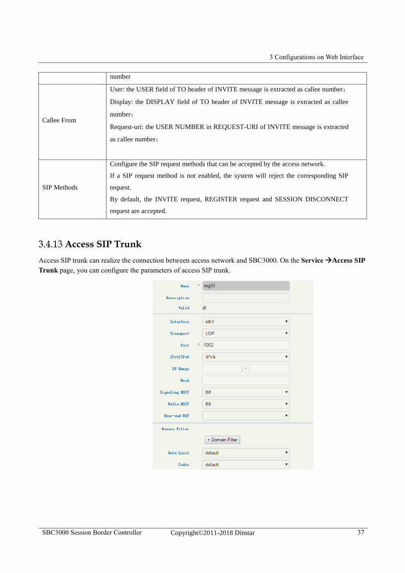
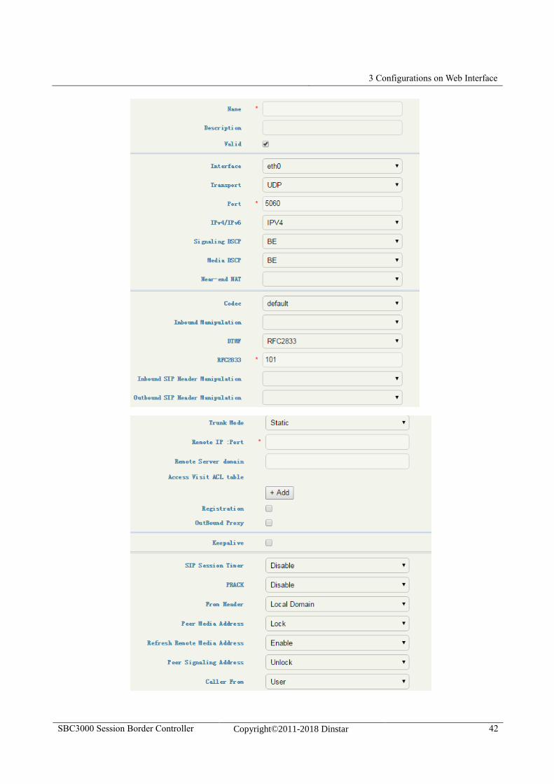
Access SIP Trunk
Access SIP trunk can realize the connection between access network and SBC3000. On the Service Access SIP
Trunk page, you can configure the parameters of access SIP trunk.
3 Configurations on Web Interface
SBC3000 Session Border Controller Copyright©2011-2018 Dinstar 38
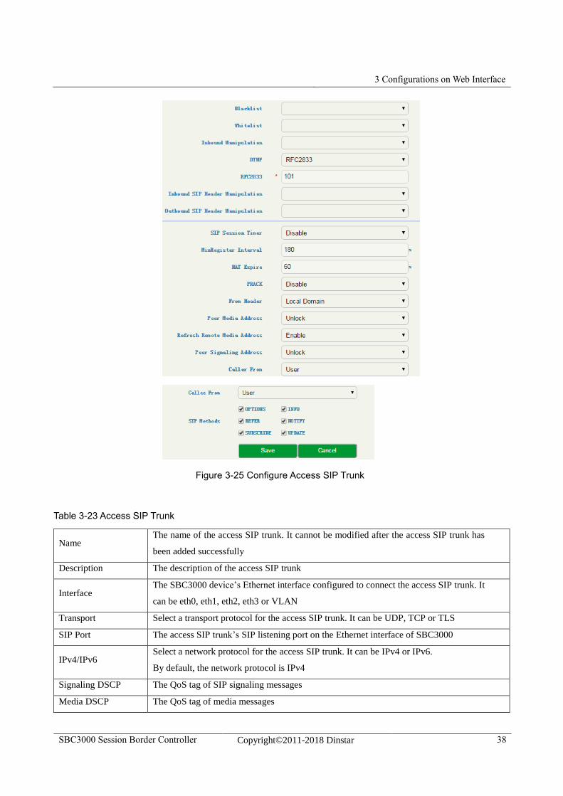
Figure 3-25 Configure Access SIP Trunk
Table 3-23 Access SIP Trunk
Name The name of the access SIP trunk. It cannot be modified after the access SIP trunk has
been added successfully
Description The description of the access SIP trunk
Interface The SBC3000 device’s Ethernet interface configured to connect the access SIP trunk. It
can be eth0, eth1, eth2, eth3 or VLAN
Transport Select a transport protocol for the access SIP trunk. It can be UDP, TCP or TLS
SIP Port The access SIP trunk’s SIP listening port on the Ethernet interface of SBC3000
IPv4/IPv6 Select a network protocol for the access SIP trunk. It can be IPv4 or IPv6.
By default, the network protocol is IPv4
Signaling DSCP The QoS tag of SIP signaling messages
Media DSCP The QoS tag of media messages
3 Configurations on Web Interface
SBC3000 Session Border Controller Copyright©2011-2018 Dinstar 39
Near-end NAT
Near-end NAT defaults to disabled. If it is enabled, the contact IP address contained in
SIP messages sent out by SBC3000 will be turned into the outbound IP address of public
network.
If NAT is enabled, you need to fill in the outbound IP address of public network.
Rate Limit The maximum RPS(registrations per second), CPS(calls per second) and total call
volume of the access SIP trunk. Please refer to3.4.5
Codec The codecs that the access SIP trunk supports. Please refer to 3.4.7
Blacklist Select a blacklist for the access SIP trunk. Calls given by the caller numbers on the
blacklist cannot be routed by the access SIP trunk. Please refer to 3.4.6
Whitelist
Select a whitelist for the access SIP trunk. Calls initiated by the caller numbers on the
whitelist will be directed by the access SIP trunk. Please refer to 3.4.6
If no black list and white list are selected for the access SIP trunk, all calls can be routed
by the access SIP trunk.
Inbound
Manipulation
Select a number manipulation rule or a number pool for the access SIP trunk. When a
call routed by the SIP trunk matches the manipulation rule, its number will be
manipulated. Please refer to 3.4.8 and 3.4.9
DTMF
DTMF is short for Dual Tone Multi Frequency;
There are three DTMF modes, including SIP Info, Inband, RFC2833;
If the DTMF mode of an access SIP trunk differs from that of core network, SBC3000
will convert it through DSP
Inbound SIP
Header
Manipulation
Select a SIP header manipulation rule for inbound calls of the access SIP trunk. If a call
matches the manipulation rule, the SIP header of the messages related to the call will be
manipulated when it comes into the access SIP trunk.
Please refer to 3.4.10
Outbound SIP
Header
Manipulation
Select a SIP header manipulation rule for outbound calls of the access SIP trunk. If a call
matches the manipulation rule, the SIP header of the messages related to the call will be
manipulated when it goes out the access SIP trunk.
Please refer to 3.4.10
Trunk Mode
When SBC is connected to IMS,
Static: you need to manually configure the IP address and port of the peer device, for
example, 192.168.2.159:5060
Remote domain name: the domain name of the peer
Dynamic: the access SIP trunk works as a server, and you need to configure username,
authentication ID and password for the SIP trunk, which will be used when a peer device
tries to register to the SIP trunk. If the peer device registers to the SIP trunk successfully,
the status of the SIP trunk will be ‘True’. If the peer device fails to register or does not
register to the SIP trunk, the status of the SIP trunk will be ‘Flase’.
3 Configurations on Web Interface
SBC3000 Session Border Controller Copyright©2011-2018 Dinstar 40
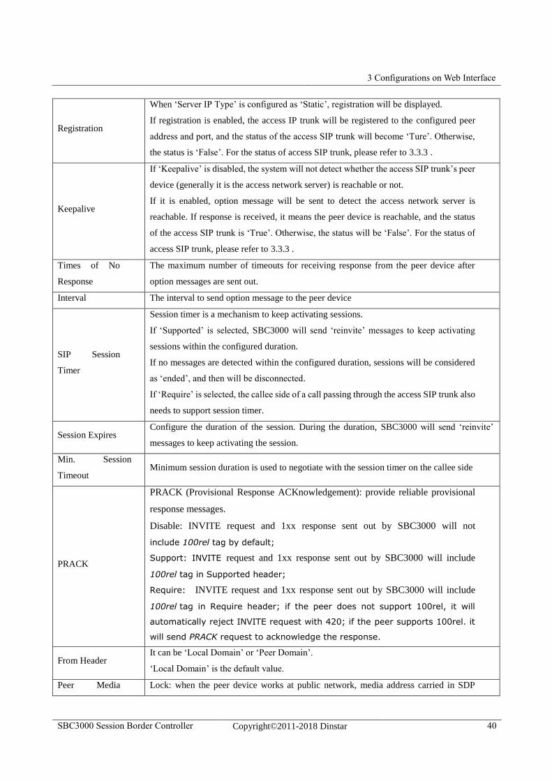
Registration
When ‘Server IP Type’ is configured as ‘Static’, registration will be displayed.
If registration is enabled, the access IP trunk will be registered to the configured peer
address and port, and the status of the access SIP trunk will become ‘Ture’. Otherwise,
the status is ‘False’. For the status of access SIP trunk, please refer to 3.3.3 .
Keepalive
If ‘Keepalive’ is disabled, the system will not detect whether the access SIP trunk’s peer
device (generally it is the access network server) is reachable or not.
If it is enabled, option message will be sent to detect the access network server is
reachable. If response is received, it means the peer device is reachable, and the status
of the access SIP trunk is ‘True’. Otherwise, the status will be ‘False’. For the status of
access SIP trunk, please refer to 3.3.3 .
Times of No
Response
The maximum number of timeouts for receiving response from the peer device after
option messages are sent out.
Interval The interval to send option message to the peer device
SIP Session
Timer
Session timer is a mechanism to keep activating sessions.
If ‘Supported’ is selected, SBC3000 will send ‘reinvite’ messages to keep activating
sessions within the configured duration.
If no messages are detected within the configured duration, sessions will be considered
as ‘ended’, and then will be disconnected.
If ‘Require’ is selected, the callee side of a call passing through the access SIP trunk also
needs to support session timer.
Session Expires Configure the duration of the session. During the duration, SBC3000 will send ‘reinvite’
messages to keep activating the session.
Min. Session
Timeout Minimum session duration is used to negotiate with the session timer on the callee side
PRACK
PRACK (Provisional Response ACKnowledgement): provide reliable provisional
response messages.
Disable: INVITE request and 1xx response sent out by SBC3000 will not
include 100rel tag by default;
Support: INVITE request and 1xx response sent out by SBC3000 will include
100rel tag in Supported header;
Require: INVITE request and 1xx response sent out by SBC3000 will include
100rel tag in Require header; if the peer does not support 100rel, it will
automatically reject INVITE request with 420; if the peer supports 100rel. it
will send PRACK request to acknowledge the response.
From Header It can be ‘Local Domain’ or ‘Peer Domain’.
‘Local Domain’ is the default value.
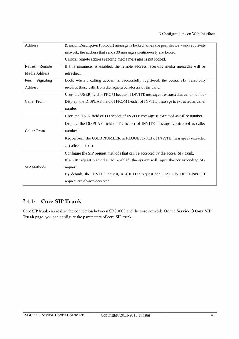
Peer Media Lock: when the peer device works at public network, media address carried in SDP
3 Configurations on Web Interface
SBC3000 Session Border Controller Copyright©2011-2018 Dinstar 41
Address (Session Description Protocol) message is locked; when the peer device works at private
network, the address that sends 30 messages continuously are locked.
Unlock: remote address sending media messages is not locked.
Refresh Remote
Media Address
If this parameter is enabled, the remote address receiving media messages will be
refreshed.
Peer Signaling
Address
Lock: when a calling account is successfully registered, the access SIP trunk only
receives those calls from the registered address of the caller.
Caller From
User: the USER field of FROM header of INVITE message is extracted as caller number
Display: the DISPLAY field of FROM header of INVITE message is extracted as caller
number
Callee From
User: the USER field of TO header of INVITE message is extracted as callee number;
Display: the DISPLAY field of TO header of INVITE message is extracted as callee
number;
Request-uri: the USER NUMBER in REQUEST-URI of INVITE message is extracted
as callee number;
SIP Methods
Configure the SIP request methods that can be accepted by the access SIP trunk.
If a SIP request method is not enabled, the system will reject the corresponding SIP
request.
By default, the INVITE request, REGISTER request and SESSION DISCONNECT
request are always accepted.
Core SIP Trunk
Core SIP trunk can realize the connection between SBC3000 and the core network. On the Service Core SIP
Trunk page, you can configure the parameters of core SIP trunk.
3 Configurations on Web Interface
SBC3000 Session Border Controller Copyright©2011-2018 Dinstar 42
3 Configurations on Web Interface
SBC3000 Session Border Controller Copyright©2011-2018 Dinstar 43
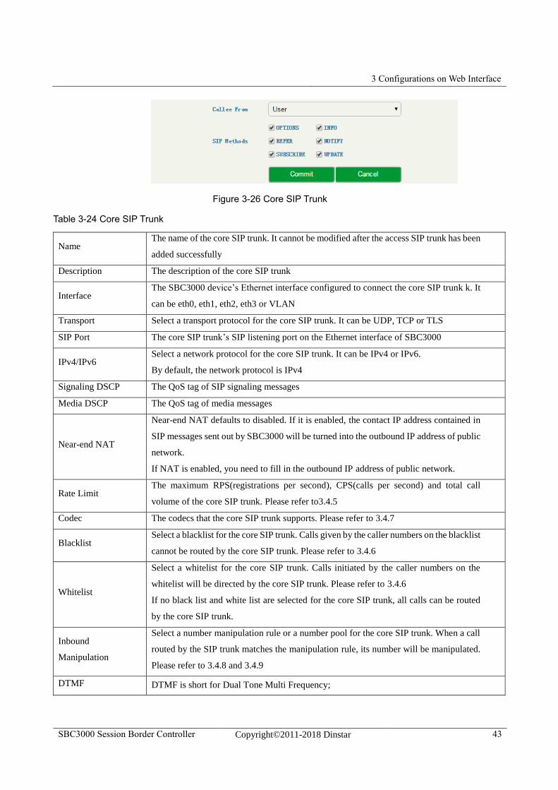
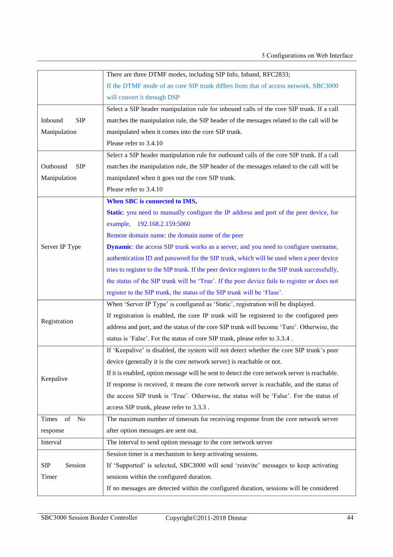
Figure 3-26 Core SIP Trunk
Table 3-24 Core SIP Trunk
Name The name of the core SIP trunk. It cannot be modified after the access SIP trunk has been
added successfully
Description The description of the core SIP trunk
Interface The SBC3000 device’s Ethernet interface configured to connect the core SIP trunk k. It
can be eth0, eth1, eth2, eth3 or VLAN
Transport Select a transport protocol for the core SIP trunk. It can be UDP, TCP or TLS
SIP Port The core SIP trunk’s SIP listening port on the Ethernet interface of SBC3000
IPv4/IPv6 Select a network protocol for the core SIP trunk. It can be IPv4 or IPv6.
By default, the network protocol is IPv4
Signaling DSCP The QoS tag of SIP signaling messages
Media DSCP The QoS tag of media messages
Near-end NAT
Near-end NAT defaults to disabled. If it is enabled, the contact IP address contained in
SIP messages sent out by SBC3000 will be turned into the outbound IP address of public
network.
If NAT is enabled, you need to fill in the outbound IP address of public network.
Rate Limit The maximum RPS(registrations per second), CPS(calls per second) and total call
volume of the core SIP trunk. Please refer to3.4.5
Codec The codecs that the core SIP trunk supports. Please refer to 3.4.7
Blacklist Select a blacklist for the core SIP trunk. Calls given by the caller numbers on the blacklist
cannot be routed by the core SIP trunk. Please refer to 3.4.6
Whitelist
Select a whitelist for the core SIP trunk. Calls initiated by the caller numbers on the
whitelist will be directed by the core SIP trunk. Please refer to 3.4.6
If no black list and white list are selected for the core SIP trunk, all calls can be routed
by the core SIP trunk.
Inbound
Manipulation
Select a number manipulation rule or a number pool for the core SIP trunk. When a call
routed by the SIP trunk matches the manipulation rule, its number will be manipulated.
Please refer to 3.4.8 and 3.4.9
DTMF DTMF is short for Dual Tone Multi Frequency;
3 Configurations on Web Interface
SBC3000 Session Border Controller Copyright©2011-2018 Dinstar 44
There are three DTMF modes, including SIP Info, Inband, RFC2833;
If the DTMF mode of an core SIP trunk differs from that of access network, SBC3000
will convert it through DSP
Inbound SIP
Manipulation
Select a SIP header manipulation rule for inbound calls of the core SIP trunk. If a call
matches the manipulation rule, the SIP header of the messages related to the call will be
manipulated when it comes into the core SIP trunk.
Please refer to 3.4.10
Outbound SIP
Manipulation
Select a SIP header manipulation rule for outbound calls of the core SIP trunk. If a call
matches the manipulation rule, the SIP header of the messages related to the call will be
manipulated when it goes out the core SIP trunk.
Please refer to 3.4.10
Server IP Type
When SBC is connected to IMS,
Static: you need to manually configure the IP address and port of the peer device, for
example, 192.168.2.159:5060
Remote domain name: the domain name of the peer
Dynamic: the access SIP trunk works as a server, and you need to configure username,
authentication ID and password for the SIP trunk, which will be used when a peer device
tries to register to the SIP trunk. If the peer device registers to the SIP trunk successfully,
the status of the SIP trunk will be ‘True’. If the peer device fails to register or does not
register to the SIP trunk, the status of the SIP trunk will be ‘Flase’.
Registration
When ‘Server IP Type’ is configured as ‘Static’, registration will be displayed.
If registration is enabled, the core IP trunk will be registered to the configured peer
address and port, and the status of the core SIP trunk will become ‘Ture’. Otherwise, the
status is ‘False’. For the status of core SIP trunk, please refer to 3.3.4 .
Keepalive
If ‘Keepalive’ is disabled, the system will not detect whether the core SIP trunk’s peer
device (generally it is the core network server) is reachable or not.
If it is enabled, option message will be sent to detect the core network server is reachable.
If response is received, it means the core network server is reachable, and the status of
the access SIP trunk is ‘True’. Otherwise, the status will be ‘False’. For the status of
access SIP trunk, please refer to 3.3.3 .
Times of No
response
The maximum number of timeouts for receiving response from the core network server
after option messages are sent out.
Interval The interval to send option message to the core network server
SIP Session
Timer
Session timer is a mechanism to keep activating sessions.
If ‘Supported’ is selected, SBC3000 will send ‘reinvite’ messages to keep activating
sessions within the configured duration.
If no messages are detected within the configured duration, sessions will be considered
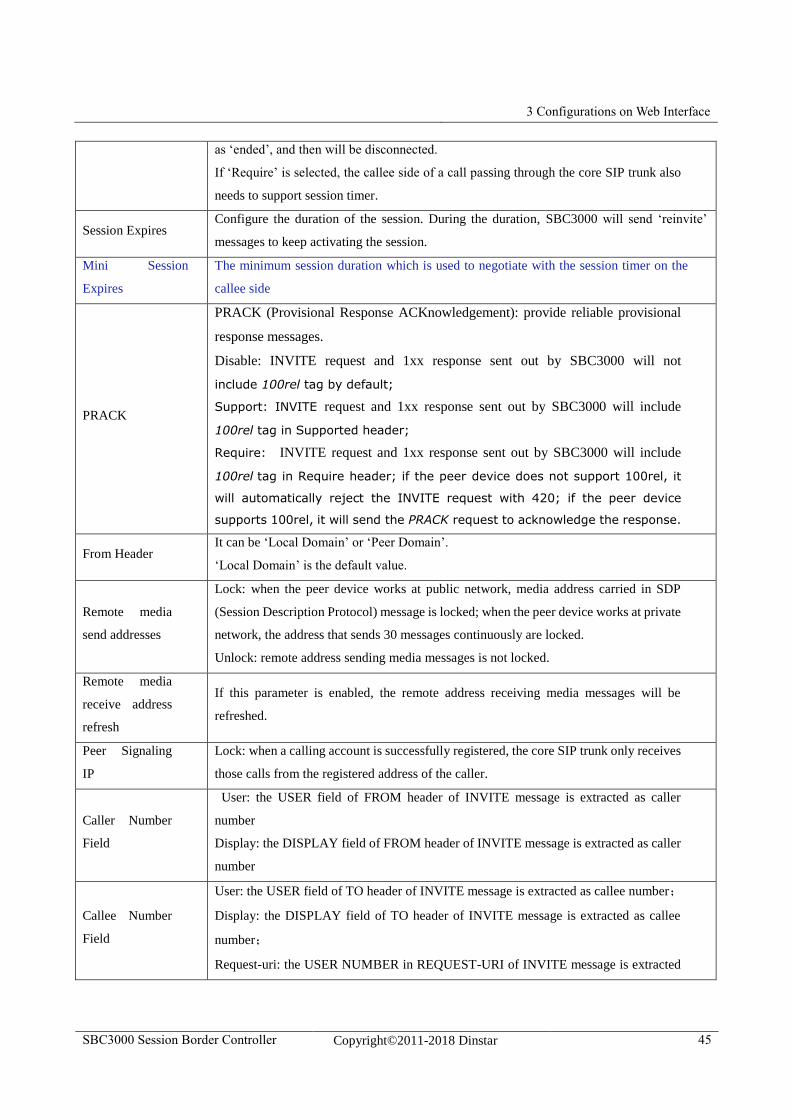
3 Configurations on Web Interface
SBC3000 Session Border Controller Copyright©2011-2018 Dinstar 45
as ‘ended’, and then will be disconnected.
If ‘Require’ is selected, the callee side of a call passing through the core SIP trunk also
needs to support session timer.
Session Expires Configure the duration of the session. During the duration, SBC3000 will send ‘reinvite’
messages to keep activating the session.
Mini Session
Expires
The minimum session duration which is used to negotiate with the session timer on the
callee side
PRACK
PRACK (Provisional Response ACKnowledgement): provide reliable provisional
response messages.
Disable: INVITE request and 1xx response sent out by SBC3000 will not
include 100rel tag by default;
Support: INVITE request and 1xx response sent out by SBC3000 will include
100rel tag in Supported header;
Require: INVITE request and 1xx response sent out by SBC3000 will include
100rel tag in Require header; if the peer device does not support 100rel, it
will automatically reject the INVITE request with 420; if the peer device
supports 100rel, it will send the PRACK request to acknowledge the response.
From Header It can be ‘Local Domain’ or ‘Peer Domain’.
‘Local Domain’ is the default value.
Remote media
send addresses
Lock: when the peer device works at public network, media address carried in SDP
(Session Description Protocol) message is locked; when the peer device works at private
network, the address that sends 30 messages continuously are locked.
Unlock: remote address sending media messages is not locked.
Remote media
receive address
refresh
If this parameter is enabled, the remote address receiving media messages will be
refreshed.
Peer Signaling
IP
Lock: when a calling account is successfully registered, the core SIP trunk only receives
those calls from the registered address of the caller.
Caller Number
Field
User: the USER field of FROM header of INVITE message is extracted as caller
number
Display: the DISPLAY field of FROM header of INVITE message is extracted as caller
number
Callee Number
Field
User: the USER field of TO header of INVITE message is extracted as callee number;
Display: the DISPLAY field of TO header of INVITE message is extracted as callee
number;
Request-uri: the USER NUMBER in REQUEST-URI of INVITE message is extracted
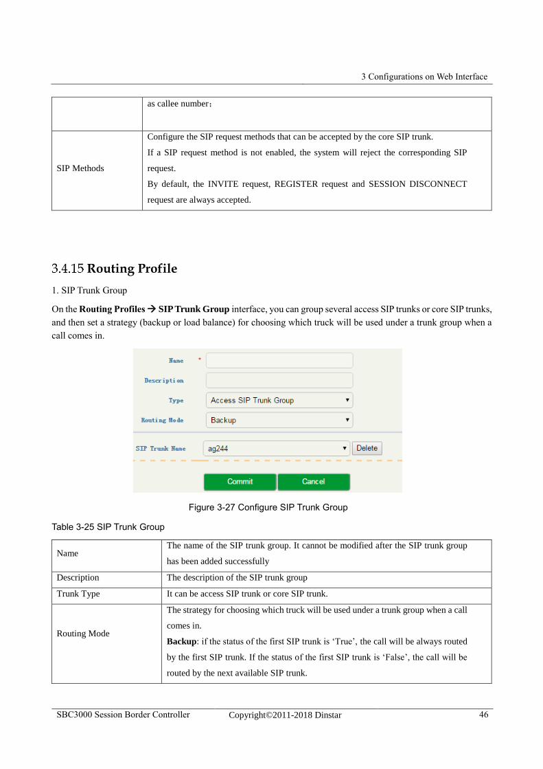
3 Configurations on Web Interface
SBC3000 Session Border Controller Copyright©2011-2018 Dinstar 46
as callee number;
SIP Methods
Configure the SIP request methods that can be accepted by the core SIP trunk.
If a SIP request method is not enabled, the system will reject the corresponding SIP
request.
By default, the INVITE request, REGISTER request and SESSION DISCONNECT
request are always accepted.
Routing Profile
1. SIP Trunk Group
On the Routing Profiles SIP Trunk Group interface, you can group several access SIP trunks or core SIP trunks,
and then set a strategy (backup or load balance) for choosing which truck will be used under a trunk group when a
call comes in.
Figure 3-27 Configure SIP Trunk Group
Table 3-25 SIP Trunk Group
Name The name of the SIP trunk group. It cannot be modified after the SIP trunk group
has been added successfully
Description The description of the SIP trunk group
Trunk Type It can be access SIP trunk or core SIP trunk.
Routing Mode
The strategy for choosing which truck will be used under a trunk group when a call
comes in.
Backup: if the status of the first SIP trunk is ‘True’, the call will be always routed
by the first SIP trunk. If the status of the first SIP trunk is ‘False’, the call will be
routed by the next available SIP trunk.
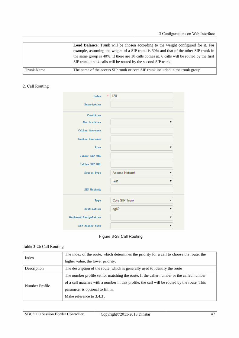
3 Configurations on Web Interface
SBC3000 Session Border Controller Copyright©2011-2018 Dinstar 47
Load Balance: Trunk will be chosen according to the weight configured for it. For
example, assuming the weight of a SIP trunk is 60% and that of the other SIP trunk in
the same group is 40%, if there are 10 calls comes in, 6 calls will be routed by the first
SIP trunk, and 4 calls will be routed by the second SIP trunk.
Trunk Name The name of the access SIP trunk or core SIP trunk included in the trunk group
2. Call Routing
Figure 3-28 Call Routing
Table 3-26 Call Routing
Index The index of the route, which determines the priority for a call to choose the route; the
higher value, the lower priority.
Description The description of the route, which is generally used to identify the route
Number Profile
The number profile set for matching the route. If the caller number or the called number
of a call matches with a number in this profile, the call will be routed by the route. This
parameter is optional to fill in.
Make reference to 3.4.3 .
3 Configurations on Web Interface
SBC3000 Session Border Controller Copyright©2011-2018 Dinstar 48
Caller Username
The caller number set for matching the route, which supports regular expression. If the
caller number of a call matches with this number, the call will be routed by the route. If
this parameter is null, it means caller number can be any number.
Callee
Username
The callee number set for matching the route, which supports regular expression. If the
callee number of a call matches with this number, the call will be routed by the route. If
this parameter is null, it means callee number can be any number.
ime Profile
The profile of time during which the route can be used; If this parameter is null, it means
the route can be used at anytime.
Please make reference to 3.4.4
Caller SIP URL
If the ‘SIP URL’ field of the ‘FROM’ header of a request message sent by a caller number
matches with the value configured here, the call will be routed by the route.
If this parameter is null, it means the SIP URL from caller can be any.
SIP URL
If the ‘SIP URL’ field of the ‘FROM’ header of a request message sent by a callee number
matches with the value configured here, the call will be routed by the route.
If this parameter is null, it means the SIP URL from callee can be any.
Source Type
The source of the call routed by the route. If the source of a call is access network or
access SIP trunk, the destination can only be core SIP trunk; If the source of a call is core
SIP trunk, the destination can be access network or access SIP trunk.
SIP Methods The SIP method(s) supported by the route. If this parameter is null, it means SIP methods
can be any.
Destination
Type
The destination of the call routed by the route. If the destination of a call is access
network or access SIP trunk, the source can only be core SIP trunk; If the destination of
a call is core SIP trunk, the source can be access network or access SIP trunk.
Destination The specific SIP truck where a call will be routed
Number
Manipulation
If it is on, the caller number or called number of a call routed by the route will be
manipulated according to the configured manipulation rule; The parameter is off by
default. For manipulation rule, please make reference to 3.4.8
SIP Header
Passthrough
If it is on, the SIP header of a call routed by the route will be manipulated according to
the configured manipulation rule; The parameter is off by default. For manipulation rule,
please make reference to 3.4.10
Note:
Caller number or called number can also be manipulated when a call comes into an access network, access SIP
trunk or core SIP trunk. In this section, number is manipulated after a call has finished choosing a route.
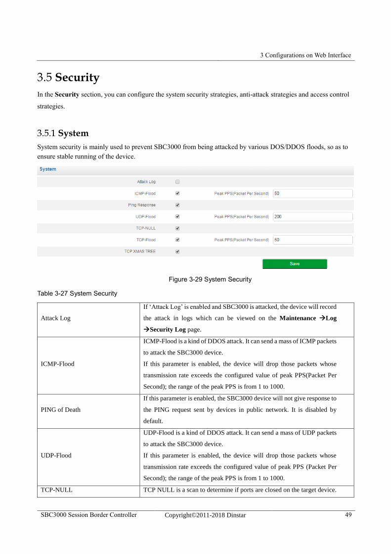
3 Configurations on Web Interface
SBC3000 Session Border Controller Copyright©2011-2018 Dinstar 49
3.5 Security
In the Security section, you can configure the system security strategies, anti-attack strategies and access control
strategies.
System
System security is mainly used to prevent SBC3000 from being attacked by various DOS/DDOS floods, so as to
ensure stable running of the device.
Figure 3-29 System Security
Table 3-27 System Security
Attack Log
If ‘Attack Log’ is enabled and SBC3000 is attacked, the device will record
the attack in logs which can be viewed on the Maintenance Log
Security Log page.
ICMP-Flood
ICMP-Flood is a kind of DDOS attack. It can send a mass of ICMP packets
to attack the SBC3000 device.
If this parameter is enabled, the device will drop those packets whose
transmission rate exceeds the configured value of peak PPS(Packet Per
Second); the range of the peak PPS is from 1 to 1000.
PING of Death
If this parameter is enabled, the SBC3000 device will not give response to
the PING request sent by devices in public network. It is disabled by
default.
UDP-Flood
UDP-Flood is a kind of DDOS attack. It can send a mass of UDP packets
to attack the SBC3000 device.
If this parameter is enabled, the device will drop those packets whose
transmission rate exceeds the configured value of peak PPS (Packet Per
Second); the range of the peak PPS is from 1 to 1000.
TCP-NULL TCP NULL is a scan to determine if ports are closed on the target device.
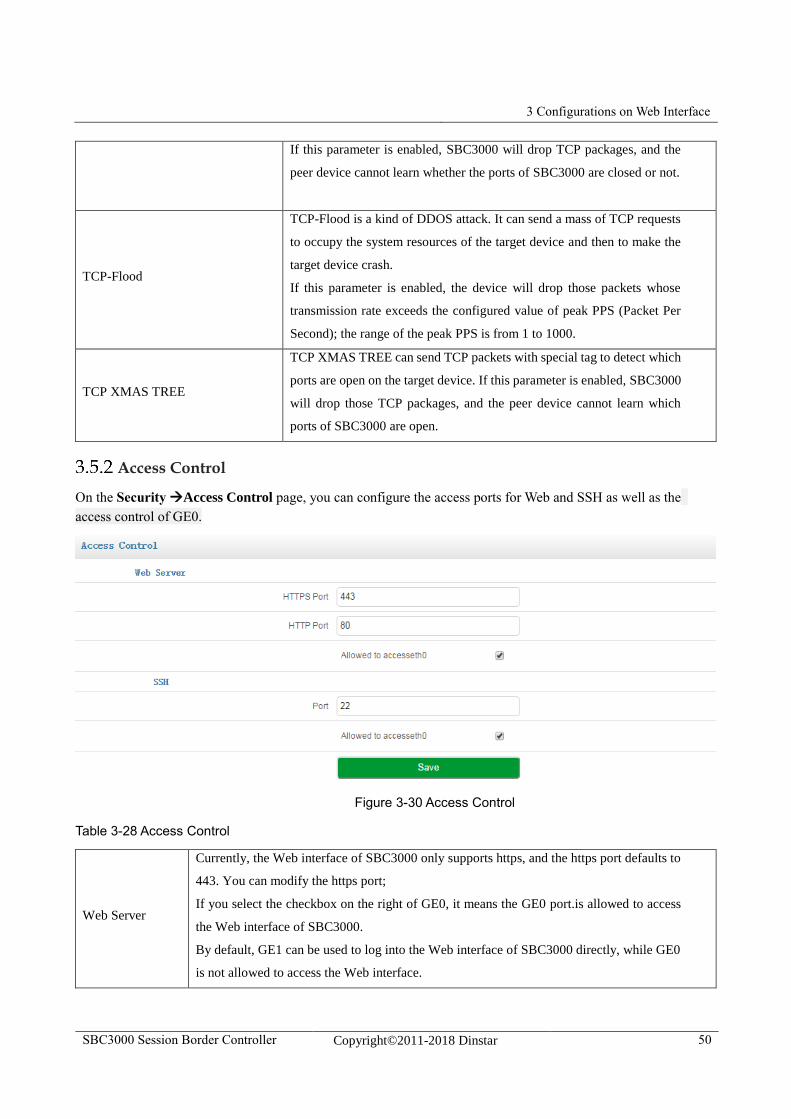
3 Configurations on Web Interface
SBC3000 Session Border Controller Copyright©2011-2018 Dinstar 50
If this parameter is enabled, SBC3000 will drop TCP packages, and the
peer device cannot learn whether the ports of SBC3000 are closed or not.
TCP-Flood
TCP-Flood is a kind of DDOS attack. It can send a mass of TCP requests
to occupy the system resources of the target device and then to make the
target device crash.
If this parameter is enabled, the device will drop those packets whose
transmission rate exceeds the configured value of peak PPS (Packet Per
Second); the range of the peak PPS is from 1 to 1000.
TCP XMAS TREE
TCP XMAS TREE can send TCP packets with special tag to detect which
ports are open on the target device. If this parameter is enabled, SBC3000
will drop those TCP packages, and the peer device cannot learn which
ports of SBC3000 are open.
Access Control
On the Security Access Control page, you can configure the access ports for Web and SSH as well as the
access control of GE0.
Figure 3-30 Access Control
Table 3-28 Access Control
Web Server
Currently, the Web interface of SBC3000 only supports https, and the https port defaults to
443. You can modify the https port;
If you select the checkbox on the right of GE0, it means the GE0 port.is allowed to access
the Web interface of SBC3000.
By default, GE1 can be used to log into the Web interface of SBC3000 directly, while GE0
is not allowed to access the Web interface.
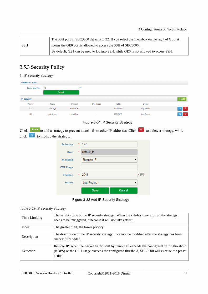
3 Configurations on Web Interface
SBC3000 Session Border Controller Copyright©2011-2018 Dinstar 51
SSH
The SSH port of SBC3000 defaults to 22. If you select the checkbox on the right of GE0, it
means the GE0 port.is allowed to access the SSH of SBC3000.
By default, GE1 can be used to log into SSH, while GE0 is not allowed to access SSH.
Security Policy
1. IP Security Strategy
Figure 3-31 IP Security Strategy
Click to add a strategy to prevent attacks from other IP addresses. Click to delete a strategy, while
click to modify the strategy.
Figure 3-32 Add IP Security Strategy
Table 3-29 IP Security Strategy
Time Limiting The validity time of the IP security strategy. When the validity time expires, the strategy
needs to be retriggered, otherwise it will not takes effect.
Index The greater digit, the lower priority
Description The description of the IP security strategy. It cannot be modified after the strategy has been
successfully added.
Detection
Remote IP: when the packet traffic sent by remote IP exceeds the configured traffic threshold
(KBPS) or the CPU usage exceeds the configured threshold, SBC3000 will execute the preset
action.
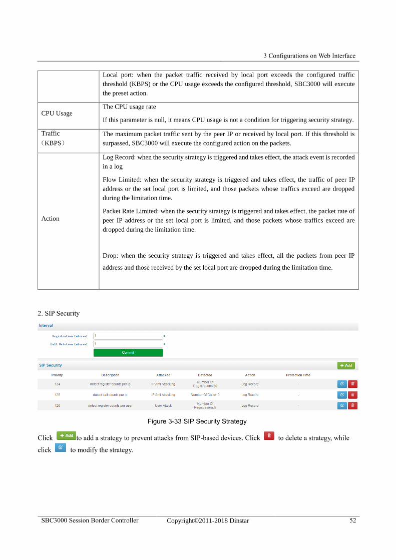
3 Configurations on Web Interface
SBC3000 Session Border Controller Copyright©2011-2018 Dinstar 52
Local port: when the packet traffic received by local port exceeds the configured traffic
threshold (KBPS) or the CPU usage exceeds the configured threshold, SBC3000 will execute
the preset action.
CPU Usage The CPU usage rate
If this parameter is null, it means CPU usage is not a condition for triggering security strategy.
Traffic
(KBPS)
The maximum packet traffic sent by the peer IP or received by local port. If this threshold is
surpassed, SBC3000 will execute the configured action on the packets.
Action
Log Record: when the security strategy is triggered and takes effect, the attack event is recorded
in a log
Flow Limited: when the security strategy is triggered and takes effect, the traffic of peer IP
address or the set local port is limited, and those packets whose traffics exceed are dropped
during the limitation time.
Packet Rate Limited: when the security strategy is triggered and takes effect, the packet rate of
peer IP address or the set local port is limited, and those packets whose traffics exceed are
dropped during the limitation time.
Drop: when the security strategy is triggered and takes effect, all the packets from peer IP
address and those received by the set local port are dropped during the limitation time.
2. SIP Security
Figure 3-33 SIP Security Strategy
Click to add a strategy to prevent attacks from SIP-based devices. Click to delete a strategy, while
click to modify the strategy.
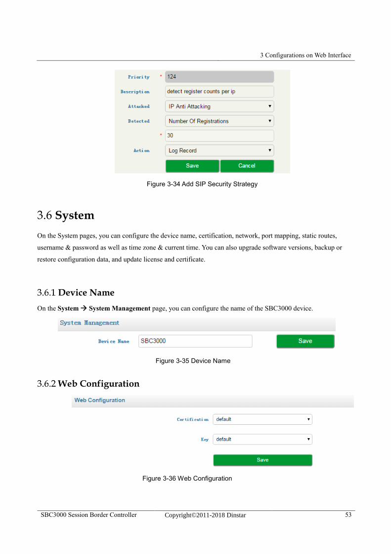
3 Configurations on Web Interface
SBC3000 Session Border Controller Copyright©2011-2018 Dinstar 53
Figure 3-34 Add SIP Security Strategy
3.6 System
On the System pages, you can configure the device name, certification, network, port mapping, static routes,
username & password as well as time zone & current time. You can also upgrade software versions, backup or
restore configuration data, and update license and certificate.
Device Name
On the System System Management page, you can configure the name of the SBC3000 device.
Figure 3-35 Device Name
Web Configuration
Figure 3-36 Web Configuration
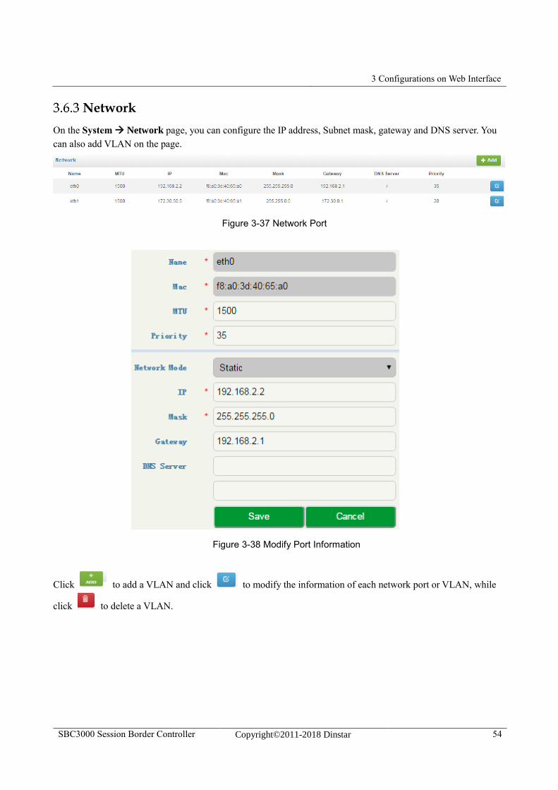
3 Configurations on Web Interface
SBC3000 Session Border Controller Copyright©2011-2018 Dinstar 54
Network
On the System Network page, you can configure the IP address, Subnet mask, gateway and DNS server. You
can also add VLAN on the page.
Figure 3-37 Network Port
Figure 3-38 Modify Port Information
Click to add a VLAN and click to modify the information of each network port or VLAN, while
click to delete a VLAN.
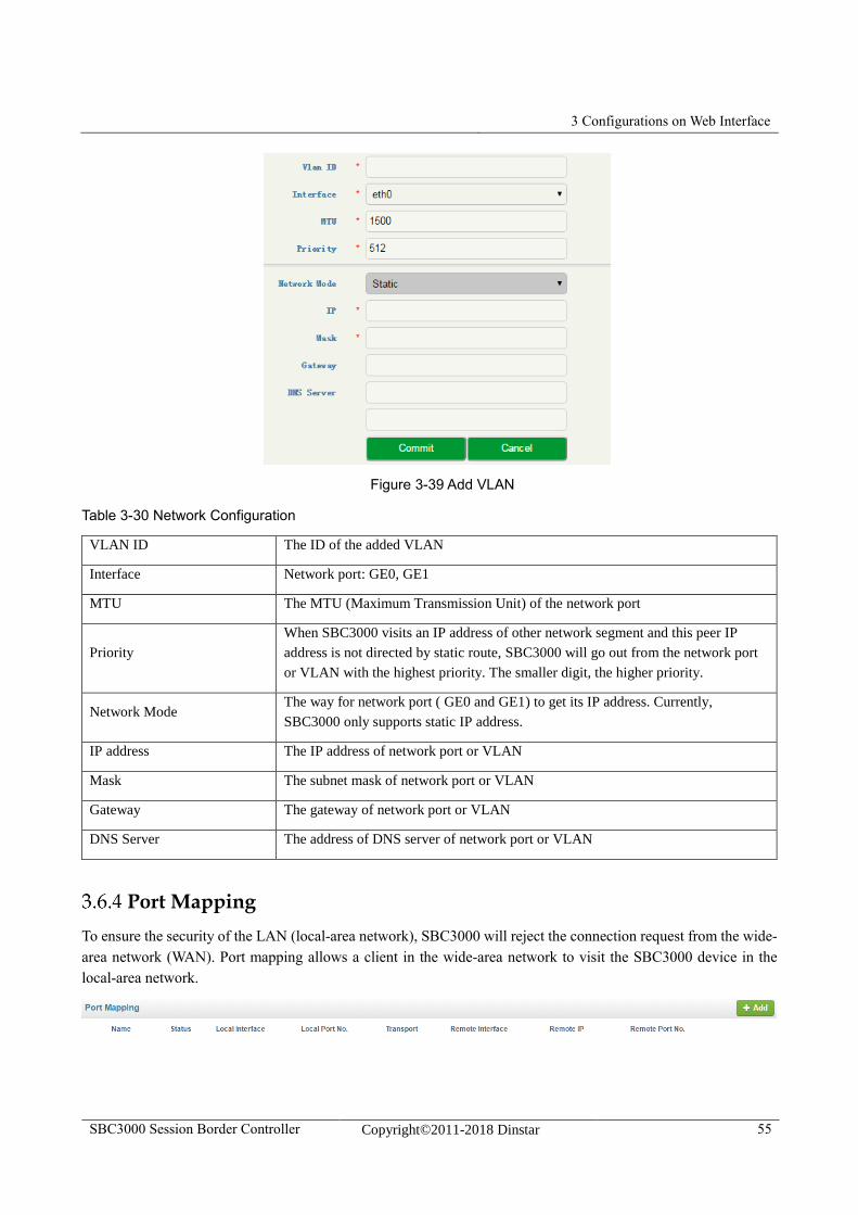
3 Configurations on Web Interface
SBC3000 Session Border Controller Copyright©2011-2018 Dinstar 55
Figure 3-39 Add VLAN
Table 3-30 Network Configuration
VLAN ID The ID of the added VLAN
Interface Network port: GE0, GE1
MTU The MTU (Maximum Transmission Unit) of the network port
Priority
When SBC3000 visits an IP address of other network segment and this peer IP
address is not directed by static route, SBC3000 will go out from the network port
or VLAN with the highest priority. The smaller digit, the higher priority.
Network Mode The way for network port ( GE0 and GE1) to get its IP address. Currently,
SBC3000 only supports static IP address.
IP address The IP address of network port or VLAN
Mask The subnet mask of network port or VLAN
Gateway The gateway of network port or VLAN
DNS Server The address of DNS server of network port or VLAN
Port Mapping
To ensure the security of the LAN (local-area network), SBC3000 will reject the connection request from the wide-
area network (WAN). Port mapping allows a client in the wide-area network to visit the SBC3000 device in the
local-area network.
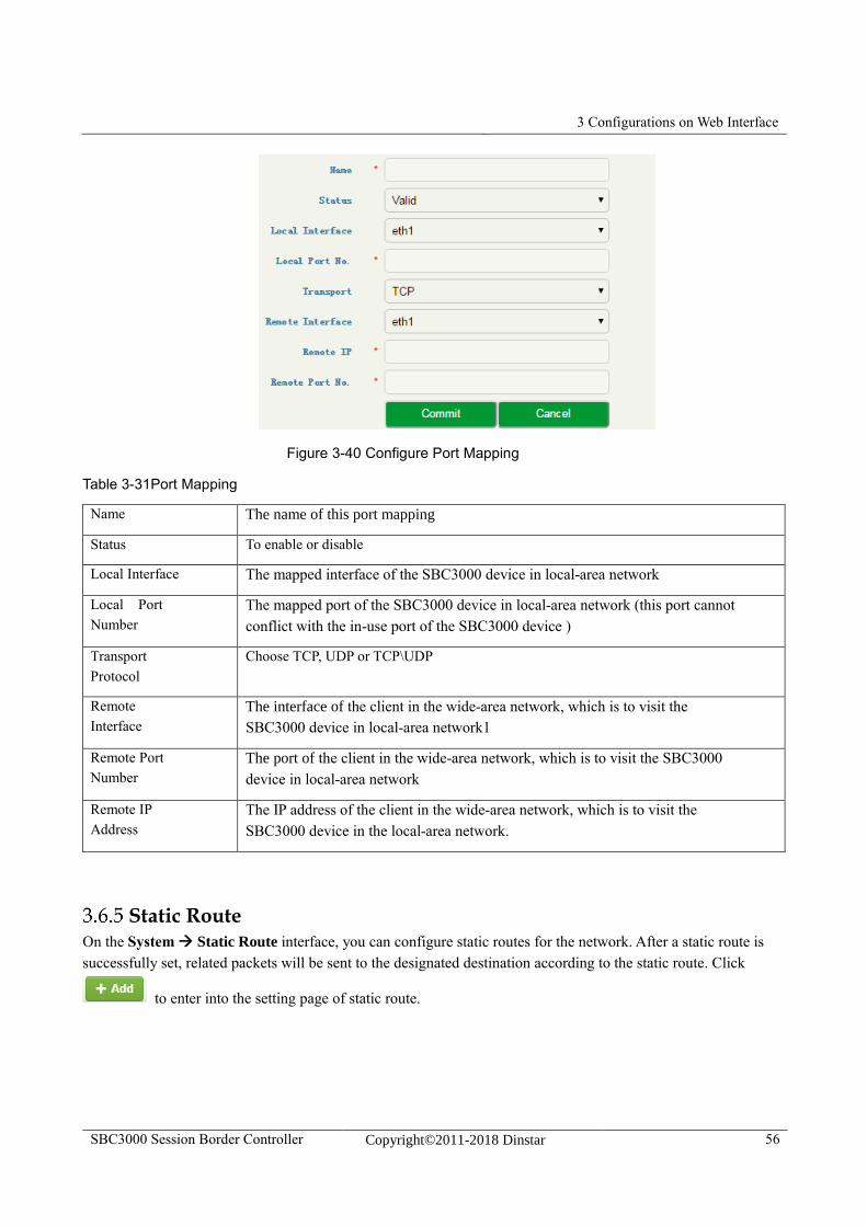
3 Configurations on Web Interface
SBC3000 Session Border Controller Copyright©2011-2018 Dinstar 56
Figure 3-40 Configure Port Mapping
Table 3-31Port Mapping
Name The name of this port mapping
Status To enable or disable
Local Interface The mapped interface of the SBC3000 device in local-area network
Local Port
Number
The mapped port of the SBC3000 device in local-area network (this port cannot
conflict with the in-use port of the SBC3000 device )
Transport
Protocol
Choose TCP, UDP or TCP\UDP
Remote
Interface
The interface of the client in the wide-area network, which is to visit the
SBC3000 device in local-area network1
Remote Port
Number
The port of the client in the wide-area network, which is to visit the SBC3000
device in local-area network
Remote IP
Address
The IP address of the client in the wide-area network, which is to visit the
SBC3000 device in the local-area network.
Static Route On the System Static Route interface, you can configure static routes for the network. After a static route is
successfully set, related packets will be sent to the designated destination according to the static route. Click
to enter into the setting page of static route.
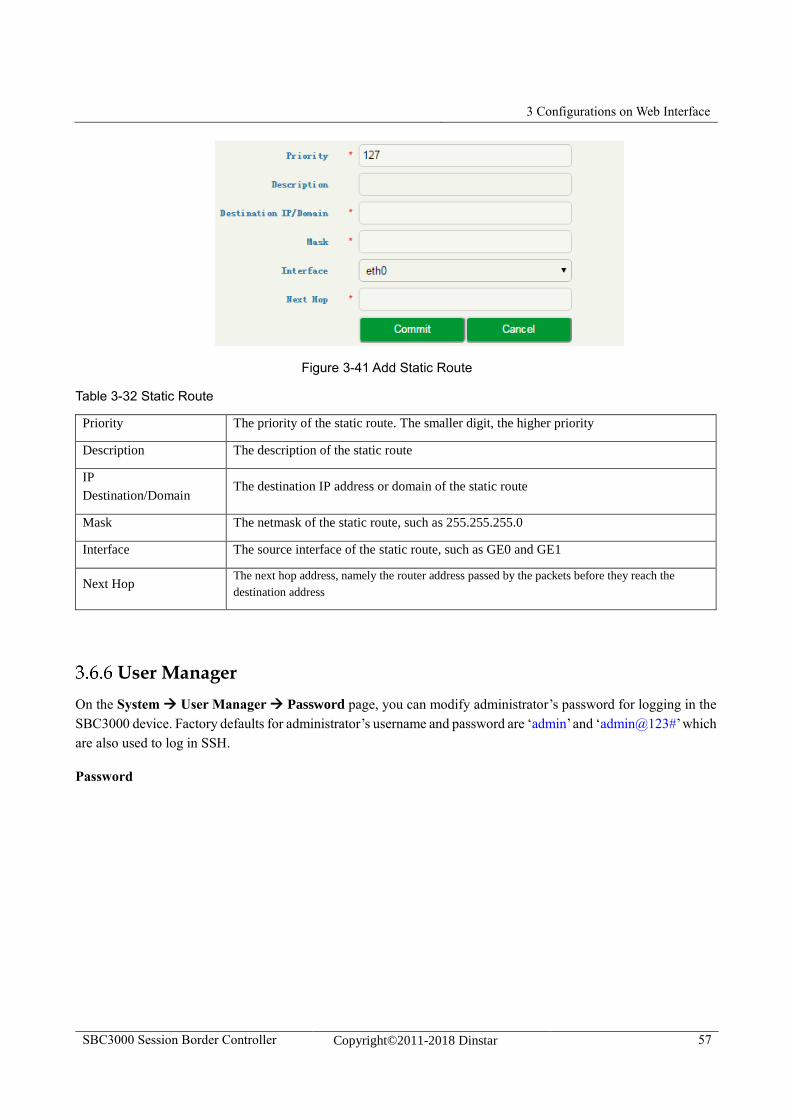
3 Configurations on Web Interface
SBC3000 Session Border Controller Copyright©2011-2018 Dinstar 57
Figure 3-41 Add Static Route
Table 3-32 Static Route
Priority The priority of the static route. The smaller digit, the higher priority
Description The description of the static route
IP
Destination/Domain The destination IP address or domain of the static route
Mask The netmask of the static route, such as 255.255.255.0
Interface The source interface of the static route, such as GE0 and GE1
Next Hop The next hop address, namely the router address passed by the packets before they reach the
destination address
User Manager
On the System User Manager Password page, you can modify administrator’s password for logging in the
SBC3000 device. Factory defaults for administrator’s username and password are ‘admin’ and ‘admin@123#’ which
are also used to log in SSH.
Password
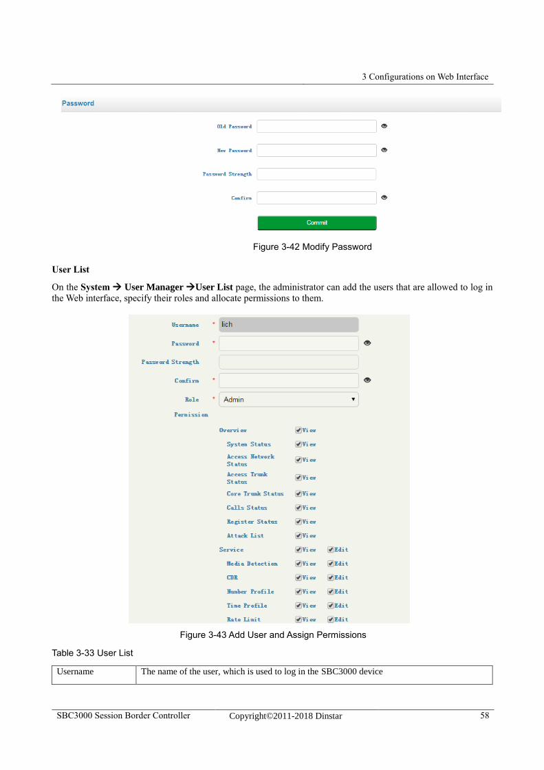
3 Configurations on Web Interface
SBC3000 Session Border Controller Copyright©2011-2018 Dinstar 58
Figure 3-42 Modify Password
User List
On the System User Manager User List page, the administrator can add the users that are allowed to log in
the Web interface, specify their roles and allocate permissions to them.
Figure 3-43 Add User and Assign Permissions
Table 3-33 User List
Username The name of the user, which is used to log in the SBC3000 device
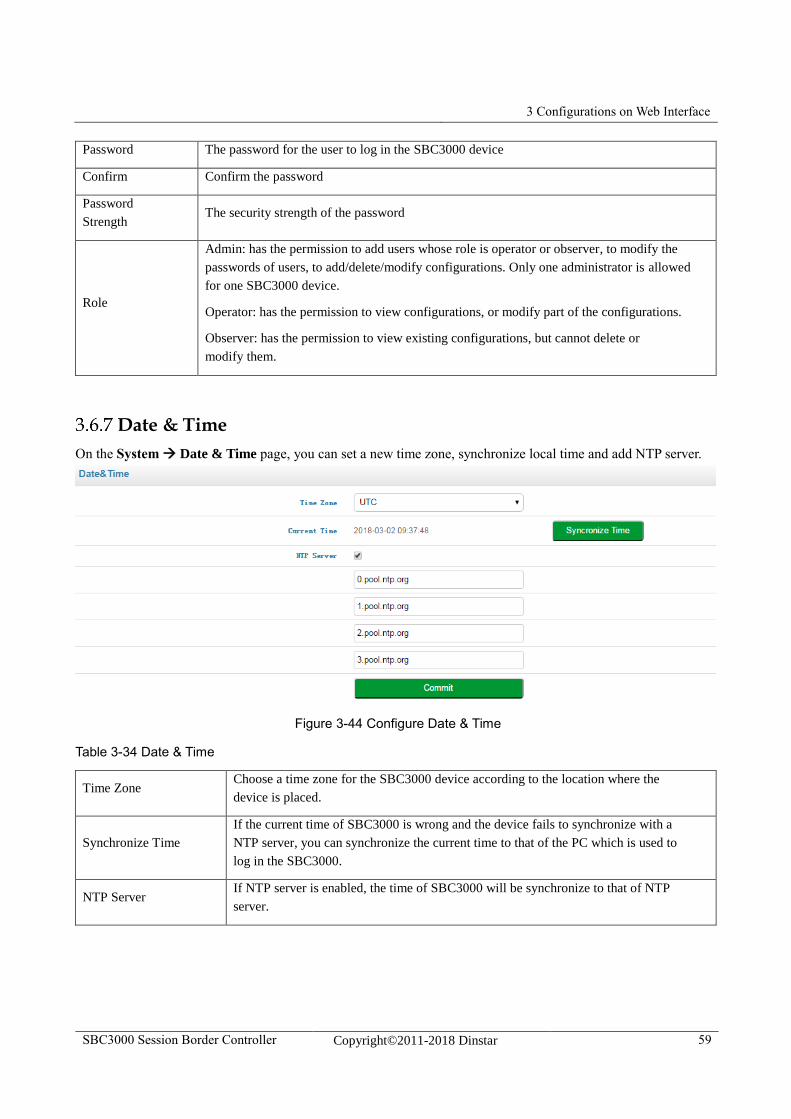
3 Configurations on Web Interface
SBC3000 Session Border Controller Copyright©2011-2018 Dinstar 59
Password The password for the user to log in the SBC3000 device
Confirm Confirm the password
Password
Strength The security strength of the password
Role
Admin: has the permission to add users whose role is operator or observer, to modify the
passwords of users, to add/delete/modify configurations. Only one administrator is allowed
for one SBC3000 device.
Operator: has the permission to view configurations, or modify part of the configurations.
Observer: has the permission to view existing configurations, but cannot delete or
modify them.
Date & Time
On the System Date & Time page, you can set a new time zone, synchronize local time and add NTP server.
Figure 3-44 Configure Date & Time
Table 3-34 Date & Time
Time Zone Choose a time zone for the SBC3000 device according to the location where the
device is placed.
Synchronize Time
If the current time of SBC3000 is wrong and the device fails to synchronize with a
NTP server, you can synchronize the current time to that of the PC which is used to
log in the SBC3000.
NTP Server If NTP server is enabled, the time of SBC3000 will be synchronize to that of NTP
server.
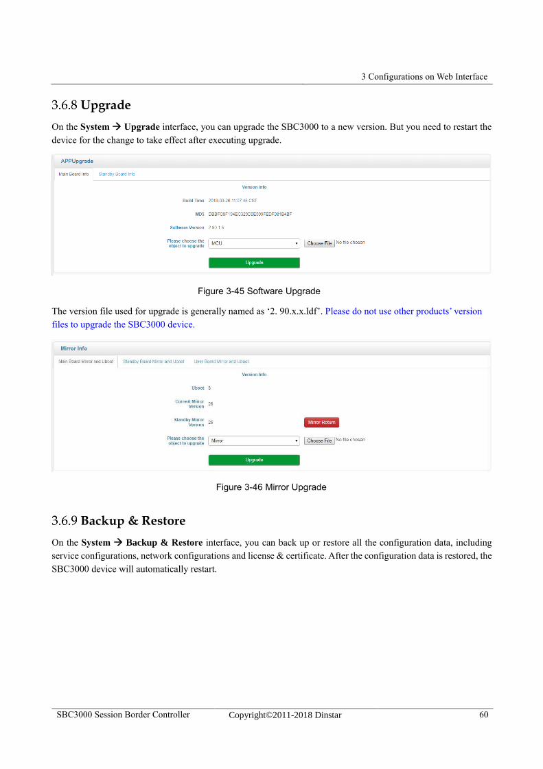
3 Configurations on Web Interface
SBC3000 Session Border Controller Copyright©2011-2018 Dinstar 60
Upgrade
On the System Upgrade interface, you can upgrade the SBC3000 to a new version. But you need to restart the
device for the change to take effect after executing upgrade.
Figure 3-45 Software Upgrade
The version file used for upgrade is generally named as ‘2. 90.x.x.ldf’. Please do not use other products’ version
files to upgrade the SBC3000 device.
Figure 3-46 Mirror Upgrade
Backup & Restore
On the System Backup & Restore interface, you can back up or restore all the configuration data, including
service configurations, network configurations and license & certificate. After the configuration data is restored, the
SBC3000 device will automatically restart.
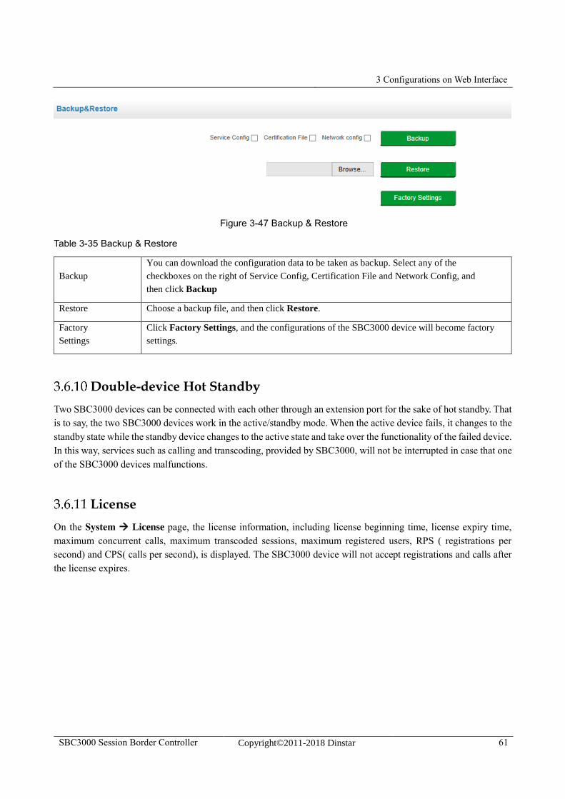
3 Configurations on Web Interface
SBC3000 Session Border Controller Copyright©2011-2018 Dinstar 61
Figure 3-47 Backup & Restore
Table 3-35 Backup & Restore
Backup
You can download the configuration data to be taken as backup. Select any of the
checkboxes on the right of Service Config, Certification File and Network Config, and
then click Backup
Restore Choose a backup file, and then click Restore.
Factory
Settings
Click Factory Settings, and the configurations of the SBC3000 device will become factory
settings.
Double-device Hot Standby
Two SBC3000 devices can be connected with each other through an extension port for the sake of hot standby. That
is to say, the two SBC3000 devices work in the active/standby mode. When the active device fails, it changes to the
standby state while the standby device changes to the active state and take over the functionality of the failed device.
In this way, services such as calling and transcoding, provided by SBC3000, will not be interrupted in case that one
of the SBC3000 devices malfunctions.
License
On the System License page, the license information, including license beginning time, license expiry time,
maximum concurrent calls, maximum transcoded sessions, maximum registered users, RPS ( registrations per
second) and CPS( calls per second), is displayed. The SBC3000 device will not accept registrations and calls after
the license expires.
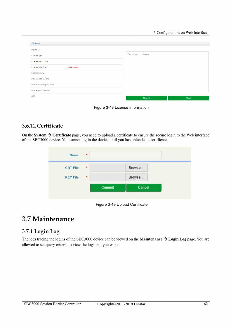
3 Configurations on Web Interface
SBC3000 Session Border Controller Copyright©2011-2018 Dinstar 62
Figure 3-48 License Information
Certificate
On the System Certificate page, you need to upload a certificate to ensure the secure login to the Web interface
of the SBC3000 device. You cannot log in the device until you has uploaded a certificate.
Figure 3-49 Upload Certificate
3.7 Maintenance
Login Log
The logs tracing the logins of the SBC3000 device can be viewed on the Maintenance Login Log page. You are
allowed to set query criteria to view the logs that you want.
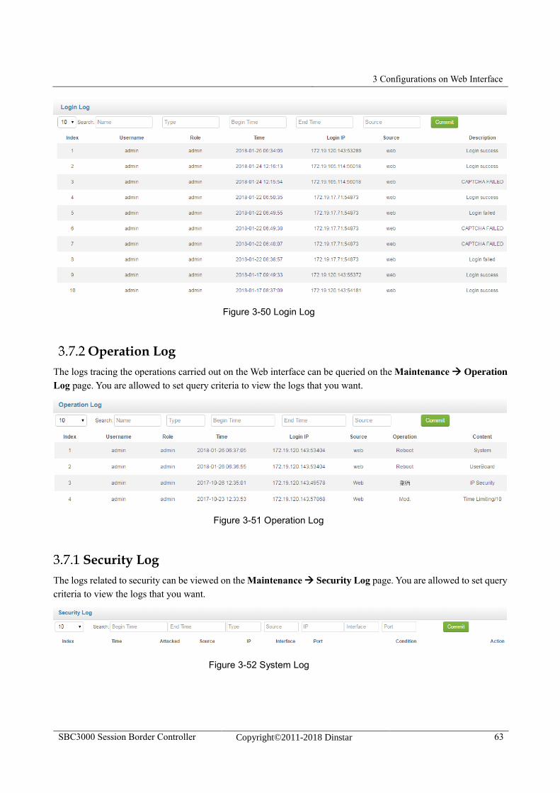
3 Configurations on Web Interface
SBC3000 Session Border Controller Copyright©2011-2018 Dinstar 63
Figure 3-50 Login Log
Operation Log
The logs tracing the operations carried out on the Web interface can be queried on the Maintenance Operation
Log page. You are allowed to set query criteria to view the logs that you want.
Figure 3-51 Operation Log
Security Log
The logs related to security can be viewed on the Maintenance Security Log page. You are allowed to set query
criteria to view the logs that you want.
Figure 3-52 System Log
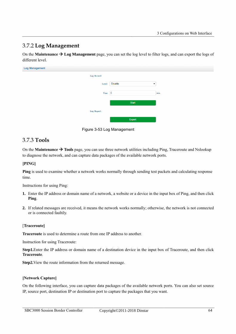
3 Configurations on Web Interface
SBC3000 Session Border Controller Copyright©2011-2018 Dinstar 64
Log Management
On the Maintenance Log Management page, you can set the log level to filter logs, and can export the logs of
different level.
Figure 3-53 Log Management
Tools
On the Maintenance Tools page, you can use three network utilities including Ping, Traceroute and Nslookup
to diagnose the network, and can capture data packages of the available network ports.
[PING]
Ping is used to examine whether a network works normally through sending test packets and calculating response
time.
Instructions for using Ping:
1. Enter the IP address or domain name of a network, a website or a device in the input box of Ping, and then click
Ping.
2. If related messages are received, it means the network works normally; otherwise, the network is not connected
or is connected faultily.
[Traceroute]
Traceroute is used to determine a route from one IP address to another.
Instruction for using Traceroute:
Step1.Enter the IP address or domain name of a destination device in the input box of Traceroute, and then click
Traceroute.
Step2.View the route information from the returned message.
[Network Capture]
On the following interface, you can capture data packages of the available network ports. You can also set source
IP, source port, destination IP or destination port to capture the packages that you want.
4 Abbreviation
SBC3000 Session Border Controller Copyright©2011-2018 Dinstar 65
4 Abbreviation
SBC: (Session Border Controller)
SIP: (Session Initiation Protocol)
DTMF: (Dual Tone Multi Frequency)
NAT:(Network Address Translation)
VLAN:(Virtual Local Area Network)
CID: Caller Identity
STUN: Simple Traversal of UDP over NAT
WLAN: Wireless Local Area Network

4 Abbreviation
SBC3000 Session Border Controller Copyright©2011-2018 Dinstar 66
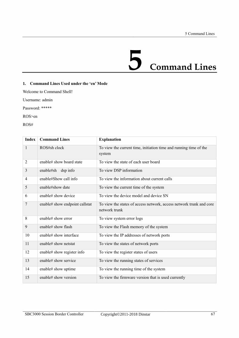
5 Command Lines
SBC3000 Session Border Controller Copyright©2011-2018 Dinstar 67
5 Command Lines
1. Command Lines Used under the ‘en’ Mode
Welcome to Command Shell!
Username: admin
Password: *****
ROS>en
ROS#
Index Command Lines Explanation
1 ROS#sh clock To view the current time, initiation time and running time of the
system
2 enable# show board state To view the state of each user board
3 enable#sh dsp info To view DSP information
4 enable#Show call info To view the information about current calls
5 enable#show date To view the current time of the system
6 enable# show device To view the device model and device SN
7 enable# show endpoint callstat To view the states of access network, access network trunk and core
network trunk
8 enable# show error To view system error logs
9 enable# show flash To view the Flash memory of the system
10 enable# show interface To view the IP addresses of network ports
11 enable# show netstat To view the states of network ports
12 enable# show register info To view the register states of users
13 enable# show service To view the running states of services
14 enable# show uptime To view the running time of the system
15 enable# show version To view the firmware version that is used currently
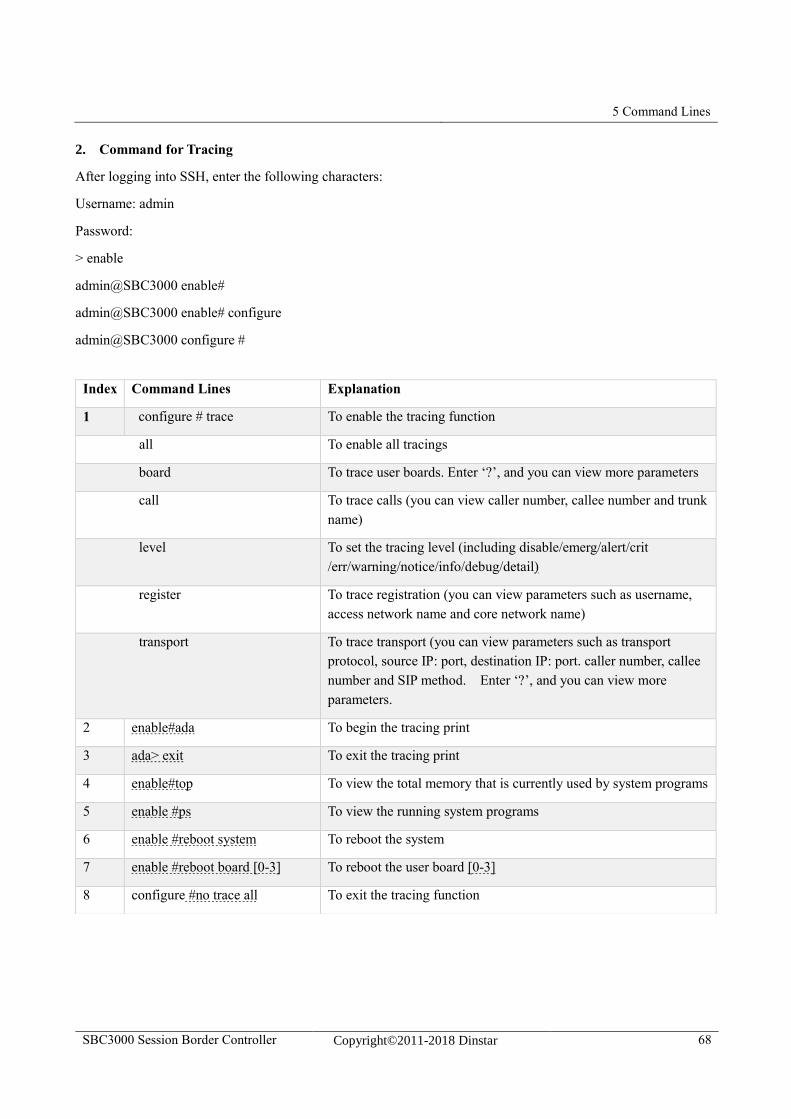
5 Command Lines
SBC3000 Session Border Controller Copyright©2011-2018 Dinstar 68
2. Command for Tracing
After logging into SSH, enter the following characters:
Username: admin
Password:
> enable
admin@SBC3000 enable#
admin@SBC3000 enable# configure
admin@SBC3000 configure #
Index Command Lines Explanation
1 configure # trace To enable the tracing function
all To enable all tracings
board To trace user boards. Enter ‘?’, and you can view more parameters
call To trace calls (you can view caller number, callee number and trunk
name)
level To set the tracing level (including disable/emerg/alert/crit
/err/warning/notice/info/debug/detail)
register To trace registration (you can view parameters such as username,
access network name and core network name)
transport To trace transport (you can view parameters such as transport
protocol, source IP: port, destination IP: port. caller number, callee
number and SIP method. Enter ‘?’, and you can view more
parameters.
2 enable#ada To begin the tracing print
3 ada> exit To exit the tracing print
4 enable#top To view the total memory that is currently used by system programs
5 enable #ps To view the running system programs
6 enable #reboot system To reboot the system
7 enable #reboot board [0-3] To reboot the user board [0-3]
8 configure #no trace all To exit the tracing function
Related Documents