Technical Report SANtricity synchronous and asynchronous mirroring (11.61 and earlier) Feature descriptions and deployment guide Mitch Blackburn, NetApp March 2022 | TR-4656 Abstract NetApp ® E-Series and EF-Series systems provide rock-solid local and remote data mirroring capabilities using the SANtricity ® synchronous and asynchronous mirroring features. Both features support connectivity between legacy E-Series arrays that use the SANtricity Storage Manager desktop thick-client UI and new generation E-Series systems that support the SANtricity System Manager web-based management UI. This document provides descriptions of the features and specific setup and operations guidance, including the use of SANtricity Unified Manager when the customer only has new generation E-Series or EF- Series systems.

Welcome message from author
This document is posted to help you gain knowledge. Please leave a comment to let me know what you think about it! Share it to your friends and learn new things together.
Transcript
Technical Report
SANtricity synchronous and asynchronous mirroring (11.61 and earlier)
Feature descriptions and deployment guide Mitch Blackburn, NetApp
March 2022 | TR-4656
Abstract
NetApp® E-Series and EF-Series systems provide rock-solid local and remote data mirroring
capabilities using the SANtricity® synchronous and asynchronous mirroring features. Both
features support connectivity between legacy E-Series arrays that use the SANtricity Storage
Manager desktop thick-client UI and new generation E-Series systems that support the
SANtricity System Manager web-based management UI. This document provides
descriptions of the features and specific setup and operations guidance, including the use of
SANtricity Unified Manager when the customer only has new generation E-Series or EF-
Series systems.
2 SANtricity synchronous and asynchronous mirroring © 2022 NetApp, Inc. All rights reserved. © 2016 NetApp, Inc. All rights reserved.
TABLE OF CONTENTS
Introduction ................................................................................................................................................. 5
Intended use ............................................................................................................................................................ 5
Overview of the mirroring features ........................................................................................................................... 5
Terminology ............................................................................................................................................................. 6
SANtricity Unified Manager—Usage and configuration ......................................................................... 8
Installing Unified Manager ....................................................................................................................................... 9
Logging in to Unified Manager ............................................................................................................................... 10
Discovering and adding storage arrays ................................................................................................................. 10
Remote mirroring with SANtricity Unified Manager ................................................................................................ 12
SANtricity Unified Manager security ...................................................................................................................... 12
Web services certificates and recommended browsers ......................................................................................... 13
Comparing asynchronous and synchronous mirroring ....................................................................... 13
Typical use cases .................................................................................................................................................. 14
Requirements and limitations ................................................................................................................. 15
Feature enablement and activation ....................................................................................................................... 15
Prerequisites .......................................................................................................................................................... 15
Supported connections .......................................................................................................................................... 15
Distances and speed ............................................................................................................................................. 19
Mirror volume requirements ................................................................................................................................... 20
Reserved capacity (repository) volume requirements ............................................................................................ 21
Connectivity and volume ownership ...................................................................................................................... 21
Storage system limits ............................................................................................................................................ 22
Asynchronous mirroring operational model.......................................................................................... 22
Initial synchronization ............................................................................................................................................ 22
Resynchronization methods for asynchronous mirroring ....................................................................................... 24
Periodic resynchronization .................................................................................................................................... 24
Using thin-provisioned volumes in asynchronous mirroring ................................................................................... 26
Suspend and resume ............................................................................................................................................ 26
Orderly role reversal .............................................................................................................................................. 26
Forced promotion of secondary ............................................................................................................................. 27
Forced demotion of primary ................................................................................................................................... 28
Example failures and how to handle ...................................................................................................................... 28
Considerations for setting up asynchronous mirroring ....................................................................... 30
3 SANtricity synchronous and asynchronous mirroring © 2022 NetApp, Inc. All rights reserved. © 2016 NetApp, Inc. All rights reserved.
RPO and synchronization interval ......................................................................................................................... 30
Sizing the network to meet RPO ............................................................................................................................ 31
Latency considerations with iSCSI ........................................................................................................................ 31
Time to complete initial or full synchronization ...................................................................................................... 32
Effect of asynchronous mirroring operations on host I/O performance .................................................................. 32
Synchronous mirroring operational model ............................................................................................ 33
Initial synchronization ............................................................................................................................................ 34
Write process ......................................................................................................................................................... 34
Resynchronization methods .................................................................................................................................. 35
Suspend and resume ............................................................................................................................................ 36
Role changes on a synchronous mirror pair .......................................................................................................... 36
Considerations for setting up synchronous mirroring ......................................................................... 37
Latency .................................................................................................................................................................. 37
Distance and number of IOPS ............................................................................................................................... 37
Bandwidth .............................................................................................................................................................. 38
Configuring through management GUI .................................................................................................. 38
Use cases and different GUIs ................................................................................................................................ 38
Management station port numbers ........................................................................................................................ 40
Web services certificates ....................................................................................................................................... 40
Mirroring and Role-Based Access Control (RBAC) ............................................................................................... 42
Asynchronous with System Manager as primary ................................................................................................... 43
Asynchronous with AMW as primary, System Manager as secondary .................................................................. 50
Asynchronous with AMW as primary and secondary ............................................................................................. 62
Synchronous with System Manager as primary ..................................................................................................... 70
Synchronous with AMW as primary, System Manager as secondary .................................................................... 77
Synchronous with AMW as primary and secondary .............................................................................................. 84
Testing the communication link ............................................................................................................................. 93
Summary .................................................................................................................................................... 98
Where to find additional information ...................................................................................................... 99
Version history .......................................................................................................................................... 99
LIST OF TABLES
Table 1) Comparison between mirroring features. ....................................................................................................... 14
Table 2) Cable distances by cable type and speed. ..................................................................................................... 19
4 SANtricity synchronous and asynchronous mirroring © 2022 NetApp, Inc. All rights reserved. © 2016 NetApp, Inc. All rights reserved.
Table 3) Transmission rates by carrier type. ................................................................................................................ 19
Table 4) Allowed candidates for mirror volumes. .......................................................................................................... 20
Table 5) Storage system limits for mirroring. ................................................................................................................ 22
Table 6) Approximate hours needed for initial or full synchronization by pipe size. ...................................................... 32
Table 7) System configuration for performance example. ............................................................................................ 33
Table 8) Example performance results. ........................................................................................................................ 33
Table 9) Management use cases for mirroring. ............................................................................................................ 38
Table 10) Port numbers used by SANtricity OS and storage manager releases. ......................................................... 40
LIST OF FIGURES
Figure 1) WSP installation wizard with the link to launch Unified Manager. ................................................................... 9
Figure 2) SANtricity Unified Manager login page. ......................................................................................................... 10
Figure 3) SANtricity Unified Manager landing page. ..................................................................................................... 11
Figure 4) SANtricity Unified Manager showing discovered arrays. ............................................................................... 12
Figure 5) Single-fabric configuration. ............................................................................................................................ 17
Figure 6) Fabric dedicated to mirroring. ....................................................................................................................... 18
Figure 7) Periodic resynchronization in asynchronous mirroring. ................................................................................. 25
Figure 8) Time from one protection point to the next. ................................................................................................... 30
Figure 9) Synchronous mirroring write process. ........................................................................................................... 35
Figure 10) Web services certificate management in SANtricity Storage Manager EMW. ............................................. 41
Figure 11) Completing CSR for web services. .............................................................................................................. 42
Figure 12) SANtricity System Manager: invoke test communication on mirror consistency group. .............................. 94
Figure 13) SANtricity System Manager: mirror consistency group test communication results. ................................... 94
Figure 14) SANtricity Storage Manager AMW: invoke test communication on asynchronous mirror group. ................ 95
Figure 15) SANtricity Storage Manager AMW: asynchronous mirror group test communication results. ..................... 96
Figure 16) SANtricity System Manager: invoke test communication for synchronous mirrored pair. ............................ 97
Figure 17) SANtricity System Manager: synchronous mirrored pair test communication results. ................................. 97
Figure 18) SANtricity Storage Manager AMW: invoke test communication for synchronous mirrored pair. ................. 98
Figure 19) SANtricity Storage Manager: synchronous mirrored pair test communication results. ................................ 98
5 SANtricity synchronous and asynchronous mirroring © 2022 NetApp, Inc. All rights reserved. © 2016 NetApp, Inc. All rights reserved.
Introduction
This document describes the two mirroring features available with NetApp E-Series storage systems and
provides guidance on how to deploy them. The mirroring features enable administrators to replicate data
online over near or far distances to protect against disasters or to centrally back up data at a remote
location.
To accomplish this replication, the administrator creates mirrored volume pairs on the local and remote
storage systems. For each pair, the volume on the local site is known as the primary, and the remote
volume is known as the secondary. Any given storage system might have both primary and secondary
volumes, enabling companies to have multiple active sites that protect data for each other.
If a disaster or other failure causes a set of primary volumes on one site to become unavailable, the
administrator can promote the corresponding secondary volumes to the role of primary to take over
responsibility for maintaining IT operations.
Note: This document does not describe procedures using the latest SANtricity System Manager (version 11.62 and later) and Unified Manager (version 4.2 and later). If you have these versions, refer to TR-4839, SANtricity Synchronous and Asynchronous Mirroring (11.62 and Later) Feature Descriptions and Deployment Guide.
Intended use
This information is for NetApp customers, partners, and OEMs. For the information and procedures
described in this document to be useful, it is assumed that the reader has:
• A minimal knowledge of NetApp E-Series platforms and products, particularly in the area of data protection
• General knowledge of disaster recovery (DR) solutions
Overview of the mirroring features
E-Series storage systems offer two types of mirroring: asynchronous and synchronous:
• Asynchronous mirroring. Replicates changed data from the primary to the secondary at discrete points in time, providing a recovery point at the secondary that is behind the current primary. Asynchronous mirroring can function over long distances and includes the following attributes:
− Block-level updates reduce bandwidth and time requirements by replicating only changed blocks.
− Crash-consistent data is available at a recovery point at the secondary site.
− A disaster recovery plan can be tested without affecting production and replication.
− Data can be replicated between dissimilar NetApp E-Series storage systems.
− A standard Internet Protocol (IP) or Fibre Channel (FC) network can be used for replication.
• Synchronous mirroring. Continuously replicates data so that the secondary is always up to date. Synchronous mirroring supports shorter distances and includes the following attributes:
− Block-level replication provides consistent data across two sites.
− Up-to-date crash-consistent data is available at a disaster recovery site.
− Data can be replicated between dissimilar NetApp E-Series storage systems.
− An FC network is used for replication.
Both types of mirroring have some effect on performance, but it is important to be aware that, with
synchronous mirroring, each write I/O is not completed until the write to the remote volume has completed.
This is an important consideration for high performance environments given the additional write latency
associated with remote write confirmation messages.
6 SANtricity synchronous and asynchronous mirroring © 2022 NetApp, Inc. All rights reserved. © 2016 NetApp, Inc. All rights reserved.
Terminology
There are a number of terms used in this document and in the industry that bear description to help reduce
confusion.
SANtricity Storage Manager—Enterprise Management Window
The Enterprise Management Window (EMW) GUI in SANtricity Storage Manager is a Java-based desktop
thick client that allows storage array administrators to monitor and manage legacy E-Series systems
(E2700/E5600/EF560) using the Array Management Window (AMW). You can also discover and launch
SANtricity System Manager sessions to monitor and manage new generation E-Series arrays
(E2800/EF280/E5700/EF570) from the EMW.
Unified Manager replaces the legacy SANtricity Storage Manager Enterprise Management Window
(EMW). Customers who have an active support agreement can download SANtricity Storage Manager
software from the NetApp Support site software download page.
Note: You must use the version of SANtricity Storage Manager that matches the latest E-Series array controller firmware version in order to manage arrays running the latest software version. This latest software version manages all previous array software versions that are still supported, but older SANtricity Storage Manager versions cannot manage arrays running later controller software versions.
SANtricity System Manager
SANtricity System Manager is the web-based management GUI that is bundled with all SANtricity OS
versions running on new generation E-Series arrays (E2800/EF280/E5700/EF570). To access the
SANtricity System Manager GUI, point your browser to the fully qualified domain name (FQDN) or IP
address of a management port on one of the two storage array controllers.
Note: You can also launch SANtricity System Manager from the EMW or from SANtricity Unified Manager when the new generation array has been discovered by either of those central management interfaces.
SANtricity Web Services Proxy
The SANtricity Web Services Proxy (WSP) is the set of API endpoints that are used to configure, monitor,
and manage E-Series and EF-Series storage arrays. Many of the endpoints support older generation and
new generation arrays.
Note: Some API endpoints do not apply to older generation arrays when those arrays do not support the associated features. For example, endpoints associated with managing web server certificates do not apply to older generation E-Series and EF-Series arrays.
SANtricity Unified Manager
SANtricity Unified Manager is a web-based GUI that is built on top of the SANtricity WSP. It provides
storage array administrators a GUI-based API orchestration tool to monitor and manage E-Series
E2800/EF280 and E5700/EF570 arrays from a single interface. Unified Manager replaces the legacy
SANtricity Storage Manager EMW for storage arrays that use the web-based SANtricity System Manager
to monitor and manage the array. Customers who have an active support agreement can download
SANtricity WSP with Unified Manager from the NetApp Support site at
https://mysupport.netapp.com/NOW/cgi-bin/software/.
Note: Older generation storage arrays (E2700/E5600/EF560) cannot be discovered and managed using SANtricity Unified Manager. If you are running a previous version of SANtricity Web Services Proxy to manage older arrays through the API interface, you can continue to use the API-based functionality with the versions of SANtricity WSP that support Unified Manager.
7 SANtricity synchronous and asynchronous mirroring © 2022 NetApp, Inc. All rights reserved. © 2016 NetApp, Inc. All rights reserved.
Initial (or full) synchronization
When a mirror relationship is established, all data from the primary is copied to the secondary. During this
process, the primary volume is fully accessible for I/O operations. Full synchronization can also be
required under certain failure conditions of the communications link or the secondary volume. If a volume
being replicated is thin, a full synchronization only copies blocks to the secondary that have been written
on the primary. Any blocks on a thin primary volume that have been unmapped are also not replicated to
the secondary.
Mirror consistency group (asynchronous mirror group)
A mirror consistency group is a container for one or more volumes participating in asynchronous mirroring.
The asynchronous mirroring feature resynchronizes all mirror pairs in a group simultaneously, thus
preserving a consistent recovery point at the secondary across all volumes in the group.
Note: These groups were called asynchronous mirror groups, or AMGs, in all management interfaces until SANtricity OS 11.30. For SANtricity OS 11.30 and beyond, SANtricity System Manager calls them mirror consistency groups. All other management interfaces continue to use the asynchronous mirror group naming convention. This document occasionally uses both names at once to help remind that they are referring to the same entity.
Note: Synchronous mirroring does not use mirror consistency groups.
Mirror pair
Two volumes linked together through a mirroring relationship are called a mirror pair. A mirror pair consists
of a primary volume and a secondary volume.
Mirror volume
A mirror volume is any volume participating in mirroring. It can have either the primary or secondary role.
Primary site
Primary site generally refers to the production site for any given mirror pair or group. Mirroring occurs from
the primary site to the secondary site. Note that with NetApp SANtricity mirroring features, sites can mirror
for each other; that is, one site can be primary for one set of volumes and secondary for another.
Primary volume
A mirror volume from which reads and writes are initiated from the host or hosts is said to be in a primary
role. The mirroring features copy data from the primary volume to the secondary volume.
Reserved capacity (repository) volume
These volumes that are not user accessible are required so that the controller can persistently save
information needed to maintain mirroring in an operational state. They contain information such as delta
logs and copy-on-write data.
Note: These volumes were called repositories in all management interfaces until SANtricity OS 11.30. For SANtricity OS 11.30 and beyond, SANtricity System Manager calls them reserved capacity. All other management interfaces continue to use the repository naming convention. This document occasionally uses both names at once to help remind that they are referring to the same entity.
Resynchronization
For synchronous mirroring, the normal operating state is for the primary and secondary to be
synchronized. However, a link failure or other type of failure or a suspend from the administrator causes
the primary and secondary to be out of synchronization. When this desynchronization happens, restoring
8 SANtricity synchronous and asynchronous mirroring © 2022 NetApp, Inc. All rights reserved. © 2016 NetApp, Inc. All rights reserved.
to normal operations requires a resynchronization in which changed data is sent from the primary to the
secondary.
For asynchronous mirroring, after initial synchronization, the mirror pair is out of synchronization most of
the time. The administrator can select either periodic or manual resynchronization. Every
resynchronization creates a recovery point.
Roles
A volume in a mirror pair is always in either a primary or secondary role. A volume does not always have
the same role: roles can be reversed by the administrator, or an individual volume can have its role
changed by the administrator in the event both members of a mirror pair are not accessible. Role changes
are typically used for recovery when a failure has occurred at the primary site or when communication
between members of a pair is lost.
Secondary site
This site is where the destination, or secondary, volumes reside for any given mirror pair/group. It is
sometimes called the recovery or disaster site. Note that with NetApp SANtricity mirroring features, sites
can mirror for each other; that is, one site can be primary for one set of volumes and secondary for
another.
Secondary volume
A mirror volume that holds data copied from the primary volume is known as the secondary volume. It is
either an exact copy with synchronous mirroring or a copy that lags in time from the primary with
asynchronous mirroring.
SANtricity Unified Manager—Usage and configuration
SANtricity Unified Manager is a web-based, central management interface for managing new generation
E-Series E2800/EF280 and E5700/EF570 systems. It is bundled with SANtricity WSP 3.0 and later.
SANtricity WSP with the Unified Manager GUI is installed on a management server that has IP access to
all arrays that you want to manage from the central management interface and can manage up to 500
arrays. SANtricity Unified Manager provides a higher level of management interface security and adds the
following time-saving features that are not available for older generation E-Series/EF-Series arrays:
• Supports a new, central storage array upgrade wizard for arrays managed using the web based SANtricity System Manager GUI.
Note: The new upgrade wizard is available with WSP 3.1 and later, but it is not available in WSP 3.0.
• Supports Lightweight Directory Access Protocol (LDAP) and role-based access control (RBAC) just like SANtricity System Manager. SANtricity Unified Manager includes a simplified certificate management workflow to manage the Unified Manager and Web Services Proxy server certificates (truststore and keystore certificates).
• Supports organizing arrays by groups you can create, name, and arrange.
• Supports importing common settings from one array to another, saving time from duplicating set-up steps for each array.
• Supports synchronous and asynchronous mirroring for E2800/EF280 and E5700/EF570 arrays. The legacy EMW is required only if the initiator or target array is a legacy E2700, E5600/EF560, or earlier array model.
Note: The legacy Symbol API management interface must be turned on to set up mirroring, but after mirroring is created, the Symbol API interface can be disabled again. This requirement will be
9 SANtricity synchronous and asynchronous mirroring © 2022 NetApp, Inc. All rights reserved. © 2016 NetApp, Inc. All rights reserved.
changed to fully support mirroring using the more secure SSL interface in SANtricity OS 11.60.2 maintenance release and Unified Manager 4.2.
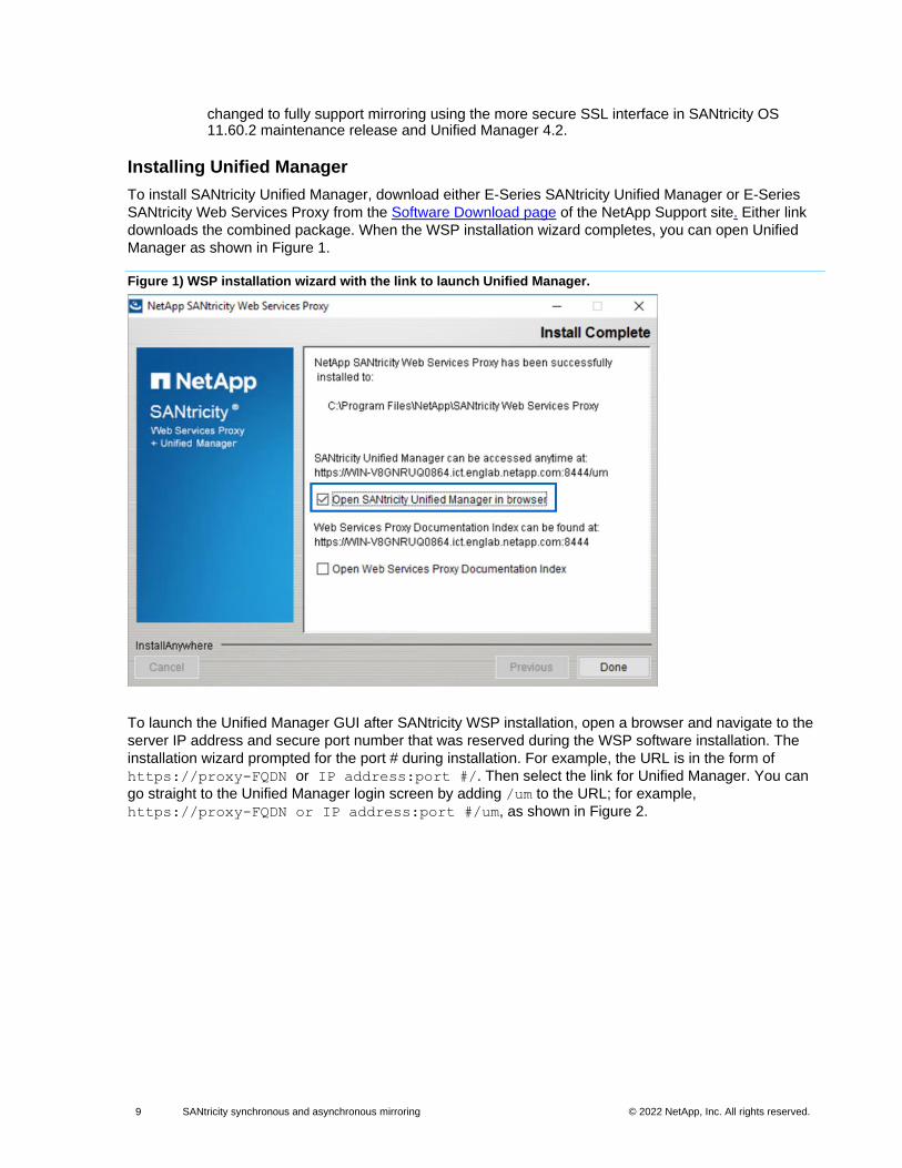
Installing Unified Manager
To install SANtricity Unified Manager, download either E-Series SANtricity Unified Manager or E-Series
SANtricity Web Services Proxy from the Software Download page of the NetApp Support site. Either link
downloads the combined package. When the WSP installation wizard completes, you can open Unified
Manager as shown in Figure 1.
Figure 1) WSP installation wizard with the link to launch Unified Manager.
To launch the Unified Manager GUI after SANtricity WSP installation, open a browser and navigate to the
server IP address and secure port number that was reserved during the WSP software installation. The
installation wizard prompted for the port # during installation. For example, the URL is in the form of
https://proxy-FQDN or IP address:port #/. Then select the link for Unified Manager. You can
go straight to the Unified Manager login screen by adding /um to the URL; for example,
https://proxy-FQDN or IP address:port #/um, as shown in Figure 2.
10 SANtricity synchronous and asynchronous mirroring © 2022 NetApp, Inc. All rights reserved. © 2016 NetApp, Inc. All rights reserved.
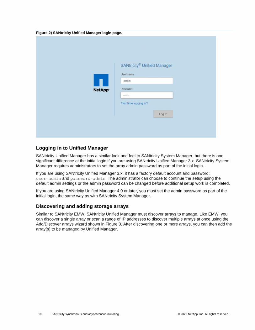
Figure 2) SANtricity Unified Manager login page.
Logging in to Unified Manager
SANtricity Unified Manager has a similar look and feel to SANtricity System Manager, but there is one
significant difference at the initial login if you are using SANtricity Unified Manager 3.x. SANtricity System
Manager requires administrators to set the array admin password as part of the initial login.
If you are using SANtricity Unified Manager 3.x, it has a factory default account and password:
user=admin and password=admin. The administrator can choose to continue the setup using the
default admin settings or the admin password can be changed before additional setup work is completed.
If you are using SANtricity Unified Manager 4.0 or later, you must set the admin password as part of the
initial login, the same way as with SANtricity System Manager.
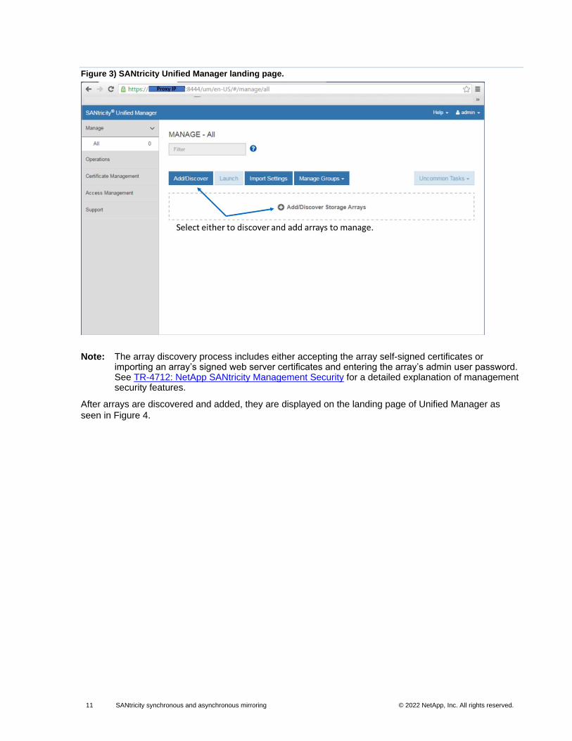
Discovering and adding storage arrays
Similar to SANtricity EMW, SANtricity Unified Manager must discover arrays to manage. Like EMW, you
can discover a single array or scan a range of IP addresses to discover multiple arrays at once using the
Add/Discover arrays wizard shown in Figure 3. After discovering one or more arrays, you can then add the
array(s) to be managed by Unified Manager.
11 SANtricity synchronous and asynchronous mirroring © 2022 NetApp, Inc. All rights reserved. © 2016 NetApp, Inc. All rights reserved.
Figure 3) SANtricity Unified Manager landing page.
Note: The array discovery process includes either accepting the array self-signed certificates or importing an array’s signed web server certificates and entering the array’s admin user password. See TR-4712: NetApp SANtricity Management Security for a detailed explanation of management security features.
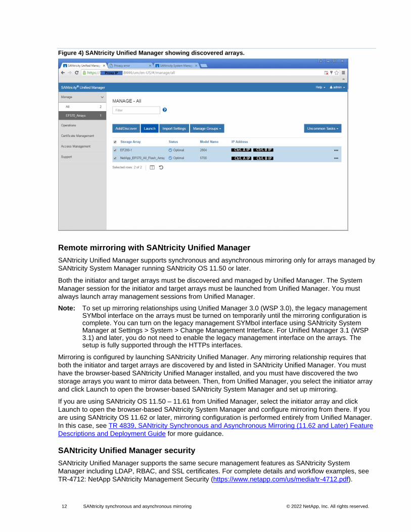
After arrays are discovered and added, they are displayed on the landing page of Unified Manager as
seen in Figure 4.
12 SANtricity synchronous and asynchronous mirroring © 2022 NetApp, Inc. All rights reserved. © 2016 NetApp, Inc. All rights reserved.
Figure 4) SANtricity Unified Manager showing discovered arrays.
Remote mirroring with SANtricity Unified Manager
SANtricity Unified Manager supports synchronous and asynchronous mirroring only for arrays managed by
SANtricity System Manager running SANtricity OS 11.50 or later.
Both the initiator and target arrays must be discovered and managed by Unified Manager. The System
Manager session for the initiator and target arrays must be launched from Unified Manager. You must
always launch array management sessions from Unified Manager.
Note: To set up mirroring relationships using Unified Manager 3.0 (WSP 3.0), the legacy management SYMbol interface on the arrays must be turned on temporarily until the mirroring configuration is complete. You can turn on the legacy management SYMbol interface using SANtricity System Manager at Settings > System > Change Management Interface. For Unified Manager 3.1 (WSP 3.1) and later, you do not need to enable the legacy management interface on the arrays. The setup is fully supported through the HTTPs interfaces.
Mirroring is configured by launching SANtricity Unified Manager. Any mirroring relationship requires that
both the initiator and target arrays are discovered by and listed in SANtricity Unified Manager. You must
have the browser-based SANtricity Unified Manager installed, and you must have discovered the two
storage arrays you want to mirror data between. Then, from Unified Manager, you select the initiator array
and click Launch to open the browser-based SANtricity System Manager and set up mirroring.
If you are using SANtricity OS 11.50 – 11.61 from Unified Manager, select the initiator array and click
Launch to open the browser-based SANtricity System Manager and configure mirroring from there. If you
are using SANtricity OS 11.62 or later, mirroring configuration is performed entirely from Unified Manager.
In this case, see TR 4839, SANtricity Synchronous and Asynchronous Mirroring (11.62 and Later) Feature
Descriptions and Deployment Guide for more guidance.
SANtricity Unified Manager security
SANtricity Unified Manager supports the same secure management features as SANtricity System
Manager including LDAP, RBAC, and SSL certificates. For complete details and workflow examples, see
TR-4712: NetApp SANtricity Management Security (https://www.netapp.com/us/media/tr-4712.pdf).
13 SANtricity synchronous and asynchronous mirroring © 2022 NetApp, Inc. All rights reserved. © 2016 NetApp, Inc. All rights reserved.
Web services certificates and recommended browsers
Certificates identify website owners for secure connections between clients and servers.
Trusted certificates
The SANtricity Unified Manager interface is installed with the WSP on a host system. When you open a
browser and try connecting to Unified Manager, the browser attempts to verify that the host is a trusted
source by checking for a digital certificate. Unified Manager might prompt you to accept the array’s self-
signed certificate, or it might show that the array’s existing security certificate is untrusted. If the certificate
is untrusted, you must import the Certificate Authority (CA) root and, in some cases, the intermediate
certificates to the Unified Manager truststore.
To acquire signed, digital certificates from a CA from within SANtricity Unified Manager, complete the
following steps:
1. Generate a certificate signing request (CSR) for the host system on which SANtricity Unified Manager is installed.
2. Send the .CSR file(s) to a CA, and then wait for them to send you the certificate files.
3. When the CA sends back the signed certificates, import the signed certificates from the Unified Manager interface.
For mirroring involving systems managed by SANtricity System Manager, NetApp recommends importing
the trusted certificates for the web services in SANtricity Unified Manager that allow the storage systems to
authenticate with the web server.
Self-signed certificates
Self-signed certificates can be used to authenticate client–server communications. If the administrator
attempts to configure mirroring without importing signed certificates, SANtricity System Manager displays
an error dialog box that allows the administrator to accept the self-signed certificate. In this case, NetApp
recommends using the latest version of Chrome or Firefox as the browser.
You can accept a self-signed certificate or install your own security certificate using Unified Manager and
navigating to Certificate > Certificate Management.
Comparing asynchronous and synchronous mirroring
Asynchronous mirroring differs from synchronous mirroring in one essential way. It captures the state of
the source volume at a particular point in time and copies just the data that has changed since the last
image capture.
• With asynchronous mirroring, the remote storage array is not always fully synchronized with the local storage array. Therefore, if the application needs to transition to the remote storage array due to a loss of the local storage array, some transactions could be lost.
• With synchronous mirroring, the state of the source volume is not captured at some point in time, but rather reflects all changes that were made on the source volume to the target volume. The copy is identical to production data at every moment because, with this type of mirror, each time the host writes to the primary volume, the storage system writes the same data to the secondary volume at the remote site. The host does not receive an acknowledgment that the write was successful until the secondary volume is successfully updated with the changes that were made on the primary volume.
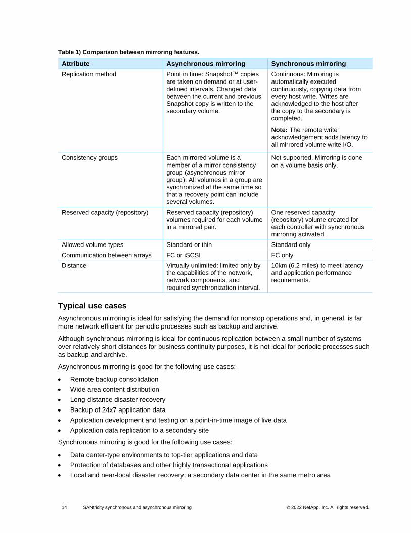
Table 1 presents a brief comparison between asynchronous and synchronous mirroring.
14 SANtricity synchronous and asynchronous mirroring © 2022 NetApp, Inc. All rights reserved. © 2016 NetApp, Inc. All rights reserved.
Table 1) Comparison between mirroring features.
Attribute Asynchronous mirroring Synchronous mirroring
Replication method Point in time: Snapshot™ copies are taken on demand or at user-defined intervals. Changed data between the current and previous Snapshot copy is written to the secondary volume.
Continuous: Mirroring is automatically executed continuously, copying data from every host write. Writes are acknowledged to the host after the copy to the secondary is completed.
Note: The remote write acknowledgement adds latency to all mirrored-volume write I/O.
Consistency groups Each mirrored volume is a member of a mirror consistency group (asynchronous mirror group). All volumes in a group are synchronized at the same time so that a recovery point can include several volumes.
Not supported. Mirroring is done on a volume basis only.
Reserved capacity (repository) Reserved capacity (repository) volumes required for each volume in a mirrored pair.
One reserved capacity (repository) volume created for each controller with synchronous mirroring activated.
Allowed volume types Standard or thin Standard only
Communication between arrays FC or iSCSI FC only
Distance Virtually unlimited: limited only by the capabilities of the network, network components, and required synchronization interval.
10km (6.2 miles) to meet latency and application performance requirements.
Typical use cases
Asynchronous mirroring is ideal for satisfying the demand for nonstop operations and, in general, is far
more network efficient for periodic processes such as backup and archive.
Although synchronous mirroring is ideal for continuous replication between a small number of systems
over relatively short distances for business continuity purposes, it is not ideal for periodic processes such
as backup and archive.
Asynchronous mirroring is good for the following use cases:
• Remote backup consolidation
• Wide area content distribution
• Long-distance disaster recovery
• Backup of 24x7 application data
• Application development and testing on a point-in-time image of live data
• Application data replication to a secondary site
Synchronous mirroring is good for the following use cases:
• Data center-type environments to top-tier applications and data
• Protection of databases and other highly transactional applications
• Local and near-local disaster recovery; a secondary data center in the same metro area
15 SANtricity synchronous and asynchronous mirroring © 2022 NetApp, Inc. All rights reserved. © 2016 NetApp, Inc. All rights reserved.
• Business continuity during scheduled maintenance of the primary storage system with the secondary acting as the primary
Requirements and limitations
This section provides a brief overview of what to know before deploying either or both of the SANtricity
mirroring features.
Feature enablement and activation
Before using mirroring, the desired feature must be both enabled and activated on each storage system
that participates in mirroring operations. NetApp ships all new E-Series and EF-Series systems with both
asynchronous and synchronous mirroring enabled. For older systems, a premium feature key might be
required to use the mirroring features. When required, the feature is enabled by applying the key through
the SANtricity Storage Manager Array Management Window.
Activating the mirroring features in the GUI
For systems managed by SANtricity System Manager (E2800, E5700, and EF570), no separate activation
step is needed; activation occurs behind the scenes while mirror groups/pairs are being set up.
For systems managed by SANtricity Storage Manager (E2700, E5600, EF560), both features are activated
through the Array Management Window. If you are using iSCSI for asynchronous mirroring, the activation
step is not needed.
Prerequisites
The following are prerequisites that must be met to configure mirroring:
• Two dual-controller (duplex) E-Series storage systems that support the mirroring feature (OS 7.84 or later). They do not have to be the same OS version.
• The administrator must know the password for both storage systems.
• Enough free capacity is available on the remote storage system to create a secondary volume at least as large as the primary volume.
• Enough free capacity is available for the reserved capacity (repository) volumes:
− For asynchronous mirroring, this capacity is one volume for each primary volume on the local system and one volume for each secondary volume on the remote array. The default for the reserved capacity volumes is 20% of the respective mirror volume, but the default can be changed.
− For synchronous mirroring, this capacity is one reserved capacity volume for each controller on the local and remote systems regardless of how many mirrored pairs are created. The size of each reserved capacity volume is 128MiB if it is created on a volume group and 4GiB if it is created on a disk pool.
Supported connections
Asynchronous mirroring can use either FC connections, iSCSI connections, or both for communication
between local and remote storage systems. At the time of creating a mirror consistency group (also known
as an asynchronous mirror group), the administrator can select either FC or iSCSI for that group if both are
connected to the remote storage system. There is no failover from one channel type to the other.
Synchronous mirroring supports only FC for communication between storage systems.
16 SANtricity synchronous and asynchronous mirroring © 2022 NetApp, Inc. All rights reserved. © 2016 NetApp, Inc. All rights reserved.
It is possible for a controller to receive host I/O through one protocol and use a different protocol for
mirroring with a remote storage system. For example, a host might be attached to the controller through a
SAS connection, while the intercontroller mirroring data is sent over FC to the remote system.
Controller-to-controller interactions for mirroring I/O occur only as follows:
• Controller A on one end of a mirror pair only interacts with controller A on the other end.
• Controller B on one end of a mirror pair only interacts with controller B on the other end.
No mirroring interactions are attempted between controller A on one end of a mirror pair and controller B
on the other end.
FC connection requirements
When either mirroring feature is activated, each controller of the storage system dedicates its highest
numbered FC host port to mirroring operations. Note that if the controller has both base FC ports and host
interface card (HIC) FC ports, the highest numbered port is on an HIC. Any host logged onto the dedicated
port is logged out, and no host login requests are accepted. I/O requests on this port are accepted only
from controllers that are participating in mirroring operations.
The dedicated mirroring ports must be attached to an FC fabric environment that supports the directory
service and name service interfaces. In particular, FC-AL and point-to-point are not supported as
connectivity options between the controllers that are participating in mirror relationships. The following
examples illustrate FC configurations supported for mirroring.
In the configuration shown in Figure 5, a single fabric is used to provide total connectivity among all
participating devices, including host systems and storage systems.
17 SANtricity synchronous and asynchronous mirroring © 2022 NetApp, Inc. All rights reserved. © 2016 NetApp, Inc. All rights reserved.
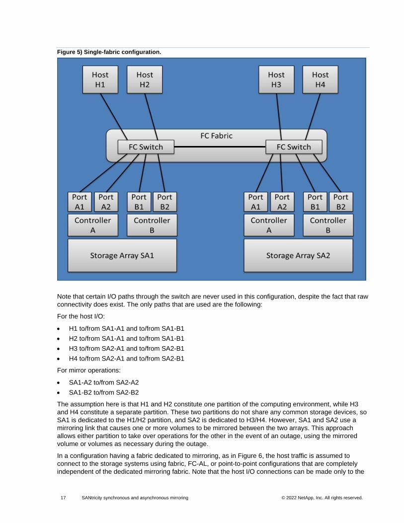
Figure 5) Single-fabric configuration.
Note that certain I/O paths through the switch are never used in this configuration, despite the fact that raw
connectivity does exist. The only paths that are used are the following:
For the host I/O:
• H1 to/from SA1-A1 and to/from SA1-B1
• H2 to/from SA1-A1 and to/from SA1-B1
• H3 to/from SA2-A1 and to/from SA2-B1
• H4 to/from SA2-A1 and to/from SA2-B1
For mirror operations:
• SA1-A2 to/from SA2-A2
• SA1-B2 to/from SA2-B2
The assumption here is that H1 and H2 constitute one partition of the computing environment, while H3
and H4 constitute a separate partition. These two partitions do not share any common storage devices, so
SA1 is dedicated to the H1/H2 partition, and SA2 is dedicated to H3/H4. However, SA1 and SA2 use a
mirroring link that causes one or more volumes to be mirrored between the two arrays. This approach
allows either partition to take over operations for the other in the event of an outage, using the mirrored
volume or volumes as necessary during the outage.
In a configuration having a fabric dedicated to mirroring, as in Figure 6, the host traffic is assumed to
connect to the storage systems using fabric, FC-AL, or point-to-point configurations that are completely
independent of the dedicated mirroring fabric. Note that the host I/O connections can be made only to the
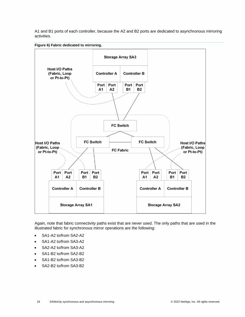
18 SANtricity synchronous and asynchronous mirroring © 2022 NetApp, Inc. All rights reserved. © 2016 NetApp, Inc. All rights reserved.
A1 and B1 ports of each controller, because the A2 and B2 ports are dedicated to asynchronous mirroring
activities.
Figure 6) Fabric dedicated to mirroring.
Again, note that fabric connectivity paths exist that are never used. The only paths that are used in the
illustrated fabric for synchronous mirror operations are the following:
• SA1-A2 to/from SA2-A2
• SA1-A2 to/from SA3-A2
• SA2-A2 to/from SA3-A2
• SA1-B2 to/from SA2-B2
• SA1-B2 to/from SA3-B2
• SA2-B2 to/from SA3-B2
19 SANtricity synchronous and asynchronous mirroring © 2022 NetApp, Inc. All rights reserved. © 2016 NetApp, Inc. All rights reserved.
iSCSI connection requirements (asynchronous mirroring only)
Unlike FC, iSCSI does not require a dedicated port. The controller maintains a list of remote storage
systems with which the iSCSI initiator attempts to establish a session. The first port that successfully
establishes an iSCSI connection is used for all subsequent communication with that remote storage
system. If communication fails, a new session is attempted using all available ports.
iSCSI ports are configured at the system level on a port-by-port basis. Intercontroller communication for
configuration messaging and data transfer uses the global settings, including settings for the following:
• VLAN: Both local and remote systems must have the same VLAN setting to communicate.
• iSCSI listening port
• Jumbo frames
• Ethernet priority
Asynchronous mirroring uses the storage system’s host-side I/O ports to convey mirrored data from the
primary side to the secondary side. Because asynchronous mirroring is intended for higher-latency, lower-
cost networks, iSCSI (and thus TCP/IP-based) connections are a good fit for it. When asynchronous
mirroring is used in iSCSI environments, it is not necessary to dedicate any of the array’s front-end iSCSI
ports for use with asynchronous mirroring. Those ports are shared for both asynchronous mirror traffic and
host-to-array I/O connections.
Note: The iSCSI intercontroller communication must use a host connect port and not the management Ethernet port.
Note: VLAN is not a requirement for configuring asynchronous replication.
Note: Activation is not required if the storage system is mirroring only through an iSCSI interface.
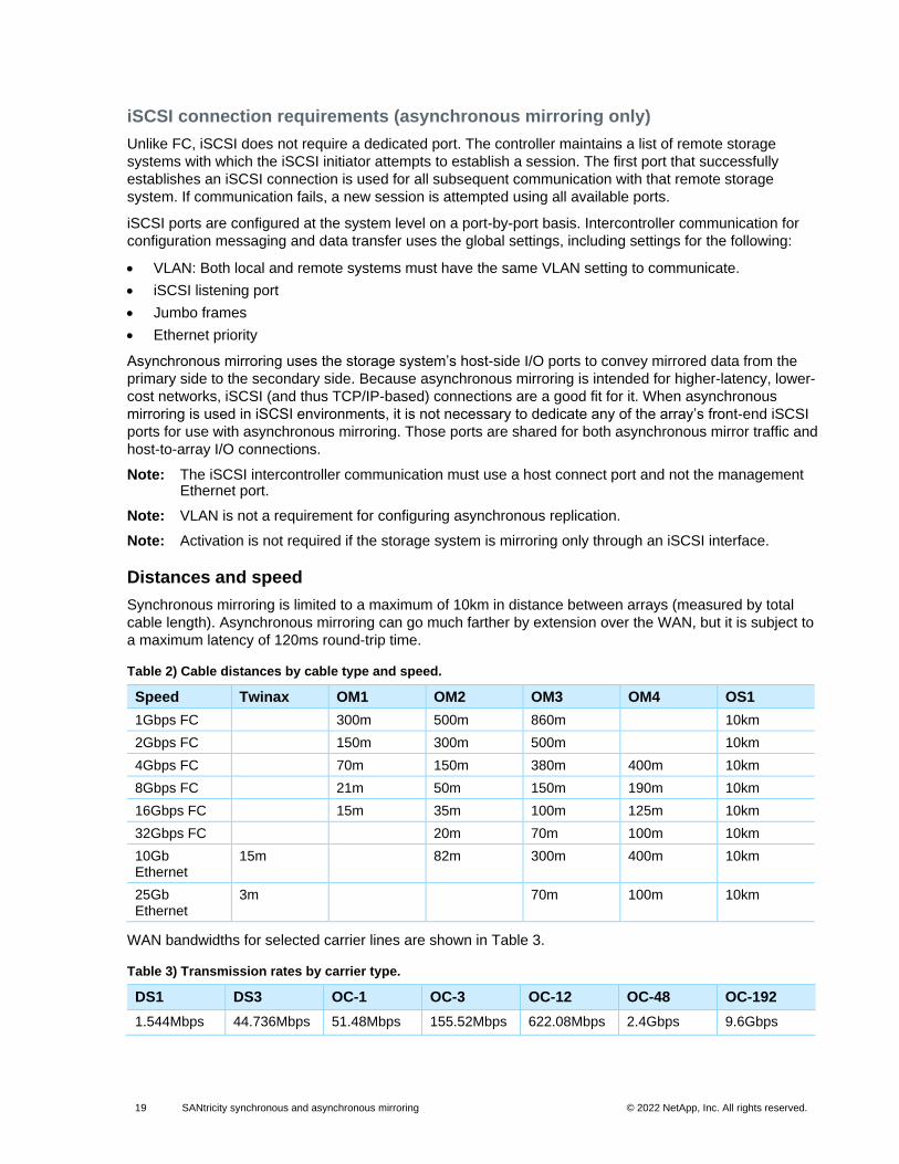
Distances and speed
Synchronous mirroring is limited to a maximum of 10km in distance between arrays (measured by total
cable length). Asynchronous mirroring can go much farther by extension over the WAN, but it is subject to
a maximum latency of 120ms round-trip time.
Table 2) Cable distances by cable type and speed.
Speed Twinax OM1 OM2 OM3 OM4 OS1
1Gbps FC 300m 500m 860m 10km
2Gbps FC 150m 300m 500m 10km
4Gbps FC 70m 150m 380m 400m 10km
8Gbps FC 21m 50m 150m 190m 10km
16Gbps FC 15m 35m 100m 125m 10km
32Gbps FC 20m 70m 100m 10km
10Gb Ethernet
15m 82m 300m 400m 10km
25Gb Ethernet
3m 70m 100m 10km
WAN bandwidths for selected carrier lines are shown in Table 3.
Table 3) Transmission rates by carrier type.
DS1 DS3 OC-1 OC-3 OC-12 OC-48 OC-192
1.544Mbps 44.736Mbps 51.48Mbps 155.52Mbps 622.08Mbps 2.4Gbps 9.6Gbps
20 SANtricity synchronous and asynchronous mirroring © 2022 NetApp, Inc. All rights reserved. © 2016 NetApp, Inc. All rights reserved.
Mirror volume requirements
Following are requirements and characteristics of mirrored volumes:
• The reported capacity of a volume participating in mirroring is the lesser of the primary and secondary capacities. The secondary volume capacity must be at least as large as the primary volume at creation time; however, after a role reversal, the new primary could be smaller than the new secondary.
• A volume is allowed to participate in only one mirroring relationship, whether asynchronous or synchronous. There is no support for three-data center mirroring or n-way mirroring.
• Pool and volume group, RAID level, caching parameters, and segment size can be different on the two mirrored volumes.
• If the primary is configured to enable data assurance (DA), the secondary must also have DA enabled.
• Regarding drive security, a best practice is for the primary and secondary volumes to be of the same drive type (FDE, FIPS, or not security capable). They should also have the same security setting (secure enabled or not):
− Synchronous mirroring. The controller does not enforce any drive security rules with respect to the synchronous mirroring feature.
− Asynchronous mirroring. If the primary is not secure capable, the secondary must also be not secure capable. If the primary is secure enabled, the secondary must be secure enabled. If the primary is secure capable (but not enabled), the secondary can be either secure capable or secure enabled. If the primary ever attains a higher security level than the secondary, the controller raises a needs attention condition. The controller allows a mix of FDE and FIPS volumes as mirror pairs, but as noted earlier, best practice is for these to match.
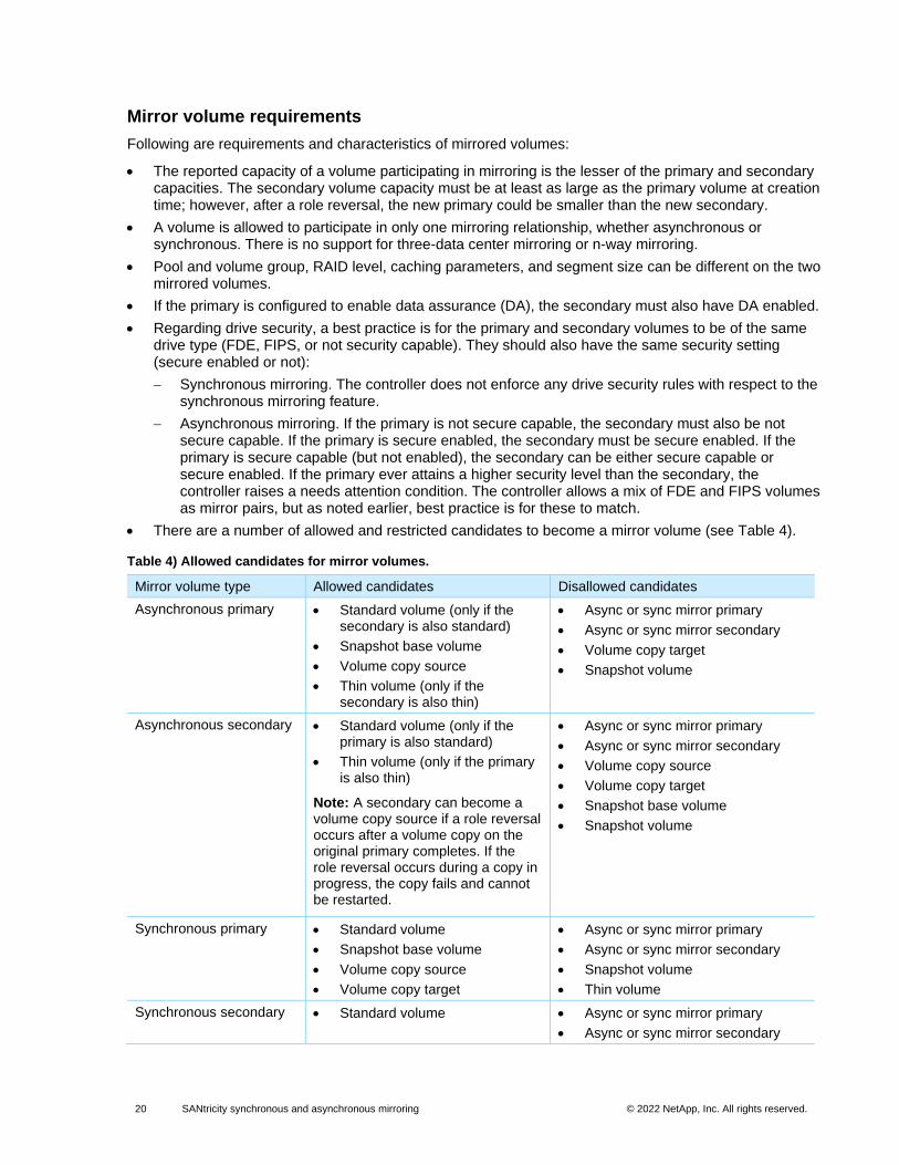
• There are a number of allowed and restricted candidates to become a mirror volume (see Table 4).
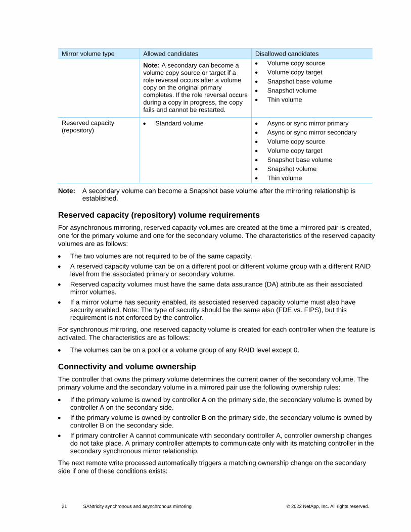
Table 4) Allowed candidates for mirror volumes.
Mirror volume type Allowed candidates Disallowed candidates
Asynchronous primary • Standard volume (only if the secondary is also standard)
• Snapshot base volume
• Volume copy source
• Thin volume (only if the secondary is also thin)
• Async or sync mirror primary
• Async or sync mirror secondary
• Volume copy target
• Snapshot volume
Asynchronous secondary • Standard volume (only if the primary is also standard)
• Thin volume (only if the primary is also thin)
Note: A secondary can become a volume copy source if a role reversal occurs after a volume copy on the original primary completes. If the role reversal occurs during a copy in progress, the copy fails and cannot be restarted.
• Async or sync mirror primary
• Async or sync mirror secondary
• Volume copy source
• Volume copy target
• Snapshot base volume
• Snapshot volume
Synchronous primary • Standard volume
• Snapshot base volume
• Volume copy source
• Volume copy target
• Async or sync mirror primary
• Async or sync mirror secondary
• Snapshot volume
• Thin volume
Synchronous secondary • Standard volume • Async or sync mirror primary
• Async or sync mirror secondary
21 SANtricity synchronous and asynchronous mirroring © 2022 NetApp, Inc. All rights reserved. © 2016 NetApp, Inc. All rights reserved.
Mirror volume type Allowed candidates Disallowed candidates
Note: A secondary can become a volume copy source or target if a role reversal occurs after a volume copy on the original primary completes. If the role reversal occurs during a copy in progress, the copy fails and cannot be restarted.
• Volume copy source
• Volume copy target
• Snapshot base volume
• Snapshot volume
• Thin volume
Reserved capacity (repository)
• Standard volume • Async or sync mirror primary
• Async or sync mirror secondary
• Volume copy source
• Volume copy target
• Snapshot base volume
• Snapshot volume
• Thin volume
Note: A secondary volume can become a Snapshot base volume after the mirroring relationship is established.
Reserved capacity (repository) volume requirements
For asynchronous mirroring, reserved capacity volumes are created at the time a mirrored pair is created,
one for the primary volume and one for the secondary volume. The characteristics of the reserved capacity
volumes are as follows:
• The two volumes are not required to be of the same capacity.
• A reserved capacity volume can be on a different pool or different volume group with a different RAID level from the associated primary or secondary volume.
• Reserved capacity volumes must have the same data assurance (DA) attribute as their associated mirror volumes.
• If a mirror volume has security enabled, its associated reserved capacity volume must also have security enabled. Note: The type of security should be the same also (FDE vs. FIPS), but this requirement is not enforced by the controller.
For synchronous mirroring, one reserved capacity volume is created for each controller when the feature is
activated. The characteristics are as follows:
• The volumes can be on a pool or a volume group of any RAID level except 0.
Connectivity and volume ownership
The controller that owns the primary volume determines the current owner of the secondary volume. The
primary volume and the secondary volume in a mirrored pair use the following ownership rules:
• If the primary volume is owned by controller A on the primary side, the secondary volume is owned by controller A on the secondary side.
• If the primary volume is owned by controller B on the primary side, the secondary volume is owned by controller B on the secondary side.
• If primary controller A cannot communicate with secondary controller A, controller ownership changes do not take place. A primary controller attempts to communicate only with its matching controller in the secondary synchronous mirror relationship.
The next remote write processed automatically triggers a matching ownership change on the secondary
side if one of these conditions exists:
22 SANtricity synchronous and asynchronous mirroring © 2022 NetApp, Inc. All rights reserved. © 2016 NetApp, Inc. All rights reserved.
• If an I/O path error causes a volume ownership change on the primary side.
• If the storage administrator changes the current owner of the primary volume.
For example, suppose that a primary volume is owned by controller A and the controller owner is changed
to controller B. In this case, the next remote write changes the controller owner of the secondary volume
from controller A to controller B. Because controller ownership changes on the secondary side are
controlled by the primary side, they do not require any special intervention by the storage administrator.
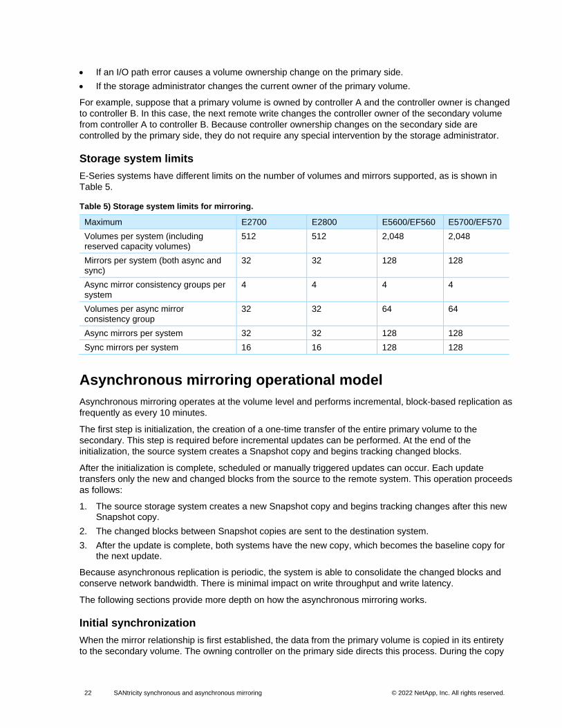
Storage system limits
E-Series systems have different limits on the number of volumes and mirrors supported, as is shown in
Table 5.
Table 5) Storage system limits for mirroring.
Maximum E2700 E2800 E5600/EF560 E5700/EF570
Volumes per system (including reserved capacity volumes)
512 512 2,048 2,048
Mirrors per system (both async and sync)
32 32 128 128
Async mirror consistency groups per system
4 4 4 4
Volumes per async mirror consistency group
32 32 64 64
Async mirrors per system 32 32 128 128
Sync mirrors per system 16 16 128 128
Asynchronous mirroring operational model
Asynchronous mirroring operates at the volume level and performs incremental, block-based replication as
frequently as every 10 minutes.
The first step is initialization, the creation of a one-time transfer of the entire primary volume to the
secondary. This step is required before incremental updates can be performed. At the end of the
initialization, the source system creates a Snapshot copy and begins tracking changed blocks.
After the initialization is complete, scheduled or manually triggered updates can occur. Each update
transfers only the new and changed blocks from the source to the remote system. This operation proceeds
as follows:
1. The source storage system creates a new Snapshot copy and begins tracking changes after this new Snapshot copy.
2. The changed blocks between Snapshot copies are sent to the destination system.
3. After the update is complete, both systems have the new copy, which becomes the baseline copy for the next update.
Because asynchronous replication is periodic, the system is able to consolidate the changed blocks and
conserve network bandwidth. There is minimal impact on write throughput and write latency.
The following sections provide more depth on how the asynchronous mirroring works.
Initial synchronization
When the mirror relationship is first established, the data from the primary volume is copied in its entirety
to the secondary volume. The owning controller on the primary side directs this process. During the copy
23 SANtricity synchronous and asynchronous mirroring © 2022 NetApp, Inc. All rights reserved. © 2016 NetApp, Inc. All rights reserved.
or mirror initialization, the primary volume is fully accessible for I/O operations by all host systems that
would normally have access to it. Until the initial synchronization completes, the secondary volume has
minimal value as a recovery point.
The initial synchronization is completed in multiple phases. The first phase copies all data from the primary
to the secondary volume. For a thin volume, this approach includes only blocks that have been written on
the primary and not unmapped. However, the first phase does not create a Snapshot copy as the
synchronization point. The first phase synchronization usually takes quite a long time (possibly many
hours for large volumes), so the mirror is not considered to be synchronized from the first pass. During the
first phase, a delta log is used to track write requests to the primary volume. The second phase of the
initial synchronization creates a Snapshot copy on the primary to use as a synchronization point. Not using
a Snapshot copy for the first phase of the synchronization process minimizes the effect on performance
during the initialization process.
When an asynchronous mirrored pair is first established, the following steps are taken on the primary
array:
1. The mirror state is set to initializing.
2. One of the delta logs (log A) in the primary side’s reserved capacity (repository) is initialized to a clean state and then activated to track updates made to the primary volume from that point forward.
3. The other delta log (log B) is initialized in a completely set state, indicating that all the data regions of the primary and secondary are out of sync.
4. A background synchronization process transfers the contents of the primary volume to the secondary. The process iterates through delta log B, copying any data flagged as unsynchronized in the delta log to the secondary volume. After copying an individual data segment, the delta log is updated to persistently save the progress of the synchronization process. Any interruption or reset of the controller causes the synchronization process to resume at the point of the most recent progress record. Such interruptions do not force the controller to restart the synchronization process from the beginning of the volume. Because the address range of an individual bit in the delta log is relatively small, a larger data chunk may be copied to the secondary, resulting in several bits in the delta log being marked complete in the synchronization progress.
5. A Snapshot copy is created to capture the post-first-phase consistent image of the primary volume to be synchronized to the secondary array.
6. Data regions of the primary volume that had been written during step 4 as recorded in delta log A are written to the secondary volume. After copying an individual data segment, the delta log is updated to persistently save the progress of the synchronization process. Any interruption or reset of the controller causes the synchronization process to resume at the point of the most recent progress record. When all data regions have been copied to the secondary, a message is sent to the remote array so that a Snapshot copy can be created to capture the recovery point on the secondary volume.
7. The Snapshot copy that was created to capture the primary synchronization image is deleted.
8. Steps 5 through 7 are repeated as long as the synchronization process does not complete within the configured synchronization interval.
9. When the background synchronization process completes within the synchronization interval, the mirror state is set to optimal.
10. The next synchronization process for normal mirror operation is scheduled based on the creation time of the Snapshot copy that was used to complete initial synchronization.
The following steps are taken on the secondary array:
1. The secondary side receives the mirror state change to initializing from the primary array and persists with the state change.
2. The secondary volume receives synchronization write commands from the primary side. Because this synchronization is the initial one, the updates are written directly to the secondary’s base volume, without first creating a Snapshot copy.
24 SANtricity synchronous and asynchronous mirroring © 2022 NetApp, Inc. All rights reserved. © 2016 NetApp, Inc. All rights reserved.
3. The secondary side receives a message from the primary side that the background synchronization process is complete. A Snapshot copy is created to capture the synchronized image.
Resynchronization methods for asynchronous mirroring
After the initial synchronization is complete, and as the primary changes, the system needs to
resynchronize every so often to create a new recovery point that meets the desired SLA. Two
resynchronization methods, manual and automatic, are available for asynchronous mirroring.
Manual
• Manual resynchronization causes immediate resynchronization of data on all of the asynchronous mirrored pairs in the asynchronous mirror group. Select this option to manually start resynchronization for all mirrored pairs in the group.
• If the administrator chooses manual as the synchronization method, the administrator must use the manual resynchronization option to send updates of modified data from the local storage array to the remote storage array.
Automatic (periodic)
• Specifies the time (in minutes) from the beginning of the previous update to the beginning of the next update. For example, if the synchronization interval is set at 30 minutes, and the synchronization process starts at 4:00 p.m., the next process is started at 4:30 p.m.
• To change the automatic synchronization interval from the default of every 10 minutes, the administrator can edit the interval value, which is defined in minutes.
• If a communication failure occurs between the local storage array and the remote storage array and a synchronization interval was missed during that time period, the controller owner of the primary asynchronous mirror group starts the resynchronization process immediately after communication has been restored.
• If the administrator chooses automatic synchronization, the administrator can also execute a manual resynchronization at any time by using the manual resynchronization option.
Periodic resynchronization
Each mirror consistency group (asynchronous mirror group) has a configurable attribute that specifies the
resynchronization interval for all mirror pairs in the group. This interval is the amount of time between
automatically sending updates of modified primary-side data to the secondary side. The value represents
the time between the starting points of sending updates from primary to secondary.
For example, if the interval is 30 minutes, and the first resynchronization interval is encountered at 3:15
p.m., then the ensuing resynchronization intervals start at 3:45 p.m., 4:15 p.m., and so on. The actual
amount of time to complete a resynchronization varies due to differing quantities of modified data on the
primary volume and due to performance variations in the intercontroller communication link. For example,
the first resynchronization cycle may be from 3:15 to 3:39 p.m., the second from 3:45 to 4:06, the third
from 4:15 to 4:42, and so on.
25 SANtricity synchronous and asynchronous mirroring © 2022 NetApp, Inc. All rights reserved. © 2016 NetApp, Inc. All rights reserved.
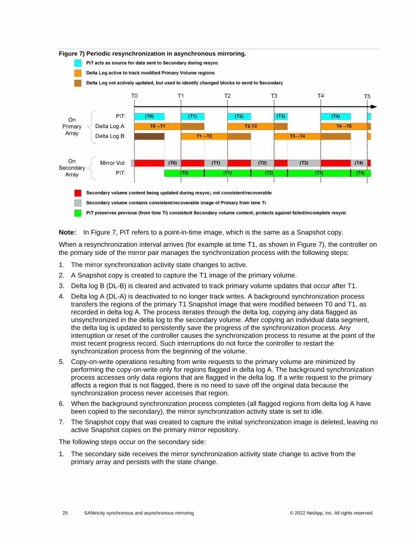
Figure 7) Periodic resynchronization in asynchronous mirroring.
Note: In Figure 7, PiT refers to a point-in-time image, which is the same as a Snapshot copy.
When a resynchronization interval arrives (for example at time T1, as shown in Figure 7), the controller on
the primary side of the mirror pair manages the synchronization process with the following steps:
1. The mirror synchronization activity state changes to active.
2. A Snapshot copy is created to capture the T1 image of the primary volume.
3. Delta log B (DL-B) is cleared and activated to track primary volume updates that occur after T1.
4. Delta log A (DL-A) is deactivated to no longer track writes. A background synchronization process transfers the regions of the primary T1 Snapshot image that were modified between T0 and T1, as recorded in delta log A. The process iterates through the delta log, copying any data flagged as unsynchronized in the delta log to the secondary volume. After copying an individual data segment, the delta log is updated to persistently save the progress of the synchronization process. Any interruption or reset of the controller causes the synchronization process to resume at the point of the most recent progress record. Such interruptions do not force the controller to restart the synchronization process from the beginning of the volume.
5. Copy-on-write operations resulting from write requests to the primary volume are minimized by performing the copy-on-write only for regions flagged in delta log A. The background synchronization process accesses only data regions that are flagged in the delta log. If a write request to the primary affects a region that is not flagged, there is no need to save off the original data because the synchronization process never accesses that region.
6. When the background synchronization process completes (all flagged regions from delta log A have been copied to the secondary), the mirror synchronization activity state is set to idle.
7. The Snapshot copy that was created to capture the initial synchronization image is deleted, leaving no active Snapshot copies on the primary mirror repository.
The following steps occur on the secondary side:
1. The secondary side receives the mirror synchronization activity state change to active from the primary array and persists with the state change.
26 SANtricity synchronous and asynchronous mirroring © 2022 NetApp, Inc. All rights reserved. © 2016 NetApp, Inc. All rights reserved.
2. The secondary volume receives synchronization write commands from the primary side. Because a Snapshot copy was created at the end of the previous synchronization cycle, the consistent secondary image is preserved during the synchronization process.
3. The secondary side receives a mirror synchronization activity state change to idle from the primary side. A Snapshot copy is created to protect the newly established consistent image; any old Snapshot copy for a previous consistent image is deleted, and the mirror state is persisted.
When the next resynchronization interval arrives (time T2), the primary side’s actions are repeated, except
that the use of DL-A and DL-B is reversed. On the secondary side, the processing is the same as just
described for the first resynchronization interval. This pattern repeats for all subsequent resynchronization
intervals.
Using thin-provisioned volumes in asynchronous mirroring
Thin-provisioned volumes are allowed to participate in a mirror consistency group (asynchronous mirror
group) only when paired with another thin-provisioned volume. Thin-provisioned volumes that are in a
group follow the same rules as normal volumes (for example, security settings, data assurance, capacity,
and so on). They also have the following operational differences from fully provisioned volumes:
• If an existing thin volume is selected for the secondary volume of a mirrored pair, that thin volume is reinitialized with a new reserved capacity volume.
• The secondary thin volume is initialized before the initial (or any full) synchronization process begins.
• Only provisioned blocks in the primary thin volume are transferred during the initial synchronization process.
• Automatic expansion must be enabled. (Note: This approach is the default in the management GUIs when creating a thin volume.) Thin volumes with automatic expansion disabled are not shown as candidates for mirroring in the GUI.
• The secondary thin volume parameters controlling its growth are set to match the primary thin volume parameters. When selecting an existing thin volume for the secondary, the user is warned of these impending changes and allowed to cancel the operation.
• The alert thresholds may only be changed on the primary side of the mirror pair. Any changes to these parameters on the primary are automatically propagated to the secondary side.
Removing a thin-provisioned volume from a mirror consistency group does not cause any changes to the
parameters controlling its growth.
Suspend and resume
The administrator can suspend synchronization on a mirror consistency group basis. When this
suspension happens, the controller immediately halts any synchronization or resynchronization activity on
that group. No attempt is made to contact the secondary volumes for that group. A recovery point on the
secondary volumes remains valid, and no alerts are issued for the age of the recovery point. While the
group is suspended, writes to the primary volumes continue as normal and are logged.
When the administrator resumes the mirror consistency group, a resynchronization of all mirror pairs in the
group begins immediately. After the resynchronization is complete, the group resumes the normal periodic
resynchronization schedule if the group is configured for periodic resynchronization.
Orderly role reversal
At certain times, an administrator might want to reverse the roles of primary and secondary. This reversal
could be when it looks like a disaster at the primary site is possible and the company wants to migrate
operations to the recovery site. Another example might be when conducting scheduled maintenance at the
primary site, the administrator can reverse roles to preserve continuity of service. Later, the roles can be
reversed again to restore the original site to normal operations.
27 SANtricity synchronous and asynchronous mirroring © 2022 NetApp, Inc. All rights reserved. © 2016 NetApp, Inc. All rights reserved.
The role reversal change affects all asynchronous mirrored pairs in the selected mirror consistency group
(asynchronous mirror group). For example, when a primary group is demoted to a secondary role, all the
primary volumes of the asynchronous mirrored pairs in that group are also demoted to secondary
volumes.
When demoting a primary group to a secondary role, if the current secondary group can be contacted, it is
automatically promoted to a primary role in the mirror relationship. Likewise, when promoting a secondary
group to a primary role, if the current primary group can be contacted, it is automatically demoted to a
secondary role in the mirror relationship.
Note: If the environment has a suspended asynchronous mirror group operation, it resumes during the change role operation.
Keep these guidelines in mind:
• When the primary group becomes a secondary, hosts that have been mapped to the mirrored volumes in the group no longer have write access to them.
• When the secondary group becomes a primary, any hosts that are accessing the secondary volumes in the group are now able to write to the asynchronous mirrored pairs.
• If a communication problem between the local and remote sites prevents the promotion of the secondary asynchronous mirror group, an error message appears. However, the administrator can still force the secondary group to a primary role. This forced promotion leads to a dual primary asynchronous mirroring condition.
Forced promotion of secondary
In the event of a catastrophic failure at the primary site, the administrator might decide to promote the
secondary mirror consistency group to primary so that business operations can resume from the current
recovery point. In this case, the controller at the secondary site that receives the command to promote
attempts to communicate with the primary to coordinate a role change. If communication is not possible,
as would likely be the case in a disaster scenario, the controller begins the process of promoting the
secondary mirror consistency group to primary.
Forced promotion first transitions the mirror consistency group to a role-change-in-progress state on the
local storage system. Because the remote storage system containing the primary group is inaccessible,
this state change is only made locally. Next, the mirror consistency group role is set to primary, which
allows all member volumes in the group to function as mirror primary volumes, allowing write access and
tracking writes to resynchronize with the original primary when it is available again. If the original primary
mirror consistency group was actively synchronizing the mirror pairs prior to the forced role change, the
data on the original secondary (the new primary) volumes is in an inconsistent state. In this case, a
rollback is performed on all members of the group as an online background operation to restore the data
back to the last known consistent state as preserved by the recovery point.
Note: If the inability to communicate is due to a communication link failure and not the primary being destroyed, and if the original primary is not force-demoted to secondary, when communication is restored, it is likely that the mirror consistency group will be in a dual primary role conflict. If this conflict occurs, the administrator is notified by a needs-attention alert. The administrator needs to follow the Recovery Guru procedures to resolve this conflict.
Note: The preceding description of the role change applies when the controller at the secondary site cannot communicate with the primary. If the controller is able to communicate with its counterpart at the primary site when it receives the forced promotion command, the two controllers proceed with an immediate role reversal. In this case, the primary volumes are not synchronized with the secondary before reversing roles, resulting in any data that had been written to the primary since the last resynchronization being lost.
Forced promotion is not allowed if any of the following conditions exist:
28 SANtricity synchronous and asynchronous mirroring © 2022 NetApp, Inc. All rights reserved. © 2016 NetApp, Inc. All rights reserved.
• Not all of the mirror consistency group member volumes have been previously synchronized and have a consistent recovery point.
• Any member volumes do not have a Snapshot image at the recovery point. This situation could occur if the reserved capacity volume is full, for example.
• The mirror consistency group has no member volumes.
• The mirror consistency group is in the failed, role-change-pending, or role-change-in-progress state.
• There is a dual role conflict.
Forced demotion of primary
Forced demotion of a mirror consistency group in the primary role to function in the secondary role allows
the storage administrator to protect the volumes from receiving new write requests while disconnected
from the remote storage system. This approach can be useful in the event that the corresponding group on
the remote system had been promoted with the force option to primary.
If the original primary is force-demoted before communication is restored, then after communication is
restored, the mirror consistency groups on both sides complete the role reversal and begin periodic
resynchronization as normal (with roles reversed). If any writes occurred to the original primary after the
communication loss, but before the demotion, they are discarded. As in the disaster recovery scenario,
operations continue from the recovery point with the original secondary now as primary.
Forced demotion first transitions the mirror group to a role-change-in-progress state on the local storage
system. Because the remote storage system is inaccessible, this state change is only made locally. If the
original primary was actively synchronizing the mirror pairs prior to the forced role change, the
synchronization operation is canceled, and the Snapshot copies used for the resynchronization are
deleted. The group role is set to secondary, which prevents all member volumes in the group from
receiving new write requests.
Note: If the original secondary is not force-promoted to primary while unable to communicate, then when communication is restored, it is likely that the mirror consistency group is in a dual secondary role conflict. If this situation occurs, the administrator is notified by a needs-attention alert. The administrator needs to follow the Recovery Guru procedures to resolve this conflict.
Note: The preceding description of the role change applies when the controller at the primary site cannot communicate with the secondary. If the controller is able to communicate with its counterpart at the secondary site when it receives the forced demotion command, the two controllers proceed with an immediate role reversal. In this case, the primary volumes are not synchronized with the secondary before reversing roles, resulting in any data that had been written to the primary since the last resynchronization being lost.
Forced demotion of the primary mirror consistency group is not allowed if any of the following conditions
exist:
• Any of the member volumes are failed.
• Any of the associated reserved capacity volumes are failed.
• The mirror consistency group is in the failed, role-change-pending, or role-change-in-progress state.
• There is a dual role conflict.
Example failures and how to handle
Following are a few failure modes with guidelines on how an administrator might handle them.
Note: These are not the only steps required to handle site failures. The steps listed here are related only to the two storage systems involved in a mirroring relationship. They do not discuss moving applications over from a primary site to a secondary, reestablishing communications, and so on.
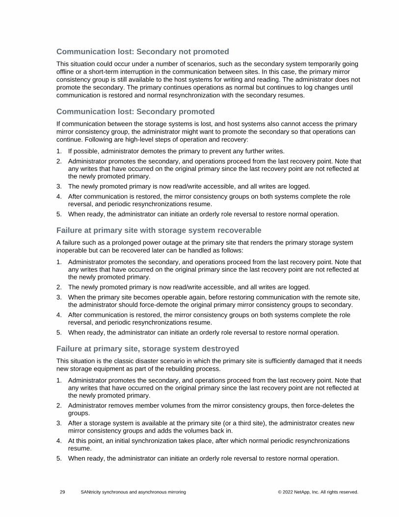
29 SANtricity synchronous and asynchronous mirroring © 2022 NetApp, Inc. All rights reserved. © 2016 NetApp, Inc. All rights reserved.
Communication lost: Secondary not promoted
This situation could occur under a number of scenarios, such as the secondary system temporarily going
offline or a short-term interruption in the communication between sites. In this case, the primary mirror
consistency group is still available to the host systems for writing and reading. The administrator does not
promote the secondary. The primary continues operations as normal but continues to log changes until
communication is restored and normal resynchronization with the secondary resumes.
Communication lost: Secondary promoted
If communication between the storage systems is lost, and host systems also cannot access the primary
mirror consistency group, the administrator might want to promote the secondary so that operations can
continue. Following are high-level steps of operation and recovery:
1. If possible, administrator demotes the primary to prevent any further writes.
2. Administrator promotes the secondary, and operations proceed from the last recovery point. Note that any writes that have occurred on the original primary since the last recovery point are not reflected at the newly promoted primary.
3. The newly promoted primary is now read/write accessible, and all writes are logged.
4. After communication is restored, the mirror consistency groups on both systems complete the role reversal, and periodic resynchronizations resume.
5. When ready, the administrator can initiate an orderly role reversal to restore normal operation.
Failure at primary site with storage system recoverable
A failure such as a prolonged power outage at the primary site that renders the primary storage system
inoperable but can be recovered later can be handled as follows:
1. Administrator promotes the secondary, and operations proceed from the last recovery point. Note that any writes that have occurred on the original primary since the last recovery point are not reflected at the newly promoted primary.
2. The newly promoted primary is now read/write accessible, and all writes are logged.
3. When the primary site becomes operable again, before restoring communication with the remote site, the administrator should force-demote the original primary mirror consistency groups to secondary.
4. After communication is restored, the mirror consistency groups on both systems complete the role reversal, and periodic resynchronizations resume.
5. When ready, the administrator can initiate an orderly role reversal to restore normal operation.
Failure at primary site, storage system destroyed
This situation is the classic disaster scenario in which the primary site is sufficiently damaged that it needs
new storage equipment as part of the rebuilding process.
1. Administrator promotes the secondary, and operations proceed from the last recovery point. Note that any writes that have occurred on the original primary since the last recovery point are not reflected at the newly promoted primary.
2. Administrator removes member volumes from the mirror consistency groups, then force-deletes the groups.
3. After a storage system is available at the primary site (or a third site), the administrator creates new mirror consistency groups and adds the volumes back in.
4. At this point, an initial synchronization takes place, after which normal periodic resynchronizations resume.
5. When ready, the administrator can initiate an orderly role reversal to restore normal operation.
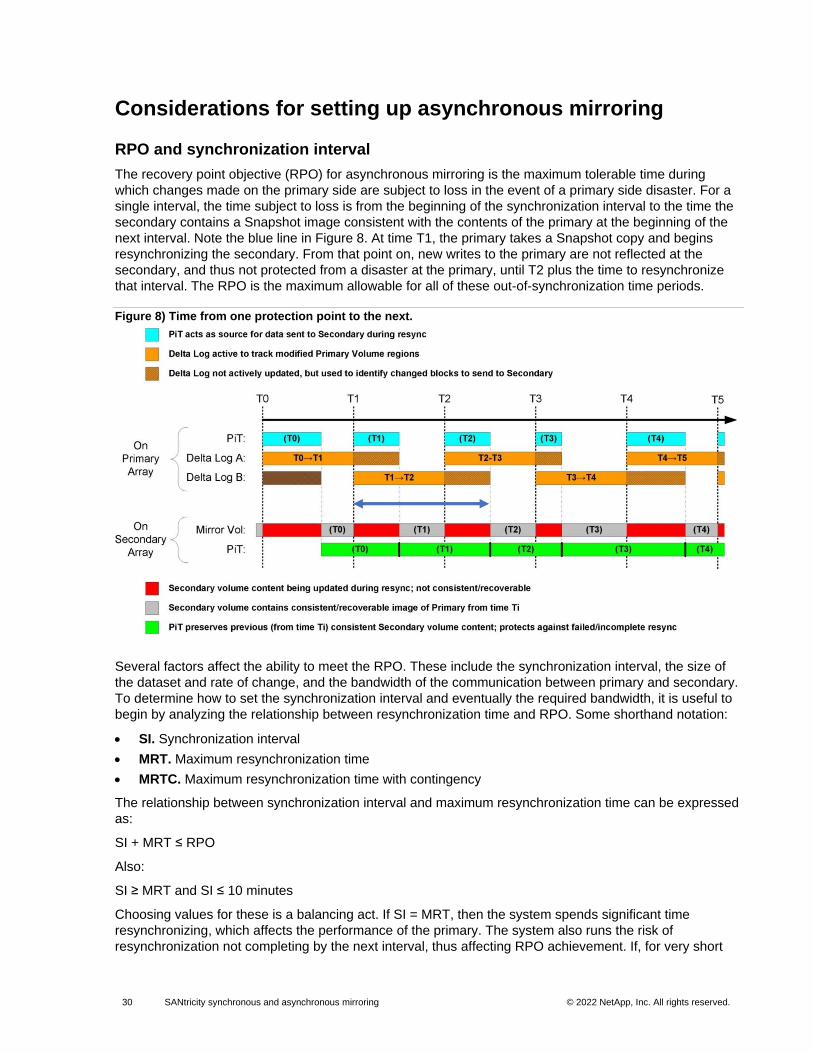
30 SANtricity synchronous and asynchronous mirroring © 2022 NetApp, Inc. All rights reserved. © 2016 NetApp, Inc. All rights reserved.
Considerations for setting up asynchronous mirroring
RPO and synchronization interval
The recovery point objective (RPO) for asynchronous mirroring is the maximum tolerable time during
which changes made on the primary side are subject to loss in the event of a primary side disaster. For a
single interval, the time subject to loss is from the beginning of the synchronization interval to the time the
secondary contains a Snapshot image consistent with the contents of the primary at the beginning of the
next interval. Note the blue line in Figure 8. At time T1, the primary takes a Snapshot copy and begins
resynchronizing the secondary. From that point on, new writes to the primary are not reflected at the
secondary, and thus not protected from a disaster at the primary, until T2 plus the time to resynchronize
that interval. The RPO is the maximum allowable for all of these out-of-synchronization time periods.
Figure 8) Time from one protection point to the next.
Several factors affect the ability to meet the RPO. These include the synchronization interval, the size of
the dataset and rate of change, and the bandwidth of the communication between primary and secondary.
To determine how to set the synchronization interval and eventually the required bandwidth, it is useful to
begin by analyzing the relationship between resynchronization time and RPO. Some shorthand notation:
• SI. Synchronization interval
• MRT. Maximum resynchronization time
• MRTC. Maximum resynchronization time with contingency
The relationship between synchronization interval and maximum resynchronization time can be expressed
as:
SI + MRT ≤ RPO
Also:
SI ≥ MRT and SI ≤ 10 minutes
Choosing values for these is a balancing act. If SI = MRT, then the system spends significant time
resynchronizing, which affects the performance of the primary. The system also runs the risk of
resynchronization not completing by the next interval, thus affecting RPO achievement. If, for very short
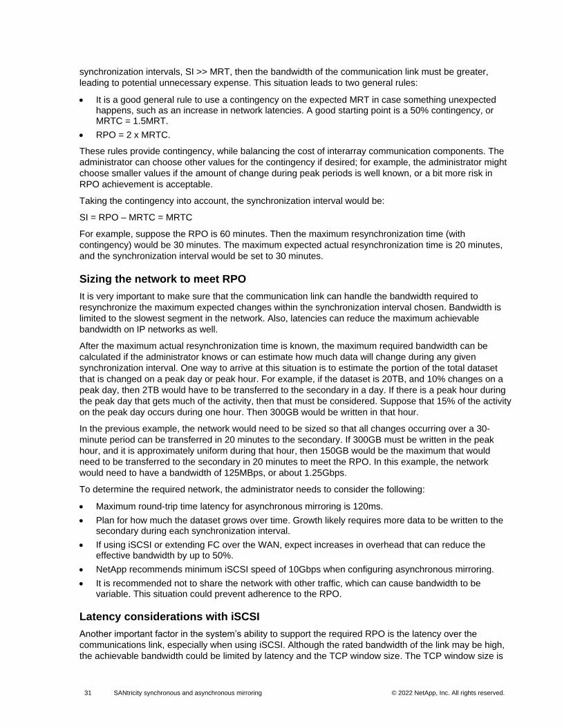
31 SANtricity synchronous and asynchronous mirroring © 2022 NetApp, Inc. All rights reserved. © 2016 NetApp, Inc. All rights reserved.
synchronization intervals, SI >> MRT, then the bandwidth of the communication link must be greater,
leading to potential unnecessary expense. This situation leads to two general rules:
• It is a good general rule to use a contingency on the expected MRT in case something unexpected happens, such as an increase in network latencies. A good starting point is a 50% contingency, or MRTC = 1.5MRT.
• RPO = 2 x MRTC.
These rules provide contingency, while balancing the cost of interarray communication components. The
administrator can choose other values for the contingency if desired; for example, the administrator might
choose smaller values if the amount of change during peak periods is well known, or a bit more risk in
RPO achievement is acceptable.
Taking the contingency into account, the synchronization interval would be:
SI = RPO – MRTC = MRTC
For example, suppose the RPO is 60 minutes. Then the maximum resynchronization time (with
contingency) would be 30 minutes. The maximum expected actual resynchronization time is 20 minutes,
and the synchronization interval would be set to 30 minutes.
Sizing the network to meet RPO
It is very important to make sure that the communication link can handle the bandwidth required to
resynchronize the maximum expected changes within the synchronization interval chosen. Bandwidth is
limited to the slowest segment in the network. Also, latencies can reduce the maximum achievable
bandwidth on IP networks as well.
After the maximum actual resynchronization time is known, the maximum required bandwidth can be
calculated if the administrator knows or can estimate how much data will change during any given
synchronization interval. One way to arrive at this situation is to estimate the portion of the total dataset
that is changed on a peak day or peak hour. For example, if the dataset is 20TB, and 10% changes on a
peak day, then 2TB would have to be transferred to the secondary in a day. If there is a peak hour during
the peak day that gets much of the activity, then that must be considered. Suppose that 15% of the activity
on the peak day occurs during one hour. Then 300GB would be written in that hour.
In the previous example, the network would need to be sized so that all changes occurring over a 30-
minute period can be transferred in 20 minutes to the secondary. If 300GB must be written in the peak
hour, and it is approximately uniform during that hour, then 150GB would be the maximum that would
need to be transferred to the secondary in 20 minutes to meet the RPO. In this example, the network
would need to have a bandwidth of 125MBps, or about 1.25Gbps.
To determine the required network, the administrator needs to consider the following:
• Maximum round-trip time latency for asynchronous mirroring is 120ms.
• Plan for how much the dataset grows over time. Growth likely requires more data to be written to the secondary during each synchronization interval.
• If using iSCSI or extending FC over the WAN, expect increases in overhead that can reduce the effective bandwidth by up to 50%.
• NetApp recommends minimum iSCSI speed of 10Gbps when configuring asynchronous mirroring.
• It is recommended not to share the network with other traffic, which can cause bandwidth to be variable. This situation could prevent adherence to the RPO.
Latency considerations with iSCSI
Another important factor in the system’s ability to support the required RPO is the latency over the
communications link, especially when using iSCSI. Although the rated bandwidth of the link may be high,
the achievable bandwidth could be limited by latency and the TCP window size. The TCP window size is
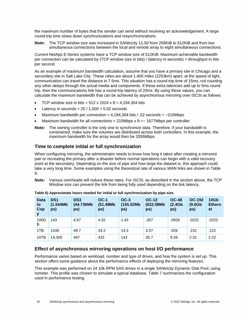
32 SANtricity synchronous and asynchronous mirroring © 2022 NetApp, Inc. All rights reserved. © 2016 NetApp, Inc. All rights reserved.
the maximum number of bytes that the sender can send without receiving an acknowledgement. A large
round-trip time slows down synchronizations and resynchronizations.
Note: The TCP window size was increased in SANtricity 11.50 from 256KiB to 512KiB and from two simultaneous connections between the local and remote array to eight simultaneous connections.
Current NetApp E-Series systems have a TCP window size of 512KiB. Maximum achievable bandwidth
per connection can be calculated by (TCP window size in bits) / (latency in seconds) = throughput in bits
per second.
As an example of maximum bandwidth calculation, assume that you have a primary site in Chicago and a
secondary site in Salt Lake City. These cities are about 1,400 miles (2253km) apart; at the speed of light,
communication can travel the distance in 7.5ms. This situation has a round-trip time of 15ms, not counting
any other delays through the actual media and components. If these extra latencies add up to 5ms round
trip, then the communications link has a round-trip latency of 20ms. By using these values, you can
calculate the maximum bandwidth that can be achieved by asynchronous mirroring over iSCSI as follows:
• TCP window size in bits = 512 x 1024 x 8 = 4,194,304 bits
• Latency in seconds = 20 / 1,000 = 0.02 seconds
• Maximum bandwidth per connection = 4,194,304 bits / .02 seconds = ~210Mbps
• Maximum bandwidth for all connections = 210Mbps x 8 =~ 1677Mbps per controller
Note: The owning controller is the only one to synchronize data. Therefore, if your bandwidth is constrained, make sure the volumes are distributed across both controllers. In this example, the maximum bandwidth for the array would then be 3355Mbps.
Time to complete initial or full synchronization
When configuring mirroring, the administrator needs to know how long it takes after creating a mirrored
pair or recreating the primary after a disaster before normal operations can begin with a valid recovery
point at the secondary. Depending on the size of pipe and how large the dataset is, this approach could
take a very long time. Some examples using the theoretical rate of various WAN links are shown in Table
6.
Note: Various overheads will reduce these rates. For iSCSI, as described in the section above, the TCP Window size can prevent the link from being fully used depending on the link latency.
Table 6) Approximate hours needed for initial or full synchronization by pipe size.
Data to Copy
DS1 (1.544Mbps)
DS3 (44.736Mbps)
OC-1 (51.48Mbps)
OC-3 (155.52Mbps)
OC-12 (622.08Mbps)
OC-48 (2.4Gbps)
OC-192 (9.6Gbps)
10Gb Ethernet
100GB
143 4.97 4.32 1.43 .357 .0926 .0231 .0222
1TB 1430 49.7 43.2 14.3 3.57 .926 .231 .222
10TB 14,300 497 432 143 35.7 9.26 2.31 2.22
Effect of asynchronous mirroring operations on host I/O performance
Performance varies based on workload, number and type of drives, and how the system is set up. This
section offers some guidance about the performance effects of deploying the mirroring features.
This example was performed on 24 10k RPM SAS drives in a single SANtricity Dynamic Disk Pool, using
Iometer. This profile was chosen to simulate a typical database. Table 7 summarizes the configuration
used in performance testing.
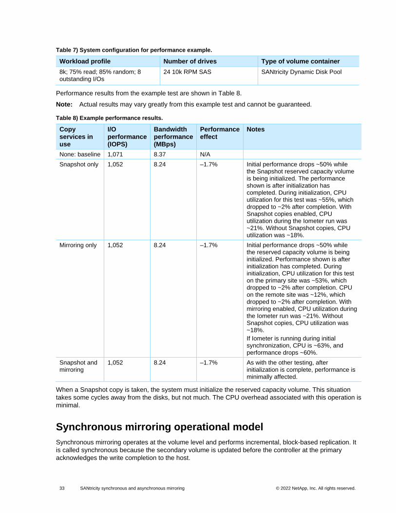
33 SANtricity synchronous and asynchronous mirroring © 2022 NetApp, Inc. All rights reserved. © 2016 NetApp, Inc. All rights reserved.
Table 7) System configuration for performance example.
Workload profile Number of drives Type of volume container
8k; 75% read; 85% random; 8 outstanding I/Os
24 10k RPM SAS SANtricity Dynamic Disk Pool
Performance results from the example test are shown in Table 8.
Note: Actual results may vary greatly from this example test and cannot be guaranteed.
Table 8) Example performance results.
Copy services in use
I/O performance (IOPS)
Bandwidth performance (MBps)
Performance effect
Notes
None: baseline 1,071 8.37 N/A
Snapshot only 1,052 8.24 –1.7% Initial performance drops ~50% while the Snapshot reserved capacity volume is being initialized. The performance shown is after initialization has completed. During initialization, CPU utilization for this test was ~55%, which dropped to ~2% after completion. With Snapshot copies enabled, CPU utilization during the Iometer run was ~21%. Without Snapshot copies, CPU utilization was ~18%.
Mirroring only 1,052 8.24 –1.7% Initial performance drops ~50% while the reserved capacity volume is being initialized. Performance shown is after initialization has completed. During initialization, CPU utilization for this test on the primary site was ~53%, which dropped to ~2% after completion. CPU on the remote site was ~12%, which dropped to ~2% after completion. With mirroring enabled, CPU utilization during the Iometer run was ~21%. Without Snapshot copies, CPU utilization was ~18%.
If Iometer is running during initial synchronization, CPU is ~63%, and performance drops ~60%.
Snapshot and mirroring
1,052 8.24 –1.7% As with the other testing, after initialization is complete, performance is minimally affected.
When a Snapshot copy is taken, the system must initialize the reserved capacity volume. This situation
takes some cycles away from the disks, but not much. The CPU overhead associated with this operation is
minimal.
Synchronous mirroring operational model
Synchronous mirroring operates at the volume level and performs incremental, block-based replication. It
is called synchronous because the secondary volume is updated before the controller at the primary
acknowledges the write completion to the host.
34 SANtricity synchronous and asynchronous mirroring © 2022 NetApp, Inc. All rights reserved. © 2016 NetApp, Inc. All rights reserved.
The first step is the creation of a one-time, baseline transfer of the entire dataset. This step is required
before incremental updates can be performed and is called initial synchronization.
After the initialization is complete, the two sides attempt to stay synchronized through normal operations.
Each update transfers the new and changed blocks from the primary volume to the secondary volume.
This operation proceeds as follows:
1. Changed data blocks are written to the primary volume.
2. The primary storage system sends the changed blocks to the secondary system.
3. The secondary system sends an acknowledgement after the changed blocks were written to cache (or disk in case of writethrough caching).
4. The primary storage system sends an acknowledgement to the host.
5. After the operation is complete, both systems are in synchronized state. From the application point of view, both systems have the same consistent dataset.
Because synchronous replication is continuous, the replication link between the two sites must provide
sufficient bandwidth capabilities.
Initial synchronization
When the mirror relationship is first established, the data from the primary volume is copied in its entirety
to the secondary volume. The owning controller on the primary side directs this process. During the copy
or mirror initialization, the primary volume is fully accessible for I/O operations by all host systems that
would normally have access to it. Until the initial synchronization completes, the secondary volume has
minimal value as a recovery point.
During the initial synchronization, all write requests on the primary volume are synchronized with the
secondary volume. This situation has to be considered for planning the mirror link between the two sites.
The link has to be able to support the initial copy load and the write requests at the same time.
Write process
This process is illustrated in Figure 9. When a primary controller (the owning controller of the primary
volume) receives a write request from a host (1), the controller first logs information about the write
request on the mirror reserved capacity (repository) volume (the information is placed in a queue), (2a). In
parallel, it writes the data to the primary volume (2b). The controller then initiates a remote write operation
to copy the affected data blocks to the secondary volume at the remote site (3). When the remote write
operation is complete (4) (5), the primary controller removes the log record from the mirror repository
volume (deletes it from the queue) (6). Finally, the controller sends an I/O completion indication back to
the host system (7).
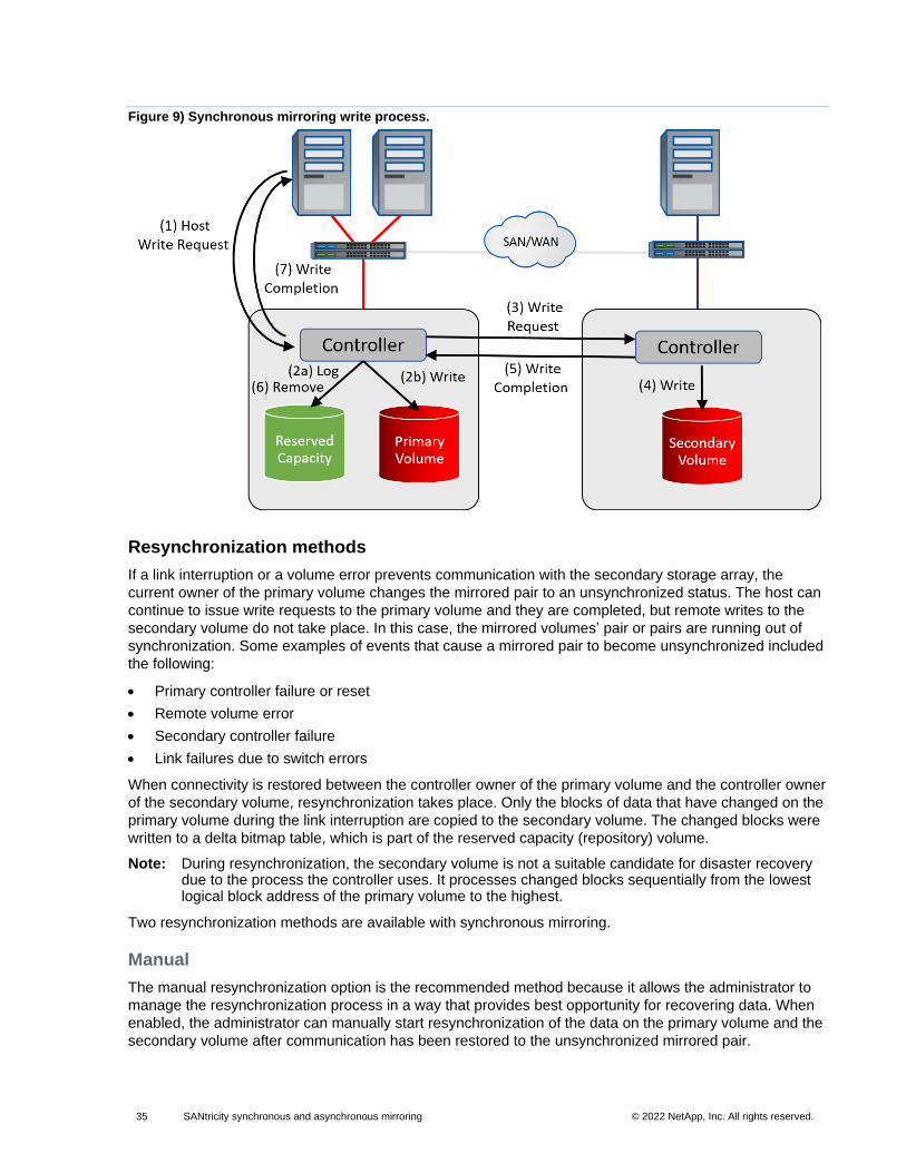
35 SANtricity synchronous and asynchronous mirroring © 2022 NetApp, Inc. All rights reserved. © 2016 NetApp, Inc. All rights reserved.
Figure 9) Synchronous mirroring write process.
Resynchronization methods
If a link interruption or a volume error prevents communication with the secondary storage array, the
current owner of the primary volume changes the mirrored pair to an unsynchronized status. The host can
continue to issue write requests to the primary volume and they are completed, but remote writes to the
secondary volume do not take place. In this case, the mirrored volumes’ pair or pairs are running out of
synchronization. Some examples of events that cause a mirrored pair to become unsynchronized included
the following:
• Primary controller failure or reset
• Remote volume error
• Secondary controller failure
• Link failures due to switch errors
When connectivity is restored between the controller owner of the primary volume and the controller owner
of the secondary volume, resynchronization takes place. Only the blocks of data that have changed on the
primary volume during the link interruption are copied to the secondary volume. The changed blocks were
written to a delta bitmap table, which is part of the reserved capacity (repository) volume.
Note: During resynchronization, the secondary volume is not a suitable candidate for disaster recovery due to the process the controller uses. It processes changed blocks sequentially from the lowest logical block address of the primary volume to the highest.
Two resynchronization methods are available with synchronous mirroring.
Manual
The manual resynchronization option is the recommended method because it allows the administrator to
manage the resynchronization process in a way that provides best opportunity for recovering data. When
enabled, the administrator can manually start resynchronization of the data on the primary volume and the
secondary volume after communication has been restored to the unsynchronized mirrored pair.
36 SANtricity synchronous and asynchronous mirroring © 2022 NetApp, Inc. All rights reserved. © 2016 NetApp, Inc. All rights reserved.
When this option is selected and a communication failure occurs between the primary volume and the
secondary volume, the remote mirrored changes to unsynchronized status. Any write requests to the
primary volume are logged, and a needs attention status appears for the storage array.
After the controller owner of the primary volume detects that communication has been restored, the
remote mirror stays in unsynchronized status until the administrator issues a resume command. The
resume starts the resynchronization process.
Automatic
When enabled, automatic resynchronization starts immediately after the controller detects that the
communication has been restored for an unsynchronized mirrored pair.
When the automatic resynchronization option is selected and a communication failure occurs between the
primary storage array and the secondary storage array, the controller owner of the primary volume starts
resynchronizing the primary volume and the secondary volume. This action occurs immediately after the
controller owner detects that communication has been restored.
Note: Any communication disruptions between the primary storage array and the secondary storage array while resynchronization is under way could result in a mix of new data and old data on the secondary volume. This situation renders the data unusable in a disaster recovery situation. For this reason, NetApp recommends using manual resynchronization and creating a Snapshot copy of the secondary volume before beginning the resynchronization. Then, if a failure occurs during the resynchronization, there is a crash-consistent image at the secondary at the point where synchronization was lost. Asynchronous mirroring is not subject to this resynchronization issue.
Suspend and resume
A storage administrator can stop mirror synchronization with a remote array by issuing a configuration
request to suspend the mirror. This mechanism allows end users to implement backup and other
strategies that are based on the split-mirror model used throughout the industry. When a mirror is in a
suspended state, no attempt is made to contact the secondary volume for any reason. While suspended,
writes to the mirror primary volume are persistently logged so that upon resumption, only the regions of the
primary known to have changed are written to the secondary. The state of the mirror remains suspended
until the administrator issues a configuration request to resume synchronization activity.
Suspend and resume commands can only be issued on the primary array.
Role changes on a synchronous mirror pair
The administrator can perform a role reversal on a synchronous mirrored volume pair. This reversal can
be done either by promoting the selected volume to a primary role or by demoting the selected volume to a
secondary role.
• The role reversal change affects only the selected synchronous mirrored pair.
Note: Make sure that the mirror is synchronized before using the role reversal command to have a consistent dataset.
• When demoting a primary synchronous mirror volume to a secondary role, if the current secondary volume can be contacted, it is automatically promoted to a primary role in the mirror relationship. Likewise, when promoting a secondary volume to a primary role, if the current primary volume can be contacted, it is automatically demoted to a secondary role in the mirror relationship.
Note: If the environment has a suspended synchronous mirror pair operation, it resumes during the change role operation.
Keep these guidelines in mind:
• Any hosts that are accessing the primary volume in a synchronous mirror pair through a mapping have read/write access to the synchronous mirrored volumes in the mirror relationship. When the primary
37 SANtricity synchronous and asynchronous mirroring © 2022 NetApp, Inc. All rights reserved. © 2016 NetApp, Inc. All rights reserved.
synchronous mirror volume becomes a secondary, hosts that have been mapped to the mirrored volumes no longer have write access to it.
• When the secondary synchronous mirror volume becomes a primary, any hosts that are accessing that volume are now able to write to it.
• If a communication problem between the local and remote sites prevents the promotion of the secondary synchronous mirror volume, an error message appears. However, the administrator can still force the secondary volume to a primary role. This forced promotion leads to a dual primary synchronous mirroring condition after communication is restored. Use the Recovery Guru to resolve this condition.
• Likewise, the administrator can force the primary volume to a secondary role if communication is not possible between the two storage systems. When communication is restored, the mirror pair is in a dual secondary condition, which can also be resolved by using the Recovery Guru.
Considerations for setting up synchronous mirroring
For a successful deployment of a synchronous mirroring solution, the right networking design between the
two sites is critical.
Latency
Latency is the time needed for the mirrored I/O and the acknowledgement frame to get over the network
link and back. The longer the distance between the two sites, the longer the round-trip time. The distance
is the limiting factor for the number of I/Os that a mirror link can handle per second. Therefore, latency
determines the I/O rate that can be achieved in a mirrored solution. In addition to distance, the latency is
influenced by the FC network: for example, by the number of hops and by the equipment that is used for
the link between the two sites. These latencies are the result of delays that are introduced by the
equipment (switches, protocol converters for IP, firewalls) and the transport medium itself. The best
method to determine the latency is to use the link test tool, which is included in the management GUIs.
Distance and number of IOPS
In a synchronous mirroring solution, all writes to the primary site are mirrored to the secondary site before
the acknowledgement is sent to the host. The link has to be sized so that required IOPS performance on
the primary side can be achieved.
To calculate the right link between the two sites, we need to know what influences the effective IOPS rate
comparing to the nominal link speed. As described earlier, latency is the most important factor in designing
the solution.
The latency in the medium is determined by the speed of light in the fiber cable. The effective speed of
light in glass is 200,000km/sec. This speed becomes more relevant as the distance between two sites
increases. Keep in mind that in a synchronous mirroring scenario, the signal has to travel the distance
between the two sites twice (to the remote site and for the acknowledgement back again) to complete an
I/O successfully and to acknowledge the I/O to the host. Round-trip time determines the maximum
possible I/O rate for the solution.
For a given distance, the calculation for the theoretical maximum number of IOPS is:
1sec / (2x distance / 200,000km/sec) = max number of IOPS
At the maximum distance of 10km for synchronous mirroring, the theoretical maximum IOPS is 10,000.
Keep in mind that components in the path, such as routers, add to the latency and reduce maximum IOPS.
The quality of the link can also add latency. Make sure that the network delivers the required service level
(QoS).
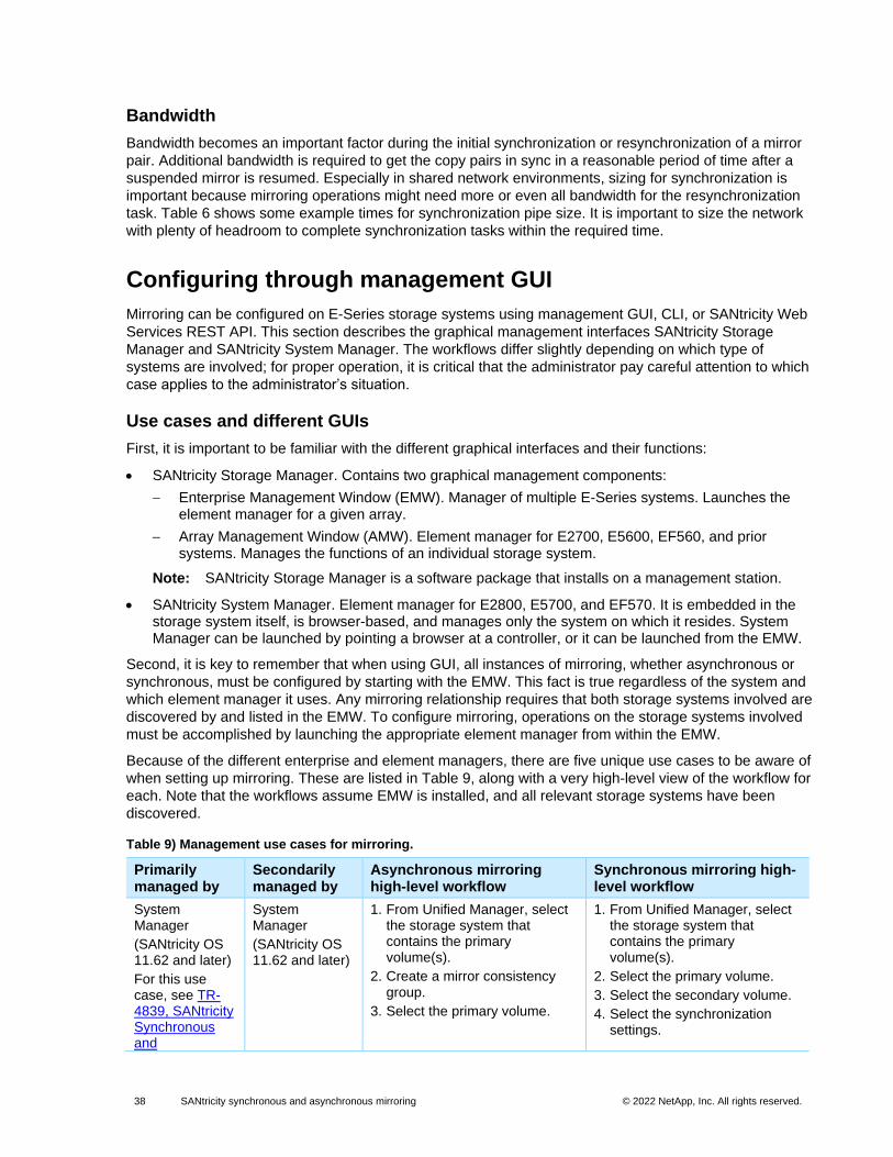
38 SANtricity synchronous and asynchronous mirroring © 2022 NetApp, Inc. All rights reserved. © 2016 NetApp, Inc. All rights reserved.
Bandwidth
Bandwidth becomes an important factor during the initial synchronization or resynchronization of a mirror
pair. Additional bandwidth is required to get the copy pairs in sync in a reasonable period of time after a
suspended mirror is resumed. Especially in shared network environments, sizing for synchronization is
important because mirroring operations might need more or even all bandwidth for the resynchronization
task. Table 6 shows some example times for synchronization pipe size. It is important to size the network
with plenty of headroom to complete synchronization tasks within the required time.
Configuring through management GUI
Mirroring can be configured on E-Series storage systems using management GUI, CLI, or SANtricity Web
Services REST API. This section describes the graphical management interfaces SANtricity Storage
Manager and SANtricity System Manager. The workflows differ slightly depending on which type of
systems are involved; for proper operation, it is critical that the administrator pay careful attention to which
case applies to the administrator’s situation.
Use cases and different GUIs
First, it is important to be familiar with the different graphical interfaces and their functions:
• SANtricity Storage Manager. Contains two graphical management components:
− Enterprise Management Window (EMW). Manager of multiple E-Series systems. Launches the element manager for a given array.
− Array Management Window (AMW). Element manager for E2700, E5600, EF560, and prior systems. Manages the functions of an individual storage system.
Note: SANtricity Storage Manager is a software package that installs on a management station.
• SANtricity System Manager. Element manager for E2800, E5700, and EF570. It is embedded in the storage system itself, is browser-based, and manages only the system on which it resides. System Manager can be launched by pointing a browser at a controller, or it can be launched from the EMW.
Second, it is key to remember that when using GUI, all instances of mirroring, whether asynchronous or
synchronous, must be configured by starting with the EMW. This fact is true regardless of the system and
which element manager it uses. Any mirroring relationship requires that both storage systems involved are
discovered by and listed in the EMW. To configure mirroring, operations on the storage systems involved
must be accomplished by launching the appropriate element manager from within the EMW.
Because of the different enterprise and element managers, there are five unique use cases to be aware of
when setting up mirroring. These are listed in Table 9, along with a very high-level view of the workflow for
each. Note that the workflows assume EMW is installed, and all relevant storage systems have been
discovered.
Table 9) Management use cases for mirroring.
Primarily managed by
Secondarily managed by
Asynchronous mirroring high-level workflow
Synchronous mirroring high-level workflow
System Manager
(SANtricity OS 11.62 and later)
For this use case, see TR-4839, SANtricity Synchronous and
System Manager
(SANtricity OS 11.62 and later)
1. From Unified Manager, select the storage system that contains the primary volume(s).
2. Create a mirror consistency group.
3. Select the primary volume.
1. From Unified Manager, select the storage system that contains the primary volume(s).
2. Select the primary volume.
3. Select the secondary volume.
4. Select the synchronization settings.
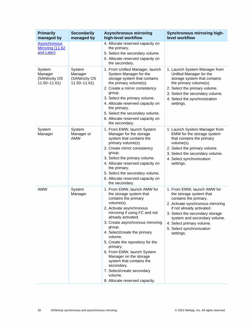
39 SANtricity synchronous and asynchronous mirroring © 2022 NetApp, Inc. All rights reserved. © 2016 NetApp, Inc. All rights reserved.
Primarily managed by
Secondarily managed by
Asynchronous mirroring high-level workflow
Synchronous mirroring high-level workflow
Asynchronous Mirroring (11.62 and Later)
4. Allocate reserved capacity on the primary.
5. Select the secondary volume.
6. Allocate reserved capacity on the secondary.
System Manager (SANtricity OS 11.50–11.61)
System Manager (SANtricity OS 11.50–11.61)
1. From Unified Manager, launch System Manager for the storage system that contains the primary volume(s).
2. Create a mirror consistency group.
3. Select the primary volume.
4. Allocate reserved capacity on the primary.
5. Select the secondary volume.
6. Allocate reserved capacity on the secondary.
1. Launch System Manager from Unified Manager for the storage system that contains the primary volume(s).
2. Select the primary volume.
3. Select the secondary volume.
4. Select the synchronization settings.
System Manager
System Manager or AMW
1. From EMW, launch System Manager for the storage system that contains the primary volume(s).
2. Create mirror consistency group.
3. Select the primary volume.
4. Allocate reserved capacity on the primary.
5. Select the secondary volume.
6. Allocate reserved capacity on the secondary.
1. Launch System Manager from EMW for the storage system that contains the primary volume(s).
2. Select the primary volume.
3. Select the secondary volume.
4. Select synchronization settings.
AMW System Manager
1. From EMW, launch AMW for the storage system that contains the primary volume(s).
2. Activate asynchronous mirroring if using FC and not already activated.
3. Create asynchronous mirroring group.
4. Select/create the primary volume.
5. Create the repository for the primary.
6. From EMW, launch System Manager on the storage system that contains the secondary.
7. Select/create secondary volume.
8. Allocate reserved capacity.
1. From EMW, launch AMW for the storage system that contains the primary.
2. Activate synchronous mirroring if not already activated.
3. Select the secondary storage system and secondary volume.
4. Select primary volume.
5. Select synchronization settings.
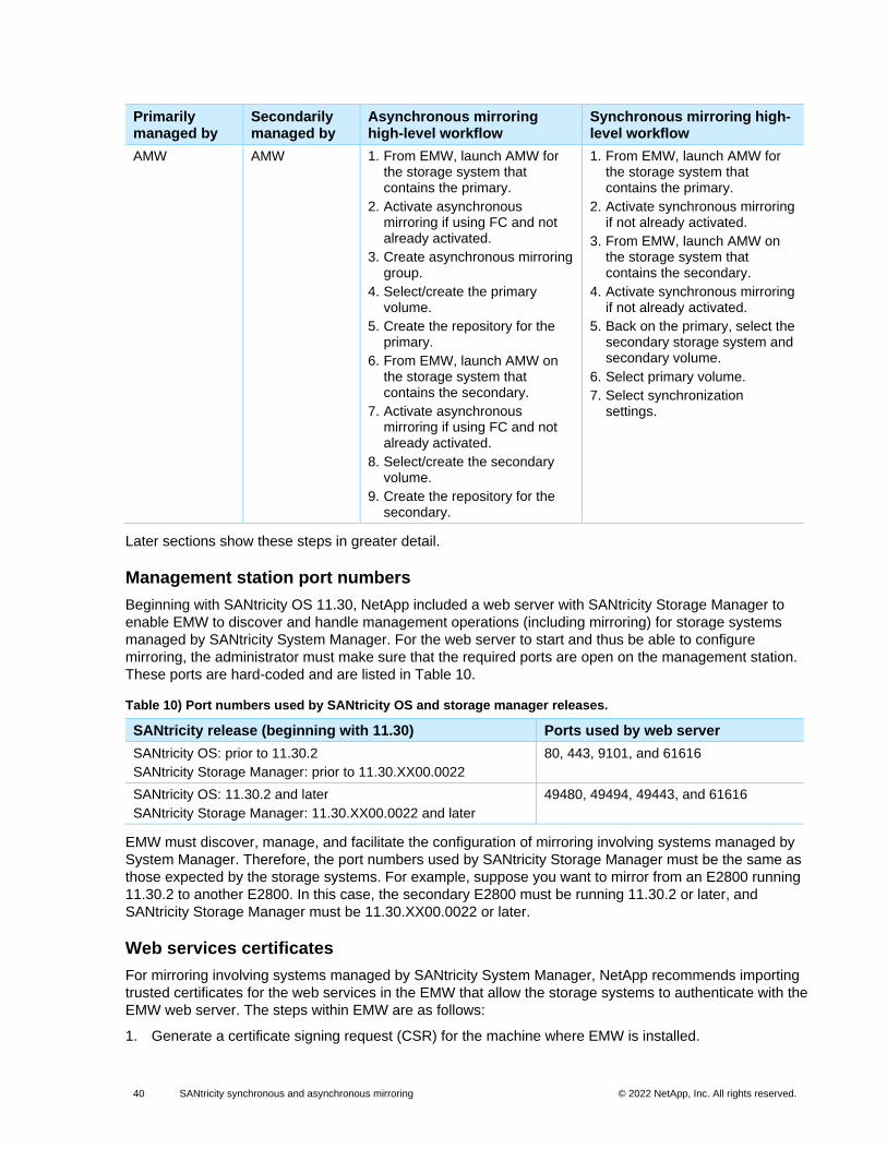
40 SANtricity synchronous and asynchronous mirroring © 2022 NetApp, Inc. All rights reserved. © 2016 NetApp, Inc. All rights reserved.
Primarily managed by
Secondarily managed by
Asynchronous mirroring high-level workflow
Synchronous mirroring high-level workflow
AMW AMW 1. From EMW, launch AMW for the storage system that contains the primary.
2. Activate asynchronous mirroring if using FC and not already activated.
3. Create asynchronous mirroring group.
4. Select/create the primary volume.
5. Create the repository for the primary.
6. From EMW, launch AMW on the storage system that contains the secondary.
7. Activate asynchronous mirroring if using FC and not already activated.
8. Select/create the secondary volume.
9. Create the repository for the secondary.
1. From EMW, launch AMW for the storage system that contains the primary.
2. Activate synchronous mirroring if not already activated.
3. From EMW, launch AMW on the storage system that contains the secondary.
4. Activate synchronous mirroring if not already activated.
5. Back on the primary, select the secondary storage system and secondary volume.
6. Select primary volume.
7. Select synchronization settings.
Later sections show these steps in greater detail.
Management station port numbers
Beginning with SANtricity OS 11.30, NetApp included a web server with SANtricity Storage Manager to
enable EMW to discover and handle management operations (including mirroring) for storage systems
managed by SANtricity System Manager. For the web server to start and thus be able to configure
mirroring, the administrator must make sure that the required ports are open on the management station.
These ports are hard-coded and are listed in Table 10.
Table 10) Port numbers used by SANtricity OS and storage manager releases.
SANtricity release (beginning with 11.30) Ports used by web server
SANtricity OS: prior to 11.30.2
SANtricity Storage Manager: prior to 11.30.XX00.0022
80, 443, 9101, and 61616
SANtricity OS: 11.30.2 and later
SANtricity Storage Manager: 11.30.XX00.0022 and later
49480, 49494, 49443, and 61616
EMW must discover, manage, and facilitate the configuration of mirroring involving systems managed by
System Manager. Therefore, the port numbers used by SANtricity Storage Manager must be the same as
those expected by the storage systems. For example, suppose you want to mirror from an E2800 running
11.30.2 to another E2800. In this case, the secondary E2800 must be running 11.30.2 or later, and
SANtricity Storage Manager must be 11.30.XX00.0022 or later.
Web services certificates
For mirroring involving systems managed by SANtricity System Manager, NetApp recommends importing
trusted certificates for the web services in the EMW that allow the storage systems to authenticate with the
EMW web server. The steps within EMW are as follows:
1. Generate a certificate signing request (CSR) for the machine where EMW is installed.
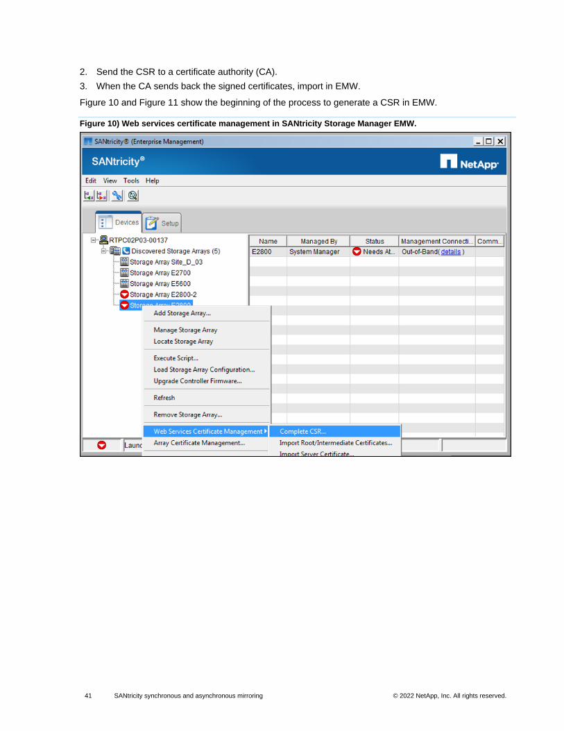
41 SANtricity synchronous and asynchronous mirroring © 2022 NetApp, Inc. All rights reserved. © 2016 NetApp, Inc. All rights reserved.
2. Send the CSR to a certificate authority (CA).
3. When the CA sends back the signed certificates, import in EMW.
Figure 10 and Figure 11 show the beginning of the process to generate a CSR in EMW.
Figure 10) Web services certificate management in SANtricity Storage Manager EMW.
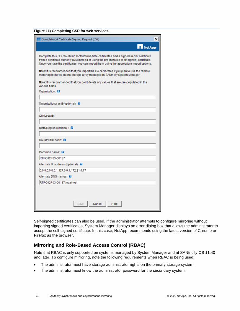
42 SANtricity synchronous and asynchronous mirroring © 2022 NetApp, Inc. All rights reserved. © 2016 NetApp, Inc. All rights reserved.
Figure 11) Completing CSR for web services.
Self-signed certificates can also be used. If the administrator attempts to configure mirroring without
importing signed certificates, System Manager displays an error dialog box that allows the administrator to
accept the self-signed certificate. In this case, NetApp recommends using the latest version of Chrome or
Firefox as the browser.
Mirroring and Role-Based Access Control (RBAC)
Note that RBAC is only supported on systems managed by System Manager and at SANtricity OS 11.40
and later. To configure mirroring, note the following requirements when RBAC is being used:
• The administrator must have storage administrator rights on the primary storage system.
• The administrator must know the administrator password for the secondary system.
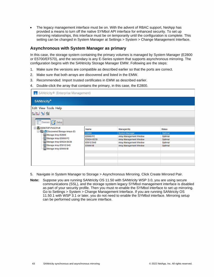
43 SANtricity synchronous and asynchronous mirroring © 2022 NetApp, Inc. All rights reserved. © 2016 NetApp, Inc. All rights reserved.
• The legacy management interface must be on. With the advent of RBAC support, NetApp has provided a means to turn off the native SYMbol API interface for enhanced security. To set up mirroring relationships, this interface must be on temporarily until the configuration is complete. This setting can be changed in System Manager at Settings > System > Change Management Interface.
Asynchronous with System Manager as primary
In this case, the storage system containing the primary volumes is managed by System Manager (E2800
or E5700/EF570), and the secondary is any E-Series system that supports asynchronous mirroring. The
configuration begins with the SANtricity Storage Manager EMW. Following are the steps:
1. Make sure the versions are compatible as described earlier so that the ports are correct.
2. Make sure that both arrays are discovered and listed in the EMW.
3. Recommended: Import trusted certificates in EMW as described earlier.
4. Double-click the array that contains the primary, in this case, the E2800.
5. Navigate in System Manager to Storage > Asynchronous Mirroring. Click Create Mirrored Pair.
Note: Suppose you are running SANtricity OS 11.50 with SANtricity WSP 3.0, you are using secure communications (SSL), and the storage system legacy SYMbol management interface is disabled as part of your security profile. Then you must re-enable the SYMbol interface to set up mirroring. Go to Settings > System > Change Management Interface. If you are running SANtricity OS 11.50.1 with WSP 3.1 or later, you do not need to enable the SYMbol interface. Mirroring setup can be performed using the secure interface.
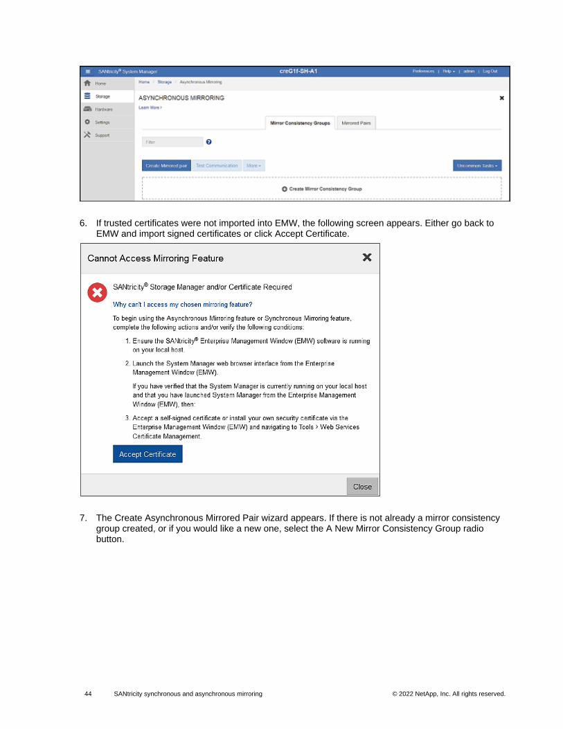
44 SANtricity synchronous and asynchronous mirroring © 2022 NetApp, Inc. All rights reserved. © 2016 NetApp, Inc. All rights reserved.
6. If trusted certificates were not imported into EMW, the following screen appears. Either go back to EMW and import signed certificates or click Accept Certificate.
7. The Create Asynchronous Mirrored Pair wizard appears. If there is not already a mirror consistency group created, or if you would like a new one, select the A New Mirror Consistency Group radio button.
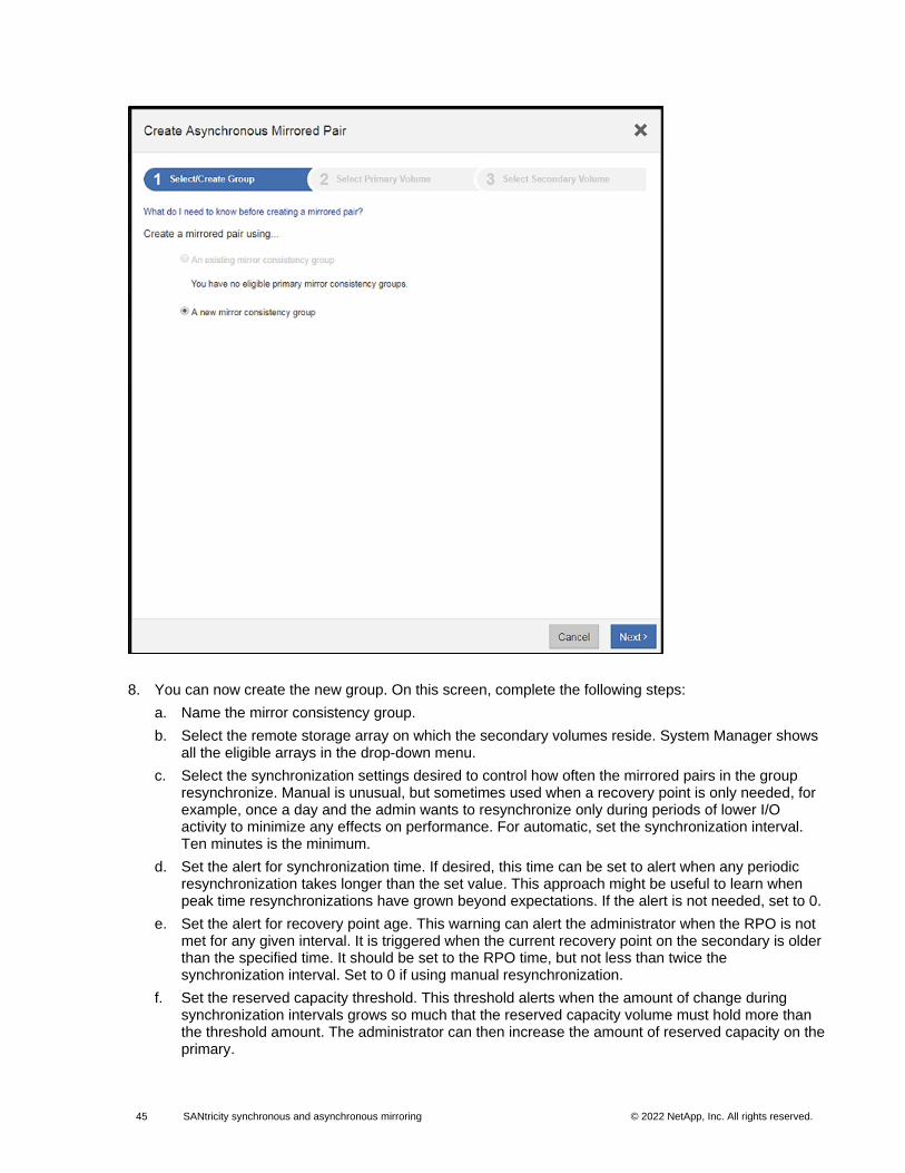
45 SANtricity synchronous and asynchronous mirroring © 2022 NetApp, Inc. All rights reserved. © 2016 NetApp, Inc. All rights reserved.
8. You can now create the new group. On this screen, complete the following steps:
a. Name the mirror consistency group.
b. Select the remote storage array on which the secondary volumes reside. System Manager shows all the eligible arrays in the drop-down menu.
c. Select the synchronization settings desired to control how often the mirrored pairs in the group resynchronize. Manual is unusual, but sometimes used when a recovery point is only needed, for example, once a day and the admin wants to resynchronize only during periods of lower I/O activity to minimize any effects on performance. For automatic, set the synchronization interval. Ten minutes is the minimum.
d. Set the alert for synchronization time. If desired, this time can be set to alert when any periodic resynchronization takes longer than the set value. This approach might be useful to learn when peak time resynchronizations have grown beyond expectations. If the alert is not needed, set to 0.
e. Set the alert for recovery point age. This warning can alert the administrator when the RPO is not met for any given interval. It is triggered when the current recovery point on the secondary is older than the specified time. It should be set to the RPO time, but not less than twice the synchronization interval. Set to 0 if using manual resynchronization.
f. Set the reserved capacity threshold. This threshold alerts when the amount of change during synchronization intervals grows so much that the reserved capacity volume must hold more than the threshold amount. The administrator can then increase the amount of reserved capacity on the primary.
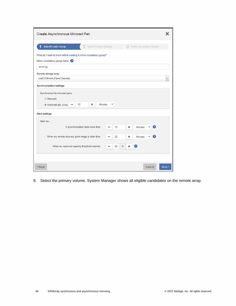
46 SANtricity synchronous and asynchronous mirroring © 2022 NetApp, Inc. All rights reserved. © 2016 NetApp, Inc. All rights reserved.
9. Select the primary volume. System Manager shows all eligible candidates on the remote array.
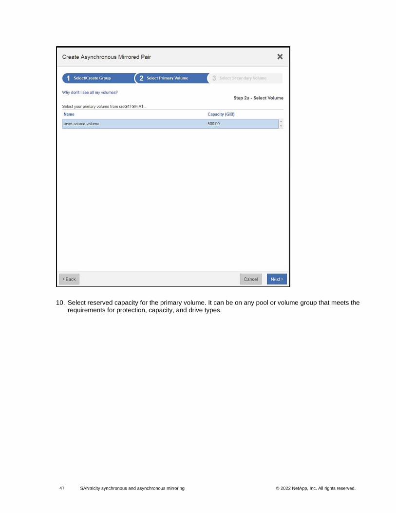
47 SANtricity synchronous and asynchronous mirroring © 2022 NetApp, Inc. All rights reserved. © 2016 NetApp, Inc. All rights reserved.
10. Select reserved capacity for the primary volume. It can be on any pool or volume group that meets the requirements for protection, capacity, and drive types.
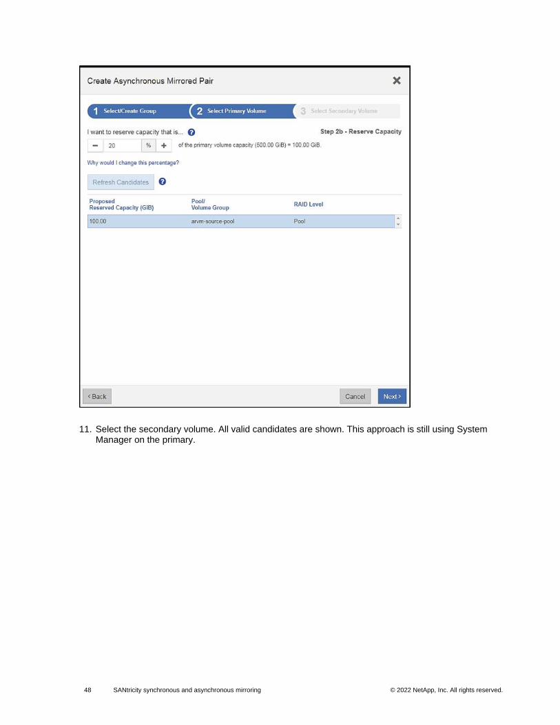
48 SANtricity synchronous and asynchronous mirroring © 2022 NetApp, Inc. All rights reserved. © 2016 NetApp, Inc. All rights reserved.
11. Select the secondary volume. All valid candidates are shown. This approach is still using System Manager on the primary.
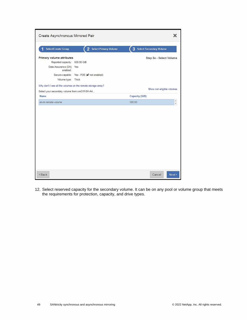
49 SANtricity synchronous and asynchronous mirroring © 2022 NetApp, Inc. All rights reserved. © 2016 NetApp, Inc. All rights reserved.
12. Select reserved capacity for the secondary volume. It can be on any pool or volume group that meets the requirements for protection, capacity, and drive types.
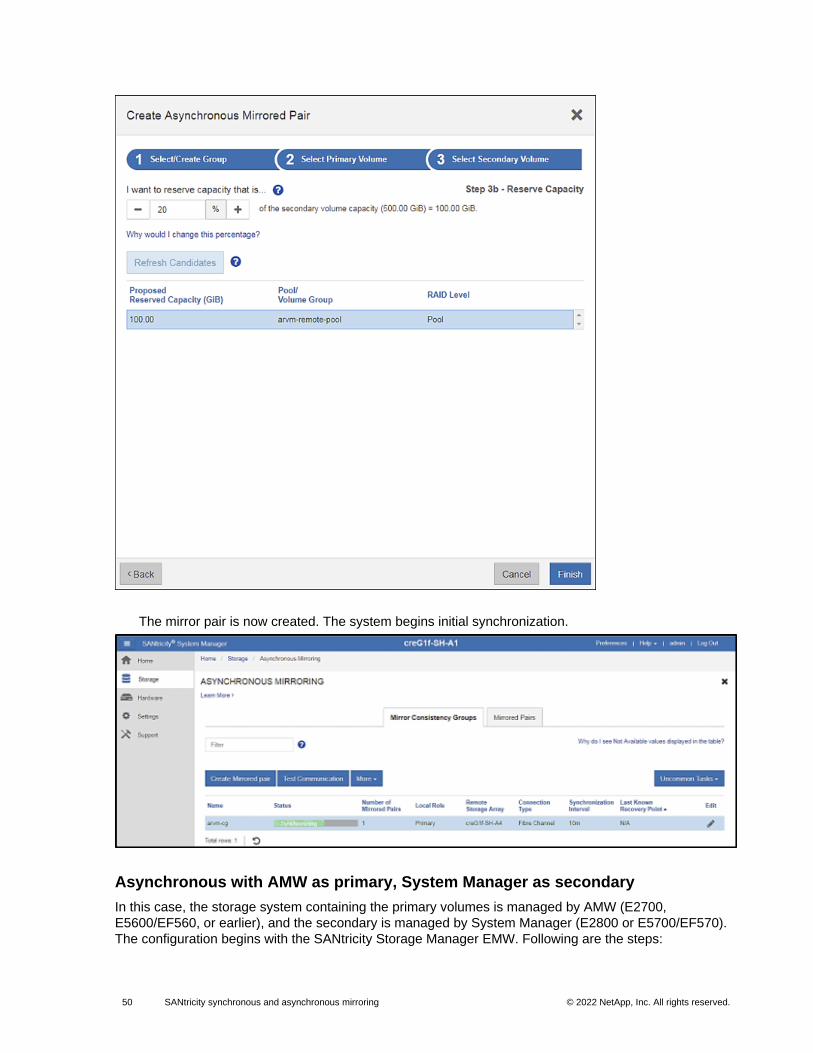
50 SANtricity synchronous and asynchronous mirroring © 2022 NetApp, Inc. All rights reserved. © 2016 NetApp, Inc. All rights reserved.
The mirror pair is now created. The system begins initial synchronization.
Asynchronous with AMW as primary, System Manager as secondary
In this case, the storage system containing the primary volumes is managed by AMW (E2700,
E5600/EF560, or earlier), and the secondary is managed by System Manager (E2800 or E5700/EF570).
The configuration begins with the SANtricity Storage Manager EMW. Following are the steps:
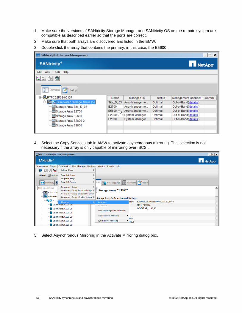
51 SANtricity synchronous and asynchronous mirroring © 2022 NetApp, Inc. All rights reserved. © 2016 NetApp, Inc. All rights reserved.
1. Make sure the versions of SANtricity Storage Manager and SANtricity OS on the remote system are compatible as described earlier so that the ports are correct.
2. Make sure that both arrays are discovered and listed in the EMW.
3. Double-click the array that contains the primary, in this case, the E5600.
4. Select the Copy Services tab in AMW to activate asynchronous mirroring. This selection is not necessary if the array is only capable of mirroring over iSCSI.
5. Select Asynchronous Mirroring in the Activate Mirroring dialog box.
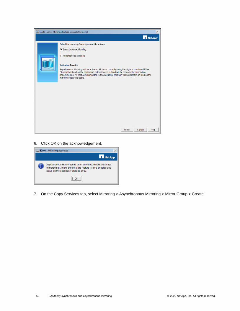
52 SANtricity synchronous and asynchronous mirroring © 2022 NetApp, Inc. All rights reserved. © 2016 NetApp, Inc. All rights reserved.
6. Click OK on the acknowledgement.
7. On the Copy Services tab, select Mirroring > Asynchronous Mirroring > Mirror Group > Create.
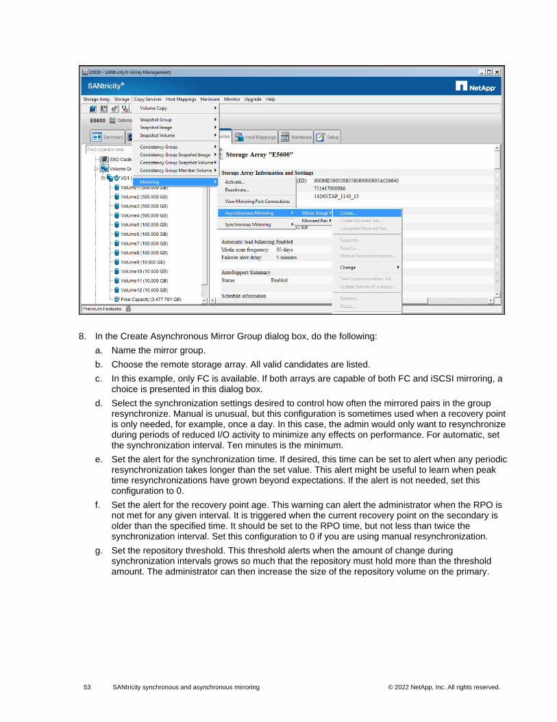
53 SANtricity synchronous and asynchronous mirroring © 2022 NetApp, Inc. All rights reserved. © 2016 NetApp, Inc. All rights reserved.
8. In the Create Asynchronous Mirror Group dialog box, do the following:
a. Name the mirror group.
b. Choose the remote storage array. All valid candidates are listed.
c. In this example, only FC is available. If both arrays are capable of both FC and iSCSI mirroring, a choice is presented in this dialog box.
d. Select the synchronization settings desired to control how often the mirrored pairs in the group resynchronize. Manual is unusual, but this configuration is sometimes used when a recovery point is only needed, for example, once a day. In this case, the admin would only want to resynchronize during periods of reduced I/O activity to minimize any effects on performance. For automatic, set the synchronization interval. Ten minutes is the minimum.
e. Set the alert for the synchronization time. If desired, this time can be set to alert when any periodic resynchronization takes longer than the set value. This alert might be useful to learn when peak time resynchronizations have grown beyond expectations. If the alert is not needed, set this configuration to 0.
f. Set the alert for the recovery point age. This warning can alert the administrator when the RPO is not met for any given interval. It is triggered when the current recovery point on the secondary is older than the specified time. It should be set to the RPO time, but not less than twice the synchronization interval. Set this configuration to 0 if you are using manual resynchronization.
g. Set the repository threshold. This threshold alerts when the amount of change during synchronization intervals grows so much that the repository must hold more than the threshold amount. The administrator can then increase the size of the repository volume on the primary.
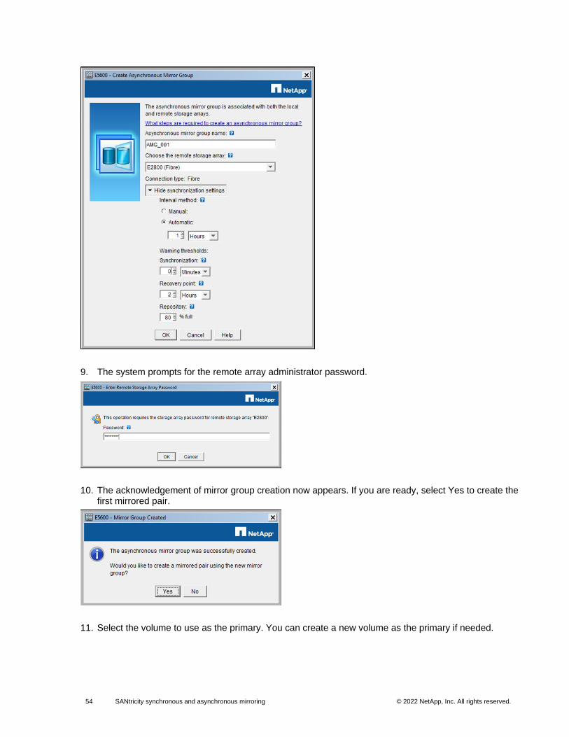
54 SANtricity synchronous and asynchronous mirroring © 2022 NetApp, Inc. All rights reserved. © 2016 NetApp, Inc. All rights reserved.
9. The system prompts for the remote array administrator password.
10. The acknowledgement of mirror group creation now appears. If you are ready, select Yes to create the first mirrored pair.
11. Select the volume to use as the primary. You can create a new volume as the primary if needed.
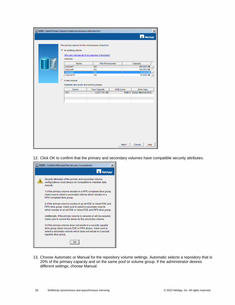
55 SANtricity synchronous and asynchronous mirroring © 2022 NetApp, Inc. All rights reserved. © 2016 NetApp, Inc. All rights reserved.
12. Click OK to confirm that the primary and secondary volumes have compatible security attributes.
13. Choose Automatic or Manual for the repository volume settings. Automatic selects a repository that is 20% of the primary capacity and on the same pool or volume group. If the administrator desires different settings, choose Manual.
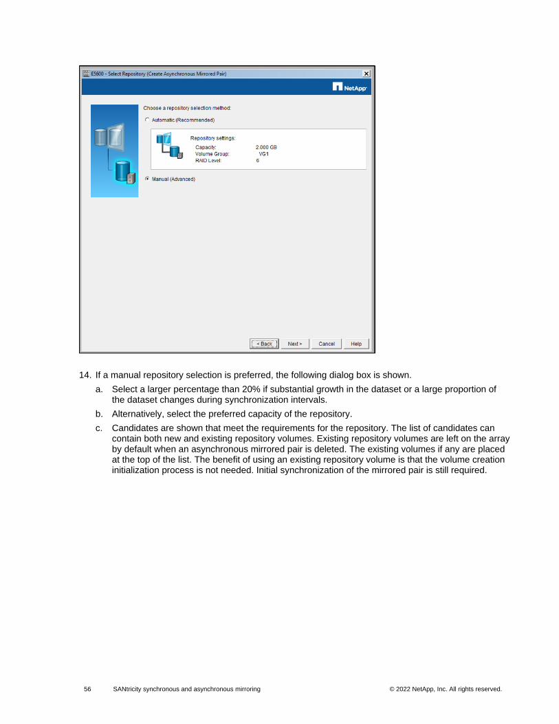
56 SANtricity synchronous and asynchronous mirroring © 2022 NetApp, Inc. All rights reserved. © 2016 NetApp, Inc. All rights reserved.
14. If a manual repository selection is preferred, the following dialog box is shown.
a. Select a larger percentage than 20% if substantial growth in the dataset or a large proportion of the dataset changes during synchronization intervals.
b. Alternatively, select the preferred capacity of the repository.
c. Candidates are shown that meet the requirements for the repository. The list of candidates can contain both new and existing repository volumes. Existing repository volumes are left on the array by default when an asynchronous mirrored pair is deleted. The existing volumes if any are placed at the top of the list. The benefit of using an existing repository volume is that the volume creation initialization process is not needed. Initial synchronization of the mirrored pair is still required.
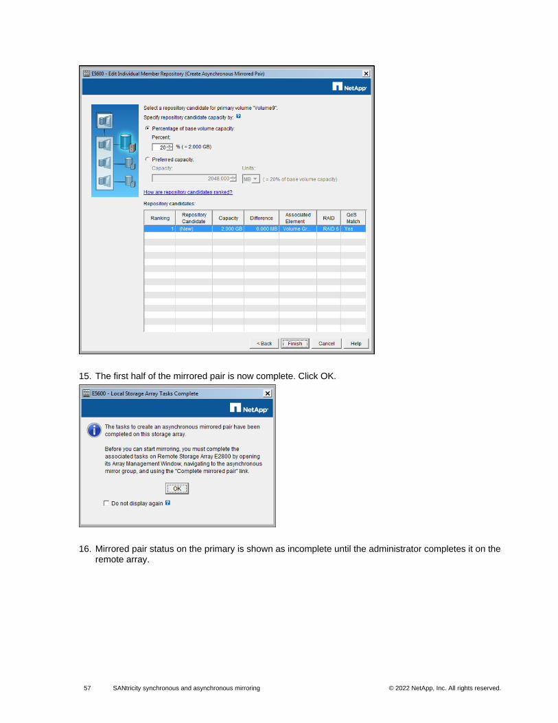
57 SANtricity synchronous and asynchronous mirroring © 2022 NetApp, Inc. All rights reserved. © 2016 NetApp, Inc. All rights reserved.
15. The first half of the mirrored pair is now complete. Click OK.
16. Mirrored pair status on the primary is shown as incomplete until the administrator completes it on the remote array.
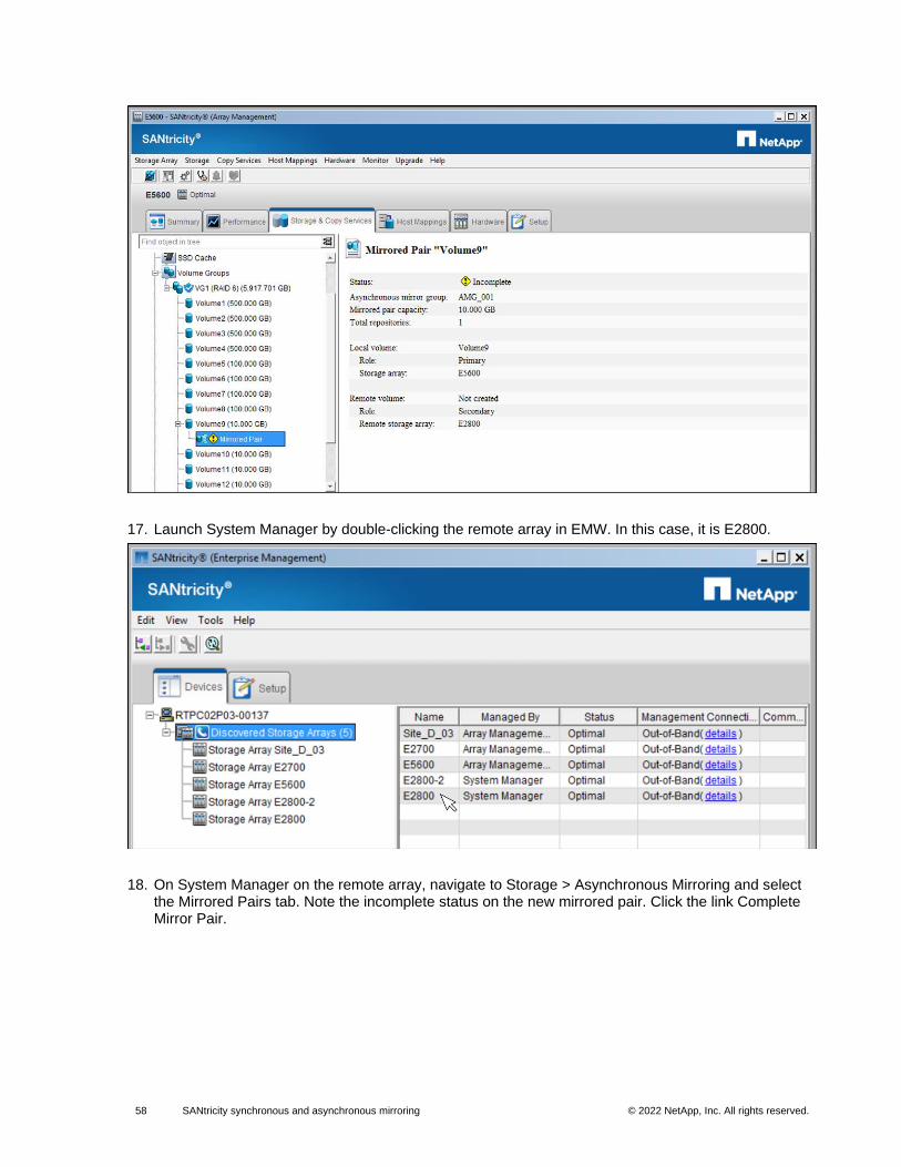
58 SANtricity synchronous and asynchronous mirroring © 2022 NetApp, Inc. All rights reserved. © 2016 NetApp, Inc. All rights reserved.
17. Launch System Manager by double-clicking the remote array in EMW. In this case, it is E2800.
18. On System Manager on the remote array, navigate to Storage > Asynchronous Mirroring and select the Mirrored Pairs tab. Note the incomplete status on the new mirrored pair. Click the link Complete Mirror Pair.
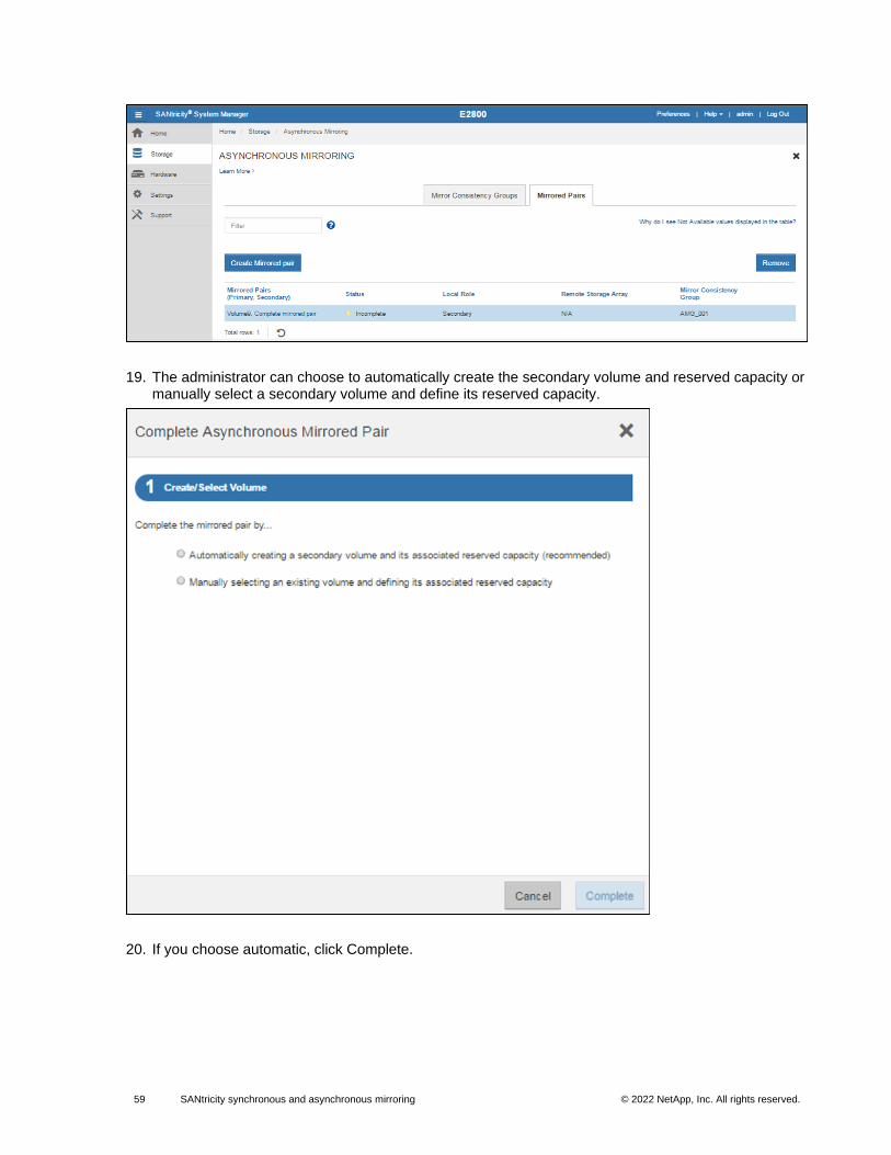
59 SANtricity synchronous and asynchronous mirroring © 2022 NetApp, Inc. All rights reserved. © 2016 NetApp, Inc. All rights reserved.
19. The administrator can choose to automatically create the secondary volume and reserved capacity or manually select a secondary volume and define its reserved capacity.
20. If you choose automatic, click Complete.
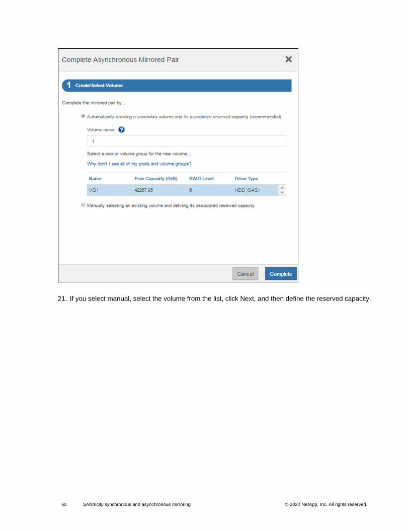
60 SANtricity synchronous and asynchronous mirroring © 2022 NetApp, Inc. All rights reserved. © 2016 NetApp, Inc. All rights reserved.
21. If you select manual, select the volume from the list, click Next, and then define the reserved capacity.
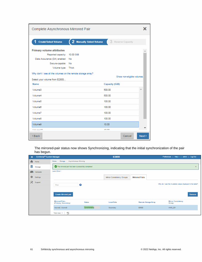
61 SANtricity synchronous and asynchronous mirroring © 2022 NetApp, Inc. All rights reserved. © 2016 NetApp, Inc. All rights reserved.
The mirrored-pair status now shows Synchronizing, indicating that the initial synchronization of the pair has begun.
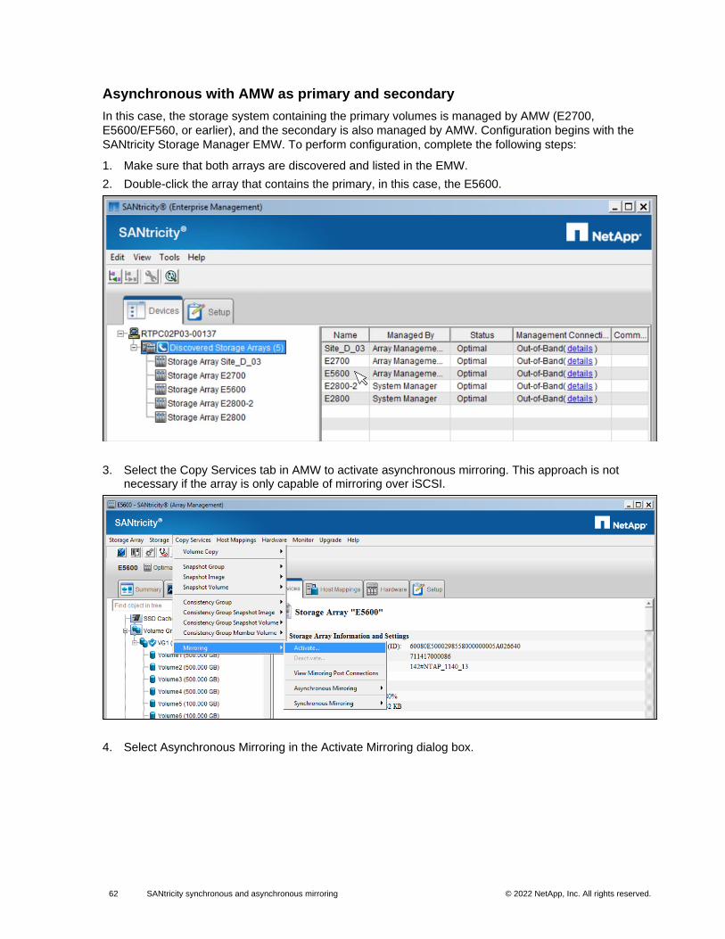
62 SANtricity synchronous and asynchronous mirroring © 2022 NetApp, Inc. All rights reserved. © 2016 NetApp, Inc. All rights reserved.
Asynchronous with AMW as primary and secondary
In this case, the storage system containing the primary volumes is managed by AMW (E2700,
E5600/EF560, or earlier), and the secondary is also managed by AMW. Configuration begins with the
SANtricity Storage Manager EMW. To perform configuration, complete the following steps:
1. Make sure that both arrays are discovered and listed in the EMW.
2. Double-click the array that contains the primary, in this case, the E5600.
3. Select the Copy Services tab in AMW to activate asynchronous mirroring. This approach is not necessary if the array is only capable of mirroring over iSCSI.
4. Select Asynchronous Mirroring in the Activate Mirroring dialog box.
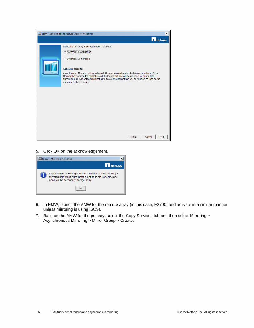
63 SANtricity synchronous and asynchronous mirroring © 2022 NetApp, Inc. All rights reserved. © 2016 NetApp, Inc. All rights reserved.
5. Click OK on the acknowledgement.
6. In EMW, launch the AMW for the remote array (in this case, E2700) and activate in a similar manner unless mirroring is using iSCSI.
7. Back on the AMW for the primary, select the Copy Services tab and then select Mirroring > Asynchronous Mirroring > Mirror Group > Create.
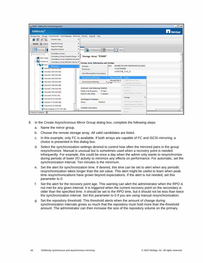
64 SANtricity synchronous and asynchronous mirroring © 2022 NetApp, Inc. All rights reserved. © 2016 NetApp, Inc. All rights reserved.
8. In the Create Asynchronous Mirror Group dialog box, complete the following steps:
a. Name the mirror group.
b. Choose the remote storage array. All valid candidates are listed.
c. In this example, only FC is available. If both arrays are capable of FC and iSCSI mirroring, a choice is presented in this dialog box.
d. Select the synchronization settings desired to control how often the mirrored pairs in the group resynchronize. Manual is unusual but is sometimes used when a recovery point is needed infrequently. For example, this could be once a day when the admin only wants to resynchronize during periods of lower I/O activity to minimize any effects on performance. For automatic, set the synchronization interval. Ten minutes is the minimum.
e. Set the alert for synchronization time. If desired, this time can be set to alert when any periodic resynchronization takes longer than the set value. This alert might be useful to learn when peak time resynchronizations have grown beyond expectations. If the alert is not needed, set this parameter to 0.
f. Set the alert for the recovery point age. This warning can alert the administrator when the RPO is not met for any given interval. It is triggered when the current recovery point on the secondary is older than the specified time. It should be set to the RPO time, but it should not be less than twice the synchronization interval. Set this parameter to 0 if you are using manual resynchronization.
g. Set the repository threshold. This threshold alerts when the amount of change during synchronization intervals grows so much that the repository must hold more than the threshold amount. The administrator can then increase the size of the repository volume on the primary.
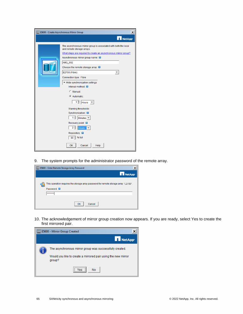
65 SANtricity synchronous and asynchronous mirroring © 2022 NetApp, Inc. All rights reserved. © 2016 NetApp, Inc. All rights reserved.
9. The system prompts for the administrator password of the remote array.
10. The acknowledgement of mirror group creation now appears. If you are ready, select Yes to create the first mirrored pair.
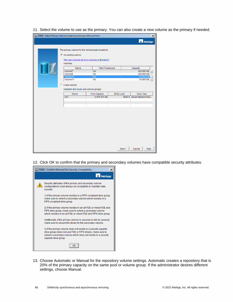
66 SANtricity synchronous and asynchronous mirroring © 2022 NetApp, Inc. All rights reserved. © 2016 NetApp, Inc. All rights reserved.
11. Select the volume to use as the primary. You can also create a new volume as the primary if needed.
12. Click OK to confirm that the primary and secondary volumes have compatible security attributes.
13. Choose Automatic or Manual for the repository volume settings. Automatic creates a repository that is 20% of the primary capacity on the same pool or volume group. If the administrator desires different settings, choose Manual.
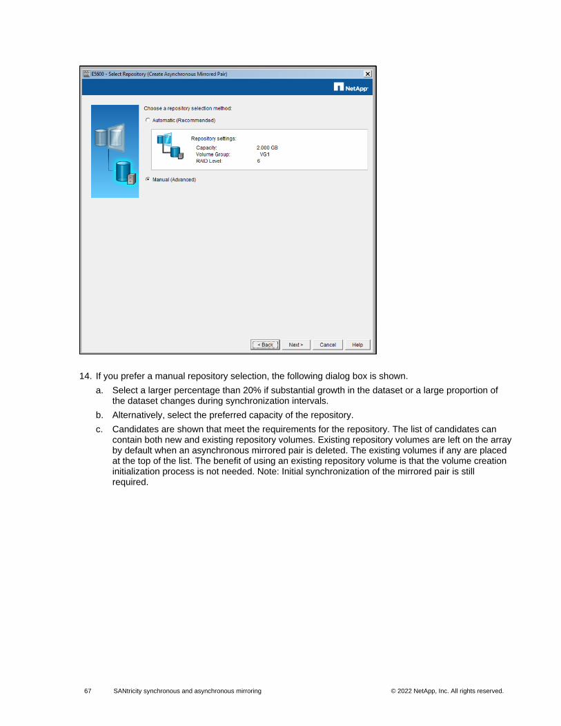
67 SANtricity synchronous and asynchronous mirroring © 2022 NetApp, Inc. All rights reserved. © 2016 NetApp, Inc. All rights reserved.
14. If you prefer a manual repository selection, the following dialog box is shown.
a. Select a larger percentage than 20% if substantial growth in the dataset or a large proportion of the dataset changes during synchronization intervals.
b. Alternatively, select the preferred capacity of the repository.
c. Candidates are shown that meet the requirements for the repository. The list of candidates can contain both new and existing repository volumes. Existing repository volumes are left on the array by default when an asynchronous mirrored pair is deleted. The existing volumes if any are placed at the top of the list. The benefit of using an existing repository volume is that the volume creation initialization process is not needed. Note: Initial synchronization of the mirrored pair is still required.
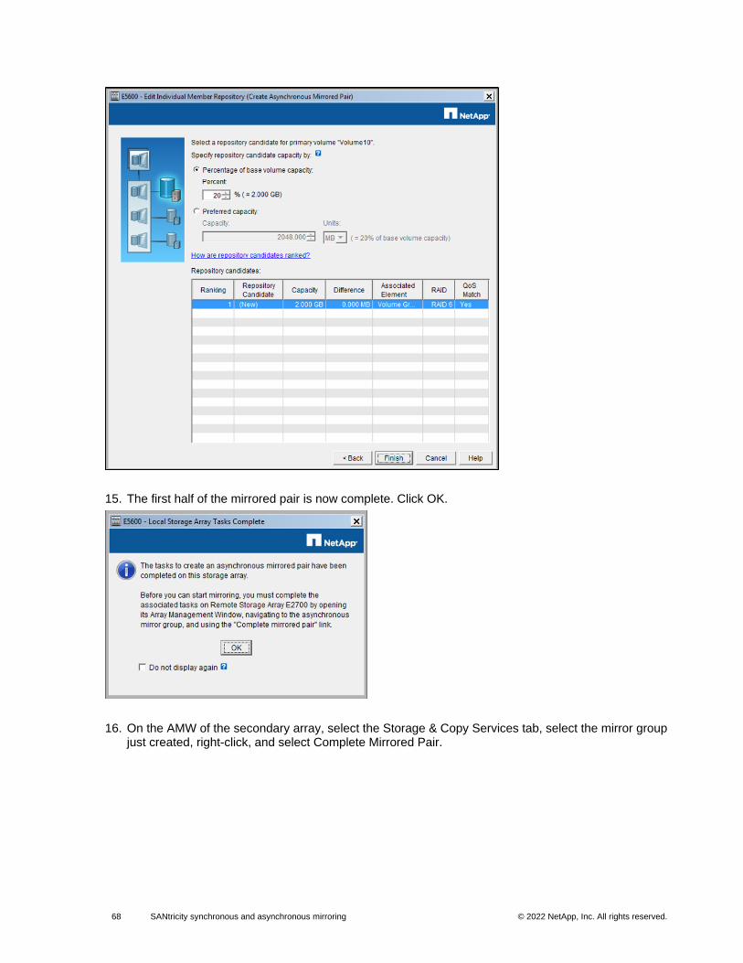
68 SANtricity synchronous and asynchronous mirroring © 2022 NetApp, Inc. All rights reserved. © 2016 NetApp, Inc. All rights reserved.
15. The first half of the mirrored pair is now complete. Click OK.
16. On the AMW of the secondary array, select the Storage & Copy Services tab, select the mirror group just created, right-click, and select Complete Mirrored Pair.
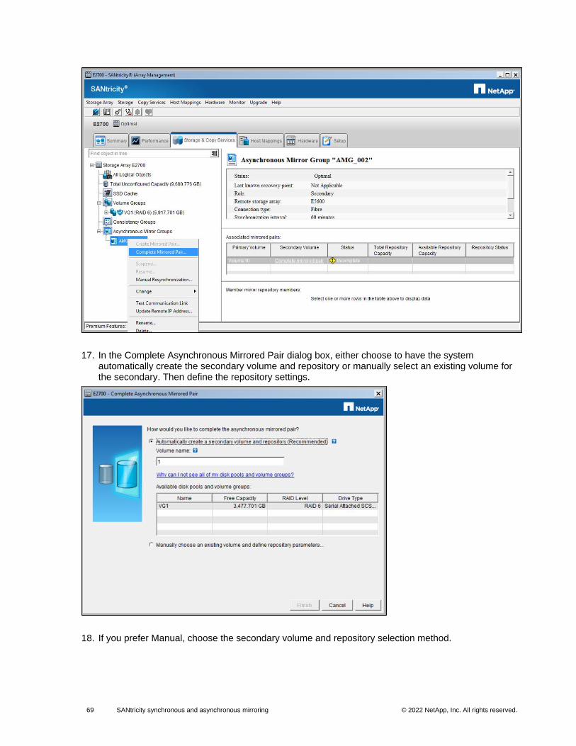
69 SANtricity synchronous and asynchronous mirroring © 2022 NetApp, Inc. All rights reserved. © 2016 NetApp, Inc. All rights reserved.
17. In the Complete Asynchronous Mirrored Pair dialog box, either choose to have the system automatically create the secondary volume and repository or manually select an existing volume for the secondary. Then define the repository settings.
18. If you prefer Manual, choose the secondary volume and repository selection method.
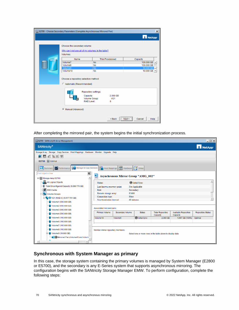
70 SANtricity synchronous and asynchronous mirroring © 2022 NetApp, Inc. All rights reserved. © 2016 NetApp, Inc. All rights reserved.
After completing the mirrored pair, the system begins the initial synchronization process.
Synchronous with System Manager as primary
In this case, the storage system containing the primary volumes is managed by System Manager (E2800
or E5700), and the secondary is any E-Series system that supports asynchronous mirroring. The
configuration begins with the SANtricity Storage Manager EMW. To perform configuration, complete the
following steps:
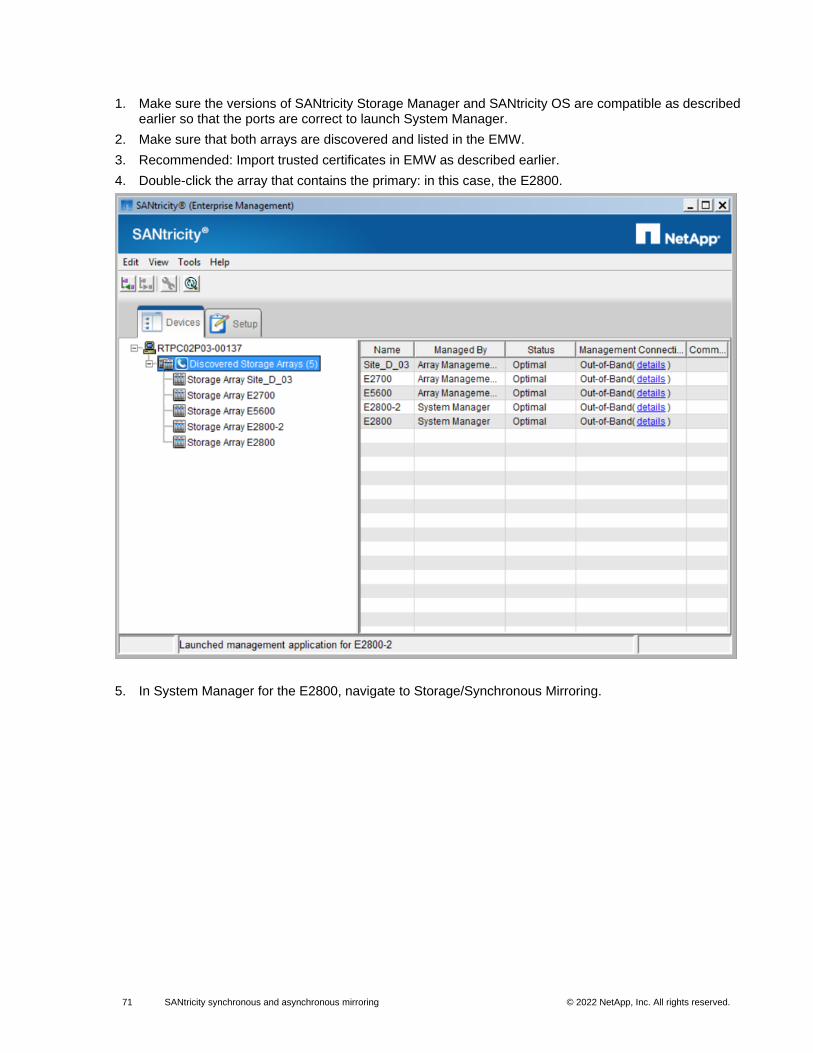
71 SANtricity synchronous and asynchronous mirroring © 2022 NetApp, Inc. All rights reserved. © 2016 NetApp, Inc. All rights reserved.
1. Make sure the versions of SANtricity Storage Manager and SANtricity OS are compatible as described earlier so that the ports are correct to launch System Manager.
2. Make sure that both arrays are discovered and listed in the EMW.
3. Recommended: Import trusted certificates in EMW as described earlier.
4. Double-click the array that contains the primary: in this case, the E2800.
5. In System Manager for the E2800, navigate to Storage/Synchronous Mirroring.
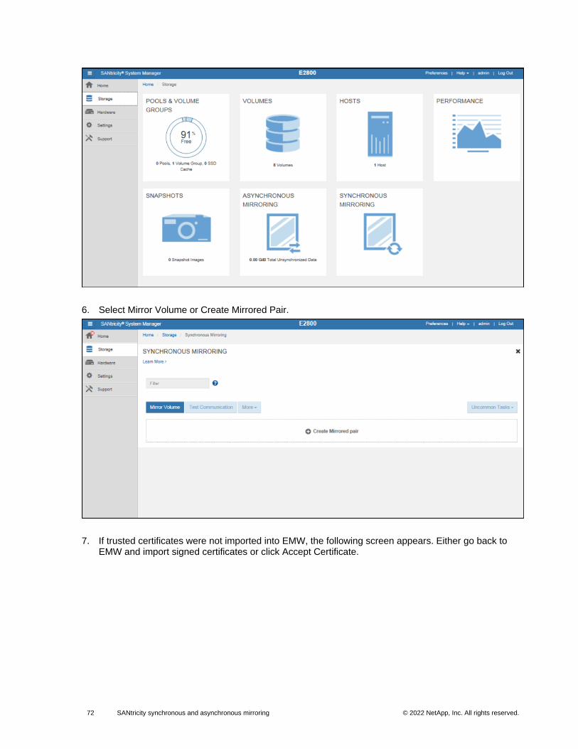
72 SANtricity synchronous and asynchronous mirroring © 2022 NetApp, Inc. All rights reserved. © 2016 NetApp, Inc. All rights reserved.
6. Select Mirror Volume or Create Mirrored Pair.
7. If trusted certificates were not imported into EMW, the following screen appears. Either go back to EMW and import signed certificates or click Accept Certificate.
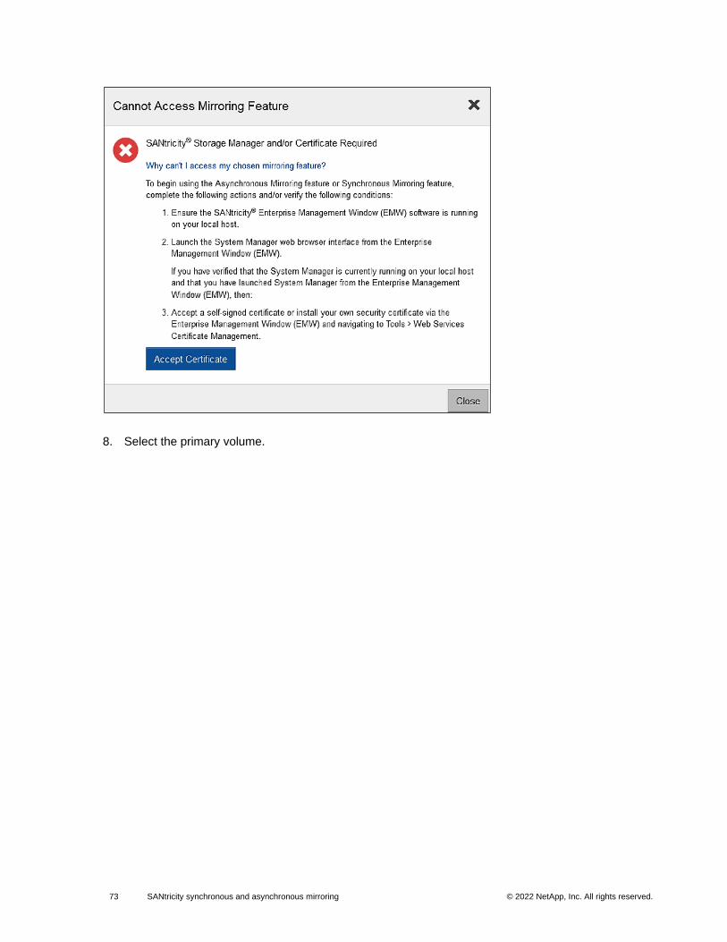
73 SANtricity synchronous and asynchronous mirroring © 2022 NetApp, Inc. All rights reserved. © 2016 NetApp, Inc. All rights reserved.
8. Select the primary volume.
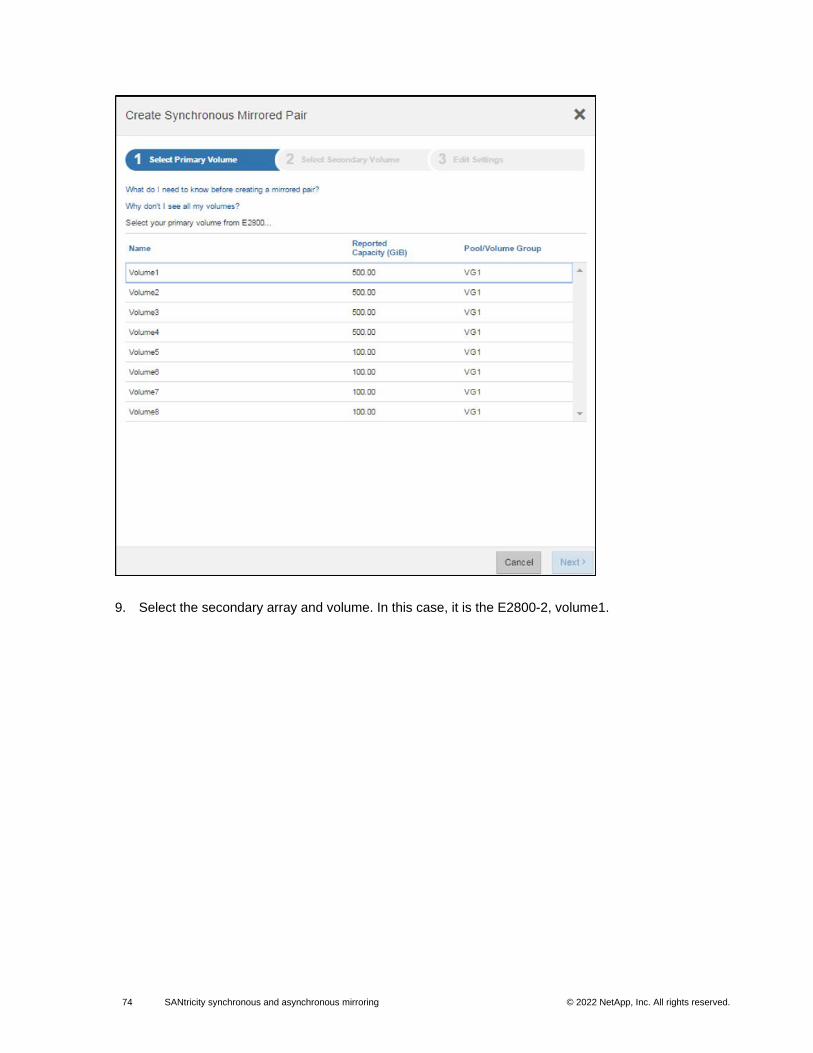
74 SANtricity synchronous and asynchronous mirroring © 2022 NetApp, Inc. All rights reserved. © 2016 NetApp, Inc. All rights reserved.
9. Select the secondary array and volume. In this case, it is the E2800-2, volume1.
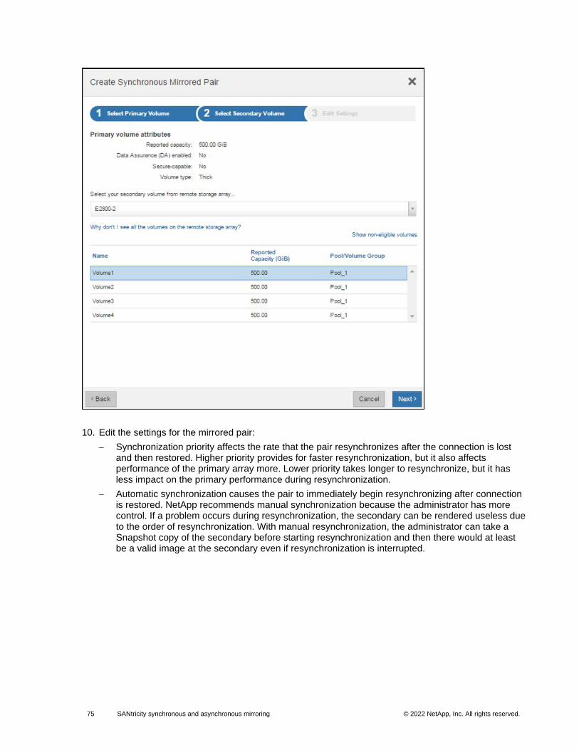
75 SANtricity synchronous and asynchronous mirroring © 2022 NetApp, Inc. All rights reserved. © 2016 NetApp, Inc. All rights reserved.
10. Edit the settings for the mirrored pair:
− Synchronization priority affects the rate that the pair resynchronizes after the connection is lost and then restored. Higher priority provides for faster resynchronization, but it also affects performance of the primary array more. Lower priority takes longer to resynchronize, but it has less impact on the primary performance during resynchronization.
− Automatic synchronization causes the pair to immediately begin resynchronizing after connection is restored. NetApp recommends manual synchronization because the administrator has more control. If a problem occurs during resynchronization, the secondary can be rendered useless due to the order of resynchronization. With manual resynchronization, the administrator can take a Snapshot copy of the secondary before starting resynchronization and then there would at least be a valid image at the secondary even if resynchronization is interrupted.
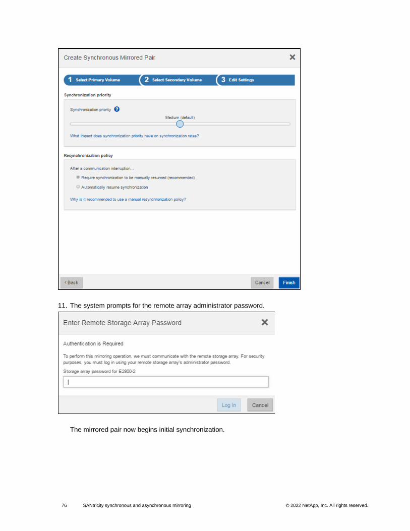
76 SANtricity synchronous and asynchronous mirroring © 2022 NetApp, Inc. All rights reserved. © 2016 NetApp, Inc. All rights reserved.
11. The system prompts for the remote array administrator password.
The mirrored pair now begins initial synchronization.
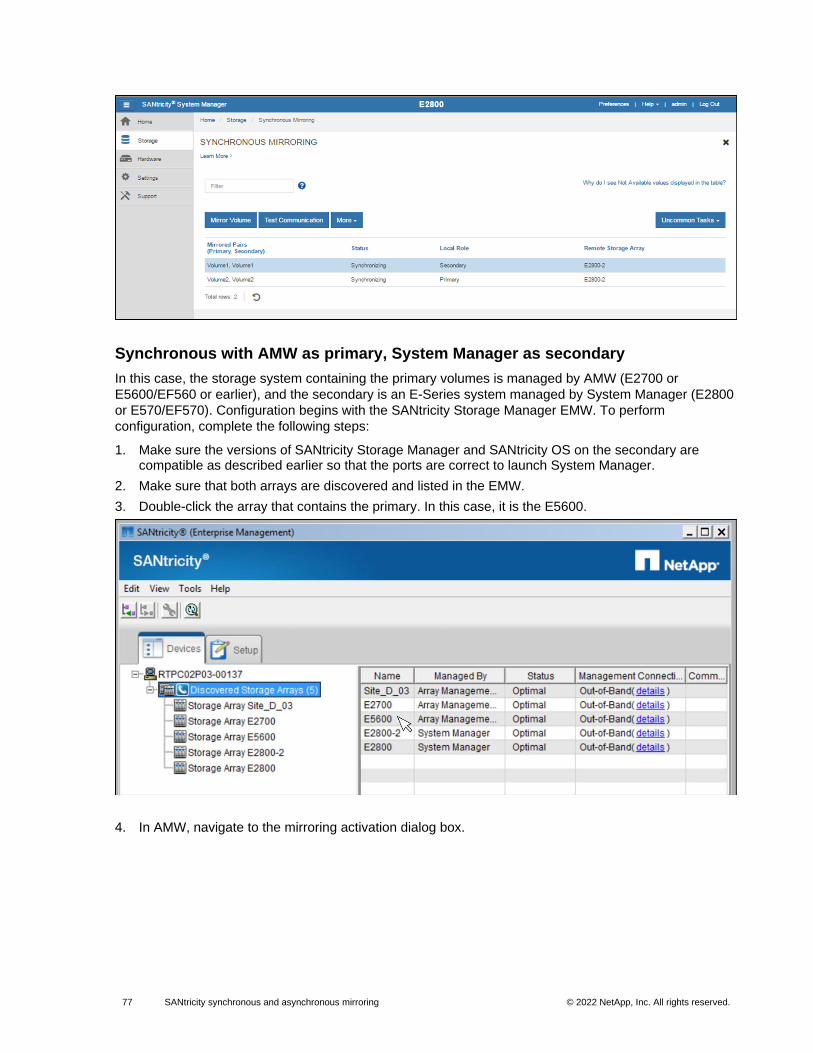
77 SANtricity synchronous and asynchronous mirroring © 2022 NetApp, Inc. All rights reserved. © 2016 NetApp, Inc. All rights reserved.
Synchronous with AMW as primary, System Manager as secondary
In this case, the storage system containing the primary volumes is managed by AMW (E2700 or
E5600/EF560 or earlier), and the secondary is an E-Series system managed by System Manager (E2800
or E570/EF570). Configuration begins with the SANtricity Storage Manager EMW. To perform
configuration, complete the following steps:
1. Make sure the versions of SANtricity Storage Manager and SANtricity OS on the secondary are compatible as described earlier so that the ports are correct to launch System Manager.
2. Make sure that both arrays are discovered and listed in the EMW.
3. Double-click the array that contains the primary. In this case, it is the E5600.
4. In AMW, navigate to the mirroring activation dialog box.
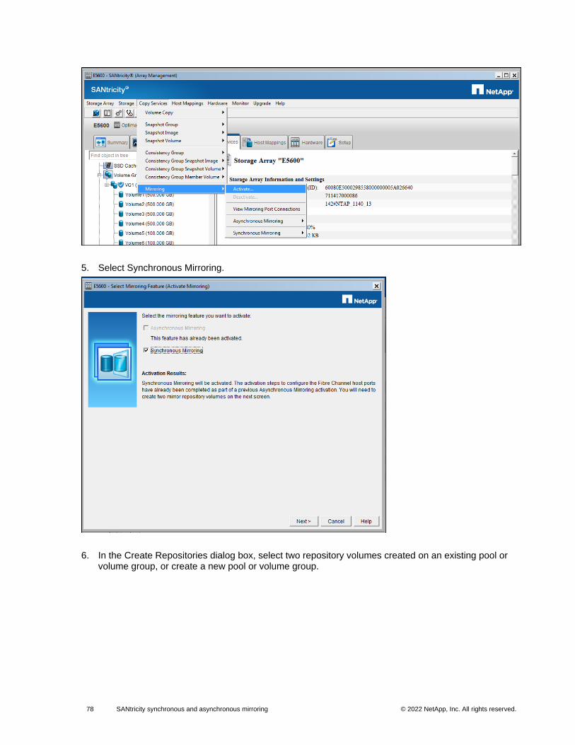
78 SANtricity synchronous and asynchronous mirroring © 2022 NetApp, Inc. All rights reserved. © 2016 NetApp, Inc. All rights reserved.
5. Select Synchronous Mirroring.
6. In the Create Repositories dialog box, select two repository volumes created on an existing pool or volume group, or create a new pool or volume group.
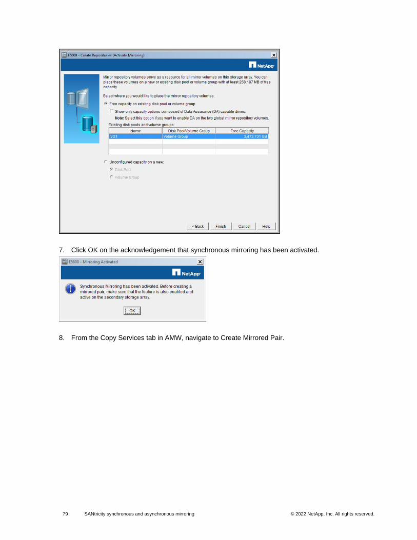
79 SANtricity synchronous and asynchronous mirroring © 2022 NetApp, Inc. All rights reserved. © 2016 NetApp, Inc. All rights reserved.
7. Click OK on the acknowledgement that synchronous mirroring has been activated.
8. From the Copy Services tab in AMW, navigate to Create Mirrored Pair.
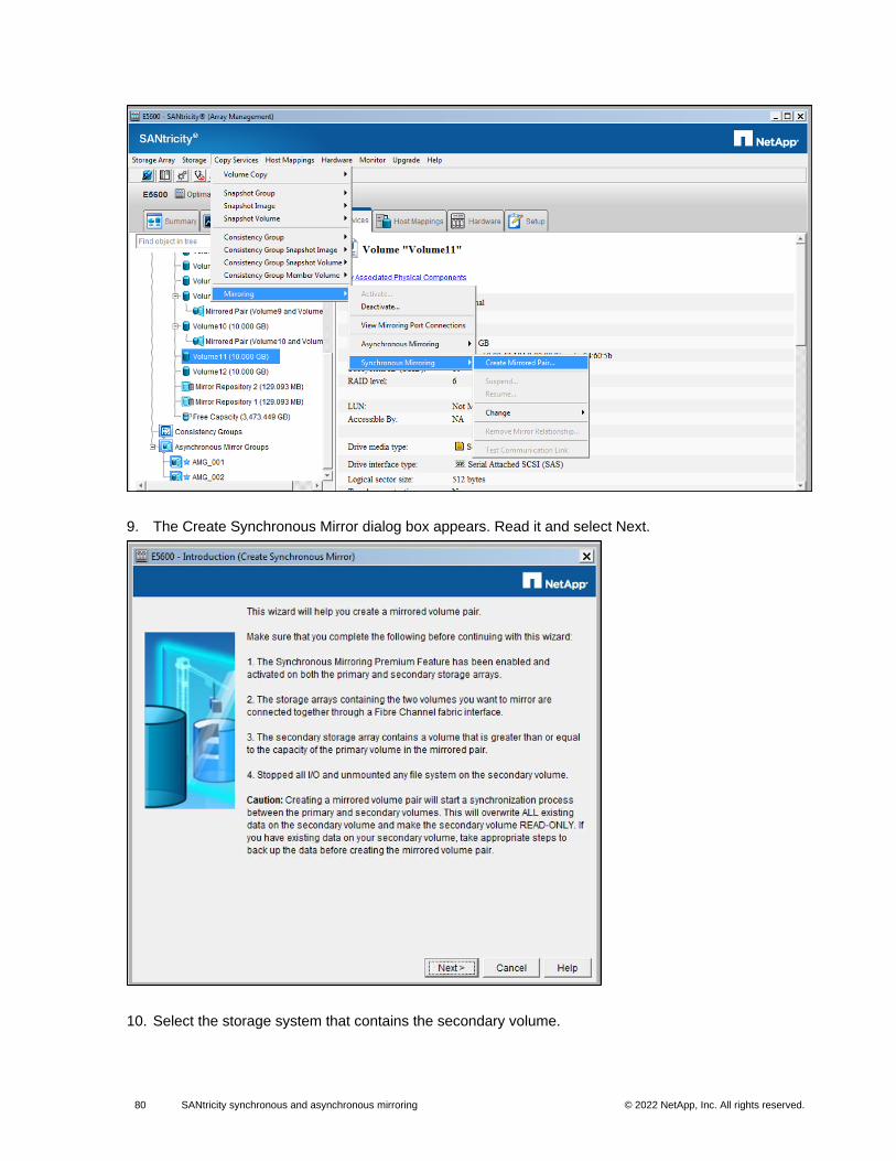
80 SANtricity synchronous and asynchronous mirroring © 2022 NetApp, Inc. All rights reserved. © 2016 NetApp, Inc. All rights reserved.
9. The Create Synchronous Mirror dialog box appears. Read it and select Next.
10. Select the storage system that contains the secondary volume.
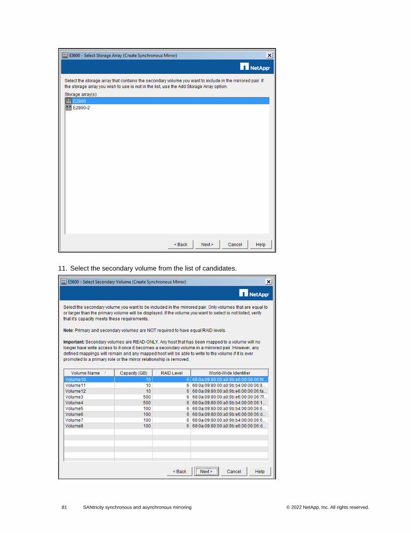
81 SANtricity synchronous and asynchronous mirroring © 2022 NetApp, Inc. All rights reserved. © 2016 NetApp, Inc. All rights reserved.
11. Select the secondary volume from the list of candidates.
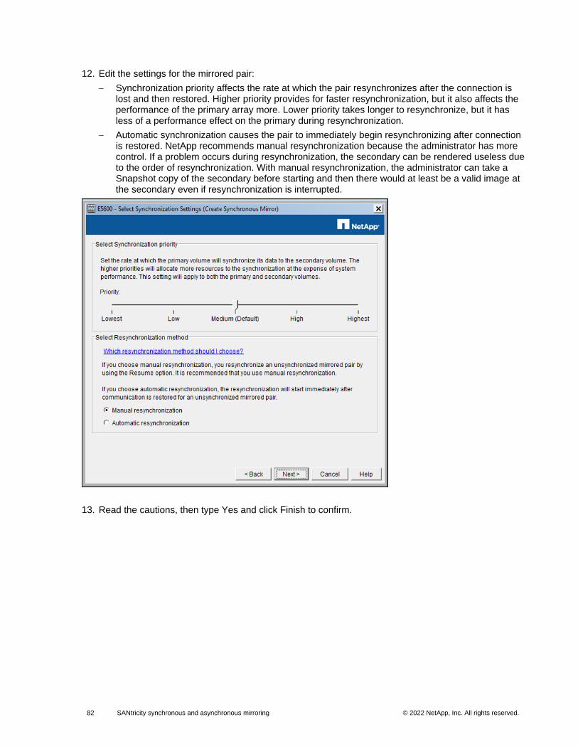
82 SANtricity synchronous and asynchronous mirroring © 2022 NetApp, Inc. All rights reserved. © 2016 NetApp, Inc. All rights reserved.
12. Edit the settings for the mirrored pair:
− Synchronization priority affects the rate at which the pair resynchronizes after the connection is lost and then restored. Higher priority provides for faster resynchronization, but it also affects the performance of the primary array more. Lower priority takes longer to resynchronize, but it has less of a performance effect on the primary during resynchronization.
− Automatic synchronization causes the pair to immediately begin resynchronizing after connection is restored. NetApp recommends manual resynchronization because the administrator has more control. If a problem occurs during resynchronization, the secondary can be rendered useless due to the order of resynchronization. With manual resynchronization, the administrator can take a Snapshot copy of the secondary before starting and then there would at least be a valid image at the secondary even if resynchronization is interrupted.
13. Read the cautions, then type Yes and click Finish to confirm.

83 SANtricity synchronous and asynchronous mirroring © 2022 NetApp, Inc. All rights reserved. © 2016 NetApp, Inc. All rights reserved.
14. The system now prompts for the remote array administrator password.
15. On the confirmation, select Yes if another mirror is to be created now; otherwise, select No. Initial synchronization now begins.
Initial synchronization progress can be seen in Operations in Progress.
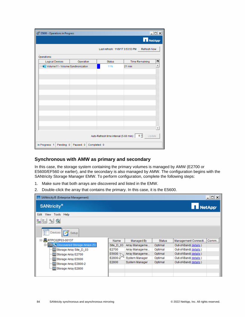
84 SANtricity synchronous and asynchronous mirroring © 2022 NetApp, Inc. All rights reserved. © 2016 NetApp, Inc. All rights reserved.
Synchronous with AMW as primary and secondary
In this case, the storage system containing the primary volumes is managed by AMW (E2700 or
E5600/EF560 or earlier), and the secondary is also managed by AMW. The configuration begins with the
SANtricity Storage Manager EMW. To perform configuration, complete the following steps:
1. Make sure that both arrays are discovered and listed in the EMW.
2. Double-click the array that contains the primary. In this case, it is the E5600.
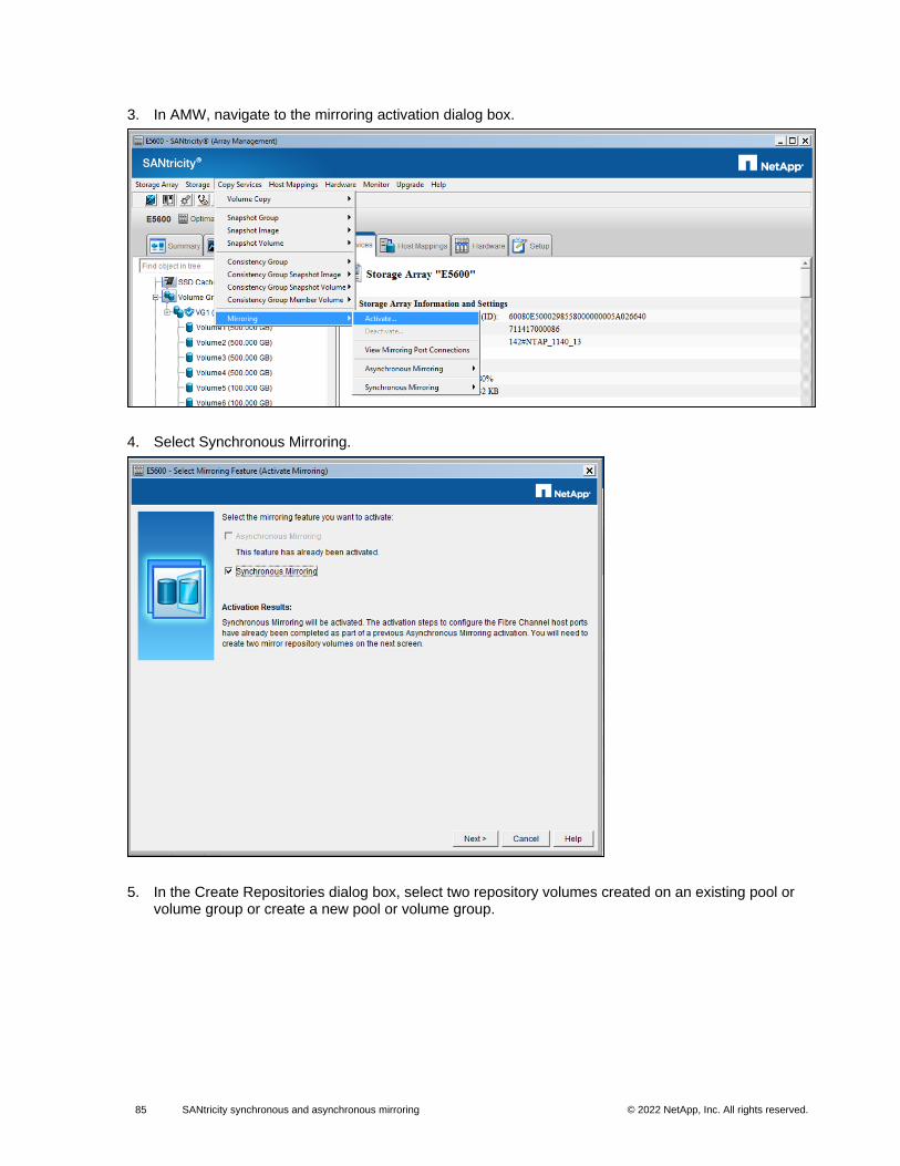
85 SANtricity synchronous and asynchronous mirroring © 2022 NetApp, Inc. All rights reserved. © 2016 NetApp, Inc. All rights reserved.
3. In AMW, navigate to the mirroring activation dialog box.
4. Select Synchronous Mirroring.
5. In the Create Repositories dialog box, select two repository volumes created on an existing pool or volume group or create a new pool or volume group.
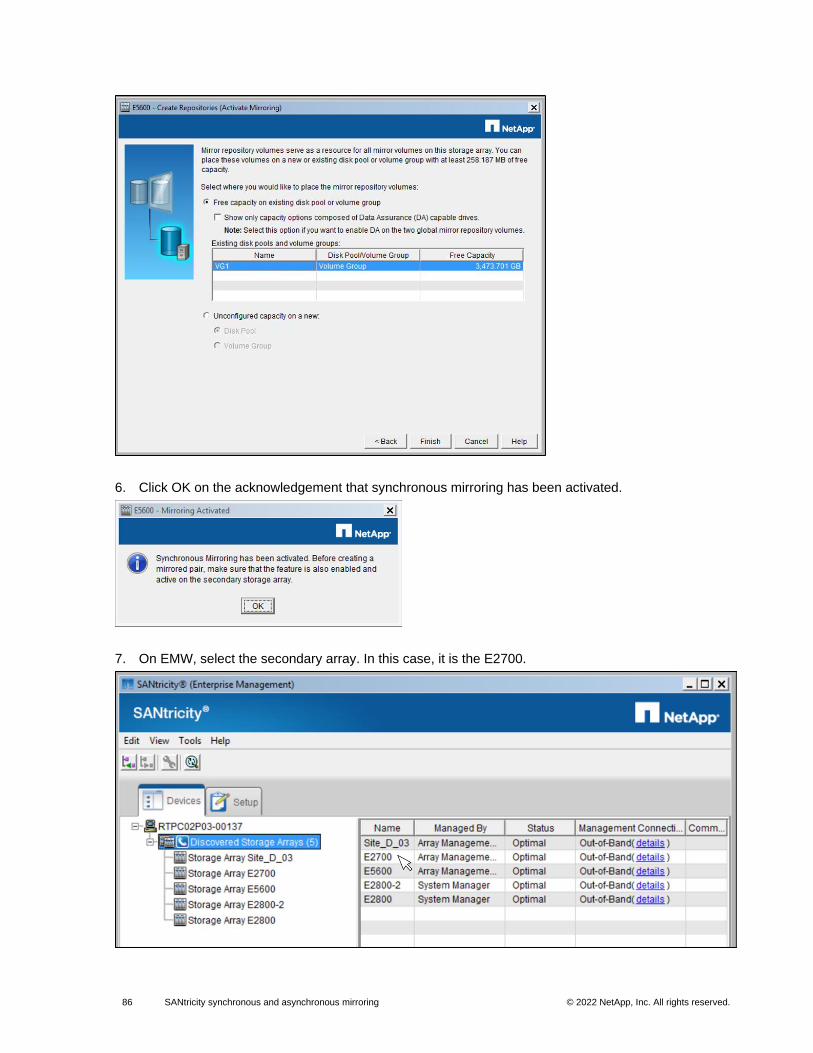
86 SANtricity synchronous and asynchronous mirroring © 2022 NetApp, Inc. All rights reserved. © 2016 NetApp, Inc. All rights reserved.
6. Click OK on the acknowledgement that synchronous mirroring has been activated.
7. On EMW, select the secondary array. In this case, it is the E2700.
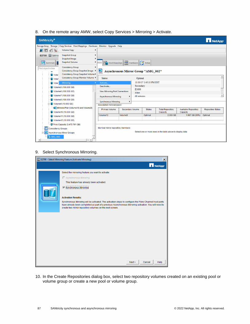
87 SANtricity synchronous and asynchronous mirroring © 2022 NetApp, Inc. All rights reserved. © 2016 NetApp, Inc. All rights reserved.
8. On the remote array AMW, select Copy Services > Mirroring > Activate.
9. Select Synchronous Mirroring.
10. In the Create Repositories dialog box, select two repository volumes created on an existing pool or volume group or create a new pool or volume group.
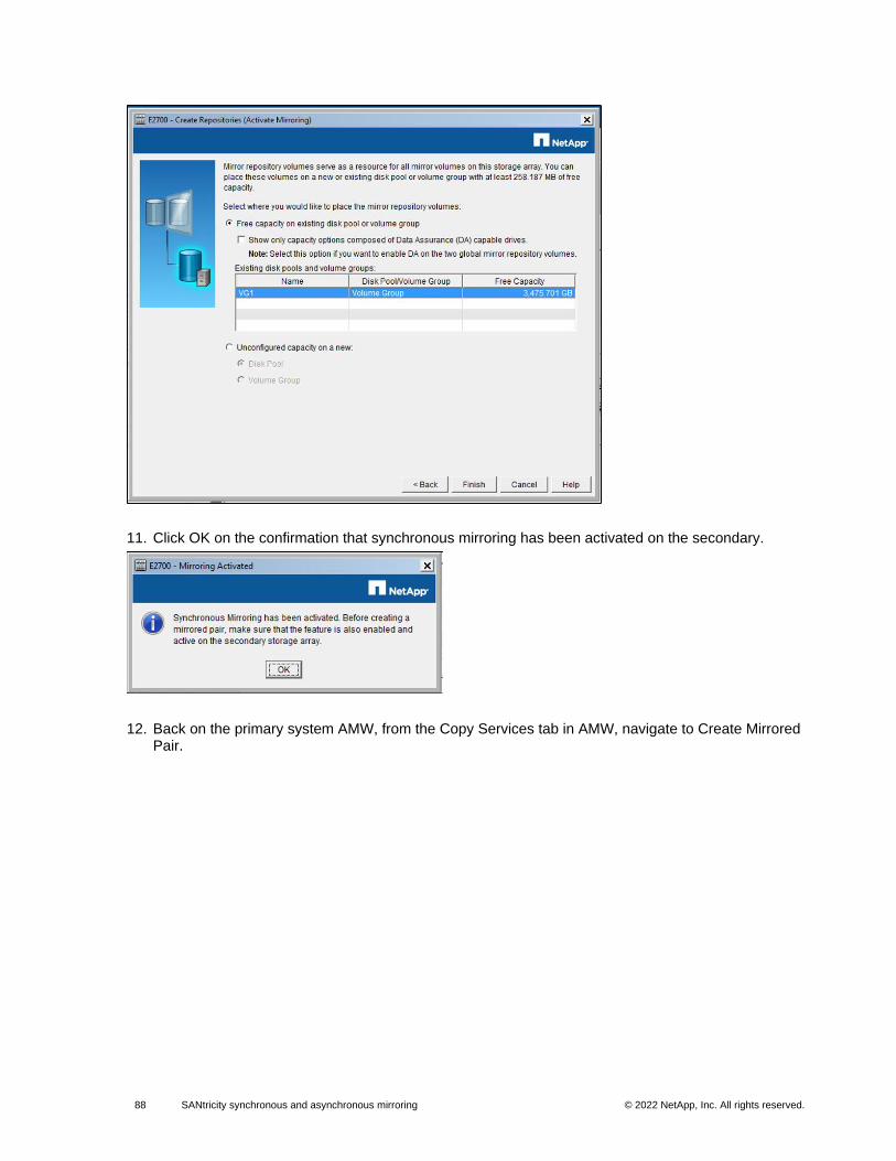
88 SANtricity synchronous and asynchronous mirroring © 2022 NetApp, Inc. All rights reserved. © 2016 NetApp, Inc. All rights reserved.
11. Click OK on the confirmation that synchronous mirroring has been activated on the secondary.
12. Back on the primary system AMW, from the Copy Services tab in AMW, navigate to Create Mirrored Pair.
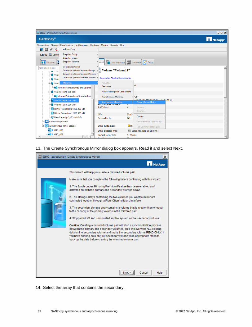
89 SANtricity synchronous and asynchronous mirroring © 2022 NetApp, Inc. All rights reserved. © 2016 NetApp, Inc. All rights reserved.
13. The Create Synchronous Mirror dialog box appears. Read it and select Next.
14. Select the array that contains the secondary.
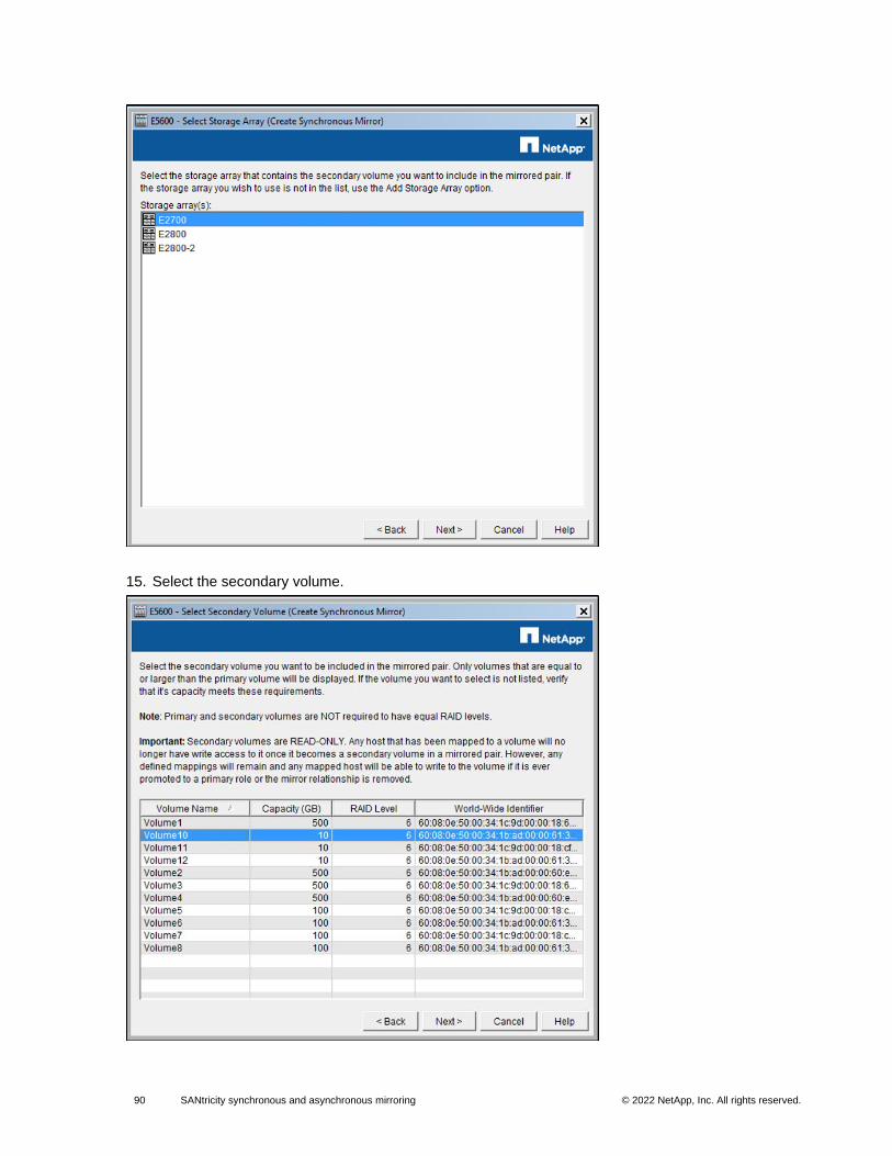
90 SANtricity synchronous and asynchronous mirroring © 2022 NetApp, Inc. All rights reserved. © 2016 NetApp, Inc. All rights reserved.
15. Select the secondary volume.
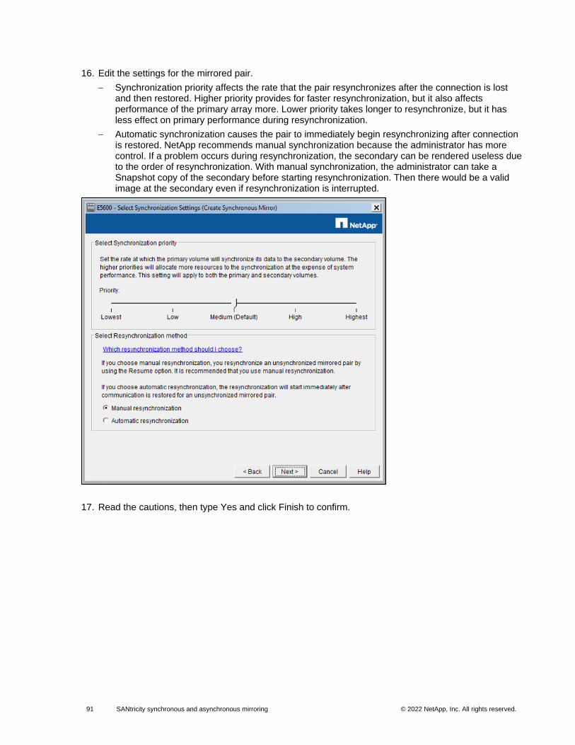
91 SANtricity synchronous and asynchronous mirroring © 2022 NetApp, Inc. All rights reserved. © 2016 NetApp, Inc. All rights reserved.
16. Edit the settings for the mirrored pair.
− Synchronization priority affects the rate that the pair resynchronizes after the connection is lost and then restored. Higher priority provides for faster resynchronization, but it also affects performance of the primary array more. Lower priority takes longer to resynchronize, but it has less effect on primary performance during resynchronization.
− Automatic synchronization causes the pair to immediately begin resynchronizing after connection is restored. NetApp recommends manual synchronization because the administrator has more control. If a problem occurs during resynchronization, the secondary can be rendered useless due to the order of resynchronization. With manual synchronization, the administrator can take a Snapshot copy of the secondary before starting resynchronization. Then there would be a valid image at the secondary even if resynchronization is interrupted.
17. Read the cautions, then type Yes and click Finish to confirm.
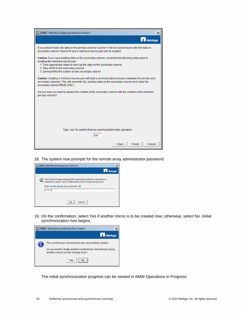
92 SANtricity synchronous and asynchronous mirroring © 2022 NetApp, Inc. All rights reserved. © 2016 NetApp, Inc. All rights reserved.
18. The system now prompts for the remote array administrator password.
19. On the confirmation, select Yes if another mirror is to be created now; otherwise, select No. Initial synchronization now begins.
The initial synchronization progress can be viewed in AMW Operations in Progress.
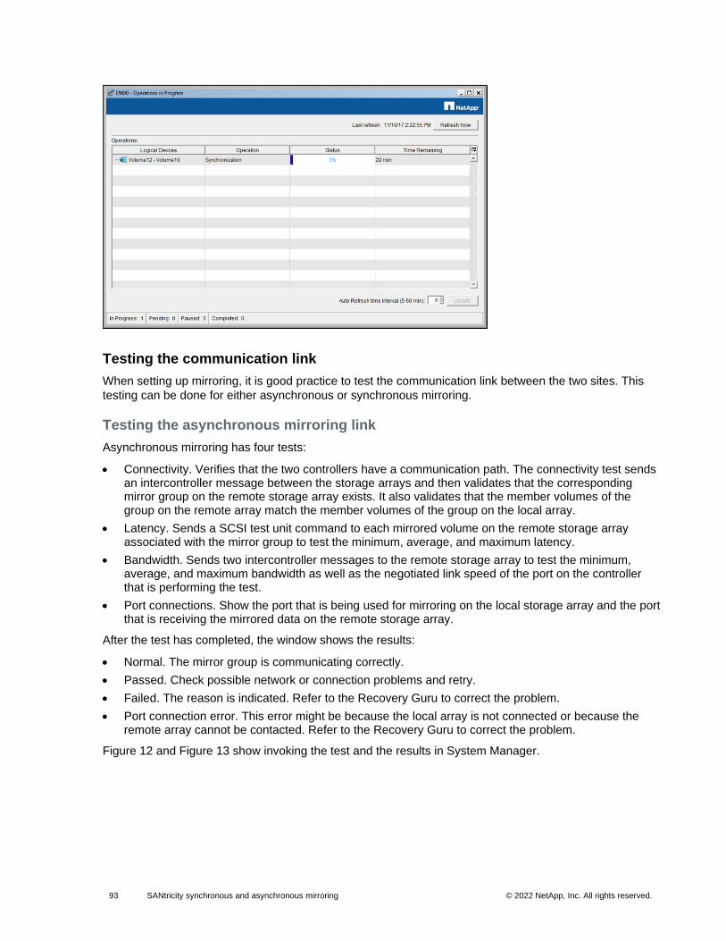
93 SANtricity synchronous and asynchronous mirroring © 2022 NetApp, Inc. All rights reserved. © 2016 NetApp, Inc. All rights reserved.
Testing the communication link
When setting up mirroring, it is good practice to test the communication link between the two sites. This
testing can be done for either asynchronous or synchronous mirroring.
Testing the asynchronous mirroring link
Asynchronous mirroring has four tests:
• Connectivity. Verifies that the two controllers have a communication path. The connectivity test sends an intercontroller message between the storage arrays and then validates that the corresponding mirror group on the remote storage array exists. It also validates that the member volumes of the group on the remote array match the member volumes of the group on the local array.
• Latency. Sends a SCSI test unit command to each mirrored volume on the remote storage array associated with the mirror group to test the minimum, average, and maximum latency.
• Bandwidth. Sends two intercontroller messages to the remote storage array to test the minimum, average, and maximum bandwidth as well as the negotiated link speed of the port on the controller that is performing the test.
• Port connections. Show the port that is being used for mirroring on the local storage array and the port that is receiving the mirrored data on the remote storage array.
After the test has completed, the window shows the results:
• Normal. The mirror group is communicating correctly.
• Passed. Check possible network or connection problems and retry.
• Failed. The reason is indicated. Refer to the Recovery Guru to correct the problem.
• Port connection error. This error might be because the local array is not connected or because the remote array cannot be contacted. Refer to the Recovery Guru to correct the problem.
Figure 12 and Figure 13 show invoking the test and the results in System Manager.
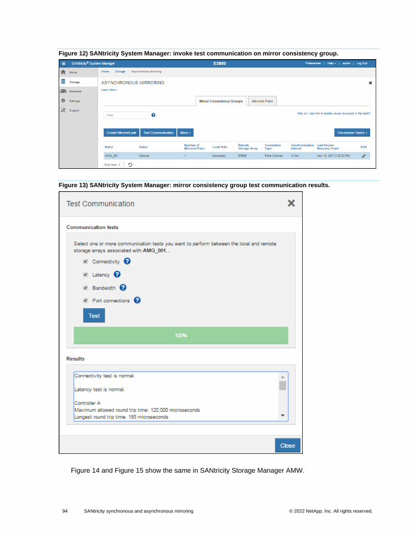
94 SANtricity synchronous and asynchronous mirroring © 2022 NetApp, Inc. All rights reserved. © 2016 NetApp, Inc. All rights reserved.
Figure 12) SANtricity System Manager: invoke test communication on mirror consistency group.
Figure 13) SANtricity System Manager: mirror consistency group test communication results.
Figure 14 and Figure 15 show the same in SANtricity Storage Manager AMW.
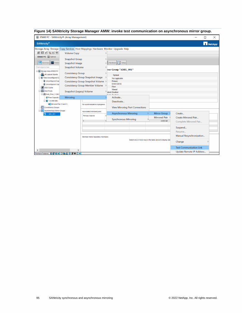
95 SANtricity synchronous and asynchronous mirroring © 2022 NetApp, Inc. All rights reserved. © 2016 NetApp, Inc. All rights reserved.
Figure 14) SANtricity Storage Manager AMW: invoke test communication on asynchronous mirror group.
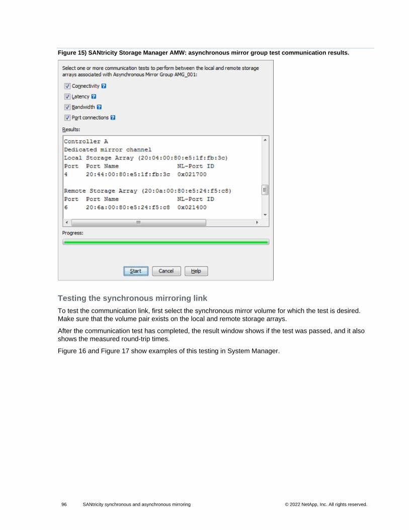
96 SANtricity synchronous and asynchronous mirroring © 2022 NetApp, Inc. All rights reserved. © 2016 NetApp, Inc. All rights reserved.
Figure 15) SANtricity Storage Manager AMW: asynchronous mirror group test communication results.
Testing the synchronous mirroring link
To test the communication link, first select the synchronous mirror volume for which the test is desired.
Make sure that the volume pair exists on the local and remote storage arrays.
After the communication test has completed, the result window shows if the test was passed, and it also
shows the measured round-trip times.
Figure 16 and Figure 17 show examples of this testing in System Manager.
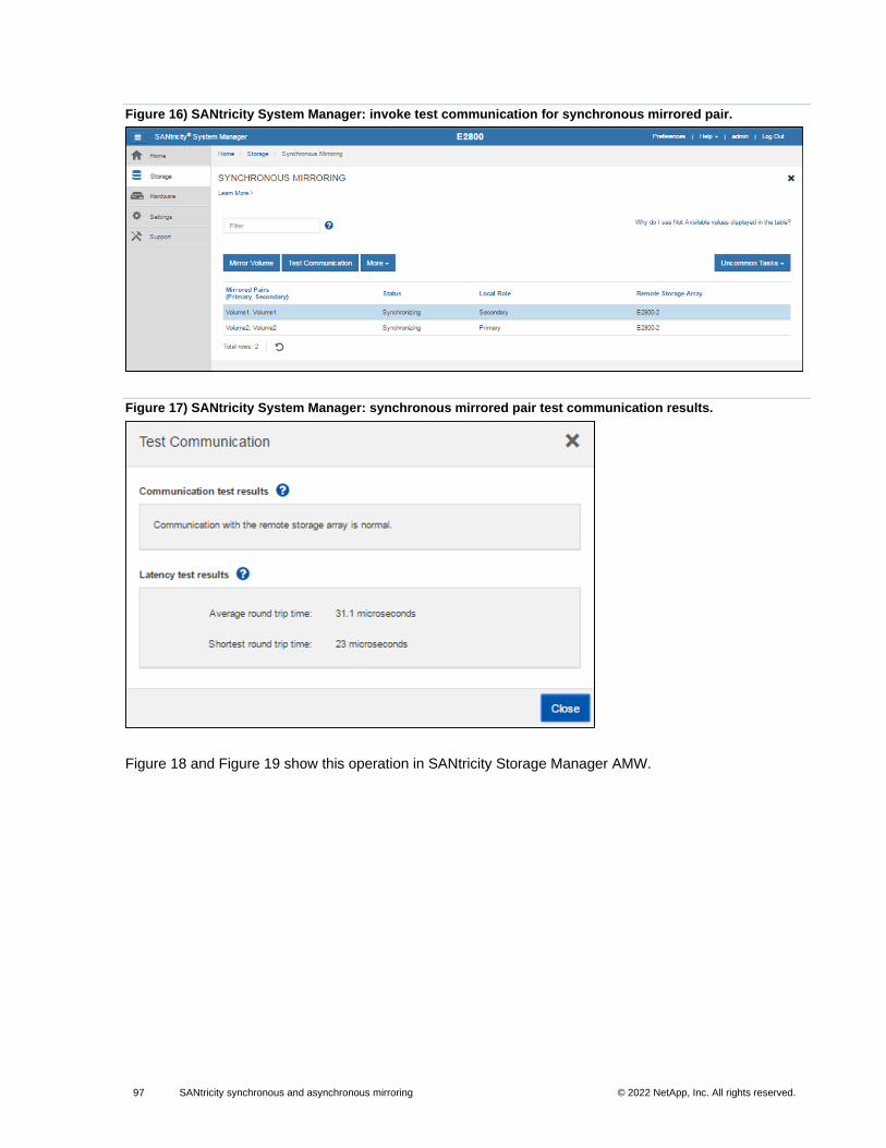
97 SANtricity synchronous and asynchronous mirroring © 2022 NetApp, Inc. All rights reserved. © 2016 NetApp, Inc. All rights reserved.
Figure 16) SANtricity System Manager: invoke test communication for synchronous mirrored pair.
Figure 17) SANtricity System Manager: synchronous mirrored pair test communication results.
Figure 18 and Figure 19 show this operation in SANtricity Storage Manager AMW.
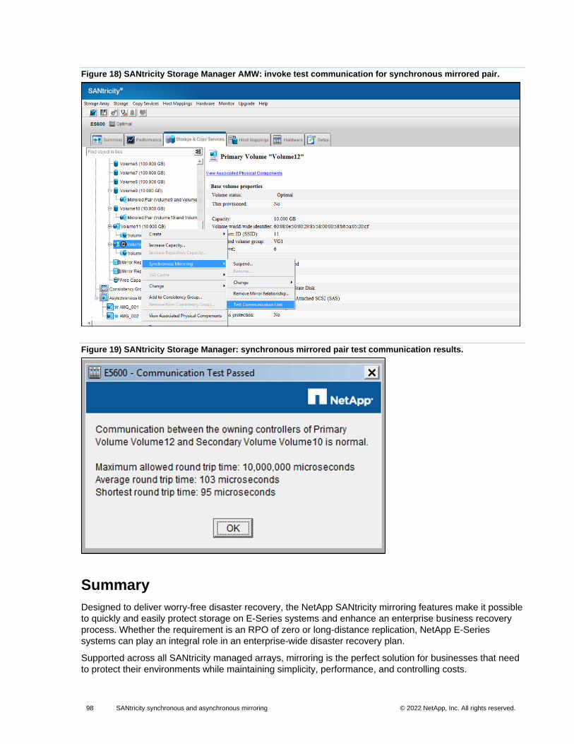
98 SANtricity synchronous and asynchronous mirroring © 2022 NetApp, Inc. All rights reserved. © 2016 NetApp, Inc. All rights reserved.
Figure 18) SANtricity Storage Manager AMW: invoke test communication for synchronous mirrored pair.
Figure 19) SANtricity Storage Manager: synchronous mirrored pair test communication results.
Summary
Designed to deliver worry-free disaster recovery, the NetApp SANtricity mirroring features make it possible
to quickly and easily protect storage on E-Series systems and enhance an enterprise business recovery
process. Whether the requirement is an RPO of zero or long-distance replication, NetApp E-Series
systems can play an integral role in an enterprise-wide disaster recovery plan.
Supported across all SANtricity managed arrays, mirroring is the perfect solution for businesses that need
to protect their environments while maintaining simplicity, performance, and controlling costs.
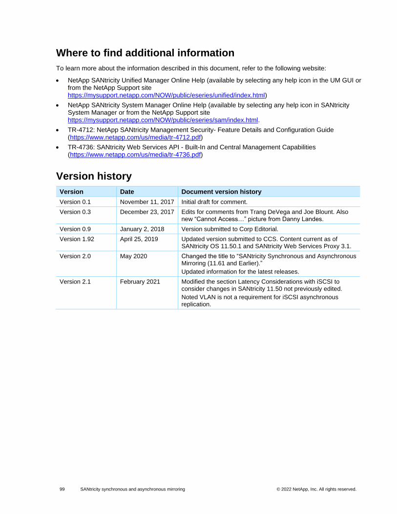
99 SANtricity synchronous and asynchronous mirroring © 2022 NetApp, Inc. All rights reserved. © 2016 NetApp, Inc. All rights reserved.
Where to find additional information
To learn more about the information described in this document, refer to the following website:
• NetApp SANtricity Unified Manager Online Help (available by selecting any help icon in the UM GUI or from the NetApp Support site https://mysupport.netapp.com/NOW/public/eseries/unified/index.html)
• NetApp SANtricity System Manager Online Help (available by selecting any help icon in SANtricity System Manager or from the NetApp Support site https://mysupport.netapp.com/NOW/public/eseries/sam/index.html.
• TR-4712: NetApp SANtricity Management Security- Feature Details and Configuration Guide (https://www.netapp.com/us/media/tr-4712.pdf)
• TR-4736: SANtricity Web Services API - Built-In and Central Management Capabilities (https://www.netapp.com/us/media/tr-4736.pdf)
Version history
Version Date Document version history
Version 0.1 November 11, 2017 Initial draft for comment.
Version 0.3 December 23, 2017 Edits for comments from Trang DeVega and Joe Blount. Also new “Cannot Access…” picture from Danny Landes.
Version 0.9 January 2, 2018 Version submitted to Corp Editorial.
Version 1.92 April 25, 2019 Updated version submitted to CCS. Content current as of SANtricity OS 11.50.1 and SANtricity Web Services Proxy 3.1.
Version 2.0 May 2020 Changed the title to “SANtricity Synchronous and Asynchronous Mirroring (11.61 and Earlier).”
Updated information for the latest releases.
Version 2.1 February 2021 Modified the section Latency Considerations with iSCSI to consider changes in SANtricity 11.50 not previously edited.
Noted VLAN is not a requirement for iSCSI asynchronous replication.
100 SANtricity synchronous and asynchronous mirroring © 2022 NetApp, Inc. All rights reserved. © 2016 NetApp, Inc. All rights reserved.
Refer to http://mysupport.netapp.com/matrix on the NetApp Support site to validate that the exact product and feature versions described in this document are supported for your specific environment. The NetApp IMT defines the product components and versions that can be used to construct configurations that are supported by NetApp. Specific results depend on each customer’s installation in accordance with published specifications.
Copyright Information
Copyright © 2019—2022 NetApp, Inc. All rights reserved. Printed in the U.S. No part of this document covered by copyright may be reproduced in any form or by any means—graphic, electronic, or mechanical, including photocopying, recording, taping, or storage in an electronic retrieval system—without prior written permission of the copyright owner.
Software derived from copyrighted NetApp material is subject to the following license and disclaimer:
THIS SOFTWARE IS PROVIDED BY NETAPP “AS IS” AND WITHOUT ANY EXPRESS OR IMPLIED WARRANTIES, INCLUDING, BUT NOT LIMITED TO, THE IMPLIED WARRANTIES OF MERCHANTABILITY AND FITNESS FOR A PARTICULAR PURPOSE, WHICH ARE HEREBY DISCLAIMED. IN NO EVENT SHALL NETAPP BE LIABLE FOR ANY DIRECT, INDIRECT, INCIDENTAL, SPECIAL, EXEMPLARY, OR CONSEQUENTIAL DAMAGES (INCLUDING, BUT NOT LIMITED TO, PROCUREMENT OF SUBSTITUTE GOODS OR SERVICES; LOSS OF USE, DATA, OR PROFITS; OR BUSINESS INTERRUPTION) HOWEVER CAUSED AND ON ANY THEORY OF LIABILITY, WHETHER IN CONTRACT, STRICT LIABILITY, OR TORT (INCLUDING NEGLIGENCE OR OTHERWISE) ARISING IN ANY WAY OUT OF THE USE OF THIS SOFTWARE, EVEN IF ADVISED OF THE POSSIBILITY OF SUCH DAMAGE.
NetApp reserves the right to change any products described herein at any time, and without notice. NetApp assumes no responsibility or liability arising from the use of products described herein, except as expressly agreed to in writing by NetApp. The use or purchase of this product does not convey a license under any patent rights, trademark rights, or any other intellectual property rights of NetApp.
The product described in this manual may be protected by one or more U.S. patents, foreign patents, or pending applications.
RESTRICTED RIGHTS LEGEND: Use, duplication, or disclosure by the government is subject to restrictions as set forth in subparagraph (c)(1)(ii) of the Rights in Technical Data and Computer Software clause at DFARS 252.277-7103 (October 1988) and FAR 52-227-19 (June 1987).
Trademark Information
NETAPP, the NETAPP logo, and the marks listed at http://www.netapp.com/TM are trademarks of NetApp, Inc. Other company and product names may be trademarks of their respective owners.
TR-4656-0322
Related Documents