SERVICE Manual ROOM AIR CONDITIONER INDOOR UNIT SH12VCD SH09VCD OUTDOOR UNIT SH12VCDX SH09VCDX CONTENTS AIR CONDITIONER 1. Precautions 2. Product Specifications 3. Operating Instructions and Installation 4. Disassembly and Reassembly 5. Troubleshooting 6. Exploded Views and Parts List 7. PCB Diagrams 8. Wiring Diagrams

Samsung Air
Oct 08, 2014
Welcome message from author
This document is posted to help you gain knowledge. Please leave a comment to let me know what you think about it! Share it to your friends and learn new things together.
Transcript
SERVICE Manual
ROOM AIR CONDITIONERINDOOR UNITSH12VCDSH09VCD
OUTDOOR UNITSH12VCDXSH09VCDX
CONTENTSAIR CONDITIONER
1. Precautions
2. Product Specifications
3. Operating Instructions and
Installation
4. Disassembly and Reassembly
5. Troubleshooting
6. Exploded Views and Parts List
7. PCB Diagrams
8. Wiring Diagrams
DB98_08728A(1)_CO 12/20/02 3:27 PM Page 3
1-1Samsung Electronics
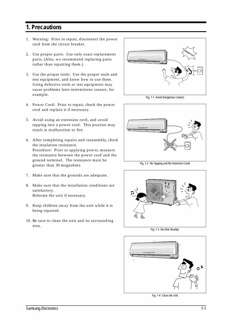
1. Warning: Prior to repair, disconnect the powercord from the circuit breaker.
2. Use proper parts: Use only exact replacementparts. (Also, we recommend replacing partsrather than repairing them.)
3. Use the proper tools: Use the proper tools andtest equipment, and know how to use them.Using defective tools or test equipment maycause problems later-intermittent contact, forexample.
4. Power Cord: Prior to repair, check the powercord and replace it if necessary.
5. Avoid using an extension cord, and avoid tapping into a power cord. This practice mayresult in malfunction or fire.
6. After completing repairs and reassembly, checkthe insulation resistance. Procedure: Prior to applying power, measurethe resistance between the power cord and theground terminal. The resistance must begreater than 30 megaohms.
7. Make sure that the grounds are adequate.
8. Make sure that the installation conditions aresatisfactory. Relocate the unit if necessary.
9. Keep children away from the unit while it isbeing repaired.
10. Be sure to clean the unit and its surroundingarea.
1. Precautions
Fig. 1-1 Avoid Dangerous Contact
Fig. 1-2 No Tapping and No Extension Cords
Fig. 1-3 No Kids Nearby!
Fig. 1-4 Clean the Unit
DB98_08728A(1)_SM_1 12/20/02 3:24 PM Page 1-1

MEMO
Samsung Electronics1-2
DB98_08728A(1)_SM_1 12/20/02 3:24 PM Page 1-2
2-1Samsung Electronics
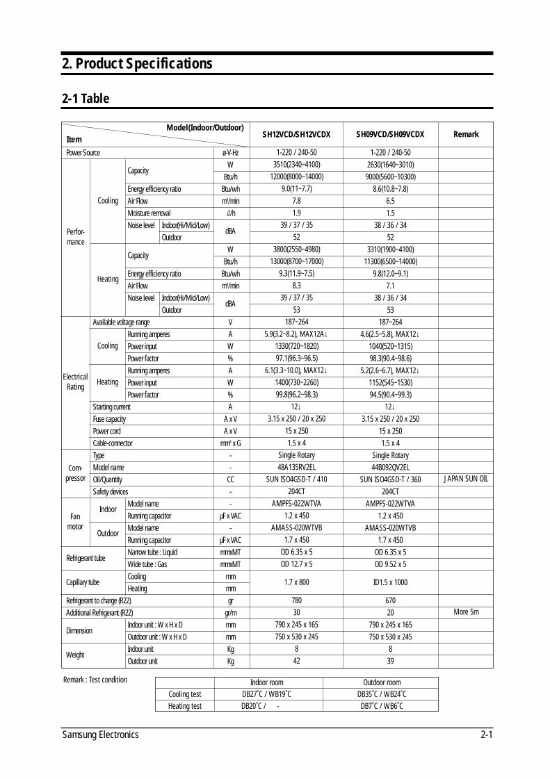
2. Product Specifications
2-1 Table
Model(Indoor/Outdoor)Item
Power Source ø-V-Hz
CapacityW
Btu/hEnergy efficiency ratio Btu/whAir Flow m3/minMoisture removal \/hNoise level Indoor(Hi/Mid/Low)
dBANoise level Outdoor
CapacityW
Btu/hEnergy efficiency ratio Btu/whAir Flow m3/minNoise level Indoor(Hi/Mid/Low)
dBANoise level Outdoor
Available voltage range VRunning amperes APower input WPower factor %Running amperes APower input WPower factor %
Starting current AFuse capacity A x VPower cord A x VCable-connector mm3 x GType -Model name -Oil/Quantity CCSafety devices -
Model name -Running capacitor µF x VACModel name -Running capacitor µF x VAC
Refrigerant tubeNarrow tube : Liquid mmxMTWide tube : Gas mmxMT
Capillary tube Cooling mmHeating mm
Refrigerant to charge (R22) grAdditional Refrigerant (R22) gr/m
Dimension Indoor unit : W x H x D mmOutdoor unit : W x H x D mm
Weight Indoor unit KgOutdoor unit Kg
SH12VCD/SH12VCDX
1-220 / 240-503510(2340~4100)
12000(8000~14000)9.0(11~7.7)
7.81.9
39 / 37 / 3552
3800(2550~4980)13000(8700~17000)
9.3(11.9~7.5)8.3
39 / 37 / 3553
187~2645.9(3.2~8.2), MAX12A↓
1330(720~1820)97.1(96.3~96.5)
6.1(3.3~10.0), MAX12↓1400(730~2260)99.8(96.2~98.3)
12↓3.15 x 250 / 20 x 250
15 x 2501.5 x 4
Single Rotary48A135RV2EL
SUN ISO4GSD-T / 410204CT
AMPFS-022WTVA1.2 x 450
AMASS-020WTVB1.7 x 450
OD 6.35 x 5OD 12.7 x 5
1.7 x 800
78030
790 x 245 x 165750 x 530 x 245
842
SH09VCD/SH09VCDX
1-220 / 240-502630(1640~3010)9000(5600~10300)
8.6(10.8~7.8)6.51.5
38 / 36 / 3452
3310(1900~4100)11300(6500~14000)
9.8(12.0~9.1)7.1
38 / 36 / 3453
187~2644.6(2.5~5.8), MAX12↓
1040(520~1315)98.3(90.4~98.6)
5.2(2.6~6.7), MAX12↓1152(545~1530)94.5(90.4~99.3)
12↓3.15 x 250 / 20 x 250
15 x 2501.5 x 4
Single Rotary44B092QV2EL
SUN ISO4GSD-T / 360204CT
AMPFS-022WTVA1.2 x 450
AMASS-020WTVB1.7 x 450
OD 6.35 x 5OD 9.52 x 5
ID1.5 x 1000
67020
790 x 245 x 165750 x 530 x 245
839
Remark
JAPAN SUN OIL
More 5m
Perfor-mance
Cooling
Cooling
Heating
Heating
Indoor
Outdoor
ElectricalRating
Com-pressor
Fanmotor
Remark : Test condition Indoor room Outdoor roomCooling test DB27˚C / WB19˚C DB35˚C / WB24˚CHeating test DB20˚C / - - DB7˚C / WB6˚C
DB98_08728A(1)_SM_1 12/20/02 3:24 PM Page 2-1
Samsung Electronics2-2
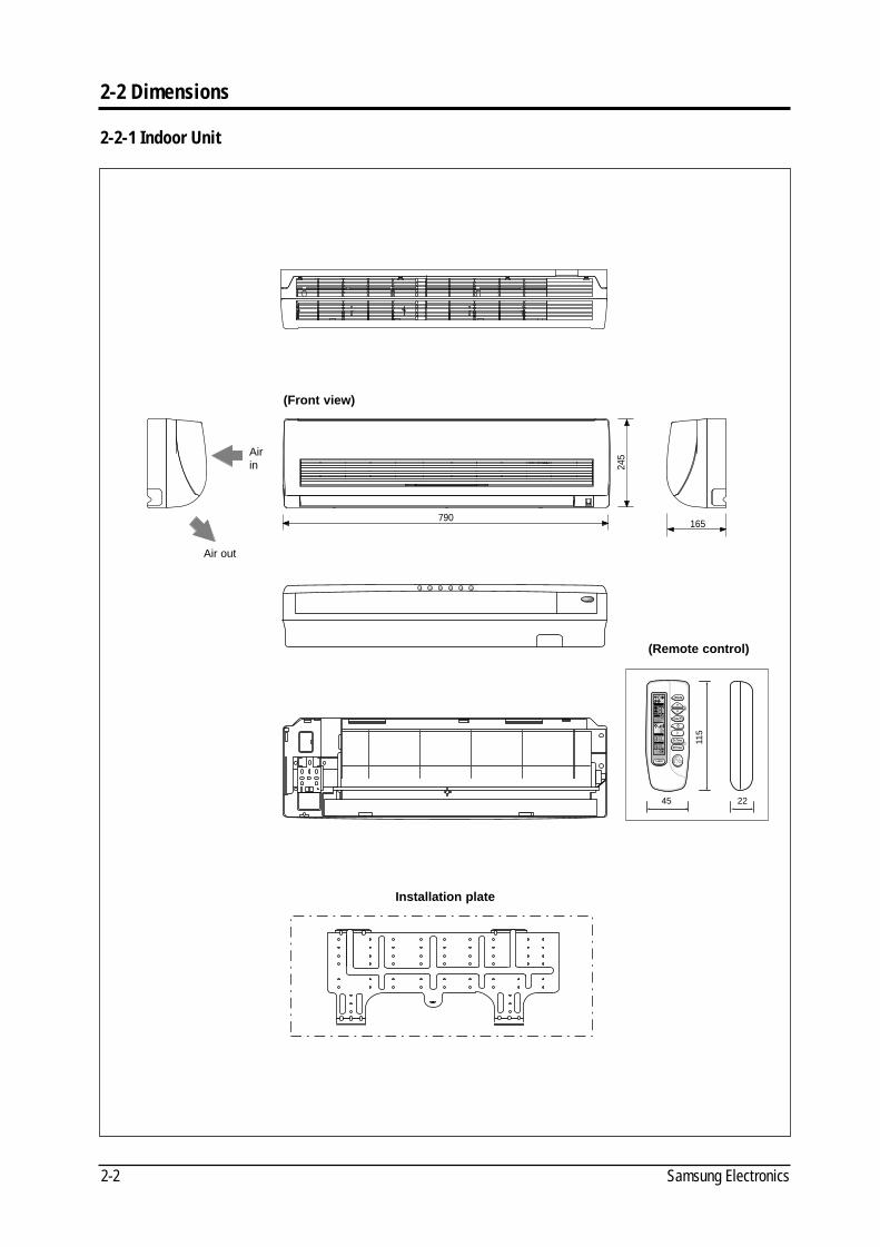
2-2 Dimensions
2-2-1 Indoor Unit
245
165790
Airin
(Front view)
(Remote control)
Air out
Installation plate
2245
115
DB98_08728A(1)_SM_1 12/20/02 3:24 PM Page 2-2
P roduct Specifications
2-3Samsung Electronics
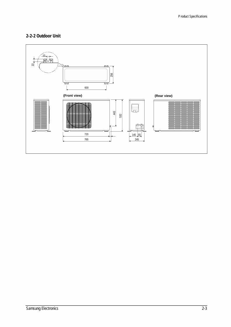
(Front view) (Rear view)
720 145 55
245
600
10
10
765
443
256
532
2-2-2 Outdoor Unit
DB98_08728A(1)_SM_1 12/20/02 3:24 PM Page 2-3
Samsung Electronics2-4
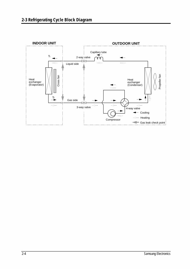
2-3 Refrigerating Cycle Block Diagram
INDOOR UNIT OUTDOOR UNIT
Heatexchanger(Evaporator)
Gas side
3-way valve
2-way valve
Liquid side
Capillary tube
Cooling
Gas leak check point
Cro
ss fa
n
Heatexchanger(Condenser)
Pro
pelle
r fa
n
HeatingCompressor
4-way valve
T1
T2
DB98_08728A(1)_SM_1 12/20/02 3:24 PM Page 2-4
3-1Samsung Electronics
3. Operating Instructions and Installation
3-1 Operating Instructions
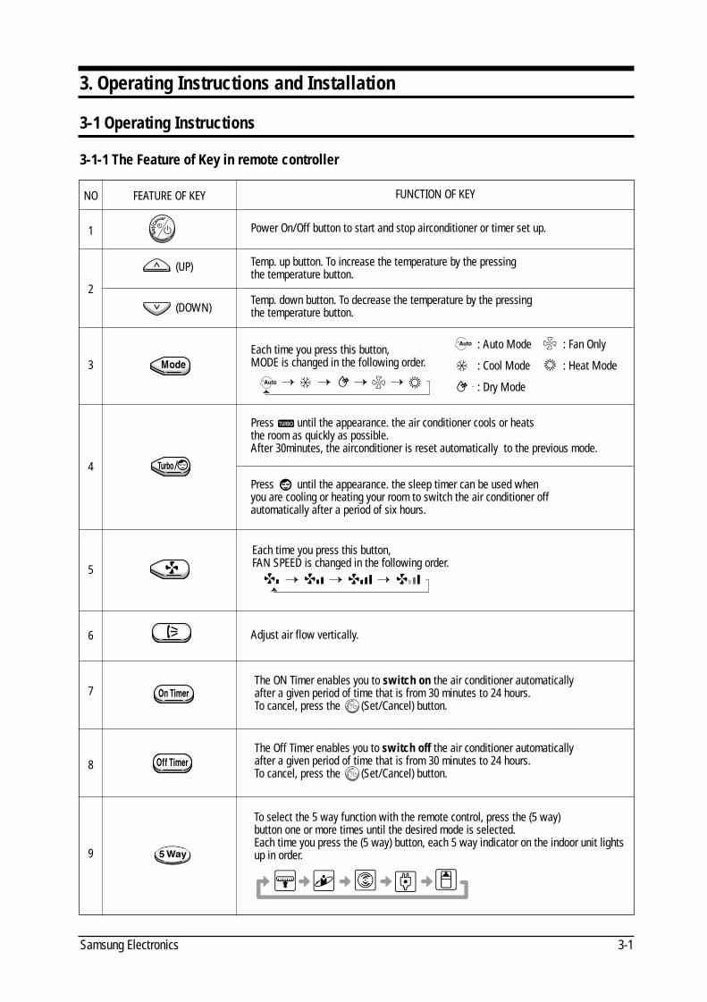
Each time you press this button, FAN SPEED is changed in the following order.
Press until the appearance. the sleep timer can be used when you are cooling or heating your room to switch the air conditioner offautomatically after a period of six hours.
Each time you press this button,MODE is changed in the following order.
FUNCTION OF KEY
3-1-1 The Feature of Key in remote controller
: Auto Mode : Fan Only
: Cool Mode : Heat Mode
: Dry Mode
(DOWN)
Press until the appearance. the air conditioner cools or heatsthe room as quickly as possible. After 30minutes, the airconditioner is reset automatically to the previous mode.
FEATURE OF KEY
(UP)
NO
1
2
3
4
5
6
7
8
9
Adjust air flow vertically.
Power On/Off button to start and stop airconditioner or timer set up.
Temp. up button. To increase the temperature by the pressingthe temperature button.
Temp. down button. To decrease the temperature by the pressingthe temperature button.
The ON Timer enables you to switch on the air conditioner automaticallyafter a given period of time that is from 30 minutes to 24 hours.To cancel, press the (Set/Cancel) button.
The Off Timer enables you to switch off the air conditioner automaticallyafter a given period of time that is from 30 minutes to 24 hours.To cancel, press the (Set/Cancel) button.
To select the 5 way function with the remote control, press the (5 way)button one or more times until the desired mode is selected.Each time you press the (5 way) button, each 5 way indicator on the indoor unit lightsup in order.
DB98_08728A(1)_SM_1 12/20/02 3:24 PM Page 2-5
Operating Instructions and Installation
Samsung Electronics3-2
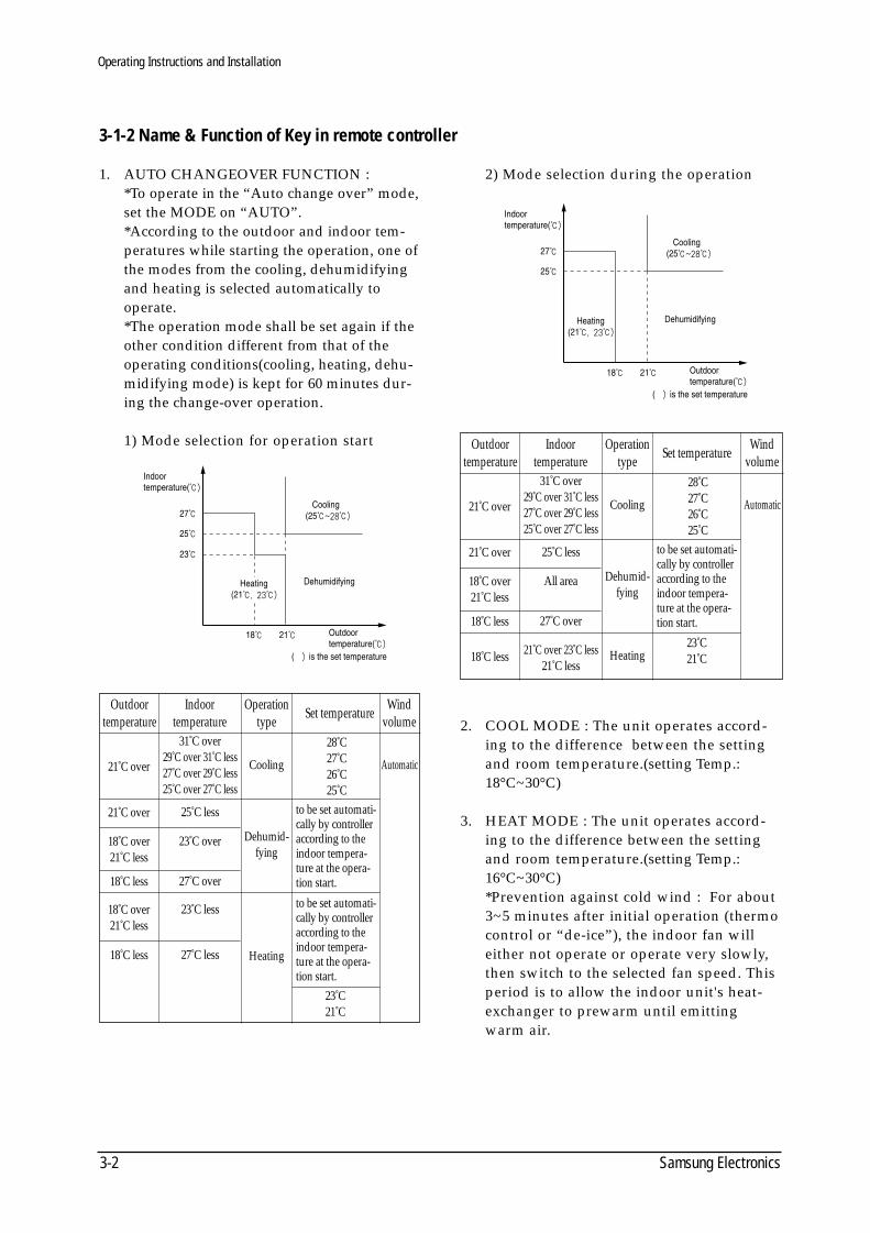
1. AUTO CHANGEOVER FUNCTION : *To operate in the “Auto change over” mode,set the MODE on “AUTO”.*According to the outdoor and indoor tem-peratures while starting the operation, one ofthe modes from the cooling, dehumidifyingand heating is selected automatically tooperate.*The operation mode shall be set again if theother condition different from that of theoperating conditions(cooling, heating, dehu-midifying mode) is kept for 60 minutes dur-ing the change-over operation.
1) Mode selection for operation start
2) Mode selection during the operation
2. COOL MODE : The unit operates accord-ing to the difference between the settingand room temperature.(setting Temp.:18°C~30°C)
3. HEAT MODE : The unit operates accord-ing to the difference between the settingand room temperature.(setting Temp.:16°C~30°C) *Prevention against cold wind : For about3~5 minutes after initial operation (thermocontrol or “de-ice”), the indoor fan willeither not operate or operate very slowly,then switch to the selected fan speed. Thisperiod is to allow the indoor unit's heat-exchanger to prewarm until emittingwarm air.
3-1-2 Name & Function of Key in remote controller
21˚C over
21˚C over
31˚C over29˚C over 31˚C less27˚C over 29˚C less25˚C over 27˚C less
25˚C less
18˚C less 27˚C over
18˚C less 27˚C less
18˚C over21˚C less
23˚C over
18˚C over21˚C less
23˚C less
Cooling
Dehumid-fying
Heating
Automatic
28˚C27˚C26˚C25˚C
23˚C21˚C
Outdoor temperature
Indoor temperature
Operationtype Set temperature Wind
volume
to be set automati-cally by controlleraccording to theindoor tempera-ture at the opera-tion start.
to be set automati-cally by controlleraccording to theindoor tempera-ture at the opera-tion start.
21˚C over
21˚C over
31˚C over29˚C over 31˚C less27˚C over 29˚C less25˚C over 27˚C less
25˚C less
18˚C less 27˚C over
18˚C over21˚C less
All area
18˚C less 21˚C over 23˚C less 21˚C less
Cooling
Dehumid-fying
Heating
Automatic
28˚C27˚C26˚C25˚C
23˚C21˚C
Outdoor temperature
Indoor temperature
Operationtype Set temperature Wind
volume
to be set automati-cally by controlleraccording to theindoor tempera-ture at the opera-tion start.
DB98_08728A(1)_SM_1 12/20/02 3:24 PM Page 2-6
3-3Samsung Electronics
Operating Instructions and Installation
*High temperature release function : Theoutdoor unit and compressor ON/OFF iscontrolled for safety operation when heatexchanger of indoor unit is over heated.*De-ice : Deicing operation is controlledby outdoor unit's heat exchanger tempera-ture and accumulating time of compres-sor's operation.De-ice ends by sensing of the processingtime by de-ice Condition.
4. DRY MODE : *According to the difference between theset temperature (Ts) and indoor tempera-ture (Tr), the operation frequency of com-pressor is controlled as each area.(Cooling area/COMPor ON/OFFarea/Monitoring area) Cooling area : same as the cool mode COMPor ON/OFF area : repeat ofCOMPor frequency 36[Hz] for 4 minutesoperation/0[Hz](off) for 6 minutes Monitoring area : COMPor off.
5. TURBO MODE : This mode is available inAUTO, COOL, HEAT, DRY, FAN MODE.When this button is pressed at first, theair conditioner is operated in “powerful”state for 30 minutes regardless of the settemperature, room temperature.When this button is pressed again, orwhen the operating time is 30 minutes,turbo operation mode is canceled andreturned to the previous mode.*But, if you press the TURBO button inDRY or FAN mode, it is changed intoAUTO mode automatically.
6. SLEEP MODE : Sleep mode is availableonly in COOL or HEAT mode.The operation will stop after 6 hours.*In COOL mode : The setting temperatureis automatically raised by 1°C each 1hourWhen the temperature has been raised bytotal of 2°C, that temperature is main-tained.
*In HEAT mode : The setting temperatureis automatically droped by 1°C each1hour.When the temperature has been droped bytotal of 2°C, that temperature is main-tained.
7. FAN SPEED : Manual (3 step), Auto (4step)Fan speed automatically varies dependingon the difference between setting and theroom temperature.
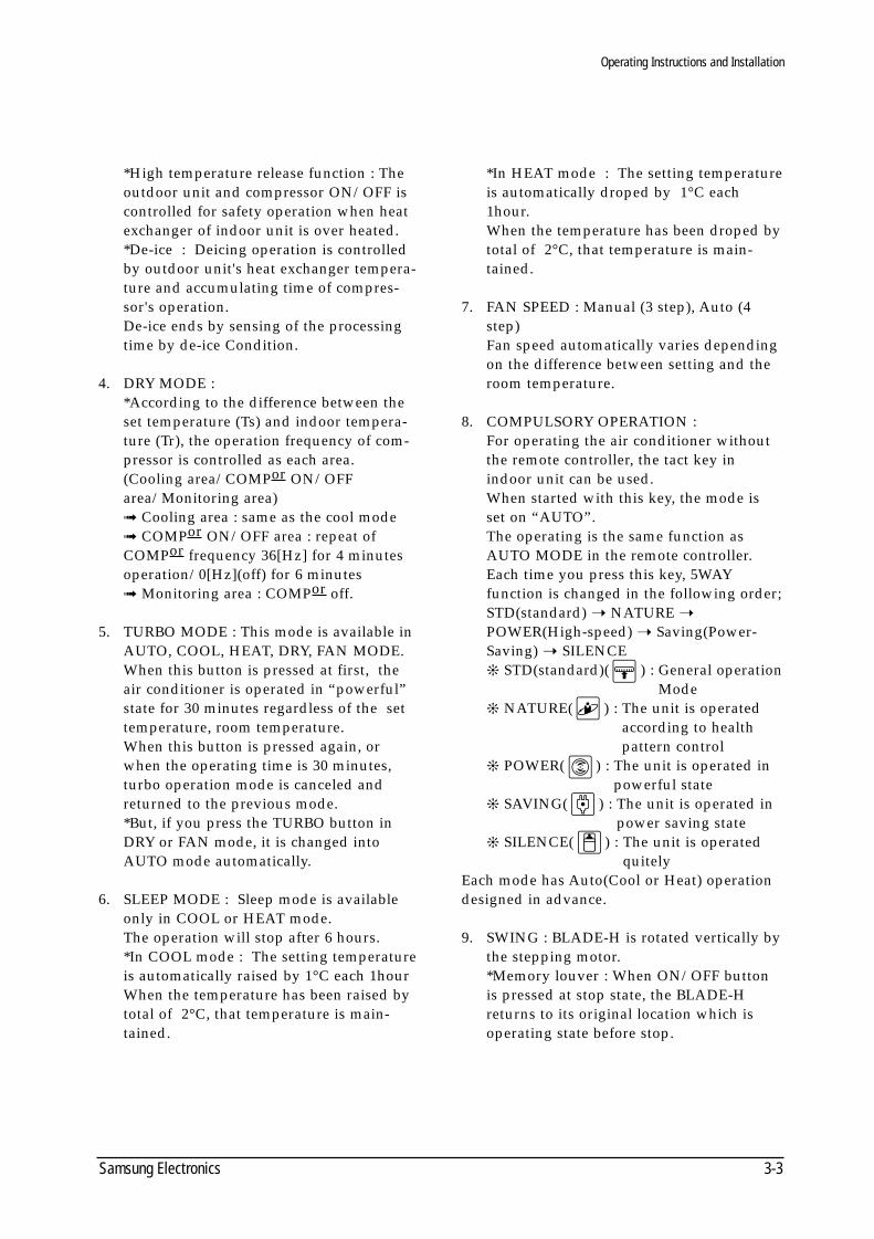
8. COMPULSORY OPERATION : For operating the air conditioner withoutthe remote controller, the tact key inindoor unit can be used.When started with this key, the mode isset on “AUTO”.The operating is the same function asAUTO MODE in the remote controller. Each time you press this key, 5WAYfunction is changed in the following order; STD(standard) NATURE POWER(High-speed) Saving(Power-Saving) SILENCE STD(standard)( ) : General operation
Mode NATURE( ) : The unit is operated
according to health pattern control
POWER( ) : The unit is operated in powerful state
SAVING( ) : The unit is operated inpower saving state
SILENCE( ) : The unit is operatedquitely
Each mode has Auto(Cool or Heat) operationdesigned in advance.
9. SWING : BLADE-H is rotated vertically bythe stepping motor.*Memory louver : When ON/OFF buttonis pressed at stop state, the BLADE-Hreturns to its original location which isoperating state before stop.
DB98_08728A(1)_SM_1 12/20/02 3:24 PM Page 3-1
Operating Instructions and Installation
Samsung Electronics3-4
*Swing Set : Press the button under theremote control is displayed on LCD theand the blades move up and down. If theone more time press the button, bladelocation is stop.
10. 24-Hour ON/OFF Real Setting Timer. :The air conditioner is turned ON at a spec-ified time using .OFF TIMER : The air Conditioner isturned OFF at a specified time using .*ON TIMER : Only timer LED lights on.*OFF TIMER : Both timer and operationLED lights on.
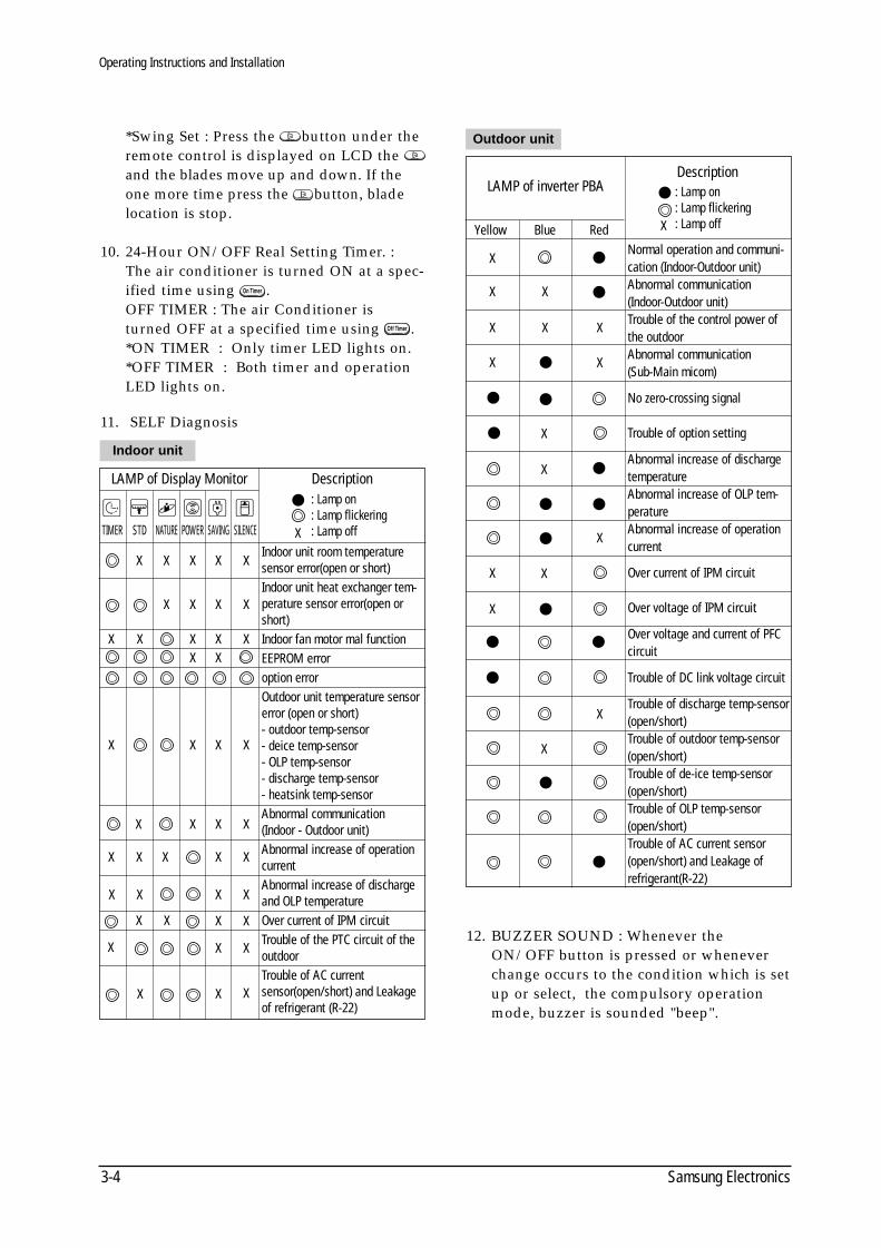
11. SELF Diagnosis
12. BUZZER SOUND : Whenever theON/OFF button is pressed or wheneverchange occurs to the condition which is setup or select, the compulsory operationmode, buzzer is sounded "beep".
DescriptionLAMP of Display Monitor
STDTIMER NATURE POWER SAVING SILENCE
: Lamp on: Lamp flickering: Lamp off
Indoor unit room temperaturesensor error(open or short)Indoor unit heat exchanger tem-perature sensor error(open orshort)Indoor fan motor mal functionEEPROM erroroption errorOutdoor unit temperature sensorerror (open or short)- outdoor temp-sensor- deice temp-sensor- OLP temp-sensor- discharge temp-sensor- heatsink temp-sensorAbnormal communication (Indoor - Outdoor unit)Abnormal increase of operation currentAbnormal increase of dischargeand OLP temperature Over current of IPM circuitTrouble of the PTC circuit of theoutdoorTrouble of AC currentsensor(open/short) and Leakageof refrigerant (R-22)
X X X X X
X
X X X X
X XX X X
X XX X
XX X X
X X
X X
X X
X X
X X
X X
X
X
X
X
X X X
X X
Indoor unit
Outdoor unit
Normal operation and communi-cation (Indoor-Outdoor unit)Abnormal communication(Indoor-Outdoor unit)Trouble of the control power ofthe outdoorAbnormal communication (Sub-Main micom)
No zero-crossing signal
Trouble of option setting
Abnormal increase of dischargetemperatureAbnormal increase of OLP tem-peratureAbnormal increase of operationcurrent
Over current of IPM circuit
Over voltage of IPM circuit
Over voltage and current of PFCcircuit
Trouble of DC link voltage circuit
Trouble of discharge temp-sensor(open/short)Trouble of outdoor temp-sensor(open/short)Trouble of de-ice temp-sensor(open/short)Trouble of OLP temp-sensor(open/short)Trouble of AC current sensor(open/short) and Leakage ofrefrigerant(R-22)
DescriptionLAMP of inverter PBA
Yellow Blue Red
: Lamp on: Lamp flickering: Lamp off
X
X X
X X X
X
X
X
X
X
X
X
X
X
X
X
DB98_08728A(1)_SM_1 12/20/02 3:24 PM Page 3-2
3-5Samsung Electronics
3-2 Installation
3-2-1 Selecting Area for Installation
Select an area for installation that is suit-able to the customer's needs.
3-2-1(a) Indoor Unit
1. Make sure that you install the indoor unitin an area providing good ventilation. Itmust not be blocked by an obstacle affect-ing the airflow near the air inlet and theair outlet.
2. Make sure that you install the indoor unitin an area allowing good air handling andendurance of vibration of the indoor unit.
3. Make sure that you install the indoor unitin an area where there is no source of heator vapor nearby.
4. Make sure that you install the indoor unitin an area from which hot or cool air isspread evenly in a room.
5. Make sure that you install the indoor unitin an area away from TVs, audio units,cordless phones, fluorescent lighting fix-tures and other electrical appliances (atleast 1 meter).
6. Make sure that you install the indoor unitin an area which provides easy pipe con-nection with the outdoor unit, and easydrainage for condensed water.
7. Make sure that you install the indoor unitin an area which is large enough to acco-modate the measurements shown in figureon the next page.
3-2-1(b) Outdoor Unit
1. Make sure that you install the outdoorunit in area not exposed to the rain ordirect sun light.(Install a separate sunblind if exposed todirect sun light.)
2. Make sure that you install the outdoorunit in area allowing good air moment,not amplifying noise or vibration, espe-cially to avoid disturbing neighbours.
(Fix the unit firmly if it is mounted in ahigh place.)
3. Make sure that you install the outdoorunit in area providing good ventilationand which is not dusty. It must not beblocked by any obstacle affecting the air-flow near the air inlet and the air outlet.
4. Make sure that you install the outdoorunit in area free from animals or plants.
5. Make sure that you install the outdoorunit in area not blocking the traffic.
6. Make sure that you install the outdoorunit in area easy to drain condensed waterfrom the indoor unit.
7. Make sure that you install the outdoorunit in area which provides easy connec-tion within the maximum allowable length of acoolant pipe(15 meters).
8. Make sure that you install the outdoorunit in an area which is large enough toaccommodate the measurements.
3-2-1(c) Remote Control Unit
1. Make sure that you install the remote con-trol unit in an area free from obstaclessuch as curtains etc, which may block sig-nals from the remote control unit.
2. Make sure that you install the remote con-trol unit in an area not exposed todirect sunlight, and where there is nosource of heat.
3. Make sure that you install the remote con-trol unit in an area away from TVs, audiounits, cordless phones, fluorescent lightingfixtures and other electrical appliances (atleast 1 meter).
1. Add 20 grams of refrigerant (R-22) for every 1 meterif the pipe length exceeds the standard pipe lengthof 5 meters.
2. Maintain a height between the indoor and outdoorunits.
Note
CautionIt is harmful to the air conditioner if it is used in the following environments: greasy areas (including areas nearmachines), salty areas such as coast areas, areas where sulfuric gas is present such as hot spring areas. Contact yourdealer for advice.
DB98_08728A(1)_SM_1 12/20/02 3:24 PM Page 3-3
Operating Instructions and Installation
Samsung Electronics3-6
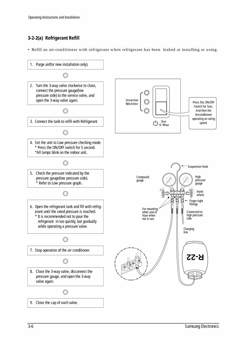
3-2-2(a) Refrigerant Refill
• Refill an air-conditioner with refrigerant when refrigerant has been leaked at installing or using.
R-22
Suspension hook
Highpressuregauge
Handwheel
Finger tightfittings
Connected tohigh pressureside
Chargingline
For mountingother and ofhose whennot in use
Compoundgauge
Press this ON/OFFSwitch for 5sec.
And then theAirconditioner
operating on ratingspeed.
1. Purge air(for new installation only).
3. Connect the tank to refill with Refrigerant
4. Set the unit to Low pressure checking mode.* Press the ON/OFF switch for 5 second.*All lamps blink on the indoor unit.
7. Stop operation of the air conditioner.
9. Close the cap of each valve.
2. Turn the 3-way valve clockwise to close, connect the pressure gauge(low pressure side) to the service valve, and open the 3-way valve again.
5. Check the pressure indicated by thepressure gauge(low pressure side).* Refer to Low pressure graph.
6. Open the refrigerant tank and fill with refrig-erant until the rated pressure is reached.* It is recommended not to pour the
refrigerant in too quickly, but gradually while operating a pressure valve.
8. Close the 3-way valve, disconnect the pressure gauge, and open the 3-way valve again.
DB98_08728A(1)_SM_1 12/20/02 3:24 PM Page 3-4
Operating Instructions and Installation
3-7Samsung Electronics
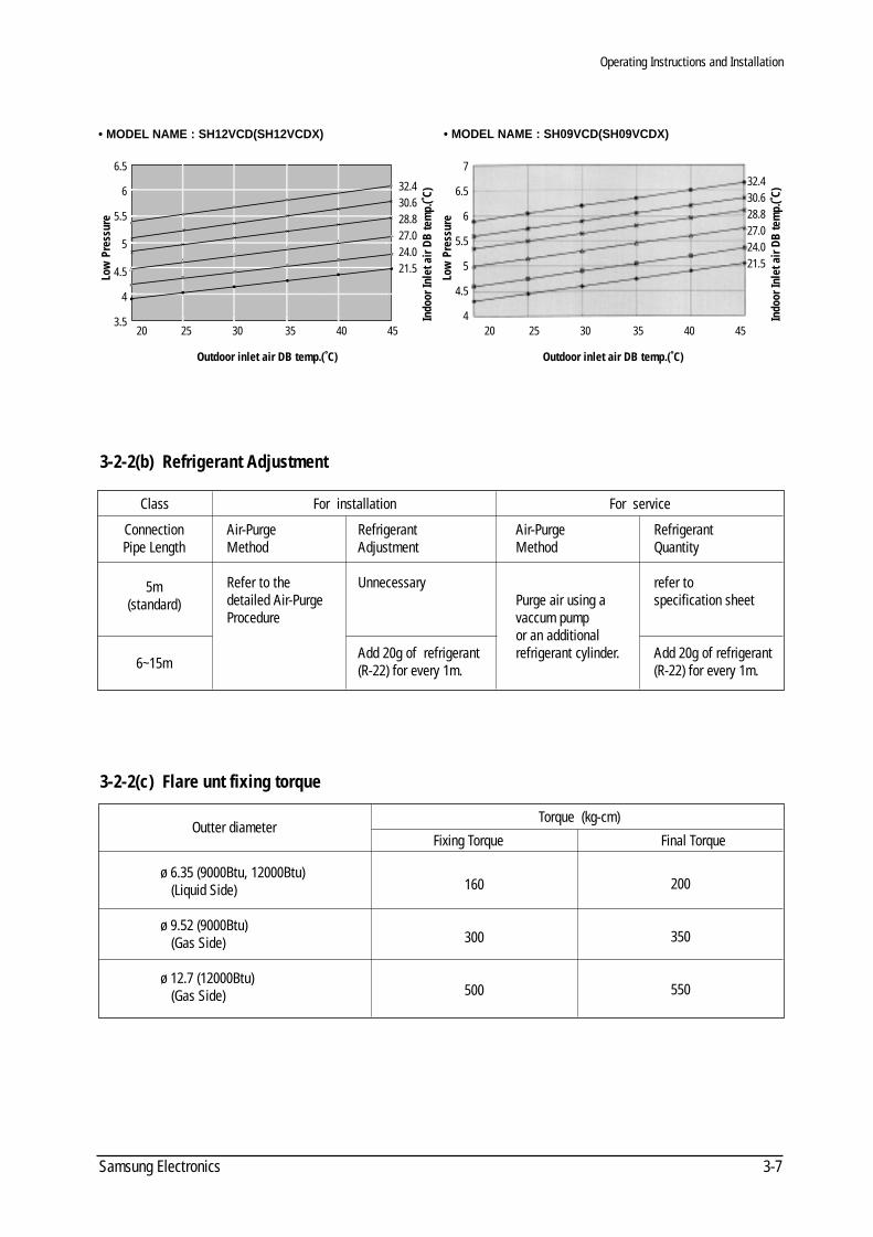
3-2-2(b) Refrigerant Adjustment
3-2-2(c) Flare unt fixing torque
Class For installation For service
Outter diameter
ø 6.35 (9000Btu, 12000Btu)(Liquid Side)
ø 9.52 (9000Btu)(Gas Side)
ø 12.7 (12000Btu)(Gas Side)
160
300
500
200
350
550
Fixing Torque Final Torque
Torque (kg-cm)
ConnectionPipe Length
5m(standard)
6~15m
Air-PurgeMethod
Refer to thedetailed Air-PurgeProcedure
RefrigerantAdjustment
Unnecessary
Add 20g of refrigerant (R-22) for every 1m.
Air-PurgeMethod
Purge air using avaccum pumpor an additionalrefrigerant cylinder.
RefrigerantQuantity
refer tospecification sheet
Add 20g of refrigerant (R-22) for every 1m.
20 25 30 35 40 45
32.430.628.827.024.021.5
6.5
6
5.5
5
4.5
4
3.5
Low
Pre
ssur
e
Outdoor inlet air DB temp.(˚C)
Indo
or In
let a
ir D
B te
mp.
(˚C)
20 25 30 35 40 45
32.430.628.827.024.021.5
7
6.5
6
5.5
5
4.5
4
Low
Pre
ssur
e
Outdoor inlet air DB temp.(˚C)
Indo
or In
let a
ir D
B te
mp.
(˚C)
• MODEL NAME : SH12VCD(SH12VCDX) • MODEL NAME : SH09VCD(SH09VCDX)
DB98_08728A(1)_SM_1 12/20/02 3:25 PM Page 3-5
Samsung Electronics4-1
4. Disassembly and Reassembly
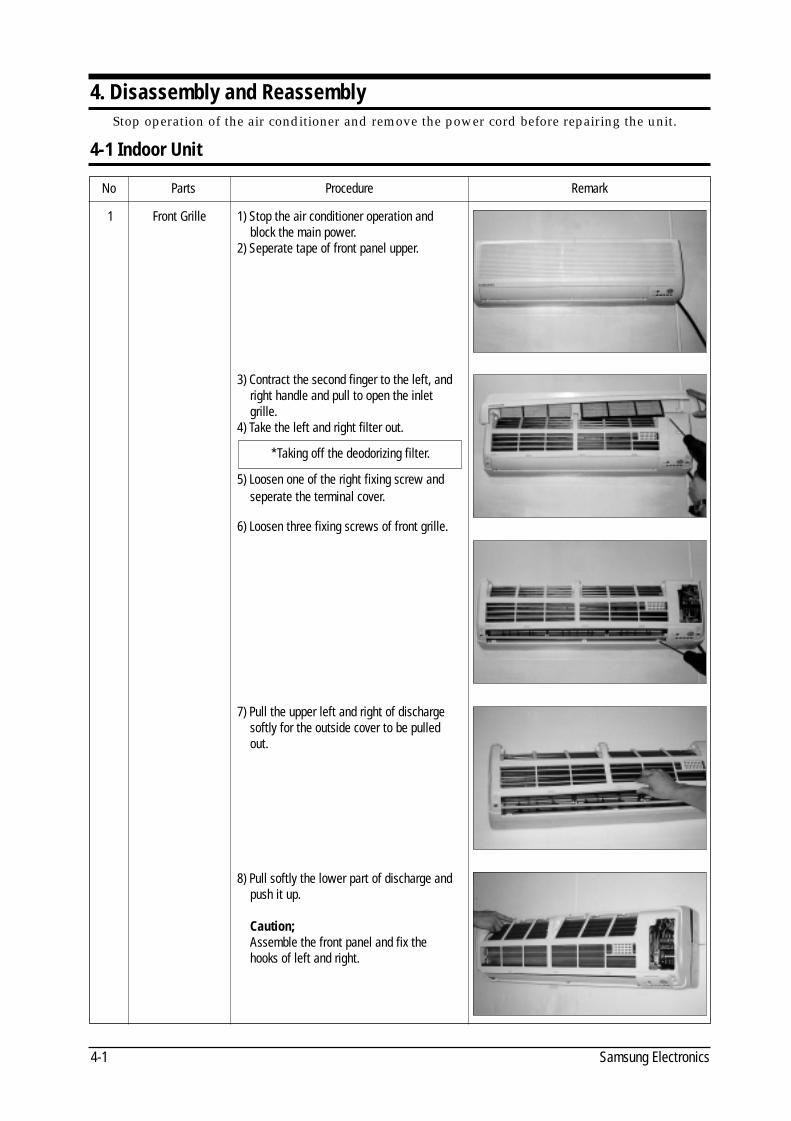
4-1 Indoor Unit
Stop operation of the air conditioner and remove the power cord before repairing the unit.
No Parts Procedure Remark
1 Front Grille 1) Stop the air conditioner operation andblock the main power.
2) Seperate tape of front panel upper.
3) Contract the second finger to the left, andright handle and pull to open the inletgrille.
4) Take the left and right filter out.
5) Loosen one of the right fixing screw andseperate the terminal cover.
6) Loosen three fixing screws of front grille.
7) Pull the upper left and right of dischargesoftly for the outside cover to be pulledout.
8) Pull softly the lower part of discharge andpush it up.
Caution;Assemble the front panel and fix the hooks of left and right.
*Taking off the deodorizing filter.
DB98_08728A(1)_SM_1 12/20/02 3:25 PM Page 3-6
Disassembly and Reassembly
4-2Samsung Electronics
No Parts Procedure Remark
2
3
4
5
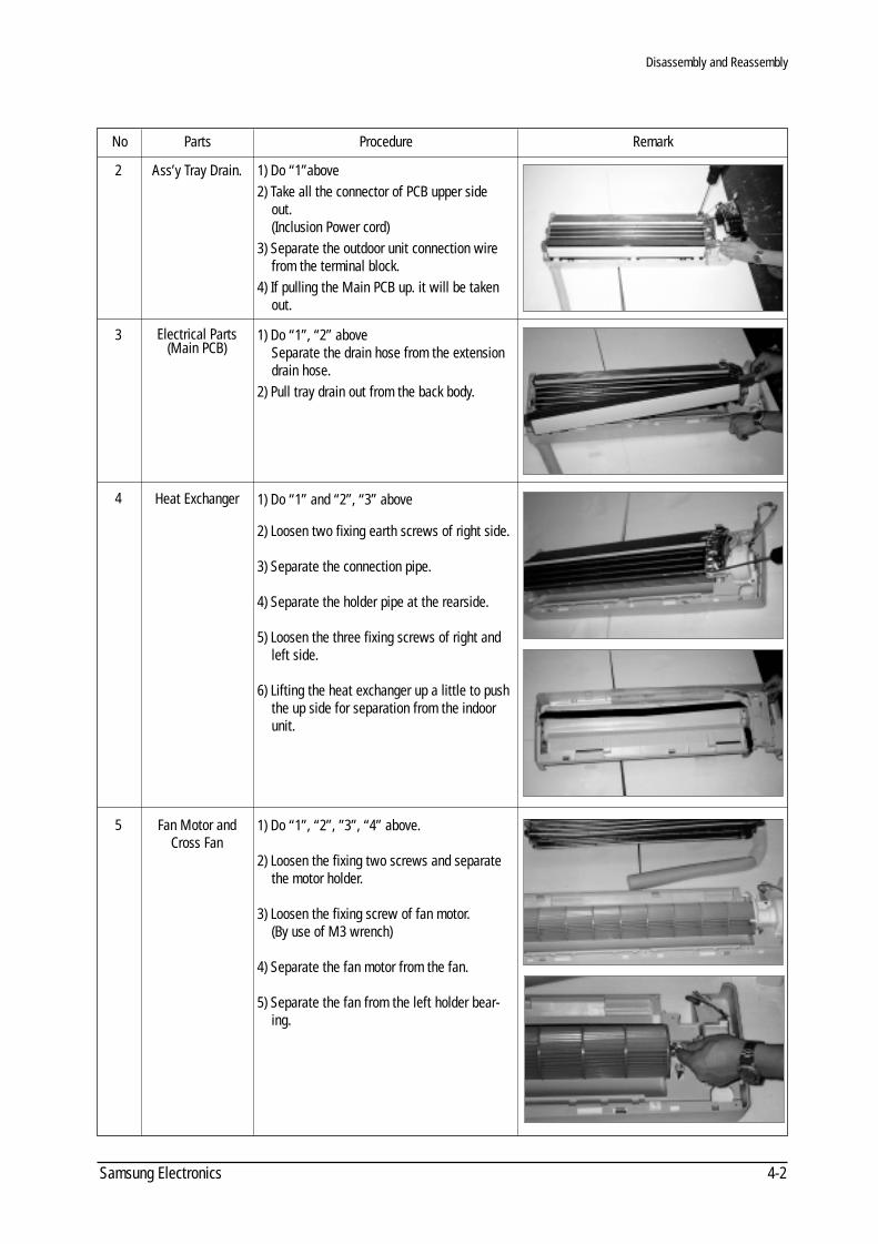
Ass’y Tray Drain.
Electrical Parts(Main PCB)
Heat Exchanger
Fan Motor andCross Fan
1) Do “1”above2) Take all the connector of PCB upper side
out.(Inclusion Power cord)
3) Separate the outdoor unit connection wirefrom the terminal block.
4) If pulling the Main PCB up. it will be takenout.
1) Do “1”, “2” aboveSeparate the drain hose from the extensiondrain hose.
2) Pull tray drain out from the back body.
1) Do “1” and “2”, “3” above
2) Loosen two fixing earth screws of right side.
3) Separate the connection pipe.
4) Separate the holder pipe at the rearside.
5) Loosen the three fixing screws of right andleft side.
6) Lifting the heat exchanger up a little to pushthe up side for separation from the indoorunit.
1) Do “1”, “2”, ”3”, “4” above.
2) Loosen the fixing two screws and separatethe motor holder.
3) Loosen the fixing screw of fan motor.(By use of M3 wrench)
4) Separate the fan motor from the fan.
5) Separate the fan from the left holder bear-ing.
DB98_08728A(1)_SM_1 12/20/02 3:25 PM Page 3-7
Samsung Electronics4-3
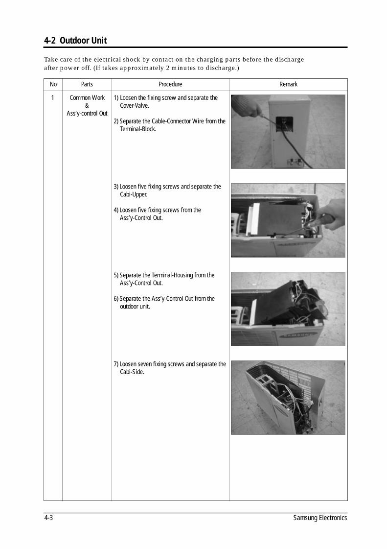
4-2 Outdoor Unit
No Parts Procedure Remark
1 Common Work&
Ass’y-control Out
1) Loosen the fixing screw and separate theCover-Valve.
2) Separate the Cable-Connector Wire from theTerminal-Block.
3) Loosen five fixing screws and separate theCabi-Upper.
4) Loosen five fixing screws from theAss’y-Control Out.
5) Separate the Terminal-Housing from theAss’y-Control Out.
6) Separate the Ass’y-Control Out from theoutdoor unit.
7) Loosen seven fixing screws and separate theCabi-Side.
Take care of the electrical shock by contact on the charging parts before the dischargeafter power off. (If takes approximately 2 minutes to discharge.)
DB98_08728A(1)_SM_1 12/20/02 3:25 PM Page 3-8
Disassembly and Reassembly
4-4Samsung Electronics
No Parts Procedure Remark
2
3
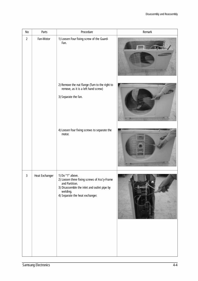
Fan-Motor
Heat Exchanger
1) Loosen Four fixing screw of the Guard-Fan.
2) Remove the nut flange (Turn to the right toremove, as it is a left hand screw)
3) Separate the fan.
4) Loosen four fixing screws to separate themotor.
1) Do “1” above.2) Loosen three fixing screws of Ass’y-Frame
and Partition.3) Disassemble the inlet and outlet pipe by
welding. 4) Separate the heat exchanger.
DB98_08728A(1)_SM_1 12/20/02 3:25 PM Page 3-9
Disassembly and Reassembly
Samsung Electronics4-5
No Parts Procedure Remark
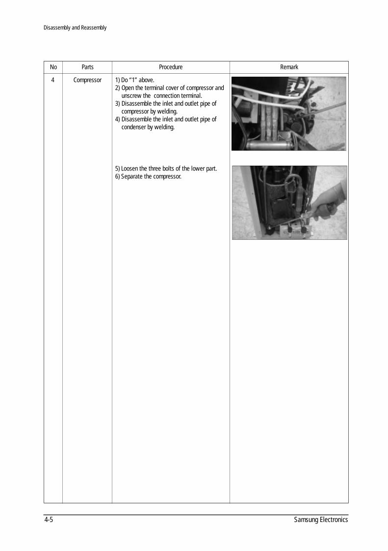
4 Compressor 1) Do “1” above.2) Open the terminal cover of compressor and
unscrew the connection terminal.3) Disassemble the inlet and outlet pipe of
compressor by welding.4) Disassemble the inlet and outlet pipe of
condenser by welding.
5) Loosen the three bolts of the lower part.6) Separate the compressor.
DB98_08728A(1)_SM_1 12/20/02 3:25 PM Page 3-10
5-1Samsung Electronics
5. Troubleshooting
5-1 Basic items for trouble shooting
Since the inverter air conditioner is equipped with Electrical control circuits at both Indoor &outdoor unit, the trouble shooting shall be performed according to the error mode.Inside the controller of the outdoor unit (inverter), the large capacity of electrolytic condenserso that it takes the time to discharge after the power off since the electrical charge remains(the charging voltage DC 340V). Take care of the electrical shock by contact on the charging part before the discharge after thepower off. (It takes approximately 2 minutes to discharge).
1) Is the power source proper?The power source shall be in the range of the rated voltage ±10%. If it is out of this range, itmay cause the abnormal operation.
2) Is the connection made between the indoor and outdoor unit?The connection between indoor and outdoor unit shall be performed with 4 wire. (connectioncable of indoor and outdoor unit + ground wire).
3) The phenomena as follows are not out of order.
NO Phenomena Cause and reason
The operation is not done.
The wind comes out but theheating/cooling is notperformed.
The remote controller doesnot operate.
The wind volume is notadjusted.
The temperature is not set.
The operation lamp continuesto be flickering.
The immediate operationstarts without control ofremote controller whenplugged
1
2
3
4
5
6
7
• Is the power off or the power unplugged?• Does it stop because it is the completion time?• Unplug and plug again the power source for 2 minutes.
• Is the filter clogged with dust or dirty?• Is there any direct light on the outdoor unit or any obstacle against it?• Is the selected temperature too high? Lower the selected temperature lower than the
current one (during cooling).• Is the selected temperature too low? Raise the desired temperature than the
current one (during heating).• Is the “Fan only Mode” operation?
• Is the battery run out?• Is the battery inserted in the wrong way(+, -)?• Is the detection part of the indoor unit blocked?• Does it interfered with the radio of neon sign?
• Is the operation selected among one of Auto / Dry / Turbo / Sleeping?• The temperature setting is not required since the wind volume set automatically.• Check again at the state of Cooling / Fan only / Heating.
• Is the operation selected among the Dry / Turbo / Sleeping / Fan only Mode.• Since the temperature is automatically set, the temperature setting is not required.• Check again at the cooling/heating state.• The standard temperature ±2˚C during the automatic operation.
• Push the Operation / Stop button.• Unplug and plug the power source.
• It is the case that the auto restart function works.# Auto restart function is the convenient function where the operation state is memorized
in the Memory IC during the blackout and the operation restarts when the power comesback.
DB98_08728A(1)_SM_1 12/20/02 3:25 PM Page 3-11
Indoor unit room temperature sensor error(open or short)
Indoor unit heat exchanger temperature sensor error
(open or short)
Indoor fan motor mal function
EEPROM error
Option error
Outdoor unit temperature sensor error(open or short)
- outdoor temp-sensor
- deice temp-sensor
- OLP temp- sensor
- discharge temp-sensor
- heatsink temp-sensor
Abnormal communication (Indoor - Outdoor unit)
\Abnormal increase of operation current
Abnormal increase of discharge and OLP temperature
Over current of IPM circuit
Trouble of the PTC circuit of the outdoor
Trouble of AC current sensor (open/short) and Leakage of
refrigerant(R-22)
Samsung Electronics5-2
5-2 The first determination method of troubled part
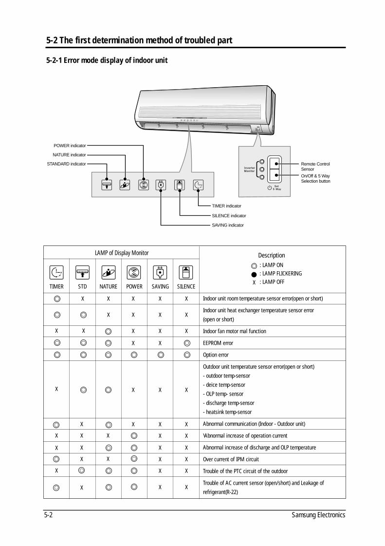
5-2-1 Error mode display of indoor unit
Description
TIMER STD NATURE POWER SAVING SILENCE
POWER indicator
NATURE indicator
STANDARD indicator
TIMER indicator
Remote ControlSensor
On/Off & 5 WaySelection button
SILENCE indicator
SAVING indicator
LAMP of Display Monitor
: LAMP ON: LAMP FLICKERING: LAMP OFFX
XXXX
XXX
XXX
XX
XXX
XX
XX
XX
XX
XX
XX
X
X
XX
X
X
X
X
X
X X
X
X
X
X
X
DB98_08728A(1)_SM_1 12/20/02 3:25 PM Page 3-12
Troubleshooting
5-3Samsung Electronics
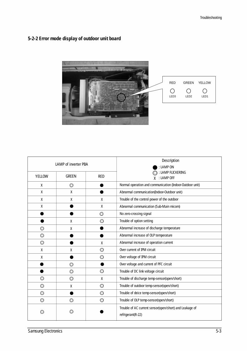
5-2-2 Error mode display of outdoor unit board
RED GREEN YELLOW
LED3 LED2 LED1
YELLOW
LAMP of inverter PBA
GREEN RED
Description
Normal operation and communication (Indoor-Outdoor unit)
Abnormal communication(Indoor-Outdoor unit)
Trouble of the control power of the outdoor
Abnormal communication (Sub-Main micom)
No zero-crossing signal
Trouble of option setting
Abnormal increase of discharge temperature
Abnormal increase of OLP temperature
Abnormal increase of operation current
Over current of IPM circuit
Over voltage of IPM circuit
Over voltage and current of PFC circuit
Trouble of DC link voltage circuit
Trouble of discharge temp-sensor(open/short)
Trouble of outdoor temp-sensor(open/short)
Trouble of deice temp-sensor(open/short)
Trouble of OLP temp-sensor(open/short)
Trouble of AC current sensor(open/short) and Leakage of
refrigerant(R-22)
: LAMP ON: LAMP FLICKERING: LAMP OFFX
X
X X
X X X
X
X
X
X
X
X
X
X
X
X
DB98_08728A(1)_SM_1 12/20/02 3:25 PM Page 3-13
Samsung Electronics5-4
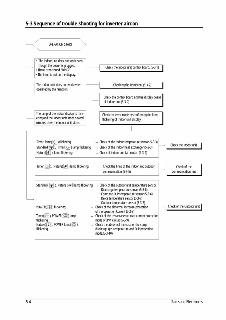
5-3 Sequence of trouble shooting for inverter aircon
OPERATION START
• The indoor unit does not work eventhough the power is plugged.
•There is no sound “DING”•The lamp is not on the display.
The indoor unit does not work when operated by the remocon.
The lamp of the indoor display is flick-ering and the indoor unit stops severalminutes after the indoor unit starts.
Timer lamp( ) flickering → Check of the indoor temperature sensor (5-3-3)Standard( ), Timer( ) lamp flickering → Check of the indoor heat exchanger (5-3-3) Nature( ) lamp flickering → Check of indoor unit fan motor (5-3-4)
Timer( ), Nature( ) lamp flickering → Check the lines of the indoor and outdoor communication (5-3-5)
Standard( ), Nature ( ) lamp flickering → Check of the outdoor unit temperature sensor: Discharge temperature sensor (5-3-6): Comp top OLP temperature sensor (5-3-6) : Deice temperature sensor (5-3-7) : Outdoor temperature sensor (5-3-7)
POWER( ) flickering → Check of the abnormal increase protection of the operation Current (5-3-8)
Timer( ), POWER( ) lamp → Check of the instantaneous over-current protectionflickering mode of IPM circuit (5-3-9)Nature( ), POWER lamp( ) → Check the abnormal increase of the comp flickering discharge gas temperature and OLP protection
mode.(5-3-10)
Check the indoor unit control board. (5-3-1)
Checking the Remocon. (5-3-2)
Check the control board and the display boardof indoor unit.(5-3-2)
Check the error mode by confirming the lampflickering of indoor unit display.
Check the indoor unit
Check of theCommunication line
Check of the Outdoor unit
DB98_08728A(1)_SM_1 12/20/02 3:25 PM Page 3-14
Troubleshooting
5-5Samsung Electronics
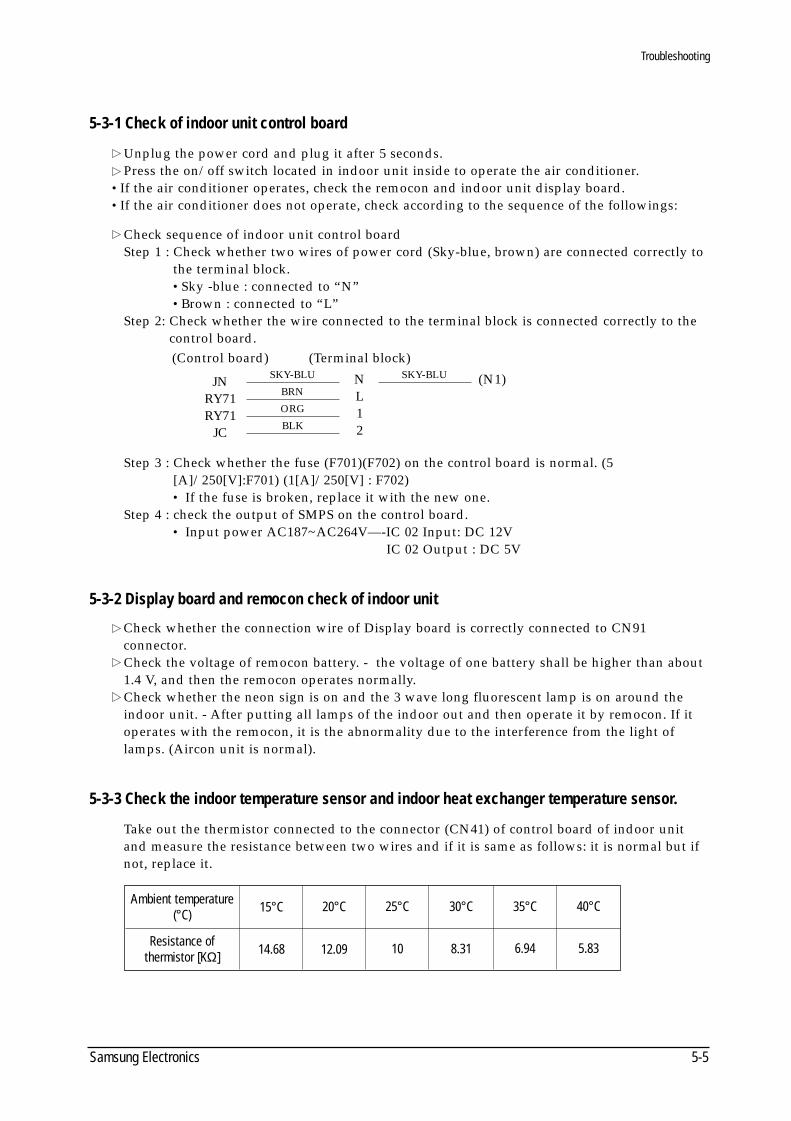
5-3-1 Check of indoor unit control board
Unplug the power cord and plug it after 5 seconds.Press the on/off switch located in indoor unit inside to operate the air conditioner.
•If the air conditioner operates, check the remocon and indoor unit display board.•If the air conditioner does not operate, check according to the sequence of the followings:
Check sequence of indoor unit control boardStep 1 : Check whether two wires of power cord (Sky-blue, brown) are connected correctly to
the terminal block.•Sky -blue : connected to “N”•Brown : connected to “L”
Step 2: Check whether the wire connected to the terminal block is connected correctly to thecontrol board.
Step 3 : Check whether the fuse (F701)(F702) on the control board is normal. (5[A]/250[V]:F701) (1[A]/250[V] : F702)• If the fuse is broken, replace it with the new one.
Step 4 : check the output of SMPS on the control board.• Input power AC187~AC264V—-IC 02 Input: DC 12V
IC 02 Output : DC 5V
5-3-2 Display board and remocon check of indoor unit
Check whether the connection wire of Display board is correctly connected to CN91 connector.Check the voltage of remocon battery. - the voltage of one battery shall be higher than about 1.4 V, and then the remocon operates normally.Check whether the neon sign is on and the 3 wave long fluorescent lamp is on around theindoor unit. - After putting all lamps of the indoor out and then operate it by remocon. If itoperates with the remocon, it is the abnormality due to the interference from the light oflamps. (Aircon unit is normal).
5-3-3 Check the indoor temperature sensor and indoor heat exchanger temperature sensor.
Take out the thermistor connected to the connector (CN41) of control board of indoor unitand measure the resistance between two wires and if it is same as follows: it is normal but ifnot, replace it.
15°CAmbient temperature(°C)
Resistance of thermistor [KΩ] 14.68 12.09 10 8.31 6.94 5.83
20°C 25°C 30°C 35°C 40°C
(Control board)
JNRY71RY71
JC
(Terminal block)
NL12
SKY-BLU
BRN
ORG
BLK
(N1)SKY-BLU
DB98_08728A(1)_SM_1 12/20/02 3:25 PM Page 3-15
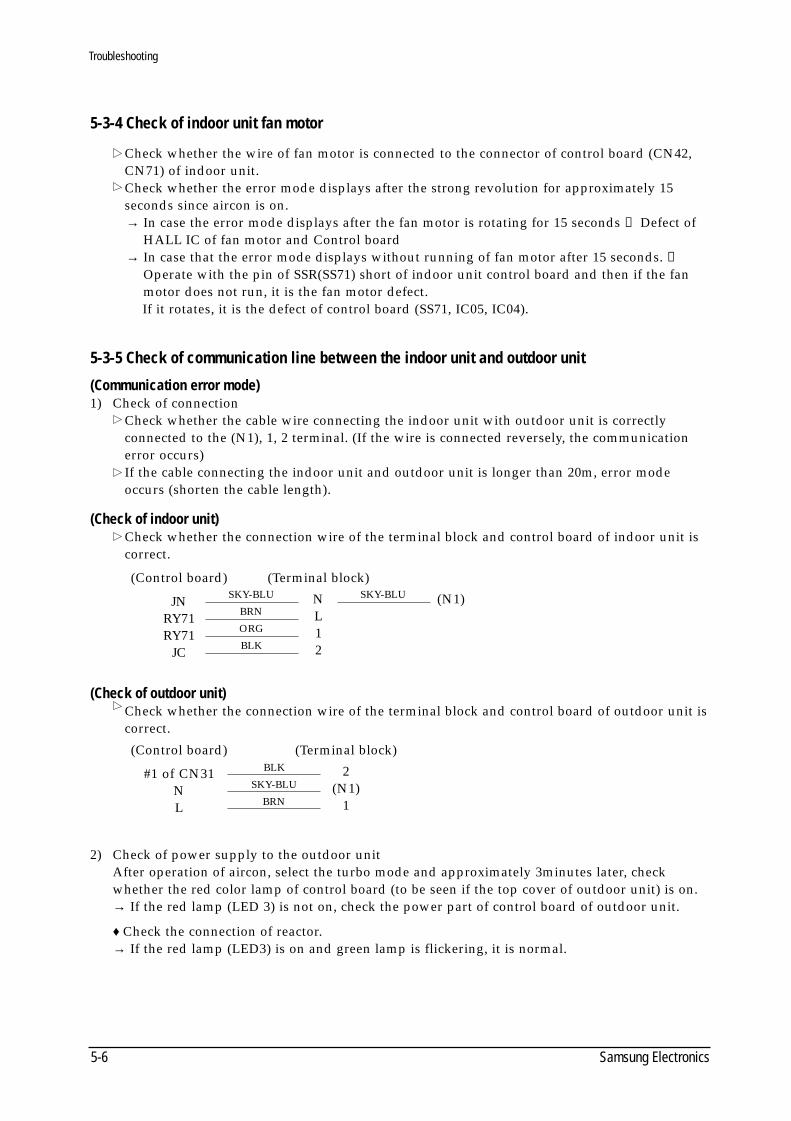
5-3-4 Check of indoor unit fan motor
Check whether the wire of fan motor is connected to the connector of control board (CN42,CN71) of indoor unit.Check whether the error mode displays after the strong revolution for approximately 15 seconds since aircon is on.→ In case the error mode displays after the fan motor is rotating for 15 seconds → Defect of
HALL IC of fan motor and Control board→ In case that the error mode displays without running of fan motor after 15 seconds. →
Operate with the pin of SSR(SS71) short of indoor unit control board and then if the fanmotor does not run, it is the fan motor defect. If it rotates, it is the defect of control board (SS71, IC05, IC04).
5-3-5 Check of communication line between the indoor unit and outdoor unit
(Communication error mode)1) Check of connection
Check whether the cable wire connecting the indoor unit with outdoor unit is correctly connected to the (N1), 1, 2 terminal. (If the wire is connected reversely, the communicationerror occurs)If the cable connecting the indoor unit and outdoor unit is longer than 20m, error modeoccurs (shorten the cable length).
(Check of indoor unit)Check whether the connection wire of the terminal block and control board of indoor unit is correct.
(Check of outdoor unit)Check whether the connection wire of the terminal block and control board of outdoor unit iscorrect.
2) Check of power supply to the outdoor unitAfter operation of aircon, select the turbo mode and approximately 3minutes later, checkwhether the red color lamp of control board (to be seen if the top cover of outdoor unit) is on.→ If the red lamp (LED 3) is not on, check the power part of control board of outdoor unit.
♦ Check the connection of reactor. → If the red lamp (LED3) is on and green lamp is flickering, it is normal.
Troubleshooting
Samsung Electronics5-6
(Control board)
JNRY71RY71
JC
(Terminal block)
NL12
SKY-BLU
BRN
ORG
BLK
(N1)SKY-BLU
(Control board)
#1 of CN31NL
(Terminal block)
2(N1)
1
BLK
SKY-BLU
BRN
DB98_08728A(1)_SM_1 12/20/02 3:25 PM Page 3-16
Troubleshooting
5-7Samsung Electronics
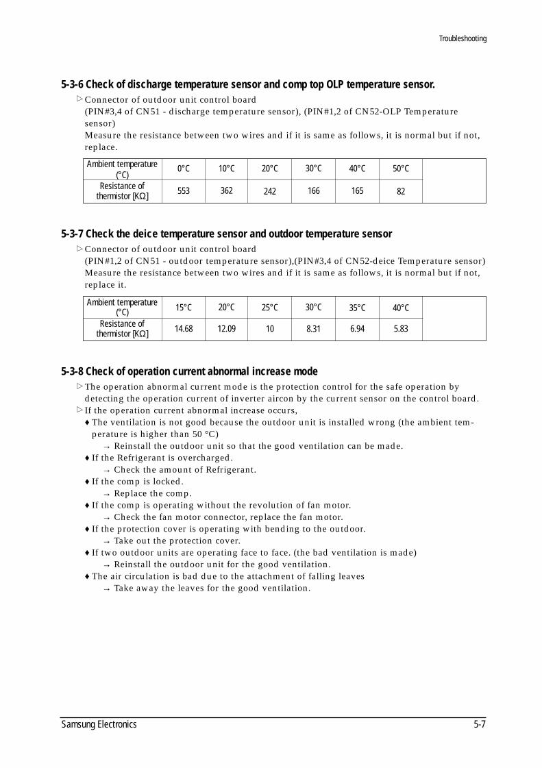
5-3-6 Check of discharge temperature sensor and comp top OLP temperature sensor.Connector of outdoor unit control board(PIN#3,4 of CN51 - discharge temperature sensor), (PIN#1,2 of CN52-OLP Temperature sensor)Measure the resistance between two wires and if it is same as follows, it is normal but if not,replace.
5-3-7 Check the deice temperature sensor and outdoor temperature sensorConnector of outdoor unit control board(PIN#1,2 of CN51 - outdoor temperature sensor),(PIN#3,4 of CN52-deice Temperature sensor)Measure the resistance between two wires and if it is same as follows, it is normal but if not,replace it.
5-3-8 Check of operation current abnormal increase modeThe operation abnormal current mode is the protection control for the safe operation bydetecting the operation current of inverter aircon by the current sensor on the control board.If the operation current abnormal increase occurs, ♦ The ventilation is not good because the outdoor unit is installed wrong (the ambient tem-
perature is higher than 50 °C) → Reinstall the outdoor unit so that the good ventilation can be made.
♦ If the Refrigerant is overcharged. → Check the amount of Refrigerant.
♦ If the comp is locked. → Replace the comp.
♦ If the comp is operating without the revolution of fan motor.→ Check the fan motor connector, replace the fan motor.
♦ If the protection cover is operating with bending to the outdoor. → Take out the protection cover.
♦ If two outdoor units are operating face to face. (the bad ventilation is made) → Reinstall the outdoor unit for the good ventilation.
♦ The air circulation is bad due to the attachment of falling leaves → Take away the leaves for the good ventilation.
0°CAmbient temperature(°C)
Resistance ofthermistor [KΩ] 553 362 242 166 165 82
10°C 20°C 30°C 40°C 50°C
Ambient temperature(°C)
Resistance ofthermistor [KΩ]
15°C
14.68 12.09 10 8.31 6.94 5.83
20°C 25°C 30°C 35°C 40°C
DB98_08728A(1)_SM_1 12/20/02 3:25 PM Page 3-17
Troubleshooting
Samsung Electronics5-8
5-3-9 Check of instantaneous over-current protection of IPM circuit.
Inverter instantaneous over-current protection mode is the mode to be actuated in order toprevent the damage of elements from the peak current of IPM circuit elements.In case that the inverter circuit instantaneous over-current protection mode actuates, checkthe following items.
(Condition of installation)♦ The ventilation is not good because the outdoor unit is installed wrong (the ambient
temperature is higher than 50 (°C) )→ Reinstall the outdoor unit so that the good ventilation can be made.
♦ In case that the operation is made with the cover bent of the outdoor unit. → Take out the cover.
♦ If two outdoor units are operating face to face, (the bad ventilation is made) → Reinstall the outdoor unit for the good ventilation.
♦ The air circulation is bad due to the attachment of falling leaves. → Take away the leaves for the good ventilation.
♦ If the Refrigerant is overcharged. → Check the amount of Refrigerant.
(Unit defect)♦ If the comp is locked.
→ Replace the comp.♦ If the comp is operating without the revolution of fan motor.
→ Check the fan motor connector and replace the fan motor.♦ In case the parts of the control board is damaged.
→ Replace simultaneously the inverter control board.
5-3-10 Check of the comp discharge gas temperature and OLP temperature abnormal rise.
If the comp discharge gas temperature and OLP temperature rises higher than a certain level,it protects the circuit.If the comp discharge gas temperature and OLP temperature rises abnormally, check the following items.
(Condition of installation)♦ The ventilation is not good because the outdoor unit is installed wrong (the ambient
temperature is higher than 50 (°C) )→ Reinstall the outdoor unit so that the good ventilation can be made.
♦ In case that the operation is made with the cover bent of the outdoor unit. → Take out the cover.
♦ If two outdoor units are operating face to face, (the bad ventilation is made)→ Reinstall the outdoor unit for the good ventilation.
♦ The air circulation is bad due to the attachment of falling leaves→ Take away the leaves for the good ventilation.
♦ If the refrigerant is insufficient. → Fill up the amount of refrigerant.
(Unit defect)♦ If the comp is locked.
→ Replace the comp.♦ If the comp is operating without the revolution of fan motor
→ Take out the protection cover.→ Check the fan motor connector and replace the fan motor.
DB98_08728A(1)_SM_1 12/20/02 3:25 PM Page 3-18
5-9Samsung Electronics
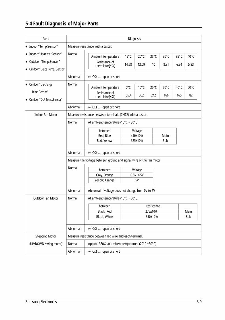
5-4 Fault Diagnosis of Major Parts
Diagnosis
Measure resistance with a tester.
Normal
Abnormal ∞, OΩ … open or short
Normal
Abnormal ∞, OΩ … open or short
Measure resistance between terminals (CN72) with a tester
Normal At ambient temperature (10°C ~ 30°C)
Abnormal ∞, OΩ … open or short
Measure the voltage between ground and signal wire of the fan motor
Normal
Abnormal Abnormal if voltage does not change from 0V to 5V.
Normal At ambient temperature (10°C ~ 30°C)
Abnormal ∞, OΩ … open or short
Measure resistance between red wire and each terminal.
Normal Approx. 380Ω at ambient temperature (20°C ~30°C)
Abnormal ∞, OΩ … open or short
Ambient temperature 15°C 20°C 25°C 30°C 35°C 40°C
Resistance of 14.68 12.09 10 8.31 6.94 5.83thermistor[KΩ]
Ambient temperature 0°C 10°C 20°C 30°C 40°C 50°CResistance of
553 362 242 166 165 82thermistor[KΩ]
between ResistanceBlack, Red 275±10% Main
Black, White 350±10% Sub
between VoltageGray, Orange 0.5V~4.5V
Yellow, Orange 5V
between VoltageRed, Blue 410±10% Main
Red, Yellow 325±10% Sub
Parts
♦ Indoor ”Temp.Sensor”
♦ Indoor “Heat ex. Sensor”
♦ Outdoor “Temp.Sensor”
♦ Outdoor “Deice Temp. Sensor”
♦ Outdoor “Discharge
Temp.Sensor”
♦ Outdoor “OLP Temp.Sensor”
Indoor Fan Motor
Outdoor Fan Motor
Stepping Motor
(UP/DOWN swing motor)
DB98_08728A(1)_SM_1 12/20/02 3:25 PM Page 4-1
Samsung Electronics5-10
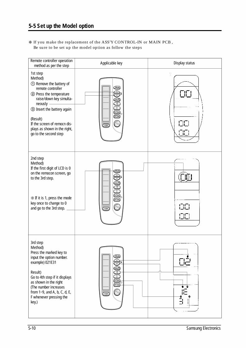
5-5 Set up the Model option
If you make the replacement of the ASS’Y CONTROL-IN or MAIN PCB , Be sure to be set up the model option as follow the steps
Remote controller operationmethod as per the step
Applicable key Display status
1st stepMethod)! Remove the battery of
remote controller@ Press the temperature
raise/down key simulta-neously
# Insert the battery again
(Result)If the screen of remocn dis-plays as shown in the right,go to the second step
2nd stepMethod)If the first digit of LCD is 0on the remocon screen, goto the 3rd step.
If it is 1, press the modekey once to change to 0and go to the 3rd step.
3rd stepMethod)Press the marked key toinput the option number.example) 021E31
Result)Go to 4th step if it displaysas shown in the right(The number increasesfrom 1~9, and A, b, C, d, E,F whenever pressing thekey.)
DB98_08728A(1)_SM_1 12/20/02 3:25 PM Page 4-2
5-11Samsung Electronics
Remote controller operationmethod as per the step
Applicable key Display status
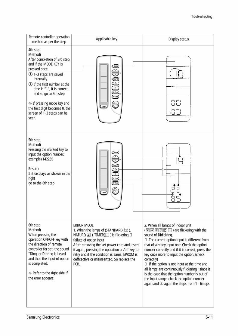
4th stepMethod)After completion of 3rd step,and if the MODE KEY ispressed once, ! 1~3 steps are saved
internally@ If the first number at the
time is “1”, it is correctand so go to 5th step
If pressing mode key andthe first digit becomes 0, thescreen of 1~3 steps can beseen.
5th stepMethod)Pressing the marked key toinput the option number.example) 142285
Result)If it displays as shown in theright go to the 6th step
6th stepMethod)When pressing the operation ON/OFF key withthe direction of remote controller for set, the sound“Ding, or Diriring is heardand then the input of optionis completed.
Refer to the right side ifthe error appears.
ERROR MODE1. When the lamps of (STANDARD( ),NATURE( ), TIMER( ) is flickering →
failute of option inputAfter removing the set power cord and insertit again, pressing the operation on/off key toretry and if the condition is same, EPROM is deffcective or misinsertted. So replace thePCB.
2. When all lamps of indoor unit( ) are flickering with thesound of Dididiring,→ The current option input is different fromthat of already input one: Check the optionnumber correctly and if it is correct, press thekey once more to input the option. (check correctly)→ If the option is not input at the time andall lamps are continuously flickering ; since itis the case that the option number is out ofthe input range, check the option numberagain and do again the steps from 1 - 6steps
Troubleshooting
DB98_08728A(1)_SM_1 12/20/02 4:02 PM Page 4-3
Troubleshooting
Samsung Electronics5-12
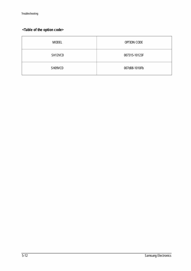
<Table of the option code>
MODEL
SH12VCD
SH09VCD
OPTION CODE
007315-10123F
007d08-1010Fb
DB98_08728A(1)_SM_1 12/20/02 3:25 PM Page 4-4
MEMO
5-13Samsung Electronics
DB98_08728A(1)_SM_1 12/20/02 3:25 PM Page 4-5
Samsung Electronics6-1
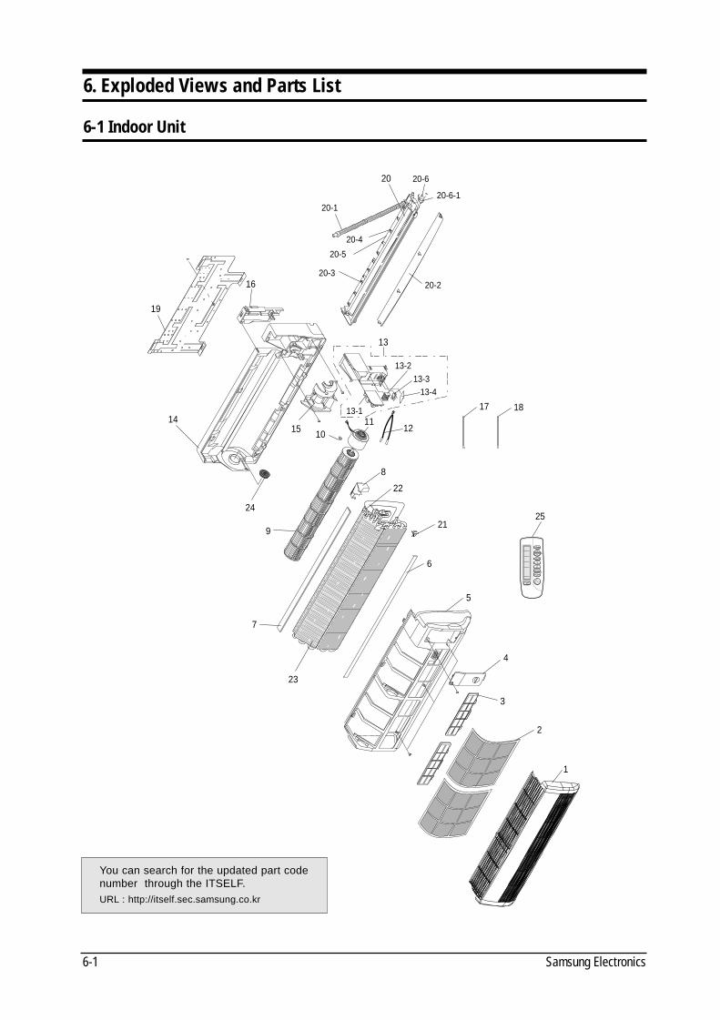
6. Exploded Views and Parts List
6-1 Indoor Unit
19
16
14
24
9
7
23
3
4
5
6
21
22
8
12
17
25
13-413-3
13-2
13
13-111
10
2
1
15
20-1
20-5
20-4
20 20-6
20-6-1
20-220-3
18
You can search for the updated part codenumber through the ITSELF.URL : http://itself.sec.samsung.co.kr
DB98_08728A(1)_SM_1 12/20/02 3:25 PM Page 4-6
Exploded Views and Parts List
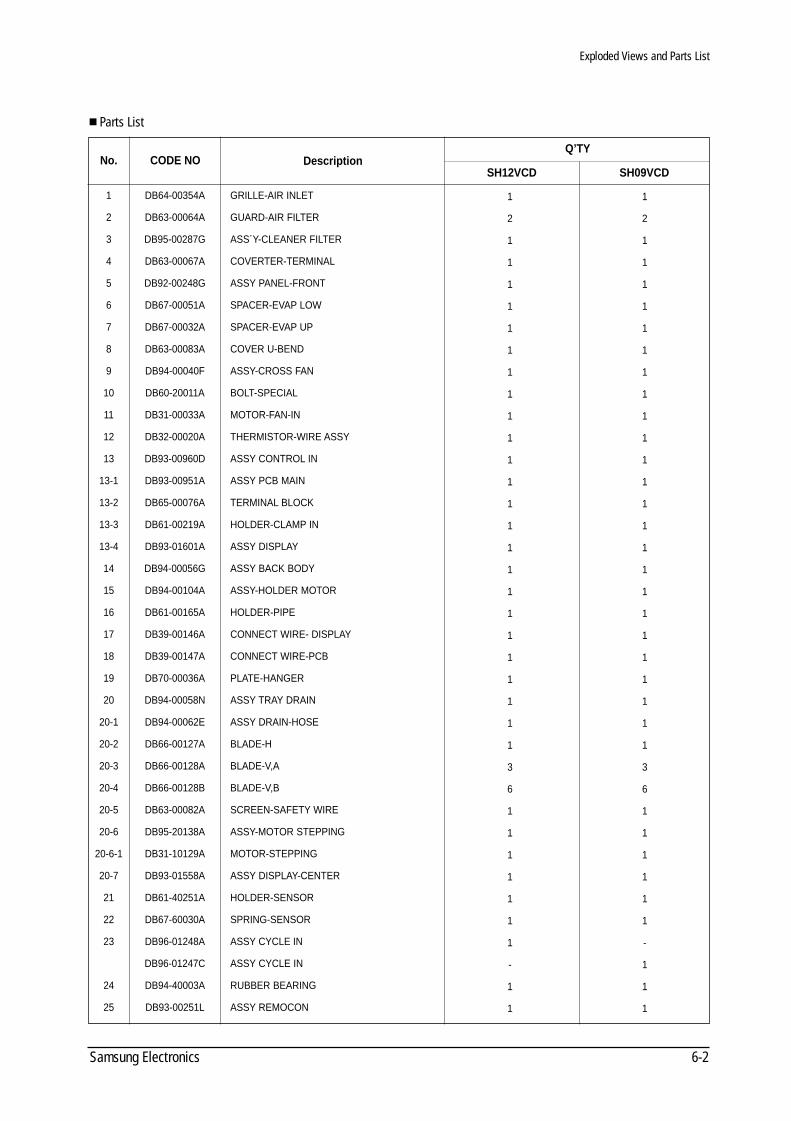
6-2Samsung Electronics
Q’TY
Parts List
CODE NONo. DescriptionSH12VCD SH09VCD
1
2
1
1
1
1
1
1
1
1
1
1
1
1
1
1
1
1
1
1
1
1
1
1
1
1
3
6
1
1
1
1
1
1
1
-
1
1
1
2
1
1
1
1
1
1
1
1
1
1
1
1
1
1
1
1
1
1
1
1
1
1
1
1
3
6
1
1
1
1
1
1
-
1
1
1
1
2
3
4
5
6
7
8
9
10
11
12
13
13-1
13-2
13-3
13-4
14
15
16
17
18
19
20
20-1
20-2
20-3
20-4
20-5
20-6
20-6-1
20-7
21
22
23
24
25
DB64-00354A
DB63-00064A
DB95-00287G
DB63-00067A
DB92-00248G
DB67-00051A
DB67-00032A
DB63-00083A
DB94-00040F
DB60-20011A
DB31-00033A
DB32-00020A
DB93-00960D
DB93-00951A
DB65-00076A
DB61-00219A
DB93-01601A
DB94-00056G
DB94-00104A
DB61-00165A
DB39-00146A
DB39-00147A
DB70-00036A
DB94-00058N
DB94-00062E
DB66-00127A
DB66-00128A
DB66-00128B
DB63-00082A
DB95-20138A
DB31-10129A
DB93-01558A
DB61-40251A
DB67-60030A
DB96-01248A
DB96-01247C
DB94-40003A
DB93-00251L
GRILLE-AIR INLET
GUARD-AIR FILTER
ASS´Y-CLEANER FILTER
COVERTER-TERMINAL
ASSY PANEL-FRONT
SPACER-EVAP LOW
SPACER-EVAP UP
COVER U-BEND
ASSY-CROSS FAN
BOLT-SPECIAL
MOTOR-FAN-IN
THERMISTOR-WIRE ASSY
ASSY CONTROL IN
ASSY PCB MAIN
TERMINAL BLOCK
HOLDER-CLAMP IN
ASSY DISPLAY
ASSY BACK BODY
ASSY-HOLDER MOTOR
HOLDER-PIPE
CONNECT WIRE- DISPLAY
CONNECT WIRE-PCB
PLATE-HANGER
ASSY TRAY DRAIN
ASSY DRAIN-HOSE
BLADE-H
BLADE-V,A
BLADE-V,B
SCREEN-SAFETY WIRE
ASSY-MOTOR STEPPING
MOTOR-STEPPING
ASSY DISPLAY-CENTER
HOLDER-SENSOR
SPRING-SENSOR
ASSY CYCLE IN
ASSY CYCLE IN
RUBBER BEARING
ASSY REMOCON
DB98_08728A(1)_SM_1 12/20/02 3:25 PM Page 4-7
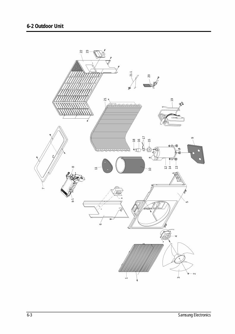
Samsung Electronics6-3
6-2 Outdoor Unit
1
6
3
7
2
4
5
10
9
1516
17
18
21
21-1
20
22 23
13141211
19
8-1
8
DB98_08728A(1)_SM_1 12/20/02 3:25 PM Page 4-8
Exploded Views and Parts List
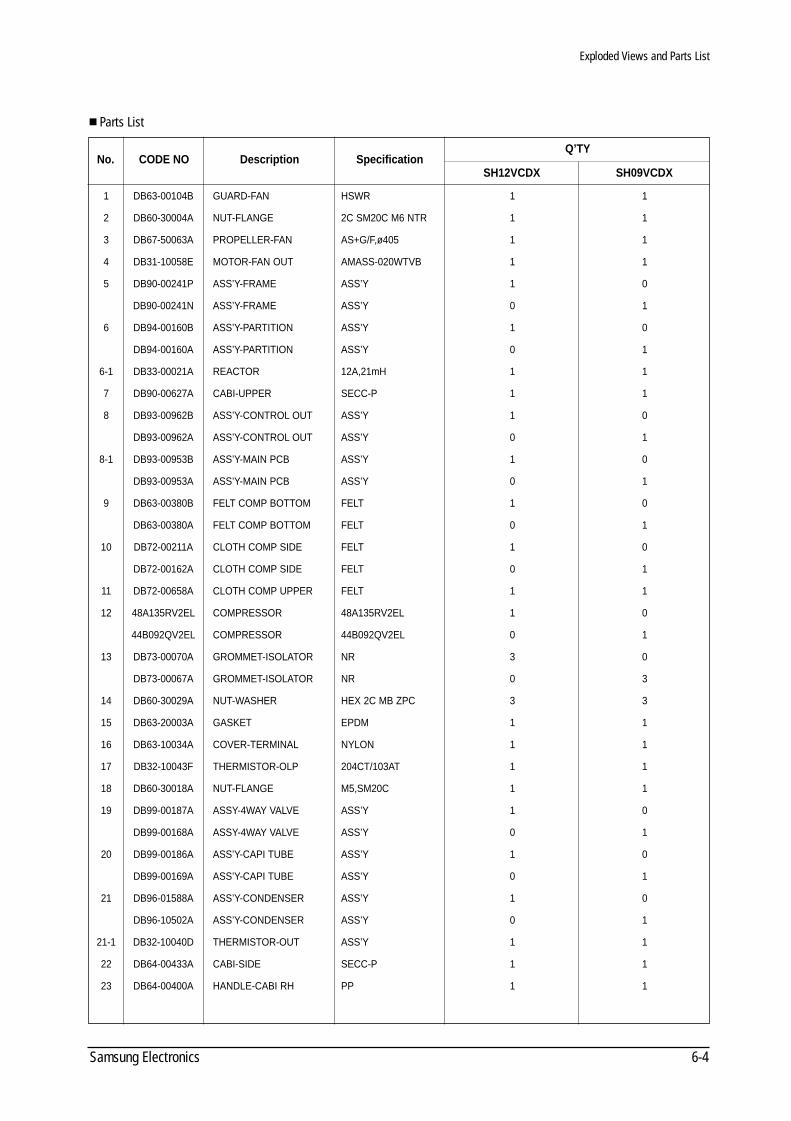
6-4Samsung Electronics
Parts List
CODE NONo. Description Specification
1 DB63-00104B GUARD-FAN HSWR 1 1
2 DB60-30004A NUT-FLANGE 2C SM20C M6 NTR 1 1
3 DB67-50063A PROPELLER-FAN AS+G/F,ø405 1 1
4 DB31-10058E MOTOR-FAN OUT AMASS-020WTVB 1 1
5 DB90-00241P ASS’Y-FRAME ASS’Y 1 0
DB90-00241N ASS’Y-FRAME ASS’Y 0 1
6 DB94-00160B ASS’Y-PARTITION ASS’Y 1 0
DB94-00160A ASS’Y-PARTITION ASS’Y 0 1
6-1 DB33-00021A REACTOR 12A,21mH 1 1
7 DB90-00627A CABI-UPPER SECC-P 1 1
8 DB93-00962B ASS’Y-CONTROL OUT ASS’Y 1 0
DB93-00962A ASS’Y-CONTROL OUT ASS’Y 0 1
8-1 DB93-00953B ASS’Y-MAIN PCB ASS’Y 1 0
DB93-00953A ASS’Y-MAIN PCB ASS’Y 0 1
9 DB63-00380B FELT COMP BOTTOM FELT 1 0
DB63-00380A FELT COMP BOTTOM FELT 0 1
10 DB72-00211A CLOTH COMP SIDE FELT 1 0
DB72-00162A CLOTH COMP SIDE FELT 0 1
11 DB72-00658A CLOTH COMP UPPER FELT 1 1
12 48A135RV2EL COMPRESSOR 48A135RV2EL 1 0
44B092QV2EL COMPRESSOR 44B092QV2EL 0 1
13 DB73-00070A GROMMET-ISOLATOR NR 3 0
DB73-00067A GROMMET-ISOLATOR NR 0 3
14 DB60-30029A NUT-WASHER HEX 2C MB ZPC 3 3
15 DB63-20003A GASKET EPDM 1 1
16 DB63-10034A COVER-TERMINAL NYLON 1 1
17 DB32-10043F THERMISTOR-OLP 204CT/103AT 1 1
18 DB60-30018A NUT-FLANGE M5,SM20C 1 1
19 DB99-00187A ASSY-4WAY VALVE ASS’Y 1 0
DB99-00168A ASSY-4WAY VALVE ASS’Y 0 1
20 DB99-00186A ASS’Y-CAPI TUBE ASS’Y 1 0
DB99-00169A ASS’Y-CAPI TUBE ASS’Y 0 1
21 DB96-01588A ASS’Y-CONDENSER ASS’Y 1 0
DB96-10502A ASS’Y-CONDENSER ASS’Y 0 1
21-1 DB32-10040D THERMISTOR-OUT ASS’Y 1 1
22 DB64-00433A CABI-SIDE SECC-P 1 1
23 DB64-00400A HANDLE-CABI RH PP 1 1
Q’TY
SH12VCDX SH09VCDX
DB98_08728A(1)_SM_1 12/20/02 3:25 PM Page 5-1
Samsung Electronics6-5
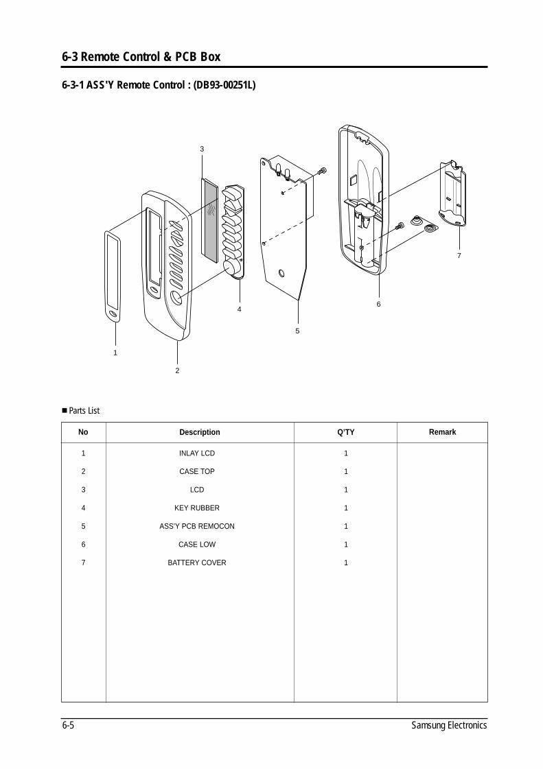
6-3 Remote Control & PCB Box
3
1
2
4
5
6
7
Parts List
No
1
2
3
4
5
6
7
Description
INLAY LCD
CASE TOP
LCD
KEY RUBBER
ASS’Y PCB REMOCON
CASE LOW
BATTERY COVER
Q’TY
1
1
1
1
1
1
1
Remark
6-3-1 ASS'Y Remote Control : (DB93-00251L)
DB98_08728A(1)_SM_1 12/20/02 3:25 PM Page 5-2
Exploded Views and Parts List
6-6Samsung Electronics
Parts List
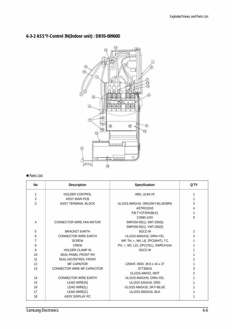
No
123
4
56789
10111213
1415161718
Description
HOLDER CONTROLASSY MAIN PCB
ASSY TERMINAL BLOCK
CONNECTOR WIRE FAN MOTOR
BRACKET EARTHCONNECTOR WIRE EARTH
SCREWCREW
HOLDER CLAMP INSEAL-PANEL FRONT RH
SEAL-H/CONTROL FRONTMF CAPAITOR
CONNECTOR WIRE MF CAPACITOR
CONNECTOR WIRE EARTHLEAD WIRE(N)LEAD WIRE(L)LEAD WIRE(C)
ASSY DISPLAY PC
Specification
ABS, UL94-V0
UL1015 AWG#16, ORG/SKY-BLUE/BRNASTRO1010
P.B.T+CF30%(BLK)C2680-1/2H
SMP250-05(1), SMT-250(5)SMP200-05(1), YMT-200(5)
SGCC-MUL1015 AWG#16, GRN+YEL
WP, TH, +, M4, L8, ZPC(WHT), T.CPH, +, M3, L22, ZPC(YEL), SWRCH10A
SGCC-M
1200nF, 450V, 39.6 x 16 x 27ST730619
UL1015 AW#22, WHTUL1015 AWG#20, GRN+YEL
UL1015 ASG#16, ORGUL1015 AWG#16, SKY=BLUE
UL1015 AWG#16, BLK
112415
221111112211111
Q’TY
6-3-2 ASS’Y-Control IN(Indoor unit) : DB93-00960D
DB98_08728A(1)_SM_1 12/20/02 3:25 PM Page 5-3
Exploded Views and Parts List
Samsung Electronics6-7
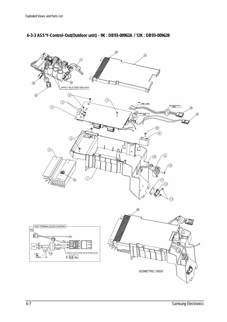
6-3-3 ASS’Y-Control-Out(Outdoor unit) - 9K : DB93-00962A / 12K : DB93-00962B
APPLY SILICONE SEALANT
ISOMETRIC VIEW
ASSY TERMINAL BLOCK DIAGRAM
CONNECT THIS TO LOWER PART OF TERMINAL BLOCK
DB98_08728A(1)_SM_1 12/20/02 3:25 PM Page 5-4
6-8Samsung Electronics
Exploded Views and Parts List
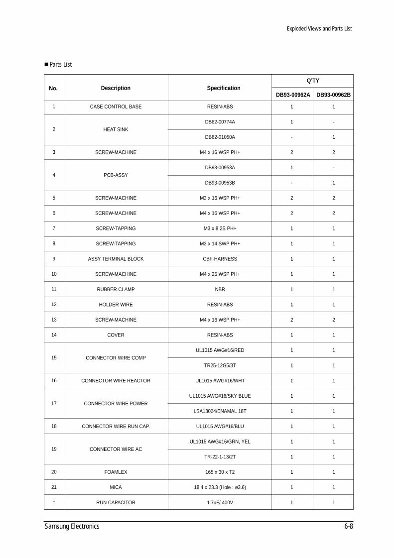
Parts List
No.
1
2
3
4
5
6
7
8
9
10
11
12
13
14
15
16
17
18
19
20
21
*
Description
CASE CONTROL BASE
HEAT SINK
SCREW-MACHINE
PCB-ASSY
SCREW-MACHINE
SCREW-MACHINE
SCREW-TAPPING
SCREW-TAPPING
ASSY TERMINAL BLOCK
SCREW-MACHINE
RUBBER CLAMP
HOLDER WIRE
SCREW-MACHINE
COVER
CONNECTOR WIRE COMP
CONNECTOR WIRE REACTOR
CONNECTOR WIRE POWER
CONNECTOR WIRE RUN CAP.
CONNECTOR WIRE AC
FOAMLEX
MICA
RUN CAPACITOR
Specification
RESIN-ABS
DB62-00774A
DB62-01050A
M4 x 16 WSP PH+
DB93-00953A
DB93-00953B
M3 x 16 WSP PH+
M4 x 16 WSP PH+
M3 x 8 2S PH+
M3 x 14 SWP PH+
CBF-HARNESS
M4 x 25 WSP PH+
NBR
RESIN-ABS
M4 x 16 WSP PH+
RESIN-ABS
UL1015 AWG#16/RED
TR25-12G5/3T
UL1015 AWG#16/WHT
UL1015 AWG#16/SKY BLUE
LSA13024/ENAMAL 18T
UL1015 AWG#16/BLU
UL1015 AWG#16/GRN, YEL
TR-22-1-13/2T
165 x 30 x T2
18.4 x 23.3 (Hole : ø3.6)
1.7uF/ 400V
1
1
-
2
1
-
2
2
1
1
1
1
1
1
2
1
1
1
1
1
1
1
1
1
1
1
1
1
-
1
2
-
1
2
2
1
1
1
1
1
1
2
1
1
1
1
1
1
1
1
1
1
1
1
Q’TY
DB93-00962A DB93-00962B
DB98_08728A(1)_SM_1 12/20/02 3:25 PM Page 5-5
Samsung Electronics7-1
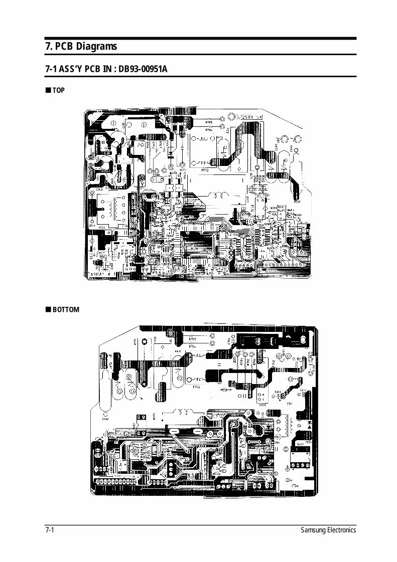
7. PCB Diagrams
7-1 ASS’Y PCB IN : DB93-00951A
TOP
BOTTOM
DB98_08728A(1)_SM_1 12/20/02 3:25 PM Page 5-6
7-2Samsung Electronics
PCB Diagrams
Parts List
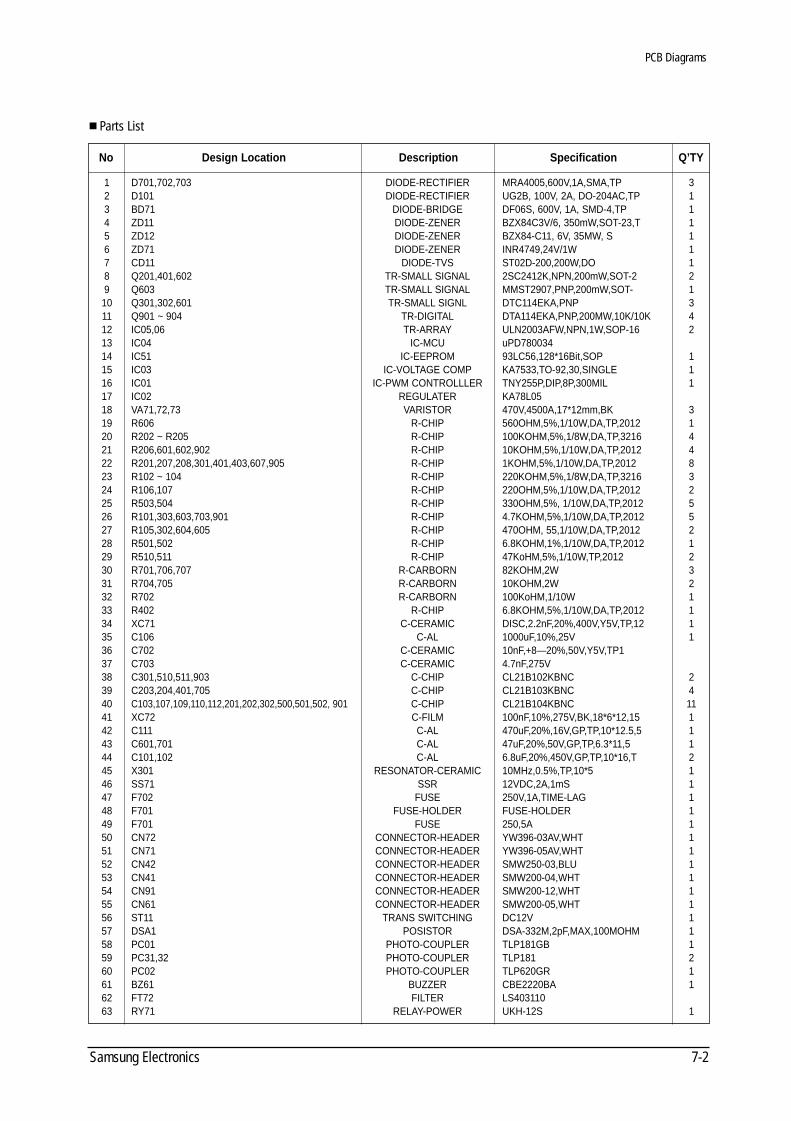
1 D701,702,703 DIODE-RECTIFIER MRA4005,600V,1A,SMA,TP 32 D101 DIODE-RECTIFIER UG2B, 100V, 2A, DO-204AC,TP 13 BD71 DIODE-BRIDGE DF06S, 600V, 1A, SMD-4,TP 14 ZD11 DIODE-ZENER BZX84C3V/6, 350mW,SOT-23,T 15 ZD12 DIODE-ZENER BZX84-C11, 6V, 35MW, S 16 ZD71 DIODE-ZENER INR4749,24V/1W 17 CD11 DIODE-TVS ST02D-200,200W,DO 18 Q201,401,602 TR-SMALL SIGNAL 2SC2412K,NPN,200mW,SOT-2 29 Q603 TR-SMALL SIGNAL MMST2907,PNP,200mW,SOT- 110 Q301,302,601 TR-SMALL SIGNL DTC114EKA,PNP 311 Q901 ~ 904 TR-DIGITAL DTA114EKA,PNP,200MW,10K/10K 412 IC05,06 TR-ARRAY ULN2003AFW,NPN,1W,SOP-16 213 IC04 IC-MCU uPD78003414 IC51 IC-EEPROM 93LC56,128*16Bit,SOP 115 IC03 IC-VOLTAGE COMP KA7533,TO-92,30,SINGLE 116 IC01 IC-PWM CONTROLLLER TNY255P,DIP,8P,300MIL 117 IC02 REGULATER KA78L0518 VA71,72,73 VARISTOR 470V,4500A,17*12mm,BK 319 R606 R-CHIP 560OHM,5%,1/10W,DA,TP,2012 120 R202 ~ R205 R-CHIP 100KOHM,5%,1/8W,DA,TP,3216 421 R206,601,602,902 R-CHIP 10KOHM,5%,1/10W,DA,TP,2012 422 R201,207,208,301,401,403,607,905 R-CHIP 1KOHM,5%,1/10W,DA,TP,2012 823 R102 ~ 104 R-CHIP 220KOHM,5%,1/8W,DA,TP,3216 324 R106,107 R-CHIP 220OHM,5%,1/10W,DA,TP,2012 225 R503,504 R-CHIP 330OHM,5%, 1/10W,DA,TP,2012 526 R101,303,603,703,901 R-CHIP 4.7KOHM,5%,1/10W,DA,TP,2012 527 R105,302,604,605 R-CHIP 470OHM, 55,1/10W,DA,TP,2012 228 R501,502 R-CHIP 6.8KOHM,1%,1/10W,DA,TP,2012 129 R510,511 R-CHIP 47KoHM,5%,1/10W,TP,2012 230 R701,706,707 R-CARBORN 82KOHM,2W 331 R704,705 R-CARBORN 10KOHM,2W 232 R702 R-CARBORN 100KoHM,1/10W 133 R402 R-CHIP 6.8KOHM,5%,1/10W,DA,TP,2012 134 XC71 C-CERAMIC DISC,2.2nF,20%,400V,Y5V,TP,12 135 C106 C-AL 1000uF,10%,25V 136 C702 C-CERAMIC 10nF,+8—20%,50V,Y5V,TP137 C703 C-CERAMIC 4.7nF,275V38 C301,510,511,903 C-CHIP CL21B102KBNC 239 C203,204,401,705 C-CHIP CL21B103KBNC 440 C103,107,109,110,112,201,202,302,500,501,502, 901 C-CHIP CL21B104KBNC 1141 XC72 C-FILM 100nF,10%,275V,BK,18*6*12,15 142 C111 C-AL 470uF,20%,16V,GP,TP,10*12.5,5 143 C601,701 C-AL 47uF,20%,50V,GP,TP,6.3*11,5 144 C101,102 C-AL 6.8uF,20%,450V,GP,TP,10*16,T 245 X301 RESONATOR-CERAMIC 10MHz,0.5%,TP,10*5 146 SS71 SSR 12VDC,2A,1mS 147 F702 FUSE 250V,1A,TIME-LAG 148 F701 FUSE-HOLDER FUSE-HOLDER 149 F701 FUSE 250,5A 150 CN72 CONNECTOR-HEADER YW396-03AV,WHT 151 CN71 CONNECTOR-HEADER YW396-05AV,WHT 152 CN42 CONNECTOR-HEADER SMW250-03,BLU 153 CN41 CONNECTOR-HEADER SMW200-04,WHT 154 CN91 CONNECTOR-HEADER SMW200-12,WHT 155 CN61 CONNECTOR-HEADER SMW200-05,WHT 156 ST11 TRANS SWITCHING DC12V 157 DSA1 POSISTOR DSA-332M,2pF,MAX,100MOHM 158 PC01 PHOTO-COUPLER TLP181GB 159 PC31,32 PHOTO-COUPLER TLP181 260 PC02 PHOTO-COUPLER TLP620GR 161 BZ61 BUZZER CBE2220BA 162 FT72 FILTER LS40311063 RY71 RELAY-POWER UKH-12S 1
SpecificationDescriptionDesign LocationNo Q’TY
DB98_08728A(1)_SM_1 12/20/02 3:25 PM Page 5-7
Samsung Electronics7-3
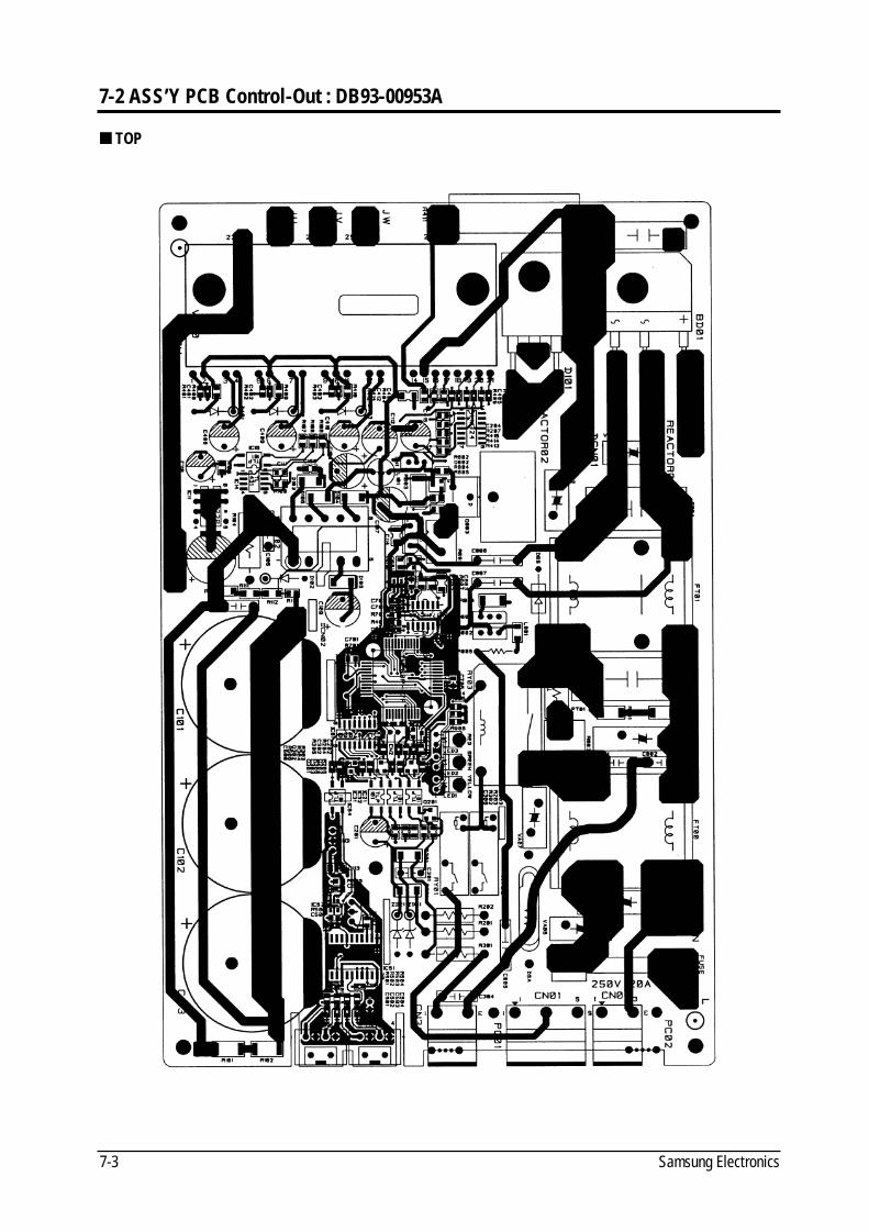
7-2 ASS’Y PCB Control-Out : DB93-00953A
TOP
DB98_08728A(1)_SM_1 12/20/02 3:25 PM Page 5-8
7-4Samsung Electronics
PCB Diagrams
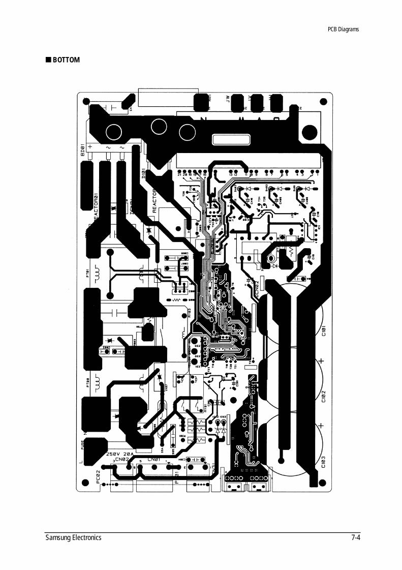
BOTTOM
DB98_08728A(1)_SM_1 12/20/02 3:25 PM Page 5-9
PCB Diagrams
Samsung Electronics7-5
Parts List
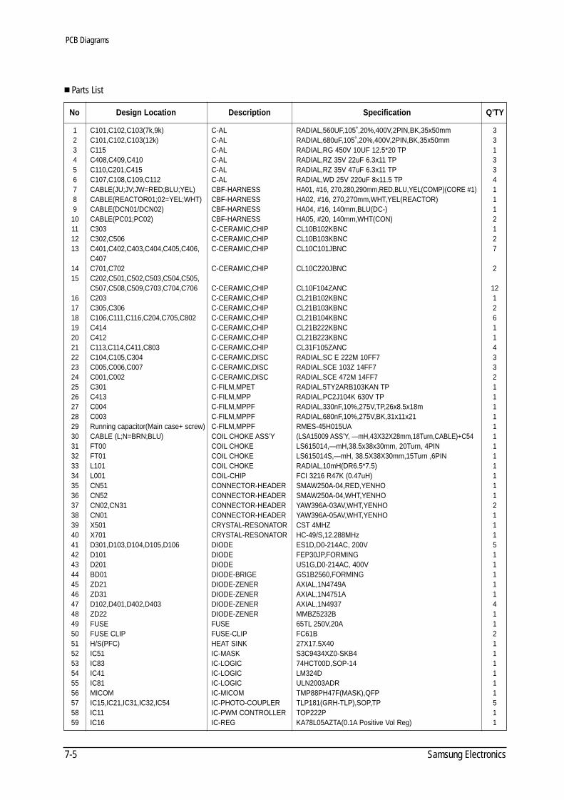
1 C101,C102,C103(7k,9k) C-AL RADIAL,560UF,105˚,20%,400V,2PIN,BK,35x50mm 3 2 C101,C102,C103(12k) C-AL RADIAL,680uF,105˚,20%,400V,2PIN,BK,35x50mm 3 3 C115 C-AL RADIAL,RG 450V 10UF 12.5*20 TP 1 4 C408,C409,C410 C-AL RADIAL,RZ 35V 22uF 6.3x11 TP 3 5 C110,C201,C415 C-AL RADIAL,RZ 35V 47uF 6.3x11 TP 3 6 C107,C108,C109,C112 C-AL RADIAL,WD 25V 220uF 8x11.5 TP 4 7 CABLE(JU;JV;JW=RED;BLU;YEL) CBF-HARNESS HA01, #16, 270,280,290mm,RED,BLU,YEL(COMP)(CORE #1) 1 8 CABLE(REACTOR01;02=YEL;WHT) CBF-HARNESS HA02, #16, 270,270mm,WHT,YEL(REACTOR) 1 9 CABLE(DCN01/DCN02) CBF-HARNESS HA04, #16, 140mm,BLU(DC-) 1 10 CABLE(PC01;PC02) CBF-HARNESS HA05, #20, 140mm,WHT(CON) 2 11 C303 C-CERAMIC,CHIP CL10B102KBNC 1 12 C302,C506 C-CERAMIC,CHIP CL10B103KBNC 2 13 C401,C402,C403,C404,C405,C406, C-CERAMIC,CHIP CL10C101JBNC 7
C40714 C701,C702 C-CERAMIC,CHIP CL10C220JBNC 2 15 C202,C501,C502,C503,C504,C505,
C507,C508,C509,C703,C704,C706 C-CERAMIC,CHIP CL10F104ZANC 12 16 C203 C-CERAMIC,CHIP CL21B102KBNC 1 17 C305,C306 C-CERAMIC,CHIP CL21B103KBNC 2 18 C106,C111,C116,C204,C705,C802 C-CERAMIC,CHIP CL21B104KBNC 6 19 C414 C-CERAMIC,CHIP CL21B222KBNC 1 20 C412 C-CERAMIC,CHIP CL21B223KBNC 1 21 C113,C114,C411,C803 C-CERAMIC,CHIP CL31F105ZANC 4 22 C104,C105,C304 C-CERAMIC,DISC RADIAL,SC E 222M 10FF7 3 23 C005,C006,C007 C-CERAMIC,DISC RADIAL,SCE 103Z 14FF7 3 24 C001,C002 C-CERAMIC,DISC RADIAL,SCE 472M 14FF7 2 25 C301 C-FILM,MPET RADIAL,5TY2ARB103KAN TP 1 26 C413 C-FILM,MPP RADIAL,PC2J104K 630V TP 1 27 C004 C-FILM,MPPF RADIAL,330nF,10%,275V,TP,26x8.5x18m 1 28 C003 C-FILM,MPPF RADIAL,680nF,10%,275V,BK,31x11x21 1 29 Running capacitor(Main case+ screw) C-FILM,MPPF RMES-45H015UA 1 30 CABLE (L;N=BRN;BLU) COIL CHOKE ASS’Y (LSA15009 ASS’Y, —mH,43X32X28mm,18Turn,CABLE)+C54 1 31 FT00 COIL CHOKE LS615014,—mH,38.5x38x30mm, 20Turn, 4PIN 1 32 FT01 COIL CHOKE LS615014S,—mH, 38.5X38X30mm,15Turn ,6PIN 1 33 L101 COIL CHOKE RADIAL,10mH(DR6.5*7.5) 1 34 L001 COIL-CHIP FCI 3216 R47K (0.47uH) 1 35 CN51 CONNECTOR-HEADER SMAW250A-04,RED,YENHO 1 36 CN52 CONNECTOR-HEADER SMAW250A-04,WHT,YENHO 1 37 CN02,CN31 CONNECTOR-HEADER YAW396A-03AV,WHT,YENHO 2 38 CN01 CONNECTOR-HEADER YAW396A-05AV,WHT,YENHO 1 39 X501 CRYSTAL-RESONATOR CST 4MHZ 1 40 X701 CRYSTAL-RESONATOR HC-49/S,12.288MHz 1 41 D301,D103,D104,D105,D106 DIODE ES1D,D0-214AC, 200V 5 42 D101 DIODE FEP30JP,FORMING 1 43 D201 DIODE US1G,D0-214AC, 400V 1 44 BD01 DIODE-BRIGE GS1B2560,FORMING 1 45 ZD21 DIODE-ZENER AXIAL,1N4749A 1 46 ZD31 DIODE-ZENER AXIAL,1N4751A 1 47 D102,D401,D402,D403 DIODE-ZENER AXIAL,1N4937 4 48 ZD22 DIODE-ZENER MMBZ5232B 1 49 FUSE FUSE 65TL 250V,20A 1 50 FUSE CLIP FUSE-CLIP FC61B 2 51 H/S(PFC) HEAT SINK 27X17.5X40 1 52 IC51 IC-MASK S3C9434XZ0-SKB4 1 53 IC83 IC-LOGIC 74HCT00D,SOP-14 1 54 IC41 IC-LOGIC LM324D 1 55 IC81 IC-LOGIC ULN2003ADR 1 56 MICOM IC-MICOM TMP88PH47F(MASK),QFP 1 57 IC15,IC21,IC31,IC32,IC54 IC-PHOTO-COUPLER TLP181(GRH-TLP),SOP,TP 5 58 IC11 IC-PWM CONTROLLER TOP222P 1 59 IC16 IC-REG KA78L05AZTA(0.1A Positive Vol Reg) 1
SpecificationDescriptionDesign LocationNo Q’TY
DB98_08728A(1)_SM_1 12/20/02 3:25 PM Page 5-10
7-6Samsung Electronics
PCB Diagrams
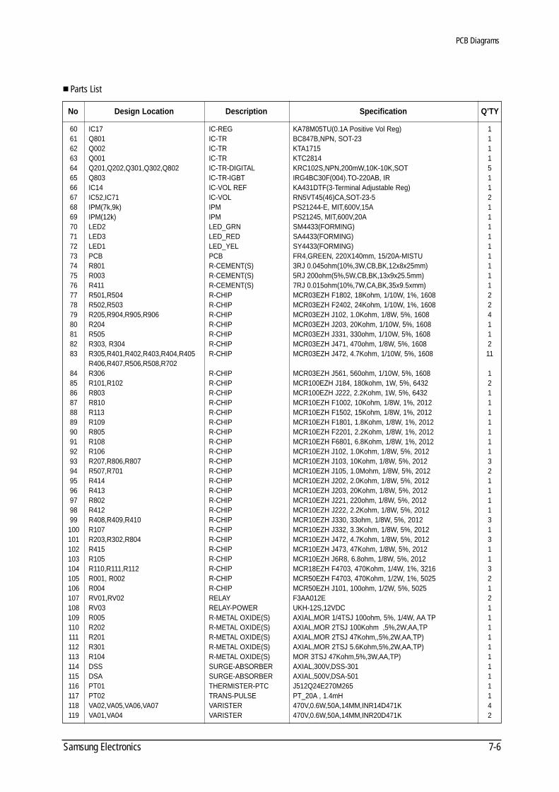
Parts List
60 IC17 IC-REG KA78M05TU(0.1A Positive Vol Reg) 1 61 Q801 IC-TR BC847B,NPN, SOT-23 1 62 Q002 IC-TR KTA1715 1 63 Q001 IC-TR KTC2814 1 64 Q201,Q202,Q301,Q302,Q802 IC-TR-DIGITAL KRC102S,NPN,200mW,10K-10K,SOT 5 65 Q803 IC-TR-IGBT IRG4BC30F(004).TO-220AB, IR 1 66 IC14 IC-VOL REF KA431DTF(3-Terminal Adjustable Reg) 1 67 IC52,IC71 IC-VOL RN5VT45(46)CA,SOT-23-5 2 68 IPM(7k,9k) IPM PS21244-E, MIT,600V,15A 1 69 IPM(12k) IPM PS21245, MIT,600V,20A 1 70 LED2 LED_GRN SM4433(FORMING) 1 71 LED3 LED_RED SA4433(FORMING) 1 72 LED1 LED_YEL SY4433(FORMING) 1 73 PCB PCB FR4,GREEN, 220X140mm, 15/20A-MISTU 1 74 R801 R-CEMENT(S) 3RJ 0.045ohm(10%,3W,CB,BK,12x8x25mm) 1 75 R003 R-CEMENT(S) 5RJ 200ohm(5%,5W,CB,BK,13x9x25.5mm) 1 76 R411 R-CEMENT(S) 7RJ 0.015ohm(10%,7W,CA,BK,35x9.5xmm) 1 77 R501,R504 R-CHIP MCR03EZH F1802, 18Kohm, 1/10W, 1%, 1608 2 78 R502,R503 R-CHIP MCR03EZH F2402, 24Kohm, 1/10W, 1%, 1608 2 79 R205,R904,R905,R906 R-CHIP MCR03EZH J102, 1.0Kohm, 1/8W, 5%, 1608 4 80 R204 R-CHIP MCR03EZH J203, 20Kohm, 1/10W, 5%, 1608 1 81 R505 R-CHIP MCR03EZH J331, 330ohm, 1/10W, 5%, 1608 1 82 R303, R304 R-CHIP MCR03EZH J471, 470ohm, 1/8W, 5%, 1608 2 83 R305,R401,R402,R403,R404,R405 R-CHIP MCR03EZH J472, 4.7Kohm, 1/10W, 5%, 1608 11
R406,R407,R506,R508,R70284 R306 R-CHIP MCR03EZH J561, 560ohm, 1/10W, 5%, 1608 1 85 R101,R102 R-CHIP MCR100EZH J184, 180kohm, 1W, 5%, 6432 2 86 R803 R-CHIP MCR100EZH J222, 2.2Kohm, 1W, 5%, 6432 1 87 R810 R-CHIP MCR10EZH F1002, 10Kohm, 1/8W, 1%, 2012 1 88 R113 R-CHIP MCR10EZH F1502, 15Kohm, 1/8W, 1%, 2012 1 89 R109 R-CHIP MCR10EZH F1801, 1.8Kohm, 1/8W, 1%, 2012 1 90 R805 R-CHIP MCR10EZH F2201, 2.2Kohm, 1/8W, 1%, 2012 1 91 R108 R-CHIP MCR10EZH F6801, 6.8Kohm, 1/8W, 1%, 2012 1 92 R106 R-CHIP MCR10EZH J102, 1.0Kohm, 1/8W, 5%, 2012 1 93 R207,R806,R807 R-CHIP MCR10EZH J103, 10Kohm, 1/8W, 5%, 2012 3 94 R507,R701 R-CHIP MCR10EZH J105, 1.0Mohm, 1/8W, 5%, 2012 2 95 R414 R-CHIP MCR10EZH J202, 2.0Kohm, 1/8W, 5%, 2012 1 96 R413 R-CHIP MCR10EZH J203, 20Kohm, 1/8W, 5%, 2012 1 97 R802 R-CHIP MCR10EZH J221, 220ohm, 1/8W, 5%, 2012 1 98 R412 R-CHIP MCR10EZH J222, 2.2Kohm, 1/8W, 5%, 2012 1 99 R408,R409,R410 R-CHIP MCR10EZH J330, 33ohm, 1/8W, 5%, 2012 3 100 R107 R-CHIP MCR10EZH J332, 3.3Kohm, 1/8W, 5%, 2012 1 101 R203,R302,R804 R-CHIP MCR10EZH J472, 4.7Kohm, 1/8W, 5%, 2012 3 102 R415 R-CHIP MCR10EZH J473, 47Kohm, 1/8W, 5%, 2012 1 103 R105 R-CHIP MCR10EZH J6R8, 6.8ohm, 1/8W, 5%, 2012 1 104 R110,R111,R112 R-CHIP MCR18EZH F4703, 470Kohm, 1/4W, 1%, 3216 3 105 R001, R002 R-CHIP MCR50EZH F4703, 470Kohm, 1/2W, 1%, 5025 2 106 R004 R-CHIP MCR50EZH J101, 100ohm, 1/2W, 5%, 5025 1 107 RV01,RV02 RELAY F3AA012E 2 108 RV03 RELAY-POWER UKH-12S,12VDC 1 109 R005 R-METAL OXIDE(S) AXIAL,MOR 1/4TSJ 100ohm, 5%, 1/4W, AA TP 1 110 R202 R-METAL OXIDE(S) AXIAL,MOR 2TSJ 100Kohm ,5%,2W,AA,TP 1 111 R201 R-METAL OXIDE(S) AXIAL,MOR 2TSJ 47Kohm,,5%,2W,AA,TP) 1 112 R301 R-METAL OXIDE(S) AXIAL,MOR 2TSJ 5.6Kohm,5%,2W,AA,TP) 1113 R104 R-METAL OXIDE(S) MOR 3TSJ 47Kohm,5%,3W,AA,TP) 1 114 DSS SURGE-ABSORBER AXIAL,300V,DSS-301 1115 DSA SURGE-ABSORBER AXIAL,500V,DSA-501 1 116 PT01 THERMISTER-PTC J512Q24E270M265 1 117 PT02 TRANS-PULSE PT_20A , 1.4mH 1 118 VA02,VA05,VA06,VA07 VARISTER 470V,0.6W,50A,14MM,INR14D471K 4119 VA01,VA04 VARISTER 470V,0.6W,50A,14MM,INR20D471K 2
SpecificationDescriptionDesign LocationNo Q’TY
DB98_08728A(1)_SM_1 12/20/02 3:25 PM Page 5-11
Samsung Electronics7-7
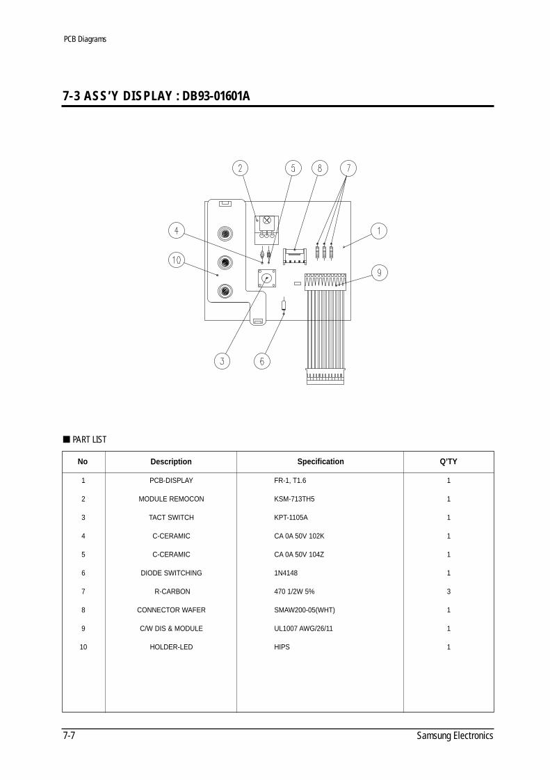
7-3 ASS’Y DISPLAY : DB93-01601A
No
1
2
3
4
5
6
7
8
9
10
Description
PCB-DISPLAY
MODULE REMOCON
TACT SWITCH
C-CERAMIC
C-CERAMIC
DIODE SWITCHING
R-CARBON
CONNECTOR WAFER
C/W DIS & MODULE
HOLDER-LED
Specification
FR-1, T1.6
KSM-713TH5
KPT-1105A
CA 0A 50V 102K
CA 0A 50V 104Z
1N4148
470 1/2W 5%
SMAW200-05(WHT)
UL1007 AWG/26/11
HIPS
Q’TY
1
1
1
1
1
1
3
1
1
1
PART LIST
PCB Diagrams
DB98_08728A(1)_SM_1 12/20/02 3:25 PM Page 5-12
8-1Samsung Electronics
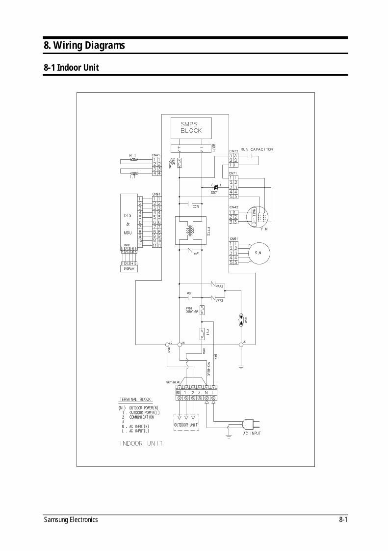
8. Wiring Diagrams
8-1 Indoor Unit
DB98_08728A(1)_SM_1 12/20/02 3:25 PM Page 5-13
Samsung Electronics8-2
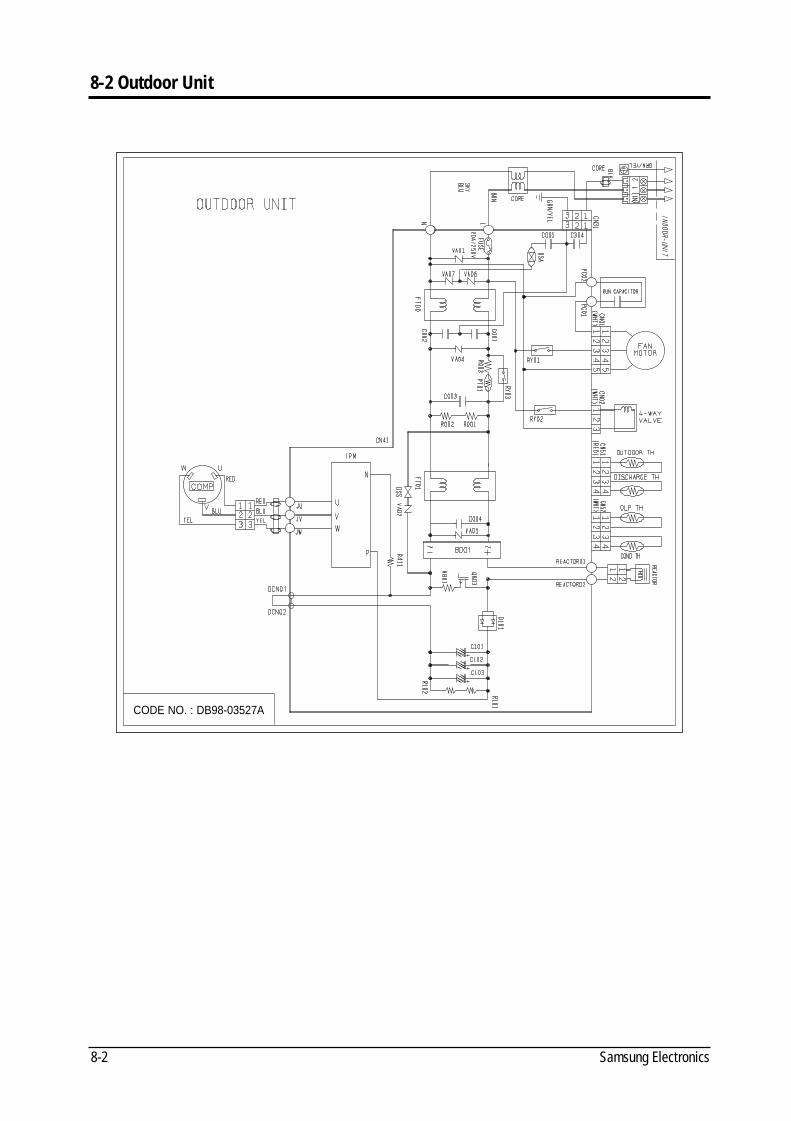
8-2 Outdoor Unit
CODE NO. : DB98-03527A
DB98_08728A(1)_SM_1 12/20/02 3:25 PM Page 5-14
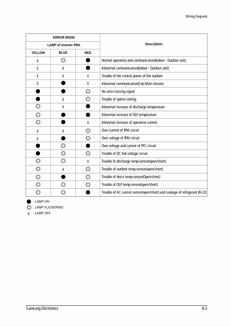
8-3Samsung Electronics
: LAMP ON
: LAMP FLICKERING
: LAMP OFFX
X
X X
X
X
X
X
X
X
X
X
X
X
X
X
X
YELLOW
ERROR MODE
LAMP of inverter PBA
BLUE RED
Description
Normal operation and communication(Indoor - Outdoor unit)
Abnormal communication(Indoor - Outdoor unit)
Trouble of the control power of the outdoor
Abnormal communication(Sub-Main micom)
No zero-crossing signal
Trouble of option setting
Abnormal increase of discharge temperature
Abnormal increase of OLP temperature
Abnormal increase of operation current
Over current of IPM circuit
Over voltage of IPM circuit
Over voltage and current of PFC circuit
Trouble of DC link voltage circuit
Tourble fo discharge temp-sensor(open/short)
Trouble of outdoor temp-sensor(open/short)
Trouble of deice temp-sensor(Open/short)
Trouble of OLP temp-sensor(open/short)
Trouble of AC current sensor(open/short) and Leakage of refrigerant (R-22)
Wiring Diagrams
DB98_08728A(1)_SM_1 12/20/02 3:25 PM Page 5-15

MEMO
Samsung Electronics8-4
DB98_08728A(1)_SM_1 12/20/02 3:25 PM Page 5-16
MEMO
8-5Samsung Electronics
DB98_08728A(1)_SM_1 12/20/02 3:25 PM Page 5-17
MEMO
Samsung Electronics8-6
DB98_08728A(1)_SM_1 12/20/02 3:25 PM Page 5-18
UPDATE LOG SHEETApplication date Page Part# Note(Cause & Solution) S/Bulletin#
Use this page to keep any special servicing information. (Service Bulletin, etc.)
If only parts number changes, Just change parts number directly on parts list.
And if you need more information, please see the service website.
Itself Solution Integrated technology supporting electronic library
http://itself.sec.samsung.co.kr
Copyright © 2002By Samsung Electronics Co., Ltd.
All rights reserved.
This manual may not, in whole or in part, be
copied, photocopied, reproduced, translated, or
converted to any electronic or machine readable
from without prior written permission of
Samsung Electronics Co., Ltd.
Printed in Korea.
DB98_08728A(1)_SM_1 12/20/02 3:25 PM Page 5-19
ELECTRONICS
© Samsung Electronics Co., Ltd. Dec. 2002.Printed in Korea.Code No. DB98-08728A(1)
DB98_08728A(1)_CO 12/20/02 3:27 PM Page 2
Related Documents


