NUREG-0847 Supplement No. 18 Safety Evaluation Report related to the operation of Watts Bar Nuclear Plant, Units 1 and 2 flFCEIVED Docket Nos. 50-390 and 50-391 Tennessee Valley Authority Flov 2 9 I995 OSTI U.S. Nuclear Regulatory Commission Office of NucIear Reactor Regulation October 1995

Welcome message from author
This document is posted to help you gain knowledge. Please leave a comment to let me know what you think about it! Share it to your friends and learn new things together.
Transcript
NUREG-0847 Supplement No. 18
Safety Evaluation Report related to the operation of Watts Bar Nuclear Plant, Units 1 and 2 flFCEIVED Docket Nos. 50-390 and 50-391
Tennessee Valley Authority
Flov 2 9 I995 O S T I
U.S. Nuclear Regulatory Commission
Office of NucIear Reactor Regulation
October 1995
AVAILABILITY NOTICE
Availability of Reference Materials Cited in NRC Publications
Most documents cited in NRC publications will be available from one of the following sources: 1. The NRC Public Document Room, 2120 L Street, NW.. Lower Level. Washington, DC
The Superintendent of Documents, U S . Government Printing Office, P. 0. Box 37082, Washington, DC 20402-9328
The National Technical Information Service, Springfield, VA 221 61 -0002
20555-0001
2.
3.
Although the listing that follows represents the majority of documents cited in NRC publiea- tions, it is not intended to be exhaustive.
Referenced documents available for inspection and copying for a fee from the NRC Public Document Room include NRC correspondence and internal NRC memoranda: NRC bulletins, circulars, information notices. inspection and investigation notices: licensee event reports: vendor reports and correspondence: Commission papers: and applicant and licensee docu- ments and correspondence.
The following documents in t h e NUREG series are available for purchase from the Government Printing Office: formal NRC staff and contractor reports, NRC-sponsored conference pro- ceedings, international agreement reports, grantee reports, and NRC booklets and bro- chures. Also available are regulatory guides, NRC regulations in the Code of federal Regula- tions, and Nuclear Regulatory Commission Issuances.
Documents available from the National Technical Information Service include NUREG-series reports and technical reports prepared by other Federal agencies and, reports prepared by the Atomic Energy Commission, forerunner agency to the Nuclear Regulatory Commission.
Documents available from public and special technical libraries include all open literature items, such as books, journal article.s, and transactions. federal Register notices, Federal and State legislation, and congressional reports can usually be obtained from these libraries.
Documents such as theses, dissertations, foreign reports and translations, and non-NRC con- ference proceedings are available for purchase from the organization sponsoring the publica- tion cited.
Single copies of NRC draft reports are available free, to the extent of supply, upon written request to the Office of Administration, Distribution and Mail Services Section, U.S. Nuclear Regulatory Commission, Washington DC 20555-0001.
Copies of industry codes and standards used in a substantive manner in t h e NRC regulatory process are maintained at the NRC Library, Two White Flint North, 1 1545 Rockville Pike, Rock- ville, MD 20852-2738, for use by t h e public. Codes and standards are usually copyrighted and may be purchased from t h e originating organization or, if they are American National Standards, from the American National Standards Institute, 1430 Broadway, New York. NY 1001 8-3308.
Portions of this document mag be illegible in electronic image produc& Images are produced from the best available original dOCUm€!IlL
NUREG-0847 Supplement No. 18
Safety Evaluation Report related to the operation of Watts Bar Nuclear Plant, Units 1 and 2 Docket Nos. 50-390 and 50-391
Tennessee Valley Authority
U.S. Nuclear Regulatory Commission
Office of Nudear Reactor Regulation
October 1995
DlSTRlBUTfON OF THIS DOCUMENT IS MIMMb\vv
ABSTRACT
T h i s report supplements the Safety Eva1 uation Report (SER) , NUREG-0847 (June 1982), Supplement No. 1 (September 1982), Supplement No. 2 (January 1984), Sup- plement No. 3 (January 1985), Supplement No. 4 (March 1985), Supplement No. 5 (November 1990), supplement No. 6 (April 1991), Supplement No. 7 (September 1991), Supplement No. 8 (January 1992), Supplement No. 9 (June 1992), Supplement No. 10 (October 1992) , Supplement No. 11 (April 1993) , Supplement No. 12 (October 1993), Supplement No. 13 (April 1994), Supplement No. 14 (December 1994), Supplement No. 15 (June 1995), Supplement No. 16 (September 1995), and Supplement No. 17 (October 1995) issued by the Office o f Nuclear Reactor Regulation of the U.S. Nuclear Regulatory Commission w i t h respect t o the application f i l ed by the Tennessee Valley Authority, as applicant and owner, for licenses t o operate the Watts Bar Nuclear Plant, Units 1 and 2 (Docket Nos. 50-390 and 50-391). The f ac i l i t y i s located i n Rhea County, Tennessee, near the Watts Bar Dam on the Tennessee River. Thi s suppl ement provi des recent information regarding resolution of some of the outstanding and confirmatory items, and proposed 1 i cense condi ti ons i denti f i ed i n the SER.
Watts Bar SSER 18 i i i

TABLE OF CONTENTS Paqe
ABSTRACT . . . . . . . . . . . . . . . . . . . . . . . . . . . . . . . . i i i ABBREVIATIONS . . . . . . . . . . . . . . . . . . . . . . . . . . . . . . vi i
1 INTRODUCTION AND DISCUSSION . . . . . . . . . . . . . . . . . . . . 1-1 1.1 Introduction . . . . . . . . . . . . . . . . . . . . . . . . 1-1 1.7 Summary of Outstanding Issues . . . . . . . . . . . . . . . . 1-2 1.8 Summary o f Confirmatory Issues . . . . . . . . . . . . . . . 1-4 1.9 Summary of Proposed License Conditions . . . . . . . . . . . 1-6 1.12 Approved Technical Issues for Incorporation in the License
1.13 as Exemptions . . . . . . . . . . . . . . . . . . . . . . . . 1-9
Programs . . . . . . . . . . . . . . . . . . . . . . . . . . 1-10 1.13.1 Corrective Action Programs . . . . . . . . . . . . . 1-10 1.13.2 Special Programs . . . . . . . . . . . . . . . . . . 1-18
Implementation o f Corrective Action Programs and Special
3 DESIGN CRITERIA-- STRUCTURESy COMPONENTSy EQUIPMENTy AND SYSTEMS . . 3-1 3.9 Mechanical Systems and Components . . . . . . . . . . . . . . 3-1
3.9.6 Inservice Testing o f Pumps and Valves (Unit 1) . . . . 3-1 3.9.6.1 Pump Test Program . . . . . . . . . . . . . . 3-1
6 ENGINEERED SAFETY FEATURES . . . . . . . . . . . . . . . . . . . . 6-1 6.2 Containment Systems . . . . . . . . . . . . . . . . . . . . . 6-1
6.2.3 Secondary Containment Functional Design . . . . . . . . 6-1 6.4 Control Room Habi tabil i ty . . . . . . . . . . . . . . . . . . 6-2
9 AUXILIARY SYSTEMS . . . . . . . . . . . . . . . . . . . . . . . . . 9-1 9.2 Water Systems . . . . . . . . . . . . . . . . . . . . . . . . 9-1
9.2.1 Essential Raw Cooling Water and Raw Cooling Water Systems . . . . . . . . . . . . . . . . . . . . . . . . 9-1
9.5 Other Auxiliary Systems . . . . . . . . . . . . . . . . . . . 9-1 9.5.1 Fire Protection . . . . . . . . . . . . . . . . . . . . 9-1
12 RADIATION PROTECTION . . . . . . . . . . . . . . . . . . . . . . . 12-1 12.4 Radiation Protection Design Features . . . . . . . . . . . . 12-1
14 INITIAL TEST PROGRAM . 1 . . . . . . . . . . . . . . . . . . . . . 14-1 14.2 Preoperational Tests . . . . . . . . . . . . . . . . . . . . 14-1
14.2.3 Concl usi on . . . . . . . . . . . . . . . . . . . . . 14-2
15 ACCIDENT ANALYSIS . . . . . . . . . . . . . . . . . . . . . . . . . 15-1 15.2 Normal Operation and Anticipated Transients . . . . . . . . . 15-1
15.2.3 Change in Coolant Inventory Transients . . . . . . . 15-1 15.4 Radiological Consequences o f Accidents . . . . . . . . . . . 15-2
15.4.1 Loss-of-Coolant Accident . . . . . . . . . . . . . 15-2
18 HUMAN FACTORS ENGINEERING . . . . . . . . . . . . . . . . . . . . . 18-1 18.1 Detailed Control Room Design Review . . . . . . . . . . . . . 18-1
Watts Bar SSER 18 V
.. ... . . . . . . . . _I .. ..... . . . . L .. +;.* ,>*:.. ' - . . . I . . . ': ..
... . . . . . ~ . 4.- . a . -.,. li . ;+?+T:;: . :' <. _- . . , . . . .'..
TABLE OF CONTENTS (continued)
APPENDIX A CHRONOLOGY OF RADIOLOGICAL REVIEW OF WATTS BAR NUCLEAR PLANT, UNITS 1 AND 2, OPERATING LICENSE REVIEW
APPENDIX E PRINCIPAL CONTRIBUTORS
APPENDIX FF SAFETY EVALUATION: WATTS BAR NUCLEAR PLANT FIRE PROTECTION PROGRAM
Watts Bar SSER 18 v i
ABBREVIATIONS
AB ABGTS ACF ACR AFW ALARA APCSB ASME ASTM AT1 AV AWG
BIT BTP '
CAM CAP CCRS ccs CCTV ccws CFR CHF CLSD CNPP CPU CRVS CST CT
DCRDR DG DNB DNBR
ECCS EOP ERCW ERFBS ERFDS
FM FPR FHA FSAR
GDC G L
HED
auxi 1 i ary b u i 1 d i n g auxi 1 i ary b u i 1 d i n g gas treatment system ampacity correction factor auxi 1 i ary control room auxi 1 i ary feedwater as low as reasonably achievable Auxil i ary Power Conversion Systems Branch Ameri can Society of Mechanical Engineers American Society of Testing and Materials acceptance t e s t instruction analysis vol ume Ameri can Wire Gauge
boron injection t a n k branch technical position
continuous a i r monitor Corrective Action Plan computerized cable routing system component cool i ng system cl osed-ci rcui t television component cooling water system Code of Federal Regul ations c r i t i ca l heat f lux Central Laboratories Services Department (TVA) Corporate Nuclear Performance Plan central processor u n i t control room ventilation system condensate storage tank component t e s t
detailed control room design review diesel generator departure from nucleate boiling departure-from-nucl eate-boil i n g r a t io
emergency core cool i ng system emergency operating procedure essential raw cool i n g water e l ec t r i cal raceway f i re barr ier system emergency response f a c i l i t y d a t a system
Factory Mutual Fire Protection Report f i r e hazards analysis f ina l safety analysis report
general design cr i ter ion generic 1 e t t e r
human engineering deficiency
Watts Bar SSER 18 v i i
HEPA HIF HVAC
ICEA IE I EEE IPS IR IST ITP
JB LB LCO LOCA LS
MCC MCR MHIFs MIC
NFPA NRC NSRB NSSS
OBE OD OPL
PASS PECO P IV PORC PORV PSRV
QA QC
RAI RCP RCS RG RHR RRSs RTD RWST
SDB SER SP S PT
h igh efficiency particulate a i r high-impedance f a u l t heating, ventilation, and a i r conditioning
Insul ated Cab1 e Engineers Associ a t i on Office of Inspection and Enforcement, In s t i t u t e o f Electrical and E l ectronics Engineers intake pumping s ta t ion infrared inservice tes t Ini t i a1 Test Program
junction box la te ra l bend limiting condition for operation 1 oss-of-cool ant accident la te ra l side
motor control center main control room multiple high-impedance f au l t s m i crobi o l ogi ca l l y induced corrosion
National Fire Protection Association Nuclear Regul atory Commission Nuclear Safety Review Board nuclear steam supply system
operating basis earthquake outside diameter Omega P o i n t Laboratories
postaccident sampling system Phil adel phia Electric Co. post-indi cator-type valve Plant Operations Review Committee pi1 ot/power-operated re1 i ef valve pressurizer safety/rel i e f valve
qual i t y assurance qual i t y control
request for additional information reactor cool any pump reactor cool ant system regul atory guide residual heat removal required response spectra resistance temperature detector refueling water storage tank
shutdown board safety evaluation report speci a1 program speci a1 performance t e s t
Watts Bar SSER 18 v i i i
SRP SSE SSER ss I STSs sws TAC TC TGV T I 3M TSs TS I TUE TVA
UL
VCT VHF VPA
WBNPP WISP WOG
standard rev iew p l an sgfe-shutdown earthquake supplement t o s a f e t y e v a l u a t i o n r e p o r t s o i l - s t r u c t u r w i n t e r a c t i o n Standard Technical Spec i f i ca t i ons s e r v i c e water system t e c h n i c a l assignment c o n t r o l thermocoupl e t hermogravi m e t r i c anal y s i s temporary i n s t r u c t i o n Minnesota Mining and Manufactur ing t e c h n i c a l s p e c i f i c a t i o n s Thermal Science, Incorporated Texas U t i l i t i e s E l e c t r i c Tennessee Val 1 ey A u t h o r i t y
Underwr i ters Laborator ies , Inc.
volume c o n t r o l tank v e r y h i g h frequency v e n t i l a t i o n and purge area
Watts Bar Nuclear Performance Plan Workload In fo rma t ion and Scheduling Program Westinghouse Owners Group
1 INTRODUCTION AND DISCUSSION
1.1 Introduction
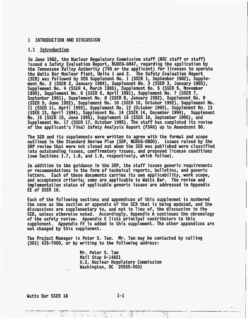
In June 1982, the Nuclear Regulatory Commission staff (NRC staff or s ta f f ) issued a Safety Eva1 uation Report , NUREG-0847, regarding the application by the Tennessee Valley Authority (TVA o r the applicant) for licenses t o operate the Watts Bar Nuclear Plant, Units 1 and 2. The Safety Evaluation Report (SER) was followed by SER Supplement No. 1 (SSER 1, September 1982), Supple- ment No. 2 (SSER 2, January 1984), Supplement No. 3 (SSER 3, January 1985), Supplement No. 4 (SSER 4, March 1985), Supplement No. 5 (SSER 5, November 1990), Supplement No. 6 (SSER 6, April 1991), Supplement No. 7 (SSER 7, September 1991), Supplement No. 8 (SSER 8, January 1992), Supplement No. 9 (SSER 9, June 1992), Supplement No. 10 (SSER 10, October 1992), Supplement No. 11 (SSER 11, April 1993), Supplement No. 12 (October 1993), Supplement No. 13 (SSER 13, Apri l 1994) , Supplement No. 14 (SSER 14, December 1994) , Supplement No. 15 (SSER 15, June 1995), Supplement 16 (SSER 16, September 1995), and Supplement No. 17 (SSER 17, October 1995). The s ta f f has completed its review of the applicant's Final Safety Analysis Report (FSAR) up t o Amendment 90.
The SER and its supplements were written t o agree w i t h the format and scope out1 ined i n the Standard Review P1 an (SRP, NUREG-0800). Issues raised by the SRP review that were n o t closed o u t when the SER was published were classified into outstanding issues, confirmatory issues, and proposed 1 icense conditions (see Sections 1.7, 1.8, and 1.9, respectively, which follow).
In addition t o the guidance i n the SRP, the staff issues generic requirements or recommendations i n the form of technical reports, bulletins, and generic letters. Each of these documents carries its own applicability, work scope, and acceptance criteria; some are applicable t o Watts Bar. The review and implementation status o f applicable generic issues are addressed in Appendix EE of SSER 16.
Each o f the following sections and appendices of this supplement is numbered the same as the section or appendix of the SER tha t is being updated, and the discussions are supplementary to , and not i n l ieu of, the discussion i n the SER, unless otherwise noted. Accordingly, Appendix A continues the chronology of the safety review. Appendix E l ists principal contributors t o this supplement. Appendix FF is added i n this supplement. The other appendices are n o t changed by t h i s supplement.
The Project Manager is Peter S. Tam. Mr. Tam may be contacted by calling (301) 415-7000, o r by writ ing t o the following address:
Mr. Peter S. Tam Mail Stop 0-14B21 U. S. Nucl ear Regul atory Commi ssi on
.. Washington, DC 20555-0001
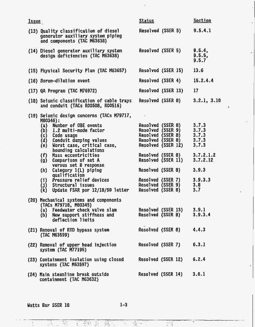
1.7 Summary of Outstandinq Issues
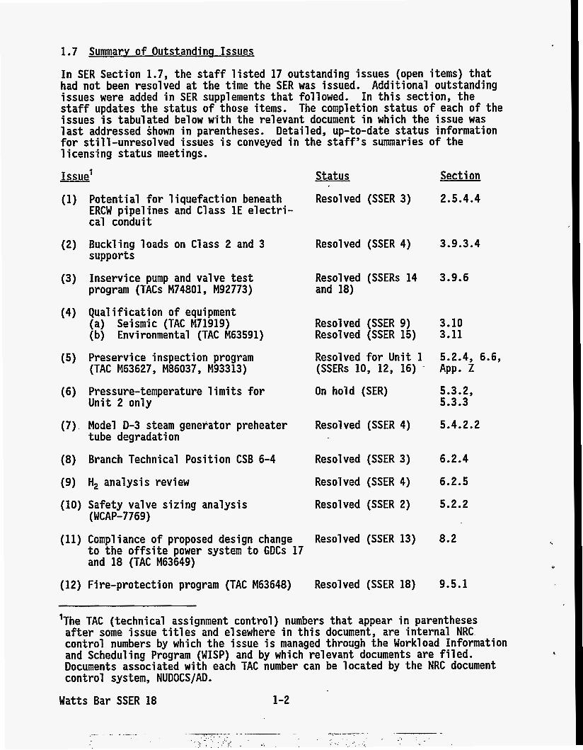
In SER Section 1.7, the staff listed 17 outstanding issues (open items) tha t had n o t been resolved a t the time the SER was issued. Additional outstanding issues were added i n SER supplements tha t followed. In this section, the staff updates the status of those items. The completion status of each of the issues is tabulated below w i t h the relevant document i n which the issue was 1 as t addressed shown i n parentheses. Detailed, up-to-date status information f o r still-unresolved issues is conveyed i n the s taff ' s summaries of the - licensing status meetings.
Issue'
Potential for liquefaction beneath ERCW pipelines and Class 1E electri- cal conduit
Buck1 ing 1 oads on C1 ass 2 and 3 supports
Inservi ce pump and valve tes t program (TACs M74801 , M92773)
Qual i f i cation of equi pment (a) Seismic (TAC M71919) (b) Environmental (TAC M63591)
Preservice inspection program (TAC M63627, M86037, M93313)
Pressure-temperature 1 imi ts fo r U n i t 2 only
Model D-3 steam generator preheater tube degradation
Branch Technical Posit ion CSB 6-4
H, analysis review
Safety valve sizing analysis (WCAP-7769)
Status Sect i on
Resolved (SSER 3) 2.5.4.4
Resolved (SSER 4) 3.9.3.4
Resolved (SSERs 14 3.9.6 and 18)
Resolved (SSER 9) 3.10 Resolved (SSER 15) 3.11
Resolved fo r U n i t 1 (SSERs 10, 12, 16) - App. Z
5.2.4, 6.6,
On hold (SER) 5.3.2, 5.3.3
Resolved (SSER 4) 5.4.2.2
Resolved (SSER 3) 6.2.4
Resolved (SSER 4) 6.2.5
Resolved (SSER 2) 5.2.2
Compliance of proposed design change Resolved (SSER 13) 8.2 t o the offsite power system t o GDCs 17 and 18 (TAC M63649)
Fire-protection program (TAC M63648) Resolved (SSER 18) 9.5.1
'The TAC (technical assignment control ) numbers that appear i n parentheses after some issue t i t les and elsewhere i n this document, are internal NRC control numbers by which the issue is managed through the Workload Information and Scheduling Program (WISP) and by which relevant documents are fi led. Documents associated with each TAC number can be located by the NRC document control system, NUDOCS/AD.
Watts Bar SSER 18 1-2
Issue
(13) Qual i ty c l assi f i c a t i on o f diesel generator aux i l i a r y system p ip ing and components (TAC M63638)
-.
(14) Diesel generator auxi 1 i ary system design def ic iencies (TAC M63638)
(15) Physical Security Plan (TAC M63657)
(16) Boron-dilution event
(17) QA Program (TAC M76972)
(18) Seismic c lass i f i ca t i on o f cable t rays and conduit (TACs R00508, R00516)
(19) Seismic design concerns (TACs M79717, M80346) : (a) Number o f OBE events (b) 1.2 multi-mode factor (c) Code usage (d) Conduit damping values (e) Worst case, c r i t i c a l case,
bounding cal cul a t i ons (f) Mass eccent r i c i t ies (9) Comparison o f set A
versus set B response (h) Category 1(L) piping
qual i f i c a t i on (i) Pressure re1 i e f devices (j) Structural issues (k) Update FSAR per 12/18/90 l e t t e r
(20) Mechanical systems and components (TACs M79718, M80345) (a) Feedwater check valve slam (b) New support s t i f fness and
def 1 ect i on 1 i m i t s
(21) Removal o f RTD bypass system (TAC M63599)
(22) Removal o f upper head in jec t ion system (TAC M77195)
(23) Containment i so la t i on using closed systems (TAC M63597)
(24) Main steamline break outside containment (TAC M63632)
Watts Bar SSER 18 1-3
Status
Resolved (SSER 5)
Resolved (SSER 5)
Resolved (SSER 15)
Resolved (SSER 4)
Resolved (SSER 13)
Resolved (SSER 8)
Resolved (SSER 8) Resolved (SSER 9) Resolved (SSER 8) Resolved (SSER 8) Resolved (SSER 12)
Resolved (SSER 8) Resolved (SSER 11)
Resolved (SSER 8)
Resolved (SSER 7) Resolved (SSER 9) Resolved (SSER 8)
Resolved (SSER 13) Resolved (SSER 8)
Resolved (SSER 8)
Resolved (SSER 7)
Resolved (SSER 12)
Resolved (SSER 14)
Section
9.5.4.1
9.5.4, 9.5.5, 9.5.7
13.6
15.2.4.4
17
3.2.1, 3-10
3.7.3 3.7.3 3.7.3 3.7.3 3.7.3
3.7.2.1.2 3.7.2.12
3.9.3
3.9.3.3 3.8 3.7
3.9.1 3.9.3.4
4.4.3
6.3.1
6.2.4
3-6.1
Issue
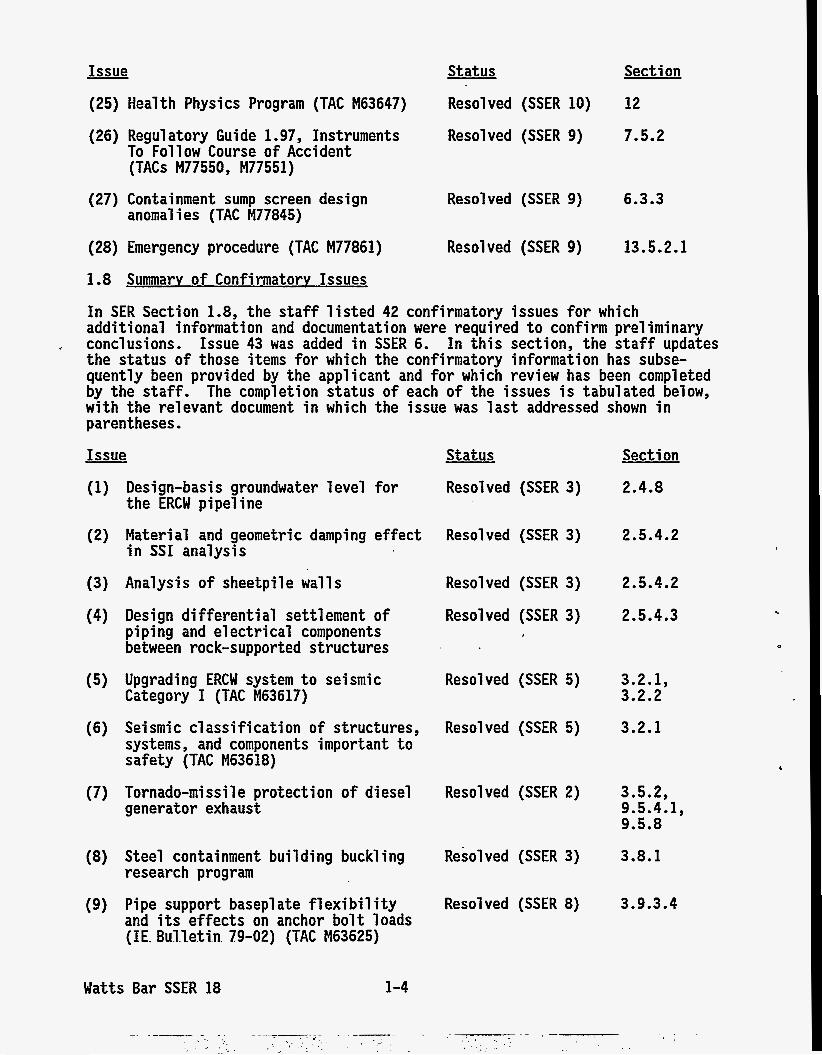
(25) Health Physics Program (TAC M63647)
(26) Regulatory Guide 1.97, Instruments To Follow Course of Accident (TACs M77550, M77551)
(27) Containment sump screen design anomal i es (TAC M77845)
(28) Emergency procedure (TAC M77861)
Status
Resolved (SSER 10)
Resolved (SSER 9)
Resolved (SSER 9)
Resolved (SSER 9)
Section
12
7.5.2
6.3.3
13 -5.2.1
1.8 Summarv of Confirmatorv Issues
In SER Section 1.8, the staff l i s ted 42 confirmatory issues for which additional information and documentation were required t o confirm preliminary conclusions. Issue 43 was added i n SSER 6. the status of those items for which the confirmatory information has subse- quently been provided by the applicant and for which review has been completed by the s ta f f . The completion s ta tus of each of the issues is tabulated below, w i t h the relevant document i n which the issue was las t addressed shown i n parentheses.
In this section, the staff updates
Issue Status
(7)
Design-basis groundwater level for the ERCW pipeline
Material and geometric damping effect i n SSI analysis
Analysis of sheetpile walls
Design differential settlement of pi ping and el ectr i cal components between rock-supported structures Upgrading ERCW system t o seismic Category I (TAC M63617)
Seismic classification of structures, systems, and components important t o safety (TAC M63618)
Tornado-missile protection of diesel generator exhaust
Resolved (SSER 3)
Resolved (SSER 3)
Resolved (SSER 5)
Resolved (SSER 3)
Resolved (SSER 3)
Resolved (SSER 5)
Resolved (SSER 2)
(8) Steel containment building buck1 ing research program
(9) Pipe support basepl ate f l exi bi 1 i t y and its effects on anchor bo l t loads (IE. B u l l e t i n 79-02) (TAC M63625)
Watts Bar SSER 18 1-4
Resolved (SSER 3)
Resolved (SSER 8)
Secti on
2.4.8
2.5.4.2
2.5.4.2
2.5.4.3
3.2.1, 3.2.2
3.2.1
3.5.2, 9.5.4.1, 9.5.8
3.8.1
3.9.3.4
Issue
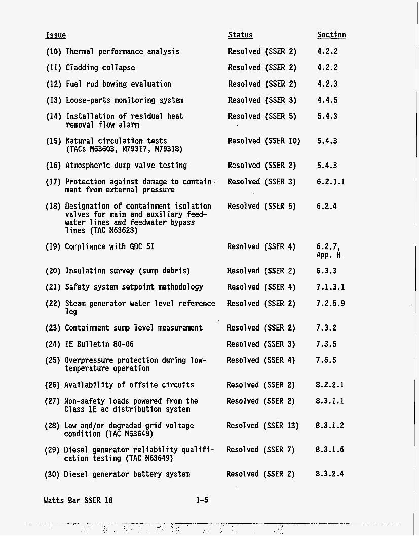
(10) Thermal performance analysis
(11) Cladding collapse
(12) Fuel rod bowing evaluation
(13) Loose-parts monitor ing system
(14) Installation of residual heat removal flow alarm
(15) Natural circulation t e s t s (TACs M63603, M79317, M79318)
(16) Atmospheric dump valve testing
(17) Protection against damage t o contain- ment from external pressure
(18) Designation of containment is01 ation valves for main and auxiliary feed- water l ines and feedwater bypass lines (TAC M63623)
(19) Compliance w i t h GDC 51
(20) Insulation survey (sump debris)
(21) Safety system setpoint method01 ogy
(22) Steam generator water 1 evel reference 1 eg
(23) Containment sump 1 evel measurement
(24) IE Bulletin 80-06
(25) Overpressure protection during 1 ow-
(26) Availability of offsite circuits
temperature operation
(27) Non-safety loads powered from the Class 1E ac distribution system
(28) Low and/or degraded g r i d voltage condi t ion (TAC M63649)
Status
Resolved (SSER 2)
Resolved (SSER 2)
Resolved (SSER 2)
Resolved (SSER 3)
Resolved (SSER 5)
Section
4.2.2
4.2.2
4.2.3
4.4.5
5.4.3
Resolved (SSER 10)
Resolved (SSER 2)
Resolved (SSER 3)
Resolved (SSER 5)
Resolved (SSER 4)
Resolved (SSER 2)
Resolved (SSER 4)
Resolved (SSER 2)
Resolved (SSER 2)
Resolved (SSER 3)
Resolved (SSER 4)
Resolved (SSER 2)
Resolved (SSER 2)
Resolved (SSER 13)
5.4.3
5.4.3
6.2.1.1
6.2.4
6.2.7, APP. H 6.3.3
7.1.3.1
7.2.5.9
7.3.2
7.3.5
7.6.5
8.2.2.1
8.3.1.1
8.3.1.2
(29) Diesel generator re1 i abi 1 i ty qual if i - Resolved (SSER 7) cation testing (TAC M63649)
(30) Diesel generator battery system
Watts Bar SSER 18
Resolved (SSER 2)
1-5
8.3.1.6
8.3.2.4
Issue Status
Resolved (SSER 2)
Resolved (SSER 13)
Sect i on
8.3.3.1.2
8.3.3.2.2
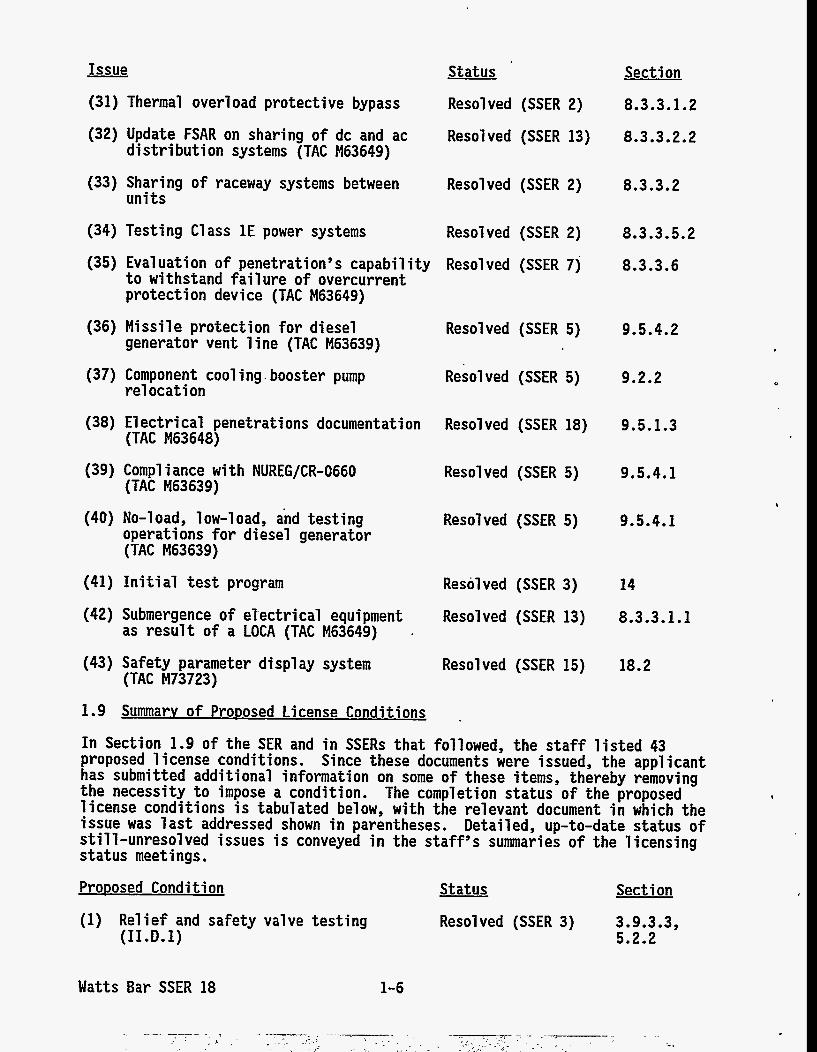
(31) Thermal overload protective bypass
(32) Update FSAR on sharing of dc and ac d i s t r i b u t i o n systems (TAC M63649)
(33) Sharing of raceway systems between u n i t s
Resolved (SSER 2) 8.3.3.2
(34) Testing Class 1E power systems Resolved (SSER 2) 8.3.3.5.2
8.3.3.6 (35) Evaluation of penetration’s capability Resolved (SSER 7) t o withstand fa i 1 ure of overcurrent protection device (TAC M63649)
(36) Missile protection for diesel generator vent 1 ine (TAC M63639)
Resolved (SSER 5) 9.5.4.2
(37) Component cool ing . booster pump re1 ocation
Resolved (SSER 5) 9.2.2
9.5.1.3
9.5.4.1
(38) E l e c t r i cal penetrations documentation Resolved (SSER 18) (TAC M63648)
(39) Compl i ance w i t h NUREG/CR-0660 (TAC M63639)
Resolved (SSER 5)
(40) No-load, low-load, and testing operations for diesel generator (TAC M63639)
(41) Ini ti a1 test program
Resolved (SSER 5) 9.5.4.1
Resolved (SSER 3)
Resolved (SSER 13)
14
8.3.3.1.1 (42) Submergence of el‘ectrical equipment as result of a LOCA (TAC M63649)
(43) Safety parameter display system (TAC M73723)
Resolved (SSER 15) 18.2
1.9 Summarv of ProDosed License Condit ions .
In Section 1.9 of the SER and i n SSERs that followed, the staff l i s ted 43 proposed 1 icense conditions. Since these documents were issued, the appl icant has submitted additional information on some of these items, thereby removing the necessity t o impose a condition. The completion status of the proposed license conditions is tabulated below, w i t h the relevant document i n which the issue was 1 a s t addressed shown i n parentheses. Detailed, up-to-date status o f still-unresolved issues is conveyed i n the staff’s summaries of the licensing status meetings.
ProDosed Condit ion Status
Resolved (SSER 3)
Section
(1) Relief and safety valve testing (II.D.l)
3.9.3.3, 5.2.2
Watts Bar SSER 18 1-6
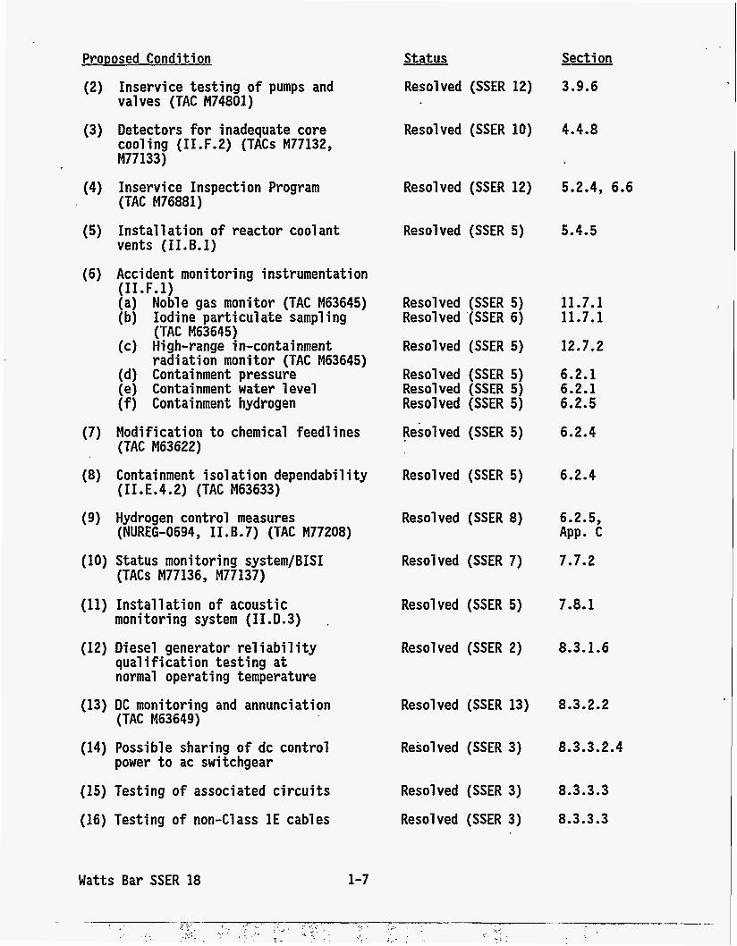
Proposed Condition
(2) Inservice testing of pumps and valves (TAC M74801)
(3) Detectors for inadequate core 1 .
cooling (II.F.2) (TACs M77132, M77133)
(4) Inservice Inspection Program (TAC M76881)
(5) Install ation of reactor coolant vents (II.B.1)
(6) Accident monitoring instrumentation (I1 .F. 1) (a) Noble gas monitor (TAC M63645) (b) Iodine particulate sampling
(TAC M63645) (c) High-range in-containment
radiation monitor (TAC M63645) (d) Containment pressure (e) Containment water level (f) Containment hydrogen
(7) Modification to chemical feed1 ines (TAC M63622)
(8) Containment is01 ation dependability
(9) Hydrogen control measures
(II.E.4.2) (TAC M63633)
(NUREG-0694, I I. B. 7) (TAC M77208)
(10) Status monitoring system/BISI (TACs M77136, M77137)
(11) Installation o f acoustic monitoring system (II.D.3)
(12) Diesel generator reliability qualification testing at normal operating temperature
(13) DC monitoring and annunciation (TAC M63649)
(14) Possible sharing o f dc control power to ac switchgear
(15) Testing of associated circuits
(16) Testing of non-Class 1 E cables
Watts Bar SSER 18 1-7
Status
Resolved (SSER 12)
Section
3.9.6
Resolved (SSER 10)
Resolved (SSER 12)
Resolved (SSER 5)
Resolved (SSER 5) Resolved '(SSER 6)
Resolved (SSER 5)
Resolved (SSER 5) Resolved (SSER 5) Resolved (SSER 5)
Resolved (SSER 5)
Resolved (SSER 5)
Resolved (SSER 8)
Resolved (SSER 7)
Resolved (SSER 5)
Resolved (SSER 2)
Resolved (SSER 13)
Resolved (SSER 3)
Resolved (SSER 3)
Resolved (SSER 3)
4.4.8
5.2.4, 6.6
5.4.5
11.7.1 11.7.1
12.7.2
6.2.1 6.2.1 6.2.5
6.2.4
6.2.4
6.2.5, APP. c 7.7.2
7.8.1
8.3.1.6
8.3.2.2
8.3.3.2.4
8.3.3.3
8.3.3.3
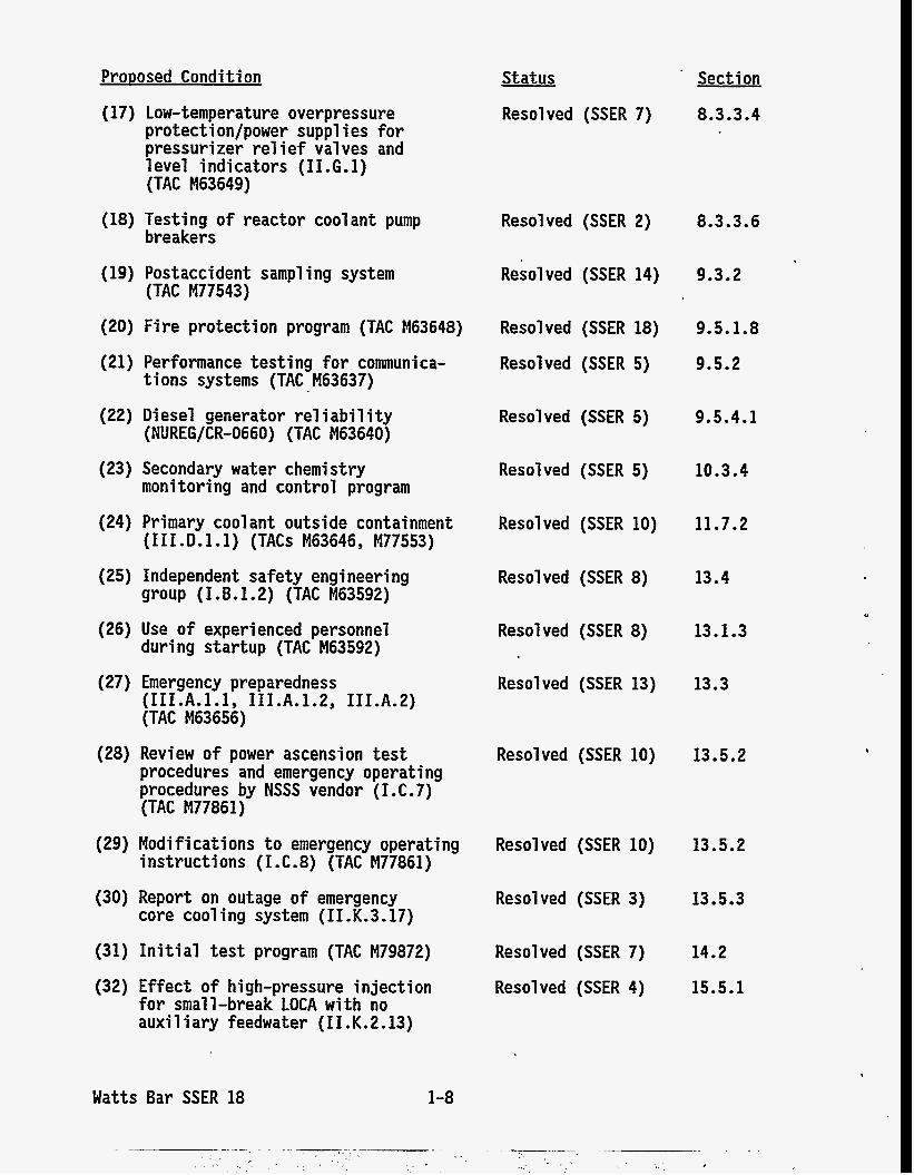
ProDosed Condition . Section
8.3.3.4
Status
Resolved (SSER 7) (17) Low-temperature overpressure protecti on/power suppl i es for pressurizer re1 i ef Val ves and level indicators (II.G.1) (TAC M63649)
Resolved (SSER 2) 8.3.3.6
9.3.2
(18) Testing of reactor coolant pump breakers
(19) Postaccident sampling system (TAC M77543)
Resolved (SSER 14)
(20) Fire protection program (TAC M63648) Resolved (SSER 18) 9.5.1.8
9.5.2 (21) Performance testing for communica-
(22) Diesel generator re1 i abi 1 i ty
tions systems (TAC M63637)
(NUREG/CR-0660) (TAC M63640)
Resolved (SSER 5)
Resolved (SSER 5) 9.5.4.1
Resolved (SSER 5)
Resolved (SSER 10)
10.3.4 (23) Secondary water chemistry monitoring and control program
11.7.2 (24) Primary cool ant outside containment (III.D.l.1) (TACs M63646, M77553)
(25) Independent safety engineering group (I.B.1.2) (TAC M63592)
Resolved (SSER 8) 13.4
Resolved (SSER 8) 13.1.3
13.3
(26) Use of experienced personnel during startup (TAC M63592)
(27) Emergency preparedness (I11 .A.1.1 I11 .A.1.2, III.A.2) (TAC M63656)
Resolved (SSER 13)
(28) Review of power ascension test procedures and emergency operating procedures by NSSS vendor ( I. C. 7) (TAC M77861)
Resolved (SSER 10) 13.5.2
(29) Modifications to emergency operating Resolved (SSER 10) instructions (I.C.8) (TAC M77861)
13.5.2
(30) Report on outage of emergency core cooling system (II.K.3.17)
Resolved (SSER 3) 13.5.3
Resolved (SSER 7)
Resolved (SSER 4)
14.2
15.5.1
(31) Initial test program (TAC M79872)
(32) Effect of high-pressure injection for small-break LOCA with no auxi 1 i ary feedwater (I1 .K. 2.13)
Watts Bar SSER 18 1-8
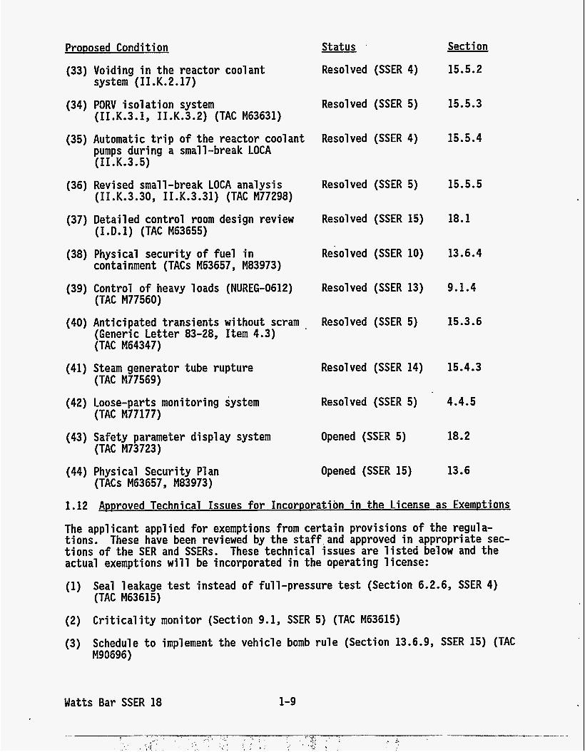
Proposed Condition
(33) Voiding i n the reactor coolant system ( I I . K. 2.17)
(34) PORV isolation system (II.K.3.1, II.K.3.2) (TAC M63631)
(35) Automatic trip of the reactor coolant pumps during a small-break LOCA (I1 .K.3.5)
(36) Revi sed small -break LOCA analysis (I I. K. 3.30, I I. K.3.31) (TAC M77298)
(37) Detailed control room design review (I.D.1) (TAC M63655)
(38) Physical security o f fuel i n containment (TACs M63657, M83973)
(39) Control of heavy loads (NUREG-0612) (TAC M77560)
(40) Anticipated transients w i t h o u t scram (Generic Letter 83-28, Item 4.3) (TAC M64347)
(TAC M77569)
(TAC M77177)
(TAC M73723)
(TACs M63657, M83973)
(41) Steam generator tube rupture
(42) Loose-parts monitoring system
(43) Safety parameter display system
(44) Physical Security P1 an
Status
Resolved (SSER 4)
Resolved (SSER 5)
Resolved (SSER 4)
Resolved (SSER 5)
Resolved (SSER 15)
Resolved (SSER 10)
Resolved (SSER 13)
Resolved (SSER 5)
Resolved (SSER 14)
Resolved (SSER 5)
Opened (SSER 5)
Opened (SSER 15)
Sect i on
15.5.2
15.5.3
15.5.4
15.5.5
18.1
13.6.4
9.1.4
15.3.6
15.4.3
4.4.5
18.2
13.6
1.12 Approved Technical Issues f o r Incorporation i n the License as Exemptions
The applicant applied for exemptions from certain provisions o f the regula- t ions . These have been reviewed by the s taff ,and approved i n appropriate sec- tions of the SER and SSERs. These technical issues are l i s ted below and the actual exemptions will be incorporated i n the operating license:
(1) Seal leakage t e s t instead of full-pressure t e s t (Section 6.2.6, SSER 4) (TAC M63615)
(2) Crit ical i ty monitor (Section 9.1, SSER 5) (TAC M63615)
(3) Schedule t o implement the vehicle bomb rule (Section 13.6.9, SSER 15) (TAC M90696)
Watts Bar SSER 18 1-9
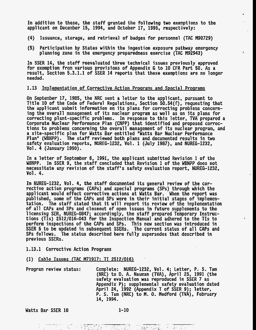
I n addi t ion t o these, the s ta f f granted the following two exemptions t o the applicant on December 15, 1994, and October 17, 1995, respectively:
(4) Issuance, storage, and retrieval of badges for personnel (TAC M90729)
(5) Participation by States within the ingestion exposure pathway emergency planning zone i n the emergency preparedness exercise (TAC M92943)
In SSER 14, the s ta f f reevaluated three technical issues previously approved for exemption from various provisions of Appendix G t o 10 CFR Part 50. As a result, Section 5.3.1.1 of SSER 14 reports t h a t these exemptions are no longer needed.
1.13 Implementation of Corrective Action Programs and Special Programs
On September 17, 1985, the NRC sent a l e t te r t o the applicant, pursuant t o Title 10 of the Code of Federal Regulations, Section 50.54(f), requesting t h a t the appl icant submi t information on its plans for correcting problems concern- ing the overall management of its nuclear program as well as on its plans for correcting pl ant-specific problems. In response t o this l e t t e r , TVA prepared a Corporate Nuclear Performance P1 an (CNPP) tha t identified and proposed correc- t i o n s t o problems concerning the overall management of its nuclear program, and a site-specific p lan for Watts Bar enti t led "Watts Bar Nuclear Performance Plan" (WBNPP). The staff reviewed both plans and. documented results i n two safety evaluation reports, NUREG-1232, Vol . 1 (July 1987) , and NUREG-1232, Vol. 4 (January 1990).
In a l e t t e r of September 6, 1991, the applicant submitted Revision 1 of the WBNPP. In SSER 9, the staff concluded tha t Revision 1 of the WBNPP does no t necessitate any revision of the staff's safety evaluation report, NUREG-1232, VOl . 4.
In NUREG-1232, Vol. 4, the staff documented its general review of the cor- rective action programs (CAPs) and special programs (SPs) through which the applicant would effect corrective actions a t Watts Bar. When the report was published, some of the CAPs and SPs were i n their in i t ia l stages of implemen- tation. The staff stated tha t i t will report its review of the implementation of a l l CAPs and SPs and closeout o f open issues i n future supplements t o the 1 icensing SER, NUREG-0847; accordingly, the staff prepared Temporary Instruc- t ions (TIS) 2512/016-043 for the Inspection Manual and adhered t o the TIS t o perform inspections of the CAPs and SPs. T h i s new section was introduced i n SSER 5 t o be updated in subsequent SSERs. The current status of a l l CAPs and SPs follows. The status described here fu l ly supersedes tha t described i n previous SSERs . 1.13.1 Corrective Action Programs
(1) Cable Issues (TAC M71917: TI 2512/016)
Program review status :
Watts Bar SSER 18
Complete: NUREG-1232, Vol. 4; Letter, P. S. Tam (NRC) t o D. A. Nauman (TVA), April 25, 1991 (the safety evaluation was reproduced i n SSER 7 as Appendix P) ; supplemental safety eval uati on dated April 24, 1992 (Appendix T of SSER 9); l e t t e r , P. S. Tam (NRC) t o M. 0. Medford (TVA), February 14, 1994.
1-10
Implementation status:
NRC inspections:
Full imp1 ementati on expected by October 1995.
Inspection Reports 50-390, 391/90-09 (June 22, 1990) ; 50-390, 391/90-20 (September 25, 1990); 50- 390, 391/90-22 (November 21, 1990); 50-390, 391/90- 24 (December 17, 1990) ; 50-390, 391/90-27 (December 20, 1990); 50-390, 391/90-30 (February 25, 1991) ; 50-390, 391/91-07 (May 31, 1991) ; 50-390, 391/91-09
50-390, 391/91-31 (January 13, 1992); 50-390, 391/ 92-01 (March 17, 1992); audit report o f June 12, 1992 (Appendix Y o f SSER 9); 50-390, 391/92-05 (April 17, 1992); 50-390, 391/92-13 (July 16,
391/92-22 (September 18, 1992) ; 50-390, 391/92-26 (October 16, 1992) ; 50-390, 391/92-30 (November 13, 1992) ; 50-390, 391/92-35 (December 15, 1992); 50- 390, 391/92-40 (January 15, 1993); 50-390, 391/93- 10 (March 19, 1993); 50-390, 391/93-11 (March 25, 1993); 50-390, 391/93-35 (June 10, 1993); 50-390,
(August 13, 1993) ; 50-390, 391/93-56 (September 20, 1993) ; 50-390, 391/93-63 (October 18, 1993) ; 50- 390, 391/93-70 (November 12, 1993) ; 50-390, 391/93- 74 (December 20, 1993) ; 50-390, 391/93-85 (January 14, 1994) ; 50-390, 391/93-91 (February 17, 1994); 50-390, 391/94-11 (March 16, 1994) ; 50-390, 391/94- 18 (April 18, 1994); 50-390, 391/94-32 (May 16, 1994) ; 50-390, 391/94-35 (June 20, 1994) ; 50-390,
(August 11, 1994); 50-390, 391/94-53 (September 20, 1994); 50-390, 391/94-55 (September 16, 1994) ; 50- 390, 391/94-61 (October 12, 1994); 50-390, 391/94- 66 (November 16, 1994) ; 50-390, 391/94-75 (December 19, 1994); 50-390, 391/94-82 (January 13, 1995); 50-390, 391/94-88 (February 15, 1995) ; 50-390, 391/95-17 (April 13, 1995) ; 50-390, 391/95-45 (August 15, 1995) ; 50-390, 391/95-57 (September 15, 1995); 50-390, 391/95-64 (October 11, 1995); to come.
(July 15, 1991); 50-390, 391/91-12 (July 12, 1991);
1992) ; 50-390, 391/92-18 (August 14, 1992) ; 50-390,
391/93-40 (July 15, 1993) ; 50-390, 391/93-48
391/94-45 (July 15, 1994); 50-390, 391/94-51
(2) Cable Tray and Tray Suworts (TAC R00516: TI 2512/0171
Program review status: Complete: Letter, S. C. Black (NRC) to 0. D. Kingsley (TVA) , September 13, 1989; NUREG-1232, Vol. 4; SSER 6, Section 3.
Implementation status: Full implementation expected by October 1995.
NRC inspections: Inspection Reports 50-390, 391/89-14 (December 18, 1989) ; 50-390, 391/90-20 (September 25, 1990) ; 50- 390, 391/90-22 (November 21, 1990); 50-390, 391/ 92-02 (March 17, 1992); audit report o f May 14, 1992 (Appendix S o f SSER 9); 50-390, 391/92-13 (July 16, 1992); 50-390, 391/92-201 (September 21, 1992); 50-390, 391/93-07 (February 19, 1993) ; 50-
Watts Bar SSER 18 1-11
390/94-64 (December 15, 1994) ; 50-390, 391/94-88 (February 15, 1995); 50-390, 391/95-23 (May 2, 1995); 50-390, 391/95-27 (May 31, 1995); 50-390, 391/95-35 (June 28, 1995); to come.
(3) Desian Baseline and Verification Proqram (TAC M63594: TI 2512/019)
Program review status: Complete: Inspection Report 50-390, 391/89-12 (November 20, 1989); NUREG-1232, Vol . 4; Inspection Report 50-390/95-36 (June 21 , 1995).
Impl ementati on status: 100% (certified by letter, R. R. Baron (TVA) to NRC, September 27, 1995).
NRC inspections: Complete: Inspection Reports 50-390, 391/89-12 (November 20, 1989); 50-390, 391/90-09 (June 22, 1990) ; 50-390, 391/90-20; (September 25, 1990) ; 50- 390/91-201 (March 22, 1991) ; 50-390, 391/91-20 (October 8, 1991); 50-390, 391/91-25 (December 13, 1991) ; 50390, 391/92-06 (April 3, 1992) ; 50-390, 391/92-201 (September 21 , 1992) ; 50-390, 391/93-29 (May 14, 1993); 50-390, 391/93-66 (October 29, 1993) ; 50-390, 391194-69 (November 18, 1994) ; 50- 390/95-36 (June 21, 1995) ; 50-390, 391/95-47 (August 16, 1995). .
(4) Electrical Conduit and Conduit Sutmort (TAC R00508: TI 2512/018)
Program review status: Complete: Kingsley (TVA) , September 1, 1989; NUREG-1232, Vol . 4; SSER 6, Section 3.
Letter, S. C. Black (NRC) to 0. D.
Impl ementation status:
NRC inspections:
Full implementation expected by October 1995.
Inspection Reports 50-390, 391/89-05 (May 25,
391/89-14 (December 18, 1989) ; 50-390, 391/90-20 (September 25, 1990) ; 50-390, 391/91-31 (January 13, 1992); 50-390, 391/92-02 (March 17, 1992); audit report o f May. 14, 1992 (Appendix S of SSER 9); 50-390, 391/92-05 (April 17, 1992); 50-390, 391/92-09 (June 29, 1992) ; 50-390, 391/92-201 (September 21 , 1992) ; 50-390, 391/92-26 (October 16, 1992); 50-390, 391/93-07 (February 19, 1993); 50-390, 391/93-35 (June 10, 1993); 50-390, 391/93- 70 (November 12, 1993) ; 50-390, 391/93-74 (December 20, 1993) ; 50-390, 391/93-91 (February 17, 1994) ; 50-390, 391/94-11 (March 16, 1994) ; 50-390, 391/94- 32 (May 16, 1994); 50-390/94-64 (December 15, 1994); 50-390, 391/94-82 (January 13, 1995); 50- 390, 391/94-88 (February 15, 1995) ; 50-390, 391/95- 23 (May 2, 1995); 50-390, 391/95-27 (May 31, 1995); 50-390, 391/95-35 (June 28, 1995) ; 50-390, 391/95- 57 (September 15, 1995); to come.
1989); 50-390, 391/89-07; (July 11, 1989); 50-390,
Watts Bar SSER 18 1-12
(5)
Program review status:
Impl ementation status:
NRC inspections:
Complete: Kingsley (TVA) , September 11 , 1989; NUREG-1232, Vole 4.
Letter, S. C. Black (NRC) to 0. D.
Full implementation expected by October 1995.
Inspecti on Reports 50-390, 391/90-30 (February 25, 1991) ; 50-390, 391/92-22 (September 18, 1992) ; 50- 390, 391/92-40 (January 15, 1993); 50-390, 391/93- 35 (June 10, 1993); 50-390, 391/93-40 (July 15, 1993) ; 50-390, 391/93-63 (October 18, 1993) ; 50- 390, 391/94-11 (March 16, 1994); 50-390, 391/94-18 (April 18, 1994); 50-390, 391/94-31 (May 11, 1994);
53 (September 20, 1994); 50-390, 391/94-66 (Novem- ber 16, 1994); 50-390, 391/94-82 (January 13, 1995) ; 50-390, 391/94-88 (February 15, 1995); 50- 390, 391/95-57 (September 15, 1995) ; 50-390, 391/95-64 (October 11, 1995); to come.
50-390, 391/94-45 (July 15, 1994); 50-390, 391/94-
(6)
Program review status:
Equitment Seismic Qualification (TAC M71919: TI 2512/021)
Complete: Letter, S. C. Black (NRC) to 0. D. Kingsley (TVA) , September 11, 1989; NUREG-1232, Vol. 4; SSER 6, Section 3.10.
Impl ementation status:
NRC inspections:
100%.
Complete: Inspecti on Reports 50-390, 391/90-05 (May 10, 1990); 50-390, 391/90-20 (September 25, 1990); 50-390, 391/90-28 (January 11, 1991); 50- 390, 391/91-03 (April 15, 1991); audit report of May 14, 1992 (Appendix-S of SSER 9); 50-390, 391/92-201 (September 21 , 1992) ; 50-390, 391/93-07 (February 19, 1993); 50-390, 391/93-79 (March 4, 1994); 50-390, 391/95-30 (June 22, 1995); 50-390, 391/95-55 (August 28, 1995).
(7)
Program review status:
Fire Protection (TAC M63648: TI 2512/022)
Complete: Letter, S. C. Black (NRC) to 0. D, Kingsley (TVA) , September 7, 1989; NUREG-1232, Vol . 4; SSER 18, Section 9.5.1 and Appendix FF.
Implementation status:
NRC inspections:
Watts Bar SSER 18
100%; staff concurrence in Inspection Report 50- 390, 391/95-61, October 5, 1995,
Complete: Inspection Reports 50-390, 391/94-45 (July 15, 1994); 50-390, 391/94-63 (November 2, 1994) ; 50-390, 391/94-62 (November 16, 1994) ; 50- 390, 391/94-66 (November 16, 1994) ; 50-390, 391/94- 78 (December 21, 1994) ; 50-390, 391/94-82 (January 13, 1995) ; 50-390, 391/95-03 (January 31 , 1995) ; 50-390, 391/95-13 (March 1 , 1995) ; 50-390, 391/95-
1-13
16 (April 6, 1995); 50-390, 391/95-26 (May 1, 1995); 50-390, 391/95-32 (June 9, 1995); 50-390,
(September 12, 1995) ; 50-390, 391/95-61 (October 5, 1995).
391/95-39 (July 18, 1995) ; 50-390, 391/95-40
(8) Hanaer and Analvsis UDdate Prouram (TAC R00512: TI 2512/0231
Program review status: Complete: Letter, S. C. Black (NRC) to 0. D. Kingsley (TVA), October 6, 1989; NUREG-1232, Vol. 4; SSER 6, Section 3.
Impl ementation status: 100%; staff concurrence in Inspection Report 50- 390, 391/95-53, September 8, 1995.
NRC inspections: Complete: Inspection Reports 50-390, 391/89-14 (December 18, 1989); 50-390, 391/90-14 (August 3, 1990) ; 50-390, 391/90-18 (September 20, 1990) ; 50- 390, 391/90-20 (September 25, 1990) ; 50-390, 391/90-28 (January 11, 1991) ; 50-390, 391/91-03 (April 15, 1991); audit report of May 14, 1992 (Appendix S of SSER 9); 50-390, 391/92-201 (September 21, 1992) ; 50-390, 391/92-26 (October 16, 1992); 50-390, 391/92-35 (December 15, 1992); 50-390, 391/93-07 (February 19, 1993) ; 50-390, 391/93-35 (June 10, 1993); 50-390, 391/93-45 (July 20, 1993) ; 50-390, 391/93-56 (September 20, 1993) ; 50-390, 391/93-70 (November 12, 1993); 50-390, 391/93-74 (December 20, 1993) ; 50-390, 391/94-11 (March 16, 1994); 50-390, 391/94-32 (May 16, 1994); 50-390, 391/94-55 (September 16, 1994); 50-390, 391/95-06 (March 16; 1995) ; 50-390, 391/95-23 (May 2, 1995); 50-390, 391/95-27 (May 31, 1995); 50-390, 391/95-35 (June 28, 1995) ; 50-390, 391/95-53 (September 8, 1995).
(9) Heat Code Traceabilitv (TAC M71920: TI 2512/024)
Program review status: Complete: Inspecti on Report 50-390, 391/89-09 (September 20, 1989); NUREG-1232, Vol . 4; letter, P. S. Tam (NRC) to D. A. Nauman (TVA), March 29, 1991.
Impl ementation status: 100% (certified by letter, E. Wallace (TVA) to NRC, July 31, 1990); staff concurrence in SSER 7, Sec- tion 3.2.2.
(September 20, 1989) ; 50-390, 391/90-02 (March 15, 1990).
NRC inspections: Complete: Inspecti on Reports 50-390, 391/89-09
(10) Heatina, Ventilation. and Air-Conditionina Duct and Duct Sumorts (TAC R00510: TI 2512/025)
Program review status: Complete: Letter, S. C, Black (NRC) to 0. D.
Watts Bar SSER 18 1-14
* , . . , . '
' , . ~ - .*-- -. 1. ., ~ .- -I ,.
.: . , . -, , -1 ,
__ -_ . ~ - ~ - ~ - - . ~ .,.,,. .: - . . . . . . , - , -
~
. - . ~ , -UT I .-. .I .I . > - ).. 1 ,- . -. , . I . * -.,,,.
~ ..,,
- ., ~
. - - ,. , ~
, , _.,
Kingsley (TVA) , October 24, 1989; NUREG-1232, Vol . 4; SSER 6, Section 3.
Impl ementation status: 100% (certif ied by l e t t e r , R. R. Baron t o NRC, October 10, 1995) ; staff concurrence i n Inspection Report 50-390, 391/95-46, August 1, 1995.
NRC i nspecti ons: Complete: Inspection Reports 50-390, 391/89-14 (December 18, 1989); 50-390, 391/90-05 (May 10, 1990); 50-390, 391/90-20 (September 25, 1990) ; 50- 390, 391/91-01 (April 4, 1991); 50-390, 391/92-02 (March 17, 1992); audi t report o f May 14, 1992 (Appendix S of SSER 9); 50-390, 391/92-08 (May 15,
391/92-201 (September 21 , 1992) ; 50-390, 391/93-07 (February 19, 1993) ; 50-390, 391/93-91 (February 17, 1994); 50-390, 391/94-08 (March 11, 1994); 50- 390, 391/95-23 (May 2, 1995); 50-390, 391/95-35 (June 28, 1995); 50-390, 391/95-46 (August 1, 1995).
1992); 50-390, 391/92-13 (July 16, 1992); 50-390,
(11) Instrument Lines (TAC M71918: TI 2512/0261
Program review status: Complete: Kingsley (WA) , September 8, 1989; NUREG-1232, Vol . 4; Appendix K of SSER 6; l e t t e r , P. S. Tam (NRC) t o 0. D. Kingsley (TVA), May 5, 1994,
100%; s ta f f concurrence i n Inspection Report 50- 390, 391/95-61, October 5, 1995.
Letter, S. C. Black (NRC) t o 0. D.
Impl ementat i on st a t us :
NRC inspections: Complete: Inspection Reports 50-390, 391/90-14 (August 3, 1990); 50-390, 391/90-23 (November 19, 1990); 50-390, 391/90-29 (January 29, 1991); 50390, 391/91-02 (March 6, 1991) ; 50-390, 391/91-03 (April 15, 1991) ; 50-390, 391/91-26 (December 6, 1991) ; 50-390, 391/93-74 (December 20, 1993) ; 50-390, 391/94-11 (March 16, 1994) ; 50-390, 391/94-24 (July 1, 1994); 50-390, 391/94-32 (May 16, 1994); 50-390, 391/94-55 (September 16, 1994) ; 50-390, 391/95-23 (May 2, 1995); 50-390, 391/95-27 (May 31, 1995);
' 50-390, 391/95-35 (June 28, 1995); 50-390, 391/95- 53 (September 8, 1995); 50-390, 391/95-61 (October 5, 1995)-
(12) Prestart Test Procrram (TAC M71924)
Program review status: Complete: Letter, S. C. Black (NRC) t o 0. D. Kingsley (TVA) , October 17, 1989; NUREG-1232, Vol . 4; l e t t e r , P. S. Tam (NRC) t o D. A. Nauman (TVA), March 27, 1991.
Impl ementation status: Withdrawn by l e t t e r , J, HI Garrity (TVA) t o NRC, February 13, 1992. Applicant will re-perform preoperational t e s t program per Regul atory Guide 1.68, Revision 2.
Watts Bar SSER 18 1-15
(13) Oual i t v Assurance Records (TAC M71923: TI 2512/0281
Program review status:
Impl emen t a t i on s t a t us :
NRC inspections :
Complete: Letter, S. C. Black (NRC) t o 0. D. Kingsley (TVA) , December 8, 1989; NUREG-1232, Vol . 4; letter, P. S. Tam (NRC) t o M. 0. Medford (TVA)
.June 9, 1992 (Appendix X of SSER 9); letter, P. S. Tam (NRC) t o M. 0. Medford (TVA), January 12, 1993; l e t t e r , F. J. Hebdon (NRC) t o M. 0. Medford (TVA), August 12, 1993; letter, P. S. Tam (NRC) t o 0. D. Kingsley (TVA), Apr i l 25, 1994.
100% (certif ied by letter, W. J. Museler (TVA), t o NRC, Apr i l 27, 1994); staff concurrence in Inspec- t i o n Report 50-390, 391/94-40, June 24, 1994.
Complete: Inspecti on Reports 50-390, 391/90-06 (April 25, 1990); 50-390, 391/90-08 (September 13, 1990); 50390, 391/91-08 (May 30, 1991); 50-390, 391/91-15 (September 5, 1991) ; 50-390, 391/91-29 (December 27,. 1991); 50-390, 391/92-05 (April 17, 1992); 50-390, 391/92-10 (June 11, 1992); 50-390, 391/92-21 (September 18, 1992); 50-390, 391/93-11 (March 25, 1993); 50-390, 391/93-21 (April 9, 1993) ; 50-390, 391/93-29 (May 14, 1993) ; 50-390, 391/93-34 (July 5, 1993) ; 50-390, 391/93-35 (June 10, 1993); 50-390, 391/93-50 (September 3, 1993); 50-390, 391/93-59 (October 25, 1993) ; 50-390, 391/93-69 (November 12, 1993) ; 50-390, 391/93-70 (November 12, 1993) ; 50-390, 391/93-78 (December 16, 1993); 50-390, 391/93-86 (January 24, 1994); 50-390, 391/94-04 (February 23, 1994) ; 50-390, 391/94-09 (March 11 , 1994) ; 50-390, 391/94-17 (April 1, 1994); 50-390, 391/94-28 (May 5, 1994); 50-390, 391/94-40 (June 24, 1994).
(14) 0-List (TAC M63590: TI 2512/029)
Program review status:
Impl ementation status:
NRC inspections:
Watts Bar SSER 18
Complete: Letter, S. C. Black (NRC) t o 0. D. Kingsley (TVA) , September 11 , 1989; NUREG-1232, Vol. 4; l e t te rs , P. S. Tam (NRC) t o 0. D. Kingsley (TVA), January 23, 1991 and March 17, 1994 (enclo- sure of this l e t t e r reproduced as Appendix AA i n SSER 13).
100% (certified by letter, W. J. Museler (TVA), t o NRC, January 28, 1994); staff concurrence i n Inspection Report 50-390, 391/94-27, April 21 , 1994.
Complete: Inspection Reports 50-390, 391/90-08 (September 13, 1990); 50-390, 391/91-08 (May 30, 1991); 50-390, 391/91-29 (December 27, 1991) ; 50- 390, 391/91-31 (January 13, 1992); 50-390, 391/93- 20 (April 16, 1993); 50-390, 391/93-68 (November 12, 1993); 50-390, 391/94-27 (April 21, 1994).
1-16
(15) Replacement Items Procrram (TAC M71922: TI 251210271
Program review status : Complete: Letter, S. C. Black (NRC) t o 0. D. Kingsley (TVA) , November 22, 1989; NUREG-1232, Vol . 4; l e t t e r , P. S. Tam (NRC) t o 0. D. Kingsley (TVA), February 11, 1991 (Appendix N of SSER 6); letter, P. S. Tam (NRC) t o M. 0. Medford (TVA), July 27, 1992, April 5, 1994, and February 6, 1995.
100% (certif ied by l e t t e r , R. R. Baron t o NRC, October 13, 1995).
ImpJementation status:
NRC inspections: Complete: Inspection Reports 50-390, 391/91-08 (May 30, 1991); 50-390, 391/91-29 (December 27, 1991); 50- 390, 391/92-03 (March 16, 1992); 50-390, 391/92-11 (June 12, 1992); 50-390, 391/92-17 (July 22, 1992); 50-390, 391/92-21 (September 18, 1992); 50-390, 391/92-40 (January 15, 1993) ; 50-390, 391/93-22 (April 25, 1993); 50-390, 391/93-34 (July 9, 1993); 50-390, 391/93-38 (June 24, 1993); 50- 390/94-201 (December 14, 1994) ; 50-390, 391/95-34 (June 23, 1995); 50-390, 391/95-50 (August 29, 1995).
(16) Seismic Analysis (TAC R00514: TI 2512/030\
Program review status: Complete: Letters, S. C. Black (NRC) t o 0. D. Kingsley (TVA), September 7 and October 31, 1989; NUREG-1232, Vol . 4; SSER 6, Section 3.7.
Imp1 ementation status: 100% (certified by l e t t e r , J. H. Garrity (TVA) t o NRC, December 2, 1991); staff concurrence i n SSER 9, Section 3.7.1.
NRC i nspect i ons : Complete: Inspecti on Reports 50-390, 391/89-21 (May 10, 1990) j 50-390, 391/90-20 (September 25, 1990); aud i t report by L. B. Marsh, October 10, 1990.
(16) (a) C iv i l Calculation Proaram (TAC ROO5141
Program review status: No program review. A number of c ivi l caJculation categories are required by the Design Baseline and Veri f i cati on Program CAP and constitute parts of the applicant's corrective actions. T h i s program is regarded as complementary t o bu t not part of the Seismic- Analysis CAP. Staff effor ts c o n s i s t mainly of audits performed a t the s i t e and i n the office.
Implementation status: 100% (final calculations transmitted by l e t t e r , W. 3. Museler (TVA) t o NRC, July 27, 1992).
NRC audits: Complete: Memorandum (publicly available), T. M. Cheng (NRC) t o P. S. Tam, January 23, 1992; l e t t e r , P. S. Tam (NRC) t o D. A. Nauman (TVA), January 31, 1992; l e t te rs , P. S. Tam (NRC) t o M. 0. Medford
Watts Bar SSER 18 1-17
(TVA), May 26 and December 18, 1992 and July 2, 1993; 50-390, 391/93-07 (February 19, 1993); l e t te r , P. S. Tam (NRC) t o M. 0. Medford (TVA), November 26, 1993.
(17) Vendor Information Prosram (TAC M71921: TI 2512/0311
Program review status:
Impl ementation status:
NRC i nspecti ons :
Complete: Letter, P. S. Tam (NRC) t o 0. D. Kingsley (TVA), September 11, 1990 (Appendix I of SSER 5); Appendix I of SSER 11.
100%.
Inspection Reports 50-390, 391/91-08 (May 30, 1991) ; 50-390, 391/91-29 (December 27, 1991) ; 50- 390, 391/93-27 (May. 14, 1993); 50-390, 391/95-10 (March 17, 1995); t o come.
(18) Weldins (TAC M72106: TI 2512/032)
Program review status:
Impl ementat i on status :
NRC inspections:
Complete: Inspection Reports 50-390, 391/89-04 (August 9, 1989); 50-390, 391/90-04 (May 17, 1990); NUREG-1232, Vol. 4; l e t t e r , P. S. Tam (NRC) t o D. A. Nauman (TVA), March 5, 1991; these inspection reports a1 so address recurrence control : 50-390, 391/93-02 (February 2, 1993) ; 50-390, 391/93-84 (December 21, 1993); 50-390, 391/94-79 (January 11, 1995).
100% (certif ied by l e t t e r , W. J. Museler (TVA) t o NRC, January 9, 1993); staff concurrence i n Inspection Report 50-390, 391/94-79, January 11, 1995.
Complete: Inspection Reports 50-390, 391/89-04 (August 9, 1989); 50-390, 391/90-04 (May 17, 1990); 50-390, 391/90-20 (September 25, 1990) ; 50-390, 391/91-05 (May 28, 1991); 50-390, 391/91-18 (October 8, 1991) ; 50-390, 391/91-23 (November 21 , 1991); 50390, 391/91-32 (February 10, 1992); 50-
(October 9, 1992); 50-390, 391/93-02 (February 2, 1993); 50-390, 391/93-19 (March 15, 1993); 50-390, 391/93-38 (June 24, 1993); 50-390, 391/93-84 (December 21 , 1993) ; 50-390, 391/94-05 (February 19, 1994); 50-390, 391/94-16 (March 15, 1994); 50-
(January 11, 1995).
390, 391/9220 (August 12, 1992); 50-390, 391/92-28
390, 391/94-49 (JUly’21, 1994); 50-390, 391/94-79
1.13.2 Speci a1 Programs
(1) Concrete Oualitv (TAC M63596: TI 2512/033)
Program review status: Complete: NUREG-1232, Vol. 4.
Impl ementation status:
Watts Bar SSER 18
100% (certif ied by l e t t e r , E. Wallace (TVA) t o NRC,
1-18
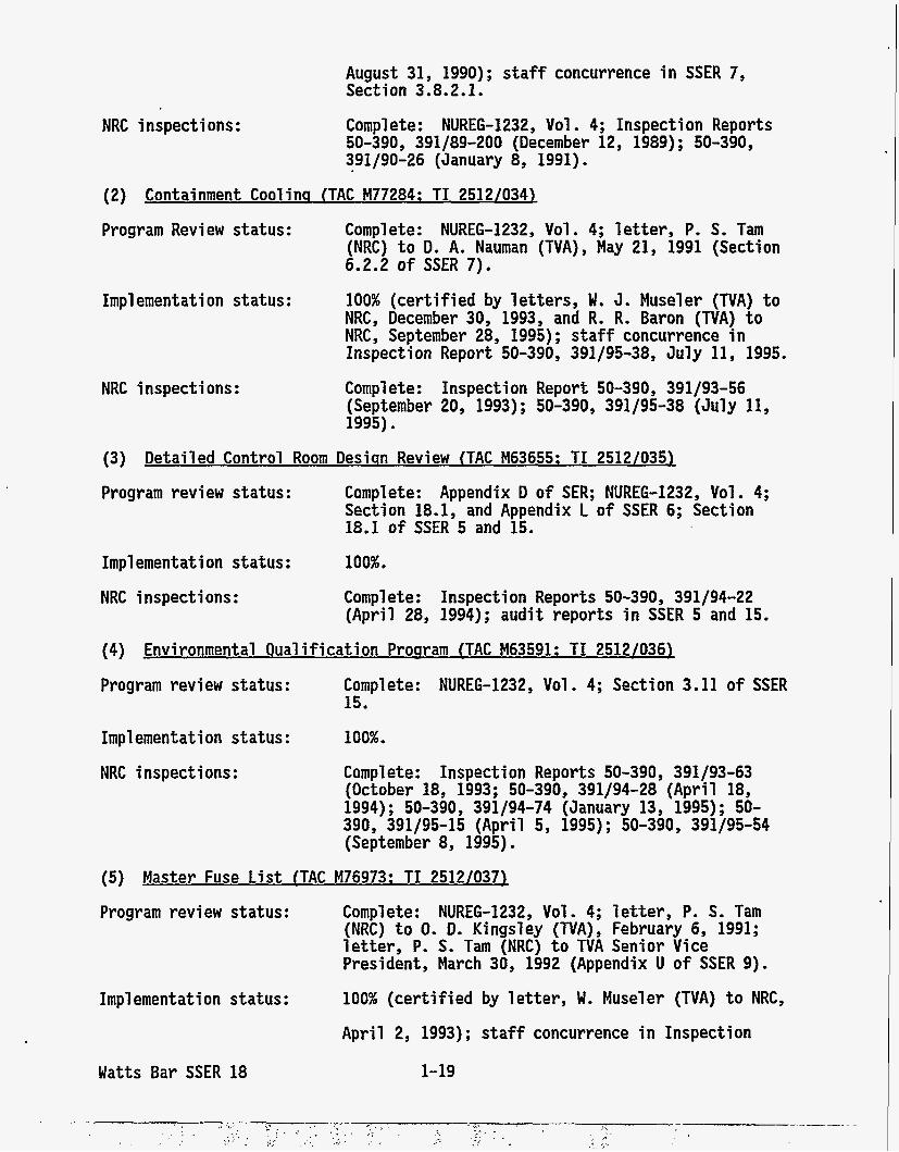
August 31, 1990); staff concurrence in SSER 7, Sect i on 3 . 8.2.1.
NRC inspections: Complete: NUREG-1232, Vol . 4; Inspection Reports 50-390, 391/89-200 (December 12, 1989) ; 50-390, 391/90-26 (January 8, 1991).
(2) Containment Coolina (TAC M77284: TI 2512/034)
Program Review status:
Impl ementati on status:
NRC inspections:
Complete: NUREG-1232, Vol. 4; letter, P, S. Tam (NRC) to D. A. Nauman (TVA), May 21, 1991 (Section 6.2.2 o f SSER 7). 100% (certified by letters, W. J. Museler (TVA) to NRC, December 30, 1993, and R. R. Baron (TVA) to NRC, September 28, 1995); staff concurrence in Inspection Report 50-390, 391/95-38, July 11 , 1995. Complete: Inspecti on Report 50-390, 391/93-56 (September 20, 1993); 50-390, 391/95-38 (July 11 , 1995).
(3) Detailed Control Room Desisn Review (TAC M63655: TI 2512/035)
Program review status: Complete: Appendix D of SER; NUREG-1232, Vol. 4; Section 18.1, and Appendix L o f SSER 6; Section 18.1 of SSER 5 and 15.
Impl ementation status:
NRC inspections:
100%.
Complete: Inspection Reports 50-390, 391/94-22 (April 28, 1994); audit reports in SSER 5 and 15.
(4) Environmental Oualification Proqram (TAC M63591: TI 2512/036)
Program review status:
Impl ementat i on status :
NRC i nspecti ons :
Complete: NUREG-1232, Vol. 4; Section 3.11 of SSER 15.
100%.
Complete: Inspection Reports 50-390, 391/93-63 (October 18, 1993; 50-390, 391/94-28 (April 18, 1994); 50-390, 391/94-74 (January 13, 1995); 50- 390, 391/95-15 (April 5, 1995) ; 50-390, 391/95-54 (September 8, 1995).
(5) Master Fuse List (TAC M76973: TI 2512/037)
Program review status:
Impl ementation status:
Watts Bar SSER 18
Complete: NUREG-1232, Vol. 4; letter, P. S. Tam (NRC) to 0. D, Kingsley (TVA), February 6, 1991; letter, P. S. Tam (NRC) to TVA Senior Vice President, March 30, 1992 (Appendix U of SSER 9).
100% (certified by letter, W. Museler (TVA) to NRC,
April 2, 1993); staff concurrence in Inspection
1-19
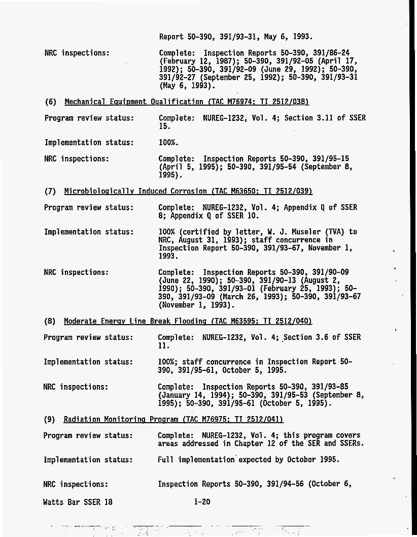
Report 50-390, 391/93-31, May 6, 1993.
NRC inspections: Complete: Inspection Reports 50-390, 391/86-24 (February 12, 1987); 50-390, 391/92-05 (April 17, 1992) ; 50-390, 391/92-09 (June 29, 1992); 50-390, 391/92-27 (September 25, 1992) ; 50-390, 391/93-31 (May 6, 1993).
(6) Mechanical EauiDment Oual if ication (TAC M76974: TI 2512/038)
Program review status: Complete: NUREG-1232, Vol. 4; Section 3.11 of SSER 15.
Implementation status: 100%.
NRC inspections: Complete: Inspection Reports 50-390, 391/95-15 (April 5, 1995); 50-390, 391/95-54 (September 8, 1995).
(7) Microbiol osicall v Induced Corrosion (TAC M63650: TI 2512/039)
Program review status: Complete: NUREG-1232, Vol. 4; Appendix Q of SSER 8; Appendix Q of SSER 10.
Impl emen t a t i on s t a t us : 100% (certif ied by letter, W. J. Museler (TVA) t o NRC, August 31, 1993); staff concurrence i n Inspection Report 50-390, 391/93-67, November 1, 1993.
NRC inspect i ons : Complete: Inspecti on Reports 50-390, 391/90-09 (June 22, 1990); 50-390, 391/90-13 (August 2, 1990) ; 50-390, 391/93-01 (February 25, 1993) ; 50- 390, 391/93-09 (March 26, 1993); 50-390, 391/93-67 (November 1, 1993).
(8 ) Moderate Enersv Line Break Floodins (TAC M63595: TI 2512/040)
Program review s ta tus : Complete: NUREG-1232, Vol . 4; .Section 3.6 of SSER 11.
Impl ementation status:
NRC inspections: Complete: Inspection Reports 50-390, 391/93-85
100%; staff concurrence i n Inspection Report 50- 390, 391/95-61, October 5, 1995.
(January 14, 1994) ; 50-390, 391/95-53 (September 8, 1995); 50-390, 391/95-61 (October 5, 1995).
(9) Radiation Monitorins Prosram (TAC M76975: TI 2512/041)
Program review status:
Impl ementation status:
Complete: NUREG-1232, Vol . 4; t h i s program covers areas addressed i n Chapter 12 of the SER and SSERs.
F u l l imp1 ementati on' expected by October 1995.
NRC inspections: Inspection Reports 50-390, 391/94-56 (October 6,
Watts Bar SSER 18 1-20
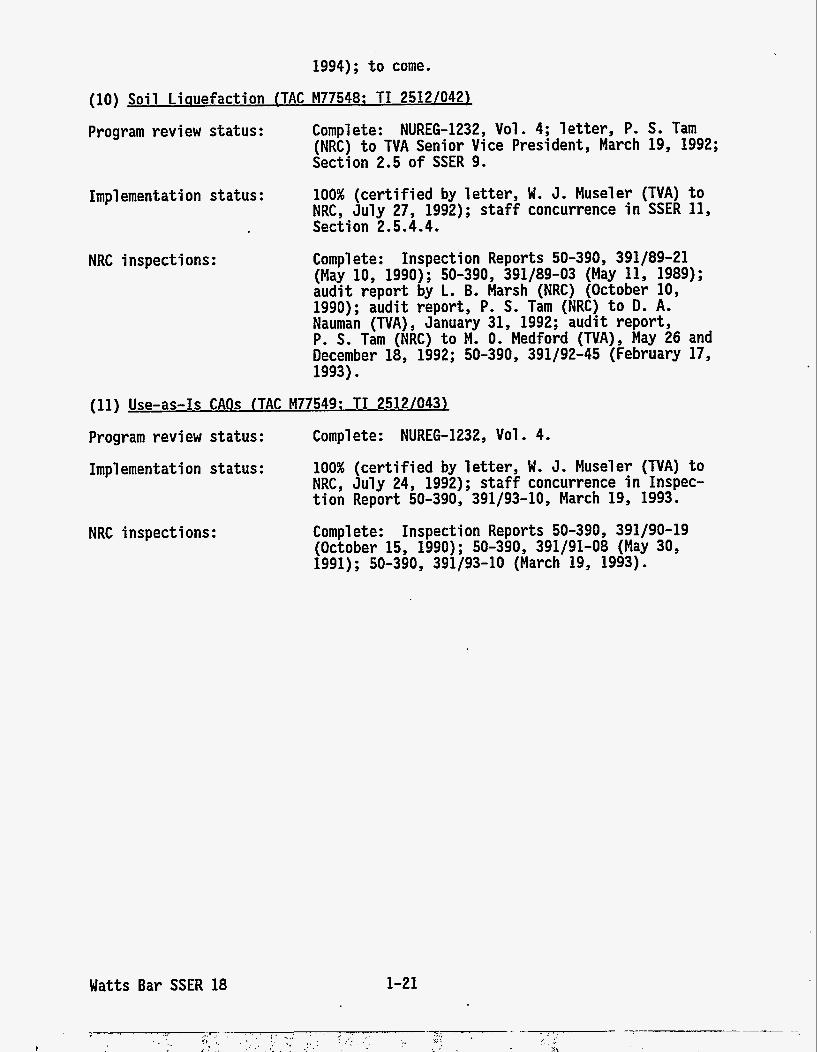
1994); t o come.
(10) Soil Liauefaction (TAC M77548: TI 25121042)
Program review status:
Impl ement a t i on status :
NRC inspections:
Complete: NUREG-1232, Vol. 4; l e t t e r , P. S. Tam (NRC) t o TVA Senior Vice President, March 19, 1992; Section 2.5 of SSER 9.
100% (certif ied by le t te r , W. J, Museler (TVA) t o NRC, July 27, 1992); s ta f f concurrence i n SSER 11, Section 2.5.4.4.
Complete: Inspection Reports 50-390, 391/89-21 (May 10, 1990); 50-390, 391/89-03 (May 11, 1989); audit report by L. B. Marsh (NRC) (October 10, 1990); audit report, P. S. Tam (NRC) t o D. A, Nauman (TVA) , January 31 , 1992; aud i t report, P. S. Tam (NRC) t o M. 0. Medford (TVA), May 26 and December 18, 1992; 50-390, 391/92-45 (February 17, 1993).
(11) Use-as-Is CAOs (TAC M77549: TI 2512/0431 Program review status: Complete: NUREG-1232, Vol . 4. Impl emen t a t i on st a t us :
NRC inspections:
Watts Bar SSER 18
100% (certif ied by le t te r , W. J. Museler (TVA) t o NRC, July 24, 1992); staff concurrence i n Inspec- t i o n Report 50-390, 391/93-10, March 19, 1993.
Complete: Inspection Reports 50-390, 391/90-19 (October 15, 1990); 50-390, 391/91-08 (May 30, 1991); 50-390, 391/93-10 (March 19, 1993).
1-21
3 DESIGN CRITERIA--STRUCTURES , COMPONENTSy EQUIPMENTy AND SYSTEMS
3.9 Mechanical S.ystems and ComDonents
3.9.6 Inservice Testing of Pumps and Valves (Unit 1)
3.9.6.1 Pump Test Program
As required by 10 CFR 50,55a, inservice testing (IST) of certain ASME Code Class 1, 2, and 3 pumps and valves should be performed in accordance with Section XI of the ASME Code and applicable addenda, except where alternatives have been authorized or relief has been requested by the applicant and granted by the Commission pursuant to Sections (a)(3)(i), (a)(3)(ii), or (f)(6)(i) of 20 CFR 50.55a. In proposing alternatives or requesting re1 ief, the applicant must demonstrate that (1) the proposed a1 ternatives provide an acceptable level of quality and safety, (2) compliance would result in hardship or unusual difficulty without a compensating increase in the level o f quality and safety, or (3) conformance is impractical for its facility.
In SSER 14, the staff reviewed the applicant's pump test program for Unit 1 and authorized testing alternatives. Subsequent to pub1 ication of SSER 14, the applicant submitted a letter dated June 29, 1995, requesting approval of an alternative for set pressure testing of the three pressurizer safety relief valves that provide overpressure protection for the reactor cool ant system. By letter of August 9, 1995, the applicant provided additional information to substantiate the request.
The staff reviewed the applicant's request and by letter of September 5, 1995, approved the proposed alternative for Unit 1 per 10 CFR 50.55(a)(3)(ii). That letter is incorporated by reference. The staff tracked its efforts by TAC M92773.
Watts Bar SSER 18 3-1
6 ENGINEERED SAFETY FEATURES
6.2 Containment Svstems
6.2.3 Secondary Containment Functional Design
In the SER, the staff stated that the auxiliary building gas treatment system (ABGTS) is started automatically upon receipt of one of the following signals:
(1) Phase A containment isolation signal from either reactor unit (2) high-radiation signal from the fuel-handling area radiation monitors (3) high-radiation signal from the auxiliary building exhaust vent monitors (4) high temperature in the auxiliary building intakes for the general supply
fan
By Amendment 89 to the FSAR, Section 6.2.3.2.3, "Auxiliary Building Gas Treatment System (ABGTS)," the applicant deleted the high-radiation signal from the auxiliary building exhaust vent monitors (signal 3 above) from the list of ABGTS initiation signals. The staff finds the deletion acceptable for the following reasons:
(1) The deletion does not compromise the capability of the system to perform one of its safety functions, namely, filtering radioactive releases t o the environment that result from a postulated fuel-handling accident in the fuel-handling area of the auxiliary building. This is because the system will continue to be initiated automatically on a high-radiation signal from the fuel-handling area radiation monitors (signal 2 above). Operability of radiation monitors in the fuel pool area is ensured by Table 3.3.8.1, "ABGTS Actuation Instrumentation," of the Unit 1 Technical Speci f i cat i ons (TSs) .
(2) During a postulated design-basis loss-of-coolant accident (LOCA), a small fraction of containment radioactivity leaks into areas of the auxiliary building. This radioactivity gets diluted in the area atmosphere, and travels via ducts and rooms to the fuel-handling area or waste packaging area of the auxiliary building. These areas are serviced by the ABGTS, which filters the leakage before discharge to the environment. Also, airborne radioactivity arising from any emergency core cooling system (ECCS) component leakage, during the recirculation phase of ECCS operation, is filtered by the ABGTS before discharge to the environment. Following a postulated design-basis LOCA, automatic safety injection occurs which initiates Phase A containment isolation. The Phase A containment isolation, in turn, initiates the ABGTS (see signal 1 above). TS Table 3.3.8.1 also includes the Phase A containment isolation signal in the list of ABGTS actuation signals. From the discussion above, it is obvious that following a LOCA, the ABGTS will be initiated and will perform its other safety functions, namely, filtering the leakage into the auxiliary building from the containment and filtering the airborne activity arising from ECCS component leakage. The deletion of the signal does not compromise the capability of the system to perform its other safety functions.
*
Watts Bar SSER 18 6-1
The s ta f f tracked this effor t by TAC M92973.
6.4 Control Room Habitabilitv
In the SER, the s ta f f stated that placing the control room ventilation system (CRVS) i n the pressurization mode would supply 200 cubic feet per minute (cfm) of pressurized a i r t o the control room envelope through adsorbers, while 4000 cfm would be recirculated through redundant particulate and carbon f i l t r a t ion components. These numbers were prel iminary and subject t o change because the pressurization flow ra te necessary t o maintain the control room envelope a t a positive pressure is determined by the actual leakage characteristics of tha t envelope. r a t e data (based on actual control room envelope leakage data) and updated dose analyses
In Amendment 90 t o the FSAR, the applicant provided updated flow
On the basis of these l a t e s t analyses, the applicant showed that if the pressurization flow rate (supplied from outside a i r ) is i n excess of 711 cfm, the allowable dose t o control room operators could be exceeded under certain postulated design-basis accident conditions. Thus, the maximum pressurization f low rate is 711 cfm. The minimum pressurization flow ra t e is dependent on (and must be higher than) the amount of control room envelope leakage. The l a t e s t data, as identified i n FSAR Amendment 90, shows this exfil tration r a t e t o be about 270 cfm i n the emergency mode of operation. The flow rates cited i n the SER were actually the design flow rates f o r a pressurization fan and an a i r f i l t r a t ion u n i t , The design flow r a t e for each of the two pressurization fans is now 711 cfm, and the design flow ra te f o r each of the two a i r f i l t r a t ion u n i t s is still 4000 cfm. Since the 711 cfm outside pressurization f low ra te is supplied t o the in le t of the f i l t r a t ion u n i t s , the actual recirculation a i r flow rate per t ra in is the difference between 711 cfm and 4000 cfm, or 3289 cfm.
These changes are considered clarifications based on the actual control room and equipment designs, and do no t affect the conclusions reached i n the SER or its supplements (SSERs 5, 11, and 16). Therefore, the control room habitabil i ty systems are still acceptable.
The s ta f f tracked i ts efforts by TAC M92973,
Watts Bar SSER 18 6-2
9 AUXILIARY SYSTEMS
9.2 Water Svstems
9.2.1 Essential Raw Cooling Water and Raw Cooling Water Systems
The staff reviewed the essential raw cooling water (ERCW) system in the SER and SSERs 9 and 10. stated that the ERCW system pumps did not perform in accordance with their original design-basis. During preoperational testing, the ERCW pumps did not match the original performance curves supplied by the pump vendor. the original design-basis capacity and head for each of the ERCW pumps was based on two-unit operation. Because the ERCW system is a continuously shared system, even during accidents, the design is such that the pumps are designed to supply cooling water to two separate trains, one for each unit. To support single-unit operation, the applicant reanalyzed the ERCW system flow requirements to determine the minimum ERCW pump performance requirements for Unit 1 operation only. The applicant's analysis showed that if the ERCW pumps could perform at no less than 72 percent of the original vendor-supplied pump performance curves, the design-basis flow requirements for Unit 1 operation would be met. On the basis of the preoperational ERCW pump tests (which showed the pumps were capable of performing .at more than 72 percent of the performance curves) , the appl icant concluded that the performance of the ERCW pumps is acceptable for Unit 1 operation only.
By Amendment 90 to the FSAR, Table 9.2-1, the applicant
However,
In Section 9.2.1 of the SER, the staff concluded that the ERCW system conformed to a number of general design criteria (GDCs), including GDC 5, "Sharing of Systems, Structures and Components," with respect to sharing of essential systems. As a result of the applicant's determination that the ERCW pumps do not conform to their original design-basis capability, the staff concludes that the ERCW system does not conform to GDC 5 for two-unit operation. However, on the basis of the applicant's analysis, the staff concludes that the ERCW system does conform to GDC 5 (not shared) for single- unit operation. The staff, therefore, concludes that the ERCW system is acceptable for Unit 1 operation.
The staff tracked its efforts by TAC M92973.
9.5 Other Auxi 1 i arv Systems
9.5.1 Fire Protection
In the SER, the staff discussed its review results of the Watts Bar fire protection program and fire hazards analysis submitted by the applicant on April 18, 1977; September 8, 1980; and August 28, 1981. Subsequently, the applicant relocated the fire protection information (via Amendment 87) from Section 9.5.1 of the FSAR and submitted the revised Watts Bar Fire Protection Report (FPR) by letters dated September 15, 1993 and its revisions dated November 18, 1994; April 27, 1995; June 15, 1995; and September 28, 1995.
The applicant initially revised its fire protection program report as a result of a comprehensive review under its fire protection corrective action program
Watts Bar SSER 18 9-1
(see Section 1.13.1 of SSER 18). The principal program changes in Revision 0 are the removal of fire protection from the Technical Specifications (TSs) and documentation of the fire area reanalysis. The applicant undertook this reanalysis to take advantage of the compartmentation at Watts Bar and further subdivide the fire areas, and had described this reanalysis in the previous February 5, 1992, revision of the FPR. By letter dated June 2, 1993, the appl i cant described the revised fire areas. The appl i cant has incorporated this description into this revision of the FPR. This revision also reflects fire protection programmatic improvements and incorporates changes made in response to NRC comments. In this revision, the applicant states that its fire protection program has been developed to comply with, and is based on, the requirements of General Design Criterion 3 in Appendix A to 10 CFR 50.48, paragraphs (a) and (e), and the applicant's commitment to Sections III.G, III.J, III.L, and 111.0 of Appendix R to 10 CFR Part 50, and Appendix A to Auxiliary Power Conversion Systems Branch (APCSB) Branch Technical Position (BTP) APCSB 9.5-1, "Guidelines for Fire Protection for Nuclear Power Plants Docketed Prior to July 1, 1976." In addition, the applicant committed to meet the following NRC fire protection guidance: 1977, "Nuclear Plant Fire Protection Functional Responsibilities, Administrative Controls and Quality Assurance"; (2) Generic Letter (GL) 81-12, "Fire Protection Rule," and NRC memorandum of clarification to GL 81-12, dated March 22, 1982; (3) GL 82-21, "Technical Specifications for Fire Protection Audits"; (4) GL 83-33, "NRC Positions on Certain Requirements of Appendix R to 10 CFR 50"; (5) GL 86-10, "Implementation of Fire Protection Requirements"; and (7) GL 88-12, "Removal of Fire Protection Requirements from Technical Speci f i cati ons .
(1) NRC letter dated June 20,
The applicant has identified its revised Fire Protection Report as the document that describes the operational phase of the fire protection program and consolidates the regulatory fire protection program into a single document. Accordingly, the staff has re-reviewed the entire fire protection program, evaluating it against the NRC fire protection requirements and review guidance listed above. (except as noted), this evaluation applies to the fire protection program for both units.
Because Watts Bar has two units of identical design
By letters of July 9, 1993; November 11, 1994; December 23, 1994; and March 29, 1995, the applicant submitted the results of its qualification testing of 1-hour Thermo-Lag 330-1 and 3-hour Thermo-Lag 770-1 electrical raceway fire barrier systems (ERFBSs). The staff has reviewed the applicant's fire endurance testing program, its acceptance criteria, and the test results against the fire barrier acceptance criteria guidance provided in GL 86-10, "Implementation o f Fire Protection Requirements," and its supplement, "Fire Endurance Test Acceptance Criteria for Fire Barrier Systems Used To Separate Redundant Safe Shutdown Trains Within the Same Fire Area."
As a result of this review, the staff, in letters of December 2, 1992; April 6, 1994; December 14, 1994 (meeting summary by P. S . Tam, dated December 21, 1994); April 19, 1995; and May 10, 1995, requested additional information related to the adequacy of the proposed fire protection program. applicant, in letters of February 10, 1993; November 26, 1993; July 1, 1994; January 27, 1995; and May 26, 1995, submitted the requested information to the staff for review and committed to make certain modifications to plant fire protection features and to the plant fire protection program and its imp1 ementat i on.
The
Watts Bar SSER 18 9-2
In addition, the s ta f f met with the applicant on October 13, 1993 (summary by P. S. Tam, November 5, 1993); Apri l 27, 1995 (summary by P. S. Tam, May 9, 1995); May 30, 1995 ( s i te review notification by P. S. Tam, May 19, 1995); August 15, 1995 (summary by M. Bugg, August 30, 1995); and October 10, 1995 (summary by M. Bugg, October 13, 1995) t o discuss technical issues related t o Watts Bar's f i r e protection program and its implementation.
The s t a f f ' s consultant, Brookhaven National Laboratory, participated i n revi ewi ng associated c i rcui ts and post-fi re safe-shutdown capabi 1 i ty and i n preparing th is safety evaluation, and concurs w i t h the s t a f f ' s findings.
Section 9.5.1 of the FSAR, currently updated t o Amendment 91, incorporates the f i r e protection program by reference. Likewise, the s ta f f ' s detailed evaluation of the revised fire protection program is moved from the text o f this section, and is relocated i n Appendix FF of t h i s SSER. Since the applicant's original f ire protection program, as evaluated i n the SER, has been ful ly superseded by subsequent submittals as stated above, the open issues (identified as Outstanding Issue 12, Confirmatory Issue 38, and Proposed License Condi ti on 20) are considered resol ved.
On the basis o f its review of the applicant's Fire Protection. Report through Revi si on 4, and the appl icant 's supplemental information as referenced by t h i s safety evaluation, the s t a f f concludes that the fire protection program for Watts Bar Nuclear Plant conforms t o the requirements of 10 CFR 50.48 and, except for (1) f i r e barrier penetration seal program (refer t o Appendix FF, Section 3.1.4) and (2) emergency l i g h t i n g inside the reactor building ( refer t o Appendix FF, Section 6.7), is acceptable. The s t a f f will report resolution of these two issues i n SSER 19.
The s ta f f tracked i ts effor ts by TAC M63648. The two open issues identified above will continue t o be tracked by this TAC number.
Watts Bar SSER 18 9-3
12 RADIATION PROTECTION
12.4 Radiat ion Protect ion Desisn Features
I n SSER 14, t he s t a f f completed i t s review o f t h i s section. FSAR Amendments 89 and 90, the appl icant revised the discussions o f t h e i n s t a l l e d area r a d i a t i o n monitor ing and the f i x e d airborne r a d i a t i o n monitoring systems. I n addit ion, Amendment 90 rev ised the estimated maximum r a d i a t i o n dose ra tes depicted on the r a d i a t i o n zone maps (FSAR Figures 12.3-1 through 12.3-19) f o r several areas i n the p lant .
Subsequently, by
The discussion o f area monitor c a l i b r a t i o n and maintenance i n FSAR Section 12.3.4 was rev ised t o c l a r i f y the d i s t i n c t i o n s between a monitor ca l i b ra t i on , a monitor channel operational t e s t , and a checksource funct ional t e s t . The frequency o f c a l i b r a t i o n f o r area r a d i a t i o n monitors was a lso revised f r o m a t l e a s t once a quar ter t o a t l e a s t once per r e f u e l i n g cyc le w i t h a channel operational t e s t a t l e a s t once per quarter.
The t e x t i n FSAR Section 12.3 and Table 12.3-5 was revised t o de lete the discussion o f f i x e d airborne r a d i a t i o n monitors i n the U n i t 2 hot sample room and the U n i t 1 con t ro l room, and t o replace them w i t h por tab le continuous a i r monitors (CAMs). These por tab le CAMs have a range o f from 0.1 t o 1.0 times the derived airborne concentrat ion l i m i t s i n 10 CFR Part 20 Appendix B, and provide a l o c a l h igh- level alarm. The s t a f f f i n d s acceptable the use o f these portable CAMs f o r meeting the monitor ing requirements o f 10 CFR Par t 20. The o p e r a b i l i t y o f the r a d i a t i o n monitor i n the U n i t 1 contro l room v e n t i l a t i o n system was no t a f fected by Amendments 89 and 90.
The s t a f f f i n d s t h a t these changes are acceptable and do no t change the s t a f f ' s conclusion documented i n SSER 14. The s t a f f tracked t h i s e f f o r t by TAC M93601.
Watts Bar SSER 18 12-1
14 INITIAL TEST PROGRAM
In SSERs 12, 14, and 16, the s taff found the applicant's Ini t ia l Test Program (ITP) up t o FSAR Amendment 89 acceptable. 1995, and FSAR Amendment 90, the applicant made changes.
Subsequently, by l e t t e r of July 13,
The s ta f f tracked i t s efforts by TAC M92973.
14.2 Preoperational Tests
The following evaluation reflects the numbering system in SSER 14.
Item 1
(e) As stated in SSER 14, in an August 19, 1994, l e t t e r , TVA had proposed t o demonstrate operabi 1 i ty and t o confi rm the adequacy of design and performance c r i te r ia for fuel handl i n g and vessel servicing equipment not associated w i t h manipulation of spent fuel, by performing a combi nati on of acceptance t e s t i nstructi ons , speci a1 performance tes ts , and work orders.
In FSAR Amendment 84, Section 14.2.7, Subparagraph 4.A. (1) (h), the applicant takes exception t o testing s t a t i c loads a t 125 percent of rated load on three of the four U n i t 1 fuel-handling devices (spent fuel p i t bridge crane, refJe1 i ng machi ne, and 125-ton auxi 1 i ary bui 1 ding crane main hook, including both polar crane hooks) i n accordance with the guidance in Regulatory Guide (RG) 1.58 (Appendix A, Subparagraph 1 .m.4). The applicant's justif ication for th i s exception is t h a t , except for the auxiliary hook of the 125-ton auxiliary building crane, (1) al l the fuel- handl i ng equipment has been previously tested a t 125-percent rated capacity and (2) this equipment had n o t undergone extensive repairs o r modifications t h a t would warrant such testing. However, the applicant commi tted t o performing the requi s i t e 125-percent-rated capacity t e s t o f the 125-ton auxi 1 i ary bui 1 ding crane auxi 1 i ary hook.
Subsequently, i n FSAR Amendment 88, Section 14.2.7, Subparagraph 4.A. (1) (h) , the applicant proposed that cranes n o t associated with spent fuel movement be operationally tested by a combination o f acceptance t e s t instructions (ATIs) , component t e s t s (CTs) , and speci a1 performance t e s t s (SPTs) as described i n the enclosures t o the applicant's July 14 and August 14, 1994, l e t te rs . The balance of equipment used for handling of spent fuel would be tested under FSAR Table 14.2-1, Sheets 74 and 75, "Fuel Handling Equipment Test Summary,'' as included i n Amendment 88 t o FSAR Chapter 14. program elements , controls, and commi tments described by TVA provi ded an acceptable approach t o demonstrate satisfactory operabi 1 i ty of the affected systems, or portions thereof, and t o confirm the adequacy o f their design and performance c r i te r ia . T h i s issue was t h u s closed i n SSER 14.
In SSER 14 the staff found that the proposed testing
However, i n a July 13, 1995, l e t t e r , and subsequently in FSAR Amendment 90, the applicant proposed t o rescind i t s commitment t o conduct further testing of fuel-handling and vessel servicing equipment n o t associated
Watts Bar SSER 18 14-1
with manipulation of spent fuel as had been approved by the s t a f f in SSER 14. In tha t l e t t e r , the applicant presented a detailed synopsis of former and recent operabi 1 i ty and performance tes t ing, periodic inspections, and post-modi f ication tes t ing tha t provides the bases for the conclusion tha t the t e s t methods and acceptance c r i t e r i a specified in the Fuel -Hand1 i ng and Vessel Servi ci ng Equi pmen t Test Summary have been met.
On the basis of the acceptable resu l t s achieved during the performance tes t ing, periodic inspections, and post-modification tes t ing as out1 ined by TVA i n the July 13, 1995, l e t t e r , the s t a f f agrees tha t TVA has presented sui tab1 e evi dence tha t the adequacy o f design and performance c r i t e r i a for the subject equipment has been ver i f ied and, therefore, s a t i s fy the provisions of RG 1.68, Appendix A, Subparagraph l.m.4. issue i s closed.
This
14.2.3 Concl usi on
The s t a f f f inds the ITP, as delineated in Chapter 14 of the FSAR, updated by Amendment 90, general ly comprehensive and encompasses the major phases o f the tes t ing program gui dance presented in the Standard Revi ew P1 an (NUREG-0800) and Standard Format (Regul atory Gui de 1.70).
Watts Bar SSER 18 14-2
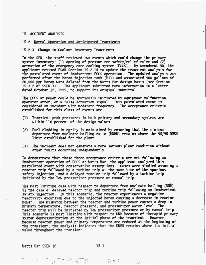
15 ACCIDENT ANALYSIS
15.2 Normal Operation and AnticiDated Transients
15.2.3 Change in Coolant 'Inventory Transients
In the SER, the staff reviewed two events which could change the primary system inventory: (1) opening of pressurizer safety/rel ief valve and ( 2 ) actuation of the emergency core cooling system (ECCS). By Amendment 90, the applicant revised FSAR Section 15.2.14 t o update the t ransient analysis for the postulated event o f inadvertent ECCS operation. The updated analysis was performed a f t e r the boron injection tank (BIT) and associated 900 gallons of 20,000 ppm boron were deleted from the Watts Bar design basis (see Section 15.3.2 of SSER 3 ) . dated October 12, 1995, t o s u p p o r t i t s original submittal.
The applicant submitted more information in a l e t t e r
The ECCS a t power could be spuriously in i t ia ted by equipment malfunction, operator error , o r a f a l se actuation signal. This postulated event i s considered an incident w i t h moderate frequency. The acceptance c r i t e r i a established for this c lass of events are
(1) Transient peak pressures i n both primary and secondary systems are within l lo 'percent of the design values.
(2) Fuel cladding in tegr i ty is maintained by ensuring tha t the minimum departure-from-nucleate-boil ing r a t io (DNBR) remains above, the 95/95 DNBR l imi t established for the p l a n t .
(3) The incident does n o t generate a more serious plant condition w i t h o u t other f au l t s occurring independently.
To demonstrate t ha t these three acceptance c r i t e r i a are met fo l lowing an inadvertent operation of ECCS a t Watts Bar, the applicant analyzed this postulated event w i t h conservative assumptions. reactor trip followed by a turbine t r i p a t the same time of the s p u r i o u s safety injection, and a delayed reactor t r ip followed by a turbine t r i p in i t ia ted by the low pressurizer pressure or manual tr ip.
The most l imiting case with respect t o departure from nucleate boiling (DNB) i s the case of delayed reactor t r i p and turbine tr ip following an inadvertent safety injection. In t h i s scenario, the reactor experiences a negative react ivi ty excursion due t o the injected boron causing a decrease i n reactor power. The mismatch between the reactor and turbine power causes a drop i n primary temperature, reactor pressure, and pressurizer water level. The reactor t r i p will be in i t ia ted by low pressurizer pressure or by manual tr ip. This scenario is most limiting w i t h respect t o DNB because of therapid primary system depressurization a t the i n i t i a l phase o f the t ransient . However, because reactor power and primary temperature are reduced a t the beginning o f the t ransient , the analysis indicates tha t the DNBR remains above i t s i n i t i a l value throughout the t ransient .
Cases were studied assuming a
Watts Bar SSER 18 15-1
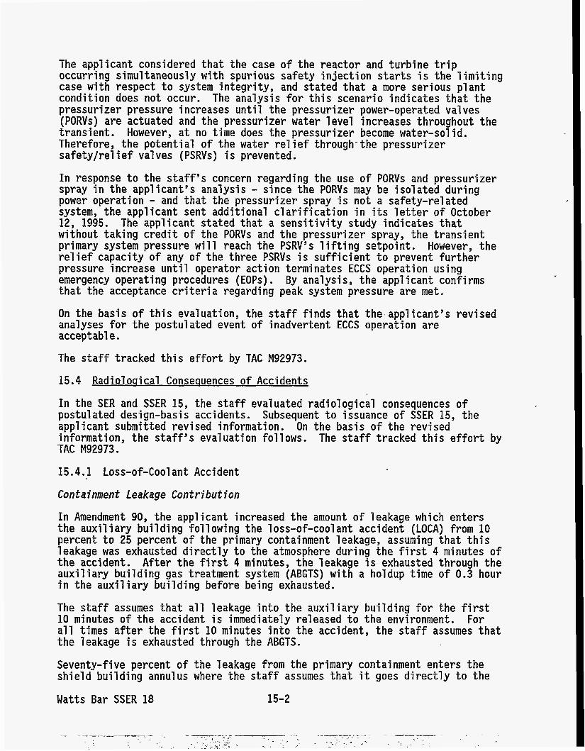
The applicant considered that the case of the reactor and turbine trip occurring simultaneously with spurious safety injection starts is the limiting case with respect to system integrity, and stated that a more serious plant condition does not occur. The analysis for this scenario indicates that the pressurizer pressure increases unti 1 the pressurizer power-operated valves (PORVs) are actuated and the pressurizer water level increases throughout the transient. Therefore, the potential of the water re1 ief through- the pressurizer safety/relief valves (PSRVs) is prevented.
However, at no time does the pressurizer become water-sol id.
In response to the staff’s concern regarding the use of PORVs and pressurizer spray in the applicant’s analysis - since the PORVs may be isolated during power operation - and that the pressurizer spray is not a safety-related system, the applicant sent additional clarification in its letter of October 12, 1995. The applicant stated that a sensitivity study indicates that without taking credit of the PORVs and the pressurizer spray, the transient primary system pressure will reach the PSRV’s lifting setpoint. relief capacity of any of the three PSRVs is sufficient to prevent further pressure increase until operator action terminates ECCS operation using emergency operating procedures ( EOPs) . By anal ysi s , the appl i cant conf i rms that the acceptance criteria regarding peak system pressure are met.
However, the
On the basis of this evaluation, the staff finds that the applicant’s revised analyses for the postulated event of inadvertent ECCS operation are acceptable.
The staff tracked this effort by TAC M92973.
15.4 Radioloqical Conseauences of Accidents
In the SER and SSER 15, the staff evaluated radiological consequences of postulated design-basis accidents. Subsequent to issuance of SSER 15, the applicant submitted revised information. On the basis of the revised information, the staff’s evaluation follows. The staff tracked this effort by TAC M92973.
15.4.1 Loss-of-Coolant Accident
Containment Leakage Contribution
In Amendment 90, the applicant increased the amount of leakage which enters the auxiliary building following the loss-of-coolant accident (LOCA) from 10 percent to 25 percent of the primary containment leakage, assuming that this leakage was exhausted directly to the atmosphere during the first 4 minutes of the accident. After the first 4 minutes, the leakage is exhausted through the auxiliary building gas treatment system (ABGTS) with a holdup time of 0.3 hour in the auxiliary building before being exhausted.
The staff assumes that all leakage into the auxiliary building for the first 10 minutes of the accident is immediately released to the environment. all times after the first 10 minutes into the accident, the staff assumes that the leakage is exhausted through the ABGTS.
Seventy-five percent of the leakage from the primary containment enters the shield building annulus where the staff assumes that it goes directly to the
For
Watts Bar SSER 18 15-2
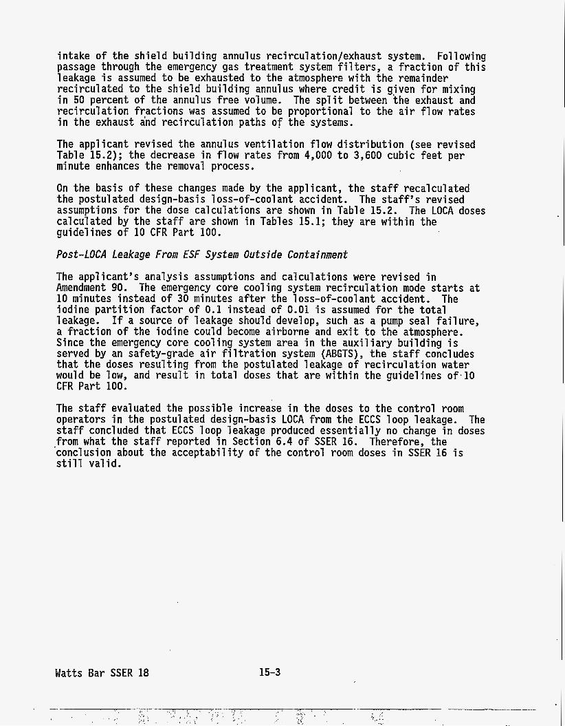
intake of the shield building annulus recirculation/exhaust system. Following passage through the emergency gas treatment system filters, a fraction of this leakage is assumed t o be exhausted t o the atmosphere w i t h the remainder recirculated t o the shield building annulus where credit i s given for mixing i n 50 percent of the annulus f r ee volume. The split between the exhaust and recirculation fractions was assumed t o be proportional t o the a i r flow rates i n the exhaust and recirculation paths o f the systems.
The applicant revised the annulus ventilation flow dis t r ibut ion (see revised Table 15.2); the decrease i n flow ra tes from 4,000 t o 3,600 cubic fee t per minute enhances the removal process.
On the basis of these changes made by the applicant, the s t a f f recalculated the postul ated design-basi s 1 oss-of-cool ant accident. The s t a f f s revised assumptions fo r the dose calculations are shown i n Table 15.2. The LOCA doses calculated by the staff are shown i n Tables 15.1; they are w i t h i n the guidelines of 10 CFR Part 100.
Post-LOCA Leakage From ESF System Outside Containment
The applicant's analysis assumptions and calculations were revised i n Amendment 90. The emergency core cooling system recirculation mode s t a r t s a t 10 minutes instead of 30 minutes a f t e r the loss-of-coolant accident. The iodine par t i t ion factor of 0.1 instead of 0.01 is assumed f o r the to ta l leakage. If a source of leakage should develop, such as a pump seal fa i lure , a fraction of the iodine could become airborne and ex i t t o the atmosphere. Since the emergency core cooling system area i n the auxiliary building is served by an safety-grade a i r f i l t r a t i o n system (ABGTS), the s t a f f concludes t h a t the doses result ing from the postulated leakage of recirculation water would be low, and r e su l t i n to ta l doses tha t are w i t h i n the guidelines o f - 1 0 CFR Part 100.
The staff evaluated the possible increase i n the doses t o the control room operators i n the postulated design-basis LOCA from the ECCS loop leakage. The staff concluded t h a t ECCS loop leakage produced essent ia l ly no change i n doses from what the staff reported i n Section 6.4 of SSER 16. Therefore, the 'conclusion about the acceptabili ty of the control room doses i n SSER 16 is st i l l valid.
Watts Bar SSER 18 15-3
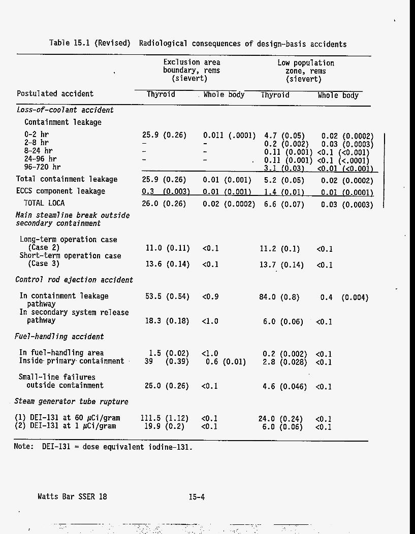
Table 15.1 (Revised) Radiological consequences o f design-basis accidents
Postulated accident
Excl usi on area boundary, rems
(s i evert)
Low popul a t i on zone, rems (sievert)
Thyroid . Whole body Thyroid Whole body Loss-of-coolant accident
Containment leakage 0-2 hr 2-8 hr 8-24 hr 24-96 hr 96-720 h r
Total containment leakage ECCS component 1 eakage
TOTAL LOCA Main steamline break outside secondary containment
Long-term operation case
Short-term operation case (Case 2)
(Case 3)
Control rod ejection accident
In containment leakage
In secondary system re1 ease pathway
pathway
25.9 (0.26) 0.011 (.0001) 4.7 (0.05) 0.02 (0.0002) - - 0.2 (0.002) 0.03 (0.0003)
3.1 (0.03) t0.01 (t0.001)
- - 0.11 (0.001) tO.l (tO.OO1) - - . 0.11 (0.001) tO.l (t.0001)
0.3 (0.003) 0.01 (0.001) 1.4 (0.01) 0.01 ~ 0 . 0 0 0 1 ~ 25.9 (0.26) 0.01 (0.001) 5.2 (0.05) 0.02 (0.0002)
26.0 (0.26) 0.02 (0.0002) 6.6 (0.07) 0.03 (0.0003)
11.0 (0.11) (0.1
13.6 (0.14) t0.1
53.5 (0.54) t0.9
18.3 (0.18) 4.0
Fuel-hand7 ing accident
In fuel-hand1 ing area 1.5 (0.02) t1.0 Inside- primary conta4nment 1 39 (0.39) 0.6 (0.01)
Small-1 i ne f a i 1 ures outside containment
Steam generator tube rupture
(1) DEI-131 a t 60 pCi/gram (2) DEI-131 a t 1 pCi/gram
26.0 (0.26) tO.l
111.5 (1.12) tO.l 19.9 (0.2) tO.l
11.2 (0.1) tO.l
13.7 (0.14) t0.1
0.4 (0.004) 84.0 (0.8)
6.0 (0.06) t0.1
0.2 (0.002) tO.l 2.8 (0.028) t0.1
4.6 (0.046) tO.l
24.0 (0.24) t O . l 6.0 (0.06) t0.1
Note: DEI-131 = dose equivalent iodine-131.
Watts Bar SSER 18 15-4
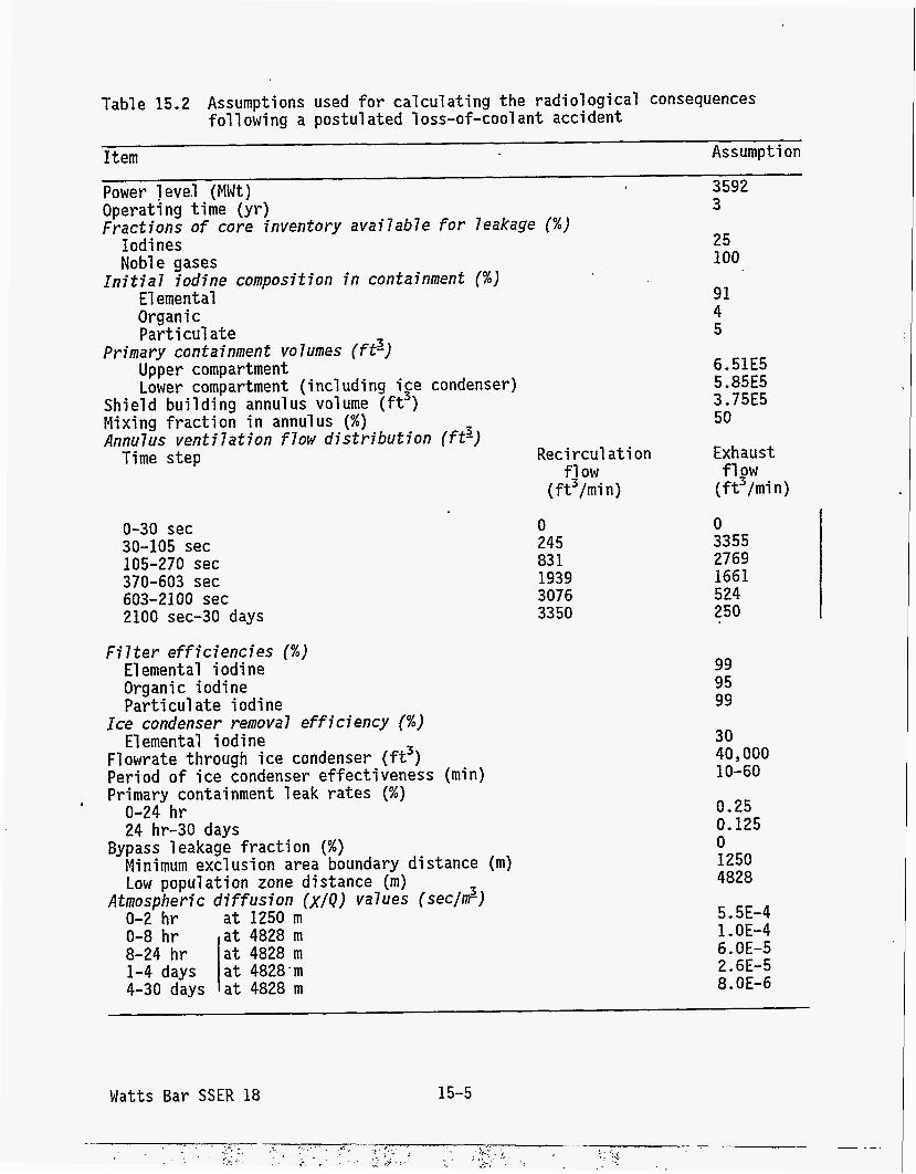
Iodi nes Noble gases
E l emen t a1 Organ i c Part i cul a te
Upper compartment Lower compartment (incl uding ige condenser)
Initial iodine composition in containment (%)
Primary containment volumes (ftz)
Shield building annulus volume ( f t ) Mixing fraction i n annulus (%) Annulus ventilation flow distribution (ft3)
Time step
8-24 hr 1-4 days
Table 15.2 Assumptions used fo r calculating the radiological consequences following a postulated loss-of-cool ant accident
Item Assumption
Power level (MWt) 3592
Fractions of core inventory availab7e for leakage (%) Operating time (yr) 3
25
a t 4828 m a t 4828.111
100
91 4 5
6.51E5 5.85E5 3.75E5 50
Reci rcul a t i on f j ow
( f t /min )
Exhaust
( f t /min) fl2W
0-30 sec 30-105 sec 105-270 sec 370-603 sec 603-2100 sec 2100 sec-30 days
0 245 83 1 1939 3076 3350
0 3355 2769 1661 524 250
99 95 99
30 40,000 10-60
0.25 0.125 0 1250 4828
5.5E-4 1 - OE-4 6.OE-5 2.6E-5 8.OE-6
18 HUMAN FACTORS ENGINEERING
18.1 Detailed Control Room Design Review
In SSER 15, the s t a f f concluded tha t the detailed control room design review (DCRDR) program implemented a t U n i t 1 conforms t o the DCRDR requirements o f Supplement 1 t o NUREG-0737. corrective actions for six safety-significant human engineering deficiencies (HEDs) were not then implemented bu t would be fu l ly implemented before fuel loading. corrective actions, commi tments, and schedules pertaining t o HE0 numbers 15, 19, 93, 119, 151, and 157 are satisfactory."
In tha t evaluation, the s t a f f s ta ted tha t
For these six HEDs, the s t a f f s ta ted tha t "the applicant 's proposed
By l e t t e r dated September 26, 1995, the applicant notified the s t a f f of i t s reassessment of the safety significance of HED 151, downgrading i t from Category 1 (safety significant) t o Category 4 ( n o t safety s ignif icant) . 151 ident i f ied Eberline condenser vacuum pump exhaust radiation monitoring system problems (e.g., problems related t o r e l i ab i l i t y , accuracy, information i n p u t and processing capabi 1 i t i es , and documentati on/procedure adequacy) t h a t de t rac t from the usabili ty o f the system. The applicant's j u s t i f i ca t ion f o r reassessing this HED was that since the original DCRDR evaluation, various design changes have signi f icant ly reduce the importance of this par t icular system. Specifically, (1) shield building vent parameters have been removed from the Eberline system and placed on separate hardware i n the control room, (2) condenser vacuum pump exhaust radiation level is available on the emergency response faci 1 i ty data system (ERFDS) which has a superior operator interface t o the Eberline system interface, and (3) a l l the parameters needed t o calculate the radiation release r a t e a re available on the ERFDS.
HED
The s t a f f revi ewed the appl i cant I s revi sed i nformati on i n the September 26, 1995 l e t t e r , and concludes tha t the jus t i f ica t ion fo r downgrading HED 151 from safety s ignif icant to not safety s ignif icant is sat isfactory fo r resolving this HED.
The staff tracked i t s e f for t s by TAC M63655.
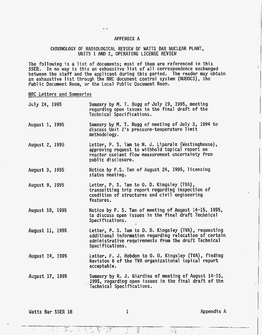
APPENDIX A
CHRONOLOGY OF RADIOLOGICAL REVIEW OF WATTS BAR NUCLEAR PLANT, UNITS 1 AND 2, OPERATING LICENSE REVIEW
The following i s a l i s t of documents; most of them are referenced i n this SSER. between the s ta f f and the applicant during this period. The reader may obtain an exhaustive l i s t through the NRC document control system (NUDOCS), the Public Document Room, or the Local Public Document Room.
In no way is this an exhaustive list of a l l correspondence exchanged
NRC Letters and Summaries
July 24, 1995 Summary by M. T. Bugg of July 19, 1995, meeting regarding open issues i n the final draft of the Techni cal Speci f i cati ons.
August 1, 1995
August 2, 1995
August 3, 1995
August 9, 1995
August 10, 1995
August 11, 1995
August 14, 1995
August 17, 1995
Watts Bar SSER 18
Summary by M. T. Bugg of meeting of July 3, 1994 t o discuss U n i t 1's pressure-temperature limit methodol ogy . l e t te r , P. S. Tam t o N. J. Liparulo (Westinghouse), approving request t o withhold topical report on reactor cool ant fl ow measurement uncertai nty from pub1 i c di scl osure.
Notice by P.S. Tam o f August 24, 1995, licensing status meeti ng . Letter, P. S. Tam t o 0. D. Kingsley (TVA), transmitting trip report regarding inspection of condi t i on o f structures and ci vi 1 engineering features.
Notice by P. S. Tam of meeting o f August 14-15, 1995, t o discuss open issues i n the final draf t Technical Speci f i cati ons.
Letter, P. S. Tam t o 0. D. Kingsley (TVA), requesting addi t i onal informati on regarding re1 ocati on o f certain administrative requirements from the draf t Technical Speci f i cati ons . Letter, F. 3. Hebdon t o 0. D. Kingsley (TVA), f i n d i n g Revi si on 6 of the TVA organizational t o p i cal report acceptabl e.
Summary. by R. J. Giardina o f meeting o f August 14-15, 1995, regarding open issues i n the final draf t of the Technical Speci fi cati ons .
1 Appendix A
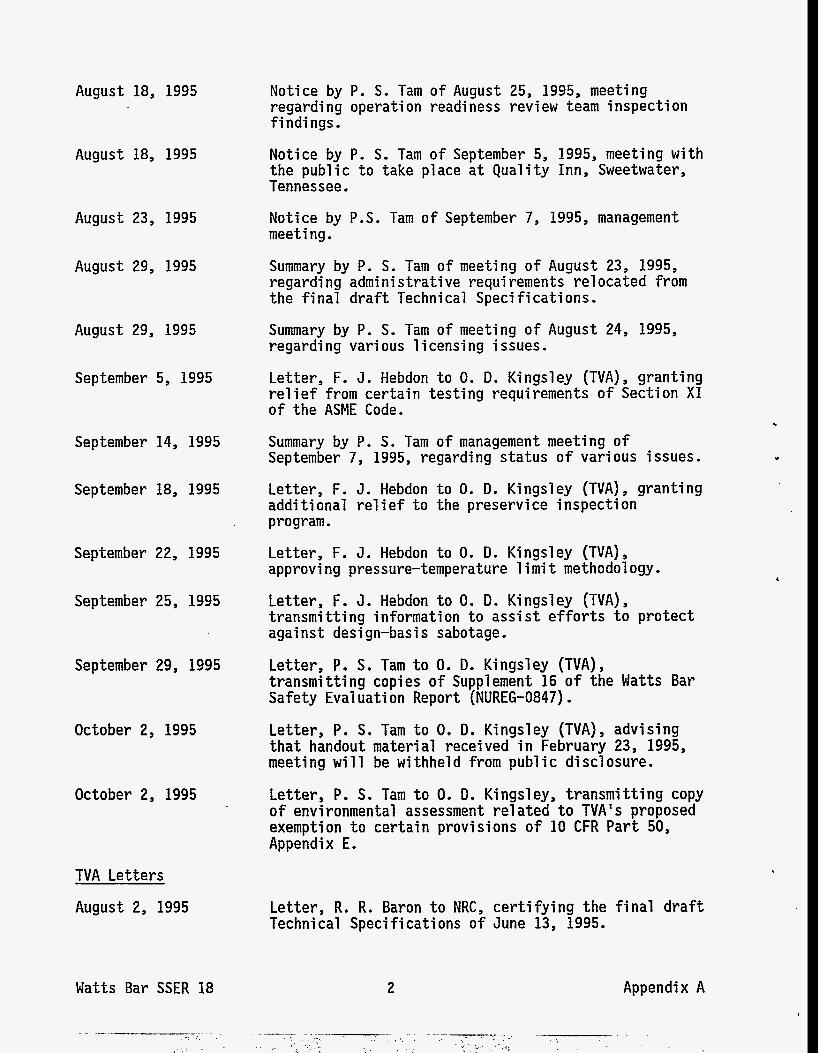
August 18, 1995
August 18, 1995
August 23, 1995
August 29, 1995
August 29, 1995
September 5, 1995
September 14, 1995
September 18, 1995
September 22, 1995
September 25, 1995
September 29, 1995
October 2, 1995
October 2, 1995
TVA Letters
August 2, 1995
Watts Bar SSER 18
Notice by P. S. Tam o f August 25, 1995, meeting regarding operation readiness review team inspection f indings .
Notice by P. S. Tam o f September 5, 1995, meeting w i t h the public t o take place a t Quality Inn, Sweetwater, Tennessee.
Notice by P.S. Tam of September 7, 1995, management meeti ng . Summary by P. S. Tam o f meeting of August 23, 1995, regarding admini strative requirements re1 ocated from the final draf t Technical Speci f i cati ons.
Summary by P. S. Tam of meeting of August 24, 1995, regardi ng vari ous 1 i censi ng i ssues.
Letter, F. 3. Hebdon t o 0. D. Kingsley (TVA), granting re1 i ef from certain testing requi rements of Section XI of the ASME Code.
Summary by P. S. Tam of management meeting of September 7, 1995, regarding s ta tus of various issues.
Letter, F. J. Hebdon t o 0. D. Kingsley (TVA), granting addi t i onal re1 i ef to the preservi ce inspecti on program.
Letter, F. J. Hebdon to 0. D. Kingsley (TVA), approving pressure-temperature 1 imi t methodology.
Letter, F. J. Hebdon to 0. D. Kingsley (TVA), transmitting information to a s s i s t e f for t s t o protect against desi gn-basi s sabotage.
Letter, P. S. Tam to 0. D. Kingsley (TVA), transmitting copies of Supplement 16 of the Watts Bar Safety Eva1 uati on Report (NUREG-0847).
Letter, P. S. Tam to 0. D. Kingsley (TVA), advising that handout material received i n February 23, 1995, meeting w i 11 be w i thhel d from pub1 i c di scl osure.
Letter, P. S. Tam to 0. D. Kingsley, transmitting copy o f environmental assessment re1 ated t o TVA's proposed exemption to certain provisions of 10 CFR Part 50, Appendix E.
,
Letter, R. R. Baron to NRC, certifying the f ina l draf t Technical Specifications o f June 13, 1995.
2 Appendix A
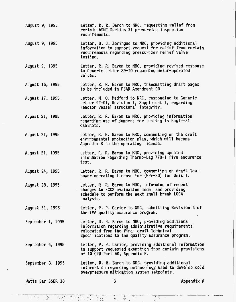
August 9, 1995
August 9, 1995
August 9, 1995
August 16, 1995
August 17, 1995
August 21, 1995
August 21, 1995
August 21, 1995
August 24, 1995
August 28, 1995
August 31, 1995
September 1, 1995
September 6, 1995
September 8, 1995
Watts Bar SSER 18
Letter, R. R. Baron t o NRC, requesting r e l i e f from certain ASME Section XI preservice inspection requi rements.
Letter, 0. J. Zeringue t o NRC, providing additional information t o s u p p o r t request for r e l i e f from certain requi rements regarding pressurizer re1 i ef valve testing.
Letter, R. R. Baron t o NRC, p rovid ing revised response t o Generi c Letter 89-10 regarding motor-operated Val ves.
Letter, R. R. Baron t o NRC, transmitting draf t pages t o be included in FSAR Amendment 90.
Letter, M. 0. Medford t o NRC, responding t o Generic Letter 92-01, Revision 1, Supplement 1, regarding reactor vessel structural integrity.
Letter, R. R. Baron t o NRC, providing information regarding use of jumpers for testing i n Eagle-21 cabi nets.
Letter, R. R. Baron t o NRC, commenting on the draf t envi ronmental protecti on plan, which w i 11 become Appendix B t o the operating license.
Letter, R. R. Baron t o NRC, providing updated information regarding Thermo-Lag 770-1 f i r e endurance tes t .
Letter, R. R. Baron t o NRC, commenting on draft low- power operating license for (NPF-20) for U n i t 1.
Letter, R. R. Baron t o NRC, informing of recent . changes t o ECCS evaluation model and providing
schedule t o perform the next small-break LOCA analysis.
Letter, P. P. Carier t o NRC, submitting Revision 6 of the TVA quality assurance program.
Letter, R. R. Baron t o NRC, providing additional i nformati on regardi ng admi n i s t r a t i ve requirements relocated from the final draft Technical Speci f i cati ons t o the qual i ty assurance program.
Letter, P. P . Cari er, provi d ing additional i nformati on t o support requested exempti on from certain provi si ons of 10 CFR Part 50, Appendix E.
Letter, R. R. Baron t o NRC, providing additional information regarding methodology used t o devel op col d overpressure mi t i gati on system setpoi nts .
3 Appendix A
September 14, 1995 Letter, R. R. Baron t o NRC, providing additional ampacity t e s t results of cables wrapped in Thermo-Lag materi a1 s .
September 26, 1995 Letter, R. R. Baron, requesting re l ie f from certain testing requirements o f ASME Section XI for some re1 i ef valves .
September 26, 1995 Letter, R. R. Baron t o NRC, revising some information previously submi tted for detai 1 ed control room design review.
September 27, 1995 Letter, R. R. Baron t o NRC, notifying of complete imp1 ementati on of the design base1 i ne verification program.
/
Watts Bar SSER 18 4 Appendix A
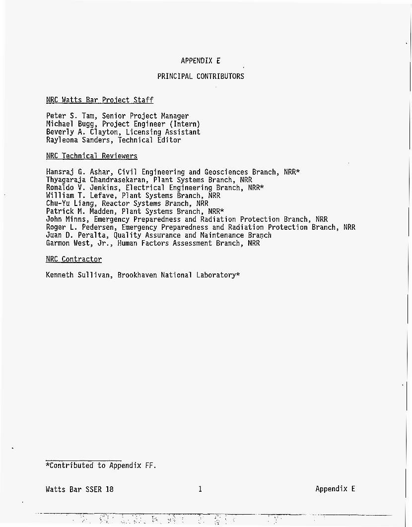
APPENDIX E
PRINCIPAL CONTRIBUTORS
NRC Watts Bar Project Staff
Peter S. Tam, Senior Project Manager Michael Bugg, Project Engineer (Intern) Beverly A. Clayton, Licensing Assistant Ray1 eona Sanders, Technical Editor
NRC Technical Reviewers
Hansraj G. Ashar, C i v i l Engineering and Geosciences Branch, NRR* Thyagaraja Chandrasekaran, P1 ant Systems Branch, NRR Ronald0 V. Jenkins, Electrical Engineering Branch, NRR* William T. Lefave, Plant Systems Branch, NRR Chu-Yu Liang, Reactor Systems Branch, NRR Patrick M. Madden, Plant Systems Branch, NRR* John Mi nns , Emergency Preparedness and Radi a t i on Protection Branch, NRR Roger L. Pedersen , Emergency Preparedness and Radi a t i on Protection Branch, NRR Juan D. Peralta, Quality Assurance and Maintenance Branch Garmon West, Jr. , Human Factors Assessment Branch, NRR
NRC Contractor
Kenneth S u l l ivan, Brookhaven National Laboratory*
*Contributed t o Appendix FF.
Appendix E Watts Bar SSER 18 1
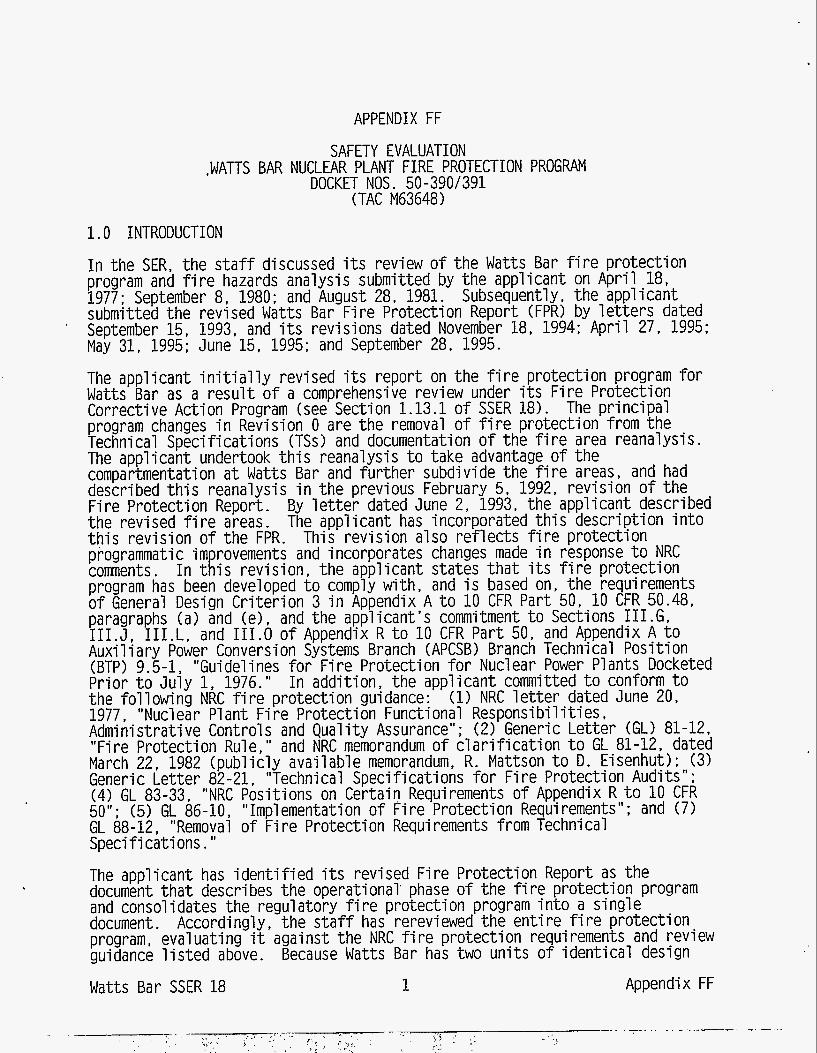
APPENDIX FF
SAFETY EVALUATION ,WATTS BAR NUCLEAR PLANT FIRE PROTECTION PROGRAM
(TAC M63648) DOCKET NOS. 50-390/391
1.0 INTRODUCTION
I n the SER, the s t a f f discussed i t s review o f t he Watts Bar f i r e protect ion program and f i r e hazards analysis submitted by the applicant on Apr i l 18, 1977; September 8, 1980; and August 28, 1981. Subsequently, the applicant submitted the revised Wat t s Bar F i r e Protection Report (FPR) by l e t t e r s dated September 15, 1993, and i t s revisions dated November 18, 1994; Apr i l 27, 1995; May 31, 1995; June 15, 1995; and September 28, 1995.
The applicant i n i t i a l l y revised i t s report on the f i r e protect ion program f o r Wat ts Bar as a resu l t o f a comprehensive review under i t s F i r e Protection Corrective Action Program (see Section 1.13.1 o f SSER 18). The pr inc ipa l program changes i n Revision 0 are the removal o f f i r e protect ion from the Technical Specif icat ions (TSs) and documentation o f the f i r e area reanalysis. The applicant undertook t h i s reanalysis t o take advantage o f the compartmentation a t Wat ts B a r and fur ther subdivide the f i r e areas, and had described t h i s reanalysis i n the previous February 5. 1992. rev is ion o f the F i re Protection Report. By l e t t e r dated June 2, 1993, the applicant described the revised f i r e areas. The applicant has incorporated t h i s descr ipt ion i n t o t h i s revis ion o f the FPR. This rev is ion also re f l ec ts f i r e protect ion programmatic improvements and incorporates changes made i n response t o NRC comments. I n t h i s revis ion, the applicant states t h a t i t s f i r e protect ion program has been developed t o comply wi th, and i s based on, the requirements o f General Design Cr i te r ion 3 i n Appendix A t o 10 CFR P a r t 50, 10 CFR 50.48, paragraphs (a) and (e), and the applicant 's commitment t o Sections I I I . G , I I I . J , 1 I I .L . and 111.0 o f Appendix R t o 10 CFR P a r t 50, and Appendix A t o Auxi l iary Power Conversion Systems Branch (APCSB) Branch Technical Posi t ion (BTP) 9.5-1, "Guidelines f o r F i r e Protection f o r Nuclear Power Plants Docketed Prior t o Ju ly 1, 1976." I n addit ion, the applicant committed t o conform t o the fo l lowing NRC f i r e protect ion guidance: (1) NRC l e t t e r dated June 20, 1977, "Nucl ear P1 ant F i r e Protection Functi onal Responsi b i 1 i ti es , Administrative Controls and Qua l i t y Assurance"; (2) Generic Let ter (GL) 81-12, "Fire Protection Rule," and NRC memorandum o f c l a r i f i c a t i o n t o GL 81-12, dated March 22, 1982 (publ ic ly avai lable memorandum, R. Mattson t o D. Eisenhut); (3) Generic Let ter 82-21, "Technical Specif icat ions f o r F i r e Protection Audits"; (4) GL 83-33, "NRC Positions on Certain Requirements o f Appendix R t o 10 CFR 50"; (5) GL 86-10, "Implementation o f F i re Protection Requirements"; and (7) GL 88-12 "Removal o f F i r e Protection Requirements f rom Technical Specif icat ions. 'I
The applicant has i d e n t i f i e d i t s revised F i r e Protection Report as the document t h a t describes the operational' phase o f t he f i r e protect ion program and consolidates the regulatory f i r e protection program i n t o a s ing le document. Accordingly , the s t a f f has rerevi ewed the en t i r e f i r e protect ion program eval ua t i ng it against the NRC fi r e protect ion requi rements and review guidance l i s t e d above. Because Wat ts Bar has two un i ts o f iden t ica l design Wat ts B a r SSER 18 1 Append-ix FF
(except as noted), t h i s evaluation applies t o the f i r e protect ion program f o r both un i ts .
By l e t t e r s o f July 9, 1994; November 11, 1994; December 23, 1994; and March 29, 1995, t he applicant submitted the resul ts o f i t s qua l i f i ca t i on tes t i ng o f 1-hour Thermo-Lag 330-1 and 3-hour Thermo-Lag 770-1 e lec t r i ca l raceway f i r e ba r r i e r systems (ERFBSs). The s t a f f has reviewed the applicant 's f i r e endurance tes t ing program, i t s acceptance c r i t e r i a , and the t e s t resul ts against t he f i r e bar r ie r acceptance c r i t e r i a guidance provided i n GL 86-10, "Implementation of F i re Protection Requirements, I' and i t s supplement, "F i re Endurance Test Acceptance Cr i t e r i a f o r F i re Barr ier Systems Used To Separate Redundant Safe Shutdown Trains Within the Same F i re Area. "
As a resu l t of t h i s review, the s t a f f , i n l e t t e r s o f December 2, 1992; Apr i l 6, 1994; December 14, 1994 (meeting summary by P. S. Tam, dated December 21, 1994); Apr i l 19. 1995; and May 10, 1995, requested addit ional information re la ted t o the adequacy of the proposed f i r e protect ion program. The applicant, i n l e t t e r s o f February 10, 1993; November 26, 1993; Ju ly 1, 1994; January 27, 1995; and May 26, 1995, submitted the requested information t o the staff f o r review and committed t o make cer ta in modifications t o p lan t f i r e protect ion features and t o the p lant f i r e protect ion program modifications and i t s implementation.
I n addit ion, the s ta f f met w i th the applicant on October 13, 1993 (summary by P. S. Tam, dated November 5. 19931, Apr i l 27, 1995 (summary by P. S. Tam, dated May 9, 19951, May 30, 1995 ( s i t e review no t i f i ca t i on by P. S. Tam, dated May 19. 19951, August 15, 1995 (summary by M. Bugg, dated August 30, 1995), and October 10, 1995'(summary by M. Bugg, dated October 13, 1995) t o discuss technical issues related t o Watts B a r ' s f i r e protect ion program and i t s implementation.
The s t a f f ' s consultant, Brookhaven National Laboratory, par t ic ipated i n reviewing associated c i r c u i t s and p o s t - f i r e safe shutdown capab i l i t y and i n preparing t h i s safety evaluation, and concurs wi th the s t a f f ' s f indings.
2.0 FIRE PROTECTION PROGRAM
2.1 PurDose and ScoDe
I n i t s f i r e protect ion plan, the applicant has consolidated previous program commitments i n t o a s ing le document. This document i s referenced by the Watts Bar Final Safety Analysis Report (FSAR) and w i l l be updated i n conjunction w i th the updates t o the FSAR. The f i r e protect ion plan describes (1) the organization supporting the Watts Bar f i r e protect ion program, (2) plant f i r e protect ion features, (3) the p lan t ' s f i r e prevention program, (4) t he p lan t ' s emergency response organization, (5) p l ant operating requi rements f o r f i r e protect ion features and systems, and ( 6 ) the tes t ing and inspection requi rements f o r these p l ant f i r e protect ion features. This p l an establ i shes the basis for Watts B a r ' s compliance w i th Sections I I I . G , 1II.J. I I I . L , and 111.0 o f Appendix R t o 10 CFR P a r t 50 and the guidelines of Appendix A t o BTP (APCSB) 9.5-1.
The f i r e protect ion plan summarizes the resul ts o f the f i r e hazards analysis (FHA) performed f o r a l l the f i r e areas and lzones established a t Watts Bar . The plan summarizes the FHA f o r each- f i re area by describing the physical
Watts Bar SSER 18 2 Appendix FF
character ist ics o f the f i r e area, combustible loadings and ant ic ipated f i r e severity, and f i r e suppression and detection capab i l i t y avai lable i n each plant area. The plan also describes how p o s t - f i r e safe shutdown would be ensured i f a serious f i r e occurred i n the f i r e area.
I n t h i s plan, the applicant described the measures t h a t are established a t Wat ts Bar t o implement a defense-in-depth f i r e protect ion program i n p lan t areas important t o p lant safety. These measures consist o f (1) preventing f i r e s from s ta r t ing , ( 2 ) detecting f i r e s rap id ly , con t ro l l ing them, and promptly ext inguishing them, and (3) protect ing systems important t o safety so t h a t a f i r e t h a t i s not promptly extinguished w i l l not prevent t he p lan t f rom achieving and maintaining safe shutdown conditions.
2.2 F i r e Protection Orqani zation
The applicant’s f i r e protect ion organization consists o f a corporate management oversight and an onsi te p lan t implementation organization. The Senior Vice President f o r Nuclear Operations has the overal l respons ib i l i t y f o r establ ishing the corporate programs and po l i c ies related t o nuclear power f i r e protection. This author i ty i s delegated t o the General Manager, Operational Services. The General Manager i s responsible f o r developing and assessing f i r e protect ion programs a t the applicant’s nuclear power plants. Agreements are maintained between TVA Nuclear and TVA Fossi l and Hydro Power organizations f o r ensuring t h a t the applicant’s nuclear power p lan t f i r e .brigades are properly t ra ined and t h a t t h e i r knowledge and s k i l l s are su f f i c i en t t o handle onsi te f i r e emergencies.
The onsite f i r e protect ion organization i s responsible f o r developing, imp1 ementi ng , and administering the Wat ts Bar f i r e protect ion program. The ult imate author i ty f o r t h i s program rests w i th the S i t e Vice President. However, t h i s author i ty has been delegated t o the Plant Manager. The Plant Manager i s responsible f o r management oversight o f the development and implementation o f the operational phase o f the Wats B a r f i r e protect ion program. Under the Plant Manager, the Operations Manager i s responsible f o r developing, implementing, and cont ro l l ing the onsi te program. This author i ty i s delegated t o the onsi te F i r e Protection Manager, who has the overa l l responsib i l i ty f o r the implementation and maintenance o f the onsi te f i r e protection program.
With respect t o p lant modifications which impact p lan t f i r e protect ion features, the S i t e Vice President delegates the respons ib i l i t y for f i r e protect ion-related design a c t i v i t i e s a t Watts B a r t o the Engineering Manager. The Engineering Manager i s responsible f o r maintaining Watts Bar’s p o s t - f i r e safe-shutdown capab i l i t y and p lant f i r e protect ion features i n conformance w i th Appendix A t o BTP (APCSB) 9.5-1 and Appendix R t o 10 CFR P a r t 50.
The s t a f f f inds t h a t the applicant’s proposed f i r e protect ion organization d id not take any exceptions t o Posit ion A . l o f Appendix A t o BTP (APCSB) 9.5-1 and, therefore, i s acceptable.
2.3 F i re Protection Qual i t v Assurance Proaram
Fo l l owing the f i r e protect ion qua l i t y assurance (QA) program guidance established by Appendix A t o BTP (APCSB) 9.5-1 and the NRC l e t t e r dated June 20, 1977, on ”Nucl ear P1 ant F i r e Protection Functional Responsi b i 1 i t i e s ,
3 Watts Bar SSER 18 Appendix FF
Administrative Controls, and Qual i ty Assurance," the applicant has developed a QA program for fire protection features t h a t protects post-fi re safe-shutdown capability and safety-related structures, systems, and components. The applicant's f i re protection QA program uses the applicable parts of the Tennessee Val ley Authority Nuclear Qual i ty Assurance P1 an (TVA-NQA-PLN-89-A).
The appl icant his committed t o imp1 ement a program which performs independent audits and inspections of i t s Watts Bar f i re protection program. The applicant stated t h a t i t s program is i n accordance w i t h GL 82-21, "Technical Specifications for Fire Protection Audits." The applicant's Nuclear Assurance organization i s responsible for conducting the f i re protection-related audits. The applicant has committed t o perform the following f i re protection program audits: (1) an annua l f i re protection and loss prevention inspection and a u d i t
(2) - a biennial a u d i t of the f i re protection program and i t s implementing procedures
(3) a triennial f i re protection and loss prevention inspection and a u d i t
Consistent w i t h the guidance i n GL 88-12, "Removal of Fire Protection Requirements From Technical Specifications , " the applicant will include these audits and their frequencies i n the Administrative Controls section of the p l a n t TSs.
The staff concl udes t h a t the appl icant ' s proposed fi re protection QA program d i d not take any exceptions t o Position C of Appendix A t o BTP (APCSB) 9.5-1 and, therefore, i s acceptable. 2.4 Fi re Protection Admi n i s trati ve and Techni cal Control s 2.4.1 Fire Protection Program Changes, Review and Approval The applicant has elected t o follow the guidance of GL 88-12 and incorporate the standard fire protection license condition. In add i t ion t o including, by reference, the NRC safety evaluation which approved the p l a n t f i re protection program, this license condition allows the applicant t o make changes t o the approved program w i t h o u t prior approval of the Commission if those changes would not adversely affect the a b i l i t y t o achieve and m a i n t a i n safe shutdown i n the event of a f ire. The applicant may change the approved f i re protection program provided (1) the change or changes do not otherwise result i n a change t o the license condition or p l a n t TSs result i n an unreviewed safety question, and (2) the change or changes do not result i n failure t o complete the fire protection program as approved by the Commission. These changes t o the f i re protection program will be performed under the provisions of 10 CFR 50.59. In this context, the determination of whether an unreviewed safety question as defined i n 10 CFR 50.59(a)(2) is involved would be based on the postulated f i re i n the FHA for the f i re area affected by the change. The applicant has committed t o m a i n t a i n , i n a n auditable form, a current record of a l l such changes, including analysis of the effects of the change on the f i re protection program, and t o make al l such records available t o NRC inspectors upon request. Watts Bar SSER 18 4 Appendix FF
I n addit ion, changes t o the Watts B a r F i r e Protection Report and the administrat ive f i r e protect on program procedures as speci f ied by Watts Bar TSs w i l l be reviewed by the Plant Operations Review Committee (PORC). The Nuclear Safety Review Board (NSRB) provides independent oversight o f f i r e protection audits and technical reviews as speci f ied by the Watts Bar TSs. The applicant has committed, i n i t s f i r e protect ion plan, t o include the f i r e protection program responsi b i 1 i ti es o f these review groups i n Section 6.0, "Administrative Controls , " o f the Watts Bar TSs .
2.4.2 F i re Protection Administrative Control
2.4.2.1 Control o f Combusti b l e
The applicant has established a program t o control combustibles. The Watts Bar program objectives are t o (1) provide ins t ruc t ion and guidelines during general employee t ra in ing on the appl i c a t i on and use o f combustible materi a1 s a t Wat ts Bar , (2) control the appl icat ion and use o f chemicals, (3) perform per i odic p l ant housekeepi ng inspections and have housekeeping tours by management and the onsi te f i r e protect ion organization, (4) control i n s i t u combustibles through the design/modification review and i n s t a l l a t i o n process, and (5) control t rans ient combusti bles through the implementation o f administrat ive controls.
The applicant has established Administrative Procedure FPI-0100, "Control o f Transient F i re Loads .I1 Implementation o f t h i s procedure w i l l establ ish administrat ive control s f o r the hand1 i n g o f combustible materi a1 s such as f i re- retardant wood, paper, p las t i c , and flammable and combustible gases and l iqu ids . I n addit ion, the applicant 's combustible control program has established combustible control zones i n the plant. The applicant considers these zones t o be subdivisions o f f i r e areas and t o serve as a form o f a f i r e barr ier , providing f i r e separation o f redundant f i r e safe-shutdown equipment. Transient combustibles may not be stored i n these zones unless an adequate f i re protection engineering eval uation or compensatory measures, or both, are i mpl emented . The s t a f f concludes t h a t the applicant 's proposed program t o control combustibles d id not take any exceptions t o Posit ion B.3.c o f Appendix A t o BTP (APCSB) 9.5-1 and, therefore, i s acceptable.
2.4.2.2 Control o f I g n i t i o n Sources I
The applicant has established a program f o r con t ro l l ing i g n i t i o n sources such as welding, cu t t ing , grinding, and the use o f open flame. The applicant 's program i n Administrat ive Procedure FPI-0101, "Control o f I gn i t i on Sources, specif ies t h a t a member o f Watts Bar l i n e supervision reviews and approves the issuance o f "hot work" permits based on p lan t conditions and a p r i o r inspection o f t he proposed work area. The i g n i t i o n source on a hot-work permit i s v a l i d f o r only one job. The applicant 's program w i l l establ ish a t ra ined f i r e watch f o r a l l i g n i t i o n source work a c t i v i t i e s t h a t are performed i n safety-related and safe-shutdown areas o f the plant. These f i r e watches, i n addit ion t o performing t h e i r duties during the hot-work a c t i v i t i e s , w i l l remain i n the area f o r a minimum o f 30 minutes a f te r t he work has been completed t o ensure t h a t potent ia l residual i g n i t i o n conditions do not ex is t .
5 Appendix FF Watts Bar SSER 18
The s ta f f concludes tha t the applicant 's proposed program t o control i g n i t sources d i d not take any exceptions t o Positions B.3.a and b o f Appendix A BTP (APCSB) 9.5-1 and, therefore, i s acceptable.
2.4.3 F i r e Protection Technical Controls
GL 88-12 provides guidance f o r removina f i r e Drotection f rom the ~ l a n t TSs
on t o
This guidance specTfies t h a t the l i m i t i n g conditions for operation (LCOs) and survei 11 ance requi rements associated wi th f i r e detection systems, f i r e suppression systems, f i r e barr iers , and administrat ive controls t h a t address f i r e brigade s t a f f i n g can be removed from the p lan t TSs and incorporated i n t o the f i n a l safety analysis repor t (FSAR) (Watts Bar f i r e protect ion plan as referenced by the Wat t s B a r FSAR). I n addit ion, GL 88-12 refers t o GL 81-12, "F i re Protection Rule," which asks licensees t o provide TSs f o r equipment used f o r safe-shutdown capabi l i ty not current ly covered by ex is t ing TSs. I n i t s f i r e protect ion plan, the applicant has confirmed tha t the p lan t equipment used t o achieve and maintain p o s t - f i r e safe shutdown from e i ther ins ide or outside the main control room i s included i n the p lan t TSs and the F i r e Protection Report.
As t o the safe-shutdown f i r e equipment not included i n the TSs, the applicant made note o f it i n Wat ts Ba r F i r e Protection Report Table 14.10. The applicant has established tes t i ng and inspection requirements which ass is t i n evaluating the operabi l i ty of the non-TS-re1 ated safe-shutdown f i r e equipment and instrumentation . I n FPR Section 14.0, "F i r e Protection Systems and Features Operating Requirements, " t he applicant established the l i m i t i n g conditions f o r p lant operation w i th t h i s equipment or instrumentation inoperable. With one or more o f t he required items of equipment l i s t e d i n Wat t s Ba r F i r e Protection Report Table 14.10 inoperable, restore the equipment t o the operable status w i th in 30 days, or then e i ther place the equipment i n the condi t ion required f o r f i r e safe shutdown, provide a backup means o f instrumentation monitoring, o r be i n Mode 3 w i th in 6 hours and Mode 4 w i th in the fo l lowing 12 hours.
I n addi t ion, the Watts Bar F i r e Protection Report establishes tes t i ng and inspection requirements f o r the f o l 1 owing f i r e protect ion features : (1) fi r e detection instrumentation, (2) water supply, (3) water-based f i r e suppression systems, (4) carbon dioxide (CO systems, (5) f i r e hose stat ions and associated preaction control vajves, ( 6 ) f i r e hydrants, (7) f i r e - r a t e d assemblies , and (8) emergency bat tery l i g h t i n g uni ts .
I n a l e t t e r dated Apr i l 6, 1994, the s t a f f requested addit ional information regarding the proposed tes t ing and inspections requirements for cer ta in p lan t f i r e protect ion features and the associated compensatory measures used i n the event a f i r e protect ion feature becomes inoperable. On Ju ly 1, 1994, the applicant submitted t h i s addi t ional information.
With respect t o f i r e detecti on i nstrumentati on, the s t a f f had concerns w i th how the applicant c lass i f ied f i r e detection devices as e i ther Function A (ear ly warning) or as Function B ( f i r e suppression system i n i t i a t i o n ) . I n the event that a Function A f i r e detection device becomes inoperable, an hourly roving f i r e watch as defined by the Watts B a r F i r e Protection Report i s required t o be established. Function B f i r e detection devices, i n addi t ion t o t h e i r f i r e suppression system i n i t i a t i o n function, perform an early-warning function, and the inoperab i l i t y o f these devices impacts both the ear ly-
Watts Bar SSER 18 6 Appendix FF
warning funct ion and the f i r e suppression system i n i t i a t i o n function. For those cases i n which an automatic f i r e suppression system protect ing safe- shutdown functions w i th in the same f i r e area i s inoperable or the ear ly warning funct ion o f the Function B detection devices i n t h i s area are operable, the applicant 's f i r e protection operating requirements (Wat t s Bar F i re Protection Report Sections 14.3.1 and 14.4.1) requires a continuous f i r e watch t o be established. For those cases i n which the automatic f i r e suppression system and the Function B detection devices are protect ing plant areas t h a t would not expose redundant safe-shutdown functions t o thermal or smoke damage from a s ing le f i r e , the applicant 's f i r e protect ion operating requi rements (Sections 14.3.2 and 14.4.2) would require an hourly f i r e watch t o be established. The s t a f f f inds t h i s acceptable.
The appl i cant ' s f i r e protect ion operating requi rements f o r inoperable fi r e detection devices ins ide containment prescribe a roving f i r e watch t o enter the containment every 8 hours o r t o monitor the air temperature i n the containment once an hour. The s t a f f was concerned t h a t t h i s f i r e protect ion operating requi rement t o monitor the containment a i r temperature d id not establ ish a temperature l i m i t o r a r i s e c r i t e r i o n which would be considered an ind icat ion o f a f i r e . The applicant, i n i t s Ju ly 1, 1994 submittal, indicated t h a t the temperature c r i t e r i a established by Wat ts Bar TS 3.6.5. "Containment A i r Temperature," would be used. I n the event the containment a i r temperature exceeded the established l i m i t s , the LCO from t h i s TS would be followed. The s t a f f f inds t h i s acceptable.
The applicant has established operating requirements f o r the f i r e protect ion water supply. These operating requirements establ ish how many f i r e pumps are required t o be operable t o adequately ensure t h a t water f i r e suppression capab i l i t y i s functional t o a l l areas on the s i t e . The minimum o f three f i r e pumps (each pump wi th a capacity 1590 gallons per minute and 300 fee t o f head) and an operable f low path w i th suction from the forebay, through d i s t r i bu t i on piping, sectional izing, control o r i so la t i on valves, supplied from two direct ions, leading t o yard hydrants, hose stat ions and t o each water-based f i r e suppression system. I n i t s operating requirements, the applicant, stated tha t , i f the required f i r e protect ion water supply or pumping capabi l i ty , or both, became inoperable, a l te rna t ive methods o f establ ishing backup f i r e pump and water supply capabi 1 i ti es would be imp1 emented . The s t a f f requested information concerning these a1 ternat ive measures. The applicant submitted t h i s information on Ju ly 1, 1994. The applicant stated tha t , i f one o f the required f i r e pumps became inoperable, an a l ternat ive pump w i th f low and pressure character ist ics equal t o or exceeding those o f the inoperable pump would be connected t o the system. I n addit ion, the applicant comnitted t o ensuring t h a t the water supply t o the backup f i r e pump w i l l come from a r e l i a b l e source and the d r i ve r f o r the backup pump w i l l be capable o f operating upon a loss o f o f f s i t e power. The s t a f f f inds the applicant 's c r i t e r i o n f o r establ ishing a l te rna t ive f i r e water pumping capab i l i t y acceptabl e.
The s t a f f found tha t the appl icant 's operating requirement f o r f i r e barr iers d id not address raceway o r equipment f i r e bar r ie r systems. The s t a f f asked the applicant t o c l a r i f y t h i s operating requirement. The applicant stated i n i t s Ju ly 1, 1994, submittal, t h a t it would revise the bases f o r t h i s operating requirement t o make it c lear tha t raceway f i r e ba r r i e r systems are covered by the f i r e ba r r i e r operating requirement. The s t a f f f inds t h i s acceptabl e.
Watts B a r SSER 18 7 Appendix FF
Throughout the "bases" sections for testing and inspection requirements , the applicant specified tes t frequencies t h a t were based on industry operating experience. The staff asked the applicant t o further justify the test frequencies t h a t i t specified i n i t s testing and inspection requirements. The applicant, i n i t s July 1, 1994, response, stated t h a t the types of tests and the inspections and their frequencies were based on the test and inspection guidance provided by the Standard Technical Specifications (STSs) and f i re protection industry consensus standards (i .e. , National Fire Protection Association Standard No. 72E (NFPA-72E), NFPA-25, and NFPA-101). The staff has reviewed these testing and inspection requirements and finds them al l acceptable except for item 14.2.E. "testing of f i re pumps." As a n alternative t o the NFPA-20 f i re pump performance testing guidance, the applicant proposed t o evaluate the electric f i re pumps by testing them on an 18-month cycle a t the rated head (130 psig/300 foot-head) and a t two diverse points, one above and below the rated head. For the diesel f i re pump, the applicant proposed t o evaluate i t s performance by testing i t every 18 months a t three points on the f i re pump curve. These points are (1) 140 percent of rated pressure a t shutoff capacity (175 psig/404 foot-head), (2) 100 percent of capacity (2500 gpm) a t rated pressure (125 psig/288 foot-head), and (3) 150 percent of capacity (3750 gpm) a t 65 percent of rated pressure (81 psig/187 foot-head). The staff finds the applicant's proposed f i re pump performance test acceptance criteria acceptable, and finds t h a t (for the electric f i re pumps) i t conforms t o the intent of general industry f i re protection engineering practice (refer t o NFPA-20). In Revision 3 t o the Fire Protection Report, the applicant revised i t s inspection frequency for f i re protection valves, f i re hose stations, and valve and flow tests t o determine valve blockage i n hose station valves. The testing .and requirements for testable f i re protection valves associated w i t h the water-based f i re suppression systems (item 14.3.a) specified a 92-day frequency i n lieu of the original 31-day frequency. The applicant based this change i n frequency on a water-based f i re protection valve survei 11 ance tes t on a study i t performed for i t s Sequoyah facility. This study evaluated the f i re protection valve lineups for a 2.5-year period and, based on the d a t a , the appl icant determined t h a t there woul d be 99.96-percent probabi 1 i t y for the 31-day tes t frequency t h a t the valves would be i n their proper al ignment , and a 99.90-percent probability of proper valve alignment if a 92-day test frequency was implemented. On the basis of this evaluation, the staff finds acceptable the applicant's change i n surveillance frequency for testable f i re protection valves associated w i t h the water-based f i re suppression system. W i t h respect t o the testing and inspection requirement t o visually inspect hose stations, the applicant revised i t tes t frequency from 31 days t o 92 days. The basis for changing the frequency i s t h a t there have been infrequent problems found w i t h hose stations a t the applicant's other nuclear power plants. The staff finds acceptable the applicant's change i n this visual inspection surveil lance frequency. In i t s review of compensatory measures the staff noted t h a t the applicant proposes t o use roving and continuous f i re watches and alternative compensatory measures. The staff had concerns regarding how the applicant i s applying these measures. The applicant's definition of a continuous f i re watch allows the f i re watch t o patrol multiple fire areas and zones as long as the area i n which the f i re protection impairment i s located i s patrolled every 15 minutes. The applicant's basis for this definition, as stated i n a July 1,
Watts Bar SSER 18 8 Appendix FF
1994 submittal, i s t h a t t h i s continuous f i r e watch c r i t e r i o n i s s im i la r t o tha t which was approved f o r i t s Sequoyah fac i l i t y . The s t a f f found t h a t t h i s response was not accurate and the continuous f i r e watch d e f i n i t i o n f o r Wat ts Bar i s not consistent w i th the continuous f i r e watch d e f i n i t i o n established by Sequoyah's bases. The applicant, i n Revisions 2 and 3 t o i t s F i r e Protection Report, provided addit ional c l a r i f i c a t i o n regarding i t s d e f i n i t i o n o f continuous f i r e watch and i t s technical basis. The applicant proposes t h a t a t ra ined continuous f i r e watch be i n the f i r e area a t a l l times, t h a t the f i r e area contain no impediment t o r e s t r i c t the movements o f the watch, and t h a t each compartment w i th in the f i r e area i s pa t ro l led a t leas t once every 15 minutes w i th a margin o f 5 minutes. The applicant, however, has i d e n t i f i e d speci f ic cases i n which it takes exception t o t h i s de f in i t ion . I n Section 13.0 o f the Wat ts Bar F i re Protection Report, the applicant speci f ied the continuous f i r e watch routes which cross more than one f i r e area boundary and tha t it c lass i f ies as exceptions t o a continuous f i r e watch staying w i th in one f i r e area. These routes are (1) diesel generator bui ld ing, 742 ft 0 i n . ; (2) diesel generator bui ld ing, 760 ft 0 i n . ; (3) aux i l i a ry bu i ld ing rooms 757.0- A2, 757.0-A9, 757.0-A10. 757.0-All, 757.0-A12, 757.0-AZ1, 782.0-A1 and 782.0- A2 when spr ink ler valves 0-FCV-26-143 and 0-FCV-26-322 are out o f service; (4) auxi 1 i ary bui 1 ding rooms 772.O-Al, 772.0-A6, 772.0-A7, 772.0-A8, 772.0-A9, 772.0-A12, and 772.0-A16 when spr ink ler valves 0-FCV-26-143 and 0-FCV-26-322 are out o f service; (5) aux i l i a ry bu i ld ing rooms 757.0-A5, 757.0-A14, 757.0- A15, 757.0-A16, 757.0-A17, 757.0-AZ4, 782.0-A3, and 782.0-A4 when spr ink ler valves 0-FCV-26-151 and 0-FCV-26-326 are out o f service; (6) aux i l i a ry bui 1 ding rooms 772.0-A2 , 772.0-54, 772. O-AlO , 772.0-All, and 727.0-A15 when spr inkler valves 0-FCV-26-151 and 0-FCV-26-326 are out o f service; and (7) aux i l ia ry bu i ld ing 737 ft 0 i n . elevation when the automatic suppression or detection system, or both, i s out o f service. I n the event t h a t t he automatic suppression or detection systems, or both, i n the above areas cannot be restored w i th in the t ime speci f ied by Watts Bar F i r e Protection Report Section 14.0, "F i r e Protection Systems and Features Operating Requirements , " then an augmented compensatory measure w i l l be taken. This measure would l i m i t these 15-minute f i r e watch patrols from patrol ' l ing mul t ip le f i r e areas and would r e s t r i c t t h e i r patrol t o the boundaries o f a s ing le f i r e area. The s t a f f f inds acceptable t h i s appl icat ion o f a continuous f i r e watch.
'
I n addit ion, the applicant i d e n t i f i e d other a l ternat ive compensatory measures such as the use o f addit ional or a l ternat ive f i r e protect ion equipment, temporary/portable detection systems, and closed-ci r c u i t t e lev i s ion (CCTV) . I n considering an a l ternat ive compensatory measure f o r an inoperable f i r e protection feature, the applicant committed t o perform an evaluation t h a t demonstrates technical equivalency t o the standard compensatory measure i den t i f i ed i n the STSs. The applicant proposes t o use temporary/portable f i r e detection systems i n l i e u o f a continuous f i r e watch. The applicant 's basis f o r using portable detection systems i s t h a t the s t a f f has approved them f o r other f a c i 1 i ti es ( D i ab1 o Canyon, Davis -Besse) . When the need occurs t o use t h i s system, the temporary detectors w i l l be attached as c losely as possible t o the c e i l i n g o f the area and i n the general locat ion o f the detector which i s out o f service. The area w i th the impaired f i r e detection system as wel l as the associated temporary/portable f i r e detection system monitor un i ts w i l l be observed by an hourly roving f i r e watch. The s t a f f f inds the use o f a temporary f i r e detection system which i s capable o f automatically t ransmi t t ing i t s i den t i f i ca t i on o f a potent ia l f i r e condit ion t o the main control room l inked w i th a roving hourly f i r e watch which pat ro ls the area o f concern as an acceptable a1 te rna t i ve t o a continuous f i re watch.
Watts Bar SSER 18 9 Appendix FF
The applicant proposes t o use CCTV as an alternative compensatory measure when speci a1 ci rcumstances , such as personal safety, operational conditions, or the ALARA standard preclude the use of a f i re watch i n the area. The staff finds this use of CCTV acceptable, provided t h a t the applicant performs an evaluation t h a t documents why a f i re watch can not be instituted and demonstrates t h a t the use of CCTV will provide a technical equivalency t o the specified compensatory measure. The staff concl udes t h a t the appl i cant's proposed survei 11 ance and test program for p l a n t f i re protection features d id not take any exceptions to Position B.5 of Appendix A t o BTP (APCSB) 9.5-1 and, therefore, i s acceptable. 2.5 Fire Briqade and Resoonse 2.5.1 Organization A f i re brigade of a t least five members will be maintained on s i te a t all times. The f i re brigade will comprise a f i r e brigade leader or f i re protection shift supervisor and four f i re brigade members. The brigade will not include the shift operations supervisor and the other members of the operations shift crew needed t o perform a safe shutdown of Watts Bar. The f i re brigade will not include any other individuals required for other essential p l a n t functions t h a t may be necessary during a f i re emergency. The fire brigade leader for each fire brigade shift will be supported by the incident commander or assistant shift supervisor. This indiv idua l will have sufficient training and knowledge of p l a n t operations and safety-related systems t o understand the effects of f i r e and f i re suppressants on safe- shutdown capa bi 1 i t y .
Before i n i t i a l training and annually thereafter, the applicant's f i re brigade program requires each f i re brigade member t o undergo a medical review and t o receive medical approval t o perform strenuous fi re-fighting-related physical activities and wear special respiratory equipment. In order t o accommodate conditions for unexpected absence, the f i re brigade composition can be less t h a n the minimum required for a period of time not t o exceed 2 hours. The staff finds t h a t the applicant's proposal for f i re brigade staffing and organization d id not take any exceptions t o Position B.5 of Appendix A t o BTP (APCSB) 9.5-1 and, therefore, i s acceptable. 2.5.2 Training The appl i cant's f i re brigade trai n i ng program consists of i n i t i a1 (cl ass room and practical 1 training and recurrent training, which includes periodic instruction, f i re dr i l ls , and annual f i re brigade training. The i n i t i a l training program consists of b u t is not limited t o (1) instruction and practical exercises i n f i re extinguishment and the use of fire-fighting equipment; ( 2 ) identification of f i re hazards and types of fires t h a t could occur i n the p l a n t ; (3) identification of the location of fire-fighting equipment i n each f i re area of the p l a n t ; (4) instruction on the proper use of p l a n t fire-fighting equipment; (5) instruction on the proper use of communications, l i g h t i n g , ventilation, and emergency breathing apparatus; (6) instruction on the toxic characteristics of the products of 'combustion; and ( 7 ) instruction and practical exercises i n f i g h t i n g fires inside buildings and
Watts Bar SSER 18 10 Appendix FF
tunnels. I n addi t ion t o i n i t i a l t ra in ing , the f i r e brigade i s inst ructed on f i r e - f i gh t i ng procedures and procedure changes, the p l ant f i r e - f i g h t i ng p l an wi th emphasis on each ind iv idua l ' s responsib i l i ty , and the l a t e s t p lan t modifications and changes a f fec t ing the f i r e - f i g h t i ng p l ans .
The recurrent t ra in ing consists o f regular planned meetings held every 3 months. These meetings w i l l repeat the i n i t i a l t r a in ing subjects over a 2- year period. Each member o f the f i r e brigade i s required t o attend t h i s t ra in ing i n order t o remain qua l i f ied . F i re brigade d r i l l s w i l l be preplanned by the applicant t o establ ish the objectives and conducted by the f i r e brigade t ra in ing ins t ruc to r or the ins t ruc to r ' s designee. Onsite f i r e brigade d r i l l s w i l l be conducted as fol lows: (1) a minimum o f one d r i l l per f i r e brigade s h i f t w i l l be conducted every 92 days, (2) a minimum o f one unannounced d r i l l w i l l be conducted per f i r e brigade s h i f t per year, and (3) a t leas t one d r i l l per fire brigade s h i f t w i l l be conducted on the backshift . Every f i r e brigade member w i l l be required t o attend a t leas t two d r i l l s per year. d
The applicant w i l l hold annual t r a i n i n g f o r each f i r e brigade member. This t ra in ing w i l l provide ins t ruc t ion , under actual f i r e - f i g h t i n g conditions, on the proper methods f o r f i g h t i n g various types o f f i r e s s i m i l a r i n magnitude, complexity, and d i f f i c u l t y t o those t h a t could be encountered i n the p lant . This t ra in ing w i l l include actual f i r e extinguishment and the use o f f i r e - f i gh t i ng equipment under strenuous conditions.
I n addit ion t o the annual f i r e brigade t ra in ing , the applicant w i l l hold annual br ie f ings f o r the loca l f i r e departments t o ensure t h e i r continued understanding o f t h e i r r o l e i n the event o f a f i r e emergency on s i t e . The applicant w i l l also hold an annual d r i l l f o r the f i r e department and the f i r e brigade. This d r i l l w i l l include a f i r e emergency scenario o f s u f f i c i e n t complexity t o judge how e f fec t i ve l y the o f f s i t e f i r e department and the p lant f i r e brigade work together and how wel l the f i r e department handles the emergency. The o f f s i t e f i r e department br ie f ings and d r i l l s w i l l be held f o r those departments tha t have act ive a i d agreements w i th the p lant .
The s t a f f concludes t h a t the appl icant 's proposed f i r e brigade t ra in ing program d id not take any exceptions t o Positions B.5.b and c o f Appendix A t o BTP (APCSB) 9.5-1 and, therefore, i s acceptable.
2.5.3 Equipment
The applicant has stated t h a t f i r e - f i g h t i n g equipment i s provided throughout the p lant and i s s t ra teg ica l l y placed t o coincide w i th the f i r e hazards present or anticipated. The applicant claims t h a t delays i n the f i r e brigade obtaining f i r e - f i g h t i n g equipment i s minimized because o f t he d i s t r i bu t i on and a v a i l a b i l i t y o f t h i s equipment throughout the p lant . The equipment avai lable t o the f i r e brigade includes (1) motorized f i r e - f i g h t i n g apparatus, (2) portable vent i la t ion equipment, (3) f i r e extinguishers, (4) self-contained breathing apparatus, (5) f i r e hose, nozzles, and f i t t i n g s , ( 6 ) foam equipment, (7) personal protect ive equipment, (8) communications equipment, (9) portable l i gh t i ng , and (10) ladders spec i f i ca l l y dedicated f o r f i r e f igh t ing .
From the applicant 's descr ipt ion o f the onsi te avai lable t o the f i r e brigade, the s t a f f f inds equipped t o hand1 e onsi t e f i r e emergencies .
Wat ts Bar SSER 18 11
f i re - f i gh t i ng equipment t h a t the brigade i s adequately
Appendix FF
2.5.4 F i r e Emergency Procedures and Pre-Fi r e P1 ans
The appl icant 's f i r e emergency procedures and p r e - f i r e p l ans specify actions taken by the indiv idual discovering a f i r e and actions considered by the emergency response organization (e. g . , control room operators and the p lan t f i r e brigade). These procedures provide d i f f e ren t leve ls o f response based on whether there i s an actual fire/smoke condit ion o r an f i r e detection system annunciation (e.g., a s ing le f i r e detection system zone annunciation i n a cross-zoned area w i l l not carry the same level o f response as a cross-zone annunciation i n the same area). For example, a repor t o f a f i r e by p lan t personnel and cross-zone annunciation o f the f i r e detection system would get an automatic response o f t he p lant f i r e brigade t o the pending f i r e emergency.
The applicant has implemented f i r e emergency procedures and p r e - f i r e 'plans which specify the actions t o be taken by the ind iv idual discovering the f i r e and actions t o be considered by the emergency response organization. The applicant has developed p r e - f i r e plans t o support the f i r e - f i g h t i n g a c t i v i t i e s i n p lant areas important t o safety. Speci f ica l ly , these plans are developed f o r safety-re1 ated areas, safe-shutdown areas, and areas t h a t present a hazard t o safety-re1 ated equipment o r p lant shutdown. The p r e - f i r e p l ans provide the fol lowing information t o the f i r e brigade: (1) equipment i n the f i r e area, (2) access and egress routes t o the f i r e area, (3) any unique f i r e - f i g h t i n g methods required because o f the hazards i n the area, (4) locations o f f i r e protect ion features and equipment, (5) special f i r e , tox ic , and radiological hazards i n t h e area, and (6) special precautions.
The s t a f f concl udes tha t t he appl i can t ' s proposed fi r e brigade prep1 ans and f i r e emergency procedures d i d not take any exceptions t o the NRC l e t t e r dated June 20, 1977, "Nuclear P1 ant F i r e Protection Functional ResDonsi b i l Administrat ive Controls and Quali ty Assurance," and, therefo're, are acceptabl e. I
2.5.5 Emergency Response
The applicant intends t o uses i t s f i r e brigade t o respond t o the f o l onsite/owner-controlled area emergencies: (1) f i res . (2) medical en
t i e s ,
owi ng - . . ~~ - rgenci es ,
(31 hazardous material s p i l l s , and (4) rescues. The s t a f f f inds acceptable the applicant 's u t i l i z a t i o n o f the p lant f i r e brigade.
3.0 GENERAL PLANT FIRE PROTECTION AND SAFE-SHUTDOWN FEATURES
3.1 F i re Protection Desiqn
3.1.1 Bui ld ing and Compartment, F i re Barr iers
Three-hour f i r e - ra ted barr iers are provided between the reactor bu i ld ing and auxi 1 i ary bui 1 ding , control bui 1 ding and auxi 1 i ary bui 1 d i ng , service bui 1 ding and auxi 1 i ary bui 1 ding , and control bui 1 d i ng and t u r b i ne bui 1 d i ng . A1 1 f loors, wal ls, and c e i l i n g enclosing the control room and the cable spreading room are rated a t a minimum o f 3 hours. Three-hour f i r e separation w i l l be maintained between adjacent diesel generator un i ts w i t h i n t h e d i esel generator bui ld ing. The main control room area contains peripheral rooms which are located w i th in the main control room complex. These peripheral rooms have automatic spr inklers, detectors, and 1-1/2-hour f i r e - r a t e d barr iers separating them from the main control room.
Wat t s Bar SSER 18 12 Appendix FF
The applicant has applied the fol lowing c r i t e r i a f o r subdividing the p lan t i n t o f i r e areas and zones: (1) f i r e areas are bounded by 3-hour f i r e barr iers and (2) f i r e areas or rooms w i th in f i r e areas are separated i n t o f i r e zones by f i r e barr iers t h a t have e i ther 1-. 2-, or 3-hour f i r e rat ings. I f the separation between the zones i s less than 3 hours, then automatic suppression and detection systems are provided or deviations are j u s t i f i e d ( re fe r t o SER Section 6.0, "Devi a t i ons From S t a f f F i r e Protection Guidance" 1 .
I n general, f i r e barr iers i n bui ldings or compartments (walls, ce i l ings , f loors ) are constructed e i ther o f reinforced concrete or o f reinforced- concrete blocks. The concrete f i r e barr iers are a t leas t 12 inches t h i c k and the concrete block barr iers are normally 8 inches th ick . The applicant 's analysis o f these f i r e bar r ie r designs concludes t h a t these barr iers are s i m i l a r t o Underwriters Laboratories, Inc. (UL) l i s t e d concrete block bar r ie r designs (Design Nos. U905, U905, U906, and U907) which are 2-hour t o 4-hour f i r e rated. I n addit ion, the applicant 's analysis used the guidance o f . Section 6, Chapter 5, o f the F i re Protection .Handbook (Seventeenth Edi t ion) . This section correlates f i r e ra t i ng and thickness o f reinforced concrete. On t h i s basis, the applicant concludes t h a t the 12-inch-thick reinforced-concrete bar r ie r exceeds the 3-hour ra t i ng assigned t o these Wat ts Bar barr iers .
A t Wat ts Ba r , equipment hatches i n the f l o o r or f i r e barr iers i n the c e i l i n g can be categorized as
(1) precast concrete plugs (2) steel covers w i th overlapping mating surfaces (3) open hatches and s ta i rwe l ls
Precast concrete plugs are associated w i th radiat ion shielding and, as f i r e barr iers , are equivalent t o the f l o o r or ce i l i ng f i r e bar r ie r i n which they are located.
The steel covers have e i ther a water cur ta in around them or redundant safe- shutdown t ra ins on e i ther side which are separated from each other by a cumulative horizontal distance o f a t leas t 20 feet . Both sides are provided w i th automatic f i r e detection and suppression systems.
The open hatches and s t a i r w e l l s are e i ther separated by hor izonta l ly redundant shutdown t ra ins t h a t are a t leas t 20 fee t apart, or one t r a i n has been protected by a 1-hour f i r e bar r ie r (without the f i r e ba r r i e r i f a water cur ta in has been ins ta l l ed around the opening). I n e i ther case, automatic f i r e detection and suppression systems are located on both sides o f the openings. The only exception t o these arrangements i s i n the refue l ing area.
I n general, the safe-shutdown systems a t Watts Bar are iso la ted f rom exposure t o f i r e hazards by physical i so la t ion , spat ia l separation, automatic suppression, or some combination o f these. Redundant safety-re1 ated functions are separated from each other or protected as specif ied by applicable NRC guidelines t o preclude damage by a s ing le f i r e hazard.
The s t a f f concludes t h a t the applicant 's proposed technical basis f o r sub- d iv id ing the p lant i n t o f i r e areas and zones of fers an equivalent leve l o f f i r e safety t o t h a t o f Posit ion D . l o f Appendix A t o BTP (APCSB) 9.5-1 and, therefore, i s acceptable.
Wat ts Ba r SSER 18 13 Appendix FF
3.1.2 Fire Doors The applicant proposes t o use f i re door assemblies (doors, frames, and hardware) t h a t are UL listed i n door openings i n required f i re barriers. These door assemblies will be either A-labeled (3 hour) or B-labeled (1-1/2 hour). A-labeled doors will be used i n 3-hour f i re barriers, and B-labeled doors will be installed i n f i re barriers having a f i re rating of 2 hours or less. S l id ing f i re doors are provided i n selected locations. These sliding f i re doors are closed by a fusible l i n k or CO, system pressure, or b o t h .
The staff finds t h a t the applicant's design criteria and bases related t o the installation of rated f i re doors i n f i re barrier assemblies i s i n accordance w i t h the guidelines of Position D . 1 . j of Appendix A t o BTP (APCSB) 9.5-1 and, therefore, are acceptable. Some doors cannot be purchased as labeled f i re doors (e.g., air lock doors, equipment doors, submarine-type doors). The applicant has evaluated these doors and concludes t h a t these doors will prevent f i re from spreading through the f i re barrier (refer t o Section 6.0, "Deviations From S t a f f Fire Protection Gui del i nes I' 1 . 3.1.3 Fire Dampers To prevent the propagation of f i re through the duct, the applicant has provided f i re dampers i n HVAC ducts t h a t penetrate required f i re barriers. In areas protected by automatic CO, suppression systems, these dampers also close during the CO, system discharge. The f i re dampers are actuated by a fusible l i n k rated a t 165 O F (74 "C) . Some f i re dampers are also closed by electrothermal links t h a t are electrically activated by a signal from the f i re detection system. The applicant has implemented a procedure t o shut down the air handlers i n the event of a f i re i n f i re areas t h a t have f i re dampers which may not close under certain HVAC air flow conditions. The air handlers will be shut down upon receipt of multiple alarms from fire detector zones or the actuation of a deluge valve from the f i re suppression system and the dispatch of the p l a n t f i re brigade. Because of this procedure, the staff has reasonable assurance t h a t the f i re dampers will function properly during a f ire. A t the same time, the staff has reasonable assurance t h a t air handlers will not be shut down unnecessarily because of unwanted f i re a1 arms. The staff concludes t h a t the f i re dampers, except for f i re dampers 1-ISD-31- 3807 and 2-ISD-31-3882 (refer t o Section 6.9.6, "Large Fire Dampers"), are i nstal 1 ed i n accordance w i t h the appl i cant ' s commitment and the gui del i nes of Section D . 1 . j of Appendix A t o BTP (APCSB) 9.5-1.
3.1.4 Fire Barrier Penetration Seals 3.1.4.1 Electrical and Mechanical Penetration Seals In FPR Sections 11.12.6, VIII.D.l.j, and D.3.d, the applicant committed t o install f i re barrier mechanical and electrical penetration seals t h a t were qualified by tests meeting the guidance and acceptance criteria of American
Watts Bar SSER 18 14 Appendix FF
Society f o r Testing and Materials (ASTM) Standard E-814-1994, "Standard Test Method f o r F i r e Tests o f Through-Penetration F i re Stops" ( f o r mechanical f i r e bar r ie r penetration seals) and I n s t i t u t e o f E lect r ica l and Electronics Engineers (IEEE) Standard 634-1978, "IEEE Standard Cable Penetration F i r e Stop Qua l i f i ca t ion Test" ( f o r e lec t r i ca l f i r e bar r ie r penetration seals).
IEEE-634 states t h a t the qua l i f i ca t i on f i r e endurance t e s t program f o r e lec t r i ca l penetration seals should include tests o f penetration seal designs representative o f the in -p lan t configuration This standard
g i ves guidance on boundi ng cab1 e fi 11 conditions
gives guidance on the size o f the penetration openings
requires t h a t the t e s t specimen have a cable fi l l representative o f i t s end use and the p lan t -spec i f i c cable construction (e.g.. i f end use was a tray f i l l e d w i th cross-l inked polyethylene instrument cables, the t e s t specimen should be representative o f t h i s condition)
gives guidance on the temperature conditions on the unexposed surface o f the t e s t specimen
recommends t h a t a t leas t three thermocouples be located on the surface o f the penetration seal t o measure the temperature on the mater ia l 's face
states t h a t temperatures shal l be measured a t the cable jacket, cable penetration f i r e stop in ter face, and the in ter face between the f i r e stop and through metal 1 i c components
Using t h i s basic guidance, the s t a f f , during a July 1995 s i t e v i s i t , reviewed the applicant 's engineering analysis and qua l i f i ca t ion tes ts f o r t he fo l lowing typ ica l Watts Bar e lec t r i ca l penetration seal designs:
cable tray seal de ta i l L 1 (3-hour design) cable tray seal de ta i l H1 (3-hour design) conduit seal ( in ternal 1 A2-2 (3-hour design) cable tray seal de ta i l B 1 (3-hour design) mul t ip le cable tray penetration seal de ta i l 62 (2-hour design) cable tray seal de ta i l A4 (3-hour design) cable tray seal de ta i l A4A (3-hour design) cable tray de ta i l M4 (3-hour design)
ASTM Standard E-814 states t h a t t he t e s t specimens f o r the mechanical penetration seals shal l be representative o f actual f i e l d ins ta l la t ions . The standard
(1) gives guidance on 'determining the temperature conditions on the unexposed surface o f the t e s t specimen
(2) recommends t h a t a t l eas t three thermocouples be located on the surface (under insulated thermocouple pads) o f the penetration seal t o measure the temperature on the mater ia l 's face
(3) states tha t temperatures sha l l be measured a t the in te r face between the f i r e stop and through-penetrating metal 1 i c component
Watts Bar SSER 18 15 Appendix FF
Using this basic guidance, the staff , during a July 1995 s i te visit, reviewed the appl icant ' s engineering analysis and qualification tests for the following typical Watts Bar mechanical penetration seal designs: 8 pipe seal detail V (3-hour design) 0 multiple p ipe seal detail X (3-hour design) 8 pipe sleeve seal detail XXXVII (3-hour design) 8 pipe seal detail XLIV (3-hour design) 8 pipe seal detail XLVII (3-hour design)
pipe boot seal detail L (3-hour detail) 8 pipe boot/silicone foam seal detail LXXXIII (3-hour detail) 0 pipe boot/silicone foam seal detail LXXXIV (3-hour detail)
The applicant has not completed i t s engineering analysis and evaluation of f i re barrier penetration seals. On the basis of a preliminary review of portions of this draft engineering report assessi ng the penetration seal program (Report No. 0006-00922-02A. Revision OA) , the staff specifically identified concerns regarding qualification testing and extrapolation of thermal performance d a t a for cable slots, large cable t r a y blockouts, and large- diameter mechanical sleeves. In add i t ion , the staff determined t h a t (1) the tests d id not meet the commitments described i n the applicant's FPR; ( 2 ) the test specimens i n the qualification test reports are either not representati ve of or bound the as-bui 1 t penetration seal condi t i ons ; (3) the acceptability of the bounding conditions for the critical f i re penetration seal material and design attributes (e.g. , material density, location/need for damming boards, amount and type of cables penetrating the seal test specimens) were no t clear; (4) the installation details and their qualification basis did not clearly establish the f i re endurance r a t i n g of the seal design; (5) testing of similar tes t specimens did not yield consistent thermal performance results ; (6) the qual i f i cati on testi ng referenced by the draft engi neeri ng report generally deviated significantly from the testing (collection of thermal performance d a t a 1 guidance provided i n industry f i re endurance penetration seal testing standards; and ( 7 ) the applicant had not properly evaluated the auto-ignition temperatures (refer t o IEEE-634 for guidance) of the various types of cable jacket and insulation used and pass-through fire- rated penetration seal s . Therefore, the staff concludes from i ts audit of the applicant's penetration seal program t h a t the f i re endurance tes t specimens identified by the applicant's engineering analysis t o qualify typical cable t r ay slots, large cable t ray blockouts, and 1 arge-diameter mechanical sleeves penetration seal do not adequately demonstrate the f i re resistive rat ing of these typical Denetration seal designs and, therefore, they do not conform t o the guide1 ines
j and D.3.d of Appendix A t o BTP (APCSB) 9.5-1 and are not staff will track resolution of this issue by TAC M63648.
o f Positions D.1 acceptable. The
3.1.4.2 Interna
Conduits will be shall have a min
Conduit Fire Barrier Penetration Seals provided with internal smoke and gas seals. These seals mum of a 3-inch-deep silicone foam and l-inch ceramic fiber
damming installed a t the bottom or back side of the foam seal. The applicant will install these internal conduit seals a t the f i r s t available opening in the conduit. Conduits t h a t terminate i n closed junction boxes or other noncombusti bl e sealed enclosures do not need internal smoke seal s , except for conduits i n the auxiliary and secondary containment envelope boundary. An
Watts Bar SSER 18 16 Appendix FF
e lec t r i ca l cubicle, such as i n a motor control center and i n a switchgear cabinet, i s considered combustible. Conduits tha t are routed through the f i r e area and t h a t do not terminate i n the area do not require in te rna l seals.
Conduits t h a t terminate w i th in 1 foo t o f a f i r e bar r ie r are required t o have an in ternal f i r e seal. Conduits t h a t are less than 3/4 inch i n diameter and t h a t terminate 1 foo t or more (but not more than 3 feet ) away f rom the f i r e bar r ie r are not required t o have in ternal f i r e seals. Conduits t h a t are 1 inch i n diameter and less than 2 inches i n diameter, are required t o have smoke seals. Conduits t h a t are 2 inches i n diameter and t h a t terminate 3 fee t o r more and less than 5 fee t from the f i r e bar r ie r and t h a t have a cable fi l l greater than 40 percent are not required t o have in ternal f i r e or smoke seals. If the cable f i l l i s less than 40 percent, a smoke seal i s required. Conduits t h a t are more than 2 inches i n diameter and t h a t terminate 1 foo t or more, but not more than 3 feet , away from the f i r e bar r ie r are required t o have in te rna l f i r e seals. Conduits t h a t are more than 2 inches i n diameter and 4 inches or less i n diameter, w i th a cable fi l l t h a t exceeds 40 percent, are not required t o be sealed. Conduits t h a t are 2 inches o r less i n diameter and t h a t terminate more than 5 fee t and less than 22 fee t away f rom the f i r e ba r r i e r are not required t o have in ternal f i r e seals. Conduits t h a t are greater than 2 inches i n diameter and t h a t terminate a t more than 5 fee t and less than 22 fee t from the f i r e bar r ie r are required t o have an in ternal smoke seal, except t h a t conduits tha t are greater than 2 inches and 4 inches or less i n diameter and t h a t have a cable fi l l greater than 40 percent are not required t o have in ternal smoke seals. Conduits t h a t terminate more than 22 fee t away from the f i r e bar r ie r are not required t o have in te rna l seals.
The s t a f f finds t h a t t he applicant 's proposal t o i n s t a l l in te rna l conduit f i r e and smoke seals i s equivalent t o the guidelines o f Positions D . 1 . j and D.3.d o f Appendix A t o BTP (APCSB) 9.5-1 and, therefore, i s acceptable.
3.2 Safe-Shutdown Capabi 1 i t v
3.2.1 Separation o f Safe-Shutdown Function's
I n order t o ensure t h a t one t r a i n o f equipment remains f ree o f f i r e damage where components o f redundant t ra ins o f systems necessary t o achieve and maintain hot-standby conditions are located w i th in the same f i r e area outside the containment, the applicant has committed t o separate equipment, components, cables, and associated c i rcu i t s o f redundant, safe-shutdown systems by the fol lowing means:
(1) a f i r e bar r ie r t h a t has a 3-hour f i r e ra t i ng
(2) a horizontal distance o f more than 20 fee t f ree o f intervening combustibles or other f i r e hazards, and by i n s t a l l i n g automatic f i r e detection and suppression systems i n t h a t f ree space (If intervening combustibles or otheer f i r e hazards are present, then the f i r e area i s required t o be protected by automatic spr ink ler systems t h a t comply w i th the appl i cants expanded spr ink ler coverage c r i t e r i a (See Section 6.0, "Devi a t i ons From S t a f f F i r e Protection Guidance. " ) . I
(3) a f i r e bar r ie r t h a t has a 1-hour f i r e ra t ing w i th automatic f i r e detection and suppression systems ins ta l l ed i n the area
Wat t s Bar SSER 18 17 Appendix FF
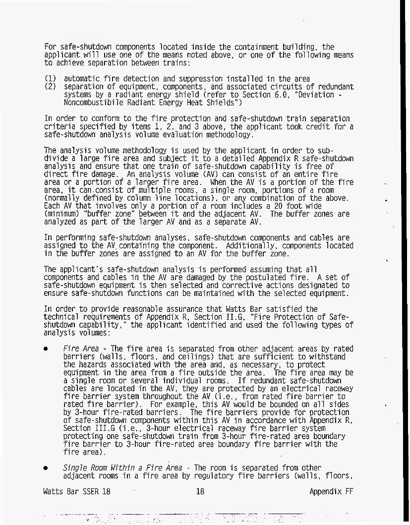
For safe-shutdown components located inside the containment bui ld ing , the app l i can t will use one of the means noted above, or one of the following means t o achieve separation between trains: (1) automatic fire detection and suppression installed i n the area ( 2 ) separation of equipment, components, and associated circuits of redundant
systems by a radiant energy shield (refer t o Section 6.0, "Deviation - Noncombusti bi 1 e Radiant Energy Heat Shiel ds I t 1
In order t o conform t o the f i re protection and safe-shutdown train separation criteria specified by items 1, 2 , and 3 above, the applicant took credit for a safe-shutdown analysis volume evaluation methodology.
The analysis volume methodology i s used by the applicant i n order t o sub- divide a large f i re area and subject i t t o a detailed Appendix R safe-shutdown analysis and ensure t h a t one train of safe-shutdown capability i s free of direct f i re damage. An analysis volume (AV) can consist of an entire f i re area or a portion o f a larger f i re area. When the AV i s a portion of the f i re area, i t can consist of multiple rooms, a single room, portions of a room (normally defined by column line locations), or any combination of the above. Each AV t h a t involves only a portion of a room includes a 20 foot wide (minimum) "buffer zone" between i t and the adjacent AV. The buffer zones are analyzed as part of the larger AV and as a separate AV.
In performing safe-shutdown analyses, safe-shutdown components and cables are assigned t o the AV. containing the component. Additionally, components located i n the buffer zones are assigned t o an AV for the buffer zone. The applicant's safe-shutdown analysis i s performed assuming t h a t a l l components and cables i n the AV are damaged by the postulated fire. A set of safe-shutdown equipment i s then selected and corrective actions designated t o ensure safe-shutdown functions can be maintained w i t h the selected equipment . In order t o provide reasonable assurance t h a t Watts Bar satisfied the technical requirements of Appendix R, Section 1I.G. "Fire Protection of Safe- shutdown capability,'' the applicant identified and used the following types of analysis vol umes : 0 Fi re Area - The f i re area i s separated from other adjacent areas by rated
barriers (walls. floors, and ceilings) t h a t are sufficient t o withstand the hazards associated w i t h the area and, as necessary, t o protect equipment i n the area from a f i re outside the area. The f i re area may be a single room or several ind iv idua l rooms. If redundant safe-shutdown cables are located i n the AV, they are protected by an electrical raceway fire barrier system throughout the AV (i .e., from rated f i re barrier t o rated f i re barrier). For example, this AV would be bounded on a l l sides by 3-hour fire-rated barriers. The fire barriers provide for protection of safe-shutdown components w i t h i n this AV i n accordance w i t h Appendix R, Section 1II.G (i .e. , 3-hour electrical raceway f i r e barrier system protecting one safe-shutdown train from 3-hour f i re-rated area boundary f i re barrier t o 3-hour fire-rated area boundary f i re barrier w i t h the fire area). Sing7e Room Within a F i re Area - The room i s separated from other adjacent rooms i n a f i re area by regulatory f i re barriers (walls, floors,
0
Watts Bar SSER 18 18 Appendix FF
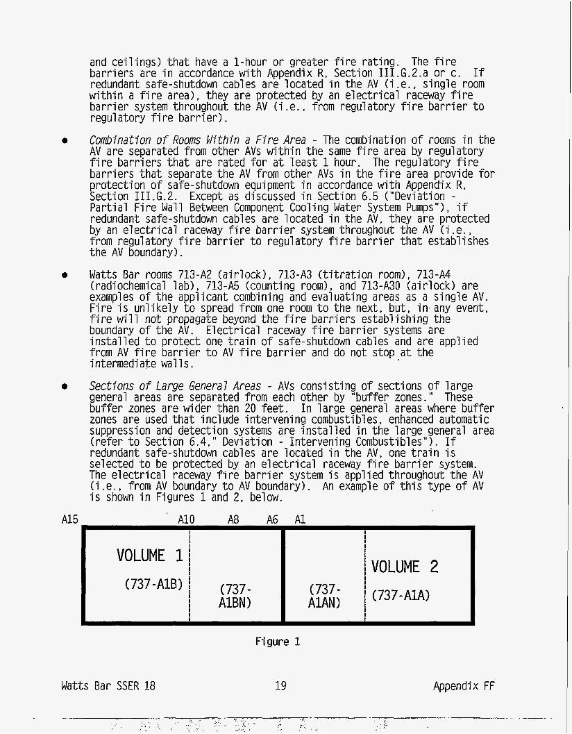
e
e
e
and ce i l ings) t h a t have a l -hour or greater f i r e ra t i ng barr iers are i n accordance w i th Appendix R, Section I11 redundant safe-shutdown cables are located i n the AV (i wi th in a f i r e area), they are protected by an e lect r ica bar r ie r system throughout the AV (i .e., from regulatory regulatory f i r e bar r ie r ) .
The f i r e G.2.a or c. If e., s ing le room
raceway f i r e f i r e ba r r i e r t o
Combination o f Rooms Cllithin a F i r e Area - The combination o f rooms i n the AV are separated from other AVs w i th in the same f i r e area by regulatory f i r e barr iers t h a t are rated f o r a t leas t 1 hour. The regulatory f i r e barr iers t h a t separate the AV from other AVs i n the f i r e area provide f o r protect ion o f safe-shutdown equipment i n accordance w i th Appendix R, Section I I I .G.2. Except as discussed i n Section 6.5 ("Deviation - P a r t i a l F i re W a l l Between Component Cooling Water System Pumps"), i f redundant safe-shutdown cables are located i n the AV, they are protected by an e lec t r i ca l raceway f i r e ba r r i e r system throughout the AV ( i . e . , from regulatory f i r e bar r ie r t o regulatory f i r e bar r ie r t h a t establishes the AV boundary).
Watts B a r rooms 713-A2 (a i r lock) , 713-A3 ( t i t r a t i o n room), 713-A4 (radiochemical lab) , 713-A5 (counting room), and 713-A30 (a i r lock) are examples o f the applicant combining and evaluating areas as a s ing le AV. F i re i s un l i ke ly t o spread from one room t o the next, but, i n any event, f i r e w i l l not propagate beyond the f i r e barr iers establ ishing the boundary o f the AV. E lect r ica l raceway f i r e bar r ie r systems are i ns ta l l ed t o protect one t r a i n o f safe-shutdown cables and are applied from AV f i r e bar r ie r t o AV f i r e ba r r i e r and do not stop a t the intermediate w a l l s .
Sections o f Large Genera7 Areas - AVs consist ing o f sections o f large general areas are separated from each other by "buffer zones." These bu f fe r zones are wider than 20 feet . I n large general areas where buf fer zones are used t h a t i n c l ude intervening combustibles , enhanced automatic suppression and detection systems are i ns ta l l ed i n the large general area ( re fe r t o Section 6.4," Deviation - Intervening Combustibles"). If redundant safe-shutdown cables are located i n the AV, one t r a i n i s selected t o be protected by an e lec t r i ca l raceway f i r e bar r ie r system. The e lec t r i ca l raceway f i r e ba r r i e r system i s applied throughout the AV (i .e., from AV boundary t o AV boundary). An example o f t h i s type o f AV i s shown i n Figures 1 and 2, below.
A15 A10 A8 A6 A 1 I I I I 1 I
I I
I !VOLUME 2 VOLUME 1 I I I I I
I (737-A1A) (737-A1B) 1 (737- (737- I I I A1AN) I I
I I AlBN) I
Figure 1
Watts Bar SSER 18 19 Appendix FF
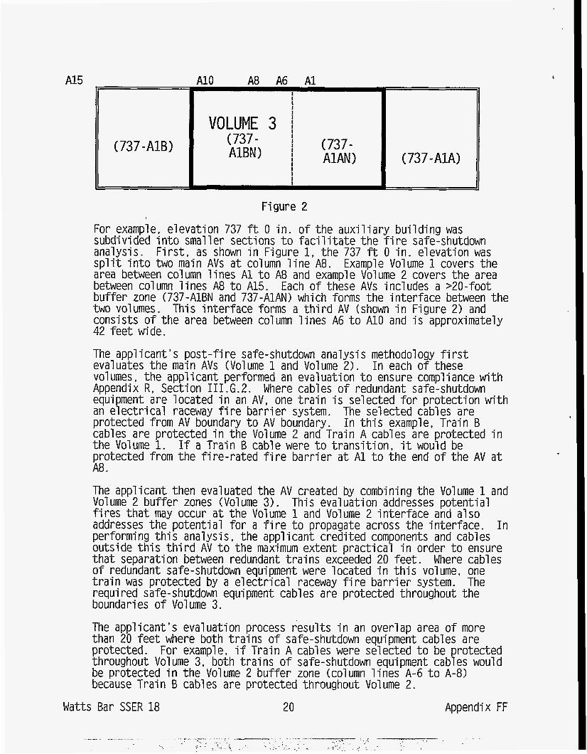
A15
(737-AZB)
A10 A8 A6 A1 I I
I I VOLUME 3 i
(737- I
AZBN) I
I
(737- ' I AlAN) ( 737 - AZA) 1 I
Figure 2
For example, elevation 737 ft 0 i n . o f the aux i l ia ry bu i ld ing was subdivided i n t o smaller sections t o f a c i l i t a t e the f i r e safe-shutdown analysis. F i r s t , as shown i n Figure 1, the 737 ft 0 i n . elevation was s p l i t i n t o two main AVs a t column l i n e A8. Example Volume 1 covers the area between column l i nes A 1 t o A8 and example Volume 2 covers the area between column l i nes A8 t o A15. Each o f these AVs includes a >20-foot buffer zone (737-A1BN and 737-AlAN) which forms the in ter face between the two volumes. This in te r face forms a t h i r d AV (shown i n Figure 2) and consists o f t he area between column l i nes A6 t o A10 and i s approximately 42 fee t wide.
The appl icant 's pos t - f i r e safe-shutdown analysis methodology f i r s t evaluates the main AVs (Volume 1 and Volume 2). I n each of these vol umes , the appl i can t performed an eval ua t i on t o ensure compl i ance w i th Appendix R, Section I11 .G.2. Where cables o f redundant safe-shutdown equipment are located i n an AV, one t r a i n i s selected f o r protect ion w i th an e lec t r i ca l raceway f i r e bar r ie r system. The selected cables are protected from AV boundary t o AV boundary. I n t h i s example, Train B cables are protected i n the Volume 2 and Train A cables are protected i n the Volume 1. If a Train B cable were t o t rans i t i on , it would be protected from the f i r e - ra ted f i r e bar r ie r a t A 1 t o the end o f the AV a t A8.
The applicant then evaluated the AV created by combining the Volume 1 and Volume 2 bu f fe r zones (Vol ume 3). This evaluation addresses potent i a1 f i r e s t h a t may occur a t t he Volume 1 and Volume 2 in te r face and also addresses the potent ia l f o r a f i r e t o propagate across the interface. I n performing t h i s analysis, the applicant credi ted components and cables outside t h i s t h i r d AV t o the maximum extent pract ica l i n order t o ensure tha t separation between redundant t ra ins exceeded 20 feet. Where cables o f redundant safe-shutdown equipment were located i n t h i s volume, one t r a i n was protected by a e lec t r i ca l raceway f i r e ba r r i e r system. The required safe-shutdown equipment cab1 es are protected throughout the boundaries o f Vol ume 3.
The appl icant 's evaluation process resul ts i n an overlap area o f more than 20 f e e t where both t ra ins o f safe-shutdown equipment cables are protected. For example, i f Train A cables were selected t o be protected throughout Volume 3, both t ra ins o f safe-shutdown equipment cables would be protected i n the Volume 2 bu f fe r zone (column l i nes A-6 t o A-8) because Train B cables are protected throughout Volume 2.
Watts Bar SSER 18 20 Appendix FF
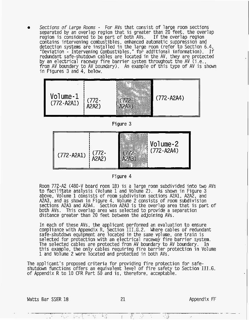
0 Sections o f Large Rooms - For AVs t h a t consist o f large room sections separated by an overlap region that i s greater than 20 feet , t he overlap region i s considered t o be pa r t o f both AVs. If the overlap region contains intervening combustibles, enhanced automatic suppression and detection systems are i ns ta l l ed i n the large room (refer t o Section 6.4, "Deviation - Intervening Combustibles, " f o r addit ional information). If redundant safe-shutdown cables are located i n the AV, they are protected by an e lec t r i ca l raceway f i r e bar r ie r system throughout the AV (i .e., from AV boundary t o AV boundary). An example o f th is type o f AV i s shown - . i n Figures 3 and 4, below.
Figure 3
Figure 4
Wat ts Bar SSER 18 21 Appendix FF
' . $, . , "'. . , . - '.
I ,, '. <. ' -
. -..-.
,,, ~ ,, . . . "' ' . ,: .., ;, ,.,, I . - r .L'
Room 772-A2 (480-V board room 1B) i s a large room subdivided i n t o two AVs t o f a c i l i t a t e analysis (Volume 1 and Volume 2). As shown i n Figure 3 above, Volume 1 consists o f room subdivision sections A2A1, A2A2, and A2A3, and as shown i n Figure 4, Volume 2 consists o f room subdivision sections A2A3 and A2A4. Section A2A3 i s the overlap area t h a t i s par t o f both AVs. This overlap area was selected t o provide a separation distance greater than 20 fee t between the adjoining AVs.
I n each o f these AVs, the applicant performed an evaluation t o ensure compliance w i th Appendix R, Section I11 .G.2. Where cables o f redundant safe-shutdown equipment are located i n the same volume, one t ra in is selected f o r protect ion w i th an e lec t r i ca l racewai f i r e ba r r i e r system. The selected cables are protected from AV boundary t o AV boundary. I n t h i s example, the only cables requir ing f i r e bar r ie r protect ion i n Volume 1 and Volume 2 were located and protected i n both AVs.
The appl i can t ' s proposed c r i t e r i a f o r providing fi r e protect ion f o r safe- shutdown functions of fers an equivalent leve l o f f i r e safety t o Section 1 I I . G . o f Appendix R t o 10 CFR P a r t 50 and i s , therefore, acceptable.
3.2.2 Safe Shutdown - General P l a n t Areas The applicant's methodology for assessing compliance w i t h the separati on/protecti on requi rements of Secti on. I I I . G of Appendi x R consi sted of ,
determining the functions required t o achieve and m a i n t a i n safe shutdown producing shutdown logic diagrams t h a t define minimum sets of systems capable of accomplishing each shutdown function For each safety function, the major equipment required t o accomplish t h a t function was identified and arranged on the SDL i n functional groups called "keys. It These keyed blocks were then expanded by developing small er 1 ogi c d i agrams call ed "equi pment keys " ; these identify the subsystems or components or both required t o provide the specified function. The equipment keys, combined w i t h the SDL d i agram. identify the redundant paths available t o achieve and m a i n t a i n safe shutdown conditions i n the event of f ire. grouping specific p l a n t locations i n t o f i re areas identifying for each area, one or more paths through the shutdown logic diagrams t h a t will satisfy each required shutdown function developing functional criteria t h a t defined the requi red equipment for the shutdown paths identifying power and control cabl es for shutdown-re1 ated equi pment and associated circuits t h a t are not isolated from shutdown cabl ing
From the SDL and associated equipment keys, TVA identified cables, i n block diagram form, for required components. A required cable l i s t was then generated which i ncl udes ci rcui t s t o requi red equi pment and ci rcui t s of equipment whose spurious operati on could affect safe shutdown. Raceways t h a t contain these required cables were then identified, and their locations documented. An interaction i s defined as a place i n the p l a n t where redundant safe-shutdown paths are not separated i n accordance w i t h the requi rements of Appendix R, Section I I I . G. 2. Whenever an interaction was identified, i t was documented and evaluated for i t s impact on safe-shutdown capability . An appropriate resol ution was then determined and documented. relocating cables and equipment, providing f i re barriers, f i re detection and f i re suppression systems so the separation/protection requirements of Appendix R , Section 1II.G would be met, or providing justification where devi ations from these requi rements occur
On the basis of this methodology and subject t o the deviations from the requi rements of Section 111. G , the appl i cant's methodol ogy conforms t o the requirements of Appendix R t o 10 CFR Part 50 and i s , therefore, acceptable. 3.2.3 Safe-Shutdown Analysi s '
The applicant's safe-shutdown analysis demonstrated t h a t sufficient redundancy exists for systems needed for h o t and cold shutdown. The safe-shutdown Watts Bar SSER 18 22 Appendix FF
analysis included components, cab1 ing, and support equipment needed t o achieve hot and cold shutdown. Thus, i n the event o f a f i r e anywhere i n the p lant , a t leas t one t r a i n o f systems would be avai lable t o achieve and maintain hot shutdown and proceed t o cold shutdown.
For hot shutdown a t leas t one t r a i n o f the fo l lowing safe-shutdown systems would be avai 1 able: aux i l i ary feedwater system, steam generator power-operated r e l i e f valves, reactor coolant system, and the chemical and volume control system. For cold shutdown, a t leas t one t r a i n o f the residual heat removal (RHR) system would be avai lable. The RHR system would be used f o r long-term decay heat removal and provides the capabi l i ty t o achieve cold shutdown w i th in 72 hours a f te r a f i r e . The a v a i l a b i l i t y o f these systems includes the components, cabling, and support equipment necessary t o achieve cold shutdown. Support equipment i ncl udes the diesel generators and associated e lec t r i ca l d i s t r i bu t i on system, emergency r i v e r cool ing water system, component cool ing water system, and the necessary vent i la t ion systems.
The applicant performed an e lec t r i ca l separation study t o ensure t h a t a t leas t one t r a i n o f such equipment i s avai lable i n the event o f a f i r e i n areas t h a t might affect these components. Safe-shutdown equipment and cabl ing were i den t i f i ed and traced through each f i r e area from the component t o the power source. Associated c i r c u i t s whose f i re-induced spurious operation could a f fec t safe shutdown were i den t i f i ed by a system review t o determine those components whose maloperation could a f fec t the safe-shutdown capabi l i ty . Following t h e i r i den t i f i ca t i on , such c i r c u i t s were provided w i th a leve l o f f i r e protection t h a t i s equivalent t o t h a t provided f o r redundant t ra ins o f requi red equipment . The applicant 's analysis indicated t h a t the only area outside containment where redundant d iv is ions are not adequately separated i n accordance w i th Section 1 I I . G o f Appendix R i s the control bui ld ing. Alternate shutdown measures are required f o r f i r e s i n the control bui ld ing. disable the main control room, the aux i l ia ry control room (ACR), which i s located i n a separate f i r e area o f the aux i l ia ry bui ld ing, would be avai lable t o achieve, and maintain the p lant i n , hot standby and subsequent cold- shutdown conditions. The control functions and indicat ions provided a t the ACR panel are e l e c t r i c a l l y iso la ted o r otherwise separate and independent from the main control room. Further discussion o f the a l ternate shutdown capabi 1 i t y i s presented bel ow i n Section 3.3. , "A1 t e r n a t i ve Shutdown. "
On the basis o f the resul ts o f i t s review, the s t a f f f inds t h a t the systems iden t i f i ed by the applicant f o r achieving and maintaining safe shutdown i n the event o f a f i r e are acceptable. Addi t ional ly, the methodology used t o ensure an adequate leve l o f f i r e protection i f o r these safe-shutdown systems i s i n accordance w i th or equivalent t o t h a t required by Section 1 I I . G . o f Appendix R t o 10 CFR P a r t 50 and i s , therefore, acceptable.
If a f i r e should
3.2.3 Systems Required f o r Safe Shutdown
Shutdown o f the reactor and r e a c t i v i t y control i s i n i t i a l l y performed by control rod inser t ion f rom the control room. Reactor coolant system (RCS) inventory and long-term reac t i v i t y control are maintained by varying charging and letdown f low through the RCS makeup and letdown paths. Decay heat removal during hot shutdown i s accomplished by establ ishing secondary-side pressure control and supplying water t o two o f the four steam generators from one of Watts Bar SSER 18 23 Appendix FF
the redundant auxi 1 iary feedwater pumps. Long-term heat removal t o establish and m a i n t a i n cold-shutdown conditions i s provided by the residual heat removal (RHR) system. Primary system pressure may be controlled by the pressurizer heaters (if available) or by varying charging flow and level t o m a i n t a i n RCS pressure. The applicant states t h a t analyses and testing have been performed a t similar plants which demonstrate t h a t the use of charging t o control pressure by varying RCS level provides an equivalent capability t o t h a t provided by the pressurizer heaters. The applicant submitted details regarding the referenced analyses and testing for the specific f i re areas where such use may be requi red. The systems selected by the applicant are capable of satisfying the post-fire safe-shutdown requirements of Sections I11 .G and 111. L of Appendix R t o 10 CFR Part 50. and are, therefore, acceptable. 3.3 Alternative Shutdown
3.3 - 1 Areas i n Which A1 ternatj ye. Shutdown.. Ls- Requi red. The applicant's analysis has identified four areas of the control bui ld ing which do not satisfy the separation requirements of Section I11 .G of Appendix R . Specifically, these areas are the main control room, the cable spreading room, and the two auxiliary instrument rooms. The alternate shutdown system developed by the applicant provides alternative shutdown capability for a l l areas of the control bui ld ing , which includes the areas mentioned above. 3.3.2 Alternative Shutdown System The a1 ternative shutdown system uses existing p l a n t systems and equipment identified i n Section 3.2 above, and an auxiliary control room complex. No repairs or modifications are required to'implement the alternative shutdown ca pabi 1 i t y .
The auxiliary control room (ACR) complex. is physica.l-l.-y. independent of the control bui 1 d i ng . Where requi red, electrical i sol a t i on of control s and indications provided on the ACR i s achieved through the actuation of isolation/transfer switches. The ACR complex i s divided in to five independent rooms consisting of a Train A and Train B transfer switch room for each u n i t and the ACR. The ACR serves as the central control po in t during alternative shutdown from outside the main control room, and provides control and monitoring capability for redundant trains (Train A and B) of equipment required t o achieve safe shutdown. 3.4 Alternative Shutdown Performance Goals The alternative shutdown system described i n Sections 3.4.1 - 3.4.5 was designed t o enable the achievement of alternative shutdown performance goals outlined i n Section 1II.L of Appendix R as follows: 3.4.1 Reactivity Control Initial reactivity control i s provided by the control rods, which are inserted by the reactor protection system. Additional shutdown margin i s provided by
Watts Bar SSER 18 24 Appendix FF
i n j ec t i ng borated water from the refue l ing water storage tank (RWST) i n t o the reactor cool ant system (RCS) v i a t he charging pumps. Source range monitoring instrumentation i s avai lable i n the ACR t o monitor r e a c t i v i t y and ensure adequate shutdown margin.
3.4.2 Reactor Coolant Inventory
Control of the RCS inventory requires maintenance o f reactor coolant pump (RCP) seal i n t e g r i t y , maintaining RCS pressure boundary i n t e g r i t y , and providing RCS makeup and letdown.
RCP seal cooling i s required t o maintain seal i n t e g r i t y and prevent an uncontrolled loss o f reactor coolant inventory. RCP seal cool ing w i l l be achieved by d iver t ing a port ion o f t he charging f low t o the RCP seals. The RCS pressure boundary i s isolateded by i so la t i ng the normal and excess letdown l ines. To prevent depressurization o f the RCS, the solenoid valves i n the reactor vessel head vent system are assured t o remain closed.
RCS inventory i s cont ro l led by varying charging and letdown f low through RCS makeup and letdown paths. One o f the redundant centr i fugal charging pumps i s required t o provide makeup inventory t o the RCS. The volume control tank (VCT) i s required t o provide a short-term supply o f water f o r makeup o f RCS inventory and RCP seal cooling. A suction path from the RWST i s required t o provide a long-term source o f borated water f o r RCS makeup. If necessary, inventory may be removed from the RCS by way o f the pressurizer power-operated r e l i e f valves (PORVs), discharging t o the pressurizer r e l i e f tank (PRT), or discharging through the RCS head vent valves.
Reactor cool ant makeup i s usual l y avai 1 ab1 e immediately f o l 1 owing reactor t r i p from the charging system, except i n a few f i r e locations where it i s avai lable w i th in 75 minutes fo l lowing reactor t r i p . The licensee has performed an analysis which demonstrates tha t makeup due t o RCS leakage i s not required f o r 75 minutes. For these scenarios, cool ing t o prevent RCP seal f a i l u r e w i l l be provided by the thermal bar r ie r booster pumps located i n a separate f i r e area. To preclude a boron d i l u t i o n event, the RCPs w i l l be stopped w i th in 15 minutes o f reactor t r i p .
3.4.3 Decay Heat Removal
RCS temperature from power operati on t o hot -shutdown conditions i s control 1 ed by the rate o f heat removal from the reactor coolant t o the secondary-side coolant and from hot shutdown t o co ld shutdown v ia d i rec t heat t ransfer by the RHR system t o the u l t imate heat sink. During RCS cooldown t o RHR entry conditions, heat w i l l be removed from the reactor and transferred t o the steam generators v i a natural c i rcu la t ion. The removal o f decay heat f rom reactor t r i p t o hot standby conditions requires one auxi 1 iary feedwater pump supplying water t o two o f the four steam generators. The required makeup water supply can come from e i ther the condensate storage tank (CST) o r from emergency raw Ccol i ng M e r ( ERCW 1 . Two steam generators are required for cooldown. Control o f steam generator inventory requi res one Auxi 1 i ary Feedwater (AFW) pump, e i ther the turbine- driven aux i l ia ry feedwater pump (TDAFW) or one o f the two motor-driven aux i l ia ry feedwater pumps, drawing suction from the CST or ERCW, and the cor respondi ng steam generator PORVs . Each motor - d r i ven pump provides i n jec t i on
Watts Ba r SSER 18 25 Appendix FF
flow t o two steam generators: MDAFW 1-A-A t o SG-1 and SG-2 and MDAFW 1-B-B t o SG-3 and SG-4. The t u r b i ne-dri ven auxi 1 i ary. feedwater pump (TDAFW) d i scharge may be al igned t o any two steam generators. However, a supply o f steam from SG-1 or SG-4 i s required f o r TDAFW pump operation.
The CST i s normally aligned t o the suction o f the AFW pumps through locked- open valves. A f te r the CST has reached i t s low level as indicated by low pump suction pressure, the suction for the AFW system must be aligned t o the ERCW system. For shutdown from the main control room, operators t ransfer AFW pump suction by manually opening the i so la t i on valves corresponding t o the operating AFW pump. During a l ternat ive shutdown from the aux i l ia ry control room, AFW pumps w i l l automatically t ransfer from the CST t o the ERCW system.
The residual heat removal (RHR) system i s required t o provide the long-term heat removal capab i l i t y necessary t o establ ish and maintain cold-shutdown conditions. The establishment o f RHR cool ing requi res one RHR pump, heat exchanger, and associated flowpath t o provide RCS coolant f low t o the primary side of the RHR heat exchanger; one component cool ing system (CCS) pump and i t s associated flowpath t o provide cool ing t o the secondary side o f the RHR heat exchanger; and one essential r a w cool ing water (ERCW) pump and i t s associated flowpath t o supply cool ing water t o the CCS heat exchanger. If the diesel generators are required t o supply required power, an addit ional ERCW pump would be required f o r cooling purposes.
The appl icant 's p o s t - f i r e shutdown analysis states t h a t the pressurizer heaters are the preferred method o f con t ro l l ing RCS pressure, and w i l l be used i f avai lable. If the pressurizer heaters are l o s t as a resu l t o f f i r e damage, RCS pressure w i l l be control led by using the charging system t o vary the pressurizer l eve l . The shutdown analysis also indicates t h a t under cer ta in fi r e condit ions, the abi 1 i t y t o depressurize the reactor using pressurizer spray and the PORVs may be l o s t . This scenario would require RCS pressure t o be reduced by a l ternate ly f i l l i n g and draining the pressurizer using the charging system.
3.4.4 Process Monitoring
D i rec t i ndi c a t i on o f process var i ab1 es i ncl uding reactor cool ant hot-1 eg temperature (T-hot) , reactor cool ant pressure, pressurizer 1 eve1 , steam generator leve l and pressure, source range f l ux , charging header pressure and f l o w , ~lolume control tank leve l ind icat ion, and decay heat removal system f l ow are provided a t the aux i l ia ry control room.
The applicant has requested a deviat ion t o Appendix R requirements f o r instrumentation necessary t o achieve a l ternat ive shutdown. Speci f ica l ly , contrary t o Appendix R requirements, the applicant has not provided wide-range steam generator leve l , tank level ind ica t ion f o r the condensate storage tank and refue l ing water storage tank and RCS cold- leg temperature (T-cold). (Refer t o Section 6.1, "Deviation - Required Instrumentation f o r A l ternat ive Shutdown," f o r t he s t a f f ' s evaluation o f t he appliicant's deviat ion request. 1
3.4.5 Support Functions
The applicant submitted a l i s t i n g o f a l l required support functions. The TVA F i r e Protection Report and the associ ated shutdown 1 ogi c d i agram ident i f y t he onsi te e l e c t r i c a l supply (diesel generators and d i s t r i bu t i on system),
Wat t s Bar SSER 18 26 Appendix FF
envi ronmental control (HVAC components requi red f o r hot standby), cool i ng water systems, and communications as required support functions. I n Appendix A o f WBN-OSG-031 R18. it states t h a t ven t i la t ion cool ing required t o maintain hot standby i s required f o r the main control room XMCR) , reactor bui ld ing, diesel generator (DG) bui ld ing, 480-V transformer rooms, the TDAFW room, and the 713 ft 0 i n . elevation o f the aux i l ia ry bui ld ing. A l l other areas o f the p lan t containing equipment required f o r safe shutdown would maintain acceptable temperatures f o r 72 hours i f a l l ven t i la t ion were l o s t . The s t a f f f inds t h i s acceptable.
3.5 Manual Operator Actions
The applicant 's p o s t - f i r e safe-shutdown analysis, and associated cable in teract ion studies, have i d e n t i f i e d a number o f f i r e areas where operator actions t o take manual control o f equipment may be required t o compensate f o r f i re-induced equipment fa i lu res . On the basis o f i t s analyses, the applicant performed Calculation No. WBN-OSG-165, R5, "Manual Actions Required f o r Safe Shutdown Following a F i re . " This evaluation i d e n t i f i e d manual operator actions required t o achieve safe shutdown i n the event o f f i r e i n any p lan t area, established allowable operating times t o accomplish these actions, and v e r i f i e d the f e a s i b i l i t y o f performance. A review o f t h i s ca lcu lat ion noted the fol lowing: (1) manual actions required f o r each p lant area/zone f o r the "worst case" f i r e zone were i den t i f i ed ; (2) the t i m e estimates required t o accomplish each manual act ion were ve r i f i ed by physical p lan t walkdowns; and (3) t o e i ther establ ish a shutdown path o r compensate f o r f i r e damaged cables or equipment, the appl icant 's analysis credi ts the performance o f one or more manual operator actions i n areas/zones not requir ing an a l te rna t ive shutdown capabi 1 i ty . The s t a f f reviewed procedures necessary t o implement t h i s approach. The only operator act ion normally credi ted p r i o r t o control room evacuation i s a reactor t r i p (scram). However, the applicant 's F i r e Protection Report c red i ts two actions p r i o r t o control room evacuation: reactor t r i p and reactor coolant pump t r i p . I n the event o f f i r e i n the control bui ld ing, an immediate t r i p o f the reactor coolant pumps i s necessary t o prevent overcooling caused by a spurious actuation o f pressurizer spray valves. The feasi b i 1 i t y and adequacy o f the applicant 's proposed approach f o r preventing a spurious actuation o f pressurizer spray valves was adequately demonstrated during the Ju ly 1995 s i t e v i s i t and, therefore, i s acceptable.
3.5.1 Safe-Shutdown Procedures and Manpower
The applicant has developed p o s t - f i r e safe-shutdown .procedures (AOI-30.2) f o r each f i r e zone. The s t a f f found t h a t these procedures i d e n t i f i e d necessary manpower requirements and contained su f f i c i en t guidance i n the proper sequence f o r operators t o achieve safe-shutdown conditions, and t h a t the inst ruct ions f o r shutt ing down operating equipment were assigned i n the proper sequence. Therefore, the s t a f f f inds the applicant 's pos t - f i r e safe-shutdown procedure acceptable.
3.5.2 Repairs
The appl i cant states t h a t repai r a c t i v i t i e s (e. g . , 1 ifti n g k u t t i ng 1 eads , i n s t a l l i n g jumpers, and fuse replacement) are not required t o achieve and maintain hot standby conditions. Addi t ional ly, t he a l te rna t ive shutdown
Wat ts Bar SSER 18 27 Appendix FF
capability is capable of achieving cold-shutdown conditions w i t h o u t repairs. Repairs may, however, be necessary t o achieve cold shutdown conditions as a result of f i re i n the following areas: 0
0
0
Rooms 757.0-A5 and 757'. 0-A24
Repairs required t o ensure cold-shutdown capability i n the event of f i re i n these rooms include the installation of an electrical jumper t o power a second ERCW pump from 6.9-kV board 1-BD-211-A-A.
Rooms 692.0-AlA, -AlAN, and -AlBN (Col. Lines Q - U / A l - A l O ) - Room 692.0-A1C - Room 713.0-A1A - - Room 737.0-A3
Room 757.0-A2
Requi red cold-shutdown repai rs i ncl ude the instal 1 a t i on of electrical jumpers a t the respective motor control centers (1-MCC-214-A1/9A-A and 1- MCC-214-B1/9A-B) and replacement o f the power cable from the MCC t o the room cooler.
Rooms 737.OAlA. - A l A N , and AlBN (Col. Lines Q-U/Al-AlO) - Room 757.0-A2 - Room 757.0-A5 - Room 757.0-A10 - Room 772.0-A6 - Reactor building
Cold shutdown repairs for f i re i n these areas include the installation of an electrical jumper and replacement of power and limit switch cables for RHR/RCS high-low pressure interface valves. The repairs are necessary t o a1 low RHR/RCS high/low-pressure boundary valves 1-FCV-74-1-A. -2-B, -8-A, and/or -9-B t o be opened for col d-shutdown capabi 1 i t y .
Cold-shutdown repair activities include the installation o f electrical jumpers i n the ERCW and RHR systems. The applicant has identified the specific activities t o be performed and has devel oped repair procedures t o imp1 ement this capability. 'Additionally, materials necessary t o accomplish the repairs are available on site. The repair activities developed by the applicant t o achieve cold shutdown conditions satisfy the requirements of Appendix R t o 1 0 CFR Part 50 and are, therefore, acceptable.
3.6 Associated C i rcui t s The applicant has examined the potential impact of f i re damage on associated circuits of concern. Associated circuits have been categorized by the applicant as Type I : Common Power Source, Type 11: Spurious Actuation, and Type H I : Common Enclosure.
3.6.1 Circuits Associated by Common Power Source For circuits associated by a common power source, the applicant has identified all circuits supplied from a power source (Le . , switchgear, MCCs, and load
Watts Bar SSER 18 28 Appendix FF
centers) that also powers a c i r c u i t o f equipment required f o r p o s t - f i r e safe shutdown. For the i d e n t i f i e d c i r c u i t s , the coordination o f e lec t r i ca l protection devices (e:g., fuses, c i r c u i t breakers, or relays) was ve r i f i ed t o ensure that a f i re-induced f a u l t on a branch c i r c u i t o f a required supply w i l l be cleared by a t leas t one branch c i r c u i t protect ive device before the f a u l t current could propagate t o cause a t r i p o f any upstream feeder breaker t o the supply.
To meet the separation requirements o f Section I I I .G.2 o f Appendix R, Generic Let ter (GL) 86-10 states that mu l t ip le high-impedance fau l t s (MHIFs) should be considered i n the evaluation o f e lec t r i ca l power supplies required for pos t - f i r e safe shutdown. The applicant has evaluated the a f fec t o f MHIFs on the p o s t - f i r e safe-shutdown capabi l i ty o f Watts Bar Un i t 1. This evaluation i s contained i n TVA Calculation No. WBPE VAR 9509001, “Appendix R - Mul t ip le High-impedance Fault Analysis,” Revision 1, dated September 20, 1995. The applicant’s evaluation i s s im i la r t o a methodology developed by the Phi 1 adel phi a E lec t r i c Company (PECO) f o r eval ua t i ng MHIFs a t t he Peach Bottom Atomic Power Stat ion. The PECO methodology, which uses the 60-second t r i p - po int character is t ic o f the power supply feed protect ive device i n l i e u o f the 1000-second t r i p - p o i n t character is t ic , was approved by the s t a f f i n a safety evaluation dated Apr i l 12. 1989.
The applicant’s evaluation o f MHIFs i s based on a phased approach. I n Phase 1, a technical evaluation o f a l l power sources required f o r p o s t - f i r e safe shutdown was performed using the fol lowing assumptions: (1) a l l (100%) o f the connected nonessential cables experience a high-impedance f a u l t (HIF) condit ion simultaneously and (2) the HIF current has a value t h a t i s j u s t below the 1000 second t r i p character is t ic o f the load protect ive device.
The pass/fai l c r i t e r i a used during t h i s phase o f the evaluation are (1) t o t a l board current including MHIF i s less than the supply protect ive device t r i p character is t ic a t 1000 seconds or (2) t o t a l board current including MHIF i s less than the supply protect ive device t r i p character is t ic a t 60 seconds.
With the exception o f one 480-V shutdown board (480-V SDB 2A2-A). a l l required power sources a t the 480-V ac leve l and above W e . , 480-V MCCs, 480-V shutdown boards, and 6.9-kV switchgear) are capable o f sa t is fy ing evaluation c r i t e r i o n 1 (-Le., 100% o f nonessential cables fau l ted w i th the source protect ive device character is t ic a t 1000 seconds). I n the event o f f i r e i n F i re Zone 737A18, located on the 737 ft 0 i n . .elevation o f the aux i l i a ry bui ld ing, 480-V shutdown board 2A2-A cannot sa t i s f y c r i t e r i o n 1, but i s capable o f sat is fy ing c r i t e r i o n 2 (100% o f nonessential cables fau l ted w i th the source protect ive device character is t ic a t 60 seconds) with margin.
Power sources which d id not sa t i s f y the Phase 1 c r i t e r i a were i d e n t i f i e d and appropriate procedures necessary t o restore power were developed. None o f the power sources f a l l i n g i n t o t h i s category power t ime-c r i t i ca l loads (i .e., safe shutdown loads whose loss could not be to lerated f o r a short period o f t ime u n t i l actions can be taken t o restore power).
On the basis o f the fo l lowing facts , the applicant’s evaluation o f mu l t ip le high-impedance fau l ts was found acceptable:
(1) The major i ty o f safe-shutdown loads whose loss could impact safe-shutdown capab i l i t y are powered from e i ther a 6.9-kV or 480-V power source. As
Wat ts Ba r SSER 18 29 Appendix FF
currently configured and loaded, a1 1 required power sources associated w i t h these voltage levels are capable of sustaining HIFs on a l l non- essential loads a t the long-time (1000 second) t r ip characteristic of the supply breaker, w i t h the exception of one 480-V ac shutdown board (480-V SDB 2A2-A). In the event of f i re i n a l l f i re AVs except f i re AV 737AlB, 48-OV SDB 2A2-A i s also capable of satisfying this criterion. event of f i re i n this AV (737 A l B ) , SDB 2A2-A i s capable of sustaining HIFs on a l l nonessential loads using the 60-second t r ip characteristic of the supply protective device. I t i s considered highly unlikely t h a t a l l nonessential cables of a required power supply would be simultaneously faulted i n a high-impedance condition for an extended period of time. This view i s reflected i n the staff 's previous acceptance of the use of the supply protective device 60-second t r ip characteristic i n evaluating the potential affects of MHIFs (refer t o safety evaluation of the PECO analysis of MHIFs, dated April 12, 1989).
In the
Restoration procedures have been developed for power sources t h a t have a potential for loss due t o MHIFs. In no case are restoration procedures relied on for any power supply powering time critical loads ( L e . , safe shutdown loads whose loss could not be tolerated for a short period of time u n t i l actions can be taken t o restore power).
The applicant's evaluation of Type I associated circuits also considered multiple high-impedance faults t h a t may be initiated as a result of f ire. This evaluation considered the potential for multiple, concurrent high- impedance faults for each power source required for safe shutdown and i s , therefore, acceptable. 3.6.2 Spurious Actuation As part of a systems evaluation performed during the development of the shutdown logic and associated required cable l i s t s , the applicant identified circuits whose fi re-induced spurious actuation could affect the safe-shutdown circuits. During this phase of the analysis, components t h a t must be prevented from spuriously operating were identified. These components were then listed i n the shutdown logic and associated equipment keys. The appl icant then eval uated the cab1 e separati on and protection provi ded for t h i s equipment i n the same manner as required circuits. All circuits which could cause undesirable spurious operations were identified and evaluated for potential f i re damage. Additionally, i f circuits for redundant components could be affected by a common fire, they were evaluated concurrently and corrective action was identified as needed. 3.6.3 Common Encl os ure To address the common encl osure-associated circuit concern, the applicant has evaluated a l l circuits t h a t may share a common enclosure (e.g., cable tray, conduit, panel or junction box) w i t h an Appendix R-required circuit. On the basis of i t s evaluation, the applicant concludes t h a t the electrical protective equipment provided will ensure t h a t electrical faults and overloads will not result i n any more cable degradation t h a n would be expected when operating conditions are below the setpoint of the electrical protective devi ce . Watts Bar SSER 18 30 Appendix FF

On t h i s basis, the applicant 's methodology f o r assessing the potent ia l e f fec t o f f i r e damage t o nonessenti a1 associated c i r cu i t s on the safe-shutdown capab i l i t y o f the p lant was found t o sa t i s f y the requirements o f Appendix R t o 10 CFR P a r t 50, and i s , therefore, acceptable.
3.6.4 High/Low-Pressure Interfaces
The applicant has i d e n t i f i e d the fol lowing as high/low-pressure interfaces: RHR/RCS i so la t i on valves (1-FCV-74-1, 1-FCV-74- 2, 1-FCV-74-8, and l-FCV-74- 9); pressurizer PORV and block valves, excess letdown i so la t i on valves (1-FCV- 62-55 and 1-FCV-62-56): normal letdown i so la t i on valves, reactor head vent and i so la t i on valves, and the safety i n jec t i on system/RHR in te r face valve. During i t s eval ua t i on, the appl i can t considered the potent i a l f o r mu1 ti p l e c i rcu i t fau l t s . To prevent f i r e - i n i t i a t e d cable fau l t s f rom causing a spurious operation o f the RHR i so la t i on valves, power i s removed during p lan t operation.
The applicant states t h a t cables f o r the pressurizer PORV and i t s associated block valves are not subject t o concurrent damage f rom a common f i r e . Where necessary, f i r e bar r ie r wrap i s used t o protect cables o f a t leas t one valve. I n the event o f f i r e requir ing a l ternat ive shutdown ( L e . , a control bu i ld ing f i r e ) , the applicant states t h a t the PORV block valves can be closed and isolated.
To prevent spurious operation o f t he remaining h i gh/ l ow-pressure interfaces i n the event o f f i r e i n areas other than the control bui ld ing, the applicant states t h a t cables o f redundant valves i n the same high/low-pressure in ter face l i n e are not subject t o damage from a common f i r e . I n the event o a f i r e i n 'the control bui ld ing, the applicant states t h a t spurious operation o f these valves w i l l be prevented by operator actions t o deenergize and i s 0 ate c i r c u i t s o f the affected valves.
The applicant 's approach i s an acceptable means o f preventing spur operations o f high/low-pressure interfaces:
ous
3.7 F i re Barr iers Used To SeDarate Redundant Safe-Shutdown Functions Within the Same F i re Area
3.7.1 Raceway and Cable Tray F i r e Barr iers
Cable raceway t h a t requires separation by f i r e - ra ted barr iers a t Watts Bar may be protected by e i ther 1-hour or 3-hour f i r e - ra ted bar r ie r systems. The applicant w i l l use a 1-hour f i r e - ra ted bar r ie r system i f automatic detection and suppression are i ns ta l l ed i n the area and a 3-hour f i r e - ra ted bar r ie r system i f automatic suppression i s not i ns ta l l ed i n the area. Currently, the appl i can t has proposed t o use Thermo-Lag 1-hour f i re-barr ier raceway assemblies t o separate redundant safe-shutdown functions w i th in the same f i r e area.
By l e t t e r s dated October 16, 1992; February 10, 1993; June 25, 1994; and March 22, 1995, the applicant proposed t o use Thermo-Lag 330-1 and 770-1 materials t o construct the required 1-hour and 3-hour f i re-rated bar r ie r protect ion f o r one t r a i n o f safe-shutdown capab i l i t y and t o meet t h e f i r e separation requirements speci f ied f o r redundant safe-shutdown t ra ins i n Section I11 .G o f Wat t s Ba r SSER 18 31 Appendix FF
Appendix R t o 10 CFR P a r t 50. By l e t t e r s dated Ju ly 9, 1994; December 23, 1994; and March 29, 1995, the applicant submitted the resul ts o f the qua l i f i ca t i on tes t ing it d id t o demonstrate t h a t i t s proposed Thermo-Lag f i r e - bar r ie r i ns ta l l a t i ons w i l l s a t i s f y the 1-hour and 3-hour f i r e - r e s i s t i v e requirement of Appendix R, Section I11 .G.
The s ta f f audited the construction o f the f i r e endurance t e s t specimens a t the applicant 's contract t es t i ng laboratory (Omega Point Labs, San Antonio, Texas) during the weeks o f February 13, 1993, and Ju ly 25, August 1, August 22, and October 17, 1994. During these v i s i t s , t h e s t a f f observed the erection o f raceway configurations, i ns ta l l a t i on o f t e s t instrumentation, i n s t a l l a t i o n o f penetration seals, and the construction and appl icat ion o f Thermo-Lag 330-1 f i r e ba r r i e r materials. The s t a f f also observed the t e s t laboratory's 'and the applicant 's qua l i t y control (QC) and qua l i t y assurance (QA) a c t i v i t i e s .
The staff observed f i r e endurance tests on December 21 and 22, 1992; January 7, March 31, Apr i l 1, 6 and 7, 1993; September 7, 8, and 20, 1994; October 18, 19, and 27, 1994; and November 17, 1994. The s t a f f observed the t e s t setups, the f i r e exposure and hose stream tests , and the co l lec t ion o f thermocouple data. The s t a f f also observed the condit ion o f the f i r e ' b a r r i e r a f t e r the f i r e exposure and hose stream tes ts .
3.7.2 Thermo-Lag 330-1 F i r e Barr ier Materi a1 s
Thermo-Lag 330-1' used i n panels, conduit preshapes , and trowel -grade materials, i s a compound which goes through a sublimation 'process when exposed t o fi re. According t o Thermal Science, Incorporated (TSI 1 , the manufacturer of Thermo-Lag 330 f i r e bar r ie r materials, under exposure t o f i r e , the temperature o f sublimation i s attained. Once sublimation occurs, the Thermo- Lag material changes t o a vapor. The sublimate vapors given o f f by the Thermo-Lag materi a1 s go through an endothermic decomposition process which absorbs heat from the f i r e . During the pyro lys is o f the binder system, a char layer i s formed which i s composed o f s m a l l interconnecting c e l l s having a large surface area. This combined e f f e c t makes the endothermic decomposition process more e f f i c i e n t . The a b i l i t y o f t he char layer t o a t ta in high temperatures fur ther resul ts i n re-radiat ion o f energy and a reduced heat t ransfer coef f i c ien t . The low conductivi ty o f the l i g h t c e l l u l a r char s t ructure also provides an insu la t i ve function.
For i t s Phase 1, Conduit and Junction Box F i r e Barr ier Test Program, the applicant used Thermo-Lag materials extracted f o r Watts Bar s i t e stock. Each Thermo-Lag 330-1 V-ribbed panel was 5/8-inch 2 1/8-inch t h i c k (nominal) by 48 inches wide by 78 inches long, wi th stress sk in monol i th ica l ly adhered t o the panel on one face. The stress skin i s i n s t a l l e d adjacent t o the surface o f the protected commodity (e.g., a conduit o r a junct ion box). I n addi t ion t o the panels, the appl i can t used preformed conduit sections (nominal l y 5/8 inch t h i c k by 3 fee t long and 3/8 inch th i ck by 3 fee t long). A l l Thermo-Lag 330-1 panels and conduit preformed sections were measured, saw cut, and ins ta l l ed onto the respective t e s t specimens by the applicant 's c r a f t personnel using approved Wat ts B a r drawings, procedures, and speci f icat ions.
Among the other materials used were Thermo-Lag 330-1 trowel -grade material, 16-gauge stainless steel t ie -w i re , and stainless steel stress sk in (type 304, p la in weave).
Watts Bar SSER 18 32 Appendix FF
For i t s Phase 2, Cable Tray and Unique Configuration Test Program, and i t s Phase 3, Thermo-Lag 3-Hour E lec t r i ca l Raceway F i r e Barr ier Systems, the applicant used Thermo-Lag materials supplied d i r e c t l y by TSI. The Phase 2 f i r e bar r ie r materials were confirmed by the appl icant 's receipt inspection program t o have the same basic physical a t t r ibu tes as those materials used during the Phase 1 fire bar r ie r t e s t program. Thermo-Lag 770-1 f i r e bar r ie r m a t material was used t o overlay the nominal 1-1/4-inch-thick Thermo-Lag 330-1 panels and conduit preshapes . These Thermo-Lag 330-1 panels and conduit preshapes had stress skin monol i th ical ly adhered t o both the outer and inner faces o f the material. The Thermo-Lag 770-1 f i r e ba r r i e r m a t mater ia l i s 3/8- inch t h i c k w i th a d i f f e ren t s ize carbon f i b e r fab r i c mesh monol i th ical ly adhered t o each face o f the m a t . The side o f the m a t material t h a t i s i ns ta l l ed away from the protected raceway i s covered w i th a carbon f i b e r fabr ic mesh having one opening per square inch. The side o f the m a t i ns ta l l ed closest t o the protected raceway i s covered w i th a carbon f i b e r fab r i c mesh having 15 openings per square inch; t h i s mesh was used t o reinforce j o in t s .
3.7.3 F i re Tests Methods Used To Qua l i f y the Watts B a r F i r e Barriers
The external f i r e exposure used t o evaluate the Wat t s B a r Thermo-Lag raceway f i r e bar r ie r system i s described i n American Society o f Testing and Materials (ASTM) Standard E-119-1988, "Standard F i re Tests o f Bui ld ing Construction and Materials." The t e s t specimens described below were exposed t o a t e s t f i r e f o r e i ther a 1-hour or a 3-hour duration under the ASTM E-119 standard time- temperature curve. The t e s t furnace i s designed t o al low the t e s t assembly t o be uniformly exposed t o the 1-hour speci f ied time-temperature conditions. The furnace used t o t e s t the Watts Bar f i r e bar r ie r t e s t specimens was f i r e d w i th symmetrically located natural gas burners designed t o al low and even heat f l u x d is t r ibu t ion across the surface o f the t e s t assembly.
The temperature average w i th in the furnace i s the mathematical average o f the th'ermocouples (TCs) located symnetrical ly w i th in the furnace and posit ioned approximately 12 inches f rom representative surfaces o f the t e s t assembly. The exact posi t ioning o f the furnace TCs allowed the average f i r e exposure across the en t i re t e s t assembly t o be determined. These TCs had the proper t ime constant and conformed t o the ASTM E-119 standard. The furnace temperature during a t e s t i s cont ro l led so t h a t t he area under the time- temperature curve i s w i th in 10 percent o f the corresponding area under the ASTM E-119 standard time temperature curve f o r the 1-hour f i r e exposure period and w i th in 5 percent o f the 3-hour f i r e exposure period. As much as possible, the furnace pressure was contro l led t o be approximately neutral w i th respect t o the laboratory atmosphere, measured a t the ve r t i ca l mid-height o f the t e s t specimen.
3.7.4 Acceptance Cr i t e r i a f o r F i r e Endurance Test
The objective o f the applicant 's Thermo-Lag F i r e Endurance Test Program was t o qua l i f y a protect ive f i r e bar r ie r system t h a t can be generical ly applied a t the applicant 's nuclear power plants. The tes ts were performed t o sa t i s f y the requirements f o r f i r e tes t i ng these e lec t r i ca l raceway f i r e bar r ie r systems (ERFBSs) as deta i led i n UL Subject 1724, "Outline o f Invest igat ion f o r F i r e Tests f o r E lec t r i ca l C i r cu i t Protect ive Systems, " Issue No. 2, August 1991, and NRC GL 86-10, Supplement 1, "F i re Endurance Test Acceptance Cr i t e r i a f o r F i r e Barriers Systems Used To Separate Redundant Safe Shutdown Trains Within the Same F i re Area."
Wat ts Bar SSER 18 33 Appendix FF
acceptance c r i t e r i a for t h i s t e s t program were as fol lows:
The ex ter io r surface temperature o f each e lec t r i ca l raceway shal l be recorded a t the co ld s ide o f the bar r ie r . If the average recorded temperature of t he ex ter io r raceway TCs does not exceed 250 "F (139 "C) above t h e i r i n i t i a l temperature and no ind iv idual TC exceeds i t s i n i t i a l te.mperature by more than 325 OF (181 "C) , the ERFBS shal l be acceptable f o r use w i th any type o f cable.
The TCs located on the bare copper conductor (#8 American Wire Gauge (AWG) i n s t a l l e d ins ide the e lec t r i ca l raceway shal l be recorded. The highest temperature o f TCs r ises above i t s i n i t i a l temperature r i s e and average temperature r i s e above the i n i t i a l temperature shal l be recorded f o r each ERFSB.
Imed ia te l y (wi th in the 10 minutes fo l lowing the f i r e endurance t e s t ) , accessible surfaces o f the ERFBS t e s t specimen shal l be subjected t o the cooling, impact, and erosion ef fects o f a hose stream delivered through a l - l D - i n c h fog nozzle set a t a discharge angle o f 30" with a nozzle pressure o f 75 psig and a minimum f low o f 75 gallons per minute. During the t e s t , the nozzle o r i f i ce . shal l be posit ioned no more than 5 fee t f rom the t e s t specimen.
3.7.5 Placement o f ' Thermocouples i n Test Assemblies
The i n s t a l l a t i o n o f the t e s t instrumentation w i r ing and the placement of the TCs on the 1-hour and 3-hour f i r e t e s t assemblies was reviewed. In ternal temperatures o f the conduits were measured using TCs placed every 6 inches on a No. 8 AWG bare copper conductor. To read external temperatures, TCs were i n s t a l l e d on the outside o f the conduits every 6 inches. On cable t rays, TCs were i n s t a l l e d every 6 inches on the cable tray side r a i l s . When ind iv idual cable t rays d i d not contain a cable f i l l , a No. 8 AWG bare copper conductor was routed along the en t i re length o f the cable t ray and attached t o the top o f the rungs i n the center o f the tray. The TCs were located every 6 inches along t h i s bare copper conductor. For the-cable t rays t h a t contained cables (except Test Assembly 2-3, Specimen 3, an 18-inch-wide cable tray wi th s o l i d m e t a l cover), TCs were attached t o a No. 8 AWG bare copper conductor attached t o the bottom o f the cable tray rungs on t h e i r centerl ine. I n addit ion, a second No. 8 AWG bare copper conductor was i n s t a l l e d on top o f the cable fi l l down the center o f the tray. These copper conductors had TCs attached t o them every 6 inches.
A l l TCs used on these t e s t assemblies were 24 GA, type K, Chrome1 -A1 umel Teflon insulated, except on Test Assembly 1-1. These TCs were Fiberglas- insulated TC wire. This type of wire experienced moisture saturation during the f i r e tes t i ng o f Test Assembly 1-1. The moisture saturation caused a r t i f i c i a l l y high temperature readings t o be measured on the No. 8 AWG bare copper i n s t a l l e d in te rna l t o the conduit t e s t specimens.
Test Assembly 1-1 had TCs placed every 6 inches on the bare 8 AWG bare copper conductor routed ins ide the air drop configurations of 1-inch-diameter conduit and 2-inch-diameter conduit. The 5-inch-diameter conduits had TCs placed every 12 inches on the bare No. 8 AWG bare copper conductor. TCs were placed every 12 inches along the bottom exter ior surface of each conduit.
Wat ts B a r SSER 18 34 Appendix FF
Test Assembly 1-2 was not instrumented wi th TCs on the ex ter io r o f the conduit surface as speci f ied by GL 86-10, Supplement 1. The applicant followed the guidance o f UL Subject 1724. "Outl ine o f Invest igat ion f o r F i r e Tests f o r C i rcu i t Protective Systems, " Issue No. 2, dated August 1991. Internal temperatures o f the conduits were measured w i th TCs placed every 6 inches on a No. 8 AWG bare copper conductor.
The s t a f f concluded t h a t the applicant 's c r i t e r i o n f o r placing o f TCs used i n t h i s t e s t program except f o r Test Assemblies 1-1 and 1-2 conforms t o the guidance o f GL 86-10, Supplement 1, and, therefore, i s acceptable.
3.7.6 Test Specimen Design and Construction
3.7.6.1 Phase 1 - Conduit and Junction Box Program
Test Assembly 1-1 - DescriDtion
This t e s t assembly consisted o f four indiv idual configurations o f conduit loops (two o f 5-inch-diameter conduit and t w o o f 1-inch-diameter conduit and two air drop configurations o f 2-inch diameter). Conduits used were standard weight galvanized steel . Other Conduit f i t t i n g s used i n constructing these t e s t specimens included 1-inch and 5-inch malleable steel l a t e r a l bend (LB) condulet bodies; 1-inch, 2-inch, and 5-inch r i g i d galvanized steel conduit couplings; and 1-inch, 2-inch, and 5-inch r i g i d galvanized steel short radius 90" conduit e l bows. Each conduit 1 oop extended downward approximately 36 inches through the t e s t deck, i n t o a 90" condulet elbow w i th i t s long side ve r t i ca l , through a horizontal conduit run o f approximately 73 inches, i n t o a 90" standard conduit rad ia l bend and back up through the t e s t deck. Each air drop assembly extended down through the t e s t deck, i n t o a 90" standard conduit rad ia l bend where the air drop began. The air drop terminated approximately 36 inches away from i t s or ig inat ion point and entered a second. ver t i ca l section o f conduit extending up through the t e s t deck. The bottom o f the standard rad ia l bend i n each a i r drop was approximately 21 inches below the bottom surface o f the t e s t deck. The second ver t i ca l conduit section extended approximately 6 inches below the lower surface o f t he t e s t deck.
The ERFBSs f o r the LB condulets were formed from Thermo-Lag 330-1 ribbed panels (5/8-inch nominal thickness 1. The r i bs were f lat tened; separate pieces were cu t f o r the top, bottom, and each side, and were sized t o fit each condulet. The edges o f the bottom, back, and two sides o f t he condulet f i r e bar r ie r were prebuttered w i th Thermo-Lag 330-1 trowel -grade m a t e r i a l . The inside surfaces o f the condulet f i r e bar r ie r enclosure were prebuttered w i th trowel-grade material and then f i t t e d onto the condulet. The spaces between the condulet and the f i r e bar r ie r were f i l l e d w i th a combination o f Thermo-Lag panel pieces and trowel -grade material. The top and end pieces were prebuttered w i th trowel -grade materi a1 and i n s t a l 1 ed.
The conduits were enclosed w i th Thermo-Lag 330-1 preshaped sections W 8 - i n c h thickness). Indiv idual wedge-shaped sections were cu t from the conduit preshaped f i r e ba r r i e r material t o form the ERFBS around the 90" conduit rad ia l bends. A l l the i n t e r i o r surfaces, j o in t s , and seams o f the s t ra igh t conduit preshaped sections and the wedge sections were prebuttered with trowel -grade material and f i t t e d t o the conduit.
35 Appendix FF Wat ts Bar SSER 18
The air drop conduit sections were enclosed by the same f i r e ba r r i e r construction methods used f o r the conduits, except t h a t the air drop section between the air drop conduits was enclosed and connected w i th two conduit preshaped sections held together wi th stainless steel t ie -w i re . These conduit preshapes were prebuttered w i th trowel -grade materi a1 where they connected t o the a i r drop conduits .
The en t i r e t e s t assembly was skim-coated w i th trowel -grade materi a1 (approximately 1/16-inch dry thickness). A f te r the skim-coat was dry, one 1-inch-diameter conduit, one 5-inch-diameter conduit, and one 2-inch-diameter air drop were wrapped wi th stainless steel wi re mesh (ASTM E-437, type 304 stainless s tee l , kn i t t ed mesh wire c lo th, 60 density, 0.011-inchdiameter wire). A l l conduit loops and air drops were banded w i th 1/2-inch stainless steel bands. These bands were spaced no more than every 6 inches on the s t ra igh t conduit preshaped sections, no more than 4 inches on the curved conduit preshaped sections, and as needed on the LB condulets. On the condulets, sheet metal edge guards were used w i th the stainless steel bands.
Test Assembly 1-2 - Description
The configuration o f t h i s t e s t assembly was ident ica l t o t h a t of Test Assembly 1-1.
The ERFBSs f o r t he LB condulets were formed by the "score and fold" method from a s ing le piece o f Thermo-Lag 330-1 ribbed panel w i th the r i b s f la t tened t o make the panel f o r each LB condulet. The material was scored t o the in ternal stress sk in and then was folded along the scored l i nes i n t o a box configuration. These LB condulet boxes were i n te rna l l y prebuttered t o the condul e t w i th trowel -grade materi a1 and secured t o the condul e t w i th s t a i n l ess steel t ie-wi res. The s ing le j o i n t formed by the stress sk in overlap on the bottom o f each LB condulet was st i tched closed through the stress sk in w i th stainless steel t i e - w i re.
The conduits were enclosed w i th Thermo-Lag 330-1 preshaped sections (5/8-inch nominal thickness). Straight conduit preshapes were scored i n several locations t o f a c i l i t a t e bending the preshaped section t o conform t o the curvature o f the 90" rad ia l conduit bend and the air drop sections. I n several locations along the rad ia l conduit bends, the in ternal stress sk in was torn. External stress skin overlapped the t o r n sk in by 1 t o 2 inches. A l l the i n t e r i o r surfaces, j o in t s , and seams o f the s t ra igh t and bent conduit preshaped sections were prebuttered w i th t rowel -grade mater ia l and f i t t e d t o the conduit.
The a i r drop ERFBSs were constructed by means o f the same techniques used t o construct the Test Assembly 1-1 air drop ERFBSs.
The upgrade techniques used on t h i s t e s t assembly included covering a 1- inch diameter conduit , a 5 - i nch-di ameter conduit , and a 2 - i nch-di ameter a i r drop w i th a nominal 3/8-inch-thick Thermo-Lag 330-1 conduit preshaped over1 ay. The LB condulets were upgraded w i th Thermo-Lag panels which had a thickness between 1/4 and 3/8 o f an inch. The r i bs on these panels were f lat tened. A l l t he i n t e r i o r surfaces o f the LB panel pieces and the conduit preshaped conduit sections were prebuttered w i th trowel -grade material before i ns ta l 1 at ion. These t e s t specimens were then skim-coated w i th trowel -grade materi a1 (approximately 1/16-inch dry thickness). Stainless steel t i e - w i r e was applied
Watts Bar SSER 18 36 Appendix FF
..
\
L
wi th maximum spacings o f 6 inches on the s t ra igh t conduit sections, 4 inches on the curved conduit sections, and as needed on the LB condulet boxes.
The remaining three conduit and a i r drop t e s t specimens were upgraded by wrapping them wi th the same stainless steel mesh as was used on Test Assembly 1-1. The stainless steel mesh was held i n place w i th stainless steel t ie -w i re . These t ie-wi res had maximum spacings o f 6 inches on the s t ra igh t conduit sections, 4 inches on the curved conduit sections, and as needed on the LB condulet boxes. Trowel-grade material was applied over the mesh u n t i l a minimum 1/4-inch, maximum 3/8-inch, dry thickness was achieved.
Test Assemblv 1-3 - Description
This t e s t assembly consisted o f four ind iv idual conduit loop configurations o f 1-inch, 2-inch, 3-inch, 4-inch, and 5-inch-diameter conduits. Conduits used i n these assemblies were standard weight galvanized s tee l . Other conduit f i t t i n g s used i n the construction o f these t e s t specimens included 1-inch, 2-inch, 3-inch, 4-inch, and 5-inch malleable steel LB condulet bodies; 1-inch, 2-inch, 3-inch, and 4-inch r i g i d galvanized steel conduit couplings; and 1-inch, 2-inch, 3-inch, and 4-inch r i g i d galvanized steel short radius 90" conduit e l bows. Each conduit loop extended downward approximately 36 inches through the t e s t deck, i n t o a 90" condulet elbow w i th i t s long side ver t i ca l , through a horizontal run o f approximately 108 inches, i n t o a 90" standard conduit rad ia l bend and back up through the t e s t deck. A s ing le trapeze-type Unistrut hanger was fabricated t o support the horizontal section o f the four looped conduits. The hanger was si tuated a t the center l i n e o f the horizontal conduit runs. The plates on top o f the hanger were insulated from the steel deck by a 4- inch-thick block o f calcium s i l i c a t e board.
The application o f the baseline Thermo-Lag 330-1 f i r e ba r r i e r system t o these conduits and LB condulets used the same techniques t h a t were used f o r Test Assembly 1-2. Except f o r the 3-inch and the 2-inch-diameter conduits, they were enclosed preshaped sections t h a t had a nominal 3/8-inch thickness.
For the 1-inch, 2-inch, and 3-inch LB condulets, the baseline Thermo-Lag f i r e barr ier system was over la id wi th 3/8-inch-thick Thermo-Lag 330-1 ribbed panels which had the r i bs f lat tened. The 1-inch, 2-inch, and 3-inch conduits were upgraded w i th a 3/8-inch-thick preshaped overlay. A l l the i n t e r i o r surfaces, j o in t s , and seams o f the LB panel pieces and the preshaped conduit sections were prebuttered w i th trowel -grade material before i n s t a l l at ion. Stainless s tee l wi re mesh was applied, i n a s ing le layer, over the baseline overlay fire bar r ie r material i n the 1-inch, 2-inch, and 3-inch-diameter conduit rad ia l bend sections and the nominal 5/8-inch-thick baseline f i r e bar r ie r i ns ta l l ed on the 4-inch-diameter conduit rad ia l bend section. The mesh was then covered w i th a skim-coat (approximately 1/8-inch th ick ) o f trowel -grade material. Stainless steel t i e - w i r e was applied w i th maximum spacings o f 6 inches on the s t ra igh t conduit sections, 4 inches on the curved conduit sections, and as needed on theOLB condulet boxes.
Test Assemblv 1-4 - Descriotion
This assembly consisted o f three conduit loop configurations (3-inch s tee l , 3-inch a1 uminum, and l -1 /2- inch steel 1 and t w o tube steel configurations (2- inch and 4-inch). Other conduit f i t t i n g s used i n the construction o f these t e s t specimens included 3-inch and l -1/2- inch malleable steel l a t e r a l bend
Wat ts Bar SSER 18 37 Appendix FF
condulet bodies, 3-inch aluminum l a t e r a l bend condulet body, 3-inch and 1-1/2- inch r i g i d galvanized steel conduit couplings, 3-inch aluminum conduit couplings, 1-1/2-inch and 3-inch r i g i d galvanized steel short radius 90" conduit elbows, and a 3-inch aluminum short radius 90" conduit elbow. Each conduit loop extended downward approximately 36 inches through the t e s t deck, i n t o a 90" condulet elbow w i th i t s long side ve r t i ca l , through a horizontal run of approximately 108 inches, i n t o a 90" standard conduit rad ia l bend, and back up through the t e s t deck. Each tube steel configuration extended down through the t e s t deck, 36 inches below the lower surface o f deck and then ran hor izonta l ly for 30 inches. A s ing le trapeze-type Un is t ru t hanger was fabricated t o support the horizontal section o f the four looped conduits. The construction and placement o f t h i s support was the same as f o r t he support described f o r Test Assembly 1-3 above.
The baseline ERFBS f o r the 3-inch steel LB condulets was formed using the single-piece score-and-fold method. This baseline ERFBS was constructed out o f a W8-inch-thick Thermo-Lag panel. The baseline f i r e bar r ie r enclosure f o r the l - l /Z - i nch steel LB condulet was formed using the same single-piece score- and-fold method t h a t was used on the 3-inch steel LB condulet. However, the baseline f i r e bar r ie r used on t h i s condulet was constructed from a 3/8-inch- th i ck Thermo-Lag panel (see Test Assembly 1-2 f o r more de ta i l s on the construction methods used f o r the condulet ERFBS). The baseline ERFBS f o r the 3-inch-diameter a1 uminum LB condulet was formed by cu t t i ng each side ind iv idua l l y from 5/8-inch-thick panels w i th the r i b s f lat tened. Before i ns ta l l a t i on , each piece was prebuttered on the inner surfaces, j o in t s , and seams wi th trowel -grade material . The condulet was prebuttered w i th trowel - grade mater ia l , and the f i r e bar r ie r enclosure was held i n place on the condul e t w i th s t a i n l ess steel ti e-wi re .
The two 3-inch-diameter conduits and the 1-1/2-inch-diarneter conduits were enclosed w i th Thermo-Lag 330-1 preshaped sections (nominal 5/8-inch-thick material i n s t a l l e d on the 3-inch conduits and 3/8- inch-thick material i ns ta l l ed on the 1-1/2-inch conduit). The techniques used f o r i n s t a l l i n g the baseline f i r e ba r r i e r material on these conduits were the same as those used t o construct Test Assembly 1-2.
The upgrade techniques included the i n s t a l l a t i o n o f an addit ional layer o f 3/8-inch-thick Thermo-Lag panel on the 1-1/2-inch LB condulet. This overlay was constructed using a s i ngl e-piece score-and-fol d method. A1 1 inner surfaces o f t he LB overl ay were prebuttered w i th trowel -grade materi a1 p r i o r t o i ns ta l l a t i on . The 1-1/2-inch-diameter conduit was over la id w i th 3/8-inch Thermo-Lag conduit preshaped sections. The i n t e r i o r surfaces o f each conduit preshaped overl ay section were prebuttered w i th trowel -grade materi a1 before i t s i ns ta l l a t i on . I n the rad ia l bend section o f the 1-1/2-inch-diameter conduit, a s ing le layer o f stainless steel wi re mesh was wrapped over the f i r e bar r ie r material and held i n place w i th temporary t ie-wi res. The wi re mesh was then skim-coated w i th trowel -grade Thermo-Lag material (approximately 1/8-inch th i ck ) .
Stainless steel t ie-wi res were then ins ta l l ed on a l l the configurations, w i th the exception of the. 3-inch-diameter aluminum conduit. Each t i e - w i r e locat ion had a maximum spacing o f 6 inches on the s t ra igh t conduit sections, 4 inches on the rad ia l bend sections, and as needed on the LB condulets. On the 3- inch-diameter aluminum conduit, U2-inch-wide stainless steel bands were
Wat ts Ba r SSER 18 38 Appendix FF
i ns ta l l ed w i th s imi la r spacing as used f o r t he t ie -w i re . On the condulets, sheet metal edge guards were used w i th the stainless steel bands.
Test Assembly 1-5 - Description
This assembly consists o f f i v e steel junct ion boxes (JBs) ( 6 i n . by 6 i n . by 6 i n . , 20 i n . by 12 i n . by 8 i n . , 12 i n . by 12 i n . by 8 i n . , 18 i n . by 12 i n . by 12 i n . , and 24 i n . by 18 i n . by 12 i n . ) , four conduit specimens (1-inch, 2- inch, 3-inch, and 5-inch diameter) interconnecting the JBs, and one l a t e r a l side (LS) condulet i ns ta l l ed i n the 2-inch conduit configuration. The conduits used were standard weight r i g i d s t e e l . Each JB was a f f i xed t o the concrete t e s t slab w i th sleeve anchors, and the conduit runs were connected between the JBs. The conduit hangers, consist ing o f a Unistrut m a t e r i a l approximately 12 inches long, were a f f i xed t o the concrete t e s t s lab w i th sleeve anchors a t the midpoint o f the 3-inch and the 5-inch-diameter conduit runs and a t the midpoint o f the one section o f the 2-inch-diameter conduit run. The 5-inch-diameter conduit interconnected JB5 (24 i n . by 18 i n . by 12 i n . ) and JB4 (18 i n . by 12 i n . by 12 i n . ) w i th a horizontal run o f 66 inches. JB3 (12 i n . by 12 i n . by 8 i n . ) was interconnected t o JB2 (20 i n . by 12 i n . by 8 i n . ) by a 36-inch horizontal run o f 3inch-diameter conduit. 584 was interconnected t o JB2 and JB1 ( 6 i n . by 6 i n . by 6 i n . ) . JB4 was interconnected t o JB1 by a 42-inch horizontal run o f 1-inch-diameter conduit, and JB4 was interconnected t o JB2 through an L-shaped 2-inch-diameter conduit configuration wi th a t o t a l conduit run, including the LS condulet, o f 57 inches.
The ERFBS f o r the LS condulet f o r the 2-inch-diameter conduit was constructed f rom a s ing le piece o f Thermo-Lag 330-1 ribbed panel which had the r i b s f lat tened. The panel (nominally 5/8-inch th ick ) was cut and scored t o fit snugly around the LS condulet, and s u f f i c i e n t stress skin was l e f t i n place on the panel edges t o overlap onto the concrete t e s t slab 2 t o 3 inches. The condulet and panel were prebuttered; t he i n t e r i o r surfaces o f t he ERFBS and the ERFBS was f i t t e d around the LB condulet. The ERFBS was secured t o the concrete s lab wi th sleeve anchors. A l l j o i n t s and seams were prebuttered w i th trowel -grade material, and a s ing le piece o f stainless steel stress sk in was cut and formed t o fit over the condulet ERFBS and lap over onto the concrete slab. The stress skin overlay was held i n place by the base p la te and the sleeve anchors. The base p la te f o r t h i s ERFBS was constructed o f a 5/8-inch panel cut t o fit around the LB condulet ERFBS. The stress skin overlay was skim-coated w i th a 1/8-inch layer o f trowel -grade material .
The ERFBSs constructed f o r JB1, JB3, and JB4 were ind iv idua l l y constructed from a s ing le piece o f 5/8-inch-thick Thermo-Lag panel using the score-and-fold method. The methods used t o construct these ERFBSs were the same as those used t o construct the LS condulet f i r e bar r ie r discussed above. However, the ERFBS f o r JB3 had a 3-1/2 inch wide by 4-1/2 inch-long by 5/8- inch-deep s l o t cut i n t o it. This s l o t simulated a repair t o the f i r e bar r ie r . The repair patch was f rom a 5/8-inch-thick panel and fit i n the s l o t .
The ERFBS f o r JB2 had four equally spaced U4-inch-diameter bo l ts attached t o the hinged f r o n t cover t o hold the f r o n t o f t he f i r e bar r ie r enclosure i n place. The sides o f t h i s f i r e bar r ie r enclosure (nominally 5/8-inch th i ck ) were formed by using the single-piece score-and-fold method. The sides were formed t o al low the stress skin t o overlap onto the concrete s lab by 3 inches. The sides of the JB and the in ternal surfaces o f t he ERFBS were prebuttered
Watts Bar SSER 18 39 Appendix FF
w i t h trowel-grade material. The f i re barrier was installed on the JB and held i n place w i t h stainless steel tie-wire. A f i l l e r panel was cut from a 3/8- inch panel t o f i t inside the edges of the side f i re barrier pieces and t o form a solid base for the external front piece. The front piece, made out of 5/8- inch-thick Thermo-Lag panel, had a 2-inch stress skin overlap t h a t was stapled t o the sides after the front was installed. Both the f i l l e r panel and the external front panel were prebuttered w i t h trowel -grade material before installation. The front and f i l l e r pieces were held i n place by nuts and fender washers threaded onto the 1/4-inch b o l t i n the JB l i d . The bolts were cut flush w i t h the n u t , and the n u t was covered w i t h trowel -grade material. A 4-inch-square piece of stress skin was stapled over the area i n which the nuts are located, and a layer of trowel-grade material was applied over the stress skin. The sides of the ERFBS were attached w i t h Thermo-Lag backing plates and sleeve anchors - (For discussion of backing plates, refer t o construction description o f the LS condulet above. 1 The edges of the ERFBS were filled w i t h trowel-grade material and the entire enclosure was skim- coated w i t h an additional layer of trowel -grade material (approximately 1/8- inch thick). JB5 was protected by a f i re barrier enclosure installed i n the same way as the one for JB2, except t h a t the sides were constructed from two pieces o f panel instead of from one continuous panel piece. The baseline ERFBS installed on the 5-inch and 1-inch conduits was constructed using 5/8-inch-thick conduit preshapes. The baseline ERFBS for the 2-inch and 3-inch conduits was constructed using 3/8-inch-thick conduit preshapes . A1 1 conduit and interior f i re barrier surfaces, joints, and seams were prebuttered w i t h trowel -grade materi a1 before instal 1 ation. The 1-. 2- , and 3-inch conduits were upgraded using a 3/8-inch-thick conduit preshape overlay. All interior surfaces, joints, and seams of the overlay sections were prebuttered . A1 1 conduits were skim-coated w i t h trowel -grade material and smoothed. Once the skim-coat had cured, stainless steel tie-wires were installed on a l l the conduits w i t h maximum spacing of 6 inches. Test Assemblv 1-6 - Description This assembly consisted of one steel JB (48 i n . by 36 i n . by 12 i n . ) and three 4-i nch-di ameter conduit and LB condul et tes t specimens. The conduits used t o construct this tes t assembly were rigid galvanized steel. Two stanchions of 4-inch-square steel 30 inches long were fastened t o the concrete test slab w i t h concrete anchors. The JB was affixed t o these stanchions, and the ind iv idua l conduit runs were connected t o the JB. The three parallel conduits and LB condulets w i t h the long side horizontal had a horizontal run of 54 inches. The f i re barrier application techniques used t o construct LB condulet ERFBS were the same as those used t o construct the LB condulet ERFBS described for Test Assembly 1-2. The ERFBS for these 4-inch condulets was constructed from 5/8-inch-thick Thermo-Lag panel. The JB had 12 equally spaced 1/4-inch-diarneter bolts attached t o the hinged front cover t o hold the front of the ERFBS i n place. The baseline ERFBS was Watts Bar SSER 18 40 Appendix FF
formed from W8-inch-thick Thermo-Lag panels w i th the r i bs f lat tened. The sides and the f r o n t o f the enclosure were constructed using separate panel pieces. The f i r e barr ier material applied t o the end o f the JB where the conduits entered was cut down the middle and then cu t out t o fit around the conduits. The stress skin o f these two pieces was t i e d together w i th t i e - w i re, and then the seam was prebuttered wi th trowel -grade material . The sides o f t he JB and the in ternal surfaces o f the sides o f the ERFBS were prebuttered w i th trowel -grade material. The f i r e bar r ie r was ins ta l l e d onto the JB and held i n place wi th stainless steel t ie -w i re .
The f r o n t cover panel piece was cut t o fit over the edges o f the s ide panels. This f r o n t piece had a 2-inch overlap o f stress sk in t h a t was stapled t o the side pieces. A hole was cut out o f the f r o n t piece t o accommodate the handle o f the JB cover. A f i r e bar r ie r enclosure fo r - t he handle was constructed out o f a s ing le piece o f Thermo-Lag using the single-piece score-and-fold method. This box enclosure had a 2-inch stress skin overlap. This box enclosure was placed on the handle before the f r o n t panel was attached t o the JB. The f r o n t panel was prebuttered w i th trowel -grade material before i n s t a l l a t i o n and was held i n place by nuts and fender washers threaded onto the 1/4-inch bo l t s i n the JB cover. The sides o f the f i r e bar r ie r enclosure were attached w i th Thermo-Lag backing plates and sleeve anchors. (For a discussion o f backing plates,. re fe r t o construction descript ion o f the LS condulet f o r Test Assembly 1-5 above.)
The conduit f i r e barr iers were constructed from 98 - inch - th i ck conduit pre- shapes. The f i r e bar r ie r appl icat ion methods used were the same as those used t o apply the baseline f i r e bar r ie r conduit preshapes t o Test Assembly 1-2 conduits . No upgrades were appl i ed t o these conduits . The 4 - i nch-di ameter conduits were skim-coated w i th trowel -grade material and smoothed. Once the skim-coat had cured, stainless steel t ie-wi res were i ns ta l l ed on a l l t he conduits w i th maximum spacing o f 6 inches.
An overlay o f 3/8-inch-thick Thermo-Lag panel was applied t o the JB i n the same manner as the first layer. The bo l ts were cu t f lush w i th the nut and trowel-grade material was applied t o cover the nut. A 4-inch-square piece o f stress skin was stapled over the nuts, and a layer of trowel-grade material was applied over the stress skin. The edges o f the f i r e bar r ie r enclosure were f i l l e d w i th trowel-grade material and the en t i re enclosure was skim- coated w i th an addit ional trowel -grade layer (approximately 1/8-inch th i ck ) .
3.7.6.2 Phase 2 - Cable Tray and Unique Configurations Test Program
Test Assembly 2 -1 - DescriDtion
This t e s t assembly consisted o f (1) three 18-inch-wide standard weight steel cable trays w i th 4-inch side r a i l s and rungs spaced on 6-inch centers and (2) a 3-inch-diameter r i g i d steel conduit. The cable t rays and conduit t e s t specimens were configured i n an L-shape below the t e s t deck. Each raceway extended 36 inches downward i n t o the furnace, made a 90" bend, and turned i n t o a horizontal run. Each raceway had a 72-inch horizontal run before penetrating the furnace w a l l . varied cable fill: one cable tray had a 100-percent random cable fi l l (approximately 69.36 l b / l i nea r foo t ) ; the second tray was f i l l e d w i th one layer o f cables (approximately 6.24 l b / l i nea r foo t ) . The t h i r d tray i n
I n Test Specimen 1, the cable t rays had a
Watts Ba r SSER 18 41 Appendix FF
Test Specimen 1 and the steel conduit (Test Specimen 2) d i d not contain any ca bl es . The 1-hour ERFBS for Test Specimen 1 (the three cable trays) was constructed w i t h nominal 5/8-inch-thick Thermo-Lag 330-1 panels. The bottom and side pieces of a l l of the baseline cable tray ERFBS were constructed using the single-piece score-and-fold method w i t h the V-ribs flattened as necessary. This piece was cut and scored as needed t o f i t snugly t o the cable tray sides and bottom and was prebuttered w i t h Thermo-Lag 330-1 trowel -grade material and secured t o the tray w i t h a 16-gauge stainless steel tie-wire. The t o p piece was cut t o f i t over the tray flush w i t h the edges of the side pieces. The V - ribs were oriented perpendicularly t o the cable tray side rails , and the ribs were flattened on the outer edges where they contacted the side rails o f the cable tray and the mating edges o f the ERFBS side pieces. The t o p panel was prebuttered w i t h trowel-grade material where i t mated w i t h the t o p edges of the cable tray side rail and the ERFBS side piece edges. The top panel was then secured w i t h stainless steel tie-wire. cable tray ERFBS assemblies were filled i n w i t h trowel-grade material, and the joints, where the vertical and horizontal f i re barrier panels met, were laced together w i t h stainless steel tie-wire on a 5-inch spacing. A skim-coat of trowel-grade material was applied t o the cable tray enclosure, and an external layer of stainless stress skin was fitted t o cover the entire assembly and stapled, as needed, t o the ERFBS f i re barrier baseline material. The stress skin, where i t overlapped, was stitched together w i t h stainless steel tie-wire on a 3-to-5-inch spacing. A f i n a l trowel-grade skim-coat was applied (approximately 1/16-inch layer) t o the completed cable tray f i re barrier enclosures. Once each cable tray ERFBS was completed and allowed t o dry overnight, the f i n a l tie-wi res were instal led every 6 inches on center (maximum spacing) around each ERFBS.
All joints and seams on the
Test Specimen 2 (3-inch conduit) was enclosed w i t h 3/8-inch-thick Thermo-Lag 330-1 conduit preshapes except for approximately 3 feet of the vertical section above the radial bend. The internal surfaces of the f i r s t conduit preshape 1 ayer were prebuttered w i t h trowel -grade materi a1 and secured t o the conduit w i t h stainless steel tie-wires. The preshaped sections installed on the radial bend were scored and bent t o f i t . The internal surfaces of these conduit preshapes were prebuttered w i t h trowel -grade material and secured t o the conduit radial bend w i t h tie-wire. Once this layer had dried, a second 3/8-inch-thick Thermo-Lag 330-1 conduit preshape layer was installed by the same techniques used for the f i r s t layer. completed, the radial bend area was coated w i t h trowel-grade material and wrapped w i t h external stress skin, which was secured i n place w i t h stainless steel tie-wires. A skim-coat of trowel-grade material was applied over the external stress skin. overnight, the f i n a l tie-wires were installed every 6 inches on center (maximum spacing) around the ERFBS test specimen. The top 3 feet of the conduit were protected w i t h 3M Corporation M20A f i re barrier ma t . This f i re barrier mat was t i g h t l y wrapped around the conduit u n t i l five layers of this material were applied. All edges of the mat material were sealed w i t h 3M f i re mat tape. A collar approximately 6 inches wide and two layers thick was installed over the Thermo-Lag 330-1 t o 3M interface j o i n t w i t h approximately 3 inches of 3M material overlapping the Thermo-Lag 330-1 conduit preshapes. Stainless steel tie-wires, spaced every 6 inches on center, were used t o secure the M20A mat t o the conduit.
Once the second layer was
Once the assembly was completed and allowed t o dry
Watts Bar SSER 18 42 Appendix FF
Test Assembly 2-2 - Description
This t e s t assembly consisted o f a special tray f i t t i n g (double cable tray cross) connected t o two 4-foot- long by 18-inch-wide standard weight steel ladder back cable t rays wi th 4-inch side r a i l s . The cable tray rungs were spaced 6 inches on center. The cable t rays and the double-cross f i t t i n g were suspended 36 inches below the steel t e s t deck. The double-cross f i t t i n g i s an 18-inch-wide cable tray intersect ion where t w o pa ra l l e l t rays enter each side o f t h i s intersect ion. Steel angles (10 gauge) were cu t t o fit across t h e double-cross f i t t i n g and between the two para l le l cable t rays. A t o t a l of e ight steel angles were i ns ta l l ed on each side o f the assembly. Three steel angles were uniformly spaced on each side o f and across the double-cross f i t t i n g . These steel angles were located i n the areas i n which the ERFBS i s seamed together. The steel angles were d r i l l e d t o accommodate threaded steel rods t h a t extended through the assembly. These steel rods held the steel angles i n place, helped support the ERFBS panels, and kept them from sagging.
This ERFBS was a 1-hour assembly constructed from a s ing le layer o f nominal 5/8-inch-thick Thermo-Lag 330-1 panels. On the double-cross f i t t i n g and the cable trays, both the single-piece score-and-fold and ind iv idual -piece methods were used. A l l the f i r e bar r ie r panel pieces were prebuttered w i th t rowel- grade material where they mate w i th metal or other f i r e bar r ie r panel surfaces. The top and bottom o f the double-cross f i t t i n g were made out o f four pieces o f Thermo-Lag 330-1 f i r e bar r ie r panel. These pieces and those on the 18-inch-wide cable trays were d r i l l e d t o accommodate the threaded rods, and the ind iv idual f i r e bar r ie r pieces were secured t o the raceway w i th stainless steel t ie -w i res . Once the ERFBS panels were i ns ta l l ed and secured i n place, the j o i n t s and seams were f i l l e d w i th trowel-grade mater ia l , and an exter ior layer o f stress skin was f i t t e d t o cover the en t i re assembly and stapled i n place t o the baseline ERFBS as needed. A t each seam o f the double cross, a 6-inch-wide by 3/8-inch-thick f l a t Thermo-Lag 330-1 panel was ins ta l led . These panels were d r i l l e d t o accommodate the threaded rods. A 1- U2-inch-diameter f l a t washer and a nut were then applied t o each threaded rod, and the nut was torqued down u n t i l the f l a t washer was snug w i th the surface o f the ERFBS. The nuts and washers were covered wi th trowel-grade material. These trowel -grade mounds were covered w i th a 6-inch-square patch o f stress skin, which was a stapled i n place t o the baseline ERFBS mater ia l . The assembly was then completely skim-coated w i th trowel -grade material and, a f te r it dr ied overnight, the f i n a l stainless steel t ie-wi res were i n s t a l l e d every 6 inches on center (maximum spacing) around the ERFBS t e s t specimen.
Test Assembly 2-3 - Description
This t e s t specimen consisted o f (1) three 18-inch-wide standard steel cable trays w i th 4-inch side r a i l s and rungs spaced on 6-inch centers i n a stacked configuration, (2) a s ingle 18-inch-wide steel tray w i th a s o l i d metal cover which had standoff extensions t h a t ra ise the cover o f f the top cable tray rung flange by approximately 3 inches, (3) a 5-inch-diameter conduit-to-cable tray air drop, and (4) a 1-inch-diameter conduit-to-cable tray a i r drop.
I n Test Specimen 1, the stacked 18-inch-wide cable trays were spaced approximately 12 inches apart. This configuration, a U-shape, extended down from the t e s t deck i n t o the furnace a maximum o f 56 inches. This configuration made a maximum horizontal run of 108 inches. The cable t rays i n
Wat ts B a r SSER 18 43 Appendix FF
t h i s stack configuration d i d not contain cables. The stacked cable tray ERFBS common enclosure was a 1-hour assembly constructed out o f 5/8-inch-thick Thermo-Lag panels. This ERFBS specimen also tested the t rans i t i on from a common enclosure t o three ind iv idual cable tray f i r e bar r ie r enclosures. The common ERFBS enclosure was constructed using the indiv idual -piece method and the single-piece score-and-fold method. Before i ns ta l l a t i on , a l l f i r e bar r ie r panel pieces were prebuttered w i th trowel -grade material where they mated wi th the metal cable tray, i t s cover, and other f i r e bar r ie r panel surfaces. Steel angles (10 gauge) were cu t t o fit between the stacked trays. Threaded steel rods were used t o connect the para l le l angles and t o clamp them onto the cable tray side r a i l s . The f i r e bar r ie r panels were held i n place w i th stainless steel t i e - w i res and threaded rods. These threaded rods were uniformal l y spaced and provided the method f o r re ta in ing the ver t i ca l sides o f the ERFBS box enclosure up against t he stacked trays. Once the Thermo-Lag f i r e bar r ie r material was ins ta l led , a layer o f stainless steel stress skin was f i t t e d over each ind iv idual cable tray and the common ERFBS enclosures, s t i tched together w i th stainless steel t i e -w i re , and stapled t o the baseline ERFBS as necessary. A 1-1/2-inch-diameter f l a t washer and nut were i ns ta l l ed on each threaded rod, and the nut was torqued down u n t i l the f l a t washer was snug against the surface o f the f i r e bar r ie r panels. The washers and nuts on the box enclosure were covered w i th trowel-grade material and secured i n place w i th a 6-inch- square patch of stress sk in stapled t o the baseline f i r e bar r ie r panels. The assembly was then completely skim-coated w i th trowel -grade material. Once the assembly was completed and allowed t o dry overnight, the f i n a l t ie -w i res were i ns ta l l ed every 6 inches on center (maximum spacing) around the ERFBS.
Test Specimen 2, a s ing le 18-inch-wide steel tray w i th a s o l i d metal tray cover, was located approximately 15 inches away from the stacked cable tray configuration. This tray was also configured i n a U-shape, extended down i n t o the furnace approximately 36 inches, and had a horizontal run o f 96 inches. From the t e s t deck, two air drops, Test Specimen 3, a 5-inch-diameter cable bundle, and Test Specimen 4, a 1-inch-diameter cable bundle, extended down from the deck and they t rans i t i on i n t o t h i s tray. The 1-inch air drop t rans i t ioned i n t o the rad ia l bend and the 5-inch transi t ioned i n t o the horizontal section o f the cable tray. The cable tray had a 68-percent cable fill and weighed approximately 77 pounds per l i nea r foot . Test Specimen 2, the 18-inch-wide tray w i th a s o l i d metal raised tray cover, was protected by an ERFBS constructed from W8-inch-thick Thermo-Lag 330-1 panels. This ERFBS was f i t t e d t o the raceway using both the single-piece score-and-fold method and the indiv idual-piece method. A l l f i r e bar r ie r panel pieces were prebuttered w i th trowel -grade mate r ia l where they mated wi th the meta l cable tray, i t s cover, and other f i r e bar r ie r panel surfaces. The f i r e bar r ie r panels were secured i n place t o the raceway w i th stainless steel t ie-wi res, and the ERFBS j o i n t s were s t i tched together i n cer ta in locations. The two air drops feeding i n t o t h i s tray were enclosed w i th Thermo-Lag 330-1 conduit preshapes. The conduit preshapes on the 5-inch air drop had a baseline f i r e bar r ie r constructed from 5/8-inch-thick Thermo-Lag 330-1 conduit preshapes. The ERFBS for the 1- inch a i r drop had a baseline f i r e bar r ie r constructed from W8-inch-thick Thermo-Lag 330-1 conduit preshapes. This baseline was upgraded by enclosing it wi th a second 3/8-inch-thick conduit f i r e ba r r i e r preshape. Before i t s i ns ta l l a t i on , t h e inner surface o f the overlay f i r e bar r ie r material was prebuttered w i th trowel -grade material . The assembly was held i n place w i th stainless steel t ie-wi res, and a l l j o i n t s and seams o f t h i s overlay were prebuttered and fi 11 ed w i th trowel -grade materi a1 . Once the Thermo-Lag panels on t h i s cable tray assembly and air drops were secured i n place, a
Wat ts Ba r SSER 18 44 Appendix FF
layer o f stress sk in was f i t t e d t o cover the en t i re assembly, stapled t o the ERSBS, as necessary, t o hold it i n place, and s t i tched together a t the seams i n cer ta in locat ions. The assembly was then completely skim-coated w i th trowel -grade mater ia l . Once the assembly was completed and allowed t o dry overnight, the f i n a l t ie-wi res were i ns ta l l ed 6 inches on center.
The s t ructura l steel supporting the cable tray specimens was protected a t i t s midspan w i th Thermo-Lag 330-1 f o r 18 inches from the point a t which the support meets the ERFBS. The remainder o f the support was protected w i th three layers o f 3M M20A f i r e bar r ie r m a t ma te r ia l ( f rom the Thermo-Lag in ter face po in t t o the top o f the t e s t deck). A t the Thermo-Lag 3M in ter face, the material over1 apped the Thermo-Lag material f o r approximately 6-inches.
Test Assembl v 2-4 - Descriotion
This t e s t assembly consisted o f (1) group o f e ight 4-inch-diameter aluminum conduits (two columns o f four conduits, (2) group o f t w o 1-inch-diameter steel conduits (one column o f two conduits), and (3) two seismic s t ructura l cable tray support members.
Test Specimen 1, a group o f e ight 4-inch-diameter aluminum conduits (two columns o f four conduits) was i ns ta l l ed near the f r o n t o f t he t e s t deck. Spaced 7 inches apart both hor izonta l ly and ve r t i ca l l y , these conduits passed through a rectangular blockout i n the l e f t concrete t e s t deck w a l l , then transversed the en t i re length o f the t e s t deck, and ex i ted through a large rectangular blockout i n the r i g h t concrete t e s t deck w a l l . These conduits had a 144-inch hor izontal run through the furnace. A l l e ight conduits were secured w i th steel conduit clamps attached t o Unis t ru t supports anchored t o the concrete t e s t deck ce i l ing. A Unis t ru t f i r e ba r r i e r support s t ructure (120 inches long by 33 inches wide by 33 inches deep) was constructed so as t o enclose t w o sides o f the eight grouped conduits. This structure was independent o f and not i n d i rec t contact w i th the conduits and t h e i r supports. The f i r e ba r r i e r support structure was anchored t o the f r o n t w a l l and the c e i l i n g o f the t e s t slab, and had an annular space o f approximately 7 inches between the f i r e bar r ie r material and the conduits.
Test Specimen 2. a group o f two 1-inch-diameter steel conduits (one column o f two conduits), was i ns ta l l ed near the rear o f the t e s t deck. Each o f these conduits passed through blockouts i n the r i g h t and l e f t concrete t e s t deck w a l l s and had a 144-inch horizontal run through the furnace. A Unis t ru t f i r e bar r ie r support structure was constructed t o enclose two sides o f these grouped conduits. This Unistrut f i r e ba r r i e r support structure was 120 inches long by 18 inches wide by 12 inches deep and was constructed l i k e the one constructed f o r Test Specimen 1.
For Test Specimens 1 and 2, nominal 5/8-inch-thick Thermo-Lag 330-1 panels were used t o construct the two-sided f i r e bar r ie r enclosure. These Unis t ru t f i r e bar r ie r support structures were L-shaped frames and were used t o support the Thermo-Lag 330-1 f i r e barr ier panels. The frames were anchored t o the t e s t deck s ide w a l l and the ce i l i ng and had bol ts welded on 12-inch centers along t h e i r hor izontal and ver t i ca l frame t o f i r e bar r ie r panel mating surfaces.
The Thermo-Lag 330-1 f i r e barr ier panels were cut t o fit the frame and the r i bs were f la t tened i n the places where the panels contacted the frame. The
Wat ts Bar SSER 18 45 Appendix FF
frame and f i re barrier panels were prebuttered w i t h Thermo-Lag 330-1 trowel - grade material, and the panels were bolted t o the frame. Three types of b u t t j o i n t designs were used t o construct these conduit f i re barrier enclosures: (1) b u t t j o in t between two f i re barrier panels over the Unistrut f i re barrier support structure frame members, (2) b u t t j o i n t between two fire barrier panels w i t h the j o i n t i n an open span between two frame members (backed w i t h a 5/8-inch-thick by 6-inch-wide Thermo-Lag 330-1 panel on the inside of the enclosure), and (3) b u t t j o i n t between two f i re barrier panels w i t h the j o i n t i n a n open span between two frame members (backed w i t h a 5/8-inch-thick by 6-inch-wide Thermo-Lag 330-1 panel on the outside of the enclosure). Where these joints were formed by backing the j o i n t w i t h a Thermo-Lag 330-1 panel on the inside of the enclosure, the backing panel was held i n place w i t h bolts, fender washers, and nuts. These bolts are i n a parallel pattern w i t h one on either side of the j o i n t and spaced approximately 2 inches inward from the joint's edge and 4 inches away from each other. This b o l t pattern i-s repeated every 12 inches along the entire length of the joint. On the f i re barrier exterior, the j o i n t was prebuttered w i t h trowel -grade material, and stainless stress skin was installed over the j o i n t . The stress skin was stapled i n place and overlapped the j o i n t on either side by 3 inches. For those joints where the backing panel was applied on the exterior of the f i re panels, the backing panel was prebuttered and applied over the joint. The backing panel assembly was then covered by an external layer of stainless steel stress skin. The stress skin overlapped the edges of the backing panel by 2 inches and was stapled i n place t o the backing panel and the f i re barrier panels . Once the f i re barrier material had been completely installed, the enclosure was skim-coated w i t h trowel-grade material and, while s t i l l wet, covered w i t h an external stress skin. The external stress skin was secured t o the enclosure w i t h U2-inch-long staples. The fender washers and nuts were installed on the frame studs where they penetrated the f i re barrier material. The entire f i re barrier enclosure was covered w i t h a second skim-coat layer of trowel -grade material, and the nuts and fender washers were covered w i t h a mound of trowel-grade material and covered w i t h a 6-inch-square stress skin patch, which was secured t o the f i re barrier by staples. Each patch was then covered w i t h a skim-coat of trowel -grade material. This ERFBS terminated approximately 24 inches away from where the conduits penetrate the test slab wall. The end of the two-sided f i re barrier enclosure t h a t terminated i n the furnace was constructed out o f i nd iv idua l f i re barrier panel pieces (three pieces for Test Specimen 1 and two for Test Specimen 2) and cut t o f i t the contour of the conduits. The joints were backed on Test Specimen 1 w i t h 5/8-inch-thick Thermo-Lag 330-1 panel on the inside of the enclosure. On the external side of the ERFBS, these joints were covered w i t h stainless steel stress skin. The stress skin was secured t o the f i re barrier panels w i t h staples. Once the end f i re barrier panel pieces were installed, they were skim-coated w i t h trowel -grade material, and external stress skin was installed on the end of the enclosure around the conduits. After the stress skin was instal 1 ed , a second skim-coat 1 ayer of trowel -grade materi a1 was appl ied . The conduits (eight 4-inch-diameter conduits) t h a t exited the Test Specimen 1 ERFBS enclosure were protected w i t h 5/8-inch-thick Thermo-Lag preshaped conduit sections. The conduits (two 1-inch-diameter conduits) t h a t exited the Test Specimen 2 ERFBS enclosure were protected w i t h a 5/8-inch-thick Thermo- Watts Bar SSER 18 46 Appendix FF
,
Lag 330-1 conduit preshape over la id w i th a 3/8-inch-thick Thermo-Lag conduit preshape. A l l conduit surfaces and t h e i r f i r e bar r ie r preshapes were prebuttered w i th trowel -grade material . The conduit preshapes were secured t o the conduits w i th stainless steel t i e - w i r e spaced 6 inches on center (maximum).
Test Specimen 3 consisted o f t w o seismic s t ructura l steel cable tray support members. These members were constructed from 6-inch by 6-inch by ?$-inch-thick w a l l steel tubing. These seismic supports formed trapeze-type hangers w i th three cross bars. The supports were 56 inches wide and 42 inches t a l l w i th 12-inch spacing between the cross bars. Ins ta l led on the cross bars o f the support were 8-inch-long sections o f 18-inch-wide steel ladder back cable trays. Support 1 had a s ing le tray section attached t o each cross bar w i th the tray section positioned i n the center o f the cross bar. Support 2 had one cable tray section pos i t ion i n the center o f the top cross bar and two cable tray sections equally spaced on the middle and the bottom cross bars.
The two cable tray sections i ns ta l l ed on the bottom cross bar o f support 1 and the s ing le cable tray section on the middle cross bar o f support 2 were protected using the separate-piece method w i th 5/8-inch Thermo-Lag 330-1 panels. The tray section baseline f i r e bar r ie r i ns ta l l a t i ons were then upgraded by applying a skim-coat o f trowel -grade material and i n s t a l l i n g external stress skin. The external stress skin was stapled t o the cable tray f i r e bar r ie r enclosure. Once the stress skin was ins ta l led , a second skim- coat layer o f trowel-grade material was applied. The remaining cable t ray sections on the other cross members had no f i r e ba r r i e r protect ion.
The supports were protected wi th 5/8-inch-thick panels using the separate- piece method. The V-ribs were f la t tened on a l l panels, and these panels were prebuttered w i th trowel -grade material a t t h e i r points o f contact w i th the support steel and other panels. Once the f i r e ba r r i e r had been ins ta l l ed , the f i n a l stainless steel t ie-wi res were i n s t a l l e d 6 inches on center (maximum).
Test Assemblv 2-5 - Description
This t e s t assembly consisted o f (1) a 5-foot-wide by 3-foot-high by 2- foot - deep steel junct ion box (JB) fastened d i r e c t l y t o the concrete t e s t slab w a l l w i th anchor bo l ts , (2) A group o f three para l le l 3-inch-diameter aluminum conduits spaced 6 inches apart, (3) two para l le l 1-inch-diameter steel conduits , and (4) a bank o f a1 umi num conduits (fi ve 2 - i nch-di ameter conduits , a Z-l/Z-inch-diameter conduit, and a 3-inch-diameter conduit).
The three para l le l 3-inch-diameter aluminum conduits o f Test Specimen 2 passed through a rectangular blockout i n the t e s t slab and entered an aluminum condulet LB t h a t had i t s long side para l le l t o the t e s t slab. These conduits extended v e r t i c a l l y and para l le l t o the slab and a t the end o f t h e i r run they were capped w i th a coupling and a plug. The overal l ver t i ca l run f o r each conduit was 36 inches. A l l three conduits were fastened t o the t e s t s lab w i th a Unis t ru t support and the appropriate conduit clamps.
I n Test Specimen 3, two para l le l 1-inch-diameter steel conduits passed through a rectangular block out i n the t e s t slab and entered a malleable i r o n condulet LB t h a t had i t s long side para l le l t o the t e s t slab. These conduits extended v e r t i c a l l y and para l le l t o the slab and a t the end o f t h e i r run were capped w i th a coupling and a plug. The overal l ver t i ca l run f o r each 1-inch conduit
Watts B a r SSER 18 47 Appendix FF
was 96 inches. Both conduits were fastened t o the t e s t slab w i th a Unis t ru t support and the appropriate conduit c l amps.
I n Test Specimen 4, a bank o f seven aluminum conduits passed through the t e s t slab v ia a common rectangular blockout, and each conduit entered i t s respective aluminum condulet LB t h a t had i t s long side pa ra l l e l t o the t e s t slab. These conduits extended v e r t i c a l l y and para l le l t o the slab and a t the end o f t h e i r run were capped w i th a coupling and a plug. The overal l ver t i ca l run f o r each conduit i n the bank was 96 inches. The conduits w i th in the bank were spaced nominally 4 inches apart and fastened t o the t e s t slab w i th a Uni- s t r u t support and the appropriate conduit c l amps.
Two basic techniques were used t o construct the three-sided Thermo-Lag 330-1 f i r e bar r ie r configurations. The single-piece score-and-fold method was used t o construct the basel i ne ERFBS on the three 3 - i nch-di ameter a1 umi num conduits (Test Specimen 2) and on the t w o 1-inch steel conduits (Test Specimen 1). I n t h i s method of i n s t a l 1 at ion, a s ing le 5/8-inch Thermo-Lag 330-1 preformed panel material was score-cut and folded t o form the appropriately sized box enclosures. These boxes enclosed the conduits against the concrete t e s t slab. The f i r e bar r ie r panels were prebuttered w i th trowel-grade material on a l l i n t e r i o r surfaces which were i n contact w i th the conduits and the concrete t e s t slab. Thermo-Lag 330-1 trowel-grade material was used t o square the corners along the folds..
The second method was the separate-board technique, which was used t o construct the bank o f seven conduits (Test Specimen 4). This baseline ERFBS was constructed o f nominal 5/8-inch Thermo-Lag 330-1 preformed panel materi a1 cu t t o form the sides and top o f t he conduit box enclosure.' The cuts were staggered and panel s were i n s t a l 1 ed in te rna l l y , between the conduits , t o provide addit ional support and keep the assembly square. The f i r e bar r ie r material was prebuttered w i th trowel -grade material on a l l i n t e r i o r surfaces which were i n contact wi th the conduits and the concrete t e s t slab.
The JB was enclosed w i th Thermo-Lag 330-1 W8-inch-thick f i r e bar r ie r panels which had the r i bs f lat tened. The separate-board method was used t o construct t h i s baseline ERFBS. A l l i n te rna l surfaces o f the f i r e bar r ie r panels were prebuttered w i th trowel -grade material before i ns ta l l a t i on . The panels were secured t o the junct ion box using U4-inch-diameter bo l ts , fender washers, and nuts.
Once a l l the baseline ERFBSs were constructed, they were upgraded by applying a skim-coat o f trowel-grade material and external stress skin. The external stress sk in was secured t o the ERFBS enclosure wi th l /Z- inch- long staples, and a second skim-coat layer o f trowel-grade material was applied over the external stress sk in . Test Assemblv 2-6 - DeSCriDtiOn
This t e s t assembly consisted o f (1) e igh t 4-inch-diameter aluminum conduits banked i n two sets o f four, (2) one 60-inch by 12-inch by 12-inch p u l l box w i th a 4-inch-diameter conduit e x i t i n g the ends o f the p u l l box, (3) four 3- inch-diameter steel conduits banked i n sets o f two , and (4) four l - i n c h - diameter steel conduits banked i n two sets o f two. This assembly was tested i n a w a l l furnace w i th the t e s t specimens i n a ver t i ca l or ientat ion. Each
Watts Bar SSER 18 48 Appendix FF
t e s t specimen was 10 fee t high and was o f f se t from the back concrete w a l l by 6 t o 8 inches.
Each t e s t specimen associated wi th t h i s t e s t deck was protected by a 1-hour upgraded Thermo-Lag 330-1 ERFBS. The f i r e bar r ie r applied t o Test Specimen 1 (eight 4-inch-diameter conduit configurations) was constructed using 5/8-inch- th i ck Thermo-Lag 330-1 panels and conduit preshapes. The conduit preshapes were cu t down the center t o form 90" sections. These sections were prebuttered on t h e i r inner surface wi th trowel -grade material and then used t o form the outside corners o f the conduit bank ERFBS enclosure. The sides o f the f i r e bar r ie r enclosure was formed o f Thermo-Lag 330-1 f i r e bar r ie r panels cut t o fit between the conduit preshapes. These ind iv idual f i r e bar r ie r panel pieces were prebuttered on t h e i r i n t e r i o r surfaces w i th trowel -grade material before being i n s t a l l e d up against the conduits. A l l j o i n t s and seams o f the f i r e bar r ie r assembly were prebuttered and f i l l e d w i th trowel -grade material. F i re bar r ie r panels t h a t were wider than 36 inches were held i n place w i th threaded steel rods. These steel rods were i n s t a l l e d through the assembly t o support the f i r e ba r r i e r panels and keep them up against the conduits. A 1-1/2-inch-diameter f l a t washer and a nut were applied t o each threaded rod, and the nut was torqued down u n t i l the f l a t washer was snug w i th the surface o f the panels. The steel rods were spaced approximately every 18 inches on center along the length o f the enclosure. I n addit ion, a t f i r e bar r ie r panel j o in t s on panels wider than 36 inches, a backing board (6 inches wide by 5/8 inch t h i c k by length o f j o i n t ) was ins ta l led . Bol ts, fender washers, and nuts were used t o hold the j o i n t backing board i n place and t o secure the panel sections together. Once the f i r e bar r ie r material was i ns ta l l ed on the conduit bank assembly, a layer o f stress sk in was f i t t e d , stapled, and s t i tched together i n cer ta in locations t o cover the en t i re assembly. The washers and nuts on the box enclosure were then covered w i th trowel-grade material and secured i n place w i th a 6-inch-square patch o f stress skin, which was stapled i n place t o the ERFBS baseline mater ia l . The assembly was then completely skim-coated w i th trowel -grade materi a1 and a1 1 owed t o dry overnight. Once the ERFBS had dried, the f i n a l t ie-wi res were i n s t a l l e d every 6 inches on center (maximum spacing) around the ERFBS.
The ERFBS i ns ta l l ed on Test Specimen 2 (conduit p u l l box) was constructed from 5/8- inch-thick Thermo-Lag f i r e bar r ie r panels and conduit preshapes. The Thermo-Lag 330-1 panels were cut t o fit the p u l l box, and conduit preshapes were used t o construct the ERFBS f o r the conduits t h a t e x i t the ends of the p u l l box. The in ternal surfaces o f the f i r e ba r r i e r panels and the conduit preshapes where they mate w i th the p u l l box and the conduit surfaces and t h e i r adjoining j o i n t s and seams were prebuttered w i th trowel -grade materi a1 . The f i r e bar r ie r material was then ins ta l l ed onto the raceway and secured i n place w i th stainless steel t ie-wi res. Once the baseline ERFBS was ins ta l led , a layer o f stress sk in was f i t t e d t o cover the en t i re conduit p u l l box assembly, stapled i n place t o the ERFBS baseline mater ia l , and s t i tched together i n cer ta in locations. The e n t i r e conduit and p u l l box t e s t specimen was then completely skim-coated w i th trowel -grade material and a1 lowed t o dry overnight, and the f i n a l t ie-wi res were i n s t a l l e d every 6 inches on center (maximum spacing) around the ERFBS.
The f i r e bar r ie r being i ns ta l l ed on Test Specimen 3 ( four 3-nch-diameter conduits) was constructed of 5/8-inch-thick Thermo-Lag 330-1 f i r e bar r ie r panels. This conduit ERFBS enclosure was constructed by the single-piece score-and-fol d method. The jo in t s and seams were prebuttered w i th trowel -
Wat ts B a r SSER 18 49 Appendix FF
_I- -.
grade material. In a d d i t i o n , the f i re barrier panels will be prebuttered w i t h trowel-grade material t o the conduits. The f i re barrier panels were secured i n place w i t h stainless steel tie-wires. Once the f i re barrier panels were secured i n place, a layer of stress skin was fitted t o cover the entire assembly, stapled i n place t o the ERFBS baseline material, and stitched together i n certain locations. The assembly was then completely skim-coated w i t h trowel-grade material and allowed t o dry overnight. Once the ERFBS had dried, the f i n a l tie-wi res were instal led every 6 inches on center (maximum spacing) around the ERFBS.
Test Specimen 4 (bank of four 1-inch-diameter conduits) had a f i re barrier enclosure applied t o i t t h a t was constructed from ind iv idua l W8-inch-thick Thermo-Lag 330-1 panels. The joints and seams of the f i re barrier panel pieces and the internal surfaces where they mate w i t h the conduits were prebuttered w i t h trowel -grade materi a1 . The f i re barrier materi a1 was secured i n place w i t h stainless steel tie-wires and a layer of stress skin was fitted t o cover the entire assembly, stapled i n place t o the ERFBS baseline material and stitched together i n certain locations. Upon completing the installation of the stress skin upgrade, the assembly was completely skim-coated w i t h trowel -grade material. Once the installation was completed, the ERFBS was allowed t o dry overnight and the final tie-wires were installed every 6 inches on center (maximum spacing) around the ERFBS.
Two types of f i re barrier base piates (used t o terminate ERFBS a t a concrete w a l l , floor, or ceiling) were tested as part of this tes t assembly. The Type A base plates were installed after the ERFBS had been installed, and Type B base plates were installed before the ERFBS was installed. Both base plate designs were constructed from 5/8-inch-thick Thermo-Lag 330-1 panels, and were prebuttered w i t h trowel -grade materi a1 , and fastened t o the concrete w i t h concrete anchors spaced 12 inches on center. Test Assembly 2-7 - DescriDtion This tes t assembly consisted of (1) seven parallel 4-inch steel conduits spaced approximately 1-1/2 inches apart, (2) one 3/4-inch a1 uminum conduit, and (3) a 3/4-inch steel conduit. The seven parallel conduits were configured i n a U-shape. These seven parallel conduits extended down from the tes t deck approximately 36 inches, made a 90" turn through a lateral bend (LB) condulet, ran horizontally approximately 108 inches, and made a 90" turn through radial conduit bends back up through the test deck. The 3/4-inch aluminum and steel conduits were arranged i n two separate U-shape configurations and incorporated a 90" LB and a 90" radial bend. These conduits extend down from the tes t deck 36 inches and have a horizontal run of approximately 48 inches. The ERFBS enclosure for the seven parallel 4-inch conduits was constructed from W8-inch-thick Thermo-Lag 330-1 panels and conduit preshapes. The horizontal run and the vertical span created by the parallel plane of these conduits were enclosed w i t h ind iv idua l f i re barrier panels. The outer edges of the conduits were enclosed using Thermo-Lag conduit preshapes. The inner surfaces and ad jo in ing edges of the conduit preshapes and panel pieces were prebuttered w i t h trowel -grade material and secured t o the raceway w i t h stainless steel tie-wires. In a d d i t i o n , threaded steel rods were used t o secure the Thermo-Lag t o p and bottom panels t o the parallel conduit bank. The threaded rod sets, consisting of two rods spaced approximately 20 inches apart, were distributed along the length of the assembly a t 18-inch intervals. Watts Bar SSER 18 50 Appendix FF
Each rod was located approximately 10 inches away from the outer edges o f the conduit bank. The rad ia l conduit bends on the pa ra l l e l conduits were enclosed using Thermo-Lag 330-1 panels. On the inside and outside o f t he rad ia l bend these panels were f i t t e d by using the single-piece score-and-fold method. The outer ends o f t h i s assembly were f i t t e d w i th f l a t panels. A l l j o i n t s and seams and mating surfaces o f the rad ia l bend f i r e ba r r i e r segment were prebuttered w i th trowel -grade materi a1 before i n s t a l 1 at ion. Where t h i s segment terminated j u s t above the rad ia l bend, the seven pa ra l l e l conduits extending v e r t i c a l l y up through the t e s t deck were protected i nd i v idua l l y w i th Thermo-Lag 330-1 5/8-inch-thick conduit preshapes .
A t the opposite end o f t h i s t e s t specimen, the seven para l le l conduits t rans i t i on from horizontal t o ver t i ca l through LBs t h a t made a 90" tu rn . A common box f i r e bar r ie r enclosure was constructed f o r the LBs. Where the LB fi re bar r ie r enclosure segment ended, the conduits were protected using the same Thermo-Lag panel /conduit preshape technique used on the hor izontal run. Once the f i r e bar r ie r was completely ins ta l led , a layer o f stress sk in was f i t t e d t o cover the en t i re assembly and stapled i n place t o t h e ERFBS baseline material. The ERFBS was completely skim-coated w i t h trowel -grade material and allowed t o dry overnight, and the f i n a l t ie-wi res were i n s t a l l e d every 6 inches on center (maximum spacing) around the ERFBS t e s t specimen.
The ERFBSs f o r both the steel and the aluminum 3/4-inch LBs were constructed by the single-piece score-and-fold method from Thermo-Lag 330-1 V-ri bbed, 5/8- inch-thick panel. The in ternal surfaces o f these ERFBS boxes were prebuttered wi th trowel -grade material and held i n place w i th t i e - w i r e u n t i l the trowel - grade mate r ia l dr ied. Af ter the baseline material was ins ta l led , an overlay o f a 3/8-inch-thick f i r e bar r ie r panel was applied using the single-piece method.
Both the steel and the aluminum 3/4-inch conduits were protected by 5/8 inch th ick conduit preshapes and over la id w i th a 3/8- inch-thick Thermo-Lag 330-1 fire bar r ie r conduit preshape. The i n t e r i o r surfaces and edges o f the conduit preshape f i r e bar r ie r material were prebuttered w i th trowel grade material. The f i r e bar r ie r assembly was held i n place w i th stainless steel t ie-wi res. The same i n s t a l l a t i o n techniques were used f o r the rad ia l bend section, except t ha t an addit ional external stainless steel stress skin layer was i n s t a l l e d i n the rad ia l bend area.
Once the i n s t a l 1 at ion o f these ERFBSs had been completed, these assemblies were compl etely skim-coated w i th t rowe l -grade materi a1 , a1 1 owed t o dry overnight, and the f i n a l t ie-wi res were i ns ta l l ed every 6 inches on center (maximum spacing) around the ERFBS. . 3.7.6.3 Phase 3 - Cable Tray, Conduit, and Junction Box 3-Hour F i r e Barr ier
Test Program
Test Assemblv 3-1 - Description
This t e s t assembly consisted o f (1) a 24-inch-wide steel cable tray, (2) a 12- inch-wide steel cable tray, and (3) a 12-inch-high by 12-inch-wide by 60-inch- long steel JB. The cable t rays were assembled i n an L-shaped configuration wi th each ver t i ca l l eg t rans i t ion ing 36 inches down from the upper t e s t deck i n t o a zero-radius 90" bend (formed by adjustable sp l i ce plates) and extending hor izonta l ly 70 inches out through the f r o n t furnace w a l l . Both cable t rays Wat ts Ba r SSER 18 51 Appendix FF
were supported i n position by a single "trapeze"-type hanger constructed from 3-inch steel channels bolted and welded together. The JB was supported from the test deck by two "trapeze"-type hangers from 3-inch steel channels. The application of these ERFBS is divided in to four distinct installation steps: (1) installation of Thermo-Lag 330-1 baseline f i re barrier material, (2) reinforcement of the baseline f i re barrier system, (3) installation of the Thermo-Lag 770-1 mat upgrade, and (41 trowel -grade skim-coat finish. . The "base1 ine" ERFBS application was constructed using Thermo-Lag 330-1 materials. The design of this baseline f i re barrier used a "worst-case" design which represented the 1 east desi rabl e attributes . For exampl e, a1 1 the joints between the Thermo-Lag 330-1 panels were post-buttered and the f i re barrier panel V-ribs were installed parallel t o the cable tray side rails. The baseline ERFBS application on the cable trays used the separate-piece method. This f i re barrier was constructed from nominal l-l/.l-inch-thick Thermo-Lag 330-1 V-ribbed panels. The f i re barrier panels were dry f i t t o the cable trays and banded t o hold them i n place. The t o p and bottom f i re barrier panels had the V-ribs running parallel, t o the cable tray side rails and the side panels had the V-ribs perpendicular t o the side rails. Once the baseline ERFBS was installed on the cable trays, the baseline fire barrier material was installed on the cable tray hanger/support. The f i re barrier enclosure for the cable tray support was constructed using separate 1-1/4-inch Thermo-Lag 330-1 panels dry fitted and banded t o the support steel. The band spacing for the cable trays and their common support was 12 inches maximum w i t h bands installed w i t h i n 2 inches of joints. The JB ERFBS was constructed using the same techniques as for the cable trays. Once the baseline f i re barrier system had been installed, the baseline system was reinforced w i t h a layer o f external stress skin. A liberal layer of Thermo-Lag 770-1 trowel -grade material was appl ied t o the baseline f i re barrier system before the installation of the external skin and then stapled t o the baseline while the trowel -grade material was s t i l l wet. The trowel - grade material was smoothed and allowed t o dry overnight. Once the assembly had dried, stainless steel tie-wires were added (maximum spacing 6 inches). To begin the Thermo-Lag 770-1 upgrade, the cable tray 90" bend was covered w i t h the mat f i r s t . Before its installation, the Thermo-Lag 770-1 trowel- grade material was applied t o baseline f i re barrier system i n the area of the 90" bend and the inside surface of the f i re barrier mat . The mat material was then installed and stapled t o the baseline material w i t h 1-inch-long staples. Once the 90" Tire barrier material had been installed, the f i re barrier mat was installed on the vertical and horizontal tray sections. A liberal coat of Thermo-Lag 770-1 trowel -grade material was applied t o the baseline f i re barrier system and t o the inner surface of the fire' barrier mat . The f i re barrier mat was installed around the tray w i t h a t least a 3-inch overlap. Staples were used as necessary t o ensure the mat was i n contact w i t h the baseline material. The joints between mats were butted together and a minimum 6-inch-wide wrap of Thermo-Lag 75 High Temperature Fabric Reinforcement was applied over the joint. Tie-wires were then installed w i t h a maximum spacing of 6 inches. Once the f i r s t layer was completed, the second layer of Thermo- Lag 770-1 mat was installed using the same installation techniques and design attributes. All the overlaps and material seams were staggered between the 1 ayers .
Watts Bar SSER 18 52 Appendix FF
The same basic two-layer Thermo-Lag 770-1 f i r e ba r r i e r system using the same i n s t a l 1 a t ion techniques and design at t r ibutes u t i 1 i zed on the cab1 e t rays was applied t o the JB and i t s supports and t o the cable tray supports.
Upon completion o f the Thermo-Lag 770-1 f i r e bar r ie r m a t ins ta l la t ions , the assembly was then skim-coated w i th trowel -grade material . Test Assembly 3-2 - DescriDtion
This t e s t assembly consisted o f (1) a 24-inch-wide steel cable tray, (2) a 12- inch-wide stee l cable tray, (3) a 5-inch-diameter steel conduit wi th LB, (4) a 2 steel conduit w i th LB, (5) a 1-inch-diameter steel conduit, and (6) 2-inch- diameter air drop. The cable trays were assembled i n an L-shaped configuration wi th each ver t i ca l l e g t rans i t ion ing 36 inches down f rom the upper t e s t deck i n t o a zero-radius 90" bend (formed by adjustable sp l i ce plates) and extending hor izonta l ly 70 inches out through the f r o n t furnace w a l l . An air drop t rans i t ioned from a 2-inch steel conduit passing through the upper t e s t deck i n t o the l e f t s ide o f the 24-inch-wide cable tray. The conduits were assembled i n an L-shaped configuration w i th the ind iv idual 36- inch ver t i ca l conduit runs t rans i t ion ing i n t o LB and extending 70 inches hor izonta l ly through the f r o n t furnace w a l l . Both cable trays and conduits were supported i n pos i t ion by a common "trapeze"- type hanger constructed from 3-inch steel channels and Uni s t r u t bo1 ted and welded together.
The ERFBS applied t o the 12- and 24-inch-wide cable t rays u t i l i z e d the baseline Thermo-Lag 330-1 f i r e bar r ie r design w i th a Thermo-Lag 770-1 f i r e ' barr ier upgrade. t o construct t h i s ERFBS and the f i r e barr iers f o r t he cable tray and conduit supports were the same as those used t o construct t he ERFBS for t he cable tray and support t e s t specimens tested as par t of Test Assembly 3-1.
The conduits were dry f i t t e d and banded wi th nominal 1 4 4 - i n c h - t h i c k Thermo- Lag 330-1 conduit preshapes. The stainless steel bands were spaced every 12 inches (maximum spacing) and i n s t a l l e d w i th in 2 inches o f a j o i n t . The LBs were constructed by the separate-piece method. The baseline ERFBS was constructed from Thermo-Lag 330-1 V-ribbed 1-1/4-inch-thick panels, and small f in ish ing n a i l s were used t o hold the pieces together during assembly. The LBs were i ns ta l l ed a f te r the conduit ERFBS and overlapped the conduit f i r e barr ier material. Af ter the i n s t a l l a t i o n o f the baseline f i r e bar r ie r material , the en t i r e assembly was post-buttered w i th Thermo-Lag trowel -grade mater ia l .
The design at t r ibutes and the i n s t a l l a t i o n techniques used
The baseline Thermo-Lag 330-1 f i r e bar r ie r system f o r t he 2-inch air drop was constructed by dry f i t t i n g and banding conduit preshape material together and post-buttering the assembly w i th Thermo-Lag trowel -grade material together.
The baseline ERFBS i ns ta l l ed on the LBs and the air drop was reinforced by covering i t s surface w i th external stainless steel stress skin. Before i n s t a l l i n g the stress sk in reinforcement, a l i b e r a l coating o f Thermo-Lag 770- 1 trowel-grade material was applied t o the LB. The external stress sk in was stapled t o the base1 i n e material whi le the trowel -grade material was s t i l l wet. Once the stress sk in was i n s t a l led, a second coat o f trowel -grade material was applied t o cover the stress skin. dry and stainless steel t ie-wi res were then ins ta l l ed w i th a maximum spacing o f 6 inches.
The assembly was allowed t o
Wat ts Ba r SSER 18 53 Appendix FF
The Thermo-Lag 770-1 m a t upgrade was i n s t a l l e d on the conduit LBs f i r s t . Before i n s t a l l i n g the m a t on the LB, the inner surface o f the m a t and external surface o f t he baseline f i r e bar r ie r material were coated w i th Thermo-Lag 770- 1 trowel -grade material. The m a t was held i n place by s tap l ing it t o the baseline f i r e bar r ie r material. On the conduits, the Thermo-Lag 770-1 m a t was wrapped around the conduit and had an overlapping seam. The inner surface o f t he m a t and the external surface o f the conduit baseline f i r e ba r r i e r material were prebuttered w i th Thermo-Lag 770-1 trowel -grade material. Two layers o f m a t material were i ns ta l l ed on the 2-inch and 5-inch-diameter conduits and t h e i r associated LBs, and three layers were applied t o the l- inch-diameter conduit and i t s LB. The addit ional layers o f m a t were i ns ta l l ed i n the same manner as the first layer and the seams and overlaps o f these layers were appropriately staggered. Once the i n s t a l 1 at ion o f the m a t was completed, t i e - wires were then ins ta l l ed on the assembly w i th a maximum spacing o f 6 inches.
The a i r drop and cable tray upgrades are in ter re la ted. The air drop upgrade consisted o f applying a t o t a l o f three layers o f Thermo-Lag 770-1 m a t t o the baseline f i r e bar r ie r mater ia l . The Thermo-Lag 770-1 f i r e ba r r i e r material was always i ns ta l l ed on the air drop f i r s t and then on the cable tray f o r each 1 ayer . This materi a1 over1 appi ng formed an in te r lock between the 1 ayers . The general method o f material i n s t a l l a t i o n and application o f trowel -grade material and t ie-wi res was the same as t h a t used f o r upgrading the baseline conduit ERFBS . Upon completion o f the Thermo-Lag 770-1 f i r e bar r ie r m a t i ns ta l 1 ations ,' the assembly was then skim-coated w i th trowel -grade material .
3.7.7 F i r e Endurance Test Results
The resul ts o f the applicant 's Phase 1 (1-hour f i r e tests o f conduit and junct ion boxes). Phase 2 (1-hour f i r e tes ts o f cable tray and unique configurations), and Phase 3, (3-hour f i r e tes ts o f cable tray, conduit and junct ion boxes) e lec t r i ca l raceway f i r e bar r ie r system tes t ing program are summarized a t the end o f t h i s safety evaluation i n Tables 1, 2, and 3, respectively. Each t e s t assembly was subjected t o an ASTM E-119 standard f i r e for 1 hour and a hose stream (fog) t e s t as described i n Section 3.7.4.
3.7.8 Conclusion - E lec t r i ca l Raceway F i re Barr ier Systems
On the basis o f the applicant 's Thermo-Lag Phase 1, 2 , and 3 f i r e endurance t e s t programs, the s t a f f concludes t h a t the f i r e bar r ie r appl icat ions presented i n Tables 4 and 5 ( a t the end o f t h i s safety evaluation) met the f i r e t e s t acceptance c r i t e r i o n and provide the required f i r e - r e s i s t i v e ra t i ng and, therefore, are acceptable.
3.7.9 F i r e Barr ier Deviations and Special Configurations
The appl icant 's Thermo-Lag f i r e endurance tes t i ng program established the technical and i n s t a l l a t i o n at t r ibutes f o r most o f the ERFBS configurations being i n s t a l l e d a t Wat ts Bar . The applicant found approximately 346 cases i n which the appl icat ion o f Thermo-Lag f i r e bar r ie r materials used t o protect e lec t r i ca l raceways and t h e i r s t ructura l steel supports deviated from the tested configurations. I n Generic Let ter 86-10. "Implementation o f F i r e Protection Requi rements , " Apri 1 24, 1986, NRC provided i t s guidance on what
Watts Bar SSER 18 54 Appendix FF
should be considered when performing an engineering eval uation o f a deviat ing in -p lan t f i r e bar r ie r condit ion. The applicant, i n i t s engineering evaluations o f these conditions, used t h i s guidance t o establ ish the f i r e bar r ie r evaluation c r i t e r i a , summarized below:
(1) The cont inu i ty o f the f i r e bar r ie r material applied was consistent w i th the tested configuration.
(2) The e f fec t i ve thickness o f the f i r e bar r ie r material applied t o the unique configuration was consistent w i th the thickness o f t he f i r e bar r ie r material tested.
(3) The nature and effectiveness o f the f i r e bar r ie r support assembly were consistent w i th the tested configurations.
(4) The appl icat ion and end use o f t he f i r e bar r ie r material were consistent w i th the tested configuration.
The applicant has performed engineering evaluations f o r the fo l lowing deviat ing f i r e bar r ie r conditions: minor ERFBS configuration var iat ions, minor ERFBS devi a t i ons , uni que ERFBS configurations, ERFBS i nterveni ng i tem protect ion var iat ions, and ERFBS support protect ion var iat ions. The inspectors audited 30 deviat ing ERFBS configurations t o determine i f they were engineered, designed, and constructed using the same basic appl icat ion techniques and construction a t t r ibu tes qua l i f ied i n the applicant 's Thermo-Lag f i r e endurance t e s t program. The res t o f Section 3.7.9 summarizes the s t a f f ' s audi t o f s ign i f i can t deviat ing Thermo-Lag f i r e bar r ie r configurations.
Minor ERFBS Confiquration Variations
Confiquration 1: DCN F36027A - The f l e x connector protect ion was located close t o the support strap oversize conduit section a t support D1207042-2-A47056-205; therefore, the conduit section could not be 1 apped 1 inch over the conduit protect ion as required by Drawing 47W243. The applicant 's f i r e endurance t e s t program demonstrated the a b i l i t y of two layers o f 3/8-inch-thick preformed Thermo-Lag 330-1 conduit sections t o protect a 3-inch-diameter conduit. The design f o r t h i s f i r e bar r ie r in te r face between the oversized protect ion a t the support strap assembly and the oversized coverage f o r the f l e x i b l e connector provided the essential f i r e bar r ie r a t t r ibu tes o f the tested configuration. Therefore, the s t a f f found reasonable assurance tha t t h i s p lant -speci f ic f i r e bar r ie r var ia t ion had a minimum 1-hour f i r e resistance.
Confiquration 2: DCN F37025A - Large base plates were located close t o the M- board interface: therefore, cable tray f i r e bar r ie r protect ion could not be i ns ta l l ed a t the in te r face as required by Drawing 47W243-23, Deta i l C-23. Thermo-Lag shims were i n s t a l l e d t o br ing the cable tray coverage out t o abut the corners o f the adjacent baseplates. The shims were secured by two t i e - wires. The cable tray f i r e bar r ie r , external stress skin, and the border o f the tray were notched a t the baseplate. A l l gaps were f i l l e d w i th Thermo-Lag trowel -grade material . The external stress skin and put ty b a l l s were i ns ta l l ed over the M-board/Thermo-Lag fasteners. The design f o r t h i s in ter face between the cable tray and the baseplate maintained the cont inu i ty o f the f i r e bar r ie r appl icat ion and f i r e bar r ie r material thickness t o t h a t which was tested by the applicant 's t e s t program. Therefore, t he s t a f f found Wat ts Ba r SSER 18 55 Appendix FF
reasonable assurance t h a t this plant-specific f i re barrier variation retained a m i n i m u m 1-hour f i re resistance. Mi nor ERFBS Devi a t i ons Confiquration 3: DCN F35139A - The f i r s t layer of Thermo-Lag protection on conduit 2PLC590B (l-l/Z-inch diameter) was installed close t o f i re protection pipe support H491-28-41-7; therefore, the required second 1 ayer of Thermo-Lag cannot be installed w i t h o u t protecting the support as an intervening item. A t the interface of conduit 2PLC59OB and the f i re protection support, the second 1 ayer of 3/8-inch-thick preformed conduit section was prenotched t o accommodate the upper and lower sections of the support. All interface points were prebuttered w i t h Thermo-Lag trowel -grade material. A third layer of 3/8- inch-thick preformed Thermo-Lag conduit section was notched and butted up t o the support interface and extends a t least 2 inches beyond the areas of interference. The design for this f i re barrier interface between the conduit and the pipe support maintained i ts continuity and increased the thickness of the fire barrier material a t the p o i n t of interface over t h a t which was typically tested i n the applicant's test program. Therefore, the staff found reasonable assurance t h a t this plant-specific f i re barrier deviation retained a minimum 1-hour f i re resistance. Confiquration 4: DCN F37087A - The close proximity o f cable tray 3B21902191 t o i t s support prevented the add i t iona l circumferential external stress skin from being installed around and over air drop collar as required by Drawing 47W243. The Thermo-Lag panel air drop collar (5/8-inch thick) was installed over the previously installed cable tray circumferential stress skin. An add i t iona l layer of external stress skin was installed over the Thermo-Lag collar panel. This stress skin extended vertically (up and down) 6 inches onto the cable tray coverage and 3 inches onto the side rail coverage. This external stress skin was secured i n place w i t h tie-wires t h a t were bridled off from the circumferential tie-wires. The maximum wire spacing of 6 inches was maintained. The applicant tested typical cable tray and air drop interfaces i n i t s f i re endurance test program and, t o construct this deviating assembly, used the construction attributes proven by the test configuration. In a d d i t i o n , this interface design between the air drop and the cable tray/support interference maintained the required continuity of the f i re barrier application and the required f i re barrier materi a1 thickness. Therefore, the staff found reasonable assurance t h a t t h i s pl ant-speci f i c f i re barrier deviation retained a minimum 1-hour f i re resistance. Unique ERFBS Confiaurations Confiquration 6: DCN F33862A - Security bars were located near nonessential conduits 2PLC4044B and 2PLC4045B and essenti a1 conduit 1PLC593S ; therefore, Thermo-Lag f i re barrier material could not be installed on these conduits as required by Drawing 47W243. The f i re barrier enclosure for this unique design was a six-sided box constructed w i t h nominal 5/8-inch-thick Thermo-Lag 330-1 panels. The dimensions of this enclosure were 22 inches by 18 inches by 60 inches. The enclosure was constructed using the separate-piece score-and-fold installation methods. Two of the side panels of the box enclosure had t o be notched and fitted around tube steel supports. The top and bottom panels were stitched w i t h tie-wire on both sides of the conduit and enclosed the support tube steel w i t h i n the box. The conduit collars a t the box conduit interface were constructed w i t h preformed Thermo-Lag conduit sections or f l a t panels Watts Bar SSER 18 56 Appendix FF
. using the score-and-fold/rol l method and were secured i n place a t t he in ter face w i th t ie-wi res. The side panels o f t he box enclosure were secured i n place w i th a l l -thread rods spaced 12 inches on center. A l l j o i n t s , seams, and in te r face points were prebuttered, and voids were f i l l e d w i th Thermo-Lag trowel -grade material. The assembly was covered w i th external stress skin and skim-coated. Variations typ ica l o f box enclosures and t h e i r methods o f attachment t o the raceway were tested i n the applicant 's f i r e endurance t e s t program, and the construction a t t r ibu tes proven by these tested configurations were used t o construct t h i s unique f i r e bar r ie r assembly. I n addit ion, t h i s design maintained the required cont inu i ty o f the f i r e ba r r i e r appl icat ion and the f i r e bar r ie r material thickness. Therefore, the s t a f f found reasonable assurance t h a t t h i s p lant -speci f ic f i r e bar r ie r deviat ion retained a minimum 1-hour f i r e resistance.
Confiquration 7: DCN F34517A - Essential cable tray 5B1532154 was located near the ce i l i ng : therefore, the top panel o f the f i r e bar r ie r could not be i n s t a l l e d as depicted i n Drawing 47W27314, Detai l C4 or D4. The cable tray box enclosure was attached d i r e c t l y t o the c e i l i n g because the tray was located close t o the ce i l i ng . The box enclosure was constructed o f 5/8-inch- th i ck Thermo-Lag panels. The bottom panels were st i tched t o t h e s ide panels wi th t i e - w i r e on 6-inch centers. I n addit ion, the bottom panels were supported by two sets o f t ie-wi res wrapped around the cable tray through p red r i l l ed holes. One set o f t ie -w i res was i ns ta l l ed before the stress skin was ins ta l l ed and the other was ins ta l l ed a f t e r the stress sk in has been applied. The t ie-wi res were on 6-inch centers. The panels t h a t formed the ends o f t h i s enclosure were secured i n place t o the side panels w i th t i e -w i re st i tches. Variations o f typ ica l box enclosures and t h e i r methods o f attachment t o raceway and concrete slabs were tested i n the appl icant 's f i r e endurance t e s t program, and the construction at t r ibutes proven by these tested configurations were used t o construct t h i s unique f i r e ba r r i e r assembly. I n addi t ion, t h i s design maintained the required cont inu i ty o f t he f i r e bar r ie r appl icat ion and the f i r e bar r ie r material thickness. Therefore, t he s t a f f found reasonable assurance t h a t t h i s p lant -speci f ic f i r e ba r r i e r deviat ion retained a minimum 1-hour f i r e resistance.
Confiquration 8: DCN No F34559A - A l a te ra l bend (LBH4-inch by 19-1/2-inch by 6-1/2-inch) on essential 3-inch-diameter conduit 1PLC3949B was located near essenti a1 4 - i nch-di ameter conduit lPLC3803B; therefore, t he essenti a1 LB could not be protected as required by Drawing 47W243-2, Detai l A2. Shim panels o f 5/8-inch Thermo-Lag 330-1 material were i n s t a l l e d on both sides o f t he LB and were secured i n place w i th t ie -w i re . These panels extended from the w a l l t o the top o f the LB f i t t i n g . A box assembly was then i n s t a l l e d around the LB condul e t and essenti a1 f l e x i b l e conduits 1PLC3803B and lPLC3804B. The box assembly was constructed using the single-piece method, and the j o i n t s and seams were s t i tched together. The external stress skin f o r a l l panels covering the ver t i ca l port ion o f the LB extended over the top piece and lapped on t o the conduit a minimum o f 2 inches. The essential f l e x i b l e conduits were protected w i th Thermo-Lag and abutted the box assembly. The external stress skin on the essential conduits extended on t o the box assembly a minimum o f 6 inches. The border panels were attached t o the w a l l , and external stress skin overlapped the in ter face j o i n t and extended a minimum o f 6 inches onto the box. This in ter face j o i n t was s t i tched together on 6-inch centers.
raceway and concrete slabs were tested i n the applicant 's f i r e endurance t e s t program, and the construction a t t r ibu tes proven by these tested configurations
Wat t s Bar SSER 18 57 Appendix FF
. Variations o f typ ica l box enclosures and t h e i r methods o f attachment t o
were used t o construct t h i s unique f i r e bar r ie r assembly. This design maintained the required cont inu i ty o f the f i r e bar r ie r appl icat ion and the f i r e bar r ie r material thickness. Therefore, the s t a f f found reasonable assurance t h a t t h i s p lant -speci f ic f i r e bar r ie r deviat ion retained a minimum 1-hour f i r e resistance.
Confiquration 9 : DCN F36295A - Pul l Box 2-PB-292-588-03 (47-1/2 inches high by 47-1/2 inches wide by 12 inches deep) was protected w i th Thermo-Lag 330-1. The p u l l box was covered w i th 5/8-inch-thick Thermo-Lag f l a t panels. The tube steel and Unis t ru t supports f o r the p u l l box were covered wi th 5/8-inch-thick Thermo-Lag f l a t panels. Mounting bo l ts were used t o attach the Thermo-Lag panels t o the p u l l box. These panel-mounting bol ts were i ns ta l l ed on 12-inch centers. A complete external stress sk in wrap was appl ied t o the en t i re essential box configuration. This stress sk in was lapped onto the adjacent support and onto the Thermo-Lag por t ion of t he adjacent nonessential p u l l box. Variations o f t yp i ca l box enclosures, including t h e i r methods of attachment t o junct ion and p u l l boxes and concrete slabs, were tested i n the applicant 's f i r e endurance t e s t program, and the construction a t t r ibu tes proven by these tested configurations were used t o construct t h i s unique f i r e bar r ie r assembly. This p u l l box f i r e ba r r i e r design maintained the required cont inu i ty o f the f i r e ba r r i e r appl icat ion and the f i r e bar r ie r material thickness. Therefore, the s t a f f found reasonable assurance t h a t t h i s p lant - spec i f ic f i r e ba r r i e r deviat ion retained a minimum 1-hour f i r e resistance.
Confiquration 10: DCN F37282A - The in -p lan t configuration prohibi ted the i n s t a l l a t i o n o f ind iv idual protect ion on the EYE f i t t i n g s i ns ta l l ed a t the w a l l . I n addit ion, space l im i ta t i ons associated w i th the ground clamps prohibi ted the EYE f i t t i n g s f o r essenti a1 f l exi b l e conduit 1NM3371D and intervening fl exi b l e conduit 1NM3370D from bei ng encl osed i n a 318-i nch p l us 3/8-inch enclosure. The EYE f i t t i n g s were enclosed i n a common box. This box design had V8- inch- th ick Thermo-Lag f l a t panels. Shims were i ns ta l l ed a t the bottom o f the EYE f i t t i n g s t o extend the bottom o f the box enclosure below the ground clamps. The t w o f l e x i b l e conduits were protected w i th a two-layer design. The f i r s t Thermo-Lag conduit preformed 1 ayer was 5/8-inch th ick , and the second layer was 3/8-inch th i ck . The conduits and the box enclosure were enclosed w i th external stress skin and a layer o f Thermo-Lag trowel-grade material. The border o f the box and the i n t e r i o r stress skin overlap were anchored t o the w a l l , and the external stress skin covering the box was stapled t o the Thermo-Lag border. Variations o f t yp i ca l box enclosures, including methods o f attachment t o LB f i t t i n g s and concrete slabs, were tested i n the applicant 's f i r e endurance t e s t program, and t h e construction at t r ibutes proven by these tested configurations were used t o construct t h i s unique f i r e ba r r i e r assembly. This p u l l box f i r e ba r r i e r design maintained the required cont inu i ty o f t he f i r e bar r ie r appl icat ion and the f i r e bar r ie r material thickness. Therefore, the s t a f f found reasonable assurance t h a t t h i s p lant -speci f ic f i r e bar r ie r deviat ion retained a minimum 1-hour f i r e resistance.
ERFBS Intervenins Item Protection Variations
Confiquration 11: DCN F35139A - A tube steel member was i n contact wi th essential conduit 2PLC590B causing the sheet metal w a l l t o be a secondary interference. Essential conduit 2PLC590B was protected i n accordance w i th the approved methods qua l i f i ed i n the applicant 's Thermo-Lag f i r e endurance t e s t program. The top p la te and the horizontal tube steel support f o r the sheet
Watts Bar SSER 18 58 Appendix FF
metal w a l l were protected w i th W8-inch-thick Thermo-Lag panels f o r 18 inches i n a l l d i rect ions from the in te r fac ing essential conduit. Some 3/8-inch shims were i n s t a l l e d around the sheet metal w a l l fasteners t o create a leve l surface. The sheet metal w a l l was protected w i th 5/8-inch Thermo-Lag f i r e bar r ie r panel f o r 9 inches away from the penetrating essential conduit on both sides o f the w a l l . Through-bolt and a l l - th read fasteners were used t o attach the Thermo-Lag panels t o the sheet metal w a l l , and t i e -w i re s t i t ch ing was used t o secure a b u t t j o i n t between the panel pieces on opposite s ide o f the w a l l from the tube steel support. Variations o f typ ica l s t ructura l steel raceway supports were tested i n the appl icant 's Thermo-Lag f i r e endurance t e s t program. This t e s t program established the technical basis f o r protect ing a minimum o f 18 inches f o r s t ructura l steel supports and other intervening or in ter fac ing items tha t were i n d i rec t contact w i th the protected raceway and the technical basis f o r protect ing 9 inches o f a comodity t h a t in ter feres w i th the raceway's f i r e ba r r i e r system but does not come i n d i r e c t contact w i th the essential raceway. This deviat ing f i r e bar r ie r condit ion was constructed using a t t r ibu tes proven by the applicant 's t e s t program, and these same basic at t r ibutes were used t o construct t h i s unique f i r e ba r r i e r f o r an intervening item. This support/sheet meta l w a l l interference f i r e bar r ie r design maintained the required cont inu i ty o f the f i r e bar r ie r appl icat ion and the f i r e bar r ie r material thickness. Therefore, the s t a f f found reasonable assurance t h a t a minimum 1-hour f i r e resistance was provided f o r t h i s p lant - spec i f ic f i r e bar r ie r deviat ion.
Confiquration 12: DCN F37025 - Nonessential a i r drop LTB1862 was located near essential cable tray 3B20452046; therefore, the required intervening protect ion w i l l extend down onto the unsupported air drop. The preformed Thermo-Lag conduit sections were extended beyond the ends o f the nonessential conduit ( intervening i tem w i th essential cable tray 3B20452046) approximately 1-1/4 inches. Two 5/8-inch panels were trimmed t o fit around the a i r drop cables and t o fit snugly up i n t o the conduit preformed ends where the air drop cables enter the conduit. External stress sk in was ins ta l l ed over the end panels and extending back onto the conduit protect ion a minimum o f 2 inches. This conduit/ai r drop interference f i r e ba r r i e r design maintained the required cont inu i ty o f the f i r e ba r r i e r appl icat ion and the f i r e bar r ie r material thickness. Therefore, the s t a f f found reasonable assurance t h a t t h i s p lant - spec i f ic f i r e bar r ie r deviat ion retained a minimum 1-hour f i r e resistance.
On the basis o f i t ' s review o f these deviat ing Thermo-Lag f i r e ba r r i e r configurations, the s t a f f concluded t h a t the applicant adequately demonstrated t h a t (1) the cont inu i ty o f the f i r e bar r ie r material applied was consistent wi th the tested configuration, (2) the e f fec t i ve thickness o f the f i r e bar r ie r material applied t o the unique configuration was consistent w i th the thickness o f the f i r e bar r ie r material tested, (3) the nature and effectiveness of the f i r e ba r r i e r support assembly was consistent w i th the tested Configurations, and (4) the application and end use o f the f i r e bar r ie r material were consistent w i th the tested configuration. Therefore, the applicant 's program f o r evaluating deviat ing f i r e ba r r i e r conditions should provide reasonable assurance t h a t these condit ions w i l l not s ign i f i can t l y a f fec t the f i r e res i s t i ve performance o f t he i n s t a l l e d raceway f i r e bar r ie r system and, therefore, i s acceptable.
Wat ts Ba r SSER 18 59 Appendix FF
3.7.10 Ampacity, Derating Tests, and the Application of Test Results The applicant conducted extensive ampacity derating testing of various Thermo- Lag f ire barrier configurations a t the applicant's Central Laboratories Services Department (CLSD) (denoted "Phase I tests") i n Chattanooga, Tennessee, from March 9 t o April 6 , 1993; April 30 t o May 1 0 , 1993; and June 1 t o June 22, 1993; and a t .Omega Point Laboratories (OPL) (denoted "Phase I1 tests") i n San Antonio, Texas, from August 16 t o 26, 1994; September 14 t o October 6, 1994; November 15 t o December 3, 1994; and January 4 t o 23, 1995. The applicant submitted the results of i t s Thermo-Lag 330-1 Phase I and I1 ampacity tests t o the staff on July 9, 1993, and April 25, 1995, respectively. Finally, a new Thermo-Lag f i re barrier material, Thermo-Lag 770-1, for a 3- hour fire-rated electrical raceway application will be submitted for staff review a t a later date. Given t h a t no deviationswere identified t h a t required cable functionality verification, this evaluation pertains t o ampacity-related issues only.
The applicant has committed t o submit the results of a l l of the required ampacity derating tests as they become available. ' The following interim evaluation reviews the technical basis of the ampacity derating factors for Watts Bar U n i t 1 u n t i l the applicant can complete a l l of the ampacity derating tests and analysis. The applicant's ampacity derating tes t methodology conformed t o the guidance i n d r a f t Institute of Electrical and Electronics Engineers (IEEE) Standard P848, "Procedure for the Determination of the Ampacity Derating of Fire Protected Cables," Revisions 11, 12, and 14, aated April 6 , 1992; February 24, 1993; and April 15, 1994, respectively, except for changes identified i n i nd iv idua l test plans. After the applicant issued the tes t report "Testing To Determine Ampaci t y Derating Factors for Fi re Protected Cables for Watts Bar Nuclear P l a n t " (Phase 1 tests) , w i t h i t s submittal of July 9, 1993, the staff documented i t s concerns i n i t s request for add i t iona l information (MI) , which the NRC staff gave t o applicant representatives i n a meeting on October 13, 1993. The staff also identified concerns documented i n i t s RAI dated May 5, 1993, before the s tar t of testing. A meeting between applicant representatives and NRC staff was also held on August 30, 1994 (summary by L. Dudes, dated September 15, 1994). The applicant responded t o the staff 's questions regarding Watts Bar by letters dated Jone 30, 1.993; November 26, 1993; and December 23, 1994.
General Design Criterion (GDC) 17 requires t h a t onsite electric power systems be provided t o permit the functioning of structures, systems, and components important t o safety. The onsite electric power system must have sufficient capacity and capability t o ensure t h a t v i t a l functions are maintained. IEEE Standard 279, "Criteria for Protection Systems for Nuclear Power Generating Stations , " and IEEE Standard 603, "Criteria for Safety Systems for Nucl ear Power Generating Stations, I t contain guidance on acceptable methods of complying w i t h GDC 17 and the single-failure criterion. These IEEE standards state t h a t the qual i ty of protection system components and the onsite power system shall be achieved by specifying requirements known t o promote h i g h qual i ty , such as. the requirements for the derating of components, and t h a t the qual i ty shall be consistent w i t h minimum maintenance requirements and low failure rates. Furthermore, IEEE Standards 279 and 603 state t h a t test d a t a or reasonable engineering extrapolation based on tes t d a t a shall be made available t o verify t h a t protection system equipment continually conforms t o the performance requi rements determined t o be necessary for achieving the system requirements . Watts Bar SSER 18 60 Appendix FF
I n Regulatory Guide (RG) 1.75, "Physical Independence o f E lec t r i c Systems ,I' the NRC s t a f f gave guidance f o r complying wi th IEEE Standard 279 and GDC 17 f o r the physical independence o f the c i r c u i t s and e l e c t r i c equipment comprising or associated wi th the Class 1 E power system. The applicant uses Thermo-Lag 330-1 barr iers t o achieve physical independence o f Class 1 E e lec t r i ca l systems i n accordance w i th RG 1.75. The s t a f f ' s concerns about ampacity derating apply t o Thermo-Lag 330-1 barr iers i ns ta l l e d t o achieve physical independence o f e l e c t r i c systems and t o those ins ta l l ed t o protect the safe-shutdown capabi l i ty from f i r e .
Cables enclosed i n e lec t r i ca l raceways protected w i th f i r e ba r r i e r mater ia ls are derated because o f the insu lat ing e f fec t o f the f i r e ba r r i e r mater ia l . Other factors t h a t a f fec t ampacity derating include cable fill, cable loading, cable type, raceway construction, and ambient temperature. The National E lect r ica l Code, Insulated Cable Engineers Association (ICEA) pub1 icat ions, and other industry standards provide general ampacity derating factors f o r open air ins ta l l a t i ons but do not include derating factors f o r f i r e ba r r i e r systems. Although a national standard ampacity derating t e s t method has not been established, ampacity derating factors f o r raceways enclosed w i th f i r e bar r ie r material have been determined f o r spec i f ic i ns ta l l a t i o n configurations by test ing.
As par t o f i t s Thermo-Lag f i r e ba r r i e r t e s t program, the applicant performed ampacity derating tes ts and submitted Phase I and I1 ampacity derating t e s t resul ts f o r NRC s t a f f review on Ju ly 9, 1993, and Ap.ril 25. 1995, respectively. associated w i th the applicant 's Phase I and Phase I1 t e s t resul ts and t h e i r use: (1) the presence o f negative ampacity derating t e s t resul ts , ( 2 ) t he appl i can t I s methods f o r der iv ing cal cul ated ampaci t y correct ion factors based upon the t e s t resul ts , (3) the select ion o f the appropriate t e s t method among the various configurations used during the tests , (4) the select ion o f one ampacity derating value given the variance i n the weight and thickness o f the tested Thermo-Lag encl osed conduits , (5) the appl i cabi 1 i t y o f the selected ampacity derating factor f o r d i f f e r e n t conduit sizes, (6) t he u t i l i z a t i o n o f derating correct ion factors i n a i r drop raceway design calculat ions, (7) the nature o f p lan t configuration controls which w i l l assure t h a t p lan t modifications w i l l not inva l idate t e s t derived ampacity derating factors, and (8) the appl icat ion o f ampacity derating factors t o fu ture nonstandard raceway f i r e bar r ie r configurations.
The s t a f f ' s review i d e n t i f i e d the fol lowing concerns
I n i t s submittal of November 26, 1993, the applicant stated t h a t t he most s ign i f i can t f ind ing was the assertion t h a t the el iminat ion o f the annular air space between the conduit 's outer surface and the inner surface o f the Thermo- Lag bar r ie r can s ign i f i can t l y lessen the impact o f the bar r ie r on ampacity. This was accomplished by prebuttering the sections o f the Thermo-Lag bar r ie r before placing it over the conduit as required by the i n s t a l l a t i o n procedures. The applicant estimated tha t a Thermo-Lag protected 1-inch conduit containing a s ingle 3-conductor #6 AWG cable, approximately 4.6 thermal ohms are added t o the c i r c u i t f o r each 0.05 inch o f a i r gap between the conduit and the bar r ie r . Given t h a t the t o t a l thermal resistance o f such a configuration i s approximately 20 thermal ohms, the e f fec t o f the gap i s believed t o be s ign i f i can t (an approximate 10 percent derating f o r the f i r s t 0.05 inch o f gap). By el iminat ing t h i s gap, TVA the applicant demonstrated a s ign i f i can t improvement i n the ampacity performance o f the system.
Wat ts Bar SSER 18 61 Appendix FF
Ampacity correction factors (ACFs) i n excess of 1 . 0 were unexpected, based on the staff 's observation of Texas Utilities Electric (TUE) testing and on the original TSI results. Given the improved performance resulting from the elimination of the air gap as described above, the ACFs a t or above 1 . 0 appear t o be the result of Thermo-Lag's decreased thermal resistance t o the a i r , which more t h a n offsets the increased thermal resistance caused by the add i t ion of the Thermo-Lag. The applicant cited a Neher-McGrath equation for the thermal resistance from the surface t o the surrounding air , which characterizes the decreased thermal resistance as a function of the greater surface area presented by the wrapped conduit and the higher emissivity of the Thermo-Lag f i re barrier material. In the applicant's testing, 1-inch conduits ( w i t h a nominal 1.32-inch OD) were wrapped w i t h a 5/8-inch-thick barrier ( w i t h the +1/8-inch tolerance). The resultant new OD i s approximately 2.8 inches, w i t h a corresponding increase i n the surface area. In add i t ion , the surface emissivity of the d u l l white Thermo-Lag i s well above t h a t of a bare conduit. This arrangement further increases the conduit/fire barrier system's a b i l i t y t o dissipate heat. The applicant noted t h a t conduit tests performed w i t h three conductors connected i n series and powered single phase, as was required by both drafts 11 and 12 of IEEE Standard P848, d i d not produce meaningful results. The eddy currents and hysteresis losses i n the conduit are of such a magnitude for this configuration (because of incomplete cancellation of magnetic fields) t h a t the tes t i s more a measure of the cable-and-conduit ampacity t h a n the cable-in- conduit ampacity. The conduit losses are a function of the material properties of the steel used i n i t s manufacture so t h a t the magnitude of the losses are dependent upon the electrical resistivity and magnetic permeability parameters for specific conduit test segments. Thus, the applicant performed a d d i t i o n a l testing w i t h a1 ternate conductor and power supply configurations i n order t o reduce the conduit losses. Conduit surface temperatures during these latter -tests were approximately 60 "C (as compared t o 80 "C when connected according t o the draft standard), which was a result of a reduction i n the above-mentioned losses. The staff reviewed Phase I ampacity derating tes t d a t a and concluded t h a t negative ampacity derating tes t results or an ACF greater t h a n 1 . 0 i s possible, given the low emissivity of the barrier material and the absence o f a n air gap i n the barrier construction. However, the purpose of the test procedure i s t o determine the addi t iona l ampacity derating value, which should be assigned t o the specific Thermo-Lag f i re barrier configuration. The selection of negative ampacity derating value would not represent a conservative f ind ing , given other test results on the same tes t specimen w i t h small bu t positive ampacity derating values. However, since the applicant will not be u t i l i z ing the ampacity derating values i n question, this issue i s considered resolved . In response t o the staff 's concern regarding the use of the tes t results, the applicant, i n i t s submittal of November 26, 1993, contends t h a t because ACFs i n excess of 1 . 0 were not originally anticipated, the results of early tests caused the applicant t o revisit the basic ampacity relationships. Using the mathematical models constructed for bare 1-inch and 4-inch conduits, the applicant determined the allowable current for 3-conductor cables having standard ICEA diameters. By confirming t h a t those calculated currents matched Watts Bar SSER 18 62 Appendix FF
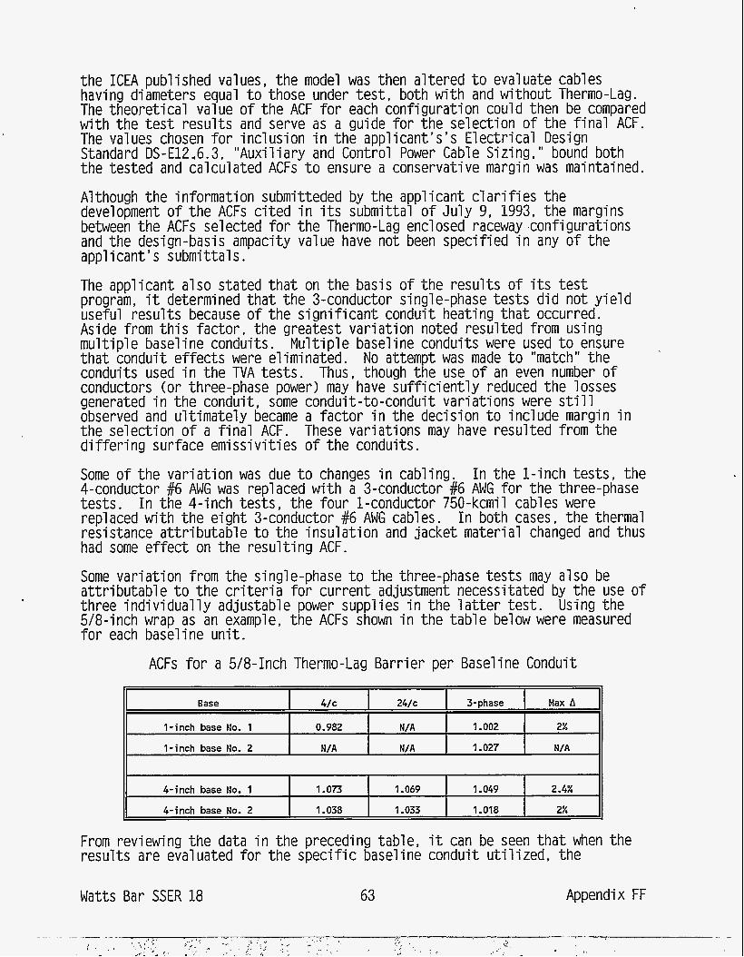
the ICEA published values, the model was then al tered t o evaluate cables having diameters equal t o those under t e s t , both w i th and without Thermo-Lag. The theoret ical value o f the ACF f o r each configuration could then be compared w i th the t e s t resul ts and serve as a guide f o r the selection o f the f i n a l ACF. The values chosen f o r inclusion i n the app l ican t ' s3 E lec t r i ca l Design Standard DS-E12,6.3, "Auxi l iary and Control Power Cable Sizing,'' bound both the tested and calculated ACFs t o ensure a conservative margin was maintained.
Although the information submitteded by the applicant c l a r i f i e s the development o f the ACFs c i t ed i n i t s submittal o f Ju ly 9, 1993, the margins between the ACFs selected f o r the Thermo-Lag enclosed raceway configurations and the design-basis ampacity value have not been speci f ied i n any o f t he applicant 's submittals.
The applicant also stated t h a t on the basis o f the resul ts o f i t s t e s t program, it determined tha t the 3-conductor sing1 e-phase tes ts d id not y i e l d useful resul ts because o f the s ign i f i can t conduit heating t h a t occurred. Aside from t h i s factor , the greatest var ia t ion noted resulted from using mu1 ti p l e basel i ne conduits . Mu1 ti p l e basel i ne conduits were used t o ensure tha t conduit e f fects were eliminated. No attempt was made t o "match" the conduits used i n the TVA tes ts . Thus, though the use o f an even number o f conductors (or three-phase power) may have s u f f i c i e n t l y reduced the losses generated i n the conduit, some conduit-to-conduit var iat ions were s t i l l observed and u l t imate ly became a fac to r i n the decision t o include margin i n the selection o f a f i n a l ACF. These variat ions may have resulted from the d i f f e r i n g surface emissiv i t ies o f the conduits.
Some o f the var ia t ion was due t o changes i n cabling. I n the 1-inch tests , the 4-conductor #6 AWG was replaced w i th a 3-conductor #6 AWG f o r the three-phase tests . I n the 4-inch tests , the four 1-conductor 750-kcmil cables were replaced w i th the e ight 3-conductor #6 AWG cables. I n both cases, t he thermal resistance attri butabl e t o the insu la t ion and jacket materi a1 changed and thus had some e f fec t on the resul t ing ACF.
Some var ia t ion from the single-phase t o the three-phase tests may also be a t t r ibu tab le t o the c r i t e r i a f o r current adjustment necessitated by t h e use o f three ind iv idua l l y adjustable power supplies i n the l a t t e r t es t . Using the 5/8-inch wrap as an example, t he ACFs shown i n the tab le below were measured f o r each baseline un i t .
ACFs for a 5/8-Inch Thermo-Lag Barrier per Baseline Conduit
Base 4/c 24/c 3-phase Max A
I-inch base No. 1 0.982 N/A 1.002 2%
I-inch base No. 2 N/A N/A 1.027 N/A
4-inch base No. 1 1.073 1.069 1 -049 2.4%
4-inch base No. 2 I -038 1 -033 1 .oia 2%
From reviewing the data i n the preceding table, it can be seen t h a t when the resul ts are evaluated f o r the spec i f i c baseline conduit u t i l i zed , the
Wat ts Ba r SSER 18 63 Appendix FF
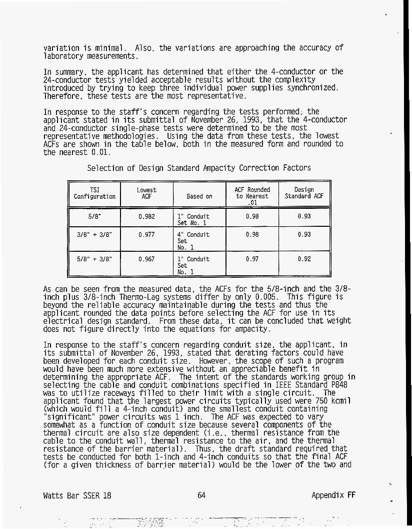
variation i s minimal. Also, the variations are approaching the accuracy of 1 aboratory measurements.
TSI Configuration
5/81'
3/a" .+ 3/a"
w a " + 3/a"
In summary, the applicant has determined t h a t either the 4-conductor or the 24-conductor tests yielded acceptable results w i t h o u t the complexity introduced by trying t o keep three indiv idua l power supplies synchronized. Therefore, these tests are the most representative. In response t o the staff 's concern regarding the tests performed; the applicant stated i n i t s submittal of November 26, 1993, t h a t the 4-conductor and 24-conductor single-phase tests were determined t o be the most representative methodol ogi es . Using the d a t a from these tests, the 1 owest ACFs are shown i n the table below, both i n the measured form and rounded t o the nearest 0.01.
Lowest ACF Rounded Design ACF Based on t o Nearest Standard ACF
.Ol
0.982 1" Conduit 0.98 0.93
0.977 4" Conduit 0.98 0.93
Set No. 1
Set No. 1
Set No. 1
0.967 1" Conduit 0.97 0.92
As can be seen from the measured d a t a , the ACFs for the 5/8-inch and the 318- inch plus 3/8-inch Thermo-Lag systems differ by only 0.005. This figure i s beyond the re1 i ab1 e accuracy m a i n t a i nab1 e during the tests and thus the applicant rounded the da ta points before selecting the ACF for use i n i t s electrical design standard. From these d a t a , i t can be concluded t h a t weight does not figure directly in to the equations for ampacity. In response t o the staff 's concern regarding conduit size, the applicant, i n i t s submittal of November 26, 1993, stated t h a t derating factors could have been developed for each conduit size. However, the scope of such a program would have been much more extensive w i t h o u t an appreciable benefit i n determining the appropriate ACF. The intent of the standards working group selecting the cable and conduit combinations specified i n IEEE Standard P848 was t o utilize raceways filled t o their limit w i t h a single circuit. The applicant found t h a t the largest power circuits typically used were 750 kcmi (which would f i l l a 4-inch conduit) and the smallest conduit containing "significant" power circuits was 1 inch. The ACF was expected t o vary somewhat as a function of conduit size because several components of the thermal circuit are also size dependent (i . e . , thermal resistance from the cable t o the conduit w a l l , thermal resistance t o the a i r , and the thermal resistance of the barrier material). Thus, the draft standard required t h a t tests be conducted for both 1-inch and 4-inch conduits so t h a t the f i n a l ACF
n
(for a given thickness of barrier material 1 would be the lower of the two and
Watts Bar SSER 18 64 Appendix FF
thus would envelope the range. Addit ional variances observed by the applicant may have been a funct ion o f the t e s t configurations.
Although the tes t i ng o f 3/4-inch and 5-inch conduits i s not required by the d r a f t IEEE standard, informal analysis by the applicant o f the wrapped 3/4- inch conduit indicates tha t it would be able t o carry more current than i n the baseline condit ion. This i s believed t o be a f ac t because the appl icat ion o f Thermo-Lag resul ts i n a s ign i f i can t increase i n the heat d iss ipat ing surface area, as previously discussed. Informal analysis o f three 1-conductor 750- kcmil cables i n a 5-inch conduit indicates t h a t although the r e l a t i v e increase i n surface i s not great, the ACF i s expected t o vary by no more than 1 percent.
The f i n a l ACFs chosen f o r use i n the applicant 's design standards include margin, pa r t l y t o account f o r the d i f f e r i n g configurations, variances resu l t ing from manufacturing, and maintenance o f conservatism i n the overa l l design . Although the s t a f f would agree t h a t nominal differences i n conduit sizes should not resu l t i n the need f o r s ign i f i can t margin, the applicant has not quant i f ied the margin between the design ampacity l i m i t s and the ampacity derating value on the basis o f t e s t resul ts. Although the applicant adequately addressed t h i s concern, the s t a f f w i l l reexamine t h i s issue upon completion o f i t s ampacity t e s t program.
I n response t o the s t a f f ' s concern regarding the use o f the a i r drop ampacity derating value, the applicant stated i n i t s November 26, 1993, submittal t h a t cable s iz ing (wi th respect t o ampacity considerations) i s a funct ion o f the load current, the load type, the raceway type, and the environment along i t s route. Because the raceway type and environment may change along the route o f a cable, a series o f ACFs of ten ex is ts , each applicable t o a s ing le raceway configuration and environment. Thus, ACFs are determined f o r each segment and a corresponding set o f values f o r the required ampacity o f the cable under evaluation i s calculated. This set i s compared t o the current t h a t a cable can carry according t o in ternal or industry standards f o r each raceway type f o r the cable being evaluated. As expected, cable s iz ing i s d ic ta ted by the most l i m i t i n g segment and ambient conditions along i t s en t i re route.
I n i t s cable ampacity program, the applicant evaluates cables i n each raceway segment and applies the necessary correct ion factors. I n the past, no ampacity evaluation was required f o r power cable air drops because the ampacity i n f ree a i r f a r exceeds t h a t i n a tray or i n a conduit. Given the application o f Appendix R wrap, the applicant w i l l evaluate air drops containing power c i r c u i t s t ha t are wrapped i n excess o f 6 fee t .
I n response t o the s t a f f ' s concern regarding plant configuration controls , the applicant, i n i t s submittal o f November 26, 1993, stated t h a t cable ampacity analysis i s based on various standard ACFs, which are conservatively chosen t o bound actual conditions o f p lant environment, load type, raceway type, and other a t t r ibutes. When a cable displays marginally i n s u f f i c i e n t ampacity based on the standard ACFs, it i s economically prudent t o reevaluate the cable ampacity based on ACFs more closely matching the actual conditions o f the indiv idual cable. This standard pract ice was applied i n the ampacity reevaluation t h a t considered the Thermo-Lag f i r e wrap derating factors f o r cable t rays. The fol lowing adjustments were u t i l i zed : (1) the actual motor
Watts Bar SSER 18 65 Appendix FF
nameplate load current, ( 2 ) t he load factor f o r motor-operated valves, and (3 ) t he percentage o f cable f i l l i n a cable tray.
The ACF values used for ampacity analysis must be documented i n the ampacity calculat ion. Proposed changes t o e i ther the cable o r the load procedurally require review and revis ion o f the ampacity calculat ion. The cable tray fi l l factor i s control led through the computerized cable rout ing system (CCRS). The maximum percentage of fill f o r acceptable cable ampacity i s established and becomes the tray f i l l l i m i t according t o the CCRS f o r t he involved tray segments. Additional cables could only be added up t o the tray l i m i t .
I n response t o the s t a f f ’ s concern regarding nonstandard configurations, the applicant stated i n i t s submittal o f December 23, 1994, t h a t the ACFs t h a t w i l l be used are based upon t h e extensive t e s t programs conducted by both TUE and the applicant a t Omega Point Laboratories (OPL) i n San Antonio, Texas, and by the applicant a t i t s own Central Laboratories Services Department (CLSD) f a c i l i t i e s i n Chattanooga, Tennessee. The ACFs used by the applicant f o r ind iv idua l l y wrapped open-top ladder t rays and wrapped air drops are based on the resul ts o f the TUE-sponsored tests . The ACFs used by the applicant f o r ind iv idua l l y wrapped conduits are based on the resul ts o f the CLSD tes ts .
The resul ts o f the TUE tray tes ts are also being used t o represent the common enclosure o f trays t h a t are hor izonta l ly adjacent (i .e., run side by side). This arrangement i s consistent w i th the Stople model on which tray ampacities (given i n ICEA publ icat ions) are derived i n which the model considers heat being dissipated from the top and bottom surfaces only (and not’ from the sides). The TUE tes ts t h a t were performed on ladder-type trays w i l l also be used t o represent solid-bottom t rays. This appl icat ion i s conservative i n t h a t t rue solid-bottom trays do not have an air gap between the cables and the Thermo-Lag bar r ie r because o f t he presence of t he tray rungs.
The TVA-sponsored tes ts a t OPL address the enclosure o f ladder-type trays over which a sheet steel cover has been applied before the appl icat ion o f any bar r ie r material. Those tes ts also include a ver t i ca l stack o f t rays w i th in a common Thermo-Lag encl osure.
The f i n a l determination o f t he appropriateness o f the f i n a l ampacity derating factors f o r the configurations expected t o be i ns ta l l ed a t Watts B a r w i l l be made upon completion o f p lan t i n s t a l l a t i o n o f t he Thermo-Lag f i r e barr iers and the ampacity derating tes t ing program.
The applicant has selected the fol lowing cable ampacity derating factors f o r Thermo-Lag-enclosed e lec t r i ca l raceways a t Watts Bar :
Wat t s Ba r SSER 18 66 Appendix FF
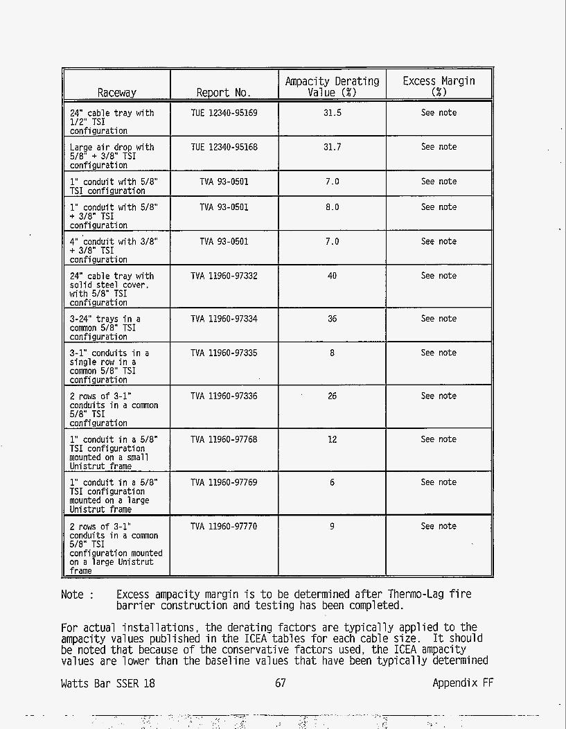
Ampaci t y Derating Excess Margin Raceway Report No. Value (%I ( X I
24" cable tray wi th TUE 12340-95169 31.5 See note 1/2" TSI configuration
See note 31.7 Large a i r drop wi th TUE 12340-95168 5/8" + 3/8" TSI configuration
1" conduit w i th 5/8" TVA 93-0501 7.0 See note TSI configuration
TVA 93-0501 See note 8.0 1" conduit w i th 5/8" + 3/8" TSI configuration
7.0 4" 'conduit w i th 3/8" TVA 93-0501 See note + 3/8" TSI configuration
24" cable tray wi th TVA 11960-97332 40 See note s o l i d steel cover, w i th 5/8" TSI configuration 3-24" trays i n a TVA 11960-97334 36 See note common 5/8" TSI configuration 3-1" conduits i n a TVA 11960-97335 8 See note s ing le row i n a common 5/8" TSI configuration 2 rows o f 3-1" TVA 11960-97336 26 See note conduits i n a comon 5/8" TSI configuration
1" conduit i n a 5/8" TVA 11960-97768 12 See note TSI configuration mounted on a small Uni s t r u t frame 1" conduit i n a 5/8" TVA 11960-97769 6 See note TSI configuration mounted on a large Uni s t r u t frame
2 rows o f 3-1" TVA 11960-97770 9 See note conduits i n a common 5/8" TSI configuration mounted on a large Unistrut f rame
Note : Excess ampacity margin i s t o be determined a f te r Therrno-Lag f i r e bar r ie r construction and tes t i ng has been completed.
For actual i ns ta l l a t i ons , the derating factors are t y p i c a l l y applied t o the ampacity values published i n the ICEA tables f o r each cable size. be noted t h a t because o f the conservative factors used, the ICEA ampacity values are lower than the baseline values t h a t have been t y p i c a l l y determined
Watts Bar SSER 18 67 Appendix FF
It should
by the ampacity derating tests . Cables are sized on the basis o f the f u l l load current mu l t ip l ied by a fac to r of 1.25 i n order t o account f o r the voltage and the service factor requirements o f the load. Upgrading o f the cable s ize i s another var iable t h a t may be required because o f voltage drop consideration f o r long c i r c u i t lengths. Because most safety-related loads are operated in te rmi t ten t ly , t y p i c a l l y once a month during survei l lance tes t ing , t he s t a f f has judged it unl ike ly t h a t cable-related fa i l u res could be induced as a resu l t o f incorrect ampacity derating factors over the in te r im period. The s t a f f believes t h a t the ampacity derating concern i s an aging issue t h a t i s t o be resolved over the long term. Therefore, the s t a f f concludes t h a t the use o f in te r im ampacity derating factors i s acceptable.
On the basis o f the completion o f the ampacity derating tes t i ng program and the resolut ion o f the following three issues:
(1) the applicant’s completion of the Phase I11 ampacity derating tes ts f o r the Watts Bar Thermo-Lag 770-1 f i r e barr iers systems and i t s submittal confirming t h a t the ex is t ing ampacity design margins are adequate and s u f f i c i e n t f o r each o f these i n s t a l l e d f i r e ba r r i e r configuration
( 2 ) the applicant’s confirmation t h a t the ex is t ing ampacity design margins (Phase I and I1 ampacity derating tes ts ) are adequate and s u f f i c i e n t f o r each o f t he Thermo-Lag 330-1 and 330-660 f i r e barr iers t o be i n s t a l l e d a t Watts B a r
(3) the NRC s t a f f ’ s confirmation t h a t the t e s t resul ts using IEEE Standard P848 adequately bound the nominally d i f f e ren t conduit sizes which are protected by Thermo-Lag f i r e bar r ie r materials
The s t a f f f inds the use o f the ampacity derating factors acceptable. Further, the s t a f f concludes t h a t no s ign i f i can t safety hazards e x i s t due t o the use of these in te r im ampacity derating factors on cables enclosed by Thermo-Lag f i r e bar r ie r materials.
3.7.11 Chemical Composition of Elec t r i ca l Raceway F i r e Barr ier Materials
I n order t o conform t o the NRC’s f i r e protect ion guidelines and regulations, the applricant w i l l perform the chemical analysis tes t i ng on i t s Thermo-Lag 330-1 and 770-1 f i r e bar r ie r materials. The t e s t methods proposed are in f ra red ( I R ) spectroscopy and thermogravimetric analysis (TGV) . The resul ts o f these t e s t s w i l l be used t o evaluate the chemical composition o f the Thermo-Lag f i r e bar r ie r materials used t o construct t he f i r e barr iers i ns ta l l ed a t Wat t s Bar and those which were used t o construct the f i r e endurance and ampacity derating t e s t specimens.
The I R t e s t method w i l l be used t o i d e n t i f y organic and inorganic materials used t o formulate the f i r e bar r ie r materials. Each compound which i s subjected t o t h i s type o f t es t i ng can be characterized by i t s unique absorption spectrum and can be p lo t ted as a percentage o f transmittance or ref lectance as a funct ion of frequency. These data can be used t o evaluate the var ia t ion i n chemical composition of f i r e bar r ie r materials w i th in a t yp ica l l o t and from l o t t o l o t . The TGA i s an empirical technique i n which a substance i s heated under contro l led conditions and the mass o f the material i s recorded as a function o f t ime or temperature. The mass loss over a
Wat t s Bar SSER 18 68 Appendix FF
spec i f i c temperature and i n a control led atmosphere over a speci f ied t ime period provides composition analysis o f the f i r e barr ier material.
The applicant c o m i t t e d t o perform these tes ts on a sample f rom each . production l o t o f Thermo-Lag used t o construct the ERFBS a t Watts Bar . The
sample s ize w i l l be selected i n accordance w i th the general inspection leve ls provided by M i 1 i tary Standard MIL-STD-l05E, "Sampl i ng Procedures and Tab1 es f o r Inspecti on by At t r ibutes . I'
The s t a f f f inds t h a t t he applicant 's proposed means t o chemically analyze the composition o f the Thermo-Lag f i r e bar r ie r materials used t o construct the i n - p lan t ERFBS and the f i r e endurance and ampacity derating t e s t specimens w i l l provide reasonable assurance t h a t these materials are chemically the same: therefore, the method i s acceptabl e.
3.7.12 Seismic and Material Properties o f E lec t r i ca l Raceway F i r e Barr ier Sys tems
Recognizing a need t o address the seismic adequacy concern re la ted t o the Thermo-Lag f i r e bar r ie r panels and conduit wraps, the applicant f o r Watts B a r had performed shake-tab1 e tes t i ng o f some typ ica l Thermo-Lag 330-1 protected cable tray and conduit configurations, and had tested Thermo-Lag 330-1 and 770-1 specimens t o determine the mechanical properties o f the material. On the basis o f the tes ts , the applicant prepared (1) the s t ructura l evaluation c r i t e r i a and (2) a general speci f icat ion f o r i ns ta l l a t i on , modif icat ion, and maintenance o f e lec t r i ca l raceway f i r e bar r ie r systems ins ta l l ed a t Watts Bar .
This evaluation addresses the seismic adequacy o f Thermo-Lag 330-1 panels and preformed conduit wraps and Thermo-Lag 770-1 m a t . It also addresses the concern regarding appropriate consideration o f Thermo-Lag material weight i n the seismic adequacy calculat ions o f the raceway supports and t h e i r anchorages.
Wyle Laboratories performed two series o f shake-table tests f o r t he applicant: Series 1 consisted o f two specimens on the shake table: (1) Thermo-Lag 330-1 panels i n s t a l l e d on three stacked cable trays and (2) Thermo-Lag 330-1 panels on a s ing le cable tray w i th an air drop. Series 2 consisted o f (1) Thermo-Lag 330-1 panels i ns ta l l ed on seven-ganged conduits and (2) Thermo-Lag 330-1 preformed conduit wraps around a sing1 e conduit . Thermo-Lag was i n s t a l 1 ed on a1 1 the configurations i n accordance w i th the applicant 's standard i ns ta l l a t i o n procedure (TVA General Engineering Specif icat ion 6-98, " Ins ta l la t ion , Modif icat ion, and Maintenance o f E lect r ica l Raceway F i r e Barr ier Systems," Revision 2, Apr i l 1995). The supports o f t h e specimens were welded t o the t e s t tab le.
Control accelerometers were mounted on the t e s t tab le near the base o f t he specimens. Six uniaxial accelerometers (two t r i a x i a l locations) were i ns ta l l ed on a l l four configurations. I n addit ion, two accelerometers were located on the ver t i ca l support o f the s ing le cable-tray configuration. Magnetic tape recorders provided records o f each accelerometer ' s response.
The specimens were subjected t o 30-second duration t r i a x i a l multifrequency random motions simulating the required response spectra (RRSs) corresponding t o t w o operating basis earthquakes (OBEs), and one safe-shutdown earthquake
69 Appendix FF Watts Bar SSER 18
(SSE). The RRSs were generated considering the highest of the amplified floor response spectra i n any of the safety-related structures. An environmental enclosure was installed on the test table t o m a i n t a i n the temperature of the specimens between 120 O F (49 " C ) and 140 O F (60 "C) during the tests. The tests indicated t h a t there was no appreciable damage t o Thermo-Lag 330-1 panels or preformed conduit wraps. A piece of Thermo-Lag material, less t h a n 1 cubic inch, fell from the interior of the ganged conduit specimen after the second OBE tes t . These tests demonstrated t h a t when the Thermo-Lag panels are completely enclosed by an outer layer of stress-skin, which is kept i n position by addi t iona l tie-wires, the panels are not likely t o get dislodged i n pieces large enough t o be of safety consequence during the postulated seismic events. Preformed sections of the single conduit were not enclosed by the exterior stress skin. However, they survived the seismic tests w i t h o u t damage. Though the tested configurations represented typical onsi t e instal 1 a t i ons , the applicant recognized the potential departures t h a t would be inherent i n the as-built conditions. To analyze the conditions other t h a n the tested configurations, the appl icant performed mechanical properties tests (tests for tensile strength, flexural strength, shear strength, etc. for Thermo-Lag 330-1. The applicant used the lower bound of these properties w i t h a factor of safety of about 1.2 for analyzing various raceway configurations. The staff considers this safety factor t o be relatively low. However, considering. the conservati sms used i n determi n i ng weights and sei smi c amp1 i f i cati ons , and observations of no or minor damage during the seismic tests, the staff finds the evaluation procedure acceptable. After reviewing the appropriateness of the seismic tests and the applicant's "general design criteria" related t o the evaluation of Thermo-Lag f i re barrier systems, the staff finds the appl i cant's approach for resolving the concern related t o the fire barrier t o be acceptable. A review of the applicant's "General Engineering Specification 6-98'' related t o the installation and maintenance of the f i re barrier systems a t Watts Bar provides an assurance t h a t the Thermo-Lag f i re barrier systems will be installed and maintained consistent w i t h the evaluation procedures. The applicant plans t o install Thermo-Lag 770-1 moldable conduit wraps covering the existing Thermo-Lag 330-1 i n three specific areas i n the auxiliary bui ld ing (refer t o Table 1 of TVA's design report on "Thermo-Lag Structural E v a l u a t i o n , " Revision 2, July 1995), where 3-hour f i re rating is required. The Thermo-Lag 770-1 f i re barrier material i s moldable and does not have flexural strength. The 3/8-inch layers of the Thermo-Lag 770-1 f i re barrier material are directly installed on the Thermo-Lag 330-1 conduit pre- formed sections and kept t i g h t l y attached t o them by stainless steel tie-wires spaced every 6 inches. Thus, the mechanical properties essential for ensuring the retention of Thermo-Lag 770-1 material i n place during a seismic event are the bonding capacity of this material t o the Thermo-Lag 330-1 f i re barrier material and the punching strength t o ensure the retention of the tie-wires under the postul ated sei smic 1 oadings , The 1 ower bound punching strength and bond strength (between the Thermo-Lag 330-1 and 770-1 f i re barrier materials) values were set as two standard deviations lower t h a n the mean strength values obtained from the tests. An a d d i t i o n a l factor of safety of 1 .2 was used on the established lower bound values for arriving a t the acceptable values.
4
Watts Bar SSER 18 70 Appendix FF
This process gave the acceptable punching strength as 12.2 l b f per inch, and bond strength as 4.4 ps i .
The applicant analyzed the conduit sizes varying between 3/4 inch and 5 inches i n diameter enclosed w i th four layers (two layers o f 5/8-inch-thick Thermo-Lag 330-1 and two layers o f 3/8-inch-thick Thermo-Lag 770-1) o f Thermo-Lag, spanning 12 f e e t o f unsupported length, subjected t o peak spectral acceleration (horizontal and ve r t i ca l ) a t the highest f l o o r elevation i n the aux i l ia ry bu i ld ing. The seismic accelerations were vec to r ia l l y combined and s t a t i c a l l y applied t o the t o t a l dead loads o f the combined assemblies. The maximum punching and bond values corresponding t o the above allowable value determined from these analyses are 1.33 l b f per inch and 0.66 ps i . Having reviewed the applicant 's analyses, the s t a f f f inds t h a t the added Thermo-Lag 770-1 f i r e ba r r i e r material w i l l re ta in i t s pos i t ion on the ex is t ing Thermo- Lag 330-1 f i r e bar r ie r mater ia l , and w i l l not f a l l i n large enough pieces t o cause a safety hazard f o r the nearby safety-related components and equipment.
Singleton Laboratories performed the density tes ts on Thermo-Lag 330-1 material i n accordance w i th ASTM D-1188. The applicant supplied the t e s t specimens o f 3/8-inch, 5/8-inch, and 1%-inch panels and supplied preformed conduit wraps f rom the l o t s t o be i ns ta l l ed i n the p lan t and the l o t s t o be used i n various other tes t i ng programs (i .e., f i r e tes ts , seismic tes ts and ampacity tes ts ) . The density o f 58 panel specimens ranged from 56 t o 75 l b per cubic foot, w i th an average o f about 67 l b per cubic foot ; and t h a t o f the 68 preformed conduit wraps ranged f rom 68 t o 88 l b per cubic foo t , w i th an average o f about 78 l b per cubic foo t . I n the design evaluations o f Thermo- Lag 330-1 panel s and preformed wraps, raceway supports, and t h e i r anchorages, the appqicant has used (TVA Design Standard DS-C1.6.16, "Structural Evaluation o f E lect r ica l Raceway F i re Barr ier Systems," Revision 2 Apr i l 1995) density- values as 72 l b per cubic foo t f o r the panels, and 84 l b per cubic f o o t f o r the preformed conduit wraps. The s t a f f considers these density values adequate, provided (1) upperbound thicknesses are considered i n computing the weight o f Thermo-Lag and (2) the weight o f the trowel-grade Thermo-Lag material i s properly considered i n the evaluations o f raceway supports and anchorages. The examples provided i n Design Standard DS-(3.6.16, ind icate t h a t the applicant has properly considered the weights o f Thermo-Lag 330-1 material i n such evaluations. I n i t s design report "Thermo-Lag Structural Evaluation, It Revision 2, Ju ly 1995, the applicant has appropriately considered the weight o f Thermo-Lag 770-1 material i n computing the loads on the applicable conduit supports and t h e i r anchorages.
On the basis o f i t s review o f the seismic t e s t resul ts o f t yp ica l raceway configurations, the c r i t e r i a set up f o r the s t ructura l evaluation o f e lec t r i ca l raceway f i r e bar r ie r systems, and the speci f icat ion f o r i ns ta l l a t i on , modif icat ion, and maintenance o f the f i r e bar r ie r systems, the s t a f f concludes t h a t i f the Thermo-Lag 330-1 and 770-1 f i r e bar r ie r systems are evaluated and ins ta l l ed i n compliance wi th these c r i t e r i a and t h i s speci f icat ion, they w i l l be able t o withstand the postulated seismic events a t Watts Bar without s ign i f i can t damage t o the f i r e barr iers . The f i r e barr iers (i .e., panels and. conduit wraps) may crack and su f fe r minor damage, but w i l l not cause undue hazard t o the safety systems ( including the protected cables, cable t rays and conduits) i n the v i c i n i t y o f the i n s t a l l e d f i r e barr iers . The review a l s o indicated t h a t the applicant has properly considered the weight o f the f i r e barr iers i n ensuring the seismic adequacy o f the raceway supports and t h e i r anchorages.
Watts Bar SSER 18 ,71 Appendix FF
3.8 Smoke Control and Ventilation The applicant has evaluated a1 1 f i re areas containing safe-shutdown equipment and the p l a n t ' s capability t o remove products of combustion from areas of f i re origin. To support f i re brigade activities, the applicant intends t o use a combination of the normal ventilation exhaust system and portable fans t o remove smoke from specific rooms. The normal ventilation exhaust systems generally move smoke directly t o the outside. When the normal exhaust paths are interrupted, either because of the isolation of one room or a group of rooms t o contain the fire; or because of action of the f i re brigade, most of the smoke will be confined w i t h i n the rooms by the fire-rated barriers. Hot gases caused by combustion w i t h i n the rooms will be confined w i t h i n the fire-rated barriers or control led by automatic area suppression systems. When i t i s necessary t o remove products o f combustion from a room, the f i re brigade will use portable fans and ducting equipment t o remove cooled smoke from the fire-affected room and exhaust i t either t o the outside or t o other rooms. From these rooms, smoke will .be removed by the normal ventilation exhaust system or by natural venting t o the outside. Where smoke is moved t o other rooms, the normal ventilation rates or the natural vent openings i n these rooms are sufficient t o prevent smoke from stratifying or excessively concentrating i n the rooms. The smoke will be removed from these rooms directly t o the outside. When fixed ventilation equipment i s used for removal of smoke, a l l necessary equipment and cabling from the fire area are separated by l-l/Z-hour fire-rated barriers. Manual operations required t o achieve and m a i n t a i n safe shutdown will not be affected by the applicant's activities related t o smoke removal from p l a n t areas affected by fire. In a d d i t i o n , electrical equipment t h a t i s related t o safe shutdown will also be unaffected by smoke removal operations. The staff concludes t h a t the applicant's smoke removal concept conforms t o the guidelines of Section D.4 of Appendix A t o BTP (APCSB) 9.5-1 and i s , therefore, acceptable. 3.9 L i q h t i n q and Communications The applicant has committed t o provide fixed, self-contained l i g h t i n g consisting of fluorescent or sealed-beam units w i t h i nd iv idua l 8-hour minimum battery power supplies i n areas t h a t must be manned for safe shutdown and i n access and egress routes t o and from a l l f i re areas containing equipment required for safe shutdown. The illumination provided by the emergency l i g h t i n g shall be sufficient t o al low the operator safe access or egress t o those p l a n t areas where shutdown functions must be performed. In a d d i t i o n , the emergency l i g h t i n g i l l umina t ion level shall be sufficient t o enable a qualified operator t o perform the required manual action. This design concept complies w i t h the requirements of Section 1II.J and the guidelines contained i n Section D.5.a of Appendix A t o BTP (APCSB) 9.5-1 and i s , therefore, acceptabl e. The applicant has requested t o deviate from i t s emergency l i g h t i n g criteria inside the Reactor Bui ld ing , yard area, and the turbine bui ld ing . These deviations are addressed i n Section 6.7. "Deviation - Emergency Lighting." Watts Bar SSER 18 72 Appendix FF
The applicant has provided several means o f communications t o support safe- shutdown operations. These means include (1) telephones, (2) a code, a l a r m , and paging system, (3) sound-powered phones, and (4) two-way radios. The i n - p lant radio repeater system w i l l be the primary means o f communication f o r performing manual shutdown actions and f o r f i r e brigade f i r e - f i g h t i n g operations. This repeater system consists o f three very high frequency (VHF) radio repeaters, remote control un i ts , portable radios, and coaxial cable. These radios are pr imar i ly intended f o r use by operations and maintenance personnel, but one channel o f the in -p lan t radio system has been designated f o r use by the f i r e brigade during f i r e s or other emergencies. The VHF radio equipment i s located on the turb ine deck where it w i l l be unaffected by aux i l ia ry bu i ld ing f i r e s . I n addi t ion t o antennas on the roo f o f the turb ine bui ld ing, antennas are located i n the control and tu rb ine bui ldings, and two widely separated trunk l i nes feed the radio signal t o redundant antenna systems located throughout the aux i l i a ry bui ld ing.
The s t a f f f inds t h a t the applicant 's proposed means o f communications d id not take any exceptions t o Positions D.5.c and d of Appendix A t o BTP (APCSB) 9.5- 1 and, therefore, are acceptable.
4.0 FIRE PROTECTION SYSTEMS
4.1 Water Supply and D is t r ibu t ion
The high-pressure f i r e protect ion water system a t Watts Bar i s common t o both un i ts and consists o f four American Society o f Mechanical Engineers (ASME) Section I11 seismic Category I high-pressure ver t i ca l turb ine motor-driven pumps, each rated a t 1590 gpm a t 300 foot-head (130 psig). Each o f these pumps can supply 50 percent o f the required f i r e water f low t o safety-related p lant areas, t o safe-shutdown-related areas, and t o those areas t h a t are e i ther important t o p lan t safety or where a f i r e could challenge reactor safety systems. Pressure control i s provided by one pressure control valve downstream o f the four pumps. The pumps are located i n the seismic Category I intake pumping s ta t ion w i th a 3-hour f i r e - ra ted f i r e ba r r i e r provided t o separate two f i r e pumps from the other two. A single, automatically motor- driven, sel f -c leaning s t ra iner i s provided f o r each power t r a i n . Each s t ra iner t r a i n f i l t e r s the discharge f low o f the two t ra in-or iented f i r e pumps. Each s t ra iner i s capable o f f i l t e r i n g 100 percent o f the f low o f the two f i r e pumps.
Each f i r e pump i s powered from a separate 480-V shutdown board. I n the event o f loss o f o f f s i t e power, each 480-V shutdown board i s automatically connected t o a separate emergency diesel generator. Supervised a1 a r m c i r c u i t s , ind icat ing f i r e pump motor running condit ion and loss o f l i n e power on the l i n e side o f the switchgear, are provided i n the main control room f o r each Pump - A 100-percent capacity, UL-l isted, diesel f i r e pump i s remotely located i n the yard adjacent t o the Uni t 1 cooling tower. The diesel f i r e pump i s capable o f developing a f low o f 2500 gpm (100-percent capacity) a t 125 ps ig (404 foo t - head) and 3750 gpm (150-percent capacity) a t 81 psig (187 foot-head). The f i r e pump i n s t a l l a t i o n and i t s associated cont ro l le r are i ns ta l l ed i n accordance w i th NFPA-20, " Ins ta l 1 at ion o f F i r e Pumps. " This f i r e pump automatically s t a r t s when the pressure i n the underground f i r e water d i s t r i bu t i on p ip ing drops below 50 psig. Watts Bar SSER 18 73 Appendix FF
The normal starting logic for the electric pumps i s as follows. The pumps are i n the automatic mode w i t h the main control room hand-switch for one Train A and one Train B pump i n the auto position and the hand-switch for the other pumps i n the a u t o standby position. Upon receiving an au to start signal, the Train A pump will s tar t , followed by the Train B pump after a 10-second delay. I f , a t any time 20 seconds after the receipt of an auto start signal, the pressure cannot be maintained above 105 psig, the Train A pump i n a u t o standby will s tar t , followed by the Train B pump after a 10-second delay. Water supply for the electric f i re pumps i s taken from the Tennessee River and i s considered unlimited for f i re protection purposes. The diesel f i re pump takes i t s water from the U n i t 1 cooling tower basin and is considered t o be an unlimited water supply for f i re protection purposes (i . e . , sufficient capacity for the diesel f i re pump t o pump a t 150-percent capacity for 2 hours). An underground fi re main 1 oop serves both units . Sectional i sol a t i on va l ves allow maintenance t o be performed on portions of the loop for one u n i t w i t h o u t affecting the fire-fighting capability of either u n i t . The sectional i sol a t ion valves i n the underground 1 oop are mechani cal l y 1 ocked i n position, and surveillance i s placed upon supervision of valve position t o ensure proper system alignment. The yard f i re main loop i s cross-tied between units. The high-pressure f i re protection system i s shared w i t h the raw service water system. Automatic isolation valves isolate selected large raw cooling water loads from the high-pressure f i re protection system when any of the f i re pumps start . All post-indicator-type valves (PIVs) are either sealed or locked open w i t h a key-operated "breakaway" type lock. Curb box valves are not locked open. However, these valves are tamper resistant because they cannot be operated w i t h o u t a special "key" tool . This tool i s not generally available, and , therefore, the staff has reasonable assurance t h a t these valves will remain open. The applicant's f i re water supply system - i s designed t o provide 100-percent fire-fighting capacity either w i t h one electric pump and the diesel pump inactive or w i t h the hydraulically least demanding portion of any loop main out of service. The fire pumps can supply water a t design flow t o the largest sprinkler or water spray system w i t h design flow t o non-isolated raw service water loads and can supply 500 gpm for hose streams. Automatic sprinkler systems and hose station standpipe systems are separately connected t o the yard main or t o headers w i t h i n buildings and are fed from each end of the bui ld ing; therefore, a single failure cannot impair the sprinkler systems and the hose station a t the same time. As result of the concern w i t h microbiologically induced corrosion (MIC), the appl i cant has adopted a permanent monitoring program for determi n i ng the performance of the standpipe and suppression systems. This permanent test capability has been installed for the hydraulically most remote areas of Watts Bar. The applicant has committed t o perform this periodic testing of the high-pressure f i re protection distribution system once a year for the f i r s t 3 years of p l a n t operation and once every 3 years thereafter. The applicant will use the calculated design-basis pressure and flow requirements as the basis t o monitor system performance. The applicant's design standard (DS-M3.5.1, "Pressure Drop Calculation for Raw Water Pip ing and Fittings") requires an 0.8-inch reduction of the actual pipe inside diameter and a Hazen- Watts Bar SSER 18 74 Appendix FF
W i l l i a m s C factor o f 55 f o r the sections o f p ip ing t h a t are normally wetted. The purpose o f these p ip ing res t r i c t ions and the C factor of 55 i s t o predic t a 40-year service l i f e o f the pipe. The data col lected f rom these tes ts w i l l be compared t o the calculated values and trended t o predic t system degradation.
The applicant h is committed t o t r e a t a l l raw water systems a t Wat ts B a r w i th oxidiz ing biocides for M I C and a non-oxidizing biocide f o r clams and M I C . I n addit ion, the applicant i n jec ts addit ional treatments i n t o t h e system t o provide the chemistry t o clean up corrosion products and i n h i b i t corrosion o f carbon steel and copperkopper a l loy materials. This chemical. i n jec t i on i s coordinated wi th per iodic system flushes i n order t o bet ter d i s t r i bu te these biocides i n normally stagnant portions o f the system. I n addit ion, using ul t rasonic techniques, the applicant w i l l semiannually monitor pipe w a l l thickness a t several locations o f the high-pressure f i r e protect ion pipe. This tes t ing w i l l maintain confidence i n the s t ructura l i n t e g r i t y o f the high- pressure f i r e protect ion piping.
I n addit ion, the applicant performed a code compliance review and i d e n t i f i e d several areas i n which the outside protect ion deviated f rom NFPA-24 (1973). "Outside Protection. 'I Some o f the more important code devi a t i ons i d e n t i f i e d were (1) check valves approved for f i r e protect ion service are generally used except f o r the check valves t h a t i so la te the raw water tank (NFPA-24, Section 3102); (2) post- indicator valves are not a l l 36 inches above the ground level (NFPA-24, Section 3303); (3) breakaway locks o r the red seals are used on fi re-related valves t o administrat ively control t h e i r posi t ions (NFPA-24, Section 3601); and (4) select ion, coating and l i n i n g , and f i t t i n g s o f j o i n t s f o r p ip ing i s according t o the applicant 's design, construction, and modif icat ion procedures. These procedures provide guidance t h a t conforms t o or exceeds the code (NFPA-24. Secti'ons 81 through 85).
The s t a f f has reviewed the applicant 's requested deviations from NFPA-24 and has determined tha t they w i l l not a f fec t the performance o f t h e f i r e water supply system and, therefore, they are acceptable.
On the basis o f i t s review, the s t a f f concludes t h a t the f i r e water supply system conforms t o the guidelines o f Section C.2 o f Appendix A t o BTP APCSB 9.5-1 and, therefore, i s acceptable.
4.2 Active F i re Control and Suooression Features
4.2.1 Automatic F i r e Suppression Systems
4.2.1.1 Sprinklers and Fixed Spray Systems With Closed Heads
Fixed water spray systems and spr ink ler systems are designed i n accordance w i th the applicable requirements o f National F i re Protection Association Standard No. 13-1975 (NFPA-131, "Standard f o r I ns ta l l a t i on o f Sprinkler Systems, I' and NFPA-15 (19731, "Standard f o r Water Spray Fixed System. I n addi ti on, the appl i cant performed a code compl i ance rev i ew and i d e n t i f i e d several areas i n which the spr ink ler and f i xed spray systems deviated from the code. Some of the more important NFPA-13 code deviations i d e n t i f i e d were (1) no f i r e department pumper connections f o r the spr ink ler systems (NFPA-13, Section 2-71. (2) use o f water curtains t o protect s t a i r , elevator shaft , and equipment hatch openings where they could not be adequately sealed through the
Watts B a r SSER 18 75 Appendix FF
use of a fire-rated door, damper, etc. (NFPA-13. Section 4-4.8). (3) sprinklers not provided below the double duct near cooler 1 B - B and below open grating above the high-pressure f i re pump f low control valve on elevation 692 f t 0 i n . i n the U n i t 1 penetration room. This grating i s approximately 5-feet wide by 15- feet long and i s 15 feet above the room floor. Two sprinklers are instal led approximately 3 feet above the grating. P1 a n t procedures prohibit the storage of material on these grated walkways, so the gratings would be free of foreign obstructions. Due t o the size of the grating (4 i n . by 1 i n . ) , flow from the sprinklers is not expected t o be restricted by the grating. Therefore, the current sprinkler configuration i n the U n i t 1 penetration room i s acceptable (NFPA-13, Sections 4-4.11 and 4-4.13). With respect t o NFPA-15, the applicant d i d no t take any exceptions t o the code for the water spray systems protecting outdoor transformers, the hydrogen trailer, turbine hydrogen seal o i l u n i t , and the turbine lube o i l reservoir. The applicant used the guidance of NFPA-13 t o design the directional fusible nozzle water spray systems used t o protect certain charcoal f i l ters and the reactor cool a n t pumps. The staff has reviewed the applicant's requested deviations from NFPA-13 and 15 and has determined t h a t they will not affect the performance of these systems and, therefore, they are acceptable. The applicant has provided automatic preaction sprinklers i n areas i n which i t i s important t o prevent accidental discharge of water. Operation of the preaction sprinkler system i s initiated by a s igna l from the f i re detection system i n the area. Actuation can also be initiated manually by mechanical operation a t the deluge valve. In add i t ion , selected preaction systems a t Watts Bar have manual actuation stations placed a t strategic locations remote from the valve. These systems are provided w i t h air supervision if the p ip ing downstream of the system control valve supplies more t h a n 20 sprinkler heads. The applicant has provided automatic fixed water spray systems w i t h closed heads for heating, ventilation, and air conditioning (HVAC) charcoal f i l t e r units i n the auxiliary and control buildings, the reactor coolant pumps, the auxiliary boiler, the area of divisional interaction w i t h i n the containment annulus space, and the cable tray penetrations through the turbine buildingkontrol bu i ld ing w a l l . These systems are actuated i n a similar manner t o the preaction sprinkler systems used a t Watts Bar. In a d d i t i o n , automatic fixed water spray systems w i t h open directional spray heads are provided for the transformers i n the yard, the hydrogen trailer port, the main turbine o i l tanks, the turbine head ends, the seal o i l units, and main feedwater pump turbines 1 A and B and 2 A and B. Aqueous-film-forming foam systems are provided i n the add i t iona l generator bu i ld ing and the security backup power bui 1 d ing .
For both the preaction sprinkler and the fixed water spray systems, the only time water is discharged after system actuation i s when the heat from the f i re melts the fusible element of the sprinkler head. Valves i n the f i re protection system are not electrically supervised; however, a l l valves whose misalignment would prevent proper operation of the system will be mechanically locked i n their normal position. To ensure system al ignment , the applicant has imposed operating requirements on supervision of valve position. Watts Bar SSER 18 76
The following areas are equipped w i t h automatic preaction sprinkler systems: control bu i ld ing (elevation 755 f t 0 in . ) - mechanical equipment room - janitor's closet - corridor - kitchen - to i 1 e t - locker room - instrument calibration - chart storage - shift engineer's office - record storage v a u l t - PSO engineering shop -
control b u i l d i n g (elevation 692 f t 0 i n . 1
control room air cleanup and charcoal f i l ters
- mechanical equipment rooms - 250-V battery room 1 and 2 - 24-V and 48-V battery room - communications - corridor - secondary alarm station control bu i ld ing (elevation 729 f t 0 in. 1
- cable spreading room diesel generator bu i ld ing (elevation 742 f t 0 i n . )
- pipe gallery and corridor intake pumping station (elevation 710 f t 0 in . ) - electrical equipment room reactor bui 1 ding
- reactor coolant pumps - annul us area (division interactions ) turbine bui ld ing
- numerous areas of bui ld ing
auxiliary bu i ld ing (elevation 772 f t 0 i n . 1
- 480-V board rooms - 125-V v i t a l battery rooms - 480-V transformer rooms - mechanical equipment rooms - high-efficiency particulate air (HEPA) f i l t e r plenum rooms
Watts Bar SSER 18 77 Appendix FF
0
0
0
0
0
0
0
auxiliary bui ld ing (elevation 782 f t 0 i n . ) - - pressure heater transfer rooms
control rod drive equipment rooms
auxiliary bui ld ing (elevation 757 f t 0 i n . )
auxiliary control room 6.9k-V and 480-V shutdown board rooms 125-V v i t a l battery rooms personnel and equipment access reverse osmosis equipment room reactor bui 1 d i ng equi pment hatches reactor bui 1 ding access rooms emergency gas treatment rooms auxiliary control instrument rooms
auxiliary bui ld ing (elevation 737 f t 0 i n . )
common area hot instrument shop heating and vent ventilation and purge air GF fuel detector room auxiliary bu i ld ing gas treatment system fil ters
auxiliary bui ld ing (elevation 733 f t 0 in.) Val ve gal lery decontamination room
auxiliary bui ld ing (elevation 729 ft 0 in , . )
waste package areas fuel transfer valve room
auxiliary bu i ld ing (elevation 713 ft 0 i n . )
auxiliary bui ld ing common area pipe gal lery a i r 1 ock volume control t a n k rooms titration room sample rooms radiochemical 1 aboratory pipe gal lery counting room containment purge air exhaust f i l ters
auxiliary bu i ld ing (elevation 692 f t 0 i n . )
- auxiliary feedwater pump rooms - pipe gallery
Watts Bar SSER 18 78 Appendix FF
charging pump room safety i n jec t i on pump rooms cast decontamination co l lec t ion tank room spent resin tank room valve gal 1 ery waste evaporator package room auxi 1 i ary waste evaporator packaging corr idor chemical drain tank room
The s t a f f has reviewed the design c r i t e r i a and bases f o r the water suppression systems and concludes t h a t these systems conform t o the guide1 ines o f Appendix A t o BTP (APCSB) 9.5-1 and are, therefore, acceptable.
4.2.1.2 Gas Suppression System
A low-pressure t o t a l - f looding carbon dioxide (CO,) system i s provided f o r the f o l 1 owing areas :
emergency diesel generator rooms 1A-A, 2A-A, 1B-B, 2B-B turb ine lube o i l dispensing room computer room pa in t shop and storage room aux i l ia ry instrument rooms 480-V board room lube o i l storage room fue l o i l t ransfer room lube o i l pu r i f i ca t i on room
The CO, systems are designed and ins ta l l ed according t o NFPA-12, "Carbon Dioxide Extinguishment Systems . I ' I n addit ion, the applicant performed a code compliance review and i d e n t i f i e d several areas i n which the f i x e d suppression systems deviated from the code. Some o f the more important NFPA-12 code deviations i den t i f i ed were (1) the Class A supervised detection system does not have a secondary power source i f the 0-DPL-13-1 (main f i r e detection l og i c and control panel) power i s l o s t (NFPA-14, Sections 1423 and 1431) and (2) diesel generator bui 1 ding pressure re1 i e f val ves discharge t o the exter ior , but those f o r the power house and the r e l i e f valves f o r f i l l and equalizing l i nes do not. The power house main head vent and bleeder r e l i e f l i nes do discharge t o the exter ior . The s t a f f has reviewed these requested deviations from NFPA-12 and has determined t h a t they w i l l not a f fec t t h e performance o f the CO, systems and, therefore, they are acceptable.
The CO, system i s actuated by a signal f rom e i ther the f i r e detection system i n the area or a pushbutton stat ion. Once a CO system i s act ivated, it actuates area a la rms, the predischarge t imer, the discharge t imer, the master control valve, and the area selector valve (which permits the CO, t o be discharged i n t o the room o r other selected area). I n designing these systems, the applicant has considered personnel safety by providing the predischarge a l a r m t o n o t i f y anyone i n the area t h a t CO, i s going t o discharge and by adding an odorant t o t h e CO, t o warn personnel t h a t t he system has been discharged .
Watts B a r SSER 18 79 Appendix FF
Actuation o f these systems causes selected f i r e dampers and doors t o the protected area t o close and the HVAC fans t o the area t o shut down ensuring t h a t the minimum concentration o f CO, i s maintained.
The design basis f o r the areas protected by automatic CO, are as fol lows: (1) aux i l ia ry instrument rooms - the primary f i r e hazard i s cables and i s considered a deep-seated f i r e source; therefore, the system must achieve a 30- percent concentration w i th in 2 minutes and 50-percent concentration w i th in 7 minutes a f t e r system discharge. I n addit ion. the leakage f rom the room must be l im i ted and the system must maintain a t l eas t a 50-percent concentration f o r 15 minutes; ( 2 ) computer room K O , system i s provided f o r property protection) - the system must achieve a 30-percent concentration w i th in 2 minutes and 50-percent concentration w i th in 7 minutes a f t e r system discharge; (3) diesel generator engine rooms - the primary f i r e hazard i s a surface f i r e (diesel fue l 1 ; therefore, the system must achieve a 34-percent concentration w i th in 1 minute and maintain a t l eas t a 34 percent concentration f o r 20 minutes; (4) diesel generator e lec t r i ca l board rooms KO, systems are provided f o r property protection) - the system must achieve a 30-percent concentration w i th in 2 minutes and 50-percent concentration w i th in 7 minutes a f t e r system discharge; and (5) lube o i l storage and fue l o i l t ransfer rooms KO, system i s provided for property protection) - the system must achieve a 34-percent concentration w i th in 1 minute.
The applicant 's CO, storage tank f o r supplying CO, t o the diesel generator system i s located i n the diesel generator bui ld ing. The diesel generators are protected from the ef fects o f a postulated f a i l u r e o f t h i s tank by an 18-inch- t h i c k reenforced concrete w a l l . The vent path f o r the tank room f o r the storage tank compartment i s through a set o f double doors which lead i n t o the s ta i rwe l l and, i f needed, through another set o f double doors which open t o the atmosphere from the s t a i rwel l .
The CO, f o r the balance o f the p lant i s supplied f rom a storage tank i n an underground vaul t i n the yard. The fa i l u re o f the tank cannot pose a threat t o any safety-related areas or structures.
The s t a f f f inds t h a t the applicant 's design c r i t e r i a and bases f o r the automatic CO, f i r e suppression systems d id not take any exceptions t o Posit ion C.5 o f Appendix A t o BTP (APCSB) 9.5-1 and, therefore, are acceptable.
4.2.2 Manual Suppression Capabi 1 i t y
4.2.2.1 Hose Stations
Manual hose stat ions are located throughout the p lan t t o ensure t h a t an effective hose stream can be directed t o any safety-related area i n the p lant . The system i s designed according t o the requirements o f NFPA-14 (19741, "Standpipe and Hose System f o r Sizing, Spacing, and Pipe Support Requirements," except f o r those hose stat ions i n cer ta in areas of the p lant i n which the applicant has requested a deviat ion t o exceed the 100-foot hose spacing l i m i t a t i o n . These deviations are discussed i n Section 6.9.4, "Deviation - Manual Hose Stations. "
I n addit ion, the applicant performed a code compliance review and i d e n t i f i e d several areas i n which the manual f i r e - f i g h t i n g hose stat ions and standpipe system deviated from the code. Some o f the more important NFPA-14 code
Watts Bar SSER 18 80 Appendix FF
4
deviations i d e n t i f i e d were (1) t he standpipes located on elevations 676 ft, 692 ft, 713 ft, 729 ft, 757 ft, 772 ft, and'782 ft o f the aux i l i a ry bu i ld ing are supplied wi th 3-inch pipe rather than the 4 inches required by the code and NRC f i r e protection guidelines: and elevation 755 ft o f the control bu i ld ing has 2-1/2-inch supply piping. These pipe sizes were v e r i f i e d as adequate by hydraulic calculat ion (NFPA-14. Section 212) : (2) l - l / Z - i n c h hose connections a t each f l o o r f o r Class I 1 service are not provided a t each f l o o r leve l : however, p lant locations can be reached by avai lable hose len44gths a t ex is t ing stat ions (NFPA-14, Section 342); (3) hose out le ts are only located i n or near enclosed stairways i n the control bui ld ing. No other bu i ld ing has enclosed stairways (NFPA-14, Section 412) : (4) valves approved f o r f i r e protect ion service and o f the ind icat ing type are provided a t the main r i s e r , except f o r 0-26-677 and -690 (NFPA-14, Sections 413 and 622); however, these systems can be iso la ted and do not preclude the a b i l i t y t o provide hose stream coverage i n the same locat ion: (5) since the hose stat ions are fo r f i r e brigade use only, the pressure-reducing devices a t the hose stat ions have been deleted from the design (NFPA-14, Section 442) : (6) high-pressure valves, pipes, and f i t t i n g s not used, even though system spikes o f up t o 190 ps i occur due t o pump s t a r t surges. This i s acceptable and i n accordance w i th ANSI B31.1 systems requirements (NFPA-14, Sections 625, 631, and 641); and (7) pushbutton f i r e pump s t a r t stat ions a t the hose s ta t ion locations ins ide containment w i l l a l a r m i n the control room, and water f low alarms are not provided on standpipes. The pushbutton stat ions w i l l provide adequate no t i f i ca t i on o f hose s ta t ion use t o the main control room: therefore, water f l o w a la rms are not needed (NFPA-14, Section 67).
The s t a f f has reviewed the requested deviations from NFPA-14 and has determined t h a t they w i l l not a f fec t the performance o f the hose stat ions and the standpi pes and, therefore, they are acceptable.
The f i r e hose stat ions have e l e c t r i c a l l y safe nozzles approved (UL/FM) f o r use on f i r e involv ing energized e lec t r i ca l equipment (e.g., cable trays, motor control centers, switchgear). I n addit ion, t he applicant has made provisions i n the p lan t design t o supply water a t s u f f i c i e n t pressure and capacity t o the standpipes, hose stat ions, and hose connections f o r manual f i r e f i g h t i n g i n areas required f o r safe p lant shutdown i n the event o f a safe-shutdown earthquake .
The s t a f f f inds t h a t the applicant 's design c r i t e r i a and bases f o r manual f i r e - f i gh t i ng standpipe system and hose stat ions d id not take any exceptions t o Posit ion C.3 o f Appendix A t o BTP (APCSB) 9.5-1 and, therefore, are acceptable.
4.2.2.2 F i r e Extinguishers
The applicant has not i ns ta l l ed portable f i r e extinguishers i n .accordance w i th the spacing and locat ion c r i t e r i a speci f ied by NFPA-10 (19751, "Portable F i r e Extinguishers." The applicant has committed t o provide portable f i r e extinguishers o f a s ize and type compatible w i th spec i f i c hazards and t o locate them s t ra teg ica l l y throughout the p lan t f o r use by the f i r e brigade. I n addit ion, the appl i cant has c o m i t t e d t o inspect these fi r e e x t i ngui shers on a quarter ly basis.
The s t a f f f inds tha t the applicant 's proposed appl icat ion and the d i s t r i bu t i on o f portable f i r e extinguishers throughout the plant, f o r f i r e brigade use
Watts Bar SSER 18 81 Appendix FF
only, provides reasonable assurance t h a t the f i r e extinguishers w i l l be read i l y avai lable and quickly accessed i n the event o f a f i r e emergency and, therefore, the appl icant 's solut ion i s acceptable.
4.3 F i re Detection CaDabil itv
The f i r e detection system,consists o f i n i t i a t i n g devices, loca l control panel s , a remote t ransmit ter - recei ver provi d i ng a remote mu1 ti p l es (MUX) function, computerized mult ip lex central control equipment, and power supply. The types o f detectors used are photoelectr ic and ion izat ion f o r products o f combustion--thermal and in f rared. The f i r e detection and a l a r m system also monitors duct detectors and devices f o r monitoring f i r e suppression system p ip ing i n t e g r i t y , water or CO, f low, and valve and door pos i t ion ind icat ion. F i re detection systems w i l l g ive an audible and visual a l a r m and w i l l also annunciate i n the control room. Local audible o r visual alarms or both are a1 so provided .
The system i s e l e c t r i c a l l y supervised f o r ground and open w i r ing fau l t s i n the detection, power supply, a l a r m , and MUX data transmission c i r c u i t s . Supervision is Class A i n the detection and data transmission c i r c u i t s . A w i r ing fau l t i n these c i r c u i t s resul ts i n an audible and visual t rouble ind icat ion, both l o c a l l y and a t control locat ions. The f i r e detection system i s powered from two 120-V ac power sources. The primary power supply i s f rom a Class 1E power source w i th the standby power f rom the standby emergency diesel generator. An in te r im power supply i s provided when an automatic transfer from the main power t o the standby power takes longer than 30 seconds. The in te r im power source consists o f bat ter ies t h a t provide power, for a minimum o f 4 hours, t o the remote t ransmit ter and receiver modul es only.
. The system processes the fol lowing types o f signals: (1) a la rm, a signal .. ind ica t ing the actuation o f a smoke or heat detector or the sensing of flow
through f i r e suppression systems, and (2) t rouble, a signal ind icat ing a fau l t condit ion i n the propr ietary protect ive s ignal ing system.
A central processor u n i t (CPU) o f the computerized mu1 t i p l e x central control equipment communicates w i th the local control panels v ia remote t ransmit ter- receiver un i ts over a looped c i r c u i t . The t ransmi t t ing equipment allows the processor t o in ter rogate the loca l control panels and t o receive data f rom these panels. When an i n i t i a t i n g device changes s tate from normal t o a l a r m of t rouble, the change i s detected by the loca l control panel', and when the next in ter rogat ion occurs, the. remote transmitter-receiver transmits the status change. This status change i s evaluated by the CPU, and visual and audible indicat ions are annunciated i n the control room. A second CPU i s provided as backup and i s located i n a constantly attended locat ion as an i ns ta l l ed spare i n case the primary processor i n the main control room f a i l s .
The s t a f f has reviewed the f i r e detection systems t o ensure t h a t f i r e detectors are adequate t o provide detection and a l a r m o f f i r e s t h a t could occur. It has also reviewed the f i r e detection system's design c r i t e r i a t o ensure t h a t they conform t o the applicable sections o f NFPA-72D (1975). " Ins ta l la t ion . Maintenance and Use o f Proprietary Signaling Systems;" and NFPA-72E (19741, "Automatic F i r e Detectors. "
Watts Bar SSER 18 82 Appendix FF
In a d d i t i o n , the applicant performed a code compliance review and identified several areas i n which the manual fire-fighting hose stations and standpipe system deviated from the code. Some of the more important NFPA-72D and 72E code deviations identified were as follows:
The operation and supervision of f i re alarms are not the primary functions of control room operators ; operators are responsible for a1 1 control room alarms (NFPA-72D. Section 1223). Water flow is not performed through the test . A 2-inch main drain test is conducted annually (NFPA-72D, Section 1233). The f i re alarm console i n the main control room was a UL-listed device; however, the applicant has modified the this console by adding non-UL- listed panels known as A-B switchover panels, which allow a quick changeover t o the installed spare control system. This option i s not commercially available and does not degrade the system. The two alerting tone volume control devices have been adjusted t o meet the requirements of the human factors analysis for the main control room (NFPA-72D, Sections 1213 and 2022).
Actions upon receipt of a f i re alarm, signal the f i re department: the brigade i s not imediately notified. Upon receipt of an alarm from a cross-zoned detection system, an i n d i v i d u a l (auxiliary or f i re operator) is dispatched t o the area t o determine the cause o f the alarm. If a f ire exists, the i n d i v i d u a l notifies the main control room and control room operators notify the p l a n t f i re brigade. If both detection zones of a cross-zoned detection system alarm, the f i re brigade i s notified immediately (NFPA-72D. Section 1251).
The system i s not rated t o operate a t 85 percent of rated voltage (NFPA- 72D, Section 2036). The f i re alarm system has the emergency diesel generators as the automatic secondary power supply. The UPS backup and batteries w i t h i n the f i re alarm console supply selected devices i n the f i re alarm console (NFPA-72D. Sections 2223 and 2231).
Low header pressure on Zones 302, 303, 304, 313, 314, 316, 317, 376, 377, 399, 400, 423, and 431 are annunciated as a trouble condition and not a as a supervisory signal a t the f i re alarm console (NFPA-72D, Sections 2461, 2462, and 3422).
Signal attachments and circuits (pressure switches) can be removed or tampered w i t h and not cause an alarm. The s i te personnel access control and the work control system provide adequate assurance t h a t work on such devices i s properly controlled and documented. These devices are i n controlled p l a n t areas which reduce the likelihood t h a t the device will be maliciously by-passed (NFPA-72D, Section 3423). Sprinkler system control valves are not electrically supervised: they are locked open or sealed open and periodically inspected instead (NFPA-72D. Section 3442 1 .
Watts Bar SSER 18 83 Appendix FF
, -_ I_--
7 % - -_- , . , .,-
-- - H , .
' ,, . _.. . . . I
r , .f" I.
-.'.r - , . , ; , . .' , . ..: I _ . ,,-, . ,
. +, , , , ... , _ . , .
' , ,.,, , ,.I ,
. . . __ -_
,:..'. ..- . .
(10) Both visual and recorded displays meet the code, bu t records are not preserved for 1 ater inspection. P1 a n t procedures have reporting requi rements for conditions adverse t o qual i t y . These procedures requi re an adverse condition report t o be completed before the end of the shift on which the problem was identified, and documentation from the f i re alarm printout would be available t o support the adverse condition report (NFPA-72D. Section 4111).
(11) The transmission of an alarm signal t o the f i re alarm console, because of a wi re-to-wi re short circuit , cannot be recorded. A wi re-to-wi re short will generate a trouble signal which requires corrective action (NFPA- 72D. Sections 4112 and 4311).
(12) Fire detection has no t been provided i n the diesel generator building stairway D 1 , bathroom, and C02 storage room on elevation 742 f t , and the corridor and rad ia t ion shelter room on elevation 760 f t . In a d d i t i o n , no detection capability i s installed under the g ra t ing and duct work . i n U n i t 1 penetration rooms on auxiliary building elevation 692 f t , the airlock, specific auxiliary building pump room labyrinths, and the auxiliary bui 1 ding elevator shaft and associated auxi 1 i ary elevator equipment (NFPA-72E, Section 2-6-51.
(13) Smoke detectors i n the h i g h ceiling areas of the plant are not installed alternately on two levels. The high ceilings are addressed by reducing the spacing of the detectors a t the ceiling level. This reduced spacing is used on auxiliary building elevations 692 f t , 713 f t , 737 f t , 757 f t , and the waste packaging room (NFPA-72E, Section 4-4.5.2).
(14) Use of duct detectors i n lieu of area detectors in the reactor building upper and 1 ower compartment coolers ; however, regul atory requi rements for detectors met in reactor building (NFPA-72E, Section 8-1.1.2).
(15) Duct detectors not provided per NFPA-90A requirements; fans serving the area of the plant t h a t is on f ire are shut down manually t o ensure t h a t a i r flow will not prevent f i re dampers from closing (NFPA-72E, Section 8- 1.2.1).
The staff has reviewed the requested deviations from NFPA-72D and 72E and has determined t h a t they will not affect the performance of the hose stations and the standpipes and, therefore, they are acceptable.
The staff f inds t h a t the applicant's design criteria and bases for the plant f i re detection system did not take any exceptions t o Position C . l of Appendix A t o BTP (APCSB) 9.5-1 and, therefore, are acceptable.
5.0 FIRE PROTECTION FOR SPECIFIC PLANT AREAS AND HAZARDS
5.1 Containment
The major f i re hazard within the containment i s the lube oil system for the reactor coolant pump (RCP). To prevent a f i re from oil leakage, the applicant has provided an oil collection system for each RCP. This system on each RCP collects oil from all potential leakage locations, including the RCP oil l i f t pump, system piping. overflow lines, the lube oil cooler,oil f i l l and d ra in lines. flanged connections on the oil lines, and the lube oil reservqirs. Watts Bar SSER. 18 84 Appendix FF
Each RCP o i l co l lec t ion system consists o f spray shields/deflectors, a co l lec t ion basin, a l i f t pump co l lec t ion tray, a lower bearing co l lec t ion tray and drain, drain piping, and a closed, vented container (reactor bu i ld ing f l o o r and equipment drain sump).
The RCP o i l cooler, o i l reservoirs, and the o i l lift pump are enclosed ins ide a sheet meta l box; these are designed t o prevent high-pressure o i l from spraying onto other components. The bottom panel o f t he box around the o i l l i f t pump i s equipped w i th a 3-inch dra in pipe, which drains i n t o the co l lect ion basin (RCP platform). The upper o i l reservoir , located near the top o f the RCP motor, i s the largest s ing le potent ia l leak s i t e . It i s t o t a l l y enclosed on the RCP motor s ide and any o i l leakage on t h i s s ide i s directed down the motor casing and i s deflected by a metal s k i r t onto the co l lect ion basin. The shielding box around the o i l cooler i s designed t o perform i n the same fashion as the shielding box surrounding the l ift pump. O i l from other potent ia l leakage s i t es w i l l d r i p or be deflected onto the co l lec t ion basin.
The drain piping f rom each RCP's o i l co l lec t ion basin i s directed t o a drain header. The drain header runs through the sh ie ld w a l l and i n t o the raceway area ins ide primary containment and runs through the f l o o r i n t o the 1600- gallon-capacity sump. As required by Appendix R, the sump i s a closed container and i s equipped w i th a flame arrester on the vent l i n e . The sump has su f f i c i en t capacity t o hold the en t i re RCP o i l inventory o f a l l four RCPs.
The RCP pumps, lubr ica t ing o i l systems, o i l spray shields, o i l co l lec t ion basins, drain piping, and containment sump are designed t o seismic Category I requirements so as not t o f a i l during a safe-shutdown earthquake (SSE).
I n addit ion, each RCP contains a control loop f o r the o i l reservoir leve l indicat ion. An annunciator f o r high o r low o i l leve l i s located i n the main control room. Each control 1 oop contains two ind icators and these indicators are set t o give ear ly warning o f a loss o f lube o i l . An a l a r m i s annunciated i n the MCR i f 12 or more gallons o f o i l are l o s t f rom the reservoirs.
Each o f the four RCPs i s protected by a f i xed f i r e suppression and detection system. A heat co l lec t ion hood i s i n s t a l l e d d i r e c t l y above the RCP motors. Each o f the four RCPs i s protected by a separate closed-head preaction automatic water spray system t h a t i s i ns ta l l ed under t h i s hood. Each system has a r i ng header containing e ight nozzles. The header i s located approximately 4 fee t above the top o f the RCP motor and the nozzles, which actuate a t 500 O F (234 O C ) , are oriented so as t o provide optimum coverage o f the RCP motor from above. I n addi t ion, there are four ra te- compensati ng/f ixed- temperature spot-type thermal detectors located above the RCP motors on the bottom side o f t he heat-col lect ion hood. These detectors are class A supervised, have a thermal ra t i ng o f 200 O F (93 O C ) . and are alarmed and annunciated i n the main control room. I n the event o f a f i r e , t h i s hood acts as a ce i l ing , forc ing the heat t o s t a l l around the detectors and the suppression nozzles, thus reducing the response t ime o f these f i r e protection devices . Areas o f d iv is ional in teract ion w i th in the annulus area w i l l be protected by an automatic f i xed water-spray system designed according t o NFPA-15, except t h a t conventional spr inkler heads w i l l be used. I n addi t ion, a l l exposed cables w i th in t h i s area w i l l be coated w i th a flame retardant material. The d iv is ional interact ions involv ing redundant p o s t - f i r e safe-shutdown functions
Watts Bar SSER 18 85 Appendix FF
necessary t o achieve safe shutdown i n the event of f i re will be provided w i t h a 1-hour fire-rated f i re barrier. The fixed automatic water-spray systems for the RCPs and the divisional interactions w i t h i n the annulus area are designed i n accordance w i t h NFPA-15 (1973). except t h a t these spray systems do not use open head nozzles and are provided w i t h thermally actuated nozzles. A standpipe and hose system, designed according t o NFPA-14, has been provided t o complement the fixed-water suppression system i n the reactor bui ld ing annulus. The standpipe system w i t h i n the containment will normally be dry and arranged t o admit water when remote control devices a t each hose station are manually operated .. The containment and annul us fi re detection system i s designed according t o NFPA-72D w i t h Class A supervision. Thermal detectors are provided for the charcoal f i l ters and HEPA f i l t e rs , and ionization detectors are provided for divisional cable interaction areas. Fixed water-spray systems are provided for the charcoal and HEPA f i l ters i n the lower containment air-cleanup units. Ionization duct detectors are provided for each lower containment cooling u n i t and each upper compartment cooling unit. In a d d i t i o n , ionization smoke detectors are provided for the exhaust ducts serving the containment purge and air exhaust systems and the emergency gas treatment system. In the annulus area, heat and smoke col 1 ectors ensure t h a t f i re detectors wi 11 respond quickly. The applicant d i d not identify any deviations t o separation requirements of Section 1II.G of Appendix R t o 10 CFR Part 50 and has committed t o install non-combustible radiant energy heat shields i n those areas inside the containment where there are interactions between redundant safe-shutdown trains. The staff has reviewed the applicant's f i re hazard analysis and the fire protection provided for the area inside containment. The staff concludes t h a t the f i re protection for this area i s appropriate and conforms t o the guidelines of Appendix A t o BTP (APCSB) 9.5-1 and i s , therefore, acceptable. 5.2 Control Room ComDlex 5.2.1 Control Room
I
The control room complex i s separated from other areas of the p l a n t by 3-hour fire-rated barriers. The control room i s separated from adjacent rooms i n the control room complex by 1-hour fire-rated barriers. control room and the turbine bu i ld ing and the control room and the auxiliary bui ld ing are 3-hour fire-rated f i re doors. These doors are normally closed, locked, and operated by card readers. Operation of these doors is alarmed i n the main control room. Administrative procedures will be used t o ensure t h a t the doors are not lef t open or propped open during maintenance or p l a n t operation. All other doors i n the complex are 1 l/Z-hour f i re rated. Three- hour f i re dampers are installed i n ducts t h a t penetrate the wall from the control bui 1 ding t o the auxi 1 i ary bui 1 d ing .
Doors between the
Watts Bar SSER 18 86 Appendix FF
F i r e extinguishers are provided i n the main control room. Standpipe hose stat ions are located i n s ta i rwel ls adjacent t o the main control room and i n s ta i rwel ls from the turb ine bui ld ing.
Ionizat ion smoke detection i s provided i n selected control room cabinets. I n addit ion t o the ,areawide ion izat ion detectors i ns ta l l ed i n the main control room, ion izat ion duct detectors are provided i n the main control room vent i la t ion system. No smoke detectors are i ns ta l l ed above the control room suspended ce i 1 i ng . The conceal ed space i s devoid o f combustible materi a1 and therefore does not require detection. Any fu tu re modif icat ion which adds combustible material above the fa lse c e i l i n g would require the addi t ion o f smoke detection i n t h i s space.
Smoke detection which i s provided i n the control room vent i la t ion intake a la rms l o c a l l y and i n the main control room. The control room vent i la t ion air intakes are provided w i th remotely contro l led dampers t o prevent smoke migration from an external f i r e event from entering the control room. Smoke i s manually vented from the control room by opening doors and using the f i r e brigade's portable smoke control equipment.
Carpeting and a dropped suspended c e i l i n g w i th a v iny l dust cover are t o be i ns ta l l ed i n the control room. The carpeting i n the control room has been tested i n accordance w i th NFPA-253 (1984), "Standard Method o f Test f o r C r i t i c a l Radiant Flux o f Floor Covering Systems." The carpet selected by the applicant f o r use i n the control room has a c r i t i c a l heat f l u x (CHF) i n excess o f 0.45 w/cm . This CHF provides reasonable assurance t h a t the control room carpet w i l l not contr ibute t o a spread o f f i r e i n the control room; therefore, the s t a f f f inds the use o f carpeting i n the main control room acceptable.
Below the main control room consoles, a 3- foot by 4- foot access walkway extends approximately 4 fee t down i n t o the cable spreading room. This walkway i s separated from the cable spreading room by a 3-hour f i r e - ra ted f i r e bar r ie r . through the enclosed walkway from the spreading room t o the termination s t r i ps on the main control room cabinets i s enclosed i n metal cable gutters t o a po int j u s t above the main control room f l o o r where the cable gutters meet cable r i sers i n the control room cabinets. The cabl ing enters the metal gutters from the spreading room cable tray system a t the bottom o f t he enclosed raceway, passing through 3-hour f i r e - ra ted penetration seals. Because the metal gut ters enclose the cables t o a po int j u s t above the control room f l o o r elevation, the cables are not i n a f i re-propagating configuration. Exist ing manual f i r e - f i g h t i n g capabi l i ty should provide adequate f i r e protection f o r t h i s area. The s t a f f f inds that the f i r e protect ion f o r the control room complex conforms t o the guidelines o f Posit ion D.2 t o Appendix A o f APCSB 9.5-1 and i s , therefore, acceptable.
The applicant stated t h a t a l l safety-related cabl ing t h a t passes
5.2.2 Auxi 1 i a ry Control Room
The aux i l ia ry control room (ACR) i s separated physical ly and e l e c t r i c a l l y (by t ransfer switches) from the main control room and the cable spreading room. I n the event o f a damaging f i r e i n the main control room, the cable spreading room, or the two aux i l ia ry instrument rooms, p lan t shutdown capab i l i t y can be maintained from the ACR. Curbs are i n s t a l l e d a t a l l four aux i l ia ry control instrument room openings t o prevent the p o s s i b i l i t y o f a f i r e invo lv ing a
Watts Bar SSER 18 87 Appendix FF
flammable or combustible l i q u i d s p i l l f rom impacting a l l four channels o f both t ra ins of safe-shutdown capabi l i ty .
The room i s constructed o f reinforced concrete and i s f i r e rated for 2 hours. Doors, dampers, and penetration seals i n s t a l l e d i n the openings o f t h i s room have an equivalent f i r e ra t ing. The ACR and i t s instrument rooms are protected by automatic preaction spr inklers, and areawide ion izat ion detection i s provided.
The staff f inds t h a t the f i r e protect ion f o r the ACR and ACR instrument rooms i s i n accordance w i th Appendix A t o BTP (APCSB) 9.5-1 and i s , therefore, acceptable.
The cable spreading room i s shared by both uni ts. The wal ls, f loors , and c e i l i n g are designed t o have a f i r e ra t i ng o f 3 hours. An automatic preaction spr ink ler system has been provided. The system has two horizontal leve ls i n the cable spreading room: (1) an upper leve l near the c e i l i n g and (2) an intermediate 1 eve1 approximately ha1 hay between the f l o o r and cei 1 i ng . The spr inklers i n the intermediate leve l are staggered hor izonta l ly between the upper leve l spr ink ler g r i d . Portable f i r e extinguishers are located ins ide and immediately outside the cable spreading room and are readi ly avai lable f o r i nc ip ien t f i r e f igh t ing . Hose stat ions are avai lable f rom the s ta i rwe l ls located a t e i ther end o f the spreading room and from the turb ine bui ld ing. A cross-zoned ion iza t ion detection system i s also i ns ta l l ed i n t h i s area, and two remote and separate entrances are provided f o r f i r e brigade access.
A l l exposed non-IEEE-383 qua l i f ied cable i s coated w i th a f i r e retardant t o minimize f i r e propagation. I n the event o f a f i r e i n the cable spreading room, p lant shutdown capab i l i t y can be maintained from the ACR, which i s completely separate and independent o f these areas.
The staff concl udes tha t the appl i can t ' s proposed f i r e protect ion features f o r t he cable spreading room d id not take any exceptions t o Posit ion D.3 o f Appendix A t o BTP (APCSB) 9.5-1 and, therefore, are acceptable.
5.4 Swi tchclea r Rooms
The t ra ined 6.9-kV and 480-V switchgear rooms are separated from each other and from other areas w i th in the aux i l i a ry bu i ld ing by 2-hour f i r e - ra ted barr iers and from the control bu i ld ing by 3-hour f i r e - ra ted barr iers . Each room i s provided w i th a f u l l -area-coverage automatic preaction spr ink ler system t h a t i s actuated by a cross-zoned areawide ion izat ion smoke detection system. Water-spray shields have been i n s t a l l e d as necessary t o protect safety-re1 ated e lec t r i ca l equipment against the ef fects o f inadvertent o r advertent actuation of the automatic suppression system.
The staff concludes tha t the applicant 's proposed f i r e protect ion features for t he essential switchgear rooms provide an equivalent leve l o f f i r e safety t o Posit ion D.5 o f Appendix A t o BTP (APCSB) 9.5-1 and, therefore, are acceptable.
5.5 Battery Rooms
Watts Bar SSER 18 88 Appendix FF
The v i t a l bat tery rooms ( I - I V ) are separated from a l l other p lan t areas by 3- hour f i r e - ra ted barr iers . Each battery room has a ce i l i ng vent d i r e c t l y exhausting t o outside the bui ld ing. This exhaust system i s designed t o maintain the hydrogen concentration below 2 percent by volume w i th in the battery rooms. The operation o f these exhaust fans i s alarmed and annunciated i n the main control room. Portable f i r e extinguishers and hose stat ions are avai lable i n the area o f these rooms f o r manual f i r e f igh t ing . Areawide ion izat ion smoke detectors and a manually actuated spr inkler system are i n each v i t a l bat tery room. The s t a f f f inds t h a t the applicant 's proposed f i r e protect ion features f o r the p lant v i t a l bat tery rooms d id not take any exceptions t o Posit ion D.7 o f Appendix A t o BTP (APCSB) 9.5-1 and, therefore, are acceptable.
5.6 Turbi ne Bui 1 d i nq
The turb ine bui ld ing o i l hazards are protected by f i xed water-spray systems. Cable tray penetrations through the 3-hour f i re-rated f i r e ba r r i e r separating the turb ine bui ld ing from the control bu i ld ing are sealed w i th 3-hour f i r e - rated penetration seals and are provided w i th automatic water cur ta in protect ion on the turb ine bui ld ing side.
The s t a f f concludes t h a t the applicant 's proposed f i r e protect ion features f o r the turb ine bui ld ing d id not take any exceptions t o Posit ion D.8 o f Appendix A t o BTP (APCSB) 9.5-1 and, therefore, are acceptable.
5.7 Diesel Generator Areas
The diesel generator bu i ld ing i s remotely located and i s not adjacent t o any other safety-related bui ld ing or structure. Each diesel generator w i th i t s associated 480-V board room and equipment are separated from each other by 3-hour f i r e - ra ted barr iers . Each diesel generator and i t s 480-V board room are protected by an automatic t o t a l - f looding CO, f i r e suppression system (see Section 4.2.1.2, "Gas Suppression System"). The pipe gal ley and the corr idor are protected by a preaction spr ink ler system. Each diesel generator compartment i s provided w i th thermal f i r e detection, and i t s associated 480-V board room i s provided w i th ion izat ion f i r e detection. Portable f i r e extinguishers and hose stat ions are avai lable t o support manual f i r e f i gh t i ng i n these areas.
The s t a f f f inds t h a t the applicant 's proposed f i r e protection features provided for the diesel generator area d id not take any exceptions t o Positions D.5 and D.9 o f Appendix A t o BTP (APCSB) 9.5-1 and, therefore, are acceptabl e.
5.8 Diesel Generator Fuel O i l Storaqe Areas
The above-ground diesel fue l o i l storage tanks are located i n a remote yard more than 50 fee t away from any safety-related bui ld ing or structure. Dikes surround the area around the tanks. This diesel fue l storage f a c i l i t y i s designed t o meet NFPA-30 (1973), "Flammable and Combustible Liquids Code. " The safety-related 7-day diesel fue l storage tanks are buried.
The s t a f f f inds t h a t the applicant 's proposed f i r e protection features provided for the diesel fue l o i l storage areas d id not take any exceptions t o
Watts Bar SSER 18 89 Appendix FF
Posit ion D.10 of Appendix A t o BTP (APCSB) 9.5-1 and, therefore, are accepta b l e.
I n the diesel generator bu i ld ing a t elevation 742 ft 0 i n . , the lube o i l storage room i s i n a 3-hour f i r e - ra ted f i r e compartment. The 3-hour f i r e - rated doors are, in the open pos i t ion and close only when the thermal l i n k above the door melts or the CO system f o r the room discharges. To conform t o the guidelines of Section 6-6.5.2 o f NFPA-101 (19761, as wel l as o f Section 4- 4.1.2 o f NFPA-30, these doors should be se l f -c los ing. A t each opening, the applicant i ns ta l l ed hollow side-hinged metal doors, which are normally closed. These doors w i l l prevent smoke and hot gases from a f i r e frompassing through the opening u n t i l the f i r e doors close and the f i r e suppression system actuates. These doors and the curbs a t t he door openings w i l l prevent material from being placed i n the path o f the s l i d ing f i r e door and preventing it from closing completely.
The s t a f f concludes t h a t the f i r e door configuration i n the lube o i l storage room complies wi th Posit ion D . 1 . j of Appendix A t o BTP (APCSB) 9.5-1 and i s , therefore, acceptable.
5.9 Safety-Re1 ated PumD Areas
5.9.1 Component Cooling Water System (CCWS) Pump Area
The two.Train A CCWS pumps are separated f rom the two Train B pumps and the spare by a 1-hour f i re- rated f i r e bar r ie r t h a t extends 3 feet above the highest po in t o f the pumps. Raceways containing the redundant c i r c u i t s f o r t he CCWS pumps are separated by 20 fee t o r more or by 1-hour f i r e - ra ted barr iers . Train B control c i r c u i t s routed i n conduits above o r near the edge o f the pump f i r e bar r ie r are enclosed i n a 1-hour raceway f i r e ba r r i e r system. A ce i l ing- leve l preaction spr ink ler system i s provided f o r cable tray and general area coverage. Automatic spr ink ler coverage has a1 so been provided under the p i pebreak bar r ie r f o r the motor-driven auxi 1 i ary feedwater pumps and under the mezzanine f o r a l l f i v e CCWS pumps. Cross-zoned ion iza t ion smoke detectors are provided t o actuate the preaction suppression systems and provide ear ly warning i n case o f f i r e . The application o f a p a r t i a l height f i r e bar r ie r between these pumps i s a deviat ion f rom Appendix R Section 1II.G f i r e protect ion requirements. This deviat ion i s discussed i n Section 6.5, "Devi a t ion - P a r t i a1 F i r e W a l l Between Component Cool i ng Water System Pumps. It
5.9.2 Charging Pumps
Each charging pump i s located i n i t s own 2-hour f i r e - ra ted f i r e compartment. The pump rooms and the corr idor outside these rooms are protected by automatic ion iza t ion f i r e detection and an automatic preaction spr ink ler system. However, the spr ink ler protect ion i s not extended i n t o the entrance 1 abyrinths t o the pump rooms. Hose stat ions are located i n the corr idor leading t o these rooms and are avai lable t o support manual f i r e f i gh t i ng ins ide these pump rooms. The lack o f fu l l -a rea spr ink ler coverage i s a deviat ion and i s discussed fur ther i n Section 6.8, "Deviation - Lack o f Total Area Suppression and Detection. " 5.9.3 Auxi 1 i ary Feedwater Pumps
Watts Bar SSER 18 90 Appendix FF
The steam-dri ven auxi 1 i ary feedwater pump i s 1 ocated on auxi 1 i ary bui 1 ding elevation 692 ft 0 i n . This pump i s located i n i t s own 2-hour f i r e - r a t e d f i r e compartment. The pump room i s protected by automatic ion izat ion f i r e detection and an automatic preaction spr inkler system. Hose stat ions are located i n the corr idor leading t o t h i s room and are avai lable t o support manual f i r e f i gh t i ng ins ide the pump room.
The redundant motor-driven aux i l ia ry feedwater pumps are located on aux i l i a ry bui ld ing elevat ion 713 ft 0 i n . The f i r e area i n which these pumps are located i s protected by an automatic preaction spr ink ler system. ion izat ion detection i s provided i n the area, and hose stat ions are avai lable i n the area t o support manual f i r e - f i g h t i n g operations.
The s t a f f concludes t h a t the applicant 's proposed f i r e protect ion features provided f o r the turb ine-dr i ven auxi 1 i ary feedwater pump provide an equivalent leve l o f fire safety t o Posit ion D.11 o f Appendix A t o BTP (APCSB) 9.5-1 and, therefore, are acceptable.
5.9.4 Residual Heat Removal Pumps
Automatic
Each residual heat removal (RHR) pump i s located i n i t s own 2-hour f i r e - r a t e d f i r e compartment. The pump rooms and the corr idor outside these rooms are protected by automatic ion izat ion f i r e detection. Hose stat ions are located i n the corr idor leading t o these rooms and are avai lable t o support manual f i r e f i gh t i ng ins ide the indiv idual RHR pump rooms.
Considering the f i r e hazards i n the area, the s t a f f concludes t h a t t he applicant 's proposed f i r e protect ion features f o r the RHR pumps provide an equivalent leve l o f f i r e safety t o Posit ion D.11 o f Appendix A t o BTP (APCSB) 9.5-1 and, therefore, are acceptable.
5.9.5 Service Water Pumps
A t elevation 741 ft 0 i n . o f t he intake pumping s tat ion, the redundant essential r a w cool ing water (ERCW) pumps are separated by 3-hour f i r e - ra ted barr iers. These pumps are also separated f rom the t rave l ing screen pumps by 3-hour barr iers ; however, these barr iers have open scuppers a t the base of the w a l l o f the ERCW pump rooms. The open scuppers i n the f i r e barr iers t h a t separate the pumps from the t rave l ing screens are a deviat ion and are discussed fu r ther i n Section 6.6, "Deviation - Openings i n F i re Barr iers . "
The ERCW pumps have no f i r e detectors. Hose stat ions f rom the ERCW s t ra iner room and the screen wash pump room can be used f o r manual f i r e f i g h t i n g i n the ERCW pump rooms.
The s t a f f concludes t h a t the applicant 's proposed f i r e protect ion features for the ERCW pumps provide an equivalent leve l o f f i r e safety t o Posi t ion D . 1 1 of Appendix A t o BTP (APCSB) 9.5-1 and, therefore, are acceptable.
5.10 Other Plant Areas
5.10.1 Hydrogen P i ping
A 1-inch seismical ly designed hydrogen l i n e i s routed through the aux i l i a ry bu i ld ing (AB) on elevation 713 ft 0 i n . from the A15 w a l l t o each u n i t ' s
Watts Bar SSER 18 91 Appendix FF
volume control tank. Two i so la t i on valves are i ns ta l l ed i n the hydrogen supply l i n e outside the AB. .These valves close automatically when the downstream flow ra te reaches 50 standard cubic fee t per minute (scfm). Any hydrogen leakage less than 50 scfm w i l l be di f fused and carr ied away by the AB vent i la t ion system, keeping the hydrogen concentration i n any given area below the 1 ower explosive 1 i m i t -
The staff concludes tha t the applicant’s design c r i t e r i a and bases f o r the hydrogen supply p ip ing i n the AB d id not take any exceptions t o Posit ion D.2.b o f Appendix A t o BTP (APCSB) 9.5-1 and, therefore, are acceptable.
5.10.2 Askarel -Insulated Transformers
High-voltage high-amperage transformers are not i ns ta l l ed w i th in bu i ld ing spaces. Transformers i n s t a l l e d w i th in safety-related bui ldings are e i ther the dry type o r are insulated w i th a noncombustible l i q u i d .
Transformers insulated w i th Askarel o i l ( a noncombustible insu la t ing l i q u i d ) are located i n various areas of the p lant without being located i n a separate room. Near these transformers are various redundant safety-re1 ated cable t rays or conduits or both. .The fol lowing locations contain these transformers: (1) intake structure, elevation 711 ft 0 i n . ; (2) aux i l ia ry bu i ld ing, elevation 692 ft 0 i n . ; (3) east and west ends o f the aux i l ia ry bu i ld ing, elevation 772 ft 0 i n . ; (4) rooms A5. A6, and A12, aux i l i a ry bui ld ing, elevation 737 ft 0 i n . ; and (5) aux i l i a ry bui ld ing, elevation 737 ft 0 i n . These transformers have r e l i e f valves t o vent vapors generated by arcing w i th in transformer housing . The s t a f f f inds t h a t the applicant’s proposed use o f transformers f i l l e d w i th noncombusti b l e i nsul a t i ng 1 i quid conforms t o the gui del i nes o f Posit ion D -1. g o f Appendix A t o BTP (APCSB) 9.5-1 and, therefore, i s acceptable.
6.0 DEVIATIONS FROM STAFF FIRE PROTECTION GUIDANCE
6.1 Deviation - Requi red Instrumentation f o r A1 te rna t i ve Shutdown
Section I 11. L . e. d o f Appendix R requi res the process monitoring funct ion f o r t he a l te rna t ive shutdown t o be capable o f providing d i rec t readings of the process variables necessary t o perform and control a p lan t cooldown.
Contrary t o these requirements , the applicant has not provided instrumentation i n the aux i l ia ry control room (ACR) f o r (1) tank leve l ind ica t ion f o r the condensate storage tank (CST) and the refue l ing waters storage tank (RWST), (2) wide-range steam generator ind icat ion, and (3) cold- leg temperature ind icat ion. The j u s t i f i c a t i o n f o r omit t ing t h i s instrumentation i s given bel ow.
The CST leve l ind icat ion i s not considered essential i n the ACR because automatic switchover o f the aux i l i a ry feedwater pump suction from the CST t o the service water system (SWS) header will be functional when control i s established i n the ACR.
The RWST level ind icat ion i s not considered essential i n the ACR because the RWST contains almost 20 times the inventory required f o r cold shutdown. The
Watts Bar SSER 18 92 Appendix FF
RWST i s p r imar i l y used as makeup f o r contraction resul t ing f rom cooldown over a period o f hours.
Narrow-range steam generator leve l and aux i l ia ry feedwater (AFW) f l o w ind icat ion t o each generator are provided i n the ACR i n l i e u o f the wide-range steam generator leve l indicat ion. This instrumentation provides input t o the automatic control u t i l i z e d t o maintain steam generator leve l during p lan t shutdown during a f i r e . Although wide-range instrumentation i s avai lable i n the main control room, no automatic control or safety system inputs are derived from t h i s instrumentation. Using AFW f l o w ind icat ion, the operator i s ab1 e t o confirm adequate pos t - t r i p steam generator inventory should the 1 evel f a l l below the narrow range.
I n the natural -c i rcu la t ion mode o f operation, the di f ference between t h e hot- l eg and co ld- leg temperature (T - T,) provides a d i rec t ind icat ion o f when the natural c i r cu la t i on i s established and whether it i s being maintained The applicant proposes t o monitor natural c i rcu la t ion by i n f e r r i n g TSat. t he saturation temperature corresponding t o the secondary-side steam generator pressure, instead o f using T,. The applicant has stated 'that Tsat will accurately monitor natural c i rcu la t ion i n the reactor coolant loop i n the operating range from f u l l power t o the hot-standby condition. To demonstrate tha t Tsat w i l l accurately monitor natural c i rcu la t ion i n the operating range from hot standby t o cold shutdown, the applicant analyzed the corre la t ion between T,, and T, whi le a reactor i s brought t o the cold-shutdown condit ion.
The applicant bases i t s j u s t i f i c a t i o n f o r i t s deviat ion i n using the saturation temperature corresponding t o the secondary-side steam generator pressure i n place o f T, on the unique design o f the ACR, the leve l o f control and instrumentation avai lable i n the ACR and i n the adjacent shutdown board rooms, Westinghouse Owners Group (WOG) recommendations, p lant procedures and t ra in ing on the ACR, and'accuracy o f Tsat t o i n f e r T,.
I n Revision 1 t o i t s "Emergency Response Guidelines, Generic Issue on Natural Circulat ion," WOG o f fe rs speci f ic guidelines on how an operator can v e r i f y t ha t natural c i r cu la t i on has been established. WOG recommends the use o f the fo l lowing c r i t e r i a f o r ver i fy ing natural c i rcu la t ion: (1) The RCS i s subcool i ng (determining by converting o f pressurizer pressure t o Tsat and subtracting from Th), (2) Th i s stable or decreasing, and (3) steam generator pressure i s stable or decreasing. The instrumentation needed t o use these methods o f ver i f y ing natural c i rcu la t ion i s avai lable t o the operator i n the ACR . Because the d i ve rs i t y i n the design o f the Watts Bar ACR provides other methods f o r ver i f y ing t h a t natural c i rcu la t ion has e i ther been established or l o s t , t he s t a f f concludes t h a t the applicant has adequately j u s t i f i e d not providing wide- range steam generator 1 evel and CST, RWST, and component cooling water surge tank water leve l ind icat ion on the ACR and t h a t t he appl i cant ' s request f o r a devi a t i on from the requi rements o f Section I I I . L . e. d o f Appendix R t o 10 CFR P a r t 50 i s acceptable.
6.2 Devi a t ion - Noncombusti b l e Radi ant Enerqv Heat Shields
I n Section I I I .G.2 . f o f Appendix R, the s t a f f states t h a t separating the t ra ins by means o f a noncombustible radiant energy sh ie ld i s an acceptable way o f ensuring t h a t a redundant t r a i n o f the systems located ins ide a noninerted
Watts Bar SSER 18 93 Appendix FF
containment and t h a t are necessary t o ensure safe shutdown w i l l be protected from damage from a f i r e .
SRP 9.5-1, Section B.4, defines noncombustible as "a material which i n the form i n which it i s used and under the conditions anticipated, w i l l not i gn i te , burn, support combustion, o r release flammable vapor when subjected t o f i r e or heat." This d e f i n i t i o n was derived from the d e f i n i t i o n o f non- combustible stated i n NFPA-220 (19791, "Standard on Types o f Bui ld ing Construction. " NFPA-220 ident i f ies ASTM E-136, "Standard Method o f Test for Non-combustibil i ty o f Elementary Materials," as a t e s t method f o r determining the combust ib i l i ty o f a mater ia l .
The applicant i s using Minnesota Mining and Manufacturing (3M) material M-20A i n the secondary containment/annulus and M-20C i n the primary containment. Using the ASTM E-136 t e s t method, these materials do not sat isfy the de f i n i t i on o f noncombustible.
The appl icant 's radiant energy heat sh ie ld design i n secondary containment uses four 1 ayers of M-20A on raceways (conduits, junct ion boxes, and penetration boxes) and two layers on the raceway supports and intervening items. Ins ide the primary containment, the radiant energy heat shields are constructed using three layers o f M-20C on the raceway and two layers on the raceway supports and intervening i tems .
I n order t o evaluate the combust ib i l i ty o f t he 3M materials, t he applicant tested t h i s materi a1 , gypsum board, and a known noncombustible materi a1 (marinite board) t o ASTM E-162, "Standard Test Method f o r Surface Flammability o f Materials Using a Radiant Heat Energy Source," and ASTM E-1354, "Standard Test Method for Heat and V is ib le Smoke Release Rates f o r Materials and Products Using an Oxygen Consumption Calorimeter. 'I
The ASTM E-162 t e s t method i s used f o r research and development purposes and gives a r e l a t i v e ind icat ion o f a mater ia l 's flame spread index when exposed t o a known radiant heat energy source. This standard t e s t method does not have an acceptance c r i t e r i on . A l l three materials exhibited a very low flame spread index. The marini te board had a flame spread index o f 0.1, gypsum board had a value o f 0.9 and M20 material ranged from 0.9 t o 1.2. By comparison, most typ ica l bu i ld ing materials have a flame spread index which ranges from 0 t o 4 0 0 .
The ASTM E-1354 t e s t method i s used pr imar i l y t o determine the heat evolved i n , o r contr ibuted t o , a f i r e invo lv ing products o f the t e s t mater ia l . This t e s t method determines the ef fect ive heat o f combustion, mass loss rate, and the t ime t o sustain flaming and smoke production.
One o f t he pr inc ipa l propert ies determined by t h i s t e s t method i s the ra te of heat release by the material when exposed t o an external heat f lux o f 75kW/m wi th external e l e c t r i c spark i gn i t i on . Each o f these materials were exposed t o t h i s external heat f l u x f o r 10 minutes. The peak heat release ra te f o r marini te board was 11.6kW/m2 and 27.1kW/m2 f o r M20 material without the aluminum f o i l or a carbon steel exposed face. The t o t a l heat release for the marini te board was 31.1 kJ and 31.7 kJ f o r M20. The e f fec t i ve heat o f combustion f o r both the marini te and the M20 was 7.2 MJ/kg. The appl icant 's t e s t data f o r the M20-A (aluminum fo i l - faced material) M20-C (carbon s tee l - faced material ) improved the thermal resistance performance o f the M20
Watts B a r SSER 18 94 Appendix FF
material when exposed t o the ASTM E-1354 t e s t conditions. i t s test ing, the M20-A and M20-C d id not i gn i te .
For example, during
On the basis o f the applicant 's t e s t data which demonstra,e t h a t the peak heat release rate, t o t a l heat release, and e f fec t i ve heat o f combustion o f M20 and marini te board are somewhat equivalent, and t h a t the addi t ion o f an aluminum or a carbon steel face t o M20 material improves i t s thermal resistance performance, the s t a f f concludes that the use o f M20-A and M20-C radiant energy heat sh ie ld designs inside containment provides an equivalent leve l o f f i r e safety t o t h a t required by Section I I I .G .2 . f o f Appendix R and, therefore, i s an acceptabl e deviat ion.
6.3 Deviation - Lack o f Automatic F i re SuDoression
Section I I I .G.3 o f Appendix R requires t h a t f i xed f i r e suppression or f i r e detection be i n s t a l l e d i n the areas, rooms, or zones requi r ing a l ternat ive or dedicated shutdown capability.
The applicant requested a deviat ion f rom t h i s Appendix R requirement f o r t he following control bu i ld ing areas: (1) 250-V battery board room, (2) 24-48-V battery board room and charger room, (3) s ta i r s , (4) corr idor C2, (5) shower rooms, (6) main control room, ( 7 ) re lay room, (8) corr idor C15. ( 9 ) telephone room, and shop C20.
The purpose o f providing f i r e detection and f i xed f i r e suppression i n an area containing normal shutdown equipment i s t o keep the f i r e from a f fec t ing a l ternat ive safe-shutdown capabi l i ty . A f i r e i n the Watts B a r control bu i ld ing could require the main control room t o be abandoned and the p lan t t o be shut down from the ACR. The control bu i ld ing i s separated from the ACR and adjacent p lant areas by 3-hour f i r e - ra ted barr iers . Therefore, a f i r e i n the control bu i ld ing i s not expected t o a f fec t the ACR o r the operator's a b i l i t y t o implement a l te rna t ive shutdown from the ACR. The s t a f f concludes t h a t the lack o f f i r e detection and f i xed suppression i n the control bu i ld ing areas i d e n t i f i e d above i s an acceptable deviat ion from the requirements o f Section I I I .G.3 o f Appendix R t o 10 CFR P a r t 50.
6.4 Devi a t ion - Interveni nq Combustibles
Section II I .G.2.b o f Appendix R t o 1 0 CFR P a r t 50 requires separation o f redundant t ra ins o f safe-shutdown cables and equipment by a horizontal distance o f more than 20 f e e t w i th no intervening combustibles. I n addi t ion t o spat ia l separation, t h i s section o f Appendix R requires t h a t automatic f i r e detection and suppression be i n s t a l l e d i n the area. The applicant requested a deviat ion from the res t r i c t ions o f not allowing intervening combustibles i n the 20-foot separation zone between redundant safe-shutdown t ra ins . The primary combustibles between redundant safe-shutdown components are cables i n open 1 adder-type t rays.
The presence o f these intervening combustibles i s a concern because they add t o the f i r e ' s i n tens i t y a t the c e i l i n g and they could serve as a path f o r f i r e propagation between the redundant safe-shutdown t ra ins . The applicant bases i t s request on the automatic spr inkler system design i n these areas. The applicant has provided spr inkler protect ion a t the c e i l i n g leve l i n rooms containing redundant safe-shutdown components. To compensate f o r the presence of equipment and such structural obstructions as overlapping cable t rays, HVAC
Watts Bar SSER 18 95 Appendix FF
ducts, and pipes and supports, and provide f u l l coverage a t the ce i l i ng , addit lonal spr ink ler heads have been incorporated i n t o the design.
To mi t igate the consequences o f a floor-based f i r e , the applicant has provided addit ional spr inklers under. intermediate obstructions f o r a path up t o 30 fee t wide between spa t ia l l y separated redundant safe-shutdown t ra ins t h a t , are not separated by intervening spaces t h a t are f ree o f combustibles.
The applicant has used the fol lowing design c r i t e r i o n as the-basis f o r t h i s devi a t ion request:
I
Ex is t ing spr ink ler heads, which have been located t o produce f u l l y developed spray patterns a t the ce i l ing , w i l l provide acceptable f loor coverage i f there are no intermediate obstructions i n t h e i r patterns which are greater than 48-inch-wide. When ind iv idual obstructions overlap o r have less than a 4-inch wide f l u e space between them when viewed from immediately below, they shal l be considered a s ing le obstruction f o r determining t h e i r cumulative horizontal width. No combination o f obstructions may transverse the 4-inch f l u e space and block more than 2-feet o f any 8- feet o f t he f l u e space.
Conforming t o t h i s c r i t e r i o n gives reasonable assurance t h a t a f i r e would actuate the ce i 1 i ng 1 evel spr inklers . These spr inklers would devel op e f fec t i ve spray patterns a t t h e ce i l i ng , and the water would cascade down through the cable t rays i n the intervening space. The cool ing e f fec t o f these spr inklers once actuated should help cool the layer o f hot gas a t the ce i l i ng , and the spr inklers under the intermediate leve l obstructions should actuate t o ensure t h a t f l o o r leve l coverage i s provided.
I n addit ion, the coverage provided by the c e i l i n g spr inklers should produce s u f f i c i e n t cool ing t o reduce the l i ke l ihood t h a t f i r e w i l l propagate across the intervening space between the redundant t ra ins . Therefore, considering the enhanced d i s t r i bu t i on o f spr inklers i n these intervening combusti b l e spaces and the addit ional spr inklers provided under intermediate 1 evel obstructions, the staff concl udes t h a t the- presence of intervening combustibles as f i r e hazards between redundant t ra ins o f safe-shutdown functions i s adequately mit igated by the spr ink ler design. Accordingly, the s ta f f finds acceptablet the applicant 's request t o deviate from the requirements o f Section 111. G. 2. b o f Appendix R t o 10 CFR P a r t 50.
6.5 Deviation - P a r t i a l F i re W a l l Between ComDonent Coolinq Water System PUrnDS
The two Train A pumps are separated from the two Train B pumps and the spare pump by a 1-hour f i r e - ra ted f i r e bar r ie r t h a t extends 3 fee t above the highest po int o f t he pumps. Raceways containing the redundant c i r c u i t s f o r the component cool ing water system (CCWS) pumps are separated by 20 fee t or more or by 1-hour fi-re-Fa~edr.baFl?irel?s;: Train B control c i r c u i t s routed i n conduits located above or near the edge o f the pump f i r e ba r r i e r are enclosed i n a 1- hour raceway f i r e bar r ie r systems. A ce i l ing- leve l preaction spr ink ler system i s provided f o r cable tray and general area coverage. Automatic spr ink ler coverage has also been provided under the pipe-break bar r ie r f o r the motor- driven aux i l i a ry feedwater pumps and under the mezzanine f o r a l l f i v e CCWS pumps. Cross-zoned ion iza t ion smoke detectors are provided t o actuate the preaction suppression systems and give ear ly warning o f a f i r e .
Watts Bar SSER 18 96 Appendix FF
To the extent t h a t the par t ia l -he ight w a l l does not completely i so la te the redundant pumps, t h i s configuration represents a deviat ion from Section I11 .G o f Appendix R t o 10 CFR P a r t 50. However, because of the f i r e detection system and automatic spr ink ler system, the s t a f f has reasonable assurance t h a t any potent ia l f i r e would be detected and suppressed before becoming a th rea t t o the redundant pumps on the other side o f the w a l l . Un t i l the f i r e i s suppressed, the p a r t i a l -height w a l l w i l l sh ie ld the pumps f rom radiant heat on one side and f rom f i r e on the other. Therefore, the par t ia l -he ight w a l l i s an accepta b l e devi a t i on from the technical requi rements o f Section I I I. G o f Appendix R t o 10 CFR P a r t 50.
6.6 Deviation - Ooeninqs i n F i re Barr iers
Appendix A t o BTP (APCSB) 9.5-1 specif ies t h a t penetrations i n wal ls , f loors , and c e i l i n g forming pa r t o f a f i r e bar r ie r be protected w i th seal-of-closure devices having a f i r e - r e s i s t i v e ra t i ng equivalent t o t h a t o f t he bar r ie r .
The applicant i d e n t i f i e d the fol lowing f i r e bar r ie r conditions a t Wat ts Ba r t h a t deviate from t h i s f i r e protection guidance: (1) the w a l l and f l o o r t o the vent i la t ion and purge air (VPA) rooms are equivalent t o l - l /Z-hour f i r e - ra ted barr iers , but the postaccident sampling system (PASS) f a c i l i t y HVAC penetrations through these barr iers do not have f i r e dampers; (2) the wal ls separating the essential raw cool ing water (ERCW) pump rooms from the t rave l ing screen room on elevation 741, ft 0 i n . o f t he intake pumping s ta t ion ( I P S ) are equivalent t o 3-hour f i r e - ra ted barr iers , but have unprotected scupper openings; and (3) f l o o r slabs i n the aux i l ia ry bu i ld ing (AB) are used as zonal separation f i r e barr iers between elevations, but have some HVAC penetrations t h a t have no f i r e dampers, and s ta i rwe l ls and an equipment hatch t h a t have water curtains i n l i e u o f rated barr iers .
I n the VPAs, the w a l l s and f l o o r are penetrated by ducts associated w i th the PASS. These ducts have no f i r e dampers, but they also have no openings i n t o the VPAs. A l l o f these ducts are constructed f rom Schedule 40 carbon steel pipe. Pipe sleeves are provided where the ducts penetrate the barr iers between the VPAs and the PASS and nitrogen storage rooms. The annular space between the sleeves and the pipes i s sealed w i th a f i r e - ra ted s i l i cone foam t o a depth o f 12 inches.
The only s ign i f i can t f i r e exposure t o the ducts consists o f two charcoal f i l t e r un i ts . The ducts are separated from the nearest safe-shutdown c i r c u i t by a distance o f 80 f e e t . Closed-head water-spray systems are provided i n the charcoal f i l t e r s and are actuated by duct-mounted ion izat ion smoke detectors. The VPAs are provided w i th preaction spr ink ler systems which are actuated by ion izat ion smoke detectors. The PASS rooms (Units 1 and 2) have preaction spr ink ler systems t h a t are actuated by ion izat ion smoke detectors. The nitrogen storage room has ion izat ion smoke detection. Standpipe and hose systems and portable extinguishers also serve f o r manual f i r e f i g h t i n g i n these rooms.
The e f fec t o f a f i r e i n the PASS or the nitrogen storage rooms could be experienced i n the VPA i n the form o f radiant heat f rom hot gases passing through the ducts. immediate v i c i n i t y o f these ducts, and the ducts and the nearest safe-shutdown c i r c u i t are separated by more than 20 feet . This provides a high degree o f
I n the VPA, no f i xed combustibles are located i n the
Watts Bar SSER 18 97 Appendix FF
assurance t h a t radiant heat from the duct will not challenge the safe-shutdown components located i n the VPA. Because of the limited f i re hazard, the available protection on either side of the duct penetrations of the VPA perimeter construction, and the construction of the ducts, the staff concludes t h a t the ducts will remain i n place u n t i l the fire i s extinguished and t h a t the absence of f i re dampers will not lead t o f i re propagation from one f i re area t o another. Therefore, this duct configuration i s an acceptable deviation from Section D.1. j of Appendix A t o BTP (APCSB) 9.5-1 and Sections III.G.2.a and c of Appendix R t o 1 0 CFR Part 50.
On elevation 741 f t 0 i n . of the intake pumping station. the redundant ERCW pumps are separated by a 3-hour fire-rated barrier. These pumps are also separated from the traveling screen pumps by a 3-hour barrier: however, this barrier wall has an open scupper a t i t s base i n each ERCW pump room. The scupper openings penetrating the f i re wal l between the ERCW pump rooms and traveling screen rooms are provided t o drain rain water from the open pump rooms t o . the pump well. The floor deck a t elevation 741 f t i s sloped so t h a t an oil spill from any one train of ERCW pumps does not have a direct route t o the other train of pumps. The deck i s sloped t o the openings i n the south wall (ERCW pump room side) so t h a t a postulated oi l spill will flow t o the scupper passthrough, and immedi ately drop i n t o the noncritical travel i ng screen wells i n the traveling screen and screen wash pump room. The w a l l separating the ERCW pump rooms and traveling screen rooms i s intended t o protect the rooms from the radiant heat of an exposure fire. The roof of the intake pumping station deck i s constructed o f wide-flange beams t o protect against missiles. However, the roof design permits free air flow between the beams so t h a t , i n the event of f i re , heat will not stratify or bank down from the ceiling, thereby minimizing the temperature rise w i t h i n the room. The applicant found t h a t this w a l l separating the ERCW pumps form the adjacent traveling screens and screen wash pump room i s adequate t o prevent the spread of f ire. Therefore, this scupper configuration i s a n acceptable deviation from Position D . 1 . j of Appendix A t o BTP APCSB 9.5-1 and Sections III.G.2.a and c of Appendix R t o 10 CFR Part 50. The auxiliary bui ld ing i s subdivided in to indiv idua l f i re zones on the basis of l-l/Z-hour fire-rated enclosures. However, the floor slabs w i t h i n the bui ld ing which form the boundary of some of these zones are not a l l f i re rated. The floor itself i s reinforced concrete t h a t i s equivalent t o a l-l/Z-hour fi re-rated barrier, except for equipment hatch openings, stai rwel 1 s , unseal ed' spare conduit sleeves , 'and unprotected venti 1 a t i o n duct penetrations. The applicant has installed a water curtain designed i n accordance w i t h NFPA-13, Section 4 -4 -82 . for (1) AB stairwells 5 and 6 openings located near column lines A11/S and A5/S, through floor slabs a t elevation 713 f t 0 i n . and 737 f t 0 i n . : (2) the normally closed equipment hatch located a t A13/S on elevation 772 f t 0 i n . : (3) AB stairwell 3 openings located a t column lines A8/U-V below floor elevations 713 f t 0 i n . and 737 f t 0 i n . : (4) equipment hatch openings located a t column lines A8/V-W below floor elevations 713 f t 0 i n . , 737 f t 0 i n . , and 757 f t 0 i n . : (5) equipment hatch opening located a t column lines A3/S below floor elevation 772 f t 0 i n . : and ( 6 ) the elevator door openings located a t column lines A8/T below floor elevations 713 f t 0 i n . , 737 ft 0 i n . , and 757 f t 0 i n .
Watts Bar SSER 18 98 Appendix FF
F i re dampers w i th a 1-1/2-hour f i r e ra t i ng are i n s t a l l e d i n HVAC ducts located a t col umn 1 i nes and elevations A6/S-713, AlO-A22/S-713, and A5/R-737. No other equipment hatches, s t a i rwel 1 s , or HVAC duct penetrations can expose redundant safe-shutdown equipment located on d i f f e r e n t f l o o r elevations t o damage from a s ing le f i r e . For the remaining unprotected opening, the applicant has achieved compliance wi th Section II I .G.2.b o f Appendix R t o 10 CFR P a r t 50 by providing more than 20 fee t o f cumulative hor izontal separation between the redundant equipment and by providing areawide fi r e detection and automatic f i r e suppression.
The spare conduit sleeves consist o f a section o f r i g i d steel conduit embedded i n the reinforced-concrete f l o o r slabs. Both ends o f the sleeves extend only a few inches from the f l o o r slabs and are sealed w i th threaded conduit plugs.
The rooms containing the required safe-shutdown c i r c u i t s t h a t are separated from t h e i r redundant c i r c u i t s by the f loors w i th the conduit sleeves and plugs are protected by automatic f i r e detection and spr ink ler systems. The actuation o f the spr ink ler systems during a f i r e w i l l produce f u l l y developed water spray patterns a t the c e i l i n g leve l . This w i l l p rotect t he sleeves f rom damage from a f i r e below and w i l l reduce the temperature r i s e on the side not exposed t o the f i r e . The s t a f f , therefore, has reasonable assurance t h a t the sleeves and plugs w i l l prevent f i r e propagation i n t o adjoining areas. The absence o f continuous f i re-rated construction a t the above-referenced s ta i rways , hatchways, and conduit sleeves i s an acceptable deviat ion from the guidelines o f Section D.1 o f Appendix A t o BTP (APCSB) 9.5-1.
The HVAC ducts associated w i th the waste gas system are constructed o f s p i r a l l y welded pipe and have no f i r e dampers where the pipes penetrate f i r e barr iers . These penetrations are t reated as normal pipe penetrations and have fi re-rated seals .
The applicant requested a deviat ion from the guidelines o f Section D . 1 . j o f Appendix A t o BTP (APCSB) 9.5-1 and Sections II I .G.2(a) and (c) o f Appendix R t o 10 CFR P a r t 50 t o the extent t h a t they require the i n s t a l l a t i o n o f f i r e dampers i n waste gas system ducts t h a t pass through f i r e barr iers . The absence o f these f i r e dampers i n the waste gas system i s acceptable because the applicant has complied w i th Section I I I .G.2.b o f Appendix R t o 10 CFR P a r t 50.
6.7 Devi a t i on - Emerqencv L i qh t i nq
Section 1II.J of Appendix R t o 10 CFR P a r t 50 requires t h a t emergency l i g h t i n g uni ts w i th a t leas t an 8-hour battery power supply be provided i n a l l areas needed for operation o f safe-shutdown equipment and i n access and egress routes thereto. The applicant has requested a deviat ion from t h i s emergency l i g h t i n g requirement f o r the reactor bui ld ing, turb ine bui ld ing, and the yard.
I n the reactor bui ld ing, valve manipulations require l i g h t i n g . Twelve valves, four i n t h e lower containment and e ight i n the annulus, may require manual act ion (open/closing); the ea r l i es t o f these actions may take place w i th in 2 hours o f the f i r e event. The applicant claims t h a t emergency l i g h t i n g uni ts cannot be qual i fi ed f o r high temperature and humi d i t y envi ronment ins ide the reactor bui ld ing. I n addit ion, the applicant claims t h a t access t o the reactor bu i ld ing during p lan t operations i s very l im i ted , which means t h a t the battery un i ts could only be inspected and tested during an outage. It i s the applicant 's posi t ion, t h a t the use o f portable lanterns provides a more Wat ts Ba r SSER 18 99 Appendix FF
dependable source o f l i g h t i n the case o f an Appendix R event and, therefore, conforms t o the intended purpose o f ensuring adequate 1 i gh t i ng f o r an operator t o perform a manual act ion,
The s t a f f concluded t h a t f o r access and egress t o the s i t es w i th in the reactor bu i ld ingat where manual act ion must be performed, the use of portable lanterns w i l l not a f fo rd the same level o f operator safety as f i xed emergency l i g h t i n g uni ts . I n addit ion, the s t a f f does not agree tha t these l i g h t i n g uni ts are as dependable as f i xed l i g h t i n g uni ts . The staff i s concerned tha t when ca l led on t o perform, a portable lantern (due t o the human element) i s more l i k e l y t o f a i l than a f i xed l i g h t i n g un i t . For example, an operator may drop or damage a portable lantern whi le using it or t ransport ing it i n congested p lan t areas, rendering it inoperable. The s t a f f , i s a lso concerned t h a t , i n contrast t o using a f i xed emergency l i g h t i n g u n i t , an operator may need t o focus a portable l i g h t by manually manipulating it. This need f o r manual manipulation, coup1 ed w i th 1 i g h t i ng b l ackout conditions , may hinder the operator ’ s abi 1 i t y t o recognize equipment and complete t h e requi red manual action. Therefore, the s t a f f f inds unacceptable the applicant’s request t o deviate from the l i g h t i n g c r i t e r i a required by Section 1II.J o f Appendix R t o 10 CFR P a r t 50 ins ide the reactor bu i ld ing annulus and lower containment. The s t a f f w i l l t rack t h i s issue t o resolut ion by TAC M63648.
For f i r e s i n the aux i l i a ry bu i ld ing invo lv ing the reactor coolant pump t r i p breakers, manual actions are required i n the yard. The associated manual actions t h a t require l i g h t i n g i n the yard are t r i pp ing the reactor coolant pump breakers located i n the breaker switchhouse. Access t o these breakers i s through the transformer/switchyard. This area i s provided wi th normal l i g h t i n g and secur i ty l i g h t i n g i n the event normal l i g h t i n g i s l o s t . It i s the applicant’s posi t ion, t h a t i n the event normal l i g h t i n g i s l o s t and the secur i ty diesel l i g h t i n g i s unavailable (e.g., maintenance outage) dedicated portable 1 anterns would provide a dependable source o f 1 i g h t f o r operator access and egress t o the switchhouse. From i t s review, the s t a f f would not expect a f i r e i n the aux i l i a ry *bu i l d ing invo lv ing the reactor coolant pump t r i p breakers t o cause a loss o f normal yard l i g h t i n g system or the diesel generator-powered secur i ty 1 igh t ing system. Therefore, t he s t a f f f inds acceptable the applicant’s pos i t ion t o use dedicated portable lanterns t o provide backup l i g h t i n g t o the normal yard and secur i ty l i g h t i n g systems and t o support operator access and egress t o the switchhouse.
I n the event o f a f i r e tha t prevents access t o the reactor t r i p switchgear ( f i r e i n f i r e areas 782.0-A1 and 757.0-A10), operators i n the turb ine bu i ld ing w i l l normally need t o manipulate breakers i n order t o ensure tha t the reactor i s t r ipped. Normal l i g h t i n g and standby l i g h t i n g systems powered from an onsi te emergency diesel generator w i l l provide access l i g h t i n g and l i g h t i n g t o support the required manual actions. A f i r e i n aux i l ia ry bu i ld ing f i r e areas 782.0-A1 and 757.0-A10 w i l l not a f fec t the power cables and the turb ine bui ld ing standby l i g h t i n g feeder cables since these cables are not routed through these f i r e areas. Therefore, since the standby l i g h t i n g system i s not affected by the f i r e and i s powered from an emergency diesel generator, the s t a f f f inds t h i s a1 ternati.ve 1 i ghti ng method equi valent t o the 1 i ght i ng c r i t e r i a required by Section 1II.J o f Appendix R t o CFR P a r t 50.
For cer ta in p lan t areas i n which a postulated f i r e has occurred, the applicant’s safe-shutdown analysis requires reentry i n t o the area a f t e r the f i r e has been extinguished t o perform cer ta in manual actions (e.g., valve
Watts Bar SSER 18 100 Appendix FF
manipulations). The applicant has provided emergency l i g h t i n g f o r access and egress t o these areas. The applicant 's pos i t ion i s t h a t i n s t a l l i n g emergency l i g h t i n g un i ts i n the p lan t area affected by the f i r e could render them inoperable as a resu l t o f f i r e damage. Therefore, the applicant proposed t o use dedicated portable lanterns i n l i e u o f f i xed l i g h t i n g uni ts t o provide l i g h t i n g suppor;t i n these areas i n which reentry i n t o a f i re -a f fec ted p lant area (a f te r the f i r e i s extinguished) i s necessary t o perform manual p lant actions. On the basis o f i t s review, the s t a f f concludes t h a t portable lanterns provide a more dependable source o f l i g h t than f i xed emergency l i g h t i n g un i ts (which may be damaged by the f i r e ) i n those p lan t areas i n which reentry i n t o the f i re -a f fec ted area i s required t o perform manual actions and, therefore, i s an acceptable deviat ion t o the l i g h t i n g c r i t e r i a requi red by Section I 11. J o f Appendix R t o 10 CFR P a r t 50.
6.8 Deviation - Lack o f Total Area Suppression and Detection
Sections II I .G.2.b and c o f Appendix R t o 10 CFR P a r t 50 require t h a t automatic f i r e detection and suppression be i n s t a l l e d i n the areas o f concern. To comply w i th these provisions, automatic suppression and detection s u f f i c i e n t t o protect against the hazards o f the area shal l be provided. The applicant has provided p a r t i a l suppression and detection t o protect against f i r e hazards i n the fo l lowing areas: (1) RHR pump rooms and corr idor 676.0-A1, (2) containment spray pump rooms, (2) AB pipe chase, (3) tunnel f rom AB t o re fue l ing water storage tank, (4) entrance labyr in th t o the decon room, (5) centrifugal charging pump rooms, (6) bor ic acid t ransfer pump, tank, and f i l t e r areas, (7) 480-V board room 1BV and 28 (rooms 772.0-A2 and -A15), and (8) RHR heat exchanger rooms 1 A and 1B.
The RHR pumps, t h e i r power cables, and the RHR room coolers are required f o r cold shutdown a f te r a f i r e . Redundant pumps, cables, and coolers are separated by a combination o f f i r e barr iers (2-hour f i r e - ra ted pump cubicles and 1-hour f i r e - ra ted raceway barr iers) and 20 f ee t o f spat ia l separation without intervening combustibles . The rooms i n which the pumps are located are provided w i th ion iza t ion smoke detectors but not w i th an automatic suppression system. The conduits i n the corr idor on AB elevation 676 ft 0 i n . t h a t contain both t r a i n s o f RHR pump power cables are protected w i th 1- hour f i r e - ra ted barr iers and are routed on opposite sides o f the elevator shaft. This corr idor does not have an automatic suppression system: however, automatic i oni za t i on detection i s provided i n t h i s area. The exposed conduit on elevation 676 ft 0 i n . which contains one t r a i n o f RHR pump power cables i s protected w i th a 3-hour f i r e - ra ted ERFBS where it i s routed along the w a l l o f the elevator shaf t enclosure. The i n s i t u f i r e load i s low and i s not i n a configuration tha t would present a s ign i f i can t challenge t o the protected power cable conduits. If a f i r e occurred i n e i ther an RHR pump cubic le or the corr idor , t he s t a f f has reasonable assurance t h a t the f i r e would be promptly detected by the f i r e detection devices i n these areas and t h a t the passive f i r e barr iers would ensure t h a t one t r a i n o f cold-shutdown capab i l i t y would remain undamaged unt i 1 the p l ant f i r e brigade coul d control and extinguish the f i r e .
Each containment spray pump room i s bounded by 2-hour f i r e - ra ted barr iers and the rooms have automatic f i r e detection but do not have an automatic suppression system. Each pump room contains the pump and i t s associated power cable and room cooler. Each containment spray pump i s i d e n t i f i e d as a po ten t ia l l y spuriously operating component which i s prevented f rom s ta r t i ng i n
Watts Bar SSER 18 101 Appendix FF
the event of a f i re i n the room. The combustible load i n these rooms i s low and the configuration of the i n situ combustibles i s arranged so t h a t a f i re i n this room would not achieve a severity which would challenge the f i re rating of the 2-hour fire-rated boundaries. On the basis of low combustible loads i n these rooms, the f i re ra t ing of the f i re barriers t h a t bound these rooms, i n combination w i t h automatic f i re detection (except i n the entrance labyrinth), i t i s not expected t h a t a f i re inside one of the containment spray pump rooms would propagate t o ,adjacent p l a n t areas; therefore, the staff has reasonable assurance t h a t the f i re would be promptly detected by the f i re detection devices i n these areas and t h a t the passive f i re barriers would ensure t h a t the plant’s a b i l i t y t o achieve and m a i n t a i n post-fire safe- shutdown condition would remain undamaged u n t i l the p l a n t f i re brigade could control and extinguish the f i re . The AB pipe chase extends from elevation 676 ft 0 i n . t o 757 f t 0 i n . The pipe chase i s enclosed by a reinforced-concrete construction and has a f i r e rating of 1 hour. There are minimal combustibles i n the chase i tself . The applicant has provided automatic ionization smoke detection inside the chase. Routed inside the chase are one train of the cabling, the level transmitter associated w i t h the volume control t a n k , and the cabling associated w i t h wide- range level indication for two steam generators. The redundant instrumentation associated w i t h VCT level and steam generator wide-range level i s located outside the pipe chase i n an area t h a t has automatic suppression. Located inside this chase are the RHR mini-flow valves which have containment spray suction valves and are required only if a f i re causes the spurious operation of RHR or containment spray pumps. The cable associated w i t h these pumps, which, if exposed t o f i re , could cause their spurious operation, i s located outside the pipe chase i n a p l a n t area t h a t i s protected by automatic suppression. Therefore, if a f i re occurred inside the pipe chase, the staff has reasonable assurance t h a t the f i re would be promptly detected by the f i re detection devices i n these areas and the passive f i re barrier around the chase would ensure t h a t the one train of shutdown capability outside the chase would remain undamaged u n t i l the p l a n t f i re brigade could control and extinguish the f i re . The RWST tunnel i s an underground tunnel of reinforced concrete. One end of the tunnel opens in to the AB on elevation 692 f t 0 i n . and the other end i s accessed v i a a manhole located i n the yard near the RWST. The tunnel does not have automatic f i re and smoke detection or suppression capabilities. Fire detection and automatic sprinklers are provided on elevation 692 ft 0 in. of the AB, protecting the entrance t o the tunnel from an AB-related exposure fire. RWST level transmitter circuits are routed through the tunnel i n conduits. These circuits are required for shutdown only if the f i re causes the RHR or the containment spray pumps t o activate spuriously or the containment sump valves t o open. A f i re originating i n the tunnel cannot cause spurious signals t o actuate this equipment. Therefore, if a f i re occurred inside the tunnel, the staff has reasonable assurance t h a t the f i re would not affect the plant’s a b i l i t y t o achieve and m a i n t a i n safe shutdown and t h a t the automatic f i re suppression system on AB elevation 692 ft 0 i n . would prevent f i re from spreading i n t o the AB. In a d d i t i o n , the automatic f i re detection capability on AB elevation 692 f t 0 i n . would detect the tunnel f i r e , and the p l a n t f i re brigade would respond t o assist i n controlling and suppressing the fire.
Watts Bar SSER 18 102 Appendix FF
The decon room (room 692.0-Al8) i s provided w i th f i r e detection and automatic suppression; however, the suppression system does not extend i n t o the entrance labyr in th. The decon room contains one t r a i n o f safe-shutdown cabl ing and t h i s cabl ing i s not located i n the entrance labyr in th. The decon room and i t s labyr in th i s bounded by f i r e barr iers having a 2-hour f i r e ra t ing. The i n s i t u combustible load i s low; t h i s area i s a rad io log ica l ly control led area and i t s access i s administrat ively control led. I n the event t h a t a f i r e d id occur i n the room's labyr in th, it would be detected by the decon room's automatic f i r e detection system and the automatic spr inklers would prevent the fire from propagating i n t o the decon room. Considering the f i r e protect ion features provided f o r the decon room, the s t a f f has reasonable assurance t h a t a f i r e i n the decon entrance labyr in th would be detected and control led by the room's automatic spr ink ler system u n t i l the f i r e brigade could respond and extinguish the f i r e and, therefore, the s t a f f f inds acceptable the current leve l o f f i r e safety provided f o r the decon room and i t s entrance labyr in th.
I n the centr i fugal charging pump rooms, the spr ink ler system protects the safe-shutdown systems but does not extend t o an entrance labyr in th, on AB elevation 713 ft 0 i n . , the general f l o o r area i s provided w i th automatic suppression except f o r the bor ic acid t ransfer pump, tank, and f i l t e r areas (column l i nes All-A14/Q-S). I n the 480-V board rooms 1BV and 2B. the spr ink ler system does not extend over the port ion o f the room t h a t contains one set o f v i t a l bat tery inverters and chargers (column l i nes A6-8/Q-R and A8- 10/Q-R). This set may be damaged by water from the spr ink ler heads. A f i r e i n any o f these locations would be detected by the ex is t ing f i r e detection system before propagating s ign i f i can t l y . If the f i r e propagated rap id ly before the brigade arr ived, ind iv idual spr inklers i n the protected por t ion o f the area would operate t o l i m i t the spread o f f i r e and t o protect the shutdown-related systems u n t i l the f i r e was control led and suppressed by the p lant f i r e brigade. I n e i ther event, t he s t a f f has reasonable assurance t h a t a safe-shutdown capabi l i ty would remain undamaged.
The RHR heat exchanger room 1A and 1B (rooms 713.0-All and 713.0-Al2) are separated f rom each other and from other areas o f the p lan t by 2-hour f i r e - rated barr iers . These areas do not have automatic f i r e detection or suppression systems. Each RHR heat exchanger i s a passive safe-shutdown component. The combustible load i n these rooms i s low and a f i r e i n e i ther of these rooms would not damage the heat exchanger or i t s associated valves. On the basis o f t he passive f i r e protect ion features i n the RHR heat exchanger rooms, 1 ow combusti b l e 1 oadi ng , and the admi n i s t r a t i ve rad i ol ogi cal control s t h a t r e s t r i c t access t o these rooms, the s t a f f has reasonable assurance t h a t a f i r e i n e-ither o f these rooms would not damage the passive RHR system components : therefore the s t a f f f inds acceptable the current leve l o f f i r e safety provided f o r the RHR heat exchanger rooms.
The s t a f f concludes t h a t the p a r t i a l coverage o f the automatic suppression and detection i n these p lant areas i s s u f f i c i e n t t o protect against the f i r e hazards i n these area and t h a t t h i s leve l o f protection provides an equivalent leve l o f f i r e safety t o t h a t required by Sections I11 .G. 2. b and c o f Appendix R t o 10 CFR P a r t 50 and, therefore, i s acceptable.
The remai n i ng 1 ocat i ons i denti f i ed i n the appl i cant's September 28, 1995, F i r e Protect1 on Report ( P a r t V I I , "Devi a t i ons and Eva1 ua t i ons " ; Secti on 3.1, "Lack o f Total Area Suppression and Detection") have no sprinkler/water-spray protection because they contain no safety-related or shutdown-related systems
103 Appendix FF Watts Ba r SSER 18
and because so t h a t any f i re , would
the f i re hazard i s minimal . Combustible materials are dispersed postulated f i re would be of limited magnitude and duration. A be detected by existins automatic f i re detection svstems i n these
would locations or i n adjoiningrooms w i t h i n the overall f i re area. -The f i re be suppressed by the f i re brigade using manual fire-fighting equipment. Because these locations have no shutdown systems, f i re damage i n them w have no effect on the a b i l i t y t o achieve and m a i n t a i n safe shutdown. Therefore, the staff concludes t h a t the lack of automatic f i re suppress capability i n p l a n t areas identified i n the applicant's Fire Protection (Part VII, Section 3.1) i s an acceptable deviation t o Section III.G.2.b Appendix R t o 10 CFR Part 50.
11
on Report 5
o f P
6.9 Deviations - BTP 9.5-1, Amendix A
6.9.1 Automatic Detection i n Refueling Room - 757.0-A13
Position F.13 of Appendix A t o BTP (APCSB) 9.5-1 specifies t h a t automatic f i re detectors should be installed i n the area of spent fuel pools. The refueling room (room 757.0-Al3) has no automatic f i re detection system. I
The applicant justifies i t s requested deviation from the f i re protection guidance provided i n Appendix A on the bases t h a t this p l a n t area i s a large open area (16,000 ft2) w i t h a h igh ceiling (approximately 55 feet above the floor), and t h a t during normal operations, the i n situ combustible loading i n this room i s insignificant. During i t s July 1995 s i te visi t , the staff reviewed this area of the p l a n t . On the basis of this s i te visi t , the staff concurs t h a t the installation of early-warning smoke detectors on the ceiling of this p l a n t area would not improve the overall f i re safety of this p l a n t area. After reviewing this area, i t i s the staff 's judgment t h a t , because of the h i g h ceiling, this area could potentially be susceptible t o smoke stratification. Therefore, a f i re i n this area would not have sufficient energy t o create the necessary air currents t o carry the smoke t o the cei-1-ing thus-, smoke detectors a t the ceiling level would not be reliable t o provide early detection of a f i re . In this area, the associated f i re risk i s higher when the p l a n t i s i n the refuel i n g mode and, general ly , this area would be manned throughout these operations, In add i t ion , if a f i re where t o occur i n this area while the p l a n t i s operating, the capability t o safely shut down the reactor would not be affected. Therefore, considering the configuration of the refueling room and t h a t a f i re i n this area would not affect the plant's a b i l i t y t o achieve safe shutdown, the staff finds acceptable the applicant's request t o not provide automatic f i re detection i n the refueling room.
9
6.9.2 Fire Doors Position D.1.j i n Appendix A t o BTP (APCSB) 9.5-1, recommends t h a t door openings be protected w i t h equivalently rated f i re doors, frames, and hardware t h a t have been tested and approved by a nationally recognized laboratory. A number of the f i re doors a t Watts Bar have been altered by the add i t ion of signs and security hardware or have been damaged and repaired. Fire doors i n most of the f i re zone and f i re area boundaries are UL labeled. The special-purpose doors i n the auxiliary bu i ld ing , such as flood doors and
Watts Bar SSER 18 104 Appendix FF
pressure doors, are not UL labeled. These doors are designed t o ASME standards and are o f heavi ly welded steel construction. The applicant has
* evaluated these doors and determined t h a t they w i l l provide a f i r e ra t i ng commensurate t o the f i r e loading i n the areas or zones they separate. The secur i ty doors i n the main control room are not UL labeled. They are made of bul l e t - res i s tan t , heavy-gauge steel , and the door manufacturer has c e r t i f i e d t h a t the doors are equivalent t o UL-tested 3-hour f i r e - ra ted doors. The applicant considers these untested doors equivalent t o UL-tested doors. S i m i l a r doors were found acceptable f o r t he Sequoyah nuclear plant. Therefore, the s t a f f f inds these doors acceptable.
The s t a f f eval uated the unl is ted speci a1 -purpose f i r e doors. The applicant submitted the resul ts o f an independent UL evaluation o f f i r e doors i n the plant. I n i t s report, UL recommended a number o f modif icat ions t o cer ta in doors t o ensure the performance o f t he doors during a f i r e . The applicant has addressed the fol lowing general recommendations o f UL:
I n s t a l l i n g signs on f i r e doors i s a minor modif icat ion which w i l l not change the f i r e ra t i ng o f the doors.
Gasketing material i s approved f o r use on f i r e doors.
Conduit penetrations i n t o the door frame are anchored e i ther i n accordance wi th UL recommendations o r are continuously welded t o the door frames . S m a l l holes (3/16-inch diameter or smaller) i n f i r e doors and frames have been repaired by s l i g h t l y dimpling the hole, welding it completely closed, and grinding it smooth, o r by i n s t a l l i n g se l f -seal ing r i ve ts or steel pan-head sel f - tapping sheet metal screws t o seal the hole closed. Holes 3/16 inch t o 2 inches i n diameter or rectangular holes w i th the longest side less than 1-1/2 inches can be repaired by welding a 16-gauge steel p la te overlapping the edge o f t he hole by a minimum o f 3/4 inch.
,Fire door hardware i s UL l i s t e d or Factory Mutual (FM) approved.
A l l p lant f i r e doors, except A188 ( f i r e door between mechanical equipment room and 480-V shutdown board room ZA), C49, and C50 ( f i r e doors between the main control room and 480-V shutdown board room 1B) are adjusted t o ensure the gap between the door and the frame i s 3/16 inch or less.
Labeled f i r e doors and frames t h a t are missing labels have been evaluated as provi d i ng equi val ent protect ion t o 1 abel ed doors.
Where the applicant has modified the doors according t o the UL recommendations, the s t a f f considers these doors t o be i n accordance w i th the guidelines i n Section D . 1 . j o f Appendix A t o BTP (APCSB) 9.5-1 and, therefore, acceptable. The applicant does not intend t o remove p l a s t i c and metal signs on cer ta in doors as recommended. UL was concerned t h a t these signs might i g n i t e on the side t h a t was not exposed t o a f i r e and cause fur ther f i r e spread. The s t a f f observed these signs during i t s sign audits and concludes tha t , because o f t h e i r l im i ted s ize, they do not represent a s ign i f icant f i r e hazard. I n addit ion, the ex is t ing f i r e protect ion and the c lear area around the doors give the s t a f f reasonable assurance tha t i f the signs i g n i t e during
105 Appendix FF Watts Bar SSER 18
a f ire, the f i re would not propagate. Therefore, the placement of these plastic signs on the doors i s acceptable. The applicant provided justification as t o why the doors A188, C49, and C50 should not be modified according t o UL recommendations. The modifications pertain t o reducing the existing 3/8-inch gap between the door and i t s frame so as not t o exceed the maximum allowable clearances as stipulated i n Paragraph 2-5.4 of NFPA-80: UL was concerned t h a t the gap would result i n fi re propagation through the door. However, except for the constantly manned main control room, the rooms on both sides of these doors are protected by complete f i re detection and automatic f i re suppression systems. The staff, therefore, has reasonable assurance t h a t any f i re would be detected i n i t s i n i t i a l stages before a significant f i re developed and would be suppressed quickly by the automatic systems or manually by the control room operators or f i re brigade. Because of the gaps, a small amount of smoke and hot gases would be expected t o pass through the opening, bu t because of the existing level of protection and the expected early f i re control, the staff does not consider this t o represent a significant hazard. Therefore, the unmodified doors referenced above are an unacceptable deviation from Position D . 1 . j of Appendix A t o BTP (APCSB) 9.5-1.
6.9.3 Openings i n Fire Walls Position D.1. j of Appendix A t o BTP (APCSB) 9.5-1 specifies t h a t penetrations i n f ire barriers be sealed or closed t o provide a f i re resistance rating a t least equal t o t h a t of the barrier i tself . The applicant requested a deviation from this position for a 6-inch-wide by 3-inch-deep gutter which penetrates two stairwell enclosures (stair C 1 and C2) on control bui ld ing elevation 692 f t 0 i n . These two stairwells are located a t the opposite ends of the corridor, (approximately 70 feet apart). The gutter penetrates the walls separating the stairwells from the corridor. Floor drains, one i n each stairwell and two i n the corridor, are located i n this gutter. The only i n situ combustible liquids (35 gallons) i n the area of the corridor are associated w i t h the electrical board room chiller packages located i n the mechanical equipment room. This room i s separated from stairwell C2 by a 3-hour fire-rated barrier. The corridor has a preaction sprinkler system t h a t i s actuated by an ionization detection system. A f i re would be detected by existing automatic f i re detection systems i n the corridor. The sprinkler i n the corridor would control the f i re i n the corridor and limit the f i re spread. The fire would be suppressed by the f i re brigade using manual fire-fighting equipment. Because these locations do not contain shutdown systems, f i re damage i n them will have no effect on the a b i l i t y t o achieve and m a i n t a i n safe shutdown. Therefore, the staff concludes t h a t the applicant's request for a deviation from Position D . 1 . j of Appendix A t o BTP (APCSB) 9.5-1 for the gutters t h a t penetrate stairwells. C2 and C3 on control bui ld ing elevation 692 f t 0 i n . i s acceptable. 6.9.4 Manual Hose Stat ions Position D.3.d of Appendix A t o BTP (APCSB) 9.5-1 specifies t h a t interior manual hose stations be able t o reach any location w i t h a t least one effective hose stream. This requirement should be satisfied by providing standpipes thoughout the p l a n t equipped w i t h hose stations t h a t have a maximum of 75 feet of l-l/Z-inch f i re hose and a suitable fire-fighting nozzle. The applicant
Watts Bar SSER 18 106 Appendix FF
requests a deviat ion from t h i s guidance because manual hose stat ions w i th 100 f e e t o f f i r e hose are located throughout the Watts Bar f a c i l i t y and because some hose stat ions have more than 100 f ee t o f hose. The hose stat ions t h a t have more than 100 fee t o f hose are (1) s ta t ion 0-26-1077, diesel generator bu i ld ing, elevation 742 ft 0 i n . ; (2) s ta t ion 0-26-1188, control bui ld ing, elevation 708 ft 0 i n . , (3) s ta t ion 0-26-1193, control bui ld ing, elevation 708 ft 0 i n . , (4) s ta t ion 1-26-664, aux i l i a ry bui ld ing, elevation 772 ft 0 i n . . (5) s ta t ion 2-26-664, aux i l ia ry bui ld ing, elevation 772 ft 0 i n . , (6) s ta t ion 1-26-665, aux i l ia ry bui ld ing, e levat ion 757 ft 0 i n . , and (7) s ta t ion 2-26-665, aux i l ia ry bui ld ing, elevation 757 ft 0 i n .
The standpipe and hose stat ions a t Watts Bar are designed t o meet NFPA-14. which would al low up t o 100 fee t o f f i r e hose a t each hose s tat ion. I n addit ion, the applicant took care during design t o place hose stat ions i n p lant areas t h a t support t h e i r access ib i l i t y and deployment. The s t a f f concludes t h a t the applicant 's hose s ta t ion layout. using hose l i nes o f 100 fee t i n l i e u o f 75 fee t and, i n the special cases, using hose l i nes more than 100 f ee t (noted above) w i l l ensure an e f fec t i ve hose stream t o a l l p lant areas and, therefore, i s an acceptable deviat ion from s t a f f f i r e protect ion guidance.
6.9.5 F i re Barr ier Penetration Between Fuel O i l Transfer Pump Room and the Diesel Generator Bui 1 ding Corridor .
Posit ion D.1.j o f Appendix A t o BTP (APCSB) 9.5-1 specif ies t h a t penetrations i n f i r e barr iers should be sealed o r closed t o provide a f i r e resistance ra t i ng a t leas t equal t o t h a t o f the bar r ie r i t s e l f . The applicant requested a deviat ion f rom t h i s pos i t ion f o r a penetration ( a control panel steel box) i n a 2-hour f i r e - ra ted bar r ie r which separates the fue l o i l t ransfer pump room from the diesel generator bu i ld ing corr idor. This penetration i s not a tested configuration. The f i r e bar r ie r separating the fue l o i l t ransfer pumps from the diesel generator corr idor i s constructed o f 8-inch-thick reinforced- concrete block ( f i r e rated f o r 2 hours). The non-f i re-rated opening i n t h i s w a l l i s 41 inches by 24 inches and contains a steel control panel box. The annular gap between the box and the w a l l i s f i l l e d w i th concrete grout. The back o f t h i s box i s f lush w i th the surface o f the w a l l ins ide the fue l t ransfer pump room, and the f r o n t o f the panel i s f lush w i th the outside w a l l on the diesel generator corr idor side.
The fue l o i l t ransfer pump room has an automatic detection system and a t o t a l f looding CO, suppression system. The corr idor has an automatic detection and spr ink ler system. These detection systems are alarmed and annunciated i n the main control room. Upon receipt o f a detection a l a r m (both detection zones i n a given p lant area), the control room no t i f i es /a le r t s the s i t e f i r e brigade.
If a f i r e were t o occur i n the fue l o i l t ransfer pump room t h a t was not control led by e i ther the automatic f i r e suppression system o r the p lant f i r e brigade, the applicant claims t h a t the f i r e would not challenge the a b i l i t y o f the box t o prevent the passage o f flame and hot gases from one side o f the bar r ie r t o the other. The applicant bases i t s claims on observations o f 3- hour f i r e tes ts o f penetrations t h a t contained pipes (30 inches t o 2 inches) wi th s imi la r thickness o f steel p la te welded on the end o f t he pipe placed i n the t e s t furnace and observation t h a t t h i s s ing le steel p la te during the t e s t d id not al low the passage o f flame. The applicant concludes t h a t t h i s box
Watts Ba r SSER 18 107 Appendix FF
configuration w i th two layers o f steel p la te separated by an air gap would perform as we l l .
On the basie o f i t s review o f t h i s penetration conf igurat ion and the associated f i r e protect ion features i n the areas o f concern, the s t a f f f inds t h a t t h i s non-f i re-rated steel box configuration i n s t a l l e d i n the 2-hour f i r e - rated bar r ie r separating the fue l o i l t ransfer pump room from the diesel generator corr idor i s adequate t o prevent the passage o f flame from one o f these p lant areas t o the other and, therefore, t h i s i s an acceptable deviat ion from Posit ion D . 1 . j o f Appendix A t o BTP (APCSB) 9.5-1.
6.9.6 Large F i re Dampers
F i r e dampers 1-ISD-31-3807 and 2-ISD-31-3882 are i n s t a l l e d i n w a l l openings t h a t measure approximately 100 inches by 25 inches. These dampers measure approximately 98 inches by 2 4 4 2 inches and deviate from t h e maximum damper s ize shown on the vendor's drawing.
F i r e t e s t reports dated June 15 and Ju ly 19, 1984, document the resul ts o f t es ts conducted by Underwriters Laboratories (UL) f o r Ruskin on large-size f i r e damper ins ta l la t ions . These large f i r e damper configurations (100 inches by 91 inches and 100 inches by 72 inches) passed the 3-hour f i r e endurance acceptance c r i t e r i a by remaining i n place and preventing the passage o f f i r e : however, they f a i l e d the hose stream tes t . The applicant asked UL t o evaluate t h e i n s t a l l a t i o n f o r dampers 1-ISD-31-3807 and 2-ISD-31-3882 and, i n a repor t dated December 12, 1984, UL stated tha t , "It i s judged t h a t the reduction i n s i ze from 100 by 91 i n . t o 100 by 36 i n . would s i g n i f i c a n t l y minimize the buckling and tw is t i ng o f the ve r t i ca l mull ions noted i n t h e June 15, 1984 Report." UL also stated t h a t the maximum s ize o f dampers covered by the UL c lass i f i ca t i on and followup service program i s 90 inches wide by 72 inches high i n mu l t ip le assemblies (maximum assembly sections being 30 inches wide by 36 inches high) and t h a t dampers exceeding these dimensions are not e l i g i b l e t o be labeled.
These large f i r e damper i ns ta l l a t i ons a t Watts B a r are (1) constructed from ind iv idual damper sections which are smaller than the maximum allowed by UL; (2) the UL- l isted assembly i s three sections wide by two sections high, but t he Wat ts Ba r configuration i s only one section high, thus making the assembly more r i g i d and less susceptible t o buckling and tw is t i ng under actual f i r e conditions; and (3) t he t e s t assemblies were subjected t o a 3-hourt f i r e t e s t . The Watts Ba r i ns ta l l a t i ons are only required t o r e s i s t f i r e f o r 2 hours: thus, the reduction i n f i r e exposure would also increase the confidence t h a t these dampers can perform t h e i r intended function. On the basis o f i t s review of the f i r e hazards i n the area o f these speci f ic Watts B a r f i r e damper i n s t a l 1 ations, t he s t a f f concl udes tha t these f i r e dampers w i l l adequately prevent the spread o f f i r e and, therefore, they are acceptable.
7.0 CONCLUSION
On the basis o f i t s review o f the applicant 's F i re Protection Report through Revision 4 and the applicant 's supplemental information as referenced by t h i s safety eval ua t i on, t he s t a f f concl udes t h a t t he fi r e protect ion program f o r Watts Bar Nuclear Plant conforms t o the requirements o f 1 0 CFR 50.48 and, except f o r (1) the f i r e bar r ie r penetration seal program ( re fe r t o Section 3.1.4. "F i re Barr ier Penetration Seals"; and (2) emergency l i g h t i n g ins ide the
Watts Bar SSER 18 108 Appendix FF
reactor bui 1 ding ( re fer t o Section 6.7, "Deviation - Emergency Light ing" 1 , i s accepta b l e.
Wat ts B a r SSER 18 109 Appendix FF
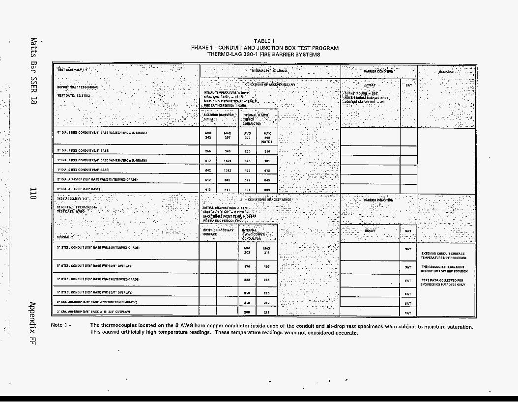
TABLE 1 PHASE 1 - CONDUIT AND JUNCTION BOX TEST PROGRAM
THERMO-LAG 330-1 FIRE BARRIER SYSTEMS
EXTERIOR CONWIT SURFACE TEMPERATURE NOT RECORDED I I 6' STEEL CONWITISIB' BASE WIMESII~OWELd3RADEI
I I
5- STEEL COHWITISILV BASE wim 318- OVERLAYI
1' STEEL CONWITISIB' BASE WIMESHITROWEL.GRADEI
1- STEEL C o N w i r i s I r BASE w i n 1 318- OVERLAY^ ~~
213 I 225
.(.. ~ .... '... . . , .;:.: .,. SAT THERMOCOUPLE PLACEMENT . .....
, ., , . . . . . . ,:.; , . ' .
' . . . . ' . ' , . . .. . . . . . . I MD NOT FOLLOW NRC POSlnDN . . , ... .. . . . , .. . . . . . . . . . . . ....__. .. , . , .. . . . . .
I. . . ..,., :.. .. , SAT TEST DATA COLLECTED FOR
.. . ... ,, . , . . . :. . . I . . ' ., ENClNEERlNC WRPOSES ONLY
. . .. . . . . . . , . . . . . . . . , , .., , , , . . . . . . . . . . . .. . ' . . . . .. . .. . . .
I
SAT . , . , . . . . . . , . . . . . . . . . . , .I . . . . , .. '.. , _ , .
: . . . . I , .. ,. , ._._ SAT
..;., ... ,.. .. . .. . , .:. ./. . .: ,... . . . 1 .. , , , , . , . . . . , . . . . . . . . . . . , . ' . . . . . . . . . . . . . . . . . . . . . . .. . . . . .. .
SAT . ' . . . .. (..( .. . .... .; ,
4 Note 1 - x 7-l -n
Tho thormocouples located on the 8 AWG bare copper conductor inside each of the conduit and air-drop test spocimons were subject to moisture saturation. This caused artificially high temperature readings. These temperature readings were not considered accurate.
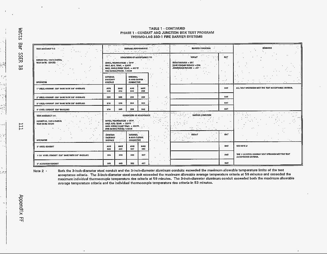
I I
- - ,
v) v) m 7J
I--L P P
TABLE 1 - CONTINUED PHASE 1 - CONDUIT AND JUNCTION BOX TEST PROGRAM
THERMO-LAG 330-1 FIRE BARRIER SYSTEMS
R€PO~TN0..11210~94354b ' TESTOArr: 411193
. \ .
3' STEEL CONWIT
Note 2 - Both the 3-inch-diameter steel conduit and the 3-inch-diameter aluminum conduits exceeded the maximum allowable temperature limits of the test acceptance criteria, The 3-inch-diameter steel conduit exceeded the maximum allowable avorago temperature criteria at 56 minutes and exceeded the maximum individual thermocouple temperature rise criteria at 59 minutes. The 3-inch-diameter aluminum conduit exceeded both the maximum allowable average temperature criteria and the individual thermocouple temperature rise criteria in 53 minutes.
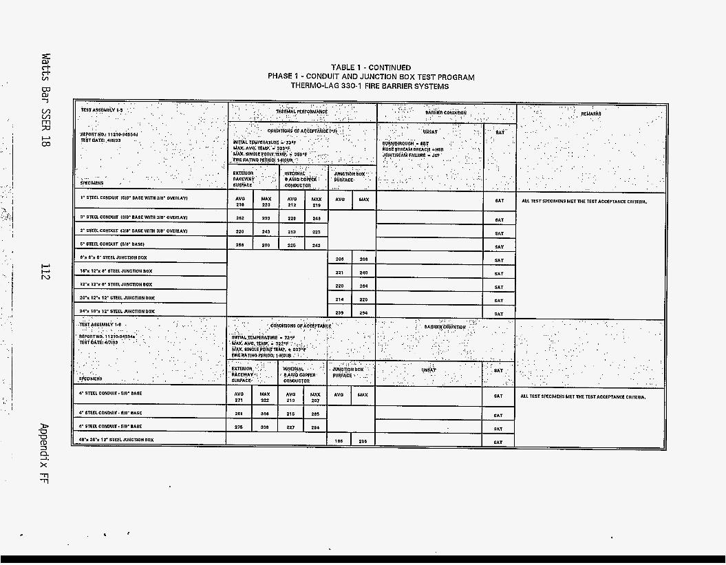
W nr 7
v, v, 70 n
P 03
. _i ' , C ,
' I
P P N
> -0 -0 CD 3
x T T
2
. . . . . . . . . . . . . . . . . . . . , .
'. . kWA$:EMO& l.,S ',',' ' , ' . . . . . . . . . . . . I . . . . . . . . . . . . .
,, . _ . , . . , , . . , . . . .
, I . . , , ,:. 'AEPOR!NO.: 11210.94554d ' . , , .
?€$TDA~:.4I6193 . . . . . . . , .. . . . . .
:. . . . . . . . I . .
. . . . . . . . . . . . . . . : ..,,: , I . . . . . . . . . . . ' . . ,,
, . . . . . . . . . . .... . . . . ... , . , . .I. . ' , . :: I
I
S.WCIMFNS .. '
1' STEEL COHWIT 1618' BASE WITH 310' OVERLAYI
3. STEEL CONDUIT (310' BASE W I M 318' OVERLAY1
2' STEEL CONDUIT 1310' BASE WlTIt 310' OVERLAYI
6' STEEL CONDUIT 1510' BASEI
V x 6% STEEL JUNCTION BOX
10.x 12% 0. STEEL JUNCTION BOX ~
12'x 12'x 8' STEEL JUNCTION BOX
20% 12.x 12' STEEL JUNCTION BOX
24.X 10% 12' STEEL JUNCTIONBOX . . . . . . . . I. . . . . . . . . . . . . . . . . . . . . . . . . . . . . . . . . . . . . , ( I . . . . . .,. .I&Sr*S5E!.WlY 1.8 . ,
nEPonTNO: 11210,945?4*~: :, , , ; '. , , . 'dsr bAti: 4rzi93 .......... . . . . . . '
,. .' . . . . . . . . . . . . . . . . ... . ' . . .
... . .
. . . SeClMENS , ., . , . . . .
4' STEEL CONDUIT. 610' BASE
~~
4' STEEL CONDUIT. 610' BASE
4' STEEL CONDUIT. 518' BASE
4 V x 36% 1Z'STEEL JUNCTION BOX
TABLE 1 - CONTINUED PHASE 1 - CONDUIT AND JUNCTION BOX TEST PROGRAM
THERMO-LAG 330-1 FIRE BARRIER SYSTEMS
220 243 213 223
1 I ' I
239 294 . .. . , ( . ' . . . . . . . . ' CQNWIONS Ork'CC$TAU!<' "'" ' '' . . . . . . , . _ L .. ' . . . . . .
~
186 206
. . . ........ . . . . . . . . . . . . . . . . , , . , ' .
' , ' , .; < ' . ... . . . . , , . : .
. . . . . . , . . . . . . . . . . . . . . . . . . , . . . . . . . . . . . . . . . . . , . .
, . , . .
. . . . . . . . '. . ( . S A T ; : . I :.
. . . . . . . .,, , , ,: _ ' .' . ,
. . ( ( . . . .
.,.. : . . .
. . . . , . " : q+&r . ;
. . . . ._ , . . . . . . . . .: , .
I SAT I ALL TEST SPECIMENS MET M E TEST ACCEPTANCE CRITERIA. I
SAT I
SAT
SAT
i
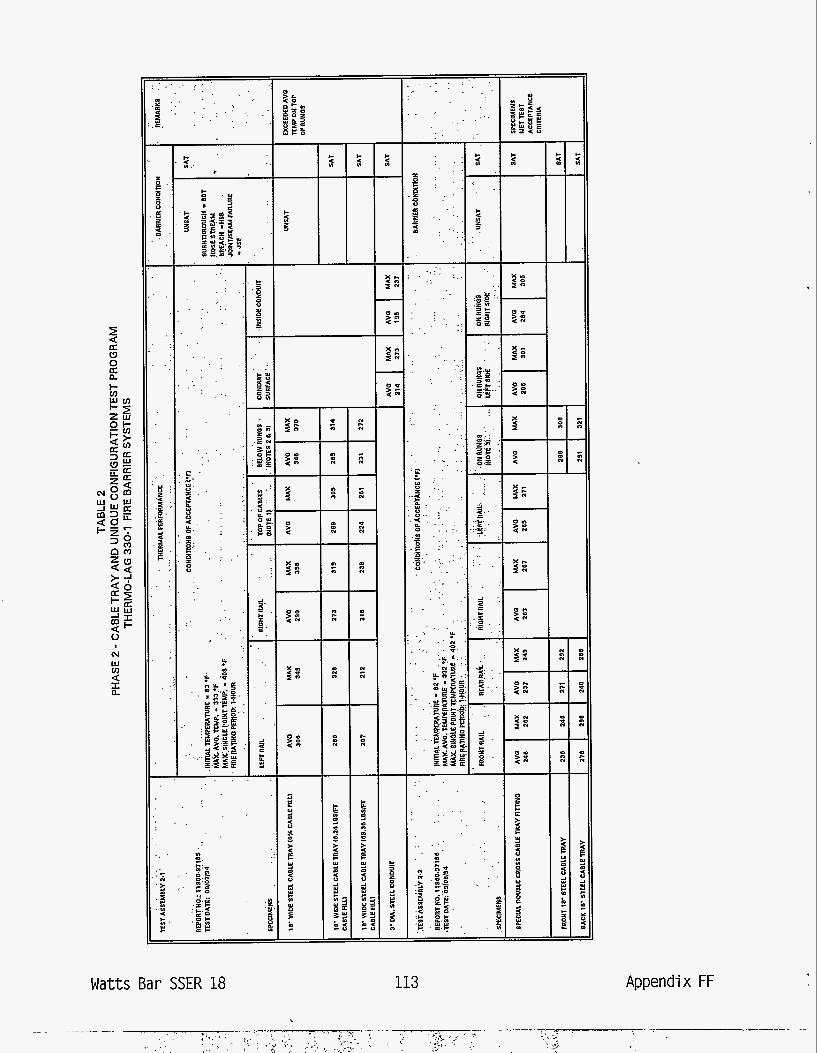
Watts Bar SSER 18
z z z
I- t! 0
I
113
E I c 5 U
v)
P 3
a 3
-I - f
Appendix FF
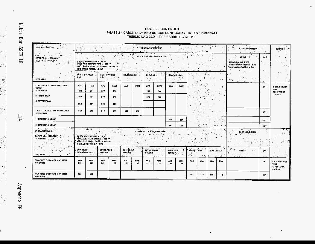
~ . . . . . . . . . . . dSTA$SEkFiLV2.3 ',':';:. .,
. . . . .. , . ,
. . . . . . . . . . . . . . . . ' . . ( kEPOnTN0.: 119(0"J7107 (, ..'. ' lE$T OATEi 0?/20194 .'. ' ' , ' I' . . . . . . . . . .
. (
. . . . . .
. . . .
SPECIMENS ' . I
COMMON ENCLOSURE 13.18' CABLE
A. TOP TRAY
E. MlWLE TRAY
C. EOTTOM TRAY
rnAYsi
18' STEEL CABLE TRAY W I M RAISE0 STEEL COVER
1' MAMETER AIR DROP
I :. . . . . . . . . . . . . . . .:.. ... . ,.: . .'
. . .. , . . . . . . . . . ,., . . . . . . . . . . . . . .
SPECIMENS.. (, . . . . M O W D E D ENCLOSURE 18.4' STEEL CONDUITS1
TWO.SIIX0 ENCLOSURE 12.1' STEEL CONWITS1
TABLE 2 - CONTINUED PHASE 2 - CABLE TRAY AND UNIQUE CONFIGURATION TEST PROGRAM
THERMO-LAG 330-1 FIRE BARRIER SYSTEMS
I 206 214 4 , . ':. .... .:.:,:. ....... :?. .. 1 . . . . . . . . . . . . . . . . . . . . . , . . .
. . . . - skt
- SAT
- SAT - SAT - SAT
. . . . . . . . . . . . . . .
143 164 SAT 135 152 192 218
. . . . . . . f lBhRKd ' . . . . . . . . . . . . .
. . .
.. , I .
SPECIMENS MET TEST ACCEPTANCE CRITERIA
. . . , , '.
, . . . . , .
I ,. . ,. . . . ~
. I
. . , . '.
SPECIMENS MET TEST ACCEPTANCE CRITERIA
c
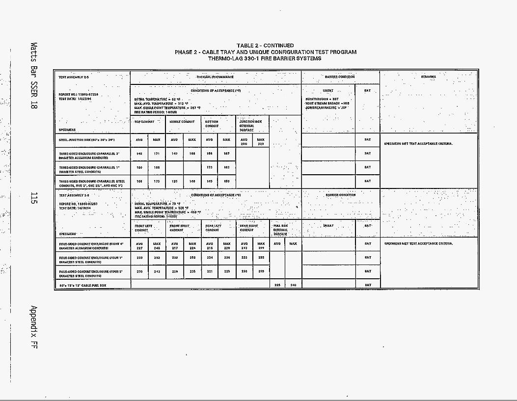
. . . . TEST ASSEMBLY 2.5
. . . . REPORTNO.! 11960.B7251) , , ,
TESTDATE$ 10127194 . . .
. . . . . . . . . . . . . . . . . . . . . . . . . . . . . . . . . . . . . . . . . . . . . . . . . . . .' .'. .MERML'~RMRMANCE . . . .
. . . . . . . . . . . SPEtlMENf, , . . . . S E E 1 JUNCTION BOX(6o'x 36.x 24'1
TIIREE.SIM0 ENCLOSURE I3.PARALLEL 3' DIAMElER ALUMINUM CONWITSI
. . . . . . . . . , '. BAfIRlERCONDITlON
. . . .
TlIREE.SIDE0 ENCLOSURE I2.PARALLEL 1' DIAMETER SlEEL CONWITSI
TIIREE~SIMO ENCLOSURE (7.PARALLEL STEEL CONWITS. FIVE 2.. ONE zn-. AND ONE 3.1
ESTASSEMBLY 2.6
REPORTNO. l1960~97259 TESTDATE: 10119194
SPECIMENS
MUR.SIDED CONWIT ENCLOSURE (EIQHT 4' DIAMETER ALUMINUM CONDUITS1
FOUR.SIDE0 CONDUIT ENCLOSURE (FOUR 1. DIAMETER STEEL CONWITSI
FOURWXO CONWIT ENCLOSURE (FOUR 3' DIAMETER STEEL CONWITSI
6O'x lrx 12' CABLEPULLBOX
TABLE 2 - CONTINUED PHASE 2 - CABLE TRAY AND UNIQUE CONFIGURATION TEST PROGRAM
THERMO-LAG 330-1 FIRE BARRIER SYSTEMS
. . . . . . . . . . . . . . . . . . . . . . . . . . . . . . . . . .
. . . ... UNShT
BUkN~ROUOH I SBY . 'HOPESTREAM BREACH 'HSB ?OINTISCW FARUAC ;'?SF
. . . . . . .
. . . . . . . . . , .
. . . . ' ' , +----- . . . . . . . . . . . . . ; . . . . ( , 06RRlER CONdnt . . . . . . . . . . . j . . ~ ~ N D I ~ ~ N ~ ~ F A ~ c E ~ T A N ~ E ~ ~ F I .
SAT
. . SAT
SAT
I 225 I 240 I I SAT
. . . . . _. . . . . . ,' RFUARKS . . . . . . . . .
. . . . . . . . . . . . . . . . . . . . . . . . . . . . .
SPECIMENS MET TEST ACCEPTANCE CRITERIA.
. . . . . . . . . . . . . . . . . . . . . . . . . . . . . , , . . . . . . . . . . . . I .
. . . . . , . . . .
. . . . . . . . . . . . . . . . . . .... . . . . . . . . . . . . . . . . , . .
. . . . . . . . . . . . . . . . . . . . . . .
SPECIMENS MET TEST ACCEPTANCE c n i m i A .
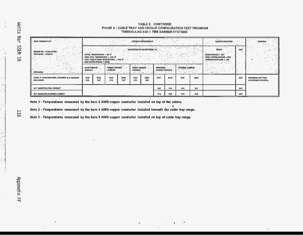
z rt P)
ct W P) 7
v) v)
73 rn
I--L a3
TABLE 2 - CONTINUED PHASE 2 - CABLE TRAY AND UNIQUE CONFIGURATION TEST PROGRAM
THERMO-LAG 330-1 FIRE BARRIER SYSTEMS
314' DIAMETER STEEL CONWIT 220 233 213 227 SAT
314' DIAMETER ALUMINUM CONWIT 216 226 210 210 SAT
Note 1 - Temperatures measured by the bare 8 AWG copper conductor installed on top of the cables.
Note 2 - Temperatures measured by the bare 8 AWG copper conductor installed beneath the cable tray rungs. 0
Note 3 - Temperatures measured by the bare 8 AWG copper conductor installed on top of cable tray rungs.
. . . . . . . . . ' . REMURI(s, ' :": . . :,. ..
'. , , , , : ' . ,'. . . I . .. ::. . . . . . . . . . . . . . . . . , .
. . . . . . I ..
. . . . . . .,
. . . . . .
SPECIMENS MET E S T ACCEPTANCE cnIEnIA.
i
c
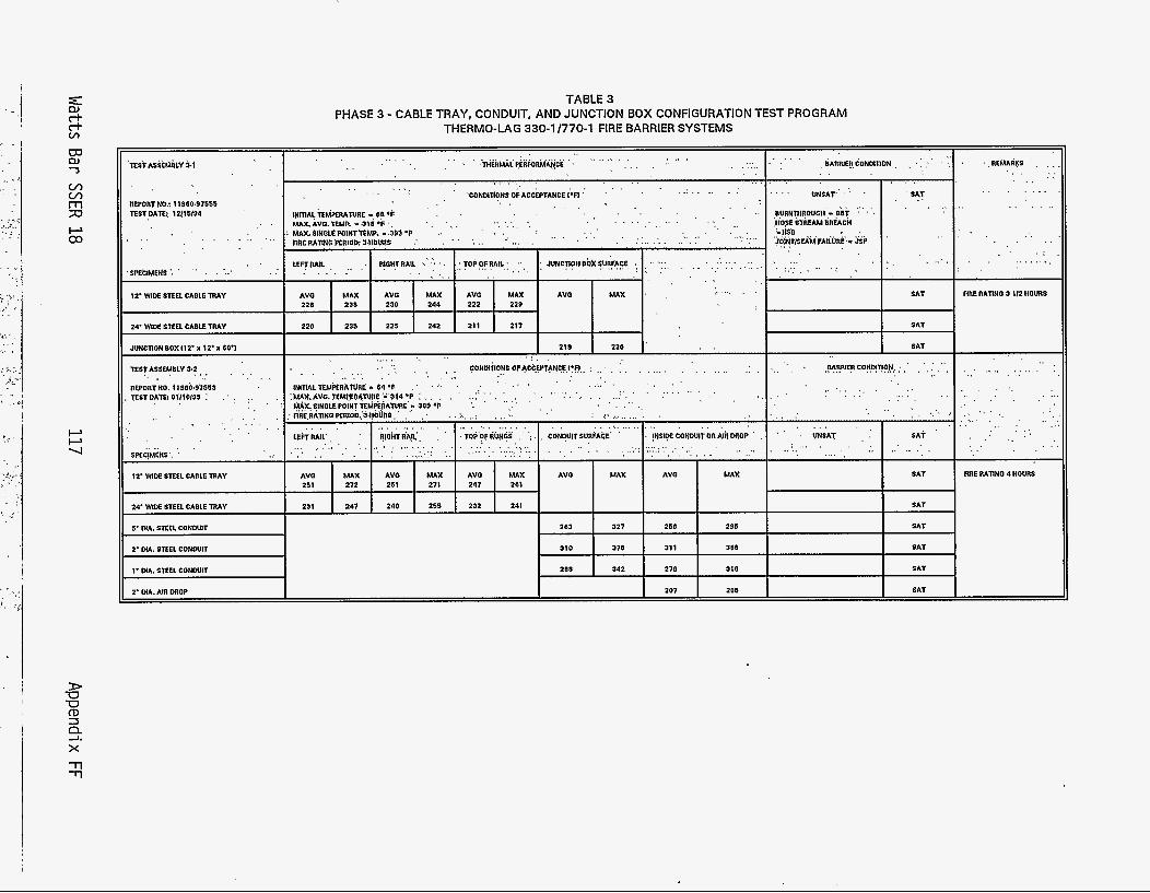
. . . . AVO MAX 211 272
231 247
. . . . . . . . . . . . . . . . . . : . . . . . . . . . AVO MAX AVO MAX AVO MAX AVO MAX 211 271 247 261
240 255 232 241
AVO MAX 211 272
231 247
AVO MAX AVO MAX AVO MAX AVO MAX 211 271 247 261
240 255 232 241
TABLE 3 PHASE 3 - CABLE TRAY, CONDUIT, AND JUNCTION BOX CONFIGURATION TEST PROGRAM
THERMO-LAG 330-1 1770-1 FIRE BARRIER SYSTEMS
m a, 'J
. . . .. ,. . . . . , . ~ ~ ~ L f f n ~ R M ~ c E . . . . . . . . . . . . . . . . . . . . . . . ... ..... . . . . . . I
.BARRlER,CONMTION,, , I , : .:
. SAT
....... HOSE OPEAM BREACH ..... JO!NT)SEAMFAILURE. - JSF
. . . . . . . . . . . . . . . . .
. ..REMARKS . . . . . . . v) v) m 7J
. . . .... . . . . . . . . . . . . . . .CONMTI?HSOFACCEPTANCE~*~~.' . . . . . . . .
. . . . . . . . . . . . . . . . . . . . . .
, , . i . . . . . . . . . , ,. . . . . . . . . . . . . . . . . . .... .... ( . .... . . . . .
. . wim; ~U~PERAN~E an OF MAX. AVO. TEMP. - 318 ' 6 ' . MAX$INGlEPOINTW.MP. -.393'F ,. DRE RATINB PERIOD: 3.llOURS .' . ... . . . . . . . . . . . . . . . . . . . . . . ~.
. . . . . . . . . . . . . . . . . . . . . . . . . . . . . UAX.AV0. ?€MqEOA,NnE *'a14 'P :
WX. SINGLE POINTTEMPERATURE - 309 OF '. ' ' ' : ' ' . . . . . . .
F 03
I SAT RRE RATING 3 112 IIOURS
I SAT 24' W I M STEEL CABLE TRAY
JUNCTION BOX 112' x 12' x 60'1
REPORTNO. Il$Ob.$Y65j . T E ~ T D A ~ 0 1 1 1 0 1 1 ~ : : :,
I SAT
. . . . . . ..... M R R l E R CONO!nO,~,. : , , , . , ,
. . . . . . . . . . . .... , . . . .
. . . . . . . . . . . . . . . . . .
, , . . . . . . . . . . . , . ,. ~ . ' .
i, . . . . . . . . . . . . . . . . . . . . . . .
RRE RATING 4 HOURS
. . . . ............
12' WIDE STEEL CABLE TRAY
' ' : ' ( 'GNSAT , ' , : I , SA+ ' . . . . . , . .... . . . . . . . . . . . . . . . . . , . . . . . . . . . ..I-.* : . ...... . . . . . . ..; , . I ' ;,:::, . . . . . '.,;,,,'~.~:~::.~ . . . . ' 1 : . . . . . . . __..
I SAT
It 24' WIDE SQEL CABLE TRAY SAT
SAT I 263 I 327 I 256 I 291 1 310 I 370 1 13: I .JJ:
207 200
208 342
1 310 I 370 1 13: I .JJ:
207 200
208 342
I SAT 2' MA. STEEL CONWIT
I SAT
SAT 2' MA. AIR DROP
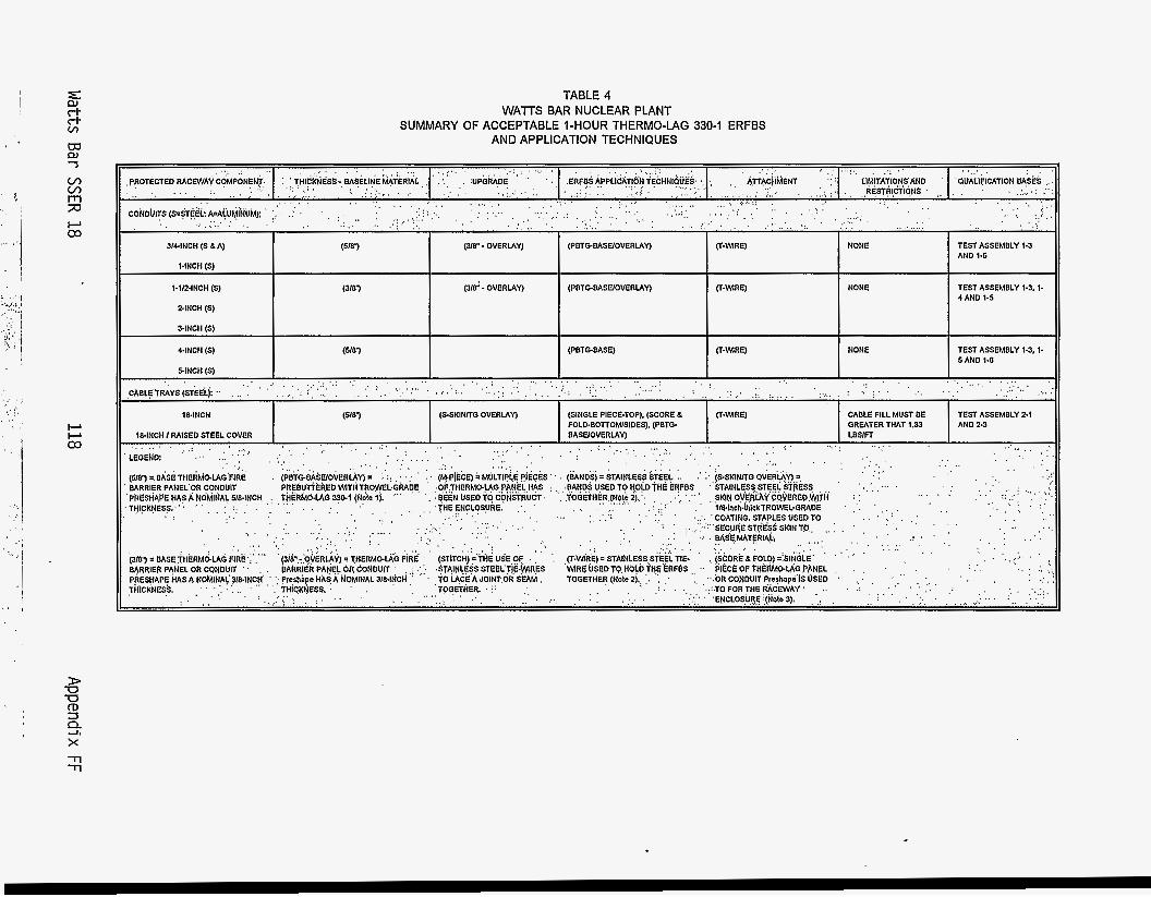
m W J
TABLE 4 W A T S BAR NUCLEAR PLANT
AND APPLICATION TECHNIQUES SUMMARY OF ACCEPTABLE I-HOUR THERMO-LAG 330-1 ERFBS
D -0 -0 m 3
f3: x -n
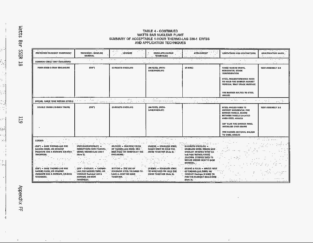
TABLE 4 - CONTINUED WATTS BAR NUCLEAR PLANT
AND APPLICATION TECHNIQUES SUMMARY OF ACCEPTABLE I-HOUR THERMO-LAG 330-1 ERFBS
. . . . . . . . . . . . . . . . . . . . . . . . . . . . . . . . . . . . . . . . . . . . . . . . . . . . . . . . . . . . . . '1 ERFBS APFWATION . . . A l f A C H ' i n g T ' .. : .. .' . LlhilTATiONS'AND RESTRICTIONS ~ ~ U A L l F l C A T l O N BASES:"
,. - ., TFCHNIQUES . . . . . . . . . . . . . . . . . . . . . . . . . . . . . . . . . . . . . . , .,UbCRb.DE . . F'ROTECTED'RACEWAY COMPGNENT THICKNEW - BASELINE
COMMON CABLE TRAY ENCLOSURE
MATERIAL . . . . . . . . . . . . . . . . . . . . . . . . . . , ( . . . . . .
. .
v, v,
;D n
P 03
FOUR.SIDED STRAY ENCLOSURE 1618'1 IM.PIECE1, IPBTC. BASElGVERLAYI
IFWIRE1 THREE 104NCH TRAYS, HORIZONTAL STACK CONFIGURATION
STEEL ANGLES/lHREADED RODS TO HOLD FIRE BARRIER AOAINST VERTICAL TRAY STACK SURFACE
FIRE BARRIER BOLTED TO STEEL ANGLES
.. . . . . . . . . . ........................ . . . . . . . . . . . . 1M.PIECEI. IPBTO. BASE1OVERLAYl
1618'1 lS.SKINllO OVERLAY1
~~ ~ ~~
TEST ASSEMBLY 2-2 STEEL ANGLES USED TO SUPPORT HORIZONTAL FIRE BARRIER PANELS, SEAMS DETWEEN PANELS LOCATE0 OVER STEEL ANGLES P
Lo 310- FLAT FinE m n n m PANEL INSTALLED OVER SEAMS
FIRE BARRIER MATERIAL BOLTED TO STEEL ANOLES
. . . . . . . . . . . . . . . . .
. . , : . . . . . .:. . . . . . . . . . . . , . . . . . . . . . . . . . . . . . . . . . . . . .
, . . , . . . . . , . , . . . . . ,I , . .. , I . . . . . .
. . . . . . . . . . . . . . . . . . . . . . . , , , , . , , , . , . . , . . , . . . . . . . . . . . . . . . . . . . . . . . . . . . . . . . . . . . . . . . . . . . . . . . . . . . . . . . .
. (610') - EASE T t l E R M O U O FIRE ' iPkTO~kiASE/GVERlAYl 4 IM.PIECEl - MULTlPlE PIECES,, iOAN0SI'- STAINLESS $TEE1 '
BARRIER PANEL OR coiioiirr ~ E O U f t E l l E D W I I ~ t h ~ W E L . , ' dF,tJ$fihJO:JOb,PI\NeL MXS;,, bA&S U S 6 td,itOLD W E .
hESt lAPE HAS A dOblhAL'6/84~CH~" a~ADE;TI(ERMOdAO 330.1 'BEEN V$ED TD'CONSTRUCT,THE , . ERFBS TOCETMER Itfots 21.: ' OVERLAY COVEREO'W(T$'l/8. ' . . THICKNESS. . . iN0to11. , , : ENcloSUREv ., . i&.thrcri TR~WELWIADE . . .
, . cop;riNb.sTA~E$'usEbio . . ,; ' . SECURE Sf(kS6 Si(lfi?O BA$E
. . . . . . . . . . . . . . . . . . . . . . . . . . . . . . . . . . . . . . . . . . . . . . . . . . . . . . . , , , , , . , , , . . , 1 I . .
. . . . . . . . . . . ... . . . . . . . . . . . . . . . . . . . . . !?T.!!!!!?:: . . . . . , .
. . , . , . . . . : . . I . .
' , . , . , . , . ' I
. . . . . . . . . . . . . . . . . . . . . .
. . . . . . . . . . . . . . . . . . . . . . . . . . . . . . . .. , . . . . . . . . . . . . . . . . . . . . . . . . . . . . . . . . . . . . . .,, . . . . . . . . . . . . . . . . . ' . '.TtilCKNdSS;,' , ,.
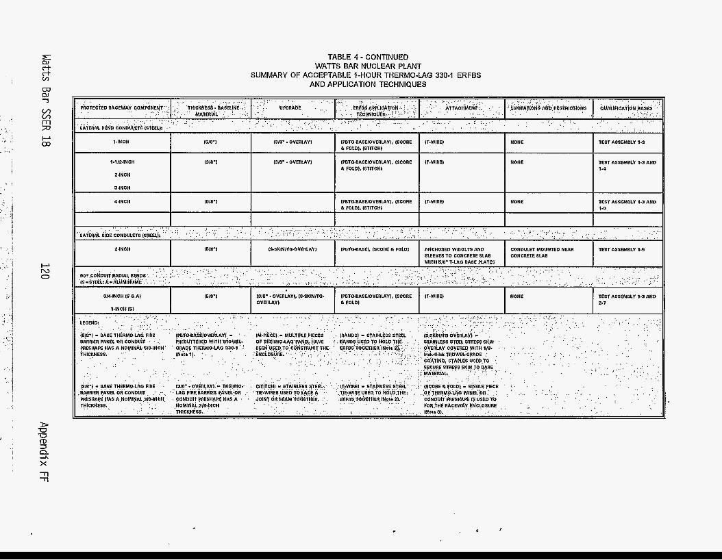
TABLE 4 - CONTINUED WATTS BAR NUCLEAR PLANT
AND APPLICATION TECHNIQUES SUMMARY OF ACCEPTABLE I-HOUR THERMO-LAG 330-1 ERFBS
1318' -OVERLAY)
IWTO~BASEIOVERLAYL ISCORE IT-WIRE1 I (618'1 I 13/8' - OVERLAY1 I I & FOLD). ISTITCHI
lPBTO~BASE/OVERLAY), (SCORE IT.WIREI & FOLD), ISTITCHI
I NONE
44NClt
II I TEST ASSEMBLY 1.3
1618'1 IPBTO~BASE1OVERLAYL (SCORE IT-WIRE1 NONE TEST ASSEMBLY 1.3 AND & FOLD], ISTITCHI 1.0
l.I/Z.INCH
Z4NCH
%INCH
NONE TEST ASSEMBLY 1.3 AND I II 24NCH 1S.SKINffO.OVERLAY) CONDULET MOUNTED NEAR TEST ASSEMBLY 1.5
. . . . . . . . . . . . . . . . .
3144NCH IS & A I TEST ASSEMBLY 1.3 AND
. . . . . . ' :.' , .
. . . . . . . . . . . . . . . . . . . . . . . . . . . . . . . . ::',, . . . : ,:. : ; ..: " C&k'tlt4b, Stn'PLC6 UQLb.70 .. ' , ,, ,, , , -. . , , , . ' , , ' . . . . . . . . . . . . . . . . . . . ... . . . . . . . . . . . . . . . .... . . . . . . . . . . . . . . . . . . . . . . . . . . .
. . , .
. . . . . .
. . , . . . ) . . . , ' . "
. . . . . . . . . . . . . . . . . . . . . . . . . . . . . . . . . . , j . (SCORE 6 FOLOI - S~NOLE PIECE : . . . . I . . . .
. . . . . . . . . . . . . . . . . . , . .
13/EbI -'BASE THERMQ4AO FIRE ' , . ,, BARRIER, PANEL OR'CONDUIT , : .-.. ' LAC FIRE BA~R'IER PANEL:OR _ I ' . TIE.WIRES USED TO i'dCE A
.,OV$RLAYI.'- THERMO.' I ISTiTCH) .,SlA!N;lESS WiEL,:, '. , ::lT~WlRE1 - .,yi&w$$ u
, ., . . . . . . .I . ;O~THE?MO.~AQP~NELOR~ . . . ( . . ,. . . . . . . . . . . . . . . . . .. . . . . . . . . . . . . . . . . . . . . . . . . . . . . . . . . . . . . . . . . . . . . . . . . . . . . . . Pbfi.Wt RACEWA~,~NCLOSURE . , ' . . , '. . lNolo3l. THICKNESS..
I .
.( . . . , . .
. . . . . . . . . . . . . . PIIESHAe HAS A,NOMINAL,3!84NbH, . CONOUIT mESH!lF HAS A : ,JOINT OR,SEAM TObET!lEli.' :' , .ERFDS.TOh CO~~UIT'PRESHAPE I$ U S E D T b '
TH!cK3Ess*,, . . '. , , . , , . NOMINAl.,3/8.!NCH . . . . . _ . . . . . ( . , . ( .
( . . ,
. f c
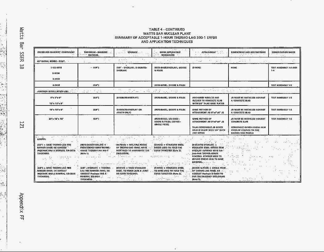
v, v, m 7J P 03
P N P
D -0 -0 rD =I
x 2
TABLE 4 - CONTINUED WATTS BAR NUCLEAR PLANT
AND APPLICATION TECHNIQUES SUMMARY OF ACCEPTABLE 1-HOUR THERMO-LAG 330-1 ERFBS
. . . . . . .. , . . . . . . . . . . . . . . . . . . . ATTACHMENT-. : . . . . ~IMITAYI?N$~ND RE~TAICTI~NS . PUALIFICAT~ON B A ~ P S ........... . . . . . . . , . . . . . . PnOTECTBD R A C E ~ A Y 6OhlPONENT thlCKNESS BASELINE. .: l!POnADE :.. ERFDS,APPL!CATlON
. I . , . ~ T E c n N i a u w . MATERIAL. . . . . . . . . . . . . . . ... . . . . . . . . . . . . . . . . . . . . . . . . . . , . . . .
. . . . . . . . _ , _ , . . . . , .
Ob" RADIAL BLIIbS - CONT. . . . I
I I I I I I 1-1124NCH
24NCH
34NCH
1310') 1318' - DVERLAYI. ISSKINITO. IPBTO~DASEIOVERLAYI. ISCORE IT-WIRE1 OVERLAY1 & FOLD) I
44NCH 1518'1 1PBTQ.DASEh ISCORE & FOLDI TEST ASSEMDLY 1-3 . I I . , . . . . . . . . . . . . . . . . . . . . . . . . . . . . . . . . . . . . . . . . . . . . . . . . . . . . . . .... . . . , . ,
I I I I I I JUNCTION ISTEEL~,~~O~SIJBI:,:'.:. .' .: ,.: . ' . . . . . . . . . . . . . . . . . . . .
O'X O'X 0' I1 1 z - x 12 -x 8'
1510'1 IS.SKINITQ.OVERLAYI JD MUST DE INSTALLED AOAINST TEST ASSEMDLY 1.6 I IWTO.BASEI. ISCORE FOLDI ANCHORED w m o L T s AND SLEEVES TO CONCRETE SLAB I WITH 618' 1-LAC DASE PLATES I
10-x 12% 8'
ZO'X 12.X 12'
. . . . . . . . . ... . . . . . , , . . LEOEND: . . .
IS.SKINITO.OVERLAY ON JOINTS ONLY)
. . . . , . . ; ' ; ' , . .....
IPBTO4?ASEI, ISCORE & FOLD1
IPBTO.DASEL IJD SIDES * SCORE st FOLDI, ICOVER - SINOLE PIECE1
. . . . . . . . . : .,. , . . . . . . . . . . , . . .
SAME METHOD OF ATTACHMENT AS 8'XO.XO. JB
JB MUST DE INSTALLED AOAINST A CONCRETE SLAO
SAME METHOD OF JD MUST DE INSTALLED AOAINST
TEST ASSEMDLY 1.6
TEST ASSEMBLY 1.5
. . . . . . . , . . . . . . . . . . . . . . . . . . . . . . . . . . . . . . . . , I , .( . . , . , . ( 0 , . . . (618'1 - DASE T1IERMO:LAQ FIRE ' SEiOVEnLAYJ - .(M.PIECE) - MULTIPLE PiECES . . .
. . BARRIER ?ANEL ori coNduir", ' , .., '
THICKNESS. . INn te l ) . ' ,
EhED W I T H TllOWEL- OF 'fHERMd.LA6 PANEL HAVE .. pn~spm A NOMIN~L SIOJNCH EflMO.LAC( 33p.1' , BEEY'USEP TO,CO~STRUCr,fHE
. , . . . . . . . . . . . . . . . . . . . . . . . . . . . . . . . . . . , . .
. . . ., .. . ' I SECUhESTn€o$KlNTOeASE, .,, , ..... . . . . . . . . . . . . . . . . . . . . . . . . . . . . . . . . . . . . . . . . . . . . . . . . . . . . . . . . . . . . . . . . . . . ......... . . .
(l"WIhE) -'BYAlNLCSS &€L
. . . . . . . . . . . . . . . . . . . . . . . . . . . ;
. . . . . . .
. . . . . . . . . . . .. , . , , ., . . . . . . . I
. . . . ,
MAT'3141, :.. ,. I .' . , . , . _
. I . _ . . , , . . . . . ,
. . I . . , , , , &0') y DASE THEfiMO.hO FIRE
THICKNESS. ,, . . NOMINALJ/B.!NCH ;
: (3181, Ovp lLAV j - THERMO. . (8l(TCH) - USEb StAlNLEeS ,
LAO F!RE llARRl6R PANELOR STLEL TIE.WIAES l 4 C e A SOINT . . ,TIEWREUSED TO HOLD TPE .... .'OF THERMOLAO PANEL,OR, . . . . . . . . . . . . . . . . , (SCOkE& 66LW - SlNpLE PIECK.. , . . . BARRIER PPNBL OR CONDUIT . . .
. . . . . . . . . . . . . . . . PnESHAPE HAS A NOMINAL 3IO.INCH , CONDUIT Ptuhspo HAS A' Of ISu \M TOOETIIER. ' ' EnFDS TDOETIIER l,NoI?-2l. ; : CONDUIT Rcrhapb IS USED TO ,
. . . . . . . . . . . . . . . . . . . . . . . . . . . . . . . . . . . . . . . . . . . . . . . . . , . , . . . . . . . . . . . . . . . . . ll l lCKN1SS.. , , , . . , ' ..' ' , :"' ' . FOR'.X!IEftACEWbY ENCLbSUIE
lNot*3). :
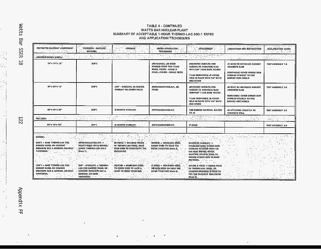
D U U rD 3
x -rl -rl
!3
OO'x 30-x 24'
TABLE 4 - CONTINUED
SUMMARY OF ACCEPTABLE 1-HOUR THERMO-LAG 330-1 ERFBS WATTS BAR NUCLEAR PLANT
AND APPLICATION TECHNIQUES
1518'1 1S.SKINITO OVERLAY1
40'x 30-x 12' 16/87 1310' - OVERLAYI, IS6KINITO- OVERLAY ON JOINTS ONLY)
. . . . . . IPBTO23ASEL IJB SIDES FORMED FROM TWO T.LA0 PANEL PIECES * SCORE B FOLD), (COVER. SINOLE PlECEl
IPBTO~BASEIOVERLAYI, IM- PlECEl
IWTO.BASE/OVERLAYl
. . . . . . . . .
. . . . . . . . . . . . . . ANCHORED WIOOLTS AND SLEEVES TO CONCRETE SLAB WITH 610' TdAO BASE PLATES
T.LAO REMOVABLE JB COVER HELD IN PLACE WITH 114' NUTS AND STUDS
ANCHORED WIOOLTS AND SLEEVES TO CONCRETE SLAB WITH 610' TdAO BASE PLATES
T.LA0 REMOVADLE JB COVER HELD IN PLACE WITH 114' NUTS A N 0 STUDS
FIRE BARRIER MATERIAL BOLTED TO JB ........... .: . . . . . . . . . . . . . . . . .... . . . . . . . . . . . . . . . . . . . . . . . . . . . . . . . . . . . . . . . . . . .:: . . . . . . . . . . ....... . . . . . . . . . . . . . . .
. . , . . . . . . . . . . . . . . . . . . . ., , . . . . WLL'DOX: . ,
I I I I
I WE") IS.SKINIT0 OVERLAYI IWTO~BASEIOVERLAY I IT-WIRE1 OO'X 12% 12' . . I I I
. . . . . . . . . . . . . . . . . . . . . . . . . . . . . . . . . . . . . . . . . . . . . . ,:.:: . . . . . . . . . . . . . . . . . . . . . . . . . . . . . . . . . . . . . . , , , . " I
. . . . . . . . .... . . . . . . . . . . :..
I . :;, : .' , .. '.. . . . . . . . . . . . . . . . . . . . . . . . . ...... . . . . I . :. . . . .:. . . . . . . . . .
: . , . . . . LEOEND... . ., ..:
JO MUST DE INSTALLED AOAINST CONCRETE SLAB
REMOVABLE COVER STRESS SKIN OVERLAP STAPLE0 TO FIRE BARRIER SIDE PANELS
JB MUST BE INSTALLED AOAINST CONCRETE SLAB
REMOVABLE COVER STRESS SKIN OVERLAP STAPLED TO FIRE BARRIER SIDE PANELS
JB ATTACHED DIRECTLY TO CONCRETE WALL . . . . . . . . . . . . . . . , . . . . . . . . . .
TEST ASSEMBLY 1.6
TEST ASSEMBLY 1.0
TEST ASSEMBLY 2.6
. . . . , . .( (. . ' , :: :, ...... . . . . . . TEST ASSEMBLY 2.0
I , :. , . ................................ . . . . ( ' , .:. . . . . . . . , . . . . . . . . . . . < ,
. . . . . . . . . . . . . .
c c . o
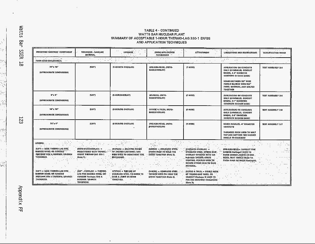
TABLE 4 - CONTINUED
SUMMARY OF ACCEPTABLE 1-HOUR THERMO-LAG 330-1 ERFBS WATTS BAR NUCLEAR PLANT
AND APPLICATION TECHNIQUES
. . . . . . . . . . . . . . . . . . . . _ . , . . PROTECTED RACEWAY COMPONENT . : THICKNESS .OASELINE ' , UPGRADE::' ',, 1. .ERFBSAPPLICA~ION . ' A ~ T A C ~ M E N T _ " LIMITATIONS AND RESTRICTIONS ' 'QUALIFICATION BASES . . . . . . . . . . . . . . . . . . . . . . . . . . , . . . . . . .
. , .TECHNIQUES .. . . . . .
. . MATERIAL
. . . . . . . . . . . . . . . . . .~ , . . . . . . . . . . . . . . . . .
iouR.s !~En ENCLOSUR~G: ' 1 , '
33-x 10-
IAPPROXIMATE DIMENSIONS)
1S.SKINNQ OVERLAY) IPRE*SIM+IECEI~ IPBTG. I IT-WIRE) BASElOVERLAY I
APPLICATION ON CONDUITS ONLY 12-PARALLEL CONDUIT BANKS. 4.4' DIAMETER CONDUITS IN EACH OANKl
SEAMS BETWEEN 30' WIDE PANELS BACKED WITH 618' PANEL MATERIAL AND BOLTED TOOETHER
TEST ASSEMBLY 2.0 15/87
8'X 8'
IAPPROXIMATE DIMENSIONS)
1618'1 ISSKINIOVERLAYI TEST ASSEMBLY 2.0 1M.PIECEI. IfflTG. BASElOVERLAY I
IT-WIRE) APPLICATION ON CONDUITS ONLY INARALLEL CONDUIT BANKS, 2.1' DIAMETER CONDUITS IN EACH BANK) I
I 18"X 18'
[APPROXIMATE DIMENSIONS1
16/07 IS.SKIN/TQ OVERLAY) ISCORE E FOLD]. (POTO. BASElOVERLAYl
IT.WIREI TEST ASSEMOLY 2.0 APPLICATION ON CONDUITS ONLY I2.PARALLEL CONDUIT OANKS. 2-3' DIAMETER CONDUITS IN EACH DANK)
SEVEN PARALLEL 4' DIAMETER CONDUITS
THREADED RODS USED TO BOLT TOP AND BOTTOM FIRE BARRIER PANELS TO RACEWAY
TEST ASSEMBLY 2.7
. . , .
30'x 0.
IAPPnOXIMATE DIMENSIONS1
1510'1 IPRE.S/M.PIECEI, IWTQ- IIASE/OVERLAYl
IT-WIRE1
, . . . . .., . . LEGEND:: . . . . . . . . . . . . iwo-) - B ~ S E THERMOLAO FIRE uAnniEn PAN~L on CdNoui~'.":'~' ''
. . . . . . . .
&ES(IAf?E'HAS A NbhilNALS/O.INCH THICKNESS. ., , ..', , . , . . . . , . ",., I .
. . . . . . . . . . , . , , . ~ . . ( . . . . ....... . . . . . . . . . . . . . . . . , , I . . . . . . . . . . . . . . . .
"' . . (S6KlNTO GVERLAY) '2 ., ' ' ., l P R L S / M . P l ~ ~ ~ l ~ ~ C O N D U I T FIRE " ' STAINLESS STEEL STRESS 6KINI "" BAhRER ProhapeS USEDTO .
' '. FORM CORNER JOlhTS On END. OVERLAY COVEREb,WlTH l / B *
C0,ATINCh STAPLES USSD YO,' , #OhM SlOES BilW€EN'&h$kS, ... r4*.th!* ~ R ~ , ~ E L . G ~ ~ A ~ E : . . . . bbE& RAT PANEL& USED TO
. . . . . . . . . . . . . . . . . . . . . . . . . . . . , ,
' SECUllE STRESS SKIN TO UASE ,
. . . . . .
. . . . . . . . . . . . . . . . . . ( . . . . . . . . . . ( ( . . . . . . , . , , . . ,
IfflTQ~BASEiOVERLAY) - IM.PlECE) ,-.MULTIPLE PIECES '
~EOUTTEREO WITH TROWEL-. OFfllERMO~LAQ~PANEL'lV\S ORAOE THERMO:@O 330.1 1Noi64l: I
BEEN USED TO CONSTIIUCT THE, ,:, : : ,INCiQSUdE.. . .,,: . . . . . . . . . . . . . . . , . . , .
. . . . . . . . . . . . . . , . . . . . . . . . . . . . . . . . . . . .
. . . , . , I . . , , . I ,
... . .
, . . . . . . . . . .i , . . . . . . .
. . ...... . . . . . . . . . . . . . . . . . .
. . ,. ,
. . , , . . . . . . . . . . ... . . . . . . . . . . ,
, ., I. , . .
. . . . .
. . . . . . . . , . . I . , . . , . . ,
1310') Y bASE THERMOLAC FIRE DARRIEII PANEL DN CONDUIT PkESHAK ;{As A'NOhlNAL 3p.INCI4 '
(31O'rOVEflLAYI M THERMO- ISTITCHI .( THEUGE OF LAO FIREBARRIER PANEL'OR', CONDUIT herhapa llAS A , ',:,L$CE4 J b l N t Oh 68AM
(T-W!liEl -, STAINLESS STEEL. (. ..I.. .[SCbnE & FOLD!,- SINGLE PIECE
ERFOS TOOET!IEll lNoI6 2). ' CONDUtf Pielhapa IS USgO 79 .' , , ' .' . ' . . . . ' S~AINLESS 6ThEL'T~E.WlRESlO ' TIE-WIFE USEDTO HOLDTHE ' ' . ' OF THERMO.LAO PANEL OR '
, ' FOR.Ttj6 RACEWAY ENCLO6URE ' ' ' I . FlOMlNAL 3!84NCH . TOGETHSII. ' , ..
THICKNESS. , :I *, ,
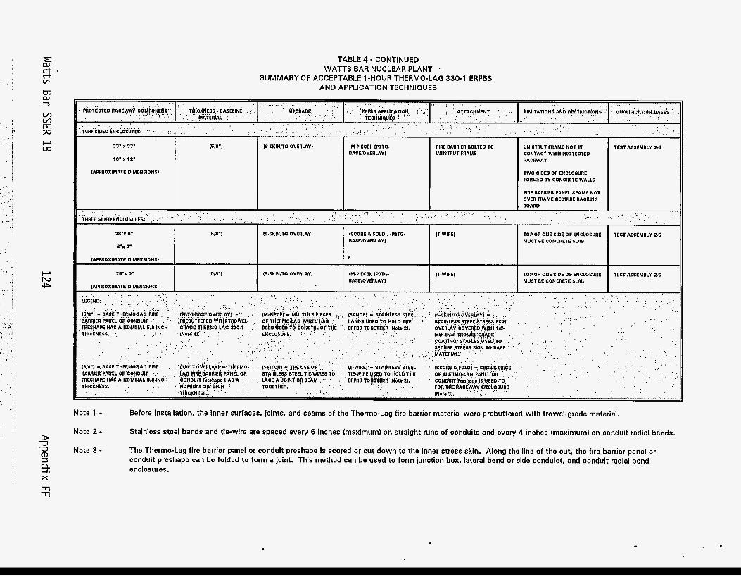
.: , CR W '3
, I * ' I 0
1 I
. i
, ,-I
I
D W W CD 3
x -rl -rl
ff:
TABLE 4 - CONTINUED
SUMMARY OF ACCEPTABLE 1-HOUR THERMO-LAG 330-1 ERFBS WATTS BAR NUCLEAR PLANT .
AND APPLICATION TECHNIQUES
Note 1 - Note 2 -
Note 3 -
TEST ASSEMBLY 2.4 DASElOVEflLAYl UNISTRUT FflAME CONTACT WITH PnOTECTED
18' x 12'
IAPPnOXlMATE DIMENSIONS1 TWO SIDES OF ENCLOSURE FORMED DY CONCRETE WALLS
BASElOVEflLAYl MUST BE CONCRETE SLAB
Before installation, the inner surfaces, joints, and seams of the Thermo-Lag fire barrier material were prebuttered with trowel-grade material.
Stainless steel bands and tie-wire are spaced every 6 inches (maximum) on straight runs of conduits and every 4 inches (maximum) on conduit radial bends.
The Thermo-Lag fire barrier panel or conduit preshape is scored or cut down to the inner stress skin. Along the line of the cut, the fire barrier panel or conduit preshape can be folded to form a joint. This method can be used to form junction box, lateral bend or side condulet, and conduit radial bend enclosures.
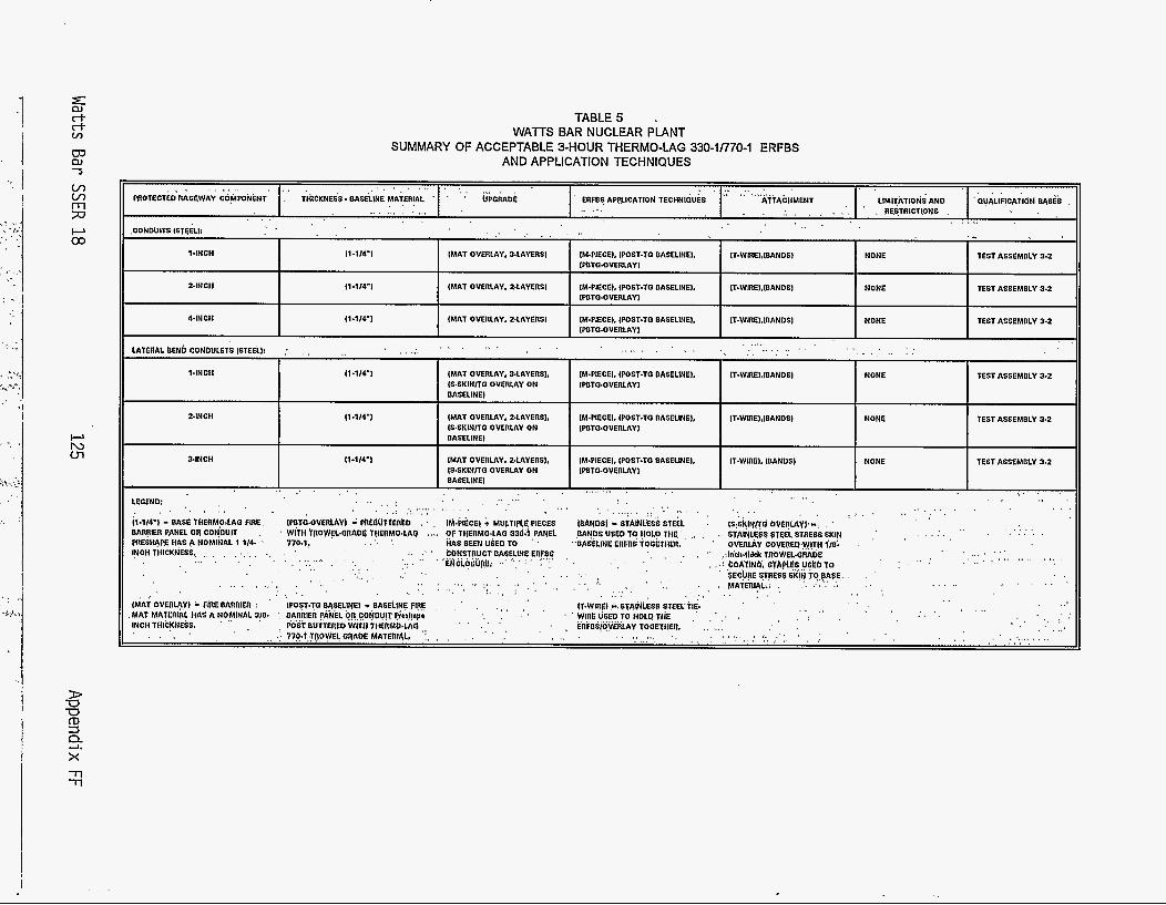
i I
.'- I
' 3 ,
w n, -J
Ln Ln
7J t--L a3
n
t--L N m
TABLES . WATTS BAR NUCLEAR PLANT
AND APPLICATION TECHNIQUES SUMMARY OF ACCEPTABLE 3-HOUR THERMO-LAG 330-1/770-1 ERFBS
..... I . . . . . . . . . . . , . I , , ;. . , ,. . , . I . RESTRICTIONS . I . . . . . . . . . . . .
. ) _ . . . . . . . . . .
. . , . . . .CONOUITS ISTSELI:
1-INCH I1.1/4') (MAT OVERLAY, 3.LAYERS) IM4'IECEI. IWST-TO OASELINEI. IT-WIREl.lOAN0SI NONE TEST ASSEMBLY 3.2 1PBTO.OVERLAY I
11-114-1 IMAT OVERLAY. 2.LAYERSI IM+'IECEl, [POST-TO BASELINE). IT-WIRE).lBANOS) NONE TEST ASSEMBLY 3.2 24NCH IFUTO.OVERLAY1
I I I I
I1 .1/4-I [MAT OVERLAY. 2.LAYERSl IM.PIECE). IPOST-TO BASELINE). NONE TEST ASSEMBLY 3.2 IT-WIREI.lBANOS1 44NCll IPBTO.OVERLAYI
...... . . . . . . . . . . . . . . . . . . . . . . . ...... . . . . . . . . . . . , . ~ . LATERAL kENb CbNDULETS ISTEEi!: : , , . . . . .
TEST ASSEMBLY 3.2 14NCI l 11*1/4*1 (MAT OVERLAY, 3.LAYERS). 1M.PIECEI. IPOST*TO BASELINE), IT-WIREI.IOAN0SI NONE IS.SKINITO OVERLAY ON 1WTC.OVERLAYI OASELlNEl
Z4NCH 11-1/4ml IMAT OVERLAY. Z.LAYERS), (M.PIECEI, IPOST.TO BASELINE), IT.WIREI.IBAN0S) NONE TEST ASSEMBLY 3.2 1S.SKINITC OVERLAY ON [WTO.OVERLAY I BASELINE)
34NCH l1-1/4-l IMAT OVERLAY. 2.LAYERSI. (M.PIECEI, [POST-TO BASELINE). IT-WIRE), [BANDS) NONE TEST ASSEMOLY 3.2 (5.SKINITO OVERLAY ON WBTO.OVERLAY 1 BASELINE) . . . . . . . . . . . . . . . . . ( . . , . . . . . . . . . . . . . . . . . . . . . . . . . . . . . . . . . . . . .
, .
. . . . . . . . . . . . . . . . . . . . . . . . . . , . . , , . . , , . . . . . . . . . . . . . . . , I
. . .I . . . . ~ .: , . LEOENO: ,
I&1/4.l - BASE WERM0,LAO FIRE. (peTd.oVk6lAV) - F'hC6uTtEPlD . ' , I M : P I k E I - hiULYlfiGPlECdS IbANbSI - St41NL& 6tEEI. : (s,sKlypd bVEhlAy).-: , ' '
MR?lER PANEL OR COt@UlT . . . . . . ,. . . . . . . . . . . . , ' W l i l l t R O W ~ l 4 R A O E THERMO.LAQ . .~. OF THERMO.LA0 33d;l,PANEL ,PAN05 UFSP T? HOLD T H E ' , ,, , . STAINUSS GTEEI. STRE65 SkIN ,' HAS BEEN USE0 TO ' "OAGELINE ERFOS TOEETHER. ' O V E n d Y COVEREO~WITH l / & ,
, . fflESH+PE HAS A NOMINAL 1 114- ' 770.1, . . , . . . :. .' ' ~ONSTRUCTBA5ELINEER~OS , . . . . . . . . . . . . . . . . . . . . . . . . . . . . . . . . gNi~qi"fi)!; .: "'; : ' , , .
INCH TIIICKNESS., ,, , , , , , , ,
. . . . . . . . . . . . . . . '$E'C!.!RE 6TRES6 StIN iO.p63. , , . ' ' . . . . . . . . . . . . . . . . . . . . . . . . . . . . . . . . . . . . . . . . . . . . . . . . MATmI+: . . . . . . . . . . . . , . . . . , ) . .; ,
. . . . , , .
. . . . . . . . . . . . . . . . . . . . . . . . . . . . , , . . .
, .. . ,
. I , . (T-WIAEI .+.STNNLESS $TEEClIp , ' . . . . I I . . I .
IMAT OVERLAY) - FIRE BARAIER : ' IPO6T.70 BA6EL!NEi - BASELINE FIRE , , , ' . ,
MAT M A l E R l i l t iAS A NOMINAL 3!0* : BARRlEll PANEL OR CONDUIT Pirahapo INCH TlllCKNESS. ' ,
. , ( . . . . ' ' WlflEUSEDTU HOLQTtiE , , , , . . . . . . . . . . . . . . . . . . . . . . . . . . . . . . . . . . . , .., . .L _ ' , . ' . . . .
. , . . , . ' , EflFOb(0VEiiLAY TOOETllEl7. ,, .,. , . . . . . . . . . . . . . . . . . . . ..... . . . . . . . .
, POST BUT~EREO wii i i itilik'lrtb.iiia ,, , . , . .'. 770.1;TRO9kl bfiAOE MATBRIAL, :, , , , , , . , .
. . . . . . . . . . . . . . . . . . . . . . . ( . . . . . . .
. . . .
. , , . . . . 1 , . . . . . .
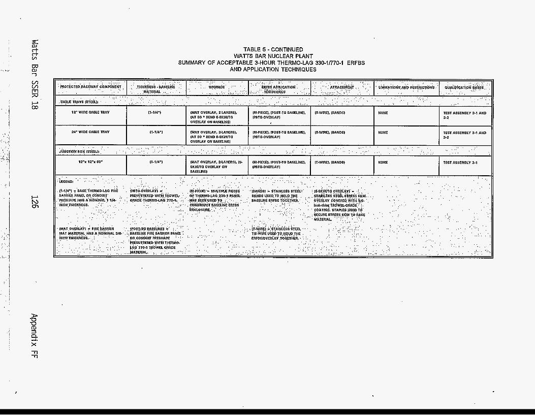
I
' I
i
TABLE 5 - CONTINUED WATTS BAR NUCLEAR PLANT
AND APPLICATION TECHNIQUES SUMMARY OF ACCEPTABLE 3-HOUR THERMO-LAG 330-1/770-1 ERFBS
12-x 12-x ao- 11-1/4-l (MAT OVERLAY. ZLAYERSI, is. IM.PIECEI, iPosT.Ta BASELINEI. iT.winEi. (BANDS) NONE TEST ASSEMBLY 3.1 SKlNnQ OVERLAY ON IPBTC~OVERLAYI BASELINE1
. . . . . . . . . . . . . . . . . . . I , . . . . . . . .
. . ., . . . . . . . . . . . . . . . td.. ~. . . I . , . . . . ' . . . : . (. ... . . . ... . . . . . . . . . . . . . . . . . . . . . . . . . . . . . . . . . . . . . . . . . . . . . . . . . . . . . . . . : I ,I ,
. . . . . . . . . . . . . . . . . . . . . . . . . . . . . . . . . . . . . . TOEASE ' ' " * .
, . . . . . . . . . . . . . . . . . . . . . . . . . .
. . . . :. ' ' MATERIAL. , . . .. ,
,, . i.
I I . . .
. , . . : , , I i
, . . . I .,
. , . . . . . . . . . . . . . . . . . . . . . . . . . . . . . . . . . . . . . . . . . . . . . . . . . . . . .
. . ...... . . . . . , . .
:
. . . . . . . . . . . . . . . . _) ' ' . . .,. ~
' . . . . , . . . . . . . . . . . . . . . . . . . . . . .
IRC FORM 335 tag) RCM 1102, 201,3202 BIBLIOGRAPHIC DATA SHEET
US. NUCLEAR REGULATORY COMMISSION 1. REPORT NUMBER (AtslpMd bv N R C Add VoL, supp, RH., n d Addendum Numbsn. if any.)
Same as 8. above.
(See instructiom on the reverse)
,TITLE AND SUBTITLE Safety Evaluation Report Related to the Operation of Watts Bar Nuclear Plant, Units 1 and 2 -
I AUTHORE)
Peter S. Tam e t a l . .
I UPPLE E A R Y N tocke! Fos. %:390 and 50-391
NUREG-0847 Supplement No. 18
3. DATE REPORT PUBLISHED MONTH YEAR
October ' 1995 4. FIN OR GRANT NUMBER
6. TYPE OF REPORT
Technical 7. PERIOD COVERED(hcluriveDam)
. ABSTRACT (200 wordr or kx)
Supplement No. 18 to the Safety Evaluation Report for the application fi led by the Tennessee Valley Authority for license t o operate Watts Bar Nuclear Plant, Units 1 and 2, Docket Nos. 50-390 and 50-391, located i n Rhea County Tennessee, has been prepared by the Office of Nuclear Reactor Regulation of the Nuclear Regulatory Commission, The purpose of this supplement is to'update the Safety Evaluation w i t h (1) additional information submitted by the applicant since Supplement No. 17 was issued, and (2) matters that the s taff had under review when Supplement No. 17 was issued.
I. KEY WORDSIDESCR: PTORS (List words orphnat chat wiItapirrrrsc.rdrrn b lourhgtharrpom.)
Safety Eva1 uation Report (SER) Watts Bar Nuclear Plant Docket Nos. 50-390/50-391
13. AVAllABlLlTY STATEMENT
Unl i m i ted
v"6m as s i f i ed
'"&8?%ssi f i ed
'14. SECURITY CIASSlFlCATlON
15. NUMBER OF PAGES
16. PRICE
Related Documents