Safety Analysis of Software-intensive Systems Tor Stålhane IDI / NTNU

Safety Analysis of Software-intensive Systems Tor Stålhane IDI / NTNU.
Dec 28, 2015
Welcome message from author
This document is posted to help you gain knowledge. Please leave a comment to let me know what you think about it! Share it to your friends and learn new things together.
Transcript
Safety Analysis of Software-intensive Systems
Tor Stålhane
IDI / NTNU

2
What is safetyA system is safe if it behaves in such a way
that it does not harms people, equipment or the environment.
Safety is a relationship between a system and its environment
Safety is not an add-on to a system but an integrated part that needs to be considered from day one of a development project.
3
What is safety analysis - 1
Safety analysis is the totality of activities that are used to identify
• Hazards that may rise when a system is put into operation.
• Ways to remove these hazards or reduce their consequences to an acceptable level.
• Actions needed throughout the system’s development to ensure that all safety requirements are implemented.
4
What is safety analysis - 2
The soft side of safety analysis: Collecting and analyzing info. The problems are human related.
• Collecting info from all stakeholders • Organize it in such a way that it can be
used to create– Safety requirements for development– Safety tests – Safety routines and procedures for the
operation and maintenance of the system
5
What is safety analysis - 3
The hard side of safety analysis: Defining barriers. The problems are related to both humans, software and hardware:
• How can we construct barriers against hazards in the software?
• How can we define operating procedures for handling crises?
6
Collecting info - 1
All stakeholders must be involved in the safety analysis since they all possess vital info.
Safety analysis is thus a people intensive process – critically dependent on
• The participants’ experience and knowledge.
• Our ability to elicit relevant info
7
Collecting info - 2
We need to identify
• All potentially dangerous events - hazards.
• The events’ consequences.
• The events’ probability or frequency – at least in qualitative terms.
• Important scenarios. The quality of the info from a person increases when the questions are related to a scenario.
8
Tools and methods - 1
The methods that we use in safety analysis – especially in the early phases – must be able to involve all stakeholders.
We need methods that are easy to
• Learn and understand
• Use on real-life problems
• Apply to software, hardware, people and routines and procedures.

9
Tools and methods - 2
Which tools and methods to use depend on who participate in the process, the info available and how it is represented.
The info available will depend on where in the development process we are.
The way the info is represented is, at least partly, something that we can influence. We have good experience with using UML diagrams in all phases.
10
Tools and methods - 3As we move from a concept to a high level
design and then on to detailed design and implementation, more and more
• Information will be available• Decisions will be made and thus leave us
with less freedom when making new decisions.
Thus, we will need different analysis methods in different phases of the system’s life cycle.
11
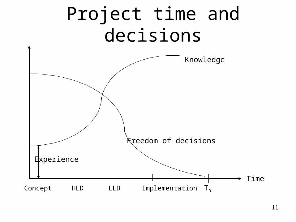
Project time and decisions
Time TD
Knowledge
Freedom of decisions
Experience
Concept HLD LLD Implementation
12
The concept phase
Most systems start as a concept, e.g.:
• Automatic shut-down of production when we discover a gas leakage.
• All patient info kept in a central database and be available for all that need it through a data network.
• Complete overview of all our trains – where they are, their speed and so on.
13
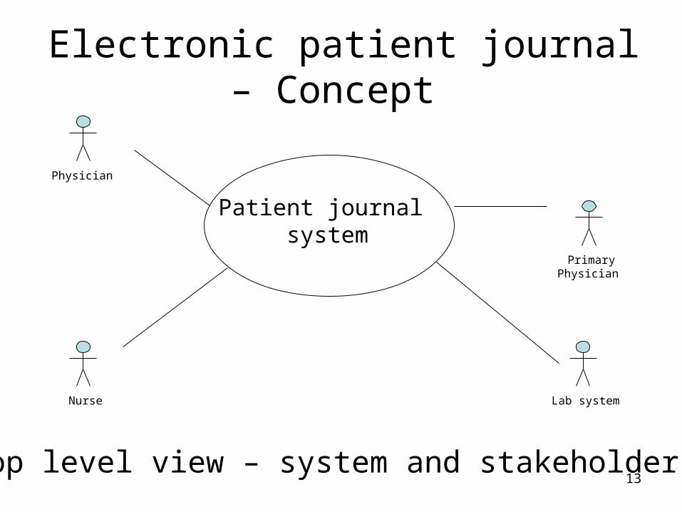
Electronic patient journal – Concept
Primary Physician
Nurse
Physician
Lab system
Patient journal system
Top level view – system and stakeholders
14
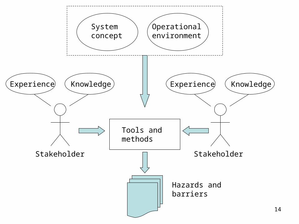
Experience Knowledge Experience Knowledge
Systemconcept
Tools and methods
Hazards andbarriers
Operationalenvironment
Stakeholder Stakeholder
15
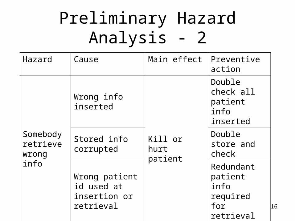
Preliminary Hazard Analysis - 1
The preliminary hazard analysis is used early in the process. This is reflected in the level of details required in the PHA table.
We can include both hazards and the corresponding preventive actions – barriers.
Barrier descriptions are converted to system requirements.
16
Preliminary Hazard Analysis - 2
Hazard Cause Main effect Preventive action
Somebody retrieve wrong info
Wrong info inserted
Kill or hurt patient
Double check all patient info inserted
Stored info corrupted
Double store and check
Wrong patient id used at insertion or retrieval
Redundant patient info required for retrieval
: : : :

17
Requirements
Once we have decided to go ahead with the project, we need to elicit and document the requirements. These consist of two components:
• The functions used to fulfil the customer’s needs
• Barriers against hazards identified in the PHA
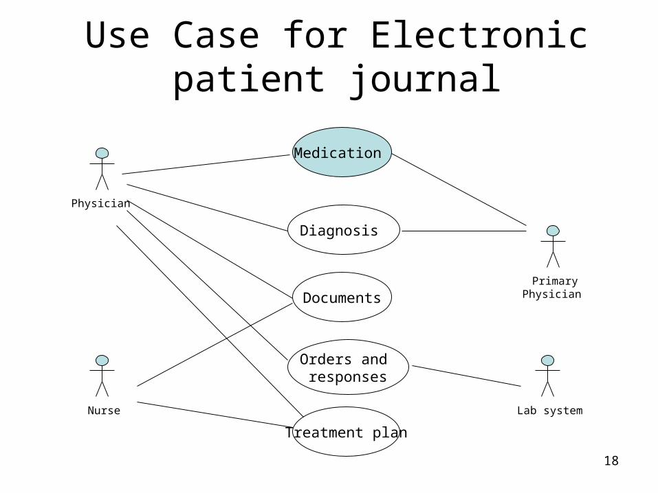
18
Use Case for Electronic patient journal
Nurse
Medication
Documents
Diagnosis
Orders and responses
Treatment plan
Physician
Primary Physician
Lab system
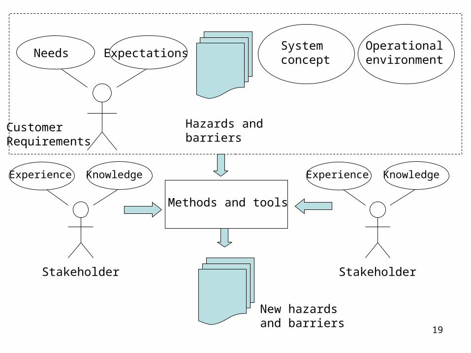
19
Needs Expectations
Customer Requirements
Hazards andbarriers
Systemconcept
Operationalenvironment
Methods and tools
New hazards and barriers
Experience Knowledge
Stakeholder
Experience Knowledge
Stakeholder
20
Safety in the requirements phase
Functional requirements – which services should the system offer to its users?
Use case diagrams and textual use cases have turned out to be two efficient ways of documenting this. They
• Are easy to understand for all stakeholders.
• Can be used as input to several safety analysis methods.
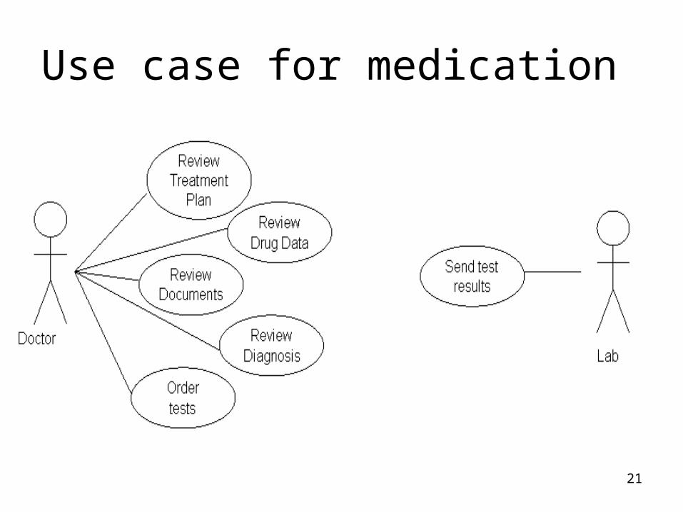
21
Use case for medication
22
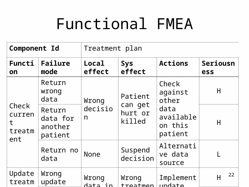
Functional FMEA
Component Id Treatment plan
Function Failure mode
Local effect
Sys effect Actions Seriousness
Check current treatment
Return wrong data
Wrong decision
Patient can get hurt or killed
Check against other data available on this patient
H
Return data for another patient
H
Return no data
NoneSuspend decision
Alternative data source
L
Update treatment plan
Wrong update
Wrong data in journal
Wrong treatment
Implement update receipt
H
No update H
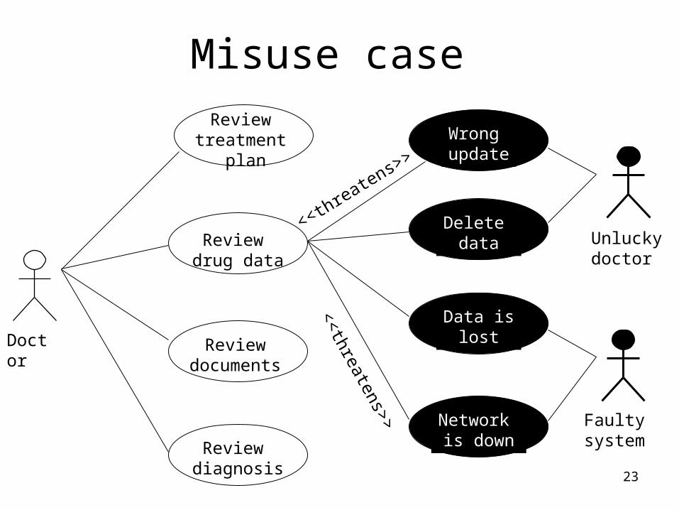
23
Misuse case Review
treatment plan
Review drug data
Review documents
Review diagnosis
Network is down
Wrong update
Delete data
Data islost
Unluckydoctor
Faulty system
Doctor<<threatens>>
<<threatens>>
24
High level design
When we enter high level design, all identified hazards and barriers have been converted to requirements.
The high level design can be documented for instance as
• Package diagrams
• High level class diagrams
• High level sequence diagrams
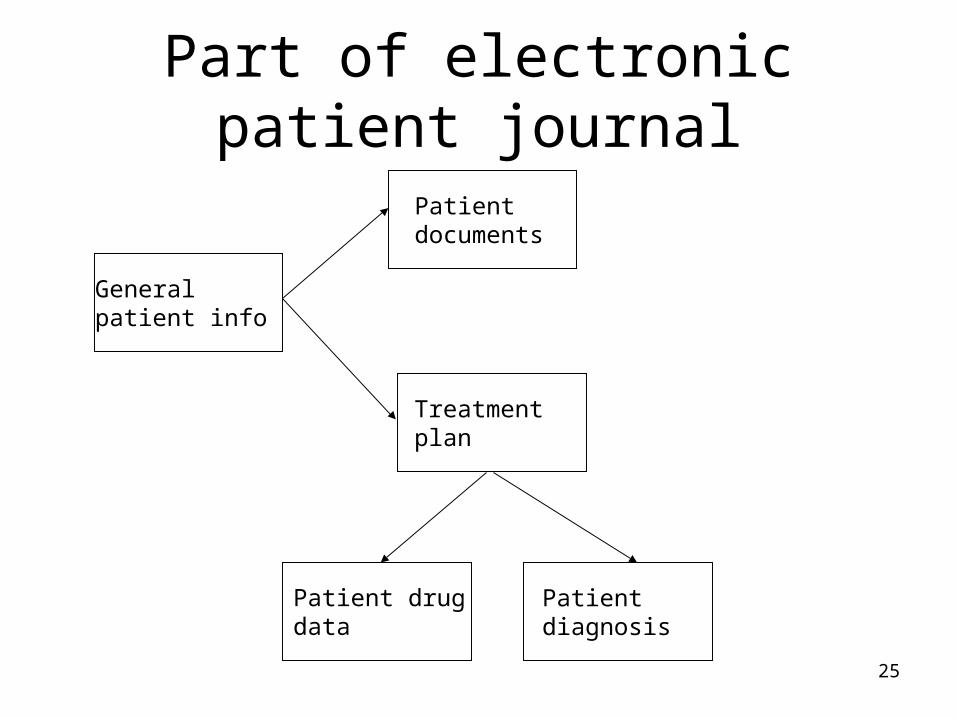
25
Part of electronic patient journal
Patient diagnosis
Patient drugdata
General patient info
Patient documents
Treatment plan

26
Experience Knowledge Experience Knowledge
Systemconcept
Tools and methods
New hazards
Operationalenvironment
Extendedrequirements
Barriers andtests
Stakeholders Stakeholders
27
Safety and design
Packages and classes can be viewed as components and we can thus make our safety analysis much more detailed.
Important methods that can be used at this stage are for instance:
• HazOp, for architectural design.
• Component FMEA
28
HazOp - 1
HazOp uses study nodes as units of investigation and guide words to help in the hazard identification process. This makes the method quite efficient for identifying hazards
On the other hand, HazOp also requires more information – the system’s architecture – to define the study nodes.
29
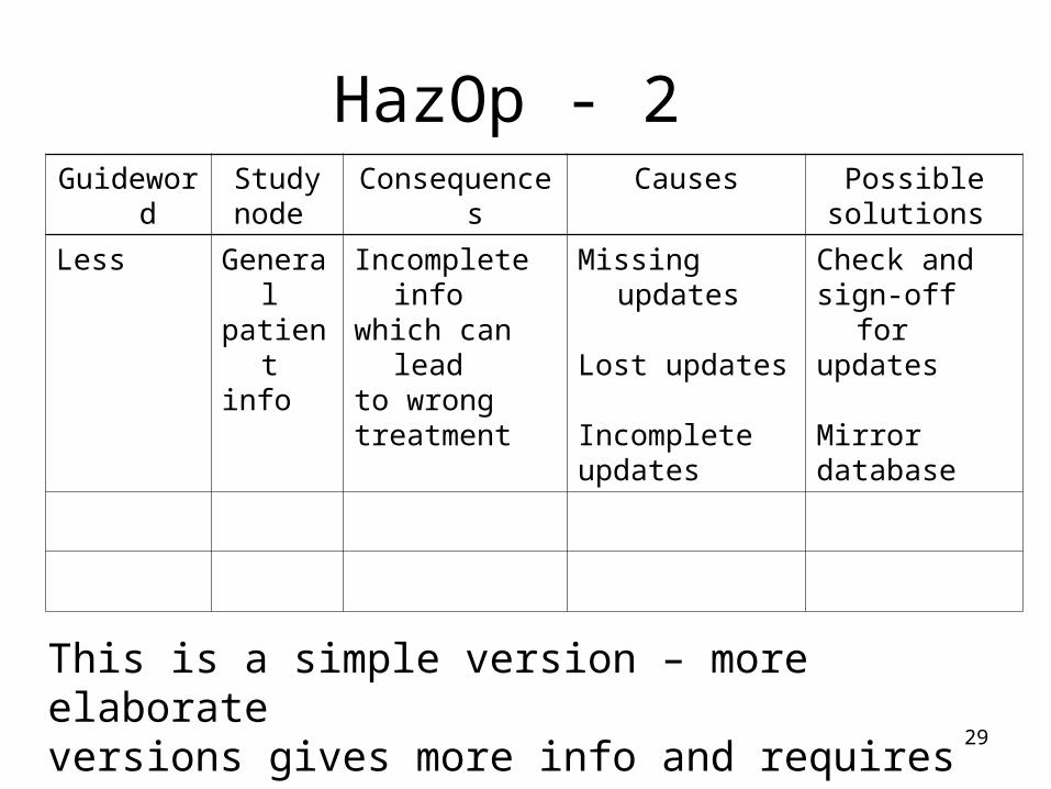
HazOp - 2
This is a simple version – more elaborate versions gives more info and requires more work.
Guideword Studynode
Consequences Causes Possiblesolutions
Less Generalpatientinfo
Incomplete infowhich can leadto wrongtreatment
Missing updates
Lost updates
Incompleteupdates
Check andsign-off forupdates
Mirrordatabase

30
Failure Mode Effect Analysis - 1
FMEA will systematically check each system component
• How can this component fail?
• What are the consequences for the component?
• What are the consequences for the system?
• How can we handle the hazard?

31
Failure Mode Effect Analysis - 2
Component Failure mode
Effect Handling or barrier
Seriousness
Patient drug data
Give wrong data
Wrong medication description. e.g. dosage
Check dosage against medication rules database.Prevent too high dosage
High
Incorrect or missing update
Outdated medication description, e.g. dosage
High

32
Failure Mode Effect Analysis - 3
The failure Mode Effect Analysis:• Offers a systematic walk-through of one or
more system components.• Focuses on preventions – barriers - rather
than cures and fixes.• Produces an easy-to-use list of hazards
and ideas on how they can be removed or handled.

33
Detailed design
Just as high level design, the detailed design can be documented for instance as packages, class diagrams and sequence diagrams.
We have more info than we had during high level design and we can thus make a more detailed safety analysis.

34
Patient info
Patient documents
Drug DBPatientdrug data
Treatmentplan
Test results
Currenttreatment
Drugdescription
If changes necessary
Update drug data

35
Experience Knowledge Experience Knowledge
Tools and methods
New hazards
Operationalenvironment
High level design
Barriers andtests
Barriers Detaileddesign
Stakeholder Stakeholder

36
Component FMEA
Component Id
Treatment plan
Failure mode Local effect Sys effect Actions Seriousness
Return wrongtreatment
Wrong info todoctor
Wrongdecision
Sanity check H
Update wrongdrug data
Wrong info inpatient’sjournal
Wrongmedication
Update receipt
H
Update drugdata forwrongpatient
H
: : : : :

37
Implementing barriers
All hazard analyses must lead to barriers that have one of the following effects:
• Prevent a hazard from leading to a problem.
• Prevent a problem from causing a dangerous event.
• Reduce the effect of a dangerous event if it cannot be prevented.

38
Bar
rier
1 Bar
rier
2 Bar
rier
3 Bar
rier
4 Bar
rier
5 Bar
rier
6
Risk Prob. Event
PreventionPrevent risk from becoming a problem
HandlingPrevent event from having bad consequences
Reduction Reduce effect of event
Barrier roles

39Risk RM
Minimum achievablerisk
RA
Acceptablerisk
Unmitigated riskfrom EUC
Ru
All barriers work as planned
Barr. 1Barr. 2Barr. 3Barr. n
Barrier failure
Barrier reliability
40
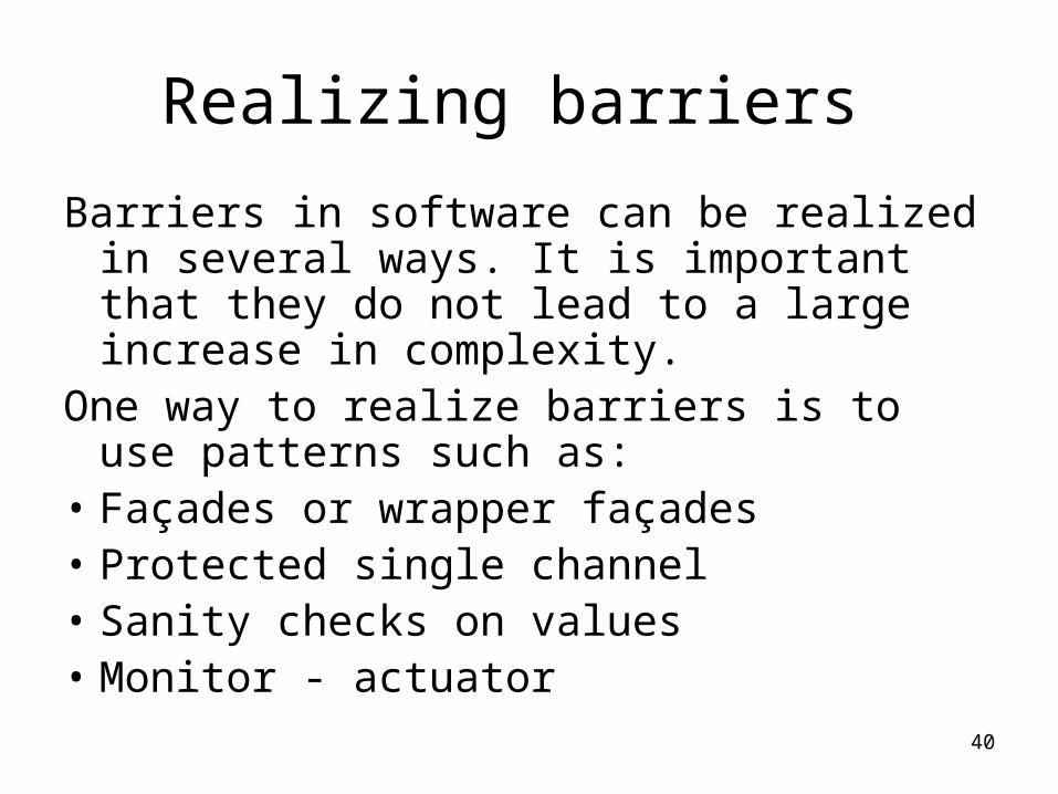
Realizing barriers
Barriers in software can be realized in several ways. It is important that they do not lead to a large increase in complexity.
One way to realize barriers is to use patterns such as:
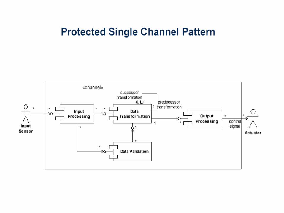
• Façades or wrapper façades • Protected single channel• Sanity checks on values• Monitor - actuator

41
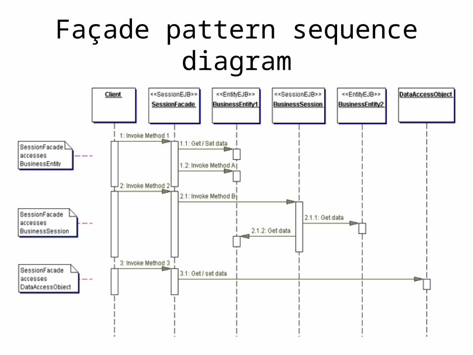
Façade pattern
42
Façade pattern sequence diagram

43
Wrapper façade pattern
44
45
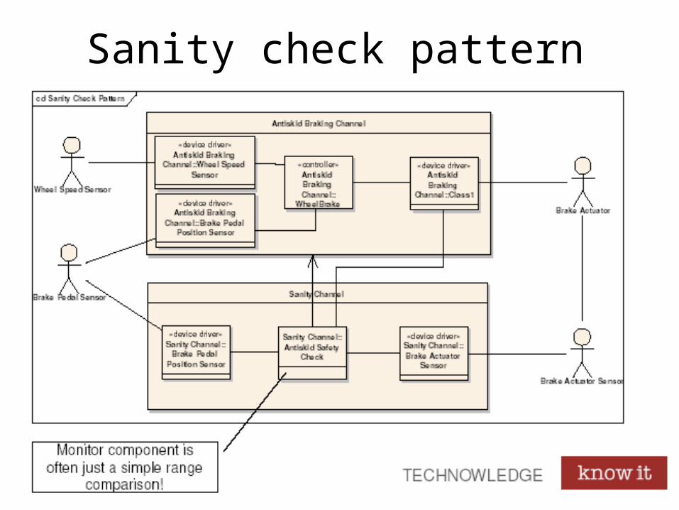
Sanity check pattern

46
Monitor - actuator
47
Safety analysis research - 1
Research on safety analysis are concerned with some broad problem areas: How to
• Implement barriers to prevent or reduce the effect of dangerous events?
• Create safety analysis patterns?
• Elicit the necessary information from all stakeholders?
48
Safety analysis research - 2
Our current research in the area of software safety has focused on:
• Which methods are the easier to understand, learn and use?
• What is the relationship between method and system representation – is it e.g. easier to base an analysis on scenarios than on a requirements list?
49
Safety analysis research - 3
How can we
• Improve the safety analysis by making earlier experiences on similar systems available to all stakeholders?
• Most efficiently move from identified hazards to– Prevention, e.g. barriers– Tests – do the barriers work as intended?

50
Last but not least
It is possible to be too safe. A chainsaw with a fully protected blade is
• Absolutely safe• Absolutely useless
It is not possible to be absolutely safe. Whatever you do or don’t do, the probability of dying during the next hour is more than 10-6.
Make sure you have a nice day.
Related Documents