H Multi-function and mono-function timer range 80.01 - Multi-function & multi-voltage 80.11 - On-delay, multi-voltage • 17.5 mm wide • Six time scales from 0.1 s to 24 h • High input/output isolation • 35 mm rail (EN 60715) mount • “Blade + cross” - both flat blade and cross head screw drivers can be used to adjust the range and function selectors, the timing trimmer, and to disengage the rail mounting clip • New multi-voltage versions with “PWM clever” technology 80.01 / 80.11 Screw terminal 80.01 80.11 • Multi-voltage • Multi-function • Multi-voltage • Mono-function AI: On-delay DI: Interval SW: Symmetrical flasher (starting pulse on) BE: Off-delay with control signal CE: On- and off-delay with control signal DE: Interval with control signal on AI: On-delay Wiring diagram (without control signal) Wiring diagram (with control signal) Wiring diagram (without control signal) FOR UL RATINGS SEE: “General technical information” page V For outline drawing see page 6 Contact specification Contact configuration 1 CO (SPDT) 1 CO (SPDT) Rated current/Maximum peak current A 16/30 16/30 Rated voltage/ Maximum switching voltage V AC 250/400 250/400 Rated load AC1 VA 4000 4000 Rated load AC15 (230 V AC) VA 750 750 Single phase motor rating (230 V AC) kW 0.55 0.55 Breaking capacity DC1: 30/110/220 V A 16/0.3/0.12 16/0.3/0.12 Minimum switching load mW (V/mA) 500 (10/5) 500 (10/5) Standard contact material AgNi AgNi Supply specification Nominal voltage (UN ) V AC (50/60 Hz) 12…240 24…240 V DC 12…240 24…240 Rated power AC/DC VA (50 Hz)/W < 1.8/< 1 < 1.8/< 1 Operating range V AC 10.8…265 16.8…265 V DC 10.8…265 16.8…265 Technical data Specified time range (0.1…2)s, (1…20)s, (0.1…2)min, (1…20)min, (0.1…2)h, (1…24)h Repeatability % ± 1 ± 1 Recovery time ms 100 100 Minimum control impulse ms 50 — Setting accuracy-full range % ± 5 ± 5 Electrical life at rated load in AC1 cycles 50 · 10 3 50 · 10 3 Ambient temperature range °C –10…+50 –10…+50 Protection category IP 20 IP 20 Approvals (according to type) 1 XI-2016, www.findernet.com 80 SERIES 80 SERIES Modular timers 16 A

Welcome message from author
This document is posted to help you gain knowledge. Please leave a comment to let me know what you think about it! Share it to your friends and learn new things together.
Transcript
H
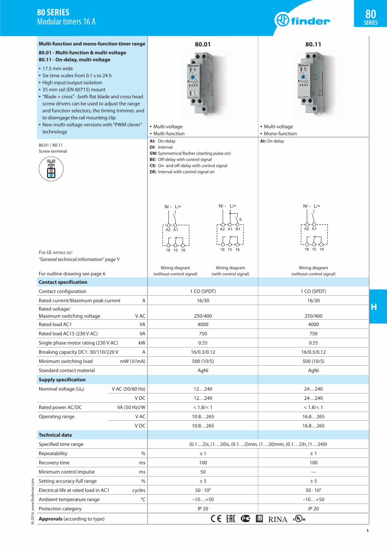
Multi-function and mono-function timer range
80.01 - Multi-function & multi-voltage80.11 - On-delay, multi-voltage
• 17.5 mm wide• Six time scales from 0.1 s to 24 h• High input/output isolation• 35 mm rail (EN 60715) mount• “Blade + cross” - both flat blade and cross head
screw drivers can be used to adjust the range and function selectors, the timing trimmer, and to disengage the rail mounting clip
• New multi-voltage versions with “PWM clever” technology
80.01 / 80.11Screw terminal
80.01 80.11
• Multi-voltage• Multi-function
• Multi-voltage• Mono-function
AI: On-delayDI: IntervalSW: Symmetrical flasher (starting pulse on)BE: Off-delay with control signalCE: On- and off-delay with control signalDE: Interval with control signal on
AI: On-delay
Wiring diagram (without control signal)
Wiring diagram (with control signal)
Wiring diagram (without control signal)
For UL ratings see: “General technical information” page V
For outline drawing see page 6
Contact specification
Contact configuration 1 CO (SPDT) 1 CO (SPDT)
Rated current/Maximum peak current A 16/30 16/30
Rated voltage/ Maximum switching voltage V AC 250/400 250/400
Rated load AC1 VA 4000 4000
Rated load AC15 (230 V AC) VA 750 750
Single phase motor rating (230 V AC) kW 0.55 0.55
Breaking capacity DC1: 30/110/220 V A 16/0.3/0.12 16/0.3/0.12
Minimum switching load mW (V/mA) 500 (10/5) 500 (10/5)
Standard contact material AgNi AgNi
Supply specification
Nominal voltage (UN) V AC (50/60 Hz) 12…240 24…240
V DC 12…240 24…240
Rated power AC/DC VA (50 Hz)/W < 1.8/< 1 < 1.8/< 1
Operating range V AC 10.8…265 16.8…265
V DC 10.8…265 16.8…265
Technical data
Specified time range (0.1…2)s, (1…20)s, (0.1…2)min, (1…20)min, (0.1…2)h, (1…24)h
Repeatability % ± 1 ± 1
Recovery time ms 100 100
Minimum control impulse ms 50 —
Setting accuracy-full range % ± 5 ± 5
Electrical life at rated load in AC1 cycles 50 · 103 50 · 103
Ambient temperature range °C –10…+50 –10…+50
Protection category IP 20 IP 20
Approvals (according to type)
1
XI-2
016,
ww
w.fi
nder
net.c
om
80SERIES
80 SERIES Modular timers 16 A
H
Mono-function timer range
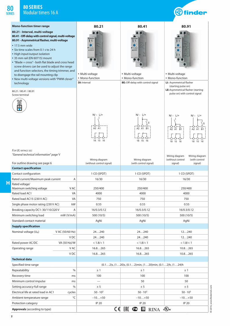
80.21 - Interval, multi-voltage80.41 - Off-delay with control signal, multi-voltage80.91 - Asymmetrical flasher, multi-voltage
• 17.5 mm wide• Six time scales from 0.1 s to 24 h• High input/output isolation• 35 mm rail (EN 60715) mount• “Blade + cross” - both flat blade and cross head
screw drivers can be used to adjust the range and function selectors, the timing trimmer, and to disengage the rail mounting clip
• New multi-voltage versions with “PWM clever” technology
80.21 / 80.41 / 80.91Screw terminal
80.21 80.41 80.91
• Multi-voltage• Mono-function
• Multi-voltage• Mono-function
• Multi-voltage• Mono-function
DI: Interval BE: Off-delay with control signal LI: Asymmetrical flasher (starting pulse on)
LE: Asymmetrical flasher (starting pulse on) with control signal
Wiring diagram (without control signal)
Wiring diagram (with control signal)
Wiring diagram (without control
signal)
Wiring diagram (with control
signal)
For UL ratings see: “General technical information” page V
For outline drawing see page 6
Contact specification
Contact configuration 1 CO (SPDT) 1 CO (SPDT) 1 CO (SPDT)
Rated current/Maximum peak current A 16/30 16/30 16/30
Rated voltage/ Maximum switching voltage V AC 250/400 250/400 250/400
Rated load AC1 VA 4000 4000 4000
Rated load AC15 (230 V AC) VA 750 750 750
Single phase motor rating (230 V AC) kW 0.55 0.55 0.55
Breaking capacity DC1: 30/110/220 V A 16/0.3/0.12 16/0.3/0.12 16/0.3/0.12
Minimum switching load mW (V/mA) 500 (10/5) 500 (10/5) 500 (10/5)
Standard contact material AgNi AgNi AgNi
Supply specification
Nominal voltage (UN) V AC (50/60 Hz) 24…240 24…240 12…240
V DC 24…240 24…240 12…240
Rated power AC/DC VA (50 Hz)/W < 1.8/< 1 < 1.8/< 1 < 1.8/< 1
Operating range V AC 16.8…265 16.8…265 10.8…265
V DC 16.8…265 16.8…265 10.8…265
Technical data
Specified time range (0.1…2)s, (1…20)s, (0.1…2)min, (1…20)min, (0.1…2)h, (1…24)h
Repeatability % ± 1 ± 1 ± 1
Recovery time ms 100 100 100
Minimum control impulse ms — 50 50
Setting accuracy-full range % ± 5 ± 5 ± 5
Electrical life at rated load in AC1 cycles 50 · 103 50 · 103 50 · 103
Ambient temperature range °C –10…+50 –10…+50 –10…+50
Protection category IP 20 IP 20 IP 20
Approvals (according to type)
2
XI-2
016,
ww
w.fi
nder
net.c
om
80 SERIES Modular timers 16 A
80SERIES
H
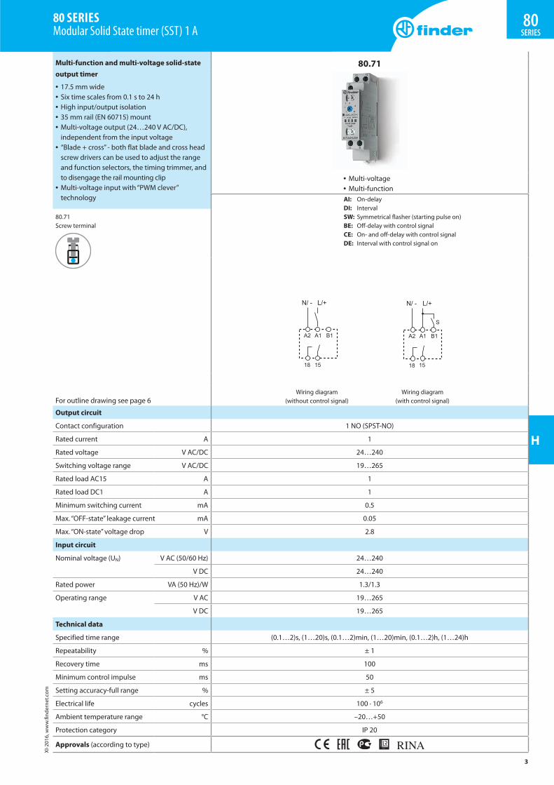
Multi-function and multi-voltage solid-state output timer
• 17.5 mm wide• Six time scales from 0.1 s to 24 h• High input/output isolation• 35 mm rail (EN 60715) mount• Multi-voltage output (24…240 V AC/DC),
independent from the input voltage• “Blade + cross” - both flat blade and cross head
screw drivers can be used to adjust the range and function selectors, the timing trimmer, and to disengage the rail mounting clip
• Multi-voltage input with “PWM clever” technology
80.71Screw terminal
80.71
• Multi-voltage• Multi-functionAI: On-delayDI: IntervalSW: Symmetrical flasher (starting pulse on)BE: Off-delay with control signalCE: On- and off-delay with control signalDE: Interval with control signal on
Wiring diagram (without control signal)
Wiring diagram (with control signal)For outline drawing see page 6
Output circuit
Contact configuration 1 NO (SPST-NO)
Rated current A 1
Rated voltage V AC/DC 24…240
Switching voltage range V AC/DC 19…265
Rated load AC15 A 1
Rated load DC1 A 1
Minimum switching current mA 0.5
Max. “OFF-state” leakage current mA 0.05
Max. “ON-state” voltage drop V 2.8
Input circuit
Nominal voltage (UN) V AC (50/60 Hz) 24…240
V DC 24…240
Rated power VA (50 Hz)/W 1.3/1.3
Operating range V AC 19…265
V DC 19…265
Technical data
Specified time range (0.1…2)s, (1…20)s, (0.1…2)min, (1…20)min, (0.1…2)h, (1…24)h
Repeatability % ± 1
Recovery time ms 100
Minimum control impulse ms 50
Setting accuracy-full range % ± 5
Electrical life cycles 100 · 106
Ambient temperature range °C –20…+50
Protection category IP 20
Approvals (according to type)
3
XI-2
016,
ww
w.fi
nder
net.c
om
80SERIES
80 SERIES Modular Solid State timer (SST) 1 A
H
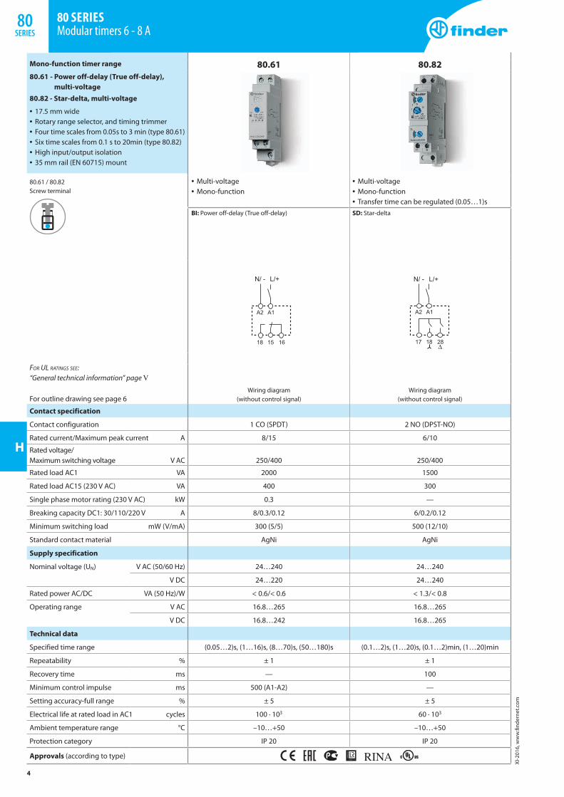
Mono-function timer range
80.61 - Power off-delay (True off-delay), multi-voltage
80.82 - Star-delta, multi-voltage
• 17.5 mm wide• Rotary range selector, and timing trimmer• Four time scales from 0.05s to 3 min (type 80.61)• Six time scales from 0.1 s to 20min (type 80.82)• High input/output isolation• 35 mm rail (EN 60715) mount
80.61 / 80.82Screw terminal
80.61 80.82
• Multi-voltage• Mono-function
• Multi-voltage• Mono-function• Transfer time can be regulated (0.05…1)s
BI: Power off-delay (True off-delay) SD: Star-delta
Wiring diagram (without control signal)
Wiring diagram (without control signal)
For UL ratings see: “General technical information” page V
For outline drawing see page 6
Contact specification
Contact configuration 1 CO (SPDT) 2 NO (DPST-NO)
Rated current/Maximum peak current A 8/15 6/10
Rated voltage/ Maximum switching voltage V AC 250/400 250/400
Rated load AC1 VA 2000 1500
Rated load AC15 (230 V AC) VA 400 300
Single phase motor rating (230 V AC) kW 0.3 —
Breaking capacity DC1: 30/110/220 V A 8/0.3/0.12 6/0.2/0.12
Minimum switching load mW (V/mA) 300 (5/5) 500 (12/10)
Standard contact material AgNi AgNi
Supply specification
Nominal voltage (UN) V AC (50/60 Hz) 24…240 24…240
V DC 24…220 24…240
Rated power AC/DC VA (50 Hz)/W < 0.6/< 0.6 < 1.3/< 0.8
Operating range V AC 16.8…265 16.8…265
V DC 16.8…242 16.8…265
Technical data
Specified time range (0.05…2)s, (1…16)s, (8…70)s, (50…180)s (0.1…2)s, (1…20)s, (0.1…2)min, (1…20)min
Repeatability % ± 1 ± 1
Recovery time ms — 100
Minimum control impulse ms 500 (A1-A2) —
Setting accuracy-full range % ± 5 ± 5
Electrical life at rated load in AC1 cycles 100 · 103 60 · 103
Ambient temperature range °C –10…+50 –10…+50
Protection category IP 20 IP 20
Approvals (according to type)
4
XI-2
016,
ww
w.fi
nder
net.c
om
80 SERIES Modular timers 6 - 8 A
80SERIES
H
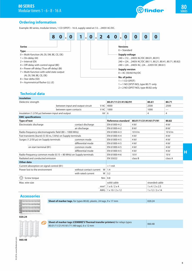
Ordering informationExample: 80 series, modular timers, 1 CO (SPDT) - 16 A, supply rated at (12…240)V AC/DC.
8 0 . 0 1 . 0 . 2 4 0 . 0 0 0 0
Series
Type0 = Multi-function (AI, DI, SW, BE, CE, DE)1 = On-delay (AI)2 = Interval (DI)4 = Off-delay with control signal (BE)6 = Power off-delay (True off-delay) (BI)7 = Multi-function with solid state output
(AI, DI, SW, BE, CE, DE)8 = Star-delta (SD)9 = Asymmetrical flasher (LI, LE)
Versions0 = Standard
Supply voltage240 = (12…240)V AC/DC (80.01, 80.91)240 = (24…240)V AC/DC (80.11, 80.21, 80.41, 80.71, 80.82)240 = (24…240)V AC, (24…220)V DC (80.61)
Supply version0 = AC (50/60 Hz)/DC
No. of poles1 = 1 CO (SPDT)1 = 1 NO (SPST-NO), type 80.71 only2 = 2 NO (DPST-NO), type 80.82 only
Technical dataInsulationDielectric strength 80.01/11/21/41/82/91 80.61 80.71
between input and output circuit V AC 4000 2500 2500between open contacts V AC 1000 1000 —
Insulation (1.2/50 µs) between input and output kV 6 4 4EMC specificationsType of test Reference standard 80.01/11/21/41/61/71/91 80.82Electrostatic discharge contact discharge EN 61000-4-2 4 kV 4 kV
air discharge EN 61000-4-2 8 kV 8 kVRadio-frequency electromagnetic field (80 ÷ 1000 MHz) EN 61000-4-3 10 V/m 10 V/mFast transients (burst) (5-50 ns, 5 kHz) on Supply terminals EN 61000-4-4 4 kV 4 kVSurges (1.2/50 µs) on Supply terminals common mode EN 61000-4-5 4 kV 4 kV
differential mode EN 61000-4-5 4 kV 4 kVon start terminal (B1) common mode EN 61000-4-5 4 kV 4 kV
differential mode EN 61000-4-5 4 kV 4 kVRadio-frequency common mode (0.15 ÷ 80 MHz) on Supply terminals EN 61000-4-6 10 V 10 VRadiated and conducted emission EN 55022 class B class AOther dataCurrent absorption on signal control (B1) < 1 mAPower lost to the environment without contact current W 1.4
with rated current W 3.2
Screw torque Nm 0.8
Max. wire size solid cable stranded cable mm2 1 x 6 / 2 x 4 1 x 4 / 2 x 2.5 AWG 1 x 10 / 2 x 12 1 x 12 / 2 x 14
Accessories
020.24
Sheet of marker tags, for types 80.82, plastic, 24 tags, 9 x 17 mm 020.24
060.48
Sheet of marker tags (CEMBRE'S Thermal transfer printers) for relays types 80.01/11/21/41/61/71 (48 tags), 6 x 12 mm
060.48
5
XI-2
016,
ww
w.fi
nder
net.c
om
80SERIES
80 SERIES Modular timers 1 - 6 - 8 - 16 A
H
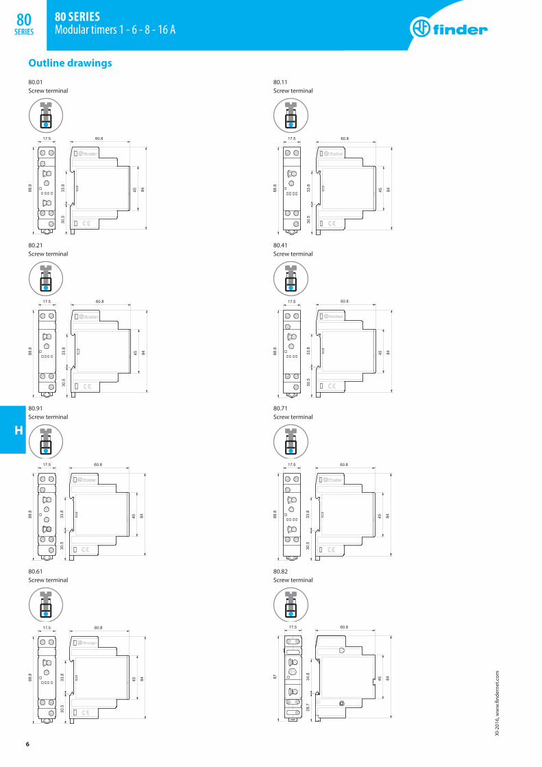
Outline drawings
80.01Screw terminal
80.11Screw terminal
80.21Screw terminal
80.41Screw terminal
80.91Screw terminal
80.71Screw terminal
80.61Screw terminal
80.82Screw terminal
6
XI-2
016,
ww
w.fi
nder
net.c
om
80 SERIES Modular timers 1 - 6 - 8 - 16 A
80SERIES
H
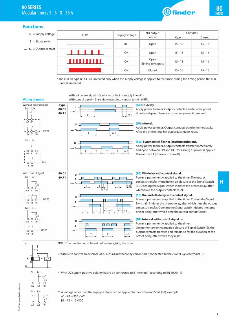
Functions U = Supply voltage
S = Signal switch
= Output contact
LED* Supply voltageNO output
contactContacts
Open Closed
OFF Open 15 - 18 15 - 16
ON Open 15 - 18 15 - 16
ONOpen
(Timing in Progress)15 - 18 15 - 16
ON Closed 15 - 16 15 - 18
* The LED on type 80.61 is illuminated only when the supply voltage is applied to the timer; during the timing period the LED is not illuminated.
Wiring diagramWithout control signal = Start via contact in supply line (A1).With control signal = Start via contact into control terminal (B1).
Without control signal
80.01
80.71
Type80.0180.71
(AI) On-delay.Apply power to timer. Output contacts transfer after preset time has elapsed. Reset occurs when power is removed.
(DI) Interval.Apply power to timer. Output contacts transfer immediately.After the preset time has elapsed, contacts reset.
(SW) Symmetrical flasher (starting pulse on).Apply power to timer. Output contacts transfer immediately and cycle between ON and OFF for as long as power is applied. The ratio is 1:1 (time on = time off ).
With control signal
80.01
80.71
80.0180.71
(BE) Off-delay with control signal.Power is permenently applied to the timer. The output contacts transfer immediately on closure of the Signal Switch (S). Opening the Signal Switch initiates the preset delay, after which time the output contacts reset.
(CE) On- and off-delay with control signal.Power is permenently applied to the timer. Closing the Signal Switch (S) initiates the preset delay, after which time the output contacts transfer. Opening the Signal switch initiates the same preset delay, after which time the output contacts reset.
(DE) Interval with control signal on.Power is permenently applied to the timer.On momentary or maintained closure of Signal Switch (S), the output contacts transfer, and remain so for the duration of the preset delay, after which they reset.
NOTE: The function must be set before energising the timer.
• Possible to control an external load, such as another relay coil or timer, connected to the control signal terminal B1.
* With DC supply, positive polarity has to be connected to B1 terminal (according to EN 60204-1).
** A voltage other than the supply voltage can be applied to the command Start (B1), example: A1 - A2 = 230 V AC B1 - A2 = 12 V DC
7
XI-2
016,
ww
w.fi
nder
net.c
om
80SERIES
80 SERIES Modular timers 1 - 6 - 8 - 16 A
H
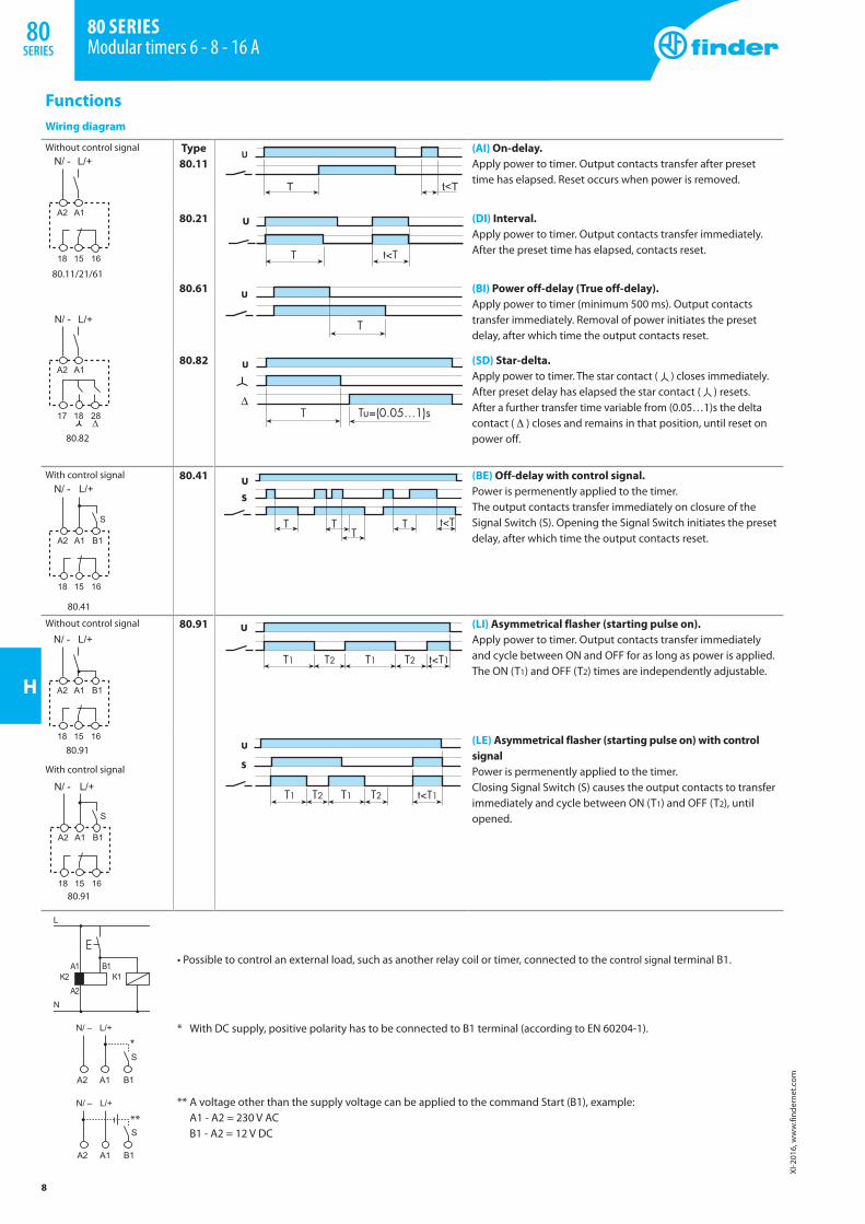
FunctionsWiring diagram
Without control signal
80.11/21/61
80.82
Type80.11
(AI) On-delay.Apply power to timer. Output contacts transfer after preset time has elapsed. Reset occurs when power is removed.
80.21 (DI) Interval.Apply power to timer. Output contacts transfer immediately.After the preset time has elapsed, contacts reset.
80.61 (BI) Power off-delay (True off-delay).Apply power to timer (minimum 500 ms). Output contacts transfer immediately. Removal of power initiates the preset delay, after which time the output contacts reset.
80.82 (SD) Star-delta.Apply power to timer. The star contact ( ) closes immediately. After preset delay has elapsed the star contact ( ) resets.After a further transfer time variable from (0.05…1)s the delta contact ( ∆ ) closes and remains in that position, until reset on power off.
With control signal
80.41
80.41 (BE) Off-delay with control signal.Power is permenently applied to the timer.The output contacts transfer immediately on closure of theSignal Switch (S). Opening the Signal Switch initiates the preset delay, after which time the output contacts reset.
Without control signal
80.91
With control signal
80.91
80.91 (LI) Asymmetrical flasher (starting pulse on).Apply power to timer. Output contacts transfer immediately and cycle between ON and OFF for as long as power is applied. The ON (T1) and OFF (T2) times are independently adjustable.
(LE) Asymmetrical flasher (starting pulse on) with control signalPower is permenently applied to the timer.Closing Signal Switch (S) causes the output contacts to transfer immediately and cycle between ON (T1) and OFF (T2), until opened.
• Possible to control an external load, such as another relay coil or timer, connected to the control signal terminal B1.
* With DC supply, positive polarity has to be connected to B1 terminal (according to EN 60204-1).
** A voltage other than the supply voltage can be applied to the command Start (B1), example: A1 - A2 = 230 V AC B1 - A2 = 12 V DC
8
XI-2
016,
ww
w.fi
nder
net.c
om
80 SERIES Modular timers 6 - 8 - 16 A
80SERIES
Related Documents