MINI HiFi COMPONENT SYSTEM RXD-251/301/301E/301W/ RXD-351/351E/351W/371S/A3 SERVICE MANUAL © 1998-7/B51-5454-00 (K/K) 3763 (XD-251~A3)** In compliance with Federal Regulations, following are reproduc- tions of labels on, or inside the product relating to laser product safety. **Refer to page 2 if you want to know system configuration. KENWOOD-Crop. certifies this equipment conforms to DHHS Regulations No. 21 DFR 1040. 10, Chapter 1, Subchapter J. DANGER : Laser radiation when open and interlock defeated. AVOID DIRECT EXPOSURE TO BEAM Panel(CD) * (A60-) Front glass * (A29-) Knob * (K29-) Knob (K29-7512-08) Knob (K29-7519-08) Knob (K29-7518-08) Phone jack (E11-0386-08) Konb (K-29-7516-08) Cassette lid(R) * (A53-) Front glass(R) (B10-3451-08) Front panel * (A60-) Knob * (k29-) Knob (K29-7523-08) Knob (K29-7522-08) Knob (K29-7521-08) Cassette lid(L) * (A53-) Front glass(L) (B10-3450-08) Knob (K29-7515-08) Knob (K29-7511-08) Mic jack (E11-0387-08) Knob * (K29-) Knob * (K29-) Knob (K29-7513-08) Illust. is RXD-351. * Refer to parts list on page 38.

Welcome message from author
This document is posted to help you gain knowledge. Please leave a comment to let me know what you think about it! Share it to your friends and learn new things together.
Transcript

MINI HiFi COMPONENT SYSTEM
RXD-251/301/301E/301W/RXD-351/351E/351W/371S/A3SERVICE MANUAL
© 1998-7/B51-5454-00 (K/K) 3763(XD-251~A3)**
In compliance with Federal Regulations, following are reproduc-tions of labels on, or inside the product relating to laser productsafety.
**Refer to page 2 if you want to know system configuration.
KENWOOD-Crop. certifies this equipment conforms to DHHSRegulations No. 21 DFR 1040. 10, Chapter 1, Subchapter J.
DANGER : Laser radiation when open and interlock defeated.AVOID DIRECT EXPOSURE TO BEAM
Panel(CD) *(A60-)
Front glass *(A29-)
Knob *(K29-)
Knob (K29-7512-08)
Knob (K29-7519-08)
Knob (K29-7518-08)
Phone jack(E11-0386-08)
Konb(K-29-7516-08)
Cassette lid(R) *(A53-)
Front glass(R)(B10-3451-08)
Front panel *(A60-)
Knob *(k29-)
Knob(K29-7523-08)
Knob(K29-7522-08)
Knob(K29-7521-08)
Cassette lid(L) *(A53-)
Front glass(L)(B10-3450-08)
Knob(K29-7515-08)
Knob(K29-7511-08)
Mic jack(E11-0387-08)
Knob *(K29-)
Knob *(K29-)
Knob(K29-7513-08)
Illust. is RXD-351.* Refer to parts list on page 38.

FM indoor antenna (1)
Europe and U.K. Other countries
AM(T90-0815-08)
loop antenna (1)
AC(E03-0115-05)
plug adaptor (1)
Remote(A70-1260-08)
control unit (1)
Batteries (R6/AA) (2)
Use to adapt the plug on the power cordto the shape of the wall outlet.(Accessory only for regions where use isnecessary.)
(T90-0801-05): K1P1Y1M1M2M3X1X2X3
(T90-0836-05): E1E2E3E4T1T2Q1Q2
Operation to resetThe microcomputer may fall into malfunction (impossibility to oper-ate, erroneous display, etc.) when the power cord is unpluggedwhile power is ON or due to an external factor. In this case, executethe following procedure to reset the microcomputer and return it tonormal condition.
Press the "POWER" key while holding the Stop (7) key ofthe CD section pressed, to switch off the power, and thenswitch the power on again after a few seconds.
÷ Please note that resetting the microcomputer clears the contentsstored in and returns and to condition when it left the factory.
SYSTEM MAIN UNIT DESTINATION SPEAKER
XD-301 RXD-301 E3T2X3 LS-N301XD-301E RXD-301E E4 LS-N301
XD-301W RXD-301W Q2 LS-N301
XD-351 RXD-351 E1T1 LS-N351
XD-351 RXD-351 M1X1Y1 LS-N371
XD-351E RXD-351E E2 LS-N351
XD-351W RXD-351W Q1 LS-N351
XD-A3 RXD-A3 K1P1 LS-N351
XD-371S RXD-371S M2 LS-N371
XD-251 RXD-251 M3X2 LS-N351
RXD-251/301/351/371S/A3
2
CONTENTS / ACCESSORIES
CONTENTS / ACCESSORIES ....................................2EXTERNAL VIEW ........................................................3CONTROLS .................................................................4BLOCK DIAGRAM .......................................................6CIRCUIT DESCRIPTION .............................................7CD MECHANISM OPERATION DESCRIPTION .........9ADJUSTMENT .......................................................... 11
WIRING DIAGRAM ....................................................15PARTS DESCRIPTIONS ...........................................16PC BOARD ................................................................17SCHEMATIC DIAGRAM ............................................23EXPLODED VIEW .....................................................37PARTS LIST...............................................................38SPECIFICATIONS .....................................................47
Contents
Accessories
System configuration Cautions
RXD-251/301/351/371S/A3
3
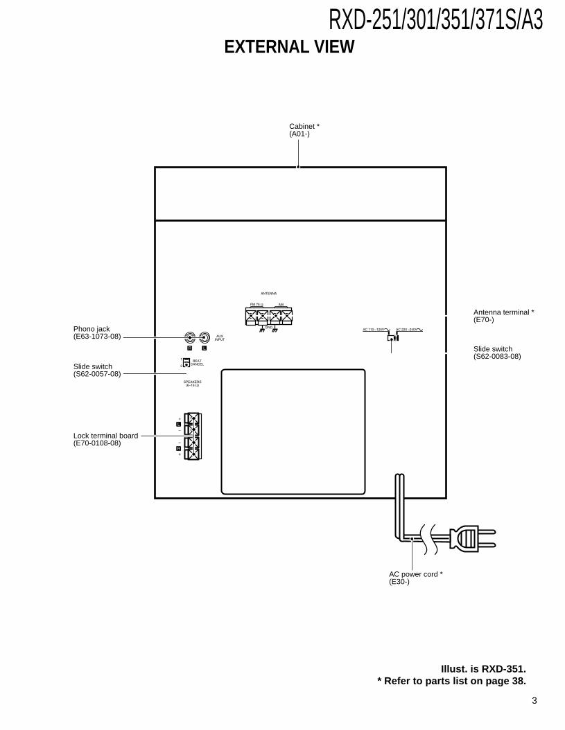
EXTERNAL VIEW
Slide switch (S62-0083-08)
AC power cord *(E30-)
Cabinet *(A01-)
Phono jack(E63-1073-08)
Slide switch(S62-0057-08)
Lock terminal board(E70-0108-08)
Antenna terminal *(E70-)
Illust. is RXD-351.* Refer to parts list on page 38.

RXD-251/301/351/371S/A3
4
CONTROLS
CD unit
DISC 1 DISC 2 DISC 3 0 7 6¢
4 DISCSKIP
1 2 3 4 5 6
7
Receiver unit
ON/STANDBY
INPUT
STANDBY
MIC 1
MIC 2
MIC VOLUME
MIN. MAX.
TIMER SET
CLOCK
DISPLAY/DEMO
ROCK FLAT
EX.BASS
POP JAZZ
BANDTUNING
PHONES
UP
DOWN
AUTOPRESET
MANUALPRESETAUTO/MONOTIMER
8
90
!
@
# $ %&
( )
¡
™
£
^*
¢
∞
1Skip (4, ¢ ) keys2DISC SKIP key
Used to skip discs.3Disc selection keys
The disc number is selected directly and playback starts.
4OPEN/CLOSE (0) keyThe disc tray is opened and closed.
5Stop (7) key6Play/pause (6) key7Disc tray
Three discs can be stored.
8ON/STANDBY ( ) key9 INPUT key
Key for input switching.0TIMER key
Key for timer START/STOP switching.!MIC 1/MIC 2 jack (except for some areas)@MIC VOLUME knob (except for some areas)#TIMER SET key
Used for setting the timer ON/OFF time.$CLOCK key
Used to set the present time.%DISPLAY/DEMO key
Switches the display contents.*Used for demonstration (DEMO) ON/OFF.
^AUTO/MONO keySwitches the tuning mode.
&MANUAL PRESET keyUsed to memorize broadcasting stations in the desired order.
*BAND keyPress to switch the receiving band.
(TUNING/ keysUsed for tuning to broadcasting stations and for time settings.
)PHONES terminalFor connection of a headphone (optional).
¡ AUTO PRESET keyUsed for automatic presetting of broadcasting stations.
™ VOLUME CONTROL knobThis is used for volume adjustment.
£ Sound selection keysUsed to select the desired sound type.FLAT : For listening without changing the sound.JAZZ : A sound quality curve suitable for jazz.POP : A sound quality curve suitable for popular
music.ROCK : A sound quality curve suitable for rock-and-roll.EX.BASS: For listening with abundant bass. (Can be used
together with other sound selection keys.)¢ Display∞ STANDBY indicator (Except for some areas)

RXD-251/301/351/371S/A3
5
CONTROLS
RXD-251/301/351/371S/A3
6
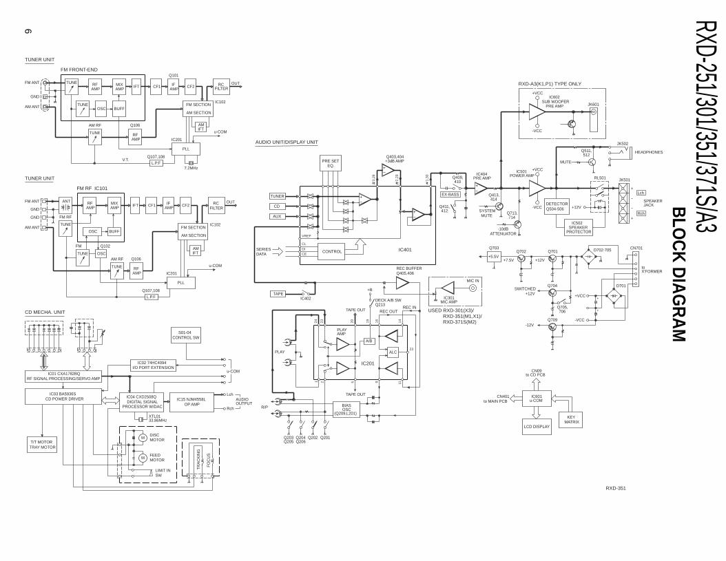
BLO
CK
DIA
GR
AM
CEDICL
VREF
24 23 20 19 16 14
1 2 5 9 11
23
3,28
2,29
1,30
+
+
TUNER
CD
AUX
CONTROLSERIESDATA
A/B
PLAYAMP
ALCPLAY
R/P OSCBIAS
(Q209,L201)
Q205Q203 Q204
Q206Q201Q202
TAPE OUT
TAPE
Q405,406REC BUFFER
IC402
TAPE OUT REC OUTREC IN
DECK A/B SWQ213
+B
IC301MIC AMP
MIC IN
Q403,404+3dB AMPPRE SET
EQ.
PRE AMPIC404
EX-BASS
412Q411,
410Q409, RL501
Q413,414
MUTESYSTEM
714
-10dBATTENUATOR
Q713,
POWER AMPIC501 +VCC
-VCC Q504-506DETECTOR
IC502SPEAKER
PROTECTOR
+12V
512Q511,
MUTE
JACKSPEAKER
Lch
HEADPHONES
JK502
Rch
JK501
+5.5VQ702
+7.5V +12V
Q701
Q704
+VCC
SWITCHED
toX'FORMER
-12VQ709
+12V
-VCC
CN701D702-705
D701
Q705,706
Q703
LCD DISPLAY
IC601u-COM
KEYMATRIX
CN09to CD PCB
CN401to MAIN PCB
RFAMP FILTER
RCTUNE
AMPMIX IFT CF1
BUFFOSCTUNE
AMPIF CF2
TUNE
AM RF
AMPRF
Q106
FM SECTION
Q101
PLL
IFTAM
u-COM
IC201
L.P.F
Q107,108
7.2MHz
AM SECTION
V.T.
AM ANT
GND
FM ANT OUT
MIX
BUFF
AMP
TUNE
AM ANT
GND
FM ANT
AMP
AM RF
TUNE
OSC
ANT RF
IFT
PLL
L.P.F
Q107,108
AMPRF
IC201
u-COM
AMP
Q106
IFT CF1 IFFILTER
AM SECTION
AM
FM SECTION
CF2OUTRC
IC102
IC102
TUNE
FM RF
FM
OSC
Q102
GND
IC01 CXA1782BQRF SIGNAL PROCESSING/SERVO AMP
PROCESSOR W/DACDIGITAL SIGNAL
CD POWER DRIVERIC03 BA5936S
I/O PORT EXTENSIONIC02 74HC4094
IC04 CXD2508Q
XTL0133.86MHz
IC15 NJM4558LOP AMP
M MOTORDISC
MOTORFEED
M
TR
AC
KIN
G
FO
CU
S
TRAY MOTORT/T MOTOR
SWLIMIT IN
OUTPUTAUDIO
CONTROL SWS01-04
Rch
Lch
u-COM
SUB WOOFERIC602
-VCC
+VCC
PRE AMP JK601
USED RXD-301(X3)/RXD-351(M1,X1)/RXD-371S(M2)
IC201
FM FRONT-END
FM RF IC101
TUNER UNIT
CD MECHA. UNIT
TUNER UNIT
AUDIO UNIT/DISPLAY UNIT
RXD-351
IC401
RXD-A3(K1,P1) TYPE ONLY

No. Name I/O DescriptionActive
H L
1 CE I LC7218, LC75392 CE out
2 ENABLE – No used
3 DI I LC7218, LC75392, 74HC4094 data out
4 DO O Data output to LC7218
5 CLK I LC 7218, LC75392, 74HC4094 clock out
6 DATA O Serial data out to CXD2508Q
7 SQCO I Serial output of SUBQ 80BIT
8 SQCK O Clock output
9 XLAT O Latch output
10 FOK O Focus OK output
11 GND – GND
12 RESET I Reset signal input
13 POWER - DOWN I Power down input
14 SENS I CXD2508Q sens
15 VSS – Vss
16 X1 – Xtal 6.0MHz
17 X2 – Xtal 6.0MHz
18 VDD1 – Vdd
19~22 K1~K4 I Key input (K1~K4)
23, 24 GND – GND
25 MODE - SW2 I Model discrimination (RXD-371S only)
26 MODE - SW1 I Model discrimination
27 SCOR I CXD2508Q Sub - code synch detect
28 COUNT O Track number count signal output
29 REMOTE IN I Remote signal input
30 VR + I VR encoder input A
31 VR - I VR encoder input B
32 PIC - UP I Pick - up SW
33 PIC - DOWN I Pick - down SW
34 DISC - COUNT I Disc counter SW
35 TURNTABLE - SW I Turntable SW
36 TRAY - OPEN I Tray open SW
37 TRAY - CLOSE I Tray close SW
38 N/C – No used
39 VR - 1 O VR step extend out 0, 1 step others
40~51 N/C – No used
52~55 S1 - S4 O Segment out (1~4)
56 VDD2 – Vdd
57 VSS2 – Vss
58~79 S5~S26 O Segment out (5~26)
80~82 BIAS 3~1 – GND
83~86 COM - 0~3 O FL Common 0~3
87 FM - STEREO I FM stereo signal input Mono Stereo
88 SYN REC I Synchro start input
89 VSS3 – Vss
RXD-251/301/351/371S/A3
7
CIRCUIT DESCRIPTION
1. Microprocessor : (IC601, LC867224A-5H71)
1-1 Pin description

PORT SW 1 SW 2 SW 3 SW 4 SW 5 SW 6 SW 7 SW 8 SW 9 SW 10
Pin 19 Power Input Clock Timer Timer Display EQ Off Rock Jazz Pop
(K1) Set Mode Set
Pin 20 Tuning Tuning Band Auto/ Auto Manual EX Bass – – –
(K2) Up Down Mono Preset Preset
Pin 21 CD AMS - – – Disc Disc 1 Disc 2 Disc 3 Open –
(K3) AMS + Skip Close
Pin 22 CD CD Play FF – – – – – – –
(K4) Stop Pause
RXD-251/301/351/371S/A3
8
CIRCUIT DESCRIPTION
No. Name I/O DescriptionActive
H L
90 VDD3 – Vdd
91 POWER - SW O Power SW out On Off
92 SYS - MUT O System mute out Off On
93 TU - MUT O Tuner mute out On Off
94 MODE - SW - IN I No used
95 FUNCTION - TAPE O Function tape out Tape Others
96 LCD - BACK - LIGHT O LCD back light control On Off
97 N/C – No used
98 EX - BASS O EX - bass control On Off
99 LATCH – No used
100 STB O 74HC4094 strobe
PIN NAME I/O DESCRIPTION ACTIVE
4 MUTE O CXD2508Q Muting (DAC) H : ON L : OFF
5 CONTROL O CXA1782BQ, CXD2508Q Vdd control H : Others L : CD
6 XRST O CXD2508Q XRST
7 T • T + O T • T/U • D Motor (+)
11 CONTROL O T • T Motor speed Control
12 TRAY - O Tray Motor Control (-)
13 TRAY + O Tray Motor Control (+)
14 T • T - O T • T/U • D Motor (-)
4. All LCD light on mode• The all LCD light up when the STOP key and TIMER SET key are pressed simultaneously, while the power is ON.• When the ON/STANDBY key is pressed, the all LCD light on mode is canceled.
2. Key matrix
3. I/O port extension (CD mecha. unit)IC02 (74HC4094)

RXD-251/301/351/371S/A3
9
CD MECHANISM OPERATION DESCRIPTION
ROTARY MOTOR
GEARPULLEY
RELAYGEAR A
RELAYGEAR B
TR LOCKGEAR
UD-CAM
UD REDUCEGEAR
CHANGEGEAR
TURN TABLE
DISC 2 DISC 1
DISC 3
DISC SW
Fig.1
SW C
TRAY MOTOR
Fig.3
Fig.2
2
3
TR GEAR SENSOR SW
(STOP POSITION OF DISC 3)
1. In case of disc 3 (Refer to figure 1 and 2)1 The rotary motor turns counterclockwise by pressing disc 3 key, therefore the turntable turns clockwise and disc 3 is detect-
ed by disc number detector switch.2 The turntable stops the position of 3 marked as figure 2 and stop position of disc 3 is detected by sensor switch.
At this time, the position of TR lock gear is as shown figure 1.3 The rotary motor turns clockwise and the relay gear B also turns clockwise.
By turning the relay gear B, the arm of relay gear B moves to arrow direction (2 7 7 7) and the TR lock gear will belocked.After that, the change gear separates from TR lock gear.
4 The UD reduce gear turns clockwise by turning the change gear.5 The traverse moves up-side.6 After finished the traverse operation, the disc motor turns and the disc 3 will be played.
2. Open/Close operation of traywhile playing the disc. (Refer to figure 3)
1 The tray motor turns clockwise by pressingopen/close key while playing the disc.
2 The change base moves to frontward byturning the TR gear.
3 Pushing switch C by change base, the traymotor stops.

RXD-251/301/351/371S/A3
10
CD MECHANISM OPERATION DESCRIPTION
How to replace the pick up. (Refer to figure 4~7)1. Remove the screws (1 x 4), top chassis and spring (2 x 2).2. Detach the traverse unit by removing shield (bottom side) and screws (3 x 2).3. Short the short land and remove screws (4 x 4, 5 x 1).4. Remove the rod and replace the pick up.
1 x2
1 x2
3 x13 x1
2 x2
2 x1
Fig.4 Fig.5
BOTTOM VIEW
4 x2 4 x25 x1
Fig.7
Fig.6
SHORT LAND
TOP VIEW

RXD-251/301/351/371S/A3
NO. ITEM INPUT SETTING
OUTPUTSETTING
TUNERSETTING
ALIGNMENTPOINTS
ALIGN FOR FIG.
1. IF
(A)98 MHz,1 kHz MOD
±75 KHz (DEV)60 dBu (ANT INPUT)
(B) 98MHz T101Maximum output
(Minimum distortion
2 .LOW ENDTRACKING
(A)87MHz, 1 kHz MOD
±75 kHz (DEV)35 dBu ( ANT INPUT)
(B) 87MHz L102 Maximum output
3 .HI END
TRACKING
(A)108MHz,1 kHz MOD
±75 kHz (DEV)35 dBu (ANT INPUT)
(B) 108MHz TC101 Maximum output
4. VT –Connect the DCvoltage meter to
TP2.
87.5 MHz L103 VT=1.0V±0.05V
108 MHz –Check the
VT=7.0V±1.0V
NO. ITEMINPUT
SETTINGOUTPUTSETTING
TUNERSETTING
ALIGNMENTPOINTS ALIGN FOR FIG.
1. IF
(A)531 kHz or 530 kHz1 kHz, 30% MOD
60 dBu (ANT INPUT)
(B)531 kHz
or530 kHz
T102 Maximum output(Minimum distortion)
2. LOW ENDTRACKING
(A)531 kHz or 530 kHz1 kHz, 30% MOD
30 dBu (ANT INPUT)
(B)531 kHz
or530 kHz
L104 Maximum output
3. HIGH ENDTRACKING
(A)1602 kHz or 1610 kHz
1 kHz, 30% MOD30 dBu (ANT INPUT)
(B)1602 kHz
or1610 kHz
TC102 Maximum output
4. VT –Connect the DCvoltage meter to
TP2.
531 kHz L105 VT=1.2V±0.05V
1602 kHz – Check theVT=7.3V±1.0V
NO. ITEMINPUT
SETTINGOUTPUTSETTING
TUNERSETTING
ALIGNMENTPOINTS ALIGN FOR FIG.
1. IF
5.95 MHz1 kHz, 30% MOD
60 dBu (ANT INPUT) (D)
(B) 5.95 MHz T102 Maximum output(Minimum distortion)
2. LOW ENDTRACKING
5.95 MHz1 kHz, 30% MOD
30 dBu (ANT INPUT)(D)
(B) 5.95 MHz L201 Maximum output
3. HIGH ENDTRACKING
17.9 MHz1 kHz, 30% MOD
30 dBu (ANT INPUT)(D)
(B) 17.9 MHz TC201 Maximum output
4. VT –Connect the DCvoltage meter to
TP2.
5.95 MHz L202 VT=1.0V±0.05V
17.9 MHz – Check theVT=8.4V±1V 11
RXD-251/301/351/371S/A3ADJUSTMENT
FM SECTION (Except for Europe version)* Europe version no Adjustment
MW SECTION
SW SECTION
RXD-251/301/351/371S/A3
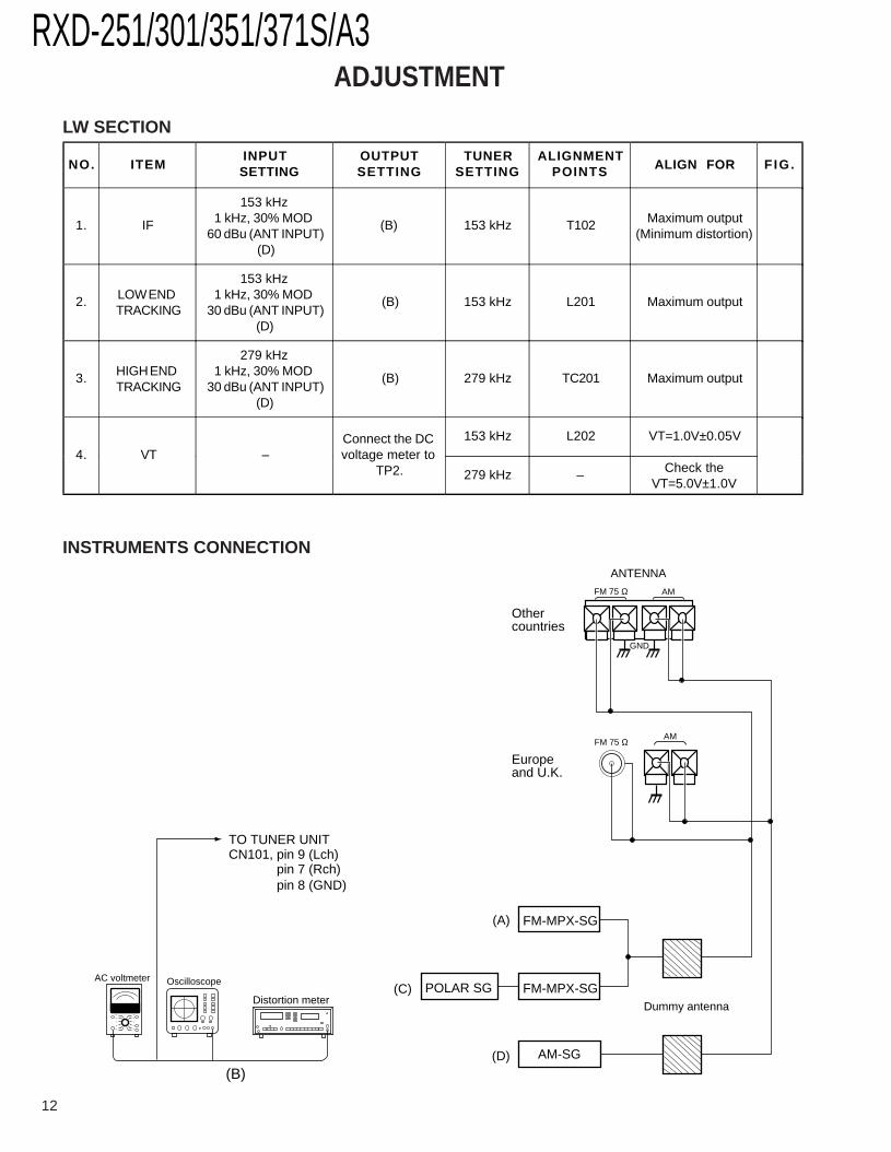
FM 75 Ω AM
ANTENNA
Europeand U.K.
Othercountries
AMFM 75 Ω
GND
(A)
(C)
(D) AM-SG
FM-MPX-SG
FM-MPX-SG
POLAR SGDummy antenna
OscilloscopeAC voltmeter
(B)
Distortion meter
TO TUNER UNITCN101, pin 9 (Lch)
pin 7 (Rch)pin 8 (GND)
NO. ITEMINPUT
SETTINGOUTPUTSETTING
TUNERSETTING
ALIGNMENTPOINTS ALIGN FOR FIG.
1. IF
153 kHz1 kHz, 30% MOD
60 dBu (ANT INPUT) (D)
(B) 153 kHz T102 Maximum output(Minimum distortion)
2. LOW ENDTRACKING
153 kHz1 kHz, 30% MOD
30 dBu (ANT INPUT)(D)
(B) 153 kHz L201 Maximum output
3. HIGH ENDTRACKING
279 kHz1 kHz, 30% MOD
30 dBu (ANT INPUT)(D)
(B) 279 kHz TC201 Maximum output
4. VT –Connect the DCvoltage meter to
TP2.
153 kHz L202 VT=1.0V±0.05V
279 kHz – Check theVT=5.0V±1.0V
ADJUSTMENT
12
LW SECTION
INSTRUMENTS CONNECTION

RXD-251/301/351/371S/A3
NO. ITEM INPUT
SETTINGSOUTPUT
SETTINGSCASSETTE TAPEDECK SETTINGS
ALIGNMENTPOINT ALGN FOR
FIG.
Unless otherwise specified : each ; switch should be set as follows : 0dBs = 0.775VBEAT SW : OFFI. Cassette mechanism section (REC/PB head adjustment)
[1] Demagnetizationand cleaning
– –Power OFF,
demagnetization,cleaning play
REC/PB head,erase head.
capstan, pinchroller
Demagnetize the REC/PBhead by head eraser. Cleanthe REC/PB head, erasehead capstan and pinchroller with a cotton swabimmersed in alcohol.
[2]REC/PB headazimuth
MTT-114,TCC-153
SCC-172710 kHz, -10dB
(A) PLAYAzimuth
adjustmentscrew
In a setting wher the outputis maximized, adjust theazimuth adjustment screwso that the Lissajous figureappearing on the oscilloscopescreen comes near to a lineslanted45° Note : The headshould be installed in such amanner that it approaches thetape face.
II. PC board adjustment
< 1 > Tape speed
MTT-111TCC-100
SCC-17273 kHz, -4 dB
(A) PLAY SFR201Adjust so that Frequency is3 kHz at the center of thetape.
< 2 > Playback levelTCC-120
315 Hz 0dB (A) PLAYApprox. -5dBm
reference level
< 3 >
Recording level
Put standardtest tape(TCC-120)
into B deck.
Put standardblank tapeinto A deck.
(A)
Dubbing andplayback. Approx. -5dBm
reference level
13
ADJUSTMENT
CASSETTE DECK SECTION
Oscilloscope
Frequency counter
AC voltmeter
PIN2IC401
(A)
MAIN UNIT
INSTRUMENTS CONNECTION
RXD-251/301/351/371S/A3
14
ADJUSTMENT
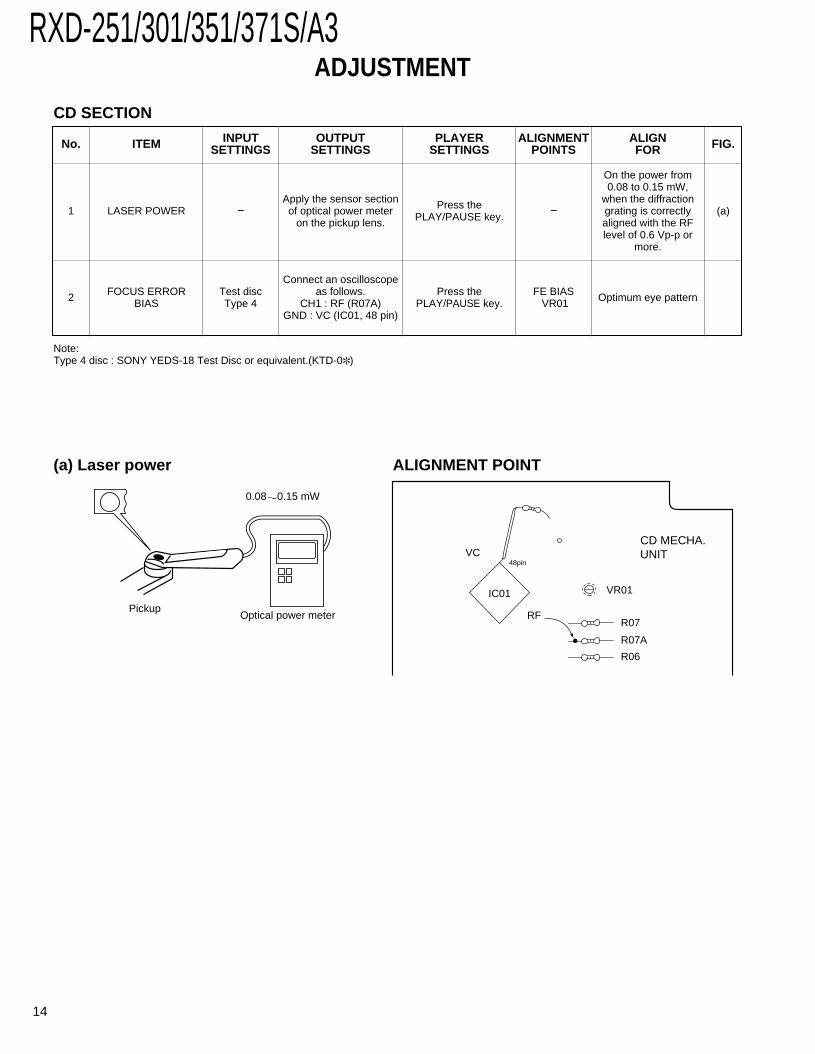
CD MECHA.UNIT
R07
VR01
VC
IC01
48pin
RF
R07A
R06
FIG.
(a)
No. ITEM INPUTSETTINGS
OUTPUTSETTINGS
ALIGNMENTPOINTS
ALIGNFOR
PLAYERSETTINGS
1 LASER POWER −Apply the sensor sectionof optical power meter
on the pickup lens.−
On the power from0.08 to 0.15 mW,
when the diffractiongrating is correctlyaligned with the RFlevel of 0.6 Vp-p or
more.
Press thePLAY/PAUSE key.
Pickup
FOCUS ERRORBIAS
Test discType 4
Connect an oscilloscopeas follows.
CH1 : RF (R07A)GND : VC (IC01, 48 pin)
FE BIASVR01 Optimum eye patternPress the
PLAY/PAUSE key.
Note:Type 4 disc : SONY YEDS-18 Test Disc or equivalent.(KTD-0)
0.08 0.15 mW
Optical power meter
2
(a) Laser power ALIGNMENT POINT
CD SECTION

RXD-251/301/351/371S/A315
WIR
ING
DIA
GR
AM
RXD-351(J,X1,X3,Y1,M1), RXD-A3(K1,P1),RXD-251(X2,M3), RXD-371S(M2)
RXD-351E(E2), RXD-301W(Q2), RXD-351W(Q1)RXD-301(E3,T2), RXD-351(E1,T1), RXD-301E(E4),
RXD-301E/351ERXD-301W/351WRXD-371S
RXD-351RXD-301RXD-A3RXD-251
TUNER UNIT
TUNER UNIT
CASSETTE DECKRECORD SWITCHMOTORUNIT
SWITCH AUNIT
SWITCH DUNIT
SWITCH CUNIT
CD MECHA.UNIT
CD MECHA.ASS'Y
HEADPHONE
MIC MIX UNIT
AUDIO UNIT
SUB WOOFERPRE AMP
DISPLAY UNIT
UNITSENSOR
CDCONTROLUNIT
UNIT
UNIT
RXD-A3 TYPE
RXD-371S(M2)RXD-351(M1,X1)/RXD-301(X3)/USED
UNITSWITCH B
TRANSFORMERPOWER
AC CORD UNIT
RXD-371S(M2)RXD-351(M1)/USED RXD-251(M3,X2)/
ONLY
MECHA. ASS'Y
CN101
CN101
AM
GND
FM 75
GND
JK101
CN08 CN402
FM 75
AM
GND
JK101
CN101
CN01 CN01
CN03 CN03
CN05
CN05
CN16CN16
CN06
CN06
CN18CN18
CN205
CN205
CN204 CN204
CN206 CN206
CN201
CN201
CN202
CN202
CN203
CN203
CN302
MIC1
MIC2
HEADPHONES
CN301 CN401
CN601CN601
CN604 CN604
CN403 CN403
CN302
CN502 CN502
CN605 CN605
JK601
SPEAKERS
Rch
Lch
OUT
JK501Rch 2
Lch 1
AUX
JK401
CN701
GND
(MW/SW)
RXD-351
RXD-A3
RXD-251
RXD-371S
RXD-351
RXD-301E
RXD-351W
CN19 CN19
RXD-251
RXD-301
RXD-301W
RXD-301E
RXD-351
RXD-371S
RXD-A3
S701
CN701
RXD-A3 ONLY
RXD-351
RXD-301
RXD-A3
RXD-251
RXD-351W
RXD-351ERXD-371S
T/TMOTOR
CN09
CN09
M
RXD-301W
RXD-301
RXD-351E
RXD-351E
RXD-351W
RXD-301W
RXD-301E
10
1
10
1
6
1
6
1
10
1
1
1515
1
6 6
1 1
1 5
3 3
1 1
51
1 5
1 5
2 2
1 1
1
1
8
8
6
1
6
1
4
1
4
1
31
31
51
51
21
21
31
1
17
1
17
3 3
1 1
3
1
3
1
1
4
1
4
1 3
5
1
5
1
6
1
6
1
1
6
CANADA
U.S.A.
P1
K1
COUNTRYDESTINATION
AUSTRALIA
GENERAL MARKET
JAPAN
PXM1
X3
J
Y1
ABB.
DESTINATIONCOUNTRY ABB.
COUNTRYDESTINATION
ABB.
AUSTRALIA X2
GENERAL MARKET M3
GENERAL MARKET
DESTINATIONCOUNTRY
M2ABB.
ABB.
U.K.
DESTINATIONCOUNTRYEUROPE
T1E1
DESTINATIONCOUNTRYEUROPE
ABB.E4
DESTINATIONCOUNTRYRUSSIA
ABB.Q1
2
1
2
1
ABB.
X2M3
AUSTRALIAGENERAL MARKET
COUNTRYDESTINATION
T2E3
ABB.
U.KEUROPE
DESTINATIONCOUNTRY
AUSTRALIA X3
Q2ABB.
RUSSIA
DESTINATIONCOUNTRY
E4ABB.
EUROPECOUNTRY
DESTINATION
EUROPE E1T1U.K
JABB.
JAPANCOUNTRY
DESTINATION
AUSTRALIAGENERAL MARKET
PX Y1M1X1
M2ABB.COUNTRY
GENERAL MARKET
DESTINATION
P1K1
ABB.
CANADAU.S.A.
DESTINATIONCOUNTRY
6
5
4
2
3
1
11
10
9
8
7
P9
T3
P5
P4
P8
P3
P2
P1
P6
P3
P1
F703
F702
P2
P7
P4
P6
P8
240V220-
110-120V
: AC100V 50/60Hz
: AC230V~ 50Hz: AC240V~ 50Hz: AC220V~ 50Hz
50/60Hz: AC110-120V/220-240V~: AC120V 60Hz
(Y,M)
P7
(T,E)(X)(Q)
(K,P)
T3
P5
P9
AC1
AC2
(J)
EUROPEU.K.
GENERAL MARKETPX
AUSTRALIA
E1T1
X1M1Y1
ABB.DESTINATION
COUNTRYJAPAN J
ABB.E3T2X3AUSTRALIA
COUNTRY
U.K.EUROPE
DESTINATION
K1P1
ABB.
CANADAU.S.A.
DESTINATIONCOUNTRY
ABB.COUNTRYDESTINATION
M3X2AUSTRALIA
GENERAL MARKET
Q1ABB.
RUSSIACOUNTRYDESTINATION
ABB.DESTINATION
COUNTRYEUROPE E2
DESTINATIONCOUNTRY ABB.
GENERAL MARKET M2
1 6
E D
1 18
18
1
AUSTRALIA X1
DESTINATIONCOUNTRYRUSSIA Q2
ABB.
ABB.EUROPE
U.K.
DESTINATIONCOUNTRY
E3T2
EUROPE E2
DESTINATIONCOUNTRY ABB.
DESTINATIONCOUNTRYEUROPE
ABB.E2
COUNTRYDESTINATION
RUSSIAABB.Q1
DESTINATIONCOUNTRYRUSSIA
ABB.Q2
E4ABB.COUNTRY
EUROPE
DESTINATION

RXD-251/301/351/371S/A3
16
PARTS DESCRIPTIONS

X20
1
CF1
05
C12
3
C12
2
J135
R130
C157
C118C121C147
J201
R123
C204
R205 R201
R114
R113
C114
C205
C117
J115
J143
J105
J104
C149
R118
C108
R204R203
R108
R141
R106
R105
R107
L103
J117
C107
R112
C154
C116
R202
TC10
2
L104
L201
TC201
C148
C124J118
C160C126
C127
C138
J150
R132
R140
R122
C150CF102
CF101
R149
J151
J149
C20
1
R20
8
CF1
03R
207
D201Q201
Q202
Q205Q204
D111
D112
C12
8R
145C
156
C135
C20
2
C20
6
R13
4
Q203
Q101
Q106
TC20
2
L106
C10
2
J144
L101
FE10
1
C10
3
G
J104
C10
6
D101
D108
D102
CF1
061
8 1
4
J108
J107
C10
1
R10
4
L102
R12
1
C13
7
R10
3C
203
R20
6
C13
9
C14
0C
165
C13
2
R12
8C
126
C13
3
R12
9
R12
7
R21
2
C13
1
R22
0
C14
1
C14
2
C12
5
R13
1
J193
C22
0
J175
R21
1
C13
0
C12
9
R11
9
R21
0
D202
J148
C21
0
C20
9
C15
2
C10
6A
C14
4
12 1
13 24
12
1
10 1
1324
EB
EB
EB
EB
C15
3
C211R
133
TP1
T101
12
TP2
12
C15
1
C11
2
Q110
Q111
D110
J123
J138
J139
J145
B162
J147
J12
1
J120
J122
J119
J131
J129
J146
J192
J126 C16
1
C16
4
EB
E
C14
3C215
E BB
EB
J125
J130
J124J1
13
L110
J111
L202 T1
02L105
CF104
J176
J134
J133
J112J1
10
J106
J142JK
101
J202
J116
J177
J140
J141
J190
L107
L108
C11
1
J191
R115
R213
J128C213
C214
C212R137
Q105R214
C207
L203
C208
C145J132
J127
R120
J136
R146
J185
CN101
Q108
Q107
Q109
IC201
IC102
E B
E BE B G S D
EB
17Refer to the schematic diagram for the value of resistors and capacitors.
A C EB D
2
1
3
5
7
4
6
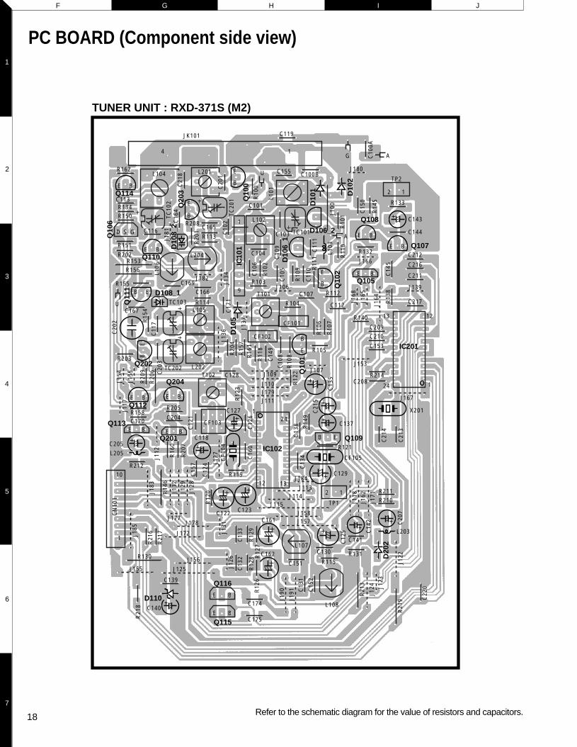
PC BOARD (Component side view)
R146
R130
J126
J136
J137
R122
C108
C149
R118
R161
R108
C109C105
C106
C110
C111L101
D106_1R109
C103J123
R111R106
R107
J168
J165
R110R101J100
C150
R145
IC101
Q106
C102
TC102
R134 C116
R114
R113
C114 C171
C134C138
R149
C126
R123
C147 C121
C160
C124
C157
C214
C213
C220
C13
7
CF1
05
C12
8
T102
C135
R102
D112
D111
1 9
C10
1
TC10
2
L102
R10
3
C10
4
TC10
1
J106
C10
7C
117
TC10
3
L105
C21
2
J139
C21
1
R13
2
J116
C14
4
C14
3
R13
3
C10
0BC
155
JK10
1
J101
R138
J164C145
C166
C100A
C11
9G
G
C11
2
R10
4R
112
C15
3
R21
4
C20
8
C21
0
C20
9
R14
0
R12
1
C12
9
14
C13
9
C14
0
R11
9
C12
7
CF1
03
R21
2
D202
R21
0R
211
J107
R10
5
X20
1
12 1
13 24
12
1
10 1
13
24
TP1
21
TP2
21
C16
1 C16
2
D110
J128
J155J1
22
J184
J180
J178
C21
5J153
J113
R22
0
J124
J118J162
J171
J127CF104
R213
J117
C16
5
C16
4
C15
1R
115
J177
L108
J157 L1
07
J115
J158
J114
J176
C13
0
C125
R13
1
C14
1
Q109
EB
T101
CF1
02
CF1
01
J109
J110
J108
C118
J111
J167
J179
C221
J175
C222
C223
R217
R218
C132
C133
R120
R129
R127R128
R126
C12
2
C12
3
R216
C152
C131
EB
Q105
EB
EB
Q108
Q107 C207
C142
J131
J185
CN101
IC201
IC102
G S D
BE
Q101
EB
D105
Q102
D106_2
D101
D102
L103
L203
Q110
EB
Q111
EB
TUNER UNIT (K1P1Y1M1X1X2M3X3)
TUNER UNIT (E1T1Q1E2T2Q2E3E4)
C123C122
J129
J128
R14
6
C15
7C
121
R12
3
C11
7R15
4
J135
R20
9 C20
3R
206
J136
J164
C20
2
J117
J154
R20
4R
157
R16
1
R11
8
C14
9
J137
C17
1D
105
J134L1
06
C10
6
C10
2
C10
5
R10
9 R11
1C
110
R10
6
R10
7
C10
8R
108
R11
0R
101J1
00
C15
0C
100A
R14
5
C10
9
IC101
C103 TC101
C11
1
R10
2
TC10
2
TC20
1 R10
0
L101
R20
1
C16
4
J181
C20
1
C21
8
J127
C12
4R
120
C16
0C
126
R14
9
C13
8
C21
4
C21
3
R12
2
CF102
CF101
C13
4R20
7C205
R16
0
J112
CF103
C118
C21
5
C137
C128
R203
C13
5
J182
L204
R113C116
R162
1
9
C165R208
R151
R202
R155
Q101
TC103C107
R114
C166C169
D108_1
C167C112
C210C209
R140
J168
C14
5
J165
R13
8
C153
C216
C212
C144
C143
R133
J180C155 C100B
C211
J139
C217R112
J166
R132
C101
L102
L201L104
C119JK101
C113R134R150
AG
U
U
A
R103J106
C104
R104
R105
J107
R121
CF105
14
R205
C204
C139
C140
R212
C170R158
C151
J177
C130
C12
5
R115
L108
L107
C13
1
C15
2
R119 C129J184
D202
R210R211
C141
R131
C208
X201
R214
12
1
13
24
12
1
10
1
13
24
EB
E B
TP1
2 1
TP2
2 1
C162
C161
Q115
D110
J155J156
J172
J178
R130
J125
J157J158
J114J113
J124
R21
3
R21
9J1
22
J171
J162
J118
J191
J190
J115
C175
C174
E B
Q116
E B
Q109EB
C127
T102
L105
T101
L202TC202
CF1
04
J167
J153
J109
R153 R156
J111J179J110
C13
2
R12
8R
126
J126
R21
8
R21
7
R21
6
C13
3J131
R12
9R
127
J123
C22
0E B
Q113E B
Q201
E BQ105
Q112
EB
E B
Q204
E BQ110
Q106
Q111
E BQ114
E B
Q108
E B Q107
Q202
E
B Q102
E
B
Q100
E
B
Q203
D108_2
C20
7
C14
2
J132
J183
J185
CN
101
IC201
IC102
GSD
E
B
D106_1
D106_2
D101
D102
L103
L203
L205
18
F G IH J
2
1
3
5
7
4
6
Refer to the schematic diagram for the value of resistors and capacitors.
PC BOARD (Component side view)
TUNER UNIT : RXD-371S (M2)

Q418Q403
IC401 D4
02
D7
14
D7
15
D5
02
D5
01
D5
05
D2
12
D2
11
D2
03
D2
13
D2
09
D2
01
D7
04D
70
5
D7
03
D7
02
D2
04
D5
03
D504
D706D712
D581
D701
D202
D205
D585
D208
D206
D7
11
D7
07
D7
10
D7
09
D401
C488
C487C431
C239
C527
JK502
C203
C205
C201C217
C209
C223
C218
C245
C230
L201
C244
C231
C242
C232
C210
C213
C202C240
C206
C204
C42
7
C48
9
C48
3
C42
1C
429
C42
3
C41
7
C41
5
C21
4
C22
4
C21
6
C70
3C
704
C70
6C
705
C51
5
C53
0
C51
2
C54
3
C52
6C
525
C541
C511
C731
C711
C502
C503 C504
C505
C736
C722
C484
C405
C50
1
C73
0
C72
8C
723
C71
6
C71
2
C71
4
C42
6
C40
4C
403
C43
0
C43
2
C42
0
C41
8
C41
4
C41
6
C42
8
C42
2
C71
8
C72
9
C72
0
C51
0
C50
6
C542
C507
C51
6
C52
0
C52
2
C51
4C
513
C21
5
C52
8
C23
3
C24
6
C23
5
C70
8
C70
9
C71
0C70
7
C73
4
C74
1
C45
9C
458
C48
2C
450
C46
0
C46
1
C45
3
C45
1
C48
1
C43
9
C45
2
C44
0
C40
2
C40
1 CN
402
C41
9
C43
3R421
GND
R419
R417
R461
R459
R457
R446
R447
R444
R485
4
1
8
1
R213A
R486
R487
R480
R321
R213
R211
R205A
R205
R229
R231
R202
R227
R228R254
R230
R232R206
R217
R218
R220
R233R201
3
1
R206A
R263
R264
R241
R508
R484
R535
R536
R547
R545
R549
18
R527
C
P8
P7
P2
P4
P6
D C
D
E
FF
E
A
A
BB
R701
R706
R708
R705
R524L501
L502
C509
R528
4 1 6
3 2
RL501
5
R523
R505
R700
P9
T3P5
P7
P1
P3
F702
F703P6
P8
AC
1
AC
2
R502
B
E
R551
R543
R552
C508
C732
C701
C518
C517C531
R237
R257
R256
R249
R262
R242
R537
R538
R209
R255
R219
R268
R235
R455
R738
R481R741
R422
R498
R497
R742
R43
7
R43
5R
439
R44
0
C434
C445
SW
201
C721
C733
C435
141
87
C437
C45
4
C455
C413
C412
C438
C409
C448
C719
C715C713
C724
CN605
6 1
CN206
1
L202
4
C447
E
B
Q703E
B
Q706
E
B
Q503 Q502
Q414Q413
AUX
E
B
Q705E
B
Q501E
B
Q505E
B
Q220
E
B
E
B
Q217
E
B
Q209
E
1
1
1
2
8
B
Q218
E
B
SFR201
Q216
Q508
E
B
Q512
E
B
Q511E
B
Q207
E
B
Q201
PHONES
POWER
E
BQ202
IC201
E
B
Q219E
B
Q211E
B
Q709E
B
Q210E
B
Q404E
B
Q714
E
B
Q713E
B
Q408
IC4
04
E
B
Q411
E
B
Q409
IC402
E
B
Q4
05
E
B
Q4
12
E
B
Q410
E
B
Q407
B
E
Q204B
E
Q206
5CN202
E
Q203
BB
E
Q205
B
E
Q208 B
E
Q213
B
E
IC5
01
B
E
BE
E
B
Q504 B
E
Q506
B
E
Q212
Q2
15
B
E
B
E
Q406 B
E
Q415
Q702
B
E
Q704
B
E
Q701
B
E
Q416 B
E
C410C485
CN101
1
1
6
10
C408
C436
C411
C727
C523C524
C532
C735
C529
C702
C519
C220 C219
1
6
C238
C241
C222
C225
C442
C449
C456
C462
C226
C463
C221
C208
C227 C237
C211
C207
C212
C228C521
C446
C726
C441 C444
C464
C465
C407
C406
C725
C443
R40
6
JK401
SW
751
R40
8
R43
6
R43
8
R43
4
R43
2
R43
0
R42
0
R42
6
R41
4
R41
0
R46
2
R45
8 R46
0 R45
1
R47
0
R49
4
R47
2R
467
R46
5
R21
2
R21
4R
221
R23
6
R27
0
R70
3
CN
701
R71
5
R22
4
R22
6
R22
5
R25
9
R24
8
R24
4
R24
3
R24
7R
265
R23
8
CN
205
1
8
CN
205
1
6
CN
204
R24
0
R25
8
R26
1
R26
0
R23
9
R26
7
R26
6
R54
1
R54
0
R54
2
R54
8
R54
4
R54
6
R52
5R53
1
R51
2
R51
1R
513
R51
4
C234C243
CN
203
R51
5
R51
0
R70
7
R70
9
R71
3
R71
0
R50
4
R50
3R
506
R50
1
R52
9
R53
3
R50
7
R50
9
R70
4 D7
08
R70
2
R53
4
R53
0
R55
0
R53
2
R52
6
R53
9R
522
R51
7
C457
C480
C479
R26
9
R51
6R
519
R52
1
R71
1
R51
8
R71
2
R73
7 R52
0R
222
R23
4
R24
6
R24
5
R22
3
R25
0
R25
1
R21
5
R20
7
1213 24
1R
203
CN
201
R20
8
R20
4
R45
6
R44
9
R47
7
R47
9
CN
403
5
1
17
1
CN
502
CN
301
5
1
CN
502
R74
0
R73
9
R45
2
R45
3
R47
6
R47
4R
454
R47
8
R44
5
R32
2 R49
1
R46
9
R46
3
R47
3
R49
3
R47
5
R46
4
R47
1R
468
R49
2
R46
6R45
0R44
8
R41
2
R42
8
R41
6R
424
R41
8
R40
5
R40
7R
483
R48
2
R49
6
R49
5R
433
R43
1
R42
9
1516 30
1
R42
5
R42
3
R41
3
R40
4
R48
2
R49
0
R44
1
R44
2
R44
3
R40
2
R40
3 R40
1
R42
7
R41
5
R41
1
R40
9
J405
J406
J401
J402
J403
J450
J404
J461
J407 J408
J411
J410E
B
Q417E
B
Q507B
E
Q708E
B
Q513
E
B
Q707E
B
Q510
IC502
E
B
Q509
E
B
Q214
EB
Q711E
B
J418
J424
J520
J465C
14
14
1
J419J455
J430
J546
J465D
J522
GND1
J531
J462
J517
S701
J516
J521
J514
J551
J202
J229
J231
C236
J227
J444
J423
J414
J465
J460
J449J448
J447J446
J445
J463
J222
J221
J220 J216
J205
J203
J234
J218J219
J225
J210
J207
J523
J526
J544
J208
J528
J529
F701
J527
J501J502
J550
J505
J506
J206
J504
J503
J415
J416
J465
B J541
J542
J543
J540
J539
J545
J452
J453
J437
J214
A
J435
J434
J431
J433
J438
J432
J426
J456
J215J2
17
J212
J518
JK50
1
J519
J536
J537
J538
J213
J204
D2
07
J232 J233
J209
J530
J510
J512
J436
J513
J511
J508
J509
J507
J524
J525
J228
J226
J532
J535
J224J5
34
J535 J2
30
J214
J211
J429
J457
J428
J440
J441
J201
J465
A
J439 J4
42
J443
J464
J427
J459
J422
J458
J425J4
51
J454
J417
J420
J421
J413
J412
J409
GND4
K M O Q SL N P R T
2
1
3
5
7
4
6
Refer to the schematic diagram for the value of resistors and capacitors.
PC BOARD (Component side view)
19 20
AUDIO UNIT
@@@@@@e
@@f
@@f
@@f
@@f
@@f
@@f
@@f
@@f
@@f
@@f
@@f
@@f
@@f
@@f
@@@@@@e
????????
?@@@6Xg?@@@@@?
I'@)X?g?@e?
?N@@1?g?@e?
@@@Lg?@e?
@V')X?f?@e?
@?V')Xf?@e?
@??V')X?e?@e?
@?eN@1?e?@e?
@?e?3@Le?@e?
@?e?V')X??@e?
@?fV')X?@e?
@?f?V')X@e?
@?gN@@@e?
@?g?3@@e?
@?g?V'@e?
?@@@@@@?gV'e????????
????????
?@@@@@@@@@@@@@@??
?@(Me?@@?eI'@??
?@H?e?@@?e?N@??
?@f?@@?f@??
?@@?g?
?@@?g?
?@@?g?
?@@?g?
?@@?g?
?@@?g?
?@@?g?
?@@?g?
?@@?g?
?@@?g?
?@@?g?
?@@@@@@?f????????
?O2@@6X?f
@@@@@@)Xf
?J(MeI'@1f
?.Y?e?N@@f
@@f
@@f
?J@5f
?7@Hf
J@5?f
7(Y?f
?J(Yg
W.Y?g
?W.Yh
W&Y?fO.e
?W&@@@@@@@(Ye
?&@@@@@@@0Y?e
?W&?2@6Kf
O&@@@@@@@?e
?@@@@(M?I'@Le
?@@He?N@1e
?@@?f@@e
?@@?f@@e
?@@?f@@e
?@@?f@5e
?@@Le?J@He
?@@)K?O&@?e
?@@V4@0Mf
?@@?h
?@@?h
?@@?h
?@@?h
?@@?h
?@@@@@@?g
O2@@6Kf
?@@(MI'@@?e
J@(YeV'@Le
7@H?e?N@1e
@@g@@e
@@g@@e
3@L?e?J@@e
N@)XeW&@@e
?@@)KO&@@@e
I4@@0Y@5e
?J@He
W&5?e
?W&(Y?e
O&(Yf
O2@0Y?f
?@@0M?g
O2@@6Kf
?@@(MI'@@?e
J@(YeV'@Le
7@H?e?N@1e
@@g@@e
@@g@@e
3@L?e?J@@e
N@)XeW&@@e
?@@)KO&@@@e
I4@@0Y@5e
?J@He
W&5?e
?W&(Y?e
O&(Yf
O2@0Y?f
?@@0M?g
?@@?e
?@@?e
W&g
?W&@g
W&@@g
.Y@@g
@@g
@@g
@@g
@@g
@@g
@@g
@@g
@@g
@@g
@@g
@@g
@@@@@@f
W2@@6Xf
?W&(MI')X?e
?7@HeN@1?e
J@5?e?3@Le
7@H?e?N@1e
@@g@@e
@@g@@e
@@g@@e
@@g@@e
@@g@@e
@@g@@e
3@L?e?J@5e
N@1?e?7@He
?3@LeJ@5?e
?V')KO&(Y?e
V4@@0Yf
?@@?e
?@@?e
W2@@6Xf
?W&(MI')X?e
?7@HeN@1?e
?@@?e?@@?e
?@@LeJ@@?e
?3@)KO&@5?e
?V'@@@@(Y?e
?@@@@?f
?W&(?'@)X?e
W&(Y?V'@)Xe
7@H?eV'@1e
@@f?N@@e
@@g@@e
3@L?e?J@5e
V4)KeO&0Ye
I4@@0Mf
?O2@@@e
?W2@0Mf
W&(Mg
?W&(Y?g
?7@Hh
J@@=h
7@S@@@6Kf
@@(M?I'@@?e
@@H?eV'@Le
@@f?N@1e
@@g@@e
@@g@@e
3@L?e?J@5e
N@)XeW&@He
?@@)KO&@@?e
I4@@0Mf
?????????????
?@@?e?
?@@?e????????
?@@?e?
?@@?e????????
W2@@@@@(e
7@@@@@0Ye
?J@?h
?75?h
J@Y?h
@@@@@6K?f
I4@@@@f
I'@@L?e
?V'@1?e
N@@?e
?@@?e
?@5?e
J@H?e
?@6Xe?W&5f
?3@)K?O&0Yf
?V4@@@0Mg
O2@@6Kf
?@@(MI'@@?e
J@(YeV'@Le
7@H?e?N@1e
@@g@@e
@@g@@e
3@L?e?J@@e
N@)XeW&@@e
?@@)KO&@@@e
I4@@0Y@5e
?J@He
W&5?e
?W&(Y?e
O&(Yf
O2@0Y?f
?@@0M?g
????????
?@@@@@@@@6K?e?
?@@?eI'@@e?
?@@?e?N@@L??
?@@?f@@1??
?@@?f@@@??
?@@?f@@5??
?@@?e?J@@H??
?@@?eO&@@e?
?@@@@@@0M?e?
?@@?h?
?@@?h?
?@@?h?
?@@?h?
?@@?h?
?@@?h?
?@@@@@@?g????????
????????
@@@@he@@@@@??
@@L?g?J@@@?e?
@@1?g?7Y@@?e?
@@@Lg?@?@@?e?
@?@1gJ5?@@?e?
@?3@L?f7H?@@?e?
@?N@1?f@??@@?e?
@??3@Le?J5??@@?e?
@??N@1e?7H??@@?e?
@?e3@L??@e?@@?e?
@?eN@1?J5e?@@?e?
@?e?3@W&He?@@?e?
@?e?N@@@?e?@@?e?
@?f3@5?e?@@?e?
@?fN@H?e?@@?e?
@@@@@?e?@e?@@@@@@?????????
W26Xf
7<B1f
3=C5f
W2@@6XfV40Yf
?W&(MI')X?he
W&(YeV')Xhe
?W&(Y?e?V')X?h
W&(YgV')Xh
@?&@H?g?V')X?g
3@@5heV')Xg
V40Yhe?V')K?f
V'@6X?e
?V'@)Xe
V'@1e
?V4@e
?O26X?e
?@K?f?O2@@@@@@@@@1?e
?3@@@@@@@@0Mg?I@?e
?V40M?
@@6Khe'6X?e
?I'@@?f?'6XV'1?e
V4@?f?V'1?V'?e
V'g
?@@6K?
I'@@hfW.f
?V4@he?W&Hf
W&5?f
?W&(Y?f
W&(Yg
?W&(Y?g
O&(Yh
W2@(Y?h
?O&@0Yhe
?O2@(Mhf
?@KO2@@0Y?hf
?3@@@0M?hg
?V40M?
O2@6X?f
W2@@@@)Xf
7(M?I'@1f
(Ye?N@@f
?J@5f
W&(Yf
?W&@g
?&@@)Xf
?I')X?e
N@1?e
?@@?e
?@@?e
?@5?e
@6X?eJ@H?e
3@)K?O&@f
V4@@@0M?f
U V X Z AB ADW Y AA AC
2
1
3
5
7
4
6
D604
Q602
D603
D602
VOLUME
CONTROL
D601
D607
AMS -
S624
AMS +
S619
D613
DISC SKIP
S618
TUNER DOWN
S616
S613
TUNER UP
AUTO PRESET
S611S614
MANUAL PRESET
S607
FLATE
S605
POP
EX BASS
S615
Q604
S604
ROCK
AUTO/MONO
S617
TIME MODE
S610
IC601
S606
DISPLAYS602
CLOCK SET
TIME SET
S601
FUNC IN
S609
POWER
S603
S612
BAND
S608
JAZZ
DISC 1
S621
DISC 2
S622
DISC 3
S620 S623
Q6
01
OPEN/CLOSE
S625
STOPPLAY/PAUSE
S626
R673
C628
CN604
1
3
R672 R674 R675 R676 R677
C60
9
R60
4
R60
3
E
B
R678 R671
CN601
CN601
C603
13
13C60
8
C61
0
R60
5
C60
6 C61
1
R68
0
R61
9
R61
8
J670
J612
R62
9
R63
0
R63
1
J616
J623
R65
4J629
R65
6
J 66
9
J642
R62
0
J653
J657
J658
CN
302
J624
J621
R63
5
R63
6
R63
7
J666
J604
J603
J609
J608
J620
J618
J611
J610
J619
J622
J625
J648
LP601 LP602 LP603
J649 J668
J631
J626
J627
J607
J641
J637
J636
J633
J667
J605
J606
C60
4
C61
5
C61
6
J617
C61
4R64
5
R61
6
J630
C60
1
R64
5
R64
3
R64
2
R64
1
C61
9
C62
0
R69
0
J680
C68
6
R68
3
R68
1C
685
R68
2
R68
9R
687
R68
5R
686
R68
8C
687
R69
2
R31
9
R32
6
CN
403
R32
3
R31
7
R31
4
R30
8
R31
6
C32
1
R30
7
R30
5C
319
J301
R30
4
R30
3
R30
1
R32
8
JK30
2
JK30
1
R32
5
R30
2R30
6
J302
C31
7
R32
4
R31
8
R68
4
J602
L601
R60
2
R60
1
C60
7
C605
C681 C628
18
CN605
1
1
17
6
C683
JK601
C684
C631
1
CN604
RM601
REMOTE
SENSOR
3
C622
C623
X601
100
31
50
81
51
8030
1
C618
1
3
C629
E
B
Q6
11 IC602
E
B
Q3
01
Q302
Q303
IC301
MIC2 MIC1 PHONES
E
E
C316
C315
4
1
3 1 C314
E
7 1
CN302B
B
B
Q6
03E
J645
J646
J663
J652
J656
J650
J651
CN09
18
17 1
2
J659
VR601
MIC VOLUME
J655
J640
J639
J638
J635
J634
J643
J654
J662
J661
J665
J664
J632
J628
J660
J644
R622CN401A VR603
B
C
R621
C621R320
R327
R315
C311
C313
C308
C306
C305
C301C307
C309
A
C302
C320
R614
J647
LDC6011 32
R615
R652
R646
R653
R608
R607
R655ICT 1 2
J671
C613
R648
R647
J600
R632
R617
J601
C62
4
C61
7
C62
5
C62
6
C62
7
R62
8
R62
7
R62
6
R62
5
R62
4
R62
3
C63
2
R610
R609
C612
R651R606 R650
R649
B
EB
B
B
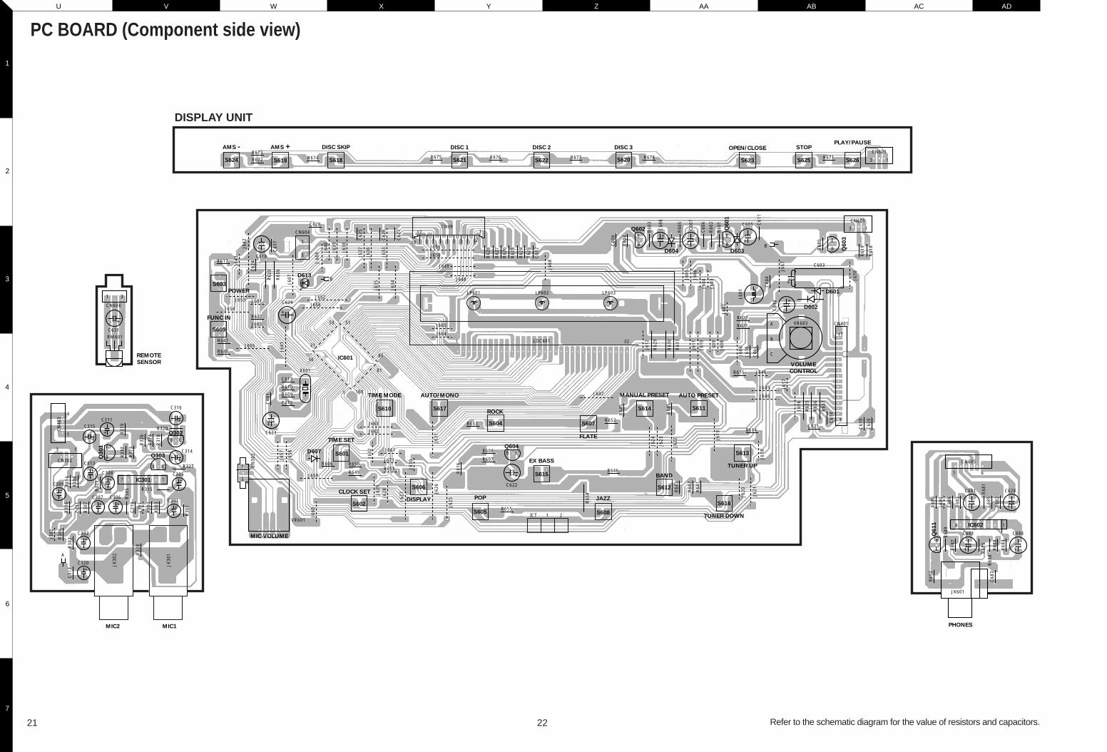
Refer to the schematic diagram for the value of resistors and capacitors.
PC BOARD (Component side view)
DISPLAY UNIT
21 22
@@@@@@e
@@f
@@f
@@f
@@f
@@f
@@f
@@f
@@f
@@f
@@f
@@f
@@f
@@f
@@f
@@@@@@e
????????
?@@@6Xg?@@@@@?
I'@)X?g?@e?
?N@@1?g?@e?
@@@Lg?@e?
@V')X?f?@e?
@?V')Xf?@e?
@??V')X?e?@e?
@?eN@1?e?@e?
@?e?3@Le?@e?
@?e?V')X??@e?
@?fV')X?@e?
@?f?V')X@e?
@?gN@@@e?
@?g?3@@e?
@?g?V'@e?
?@@@@@@?gV'e????????
????????
?@@@@@@@@@@@@@@??
?@(Me?@@?eI'@??
?@H?e?@@?e?N@??
?@f?@@?f@??
?@@?g?
?@@?g?
?@@?g?
?@@?g?
?@@?g?
?@@?g?
?@@?g?
?@@?g?
?@@?g?
?@@?g?
?@@?g?
?@@@@@@?f????????
?O2@@6X?f
@@@@@@)Xf
?J(MeI'@1f
?.Y?e?N@@f
@@f
@@f
?J@5f
?7@Hf
J@5?f
7(Y?f
?J(Yg
W.Y?g
?W.Yh
W&Y?fO.e
?W&@@@@@@@(Ye
?&@@@@@@@0Y?e
?W&?2@6Kf
O&@@@@@@@?e
?@@@@(M?I'@Le
?@@He?N@1e
?@@?f@@e
?@@?f@@e
?@@?f@@e
?@@?f@5e
?@@Le?J@He
?@@)K?O&@?e
?@@V4@0Mf
?@@?h
?@@?h
?@@?h
?@@?h
?@@?h
?@@@@@@?g
O2@@6Kf
?@@(MI'@@?e
J@(YeV'@Le
7@H?e?N@1e
@@g@@e
@@g@@e
3@L?e?J@@e
N@)XeW&@@e
?@@)KO&@@@e
I4@@0Y@5e
?J@He
W&5?e
?W&(Y?e
O&(Yf
O2@0Y?f
?@@0M?g
O2@@6Kf
?@@(MI'@@?e
J@(YeV'@Le
7@H?e?N@1e
@@g@@e
@@g@@e
3@L?e?J@@e
N@)XeW&@@e
?@@)KO&@@@e
I4@@0Y@5e
?J@He
W&5?e
?W&(Y?e
O&(Yf
O2@0Y?f
?@@0M?g
?@@?e
?@@?e
W&g
?W&@g
W&@@g
.Y@@g
@@g
@@g
@@g
@@g
@@g
@@g
@@g
@@g
@@g
@@g
@@g
@@@@@@f
W2@@6Xf
?W&(MI')X?e
?7@HeN@1?e
J@5?e?3@Le
7@H?e?N@1e
@@g@@e
@@g@@e
@@g@@e
@@g@@e
@@g@@e
@@g@@e
3@L?e?J@5e
N@1?e?7@He
?3@LeJ@5?e
?V')KO&(Y?e
V4@@0Yf
?@@?e
?@@?e
W2@@6Xf
?W&(MI')X?e
?7@HeN@1?e
?@@?e?@@?e
?@@LeJ@@?e
?3@)KO&@5?e
?V'@@@@(Y?e
?@@@@?f
?W&(?'@)X?e
W&(Y?V'@)Xe
7@H?eV'@1e
@@f?N@@e
@@g@@e
3@L?e?J@5e
V4)KeO&0Ye
I4@@0Mf
?O2@@@e
?W2@0Mf
W&(Mg
?W&(Y?g
?7@Hh
J@@=h
7@S@@@6Kf
@@(M?I'@@?e
@@H?eV'@Le
@@f?N@1e
@@g@@e
@@g@@e
3@L?e?J@5e
N@)XeW&@He
?@@)KO&@@?e
I4@@0Mf
?????????????
?@@?e?
?@@?e????????
?@@?e?
?@@?e????????
W2@@@@@(e
7@@@@@0Ye
?J@?h
?75?h
J@Y?h
@@@@@6K?f
I4@@@@f
I'@@L?e
?V'@1?e
N@@?e
?@@?e
?@5?e
J@H?e
?@6Xe?W&5f
?3@)K?O&0Yf
?V4@@@0Mg
O2@@6Kf
?@@(MI'@@?e
J@(YeV'@Le
7@H?e?N@1e
@@g@@e
@@g@@e
3@L?e?J@@e
N@)XeW&@@e
?@@)KO&@@@e
I4@@0Y@5e
?J@He
W&5?e
?W&(Y?e
O&(Yf
O2@0Y?f
?@@0M?g
????????
?@@@@@@@@6K?e?
?@@?eI'@@e?
?@@?e?N@@L??
?@@?f@@1??
?@@?f@@@??
?@@?f@@5??
?@@?e?J@@H??
?@@?eO&@@e?
?@@@@@@0M?e?
?@@?h?
?@@?h?
?@@?h?
?@@?h?
?@@?h?
?@@?h?
?@@@@@@?g????????
????????
@@@@he@@@@@??
@@L?g?J@@@?e?
@@1?g?7Y@@?e?
@@@Lg?@?@@?e?
@?@1gJ5?@@?e?
@?3@L?f7H?@@?e?
@?N@1?f@??@@?e?
@??3@Le?J5??@@?e?
@??N@1e?7H??@@?e?
@?e3@L??@e?@@?e?
@?eN@1?J5e?@@?e?
@?e?3@W&He?@@?e?
@?e?N@@@?e?@@?e?
@?f3@5?e?@@?e?
@?fN@H?e?@@?e?
@@@@@?e?@e?@@@@@@?????????
W26Xf
7<B1f
3=C5f
W2@@6XfV40Yf
?W&(MI')X?he
W&(YeV')Xhe
?W&(Y?e?V')X?h
W&(YgV')Xh
@?&@H?g?V')X?g
3@@5heV')Xg
V40Yhe?V')K?f
V'@6X?e
?V'@)Xe
V'@1e
?V4@e
?O26X?e
?@K?f?O2@@@@@@@@@1?e
?3@@@@@@@@0Mg?I@?e
?V40M?
@@6Khe'6X?e
?I'@@?f?'6XV'1?e
V4@?f?V'1?V'?e
V'g
?@@6K?
I'@@hfW.f
?V4@he?W&Hf
W&5?f
?W&(Y?f
W&(Yg
?W&(Y?g
O&(Yh
W2@(Y?h
?O&@0Yhe
?O2@(Mhf
?@KO2@@0Y?hf
?3@@@0M?hg
?V40M?
?O2@@6X?f
@@@@@@)Xf
?J(MeI'@1f
?.Y?e?N@@f
@@f
@@f
?J@5f
?7@Hf
J@5?f
7(Y?f
?J(Yg
W.Y?g
?W.Yh
W&Y?fO.e
?W&@@@@@@@(Ye
?&@@@@@@@0Y?e

Y39-2930-11
RXD-251/301/351/371S/A3
A
1
2
3
4
5
6
7
B C D E F G I K M OH J L N
TUNER UNIT RXD-351(J,X1,Y1,M1), RXD-A3(K1,P1), RXD-251(X2,M3), RXD-371S(M2)
IC102
IC201
IC101
RXD-371S(M2) (1/5)RXD-251(X2,M3) (1/5)RXD-A3(K1,P1) (1/5)RXD-351(J,X1,Y1,M1) (1/5)
+B
CANADAU.S.A.
P1K1
COUNTRYDESTINATION
AUSTRALIA
GENERAL MARKET
JAPAN
PXM1
X1J
Y1NO MTZ5.6B
ABB. H,JA,D,E, D110
YES
F,IB,C,
YES
G
NOYES
D111,112
C100A,147,
YES
221-223
2.2P
C110
470P
C116
0.015 1u50
C143 C171
0.1
C166,
NO
216,217 R115
22 1/2W
R130
150 3.3K
R134
NO
219R150,
NO
R151
YES
R220
DESTINATIONCOUNTRY
C143
1u50
D111,
YESNO MTZ5.6B YES
B,C,ABB. F,IG,H,J
A,D,E, D110 112
0.022YES 2.2P 470P
C100A,147,221-223 C110 C116
NONO 22 3.3K1501/2W NO
R115 R134R130 219R150,
YES
R220R151
COUNTRYDESTINATION R150,C100A,147,A,D,E, B,C, D111,
1u50
C143
YESNO
ABB. G,H,J F,I
YESMTZ5.6B
D110 112
2.2PYES
221-223 C110
470P 0.015
C116
NO22
R115
NO3.3K1/2W
R134
150
R130 219
YES
R220R151
AUSTRALIA X2
GENERAL MARKET M3
GENERAL MARKET
DESTINATIONCOUNTRY
C143
3.3u50
D111,
NO
B,C,
M2 YES
ABB. F,IG,H,JA,D,E,
MTZ6.2B NO
D110 112
NO 4.7P
221-223C100A,147, C110
0.01510P
C116
YES27P0.022 47
214C213,C171 R115
100 101/2W YES
R134R130 219R150,
NO
R220R151
X3AUSTRALIA
C117
20P
C130,131
24P
C213,214
2.2K
R161
20P
C117 C130,131
C166,216,217
0.1
C171
24P
214C213, R161
2.2K
JUMPER
YES
JUMPER
YES
20P
C117 131C130,
24PNO 0.1
C213,214216,217
C166, C171
2.2K
R161
YES
JUMPER
C130,131C117
5.6P
C166,
YES
216,217 R161
4.7K
JUMPER
NO
NO
Q110,111
Q110,111
NO
111
NO
Q110,
Q110,
2SC2878A
111
DTC114YS
G
NOYES
RXD-301/351
RXD-A3
RXD-251
RXD-371S
+B LINE
VCC
STEREO
IFFM
GNDREG
DRIVETUNING
COMP
BUFF
FMDET
IF
FM
AM
AM/FMSW
OSCAM
LEVELDET
BUFF
ALC
AGC
AM/
S-CURVEFM
IFAM
DETAM
AMMIX RF.AGC
AM
MUTE
PHASE DET
VCOPILOTDET
STEREO
FF FF FF
DRIVETRIG
SW
DECODER
470
R11
9
3.3K
R12
0
20P
C12
4
1KR21
1
4.7K
R21
0
100P
C20
9
100P
C21
0
C21
4C
213
20P
C11
7
470PC11610
PT
C10
2
175 OHM
GND 2
3GND
(MW/SW) 4
L104
L105
CF
104CF103
T102
1
2
3 4
5
6
X20
17.
2MH
z
DI
CE
X IN
OU
T0
SY
C
DO
CL
IN1
IN0
OU
T2
OU
T1
OU
T3
DIVIDER
SHIFT REGISTER LATCH
21
PROGRAMMABLE12bit
1/16, 1/17 4bitSWALLOW COUNTER
COUNTERUNIVERSAL
CHARGE PUMPPHASE DETECTOR
DIVIDERREFERENCE
X O
UT
VS
S
PD
2
FM
IN
VD
D
PD
1
AM
IN
OU
T6
OU
T5
LCT
R
HC
TR
OU
T4
3
2
1
6
5
4
1 2 4 5
3 6
FM
C13
1
47mHL107
C1511500P
47mH
L108
C1521500P
1u50
C12
9
+
2
1
TP1
CF
105
1000
P
0.01
C13
4
4.7K
1000
P
4.7K
1000
P
21 18 16 14 1315171920222324
1 2 3 4 5 6 7 8 9 10 11 12
0.47
u50
C13
7 +
3.3K
R122
3.3u
50C
135 +
0.022
R13
4
8.2K
R12
3
0.02
2
0.04
7
10u5
0 +
R118100
15P
2.2u
50C
122
+1u50C123
+C119
1 2 3 4 5 6 7 8 9 10 11 12
24 23 22 21 20 19 18 17 16 15 14 13
47u1
6 +
0.01
56P
C14
5
6.8K
C1440.01
C143+2.2K
R133
L203
47uH
0.02
2C
153
R21
2
22u16+
0.02
2C
160
100u
16C
118 +
R1384.7K
C21
70.
022
R140
C14
70.
022
100u
16C
140 +
0.02
2C
139
1KR131
100u
16C
142
C14
10.
022 +
32 4
Q107,108
1
3
2
4
6
5
100KR114
100K
R11
30.
1C
114
1000P
1KR145
2TP2 1
GN
D
VT
R104100 CF101
6.8K
R10
7R
106
1.5K
0.02
2C
107
R105
1K
R10
833
0
0.02
2C
108
CF102
ST IND
Lch
GND
Rch
DO
CLK
CE
+12V
2
1
4
DI3
5
6
8
7
9
MUTE10
5
4
3
2
5
12
3.6K
C13
3
R12
9
C13
2
R12
8
100P
C21
1
R14
6
1000
P
R1213.3K
1u50+
1u50+
15K
R14
9
C22
322
0P
C22
222
0P
C22
122
0P
R21
71K R21
61K R21
81K
C17
1
R16
110K
0.01
C15
0
0.1
C16
6
RF
I N
BY
PA
S
MIX
IN
AF
C G
ND
GN
D
IF O
UT
AF
C
OS
C
VC
C
1 2 3 4 5 6 7 8 9
TC
101
10P
0.02
2
C10
4
1K
R102
100K
R10
1
L102T1011
2
3
6
5
4
6
5
4
1
2
3
22R10
3
18P
C10
5
33KR110
C110 R11
11K
100K
R109
56P
C11
1
L103
0.1
C10
0A
100PC112
2
3
1
4
5L101
1000PC101
100PC155
R214
0.02
2C
106
R112100
AM
FM
BAND
HFLFHFLF
QUENCYFRE-
7.3V1.1V7.0V1.2V
VOLTAGEVT
43 TC
102
2
1L104
5
10P
6
L201
3
2
4
1
5
C169
0.022
47m
HL1
06
0.01
C16
4
2.2M
R20
8
100K
R11
4
100K
R11
3
100K
R15
4
0.02
2C
165
0.02
2C
166
1K
1/4W
R153
3 4
2
1L105
6
5
10R157
20P
C11
7
47K
R15
62.
2MR
155
470PC167
C20
2
4700
P
2.2M
R20
9
R158
4.7K
1/4W
3 4
L2021
2
6
5
10R204
4.7KR162
C201
560P R20
1
1K
TC
201
10P
R1004.7K R
202
4.7K
47m
H
L204
4.7KR205
4.7K
R20
3
0.02
2C
204
4.7K
R20
7
C17
00.
01
4.7K
R16
0
47uH
L205
47u1
6C
205 +
A
B
JUMPER
10PC116
470R151
R15
0
2.2M
JUMPER
C128
C13
8
IF
GND
C13
0
6800
PC
164
C16
568
00P
C17
468
00P
6800
PC
175
C215
C162
C161
R1263.3K
R1273.3K
C15
7
100
1/4W
C121
1u50
C12
5 +
10K
C20
8
C20
7
R20
6
4.7
1/4W
R11
5
10KR213
R130
1/4W
C12
6
C14
9
C12
7
10 1
/4W
R21
9
R22
0
10 1
/4W
220P
C22
0
0.02
2C
212
100P
C21
2
12
1000
PC
102
R132
GND LINESIGNAL LINE
I
J
C21
60.
022
AM-CN101AUDIO
4/5
+B
+5V
+5V
+B
+5V
+B
+B
+5V +5V
+B
+5V
+12
V
+B
+B
+B
+B
+12
V
+5V
+5V
+5V
+5V
+12V
+B +B
+12V
+B
+B
+12V
+B
+12V
+12
V
2.1V
(5.0
V)
4.4V 2.
4V(3
.6V
)
4.5V
(5.0
V)
3.4V
(1.4
V)
3.3V
(0V
)
2.1V
2.1V
TUNED: 0V
MONO: 4.7VST: 0V
4.3V(5.0V)
(3.7V)2.9V
2.1V
(1.1
V)
2.1V
(1.9
V)
1.5V
(1.1
V)
2.7V
(0.6
V)
2.0V
2.1V
1.3V
1.3V
0V
(2.5
V)
0V
(0V
)2.
3V
(5.5
V)
0V 0V 0V 3.3V
(0V
)
4.1V
2.1V
2.0V 0V 0V 0V
OFF: 2.3V
MUTEON: 0V
OFF: 0V
MUTEON: 4.5V
MONO: 0VST: 3.2V
11.5V
11.5V
1.0V
5.0V
(5.6V)5.0V
(5.5V)1.3V
(0V)5.0V
1.0V
0.6V
0.7V
2.4V
0.1V
0.7V
3.8V
4.1V
4.5V(5.0V)
AN
TE
NN
A
JK101
D10
1
D10
2
AM ANTCOIL
MW OSCCOIL
AM IFT
AM/FM/MPXSYSTEMIC
PLL
IC102IC201
Q101
Q105Q106Q107,108Q109,115,116
D101,102,105,111,112,202
: 2SK161(GR)
: DTC114YS: 2SC945(Q)
: LC7218
: DTA114YS
: 2SC1675(L)
: LA1831
: 1SS133
Q108
Q107
Q109
Q105
D20
2
D11
0
Q106
MUTECONTROL
L.P.F
AM RFAMP
D108
D11
2
D11
1
Q101IFAMP
CN101
D106
FM RFCOIL
D10
5
(1/2)
FM IFT
FM OSC
IC101 : LA1186N
Q102
: 2SC1674(L)Q102
RF AMP
COIL
F
AM ANTCOIL
(2/2)
D106
D108 D108(2/2) (1/2)
Q110
COILMW OSC
Q111
Q112
Q202
COILSW ANT
Q114
Q100
Q203
COILSW OSC
Q204
Q201
Q113
Q110 Q111
G
Q116 Q115
H
E
D
C
COILFM ANT
Q113,201
Q100,114
Q112,202-204: DTA144ES
: 2SC2001(L)
: 2SC2878A
D110
D106D108 : KV1581A
:
: KV1340A
: Q110,111
A
CAUTION: For continued safety, replace safety critical components only with manu-facturer's recommended parts (refer to parts list). indicates safety critical compo-nents. For continued protection against risk of fire, replace only with same type andrating fuse(s). To reduce the risk of electric shock, leakage-current or resistancemeasurements shall be carried out (exposed parts are acceptably insulated fromthe supply circuit) before the appliance is returned to the customer.
MODE CARRIERMODULATION
ANT INPUTFREQUENCY DEVIATION
FM 98MHz 1kHz STEREO 67.5kHz 7.5kHz(Pilot) 60dB
AM 1000(999)kHz 400Hz MONO 30% MOD 60dB
The DC voltage is an actual reading measured with a high impedance type volt-meter as the AM/FM signal generator is specified to the conditions as shown in thelist below. The measurement value may vary depending on the measuring instru-ments used or on the product. The value shown in ( ) is actual reading mea-sured in the AM mode.

1
P R T V X Z AB ADQ S U W Y AA AC
3
5
7
2
4
6
Y39-2930-11
RXD-251/301/351/371S/A347
0R
119
3.3K
R12
020P
C12
4
1KR21
1
4.7K
R21
0
100P
C20
9
100P
C21
0
24P
C21
424
PC
213
175 OHM
GND 2
3GND
AM 4 CF
104
CF103
T102
X20
17.
2MH
z
DI
CE
X IN
OU
T0
SY
C
DO
CL
IN1
IN0
OU
T2
OU
T1
OU
T3
DIVIDER
SHIFT REGISTER LATCH
21
PROGRAMMABLE12bit
1/16, 1/17 4bitSWALLOW COUNTER
COUNTERUNIVERSAL
CHARGE PUMPPHASE DETECTOR
DIVIDERREFERENCE
X O
UT
VS
S
PD
2
FM
IN
VD
D
PD
1
AM
IN
OU
T6
OU
T5
LCT
R
HC
TR
OU
T4
3
2
1
6
5
4
1 2 4 5
3 6
FM
0.01
5
1u50
+
47m
HL1
07
C11
115
00P
0.01
5
1u50
+
47m
HL1
08
C11
215
00P
3.3K
3.3K
1u50
C12
9
+
2
1
TP11
2
3
6
5
4
C15
2
1200
P
R12
1
3.3K
CF
105
180P
C13
8 0.
01
C15
1
4.7K
1000
P
4.7K
1000
P
0.47
u50
C13
7 +
3.3KR122
3.3u
50
C13
5
+
0.022 22uHL110
10P
C15
6
3.3K
R13
4
R12
3
0.02
2
0.04
7
10u5
0 +
R118100
C121 15P
2.2u
50C
122
+1u50C123
+
1u50
+
C148
0.1
C10
3
1 2 3 4 5 6 7 8 9
10 11 12
24 23 22 21 20 19 18 17 16 15 14 13
47u1
6 +
0.01
56P
C14
5
R214 6.8K
C144
0.022
0.47u50C143
+
3.3KR133
L203
47uH 0.
022
C15
3
10K
22u16
+
0.02
2C
160
100u
16C
118 +22
R13
710
K
C21
2
100P
R140
150 1/2WR130
C22
022
0P
10K
100u
16C
140 +
0.02
2C
139
1KR13
1
100u
16C
142
C14
10.
022+
10K
C12
5
R115
32 4
Q107,108
OSC 3
56
7
82
1
4
0.1
0.1
C15
0
1KR145
2TP2
1
GN
D
VT
R104220
CF101
L10222uH
C10
1 +
0.02
2C
106
R103L10322uH 100
R112
6.8K
R10
7
R10
61.
5K
330
R14
10.
01C
154
0.02
2C
107
R105
1K
R10
833
0
0.01
C10
8
CF102
ST IND
Lch
GND
Rch
DO
CLK
CE
+12V
2
1
4
DI3
5
6
8
7
9
MUTE10
5
4
3
2
5
16
16
C13
3
R12
9
C13
2
R12
8
100P
C21
1
R21
3
C11
40.
1
R114100K
52
TC
102
10P
3 4
R11
310
0K
L1041 6
L105
2
C11
720
P
3
C116470P 1
5
4
6
2
3
1L201
4
5
6
TC
201
30P
10P
C20
6
R203 47K
C202 0.022
10K
R20
4
R202 22K
R201 22K
10K
R20
5
TC
202
30P
C20
410
P
1
2
3
L202
4
6
5
180PC203
0.02
2C
147
22K
R20
7
10K
R20
8
100K
R20
6
0.02
2C
205
0.02
2C
201
5
8
2
1
6
4
7
3
ABB.
U.K.
DESTINATION
COUNTRY
EUROPET2E3
68 1/2WNOYES
8.2K
C101
3.6K
R140
100u16
R123R103A
68 1/2W
R103DESTINATION
COUNTRY
EUROPE
ABB.
E4
A
NO 100u16
R123
8.2K
R140
3.6K
C101
33 1/2W
R103DESTINATION
COUNTRY
RUSSIA
ABB.
Q2
A
NO 220u16
R123
18K
R140
5.6K
C101
15K
R14
9C
130
C13
1
C16
1
C16
2
B
C128
GND
IF
C20
8
C20
7
R21
2
C215
C12
7
C14
9
C12
6
R132
R126
R127
100R146
1000
PC
157
B
B
YES
B
NO
YES
YES
VCC
GND
IF-OUT
VT
GND
ANT
IF-OUT
GND
VCC
OSC
VT
GND
GND
ANT
L106
22uH
1000
PC
102
BAND
AM
FM
VOLTAGEQUENCY
LF
HF
LF
HF
1.1V
7.3V
1.2V
7.0V
VTFRE-
10K
R22
0
+B
21 3 54 1110987 12
AMAM
24 23 22
AMOSCALC
BUFF
2021
RF.AGCMIXAM AM
19 18
AGC
IF DET
IF
LEVELDET
S-CURVE
FM DETFM
BUFF
FMAM/
IF
COMP
TUNINGDRIVE
AM
REG GNDFM
STEREO
17 16 15 14
DECODER
MUTE
DRIVESTEREO
13
SW
TRIG
FFFF
VCO
AM/
SWFM
PHASE DET
PILOT
FF
DET
VCC
DESTINATION
COUNTRY
RUSSIA NOQ1
AABB.
R123
33 1/2W
R103
YES
B
18K
C101
220u165.6K
R140
YES
DESTINATION
COUNTRY
DESTINATION
EUROPE NOE2
AABB.
COUNTRY
U.K. T1EUROPE NOE1
AABB.
8.2K
R123
68 1/2W
R103
YES
B C101
100u163.6K
R140
8.2K
R123
NO68 1/2W
R103
YES
B
100u163.6K
R140 C101
+5V
+B
+5V
+B
+B
+5V
+5V
+5V
+B
+5V
+B
+12
V
+5V
+B +12V
+B
+B
+B
+B
+B
+5V
+12
V
+12V
+B
+B
+5V
+B
+B
+B
(Q) TYPE ONLY: FE101 (FE340-P01)
EXCEPT (Q) TYPE: FE101 (TFFJ4E553X)
B
IC102
RXD-301W(Q2)/351W(Q1) (2/5)RXD-301E(E4)/351E(E2) (2/5)RXD-301(E3,T2)/351(E1,T1) (2/5)
IC201
TUNER UNIT RXD-301(E3,T2)/351(E1,T1), RXD-301E(E4)/351E(E2), RXD-301W(Q2)/351W(Q1)
+B LINEGND LINESIGNAL LINE
-CN101AUDIO
4/5
AN
TE
NN
A
JK101
D10
1
D10
2
AM IFT
AM/FM/MPX
SYSTEMIC
PLL
IC102IC201
Q101Q105Q106Q107,108,205Q109
D101,102,111,112,202
: 2SK161(R)
: DTC114YS: 2SC945P/Q
: LC7218
: DTA114YS: 2SC1675(L)
: LA1831 : 1SS133
T101
Q108Q107
Q109
Q105
D20
2
D11
0
Q106
MUTECONTROL
L.P.F
RFAMP
Q101
IFAMP
CN101
COIL
A
COILMW OSCD108
AM ANT
COILLW ANT LW OSC
COIL
Q204
Q202Q203
Q205
D201
Q201
MIX
MIX
RXD-301
RXD-301E
RXD-301W
D11
2
D11
1
: 2SC2001L: 2SC945P: 2SA733P/Q
Q203,204Q202Q201
D110 : 5.6VD108 : KV1561A-2
D201 : 1SS176T
RXD-351W
RXD-351E
RXD-351
4.4V
(5.0
V)
2.1V
2.1V 2.
1V
MONO: 4.7V
TUNED: 0V
ST: 0V
(5.0
V)
4.5V
(3.6
V)
2.4V
(1.4
V)
3.4V
3.3V
(0V
)
0V
(1.1
V)
2.1V
(1.1
V)
(1.9
V)
1.5V
2.7V
(0.6
V)
2.0V
2.1V 1.
3V
1.3V2.1V
(5.0V)4.3V
2.9V(3.7V)
0V (
2.5V
)
2.3V
(0V
)
(5.5
V)
0V 0V 0V
3.3V
(0V
)
MONO: 0VST: 3.2V
4.1V
2.1V
2.0V
0V 0V 0V
OFF: 0VON: 4.5VMUTE
MUTEON: 0VOFF: 2.3V
11.5V
1.0V
5.0V
(5.5V)1.3V
(0V)5.0V
0.6V
1.0V
0.7V3.8V
0.1V
4.1V CAUTION: For continued safety, replace safety critical components only with manu-facturer's recommended parts (refer to parts list). indicates safety critical compo-nents. For continued protection against risk of fire, replace only with same type andrating fuse(s). To reduce the risk of electric shock, leakage-current or resistancemeasurements shall be carried out (exposed parts are acceptably insulated fromthe supply circuit) before the appliance is returned to the customer.
MODE CARRIERMODULATION
ANT INPUTFREQUENCY DEVIATION
FM 98MHz 1kHz STEREO 67.5kHz 7.5kHz(Pilot) 60dB
AM 1000(999)kHz 400Hz MONO 30% MOD 60dB
The DC voltage is an actual reading measured with a high impedance type volt-meter as the AM/FM signal generator is specified to the conditions as shown in thelist below. The measurement value may vary depending on the measuring instru-ments used or on the product. The value shown in ( ) is actual reading mea-sured in the AM mode.
2SD882 DTA114YSDTA144ESDTC114TSDTC124ES
DTC114YS TC4066BP
NJM4558L UPC1237HA LA1831 LC7218
2SA7332SA9882SC16742SC16752SC18412SC20012SC2878A2SC945
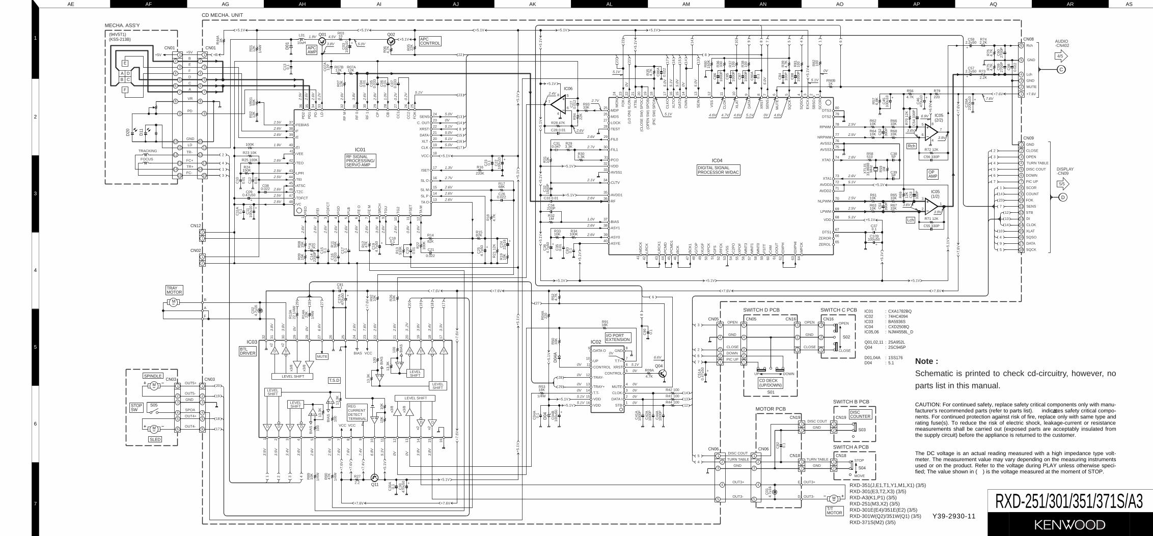
Y39-2930-11
RXD-251/301/351/371S/A3
AE
1
2
3
4
5
6
7
AF AG AH AI AJ AK AM AO AQ ASAL AN AP AR
RF SIGNAL
SERVO AMPPROCESSING/
DIGITAL SIGNALPROCESSOR W/DAC
I/O PORTEXTENSION
BTLDRIVER
CN01CN01
CN03CN03
CN09
CN08
CN05 CN05
D01
APC
APCCONTROL
Q01 Q02
AMP
CN12
CN02
T.S.D
M
D04
A
D04
Q04
CN16 CN16
S01
CD DECK(UP/DOWN)
S02
Lch
OPAMP
Rch
S05
M
M
SPINDLE
SLED
SWSTOP
TRAYMOTOR
Q11
CN19
CN18
CN06 CN06
S03
CN19
S04
CN18
MOTOR
M
T/T
F
DAB C
E
(94V5T1)(KSS-213B)
D11
D20
IC01 : CXA1782BQIC02 : 74HC4094IC03 : BA5936SIC04 : CXD2508QIC05,06 : NJM4558L_D
Q01,02,11 : 2SA952LQ04 : 2SC945P
D01,04A : 1SS176D04 : 5.1
(2/2)IC05
(1/2)IC05
IC06
DISCCOUNTER
-CN09DISPLAY
5/5
4/5
-CN402AUDIO
9
10
11
12
13
14
15
16
DATA O
UP
CONTROL
TRAY-
TRAY+
T.T-
VDD
VDD
8
7
6
5
4
3
2
1
GND
T.T+
XRST
CONTROL
MUTE
CLOK
DATA I
STB
24 23 22 21 20 19 18 17 16 15 14 13 12 11 10 9 8 7 6 5 4 3 2 1
41 42 43 44 45 46 47 48 49 50 51 52 53 54 55 56 57 58 59 60 61 62 63 64
MO
N
FO
K
(LO
ON
) X
LON
XT
SL
(CLO
SE
SW
) S
PO
C
(OP
EN
SW
) S
PO
B
(PIC
SW
) S
PO
A
CLK
O
XLT
O
DA
TO
CN
IN
SE
IN
VS
S
CLO
K
XLA
T
DA
TA
XR
ST
SE
NS
MU
TE
SQ
CK
SQ
SO
EX
CK
SB
SO
SC
OR
WD
CK
LRC
K
LRC
K1
PC
MD
PC
MD
1
BC
K
BC
K1
GT
OP
XU
GF
XP
CK
GF
S
RF
CK
VS
S
C2P
O
XP
OF
MN
T3
MN
T1
MN
T0
FS
TT
C4M
DO
UT
EM
PH
EM
PH
I
WF
CK
25
26
27
28
29
30
31
32
33
34
35
36
37
38
39
40
80
79
78
77
76
75
74
73
72
71
70
69
68
67
66
65
MDP
MDS
LOCK
TEST
FIL0
FIL1
PCO
VDD
AVSS1
CLTV
AVDD1
RF
BIAS
ASY1
ASY0
ASYE
DTS3
DTS2
RPWM
NRPWM
AVSS2
AVSS3
XTA0
XTA1
AVDD3
AVDD2
NLPWM
LPWM
VDD
DTS1
ZEROR
ZEROL
15
14
13
12
11
10
9
8
7
6
5
4
3
2
1
FC-
TR+
FC+
TR-
LD
GND
PD
VR
A
C
D
F
E
B
+5V
15
14
13
12
11
10
9
8
7
6
5
4
3
2
1
1
2
3
4
5
6
OUT5+
OUT5-
GND
SPOA
OUT4+
OUT4-
1
2
3
4
5
6
1
2
3
4
5
6
7
8
9
10
11
12
13
14
15
16
17
18
GND
CLOSE
OPEN
TURN TABLE
DISC COUT
DOWN
PIC UP
SCOR
COUNT
FOK
SENS
STB
DI
CLOK
XLAT
SQSO
DATA
SQCK
6
5
4
3
2
1
Rch
GND
Lch
GND
MUTE
+7.6V
1
2
3
4
5
PIC UP
DOWN
CLOSE
OPEN
GND
1
2
3
4
5
36 35 34 33 32 31 30 29 28 27 26 25
1 2 3 4 5 6 7 8 9 10 11 12
PD
2
PD
1
PD LD
RF
M
RF
0
RF
1
CP
CB
CC
1
CC
2
FO
K
FE
O
FE
I
FD
FC
T
FG
D
FLB
FE
O
FE
M
SR
CH
TG
U
TG
2
FS
ET
TA M
37
38
39
40
41
42
43
44
45
46
47
48
24
23
22
21
20
19
18
17
16
15
14
13
FEBIAS
F
E
EI
VEE
TEO
LPFI
TEI
ATSC
TZC
TDFCT
VC
SENS
C. OUT
XRST
DATA
XLT
CLK
VCC
ISET
SL O
SL M
SL P
TA O
R18
4.7K
10K
R19
22u1
6C
24
+
R21
12K
4.7u
50C
25
+
82KR15
R14
82K
R22
100K
C21
0.022
C20
0.01
510K
R13
15K
R08
15K
R09
2.7KR10
2200
PC
14
0.1
C15
0.03
3C
1656
KR
11
0.1
C17
47K
R12
4.7u
50C
19
+ 0.1C18
C10
0.01
0.1
C11
A
100u
10C
11
+
C12
0.01
R25 100K
150KR24
0.47u50C09
+
R23 10K
0.022C08
12P
C07
A
12KR07B
12KR07A
12K
R07
0.01
C04
0.03
3C
05
0.03
3C
07
0.01
C06
L01
10uH
100u
10C
03
+
10R03
4.7K
R06 22
KR
05
R01
50K
VR
0112
KR
0212
K
1/4W
2
1
1
2
2
4
1
3
R16
220K
100u
10C
22
+
0.1
C23
68KR17
0.022C26
16
17
8
14
13
15
23
22
5
6
8
4
7
R94
22K
0.01
2C
27
33KR93
R28 47K
C28 0.01
1500
PC
32
10KR33
100KR34
4.7u
50C
36
+
0.01
C35
220PC34
1MR32
0.047C31
3.3KR29
3.3KR30
10K
R31
C33 0.01
0.1
C83
33KR68
C52
390P
10KR64
10KR62
33KR66
5
6
8
7
2
4
31
R70
12K
C56 330P
R72 12K
R6110K
10KR63 R67
33K
33KR65
390P
C51
MH
z33
.868
8X
TL0
1
R69
12K
510R58
5PC38
1MR59
5PC39
C53
330P
C54
330
P
C55 330P
R71 12K
0.1C37
100u50C37B
+
23
23
22
4.7K
R35
17 16 15 14
14
13
1KR90B
100
R38
100
R37
330
R36
150K
R80
C86
1000
P
4.7K
R39
1000
P
C85
1000
P
C87
100P
C84
1000
P
C88
R81
100
10 9 7 5 4
100
R82
1
8
C86
A
0.02
2
0.1
C90
A
13.3
K
1 2
D D
43 5
DD
BIA
S
100
DETECTTERMINAL
6 87
BIA
S
100
VCC VCC
109 1110
K
1312 14x2
D
15 16
x2
D
MUTE
27
x3/8
x3/8
LEVEL SHIFT
LEVELSHIFT
LEVELSHIFT
x2x2
D
32 31 30
D
29 28
13.3
K
CURRENTREG
13.3
K
10K
13.3
K
BIAS2426 25
VCC
BIA
S
100
23 22
LEVEL SHIFT
x3/8
x3/8
SHIFTLEVEL
SHIFTLEVEL
BIA
S
100
DD
2021 19
DD
1718
29
R13
A22
1/4
W
R14
A
1/4W22
K28 27 181920 17
10K
R92
10K
R26
0.1C81
470u
50C
37A +
321 4
10K
R89
47K
R90
1/4W
1/4W R27
2.2
F
A
B
4.7u
16C
02
R42 100
R09A
4.7K
4.7K
R52
220
R04
A0.
1C
04A
100u
50C
04B +
1000
PC
41A
1000
PC
44A
1000
PC
42A
R50
33K
18KR53
18K
R41 100
R44 100
1/4W
OPEN
2
CLOSE
3
GND
1
2
3
1
DOWNUP
CLOSE
OPEN
C98
0.02
2
2.2K
R732.2u50C57
+
4.7K
R75
2.2KR74
4.7K
R76
2.2u50C58
+
2700
PC
6027
00P
C59
R79
2204.7K
R56
100u
10C
45
+
6.8K
R57
470u
10C
46
+
C29
A22
00u1
0
+
17
18
20
19
R44
A1K 8 6
C90 0.1
6
8
29
28
27
12
13
14
0.47
u50
C51
A +
1
2
2
1
5 5
1GND
DISC COUT
2
OUT3+
TURN TABLE
DISC COUT
GND2
1
3
4
GND2
1
3
1TURN TABLE
2
4OUT3+E
OUT3- OUT3-D
STOP
MOVE
6
7
2
3
4
5
+7.6V
+7.
6V
+6.
9V
+7.6V
+7.
6V
+7.6V +7.6V+7.6V
+7.
6V
+7.
6V+
7.6V
+7.6V
+7.
6V
+7.
6V
+7.6V
+7.
4V
+5.
1V
+5.1V
+5.
1V+
5.1V
+5.
1V
+5.1V
+5.1V+5.1V
+5.
1V+
5.1V
+5.
1V
+5.1V
+5.1V
+5.
1V
+5.1V+5.1V +5.1V
+B
+5.1V
+5.
1V
+5.1V
+5.
1V
+5.
1V
+5.
1V
+5.1V+5.1V
+5.1V
+5.1V
+5.
1V
14
5
12
7
23
14
1
7
6
5
4
3
2
9
4
10
13
+5.
1V
+5.1V
+5.1V
TRACKING
FOCUS
+5V
0.1
C13
+5.1V
R91
0.1
C30
A
470u
50C
30
+
+5.
1V
4.7u
16C
01
C82 0.1
100K
RXD-371S(M2) (3/5)
SWITCH A PCB
SWITCH B PCBMOTOR PCB
SWITCH D PCB SWITCH C PCB
RXD-301W(Q2)/351W(Q1) (3/5)RXD-301E(E4)/351E(E2) (3/5)RXD-251(M3,X2) (3/5)RXD-A3(K1,P1) (3/5)RXD-301(E3,T2,X3) (3/5)RXD-351(J,E1,T1,Y1,M1,X1) (3/5)
MECHA. ASS'Y
CD MECHA. UNIT
IC01
IC02
IC04
IC03
D
C
2.5V
2.6V
2.6V
1.9V
2.6V
2.5V
2.5V
2.6V
2.5V
2.6V
5.0V
0V
5.0V
5.1V
5.0V
5.1V
1.3V
2.7V
2.6V
2.6V
2.6V
2.6V
2.6V
2.6V
2.6V
2.6V
2.6V
2.6V
3.0V
2.6V
2.6V
0.8V
2.6V
2.6V
2.6V
2.8V
1.0V
0.2V
0.2V
3.8V
5.1V
0.2V
2.6V
2.6V
2.5V
1.9V 4.5V
5.0V3.8V
3.8V
3.8V
0V 0V 6.6V
2.6V
7.6V
2.6V
2.6V
3.,2
V
3.8V
3.4V
3.3V
3.5V
3.5V
3.4V
3.6V
2.6V
2.6V
7.6V
7.6V
7.4V
6.8V
5.1V
0V 0V 3.8V
3.8V
0V
0V
0V
0V
5.1V
5.1V
0V
0V
0V
0V
5.1V
0V
0V6.6V
2.4V
2.7V
2.6V
2.6V
2.7V
2.1V
1.0V
2.6V
2.6V
2.6V
5.1V
0V 5.0V
5.1V
5.1V
5.0V
0V 5.0V
4.6V4.7V4.6V 5.1V
5.0V
0V
5.1V
0V 4.6V
2.5V
2.5V
2.6V
2.6V
5.1V
2.5V
2.5V
5.1V
3.6V
3.9V
6.9V
3.6V
3.9V
7.6V
CAUTION: For continued safety, replace safety critical components only with manu-facturer's recommended parts (refer to parts list). indicates safety critical compo-nents. For continued protection against risk of fire, replace only with same type andrating fuse(s). To reduce the risk of electric shock, leakage-current or resistancemeasurements shall be carried out (exposed parts are acceptably insulated fromthe supply circuit) before the appliance is returned to the customer.
The DC voltage is an actual reading measured with a high impedance type volt-meter. The measurement value may vary depending on the measuring instrumentsused or on the product. Refer to the voltage during PLAY unless otherwise speci-fied; The value shown in ( ) is the voltage measured at the moment of STOP.
Note :
Schematic is printed to check cd-circuitry, however, no
parts list in this manual.

1
AT AV AX AZ BB BD BF BHAU AW AY BA BC BE BG
3
5
7
2
4
6
Y39-2930-11
RXD-251/301/351/371S/A3
-CN08CD MECHA
3/5
2/5
1/5
TUNER-CN101
-CN101TUNER
RXD-301E(E4)/351E(E2) (4/5)RXD-301W(Q2)/351W(Q1) (4/5)RXD-371S(M2) (4/5)
RXD-351(J,E1,T1,Y1,M1,X1) (4/5)RXD-301(E3,T2,X3) (4/5)RXD-A3(K1,P1) (4/5)RXD-251(M3,X2) (4/5)
-CN302DISPLAY
5/5
5/5
DISPLAY-CN401
10 11 124 7 9865321
1315 1421 18 16171920222324
1
2
3
4
5
6
7
8
9
10
11
12
13
14
15
LVR O
LVR I
LT OUT
LT COM
POP
ROCK
JAZZ
FLAT
TUNER
CD
AUX
TAPE(REC)
VDD
CL
DI
30
29
28
27
26
25
24
23
22
21
20
19
18
17
16
RVR O
RVR I
RT OUT
AT COM
VREF
VSS
CE
14
131
2
3 12
5
4
10
11
7
68
9
2 15 4 3+
B
-B+B
11 8
-B67
IN(R
ch)
GN
D9
OU
T(R
ch)
10
OU
T(L
ch)
12
GN
D
IN(L
ch)
1314
R409 100K
C415 10P
R411 47K C417 470P
C419 5600P R413 22K
C421 470P
R415 33K
R423 33K C429 0.018
C433 6800P R425 3.3K
R427 12K
C431 680P
R417 C423 1000P
C483 150P
C427 1500P R419 10K
R421 27K
C40
9 0.
47u5
0
+
47K
R433
47K
R435
R429 33K
47KR431
220K
C407 4.7u50
+
C414 10P
R410 100K
C416 470P
R414 22K
R412 47K
C418 5600P
R416 33K
C420 470P
C426 0.018 R424 33K
R425 3.3K C432 6800P
R428 12K
C430 680P
C484 150P
C422 1000P R418 220K
R420 10K C426 1500P
R422 27K
R43
4 47
K
47KR436
R43
2 47
K
R43
0 33
K
0.47u50C412
+
220u
16C
434 +
R44
0
R43
9 10
K
10K
R44
1 1K
R44
2 1K
R44
3 1K
C43
5 0.
47u5
0
+
47K
R43
747
KR
438
4.7u50C406
+
10KR490
10KR482
C411 0.47u50
+
10 9 8 7 6 5 4 3 2 1
MU
TE
L G R ST
IND
+12
V
CE
DI
CLK
DO
0.47
u50
C41
0
+
1 2 3 4 5 6 7 8 9 10 11 12 13 14 15 16 17
TAP
E H
GN
D
+12
V/S
W
PO
WE
R
CE
CLK
DI
DO
ST
/IN
TU
MU
TE
SY
NC
RE
C
MU
TE
GN
D
+5.
6V
S.B
AS
S
BA
CK
VR
-1
100K
R73
9
R45
2 10
K
R45
3 22
K
10K
R44
4
10u5
0C
444 +
470
1/4W
R44
7
1u50C441
+
4.7K
R45
1
470PC439
0.47u50C437
+
1MR449
100u
16C
443 +
C44
21u
50
+
C43
6 0.
47u5
0
+
0.47
u50
+
470PC440
1MR448
C43
8
4.7K
R45
0
220
R446
4.7K
R44
5
220u
10C
445 +
R45
4
18K
R45
6
100K
R45
5
100K
Q405,406
R40
4 1.
2K
C40
2 33
0P
C40
1 33
0P
1.2K
R40
3
1K
R402
1K
R401
1
2
3
4
5
6
+7.6V
MUTE
GND
Lch
GND
Rch
6.8K
R40
86.
8KR
407
470P
C40
4
33KR406
33KR405
470P
C40
3
0.1
C40
5 GND1
LIG
HT
10R202
220PC202
1u50
C21
2
+
12KR208
0.01
C21
0
47u16C208
+
680PC20415
0R
206
1KR
206A
220PC206
180KR204
330u16C237
+220PC218
3.3u
50C
238
+
180KR228
100u10C241
+
12KR216
R21747K
R230 330K
180R232
+
47u16C222
R220 27K
680P
C24
0
4.7KR250
330K
R21
2
1.5K
R214
1500
PC
214
R21
8 22
0
1/4W
C22
7 47
u16
+
1000
PC
224
R23
4 2.
2K
R25
4 1M
3.3u50C226
+
100KR236
22KR270
2.7KR219
150
R20
5
1u50
C21
1 +
0.01
C20
9
1KR
205A 12K
R207
47u16C207
+ 180
R23
1
1200
PC
215
22K
R22
5
330K
R22
9
10K
R22
3
100K
R22
1
3.3u
50C
219 +
R22
4 10
K
47u1
6C
221 +
R22
2 10
0K
10K
R21
5
680PC203
220PC205
680P
C23
9
180KR203
10R201
220PC201
220P
C21
7
180KR227
R211330K
22K
R22
6
1200
PC
216
3.3u
50C
220 +
PB
IN(R
ch)
(Rch
)P
B O
UT
PB
IN(L
ch)
(Lch
)P
B O
UT
1
2
3
4
5
10
R245
3
2
1
R24
3
10K
10K
R24
4
10K
R24
7
R23
8
3.3K
0.02
2C
233
78
9
3
2
1
6
5
4
L201
C23
1 0.
01
0.01
5C
230
C23
2 47
00P
R24
1 27
K
R24
02
1
1R
249
100u
16C
243 +
47u1
6C
234 +
27K
R24
8
R24
2 39
0
2.2K
R26
7
0.02
2
C23
53300
PC
245
1KR259
0.02
2C
246
10K
R20
9
R24
6
10
1/4W
Q201-206
1KR26
610
KR
239
1
2
3
4
5
6
7
8
1
2
3
4
5
6
7
8
10K
SF
R20
1
15K
R26
0
R261
3.9K
0.47u50
+1
2
2
1
3
5
4
2
3
1
1000
PC
223
R23
32.
2K
2.2K
R25
7
R25
647
K
220K
R23
7
2.2K
R26
2
10u5
0C
228 +
22K
R26
5
R235 3.3u50C225
+
22K
R25
5
47K
R25
8
R26
4 2.
2K
R26
3 1K
C242
2
5
6
4
3
1L202
470uH
220u
16C
236 +
0.02
2C
244
2
4
3
1
4
1
4
3
2
6
5
3
2
1
4.7KR251
1500
PC
213
1u50C446
+
0.1
C45
3
47K
R46
4
0.1
C45
2
10u5
0C
449 +
220u
16C
448 +
100K
R46
5
1.5K
R46
0
6.8K
R46
83.
3KR
470
47K
R46
71MR46
6
4700
PC
450
0.1C482
1MR45
8
2.2K
R46
2
1.5K
R45
9
1MR4571u
50C
447 +
2.2K
R46
1
10u50C457
+
6.8K
R46
9
1MR46
3
3.3K
R47
1
47K
R47
5
4.7K
R49
1
4.7K
R49
3
R4924.7K
47K
R47
44.
7KR
494
10u5
0C
456
+
2.2KR472
2.2u50C454
+
R479 10K
1KR47
7
5
6
4
8
7
C461 100P
100u
16C
480
+
1/4WR485 220
2.2K
R48
0
0.47
u50
C53
2 +
R484 68K
2.2u
50C
462 +
3.3K
R48
3
3
21
R478 10K
1KR47
6C
458
100P
2.2u50C465
+
2.2u50C463
+
2.2KR481
Q409-412
2.2u
50C
455 +
2.2KR473
4700PC451
0.1C481
3.3K
R214A 3.3K
R26
8 47
K
R26
9 47
K
R487 560
1/4W
1
2
3
4
5
6
L
G
R
MUT
+12V
-12V
1KR496
10KR742
C74
1
0.1
10KR741 1K
R495
2.2K
R508
47u1
6C
519 +
1KR51
6 4.7K
R517
18KR519
15KR518
15K
R52
0
27KR521
1u50
C53
1 +
1KR515
1KR514
100u
50C
517 +
15K
R51
3
10KR5120.
1C
506
100u
50C
505
+ 10K
R51
010
0R
509
1/2W
12KR544
R543 2.2K
C518 1u50
+
12K
R54
5
47K
R54
6
220u
50C
508 +
56K
R50
1
1000
PC
501
4.7KR547
100u
16C
524 +
+
4.7u
50C
523
2.2u50C464
+
1000
PC
502
56K
R50
2
47u2
5C
504
+
2.7K
R50
4
47u2
5C
503
+
2.7K
R50
3
C50
710
0u50 +
C50
922
0u50
+ C51
00.
1
56KR506
56K
R505
4.7PC512
4.7P
C511
R52
3
2.2K
R525
15K
15K
R52
6R
524
2.2K
0.022C516
C5150.022
R527
0.1 2W4.7
R52
90.
1C
513
0.1R528
10K
R51
1 1/2W
R531
100K
100K
R53
2R
530
4.7
0.1
C51
4
1/2W
R507
100 1/4W
Q504-506
2W
470u
16C
733
+
220
1/4W
R48
6
0.02
2C
734
100u
16C
479 +
47u1
6C
732 +
1K 1
/4W
R71
5
100 1/2W
R703
10K
R71
1
10K
R71
2
1u50
C73
5 +
1
2
7
4
6
8
3
5
10K
R54
8
0.01
C52
0
0.02
2C
522
47K
R54
9
100u
16C
521 +
56KR551
1K 1/4WR550
1 3
2 4
5 6
4.7 1/2WR534
L5021uH
L5011uH
4.7 1/2WR533
1000
P
C52
510
00P
C52
6
3.3K
R540
3.3KR539
270 1WR535
68 1/2WR537
4.7u50C529
+
100K
R54
2
R536270 1W 68 1/2W
R538
4
3
2
1
4
3
2
1
4
3
2
1
4
3
2
1
4
3
2
1
4
3
2
1
4
3
2
1
4
3
2
1
4
3
2
1
4
3
2
1
GND
AC3
11111
22222
AC5
AC4
44444
33333
AC6
GND
5
6
0.01
C70
5
0.01
C704
0.01
C70
6
0.01C703
C701
+
C702
+
F701 2A 250V
0.1
C71
0
0.1C707
C708 0.1C709 0.1
2200
u25
C72
6 +
100u
16C
736 +
0.02
2C
730
0.02
2C
728
1 1W
R70
1
330
1/4W
R70
2
47u2
5C
727 +
C73
1 0.
022
R706 1 1W
330
1/4W
R70
5
C71
80.
022
0.02
2C72
9 0.
022
C72
0
100u
16C
719 +
0.02
20.
022
C71
6 0.
022
C71
4C
712
470
1/4W
C71
310
0u16 +
R70
4
C72
1 10
0u16
+
C71
5 47
0u16
+
C71
1 47
0u16
+
220u
25C
725 +
10KR713
6.8KR710
100u
16C
722 +
0.02
2C
723
10K
R70
910
KR
707
470
R70
8
470u
16C
724 +
1/2W
1/4W
4.7K
1/4
WR
552
R738
1K
56K
R52
2
100K
R54
1
1/4W
R740100K
+12V
2 GND
4
Rch3
1 Lch
2
3
5
4
1
6
1000
PC
528
1000
PC
527
3
4
1
2
5
6
1
2
3
4
5
6
7
8
10
9
11
P1
P2
P3
P4
P5
RED
ORG
WHT
P8
P2
P6
P4
P7
ORG
ORG
BRN
WHT
GRY
120V
220-
P8 ORG
BRN
RED
P3
P6
YEL
P1
P7
P5
AC2F703
F702
4.7M
R700
GND4
AC1
+5.5V
+12V
+7.6V
+7.6V
+12V
5.5V
+12
V
+12V+12V
+12
V+
12V
+12
V
+12V
+19.2V
+19.2V
+19.0V
+31.3V
-31.3V
-12V
+12
V
+12
V+
12V
+12
V
-12V
+12V
+12
V
-12V
+12V
-12V
+12V
+12V
+12V
+12V
+12
V
+12
V
+12V+12V
+7.6V
+7.6V
+12V+12V
+7.6V
+12V
+7.6V
+7.
6V
+12V+11.5V
+11
.5V
+11.5V
110-
240V
0.47
u50
C48
5 + C413 0.47u50
+
C408 0.47u50
+
1
2
3
==
100K
R322
100KR321
-12V
-12V
-31.3V
-12V
3.3KR582
100K
R49
7
+12
V
ALC
A/B
1.5K
R213
14
5 2
36
R49
8
100K
RL501
5 5
0.1
C53
0
4.7K
R73
7
1
2
3
4
5
6
P9
ABB.
X2M3
AUSTRALIAGENERAL MARKET
COUNTRYDESTINATION A,B,C
NO
IC501
STK405-70A
P9
NO T3AL250V
F702
T2AL250V NO
F703
T2AL250V NO
C450,451,525,526
NO 3300u50
C701,702
GBU4D
D701
T2AL250V
T16A250V
F702
T2E3
ABB.
U.KEUROPE
DESTINATIONCOUNTRY
NOSTK405-70ANO
B,C
NO
A IC501 P9
NONO
F703
3300u50YES
NO
C525,526C450,451
C701,702
AUSTRALIA X3 YES NOGBU4D
D701
T16A250V
F702
Q1ABB.
RUSSIA
DESTINATIONCOUNTRY
NOSTK405-70ANO
A,B,C IC501 P9
NO
F703
NO GBU4D3300u50NO
C701,702C450,451
D704C525,526
YES
T16A250V
F702
E2ABB.
EUROPECOUNTRYDESTINATION IC501
STK405-70A
A,B,C
NO NO
P9 C450,F703
NO NO NO451
YES
C525,526 C701,702
3300u50
D704
GBU4D
T2AL250V
T16A250V
F702
EUROPE E1T1U.K
YES
JABB.
JAPANCOUNTRYDESTINATION
STK405-70ANO
A IC501
NO
P9
3300u50 GBU4DNONO
NO
C450,451
F703 C701,702
YES
C525,526 D701
AUSTRALIAGENERAL MARKET
PX Y1M1X1
B
NO
C
NO
YES
NOSTK405-100A
T4AL250V
T2AL250V
T2AL250V
NO
R700
NO
YES 4700u50 GBU6D
F702
T4AL250VM2ABB.COUNTRY
GENERAL MARKET
DESTINATION
STK405-100A
IC501
YES
A,C B
NO
P9 C450,
T2AL250V
F703451YES NO
C525,526
4700u50 GBU6D
C701,702 D701
NO
R700
NO
3A250V
F702
P1K1
ABB.
CANADAU.S.A.
DESTINATIONCOUNTRY
YESSTK405-70AYESNO
B IC501 P9
NO
F703
GBU4D3300u50NO
C701,702C450,451
D701A,C R700
YES
C525,526
NO
R21
3A
10
3
2
1
4
3
2
1
B+12V
R-O/P
GND
L-O/P
R325
1K
2.2K
R30
810
u50
C30
9
+
100K
R30
7
4700
PC
321
0.22
u50
C30
8 +4 123567
R30
5
R30
6 47
0
100u
16 +
10u5
0 +
47
R31
54.
7u50
C30
5 +
C319
3900P
R3032.2K 0.22u50
C301
+
R327
22K
R3281.2K
2
4
3
1
3
1
4
20.22u50C302
2.2K
+
R304
47K
R30
1
47K
R30
2
0.47
u50
C31
3
+0.47
u50
C31
4
+
R32
0
150
R32
4
1K
270K270K
R318 R317
R31
9
R32
3
150
1K
47u5
0C
315 +
1u50C316
+
+
220u
16C
311
330
R31
6R
326
22K
0.1
C31
7
1u50
C32
0
+
A
47K
R31
4
C30
7
C30
6
1M
6
5
4
3
2
15
6
8
4
7
3
21
C686
0.1
C685
0.1
R68
1
100K
R68
2
100K
10u50C681
+
10u50C682
+
100K
R68
5+
C68310u50
C684
+
10u50
R68
610
0K
R69
047
K
0.1C687
R689470
R6871.5K
1.5KR688
10KR684
10KR683
-12V
+12V
MUT
Rch
GND
Lch
+12V
12V
+12
V12
V
+12V
12V
(K,P)(Y,M)
(Q)(X)
(T,E)
: AC120V 60Hz: AC110-120V/220-240V~
50/60Hz: AC220V~ 50Hz: AC240V~ 50Hz: AC230V~ 50Hz
: AC100V 50/60Hz(J)1/2W
P9
T3
T3
EUROPE E4 STK405-70ANO
DESTINATIONCOUNTRY ABB.
A,B,C IC501
NO T16A250VNO
F703F702P9
DESTINATION
RUSSIACOUNTRY
Q2ABB.
STK405-70A
A,B,C
NO
IC501
NO
F703F702
T16A250V
P9
NO
NO NO YES 3300u50
C450,451
C525,526 C701,702
GBU4D
D704
NO
C450,
NO451
C525,526
YES
C701,702
3300u50
D704
GBU4D
C54
1 10
00P
C54
2 10
00P
100K
R700
R700
R700
R700
R700
R700
IC201
IC401
IC402
IC501
C
B
A
AUDIO UNIT
IC301
MIC MIX UNIT
SUB-WOOFER PRE AMP
RXD-A3 TYPE ONLY
E
AC CORD UNITTRANSFORMERPOWER
F
HEADPHONE UNIT
RECORD SWITCH UNIT
MECHA. ASS'YCASSETTE DECK
Q415
Q416
CN101 CN301
Q711
D40
1
Q407
Q405 Q406
Q408
BUFFERREC
Q417
Q418
CN402
MUTE
AUDIO
VR.SYSTEMELECTRIC
AUX
Lch 1
Rch 2
JK401
GND
D201
D211
D21
2Q213
Q210 Q214MUTEPB
DECKA/BSW
PRE/RECAMP
Q215
D21
3
D20
3
Q211
Q212
CN202
CN201
SW
751
Q202 Q204 Q203
Q205Q206Q201
BIAS OSC COIL
Q209
BIAS OSC
CN203
Q208
D20
8
Q207
TAPESPEED
SWITCHINGR/P
CANCELBEAT
Q220
BIAS OSC
CN205CN205
Lch
Rch
ERASE
Lch
Rch
CN203
CN202
CN201
PLAYTAPE B
TAPE AREC./PLAY
Q217
D20
5D
202
Q216
D204Q218
CN204
D206
SW201
D207
CN206
REC SW
CN206
CN204
M
S203
S201
S202
TAPEA
TAPEB
TAPEB
PLAY
L
M
Q219
PB MUTED581
PRE AMP(2/2)IC404
(1/2)IC404
Q413
Q414
SYSTEM MUTE
Q412
Q410
Q411
Q404
Q403
EX.BASSON/OFF
AMP+3dB
AMP+3dB
Q409
CN605
Q714
Q713
ATTENUATOR+10dB
Q508
Q507
MUTE
Q501
Q502
Q503
Q509
Q510
D504
D505
Q506
D50
1
D50
2 Q504
Q505
PROTECTION
SPEAKERPROTECTOR
POWER AMP
D71
1
D712
Q707
Q708
Q709
12V AVR
IC502
D503
D58
5
Q511
Q512
Q513
MUTE
CN502 CN502CN502 CN502CN502 CN502CN502 CN502CN502
CN701
D701
D705
D703
D704
D702
D70
6
D71
0
Q701 +12V AVR
D70
8
Q703+5.5V AVR +7.6V AVR
D70
7
Q702
Q704
D70
9
D714
Q705
Q706
+12V SWITCHED
CN403
EX.BASSCONTROL
HEADPHONES
CN701
S701
IC201 : TA8189NIC401 : LC75392IC402 : TC4066IC404 : NJM4558LIC501 :IC502 : uPC1237HA
Q201-206,208,215,219: 2SC945P
Q207,213,216,218,409,410,503,508: 2SA733P,Q
Q209,220,703 : 2SC2001L
Q405-408,415,416,501,502,706: 2SC945P/Q
Q210-212,217,403,404: 2SC945P,Q
Q214,507,509,510,707: DTC124ES
Q413,414,713,714 : 2SC2878A/B
Q504,505 : 2SC1841Q506 : 2SA988F
Q411,412,511,512 : 2SC2878A
Q513,711 : DTA144ESQ701,702,704 : 2SD882PQ705 : 2SA733PQ709 : 2SA593L
D201-205,208,211-213,401,402,501-505,581,585,706,712,714 : 1N4148M
D206,207 : 1N4002D701
: UZ12B
D707 : UZ8.2BD708 : UZ6.2BD709 : VZ12B
D711 : VZ12V
D402
A
B
Rch
Lch
SPEAKERS
Lch
Rch
OUT
JK501RELAYSPEAKER
JK502
C
D702-705 : 1N4002L
D710
:
Q417,418,708, DTC114ST:
RXD-251
RXD-301
RXD-351W
RXD-351E
RXD-351
RXD-371S
RXD-A3
CN302
CN403 MIC1
JK301
JK302
MIC2
Q301Q302
Q303
MIC AMP
IC301 : TA2011S
Q301,302 : 2SC945Q303 : 2SC2878
E
CN605 (2/2)IC602
IC602(1/2)
Q611
JK601
: NJM4558LIC602Q611 : 2SC945
F
RXD-301E
RXD-301W
D20
9
REC:0.7VB PLAY:0.4VA PLAY:0V
ON:4.0VMUTE
OFF:0VON:0.6VEX.BASS
ON:0VOFF:6.2V
10.6V
TAPE:4.6V
REC:0VPLAY:4.7V
4.9V
4.9V
4.9V
4.9V
4.9V
4.9V
4.9V
4.9V
4.9V
4.9V
4.9V
4.9V
4.9V
4.9V
4.9V
4.9V
4.9V
4.9V
4.9V
4.9V
4.9V
4.9V
4.9V
4.9V
A PLAY:0VREC:9.3V
REC:8.6VPLAY:10.1V
REC:6.2V REC:0VA PLAY:10.7V
A PLAY:0VREC:11.1V
11.5V
REC:1.9V
1.3V 0V1.4V
1.4V1.3V
11.5V
1.4V1.3V 2.0V0V
1.3V
REC:0.7V
REC:10.1VPLAY:8.3V
0.3VREC:
REC:9.0VPLAY:8.9V
B PLAY:0VA PLAY:0.6V
0.8V
11.5V
B PLAY:
REC:7.8VB PLAY:11.0V
REC:8.4V
B PLAY:1.0VREC:8.4V
REC:0.7V
A PLAY:9.0VB PLAY:8.8V
B PLAY:8.8VA PLAY:9.0V
REC:0.5V
0.9V
REC:0.7V
0V0V
0V
0V
0V
4.9V
4.4V
4.9V
0V
0V
4.4V
4.9V
2.1V2.6V
4.9V
2.1V
2.6V
4.9V
0V
-29.4V
29.8V31.3V
0V
-31.3V
-12.3V
1.7V
0V
0.8V
2.3V4.1V
0V
-11.6V
12.3V
11.6V0.7V
0V
18.7V
4.7V
12.2V 11.8V
6.2V 8.2V
12.3V11.8V
ON:4.4VPOWER
POWER ON:0VSTANDBY:9.7V
ON:10.4VPOWER
0V0V
10.9V
OFF:-2.7VMUTE ON:5.1V
0V0V
0V5.4V
11.5V
8.9V
REC: 0.7V
2.0V
0V
PLAY:10.8VREC:10.8V
REC:6.2V
REC:10.9V
REC:11.5V
BPLAY:11.0V
11.8V
6.0V
5.7V 5.7V
6.0V
11.8V
-10.9V
-11.8V
11.8V
-29.0V
4.4V
MUTE ON:3.4VOFF:0V
0V
0V
11.8V
0V
0V
1.7V
-31.3V
31.3V
+B +B LINEB -B LINE
GND LINE
SIGNAL LINE
RECORDING LINE
CAUTION: For continued safety, replace safety critical components onlywith manufacturer's recommended parts (refer to parts list). indicatessafety critical components. For continued protection against risk of fire,replace only with same type and rating fuse(s). To reduce the risk of electricshock, leakage-current or resistance measurements shall be carried out(exposed parts are acceptably insulated from the supply circuit) before theappliance is returned to the customer.
The DC voltage is an actual reading measured with a high impedance type voltmeter with a cassette loaded at playback mode. The measurementvalue may vary depending on the measuring instruments used or on the product. Bias circuit DC voltage is measured while in the record mode.
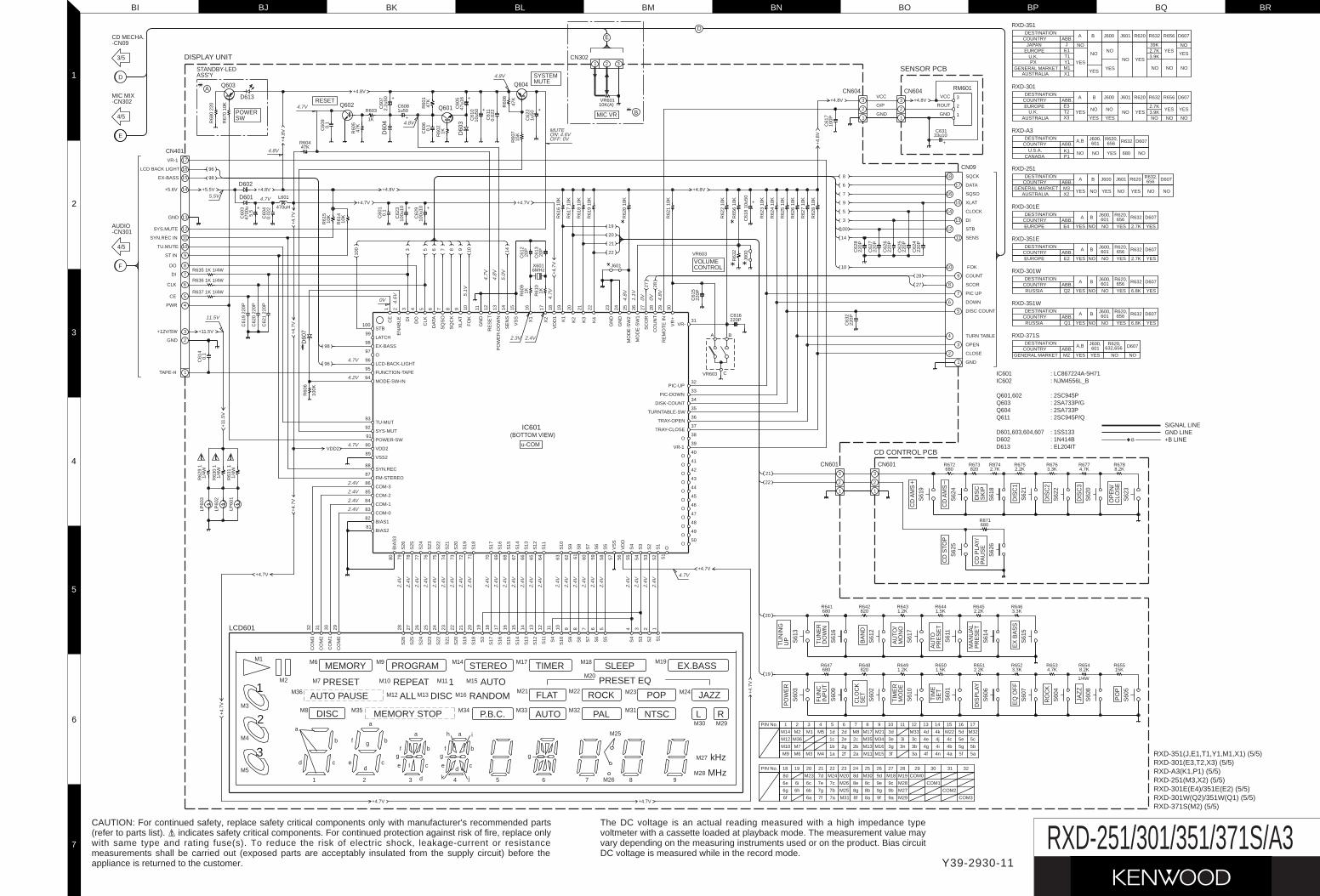
BI BK BM BO BQBJ BL BN BP BR
2
1
3
5
7
4
6
RXD-301E(E4)/351E(E2) (5/5)RXD-301W(Q2)/351W(Q1) (5/5)RXD-371S(M2) (5/5)
RXD-351(J,E1,T1,Y1,M1,X1) (5/5)RXD-301(E3,T2,X3) (5/5)RXD-A3(K1,P1) (5/5)RXD-251(M3,X2) (5/5)
(BOTTOM VIEW)
u-COM
CN09
M6
M8
M9 M14
M7 M10 M15
M36 M12 M13
M35 M34
M16
M17 M18
M21
M33 M32
M22 M23
M31
M24
M19
M25
M26
M27
M28
M1
M2
b g
ec
f
a
b
cd
1
d
a
2
a
f bg
e c
d3 4
d
5
I c
f b
a
g
6 7
g
8 9
M3
M4
M5
h i
k j
e
M20
M30 M29
M11
D60
7
D602
D601
D613
POWER
STANDBY-LEDASS'Y
Q602 Q601
Q604A
SW
Q603
RESET
D60
4
D60
3
SYSTEMMUTE
VOLUMECONTROL
CN604
CN302
B
S61
9
S62
4
S61
8
S62
1
S62
2
S62
0
S62
3
CD
AM
S
CLO
SE
OP
EN
/
DIS
CS
KIP
CD
AM
S
DIS
C1
DIS
C2
DIS
C3
CD
STO
PS
625
PAU
SE
CD
PLA
Y/
S62
6
UP S61
3
DO
WN
S61
6
S61
2
S61
7M
ON
O
PR
ES
ET
PR
ES
ET
S61
1
S61
4
EX
BA
SS
S61
5
PO
WE
R
S60
3
INP
UT
S60
9
CLO
CK
S60
2S
ET
S61
0M
OD
E
SE
T
EQ
OF
F
DIS
PLA
Y
S60
1
S60
6
S60
7
S60
5
S60
8
S60
4
JAZ
Z
RO
CK
TU
NE
RF
UN
C
TU
NIN
G
BA
ND
TIM
ER
AU
TO/
MA
NU
AL
AU
TO
PO
P
TIM
E
CN601
D602 : 1N414B: 1SS133D601,603,604,607
: 2SA733PQ604: 2SA733P/GQ603: 2SC945PQ601,602
: NJM4556L_BIC602: LC867224A-5H71IC601
MIC VR
CN604
CN601
Q611 : 2SC945P/Q
D613 : EL204IT
RXD-351
RXD-301
RXD-A3
RXD-251
RXD-351W
RXD-351E
RXD-371S
E
RM601
D
RXD-301E
RXD-301W
1 2 3 4 5 6 7 8 9 10 11 12 13 14 15 16 17 18 19 20 21 22 23 24 25 26 27 28 29 30
80 79 78 77 76 75 74 73 72 71 70 69 68 67 66 65 64 63 62 61 60 59 58 57 56 55 54 53 52 51
CE
EN
AB
LE DODI
CLK
DA
TA
SQ
SO
SQ
CK
XLA
T
FO
K
GN
D
RE
SE
T
PO
WE
R-D
OW
N
SE
NS
VS
S
X1
X2
VD
D1
K1
K2
K3
K4
GN
D
GN
D
MO
DE
-SW
2
MO
DE
-SW
1
SC
OR
CO
UN
T
RE
MO
TE
IN
VR
+
BIA
S3
S26
S25
S24
S23
S22
S21
S20
S19
OS18
S17
S16
S15
S14
S13
S12
S11
S10
S9
S8
S7
S6
S5
VS
S
VD
D
S4
S3
S2
S1
100
99
98
97
96
95
94
93
92
91
90
89
88
87
86
85
84
83
82
81
31
32
33
34
35
36
37
38
39
40
41
42
43
44
45
46
47
48
49
50
STB
LATCH
EX-BASS
O
LCD-BACK-LIGHT
FUNCTION-TAPE
MODE-SW-IN
TU-MUT
SYS-MUT
POWER-SW
VDD2
VSS2
SYN.REC
FM-STEREO
COM-3
COM-2
COM-1
COM-0
BIAS1
BIAS2
VR-
PIC-UP
PIC-DOWN
DISK-COUNT
TURNTABLE-SW
TRAY-OPEN
TRAY-CLOSE
O
VR-1
O
17
16
15
14
13
12
11
10
9
8
7
6
5
4
3
2
1
VR-1
LCD BACK LIGHT
EX-BASS
+5.6V
GND
SYS.MUTE
SYN.REC IN
TU.MUTE
ST IN
DI
DO
CLK
CE
PWR
+12V/SW
GND
TAPE-H
18
17
16
15
14
13
12
11
10
9
8
7
6
5
4
3
2
1
SQCK
DATA
SQSO
XLAT
CLOCK
DI
STB
SENS
FOK
COUNT
SCOR
PIC UP
DOWN
DISC COUNT
TURN TABLE
OPEN
CLOSE
GND
28
272827
14109
6
8
7
R62
3 10
K
R62
4 10
K
R62
5 10
K
R62
6 10
K
R62
7 10
K
R62
8 10
K
R62
2 10
K
R62
1 10
K
R61
6 10
K
R61
8 10
K
R61
7 10
K
R61
9 10
K
220P
C61
5
220P
R65
6 10
KR
632 22
0PC
624
C62
522
0P
220P
C62
7
C62
622
0P
220P
C62
8
R62
0 10
K
19
20
21
22
C61
8 10
u50
+
R60
6
100K
0.1
C61
4L601
470uHR
680
220
R67
0 10
K
96
98
96
98
1K 1K
J601
20P
20P
6MHzX601
C61
3R
610
87653
100
10K
R61
5
R61
410
K
R603
1K
47KR604
R62
9 1
1/4W
R63
0 1
1/4W
R63
1 1
1/4W
LP60
3
LP60
2
LP60
1
4700
uC
603 +
0.02
2C
604
0.1
C60
1
100u
10C
623 +
100u
10C
629 +
47K
R60
5
0.1
C60
9
5.5
10
14
100
5
3
9
VR603
J600
220P
3
2
1 1
3
2
R635 1K 1/4W
R636 1K 1/4W
R637 1K 1/4W
C61
9 22
0P
C62
0 22
0P
C62
1 22
0P
0.1
C60
6
1KR60
2
0.02
2C
611
10u5
0C
610 +47
u16
C60
5 +
47K
R60
1
2.2u
50C
607 +
47K
R60
8
15K
R60
7
1u50
C62
2 +1u50C608
+
C61
2R
609
321
10K(A)VR601
C61
710
0P
2
1
33.3KR676
2.2KR675
2.7KR874
680R672 R677
4.7KR6788.2K820
R673
680R871
1.5KR644
820680R641 R642
1.2KR643
2.2KR645
3.3KR646
R6501.5K680
R647820
R648 R6491.2K
R6512.2K 3.3K
R6524.7KR653 R654
8.2KR65515K
1
2
321
22
CO
M3
32
CO
M2
31
CO
M1
30
CO
M0
29
S26
28
S25
27
S24
26
S23
25
S22
24
S21
23
S20
22
S19
21
S18
20
S3
19
S17
18
S16
17
S15
16
S14
15
S13
14
S12
13
S11
12
S4
11
S10
10
S9
9
S8
8
S7
7
S6
6
S5
5
S4
4
S3
3
S2
2
S1
1
PIN No. 1
M14
M12
M9
M10
M6
M7
M36
M2
2
M3
M1
3
M4 1a 2f
M5
4
1c
1b 2g
2e
1d
5 6
2d
2a M11 M15
2b
2c
M8
7
M35
M13 M16
M34
M17
8 9
M21
3a3f
M33
3c
3b3n
3i3e
3g
10
3d
11 12
4f 4n
4e
4g 4i
4j
4d
13 14
4k
4a 5f
4c
4b 5g
5e
M22
15
5d
16
6f
PIN No.
6e
6g 6h
6i
8d
18 19
COM0
7a6a 7f M31 8f
M24
7c
7b7g
7e6c
6b
7d
20
M23
21
M26
M25 8g
8e
M20
2322 24
8d
9a8a 9f M29
M18
9c
9b
8c
8b 9g
9e
M30
25
9d
26
M27
M28
M19
2827 29
COM3
COM1
COM2
30 31 32
VR603
20
19
+5.5V
VCC
O/P
GND
3
2
1
33u10C631
+
VCC
ROUT
GND
+4.8V
+4.8V
+4.7V +4.7V
+4.
7V
+4.8V
+4.
8V
+4.8V
+11.5V +4.
7V+
4.7V
+11
.5V
VDD2
+4.
7V
+4.7V
+4.
7V
+4.7V
+4.
7V
+4.7V
+4.7V
B
C
A
O
O
O
O
O
O
O
O
O
O
C63
2C616
EUROPEU.K.
GENERAL MARKETPX
AUSTRALIA
E1T1
X1M1Y1
YES
ABB.DESTINATION
COUNTRYJAPAN J
NO
NO
D607
NO
YES
A
YES
NO
B
YES
NO
J600
NO
J601
YES
R620
NO
39K2.7K3.9K
R632
ABB.E3T2X3AUSTRALIA
COUNTRY
U.K.EUROPE
DESTINATION
NOYESYES
NO
A B J600 J601
YESNO
R632
2.7K3.9K
R620
YES
NO
D607
NO
YES
K1P1
ABB.
CANADAU.S.A.
DESTINATIONCOUNTRY
NO
A,B
NO
J600,
NO
D607601
YES
R620,656
680
R632
ABB.COUNTRYDESTINATION
YES
A 656
NO
R632,
NO
D607
M3X2AUSTRALIA
GENERAL MARKET
B
NO
J600
YES
J601
NO YES
R620
R632
6.8KQ1ABB.
RUSSIACOUNTRYDESTINATION
NO
J600,601
YES
A 656YES
R620,
YES
D607
NO
B
R620,ABB.
DESTINATIONCOUNTRY
YES
A
NO
B
NO601
J600,
YES656 D607R632
2.7K YESEUROPE E2
DESTINATIONCOUNTRY ABB.
YES601
J600,A,B
YES
R620,
NO
632,656 D607
NOGENERAL MARKET M2
GND LINESIGNAL LINE
B
CN401
-CN301AUDIO
4/5
4/5
-CN302MIC MIX
CD MECHA.
3/5
-CN09
5a
5b
5c
M32
17
+4.8V +4.8V
+4.
8V
COUNTRYEUROPE
DESTINATION R620,J600,
NOABB.E4 YES
A B
YES656
NO601 R632
2.7K
D607
YES
COUNTRYRUSSIA
DESTINATION R620,J600,
NOABB.Q2
BA
YES YES656601
NO 6.8K
R632 D607
YES
1/4W
NO
R656
NO
YES
R656
YES
+B LINE
2
1
3
IC601
LCD601
CD CONTROL PCB
SENSOR PCB
DISPLAY UNIT
F
E
D
2.4V
2.4V
2.4V
2.4V
2.4V
2.4V
2.4V
2.4V
2.4V
2.4V
2.4V
2.4V
2.4V
2.4V
2.4V
2.4V
2.4V
2.4V
2.4V
2.4V
2.4V
2.4V
2.4V
2.4V
2.4V
4.7V
2.4V
2.4V
2.4V
2.4V
4.7V
4.2V
4.7V
0V 4.6V
5.1V
4.7V
4.8V
5.0V
4.7V
4.8V
1.1V
0V 0V 4.8V
2.3V 2.4V
11.5V
5.5V 4.7V
4.8V
4.7V
4.8V
4.8V
OFF: 0V
MUTEON: 4.6V
2.4V
REPEAT
PROGRAM
PRESET
MEMORY STEREO
AUTO
TIMER SLEEP EX.BASS
PRESET EQ
ALLAUTO PAUSE
DISC MEMORY STOP
RANDOM
MHz
kHz
P.B.C.
FLAT
AUTO PAL
ROCK
NTSC
POP
L R
JAZZDISC
1
Y39-2930-11
RXD-251/301/351/371S/A3CAUTION: For continued safety, replace safety critical components only with manufacturer's recommended parts(refer to parts list). indicates safety critical components. For continued protection against risk of fire, replace onlywith same type and rating fuse(s). To reduce the risk of electric shock, leakage-current or resistancemeasurements shall be carried out (exposed parts are acceptably insulated from the supply circuit) before theappliance is returned to the customer.
The DC voltage is an actual reading measured with a high impedance typevoltmeter with a cassette loaded at playback mode. The measurement value mayvary depending on the measuring instruments used or on the product. Bias circuitDC voltage is measured while in the record mode.
@@@@@@e
@@f
@@f
@@f
@@f
@@f
@@f
@@f
@@f
@@f
@@f
@@f
@@f
@@f
@@f
@@@@@@e
????????
?@@@6Xg?@@@@@?
I'@)X?g?@e?
?N@@1?g?@e?
@@@Lg?@e?
@V')X?f?@e?
@?V')Xf?@e?
@??V')X?e?@e?
@?eN@1?e?@e?
@?e?3@Le?@e?
@?e?V')X??@e?
@?fV')X?@e?
@?f?V')X@e?
@?gN@@@e?
@?g?3@@e?
@?g?V'@e?
?@@@@@@?gV'e????????
????????
?@@@@@@@@@@@@@@??
?@(Me?@@?eI'@??
?@H?e?@@?e?N@??
?@f?@@?f@??
?@@?g?
?@@?g?
?@@?g?
?@@?g?
?@@?g?
?@@?g?
?@@?g?
?@@?g?
?@@?g?
?@@?g?
?@@?g?
?@@@@@@?f????????
?O2@@6X?f
@@@@@@)Xf
?J(MeI'@1f
?.Y?e?N@@f
@@f
@@f
?J@5f
?7@Hf
J@5?f
7(Y?f
?J(Yg
W.Y?g
?W.Yh
W&Y?fO.e
?W&@@@@@@@(Ye
?&@@@@@@@0Y?e
?W&?2@6Kf
O&@@@@@@@?e
?@@@@(M?I'@Le
?@@He?N@1e
?@@?f@@e
?@@?f@@e
?@@?f@@e
?@@?f@5e
?@@Le?J@He
?@@)K?O&@?e
?@@V4@0Mf
?@@?h
?@@?h
?@@?h
?@@?h
?@@?h
?@@@@@@?g
O2@@6Kf
?@@(MI'@@?e
J@(YeV'@Le
7@H?e?N@1e
@@g@@e
@@g@@e
3@L?e?J@@e
N@)XeW&@@e
?@@)KO&@@@e
I4@@0Y@5e
?J@He
W&5?e
?W&(Y?e
O&(Yf
O2@0Y?f
?@@0M?g
O2@@6Kf
?@@(MI'@@?e
J@(YeV'@Le
7@H?e?N@1e
@@g@@e
@@g@@e
3@L?e?J@@e
N@)XeW&@@e
?@@)KO&@@@e
I4@@0Y@5e
?J@He
W&5?e
?W&(Y?e
O&(Yf
O2@0Y?f
?@@0M?g
?@@?e
?@@?e
W&g
?W&@g
W&@@g
.Y@@g
@@g
@@g
@@g
@@g
@@g
@@g
@@g
@@g
@@g
@@g
@@g
@@@@@@f
W2@@6Xf
?W&(MI')X?e
?7@HeN@1?e
J@5?e?3@Le
7@H?e?N@1e
@@g@@e
@@g@@e
@@g@@e
@@g@@e
@@g@@e
@@g@@e
3@L?e?J@5e
N@1?e?7@He
?3@LeJ@5?e
?V')KO&(Y?e
V4@@0Yf
?@@?e
?@@?e
W2@@6Xf
?W&(MI')X?e
?7@HeN@1?e
?@@?e?@@?e
?@@LeJ@@?e
?3@)KO&@5?e
?V'@@@@(Y?e
?@@@@?f
?W&(?'@)X?e
W&(Y?V'@)Xe
7@H?eV'@1e
@@f?N@@e
@@g@@e
3@L?e?J@5e
V4)KeO&0Ye
I4@@0Mf
?O2@@@e
?W2@0Mf
W&(Mg
?W&(Y?g
?7@Hh
J@@=h
7@S@@@6Kf
@@(M?I'@@?e
@@H?eV'@Le
@@f?N@1e
@@g@@e
@@g@@e
3@L?e?J@5e
N@)XeW&@He
?@@)KO&@@?e
I4@@0Mf
?????????????
?@@?e?
?@@?e????????
?@@?e?
?@@?e????????
W2@@@@@(e
7@@@@@0Ye
?J@?h
?75?h
J@Y?h
@@@@@6K?f
I4@@@@f
I'@@L?e
?V'@1?e
N@@?e
?@@?e
?@5?e
J@H?e
?@6Xe?W&5f
?3@)K?O&0Yf
?V4@@@0Mg
O2@@6Kf
?@@(MI'@@?e
J@(YeV'@Le
7@H?e?N@1e
@@g@@e
@@g@@e
3@L?e?J@@e
N@)XeW&@@e
?@@)KO&@@@e
I4@@0Y@5e
?J@He
W&5?e
?W&(Y?e
O&(Yf
O2@0Y?f
?@@0M?g
????????
?@@@@@@@@6K?e?
?@@?eI'@@e?
?@@?e?N@@L??
?@@?f@@1??
?@@?f@@@??
?@@?f@@5??
?@@?e?J@@H??
?@@?eO&@@e?
?@@@@@@0M?e?
?@@?h?
?@@?h?
?@@?h?
?@@?h?
?@@?h?
?@@?h?
?@@@@@@?g????????
????????
@@@@he@@@@@??
@@L?g?J@@@?e?
@@1?g?7Y@@?e?
@@@Lg?@?@@?e?
@?@1gJ5?@@?e?
@?3@L?f7H?@@?e?
@?N@1?f@??@@?e?
@??3@Le?J5??@@?e?
@??N@1e?7H??@@?e?
@?e3@L??@e?@@?e?
@?eN@1?J5e?@@?e?
@?e?3@W&He?@@?e?
@?e?N@@@?e?@@?e?
@?f3@5?e?@@?e?
@?fN@H?e?@@?e?
@@@@@?e?@e?@@@@@@?????????
W26Xf
7<B1f
3=C5f
W2@@6XfV40Yf
?W&(MI')X?he
W&(YeV')Xhe
?W&(Y?e?V')X?h
W&(YgV')Xh
@?&@H?g?V')X?g
3@@5heV')Xg
V40Yhe?V')K?f
V'@6X?e
?V'@)Xe
V'@1e
?V4@e
?O26X?e
?@K?f?O2@@@@@@@@@1?e
?3@@@@@@@@0Mg?I@?e
?V40M?
@@6Khe'6X?e
?I'@@?f?'6XV'1?e
V4@?f?V'1?V'?e
V'g
?@@6K?
I'@@hfW.f
?V4@he?W&Hf
W&5?f
?W&(Y?f
W&(Yg
?W&(Y?g
O&(Yh
W2@(Y?h
?O&@0Yhe
?O2@(Mhf
?@KO2@@0Y?hf
?3@@@0M?hg
?V40M?
W&g
?W&@g
W&@@g
.Y@@g
@@g
@@g
@@g
@@g
@@g
@@g
@@g
@@g
@@g
@@g
@@g
@@@@@@f
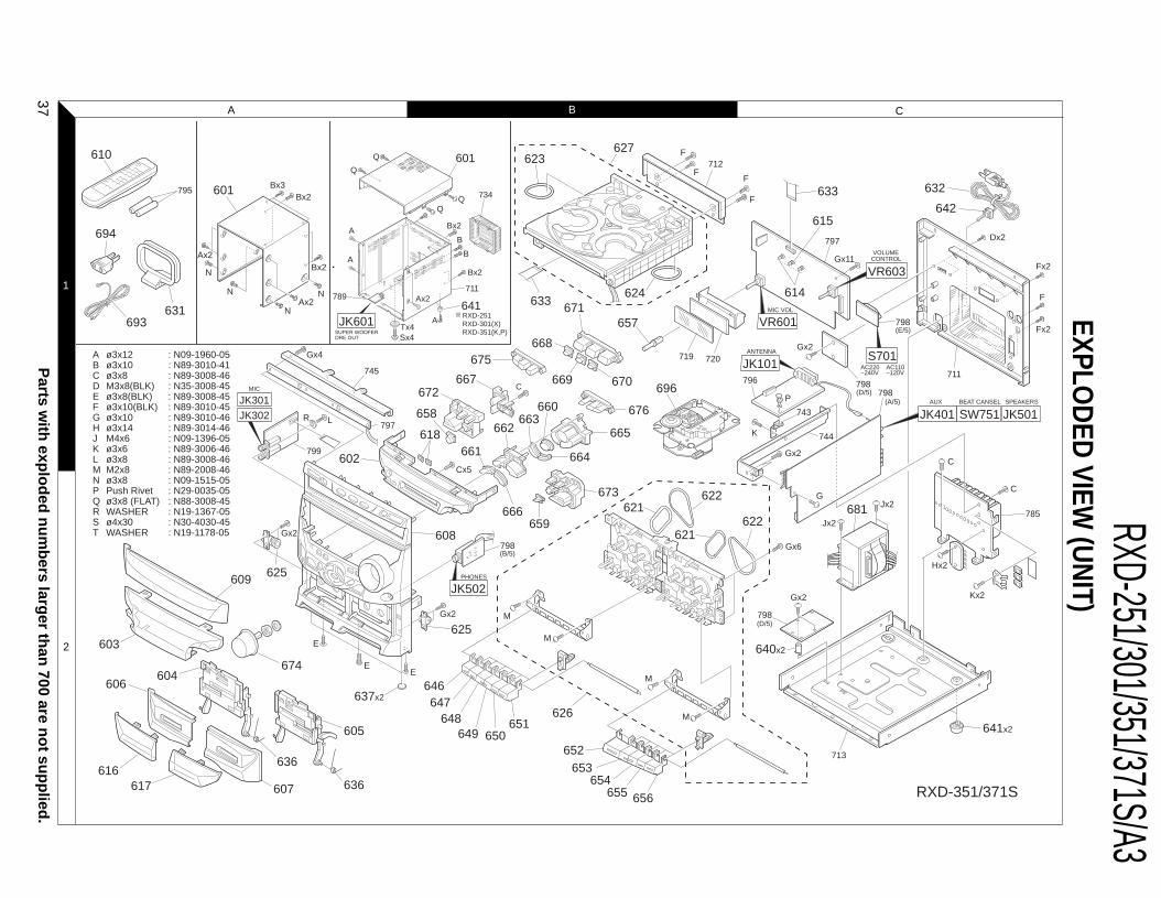
RXD-251/301/351/371S/A3EXPLO
DED
VIEW (U
NIT)
RXD-351/371S
ABCDEFGHJKLMNPQRST
: N09-1960-05: N89-3010-41: N89-3008-46: N35-3008-45: N89-3008-45: N89-3010-45: N89-3010-46: N89-3014-46: N09-1396-05: N89-3006-46 : N89-3008-46: N89-2008-46: N09-1515-05: N29-0035-05: N88-3008-45: N19-1367-05: N30-4030-45: N19-1178-05
ø3x12ø3x10ø3x8M3x8(BLK)ø3x8(BLK)ø3x10(BLK)ø3x10ø3x14M4x6ø3x6ø3x8M2x8ø3x8Push Rivetø3x8 (FLAT)WASHERø4x30WASHER
610
601
641
601 623
624633 671
675
JK601 657
627
667672
668
669 670
659666
661
676
633 632
642
621
621
622
622
626
681
665
660663
662618
658
602
625
604606
609
625
608
674
605
607
636
636
637x2
664
673
694
693631
795Bx3
Bx2
Bx2
N
N N
N
Ax2
Ax2
Q
Q
Bx2
Bx2
B
Cx5
Gx2
Gx2 M
M
M
M
Gx4
745
797
799
654653
652
647648
649 650651
646
603
617616
655 656
798
720719
BA
ATx4Sx4
A
Ax2789711
734
712
640x2
641x2
798
713
Gx2
615
614
F
FF
F
LR
E
EE
Gx2
Gx2
Dx2
Gx11
G
Gx6
C
C
Jx2
Jx2
Hx2
Kx2
785
798
744
743
797
711798
798
796
K
P
Fx2
Fx2
F
RXD-251RXD-301(X)RXD-351(K,P)SUPER WOOFER
ORE OUT
PHONES
MIC
JK502
JK301JK302
AC220~240V
AC110~120V
MIC VOL
AUX BEAT CANSEL
ANTENNA S701
VOLUMECONTROL
VR603
JK401 SW751SPEAKERS
JK501
JK101
VR601
C
(B/5)
(E/5)
(D/5)
(D/5)
(A/5)
696
1
2
A CB
Parts w
ith exp
lod
ed n
um
bers larg
er than
700 are no
t sup
plied
. 37
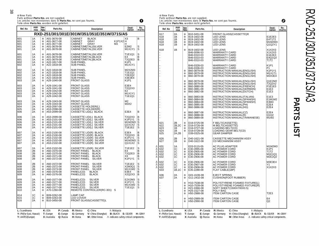
RXD-251/301/351/371S/A3
38
PAR
TS LIST New PartsParts without Parts No. are not supplied.Les articles non mentionnes dans le Parts No. ne sont pas fournis.Teile ohne Parts No. werden nicht geliefert.
Ref. NoAdd-ress
NewParts Description
Desti-nation
Re-marksParts No.
New PartsParts without Parts No. are not supplied.Les articles non mentionnes dans le Parts No. ne sont pas fournis.Teile ohne Parts No. werden nicht geliefert.
Ref. NoAdd-ress
NewParts Description Desti-
nationRe-
marksParts No.
617 2A B10-3451-08 FRONT GLASS(CASSETTE)R618 1B B19-1602-08 LED LENS E1E2E3618 1B B19-1602-08 LED LENS E4T1T2618 1B B19-1602-08 LED LENS M1M2M3618 1B B19-1602-08 LED LENS Q1Q2Y1
618 1B B19-1602-08 LED LENS X1X2X3- B46-0096-53 WARRANTY CARD X1X2X3- B46-0310-03 WARRANTY CARD E1E2E3- B46-0310-03 WARRANTY CARD E4Q1Q2- B46-0310-03 WARRANTY CARD T1T2
- B46-0328-03 WARRANTY CARD K1P1- B46-0336-03 WARRANTY CARD P1- B60-3879-08 INSTRUCTION MANUAL(ENGLISH) K1P1Y1- B60-3879-08 INSTRUCTION MANUAL(ENGLISH) M1X1T1- B60-3879-08 INSTRUCTION MANUAL(ENGLISH) M3X3E4
- B60-3879-08 INSTRUCTION MANUAL(ENGLISH) Q1E2M2- B60-3879-08 INSTRUCTION MANUAL(ENGLISH) T2Q2X2- B60-3880-08 INSTRUCTION MANUAL(FRENCH) P1E1E3- B60-3881-08 INSTRUCTION MANUAL(GERMAN) E1E3- B60-3882-08 INSTRUCTION MANUAL(DUTCH) E1E3
- B60-3883-08 INSTRUCTION MANUAL(ITALIAN) E1E3- B60-3884-08 INSTRUCTION MANUAL(SPANISH) E1M1M2- B60-3884-08 INSTRUCTION MANUAL(SPANISH) E3M3- B60-3885-08 INSTRUCTION MANUAL(PH) E2E4- B60-3886-08 INSTRUCTION MANUAL(HG) E2E4
- B60-3887-08 INSTRUCTION MANUAL(CZ) E2E4- B60-3888-08 INSTRUCTION MANUAL(R) Q1Q2- B60-3889-08 INSTRUCTION MANUAL(TAIWANESE) M1M2
621 2B D16-0725-08 F BELT(CASSETTE)622 2B,2C D16-0726-08 M BELT(CASSETTE)623 1B D16-0727-08 LOADING BELT(CD)624 1B D16-0728-08 LOADING GEAR BELT(CD)625 2A,2B D39-0325-08 GEAR DAMPER
626 2B D40-1621-08 CASSETTE MECHANISM ASSY627 1B D40-1622-08 CD MECHANISM ASSY
631 1A E03-0115-05 AC PLUG ADAPTER M1M2M3632 1C E30-2895-08 AC POWER CORD K1P1632 1C E30-2905-08 AC POWER CORD T1T2632 1C E30-2906-08 AC POWER CORD M1E1Q1632 1C E30-2906-08 AC POWER CORD M2E2Q2
632 1C E30-2906-08 AC POWER CORD M3E3E4632 1C E30-2907-08 AC POWER CORD Y1632 1C E30-2908-08 AC POWER CORD X1X2X3633 1B,1C E35-2288-08 FLAT CABLE(18P)
636 2A G01-4106-08 EJECT SPRING637 2A G11-2432-08 CUSHION(FOOT RUBBER)
- H10-7538-08 POLYSTYRENE FOAMED FIXTURE(L)- H10-7539-08 POLYSTYRENE FOAMED FIXTURE(R)- H21-0366-08 SOFT SHEET(1500X700X0.5)- H25-1527-08 POLY BAG- H50-2988-08 ITEM CARTON CASE T2E3
- H50-2989-08 ITEM CARTON CASE E4- H50-2990-08 ITEM CARTON CASE Q2
601 1A A01-3676-08 CABINET BLACK X3 B601 1A A01-3677-08 CABINET GRAY K1P1X2 H601 1A A01-3677-08 CABINET GRAY M3 H601 1A A01-3678-08 CABINET(METAL)SILVER E2M2 S601 1A A01-3678-08 CABINET(METAL)SILVER M1X1Y1 S
601 1A A01-3678-08 CABINET(METAL)SILVER T1E1Q1 S601 1A A01-3679-08 CABINET(METAL)BLACK E4 B601 1A A01-3679-08 CABINET(METAL)BLACK T2Q2E3 B602 1A A22-1817-08 SUB PANEL K1P1602 1A A22-1818-08 SUB PANEL M1X1Y1
602 1A A22-1818-08 SUB PANEL M2X2M3602 1A A22-1818-08 SUB PANEL T1E1Q1602 1A A22-1818-08 SUB PANEL T2E2Q2602 1A A22-1818-08 SUB PANEL X3E3E4603 2A A29-1040-08 FRONT GLASS K1P1
603 2A A29-1041-08 FRONT GLASS E3E4603 2A A29-1041-08 FRONT GLASS T2Q2X3603 2A A29-1042-08 FRONT GLASS E2603 2A A29-1042-08 FRONT GLASS M1X1Y1603 2A A29-1042-08 FRONT GLASS T1E1Q1
603 2A A29-1043-08 FRONT GLASS M2603 2A A29-1044-08 FRONT GLASS M3X2604 2A A53-2097-08 CASSETTE HOLDER(L)605 2A A53-2098-08 CASSETTE HOLDER(R)606 2A A53-2099-08 CASSETTE LID(L) BLACK E3E4 B
606 2A A53-2099-08 CASSETTE LID(L) BLACK T2Q2X3 B606 2A A53-2101-08 CASSETTE LID(L) SILVER K1P1Y1 S606 2A A53-2101-08 CASSETTE LID(L) SILVER M1M2M3 S606 2A A53-2101-08 CASSETTE LID(L) SILVER Q1X1X2 S606 2A A53-2101-08 CASSETTE LID(L) SILVER T1E1E2 S
607 2A A53-2100-08 CASSETTE LID(R) BLACK E3E4 B607 2A A53-2100-08 CASSETTE LID(R) BLACK T2Q2X3 B607 2A A53-2102-08 CASSETTE LID(R) SILVER K1P1Y1 S607 2A A53-2102-08 CASSETTE LID(R) SILVER M1M2M3 S607 2A A53-2102-08 CASSETTE LID(R) SILVER Q1X1X2 S
607 2A A53-2102-08 CASSETTE LID(R) SILVER T1E1E2 S608 2B A60-1570-08 FRONT PANEL BLACK E4 B608 2B A60-1570-08 FRONT PANEL BLACK T2Q2E3 B608 2B A60-1571-08 FRONT PANEL BLACK X3 B608 2B A60-1572-08 FRONT PANEL SILVER K1P1Y1 S
608 2B A60-1572-08 FRONT PANEL SILVER T1E1E2 S608 2B A60-1572-08 FRONT PANEL SILVER X2M3Q1 S608 2B A60-1573-08 FRONT PANEL SILVER M1X1M2 S609 2A A60-1576-08 PANEL(CD) BLACK E3E4 B609 2A A60-1576-08 PANEL(CD) BLACK X2Q2X3 B
609 2A A60-1577-08 PANEL(CD) SILVER E2X2M3 S609 2A A60-1577-08 PANEL(CD) SILVER K1P1Y1 S609 2A A60-1577-08 PANEL(CD) SILVER M1X1M2 S609 2A A60-1577-08 PANEL(CD) SILVER T1E1Q1 S610 1A A70-1260-08 REMOTE CONTROLLER(RC-301) S
614 1C B09-0262-08 LAMP CAP615 1C B09-0263-08 LED COVER616 2A B10-3450-08 FRONT GLASS(CASSETTE)L
L : Scandinavia K : USA P : Canada R : Mexico C : China I : MalaysiaY : PX(Far East, Hawaii) T : Europe E : Europe G : Germany V : China (Shanghai) B : BLACK S : SILVER H : GRAYY : AAFES(Europe) X : Australia Q : Russia H : Korea M : Other Areas indicates safety critical components.
L : Scandinavia K : USA P : Canada R : Mexico C : China I : MalaysiaY : PX(Far East, Hawaii) T : Europe E : Europe G : Germany V : China (Shanghai) B : BLACK S : SILVER H : GRAYY : AAFES(Europe) X : Australia Q : Russia H : Korea M : Other Areas indicates safety critical components.
1 2
RXD-251/301/301E/301W/351/351E/351W/371S/A5

RXD-251/301/351/371S/A339
PAR
TS LIST New PartsParts without Parts No. are not supplied.Les articles non mentionnes dans le Parts No. ne sont pas fournis.Teile ohne Parts No. werden nicht geliefert.
Ref. NoAdd-ress
NewParts Description
Desti-nation
Re-marksParts No.
New PartsParts without Parts No. are not supplied.Les articles non mentionnes dans le Parts No. ne sont pas fournis.Teile ohne Parts No. werden nicht geliefert.
Ref. NoAdd-ress
NewParts Description Desti-
nationRe-
marksParts No.
651 2B K29-7492-08 CASSETTE PAUSE BUTTON(A) T2Q2X3 B651 2B K29-7503-08 CASSETTE PAUSE BUTTON(A) K1P1Y1 H651 2B K29-7503-08 CASSETTE PAUSE BUTTON(A) M1M2M3 H651 2B K29-7503-08 CASSETTE PAUSE BUTTON(A) T1E1E2 H651 2B K29-7503-08 CASSETTE PAUSE BUTTON(A) X1X2Q1 H
652 2B K29-7493-08 CASSETTE PLAY BUTTON(B) E3E4 B652 2B K29-7493-08 CASSETTE PLAY BUTTON(B) T2Q2X3 B652 2B K29-7504-08 CASSETTE PLAY BUTTON(B) K1P1Y1 H652 2B K29-7504-08 CASSETTE PLAY BUTTON(B) M1M2M3 H652 2B K29-7504-08 CASSETTE PLAY BUTTON(B) T1E1E2 H
652 2B K29-7504-08 CASSETTE PLAY BUTTON(B) X1X2Q1 H653 2B K29-7494-08 CASSETTE REWIND BUTTON(B) E3E4 B653 2B K29-7494-08 CASSETTE REWIND BUTTON(B) T2Q2X3 B653 2B K29-7505-08 CASSETTE REWIND BUTTON(B) K1P1Y1 H653 2B K29-7505-08 CASSETTE REWIND BUTTON(B) M1M2M3 H
653 2B K29-7505-08 CASSETTE REWIND BUTTON(B) T1E1E2 H653 2B K29-7505-08 CASSETTE REWIND BUTTON(B) X1X2Q1 H654 2B K29-7495-08 CASSETTE FASTFORWARD BUTTON(B) E3E4 B654 2B K29-7495-08 CASSETTE FASTFORWARD BUTTON(B) T2Q2X3 B654 2B K29-7506-08 CASSETTE FASTFORWARD BUTTON(B) K1P1Y1 H
654 2B K29-7506-08 CASSETTE FASTFORWARD BUTTON(B) M1M2M3 H654 2B K29-7506-08 CASSETTE FASTFORWARD BUTTON(B) T1E1E2 H654 2B K29-7506-08 CASSETTE FASTFORWARD BUTTON(B) X1X2Q1 H655 2B K29-7496-08 CASSETTE STOP/EJECT BUTTON(B) E3E4 B655 2B K29-7496-08 CASSETTE STOP/EJECT BUTTON(B) T2Q2X3 B
655 2B K29-7507-08 CASSETTE STOP/EJECT BUTTON(B) K1P1Y1 H655 2B K29-7507-08 CASSETTE STOP/EJECT BUTTON(B) M1M2M3 H655 2B K29-7507-08 CASSETTE STOP/EJECT BUTTON(B) T1E1E2 H655 2B K29-7507-08 CASSETTE STOP/EJECT BUTTON(B) X1X2Q1 H656 2B K29-7497-08 CASSETTE PAUSE BUTTON(B) E3E4 B
656 2B K29-7497-08 CASSETTE PAUSE BUTTON(B) T2Q2X3 B656 2B K29-7508-08 CASSETTE PAUSE BUTTON(B) K1P1Y1 H656 2B K29-7508-08 CASSETTE PAUSE BUTTON(B) M1M2M3 H656 2B K29-7508-08 CASSETTE PAUSE BUTTON(B) T1E1E2 H656 2B K29-7508-08 CASSETTE PAUSE BUTTON(B) X1X2Q1 H
657 1B K29-7509-08 KNOB(MIC) M1X1M2 H657 1B K29-7509-08 KNOB(MIC) X3 H658 1B K29-7511-08 KNOB(DISPLAY/DEMO)659 2B K29-7519-08 KNOB(BAND)660 1B K29-7512-08 KNOB(EX.BASS)
661 1A K29-7513-08 KNOB(ROCK)662 1A K29-7514-08 KNOB(BASE ROCK)663 1A K29-7515-08 KNOB(POP)664 1A K29-7516-08 KNOB(JAZZ)665 1A K29-7517-08 KNOB(BASE JAZZ)
666 2B K29-7518-08 KNOB(FLAT)667 1B K29-7520-08 KNOB(ON/STANDBY.INPUT) E3E4 B667 1B K29-7520-08 KNOB(ON/STANDBY.INPUT) T2Q2X3 B667 1B K29-7549-08 KNOB(ON/STANDBY.INPUT) E1E2T1 H667 1B K29-7549-08 KNOB(ON/STANDBY.INPUT) M1M2M3 H
667 1B K29-7549-08 KNOB(ON/STANDBY.INPUT) X1X2Q1 H667 1B K29-7549-08 KNOB(ON/STANDBY.INPUT) Y1 H667 1B K29-7550-08 KNOB(POWER INPUT) K1P1 H668 1B K29-7521-08 KNOB(DISC 1)669 1B K29-7522-08 KNOB(DISC 2)
- H50-2992-08 ITEM CARTON CASE T1E1- H50-2993-08 ITEM CARTON CASE E2- H50-2994-08 ITEM CARTON CASE Q1- H50-2995-08 ITEM CARTON CASE M1- H50-2996-08 ITEM CARTON CASE M2
- H50-3001-08 ITEM CARTON CASE M3- H60-0685-08 ITEM CARTON CASE K1P1- H60-0686-08 ITEM CARTON CASE X3- H60-0687-08 ITEM CARTON CASE X1Y1- H60-0771-08 ITEM CARTON CASE X2
640 2C J19-5961-08 UNIT HOLDER E1E2E3640 2C J19-5961-08 UNIT HOLDER E4Q1Q2640 2C J19-5961-08 UNIT HOLDER T1T2641 2C J02-1433-08 FOOT(REAR) E1E2E3641 2C J02-1433-08 FOOT(REAR) M1M2E4
641 2C J02-1433-08 FOOT(REAR) Q1Q2X1641 2C J02-1433-08 FOOT(REAR) T1T2Y1641 2C J02-1434-08 FOOT(REAR) K1P1X2641 2C J02-1434-08 FOOT(REAR) M3X3642 1C J42-0330-08 POWER CORD BUSHING E1E2E3
642 1C J42-0330-08 POWER CORD BUSHING E4Q1Q2642 1C J42-0330-08 POWER CORD BUSHING M1M2Y1642 1C J42-0330-08 POWER CORD BUSHING T1T2X1
646 2B K29-7487-08 CASSETTE RECORD BUTTON(A) E3E4 B646 2B K29-7487-08 CASSETTE RECORD BUTTON(A) T2Q2X3 B646 2B K29-7498-08 CASSETTE RECORD BUTTON(A) K1P1Y1 H646 2B K29-7498-08 CASSETTE RECORD BUTTON(A) M1M2M3 H646 2B K29-7498-08 CASSETTE RECORD BUTTON(A) T1E1E2 H
646 2B K29-7498-08 CASSETTE RECORD BUTTON(A) X1X2Q1 H647 2B K29-7488-08 CASSETTE PLAY BUTTON(A) E3E4 B647 2B K29-7488-08 CASSETTE PLAY BUTTON(A) T2Q2X3 B647 2B K29-7499-08 CASSETTE PLAY BUTTON(A) K1P1Y1 H647 2B K29-7499-08 CASSETTE PLAY BUTTON(A) M1M2M3 H
647 2B K29-7499-08 CASSETTE PLAY BUTTON(A) T1E1E2 H647 2B K29-7499-08 CASSETTE PLAY BUTTON(A) X1X2Q1 H648 2B K29-7489-08 CASSETTE REWIND BUTTON(A) E3E4 B648 2B K29-7489-08 CASSETTE REWIND BUTTON(A) T2Q2X3 B648 2B K29-7500-08 CASSETTE REWIND BUTTON(A) K1P1Y1 H
648 2B K29-7500-08 CASSETTE REWIND BUTTON(A) M1M2M3 H648 2B K29-7500-08 CASSETTE REWIND BUTTON(A) T1E1E2 H648 2B K29-7500-08 CASSETTE REWIND BUTTON(A) X1X2Q1 H649 2B K29-7490-08 CASSETTE FASTFORWARD BUTTON(A) E3E4 B649 2B K29-7490-08 CASSETTE FASTFORWARD BUTTON(A) T2Q2X3 B
649 2B K29-7501-08 CASSETTE FASTFORWARD BUTTON(A) K1P1Y1 H649 2B K29-7501-08 CASSETTE FASTFORWARD BUTTON(A) M1M2M3 H649 2B K29-7501-08 CASSETTE FASTFORWARD BUTTON(A) T1E1E2 H649 2B K29-7501-08 CASSETTE FASTFORWARD BUTTON(A) X1X2Q1 H650 2B K29-7491-08 CASSETTE STOP/EJECT BUTTON(A) E3E4 B
650 2B K29-7491-08 CASSETTE STOP/EJECT BUTTON(A) T2Q2X3 B650 2B K29-7502-08 CASSETTE STOP/EJECT BUTTON(A) K1P1Y1 H650 2B K29-7502-08 CASSETTE STOP/EJECT BUTTON(A) M1M2M3 H650 2B K29-7502-08 CASSETTE STOP/EJECT BUTTON(A) T1E1E2 H650 2B K29-7502-08 CASSETTE STOP/EJECT BUTTON(A) X1X2Q1 H
651 2B K29-7492-08 CASSETTE PAUSE BUTTON(A) E3E4 B
L : Scandinavia K : USA P : Canada R : Mexico C : China I : MalaysiaY : PX(Far East, Hawaii) T : Europe E : Europe G : Germany V : China (Shanghai) B : BLACK S : SILVER H : GRAYY : AAFES(Europe) X : Australia Q : Russia H : Korea M : Other Areas indicates safety critical components.
L : Scandinavia K : USA P : Canada R : Mexico C : China I : MalaysiaY : PX(Far East, Hawaii) T : Europe E : Europe G : Germany V : China (Shanghai) B : BLACK S : SILVER H : GRAYY : AAFES(Europe) X : Australia Q : Russia H : Korea M : Other Areas indicates safety critical components.
3 4

RXD-251/301/351/371S/A3
40
PAR
TS LIST New PartsParts without Parts No. are not supplied.Les articles non mentionnes dans le Parts No. ne sont pas fournis.Teile ohne Parts No. werden nicht geliefert.
Ref. NoAdd-ress
NewParts Description
Desti-nation
Re-marksParts No.
New PartsParts without Parts No. are not supplied.Les articles non mentionnes dans le Parts No. ne sont pas fournis.Teile ohne Parts No. werden nicht geliefert.
Ref. NoAdd-ress
NewParts Description Desti-
nationRe-
marksParts No.
C105 CC45FSL1H180J CERAMIC 18PF JC106-108 C91-0085-05 CERAMIC 0.022UF NC109 C91-0713-05 CERAMIC 2.2PF K M2C110 C91-0713-05 CERAMIC 2.2PF K K1P1Y1C110 C91-0713-05 CERAMIC 2.2PF K M1X1X2
C110 C91-0713-05 CERAMIC 2.2PF K M3X3C110 C91-0717-05 CERAMIC 4.7PF K M2C111 C91-0739-05 CERAMIC 56PF JC112 C91-0745-05 CERAMIC 100PF KC114 CK45FB1H104Z CERAMIC 0.10UF Z K1P1Y1
C114 CK45FB1H104Z CERAMIC 0.10UF Z M1X1X2C114 CK45FB1H104Z CERAMIC 0.10UF Z M3X3C116 CC45FSL1H100J CERAMIC 10PF J M2C116 CQ93FMG1H471J MYLAR 470PF J K1P1Y1C116 CQ93FMG1H471J MYLAR 470PF J M1X1X2
C116 CQ93FMG1H471J MYLAR 470PF J M3X3C117 CC45FSL1H200J CERAMIC 20PF J K1P1Y1C117 CC45FSL1H200J CERAMIC 20PF J M1X1X2C117 CC45FSL1H200J CERAMIC 20PF J M3X3C117 C91-0718-05 CERAMIC 5.6PF K M2
C118 CE04KW1C101M ELECTRO 100UF 16WVC119 C91-0757-05 CERAMIC 1000PF KC121 C91-0725-05 CERAMIC 15PF JC122 CE04KW1H2R2M ELECTRO 2.2UF 50WVC123 CE04KW1H010M ELECTRO 1.0UF 50WV
C124 CC45FSL1H200J CERAMIC 20PF JC125 CE04KW1H010M ELECTRO 1.0UF 50WVC126 CK45FB1H473Z CERAMIC 0.047UF ZC127 CE04KW1H100M ELECTRO 10UF 50WVC128 C91-0085-05 CERAMIC 0.022UF N
C129 CE04KW1H010M ELECTRO 1.0UF 50WVC130,131 CQ92FM1H153J MYLAR 0.015UF J M1M2M3C130,131 CQ92FM1H153J MYLAR 0.015UF J X1X2X3C130,131 CQ92FM1H153J MYLAR 0.015UF J Y1C130,131 CQ92FM1H223J MYLAR 0.022UF J K1P1
C132,133 CQ92FM1H102J MYLAR 1000PF JC134 C91-0757-05 CERAMIC 1000PF KC135 CE04KW1H3R3M ELECTRO 3.3UF 50WVC137 CE04KW1HR47M ELECTRO 0.47UF 50WVC138 C91-0769-05 CERAMIC 0.010UF K
C139 C91-0085-05 CERAMIC 0.022UF NC140 CE04KW1C101M ELECTRO 100UF 16WVC141 C91-0085-05 CERAMIC 0.022UF NC142 CE04KW1C101M ELECTRO 100UF 16WVC143 CE04KW1H010M ELECTRO 1.0UF 50WV K1P1Y1
C143 CE04KW1H010M ELECTRO 1.0UF 50WV M1X1X2C143 CE04KW1H010M ELECTRO 1.0UF 50WV M3X3C143 CE04KW1H3R3M ELECTRO 3.3UF 50WV M2C144 C91-0769-05 CERAMIC 0.010UF KC145 C91-0739-05 CERAMIC 56PF J
C147 C91-0085-05 CERAMIC 0.022UF N K1P1Y1C147 C91-0085-05 CERAMIC 0.022UF N M1X1X2C147 C91-0085-05 CERAMIC 0.022UF N M3X3C149 C91-0085-05 CERAMIC 0.022UF NC150 C91-0769-05 CERAMIC 0.010UF K
670 1B K29-7523-08 KNOB(DISC 3)671 1B K29-7524-08 KNOB(BASE DISC)672 1B K29-7525-08 KNOB(TIMER) E3E4 B672 1B K29-7525-08 KNOB(TIMER) T2Q2X3 B672 1B K29-7530-08 KNOB(TIMER) K1P1Y1 H
672 1B K29-7530-08 KNOB(TIMER) M1M2M3 H672 1B K29-7530-08 KNOB(TIMER) T1E1E2 H672 1B K29-7530-08 KNOB(TIMER) X1X2Q1 H673 2B K29-7526-08 KNOB(TUNING) E3E4 B673 2B K29-7526-08 KNOB(TUNING) T2Q2X3 B
673 2B K29-7531-08 KNOB(TUNING) K1P1Y1 H673 2B K29-7531-08 KNOB(TUNING) M1M2M3 H673 2B K29-7531-08 KNOB(TUNING) T1E1E2 H673 2B K29-7531-08 KNOB(TUNING) X1X2Q1 H674 2A K29-7527-08 KNOB(VOLUME) E3E4 B
674 2A K29-7527-08 KNOB(VOLUME) T2Q2X3 B674 2A K29-7532-08 KNOB(VOLUME) K1P1Y1 S674 2A K29-7532-08 KNOB(VOLUME) M1M2M3 S674 2A K29-7532-08 KNOB(VOLUME) T1E1E2 S674 2A K29-7532-08 KNOB(VOLUME) X1X2Q1 S
675 1B K29-7528-08 KNOB(SKIP) E3E4 B675 1B K29-7528-08 KNOB(SKIP) T2Q2X3 B675 1B K29-7533-08 KNOB(SKIP) K1P1Y1 H675 1B K29-7533-08 KNOB(SKIP) M1M2M3 H675 1B K29-7533-08 KNOB(SKIP) T1E1E2 H
675 1B K29-7533-08 KNOB(SKIP) X1X2Q1 H676 1B K29-7529-08 KNOB(OPEN/CLOSE/PLAY/STOP) E3E4 B676 1B K29-7529-08 KNOB(OPEN/CLOSE/PLAY/STOP) T2Q2X3 B676 1B K29-7534-08 KNOB(OPEN/CLOSE/PLAY/STOP) K1P1Y1 H676 1B K29-7534-08 KNOB(OPEN/CLOSE/PLAY/STOP) M1M2M3 H
676 1B K29-7534-08 KNOB(OPEN/CLOSE/PLAY/STOP) T1E1E2 H676 1B K29-7534-08 KNOB(OPEN/CLOSE/PLAY/STOP) X1X2Q1 H
681 2C L07-2670-08 POWER TRANSFORMER K1P1681 2C L07-2671-08 POWER TRANSFORMER X2X3681 2C L07-2672-08 POWER TRANSFORMER M3681 2C L07-2673-08 POWER TRANSFORMER X1681 2C L07-2674-08 POWER TRANSFORMER E3E4
681 2C L07-2674-08 POWER TRANSFORMER T1E1Q1681 2C L07-2674-08 POWER TRANSFORMER T2E2Q2681 2C L07-2675-08 POWER TRANSFORMER M1Y1M2
693 1A T90-0801-05 LEAD WIRE ANTENNA K1P1Y1693 1A T90-0801-05 LEAD WIRE ANTENNA M1M2M3693 1A T90-0801-05 LEAD WIRE ANTENNA X1X2X3693 1A T90-0836-05 LEAD WIRE ANTENNA E1E2E3693 1A T90-0836-05 LEAD WIRE ANTENNA E4T1T2
693 1A T90-0836-05 LEAD WIRE ANTENNA Q1Q2694 1A T90-0815-08 LOOP ANTENNA696 1B T25-0079-08 TRAVERSE ASSY
C100A CK45FB1H104Z CERAMIC 0.10UF Z K1P1Y1C100A CK45FB1H104Z CERAMIC 0.10UF Z M1X1X2C100A CK45FB1H104Z CERAMIC 0.10UF Z M3X3C101,102 C91-0757-05 CERAMIC 1000PF KC104 C91-0085-05 CERAMIC 0.022UF N
L : Scandinavia K : USA P : Canada R : Mexico C : China I : MalaysiaY : PX(Far East, Hawaii) T : Europe E : Europe G : Germany V : China (Shanghai) B : BLACK S : SILVER H : GRAYY : AAFES(Europe) X : Australia Q : Russia H : Korea M : Other Areas indicates safety critical components.
L : Scandinavia K : USA P : Canada R : Mexico C : China I : MalaysiaY : PX(Far East, Hawaii) T : Europe E : Europe G : Germany V : China (Shanghai) B : BLACK S : SILVER H : GRAYY : AAFES(Europe) X : Australia Q : Russia H : Korea M : Other Areas indicates safety critical components.
5 6
TUNER UNIT (K1P1Y1M1X1M2X2M3X3)
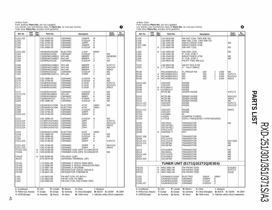
RXD-251/301/351/371S/A341
PAR
TS LIST New PartsParts without Parts No. are not supplied.Les articles non mentionnes dans le Parts No. ne sont pas fournis.Teile ohne Parts No. werden nicht geliefert.
Ref. NoAdd-ress
NewParts Description
Desti-nation
Re-marksParts No.
New PartsParts without Parts No. are not supplied.Les articles non mentionnes dans le Parts No. ne sont pas fournis.Teile ohne Parts No. werden nicht geliefert.
Ref. NoAdd-ress
NewParts Description Desti-
nationRe-
marksParts No.
L104 L31-0618-08 AM ANT COIL TWS-358-762L105 L32-0581-08 MW OSC COIL TWS-358-751L106 L39-1340-08 INDUCTANCE 473K M2L107,108 L39-1340-08 INDUCTANCE 473KL201 L31-0634-08 SW ANT COIL M2
L202 L32-1005-08 SW OSC COIL M2L203 L39-1344-08 P. COIL 470K-TL204 L39-1340-08 INDUCTANCE 473K M2L205 L39-1344-08 P. COIL 470K-T M2T101 L30-0926-08 FM IFT TWS-358-412
T102 L30-0922-08 AM IFT R22-E792X201 L77-2243-08 X TAL(7.2MHZ)
R130 RS14GB2H101J FL-PROOF RS 100 J 1/2W M2R130 RD14GB2H151J RD 150 J 1/2W K1P1Y1R130 RD14GB2H151J RD 150 J 1/2W M1X1X2R130 RD14GB2H151J RD 150 J 1/2W M3X3
D101,102 1SS133T DIODED105 1SS133T DIODED106 KV1340A-2 DIODED108 KV1561A-2 DIODED110 MTZ5.6B ZENER DIODE K1P1Y1
D110 MTZ5.6B ZENER DIODE M1X1X2D110 MTZ5.6B ZENER DIODE M3X3D110 MTZ6.2B ZENER DIODE M2D111,112 1SS133T DIODE K1P1Y1D111,112 1SS133T DIODE M1X1X2
D111,112 1SS133T DIODE M3X3D202 1SS133T DIODEIC101 LA1186N ICIC102 LA1831 IC(AM/FM TUNER)IC201 LC7218 IC(PLL FREQUENCY SYNTHESIZER)
Q100 2SC2001L TRANSISTOR M2Q101 2SC1675(L) TRANSISTORQ102 2SC1674(L) TRANSISTORQ105 DTA114YS TRANSISTORQ106 2SK544F-T FET
Q107,108 2SC945 TRANSISTORQ109 DTC114YS TRANSISTORQ110-111 DTC114YS TRANSISTOR M1Y1M3Q110-111 2SC2878A TRANSISTOR M2Q112 2SC2878A TRANSISTOR M2
Q113 DTA144ES TRANSISTOR M2Q114 2SC2001L TRANSISTOR M2Q115,116 DTC114YS TRANSISTOR M2Q201 DTA144ES TRANSISTOR M2Q202,203 2SC2878A TRANSISTOR M2
FE101 W02-2681-08 FM FRONT END E1E2E3FE101 W02-2681-08 FM FRONT END E4T1T2FE101 W02-2682-08 FM FRONT END Q1Q2
C101 CE04KW1C101M ELECTRO 100UF 16WVC102 CK45FB1H102K CERAMIC 1000PF KC103 CK45FB1H104K CERAMIC 0.10UF KC106,107 CK45FB1E223Z CERAMIC 0.022UF Z
C151,152 C91-0759-05 CERAMIC 1500PF MC153 C91-0085-05 CERAMIC 0.022UF NC155 C91-0745-05 CERAMIC 100PF KC157 C91-0757-05 CERAMIC 1000PF KC160 C91-0085-05 CERAMIC 0.022UF N
C161,162 CE04KW1H010M ELECTRO 1.0UF 50WVC164 CK45FB1H103Z CERAMIC 0.010UF Z M2C164 CQ93FMG1H682J MYLAR 6800PF J M1M2M3C164 CQ93FMG1H682J MYLAR 6800PF J Y1C165 CK45FB1H223Z CERAMIC 0.022UF Z M2
C165 CQ93FMG1H682J MYLAR 6800PF J K1P1Y1C165 CQ93FMG1H682J MYLAR 6800PF J M1X1X2C165 CQ93FMG1H682J MYLAR 6800PF J M3X3C166 CK45FB1H223Z CERAMIC 0.022UF Z M2C167 CQ93FMG1H471J MYLAR 470PF J M2
C169 C91-0085-05 CERAMIC 0.022UF N M2C170 C91-0769-05 CERAMIC 0.010UF K M2C171 CK45FB1H104Z CERAMIC 0.10UF Z K1P1Y1C171 CK45FB1H104Z CERAMIC 0.10UF Z M1X1X2C171 CK45FB1H104Z CERAMIC 0.10UF Z M3X3
C171 CK45FB1H223Z CERAMIC 0.022UF Z M2C174,175 CQ92FM1H682J MYLAR 6800PF J M2C201 CK45FB1H561K CERAMIC 560PF K M2C202 CQ09S1H472J POLYSTY 4700PF J M2C204 C91-0085-05 CERAMIC 0.022UF N M2
C205 CE04KW1C470M ELECTRO 47UF 16WV M2C207 CE04KW1C470M ELECTRO 47UF 16WVC208 C91-0769-05 CERAMIC 0.010UF KC209 C91-0745-05 CERAMIC 100PF KC210-212 C91-0745-05 CERAMIC 100PF K
C212 C91-0085-05 CERAMIC 0.022UF N M2C213,214 CC45FCH1H240J CERAMIC 24PF J K1P1Y1C213,214 CC45FCH1H240J CERAMIC 24PF J M1X1X2C213,214 CC45FCH1H240J CERAMIC 24PF J M3X3C213,214 CC45FCH1H270J CERAMIC 27PF J M2
C215 CE04KW1C220M ELECTRO 22UF 16WVC216 C91-0085-05 CERAMIC 0.022UF N M2C217 C91-0085-05 CERAMIC 0.022UF N M2C220 C91-0749-05 CERAMIC 220PF KC221-223 C91-0749-05 CERAMIC 220PF K K1P1Y1
C221-223 C91-0749-05 CERAMIC 220PF K M1X1X2C221-223 C91-0749-05 CERAMIC 220PF K M3X3TC101,102 C05-0238-08 TRIMMER CON 10PS TZ-03N100TRTC201 C05-0238-08 TRIMMER CON 10PS TZ-03N100TR M2
CN101 E40-8336-08 PIN ASSY (10P)JK101 E70-0070-08 ANTENNA TERMINAL (4P)
CF101 L72-0591-08 CERAMIC F SFE10.7MA5 REDCF102 L72-0586-08 CERAMIC F SFE10.7MSG3GYM REDCF103 L72-0587-08 CERAMIC F SFZ450BCF104 L78-0651-08 RESONATOR CDA10.7MG43-ACF105 L78-0641-08 RESONATOR CSB456F15
L101 L31-0622-08 FM ANT COIL PC-8474-1L102 L31-0623-08 FM RF COIL PC-8867L103 L32-0584-08 FM OSC COIL R22-F036X ORG
L : Scandinavia K : USA P : Canada R : Mexico C : China I : MalaysiaY : PX(Far East, Hawaii) T : Europe E : Europe G : Germany V : China (Shanghai) B : BLACK S : SILVER H : GRAYY : AAFES(Europe) X : Australia Q : Russia H : Korea M : Other Areas indicates safety critical components.
L : Scandinavia K : USA P : Canada R : Mexico C : China I : MalaysiaY : PX(Far East, Hawaii) T : Europe E : Europe G : Germany V : China (Shanghai) B : BLACK S : SILVER H : GRAYY : AAFES(Europe) X : Australia Q : Russia H : Korea M : Other Areas indicates safety critical components.
7 8
TUNER UNIT (E1T1Q1E2T2Q2E3E4)

RXD-251/301/351/371S/A3
42
PAR
TS LIST New PartsParts without Parts No. are not supplied.Les articles non mentionnes dans le Parts No. ne sont pas fournis.Teile ohne Parts No. werden nicht geliefert.
Ref. NoAdd-ress
NewParts Description
Desti-nation
Re-marksParts No.
New PartsParts without Parts No. are not supplied.Les articles non mentionnes dans le Parts No. ne sont pas fournis.Teile ohne Parts No. werden nicht geliefert.
Ref. NoAdd-ress
NewParts Description Desti-
nationRe-
marksParts No.
TP1 ,2 E40-8111-08 40P PIN HEADER
CF103 L72-0587-08 CERAMIC FCF104 L78-0651-08 RESONATORCF105 L78-0641-08 RESONATORL102,103 L39-1334-08 COILL104 L31-0618-08 AM ANT COIL
L105 L32-0581-08 MW OSC COILL106 L39-1334-08 COILL107,108 L39-1340-08 INDUCTANCEL110 L39-1332-08 COILL201 L31-0635-08 ANT COIL T1T2
L202 L32-0581-08 COIL(CHOKE) 470UH E1E2E3L202 L32-0581-08 COIL(CHOKE) 470UH E4Q1Q2L202 L32-1008-08 OSC COIL T1T2L203 L39-1344-08 COILSF101,102 L72-0615-08 C.FILTER
T101 L79-1229-08 FTZ L.P.FT102 L30-0922-08 AM IFTX201 L77-2243-08 CRYSTAL
R103 RD14GB2H330J RD 33 J 1/2W Q1Q2R103 RD14GB2H680J RD 68 J 1/2W E1E2E3R103 RD14GB2H680J RD 68 J 1/2W E4T1T2R130 RD14GB2H151J RD 150 J 1/2W
D101,102 1SS133T-77 DIODED108 KV1561A-2 DIODED110 MTZ5.6B ZENER DIODED111,112 1SS133T-77 DIODED201 1SS133T-77 DIODE T1T2
D202 1SS133T-77 DIODEIC102 LA1831A-KEN IC(AM/FM/MPX SYSTEM IC)IC201 LC7218 IC(PLL FREQUENCY SYNTHESIZER)Q101 2SC1675(L) TRANSISTORQ105 DTA114YS TRANSISTOR
Q106 2SK544F-T TRANSISTORQ107,108 2SC945 TRANSISTORQ109 DTC114YS TRANSISTORQ201 2SA733 TRANSISTOR T1T2Q202 2SC945 TRANSISTOR T1T2
Q203,204 2SC2001(L) TRANSISTOR T1T2Q205 2SC945 TRANSISTOR T1T2
C201,202 CK45FB1H221K CERAMIC 220PF KC203,204 CK45FB1H681K CERAMIC 680PF KC205,206 CK45FB1H221K CERAMIC 220PF KC207,208 CE04KW1C470M ELECTRO 47UF 16WVC209,210 CQ92FM1H103J MYLAR 0.010UF J
C211,212 CE04KW1H1R0M ELECTRO 1.0UF 50WVC213,214 CK45FB1C152K CERAMIC 1500PF KC215,216 C91-0758-05 CERAMIC 1200PF MC217,218 CK45FB1H221K CERAMIC 220PF KC219,220 CE04KW1H3R3M ELECTRO 3.3UF 50WV
C221,222 CE04KW1C470M ELECTRO 47UF 16WVC223,224 CK45FB1H102K CERAMIC 1000PF K
C108 CK45FB1C103K CERAMIC 0.010UF KC111,112 CK45FB1C152K CERAMIC 1500PF KC114 CK45FB1H104Z CERAMIC 0.10UF ZC116 CQ93FMG1H471J MYLAR 470PF JC117 CC45FSL1H200J CERAMIC 20PF J
C118 CE04KW1C101M ELECTRO 100UF 16WVC121 CC45FSL1H150J CERAMIC 15PF JC122 CE04KW1H2R2M ELECTRO 2.2UF 50WVC123 CE04KW1H010M ELECTRO 1.0UF 50WVC124 CC45FSL1H200J CERAMIC 20PF J
C125 CE04KW1H010M ELECTRO 1.0UF 50WVC126 CK45FB1H473Z CERAMIC 0.047UF ZC127 CE04KW1H100M ELECTRO 10UF 50WVC128 CK45FB1E223Z CERAMIC 0.022UF ZC129 CE04KW1H010M ELECTRO 1.0UF 50WV
C130,131 CQ92FM1H153J MYLAR 0.015UF JC132,133 CQ92FM1H102J MYLAR 1000PF JC135 CE04KW1H3R3M ELECTRO 3.3UF 50WVC137 CE04KW1HR47M ELECTRO 0.47UF 50WVC138 CK45FB1C103K CERAMIC 0.010UF K
C139 CK45FB1E223Z CERAMIC 0.022UF ZC140 CE04KW1C101M ELECTRO 100UF 16WVC141 CK45FB1E223Z CERAMIC 0.022UF ZC142 CE04KW1C101M ELECTRO 100UF 16WVC143 CE04KW1HR47M ELECTRO 0.47UF 50WV
C144 CK45FB1E223Z CERAMIC 0.022UF ZC145 CC45FSL1H560J CERAMIC 56PF JC147 CK45FB1E223Z CERAMIC 0.022UF ZC148 CK45FB1H104Z CERAMIC 0.10UF ZC149 CK45FB1E223Z CERAMIC 0.022UF Z
C150 CK45FB1H104Z CERAMIC 0.10UF ZC151 CK45FB1H181K CERAMIC 180PF KC152 CK45FB1E122K CERAMIC 1200PF KC153 CK45FB1E223Z CERAMIC 0.022UF ZC154 CK45FB1C103K CERAMIC 0.010UF K
C156 CC45FCH1H100J CERAMIC 10PF JC157 CK45FB1H102K CERAMIC 1000PF KC160 CK45FB1E223Z CERAMIC 0.022UF ZC161,162 CE04KW1H010M ELECTRO 1.0UF 50WVC201,202 CK45FB1E223Z CERAMIC 0.022UF Z T1T2
C203 CQ93FMG1H181J MYLAR 180PF J T1T2C204 CC45FCH1H100J CERAMIC 10PF J T1T2C205 CK45FB1E223Z CERAMIC 0.022UF Z T1T2C206 CC45FCH1H100J CERAMIC 10PF J T1T2C207 CE04KW1C470M ELECTRO 47UF 16WV
C208 CK45FB1C103K CERAMIC 0.010UF KC209-212 CK45FB1H101K CERAMIC 100PF KC213,214 CC45FSL1H240J CERAMIC 24PF JC215 CE04KW1C220M ELECTRO 22UF 16WVC220 CK45FB1H221K CERAMIC 220PF K
TC102 C05-0238-08 TRIMMER 10PTC201,202 C05-0239-08 TRIMMER 30P T1T2
CN101 E40-8336-08 PIN ASSY(10P)JK101 E20-0321-05 ANTENNA TERMINAL(3P)
L : Scandinavia K : USA P : Canada R : Mexico C : China I : MalaysiaY : PX(Far East, Hawaii) T : Europe E : Europe G : Germany V : China (Shanghai) B : BLACK S : SILVER H : GRAYY : AAFES(Europe) X : Australia Q : Russia H : Korea M : Other Areas indicates safety critical components.
L : Scandinavia K : USA P : Canada R : Mexico C : China I : MalaysiaY : PX(Far East, Hawaii) T : Europe E : Europe G : Germany V : China (Shanghai) B : BLACK S : SILVER H : GRAYY : AAFES(Europe) X : Australia Q : Russia H : Korea M : Other Areas indicates safety critical components.
9 0
AUDIO UNIT

RXD-251/301/351/371S/A343
PAR
TS LIST New PartsParts without Parts No. are not supplied.Les articles non mentionnes dans le Parts No. ne sont pas fournis.Teile ohne Parts No. werden nicht geliefert.
Ref. NoAdd-ress
NewParts Description
Desti-nation
Re-marksParts No.
New PartsParts without Parts No. are not supplied.Les articles non mentionnes dans le Parts No. ne sont pas fournis.Teile ohne Parts No. werden nicht geliefert.
Ref. NoAdd-ress
NewParts Description Desti-
nationRe-
marksParts No.
C416,417 CK45FB1H471K CERAMIC 470PF KC418,419 CQ92FM1H562J MYLAR 5600PF JC420,421 CK45FB1H471K CERAMIC 470PF KC422,423 CK45FB1H102K CERAMIC 1000PF KC424 CE04KW1HR47M ELECTRO 0.47UF 50WV K1P1Y1
C424 CE04KW1HR47M ELECTRO 0.47UF 50WV M3X2C426,427 CK45FB1C152K CERAMIC 1500PF KC428,429 CQ92FM1H183J MYLAR 0.018UF JC430,431 CK45FB1H681K CERAMIC 680PF KC432,433 C91-0767-05 CERAMIC 6800PF M
C434 CE04KW1C221M ELECTRO 220UF 16WVC435-438 CE04KW1HR47M ELECTRO 0.47UF 50WVC439,440 CK45FB1H471K CERAMIC 470PF KC441,442 CE04KW1H1R0M ELECTRO 1.0UF 50WVC443 CE04KW1C101M ELECTRO 100UF 16WV
C444 CE04KW1H100M ELECTRO 10UF 50WVC445 CE04KW1A221M ELECTRO 220UF 10WVC446,447 CE04KW1H1R0M ELECTRO 1.0UF 50WVC448 CE04KW1C221M ELECTRO 220UF 16WVC449 CE04KW1H100M ELECTRO 10UF 50WV
C450,451 CQ92FM1H472J MYLAR 4700PF J M1X1Y1C450,451 CQ92FM1H472J MYLAR 4700PF J M2C452,453 C91-1525-08 CERAMIC 0.1UF ZC454,455 CE04KW1H2R2M ELECTRO 2.2UF 50WVC456,457 CE04KW1H100M ELECTRO 10UF 50WV
C458 CK45FB1H101K CERAMIC 100PF KC461 CK45FB1H101K CERAMIC 100PF KC462-465 CE04KW1H2R2M ELECTRO 2.2UF 50WVC479,480 CE04KW1C101M ELECTRO 100UF 16WVC481,482 C91-1525-08 CERAMIC 0.1UF Z
C483,484 CK45FB1H151K CERAMIC 150PF KC485 CE04KW1HR47M ELECTRO 0.47UF 50WVC501,502 CK45FB1H102K CERAMIC 1000PF KC503,504 CE04KW1E470M ELECTRO 47UF 25WVC505 CE04KW1H101M ELECTRO 100UF 50WV
C506 C91-1525-08 CERAMIC 0.1UF ZC507 CE04KW1H101M ELECTRO 100UF 50WVC508,509 CE04KW1H221M ELECTRO 220UF 50WVC510 C91-1525-08 CERAMIC 0.1UF ZC511,512 C91-0717-05 CERAMIC 4.7PF K
C513,514 CQ92FM1H104J MYLAR 0.10UF JC515,516 CK45FB1E223Z CERAMIC 0.022UF ZC517 CE04KW1H101M ELECTRO 100UF 50WVC518 CE04KW1H1R0M ELECTRO 1.0UF 50WVC519 CE04KW1C470M ELECTRO 47UF 16WV
C520 CK45FB1C103K CERAMIC 0.010UF KC521 CE04KW1C101M ELECTRO 100UF 16WVC522 CK45FB1E223Z CERAMIC 0.022UF ZC523 CE04KW1H4R7M ELECTRO 4.7UF 50WVC524 CE04KW1C101M ELECTRO 100UF 16WV
C525,526 CK45FB1H102K CERAMIC 1000PF K E1E2E3C525,526 CK45FB1H102K CERAMIC 1000PF K E4T1T2C525,526 CK45FB1H102K CERAMIC 1000PF K Q1Q2C527,528 CK45FB1H102K CERAMIC 1000PF KC529 CE04KW1H4R7M ELECTRO 4.7UF 50WV
C225 CE04KW1H3R3M ELECTRO 3.3UF 50WVC226 CE04KW1H3R3M ELECTRO 3.3UF 50WVC227 CE04KW1C470M ELECTRO 47UF 16WVC228 CE04KW1H100M ELECTRO 10UF 50WVC230 CQ93FMG2A153J MYLAR 0.015UF J
C231 CQ92FM1H103J MYLAR 0.010UF JC232 CQ92FM1H472J MYLAR 4700PF JC233 CQ92FM1H223J MYLAR 0.022UF JC234 CE04KW1C470M ELECTRO 47UF 16WVC235 CK45FB1E223Z CERAMIC 0.022UF Z
C236 CE04KW1C221M ELECTRO 220UF 16WVC237 CE04KW1C331M ELECTRO 330UF 16WVC238 CE04KW1H3R3M ELECTRO 3.3UF 50WVC239,240 CK45FB1H681K CERAMIC 680PF KC241 CE04KW1A101M ELECTRO 100UF 10WV
C242 CE04KW1HR47M ELECTRO 0.47UF 50WV E1E2E3C242 CE04KW1HR47M ELECTRO 0.47UF 50WV E4T1T2C242 CE04KW1HR47M ELECTRO 0.47UF 50WV M1M2X1C242 CE04KW1HR47M ELECTRO 0.47UF 50WV Q1Q2X3C243 CE04KW1H2R2M ELECTRO 2.2UF 50WV
C244 CK45FB1E223Z CERAMIC 0.022UF ZC245 CQ93FMG2A332J MYLAR 3300PF JC246 CK45FB1E223Z CERAMIC 0.022UF ZC301,302 CE04KW1HR22M ELECTRO 0.22UF 50WV M1M2X1C301,302 CE04KW1HR22M ELECTRO 0.22UF 50WV X3
C305 CE04KW1H4R7M ELECTRO 4.7UF 50WV M1M2X1C305 CE04KW1H4R7M ELECTRO 4.7UF 50WV X3C306 CE04KW1H100M ELECTRO 10UF 50WV M1M2X1C306 CE04KW1H100M ELECTRO 10UF 50WV X3C307 CE04KW1C100M ELECTRO 10UF 16WV M1M2X1
C307 CE04KW1C100M ELECTRO 10UF 16WV X3C308 CE04KW1HR22M ELECTRO 0.22UF 50WV M1M2X1C308 CE04KW1HR22M ELECTRO 0.22UF 50WV X3C309 CE04KW1H100M ELECTRO 10UF 50WV M1M2X1C309 CE04KW1H100M ELECTRO 10UF 50WV X3
C311 CE04KW1C221M ELECTRO 220UF 16WV M1M2X1C311 CE04KW1C221M ELECTRO 220UF 16WV X3C313,314 CE04KW1HR47M ELECTRO 0.47UF 50WV M1M2X1C313,314 CE04KW1HR47M ELECTRO 0.47UF 50WV X3C315 CE04KW1H471M ELECTRO 470UF 50WV M1M2X1
C316 CE04KW1H010M ELECTRO 1.0UF 50WV X3C317 CK45FB1H104Z CERAMIC 0.10UF Z M1M2X1C317 CK45FB1H104Z CERAMIC 0.10UF Z X3C319 CK45FB1H392K CERAMIC 3900PF K M1M2X1C319 CK45FB1H392K CERAMIC 3900PF K X3
C320 CE04KW1H010M ELECTRO 1.0UF 50WV M1M2X1C320 CE04KW1H010M ELECTRO 1.0UF 50WV X3C321 CK45FB1E472K CERAMIC 4700PF K M1M2X1C321 CK45FB1E472K CERAMIC 4700PF K X3C401,402 CK45FB1H331K CERAMIC 330PF K
C403,404 CK45FB1H471K CERAMIC 470PF KC405 C91-1525-08 CERAMIC 0.1UF ZC406,407 CE04KW1H4R7M ELECTRO 4.7UF 50WVC408-413 CE04KW1HR47M ELECTRO 0.47UF 50WVC414,415 CC45FSL1H100J CERAMIC 10PF J
L : Scandinavia K : USA P : Canada R : Mexico C : China I : MalaysiaY : PX(Far East, Hawaii) T : Europe E : Europe G : Germany V : China (Shanghai) B : BLACK S : SILVER H : GRAYY : AAFES(Europe) X : Australia Q : Russia H : Korea M : Other Areas indicates safety critical components.
L : Scandinavia K : USA P : Canada R : Mexico C : China I : MalaysiaY : PX(Far East, Hawaii) T : Europe E : Europe G : Germany V : China (Shanghai) B : BLACK S : SILVER H : GRAYY : AAFES(Europe) X : Australia Q : Russia H : Korea M : Other Areas indicates safety critical components.
! @

RXD-251/301/351/371S/A3
44
PAR
TS LIST New PartsParts without Parts No. are not supplied.Les articles non mentionnes dans le Parts No. ne sont pas fournis.Teile ohne Parts No. werden nicht geliefert.
Ref. NoAdd-ress
NewParts Description
Desti-nation
Re-marksParts No.
New PartsParts without Parts No. are not supplied.Les articles non mentionnes dans le Parts No. ne sont pas fournis.Teile ohne Parts No. werden nicht geliefert.
Ref. NoAdd-ress
NewParts Description Desti-
nationRe-
marksParts No.
JK501 E70-0108-08 LOCK TERMINAL BOARD(4P)JK502 E11-0386-08 JACK(H/P)JK601 E63-1074-08 PIN JACK(1P) K1P1
F701 F04-2025-05 FUSE T2AL250V K1P1F701 F06-2021-05 FUSE T2AL250V E1E2E3F701 F06-2021-05 FUSE T2AL250V M1M2M3F701 F06-2021-05 FUSE T2AL250V Q1Q2Y1F701 F06-2021-05 FUSE T2AL250V T1T2E4
F701 F06-2021-05 FUSE T2AL250V X1X2X3F702 F05-1623-05 FUSE T1.6AL250V E1E2E3F702 F05-1623-05 FUSE T1.6AL250V Q1Q2X3F702 F05-1623-05 FUSE T1.6AL250V T1T2E4F702 F05-3121-05 FUSE T3.15AL250V M3
F702 F06-2021-05 FUSE T2AL250V X1F702 F06-3027-05 FUSE T3AL250V K1K2F703 F05-4025-05 FUSE T4AL250V M1M2Y1F703 F06-2021-05 FUSE T2AL250V M1M2Y1F703 F06-2021-05 FUSE T2AL250V M3
L201 L32-1007-08 COIL(BIAS OSC)L201 L32-1007-08 COIL(BIAS OSC)L202 L39-1375-08 COIL(CHOKE 470UH)L501,502 L39-1341-08 COIL(SPRING) 1.0UH
R485,486 RD14BB2E221J RD 220 J 1/4WR507 RD14BB2E101J RD 100 J 1/4WR509 RS14GB2H101J FL-PROOF RS 100 J 1/2WR527,528 R92-1913-08 WIRE WOUND 0.1 K 2DR529,530 RD14GB2H4R7J RD 4.7 J 1/2W
R533,534 RD14GB2H4R7J RD 4.7 J 1/2WR535,536 RS14GB3A271J FL-PROOF RS 270 J 1WR537,538 RD14GB2H680J RD 68 J 1/2WR700 RD14BB2H475J RD 4.7M J 1/2W K1P1R701 RS14GB3A1R0J FL-PROOF RS 1 J 1W
R703 RS14GB2H101J FL-PROOF RS 100 J 1/2WR706 RS14GB3A1R0J FL-PROOF RS 1 J 1WR708 RS14GB2H471J FL-PROOF RS 470 J 1/2W
SFR201 R32-0006-08 VRVR601 R31-0099-08 VR(MIC) M1X1M2VR601 R31-0099-08 VR(MIC) X3
RL501 S76-0048-08 MAGNETIC RELAYS701 S62-0083-08 SLIDE SWITCH M1Y1M2S701 S62-0083-08 SLIDE SWITCH M3SW201 S68-0114-08 SWITCH(REC SW)SW751 S62-0057-08 SLIDE SWITCH(BEAT CANCEL)
D201-205 1SS133T-77 DIODED206,207 1N4002 DIODED208,209 1SS133T-77 DIODED211-213 1SS133T-77 DIODED401,402 1SS133T-77 DIODE
D501-505 1SS133T-77 DIODED581 1SS133T-77 DIODED585 1SS133T-77 DIODED701 GBU4D DIODE E1E2E3
C530 C91-1525-08 CERAMIC 0.1UF ZC531 CE04KW1H1R0M ELECTRO 1.0UF 50WVC532 CE04HW1HR47M NP-ELEC 0.47UF 50WVC541,542 CK45FB1H102K CERAMIC 1000PF KC681-684 CE04KW1H100M ELECTRO 10UF 50WV K1P1
C685-687 CK45FB1H104Z CERAMIC 0.10UF Z K1P1C701,702 CE04KW1H332M ELECTRO 3300UF 50WV E1E2E3C701,702 CE04KW1H332M ELECTRO 3300UF 50WV E4T1T2C701,702 CE04KW1H332M ELECTRO 3300UF 50WV K1P1C701,702 CE04KW1H332M ELECTRO 3300UF 50WV M3X2X3
C701,702 CE04KW1H332M ELECTRO 3300UF 50WV Q1Q2C701,702 CE04KW1H472M ELECTRO 4700UF 50WV M1M2X1C701,702 CE04KW1H472M ELECTRO 4700UF 50WV Y1C703-706 CK45FB1E103Z CERAMIC 0.010UF ZC707-710 C91-1525-08 CERAMIC 0.1UF Z
C711 CE04KW1C471M ELECTRO 470UF 16WVC712 CK45FB1E223Z CERAMIC 0.022UF ZC713 CE04KW1C101M ELECTRO 100UF 16WVC714 CK45FB1E223Z CERAMIC 0.022UF ZC715 CE04KW1C471M ELECTRO 470UF 16WV
C716 CK45FB1E223Z CERAMIC 0.022UF ZC718 CK45FB1E223Z CERAMIC 0.022UF ZC719 CE04KW1C101M ELECTRO 100UF 16WVC720 CK45FB1E223Z CERAMIC 0.022UF ZC721,722 CE04KW1C101M ELECTRO 100UF 16WV
C723 CK45FB1E223Z CERAMIC 0.022UF ZC724 CE04KW1C471M ELECTRO 470UF 16WVC725 CE04KW1E221M ELECTRO 220UF 25WVC726 CE04KW1E222M ELECTRO 2200UF 25WVC727 CE04KW1E470M ELECTRO 47UF 25WV
C728-731 CK45FB1E223Z CERAMIC 0.022UF ZC732 CE04KW1C470M ELECTRO 47UF 16WVC733 CE04KW1C471M ELECTRO 470UF 16WVC734 CK45FB1E223Z CERAMIC 0.022UF ZC735 CE04KW1H1R0M ELECTRO 1.0UF 50WV
C736 CE04KW1C101M ELECTRO 100UF 16WVC741 C91-1525-08 CERAMIC 0.1UF Z
CN201 E40-3247-05 PIN ASSY(3P)CN202 E40-3249-05 PIN ASSY(5P)CN203 E40-3246-05 PIN ASSY(2P)CN205 E40-9861-08 PIN ASSY(8P)CN301 E40-8350-08 PIN ASSY(17P)
CN302 E40-8334-08 PIN ASSY(3P) M1X1M2CN302 E40-8334-08 PIN ASSY(3P) X3CN402 E40-8351-08 PIN ASSY(6P)CN403 E40-8335-08 PIN ASSY(4P) M1X1M2CN403 E40-8335-08 PIN ASSY(4P) X3
CN605 E40-8351-08 PIN ASSY(6P)CN701 E40-8352-08 PIN ASSY(6P)JK301 E11-0387-08 JACK(MIC) M1X1M2JK301 E11-0387-08 JACK(MIC) X3JK302 E11-0387-08 JACK(MIC) M1X1M2
JK302 E11-0387-08 JACK(MIC) X3JK401 E63-1073-08 PHONO JACK(2P)
L : Scandinavia K : USA P : Canada R : Mexico C : China I : MalaysiaY : PX(Far East, Hawaii) T : Europe E : Europe G : Germany V : China (Shanghai) B : BLACK S : SILVER H : GRAYY : AAFES(Europe) X : Australia Q : Russia H : Korea M : Other Areas indicates safety critical components.
L : Scandinavia K : USA P : Canada R : Mexico C : China I : MalaysiaY : PX(Far East, Hawaii) T : Europe E : Europe G : Germany V : China (Shanghai) B : BLACK S : SILVER H : GRAYY : AAFES(Europe) X : Australia Q : Russia H : Korea M : Other Areas indicates safety critical components.
# $
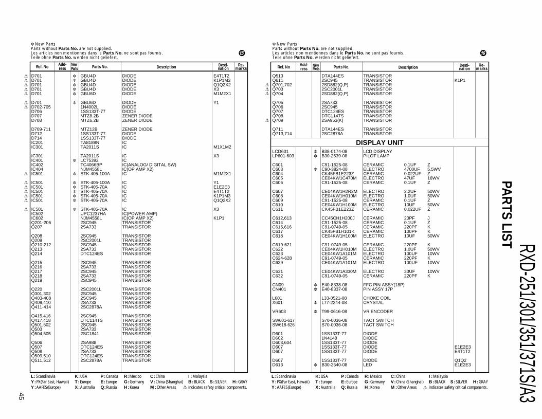
RXD-251/301/351/371S/A345
PAR
TS LIST New PartsParts without Parts No. are not supplied.Les articles non mentionnes dans le Parts No. ne sont pas fournis.Teile ohne Parts No. werden nicht geliefert.
Ref. NoAdd-ress
NewParts Description
Desti-nation
Re-marksParts No.
New PartsParts without Parts No. are not supplied.Les articles non mentionnes dans le Parts No. ne sont pas fournis.Teile ohne Parts No. werden nicht geliefert.
Ref. NoAdd-ress
NewParts Description Desti-
nationRe-
marksParts No.
Q513 DTA144ES TRANSISTORQ611 2SC945 TRANSISTOR K1P1Q701,702 2SD882(Q,P) TRANSISTORQ703 2SC2001L TRANSISTORQ704 2SD882(Q,P) TRANSISTOR
Q705 2SA733 TRANSISTORQ706 2SC945 TRANSISTORQ707 DTC124ES TRANSISTORQ708 DTC114TS TRANSISTORQ709 2SA953(K) TRANSISTOR
Q711 DTA144ES TRANSISTORQ713,714 2SC2878A TRANSISTOR
LCD601 B38-0174-08 LCD DISPLAYLP601-603 B30-2539-08 PILOT LAMP
C601 C91-1525-08 CERAMIC 0.1UF ZC603 C90-3824-08 ELECTRO 4700UF 5.5WVC604 CK45FB1E223Z CERAMIC 0.022UF ZC605 CE04KW1C470M ELECTRO 47UF 16WVC606 C91-1525-08 CERAMIC 0.1UF Z
C607 CE04KW1H2R2M ELECTRO 2.2UF 50WVC608 CE04KW1H010M ELECTRO 1.0UF 50WVC609 C91-1525-08 CERAMIC 0.1UF ZC610 CE04KW1H100M ELECTRO 10UF 50WVC611 CK45FB1E223Z CERAMIC 0.022UF Z
C612,613 CC45CH1H200J CERAMIC 20PF JC614 C91-1525-08 CERAMIC 0.1UF ZC615,616 C91-0749-05 CERAMIC 220PF KC617 CK45FB1H101K CERAMIC 100PF KC618 CE04KW1H100M ELECTRO 10UF 50WV
C619-621 C91-0749-05 CERAMIC 220PF KC622 CE04KW1H010M ELECTRO 1.0UF 50WVC623 CE04KW1A101M ELECTRO 100UF 10WVC624-628 C91-0749-05 CERAMIC 220PF KC629 CE04KW1A101M ELECTRO 100UF 10WV
C631 CE04KW1A330M ELECTRO 33UF 10WVC632 C91-0749-05 CERAMIC 220PF K
CN09 E40-8338-08 FFC PIN ASSY(18P)CN401 E40-8337-08 PIN ASSY 17P
L601 L33-0521-08 CHOKE COILX601 L77-2244-08 CRYSTAL
VR603 T99-0616-08 VR ENCODER
SW601-617 S70-0036-08 TACT SWITCHSW618-626 S70-0036-08 TACT SWITCH
D601 1SS133T-77 DIODED602 1N4148 DIODED603,604 1SS133T-77 DIODED607 1SS133T-77 DIODE E1E2E3D607 1SS133T-77 DIODE E4T1T2
D607 1SS133T-77 DIODE Q1Q2D613 B30-2540-08 LED E1E2E3
D701 GBU4D DIODE E4T1T2D701 GBU4D DIODE K1P1M3D701 GBU4D DIODE Q1Q2X2D701 GBU4D DIODE X3D701 GBU6D DIODE M1M2X1
D701 GBU6D DIODE Y1D702-705 1N4002L DIODED706 1SS133T-77 DIODED707 MTZ8.2B ZENER DIODED708 MTZ6.2B ZENER DIODE
D709-711 MTZ12B ZENER DIODED712 1SS133T-77 DIODED714 1SS133T-77 DIODEIC201 TA8189N ICIC301 TA2011S IC M1X1M2
IC301 TA2011S IC X3IC401 LC75392 ICIC402 TC4066BP IC(ANALOG/ DIGITAL SW)IC404 NJM4558L IC(OP AMP X2)IC501 STK-405-100A IC M1M2X1
IC501 STK-405-100A IC Y1IC501 STK-405-70A IC E1E2E3IC501 STK-405-70A IC E4T1T2IC501 STK-405-70A IC K1P1M3IC501 STK-405-70A IC Q1Q2X2
IC501 STK-405-70A IC X3IC502 UPC1237HA IC(POWER AMP)IC602 NJM4558L IC(OP AMP X2) K1P1Q201-206 2SC945 TRANSISTORQ207 2SA733 TRANSISTOR
Q208 2SC945 TRANSISTORQ209 2SC2001L TRANSISTORQ210-212 2SC945 TRANSISTORQ213 2SA733 TRANSISTORQ214 DTC124ES TRANSISTOR
Q215 2SC945 TRANSISTORQ216 2SA733 TRANSISTORQ217 2SC945 TRANSISTORQ218 2SA733 TRANSISTORQ219 2SC945 TRANSISTOR
Q220 2SC2001L TRANSISTORQ301,302 2SC945 TRANSISTORQ403-408 2SC945 TRANSISTORQ409,410 2SA733 TRANSISTORQ411-414 2SC2878A TRANSISTOR
Q415,416 2SC945 TRANSISTORQ417,418 DTC114TS TRANSISTORQ501,502 2SC945 TRANSISTORQ503 2SA733 TRANSISTORQ504,505 2SC1841 TRANSISTOR
Q506 2SA988 TRANSISTORQ507 DTC124ES TRANSISTORQ508 2SA733 TRANSISTORQ509,510 DTC124ES TRANSISTORQ511,512 2SC2878A TRANSISTOR
L : Scandinavia K : USA P : Canada R : Mexico C : China I : MalaysiaY : PX(Far East, Hawaii) T : Europe E : Europe G : Germany V : China (Shanghai) B : BLACK S : SILVER H : GRAYY : AAFES(Europe) X : Australia Q : Russia H : Korea M : Other Areas indicates safety critical components.
L : Scandinavia K : USA P : Canada R : Mexico C : China I : MalaysiaY : PX(Far East, Hawaii) T : Europe E : Europe G : Germany V : China (Shanghai) B : BLACK S : SILVER H : GRAYY : AAFES(Europe) X : Australia Q : Russia H : Korea M : Other Areas indicates safety critical components.
% ^
DISPLAY UNIT
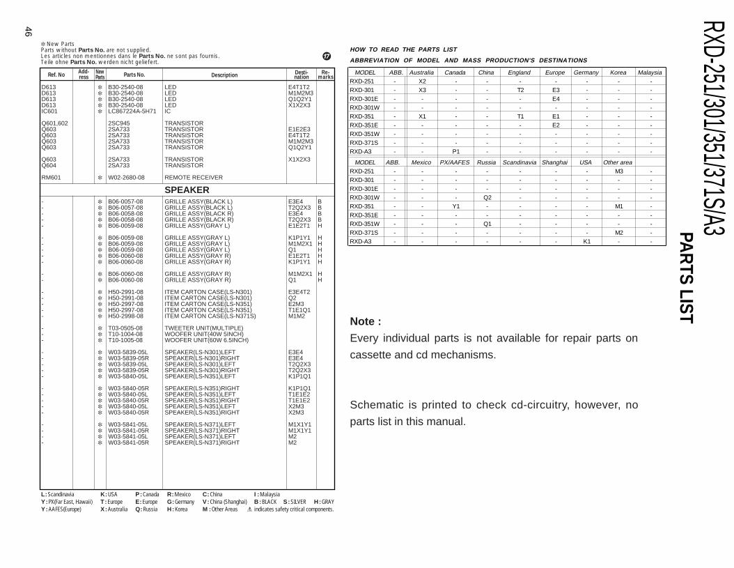
RXD-251/301/351/371S/A3
46
PAR
TS LIST New PartsParts without Parts No. are not supplied.Les articles non mentionnes dans le Parts No. ne sont pas fournis.Teile ohne Parts No. werden nicht geliefert.
Ref. NoAdd-ress
NewParts Description Desti-
nationRe-
marksParts No.
D613 B30-2540-08 LED E4T1T2D613 B30-2540-08 LED M1M2M3D613 B30-2540-08 LED Q1Q2Y1D613 B30-2540-08 LED X1X2X3IC601 LC867224A-5H71 IC
Q601,602 2SC945 TRANSISTORQ603 2SA733 TRANSISTOR E1E2E3Q603 2SA733 TRANSISTOR E4T1T2Q603 2SA733 TRANSISTOR M1M2M3Q603 2SA733 TRANSISTOR Q1Q2Y1
Q603 2SA733 TRANSISTOR X1X2X3Q604 2SA733 TRANSISTOR
RM601 W02-2680-08 REMOTE RECEIVER
- B06-0057-08 GRILLE ASSY(BLACK L) E3E4 B- B06-0057-08 GRILLE ASSY(BLACK L) T2Q2X3 B- B06-0058-08 GRILLE ASSY(BLACK R) E3E4 B- B06-0058-08 GRILLE ASSY(BLACK R) T2Q2X3 B- B06-0059-08 GRILLE ASSY(GRAY L) E1E2T1 H
- B06-0059-08 GRILLE ASSY(GRAY L) K1P1Y1 H- B06-0059-08 GRILLE ASSY(GRAY L) M1M2X1 H- B06-0059-08 GRILLE ASSY(GRAY L) Q1 H- B06-0060-08 GRILLE ASSY(GRAY R) E1E2T1 H- B06-0060-08 GRILLE ASSY(GRAY R) K1P1Y1 H
- B06-0060-08 GRILLE ASSY(GRAY R) M1M2X1 H- B06-0060-08 GRILLE ASSY(GRAY R) Q1 H
- H50-2991-08 ITEM CARTON CASE(LS-N301) E3E4T2- H50-2991-08 ITEM CARTON CASE(LS-N301) Q2- H50-2997-08 ITEM CARTON CASE(LS-N351) E2M3- H50-2997-08 ITEM CARTON CASE(LS-N351) T1E1Q1- H50-2998-08 ITEM CARTON CASE(LS-N371S) M1M2
- T03-0505-08 TWEETER UNIT(MULTIPLE)- T10-1004-08 WOOFER UNIT(40W 5INCH)- T10-1005-08 WOOFER UNIT(60W 6.5INCH)
- W03-5839-05L SPEAKER(LS-N301)LEFT E3E4- W03-5839-05R SPEAKER(LS-N301)RIGHT E3E4- W03-5839-05L SPEAKER(LS-N301)LEFT T2Q2X3- W03-5839-05R SPEAKER(LS-N301)RIGHT T2Q2X3- W03-5840-05L SPEAKER(LS-N351)LEFT K1P1Q1
- W03-5840-05R SPEAKER(LS-N351)RIGHT K1P1Q1- W03-5840-05L SPEAKER(LS-N351)LEFT T1E1E2- W03-5840-05R SPEAKER(LS-N351)RIGHT T1E1E2- W03-5840-05L SPEAKER(LS-N351)LEFT X2M3- W03-5840-05R SPEAKER(LS-N351)RIGHT X2M3
- W03-5841-05L SPEAKER(LS-N371)LEFT M1X1Y1- W03-5841-05R SPEAKER(LS-N371)RIGHT M1X1Y1- W03-5841-05L SPEAKER(LS-N371)LEFT M2- W03-5841-05R SPEAKER(LS-N371)RIGHT M2
L : Scandinavia K : USA P : Canada R : Mexico C : China I : MalaysiaY : PX(Far East, Hawaii) T : Europe E : Europe G : Germany V : China (Shanghai) B : BLACK S : SILVER H : GRAYY : AAFES(Europe) X : Australia Q : Russia H : Korea M : Other Areas indicates safety critical components.
&
SPEAKER
HOW TO READ THE PARTS LIST
ABBREVIATION OF MODEL AND MASS PRODUCTION'S DESTINATIONS MODEL ABB. Australia Canada China England Europe Germany Korea Malaysia
RXD-251 - X2 - - - - - - -RXD-301 - X3 - - T2 E3 - - -RXD-301E - - - - - E4 - - -RXD-301W - - - - - - - - -RXD-351 - X1 - - T1 E1 - - -RXD-351E - - - - - E2 - - -RXD-351W - - - - - - - - -RXD-371S - - - - - - - - -RXD-A3 - - P1 - - - - - -
MODEL ABB. Mexico PX/AAFES Russia Scandinavia Shanghai USA Other areaRXD-251 - - - - - - - M3 -RXD-301 - - - - - - - - -RXD-301E - - - - - - - - -RXD-301W - - - Q2 - - - - -RXD-351 - - Y1 - - - - M1 -RXD-351E - - - - - - - - -RXD-351W - - - Q1 - - - - -RXD-371S - - - - - - - M2 -RXD-A3 - - - - - - K1 - -
Note :
Every individual parts is not available for repair parts on
cassette and cd mechanisms.
Schematic is printed to check cd-circuitry, however, no
parts list in this manual.
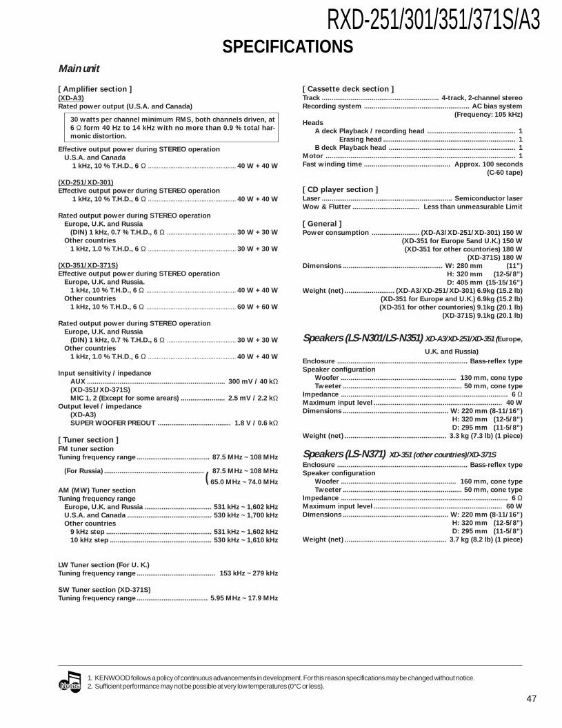
RXD-251/301/351/371S/A3
47
SPECIFICATIONSMain unit
[ Amplifier section ](XD-A3)
Rated power output (U.S.A. and Canada)
30 watts per channel minimum RMS, both channels driven, at
6 Ω form 40 Hz to 14 kHz with no more than 0.9 % total har-
monic distortion.
Effective output power during STEREO operation
U.S.A. and Canada
1 kHz, 10 % T.H.D., 6 Ω ................................................... 40 W + 40 W
(XD-251/XD-301)
Effective output power during STEREO operation
1 kHz, 10 % T.H.D., 6 Ω ................................................... 40 W + 40 W
Rated output power during STEREO operation
Europe, U.K. and Russia
(DIN) 1 kHz, 0.7 % T.H.D., 6 Ω ........................................ 30 W + 30 W
Other countries
1 kHz, 1.0 % T.H.D., 6 Ω ................................................... 30 W + 30 W
(XD-351/XD-371S)
Effective output power during STEREO operation
Europe, U.K. and Russia.
1 kHz, 10 % T.H.D., 6 Ω .................................................... 40 W + 40 W
Other countries
1 kHz, 10 % T.H.D., 6 Ω .................................................... 60 W + 60 W
Rated output power during STEREO operation
Europe, U.K. and Russia
(DIN) 1 kHz, 0.7 % T.H.D., 6 Ω ........................................ 30 W + 30 W
Other countries
1 kHz, 1.0 % T.H.D., 6 Ω ................................................... 40 W + 40 W
Input sensitivity / inpedance
AUX ........................................................................ 300 mV / 40 kΩ(XD-351/XD-371S)
MIC 1, 2 (Except for some arears) ....................... 2.5 mV / 2.2 kΩOutput level / impedance
(XD-A3)
SUPER WOOFER PREOUT ...................................... 1.8 V / 0.6 kΩ
[ Tuner section ]FM tuner section
Tuning frequency range ...................................... 87.5 MHz ~ 108 MHz
(For Russia) ....................................................
( 87.5 MHz ~ 108 MHz
65.0 MHz ~ 74.0 MHz
AM (MW) Tuner section
Tuning frequency range
Europe, U.K. and Russia ................................... 531 kHz ~ 1,602 kHz
U.S.A. and Canada ............................................ 530 kHz ~ 1,700 kHz
Other countries
9 kHz step ....................................................... 531 kHz ~ 1,602 kHz
10 kHz step ..................................................... 530 kHz ~ 1,610 kHz
LW Tuner section (For U. K.)
Tuning frequency range ......................................... 153 kHz ~ 279 kHz
SW Tuner section (XD-371S)
Tuning frequency range ..................................... 5.95 MHz ~ 17.9 MHz
[ Cassette deck section ]Track ............................................................. 4-track, 2-channel stereo
Recording system ....................................................... AC bias system
(Frequency: 105 kHz)
Heads
A deck Playback / recording head .............................................. 1
Erasing head ..................................................................... 1
B deck Playback head .................................................................. 1
Motor ................................................................................................... 1
Fast winding time ............................................. Approx. 100 seconds
(C-60 tape)
[ CD player section ]Laser .................................................................... Semiconductor laser
Wow & Flutter ................................... Less than unmeasurable Limit
[ General ]Power consumption ......................... (XD-A3/XD-251/XD-301) 150 W
(XD-351 for Europe 5and U.K.) 150 W
(XD-351 for other countories) 180 W
(XD-371S) 180 W
Dimensions .................................................... W: 280 mm (11”)
H: 320 mm (12-5/8”)
D: 405 mm (15-15/16”)
Weight (net) .......................... (XD-A3/XD-251/XD-301) 6.9kg (15.2 lb)
(XD-351 for Europe and U.K.) 6.9kg (15.2 lb)
(XD-351 for other countories) 9.1kg (20.1 lb)
(XD-371S) 9.1kg (20.1 lb)
Speakers (LS-N301/LS-N351) XD-A3/XD-251/XD-351 (Europe,
U.K. and Russia)
Enclosure .................................................................... Bass-reflex type
Speaker configuration
Woofer ............................................................ 130 mm, cone type
Tweeter .............................................................. 50 mm, cone type
Impedance ....................................................................................... 6 ΩMaximum input level ................................................................... 40 W
Dimensions ....................................................... W: 220 mm (8-11/16”)
H: 320 mm (12-5/8”)
D: 295 mm (11-5/8”)
Weight (net) ..................................................... 3.3 kg (7.3 lb) (1 piece)
Speakers (LS-N371) XD-351 (other countries)/XD-371SEnclosure .................................................................... Bass-reflex type
Speaker configuration
Woofer ............................................................ 160 mm, cone type
Tweeter .............................................................. 50 mm, cone type
Impedance ....................................................................................... 6 ΩMaximum input level ................................................................... 60 W
Dimensions ....................................................... W: 220 mm (8-11/16”)
H: 320 mm (12-5/8”)
D: 295 mm (11-5/8”)
Weight (net) ..................................................... 3.7 kg (8.2 lb) (1 piece)
NotesNotes1. KENWOOD follows a policy of continuous advancements in development. For this reason specifications may be changed without notice.2. Sufficient performance may not be possible at very low temperatures (0°C or less).
RXD-251/301/351/371S/A3
14-6,Dogenzaka 1-chome, Shibuya-ku, Tokyo, 150-8501 Japan
KENWOOD SERVICE CORPORATIONP.O BOX 22745, 2201 East Dominguez St., Long Beach, CA 90801-5745, U.S.A.
KENWOOD ELECTRONICS CANADA INC.6070 Kestrel Road, Mississauga, Ontario, Canada L5T 1S8
KENWOOD ELECTRONICS LATIN AMERICA S.A.P.O BOX 55-2791, Piso 6 plaza Chase, Cl. 47 y Aquilino de la Guardia Panama, Republic de Panama
KENWOOD ELECTRONICS BRASIL LTDA.Av Indianópolis, 628, 04062-001 Planalto Paullsta São Paulo-SP-Brasil
KENWOOD ELECTRONICS U.K. LIMITEDKENWOOD House, Dwight Road, Watford, Herts., WD1 8EB., United Kingdom
KENWOOD ELECTRONICS BELGUM N.V.Meachelsesteenweg 418, B-1930 Zaventem, Belgium
KENWOOD ELECTRONICS DEUTSCHLAND GMBHRembrücker Str. 15, 63150 Heusenstamm, Germany
KENWOOD ELECTRONICS FRANCE S.A.13 Boulevard Ney, 75018 Paris, France
KENWOOD ELECTRONICS ITALIA S.p.A.Via G. Sirtori, 7/9 20129, Milano, ltaly
KENWOOD IBÉRICA S.A.Bolivia, 239-08020 Barcelona, Spain
KENWOOD ELECTRONICS AUSTRALIA PTY. LTD.(A.C.N. 001499 074) P.O Box 504, 8 Figtree Drive, Australia Centre, Homebush, N.S.W. 2140, Australia
KENWOOD & LEE ELECTRONICS, LTD.Unit 3712-3724, Level 37, Tower 1, Metroplaza, 223 Hing Fong Road, Kwai Fong N.T., Hong Kong
KENWOOD ELECTRONICS GULF FZEP.O.Box 61318, Jebel Ali, Dubai, U.A.E.
KENWOOD ELECTRONICS SINGAPORE PTE LTD. No. 1 Genting Lane #02-02, KENWOOD Building, Singapore, 349544
KENWOOD ELECTRONICS (MALAYSIA) SDN BHD.#4.01 Level 4, Wisma Academy Lot 4A, Jalan 19/1 46300 Petaling Jaya Selangor Darul EhsanMalaysia
KENWOOD ELECTRONICS (THAILAND) CO., LTD.573/111 Soi Ramkhamhaeng 39, Ramkhamhaeng Road, Wangthonglang, Bangkapi, Bankok10301 Thailand
Note:Component and circuit are subject to modification to insure bestoperation under differing local conditions. This manual is based onEurope (E) standard, and provides information on regional circuitmodification through use of alternate schematic diagrams, and infor-mation on regional component variations through use of parts list.
Related Documents


![EtherNet/IPTM Connection Guide IAI Corporation SYSMAC-SE2[][][] Sysmac Studio Version 1 Operation Manual ME0313 XSEL-R/S/RX/SX/RXD/SXD XSEL Controller R/S/ RX/SX/RXD/SXD Type Operation](https://static.cupdf.com/doc/110x72/5acd57707f8b9a875a8db137/ethernetiptm-connection-guide-iai-corporation-sysmac-se2-sysmac-studio-version.jpg)