EECCIS 2012 Abstract — Annealing is the last stage of aluminum foil production process which often causes undesired condition of foil. It is mostly caused by improper annealing treatment. In this paper, annealing treatment for aluminum alloy AA 1235 in foil annealing furnace (FAF) has been analyzed. A combined study was conducted by means of Computational Fluid Dynamic (CFD) to evaluate thermal distribution inside the two FAF A and FAF B during heating. Furnace performance from the temperature control response and conduction time for heating of aluminum are also analyzed. The FAF A has a better temperature distribution than that of FAF B, but there is saturated airflow between the aluminum roll in the second stage. Based on temperature control response, settling time of evaporation temperature is achieved about 4 hours for FAF B and can’t be reached in FAF A whereas it is desired to be reached in 1 hour. It is suggested to change the proportional mode control to higher value in order to get fast settling time since the furnace employs PID controller. There is large different between theoretical and actual conduction time of aluminum foil that indicates improper work of insulating material of furnace so that there is much heat losses. Keywords — CFD, Annealing treatment, FAF, AA1235. I. I NTRODUCTION very rolling mill company especially aluminum foil production possess many kind of defect and undesired quality of aluminum foil. They are caused by improper conditions and treatments of two main production processes which consist of rolling and finishing [1] – [2]. It employs a set of cold works in rolling process that include some passes through rolling to obtain the desired thickness of aluminum foil. At the next process, finishing, aluminum foil is also passed through some steps. They are separating, slitting, rewinding, annealing and packaging [3]. Rolling process that usually employed in aluminum company is categorized to cold work. It reduces thickness of aluminum coil to particular thickness of aluminum foil by external force from work rolls. It is operated below the re-crystallization temperature of aluminum alloy. There is also coolant oil that sprayed along the surfaces of aluminum coil and work rolls during rolling process. This coolant oil is added to avoid direct surface friction between work rolls and coil of aluminum which caused many defects [3] – [4]. The consequent of rolling process is carrying coolant oil which embedded inside the rolled aluminum. The carrying oil needs to be removed from the rolled aluminum. Therefore, annealing is employed. Basically, annealing is a heat treatment given to soften the metal due to cold work [1] – [5]. It removes physical stress of the metal so that some of the mechanical properties are back to normal. Annealing in aluminum foil production is a part of finishing process. It is employed to remove both physical stress and carrying coolant oil of aluminum foil [2], [3]. It is often found that the aluminum foils still have worse wet-ability (usually called as weta) and some of them are too sticky. It is induced by non-evaporated coolant oil trapped inside the roll of aluminum. Improper heat treatment of annealing process may be caused by insufficient heat in the furnace or temperature control in the furnace. In this study we collaborate with PT. Supra Aluminium Industri (SAI), one of growing aluminum industries in Indonesia, which mostly work with AA 1235 (non heat treatable alloy). As the problem remains, data of quality control of SAI show that there is still undesired quality of final product after pass through annealing process. Foil annealing furnaces (FAF) employed in SAI are two kind of sided blow inlet-outlet furnace. They have specific structure and dimension, thermal distribution characteristic, and also response to the temperature control. However, the treatment of annealing process given to roll of aluminum foil is same to the all of furnace [2]. The aim of this study is to evaluate the overall annealing treatment including temperature control, thermal distribution, and furnace’s performance since AA 1235 must be treated in proper heat treatment to get high quality product. II. THEORETICAL APPROACH AND REAL PROCESS Annealing is an additional heat treatment to soften the metal. It removes physical stress resulting from cold working (cold rolling) given during overall production process of rolled aluminum foil [1] – [3]. Annealing A Computational Fluid Dynamics Study of 6.5 Micron AA 1235 Annealing Treatment in Sided Blow Inlet – Outlet Furnace Ruri A. Wahyuono a) , Wiratno A. Asmoro b) , Edy Sugiantoro c) , and Muhamad Faisal d) a,b,d) Departme nt of Engineering Physics, Institut Teknologi Sepuluh Nopember Surabaya c) PT. Supra Aluminium Industri (SAI), J alan raya Kasrie 146 Pandaan - Pasuruan E-mail address: r_agung_w@ep.its.ac.id, wiratno@ep. its.ac.id, eds@supra- aluminium.co.id, muhamad .faisal11@mh s.ep.its.ac.id E

Welcome message from author
This document is posted to help you gain knowledge. Please leave a comment to let me know what you think about it! Share it to your friends and learn new things together.
Transcript
8/15/2019 Ruri Agung W Et Al (2012, A CFD Study of Annealing Treatment ...)
http://slidepdf.com/reader/full/ruri-agung-w-et-al-2012-a-cfd-study-of-annealing-treatment- 1/6
EECCIS 2012
Abstract — Annealing is the last stage of aluminum foil
production process which often causes undesired condition
of foil. It is mostly caused by improper annealing
treatment. In this paper, annealing treatment for
aluminum alloy AA 1235 in foil annealing furnace (FAF)
has been analyzed. A combined study was conducted by
means of Computational Fluid Dynamic (CFD) to evaluate
thermal distribution inside the two FAF A and FAF B
during heating. Furnace performance from the
temperature control response and conduction time for
heating of aluminum are also analyzed. The FAF A has a
better temperature distribution than that of FAF B, but
there is saturated airflow between the aluminum roll in the
second stage. Based on temperature control response,
settling time of evaporation temperature is achieved about
4 hours for FAF B and can’t be reached in FAF A whereas
it is desired to be reached in 1 hour. It is suggested tochange the proportional mode control to higher value in
order to get fast settling time since the furnace employs
PID controller. There is large different between theoretical
and actual conduction time of aluminum foil that indicates
improper work of insulating material of furnace so that
there is much heat losses.
Keywords — CFD, Annealing treatment, FAF, AA1235.
I. I NTRODUCTION
very rolling mill company especially aluminum foil
production possess many kind of defect and
undesired quality of aluminum foil. They are caused byimproper conditions and treatments of two main
production processes which consist of rolling and
finishing [1] – [2]. It employs a set of cold works in
rolling process that include some passes through rolling
to obtain the desired thickness of aluminum foil. At the
next process, finishing, aluminum foil is also passed
through some steps. They are separating, slitting,
rewinding, annealing and packaging [3].
Rolling process that usually employed in aluminum
company is categorized to cold work. It reduces
thickness of aluminum coil to particular thickness of
aluminum foil by external force from work rolls. It isoperated below the re-crystallization temperature ofaluminum alloy. There is also coolant oil that sprayed
along the surfaces of aluminum coil and work rolls
during rolling process. This coolant oil is added to avoid
direct surface friction between work rolls and coil ofaluminum which caused many defects [3] – [4].
The consequent of rolling process is carrying coolant
oil which embedded inside the rolled aluminum. The
carrying oil needs to be removed from the rolled
aluminum. Therefore, annealing is employed. Basically,annealing is a heat treatment given to soften the metal
due to cold work [1] – [5]. It removes physical stress of
the metal so that some of the mechanical properties are
back to normal. Annealing in aluminum foil production
is a part of finishing process. It is employed to remove
both physical stress and carrying coolant oil ofaluminum foil [2], [3].
It is often found that the aluminum foils still have
worse wet-ability (usually called as weta) and some of
them are too sticky. It is induced by non-evaporated
coolant oil trapped inside the roll of aluminum.
Improper heat treatment of annealing process may becaused by insufficient heat in the furnace or temperature
control in the furnace. In this study we collaborate with
PT. Supra Aluminium Industri (SAI), one of growing
aluminum industries in Indonesia, which mostly work
with AA 1235 (non heat treatable alloy). As the problem
remains, data of quality control of SAI show that there isstill undesired quality of final product after pass through
annealing process.
Foil annealing furnaces (FAF) employed in SAI are
two kind of sided blow inlet-outlet furnace. They havespecific structure and dimension, thermal distributioncharacteristic, and also response to the temperature
control. However, the treatment of annealing process
given to roll of aluminum foil is same to the all of
furnace [2]. The aim of this study is to evaluate the
overall annealing treatment including temperature
control, thermal distribution, and furnace’s performancesince AA 1235 must be treated in proper heat treatment
to get high quality product.
II. THEORETICAL APPROACH AND REAL
PROCESS
Annealing is an additional heat treatment to soften themetal. It removes physical stress resulting from cold
working (cold rolling) given during overall production
process of rolled aluminum foil [1] – [3]. Annealing
A Computational Fluid Dynamics Study of 6.5
Micron AA 1235 Annealing Treatment in Sided
Blow Inlet – Outlet FurnaceRuri A. Wahyuonoa), Wiratno A. Asmoro b), Edy Sugiantoro c), and Muhamad Faisal d)
a,b,d) Department of Engineering Physics, Institut Teknologi Sepuluh Nopember Surabayac) PT. Supra Aluminium Industri (SAI), Jalan raya Kasrie 146 Pandaan - Pasuruan
E-mail address: [email protected], [email protected], [email protected],[email protected]
E

8/15/2019 Ruri Agung W Et Al (2012, A CFD Study of Annealing Treatment ...)
http://slidepdf.com/reader/full/ruri-agung-w-et-al-2012-a-cfd-study-of-annealing-treatment- 2/6
EECCIS 2012
applies heat by convection through the atmosphere
inside an annealing furnace. To avoid oxidizing any
un-evaporated lubricant residues or forming magnesium
oxide on magnesium-bearing alloys, annealing may be
carried out in a dry, inert (low O2) atmosphere such as
nitrogen gas. A large integrated aluminum rolling plantmay have its own nitrogen generating plant for this
purpose [2], [6].
Non-heat-treatable aluminum alloy, commonly
heated for 1.5 – 2 hours in the range of operating
temperature 635 – 765oF or equivalent to 335 – 445oC
[6], [7]. The heat released to the rolled aluminum hasanother objective. It also evaporates the carrying coolant
oil inside rolled aluminum. So that’s why, annealing
chamber must be dry (very low oxygen intensity) to
avoid oxidizing of coolant oil in the surfaces.
Annealing process in SAI is batch annealing. It
means loading a furnace with a batch of metal, roll ofaluminum foil, and holding it there until the annealing
process is complete. Rolls of aluminum foil are annealed
as a single batch, depending on the size of the foils andthe size and shape of the furnace [2]. In batch annealing,
heat conveyed by the furnace atmosphere to the outsidesurfaces of the foils must be conducted through the
metal to the innermost layers, and sufficient time must
be allowed for all parts of each foil to absorb enough
heat to achieve the planned anneal [1], [3]. Batch
annealing is an efficient approach and is the most
commonly used method in high-production aluminumfoil mills.
Fig. 1. Heat treatment scheme of batch annealing in SAI
The annealing scheme is describe as three stages of
thermal treatments (See Fig. 1). They are heating,
soaking and cooling. In heating stage, aluminum foil is
heated to particular temperature up to 5 hours.
Temperature setting depends on the thickness of
aluminum foil. Soaking stage holds annealing chambertemperature to particular value for 15 – 20 hours. This
step also includes evaporating and drying. The last
stage, cooling, chills amount of rolled aluminum for two
hours inside the annealing chamber. It’ll be pulled out
later if the temperature reaches 70oC [2].
Evaporation of carrying coolant oil of 6.5 micronaluminum foil is estimated to occupy 15 hours of
heating with temperature setting 225
o
C. Since the presence of receding fold (RF) on aluminum foil after
annealing, it is identified that the mechanism of
preheating (big temperature different) induces thermal
shock. The thermal shock effect can be reduced by
applying graded pre-heating.
III. METHOD
First analysis of the annealing problem is temperature
and airflow distribution since decrease in temperature in
some volume of chamber can induce incomplete
evaporation. This has caused to some rolls of aluminumfoil is still in worse wet-ability and/or sticky. This
analysis is conducted based on the simulation results of
Computational Fluid Dynamics (CFD) simulation
intended to analyze temperature and air flow
distribution in the empty and filled chamber of Foil
Annealing Furnace (FAF). The furnace is distinguished
as FAF A and FAF B which the aluminum is in specific
orientation inside the chamber.
A. Computational Fluid Dynamics
The computational fluid dynamics, usually
abbreviated as CFD, is a branch of fluid mechanics
using numerical methods to analyze and solve problemsthat involve flows of fluid. CFD has also been used as
powerful tool for thermal analysis in incubator [8], [9].
Numerical method is built by employs the governing
equations such as conservation of energy, momentum
and continuity. Energy conservation is determined as
equation shown below [10].
heff
eff
S
T k p E E t
..
.. (1)
where k eff is effective conductivity which the value is
equal to sum of k and k t (thermal conductivity for the
presence of turbulence). The two terms on the right siderepresent the energy transfer by conduction and
viscosity dissipation.For the solid region (i.e. newborn body), energy
transfer is calculated by employing equation as follow
[8], [9]:
hS T k hvht
).().()(
(2)
where is solid density, h is sensible enthalpy, k isconductivity constant of newborn, T is newborn skin
temperature, and S h is volumetric heat source.
The equation (1) and (2) are complemented by
continuity and conservation of momentum defined below:
0. u (3)
u p F dt
du 2 (4)
where p is normal pressure (N/m2), F is body force on
solid region.
B. Thermodynamic Analysis
The analysis of conduction rate has been developed.
The heat transfer and thermodynamic (control volume)
approach is used to determine how long the aluminumfoil steadily reaches the setting temperature furnace. The
first assumption is the type of material must be solid or
rigid body so that the roll of aluminum foil is same as
0 10 20 30 40 50 60 70 80 9040
60
80
100
120
140
160
180
200
220
240
Time (hours)
Temperatur(oC)
Pre-heating 1 (130 oC ~ 8 hr)
Drying (180 oC ~ 60 hr)
Pre-heating 2 (160oC ~ 8 hr)
Evaporating (225 oC ~ 15 hr)

8/15/2019 Ruri Agung W Et Al (2012, A CFD Study of Annealing Treatment ...)
http://slidepdf.com/reader/full/ruri-agung-w-et-al-2012-a-cfd-study-of-annealing-treatment- 3/6
EECCIS 2012
rigid cylinder. The Fourier equation that represent
conduction rate is given below [11].
dx
dT k
A
q (6)
Since the aluminum foil is assumed to be cylindrical, the
cross-section area become a circle. The equation (6) can
be written:
dr
dT rLk
dr
dT kAqr 2 (7)
Integrating (7) for r 1 to r 2 in left side and T 1 to T 2 in right
side, so that we obtain:
1
2
21
ln
2
r
r
T T kLqr
(8)
In evaporating phase, the temperature different is 65oC.
The aluminum foil on evaporation temperature (225
o
C)has conductivity coefficient 222 W/m K. In this study,
specification of aluminum roll is 82 cm width, 34 cmOD (Outer Diameter) and ID (Inner Diameter) 8 cm. By
using (8), the heat needed for aluminum foil roll is 5.413
kW. As the time setting for transient response during
pre-heating to evaporating is 1 hour, the released heat
which needed is approximately 51,356 kWh .
The energy balance on a control volume is given asequation below.
ee
e
q
q
e
ii
i
p
p
icvcvcv
gz V
hm
gz V
hmW Qdt
dE
n
n
2
2
2
1
2
1
(9)
There are no work applied in the control volume so that
the value ofcvW equals to zero. Potential energy
difference of inlet and outlet can be neglected since the
value is too small. Steady state analysis results as
follow:
ip
ip
ip
p
p
ip
eq
eq
eq
q
q
qecv
gz V
hm
gz V
hmQ
n
n
2
22
1
2
1
(10)
Since AV m , (10) can be rewritten as,
ip
ip
ip
p
p
ipip
eq
eq
eq
q
qqeeqcv
gz V
hV A
gz V
hV AQ
n
n
2
2
2
1
2
1
(11)
The calculation of energy in control volume (furnace)
provides the data of heat accumulated inside the
chamber. From this value, it can be determined the
theoretical settling time of air chamber and annealed
aluminum in the FAF.
IV. RESULT AND DISCUSSION
A. Thermal Distribution
FAF A has the setting basket to hang the roll of
aluminum foil in front-rear direction. The heat is blown
to spherical surface of aluminum roll. The orientation of
aluminum rolls inside the chamber makes the capacity
of FAF A is only 32 rolls. The CFD simulation result of
temperature and airflow distribution is given as follow.
Fig. 2. Temperature distribution of FAF A in (a) right-
left view and (b) front-rear view
This Fig. 2 expresses temperature distribution of FAF
A chamber. It shows that the chamber has better
temperature distribution in bottom to half of chamber
height. The upper stage reaches temperature setting inthe center.
Fig. 3. Airflow distribution of FAF A in (a) right- left
view and (b) front-rear view
Based on Fig. 3, lower velocity magnitude of air is
distributed in upper side. However, it won’t affect much
to annealing in FAF A since the upper side of chamber
isn’t fully filled by rolls of aluminum foil. It shows that
the airflow distribution is almost well (average airflow
magnitude is about 2.09 ms-1). The higher airflowmagnitude (3.35 – 4.19 ms-1) is only distributed in
bottom of chamber.
8/15/2019 Ruri Agung W Et Al (2012, A CFD Study of Annealing Treatment ...)
http://slidepdf.com/reader/full/ruri-agung-w-et-al-2012-a-cfd-study-of-annealing-treatment- 4/6
EECCIS 2012
Fig. 4. Temperature distribution on roll of aluminum foil
inside FAF A
The distributed heat in the roll of aluminum annealed
in FAF A is shown as Fig. 4. In the figure shows that
almost all of aluminum is well treated by the proper
heat, especially in the side closed to inlet flow. This
condition can minimize the weta and/or sticky of
aluminum foil.
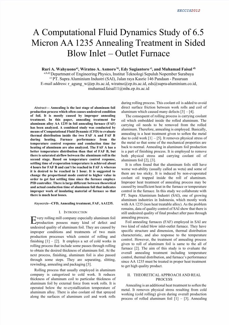
Fig. 5. Temperature distribution of FAF B in (a) right-
left view and (b) front-rear view
Fig. 6. Airflow distribution of FAF B in (a) right- left
view and (b) front-rear view
Based on the result on Fig. 5, temperature of FAF B
chamber can’t reach the set point in almost all of area.
Only several rolls of aluminum in the upper side get air
temperature 1 – 2 oC lower than the set point
temperature. The highest airflow magnitude (2.66 – 3.2ms-1) in FAF B is achieved in bottom to half of chamber
then it drops until 0.38 ms-1 on the upper side. Fig. 6
clearly shows that the fourth stage of aluminum rollsisn’t supplied adequate airflow to blow up the vaporized
carrying oil.
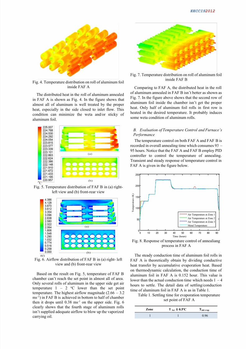
Fig. 7. Temperature distribution on roll of aluminum foil
inside FAF B
Comparing to FAF A, the distributed heat in the roll
of aluminum annealed in FAF B isn’t better as shown as
Fig. 7. In the figure above shows that the second row of
aluminum foil inside the chamber isn’t get the proper
heat. Only half of aluminum foil rolls in first row is
heated in the desired temperature. It probably induces
some weta condition of aluminum rolls.
B. Evaluation of Temperature Control and Furnace’s
Performance
The temperature control on both FAF A and FAF B is
recorded in overall annealing time which consumes 93 –
95 hours. Notice that the FAF A and FAF B employ PID
controller to control the temperature of annealing.
Transient and steady response of temperature control in
FAF A is given in the figure below.
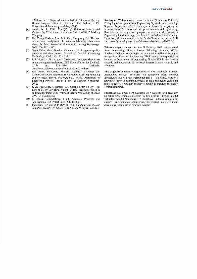
Fig. 8. Response of temperature control of annealiang
process in FAF A
The steady conduction time of aluminum foil rolls in
FAF A is theoretically obtain by dividing conductive
heat transfer by accumulative evaporation heat. Based
on thermodynamic calculation, the conduction time of
aluminum foil in FAF A is 0.152 hour. This value is
lower than the actual conduction time which needs 1 – 4
hours to settle. The detail data of settling/conduction
time of aluminum foil in FAF A is as in Table 1.
Table 1. Settling time for evaporation temperature
set point of FAF A
Zone T Set 0.5oC Tinit evap.
1 1 0.96
0 10 20 30 40 50 60 70 80 900
50
100
150
200
250
Time (hours)
Temperature(K)
Air Temperature at Zone 1
Air Temperature at Zone 2
Air Temperature at Zone 3
Metal Temperature

8/15/2019 Ruri Agung W Et Al (2012, A CFD Study of Annealing Treatment ...)
http://slidepdf.com/reader/full/ruri-agung-w-et-al-2012-a-cfd-study-of-annealing-treatment- 5/6
EECCIS 2012
2 1 0.96
3 1 0.96
Metal Temp. ~ 4
The recorded temperature response of annealing in
FAF B is follow.
Fig. 9. Response of temperature control of annealiang
process in FAF B
The evaporation settling time based on control
response in FAF B (see Table 2) is about 1 hour foraluminum in zone 1 and can’t be reached for aluminum
in zone 2 (see Fig. 9). The conduction time for annealing
aluminum foil in FAF B is 0,042 hour theoretically.
Table 2. Settling time for evaporation temperature
set point of FAF B
Zone T Set 0.5oC Tinit evap.
1 1 0.97
2 1 0.93
Metal Z1 1 0.97
Metal Z2 ~ ~
Both of FAF A and FAF B have a quite big different
of conduction time theoretically and actual, taken from
response of temperature control. As usual, this data
analysis indicates that improper heat treatment is
occurred while annealing. Two conditions that might become the cause of this condition are undesired heat
process/heat transfer and inappropriate control mode for
temperature annealing.
C. Discussion
Considering the result of temperature and airflow
distribution from CFD simulation, FAF A has good
thermal distribution than FAF B. However, the settling
time to evaporating phase in FAF A is about 1 – 4 hours.
The FAF B has average settling time to evaporation phase about 1 hour. It fit to transition setting time of
pre-heating and evaporating. The temperature andairflow distribution for FAF B is worse than FAF A.
That is caused by the profile of airflow inside the
chamber is different. Comparing to furnace that has
inlet-outlet in the side of chamber, the airflow of FAF B
is worse than the FAF A. This condition is caused by the
geometry of blade sticked in the inlet and outlet zone is
different to FAF A. The orientation of aluminum foil roll
is also affect to airflow distribution. It is recommended
to change the blade of FAF B as the FAF A has orchange the orientation of aluminum roll annealed in the
chamber to get better het treatment.
Comparing settling time of metal/aluminum in to
conduction time of aluminum oil rolls in each FAF,
there is big different value. Theoretically in FAF A, it
only need about 0,016 – 0,152 hour to reach the set pointtemperature. However in fact, aluminum foils need 4 to
reach the set point temperature. Moreover aluminum foil
in FAF B can’t achieve the set point temperature. It is
probably caused by two problems explained in the
previous point. They are improper tuning controller and
the condition of insulating material. Due the FAF A andB still using PID controller, it should be check that the
value of proportional constant, time derivative and time
integral setting is based on transient response. Since thesettling time is too much longer then the proportional
constant should be substituted to higher value to get fastresponse. The other problem may be caused by the
insulating material (e.g. glass wool, grafite, gypsum,
etc) inside the annealing chamber doesn’t work properly
so that there is so much heat losses during the annealing
process. In order to reduce the heat losses, it is
recommended to check the condition or thermalconductivity of the insulating material.
V. CONCLUSIONS
Annealing treatment of AA 1235 in foil annealing
furnace has been analyzed. FAF A has quite bettertemperature and airflow distribution which is set point
temperature and higher airflow magnitude is distributed
in upper side of chamber. The worst temperature and
airflow distribution is possessed by FAF B. The
upper-right side of chamber gets lower temperature so
that it may induce weta. There is heating problem due
the big difference between conduction time of real
process and theoretical calculation. It is probably caused
by improper control tuning of PID controller in the
furnace and heat losses by under works of insulation
material.
ACKNOWLEDGMENT
Thanks to Dr.-Ing. Doty D. Risanti and Dyah Sawitri,
M.T. for the helpful comments on the analysis of
annealing treatment. This study was supported by PT.
Supra Aluminium Industri Pasuruan for giving
measurement data of FAF and Indonesia-Germany Fast
Track Scholarship from Directorate of Higher Education
for the grant.
R EFERENCES
[1] The Aluminum Association. 2007. Rolling Aluminum: From the
Mine Through the Mill . The Aluminum Association, Inc.[2] Visual Quality Characteristic of Aluminum Sheet and Plate, the
Aluminum Association Inc., 4th Edition February 2002
[3] Annisa Kesy Garside, “Penentuan Setting Parameter ProsesFinishing Rolling untuk Aluminium Foil dengan Thickness Exit
0 10 20 30 40 50 60 70 80 90
0
50
100
150
200
250
Time (hours)
Temperature(K)
Air Temperature at Zone 1
Air Temperature at Zone 2
Metal Temperature at Zone 1
Metal Temperature at Zone 2
8/15/2019 Ruri Agung W Et Al (2012, A CFD Study of Annealing Treatment ...)
http://slidepdf.com/reader/full/ruri-agung-w-et-al-2012-a-cfd-study-of-annealing-treatment- 6/6
EECCIS 2012
7 Mikron di PT. Supra Aluminium Industri.” Laporan Magang
Dosen, Program Hibah A1, Jurusan Teknik Industri – FT,
Universitas Muhammadiyah Malang, 2005.[4] Smith, W. F. 1990. Principle of Materials Science and
Engineering 2nd Edition. New York: McGraw-Hill Publishing
Company.[5] Jing Zhang, Fusheng Pan, Rulin Zuo, Chenguang Bai. The low
temperature precipitation in commercial-purity aluminium
sheets for foils. Journal of Materials Processing Technology.2008; 206: 382 – 387.
[6]
Ozgul Keles, Murat Dundar. Aluminum foil: Its typical quality
problems and their causes. Journal of Materials ProcessingTechnology. 2007; 186: 125 – 137.
[7] R. J. Vidmar. (1992, August). On the use of atmospheric plasmas
as electromagnetic reflectors. IEEE Trans. Plasma Sci. [Online].21(3). pp. 876 — 880. Available:
http://www.halcyon.com/pub/journals/21ps03-vidmar
[8] Ruri Agung Wahyuono. Analisis Distribusi Temperatur dan
Aliran Udara Pada Inkubator Bayi dengan Variasi Tipe Dinding
dan Overhead Screen. Undergraduate Thesis Department of
Enginering Physics. Institut Teknologi Sepuluh Nopember.2012.
[9] R. A. Wahyuono, R. Hantoro, G. Nugroho. Study on Dry Heat
Loss of a Very Low Birth Weight (VLBW) Newborn Nursed inan Infant Incubator with Overhead Screen. Proceeding of SITIA
2012 - ITS, Indonesia.
[10]
J. Blazek. Computational Fluid Dynamics: Principle andApplications. ELSEVIER SCIENCE ltd. 2001.
[11] Incropera, F. P. and D. P. DeWitt. 1996. Fundamentals of Heat
and Mass Transfer 4th Edition. U.S.A.: John Wiley & Sons, Inc.
Ruri Agung Wahyuono was born in Pasuruan, 21 February 1990. His
B.Eng degree was gotten from Engineering Physics Institut Teknologi
Sepuluh Nopember (ITS), Surabaya - Indonesia majoring ininstrumentation & control and energy – environmental engineering.
Recently, he takes graduate program in the same department of
Engineering Physics through Fast Track Grant Indonesia – Germany.He actively do some research in the field of heat process using CFD
and currently develop research of dye-sensitized solar cell (DSCs).
Wiratno Argo Asmoro was born 29 February 1960. He graduated
from Engineering Physics Institut Teknologi Bandung (ITB),
Surabaya - Indoensia majoring in instrumentation and his M.Sc degreewas get from Electrical Engineering ITB. Recently, he responsible as
lecturer in Department of engineering Physics ITS in the field of
acoustic and electronics. His research interest is about acoustic andvibration.
Edy Sugiantoro recently responsible as PPIC manager in Supra
Aluminium Industri Pasuruan. He graduated from Material
Engineering Institut Teknologi Bandung (ITB) – Indonesia. He is well
known as expert in aluminum process in high-production aluminummills in several aluminum industries mostly as manager in quality
control department.
Muhamad Faisal was born in Jakarta, 23 November 1992. Recently,
he takes undergraduate program in Engineering Physics Institut
Teknologi Sepuluh Nopember (ITS), Surabaya - Indoensia majoring inenergy – environmental engineering. His research interest is about
developing technology of renewable energy.
Related Documents