INCOSE Colorado Front Range Chapter Meeting December 9, 2014

RTD FasTracks - INCOSE Colorado Front Range Chapter Presentation - Dec, 2014
Jul 14, 2015
Welcome message from author
This document is posted to help you gain knowledge. Please leave a comment to let me know what you think about it! Share it to your friends and learn new things together.
Transcript

INCOSE Colorado Front Range Chapter Meeting
December 9, 2014

Agenda Overview – Tara Bettale • RTD FasTracks Plan • Commuter Rail vs. Light Rail • FasTracks Status • Eagle P3 • East Rail Line • Gold Line • Northwest Rail to Westminster
2
Systems – Jeff Whiteman & Jeff Boerma
• Overhead Catenary System • Traction Power • Communications • Signals • Vehicles

The RTD FasTracks Plan • 122 miles of new light rail and
commuter rail • 18 miles of Bus Rapid Transit
(BRT) service • 31 new Park-n-Rides; more than
21,000 new parking spaces • Enhanced Bus Network & Transit
Hubs (FastConnects) • Redevelopment of Denver Union
Station
• 57 new rail and/or BRT stations • Opportunities for Transit Oriented
Communities

Commuter vs. Light Rail • Light rail
– Lighter in weight, smaller, designed to make more stops, better turning radius and city street operation
• Commuter rail – Heavier, larger, faster, carries more
people, fewer stops, compliant for railroad corridors

FasTracks Status • West Rail Line (W Line)—First
FasTracks line to open—April 2013
• Denver Union Station—Bus Concourse opened in May; historic building in July
• East/Gold/Northwest Rail Lines (EAGLE)—67% complete
• I-225 Line—44% complete
• U.S. 36 BRT—Phase 1 of managed lanes 82% complete, Phase 2—42%
• North Metro Line—Design underway, early work in progress
• Southeast Rail Extension—Submittal to Engineering phase for New Starts federal funding process made Oct. 1 5

Eagle P3 Project • Includes East Rail Line, Gold Line, first segment of Northwest Rail and
commuter rail maintenance facility
• Project Funding—$2.2 billion – $1.03 billion funded by federal grant
• First commuter rail car arrives in the fall • Opening in 2016
6

Eagle P3 Project • RTD pursued concept of P3 in
2007 – “The Perfect Storm”
• Costs skyrocketed • Revenues plummeted
• First transit P3 of this magnitude in the U.S.
• RTD retains ownership of assets • 34-year contract
– 6 years design/build – 28 years operate/maintain
• More public entities are turning to P3s to build out their projects 10

East Rail Line
• 22.8 miles electric commuter rail • 6 stations • 35-minute travel time to DIA • Complete in 2016

Gold Line
• 11.2 miles electric commuter rail
• 7 Stations • 25-minute travel time
to Ward Road • Complete in 2016

Northwest Rail Line – Segment 1 • 6.2 miles electric
commuter rail
• Downtown to Westminster at the 71st/Lowell Station
• 11-minute travel time to Westminster
• Complete in 2016

RTD Overhead Catenary System
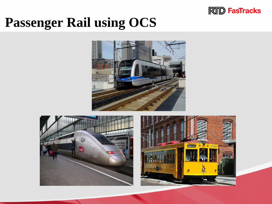
Passenger Rail using OCS

Other systems using OCS
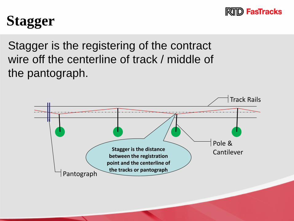
Stagger Stagger is the registering of the contract wire off the centerline of track / middle of the pantograph.
Track Rails
Pole & Cantilever Stagger is the distance
between the registration point and the centerline of the tracks or pantograph Pantograph
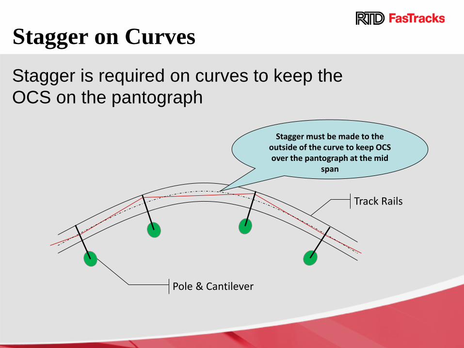
Stagger on Curves Stagger is required on curves to keep the OCS on the pantograph
Pole & Cantilever
Track Rails
Stagger must be made to the outside of the curve to keep OCS over the pantograph at the mid
span

Fixed Termination Catenary
Catenary sags as temperature rises.
Foundation
Pole
Catenary

Auto Tension Catenary Weights move up and down as wire expands or contracts due to temperature change.
Set of weights = to wire tension
Pole
Foundation
Catenary

Single Contact Wire
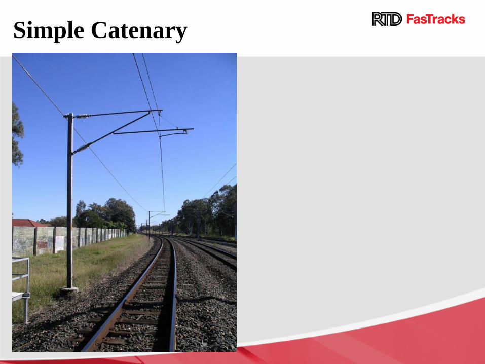
Simple Catenary

Wiring Aesthetics

Wiring Aesthetics

Wiring Aesthetics
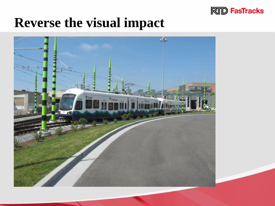
Reverse the visual impact

RTD Traction Power

Two Traction Power Modes
Light Rail 825V DC
Commuter Rail 25kV AC

Different Style TPSS
Light Rail – Prefab Substations
Commuter Rail – Outdoor Substations

LRT TPSS • Convert Utility power to 825V dc power for light
rail • TPSS are needed about every mile along light
rail alignment – there are close to 50 on system.
• Each TPSS is typically rated at 1.5 MegaWatts.
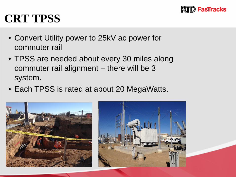
CRT TPSS • Convert Utility power to 25kV ac power for
commuter rail • TPSS are needed about every 30 miles along
commuter rail alignment – there will be 3 system.
• Each TPSS is rated at about 20 MegaWatts.

TPSS Site Installation

RTD Communications System

Major Components • Operation Control Center • Security Command Center • Supervisory Control and Data Acquisition • Communication Transmission System • Closed Circuit Television (CCTV) • Telephone System • Public Address System (PA) • Variable Message Sign System (VMS) • Radio System

Operation Control Center • Dispatcher Location for LRT or CRT • Provides Centralized Operation Monitoring and
Control

Security Command Center • Provide Centralized Security Monitoring • Dispatch Room with Monitors

Supervisory Control and Data Acquisition
Traction Power Substation
• Signal Aspect
• Train Location
• Train Identification (TWC)
• Switch Position and Control
• Switch Heaters
• Gate Position
CCS Console
SCADA System
• Elevator Access
• Emergency Telephone Activated
• Intrusion Detection
• Access Gates
Communication House/Station
Signal System
• Substation Breakers
• OCS disconnect switches

Communication Transmission System Public Address
(PA)
TVMs
CCTV
Phones SCADA
Variable Message Signs
(VMS)
Radio
Communications Transmission System
District Shops
Mariposa
or Fox
Elati

Closed Circuit Television System • Cameras at Platforms, Parking lots, and other RTD
facilities • All IP network based • Includes; Cameras, NVRs, Video Servers at SCC

Emergency Telephone System • Emergency Telephones (ETELs) • Typically on Platforms, Pedestrian Bridges and Plaza
Areas • One Button Auto Dials Security Command Center

Public Address System • Provides Audio Mainly Under Shelters • Both Local and Central Announcement Capabilities • Ad Hoc and Canned Messages

Variable Message Sign System • Provides Visual • Both Local and Central Announcement Capabilities • Ad Hoc, Canned, and Scheduled Announcements
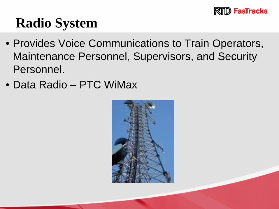
Radio System • Provides Voice Communications to Train Operators,
Maintenance Personnel, Supervisors, and Security Personnel.
• Data Radio – PTC WiMax

Communication System Challenges • High Visibility with Many Stakeholders • Integrating New System Into Existing (especially
software) • Continually Evolving Technology
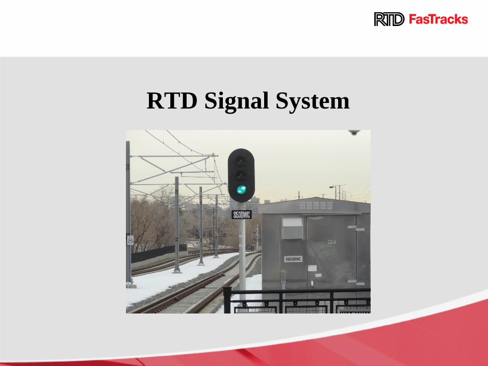
RTD Signal System

Common Signal System Equipment • Automatic Block Signaling (ABS) • Track Circuits (TC) • Signals • Switches & Interlockings • Operations Control Center (OCC) • Grade Crossing Warning System • Positive Train Control (PTC)

Automatic Block Signals
• Signals are installed at boundaries of “blocks” • Signal aspect control train movements. Green – proceed, Yellow –
prepare to stop, Red-stop. • Safe Braking Distance – basis of block design, dependant on
vertical and horizontal curves, civil constraints , and train speed. • Signal enforcement – “Automatic Trip Stops “ are installed to
automatically stop the train if it overruns a Red signal. • Grade Crossing warning system allow safe train operation through
street crossings in high speed. • Signal system is tied into the Operational Control Center
T1 R1
TC1
R2 R3 T2 T3
TC2 TC3

Track Circuit (TC)
• The boundary of a Track Circuit is defined by insulated joints • An insulated joint is a physical break in the rail that separates the rail
into electrical circuits • In Signal System the rails are used to function as two un-insulated
wires • From the signal house, the transformer(T) and relay(R) is
connected to each end of rail block. • The track circuit is described in its “Normal” state with no train in
circuit.
Track Circuit is installed in each rail “block” to monitor the train occupancy
R1 T1
TC

Switch Interlocking
• Track switches are installed at strategic locations to allow train to switch to other tracks.
• Switches, Signals, Track Circuits are all “interlocked” to provide safe routing.

Operations Control Center
• Signal systems are tied into the Operations Control Center to enable centralized control and monitor the whole transit system

Grade Crossings • Grade Crossings protect street traffic from
LRVs or CRVs. • Signal system sometimes is integrated with
local street traffic control.

Positive Train Control • Signal system for Eagle P3 requires
Positive Train Control (PTC) • Basic components of PTC
• OCC - Server • Train - gps, vehicle status… • Radio – communication equipment

RTD Rail Vehicle Technologies
Vehicles Why Two Types of Vehicles? • Light Rail Used on Initial RTD Corridors
and Some Extensions – Largely Dedicated Right-of-Ways – Older Agreements with Freight Railroads
• Commuter Rail Now Required by Denver’s Freight Railroads to Operate in or near Their Corridors – Must Meet Federal Railroad Administration
(FRA) Safety Standards

Rail Technology Comparison
Commuter Rail (EMU) Light Rail (LRV)
Powered by 25kV AC overhead electrical system
Powered by 750V DC by overhead electrical system
Typically serves longer lines with few stations
Has a lighter frame than a commuter train
Can operate up to 79mph Can operate along crowded, narrow streets
Larger interior with more seats Can accelerate and decelerate quickly

Light Rail
• 81.4 ft long, 8.7 ft wide, 12.4 ft tall • 6 Axles, Articulated Body, Two Cabs • Low Alloy High Tensile (LAHT) Steel Body, Painted • 64 seats, 120+ standees • 90,000 to 122,000 lbs • 82 ft Minimum Horizontal Curve • 3.0 mphps Maximum Acceleration • 3.0 / 6.2 mphps Maximum Braking
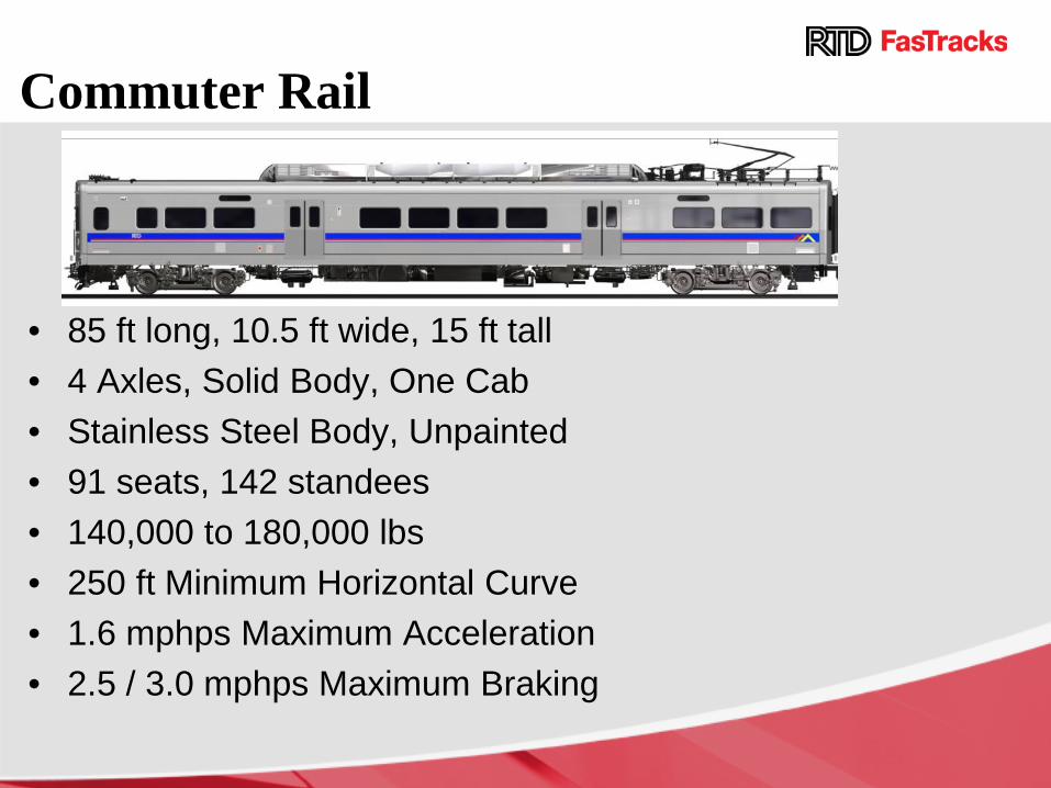
Commuter Rail
• 85 ft long, 10.5 ft wide, 15 ft tall • 4 Axles, Solid Body, One Cab • Stainless Steel Body, Unpainted • 91 seats, 142 standees • 140,000 to 180,000 lbs • 250 ft Minimum Horizontal Curve • 1.6 mphps Maximum Acceleration • 2.5 / 3.0 mphps Maximum Braking

Vehicle Differences Carbody Strength: • RTD LRV’s designed to resist about 250,000
pounds coupler-to-coupler crush force, generally European crash standards.
• RTD EMU’s designed to resist 800,000 pounds coupler-to-coupler crush force, must meet FRA and APTA strength standards.
Signaling: • RTD LRV’s automatic train stop (ATS). • RTD EMU’s will use positive train control
(PTC) with automatic train control (ATC) as a backup.
Questions?
Related Documents