Ma’aden Ma’aden Mine and Refinery Project Page 1 of 15 ENGINEERING AND DESIGN SYSTEMS TECHNICAL NOTE DATA Project Name MA’ADEN MINE AND REFINERY PROJECT Technical Note No. 201001-00168-JN-SPEL2 Technical Note Created By Rick Briggs Date 2012-02-06 Subject Ma'aden SmartPlant Electrical - Create Power Distribution Boards Rev Date Description Originator Checked A 2010-02-06 ISSUED FOR INTERNAL REVIEW RTB JKP TO DISCIPLINE Piping Electrical Process Equipment Instrumentation Civil Structural HVAC Design Systems Support Contents Introduction ............................................................................................................................................ 2 General for all Power Distribution Boards (PDB) .................................................................................... 2 Facility Workspace .............................................................................................................................. 2 Equipment Numbering........................................................................................................................ 2 Creating a Power Distribution Board (PDB) ........................................................................................ 3 Creating a Bus ..................................................................................................................................... 4 Creating Circuits (Incomer, Bus Coupler and Bus Riser) ..................................................................... 5 PDB Properties .................................................................................................................................... 7 Bus Properties ..................................................................................................................................... 9 Motor Control Centre & Switchboards ................................................................................................... 9 MCC & SB Typical Circuits ................................................................................................................... 9 Circuit Items (Incomer, Bus Tie etc.) for MCC’s & SB’s ..................................................................... 11 Distribution Board................................................................................................................................. 12 Distribution Board Typical Circuits.................................................................................................... 13 Distribution Board Properties ........................................................................................................... 15

Rtb spel job_note_2_-_pd_bs_-_a.pdf
Jul 17, 2015
Welcome message from author
This document is posted to help you gain knowledge. Please leave a comment to let me know what you think about it! Share it to your friends and learn new things together.
Transcript
Ma’aden
Ma’aden Mine and Refinery Project
Page 1 of 15
ENGINEERING AND DESIGN SYSTEMS TECHNICAL NOTE DATA
Project Name MA’ADEN MINE AND REFINERY PROJECT
Technical Note No. 201001-00168-JN-SPEL2
Technical Note Created By Rick Briggs Date 2012-02-06
Subject Ma'aden SmartPlant Electrical - Create Power Distribution Boards
Rev Date Description Originator Checked
A 2010-02-06 ISSUED FOR INTERNAL REVIEW RTB JKP
TO DISCIPLINE
Piping Electrical Process
Equipment Instrumentation Civil
Structural HVAC Design Systems Support
Contents
Introduction ............................................................................................................................................ 2
General for all Power Distribution Boards (PDB) .................................................................................... 2
Facility Workspace .............................................................................................................................. 2
Equipment Numbering ........................................................................................................................ 2
Creating a Power Distribution Board (PDB) ........................................................................................ 3
Creating a Bus ..................................................................................................................................... 4
Creating Circuits (Incomer, Bus Coupler and Bus Riser) ..................................................................... 5
PDB Properties .................................................................................................................................... 7
Bus Properties ..................................................................................................................................... 9
Motor Control Centre & Switchboards ................................................................................................... 9
MCC & SB Typical Circuits ................................................................................................................... 9
Circuit Items (Incomer, Bus Tie etc.) for MCC’s & SB’s ..................................................................... 11
Distribution Board ................................................................................................................................. 12
Distribution Board Typical Circuits .................................................................................................... 13
Distribution Board Properties ........................................................................................................... 15
Ma’aden
Ma’aden Mine and Refinery Project
Page 2 of 15
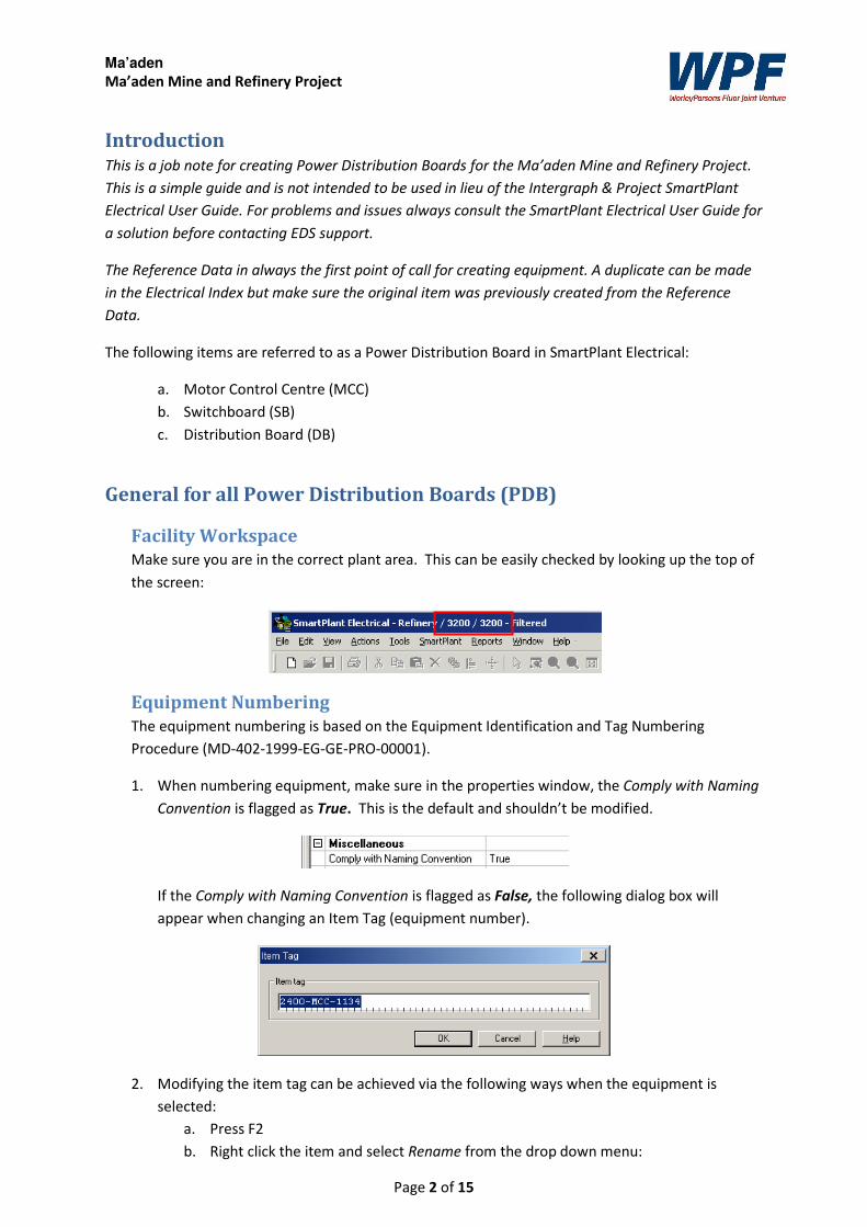
Introduction This is a job note for creating Power Distribution Boards for the Ma’aden Mine and Refinery Project.
This is a simple guide and is not intended to be used in lieu of the Intergraph & Project SmartPlant
Electrical User Guide. For problems and issues always consult the SmartPlant Electrical User Guide for
a solution before contacting EDS support.
The Reference Data in always the first point of call for creating equipment. A duplicate can be made
in the Electrical Index but make sure the original item was previously created from the Reference
Data.
The following items are referred to as a Power Distribution Board in SmartPlant Electrical:
a. Motor Control Centre (MCC)
b. Switchboard (SB)
c. Distribution Board (DB)
General for all Power Distribution Boards (PDB)
Facility Workspace
Make sure you are in the correct plant area. This can be easily checked by looking up the top of
the screen:
Equipment Numbering
The equipment numbering is based on the Equipment Identification and Tag Numbering
Procedure (MD-402-1999-EG-GE-PRO-00001).
1. When numbering equipment, make sure in the properties window, the Comply with Naming
Convention is flagged as True. This is the default and shouldn’t be modified.
If the Comply with Naming Convention is flagged as False, the following dialog box will
appear when changing an Item Tag (equipment number).
2. Modifying the item tag can be achieved via the following ways when the equipment is
selected:
a. Press F2
b. Right click the item and select Rename from the drop down menu:
Ma’aden
Ma’aden Mine and Refinery Project
Page 3 of 15
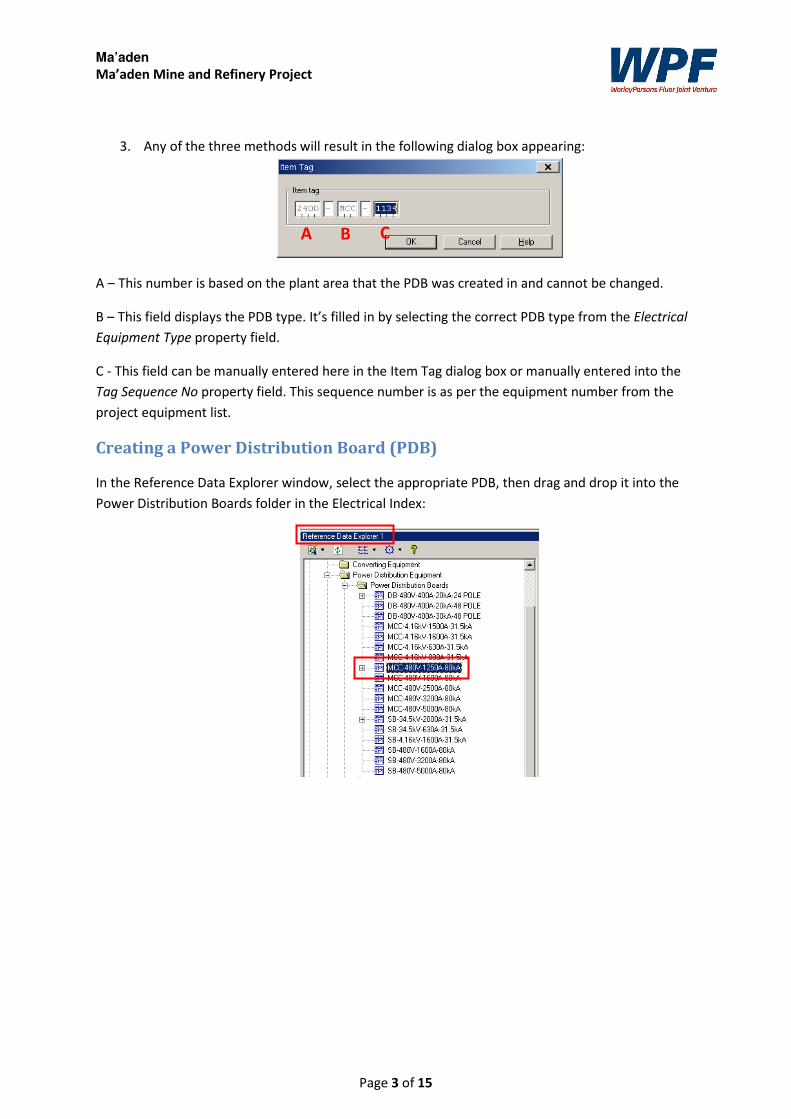
3. Any of the three methods will result in the following dialog box appearing:
A – This number is based on the plant area that the PDB was created in and cannot be changed.
B – This field displays the PDB type. It’s filled in by selecting the correct PDB type from the Electrical
Equipment Type property field.
C - This field can be manually entered here in the Item Tag dialog box or manually entered into the
Tag Sequence No property field. This sequence number is as per the equipment number from the
project equipment list.
Creating a Power Distribution Board (PDB)
In the Reference Data Explorer window, select the appropriate PDB, then drag and drop it into the
Power Distribution Boards folder in the Electrical Index:
A B C
Ma’aden
Ma’aden Mine and Refinery Project
Page 4 of 15
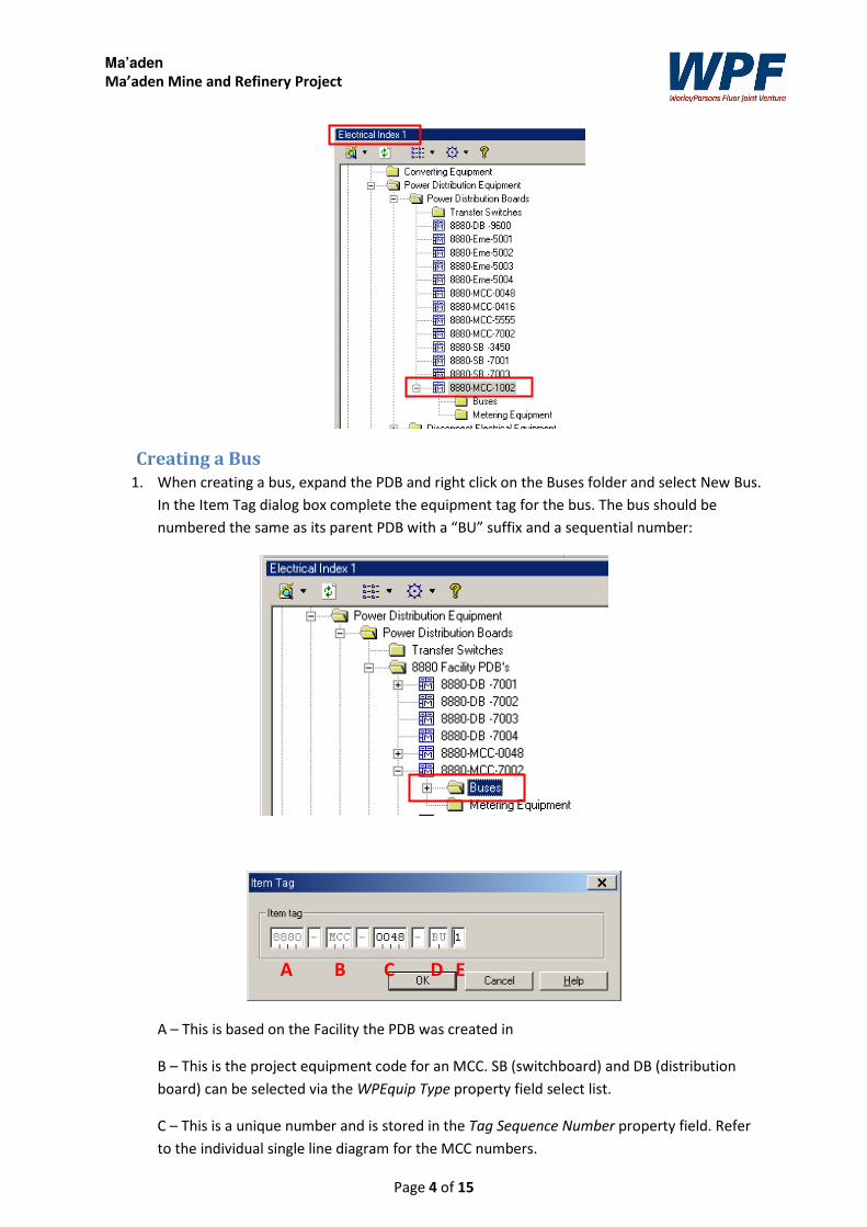
Creating a Bus
1. When creating a bus, expand the PDB and right click on the Buses folder and select New Bus.
In the Item Tag dialog box complete the equipment tag for the bus. The bus should be
numbered the same as its parent PDB with a “BU” suffix and a sequential number:
A – This is based on the Facility the PDB was created in
B – This is the project equipment code for an MCC. SB (switchboard) and DB (distribution
board) can be selected via the WPEquip Type property field select list.
C – This is a unique number and is stored in the Tag Sequence Number property field. Refer
to the individual single line diagram for the MCC numbers.
A B D C E
Ma’aden
Ma’aden Mine and Refinery Project
Page 5 of 15
D – “BU” is the suffix applied to a bus bar and cannot be changed.
E – This is the sequential number given to each bus bar in a PDB, and is stored in the Tag
Suffix property.
2. Create as many buses as is required for each PDB. Motor Control Centres and Switch Boards
will typically have 2 Buses with 1 Incomer per Bus and Distribution Boards will typically have
1 Bus with 2 incomers.
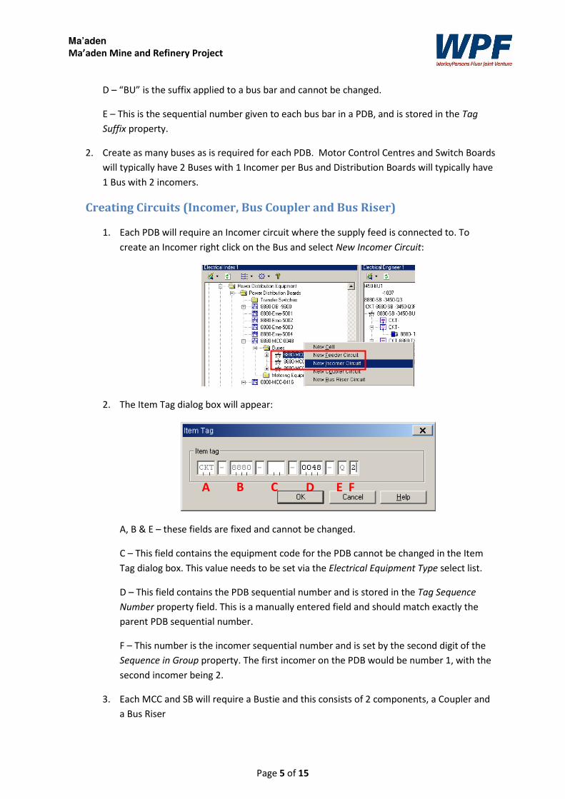
Creating Circuits (Incomer, Bus Coupler and Bus Riser)
1. Each PDB will require an Incomer circuit where the supply feed is connected to. To
create an Incomer right click on the Bus and select New Incomer Circuit:
2. The Item Tag dialog box will appear:
A, B & E – these fields are fixed and cannot be changed.
C – This field contains the equipment code for the PDB cannot be changed in the Item
Tag dialog box. This value needs to be set via the Electrical Equipment Type select list.
D – This field contains the PDB sequential number and is stored in the Tag Sequence
Number property field. This is a manually entered field and should match exactly the
parent PDB sequential number.
F – This number is the incomer sequential number and is set by the second digit of the
Sequence in Group property. The first incomer on the PDB would be number 1, with the
second incomer being 2.
3. Each MCC and SB will require a Bustie and this consists of 2 components, a Coupler and
a Bus Riser
A B C D E F
Ma’aden
Ma’aden Mine and Refinery Project
Page 6 of 15
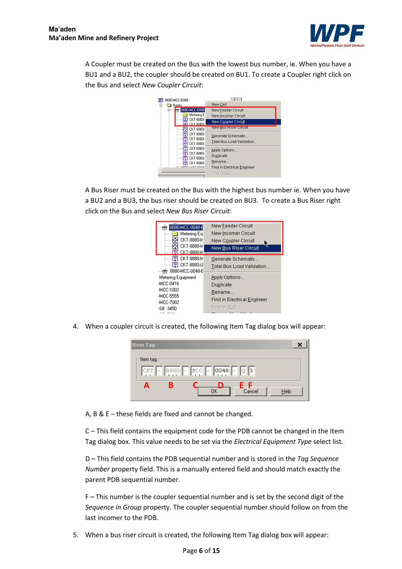
A Coupler must be created on the Bus with the lowest bus number, ie. When you have a
BU1 and a BU2, the coupler should be created on BU1. To create a Coupler right click on
the Bus and select New Coupler Circuit:
A Bus Riser must be created on the Bus with the highest bus number ie. When you have
a BU2 and a BU3, the bus riser should be created on BU3. To create a Bus Riser right
click on the Bus and select New Bus Riser Circuit:
4. When a coupler circuit is created, the following Item Tag dialog box will appear:
A, B & E – these fields are fixed and cannot be changed.
C – This field contains the equipment code for the PDB cannot be changed in the Item
Tag dialog box. This value needs to be set via the Electrical Equipment Type select list.
D – This field contains the PDB sequential number and is stored in the Tag Sequence
Number property field. This is a manually entered field and should match exactly the
parent PDB sequential number.
F – This number is the coupler sequential number and is set by the second digit of the
Sequence in Group property. The coupler sequential number should follow on from the
last incomer to the PDB.
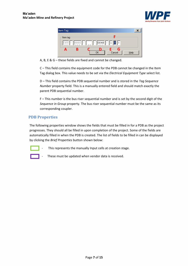
5. When a bus riser circuit is created, the following Item Tag dialog box will appear:
A B C D E F
Ma’aden
Ma’aden Mine and Refinery Project
Page 7 of 15
A, B, E & G – these fields are fixed and cannot be changed.
C – This field contains the equipment code for the PDB cannot be changed in the Item
Tag dialog box. This value needs to be set via the Electrical Equipment Type select list.
D – This field contains the PDB sequential number and is stored in the Tag Sequence
Number property field. This is a manually entered field and should match exactly the
parent PDB sequential number.
F – This number is the bus riser sequential number and is set by the second digit of the
Sequence in Group property. The bus riser sequential number must be the same as its
corresponding coupler.
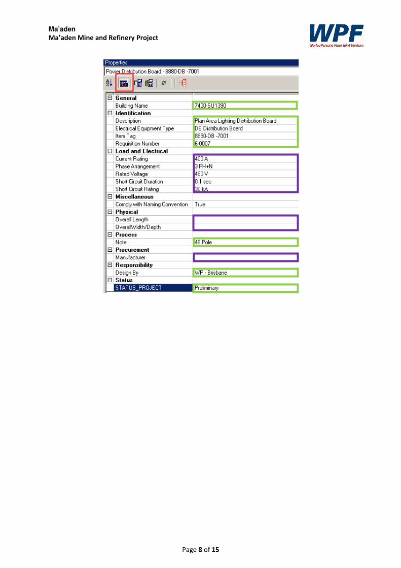
PDB Properties
The following properties window shows the fields that must be filled in for a PDB as the project
progresses. They should all be filled in upon completion of the project. Some of the fields are
automatically filled in when the PDB is created. The list of fields to be filled in can be displayed
by clicking the Brief Properties button shown below:
- This represents the manually Input cells at creation stage.
- These must be updated when vendor data is received.
A B C D E
F
G
Ma’aden
Ma’aden Mine and Refinery Project
Page 8 of 15
Ma’aden
Ma’aden Mine and Refinery Project
Page 9 of 15
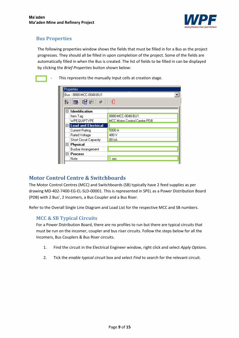
Bus Properties
The following properties window shows the fields that must be filled in for a Bus as the project
progresses. They should all be filled in upon completion of the project. Some of the fields are
automatically filled in when the Bus is created. The list of fields to be filled in can be displayed
by clicking the Brief Properties button shown below:
- This represents the manually Input cells at creation stage.
Motor Control Centre & Switchboards The Motor Control Centres (MCC) and Switchboards (SB) typically have 2 feed supplies as per
drawing MD-402-7400-EG-EL-SLD-00001. This is represented in SPEL as a Power Distribution Board
(PDB) with 2 Bus’, 2 Incomers, a Bus Coupler and a Bus Riser.
Refer to the Overall Single Line Diagram and Load List for the respective MCC and SB numbers.
MCC & SB Typical Circuits
For a Power Distribution Board, there are no profiles to run but there are typical circuits that
must be run on the incomer, coupler and bus riser circuits. Follow the steps below for all the
Incomers, Bus Couplers & Bus Riser circuits.
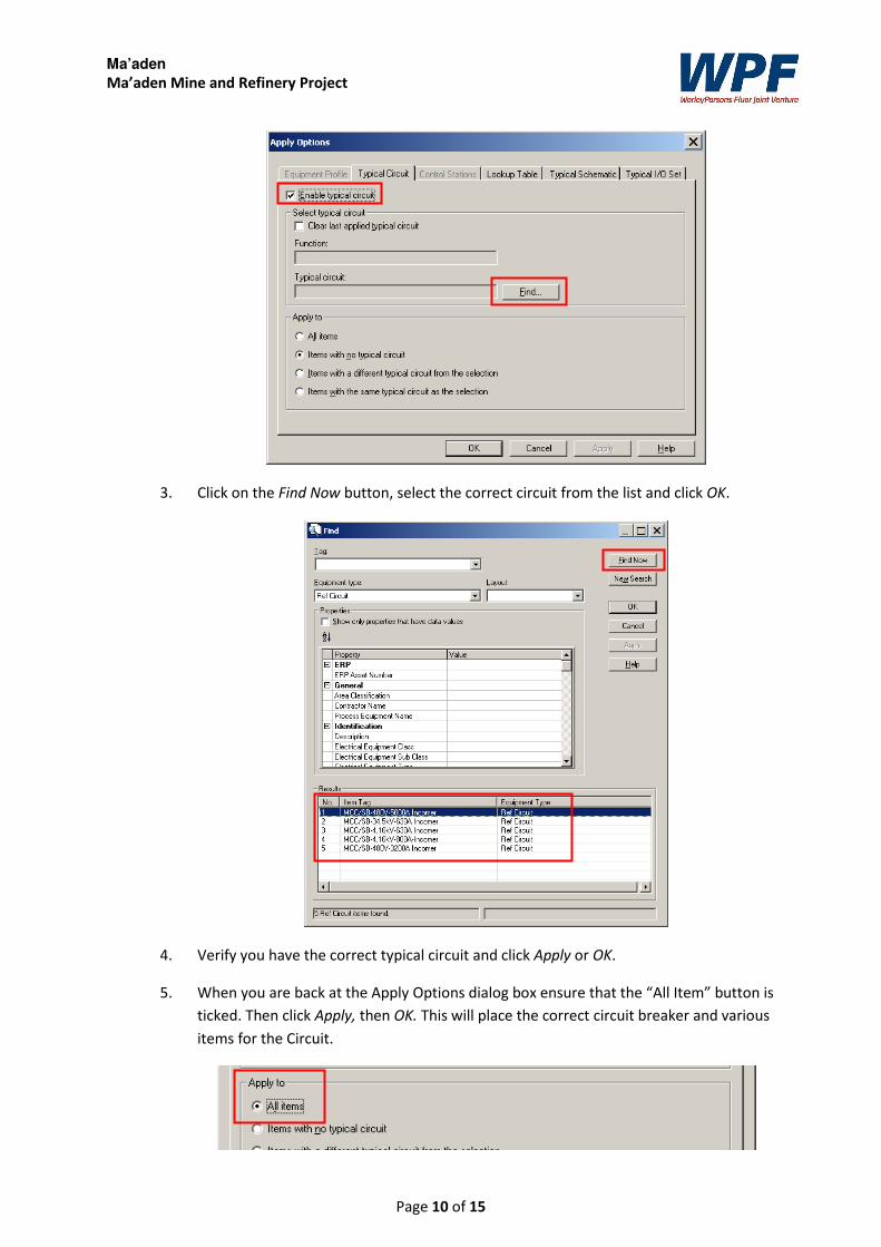
1. Find the circuit in the Electrical Engineer window, right click and select Apply Options.
2. Tick the enable typical circuit box and select Find to search for the relevant circuit.
Ma’aden
Ma’aden Mine and Refinery Project
Page 10 of 15
3. Click on the Find Now button, select the correct circuit from the list and click OK.
4. Verify you have the correct typical circuit and click Apply or OK.
5. When you are back at the Apply Options dialog box ensure that the “All Item” button is
ticked. Then click Apply, then OK. This will place the correct circuit breaker and various
items for the Circuit.
Ma’aden
Ma’aden Mine and Refinery Project
Page 11 of 15
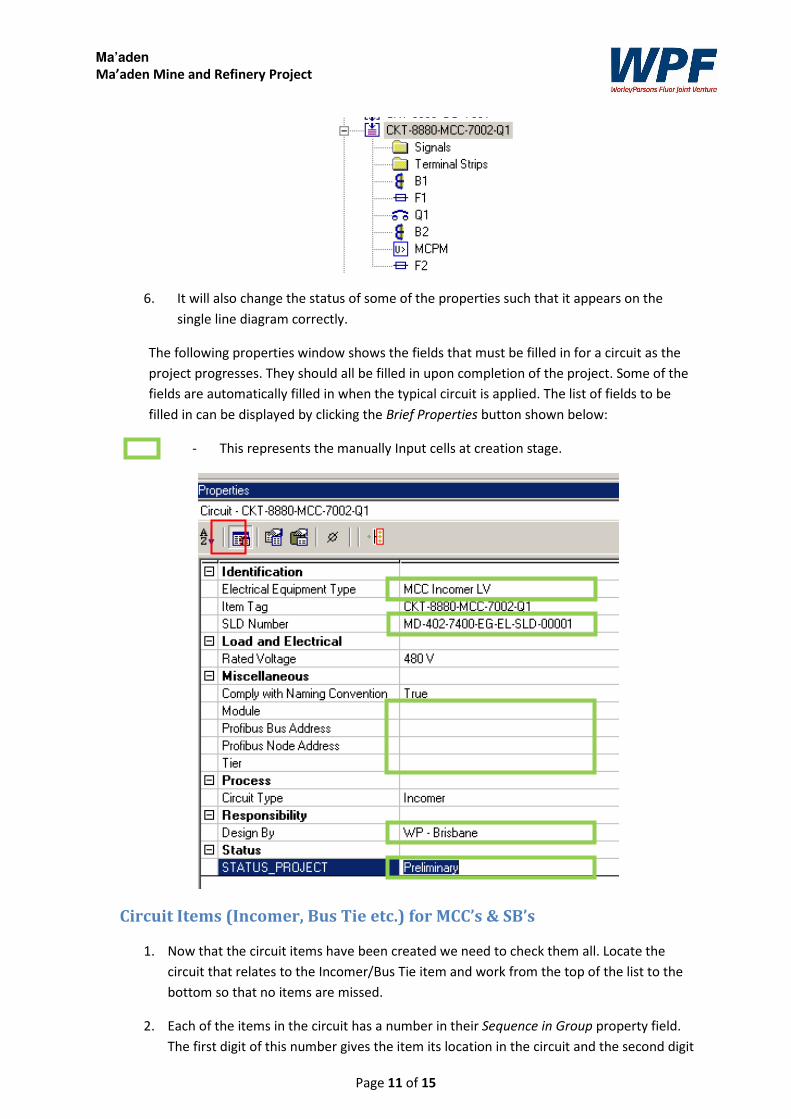
6. It will also change the status of some of the properties such that it appears on the
single line diagram correctly.
The following properties window shows the fields that must be filled in for a circuit as the
project progresses. They should all be filled in upon completion of the project. Some of the
fields are automatically filled in when the typical circuit is applied. The list of fields to be
filled in can be displayed by clicking the Brief Properties button shown below:
- This represents the manually Input cells at creation stage.
Circuit Items (Incomer, Bus Tie etc.) for MCC’s & SB’s
1. Now that the circuit items have been created we need to check them all. Locate the
circuit that relates to the Incomer/Bus Tie item and work from the top of the list to the
bottom so that no items are missed.
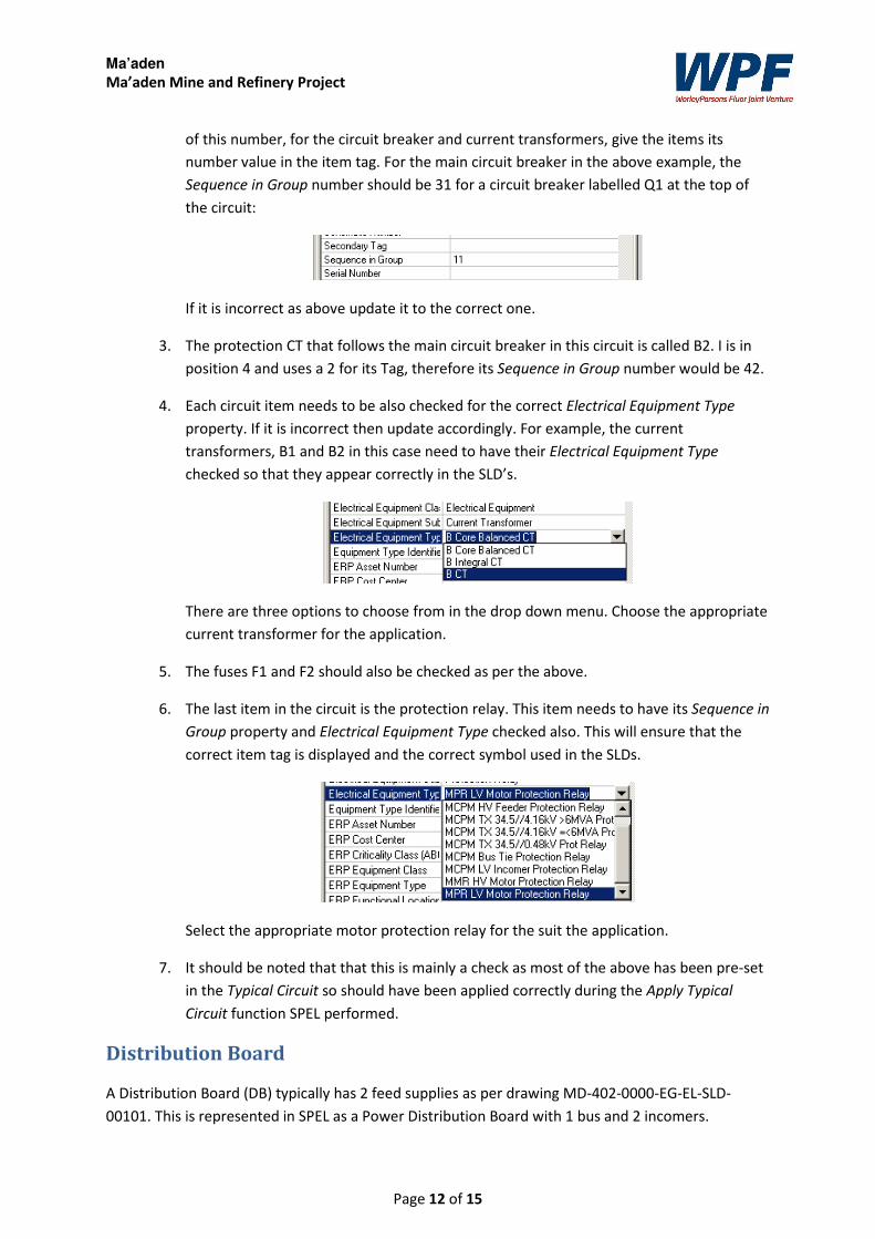
2. Each of the items in the circuit has a number in their Sequence in Group property field.
The first digit of this number gives the item its location in the circuit and the second digit
Ma’aden
Ma’aden Mine and Refinery Project
Page 12 of 15
of this number, for the circuit breaker and current transformers, give the items its
number value in the item tag. For the main circuit breaker in the above example, the
Sequence in Group number should be 31 for a circuit breaker labelled Q1 at the top of
the circuit:
If it is incorrect as above update it to the correct one.
3. The protection CT that follows the main circuit breaker in this circuit is called B2. I is in
position 4 and uses a 2 for its Tag, therefore its Sequence in Group number would be 42.
4. Each circuit item needs to be also checked for the correct Electrical Equipment Type
property. If it is incorrect then update accordingly. For example, the current
transformers, B1 and B2 in this case need to have their Electrical Equipment Type
checked so that they appear correctly in the SLD’s.
There are three options to choose from in the drop down menu. Choose the appropriate
current transformer for the application.
5. The fuses F1 and F2 should also be checked as per the above.
6. The last item in the circuit is the protection relay. This item needs to have its Sequence in
Group property and Electrical Equipment Type checked also. This will ensure that the
correct item tag is displayed and the correct symbol used in the SLDs.
Select the appropriate motor protection relay for the suit the application.
7. It should be noted that that this is mainly a check as most of the above has been pre-set
in the Typical Circuit so should have been applied correctly during the Apply Typical
Circuit function SPEL performed.
Distribution Board
A Distribution Board (DB) typically has 2 feed supplies as per drawing MD-402-0000-EG-EL-SLD-
00101. This is represented in SPEL as a Power Distribution Board with 1 bus and 2 incomers.
Ma’aden
Ma’aden Mine and Refinery Project
Page 13 of 15
Note: All Distribution Boards in the plant, regardless of whether they have cables connected to them
in SPEL or not, need to be created in SPEL with their correct equipment numbers.
Refer to the individual substation DB system single line diagrams for the respective equipment
numbers.
Distribution Board Typical Circuits
For a distribution board, a typical circuit should be applied to the DB feeder originating at the
MCC. There are no profiles for the actual distribution board. Typical circuits need to be applied
to the individual feeder circuits:
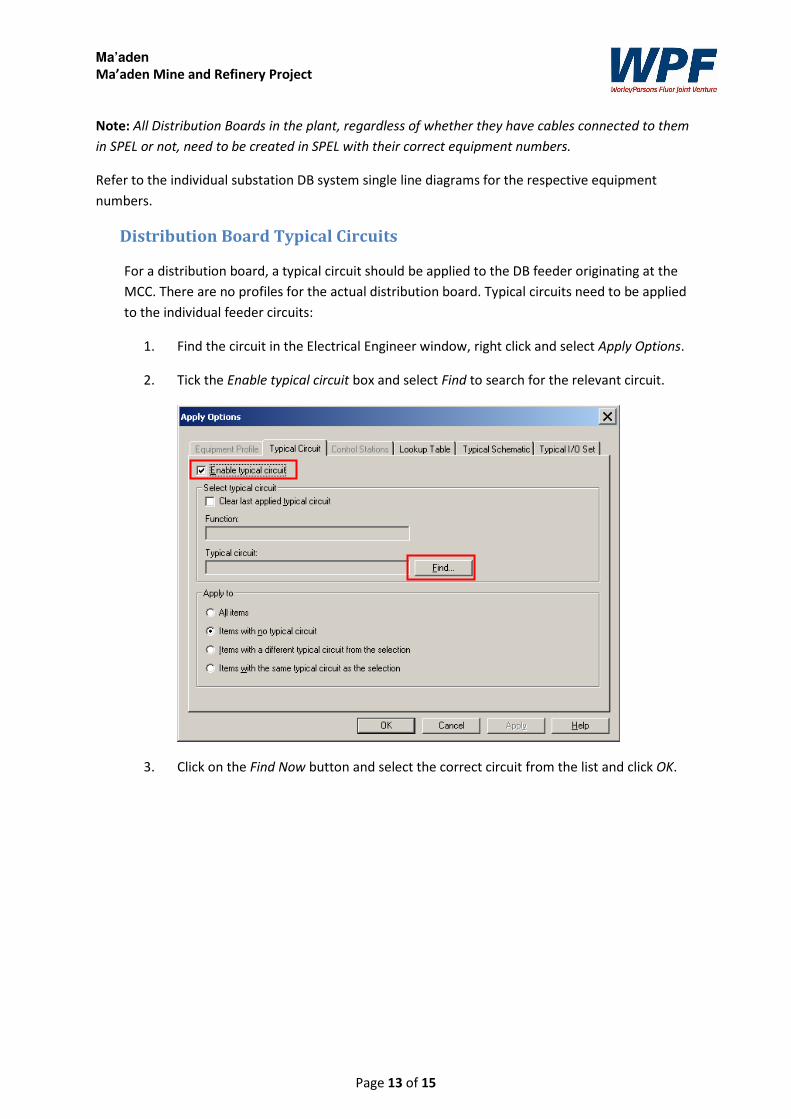
1. Find the circuit in the Electrical Engineer window, right click and select Apply Options.
2. Tick the Enable typical circuit box and select Find to search for the relevant circuit.
3. Click on the Find Now button and select the correct circuit from the list and click OK.
Ma’aden
Ma’aden Mine and Refinery Project
Page 14 of 15
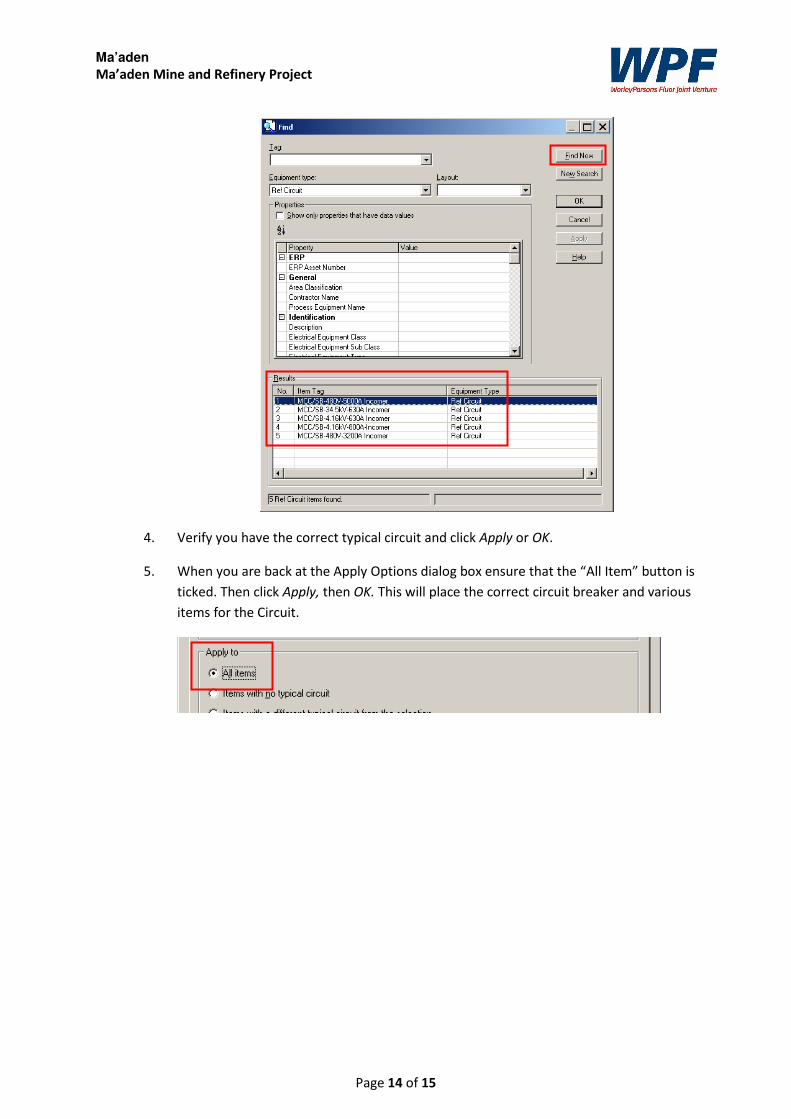
4. Verify you have the correct typical circuit and click Apply or OK.
5. When you are back at the Apply Options dialog box ensure that the “All Item” button is
ticked. Then click Apply, then OK. This will place the correct circuit breaker and various
items for the Circuit.
Ma’aden
Ma’aden Mine and Refinery Project
Page 15 of 15
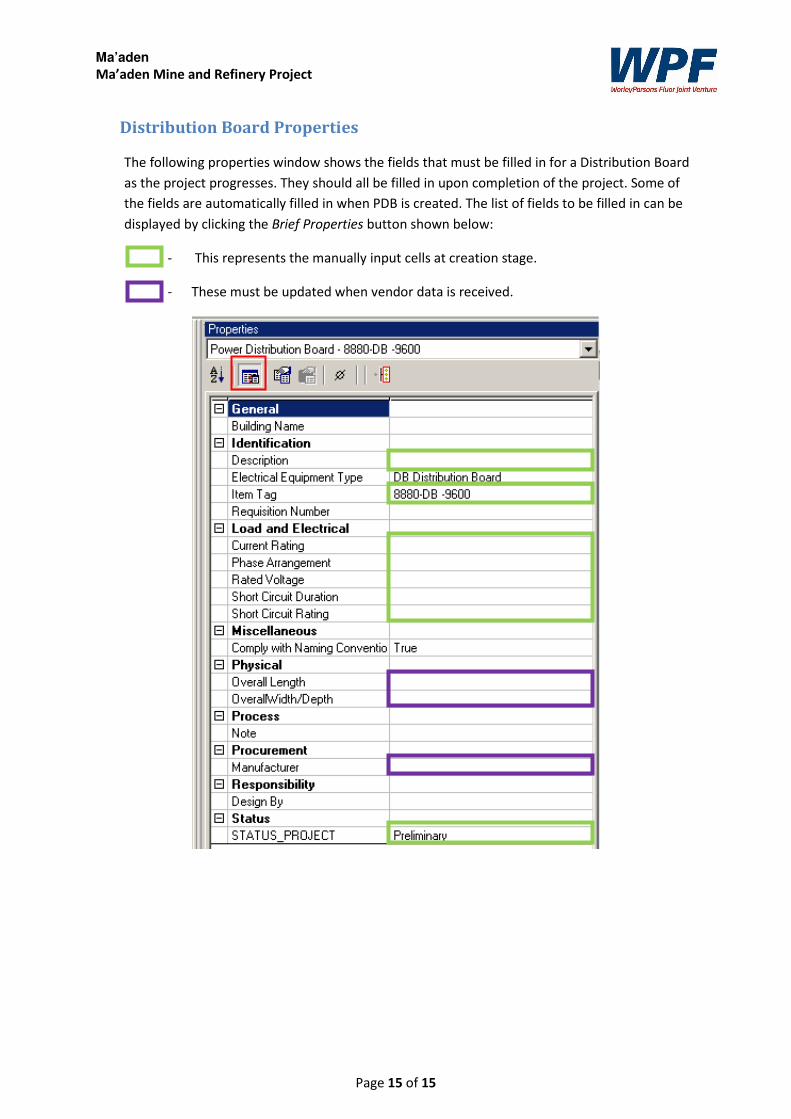
Distribution Board Properties
The following properties window shows the fields that must be filled in for a Distribution Board
as the project progresses. They should all be filled in upon completion of the project. Some of
the fields are automatically filled in when PDB is created. The list of fields to be filled in can be
displayed by clicking the Brief Properties button shown below:
- This represents the manually input cells at creation stage.
- These must be updated when vendor data is received.
Related Documents