IEEE/ASME Transactions on Mechatronics 1 Feifei Bu, Senior Member, IEEE, Fuqiang Xuan, Zhida Yang, Yu Gao, Zihao Pan, Michele Degano, Member, IEEE, and Chris Gerada, Senior Member, IEEE Abstract—In this paper, a rotor position tracking control (RPTC) strategy is proposed to effectively reduce the speed fluctuation for a direct-drive permanent magnet synchronous motor (DD-PMSM) servo system operating at low speed with different torque disturbances. In this strategy, considering the derivative relationship between the rotor position and speed, a speed command is converted to a real-time rotor position trajectory, and then a position-current two-loop control with the RPTC controller is proposed based on the internal model method to smoothly track the rotor position. In addition, the parameter design of RPTC controller from the perspectives of robust stability and anti-disturbance capability is investigated as well. Comparative simulation and experimental results demonstrate that, at low speed, the proposed RPTC strategy has a good speed performance for both periodic and non-periodic torque disturbances. Moreover, it enjoys simple implementation for not requiring the precise speed feedback and specific torque disturbance information. Index Terms—direct-drive servo system, PMSM, RPTC, low speed, torque disturbance. I.INTRODUCTION ifferent from the traditional low speed drive system, the direct drive permanent magnet synchronous motor (DD-PMSM) system eliminates gear transmission mechanisms such as reducers, and adopts a low-speed high-torque motor to directly drive loads [1]. It has a series of advantages such as compact structure, high accuracy, high efficiency, fast dynamic response, high reliability, low noise, and so on [2]. So it is widely used in high-performance servo equipments for industry, aerospace, etc. [3], [4]. However, for low speed or even ultra-low speed operations, the motor is usually subject to torque disturbances from the system itself (such as cogging torque, harmonic torque) and outside loads (such as load torque, friction torque) [5]. And because there is no transmission or reduction mechanism, these disturbances would directly act on loads, and load disturbances would also be directly transmitted to the motor shaft, which seriously affects the speed stability and performance, especially at low speed [2]. A conventional speed control strategy of the PMSM servo system can be briefly divided into three parts: a speed outer loop, a current inner loop and a pulse width modulation module. Among them, the speed outer-loop controller is usually based on a proportional-integral (PI) regulator which is simple and reliable, but in some high-performance applications, its disturbance rejection performance is not satisfactory [6]. Therefore, various methods are proposed to reject torque disturbances. For periodic disturbances, such as cogging torque, flux harmonics, current measurement errors and phase unbalancing, [7]-[9] respectively explore the proportional resonance control, repetitive control, and iterative learning control to improve speed performance. In general, the lower the speed is, the larger the speed fluctuation caused by periodic disturbances would arise. Unfortunately, to overcome this problem, the above methods usually need to know the specific information of disturbances [10]-[12]. For non-periodic disturbances, such as step-change loads and random disturbances, some scholars also propose several approaches. In [13]-[16], different disturbance observers, including the reduced-order observer, extended state observer, sliding-mode disturbance observer, and so on, are studied for direct compensation to reject non-periodic disturbances. However, the accuracy of observers is usually affected by the decrease of speed and inaccurate models, which reduces the compensation effect [17]-[19], and may increase the control complexity. Generally, for the traditional control strategy with a speed outer loop, the accurate speed feedback is a basic requirement. For common speed or high speed, the speed information is usually easy to be acquired and its accuracy can be guaranteed. But, at low speed or even ultra-low speed, even if the error of position measurement is very small, it would cause large error in speed information due to the derivative operation in speed calculation [20]-[22], which usually cannot be neglected. Thus, if such an inaccurate speed signal is used as the feedback, not only the speed stability would be affected, but also the capability of disturbance rejection would be weakened. Based on the above analysis, in order to effectively improve the low speed performance of DD-PMSM servo system under different torque disturbances, this paper proposes a novel strategy that realizes the speed control through the position control, namely the rotor position tracking control (RPTC) strategy. In this strategy, based on the derivative relationship between the rotor speed and position, the speed control is converted to the position control. And with the help of internal model method, a position-current two-loop control is employed, and the RPTC controller is proposed, so as to guarantee the Rotor Position Tracking Control for Low Speed Operation of Direct-Drive PMSM Servo System D This work was supported in part by the National Natural Science Foundation of China under Grant 51507079, in part by the China Postdoctoral Science Foundation Funded Project under Grant 2016T90454, and in part by the Fundamental Research Funds for the Central Universities of China under Grant NS2018025. (Corresponding author: Feifei Bu.) F. Bu, F. Xuan, Z. Yang, Y. Gao, and Z. Pan are with the Center for More-Electric-Aircraft Power System, Nanjing University of Aeronautics and Astronautics, Nanjing 211106, China (e-mail: [email protected]; [email protected]; [email protected]; [email protected]; [email protected]). M. Degano and C. Gerada are with the Power Electronics, Machines and Control Group, University of Nottingham, Nottingham NG72RD, U.K. (e-mail:[email protected];[email protected]). This is the author's version of an article that has been published in this journal. Changes were made to this version by the publisher prior to publication. The final version of record is available at http://dx.doi.org/10.1109/TMECH.2020.3019039 Copyright (c) 2020 IEEE. Personal use is permitted. For any other purposes, permission must be obtained from the IEEE by emailing [email protected].

Welcome message from author
This document is posted to help you gain knowledge. Please leave a comment to let me know what you think about it! Share it to your friends and learn new things together.
Transcript
IEEE/ASME Transactions on Mechatronics 1
Feifei Bu, Senior Member, IEEE, Fuqiang Xuan, Zhida Yang, Yu Gao, Zihao Pan, Michele Degano, Member, IEEE, and Chris Gerada, Senior Member, IEEE
Abstract—In this paper, a rotor position tracking control (RPTC) strategy is proposed to effectively reduce the speed fluctuation for a direct-drive permanent magnet synchronous motor (DD-PMSM) servo system operating at low speed with different torque disturbances. In this strategy, considering the derivative relationship between the rotor position and speed, a speed command is converted to a real-time rotor position trajectory, and then a position-current two-loop control with the RPTC controller is proposed based on the internal model method to smoothly track the rotor position. In addition, the parameter design of RPTC controller from the perspectives of robust stability and anti-disturbance capability is investigated as well. Comparative simulation and experimental results demonstrate that, at low speed, the proposed RPTC strategy has a good speed performance for both periodic and non-periodic torque disturbances. Moreover, it enjoys simple implementation for not requiring the precise speed feedback and specific torque disturbance information.
Index Terms—direct-drive servo system, PMSM, RPTC, low speed, torque disturbance.
I.INTRODUCTION
ifferent from the traditional low speed drive system, the direct drive permanent magnet synchronous motor
(DD-PMSM) system eliminates gear transmission mechanisms such as reducers, and adopts a low-speed high-torque motor to directly drive loads [1]. It has a series of advantages such as compact structure, high accuracy, high efficiency, fast dynamic response, high reliability, low noise, and so on [2]. So it is widely used in high-performance servo equipments for industry, aerospace, etc. [3], [4]. However, for low speed or even ultra-low speed operations, the motor is usually subject to torque disturbances from the system itself (such as cogging torque, harmonic torque) and outside loads (such as load torque, friction torque) [5]. And
because there is no transmission or reduction mechanism, these disturbances would directly act on loads, and load disturbances would also be directly transmitted to the motor shaft, which seriously affects the speed stability and performance, especially at low speed [2].
A conventional speed control strategy of the PMSM servo system can be briefly divided into three parts: a speed outer loop, a current inner loop and a pulse width modulation module. Among them, the speed outer-loop controller is usually based on a proportional-integral (PI) regulator which is simple and reliable, but in some high-performance applications, its disturbance rejection performance is not satisfactory [6]. Therefore, various methods are proposed to reject torque disturbances. For periodic disturbances, such as cogging torque, flux harmonics, current measurement errors and phase unbalancing, [7]-[9] respectively explore the proportional resonance control, repetitive control, and iterative learning control to improve speed performance. In general, the lower the speed is, the larger the speed fluctuation caused by periodic disturbances would arise. Unfortunately, to overcome this problem, the above methods usually need to know the specific information of disturbances [10]-[12]. For non-periodic disturbances, such as step-change loads and random disturbances, some scholars also propose several approaches. In [13]-[16], different disturbance observers, including the reduced-order observer, extended state observer, sliding-mode disturbance observer, and so on, are studied for direct compensation to reject non-periodic disturbances. However, the accuracy of observers is usually affected by the decrease of speed and inaccurate models, which reduces the compensation effect [17]-[19], and may increase the control complexity.
Generally, for the traditional control strategy with a speed outer loop, the accurate speed feedback is a basic requirement. For common speed or high speed, the speed information is usually easy to be acquired and its accuracy can be guaranteed. But, at low speed or even ultra-low speed, even if the error of position measurement is very small, it would cause large error in speed information due to the derivative operation in speed calculation [20]-[22], which usually cannot be neglected. Thus, if such an inaccurate speed signal is used as the feedback, not only the speed stability would be affected, but also the capability of disturbance rejection would be weakened.
Based on the above analysis, in order to effectively improve the low speed performance of DD-PMSM servo system under different torque disturbances, this paper proposes a novel strategy that realizes the speed control through the position control, namely the rotor position tracking control (RPTC) strategy. In this strategy, based on the derivative relationship between the rotor speed and position, the speed control is converted to the position control. And with the help of internal model method, a position-current two-loop control is employed, and the RPTC controller is proposed, so as to guarantee the
Rotor Position Tracking Control for Low Speed Operation of Direct-Drive PMSM Servo System
D
This work was supported in part by the National Natural Science Foundation of China under Grant 51507079, in part by the China Postdoctoral Science Foundation Funded Project under Grant 2016T90454, and in part by the Fundamental Research Funds for the Central Universities of China under Grant NS2018025. (Corresponding author: Feifei Bu.)
F. Bu, F. Xuan, Z. Yang, Y. Gao, and Z. Pan are with the Center for More-Electric-Aircraft Power System, Nanjing University of Aeronautics and Astronautics, Nanjing 211106, China (e-mail: [email protected]; [email protected]; [email protected]; [email protected]; [email protected]).
M. Degano and C. Gerada are with the Power Electronics, Machines and Control Group, University of Nottingham, Nottingham NG72RD, U.K. (e-mail:[email protected];[email protected]).
This is the author's version of an article that has been published in this journal. Changes were made to this version by the publisher prior to publication.The final version of record is available at http://dx.doi.org/10.1109/TMECH.2020.3019039
Copyright (c) 2020 IEEE. Personal use is permitted. For any other purposes, permission must be obtained from the IEEE by emailing [email protected].
IEEE/ASME Transactions on Mechatronics 2
continuous rotor position trajectory tracked smoothly. Using this strategy, for the DD-PMSM servo system operating at low speed, periodic and non-periodic torque disturbances can be effectively suppressed, and a good speed performance can be obtained as well. In addition, it has the advantage of simple implementation because the precise speed feedback and specific torque disturbance information are not required.
The rest of this paper is organized as follows. In Section II, the traditional PI-based speed control is analyzed. Section III presents the proposed RPTC strategy. And the design of RPTC controller is studied in Section IV. Section V and Section VI give the simulation and experiments, respectively. Finally, conclusions are drawn in Section VII.
II.ANALYSIS OF TRADITIONAL PI-BASED SPEED CONTROL
A. PMSM Model
The model of a PMSM in the synchronous d-q rotating frame is given as follows [9]:
dd s d d n q q
q
q s q q n d d n f
e L a
diu R i L p L i
dtdi
u R i L p L i pdt
dJ T T B
dt
(1)
where, ω is the rotor mechanical angular speed; ud, uq are the d-axis and q-axis stator voltages, respectively; id, iq are the d-axis and q-axis stator currents, respectively; Ld, Lq, Rs, pn, ψf are the d-axis inductance, q-axis inductance, resistance, pole pairs, magnet flux linkage, respectively; Te, TL, J and Ba are the electromagnetic torque, load torque, inertia and viscous coefficient, respectively.
B. Limitations of the Traditional PI-Based Speed Control
(1) Contradiction between the tracing and anti-disturbance
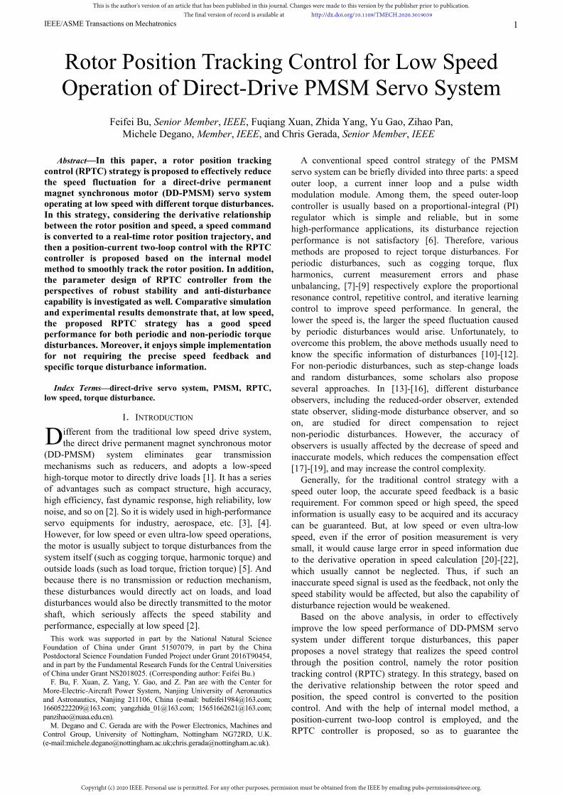
Fig. 1 shows the conventional speed control block diagram with a PI regulator based on (1), where the load torque is regarded as the disturbance torque Td; τi is the inverse of current loop bandwidth; KT is the torque constant, KT=1.5pnψf; kp and ki are the proportional and integral coefficients, respectively.
p ik s k
s
11is
1
aJs B
*qi
Fig. 1. Traditional PI-based speed control block diagram.
[23] and [24] explain the contradiction between the tracing and anti-disturbance for the speed control shown in Fig. 1. As ki/kp increases, the speed tracing performance would be improved, but the anti-disturbance performance would contrarily show a deterioration trend. In other words, the traditional PI-based speed control has a limitation: It is hard to obtain a good speed tracing and anti-disturbance performance at the same time. This is an unfavorable factor for high-performance speed control, especially at low speed.
(2) Error in the speed acquisition at low speed
In general, the position error is small because of high acquisition accuracy. However, because the speed is
obtained by the position derivative, it can be known from (2) that this error would be amplified by nearly 1/Tc times in speed acquisition [20], [22]. It means that the error would be up to 2000 times if the speed loop control frequency is 2kHz.
err errerr
c
d
dt T
(2)
where, ωerr, θerr are the speed error and position error,
respectively; Tc is the speed loop control period. In other words, due to the derivative calculation process,
the above-mentioned large error in speed acquisition is difficult to be avoided. At common speed or high speed, this kind of error has little influence because it accounts for a small proportion of speed itself. However, it cannot be ignored at low speed, thus requiring much more attention then. If such an inaccurate speed signal is used as the outer loop feedback at low speed, the speed stability wouldn’t be guaranteed, let alone the anti-disturbance performance.
III.PROPOSED ROTOR POSITION TRACKING CONTROL
A. Basic Idea and Structure of the RPTC Strategy
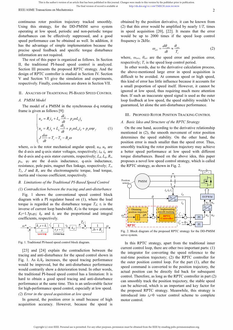
On the one hand, according to the derivative relationship mentioned in (2), the smooth movement of rotor position determines the speed stability. On the other hand, the position error is much smaller than the speed error. Thus, smoothly tracking the rotor position trajectory may achieve a better speed performance at low speed with different torque disturbances. Based on the above idea, this paper proposes a novel low speed control strategy, which is called the RPTC strategy, as shown in Fig. 2.
2s2r1: Obtaining
position trajectory
PMSM
PI
PI
RPTC
RPTC Controller
θ*∫
2: Implementing smooth tracking
ω*
Position sensor
SVPWM
* 0di -
++
-
ia ib ic
θ
*qi -
uα uβ
3s2r
ud uq
+
-+udc
iq
id
Fig. 2. Block diagram of the proposed RPTC strategy for the DD-PMSM servo system.
In this RPTC strategy, apart from the traditional inner current control loop, there are other two important parts: (1) the integrator for converting the speed reference to the real-time position trajectory; (2) the RPTC controller for the outer position control loop. For the part (1), after the speed command is converted to the position trajectory, the actual position can be directly fed back for subsequent control. Therefore, as long as the RPTC controller in part (2) can smoothly track the position trajectory, the stable speed can be achieved, which is an important and key factor for the proposed RPTC strategy. Meanwhile, this strategy is introduced into id=0 vector control scheme to complete motor control.
This is the author's version of an article that has been published in this journal. Changes were made to this version by the publisher prior to publication.The final version of record is available at http://dx.doi.org/10.1109/TMECH.2020.3019039
Copyright (c) 2020 IEEE. Personal use is permitted. For any other purposes, permission must be obtained from the IEEE by emailing [email protected].
IEEE/ASME Transactions on Mechatronics 3
B. Type Selection of the RPTC Controller
(1) Important requirements for the RPTC controller
From the analysis above, the command to be tracked in the PRTC strategy is no longer a constant speed signal, but a real-time position trajectory. So, in order to implement the RPTC strategy, the following conditions (3) and (4) must be simultaneously satisfied. In (3), θ*
p (s) is the Laplace transform of any position point on the real-time trajectory; θ(s) is the actual position; R is a constant; Φ(s) is the closed loop transfer function of the system. In (4), θ*(s) can be regarded as smooth links between points on this trajectory. In other words, the tracking of real-time position trajectory needs to be theoretically free of static and dynamic errors.
*
0 0lim ( )- ( ) lim 1 ( ) 0ps s
Rs s s s s
s
(3)
*
20 0
*lim ( ) ( ) lim 1 ( ) 0s s
s s s s ss
(4)
Equation (3) lays emphasis on the accurate position of each point on the trajectory. And (4) means the smoothness of the rotor movement between these points. However, as torque disturbances would cause speed fluctuations, the above two conditions often cannot be strictly satisfied. Therefore, the controller should be designed to meet (3) and (4) as much as possible, so as to reject torque disturbances.
In addition, some application areas, such as aerospace, have certain limitations on control resources and require high reliability, so the RPTC controller structure should also be simple and easy to be implemented.
In summary, to meet the above requirements, the choice of controller type is very critical.
(2) Introduction of internal model method
Many methods often focus on the above condition (3), which is mainly to realize position locating [25]-[27], and the smoothness of rotor tracking is not strictly required. One reason is that their control goal is to accurately reach the position command, not to obtain a good speed performance. This is the main difference from the proposed RPTC strategy in this paper. The other reason is that if the methods themselves do not possess strong robustness, it is difficult to guarantee the smoothness of position movement once disturbances occur. Even if it is possible to satisfy above conditions (3) and (4) by combining many kinds of methods, the algorithm complexity would be inevitable.
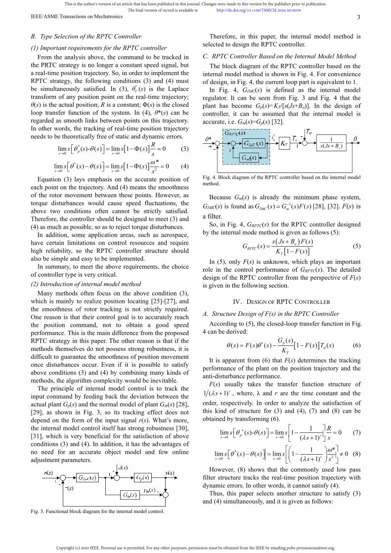
The principle of internal model control is to track the input command by feeding back the deviation between the actual plant Gp(s) and the normal model of plant Gm(s) [28], [29], as shown in Fig. 3, so its tracking effect does not depend on the form of the input signal r(s). What’s more, the internal model control itself has strong robustness [30], [31], which is very beneficial for the satisfaction of above conditions (3) and (4). In addition, it has the advantages of no need for an accurate object model and few online adjustment parameters.
Fig. 3. Functional block diagram for the internal model control.
Therefore, in this paper, the internal model method is selected to design the RPTC controller.
C. RPTC Controller Based on the Internal Model Method
The block diagram of the RPTC controller based on the internal model method is shown in Fig. 4. For convenience of design, in Fig. 4, the current loop part is equivalent to 1. In Fig. 4, GIMC(s) is defined as the internal model regulator. It can be seen from Fig. 3 and Fig. 4 that the plant has become Gp(s)=KT/[s(Js+Ba)]. In the design of controller, it can be assumed that the internal model is accurate, i.e. Gm(s)=Gp(s) [32].
*qi 1
( )as Js B
Fig. 4. Block diagram of the RPTC controller based on the internal model method.
Because Gm(s) is already the minimum phase system,
GIMC(s) is found as 1( ) ( ) ( )IMC mG s G s F s [28], [32]. F(s) is
a filter. So, in Fig. 4, GRPTC(s) for the RPTC controller designed by the internal mode method is given as follows (5):
( )( )
1 ( )a
RPTC
T
s Js B F sG s
K F s
(5)
In (5), only F(s) is unknown, which plays an important role in the control performance of GRPTC(s). The detailed design of the RPTC controller from the perspective of F(s) is given in the following section.
IV.DESIGN OF RPTC CONTROLLER
A. Structure Design of F(s) in the RPTC Controller
According to (5), the closed-loop transfer function in Fig. 4 can be derived:
( )
( ) ( ) ( ) 1 ( ) ( )p
d
T
G ss F s s F s T s
K (6)
It is apparent from (6) that F(s) determines the tracking performance of the plant on the position trajectory and the anti-disturbance performance.
F(s) usually takes the transfer function structure of
1 ( 1)rs , where, λ and r are the time constant and the
order, respectively. In order to analyze the satisfaction of this kind of structure for (3) and (4), (7) and (8) can be obtained by transforming (6).
0 0
1lim ( )- ( ) lim 1 0
( 1)p rs s
Rs s s s
s s
(7)
*
20 0
1 *lim ( ) ( ) lim 1 0
( 1)rs ss s s s
s s
(8)
However, (8) shows that the commonly used low pass filter structure tracks the real-time position trajectory with dynamic errors. In other words, it cannot satisfy (4).
Thus, this paper selects another structure to satisfy (3) and (4) simultaneously, and it is given as follows:
This is the author's version of an article that has been published in this journal. Changes were made to this version by the publisher prior to publication.The final version of record is available at http://dx.doi.org/10.1109/TMECH.2020.3019039
Copyright (c) 2020 IEEE. Personal use is permitted. For any other purposes, permission must be obtained from the IEEE by emailing [email protected].
IEEE/ASME Transactions on Mechatronics 4
1( )
1r
r sF s
s
(9)
F(s) in (9) can conduct the tracking of position trajectory without dynamic errors, which can be proved by (10).
*
20 0
1 *lim ( ) ( ) lim 1 0
1rs s
r ss s s s
ss
(10)
From the above analysis, it can be seen that if the structure (9) is selected, the RPTC controller can achieve the smooth tracking of the position trajectory in theory, and then stabilize the speed. However, in F(s), there are two parameters, the order r and the time constant λ, which need to be considered carefully. This is analyzed below.
B. Determining of the Order r in F(s)
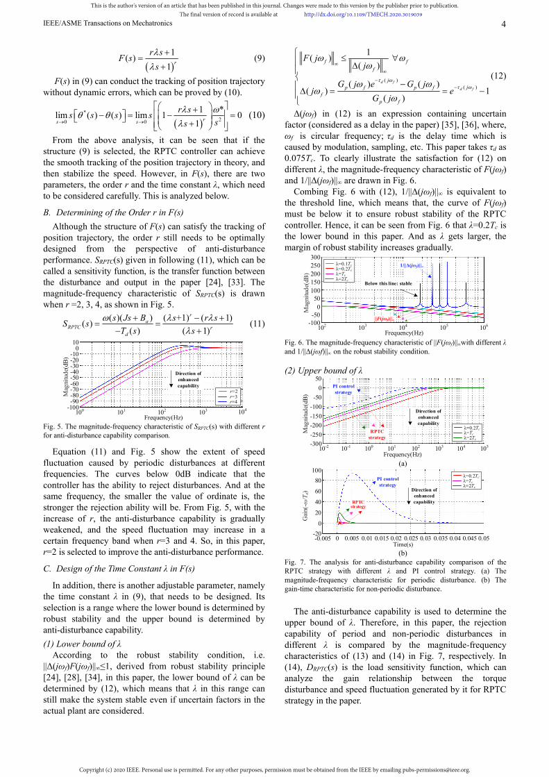
Although the structure of F(s) can satisfy the tracking of position trajectory, the order r still needs to be optimally designed from the perspective of anti-disturbance performance. SRPTC(s) given in following (11), which can be called a sensitivity function, is the transfer function between the disturbance and output in the paper [24], [33]. The magnitude-frequency characteristic of SRPTC(s) is drawn when r =2, 3, 4, as shown in Fig. 5.
( )( ) ( +1) ( 1)( )
( ) ( 1)
ra
RPTC rd
s Js B s r sS s
T s s
(11)
104
-50-60
-80
-100-90
Mag
nitu
de(
dB)
0-10
Frequency(Hz)100 101 102 103
-20
-70
-40-30
10
r=2 r=3r=4
Direction of enhanced capability
Fig. 5. The magnitude-frequency characteristic of SRPTC(s) with different r for anti-disturbance capability comparison.
Equation (11) and Fig. 5 show the extent of speed fluctuation caused by periodic disturbances at different frequencies. The curves below 0dB indicate that the controller has the ability to reject disturbances. And at the same frequency, the smaller the value of ordinate is, the stronger the rejection ability will be. From Fig. 5, with the increase of r, the anti-disturbance capability is gradually weakened, and the speed fluctuation may increase in a certain frequency band when r=3 and 4. So, in this paper, r=2 is selected to improve the anti-disturbance performance.
C. Design of the Time Constant λ in F(s)
In addition, there is another adjustable parameter, namely the time constant λ in (9), that needs to be designed. Its selection is a range where the lower bound is determined by robust stability and the upper bound is determined by anti-disturbance capability.
(1) Lower bound of λ According to the robust stability condition, i.e.
||Δ(jωf)F(jωf)||∞≤1, derived from robust stability principle [24], [28], [34], in this paper, the lower bound of λ can be determined by (12), which means that λ in this range can still make the system stable even if uncertain factors in the actual plant are considered.
( )
( )
1( )
( )
( ) ( )( ) 1
( )
d f
d f
f f
f
j
jp f p f
f
p f
F jj
G j e G jj e
G j
(12)
Δ(jωf) in (12) is an expression containing uncertain factor (considered as a delay in the paper) [35], [36], where, ωf is circular frequency; τd is the delay time which is caused by modulation, sampling, etc. This paper takes τd as 0.075Tc. To clearly illustrate the satisfaction for (12) on different λ, the magnitude-frequency characteristic of F(jωf) and 1/||Δ(jωf)||∞ are drawn in Fig. 6.
Combing Fig. 6 with (12), 1/||Δ(jωf)||∞ is equivalent to the threshold line, which means that, the curve of F(jωf) must be below it to ensure robust stability of the RPTC controller. Hence, it can be seen from Fig. 6 that λ=0.2Tc is the lower bound in this paper. And as λ gets larger, the margin of robust stability increases gradually.
102 103 106104
150
100
200
0
50
-100-50
Mag
nitu
de(
dB)
250300
105
Frequency(Hz)
λ=0.1Tc λ=0.2Tc λ=Tc λ=2Tc
Below this line: stable
1/||Δ(jωf)||∞
||F(jωf)||∞
Fig. 6. The magnitude-frequency characteristic of ||F(jωf)||∞with different λ and 1/||Δ(jωf)||∞ on the robust stability condition.
(2) Upper bound of λ
10-2 105
-150
-200
-250
50
-300
Mag
nitu
de(
dB)
0
-50
Frequency(Hz)10-1 100 101 102 103 104
-100
RPTC strategy
PI control strategy
λ=0.2Tc λ=Tc λ=2Tc
Direction of enhanced capability
(a)
0
60
-20
0
40
Time(s)0.005 0.015 0.02 0.025
20
0.03
80
0.045 0.05
Gai
n(-ω
/Td)
0.040.0350.01-0.005
PI control strategy
λ=0.2Tc λ=Tc λ=2Tc
Direction of enhanced capabilityRPTC
strategy
100
(b)
Fig. 7. The analysis for anti-disturbance capability comparison of the RPTC strategy with different λ and PI control strategy. (a) The magnitude-frequency characteristic for periodic disturbance. (b) The gain-time characteristic for non-periodic disturbance.
The anti-disturbance capability is used to determine the
upper bound of λ. Therefore, in this paper, the rejection capability of period and non-periodic disturbances in different λ is compared by the magnitude-frequency characteristics of (13) and (14) in Fig. 7, respectively. In (14), DRPTC(s) is the load sensitivity function, which can analyze the gain relationship between the torque disturbance and speed fluctuation generated by it for RPTC strategy in the paper.
This is the author's version of an article that has been published in this journal. Changes were made to this version by the publisher prior to publication.The final version of record is available at http://dx.doi.org/10.1109/TMECH.2020.3019039
Copyright (c) 2020 IEEE. Personal use is permitted. For any other purposes, permission must be obtained from the IEEE by emailing [email protected].
IEEE/ASME Transactions on Mechatronics 5
2 2
2
( )( )( )
( ) ( 1)a
RPTC
d
s Js B sS s
T s s
(13)
2 3 2 2
2 3 2 2
( )( )
( ) ( )( 2 1)i
RPTC
d a i
s ssD s
T s Js B s s s
(14)
In Fig. 7 (a), the lower the ordinate is, the stronger the capability to reject periodic disturbances will be. Fig. 7 (b) shows that the value of the speed fluctuation caused by the unit step-type non-periodic disturbance and steady state recovery time. From Fig. 7, with the increase of λ, the anti-disturbance capability is weakened. Thus, 2Tc is used as the upper bound to ensure sufficient anti-disturbance performance. Moreover, even if λ is selected as 2Tc, the anti-disturbance capability of RPTC strategy is still much better than that of PI control strategy.
According to the above analysis, in this paper, the range of λ can be obtained, as shown in (15).
0.2 , 2c cT T (15)
But the specific determination of λ should be further conducted according to the actual operating conditions.
V.SIMULATION RESULTS AND ANALYSIS
To evaluate the performance of proposed RPTC strategy, a simulation model for a prototype of DD-PMSM servo system is built. The relevant parameters are given in Table I.
It should be pointed out that, in this paper, a prototype with large cogging torque for aerospace application is selected, and its cogging torque is about 70% (The amplitude is 35mNm) of the rated torque (50mNm) (This large cogging torque is used to remove the electromagnetic brake of the motor).
TABLE I MAIN PARAMETERS OF THE PROTOTYPE AND TORQUE DISTURBANCES
Parameters Value
Rate voltage 24V Rate current 0.35A Rate speed 1100r/min
Stator winding resistance 11.5Ω Stator inductance 4.78mH
Number of pole pairs 6 Flux linkage 0.018444Wb
Nominal inertia 1.86kg·mm2 Viscous friction coefficient 1.1×10⁻⁶
DC BUS voltage 31V Speed loop control frequency 2kHz
Switching frequency 20kHz
Load torque (non-periodic disturbance) 50mNm Cogging torque (periodic disturbance) 35mNm
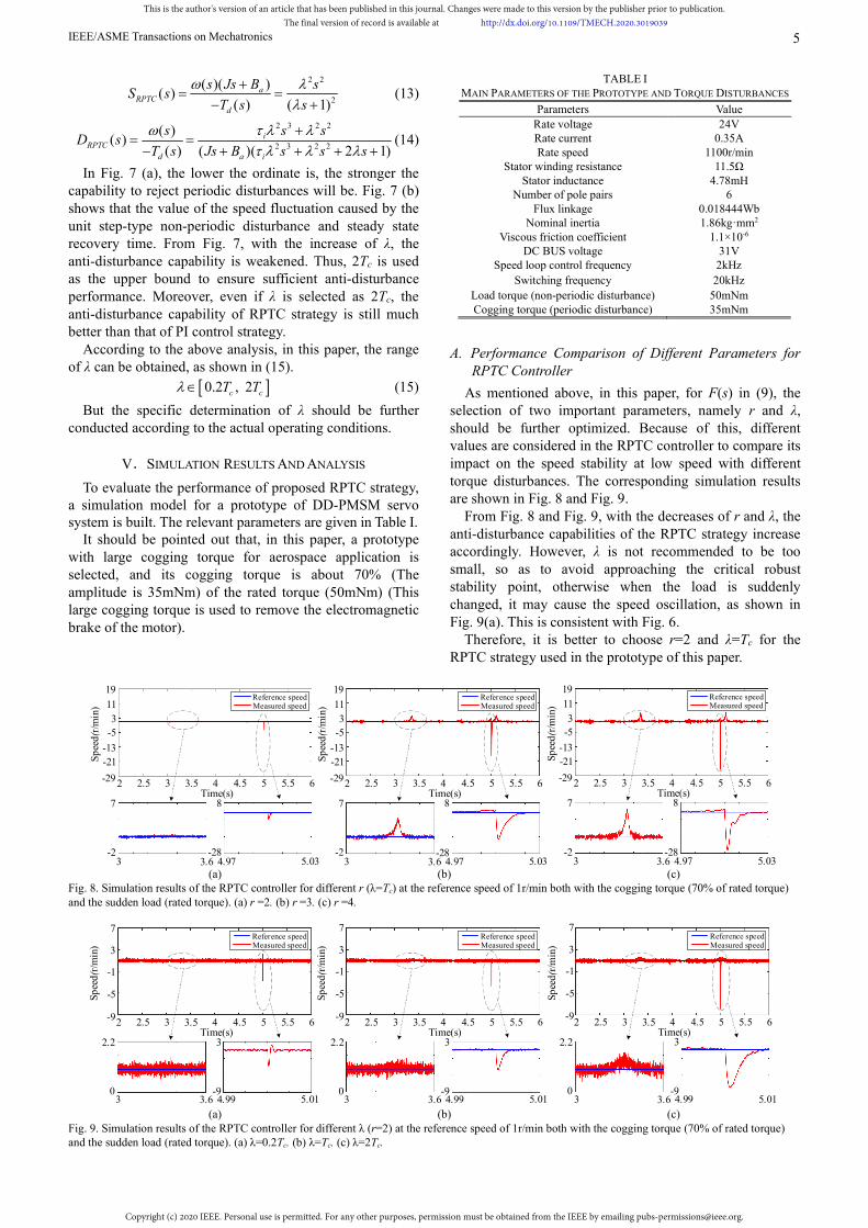
A. Performance Comparison of Different Parameters for RPTC Controller
As mentioned above, in this paper, for F(s) in (9), the selection of two important parameters, namely r and λ, should be further optimized. Because of this, different values are considered in the RPTC controller to compare its impact on the speed stability at low speed with different torque disturbances. The corresponding simulation results are shown in Fig. 8 and Fig. 9.
From Fig. 8 and Fig. 9, with the decreases of r and λ, the anti-disturbance capabilities of the RPTC strategy increase accordingly. However, λ is not recommended to be too small, so as to avoid approaching the critical robust stability point, otherwise when the load is suddenly changed, it may cause the speed oscillation, as shown in Fig. 9(a). This is consistent with Fig. 6.
Therefore, it is better to choose r=2 and λ=Tc for the RPTC strategy used in the prototype of this paper.
2 3 5.5 6Time(s)
2.5 3.5 4 4.5
Sp
eed
(r/m
in)
-13
-21
3
-5
-29
Measured speed Reference speed
5
3 3.6-2
7
4.97 5.03-28
8
11
19
2 3 5.5 6Time(s)
2.5 3.5 4 4.5
Sp
eed
(r/m
in)
-13
-21
3
-5
-29
Measured speed Reference speed
5
3 3.6-2
7
4.97 5.03-28
8
11
19
2 3 5.5 6Time(s)
2.5 3.5 4 4.5
Sp
eed
(r/m
in)
-13
-21
3
-5
-29
Measured speed Reference speed
5
3 3.6-2
7
4.97 5.03-28
8
11
19
(a) (b) (c) Fig. 8. Simulation results of the RPTC controller for different r (λ=Tc) at the reference speed of 1r/min both with the cogging torque (70% of rated torque) and the sudden load (rated torque). (a) r =2. (b) r =3. (c) r =4.
2 3 5.5 6Time(s)
2.5 3.5 4 4.5
Sp
eed
(r/m
in) Measured speed
Reference speed
5
3 3.60
2.2
4.99 5.01-9
3
2 3 5.5 6Time(s)
2.5 3.5 4 4.5
Sp
eed
(r/m
in) Measured speed
Reference speed
5
3 3.60
2.2
4.99 5.01-9
3
2 3 5.5 6Time(s)
2.5 3.5 4 4.5
Sp
eed
(r/m
in)
-1
-5
7
3
-9
Measured speed Reference speed
5
3 3.60
2.2
4.99 5.01-9
3
-1
-5
7
3
-9
-1
-5
7
3
-9
(a) (b) (c) Fig. 9. Simulation results of the RPTC controller for different λ (r=2) at the reference speed of 1r/min both with the cogging torque (70% of rated torque) and the sudden load (rated torque). (a) λ=0.2Tc. (b) λ=Tc. (c) λ=2Tc.
This is the author's version of an article that has been published in this journal. Changes were made to this version by the publisher prior to publication.The final version of record is available at http://dx.doi.org/10.1109/TMECH.2020.3019039
Copyright (c) 2020 IEEE. Personal use is permitted. For any other purposes, permission must be obtained from the IEEE by emailing [email protected].
IEEE/ASME Transactions on Mechatronics 6
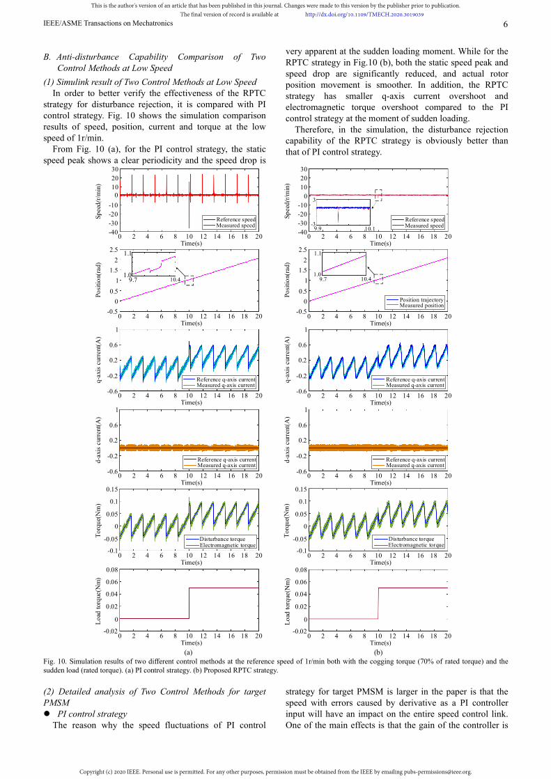
B. Anti-disturbance Capability Comparison of Two Control Methods at Low Speed
(1) Simulink result of Two Control Methods at Low Speed In order to better verify the effectiveness of the RPTC
strategy for disturbance rejection, it is compared with PI control strategy. Fig. 10 shows the simulation comparison results of speed, position, current and torque at the low speed of 1r/min.
From Fig. 10 (a), for the PI control strategy, the static speed peak shows a clear periodicity and the speed drop is
very apparent at the sudden loading moment. While for the RPTC strategy in Fig.10 (b), both the static speed peak and speed drop are significantly reduced, and actual rotor position movement is smoother. In addition, the RPTC strategy has smaller q-axis current overshoot and electromagnetic torque overshoot compared to the PI control strategy at the moment of sudden loading.
Therefore, in the simulation, the disturbance rejection capability of the RPTC strategy is obviously better than that of PI control strategy.
Time(s)
100
-10
-20
-40
Sp
eed
(r/m
in)
-30
20
30
q-a
xis
curr
ent(
A)
1.5
1
0.5
0
-0.5
Po
siti
on(
rad)
Measured speed Reference speed
Measured q-axis currentReference q-axis current
9.7 10.41.0
1.12
2.5
0 4 12 14 162 6 8 10 18 20
9.7 10.41.0
1.1
Time(s)0 4 12 14 162 6 8 10 18 20
Measured q-axis currentReference q-axis current
Measured position Position trajectory
Measured speed Reference speed
9.9 10.1-3
3
-0.6
0.2
0.6
-0.2
1
Time(s)
10
0
-10
-20
-40
Sp
eed(
r/m
in)
-30
20
30
0 4 12 14 162 6 8 10 18 20
Time(s)0 4 12 14 162 6 8 10 18 20
q-a
xis
curr
ent(
A)
1.5
1
0.5
0
-0.5
Po
siti
on(
rad)
2
2.5
-0.6
0.2
0.6
-0.2
1Time(s)
0 4 12 14 162 6 8 10 18 20
Time(s)0 4 12 14 162 6 8 10 18 20
d-ax
is c
urre
nt(A
)
Measured q-axis currentReference q-axis current
Measured q-axis currentReference q-axis current
-0.6
0.2
0.6
-0.2
1
Time(s)0 4 12 14 162 6 8 10 18 20
d-ax
is c
urre
nt(A
)
-0.6
0.2
0.6
-0.2
1
Time(s)0 4 12 14 162 6 8 10 18 20
Measured q-axis currentReference q-axis current
0.15
-0.05
To
rqu
e(N
m)
0
0.1
-0.1
0.05
Electromagnetic torqueDisturbance torque
Electromagnetic torqueDisturbance torque
Time(s)0 4 12 14 162 6 8 10 18 20
0.15
-0.05
To
rqu
e(N
m)
0
0.1
-0.1
0.05
Time(s)0 4 12 14 162 6 8 10 18 20
0.08
0Lo
ad t
orq
ue(N
m)
0.02
0.06
-0.02
0.04
Time(s)0 4 12 14 162 6 8 10 18 20
0.08
0
Lo
ad t
orq
ue(N
m)
0.02
0.06
-0.02
0.04
Time(s)0 4 12 14 162 6 8 10 18 20
(a) (b) Fig. 10. Simulation results of two different control methods at the reference speed of 1r/min both with the cogging torque (70% of rated torque) and the sudden load (rated torque). (a) PI control strategy. (b) Proposed RPTC strategy.
(2) Detailed analysis of Two Control Methods for target PMSM PI control strategy
The reason why the speed fluctuations of PI control
strategy for target PMSM is larger in the paper is that the speed with errors caused by derivative as a PI controller input will have an impact on the entire speed control link. One of the main effects is that the gain of the controller is
This is the author's version of an article that has been published in this journal. Changes were made to this version by the publisher prior to publication.The final version of record is available at http://dx.doi.org/10.1109/TMECH.2020.3019039
Copyright (c) 2020 IEEE. Personal use is permitted. For any other purposes, permission must be obtained from the IEEE by emailing [email protected].
IEEE/ASME Transactions on Mechatronics 7
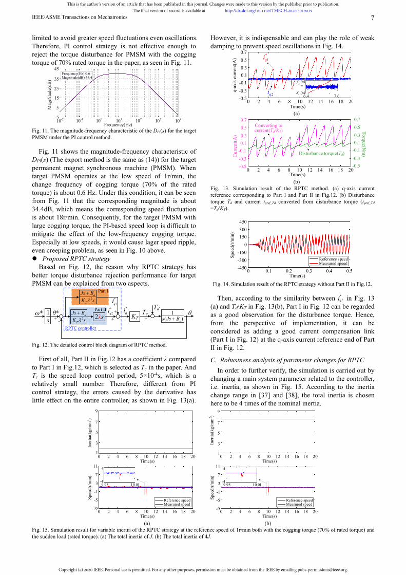
limited to avoid greater speed fluctuations even oscillations. Therefore, PI control strategy is not effective enough to reject the torque disturbance for PMSM with the cogging torque of 70% rated torque in the paper, as seen in Fig. 11.
15
5
45
-5
35
Frequency(Hz)10-1 100 101 102 103 104
25
Frequency(Hz):0.6Magnitude(dB):34.4
10-2
Mag
n'it
ude(
dB)
Fig. 11. The magnitude-frequency characteristic of the DPI(s) for the target PMSM under the PI control method.
Fig. 11 shows the magnitude-frequency characteristic of DPI(s) (The export method is the same as (14)) for the target permanent magnet synchronous machine (PMSM). When target PMSM operates at the low speed of 1r/min, the change frequency of cogging torque (70% of the rated torque) is about 0.6 Hz. Under this condition, it can be seen from Fig. 11 that the corresponding magnitude is about 34.4dB, which means the corresponding speed fluctuation is about 18r/min. Consequently, for the target PMSM with large cogging torque, the PI-based speed loop is difficult to mitigate the effect of the low-frequency cogging torque. Especially at low speeds, it would cause lager speed ripple, even creeping problem, as seen in Fig. 10 above. Proposed RPTC strategy Based on Fig. 12, the reason why RPTC strategy has better torque disturbance rejection performance for target PMSM can be explained from two aspects.
+
TdTe
-+
-ω* θ* KT
+
+
RPTC controller
Part Ⅰ
Part Ⅱ θ
*qi 1
( )a
s Js B2λs1s
*
1qi
*
2qi
2a
T
Js B
K s
2a
T
Js B
K s
Fig. 12. The detailed control block diagram of RPTC method.
First of all, Part II in Fig.12 has a coefficient λ compared to Part Ⅰ in Fig.12, which is selected as Tc in the paper. And Tc is the speed loop control period, 5×10⁻⁴s, which is a relatively small number. Therefore, different from PI control strategy, the errors caused by the derivative has little effect on the entire controller, as shown in Fig. 13(a).
However, it is indispensable and can play the role of weak damping to prevent speed oscillations in Fig. 14.
Time(s)0 4 12 14 162 6 8 10 18
0.3
-0.3q-ax
is c
urre
nt(A
)
-0.1
0.1
-0.5
0.5
0.7
0.04
-0.046.4 7.6
20
*1qi
*2qi
(a)
Time(s)0 4 12 14 162 6 8 10 18 20
Converting to current(Td/KT)
0.3
-0.3
-0.1
0.1
-0.5
0.5
0.7
Cu
rren
t(A
)
Disturbance torque(Td)
0.3
-0.3
-0.1
0.1
-0.5
0.5
0.7
To
rque(N
m)
(b)
Fig. 13. Simulation result of the RPTC method. (a) q-axis current reference corresponding to Part Ⅰ and Part Ⅱ in Fig.12. (b) Disturbance torque Td and current iqref_Td converted from disturbance torque (iqref_Td
=Td/KT).
Time(s)
150
0
-150
-450
Sp
eed
(r/m
in)
-300
300
450
0 0.1 0.3 0.40.2 0.5
Measured speed Reference speed
Fig. 14. Simulation result of the RPTC strategy without Part II in Fig.12.
Then, according to the similarity between i* q1 in Fig. 13
(a) and Td/KT in Fig. 13(b), Part Ⅰ in Fig. 12 can be regarded as a good observation for the disturbance torque. Hence, from the perspective of implementation, it can be considered as adding a good current compensation link (Part Ⅰ in Fig. 12) at the q-axis current reference end of Part Ⅱ in Fig. 12.
C. Robustness analysis of parameter changes for RPTC
In order to further verify, the simulation is carried out by changing a main system parameter related to the controller, i.e. inertia, as shown in Fig. 15. According to the inertia change range in [37] and [38], the total inertia is chosen here to be 4 times of the nominal inertia.
Measured speed Reference speed
Time(s)
Sp
eed
(r/m
in)
0 4 12 14 162 6 8 10 18 20
Measured speed Reference speed
Time(s)
7
3
-1
-9
Sp
eed
(r/m
in)
-5
11
0 4 12 14 162 6 8 10 18 20
Time(s)0 4 12 14 162 6 8 10 18 20
Time(s)
5
7
3
1
Iner
tia(
kg/
mm
2 )
9
0 4 12 14 162 6 8 10 18 20
Iner
tia(
kg/
mm
2 )
7
3
-1
-9
-5
11
9.95 10.01-4
4
9.95 10.01-4
4
5
7
3
1
9
(a) (b) Fig. 15. Simulation result for variable inertia of the RPTC strategy at the reference speed of 1r/min both with the cogging torque (70% of rated torque) and the sudden load (rated torque). (a) The total inertia of J. (b) The total inertia of 4J.
This is the author's version of an article that has been published in this journal. Changes were made to this version by the publisher prior to publication.The final version of record is available at http://dx.doi.org/10.1109/TMECH.2020.3019039
Copyright (c) 2020 IEEE. Personal use is permitted. For any other purposes, permission must be obtained from the IEEE by emailing [email protected].
IEEE/ASME Transactions on Mechatronics 8
VI.EXPERIMENTAL RESULTS
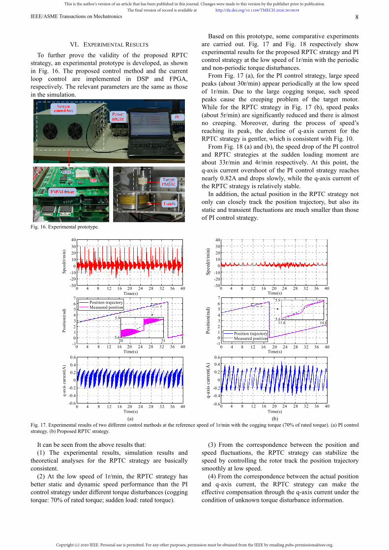
To further prove the validity of the proposed RPTC strategy, an experimental prototype is developed, as shown in Fig. 16. The proposed control method and the current loop control are implemented in DSP and FPGA, respectively. The relevant parameters are the same as those in the simulation.
Fig. 16. Experimental prototype.
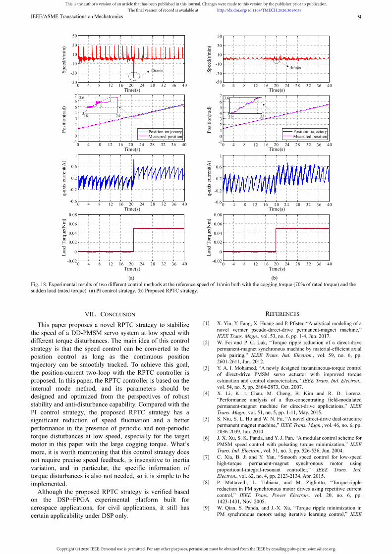
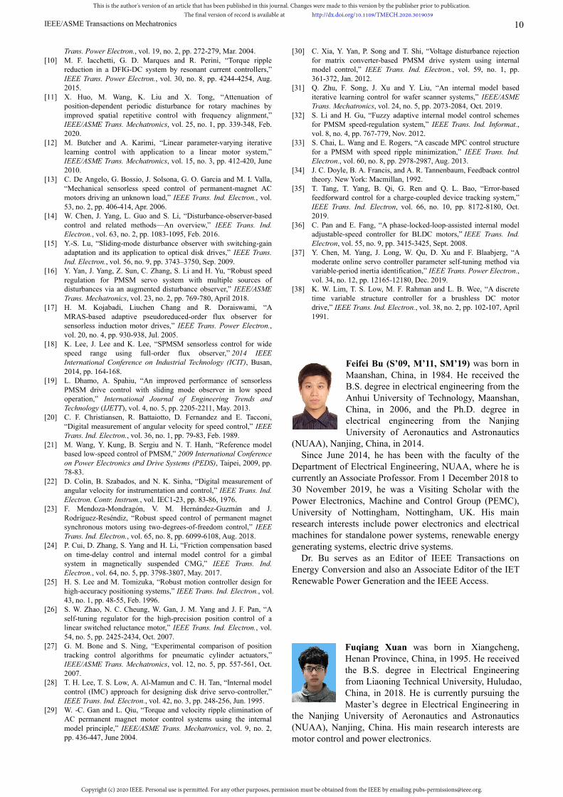
Based on this prototype, some comparative experiments are carried out. Fig. 17 and Fig. 18 respectively show experimental results for the proposed RPTC strategy and PI control strategy at the low speed of 1r/min with the periodic and non-periodic torque disturbances.
From Fig. 17 (a), for the PI control strategy, large speed peaks (about 30r/min) appear periodically at the low speed of 1r/min. Due to the large cogging torque, such speed peaks cause the creeping problem of the target motor. While for the RPTC strategy in Fig. 17 (b), speed peaks (about 5r/min) are significantly reduced and there is almost no creeping. Moreover, during the process of speed’s reaching its peak, the decline of q-axis current for the RPTC strategy is gentler, which is consistent with Fig. 10.
From Fig. 18 (a) and (b), the speed drop of the PI control and RPTC strategies at the sudden loading moment are about 33r/min and 4r/min respectively. At this point, the q-axis current overshoot of the PI control strategy reaches nearly 0.82A and drops slowly, while the q-axis current of the RPTC strategy is relatively stable.
In addition, the actual position in the RPTC strategy not only can closely track the position trajectory, but also its static and transient fluctuations are much smaller than those of PI control strategy.
30
20
10
0
-10
-20
-30
Sp
eed(
r/m
in)
40
q-a
xis
cur
ren
t(A
)
5
4
3
2
1
0
-1
Po
siti
on
(rad
)
7
6
0.2
0
-0.2
-0.6
0.4
-0.4
0.6
Time(s)0 8 24 28 324 12 16 20 36 40
30
20
10
0
-10
-20
-30
Sp
eed
(r/m
in)
40
Time(s)0 8 24 28 324 12 16 20 36 40
Time(s)0 8 24 28 324 12 16 20 36 40
Time(s)0 8 24 28 324 12 16 20 36 40
q-a
xis
curr
ent(
A)
0.2
0
-0.2
-0.6
0.4
-0.4
0.6
5
4
3
2
1
0
-1
7
6
Time(s)0 8 24 28 324 12 16 20 36 40
Time(s)8 24 28 324 12 16 20 36 400
Measured position Position trajectory
11.6 14.85.6
5.9
28 315.6
5.9
Po
siti
on(
rad)
Measured position Position trajectory
(a) (b) Fig. 17. Experimental results of two different control methods at the reference speed of 1r/min with the cogging torque (70% of rated torque). (a) PI control strategy. (b) Proposed RPTC strategy.
It can be seen from the above results that: (1) The experimental results, simulation results and
theoretical analyses for the RPTC strategy are basically consistent.
(2) At the low speed of 1r/min, the RPTC strategy has better static and dynamic speed performance than the PI control strategy under different torque disturbances (cogging torque: 70% of rated torque; sudden load: rated torque).
(3) From the correspondence between the position and speed fluctuations, the RPTC strategy can stabilize the speed by controlling the rotor track the position trajectory smoothly at low speed.
(4) From the correspondence between the actual position and q-axis current, the RPTC strategy can make the effective compensation through the q-axis current under the condition of unknown torque disturbance information.
This is the author's version of an article that has been published in this journal. Changes were made to this version by the publisher prior to publication.The final version of record is available at http://dx.doi.org/10.1109/TMECH.2020.3019039
Copyright (c) 2020 IEEE. Personal use is permitted. For any other purposes, permission must be obtained from the IEEE by emailing [email protected].
IEEE/ASME Transactions on Mechatronics 9
Time(s)
10
-10
-30Sp
eed
(r/m
in) 30
q-a
xis
curr
ent(
A)
0.2
-0.2
-0.6
-50
50
0.6
5
4
3
2
1
0
-1
Po
siti
on(
rad)
7
6
1
0 8 24 28 324 12 16 20 36 40Time(s)
10
-10
-30
Sp
eed
(r/m
in) 30
-50
50
0 8 24 28 324 12 16 20 36 40
Time(s)0 8 24 28 324 12 16 20 36 40
Time(s)0 8 24 28 324 12 16 20 36 40
q-ax
is c
urre
nt(A
)
0.2
-0.2
-0.6
0.6
1
Time(s)0 8 24 28 324 12 16 20 36 40
Time(s)0 8 24 28 324 12 16 20 36 40
54
3
2
1
0-1
Po
siti
on(
rad)
7
6
16 2318 243
3.6
3
3.6
40r/min4r/min
Measured position Position trajectory
Lo
ad T
orq
ue(N
m)
Time(s)0 8 24 28 324 12 16 20 36 40
0.02
0
-0.02
0.04
0.06
Time(s)0 8 24 28 324 12 16 20 36 40
0.08
Lo
ad T
orq
ue(N
m)
0.02
0
-0.02
0.04
0.06
0.08
Measured position Position trajectory
(a) (b)
Fig. 18. Experimental results of two different control methods at the reference speed of 1r/min both with the cogging torque (70% of rated torque) and the sudden load (rated torque). (a) PI control strategy. (b) Proposed RPTC strategy.
VII.CONCLUSION
This paper proposes a novel RPTC strategy to stabilize the speed of a DD-PMSM servo system at low speed with different torque disturbances. The main idea of this control strategy is that the speed control can be converted to the position control as long as the continuous position trajectory can be smoothly tracked. To achieve this goal, the position-current two-loop with the RPTC controller is proposed. In this paper, the RPTC controller is based on the internal mode method, and its parameters should be designed and optimized from the perspectives of robust stability and anti-disturbance capability. Compared with the PI control strategy, the proposed RPTC strategy has a significant reduction of speed fluctuation and a better performance in the presence of periodic and non-periodic torque disturbances at low speed, especially for the target motor in this paper with the large cogging torque. What’s more, it is worth mentioning that this control strategy does not require precise speed feedback, is insensitive to inertia variation, and in particular, the specific information of torque disturbances is also not needed, so it is simple to be implemented.
Although the proposed RPTC strategy is verified based on the DSP+FPGA experimental platform built for aerospace applications, for civil applications, it still has certain applicability under DSP only.
REFERENCES
[1] X. Yin, Y. Fang, X. Huang and P. Pfister, “Analytical modeling of a novel vernier pseudo-direct-drive permanent-magnet machine,” IEEE Trans. Magn., vol. 53, no. 6, pp. 1-4, Jun. 2017.
[2] W. Fei and P. C. Luk, “Torque ripple reduction of a direct-drive permanent-magnet synchronous machine by material-efficient axial pole pairing,” IEEE Trans. Ind. Electron., vol. 59, no. 6, pp. 2601-2611, Jun. 2012.
[3] Y. A. I. Mohamed, “A newly designed instantaneous-torque control of direct-drive PMSM servo actuator with improved torque estimation and control characteristics,” IEEE Trans. Ind. Electron., vol. 54, no. 5, pp. 2864-2873, Oct. 2007.
[4] X. Li, K. t. Chau, M. Cheng, B. Kim and R. D. Lorenz, “Performance analysis of a flux-concentrating field-modulated permanent-magnet machine for direct-drive applications,” IEEE Trans. Magn., vol. 51, no. 5, pp. 1-11, May. 2015.
[5] S. Niu, S. L. Ho and W. N. Fu, “A novel direct-drive dual-structure permanent magnet machine,” IEEE Trans. Magn., vol. 46, no. 6, pp. 2036-2039, Jun. 2010.
[6] J. X. Xu, S. K. Panda, and Y. J. Pan. “A modular control scheme for PMSM speed control with pulsating torque minimization,” IEEE Trans. Ind. Electron., vol. 51, no. 3, pp. 526-536, Jun. 2004.
[7] C. Xia, B. Ji and Y. Yan, “Smooth speed control for low-speed high-torque permanent-magnet synchronous motor using proportional-integral-resonant controller,” IEEE Trans. Ind. Electron., vol. 62, no. 4, pp. 2123-2134, Apr. 2015.
[8] P. Mattavelli, L. Tubiana, and M. Zigliotto, “Torque-ripple reduction in PM synchronous motor drives using repetitive current control,” IEEE Trans. Power Electron., vol. 20, no. 6, pp. 1423-1431, Nov. 2005.
[9] W. Qian, S. Panda, and J.-X. Xu, “Torque ripple minimization in PM synchronous motors using iterative learning control,” IEEE
This is the author's version of an article that has been published in this journal. Changes were made to this version by the publisher prior to publication.The final version of record is available at http://dx.doi.org/10.1109/TMECH.2020.3019039
Copyright (c) 2020 IEEE. Personal use is permitted. For any other purposes, permission must be obtained from the IEEE by emailing [email protected].
IEEE/ASME Transactions on Mechatronics 10
Trans. Power Electron., vol. 19, no. 2, pp. 272-279, Mar. 2004. [10] M. F. Iacchetti, G. D. Marques and R. Perini, “Torque ripple
reduction in a DFIG-DC system by resonant current controllers,” IEEE Trans. Power Electron., vol. 30, no. 8, pp. 4244-4254, Aug. 2015.
[11] X. Huo, M. Wang, K. Liu and X. Tong, “Attenuation of position-dependent periodic disturbance for rotary machines by improved spatial repetitive control with frequency alignment,” IEEE/ASME Trans. Mechatronics, vol. 25, no. 1, pp. 339-348, Feb. 2020.
[12] M. Butcher and A. Karimi, “Linear parameter-varying iterative learning control with application to a linear motor system,” IEEE/ASME Trans. Mechatronics, vol. 15, no. 3, pp. 412-420, June 2010.
[13] C. De Angelo, G. Bossio, J. Solsona, G. O. Garcia and M. I. Valla, “Mechanical sensorless speed control of permanent-magnet AC motors driving an unknown load,” IEEE Trans. Ind. Electron., vol. 53, no. 2, pp. 406-414, Apr. 2006.
[14] W. Chen, J. Yang, L. Guo and S. Li, “Disturbance-observer-based control and related methods—An overview,” IEEE Trans. Ind. Electron., vol. 63, no. 2, pp. 1083-1095, Feb. 2016.
[15] Y.-S. Lu, “Sliding-mode disturbance observer with switching-gain adaptation and its application to optical disk drives,” IEEE Trans. Ind. Electron., vol. 56, no. 9, pp. 3743–3750, Sep. 2009.
[16] Y. Yan, J. Yang, Z. Sun, C. Zhang, S. Li and H. Yu, “Robust speed regulation for PMSM servo system with multiple sources of disturbances via an augmented disturbance observer,” IEEE/ASME Trans. Mechatronics, vol. 23, no. 2, pp. 769-780, April 2018.
[17] H. M. Kojabadi, Liuchen Chang and R. Doraiswami, “A MRAS-based adaptive pseudoreduced-order flux observer for sensorless induction motor drives,” IEEE Trans. Power Electron., vol. 20, no. 4, pp. 930-938, Jul. 2005.
[18] K. Lee, J. Lee and K. Lee, “SPMSM sensorless control for wide speed range using full-order flux observer,” 2014 IEEE International Conference on Industrial Technology (ICIT), Busan, 2014, pp. 164-168.
[19] L. Dhamo, A. Spahiu, “An improved performance of sensorless PMSM drive control with sliding mode observer in low speed operation,” International Journal of Engineering Trends and Technology (IJETT), vol. 4, no. 5, pp. 2205-2211, May. 2013.
[20] C. F. Christiansen, R. Battaiotto, D. Fernandez and E. Tacconi, “Digital measurement of angular velocity for speed control,” IEEE Trans. Ind. Electron., vol. 36, no. 1, pp. 79-83, Feb. 1989.
[21] M. Wang, Y. Kung, B. Sergiu and N. T. Hanh, “Reference model based low-speed control of PMSM,” 2009 International Conference on Power Electronics and Drive Systems (PEDS), Taipei, 2009, pp. 78-83.
[22] D. Colin, B. Szabados, and N. K. Sinha, “Digital measurement of angular velocity for instrumentation and control,” IEEE Trans. Ind. Electron. Contr. Instrum., vol. IEC1-23, pp. 83-86, 1976.
[23] F. Mendoza-Mondragón, V. M. Hernández-Guzmán and J. Rodríguez-Reséndiz, “Robust speed control of permanent magnet synchronous motors using two-degrees-of-freedom control,” IEEE Trans. Ind. Electron., vol. 65, no. 8, pp. 6099-6108, Aug. 2018.
[24] P. Cui, D. Zhang, S. Yang and H. Li, “Friction compensation based on time-delay control and internal model control for a gimbal system in magnetically suspended CMG,” IEEE Trans. Ind. Electron., vol. 64, no. 5, pp. 3798-3807, May. 2017.
[25] H. S. Lee and M. Tomizuka, “Robust motion controller design for high-accuracy positioning systems,” IEEE Trans. Ind. Electron., vol. 43, no. 1, pp. 48-55, Feb. 1996.
[26] S. W. Zhao, N. C. Cheung, W. Gan, J. M. Yang and J. F. Pan, “A self-tuning regulator for the high-precision position control of a linear switched reluctance motor,” IEEE Trans. Ind. Electron., vol. 54, no. 5, pp. 2425-2434, Oct. 2007.
[27] G. M. Bone and S. Ning, “Experimental comparison of position tracking control algorithms for pneumatic cylinder actuators,” IEEE/ASME Trans. Mechatronics, vol. 12, no. 5, pp. 557-561, Oct. 2007.
[28] T. H. Lee, T. S. Low, A. Al-Mamun and C. H. Tan, “Internal model control (IMC) approach for designing disk drive servo-controller,” IEEE Trans. Ind. Electron., vol. 42, no. 3, pp. 248-256, Jun. 1995.
[29] W. -C. Gan and L. Qiu, “Torque and velocity ripple elimination of AC permanent magnet motor control systems using the internal model principle,” IEEE/ASME Trans. Mechatronics, vol. 9, no. 2, pp. 436-447, June 2004.
[30] C. Xia, Y. Yan, P. Song and T. Shi, “Voltage disturbance rejection for matrix converter-based PMSM drive system using internal model control,” IEEE Trans. Ind. Electron., vol. 59, no. 1, pp. 361-372, Jan. 2012.
[31] Q. Zhu, F. Song, J. Xu and Y. Liu, “An internal model based iterative learning control for wafer scanner systems,” IEEE/ASME Trans. Mechatronics, vol. 24, no. 5, pp. 2073-2084, Oct. 2019.
[32] S. Li and H. Gu, “Fuzzy adaptive internal model control schemes for PMSM speed-regulation system,” IEEE Trans. Ind. Informat., vol. 8, no. 4, pp. 767-779, Nov. 2012.
[33] S. Chai, L. Wang and E. Rogers, “A cascade MPC control structure for a PMSM with speed ripple minimization,” IEEE Trans. Ind. Electron., vol. 60, no. 8, pp. 2978-2987, Aug. 2013.
[34] J. C. Doyle, B. A. Francis, and A. R. Tannenbaum, Feedback control theory. New York: Macmillan, 1992.
[35] T. Tang, T. Yang, B. Qi, G. Ren and Q. L. Bao, “Error-based feedforward control for a charge-coupled device tracking system,” IEEE Trans. Ind. Electron, vol. 66, no. 10, pp. 8172-8180, Oct. 2019.
[36] C. Pan and E. Fang, “A phase-locked-loop-assisted internal model adjustable-speed controller for BLDC motors,” IEEE Trans. Ind. Electron, vol. 55, no. 9, pp. 3415-3425, Sept. 2008.
[37] Y. Chen, M. Yang, J. Long, W. Qu, D. Xu and F. Blaabjerg, “A moderate online servo controller parameter self-tuning method via variable-period inertia identification,” IEEE Trans. Power Electron., vol. 34, no. 12, pp. 12165-12180, Dec. 2019.
[38] K. W. Lim, T. S. Low, M. F. Rahman and L. B. Wee, “A discrete time variable structure controller for a brushless DC motor drive,” IEEE Trans. Ind. Electron., vol. 38, no. 2, pp. 102-107, April 1991.
Feifei Bu (S’09, M’11, SM’19) was born in Maanshan, China, in 1984. He received the B.S. degree in electrical engineering from the Anhui University of Technology, Maanshan, China, in 2006, and the Ph.D. degree in electrical engineering from the Nanjing University of Aeronautics and Astronautics
(NUAA), Nanjing, China, in 2014. Since June 2014, he has been with the faculty of the Department of Electrical Engineering, NUAA, where he is currently an Associate Professor. From 1 December 2018 to 30 November 2019, he was a Visiting Scholar with the Power Electronics, Machine and Control Group (PEMC), University of Nottingham, Nottingham, UK. His main research interests include power electronics and electrical machines for standalone power systems, renewable energy generating systems, electric drive systems.
Dr. Bu serves as an Editor of IEEE Transactions on Energy Conversion and also an Associate Editor of the IET Renewable Power Generation and the IEEE Access.
Fuqiang Xuan was born in Xiangcheng, Henan Province, China, in 1995. He received the B.S. degree in Electrical Engineering from Liaoning Technical University, Huludao, China, in 2018. He is currently pursuing the Master’s degree in Electrical Engineering in
the Nanjing University of Aeronautics and Astronautics (NUAA), Nanjing, China. His main research interests are motor control and power electronics.
This is the author's version of an article that has been published in this journal. Changes were made to this version by the publisher prior to publication.The final version of record is available at http://dx.doi.org/10.1109/TMECH.2020.3019039
Copyright (c) 2020 IEEE. Personal use is permitted. For any other purposes, permission must be obtained from the IEEE by emailing [email protected].
IEEE/ASME Transactions on Mechatronics 11
Zhida Yang was born in Jiangyin, Jiangsu Province, China, in 1995. He received the B.S. degree and the Master’s degree in Electrical Engineering from Nanjing University of Aeronautics and Astronautics (NUAA), Nanjing, China, in 2017 and 2020.
His main research interests are motor control and power electronics.
Yu Gao was born in Xinghua, Jiangsu Province, China, in 1993. He received the B.S. degree and the Master’s degree in Electrical Engineering from Nanjing University of Aeronautics and Astronautics (NUAA), Nanjing, China, in 2016 and 2019.
His main research interests are motor drive, power electronics and standalone power systems.
Zihao Pan was born in Suzhou, Jiangsu Province, China, in 1996. He received the B.S. degree in Electrical Engineering from Nanjing University of Aeronautics and Astronautics (NUAA), Nanjing, China, in 2018. He is currently pursuing the Master’s
degree in Electrical Engineering in NUAA, Nanjing, China. His main research interests are modulation technology and motor control.
Michele Degano (M’15) received the Laurea degree in electrical engineering from the University of Trieste, Trieste, Italy, in 2011, and the Ph.D. degree in industrial engineering from the University of Padova, Padova, Italy, in 2015.
In 2015, he joined the Power Electronics, Machines and Control Group, The University of Nottingham, Nottingham, U.K., as a Research Fellow, where he is currently an Assistant Professor teaching advanced courses on electrical machines. His main research interests include design and optimization of permanent magnet machines, reluctance and permanent-magnet-assisted synchronous reluctance motors through genetic optimization techniques, for automotive and aerospace applications.
Chris Gerada (M’05, SM’12) received the Ph.D. degree in numerical modeling of electrical machines from the University of Nottingham, Nottingham, U.K., in 2005. He subsequently worked as a Researcher
with The University of Nottingham on high-performance electrical drives and on the design and modeling of electromagnetic actuators for aerospace applications. Since 2006, he has been the Project Manager of the GE Aviation Strategic Partnership. In 2008, he was appointed as a Lecturer in electrical machines; in 2011, as an Associate Professor; and in 2013, as a Professor at The University of Nottingham. He was awarded a Research Chair from the Royal Academy of Engineering. He is currently an Associate Pro-Vice-Chancellor for industrial strategy and impact at The University of Nottingham. His main research interests include the design and modeling of high-performance electric drives and machines.
Prof. Gerada serves as an Associate Editor for the IEEE Transactions on Industry Applications and is the past Chair of the IEEE IES Electrical Machines Committee.
This is the author's version of an article that has been published in this journal. Changes were made to this version by the publisher prior to publication.The final version of record is available at http://dx.doi.org/10.1109/TMECH.2020.3019039
Copyright (c) 2020 IEEE. Personal use is permitted. For any other purposes, permission must be obtained from the IEEE by emailing [email protected].
Related Documents