Department of Electrical Engineering, Southern Taiwan University Initial Rotor Position Estimati on for Sensorless Brushless DC Drives Student : G-E Lin Adviser : Ming-Shyan Wang Date : 25th-Dec-2009 IEEE TRANSACTIONS ON INDUSTRY APPLICATIONS, VOL. 45, NO. 4, JULY/AUGUST 2009

Initial Rotor Position Estimation for Sensorless Brushless DC Drives
Jan 02, 2016
Initial Rotor Position Estimation for Sensorless Brushless DC Drives. Student : G-E Lin Adviser : Ming-Shyan Wang Date : 25th-Dec-2009. IEEE TRANSACTIONS ON INDUSTRY APPLICATIONS, VOL. 45, NO. 4, JULY/AUGUST 2009. Outline. Abstract I. INTRODUCTION - PowerPoint PPT Presentation
Welcome message from author
This document is posted to help you gain knowledge. Please leave a comment to let me know what you think about it! Share it to your friends and learn new things together.
Transcript
Department of Electrical Engineering, Southern Taiwan University
Department of Electrical Engineering, Southern Taiwan University
Initial Rotor Position Estimation forSensorless Brushless DC Drives
Initial Rotor Position Estimation forSensorless Brushless DC Drives
Student: G-E LinAdviser: Ming-Shyan Wang Date : 25th-Dec-2009
IEEE TRANSACTIONS ON INDUSTRY APPLICATIONS, VOL. 45, NO. 4, JULY/AUGUST 2009
2Department of Electrical Engineering, Southern Taiwan UniversityDepartment of Electrical Engineering, Southern Taiwan University
OutlineOutline
Abstract
I. INTRODUCTION
II. PROPOSED INITIAL ROTOR POSITION ESTIMATION METHOD
A. Inductance Comparison Process
B. Polarity Determination Process
III. EXPERIMENTAL RESULTS
IV. CONCLUSION
REFERENCES
3Department of Electrical Engineering, Southern Taiwan UniversityDepartment of Electrical Engineering, Southern Taiwan University
AbstractAbstract
This paper presents a method for determining the initial rotor position of a brushless dc machine at standstill without a position sensor.
The key principle of the rotor position estimation is based on the simple detection and comparison of phase voltage and current responses relating to the stator inductance varied with the position of the rotor magnet.
In the proposed method, only three voltage-pulse injections are applied , and a 30◦ resolution can be achieved. Moreover, no knowledge of machine parameters is required.
4Department of Electrical Engineering, Southern Taiwan UniversityDepartment of Electrical Engineering, Southern Taiwan University
I. INTRODUCTIONI. INTRODUCTION
brushless dc (BLDC) motors are widely used in a number of industrial applications because of their high power density, durability, high efficiency, silent operation, and high starting torque.
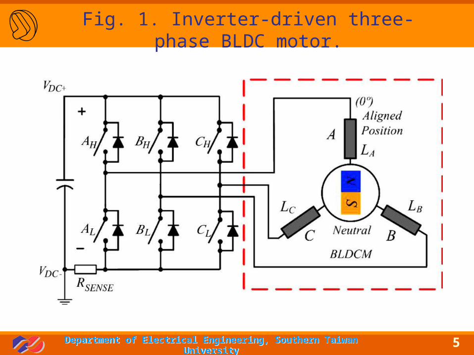
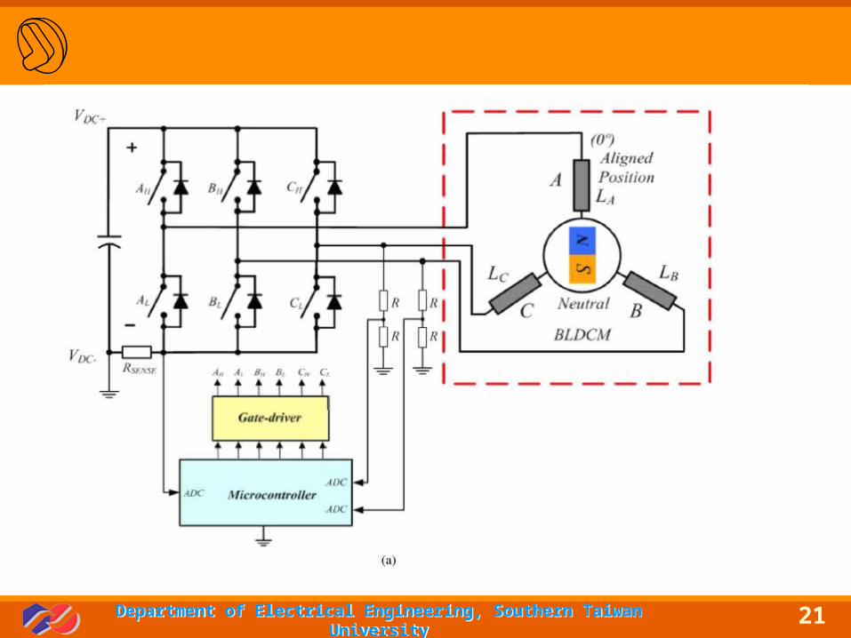
An inverter-driven three-phase BLDC motor, as shown in Fig. 1, needs rotor position information to ensure stable operation by synchronizing the phase excitation to the rotor position.
Startup is one of the major problems in sensorless BLDC drives, which are mostly based on back-electromotive-force (EMF) estimation techniques. The main reason is that the back-EMF voltage disappears at standstill.
To solve these startup problems, the initial rotor position should previously be determined. Most popular techniques to estimate the rotor position are based on the inductance variation, varying with the rotor position.
5Department of Electrical Engineering, Southern Taiwan UniversityDepartment of Electrical Engineering, Southern Taiwan University
Fig. 1. Inverter-driven three-phase BLDC motor.
6Department of Electrical Engineering, Southern Taiwan UniversityDepartment of Electrical Engineering, Southern Taiwan University
II. PROPOSED INITIAL ROTOR POSITION II. PROPOSED INITIAL ROTOR POSITION ESTIMATION METHODESTIMATION METHOD
The basic principle of estimating rotor position is based on the saturation effect of the stator core.
The key principle of the proposed method for detecting the rotor position at standstill is to measure and then compare the stator inductance of each phase.
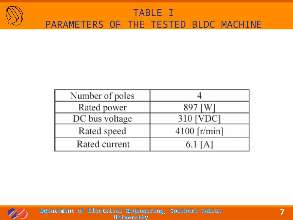
The machine parameters are listed in Table I.
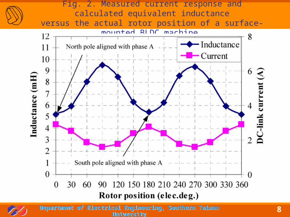
Fig. 2 shows the measured current response and calculated inductance against the actual rotor position.
7Department of Electrical Engineering, Southern Taiwan UniversityDepartment of Electrical Engineering, Southern Taiwan University
TABLE IPARAMETERS OF THE TESTED BLDC MACHINE
8Department of Electrical Engineering, Southern Taiwan UniversityDepartment of Electrical Engineering, Southern Taiwan University
Fig. 2. Measured current response and calculated equivalent inductanceversus the actual rotor position of a surface-mounted BLDC machine.
9Department of Electrical Engineering, Southern Taiwan UniversityDepartment of Electrical Engineering, Southern Taiwan University
A. Inductance Comparison ProcessA. Inductance Comparison Process
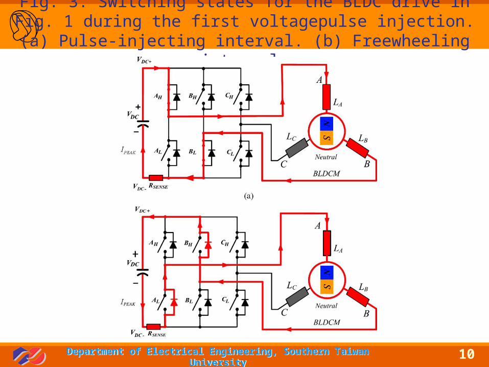
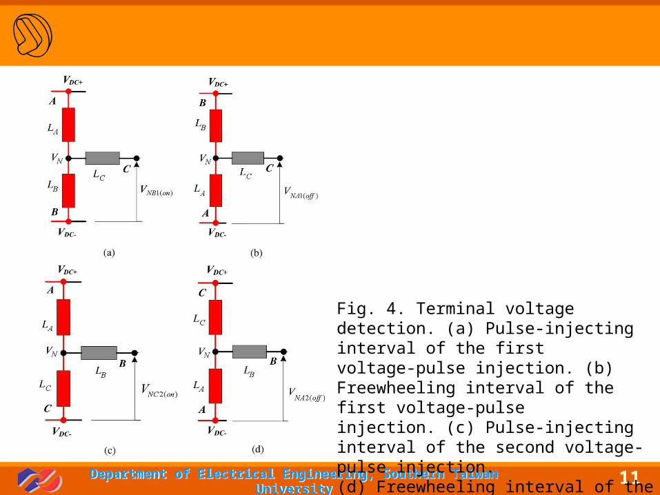
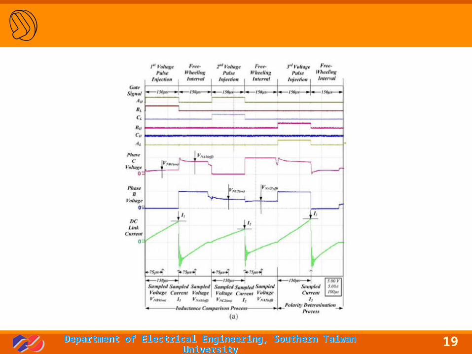
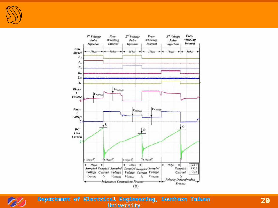
In this process, a sequence of two voltage pulses is injected to a pair of selected windings. As shown in Fig. 3, each voltage-pulse injection consists of two intervals.
The first voltage pulse is injected to the phase-A and phase-B windings by turning “on” switches AH and BL, as shown in Fig. 3(a).
Therefore, the voltage across the phase-B winding can be detected through the phase-C terminal and the negative dc bus. Its
equivalent circuit is simplified, as depicted in Fig. 4(a).
10Department of Electrical Engineering, Southern Taiwan UniversityDepartment of Electrical Engineering, Southern Taiwan University
Fig. 3. Switching states for the BLDC drive in Fig. 1 during the first voltagepulse injection. (a) Pulse-injecting interval. (b) Freewheeling
interval.
11Department of Electrical Engineering, Southern Taiwan UniversityDepartment of Electrical Engineering, Southern Taiwan University
Fig. 4. Terminal voltage detection. (a) Pulse-injecting interval of the firstvoltage-pulse injection. (b) Freewheeling interval of the first voltage-pulseinjection. (c) Pulse-injecting interval of the second voltage-pulse injection.(d) Freewheeling interval of the second voltage-pulse injection.

12Department of Electrical Engineering, Southern Taiwan UniversityDepartment of Electrical Engineering, Southern Taiwan University
13Department of Electrical Engineering, Southern Taiwan UniversityDepartment of Electrical Engineering, Southern Taiwan University
14Department of Electrical Engineering, Southern Taiwan UniversityDepartment of Electrical Engineering, Southern Taiwan University
15Department of Electrical Engineering, Southern Taiwan UniversityDepartment of Electrical Engineering, Southern Taiwan University
16Department of Electrical Engineering, Southern Taiwan UniversityDepartment of Electrical Engineering, Southern Taiwan University

17Department of Electrical Engineering, Southern Taiwan UniversityDepartment of Electrical Engineering, Southern Taiwan University

18Department of Electrical Engineering, Southern Taiwan UniversityDepartment of Electrical Engineering, Southern Taiwan University
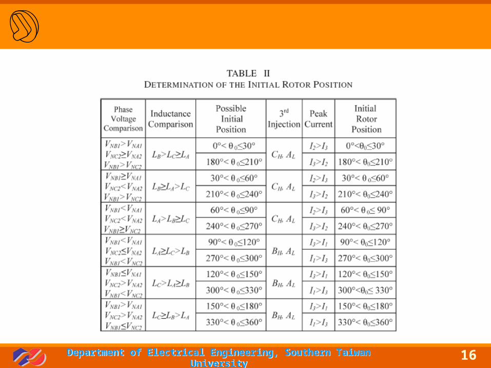
B. Polarity Determination ProcessB. Polarity Determination Process
19Department of Electrical Engineering, Southern Taiwan UniversityDepartment of Electrical Engineering, Southern Taiwan University
20Department of Electrical Engineering, Southern Taiwan UniversityDepartment of Electrical Engineering, Southern Taiwan University
21Department of Electrical Engineering, Southern Taiwan UniversityDepartment of Electrical Engineering, Southern Taiwan University
22Department of Electrical Engineering, Southern Taiwan UniversityDepartment of Electrical Engineering, Southern Taiwan University
IV. CONCLUSIONIV. CONCLUSION
A simple initial rotor position estimation method at standstill has been introduced in this paper. It is based on the stator inductance variation due to the influences of the saturation of the stator iron and the flux due to the position of the rotormagnets.
In the proposed method, only three narrow voltage pulses have been applied to the phase windings to determine the rotor position, and a 30◦ resolution has been achieved.
Additionally, only one sensing resistor has been added into a typical BLDC drive. It is particularly suitable for sensorless BLDC drive
applications in which low cost is the major requirement.Moreover, no machine parameters are required.
23Department of Electrical Engineering, Southern Taiwan UniversityDepartment of Electrical Engineering, Southern Taiwan University
ReferencesReferences
[1] STMicroelectronics, Application Note AN1276 BLDC Motor Start Routine for the ST72141 Microcontroller. [Online]. Available: www.st.com[2] S. Ogasawara and H. Agaki, “An approach to position sensorless drives for brushless DC motors,” IEEE Trans. Ind. Appl., vol. 27, no. 5, pp. 928–933,Sep./Oct. 1991.[3] P. B. Schmidt, M. L. Gasperi, G. Ray, and A. H. Wijenayake, “Initial rotor angle detection of a non-salient pole permanent magnet synchronous machine,” in Conf. Rec. IEEE IAS Annu. Meeting, New Orleans, LA, 1997,pp. 459–463.[4] G. H. Jang, J. H. Park, and J. H. Chang, “Position detection and startup algorithm of a rotor in a sensorless BLDC motor utilizing inductance variation,” Proc. Inst. Elect. Eng.—Elect. Power Appl., vol. 149, no. 2,pp. 137–142, Mar. 2002.[5] W.-J. Lee and S.-K. Sul, “A new starting method of BLDC motors without position sensor,” IEEE Trans. Ind. Appl., vol. 42, no. 6, pp. 1532–1538, Nov./Dec. 2006.[6] Y.-S. Lai, F.-S. Shyu, and S. S. Tseng, “New initial position detection for three-phase brushless DC motor without position and current sensors,” IEEE Trans. Ind. Appl., vol. 39, no. 2, pp. 485–491, Mar./Apr. 2003.[7] J. Sugawara, T. Kaimori, and S. Nichikata, “A novel and simple initial rotor position detecting method for PMSMs,” in Proc. IEEE PEDS, 2005,pp. 612–617.

24Department of Electrical Engineering, Southern Taiwan UniversityDepartment of Electrical Engineering, Southern Taiwan University
Thank you for your attention.
Related Documents