November 2014 Issue A 3 Bushells Place Wetherill Park NSW. 2164 Tel: 02 8781 2100 ROOFSAFE INDUSTRIAL SAFETY OPERATIONS & MAINTENANCE MANUAL The University of Wollongong Client: Axis Metal Roofing

Welcome message from author
This document is posted to help you gain knowledge. Please leave a comment to let me know what you think about it! Share it to your friends and learn new things together.
Transcript

November 2014 Issue A
3 Bushells Place
Wetherill Park NSW. 2164
Tel: 02 8781 2100
ROOFSAFE INDUSTRIAL SAFETY
OPERATIONS
& MAINTENANCE MANUAL
The University of Wollongong
Client: Axis Metal Roofing
November 2014 Page 2 of 54
Issue A
Roofsafe Industrial Safety The University of Wollongong
PURPOSE AND USE OF THIS MANUAL..................................................3
GENERAL SYSTEM CONFIGURATION....................................................3
GENERAL EQUIPMENT SELECTION.......................................................4
FALL PROTECTION PLAN........................................................................7
HEIGHT SAFETY MAINTENANCE & INSPECTIONS..............................11
GENERAL CONFIGURATION OF SAFETY SYSTEM.............................15
TRAINING..................................................................................................22
HARNESS ATTACHMENT PROCEDURE................................................25
SAFE WORK METHOD STATEMENT......................................................30
SITE INDUCTION CHECKLIST.................................................................48
CARE, USE AND GENERAL MAINTENANCE GUIDELINES..................61
EMERGENCY PROCEDURES..................................................................53
APPENDIX A: ...........................................................................................54
Certification
Warranty
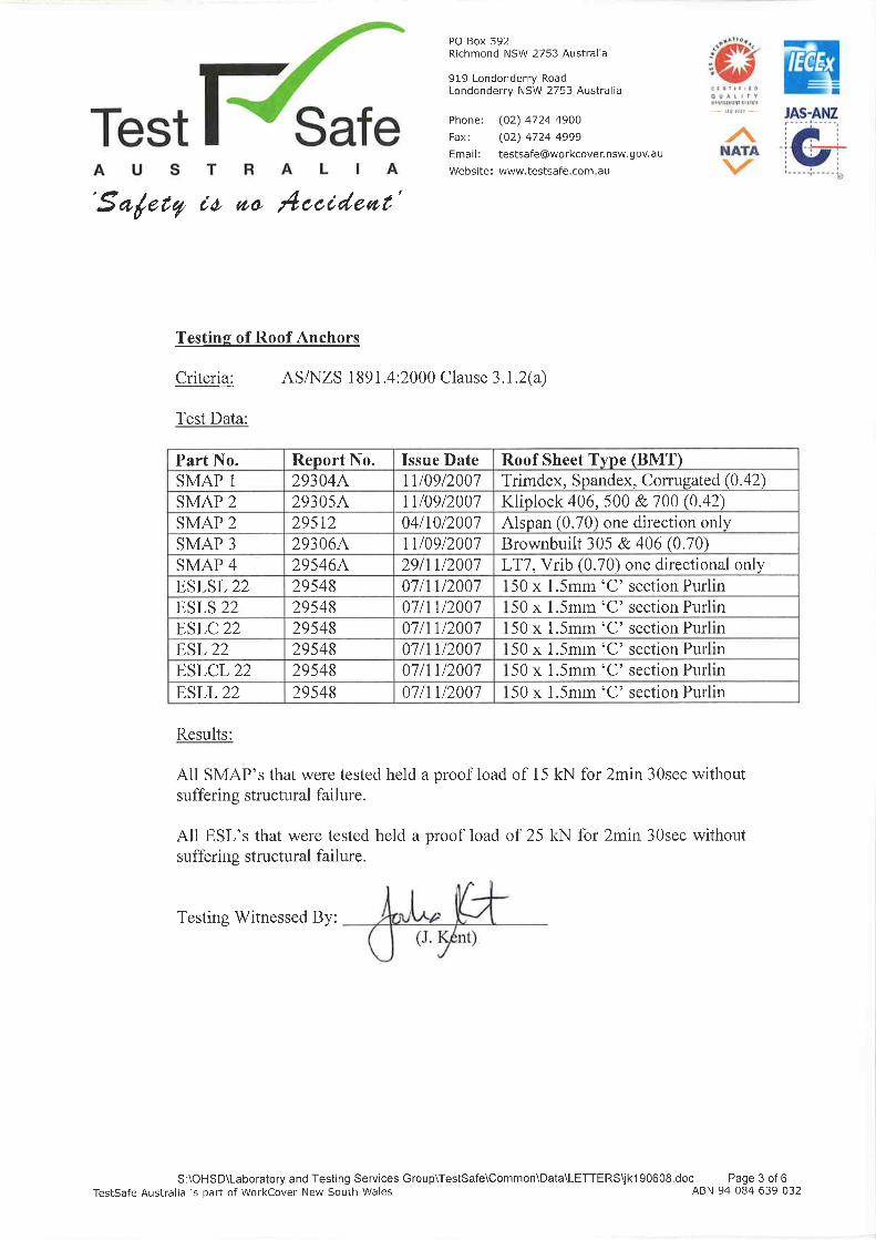
Test Data

November 2014 Page 3 of 54
Issue A
Roofsafe Industrial Safety The University of Wollongong
PURPOSE AND USE OF THIS MANUAL
To provide the information required to safely and correctly use the RIS Anchor Point, Static Line & Abseil System at The University of Wollongong. Please note: This manual is a GUIDE ONLY and provides information on general use of the system. The Manual MUST
be used in conjunction with a Task specific Safe Work Method Statement (SWMS).
GENERAL SYSTEM CONFIGURATION The systems installed at The University of Wollongong site contain the following:
♦ Twenty Nine Stainless Steel Anchor Points
♦ Eighty Four metres Stainless Steel Horizontal Static Line
♦ Forty Two metres Aluminium Handrail
♦ One Hundred and Seventy Five metres Saferail
♦ Three Aluminium Ladders and Four Ladders Heads
♦ Ten Stainless Steel Ladder Brackets
♦ Ten Stainless Steel Anchor Cable Strops
♦ Two Aluminium Lightweight Platforms
♦ Signage
The above systems are designed to ensure that individuals who are required to undertake work at height at the above locations can do so in a safe and unhindered manner.

November 2014 Page 4 of 54
Issue A
Roofsafe Industrial Safety The University of Wollongong
GENERAL EQUIPMENT SELECTION The Safety System will require the following accessories:
♦ TRRW01 Tradesman – Roofworkers fall arrest harness

November 2014 Page 5 of 54
Issue A
Roofsafe Industrial Safety The University of Wollongong
♦ WL02 2m Shock Absorbing Lanyard.
♦ ROPEP01 15m Polyester rope with rope grab.

November 2014 Page 6 of 54
Issue A
Roofsafe Industrial Safety The University of Wollongong
♦ LDV-0010 Static line shuttle.
♦ SA01 300mm Personal Shock Absorber
KAS018 Karabiners

November 2014 Page 7 of 54
Issue A
Roofsafe Industrial Safety The University of Wollongong
FALL PROTECTION PLAN
1. PURPOSE
To document a Fall Protection Plan (See Instructions Pages: for the The University of Wollongong site using The RIS anchor point, Static Line and Saferail system engineered specifically to suit each installation location for maintenance as per relevant Work Cover requirements.
2. EQUIPMENT & QUANTITY REQUIRED PER USER
Below is a list of safety equipment:
♦ Anchor Points (permanent)
November 2014 Page 8 of 54
Issue A
Roofsafe Industrial Safety The University of Wollongong
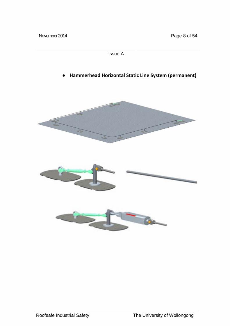
♦ Hammerhead Horizontal Static Line System (permanent)

November 2014 Page 9 of 54
Issue A
Roofsafe Industrial Safety The University of Wollongong
♦ Saferail (permanent)
♦ RW01 – Roofworkers fall arrest harness (1 off) ♦ WL02 2m Shock Absorbing Lanyard. (1 off) ♦ SA01 300mm Personal Shock Absorber (1 off) ♦ ROPEP01 15m Polyester rope with rope grab (1 off) ♦ LDV-0010 Static line shuttle. (1 off) ♦ KAS018 Karabiner (1 off)
NB: Above Items Photo’s on pages: 4, 5, 6, 7, 8 & 9

November 2014 Page 10 of 54
Issue A
Roofsafe Industrial Safety The University of Wollongong
3. POTENTIAL HAZARDS
Restrained and free-fall injuries. These hazards usually occur when the person(s):
♦ Uses a lanyard assembly longer than permissible;
♦ Exceeds the number of persons rated for the system (i.e. one person maximum on Anchor Points).
♦ Does not connect – or not properly connected.
♦ Does not follow clear instructions and guidelines.
4. REFERENCES
Always read and comply with instructions for use that accompanies the system and safety equipment required.

November 2014 Page 11 of 54
Issue A
Roofsafe Industrial Safety The University of Wollongong
Height Safety Maintenance – Preventative/Routine Maintenance
YEARLY
The Height Safety Systems installed at The Sydney Cricket Ground – MA Noble / Don Bradman Grandstand should be inspected and Re-Certified by a competent person of Height Safety Operator as per the Australian Standards AS1891.4.2009 every 12 months from the date of the installation certification.
All inspections should be documented to ensure the traceability of maintenance records.
A record card, history sheet or similar documentation must be kept for all items installed at The University of Wollongong.
Documentation of the maintenance records and servicing history of the items must be made available to all operators and users for at least the life of the equipment.
The following list is the required information to be documented for Re-Certification Purposes:
1: Manufacturer’s, Suppliers or Installers Name and Address.
2: Manufacturer’s Serial or Indentifying Number.
3: Year of Manufacture / Installation.
4: Suitability and Limitations on Various Usage.
5: Date of Purchase.
6: Date first put into Service.
7: Dates and Details of Inspections and Services.
Inspection Requirements:
• Anchor Points: Inspected and Re-Certified every 12 months.
• Horizontal Static Line: Inspected and Re-Certified every 12 months.
• Saferail: Inspected and Re-Certified every 12 months.
• Anchor Cable Strops: Inspected and Re-Certified every 12 months.
• Ladder Brackets: Inspected and Re-Certified every 12 months.

November 2014 Page 12 of 54
Issue A
Roofsafe Industrial Safety The University of Wollongong
Aluminium Walkway, Handrail, Ladders and Platforms as per AS1657-2013 should be Re-Certified every 5 years – However, these items should be inspected periodically for Loose Rivets, Washers, EPDM Seal and Retaining Discs.
Inspections are required as per the Australian Standards AS1891.4.2009 to identify any breakdown in the performance of the installed products.
In the event of any damage to the Height Safety System Installed at The University of Wollongong due to incorrect use (free fall or restrained fall) or abuse, the anchor points, horizontal static line, vertical line, Saferail, strops or ladder bracket must be withdrawn from use and inspected by a competent person or height safety operator (AS1891.4.2009 Series – Industrial Fall Arrest Systems and Devices)
In the unlikely event of a fall on the system at The University of Wollongong – the system MUST be placed out of service and Roofsafe Industrial Safety or a Height Safety Operator called o complete a full inspection. The system is to remain out of service until rectified and recertified.
Personal Protective Equipment (PPE): Harnesses, Lanyards, Ropes, Shock Absorbers and associated personal equipment must be inspected every 6 months by a competent person or Height Safety Equipment Inspector.
A PPE register must be kept by each individual and produced prior to usage of the system to The Sydney Cricket Ground Trust or Maintenance Manager.

November 2014 Page 13 of 54
Issue A
Roofsafe Industrial Safety The University of Wollongong
A record card, history sheet or similar record should be kept with each of the items of equipment listed for each item the information to be recorded. Documentation on the maintenance and servicing history of an item of equipment shall be freely available to operators and users of the equipment.
Item to be recorded
Harnesses, lineworker
s,body belts and
assemblies
Lanyard assembly and pole
straps
Type 1 fall-arrest
devices including
anchorage line
Type 2/3 fall-arrest device
Mobile attached devices
Fixed anchorages,
horizontal life lines and life
rails
Manufacturer’s, supplier’s or installer’s name Yes Yes Yes Yes Yes Yes
and address Manufacturer’s batch number Yes Yes
Serial or identifying number
Yes Yes Yes Yes
Year of manufacture Yes Yes Yes Yes Yes
Details of recommended connections to
Yes Yes Yes
belts or harnesses Type of anchorage line to be used
Yes
Suitability and limitations on Yes Yes Yes Yes Yes Yes various usages Date of purchase Yes Yes Yes Yes Yes
Date first put into service Yes Yes Yes Yes Yes Yes
Dates and details of inspections and Yes Yes Yes Yes Yes Yes services

November 2014 Page 14 of 54
Issue A
Roofsafe Industrial Safety The University of Wollongong
SUSPENSION TRAUMA (AS/NZS 1891.4:2009) (Informative)
Suspension intolerance trauma is a condition (e.g. following a fall), whereby a person suspended in a harness in a substantially upright position may experience blood pooling in the legs. Depending on the susceptibility of the individual, this may lead to loss of consciousness, renal failure and eventually death. In clinical trials, although some subjects experienced no effects after prolonged suspension, others experienced fainting or loss of consciousness in just a few minutes. The initial indications are that a person’s susceptibility may be unrelated to fitness level or other obvious physical conditions or attributes. Although the condition is still being researched, is recommended that certain measures be taken to reduce the effects of this condition or delay its onset. It appears to help if the person suspended in a substantially horizontal position or with the knees elevated and with an opportunity to “pump” the legs, ideally with the feet against a firm surface. The person should be encouraged to maintain leg activity by both moving the legs and where possible pushing with the feet against a firm surface at regular intervals until retrieval can be effected. It is clear however, that an effective incident response plan is necessary to ensure that following an incident, the person can be removed from the suspended position as quickly as possible.

November 2014 Page 15 of 54
Issue A
Roofsafe Industrial Safety The University of Wollongong
GENERAL CONFIGURATION OF SAFETY SYSTEM
♦ The Anchors at The University of Wollongong site employs the use of anchor points that are structurally mounted. Watertight integrity is ensured by the installation of neoprene gaskets. All external components are manufactured from stainless steel and can be used in fall arrest and fall restraint applications. The anchor points have been manufactured by Roofsafe Industrial Safety and have been independently tested to exceed the requirements of AS/NZ 1891.4:2009

November 2014 Page 16 of 54
Issue A
Roofsafe Industrial Safety The University of Wollongong
♦ The Aluminium Fixed access ladders installed at The University of Wollongong site have been manufactured with the highest level of safety in mind and to ensure compliance with Australian and International Standards. The extra strong frame ensures a very stable and rigid ladder even at considerable heights. The Ladder Rungs have been specially designed to provide superior grip and support, ensuring a higher level of safety while climbing the ladder.

November 2014 Page 17 of 54
Issue A
Roofsafe Industrial Safety The University of Wollongong
♦ The Horizontal Lifeline System employs the use of Stainless Steel Intermediates and end Anchors structurally mounted. RIS Hammerhead system is designed for permanent installation on buildings and other structures where workers are exposed to a risk of falling when performing height safety work. The Hammerhead system incorporates two energy absorbing devices with mounting brackets at each end and where needed also in-between, which limits structural loads to 6kn in the event of a fall. The Hammerhead Lifeline system is designed to protect 1 to 4 workers attached simultaneously to the same line. Each worker will need to be fitted with a harness (TRWW01) and a lanyard with a suitable energy absorber. The worker wearing a full body harness and energy absorbing lanyard is continuously attached to the Hammerhead Lifeline system with the glider, which can travel along the cable and pass through the intermediate brackets.
November 2014 Page 18 of 54
Issue A
Roofsafe Industrial Safety The University of Wollongong
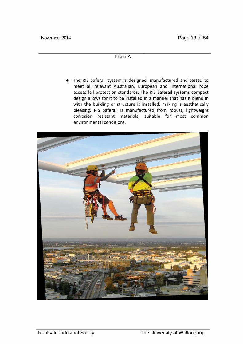
♦ The RIS Saferail system is designed, manufactured and tested to meet all relevant Australian, European and International rope access fall protection standards. The RIS Saferail systems compact design allows for it to be installed in a manner that has it blend in with the building or structure is installed, making is aesthetically pleasing. RIS Saferail is manufactured from robust, lightweight corrosion resistant materials, suitable for most common environmental conditions.

November 2014 Page 19 of 54
Issue A
Roofsafe Industrial Safety The University of Wollongong

November 2014 Page 20 of 54
Issue A
Roofsafe Industrial Safety The University of Wollongong
♦ The RIS Handrail, Walkway and Platform system provides safe access to roof top plant and equipment. RIS Handrail, Walkway and platforms are lightweight yet incredibly strong and virtually maintenance free, which provides a simple solution to safety in the workplace. The system is compatible with the vast majority of roof profiles available. All walkways/platforms and handrails are designed to meet the relevant requirements of AS/1657-1992 and various statutory codes.

November 2014 Page 21 of 54
Issue A
Roofsafe Industrial Safety The University of Wollongong
♦ Roofsafe only manufacture, distribute and promote products that meet or exceed the relevant standard AS/NZS 1891.4 and comply with the NSW Code of Practice – Safe Work on Roofs and Occupational Health and Safety Regulations 2001. Roofsafe products have been independently tested by Testsafe Australia assured by their ISO 9001 quality management systems and accredited by NATA testing laboratories.

November 2014 Page 22 of 54
Issue A
Roofsafe Industrial Safety The University of Wollongong
TRAINING
A Height Safety competently trained person must train every person working at heights at The University of Wollongong site.
Document the names of persons who receive fall protection training and their training dates. 1
To ensure that highest levels of safety are maintained RIS can offer tailored height training packages that provide the users with intensive skills required for working at heights. Please note: that all personnel required too work on the roof area must have completed a national accredited height safety awareness course.
Please note: that all personnel required too work on the roof areas must have completed a national accredited height safety awareness course.
Ensure information, instruction and training is provided to all employees about the risks of working at height and about any safety measures you put in place.
If you have designated work groups at your workplace, the Falls Regulations require you to consult with the health and safety representative for each designated work group who may be affected by any fall hazard identification, risk assessment or risk control process. That consultation must happen as long as it’s practicable; there should be few, if any, occasions where it would not be practicable to consult with the health and safety representative.
1 Competent person – a person who has, through a combination of training, education and experience, acquired knowledge and skills enabling that person to correctly perform a specified task (clause 1.3.1 AS/NZS 1891.2:2001.
The term competent person has a legal interpretation should an accident or injury occur.

November 2014 Page 23 of 54
Issue A
Roofsafe Industrial Safety The University of Wollongong
The training program must cover:
♦ Fall hazards that workers will encounter;
♦ How the system will protect workers from falls;
♦ Worker’s responsibility under the fall protection plan;
♦ Procedures for maintaining personal fall arrest systems;
♦ Equipment limitations and restrictions of use;
♦ Procedures for rescue/retrieval.

November 2014 Page 24 of 54
Issue A
Roofsafe Industrial Safety The University of Wollongong
USER TRAINING (EXCERT FROM AS/NZS 1891.4 :2009 ) 2.2.10 User competency Users of fall-arrest systems and equipment shall be assessed for competence prior to being allowed to work without direct supervision and shall undergo additional training if necessary to ensure that they are competent in correct use of the equipment they are required to use. Users shall be assessed on their understanding of the following as appropriate:
(a) Manufacturer’s instructions (as per Harness user brochure appendix B) supplied with each devise or system indicating the method of fitting, adjustments and use.
(b) The choice of suitable anchorage points, and the appropriate release and rescue procedures in the event of an arrested fall.
(c) The need to ensure that the forces applied to the body through a lanyard or anchorage line at fall arrest, do not exceed 6 kN, by ensuring that wherever necessary, i.e. if free falls are in excess of 0.6m recommended energy absorbing equipment or devices are always used, and used in the correct manner.
(d) Awareness of the physical hazard to a person’s body if a person free falls wearing incorrect fall-arrest equipment, a belt where a harness is required.
(e) Hazards or problems likely to be encountered in the use of specific items of equipment as detailed elsewhere in this Standard.
(f) Requirements for carrying out prescribed user inspections of equipment.
The assessment shall be conducted by a competent person not necessarily independent of the operator’s employer.
1.4.1 Competent person: A person who has, through a combination of training, education and experience, acquired knowledge and skills enabling that person to correctly perform a specified task.
November 2014 Page 25 of 54
Issue A
Roofsafe Industrial Safety The University of Wollongong
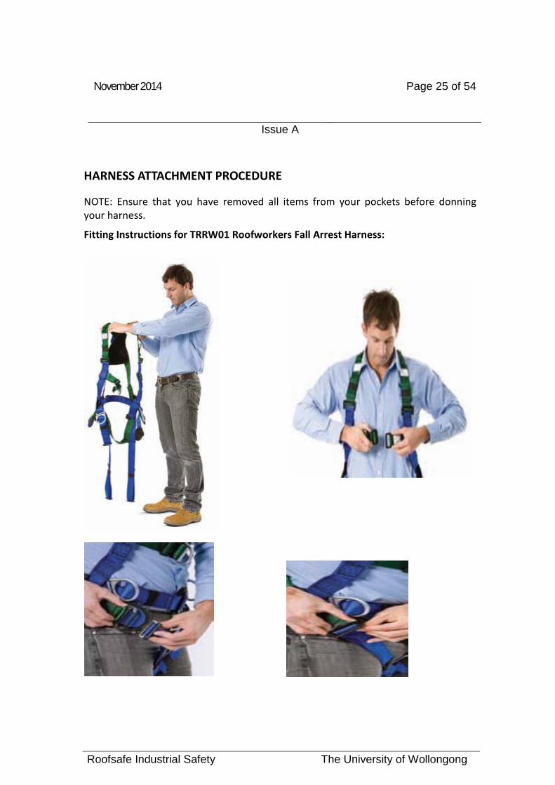
HARNESS ATTACHMENT PROCEDURE
NOTE: Ensure that you have removed all items from your pockets before donning your harness.
Fitting Instructions for TRRW01 Roofworkers Fall Arrest Harness:

November 2014 Page 26 of 54
Issue A
Roofsafe Industrial Safety The University of Wollongong

November 2014 Page 27 of 54
Issue A
Roofsafe Industrial Safety The University of Wollongong
Find the top of the triangular delta at the back of the harness. Alternatively, identify the front and back of the harness.
Identify a label sewn at the apex of the delta marked "ATTACHMENT POINT FOR FALL-ARREST". The triangular delta rests on your back with the attachment point "D" ring positioned on the outside between your shoulder blades.
Identify the frontal “ATTACHMENT POINT FOR FALL - ARREST”
Put your right arm between the triangular delta and the shoulder straps.

November 2014 Page 28 of 54
Issue A
Roofsafe Industrial Safety The University of Wollongong
Pass your head through the “V” in the shoulder straps.
Make sure that the shoulder straps are not twisted.
Locate the waist belt and connect to the waist buckle.
The waist belt and waist buckle are the same colour.
Make sure that webbing straps are not twisted.
Identify the left cross over strap below the frontal attachment point.
Connect to the left buckle of the strap with the buckle having the black patch.
Identify right leg strap and connect to right buckle.
Identify left leg strap and connect to left buckle.
Adjustment Instructions for Full Body Harnesses:
The harness should be comfortable without undue pressure on the shoulders, thighs or pelvis.
A good guide is to use your open hand and clenched fist to determine if the adjustment is correct.
You should be able to pass your open hand between all webbing straps and your body.
You should not be able to pass your clenched fist between all webbing straps and your body. If you can, readjust all buckles.

November 2014 Page 29 of 54
Issue A
Roofsafe Industrial Safety The University of Wollongong
To ensure maximum safety and comfort, adjust your harness in the following sequence:
Adjust the waist belt first.
Position the waist belt just on or just below the navel.
Semi-squat and adjust both leg straps at the same time to the same length.
Stand erect and adjust buckles on your shoulder straps.
Adjust the frontal attachment so that it is positioned on the sternum in the center of your chest.
November 2014 Page 30 of 54
Issue A
Roofsafe Industrial Safety The University of Wollongong
SAFE WORK METHOD STATEMENT ANCHOR POINTS
Ensure that all people working on roof have been competently trained in Height Safety and possess a Height Safety ticket.
Make sure you possess and wear the correct equipment.
o TRRW01 Tradesman – Roofworkers fall arrest harness
o WL02 2m Shock Absorbing Lanyard.
o ROPEP01 15m Polyester rope with rope grab.
o SA01 300mm Personal Shock Absorber
o KAS018 Karabiners.
ACCESS TO ROOF AREA IS VIA: ROOF ACCESS DOOR
INFORM THE UNIVERSITY OF WOLLONGONG TRUST/MANAGEMENT OR SECURITY THAT WORKS ARE BEING CONDUCTED ON THE ROOF AREA BEFORE COMMENCEMENT OF ANY WORKS – ALWAYS WORK ON THE ROOF AREA WITH A SECOND PERSON.
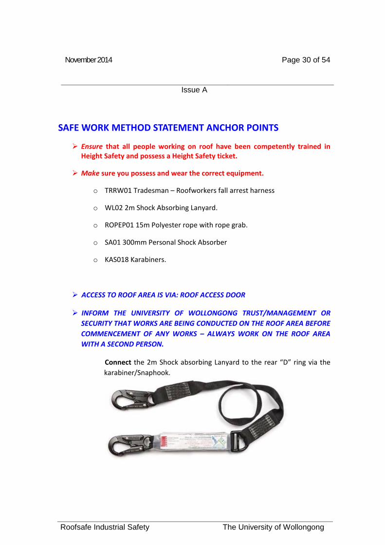
Connect the 2m Shock absorbing Lanyard to the rear “D” ring via the karabiner/Snaphook.

November 2014 Page 31 of 54
Issue A
Roofsafe Industrial Safety The University of Wollongong
Connect the Personal Shock Absorber to the frontal “D” ring of the harness via the karabiner.
Connect the Rope Grab Fall Arrestor & Rope to the free end of the 2m Shock Absorbing Lanyard via the Karabiner.
Make sure harness is fitted correctly (See Pages 22-26)
Make sure all attachments are fitted securely and correctly.
Carry 15m rope with rope grab either by securing over shoulder or in a backpack.
Locate Roof Access Door
Open door and walk out onto roof area.
Walk to the anchor point you wish to connect to.
Connect the free end of rope to the anchor point via the karabiner.
Make sure the Adjustable Rope Grab & Rope is securely attached to the anchor point.

November 2014 Page 32 of 54
Issue A
Roofsafe Industrial Safety The University of Wollongong
Walk to the high side of the anchor point ensuring you are greater than 2 metres away from edge.
Correct Attachment to Transition Anchor Point
GENERAL NOTE:
NOTE - When utilising the Adjustable Rope Grab & Rope system it is important that the user adjusts the lanyard length (i.e. make sure the Rope and Shock Absorber are taut to prevent any working slack. It is advisable to have NO working slack.
If the roof slope is greater than 15 degrees the user must remain connected to an anchorage point at all times.
Perform the work required using care.
NOTE – When accessing the corners of the building connect the Karabiner to the Adjustable Rope and then connect the Karabiner to the Diversion Anchor to prevent a pendulum effect.

November 2014 Page 33 of 54
Issue A
Roofsafe Industrial Safety The University of Wollongong
Detach yourself from the anchor point only when you are in a position (i.e. greater than 2 metres from the edge)
To attach to the other anchor points, ensure that you repeat the above steps
General Note: if the roof is to steep to transfer safely, a second Adjustable Rope Grab & Rope is required.
Note:
1. Always attach to the anchor point that is directly behind you.
2. Do not pass another anchor without being attached to it.
3. Using an anchor that is not directly behind you will cause a pendulum effect.
Once all work is complete, return to the roof access door.
Secure rope over shoulder or in a back pack
Disconnect from anchor point system.
Enter through roof access door, close and lock.
Return all equipment used to the appropriate Storage Area or to the Building Maintenance Manager.
November 2014 Page 34 of 54
Issue A
Roofsafe Industrial Safety The University of Wollongong
SAFE WORK METHOD STATEMENT – STATIC LINE Ensure that all people working on roof have been competently trained in
Height Safety and possess a Height Safety ticket.
Make sure you possess and wear the correct equipment.
ACCESS TO ROOF AREA IS VIA: ROOF ACCESS DOOR
INFORM MANAGEMENT OR SECURITY THAT WORK IS BEING CONDUCTED ON THE ROOF AREA BEFORE COMMENCEMENT OF ANY WORKS – ALWAYS WORK ON THE ROOF AREA WITH A SECOND PERSON.
Personal equipment required:
♦ TRW01 – Roofworkers fall arrest harness ♦ WLAD02 2m Shock Absorbing Lanyard. ♦ WLSA01 300mm Personal Shock Absorber ♦ HL911 Static line shuttle/Glider with Karabiner ♦ L024T Karabiner
Make sure harness is fitted correctly.
Connect the 2m Shock Absorbing Lanyard to your rear dorsal ‘D’ ring via the karabiner.
Connect the Personal Shock Absorber to the frontal “D” ring of the harness via the karabiner.
Locate the roof access door.
Open door and enter onto the roof.

November 2014 Page 35 of 54
Issue A
Roofsafe Industrial Safety The University of Wollongong
Walk to the Horizontal Lifeline System ensuring you remain in a safe working zone.
Connect the Shuttle to the Horizontal Lifeline system.
Firstly remove the karabiner from shuttle.
Open the Shuttle mouth via lever.
Place the Shuttle mouth around the cable and close. Make sure the slot in the Shuttle will line up with the intermediate bracket.

November 2014 Page 36 of 54
Issue A
Roofsafe Industrial Safety The University of Wollongong
Connect the karabiner to the Shuttle to prevent the mouth from opening (the Shuttle is now securely attached to the safety line).

November 2014 Page 37 of 54
Issue A
Roofsafe Industrial Safety The University of Wollongong
Connect the 2m Shock Absorbing Lanyard to the Shuttle via the karabiner.

November 2014 Page 38 of 54
Issue A
Roofsafe Industrial Safety The University of Wollongong
Make sure user is secured correctly to the Horizontal Lifeline system.
Make sure the Shuttle in combination with the 2m Shock Absorbing Lanyard follows the user along the Horizontal Lifeline system.
The user must
Caution should be employed at all times, especially when working near the edge.
stay connected to the Static Line System at ALL times whilst doing gutter maintenance or working within 2m of the edge.
Once all work is complete, return to the roof access point.
Disconnect the Shuttle from the Horizontal Lifeline system.
Remove the karabiner from the Shuttle.
Open the Shuttle mouth via lever.

November 2014 Page 39 of 54
Issue A
Roofsafe Industrial Safety The University of Wollongong
Remove the Shuttle mouth from around the cable.
Connect the karabiner to the shuttle for storage.
Exit roof area via roof access door making sure that door is closed and locked.
Return all equipment used to the appropriate Storage Area or to the Building Maintenance Manager.

November 2014 Page 40 of 54
Issue A
Roofsafe Industrial Safety The University of Wollongong
SWMS - SAFERAIL ABSEIL TRACK
ROOFSAFE INDUSTRIAL SAFETY INSTALL & DESIGN ABSEIL SYSTEMS ONLY – A TRAINED AND QUALIFIED ABSEILER TO IS TO PROVIDE A SAFE WORK METHOD STATEMENT PRIOR TO ANY COMMENCEMENT OF WORKS.
BELOW IS A GUIDE ONLY
SAFE WORK METHOD STATEMENT – INSTALLED SYSTEMS SAFERAIL FOR ABSEIL USE – FRONT GLASS AWNING WESTERN END & INTERNAL AUDITORIUM GLASSED AREA.
ACCESS SYSTEM FOR ABSEILING:
FRONT GLASS AWNING WESTEN END – VIA EWP
INTERNAL ATRIUM GLASSED AREA: 1ST
IT IS RECOMMENDED THAT TWO PEOPLE WORK AS A TEAM
MAN UP SYSTEM
Ensure that all persons conform to the work procedures detailed in AS/NZS 4488.1:1997 Industrial Rope Access Systems.
HAZARD INFORMATION
POTENTIAL HAZARD PROPOSED ACTION/CONTROL
Falling objects. • Area below to be barricaded off.
• Tool straps/lanyards must be used.
• Ensure other persons in the area are advised of your work.
Persons falling. • Ensure all ropes are properly connected.
• Ensure that all persons confirm with AS/NZS 4488.1:1997.

November 2014 Page 41 of 54
Issue A
Roofsafe Industrial Safety The University of Wollongong
• Ensure all equipment conforms to the relevant Australian Standards.
Equipment Damage • Use rope protection on edges.
• Ensure that cleaning chemicals do not contact ropes and harnesses.
• Do not drag ropes, coil and carry.
Building Damage • Ensure care is taken when lowering ropes.
• Ensure correct footwear is worn.
• Ensure that protection is provided between the building and rope at all locations.
November 2014 Page 42 of 54
Issue A
Roofsafe Industrial Safety The University of Wollongong
ABSEIL System Access:
When accessing Roofsafe Industrial safety Rope Access Anchorage Point System, the Rope technician must first insure the following items.
• The systems have been inspected and tested as required within the last 12 months – Refer maintenance schedule Pages 11, 12 & 13
• The systems are to be used in a twin rope access manner no single rope application is permitted or recommended for any suspended works.
• A current risk assessment and work method statement is to be handed to The Trust / Management or security prior to completing any works.
Suggested Connection and Access Method
General Note:
When accessing the system for the purpose of suspended work the rope access technician must mobilise all equipment required to the closest set of anchorage point directly adjacent to the required drop zone ensure that at no time they are in a position where a fall of any distance could be sustained
System Operating Instructions
The Saferail abseiling system is designed to be used in conjunction with traditional rope access techniques, as such it is essential that the personnel using the system are able to demonstrate competency in such work.
RIS recommends that any person using the Saferail abseiling system should be able to produce a current certificate of competency in vertical access from one of the following accredited sources.

November 2014 Page 43 of 54
Issue A
Roofsafe Industrial Safety The University of Wollongong
• Registered training Organisation (RTO) • Australian Rope Access Association (ARAA) • International Rope Assess Trade Association (IRATA)
Prior to beginning work the operators should familiarise themselves with the system and the system inspection criteria. The pre start inspection for the Saferail system should form part of a Safe Work Method Statement SWMS, which should be produced by the contractor and provided to the client.
Pre Start Inspection
The client representative should have a formal hand over system in place prior to work beginning and this hand over should include the following inspection criteria:
Trolley o Inspection of the trolley should be completed on a per user basis as
well as annual documented inspections by the installer for re-certification purposes – Inspection criteria see Pages 11, 12 & 13
o Bronze Wheels Wear and tear on the bronze rollers Slogging of the bolts and pin housing Bending or splitting
o Body Wear or distortion of the rope connection point
o Bolts Loosening or slogging of the housing, threads or nuts
o Fitting When fitting the trolley to the system the user must ensure the
trolley cannot become dislodged from the rail and that the exit entry point is locked prior to the user attaching to the system.

November 2014 Page 44 of 54
Issue A
Roofsafe Industrial Safety The University of Wollongong
Rail and Anchorage System (strong back and fixing posts) o Inspection of the Rail assembly should be completed on a per user
basis as well as annual documented inspections by a Height Safety Company the installer for re-certification purposes. Dependent on the areas being used the operator should position the ropes in the required areas and ascend to the top of the rope and inspect the track for the following items.
o Track wear o Loosened bolts connecting the strong back to the structural angle o Rail alignment with the strong back (the vertical face of the Saferail
should remain parallel with the vertical face of the strong back assembly).
o General distortion or movement in any components of the system
Setting Up for Work
RIS recommends that users of the Saferail abseiling system operate in the traditional vertical movement process for cleaning and maintaining windows. Rarely are windows cleaned or maintained by rope access technique bottom to top or horizontally. To ensure optimal system life and operation the user must follow the items below.
Access to the system shall be gained via a Temporary Ladder and Ladder Bracket – see appendix A for site plans - the ropes should be pre-rigged from this zone and then lowered to the floor level below prior to loading to eliminate the risk of falls from height. The safe zone must provide suitable guardrail or barrier equal to the requirements set out in AS1657 i.e. min

November 2014 Page 45 of 54
Issue A
Roofsafe Industrial Safety The University of Wollongong
1000mm guardrail with no more than 450mm gap between top, bottom and mid rails based upon the user(s) standing height.
To get the optimal operating life from the system the user will position the ropes directly under the work area. Once positioned the user will suspend their full body weight into the system and ascend to the top of the ropes and begin work in a downward motion.
The user should repeat this process at each work position.
Whilst horizontal movement is possible and permissible with this system the best outcome for the client is to limit the systems use to vertical access only.
It is recommended that the user of the system ensures that the backup line is positioned approximately 2m away from the primary access line as this ensures coverage across 2 bays and gives the user added protection in the unlikely event of a rope or hardware failure.
Care should be taken to ensure the operator does not overload the system by
suspending or lifting materials or goods that will exceed the SWL (150 KG) as any over loading of the system may affect the wear of the trolley on the track and subsequently damage the rail.
The Saferail abseiling system has been tested to 15kn and meets or exceeds
the requirements of AS1891.2 and is designed for personnel access only. The only permissible time that the system may be used with more than 150kg between each support structure is in the event of an emergency rescue in which case the rescuer may expose the system to 250 kg maximum. In such an event the system must be immediately removed from service and inspected by the manufacturer prior to being placed back into service.
The user of the system is responsible for organising and planning for rescue
scenarios they may encounter.

November 2014 Page 46 of 54
Issue A
Roofsafe Industrial Safety The University of Wollongong
From within the safe zone engage first shuttle to rail system and ensure compliance plate is in date
Engage first shuttle to upper rail system
Engage two karabiners to each of the shuttles and tie figure of 8 or 9 knots independently ensuring screw gates are then closed

November 2014 Page 47 of 54
Issue A
Roofsafe Industrial Safety The University of Wollongong
Completion of Work.
RIS recommends that at the completion of work on each day of use, the persons operating the system hand back the trolleys to the client representative as a part of the safe operating system and SWMS.
A new inspection should be completed at the start of the next day’s work or next time the system is to be used.
Ensure the End Stop Mechanism is engaged so that trolleys cannot pass

November 2014 Page 48 of 54
Issue A
Roofsafe Industrial Safety The University of Wollongong
SAMPLE
SITE INDUCTION CHECKLIST
Place a tick in the box † only when completed satisfactorily
Name: ......................................... Start Date: ...................... Site: .............................................. Contractor: .........................
Hours of Work
θ Start and Finish times & Site Hours Confirm Terms of Engagement/Contract
θ _______________________________________________ Safety
θ Safety Rules issued and discussed θ Danger tags and lockouts explained θ Protective equipment issued and discussed θ Fire Safety and Evacuation explained θ First Aid θ Smoking θ Explain how to report a hazard or safety concern
Absence From Work
θ Workers Compensation. θ Reporting Injuries
Amenities
θ Toilets & Facilities

November 2014 Page 49 of 54
Issue A
Roofsafe Industrial Safety The University of Wollongong
θ Parking and transport
Job Instruction
θ Explain the Safe Work Method Statement θ Encourage questions and suggestions
Completed by: ........................................ Date: ................................
I hereby acknowledge receipt of The University of Wollongong site Occupational Health and Safety Rules and have read and understood them and agree to comply with all safety requirements.
Name: ___________________ Signature: ________________ Date: ________

November 2014 Page 50 of 54
Issue A
Roofsafe Industrial Safety The University of Wollongong
SAMPLE
Site Induction Register
Company:____
Date: _____________________________Time:
Name: _____
General System Details Other: ………………………………………….
Product/Equipment Use ………………………………………….
Harness Donning ………………………………………….
No. Name Company Signature
1
2
3
4
5
6
7
8
12

November 2014 Page 51 of 54
Issue A
Roofsafe Industrial Safety The University of Wollongong
CARE, USE AND GENERAL MAINTENANCE GUIDELINES
Next annual certification/or any site inspection will incur a fee. In the event of any damage to the anchor point system due to incorrect use (free-fall or restrained fall) or abuse, the anchor points must be withdrawn from use and inspected by RIS (AS1891 Series – Industrial Fall-Arrest Systems and Devices).
EMERGENCY PROCEDURES Rescue and retrieval of fallen operators is critical and should only be carried out by properly trained personnel. It is important that notification of a fall be made immediately upon fall. Prolonged hanging in full body harness can result in blood circulation problems. IF YOUR COMPANY DOES NOT HAVE TRAINED PEOPLE TO PERFORM A RESCUE THE FIRE BRIGADE & OTHER RESCUE PERSONNEL SHOULD BE CONTACTED FOR THIS PURPOSE. EMERGENCY PHONE NUMBER IS 000.
In the event of a fall on the system – the system should be placed out of service and RIS or a reputable Height Safety called to complete a full inspection. The system is to remain out of service until recertified by RIS or a reputable Height Safety Company
November 2014 Page 52 of 54
Issue A
Roofsafe Industrial Safety The University of Wollongong
SAMPLE
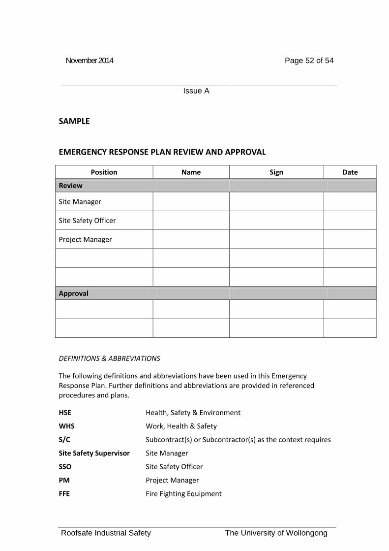
EMERGENCY RESPONSE PLAN REVIEW AND APPROVAL
Position Name Sign Date
Review
Site Manager
Site Safety Officer
Project Manager
Approval
DEFINITIONS & ABBREVIATIONS
The following definitions and abbreviations have been used in this Emergency Response Plan. Further definitions and abbreviations are provided in referenced procedures and plans.
HSE Health, Safety & Environment
WHS Work, Health & Safety
S/C Subcontract(s) or Subcontractor(s) as the context requires
Site Safety Supervisor Site Manager
SSO Site Safety Officer
PM Project Manager
FFE Fire Fighting Equipment

November 2014 Page 53 of 54
Issue A
Roofsafe Industrial Safety The University of Wollongong
SAMPLE
Emergency Procedure
It is essential that any relevant person involved in the use of the installed systems outlined in this manual have made effective arrangements to act in a timely manner in the event that a person using the systems falls and becomes suspended. It is the responsibility of the building owner, occupier and those charged with its maintenance to make sure that a risk assessment is completed that cover the task being under taken in full and that the provision for timely and effective rescue are made in the event of a fall.
The rescue plan should include and factor in the following in detail.
• Copies of the safe work method statement • Copies of the training qualifications of those performing the work • Detail of the local emergency service contact (fire rescue, ambulance, local
doctor, local first aid officer) • Location of the task (site address, building or asset identification number) • Current contact detail and method for the site and its personnel • Type of work being under taken • Training required for those required to perform the rescue • Details of those that are trained to perform the rescue • Equipment required to perform the rescue • Location of the equipment required to perform the rescue
r Location Drawings
EMERGENCY PROCEDURE FOR THIS SITE IS THE REPONSIBILTY OF THE UNIVERSITY OF WOLLONGONG

November 2014 Page 54 of 54
Issue A
Roofsafe Industrial Safety The University of Wollongong
APPENDIX A – See Content Page for Items Appendix A
Anchor Point Certification
Warranty Statement
Brochure Material
ASSET TYPE BAR CODE COMISSION DATE
NEXT SERVICE RATING *COMPLYING
STANDARDS MANUFACTURED & INSTALLED BY COMMENTS
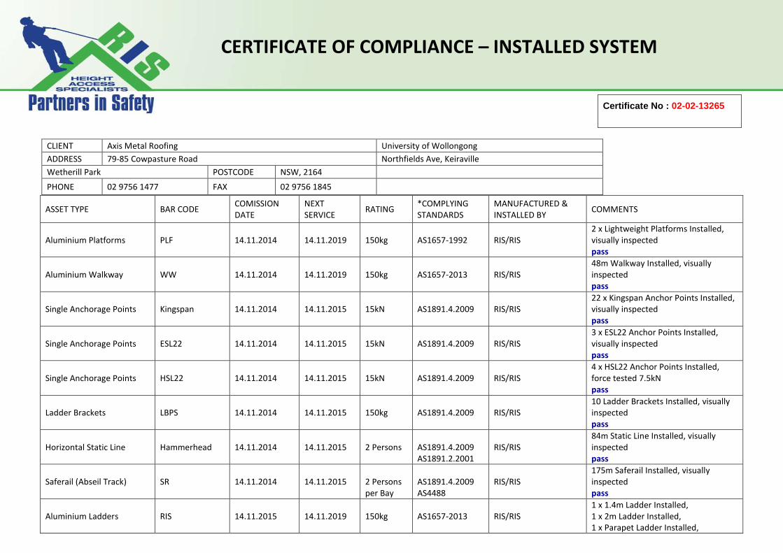
Aluminium Platforms
PLF
14.11.2014
14.11.2019
150kg
AS1657-1992
RIS/RIS
2 x Lightweight Platforms Installed, visually inspected pass
Aluminium Walkway
WW
14.11.2014
14.11.2019
150kg
AS1657-2013
RIS/RIS
48m Walkway Installed, visually inspected pass
Single Anchorage Points
Kingspan
14.11.2014
14.11.2015
15kN
AS1891.4.2009
RIS/RIS
22 x Kingspan Anchor Points Installed, visually inspected pass
Single Anchorage Points
ESL22
14.11.2014
14.11.2015
15kN
AS1891.4.2009
RIS/RIS
3 x ESL22 Anchor Points Installed, visually inspected pass
Single Anchorage Points
HSL22
14.11.2014
14.11.2015
15kN
AS1891.4.2009
RIS/RIS
4 x HSL22 Anchor Points Installed, force tested 7.5kN pass
Ladder Brackets
LBPS
14.11.2014
14.11.2015
150kg
AS1891.4.2009
RIS/RIS
10 Ladder Brackets Installed, visually inspected pass
Horizontal Static Line
Hammerhead
14.11.2014
14.11.2015
2 Persons
AS1891.4.2009 AS1891.2.2001
RIS/RIS
84m Static Line Installed, visually inspected pass
Saferail (Abseil Track)
SR
14.11.2014
14.11.2015
2 Persons per Bay
AS1891.4.2009 AS4488
RIS/RIS
175m Saferail Installed, visually inspected pass
Aluminium Ladders
RIS
14.11.2015
14.11.2019
150kg
AS1657-2013
RIS/RIS
1 x 1.4m Ladder Installed, 1 x 2m Ladder Installed, 1 x Parapet Ladder Installed,
Certificate No : 02-02-13265
CLIENT Axis Metal Roofing University of Wollongong ADDRESS 79-85 Cowpasture Road Northfields Ave, Keiraville Wetherill Park POSTCODE NSW, 2164
PHONE 02 9756 1477 FAX 02 9756 1845
CERTIFICATE OF COMPLIANCE – INSTALLED SYSTEM

4 x Ladder Heads Installed, visually inspected pass
Anchor Cable Strop
Strop
14.11.2014
14.11.2015
15kN
AS1891.4.2009
RIS/RIS
10 Strops Installed, visually inspected pass
Aluminium Handrail
HR
14.11.2015
14.11.2019
150kg
AS1657-2013
RIS/RIS
42m Handrail Installed, visually inspected pass
*Design and location of the Height Safety System is in accordance with AS/NZS 1891-4 – AS1657-2013 and local Regulatory Authorities
AUTHORISED BY: Dean Harrison DATE: 14.11.2014 SIGNATURE:

HEIGHT SAFETY SYSTEM WARRANTY 1. Roofsafe-T-Systems Pty Ltd t/as Roofsafe Industrial Safety guarantees the height safety
system and installation against defects caused by faulty workmanship and materials for
twelve (12) months from the date of purchase.
2. During this Guarantee period Roofsafe Industrial Safety will replace any defective parts and
provide labour to install. However if the product includes a number of accessories only the
defective product or accessory will be replaced.
3. It is a condition of this warranty and a requirement of the Australian Standard AS/NZS 1891
Part 4 that this system be inspected and rectified every twelve months.
4. Roofsafe Industrial Safety reserves the right to make minor adjustments instead of replacing
the product or accessory.
5. In the event of a part, product, accessory or system being replaced during this guarantee, the
guarantee on the replacement will expire at the original date i.e.12 months from the original
purchase date.
6. This guarantee excludes defects caused by the product or system not being used in
accordance with instructions, accidental damage, misuse or being tampered with by
unauthorised persons.
7. If failure or fault occurs, notification should immediately be given in writing to Roofsafe
Industrial Safety at 3 Bushells Place, Wetherill Park, NSW 2164.
8. If any product or part is forwarded to Roofsafe Industrial Safety a label should be attached
stating full name, address and nature of fault or complaint. The Guarantee and copy of the
purchase receipt should also accompany any claims.
9. This guarantee is additional to the Conditions and Guarantee which are mandatory and is
implied by the Trade Practices Act 1974 and other legislation.
PRODUCT: ANCHOR POINTS/LADDER
BRACKETS/STROPS/WALKWAY/PLATFORMS/STATIC LINE/SAFERAIL/LADDERS/HANDRAIL
MODEL: KINGSPAN, ESL22, HSL22, LBPS, STROP, WW, PLF,
HAMMERHEAD, SR, RIS, HR DATE OF PURCHASE / INSTALLATION: 14.11.2014 PURCHASED BY: AXIS METAL ROOFING LOCATION: UNIVERSITY OF WOLLONGONG
AUTHORISED BY:


www.RISsafety.com
RISAUSTRALIA WIDE SERVICE:

RIS
2 quick start guide
Always attach to the highest possible anchorage point never
attach to anything below your foot level.
Always make sure that the space you would travel through
in the event of a fall is free from protrusions and hazards.
Always ensure you have adequate clearance
under your work zone.
Always use only RIS compatible components.
Never use an anchorage point that will not take a shock load of
15kN (1.5 metric ton or 1500kg).
Never use your side mounted attachment points for fall arrest
applications. Side mounted connection points are for use
with a pole strap only.
Never loop the safety lanyards around structures and avoid
sharp edges and structure that will cause cutting or abrasive
damage to the webbing.
Never use any RIS Products that are showing
any signs of wear and tear. Return to RIS for
formal inspection or discard immediately.
Never extend the length of your lanyard beyond 2.0m.
Never expose your self to the risk of a fall.
A LW AY S
N E V E R

www.RISsafety.com 3
IF YOU HAVE ANY DOUBT
THEN CONTACT US
ph: (02) 9896 8644
The purpose of a RIS Safety Harness
Fall Arrest System is to limit the extent
of a person’s fall.
This is achieved by absorbing the energy
generated in the fall, by retarding the fall by
way of applying an arresting force. HOWEVER
to ensure that the user does not collide with
the floor or other object below them there
must be sufficient space directly under
the user to be arrested - this is called
the Minimum Free Space (MFS).
This Minimum Free Space is the straight line
vertical distance between the anchorage point
and the ground or next platform or obstacle.
(Anchorage Point that is to the Substantial
Structure 15kN+). It is the duty of the user
to familiarise themselves with the MFS and
apply this safety principle at all times.
The Formula to use is:
Lanyard Length + Shock Absorber Length
+ Harness Stretch + Distance b/w harness
attachment point and upper back + Safety
clearance at bottom of fall.
Lanyard length RIS maximum allowable
= 2.0m RIS, Shock Absorber = 1.75m
in length, Rule of thumb for the sum of Harness
stretch + attachment point to upper back
is 1.8m. We recommend that the Safety
Clearance is given a value of 1m.
To illustrate a worst case scenario,
which is when the anchor point is at the
user’s feet, so the MFS is calculated using
the following formula:
Lanyard Length + Shock Absorber = 2m
+ 1.75m; AND the sum of Stretch & The
Attachment point to Upper Back Distance
= 1.8m; THEN add to this your
Safety Clearance of 0.4m; THEN this will give
you an MFS of 5.75m (FIVE point SEVEN FIVE
meters) in this worst case example
(refer to diagrams on page 7&8).
minimum free space - (MFS)
RIS
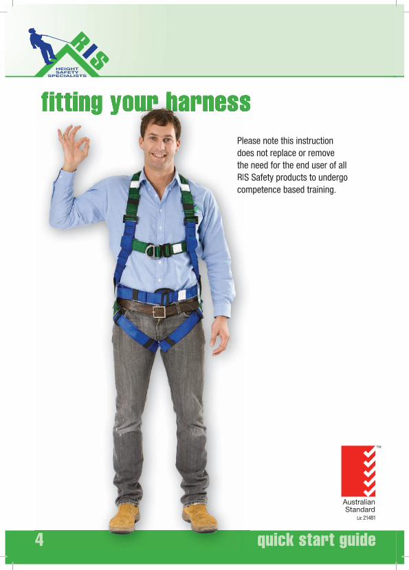
4 quick start guide
fitting your harness Please note this instruction
does not replace or remove the need for the end user of all RIS Safety products to undergo competence based training.
eaoese S
om
44
PledotheRISco

www.RISsafety.com 5
Ultimate harness fitting1. Inspect the Harness to ensure
it is fit for use 2. Locate the top of the harness and
align it in its correct orientation 3. Taking out all twists in the
webbing and padding
4. Slide the harness on like you would a jacket
5. Ensure the dorsal dee ring on the harness is located between your shoulder blades.
6. Connect the chest strap to secure the harness to your upper body. Secure the waist strap if applicable as well.
7. Fit leg straps ensuring the webbing is siting flat against the legs or padding. Always connect the left leg strap to the left leg buckle never cross them over.
8. Once fitted adjust all straps to ensure the harness is fitted securely to the body and get your work mate to check it over for you.
9. When using the front webbing loops ensure they are always brought together and connected with an approved connector
10.Never use the front webbing loops singularly
et
Please note this instruction does not replace or remove
the need for the end user of all RIS
Safety products to undergo
competence based training.
Failing to fit or maintain your harness properly may cause extreme pain or death.
d
77
8Please note this
oesinstruction do
RIS
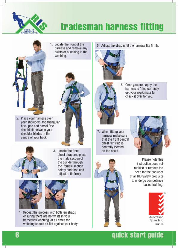
6 quick start guide
2. Place your harness over your shoulders, the triangular back pad and dorsal Dee should sit between your shoulder blades in the centre of your back.
3. Locate the front chest strap and place the male section of the buckle through the female section pointy end first. and adjust to fit firmly.
4. Repeat the process with both leg straps ensuring there are no twists in your harnesses webbing. At all times the webbing should sit flat against your body.
5. Adjust the strap until the harness fits firmly.
6. Once you are happy the harness is fitted correctly get your work mate to check it over for you.
7. When fitting your harness make sure that the front central chest “D” ring is centrally located on the chest.
1. Locate the front of the harness and remove any twists or bunching in the webbing.
Please note this instruction does not
replace or remove the need for the end user
of all RIS Safety products to undergo competence
based training.
tradesman harness fitting

www.RISsafety.com 7
When donning any of the tradesmen range of harnesses with the feed through buckle always ensure the male buckle’s pointy end goes into the female buckle first.
As illustrated here.
7M
6M
5M
4M
3M
2M
1M
0M
7M
6M
5M
4M
3M
2M
1M
0M
2m lanyard
1.5m shock absorber
Av. 1.8m
> 1m clearance SAFE
A
B
C
A
BBBBBBBBBBBBBBBBBBBBBBBBBBBBBBBBBBBBBBBBBBB
C
minimum free space - (MFS)
continued next page
A
B
C

RIS
8 quick start guide
2m lanyard
2m lanyard
1.5m shock absorber
1.5m shock absorberAv. 1.8m
< 1m clearance Potentially hazardous
1.5m remaining
INJURY INCURRED
minimum free space - (MFS)
7M
6M
5M
4M
3M
2M
1M
0M
A
B
C
7M
6M
5M
4M
3M
2M
1M
0M
A
B
C
BBBBBBBBBBBBBBBBBBBBBBBBBBBBBBBBBBBBBBBBBBBBBBBBBBBBBBBBBBBBBBBBBBBBBBBBBBBBBBBBBBBBBBBBBBBBBBBBBB
CCCCCCCCCCCCCCCCCCCCCCCCCCCCCCCCCCCCCCCCCCCCCCCCCCCCC
7M
6M
5M
4M
3M
2M
1M
0M
A
B
C
7M
6M
5M
4M
3M
2M
1M
0M
A
B
C

www.RISsafety.com 9
Roofsafe Industrial Safety Manufacture the following products:
a) Harnesses: Full Body Harnesses are designed to hold you in upright position / attitude if you’re involved in an incident.
When using this group of products when there is a risk of fall you must use either an item from category c) below or an inertia reel block or a system that will absorb most of the forces that could be generated during an incident.
The maximum force permitted to be transferred to a person during an incident is 6kN.
b) Pole straps: A Pole Strap is to be used in such a way that only a restrained fall could occur. Care should be taken at all times when using this product to ensure that no free fall is possible and that the connection is secure and visible to the user.
c) Energy Absorbing Lanyards for use in a fall: The Energy Absorber will tear apart up to a maximum of 1.75m keeping the force on the body to below 6kN at all times when the fall is less than 2m. All Energy Absorbing Lanyards used with RIS harness must be no greater than 2m in length. If the anchor point is at feet level it is possible to end up as much as 5.75m from the anchor point in a distance fall.
Warning: if any additions or alterations are made to any part of any RIS Safety Equipment, the effectiveness of these life saving devices may be compromised and such alterations and/or additions are not agreed to by RIS
Advice: Your Lanyard Assembly should be secured to an anchorage point which is at a level which will result in the minimum free fall and the least total fall distance consistent with the wearer’s ability to carry out work tasks.
Warning: If any part of the assembly is to be exposed to chemicals, e.g. Cleaning material or hazardous atmospheres, the user should consult the manufacturer to determine whether the part is suitable for continued use. The harness and lanyard assembly should be destroyed or returned to RIS for inspection if a fall has been sustained.
Advice: When making any connection to a point on a harness which cannot be seen by the wearer of the harness, either the connection should be made before putting the harness on or the connection should be made or checked for security by a second person.
Warning: be aware that energy absorbers that absorb energy by permanent deformation or destructive action, (the RIS product falls into this category) should be discarded if that process has com-menced. Every time you wear your harness do fill out the Inspection Log supplied with this Instruction Sheet. If any of the inspection items cause identification of requirement for maintenance then return the harness to RIS identifying these items in order that corrective action can be carried out by RIS the manufacturer. Only corrective action recommended or authorised by RIS can be construed as life saving action. Do consult AS 2626 or NZA 5811.2 for guidance on selection, use and maintenance matters.
Warning: For twin tail lanyards – do not “back hook” the free tail to any point on yourself, your equipment or the lanyard below the bifurcation other than on the Dee at the bifurcation point.
Advice: When not in use the “free” tail should be connected to the bifurcation dee at the base of the Energy Absorber.

RIS
10 quick start guide
important informationGENERAL USE INFORMATION:
The Fall Protection Equipment is essential
for your safety so we recommend that prior
to use you inspect your equipment for the
following:
and on the back seat of your car)
burrs, worn or broken hardware
slivers, stitching unravelling
of rope or webbing
used excessively or is beginning to unravel
If you are in any doubt whatsoever about the safe
condition of this product of if the product has been
used to arrest a fall, it is essential for safety that it is
withdrawn from use and returned to the manufacturer
or discarded and destroyed immediately.
Ensure that the instructions for other components
used in conjunction with these products are complied
with as stated
The anchorage point should be above the user,
considering both the height of fall and the extension
of the lanyard and energy absorber in order to avoid
possible obstructions (i.e. the ground). Be sure that
RECOMMENDED READING:
Industrial Rope Access Systems
– AS/NZ 4488 Series
Industrial Fall Arrest Systems and Devices
– AS/NZ1891
Fibre Ropes – AS 4143 Series
Flat synthetic – webbing slings AS 1353 Series
Wire Rope Slings – AS 1666 Series
Round Slings – synthetic fibre AS 4497 Series
Safe working in a confined space –
AS 2865 Series
http://www.sai-global.com
Written Inspection Records must be kept. An inspection log sheet has been included in this booklet.

www.RISsafety.com 11
MAINTENANCE, SERVICING,
STORAGE AND TRAINING
Cleaning:
If soiled, rinse in clean water of domestic
supply quality (maximum temperature
40degC) with mild neutral detergent.
Dry naturally away from direct heat.
Lubrication:
Lubricate mobile parts with a silicone based
lubricant only. This should be carried out af-
ter cleaning and drying. Avoid any oil contact
with textile parts.
Storage:
After any necessary cleaning or drying and
store unpacked in a cool, dry, dark place in
a chemically neutral environment away from
excessive heat or heat sources, high humid-
ity, sharp edges, corrosives or other possible
causes of damage. Do not store wet. Avoid
UV radiation, and salt environments.
Training:
All persons conducting and organizing
working at height must be competently
trained to ensure a safe work environment is
maintained RIS users should first undergo
training prior to the using any of the equip-
ment we manufacture or sell.
INSPECTION
CRITERIA
Frequency of inspection:
Inspection must be made by the user before and
after each use. Further to this a competent person
is required to perform an inspection at time periods
ranging from 3 monthly to annually depending upon
the equipment.
All fall arrest/restraint components should be
inspected prior to each use by the user.
Harnesses and lanyards: 6 monthly documented
inspection.
Type 1, 2 & 3 retractable lanyards and inertia reels
3 monthly inspections and 12 monthly service by
approved trained technician.
Anchorage points and static lines and rail systems
12 monthly documented inspection by approved
and trained technician.

RIS
12 quick start guide
Before you expose yourself
to a work environment that
may result in a suspended
fall make sure you know how
to use your standing step
It may save your life!
Trauma step by step

www.RISsafety.com 13
INTRODUCING
THE STANDING STEP
Fast deployment and ergonomic
design and medically tested.
Can you afford not to have
a RIS harness!
RIS recommend that prior to using your harness you deploy the standing step and familiarise yourself with the device and its operation and adjust it to suit your leg length. As well as conduct any other mandatory checks required, as previously mentioned in this booklet.
be 100mm shorter than your own leg length to achieve a comfortable position post fall.
Your standing
step is located
on the left or right
side of your harness
near your buttock.

RIS
14 quick start guide
Trauma step by step
Hang on to the clip at the top of the pouch and let the strap fall below you.
To deploy the standing step pull the Velcro straps on the pouch.
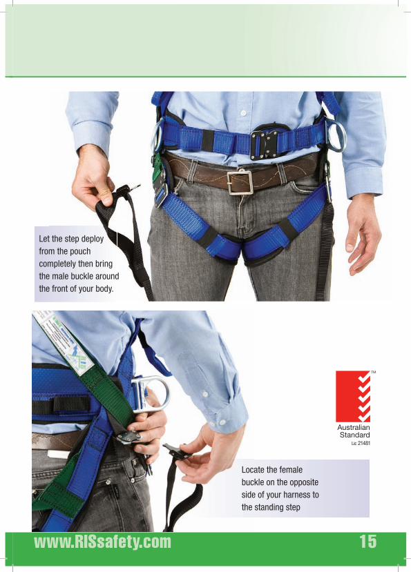
www.RISsafety.com 15
Let the step deploy from the pouch completely then bring the male buckle around the front of your body.
Locate the female buckle on the opposite side of your harness to the standing step

RIS
16 quick start guide
trauma step by step
Connect the male and female components of the buckle together until they click and are secure.
At all times post fall, do not panic.
Remain calm and deploy your standing step.
Place your foot into the base of the standing step and then adjust the strap to a position were you are comfortable.
The standing step is very easy to adjust as you wait in
suspension for rescue.
If the base of the step is adjusted too high you may begin to become
uncomfortable. Simply lift the buckle 900 and readjust to a more
comfortable lower position.

www.RISsafety.com 17
Please remember the standing
step has been designed for
your comfort and safety
but is not a substitute for
effective and fast rescue
plan. Consideration
should be given to every
working scenario to
ensure rescue is
possible as soon
as possible.
RIS
18 quick start guide
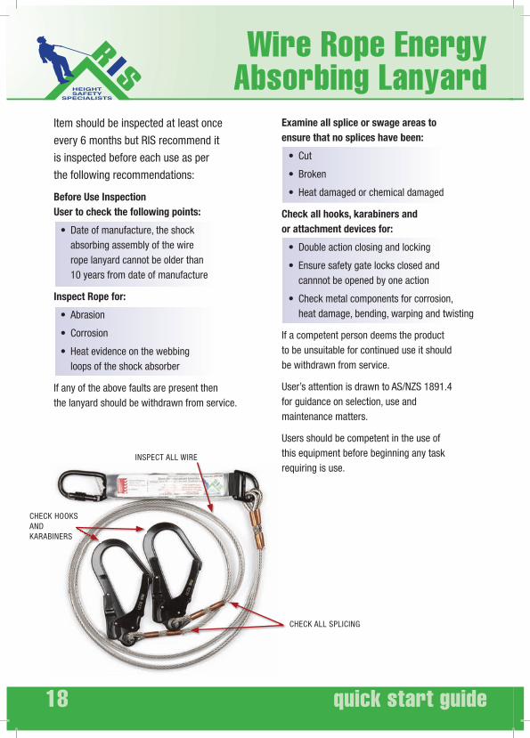
Wire Rope Energy Absorbing Lanyard
AND
INSPECT ALL WIRE
Item should be inspected at least once
every 6 months but RIS recommend it
is inspected before each use as per
the following recommendations:
Before Use Inspection
User to check the following points:
absorbing assembly of the wire rope lanyard cannot be older than 10 years from date of manufacture
Inspect Rope for:
loops of the shock absorber
If any of the above faults are present then the lanyard should be withdrawn from service.
Examine all splice or swage areas to
ensure that no splices have been:
Check all hooks, karabiners and
or attachment devices for:
cannnot be opened by one action
heat damage, bending, warping and twisting
If a competent person deems the product to be unsuitable for continued use it should be withdrawn from service.
User’s attention is drawn to AS/NZS 1891.4 for guidance on selection, use and maintenance matters.
Users should be competent in the use of this equipment before beginning any task requiring is use.
www.RISsafety.com 19
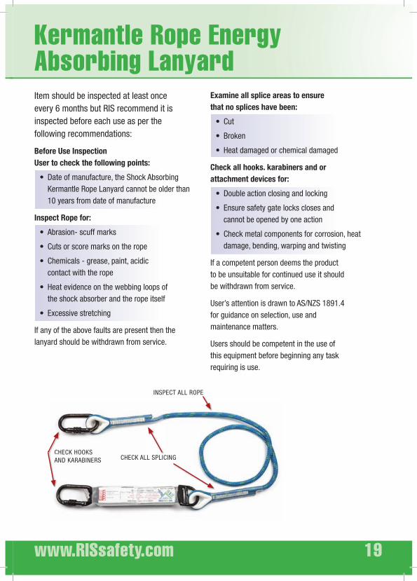
Kermantle Rope Energy Absorbing Lanyard
INSPECT ALL ROPE
Item should be inspected at least once every 6 months but RIS recommend it is inspected before each use as per the following recommendations:
Before Use Inspection
User to check the following points:
10 years from date of manufacture
Inspect Rope for:
contact with the rope
the shock absorber and the rope itself
If any of the above faults are present then the lanyard should be withdrawn from service.
Examine all splice areas to ensure
that no splices have been:
Check all hooks. karabiners and or
attachment devices for:
cannot be opened by one action
damage, bending, warping and twisting
If a competent person deems the product to be unsuitable for continued use it should be withdrawn from service.
User’s attention is drawn to AS/NZS 1891.4 for guidance on selection, use and maintenance matters.
Users should be competent in the use of this equipment before beginning any task requiring is use.

RIS
20 quick start guide
Adjustable Webbing Energy Absorbing Lanyard
Item should be inspected at least once
every 6 months but RIS recommend
it is inspected before each use as per
the following recommendations:
Before Use Inspection
User to check the following points:
Shock Absorbing Webbing Lanyard cannot be older than 10 years from date of manufacture
Inspect Lanyard for:
with the rope
the shock absorber and the webbing itself, burn marks or shiny patches
If any of the above faults are present then the lanyard should be withdrawn from service.
Examine all stitching areas to ensure that no stitches have been
Check all hooks, karabiners and or
attachment devices for:
and cannot be opened by one action
heat damage, bending, warping and twisting
If a competent person deems the product to be unsuitable for continued use it should be withdrawn from service.
User’s attention is drawn to AS/NZS 1891.4 for guidance on selection, use and maintenance matters.
Users should be competent in the use of this equipment before beginning any task requiring is use.

www.RISsafety.com 21
Confined Space Spreader Bar
PATTERNS
SPREADER BARS
Item should be inspected at least once every
6 months but RIS recommend it is inspected
before each use as per the following recom-
mendations:
Before Use Inspection
User to check the following points:
Bar cannot be older than 10 years from date of manufacture
Inspect Assembly for:
with the rope
of the shock absorber and the webbing itself, burn marks or shiny patches
If any of the above faults are present then the Spreader Bar Assembly should be withdrawn from service.
Examine all stitching areas to ensure
that no stitches have been:
Check all hooks. karabiners and or attachment devices for
and cannot be opened by one action
damage, bending, warping and twisting
If a competent person deems the product to be unsuitable for continued use it should be withdrawn from service.
User’s attention is drawn to AS/NZS 1891.4 for guidance on selection, use and maintenance matters.
Users should be competent in the use of this equip-ment before beginning any task requiring is use.

RIS
22 quick start guide
BACK POINT
For use with fixed anchor or mobile & absorbing lanyard
definitions
CHEST POINT
For use on a pitched roof or vertical ladder systems. Always check the load capacity of the attachment point prior to use.
SIDE WAIST POINT
For use on a pylon & monopole (or similar) with help of an adjustable work positioning lanyard.
INERTIA BLOCKINERTIA BLOCK
FALL ARREST
A fall arrest system consists of a harness and a subsystem design to arrest a fall. Fall arrest equipment is designed to arrest a fall safely, limiting the risk of injury by dissipating the energy produced and hold-ing the person in a suitable position.
Sub-system of fall arrester:
www.RISsafety.com 23
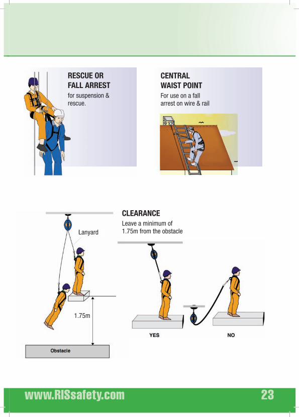
CLEARANCE
Leave a minimum of 1.75m from the obstacleLanyard
1.75m
RESCUE OR
FALL ARREST
for suspension & rescue.
CENTRAL
WAIST POINT
For use on a fall arrest on wire & rail

RIS
24 quick start guide
configurations
Flexible anchorage lines used in conjunction with a robe grab offers the best solution for temporary work access systems.
The full arrest is connected to the harness by the chest point.
The fall arrest connected to the chest point is used in this configuration.
ALTERNATIVE ANCHOR
ON STRUCTURE
MOBILE ANCHOR FIXED ANCHOR

www.RISsafety.com 25
Visual verification
for cuts, abrasions, tears.
abrasion, distortion break.
Fitting
correctly to the body
Cleaning and storing
& delicate detergent for textiles.
away from sun & heat.
harness in contact with any chemicals.

RIS
26 quick start guide
Roofsafe product rangeCONTACT YOUR LOCAL BRANCH FOR FURTHER DETAILS

www.RISsafety.com 27
Product type :
Serial no. :
Year of Mnf. :
User name :
Date of purchase :
Date of first use :
Comments :
DATE STITCHING WEBBING
HOOKS/
BUCKLES/
D-RINGS/
CARRABINERS
COMMENTS SIGNATURE

RIS
CREATING EFFECTIVE
HEIGHT SAFETY SOLUTIONS
Related Documents