E-1 Index SECTION E ROLLER CHAIN SPROCKETS PRODUCT PAGE INDEX E-1 – E-2 MADE-TO-ORDER CAPABILITIES E-3 SECTION I — STANDARD SPROCKETS E-4 – E-112 SHEAR PIN SPROCKETS, BOLT-ON E-4 – E-6 TYPE D SPROCKETS, DETACHABLE HUBS SPLIT AND SOLID E-7 INSTANT SPLIT ® SPROCKETS E-8 TORQUE LIMITER E-9 – E-10 DOUBLE PITCH SPROCKETS E-11 – E-15 DOUBLE SINGLE SPROCKETS (SEE PITCH BELOW) SPROCKETS, STOCK E-16 – E-112 NO 25 — 1/4" PITCH E-16 – E-17 NO 35 — 3/8" PITCH E-18 – E-26 NO 41 — 1/2" PITCH E-27 – E-29 NO 40 — 1/2" PITCH E-30 – E-42 NO 50 — 5/8" PITCH E-43 – E-55 NO 60 — 3/4" PITCH E-56 – E-68 NO 80 — 1" PITCH E-69 – E-81 NO 100 — 1-1/4" PITCH E-82 – E-91 NO 120 — 1-1/2" PITCH E-92 – E-97 NO 140 — 1-3/4" PITCH E-98 – E-102 NO 160 — 2" PITCH E-103 – E-107 NO 180 — 2-1/4" PITCH E-108 NO 200 — 2-1/2" PITCH E-109 – E-111 NO 240 — 3" PITCH E-112 SECTION II — METRIC SPROCKETS E-113 – E-151 ISO - 06B-1, METRIC 35 - 0375" (9525 MM) PITCH, SIMPLEX E-114 – E-115 ISO - 06B-2, METRIC 35-2 - 0375" (9525 MM) PITCH, DUPLEX E-116 – E-117 ISO - 06B-3, METRIC 35-3 - 0375" (9525 MM) PITCH, TRIPLEX E-118 ISO - 08B-1, METRIC 40 - 0500" (1270 MM) PITCH, SIMPLEX E-119 – E-120 ISO - 08B-2, METRIC 40-2 - 0500" (1270 MM) PITCH, DUPLEX E-121 – E-122 ISO - 08B-3, METRIC 40-3 - 0500" (1270 MM) PITCH, TRIPLEX E-123 ISO - 10B-1, METRIC 50 - 0625" (1588 MM) PITCH, SIMPLEX E-124 – E-125 ISO - 10B-2, METRIC 50-2 - 0625" (1588 MM) PITCH, DUPLEX E-126 – E-127 ISO - 10B-3, METRIC 50-3 -0625" (1588 MM) PITCH, TRIPLEX E-128 ISO - 12B-1, METRIC 60 - 0750" (1905 MM) PITCH, SIMPLEX E-129 – E-130 ISO - 12B-2, METRIC 60-2 - 0750" (1905 MM) PITCH, DUPLEX E-131 – E-132 ISO - 12B-3, METRIC 60-3 - 0750" (1905 MM) PITCH, TRIPLEX E-133 ISO - 16B-1, METRIC 80 - 1000" (2540 MM) PITCH, SIMPLEX E-134 – E-135 ISO - 16B-2, METRIC 80-2 - 1000" (2540MM) PITCH, DUPLEX E-136 – E-137 ISO - 16B-3, METRIC 80-3 - 1000" (2540MM) PITCH, TRIPLEX E-138 ISO - 20B-1, METRIC 100 - 1250" (3175MM) PITCH, SIMPLEX E-139 – E-140

Welcome message from author
This document is posted to help you gain knowledge. Please leave a comment to let me know what you think about it! Share it to your friends and learn new things together.
Transcript
E-1
IndexSECTION E
ROLLER CHAIN SPROCKETSPRODUCT PAGE
INDEX . . . . . . . . . . . . . . . . . . . . . . . . . . . . . . . . . . . . . . . . . . . . . . . . . . . . . . . . . . . . . . . . . . . . . . . . . . . . . E-1 – E-2
MADE-TO-ORDER CAPABILITIES . . . . . . . . . . . . . . . . . . . . . . . . . . . . . . . . . . . . . . . . . . . . . . . . . . . . . . . . . . . . . . . . . E-3
SECTION I — STANDARD SPROCKETS . . . . . . . . . . . . . . . . . . . . . . . . . . . . . . . . . . . . . . . . . . . . . . . . . . . . . . . E-4 – E-112
SHEAR PIN SPROCKETS, BOLT-ON . . . . . . . . . . . . . . . . . . . . . . . . . . . . . . . . . . . . . . . . . . . . . . . . . . . . . . . . . . . . . . . . . . E-4 – E-6 TYPE D SPROCKETS, DETACHABLE HUBS SPLIT AND SOLID . . . . . . . . . . . . . . . . . . . . . . . . . . . . . . . . . . . . . . . . . . . . . . . . . . . E-7 INSTANT SPLIT® SPROCKETS . . . . . . . . . . . . . . . . . . . . . . . . . . . . . . . . . . . . . . . . . . . . . . . . . . . . . . . . . . . . . . . . . . . . . . . . . . . E-8 TORQUE LIMITER . . . . . . . . . . . . . . . . . . . . . . . . . . . . . . . . . . . . . . . . . . . . . . . . . . . . . . . . . . . . . . . . . . . . . . . . . . . . . . . E-9 – E-10 DOUBLE PITCH SPROCKETS . . . . . . . . . . . . . . . . . . . . . . . . . . . . . . . . . . . . . . . . . . . . . . . . . . . . . . . . . . . . . . . . . . . . . E-11 – E-15 DOUBLE SINGLE SPROCKETS . . . . . . . . . . . . . . . . . . . . . . . . . . . . . . . . . . . . . . . . . . . . . . . . . . . . . . . . . . . . . (SEE PITCH BELOW) SPROCKETS, STOCK . . . . . . . . . . . . . . . . . . . . . . . . . . . . . . . . . . . . . . . . . . . . . . . . . . . . . . . . . . . . . . . . . . . . . . . . . . E-16 – E-112 NO . 25 — 1/4" PITCH . . . . . . . . . . . . . . . . . . . . . . . . . . . . . . . . . . . . . . . . . . . . . . . . . . . . . . . . . . . . . . . . . . . . . . . E-16 – E-17 NO . 35 — 3/8" PITCH . . . . . . . . . . . . . . . . . . . . . . . . . . . . . . . . . . . . . . . . . . . . . . . . . . . . . . . . . . . . . . . . . . . . . . . E-18 – E-26 NO . 41 — 1/2" PITCH . . . . . . . . . . . . . . . . . . . . . . . . . . . . . . . . . . . . . . . . . . . . . . . . . . . . . . . . . . . . . . . . . . . . . . . E-27 – E-29 NO . 40 — 1/2" PITCH . . . . . . . . . . . . . . . . . . . . . . . . . . . . . . . . . . . . . . . . . . . . . . . . . . . . . . . . . . . . . . . . . . . . . . . E-30 – E-42 NO . 50 — 5/8" PITCH . . . . . . . . . . . . . . . . . . . . . . . . . . . . . . . . . . . . . . . . . . . . . . . . . . . . . . . . . . . . . . . . . . . . . . . E-43 – E-55 NO . 60 — 3/4" PITCH . . . . . . . . . . . . . . . . . . . . . . . . . . . . . . . . . . . . . . . . . . . . . . . . . . . . . . . . . . . . . . . . . . . . . . . E-56 – E-68 NO . 80 — 1" PITCH . . . . . . . . . . . . . . . . . . . . . . . . . . . . . . . . . . . . . . . . . . . . . . . . . . . . . . . . . . . . . . . . . . . . . . . . . E-69 – E-81 NO . 100 — 1-1/4" PITCH . . . . . . . . . . . . . . . . . . . . . . . . . . . . . . . . . . . . . . . . . . . . . . . . . . . . . . . . . . . . . . . . . . . . . E-82 – E-91 NO . 120 — 1-1/2" PITCH . . . . . . . . . . . . . . . . . . . . . . . . . . . . . . . . . . . . . . . . . . . . . . . . . . . . . . . . . . . . . . . . . . . . . E-92 – E-97 NO . 140 — 1-3/4" PITCH . . . . . . . . . . . . . . . . . . . . . . . . . . . . . . . . . . . . . . . . . . . . . . . . . . . . . . . . . . . . . . . . . . . . E-98 – E-102 NO . 160 — 2" PITCH . . . . . . . . . . . . . . . . . . . . . . . . . . . . . . . . . . . . . . . . . . . . . . . . . . . . . . . . . . . . . . . . . . . . . . E-103 – E-107 NO . 180 — 2-1/4" PITCH . . . . . . . . . . . . . . . . . . . . . . . . . . . . . . . . . . . . . . . . . . . . . . . . . . . . . . . . . . . . . . . . . . . . . . . . . . E-108 NO . 200 — 2-1/2" PITCH . . . . . . . . . . . . . . . . . . . . . . . . . . . . . . . . . . . . . . . . . . . . . . . . . . . . . . . . . . . . . . . . . . . E-109 – E-111 NO . 240 — 3" PITCH . . . . . . . . . . . . . . . . . . . . . . . . . . . . . . . . . . . . . . . . . . . . . . . . . . . . . . . . . . . . . . . . . . . . . . . . . . . . . E-112
SECTION II — METRIC SPROCKETS . . . . . . . . . . . . . . . . . . . . . . . . . . . . . . . . . . . . . . . . . . . . . . . . . . . . . . . .E-113 – E-151
ISO - 06B-1, METRIC 35 - 0 .375" (9 .525 MM) PITCH, SIMPLEX . . . . . . . . . . . . . . . . . . . . . . . . . . . . . . . . . . . . . . . . E-114 – E-115 ISO - 06B-2, METRIC 35-2 - 0 .375" (9 .525 MM) PITCH, DUPLEX . . . . . . . . . . . . . . . . . . . . . . . . . . . . . . . . . . . . . . . E-116 – E-117 ISO - 06B-3, METRIC 35-3 - 0 .375" (9 .525 MM) PITCH, TRIPLEX . . . . . . . . . . . . . . . . . . . . . . . . . . . . . . . . . . . . . . . . . . . . . . E-118 ISO - 08B-1, METRIC 40 - 0 .500" (12 .70 MM) PITCH, SIMPLEX . . . . . . . . . . . . . . . . . . . . . . . . . . . . . . . . . . . . . . . . E-119 – E-120 ISO - 08B-2, METRIC 40-2 - 0 .500" (12 .70 MM) PITCH, DUPLEX . . . . . . . . . . . . . . . . . . . . . . . . . . . . . . . . . . . . . . . E-121 – E-122 ISO - 08B-3, METRIC 40-3 - 0 .500" (12 .70 MM) PITCH, TRIPLEX . . . . . . . . . . . . . . . . . . . . . . . . . . . . . . . . . . . . . . . . . . . . . . E-123 ISO - 10B-1, METRIC 50 - 0 .625" (15 .88 MM) PITCH, SIMPLEX . . . . . . . . . . . . . . . . . . . . . . . . . . . . . . . . . . . . . . . . E-124 – E-125 ISO - 10B-2, METRIC 50-2 - 0 .625" (15 .88 MM) PITCH, DUPLEX . . . . . . . . . . . . . . . . . . . . . . . . . . . . . . . . . . . . . . . E-126 – E-127 ISO - 10B-3, METRIC 50-3 -0 .625" (15 .88 MM) PITCH, TRIPLEX . . . . . . . . . . . . . . . . . . . . . . . . . . . . . . . . . . . . . . . . . . . . . . E-128 ISO - 12B-1, METRIC 60 - 0 .750" (19 .05 MM) PITCH, SIMPLEX . . . . . . . . . . . . . . . . . . . . . . . . . . . . . . . . . . . . . . . . E-129 – E-130 ISO - 12B-2, METRIC 60-2 - 0 .750" (19 .05 MM) PITCH, DUPLEX . . . . . . . . . . . . . . . . . . . . . . . . . . . . . . . . . . . . . . . E-131 – E-132 ISO - 12B-3, METRIC 60-3 - 0 .750" (19 .05 MM) PITCH, TRIPLEX . . . . . . . . . . . . . . . . . . . . . . . . . . . . . . . . . . . . . . . . . . . . . . E-133 ISO - 16B-1, METRIC 80 - 1 .000" (25 .40 MM) PITCH, SIMPLEX . . . . . . . . . . . . . . . . . . . . . . . . . . . . . . . . . . . . . . . . E-134 – E-135 ISO - 16B-2, METRIC 80-2 - 1 .000" (25 .40MM) PITCH, DUPLEX . . . . . . . . . . . . . . . . . . . . . . . . . . . . . . . . . . . . . . . . E-136 – E-137 ISO - 16B-3, METRIC 80-3 - 1 .000" (25 .40MM) PITCH, TRIPLEX . . . . . . . . . . . . . . . . . . . . . . . . . . . . . . . . . . . . . . . . . . . . . . E-138 ISO - 20B-1, METRIC 100 - 1 .250" (31 .75MM) PITCH, SIMPLEX . . . . . . . . . . . . . . . . . . . . . . . . . . . . . . . . . . . . . . . . E-139 – E-140
E-2
IndexSECTION E
ROLLER CHAIN SPROCKETSPRODUCT PAGE
SECTION II — METRIC SPROCKETS (CONTINUED)
ISO - 20B-2, METRIC 100-2 - 1 .250" (31 .75MM) PITCH, DUPLEX . . . . . . . . . . . . . . . . . . . . . . . . . . . . . . . . . . . . . . . . . . . . . . E-141 ISO - 20B-3, METRIC 100-3 - 1 .250" (31 .75MM) PITCH, TRIPLEX . . . . . . . . . . . . . . . . . . . . . . . . . . . . . . . . . . . . . . . . . . . . . E-142 ISO - 24B-1, METRIC 120 - 1 .500" (38 .10MM) PITCH, SIMPLEX . . . . . . . . . . . . . . . . . . . . . . . . . . . . . . . . . . . . . . . . E-143 – E-144 ISO - 24B-2, METRIC 120-2 - 1 .500" (38 .10MM) PITCH, DUPLEX . . . . . . . . . . . . . . . . . . . . . . . . . . . . . . . . . . . . . . . . . . . . . . E-145 ISO - 28B-1, METRIC 140 - 1 .750" (44 .45MM) PITCH, SIMPLEX . . . . . . . . . . . . . . . . . . . . . . . . . . . . . . . . . . . . . . . . E-146 – E-147 ISO - 28B-2, METRIC 140-2 - 1 .750" (44 .45MM) PITCH, DUPLEX . . . . . . . . . . . . . . . . . . . . . . . . . . . . . . . . . . . . . . . . . . . . . . E-148 ISO - 32B-1, METRIC 160 - 2 .00" (50 .80MM) PITCH, SIMPLEX . . . . . . . . . . . . . . . . . . . . . . . . . . . . . . . . . . . . . . . . . E-149 – E-150 ISO - 32B-2, METRIC 160-2 - 2 .00" (50 .80MM) PITCH, SIMPLEX . . . . . . . . . . . . . . . . . . . . . . . . . . . . . . . . . . . . . . . . . . . . . . E-151
SECTION III — ENGINEERING . . . . . . . . . . . . . . . . . . . . . . . . . . . . . . . . . . . . . . . . . . . . . . . . . . . . . . . . . . . .E-152 – E-192
SPROCKET NOMENCLATURE . . . . . . . . . . . . . . . . . . . . . . . . . . . . . . . . . . . . . . . . . . . . . . . . . . . . . . . . . . . . . . . . . . . E-153 – E-155 ROLLER CHAIN DIMENSIONS . . . . . . . . . . . . . . . . . . . . . . . . . . . . . . . . . . . . . . . . . . . . . . . . . . . . . . . . . . . . . . . . . . . . . . . . . E-156 SPROCKET TOOTH DIMENSIONS . . . . . . . . . . . . . . . . . . . . . . . . . . . . . . . . . . . . . . . . . . . . . . . . . . . . . . . . . . . . . . . . . . . . . . . E-157 MAXIMUM BORE AND HUB SIZE . . . . . . . . . . . . . . . . . . . . . . . . . . . . . . . . . . . . . . . . . . . . . . . . . . . . . . . . . . . . . . . . E-158 – E-159 SPROCKET SELECTION . . . . . . . . . . . . . . . . . . . . . . . . . . . . . . . . . . . . . . . . . . . . . . . . . . . . . . . . . . . . . . . . . . . . . . . E-160 – E-163 SPROCKET ENGINEERING . . . . . . . . . . . . . . . . . . . . . . . . . . . . . . . . . . . . . . . . . . . . . . . . . . . . . . . . . . . . . . . . . . . . . E-164 – E-166 HARDENING . . . . . . . . . . . . . . . . . . . . . . . . . . . . . . . . . . . . . . . . . . . . . . . . . . . . . . . . . . . . . . . . . . . . . . . . . . . . . . . . . . . . . . . E-167 CHAIN DRIVE ENGINEERING . . . . . . . . . . . . . . . . . . . . . . . . . . . . . . . . . . . . . . . . . . . . . . . . . . . . . . . . . . . . . . . . . . . E-168 – E-169 ROLLER CHAIN LENGTHS . . . . . . . . . . . . . . . . . . . . . . . . . . . . . . . . . . . . . . . . . . . . . . . . . . . . . . . . . . . . . . . . . . . . . . . . . . . . E-169 SPEED RATIOS . . . . . . . . . . . . . . . . . . . . . . . . . . . . . . . . . . . . . . . . . . . . . . . . . . . . . . . . . . . . . . . . . . . . . . . . . . . . . . . . . . . . . E-170 SPROCKET DIAMETERS . . . . . . . . . . . . . . . . . . . . . . . . . . . . . . . . . . . . . . . . . . . . . . . . . . . . . . . . . . . . . . . . . . . . . . . E-171 – E-183 HORSEPOWER RATINGS . . . . . . . . . . . . . . . . . . . . . . . . . . . . . . . . . . . . . . . . . . . . . . . . . . . . . . . . . . . . . . . . . . . . . . E-184 – E-192
E-3E-3
Made-to-OrderSprockets
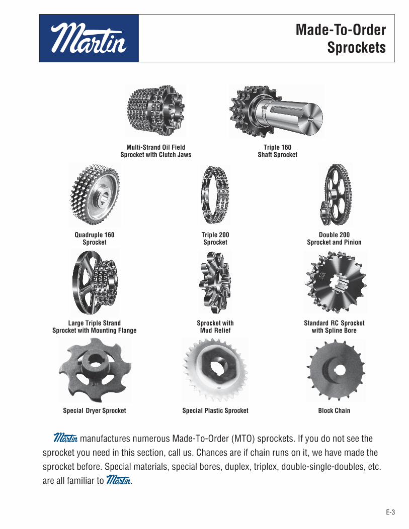
Multi-Strand Oil Field Triple 160 Sprocket with Clutch Jaws Shaft Sprocket
Quadruple 160 Triple 200 Double 200 Sprocket Sprocket Sprocket and Pinion
Large Triple Strand Sprocket with Standard RC Sprocket Sprocket with Mounting Flange Mud Relief with Spline Bore
Special Dryer Sprocket Special Plastic Sprocket Block Chain
Martin manufactures numerous Made-To-Order (MTO) sprockets. If you do not see thesprocket you need in this section, call us. Chances are if chain runs on it, we have made thesprocket before. Special materials, special bores, duplex, triplex, double-single-doubles, etc.are all familiar to Martin.
Made-To-OrderSprockets

E-4
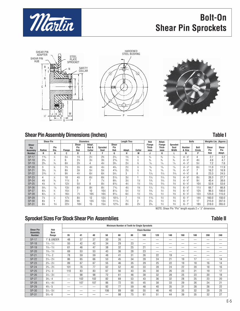
Shear Pin sprockets provide simple, dependable protection againstexpensive machinery damage caused by overloads or jamming.Torque is transmitted by a single pin, necked to shear when the safeload is exceeded. When an overload occurs, the pin shears,disconnecting the drive immediately.
The Bolt-on Shear Pin Adapter converts any plate sprocket into astock Shear Pin sprocket allowing immediate delivery of stockShear Pin sprockets.
Selection guide on page E-6 gives complete procedure to select theproper Shear Pin assembly.
Stock Shear Pin Assemblies
Pricing Examples:1. Stock Shear Pin Sprocket
To price a 35 tooth shear pin sprocket for 160 chain (160SP35)using SP-26 shear pin assembly with 37⁄16" bore, standardkeyway and setscrew: SP-26 Assembly List Price.................... See List 160A35 List Price.................................. Price Sheet Total List Price .....................................
SP-17 1" & UNDER SPH-17 SPA-17 SP-18 11⁄16 - 11⁄4 SPH-18 SPA-18 SP-19 15⁄16 - 11⁄2 SPH-19 SPA-19 SP-20 19⁄16 - 13⁄4 SPH-20 SPA-20 SP-21 113⁄16 - 2 SPH-21 SPA-21 SP-22 21⁄16 - 21⁄4 SPH-22 SPA-22 SP-23 25⁄16 - 21⁄2 SPH-23 SPA-23 SP-24 29⁄16 - 23⁄4 SPH-24 SPA-24 SP-25 213⁄16 - 3 SPH-25 SPA-25 SP-26 31⁄16 - 31⁄2 SPH-26 SPA-26 SP-27 39⁄16 - 4 SPH-27 SPA-27 SP-28 41⁄16 - 41⁄2 SPH-28 SPA-28 SP-29 49⁄16 - 5 SPH-29 SPA-29 SP-30 47⁄8 - 51⁄2 SPH-30 SPA-30 SP-31 59⁄16 - 6 SPH-31 SPA-31
Bolt-OnShear Pin Sprockets
E-4
Shear Pin Sprockets can also be furnished in other standard stylesor made to customer’s specifications. Price on application.
It is important that the torque requirement for the selected hub be checkedin the torque rating table on page E-6 and the neck diameter of Shear Pin be specified.
2. Shear Pin Adapter and Sprocket for Existing HubTo price a “Bolt-on” shear pin adapter and sprocket to replacethe sprocket part of existing 50SP40 using SP-19 hub: SPA-19 Adapter List Price..................... See List 50A40 List Price.................................... Price Sheet Total List Price .....................................
Shear Pin Shear Pin Shear Pin Hub Hub Adapter Assembly Bore Catalog Catalog Number Range Number Number
Notes on Pricing:Shear Pin Hub List Price includes any finished bore within thestated range, standard keyway, setscrew, and hardened steel shearpin bushing.
Shear Pin Adapter List Price includes the Shear Pin bushin andgrease fitting.
Complete Assembly List Price includes all components of theShear Pin assembly as described above. Total list price of anyShear Pin sprocket is the complete assembly list price plus the listprice of the desired plate sprocket (from tables of stock sprocketlist prices).
Replacement Sprockets should be priced as altered stocksprockets directly from List Price and Alteration Charge tables.
Shear Pin Components may be ordered separately and will betreated as stock items when conforming to standard specificationsand descriptions above.
Bolt-OnShear Pin Sprockets
E-5E-5
Bolt-OnShear Pin Sprockets
SP-17 113⁄16 1⁄4 51⁄4 13⁄4 21⁄2 25⁄8 27⁄16 13⁄8 3⁄8 9⁄16 9⁄16 7⁄16 4 - 3⁄8" 4 2.7 3.2 SP-18 23⁄16 1⁄4 6 21⁄4 31⁄4 33⁄8 215⁄16 13⁄4 1⁄2 9⁄16 9⁄16 9⁄16 4 - 3⁄8" 43⁄4 4.6 4.7 SP-19 29⁄16 5⁄16 63⁄4 23⁄4 4 41⁄8 39⁄16 21⁄8 5⁄8 11⁄16 11⁄16 11⁄16 4 - 1⁄2" 51⁄2 7.2 7.6 SP-20 3 3⁄8 73⁄4 31⁄4 43⁄4 47⁄8 43⁄16 21⁄2 3⁄4 13⁄16 13⁄16 11⁄16 4 - 1⁄2" 61⁄4 11.0 11.9 SP-21 35⁄16 7⁄16 83⁄4 33⁄4 51⁄4 53⁄8 413⁄16 27⁄8 7⁄8 15⁄16 15⁄16 15⁄16 4 - 5⁄8" 7 16.2 16.9 SP-22 313⁄16 1⁄2 93⁄4 41⁄4 61⁄4 63⁄8 53⁄16 3 1 11⁄16 11⁄16 13⁄16 4 - 5⁄8" 8 23.3 24.5 SP-23 4 1⁄2 10 41⁄2 61⁄2 65⁄8 511⁄16 31⁄2 1 11⁄16 11⁄16 13⁄8 4 - 5⁄8" 81⁄4 26.3 27.7 SP-24 43⁄8 9⁄16 111⁄2 5 7 71⁄8 65⁄16 37⁄8 11⁄8 13⁄16 13⁄16 13⁄8 4 - 5⁄8" 91⁄4 40.4 38.6 SP-25 47⁄8 5⁄8 121⁄2 51⁄2 8 81⁄8 615⁄16 41⁄4 11⁄4 15⁄16 15⁄16 13⁄8 6 - 5⁄8" 101⁄4 52.6 53.6 SP-26 55⁄16 11⁄16 131⁄2 61⁄4 83⁄4 87⁄8 713⁄16 47⁄8 13⁄8 17⁄16 17⁄16 13⁄8 6 - 5⁄8" 111⁄4 66.7 66.8 SP-27 61⁄16 3⁄4 151⁄2 7 10 101⁄8 811⁄16 51⁄2 11⁄2 19⁄16 11⁄2 13⁄8 6 - 5⁄8" 123⁄4 96.5 100.0 SP-28 67⁄16 3⁄4 161⁄4 73⁄4 103⁄4 107⁄8 911⁄16 61⁄2 11⁄2 19⁄16 11⁄2 13⁄8 6 - 3⁄4" 131⁄2 125.0 115.0 SP-29 71⁄8 7⁄8 171⁄2 81⁄2 12 121⁄8 1011⁄16 7 13⁄4 113⁄16 11⁄2 13⁄4 6 - 1" 143⁄4 160.0 150.0 SP-30 81⁄8 1 201⁄4 93⁄4 133⁄4 137⁄8 1111⁄16 71⁄2 2 21⁄16 11⁄2 13⁄4 6 - 1" 17 215.0 207.0 SP-31 87⁄8 11⁄8 221⁄2 103⁄4 15 151⁄8 1215⁄16 81⁄4 21⁄4 25⁄16 11⁄2 13⁄4 6 - 1" 183⁄4 318.0 265.0
Shear Pin Diameters Length Thru Hub Adapt. Bolts Weights Lbs. (Approx.) Shear Shear Adapt. Shear Flange Flange Sprocket Pin Pin Pin Hub & Sprocket Pin Thick- Thick- Seat Number Bolt Shear Shear Assembly Radius Dia. Flange Hub Collar Seat Hub Adapt. Collar ness ness Width & Size Circle Pin Pin Number R B C D E F G H M J K L N P Hub Adapt.
Shear Pin Assembly Dimensions (Inches) Table I
SP-17 1" & UNDER 48 37 37 30 26 — — — — — — — — SP-18 11⁄16 - 11⁄4 55 42 42 34 29 23 — — — — — — — SP-19 15⁄16 - 11⁄2 61 46 47 38 32 25 21 — — — — — — SP-20 19⁄16 - 13⁄4 69 53 53 43 36 28 23 — — — — — — SP-21 113⁄16 - 2 78 59 59 48 41 31 26 22 19 — — — — SP-22 21⁄16 - 21⁄4 86 65 66 53 45 34 28 24 21 19 17 — 14 SP-23 25⁄16 - 21⁄2 89 67 67 55 46 35 29 25 22 19 18 16 14 SP-24 29⁄16 - 23⁄4 101 76 77 62 52 40 33 28 24 22 20 18 16 SP-25 213⁄16 - 3 110 83 83 67 56 43 35 30 26 23 21 19 17 SP-26 31⁄16 - 31⁄2 — 98 98 72 61 46 38 32 28 25 23 20 18 SP-27 39⁄16 - 4 — 102 102 82 69 53 43 36 32 28 25 23 20 SP-28 41⁄16 - 41⁄2 — 107 107 86 72 55 45 38 33 29 26 24 21 SP-29 49⁄16 - 5 — — — 92 77 59 48 40 35 31 28 26 22 SP-30 51⁄16 - 51⁄2 — — — 106 89 68 55 46 40 35 32 29 25 SP-31 59⁄16 - 6 — — — — 98 75 61 51 44 39 35 32 27
Minimum Number of Teeth for Single Sprockets Shear Pin Hub Chain Number Assembly Bore Number Range 35 41 40 50 60 80 100 120 140 160 180 200 240
Sprocket Sizes For Stock Shear Pin Assemblies Table II
NOTE: Shear Pin “Pin” length equals 2 × “J” dimension.
SHEAR PINADAPTER
SHEAR PINHUB
SAFETYCOLLAR
HARDENEDSTEEL BUSHING
STEELPLATE
SPROCKET
B
R
C D F
P
E
N
J K LH
G
M1⁄8"
Bolt-OnShear Pin Sprockets
E-6
Table III
Bolt-On Shear Pin Sprockets
E-6
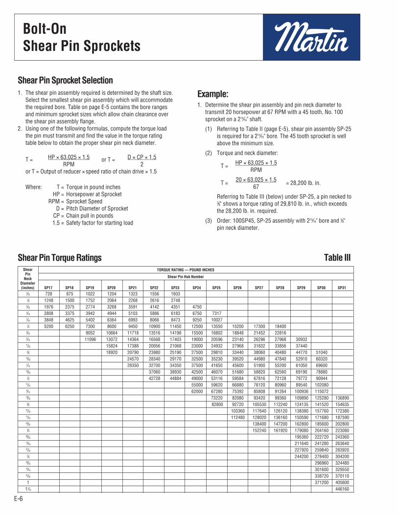
Shear Pin Sprocket Selection1. The shear pin assembly required is determined by the shaft size.
Select the smallest shear pin assembly which will accommodatethe required bore. Table on page E-5 contains the bore rangesand minimum sprocket sizes which allow chain clearance overthe shear pin assembly flange.
2. Using one of the following formulas, compute the torque loadthe pin must transmit and find the value in the torque ratingtable below to obtain the proper shear pin neck diameter.
T = HP × 63,025 × 1.5 or T = D × CP × 1.5 RPM 2 or T = Output of reducer × speed ratio of chain drive × 1.5
Where: T = Torque in pound inches HP = Horsepower at Sprocket RPM = Sprocket Speed D = Pitch Diameter of Sprocket CP = Chain pull in pounds 1.5 = Safety factor for starting load
Example:1. Determine the shear pin assembly and pin neck diameter to
transmit 20 horsepower at 67 RPM with a 45 tooth, No. 100sprocket on a 215⁄16" shaft.
(1) Referring to Table II (page E-5), shear pin assembly SP-25is required for a 215⁄16" bore. The 45 tooth sprocket is wellabove the minimum size.
(2) Torque and neck diameter:
T = HP × 63,025 × 1.5 RPM
T = 20 × 63,025 × 1.5 = 28,200 lb. in. 67
Referring to Table III (below) under SP-25, a pin necked to3⁄8" shows a torque rating of 29,810 lb. in., which exceedsthe 28,200 lb. in. required.
(3) Order: 100SP45, SP-25 assembly with 215⁄16" bore and 3⁄8"pin neck diameter.
3⁄32 728 875 1022 1204 1323 1556 1603 1⁄8 1248 1500 1752 2064 2268 2616 2748 5⁄32 1976 2375 2774 3268 3591 4142 4351 4750 3⁄16 2808 3375 3942 4944 5103 5886 6183 6750 7317 7⁄32 3848 4625 5402 6364 6993 8066 8473 9250 10027 1⁄4 5200 6250 7300 8600 9450 10900 11450 12500 13550 15200 17300 18400 9⁄32 9052 10664 11718 13516 14198 15500 16802 18848 21452 22816 5⁄16 11096 13072 14364 16568 17403 19000 20596 23140 26296 27968 30932 11⁄32 15824 17388 20056 21068 23000 24932 27968 31832 33856 37440 3⁄8 18920 20790 23980 25190 27500 29810 33440 38060 40480 44770 51040 13⁄32 24570 28340 29170 32500 35230 39520 44980 47840 52910 60320 7⁄16 28350 32700 34350 37500 41650 45600 51900 55200 61050 69600 15⁄32 37060 38930 42500 46070 51680 58820 62560 69190 78880 1⁄2 42728 44884 49000 53116 59584 67816 72128 79772 90944 17⁄32 55000 59620 66880 76120 80960 89540 102080 9⁄16 62000 67280 75392 85808 91264 100936 115072 19⁄32 73220 82080 93420 99360 109890 125280 136890 5⁄8 82800 92720 105530 112240 124135 141520 154635 21⁄32 103360 117640 126120 138380 157760 172380 11⁄16 112480 128020 136160 150590 171680 187590 23⁄32 138400 147200 162800 185600 202800 3⁄4 152240 161920 179080 204160 223080 25⁄32 195360 222720 243360 13⁄16 211640 241280 263640 27⁄32 227920 259840 283920 7⁄8 244200 278400 304200 29⁄32 296960 324480 15⁄16 301600 329550 31⁄32 338720 370110 1 371200 405600 11⁄16 446160 11⁄8 507000
Shear
Pin TORQUE RATING — POUND INCHES
Neck Shear Pin Hub Number
Diameter (inches) SP17 SP18 SP19 SP20 SP21 SP22 SP23 SP24 SP25 SP26 SP27 SP28 SP29 SP30 SP31
Shear Pin Torque Ratings
Bolt-OnShear Pin Sprockets
E-7
Solid and SplitDetachable Hubs
E-7
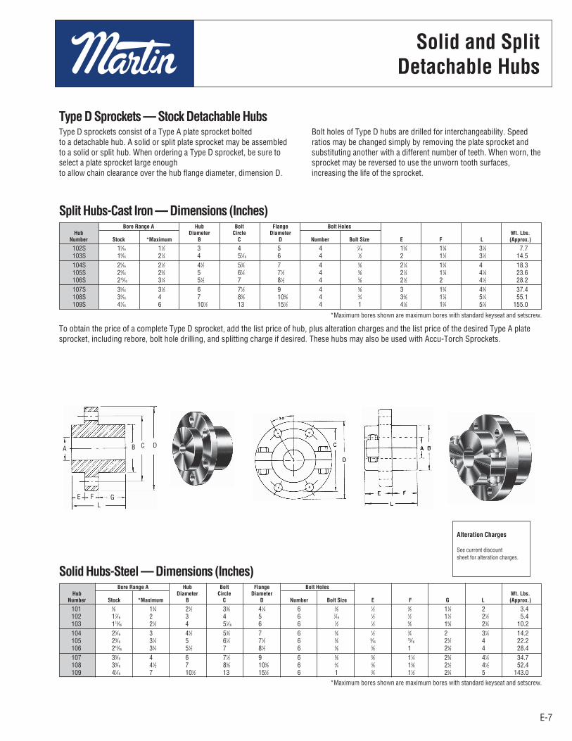
Type D Sprockets — Stock Detachable HubsType D sprockets consist of a Type A plate sprocket bolted to a detachable hub. A solid or split plate sprocket may be assembledto a solid or split hub. When ordering a Type D sprocket, be sure toselect a plate sprocket large enough to allow chain clearance over the hub flange diameter, dimension D.
Bolt holes of Type D hubs are drilled for interchangeability. Speedratios may be changed simply by removing the plate sprocket andsubstituting another with a different number of teeth. When worn, thesprocket may be reversed to use the unworn tooth surfaces,increasing the life of the sprocket.
102S 15⁄16 11⁄2 3 4 5 4 7⁄16 13⁄4 13⁄8 31⁄8 7.7 103S 19⁄16 21⁄4 4 51⁄16 6 4 1⁄2 2 11⁄2 31⁄2 14.5 104S 25⁄16 21⁄2 41⁄2 53⁄4 7 4 5⁄8 21⁄4 13⁄4 4 18.3 105S 29⁄16 23⁄4 5 61⁄4 71⁄2 4 5⁄8 21⁄4 17⁄8 41⁄8 23.6 106S 213⁄16 31⁄4 51⁄2 7 81⁄2 4 5⁄8 21⁄2 2 41⁄2 28.2 107S 35⁄16 31⁄2 6 71⁄2 9 4 5⁄8 3 13⁄4 43⁄4 37.4 108S 39⁄16 4 7 85⁄8 103⁄8 4 3⁄4 33⁄8 17⁄8 51⁄4 55.1 109S 41⁄16 6 101⁄2 13 151⁄2 4 1 41⁄8 13⁄4 57⁄8 155.0
Bore Range A Hub Bolt Flange Bolt Holes Hub Diameter Circle Diameter Wt. Lbs. Number Stock *Maximum B C D Number Bolt Size E F L (Approx.)
Split Hubs-Cast Iron — Dimensions (Inches)
101 5⁄8 13⁄4 21⁄2 33⁄8 41⁄4 6 3⁄8 1⁄2 3⁄8 11⁄8 2 3.4 102 17⁄16 2 3 4 5 6 7⁄16 1⁄2 1⁄2 11⁄2 21⁄2 5.4 103 113⁄16 21⁄2 4 51⁄16 6 6 1⁄2 1⁄2 5⁄8 15⁄8 23⁄4 10.2 104 25⁄16 3 41⁄2 53⁄4 7 6 5⁄8 1⁄2 3⁄4 2 31⁄4 14.2 105 29⁄16 31⁄4 5 61⁄4 71⁄2 6 5⁄8 9⁄16 15⁄16 21⁄2 4 22.2 106 213⁄16 33⁄4 51⁄2 7 81⁄2 6 5⁄8 5⁄8 1 23⁄8 4 28.4 107 35⁄16 4 6 71⁄2 9 6 5⁄8 5⁄8 11⁄4 23⁄8 41⁄4 34.7 108 39⁄16 41⁄2 7 85⁄8 103⁄8 6 3⁄4 5⁄8 13⁄8 21⁄2 41⁄2 52.4 109 41⁄16 7 101⁄2 13 151⁄2 6 1 3⁄4 11⁄2 23⁄4 5 143.0
Bore Range A Hub Bolt Flange Bolt Holes Hub Diameter Circle Diameter Wt. Lbs. Number Stock *Maximum B C D Number Bolt Size E F G L (Approx.)
Solid Hubs-Steel — Dimensions (Inches)
*Maximum bores shown are maximum bores with standard keyseat and setscrew.
To obtain the price of a complete Type D sprocket, add the list price of hub, plus alteration charges and the list price of the desired Type A platesprocket, including rebore, bolt hole drilling, and splitting charge if desired. These hubs may also be used with Accu-Torch Sprockets.
Alteration Charges
See current discountsheet for alteration charges.
*Maximum bores shown are maximum bores with standard keyseat and setscrew.
A B DC
E FL
G
Solid and SplitDetachable Hubs
E-8
All Steel Instant Split® Sprocket
E-8
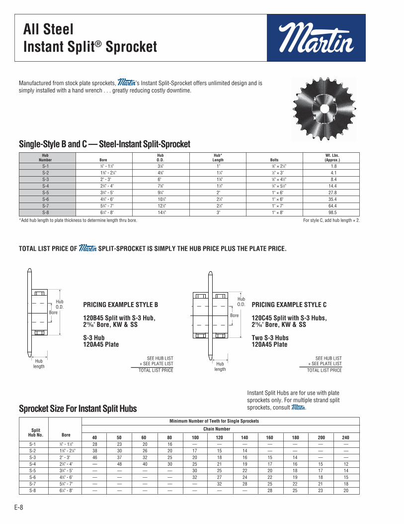
S-1 3⁄4" - 11⁄2" 31⁄8" 1" 3⁄8" × 21⁄4" 1.8 S-2 13⁄8" - 21⁄4" 43⁄8" 11⁄4" 1⁄2" × 3" 4.1 S-3 2" - 3" 6" 13⁄8" 5⁄8" × 41⁄2" 8.4 S-4 23⁄4" - 4" 75⁄8" 11⁄2" 3⁄4" × 51⁄2" 14.4 S-5 33⁄4" - 5" 91⁄4" 2" 1" × 6" 27.8 S-6 43⁄4" - 6" 101⁄4" 21⁄4" 1" × 6" 35.4 S-7 53⁄4" - 7" 121⁄2" 21⁄2" 1" × 7" 64.4 S-8 61⁄4" - 8" 141⁄2" 3" 1" × 8" 98.5
Hub Hub Hub* Wt. Lbs. Number Bore O.D. Length Bolts (Approx.)
S-1 3⁄4" - 11⁄2" 28 23 20 16 — — — — — — — S-2 13⁄8" - 21⁄4" 38 30 26 20 17 15 14 — — — — S-3 2" - 3" 46 37 32 25 20 18 16 15 14 — — S-4 23⁄4" - 4" — 48 40 30 25 21 19 17 16 15 12 S-5 33⁄4" - 5" — — — — 30 25 22 20 18 17 14 S-6 43⁄4" - 6" — — — — 32 27 24 22 19 18 15 S-7 53⁄4" - 7" — — — — — 32 28 25 22 21 18 S-8 61⁄4" - 8" — — — — — — — 28 25 23 20
Minimum Number of Teeth for Single Sprockets
Chain Number Split Hub No. Bore 40 50 60 80 100 120 140 160 180 200 240
Sprocket Size For Instant Split Hubs
TOTAL LIST PRICE OF Martin SPLIT-SPROCKET IS SIMPLY THE HUB PRICE PLUS THE PLATE PRICE.
Single-Style B and C — Steel-Instant Split-Sprocket
Manufactured from stock plate sprockets, Martin’s Instant Split-Sprocket offers unlimited design and issimply installed with a hand wrench . . . greatly reducing costly downtime.
*Add hub length to plate thickness to determine length thru bore. For style C, add hub length × 2.
PRICING EXAMPLE STYLE B
120B45 Split with S-3 Hub,215⁄16" Bore, KW & SS
S-3 Hub120A45 Plate
SEE HUB LIST+ SEE PLATE LIST
TOTAL LIST PRICE
PRICING EXAMPLE STYLE C
120C45 Split with S-3 Hubs,215⁄16" Bore, KW & SS
Two S-3 Hubs120A45 Plate
SEE HUB LIST+ SEE PLATE LIST
TOTAL LIST PRICE
Instant Split Hubs are for use with platesprockets only. For multiple strand splitsprockets, consult Martin.
Hublength
HubO.D.
Bore
Hublength
HubO.D.
Bore
All SteelInstant Split® Sprocket

E-9
Martin TORQUE-LIMITERclutch offers thrifty overload protectionthat’s easy to adjust.
Here is low cost protection for your machinery . . . a torque limitingclutch that is easy to install.
Torque-Limiter clutches feature an exclusive “Easy-SetAdjustment.” With “Easy-Set,” torque adjustment is accomplishedquickly! The need for hammer and block, brute strength, andspanner wrenches is eliminated.
These simple steps and the job is done:
1. Snug up the adjusting nut, finger tight, locate set screw overnearest spline notch, and tighten. See table at right.
2. Tighten three cap screws until heads bottom — with a smallwrench; this gives maximum torque.
3. For less torque — back off the cap screws, loosen the setscrew, back off adjusting nut to one of the six spline notches asrequired, and retighten set screw and cap screws.
“Easy-Set Adjustment” not only simplifies installation, it providessolid support for pressure plates by compression at theirperipheries.
The Torque-Limiter clutch gives machinery permanent protec tionagainst overloads during starting, reversing, or driving — byslipping at any desired load. It resumes driving without resettingwhen the overload is relieved. It is simple in design, compact,efficient, and built for long life. It provides low cost torque limitingservice for a wide variety of applications. No lubrication . . .minimum maintenance.
Starting shock from electric motors is a major cause ofmaintenance of moving parts. Torque-Limiter clutches provide acushion by slipping until the torque drops to a pre-set level. Theycan be set to reduce shock loads on motors and driven equipmentduring reversing or inching. They provide mechanical protectionagainst breakage due to sudden overload — by slipping when thepre-set torque limit is reached.
Torque-LimiterClutches
E-9
Torque-Limiter clutches may be used with a sprocket, gear, sheave,flange, or other driven member. It is recommended that the rubbingsides of the driven member be ground to provide a smooth rubbingsurface of 63 to 125 micro-inches. See torque rating table onfollowing page.
The driven member is mounted on an oil-impregnated bushing andclamped between two, high quality friction discs by springpressure. Each Torque-Limiter unit, completely assembled,contains one spring. Higher torque ratings can be obtained by theuse of a second spring nested within the original spring. See ratingtable on following page.
When an overload occurs, the driven member slips between long-life, clutch-type friction discs. After slipping has started, it willcontinue at approximately 90% of the torque setting, due to thelower coefficient of friction when slipping, until the overloadcondition has been corrected.
TORQ
UE (l
b.-in
.)
70-2
70-1
50-2
50-135-2
35-125-2
25-1
0 1 2 3 4 5 6 7
SPLINES
Note:Graph indicates approximate rated torque vs. number of splinesadjusting nut is backed off from finger tight.
TORQUE-LIMITER CLUTCH CALIBRATION
#25 300 700 400 1200 #35 600 1700 900 2500 #50 950 2650 2350 5700 #70 2000 8000 3100 11500
Torque Rating One Spring Two Springs Size Min. Max. Min. Max.
12000
11000
10000
9000
8000
7000
6000
5000
4000
3000
2000
1000
0
Non-AsbestosFriction Discs
Pressure PlateSpring Washer
Long-Life Bushing
More AdjustmentCapability with Spline Hub
Cap Screw SpringCompression
Setscrew
Adjustment Nut
Sprocket
Torque-LimiterClutches

E-10
Torque-LimiterClutches
E-10
Stock Plate Sprockets with Ground
Face and Bored to Fit the MartinTorque Limiter
Sprocket Size
35TTA25-2535TTA26-2540TTA20-2540TTA22-2540TTA24-2540TTA28-2540TTA30-2550TTA17-2550TTA21-2550TTA22-25
Sprocket Size
35TTA35-3535TTA40-3540TTA28-3540TTA30-3540TTA32-3550TTA22-3550TTA24-3550TTA25-3550TTA26-3560TTA18-3560TTA20-35
TT25 1.0 300 700 400 1200 21⁄2 13⁄4 1⁄8 11⁄32 29⁄64 19⁄64 19⁄64 21⁄2 11⁄2 1.368 1.631/1.628 TT35 2.5 600 1700 900 2500 31⁄2 27⁄16 1⁄8 5⁄8 45⁄64 23⁄64 35⁄64 33⁄16 115⁄16 1.675 2.006/2.003 TT50 6.0 950 2650 2350 5700 5 27⁄8 1⁄8 5⁄8 53⁄64 29⁄64 21⁄32 45⁄16 213⁄16 2.625 3.008/3.005 TT70 18.0 2100 8000 3100 11500 7 37⁄8 1⁄4 11⁄4 55⁄64 31⁄64 29⁄32 6 4 3.811 4.197/4.194
Torque Rating s C K L (Pound-Inches) +.000 +.003 With One With Two –.002 –.000 Size Avg. Spring Springs** G Spline Spkt. No. Wt. Min. Max. Min. Max A B Min. Max. D E ✤ H J O. D. Bore
Torque-Limiter Clutch Ratings
TT25 1⁄2 7⁄8 1 TT35 3⁄4 13⁄16 11⁄4 TT50 1 13⁄4 2 TT70 13⁄8 23⁄4 3
Size Stock Max. Bore No. Bore Std. KW* Shallow KW*
1⁄2 - 9⁄16 1⁄8 × 1⁄16 17⁄16 - 13⁄4 3⁄8 × 3⁄16
5⁄8 - 7⁄8 3⁄16 × 3⁄32 113⁄16 - 21⁄4 1⁄2 × 1⁄4 15⁄16 - 11⁄4 1⁄4 × 1⁄8 25⁄16 - 23⁄4 5⁄8 × 5⁄16
15⁄16 - 13⁄8 5⁄16 × 5⁄32 213⁄16 - 3 3⁄4 × 3⁄8
Torque- Torque- Limiter Limiter Bore Keyway Bore Keyway
TT25 1⁄2 5⁄8 3⁄4 7⁄8 TT35 3⁄4 7⁄8 1 TT50 1 11⁄8 13⁄16 11⁄4 13⁄8 17⁄16 11⁄2 15⁄8 TT70 17⁄16 11⁄2 13⁄4 115⁄16 2 27⁄16
Size No. Finished Bores
STOCK H 25 19 19 16 .. .. .. .. .. .. TT25 Min. Teeth MTO l 25 19 19 16 .. .. .. .. .. .. Bush. Lght. Req’d. 1⁄8 1⁄8 1⁄4 1⁄4 .. .. .. .. .. .. STOCK H 35 25 26 21 18 15 .. .. .. .. TT35 Min. Teeth MTO ll 33 25 26 21 18 15 .. .. .. .. Bush. Lght. Req’d. 1⁄8 1⁄8 1⁄4 1⁄4 3⁄8 3⁄8 .. .. .. .. STOCK H 48 35 35 29 25 19 .. .. .. .. TT50 Min. Teeth MTO ll 46 35 35 29 25 19 .. .. .. .. Bush. Lght. Req’d. 1⁄8 1⁄8 1⁄4 1⁄4 3⁄8 3⁄8 .. .. .. .. STOCK H .. .. 48 38 33 26 21 18 16 14 TT70 Min. Teeth MTO ll .. .. 48 38 33 26 21 18 16 14 Bush. Lght. Req’d. .. .. 1⁄4 1⁄4 3⁄8 3⁄8 1⁄2 7⁄8 Q 7⁄8 Q 1uu
Unit Min. Allowable Sprocket Teeth and Length of Bushing Req’d for Chain Number Size Sprocket Pitch 35 41 40 50 60 80 100 120 140 160
H Min. number of teeth on sprocket stocked by Martin which can be used w/Torque-Limiter clutch.l Min. number of teeth on made-to-order sprocket which will permit chain to clear friction disc.Q Use one 3⁄8" long bushing and one 1⁄2" long.uu Use two 1⁄2" long bushings.
† KW same as std. listed in tables above. For additional SS see List Price.
Bored to Size Torque Limiters w/Std. KW & 1-SS†
† For additional SS see List Price Alterations.* KW to be cut central w/threaded spline.
Standard Keyways
Stock Bores — Torque Limiters (No KW 1-SS†)
s Using a center member with rubbing sides ground parallel— 63 to 125 micro-inches. Center member must be cleanand free from oil, rust, etc.
** Second spring may be nested in one originally furnished.Order if required.
✤ Nominal for maximum torque setting. For minimum torquesetting, add 3⁄64" for No. 25; 5⁄64" for No. 35; 3⁄32" for Nos. 50and 70. When two springs are used this dimension isincreased approximately 1⁄16" on Nos. 25, 35 and 50 — 3⁄32"on No. 70.
TORQUE-LIMITER CLUTCHESEach assembled unit contains one spring.Higher ratings can be obtained by orderinga second spring to nest in the original one.Bushings need to be ordered separately, ifrequired.
The rubbing sides of the center membershould be ground parallel — 63 to 125micro-inches.
Sprocket Size
40TTA35-5050TTA30-5050TTA32-5060TTA25-5060TTA26-5060TTA28-5060TTA30-5080TTA20-5080TTA22-5080TTA24-50
Sprocket Size
60TTA36-7080TTA26-7080TTA28-70 80TTA30-7080TTA36-70100TTA22-70100TTA24-70
PRESSURE PLATE 2 FRICTION DISC 2 ADJ. NUT ASSY. & S.S. 1 ADJ. TENSION NUT 3 HUB 1
TT25 TT50 TT35 TT70 QTY. REQ.*
SPARE PARTS
UNIT TT25 UNIT TT35
UNIT TT50 UNIT TT70
* PER UNIT
BG E
CE D
J L K
A
Torque-LimiterClutches

E-11
Double PitchAll Steel Stock Sprockets
E-11
Double-Pitch Sprockets
Standard Roller Carrier Double Duty Roller
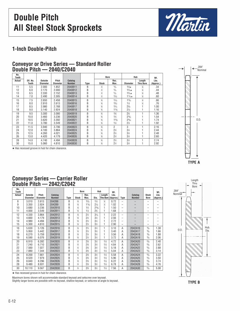
Series C-2000 chains have rollers of the same diameters and widthsas American Standard Roller Chains of one half the conveyor chainpitch. Engaged by every other tooth, double duty sprockets have twoteeth per chain pitch. During each revolution only half the teethfunction effectively. Sprockets with odd numbers of teeth will allowany given tooth to engage only on every other revolution,automatically increasing sprocket life. Double duty sprockets witheven number of teeth may be manually advanced one toothperiodically to increase sprocket life. Martin Stock C-2000 seriessprockets are furnished double duty only.
Sprockets for the C-2002 series chain with carrier rollers are cutwith space cutters or standard hobs for the American Standardroller Chain of the same diameter. Each sprocket tooth meshes withthese chains. Double-duty sprockets cannot be made for doublepitch chain with Carrier Rollers.
NOTE: For drives of 31 teeth or more we recommend usingStandard sprockets with series C-2000 chains.
All altered double pitch sprockets requiring a keyway will befurnished with keyway on center line of tooth, unless otherwisespecified.
Double Pitch Single Duty Standard Rollers Made-To-Order Carrier Rollers
Double PitchAll Steel Stock Sprockets
E-12
No. Bore Hub Teeth Wt.
Actual Eff. No. Outside Pitch Catalog Rec. Length Lbs. Teeth Diameter Diameter Number Type Stock Max. Diameter Thru Bore (Approx.)
Conveyor or Drive Series — Standard RollerDouble Pitch — 2040/C2040
Double PitchAll Steel Stock Sprockets
E-12
1-Inch Double-Pitch
8 3.010 2.613 2042B8 B 5⁄8 19⁄32 17⁄8 7⁄8 0.72 – – – – 9 3.350 2.924 2042B9 B 5⁄8 115⁄32 27⁄32 7⁄8 1.02 – – – – 10 3.680 3.236 2042B10 B 5⁄8 13⁄4 235⁄64 1 1.50 – – – – 11 4.000 3.549 2042B11 B 5⁄8 17⁄8 25⁄8 1 1.68 – – – – 12 4.330 3.864 2042B12 B 5⁄8 21⁄4 31⁄16 1 2.22 – – – – 13 4.660 4.179 2042B13 B 5⁄8 21⁄4 31⁄4 1 2.56 – – – – 14 4.980 4.494 2042B14 B 5⁄8 21⁄4 31⁄4 1 2.72 – – – – 15 5.300 4.810 2042B15 B 5⁄8 21⁄4 31⁄4 1 2.90 – – – – 16 5.630 5.126 2042B16 B 5⁄8 21⁄4 31⁄4 1 3.10 A 2042A16 19⁄32 1.38 17 5.950 5.442 2042B17 B 5⁄8 21⁄4 31⁄4 1 3.40 A 2042A17 19⁄32 1.66 18 6.270 5.759 2042B18 B 5⁄8 21⁄4 31⁄4 1 3.56 A 2042A18 19⁄32 1.88 19 6.590 6.076 2042B19 B 5⁄8 21⁄4 31⁄4 1 3.72 A 2042A19 19⁄32 2.06 20 6.910 6.392 2042B20 B 3⁄4 23⁄8 31⁄2 11⁄8 4.72 A 2042A20 23⁄32 2.40 21 7.240 6.710 2042B21 B 3⁄4 23⁄8 31⁄2 11⁄8 4.84 A 2042A21 23⁄32 2.62 22 7.560 7.027 2042B22 B 3⁄4 23⁄8 31⁄2 11⁄8 5.18 A 2042A22 23⁄32 2.88 23 7.880 7.344 2042B23 B 3⁄4 23⁄8 31⁄2 11⁄8 5.04 A 2042A23 23⁄32 3.14 24 8.200 7.661 2042B24 B 3⁄4 23⁄8 31⁄2 11⁄8 5.58 A 2042A24 23⁄32 3.22 25 8.520 7.979 2042B25 B 3⁄4 23⁄8 31⁄2 11⁄8 5.96 A 2042A25 23⁄32 3.50 26 8.840 8.296 2042B26 B 3⁄4 23⁄8 31⁄2 11⁄8 6.22 A 2042A26 23⁄32 3.74 28 9.480 8.931 2042B28 B 3⁄4 23⁄8 31⁄2 11⁄8 6.78 A 2042A28 23⁄32 4.76 30 10.110 9.567 2042B30 B 3⁄4 23⁄8 31⁄2 11⁄8 7.56 A 2042A30 23⁄32 5.08
No. Bore Hub Teeth Wt. Wt.
Actual Outside Pitch Catalog Rec. Length Lbs. Catalog Stock Lbs. Diameter Diameter Number Type Stock Max. Dia. Thru Bore (Approx.) Type Number Bore (Approx.)
Conveyor Series — Carrier RollerDouble Pitch — 2042/C2042
H Has recessed groove in hub for chain clearance.
Maximum bores shown will accommodate standard keyseat and setscrew over keyseat.Slightly larger bores are possible with no keyseat, shallow keyseat, or setscrew at angle to keyseat.
TYPE A
TYPE B
.284"Nominal
LengthThruBore
Hub.Dia.O.D.
.284"Nominal
O.D.
11 5.5 2.000 1.852 2040B11 B 1⁄2 13⁄16 13⁄8H 7⁄8 .34 12 6.0 2.170 2.000 2040B12 B 1⁄2 13⁄16 19⁄16H 7⁄8 .44 13 6.5 2.330 2.152 2040B13 B 1⁄2 21⁄32 19⁄16H 7⁄8 .48 14 7.0 2.490 2.305 2040B14 B 1⁄2 11⁄32 111⁄16H 7⁄8 .60 15 7.5 2.650 2.458 2040B15 B 5⁄8 17⁄32 123⁄32 7⁄8 .66 16 8.0 2.810 2.613 2040B16 B 5⁄8 19⁄32 17⁄8 7⁄8 .76 17 8.5 2.980 2.768 2040B17 B 5⁄8 15⁄16 23⁄64 1 1.00 18 9.0 3.140 2.924 2040B18 B 5⁄8 115⁄32 27⁄32 1 1.16 19 9.5 3.300 3.080 2040B19 B 5⁄8 15⁄8 23⁄8 1 1.36 20 10.0 3.460 3.236 2040B20 B 5⁄8 13⁄4 235⁄64 1 1.54 21 10.5 3.620 3.392 2040B21 B 5⁄8 125⁄32 245⁄64 1 1.74 22 11.0 3.780 3.549 2040B22 B 5⁄8 17⁄8 27⁄8 1 1.92 23 11.5 3.940 3.706 2040B23 B 5⁄8 2 3 1 2.16 24 12.0 4.100 3.864 2040B24 B 5⁄8 21⁄4 31⁄4 1 2.44 25 12.5 4.260 4.021 2040B25 B 5⁄8 21⁄4 31⁄4 1 2.48 26 13.0 4.420 4.179 2040B26 B 5⁄8 21⁄4 31⁄4 1 2.60 28 14.0 4.740 4.494 2040B28 B 5⁄8 21⁄4 31⁄4 1 2.74 30 15.0 5.060 4.810 2040B30 B 5⁄8 21⁄4 31⁄4 1 2.92
H Has recessed groove in hub for chain clearance.
Double PitchAll Steel Stock Sprockets

E-13
11 5.5 2.500 2.315 2050B11 B 5⁄8 13⁄16 13⁄4H 1 0.62 – – – – 12 6.0 2.710 2.500 2050B12 B 5⁄8 1 163⁄64 1 0.80 – – – – 13 6.5 2.910 2.690 2050B13 B 5⁄8 17⁄32 123⁄32 1 0.82 – – – – 14 7.0 3.110 2.881 2050B14 B 5⁄8 19⁄32 115⁄16 1 1.00 – – – – 15 7.5 3.320 3.073 2050B15 B 5⁄8 113⁄32 25⁄32 1 1.22 – – – – 16 8.0 3.520 3.266 2050B16 B 5⁄8 119⁄32 223⁄64 1 1.44 – – – – 17 8.5 3.720 3.460 2050B17 B 5⁄8 13⁄4 29⁄16 1 1.68 – – – – 18 9.0 3.920 3.655 2050B18 B 5⁄8 125⁄32 225⁄32 1 1.94 – – – – 19 9.5 4.120 3.850 2050B19 B 5⁄8 131⁄32 263⁄64 1 2.24 – – – – 20 10.0 4.320 4.045 2050B20 B 3⁄4 2 3 1 2.30 – – – – 21 10.5 4.520 4.241 2050B21 B 3⁄4 2 3 1 2.40 – – – – 22 11.0 4.720 4.437 2050B22 B 3⁄4 2 3 1 2.54 – – – – 23 11.5 4.920 4.633 2050B23 B 3⁄4 2 3 1 2.66 – – – – 24 12.0 5.120 4.830 2050B24 B 3⁄4 2 3 11⁄4 3.30 A 2050A24 23⁄32 1.58 25 12.5 5.320 5.026 2050B25 B 3⁄4 2 3 11⁄4 3.42 A 2050A25 23⁄32 1.68 26 13.0 5.520 5.223 2050B26 B 3⁄4 2 3 11⁄4 3.62 A 2050A26 23⁄32 1.88 28 14.0 5.920 5.617 2050B28 B 3⁄4 2 3 11⁄4 3.78 A 2050A28 23⁄32 2.22 30 15.0 6.320 6.012 2050B30 B 3⁄4 21⁄4 31⁄4 11⁄4 4.58 A 2050A30 23⁄32 2.54
No. Bore Hub Teeth Wt. Wt.
Actual Eff. No. Outside Pitch Catalog Rec. Length Lbs. Catalog Stock Lbs. Teeth Diameter Diameter Number Type Stock Max. Dia. Thru Bore (Approx.) Type Number Bore (Approx.)
Double PitchAll Steel Stock Sprockets
E-13
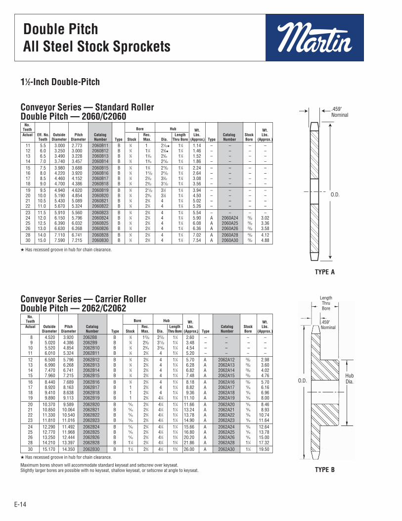
11⁄4-Inch Double-Pitch
8 3.770 3.266 2052B8 B 5⁄8 119⁄32 223⁄64 1 1.38 – – – – 9 4.190 3.655 2052B9 B 5⁄8 125⁄32 225⁄32 1 1.92 – – – – 10 4.600 4.045 2052B10 B 5⁄8 2 3 1 2.30 – – – – 11 5.010 4.437 2052B11 B 5⁄8 2 3 1 2.54 – – – – 12 5.420 4.830 2052B12 B 3⁄4 2 3 11⁄4 3.20 A 2052A12 23⁄32 1.58 13 5.820 5.223 2052B13 B 3⁄4 2 3 11⁄4 3.48 A 2052A13 23⁄32 1.82 14 6.230 5.617 2052B14 B 3⁄4 2 3 11⁄4 3.88 A 2052A14 23⁄32 2.28 15 6.630 6.012 2052B15 B 3⁄4 21⁄4 31⁄4 11⁄4 4.46 A 2052A15 23⁄32 2.46 16 7.030 6.407 2052B16 B 3⁄4 21⁄4 31⁄4 11⁄4 4.80 A 2052A16 23⁄32 2.88 17 7.440 6.803 2052B17 B 3⁄4 21⁄4 31⁄4 11⁄4 5.34 A 2052A17 23⁄32 3.28 18 7.840 7.198 2052B18 B 3⁄4 21⁄4 31⁄4 11⁄4 5.64 A 2052A18 23⁄32 3.64 19 8.240 7.595 2052B19 B 3⁄4 21⁄4 31⁄4 11⁄4 6.04 A 2052A19 23⁄32 4.12 20 8.640 7.991 2052B20 B 3⁄4 21⁄4 31⁄4 11⁄4 6.48 A 2052A20 23⁄32 4.72 21 9.040 8.387 2052B21 B 3⁄4 21⁄4 31⁄4 11⁄4 7.00 A 2052A21 23⁄32 5.08 22 9.440 8.783 2052B22 B 3⁄4 21⁄4 31⁄4 11⁄4 7.30 A 2052A22 23⁄32 5.20 23 9.850 9.180 2052B23 B 1 23⁄4 33⁄4 11⁄4 8.66 A 2052A23 15⁄16 5.84 24 10.250 9.577 2052B24 B 15⁄16 23⁄4 33⁄4 11⁄4 9.32 A 2052A24 15⁄16 6.70 25 10.650 9.973 2052B25 B 15⁄16 23⁄4 33⁄4 11⁄4 10.30 A 2052A25 15⁄16 7.54 26 11.050 10.370 2052B26 B 15⁄16 23⁄4 33⁄4 11⁄4 11.00 A 2052A26 15⁄16 8.24 28 11.840 11.164 2052B28 B 15⁄16 23⁄4 33⁄4 11⁄4 11.70 A 2052A28 15⁄16 8.70 30 12.640 11.958 2052B30 B 15⁄16 23⁄4 33⁄4 11⁄4 12.90 A 2052A30 15⁄16 9.92
No. Bore Hub Teeth Wt. Wt.
Actual Outside Pitch Catalog Rec. Length Lbs. Catalog Stock Lbs. Diameter Diameter Number Type Stock Max. Dia. Thru Bore (Approx.) Type Number Bore (Approx.)
Conveyor Series — Carrier RollerDouble Pitch — 2052/C2052
Conveyor or Drive Series — Standard RollerDouble Pitch — 2050/C2050
H Has recessed groove in hub for chain clearance.
Maximum bores shown will accommodate standard keyseat and setscrew over keyseat.Slightly larger bores are possible with no keyseat, shallow keyseat, or setscrew at angle to keyseat.
TYPE A
TYPE B
.343"Nominal
.343"Nominal
LengthThruBore
O.D.
O.D. Hub.Dia.
H Has recessed groove in hub for chain clearance.
Double PitchAll Steel Stock Sprockets
E-14
11 5.5 3.000 2.773 2060B11 B 3⁄4 1 21⁄16H 11⁄4 1.14 – – – – 12 6.0 3.250 3.000 2060B12 B 3⁄4 11⁄4 23⁄8H 11⁄4 1.46 – – – – 13 6.5 3.490 3.228 2060B13 B 3⁄4 15⁄16 25⁄64 11⁄4 1.52 – – – – 14 7.0 3.740 3.457 2060B14 B 3⁄4 19⁄16 221⁄64 11⁄4 1.86 – – – – 15 7.5 3.980 3.688 2060B15 B 3⁄4 13⁄4 219⁄32 11⁄4 2.24 – – – – 16 8.0 4.220 3.920 2060B16 B 3⁄4 127⁄32 227⁄32 11⁄4 2.64 – – – – 17 8.5 4.460 4.152 2060B17 B 3⁄4 23⁄32 33⁄32 11⁄4 3.08 – – – – 18 9.0 4.700 4.386 2060B18 B 3⁄4 29⁄32 311⁄32 11⁄4 3.56 – – – – 19 9.5 4.940 4.620 2060B19 B 3⁄4 211⁄32 31⁄2 11⁄4 3.94 – – – – 20 10.0 5.190 4.854 2060B20 B 3⁄4 29⁄16 37⁄8 11⁄4 4.50 – – – – 21 10.5 5.430 5.089 2060B21 B 3⁄4 23⁄4 4 11⁄4 5.02 – – – – 22 11.0 5.670 5.324 2060B22 B 3⁄4 23⁄4 4 11⁄4 5.26 – – – – 23 11.5 5.910 5.560 2060B23 B 3⁄4 23⁄4 4 11⁄4 5.54 – – – – 24 12.0 6.150 5.796 2060B24 B 3⁄4 23⁄4 4 11⁄4 5.90 A 2060A24 23⁄32 3.02 25 12.5 6.390 6.032 2060B25 B 3⁄4 23⁄4 4 11⁄4 6.08 A 2060A25 23⁄32 3.36 26 13.0 6.630 6.268 2060B26 B 3⁄4 23⁄4 4 11⁄4 6.36 A 2060A26 23⁄32 3.58 28 14.0 7.110 6.741 2060B28 B 3⁄4 23⁄4 4 11⁄4 7.02 A 2060A28 23⁄32 4.12 30 15.0 7.590 7.215 2060B30 B 3⁄4 23⁄4 4 11⁄4 7.54 A 2060A30 23⁄32 4.88
Double PitchAll Steel Stock Sprockets
E-14
11⁄2-Inch Double-Pitch
8 4.520 3.920 2062B8 B 3⁄4 127⁄32 227⁄32 11⁄4 2.60 – – – – 9 5.020 4.386 2062B9 B 3⁄4 29⁄32 311⁄32 11⁄4 3.48 – – – – 10 5.520 4.854 2062B10 B 3⁄4 29⁄16 353⁄64 11⁄4 4.54 – – – – 11 6.010 5.324 2062B11 B 3⁄4 23⁄4 4 11⁄4 5.20 – – – – 12 6.500 5.796 2062B12 B 3⁄4 23⁄4 4 11⁄4 5.70 A 2062A12 23⁄32 2.98 13 6.990 6.268 2062B13 B 3⁄4 23⁄4 4 11⁄4 6.28 A 2062A13 23⁄32 3.60 14 7.470 6.741 2062B14 B 3⁄4 23⁄4 4 11⁄4 6.82 A 2062A14 23⁄32 4.02 15 7.960 7.215 2062B15 B 3⁄4 23⁄4 4 11⁄4 7.48 A 2062A15 23⁄32 4.76 16 8.440 7.689 2062B16 B 3⁄4 23⁄4 4 11⁄4 8.18 A 2062A16 23⁄32 5.70 17 8.920 8.163 2062B17 B 1 23⁄4 4 11⁄4 8.82 A 2062A17 15⁄16 6.16 18 9.410 8.638 2062B18 B 1 23⁄4 4 11⁄4 9.36 A 2062A18 15⁄16 6.96 19 9.890 9.113 2062B19 B 1 23⁄4 41⁄4 11⁄4 11.10 A 2062A19 15⁄16 8.00 20 10.370 9.589 2062B20 B 15⁄16 23⁄4 41⁄4 11⁄4 11.66 A 2062A20 15⁄16 8.46 21 10.850 10.064 2062B21 B 15⁄16 23⁄4 41⁄4 11⁄4 13.24 A 2062A21 15⁄16 8.93 22 11.330 10.540 2062B22 B 15⁄16 23⁄4 41⁄4 11⁄4 13.78 A 2062A22 15⁄16 10.74 23 11.810 11.016 2062B23 B 15⁄16 23⁄4 41⁄4 11⁄4 14.90 A 2062A23 15⁄16 11.64 24 12.290 11.492 2062B24 B 15⁄16 23⁄4 41⁄4 11⁄4 15.66 A 2062A24 15⁄16 12.64 25 12.770 11.968 2062B25 B 15⁄16 23⁄4 41⁄4 11⁄4 16.80 A 2062A25 15⁄16 13.78 26 13.250 12.444 2062B26 B 15⁄16 23⁄4 41⁄4 13⁄4 20.20 A 2062A26 15⁄16 15.00 28 14.210 13.397 2062B28 B 11⁄4 23⁄4 41⁄4 13⁄4 21.86 A 2062A28 11⁄4 17.32 30 15.170 14.350 2062B30 B 11⁄4 23⁄4 41⁄4 13⁄4 26.00 A 2062A30 11⁄4 19.50
No. Bore Hub Teeth Wt. Wt.
Actual Outside Pitch Catalog Rec. Length Lbs. Catalog Stock Lbs. Diameter Diameter Number Type Stock Max. Dia. Thru Bore (Approx.) Type Number Bore (Approx.)
Conveyor Series — Carrier RollerDouble Pitch — 2062/C2062
No. Bore Hub Teeth Wt. Wt.
Actual Eff. No. Outside Pitch Catalog Rec. Length Lbs. Catalog Stock Lbs. Teeth Diameter Diameter Number Type Stock Max. Dia. Thru Bore (Approx.) Type Number Bore (Approx.)
Conveyor Series — Standard RollerDouble Pitch — 2060/C2060
H Has recessed groove in hub for chain clearance.
Maximum bores shown will accommodate standard keyseat and setscrew over keyseat.Slightly larger bores are possible with no keyseat, shallow keyseat, or setscrew at angle to keyseat.
TYPE A
TYPE B
.459"Nominal
.459"Nominal
LengthThruBore
O.D.
O.D.HubDia.
H Has recessed groove in hub for chain clearance.
Double PitchAll Steel Stock Sprockets
E-15
Double PitchAll Steel Stock Sprockets
E-15
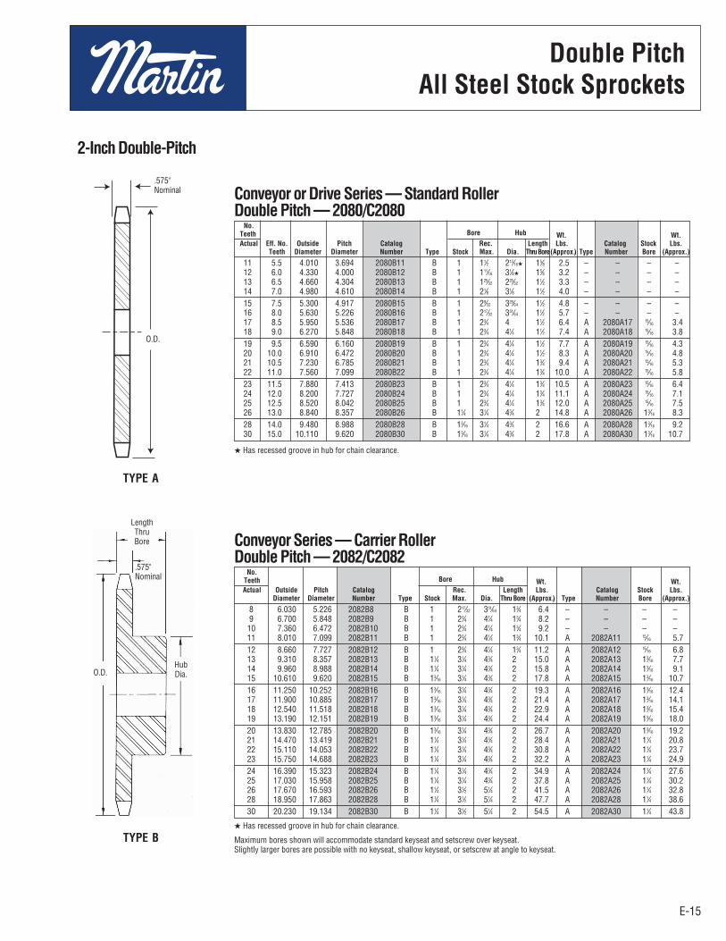
2-Inch Double-Pitch
8 6.030 5.226 2082B8 B 1 217⁄32 351⁄64 13⁄4 6.4 – – – – 9 6.700 5.848 2082B9 B 1 23⁄4 41⁄4 13⁄4 8.2 – – – – 10 7.360 6.472 2082B10 B 1 23⁄4 41⁄4 13⁄4 9.2 – – – – 11 8.010 7.099 2082B11 B 1 23⁄4 41⁄4 13⁄4 10.1 A 2082A11 15⁄16 5.7 12 8.660 7.727 2082B12 B 1 23⁄4 41⁄4 13⁄4 11.2 A 2082A12 15⁄16 6.8 13 9.310 8.357 2082B13 B 11⁄4 31⁄4 43⁄4 2 15.0 A 2082A13 13⁄16 7.7 14 9.960 8.988 2082B14 B 11⁄4 31⁄4 43⁄4 2 15.8 A 2082A14 13⁄16 9.1 15 10.610 9.620 2082B15 B 13⁄16 31⁄4 43⁄4 2 17.8 A 2082A15 13⁄16 10.7 16 11.250 10.252 2082B16 B 13⁄16 31⁄4 43⁄4 2 19.3 A 2082A16 13⁄16 12.4 17 11.900 10.885 2082B17 B 13⁄16 31⁄4 43⁄4 2 21.4 A 2082A17 13⁄16 14.1 18 12.540 11.518 2082B18 B 13⁄16 31⁄4 43⁄4 2 22.9 A 2082A18 13⁄16 15.4 19 13.190 12.151 2082B19 B 13⁄16 31⁄4 43⁄4 2 24.4 A 2082A19 13⁄16 18.0 20 13.830 12.785 2082B20 B 13⁄16 31⁄4 43⁄4 2 26.7 A 2082A20 13⁄16 19.2 21 14.470 13.419 2082B21 B 11⁄4 31⁄4 43⁄4 2 28.4 A 2082A21 11⁄4 20.8 22 15.110 14.053 2082B22 B 11⁄4 31⁄4 43⁄4 2 30.8 A 2082A22 11⁄4 23.7 23 15.750 14.688 2082B23 B 11⁄4 31⁄4 43⁄4 2 32.2 A 2082A23 11⁄4 24.9 24 16.390 15.323 2082B24 B 11⁄4 31⁄4 43⁄4 2 34.9 A 2082A24 11⁄4 27.6 25 17.030 15.958 2082B25 B 11⁄4 31⁄4 43⁄4 2 37.8 A 2082A25 11⁄4 30.2 26 17.670 16.593 2082B26 B 11⁄4 31⁄2 51⁄4 2 41.5 A 2082A26 11⁄4 32.8 28 18.950 17.863 2082B28 B 11⁄4 31⁄2 51⁄4 2 47.7 A 2082A28 11⁄4 38.6 30 20.230 19.134 2082B30 B 11⁄4 31⁄2 51⁄4 2 54.5 A 2082A30 11⁄4 43.8
No. Bore Hub Teeth Wt. Wt.
Actual Outside Pitch Catalog Rec. Length Lbs. Catalog Stock Lbs. Diameter Diameter Number Type Stock Max. Dia. Thru Bore (Approx.) Type Number Bore (Approx.)
Conveyor Series — Carrier RollerDouble Pitch — 2082/C2082
11 5.5 4.010 3.694 2080B11 B 1 11⁄2 213⁄16H 15⁄8 2.5 – – – – 12 6.0 4.330 4.000 2080B12 B 1 111⁄16 31⁄8H 15⁄8 3.2 – – – – 13 6.5 4.660 4.304 2080B13 B 1 125⁄32 225⁄32 11⁄2 3.3 – – – – 14 7.0 4.980 4.610 2080B14 B 1 21⁄8 31⁄8 11⁄2 4.0 – – – – 15 7.5 5.300 4.917 2080B15 B 1 29⁄32 329⁄64 11⁄2 4.8 – – – – 16 8.0 5.630 5.226 2080B16 B 1 217⁄32 351⁄64 11⁄2 5.7 – – – – 17 8.5 5.950 5.536 2080B17 B 1 23⁄4 4 11⁄2 6.4 A 2080A17 15⁄16 3.4 18 9.0 6.270 5.848 2080B18 B 1 23⁄4 41⁄4 11⁄2 7.4 A 2080A18 15⁄16 3.8 19 9.5 6.590 6.160 2080B19 B 1 23⁄4 41⁄4 11⁄2 7.7 A 2080A19 15⁄16 4.3 20 10.0 6.910 6.472 2080B20 B 1 23⁄4 41⁄4 11⁄2 8.3 A 2080A20 15⁄16 4.8 21 10.5 7.230 6.785 2080B21 B 1 23⁄4 41⁄4 13⁄4 9.4 A 2080A21 15⁄16 5.3 22 11.0 7.560 7.099 2080B22 B 1 23⁄4 41⁄4 13⁄4 10.0 A 2080A22 15⁄16 5.8 23 11.5 7.880 7.413 2080B23 B 1 23⁄4 41⁄4 13⁄4 10.5 A 2080A23 15⁄16 6.4 24 12.0 8.200 7.727 2080B24 B 1 23⁄4 41⁄4 13⁄4 11.1 A 2080A24 15⁄16 7.1 25 12.5 8.520 8.042 2080B25 B 1 23⁄4 41⁄4 13⁄4 12.0 A 2080A25 15⁄16 7.5 26 13.0 8.840 8.357 2080B26 B 11⁄4 31⁄4 43⁄4 2 14.8 A 2080A26 13⁄16 8.3 28 14.0 9.480 8.988 2080B28 B 13⁄16 31⁄4 43⁄4 2 16.6 A 2080A28 13⁄16 9.2 30 15.0 10.110 9.620 2080B30 B 13⁄16 31⁄4 43⁄4 2 17.8 A 2080A30 13⁄16 10.7
No. Bore Hub Teeth Wt. Wt.
Actual Eff. No. Outside Pitch Catalog Rec. Length Lbs. Catalog Stock Lbs. Teeth Diameter Diameter Number Type Stock Max. Dia. Thru Bore(Approx.) Type Number Bore (Approx.)
Conveyor or Drive Series — Standard RollerDouble Pitch — 2080/C2080
H Has recessed groove in hub for chain clearance.
Maximum bores shown will accommodate standard keyseat and setscrew over keyseat.Slightly larger bores are possible with no keyseat, shallow keyseat, or setscrew at angle to keyseat.
TYPE A
TYPE B
.575"Nominal
O.D.
O.D.HubDia.
.575"Nominal
LengthThruBore
H Has recessed groove in hub for chain clearance.
Double PitchAll Steel Stock Sprockets

E-16
No. 251⁄4" Pitch
E-16
All SteelStock Sprockets
9 25B9 0.837 B 1⁄4 1⁄4 7⁄16 1⁄2 0.03 – – – – 10 25B10 0.919 B 1⁄4 1⁄4 1⁄2 1⁄2 0.03 – – – – 11 25B11 1.002 B 1⁄4 5⁄16 9⁄16 1⁄2 0.04 – – – – 12 25B12 1.083 B 1⁄4 3⁄8 5⁄8 1⁄2 0.06 – – – – 13 25B13 1.167 B 1⁄4 7⁄16 23⁄32 1⁄2 0.07 – – – – 14 25B14 1.246 B 1⁄4 9⁄16 13⁄16 1⁄2 0.08 – – – – 15 25B15 1.326 B 1⁄4 9⁄16 57⁄64 1⁄2 0.10 – – – – 16 25B16 1.407 B 1⁄4 9⁄16 31⁄32 1⁄2 0.12 – – – – 17 25B17 1.487 B 1⁄4 5⁄8 11⁄32 1⁄2 0.14 – – – – 18 25B18 1.568 B 1⁄4 3⁄4 11⁄8 1⁄2 0.16 A 25A18 1⁄4 0.04 19 25B19 1.648 B 1⁄4 13⁄16 17⁄32 1⁄2 0.19 A 25A19 1⁄4 0.04 20 25B20 1.729 B 1⁄4 7⁄8 19⁄32 5⁄8 0.25 A 25A20 1⁄4 0.04 21 25B21 1.809 B 1⁄4 7⁄8 13⁄8 5⁄8 0.28 A 25A21 3⁄8 0.04 22 25B22 1.889 B 1⁄4 15⁄16 17⁄16 5⁄8 0.31 A 25A22 3⁄8 0.06 23 25B23 1.969 B 1⁄4 1 11⁄2 5⁄8 0.32 A 25A23 3⁄8 0.06 24 25B24 2.049 B 3⁄8 1 11⁄2 5⁄8 0.33 A 25A24 3⁄8 0.08 25 25B25 2.129 B 3⁄8 1 11⁄2 5⁄8 0.34 A 25A25 3⁄8 0.08 26 25B26 2.209 B 3⁄8 1 11⁄2 5⁄8 0.35 A 25A26 3⁄8 0.09 28 25B28 2.369 B 3⁄8 1 11⁄2 5⁄8 0.36 A 25A28 3⁄8 0.10 30 25B30 2.529 B 3⁄8 1 11⁄2 5⁄8 0.38 A 25A30 3⁄8 0.12 32 25B32 2.688 B 3⁄8 1 11⁄2 5⁄8 0.40 A 25A32 3⁄8 0.14 35 – 2.928 – – – – – – A 25A35 3⁄8 0.16 36 25B36 3.008 B 3⁄8 1 11⁄2 3⁄4 0.50 A 25A36 3⁄8 0.18 40 25B40 3.327 B 1⁄2 13⁄8 2 3⁄4 0.53 A 25A40 1⁄2 0.20 42 – 3.486 – – – – – – A 25A42 1⁄2 0.24 45 25B45 3.725 B 1⁄2 13⁄8 2 3⁄4 0.56 A 25A45 1⁄2 0.25 48 25B48 3.964 B 1⁄2 13⁄8 2 3⁄4 0.56 A 25A48 1⁄2 0.32 54 25B54 4.442 B 1⁄2 13⁄8 2 3⁄4 1.00 A 25A54 1⁄2 0.38 60 25B60 4.920 B 1⁄2 13⁄8 2 3⁄4 1.10 A 25A60 1⁄2 0.54 70 25B70 5.717 B 1⁄2 13⁄8 2 3⁄4 1.25 – – – – 72 25B72 5.876 B 1⁄2 13⁄8 2 3⁄4 1.30 A 25A72 1⁄2 0.74
Bore (inches) Hub (inches) Weight Weight No. Catalog Outside Rec. Length Lbs. Catalog Stock Lbs. Teeth Number Diameter Type Stock Max. Diameter Thru Bore (Approx.) Type Number Bore (Approx.)
Single - Type B Single - Type A
Maximum bores shown will accommodate standard keyseat and setscrew over keyseat. Slightly larger bores are possible with no keyseat, shallow keyseat, or setscrew at angle to keyseat.
Alteration Charges
See current discountsheet for alteration charges.
TYPE B
.110"Nominal
HubDia.
Length Thru Bore
O.D.
No . 25¼" Pitch
All SteelStock Sprockets
E-17
No . 25¼" Pitch
Stainless SteelStock Sprockets
E-17
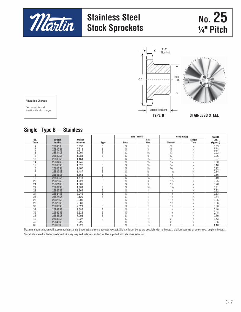
No. 251⁄4" Pitch
Stainless SteelStock Sprockets
9 25B9SS 0.837 B 1⁄4 1⁄4 7⁄16 1⁄2 0.03 10 25B10SS 0.919 B 1⁄4 1⁄4 1⁄2 1⁄2 0.03 11 25B11SS 1.001 B 1⁄4 5⁄16 9⁄16 1⁄2 0.03 12 25B12SS 1.083 B 1⁄4 3⁄8 5⁄8 1⁄2 0.06 13 25B13SS 1.164 B 1⁄4 7⁄16 23⁄32 1⁄2 0.07 14 25B14SS 1.245 B 1⁄4 9⁄16 13⁄16 1⁄2 0.08 15 25B15SS 1.326 B 1⁄4 9⁄16 57⁄64 1⁄2 0.10 16 25B16SS 1.407 B 1⁄4 9⁄16 31⁄32 1⁄2 0.12 17 25B17SS 1.487 B 1⁄4 5⁄8 11⁄32 1⁄2 0.14 18 25B18SS 1.568 B 1⁄4 3⁄4 11⁄8 1⁄2 0.16 19 25B19SS 1.648 B 1⁄4 13⁄16 17⁄32 1⁄2 0.19 20 25B20SS 1.728 B 1⁄4 7⁄8 19⁄32 5⁄8 0.25 21 25B21SS 1.809 B 1⁄4 7⁄8 13⁄8 5⁄8 0.28 22 25B22SS 1.889 B 1⁄4 15⁄16 17⁄16 5⁄8 0.31 23 25B23SS 1.969 B 1⁄4 1 11⁄2 5⁄8 0.32 24 25B24SS 2.049 B 3⁄8 1 11⁄2 5⁄8 0.33 25 25B25SS 2.129 B 3⁄8 1 11⁄2 5⁄8 0.34 26 25B26SS 2.209 B 3⁄8 1 11⁄2 5⁄8 0.35 28 25B28SS 2.369 B 3⁄8 1 11⁄2 5⁄8 0.36 30 25B30SS 2.529 B 3⁄8 1 11⁄2 5⁄8 0.38 32 25B32SS 2.688 B 3⁄8 1 11⁄2 5⁄8 0.40 35 25B35SS 2.928 B 3⁄8 1 11⁄2 3⁄4 0.48 36 25B36SS 3.008 B 3⁄8 1 11⁄2 3⁄4 0.50 40 25B40SS 3.327 B 1⁄2 13⁄8 2 3⁄4 0.53 45 25B45SS 3.725 B 1⁄2 13⁄8 2 3⁄4 0.56 60 25B60SS 4.920 B 1⁄2 13⁄8 2 3⁄4 1.10
Bore (inches) Hub (inches) Weight No. Catalog Outside Rec. Length Lbs. Teeth Number Diameter Type Stock Max. Diameter Thru (Approx.)
Single - Type B — Stainless
Maximum bores shown will accommodate standard keyseat and setscrew over keyseat. Slightly larger bores are possible with no keyseat, shallow keyseat, or setscrew at angle to keyseat.
Sprockets altered at factory (rebored with key way and setscrew added) will be supplied with stainless setscrew.
Alteration Charges
See current discountsheet for alteration charges.
TYPE B STAINLESS STEEL
.110"Nominal
Hub.Dia.
Length Thru Bore
O.D.

E-18E-18
No. 353⁄8" Pitch
All SteelStock Sprockets
9 35BS9 1.260 3⁄4 0.10 H3⁄8 10 35BS10 1.380 3⁄4 0.11 H3⁄8 — H1⁄2 — † 5⁄8 11 35BS11 1.500 3⁄4 0.15 H3⁄8 — H1⁄2 — † 5⁄8 — † 3⁄4 12 35BS12 1.630 3⁄4 0.18 — H1⁄2 — 5⁄8 — †3⁄4 13 35BS13 1.750 3⁄4 0.20 — H1⁄2 — 5⁄8 — 3⁄4 14 35BS14 1.870 3⁄4 0.22 — H1⁄2 — 5⁄8 — 3⁄4 15 35BS15 1.990 3⁄4 0.24 — H1⁄2 — 5⁄8 — 3⁄4 — 7⁄8 — 1 16 35BS16 2.110 3⁄4 0.29 — H1⁄2 — 5⁄8 — 3⁄4 — 7⁄8 — 1 17 35BS17 2.230 3⁄4 0.36 — H1⁄2 — 5⁄8 — 3⁄4 — 7⁄8 — 1 18 35BS18 2.350 3⁄4 0.39 — H1⁄2 — 5⁄8 — 3⁄4 — 7⁄8 — 1 19 35BS19 2.470 3⁄4 0.44 — H1⁄2 — 5⁄8 — 3⁄4 — — 1 20 35BS20 2.590 3⁄4 0.51 — H1⁄2 — 5⁄8 — 3⁄4 — — 1 21 35BS21 2.710 7⁄8 0.75 — H1⁄2 — 5⁄8 — 3⁄4 — — 1 22 35BS22 2.830 7⁄8 0.78 — H1⁄2 — 5⁄8 — 3⁄4 — — 1 23 35BS23 2.950 7⁄8 0.78 — H1⁄2 — 5⁄8 — 3⁄4 — — 1 24 35BS24 3.070 7⁄8 0.79 — H1⁄2 — 5⁄8 — 3⁄4 — — 1 25 35BS25 3.190 7⁄8 0.80 — H1⁄2 — 5⁄8 — 3⁄4 — — 1 26 35BS26 3.310 7⁄8 0.84 — 5⁄8 — 3⁄4 — 7⁄8 — 1 — 11⁄8 — 13⁄16 — 11⁄4 27 35BS27 3.430 7⁄8 0.88 — 5⁄8 — 3⁄4 — 7⁄8 — 1 — 11⁄8 — 13⁄16 — 11⁄4 28 35BS28 3.550 7⁄8 0.86 — 5⁄8 — 3⁄4 — 7⁄8 — 1 — 11⁄8 — 13⁄16 — 11⁄4 30 35BS30 3.790 7⁄8 0.96 — 5⁄8 — 3⁄4 — 7⁄8 — 1 — 11⁄8 — 13⁄16 — 11⁄4 32 35BS32 4.030 7⁄8 1.14 — 5⁄8 — 3⁄4 — 7⁄8 — 1 — 11⁄8 — 13⁄16 — 11⁄4 35 35BS35 4.390 7⁄8 1.38 — 5⁄8 — 3⁄4 — 7⁄8 — 1 — 11⁄8 — 13⁄16 — 11⁄4 36 35BS36 4.510 7⁄8 1.41 — 5⁄8 — 3⁄4 — 7⁄8 — 1 — 11⁄8 — 13⁄16 — 11⁄4 40 35BS40 4.990 1 1.56 — 5⁄8 — 3⁄4 — 7⁄8 — 1 — 11⁄8 — 13⁄16 — 11⁄4 42 35BS42 5.230 1 1.64 — 5⁄8 — 3⁄4 — 7⁄8 — 1 — 11⁄8 — 13⁄16 — 11⁄4 45 35BS45 5.590 1 1.74 — 5⁄8 — 3⁄4 — 7⁄8 — 1 — 11⁄8 — 13⁄16 — 11⁄4 48 35BS48 5.950 1 1.86 — 5⁄8 — 3⁄4 — 7⁄8 — 1 — 11⁄8 — 13⁄16 — 11⁄4 54 35BS54 6.660 1 1.98 — 5⁄8 — 3⁄4 — 7⁄8 — 1 — 11⁄8 — 13⁄16 — 11⁄4 60 35BS60 7.380 1 2.34 — 3⁄4 — 7⁄8 — 1 — 11⁄8 — 13⁄16 — 11⁄4 70 35BS70 8.580 1 3.14 — 3⁄4 — 7⁄8 — 1 — 11⁄8 — 13⁄16 — 11⁄4 72 35BS72 8.810 1 3.30 — 3⁄4 — 7⁄8 — 1 — 11⁄8 — 13⁄16 — 11⁄4 80 35BS80 9.770 1 3.94 — 3⁄4 — 7⁄8 — 1 — 11⁄8 — 13⁄16 — 11⁄4 84 35BS84 10.250 1 4.26 — 3⁄4 — 7⁄8 — 1 — 11⁄8 — 13⁄16 — 11⁄4 96 35BS96 11.680 1 5.22 — 3⁄4 — 7⁄8 — 1 — 11⁄8 — 13⁄16 — 11⁄4 112 35BS112 13.590 1 6.50 — 3⁄4 — 7⁄8 — 1 — 11⁄8 — 13⁄16 — 11⁄4
Length Weight No. Catalog Outside Thru Lbs. Stock Finished Bores Teeth Number Diameter Bore (Approx.) Includes Keyway and 2 Setscrews
Single - Type BS — 2 Setscrews — Bored-To-Size
H Indicates no keyway. (2) 1⁄4" setscrews only in 1⁄2" & 3⁄8" bore. † Keyway with Setscrew at 90°.Hub diameters vary to suit different bore sizes.NOTE: KEYWAY IS ON CENTER LINE OF TOOTH.
TYPE BS
BORED-TO-SIZE
.168"Nominal
Length Thru Bore
No . 353⁄8" Pitch
All SteelStock Sprockets

E-19E-19
No. 353⁄8" Pitch
All SteelStock Sprockets
9 35BS9HT 1.260 3⁄4 0.10 H3⁄8 10 35BS10HT 1.380 3⁄4 0.11 H3⁄8 — H1⁄2 — † 5⁄8 11 35BS11HT 1.500 3⁄4 0.15 H3⁄8 — H1⁄2 — † 5⁄8 — † 3⁄4 12 35BS12HT 1.630 3⁄4 0.18 — H1⁄2 — 5⁄8 — † 3⁄4 13 35BS13HT 1.750 3⁄4 0.20 — H1⁄2 — 5⁄8 — 3⁄4 14 35BS14HT 1.870 3⁄4 0.22 — H1⁄2 — 5⁄8 — 3⁄4 15 35BS15HT 1.990 3⁄4 0.24 — H1⁄2 — 5⁄8 — 3⁄4 — 7⁄8 — 1 16 35BS16HT 2.110 3⁄4 0.29 — H1⁄2 — 5⁄8 — 3⁄4 — 7⁄8 — 1 17 35BS17HT 2.230 3⁄4 0.36 — H1⁄2 — 5⁄8 — 3⁄4 — 7⁄8 — 1 18 35BS18HT 2.350 3⁄4 0.39 — H1⁄2 — 5⁄8 — 3⁄4 — 7⁄8 — 1 19 35BS19HT 2.470 3⁄4 0.44 5⁄8 — 3⁄4 — — 1 20 35BS20HT 2.590 3⁄4 0.51 5⁄8 — 3⁄4 — — 1 21 35BS21HT 2.710 7⁄8 0.75 5⁄8 — 3⁄4 — — 1 22 35BS22HT 2.830 7⁄8 0.76 5⁄8 — 3⁄4 — — 1 23 35BS23HT 2.950 7⁄8 0.78 5⁄8 — 3⁄4 — — 1 24 35BS24HT 3.070 7⁄8 0.79 5⁄8 — 3⁄4 — — 1 25 35BS25HT 3.190 7⁄8 0.80 5⁄8 — 3⁄4 — — 1 26 35BS26HT 3.310 7⁄8 0.84 5⁄8 — 3⁄4 — — 1 28 35BS28HT 3.550 7⁄8 0.88 5⁄8 — 3⁄4 — — 1 30 35BS30HT 3.790 7⁄8 0.96 5⁄8 — 3⁄4 — — 1
Length Weight No. Catalog Outside Thru Lbs. Stock Finished Bores Teeth Number Diameter Bore (Approx.) Includes Keyway and 2 Setscrews
No. 35-Hardened Teeth — 2 Setscrews — Bored-To-Size
H Indicates no keyway. (2) 1⁄4" setscrews only in 1⁄2" & 3⁄8" bore at 90°. † Keyway with Setscrew at 90° & 180°. Hub diameters vary to suit different bore sizes. NOTE: KEYWAY IS ON CENTER LINE OF TOOTH.
Martin stock hardened teeth sprockets afford longer chain and sprocket life. Hardened teeth on the smaller sprocket of a roller chain drive arerecommended if the drive ratio is four to one or greater or if the smaller sprocket has 24 teeth or less and is running at a speed of over 600R.P.M.
BORED-TO-SIZETYPE BS
.168"Nominal
Length Thru Bore
No . 353⁄8" Pitch
All SteelStock Sprockets

E-20
9 35B9SS 1.260 B 3⁄8 3⁄8 27⁄32H 3⁄4 0.10 10 35B10SS 1.380 B 3⁄8 9⁄16 31⁄32H 3⁄4 0.15 11 35B11SS 1.500 B 3⁄8 9⁄16 11⁄16H 3⁄4 0.20 12 35B12SS 1.630 B 1⁄2 5⁄8 17⁄32H 3⁄4 0.22 13 35B13SS 1.750 B 1⁄2 3⁄4 11⁄4H 3⁄4 0.25 14 35B14SS 1.870 B 1⁄2 7⁄8 11⁄4 3⁄4 0.26 15 35B15SS 1.990 B 1⁄2 7⁄8 111⁄32 3⁄4 0.30 16 35B16SS 2.110 B 1⁄2 15⁄16 115⁄32 3⁄4 0.40 17 35B17SS 2.230 B 1⁄2 11⁄16 119⁄32 3⁄4 0.43 18 35B18SS 2.350 B 1⁄2 13⁄16 123⁄32 3⁄4 0.50 19 35B19SS 2.470 B 1⁄2 11⁄4 127⁄32 3⁄4 0.56 20 35B20SS 2.590 B 1⁄2 15⁄16 115⁄16 3⁄4 0.68 21 35B21SS 2.710 B 1⁄2 13⁄8 2 7⁄8 0.80 22 35B22SS 2.830 B 1⁄2 13⁄8 2 7⁄8 0.82 23 35B23SS 2.950 B 1⁄2 13⁄8 2 7⁄8 0.87 24 35B24SS 3.070 B 1⁄2 13⁄8 2 7⁄8 0.89 25 35B25SS 3.190 B 1⁄2 13⁄8 2 7⁄8 0.91 26 35B26SS 3.310 B 1⁄2 13⁄8 2 7⁄8 0.93 28 35B28SS 3.550 B 1⁄2 13⁄8 2 7⁄8 1.00 30 35B30SS 3.790 B 1⁄2 13⁄8 2 7⁄8 1.06 32 35B32SS 4.032 B 1⁄2 13⁄8 2 7⁄8 1.24 35 35B35SS 4.390 B 5⁄8 11⁄2 21⁄4 7⁄8 1.56 36 35B36SS 4.551 B 5⁄8 11⁄2 21⁄4 7⁄8 1.60 40 35B40SS 4.990 B 5⁄8 11⁄2 21⁄4 1 1.70 A 35A40SS 19⁄32 1.04 45 35B45SS 5.590 B 5⁄8 11⁄2 21⁄4 1 2.18 A 35A45SS 19⁄32 1.26 60 35B60SS 7.380 B 3⁄4 11⁄2 21⁄4 1 3.00 A 35A60SS 23⁄32 2.10
E-20
No. 353⁄8" Pitch
Stainless SteelStock Sprockets
Bore (inches) Hub (inches) Weight Weight No. Catalog Outside Rec. Length Lbs. Catalog Stock Lbs. Teeth Number Diameter Type Stock Max. Diameter Thru (Approx.) Type Number Bore (Approx.)
Single - Type B — Stainless Single - Type A
STAINLESS STEEL TYPE B
H Has recessed groove in hub for chain clearance.
Maximum bores shown will accommodate standard keyseat and setscrew over keyseat. Slightly larger bores are possible with no keyseat, shallow keyseat, or setscrew at angle to keyseat.
Sprockets altered at factory (rebored with keyway and setscrew added) will be supplied with stainless setscrew.
Alteration Charges
See current discountsheet for alteration charges.
.168"Nominal
HubDia.
Length Thru Bore
O.D.
No . 353⁄8" Pitch
Stainless SteelStock Sprockets

E-21E-21
No. 353⁄8" Pitch
All SteelStock Sprockets
8 35B8 1.130 B 3⁄8 3⁄8 3⁄4H 3⁄4 0.07 9 35B9 1.260 B 3⁄8 3⁄8 27⁄32H 3⁄4 0.09 10 35B10 1.380 B 3⁄8 9⁄16 31⁄32H 3⁄4 0.14 11 35B11 1.500 B 3⁄8 9⁄16 11⁄16H 3⁄4 0.17 12 35B12 1.630 B 1⁄2 9⁄16 17⁄32H 3⁄4 0.20 13 35B13 1.750 B 1⁄2 11⁄16 11⁄4H 3⁄4 0.23 14 35B14 1.870 B 1⁄2 7⁄8 11⁄4 3⁄4 0.25 15 35B15 1.990 B 1⁄2 7⁄8 111⁄32 3⁄4 0.29 A 35A15 1⁄2 0.10 16 35B16 2.110 B 1⁄2 15⁄16 115⁄32 3⁄4 0.35 A 35A16 1⁄2 0.12 17 35B17 2.230 B 1⁄2 11⁄16 119⁄32 3⁄4 0.42 A 35A17 1⁄2 0.12 18 35B18 2.350 B 1⁄2 13⁄16 123⁄32 3⁄4 0.48 A 35A18 1⁄2 0.14 19 35B19 2.470 B 1⁄2 11⁄4 127⁄32 3⁄4 0.54 A 35A19 1⁄2 0.16 20 35B20 2.590 B 1⁄2 15⁄16 115⁄16 3⁄4 0.59 A 35A20 1⁄2 0.20 21 35B21 2.710 B 1⁄2 13⁄8 2 7⁄8 0.80 A 35A21 1⁄2 0.20 22 35B22 2.830 B 1⁄2 13⁄8 2 7⁄8 0.80 A 35A22 1⁄2 0.22 23 35B23 2.950 B 1⁄2 13⁄8 2 7⁄8 0.82 A 35A23 1⁄2 0.24 24 35B24 3.070 B 1⁄2 13⁄8 2 7⁄8 0.88 A 35A24 1⁄2 0.26 25 35B25 3.190 B 1⁄2 13⁄8 2 7⁄8 0.88 A 35A25 1⁄2 0.28 26 35B26 3.310 B 1⁄2 13⁄8 2 7⁄8 0.90 A 35A26 1⁄2 0.28 27 35B27 3.430 B 1⁄2 13⁄8 2 7⁄8 0.94 A 35A27 1⁄2 0.34 28 35B28 3.550 B 1⁄2 13⁄8 2 7⁄8 0.94 A 35A28 1⁄2 0.34 30 35B30 3.790 B 1⁄2 13⁄8 2 7⁄8 1.02 A 35A30 1⁄2 0.46 32 35B32 4.030 B 1⁄2 13⁄8 2 7⁄8 1.24 A 35A32 5⁄8 0.46 35 35B35 4.390 B 5⁄8 11⁄2 21⁄4 7⁄8 1.50 A 35A35 5⁄8 0.60 36 35B36 4.510 B 5⁄8 11⁄2 21⁄4 7⁄8 1.56 A 35A36 5⁄8 0.62 40 35B40 4.990 B 5⁄8 11⁄2 21⁄4 1 1.62 A 35A40 19⁄32 0.70 42 35B42 5.230 B 5⁄8 11⁄2 21⁄4 1 1.68 A 35A42 19⁄32 0.78 45 35B45 5.590 B 5⁄8 11⁄2 21⁄4 1 1.78 A 35A45 19⁄32 0.88 48 35B48 5.950 B 5⁄8 11⁄2 21⁄4 1 1.88 A 35A48 19⁄32 1.21 54 35B54 6.660 B 5⁄8 11⁄2 21⁄4 1 2.20 A 35A54 19⁄32 1.32 60 35B60 7.380 B 3⁄4 11⁄2 21⁄4 1 2.48 A 35A60 23⁄32 1.66 70 35B70 8.580 B 3⁄4 11⁄2 21⁄4 1 3.12 A 35A70 23⁄32 2.30 72 35B72 8.810 B 3⁄4 11⁄2 21⁄4 1 3.42 A 35A72 23⁄32 2.56 80 35B80 9.770 B 3⁄4 11⁄2 21⁄4 1 3.82 A 35A80 23⁄32 3.16 84 35B84 10.250 B 3⁄4 11⁄2 21⁄4 1 4.24 A 35A84 23⁄32 3.26 96 35B96 11.680 B 3⁄4 11⁄2 21⁄4 1 5.16 A 35A96 23⁄32 4.64 112 35B112 13.590 B 3⁄4 11⁄2 21⁄4 1 6.70 A 35A112 23⁄32 5.05
Bore (inches) Hub (inches) Weight Weight No. Catalog Outside Rec. Length Lbs. Catalog Stock Lbs. Teeth Number Diameter Type Stock Max. Diameter Thru (Approx.) Type Number Bore (Approx.)
Single - Type B — Steel Single - Type A
TYPE A TYPE A TYPE BTYPE B
H Has recessed groove in hub for chain clearance.
Maximum bores shown will accommodate standard keyseat and setscrew over keyseat. Slightly larger bores are possible with no keyseat, shallow keyseat, or setscrew at angle to keyseat.
Alteration Charges
See current discountsheet for alteration charges.
.168"Nominal
O.D.
.168"Nominal
HubDia.
Length Thru Bore
O.D.
No . 353⁄8" Pitch
All SteelStock Sprockets
E-22E-22
No. 353⁄8" Pitch
All SteelStock Sprockets
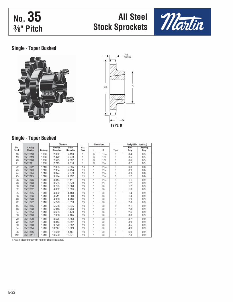
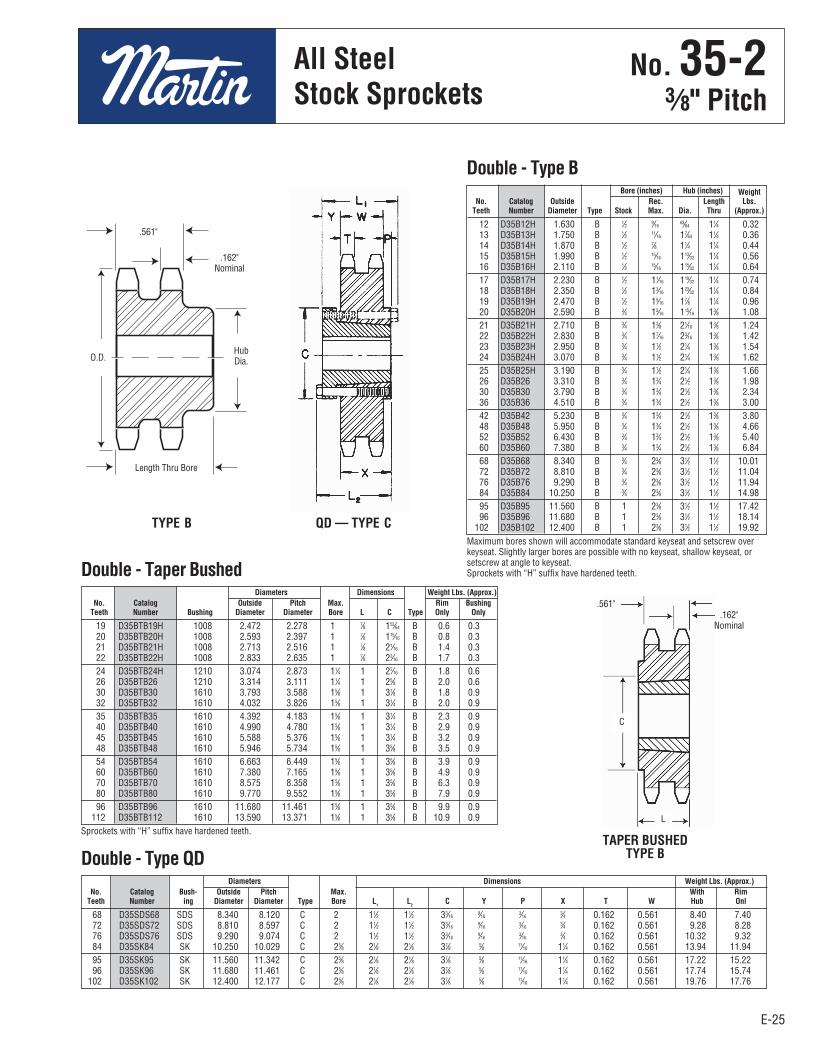
18 35BTB18 1008 2.352 2.159 1 7⁄8 17⁄8H B 0.4 0.3 19 35BTB19 1008 2.472 2.278 1 7⁄8 113⁄16 B 0.5 0.3 20 35BTB20 1008 2.593 2.397 1 7⁄8 115⁄16 B 0.6 0.3 21 35BTB21 1008 2.713 2.516 1 7⁄8 21⁄16 B 0.7 0.3 22 35BTB22 1210 2.883 2.635 11⁄4 1 23⁄8H B 0.8 0.6 23 35BTB23 1210 2.954 2.754 11⁄4 1 27⁄16 B 0.9 0.6 24 35BTB24 1210 3.074 2.873 11⁄4 1 27⁄16 B 0.9 0.6 25 35BTB25 1210 3.194 2.992 11⁄4 1 27⁄16 B 1.2 0.6 26 35BTB26 1610 3.314 3.111 15⁄8 1 27⁄8H B 1.1 0.9 28 35BTB28 1610 3.553 3.349 15⁄8 1 27⁄8 B 1.2 0.9 30 35BTB30 1610 3.793 3.588 15⁄8 1 31⁄8 B 1.2 0.9 32 35BTB32 1610 4.032 3.826 15⁄8 1 31⁄4 B 1.3 0.9 35 35BTB35 1610 4.392 4.183 15⁄8 1 31⁄4 B 1.4 0.9 36 35BTB36 1610 4.511 4.303 15⁄8 1 31⁄4 B 1.4 0.9 40 35BTB40 1610 4.990 4.786 15⁄8 1 31⁄4 B 1.9 0.9 42 35BTB42 1610 5.229 5.018 15⁄8 1 31⁄4 B 2.0 0.9 45 35BTB45 1610 5.588 5.376 15⁄8 1 31⁄4 B 2.1 0.9 48 35BTB48 1610 5.946 5.734 15⁄8 1 31⁄4 B 2.3 0.9 54 35BTB54 1610 6.663 6.449 15⁄8 1 31⁄4 B 2.6 0.9 60 35BTB60 1610 7.380 7.165 15⁄8 1 31⁄4 B 3.0 0.9 70 35BTB70 1610 8.575 8.358 15⁄8 1 31⁄4 B 3.7 0.9 72 35BTB72 1610 8.814 8.597 15⁄8 1 31⁄4 B 3.9 0.9 80 35BTB80 1610 9.770 9.552 15⁄8 1 31⁄4 B 4.5 0.9 84 35BTB84 1610 10.247 10.029 15⁄8 1 31⁄4 B 4.9 0.9 96 35BTB96 1610 11.680 11.461 15⁄8 1 31⁄4 B 6.0 0.9 112 35BTB112 1610 13.590 13.371 15⁄8 1 31⁄4 B 7.8 0.9
Diameter Dimensions Weight Lbs. (Approx.) No. Catalog Outside Pitch Max. Rim Bushing Teeth Number Bushing Diameter Diameter Bore L C Type Only Only
Single - Taper Bushed
H Has recessed groove in hub for chain clearance.
Single - Taper Bushed
TYPE B
.168"Nominal
C
L
O.D.
No . 353⁄8" Pitch
All SteelStock Sprockets
E-23E-23
No. 353⁄8" Pitch
All SteelStock Sprockets
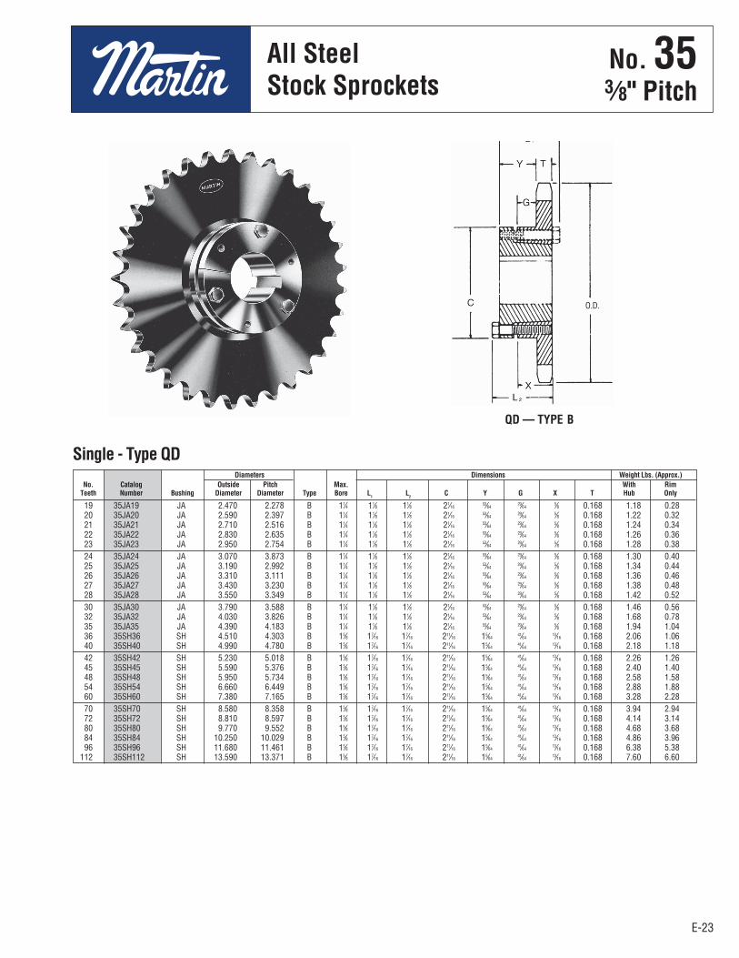
19 35JA19 JA 2.470 2.278 B 11⁄4 11⁄8 11⁄8 21⁄16 53⁄64 29⁄64 5⁄8 0.168 1.18 0.28 20 35JA20 JA 2.590 2.397 B 11⁄4 11⁄8 11⁄8 21⁄16 53⁄64 29⁄64 5⁄8 0.168 1.22 0.32 21 35JA21 JA 2.710 2.516 B 11⁄4 11⁄8 11⁄8 21⁄16 53⁄64 29⁄64 5⁄8 0.168 1.24 0.34 22 35JA22 JA 2.830 2.635 B 11⁄4 11⁄8 11⁄8 21⁄16 53⁄64 29⁄64 5⁄8 0.168 1.26 0.36 23 35JA23 JA 2.950 2.754 B 11⁄4 11⁄8 11⁄8 21⁄16 53⁄64 29⁄64 5⁄8 0.168 1.28 0.38 24 35JA24 JA 3.070 3.873 B 11⁄4 11⁄8 11⁄8 21⁄16 53⁄64 29⁄64 5⁄8 0.168 1.30 0.40 25 35JA25 JA 3.190 2.992 B 11⁄4 11⁄8 11⁄8 21⁄16 53⁄64 29⁄64 5⁄8 0.168 1.34 0.44 26 35JA26 JA 3.310 3.111 B 11⁄4 11⁄8 11⁄8 21⁄16 53⁄64 29⁄64 5⁄8 0.168 1.36 0.46 27 35JA27 JA 3.430 3.230 B 11⁄4 11⁄8 11⁄8 21⁄16 53⁄64 29⁄64 5⁄8 0.168 1.38 0.48 28 35JA28 JA 3.550 3.349 B 11⁄4 11⁄8 11⁄8 21⁄16 53⁄64 29⁄64 5⁄8 0.168 1.42 0.52 30 35JA30 JA 3.790 3.588 B 11⁄4 11⁄8 11⁄8 21⁄16 53⁄64 29⁄64 5⁄8 0.168 1.46 0.56 32 35JA32 JA 4.030 3.826 B 11⁄4 11⁄8 11⁄8 21⁄16 53⁄64 29⁄64 5⁄8 0.168 1.68 0.78 35 35JA35 JA 4.390 4.183 B 11⁄4 11⁄8 11⁄8 21⁄16 53⁄64 29⁄64 5⁄8 0.168 1.94 1.04 36 35SH36 SH 4.510 4.303 B 15⁄8 17⁄16 17⁄16 211⁄16 15⁄64 41⁄64 13⁄16 0.168 2.06 1.06 40 35SH40 SH 4.990 4.780 B 15⁄8 17⁄16 17⁄16 211⁄16 15⁄64 41⁄64 13⁄16 0.168 2.18 1.18 42 35SH42 SH 5.230 5.018 B 15⁄8 17⁄16 17⁄16 211⁄16 15⁄64 41⁄64 13⁄16 0.168 2.26 1.26 45 35SH45 SH 5.590 5.376 B 15⁄8 17⁄16 17⁄16 211⁄16 15⁄64 41⁄64 13⁄16 0.168 2.40 1.40 48 35SH48 SH 5.950 5.734 B 15⁄8 17⁄16 17⁄16 211⁄16 15⁄64 41⁄64 13⁄16 0.168 2.58 1.58 54 35SH54 SH 6.660 6.449 B 15⁄8 17⁄16 17⁄16 211⁄16 15⁄64 41⁄64 13⁄16 0.168 2.88 1.88 60 35SH60 SH 7.380 7.165 B 15⁄8 17⁄16 17⁄16 211⁄16 15⁄64 41⁄64 13⁄16 0.168 3.28 2.28 70 35SH70 SH 8.580 8.358 B 15⁄8 17⁄16 17⁄16 211⁄16 15⁄64 41⁄64 13⁄16 0.168 3.94 2.94 72 35SH72 SH 8.810 8.597 B 15⁄8 17⁄16 17⁄16 211⁄16 15⁄64 41⁄64 13⁄16 0.168 4.14 3.14 80 35SH80 SH 9.770 9.552 B 15⁄8 17⁄16 17⁄16 211⁄16 15⁄64 41⁄64 13⁄16 0.168 4.68 3.68 84 35SH84 SH 10.250 10.029 B 15⁄8 17⁄16 17⁄16 211⁄16 15⁄64 41⁄64 13⁄16 0.168 4.86 3.96 96 35SH96 SH 11.680 11.461 B 15⁄8 17⁄16 17⁄16 211⁄16 15⁄64 41⁄64 13⁄16 0.168 6.38 5.38 112 35SH112 SH 13.590 13.371 B 15⁄8 17⁄16 17⁄16 211⁄16 15⁄64 41⁄64 13⁄16 0.168 7.60 6.60
Diameters Dimensions Weight Lbs. (Approx.) No. Catalog Outside Pitch Max. With Rim Teeth Number Bushing Diameter Diameter Type Bore L
1 L
2 C Y G X T Hub Only
Single - Type QD
QD — TYPE B
O.D.
No . 353⁄8" Pitch
All SteelStock Sprockets
E-24E-24
No. 353⁄8" Pitch
MST®
Sprockets
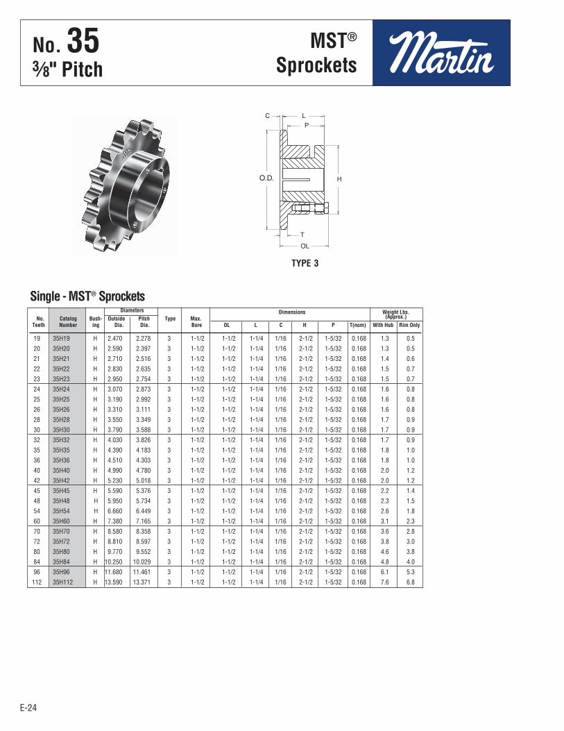
19 35H19 H 2.470 2.278 3 1-1/2 1-1/2 1-1/4 1/16 2-1/2 1-5/32 0.168 1.3 0.5
20 35H20 H 2.590 2.397 3 1-1/2 1-1/2 1-1/4 1/16 2-1/2 1-5/32 0.168 1.3 0.5
21 35H21 H 2.710 2.516 3 1-1/2 1-1/2 1-1/4 1/16 2-1/2 1-5/32 0.168 1.4 0.6
22 35H22 H 2.830 2.635 3 1-1/2 1-1/2 1-1/4 1/16 2-1/2 1-5/32 0.168 1.5 0.7
23 35H23 H 2.950 2.754 3 1-1/2 1-1/2 1-1/4 1/16 2-1/2 1-5/32 0.168 1.5 0.7
24 35H24 H 3.070 2.873 3 1-1/2 1-1/2 1-1/4 1/16 2-1/2 1-5/32 0.168 1.6 0.8
25 35H25 H 3.190 2.992 3 1-1/2 1-1/2 1-1/4 1/16 2-1/2 1-5/32 0.168 1.6 0.8
26 35H26 H 3.310 3.111 3 1-1/2 1-1/2 1-1/4 1/16 2-1/2 1-5/32 0.168 1.6 0.8
28 35H28 H 3.550 3.349 3 1-1/2 1-1/2 1-1/4 1/16 2-1/2 1-5/32 0.168 1.7 0.9
30 35H30 H 3.790 3.588 3 1-1/2 1-1/2 1-1/4 1/16 2-1/2 1-5/32 0.168 1.7 0.9
32 35H32 H 4.030 3.826 3 1-1/2 1-1/2 1-1/4 1/16 2-1/2 1-5/32 0.168 1.7 0.9
35 35H35 H 4.390 4.183 3 1-1/2 1-1/2 1-1/4 1/16 2-1/2 1-5/32 0.168 1.8 1.0
36 35H36 H 4.510 4.303 3 1-1/2 1-1/2 1-1/4 1/16 2-1/2 1-5/32 0.168 1.8 1.0
40 35H40 H 4.990 4.780 3 1-1/2 1-1/2 1-1/4 1/16 2-1/2 1-5/32 0.168 2.0 1.2
42 35H42 H 5.230 5.018 3 1-1/2 1-1/2 1-1/4 1/16 2-1/2 1-5/32 0.168 2.0 1.2
45 35H45 H 5.590 5.376 3 1-1/2 1-1/2 1-1/4 1/16 2-1/2 1-5/32 0.168 2.2 1.4
48 35H48 H 5.950 5.734 3 1-1/2 1-1/2 1-1/4 1/16 2-1/2 1-5/32 0.168 2.3 1.5
54 35H54 H 6.660 6.449 3 1-1/2 1-1/2 1-1/4 1/16 2-1/2 1-5/32 0.168 2.6 1.8
60 35H60 H 7.380 7.165 3 1-1/2 1-1/2 1-1/4 1/16 2-1/2 1-5/32 0.168 3.1 2.3
70 35H70 H 8.580 8.358 3 1-1/2 1-1/2 1-1/4 1/16 2-1/2 1-5/32 0.168 3.6 2.8
72 35H72 H 8.810 8.597 3 1-1/2 1-1/2 1-1/4 1/16 2-1/2 1-5/32 0.168 3.8 3.0
80 35H80 H 9.770 9.552 3 1-1/2 1-1/2 1-1/4 1/16 2-1/2 1-5/32 0.168 4.6 3.8
84 35H84 H 10.250 10.029 3 1-1/2 1-1/2 1-1/4 1/16 2-1/2 1-5/32 0.168 4.8 4.0
96 35H96 H 11.680 11.461 3 1-1/2 1-1/2 1-1/4 1/16 2-1/2 1-5/32 0.168 6.1 5.3
112 35H112 H 13.590 13.371 3 1-1/2 1-1/2 1-1/4 1/16 2-1/2 1-5/32 0.168 7.6 6.8
Single - MST® Sprockets Diameters Dimensions Weight Lbs. No. Catalog Bush- Outside Pitch Type Max. (Approx.) Teeth Number ing Dia. Dia. Bore OL L C H P T(nom) With Hub Rim Only
TYPE 3
No . 353⁄8" Pitch
MST®
Sprockets
E-25E-25
No. 35-23⁄8" Pitch
All SteelStock Sprockets
68 D35SDS68 SDS 8.340 8.120 C 2 11⁄2 11⁄2 33⁄16 9⁄16 3⁄16 3⁄4 0.162 0.561 8.40 7.40 72 D35SDS72 SDS 8.810 8.597 C 2 11⁄2 11⁄2 33⁄16 9⁄16 3⁄16 3⁄4 0.162 0.561 9.28 8.28 76 D35SDS76 SDS 9.290 9.074 C 2 11⁄2 11⁄2 33⁄16 9⁄16 3⁄16 3⁄4 0.162 0.561 10.32 9.32 84 D35SK84 SK 10.250 10.029 C 25⁄8 21⁄8 21⁄8 37⁄8 5⁄8 11⁄16 11⁄4 0.162 0.561 13.94 11.94 95 D35SK95 SK 11.560 11.342 C 25⁄8 21⁄8 21⁄8 37⁄8 5⁄8 11⁄16 11⁄4 0.162 0.561 17.22 15.22 96 D35SK96 SK 11.680 11.461 C 25⁄8 21⁄8 21⁄8 37⁄8 5⁄8 11⁄16 11⁄4 0.162 0.561 17.74 15.74 102 D35SK102 SK 12.400 12.177 C 25⁄8 21⁄8 21⁄8 37⁄8 5⁄8 11⁄16 11⁄4 0.162 0.561 19.76 17.76
Diameters Dimensions Weight Lbs. (Approx.) No. Catalog Bush- Outside Pitch Max. With Rim Teeth Number ing Diameter Diameter Type Bore L
1 L
2 C Y P X T W Hub Onl
Double - Type QD
12 D35B12H 1.630 B 1⁄2 9⁄16 63⁄64 11⁄4 0.32 13 D35B13H 1.750 B 1⁄2 11⁄16 17⁄64 11⁄4 0.36 14 D35B14H 1.870 B 1⁄2 7⁄8 11⁄4 11⁄4 0.44 15 D35B15H 1.990 B 1⁄2 15⁄16 113⁄32 11⁄4 0.56 16 D35B16H 2.110 B 1⁄2 15⁄16 115⁄32 11⁄4 0.64 17 D35B17H 2.230 B 1⁄2 11⁄16 119⁄32 11⁄4 0.74 18 D35B18H 2.350 B 1⁄2 13⁄16 123⁄32 11⁄4 0.84 19 D35B19H 2.470 B 1⁄2 15⁄16 17⁄8 11⁄4 0.96 20 D35B20H 2.590 B 3⁄4 15⁄16 115⁄16 13⁄8 1.08 21 D35B21H 2.710 B 3⁄4 13⁄8 21⁄16 13⁄8 1.24 22 D35B22H 2.830 B 3⁄4 17⁄16 23⁄16 13⁄8 1.42 23 D35B23H 2.950 B 3⁄4 11⁄2 21⁄4 13⁄8 1.54 24 D35B24H 3.070 B 3⁄4 11⁄2 21⁄4 13⁄8 1.62 25 D35B25H 3.190 B 3⁄4 11⁄2 21⁄4 13⁄8 1.66 26 D35B26 3.310 B 3⁄4 13⁄4 21⁄2 13⁄8 1.98 30 D35B30 3.790 B 3⁄4 13⁄4 21⁄2 13⁄8 2.34 36 D35B36 4.510 B 3⁄4 13⁄4 21⁄2 13⁄8 3.00 42 D35B42 5.230 B 3⁄4 13⁄4 21⁄2 13⁄8 3.80 48 D35B48 5.950 B 3⁄4 13⁄4 21⁄2 13⁄8 4.66 52 D35B52 6.430 B 3⁄4 13⁄4 21⁄2 13⁄8 5.40 60 D35B60 7.380 B 3⁄4 13⁄4 21⁄2 13⁄8 6.84 68 D35B68 8.340 B 3⁄4 23⁄8 31⁄2 11⁄2 10.01 72 D35B72 8.810 B 3⁄4 23⁄8 31⁄2 11⁄2 11.04 76 D35B76 9.290 B 3⁄4 23⁄8 31⁄2 11⁄2 11.94 84 D35B84 10.250 B 3⁄4 23⁄8 31⁄2 11⁄2 14.98 95 D35B95 11.560 B 1 23⁄8 31⁄2 11⁄2 17.42 96 D35B96 11.680 B 1 23⁄8 31⁄2 11⁄2 18.14 102 D35B102 12.400 B 1 23⁄8 31⁄2 11⁄2 19.92
Bore (inches) Hub (inches) Weight No. Catalog Outside Rec. Length Lbs. Teeth Number Diameter Type Stock Max. Dia. Thru (Approx.)
Double - Type B
Maximum bores shown will accommodate standard keyseat and setscrew overkeyseat. Slightly larger bores are possible with no keyseat, shallow keyseat, orsetscrew at angle to keyseat.Sprockets with “H” suffix have hardened teeth.
QD — TYPE CTYPE B
19 D35BTB19H 1008 2.472 2.278 1 7⁄8 153⁄64 B 0.6 0.3 20 D35BTB20H 1008 2.593 2.397 1 7⁄8 115⁄16 B 0.8 0.3 21 D35BTB21H 1008 2.713 2.516 1 7⁄8 21⁄16 B 1.4 0.3 22 D35BTB22H 1008 2.833 2.635 1 7⁄8 23⁄16 B 1.7 0.3 24 D35BTB24H 1210 3.074 2.873 11⁄4 1 27⁄16 B 1.8 0.6 26 D35BTB26 1210 3.314 3.111 11⁄4 1 25⁄8 B 2.0 0.6 30 D35BTB30 1610 3.793 3.588 15⁄8 1 31⁄8 B 1.8 0.9 32 D35BTB32 1610 4.032 3.826 15⁄8 1 31⁄4 B 2.0 0.9 35 D35BTB35 1610 4.392 4.183 15⁄8 1 31⁄4 B 2.3 0.9 40 D35BTB40 1610 4.990 4.780 15⁄8 1 31⁄4 B 2.9 0.9 45 D35BTB45 1610 5.588 5.376 15⁄8 1 31⁄4 B 3.2 0.9 48 D35BTB48 1610 5.946 5.734 15⁄8 1 35⁄8 B 3.5 0.9 54 D35BTB54 1610 6.663 6.449 15⁄8 1 35⁄8 B 3.9 0.9 60 D35BTB60 1610 7.380 7.165 15⁄8 1 35⁄8 B 4.9 0.9 70 D35BTB70 1610 8.575 8.358 15⁄8 1 35⁄8 B 6.3 0.9 80 D35BTB80 1610 9.770 9.552 15⁄8 1 35⁄8 B 7.9 0.9 96 D35BTB96 1610 11.680 11.461 15⁄8 1 35⁄8 B 9.9 0.9 112 D35BTB112 1610 13.590 13.371 15⁄8 1 35⁄8 B 10.9 0.9
Diameters Dimensions Weight Lbs. (Approx.) No. Catalog Outside Pitch Max. Rim Bushing Teeth Number Bushing Diameter Diameter Bore L C Type Only Only
Double - Taper Bushed
TAPER BUSHEDTYPE B
.561"
HubDia.
.162"Nominal
.561"
Sprockets with “H” suffix have hardened teeth.
Length Thru Bore
O.D.
L
C
.162"Nominal
No . 35-23⁄8" Pitch
All SteelStock Sprockets

E-26
68 E35SK68 SK 8.340 8.120 C 25⁄8 21⁄8 21⁄8 37⁄8 5⁄8 19⁄64 11⁄4 0.162 0.960 13.90 11.90 72 E35SK72 SK 8.810 8.597 C 25⁄8 21⁄8 21⁄8 37⁄8 5⁄8 19⁄64 11⁄4 0.162 0.960 15.56 13.56 76 E35SK76 SK 9.290 9.074 C 25⁄8 21⁄8 21⁄8 37⁄8 5⁄8 19⁄64 11⁄4 0.162 0.960 17.42 15.42 84 E35SK84 SK 10.250 10.029 C 25⁄8 21⁄8 21⁄8 37⁄8 5⁄8 19⁄64 11⁄4 0.162 0.960 20.92 18.92 95 E35SK95 SK 11.560 11.342 C 25⁄8 21⁄8 21⁄8 37⁄8 5⁄8 19⁄64 11⁄4 0.162 0.960 26.76 24.76 96 E35SK96 SK 11.680 11.461 C 25⁄8 21⁄8 21⁄8 37⁄8 5⁄8 19⁄64 11⁄4 0.162 0.960 27.58 25.58 102 E35SK102 SK 12.400 12.177 C 25⁄8 21⁄8 21⁄8 37⁄8 5⁄8 19⁄64 11⁄4 0.162 0.960 31.18 29.18
E-26
No. 35-33⁄8" Pitch
All SteelStock Sprockets
13 E35B13H 1.750 B 1⁄2 11⁄16 17⁄64 13⁄4 0.50 14 E35B14H 1.870 B 1⁄2 7⁄8 11⁄4 13⁄4 0.62 15 E35B15H 1.990 B 1⁄2 15⁄16 113⁄32 13⁄4 0.78 16 E35B16H 2.110 B 1⁄2 15⁄16 115⁄32 13⁄4 0.82 17 E35B17H 2.230 B 1⁄2 11⁄16 119⁄32 13⁄4 1.04 18 E35B18H 2.350 B 1⁄2 13⁄16 123⁄32 13⁄4 1.22 19 E35B19H 2.470 B 1⁄2 15⁄16 17⁄8 13⁄4 1.40 20 E35B20H 2.590 B 3⁄4 15⁄16 115⁄16 17⁄8 1.50 21 E35B21H 2.710 B 3⁄4 13⁄8 21⁄16 17⁄8 1.72 22 E35B22H 2.830 B 3⁄4 17⁄16 23⁄16 17⁄8 1.96 23 E35B23H 2.950 B 3⁄4 11⁄2 21⁄4 17⁄8 2.12 24 E35B24H 3.070 B 3⁄4 11⁄2 21⁄4 17⁄8 2.26 25 E35B25H 3.190 B 3⁄4 11⁄2 21⁄4 17⁄8 2.42 26 E35B26 3.310 B 3⁄4 11⁄2 21⁄2 17⁄8 2.78 30 E35B30 3.790 B 3⁄4 13⁄4 21⁄2 17⁄8 3.42 36 E35B36 4.510 B 3⁄4 13⁄4 21⁄2 17⁄8 4.52 42 E35B42 5.230 B 3⁄4 13⁄4 21⁄2 17⁄8 5.88 48 E35B48 5.950 B 3⁄4 13⁄4 21⁄2 17⁄8 7.42 52 E35B52 6.430 B 3⁄4 13⁄4 21⁄2 17⁄8 8.52 60 E35B60 7.380 B 3⁄4 13⁄4 21⁄2 17⁄8 11.22 68 E35B68 8.340 B 3⁄4 23⁄8 31⁄2 17⁄8 15.38 72 E35B72 8.810 B 3⁄4 23⁄8 31⁄2 17⁄8 17.34 76 E35B76 9.290 B 3⁄4 23⁄8 31⁄2 17⁄8 18.90 84 E35B84 10.250 B 3⁄4 23⁄8 31⁄2 17⁄8 22.82 95 E35B95 11.560 B 1 21⁄2 33⁄4 21⁄8 29.32 96 E35B96 11.680 B 1 21⁄2 33⁄4 21⁄8 30.06 102 E35B102 12.400 B 1 21⁄2 33⁄4 21⁄8 33.36
Bore (inches) Hub (inches) Weight No. Catalog Outside Rec. Length Lbs. Teeth Number Diameter Type Stock Max. Dia. Thru (Approx.
Triple - Type B
Maximum bores shown will accommodate standard keyseat and setscrew over keyseat.Slightly larger bores are possible with no keyseat, shallow keyseat, or setscrew at angle tokeyseat.
NOTE: Triple 35 stock sprockets with 25 teeth or less have hardened teeth.Sprockets with “H” suffix have hardened teeth.
Alteration Charges
See current discountsheet for alteration charges.
Diameters Dimensions Weight (Approx.) No. Catalog Bush- Outside Pitch Max. With Rim Teeth Number ing Diameter Diameter Type Bore L1
L2 C Y P X T W Hub Only
Triple - Type QD
TYPE B
QD — TYPE C
HubDia.
.162"Nominal
.960"
Length Thru Bore
No . 35-33⁄8" Pitch
All SteelStock Sprockets

E-27E-27
No. 411⁄2" Pitch
All SteelStock Sprockets
9 41BS9 1.670 7⁄8 0.20 — H1⁄2 — 5⁄8 10 41BS10 1.840 7⁄8 0.25 — H1⁄2 — 5⁄8 11 41BS11 2.000 7⁄8 0.32 — H1⁄2 — 5⁄8 — 3⁄4 12 41BS12 2.170 7⁄8 0.33 — H1⁄2 — 5⁄8 — 3⁄4 — 7⁄8 13 41BS13 2.330 7⁄8 0.43 — H1⁄2 — 5⁄8 — 3⁄4 — 7⁄8 — 1 14 41BS14 2.490 7⁄8 0.48 — H1⁄2 — 5⁄8 — 3⁄4 — 7⁄8 — 1 15 41BS15 2.650 7⁄8 0.59 — H1⁄2 — 5⁄8 — 3⁄4 — — 1 16 41BS16 2.810 7⁄8 0.72 — 5⁄8 — 3⁄4 — — 1 17 41BS17 2.970 1 1.00 — 5⁄8 — 3⁄4 — — 1 18 41BS18 3.140 1 1.10 — 5⁄8 — 3⁄4 — — 1 19 41BS19 3.300 1 1.21 — 5⁄8 — 3⁄4 — — 1 20 41BS20 3.460 1 1.39 — 5⁄8 — 3⁄4 — — 1 21 41BS21 3.620 1 1.77 — 5⁄8 — 3⁄4 — — 1 22 41BS22 3.780 1 1.92 — 5⁄8 — 3⁄4 — — 1 23 41BS23 3.940 1 2.18 — 5⁄8 — 3⁄4 — — 1 24 41BS24 4.100 1 2.24 — 5⁄8 — 3⁄4 — — 1 25 41BS25 4.260 1 2.42 — 5⁄8 — 3⁄4 — — 1 26 41BS26 4.420 1 2.46 — 5⁄8 — 3⁄4 — — 1 27 41BS27 4.580 1 2.52 — 5⁄8 — 3⁄4 — — 1 28 41BS28 4.740 1 2.60 — 5⁄8 — 3⁄4 — — 1 30 41BS30 5.060 1 2.76 — 5⁄8 — 3⁄4 — — 1 32 41BS32 5.380 1 2.92 — 5⁄8 — 3⁄4 — — 1 35 41BS35 5.860 1 3.08 — 5⁄8 — 3⁄4 — — 1 36 41BS36 6.020 1 3.28 — 5⁄8 — 3⁄4 — — 1 40 41BS40 6.650 11⁄16 3.82 — 3⁄4 — — 1 — 11⁄8 — 13⁄16 — 11⁄4 — 13⁄8 — 17⁄16 — 11⁄2 42 41BS42 6.970 11⁄16 3.68 — 3⁄4 — — 1 — 11⁄8 — 13⁄16 — 11⁄4 — 13⁄8 — 17⁄16 — 11⁄2 45 41BS45 7.450 11⁄16 3.94 — 3⁄4 — — 1 — 11⁄8 — 13⁄16 — 11⁄4 — 13⁄8 — 17⁄16 — 11⁄2 48 41BS48 7.930 11⁄16 4.68 — 3⁄4 — — 1 — 11⁄8 — 13⁄16 — 11⁄4 — 13⁄8 — 17⁄16 — 11⁄2 54 41BS54 8.880 11⁄16 5.44 — 3⁄4 — — 1 — 11⁄8 — 13⁄16 — 11⁄4 — 13⁄8 — 17⁄16 — 11⁄2 60 41BS60 9.840 11⁄16 6.54 — 3⁄4 — — 1 — 11⁄8 — 13⁄16 — 11⁄4 — 13⁄8 — 17⁄16 — 11⁄2 70 41BS70 11.430 13⁄16 9.28 — 3⁄4 — — 1 — 11⁄8 — 13⁄16 — 11⁄4 — 13⁄8 — 17⁄16 — 11⁄2 72 41BS72 11.750 13⁄16 9.38 — 3⁄4 — — 1 — 11⁄8 — 13⁄16 — 11⁄4 — 13⁄8 — 17⁄16 — 11⁄2 80 41BS80 13.030 13⁄16 11.28 — 3⁄4 — — 1 — 11⁄8 — 13⁄16 — 11⁄4 — 13⁄8 — 17⁄16 — 11⁄2 84 41BS84 13.660 13⁄16 11.94 — 3⁄4 — — 1 — 11⁄8 — 13⁄16 — 11⁄4 — 13⁄8 — 17⁄16 — 11⁄2 96 41BS96 15.570 13⁄16 14.51 1 — 11⁄8 — 13⁄16 — 11⁄4 — 13⁄8 — 17⁄16 — 11⁄2 112 41BS112 18.120 13⁄16 18.81 1 — 11⁄8 — 13⁄16 — 11⁄4 — 13⁄8 — 17⁄16 — 11⁄2
Length Weight Stock Finished Bores No. Catalog Outside Thru Lbs. Includes Keyway Teeth Number Diameter Bore (Approx.) and 2 Setscrews
Single - Type BS — 2 Setscrews — Bored-To-Size
H Indicates no keyway. (2) 1⁄4" setscrews only in 1⁄2" bore. Hub diameters vary to suit different bore sizes.NOTE: KEYWAY IS ON CENTER LINE OF TOOTH.
BORED-TO-SIZE TYPE BS
.227"Nominal
Length Thru Bore
No . 41½" Pitch
All SteelStock Sprockets

E-28E-28
No. 411⁄2" Pitch
All Steel & StainlessSteel Stock Sprockets
6 41B6 1.170 B 3⁄8 3⁄8 21⁄32H 7⁄8 0.07 7 41B7 1.340 B 3⁄8 3⁄8 3⁄4H 7⁄8 0.10 8 41B8 1.510 B 1⁄2 1⁄2 63⁄64H 7⁄8 0.19 9 41B9 1.670 B 1⁄2 5⁄8 11⁄8H 7⁄8 0.20 10 41B10 1.840 B 1⁄2 3⁄4 11⁄4H 7⁄8 0.27 11 41B11 2.000 B 1⁄2 7⁄8 17⁄16H 7⁄8 0.35 12 41B12 2.170 B 1⁄2 15⁄16 19⁄16H 7⁄8 0.44 13 41B13 2.330 B 1⁄2 1 19⁄16 7⁄8 0.50 14 41B14 2.490 B 1⁄2 11⁄4 13⁄4 7⁄8 0.57 15 41B15 2.650 B 1⁄2 15⁄16 129⁄32 7⁄8 0.72 A 41A15 5⁄8 0.28 16 41B16 2.810 B 5⁄8 13⁄8 21⁄16 7⁄8 0.91 A 41A16 5⁄8 0.34 17 41B17 2.970 B 5⁄8 11⁄2 215⁄64 1 1.09 A 41A17 5⁄8 0.36 18 41B18 3.140 B 5⁄8 15⁄8 23⁄8 1 1.25 A 41A18 5⁄8 0.44 19 41B19 3.300 B 5⁄8 13⁄4 215⁄32 1 1.49 A 41A19 5⁄8 0.46 20 41B20 3.460 B 5⁄8 17⁄8 23⁄4 1 1.64 A 41A20 5⁄8 0.52 21 41B21 3.620 B 5⁄8 17⁄8 27⁄8 1 1.81 A 41A21 5⁄8 0.60 22 41B22 3.780 B 5⁄8 2 3 1 1.93 A 41A22 5⁄8 0.66 23 41B23 3.940 B 5⁄8 21⁄4 33⁄16 1 2.25 A 41A23 5⁄8 0.72 24 41B24 4.100 B 5⁄8 21⁄4 31⁄4 1 2.33 A 41A24 5⁄8 0.82 25 41B25 4.260 B 5⁄8 21⁄4 31⁄4 1 2.46 A 41A25 5⁄8 0.88 26 41B26 4.420 B 5⁄8 21⁄4 31⁄4 1 2.50 A 41A26 5⁄8 0.94 27 41B27 4.580 B 5⁄8 21⁄4 31⁄4 1 2.56 A 41A27 5⁄8 1.00 28 41B28 4.740 B 5⁄8 21⁄4 31⁄4 1 2.64 A 41A28 5⁄8 1.08 30 41B30 5.060 B 5⁄8 21⁄4 31⁄4 1 2.80 A 41A30 19⁄32 1.20 32 41B32 5.380 B 5⁄8 21⁄4 31⁄4 1 2.96 A 41A32 19⁄32 1.44 35 41B35 5.860 B 5⁄8 23⁄8 31⁄4 1 3.12 A 41A35 19⁄32 1.70 36 41B36 6.020 B 5⁄8 23⁄8 31⁄4 1 3.32 A 41A36 19⁄32 1.84 40 41B40 6.650 B 3⁄4 23⁄8 31⁄4 11⁄16 4.06 A 41A40 23⁄32 2.22 42 41B42 6.970 B 3⁄4 23⁄8 31⁄2 11⁄16 4.10 A 41A42 23⁄32 2.50 45 41B45 7.450 B 3⁄4 23⁄8 31⁄2 11⁄16 4.18 A 41A45 23⁄32 2.52 48 41B48 7.930 B 3⁄4 23⁄8 31⁄2 11⁄16 4.92 A 41A48 23⁄32 2.92 54 41B54 8.880 B 3⁄4 23⁄8 31⁄2 11⁄16 5.68 A 41A54 23⁄32 3.54 60 41B60 9.840 B 3⁄4 23⁄8 31⁄2 11⁄16 6.78 A 41A60 23⁄32 4.60 70 41B70 11.430 B 3⁄4 23⁄4 4 13⁄16 9.54 A 41A70 23⁄32 6.22 72 41B72 11.750 B 3⁄4 23⁄4 4 13⁄16 9.64 A 41A72 23⁄32 6.32 80 41B80 13.030 B 3⁄4 23⁄4 4 13⁄16 11.54 A 41A80 23⁄32 8.46 84 41B84 13.660 B 3⁄4 23⁄4 4 13⁄16 12.20 A 41A84 23⁄32 9.12 96 41B96 15.570 B 1 23⁄4 4 13⁄16 14.86 A 41A96 15⁄16 11.84 112 41B112 18.120 B 1 23⁄4 4 13⁄16 19.16 A 41A112 15⁄16 15.84
Bore (inches) Hub (inches) Weight Weight No. Catalog Outside Rec. Length Lbs. Catalog Stock Lbs. Teeth Number Diameter Type Stock Max. Diameter Thru Bore (Approx.) Type Number Bore (Approx.)
Single - Type B Single - Type A
H Has recessed groove in hub for chain clearance.
Maximum bores shown will accommodate standard keyseat and setscrew over keyseat.Slightly larger bores are possible with no keyseat, shallow keyseat, or setscrew at angle to keyseat.
TYPE A TYPE B
.227"Nominal
O.D.
.227"Nominal
HubDia.
Length ThruBore
O.D.
9 41B9SS 1.670 B 1⁄2 5⁄8 11⁄8H 7⁄8 0.20 10 41B10SS 1.840 B 1⁄2 3⁄4 11⁄4H 7⁄8 0.27 11 41B11SS 2.000 B 1⁄2 7⁄8 17⁄16H 7⁄8 0.35 12 41B12SS 2.170 B 1⁄2 15⁄16 19⁄16H 7⁄8 0.44 13 41B13SS 2.330 B 1⁄2 1 19⁄16 7⁄8 0.50 14 41B14SS 2.490 B 1⁄2 11⁄4 13⁄4 7⁄8 0.57 15 41B15SS 2.650 B 1⁄2 15⁄16 129⁄32 7⁄8 0.72 16 41B16SS 2.810 B 5⁄8 13⁄8 21⁄16 7⁄8 0.91 17 41B17SS 2.970 B 5⁄8 11⁄2 215⁄64 1 1.09 18 41B18SS 3.140 B 5⁄8 15⁄8 23⁄8 1 1.25 19 41B19SS 3.300 B 5⁄8 13⁄4 215⁄32 1 1.49 20 41B20SS 3.460 B 5⁄8 17⁄8 23⁄4 1 1.64
Bore (inches) Hub (inches) Weight Weight No. Catalog Outside Rec. Length Lbs. Catalog Stock Lbs. Teeth Number Diameter Type Stock Max. Diameter Thru Bore (Approx.) Type Number Bore (Approx.)
Single - Type B — Stainless Single - Type A — Stainless
No . 41½" Pitch
All Steel & StainlessSteel Stock Sprockets

E-29E-29
No. 411⁄2" Pitch
All SteelStock Sprockets
14 41BTB14 1008 2.490 2.247 1 7⁄8 17⁄8H B 0.4 0.3 15 41BTB15 1008 2.650 2.405 1 7⁄8 17⁄8 B 0.5 0.3 16 41BTB16 1008 2.810 2.503 1 7⁄8 2 B 0.6 0.3 17 41BTB17 1210 2.970 2.721 11⁄4 1 23⁄8H B 0.7 0.6 18 41BTB18 1210 3.140 2.879 11⁄4 1 23⁄8 B 0.9 0.6 19 41BTB19 1210 3.300 3.038 11⁄4 1 21⁄2 B 1.1 0.6 20 41BTB20 1610 3.460 3.196 15⁄8 1 27⁄8H B 1.1 0.9 21 41BTB21 1610 3.620 3.355 15⁄8 1 3H B 1.2 0.9 22 41BTB22 1610 3.780 3.513 15⁄8 1 3 B 1.3 0.9 23 41BTB23 1610 3.940 3.672 15⁄8 1 3 B 1.4 0.9 24 41BTB24 1610 4.100 3.831 15⁄8 1 3 B 1.4 0.9 25 41BTB25 1610 4.260 3.989 15⁄8 1 3 B 1.5 0.9 26 41BTB26 1610 4.420 4.148 15⁄8 1 3 B 1.5 0.9 28 41BTB28 1610 4.740 4.466 15⁄8 1 3 B 1.7 0.9 30 41BTB30 1610 5.060 4.783 15⁄8 1 3 B 1.8 0.9 32 41BTB32 1610 5.380 5.101 15⁄8 1 3 B 1.9 0.9 35 41BTB35 1610 5.860 5.578 15⁄8 1 3 B 2.3 0.9 36 41BTB36 1610 6.020 5.737 15⁄8 1 3 B 2.4 0.9 40 41BTB40 1610 6.650 6.373 15⁄8 1 3 B 2.7 0.9 45 41BTB45 1610 7.450 7.168 15⁄8 1 3 B 3.5 0.9 48 41BTB48 1610 7.930 7.645 15⁄8 1 3 B 4.1 0.9 54 41BTB54 1610 8.880 8.599 15⁄8 1 3 B 4.9 0.9 60 41BTB60 1610 9.840 9.554 15⁄8 1 3 B 5.7 0.9 70 41BTB70 1610 11.430 11.145 15⁄8 1 3 B 7.4 0.9 72 41BTB72 1610 11.750 11.463 15⁄8 1 3 B 8.2 0.9 80 41BTB80 1610 13.030 12.736 15⁄8 1 3 B 9.6 0.9 96 41BTB96 1610 15.570 15.282 15⁄8 1 3 B 13.1 0.9
Diameters Dimensions Weight Lbs. (Approx.) No. Catalog Outside Pitch Max. Rim Bushing Teeth Number Bushing Diameter Diameter Bore L C Type Only Only
Single - Taper Bushed
H Has recessed groove in hub for chain clearance.
15 41JA15 JA 2.650 2.405 B 11⁄4 11⁄8 11⁄8 21⁄16 49⁄64 25⁄64 5⁄8 .227 1.22 0.32 16 41JA16 JA 2.810 2.563 B 11⁄4 11⁄8 11⁄8 21⁄16 49⁄64 25⁄64 5⁄8 .227 1.30 0.40 17 41JA17 JA 2.980 2.721 B 11⁄4 11⁄8 11⁄8 21⁄16 49⁄64 25⁄64 5⁄8 .227 1.40 0.50 18 41JA18 JA 3.140 2.879 B 11⁄4 11⁄8 11⁄8 21⁄16 49⁄64 25⁄64 5⁄8 .227 1.50 0.60 19 41JA19 JA 3.300 3.038 B 11⁄4 11⁄8 11⁄8 21⁄16 49⁄64 25⁄64 5⁄8 .227 1.58 0.68 20 41SH20 SH 3.460 3.196 B 15⁄8 17⁄16 17⁄16 211⁄16 11⁄32 37⁄64 13⁄16 .227 1.78 0.78 21 41SH21 SH 3.620 3.355 B 15⁄8 17⁄16 17⁄16 211⁄16 11⁄32 37⁄64 13⁄16 .227 1.82 0.82 22 41SH22 SH 3.780 3.513 B 15⁄8 17⁄16 17⁄16 211⁄16 11⁄32 37⁄64 13⁄16 .227 2.06 1.06 23 41SH23 SH 3.940 3.672 B 15⁄8 17⁄16 17⁄16 211⁄16 11⁄32 37⁄64 13⁄16 .227 2.14 1.14 24 41SH24 SH 4.100 3.831 B 15⁄8 17⁄16 17⁄16 211⁄16 11⁄32 37⁄64 13⁄16 .227 2.16 1.16 25 41SH25 SH 4.260 3.989 B 15⁄8 17⁄16 17⁄16 211⁄16 11⁄32 37⁄64 13⁄16 .227 2.22 1.22 26 41SH26 SH 4.420 4.148 B 15⁄8 17⁄16 17⁄16 211⁄16 11⁄32 37⁄64 13⁄16 .227 2.26 1.26 27 41SH27 SH 4.580 4.307 B 15⁄8 17⁄16 17⁄16 211⁄16 11⁄32 37⁄64 13⁄16 .227 2.40 1.40 28 41SH28 SH 4.740 4.466 B 15⁄8 17⁄16 17⁄16 211⁄16 11⁄32 37⁄64 13⁄16 .227 2.54 1.54 30 41SH30 SH 5.060 4.783 B 15⁄8 17⁄16 17⁄16 211⁄16 11⁄32 37⁄64 13⁄16 .227 2.58 1.58 32 41SH32 SH 5.380 5.101 B 15⁄8 17⁄16 17⁄16 211⁄16 11⁄32 37⁄64 13⁄16 .227 2.68 1.68 35 41SH35 SH 5.860 5.578 B 15⁄8 17⁄16 17⁄16 211⁄16 11⁄32 37⁄64 13⁄16 .227 2.79 1.79 36 41SDS36 SDS 6.020 5.737 B 2 11⁄2 11⁄2 33⁄16 13⁄32 17⁄32 3⁄4 .227 2.92 1.92 40 41SDS40 SDS 6.650 6.373 B 2 11⁄2 11⁄2 33⁄16 13⁄32 17⁄32 3⁄4 .227 3.32 2.32 42 41SDS42 SDS 6.970 6.691 B 2 11⁄2 11⁄2 33⁄16 13⁄32 17⁄32 3⁄4 .227 3.44 2.44 45 41SDS45 SDS 7.450 7.168 B 2 11⁄2 11⁄2 33⁄16 13⁄32 17⁄32 3⁄4 .227 3.76 2.76 48 41SDS48 SDS 7.930 7.645 B 2 11⁄2 11⁄2 33⁄16 13⁄32 17⁄32 3⁄4 .227 4.36 3.36 54 41SDS54 SDS 8.890 8.599 B 2 11⁄2 11⁄2 33⁄16 13⁄32 17⁄32 3⁄4 .227 4.98 3.98 60 41SDS60 SDS 9.840 9.554 B 2 11⁄2 11⁄2 33⁄16 13⁄32 17⁄32 3⁄4 .227 6.54 5.54 70 41SK70 SK 11.430 11.145 B 25⁄8 21⁄8 21⁄8 37⁄8 141⁄64 11⁄32 11⁄4 .227 9.42 7.42 72 41SK72 SK 11.750 11.463 B 25⁄8 21⁄8 21⁄8 37⁄8 141⁄64 11⁄32 11⁄4 .227 10.02 8.02 80 41SK80 SK 13.030 12.736 B 25⁄8 21⁄8 21⁄8 37⁄8 141⁄64 11⁄32 11⁄4 .227 11.64 9.64 84 41SK84 SK 13.660 13.372 B 25⁄8 21⁄8 21⁄8 37⁄8 141⁄64 11⁄32 11⁄4 .227 12.40 10.40 96 41SK96 SK 15.570 15.281 B 25⁄8 21⁄8 21⁄8 37⁄8 141⁄64 11⁄32 11⁄4 .227 14.82 12.82 112 41SK112 SK 18.120 17.828 B 25⁄8 21⁄8 21⁄8 37⁄8 141⁄64 11⁄32 11⁄4 .227 19.28 17.28
Diameters Dimensions Weight Lbs. (Approx.)No. Catalog Outside Pitch Max. With Rim
Teeth Number Bushing Diameter Diameter Type Bore L1 L
2 C Y G X T Hub Only
Single - Type QD
TAPER BUSHEDTYPE B
QD — TYPE B
.227"Nominal
O.D.
No . 41½" Pitch
All SteelStock Sprockets
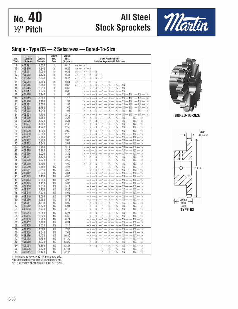
E-30
H Indicates no keyway. (2) 1⁄4" setscrews only. Hub diameters vary to suit different bore sizes.NOTE: KEYWAY IS ON CENTER LINE OF TOOTH.
E-30
No. 401⁄2" Pitch
All SteelStock Sprockets
9 40BS9 1.670 7⁄8 0.16 H1⁄2 — 5⁄8 10 40BS10 1.840 7⁄8 0.24 H1⁄2 — 5⁄8 — 3⁄4 11 40BS11 2.000 7⁄8 0.28 H1⁄2 — 5⁄8 — 3⁄4 — 7⁄8 12 40BS12 2.170 7⁄8 0.34 H1⁄2 — 5⁄8 — 3⁄4 — 7⁄8 — 1 13 40BS13 2.330 7⁄8 0.45 H1⁄2 — 5⁄8 — 3⁄4 — 7⁄8 — 1 14 40BS14 2.490 7⁄8 0.51 H1⁄2 — 5⁄8 — 3⁄4 — 7⁄8 — 1 — 11⁄8 15 40BS15 2.650 7⁄8 0.53 H1⁄2 — 5⁄8 — 3⁄4 — 7⁄8 — 1 — 11⁄8 — 13⁄16 — 11⁄4 16 40BS16 2.810 7⁄8 0.66 5⁄8 — 3⁄4 — 7⁄8 — 1 — 11⁄8 — 13⁄16 — 11⁄4 17 40BS17 2.970 1 0.88 5⁄8 — 3⁄4 — 7⁄8 — 1 — 11⁄8 — 13⁄16 — 11⁄4 18 40BS18 3.140 1 1.03 5⁄8 — 3⁄4 — 7⁄8 — 1 — 11⁄8 — 13⁄16 — 11⁄4 — 13⁄8 — 17⁄16 — 11⁄2 19 40BS19 3.300 1 1.17 5⁄8 — 3⁄4 — 7⁄8 — 1 — 11⁄8 — 13⁄16 — 11⁄4 — 13⁄8 — 17⁄16 — 11⁄2 20 40BS20 3.460 1 1.33 5⁄8 — 3⁄4 — 7⁄8 — 1 — 11⁄8 — 13⁄16 — 11⁄4 — 13⁄8 — 17⁄16 — 11⁄2 21 40BS21 3.620 1 1.53 5⁄8 — 3⁄4 — 7⁄8 — 1 — 11⁄8 — 13⁄16 — 11⁄4 — 13⁄8 — 17⁄16 — 11⁄2 22 40BS22 3.780 1 1.66 5⁄8 — 3⁄4 — 7⁄8 — 1 — 11⁄8 — 13⁄16 — 11⁄4 — 13⁄8 — 17⁄16 — 11⁄2 23 40BS23 3.940 1 1.92 5⁄8 — 3⁄4 — 7⁄8 — 1 — 11⁄8 — 13⁄16 — 11⁄4 — 13⁄8 — 17⁄16 — 11⁄2 24 40BS24 4.100 1 2.10 5⁄8 — 3⁄4 — 7⁄8 — 1 — 11⁄8 — 13⁄16 — 11⁄4 — 13⁄8 — 17⁄16 — 11⁄2 25 40BS25 4.260 1 2.22 5⁄8 — 3⁄4 — 7⁄8 — 1 — 11⁄8 — 13⁄16 — 11⁄4 — — 17⁄16 — 11⁄2 26 40BS26 4.420 1 2.34 5⁄8 — 3⁄4 — 7⁄8 — 1 — 11⁄8 — 13⁄16 — 11⁄4 — — 17⁄16 — 11⁄2 27 40BS27 4.580 1 2.42 5⁄8 — 3⁄4 — 7⁄8 — 1 — 11⁄8 — 13⁄16 — 11⁄4 — — 17⁄16 — 11⁄2 28 40BS28 4.740 1 2.50 5⁄8 — 3⁄4 — 7⁄8 — 1 — 11⁄8 — 13⁄16 — 11⁄4 — — 17⁄16 — 11⁄2 29 40BS29 4.900 1 2.60 5⁄8 — 3⁄4 — 7⁄8 — 1 — 11⁄8 — 13⁄16 — 11⁄4 — — 17⁄16 — 11⁄2 30 40BS30 5.060 1 2.70 5⁄8 — 3⁄4 — 7⁄8 — 1 — 11⁄8 — 13⁄16 — 11⁄4 — — 17⁄16 — 11⁄2 31 40BS31 5.220 1 2.88 5⁄8 — 3⁄4 — 7⁄8 — 1 — 11⁄8 — 13⁄16 — 11⁄4 — — 17⁄16 — 11⁄2 32 40BS32 5.380 1 3.00 5⁄8 — 3⁄4 — 7⁄8 — 1 — 11⁄8 — 13⁄16 — 11⁄4 — — 17⁄16 — 11⁄2 33 40BS33 5.540 1 3.03 5⁄8 — 3⁄4 — 7⁄8 — 1 — 11⁄8 — 13⁄16 — 11⁄4 — — 17⁄16 — 11⁄2 34 40BS34 5.700 1 3.11 5⁄8 — 3⁄4 — 7⁄8 — 1 — 11⁄8 — 13⁄16 — 11⁄4 — — 17⁄16 — 11⁄2 35 40BS35 5.860 1 3.20 5⁄8 — 3⁄4 — 7⁄8 — 1 — 11⁄8 — 13⁄16 — 11⁄4 — — 17⁄16 — 11⁄2 36 40BS36 6.020 1 3.39 5⁄8 — 3⁄4 — 7⁄8 — 1 — 11⁄8 — 13⁄16 — 11⁄4 — — 17⁄16 — 11⁄2 37 40BS37 6.170 1 3.45 5⁄8 — 3⁄4 — 7⁄8 — 1 — 11⁄8 — 13⁄16 — 11⁄4 — — 17⁄16 — 11⁄2 38 40BS38 6.330 1 3.50 5⁄8 — 3⁄4 — 7⁄8 — 1 — 11⁄8 — 13⁄16 — 11⁄4 — — 17⁄16 — 11⁄2 39 40BS39 6.490 1 4.00 5⁄8 — 3⁄4 — 7⁄8 — 1 — 11⁄8 — 13⁄16 — 11⁄4 — — 17⁄16 — 11⁄2 40 40BS40 6.650 11⁄8 4.28 — 3⁄4 — 7⁄8 — 1 — 11⁄8 — 13⁄16 — 11⁄4 — — 17⁄16 — 11⁄2 41 40BS41 6.810 11⁄8 4.58 — 3⁄4 — 7⁄8 — 1 — 11⁄8 — 13⁄16 — 11⁄4 — — 17⁄16 — 11⁄2 42 40BS42 6.970 11⁄8 4.64 — 3⁄4 — 7⁄8 — 1 — 11⁄8 — 13⁄16 — 11⁄4 — — 17⁄16 — 11⁄2 43 40BS43 7.130 11⁄8 4.80 — 3⁄4 — 7⁄8 — 1 — 11⁄8 — 13⁄16 — 11⁄4 — — 17⁄16 — 11⁄2 44 40BS44 7.290 11⁄8 4.96 — 3⁄4 — 7⁄8 — 1 — 11⁄8 — 13⁄16 — 11⁄4 — — 17⁄16 — 11⁄2 45 40BS45 7.450 11⁄8 5.06 — 3⁄4 — 7⁄8 — 1 — 11⁄8 — 13⁄16 — 11⁄4 — — 17⁄16 — 11⁄2 46 40BS46 7.610 11⁄8 5.19 — 3⁄4 — 7⁄8 — 1 — 11⁄8 — 13⁄16 — 11⁄4 — — 17⁄16 — 11⁄2 47 40BS47 7.770 11⁄8 5.26 — 3⁄4 — 7⁄8 — 1 — 11⁄8 — 13⁄16 — 11⁄4 — — 17⁄16 — 11⁄2 48 40BS48 7.930 11⁄8 5.66 — 3⁄4 — 7⁄8 — 1 — 11⁄8 — 13⁄16 — 11⁄4 — — 17⁄16 — 11⁄2 49 40BS49 8.090 11⁄8 5.72 — 3⁄4 — 7⁄8 — 1 — 11⁄8 — 13⁄16 — 11⁄4 — — 17⁄16 — 11⁄2 50 40BS50 8.250 11⁄8 5.78 — 3⁄4 — 7⁄8 — 1 — 11⁄8 — 13⁄16 — 11⁄4 — — 17⁄16 — 11⁄2 51 40BS51 8.410 11⁄8 5.90 — 3⁄4 — 7⁄8 — 1 — 11⁄8 — 13⁄16 — 11⁄4 — — 17⁄16 — 11⁄2 52 40BS52 8.570 11⁄8 5.94 — 3⁄4 — 7⁄8 — 1 — 11⁄8 — 13⁄16 — 11⁄4 — — 17⁄16 — 11⁄2 53 40BS53 8.730 11⁄8 6.12 — 3⁄4 — 7⁄8 — 1 — 11⁄8 — 13⁄16 — 11⁄4 — — 17⁄16 — 11⁄2 54 40BS54 8.880 11⁄8 6.24 — 3⁄4 — 7⁄8 — 1 — 11⁄8 — 13⁄16 — 11⁄4 — — 17⁄16 — 11⁄2 55 40BS55 9.040 11⁄8 6.66 — 3⁄4 — 7⁄8 — 1 — 11⁄8 — 13⁄16 — 11⁄4 — — 17⁄16 — 11⁄2 56 40BS56 9.200 11⁄8 6.71 — 3⁄4 — 7⁄8 — 1 — 11⁄8 — 13⁄16 — 11⁄4 — — 17⁄16 — 11⁄2 57 40BS57 9.360 11⁄8 6.94 — 3⁄4 — 7⁄8 — 1 — 11⁄8 — 13⁄16 — 11⁄4 — — 17⁄16 — 11⁄2 58 40BS58 9.520 11⁄8 7.17 — 3⁄4 — 7⁄8 — 1 — 11⁄8 — 13⁄16 — 11⁄4 — — 17⁄16 — 11⁄2 59 40BS59 9.680 11⁄8 7.38 — 3⁄4 — 7⁄8 — 1 — 11⁄8 — 13⁄16 — 11⁄4 — — 17⁄16 — 11⁄2 60 40BS60 9.840 11⁄8 7.68 — 3⁄4 — 7⁄8 — 1 — 11⁄8 — 13⁄16 — 11⁄4 — — 17⁄16 — 11⁄2 70 40BS70 11.430 11⁄4 10.80 — 3⁄4 — 7⁄8 — 1 — 11⁄8 — 13⁄16 — 11⁄4 — — 17⁄16 — 11⁄2 72 40BS72 11.750 11⁄4 11.30 — 3⁄4 — 7⁄8 — 1 — 11⁄8 — 13⁄16 — 11⁄4 — — 17⁄16 — 11⁄2 80 40BS80 13.030 11⁄4 13.20 — 3⁄4 — 7⁄8 — 1 — 11⁄8 — 13⁄16 — 11⁄4 — — 17⁄16 — 11⁄2 84 40BS84 13.660 11⁄4 13.84 — 3⁄4 — 7⁄8 — 1 — 11⁄8 — 13⁄16 — 11⁄4 — — 17⁄16 — 11⁄2 96 40BS96 15.570 11⁄4 17.44 — 1 — 11⁄8 — 13⁄16 — 11⁄4 — — 17⁄16 — 11⁄2 112 40BS112 18.120 11⁄4 22.45 — 1 — 11⁄8 — 13⁄16 — 11⁄4 — — 17⁄16 — 11⁄2
Length Weight No. Catalog Outside Thru Lbs. Stock Finished Bores Teeth Number Diameter Bore (Approx.) Includes Keyway and 2 Setscrews
Single - Type BS — 2 Setscrews — Bored-To-Size
BORED-TO-SIZE
TYPE BS
.284"Nominal
LengthThruBore
No . 40½" Pitch
All SteelStock Sprockets

E-31E-31
12 40C12 2.170 1⁄2 1 139⁄64H 11⁄2 0.75 13 40C13 2.330 1⁄2 11⁄16 13⁄4 11⁄2 0.94 14 40C14 2.490 1⁄2 11⁄8 111⁄16 11⁄2 0.91 15 40C15 2.650 1⁄2 11⁄4 17⁄8 11⁄2 1.19 16 40C16 2.810 1⁄2 13⁄8 2 11⁄2 1.34 17 40C17 2.970 5⁄8 17⁄16 21⁄8 11⁄2 1.50
18 40C18 3.140 5⁄8 11⁄2 25⁄16 11⁄2 1.80
Bore (inches) Hub (inches) Weight No. Catalog Outside Lbs. Teeth Number Diameter Stock Rec. Max. Diameter Length (Approx.)
No. 401⁄2" Pitch
All SteelStock Sprockets
9 40BS9HT 1.670 7⁄8 0.16 H1⁄2 — 5⁄8 10 40BS10HT 1.840 7⁄8 0.24 H1⁄2 — 5⁄8 — 3⁄4 11 40BS11HT 2.000 7⁄8 0.28 H1⁄2 — 5⁄8 — 3⁄4 —7⁄8 12 40BS12HT 2.170 7⁄8 0.34 H1⁄2 — 5⁄8 — 3⁄4 —7⁄8 —1 13 40BS13HT 2.330 7⁄8 0.45 H1⁄2 — 5⁄8 — 3⁄4 —7⁄8 —1 14 40BS14HT 2.490 7⁄8 0.51 H1⁄2 — 5⁄8 — 3⁄4 —7⁄8 —1—11⁄8 15 40BS15HT 2.650 7⁄8 0.53 H1⁄2 — 5⁄8 — 3⁄4 —7⁄8 —1—11⁄8 —13⁄16 —11⁄4 16 40BS16HT 2.810 7⁄8 0.66 5⁄8 — 3⁄4 —7⁄8 —1—11⁄8 —13⁄16 —11⁄4 17 40BS17HT 2.970 1 0.88 5⁄8 — 3⁄4 —7⁄8 —1—11⁄8 —13⁄16 —11⁄4 18 40BS18HT 3.140 1 1.03 5⁄8 — 3⁄4 —7⁄8 —1—11⁄8 —13⁄16 —11⁄4 —13⁄8 —17⁄16 —11⁄2
19 40BS19HT 3.292 1 1.17 5⁄8 — 3⁄4 —7⁄8 —1—11⁄8 —13⁄16 —11⁄4 —13⁄8 —17⁄16 —11⁄2 20 40BS20HT 3.460 1 1.33 5⁄8 — 3⁄4 —7⁄8 —1—11⁄8 —13⁄16 —11⁄4 —13⁄8 —17⁄16 —11⁄2 21 40BS21HT 3.620 1 1.53 5⁄8 — 3⁄4 —7⁄8 —1—11⁄8 —13⁄16 —11⁄4 —13⁄8 —17⁄16 —11⁄2 22 40BS22HT 3.780 1 1.66 5⁄8 — 3⁄4 —7⁄8 —1—11⁄8 —13⁄16 —11⁄4 —13⁄8 —17⁄16 —11⁄2 23 40BS23HT 3.940 1 1.92 5⁄8 — 3⁄4 —7⁄8 —1—11⁄8 —13⁄16 —11⁄4 —13⁄8 —17⁄16 —11⁄2 24 40BS24HT 4.100 1 2.10 5⁄8 — 3⁄4 —7⁄8 —1—11⁄8 —13⁄16 —11⁄4 —13⁄8 —17⁄16 —11⁄2 25 40BS25HT 4.260 1 2.22 3⁄4 —7⁄8 —1—11⁄8 —13⁄16 —11⁄4 —17⁄16 —11⁄2 26 40BS26HT 4.420 1 2.34 3⁄4 —7⁄8 —1—11⁄8 —13⁄16 —11⁄4 —17⁄16 —11⁄2 28 40BS28HT 4.740 1 2.50 3⁄4 —7⁄8 —1—11⁄8 —13⁄16 —11⁄4 —17⁄16 —11⁄2 30 40BS30HT 5.060 1 2.70 3⁄4 —7⁄8 —1—11⁄8 —13⁄16 —11⁄4 —17⁄16 —11⁄2
Length Weight No. Catalog Outside Thru Lbs. Stock Finished Bores Teeth Number Diameter Bore (Approx.) Includes Keyway and 2 Setscrews
No. 40-Hardened Teeth — 2 Setscrews — Bored-To-Size
HIndicates no keyway. (2) 1⁄4" setscrews only in 1⁄2" & 3⁄8" bore at 90°. NOTE: KEYWAY IS ON CENTER LINE OF TOOTH.
Martin stock hardened teeth sprockets afford longer chain and sprocket life. Hardened teeth on thesmaller sprocket of a roller chain drive are recommended if the drive ratio is four to one or greater orif the smaller sprocket has 24 teeth or less and is running at a speed of over 600 R.P.M.
TYPE BS
Single - Type C — Steel
TYPE C
H Has recessed groove in hub for chain clearance.
Length Thru Bore
.284"Nominal
LengthThruBore
.284"Nominal
HubDia.
O.D.
No . 40½" Pitch
All SteelStock Sprockets

E-32E-32
No. 401⁄2" Pitch
All SteelStock Sprockets
Diameters Dimensions No. Catalog Outside Pitch Min. Max. w Wt. Lbs. Teeth Number Diameter Diameter Type Bore Bore L C E Nom. (Approx.)
Double Single - Type A — Steel
Diameters Dimensions Wt. No. Catalog Bushing Outside Pitch Min. Max. w Rim Teeth Number Size Diameter Diameter Bore Bore Type L
1 C E L
2 Nom. Only
Double Single - Taper Bushed — Steel
MST TYPE B
TYPE A
Diameters Dimensions Wt. No. Catalog Bushing Outside Pitch Min. Max. w Rim Teeth Number Size Diameter Diameter Bore Bore Type L
1 C E L
2 Nom. Only
Double Single - MST® — Steel
TAPER BUSHTYPE A
15 DS40A15 2.650 2.405 A 1⁄2 11⁄4 113⁄32 11⁄8 113⁄16 .284 1.2 16 DS40A16 2.810 2.563 A 1⁄2 11⁄4 113⁄32 11⁄8 2 .284 1.4 17 DS40A17 2.980 2.721 A 1⁄2 15⁄16 113⁄32 11⁄8 21⁄8 .284 1.6 18 DS40A18 3.140 2.879 A 1⁄2 11⁄2 113⁄32 11⁄8 25⁄16 .284 1.8 19 DS40A19 3.300 3.038 A 5⁄8 111⁄16 113⁄32 11⁄8 21⁄2 .284 2.2 20 DS40A20 3.460 3.196 A 5⁄8 13⁄4 113⁄32 11⁄8 25⁄8 .284 2.6 21 DS40A21 3.620 3.355 A 5⁄8 13⁄4 113⁄32 11⁄8 225⁄32 .284 2.9 22 DS40A22 3.780 3.513 A 5⁄8 113⁄16 113⁄32 11⁄8 215⁄16 .284 3.0 23 DS40A23 3.940 3.672 A 5⁄8 21⁄16 113⁄32 11⁄8 33⁄32 .284 3.5 24 DS40A24 4.100 3.831 A 5⁄8 21⁄4 113⁄32 11⁄8 317⁄64 .284 4.0
25 DS40A25 4.260 3.989 A 5⁄8 21⁄4 113⁄32 11⁄8 37⁄16 .284 4.5
18 DS40ATB18H 1215 3.140 2.879 1⁄2 11⁄4 A 113⁄32 11⁄8 25⁄16 11⁄2 .284 1.0 19 DS40ATB19H 1215 3.300 3.038 1⁄2 11⁄4 A 113⁄32 11⁄8 21⁄2 11⁄2 .284 1.1 20 DS40ATB20H 1215 3.460 3.196 1⁄2 11⁄4 A 113⁄32 11⁄8 25⁄8 11⁄2 .284 1.3 21 DS40ATB21H 1615 3.620 3.355 1⁄2 15⁄8 A 113⁄32 11⁄8 225⁄32 11⁄2 .284 1.3 23 DS40ATB23H 1615 3.940 3.672 1⁄2 15⁄8 A 113⁄32 11⁄8 33⁄32 11⁄2 .284 1.5 24 DS40ATB24H 1615 4.100 3.831 1⁄2 15⁄8 A 113⁄32 11⁄8 317⁄64 11⁄2 .284 1.7
19 DS40H19H H 3.300 3.038 3⁄8 11⁄2 BH 113⁄32 11⁄8 21⁄2 21⁄32 .284 1.5 21 DS40H21H H 3.620 3.355 3⁄8 11⁄2 BH 113⁄32 11⁄8 225⁄32 21⁄32 .284 2.0 23 DS40P23H P1 3.940 3.672 1⁄2 13⁄4 B 113⁄32 11⁄8 33⁄32 29⁄32 .284 2.3 24 DS40P24H P1 4.100 3.831 1⁄2 13⁄4 B 113⁄32 11⁄8 317⁄64 29⁄32 .284 2.5
No . 40½" Pitch
All SteelStock Sprockets
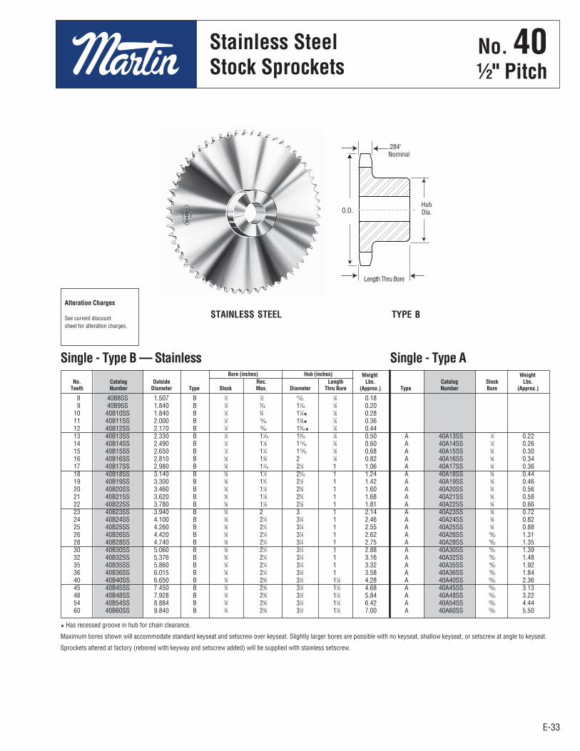
E-33
No. 401⁄2" Pitch
Stainless SteelStock Sprockets
E-33
8 40B8SS 1.507 B 1⁄2 1⁄2 31⁄32 7⁄8 0.18 9 40B9SS 1.840 B 1⁄2 9⁄16 11⁄16 7⁄8 0.20 10 40B10SS 1.840 B 1⁄2 3⁄4 11⁄4H 7⁄8 0.28 11 40B11SS 2.000 B 1⁄2 13⁄16 13⁄8H 7⁄8 0.36 12 40B12SS 2.170 B 1⁄2 15⁄16 19⁄16H 7⁄8 0.44 13 40B13SS 2.330 B 1⁄2 11⁄16 19⁄16 7⁄8 0.50 A 40A13SS 1⁄2 0.22 14 40B14SS 2.490 B 1⁄2 11⁄8 111⁄16 7⁄8 0.60 A 40A14SS 1⁄2 0.26 15 40B15SS 2.650 B 1⁄2 11⁄4 113⁄16 7⁄8 0.68 A 40A15SS 5⁄8 0.30 16 40B16SS 2.810 B 5⁄8 13⁄8 2 7⁄8 0.82 A 40A16SS 5⁄8 0.34 17 40B17SS 2.980 B 5⁄8 17⁄16 21⁄8 1 1.06 A 40A17SS 5⁄8 0.36 18 40B18SS 3.140 B 5⁄8 11⁄2 25⁄16 1 1.24 A 40A18SS 5⁄8 0.44 19 40B19SS 3.300 B 5⁄8 13⁄4 21⁄2 1 1.42 A 40A19SS 5⁄8 0.46 20 40B20SS 3.460 B 5⁄8 17⁄8 25⁄8 1 1.60 A 40A20SS 5⁄8 0.56 21 40B21SS 3.620 B 5⁄8 17⁄8 23⁄4 1 1.68 A 40A21SS 5⁄8 0.58 22 40B22SS 3.780 B 5⁄8 17⁄8 27⁄8 1 1.81 A 40A22SS 5⁄8 0.66 23 40B23SS 3.940 B 5⁄8 2 3 1 2.14 A 40A23SS 5⁄8 0.72 24 40B24SS 4.100 B 5⁄8 21⁄4 31⁄4 1 2.46 A 40A24SS 5⁄8 0.82 25 40B25SS 4.260 B 5⁄8 21⁄4 31⁄4 1 2.55 A 40A25SS 5⁄8 0.88 26 40B26SS 4.420 B 5⁄8 21⁄4 31⁄4 1 2.62 A 40A26SS 19⁄32 1.31 28 40B28SS 4.740 B 5⁄8 21⁄4 31⁄4 1 2.75 A 40A28SS 19⁄32 1.35 30 40B30SS 5.060 B 5⁄8 21⁄4 31⁄4 1 2.88 A 40A30SS 19⁄32 1.39 32 40B32SS 5.376 B 5⁄8 21⁄4 31⁄4 1 3.16 A 40A32SS 19⁄32 1.48 35 40B35SS 5.860 B 5⁄8 21⁄4 31⁄4 1 3.32 A 40A35SS 19⁄32 1.92 36 40B36SS 6.015 B 5⁄8 21⁄4 31⁄4 1 3.58 A 40A36SS 19⁄32 1.84 40 40B40SS 6.650 B 3⁄4 23⁄8 31⁄2 11⁄8 4.28 A 40A40SS 23⁄32 2.36 45 40B45SS 7.450 B 3⁄4 23⁄8 31⁄2 11⁄8 4.68 A 40A45SS 23⁄32 3.13 48 40B48SS 7.928 B 3⁄4 23⁄8 31⁄2 11⁄8 5.84 A 40A48SS 23⁄32 3.22 54 40B54SS 8.884 B 3⁄4 23⁄8 31⁄2 11⁄8 6.42 A 40A54SS 23⁄32 4.44 60 40B60SS 9.840 B 3⁄4 23⁄8 31⁄2 11⁄8 7.00 A 40A60SS 23⁄32 5.50
Bore (inches) Hub (inches) Weight Weight No. Catalog Outside Rec. Length Lbs. Catalog Stock Lbs. Teeth Number Diameter Type Stock Max. Diameter Thru Bore (Approx.) Type Number Bore (Approx.)
Single - Type B — Stainless Single - Type A
STAINLESS STEEL TYPE B
H Has recessed groove in hub for chain clearance.
Maximum bores shown will accommodate standard keyseat and setscrew over keyseat. Slightly larger bores are possible with no keyseat, shallow keyseat, or setscrew at angle to keyseat.
Sprockets altered at factory (rebored with keyway and setscrew added) will be supplied with stainless setscrew.
Alteration Charges
See current discountsheet for alteration charges.
HubDia.
Length Thru Bore
.284"Nominal
O.D.
No . 40½" Pitch
Stainless SteelStock Sprockets
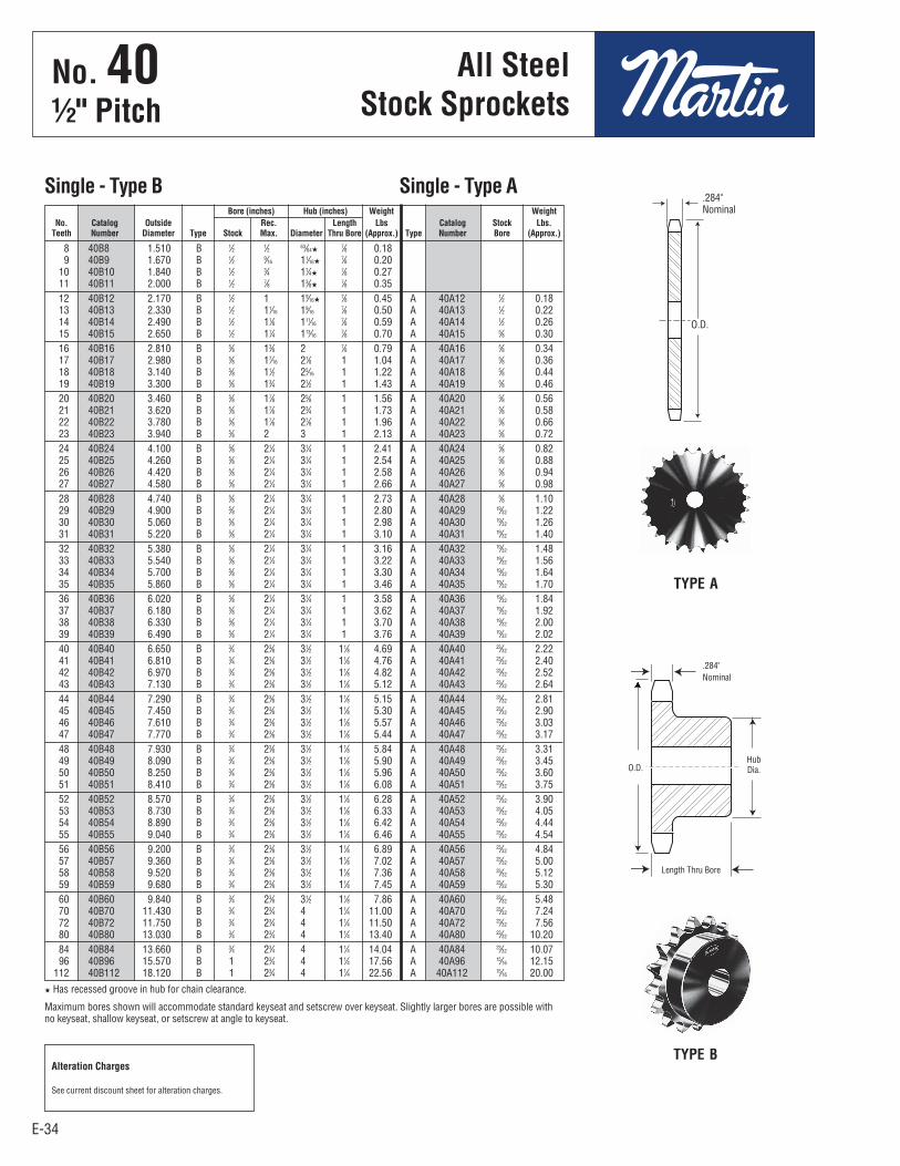
E-34E-34
No. 401⁄2" Pitch
All SteelStock Sprockets
8 40B8 1.510 B 1⁄2 1⁄2 63⁄64H 7⁄8 0.18 9 40B9 1.670 B 1⁄2 9⁄16 11⁄16H 7⁄8 0.20 10 40B10 1.840 B 1⁄2 3⁄4 11⁄4H 7⁄8 0.27 11 40B11 2.000 B 1⁄2 7⁄8 13⁄8H 7⁄8 0.35 12 40B12 2.170 B 1⁄2 1 19⁄16H 7⁄8 0.45 A 40A12 1⁄2 0.18 13 40B13 2.330 B 1⁄2 11⁄16 19⁄16 7⁄8 0.50 A 40A13 1⁄2 0.22 14 40B14 2.490 B 1⁄2 11⁄8 111⁄16 7⁄8 0.59 A 40A14 1⁄2 0.26 15 40B15 2.650 B 1⁄2 11⁄4 113⁄16 7⁄8 0.70 A 40A15 5⁄8 0.30 16 40B16 2.810 B 5⁄8 13⁄8 2 7⁄8 0.79 A 40A16 5⁄8 0.34 17 40B17 2.980 B 5⁄8 17⁄16 21⁄8 1 1.04 A 40A17 5⁄8 0.36 18 40B18 3.140 B 5⁄8 11⁄2 25⁄16 1 1.22 A 40A18 5⁄8 0.44 19 40B19 3.300 B 5⁄8 13⁄4 21⁄2 1 1.43 A 40A19 5⁄8 0.46 20 40B20 3.460 B 5⁄8 17⁄8 25⁄8 1 1.56 A 40A20 5⁄8 0.56 21 40B21 3.620 B 5⁄8 17⁄8 23⁄4 1 1.73 A 40A21 5⁄8 0.58 22 40B22 3.780 B 5⁄8 17⁄8 27⁄8 1 1.96 A 40A22 5⁄8 0.66 23 40B23 3.940 B 5⁄8 2 3 1 2.13 A 40A23 5⁄8 0.72 24 40B24 4.100 B 5⁄8 21⁄4 31⁄4 1 2.41 A 40A24 5⁄8 0.82 25 40B25 4.260 B 5⁄8 21⁄4 31⁄4 1 2.54 A 40A25 5⁄8 0.88 26 40B26 4.420 B 5⁄8 21⁄4 31⁄4 1 2.58 A 40A26 5⁄8 0.94 27 40B27 4.580 B 5⁄8 21⁄4 31⁄4 1 2.66 A 40A27 5⁄8 0.98 28 40B28 4.740 B 5⁄8 21⁄4 31⁄4 1 2.73 A 40A28 5⁄8 1.10 29 40B29 4.900 B 5⁄8 21⁄4 31⁄4 1 2.80 A 40A29 19⁄32 1.22 30 40B30 5.060 B 5⁄8 21⁄4 31⁄4 1 2.98 A 40A30 19⁄32 1.26 31 40B31 5.220 B 5⁄8 21⁄4 31⁄4 1 3.10 A 40A31 19⁄32 1.40 32 40B32 5.380 B 5⁄8 21⁄4 31⁄4 1 3.16 A 40A32 19⁄32 1.48 33 40B33 5.540 B 5⁄8 21⁄4 31⁄4 1 3.22 A 40A33 19⁄32 1.56 34 40B34 5.700 B 5⁄8 21⁄4 31⁄4 1 3.30 A 40A34 19⁄32 1.64 35 40B35 5.860 B 5⁄8 21⁄4 31⁄4 1 3.46 A 40A35 19⁄32 1.70 36 40B36 6.020 B 5⁄8 21⁄4 31⁄4 1 3.58 A 40A36 19⁄32 1.84 37 40B37 6.180 B 5⁄8 21⁄4 31⁄4 1 3.62 A 40A37 19⁄32 1.92 38 40B38 6.330 B 5⁄8 21⁄4 31⁄4 1 3.70 A 40A38 19⁄32 2.00 39 40B39 6.490 B 5⁄8 21⁄4 31⁄4 1 3.76 A 40A39 19⁄32 2.02 40 40B40 6.650 B 3⁄4 23⁄8 31⁄2 11⁄8 4.69 A 40A40 23⁄32 2.22 41 40B41 6.810 B 3⁄4 23⁄8 31⁄2 11⁄8 4.76 A 40A41 23⁄32 2.40 42 40B42 6.970 B 3⁄4 23⁄8 31⁄2 11⁄8 4.82 A 40A42 23⁄32 2.52 43 40B43 7.130 B 3⁄4 23⁄8 31⁄2 11⁄8 5.12 A 40A43 23⁄32 2.64 44 40B44 7.290 B 3⁄4 23⁄8 31⁄2 11⁄8 5.15 A 40A44 23⁄32 2.81 45 40B45 7.450 B 3⁄4 23⁄8 31⁄2 11⁄8 5.30 A 40A45 23⁄32 2.90 46 40B46 7.610 B 3⁄4 23⁄8 31⁄2 11⁄8 5.57 A 40A46 23⁄32 3.03 47 40B47 7.770 B 3⁄4 23⁄8 31⁄2 11⁄8 5.44 A 40A47 23⁄32 3.17 48 40B48 7.930 B 3⁄4 23⁄8 31⁄2 11⁄8 5.84 A 40A48 23⁄32 3.31 49 40B49 8.090 B 3⁄4 23⁄8 31⁄2 11⁄8 5.90 A 40A49 23⁄32 3.45 50 40B50 8.250 B 3⁄4 23⁄8 31⁄2 11⁄8 5.96 A 40A50 23⁄32 3.60 51 40B51 8.410 B 3⁄4 23⁄8 31⁄2 11⁄8 6.08 A 40A51 23⁄32 3.75 52 40B52 8.570 B 3⁄4 23⁄8 31⁄2 11⁄8 6.28 A 40A52 23⁄32 3.90 53 40B53 8.730 B 3⁄4 23⁄8 31⁄2 11⁄8 6.33 A 40A53 23⁄32 4.05 54 40B54 8.890 B 3⁄4 23⁄8 31⁄2 11⁄8 6.42 A 40A54 23⁄32 4.44 55 40B55 9.040 B 3⁄4 23⁄8 31⁄2 11⁄8 6.46 A 40A55 23⁄32 4.54 56 40B56 9.200 B 3⁄4 23⁄8 31⁄2 11⁄8 6.89 A 40A56 23⁄32 4.84 57 40B57 9.360 B 3⁄4 23⁄8 31⁄2 11⁄8 7.02 A 40A57 23⁄32 5.00 58 40B58 9.520 B 3⁄4 23⁄8 31⁄2 11⁄8 7.36 A 40A58 23⁄32 5.12 59 40B59 9.680 B 3⁄4 23⁄8 31⁄2 11⁄8 7.45 A 40A59 23⁄32 5.30 60 40B60 9.840 B 3⁄4 23⁄8 31⁄2 11⁄8 7.86 A 40A60 23⁄32 5.48 70 40B70 11.430 B 3⁄4 23⁄4 4 11⁄4 11.00 A 40A70 23⁄32 7.24 72 40B72 11.750 B 3⁄4 23⁄4 4 11⁄4 11.50 A 40A72 23⁄32 7.56 80 40B80 13.030 B 3⁄4 23⁄4 4 11⁄4 13.40 A 40A80 23⁄32 10.20 84 40B84 13.660 B 3⁄4 23⁄4 4 11⁄4 14.04 A 40A84 23⁄32 10.07 96 40B96 15.570 B 1 23⁄4 4 11⁄4 17.56 A 40A96 15⁄16 12.15 112 40B112 18.120 B 1 23⁄4 4 11⁄4 22.56 A 40A112 15⁄16 20.00
Bore (inches) Hub (inches) Weight Weight No. Catalog Outside Rec. Length Lbs Catalog Stock Lbs. Teeth Number Diameter Type Stock Max. Diameter Thru Bore (Approx.) Type Number Bore (Approx.)
Single - Type B Single - Type A
H Has recessed groove in hub for chain clearance.
Maximum bores shown will accommodate standard keyseat and setscrew over keyseat. Slightly larger bores are possible withno keyseat, shallow keyseat, or setscrew at angle to keyseat.
Alteration Charges
See current discount sheet for alteration charges.
TYPE A
TYPE B
O.D.
.284"Nominal
.284"Nominal
HubDia.
Length Thru Bore
O.D.
No . 40½" Pitch
All SteelStock Sprockets

E-35
15 40JA15H
16 40JA16H
17 40JA17H
18 40JA18H
19 40JA19H
20 40SH20H
21 40SH21H
22 40SH22H
23 40SH23H
24 40SH24H
25 40SH25H
26 40SH26H
27 40SH27H
28 40SH28H
30 40SH30H
All SteelStock Sprockets
15 40JA15 JA 2.650 2.405 B 11⁄4 11⁄8 11⁄8 21⁄16 23⁄32 11⁄32 5⁄8 0.284 1.24 0.34 16 40JA16 JA 2.810 2.563 B 11⁄4 11⁄8 11⁄8 21⁄16 23⁄32 11⁄32 5⁄8 0.284 1.30 0.40 17 40JA17 JA 2.980 2.721 B 11⁄4 11⁄8 11⁄8 21⁄16 23⁄32 11⁄32 5⁄8 0.284 1.38 0.48 18 40JA18 JA 3.140 2.879 B 11⁄4 11⁄8 11⁄8 21⁄16 23⁄32 11⁄32 5⁄8 0.284 1.44 0.54 19 40JA19 JA 3.300 3.038 B 11⁄4 11⁄8 11⁄8 21⁄16 23⁄32 11⁄32 5⁄8 0.284 1.50 0.60 20 40SH20 SH 3.460 3.196 B 15⁄8 17⁄16 17⁄16 211⁄16 31⁄32 17⁄32 13⁄16 0.284 1.76 0.76 21 40SH21 SH 3.620 3.355 B 15⁄8 17⁄16 17⁄16 211⁄16 31⁄32 17⁄32 13⁄16 0.284 1.84 0.84 22 40SH22 SH 3.780 3.513 B 15⁄8 17⁄16 17⁄16 211⁄16 31⁄32 17⁄32 13⁄16 0.284 1.92 0.92 23 40SH23 SH 3.940 3.672 B 15⁄8 17⁄16 17⁄16 211⁄16 31⁄32 17⁄32 13⁄16 0.284 2.14 1.14 24 40SH24 SH 4.100 3.831 B 15⁄8 17⁄16 17⁄16 211⁄16 31⁄32 17⁄32 13⁄16 0.284 2.22 1.22 25 40SH25 SH 4.260 3.989 B 15⁄8 17⁄16 17⁄16 211⁄16 31⁄32 17⁄32 13⁄16 0.284 2.30 1.30 26 40SH26 SH 4.420 4.148 B 15⁄8 17⁄16 17⁄16 211⁄16 31⁄32 17⁄32 13⁄16 0.284 2.44 1.44 27 40SH27 SH 4.580 4.307 B 15⁄8 17⁄16 17⁄16 211⁄16 31⁄32 17⁄32 13⁄16 0.284 2.46 1.46 28 40SH28 SH 4.740 4.466 B 15⁄8 17⁄16 17⁄16 211⁄16 31⁄32 17⁄32 13⁄16 0.284 2.54 1.54 30 40SH30 SH 5.060 4.783 B 15⁄8 17⁄16 17⁄16 211⁄16 31⁄32 17⁄32 13⁄16 0.284 2.72 1.72 32 40SH32 SH 5.380 5.101 B 15⁄8 17⁄16 17⁄16 211⁄16 31⁄32 17⁄32 13⁄16 0.284 2.90 1.90 35 40SH35 SH 5.860 5.578 B 15⁄8 17⁄16 17⁄16 3 31⁄32 17⁄32 13⁄16 0.284 3.22 2.22 36 40SDS36 SDS 6.020 5.737 B 2 11⁄2 11⁄2 33⁄16 11⁄32 15⁄32 3⁄4 0.284 3.20 2.20 40 40SDS40 SDS 6.650 6.373 B 2 11⁄2 11⁄2 33⁄16 11⁄32 15⁄32 3⁄4 0.284 3.72 2.72 42 40SDS42 SDS 6.970 6.691 B 2 11⁄2 11⁄2 33⁄16 11⁄32 15⁄32 3⁄4 0.284 3.92 2.92 45 40SDS45 SDS 7.450 7.168 B 2 11⁄2 11⁄2 33⁄16 11⁄32 15⁄32 3⁄4 0.284 4.32 3.32 48 40SDS48 SDS 7.930 7.645 B 2 11⁄2 11⁄2 33⁄16 11⁄32 15⁄32 3⁄4 0.284 4.70 3.70 54 40SDS54 SDS 8.890 8.599 B 2 11⁄2 11⁄2 33⁄16 11⁄32 15⁄32 3⁄4 0.284 5.78 4.78 60 40SDS60 SDS 9.840 9.554 B 2 11⁄2 11⁄2 33⁄16 11⁄32 15⁄32 3⁄4 0.284 6.86 5.86 70 40SK70 SK 11.430 11.145 B 25⁄8 21⁄8 21⁄8 37⁄8 119⁄32 31⁄32 11⁄4 0.284 10.68 8.68 72 40SK72 SK 11.750 11.463 B 25⁄8 21⁄8 21⁄8 37⁄8 119⁄32 31⁄32 11⁄4 0.284 10.84 8.84 80 40SK80 SK 13.030 12.736 B 25⁄8 21⁄8 21⁄8 37⁄8 119⁄32 31⁄32 11⁄4 0.284 13.20 11.20 84 40SK84 SK 13.660 13.372 B 25⁄8 21⁄8 21⁄8 37⁄8 119⁄32 31⁄32 11⁄4 0.284 13.56 11.56 96 40SK96 SK 15.570 15.282 B 25⁄8 21⁄8 21⁄8 37⁄8 119⁄32 31⁄32 11⁄4 0.284 17.76 15.76 112 40SK112 SK 18.120 17.828 B 25⁄8 21⁄8 21⁄8 37⁄8 119⁄32 31⁄32 11⁄4 0.284 22.28 20.28
Diameters Dimensions Weight Lbs. (Approx.) No. Catalog Bush- Outside Pitch Max. With Rim Teeth Number ing Diameter Diameter Type Bore L
1 L
2 C Y G X T Hub Only
Single - Type QD
No. Catalog Teeth Number
Single - Type QD With Hardened Teeth
QD — TYPE B
SABER
TOOTH®
O.D.
E-35
No. 401⁄2" PitchNo . 40½" Pitch
All SteelStock Sprockets
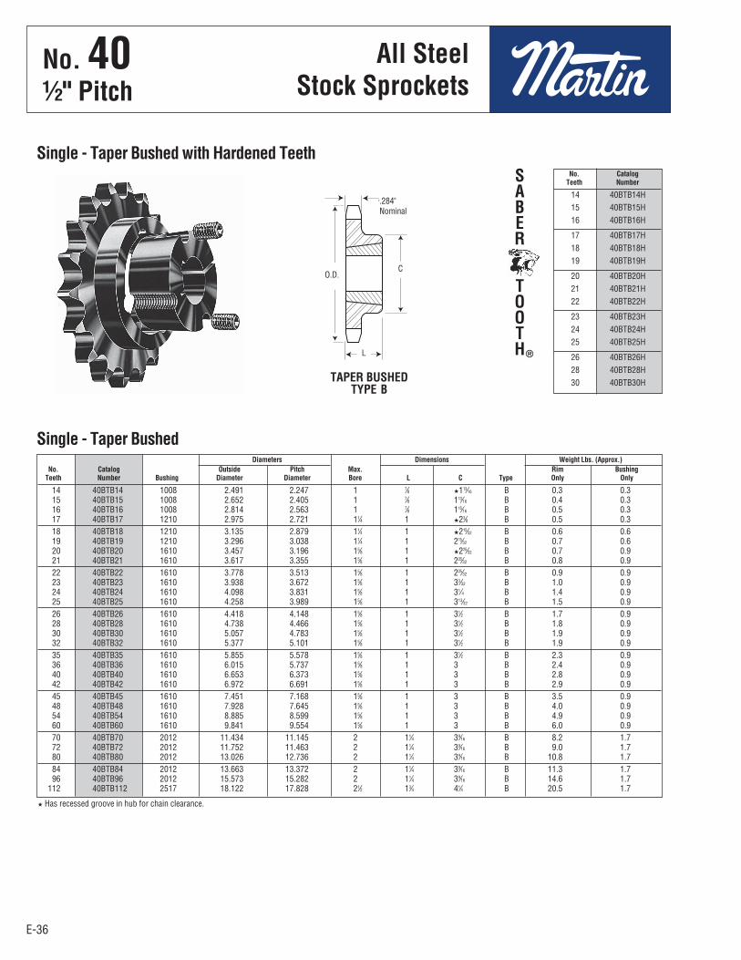
E-36
No. 401⁄2" Pitch
All SteelStock Sprockets
E-36
14 40BTB14H 15 40BTB15H 16 40BTB16H
17 40BTB17H 18 40BTB18H 19 40BTB19H
20 40BTB20H 21 40BTB21H 22 40BTB22H
23 40BTB23H 24 40BTB24H 25 40BTB25H
26 40BTB26H 28 40BTB28H 30 40BTB30H
No. Catalog Teeth Number
Single - Taper Bushed with Hardened Teeth
TAPER BUSHEDTYPE B
14 40BTB14 1008 2.491 2.247 1 7⁄8 H113⁄16 B 0.3 0.3 15 40BTB15 1008 2.652 2.405 1 7⁄8 113⁄16 B 0.4 0.3 16 40BTB16 1008 2.814 2.563 1 7⁄8 115⁄16 B 0.5 0.3 17 40BTB17 1210 2.975 2.721 11⁄4 1 H23⁄8 B 0.5 0.3 18 40BTB18 1210 3.135 2.879 11⁄4 1 H215⁄32 B 0.6 0.6 19 40BTB19 1210 3.296 3.038 11⁄4 1 215⁄32 B 0.7 0.6 20 40BTB20 1610 3.457 3.196 15⁄8 1 H225⁄32 B 0.7 0.9 21 40BTB21 1610 3.617 3.355 15⁄8 1 225⁄32 B 0.8 0.9 22 40BTB22 1610 3.778 3.513 15⁄8 1 225⁄32 B 0.9 0.9 23 40BTB23 1610 3.938 3.672 15⁄8 1 33⁄32 B 1.0 0.9 24 40BTB24 1610 4.098 3.831 15⁄8 1 31⁄4 B 1.4 0.9 25 40BTB25 1610 4.258 3.989 15⁄8 1 313⁄32 B 1.5 0.9 26 40BTB26 1610 4.418 4.148 15⁄8 1 31⁄2 B 1.7 0.9 28 40BTB28 1610 4.738 4.466 15⁄8 1 31⁄2 B 1.8 0.9 30 40BTB30 1610 5.057 4.783 15⁄8 1 31⁄2 B 1.9 0.9 32 40BTB32 1610 5.377 5.101 15⁄8 1 31⁄2 B 1.9 0.9 35 40BTB35 1610 5.855 5.578 15⁄8 1 31⁄2 B 2.3 0.9 36 40BTB36 1610 6.015 5.737 15⁄8 1 3 B 2.4 0.9 40 40BTB40 1610 6.653 6.373 15⁄8 1 3 B 2.8 0.9 42 40BTB42 1610 6.972 6.691 15⁄8 1 3 B 2.9 0.9 45 40BTB45 1610 7.451 7.168 15⁄8 1 3 B 3.5 0.9 48 40BTB48 1610 7.928 7.645 15⁄8 1 3 B 4.0 0.9 54 40BTB54 1610 8.885 8.599 15⁄8 1 3 B 4.9 0.9 60 40BTB60 1610 9.841 9.554 15⁄8 1 3 B 6.0 0.9 70 40BTB70 2012 11.434 11.145 2 11⁄4 39⁄16 B 8.2 1.7 72 40BTB72 2012 11.752 11.463 2 11⁄4 39⁄16 B 9.0 1.7 80 40BTB80 2012 13.026 12.736 2 11⁄4 39⁄16 B 10.8 1.7 84 40BTB84 2012 13.663 13.372 2 11⁄4 39⁄16 B 11.3 1.7 96 40BTB96 2012 15.573 15.282 2 11⁄4 39⁄16 B 14.6 1.7 112 40BTB112 2517 18.122 17.828 21⁄2 13⁄4 41⁄4 B 20.5 1.7
Diameters Dimensions Weight Lbs. (Approx.) No. Catalog Outside Pitch Max. Rim Bushing Teeth Number Bushing Diameter Diameter Bore L C Type Only Only
Single - Taper Bushed
H Has recessed groove in hub for chain clearance.
SABER
TOOTH®
.284"Nominal
L
O.D.C
No . 40½" Pitch
All SteelStock Sprockets
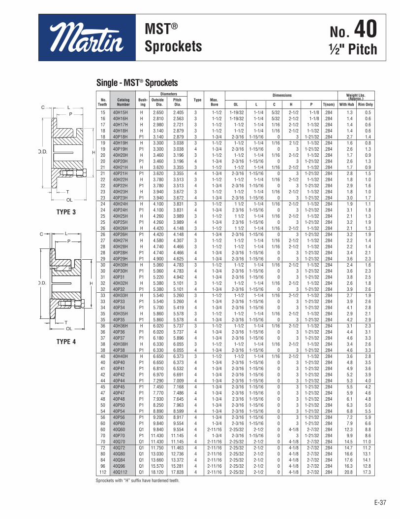
E-37
No. 401⁄2" Pitch
MST®
Sprockets
E-37
15 40H15H H 2.650 2.405 3 1-1/2 1-19/32 1-1/4 5/32 2-1/2 1-1/8 .284 1.3 0.5 16 40H16H H 2.810 2.563 3 1-1/2 1-19/32 1-1/4 5/32 2-1/2 1-1/8 .284 1.4 0.6 17 40H17H H 2.980 2.721 3 1-1/2 1-1/2 1-1/4 1/16 2-1/2 1-1/32 .284 1.4 0.6 18 40H18H H 3.140 2.879 3 1-1/2 1-1/2 1-1/4 1/16 2-1/2 1-1/32 .284 1.4 0.6 18 40P18H P1 3.140 2.879 3 1-3/4 2-3/16 1-15/16 0 3 1-21/32 .284 2.7 1.4 19 40H19H H 3.300 3.038 3 1-1/2 1-1/2 1-1/4 1/16 2 1/2 1-1/32 .284 1.6 0.8 19 40P19H P1 3.300 3.038 4 1-3/4 2-3/16 1-15/16 0 3 1-21/32 .284 2.6 1.3 20 40H20H H 3.460 3.196 3 1-1/2 1-1/2 1-1/4 1/16 2-1/2 1-1/32 .284 1.7 0.9 20 40P20H P1 3.460 3.196 4 1-3/4 2-3/16 1-15/16 0 3 1-21/32 .284 2.6 1.3 21 40H21H H 3.620 3.355 3 1-1/2 1-1/2 1-1/4 1/16 2-1/2 1-1/32 .284 1.7 0.9 21 40P21H P1 3.620 3.355 4 1-3/4 2-3/16 1-15/16 0 3 1-21/32 .284 2.8 1.5 22 40H22H H 3.780 3.513 3 1-1/2 1-1/2 1-1/4 1/16 2-1/2 1-1/32 .284 1.8 1.0 22 40P22H P1 3.780 3.513 4 1-3/4 2-3/16 1-15/16 0 3 1-21/32 .284 2.9 1.6 23 40H23H H 3.940 3.672 3 1-1/2 1-1/2 1-1/4 1/16 2-1/2 1-1/32 .284 1.8 1.0 23 40P23H P1 3.940 3.672 4 1-3/4 2-3/16 1-15/16 0 3 1-21/32 .284 3.0 1.7 24 40H24H H 4.100 3.831 3 1-1/2 1 1/2 1-1/4 1/16 2-1/2 1-1/32 .284 1.9 1.1 24 40P24H P1 4.100 3.831 4 1-3/4 2 3/16 1-15/16 0 3 1-21/32 .284 3.1 1.8 25 40H25H H 4.260 3.989 3 1-1/2 1 1/2 1-1/4 1/16 2-1/2 1-1/32 .284 2.1 1.3 25 40P25H P1 4.260 3.989 4 1-3/4 2 3/16 1-15/16 0 3 1-21/32 .284 3.2 1.9 26 40H26H H 4.420 4.148 3 1-1/2 1 1/2 1-1/4 1/16 2-1/2 1-1/32 .284 2.1 1.3 26 40P26H P1 4.420 4.148 4 1-3/4 2-3/16 1-15/16 0 3 1-21/32 .284 3.2 1.9 27 40H27H H 4.580 4.307 3 1-1/2 1-1/2 1-1/4 1/16 2-1/2 1-1/32 .284 2.2 1.4 28 40H28H H 4.740 4.466 3 1-1/2 1-1/2 1-1/4 1/16 2-1/2 1-1/32 .284 2.2 1.4 28 40P28H P1 4.740 4.466 4 1-3/4 2-3/16 1-15/16 0 3 1-21/32 .284 3.4 2.1 29 40P29H P1 4.900 4.625 4 1-3/4 2-3/16 1-15/16 0 3 1-21/32 .284 3.6 2.3 30 40H30H H 5.060 4.783 3 1-1/2 1-1/2 1-1/4 1/16 2-1/2 1-1/32 .284 2.4 1.6 30 40P30H P1 5.060 4.783 4 1-3/4 2-3/16 1-15/16 0 3 1-21/32 .284 3.6 2.3 31 40P31 P1 5.220 4.942 4 1-3/4 2-3/16 1-15/16 0 3 1-21/32 .284 3.8 2.5 32 40H32H H 5.380 5.101 3 1-1/2 1-1/2 1-1/4 1/16 2-1/2 1-1/32 .284 2.6 1.8 32 40P32 P1 5.380 5.101 4 1-3/4 2-3/16 1-15/16 0 3 1-21/32 .284 3.9 2.6 33 40H33H H 5.540 5.260 3 1-1/2 1-1/2 1-1/4 1/16 2-1/2 1-1/32 .284 2.7 1.9 33 40P33 P1 5.540 5.260 4 1-3/4 2-3/16 1-15/16 0 3 1-21/32 .284 3.9 2.6 34 40P34 P1 5.700 5.419 4 1-3/4 2-3/16 1-15/16 0 3 1-21/32 .284 4.1 2.8 35 40H35H H 5.860 5.578 3 1-1/2 1-1/2 1-1/4 1/16 2-1/2 1-1/32 .284 2.9 2.1 35 40P35 P1 5.860 5.578 4 1-3/4 2-3/16 1-15/16 0 3 1-21/32 .284 4.2 2.9 36 40H36H H 6.020 5.737 3 1-1/2 1-1/2 1-1/4 1/16 2-1/2 1-1/32 .284 3.1 2.3 36 40P36 P1 6.020 5.737 4 1-3/4 2-3/16 1-15/16 0 3 1-21/32 .284 4.4 3.1 37 40P37 P1 6.180 5.896 4 1-3/4 2-3/16 1-15/16 0 3 1-21/32 .284 4.6 3.3 38 40H38H H 6.330 6.055 3 1-1/2 1-1/2 1-1/4 1/16 2-1/2 1-1/32 .284 3.4 2.6 38 40P38 P1 6.330 6.055 4 1-3/4 2-3/16 1-15/16 0 3 1-21/32 .284 4.6 3.3 40 40H40H H 6.650 6.373 3 1-1/2 1-1/2 1-1/4 1/16 2-1/2 1-1/32 .284 3.6 2.8 40 40P40 P1 6.650 6.373 4 1-3/4 2-3/16 1-15/16 0 3 1-21/32 .284 4.8 3.5 41 40P41 P1 6.810 6.532 4 1-3/4 2-3/16 1-15/16 0 3 1-21/32 .284 4.9 3.6 42 40P42 P1 6.970 6.691 4 1-3/4 2-3/16 1-15/16 0 3 1-21/32 .284 5.2 3.9 44 40P44 P1 7.290 7.009 4 1-3/4 2-3/16 1-15/16 0 3 1-21/32 .284 5.3 4.0 45 40P45 P1 7.450 7.168 4 1-3/4 2-3/16 1-15/16 0 3 1-21/32 .284 5.5 4.2 47 40P47 P1 7.770 7.486 4 1-3/4 2-3/16 1-15/16 0 3 1-21/32 .284 5.9 4.6 48 40P48 P1 7.930 7.645 4 1-3/4 2 3/16 1-15/16 0 3 1-21/32 .284 6.1 4.8 50 40P50 P1 8.250 7.963 4 1-3/4 2-3/16 1-15/16 0 3 1-21/32 .284 6.3 5.0 54 40P54 P1 8.890 8.599 4 1-3/4 2-3/16 1-15/16 0 3 1-21/32 .284 6.8 5.5 56 40P56 P1 9.200 8.917 4 1-3/4 2-3/16 1-15/16 0 3 1-21/32 .284 7.2 5.9 60 40P60 P1 9.840 9.554 4 1-3/4 2-3/16 1-15/16 0 3 1-21/32 .284 7.9 6.6 60 40Q60 Q1 9.840 9.554 4 2-11/16 2-25/32 2-1/2 0 4-1/8 2-7/32 .284 12.3 8.8 70 40P70 P1 11.430 11.145 4 1-3/4 2-3/16 1-15/16 0 3 1-21/32 .284 9.9 8.6 70 40Q70 Q1 11.430 11.145 4 2-11/16 2-25/32 2-1/2 0 4-1/8 2-7/32 .284 14.5 11.0 72 40Q72 Q1 11.750 11.463 4 2-11/16 2-25/32 2-1/2 0 4-1/8 2-7/32 .284 14.7 11.2 80 40Q80 Q1 13.030 12.736 4 2-11/16 2-25/32 2-1/2 0 4-1/8 2-7/32 .284 16.6 13.1 84 40Q84 Q1 13.660 13.372 4 2-11/16 2-25/32 2-1/2 0 4-1/8 2-7/32 .284 17.6 14.1 96 40Q96 Q1 15.570 15.281 4 2-11/16 2-25/32 2-1/2 0 4-1/8 2-7/32 .284 16.3 12.8 112 40Q112 Q1 18.120 17.828 4 2-11/16 2-25/32 2-1/2 0 4-1/8 2-7/32 .284 20.8 17.3
Diameters Dimensions Weight Lbs. No. Catalog Bush- Outside Pitch Type Max. (Approx.) Teeth Number ing Dia. Dia. Bore OL L C H P T(nom) With Hub Rim Only
Single - MST® Sprockets
Sprockets with “H” suffix have hardened teeth.
TYPE 3
TYPE 4
No . 40½" Pitch
MST®
Sprockets
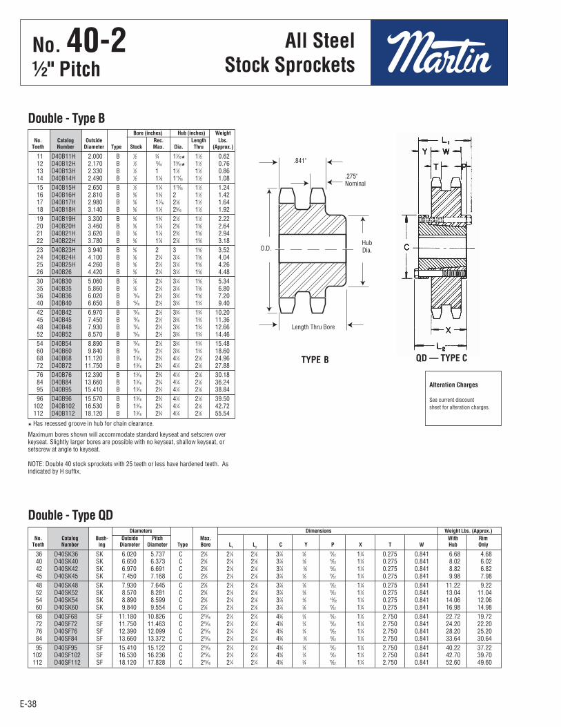
E-38E-38
No. 40-21⁄2" Pitch
36 D40SK36 SK 6.020 5.737 C 25⁄8 21⁄8 21⁄8 37⁄8 5⁄8 13⁄32 11⁄4 0.275 0.841 6.68 4.68 40 D40SK40 SK 6.650 6.373 C 25⁄8 21⁄8 21⁄8 37⁄8 5⁄8 13⁄32 11⁄4 0.275 0.841 8.02 6.02 42 D40SK42 SK 6.970 6.691 C 25⁄8 21⁄8 21⁄8 37⁄8 5⁄8 13⁄32 11⁄4 0.275 0.841 8.82 6.82 45 D40SK45 SK 7.450 7.168 C 25⁄8 21⁄8 21⁄8 37⁄8 5⁄8 13⁄32 11⁄4 0.275 0.841 9.98 7.98 48 D40SK48 SK 7.930 7.645 C 25⁄8 21⁄8 21⁄8 37⁄8 5⁄8 13⁄32 11⁄4 0.275 0.841 11.22 9.22 52 D40SK52 SK 8.570 8.281 C 25⁄8 21⁄8 21⁄8 37⁄8 5⁄8 13⁄32 11⁄4 0.275 0.841 13.04 11.04 54 D40SK54 SK 8.890 8.599 C 25⁄8 21⁄8 21⁄8 37⁄8 5⁄8 13⁄32 11⁄4 0.275 0.841 14.06 12.06 60 D40SK60 SK 9.840 9.554 C 25⁄8 21⁄8 21⁄8 37⁄8 5⁄8 13⁄32 11⁄4 0.275 0.841 16.98 14.98 68 D40SF68 SF 11.180 10.826 C 215⁄16 21⁄4 21⁄4 45⁄8 3⁄4 13⁄32 11⁄4 2.750 0.841 22.72 19.72 72 D40SF72 SF 11.750 11.463 C 215⁄16 21⁄4 21⁄4 45⁄8 3⁄4 13⁄32 11⁄4 2.750 0.841 24.20 22.20 76 D40SF76 SF 12.390 12.099 C 215⁄16 21⁄4 21⁄4 45⁄8 3⁄4 13⁄32 11⁄4 2.750 0.841 28.20 25.20 84 D40SF84 SF 13.660 13.372 C 215⁄16 21⁄4 21⁄4 45⁄8 3⁄4 13⁄32 11⁄4 2.750 0.841 33.64 30.64 95 D40SF95 SF 15.410 15.122 C 215⁄16 21⁄4 21⁄4 45⁄8 3⁄4 13⁄32 11⁄4 2.750 0.841 40.22 37.22 102 D40SF102 SF 16.530 16.236 C 215⁄16 21⁄4 21⁄4 45⁄8 3⁄4 13⁄32 11⁄4 2.750 0.841 42.70 39.70 112 D40SF112 SF 18.120 17.828 C 215⁄16 21⁄4 21⁄4 45⁄8 3⁄4 13⁄32 11⁄4 2.750 0.841 52.60 49.60
11 D40B11H 2.000 B 1⁄2 3⁄4 17⁄16H 11⁄2 0.62 12 D40B12H 2.170 B 1⁄2 15⁄16 19⁄16H 11⁄2 0.76 13 D40B13H 2.330 B 1⁄2 1 11⁄2 11⁄2 0.86 14 D40B14H 2.490 B 1⁄2 11⁄8 111⁄16 11⁄2 1.08 15 D40B15H 2.650 B 1⁄2 11⁄4 113⁄16 11⁄2 1.24 16 D40B16H 2.810 B 5⁄8 13⁄8 2 11⁄2 1.42 17 D40B17H 2.980 B 5⁄8 17⁄16 21⁄8 11⁄2 1.64 18 D40B18H 3.140 B 5⁄8 11⁄2 25⁄16 11⁄2 1.92 19 D40B19H 3.300 B 5⁄8 13⁄4 21⁄2 11⁄2 2.22 20 D40B20H 3.460 B 5⁄8 17⁄8 25⁄8 15⁄8 2.64 21 D40B21H 3.620 B 5⁄8 17⁄8 23⁄4 15⁄8 2.94 22 D40B22H 3.780 B 5⁄8 17⁄8 27⁄8 15⁄8 3.18 23 D40B23H 3.940 B 5⁄8 2 3 15⁄8 3.52 24 D40B24H 4.100 B 5⁄8 21⁄4 31⁄4 15⁄8 4.04 25 D40B25H 4.260 B 5⁄8 21⁄4 31⁄4 15⁄8 4.26 26 D40B26 4.420 B 5⁄8 21⁄4 31⁄4 15⁄8 4.48 30 D40B30 5.060 B 7⁄8 21⁄4 31⁄4 15⁄8 5.34 35 D40B35 5.860 B 7⁄8 21⁄4 31⁄4 15⁄8 6.80 36 D40B36 6.020 B 15⁄16 21⁄2 33⁄4 15⁄8 7.20 40 D40B40 6.650 B 15⁄16 21⁄2 33⁄4 13⁄4 9.40 42 D40B42 6.970 B 15⁄16 21⁄2 33⁄4 13⁄4 10.20 45 D40B45 7.450 B 15⁄16 21⁄2 33⁄4 13⁄4 11.36 48 D40B48 7.930 B 15⁄16 21⁄2 33⁄4 13⁄4 12.66 52 D40B52 8.570 B 15⁄16 21⁄2 33⁄4 13⁄4 14.46 54 D40B54 8.890 B 15⁄16 21⁄2 33⁄4 13⁄4 15.48 60 D40B60 9.840 B 15⁄16 21⁄2 33⁄4 13⁄4 18.60 68 D40B68 11.120 B 13⁄16 23⁄4 41⁄4 21⁄8 24.96 72 D40B72 11.750 B 13⁄16 23⁄4 41⁄4 21⁄8 27.88 76 D40B76 12.390 B 13⁄16 23⁄4 41⁄4 21⁄8 30.18 84 D40B84 13.660 B 13⁄16 23⁄4 41⁄4 21⁄8 36.24 95 D40B95 15.410 B 13⁄16 23⁄4 41⁄4 21⁄8 38.84 96 D40B96 15.570 B 13⁄16 23⁄4 41⁄4 21⁄8 39.50 102 D40B102 16.530 B 13⁄16 23⁄4 41⁄4 21⁄8 42.72 112 D40B112 18.120 B 13⁄16 23⁄4 41⁄4 21⁄8 55.54
Double - Type B
H Has recessed groove in hub for chain clearance.
Maximum bores shown will accommodate standard keyseat and setscrew overkeyseat. Slightly larger bores are possible with no keyseat, shallow keyseat, orsetscrew at angle to keyseat.
NOTE: Double 40 stock sprockets with 25 teeth or less have hardened teeth. Asindicated by H suffix.
TYPE B QD — TYPE C
Alteration Charges
See current discountsheet for alteration charges.
Bore (inches) Hub (inches) Weight No. Catalog Outside Rec. Length Lbs. Teeth Number Diameter Type Stock Max. Dia. Thru (Approx.)
Diameters Dimensions Weight Lbs. (Approx.) No. Catalog Bush- Outside Pitch Max. With Rim Teeth Number ing Diameter Diameter Type Bore L
1 L
2 C Y P X T W Hub Only
Double - Type QD
.275"Nominal
.841"
HubDia.
Length Thru Bore
O.D.
All SteelStock Sprockets
No . 40-2½" Pitch
All SteelStock Sprockets

E-39
15 D40ATB15H 1008 2.652 2.405 1 7⁄8 117⁄64 A 0.5 0.3 16 D40ATB16H 1008 2.814 2.563 1 7⁄8 117⁄64 A 0.6 0.3 17 D40ATB17H 1008 2.975 2.721 1 7⁄8 117⁄64 A 0.7 0.3 18 D40BTB18H 1210 3.135 2.879 11⁄4 1 25⁄16 B 0.7 0.6 19 D40BTB19H 1210 3.296 3.038 11⁄4 1 21⁄2 B 0.9 0.6 20 D40BTB20H 1610 3.457 3.196 15⁄8 1 25⁄8 B 0.9 0.9 21 D40BTB21H 1610 3.617 3.355 15⁄8 1 23⁄4 B 1.0 0.9 23 D40BTB23H 1610 3.938 3.672 15⁄8 1 3 B 1.3 0.9 25 D40BTB25H 2012 4.258 3.989 2 11⁄4 313⁄32 B 1.6 1.7 30 D40BTB30 2012 5.057 4.783 2 11⁄4 415⁄64 B 3.4 1.7 36 D40BTB36 2012 6.015 5.737 2 11⁄4 55⁄32 B 5.9 1.7 42 D40CTB42 2517 6.972 6.691 21⁄2 13⁄4 41⁄4 C 7.0 3.5 48 D40CTB48 2517 7.928 7.645 21⁄2 13⁄4 41⁄4 C 9.6 3.5 52 D40CTB52 2517 8.566 8.281 21⁄2 13⁄4 41⁄4 C 11.4 3.5 60 D40CTB60 2517 9.841 9.554 21⁄2 13⁄4 41⁄4 C 15.4 3.5 68 D40CTB68 2517 11.115 10.826 21⁄2 13⁄4 41⁄4 C 20.5 3.5 76 D40CTB76 2517 12.389 12.099 21⁄2 13⁄4 41⁄4 C 25.7 3.5 84 D40CTB84 2517 13.663 13.372 21⁄2 13⁄4 41⁄4 C 31.6 3.5 95 D40CTB95 2517 15.414 15.122 21⁄2 13⁄4 41⁄4 C 34.1 3.5 102 D40CTB102 2517 16.529 16.236 21⁄2 13⁄4 41⁄4 C 36.8 3.5
E-39
No. 40-21⁄2" Pitch
All SteelStock Sprockets
Diameters Dimensions Weight Lbs. (Approx.) No. Catalog Outside Pitch Max. Rim Bushing Teeth Number Bushing Diameter Diameter Bore L C Type Only Only
Double - Taper Bushed
TYPE CTYPE BTYPE A
NOTE: Double 40 stock sprockets with 25 teeth or less have hardened teeth. As indicated by H suffix.
.841".841"
.841"
.275"Nom.
.275"Nom.
.275"Nom.
L
C
L
C
L
C
No . 40-2½" Pitch
All SteelStock Sprockets
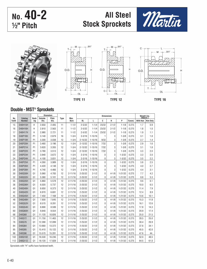
E-40E-40
15 D40H15H H 2.650 2.405 11 1-1/2 2-5/32 1-1/4 23/32 2-1/2 1-1/8 0.275 1.7 0.9
16 D40H16H H 2.810 2.563 11 1-1/2 2-5/32 1-1/4 23/32 2-1/2 1-1/8 0.275 1.8 1.0
17 D40H17H H 2.980 2.721 11 1-1/2 2-5/32 1-1/4 23/32 2-1/2 1-1/8 0.275 1.9 1.1
18 D40P18H P1 3.140 2.879 16 1-3/4 3-3/16 1-15/16 1 3 1-3/8 0.275 3.1 1.8
19 D40P19H P1 3.300 3.038 12 1-3/4 2-15/32 1-15/16 9/32 3 1-3/8 0.275 2.7 1.4
20 D40P20H P1 3.460 3.196 12 1-3/4 2-13/32 1-15/16 7/32 3 1-3/8 0.275 2.9 1.6
21 D40P21H P1 3.620 3.355 12 1-3/4 2-13/32 1-15/16 7/32 3 1-3/8 0.275 3.1 1.8
22 D40P22H P1 3.780 3.513 12 1-3/4 2-13/32 1-15/16 7/32 3 1-3/8 0.275 3.3 2.0
23 D40P23H P1 3.940 3.672 12 1-3/4 2-3/16 1-15/16 0 3 1-3/32 0.275 3.3 2.0
24 D40P24H P1 4.100 3.831 12 1-3/4 2-3/16 1-15/16 0 3 1-3/32 0.275 3.5 2.2
25 D40P25H P1 4.260 3.989 12 1-3/4 2-3/16 1-15/16 0 3 1-3/32 0.275 3.8 2.5
26 D40P26H P1 4.420 4.148 12 1-3/4 2-3/16 1-15/16 0 3 1-3/32 0.275 4.0 2.7
28 D40P28H P1 4.740 4.466 12 1-3/4 2-3/16 1-15/16 0 3 1-3/32 0.275 4.4 3.1
30 D40Q30H Q1 5.060 4.783 12 2-11/16 2-25/32 2-1/2 0 4-1/8 1-21/32 0.275 7.7 4.2
32 D40Q32H Q1 5.380 5.101 12 2-11/16 2-25/32 2-1/2 0 4-1/8 1-21/32 0.275 8.8 5.3
35 D40Q35H Q1 5.860 5.578 12 2-11/16 2-25/32 2-1/2 0 4-1/8 1-21/32 0.275 9.6 6.1
36 D40Q36H Q1 6.020 5.737 12 2-11/16 2-25/32 2-1/2 0 4-1/8 1-21/32 0.275 10.0 6.5
40 D40Q40H Q1 6.650 6.373 12 2-11/16 2-25/32 2-1/2 0 4-1/8 1-21/32 0.275 11.4 7.9
42 D40Q42H Q1 6.970 6.691 12 2-11/16 2-25/32 2-1/2 0 4-1/8 1-21/32 0.275 12.4 8.9
45 D40Q45H Q1 7.450 7.168 12 2-11/16 2-25/32 2-1/2 0 4-1/8 1-21/32 0.275 13.6 10.1
48 D40Q48H Q1 7.930 7.645 12 2-11/16 2-25/32 2-1/2 0 4-1/8 1-21/32 0.275 15.3 11.8
52 D40Q52H Q1 8.570 8.281 12 2-11/16 2-25/32 2-1/2 0 4-1/8 1-21/32 0.275 16.1 12.6
54 D40Q54H Q1 8.890 8.599 12 2-11/16 2-25/32 2-1/2 0 4-1/8 1-21/32 0.275 17.8 14.3
60 D40Q60H Q1 9.840 9.554 12 2-11/16 2-25/32 2-1/2 0 4-1/8 1-21/32 0.275 20.9 17.4
68 D40Q68 Q1 11.120 10.826 12 2-11/16 2-25/32 2-1/2 0 4-1/8 1-21/32 0.275 25.0 21.5
72 D40Q72 Q1 11.750 11.463 12 2-11/16 2-25/32 2-1/2 0 4-1/8 1-21/32 0.275 28.5 25.0
76 D40Q76 Q1 12.390 12.099 12 2-11/16 2-25/32 2-1/2 0 4-1/8 1-21/32 0.275 30.4 26.9
84 D40Q84 Q1 13.660 13.372 12 2-11/16 2-25/32 2-1/2 0 4-1/8 1-21/32 0.275 37.6 34.1
95 D40Q95 Q1 15.410 15.122 12 2-11/16 2-25/32 2-1/2 0 4-1/8 1-21/32 0.275 45.5 42.0
96 D40Q96 Q1 15.570 15.281 12 2-11/16 2-25/32 2-1/2 0 4-1/8 1-21/32 0.275 47.6 44.
102 D40Q102 Q1 16.530 16.236 12 2-11/16 2-25/32 2-1/2 0 4-1/8 1-21/32 0.275 52.0 48.5
112 D40Q112 Q1 18.120 17.828 12 2-11/16 2-25/32 2-1/2 0 4-1/8 1-21/32 0.275 64.5 61.0
MST®
SprocketsNo. 40-21⁄2" Pitch
Double - MST® Sprockets Diameters Dimensions Weight Lbs. No. Catalog Bush- Outside Pitch Type Max. (Approx.) Teeth Number ing Dia. Dia. Bore OL L C H P T(nom) With Hub Rim Only
Sprockets with “H” suffix have hardened teeth.
.841" .841"
.841"
TYPE 11 TYPE 12 TYPE 16
No . 40-2½" Pitch
All SteelStock Sprockets
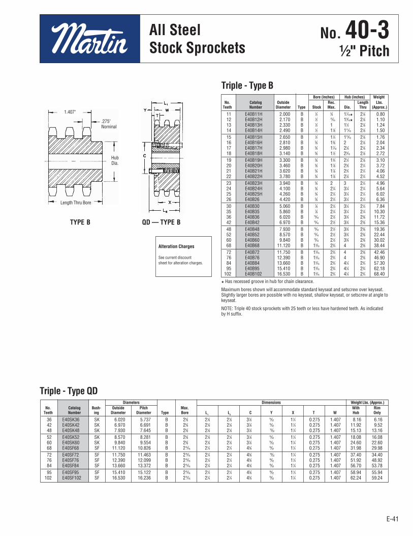
E-41E-41
No. 40-31⁄2" Pitch
All SteelStock Sprockets
11 E40B11H 2.000 B 1⁄2 3⁄4 17⁄16H 21⁄8 0.80 12 E40B12H 2.170 B 1⁄2 15⁄16 19⁄16H 21⁄8 1.10 13 E40B13H 2.330 B 1⁄2 1 11⁄2 21⁄8 1.24 14 E40B14H 2.490 B 1⁄2 11⁄8 111⁄16 21⁄8 1.50 15 E40B15H 2.650 B 1⁄2 11⁄4 113⁄16 21⁄8 1.76 16 E40B16H 2.810 B 5⁄8 13⁄8 2 21⁄8 2.04 17 E40B17H 2.980 B 5⁄8 17⁄16 21⁄8 21⁄8 2.34 18 E40B18H 3.140 B 5⁄8 11⁄2 25⁄16 21⁄8 2.72 19 E40B19H 3.300 B 5⁄8 13⁄4 21⁄2 21⁄8 3.10 20 E40B20H 3.460 B 5⁄8 17⁄8 25⁄8 21⁄4 3.72 21 E40B21H 3.620 B 5⁄8 17⁄8 23⁄4 21⁄4 4.06 22 E40B22H 3.780 B 5⁄8 17⁄8 27⁄8 21⁄4 4.52 23 E40B23H 3.940 B 5⁄8 2 3 21⁄4 4.96 24 E40B24H 4.100 B 5⁄8 21⁄4 31⁄4 21⁄4 5.64 25 E40B25H 4.260 B 5⁄8 21⁄4 31⁄4 21⁄4 6.02 26 E40B26 4.420 B 5⁄8 21⁄4 31⁄4 21⁄4 6.36 30 E40B30 5.060 B 7⁄8 21⁄4 31⁄4 21⁄4 7.84 35 E40B35 5.860 B 7⁄8 21⁄4 31⁄4 21⁄4 10.30 36 E40B36 6.020 B 15⁄16 21⁄2 33⁄4 23⁄8 11.72 42 E40B42 6.970 B 15⁄16 21⁄2 33⁄4 23⁄8 15.36 48 E40B48 7.930 B 15⁄16 21⁄2 33⁄4 23⁄8 19.36 52 E40B52 8.570 B 15⁄16 21⁄2 33⁄4 23⁄8 22.44 60 E40B60 9.840 B 15⁄16 21⁄2 33⁄4 23⁄8 30.02 68 E40B68 11.120 B 13⁄16 23⁄4 4 25⁄8 38.44 72 E40B72 11.750 B 13⁄16 23⁄4 4 25⁄8 42.46 76 E40B76 12.390 B 13⁄16 23⁄4 4 25⁄8 46.90 84 E40B84 13.660 B 13⁄16 23⁄4 41⁄4 23⁄4 57.30 95 E40B95 15.410 B 13⁄16 23⁄4 41⁄4 23⁄4 62.18 102 E40B102 16.530 B 13⁄16 23⁄4 41⁄4 23⁄4 68.40
Triple - Type B
36 E40SK36 SK 6.020 5.737 B 25⁄8 21⁄8 21⁄8 37⁄8 15⁄32 11⁄4 0.275 1.407 8.16 6.16 42 E40SK42 SK 6.970 6.691 B 25⁄8 21⁄8 21⁄8 37⁄8 15⁄32 11⁄4 0.275 1.407 11.92 9.52 48 E40SK48 SK 7.930 7.645 B 25⁄8 21⁄8 21⁄8 37⁄8 15⁄32 11⁄4 0.275 1.407 15.13 13.16 52 E40SK52 SK 8.570 8.281 B 25⁄8 21⁄8 21⁄8 37⁄8 15⁄32 11⁄4 0.275 1.407 18.08 16.08 60 E40SK60 SK 9.840 9.554 B 25⁄8 21⁄8 21⁄8 37⁄8 15⁄32 11⁄4 0.275 1.407 24.60 22.60 68 E40SF68 SF 11.120 10.826 B 215⁄16 21⁄4 21⁄4 45⁄8 19⁄32 11⁄4 0.275 1.407 31.98 29.98 72 E40SF72 SF 11.750 11.463 B 215⁄16 21⁄4 21⁄4 45⁄8 19⁄32 11⁄4 0.275 1.407 37.40 34.40 76 E40SF76 SF 12.390 12.099 B 215⁄16 21⁄4 21⁄4 45⁄8 19⁄32 11⁄4 0.275 1.407 51.92 48.92 84 E40SF84 SF 13.660 13.372 B 215⁄16 21⁄4 21⁄4 45⁄8 19⁄32 11⁄4 0.275 1.407 56.70 53.78 95 E40SF95 SF 15.410 15.122 B 215⁄16 21⁄4 21⁄4 45⁄8 19⁄32 11⁄4 0.275 1.407 58.94 55.94 102 E40SF102 SF 16.530 16.236 B 215⁄16 21⁄4 21⁄4 45⁄8 19⁄32 11⁄4 0.275 1.407 62.24 59.24
Bore (inches) Hub (inches) Weight No. Catalog Outside Rec. Length Lbs. Teeth Number Diameter Type Stock Max. Dia. Thru (Approx.)
Diameters Dimensions Weight Lbs. (Approx.) No. Catalog Bush- Outside Pitch Max. With Rim Teeth Number ing Diameter Diameter Type Bore L
1 L
2 C Y X T W Hub Only
Triple - Type QD
Alteration Charges
See current discountsheet for alteration charges.
TYPE B QD — TYPE B
H Has recessed groove in hub for chain clearance.
Maximum bores shown will accommodate standard keyseat and setscrew over keyseat.Slightly larger bores are possible with no keyseat, shallow keyseat, or setscrew at angle tokeyseat.
NOTE: Triple 40 stock sprockets with 25 teeth or less have hardened teeth. As indicatedby H suffix.
.275"Nominal
1.407"
HubDia.
Length Thru Bore
No . 40-3½" Pitch
All SteelStock Sprockets
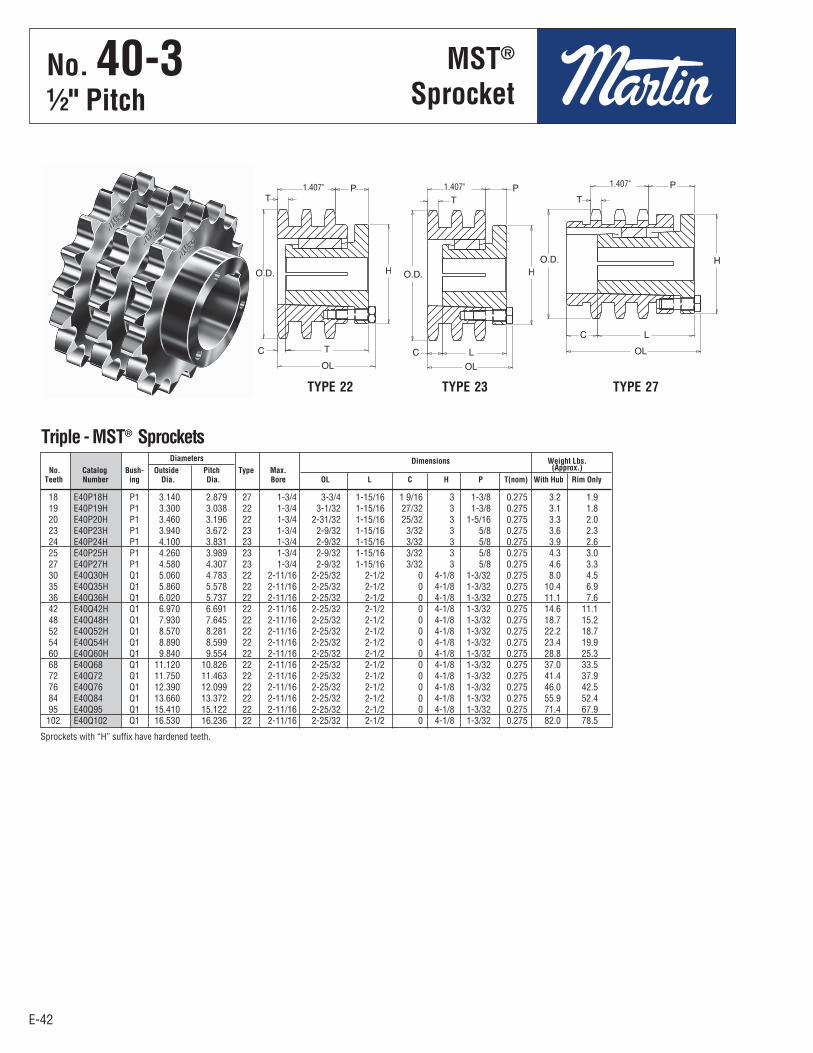
E-42
1.407" 1.407"
E-42
No. 40-31⁄2" Pitch
Triple - MST® Sprockets
1.407"
MST®
Sprockets
Sprockets with “H” suffix have hardened teeth.
Diameters Dimensions Weight Lbs. No. Catalog Bush- Outside Pitch Type Max. (Approx.) Teeth Number ing Dia. Dia. Bore OL L C H P T(nom) With Hub Rim Only
18 E40P18H P1 3.140 2.879 27 1-3/4 3-3/4 1-15/16 1 9/16 3 1-3/8 0.275 3.2 1.9 19 E40P19H P1 3.300 3.038 22 1-3/4 3-1/32 1-15/16 27/32 3 1-3/8 0.275 3.1 1.8 20 E40P20H P1 3.460 3.196 22 1-3/4 2-31/32 1-15/16 25/32 3 1-5/16 0.275 3.3 2.0 23 E40P23H P1 3.940 3.672 23 1-3/4 2-9/32 1-15/16 3/32 3 5/8 0.275 3.6 2.3 24 E40P24H P1 4.100 3.831 23 1-3/4 2-9/32 1-15/16 3/32 3 5/8 0.275 3.9 2.6 25 E40P25H P1 4.260 3.989 23 1-3/4 2-9/32 1-15/16 3/32 3 5/8 0.275 4.3 3.0 27 E40P27H P1 4.580 4.307 23 1-3/4 2-9/32 1-15/16 3/32 3 5/8 0.275 4.6 3.3 30 E40Q30H Q1 5.060 4.783 22 2-11/16 2-25/32 2-1/2 0 4-1/8 1-3/32 0.275 8.0 4.5 35 E40Q35H Q1 5.860 5.578 22 2-11/16 2-25/32 2-1/2 0 4-1/8 1-3/32 0.275 10.4 6.9 36 E40Q36H Q1 6.020 5.737 22 2-11/16 2-25/32 2-1/2 0 4-1/8 1-3/32 0.275 11.1 7.6 42 E40Q42H Q1 6.970 6.691 22 2-11/16 2-25/32 2-1/2 0 4-1/8 1-3/32 0.275 14.6 11.1 48 E40Q48H Q1 7.930 7.645 22 2-11/16 2-25/32 2-1/2 0 4-1/8 1-3/32 0.275 18.7 15.2 52 E40Q52H Q1 8.570 8.281 22 2-11/16 2-25/32 2-1/2 0 4-1/8 1-3/32 0.275 22.2 18.7 54 E40Q54H Q1 8.890 8.599 22 2-11/16 2-25/32 2-1/2 0 4-1/8 1-3/32 0.275 23.4 19.9 60 E40Q60H Q1 9.840 9.554 22 2-11/16 2-25/32 2-1/2 0 4-1/8 1-3/32 0.275 28.8 25.3 68 E40Q68 Q1 11.120 10.826 22 2-11/16 2-25/32 2-1/2 0 4-1/8 1-3/32 0.275 37.0 33.5 72 E40Q72 Q1 11.750 11.463 22 2-11/16 2-25/32 2-1/2 0 4-1/8 1-3/32 0.275 41.4 37.9 76 E40Q76 Q1 12.390 12.099 22 2-11/16 2-25/32 2-1/2 0 4-1/8 1-3/32 0.275 46.0 42.5 84 E40Q84 Q1 13.660 13.372 22 2-11/16 2-25/32 2-1/2 0 4-1/8 1-3/32 0.275 55.9 52.4 95 E40Q95 Q1 15.410 15.122 22 2-11/16 2-25/32 2-1/2 0 4-1/8 1-3/32 0.275 71.4 67.9 102 E40Q102 Q1 16.530 16.236 22 2-11/16 2-25/32 2-1/2 0 4-1/8 1-3/32 0.275 82.0 78.5
TYPE 22 TYPE 23 TYPE 27
No . 40-3½" Pitch
MST®
Sprocket

E-43E-43
No. 505⁄8" Pitch
All SteelStock Sprockets
9 50BS9 2.090 1 0.30 5⁄8 — 3⁄4 10 50BS10 2.300 1 0.30 5⁄8 — 3⁄4 — 7⁄8 — † 1 11 50BS11 2.500 1 0.60 5⁄8 — 3⁄4 — 7⁄8 — 1 12 50BS12 2.710 1 0.70 5⁄8 — 3⁄4 — 7⁄8 — 1 — 11⁄8 — 13⁄16 — 11⁄4 13 50BS13 2.910 1 0.80 5⁄8 — 3⁄4 — 7⁄8 — 1 — 11⁄8 — 13⁄16 — 11⁄4 14 50BS14 3.110 1 1.00 5⁄8 — 3⁄4 — 7⁄8 — 1 — 11⁄8 — 13⁄16 — 11⁄4 15 50BS15 3.320 1 1.20 5⁄8 — 3⁄4 — 7⁄8 — 1 — 11⁄8 — 13⁄16 — 11⁄4 — 13⁄8 — 17⁄16 — 11⁄2 16 50BS16 3.520 1 1.45 5⁄8 — 3⁄4 — 7⁄8 — 1 — 11⁄8 — 13⁄16 — 11⁄4 — 13⁄8 — 17⁄16 — 11⁄2 — 15⁄8 17 50BS17 3.720 1 1.60 5⁄8 — 3⁄4 — 7⁄8 — 1 — 11⁄8 — 13⁄16 — 11⁄4 — 13⁄8 — 17⁄16 — 11⁄2 — 15⁄8 18 50BS18 3.920 1 1.90 5⁄8 — 3⁄4 — 7⁄8 — 1 — 11⁄8 — 13⁄16 — 11⁄4 — 13⁄8 — 17⁄16 — 11⁄2 — 15⁄8 19 50BS19 4.120 1 2.00 5⁄8 — 3⁄4 — 7⁄8 — 1 — 11⁄8 — 13⁄16 — 11⁄4 — 13⁄8 — 17⁄16 — 11⁄2 — 15⁄8 20 50BS20 4.320 1 2.10 3⁄4 — 7⁄8 — 1 — 11⁄8 — 13⁄16 — 11⁄4 — 13⁄8 — 17⁄16 — 11⁄2 — 15⁄8 21 50BS21 4.520 1 2.25 3⁄4 — 7⁄8 — 1 — 11⁄8 — 13⁄16 — 11⁄4 — 13⁄8 — 17⁄16 — 11⁄2 22 50BS22 4.720 1 2.40 3⁄4 — 7⁄8 — 1 — 11⁄8 — 13⁄16 — 11⁄4 — 13⁄8 — 17⁄16 — 11⁄2 23 50BS23 4.920 1 2.50 3⁄4 — 7⁄8 — 1 — 11⁄8 — 13⁄16 — 11⁄4 — 13⁄8 — 17⁄16 — 11⁄2 24 50BS24 5.120 11⁄4 3.00 3⁄4 — 7⁄8 — 1 — 11⁄8 — 13⁄16 — 11⁄4 — 13⁄8 — 17⁄16 — 11⁄2 25 50BS25 5.320 11⁄4 3.10 3⁄4 — 7⁄8 — 1 — 11⁄8 — 13⁄16 — 11⁄4 — 13⁄8 — 17⁄16 — 11⁄2 26 50BS26 5.520 11⁄4 3.30 3⁄4 — 7⁄8 — 1 — 11⁄8 — 13⁄16 — 11⁄4 — 13⁄8 — 17⁄16 — 11⁄2 27 50BS27 5.720 11⁄4 3.46 3⁄4 — 7⁄8 — 1 — 11⁄8 — 13⁄16 — 11⁄4 — 13⁄8 — 17⁄16 — 11⁄2 28 50BS28 5.920 11⁄4 3.60 3⁄4 — 7⁄8 — 1 — 11⁄8 — 13⁄16 — 11⁄4 — 13⁄8 — 17⁄16 — 11⁄2 29 50BS29 6.120 11⁄4 3.78 3⁄4 — 7⁄8 — 1 — 11⁄8 — 13⁄16 — 11⁄4 — 13⁄8 — 17⁄16 — 11⁄2 30 50BS30 6.320 11⁄4 3.90 3⁄4 — 7⁄8 — 1 — 11⁄8 — 13⁄16 — 11⁄4 — 13⁄8 — 17⁄16 — 11⁄2 31 50BS31 6.520 11⁄4 4.46 3⁄4 — 7⁄8 — 1 — 11⁄8 — 13⁄16 — 11⁄4 — 13⁄8 — 17⁄16 — 11⁄2 — — 13⁄4 — 115⁄16
32 50BS32 6.720 11⁄4 4.70 3⁄4 — 7⁄8 — 1 — 11⁄8 — 13⁄16 — 11⁄4 — 13⁄8 — 17⁄16 — 11⁄2 — — 13⁄4 — 115⁄16
33 50BS33 6.920 11⁄4 4.92 3⁄4 — 7⁄8 — 1 — 11⁄8 — 13⁄16 — 11⁄4 — 13⁄8 — 17⁄16 — 11⁄2 — — 13⁄4 — 115⁄16
34 50BS34 7.120 11⁄4 5.06 3⁄4 — 7⁄8 — 1 — 11⁄8 — 13⁄16 — 11⁄4 — 13⁄8 — 17⁄16 — 11⁄2 — — 13⁄4 — 115⁄16
35 50BS35 7.320 11⁄4 5.30 3⁄4 — 7⁄8 — 1 — 11⁄8 — 13⁄16 — 11⁄4 — 13⁄8 — 17⁄16 — 11⁄2 — — 13⁄4 — 115⁄16
36 50BS36 7.520 11⁄4 5.50 3⁄4 — 7⁄8 — 1 — 11⁄8 — 13⁄16 — 11⁄4 — 13⁄8 — 17⁄16 — 11⁄2 — — 13⁄4 — 115⁄16
37 50BS37 7.720 11⁄4 5.62 3⁄4 — 7⁄8 — 1 — 11⁄8 — 13⁄16 — 11⁄4 — 13⁄8 — 17⁄16 — 11⁄2 — — 13⁄4 — 115⁄16
38 50BS38 7.920 11⁄4 5.80 3⁄4 — 7⁄8 — 1 — 11⁄8 — 13⁄16 — 11⁄4 — 13⁄8 — 17⁄16 — 11⁄2 — — 13⁄4 — 115⁄16
39 50BS39 8.120 11⁄4 6.02 3⁄4 — 7⁄8 — 1 — 11⁄8 — 13⁄16 — 11⁄4 — 13⁄8 — 17⁄16 — 11⁄2 — — 13⁄4 — 115⁄16
40 50BS40 8.320 11⁄4 6.20 3⁄4 — 7⁄8 — 1 — 11⁄8 — 13⁄16 — 11⁄4 — 13⁄8 — 17⁄16 — 11⁄2 — — 13⁄4 — 115⁄16
41 50BS41 8.520 11⁄4 6.45 3⁄4 — 7⁄8 — 1 — 11⁄8 — 13⁄16 — 11⁄4 — 13⁄8 — 17⁄16 — 11⁄2 — — 13⁄4 — 115⁄16
42 50BS42 8.720 11⁄4 6.68 3⁄4 — 7⁄8 — 1 — 11⁄8 — 13⁄16 — 11⁄4 — 13⁄8 — 17⁄16 — 11⁄2 — — 13⁄4 — 115⁄16
43 50BS43 8.910 11⁄4 6.99 3⁄4 — 7⁄8 — 1 — 11⁄8 — 13⁄16 — 11⁄4 — 13⁄8 — 17⁄16 — 11⁄2 — — 13⁄4 — 115⁄16
44 50BS44 9.110 11⁄4 7.30 3⁄4 — 7⁄8 — 1 — 11⁄8 — 13⁄16 — 11⁄4 — 13⁄8 — 17⁄16 — 11⁄2 — — 13⁄4 — 115⁄16
45 50BS45 9.310 11⁄4 8.00 3⁄4 — 7⁄8 — 1 — 11⁄8 — 13⁄16 — 11⁄4 — 13⁄8 — 17⁄16 — 11⁄2 — — 13⁄4 — 115⁄16
46 50BS46 9.510 11⁄4 8.51 1 — 11⁄8 — 13⁄16 — 11⁄4 — 13⁄8 — 17⁄16 — 11⁄2 — — 13⁄4 — 115⁄16
47 50BS47 9.710 11⁄4 8.76 1 — 11⁄8 — 13⁄16 — 11⁄4 — 13⁄8 — 17⁄16 — 11⁄2 — — 13⁄4 — 115⁄16
48 50BS48 9.910 11⁄4 9.03 1 — 11⁄8 — 13⁄16 — 11⁄4 — 13⁄8 — 17⁄16 — 11⁄2 — — 13⁄4 — 115⁄16
49 50BS49 10.110 11⁄4 9.33 1 — 11⁄8 — 13⁄16 — 11⁄4 — 13⁄8 — 17⁄16 — 11⁄2 — — 13⁄4 — 115⁄16
50 50BS50 10.310 11⁄4 9.63 1 — 11⁄8 — 13⁄16 — 11⁄4 — 13⁄8 — 17⁄16 — 11⁄2 — — 13⁄4 — 115⁄16
51 50BS51 10.510 11⁄4 9.81 1 — 11⁄8 — 13⁄16 — 11⁄4 — 13⁄8 — 17⁄16 — 11⁄2 — — 13⁄4 — 115⁄16
52 50BS52 10.710 11⁄4 9.99 1 — 11⁄8 — 13⁄16 — 11⁄4 — 13⁄8 — 17⁄16 — 11⁄2 — — 13⁄4 — 115⁄16
53 50BS53 10.910 11⁄4 10.37 1 — 11⁄8 — 13⁄16 — 11⁄4 — 13⁄8 — 17⁄16 — 11⁄2 — — 13⁄4 — 115⁄16
54 50BS54 11.110 11⁄4 10.75 1 — 11⁄8 — 13⁄16 — 11⁄4 — 13⁄8 — 17⁄16 — 11⁄2 — — 13⁄4 — 115⁄16
55 50BS55 11.310 11⁄4 11.08 1 — 11⁄8 — 13⁄16 — 11⁄4 — 13⁄8 — 17⁄16 — 11⁄2 — — 13⁄4 — 115⁄16
56 50BS56 11.500 11⁄4 11.41 1 — 11⁄8 — 13⁄16 — 11⁄4 — 13⁄8 — 17⁄16 — 11⁄2 — — 13⁄4 — 115⁄16
57 50BS57 11.700 11⁄4 11.75 1 — 11⁄8 — 13⁄16 — 11⁄4 — 13⁄8 — 17⁄16 — 11⁄2 — — 13⁄4 — 115⁄16
58 50BS58 11.900 11⁄4 12.08 1 — 11⁄8 — 13⁄16 — 11⁄4 — 13⁄8 — 17⁄16 — 11⁄2 — — 13⁄4 — 115⁄16
59 50BS59 12.100 11⁄4 12.41 1 — 11⁄8 — 13⁄16 — 11⁄4 — 13⁄8 — 17⁄16 — 11⁄2 — — 13⁄4 — 115⁄16
60 50BS60 12.300 11⁄4 13.50 1 — 11⁄8 — 13⁄16 — 11⁄4 — 13⁄8 — 17⁄16 — 11⁄2 — — 13⁄4 — 115⁄16
70 50BS70 14.290 13⁄4 17.81 1 — 11⁄8 — 13⁄16 — 11⁄4 — 13⁄8 — 17⁄16 — 11⁄2 — — 13⁄4 — 115⁄16
72 50BS72 14.690 13⁄4 19.13 1 — 11⁄8 — 13⁄16 — 11⁄4 — 13⁄8 — 17⁄16 — 11⁄2 — — 13⁄4 — 115⁄16
80 50BS80 16.280 13⁄4 24.39 1 — 11⁄8 — 13⁄16 — 11⁄4 — 13⁄8 — 17⁄16 — 11⁄2 — — 13⁄4 — 115⁄16
84 50BS84 17.080 13⁄4 25.15 1 — 11⁄8 — 13⁄16 — 11⁄4 — 13⁄8 — 17⁄16 — 11⁄2 — — 13⁄4 — 115⁄16
96 50BS96 19.470 13⁄4 32.57 1 — 11⁄8 — 13⁄16 — 11⁄4 — 13⁄8 — 17⁄16 — 11⁄2 — — 13⁄4 — 115⁄16
112 50BS112 22.650 13⁄4 41.65 1 — 11⁄8 — 13⁄16 — 11⁄4 — 13⁄8 — 17⁄16 — 11⁄2 — — 13⁄4 — 115⁄1
Length Weight Stock Finished Bores No. Catalog Outside Thru Lbs. Includes Keyway Teeth Number Diameter Bore (Approx.) and 2 Setscrews
Single Type BS — 2 Setscrews — Bored-To-Size
† Keyway with Setscrew at 90°.Hub diameters vary to suit different bore sizes.KEYWAY IS ON CENTER LINE OF TOOTH.
No . 505⁄8" Pitch
All SteelStock Sprockets
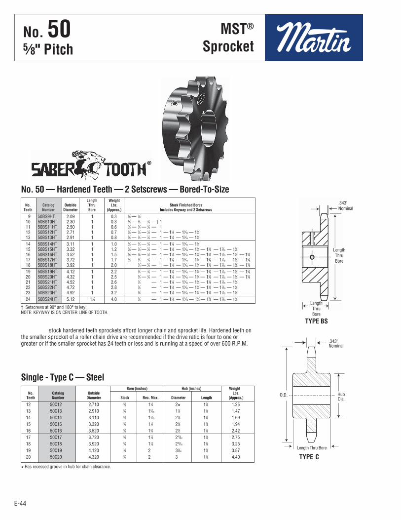
E-44
TYPE BS
12 50C12 2.710 5⁄8 11⁄4 2H 15⁄8 1.25 13 50C13 2.910 5⁄8 15⁄16 17⁄8 15⁄8 1.47 14 50C14 3.110 5⁄8 17⁄16 21⁄8 15⁄8 1.69 15 50C15 3.320 5⁄8 11⁄2 23⁄8 15⁄8 1.94 16 50C16 3.520 5⁄8 13⁄4 21⁄2 15⁄8 2.42 17 50C17 3.720 5⁄8 17⁄8 247⁄64 15⁄8 2.75 18 50C18 3.920 5⁄8 17⁄8 215⁄16 15⁄8 3.25 19 50C19 4.120 3⁄4 2 35⁄64 15⁄8 3.87 20 50C20 4.320 3⁄4 2 3 15⁄8 4.40
E-44
No. 505⁄8" Pitch
All SteelStock Sprockets
9 50BS9HT 2.09 1 0.3 5⁄8 — 3⁄4 10 50BS10HT 2.30 1 0.3 5⁄8 — 3⁄4 — 7⁄8 —† 1 11 50BS11HT 2.50 1 0.6 5⁄8 — 3⁄4 — 7⁄8 — 1 12 50BS12HT 2.71 1 0.7 5⁄8 — 3⁄4 — 7⁄8 — 1 — 11⁄8 — 13⁄16 — 11⁄4 13 50BS13HT 2.91 1 0.8 5⁄8 — 3⁄4 — 7⁄8 — 1 — 11⁄8 — 13⁄16 — 11⁄4 14 50BS14HT 3.11 1 1.0 5⁄8 — 3⁄4 — 7⁄8 — 1 — 11⁄8 — 13⁄16 — 11⁄4 15 50BS15HT 3.32 1 1.2 5⁄8 — 3⁄4 — 7⁄8 — 1 — 11⁄8 — 13⁄16 — 11⁄4 — 13⁄8 — 17⁄16 — 11⁄2 16 50BS16HT 3.52 1 1.5 5⁄8 — 3⁄4 — 7⁄8 — 1 — 11⁄8 — 13⁄16 — 11⁄4 — 13⁄8 — 17⁄16 — 11⁄2 — 15⁄8 17 50BS17HT 3.72 1 1.7 5⁄8 — 3⁄4 — 7⁄8 — 1 — 11⁄8 — 13⁄16 — 11⁄4 — 13⁄8 — 17⁄16 — 11⁄2 — 15⁄8 18 50BS18HT 3.92 1 2.0 3⁄4 — 7⁄8 — 1 — 11⁄8 — 13⁄16 — 11⁄4 — 13⁄8 — 17⁄16 — 11⁄2 — 15⁄8 19 50BS19HT 4.12 1 2.2 3⁄4 — 7⁄8 — 1 — 11⁄8 — 13⁄16 — 11⁄4 — 13⁄8 — 17⁄16 — 11⁄2 — 15⁄8 20 50BS20HT 4.32 1 2.5 3⁄4 — 7⁄8 — 1 — 11⁄8 — 13⁄16 — 11⁄4 — 13⁄8 — 17⁄16 — 11⁄2 — 15⁄8 21 50BS21HT 4.52 1 2.6 3⁄4 — 7⁄8 — 1 — 11⁄8 — 13⁄16 — 11⁄4 — 13⁄8 — 17⁄16 — 11⁄2 22 50BS22HT 4.72 1 2.8 3⁄4 — 7⁄8 — 1 — 11⁄8 — 13⁄16 — 11⁄4 — 13⁄8 — 17⁄16 — 11⁄2 23 50BS23HT 4.92 1 3.2 3⁄4 — 7⁄8 — 1 — 11⁄8 — 13⁄16 — 11⁄4 — 13⁄8 — 17⁄16 — 11⁄2 24 50BS24HT 5.12 11⁄4 4.0 3⁄4 — 7⁄8 — 1 — 11⁄8 — 13⁄16 — 11⁄4 — 13⁄8 — 17⁄16 — 11⁄2
Length Weight No. Catalog Outside Thru Lbs. Stock Finished Bores Teeth Number Diameter Bore (Approx.) Includes Keyway and 2 Setscrews
No. 50 — Hardened Teeth — 2 Setscrews — Bored-To-Size
† Setscrews at 90° and 180° to key.NOTE: KEYWAY IS ON CENTER LINE OF TOOTH.
stock hardened teeth sprockets afford longer chain and sprocket life. Hardened teeth onthe smaller sprocket of a roller chain drive are recommended if the drive ratio is four to one orgreater or if the smaller sprocket has 24 teeth or less and is running at a speed of over 600 R.P.M.
Single - Type C — Steel
TYPE CH Has recessed groove in hub for chain clearance.
.343"Nominal
HubDia.
Bore (inches) Hub (inches) Weight No. Catalog Outside Lbs. Teeth Number Diameter Stock Rec. Max. Diameter Length (Approx.)
.343"Nominal
LengthThruBore
O.D.
LengthThruBore
Length Thru Bore
No . 505⁄8" Pitch
MST®
Sprocket

E-45E-45
No. 505/8" Pitch
All SteelStock Sprockets
15 DS50A15 3.320 3.006 A 5⁄8 11⁄2 121⁄32 15⁄16 23⁄8 0.343 2.1 16 DS50A16 3.520 3.204 A 5⁄8 111⁄16 121⁄32 15⁄16 231⁄64 0.343 2.4 17 DS50A17 3.720 3.401 A 5⁄8 13⁄4 121⁄32 15⁄16 211⁄16 0.343 2.9 18 DS50A18 3.920 3.599 A 5⁄8 17⁄8 121⁄32 15⁄16 257⁄64 0.343 3.3 19 DS50A19 4.120 3.797 A 5⁄8 21⁄16 121⁄32 15⁄16 35⁄64 0.343 3.7 20 DS50A20 4.320 3.995 A 5⁄8 21⁄4 121⁄32 15⁄16 39⁄32 0.343 4.2 21 DS50A21 4.520 4.194 A 5⁄8 21⁄4 121⁄32 15⁄16 331⁄64 0.343 4.8 22 DS50A22 4.720 4.392 A 5⁄8 27⁄16 121⁄32 15⁄16 311⁄16 0.343 5.3 23 DS50A23 4.920 4.590 A 5⁄8 25⁄8 121⁄32 15⁄16 357⁄64 0.343 5.8 24 DS50A24 5.120 4.788 A 5⁄8 23⁄4 121⁄32 15⁄16 45⁄64 0.343 6.3
16 DS50ATB16H 1215 3.520 3.204 1⁄2 15⁄8 A 121⁄32 15⁄16 2 31⁄64 11⁄2 0.343 1.5 17 DS50ATB17H 1615 3.720 3.401 1⁄2 15⁄8 A 121⁄32 15⁄16 211⁄16 11⁄2 0.343 1.8 18 DS50ATB18H 1615 3.920 3.599 1⁄2 15⁄8 A 121⁄32 15⁄16 257⁄64 11⁄2 0.343 2.2 19 DS50ATB19H 1615 4.120 3.797 1⁄2 15⁄8 A 121⁄32 15⁄16 35⁄64 11⁄2 0.343 2.7 20 DS50ATB20H 1615 4.320 3.995 1⁄2 15⁄8 A 121⁄32 15⁄16 3 9⁄32 11⁄2 0.343 5.0 21 DS50ATB21H 2012 4.520 4.194 1⁄2 2 A 121⁄32 15⁄16 331⁄64 11⁄4 0.343 3.3 23 DS50ATB23H 2012 4.920 4.590 1⁄2 2 A 121⁄32 15⁄16 357⁄64 11⁄4 0.343 3.7 24 DS50ATB24H 2012 5.120 4.788 1⁄2 2 A 121⁄32 15⁄16 45⁄64 11⁄4 0.343 4.1
Diameters Dimensions No. Catalog Outside Pitch Min. Max. w Wt. Lbs. Teeth Number Diameter Diameter Type Bore Bore L C E Nom. (Approx.)
Double Single - Type A — Steel
Diameters Dimensions Wt. No. Catalog Bushing Outside Pitch Min. Max. w Rim Teeth Number Size Diameter Diameter Bore Bore Type L
1 C E L
2 Nom. Only
Double Single - Taper Bushed — Steel
TAPER BUSHTYPE A
TYPE A
17 DS50H17H H 3.720 3.401 3⁄8 11⁄2 BH 121⁄32 15⁄16 211⁄16 29⁄32 0.343 2.3 19 DS50P19H P1 4.120 3.797 1⁄2 13⁄4 B 121⁄32 15⁄16 35⁄64 217⁄32 0.343 2.8 21 DS50P21H P1 4.520 4.194 1⁄2 13⁄4 B 121⁄32 15⁄16 331⁄64 217⁄32 0.343 3.8 23 DS50P23H P1 4.920 4.590 1⁄2 13⁄4 B 121⁄32 15⁄16 357⁄64 217⁄32 0.343 4.6 24 DS50P24H P1 5.120 4.788 1⁄2 13⁄4 B 121⁄32 15⁄16 45⁄64 217⁄32 0.343 5.0
Diameters Dimensions Wt. No. Catalog Bushing Outside Pitch Min. Max. w Rim Teeth Number Size Diameter Diameter Bore Bore Type L
1 C E L
2 Nom. Only
Double Single- MST®— Steel
MSTTYPE B
Sprockets with “H” suffix have hardened teeth.
Sprockets with “H” suffix have hardened teeth.
No . 505⁄8" Pitch
All SteelStock Sprockets
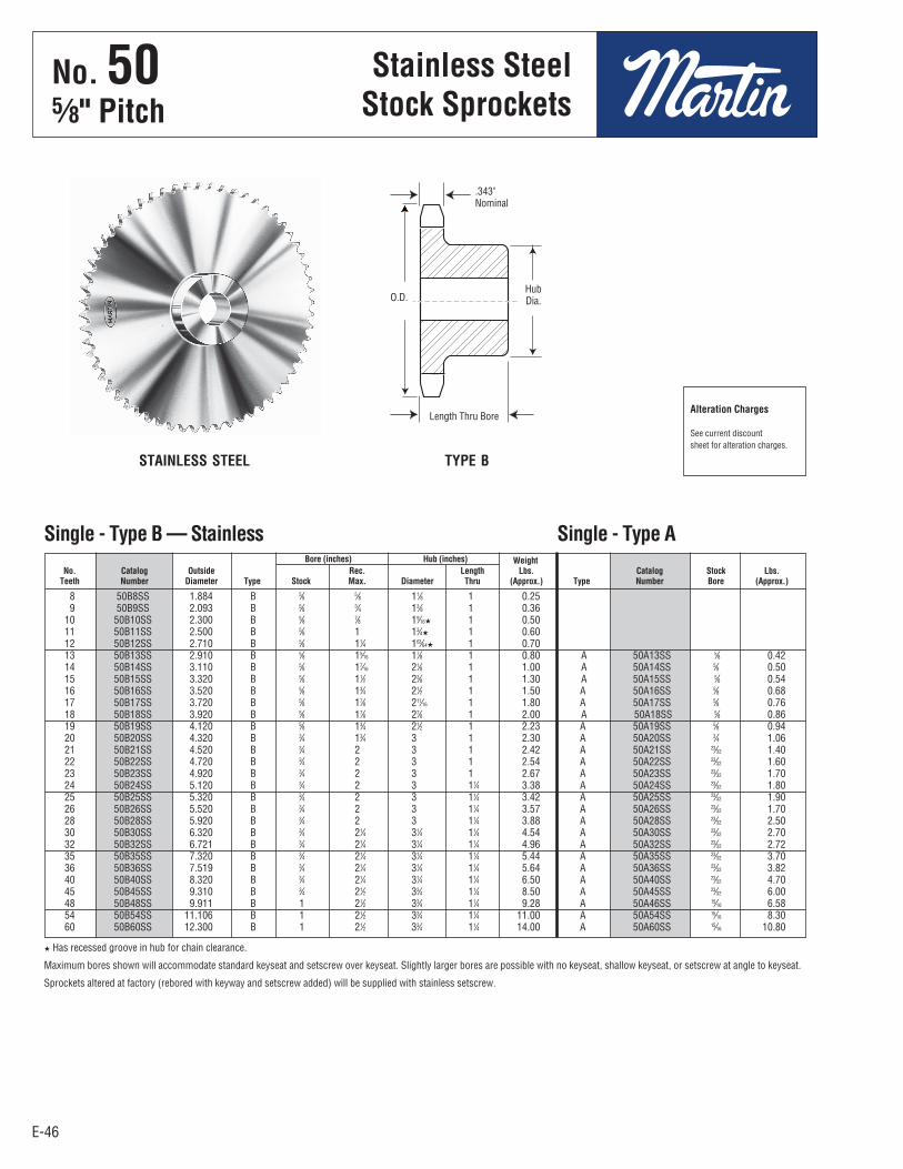
E-46
8 50B8SS 1.884 B 5⁄8 5⁄8 11⁄8 1 0.25 9 50B9SS 2.093 B 5⁄8 3⁄4 13⁄8 1 0.36 10 50B10SS 2.300 B 5⁄8 7⁄8 19⁄16H 1 0.50 11 50B11SS 2.500 B 5⁄8 1 13⁄4H 1 0.60 12 50B12SS 2.710 B 5⁄8 11⁄4 163⁄64H 1 0.70 13 50B13SS 2.910 B 5⁄8 15⁄16 17⁄8 1 0.80 A 50A13SS 5⁄8 0.42 14 50B14SS 3.110 B 5⁄8 17⁄16 21⁄8 1 1.00 A 50A14SS 5⁄8 0.50 15 50B15SS 3.320 B 5⁄8 11⁄2 23⁄8 1 1.30 A 50A15SS 5⁄8 0.54 16 50B16SS 3.520 B 5⁄8 13⁄4 21⁄2 1 1.50 A 50A16SS 5⁄8 0.68 17 50B17SS 3.720 B 5⁄8 17⁄8 211⁄16 1 1.80 A 50A17SS 5⁄8 0.76 18 50B18SS 3.920 B 5⁄8 17⁄8 27⁄8 1 2.00 A 50A18SS 5⁄8 0.86 19 50B19SS 4.120 B 5⁄8 13⁄4 21⁄2 1 2.23 A 50A19SS 5⁄8 0.94 20 50B20SS 4.320 B 3⁄4 13⁄4 3 1 2.30 A 50A20SS 3⁄4 1.06 21 50B21SS 4.520 B 3⁄4 2 3 1 2.42 A 50A21SS 23⁄32 1.40 22 50B22SS 4.720 B 3⁄4 2 3 1 2.54 A 50A22SS 23⁄32 1.60 23 50B23SS 4.920 B 3⁄4 2 3 1 2.67 A 50A23SS 23⁄32 1.70 24 50B24SS 5.120 B 3⁄4 2 3 11⁄4 3.38 A 50A24SS 23⁄32 1.80 25 50B25SS 5.320 B 3⁄4 2 3 11⁄4 3.42 A 50A25SS 23⁄32 1.90 26 50B26SS 5.520 B 3⁄4 2 3 11⁄4 3.57 A 50A26SS 23⁄32 1.70 28 50B28SS 5.920 B 3⁄4 2 3 11⁄4 3.88 A 50A28SS 23⁄32 2.50 30 50B30SS 6.320 B 3⁄4 21⁄4 31⁄4 11⁄4 4.54 A 50A30SS 23⁄32 2.70 32 50B32SS 6.721 B 3⁄4 21⁄4 31⁄4 11⁄4 4.96 A 50A32SS 23⁄32 2.72 35 50B35SS 7.320 B 3⁄4 21⁄4 31⁄4 11⁄4 5.44 A 50A35SS 23⁄32 3.70 36 50B36SS 7.519 B 3⁄4 21⁄4 31⁄4 11⁄4 5.64 A 50A36SS 23⁄32 3.82 40 50B40SS 8.320 B 3⁄4 21⁄4 31⁄4 11⁄4 6.50 A 50A40SS 23⁄32 4.70 45 50B45SS 9.310 B 3⁄4 21⁄2 33⁄4 11⁄4 8.50 A 50A45SS 23⁄32 6.00 48 50B48SS 9.911 B 1 21⁄2 33⁄4 11⁄4 9.28 A 50A46SS 15⁄16 6.58 54 50B54SS 11.106 B 1 21⁄2 33⁄4 11⁄4 11.00 A 50A54SS 15⁄16 8.30 60 50B60SS 12.300 B 1 21⁄2 33⁄4 11⁄4 14.00 A 50A60SS 15⁄16 10.80
E-46
No. 505⁄8" Pitch
Stainless SteelStock Sprockets
Bore (inches) Hub (inches) Weight No. Catalog Outside Rec. Length Lbs. Catalog Stock Lbs. Teeth Number Diameter Type Stock Max. Diameter Thru (Approx.) Type Number Bore (Approx.)
Single - Type B — Stainless Single - Type A
STAINLESS STEEL TYPE B
H Has recessed groove in hub for chain clearance.
Maximum bores shown will accommodate standard keyseat and setscrew over keyseat. Slightly larger bores are possible with no keyseat, shallow keyseat, or setscrew at angle to keyseat.
Sprockets altered at factory (rebored with keyway and setscrew added) will be supplied with stainless setscrew.
Alteration Charges
See current discountsheet for alteration charges.
.343"Nominal
HubDia.
Length Thru Bore
O.D.
No . 505⁄8" Pitch
Stainless SteelStock Sprockets
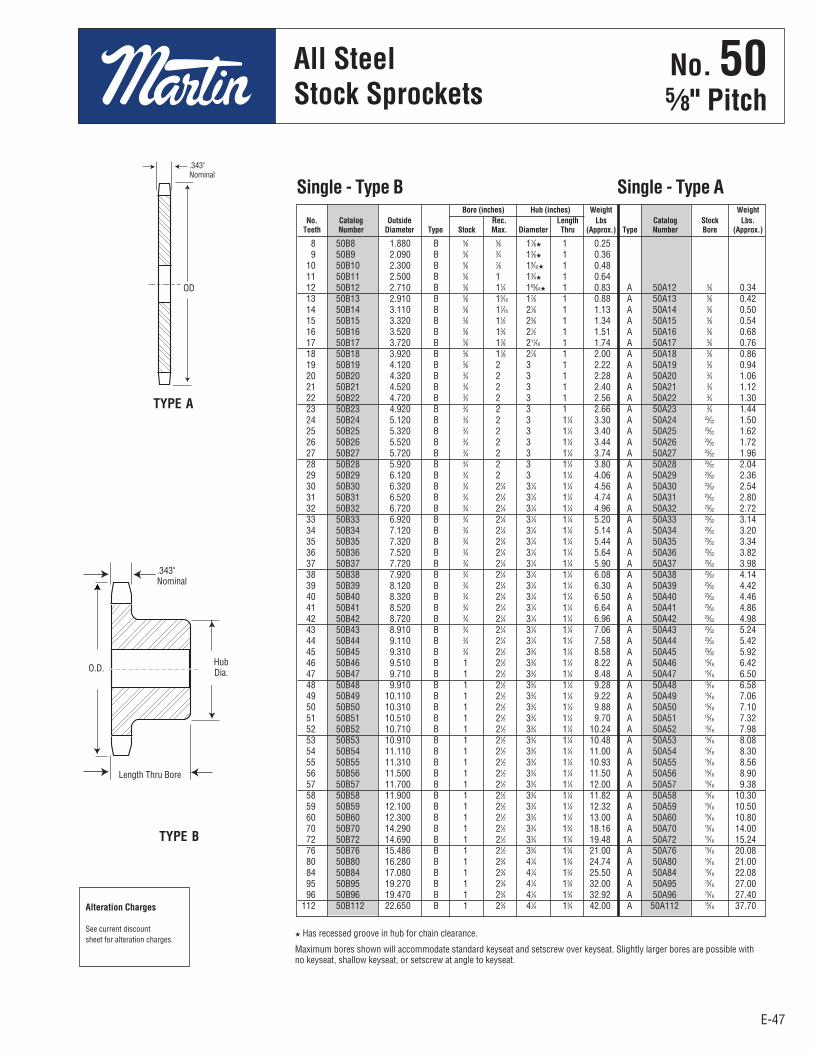
E-47E-47
No. 505/8" Pitch
8 50B8 1.880 B 5⁄8 5⁄8 11⁄8H 1 0.25 9 50B9 2.090 B 5⁄8 3⁄4 13⁄8H 1 0.36 10 50B10 2.300 B 5⁄8 7⁄8 19⁄16H 1 0.48 11 50B11 2.500 B 5⁄8 1 13⁄4H 1 0.64 12 50B12 2.710 B 5⁄8 11⁄4 163⁄64H 1 0.83 A 50A12 5⁄8 0.34 13 50B13 2.910 B 5⁄8 15⁄16 17⁄8 1 0.88 A 50A13 5⁄8 0.42 14 50B14 3.110 B 5⁄8 17⁄16 21⁄8 1 1.13 A 50A14 5⁄8 0.50 15 50B15 3.320 B 5⁄8 11⁄2 23⁄8 1 1.34 A 50A15 5⁄8 0.54 16 50B16 3.520 B 5⁄8 13⁄4 21⁄2 1 1.51 A 50A16 5⁄8 0.68 17 50B17 3.720 B 5⁄8 17⁄8 211⁄16 1 1.74 A 50A17 5⁄8 0.76 18 50B18 3.920 B 5⁄8 17⁄8 27⁄8 1 2.00 A 50A18 5⁄8 0.86 19 50B19 4.120 B 5⁄8 2 3 1 2.22 A 50A19 5⁄8 0.94 20 50B20 4.320 B 3⁄4 2 3 1 2.28 A 50A20 3⁄4 1.06 21 50B21 4.520 B 3⁄4 2 3 1 2.40 A 50A21 3⁄4 1.12 22 50B22 4.720 B 3⁄4 2 3 1 2.56 A 50A22 3⁄4 1.30 23 50B23 4.920 B 3⁄4 2 3 1 2.66 A 50A23 3⁄4 1.44 24 50B24 5.120 B 3⁄4 2 3 11⁄4 3.30 A 50A24 23⁄32 1.50 25 50B25 5.320 B 3⁄4 2 3 11⁄4 3.40 A 50A25 23⁄32 1.62 26 50B26 5.520 B 3⁄4 2 3 11⁄4 3.44 A 50A26 23⁄32 1.72 27 50B27 5.720 B 3⁄4 2 3 11⁄4 3.74 A 50A27 23⁄32 1.96 28 50B28 5.920 B 3⁄4 2 3 11⁄4 3.80 A 50A28 23⁄32 2.04 29 50B29 6.120 B 3⁄4 2 3 11⁄4 4.06 A 50A29 23⁄32 2.36 30 50B30 6.320 B 3⁄4 21⁄4 31⁄4 11⁄4 4.56 A 50A30 23⁄32 2.54 31 50B31 6.520 B 3⁄4 21⁄4 31⁄4 11⁄4 4.74 A 50A31 23⁄32 2.80 32 50B32 6.720 B 3⁄4 21⁄4 31⁄4 11⁄4 4.96 A 50A32 23⁄32 2.72 33 50B33 6.920 B 3⁄4 21⁄4 31⁄4 11⁄4 5.20 A 50A33 23⁄32 3.14 34 50B34 7.120 B 3⁄4 21⁄4 31⁄4 11⁄4 5.14 A 50A34 23⁄32 3.20 35 50B35 7.320 B 3⁄4 21⁄4 31⁄4 11⁄4 5.44 A 50A35 23⁄32 3.34 36 50B36 7.520 B 3⁄4 21⁄4 31⁄4 11⁄4 5.64 A 50A36 23⁄32 3.82 37 50B37 7.720 B 3⁄4 21⁄4 31⁄4 11⁄4 5.90 A 50A37 23⁄32 3.98 38 50B38 7.920 B 3⁄4 21⁄4 31⁄4 11⁄4 6.08 A 50A38 23⁄32 4.14 39 50B39 8.120 B 3⁄4 21⁄4 31⁄4 11⁄4 6.30 A 50A39 23⁄32 4.42 40 50B40 8.320 B 3⁄4 21⁄4 31⁄4 11⁄4 6.50 A 50A40 23⁄32 4.46 41 50B41 8.520 B 3⁄4 21⁄4 31⁄4 11⁄4 6.64 A 50A41 23⁄32 4.86 42 50B42 8.720 B 3⁄4 21⁄4 31⁄4 11⁄4 6.96 A 50A42 23⁄32 4.98 43 50B43 8.910 B 3⁄4 21⁄4 31⁄4 11⁄4 7.06 A 50A43 23⁄32 5.24 44 50B44 9.110 B 3⁄4 21⁄4 31⁄4 11⁄4 7.58 A 50A44 23⁄32 5.42 45 50B45 9.310 B 3⁄4 21⁄2 33⁄4 11⁄4 8.58 A 50A45 23⁄32 5.92 46 50B46 9.510 B 1 21⁄2 33⁄4 11⁄4 8.22 A 50A46 15⁄16 6.42 47 50B47 9.710 B 1 21⁄2 33⁄4 11⁄4 8.48 A 50A47 15⁄16 6.50 48 50B48 9.910 B 1 21⁄2 33⁄4 11⁄4 9.28 A 50A48 15⁄16 6.58 49 50B49 10.110 B 1 21⁄2 33⁄4 11⁄4 9.22 A 50A49 15⁄16 7.06 50 50B50 10.310 B 1 21⁄2 33⁄4 11⁄4 9.88 A 50A50 15⁄16 7.10 51 50B51 10.510 B 1 21⁄2 33⁄4 11⁄4 9.70 A 50A51 15⁄16 7.32 52 50B52 10.710 B 1 21⁄2 33⁄4 11⁄4 10.24 A 50A52 15⁄16 7.98 53 50B53 10.910 B 1 21⁄2 33⁄4 11⁄4 10.48 A 50A53 15⁄16 8.08 54 50B54 11.110 B 1 21⁄2 33⁄4 11⁄4 11.00 A 50A54 15⁄16 8.30 55 50B55 11.310 B 1 21⁄2 33⁄4 11⁄4 10.93 A 50A55 15⁄16 8.56 56 50B56 11.500 B 1 21⁄2 33⁄4 11⁄4 11.50 A 50A56 15⁄16 8.90 57 50B57 11.700 B 1 21⁄2 33⁄4 11⁄4 12.00 A 50A57 15⁄16 9.38 58 50B58 11.900 B 1 21⁄2 33⁄4 11⁄4 11.82 A 50A58 15⁄16 10.30 59 50B59 12.100 B 1 21⁄2 33⁄4 11⁄4 12.32 A 50A59 15⁄16 10.50 60 50B60 12.300 B 1 21⁄2 33⁄4 11⁄4 13.00 A 50A60 15⁄16 10.80 70 50B70 14.290 B 1 21⁄2 33⁄4 13⁄4 18.16 A 50A70 15⁄16 14.00 72 50B72 14.690 B 1 21⁄2 33⁄4 13⁄4 19.48 A 50A72 15⁄16 15.24 76 50B76 15.486 B 1 21⁄2 33⁄4 13⁄4 21.00 A 50A76 15⁄16 20.08 80 50B80 16.280 B 1 23⁄4 41⁄4 13⁄4 24.74 A 50A80 15⁄16 21.00 84 50B84 17.080 B 1 23⁄4 41⁄4 13⁄4 25.50 A 50A84 15⁄16 22.08 95 50B95 19.270 B 1 23⁄4 41⁄4 13⁄4 32.00 A 50A95 15⁄16 27.00 96 50B96 19.470 B 1 23⁄4 41⁄4 13⁄4 32.92 A 50A96 15⁄16 27.40 112 50B112 22.650 B 1 23⁄4 41⁄4 13⁄4 42.00 A 50A112 15⁄16 37.70
All SteelStock Sprockets
Bore (inches) Hub (inches) Weight Weight No. Catalog Outside Rec. Length Lbs Catalog Stock Lbs. Teeth Number Diameter Type Stock Max. Diameter Thru (Approx.) Type Number Bore (Approx.)
Single - Type B Single - Type A
H Has recessed groove in hub for chain clearance.
Maximum bores shown will accommodate standard keyseat and setscrew over keyseat. Slightly larger bores are possible withno keyseat, shallow keyseat, or setscrew at angle to keyseat.
Alteration Charges
See current discountsheet for alteration charges.
TYPE A
TYPE B
.343"Nominal
.343"Nominal
HubDia.
Length Thru Bore
OD
O.D.
No . 505⁄8" Pitch
All SteelStock Sprockets

E-48
12 50JA12H
13 50JA13H
14 50JA14H
15 50JA15H
16 50JA16H
17 50SH17H
18 50SH18H
19 50SH19H
20 50SDS20H
21 50SDS21H
22 50SDS22H
23 50SDS23H
24 50SDS24H
25 50SDS25H
26 50SDS26H
27 50SDS27H
28 50SDS28H
30 50SDS30H
E-48
No. 505⁄8" Pitch
All SteelStock Sprockets
12 50JA12 JA 2.710 2.415 B 11⁄4 11⁄8 11⁄8 21⁄16 21⁄32 9⁄32 5⁄8 0.343 1.24 0.34 13 50JA13 JA 2.910 2.612 B 11⁄4 11⁄8 11⁄8 21⁄16 21⁄32 9⁄32 5⁄8 0.343 1.30 0.40 14 50JA14 JA 3.110 2.803 B 11⁄4 11⁄8 11⁄8 21⁄16 21⁄32 9⁄32 5⁄8 0.343 1.45 0.52 15 50JA15 JA 3.320 3.006 B 11⁄4 11⁄8 11⁄8 21⁄16 21⁄32 9⁄32 5⁄8 0.343 1.50 0.60 16 50JA16 JA 3.520 3.204 B 11⁄4 11⁄8 11⁄8 21⁄16 21⁄32 9⁄32 5⁄8 0.343 1.58 0.68 17 50SH17 SH 3.720 3.401 B 15⁄8 17⁄16 17⁄16 211⁄16 29⁄32 15⁄32 13⁄16 0.343 1.84 0.84 18 50SH18 SH 3.920 3.599 B 15⁄8 17⁄16 17⁄16 211⁄16 29⁄32 15⁄32 13⁄16 0.343 2.04 1.04 19 50SH19 SH 4.120 3.797 B 15⁄8 17⁄16 17⁄16 211⁄16 29⁄32 15⁄32 13⁄16 0.343 2.24 1.24 20 50SDS20 SDS 4.320 3.995 B 2 11⁄2 11⁄2 33⁄16 31⁄32 13⁄32 3⁄4 0.343 2.20 1.20 21 50SDS21 SDS 4.520 4.194 B 2 11⁄2 11⁄2 33⁄16 31⁄32 13⁄32 3⁄4 0.343 2.32 1.32 22 50SDS22 SDS 4.720 4.392 B 2 11⁄2 11⁄2 33⁄16 31⁄32 13⁄32 3⁄4 0.343 2.48 1.42 23 50SDS23 SDS 4.920 4.590 B 2 11⁄2 11⁄2 33⁄16 31⁄32 13⁄32 3⁄4 0.343 2.58 1.58 24 50SDS24 SDS 5.120 4.788 B 2 11⁄2 11⁄2 33⁄16 31⁄32 13⁄32 3⁄4 0.343 2.70 1.70 25 50SDS25 SDS 5.320 4.987 B 2 11⁄2 11⁄2 33⁄16 31⁄32 13⁄32 3⁄4 0.343 2.86 1.86 26 50SDS26 SDS 5.520 5.185 B 2 11⁄2 11⁄2 33⁄16 31⁄32 13⁄32 3⁄4 0.343 3.00 2.00 27 50SDS27 SDS 5.720 5.384 B 2 11⁄2 11⁄2 33⁄16 31⁄32 13⁄32 3⁄4 0.343 3.12 2.12 28 50SDS28 SDS 5.920 5.582 B 2 11⁄2 11⁄2 33⁄16 31⁄32 13⁄32 3⁄4 0.343 3.32 2.32 30 50SDS30 SDS 6.320 5.979 B 2 11⁄2 11⁄2 33⁄16 31⁄32 13⁄32 3⁄4 0.343 3.64 2.64 32 50SDS32 SDS 6.720 6.376 B 2 11⁄2 11⁄2 33⁄16 31⁄32 13⁄32 3⁄4 0.343 3.98 2.98 35 50SDS35 SDS 7.320 6.972 B 2 11⁄2 11⁄2 33⁄16 31⁄32 13⁄32 3⁄4 0.343 4.62 3.62 36 50SDS36 SDS 7.520 7.171 B 2 11⁄2 11⁄2 33⁄16 31⁄32 13⁄32 3⁄4 0.343 4.64 3.64 40 50SDS40 SDS 8.320 7.966 B 2 11⁄2 11⁄2 33⁄16 31⁄32 13⁄32 3⁄4 0.343 5.74 4.74 42 50SDS42 SDS 8.720 8.363 B 2 11⁄2 11⁄2 33⁄16 31⁄32 13⁄32 3⁄4 0.343 6.40 5.40 45 50SDS45 SDS 9.310 8.960 B 2 11⁄2 11⁄2 33⁄16 31⁄32 13⁄32 3⁄4 0.343 6.90 5.90 48 50SDS48 SDS 9.910 9.556 B 2 11⁄2 11⁄2 33⁄16 31⁄32 13⁄32 3⁄4 0.343 7.66 6.66 54 50SK54 SK 11.110 10.749 B 25⁄8 21⁄8 21⁄8 37⁄8 117⁄32 29⁄32 11⁄4 0.343 11.68 9.68 60 50SK60 SK 12.300 11.942 B 25⁄8 21⁄8 21⁄8 37⁄8 117⁄32 29⁄32 11⁄4 0.343 13.88 11.88 70 50SK70 SK 14.290 13.931 B 25⁄8 21⁄8 21⁄8 37⁄8 117⁄32 29⁄32 11⁄4 0.343 17.52 15.52 72 50SK72 SK 14.690 14.329 B 25⁄8 21⁄8 21⁄8 37⁄8 117⁄32 29⁄32 11⁄4 0.343 18.44 16.44 80 50SF80 SF 16.280 15.920 B 215⁄16 21⁄4 21⁄4 45⁄8 121⁄32 29⁄32 11⁄4 0.343 22.90 19.90 84 50SF84 SF 17.080 16.715 B 215⁄16 21⁄4 21⁄4 45⁄8 121⁄32 29⁄32 11⁄4 0.343 25.98 22.98 96 50SF96 SF 19.470 19.102 B 215⁄16 21⁄4 21⁄4 45⁄8 121⁄32 29⁄32 11⁄4 0.343 32.88 29.88 112 50SF112 SF 22.650 22.285 B 215⁄16 21⁄4 21⁄4 45⁄8 121⁄32 29⁄32 11⁄4 0.343 43.10 40.10
Diameters Dimensions Weight (Approx.) No. Catalog Bush- Outside Pitch Max. With Rim Teeth Number ing Diameter Diameter Type Bore L
1 L
2 C Y G X T Hub Only
Single - Type QD
No. Catalog Teeth Number
Single - Type QD With Hardened Teeth
QD — TYPE B
SABER
TOOTH® O.D.
No . 505⁄8" Pitch
All SteelStock Sprockets

E-49
No. 505⁄8" Pitch
E-49
All SteelStock Sprockets
12 50BTB12 1008 2.708 2.415 1 7⁄8 115⁄16HH B 0.5 0.3 13 50BTB13 1008 2.911 2.612 1 7⁄8 113⁄16 B 0.5 0.3 14 50BTB14 1008 3.113 2.809 1 7⁄8 115⁄16 B 0.6 0.3 15 50BTB15 1210 3.315 3.006 11⁄4 1 215⁄32HH B 0.7 0.6 16 50BTB16 1610 3.517 3.204 15⁄8 1 225⁄32HH B 0.7 0.9 17 50BTB17 1610 3.719 3.401 15⁄8 1 225⁄32HH B 0.8 0.9 18 50BTB18 1610 3.920 3.599 15⁄8 1 225⁄32 B 0.9 0.9 19 50BTB19 1610 4.120 3.797 15⁄8 1 3 B 1.3 0.9 20 50BTB20 1610 4.321 3.995 15⁄8 1 31⁄4 B 1.6 0.9 21 50BTB21 1610 4.522 4.193 15⁄8 1 31⁄2 B 1.5 0.9 22 50BTB22 1610 4.722 4.392 15⁄8 1 31⁄2 B 1.6 0.9 23 50BTB23 2012 4.922 4.590 2 11⁄4 37⁄8 B 2.0 1.7 24 50BTB24 2012 5.122 4.788 2 11⁄4 4 B 2.2 1.7 25 50BTB25 2012 5.322 4.987 2 11⁄4 4 B 2.4 1.7 26 50BTB26 2012 5.522 5.185 2 11⁄4 4 B 2.5 1.7 27 50BTB27 2012 5.723 5.384 2 11⁄4 4 B 2.6 1.7 28 50BTB28 2012 5.922 5.582 2 11⁄4 4 B 2.8 1.7 30 50BTB30 2012 6.321 5.979 2 11⁄4 39⁄16 B 3.2 1.7 32 50BTB32 2012 6.721 6.376 2 11⁄4 39⁄16 B 3.6 1.7 35 50BTB35 2012 7.319 6.972 2 11⁄4 39⁄16 B 4.2 1.7 36 50BTB36 2012 7.519 7.171 2 11⁄4 39⁄16 B 4.3 1.7 40 50BTB40 2012 8.316 7.966 2 11⁄4 39⁄16 B 5.2 1.7 42 50BTB42 2012 8.715 8.363 2 11⁄4 39⁄16 B 5.9 1.7 45 50BTB45 2012 9.313 8.960 2 11⁄4 39⁄16 B 6.5 1.7 48 50BTB48 2012 9.911 9.556 2 11⁄4 39⁄16 B 7.3 1.7 54 50BTB54 2012 11.106 10.749 2 11⁄4 39⁄16 B 9.0 1.7 60 50BTB60 2012 12.301 11.942 2 11⁄4 39⁄16 B 10.8 1.7 70 50BTB70 2517 14.292 13.931 21⁄2 13⁄4 41⁄4 B 14.0 3.5 72 50BTB72 2517 14.690 14.329 21⁄2 13⁄4 41⁄4 B 15.5 3.5 80 50BTB80 2517 16.282 15.920 21⁄2 13⁄4 41⁄4 B 19.5 3.5 84 50BTB84 2517 17.079 16.715 21⁄2 13⁄4 41⁄4 B 22.5 3.5 96 50BTB96 2517 19.466 19.102 21⁄2 13⁄4 41⁄4 B 29.0 3.5 112 50BTB112 2517 22.651 22.285 21⁄2 13⁄4 41⁄4 B 38.7 3.5
Diameter Dimensions Weight Lbs. (Approx.) No. Catalog Outside Pitch Max. Rim Bushing Teeth Number Bushing Diameter Diameter Bore L C Type Only Only
Single - Taper Bushed
HH Has recessed groove in hub for chain clearance.
12 50BTB12H 13 50BTB13H 14 50BTB14H 15 50BTB15H 16 50BTB16H 17 50BTB17H 18 50BTB18H 19 50BTB19H 20 50BTB20H 21 50BTB21H 22 50BTB22H 23 50BTB23H 24 50BTB24H 25 50BTB25H 26 50BTB26H 27 50BTB27H 28 50BTB28H 30 50BTB30H
No. Catalog Teeth Number
Single - Taper Bushed with Hardened Teeth
TYPE B
SABER
TOOTH®
.343"Nominal
C
L
O.D.
No . 505⁄8" Pitch
All SteelStock Sprockets

E-50
No. 505⁄8" Pitch
E-50
MST®
Sprockets
TYPE 3
TYPE 4
13 50H13H H 2.910 2.612 3 1-1/2 1 21/32 1 1/4 7/32 2-1/2 1-1/8 0.343 1.4 0.6 14 50H14H H 3.110 2.809 3 1-1/2 1 19/32 1 1/4 5/32 2-1/2 1-1/16 0.343 1.4 0.6 15 50H15H H 3.320 3.006 3 1-1/2 1 1/2 1 1/4 1/16 2-1/2 31/32 0.343 1.6 0.8 15 50P15H P1 3.320 3.006 4 1-3/4 2 3/16 1 15/16 – 3 1-19/32 0.343 2.4 1.1 16 50H16H H 3.520 3.204 3 1-1/2 1 1/2 1 1/4 1/16 2-1/2 31/32 0.343 1.7 0.9 16 50P16H P1 3.520 3.204 4 1-3/4 2 3/16 1 15/16 – 3 1-19/32 0.343 2.7 1.4 17 50H17H H 3.720 3.401 3 1-1/2 1 1/2 1 1/4 1/16 2-1/2 31/32 0.343 1.8 1.0 17 50P17H P1 3.720 3.401 4 1-3/4 2 3/16 1 15/16 – 3 1-19/32 0.343 2.7 1.4 18 50H18H H 3.920 3.599 3 1-1/2 1 1/2 1 1/4 1/16 2-1/2 31/32 0.343 1.9 1.1 18 50P18H P1 3.920 3.599 4 1-3/4 2 3/16 1 15/16 – 3 1-19/32 0.343 3.1 1.8 19 50H19H H 4.120 3.797 3 1-1/2 1 1/2 1 1/4 1/16 2-1/2 31/32 0.343 2.1 1.3 19 50P19H P1 4.120 3.797 4 1-3/4 2 3/16 1 15/16 – 3 1-19/32 0.343 3.1 1.8 20 50H20H H 4.320 3.995 3 1-1/2 1 1/2 1 1/4 1/16 2-1/2 31/32 0.343 2.3 1.5 20 50P20H P1 4.320 3.995 4 1-3/4 2 3/16 1 15/16 – 3 1-19/32 0.343 3.3 2.0 21 50H21H H 4.520 4.194 3 1-1/2 1 1/2 1 1/4 1/16 2-1/2 31/32 0.343 2.2 1.4 21 50P21H P1 4.520 4.194 4 1-3/4 2-3/16 1-15/16 – 3 1-19/32 0.343 3.4 2.1 22 50H22H H 4.720 4.392 3 1-1/2 1-1/2 1-1/4 1/16 2-1/2 31/32 0.343 2.3 1.5 22 50P22H P1 4.720 4.392 4 1-3/4 2-3/16 1-15/16 – 3 1-19/32 0.343 3.5 2.2 23 50H23H H 4.920 4.590 3 1-1/2 1-1/2 1-1/4 1/16 2-1/2 31/32 0.343 2.5 1.7 23 50P23H P1 4.920 4.590 4 1-3/4 2-3/16 1-15/16 – 3 1-19/32 0.343 3.7 2.4 23 50Q23H Q1 4.920 4.590 4 2-11/16 2-25/32 2-1/2 – 4-1/8 2-5/32 0.343 6.7 3.2 24 50H24H H 5.120 4.788 3 1-1/2 1-1/2 1-1/4 1/16 2-1/2 31/32 0.343 2.6 1.8 24 50P24H P1 5.120 4.788 4 1-3/4 2-3/16 1-15/16 – 3 1-19/32 0.343 3.9 2.6 24 50Q24H Q1 5.120 4.788 4 2-11/16 2-25/32 2-1/2 – 4-1/8 2-5/32 0.343 7.0 3.5 25 50H25H H 5.320 4.987 3 1-1/2 1-1/2 1-1/4 1/16 2-1/2 31/32 0.343 2.7 1.9 25 50P25H P1 5.320 4.987 4 1-3/4 2-3/16 1-15/16 – 3 1-19/32 0.343 4.0 2.7 25 50Q25H Q1 5.320 4.987 4 2-11/16 2-25/32 2-1/2 – 4-1/8 2-5/32 0.343 7.1 3.6 26 50H26H H 5.520 5.185 3 1-1/2 1-1/2 1-1/4 1/16 2-1/2 31/32 0.343 2.8 2.0 26 50P26H P1 5.520 5.185 4 1-3/4 2-3/16 1-15/16 – 3 1-19/32 0.343 4.1 2.8 26 50Q26H Q1 5.520 5.185 4 2-11/16 2-25/32 2-1/2 – 4-1/8 2-5/32 0.343 7.2 3.7 27 50H27H H 5.720 5.384 3 1-1/2 1-1/2 1-1/4 1/16 2-1/2 31/32 0.343 3.0 2.2 27 50P27H P1 5.720 5.384 4 1-3/4 2-3/16 1-15/16 – 3 1-19/32 0.343 4.2 2.9 27 50Q27H Q1 5.720 5.384 4 2-11/16 2-25/32 2-1/2 – 4-1/8 2-5/32 0.343 7.3 3.8 28 50H28H H 5.920 5.582 3 1-1/2 1-1/2 1-1/4 1/16 2-1/2 31/32 0.343 3.3 2.5 28 50P28H P1 5.920 5.582 4 1-3/4 2-3/16 1-15/16 – 3 1-19/32 0.343 4.3 3.0 28 50Q28H Q1 5.920 5.582 4 2-11/16 2-25/32 2-1/2 – 4-1/8 2-5/32 0.343 7.5 4.0 29 50P29H P1 6.120 5.781 4 1-3/4 2-3/16 1-15/16 – 3 1-19/32 0.343 4.7 3.4 30 50H30H H 6.320 5.979 3 1-1/2 1-1/2 1-1/4 1/16 2-1/2 31/32 0.343 3.7 2.9 30 50P30H P1 6.320 5.979 4 1-3/4 2-3/16 1-15/16 – 3 1-19/32 0.343 4.9 3.6 30 50Q30H Q1 6.320 5.979 4 2-11/16 2-25/32 2-1/2 – 4-1/8 2-5/32 0.343 9.1 5.6 31 50P31 P1 6.520 6.178 4 1-3/4 2-3/16 1-15/16 – 3 1-19/32 0.343 4.9 3.6 32 50H32H H 6.720 6.376 3 1-1/2 1-1/2 1 1/4 1/16 2-1/2 31/32 0.343 4.0 3.2 32 50P32 P1 6.720 6.376 4 1-3/4 2-3/16 1-15/16 – 3 1-19/32 0.343 5.2 3.9 32 50Q32 Q1 6.720 6.376 4 2-11/16 2-25/32 2-1/2 – 4-1/8 2-5/32 0.343 9.6 6.1 33 50H33H H 6.920 6.575 3 1-1/2 1-1/2 1-1/4 1/16 2-1/2 31/32 0.343 4.2 3.4 33 50P33 P1 6.920 6.575 4 1-3/4 2-3/16 1-15/16 – 3 1-19/32 0.343 5.4 4.1 34 50H34H H 7.120 6.774 3 1-1/2 1-1/2 1-1/4 1/16 2-1/2 31/32 0.343 4.5 3.7 34 50P34 P1 7.120 6.774 4 1-3/4 2-3/16 1-15/16 – 3 1-19/32 0.343 5.6 4.3 35 50H35H H 7.320 6.972 3 1-1/2 1-1/2 1-1/4 1/16 2-1/2 31/32 0.343 4.6 3.8 35 50P35 P1 7.320 6.972 4 1-3/4 2-3/16 1-15/16 – 3 1-19/32 0.343 5.6 4.3 35 50Q35 Q1 7.320 6.972 4 2-11/16 2-25/32 2-1/2 – 4-1/8 2 5/32 0.343 10.3 6.8 36 50H36H H 7.520 7.171 3 1-1/2 1-1/2 1-1/4 1/16 2-1/2 31/32 0.343 4.8 4.0 36 50P36 P1 7.520 7.171 4 1-3/4 2-3/16 1-15/16 – 3 1-19/32 0.343 6.1 4.8 36 50Q36 Q1 7.520 7.171 4 2-11/16 2-25/32 2-1/2 – 4-1/8 2-5/32 0.343 10.3 6.8 37 50Q37 Q1 7.720 7.370 4 2-11/16 2-25/32 2-1/2 – 4-1/8 2-5/32 0.343 10.5 7.0 38 50H38H H 7.920 7.569 3 1-1/2 1-1/2 1-1/4 1/16 2-1/2 31/32 0.343 5.2 4.4 38 50Q38 Q1 7.920 7.569 4 2-11/16 2-25/32 2-1/2 – 4-1/8 2-5/32 0.343 10.9 7.4 39 50Q39 Q1 8.120 7.767 4 2-11/16 2-25/32 2-1/2 – 4-1/8 2-5/32 0.343 11.1 7.6 40 50H40H H 8.320 7.966 3 1-1/2 1-1/2 1-1/4 1/16 2-1/2 31/32 0.343 5.6 4.8 40 50Q40 Q1 8.320 7.966 4 2-11/16 2-25/32 2-1/2 – 4-1/8 2-5/32 0.343 11.5 8.0 41 50Q41 Q1 8.520 8.165 4 2-11/16 2-25/32 2-1/2 – 4-1/8 2-5/32 0.343 11.7 8.2 42 50Q42 Q1 8.720 8.363 4 2-11/16 2-25/32 2-1/2 – 4-1/8 2-5/32 0.343 11.8 8.3 44 50Q44 Q1 9.110 8.761 4 2-11/16 2-25/32 2-1/2 – 4-1/8 2-5/32 0.343 12.1 8.6 45 50Q45 Q1 9.310 8.960 4 2-11/16 2-25/32 2-1/2 – 4-1/8 2-5/32 0.343 12.5 9.0 47 50Q47 Q1 9.710 9.357 4 2-11/16 2-25/32 2-1/2 – 4-1/8 2-5/32 0.343 12.8 9.3 48 50Q48 Q1 9.910 9.556 4 2-11/16 2-25/32 2-1/2 – 4-1/8 2-5/32 0.343 13.1 9.6 50 50Q50 Q1 10.310 9.954 4 2-11/16 2-25/32 2-1/2 – 4-1/8 2-5/32 0.343 13.3 9.8 54 50Q54 Q1 11.110 10.749 4 2-11/16 2-25/32 2-1/2 – 4-1/8 2-5/32 0.343 14.8 11.3 56 50Q56 Q1 11.500 11.147 4 2-11/16 2-25/32 2-1/2 – 4-1/8 2-5/32 0.343 15.8 12.3 60 50Q60 Q1 12.300 11.942 4 2-11/16 2-25/32 2-1/2 – 4-1/8 2-5/32 0.343 16.8 13.3 70 50Q70 Q1 14.290 13.931 4 2-11/16 2-25/32 2-1/2 – 4-1/8 2-5/32 0.343 20.4 16.9 72 50Q72 Q1 14.690 14.329 4 2-11/16 2-25/32 2-1/2 – 4-1/8 2-5/32 0.343 21.6 18.1 80 50Q80 Q1 16.280 15.920 4 2-11/16 2-25/32 2-1/2 – 4-1/8 2-5/32 0.343 24.6 21.1 84 50Q84 Q1 17.080 16.715 4 2-11/16 2-25/32 2-1/2 – 4-1/8 2-5/32 0.343 27.8 24.3 96 50Q96 Q1 19.470 19.102 4 2-11/16 2-25/32 2-1/2 – 4-1/8 2-5/32 0.343 33.3 29.8 112 50Q112 Q1 22.650 22.285 4 2-11/16 2-25/32 2-1/2 – 4-1/8 2-5/32 0.343 42.8 39.3
Diameters Dimensions Weight Lbs. No. Catalog Bush- Outside Pitch Type Max. (Approx.) Teeth Number ing Dia. Dia. Bore OL L C H P T(nom) With Hub Rim Only
Single - MST® Sprockets
Sprockets with “H” suffix have hardened teeth.
No . 505⁄8" Pitch
MST®
Sprockets
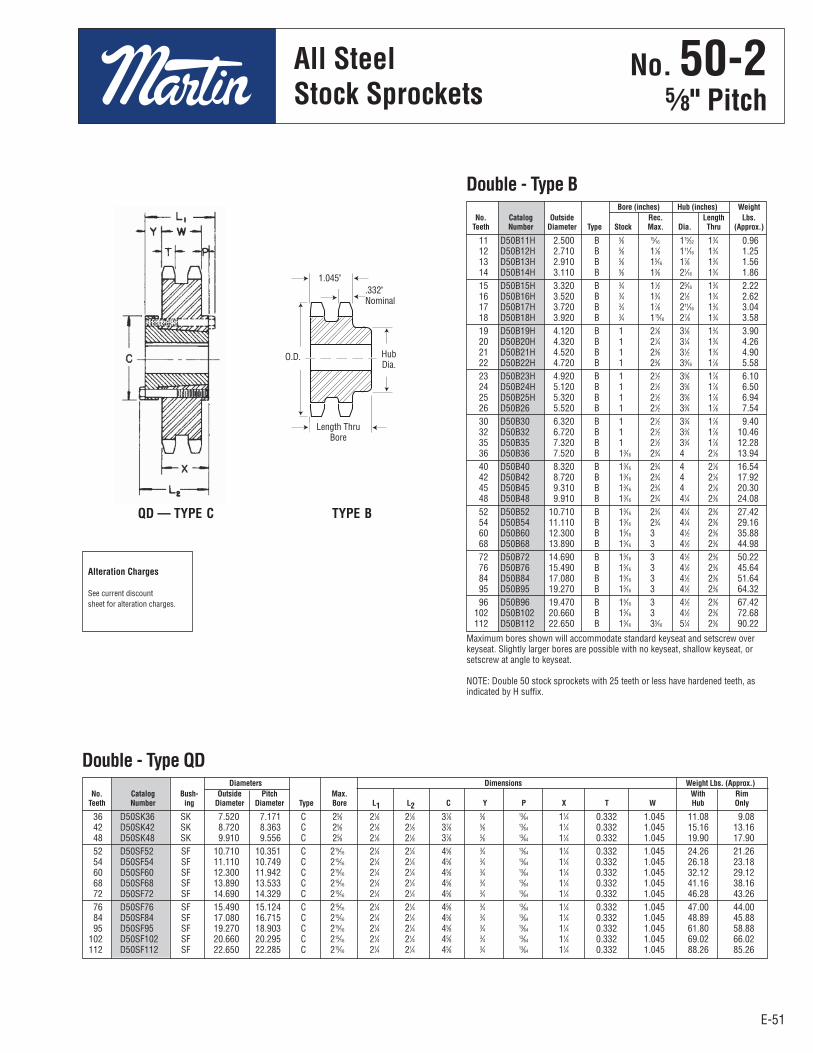
E-51
No. 50-25⁄8" Pitch
E-51
All Steel Stock Sprockets
36 D50SK36 SK 7.520 7.171 C 25⁄8 21⁄8 21⁄8 37⁄8 5⁄8 13⁄64 11⁄4 0.332 1.045 11.08 9.08 42 D50SK42 SK 8.720 8.363 C 25⁄8 21⁄8 21⁄8 37⁄8 5⁄8 13⁄64 11⁄4 0.332 1.045 15.16 13.16 48 D50SK48 SK 9.910 9.556 C 25⁄8 21⁄8 21⁄8 37⁄8 5⁄8 13⁄64 11⁄4 0.332 1.045 19.90 17.90 52 D50SF52 SF 10.710 10.351 C 215⁄16 21⁄4 21⁄4 45⁄8 3⁄4 13⁄64 11⁄4 0.332 1.045 24.26 21.26 54 D50SF54 SF 11.110 10.749 C 215⁄16 21⁄4 21⁄4 45⁄8 3⁄4 13⁄64 11⁄4 0.332 1.045 26.18 23.18 60 D50SF60 SF 12.300 11.942 C 215⁄16 21⁄4 21⁄4 45⁄8 3⁄4 13⁄64 11⁄4 0.332 1.045 32.12 29.12 68 D50SF68 SF 13.890 13.533 C 215⁄16 21⁄4 21⁄4 45⁄8 3⁄4 13⁄64 11⁄4 0.332 1.045 41.16 38.16 72 D50SF72 SF 14.690 14.329 C 215⁄16 21⁄4 21⁄4 45⁄8 3⁄4 13⁄64 11⁄4 0.332 1.045 46.28 43.26 76 D50SF76 SF 15.490 15.124 C 215⁄16 21⁄4 21⁄4 45⁄8 3⁄4 13⁄64 11⁄4 0.332 1.045 47.00 44.00 84 D50SF84 SF 17.080 16.715 C 215⁄16 21⁄4 21⁄4 45⁄8 3⁄4 13⁄64 11⁄4 0.332 1.045 48.89 45.88 95 D50SF95 SF 19.270 18.903 C 215⁄16 21⁄4 21⁄4 45⁄8 3⁄4 13⁄64 11⁄4 0.332 1.045 61.80 58.88 102 D50SF102 SF 20.660 20.295 C 215⁄16 21⁄4 21⁄4 45⁄8 3⁄4 13⁄64 11⁄4 0.332 1.045 69.02 66.02 112 D50SF112 SF 22.650 22.285 C 215⁄16 21⁄4 21⁄4 45⁄8 3⁄4 13⁄64 11⁄4 0.332 1.045 88.26 85.26
Diameters Dimensions Weight Lbs. (Approx.) No. Catalog Bush- Outside Pitch Max. With Rim Teeth Number ing Diameter Diameter Type Bore L1 L2 C Y P X T W Hub Only
Double - Type QD
11 D50B11H 2.500 B 5⁄8 15⁄16 115⁄32 13⁄4 0.96 12 D50B12H 2.710 B 5⁄8 11⁄8 111⁄16 13⁄4 1.25 13 D50B13H 2.910 B 5⁄8 15⁄16 17⁄8 13⁄4 1.56 14 D50B14H 3.110 B 5⁄8 13⁄8 21⁄16 13⁄4 1.86 15 D50B15H 3.320 B 3⁄4 11⁄2 25⁄16 13⁄4 2.22 16 D50B16H 3.520 B 3⁄4 13⁄4 21⁄2 13⁄4 2.62 17 D50B17H 3.720 B 3⁄4 17⁄8 211⁄16 13⁄4 3.04 18 D50B18H 3.920 B 3⁄4 115⁄16 27⁄8 13⁄4 3.58 19 D50B19H 4.120 B 1 21⁄8 31⁄8 13⁄4 3.90 20 D50B20H 4.320 B 1 21⁄4 31⁄4 13⁄4 4.26 21 D50B21H 4.520 B 1 23⁄8 31⁄2 13⁄4 4.90 22 D50B22H 4.720 B 1 23⁄8 39⁄16 17⁄8 5.58 23 D50B23H 4.920 B 1 21⁄2 35⁄8 17⁄8 6.10 24 D50B24H 5.120 B 1 21⁄2 35⁄8 17⁄8 6.50 25 D50B25H 5.320 B 1 21⁄2 35⁄8 17⁄8 6.94 26 D50B26 5.520 B 1 21⁄2 33⁄4 17⁄8 7.54 30 D50B30 6.320 B 1 21⁄2 33⁄4 17⁄8 9.40 32 D50B32 6.720 B 1 21⁄2 33⁄4 17⁄8 10.46 35 D50B35 7.320 B 1 21⁄2 33⁄4 17⁄8 12.28 36 D50B36 7.520 B 13⁄16 23⁄4 4 21⁄8 13.94 40 D50B40 8.320 B 13⁄16 23⁄4 4 21⁄8 16.54 42 D50B42 8.720 B 13⁄16 23⁄4 4 21⁄8 17.92 45 D50B45 9.310 B 13⁄16 23⁄4 4 21⁄8 20.30 48 D50B48 9.910 B 13⁄16 23⁄4 41⁄4 23⁄8 24.08 52 D50B52 10.710 B 13⁄16 23⁄4 41⁄4 23⁄8 27.42 54 D50B54 11.110 B 13⁄16 23⁄4 41⁄4 23⁄8 29.16 60 D50B60 12.300 B 15⁄16 3 41⁄2 23⁄8 35.88 68 D50B68 13.890 B 15⁄16 3 41⁄2 23⁄8 44.98 72 D50B72 14.690 B 15⁄16 3 41⁄2 23⁄8 50.22 76 D50B76 15.490 B 15⁄16 3 41⁄2 23⁄8 45.64 84 D50B84 17.080 B 15⁄16 3 41⁄2 23⁄8 51.64 95 D50B95 19.270 B 15⁄16 3 41⁄2 23⁄8 64.32 96 D50B96 19.470 B 15⁄16 3 41⁄2 23⁄8 67.42 102 D50B102 20.660 B 15⁄16 3 41⁄2 23⁄8 72.68 112 D50B112 22.650 B 15⁄16 35⁄16 51⁄4 23⁄8 90.22
Bore (inches) Hub (inches) Weight No. Catalog Outside Rec. Length Lbs. Teeth Number Diameter Type Stock Max. Dia. Thru (Approx.)
Double - Type B
Maximum bores shown will accommodate standard keyseat and setscrew overkeyseat. Slightly larger bores are possible with no keyseat, shallow keyseat, orsetscrew at angle to keyseat.
NOTE: Double 50 stock sprockets with 25 teeth or less have hardened teeth, asindicated by H suffix.
QD — TYPE C TYPE B
Alteration Charges
See current discountsheet for alteration charges.
.332"Nominal
1.045"
HubDia.
Length ThruBore
O.D.
No . 50-25⁄8" Pitch
All SteelStock Sprockets
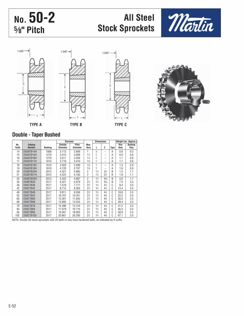
E-52
No. 50-25⁄8" Pitch
E-52
1.045"
14 D50ATB14H 1008 3.113 2.809 1 7⁄8 – A 0.8 0.3 15 D50ATB15H 1210 3.315 3.006 11⁄4 1 – A 0.9 0.6 16 D50ATB16H 1210 3.517 3.204 11⁄4 1 – A 1.1 0.6 17 D50ATB17H 1610 3.719 3.410 15⁄8 1 – A 1.1 0.6 18 D50ATB18H 1610 3.920 3.599 15⁄8 1 – A 1.3 0.9 19 D50ATB19H 1610 4.120 3.797 15⁄8 1 – A 1.6 0.9 20 D50BTB20H 2012 4.321 3.995 2 11⁄4 31⁄4 B 1.5 1.7 21 D50BTB21H 2012 4.522 4.193 2 11⁄4 31⁄2 B 1.9 1.7 25 D50BTB25H 2012 5.322 4.987 2 11⁄4 49⁄32 B 3.8 1.7 30 D50BTB30 2517 6.321 5.979 21⁄2 13⁄4 59⁄32 B 7.5 3.5 36 D50CTB36 2517 7.519 7.171 21⁄2 13⁄4 41⁄4 C 9.4 3.5 42 D50CTB42 2517 8.715 8.363 21⁄2 13⁄4 41⁄4 C 13.4 3.5 48 D50CTB48 2517 9.911 9.556 21⁄2 13⁄4 41⁄4 C 18.6 3.5 52 D50CTB52 2517 10.707 10.351 21⁄2 13⁄4 43⁄8 C 22.2 3.5 60 D50CTB60 2517 12.301 11.942 21⁄2 13⁄4 43⁄8 C 30.3 3.5 68 D50CTB68 2517 13.893 13.533 21⁄2 13⁄4 43⁄8 C 39.4 3.5 76 D50CTB76 2517 15.486 15.124 21⁄2 13⁄4 43⁄8 C 41.2 3.5 84 D50CTB84 2517 17.079 16.715 21⁄2 13⁄4 43⁄8 C 45.3 3.5 95 D50CTB95 2517 19.267 18.903 21⁄2 13⁄4 43⁄8 C 58.8 3.5 102 D50CTB102 2517 20.661 20.295 21⁄2 13⁄4 43⁄8 C 67.1 3.5
Diameter Dimensions Weight Lbs. (Approx.) No. Catalog Outside Pitch Max. Rim Bushing Teeth Number Bushing Diameter Diameter Bore L C Type Only Only
Double - Taper Bushed
NOTE: Double 50 stock sprockets with 25 teeth or less have hardened teeth, as indicated by H suffix.
1.045" 1.045"
L
C
L
C
L
C
TYPE A TYPE B TYPE C
All SteelStock Sprockets
No . 50-25⁄8" Pitch
All SteelStock Sprockets

E-53
No. 50-25⁄8" Pitch
E-53
Diameters Dimensions Weight Lbs. No. Catalog Bush- Outside Pitch Type Max. (Approx.) Teeth Number ing Dia. Dia. Bore OL L C H P T(nom) With Hub Rim Only
14 D50H14H H 3.110 2.809 11 1-1/2 2-5/16 1-1/4 7/8 2-1/2 1-3/32 0.332 2.0 1.2 15 D50P15H P1 3.320 3.006 16 1-3/4 3-7/16 1-15/16 1-1/4 3 1-13/32 0.332 3.3 2.0 16 D50P16H P1 3.520 3.204 12 1-3/4 2-11/16 1-15/16 1/2 3 1-13/32 0.332 2.9 1.6 17 D50P17H P1 3.720 3.401 12 1-3/4 2-11/16 1-15/16 1/2 3 1-13/32 0.332 3.4 2.1 18 D50P18H P1 3.920 3.599 12 1-3/4 2-11/16 1-15/16 1/2 3 1-13/32 0.332 3.8 2.5 19 D50P19H P1 4.120 3.797 12 1-3/4 2-3/16 1-15/16 – 3 29/32 0.332 3.3 2.0 20 D50P20H P1 4.320 3.995 12 1-3/4 2-3/16 1-15/16 – 3 29/32 0.332 3.8 2.5 21 D50P21H P1 4.520 4.194 12 1-3/4 2-3/16 1-15/16 – 3 29/32 0.332 4.1 2.8 22 D50P22H P1 4.720 4.392 12 1-3/4 2-3/16 1-15/16 – 3 29/32 0.332 4.5 3.2 23 D50P23H P1 4.920 4.590 12 1-3/4 2-3/16 1-15/16 – 3 29/32 0.332 4.9 3.6 24 D50Q24H Q1 5.120 4.788 12 2-11/16 2-25/32 2-1/2 – 4-1/8 1-15/32 0.332 7.5 4.0 25 D50Q25H Q1 5.320 4.987 12 2-11/16 2-25/32 2-1/2 – 4-1/8 1-15/32 0.332 8.0 4.5 26 D50Q26H Q1 5.520 5.185 12 2-11/16 2-25/32 2-1/2 – 4-1/8 1-15/32 0.332 8.8 5.3 27 D50Q27H Q1 5.720 5.384 12 2-11/16 2-25/32 2-1/2 – 4-1/8 1-15/32 0.332 9.4 5.9 28 D50Q28H Q1 5.920 5.582 12 2-11/16 2-25/32 2-1/2 – 4-1/8 1-15/32 0.332 9.8 6.3 30 D50Q30H Q1 6.320 5.979 12 2-11/16 2-25/32 2-1/2 – 4-1/8 1-15/32 0.332 11.0 7.5 32 D50Q32H Q1 6.720 6.376 12 2-11/16 2-25/32 2-1/2 – 4-1/8 1-15/32 0.332 12.0 8.5 35 D50Q35H Q1 7.320 6.972 12 2-11/16 2-25/32 2-1/2 – 4-1/8 1-15/32 0.332 13.9 10.4 36 D50Q36H Q1 7.520 7.171 12 2-11/16 2-25/32 2-1/2 – 4-1/8 1-15/32 0.332 14.5 11.0 40 D50Q40H Q1 8.320 7.966 12 2-11/16 2-25/32 2-1/2 – 4-1/8 1-15/32 0.332 17.1 13.6 42 D50Q42H Q1 8.720 8.363 12 2-11/16 2-25/32 2-1/2 – 4-1/8 1-15/32 0.332 18.5 15.0 45 D50Q45H Q1 9.310 8.960 12 2-11/16 2-25/32 2-1/2 – 4-1/8 1-15/32 0.332 21.0 17.5 48 D50Q48H Q1 9.910 9.556 12 2-11/16 2-25/32 2-1/2 – 4-1/8 1-15/32 0.332 23.9 20.4 52 D50Q52 Q1 10.710 10.351 12 2-11/16 2-25/32 2-1/2 – 4-1/8 1-15/32 0.332 26.8 23.3 54 D50Q54 Q1 11.110 10.749 12 2-11/16 2-25/32 2-1/2 – 4-1/8 1-15/32 0.332 26.8 23.3 60 D50Q60 Q1 12.300 11.942 12 2-11/16 2-25/32 2-1/2 – 4-1/8 1-15/32 0.332 29.0 25.5 72 D50Q72 Q1 14.690 14.329 12 2-11/16 2-25/32 2-1/2 – 4-1/8 1-15/32 0.332 46.6 43.1 76 D50Q76 Q1 15.490 15.124 12 2-11/16 2-25/32 2-1/2 – 4-1/8 1-15/32 0.332 49.5 46.0 84 D50Q84 Q1 17.080 16.715 12 2-11/16 2-25/32 2-1/2 – 4-1/8 1-15/32 0.332 60.2 56.7 95 D50R95 R1 19.270 18.903 12 3-3/4 3-5/32 2-7/8 – 5-3/8 2-3/32 0.332 79.8 72.3 96 D50R96 R1 19.470 19.102 12 3-3/4 3-5/32 2-7/8 – 5-3/8 2-3/32 0.332 88.2 80.7 102 D50R102 R1 20.660 20.295 12 3-3/4 3-5/32 2-7/8 – 5-3/8 2-3/32 0.332 92.0 84.5 112 D50R112 R1 22.650 22.285 12 3-3/4 3-5/32 2-7/8 – 5-3/8 2-3/32 0.332 100.7 93.2
Double - MST® Sprockets
1.045" 1.045"1.045"
Sprockets with “H” suffix have hardened teeth.
TYPE 11 TYPE 12 TYPE 16
MST®
SprocketsNo . 50-2
5⁄8" PitchMST®
Sprockets

E-54
No. 50-35⁄8" Pitch
E-54
All SteelStock Sprockets
11 E50B11H 2.500 B 5⁄8 15⁄16 115⁄32 21⁄2 1.42 12 E50B12H 2.710 B 5⁄8 11⁄8 111⁄16 21⁄2 1.84 13 E50B13H 2.910 B 5⁄8 15⁄16 17⁄8 21⁄2 2.28 14 E50B14H 3.110 B 5⁄8 13⁄8 21⁄16 21⁄2 2.72 15 E50B15H 3.320 B 3⁄4 11⁄2 25⁄16 21⁄2 3.24 16 E50B16H 3.520 B 3⁄4 13⁄4 21⁄2 21⁄2 3.76 17 E50B17H 3.720 B 3⁄4 17⁄8 211⁄16 21⁄2 4.38 18 E50B18H 3.920 B 3⁄4 115⁄16 215⁄16 21⁄2 5.10 19 E50B19H 4.120 B 1 21⁄8 31⁄8 21⁄2 5.60 20 E50B20H 4.320 B 1 21⁄4 31⁄4 25⁄8 6.42 21 E50B21H 4.520 B 1 23⁄8 31⁄2 25⁄8 7.42 22 E50B22H 4.720 B 1 23⁄8 39⁄16 25⁄8 8.13 23 E50B23H 4.920 B 1 21⁄2 35⁄8 25⁄8 8.85 24 E50B24H 5.120 B 1 21⁄2 35⁄8 25⁄8 9.42 25 E50B25H 5.320 B 1 21⁄2 35⁄8 25⁄8 10.16 26 E50B26 5.520 B 1 21⁄2 33⁄4 25⁄8 11.02 30 E50B30 6.320 B 1 21⁄2 33⁄4 25⁄8 14.24 35 E50B35 7.320 B 1 21⁄2 33⁄4 25⁄8 19.09 36 E50B36 7.520 B 13⁄16 23⁄4 4 23⁄4 20.60 42 E50B42 8.720 B 13⁄16 23⁄4 4 23⁄4 27.46 48 E50B48 9.910 B 13⁄16 23⁄4 4 31⁄8 36.64 52 E50B52 10.710 B 13⁄16 23⁄4 4 31⁄8 42.54 60 E50B60 12.300 B 15⁄16 3 41⁄2 31⁄8 57.17 68 E50B68 13.890 B 15⁄16 3 41⁄2 31⁄8 73.21 72 E50C72 14.690 C 15⁄16 3 43⁄4 31⁄2 57.04 76 E50C76 15.490 C 15⁄16 3 43⁄4 31⁄2 61.57 84 E50C84 17.080 C 15⁄16 3 43⁄4 31⁄2 62.86 95 E50C95 19.270 C 15⁄16 3 43⁄4 33⁄4 75.01 102 E50C102 20.660 C 15⁄16 3 43⁄4 33⁄4 86.26
Triple - Type B & C
36 E50SK36 SK 7.520 7.171 B 25⁄8 21⁄8 21⁄8 37⁄8 1⁄8 – 11⁄4 0.332 1.758 14.8 12.8 42 E50SK42 SK 8.720 8.363 B 25⁄8 21⁄8 21⁄8 37⁄8 1⁄8 – 11⁄4 0.332 1.758 21.5 19.5 48 E50SK48 SK 9.910 9.556 B 25⁄8 21⁄8 21⁄8 37⁄8 1⁄8 – 11⁄4 0.332 1.758 29.6 27.6 52 E50SF52 SF 10.710 10.351 B 215⁄16 21⁄4 21⁄4 45⁄8 1⁄4 – 11⁄4 0.332 1.758 31.6 28.6 60 E50SF60 SF 12.300 11.942 B 215⁄16 21⁄4 21⁄4 45⁄8 1⁄4 – 11⁄4 0.332 1.758 42.1 41.3 68 E50SF68 SF 13.890 13.533 B 215⁄16 21⁄4 21⁄4 45⁄8 1⁄4 – 11⁄4 0.332 1.758 53.8 45.3 72 E50SF72 SF 14.690 14.329 B 215⁄16 21⁄4 21⁄4 45⁄8 1⁄4 1⁄2 11⁄4 0.332 1.758 46.6 60.2 76 E50SF76 SF 15.490 15.124 B 215⁄16 21⁄4 21⁄4 45⁄8 1⁄4 1⁄2 11⁄4 0.332 1.758 49.9 67.3 84 E50SF84 SF 17.080 16.715 B 215⁄16 21⁄4 21⁄4 45⁄8 1⁄4 1⁄2 11⁄4 0.332 1.758 53.9 72.4 95 E50SF95 SF 19.270 18.903 B 215⁄16 21⁄4 21⁄4 45⁄8 1⁄4 1⁄2 11⁄4 0.332 1.758 62.3 91.4 102 E50SF102 SF 20.660 20.295 B 215⁄16 21⁄4 21⁄4 45⁄8 1⁄4 1⁄2 11⁄4 0.332 1.758 69.3 103.2
Bore (inches) Hub (inches) Weight No. Catalog Outside Rec. Length Lbs. Teeth Number Diameter Type Stock Max. Dia. Thru (Approx.)
Maximum bores shown will accommodate standard keyseat and setscrew over keyseat.Slightly larger bores are possible with no keyseat, shallow keyseat, or setscrew at angleto keyseat.
NOTE: Triple 50 stock sprockets with 25 teeth or less have Hardened Teeth.As indicated by H suffix.
NOTE: Triple 50 stock sprockets with 25 teeth or less have hardened teeth.
Diameters Dimensions Weight Lbs. (Approx.) No. Catalog Bush- Outside Pitch Max. With Rim Teeth Number ing Diameter Diameter Type Bore L1 L2 C Y V X T W Hub Only
Triple - Type QD
Alteration Charges
See current discountsheet for alteration charges.
1.758"
.332"Nominal
1.758"
.332"Nominal
TYPE B TYPE C
QD — TYPE B
HubDia.
Length Thru Bore
HubDia.
Length Thru Bore
No . 50-35⁄8" Pitch
All SteelStock Sprockets

E-55
No. 50-35⁄8" Pitch
E-55
MST®
Sprockets
1.758" 1.758"1.758" 1.758"
Diameters Dimensions Weight Lbs.
No. Catalog Bush- Outside Pitch Type Max. (Approx.)
Teeth Number ing Dia. Dia. Bore OL L C H P T(nom) With Hub Rim Only
15 E50P15H P2 3.320 3.006 27 1-3/4 4-1/8 2-15/16 15/16 3 1-3/8 0.332 4.0 2.5 16 E50P16H P2 3.520 3.204 22 1-3/4 3 3/8 2-15/16 3/16 3 1-3/8 0.332 3.9 2.4 17 E50P17H P2 3.720 3.401 22 1-3/4 3 3/8 2-15/16 3/16 3 1-3/8 0.332 4.3 2.8 18 E50P18H P2 3.920 3.599 22 1-3/4 3 3/8 2-15/16 3/16 3 1-3/8 0.332 4.9 3.4 19 E50P19H P1 4.120 3.797 24 1-3/4 2-5/8 1-15/16 7/16 3 5/8 0.332 4.2 2.9 20 E50P20H P1 4.320 3.995 24 1-3/4 2-5/8 1-15/16 7/16 3 5/8 0.332 4.4 3.1 21 E50P21H P1 4.520 4.194 24 1-3/4 2-5/8 1-15/16 7/16 3 5/8 0.332 4.8 3.5 23 E50P23H P1 4.920 4.590 24 1-3/4 2-5/8 1-15/16 7/16 3 5/8 0.332 5.8 4.5 24 E50Q24H Q1 5.120 4.788 23 2-11/16 2-25/32 2-1/2 – 4-1/8 3/4 0.332 8.2 4.7 25 E50Q25H Q1 5.320 4.987 23 2-11/16 2-25/32 2-1/2 – 4-1/8 3/4 0.332 8.5 5.0 26 E50Q26H Q1 5.520 5.185 23 2-11/16 2-25/32 2-1/2 – 4-1/8 3/4 0.332 9.4 5.9 28 E50Q28H Q1 5.920 5.582 23 2-11/16 2-25/32 2-1/2 – 4-1/8 3/4 0.332 10.8 7.3 30 E50Q30H Q1 6.320 5.979 23 2-11/16 2-25/32 2-1/2 – 4-1/8 3/4 0.332 12.3 8.8 32 E50Q32H Q1 6.720 6.376 23 2-11/16 2-25/32 2-1/2 – 4-1/8 3/4 0.332 14.4 10.9 35 E50Q35H Q1 7.320 6.972 23 2-11/16 2-25/32 2-1/2 – 4-1/8 3/4 0.332 17.2 13.7 36 E50Q36H Q1 7.520 7.171 23 2-11/16 2-25/32 2-1/2 – 4-1/8 3/4 0.332 18.1 14.6 40 E50Q40H Q1 8.320 7.966 23 2-11/16 2-25/32 2-1/2 – 4-1/8 3/4 0.332 22.6 19.1 42 E50Q42H Q1 8.720 8.363 23 2-11/16 2-25/32 2-1/2 – 4-1/8 3/4 0.332 25.0 21.5 48 E50Q48H Q1 9.910 9.556 23 2-11/16 2-25/32 2-1/2 – 4-1/8 3/4 0.332 33.1 29.6 52 E50Q52 Q1 10.710 10.351 23 2-11/16 2-25/32 2-1/2 – 4-1/8 3/4 0.332 39.9 36.4 60 E50R60 R1 12.300 11.942 22 3-3/4 2-5/32 2-7/8 – 5-3/8 1-1/8 0.332 55.5 48.0 68 E50R68 R1 13.890 13.533 22 3-3/4 2-5/32 2-7/8 – 5-3/8 1-1/8 0.332 71.0 63.5 72 E50R72 R1 14.690 14.329 22 3-3/4 2-5/32 2-7/8 – 5-3/8 1-1/8 0.332 79.5 72.0 76 E50R76 R1 15.490 15.124 22 3-3/4 2-5/32 2-7/8 – 5-3/8 1-1/8 0.332 88.5 81.0 84 E50R84 R1 17.080 16.715 22 3-3/4 2-5/32 2-7/8 – 5-3/8 1-1/8 0.332 107.5 100.0 95 E50R95 R1 19.270 18.903 22 3-3/4 2-5/32 2-7/8 – 5-3/8 1-1/8 0.332 137.5 130.0 102 E50R102 R1 20.660 20.295 22 3-3/4 2-5/32 2-7/8 – 5-3/8 1-1/8 0.332 158.5 151.0
Triple - MST® Sprockets
Sprockets with “H” suffix have hardened teeth.
TYPE 22 TYPE 23 TYPE 24 TYPE 27
No . 50-35⁄8" Pitch
MST®
Sprockets

E-56
No. 603⁄4" Pitch
E-56
All SteelStock Sprockets
9 60BS9 2.510 11⁄4 0.6 3⁄4 — 7⁄8 — 1 10 60BS10 2.760 11⁄4 0.7 3⁄4 — 7⁄8 — 1 — 11⁄8 — 13⁄16 — 11⁄4 11 60BS11 3.000 11⁄4 0.9 3⁄4 — 7⁄8 — 1 — 11⁄8 — 13⁄16 — 11⁄4 11 60BS11WH 3.000 11⁄4 0.8 — 11⁄4 12 60BS12 3.250 11⁄4 1.3 3⁄4 — 7⁄8 — 1 — 11⁄8 — 13⁄16 — 11⁄4— — 17⁄16
12 60BS12WH 3.250 11⁄4 1.1 — 11⁄4 13 60BS13 3.490 11⁄4 1.3 3⁄4 — 7⁄8 — 1 — 11⁄8 — 13⁄16 — 11⁄4 — 13⁄8 — 17⁄16 — 11⁄2 14 60BS14 3.740 11⁄4 1.6 3⁄4 — 7⁄8 — 1 — 11⁄8 — 13⁄16 — 11⁄4 — 13⁄8 — 17⁄16 — 11⁄2 — 15⁄8 15 60BS15 3.980 11⁄4 1.7 3⁄4 — 7⁄8 — 1 — 11⁄8 — 13⁄16 — 11⁄4 — 13⁄8 — 17⁄16 — 11⁄2 — 15⁄8 — 13⁄4 16 60BS16 4.220 11⁄4 2.1 3⁄4 — 7⁄8 — 1 — 11⁄8 — 13⁄16 — 11⁄4 — 13⁄8 — 17⁄16 — 11⁄2 — 15⁄8 — 13⁄4 — 115⁄16
17 60BS17 4.460 11⁄4 2.4 1 — 11⁄8 — 13⁄16 — 11⁄4 — 13⁄8— 17⁄16 — 11⁄2 — 15⁄8 — 13⁄4 — 115⁄16
18 60BS18 4.700 11⁄4 2.6 1 — 11⁄8 — 13⁄16 — 11⁄4 — 13⁄8— 17⁄16 — 11⁄2 — 15⁄8 — 13⁄4 — 115⁄16
18 60BS18WH 4.700 11⁄4 2.6 11⁄4 19 60BS19 4.950 11⁄4 3.4 1 — 11⁄8 — 13⁄16 — 11⁄4 — 13⁄8— 17⁄16 — 11⁄2 — 15⁄8 — 13⁄4 — 115⁄16
20 60BS20 5.190 11⁄4 3.9 1 — 11⁄8 — 13⁄16 — 11⁄4 — 13⁄8— 17⁄16 — 11⁄2 — 15⁄8 — 13⁄4 — 115⁄16
21 60BS21 5.430 11⁄4 4.4 1 — 11⁄8 — 13⁄16 — 11⁄4 — 13⁄8— 17⁄16 — 11⁄2 — 15⁄8 — 13⁄4 — 115⁄16
22 60BS22 5.670 11⁄4 4.7 1 — 11⁄8 — 13⁄16 — 11⁄4 — 13⁄8— 17⁄16 — 11⁄2 — 15⁄8 — 13⁄4 — 115⁄16
23 60BS23 5.910 11⁄4 5.0 1 — 11⁄8 — 13⁄16 — 11⁄4 — 13⁄8— 17⁄16 — 11⁄2 — 15⁄8 — 13⁄4 — 115⁄16
24 60BS24 6.150 11⁄4 5.3 1 — 11⁄8 — 13⁄16 — 11⁄4 — 13⁄8— 17⁄16 — 11⁄2 — 15⁄8 — 13⁄4 — 115⁄16
25 60BS25 6.390 11⁄4 5.4 1 — 11⁄8 — 13⁄16 — 11⁄4 — 13⁄8— 17⁄16 — 11⁄2 — 15⁄8 — 13⁄4 — 115⁄16
26 60BS26 6.630 11⁄4 5.8 1 — 11⁄8 — 13⁄16 — 11⁄4 — 13⁄8— 17⁄16 — 11⁄2 — 15⁄8 — 13⁄4 — 115⁄16
27 60BS27 6.870 11⁄4 6.3 1 — 11⁄8 — 13⁄16 — 11⁄4 — 13⁄8— 17⁄16 — 11⁄2 — 15⁄8 — 13⁄4 — 115⁄16
28 60BS28 7.110 11⁄4 6.4 1 — 11⁄8 — 13⁄16 — 11⁄4 — 13⁄8— 17⁄16 — 11⁄2 — 15⁄8 — 13⁄4 — 115⁄16
29 60BS29 7.350 11⁄4 6.9 1 — 11⁄8 — 13⁄16 — 11⁄4 — 13⁄8— 17⁄16 — 11⁄2 — 15⁄8 — 13⁄4 — 115⁄16
30 60BS30 7.590 11⁄4 7.1 1 — 11⁄8 — 13⁄16 — 11⁄4 — 13⁄8— 17⁄16 — 11⁄2 — 15⁄8 — 13⁄4 — 115⁄16
31 60BS31 7.830 11⁄4 7.4 1 — 11⁄8 — 13⁄16 — 11⁄4 — 13⁄8— 17⁄16 — 11⁄2 — 15⁄8 — 13⁄4 — 115⁄16
32 60BS32 8.070 11⁄4 7.8 1 — 11⁄8 — 13⁄16 — 11⁄4 — 13⁄8— 17⁄16 — 11⁄2 — 15⁄8 — 13⁄4 — 115⁄16
33 60BS33 8.300 11⁄4 8.2 1 — 11⁄8 — 13⁄16 — 11⁄4 — 13⁄8— 17⁄16 — 11⁄2 — 15⁄8 — 13⁄4 — 115⁄16
34 60BS34 8.540 11⁄4 8.5 1 — 11⁄8 — 13⁄16 — 11⁄4 — 13⁄8— 17⁄16 — 11⁄2 — 15⁄8 — 13⁄4 — 115⁄16
35 60BS35 8.780 11⁄4 8.8 1 — 11⁄8 — 13⁄16 — 11⁄4 — 13⁄8— 17⁄16 — 11⁄2 — 15⁄8 — 13⁄4 — 115⁄16
36 60BS36 9.020 11⁄4 9.2 1 — 11⁄8 — 13⁄16 — 11⁄4 — 13⁄8— 17⁄16 — 11⁄2 — 15⁄8 — 13⁄4 — 115⁄16 — 2 — 23⁄16 — 27⁄16
37 60BS37 9.260 11⁄4 9.9 1 — 11⁄8 — 13⁄16 — 11⁄4 — 13⁄8— 17⁄16 — 11⁄2 — 15⁄8 — 13⁄4 — 115⁄16 — 2 — 23⁄16 — 27⁄16
38 60BS38 9.500 11⁄4 10.5 1 — 11⁄8 — 13⁄16 — 11⁄4 — 13⁄8— 17⁄16 — 11⁄2 — 15⁄8 — 13⁄4 — 115⁄16 — 2 — 23⁄16 — 27⁄16
39 60BS39 9.740 11⁄4 10.9 1 — 11⁄8 — 13⁄16 — 11⁄4 — 13⁄8— 17⁄16 — 11⁄2 — 15⁄8 — 13⁄4 — 115⁄16 — 2 — 23⁄16 — 27⁄16
40 60BS40 9.980 11⁄4 11.2 1 — 11⁄8 — 13⁄16 — 11⁄4 — 13⁄8— 17⁄16 — 11⁄2 — 15⁄8 — 13⁄4 — 115⁄16 — 2 — 23⁄16 — 27⁄16
41 60BS41 10.220 11⁄4 11.8 1 — 11⁄8 — 13⁄16 — 11⁄4 — 13⁄8— 17⁄16 — 11⁄2 — 15⁄8 — 13⁄4 — 115⁄16 — 2 — 23⁄16 — 27⁄16
42 60BS42 10.460 11⁄4 12.4 1 — 11⁄8 — 13⁄16 — 11⁄4 — 13⁄8— 17⁄16 — 11⁄2 — 15⁄8 — 13⁄4 — 115⁄16 — 2 — 23⁄16 — 27⁄16
43 60BS43 10.700 11⁄4 13.0 1 — 11⁄8 — 13⁄16 — 11⁄4 — 13⁄8— 17⁄16 — 11⁄2 — 15⁄8 — 13⁄4 — 115⁄16 — 2 — 23⁄16 — 27⁄16
44 60BS44 10.940 11⁄4 13.5 1 — 11⁄8 — 13⁄16 — 11⁄4 — 13⁄8— 17⁄16 — 11⁄2 — 15⁄8 — 13⁄4 — 115⁄16 — 2 — 23⁄16 — 27⁄16
45 60BS45 11.180 11⁄4 13.8 1 — 11⁄8 — 13⁄16 — 11⁄4 — 13⁄8— 17⁄16 — 11⁄2 — 15⁄8 — 13⁄4 — 115⁄16 — 2 — 23⁄16 — 27⁄16
46 60BS46 11.420 11⁄4 14.1 1 — 11⁄8 — 13⁄16 — 11⁄4 — 13⁄8— 17⁄16 — 11⁄2 — 15⁄8 — 13⁄4 — 115⁄16 — 2 — 23⁄16 — 27⁄16
47 60BS47 11.650 11⁄4 14.6 1 — 11⁄8 — 13⁄16 — 11⁄4 — 13⁄8— 17⁄16 — 11⁄2 — 15⁄8 — 13⁄4 — 115⁄16 — 2 — 23⁄16 — 27⁄16
48 60BS48 11.890 11⁄4 15.4 1 — 11⁄8 — 13⁄16 — 11⁄4 — 13⁄8— 17⁄16 — 11⁄2 — 15⁄8 — 13⁄4 — 115⁄16 — 2 — 23⁄16 — 27⁄16
49 60BS49 12.130 11⁄4 16.4 1 — 11⁄8 — 13⁄16 — 11⁄4 — 13⁄8— 17⁄16 — 11⁄2 — 15⁄8 — 13⁄4 — 115⁄16 — 2 — 23⁄16 — 27⁄16
50 60BS50 12.370 11⁄4 17.3 1 — 11⁄8 — 13⁄16 — 11⁄4 — 13⁄8— 17⁄16 — 11⁄2 — 15⁄8 — 13⁄4 — 115⁄16 — 2 — 23⁄16 — 27⁄16
51 60BS51 12.610 11⁄4 18.3 1 — 11⁄8 — 13⁄16 — 11⁄4 — 13⁄8— 17⁄16 — 11⁄2 — 15⁄8 — 13⁄4 — 115⁄16 — 2 — 23⁄16 — 27⁄16
52 60BS52 12.850 11⁄4 19.3 1 — 11⁄8 — 13⁄16 — 11⁄4 — 13⁄8— 17⁄16 — 11⁄2 — 15⁄8 — 13⁄4 — 115⁄16 — 2 — 23⁄16 — 27⁄16
53 60BS53 13.090 11⁄4 20.3 1 — 11⁄8 — 13⁄16 — 11⁄4 — 13⁄8— 17⁄16 — 11⁄2 — 15⁄8 — 13⁄4 — 115⁄16 — 2 — 23⁄16 — 27⁄16
54 60BS54 13.330 13⁄4 21.0 1 — 11⁄8 — 13⁄16 — 11⁄4 — 13⁄8— 17⁄16 — 11⁄2 — 15⁄8 — 13⁄4 — 115⁄16 — 2 — 23⁄16 — 27⁄16
55 60BS55 13.570 13⁄4 21.2 — 13⁄8 — 17⁄16 — 11⁄2 — 15⁄8 — 13⁄4 — 115⁄16 — 2 — 23⁄16 — 27⁄16
56 60BS56 13.810 13⁄4 21.3 — 13⁄8 — 17⁄16 — 11⁄2 — 15⁄8 — 13⁄4 — 115⁄16 — 2 — 23⁄16 — 27⁄16
57 60BS57 14.040 13⁄4 22.2 — 13⁄8 — 17⁄16 — 11⁄2 — 15⁄8 — 13⁄4 — 115⁄16 — 2 — 23⁄16 — 27⁄16
58 60BS58 14.280 13⁄4 23.0 — 13⁄8 — 17⁄16 — 11⁄2 — 15⁄8 — 13⁄4 — 115⁄16 — 2 — 23⁄16 — 27⁄16
59 60BS59 14.520 13⁄4 23.8 — 13⁄8 — 17⁄16 — 11⁄2 — 15⁄8 — 13⁄4 — 115⁄16 — 2 — 23⁄16 — 27⁄16
60 60BS60 14.760 13⁄4 25.0 — 13⁄8 — 17⁄16 — 11⁄2 — 15⁄8 — 13⁄4 — 115⁄16 — 2 — 23⁄16 — 27⁄16
70 60BS70 17.150 13⁄4 31.4 — 13⁄8 — 17⁄16 — 11⁄2 — 15⁄8 — 13⁄4 — 115⁄16 — 2 — 23⁄16 — 27⁄16
72 60BS72 17.630 2 33.5 — 13⁄8 — 17⁄16 — 11⁄2 — 15⁄8 — 13⁄4 — 115⁄16 — 2 — 23⁄16 — 27⁄16
80 60BS80 19.540 2 41.2 — 13⁄8 — 17⁄16 — 11⁄2 — 15⁄8 — 13⁄4 — 115⁄16 — 2 — 23⁄16 — 27⁄16
84 60BS84 20.490 2 45.8 — 13⁄8 — 17⁄16 — 11⁄2 — 15⁄8 — 13⁄4 — 115⁄16 — 2 — 23⁄16 — 27⁄16
96 60BS96 23.360 21⁄4 62.3 — 13⁄8 — 17⁄16 — 11⁄2 — 15⁄8 — 13⁄4 — 115⁄16 — 2 — 23⁄16 — 27⁄16
112 60BS112 27.180 21⁄4 81.0 — 13⁄8 — 17⁄16 — 11⁄2 — 15⁄8 — 13⁄4 — 115⁄16 — 2 — 23⁄16 — 27⁄16
Length Weight Stock Finished Bores No. Catalog Outside Thru Lbs. Includes Keyway Teeth Number Diameter Bore (Approx.) and Setscrews
Single Type BS — 2 Setscrews — Bored-To-Size
Hub diameters vary to suit different bore sizes. KEYWAY IS ON CENTER LINE OF TOOTH.W = Winch Sprockets — KW 5⁄16" × 5⁄32" – One SS at 90°
No . 60¾" Pitch
All SteelStock Sprockets

E-57
No. 603⁄4" Pitch
E-57
All SteelStock Sprockets
12 60C12 3.250 3⁄4 13⁄8 23⁄8 HH 2 2.25
13 60C13 3.490 3⁄4 11⁄2 211⁄32 2 2.75
14 60C14 3.740 3⁄4 13⁄4 29⁄16 2 3.19
15 60C15 3.980 3⁄4 17⁄8 27⁄8 2 3.10
16 60C16 4.220 3⁄4 2 31⁄16 2 4.19
17 60C17 4.460 3⁄4 21⁄4 31⁄4 2 4.81
18 60C18 4.700 3⁄4 23⁄8 31⁄2 2 5.62
Bore (inches) Hub (inches) Weight No. Catalog Outside Lbs. Teeth Number Diameter Stock Rec. Max. Diameter Length (Approx.)
TYPE BS
9 60BS9HT 2.51 11⁄4 0.6 3⁄4 — 7⁄8 — 1 10 60BS10HT 2.76 11⁄4 0.7 3⁄4 — 7⁄8 — 1—11⁄8 —13⁄16 —11⁄4 11 60BS11HT 3.00 11⁄4 0.9 3⁄4 — 7⁄8 — 1—11⁄8 —13⁄16 —11⁄4 12 60BS12HT 3.25 11⁄4 1.3 3⁄4 — 7⁄8 — 1—11⁄8 —13⁄16 —11⁄4 —11⁄4 —17⁄16
13 60BS13HT 3.49 11⁄4 1.3 3⁄4 — 7⁄8 — 1—11⁄8 —13⁄16 —11⁄4 —13⁄8 —17⁄16 —11⁄2 14 60BS14HT 3.74 11⁄4 1.6 3⁄4 — 7⁄8 — 1—11⁄8 —13⁄16 —11⁄4 —13⁄8 —17⁄16 —11⁄2 —15⁄8 15 60BS15HT 3.98 11⁄4 1.7 3⁄4 — 7⁄8 — 1—11⁄8 —13⁄16 —11⁄4 —13⁄8 —17⁄16 —11⁄2 —15⁄8 —13⁄4 16 60BS16HT 4.22 11⁄4 2.1 3⁄4 — 7⁄8 — 1—11⁄8 —13⁄16 —11⁄4 —13⁄8 —17⁄16 —11⁄2 —15⁄8 —13⁄4 —115⁄16
17 60BS17HT 4.46 11⁄4 2.4 1—11⁄8 —13⁄16 —11⁄4 —13⁄8 —17⁄16 —11⁄2 —15⁄8 —13⁄4 —115⁄16
18 60BS18HT 4.70 11⁄4 2.6 1—11⁄8 —13⁄16 —11⁄4 —13⁄8 —17⁄16 —11⁄2 —15⁄8 —13⁄4 —115⁄16
19 60BS19HT 4.95 11⁄4 3.4 1—11⁄8 — 13⁄16 — 11⁄4 —13⁄8 —17⁄16 —11⁄2 —15⁄8 —13⁄4 —115⁄16
20 60BS20HT 5.19 11⁄4 3.9 1—11⁄8 —13⁄16 — 11⁄4 —13⁄8 —17⁄16 —11⁄2 —15⁄8 —13⁄4 —115⁄16
Length Weight No. Catalog Outside Thru Lbs. Stock Finished Bores Teeth Number Diameter Bore (Approx.) Includes Keyway and Setscrews
No. 60-Hardened Teeth — 2 Setscrews
Single - Type C
TYPE C HH Has recessed groove in hub for chain clearance.
.459"Nominal
.459"Nominal
Length ThruBore
O.D.
Length Thru Bore
HubDia.
KEYWAY IS ON CENTER LINE OF TOOTH.
Martin stock hardened teeth sprockets afford longer chain and sprocket life. Hardened teeth on thesmaller sprocket of a roller chain drive are recommended if the drive ratio is four to one or greater or if thesmaller sprocket has 24 teeth or less and is running at a speed of over 600 R.P.M.
No . 60¾" Pitch
All SteelStock Sprockets
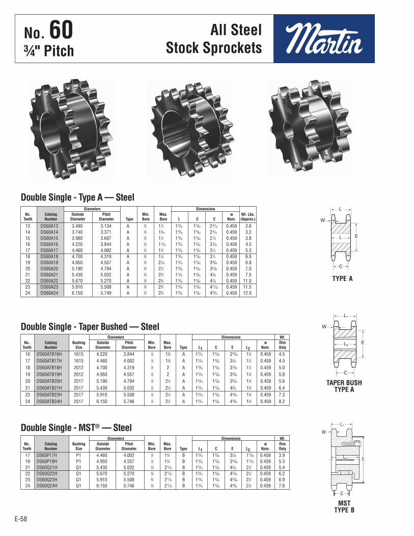
E-58
No. 603⁄4" Pitch
E-58
All SteelStock Sprockets
16 DS60ATB16H 1615 4.220 3.844 1⁄2 15⁄8 A 115⁄16 131⁄64 263⁄64 11⁄2 0.459 4.5 17 DS60ATB17H 1615 4.460 4.002 1⁄2 15⁄8 A 115⁄16 131⁄64 37⁄32 11⁄2 0.459 4.5 18 DS60ATB18H 2012 4.700 4.319 1⁄2 2 A 115⁄16 131⁄64 315⁄32 11⁄4 0.459 5.0 19 DS60ATB19H 2012 4.950 4.557 1⁄2 2 A 115⁄16 131⁄64 345⁄64 11⁄4 0.459 5.8 20 DS60ATB20H 2517 5.190 4.794 1⁄2 21⁄2 A 115⁄16 131⁄64 361⁄64 13⁄4 0.459 5.6 21 DS60ATB21H 2517 5.430 5.032 1⁄2 21⁄2 A 115⁄16 131⁄64 43⁄16 13⁄4 0.459 6.4 23 DS60ATB23H 2517 5.910 5.508 1⁄2 21⁄2 A 115⁄16 131⁄64 443⁄64 13⁄4 0.459 7.3 24 DS60ATB24H 2517 6.150 5.746 1⁄2 21⁄2 A 115⁄16 131⁄64 429⁄32 13⁄4 0.459 8.2
13 DS60A13 3.490 3.134 A 3⁄4 11⁄4 115⁄16 131⁄64 211⁄32 0.459 2.6 14 DS60A14 3.740 3.371 A 3⁄4 15⁄16 115⁄16 131⁄64 2 9⁄16 0.459 3.2 15 DS60A15 3.980 3.607 A 3⁄4 11⁄2 115⁄16 131⁄64 2 7⁄8 0.459 3.8 16 DS60A16 4.220 3.844 A 3⁄4 111⁄16 115⁄16 131⁄64 3 3⁄64 0.459 4.5 17 DS60A17 4.460 4.082 A 3⁄4 13⁄4 115⁄16 131⁄64 31⁄4 0.459 5.3 18 DS60A18 4.700 4.319 A 3⁄4 17⁄8 115⁄16 131⁄64 31⁄2 0.459 6.5 19 DS60A19 4.950 4.557 A 3⁄4 21⁄16 115⁄16 131⁄64 345⁄64 0.459 6.8 20 DS60A20 5.190 4.794 A 3⁄4 21⁄4 115⁄16 131⁄64 361⁄64 0.459 7.0 21 DS60A21 5.430 5.032 A 3⁄4 23⁄4 115⁄16 131⁄64 43⁄16 0.459 7.5 22 DS60A22 5.670 5.270 A 3⁄4 23⁄4 115⁄16 131⁄64 47⁄16 0.459 11.0 23 DS60A23 5.910 5.508 A 3⁄4 23⁄4 115⁄16 131⁄64 421⁄32 0.459 11.5 24 DS60A24 6.150 5.749 A 3⁄4 23⁄4 115⁄16 131⁄64 429⁄32 0.459 12.0
Diameters Dimensions No. Catalog Outside Pitch Min. Max. w Wt. Lbs. Teeth Number Diameter Diameter Type Bore Bore L C E Nom. (Approx.)
Double Single - Type A — Steel
Double Single - Taper Bushed — Steel
TYPE A
TAPER BUSHTYPE A
17 DS60P17H P1 4.460 4.002 1⁄2 13⁄4 B 115⁄16 131⁄64 37⁄32 115⁄16 0.459 3.9 19 DS60P19H P1 4.950 4.557 1⁄2 13⁄4 B 115⁄16 131⁄64 345⁄64 115⁄16 0.459 5.3 21 DS60Q21H Q1 5.430 5.032 3⁄4 211⁄16 B 115⁄16 131⁄64 43⁄16 21⁄2 0.459 5.4 22 DS60Q22H Q1 5.670 5.270 3⁄4 211⁄16 B 115⁄16 131⁄64 427⁄64 21⁄2 0.459 6.2 23 DS60Q23H Q1 5.910 5.508 3⁄4 211⁄16 B 115⁄16 131⁄64 443⁄64 21⁄2 0.459 6.9 24 DS60Q24H Q1 6.150 5.746 3⁄4 211⁄16 B 115⁄16 131⁄64 429⁄32 21⁄2 0.459 7.6
Diameters Dimensions Wt. No. Catalog Bushing Outside Pitch Min. Max. w Rim Teeth Number Size Diameter Diameter Bore Bore Type L1 C E L2 Nom. Only
Double Single - MST® — Steel
MSTTYPE B
Diameters Dimensions Wt. No. Catalog Bushing Outside Pitch Min. Max. w Rim Teeth Number Size Diameter Diameter Bore Bore Type L1 C E L2 Nom. Only
No . 60¾" Pitch
All SteelStock Sprockets

E-59
No. 603⁄4" Pitch
E-59
Stainless SteelStock Sprockets
8 60B8SS 2.261 B 5⁄8 5⁄8 115⁄32 H 11⁄4 0.54 – – – – 9 60B9SS 2.511 B 3⁄4 7⁄8 19⁄16 H 11⁄4 0.64 – – – – 10 60B10SS 2.759 B 3⁄4 11⁄8 115⁄16 H 11⁄4 0.99 – – – – 11 60B11SS 3.005 B 3⁄4 15⁄16 21⁄16 H 11⁄4 1.16 – – – – 12 60B12SS 3.249 B 3⁄4 13⁄8 23⁄8H H 11⁄4 1.50 – – – – 13 60B13SS 3.493 B 3⁄4 11⁄2 211⁄32 11⁄4 1.71 – – – – 14 60B14SS 3.736 B 3⁄4 13⁄4 29⁄16 11⁄4 2.05 A 60A13SS 3⁄4 0.80 15 60B15SS 3.978 B 3⁄4 17⁄8 27⁄8 11⁄4 2.51 A 60A14SS 3⁄4 0.94 16 60B16SS 4.220 B 3⁄4 2 31⁄16 11⁄4 2.88 A 60A15SS 3⁄4 1.08 17 60B17SS 4.462 B 3⁄4 21⁄4 31⁄4 11⁄4 3.27 A 60A16SS 3⁄4 1.24 18 60B18SS 4.703 B 3⁄4 23⁄8 31⁄2 11⁄4 3.77 A 60A17SS 3⁄4 1.44 19 60B19SS 4.945 B 3⁄4 23⁄8 31⁄2 11⁄4 3.98 A 60A18SS 3⁄4 1.62 20 60B20SS 5.186 B 3⁄4 25⁄8 37⁄8 11⁄4 4.69 A 60A20SS 3⁄4 1.84 21 60B21SS 5.426 B 3⁄4 23⁄4 4 11⁄4 5.10 A 60A21SS 3⁄4 2.34 22 60B22SS 5.666 B 3⁄4 23⁄4 4 11⁄4 5.34 A 60A22SS 3⁄4 2.56 23 60B23SS 5.907 B 3⁄4 23⁄4 4 11⁄4 5.59 A 60A23SS 3⁄4 2.81 24 60B24SS 6.147 B 3⁄4 23⁄4 4 11⁄4 5.59 A 60A24SS 23⁄32 3.08 25 60B25SS 6.387 B 3⁄4 23⁄4 4 11⁄4 6.13 A 60A25SS 23⁄32 3.35 26 60B26SS 6.627 B 3⁄4 23⁄4 4 11⁄4 6.42 A 60A26SS 23⁄32 3.67 28 60B28SS 7.106 B 3⁄4 23⁄4 4 11⁄4 7.03 A 60A28SS 23⁄32 4.28 30 60B30SS 7.586 B 3⁄4 23⁄4 4 11⁄4 7.69 A 60A30SS 23⁄32 4.94 32 60B32SS 8.065 B 3⁄4 23⁄4 4 11⁄4 5.26 A 60A32SS 23⁄32 5.52 35 60B35SS 8.783 B 1 23⁄4 4 11⁄4 9.41 A 60A35SS 15⁄16 6.74 36 60B36SS 9.023 B 1 23⁄4 4 11⁄4 9.60 A 60A36SS 15⁄16 6.82 40 60B40SS 9.980 B 1 23⁄4 41⁄4 11⁄4 11.91 A 60A40SS 15⁄16 8.88 45 60B45SS 11.176 B 1 23⁄4 41⁄4 11⁄4 14.34 A 60A45SS 15⁄16 11.30 60 60B60SS 14.761 B 11⁄4 23⁄4 41⁄4 13⁄4 25.05 A 60A60SS 11⁄4 20.08
Bore (inches) Hub (inches) Weight Weight No. Catalog Outside Rec. Length Lbs. Catalog Stock Lbs. Teeth Number Diameter Type Stock Max. Diameter Thru (Approx.) Type Number Bore (Appl.)
Single - Type B — Stainless Single - Type A
STAINLESS STEEL TYPE B
H Has recessed groove in hub for chain clearance.
Maximum bores shown will accommodate standard keyseat and setscrew over keyseat. Slightly larger bores are possible with no keyseat, shallow keyseat, or setscrew at angle to keyseat.
Sprockets altered at factory (rebored with keyway and setscrew added) will be supplied with stainless setscrew.
Alteration Charges
See current discountsheet for alteration charges.
.459"Nominal
HubDia.
Length Thru Bore
O.D.
No . 60¾" Pitch
Stainlessa SteelStock Sprockets

E-60
No. 603⁄4" Pitch
E-60
All SteelStock Sprockets
8 60B8 2.260 B 5⁄8 5⁄8 115⁄32H 11⁄4 0.54 – – – – 9 60B9 2.510 B 3⁄4 7⁄8 19⁄16H 11⁄4 0.64 – – – – 10 60B10 2.760 B 3⁄4 11⁄8 115⁄16H 11⁄4 0.99 A 60A10 3⁄4 0.44 11 60B11 3.000 B 3⁄4 15⁄16 21⁄16H 11⁄4 1.16 A 60A11 3⁄4 0.54 12 60B12 3.250 B 3⁄4 13⁄8 23⁄8H 11⁄4 1.47 A 60A12 3⁄4 0.68 13 60B13 3.490 B 3⁄4 11⁄2 211⁄32 11⁄4 1.66 A 60A13 3⁄4 0.80 14 60B14 3.740 B 3⁄4 13⁄4 29⁄16 11⁄4 2.00 A 60A14 3⁄4 0.94 15 60B15 3.980 B 3⁄4 17⁄8 27⁄8 11⁄4 2.51 A 60A15 3⁄4 1.08 16 60B16 4.220 B 3⁄4 2 31⁄16 11⁄4 2.81 A 60A16 3⁄4 1.24 17 60B17 4.460 B 3⁄4 21⁄4 31⁄4 11⁄4 3.22 A 60A17 3⁄4 1.44 18 60B18 4.700 B 3⁄4 23⁄8 31⁄2 11⁄4 3.72 A 60A18 3⁄4 1.62 19 60B19 4.950 B 3⁄4 23⁄8 31⁄2 11⁄4 3.92 A 60A19 3⁄4 1.84 20 60B20 5.190 B 3⁄4 25⁄8 37⁄8 11⁄4 4.63 A 60A20 3⁄4 2.12 21 60B21 5.430 B 3⁄4 23⁄4 4 11⁄4 5.00 A 60A21 3⁄4 2.28 22 60B22 5.670 B 3⁄4 23⁄4 4 11⁄4 5.25 A 60A22 3⁄4 2.48 23 60B23 5.910 B 3⁄4 23⁄4 4 11⁄4 5.48 A 60A23 3⁄4 2.68 24 60B24 6.150 B 3⁄4 23⁄4 4 11⁄4 5.78 A 60A24 23⁄32 3.00 25 60B25 6.390 B 3⁄4 23⁄4 4 11⁄4 6.13 A 60A25 23⁄32 3.34 26 60B26 6.630 B 3⁄4 23⁄4 4 11⁄4 6.38 A 60A26 23⁄32 3.54 27 60B27 6.870 B 3⁄4 23⁄4 4 11⁄4 6.72 A 60A27 23⁄32 3.96 28 60B28 7.110 B 3⁄4 23⁄4 4 11⁄4 6.88 A 60A28 23⁄32 4.14 29 60B29 7.350 B 3⁄4 23⁄4 4 11⁄4 7.28 A 60A29 23⁄32 4.40 30 60B30 7.590 B 3⁄4 23⁄4 4 11⁄4 7.58 A 60A30 23⁄32 4.78 31 60B31 7.830 B 3⁄4 23⁄4 4 11⁄4 7.72 A 60A31 23⁄32 5.24 32 60B32 8.070 B 3⁄4 23⁄4 4 11⁄4 8.26 A 60A32 23⁄32 5.52 33 60B33 8.300 B 1 23⁄4 4 11⁄4 8.42 A 60A33 15⁄16 5.86 34 60B34 8.540 B 1 23⁄4 4 11⁄4 8.80 A 60A34 15⁄16 6.16 35 60B35 8.780 B 1 23⁄4 4 11⁄4 9.04 A 60A35 15⁄16 6.78 36 60B36 9.020 B 1 23⁄4 4 11⁄4 9.60 A 60A36 15⁄16 6.82 37 60B37 9.260 B 1 23⁄4 4 11⁄4 10.24 A 60A37 15⁄16 7.52 38 60B38 9.500 B 1 23⁄4 41⁄4 11⁄4 10.84 A 60A38 15⁄16 7.84 39 60B39 9.740 B 1 23⁄4 41⁄4 11⁄4 11.36 A 60A39 15⁄16 8.28 40 60B40 9.980 B 1 23⁄4 41⁄4 11⁄4 11.50 A 60A40 15⁄16 8.56 41 60B41 10.220 B 1 23⁄4 41⁄4 11⁄4 12.14 A 60A41 15⁄16 9.10 42 60B42 10.460 B 1 23⁄4 41⁄4 11⁄4 12.74 A 60A42 15⁄16 9.84 43 60B43 10.700 B 1 23⁄4 41⁄4 11⁄4 13.00 A 60A43 15⁄16 9.74 44 60B44 10.940 B 15⁄16 23⁄4 41⁄4 11⁄4 13.88 A 60A44 15⁄16 10.76 45 60B45 11.180 B 15⁄16 23⁄4 41⁄4 11⁄4 13.98 A 60A45 15⁄16 11.08 46 60B46 11.420 B 15⁄16 23⁄4 41⁄4 11⁄4 14.60 A 60A46 15⁄16 11.50 47 60B47 11.650 B 15⁄16 23⁄4 41⁄4 11⁄4 15.00 A 60A47 15⁄16 12.32 48 60B48 11.890 B 15⁄16 23⁄4 41⁄4 11⁄4 15.82 A 60A48 15⁄16 12.42 49 60B49 12.130 B 15⁄16 23⁄4 41⁄4 11⁄4 15.90 A 60A49 15⁄16 12.92 50 60B50 12.370 B 15⁄16 23⁄4 41⁄4 11⁄4 17.66 A 60A50 15⁄16 13.98 51 60B51 12.610 B 15⁄16 23⁄4 41⁄4 11⁄4 16.98 A 60A51 15⁄16 14.58 52 60B52 12.850 B 15⁄16 23⁄4 41⁄4 11⁄4 17.93 A 60A52 15⁄16 14.60 53 60B53 13.090 B 15⁄16 23⁄4 41⁄4 11⁄4 17.99 A 60A53 15⁄16 15.84 54 60B54 13.330 B 15⁄16 23⁄4 41⁄4 13⁄4 21.60 A 60A54 15⁄16 15.92 55 60B55 13.570 B 11⁄4 23⁄4 41⁄4 13⁄4 21.14 A 60A55 11⁄4 16.96 56 60B56 13.810 B 11⁄4 23⁄4 41⁄4 13⁄4 21.88 A 60A56 11⁄4 17.60 57 60B57 14.040 B 11⁄4 23⁄4 41⁄4 13⁄4 22.26 A 60A57 11⁄4 17.62 58 60B58 14.280 B 11⁄4 23⁄4 41⁄4 13⁄4 22.80 A 60A58 11⁄4 19.00 59 60B59 14.520 B 11⁄4 23⁄4 41⁄4 13⁄4 23.86 A 60A59 11⁄4 19.20 60 60B60 14.760 B 11⁄4 23⁄4 41⁄4 13⁄4 25.22 A 60A60 11⁄4 20.02 64 60B64 15.720 B 11⁄4 23⁄4 41⁄4 13⁄4 27.40 A 60A64 11⁄4 23.00 65 60B65 15.960 B 11⁄4 23⁄4 41⁄4 13⁄4 28.92 A 60A65 11⁄4 23.24 66 – – – – – – – – A 60A66 11⁄4 24.42 68 60B68 16.670 B 11⁄4 23⁄4 41⁄4 13⁄4 30.38 A 60A68 11⁄4 25.54 70 60B70 17.150 B 11⁄4 23⁄4 41⁄4 13⁄4 31.98 A 60A70 11⁄4 27.20 72 60B72 17.630 B 11⁄4 23⁄4 41⁄4 2 34.18 A 60A72 11⁄4 28.90 76 60B76 18.580 B 11⁄4 23⁄4 41⁄4 2 38.06 A 60A76 11⁄4 32.34 80 60B80 19.540 B 11⁄4 23⁄4 41⁄4 2 41.88 A 60A80 11⁄4 45.50 84 60B84 20.490 B 11⁄4 31⁄4 43⁄4 2 46.46 A 60A84 11⁄4 40.18 90 60B90 21.930 B 11⁄4 35⁄16 5 21⁄4 63.20 A 60A90 11⁄4 43.44 96 60B96 23.360 B 11⁄4 33⁄4 51⁄2 21⁄4 63.08 A 60A96 11⁄4 52.02 112 60B112 27.180 B 11⁄4 33⁄4 51⁄2 21⁄4 81.78 A 60A112 11⁄4 70.80
Bore (inches) Hub (inches) Weight Weight No. Catalog Outside Rec. Length Lbs Catalog Stock Lbs. Teeth Number Diameter Type Stock Max. Diameter Thru (Approx.) Type Number Bore (Approx.)
Single - Type B Single - Type A
H Has recessed groove in hub for chain clearance.
Maximum bores shown will accommodate standardkeyseat and setscrew over keyseat. Slightly largerbores are possible with no keyseat, shallow keyseat,or setscrew at angle to keyseat.
TYPE B
TYPE A
Alteration Charges
See current discountsheet for alteration charges.
.459"Nominal
.459"Nominal
HubDia.
Length Thru Bore
O.D.
O.D.
No . 60¾" Pitch
All SteelStock Sprockets
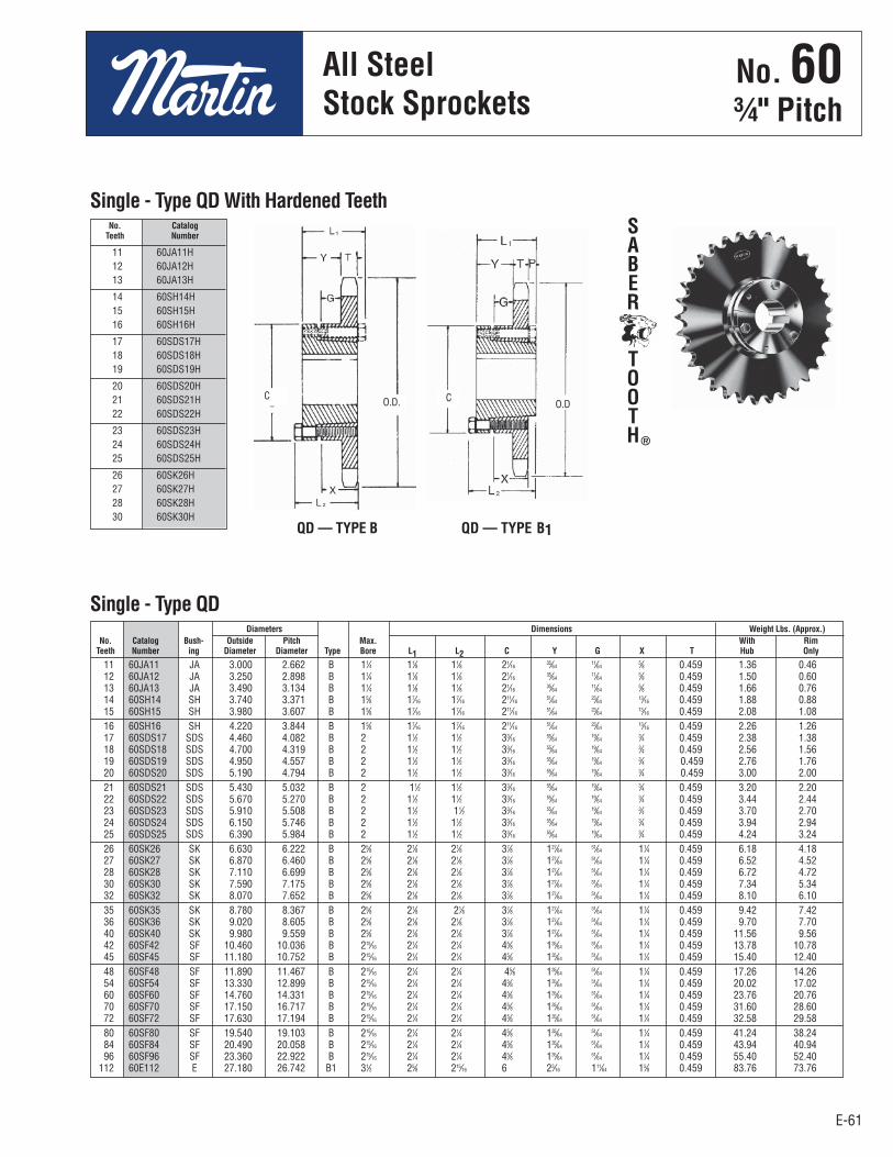
E-61
No. 603⁄4" Pitch
E-61
SABER
TOOTH®
All SteelStock Sprockets
11 60JA11H 12 60JA12H 13 60JA13H
14 60SH14H 15 60SH15H 16 60SH16H
17 60SDS17H 18 60SDS18H 19 60SDS19H
20 60SDS20H 21 60SDS21H 22 60SDS22H
23 60SDS23H 24 60SDS24H 25 60SDS25H
26 60SK26H 27 60SK27H 28 60SK28H 30 60SK30H
11 60JA11 JA 3.000 2.662 B 11⁄4 11⁄8 11⁄8 21⁄16 35⁄64 11⁄64 5⁄8 0.459 1.36 0.46 12 60JA12 JA 3.250 2.898 B 11⁄4 11⁄8 11⁄8 21⁄16 35⁄64 11⁄64 5⁄8 0.459 1.50 0.60 13 60JA13 JA 3.490 3.134 B 11⁄4 11⁄8 11⁄8 21⁄16 35⁄64 11⁄64 5⁄8 0.459 1.66 0.76 14 60SH14 SH 3.740 3.371 B 15⁄8 17⁄16 17⁄16 211⁄16 51⁄64 23⁄64 13⁄16 0.459 1.88 0.88 15 60SH15 SH 3.980 3.607 B 15⁄8 17⁄16 17⁄16 211⁄16 51⁄64 23⁄64 13⁄16 0.459 2.08 1.08 16 60SH16 SH 4.220 3.844 B 15⁄8 17⁄16 17⁄16 211⁄16 51⁄64 23⁄64 13⁄16 0.459 2.26 1.26 17 60SDS17 SDS 4.460 4.082 B 2 11⁄2 11⁄2 33⁄16 55⁄64 19⁄64 3⁄4 0.459 2.38 1.38 18 60SDS18 SDS 4.700 4.319 B 2 11⁄2 11⁄2 33⁄16 55⁄64 19⁄64 3⁄4 0.459 2.56 1.56 19 60SDS19 SDS 4.950 4.557 B 2 11⁄2 11⁄2 33⁄16 55⁄64 19⁄64 3⁄4 0.459 2.76 1.76 20 60SDS20 SDS 5.190 4.794 B 2 11⁄2 11⁄2 33⁄16 55⁄64 19⁄64 3⁄4 0.459 3.00 2.00 21 60SDS21 SDS 5.430 5.032 B 2 11⁄2 11⁄2 33⁄16 55⁄64 19⁄64 3⁄4 0.459 3.20 2.20 22 60SDS22 SDS 5.670 5.270 B 2 11⁄2 11⁄2 33⁄16 55⁄64 19⁄64 3⁄4 0.459 3.44 2.44 23 60SDS23 SDS 5.910 5.508 B 2 11⁄2 11⁄2 33⁄16 55⁄64 19⁄64 3⁄4 0.459 3.70 2.70 24 60SDS24 SDS 6.150 5.746 B 2 11⁄2 11⁄2 33⁄16 55⁄64 19⁄64 3⁄4 0.459 3.94 2.94 25 60SDS25 SDS 6.390 5.984 B 2 11⁄2 11⁄2 33⁄16 55⁄64 19⁄64 3⁄4 0.459 4.24 3.24 26 60SK26 SK 6.630 6.222 B 25⁄8 21⁄8 21⁄8 37⁄8 127⁄64 51⁄64 11⁄4 0.459 6.18 4.18 27 60SK27 SK 6.870 6.460 B 25⁄8 21⁄8 21⁄8 37⁄8 127⁄64 51⁄64 11⁄4 0.459 6.52 4.52 28 60SK28 SK 7.110 6.699 B 25⁄8 21⁄8 21⁄8 37⁄8 127⁄64 51⁄64 11⁄4 0.459 6.72 4.72 30 60SK30 SK 7.590 7.175 B 25⁄8 21⁄8 21⁄8 37⁄8 127⁄64 51⁄64 11⁄4 0.459 7.34 5.34 32 60SK32 SK 8.070 7.652 B 25⁄8 21⁄8 21⁄8 37⁄8 127⁄64 51⁄64 11⁄4 0.459 8.10 6.10 35 60SK35 SK 8.780 8.367 B 25⁄8 21⁄8 21⁄8 37⁄8 127⁄64 51⁄64 11⁄4 0.459 9.42 7.42 36 60SK36 SK 9.020 8.605 B 25⁄8 21⁄8 21⁄8 37⁄8 127⁄64 51⁄64 11⁄4 0.459 9.70 7.70 40 60SK40 SK 9.980 9.559 B 25⁄8 21⁄8 21⁄8 37⁄8 127⁄64 51⁄64 11⁄4 0.459 11.56 9.56 42 60SF42 SF 10.460 10.036 B 215⁄16 21⁄4 21⁄4 45⁄8 135⁄64 51⁄64 11⁄4 0.459 13.78 10.78 45 60SF45 SF 11.180 10.752 B 215⁄16 21⁄4 21⁄4 45⁄8 135⁄64 51⁄64 11⁄4 0.459 15.40 12.40 48 60SF48 SF 11.890 11.467 B 215⁄16 21⁄4 21⁄4 45⁄8 135⁄64 51⁄64 11⁄4 0.459 17.26 14.26 54 60SF54 SF 13.330 12.899 B 215⁄16 21⁄4 21⁄4 45⁄8 135⁄64 51⁄64 11⁄4 0.459 20.02 17.02 60 60SF60 SF 14.760 14.331 B 215⁄16 21⁄4 21⁄4 45⁄8 135⁄64 51⁄64 11⁄4 0.459 23.76 20.76 70 60SF70 SF 17.150 16.717 B 215⁄16 21⁄4 21⁄4 45⁄8 135⁄64 51⁄64 11⁄4 0.459 31.60 28.60 72 60SF72 SF 17.630 17.194 B 215⁄16 21⁄4 21⁄4 45⁄8 135⁄64 51⁄64 11⁄4 0.459 32.58 29.58 80 60SF80 SF 19.540 19.103 B 215⁄16 21⁄4 21⁄4 45⁄8 135⁄64 51⁄64 11⁄4 0.459 41.24 38.24 84 60SF84 SF 20.490 20.058 B 215⁄16 21⁄4 21⁄4 45⁄8 135⁄64 51⁄64 11⁄4 0.459 43.94 40.94 96 60SF96 SF 23.360 22.922 B 215⁄16 21⁄4 21⁄4 45⁄8 135⁄64 51⁄64 11⁄4 0.459 55.40 52.40 112 60E112 E 27.180 26.742 B1 31⁄2 25⁄8 215⁄16 6 23⁄16 111⁄64 15⁄8 0.459 83.76 73.76
Diameters Dimensions Weight Lbs. (Approx.) No. Catalog Bush- Outside Pitch Max. With Rim Teeth Number ing Diameter Diameter Type Bore L1 L2 C Y G X T Hub Only
Single - Type QD
No. Catalog Teeth Number
Single - Type QD With Hardened Teeth
QD — TYPE B QD — TYPE B1
O.D. O.DC C
No . 60¾" Pitch
All SteelStock Sprockets
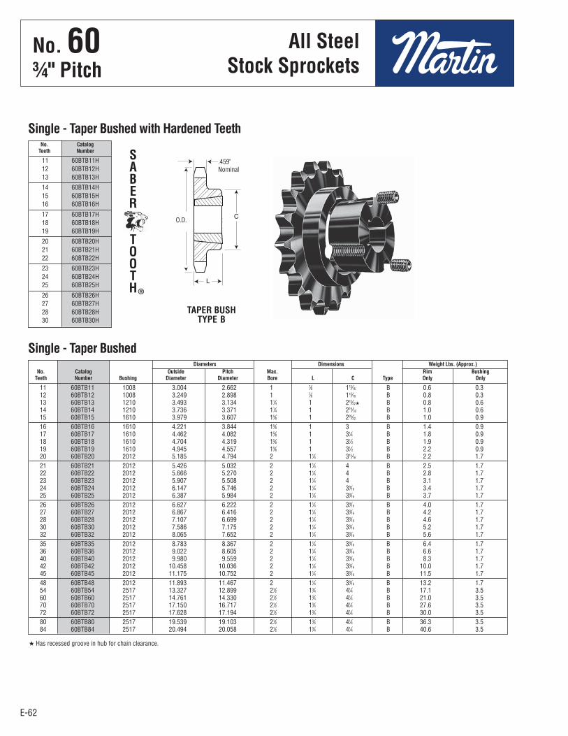
E-62
No. 60Pitch 3⁄4"
E-62
All SteelStock Sprockets
11 60BTB11H 12 60BTB12H 13 60BTB13H
14 60BTB14H 15 60BTB15H 16 60BTB16H
17 60BTB17H 18 60BTB18H 19 60BTB19H
20 60BTB20H 21 60BTB21H 22 60BTB22H
23 60BTB23H 24 60BTB24H 25 60BTB25H
26 60BTB26H 27 60BTB27H 28 60BTB28H 30 60BTB30H
11 60BTB11 1008 3.004 2.662 1 7⁄8 113⁄16 B 0.6 0.3 12 60BTB12 1008 3.249 2.898 1 7⁄8 115⁄16 B 0.8 0.3 13 60BTB13 1210 3.493 3.134 11⁄4 1 215⁄32H B 0.8 0.6 14 60BTB14 1210 3.736 3.371 11⁄4 1 219⁄32 B 1.0 0.6 15 60BTB15 1610 3.979 3.607 15⁄8 1 225⁄32 B 1.0 0.9 16 60BTB16 1610 4.221 3.844 15⁄8 1 3 B 1.4 0.9 17 60BTB17 1610 4.462 4.082 15⁄8 1 31⁄4 B 1.8 0.9 18 60BTB18 1610 4.704 4.319 15⁄8 1 31⁄2 B 1.9 0.9 19 60BTB19 1610 4.945 4.557 15⁄8 1 31⁄2 B 2.2 0.9 20 60BTB20 2012 5.185 4.794 2 11⁄4 315⁄16 B 2.2 1.7 21 60BTB21 2012 5.426 5.032 2 11⁄4 4 B 2.5 1.7 22 60BTB22 2012 5.666 5.270 2 11⁄4 4 B 2.8 1.7 23 60BTB23 2012 5.907 5.508 2 11⁄4 4 B 3.1 1.7 24 60BTB24 2012 6.147 5.746 2 11⁄4 39⁄16 B 3.4 1.7 25 60BTB25 2012 6.387 5.984 2 11⁄4 39⁄16 B 3.7 1.7 26 60BTB26 2012 6.627 6.222 2 11⁄4 39⁄16 B 4.0 1.7 27 60BTB27 2012 6.867 6.416 2 11⁄4 39⁄16 B 4.2 1.7 28 60BTB28 2012 7.107 6.699 2 11⁄4 39⁄16 B 4.6 1.7 30 60BTB30 2012 7.586 7.175 2 11⁄4 39⁄16 B 5.2 1.7 32 60BTB32 2012 8.065 7.652 2 11⁄4 39⁄16 B 5.6 1.7 35 60BTB35 2012 8.783 8.367 2 11⁄4 39⁄16 B 6.4 1.7 36 60BTB36 2012 9.022 8.605 2 11⁄4 39⁄16 B 6.6 1.7 40 60BTB40 2012 9.980 9.559 2 11⁄4 39⁄16 B 8.3 1.7 42 60BTB42 2012 10.458 10.036 2 11⁄4 39⁄16 B 10.0 1.7 45 60BTB45 2012 11.175 10.752 2 11⁄4 39⁄16 B 11.5 1.7 48 60BTB48 2012 11.893 11.467 2 11⁄4 39⁄16 B 13.2 1.7 54 60BTB54 2517 13.327 12.899 21⁄2 13⁄4 41⁄4 B 17.1 3.5 60 60BTB60 2517 14.761 14.330 21⁄2 13⁄4 41⁄4 B 21.0 3.5 70 60BTB70 2517 17.150 16.717 21⁄2 13⁄4 41⁄4 B 27.6 3.5 72 60BTB72 2517 17.628 17.194 21⁄2 13⁄4 41⁄4 B 30.0 3.5 80 60BTB80 2517 19.539 19.103 21⁄2 13⁄4 41⁄4 B 36.3 3.5 84 60BTB84 2517 20.494 20.058 21⁄2 13⁄4 41⁄4 B 40.6 3.5
Diameters Dimensions Weight Lbs. (Approx.) No. Catalog Outside Pitch Max. Rim Bushing Teeth Number Bushing Diameter Diameter Bore L C Type Only Only
Single - Taper Bushed
H Has recessed groove in hub for chain clearance.
No. Catalog Teeth Number
Single - Taper Bushed with Hardened Teeth
TAPER BUSHTYPE B
.459"Nominal
SABER
TOOTH®
O.D.
No . 60¾" Pitch
All SteelStock Sprockets
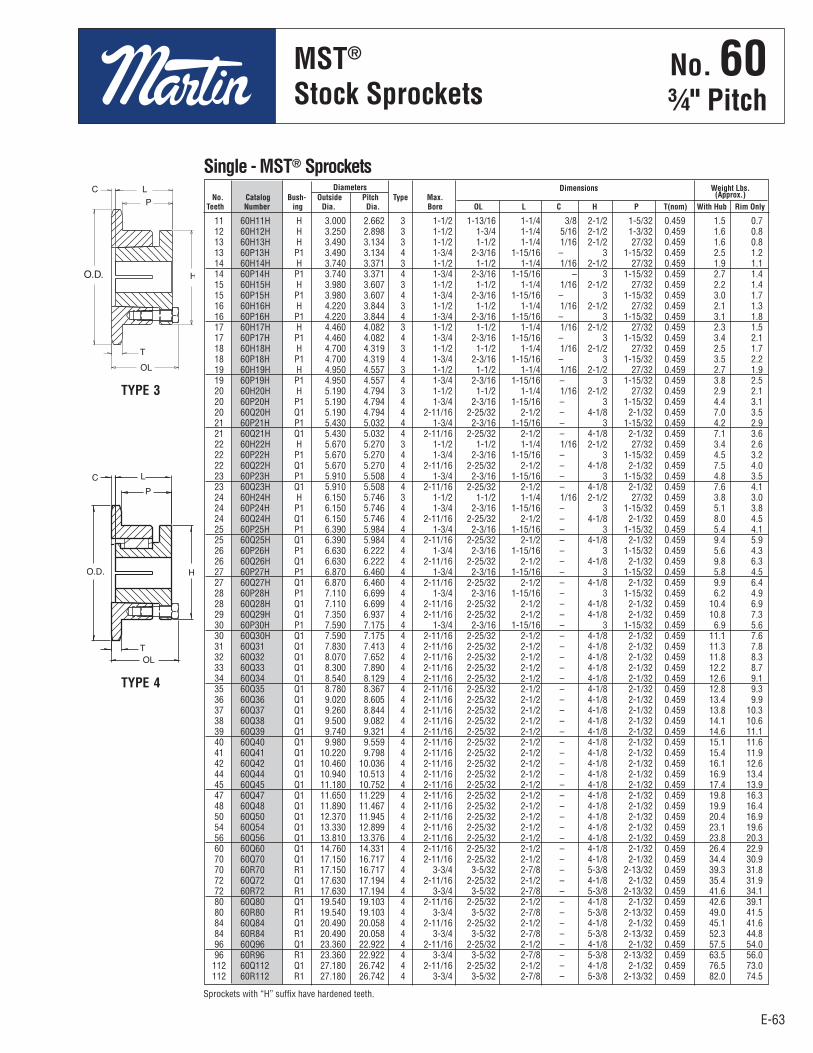
E-63
No. 603⁄4" Pitch
E-63
MST®
Sprockets
Diameters Dimensions Weight Lbs. No. Catalog Bush- Outside Pitch Type Max. (Approx.) Teeth Number ing Dia. Dia. Bore OL L C H P T(nom) With Hub Rim Only
Single - MST® Sprockets
11 60H11H H 3.000 2.662 3 1-1/2 1-13/16 1-1/4 3/8 2-1/2 1-5/32 0.459 1.5 0.7 12 60H12H H 3.250 2.898 3 1-1/2 1-3/4 1-1/4 5/16 2-1/2 1-3/32 0.459 1.6 0.8 13 60H13H H 3.490 3.134 3 1-1/2 1-1/2 1-1/4 1/16 2-1/2 27/32 0.459 1.6 0.8 13 60P13H P1 3.490 3.134 4 1-3/4 2-3/16 1-15/16 – 3 1-15/32 0.459 2.5 1.2 14 60H14H H 3.740 3.371 3 1-1/2 1-1/2 1-1/4 1/16 2-1/2 27/32 0.459 1.9 1.1 14 60P14H P1 3.740 3.371 4 1-3/4 2-3/16 1-15/16 – 3 1-15/32 0.459 2.7 1.4 15 60H15H H 3.980 3.607 3 1-1/2 1-1/2 1-1/4 1/16 2-1/2 27/32 0.459 2.2 1.4 15 60P15H P1 3.980 3.607 4 1-3/4 2-3/16 1-15/16 – 3 1-15/32 0.459 3.0 1.7 16 60H16H H 4.220 3.844 3 1-1/2 1-1/2 1-1/4 1/16 2-1/2 27/32 0.459 2.1 1.3 16 60P16H P1 4.220 3.844 4 1-3/4 2-3/16 1-15/16 – 3 1-15/32 0.459 3.1 1.8 17 60H17H H 4.460 4.082 3 1-1/2 1-1/2 1-1/4 1/16 2-1/2 27/32 0.459 2.3 1.5 17 60P17H P1 4.460 4.082 4 1-3/4 2-3/16 1-15/16 – 3 1-15/32 0.459 3.4 2.1 18 60H18H H 4.700 4.319 3 1-1/2 1-1/2 1-1/4 1/16 2-1/2 27/32 0.459 2.5 1.7 18 60P18H P1 4.700 4.319 4 1-3/4 2-3/16 1-15/16 – 3 1-15/32 0.459 3.5 2.2 19 60H19H H 4.950 4.557 3 1-1/2 1-1/2 1-1/4 1/16 2-1/2 27/32 0.459 2.7 1.9 19 60P19H P1 4.950 4.557 4 1-3/4 2-3/16 1-15/16 – 3 1-15/32 0.459 3.8 2.5 20 60H20H H 5.190 4.794 3 1-1/2 1-1/2 1-1/4 1/16 2-1/2 27/32 0.459 2.9 2.1 20 60P20H P1 5.190 4.794 4 1-3/4 2-3/16 1-15/16 – 3 1-15/32 0.459 4.4 3.1 20 60Q20H Q1 5.190 4.794 4 2-11/16 2-25/32 2-1/2 – 4-1/8 2-1/32 0.459 7.0 3.5 21 60P21H P1 5.430 5.032 4 1-3/4 2-3/16 1-15/16 – 3 1-15/32 0.459 4.2 2.9 21 60Q21H Q1 5.430 5.032 4 2-11/16 2-25/32 2-1/2 – 4-1/8 2-1/32 0.459 7.1 3.6 22 60H22H H 5.670 5.270 3 1-1/2 1-1/2 1-1/4 1/16 2-1/2 27/32 0.459 3.4 2.6 22 60P22H P1 5.670 5.270 4 1-3/4 2-3/16 1-15/16 – 3 1-15/32 0.459 4.5 3.2 22 60Q22H Q1 5.670 5.270 4 2-11/16 2-25/32 2-1/2 – 4-1/8 2-1/32 0.459 7.5 4.0 23 60P23H P1 5.910 5.508 4 1-3/4 2-3/16 1-15/16 – 3 1-15/32 0.459 4.8 3.5 23 60Q23H Q1 5.910 5.508 4 2-11/16 2-25/32 2-1/2 – 4-1/8 2-1/32 0.459 7.6 4.1 24 60H24H H 6.150 5.746 3 1-1/2 1-1/2 1-1/4 1/16 2-1/2 27/32 0.459 3.8 3.0 24 60P24H P1 6.150 5.746 4 1-3/4 2-3/16 1-15/16 – 3 1-15/32 0.459 5.1 3.8 24 60Q24H Q1 6.150 5.746 4 2-11/16 2-25/32 2-1/2 – 4-1/8 2-1/32 0.459 8.0 4.5 25 60P25H P1 6.390 5.984 4 1-3/4 2-3/16 1-15/16 – 3 1-15/32 0.459 5.4 4.1 25 60Q25H Q1 6.390 5.984 4 2-11/16 2-25/32 2-1/2 – 4-1/8 2-1/32 0.459 9.4 5.9 26 60P26H P1 6.630 6.222 4 1-3/4 2-3/16 1-15/16 – 3 1-15/32 0.459 5.6 4.3 26 60Q26H Q1 6.630 6.222 4 2-11/16 2-25/32 2-1/2 – 4-1/8 2-1/32 0.459 9.8 6.3 27 60P27H P1 6.870 6.460 4 1-3/4 2-3/16 1-15/16 – 3 1-15/32 0.459 5.8 4.5 27 60Q27H Q1 6.870 6.460 4 2-11/16 2-25/32 2-1/2 – 4-1/8 2-1/32 0.459 9.9 6.4 28 60P28H P1 7.110 6.699 4 1-3/4 2-3/16 1-15/16 – 3 1-15/32 0.459 6.2 4.9 28 60Q28H Q1 7.110 6.699 4 2-11/16 2-25/32 2-1/2 – 4-1/8 2-1/32 0.459 10.4 6.9 29 60Q29H Q1 7.350 6.937 4 2-11/16 2-25/32 2-1/2 – 4-1/8 2-1/32 0.459 10.8 7.3 30 60P30H P1 7.590 7.175 4 1-3/4 2-3/16 1-15/16 – 3 1-15/32 0.459 6.9 5.6 30 60Q30H Q1 7.590 7.175 4 2-11/16 2-25/32 2-1/2 – 4-1/8 2-1/32 0.459 11.1 7.6 31 60Q31 Q1 7.830 7.413 4 2-11/16 2-25/32 2-1/2 – 4-1/8 2-1/32 0.459 11.3 7.8 32 60Q32 Q1 8.070 7.652 4 2-11/16 2-25/32 2-1/2 – 4-1/8 2-1/32 0.459 11.8 8.3 33 60Q33 Q1 8.300 7.890 4 2-11/16 2-25/32 2-1/2 – 4-1/8 2-1/32 0.459 12.2 8.7 34 60Q34 Q1 8.540 8.129 4 2-11/16 2-25/32 2-1/2 – 4-1/8 2-1/32 0.459 12.6 9.1 35 60Q35 Q1 8.780 8.367 4 2-11/16 2-25/32 2-1/2 – 4-1/8 2-1/32 0.459 12.8 9.3 36 60Q36 Q1 9.020 8.605 4 2-11/16 2-25/32 2-1/2 – 4-1/8 2-1/32 0.459 13.4 9.9 37 60Q37 Q1 9.260 8.844 4 2-11/16 2-25/32 2-1/2 – 4-1/8 2-1/32 0.459 13.8 10.3 38 60Q38 Q1 9.500 9.082 4 2-11/16 2-25/32 2-1/2 – 4-1/8 2-1/32 0.459 14.1 10.6 39 60Q39 Q1 9.740 9.321 4 2-11/16 2-25/32 2-1/2 – 4-1/8 2-1/32 0.459 14.6 11.1 40 60Q40 Q1 9.980 9.559 4 2-11/16 2-25/32 2-1/2 – 4-1/8 2-1/32 0.459 15.1 11.6 41 60Q41 Q1 10.220 9.798 4 2-11/16 2-25/32 2-1/2 – 4-1/8 2-1/32 0.459 15.4 11.9 42 60Q42 Q1 10.460 10.036 4 2-11/16 2-25/32 2-1/2 – 4-1/8 2-1/32 0.459 16.1 12.6 44 60Q44 Q1 10.940 10.513 4 2-11/16 2-25/32 2-1/2 – 4-1/8 2-1/32 0.459 16.9 13.4 45 60Q45 Q1 11.180 10.752 4 2-11/16 2-25/32 2-1/2 – 4-1/8 2-1/32 0.459 17.4 13.9 47 60Q47 Q1 11.650 11.229 4 2-11/16 2-25/32 2-1/2 – 4-1/8 2-1/32 0.459 19.8 16.3 48 60Q48 Q1 11.890 11.467 4 2-11/16 2-25/32 2-1/2 – 4-1/8 2-1/32 0.459 19.9 16.4 50 60Q50 Q1 12.370 11.945 4 2-11/16 2-25/32 2-1/2 – 4-1/8 2-1/32 0.459 20.4 16.9 54 60Q54 Q1 13.330 12.899 4 2-11/16 2-25/32 2-1/2 – 4-1/8 2-1/32 0.459 23.1 19.6 56 60Q56 Q1 13.810 13.376 4 2-11/16 2-25/32 2-1/2 – 4-1/8 2-1/32 0.459 23.8 20.3 60 60Q60 Q1 14.760 14.331 4 2-11/16 2-25/32 2-1/2 – 4-1/8 2-1/32 0.459 26.4 22.9 70 60Q70 Q1 17.150 16.717 4 2-11/16 2-25/32 2-1/2 – 4-1/8 2-1/32 0.459 34.4 30.9 70 60R70 R1 17.150 16.717 4 3-3/4 3-5/32 2-7/8 – 5-3/8 2-13/32 0.459 39.3 31.8 72 60Q72 Q1 17.630 17.194 4 2-11/16 2-25/32 2-1/2 – 4-1/8 2-1/32 0.459 35.4 31.9 72 60R72 R1 17.630 17.194 4 3-3/4 3-5/32 2-7/8 – 5-3/8 2-13/32 0.459 41.6 34.1 80 60Q80 Q1 19.540 19.103 4 2-11/16 2-25/32 2-1/2 – 4-1/8 2-1/32 0.459 42.6 39.1 80 60R80 R1 19.540 19.103 4 3-3/4 3-5/32 2-7/8 – 5-3/8 2-13/32 0.459 49.0 41.5 84 60Q84 Q1 20.490 20.058 4 2-11/16 2-25/32 2-1/2 – 4-1/8 2-1/32 0.459 45.1 41.6 84 60R84 R1 20.490 20.058 4 3-3/4 3-5/32 2-7/8 – 5-3/8 2-13/32 0.459 52.3 44.8 96 60Q96 Q1 23.360 22.922 4 2-11/16 2-25/32 2-1/2 – 4-1/8 2-1/32 0.459 57.5 54.0 96 60R96 R1 23.360 22.922 4 3-3/4 3-5/32 2-7/8 – 5-3/8 2-13/32 0.459 63.5 56.0 112 60Q112 Q1 27.180 26.742 4 2-11/16 2-25/32 2-1/2 – 4-1/8 2-1/32 0.459 76.5 73.0 112 60R112 R1 27.180 26.742 4 3-3/4 3-5/32 2-7/8 – 5-3/8 2-13/32 0.459 82.0 74.5
Sprockets with “H” suffix have hardened teeth.
TYPE 3
TYPE 4
No . 60¾" Pitch
MST®
Stock Sprockets

E-64
No. 60-23⁄4" Pitch
E-64
All Steel Stock Sprockets
.444Nominal
1.341
14 D60SH14H SH 3.740 3.371 BHH 15⁄8 131⁄32 131⁄32 211⁄16 1⁄2 – – – 0.444 1.341 2.50 1.50 22 D60SDS22H SDS 5.670 5.270 BH 2 117⁄32 115⁄32 33⁄16 – – – 3⁄4 0.444 1.341 5.44 4.44 36 D60SF36 SF 9.020 8.605 C1 215⁄16 2 21⁄4 45⁄8 3⁄4 – – 11⁄4 0.444 1.341 19.26 16.26 42 D60E42 E 10.460 10.036 C2 31⁄2 25⁄8 215⁄16 6 7⁄8 13⁄32 9⁄32 15⁄8 0.444 1.341 34.04 24.04 45 D60E45 E 11.180 10.752 C2 31⁄2 25⁄8 215⁄16 6 7⁄8 13⁄32 9⁄32 15⁄8 0.444 1.341 38.26 28.36 52 D60E52 E 12.850 12.422 C2 31⁄2 25⁄8 215⁄16 6 7⁄8 13⁄32 9⁄32 15⁄8 0.444 1.341 49.52 39.52 60 D60E60 E 14.760 14.331 C2 31⁄2 25⁄8 215⁄16 6 7⁄8 13⁄32 9⁄32 15⁄8 0.444 1.341 63.39 53.74 68 D60E68 E 16.670 16.240 C4 31⁄2 25⁄8 215⁄16 6 7⁄8 13⁄32 9⁄32 15⁄8 0.444 1.341 54.32 44.32 76 D60E76 E 18.580 18.149 C4 31⁄2 25⁄8 215⁄16 6 7⁄8 13⁄32 9⁄32 15⁄8 0.444 1.341 61.48 51.48 95 D60E95 E 23.120 22.683 C4 31⁄2 25⁄8 215⁄16 6 7⁄8 13⁄32 9⁄32 15⁄8 0.444 1.341 82.96 72.96
Diameters Dimensions Weight Lbs. (Approx.) No. Catalog Bush- Outside Pitch Max. With Rim Teeth Number ing Diameter Diameter Type Bore L1 L2 C Y P G X T W Hub Only
Double - Type QD
11 D60B11H 3.000 B 1 11⁄4 113⁄16 21⁄8 1.62 12 D60B12H 3.250 B 1 17⁄16 21⁄8 21⁄8 2.20 13 D60B13H 3.490 B 1 11⁄2 21⁄4 21⁄8 2.60 14 D60B14H 3.740 B 1 13⁄4 21⁄2 21⁄8 3.24 15 D60B15H 3.980 B 1 17⁄8 213⁄16 21⁄8 3.96 16 D60B16H 4.220 B 1 2 3 21⁄8 4.62 17 D60B17H 4.460 B 1 21⁄4 31⁄4 21⁄8 5.40 18 D60B18H 4.700 B 1 23⁄8 31⁄2 21⁄8 6.24 19 D60B19H 4.950 B 1 21⁄2 311⁄16 21⁄8 7.00 20 D60B20H 5.190 B 1 21⁄2 33⁄4 21⁄8 7.72 21 D60B21H 5.430 B 1 23⁄4 41⁄8 21⁄8 8.82 22 D60B22H 5.670 B 1 23⁄4 41⁄4 21⁄8 9.68 23 D60B23H 5.910 B 1 23⁄4 41⁄4 21⁄8 10.30 24 D60B24H 6.150 B 1 23⁄4 41⁄4 21⁄8 11.14 25 D60B25H 6.390 B 1 23⁄4 41⁄4 21⁄8 11.96 26 D60B26 6.630 B 1 23⁄4 41⁄4 21⁄8 12.70 30 D60B30 7.590 B 1 23⁄4 41⁄4 21⁄8 16.36 32 D60B32 8.070 B 11⁄4 3 41⁄2 23⁄8 19.52 35 D60B35 8.780 B 11⁄4 3 41⁄2 23⁄8 22.80 36 D60B36 9.020 B 11⁄4 3 41⁄2 23⁄8 23.82 40 D60B40 9.980 B 11⁄4 31⁄4 43⁄4 23⁄4 30.84 42 D60B42 10.460 B 11⁄4 31⁄4 43⁄4 23⁄4 33.08 45 D60B45 11.180 B 11⁄4 31⁄4 43⁄4 23⁄4 37.08 52 D60B52 12.850 B 11⁄4 31⁄4 43⁄4 23⁄4 48.70 60 D60B60 14.760 B 11⁄4 31⁄4 43⁄4 23⁄4 63.10 68 D60C68 16.670 C 11⁄4 35⁄16 5 3 53.68 72 D60C72 17.630 C 11⁄4 35⁄16 5 3 53.74 76 D60C76 18.580 C 11⁄4 35⁄16 5 3 60.28 95 D60C95 23.120 C 11⁄4 33⁄4 51⁄2 31⁄2 87.14
Bore (inches) Hub (inches) Weight No. Catalog Outside Rec. Length Lbs. Teeth Number Diameter Type Stock Max. Dia. Thru (Approx.)
Double - Type B & C
Maximum bores shown will accommodate standard keyseat and setscrew overkeyseat. Slightly larger bores are possible with no keyseat, shallow keyseat, orsetscrew at angle to keyseat.
NOTE: Double 60 stock sprockets with 25 teeth or less have hardened teeth. Asindicated by H suffix.
Alteration Charges
See current discountsheet for alteration charges.
HH Not illustrated. Dimensions listed correspond approximately to illustrations shown.
TYPE B TYPE C
QD — TYPE C2 QD — TYPE C4QD — TYPE C1
.444Nominal
1.341
Length Thru
HubDia.
Length ThruBore
HubDia.
Length Thru Bore
No . 60-2¾" Pitch
All SteelStock Sprockets
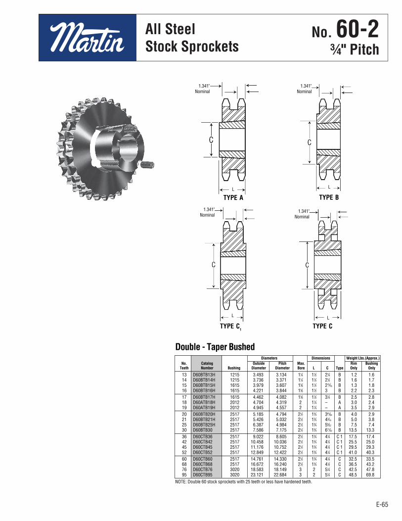
E-65
No. 60-23⁄4" Pitch
All SteelStock Sprockets
E-65
13 D60BTB13H 1215 3.493 3.134 11⁄4 11⁄2 21⁄4 B 1.2 1.6 14 D60BTB14H 1215 3.736 3.371 11⁄4 11⁄2 21⁄2 B 1.6 1.7 15 D60BTB15H 1615 3.979 3.607 15⁄8 11⁄2 213⁄16 B 1.3 1.8 16 D60BTB16H 1615 4.221 3.844 15⁄8 11⁄2 3 B 2.2 2.3 17 D60BTB17H 1615 4.462 4.082 15⁄8 11⁄2 31⁄4 B 2.5 2.8 18 D60ATB18H 2012 4.704 4.319 2 11⁄4 – A 3.0 2.4 19 D60ATB19H 2012 4.945 4.557 2 11⁄4 – A 3.5 2.9 20 D60BTB20H 2517 5.185 4.794 21⁄2 13⁄4 361⁄64 B 4.0 2.9 21 D60BTB21H 2517 5.426 5.032 21⁄2 13⁄4 43⁄16 B 5.0 3.8 25 D60BTB25H 2517 6.387 4.984 21⁄2 13⁄4 55⁄32 B 7.5 7.4 30 D60BTB30 2517 7.586 7.175 21⁄2 13⁄4 611⁄32 B 13.5 13.3 36 D60CTB36 2517 9.022 8.605 21⁄2 13⁄4 41⁄4 C 1 17.5 17.4 42 D60CTB42 2517 10.458 10.036 21⁄2 13⁄4 41⁄4 C 1 25.5 25.0 45 D60CTB45 2517 11.176 10.752 21⁄2 13⁄4 41⁄4 C 1 29.5 29.3 52 D60CTB52 2517 12.849 12.422 21⁄2 13⁄4 41⁄4 C 1 41.0 40.3 60 D60CTB60 2517 14.761 14.330 21⁄2 13⁄4 41⁄4 C 32.5 33.5 68 D60CTB68 2517 16.672 16.240 21⁄2 13⁄4 41⁄2 C 36.5 43.2 76 D60CTB76 3020 18.583 18.149 3 2 51⁄4 C 42.5 47.8 95 D60CTB95 3020 23.121 22.684 3 2 51⁄4 C 48.5 69.8
Diameters Dimensions Weight Lbs.(Approx.) No. Catalog Outside Pitch Max. Rim Bushing Teeth Number Bushing Diameter Diameter Bore L C Type Only Only
Double - Taper Bushed
NOTE: Double 60 stock sprockets with 25 teeth or less have hardened teeth.
TYPE A TYPE B
TYPE CTYPE C1
1.341"Nominal
1.341"Nominal
1.341"Nominal
1.341"Nominal
LL
LL
E65 - E80-2.qxp_E65 - E80 1/24/18 2:52 PM Page E-65
No . 60-2¾" Pitch
All SteelStock Sprockets
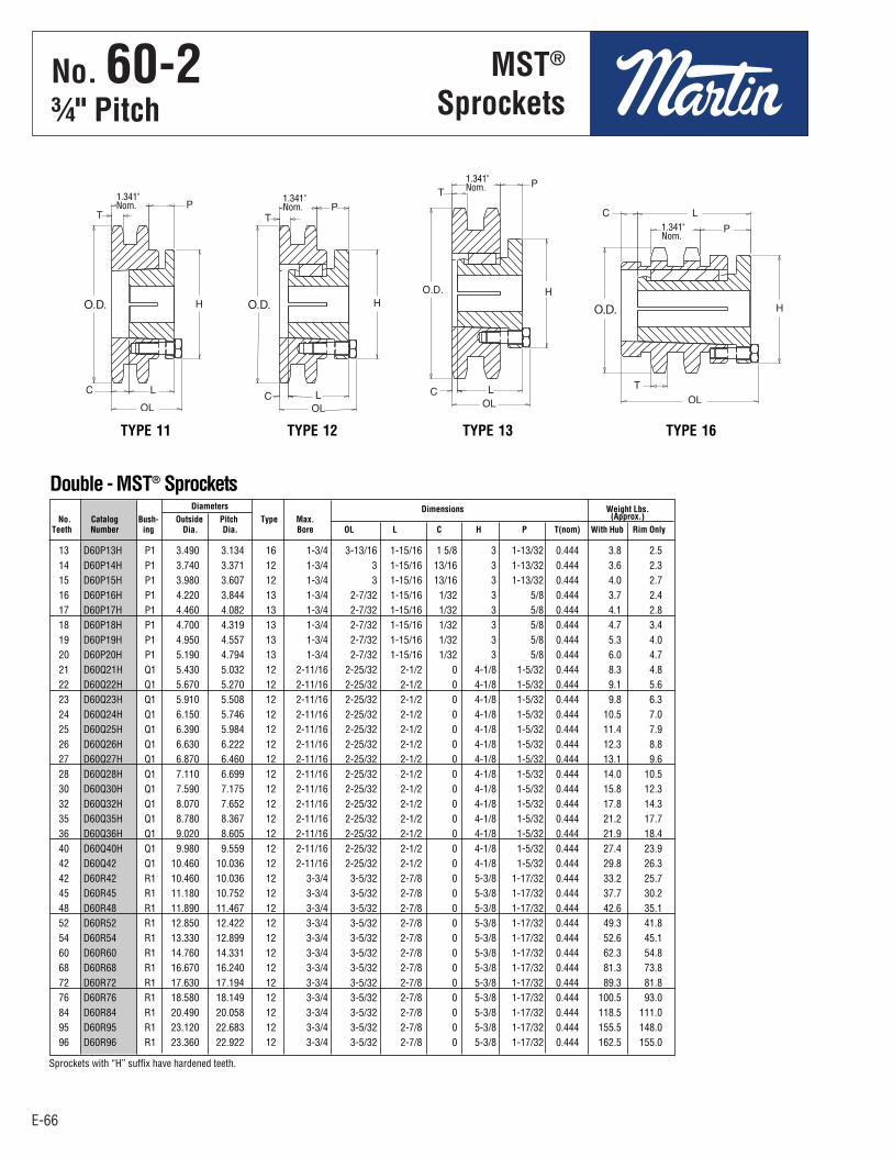
E-66
No. 60-23⁄4" Pitch
E-66
Diameters Dimensions Weight Lbs. No. Catalog Bush- Outside Pitch Type Max. (Approx.) Teeth Number ing Dia. Dia. Bore OL L C H P T(nom) With Hub Rim Only
13 D60P13H P1 3.490 3.134 16 1-3/4 3-13/16 1-15/16 1 5/8 3 1-13/32 0.444 3.8 2.5 14 D60P14H P1 3.740 3.371 12 1-3/4 3 1-15/16 13/16 3 1-13/32 0.444 3.6 2.3 15 D60P15H P1 3.980 3.607 12 1-3/4 3 1-15/16 13/16 3 1-13/32 0.444 4.0 2.7 16 D60P16H P1 4.220 3.844 13 1-3/4 2-7/32 1-15/16 1/32 3 5/8 0.444 3.7 2.4 17 D60P17H P1 4.460 4.082 13 1-3/4 2-7/32 1-15/16 1/32 3 5/8 0.444 4.1 2.8 18 D60P18H P1 4.700 4.319 13 1-3/4 2-7/32 1-15/16 1/32 3 5/8 0.444 4.7 3.4 19 D60P19H P1 4.950 4.557 13 1-3/4 2-7/32 1-15/16 1/32 3 5/8 0.444 5.3 4.0 20 D60P20H P1 5.190 4.794 13 1-3/4 2-7/32 1-15/16 1/32 3 5/8 0.444 6.0 4.7 21 D60Q21H Q1 5.430 5.032 12 2-11/16 2-25/32 2-1/2 0 4-1/8 1-5/32 0.444 8.3 4.8 22 D60Q22H Q1 5.670 5.270 12 2-11/16 2-25/32 2-1/2 0 4-1/8 1-5/32 0.444 9.1 5.6 23 D60Q23H Q1 5.910 5.508 12 2-11/16 2-25/32 2-1/2 0 4-1/8 1-5/32 0.444 9.8 6.3 24 D60Q24H Q1 6.150 5.746 12 2-11/16 2-25/32 2-1/2 0 4-1/8 1-5/32 0.444 10.5 7.0 25 D60Q25H Q1 6.390 5.984 12 2-11/16 2-25/32 2-1/2 0 4-1/8 1-5/32 0.444 11.4 7.9 26 D60Q26H Q1 6.630 6.222 12 2-11/16 2-25/32 2-1/2 0 4-1/8 1-5/32 0.444 12.3 8.8 27 D60Q27H Q1 6.870 6.460 12 2-11/16 2-25/32 2-1/2 0 4-1/8 1-5/32 0.444 13.1 9.6 28 D60Q28H Q1 7.110 6.699 12 2-11/16 2-25/32 2-1/2 0 4-1/8 1-5/32 0.444 14.0 10.5 30 D60Q30H Q1 7.590 7.175 12 2-11/16 2-25/32 2-1/2 0 4-1/8 1-5/32 0.444 15.8 12.3 32 D60Q32H Q1 8.070 7.652 12 2-11/16 2-25/32 2-1/2 0 4-1/8 1-5/32 0.444 17.8 14.3 35 D60Q35H Q1 8.780 8.367 12 2-11/16 2-25/32 2-1/2 0 4-1/8 1-5/32 0.444 21.2 17.7 36 D60Q36H Q1 9.020 8.605 12 2-11/16 2-25/32 2-1/2 0 4-1/8 1-5/32 0.444 21.9 18.4 40 D60Q40H Q1 9.980 9.559 12 2-11/16 2-25/32 2-1/2 0 4-1/8 1-5/32 0.444 27.4 23.9 42 D60Q42 Q1 10.460 10.036 12 2-11/16 2-25/32 2-1/2 0 4-1/8 1-5/32 0.444 29.8 26.3 42 D60R42 R1 10.460 10.036 12 3-3/4 3-5/32 2-7/8 0 5-3/8 1-17/32 0.444 33.2 25.7 45 D60R45 R1 11.180 10.752 12 3-3/4 3-5/32 2-7/8 0 5-3/8 1-17/32 0.444 37.7 30.2 48 D60R48 R1 11.890 11.467 12 3-3/4 3-5/32 2-7/8 0 5-3/8 1-17/32 0.444 42.6 35.1 52 D60R52 R1 12.850 12.422 12 3-3/4 3-5/32 2-7/8 0 5-3/8 1-17/32 0.444 49.3 41.8 54 D60R54 R1 13.330 12.899 12 3-3/4 3-5/32 2-7/8 0 5-3/8 1-17/32 0.444 52.6 45.1 60 D60R60 R1 14.760 14.331 12 3-3/4 3-5/32 2-7/8 0 5-3/8 1-17/32 0.444 62.3 54.8 68 D60R68 R1 16.670 16.240 12 3-3/4 3-5/32 2-7/8 0 5-3/8 1-17/32 0.444 81.3 73.8 72 D60R72 R1 17.630 17.194 12 3-3/4 3-5/32 2-7/8 0 5-3/8 1-17/32 0.444 89.3 81.8 76 D60R76 R1 18.580 18.149 12 3-3/4 3-5/32 2-7/8 0 5-3/8 1-17/32 0.444 100.5 93.0 84 D60R84 R1 20.490 20.058 12 3-3/4 3-5/32 2-7/8 0 5-3/8 1-17/32 0.444 118.5 111.0 95 D60R95 R1 23.120 22.683 12 3-3/4 3-5/32 2-7/8 0 5-3/8 1-17/32 0.444 155.5 148.0 96 D60R96 R1 23.360 22.922 12 3-3/4 3-5/32 2-7/8 0 5-3/8 1-17/32 0.444 162.5 155.0
MST®
Sprockets
Double - MST® Sprockets
1.341"Nom.
1.341"Nom.
1.341"Nom.
1.341"Nom.
Sprockets with “H” suffix have hardened teeth.
TYPE 11 TYPE 12 TYPE 13 TYPE 16
E65 - E80-2.qxp_E65 - E80 1/24/18 2:52 PM Page E-66
No . 60-2¾" Pitch
MST®
Sprockets

E-67
No. 60-33⁄4" Pitch
All SteelStock Sprockets
E-67
36 E60E36 E 9.020 8.605 B 31⁄2 25⁄8 215⁄16 6 17⁄64 1⁄8 – – 15⁄8 0.444 2.238 49.0 37.0 42 E60E42 E 10.460 10.036 B 31⁄2 25⁄8 215⁄16 6 17⁄64 1⁄8 – – 15⁄8 0.444 2.238 62.0 50.0 52 E60E52 E 12.850 12.422 B 31⁄2 25⁄8 215⁄16 6 17⁄64 1⁄8 – – 15⁄8 0.444 2.238 80.0 68.0
68 E60E68 E 16.670 16.240 B1 31⁄2 213⁄16 37⁄64 6 9⁄16 3⁄16 1⁄8 5⁄16 15⁄8 0.444 2.238 83.0 71.0 76 E60E76 E 18.580 18.149 B1 31⁄2 213⁄16 37⁄64 6 9⁄16 3⁄16 1⁄8 5⁄16 15⁄8 0.444 2.238 99.0 87.0 95 E60E95 E 23.120 22.683 B1 31⁄2 213⁄16 37⁄64 6 9⁄16 3⁄16 1⁄8 5⁄16 15⁄8 0.444 2.238 129.0 117.0
11 E60B11H 3.000 B 1 11⁄4 113⁄16 3 2.5 12 E60B12H 3.250 B 1 17⁄16 21⁄8 3 3.3 13 E60B13H 3.490 B 1 11⁄2 21⁄4 3 3.9 14 E60B14H 3.740 B 1 13⁄4 21⁄2 3 4.5 15 E60B15H 3.980 B 1 17⁄8 213⁄16 3 5.4 16 E60B16H 4.220 B 1 2 3 3 6.5 17 E60B17H 4.460 B 1 21⁄4 31⁄4 3 7.7 18 E60B18H 4.700 B 1 23⁄8 31⁄2 3 8.5 19 E60B19H 4.950 B 1 21⁄2 311⁄16 3 10.0 20 E60B20H 5.190 B 1 21⁄2 33⁄4 3 11.2 21 E60B21H 5.430 B 1 23⁄4 41⁄8 3 12.5 22 E60B22H 5.670 B 1 23⁄4 41⁄4 3 13.2 23 E60B23H 5.910 B 1 23⁄4 41⁄4 3 14.6 24 E60B24H 6.150 B 1 23⁄4 41⁄4 3 15.8 25 E60B25H 6.390 B 1 23⁄4 41⁄4 3 17.0 26 E60B26 6.630 B 1 23⁄4 41⁄4 3 18.6 30 E60B30 7.590 B 1 23⁄4 41⁄4 3 23.2 35 E60B35 8.780 B 11⁄4 3 41⁄2 31⁄4 34.5 36 E60B36 9.020 B 11⁄4 3 41⁄2 31⁄4 37.0 42 E60B42 10.460 B 11⁄4 31⁄4 43⁄4 35⁄8 49.0 45 E60B45 11.180 B 11⁄4 31⁄4 43⁄4 35⁄8 57.0 52 E60C52 12.850 C 11⁄4 31⁄4 43⁄4 31⁄2 73.0 60 E60C60 14.760 C 11⁄4 31⁄4 43⁄4 31⁄2 63.0 68 E60C68 16.670 C 11⁄4 31⁄4 5 31⁄2 73.0 72 E60C72 17.630 C 11⁄4 31⁄4 5 31⁄2 85.0 76 E60C76 18.580 C 11⁄2 33⁄4 51⁄2 31⁄2 82.0 95 E60C95 23.120 C 11⁄2 33⁄4 51⁄2 4 105.0
Bore (inches) Hub (inches) Weight No. Catalog Outside Rec. Length Lbs. Teeth Number Diameter Type Stock Max. Dia. Thru (Approx.)
Triple - Type B & C
Maximum bores shown will accommodate standard keyseat and setscrew overkeyseat. Slightly larger bores are possible with no keyseat, shallow keyseat, orsetscrew at angle to keyseat.
NOTE: Triple 60 stock sprockets with 25 teeth or less have hardened teeth. As indi-cated by H suffix.
Alteration Charges
See current discountsheet for alteration charges.
Diameters Dimensions Weight Lbs. (Approx.) No. Catalog Bush- Outside Pitch Max. With Rim Teeth Number ing Diameter Diameter Type Bore L
1 L
2 C Y P G V X T W Hub Only
Triple - Type QD
QD — TYPE B QD — TYPE B1
TYPE B TYPE C
.444"Nominal
2.238".444"Nominal
2.238"
HubDia.
Length Thru Bore
HubDia.
Length Thru Bore
E65 - E80-2.qxp_E65 - E80 1/24/18 2:52 PM Page E-67
No . zAll SteelStock Sprockets
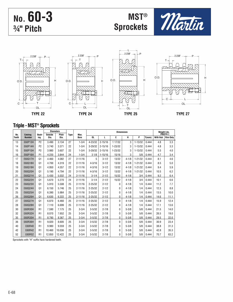
E-68
No. 60-33⁄4" Pitch
E-68
13 E60P13H P2 3.490 3.134 27 1-3/4 4-23/32 2-15/16 1 17/32 3 1-13/32 0.444 4.8 3.3
14 E60P14H P2 3.740 3.371 22 1-3/4 3-29/32 2-15/16 1-23/32 3 1-13/32 0.444 4.8 3.3
15 E60P15H P2 3.980 3.607 22 1-3/4 3-29/32 2-15/16 1-23/32 3 1-13/32 0.444 5.5 4.0
16 E60P16H P1 4.220 3.844 24 1-3/4 3 1/8 1-15/16 15/16 3 5/8 0.444 4.7 3.4
17 E60Q17H Q1 4.460 4.082 27 2-11/16 5 3-1/2 13/32 4-1/8 1-21/32 0.444 8.1 4.6
18 E60Q18H Q1 4.700 4.319 22 2-11/16 4-3/16 3-1/2 13/32 4-1/8 1-21/32 0.444 8.5 5.0
19 E60Q19H Q1 4.950 4.557 22 2-11/16 4-3/16 3-1/2 13/32 4-1/8 1-21/32 0.444 9.4 5.9
20 E60Q20H Q1 5.190 4.794 22 2-11/16 4-3/16 3-1/2 13/32 4-1/8 1-21/32 0.444 10.5 6.2
21 E60Q21H Q1 5.430 5.032 24 2-11/16 3-1/4 2-1/2 15/32 4-1/8 3/4 0.444 9.2 6.4
22 E60Q22H Q1 5.670 5.270 24 2-11/16 3-1/4 2-1/2 15/32 4-1/8 3/4 0.444 10.1 6.6
23 E60Q23H Q1 5.910 5.508 25 2-11/16 2-25/32 2-1/2 0 4-1/8 1/4 0.444 11.2 7.7
24 E60Q24H Q1 6.150 5.746 25 2-11/16 2-25/32 2-1/2 0 4-1/8 1/4 0.444 12.3 8.8
25 E60Q25H Q1 6.390 5.984 25 2-11/16 2-25/32 2-1/2 0 4-1/8 1/4 0.444 13.5 10.0
26 E60Q26H Q1 6.630 6.222 25 2-11/16 2-25/32 2-1/2 0 4-1/8 1/4 0.444 14.6 11.1
27 E60Q27H Q1 6.870 6.460 25 2-11/16 2-25/32 2-1/2 0 4-1/8 1/4 0.444 15.9 12.4
28 E60Q28H Q1 7.110 6.699 25 2-11/16 2-25/32 2-1/2 0 4-1/8 1/4 0.444 17.1 13.6
30 E60R30H R1 7.590 7.175 25 3-3/4 3-5/32 2-7/8 0 5-3/8 5/8 0.444 21.5 14.0
32 E60R32H R1 8.070 7.652 25 3-3/4 3-5/32 2-7/8 0 5-3/8 5/8 0.444 26.5 19.0
35 E60R35H R1 8.780 8.367 25 3-3/4 3-5/32 2-7/8 0 5-3/8 5/8 0.444 29.5 22.0
36 E60R36H R1 9.020 8.605 25 3-3/4 3-5/32 2-7/8 0 5-3/8 5/8 0.444 30.9 23.4
40 E60R40 R1 9.980 9.559 25 3-3/4 3-5/32 2-7/8 0 5-3/8 5/8 0.444 38.8 31.3
42 E60R42 R1 10.460 10.036 25 3-3/4 3-5/32 2-7/8 0 5-3/8 5/8 0.444 42.8 35.3
52 E60R52 R1 12.850 12.422 25 3-3/4 3-5/32 2-7/8 0 5-3/8 5/8 0.444 70.7 63.2
Diameters Dimensions Weight Lbs. No. Catalog Bush- Outside Pitch Type Max. (Approx.) Teeth Number ing Dia. Dia. Bore OL L C H P T(nom) With Hub Rim Only
MST®
Sprockets
Triple - MST® Sprockets
2.238" 2.238"2.238"
2.238"
Sprockets with “H” suffix have hardened teeth.
TYPE 22 TYPE 24 TYPE 25 TYPE 27
E65 - E80-2.qxp_E65 - E80 1/24/18 2:52 PM Page E-68
No . 60-3¾" Pitch
MST®
Sprockets

E-69
No. 801" Pitch
All SteelStock Sprockets
E-69
9 80BS9 3.350 15⁄8 1.6 1 — 11⁄8 — 13⁄16 — 11⁄4 10 80BS10 3.680 15⁄8 1.7 1 — 11⁄8 — 13⁄16 — 11⁄4 10 80BS10WH 3.680 15⁄8 1.7 — 11⁄4 11 80BS11 4.010 15⁄8 1.8 1 — 11⁄8 — 13⁄16 — 11⁄4 — 13⁄8 — 17⁄16 — 11⁄2 — 15⁄8 11 80BS11WHH 4.010 15⁄8 1.8 — 11⁄4 12 80BS12 4.330 15⁄8 3.0 1 — 11⁄8 — 13⁄16 — 11⁄4 — 13⁄8 — 17⁄16 — 11⁄2 — 15⁄8 — 13⁄4 12 80BS12WHH 4.330 15⁄8 3.0 — 11⁄4 13 80BS13 4.660 11⁄2 3.5 1 — 11⁄8 — 13⁄16 — 11⁄4 — 13⁄8 — 17⁄16 — 11⁄2 — 15⁄8 — 13⁄4 — 17⁄8 — 115⁄16 — 2 14 80BS14 4.980 11⁄2 4.1 1 — 11⁄8 — 13⁄16 — 11⁄4 — 13⁄8 — 17⁄16 — 11⁄2 — 15⁄8 — 13⁄4 — 17⁄8 — 115⁄16 — 2 15 80BS15 5.300 11⁄2 5.2 1 — 11⁄8 — 13⁄16 — 11⁄4 — 13⁄8 — 17⁄16 — 11⁄2 — 15⁄8 — 13⁄4 — 17⁄8 — 115⁄16 — 2 15 80BS15WHH 5.300 11⁄2 5.3 — 11⁄4 16 80BS16 5.630 11⁄2 5.5 1 — — 13⁄16 — 11⁄4 — 13⁄8 — 17⁄16 — 11⁄2 — 15⁄8 — 13⁄4 — — 115⁄16 — 2 — 23⁄16
17 80BS17 5.950 11⁄2 6.0 1 — — 13⁄16 — 11⁄4 — 13⁄8 — 17⁄16 — 11⁄2 — 15⁄8 — 13⁄4 — — 115⁄16 — 2 — 23⁄16 — 27⁄16
18 80BS18 6.270 11⁄2 6.5 1 — — 13⁄16 — 11⁄4 — 13⁄8 — 17⁄16 — 11⁄2 — 15⁄8 — 13⁄4 — — 115⁄16 — 2 — 23⁄16 — 27⁄16
18 80BS18WHH 6.270 11⁄2 6.0 — 11⁄4 — 11⁄2 19 80BS19 6.590 11⁄2 7.0 1 — — 13⁄16 — 11⁄4 — 13⁄8 — 17⁄16 — 11⁄2 — 15⁄8 — 13⁄4 — — 115⁄16 — 2 — 23⁄16 — 27⁄16
20 80BS20 6.910 11⁄2 8.0 1 — — 13⁄16 — 11⁄4 — 13⁄8 — 17⁄16 — 11⁄2 — 15⁄8 — 13⁄4 — — 115⁄16 — 2 — 23⁄16 — 27⁄16
21 80BS21 7.240 13⁄4 8.9 1 — — 13⁄16 — 11⁄4 — 13⁄8 — 17⁄16 — 11⁄2 — 15⁄8 — 13⁄4 — — 115⁄16 — 2 — 23⁄16 — 27⁄16
22 80BS22 7.560 13⁄4 9.5 1 — — 13⁄16 — 11⁄4 — 13⁄8 — 17⁄16 — 11⁄2 — 15⁄8 — 13⁄4 — — 115⁄16 — 2 — 23⁄16 — 27⁄16
23 80BS23 7.880 13⁄4 10.2 1 — — 13⁄16 — 11⁄4 — 13⁄8 — 17⁄16 — 11⁄2 — 15⁄8 — 13⁄4 — — 115⁄16 — 2 — 23⁄16 — 27⁄16
24 80BS24 8.200 13⁄4 10.8 1 — — 13⁄16 — 11⁄4 — 13⁄8 — 17⁄16 — 11⁄2 — 15⁄8 — 13⁄4 — — 115⁄16 — 2 — 23⁄16 — 27⁄16
25 80BS25 8.520 13⁄4 11.4 1 — — 13⁄16 — 11⁄4 — 13⁄8 — 17⁄16 — 11⁄2 — 15⁄8 — 13⁄4 — — 115⁄16 — 2 — 23⁄16 — 27⁄16
26 80BS26 8.840 2 14.0 — 11⁄4 — 13⁄8 — 17⁄16 — 11⁄2 — 15⁄8 — 13⁄4 — — 115⁄16 — 2 — 23⁄16 — 27⁄16 — 215⁄16
27 80BS27 9.160 2 14.7 — 11⁄4 — 13⁄8 — 17⁄16 — 11⁄2 — 15⁄8 — 13⁄4 — — 115⁄16 — 2 — 23⁄16 — 27⁄16 — 215⁄16
28 80BS28 9.480 2 15.3 — 11⁄4 — 13⁄8 — 17⁄16 — 11⁄2 — 15⁄8 — 13⁄4 — — 115⁄16 — 2 — 23⁄16 — 27⁄16 — 215⁄16
29 80BS29 9.800 2 16.4 — 11⁄4 — 13⁄8 — 17⁄16 — 11⁄2 — 15⁄8 — 13⁄4 — — 115⁄16 — 2 — 23⁄16 — 27⁄16 — 215⁄16
30 80BS30 10.110 2 16.7 — 11⁄4 — 13⁄8 — 17⁄16 — 11⁄2 — 15⁄8 — 13⁄4 — — 115⁄16 — 2 — 23⁄16 — 27⁄16 — 215⁄16
31 80BS31 10.430 2 18.0 — 11⁄4 — 13⁄8 — 17⁄16 — 11⁄2 — 15⁄8 — 13⁄4 — — 115⁄16 — 2 — 23⁄16 — 27⁄16 — 215⁄16
32 80BS32 10.750 2 18.8 — 11⁄4 — 13⁄8 — 17⁄16 — 11⁄2 — 15⁄8 — 13⁄4 — — 115⁄16 — 2 — 23⁄16 — 27⁄16 — 215⁄16
33 80BS33 11.070 2 18.9 — 11⁄4 — 13⁄8 — 17⁄16 — 11⁄2 — 15⁄8 — 13⁄4 — — 115⁄16 — 2 — 23⁄16 — 27⁄16 — 215⁄16
34 80BS34 11.390 2 20.6 — 11⁄4 — 13⁄8 — 17⁄16 — 11⁄2 — 15⁄8 — 13⁄4 — — 115⁄16 — 2 — 23⁄16 — 27⁄16 — 215⁄16
35 80BS35 11.710 2 21.4 — 11⁄4 — 13⁄8 — 17⁄16 — 11⁄2 — 15⁄8 — 13⁄4 — — 115⁄16 — 2 — 23⁄16 — 27⁄16 — 215⁄16
36 80BS36 12.030 2 22.4 — 11⁄4 — 13⁄8 — 17⁄16 — 11⁄2 — 15⁄8 — 13⁄4 — — 115⁄16 — 2 — 23⁄16 — 27⁄16 — 215⁄16
37 80BS37 12.350 2 23.9 — 11⁄4 — 13⁄8 — 17⁄16 — 11⁄2 — 15⁄8 — 13⁄4 — — 115⁄16 — 2 — 23⁄16 — 27⁄16 — 215⁄16
38 80BS38 12.670 2 24.0 — 11⁄4 — 13⁄8 — 17⁄16 — 11⁄2 — 15⁄8 — 13⁄4 — — 115⁄16 — 2 — 23⁄16 — 27⁄16 — 215⁄16
39 80BS39 12.990 2 24.9 — 11⁄4 — 13⁄8 — 17⁄16 — 11⁄2 — 15⁄8 — 13⁄4 — — 115⁄16 — 2 — 23⁄16 — 27⁄16 — 215⁄16
40 80BS40 13.310 2 26.0 — 11⁄4 — 13⁄8 — 17⁄16 — 11⁄2 — 15⁄8 — 13⁄4 — — 115⁄16 — 2 — 23⁄16 — 27⁄16 — 215⁄16
41 80BS41 13.630 2 27.1 — 13⁄8 — 17⁄16 — 11⁄2 — 15⁄8 — 13⁄4 — — 115⁄16 — 2 — 23⁄16 — 27⁄16 — 215⁄16
42 80BS42 13.940 2 28.0 — 13⁄8 — 17⁄16 — 11⁄2 — 15⁄8 — 13⁄4 — — 115⁄16 — 2 — 23⁄16 — 27⁄16 — 215⁄16
43 80BS43 14.260 2 29.3 — 13⁄8 — 17⁄16 — 11⁄2 — 15⁄8 — 13⁄4 — — 115⁄16 — 2 — 23⁄16 — 27⁄16 — 215⁄16
44 80BS44 14.580 2 29.3 — 13⁄8 — 17⁄16 — 11⁄2 — 15⁄8 — 13⁄4 — — 115⁄16 — 2 — 23⁄16 — 27⁄16 — 215⁄16
45 80BS45 14.900 2 30.7 — 13⁄8 — 17⁄16 — 11⁄2 — 15⁄8 — 13⁄4 — — 115⁄16 — 2 — 23⁄16 — 27⁄16 — 215⁄16
46 80BS46 15.220 2 32.4 — 13⁄8 — 17⁄16 — 11⁄2 — 15⁄8 — 13⁄4 — — 115⁄16 — 2 — 23⁄16 — 27⁄16 — 215⁄16
47 80BS47 15.540 2 33.3 — 13⁄8 — 17⁄16 — 11⁄2 — 15⁄8 — 13⁄4 — — 115⁄16 — 2 — 23⁄16 — 27⁄16 — 215⁄16
48 80BS48 15.860 2 34.8 — 13⁄8 — 17⁄16 — 11⁄2 — 15⁄8 — 13⁄4 — — 115⁄16 — 2 — 23⁄16 — 27⁄16 — 215⁄16
49 80BS49 16.180 2 35.1 — 13⁄8 — 17⁄16 — 11⁄2 — 15⁄8 — 13⁄4 — — 115⁄16 — 2 — 23⁄16 — 27⁄16 — 215⁄16
50 80BS50 16.500 2 36.6 — 13⁄8 — 17⁄16 — 11⁄2 — 15⁄8 — 13⁄4 — — 115⁄16 — 2 — 23⁄16 — 27⁄16 — 215⁄16
51 80BS51 16.810 2 38.5 — 13⁄8 — 17⁄16 — 11⁄2 — 15⁄8 — 13⁄4 — — 115⁄16 — 2 — 23⁄16 — 27⁄16 — 215⁄16
52 80BS52 17.130 2 40.3 — 13⁄8 — 17⁄16 — 11⁄2 — 15⁄8 — 13⁄4 — — 115⁄16 — 2 — 23⁄16 — 27⁄16 — 215⁄16
53 80BS53 17.450 2 42.2 — 13⁄8 — 17⁄16 — 11⁄2 — 15⁄8 — 13⁄4 — — 115⁄16 — 2 — 23⁄16 — 27⁄16 — 215⁄16
54 80BS54 17.770 2 44.0 — 13⁄8 — 17⁄16 — 11⁄2 — 15⁄8 — 13⁄4 — — 115⁄16 — 2 — 23⁄16 — 27⁄16 — 215⁄16
55 80BS55 18.090 2 46.3 — 13⁄8 — 17⁄16 — 11⁄2 — 15⁄8 — 13⁄4 — — 115⁄16 — 2 — 23⁄16 — 27⁄16 — 215⁄16
56 80BS56 18.410 2 47.3 — 13⁄8 — 17⁄16 — 11⁄2 — 15⁄8 — 13⁄4 — — 115⁄16 — 2 — 23⁄16 — 27⁄16 — 215⁄16
57 80BS57 18.730 2 48.9 — 13⁄8 — 17⁄16 — 11⁄2 — 15⁄8 — 13⁄4 — — 115⁄16 — 2 — 23⁄16 — 27⁄16 — 215⁄16
58 80BS58 19.040 2 50.6 — 13⁄8 — 17⁄16 — 11⁄2 — 15⁄8 — 13⁄4 — — 115⁄16 — 2 — 23⁄16 — 27⁄16 — 215⁄16
59 80BS59 19.360 2 52.2 — 13⁄8 — 17⁄16 — 11⁄2 — 15⁄8 — 13⁄4 — — 115⁄16 — 2 — 23⁄16 — 27⁄16 — 215⁄16
60 80BS60 19.680 2 58.8 — 13⁄8 — 17⁄16 — 11⁄2 — 15⁄8 — 13⁄4 — — 115⁄16 — 2 — 23⁄16 — 27⁄16 — 215⁄16
Length Weight Stock Finished Bores No. Catalog Outside Thru Lbs. Includes Keyway Teeth Number Diameter Bore (Approx.) and Setscrews
Single Type BS — 2 Setscrews — Bored-To-Size
Hub diameters vary to suit different bore sizes. NOTE: KEYWAY IS ON CENTER LINE OF TOOTHH W = Winch Sprockets — KW 5⁄16 × 5⁄32 – One S.S. at 90°
E65 - E80-2.qxp_E65 - E80 1/24/18 2:52 PM Page E-69
No . 801" Pitch
All SteelStock Sprockets

E-70
No. 801" Pitch
All SteelStock Sprockets
E-70
10 80BS10W 3.680 15⁄8 1.7 11⁄4
11 80BS11W 4.010 15⁄8 1.8 11⁄4
12 80BS12W 4.330 15⁄8 3.0 11⁄4
15 80BS15W 5.300 11⁄2 5.2 11⁄4
18 80BS18W 6.270 11⁄2 7.8 11⁄4 — 11⁄2
Length Weight Stock Finished Bores No. Catalog Outside Thru Lbs. Includes Keyway (see Footnote) Teeth Number Diameter Bore (Approx.) and Set Screw at 90° from Keyway
Single Type BS Winch — 1 Setscrew
NOTE: KEYWAY IS ON CENTER LINE OF TOOTH.
12 D80BS12HW 3.680 21⁄2 5.2 11⁄4 — 11⁄2 — 13⁄4
15 D80BS15HW 5.300 21⁄2 9.2 11⁄4 — 11⁄2 — 13⁄4
18 D80BS18HW 6.270 23⁄4 13.5 11⁄2 — 13⁄4 — 2
20 D80BS20HW 6.910 23⁄4 16.2 11⁄2 — 13⁄4 — 2
24 D80BS24HW 8.200 23⁄4 23.2 11⁄2 — 13⁄4 — 2
Length Weight Stock Finished Bores No. Catalog Outside Thru Lbs. Includes Keyway (see Footnote) Teeth Number Diameter Bore (Approx.) and Set Screw at 90° from Keyway
Double Type BS Winch (Hardened Teeth) — 1 Setscrew
NOTE: KEYWAY IS ON CENTER LINE OF TOOTH.
Footnote: 11⁄4" bore has a 5⁄16 × 5⁄32" keyway11⁄2" bore has a 5⁄16 × 5⁄32" keyway13⁄4" bore has a 3⁄8 × 3⁄16" keyway2" bore has a 3⁄8 × 3⁄16" keyway
SINGLE TYPE BS
DOUBLE TYPE BS
.575"Nominal
.557"Nominal
1.710"
Length ThruBore
Length ThruBore
9 80BS9HT 3.350 15⁄8 1.6 1 – 11⁄8 – 13⁄16 – 11⁄4 10 80BS10HT 3.368 15⁄8 1.7 1 – 11⁄8 – 13⁄16 – 11⁄4 11 80BS11HT 4.010 15⁄8 1.8 1 – 11⁄8 – 13⁄16 – 11⁄4 – 13⁄8 – 17⁄16 – 11⁄2 – 15⁄8 12 80BS12HT 4.330 15⁄8 3.0 1 – 11⁄8 – 13⁄16 – 11⁄4 – 13⁄8 – 17⁄16 – 11⁄2 – 15⁄8 – 13⁄4 13 80BS13HT 4.660 11⁄2 3.5 1 – 11⁄8 – 13⁄16 – 11⁄4 – 13⁄8 – 17⁄16 – 11⁄2 – 15⁄8 – 13⁄4 – 17⁄8 – 115⁄16 – 2 14 80BS14HT 4.980 11⁄2 4.1 1 – 11⁄8 – 13⁄16 – 11⁄4 – 13⁄8 – 17⁄16 – 11⁄2 – 15⁄8 – 13⁄4 – 17⁄8 – 115⁄16 – 2 15 80BS15HT 5.300 11⁄2 5.2 1 – 11⁄8 – 13⁄16 – 11⁄4 – 13⁄8 – 17⁄16 – 11⁄2 – 15⁄8 – 13⁄4 – 17⁄8 – 115⁄16 – 2 16 80BS16HT 5.630 11⁄2 6.1 1 – 11⁄4 – 13⁄8 – 17⁄16 – 11⁄2 – 15⁄8 – 13⁄4 – – 115⁄16 – 2 17 80BS17HT 5.950 11⁄2 7.0 1 – 11⁄4 – 13⁄8 – 17⁄16 – 11⁄2 – 15⁄8 – 13⁄4 – 115⁄16 – 2 – 27⁄16
18 80BS18HT 6.270 11⁄2 7.8 1 – 11⁄4 – 13⁄8 – 17⁄16 – 11⁄2 – 15⁄8 – 13⁄4 – 115⁄16 – 2 – 27⁄16
19 80BS19HT 6.590 11⁄2 8.3 – 11⁄4 – 17⁄16 – 11⁄2 – 15⁄8 – 13⁄4 – 115⁄16 – 2 – 27⁄16
20 80BS20HT 6.910 11⁄2 9.5 – 17⁄16 – 11⁄2 – 15⁄8 – 13⁄4 – 115⁄16 – 2 – 27⁄16
Length Weight No. Catalog Outside Thru Lbs. Stock Finished Bores Teeth Number Diameter Bore (Approx.) Includes Keyway and 2 Setscrews
No. 80 — Hardened Teeth — 2 Setscrews
NOTE: KEYWAY IS ON CENTER LINE OF TOOTH
Martin stock hardened teeth sprockets afford longer chain and sprocket life. Hardened teeth on the smallersprocket of a roller chain drive are recommended if the drive ratio is four to one or greater or if the smallersprocket has 24 teeth or less and is running at a speed of over 600 R.P.M.
TYPE BS
11 80C11 4.010 1 15⁄8 229⁄32HH 23⁄8 3.87 12 80C12 4.330 1 17⁄8 31⁄8H H 23⁄8 4.31 13 80C13 4.660 1 2 31⁄64 23⁄8 5.32 14 80C14 4.980 1 21⁄4 311⁄32 23⁄8 6.44 15 80C15 5.300 1 21⁄2 313⁄16 23⁄8 7.75 16 80C16 5.630 1 23⁄4 4 23⁄8 8.81
Bore (inches) Hub (inches) Weight No. Catalog Outside Lbs. Teeth Number Diameter Stock Rec. Max. Diameter Length (Approx.)
Single - Type C — Steel
H Has recessed groove in hub for chain clearance.
TYPE C
.575"Nominal
HubDia.
LengthThruBore
LengthThruBore
O.D.
.575"Nominal
E65 - E80-2.qxp_E65 - E80 1/24/18 2:52 PM Page E-70
No . 801" Pitch
All SteelStock Sprockets
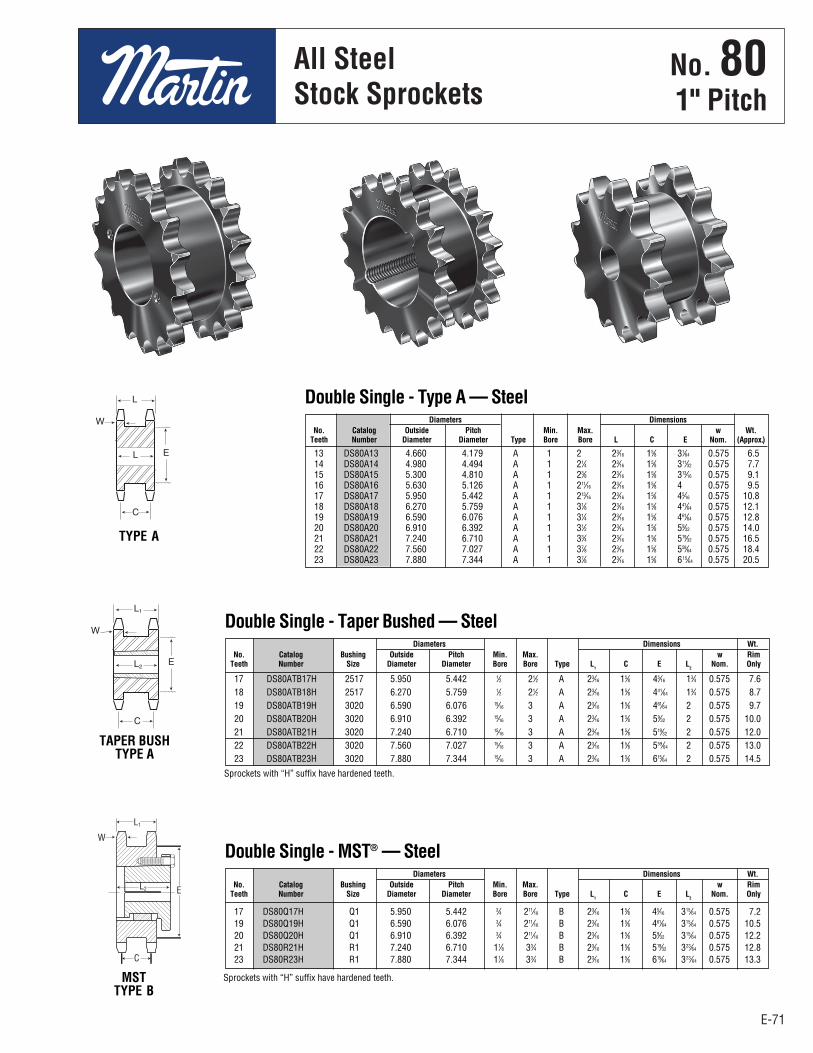
E-71
No. 801" Pitch
All SteelStock Sprockets
E-71
13 DS80A13 4.660 4.179 A 1 2 23⁄16 15⁄8 31⁄64 0.575 6.5 14 DS80A14 4.980 4.494 A 1 21⁄4 23⁄16 15⁄8 311⁄32 0.575 7.7 15 DS80A15 5.300 4.810 A 1 23⁄8 23⁄16 15⁄8 313⁄16 0.575 9.1 16 DS80A16 5.630 5.126 A 1 211⁄16 23⁄16 15⁄8 4 0.575 9.5 17 DS80A17 5.950 5.442 A 1 213⁄16 23⁄16 15⁄8 45⁄16 0.575 10.8 18 DS80A18 6.270 5.759 A 1 31⁄8 23⁄16 15⁄8 441⁄64 0.575 12.1 19 DS80A19 6.590 6.076 A 1 31⁄4 23⁄16 15⁄8 461⁄64 0.575 12.8 20 DS80A20 6.910 6.392 A 1 31⁄2 23⁄16 15⁄8 59⁄32 0.575 14.0 21 DS80A21 7.240 6.710 A 1 33⁄4 23⁄16 15⁄8 519⁄32 0.575 16.5 22 DS80A22 7.560 7.027 A 1 37⁄8 23⁄16 15⁄8 559⁄64 0.575 18.4 23 DS80A23 7.880 7.344 A 1 37⁄8 23⁄16 15⁄8 615⁄64 0.575 20.5
Diameters Dimensions No. Catalog Outside Pitch Min. Max. w Wt. Teeth Number Diameter Diameter Type Bore Bore L C E Nom. (Approx.)
Double Single - Type A — Steel
17 DS80ATB17H 2517 5.950 5.442 1⁄2 21⁄2 A 23⁄16 15⁄8 45⁄16 13⁄4 0.575 7.6 18 DS80ATB18H 2517 6.270 5.759 1⁄2 21⁄2 A 23⁄16 15⁄8 441⁄64 13⁄4 0.575 8.7 19 DS80ATB19H 3020 6.590 6.076 15⁄16 3 A 23⁄16 15⁄8 461⁄64 2 0.575 9.7 20 DS80ATB20H 3020 6.910 6.392 15⁄16 3 A 23⁄16 15⁄8 59⁄32 2 0.575 10.0 21 DS80ATB21H 3020 7.240 6.710 15⁄16 3 A 23⁄16 15⁄8 519⁄32 2 0.575 12.0 22 DS80ATB22H 3020 7.560 7.027 15⁄16 3 A 23⁄16 15⁄8 559⁄64 2 0.575 13.0 23 DS80ATB23H 3020 7.880 7.344 15⁄16 3 A 23⁄16 15⁄8 615⁄64 2 0.575 14.5
Diameters Dimensions Wt. No. Catalog Bushing Outside Pitch Min. Max. w Rim Teeth Number Size Diameter Diameter Bore Bore Type L
1 C E L
2 Nom. Only
Double Single - Taper Bushed — Steel
TYPE A
TAPER BUSHTYPE A
MSTTYPE B
17 DS80Q17H Q1 5.950 5.442 3⁄4 211⁄16 B 23⁄16 15⁄8 45⁄16 315⁄64 0.575 7.2 19 DS80Q19H Q1 6.590 6.076 3⁄4 211⁄16 B 23⁄16 15⁄8 461⁄64 315⁄64 0.575 10.5 20 DS80Q20H Q1 6.910 6.392 3⁄4 211⁄16 B 23⁄16 15⁄8 59⁄32 315⁄64 0.575 12.2 21 DS80R21H R1 7.240 6.710 11⁄8 33⁄4 B 23⁄16 15⁄8 519⁄32 323⁄64 0.575 12.8 23 DS80R23H R1 7.880 7.344 11⁄8 33⁄4 B 23⁄16 15⁄8 615⁄64 323⁄64 0.575 13.3
Diameters Dimensions Wt. No. Catalog Bushing Outside Pitch Min. Max. w Rim Teeth Number Size Diameter Diameter Bore Bore Type L
1 C E L
2 Nom. Only
Double Single - MST® — Steel
Sprockets with “H” suffix have hardened teeth.
Sprockets with “H” suffix have hardened teeth.
E65 - E80-2.qxp_E65 - E80 1/24/18 2:52 PM Page E-71
No . 801" Pitch
All SteelStock Sprockets
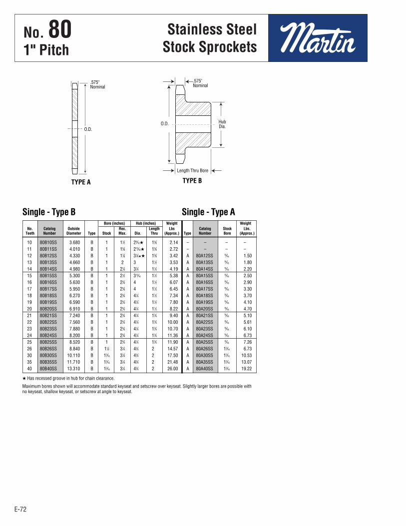
E-72
No. 801" Pitch
Stainless SteelStock Sprockets
E-72
10 80B10SS 3.680 B 1 11⁄2 29⁄16H 15⁄8 2.14 – – – – 11 80B11SS 4.010 B 1 15⁄8 213⁄16H 15⁄8 2.72 – – – – 12 80B12SS 4.330 B 1 17⁄8 31⁄8HH 15⁄8 3.42 A 80A12SS 15⁄16 1.50 13 80B13SS 4.660 B 1 2 3 11⁄2 3.53 A 80A13SS 15⁄16 1.80 14 80B14SS 4.980 B 1 21⁄4 31⁄4 11⁄2 4.19 A 80A14SS 15⁄16 2.20 15 80B15SS 5.300 B 1 21⁄2 313⁄16 11⁄2 5.38 A 80A15SS 15⁄16 2.50 16 80B16SS 5.630 B 1 23⁄4 4 11⁄2 6.07 A 80A16SS 15⁄16 2.90 17 80B17SS 5.950 B 1 23⁄4 4 11⁄2 6.45 A 80A17SS 15⁄16 3.30 18 80B18SS 6.270 B 1 23⁄4 41⁄4 11⁄2 7.34 A 80A18SS 15⁄16 3.70 19 80B19SS 6.590 B 1 23⁄4 41⁄4 11⁄2 7.80 A 80A19SS 15⁄16 4.10 20 80B20SS 6.910 B 1 23⁄4 41⁄4 11⁄2 8.22 A 80A20SS 15⁄16 4.70 21 80B21SS 7.240 B 1 23⁄4 41⁄4 13⁄4 9.40 A 80A21SS 15⁄16 5.10 22 80B22SS 7.560 B 1 23⁄4 41⁄4 13⁄4 10.00 A 80A22SS 15⁄16 5.61 23 80B23SS 7.880 B 1 23⁄4 41⁄4 13⁄4 10.70 A 80A23SS 15⁄16 6.10 24 80B24SS 8.200 B 1 23⁄4 41⁄4 13⁄4 11.36 A 80A24SS 15⁄16 6.73 25 80B25SS 8.520 B 1 23⁄4 41⁄4 13⁄4 11.90 A 80A25SS 15⁄16 7.26 26 80B26SS 8.840 B 11⁄4 31⁄4 43⁄4 2 14.57 A 80A26SS 13⁄16 6.73 30 80B30SS 10.110 B 13⁄16 31⁄4 43⁄4 2 17.50 A 80A30SS 13⁄16 10.53 35 80B35SS 11.710 B 13⁄16 31⁄4 43⁄4 2 21.48 A 80A35SS 13⁄16 13.07 40 80B40SS 13.310 B 13⁄16 31⁄4 43⁄4 2 26.00 A 80A40SS 13⁄16 19.22
Bore (inches) Hub (inches) Weight Weight No. Catalog Outside Rec. Length Lbs Catalog Stock Lbs. Teeth Number Diameter Type Stock Max. Dia. Thru (Approx.) Type Number Bore (Approx.)
Single - Type B Single - Type A
H Has recessed groove in hub for chain clearance.
Maximum bores shown will accommodate standard keyseat and setscrew over keyseat. Slightly larger bores are possible withno keyseat, shallow keyseat, or setscrew at angle to keyseat.
TYPE A TYPE B
.575"Nominal
.575"Nominal
HubDia.
Length Thru Bore
O.D.O.D.
E65 - E80-2.qxp_E65 - E80 1/24/18 2:52 PM Page E-72
No . 801" Pitch
Stainless SteelStock Sprockets
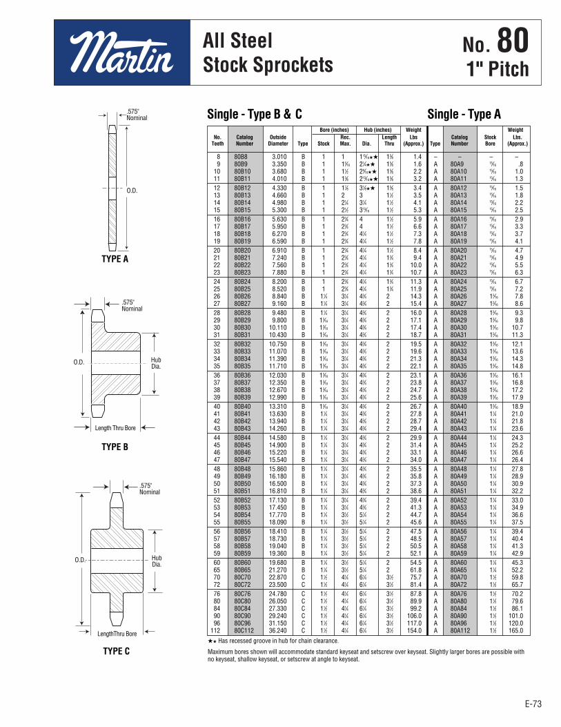
E-73
No. 801" Pitch
All SteelStock Sprockets
E-73
8 80B8 3.010 B 1 1 115⁄16HH 15⁄8 1.4 – – – – 9 80B9 3.350 B 1 15⁄16 21⁄4HH 15⁄8 1.6 A 80A9 15⁄16 .8 10 80B10 3.680 B 1 11⁄2 29⁄16HH 15⁄8 2.2 A 80A10 15⁄16 1.0 11 80B11 4.010 B 1 15⁄8 213⁄16HH 15⁄8 3.2 A 80A11 15⁄16 1.3 12 80B12 4.330 B 1 17⁄8 31⁄8HH 15⁄8 3.4 A 80A12 15⁄16 1.5 13 80B13 4.660 B 1 2 3 11⁄2 3.5 A 80A13 15⁄16 1.8 14 80B14 4.980 B 1 21⁄4 31⁄4 11⁄2 4.1 A 80A14 15⁄16 2.2 15 80B15 5.300 B 1 21⁄2 313⁄16 11⁄2 5.3 A 80A15 15⁄16 2.5 16 80B16 5.630 B 1 23⁄4 4 11⁄2 5.9 A 80A16 15⁄16 2.9 17 80B17 5.950 B 1 23⁄4 4 11⁄2 6.6 A 80A17 15⁄16 3.3 18 80B18 6.270 B 1 23⁄4 41⁄4 11⁄2 7.3 A 80A18 15⁄16 3.7 19 80B19 6.590 B 1 23⁄4 41⁄4 11⁄2 7.8 A 80A19 15⁄16 4.1 20 80B20 6.910 B 1 23⁄4 41⁄4 11⁄2 8.4 A 80A20 15⁄16 4.7 21 80B21 7.240 B 1 23⁄4 41⁄4 13⁄4 9.4 A 80A21 15⁄16 4.9 22 80B22 7.560 B 1 23⁄4 41⁄4 13⁄4 10.0 A 80A22 15⁄16 5.5 23 80B23 7.880 B 1 23⁄4 41⁄4 13⁄4 10.7 A 80A23 15⁄16 6.3 24 80B24 8.200 B 1 23⁄4 41⁄4 13⁄4 11.3 A 80A24 15⁄16 6.7 25 80B25 8.520 B 1 23⁄4 41⁄4 13⁄4 11.9 A 80A25 15⁄16 7.2 26 80B26 8.840 B 11⁄4 31⁄4 43⁄4 2 14.3 A 80A26 13⁄16 7.8 27 80B27 9.160 B 11⁄4 31⁄4 43⁄4 2 15.4 A 80A27 13⁄16 8.6 28 80B28 9.480 B 11⁄4 31⁄4 43⁄4 2 16.0 A 80A28 13⁄16 9.3 29 80B29 9.800 B 13⁄16 31⁄4 43⁄4 2 17.1 A 80A29 13⁄16 9.8 30 80B30 10.110 B 13⁄16 31⁄4 43⁄4 2 17.4 A 80A30 13⁄16 10.7 31 80B31 10.430 B 13⁄16 31⁄4 43⁄4 2 18.7 A 80A31 13⁄16 11.3 32 80B32 10.750 B 13⁄16 31⁄4 43⁄4 2 19.5 A 80A32 13⁄16 12.1 33 80B33 11.070 B 13⁄16 31⁄4 43⁄4 2 19.6 A 80A33 13⁄16 13.6 34 80B34 11.390 B 13⁄16 31⁄4 43⁄4 2 21.3 A 80A34 13⁄16 14.3 35 80B35 11.710 B 13⁄16 31⁄4 43⁄4 2 22.1 A 80A35 13⁄16 14.8 36 80B36 12.030 B 13⁄16 31⁄4 43⁄4 2 23.1 A 80A36 13⁄16 16.1 37 80B37 12.350 B 13⁄16 31⁄4 43⁄4 2 23.8 A 80A37 13⁄16 16.8 38 80B38 12.670 B 13⁄16 31⁄4 43⁄4 2 24.7 A 80A38 13⁄16 17.2 39 80B39 12.990 B 13⁄16 31⁄4 43⁄4 2 25.6 A 80A39 13⁄16 17.9 40 80B40 13.310 B 13⁄16 31⁄4 43⁄4 2 26.7 A 80A40 13⁄16 18.9 41 80B41 13.630 B 11⁄4 31⁄4 43⁄4 2 27.8 A 80A41 11⁄4 21.0 42 80B42 13.940 B 11⁄4 31⁄4 43⁄4 2 28.7 A 80A42 11⁄4 21.8 43 80B43 14.260 B 11⁄4 31⁄4 43⁄4 2 29.4 A 80A43 11⁄4 23.6 44 80B44 14.580 B 11⁄4 31⁄4 43⁄4 2 29.9 A 80A44 11⁄4 24.3 45 80B45 14.900 B 11⁄4 31⁄4 43⁄4 2 31.4 A 80A45 11⁄4 25.2 46 80B46 15.220 B 11⁄4 31⁄4 43⁄4 2 33.1 A 80A46 11⁄4 26.6 47 80B47 15.540 B 11⁄4 31⁄4 43⁄4 2 34.0 A 80A47 11⁄4 26.4 48 80B48 15.860 B 11⁄4 31⁄4 43⁄4 2 35.5 A 80A48 11⁄4 27.8 49 80B49 16.180 B 11⁄4 31⁄4 43⁄4 2 35.8 A 80A49 11⁄4 28.9 50 80B50 16.500 B 11⁄4 31⁄4 43⁄4 2 37.3 A 80A50 11⁄4 30.9 51 80B51 16.810 B 11⁄4 31⁄4 43⁄4 2 38.6 A 80A51 11⁄4 32.2 52 80B52 17.130 B 11⁄4 31⁄4 43⁄4 2 39.4 A 80A52 11⁄4 33.0 53 80B53 17.450 B 11⁄4 31⁄4 43⁄4 2 41.3 A 80A53 11⁄4 34.9 54 80B54 17.770 B 11⁄4 31⁄2 51⁄4 2 44.7 A 80A54 11⁄4 36.6 55 80B55 18.090 B 11⁄4 31⁄2 51⁄4 2 45.6 A 80A55 11⁄4 37.5 56 80B56 18.410 B 11⁄4 31⁄2 51⁄4 2 47.5 A 80A56 11⁄4 39.4 57 80B57 18.730 B 11⁄4 31⁄2 51⁄4 2 48.5 A 80A57 11⁄4 40.4 58 80B58 19.040 B 11⁄4 31⁄2 51⁄4 2 50.5 A 80A58 11⁄4 41.3 59 80B59 19.360 B 11⁄4 31⁄2 51⁄4 2 52.1 A 80A59 11⁄4 42.9 60 80B60 19.680 B 11⁄4 31⁄2 51⁄4 2 54.5 A 80A60 11⁄4 45.3 65 80B65 21.270 B 11⁄4 31⁄2 51⁄4 2 61.8 A 80A65 11⁄4 52.2 70 80C70 22.870 C 11⁄2 41⁄4 61⁄4 31⁄2 75.7 A 80A70 11⁄2 59.8 72 80C72 23.500 C 11⁄2 41⁄4 61⁄4 31⁄2 81.4 A 80A72 11⁄2 65.7 76 80C76 24.780 C 11⁄2 41⁄4 61⁄4 31⁄2 87.8 A 80A76 11⁄2 70.2 80 80C80 26.050 C 11⁄2 41⁄4 61⁄4 31⁄2 89.9 A 80A80 11⁄2 79.6 84 80C84 27.330 C 11⁄2 41⁄4 61⁄4 31⁄2 99.2 A 80A84 11⁄2 86.1 90 80C90 29.240 C 11⁄2 41⁄4 61⁄4 31⁄2 106.0 A 80A90 11⁄2 101.0 96 80C96 31.150 C 11⁄2 41⁄4 61⁄4 31⁄2 117.0 A 80A96 11⁄2 120.0 112 80C112 36.240 C 11⁄2 41⁄4 61⁄4 31⁄2 154.0 A 80A112 11⁄2 165.0
Bore (inches) Hub (inches) Weight Weight No. Catalog Outside Rec. Length Lbs Catalog Stock Lbs. Teeth Number Diameter Type Stock Max. Dia. Thru (Approx.) Type Number Bore (Approx.)
Single - Type B & C Single - Type A
HH Has recessed groove in hub for chain clearance.
Maximum bores shown will accommodate standard keyseat and setscrew over keyseat. Slightly larger bores are possible withno keyseat, shallow keyseat, or setscrew at angle to keyseat.
TYPE A
TYPE B
TYPE C
.575"Nominal
.575"Nominal
.575"Nominal
HubDia.
Length Thru Bore
O.D.
O.D.
O.D.
HubDia.
LengthThru Bore
E65 - E80-2.qxp_E65 - E80 1/24/18 2:53 PM Page E-73
No . 801" Pitch
All SteelStock Sprockets

E-74
No. 801" Pitch
All SteelStock Sprockets
E-74
11 80SH11H 12 80SH12H 13 80SDS13H
14 80SDS14H 15 80SK15H 16 80SK16H
17 80SK17H 18 80SK18H 19 80SK19H
20 80SF20H 21 80SF21H 22 80SF22H
23 80SF23H 24 80SF24H 25 80SF25H
26 80SF26H 27 80SF27H 28 80SF28H 30 80SF30H
No. Catalog Teeth Number
Single - Type QD With Hardened Teeth
QD — TYPE B QD — TYPE C
11 80SH11 SH 4.010 3.550 B 15⁄8 17⁄16 17⁄16 211⁄16 21⁄32 – 15⁄64 13⁄16 0.575 2.0 1.0 12 80SH12 SH 4.330 3.864 B 15⁄8 17⁄16 17⁄16 211⁄16 21⁄32 – 15⁄64 13⁄16 0.575 2.4 1.4 13 80SDS13 SDS 4.660 4.179 B 2 11⁄2 11⁄2 33⁄16 47⁄64 – 11⁄64 3⁄4 0.575 2.5 1.5 14 80SDS14 SDS 4.980 4.494 B 2 11⁄2 11⁄2 33⁄16 47⁄64 – 11⁄64 3⁄4 0.575 2.8 1.8 15 80SK15 SK 5.300 4.810 B 25⁄8 21⁄8 21⁄8 37⁄8 119⁄64 – 21⁄32 11⁄4 0.575 4.5 2.5 16 80SK16 SK 5.630 5.126 B 25⁄8 21⁄8 21⁄8 37⁄8 119⁄64 – 21⁄32 11⁄4 0.575 5.1 3.1 17 80SK17 SK 5.950 5.442 B 25⁄8 21⁄8 21⁄8 37⁄8 119⁄64 – 21⁄32 11⁄4 0.575 5.5 3.5 18 80SK18 SK 6.270 5.759 B 25⁄8 21⁄8 21⁄8 37⁄8 119⁄64 – 21⁄32 11⁄4 0.575 5.9 3.9 19 80SK19 SK 6.590 6.076 B 25⁄8 21⁄8 21⁄8 37⁄8 119⁄64 – 21⁄32 11⁄4 0.575 6.4 4.4 20 80SF20 SF 6.910 6.392 B 215⁄16 21⁄4 21⁄4 45⁄8 127⁄64 – 21⁄32 11⁄4 0.575 8.3 5.3 21 80SF21 SF 7.240 6.710 B 215⁄16 21⁄4 21⁄4 45⁄8 127⁄64 – 21⁄32 11⁄4 0.575 8.7 5.7 22 80SF22 SF 7.560 7.027 B 215⁄16 21⁄4 21⁄4 45⁄8 127⁄64 – 21⁄32 11⁄4 0.575 9.3 6.3 23 80SF23 SF 7.880 7.344 B 215⁄16 21⁄4 21⁄4 45⁄8 127⁄64 – 21⁄32 11⁄4 0.575 9.8 6.8 24 80SF24 SF 8.200 7.661 B 215⁄16 21⁄4 21⁄4 45⁄8 127⁄64 – 21⁄32 11⁄4 0.575 10.5 7.5 25 80SF25 SF 8.520 7.979 B 215⁄16 21⁄4 21⁄4 45⁄8 127⁄64 – 21⁄32 11⁄4 0.575 11.0 8.0 26 80SF26 SF 8.840 8.296 B 215⁄16 21⁄4 21⁄4 45⁄8 127⁄64 – 21⁄32 11⁄4 0.575 11.6 8.6 27 80SF27 SF 9.160 8.614 B 215⁄16 21⁄4 21⁄4 45⁄8 127⁄64 – 21⁄32 11⁄4 0.575 12.4 9.4 28 80SF28 SF 9.480 8.931 B 215⁄16 21⁄4 21⁄4 45⁄8 127⁄64 – 21⁄32 11⁄4 0.575 13.2 10.2 30 80SF30 SF 10.110 9.567 B 215⁄16 21⁄4 21⁄4 45⁄8 127⁄64 – 21⁄32 11⁄4 0.575 14.3 11.3 32 80SF32 SF 10.750 10.202 B 215⁄16 21⁄4 21⁄4 45⁄8 127⁄64 – 21⁄32 11⁄4 0.575 16.0 13.0 33 80SF33 SF 11.070 10.520 B 215⁄16 21⁄4 21⁄4 45⁄8 127⁄64 – 21⁄32 11⁄4 0.575 16.5 13.5 34 80SF34 SF 11.390 10.838 B 215⁄16 21⁄4 21⁄4 45⁄8 127⁄64 – 21⁄32 11⁄4 0.575 17.1 14.1 35 80SF35 SF 11.710 11.156 B 215⁄16 21⁄4 21⁄4 45⁄8 127⁄64 – 21⁄32 11⁄4 0.575 18.5 15.5 36 80SF36 SF 12.030 11.474 B 215⁄16 21⁄4 21⁄4 45⁄8 127⁄64 – 21⁄32 11⁄4 0.575 19.9 16.9 40 80SF40 SF 13.310 12.746 B 215⁄16 21⁄4 21⁄4 45⁄8 127⁄64 – 21⁄32 11⁄4 0.575 23.6 20.6 42 80SF42 SF 13.940 13.382 B 215⁄16 21⁄4 21⁄4 45⁄8 127⁄64 – 21⁄32 11⁄4 0.575 25.4 22.4 45 80SF45 SF 14.900 14.336 B 215⁄16 21⁄4 21⁄4 45⁄8 127⁄64 – 21⁄32 11⁄4 0.575 28.1 25.1 48 80SF48 SF 15.860 15.290 B 215⁄16 21⁄4 21⁄4 45⁄8 127⁄64 – 21⁄32 11⁄4 0.575 31.6 28.6 54 80SF54 SF 17.770 17.198 B 215⁄16 21⁄4 21⁄4 45⁄8 127⁄64 – 21⁄32 11⁄4 0.575 39.8 36.8 60 80SF60 SF 19.680 19.107 B 215⁄16 21⁄4 21⁄4 45⁄8 127⁄64 – 21⁄32 11⁄4 0.575 48.8 45.8 70 80E70 E 22.870 22.289 C 31⁄2 25⁄8 215⁄16 6 7⁄8 13⁄16 13⁄64 15⁄8 0.575 65.6 55.6 72 80E72 E 23.500 22.926 C 31⁄2 25⁄8 215⁄16 6 7⁄8 13⁄16 13⁄64 15⁄8 0.575 69.3 59.3 80 80E80 E 26.050 25.471 C 31⁄2 25⁄8 215⁄16 6 7⁄8 13⁄16 13⁄64 15⁄8 0.575 79.2 69.2 84 80E84 E 27.330 26.744 C 31⁄2 25⁄8 215⁄16 6 7⁄8 13⁄16 13⁄64 15⁄8 0.575 84.9 74.9 96 80E96 E 31.150 30.563 C 31⁄2 25⁄8 215⁄16 6 7⁄8 13⁄16 13⁄64 15⁄8 0.575 108.0 97.5 112 80F112 F 36.240 35.655 C 315⁄16 35⁄8 4 65⁄8 1 21⁄16 159⁄64 21⁄2 0.575 145.0 134.0
Diameters Dimensions Weight Lbs. (Approx.) No. Catalog Bush- Outside Pitch Max. With Rim Teeth Number ing Diameter Diameter Type Bore L
1 L
2 C Y P G X T Hub Only
Single - Type QD
SABER
TOOTH®
O.D.
O.D.
E65 - E80-2.qxp_E65 - E80 1/24/18 2:53 PM Page E-74
No . 801" Pitch
All SteelStock Sprockets
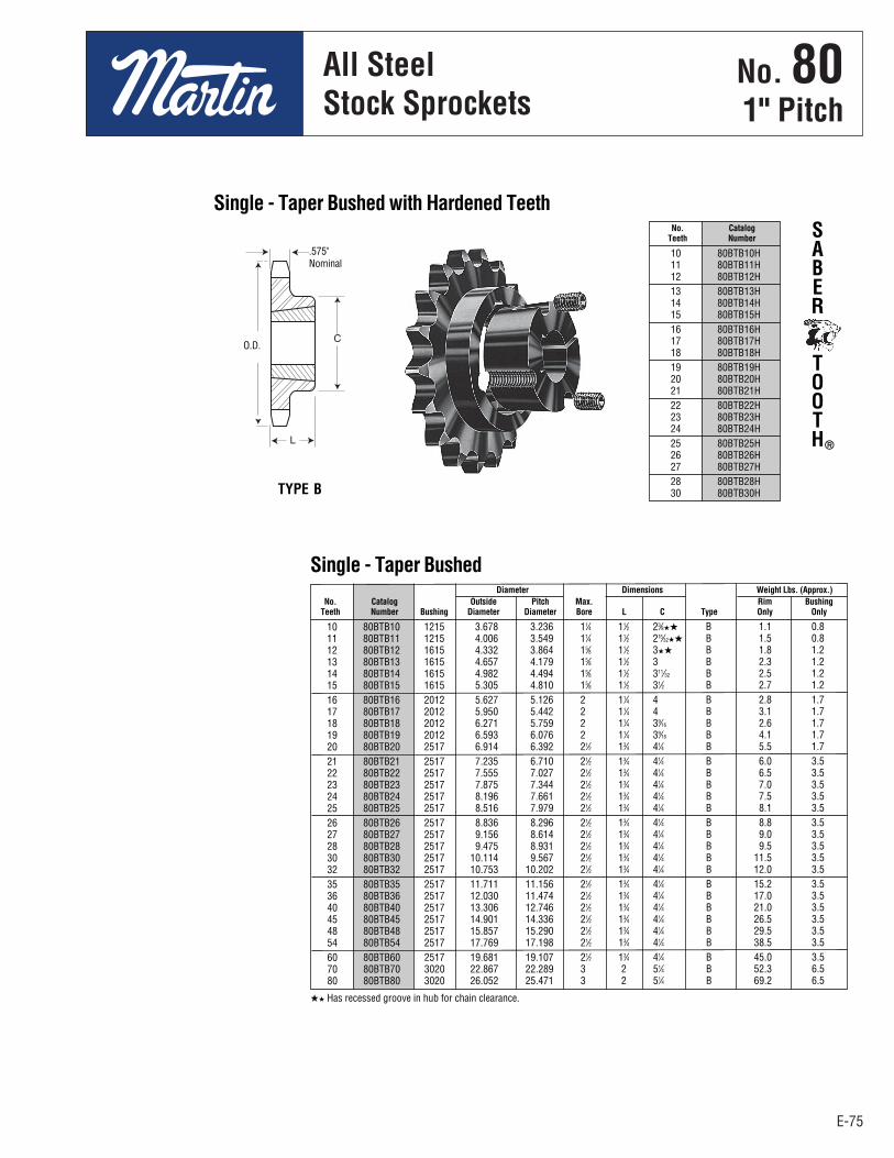
E-75
No. 801" Pitch
All SteelStock Sprockets
E-75
10 80BTB10 1215 3.678 3.236 11⁄4 11⁄2 23⁄8HH B 1.1 0.8 11 80BTB11 1215 4.006 3.549 11⁄4 11⁄2 215⁄32HH B 1.5 0.8 12 80BTB12 1615 4.332 3.864 15⁄8 11⁄2 3HH B 1.8 1.2 13 80BTB13 1615 4.657 4.179 15⁄8 11⁄2 3 B 2.3 1.2 14 80BTB14 1615 4.982 4.494 15⁄8 11⁄2 311⁄32 B 2.5 1.2 15 80BTB15 1615 5.305 4.810 15⁄8 11⁄2 31⁄2 B 2.7 1.2 16 80BTB16 2012 5.627 5.126 2 11⁄4 4 B 2.8 1.7 17 80BTB17 2012 5.950 5.442 2 11⁄4 4 B 3.1 1.7 18 80BTB18 2012 6.271 5.759 2 11⁄4 39⁄16 B 2.6 1.7 19 80BTB19 2012 6.593 6.076 2 11⁄4 39⁄16 B 4.1 1.7 20 80BTB20 2517 6.914 6.392 21⁄2 13⁄4 41⁄4 B 5.5 1.7 21 80BTB21 2517 7.235 6.710 21⁄2 13⁄4 41⁄4 B 6.0 3.5 22 80BTB22 2517 7.555 7.027 21⁄2 13⁄4 41⁄4 B 6.5 3.5 23 80BTB23 2517 7.875 7.344 21⁄2 13⁄4 41⁄4 B 7.0 3.5 24 80BTB24 2517 8.196 7.661 21⁄2 13⁄4 41⁄4 B 7.5 3.5 25 80BTB25 2517 8.516 7.979 21⁄2 13⁄4 41⁄4 B 8.1 3.5 26 80BTB26 2517 8.836 8.296 21⁄2 13⁄4 41⁄4 B 8.8 3.5 27 80BTB27 2517 9.156 8.614 21⁄2 13⁄4 41⁄4 B 9.0 3.5 28 80BTB28 2517 9.475 8.931 21⁄2 13⁄4 41⁄4 B 9.5 3.5 30 80BTB30 2517 10.114 9.567 21⁄2 13⁄4 41⁄4 B 11.5 3.5 32 80BTB32 2517 10.753 10.202 21⁄2 13⁄4 41⁄4 B 12.0 3.5 35 80BTB35 2517 11.711 11.156 21⁄2 13⁄4 41⁄4 B 15.2 3.5 36 80BTB36 2517 12.030 11.474 21⁄2 13⁄4 41⁄4 B 17.0 3.5 40 80BTB40 2517 13.306 12.746 21⁄2 13⁄4 41⁄4 B 21.0 3.5 45 80BTB45 2517 14.901 14.336 21⁄2 13⁄4 41⁄4 B 26.5 3.5 48 80BTB48 2517 15.857 15.290 21⁄2 13⁄4 41⁄4 B 29.5 3.5 54 80BTB54 2517 17.769 17.198 21⁄2 13⁄4 41⁄4 B 38.5 3.5 60 80BTB60 2517 19.681 19.107 21⁄2 13⁄4 41⁄4 B 45.0 3.5 70 80BTB70 3020 22.867 22.289 3 2 51⁄4 B 52.3 6.5 80 80BTB80 3020 26.052 25.471 3 2 51⁄4 B 69.2 6.5
Diameter Dimensions Weight Lbs. (Approx.) No. Catalog Outside Pitch Max. Rim Bushing Teeth Number Bushing Diameter Diameter Bore L C Type Only Only
Single - Taper Bushed
HH Has recessed groove in hub for chain clearance.
10 80BTB10H 11 80BTB11H 12 80BTB12H 13 80BTB13H 14 80BTB14H 15 80BTB15H 16 80BTB16H 17 80BTB17H 18 80BTB18H 19 80BTB19H 20 80BTB20H 21 80BTB21H 22 80BTB22H 23 80BTB23H 24 80BTB24H 25 80BTB25H 26 80BTB26H 27 80BTB27H 28 80BTB28H 30 80BTB30H
No. Catalog Teeth Number
Single - Taper Bushed with Hardened Teeth
TYPE B
SABER
TOOTH®
.575"Nominal
O.D.
E65 - E80-2.qxp_E65 - E80 1/24/18 2:53 PM Page E-75
No . 801" Pitch
All SteelStock Sprockets
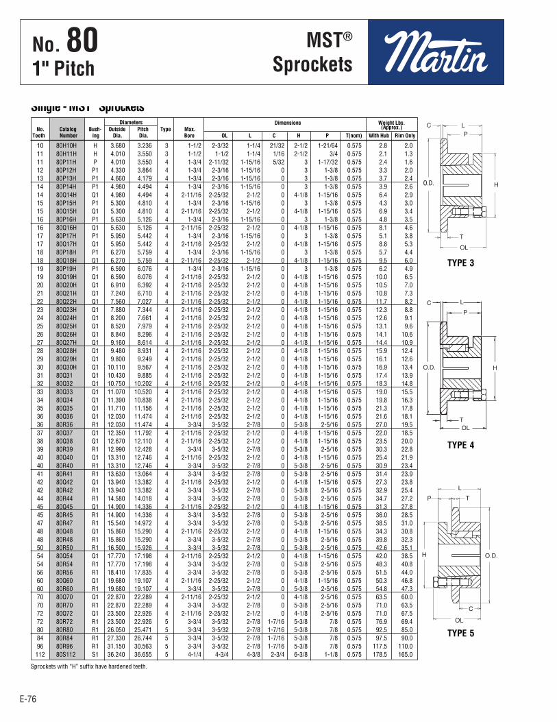
E-76
No. 801" Pitch
E-76
Diameters Dimensions Weight Lbs. No. Catalog Bush- Outside Pitch Type Max. (Approx.) Teeth Number ing Dia. Dia. Bore OL L C H P T(nom) With Hub Rim Only
MST®
Sprockets
Single - MST® Sprockets
Sprockets with “H” suffix have hardened teeth.
10 80H10H H 3.680 3.236 3 1-1/2 2-3/32 1-1/4 21/32 2-1/2 1-21/64 0.575 2.8 2.0 11 80H11H H 4.010 3.550 3 1-1/2 1-1/2 1-1/4 1/16 2-1/2 3/4 0.575 2.1 1.3 11 80P11H P 4.010 3.550 4 1-3/4 2-11/32 1-15/16 5/32 3 1-17/32 0.575 2.4 1.6 12 80P12H P1 4.330 3.864 4 1-3/4 2-3/16 1-15/16 0 3 1-3/8 0.575 3.3 2.0 13 80P13H P1 4.660 4.179 4 1-3/4 2-3/16 1-15/16 0 3 1-3/8 0.575 3.7 2.4 14 80P14H P1 4.980 4.494 4 1-3/4 2-3/16 1-15/16 0 3 1-3/8 0.575 3.9 2.6 14 80Q14H Q1 4.980 4.494 4 2-11/16 2-25/32 2-1/2 0 4-1/8 1-15/16 0.575 6.4 2.9 15 80P15H P1 5.300 4.810 4 1-3/4 2-3/16 1-15/16 0 3 1-3/8 0.575 4.3 3.0 15 80Q15H Q1 5.300 4.810 4 2-11/16 2-25/32 2-1/2 0 4-1/8 1-15/16 0.575 6.9 3.4 16 80P16H P1 5.630 5.126 4 1-3/4 2-3/16 1-15/16 0 3 1-3/8 0.575 4.8 3.5 16 80Q16H Q1 5.630 5.126 4 2-11/16 2-25/32 2-1/2 0 4-1/8 1-15/16 0.575 8.1 4.6 17 80P17H P1 5.950 5.442 4 1-3/4 2-3/16 1-15/16 0 3 1-3/8 0.575 5.1 3.8 17 80Q17H Q1 5.950 5.442 4 2-11/16 2-25/32 2-1/2 0 4-1/8 1-15/16 0.575 8.8 5.3 18 80P18H P1 6.270 5.759 4 1-3/4 2-3/16 1-15/16 0 3 1-3/8 0.575 5.7 4.4 18 80Q18H Q1 6.270 5.759 4 2-11/16 2-25/32 2-1/2 0 4-1/8 1-15/16 0.575 9.5 6.0 19 80P19H P1 6.590 6.076 4 1-3/4 2-3/16 1-15/16 0 3 1-3/8 0.575 6.2 4.9 19 80Q19H Q1 6.590 6.076 4 2-11/16 2-25/32 2-1/2 0 4-1/8 1-15/16 0.575 10.0 6.5 20 80Q20H Q1 6.910 6.392 4 2-11/16 2-25/32 2-1/2 0 4-1/8 1-15/16 0.575 10.5 7.0 21 80Q21H Q1 7.240 6.710 4 2-11/16 2-25/32 2-1/2 0 4-1/8 1-15/16 0.575 10.8 7.3 22 80Q22H Q1 7.560 7.027 4 2-11/16 2-25/32 2-1/2 0 4-1/8 1-15/16 0.575 11.7 8.2 23 80Q23H Q1 7.880 7.344 4 2-11/16 2-25/32 2-1/2 0 4-1/8 1-15/16 0.575 12.3 8.8 24 80Q24H Q1 8.200 7.661 4 2-11/16 2-25/32 2-1/2 0 4-1/8 1-15/16 0.575 12.6 9.1 25 80Q25H Q1 8.520 7.979 4 2-11/16 2-25/32 2-1/2 0 4-1/8 1-15/16 0.575 13.1 9.6 26 80Q26H Q1 8.840 8.296 4 2-11/16 2-25/32 2-1/2 0 4-1/8 1-15/16 0.575 14.1 10.6 27 80Q27H Q1 9.160 8.614 4 2-11/16 2-25/32 2-1/2 0 4-1/8 1-15/16 0.575 14.4 10.9 28 80Q28H Q1 9.480 8.931 4 2-11/16 2-25/32 2-1/2 0 4-1/8 1-15/16 0.575 15.9 12.4 29 80Q29H Q1 9.800 9.249 4 2-11/16 2-25/32 2-1/2 0 4-1/8 1-15/16 0.575 16.1 12.6 30 80Q30H Q1 10.110 9.567 4 2-11/16 2-25/32 2-1/2 0 4-1/8 1-15/16 0.575 16.9 13.4 31 80Q31 Q1 10.430 9.885 4 2-11/16 2-25/32 2-1/2 0 4-1/8 1-15/16 0.575 17.4 13.9 32 80Q32 Q1 10.750 10.202 4 2-11/16 2-25/32 2-1/2 0 4-1/8 1-15/16 0.575 18.3 14.8 33 80Q33 Q1 11.070 10.520 4 2-11/16 2-25/32 2-1/2 0 4-1/8 1-15/16 0.575 19.0 15.5 34 80Q34 Q1 11.390 10.838 4 2-11/16 2-25/32 2-1/2 0 4-1/8 1-15/16 0.575 19.8 16.3 35 80Q35 Q1 11.710 11.156 4 2-11/16 2-25/32 2-1/2 0 4-1/8 1-15/16 0.575 21.3 17.8 36 80Q36 Q1 12.030 11.474 4 2-11/16 2-25/32 2-1/2 0 4-1/8 1-15/16 0.575 21.6 18.1 36 80R36 R1 12.030 11.474 4 3-3/4 3-5/32 2-7/8 0 5-3/8 2-5/16 0.575 27.0 19.5 37 80Q37 Q1 12.350 11.792 4 2-11/16 2-25/32 2-1/2 0 4-1/8 1-15/16 0.575 22.0 18.5 38 80Q38 Q1 12.670 12.110 4 2-11/16 2-25/32 2-1/2 0 4-1/8 1-15/16 0.575 23.5 20.0 39 80R39 R1 12.990 12.428 4 3-3/4 3-5/32 2-7/8 0 5-3/8 2-5/16 0.575 30.3 22.8 40 80Q40 Q1 13.310 12.746 4 2-11/16 2-25/32 2-1/2 0 4-1/8 1-15/16 0.575 25.4 21.9 40 80R40 R1 13.310 12.746 4 3-3/4 3-5/32 2-7/8 0 5-3/8 2-5/16 0.575 30.9 23.4 41 80R41 R1 13.630 13.064 4 3-3/4 3-5/32 2-7/8 0 5-3/8 2-5/16 0.575 31.4 23.9 42 80Q42 Q1 13.940 13.382 4 2-11/16 2-25/32 2-1/2 0 4-1/8 1-15/16 0.575 27.3 23.8 42 80R42 R1 13.940 13.382 4 3-3/4 3-5/32 2-7/8 0 5-3/8 2-5/16 0.575 32.9 25.4 44 80R44 R1 14.580 14.018 4 3-3/4 3-5/32 2-7/8 0 5-3/8 2-5/16 0.575 34.7 27.2 45 80Q45 Q1 14.900 14.336 4 2-11/16 2-25/32 2-1/2 0 4-1/8 1-15/16 0.575 31.3 27.8 45 80R45 R1 14.900 14.336 4 3-3/4 3-5/32 2-7/8 0 5-3/8 2-5/16 0.575 36.0 28.5 47 80R47 R1 15.540 14.972 4 3-3/4 3-5/32 2-7/8 0 5-3/8 2-5/16 0.575 38.5 31.0 48 80Q48 Q1 15.860 15.290 4 2-11/16 2-25/32 2-1/2 0 4-1/8 1-15/16 0.575 34.3 30.8 48 80R48 R1 15.860 15.290 4 3-3/4 3-5/32 2-7/8 0 5-3/8 2-5/16 0.575 39.8 32.3 50 80R50 R1 16.500 15.926 4 3-3/4 3-5/32 2-7/8 0 5-3/8 2-5/16 0.575 42.6 35.1 54 80Q54 Q1 17.770 17.198 4 2-11/16 2-25/32 2-1/2 0 4-1/8 1-15/16 0.575 42.0 38.5 54 80R54 R1 17.770 17.198 4 3-3/4 3-5/32 2-7/8 0 5-3/8 2-5/16 0.575 48.3 40.8 56 80R56 R1 18.410 17.835 4 3-3/4 3-5/32 2-7/8 0 5-3/8 2-5/16 0.575 51.5 44.0 60 80Q60 Q1 19.680 19.107 4 2-11/16 2-25/32 2-1/2 0 4-1/8 1-15/16 0.575 50.3 46.8 60 80R60 R1 19.680 19.107 4 3-3/4 3-5/32 2-7/8 0 5-3/8 2-5/16 0.575 54.8 47.3 70 80Q70 Q1 22.870 22.289 4 2-11/16 2-25/32 2-1/2 0 4-1/8 2-5/16 0.575 63.5 60.0 70 80R70 R1 22.870 22.289 4 3-3/4 3-5/32 2-7/8 0 5-3/8 2-5/16 0.575 71.0 63.5 72 80Q72 Q1 23.500 22.926 4 2-11/16 2-25/32 2-1/2 0 4-1/8 2-5/16 0.575 71.0 67.5 72 80R72 R1 23.500 22.926 5 3-3/4 3-5/32 2-7/8 1-7/16 5-3/8 7/8 0.575 76.9 69.4 80 80R80 R1 26.050 25.471 5 3-3/4 3-5/32 2-7/8 1-7/16 5-3/8 7/8 0.575 92.5 85.0 84 80R84 R1 27.330 26.744 5 3-3/4 3-5/32 2-7/8 1-7/16 5-3/8 7/8 0.575 97.5 90.0 96 80R96 R1 31.150 30.563 5 3-3/4 3-5/32 2-7/8 1-7/16 5-3/8 7/8 0.575 117.5 110.0 112 80S112 S1 36.240 36.655 5 4-1/4 4-3/4 4-3/8 2-3/4 6-3/8 1-1/8 0.575 178.5 165.0
TYPE 3
O.D.
TYPE 4
TYPE 5
E65 - E80-2.qxp_E65 - E80 1/24/18 2:53 PM Page E-76
No . 801" Pitch
MST®
Sprockets
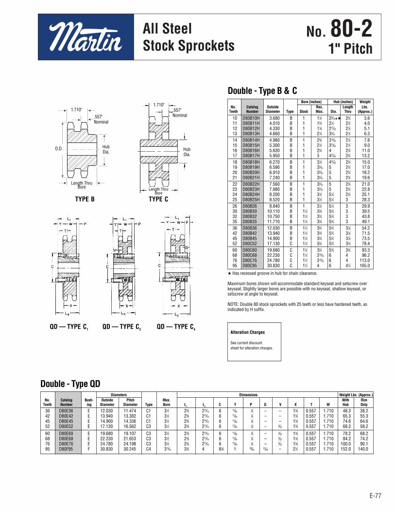
E-77
No. 80-21" Pitch
All SteelStock Sprockets
E-77
Double - Type QD
10 D80B10H 3.680 B 1 11⁄2 29⁄16HH 23⁄4 3.6 11 D80B11H 4.010 B 1 13⁄4 21⁄2 21⁄2 4.0 12 D80B12H 4.330 B 1 17⁄8 227⁄32 21⁄2 5.1 13 D80B13H 4.660 B 1 21⁄4 35⁄32 21⁄2 6.3 14 D80B14H 4.980 B 1 23⁄8 315⁄32 21⁄2 7.6 15 D80B15H 5.300 B 1 21⁄2 351⁄64 21⁄2 9.0 16 D80B16H 5.630 B 1 23⁄4 4 23⁄4 11.0 17 D80B17H 5.950 B 1 3 427⁄64 23⁄4 13.2 18 D80B18H 6.270 B 1 31⁄4 447⁄64 23⁄4 15.0 19 D80B19H 6.590 B 1 35⁄16 5 23⁄4 17.0 20 D80B20H 6.910 B 1 35⁄16 5 23⁄4 18.2 21 D80B21H 7.240 B 1 35⁄16 5 23⁄4 19.6 22 D80B22H 7.560 B 1 35⁄16 5 23⁄4 21.0 23 D80B23H 7.880 B 1 35⁄16 5 23⁄4 22.8 24 D80B24H 8.200 B 1 31⁄2 51⁄4 23⁄4 25.1 25 D80B25H 8.520 B 1 31⁄2 51⁄4 3 28.3 26 D80B26 8.840 B 1 31⁄2 51⁄4 3 29.9 30 D80B30 10.110 B 11⁄4 33⁄4 53⁄4 3 39.5 32 D80B32 10.750 B 11⁄4 33⁄4 53⁄4 3 43.8 35 D80B35 11.710 B 11⁄4 33⁄4 53⁄4 3 49.1 36 D80B36 12.030 B 11⁄4 33⁄4 53⁄4 31⁄8 54.2 42 D80B42 13.940 B 11⁄4 33⁄4 53⁄4 31⁄8 71.5 45 D80B45 14.900 B 11⁄4 33⁄4 53⁄4 31⁄8 73.5 52 D80C52 17.130 C 11⁄2 33⁄4 53⁄4 33⁄4 78.4 60 D80C60 19.680 C 11⁄2 33⁄4 53⁄4 33⁄4 93.3 68 D80C68 22.230 C 11⁄2 313⁄16 6 4 96.2 76 D80C76 24.780 C 11⁄2 313⁄16 6 4 113.0 95 D80C95 30.830 C 11⁄2 4 6 41⁄4 165.0
Bore (inches) Hub (inches) Weight No. Catalog Outside Rec. Length Lbs. Teeth Number Diameter Type Stock Max. Dia. Thru (Approx.)
Double - Type B & C
H Has recessed groove in hub for chain clearance.
Maximum bores shown will accommodate standard keyseat and setscrew overkeyseat. Slightly larger bores are possible with no keyseat, shallow keyseat, orsetscrew at angle to keyseat.
NOTE: Double 80 stock sprockets with 25 teeth or less have hardened teeth, asindicated by H suffix.
TYPE B TYPE C
QD — TYPE C3 QD — TYPE C4QD — TYPE C1Alteration Charges
See current discountsheet for alteration charges.
.557"Nominal
1.710" .557"Nominal
1.710"
36 D80E36 E 12.030 11.474 C1 31⁄2 25⁄8 215⁄16 6 51⁄64 1⁄8 – – 15⁄8 0.557 1.710 48.3 38.2 42 D80E42 E 13.940 13.382 C1 31⁄2 25⁄8 215⁄16 6 51⁄64 1⁄8 – – 15⁄8 0.557 1.710 65.3 55.3 45 D80E45 E 14.900 14.336 C1 31⁄2 25⁄8 215⁄16 6 51⁄64 1⁄8 – – 15⁄8 0.557 1.710 74.6 64.6 52 D80E52 E 17.130 16.562 C3 31⁄2 25⁄8 215⁄16 6 51⁄64 1⁄8 – 3⁄32 15⁄8 0.557 1.710 68.2 58.2
60 D80E60 E 19.680 19.107 C3 31⁄2 25⁄8 215⁄16 6 51⁄64 1⁄8 – 3⁄32 15⁄8 0.557 1.710 78.2 68.2 68 D80E68 E 22.230 21.653 C3 31⁄2 25⁄8 215⁄16 6 51⁄64 1⁄8 – 3⁄32 15⁄8 0.557 1.710 84.2 74.2 76 D80E76 E 24.780 24.198 C3 31⁄2 25⁄8 215⁄16 6 51⁄64 1⁄8 – 3⁄32 15⁄8 0.557 1.710 100.0 90.1 95 D80F95 F 30.830 30.245 C4 315⁄16 35⁄8 4 65⁄8 1 59⁄64 51⁄64 – 21⁄2 0.557 1.710 152.0 140.0
Diameters Dimensions Weight Lbs. (Approx.) No. Catalog Bush- Outside Pitch Max. With Rim Teeth Number ing Diameter Diameter Type Bore L
1 L
2 C Y P G V X T W Hub Only
HubDia.
Length ThruBore
HubDia.
Length ThruBore
O.D.
E65 - E80-2.qxp_E65 - E80 1/24/18 2:53 PM Page E-77
No . 80-21" Pitch
All SteelStock Sprockets

E-78
No. 80-21" Pitch
All SteelStock Sprockets
E-78
13 D80ATB13H 1615 4.657 4.179 15⁄8 11⁄2 – A 3.4 1.2 14 D80ATB14H 2012 4.982 4.494 2 11⁄4 – A 3.5 1.7 15 D80ATB15H 2012 5.305 4.810 2 11⁄4 – A 4.3 1.7 16 D80ATB16H 2517 5.627 5.126 21⁄2 13⁄4 31⁄8 A 3.8 3.5 17 D80ATB17H 2517 5.950 5.442 21⁄2 13⁄4 31⁄8 A 5.1 3.5 18 D80ATB18H 2517 6.271 5.759 21⁄2 13⁄4 31⁄8 A 6.4 3.5 19 D80BTB19H 3020 6.593 6.076 3 2 5 B 5.6 6.5 20 D80BTB20H 3020 6.914 6.392 3 2 51⁄4 B 7.1 6.5 21 D80BTB21H 3020 7.235 6.710 3 2 59⁄16 B 8.9 6.5 25 D80BTB25H 3020 8.516 7.979 3 2 67⁄8 B 16.5 6.5 30 D80CTB30 3020 10.114 9.567 3 2 51⁄4 C 25.1 6.5 36 D80CTB36 3020 12.030 11.474 3 2 51⁄4 C 39.4 6.5 42 D80CTB42 3020 13.944 13.392 3 2 51⁄4 C 36.4 6.5 45 D80CTB45 3020 14.901 14.336 3 2 51⁄4 C1 41.4 6.5 52 D80CTB52 3020 17.132 16.562 3 2 51⁄4 C1 56.2 6.5 60 D80CTB60 3020 19.681 19.107 3 2 51⁄4 C1 66.3 6.5 68 D80CTB68 3020 22.230 21.653 3 2 51⁄4 C1 72.0 6.5 76 D80CTB76 3020 24.778 24.198 3 2 51⁄4 C1 89.1 6.5 95 D80CTB95 3020 30.828 30.245 3 2 51⁄4 C1 112.0 6.5
Diameter Dimensions Weight Lbs. (Approx.) No. Catalog Outside Pitch Max. Rim Bushing Teeth Number Bushing Diameter Diameter Bore L C Type Only Only
Double - Taper Bushed
NOTE: Double 80 stock sprockets with 25 teeth or less have hardened teeth, as indicated by H suffix.
TYPE A TYPE B TYPE C TYPE C1
1.710"Nominal
1.710"Nominal
1.710"Nominal
1.710"Nominal
C
L
C
L
C
L
C
L
E65 - E80-2.qxp_E65 - E80 1/24/18 2:53 PM Page E-78
No . 80-21" Pitch
All SteelStock Sprockets
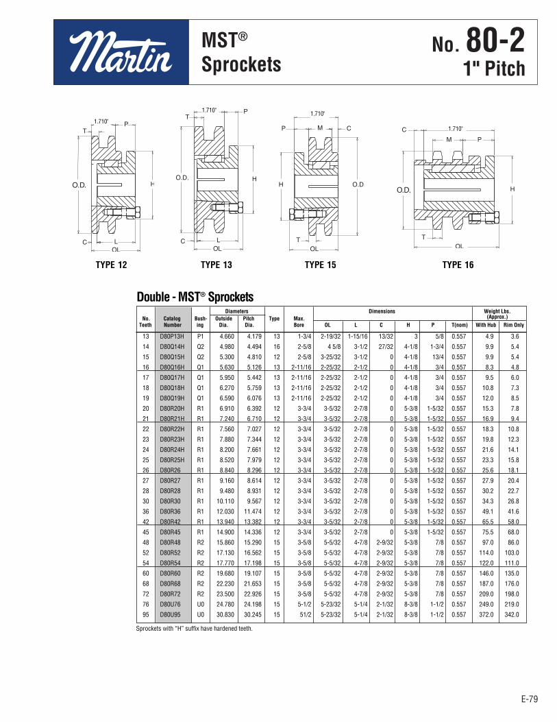
E-79
No. 80-21" Pitch
MST®
Sprockets
E-79
Diameters Dimensions Weight Lbs. No. Catalog Bush- Outside Pitch Type Max. (Approx.) Teeth Number ing Dia. Dia. Bore OL L C H P T(nom) With Hub Rim Only
13 D80P13H P1 4.660 4.179 13 1-3/4 2-19/32 1-15/16 13/32 3 5/8 0.557 4.9 3.6
14 D80Q14H Q2 4.980 4.494 16 2-5/8 4 5/8 3-1/2 27/32 4-1/8 1-3/4 0.557 9.9 5.4
15 D80Q15H Q2 5.300 4.810 12 2-5/8 3-25/32 3-1/2 0 4-1/8 13/4 0.557 9.9 5.4
16 D80Q16H Q1 5.630 5.126 13 2-11/16 2-25/32 2-1/2 0 4-1/8 3/4 0.557 8.3 4.8
17 D80Q17H Q1 5.950 5.442 13 2-11/16 2-25/32 2-1/2 0 4-1/8 3/4 0.557 9.5 6.0
18 D80Q18H Q1 6.270 5.759 13 2-11/16 2-25/32 2-1/2 0 4-1/8 3/4 0.557 10.8 7.3
19 D80Q19H Q1 6.590 6.076 13 2-11/16 2-25/32 2-1/2 0 4-1/8 3/4 0.557 12.0 8.5
20 D80R20H R1 6.910 6.392 12 3-3/4 3-5/32 2-7/8 0 5-3/8 1-5/32 0.557 15.3 7.8
21 D80R21H R1 7.240 6.710 12 3-3/4 3-5/32 2-7/8 0 5-3/8 1-5/32 0.557 16.9 9.4
22 D80R22H R1 7.560 7.027 12 3-3/4 3-5/32 2-7/8 0 5-3/8 1-5/32 0.557 18.3 10.8
23 D80R23H R1 7.880 7.344 12 3-3/4 3-5/32 2-7/8 0 5-3/8 1-5/32 0.557 19.8 12.3
24 D80R24H R1 8.200 7.661 12 3-3/4 3-5/32 2-7/8 0 5-3/8 1-5/32 0.557 21.6 14.1
25 D80R25H R1 8.520 7.979 12 3-3/4 3-5/32 2-7/8 0 5-3/8 1-5/32 0.557 23.3 15.8
26 D80R26 R1 8.840 8.296 12 3-3/4 3-5/32 2-7/8 0 5-3/8 1-5/32 0.557 25.6 18.1
27 D80R27 R1 9.160 8.614 12 3-3/4 3-5/32 2-7/8 0 5-3/8 1-5/32 0.557 27.9 20.4
28 D80R28 R1 9.480 8.931 12 3-3/4 3-5/32 2-7/8 0 5-3/8 1-5/32 0.557 30.2 22.7
30 D80R30 R1 10.110 9.567 12 3-3/4 3-5/32 2-7/8 0 5-3/8 1-5/32 0.557 34.3 26.8
36 D80R36 R1 12.030 11.474 12 3-3/4 3-5/32 2-7/8 0 5-3/8 1-5/32 0.557 49.1 41.6
42 D80R42 R1 13.940 13.382 12 3-3/4 3-5/32 2-7/8 0 5-3/8 1-5/32 0.557 65.5 58.0
45 D80R45 R1 14.900 14.336 12 3-3/4 3-5/32 2-7/8 0 5-3/8 1-5/32 0.557 75.5 68.0
48 D80R48 R2 15.860 15.290 15 3-5/8 5-5/32 4-7/8 2-9/32 5-3/8 7/8 0.557 97.0 86.0
52 D80R52 R2 17.130 16.562 15 3-5/8 5-5/32 4-7/8 2-9/32 5-3/8 7/8 0.557 114.0 103.0
54 D80R54 R2 17.770 17.198 15 3-5/8 5-5/32 4-7/8 2-9/32 5-3/8 7/8 0.557 122.0 111.0
60 D80R60 R2 19.680 19.107 15 3-5/8 5-5/32 4-7/8 2-9/32 5-3/8 7/8 0.557 146.0 135.0
68 D80R68 R2 22.230 21.653 15 3-5/8 5-5/32 4-7/8 2-9/32 5-3/8 7/8 0.557 187.0 176.0
72 D80R72 R2 23.500 22.926 15 3-5/8 5-5/32 4-7/8 2-9/32 5-3/8 7/8 0.557 209.0 198.0
76 D80U76 U0 24.780 24.198 15 5-1/2 5-23/32 5-1/4 2-1/32 8-3/8 1-1/2 0.557 249.0 219.0
95 D80U95 U0 30.830 30.245 15 51/2 5-23/32 5-1/4 2-1/32 8-3/8 1-1/2 0.557 372.0 342.0
Double - MST® Sprockets
1.710"1.710"
1.710"
1.710"
Sprockets with “H” suffix have hardened teeth.
TYPE 12 TYPE 13 TYPE 15 TYPE 16
E65 - E80-2.qxp_E65 - E80 1/24/18 2:53 PM Page E-79
No . 80-21" Pitch
MST®
Sprockets
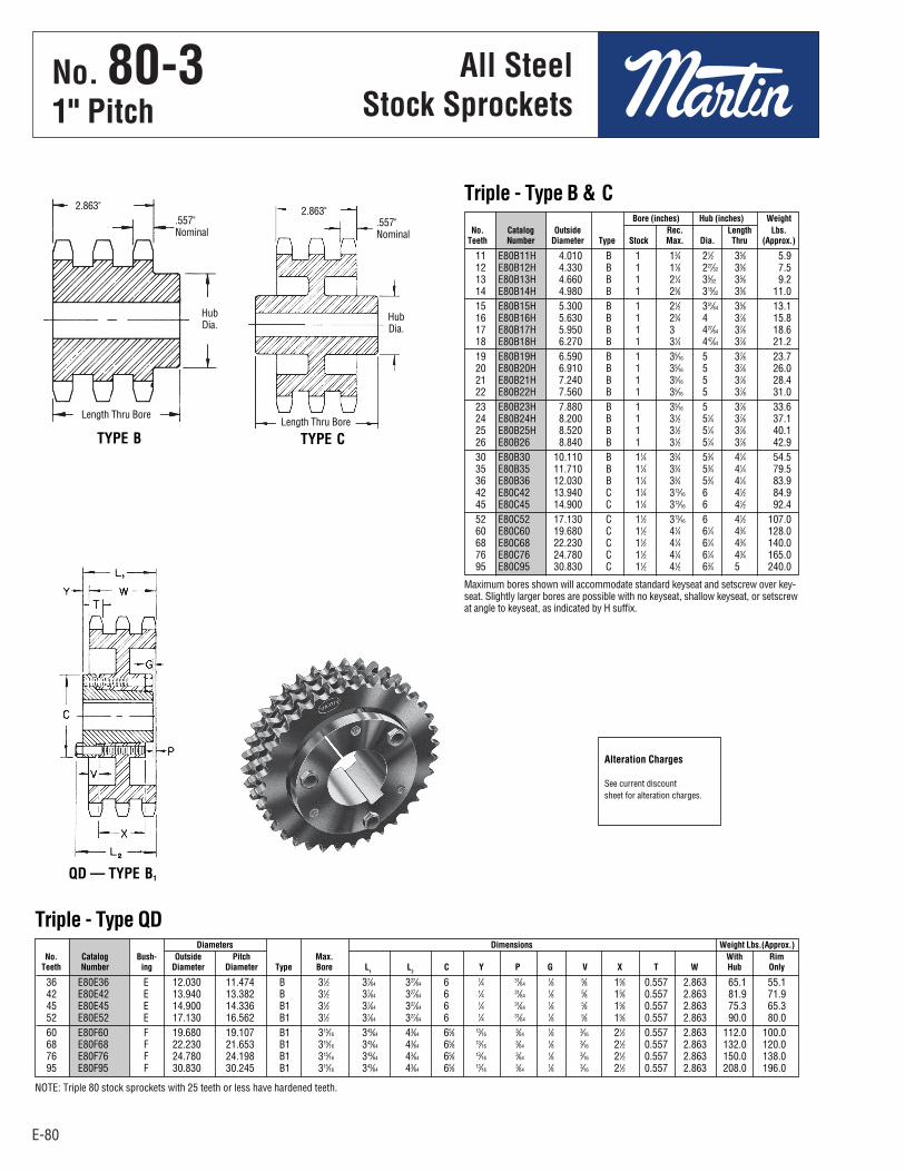
E-80
No. 80-31" Pitch
All SteelStock Sprockets
E-80
36 E80E36 E 12.030 11.474 B 31⁄2 37⁄64 327⁄64 6 1⁄4 31⁄64 1⁄8 5⁄8 15⁄8 0.557 2.863 65.1 55.1 42 E80E42 E 13.940 13.382 B 31⁄2 37⁄64 327⁄64 6 1⁄4 31⁄64 1⁄8 5⁄8 15⁄8 0.557 2.863 81.9 71.9 45 E80E45 E 14.900 14.336 B1 31⁄2 37⁄64 327⁄64 6 1⁄4 31⁄64 1⁄8 5⁄8 15⁄8 0.557 2.863 75.3 65.3 52 E80E52 E 17.130 16.562 B1 31⁄2 37⁄64 327⁄64 6 1⁄4 31⁄64 1⁄8 5⁄8 15⁄8 0.557 2.863 90.0 80.0 60 E80F60 F 19.680 19.107 B1 315⁄16 343⁄64 43⁄64 65⁄8 13⁄16 3⁄64 1⁄8 3⁄16 21⁄2 0.557 2.863 112.0 100.0 68 E80F68 F 22.230 21.653 B1 315⁄16 343⁄64 43⁄64 65⁄8 13⁄16 3⁄64 1⁄8 3⁄16 21⁄2 0.557 2.863 132.0 120.0 76 E80F76 F 24.780 24.198 B1 315⁄16 343⁄64 43⁄64 65⁄8 13⁄16 3⁄64 1⁄8 3⁄16 21⁄2 0.557 2.863 150.0 138.0 95 E80F95 F 30.830 30.245 B1 315⁄16 343⁄64 43⁄64 65⁄8 13⁄16 3⁄64 1⁄8 3⁄16 21⁄2 0.557 2.863 208.0 196.0
Diameters Dimensions Weight Lbs.(Approx.) No. Catalog Bush- Outside Pitch Max. With Rim Teeth Number ing Diameter Diameter Type Bore L
1 L
2 C Y P G V X T W Hub Only
Triple - Type QD
11 E80B11H 4.010 B 1 13⁄4 21⁄2 35⁄8 5.9 12 E80B12H 4.330 B 1 17⁄8 227⁄32 35⁄8 7.5 13 E80B13H 4.660 B 1 21⁄4 35⁄32 35⁄8 9.2 14 E80B14H 4.980 B 1 23⁄8 315⁄32 35⁄8 11.0 15 E80B15H 5.300 B 1 21⁄2 351⁄64 35⁄8 13.1 16 E80B16H 5.630 B 1 23⁄4 4 37⁄8 15.8 17 E80B17H 5.950 B 1 3 427⁄64 37⁄8 18.6 18 E80B18H 6.270 B 1 31⁄4 447⁄64 37⁄8 21.2 19 E80B19H 6.590 B 1 35⁄16 5 37⁄8 23.7 20 E80B20H 6.910 B 1 35⁄16 5 37⁄8 26.0 21 E80B21H 7.240 B 1 35⁄16 5 37⁄8 28.4 22 E80B22H 7.560 B 1 35⁄16 5 37⁄8 31.0 23 E80B23H 7.880 B 1 35⁄16 5 37⁄8 33.6 24 E80B24H 8.200 B 1 31⁄2 51⁄4 37⁄8 37.1 25 E80B25H 8.520 B 1 31⁄2 51⁄4 37⁄8 40.1 26 E80B26 8.840 B 1 31⁄2 51⁄4 37⁄8 42.9 30 E80B30 10.110 B 11⁄4 33⁄4 53⁄4 41⁄4 54.5 35 E80B35 11.710 B 11⁄4 33⁄4 53⁄4 41⁄4 79.5 36 E80B36 12.030 B 11⁄4 33⁄4 53⁄4 41⁄4 83.9 42 E80C42 13.940 C 11⁄4 313⁄16 6 41⁄2 84.9 45 E80C45 14.900 C 11⁄4 313⁄16 6 41⁄2 92.4 52 E80C52 17.130 C 11⁄2 313⁄16 6 41⁄2 107.0 60 E80C60 19.680 C 11⁄2 41⁄4 61⁄4 43⁄4 128.0 68 E80C68 22.230 C 11⁄2 41⁄4 61⁄4 43⁄4 140.0 76 E80C76 24.780 C 11⁄2 41⁄4 61⁄4 43⁄4 165.0 95 E80C95 30.830 C 11⁄2 41⁄2 63⁄4 5 240.0
Bore (inches) Hub (inches) Weight No. Catalog Outside Rec. Length Lbs. Teeth Number Diameter Type Stock Max. Dia. Thru (Approx.)
Triple - Type B & C
Maximum bores shown will accommodate standard keyseat and setscrew over key-seat. Slightly larger bores are possible with no keyseat, shallow keyseat, or setscrewat angle to keyseat, as indicated by H suffix.
Alteration Charges
See current discountsheet for alteration charges.
TYPE CTYPE B
QD — TYPE B1
NOTE: Triple 80 stock sprockets with 25 teeth or less have hardened teeth.
.557"Nominal
2.863"
.557"Nominal
2.863"
HubDia.
Length Thru Bore
HubDia.
Length Thru Bore
E65 - E80-2.qxp_E65 - E80 1/24/18 2:53 PM Page E-80
No . 80-31" Pitch
All SteelStock Sprockets

E-81E-81
No. 80-31" Pitch
Diameters Dimensions Weight Lbs. No. Catalog Bush- Outside Pitch Type Max. (Approx.) Teeth Number ing Dia. Dia. Bore OL L C H P T(nom) With Hub Rim Only
13 E80P13H P2 4.660 4.179 24 1-3/4 3-3/4 2-15/16 9/16 3 5/8 0.557 7.2 5.7
14 E80Q14H Q2 4.980 4.494 27 2-5/8 5-25/32 3-1/2 2 4-1/8 1-3/4 0.557 12.0 7.5
15 E80Q15H Q2 5.300 4.810 22 2-5/8 4-29/32 3-1/2 1-1/8 4-1/8 1-3/4 0.557 12.6 8.1
16 E80Q16H Q2 5.630 5.126 25 2-5/8 3-7/8 3-1/2 3/32 4-1/8 3/4 0.557 13.8 9.3
17 E80Q17H Q2 5.950 5.442 24 2-5/8 3-29/32 3-1/2 1/8 4-1/8 3/4 0.557 14.3 9.8
18 E80Q18H Q2 6.270 5.759 24 2-5/8 3-29/32 3-1/2 1/8 4-1/8 3/4 0.557 16.5 12.0
19 E80Q19H Q2 6.590 6.076 24 2-5/8 3-29/32 3-1/2 1/8 4-1/8 3/4 0.557 18.4 13.9
20 E80R20H R1 6.910 6.392 24 3-3/4 4-1/32 2-7/8 7/8 5-3/8 7/8 0.557 17.7 10.2
21 E80R21H R1 7.240 6.710 24 3-3/4 4-1/32 2-7/8 7/8 5-3/8 7/8 0.557 19.9 12.4
22 E80R22H R1 7.560 7.027 24 3-3/4 4-1/32 2-7/8 7/8 5-3/8 7/8 0.557 22.1 14.6
23 E80R23H R1 7.880 7.344 25 3-3/4 3-5/32 2-7/8 0 5-3/8 0 0.557 23.4 15.9
24 E80R24 R1 8.200 7.661 25 3-3/4 3-5/32 2-7/8 0 5-3/8 0 0.557 7.2 18.5
25 E80R25 R1 8.520 7.979 25 3-3/4 3-5/32 2-7/8 0 5-3/8 0 0.557 12.0 20.3
26 E80R26 R1 8.840 8.296 25 3-3/4 3-5/32 2-7/8 0 5-3/8 0 0.557 12.6 23.4
27 E80R27 R1 9.160 8.614 25 3-3/4 3-5/32 2-7/8 0 5-3/8 0 0.557 13.8 25.8
28 E80R28 R1 9.480 8.931 25 3-3/4 3-5/32 2-7/8 0 5-3/8 0 0.557 14.3 28.1
30 E80R30 R1 10.110 9.567 25 3-3/4 3-5/32 2-7/8 0 5-3/8 0 0.557 16.5 33.3
36 E80S36 S1 12.030 11.474 22 4-1/4 5-1/8 4-3/8 0 6-3/8 1-1/2 0.557 18.4 67.0
42 E80S42 S1 13.940 13.382 22 4-1/4 5-1/8 4-3/8 0 6-3/8 1-1/2 0.557 17.7 96.1
45 E80S45 S1 14.900 14.336 22 4-1/4 5-1/8 4-3/8 0 6-3/8 1-1/2 0.557 19.9 112.0
52 E80U52 U0 17.130 16.562 22 5-1/2 5-23/32 5-1/4 0 8-3/8 1-25/32 0.557 22.1 150.0
60 E80U60 U0 19.680 19.107 22 5-1/2 5-23/32 5-1/4 0 8-3/8 1-25/32 0.557 23.4 207.0
68 E80U68 U0 22.230 21.653 22 5-1/2 5-23/32 5-1/4 0 8-3/8 1-25/32 0.557 23.4 271.0
76 E80U76 U0 24.780 24.198 22 5-1/2 5-23/32 5-1/4 0 8-3/8 1-25/32 0.557 23.4 344.0
95 E80U95 U0 30.830 30.245 25 5-1/2 5-55/64 5-1/4 1/32 8-3/8 1-13/32 0.557 23.4 183.0
Triple - MST® Sprockets
2.863"2.863"2.863"
2.863"
Sprockets with “H” suffix have hardened teeth.
TYPE 25 TYPE 27TYPE 24TYPE 22
MST®
SprocketsNo . 80-3
1" PitchMST®
Sprockets
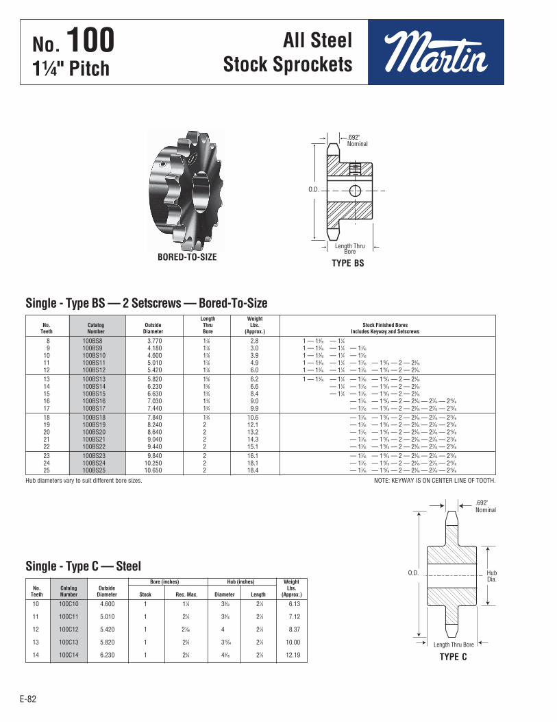
E-82
No. 10011⁄4" Pitch
All SteelStock Sprockets
E-82
10 100C10 4.600 1 17⁄8 39⁄32 27⁄8 6.13
11 100C11 5.010 1 21⁄4 39⁄16 27⁄8 7.12
12 100C12 5.420 1 21⁄46 4 27⁄8 8.37
13 100C13 5.820 1 23⁄8 357⁄64 27⁄8 10.00
14 100C14 6.230 1 23⁄4 43⁄16 27⁄8 12.19
8 100BS8 3.770 17⁄8 2.8 1 — 13⁄16 — 11⁄4 9 100BS9 4.180 17⁄8 3.0 1 — 13⁄16 — 11⁄4 — 17⁄16
10 100BS10 4.600 17⁄8 3.9 1 — 13⁄16 — 11⁄4 — 17⁄16
11 100BS11 5.010 17⁄8 4.9 1 — 13⁄16 — 11⁄4 — 17⁄16 — 115⁄16 — 2 — 23⁄16
12 100BS12 5.420 17⁄8 6.0 1 — 13⁄16 — 11⁄4 — 17⁄16 — 115⁄16 — 2 — 23⁄16
13 100BS13 5.820 15⁄8 6.2 1 — 13⁄16 — 11⁄4 — 17⁄16 — 115⁄16 — 2 — 23⁄16
14 100BS14 6.230 15⁄8 6.6 — 11⁄4 — 17⁄16 — 115⁄16 — 2 — 23⁄16
15 100BS15 6.630 13⁄4 8.4 — 11⁄4 — 17⁄16 — 115⁄16 — 2 — 23⁄16
16 100BS16 7.030 13⁄4 9.0 — 17⁄16 — 115⁄16 — 2 — 23⁄16 — 27⁄16 — 215⁄16
17 100BS17 7.440 13⁄4 9.9 — 17⁄16 — 115⁄16 — 2 — 23⁄16 — 27⁄16 — 215⁄16
18 100BS18 7.840 13⁄4 10.6 — 17⁄16 — 115⁄16 — 2 — 23⁄16 — 27⁄16 — 215⁄16
19 100BS19 8.240 2 12.1 — 17⁄16 — 115⁄16 — 2 — 23⁄16 — 27⁄16 — 215⁄16
20 100BS20 8.640 2 13.2 — 17⁄16 — 115⁄16 — 2 — 23⁄16 — 27⁄16 — 215⁄16
21 100BS21 9.040 2 14.3 — 17⁄16 — 115⁄16 — 2 — 23⁄16 — 27⁄16 — 215⁄16
22 100BS22 9.440 2 15.1 — 17⁄16 — 115⁄16 — 2 — 23⁄16 — 27⁄16 — 215⁄16
23 100BS23 9.840 2 16.1 — 17⁄16 — 115⁄16 — 2 — 23⁄16 — 27⁄16 — 215⁄16
24 100BS24 10.250 2 18.1 — 17⁄16 — 115⁄16 — 2 — 23⁄16 — 27⁄16 — 215⁄16
25 100BS25 10.650 2 18.4 — 17⁄16 — 115⁄16 — 2 — 23⁄16 — 27⁄16 — 215⁄16
Length Weight No. Catalog Outside Thru Lbs. Stock Finished Bores Teeth Number Diameter Bore (Approx.) Includes Keyway and Setscrews
Single - Type BS — 2 Setscrews — Bored-To-Size
Hub diameters vary to suit different bore sizes. NOTE: KEYWAY IS ON CENTER LINE OF TOOTH.
BORED-TO-SIZETYPE BS
.692"Nominal
Length ThruBore
Bore (inches) Hub (inches) Weight No. Catalog Outside Lbs. Teeth Number Diameter Stock Rec. Max. Diameter Length (Approx.)
Single - Type C — Steel
TYPE C
.692"Nominal
HubDia.
Length Thru Bore
O.D.
O.D.
No . 1001¼" Pitch
All SteelStock Sprockets
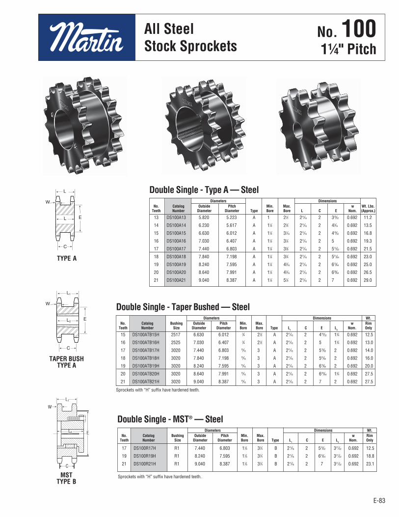
E-83
No. 10011⁄4" Pitch
All SteelStock Sprockets
E-83
15 DS100ATB15H 2517 6.630 6.012 3⁄4 21⁄2 A 211⁄16 2 419⁄32 13⁄4 0.692 12.5
16 DS100ATB16H 2525 7.030 6.407 3⁄4 21⁄2 A 211⁄16 2 5 13⁄4 0.692 13.0
17 DS100ATB17H 3020 7.440 6.803 15⁄16 3 A 211⁄16 2 513⁄32 2 0.692 14.0
18 DS100ATB18H 3020 7.840 7.198 15⁄16 3 A 211⁄16 2 551⁄64 2 0.692 16.0
19 DS100ATB19H 3020 8.240 7.595 15⁄16 3 A 211⁄16 2 613⁄64 2 0.692 20.0
20 DS100ATB20H 3020 8.640 7.991 15⁄16 3 A 211⁄16 2 639⁄64 13⁄4 0.692 27.5
21 DS100ATB21H 3020 9.040 8.387 15⁄16 3 A 211⁄16 2 7 2 0.692 27.5
13 DS100A13 5.820 5.223 A 1 21⁄2 211⁄16 2 325⁄32 0.692 11.2
14 DS100A14 6.230 5.617 A 11⁄4 23⁄4 211⁄16 2 43⁄16 0.692 13.5
15 DS100A15 6.630 6.012 A 11⁄4 31⁄16 211⁄16 2 419⁄32 0.692 16.8
16 DS100A16 7.030 6.407 A 11⁄4 31⁄4 211⁄16 2 5 0.692 19.3
17 DS100A17 7.440 6.803 A 11⁄4 35⁄8 211⁄16 2 513⁄32 0.692 21.5
18 DS100A18 7.840 7.198 A 11⁄4 33⁄4 211⁄16 2 551⁄64 0.692 23.0
19 DS100A19 8.240 7.595 A 11⁄4 43⁄16 211⁄16 2 613⁄64 0.692 25.0
20 DS100A20 8.640 7.991 A 11⁄4 43⁄16 211⁄16 2 639⁄64 0.692 26.5
21 DS100A21 9.040 8.387 A 11⁄4 51⁄4 211⁄16 2 7 0.692 29.0
Diameters Dimensions No. Catalog Outside Pitch Min. Max. w Wt. Lbs. Teeth Number Diameter Diameter Type Bore Bore L C E Nom. (Approx.)
Double Single - Type A — Steel
Diameters Dimensions Wt. No. Catalog Bushing Outside Pitch Min. Max. w Rim Teeth Number Size Diameter Diameter Bore Bore Type L
1 C E L
2 Nom. Only
Double Single - Taper Bushed — Steel
TYPE A
TAPER BUSHTYPE A
MSTTYPE B
17 DS100R17H R1 7.440 6.803 11⁄8 33⁄4 B 211⁄16 2 513⁄32 327⁄32 0.692 12.5
19 DS100R19H R1 8.240 7.595 11⁄8 33⁄4 B 211⁄16 2 613⁄64 327⁄32 0.692 18.8
21 DS100R21H R1 9.040 8.387 11⁄8 33⁄4 B 211⁄16 2 7 327⁄32 0.692 23.1
Diameters Dimensions Wt. No. Catalog Bushing Outside Pitch Min. Max. w Rim Teeth Number Size Diameter Diameter Bore Bore Type L
1 C E L
2 Nom. Only
Double Single - MST® — Steel
Sprockets with “H” suffix have hardened teeth.
Sprockets with “H” suffix have hardened teeth.
No . 1001¼" Pitch
All SteelStock Sprockets
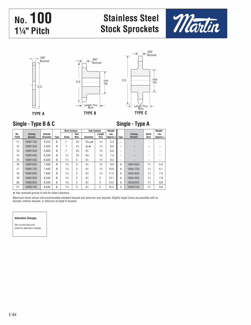
E-84
No. 10011⁄4" Pitch
Stainless SteelStock Sprockets
E-84
11 100B11SS 5.010 B 1 21⁄4 39⁄16HH 17⁄8 5.3 – – – –
12 100B12SS 5.420 B 1 21⁄4 4HH 17⁄8 6.4 – – – –
13 100B13SS 5.820 B 1 23⁄8 37⁄8 15⁄8 6.6 – – – –
14 100B14SS 6.230 B 11⁄4 23⁄4 43⁄16 15⁄8 7.4 – – – –
15 100B15SS 6.630 B 11⁄4 3 41⁄2 13⁄4 9.2 – – – –
16 100B16SS 7.030 B 15⁄16 3 41⁄2 13⁄4 9.9 A 100A16SS 11⁄4 5.4
17 100B17SS 7.440 B 15⁄16 3 41⁄2 13⁄4 10.8 A 100A17SS 11⁄4 6.1
18 100B18SS 7.840 B 15⁄16 3 41⁄2 13⁄4 11.5 A 100A18SS 11⁄4 7.0
19 100B19SS 8.240 B 15⁄16 3 41⁄2 2 13.1 A 100A19SS 11⁄4 7.8
20 100B20SS 8.640 B 15⁄16 3 41⁄2 2 14.2 A 100A20SS 11⁄4 8.8
21 100B21SS 9.040 B 15⁄16 3 41⁄2 2 15.3 A 100A21SS 11⁄4 9.8
Bore (inches) Hub (inches) Weight Weight No. Catalog Outside Rec. Length Lbs. Catalog Stock Lbs. Teeth Number Diameter Type Stock Max. Diameter Thru (Approx.) Type Number Bore (Approx.)
Single - Type B & C Single - Type A
H Has recessed groove in hub for chain clearance.
Maximum bores shown will accommodate standard keyseat and setscrew over keyseat. Slightly larger bores are possible with nokeyseat, shallow keyseat, or setscrew at angle to keyseat.
Alteration Charges
See current discountsheet for alteration charges.
TYPE CTYPE BTYPE A
.692"Nominal
.692"Nominal
HubDia.
O.D.
O.D.
O.D. HubDia.
.692"Nominal
Length ThruBore Length Thru
Bore
No . 1001¼" Pitch
Stainless SteelStock Sprockets

E-85
No. 10011⁄4" Pitch
All SteelStock Sprockets
E-85
7 3.350 A 100A7 1 1.2 8 100B8 3.770 B 1 11⁄4 27⁄16HH 17⁄8 2.3 A 100A8 1 1.4 9 100B9 4.180 B 1 15⁄8 213⁄16HH 17⁄8 3.2 A 100A9 1 1.6 10 100B10 4.600 B 1 17⁄8 31⁄4HH 17⁄8 4.1 A 100A10 1 2.0 11 100B11 5.010 B 1 21⁄4 39⁄16HH 17⁄8 5.3 A 100A11 11⁄4 2.5 12 100B12 5.420 B 1 21⁄4 4HH 17⁄8 6.4 A 100A12 11⁄4 3.0 13 100B13 5.820 B 1 23⁄8 37⁄8 15⁄8 6.6 A 100A13 11⁄4 3.5 14 100B14 6.230 B 11⁄4 23⁄4 43⁄16 15⁄8 7.4 A 100A14 11⁄4 4.1 15 100B15 6.630 B 11⁄4 3 41⁄2 13⁄4 9.2 A 100A15 11⁄4 4.7 16 100B16 7.030 B 15⁄16 3 41⁄2 13⁄4 9.9 A 100A16 11⁄4 5.4 17 100B17 7.440 B 15⁄16 3 41⁄2 13⁄4 10.8 A 100A17 11⁄4 6.1 18 100B18 7.840 B 15⁄16 3 41⁄2 13⁄4 11.5 A 100A18 11⁄4 7.0 19 100B19 8.240 B 15⁄16 3 41⁄2 2 13.1 A 100A19 11⁄4 7.8 20 100B20 8.640 B 15⁄16 3 41⁄2 2 14.2 A 100A20 11⁄4 8.8 21 100B21 9.040 B 15⁄16 3 41⁄2 2 15.3 A 100A21 11⁄4 9.8 22 100B22 9.440 B 15⁄16 3 41⁄2 2 16.1 A 100A22 11⁄4 10.5 23 100B23 9.840 B 11⁄4 3 41⁄2 2 17.2 A 100A23 11⁄4 11.8 24 100B24 10.250 B 11⁄4 3 41⁄2 2 19.2 A 100A24 11⁄4 12.8 25 100B25 10.650 B 11⁄4 3 41⁄2 2 19.5 A 100A25 11⁄4 13.9 26 100B26 11.050 B 11⁄4 35⁄16 5 2 21.7 A 100A26 11⁄4 15.0 27 100B27 11.440 B 11⁄4 35⁄16 5 2 23.0 A 100A27 11⁄4 16.0 28 100B28 11.840 B 11⁄4 35⁄16 5 2 24.4 A 100A28 11⁄4 17.4 29 100B29 12.240 B 11⁄4 35⁄16 5 2 25.0 A 100A29 11⁄4 19.6 30 100B30 12.640 B 11⁄4 35⁄16 5 2 26.9 A 100A30 11⁄4 20.1 31 13.040 A 100A31 11⁄4 21.5 32 100B32 13.440 B 11⁄4 35⁄16 5 2 29.8 A 100A32 11⁄4 22.6 33 13.840 A 100A33 11⁄4 24.1 34 14.240 A 100A34 11⁄4 26.0 35 100B35 14.640 B 11⁄4 35⁄16 5 21⁄2 36.9 A 100A35 11⁄4 27.2 36 100B36 15.040 B 11⁄4 35⁄16 5 21⁄2 38.6 A 100A36 11⁄4 30.0 37 15.440 A 100A37 11⁄4 31.0 38 100B38 15.840 B 11⁄4 35⁄16 5 21⁄2 41.5 A 100A38 11⁄4 33.0 39 100B39 16.230 B 11⁄4 35⁄16 5 21⁄2 43.6 A 100A39 11⁄4 35.0 40 100B40 16.630 B 11⁄4 35⁄16 5 21⁄2 46.9 A 100A40 11⁄4 36.0 41 17.030 A 100A41 11⁄4 39.0 42 100B42 17.430 B 11⁄4 35⁄16 5 21⁄2 50.4 A 100A42 11⁄4 40.0 43 17.830 A 100A43 11⁄2 43.0 44 18.230 A 100A44 11⁄2 45.0 45 100B45 18.630 B 11⁄2 35⁄16 5 21⁄2 54.0 A 100A45 11⁄2 47.0 46 19.020 A 100A46 11⁄2 48.0 47 19.420 A 100A47 11⁄2 52.0 48 100B48 19.820 B 11⁄2 4 6 21⁄2 66.0 A 100A48 11⁄2 54.0 49 20.220 A 100A49 11⁄2 56.0 50 20.620 A 100A50 11⁄2 57.0 51 21.020 A 100A51 11⁄2 63.0 52 21.420 A 100A52 11⁄2 64.0 53 21.810 A 100A53 11⁄2 64.2 54 100C54 22.210 C 11⁄2 4 6 31⁄4 78.0 A 100A54 11⁄2 68.0 55 22.610 A 100A55 11⁄2 70.0 56 23.010 A 100A56 11⁄2 72.0 57 23.410 A 100A57 11⁄2 75.8 58 23.810 A 100A58 11⁄2 76.0 59 24.200 A 100A59 11⁄2 77.0 60 100C60 24.600 C 11⁄2 4 6 31⁄4 89.0 A 100A60 11⁄2 80.0 70 100C70 28.580 C 11⁄2 51⁄4 7 33⁄4 125.0 A 100A70 11⁄2 113 72 100C72 29.380 C 11⁄2 51⁄4 7 33⁄4 134.0 A 100A72 11⁄2 119 76 100C76 30.973 C 11⁄2 51⁄4 7 33⁄4 143.0 A 100A76 11⁄2 133 80 100C80 32.570 C 11⁄2 51⁄4 7 33⁄4 151.0 A 100A80 11⁄2 146 84 100C84 34.160 C 11⁄2 51⁄4 7 33⁄4 170.0 A 100A84 11⁄2 162 90 100C90 36.550 C 11⁄2 51⁄4 7 33⁄4 184.0 A 100A90 11⁄2 193 96 100C96 38.930 C 11⁄2 51⁄4 7 41⁄2 203.0 A 100A96 11⁄2 215
Bore (inches) Hub (inches) Weight Weight No. Catalog Outside Rec. Length Lbs. Catalog Stock Lbs. Teeth Number Diameter Type Stock Max. Diameter Thru (Approx.) Type Number Bore (Approx.)
Single - Type B & C Single-Type A
H Has recessed groove in hub for chain clearance.
Maximum bores shown will accommodate standard keyseat and setscrew over keyseat. Slightly larger bores are possible with nokeyseat, shallow keyseat, or setscrew at angle to keyseat.
Alteration Charges
See current discountsheet for alteration charges.
TYPE C
TYPE B
TYPE A
.692"Nominal
.692"Nominal
HubDia.
O.D.
O.D.
O.D. HubDia.
.692"Nominal
Length ThruBore
Length ThruBore
No . 1001¼" Pitch
All SteelStock Sprockets
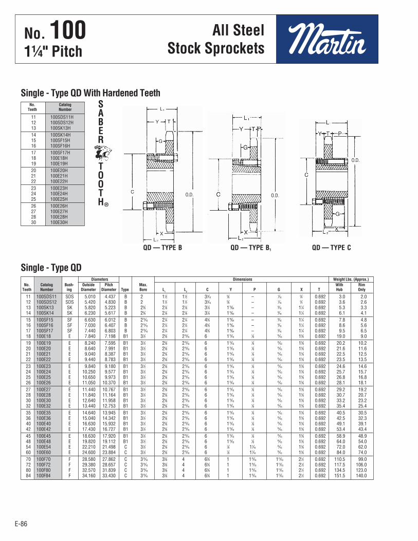
E-86
No. 10011⁄4" Pitch
E-86
11 100SDS11H 12 100SDS12H 13 100SK13H 14 100SK14H 15 100SF15H 16 100SF16H 17 100SF17H 18 100E18H 19 100E19H 20 100E20H 21 100E21H 22 100E22H 23 100E23H 24 100E24H 25 100E25H 26 100E26H 27 100E27H 28 100E28H 30 100E30H
No. Catalog Teeth Number
Single - Type QD With Hardened Teeth
QD — TYPE B QD — TYPE CQD — TYPE B1
11 100SDS11 SDS 5.010 4.437 B 2 11⁄2 11⁄2 33⁄16 5⁄8 – 1⁄16 3⁄4 0.692 3.0 2.0 12 100SDS12 SDS 5.420 4.830 B 2 11⁄2 11⁄2 33⁄16 5⁄8 – 1⁄16 3⁄4 0.692 3.6 2.6 13 100SK13 SK 5.820 5.223 B 25⁄8 21⁄8 21⁄8 37⁄8 113⁄64 – 9⁄16 11⁄4 0.692 5.3 3.3 14 100SK14 SK 6.230 5.617 B 25⁄8 21⁄8 21⁄8 37⁄8 113⁄64 – 9⁄16 11⁄4 0.692 6.1 4.1 15 100SF15 SF 6.630 6.012 B 215⁄16 21⁄4 21⁄4 45⁄8 119⁄64 – 9⁄16 11⁄4 0.692 7.8 4.8 16 100SF16 SF 7.030 6.407 B 215⁄16 21⁄4 21⁄4 45⁄8 119⁄64 – 9⁄16 11⁄4 0.692 8.6 5.6 17 100SF17 SF 7.440 6.803 B 215⁄16 21⁄4 21⁄4 45⁄8 119⁄64 – 9⁄16 11⁄4 0.692 9.5 6.5 18 100E18 E 7.840 7.198 B1 31⁄2 25⁄8 215⁄16 6 113⁄16 1⁄8 15⁄16 15⁄8 0.692 19.0 9.0 19 100E19 E 8.240 7.595 B1 31⁄2 25⁄8 215⁄16 6 113⁄16 1⁄8 15⁄16 15⁄8 0.692 20.2 10.2 20 100E20 E 8.640 7.991 B1 31⁄2 25⁄8 215⁄16 6 113⁄16 1⁄8 15⁄16 15⁄8 0.692 21.6 11.6 21 100E21 E 9.040 8.387 B1 31⁄2 25⁄8 215⁄16 6 113⁄16 1⁄8 15⁄16 15⁄8 0.692 22.5 12.5 22 100E22 E 9.440 8.783 B1 31⁄2 25⁄8 215⁄16 6 113⁄16 1⁄8 15⁄16 15⁄8 0.692 23.5 13.5 23 100E23 E 9.840 9.180 B1 31⁄2 25⁄8 215⁄16 6 113⁄16 1⁄8 15⁄16 15⁄8 0.692 24.6 14.6 24 100E24 E 10.250 9.577 B1 31⁄2 25⁄8 215⁄16 6 113⁄16 1⁄8 15⁄16 15⁄8 0.692 25.7 15.7 25 100E25 E 10.650 9.973 B1 31⁄2 25⁄8 215⁄16 6 113⁄16 1⁄8 15⁄16 15⁄8 0.692 26.8 16.8 26 100E26 E 11.050 10.370 B1 31⁄2 25⁄8 215⁄16 6 113⁄16 1⁄8 15⁄16 15⁄8 0.692 28.1 18.1 27 100E27 E 11.440 10.767 B1 31⁄2 25⁄8 215⁄16 6 113⁄16 1⁄8 15⁄16 15⁄8 0.692 29.2 19.2 28 100E28 E 11.840 11.164 B1 31⁄2 25⁄8 215⁄16 6 113⁄16 1⁄8 15⁄16 15⁄8 0.692 30.7 20.7 30 100E30 E 12.640 11.958 B1 31⁄2 25⁄8 215⁄16 6 113⁄16 1⁄8 15⁄16 15⁄8 0.692 33.2 23.2 32 100E32 E 13.440 12.753 B1 31⁄2 25⁄8 215⁄16 6 113⁄16 1⁄8 15⁄16 15⁄8 0.692 35.4 25.4 35 100E35 E 14.640 13.945 B1 31⁄2 25⁄8 215⁄16 6 113⁄16 1⁄8 15⁄16 15⁄8 0.692 40.5 30.5 36 100E36 E 15.040 14.342 B1 31⁄2 25⁄8 215⁄16 6 113⁄16 1⁄8 15⁄16 15⁄8 0.692 42.5 32.3 40 100E40 E 16.630 15.932 B1 31⁄2 25⁄8 215⁄16 6 113⁄16 1⁄8 15⁄16 15⁄8 0.692 49.1 39.1 42 100E42 E 17.430 16.727 B1 31⁄2 25⁄8 215⁄16 6 113⁄16 1⁄8 15⁄16 15⁄8 0.692 53.4 43.4 45 100E45 E 18.630 17.920 B1 31⁄2 25⁄8 215⁄16 6 113⁄16 1⁄8 15⁄16 15⁄8 0.692 58.9 48.9 48 100E48 E 19.820 19.112 B1 31⁄2 25⁄8 215⁄16 6 113⁄16 1⁄8 15⁄16 15⁄8 0.692 64.0 54.0 54 100E54 E 22.210 21.498 C 31⁄2 25⁄8 215⁄16 6 7⁄8 11⁄16 15⁄16 15⁄8 0.692 72.0 62.0 60 100E60 E 24.600 23.884 C 31⁄2 25⁄8 215⁄16 6 7⁄8 11⁄16 15⁄16 15⁄8 0.692 84.0 74.0 70 100F70 F 28.580 27.862 C 315⁄16 35⁄8 4 65⁄8 1 115⁄16 113⁄16 21⁄2 0.692 110.5 99.0 72 100F72 F 29.380 28.657 C 315⁄16 35⁄8 4 65⁄8 1 115⁄16 113⁄16 21⁄2 0.692 117.5 106.0 80 100F80 F 32.570 31.839 C 315⁄16 35⁄8 4 65⁄8 1 115⁄16 113⁄16 21⁄2 0.692 134.5 123.0 84 100F84 F 34.160 33.430 C 315⁄16 35⁄8 4 65⁄8 1 115⁄16 113⁄16 21⁄2 0.692 151.5 140.0
Diameters Dimensions Weight Lbs. (Approx.) No. Catalog Bush- Outside Pitch Max. With Rim Teeth Number ing Diameter Diameter Type Bore L
1 L
2 C Y P G X T Hub Only
Single - Type QD
SABER
TOOTH®
O.D. O.D.
O.D.
All SteelStock Sprockets
No . 1001¼" Pitch
All SteelStock Sprockets
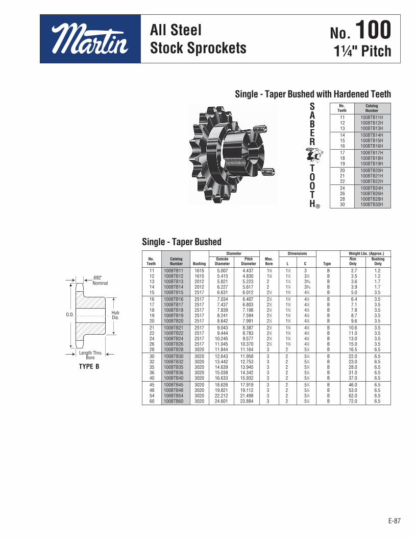
E-87E-87
No. 10011⁄4" Pitch
11 100BTB11 1615 5.007 4.437 15⁄8 11⁄2 3 B 2.7 1.2 12 100BTB12 1615 5.415 4.830 15⁄8 11⁄2 31⁄4 B 3.5 1.2 13 100BTB13 2012 5.821 5.223 2 11⁄4 39⁄16 B 3.6 1.7 14 100BTB14 2012 6.227 5.617 2 11⁄4 39⁄16 B 3.9 1.7 15 100BTB15 2517 6.631 6.012 21⁄2 13⁄4 41⁄4 B 5.0 3.5 16 100BTB16 2517 7.034 6.407 21⁄2 13⁄4 41⁄2 B 6.4 3.5 17 100BTB17 2517 7.437 6.803 21⁄2 13⁄4 41⁄2 B 7.1 3.5 18 100BTB18 2517 7.839 7.198 21⁄2 13⁄4 41⁄2 B 7.8 3.5 19 100BTB19 2517 8.241 7.594 21⁄2 13⁄4 41⁄2 B 8.7 3.5 20 100BTB20 2517 8.642 7.991 21⁄2 13⁄4 41⁄2 B 9.6 3.5 21 100BTB21 2517 9.043 8.387 21⁄2 13⁄4 41⁄2 B 10.6 3.5 22 100BTB22 2517 9.444 8.783 21⁄2 13⁄4 41⁄2 B 11.0 3.5 24 100BTB24 2517 10.245 9.577 21⁄2 13⁄4 41⁄2 B 13.0 3.5 26 100BTB26 2517 11.045 10.370 21⁄2 13⁄4 41⁄2 B 15.0 3.5 28 100BTB28 3020 11.844 11.164 3 2 51⁄4 B 16.5 6.5 30 100BTB30 3020 12.643 11.958 3 2 51⁄4 B 22.0 6.5 32 100BTB32 3020 13.442 12.753 3 2 51⁄4 B 23.0 6.5 35 100BTB35 3020 14.639 13.945 3 2 51⁄4 B 28.0 6.5 36 100BTB36 3020 15.038 14.342 3 2 51⁄4 B 31.0 6.5 40 100BTB40 3020 16.633 15.932 3 2 51⁄4 B 37.0 6.5 45 100BTB45 3020 18.626 17.919 3 2 51⁄4 B 46.0 6.5 48 100BTB48 3020 19.821 19.112 3 2 51⁄4 B 53.0 6.5 54 100BTB54 3020 22.212 21.498 3 2 51⁄4 B 62.0 6.5 60 100BTB60 3020 24.601 23.884 3 2 51⁄4 B 72.0 6.5
Diameter Dimensions Weight Lbs. (Approx.) No. Catalog Outside Pitch Max. Rim Bushing Teeth Number Bushing Diameter Diameter Bore L C Type Only Only
Single - Taper Bushed
11 100BTB11H 12 100BTB12H 13 100BTB13H 14 100BTB14H 15 100BTB15H 16 100BTB16H 17 100BTB17H 18 100BTB18H 19 100BTB19H 20 100BTB20H 21 100BTB21H 22 100BTB22H 24 100BTB24H 26 100BTB26H 28 100BTB28H 30 100BTB30H
No. Catalog Teeth Number
Single - Taper Bushed with Hardened TeethSABER
TOOTH®
TYPE B
O.D. HubDia.
.692"Nominal
Length ThruBore
All SteelStock Sprockets
No . 1001¼" Pitch
All SteelStock Sprockets
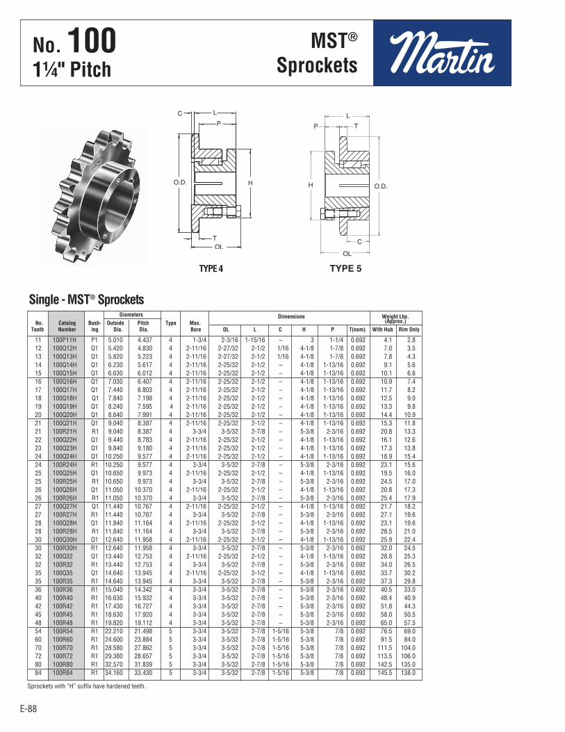
E-88
No. 10011⁄4" Pitch
E-88
11 100P11H P1 5.010 4.437 4 1-3/4 2-3/16 1-15/16 – 3 1-1/4 0.692 4.1 2.8 12 100Q12H Q1 5.420 4.830 4 2-11/16 2-27/32 2-1/2 1/16 4-1/8 1-7/8 0.692 7.0 3.5 13 100Q13H Q1 5.820 5.223 4 2-11/16 2-27/32 2-1/2 1/16 4-1/8 1-7/8 0.692 7.8 4.3 14 100Q14H Q1 6.230 5.617 4 2-11/16 2-25/32 2-1/2 – 4-1/8 1-13/16 0.692 9.1 5.6 15 100Q15H Q1 6.630 6.012 4 2-11/16 2-25/32 2-1/2 – 4-1/8 1-13/16 0.692 10.1 6.6 16 100Q16H Q1 7.030 6.407 4 2-11/16 2-25/32 2-1/2 – 4-1/8 1-13/16 0.692 10.9 7.4 17 100Q17H Q1 7.440 6.803 4 2-11/16 2-25/32 2-1/2 – 4-1/8 1-13/16 0.692 11.7 8.2 18 100Q18H Q1 7.840 7.198 4 2-11/16 2-25/32 2-1/2 – 4-1/8 1-13/16 0.692 12.5 9.0 19 100Q19H Q1 8.240 7.595 4 2-11/16 2-25/32 2-1/2 – 4-1/8 1-13/16 0.692 13.3 9.8 20 100Q20H Q1 8.640 7.991 4 2-11/16 2-25/32 2-1/2 – 4-1/8 1-13/16 0.692 14.4 10.9 21 100Q21H Q1 9.040 8.387 4 2-11/16 2-25/32 2-1/2 – 4-1/8 1-13/16 0.692 15.3 11.8 21 100R21H R1 9.040 8.387 4 3-3/4 3-5/32 2-7/8 – 5-3/8 2-3/16 0.692 20.8 13.3 22 100Q22H Q1 9.440 8.783 4 2-11/16 2-25/32 2-1/2 – 4-1/8 1-13/16 0.692 16.1 12.6 23 100Q23H Q1 9.840 9.180 4 2-11/16 2-25/32 2-1/2 – 4-1/8 1-13/16 0.692 17.3 13.8 24 100Q24H Q1 10.250 9.577 4 2-11/16 2-25/32 2-1/2 – 4-1/8 1-13/16 0.692 18.9 15.4 24 100R24H R1 10.250 9.577 4 3-3/4 3-5/32 2-7/8 – 5-3/8 2-3/16 0.692 23.1 15.6 25 100Q25H Q1 10.650 9.973 4 2-11/16 2-25/32 2-1/2 – 4-1/8 1-13/16 0.692 19.5 16.0 25 100R25H R1 10.650 9.973 4 3-3/4 3-5/32 2-7/8 – 5-3/8 2-3/16 0.692 24.5 17.0 26 100Q26H Q1 11.050 10.370 4 2-11/16 2-25/32 2-1/2 – 4-1/8 1-13/16 0.692 20.8 17.3 26 100R26H R1 11.050 10.370 4 3-3/4 3-5/32 2-7/8 – 5-3/8 2-3/16 0.692 25.4 17.9 27 100Q27H Q1 11.440 10.767 4 2-11/16 2-25/32 2-1/2 – 4-1/8 1-13/16 0.692 21.7 18.2 27 100R27H R1 11.440 10.767 4 3-3/4 3-5/32 2-7/8 – 5-3/8 2-3/16 0.692 27.1 19.6 28 100Q28H Q1 11.840 11.164 4 2-11/16 2-25/32 2-1/2 – 4-1/8 1-13/16 0.692 23.1 19.6 28 100R28H R1 11.840 11.164 4 3-3/4 3-5/32 2-7/8 – 5-3/8 2-3/16 0.692 28.5 21.0 30 100Q30H Q1 12.640 11.958 4 2-11/16 2-25/32 2-1/2 – 4-1/8 1-13/16 0.692 25.9 22.4 30 100R30H R1 12.640 11.958 4 3-3/4 3-5/32 2-7/8 – 5-3/8 2-3/16 0.692 32.0 24.5 32 100Q32 Q1 13.440 12.753 4 2-11/16 2-25/32 2-1/2 – 4-1/8 1-13/16 0.692 28.8 25.3 32 100R32 R1 13.440 12.753 4 3-3/4 3-5/32 2-7/8 – 5-3/8 2-3/16 0.692 34.0 26.5 35 100Q35 Q1 14.640 13.945 4 2-11/16 2-25/32 2-1/2 – 4-1/8 1-13/16 0.692 33.7 30.2 35 100R35 R1 14.640 13.945 4 3-3/4 3-5/32 2-7/8 – 5-3/8 2-3/16 0.692 37.3 29.8 36 100R36 R1 15.040 14.342 4 3-3/4 3-5/32 2-7/8 – 5-3/8 2-3/16 0.692 40.5 33.0 40 100R40 R1 16.630 15.932 4 3-3/4 3-5/32 2-7/8 – 5-3/8 2-3/16 0.692 48.4 40.9 42 100R42 R1 17.430 16.727 4 3-3/4 3-5/32 2-7/8 – 5-3/8 2-3/16 0.692 51.8 44.3 45 100R45 R1 18.630 17.920 4 3-3/4 3-5/32 2-7/8 – 5-3/8 2-3/16 0.692 58.0 50.5 48 100R48 R1 19.820 19.112 4 3-3/4 3-5/32 2-7/8 – 5-3/8 2-3/16 0.692 65.0 57.5 54 100R54 R1 22.210 21.498 5 3-3/4 3-5/32 2-7/8 1-5/16 5-3/8 7/8 0.692 76.5 69.0 60 100R60 R1 24.600 23.884 5 3-3/4 3-5/32 2-7/8 1-5/16 5-3/8 7/8 0.692 91.5 84.0 70 100R70 R1 28.580 27.862 5 3-3/4 3-5/32 2-7/8 1-5/16 5-3/8 7/8 0.692 111.5 104.0 72 100R72 R1 29.380 28.657 5 3-3/4 3-5/32 2-7/8 1-5/16 5-3/8 7/8 0.692 113.5 106.0 80 100R80 R1 32.570 31.839 5 3-3/4 3-5/32 2-7/8 1-5/16 5-3/8 7/8 0.692 142.5 135.0 84 100R84 R1 34.160 33.430 5 3-3/4 3-5/32 2-7/8 1-5/16 5-3/8 7/8 0.692 145.5 138.0
Diameters Dimensions Weight Lbs. No. Catalog Bush- Outside Pitch Type Max. (Approx.) Teeth Number ing Dia. Dia. Bore OL L C H P T(nom) With Hub Rim Only
Single - MST® Sprockets
Sprockets with “H” suffix have hardened teeth.
MST®
Sprockets
TYPE 4
No . 1001¼" Pitch
MST®
Sprockets
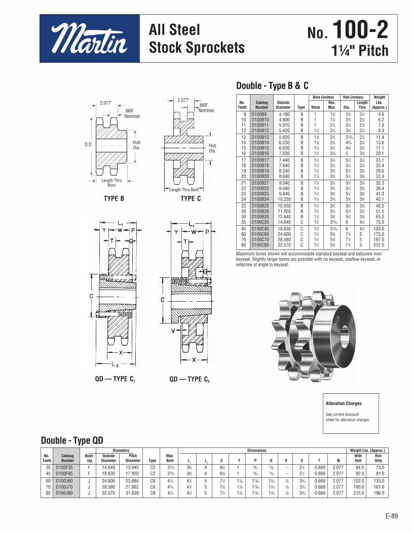
E-89E-89
No. 100-211⁄4" Pitch
35 D100F35 F 14.640 13.945 C2 315⁄16 35⁄8 4 65⁄8 1 35⁄64 27⁄64 – 21⁄2 0.669 2.077 84.5 73.0 45 D100F45 F 18.630 17.920 C2 315⁄16 35⁄8 4 65⁄8 1 35⁄64 27⁄64 – 21⁄2 0.669 2.077 92.5 81.0
60 D100J60 J 24.600 23.884 C6 47⁄16 41⁄2 5 71⁄4 17⁄32 113⁄64 13⁄32 1⁄32 33⁄16 0.669 2.077 152.0 133.0 70 D100J70 J 28.580 27.862 C6 47⁄16 41⁄2 5 71⁄4 17⁄32 113⁄64 13⁄32 1⁄32 33⁄16 0.669 2.077 180.0 161.0 80 D100J80 J 32.570 31.839 C6 47⁄16 41⁄2 5 71⁄4 17⁄32 113⁄64 13⁄32 1⁄32 33⁄16 0.669 2.077 215.0 196.0
Diameters Dimensions Weight Lbs. (Approx.) No. Catalog Bush- Outside Pitch Max. With Rim Teeth Number ing Diameter Diameter Type Bore L
1 L
2 C Y P G V X T W Hub Only
Double - Type QD
9 D100B9 4.180 B 1 15⁄8 23⁄8 27⁄8 4.6 10 D100B10 4.600 B 1 17⁄8 23⁄4 27⁄8 6.2 11 D100B11 5.010 B 1 21⁄8 31⁄8 27⁄8 7.9 12 D100B12 5.420 B 11⁄8 21⁄4 33⁄8 27⁄8 9.3 13 D100B13 5.820 B 11⁄8 21⁄2 313⁄16 27⁄8 11.4 14 D100B14 6.230 B 11⁄8 23⁄4 43⁄16 27⁄8 13.6 15 D100B15 6.630 B 11⁄4 31⁄8 45⁄8 31⁄8 17.1 16 D100B16 7.030 B 11⁄4 35⁄16 5 31⁄8 20.1 17 D100B17 7.440 B 11⁄4 31⁄2 51⁄4 31⁄8 23.1 18 D100B18 7.840 B 11⁄4 31⁄2 51⁄4 31⁄8 25.4 19 D100B19 8.240 B 11⁄4 33⁄4 51⁄2 33⁄8 29.6 20 D100B20 8.640 B 11⁄4 33⁄4 51⁄2 33⁄8 32.4 21 D100B21 9.040 B 11⁄4 33⁄4 51⁄2 33⁄8 35.3 22 D100B22 9.440 B 11⁄4 33⁄4 51⁄2 33⁄8 38.4 23 D100B23 9.840 B 11⁄4 33⁄4 51⁄2 33⁄8 41.3 24 D100B24 10.250 B 11⁄4 33⁄4 53⁄4 33⁄8 45.1 25 D100B25 10.650 B 11⁄4 33⁄4 53⁄4 33⁄8 48.5 26 D100B26 11.050 B 11⁄2 33⁄4 53⁄4 33⁄8 51.5 30 D100B30 12.640 B 11⁄2 33⁄4 53⁄4 33⁄8 65.0 35 D100C35 14.640 C 11⁄2 313⁄16 6 41⁄4 75.0 45 D100C45 18.630 C 11⁄2 313⁄16 6 41⁄2 103.0 60 D100C60 24.600 C 11⁄2 53⁄8 71⁄2 5 175.0 70 D100C70 28.580 C 11⁄2 53⁄8 71⁄2 5 197.0 80 D100C80 32.570 C 11⁄2 53⁄8 71⁄2 5 231.0
Bore (inches) Hub (inches) Weight No. Catalog Outside Rec. Length Lbs. Teeth Number Diameter Type Stock Max. Dia. Thru (Approx.)
Double - Type B & C
Maximum bores shown will accommodate standard keyseat and setscrew overkeyseat. Slightly larger bores are possible with no keyseat, shallow keyseat, orsetscrew at angle to keyseat.
TYPE B TYPE C
QD — TYPE C6QD — TYPE C2
Alteration Charges
See current discountsheet for alteration charges.
.669"Nominal
2.077" .669"Nominal
2.077"
HubDia.
Length ThruBore
HubDia.
Length Thru Bore
O.D.
All SteelStock Sprockets
No . 100-21¼" Pitch
All SteelStock Sprockets
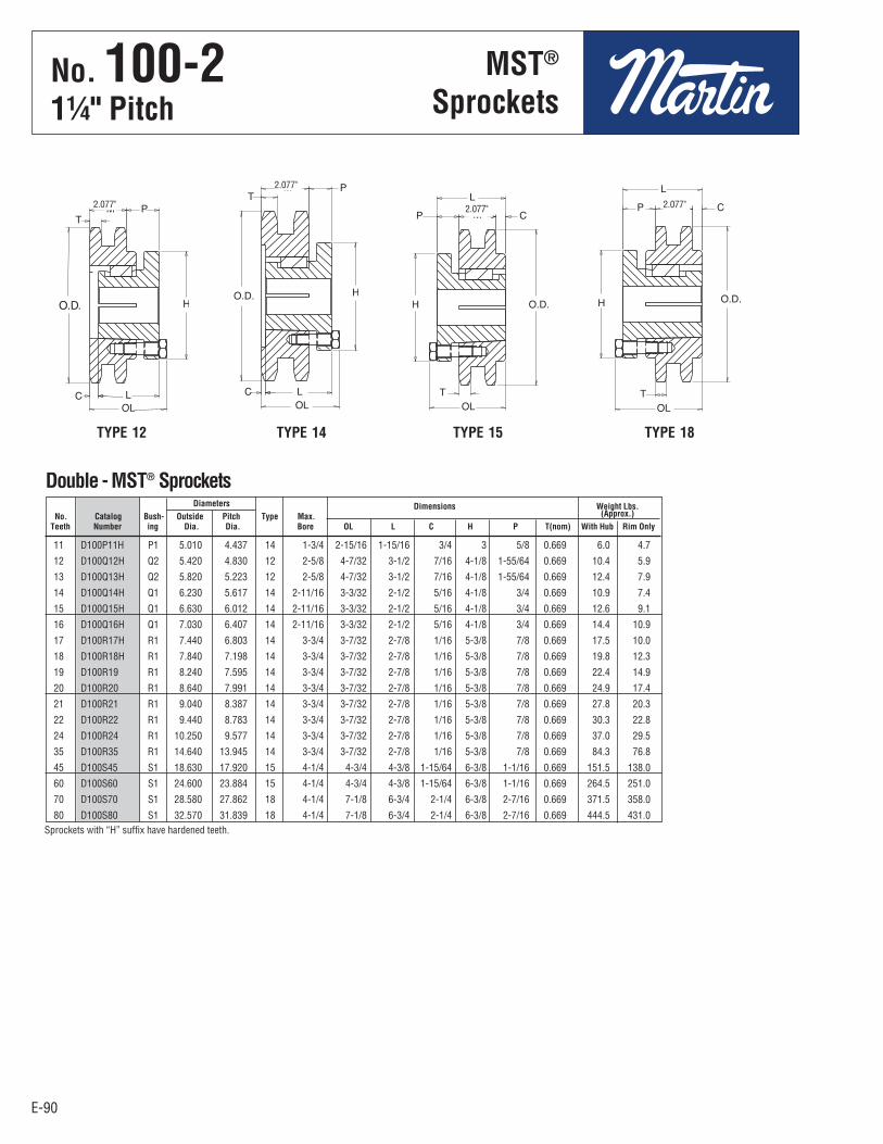
E-90
No. 100-211⁄4" Pitch
E-90
Diameters Dimensions Weight Lbs. No. Catalog Bush- Outside Pitch Type Max. (Approx.) Teeth Number ing Dia. Dia. Bore OL L C H P T(nom) With Hub Rim Only
11 D100P11H P1 5.010 4.437 14 1-3/4 2-15/16 1-15/16 3/4 3 5/8 0.669 6.0 4.7
12 D100Q12H Q2 5.420 4.830 12 2-5/8 4-7/32 3-1/2 7/16 4-1/8 1-55/64 0.669 10.4 5.9
13 D100Q13H Q2 5.820 5.223 12 2-5/8 4-7/32 3-1/2 7/16 4-1/8 1-55/64 0.669 12.4 7.9
14 D100Q14H Q1 6.230 5.617 14 2-11/16 3-3/32 2-1/2 5/16 4-1/8 3/4 0.669 10.9 7.4
15 D100Q15H Q1 6.630 6.012 14 2-11/16 3-3/32 2-1/2 5/16 4-1/8 3/4 0.669 12.6 9.1
16 D100Q16H Q1 7.030 6.407 14 2-11/16 3-3/32 2-1/2 5/16 4-1/8 3/4 0.669 14.4 10.9
17 D100R17H R1 7.440 6.803 14 3-3/4 3-7/32 2-7/8 1/16 5-3/8 7/8 0.669 17.5 10.0
18 D100R18H R1 7.840 7.198 14 3-3/4 3-7/32 2-7/8 1/16 5-3/8 7/8 0.669 19.8 12.3
19 D100R19 R1 8.240 7.595 14 3-3/4 3-7/32 2-7/8 1/16 5-3/8 7/8 0.669 22.4 14.9
20 D100R20 R1 8.640 7.991 14 3-3/4 3-7/32 2-7/8 1/16 5-3/8 7/8 0.669 24.9 17.4
21 D100R21 R1 9.040 8.387 14 3-3/4 3-7/32 2-7/8 1/16 5-3/8 7/8 0.669 27.8 20.3
22 D100R22 R1 9.440 8.783 14 3-3/4 3-7/32 2-7/8 1/16 5-3/8 7/8 0.669 30.3 22.8
24 D100R24 R1 10.250 9.577 14 3-3/4 3-7/32 2-7/8 1/16 5-3/8 7/8 0.669 37.0 29.5
35 D100R35 R1 14.640 13.945 14 3-3/4 3-7/32 2-7/8 1/16 5-3/8 7/8 0.669 84.3 76.8
45 D100S45 S1 18.630 17.920 15 4-1/4 4-3/4 4-3/8 1-15/64 6-3/8 1-1/16 0.669 151.5 138.0
60 D100S60 S1 24.600 23.884 15 4-1/4 4-3/4 4-3/8 1-15/64 6-3/8 1-1/16 0.669 264.5 251.0
70 D100S70 S1 28.580 27.862 18 4-1/4 7-1/8 6-3/4 2-1/4 6-3/8 2-7/16 0.669 371.5 358.0
80 D100S80 S1 32.570 31.839 18 4-1/4 7-1/8 6-3/4 2-1/4 6-3/8 2-7/16 0.669 444.5 431.0
2.077"
Double - MST® Sprockets
2.077"2.077"
2.077"
Sprockets with “H” suffix have hardened teeth.
TYPE 12 TYPE 14 TYPE 15 TYPE 18
MST®
SprocketsNo . 100-21¼" Pitch
MST®
Sprockets
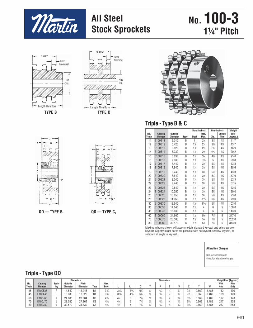
E-91
No. 100-311⁄4" Pitch
All SteelStock Sprockets
E-91
35 E100F35 F 14.640 13.945 B1 315⁄16 363⁄64 423⁄64 65⁄8 1⁄2 23⁄64 1⁄8 1⁄2 21⁄2 0.669 3.485 112 100 45 E100F45 F 18.630 17.820 B1 315⁄16 363⁄64 423⁄64 65⁄8 1⁄2 23⁄64 1⁄8 1⁄2 21⁄2 0.669 3.485 139 120 60 E100J60 J 24.600 28.884 C3 47⁄16 41⁄2 5 71⁄4 1⁄2 33⁄64 3⁄8 11⁄16 33⁄16 0.669 3.485 197 178 70 E100J70 J 28.580 27.862 C3 47⁄16 41⁄2 5 71⁄4 1⁄2 33⁄64 3⁄8 11⁄16 33⁄16 0.669 3.485 247 228 80 E100J80 J 32.570 31.839 C3 47⁄16 41⁄2 5 71⁄4 1⁄2 33⁄64 3⁄8 11⁄16 33⁄16 0.669 3.485 287 268
Diameters Dimensions Weight Lbs. (Approx.) No. Catalog Bush- Outside Pitch Max. With Rim Teeth Number ing Diameter Diameter Type Bore L
1 L
2 C Y P G V X T W Hub Only
Triple - Type QD
11 E100B11 5.010 B 1 21⁄8 31⁄8 41⁄4 11.7 12 E100B12 5.420 B 11⁄8 21⁄4 33⁄8 41⁄4 13.7 13 E100B13 5.820 B 11⁄8 21⁄2 313⁄16 41⁄4 16.9 14 E100B14 6.230 B 11⁄8 23⁄4 43⁄16 41⁄4 20.2
15 E100B15 6.630 B 11⁄4 31⁄8 45⁄8 41⁄2 25.0 16 E100B16 7.030 B 11⁄4 35⁄16 5 41⁄2 29.3 17 E100B17 7.440 B 11⁄4 31⁄2 51⁄4 41⁄2 33.8 18 E100B18 7.840 B 11⁄4 31⁄2 51⁄4 43⁄4 38.6
19 E100B19 8.240 B 11⁄4 33⁄4 51⁄2 43⁄4 43.3 20 E100B20 8.640 B 11⁄4 33⁄4 51⁄2 43⁄4 47.9 21 E100B21 9.040 B 11⁄4 33⁄4 51⁄2 43⁄4 52.3 22 E100B22 9.440 B 11⁄4 33⁄4 51⁄2 43⁄4 57.5
23 E100B23 9.840 B 11⁄4 33⁄4 51⁄2 43⁄4 62.5 24 E100B24 10.250 B 11⁄4 33⁄4 53⁄4 43⁄4 69.0 25 E100B25 10.650 B 11⁄4 33⁄4 53⁄4 43⁄4 73.0 26 E100B26 11.050 B 11⁄2 313⁄16 53⁄4 43⁄4 79.0
30 E100B30 12.640 B 11⁄2 313⁄16 53⁄4 43⁄4 103.0 35 E100C35 14.640 C 11⁄2 4 6 5 108.0 45 E100C45 18.630 C 11⁄2 4 6 5 143.0
60 E100C60 24.600 C 11⁄2 53⁄8 71⁄2 5 217.0 70 E100C70 28.580 C 11⁄2 53⁄8 71⁄2 5 262.0 80 E100C80 32.570 C 11⁄2 53⁄8 71⁄2 5 313.0
Bore (inches) Hub (inches) Weight No. Catalog Outside Rec. Length Lbs. Teeth Number Diameter Type Stock Max. Dia. Thru (Approx.)
Triple - Type B & C
Maximum bores shown will accommodate standard keyseat and setscrew overkeyseat. Slightly larger bores are possible with no keyseat, shallow keyseat, orsetscrew at angle to keyseat.
Alteration Charges
See current discountsheet for alteration charges.
TYPE B TYPE C
QD — TYPE B1 QD — TYPE C3
.669"Nominal
3.485" .669"Nominal
3.485"
HubDia.
Length Thru Bore
HubDia.
Length Thru Bore
No . 100-31¼" Pitch
All SteelStock Sprockets
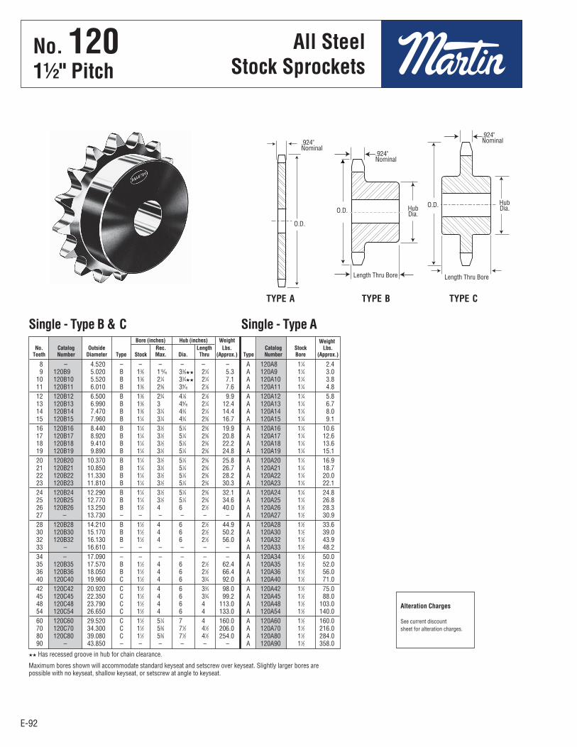
E-92
No. 12011⁄2" Pitch
All SteelStock Sprockets
E-92
8 – 4.520 – – – – – – A 120A8 11⁄4 2.4 9 120B9 5.020 B 13⁄8 113⁄16 33⁄8HH 21⁄4 5.3 A 120A9 11⁄4 3.0 10 120B10 5.520 B 13⁄8 21⁄4 33⁄4HH 21⁄4 7.1 A 120A10 11⁄4 3.8 11 120B11 6.010 B 13⁄8 23⁄8 39⁄16 21⁄8 7.6 A 120A11 11⁄4 4.8 12 120B12 6.500 B 13⁄8 23⁄4 41⁄8 21⁄8 9.9 A 120A12 11⁄4 5.8 13 120B13 6.990 B 13⁄8 3 49⁄16 21⁄4 12.4 A 120A13 11⁄4 6.7 14 120B14 7.470 B 13⁄8 31⁄4 43⁄4 21⁄4 14.4 A 120A14 11⁄4 8.0 15 120B15 7.960 B 11⁄4 31⁄4 43⁄4 23⁄8 16.7 A 120A15 11⁄4 9.1 16 120B16 8.440 B 11⁄4 31⁄2 51⁄4 23⁄8 19.9 A 120A16 11⁄4 10.6 17 120B17 8.920 B 11⁄4 31⁄2 51⁄4 23⁄8 20.8 A 120A17 11⁄4 12.6 18 120B18 9.410 B 11⁄4 31⁄2 51⁄4 23⁄8 22.2 A 120A18 11⁄4 13.6 19 120B19 9.890 B 11⁄4 31⁄2 51⁄4 23⁄8 24.8 A 120A19 11⁄4 15.1 20 120B20 10.370 B 11⁄4 31⁄2 51⁄4 23⁄8 25.8 A 120A20 11⁄4 16.9 21 120B21 10.850 B 11⁄4 31⁄2 51⁄4 23⁄8 26.7 A 120A21 11⁄4 18.7 22 120B22 11.330 B 11⁄4 31⁄2 51⁄4 23⁄8 28.2 A 120A22 11⁄4 20.0 23 120B23 11.810 B 11⁄4 31⁄2 51⁄4 23⁄8 30.3 A 120A23 11⁄4 22.1 24 120B24 12.290 B 11⁄4 31⁄2 51⁄4 23⁄8 32.1 A 120A24 11⁄4 24.8 25 120B25 12.770 B 11⁄4 31⁄2 51⁄4 23⁄8 34.6 A 120A25 11⁄4 26.8 26 120B26 13.250 B 11⁄2 4 6 21⁄2 40.0 A 120A26 11⁄2 28.3 27 – 13.730 – – – – – – A 120A27 11⁄2 30.9 28 120B28 14.210 B 11⁄2 4 6 21⁄2 44.9 A 120A28 11⁄2 33.6 30 120B30 15.170 B 11⁄2 4 6 21⁄2 50.2 A 120A30 11⁄2 39.0 32 120B32 16.130 B 11⁄2 4 6 21⁄2 56.0 A 120A32 11⁄2 43.9 33 – 16.610 – – – – – – A 120A33 11⁄2 48.2 34 – 17.090 – – – – – – A 120A34 11⁄2 50.0 35 120B35 17.570 B 11⁄2 4 6 21⁄2 62.4 A 120A35 11⁄2 52.0 36 120B36 18.050 B 11⁄2 4 6 21⁄2 66.4 A 120A36 11⁄2 56.0 40 120C40 19.960 C 11⁄2 4 6 33⁄4 92.0 A 120A40 11⁄2 71.0 42 120C42 20.920 C 11⁄2 4 6 33⁄4 98.0 A 120A42 11⁄2 75.0 45 120C45 22.350 C 11⁄2 4 6 33⁄4 99.2 A 120A45 11⁄2 88.0 48 120C48 23.790 C 11⁄2 4 6 4 113.0 A 120A48 11⁄2 103.0 54 120C54 26.650 C 11⁄2 4 6 4 133.0 A 120A54 11⁄2 140.0 60 120C60 29.520 C 11⁄2 51⁄4 7 4 160.0 A 120A60 11⁄2 160.0 70 120C70 34.300 C 11⁄2 53⁄8 71⁄2 41⁄2 206.0 A 120A70 11⁄2 216.0 80 120C80 39.080 C 11⁄2 53⁄8 71⁄2 41⁄2 254.0 A 120A80 11⁄2 284.0 90 – 43.850 – – – – – – A 120A90 11⁄2 358.0
Bore (inches) Hub (inches) Weight Weight No. Catalog Outside Rec. Length Lbs. Catalog Stock Lbs. Teeth Number Diameter Type Stock Max. Dia. Thru (Approx.) Type Number Bore (Approx.)
Single - Type B & C Single - Type A
TYPE B TYPE CTYPE A
HH Has recessed groove in hub for chain clearance.
Maximum bores shown will accommodate standard keyseat and setscrew over keyseat. Slightly larger bores arepossible with no keyseat, shallow keyseat, or setscrew at angle to keyseat.
Alteration Charges
See current discountsheet for alteration charges.
.924"Nominal
.924"Nominal
.924"Nominal
Length Thru Bore
HubDia.Hub
Dia.O.D.
O.D.
O.D.
Length Thru Bore
No . 1201½" Pitch
All SteelStock Sprockets
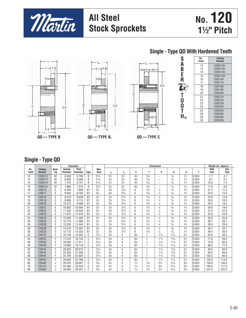
E-93
No. 12011⁄2" Pitch
All SteelStock Sprockets
E-93
12 120SF12H 13 120SF13H 14 120SF14H 15 120SF15H 16 120E16H 17 120E17H 18 120E18H 19 120E19H 20 120E20H 21 120E21H 22 120E22H 23 120E23H 24 120E24H 25 120E25H 26 120E26H 28 120E28H 30 120E30H
No. Catalog Teeth Number
Single - Type QD With Hardened Teeth
QD — TYPE B QD — TYPE CQD — TYPE B1
12 120SF12 SF 6.500 5.796 B 215⁄16 21⁄4 21⁄4 45⁄8 15⁄64 – 21⁄64 11⁄4 0.924 7.7 4.7 13 120SF13 SF 6.990 6.268 B 215⁄16 21⁄4 21⁄4 45⁄8 15⁄64 – 21⁄64 11⁄4 0.924 9.1 6.1 14 120SF14 SF 7.470 6.741 B 215⁄16 21⁄4 21⁄4 45⁄8 15⁄64 – 21⁄64 11⁄4 0.924 10.4 7.4 15 120SF15 SF 7.960 7.215 B 215⁄16 21⁄4 21⁄4 45⁄8 15⁄64 – 21⁄64 11⁄4 0.924 11.8 8.0 16 120E16 E 8.440 7.689 B1 31⁄2 25⁄8 215⁄16 6 19⁄16 1⁄8 45⁄64 15⁄8 0.924 21.2 11.2 17 120E17 E 8.920 8.163 B1 31⁄2 25⁄8 215⁄16 6 19⁄16 1⁄8 45⁄64 15⁄8 0.924 23.4 13.4 18 120E18 E 9.410 8.638 B1 31⁄2 25⁄8 215⁄16 6 19⁄16 1⁄8 45⁄64 15⁄8 0.924 24.8 14.8 19 120E19 E 9.890 9.113 B1 31⁄2 25⁄8 215⁄16 6 19⁄16 1⁄8 45⁄64 15⁄8 0.924 26.5 16.5 20 120E20 E 10.370 9.589 B1 31⁄2 25⁄8 215⁄16 6 19⁄16 1⁄8 45⁄64 15⁄8 0.924 29.2 19.2 21 120E21 E 10.850 10.064 B1 31⁄2 25⁄8 215⁄16 6 19⁄16 1⁄8 45⁄64 15⁄8 0.924 29.9 19.9 22 120E22 E 11.330 10.540 B1 31⁄2 25⁄8 215⁄16 6 19⁄16 1⁄8 45⁄64 15⁄8 0.924 31.6 21.6 23 120E23 E 11.810 11.016 B1 31⁄2 25⁄8 215⁄16 6 19⁄16 1⁄8 45⁄64 15⁄8 0.924 33.8 23.8 24 120E24 E 12.290 11.492 B1 31⁄2 25⁄8 215⁄16 6 19⁄16 1⁄8 45⁄64 15⁄8 0.924 35.8 25.8 25 120E25 E 12.770 11.968 B1 31⁄2 25⁄8 215⁄16 6 19⁄16 1⁄8 45⁄64 15⁄8 0.924 38.1 28.1 26 120E26 E 13.250 12.444 B1 31⁄2 25⁄8 215⁄16 6 19⁄16 1⁄8 45⁄64 15⁄8 0.924 39.9 29.9 28 120E28 E 14.210 13.397 B1 31⁄2 25⁄8 215⁄16 6 19⁄16 1⁄8 45⁄64 15⁄8 0.924 49.7 34.7 30 120E30 E 15.170 14.350 B1 31⁄2 25⁄8 215⁄16 6 19⁄16 1⁄8 45⁄64 15⁄8 0.924 49.4 39.4 32 120F32 F 16.130 15.303 C 315⁄16 35⁄8 4 65⁄8 1 111⁄16 137⁄64 21⁄2 0.924 62.0 50.5 35 120F35 F 17.570 16.734 C 315⁄16 35⁄8 4 65⁄8 1 111⁄16 137⁄64 21⁄2 0.924 71.0 59.5 36 120F36 F 18.050 17.211 C 315⁄16 35⁄8 4 65⁄8 1 111⁄16 137⁄64 21⁄2 0.924 74.9 63.4 40 120F40 F 19.960 19.118 C 315⁄16 35⁄8 4 65⁄8 1 111⁄16 137⁄64 21⁄2 0.924 88.5 77.0 42 120F42 F 20.920 20.072 C 315⁄16 35⁄8 4 65⁄8 1 111⁄16 137⁄64 21⁄2 0.924 94.5 83.0 45 120F45 F 22.350 21.503 C 315⁄16 35⁄8 4 65⁄8 1 111⁄16 137⁄64 21⁄2 0.924 95.5 84.0 48 120F48 F 23.790 22.935 C 315⁄16 35⁄8 4 65⁄8 1 111⁄16 137⁄64 21⁄2 0.924 103.5 92.0 54 120F54 F 26.650 25.798 C 315⁄16 35⁄8 4 65⁄8 1 111⁄16 137⁄64 21⁄2 0.924 125.0 114.0 60 120J60 J 29.520 28.661 C 47⁄16 41⁄2 5 71⁄4 13⁄16 25⁄16 217⁄64 33⁄16 0.924 159.0 140.0 70 120J70 J 34.300 33.434 C 47⁄16 41⁄2 5 71⁄4 13⁄16 25⁄16 217⁄64 33⁄16 0.924 196.0 177.0 80 120J80 J 39.080 38.207 C 47⁄16 41⁄2 5 71⁄4 13⁄16 25⁄16 217⁄64 33⁄16 0.924 241.0 222.0
Diameters Dimensions Weight Lbs. (Approx.) No. Catalog Bush- Outside Pitch Max. With Rim Teeth Number ing Diameter Diameter Type Bore L
1 L
2 C Y P G X T Hub Only
Single - Type QD
SABER
TOOTH®
O.D.O.D.
O.D.
No . 1201½" Pitch
All SteelStock Sprockets
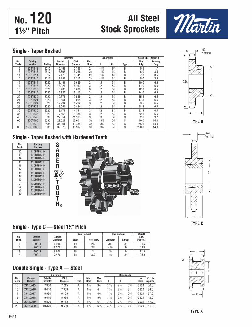
E-94
No. 12011⁄2" Pitch
All SteelStock Sprockets
E-94
12 120BTB12 2012 6.498 5.796 2 11⁄4 39⁄16 B 5.5 1.7 13 120BTB13 2517 6.896 6.268 21⁄2 13⁄4 41⁄4 B 6.0 3.5 14 120BTB14 2517 7.472 6.741 21⁄2 13⁄4 41⁄4 B 7.0 3.5 15 120BTB15 2517 7.957 7.215 21⁄2 13⁄4 41⁄4 B 8.0 3.5 16 120BTB16 3020 8.441 7.689 3 2 51⁄4 B 10.0 6.5 17 120BTB17 3020 8.924 8.163 3 2 51⁄4 B 11.0 6.5 18 120BTB18 3020 9.407 8.638 3 2 51⁄4 B 12.0 6.5 19 120BTB19 3020 9.889 9.113 3 2 51⁄4 B 14.0 6.5 20 120BTB20 3020 10.371 9.588 3 2 51⁄4 B 15.5 6.5 21 120BTB21 3020 10.851 10.064 3 2 51⁄4 B 17.5 6.5 24 120BTB24 3020 12.294 11.492 3 2 51⁄4 B 23.5 6.5 26 120BTB26 3020 13.254 12.444 3 2 51⁄4 B 28.5 6.5 30 120BTB30 3020 15.171 14.351 3 2 51⁄4 B 33.5 6.5 35 120CTB35 3020 17.566 16.734 3 2 51⁄4 C 52.0 6.5 45 120CTB45 3030 22.351 21.503 3 3 57⁄8 C 82.0 9.2 60 120CTB60 3535 29.522 28.661 31⁄2 31⁄2 61⁄2 C 140.0 14.0 70 120CTB70 3535 34.301 33.434 31⁄2 31⁄2 61⁄2 C 175.0 14.0 80 120CTB80 3535 39.078 38.207 31⁄4 31⁄2 61⁄2 C 220.0 14.0
Diameter Dimensions Weight Lbs. (Approx.) No. Catalog Outside Pitch Max. Rim Bushing Teeth Number Bushing Diameter Diameter Bore L C Type Only Only
Single - Taper Bushed
12 120BTB12 H 13 120BTB13 H 14 120BTB14 H 15 120BTB15 H 16 120BTB16 H 17 120BTB17 H 18 120BTB18 H 19 120BTB19 H 20 120BTB20 H 21 120BTB21 H 24 120BTB24 H 26 120BTB26 H 30 120BTB30 H
No. Catalog Teeth Number
Single - Taper Bushed with Hardened Teeth
TYPE B
TYPE C
11 120C11 6.010 13⁄8 23⁄8 39⁄16 33⁄8 12.45 12 120C12 6.500 13⁄8 23⁄4 413⁄16 33⁄8 14.80 13 120C13 6.990 13⁄8 3 45⁄8 33⁄8 17.15 14 120C14 7.470 13⁄8 31⁄4 43⁄4 33⁄8 19.50
Bore (inches) Hub (inches) Weight No. Catalog Outside Lbs. Teeth Number Diameter Stock Rec. Max. Diameter Length (Approx.)
Single - Type C — Steel 11⁄2" Pitch
SABER
TOOTH®
15 DS120A15 7.960 7.215 A 17⁄16 33⁄4 311⁄32 27⁄16 532⁄64 0.924 30.0 16 DS120A16 8.440 7.689 A 17⁄16 4 311⁄32 27⁄16 6 0.924 34.0 17 DS120A17 8.920 8.163 A 17⁄16 47⁄16 311⁄32 27⁄16 631⁄64 0.924 37.0 18 DS120A18 9.410 8.638 A 17⁄16 53⁄16 311⁄32 27⁄16 631⁄64 0.924 42.0 19 DS120A19 9.890 9.113 A 17⁄16 51⁄2 311⁄32 27⁄16 729⁄64 0.924 47.0 20 DS120A20 10.370 9.589 A 17⁄16 515⁄16 311⁄32 27⁄16 715⁄16 0.924 51.0
Diameters Dimensions No. Catalog Outside Pitch Min. Max. w Wt. Lbs. Teeth Number Diameter Diameter Type Bore Bore L C E Nom. (Approx.)
Double Single - Type A — Steel
TYPE A
O.D.C
C
L
L
.924"Nominal
.924"Nominal
C
L E
W
L
No . 1201½" Pitch
All SteelStock Sprockets

E-95
No. 12011⁄2 " Pitch
E-95
Diameters Dimensions Weight Lbs. No. Catalog Bush- Outside Pitch Type Max. (Approx.) Teeth Number ing Dia. Dia. Bore OL L C H P T(nom) With Hub Rim Only
11 120Q11H Q1 6.010 5.324 4 2-11/16 2-25/32 2-1/2 – 4-1/8 1 9/16 0.924 8.3 4.8 12 120Q12H Q1 6.500 5.796 4 2-11/16 2-25/32 2-1/2 – 4-1/8 1 9/16 0.924 9.8 6.3 13 120Q13H Q1 6.990 6.268 4 2-11/16 2-25/32 2-1/2 – 4-1/8 1 9/16 0.924 11.4 7.9 14 120Q14H Q1 7.470 6.741 4 2-11/16 2-25/32 2-1/2 – 4-1/8 1 9/16 0.924 12.7 9.2 15 120Q15H Q1 7.960 7.215 4 2-11/16 2-25/32 2-1/2 – 4-1/8 1 9/16 0.924 13.9 10.4 16 120Q16H Q1 8.440 7.689 4 2-11/16 2-25/32 2-1/2 – 4-1/8 1-15/16 0.924 15.3 11.8 16 120R16H R1 8.440 7.689 4 3-3/4 3-5/32 2-7/8 – 5-3/8 1-15/16 0.924 19.5 12.0 17 120Q17H Q1 8.920 8.163 4 2-11/16 2-25/32 2-1/2 – 4-1/8 1-15/16 0.924 16.9 13.4 17 120R17H R1 8.920 8.163 4 3-3/4 3-5/32 2-7/8 – 5-3/8 1-15/16 0.924 21.2 13.7 18 120Q18H Q1 9.410 8.638 4 2-11/16 2-25/32 2-1/2 – 4-1/8 1-15/16 0.924 19.1 15.6 18 120R18H R1 9.410 8.638 4 3-3/4 3-5/32 2-7/8 – 5-3/8 1-15/16 0.924 22.5 15.0 19 120R19H R1 9.890 9.113 4 3-3/4 3-5/32 2-7/8 – 5-3/8 1-15/16 0.924 24.4 16.9 20 120R20H R1 10.370 9.589 4 3-3/4 3-5/32 2-7/8 – 5-3/8 1-15/16 0.924 26.3 18.8 21 120R21H R1 10.850 10.064 4 3-3/4 3-5/32 2-7/8 – 5-3/8 1-15/16 0.924 28.2 20.7 22 120R22H R1 11.330 10.540 4 3-3/4 3-5/32 2-7/8 – 5-3/8 1-15/16 0.924 30.0 22.5 23 120R23H R1 11.810 11.016 4 3-3/4 3-5/32 2-7/8 – 5-3/8 1-15/16 0.924 31.8 24.3 24 120R24H R1 12.290 11.492 4 3-3/4 3-5/32 2-7/8 – 5-3/8 1-15/16 0.924 34.6 27.1 25 120R25H R1 12.770 11.968 4 3-3/4 3-5/32 2-7/8 – 5-3/8 1-15/16 0.924 36.6 29.1 26 120R26H R1 13.250 12.444 5 3-3/4 3-5/32 2-7/8 1-1/16 5-3/8 7/8 0.924 40.8 33.3 28 120R28H R1 14.210 13.397 5 3-3/4 3-5/32 2-7/8 1-1/16 5-3/8 7/8 0.924 45.5 38.0 30 120R30H R1 15.170 14.350 5 3-3/4 3-5/32 2-7/8 1-1/16 5-3/8 7/8 0.924 50.8 43.3 32 120R32 R1 16.130 15.303 5 3-3/4 3-5/32 2-7/8 1-1/16 5-3/8 7/8 0.924 56.9 49.4 35 120R35 R2 17.570 16.734 6 3-5/8 5-5/32 4-7/8 2 5-3/8 1-15/16 0.924 79.0 68.0 36 120R36 R2 18.050 17.211 6 3-5/8 5-5/32 4-7/8 2 5-3/8 1-15/16 0.924 83.0 72.0 40 120R40 R2 19.960 19.118 6 3-5/8 5-5/32 4-7/8 2 5-3/8 1-15/16 0.924 93.0 82.0 40 120S40 S1 19.960 19.118 5 4-1/4 4-3/4 4-3/8 2-3/8 6-3/8 1-1/16 0.924 96.5 83.0 42 120S42 S1 20.920 20.072 5 4-1/4 4-3/4 4-3/8 2-3/8 6-3/8 1-1/16 0.924 103.5 90.0 45 120R45 R2 22.350 21.503 6 3-5/8 5-5/32 4-7/8 2 5-3/8 1-15/16 0.924 113.0 102.0 45 120S45 S1 22.350 21.503 5 4-1/4 4-3/4 4-3/8 2-3/8 6-3/8 1-1/16 0.924 113.5 100.0 48 120S48 S1 23.790 22.935 5 4-1/4 4-3/4 4-3/8 2-3/8 6-3/8 1-1/16 0.924 124.5 111.0 54 120S54 S1 26.650 25.798 5 4-1/4 4-3/4 4-3/8 2-3/8 6-3/8 1-1/16 0.924 151.5 138.0 60 120R60 R2 29.520 28.661 6 3-5/8 5-5/32 4-7/8 2 5-3/8 1-15/16 0.924 190.0 179.0 60 120S60 S1 29.520 28.661 5 4-1/4 4-3/4 4-3/8 2-3/8 6-3/8 1-1/16 0.924 193.5 180.0 70 120R70 R2 34.300 33.434 6 3-5/8 5-5/32 4-7/8 2 5-3/8 1-15/16 0.924 159.0 148.0 70 120S70 S2 34.300 33.434 5 4-3/16 7-1/8 6-3/4 2-7/8 6-3/8 2-15/16 0.924 186.0 167.0 80 120R80 R2 39.080 38.207 6 3-5/8 5-5/32 4-7/8 2 5-3/8 1-15/16 0.924 302.0 291.0 80 120S80 S2 39.080 38.207 6 4-3/16 7-1/8 6-3/4 2-7/8 6-3/8 2-15/16 0.924 324.0 305.0
Single - MST® Sprockets
Sprockets with “H” suffix have hardened teeth.
TYPE 4 TYPE 5 TYPE 6
MST®
SprocketsNo . 1201½" Pitch
MST®
Sprockets

E-96
No. 120-211⁄2" Pitch
E-96
11 D120B11 6.010 B 11⁄2 23⁄8 39⁄16 33⁄4 13.6 12 D120B12 6.500 B 11⁄2 23⁄4 41⁄16 33⁄4 17.3 13 D120B13 6.990 B 11⁄2 3 41⁄2 33⁄4 21.1 14 D120B14 7.470 B 11⁄2 35⁄16 5 33⁄4 25.6 15 D120B15 7.960 B 11⁄2 31⁄2 51⁄4 33⁄4 29.9 16 D120B16 8.440 B 11⁄2 31⁄2 51⁄4 33⁄4 33.8 17 D120B17 8.920 B 11⁄2 31⁄2 51⁄4 33⁄4 36.9 18 D120B18 9.410 B 11⁄2 31⁄2 51⁄4 33⁄4 41.9 19 D120B19 9.890 B 11⁄2 31⁄2 51⁄4 33⁄4 46.5 20 D120B20 10.370 B 11⁄2 31⁄2 51⁄2 33⁄4 50.2 21 D120B21 10.850 B 11⁄2 31⁄2 51⁄2 33⁄4 55.6 22 D120B22 11.330 B 11⁄2 313⁄16 53⁄4 4 64.0 23 D120B23 11.810 B 11⁄2 4 61⁄2 4 75.0 24 D120B24 12.290 B 11⁄2 4 61⁄2 4 79.0 25 D120B25 12.770 B 11⁄2 4 61⁄2 4 84.0 26 D120B26 13.250 B 11⁄2 4 61⁄2 4 90.0 30 D120B30 15.170 B 11⁄2 4 61⁄2 4 119.0 35 D120C35 17.570 C 11⁄2 53⁄8 71⁄2 6 148.0 45 D120C45 22.350 C 11⁄2 53⁄8 71⁄2 6 188.0 60 D120C60 29.520 C 11⁄2 63⁄8 91⁄2 61⁄4 307.0
30 D120J30 J 15.170 14.350 C5 47⁄16 41⁄2 5 71⁄4 11⁄32 25⁄32 21⁄32 5⁄32 33⁄16 .894 2.683 97.5 78.0 35 D120J35 J 17.570 16.734 C5 47⁄16 41⁄2 5 71⁄4 11⁄32 25⁄32 21⁄32 5⁄32 33⁄16 .894 2.683 112.0 93.0 45 D120J45 J 22.350 21.502 C5 47⁄16 41⁄2 5 71⁄4 11⁄32 25⁄32 21⁄32 5⁄32 33⁄16 .894 2.683 157.0 138.0 60 D120M60 M 29.520 28.661 C6 51⁄2 63⁄4 63⁄4 9 29⁄32 125⁄32 121⁄32 27⁄32 53⁄16 .894 2.683 271.0 234.0
Bore (inches) Hub (inches) Weight No. Catalog Outside Rec. Length Lbs. Teeth Number Diameter Type Stock Max. Dia. Thru (Approx.)
Double - Type B & C
Diameters Dimensions Weight Lbs. (Approx.) No. Catalog Bush- Outside Pitch Max. With Rim Teeth Number ing Diameter Diameter Type Bore L
1 L
2 C Y P G V X T W Hub Only
Double - Type QD
Maximum bores shown will accommodate standard keyseat and setscrew overkeyseat. Slightly larger bores are possible with no keyseat, shallow keyseat, orsetscrew at angle to keyseat.
QD — TYPE C5 QD — TYPE C6
TYPE B TYPE C
Alteration Charges
See current discountsheet for alteration charges.
2.683".894"Nominal
2.683".894"Nominal
HubDia.
Length ThruBore
HubDia.
Length ThruBore
O.D.
All SteelStock Sprockets
No . 120-21½" Pitch
All SteelStock Sprockets
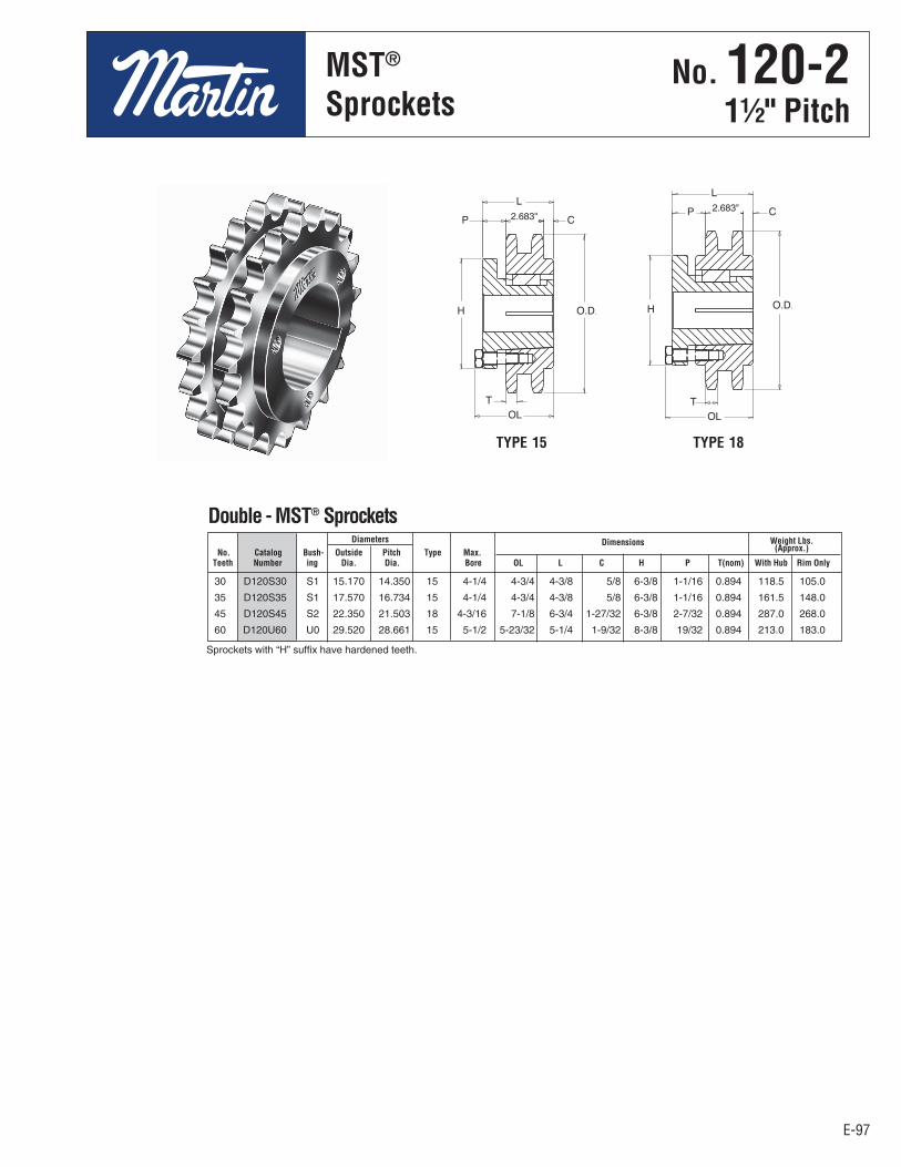
E-97
No. 120-211⁄2" Pitch
MST®
Sprockets
E-97
Diameters Dimensions Weight Lbs. No. Catalog Bush- Outside Pitch Type Max. (Approx.)
Teeth Number ing Dia. Dia. Bore OL L C H P T(nom) With Hub Rim Only
2.683"
30 D120S30 S1 15.170 14.350 15 4-1/4 4-3/4 4-3/8 5/8 6-3/8 1-1/16 0.894 118.5 105.0
35 D120S35 S1 17.570 16.734 15 4-1/4 4-3/4 4-3/8 5/8 6-3/8 1-1/16 0.894 161.5 148.0
45 D120S45 S2 22.350 21.503 18 4-3/16 7-1/8 6-3/4 1-27/32 6-3/8 2-7/32 0.894 287.0 268.0
60 D120U60 U0 29.520 28.661 15 5-1/2 5-23/32 5-1/4 1-9/32 8-3/8 19/32 0.894 213.0 183.0
Double - MST® Sprockets
2.683"
Sprockets with “H” suffix have hardened teeth.
TYPE 15 TYPE 18
No . 120-21½" Pitch
MST®
Sprockets

E-98
All SteelStock Sprockets
No. 14013⁄4" Pitch
E-98
11 140B11 7.010 B 11⁄2 23⁄4 41⁄4 21⁄4 11.3 A 140A11 11⁄2 5.0 12 140B12 7.580 B 11⁄2 3 41⁄2 21⁄4 13.2 A 140A12 11⁄2 7.8 13 140B13 8.150 B 11⁄2 39⁄16 55⁄16 23⁄8 18.9 A 140A13 11⁄2 8.2
14 140B14 8.720 B 11⁄2 33⁄4 51⁄2 23⁄8 20.4 A 140A14 11⁄2 10.0 15 140B15 9.280 B 11⁄2 41⁄4 61⁄4 23⁄8 25.1 A 140A15 11⁄2 11.0 16 140B16 9.850 B 11⁄2 41⁄4 61⁄4 21⁄2 27.9 A 140A16 11⁄2 14.0 17 140B17 10.410 B 11⁄2 41⁄4 61⁄4 21⁄2 29.8 A 140A17 11⁄2 16.0 18 140B18 10.980 B 11⁄2 41⁄4 61⁄4 21⁄2 32.0 A 140A18 11⁄2 18.0
19 140B19 11.540 B 11⁄2 41⁄4 61⁄4 21⁄2 34.1 A 140A19 11⁄2 21.0 20 140B20 12.100 B 11⁄2 41⁄4 61⁄4 21⁄2 36.0 A 140A20 11⁄2 23.0 21 140B21 12.660 B 11⁄2 41⁄4 61⁄4 21⁄2 38.7 A 140A21 11⁄2 25.0 22 140B22 13.220 B 11⁄2 41⁄4 61⁄4 21⁄2 40.6 A 140A22 11⁄2 28.0 23 140B23 13.780 B 11⁄2 41⁄4 61⁄4 21⁄2 42.1 A 140A23 11⁄2 30.0 24 140B24 14.340 B 11⁄2 41⁄4 61⁄4 21⁄2 46.2 A 140A24 11⁄2 33.0 25 140B25 14.900 B 11⁄2 41⁄4 61⁄4 21⁄2 47.8 A 140A25 11⁄2 34.0 26 140B26 15.460 B 11⁄2 41⁄4 61⁄4 3 57.2 A 140A26 11⁄2 39.0 27 140B27 16.020 B 11⁄2 41⁄4 61⁄4 3 58.5 A 140A27 11⁄2 41.0 28 140B28 16.580 B 11⁄2 41⁄4 61⁄4 3 62.2 A 140A28 11⁄2 45.0 30 140B30 17.700 B 11⁄2 41⁄4 61⁄4 3 69.8 A 140A30 11⁄2 52.0 31 – 18.260 – – – – – – – 140A31 11⁄2 56.0 32 140B32 18.820 B 11⁄2 41⁄4 61⁄4 3 76.3 A 140A32 11⁄2 60.0 35 140C35 20.490 C 11⁄2 51⁄4 7 4 108.0 A 140A35 11⁄2 73.0 36 – 21.050 – – – – – – A 140A36 11⁄2 77.0 40 140C40 23.290 C 11⁄2 51⁄4 7 4 121.0 A 140A40 11⁄2 93.0 45 140C45 26.080 C 11⁄2 51⁄4 7 4 142.0 A 140A45 11⁄2 131.0 48 140C48 27.750 C 11⁄2 51⁄4 7 4 150.0 A 140A48 11⁄2 134.0 54 140C54 31.100 C 11⁄2 51⁄4 7 4 177.0 A 140A54 11⁄2 173.0 60 140C60 34.440 C 11⁄2 51⁄4 7 5 220.0 A 140A60 11⁄2 219.0 70 140C70 40.020 C 11⁄2 53⁄8 71⁄2 5 282.0 A 140A70 11⁄2 292.0 80 140C80 45.590 C 11⁄2 53⁄8 71⁄2 5 331.0 A 140A80 11⁄2 402.0
Bore (inches) Hub (inches) Weight Weight No. Catalog Outside Rec. Length Lbs Catalog Stock Lbs. Teeth Number Diameter Type Stock Max. Dia. Thru (Approx.) Type Number Bore (Approx.)
Single - Type B & C Single - Type A
TYPE B
TYPE C
Alteration Charges
See current discount sheet for alteration charges.
Maximum bores shown will accommodate standard keyseat and setscrew over keyseat. Slightly larger bores arepossible with no keyseat, shallow keyseat, or setscrew at angle to keyseat.
TYPE A
.924"Nominal
.924"Nominal
.924"Nominal
Length ThruBore
HubDia.
HubDia.
O.D.
O.D.
O.D.
Length ThruBore
No . 1401¾" Pitch
All SteelStock Sprockets

E-99
No. 14013⁄4" Pitch
All SteelStock Sprockets
E-99
11 140SF11 H 12 140SF12 H 13 140SF13 H
14 140E14 H 15 140E15 H 16 140E16 H
17 140E17 H 18 140E18 H 19 140E19 H
20 140E20 H 21 140E21 H 22 140E22 H 23 140F23 H
24 140F24 H 25 140F25 H 26 140F26 H 30 140F30 H
11 140SF11 SF 7.010 6.212 B 215⁄16 21⁄4 21⁄4 45⁄8 15⁄64 – 21⁄64 – 11⁄4 0.924 8.6 5.6 12 140SF12 SF 7.580 6.762 B 215⁄16 21⁄4 21⁄4 45⁄8 15⁄64 – 21⁄64 – 11⁄4 0.924 10.4 7.4 13 140SF13 SF 8.150 7.313 B 215⁄16 21⁄4 21⁄4 45⁄8 15⁄64 – 21⁄64 – 11⁄4 0.924 11.9 8.9 14 140E14 E 8.720 7.864 B1 31⁄2 25⁄8 215⁄16 6 19⁄16 1⁄8 45⁄64 – 15⁄8 0.924 21.6 11.6 15 140E15 E 9.280 8.417 B1 31⁄2 25⁄8 215⁄16 6 19⁄16 1⁄8 45⁄64 – 15⁄8 0.924 24.2 14.2 16 140E16 E 9.850 8.970 B1 31⁄2 25⁄8 215⁄16 6 19⁄16 1⁄8 45⁄64 – 15⁄8 0.924 25.9 15.9 17 140E17 E 10.410 9.524 B1 31⁄2 25⁄8 215⁄16 6 19⁄16 1⁄8 45⁄64 – 15⁄8 0.924 28.0 18.0 18 140E18 E 10.980 10.078 B1 31⁄2 25⁄8 215⁄16 6 19⁄16 1⁄8 45⁄64 – 15⁄8 0.924 29.6 19.6 19 140E19 E 11.540 10.632 B1 31⁄2 25⁄8 215⁄16 6 19⁄16 1⁄8 45⁄64 – 15⁄8 0.924 32.0 22.0 20 140E20 E 12.100 11.187 B1 31⁄2 25⁄8 215⁄16 6 19⁄16 1⁄8 45⁄64 – 15⁄8 0.924 34.6 24.6 21 140E21 E 12.660 11.742 B1 31⁄2 25⁄8 215⁄16 6 19⁄16 1⁄8 45⁄64 – 15⁄8 0.924 37.6 27.6 22 140E22 E 13.220 12.297 B1 31⁄2 25⁄8 215⁄16 6 19⁄16 1⁄8 45⁄64 – 15⁄8 0.924 39.5 29.5 23 140F23 F 13.780 12.852 B1 315⁄16 35⁄8 4 65⁄8 29⁄16 1⁄8 137⁄64 – 21⁄2 0.924 48.0 36.4 24 140F24 F 14.340 13.407 B1 315⁄16 35⁄8 4 65⁄8 29⁄16 1⁄8 137⁄64 – 21⁄2 0.924 51.6 40.1 25 140F25 F 14.900 13.963 B1 315⁄16 35⁄8 4 65⁄8 29⁄16 1⁄8 137⁄64 – 21⁄2 0.924 53.8 42.3 26 140F26 F 15.460 14.518 B1 315⁄16 35⁄8 4 65⁄8 29⁄16 1⁄8 137⁄64 – 21⁄2 0.924 58.0 46.5 30 140F30 F 17.700 16.742 B1 315⁄16 35⁄8 4 65⁄8 29⁄16 1⁄8 137⁄64 – 21⁄2 0.924 72.0 60.4 35 140F35 F 20.490 19.523 C 315⁄16 35⁄8 4 65⁄8 1 111⁄16 137⁄64 – 21⁄2 0.924 89.5 78.0 36 140F36 F 21.050 20.079 C 315⁄16 35⁄8 4 65⁄8 1 111⁄16 137⁄64 – 21⁄2 0.924 95.5 84.0 40 140J40 J 23.290 22.305 C 47⁄16 41⁄2 5 71⁄4 13⁄16 23⁄8 217⁄64 – 33⁄16 0.924 117.0 98.0 45 140J45 J 26.080 25.087 C 47⁄16 41⁄2 5 71⁄4 13⁄16 23⁄8 217⁄64 – 33⁄16 0.924 139.0 120.0 48 140J48 J 27.750 26.757 C 47⁄16 41⁄2 5 71⁄4 13⁄16 23⁄8 217⁄64 – 33⁄16 0.924 148.0 129.0 54 140J54 J 31.100 30.097 C 47⁄16 41⁄2 5 71⁄4 13⁄16 23⁄8 217⁄64 – 33⁄16 0.924 168.0 149.0 60 140J60 J 34.440 33.438 C 47⁄16 41⁄2 5 71⁄4 13⁄16 23⁄8 217⁄64 – 33⁄16 0.924 205.0 186.0 70 140M70 M 40.020 39.006 C1 51⁄2 63⁄4 63⁄4 9 229⁄32 229⁄32 217⁄32 113⁄32 53⁄16 0.924 301.0 264.0 80 140M80 M 45.590 44.575 C1 51⁄2 63⁄4 63⁄4 9 229⁄32 229⁄32 217⁄32 113⁄32 53⁄16 0.924 385.0 348.0
Diameters Dimensions Weight Lbs. (Approx.) No. Catalog Bush- Outside Pitch Max. With Rim Teeth Number ing Diameter Diameter Type Bore L
1 L
2 C Y P G V X T Hub Only
Single - Type QD
No. Catalog Teeth Number
Single - Type QD With Hardened Teeth
QD — TYPE B QD — TYPE B 1 QD — TYPE C QD — TYPE C1
SABER
TOOTH®
O.D.O.D.
O.D.
No . 1401¾" Pitch
All SteelStock Sprockets
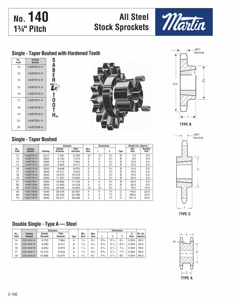
E-100
All SteelStock Sprockets
No. 14013⁄4" Pitch
E-100
12 140BTB12 H
13 140BTB13 H
14 140BTB14 H
15 140BTB15 H
16 140BTB16 H
17 140BTB17 H
18 140BTB18 H
19 140BTB19 H
21 140BTB21 H
26 140BTB26 H
12 140BTB12 2517 7.581 6.762 21⁄2 13⁄4 41⁄4 B 7.0 3.5 13 140BTB13 3020 8.150 7.313 3 2 51⁄4 B 8.0 6.5 14 140BTB14 3020 8.718 7.864 3 2 51⁄4 B 10.0 6.5 15 140BTB15 3020 9.283 8.417 3 2 51⁄4 B 12.0 6.5
16 140BTB16 3020 9.848 8.970 3 2 51⁄4 B 14.0 6.5 17 140BTB17 3020 10.411 9.524 3 2 51⁄4 B 16.0 6.5 18 140BTB18 3020 10.975 10.078 3 2 51⁄4 B 18.0 6.5 19 140BTB19 3020 11.537 10.632 3 2 51⁄4 B 20.0 6.5
21 140BTB21 3020 12.660 11.742 3 2 51⁄4 B 24.0 6.5 26 140BTB26 3020 15.463 14.518 3 2 51⁄4 B 40.0 6.5 35 140CTB35 3535 20.494 19.523 31⁄2 31⁄2 61⁄2 C 78.0 14.0
45 140CTB45 4040 26.076 25.087 4 4 73⁄4 C 118.0 22.0 60 140CTB60 4040 34.442 33.438 4 4 73⁄4 C 188.0 22.0 70 140CTB70 4040 40.017 39.006 4 4 73⁄4 C 241.0 22.0
Diameter Dimensions Weight Lbs. (Approx.) No. Catalog Outside Pitch Max. Rim Bushing Teeth Number Bushing Diameter Diameter Bore L C Type Only Only
Single - Taper Bushed
TYPE C
TYPE B
No. Catalog Teeth Number
Single - Taper Bushed with Hardened TeethSABER
TOOTH®
.924"Nominal
.924"Nominal
14 DS140A14 8.720 7.864 A 17⁄16 37⁄8 339⁄64 211⁄16 57⁄8 0.924 35.0
15 DS140A15 9.280 8.417 A 17⁄16 47⁄16 339⁄64 211⁄16 629⁄64 0.924 43.0
16 DS140A16 9.850 8.970 A 17⁄16 51⁄4 339⁄64 211⁄16 71⁄64 0.924 49.0
17 DS140A17 10.410 9.524 A 17⁄16 59⁄16 339⁄64 211⁄16 737⁄64 0.924 58.0
18 DS140A18 10.980 10.078 A 17⁄16 61⁄8 339⁄64 211⁄16 89⁄64 0.924 66.0
Diameters Dimensions No. Catalog Outside Pitch Min. Max. w Wt. Lbs. Teeth Number Diameter Diameter Type Bore Bore L C E Nom. (Approx.)
Double Single - Type A — Steel
TYPE A
O.D.
C
L
C
L
L
W
E
C
L
No . 1401¾" Pitch
All SteelStock Sprockets
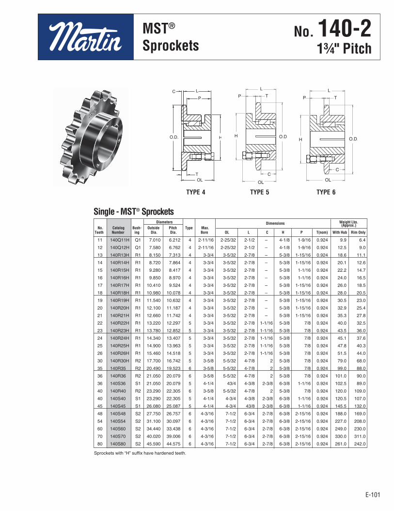
E-101
No. 140 13⁄4" Pitch
MST®
Sprockets
E-101
Diameters Dimensions Weight Lbs. No. Catalog Bush- Outside Pitch Type Max.
(Approx.)
Teeth Number ing Dia. Dia. Bore OL L C H P T(nom) With Hub Rim Only
11 140Q11H Q1 7.010 6.212 4 2-11/16 2-25/32 2-1/2 – 4-1/8 1-9/16 0.924 9.9 6.4
12 140Q12H Q1 7.580 6.762 4 2-11/16 2-25/32 2-1/2 – 4-1/8 1-9/16 0.924 12.5 9.0
13 140R13H R1 8.150 7.313 4 3-3/4 3-5/32 2-7/8 – 5-3/8 1-15/16 0.924 18.6 11.1
14 140R14H R1 8.720 7.864 4 3-3/4 3-5/32 2-7/8 – 5-3/8 1-15/16 0.924 20.1 12.6
15 140R15H R1 9.280 8.417 4 3-3/4 3-5/32 2-7/8 – 5-3/8 1-1/16 0.924 22.2 14.7
16 140R16H R1 9.850 8.970 4 3-3/4 3-5/32 2-7/8 – 5-3/8 1-1/16 0.924 24.0 16.5
17 140R17H R1 10.410 9.524 4 3-3/4 3-5/32 2-7/8 – 5-3/8 1-15/16 0.924 26.0 18.5
18 140R18H R1 10.980 10.078 4 3-3/4 3-5/32 2-7/8 – 5-3/8 1-15/16 0.924 28.0 20.5
19 140R19H R1 11.540 10.632 4 3-3/4 3-5/32 2-7/8 – 5-3/8 1-15/16 0.924 30.5 23.0
20 140R20H R1 12.100 11.187 4 3-3/4 3-5/32 2-7/8 – 5-3/8 1-15/16 0.924 32.9 25.4
21 140R21H R1 12.660 11.742 4 3-3/4 3-5/32 2-7/8 – 5-3/8 1-15/16 0.924 35.3 27.8
22 140R22H R1 13.220 12.297 5 3-3/4 3-5/32 2-7/8 1-1/16 5-3/8 7/8 0.924 40.0 32.5
23 140R23H R1 13.780 12.852 5 3-3/4 3-5/32 2-7/8 1-1/16 5-3/8 7/8 0.924 43.5 36.0
24 140R24H R1 14.340 13.407 5 3-3/4 3-5/32 2-7/8 1-1/16 5-3/8 7/8 0.924 45.1 37.6
25 140R25H R1 14.900 13.963 5 3-3/4 3-5/32 2-7/8 1-1/16 5-3/8 7/8 0.924 47.8 40.3
26 140R26H R1 15.460 14.518 5 3-3/4 3-5/32 2-7/8 1-1/16 5-3/8 7/8 0.924 51.5 44.0
30 140R30H R2 17.700 16.742 5 3-5/8 5-5/32 4-7/8 2 5-3/8 7/8 0.924 79.0 68.0
35 140R35 R2 20.490 19.523 6 3-5/8 5-5/32 4-7/8 2 5-3/8 7/8 0.924 99.0 88.0
36 140R36 R2 21.050 20.079 6 3-5/8 5-5/32 4-7/8 2 5-3/8 7/8 0.924 101.0 90.0
36 140S36 S1 21.050 20.079 5 4-1/4 43/4 4-3/8 2-3/8 6-3/8 1-1/16 0.924 102.5 89.0
40 140R40 R2 23.290 22.305 6 3-5/8 5-5/32 4-7/8 2 5-3/8 7/8 0.924 120.0 109.0
40 140S40 S1 23.290 22.305 5 4-1/4 4-3/4 4-3/8 2-3/8 6-3/8 1-1/16 0.924 120.5 107.0
45 140S45 S1 26.080 25.087 5 4-1/4 4-3/4 43/8 2-3/8 6-3/8 1-1/16 0.924 145.5 132.0
48 140S48 S2 27.750 26.757 6 4-3/16 7-1/2 6-3/4 2-7/8 6-3/8 2-15/16 0.924 188.0 169.0
54 140S54 S2 31.100 30.097 6 4-3/16 7-1/2 6-3/4 2-7/8 6-3/8 2-15/16 0.924 227.0 208.0
60 140S60 S2 34.440 33.438 6 4-3/16 7-1/2 6-3/4 2-7/8 6-3/8 2-15/16 0.924 249.0 230.0
70 140S70 S2 40.020 39.006 6 4-3/16 7-1/2 6-3/4 2-7/8 6-3/8 2-15/16 0.924 330.0 311.0
80 140S80 S2 45.590 44.575 6 4-3/16 7-1/2 6-3/4 2-7/8 6-3/8 2-15/16 0.924 261.0 242.0
Single - MST® Sprockets
Sprockets with “H” suffix have hardened teeth.
TYPE 4 TYPE 5 TYPE 6
No . 140-21¾" Pitch
MST®
Sprockets

E-102
All SteelStock Sprockets
No. 140-213⁄4" Pitch
E-102
13 D140B13 8.150 B 15⁄8 35⁄16 5 33⁄4 29.0 14 D140B14 8.720 B 15⁄8 33⁄4 51⁄2 33⁄4 34.8 15 D140B15 9.280 B 15⁄8 41⁄2 61⁄2 33⁄4 42.5 16 D140B16 9.850 B 15⁄8 51⁄4 7 4 48.1 17 D140B17 10.410 B 15⁄8 51⁄4 7 4 57.5 18 D140B18 10.980 B 13⁄4 51⁄4 7 4 65.6 19 D140B19 11.540 B 13⁄4 51⁄4 7 4 72.0 20 D140B20 12.100 B 13⁄4 51⁄4 7 4 76.0 21 D140B21 12.660 B 13⁄4 51⁄4 7 4 82.0 22 D140B22 13.220 B 13⁄4 51⁄4 7 4 94.0 23 D140B23 13.780 B 13⁄4 51⁄4 7 4 100.0 24 D140B24 14.340 B 13⁄4 51⁄4 7 4 104.0 25 D140B25 14.900 B 13⁄4 51⁄4 7 4 120.0 26 D140B26 15.460 B 13⁄4 51⁄4 7 4 128.0 35 D140C35 20.490 C 11⁄2 53⁄8 71⁄2 6 180.0 45 D140C45 26.080 C 11⁄2 53⁄8 71⁄2 6 232.0 60 D140C60 34.440 C 11⁄2 63⁄8 91⁄2 61⁄4 372.0
Bore (inches) Hub (inches) Weight No. Catalog Outside Rec. Length Lbs. Teeth Number Diameter Type Stock Max. Dia. Thru (Approx.)
Double - Type B & C
Maximum bores shown will accommodate standard keyseat andsetscrew over keyseat. Slightly larger bores are possible with no keyseat,shallow keyseat, or setscrew at angle to keyseat.
TYPE B TYPE C
QD — TYPE C6QD — TYPE C5
Alteration Charges
See current discountsheet for alterationcharges.
35 D140J35 J 20.490 19.523 C5 47⁄16 41⁄2 5 71⁄4 31⁄32 23⁄32 19⁄32 7⁄32 33⁄16 0.894 2.818 137 128 45 D140J45 J 26.080 25.087 C5 47⁄16 41⁄2 5 71⁄4 31⁄32 23⁄32 19⁄32 7⁄32 33⁄16 0.894 2.818 195 176 60 D140M60 M 34.440 33.438 C6 51⁄2 63⁄4 63⁄4 9 27⁄32 123⁄32 119⁄32 25⁄32 53⁄16 0.894 2.818 339 302
Diameters Dimensions Weight Lbs. (Approx.) No. Catalog Bush- Outside Pitch Max. With Rim Teeth Number ing Diameter Diameter Type Bore L
1 L
2 C Y P G V X T W Hub Only
Double - Type QD
2.818".894"Nominal
2.818".894"Nominal
HubDia.
Length ThruBore
HubDia.
Length ThruBore
O.D.
No . 140-21¾" Pitch
All SteelStock Sprockets
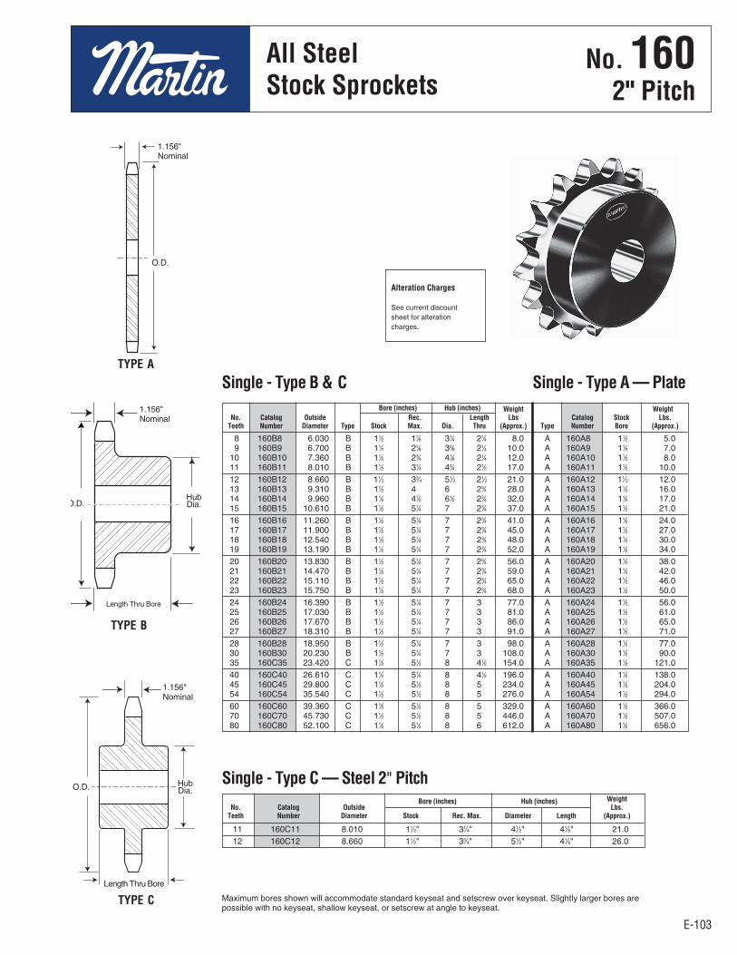
E-103
All SteelStock Sprockets
E-103
No. 1602" Pitch
11 160C11 8.010 11⁄2" 31⁄4" 41⁄2" 41⁄8" 21.0 12 160C12 8.660 11⁄2" 33⁄4" 51⁄2" 41⁄8" 26.0
8 160B8 6.030 B 11⁄2 17⁄8 31⁄4 21⁄4 8.0 A 160A8 11⁄2 5.0 9 160B9 6.700 B 11⁄2 21⁄8 35⁄8 21⁄4 10.0 A 160A9 11⁄2 7.0 10 160B10 7.360 B 11⁄2 23⁄4 41⁄8 21⁄4 12.0 A 160A10 11⁄2 8.0 11 160B11 8.010 B 11⁄2 31⁄4 43⁄4 21⁄2 17.0 A 160A11 11⁄2 10.0 12 160B12 8.660 B 11⁄2 33⁄4 51⁄2 21⁄2 21.0 A 160A12 11⁄2 12.0 13 160B13 9.310 B 11⁄2 4 6 23⁄4 28.0 A 160A13 11⁄2 16.0 14 160B14 9.960 B 11⁄2 41⁄2 61⁄2 23⁄4 32.0 A 160A14 11⁄2 17.0 15 160B15 10.610 B 11⁄2 51⁄4 7 23⁄4 37.0 A 160A15 11⁄2 21.0 16 160B16 11.260 B 11⁄2 51⁄4 7 23⁄4 41.0 A 160A16 11⁄2 24.0 17 160B17 11.900 B 11⁄2 51⁄4 7 23⁄4 45.0 A 160A17 11⁄2 27.0 18 160B18 12.540 B 11⁄2 51⁄4 7 23⁄4 48.0 A 160A18 11⁄2 30.0 19 160B19 13.190 B 11⁄2 51⁄4 7 23⁄4 52.0 A 160A19 11⁄2 34.0 20 160B20 13.830 B 11⁄2 51⁄4 7 23⁄4 56.0 A 160A20 11⁄2 38.0 21 160B21 14.470 B 11⁄2 51⁄4 7 23⁄4 59.0 A 160A21 11⁄2 42.0 22 160B22 15.110 B 11⁄2 51⁄4 7 23⁄4 65.0 A 160A22 11⁄2 46.0 23 160B23 15.750 B 11⁄2 51⁄4 7 23⁄4 68.0 A 160A23 11⁄2 50.0 24 160B24 16.390 B 11⁄2 51⁄4 7 3 77.0 A 160A24 11⁄2 56.0 25 160B25 17.030 B 11⁄2 51⁄4 7 3 81.0 A 160A25 11⁄2 61.0 26 160B26 17.670 B 11⁄2 51⁄4 7 3 86.0 A 160A26 11⁄2 65.0 27 160B27 18.310 B 11⁄2 51⁄4 7 3 91.0 A 160A27 11⁄2 71.0 28 160B28 18.950 B 11⁄2 51⁄4 7 3 98.0 A 160A28 11⁄2 77.0 30 160B30 20.230 B 11⁄2 51⁄4 7 3 108.0 A 160A30 11⁄2 90.0 35 160C35 23.420 C 11⁄2 51⁄2 8 41⁄2 154.0 A 160A35 11⁄2 121.0 40 160C40 26.610 C 11⁄2 51⁄2 8 41⁄2 196.0 A 160A40 11⁄2 138.0 45 160C45 29.800 C 11⁄2 51⁄2 8 5 234.0 A 160A45 11⁄2 204.0 54 160C54 35.540 C 11⁄2 51⁄2 8 5 276.0 A 160A54 11⁄2 294.0 60 160C60 39.360 C 11⁄2 51⁄2 8 5 329.0 A 160A60 11⁄2 366.0 70 160C70 45.730 C 11⁄2 51⁄2 8 5 446.0 A 160A70 11⁄2 507.0 80 160C80 52.100 C 11⁄2 51⁄2 8 6 612.0 A 160A80 11⁄2 656.0
Bore (inches) Hub (inches) Weight Weight No. Catalog Outside Rec. Length Lbs Catalog Stock Lbs. Teeth Number Diameter Type Stock Max. Dia. Thru (Approx.) Type Number Bore (Approx.)
Single - Type B & C Single - Type A — Plate
Single - Type C — Steel 2" Pitch Bore (inches) Hub (inches) Weight No. Catalog Outside Lbs. Teeth Number Diameter Stock Rec. Max. Diameter Length (Approx.)
Alteration Charges
See current discountsheet for alterationcharges.
Maximum bores shown will accommodate standard keyseat and setscrew over keyseat. Slightly larger bores arepossible with no keyseat, shallow keyseat, or setscrew at angle to keyseat.
TYPE B
TYPE C
TYPE A
Length Thru Bore
HubDia.
HubDia.
O.D.
O.D.
O.D.
Length Thru Bore
1.156"Nominal
1.156"Nominal
1.156"Nominal
No . 1602" Pitch
All SteelStock Sprockets
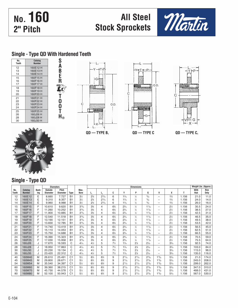
E-104
All SteelStock Sprockets
No. 1602" Pitch
E-104
12 160E12 E 8.660 7.727 B1 31⁄2 25⁄8 215⁄16 6 15⁄16 1⁄8 15⁄32 – 15⁄8 1.156 21.0 11.0 13 160E13 E 9.310 8.357 B1 31⁄2 25⁄8 215⁄16 6 15⁄16 1⁄8 15⁄32 – 15⁄8 1.156 24.0 14.0 14 160E14 E 9.960 8.988 B1 31⁄2 25⁄8 215⁄16 6 15⁄16 1⁄8 15⁄32 – 15⁄8 1.156 26.0 16.0 15 160F15 F 10.610 9.620 B1 315⁄16 35⁄8 4 65⁄8 25⁄16 1⁄8 111⁄32 – 21⁄2 1.156 35.5 24.0 16 160F16 F 11.260 10.252 B1 315⁄16 35⁄8 4 65⁄8 25⁄16 1⁄8 111⁄32 – 21⁄2 1.156 38.5 27.0 17 160F17 F 11.900 10.885 B1 315⁄16 35⁄8 4 65⁄8 25⁄16 1⁄8 111⁄32 – 21⁄2 1.156 42.5 31.0 18 160F18 F 12.540 11.518 B1 315⁄16 35⁄8 4 65⁄8 25⁄16 1⁄8 111⁄32 – 21⁄2 1.156 46.5 35.0 19 160F19 F 13.190 12.151 B1 315⁄16 35⁄8 4 65⁄8 25⁄16 1⁄8 111⁄32 – 21⁄2 1.156 49.5 38.0 20 160F20 F 13.830 12.785 B1 315⁄16 35⁄8 4 65⁄8 25⁄16 1⁄8 111⁄32 – 21⁄2 1.156 53.5 42.0 21 160F21 F 14.740 13.419 B1 315⁄16 35⁄8 4 65⁄8 25⁄16 1⁄8 111⁄32 – 21⁄2 1.156 56.5 45.0 22 160F22 F 15.110 14.053 B1 315⁄16 35⁄8 4 65⁄8 25⁄16 1⁄8 111⁄32 – 21⁄2 1.156 62.5 51.0 23 160F23 F 15.750 14.688 B1 315⁄16 35⁄8 4 65⁄8 25⁄16 1⁄8 111⁄32 – 21⁄2 1.156 66.5 55.0 24 160F24 F 16.390 15.323 B1 315⁄16 35⁄8 4 65⁄8 25⁄16 1⁄8 111⁄32 – 21⁄2 1.156 70.5 59.0 25 160F25 F 17.030 15.958 B1 315⁄16 35⁄8 4 65⁄8 25⁄16 1⁄8 111⁄32 – 21⁄2 1.156 75.5 64.0 26 160J26 J 17.670 16.593 C 47⁄16 41⁄2 5 71⁄4 13⁄16 21⁄8 21⁄32 – 33⁄16 1.156 92.5 74.0 28 160J28 J 18.950 17.863 C 47⁄16 41⁄2 5 71⁄4 13⁄16 21⁄8 21⁄32 – 33⁄16 1.156 103.0 84.0 30 160J30 J 20.230 19.134 C 47⁄16 41⁄2 5 71⁄4 13⁄16 21⁄8 21⁄32 – 33⁄16 1.156 115.0 96.0 35 160J35 J 23.420 22.312 C 47⁄16 41⁄2 5 71⁄4 13⁄16 21⁄8 21⁄32 – 33⁄16 1.156 135.0 116.0 40 160M40 M 26.610 25.491 C1 51⁄2 63⁄4 63⁄4 9 211⁄16 211⁄16 213⁄32 119⁄32 53⁄16 1.156 21.0 174.0 45 160M45 M 29.800 28.671 C1 51⁄2 63⁄4 63⁄4 9 211⁄16 211⁄16 213⁄32 119⁄32 53⁄16 1.156 245.0 208.0 54 160M54 M 35.540 34.397 C1 51⁄2 63⁄4 63⁄4 9 211⁄16 211⁄16 213⁄32 119⁄32 53⁄16 1.156 299.0 262.0 60 160M60 M 39.360 38.215 C1 51⁄2 63⁄4 63⁄4 9 211⁄16 211⁄16 213⁄32 119⁄32 53⁄16 1.156 347.0 310.0 70 160M70 M 45.730 44.578 C1 51⁄2 63⁄4 63⁄4 9 211⁄16 211⁄16 213⁄32 119⁄32 53⁄16 1.156 468.0 431.0 80 160M80 M 52.100 50.943 C1 51⁄2 63⁄4 63⁄4 9 211⁄16 211⁄16 213⁄32 119⁄32 53⁄16 1.156 567.0 530.0
12 160E12 H 13 160E13 H 14 160E14 H 15 160F15 H 16 160F16 H 17 160F17 H 18 160F18 H 19 160F19 H 20 160F20 H 21 160F21 H 22 160F22 H 23 160F23 H 24 160F24 H 25 160F25 H 26 160J26 H 28 160J28 H 30 160J30 H
QD — TYPE B1 QD — TYPE C QD — TYPE C1
Diameters Dimensions Weight Lbs. (Approx.) No. Catalog Bush- Outside Pitch Max. With Rim Teeth Number ing Diameter Diameter Type Bore L
1 L
2 C Y P G V X T Hub Only
Single - Type QD
No. Catalog Teeth Number
Single - Type QD With Hardened TeethSABER
TOOTH®
O.D.
O.D.
No . 160 2" Pitch
All SteelStock Sprockets
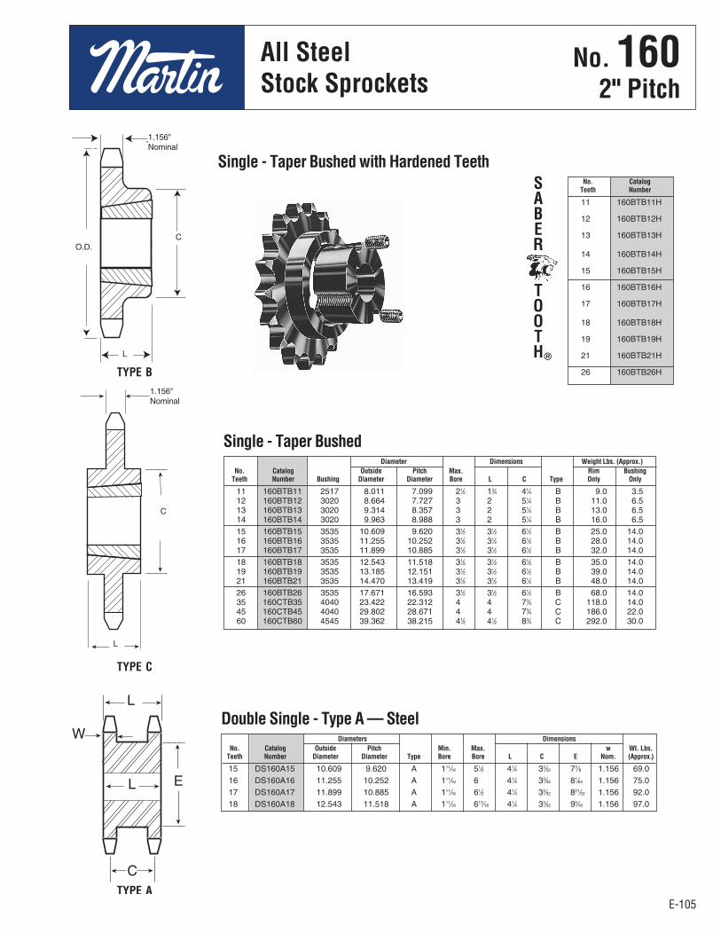
E-105
All SteelStock Sprockets
E-105
No. 1602" Pitch
11 160BTB11H
12 160BTB12H
13 160BTB13H
14 160BTB14H
15 160BTB15H
16 160BTB16H
17 160BTB17H
18 160BTB18H
19 160BTB19H
21 160BTB21H
26 160BTB26H
15 DS160A15 10.609 9.620 A 111⁄16 51⁄2 41⁄4 33⁄32 73⁄8 1.156 69.0 16 DS160A16 11.255 10.252 A 111⁄16 6 41⁄4 33⁄32 81⁄64 1.156 75.0 17 DS160A17 11.899 10.885 A 111⁄16 61⁄2 41⁄4 33⁄32 821⁄32 1.156 92.0 18 DS160A18 12.543 11.518 A 111⁄16 613⁄16 41⁄4 33⁄32 95⁄16 1.156 97.0
Diameters Dimensions No. Catalog Outside Pitch Min. Max. w Wt. Lbs. Teeth Number Diameter Diameter Type Bore Bore L C E Nom. (Approx.)
11 160BTB11 2517 8.011 7.099 21⁄2 13⁄4 41⁄4 B 9.0 3.5 12 160BTB12 3020 8.664 7.727 3 2 51⁄4 B 11.0 6.5 13 160BTB13 3020 9.314 8.357 3 2 51⁄4 B 13.0 6.5 14 160BTB14 3020 9.963 8.988 3 2 51⁄4 B 16.0 6.5 15 160BTB15 3535 10.609 9.620 31⁄2 31⁄2 61⁄2 B 25.0 14.0 16 160BTB16 3535 11.255 10.252 31⁄2 31⁄2 61⁄2 B 28.0 14.0 17 160BTB17 3535 11.899 10.885 31⁄2 31⁄2 61⁄2 B 32.0 14.0 18 160BTB18 3535 12.543 11.518 31⁄2 31⁄2 61⁄2 B 35.0 14.0 19 160BTB19 3535 13.185 12.151 31⁄2 31⁄2 61⁄2 B 39.0 14.0 21 160BTB21 3535 14.470 13.419 31⁄2 31⁄2 61⁄2 B 48.0 14.0 26 160BTB26 3535 17.671 16.593 31⁄2 31⁄2 61⁄2 B 68.0 14.0 35 160CTB35 4040 23.422 22.312 4 4 73⁄4 C 118.0 14.0 45 160CTB45 4040 29.802 28.671 4 4 73⁄4 C 186.0 22.0 60 160CTB60 4545 39.362 38.215 41⁄2 41⁄2 83⁄4 C 292.0 30.0
Diameter Dimensions Weight Lbs. (Approx.) No. Catalog Outside Pitch Max. Rim Bushing Teeth Number Bushing Diameter Diameter Bore L C Type Only Only
Single - Taper Bushed
TYPE B
TYPE C
No. Catalog Teeth Number
Single - Taper Bushed with Hardened TeethSABER
TOOTH®
1.156"Nominal
1.156"Nominal
Double Single - Type A — Steel
TYPE A
C
L
C
L
O.D.
No . 160 2" Pitch
All SteelStock Sprockets

E-106
No. 1602" Pitch
E-106
Diameters Dimensions Weight Lbs. No. Catalog Bush- Outside Pitch Type Max.
(Approx.)
Teeth Number ing Dia. Dia. Bore OL L C H P T(nom) With Hub Rim Only
11 160R11H R1 8.010 7.099 4 3-3/4 3-13/32 2-7/8 1/4 5-3/8 1-31/32 1.156 18.3 10.8
12 160R12H R1 8.660 7.727 4 3-3/4 3-13/32 2-7/8 1/4 5-3/8 1-31/32 1.156 21.7 14.2
13 160R13H R1 9.310 8.357 4 3-3/4 3-5/32 2-7/8 – 5-3/8 1-23/32 1.156 23.0 15.5
14 160R14H R1 9.960 8.988 4 3-3/4 3-5/32 2-7/8 – 5-3/8 1-23/32 1.156 26.0 18.5
15 160R15H R1 10.610 9.620 4 3-3/4 3-5/32 2-7/8 – 5-3/8 1-23/32 1.156 29.1 21.6
16 160R16H R1 11.260 10.252 4 3-3/4 3-5/32 2-7/8 – 5-3/8 1-23/32 1.156 32.5 25.0
17 160R17H R1 11.900 10.885 4 3-3/4 3-5/32 2-7/8 – 5-3/8 1-23/32 1.156 35.5 28.0
18 160R18H R1 12.540 11.518 4 3-3/4 3-5/32 2-7/8 – 5-3/8 1-23/32 1.156 39.4 31.9
19 160R19H R1 13.190 12.151 4 3-3/4 3-5/32 2-7/8 – 5-3/8 1-23/32 1.156 43.4 35.9
20 160R20H R2 13.830 12.785 6 3-5/8 5-5/32 4-7/8 2 5-3/8 1-23/32 1.156 62.0 51.0
21 160R21H R2 14.470 13.419 6 3-5/8 5-5/32 4-7/8 2 5-3/8 1-23/32 1.156 67.0 56.0
22 160R22H R2 15.110 14.053 6 3-5/8 5-5/32 4-7/8 2 5-3/8 1-23/32 1.156 71.0 60.0
23 160R23H R2 15.750 14.688 6 3-5/8 5-5/32 4-7/8 2 5-3/8 1-23/32 1.156 76.0 65.0
24 160R24H R2 16.390 15.323 6 3-5/8 5-5/32 4-7/8 2 5-3/8 1-23/32 1.156 82.5 71.5
25 160R25H R2 17.030 15.958 6 3-5/8 5-5/32 4-7/8 2 5-3/8 1-23/32 1.156 85.0 74.0
26 160R26H R2 17.670 16.593 6 3-5/8 5-5/32 4-7/8 2 5-3/8 1-23/32 1.156 90.0 79.0
26 160S26H S2 17.670 16.593 6 4-3/16 7-1/8 6-3/4 2-7/8 6-3/8 2-23/32 1.156 98.0 79.0
28 160R28H R2 18.950 17.863 6 3-5/8 5-5/32 4-7/8 2 5-3/8 1-23/32 1.156 110.8 99.8
28 160S28H S2 19.950 17.863 6 4-3/16 7-1/8 6-3/4 2-7/8 6-3/8 2-23/32 1.156 118.8 99.8
30 160R30H R2 20.230 19.134 6 3-5/8 5-5/32 4-7/8 2 5-3/8 1-23/32 1.156 117.0 106.0
30 160S30H S2 20.230 19.134 6 4-3/16 7-1/8 6-3/4 2-7/8 6-3/8 2-23/32 1.156 134.0 115.0
35 160S35 S2 23.420 22.312 6 4-3/16 7-1/8 6-3/4 2-7/8 6-3/8 2-23/32 1.156 169.0 150.0
40 160S40 S2 26.610 25.491 6 4-3/16 7-1/8 6-3/4 2-7/8 6-3/8 2-23/32 1.156 184.0 165.0
45 160S45 S2 29.800 28.671 6 4-3/16 7-1/8 6-3/4 2-7/8 6-3/8 2-23/32 1.156 223.0 204.0
60 160U60 U0 39.360 38.215 6 5-1/2 5 25/32 5-1/4 1-15/16 8-3/8 1-21/32 1.156 338.0 308.0
70 160U70 U0 45.730 44.578 6 5-1/2 5 25/32 5-1/4 1-15/16 8-3/8 1-21/32 1.156 384.0 354.0
80 160S80 S2 52.100 50.943 6 4-3/16 7-1/8 6-3/4 2-7/8 6-3/8 2-23/32 1.156 – –
80 160U80 U1 52.100 50.943 6 5-1/2 7-19/32 7-1/8 2-7/8 8-3/8 2 19/32 1.156 434.0 394.0
MST®
Sprockets
Single - MST® Sprockets
Sprockets with “H” suffix have hardened teeth.
TYPE 4 TYPE 6
No . 1602" Pitch
MST®
Sprockets

E-107
All SteelStock Sprockets
E-107
No. 160-22" Pitch
35 D160M35 M 23.420 22.312 C6 51⁄2 63⁄4 63⁄4 9 23⁄64 19⁄32 15⁄32 39⁄64 53⁄16 1.119 3.424 259 222 45 D160N45 N 29.800 28.671 C6 6 81⁄8 81⁄8 10 211⁄32 223⁄64 25⁄32 21⁄32 61⁄4 1.119 3.424 377 340 60 D160N60 N 39.360 38.215 C6 6 81⁄8 81⁄8 10 211⁄32 223⁄64 25⁄32 21⁄32 61⁄4 1.119 3.424 509 472
13 D160B13 9.310 B 2 4 6 43⁄4 48 14 D160B14 9.960 B 2 43⁄4 63⁄4 43⁄4 58 15 D160B15 10.610 B 2 51⁄4 7 43⁄4 68 16 D160B16 11.260 B 2 51⁄4 7 43⁄4 75 17 D160B17 11.900 B 2 51⁄4 7 43⁄4 91 18 D160B18 12.540 B 2 51⁄4 7 43⁄4 96 19 D160B19 13.190 B 2 51⁄4 7 43⁄4 107 20 D160B20 13.830 B 2 51⁄4 7 43⁄4 119 21 D160B21 14.470 B 2 53⁄8 71⁄2 43⁄4 130 22 D160B22 15.110 B 2 53⁄8 71⁄2 43⁄4 141 23 D160B23 15.750 B 2 53⁄8 71⁄2 43⁄4 157 24 D160B24 16.390 B 2 53⁄8 71⁄2 43⁄4 171 25 D160B25 17.030 B 2 53⁄8 71⁄2 43⁄4 187 26 D160B26 17.670 B 2 53⁄8 71⁄2 43⁄4 201 35 D160C35 23.420 C 11⁄2 63⁄4 91⁄2 65⁄8 306 45 D160C45 29.800 C 11⁄2 7 10 71⁄8 431 60 D160C60 39.360 C 11⁄2 7 10 71⁄8 564
Bore (inches) Hub (inches) Weight No. Catalog Outside Rec. Length Lbs. Teeth Number Diameter Type Stock Max. Dia. Thru (App.)
Double - Type B & C
Diameters Dimensions Weight Lbs. (Approx.) No. Catalog Bush- Outside Pitch Max. With Rim Teeth Number ing Diameter Diameter Type Bore L
1 L
2 C Y P G V X T W Hub Only
Maximum bores shown will accommodate standard keyseat and setscrewover keyseat. Slightly larger bores are possible with no keyseat, shallowkeyseat, or setscrew at angle to keyseat.
QD — TYPE C6
TYPE B TYPE C
Alteration Charges
See current discountsheet for alterationcharges.
Double - Type QD
3.424"
1.119"Nominal
3.424"
1.119"Nominal
HubDia.
Length ThruBore
HubDia.
Length ThruBore
O.D.
No . 160-2 2" Pitch
All SteelStock Sprockets
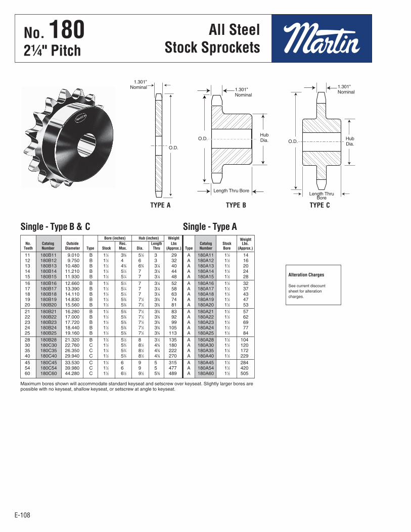
E-108
All SteelStock Sprockets
No. 18021⁄4" Pitch
E-108
TYPE A TYPE B TYPE C
11 180B11 9.010 B 11⁄2 35⁄8 51⁄2 3 29 A 180A11 11⁄2 14 12 180B12 9.750 B 11⁄2 4 6 3 32 A 180A12 11⁄2 16 13 180B13 10.480 B 11⁄2 45⁄8 63⁄4 31⁄8 40 A 180A13 11⁄2 20 14 180B14 11.210 B 11⁄2 51⁄4 7 31⁄8 44 A 180A14 11⁄2 24 15 180B15 11.930 B 11⁄2 51⁄4 7 31⁄8 48 A 180A15 11⁄2 28 16 180B16 12.660 B 11⁄2 51⁄4 7 31⁄8 52 A 180A16 11⁄2 32 17 180B17 13.390 B 11⁄2 51⁄4 7 31⁄8 58 A 180A17 11⁄2 37 18 180B18 14.110 B 11⁄2 51⁄4 7 31⁄8 63 A 180A18 11⁄2 43 19 180B19 14.830 B 11⁄2 53⁄8 71⁄2 33⁄8 74 A 180A19 11⁄2 47 20 180B20 15.560 B 11⁄2 53⁄8 71⁄2 33⁄8 81 A 180A20 11⁄2 53 21 180B21 16.280 B 11⁄2 53⁄8 71⁄2 33⁄8 83 A 180A21 11⁄2 57 22 180B22 17.000 B 11⁄2 53⁄8 71⁄2 33⁄8 92 A 180A22 11⁄2 62 23 180B23 17.720 B 11⁄2 53⁄8 71⁄2 33⁄8 99 A 180A23 11⁄2 69 24 180B24 18.440 B 11⁄2 53⁄8 71⁄2 33⁄8 105 A 180A24 11⁄2 77 25 180B25 19.160 B 11⁄2 53⁄8 71⁄2 33⁄8 113 A 180A25 11⁄2 84 28 180B28 21.320 B 11⁄2 51⁄2 8 31⁄2 135 A 180A28 11⁄2 104 30 180C30 22.760 C 11⁄2 53⁄4 81⁄2 43⁄8 180 A 180A30 11⁄2 120 35 180C35 26.350 C 11⁄2 53⁄4 81⁄2 43⁄8 222 A 180A35 11⁄2 172 40 180C40 29.940 C 11⁄2 53⁄4 81⁄2 43⁄8 270 A 180A40 11⁄2 229 45 180C45 33.530 C 11⁄2 6 9 5 315 A 180A45 11⁄2 284 54 180C54 39.980 C 11⁄2 6 9 5 477 A 180A54 11⁄2 420 60 180C60 44.280 C 11⁄2 61⁄2 91⁄2 53⁄8 489 A 180A60 11⁄2 505
Alteration Charges
See current discountsheet for alterationcharges.
Bore (inches) Hub (inches) Weight Weight No. Catalog Outside Rec. Length Lbs Catalog Stock Lbs. Teeth Number Diameter Type Stock Max. Dia. Thru (Approx.) Type Number Bore (Approx.)
Single - Type B & C Single - Type A
1.301"Nominal 1.301"
Nominal
1.301"Nominal
HubDia.
Length Thru Bore
HubDia.
Maximum bores shown will accommodate standard keyseat and setscrew over keyseat. Slightly larger bores arepossible with no keyseat, shallow keyseat, or setscrew at angle to keyseat.
O.D.
O.D.O.D.
Length ThruBore
No . 1802¼" Pitch
All SteelStock Sprockets
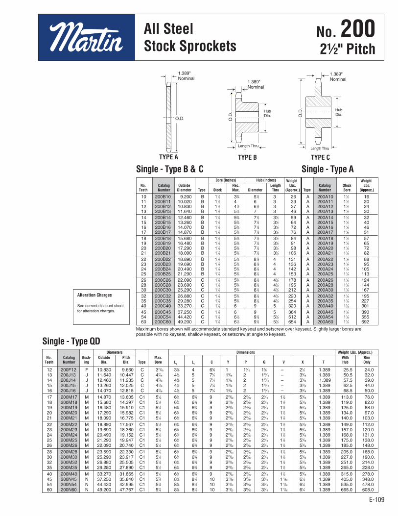
E-109
All SteelStock Sprockets
E-109
No. 20021⁄2" Pitch
10 200B10 9.200 B 11⁄2 33⁄4 51⁄2 3 26 A 200A10 11⁄2 16 11 200B11 10.020 B 11⁄2 4 6 3 33 A 200A11 11⁄2 20 12 200B12 10.830 B 11⁄2 41⁄2 61⁄2 3 37 A 200A12 11⁄2 24 13 200B13 11.640 B 11⁄2 51⁄4 7 3 46 A 200A13 11⁄2 30 14 200B14 12.460 B 11⁄2 53⁄8 71⁄2 31⁄2 59 A 200A14 11⁄2 32 15 200B15 13.260 B 11⁄2 53⁄8 71⁄2 31⁄2 64 A 200A15 11⁄2 40 16 200B16 14.070 B 11⁄2 53⁄8 71⁄2 31⁄2 72 A 200A16 11⁄2 46 17 200B17 14.870 B 11⁄2 53⁄8 71⁄2 31⁄2 76 A 200A17 11⁄2 51 18 200B18 15.680 B 11⁄2 53⁄8 71⁄2 31⁄2 84 A 200A18 11⁄2 57 19 200B19 16.480 B 11⁄2 53⁄8 71⁄2 31⁄2 91 A 200A19 11⁄2 65 20 200B20 17.290 B 11⁄2 53⁄8 71⁄2 31⁄2 98 A 200A20 11⁄2 72 21 200B21 18.090 B 11⁄2 53⁄8 71⁄2 31⁄2 106 A 200A21 11⁄2 82 22 200B22 18.890 B 11⁄2 53⁄4 81⁄2 4 131 A 200A22 11⁄2 88 23 200B23 19.690 B 11⁄2 53⁄4 81⁄2 4 136 A 200A23 11⁄2 95 24 200B24 20.490 B 11⁄2 53⁄4 81⁄2 4 142 A 200A24 11⁄2 105 25 200B25 21.290 B 11⁄2 53⁄4 81⁄2 4 153 A 200A25 11⁄2 113 26 200C26 22.090 C 11⁄2 53⁄4 81⁄2 41⁄2 178 A 200A26 11⁄2 124 28 200C28 23.690 C 11⁄2 53⁄4 81⁄2 41⁄2 195 A 200A28 11⁄2 144 30 200C30 25.290 C 11⁄2 53⁄4 81⁄2 41⁄2 212 A 200A30 11⁄2 167 32 200C32 26.880 C 11⁄2 53⁄4 81⁄2 41⁄2 220 A 200A32 11⁄2 195 35 200C35 29.280 C 11⁄2 53⁄4 81⁄2 41⁄2 254 A 200A35 11⁄2 227 40 200C40 33.270 C 11⁄2 6 9 5 320 A 200A40 11⁄2 301 45 200C45 37.250 C 11⁄2 6 9 5 364 A 200A45 11⁄2 390 54 200C54 44.420 C 11⁄2 61⁄2 91⁄2 51⁄2 512 A 200A54 11⁄2 555 60 200C60 49.200 C 11⁄2 61⁄2 91⁄2 51⁄2 654 A 200A60 11⁄2 692
Bore (inches) Hub (inches) Weight Weight No. Catalog Outside Rec. Length Lbs. Catalog Stock Lbs. Teeth Number Diameter Type Stock Max. Diameter Thru (Approx.) Type Number Bore (Approx.)
Single - Type B & C Single - Type A
12 200F12 F 10.830 9.660 C 315⁄16 35⁄8 4 65⁄8 1 15⁄16 11⁄8 – 21⁄2 1.389 25.5 24.0 13 200J13 J 11.640 10.447 C 47⁄16 41⁄2 5 71⁄4 13⁄16 2 113⁄16 – 33⁄16 1.389 50.5 32.0 14 200J14 J 12.460 11.235 C 47⁄16 41⁄2 5 71⁄4 13⁄16 2 113⁄16 – 33⁄16 1.389 57.5 39.0 15 200J15 J 13.260 12.025 C 47⁄16 41⁄2 5 71⁄4 13⁄16 2 113⁄16 – 33⁄16 1.389 62.5 44.0 16 200J16 J 14.070 12.815 C 47⁄16 41⁄2 5 71⁄4 13⁄16 2 113⁄16 – 33⁄16 1.389 68.5 50.0 17 200M17 M 14.870 13.605 C1 51⁄2 63⁄4 63⁄4 9 223⁄32 223⁄32 25⁄16 11⁄2 53⁄16 1.389 113.0 76.0 18 200M18 M 15.680 14.397 C1 51⁄2 63⁄4 63⁄4 9 223⁄32 223⁄32 25⁄16 11⁄2 53⁄16 1.389 119.0 82.0 19 200M19 M 16.480 15.910 C1 51⁄2 63⁄4 63⁄4 9 223⁄32 223⁄32 25⁄16 11⁄2 53⁄16 1.389 125.0 88.0 20 200M20 M 17.290 15.982 C1 51⁄2 63⁄4 63⁄4 9 223⁄32 223⁄32 25⁄16 11⁄2 53⁄16 1.389 134.0 97.0 21 200M21 M 18.090 16.775 C1 51⁄2 63⁄4 63⁄4 9 223⁄32 223⁄32 25⁄16 11⁄2 53⁄16 1.389 140.0 103.0 22 200M22 M 18.890 17.567 C1 51⁄2 63⁄4 63⁄4 9 223⁄32 223⁄32 25⁄16 11⁄2 53⁄16 1.389 149.0 112.0 23 200M23 M 19.690 18.360 C1 51⁄2 63⁄4 63⁄4 9 223⁄32 223⁄32 25⁄16 11⁄2 53⁄16 1.389 157.0 120.0 24 200M24 M 20.490 19.152 C1 51⁄2 63⁄4 63⁄4 9 223⁄32 223⁄32 25⁄16 11⁄2 53⁄16 1.389 168.0 131.0 25 200M25 M 21.290 19.947 C1 51⁄2 63⁄4 63⁄4 9 223⁄32 223⁄32 25⁄16 11⁄2 53⁄16 1.389 175.0 138.0 26 200M26 M 22.090 20.740 C1 51⁄2 63⁄4 63⁄4 9 223⁄32 223⁄32 25⁄16 11⁄2 53⁄16 1.389 185.0 148.0 28 200M28 M 23.690 22.330 C1 51⁄2 63⁄4 63⁄4 9 223⁄32 223⁄32 25⁄16 11⁄2 53⁄16 1.389 205.0 168.0 30 200M30 M 25.290 23.917 C1 51⁄2 63⁄4 63⁄4 9 223⁄32 223⁄32 25⁄16 11⁄2 53⁄16 1.389 227.0 190.0. 32 200M32 M 26.880 25.505 C1 51⁄2 63⁄4 63⁄4 9 223⁄32 223⁄32 25⁄16 11⁄2 53⁄16 1.389 251.0 214.0 35 200M35 M 29.280 27.890 C1 51⁄2 63⁄4 63⁄4 9 223⁄32 223⁄32 25⁄16 11⁄2 53⁄16 1.389 265.0 228.0 40 200M40 M 33.270 31.865 C1 51⁄2 63⁄4 63⁄4 9 223⁄32 223⁄32 25⁄16 11⁄2 53⁄16 1.389 315.0 278.0 45 200N45 N 37.250 35.840 C1 57⁄8 81⁄8 81⁄8 10 313⁄32 313⁄32 33⁄16 111⁄16 61⁄4 1.389 405.0 348.0 54 200N54 N 44.420 42.995 C1 57⁄8 81⁄8 81⁄8 10 313⁄32 313⁄32 33⁄16 111⁄16 61⁄4 1.389 535.0 478.0 60 200N60 N 49.200 47.767 C1 57⁄8 81⁄8 81⁄8 10 313⁄32 313⁄32 33⁄16 111⁄16 61⁄4 1.389 665.0 608.0
Diameters Dimensions Weight Lbs. (Approx.) No. Catalog Bush- Outside Pitch Max. With Rim Teeth Number ing Dia. Dia. Type Bore L
1 L
2 C Y P G V X T Hub Only
Single - Type QDMaximum bores shown will accommodate standard keyseat and setscrew over keyseat. Slightly larger bores are possible with no keyseat, shallow keyseat, or setscrew at angle to keyseat.
Alteration Charges
See current discount sheetfor alteration charges.
TYPE A TYPE B TYPE C
1.389"Nominal
1.389"Nominal
1.389"Nominal
HubDia.
Length Thru
HubDia.
O.D.
O.D
.
O.D
.
Length Thru
No . 2002½" Pitch
All SteelStock Sprockets

E-110
No. 2002 1⁄2" Pitch
MST®
Sprockets
E-110
12 200R12 R2 10.830 9.660 6 3-5/8 5-5/32 4-7/8 2 5-3/8 1-1/2 1.389 46.3 35.3
13 200S13 S2 11.640 10.447 6 4-3/16 7-1/8 6-3/4 2-7/8 6-3/8 2-1/2 1.389 71.2 52.2
14 200S14 S2 12.460 11.235 6 4-3/16 7-1/8 6-3/4 2-7/8 6-3/8 2-1/2 1.389 76.5 57.5
15 200S15 S2 13.260 12.025 6 4-3/16 7-1/8 6-3/4 2-7/8 6-3/8 2-1/2 1.389 80.0 61.0
16 200S16 S2 14.070 12.815 6 4-3/16 7-1/8 6-3/4 2-7/8 6-3/8 2-1/2 1.389 90.0 71.0
17 200S17 S2 14.870 13.605 6 4-3/16 7-1/8 6-3/4 2-7/8 6-3/8 2-1/2 1.389 98.0 79.0
18 200U18 U0 15.680 14.397 6 5-1/2 5-23/32 5-1/4 1-5/8 8-3/8 2-17/32 1.389 106.5 76.5
19 200U19 U0 16.480 15.190 6 5-1/2 5-23/32 5-1/4 1-5/8 8-3/8 2-17/32 1.389 113.7 83.7
20 200U20 U0 17.290 15.982 6 5-1/2 5-23/32 5-1/4 1-5/8 8-3/8 2-17/32 1.389 121.3 91.3
21 200U21 U0 18.090 16.775 6 5-1/2 5-23/32 5-1/4 1-5/8 8-3/8 2-17/32 1.389 129.4 99.4
22 200U22 U0 18.890 17.567 6 5-1/2 5-23/32 5-1/4 1-5/8 8-3/8 2-17/32 1.389 140.0 110.0
23 200U23 U0 19.690 18.360 6 5-1/2 5-23/32 5-1/4 1-5/8 8-3/8 2-17/32 1.389 147.0 117.0
24 200U24 U0 20.490 19.152 6 5-1/2 5-23/32 5-1/4 1-5/8 8-3/8 2-17/32 1.389 156.0 126.0
25 200U25 U0 21.290 19.947 6 5-1/2 5-23/32 5-1/4 1-5/8 8-3/8 2-17/32 1.389 170.0 140.0
26 200U26 U0 22.090 20.740 6 5-1/2 5-23/32 5-1/4 1-5/8 8-3/8 2-17/32 1.389 180.0 150.0
28 200U28 U0 23.690 22.330 6 5-1/2 5-23/32 5-1/4 1-5/8 8-3/8 2-17/32 1.389 199.0 169.0
30 200U30 U0 25.290 23.917 6 5-1/2 5-23/32 5-1/4 1-5/8 8-3/8 2-17/32 1.389 218.0 188.0
32 200U32 U0 26.880 25.505 6 5-1/2 5-23/32 5-1/4 1-5/8 8-3/8 2-17/32 1.389 242.0 212.0
35 200U35 U1 29.280 27.890 6 5-1/2 7-19/32 7-1/8 2-7/8 8-3/8 2-7/8 1.389 292.0 252.0
40 200U40 U1 33.270 31.865 6 5-1/2 7-19/32 7-1/8 2-7/8 8-3/8 2-7/8 1.389 346.0 306.0
45 200U45 U1 37.250 35.840 6 5-1/2 7-19/32 7-1/8 2-7/8 8-3/8 2-7/8 1.389 330.0 290.0
54 200U54 U2 44.420 42.995 6 5 10-19/32 10-1/8 4-1/4 8-3/8 3-29/32 1.389 435.0 385.0
60 200U60 U2 49.200 47.767 6 5 10-19/32 10-1/8 4-1/4 8-3/8 3-29/32 1.389 495.0 445.0
Diameters Dimensions Weight Lbs. No. Catalog Bush- Outside Pitch Type Max.
(Approx.)
Teeth Number ing Dia. Dia. Bore OL L C H P T(nom) With Hub Rim Only
Single - MST® Sprockets
Sprockets with “H” suffix have hardened teeth.
TYPE 6
No . 2002½" Pitch
All SteelStock Sprockets

E-111
All SteelStock Sprockets
E-111
No. 200-221⁄2" Pitch
11 D200B11 10.020 B 2 33⁄4 51⁄2 57⁄8 57 12 D200B12 10.830 B 2 41⁄2 61⁄2 61⁄4 80 13 D200B13 11.640 B 2 51⁄4 7 63⁄8 96 14 D200B14 12.460 B 2 51⁄2 8 63⁄8 119 15 D200B15 13.260 B 2 53⁄4 81⁄2 63⁄8 138 16 D200B16 14.070 B 2 53⁄4 81⁄2 65⁄8 161 17 D200B17 14.870 B 2 53⁄4 81⁄2 65⁄8 178 18 D200B18 15.680 B 2 53⁄4 81⁄2 65⁄8 196 19 D200B19 16.480 B 2 53⁄4 81⁄2 65⁄8 217 20 D200B20 17.290 B 2 53⁄4 81⁄2 65⁄8 236 21 D200B21 18.090 B 2 53⁄4 81⁄2 65⁄8 250 22 D200B22 18.890 B 2 53⁄4 81⁄2 65⁄8 284 23 D200B23 19.690 B 2 53⁄4 81⁄2 65⁄8 308
24 D200B24 20.490 B 2 53⁄4 81⁄2 65⁄8 330 25 D200B25 21.290 B 2 53⁄4 81⁄2 65⁄8 358 26 D200B26 22.090 B 2 53⁄4 81⁄2 65⁄8 386 45 D200C45 37.250 C 11⁄2 7 10 81⁄2 665 60 D200C60 49.200 C 11⁄2 7 10 9 972
Bore (inches Hub (inches) Weight No. Catalog Outside Rec. Length Lbs. Teeth Number Diameter Type Stock Max. Dia. Thru (Approx.)
Double - Type B & C
Maximum bores shown will accommodate standard keyseat and setscrewover keyseat. Slightly larger bores are possible with no keyseat, shallowkeyseat, or setscrew at angle to keyseat.
QD — TYPE C QD — TYPE C1 TYPE B TYPE C
Alteration Charges
See current discountsheet for alterationcharges.
1.344"Nominal
4.161"
1.344"Nominal
4.161"
HubDia.
Length Thru Bore
HubDia.
OD
O.D.
Length ThruBore
No . 200-22½" Pitch
All SteelStock Sprockets

E-112
All SteelStock Sprockets
No. 2403" Pitch
E-112
TYPE A TYPE B TYPE C
10 240B10 11.030 B 11⁄2 41⁄2 61⁄2 33⁄8 49.0 A 240A10 11⁄2 30.0 11 240B11 12.020 B 11⁄2 43⁄4 7 37⁄8 66.0 A 240A11 11⁄2 37.0 12 240B12 13.000 B 11⁄2 53⁄8 71⁄2 37⁄8 72.0 A 240A12 11⁄2 45.0 13 240B13 13.970 B 11⁄2 53⁄8 71⁄2 37⁄8 81.0 A 240A13 11⁄2 54.0 14 240B14 14.940 B 11⁄2 53⁄8 71⁄2 37⁄8 88.0 A 240A14 11⁄2 62.0 15 240B15 15.910 B 11⁄2 53⁄8 71⁄2 37⁄8 98.0 A 240A15 11⁄2 68.0 16 240B16 16.880 B 11⁄2 51⁄2 8 41⁄8 120.0 A 240A16 11⁄2 82.0 17 240B17 17.850 B 11⁄2 51⁄2 8 41⁄8 137.0 A 240A17 11⁄2 93.0 18 240B18 18.810 B 11⁄2 51⁄2 8 41⁄8 142.0 A 240A18 11⁄2 108.0 19 240B19 19.780 B 11⁄2 51⁄2 8 41⁄8 154.0 A 240A19 11⁄2 120.0 20 240B20 20.740 B 11⁄2 51⁄2 8 41⁄8 169.0 A 240A20 11⁄2 128.0 21 240B21 21.710 B 11⁄2 51⁄2 8 41⁄8 186.0 A 240A21 11⁄2 148.0 25 240B25 25.550 B 11⁄2 51⁄2 8 41⁄8 254.0 A 240A25 11⁄2 208.0 30 240C30 30.340 C 11⁄2 6 9 61⁄4 398.0 A 240A30 11⁄2 310.0 35 240C35 35.130 C 11⁄2 6 9 61⁄4 527.0 A 240A35 11⁄2 416.0 40 240C40 39.920 C 11⁄2 7 10 63⁄4 672.0 A 240A40 11⁄2 548.0 45 240C45 44.700 C 11⁄2 7 10 63⁄4 850.0 A 240A45 11⁄2 702.0 54 240C54 53.310 C 11⁄2 7 10 63⁄4 1148.0 A 240A54 11⁄2 1022.0 60 240C60 59.040 C 11⁄2 7 10 63⁄4 1419.0 A 240A60 11⁄2 1268.0
Bore (inches) Hub (inches) Weight Weight No. Catalog Outside Rec. Length Lbs Catalog Stock Lbs. Teeth Number Diameter Type Stock Max. Dia. Thru (Approx.) Type Number Bore (Approx.)
Single - Type B & C Single - Type A
1.738"Nominal 1.738"
Nominal
1.738"Nominal
HubDia.
Length Thru Bore
HubDia.
Length Thru Bore
O.D.
O.D.
No . 2403" Pitch
All SteelStock Sprockets

E-113E-113
Roller ChainSprockets
Metric SprocketsISO STANDARDS
Types A - B & C Stock Sprockets
TYPE A TYPE B TYPE C TYPE B SIMPLEX SIMPLEX TRIPLEX DUPLEX
TAPER BUSHED TAPER BUSHED INSTANT SIMPLEX DUPLEX SPLIT® SPROCKET
Made-to-Order
TAPER BUSHED QD IDLER TYPE B DOUBLE-SIMPLEX SIMPLEX BALL BEARING SIMPLEX HARDENED TEETH QD Sprockets Idler Sprockets STAINLESS
Double Simplex Stainless Steel
Roller ChainSprockets
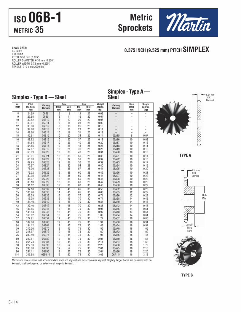
E-114
ISO 06B-1METRIC 35
E-114
Metric Sprockets
Simplex - Type B — SteelSimplex - Type A —Steel
No. Pitch Catalog Bore Hub Weight Catalog Bore Weight Teeth Diameter Number Stock Max. Dia. Thru Approx. Number Stock Approx. MM MM MM MM MM (kg) MM (kg)
8 24.89 06B8 8 9 13 22 0.03 – – – 9 27.85 06B9 8 11 16 22 0.04 – – – 10 30.82 06B10 8 12 20 22 0.06 – – – 11 33.81 06B11 8 14 23 25 0.09 – – – 12 36.80 06B12 8 16 26 25 0.10 – – – 13 39.80 06B13 10 18 29 25 0.11 – – – 14 42.80 06B14 10 19 31 25 0.12 – – – 15 45.81 06B15 10 20 34 25 0.14 06A15 8 0.07 16 48.82 06B16 10 22 37 25 0.18 06A16 10 0.08 17 51.84 06B17 10 25 40 28 0.20 06A17 10 0.18 18 54.85 06B18 10 25 43 28 0.23 06A18 10 0.11 19 57.87 06B19 10 28 46 28 0.25 06A19 10 0.12 20 60.89 06B20 10 30 49 28 0.31 06A20 10 0.13 21 63.91 06B21 12 30 50 28 0.36 06A21 10 0.14 22 66.93 06B22 12 32 51 28 0.37 06A22 10 0.15 23 69.95 06B23 12 32 52 28 0.39 06A23 10 0.17 24 72.97 06B24 12 32 54 28 0.40 06A24 10 0.19 25 76.00 06B25 12 35 57 28 0.41 06A25 10 0.20 26 79.02 06B26 12 38 60 28 0.42 06A26 10 0.21 27 82.05 06B27 12 38 60 28 0.44 06A27 10 0.22 28 85.07 06B28 12 38 60 28 0.45 06A28 10 0.23 29 88.10 06B29 12 38 60 28 0.47 06A29 10 0.25 30 91.12 06B30 12 38 60 30 0.48 06A30 10 0.27 32 97.18 06B32 14 40 65 30 0.56 06A32 12 0.20 35 106.26 06B35 14 40 65 30 0.68 06A35 12 0.27 36 109.29 06B36 16 45 70 30 0.71 06A36 12 0.28 38 115.35 06B38 16 45 70 30 0.77 06A38 14 0.43 40 121.40 06B40 16 45 70 30 0.81 06A40 14 0.45 42 127.46 06B42 16 45 70 30 0.85 06A42 14 0.48 45 136.55 06B45 16 45 75 30 0.91 06A45 14 0.51 48 145.64 06B48 16 45 75 30 0.97 06A48 14 0.54 54 163.82 06B54 16 45 75 30 1.09 06A54 14 0.61 57 172.91 06B57 19 45 75 30 1.27 06A57 18 0.86 60 182.00 06B60 19 45 75 30 1.34 06A60 18 0.91 64 194.12 06B64 19 45 75 30 1.43 06A64 18 0.97 70 212.30 06B70 19 45 75 30 1.56 06A70 18 1.06 72 218.37 06B72 19 45 75 30 1.60 06A72 18 1.09 76 230.49 06B76 19 45 75 30 1.91 06A76 18 1.45 80 242.61 06B80 19 45 75 30 2.01 06A80 18 1.53 84 254.74 06B84 19 45 75 30 2.11 06A84 18 1.60 90 272.93 06B90 19 52 75 30 2.26 06A90 18 1.72 95 288.08 06B95 19 52 75 30 2.61 06A95 18 2.18 96 291.11 06B96 19 52 75 30 2.64 06A96 18 2.20 114 345.68 06B114 19 52 75 30 3.63 06A114 18 3.13
0.375 INCH (9.525 mm) PITCH SIMPLEXCHAIN DATA:BS 228/3ISO 06B-1PITCH: 9.53 mm (0.375")ROLLER DIAMETER: 6.35 mm (0.250")ROLLER WIDTH: 5.72 mm (0.225")TENSILE: 910 kilos (2000 lbs.)
Maximum bores shown will accommodate standard keyseat and setscrew over keyseat. Slightly larger bores are possible with nokeyseat, shallow keyseat, or setscrew at angle to keyseat.
5.31 mm.209"Nominal
TYPE A
TYPE B
5.31 mm.209"Nominal
HubDia.
LengthThruBore
ISO 06B-1METRIC 35
MetricSprockets

E-115E-115
ISO O6B-1METRIC 35
MetricSprockets
0.375 INCH (9.525 mm) PITCH SIMPLEX
18 54.85 06BTB18H 1008 25.40 22.23 47.63 0.18 0.14 19 57.87 06BTB19H 1008 25.40 22.23 46.04 0.23 0.14 20 60.89 06BTB20H 1008 25.40 22.23 49.20 0.27 0.14 21 63.91 06BTB21H 1008 25.40 22.23 52.39 0.32 0.14 22 66.93 06BTB22H 1210 31.75 25.40 60.33 0.36 0.27 23 69.95 06BTB23H 1210 31.75 25.40 61.91 0.41 0.27 24 72.97 06BTB24H 1210 31.75 25.40 61.91 0.41 0.27 25 76.00 06BTB25H 1210 31.75 25.40 61.91 0.54 0.27 26 79.02 06BTB26H 1610 41.28 25.40 73.03* 0.50 0.41 28 85.07 06BTB28H 1610 41.28 25.40 73.03 0.54 0.41 30 91.12 06BTB30H 1610 41.28 25.40 79.38 0.54 0.41 32 97.18 06BTB32 1610 41.28 25.40 82.55 0.59 0.41 35 106.26 06BTB35 1610 41.28 25.40 82.55 0.64 0.41 36 109.29 06BTB36 1610 41.28 25.40 82.55 0.64 0.41 38 115.35 06BTB38 1610 41.28 25.40 82.55 0.68 0.41 40 121.40 06BTB40 1610 41.28 25.40 82.55 0.86 0.41 45 136.55 06BTB45 1610 41.28 25.40 82.55 0.95 0.41 48 145.65 06BTB48 1610 41.28 25.40 82.55 1.04 0.41 54 163.82 06BTB54 1610 41.28 25.40 82.55 1.18 0.41 57 172.91 06BTB57 1610 41.28 25.40 82.55 1.25 0.41 60 182.00 06BTB60 1610 41.28 25.40 82.55 1.36 0.41 70 212.30 06BTB70 1610 41.28 25.40 82.55 1.68 0.41 76 230.49 06BTB76 1610 41.28 25.40 82.55 1.82 0.41 95 288.08 06BTB95 1610 41.28 25.40 82.55 2.28 0.41
Pitch Bore Dimension Weight Approx. No. Diameter Catalog Bushing Max. L C Rim Bushing Teeth MM Number Number MM MM MM (kg) (kg)
Simplex- Taper Bushed — Steel
TYPE B
CHAIN DATA:BS 228/3ISO 06B-1PITCH: 9.53 mm (0.375")ROLLER DIAMETER: 6.35 mm (0.250")ROLLER WIDTH: 5.72 mm (0.225")TENSILE: 910 kilos (2000 lbs.)
5.31 mm.209"Nominal
Has recessed groove in hub for chain clearance.Sprockets with “H” suffix have hardened teeth.
C
LengthThruBore
ISO 06B-1METRIC 35
MetricSprockets

E-116
ISO 06B-2METRIC 35-2
E-116
Metric Sprockets
12 36.80 D06B12 10 16 25 25 0.16 13 39.79 D06B13 10 18 28 25 0.20 14 42.80 D06B14 10 18 31 25 0.25 15 45.81 D06B15 10 20 34 25 0.29 16 48.82 D06B16 12 20 37 30 0.34 17 51.83 D06B17 12 24 40 30 0.39 18 54.85 D06B18 12 25 43 30 0.45 19 57.87 D06B19 12 28 46 30 0.52 20 60.89 D06B20 12 30 49 30 0.59 21 63.91 D06B21 12 30 52 30 0.68 22 66.93 D06B22 12 35 55 30 0.75 23 69.95 D06B23 12 38 58 30 0.80 24 72.97 D06B24 12 39 61 30 0.84 25 76.00 D06B25 12 40 64 30 0.89 26 79.02 D06B26 12 42 67 30 0.91 27 82.05 D06B27 12 45 70 30 1.00 28 85.07 D06B28 12 48 73 30 1.07 29 88.10 D06B29 12 50 76 30 1.14 30 91.12 D06B30 12 52 80 30 1.22 32 98.18 D06B32 16 52 80 30 1.30 35 106.26 D06B35 16 52 80 30 1.42 36 109.29 D06B36 16 60 90 30 1.58 38 115.35 D06B38 16 60 90 30 1.72 40 121.40 D06B40 16 52 80 35 1.81 42 127.46 D06B42 19 60 90 35 2.05 45 136.55 D06B45 19 60 90 35 2.35 48 145.64 D06B48 19 60 90 35 2.75 52 157.75 D06B52 19 60 90 35 3.13 57 172.91 D06B57 19 60 90 35 3.47 60 182.00 D06B60 19 60 90 35 3.78 68 206.24 D06B68 19 60 90 35 4.43 70 212.30 D06B70 19 60 90 35 4.56 72 218.37 D06B72 19 60 90 35 4.89 76 230.49 D06B76 19 60 90 38 5.67 84 254.74 D06B84 19 60 90 38 7.10 95 288.08 D06B95 25 62 95 38 8.64 96 291.11 D06B96 25 62 95 38 8.75 114 345.68 D06B114 25 62 95 38 11.12
Pitch Bore Hub Weight No. Diameter Catalog Stock Max. Dia. Thru Approx. Teeth MM Number MM MM MM MM (kg)
Duplex - Type B — Steel
0.375 INCH (9.525 mm) PITCH DUPLEX WIDTH CHAIN
TYPE B
CHAIN DATA:BS 228/3ISO 06B-2PITCH: 9.53 mm (0.375")ROLLER DIAMETER: 6.35 mm (0.250")ROLLER WIDTH: 5.72 mm (0.225")TENSILE: 1730 kilos (3800 lbs.)
Maximum bores shown will accommodate standard keyseat and setscrew over keyseat. Slightly larger bores are possible with no keyseat, shallow keyseat, or setscrew at angle to keyseat.
5.2 mm.205"Nominal
15.44 mm.608"
HubDia.
LengthThruBore
ISO 06B-2METRIC 35-2
MetricSprockets

E-117E-117
ISO 06B-2METRIC 35-2
MetricSprockets
0.375 INCH (9.525 mm) PITCH DUPLEX WIDTH CHAINS
Duplex - Taper Bushed — Steel
TYPE B
CHAIN DATA:BS 228/3ISO 06B-2PITCH: 9.53 mm (0.375")ROLLER DIAMETER: 6.35 mm (0.250")ROLLER WIDTH: 5.72 mm (0.225")TENSILE: 1730 kilos (3800 lbs.)
19 57.87 D06BTB19 1008 25.40 22.23 46.43 0.6 0.14 20 60.89 D06BTB20 1008 25.40 22.23 49.20 0.8 0.14 21 63.91 D06BTB21 1008 25.40 22.23 52.39 1.4 0.14 22 66.93 D06BTB22 1008 25.40 22.23 55.56 1.7 0.14 24 72.97 D06BTB24 1210 31.75 25.40 61.91 1.8 0.27 25 76.00 D06BTB25 1210 31.75 25.40 61.91 1.9 0.27 26 79.02 D06BTB26 1210 31.75 25.40 66.68 2.0 0.27 30 91.12 D06BTB30 1610 41.28 25.40 79.38 1.8 0.41 32 97.18 D06BTB32 1610 41.28 25.40 82.55 2.0 0.41 35 106.26 D06BTB35 1610 41.28 25.40 82.55 2.3 0.41 38 115.34 D06BTB38 1610 41.28 25.40 82.55 2.5 0.41 40 121.40 D06BTB40 1610 41.28 25.40 82.55 2.9 0.41 45 136.55 D06BTB45 1610 41.28 25.40 82.55 3.2 0.41 48 145.65 D06BTB48 1610 41.28 25.40 92.08 3.5 0.41 54 163.82 D06BTB54 1610 41.28 25.40 92.08 3.9 0.41 57 172.91 D06BTB57 1610 41.28 25.40 92.08 4.1 0.41 60 182.00 D06BTB60 1610 41.28 25.40 92.08 4.9 0.41 70 212.30 D06BTB70 1610 41.28 25.40 92.08 6.3 0.41 76 230.49 D06BTB76 1610 41.28 25.40 92.08 6.8 0.41 95 288.08 D06BTB95 1610 41.28 25.40 92.08 6.9 0.41
Pitch Bore Dimension Weight Approx. No. Diameter Catalog Bushing Max. L C Rim Bushing Teeth MM Number Number MM MM MM (kg) (kg)
LengthThruBore
C
5.2 mm.205"Nominal
15.44 mm.608"
ISO 06B-2METRIC 35-2
MetricSprockets

E-118
ISO 06B-3METRIC 35-3
E-118
Metric Sprockets
0.375 INCH (9.525 mm) PITCH TRIPLEX
Triplex - Type B — Steel
CHAIN DATA:BS 228/3ISO 06B-3PITCH: 9.53 mm (0.375")ROLLER DIAMETER: 6.35 mm (0.250")ROLLER WIDTH: 5.72 mm (0.225")TENSILE: 2540 kilos (5600 lbs.)
TYPE B
5.2 mm.205"Nominal
25.7 mm1.011"
HubDia.
Length ThruBore
12 36.80 E06B12 12 16 25 35 0.23 13 39.80 E06B13 12 18 28 35 0.27 14 42.80 E06B14 12 18 31 35 0.32 15 45.81 E06B15 12 20 34 35 0.36 16 48.82 E06B16 12 20 37 35 0.45 17 51.84 E06B17 12 24 40 35 0.54 18 54.85 E06B18 12 25 43 35 0.64 19 57.87 E06B19 12 28 46 35 0.72 20 60.89 E06B20 12 30 49 35 0.77 21 63.91 E06B21 14 30 52 40 0.86 22 66.93 E06B22 14 35 54 40 0.95 23 69.95 E06B23 14 38 58 40 1.04 24 72.97 E06B24 14 39 61 40 1.18 25 76.00 E06B25 14 40 64 40 1.27 26 79.02 E06B26 14 42 67 40 1.31 27 82.05 E06B27 14 45 70 40 1.36 28 85.07 E06B28 14 48 73 40 1.50 29 88.10 E06B29 14 50 76 40 1.68 30 91.12 E06B30 14 52 80 40 1.72 32 97.18 E06B32 16 52 80 48 2.00 35 106.26 E06B35 16 52 80 48 2.25 36 109.29 E06B36 16 60 90 40 2.33 38 115.34 E06B38 16 60 90 40 2.49 40 121.40 E06B40 16 52 80 48 2.65 42 127.46 E06B42 19 60 90 48 2.81 45 136.55 E06B45 19 60 90 48 3.00 48 145.64 E06B48 19 60 90 48 3.20 52 157.75 E06B52 19 60 90 48 3.46 57 172.91 E06B57 19 60 90 48 4.77 60 182.00 E06B60 19 60 80 48 5.02 68 206.24 E06B68 19 60 90 48 5.69 72 218.37 E06B72 19 60 90 48 6.02 76 230.49 E06B76 19 64 100 48 8.48 84 254.74 E06B84 19 64 100 48 9.37 95 288.08 E06B95 25 64 100 54 13.61 96 291.11 E06B96 25 64 100 54 13.75 114 345.68 E06B114 25 64 100 54 17.48
Pitch Bore Hub Weight No. Diameter Catalog Stock Max. Dia. Thru Approx. Teeth MM Number MM MM MM MM (kg)
ISO 06B-3METRIC 35-3
MetricSprockets

E-119E-119
ISO 08B-1METRIC 40
MetricSprockets
0.500 INCH (12.70 mm) PITCH SIMPLEX CHAIN DATA:BS 228/7ISO 08B-1PITCH: 12.70 mm (0.500")ROLLER DIAMETER: 8.51 mm (0.335")ROLLER WIDTH: 7.75 mm (0.305")TENSILE: 1820 kilos (4000 lbs.)
Simplex - Type B — SteelSimplex - Type A —Steel
Maximum bores shown will accommodate standard keyseat and setscrew over keyseat. Slightly larger bores are possible with nokeyseat, shallow keyseat, or setscrew at angle to keyseat.
TYPE A
TYPE B
7.37 mm.290"Nominal
7.37 mm.290"Nominal
HubDia.
LengthThru Bore
No. Pitch Catalog Bore Hub Weight Catalog Bore Weight Teeth Diameter Number Stock Max. Dia. Thru Approx. Number Stock Approx. MM MM MM MM MM (kg) MM (kg)
9 37.13 08B9 10 15 21 25 0.14 – – – 10 41.10 08B10 10 20 26 25 0.15 – – – 11 45.08 08B11 10 22 30 25 0.17 – – – 12 49.07 08B12 10 22 34 28 0.24 08A12 10 0.08 13 53.07 08B13 10 25 38 28 0.25 08A13 10 0.10 14 57.07 08B14 10 28 42 28 0.31 08A14 10 0.12 15 61.08 08B15 10 30 46 28 0.33 08A15 10 0.14 16 65.10 08B16 12 32 50 28 0.37 08A16 10 0.15 17 69.12 08B17 12 35 54 28 0.51 08A17 10 0.16 18 73.14 08B18 12 38 57 28 0.54 08A18 10 0.20 19 77.16 08B19 12 40 64 28 0.65 08A19 10 0.21 20 81.18 08B20 12 42 67 28 0.76 08A20 10 0.25 21 85.21 08B21 12 45 70 28 0.82 08A21 12 0.26 22 89.24 08B22 12 48 73 28 0.88 08A22 12 0.30 23 93.27 08B23 12 51 78 28 1.05 08A23 12 0.33 24 97.30 08B24 14 53 82 28 1.05 08A24 12 0.37 25 101.33 08B25 14 53 82 28 1.13 08A25 12 0.40 26 105.36 08B26 16 53 82 30 1.15 08A26 16 0.43 27 109.40 08B27 16 53 82 30 1.19 08A27 16 0.44 28 113.43 08B28 16 53 82 30 1.30 08A28 16 0.50 29 117.46 08B29 16 53 82 30 1.33 08A29 16 0.55 30 121.50 08B30 16 53 89 30 1.36 08A30 15 0.57 31 125.53 08B31 16 60 89 30 1.41 08A31 15 0.64 32 129.57 08B32 16 60 89 30 1.46 08A32 15 0.67 33 133.61 08B33 16 60 89 30 1.51 08A33 15 0.71 34 137.64 08B34 16 60 89 30 1.56 08A34 15 0.74 35 141.68 08B35 16 60 89 30 1.61 08A35 15 0.77 36 145.72 08B36 16 60 89 35 1.69 08A36 15 0.83 37 149.75 08B37 16 60 89 35 1.74 08A37 15 0.87 38 153.79 08B38 16 60 89 35 1.78 08A38 15 0.91 39 157.83 08B39 19 60 89 35 1.83 08A39 18 0.92 40 161.87 08B40 19 60 89 35 1.88 08A40 18 1.01 42 169.94 08B42 19 60 89 35 1.97 08A42 18 1.13 45 182.06 08B45 19 60 89 35 2.11 08A45 18 1.43 48 194.18 08B48 19 64 100 35 2.76 08A48 18 1.46 54 218.42 08B54 19 64 100 35 3.11 08A54 18 2.01 57 230.54 08B57 19 64 100 35 3.28 08A57 18 2.27 60 242.66 08B60 19 64 100 35 3.45 08A60 18 2.03 64 258.83 08B64 19 64 100 35 3.68 08A64 18 2.17 70 283.07 08B70 19 64 100 35 4.02 08A70 18 3.28 72 291.15 08B72 19 64 100 35 4.13 08A72 18 3.51 76 307.32 08B76 19 64 100 35 5.73 08A76 18 3.70 80 323.49 08B80 19 64 100 35 6.03 08A80 18 4.63 84 339.65 08B84 19 64 100 35 6.33 08A84 18 4.57 95 384.11 08B95 25 64 100 35 8.90 08A95 24 5.45 96 388.15 08B96 25 64 100 35 8.99 08A96 24 5.51 114 460.91 08B114 25 64 100 35 11.17 08A114 24 6.54
ISO 08B-1METRIC 40
MetricSprockets

E-120
ISO 08B-1METRIC 40
E-120
Metric Sprockets
0.500 INCH (12.70 mm) PITCH SIMPLEX
Simplex - Taper Bushed — Steel
TYPE B
CHAIN DATA:BS 228/7ISO 08B-1PITCH: 12.70 mm (0.500")ROLLER DIAMETER: 8.51 mm (0.335")ROLLER WIDTH: 7.75 mm (0.305")TENSILE: 1820 kilos (4000 lbs.)
Has recessed groove in hub for chain clearance.Sprockets with “H” suffix have hardened teeth.
7.37 mm.290"Nominal
14 57.07 08BTB14H 1008 25.40 22.23 46 0.18 0.14 15 61.08 08BTB15H 1008 25.40 22.23 46 0.18 0.14 16 65.10 08BTB16H 1008 25.40 22.23 46 0.23 0.14 17 69.12 08BTB17H 1210 31.75 25.40 60 0.23 0.14 18 73.14 08BTB18H 1210 31.75 25.40 62 0.27 0.27 19 77.16 08BTB19H 1210 31.75 25.40 62 0.32 0.27 20 81.18 08BTB20H 1610 41.28 25.40 70 0.41 0.41 21 85.21 08BTB21H 1610 41.28 25.40 70 0.45 0.41 22 89.24 08BTB22H 1610 41.28 25.40 70 0.50 0.41 23 93.27 08BTB23H 1610 41.28 25.40 76 0.59 0.41 24 97.30 08BTB24H 1610 41.28 25.40 82 0.73 0.41 25 101.33 08BTB25H 1610 41.28 25.40 82 0.73 0.41 26 105.36 08BTB26H 1610 41.28 25.40 82 0.73 0.41 27 109.40 08BTB27H 1610 41.28 25.40 76 0.70 0.41 28 113.43 08BTB28H 1610 41.28 25.40 76 0.73 0.41 29 117.46 08BTB29H 1610 41.28 25.40 76 0.76 0.41 30 121.50 08BTB30H 1610 41.28 25.40 73 0.82 0.41 32 129.57 08BTB32 1610 41.28 25.40 76 0.87 0.41 35 141.68 08BTB35 1610 41.28 25.40 76 0.96 0.41 36 145.72 08BTB36 1610 41.28 25.40 76 0.98 0.41 38 153.79 08BTB38 1610 41.28 25.40 76 1.23 0.41 40 161.87 08BTB40 1610 41.28 25.40 76 1.29 0.41 42 169.94 08BTB42 1610 41.28 25.40 76 1.36 0.41 45 182.06 08BTB45 1610 41.28 25.40 76 1.46 0.41 48 194.18 08BTB48 1610 41.28 25.40 76 1.55 0.41 54 218.42 08BTB54 1610 41.28 25.40 76 1.75 0.41 57 230.54 08BTB57 1610 41.28 25.40 76 2.63 0.41 60 242.66 08BTB60 1610 41.28 25.40 76 2.77 0.41 70 283.07 08BTB70 2012 50.80 31.75 90 3.93 0.41 72 291.15 08BTB72 2012 50.80 31.75 90 4.05 0.41 76 307.32 08BTB76 2012 50.80 31.75 90 4.27 0.77 80 323.49 08BTB80 2012 50.80 31.75 90 4.49 0.77 84 339.65 08BTB84 2012 50.80 31.75 90 4.72 0.77 95 384.11 08BTB95 2012 50.80 31.75 90 6.81 0.77 96 388.15 08BTB96 2012 50.80 31.75 90 6.88 0.77 114 460.91 08BTB114 2517 63.50 44.45 108 10.44 0.77
Pitch Bore Dimension Weight Approx. No. Diameter Catalog Bushing Max. L C Rim Bushing Teeth MM Number Number MM MM MM (kg) (kg)
C
L
ISO 08B-1METRIC 40
MetricSprockets
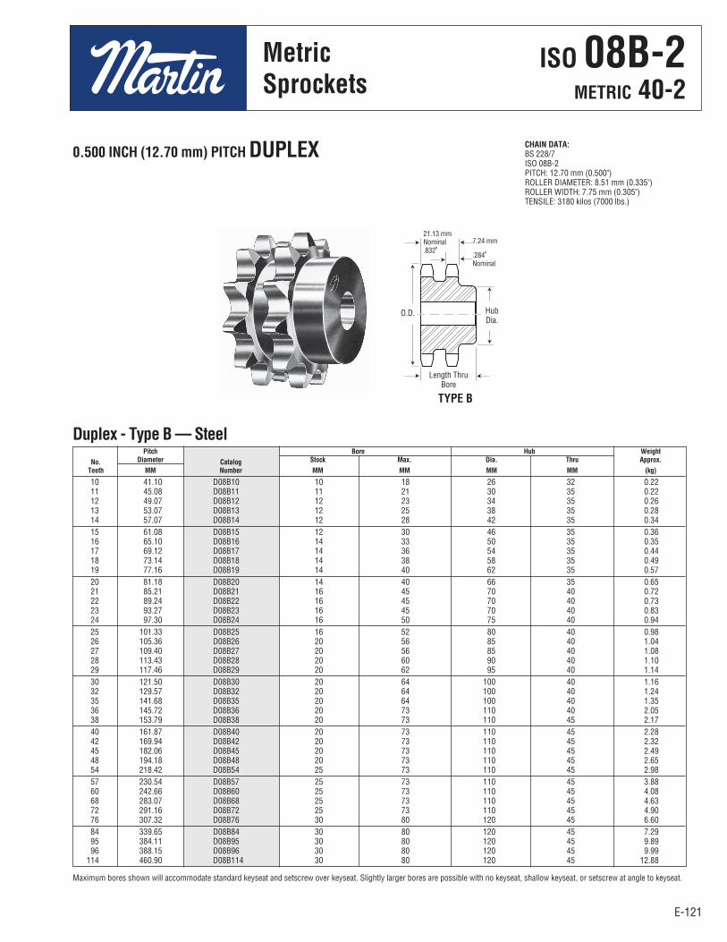
E-121E-121
ISO 08B-2METRIC 40-2
MetricSprockets
0.500 INCH (12.70 mm) PITCH DUPLEX
Duplex - Type B — Steel
CHAIN DATA:BS 228/7ISO 08B-2PITCH: 12.70 mm (0.500")ROLLER DIAMETER: 8.51 mm (0.335")ROLLER WIDTH: 7.75 mm (0.305")TENSILE: 3180 kilos (7000 lbs.)
Maximum bores shown will accommodate standard keyseat and setscrew over keyseat. Slightly larger bores are possible with no keyseat, shallow keyseat, or setscrew at angle to keyseat.
7.24 mm
.284"Nominal
21.13 mmNominal.832"
TYPE B
HubDia.
Length ThruBore
10 41.10 D08B10 10 18 26 32 0.22 11 45.08 D08B11 11 21 30 35 0.22 12 49.07 D08B12 12 23 34 35 0.26 13 53.07 D08B13 12 25 38 35 0.28 14 57.07 D08B14 12 28 42 35 0.34 15 61.08 D08B15 12 30 46 35 0.36 16 65.10 D08B16 14 33 50 35 0.35 17 69.12 D08B17 14 36 54 35 0.44 18 73.14 D08B18 14 38 58 35 0.49 19 77.16 D08B19 14 40 62 35 0.57 20 81.18 D08B20 14 40 66 35 0.65 21 85.21 D08B21 16 45 70 40 0.72 22 89.24 D08B22 16 45 70 40 0.73 23 93.27 D08B23 16 45 70 40 0.83 24 97.30 D08B24 16 50 75 40 0.94 25 101.33 D08B25 16 52 80 40 0.98 26 105.36 D08B26 20 56 85 40 1.04 27 109.40 D08B27 20 56 85 40 1.08 28 113.43 D08B28 20 60 90 40 1.10 29 117.46 D08B29 20 62 95 40 1.14 30 121.50 D08B30 20 64 100 40 1.16 32 129.57 D08B32 20 64 100 40 1.24 35 141.68 D08B35 20 64 100 40 1.35 36 145.72 D08B36 20 73 110 40 2.05 38 153.79 D08B38 20 73 110 45 2.17 40 161.87 D08B40 20 73 110 45 2.28 42 169.94 D08B42 20 73 110 45 2.32 45 182.06 D08B45 20 73 110 45 2.49 48 194.18 D08B48 20 73 110 45 2.65 54 218.42 D08B54 25 73 110 45 2.98 57 230.54 D08B57 25 73 110 45 3.88 60 242.66 D08B60 25 73 110 45 4.08 68 283.07 D08B68 25 73 110 45 4.63 72 291.16 D08B72 25 73 110 45 4.90 76 307.32 D08B76 30 80 120 45 6.60 84 339.65 D08B84 30 80 120 45 7.29 95 384.11 D08B95 30 80 120 45 9.89 96 388.15 D08B96 30 80 120 45 9.99 114 460.90 D08B114 30 80 120 45 12.88
Pitch Bore Hub Weight No. Diameter Catalog Stock Max. Dia. Thru Approx. Teeth MM Number MM MM MM MM (kg)
O.D.
ISO 08B-2METRIC 40-2
MetricSprockets

E-122
ISO 08B-2METRIC 40-2
E-122
Metric Sprockets
15 61.08 D08ATB15 1008 25.40 22.22 – 0.18 0.13 16 65.10 D08ATB16 1008 25.40 22.22 – 0.22 0.13 17 69.12 D08ATB17 1008 25.40 22.22 – 0.27 0.13 18 73.14 D08BTB18 1210 31.75 25.40 58 0.27 0.27 19 77.16 D08BTB19 1210 31.75 25.40 63 0.36 0.27 20 81.18 D08BTB20 1610 41.27 25.40 70 0.37 0.41 21 85.21 D08BTB21 1610 41.27 25.40 70 0.46 0.41 22 89.24 D08BTB22 1610 41.27 25.40 74 0.55 0.41 23 93.27 D08BTB23 1610 41.27 25.40 78 0.59 0.41 24 97.30 D08BTB24 2012 41.27 25.40 83 0.70 0.41 25 101.33 D08BTB25 2012 50.80 31.75 87 0.77 0.77 26 105.36 D08BTB26 2012 50.80 31.75 87 0.80 0.77 28 113.43 D08BTB28 2012 50.80 31.75 99 1.06 0.77 30 121.50 D08BTB30 2012 50.80 31.75 108 1.59 0.77 35 141.68 D08BTB35 2012 50.80 31.75 108 1.86 0.77 36 145.72 D08BTB36 2012 50.80 31.75 108 1.91 0.77 38 153.79 D08BTB38 2012 50.80 31.75 108 3.18 0.77 42 169.94 D08CTB42 2517 50.80 44.45 108 5.57 1.59 45 182.06 D08CTB45 2517 63.50 44.45 108 5.97 1.59 48 194.18 D08CTB48 2517 63.50 44.45 108 6.37 1.59 54 218.42 D08CTB54 2517 63.50 44.45 108 7.17 1.59 57 230.54 D08CTB57 2517 63.50 44.45 108 7.56 1.59 60 242.66 D08CTB60 2517 63.50 44.45 108 12.05 1.59 68 274.99 D08CTB68 2517 63.50 44.45 108 13.66 1.59 70 283.07 D08CTB70 2517 63.50 44.45 108 14.06 1.59 72 291.15 D08CTB72 2517 63.50 44.45 108 14.46 1.59 76 307.32 D08CTB76 2517 63.50 44.45 108 15.26 1.59 84 339.65 D08CTB84 2517 63.50 44.45 108 16.87 1.59 95 384.11 D08CTB95 2517 63.50 44.45 108 19.08 1.59 96 388.15 D08CTB96 2517 63.50 44.45 108 19.28 1.59 114 460.91 D08CTB114 2517 63.50 44.45 108 22.90 1.59
0.500 INCH (12.70 mm) PITCH DUPLEX
Duplex - Taper Bushed — Steel
TYPE B TYPE C
CHAIN DATA:BS 228/7ISO 08B-2PITCH: 12.70 mm (0.500")ROLLER DIAMETER: 8.51 mm(0.335")ROLLER WIDTH: 7.75 mm (0.305")TENSILE: 3180 kilos (7000 lbs.) 21.13 mm
Nominal.832"
21.13 mmNominal.832"
Pitch Bore Dimension Weight No. Diameter Catalog Bushing Max. L C Rim Bushing Teeth MM Number Number MM MM MM (kg) (kg)
C
L L
C
21.13 mmNominal.832"
L
TYPE A
C
ISO 08B-2METRIC 40-2
MetricSprockets
Related Documents