Uncontrolled Copy when printed or downloaded. Please refer to the 4D Systems website for the latest Revision of this document www.4dsystems.com.au DATASHEET Internet of Displays Series IoD-09TH 0.9” Through Hole version IoD-09SM 0.9” Surface Mount version Document Date: 28 th September 2017 Document Revision: 1.0

Welcome message from author
This document is posted to help you gain knowledge. Please leave a comment to let me know what you think about it! Share it to your friends and learn new things together.
Transcript

Uncontrolled Copy when printed or downloaded. Please refer to the 4D Systems website for the latest Revision of this document
www.4dsystems.com.au
DATA
SH
EET
Internet of Displays Series
IoD-09TH 0.9” Through Hole version
IoD-09SM 0.9” Surface Mount version
Document Date: 28th September 2017
Document Revision: 1.0
IoD Display Module Series IoD-09TH/SM
© 2017 4D SYSTEMS Page 2 of 22 www.4dsystems.com.au
Contents
Description ...................................................................................................................4
Features .......................................................................................................................4
Hardware Overview (IoD-09TH) ....................................................................................5
Hardware Overview (IoD-09SM) ....................................................................................6
Hardware Description ...................................................................................................7
Mounting the Hardware ................................................................................................ 7
Hardware Interface - Pins ..............................................................................................8
Serial Port – TTL Level Serial .......................................................................................... 8
System Pins .................................................................................................................... 8
SPI .................................................................................................................................. 9
I2C .................................................................................................................................. 9
1–Wire ........................................................................................................................... 9
ESP8266 SoC .................................................................................................................9
SD/SDHC Memory Cards ...............................................................................................9
Display/Module Precautions ....................................................................................... 10
Hardware Tools .......................................................................................................... 10
4D-UPA Universal Programmer ..................................................................................... 10
Programming the IoD .................................................................................................. 11
Arduino IDE .................................................................................................................... 11
4D Systems - Workshop 4 IDE ........................................................................................ 12
Starter Kit ................................................................................................................... 13
Display Module Part Numbers ..................................................................................... 13
Mechanical Details – IoD-09-TH ................................................................................... 14
Mechanical Details – IoD-09-SM .................................................................................. 15
Mechanical Details – 4D-UPA Programmer .................................................................. 16
Schematic Details – IoD-09 Display Module ................................................................. 17
Schematic Details – 4D-UPA Programming Module ...................................................... 18
Specifications ............................................................................................................. 19
IoD Display Module Series IoD-09TH/SM
© 2017 4D SYSTEMS Page 3 of 22 www.4dsystems.com.au
Hardware Revision History .......................................................................................... 21
Datasheet Revision History ......................................................................................... 21
Legal Notice ................................................................................................................ 22
Contact Information ................................................................................................... 22
IoD Display Module Series IoD-09TH/SM
© 2017 4D SYSTEMS Page 4 of 22 www.4dsystems.com.au
Description The IoD-09 (Internet of Displays) series is a range of miniature display modules Designed and Manufactured by 4D Systems. The IoD-09 modules features a full colour 0.9” TFT LCD display. They are powered by the WiFi enabled ESP8266, which offers an array of functionality and options for any Designer / Integrator / User. The IoD-09 modules can be easily programmed using 4D Systems Workshop4 or the Arduino IDE installed with the ESP8266 core. The feature rich 4D Systems GFX4dIoD09 library enables speedy development of applications by providing extensive primitive graphics functions, enhanced graphics via Workshop4, SD card access, and much more, all integrated into a single library. The on-board SD card socket enables the use of FAT16 or FAT32 formatted cards for extensive storage capabilities. The IoD-09 modules feature 12 pads, 6 on each end, for easy and simple connection to an application or mother board, or for connecting to accessory boards for a range of functionality advancements. The IoD-09TH features Through Hole (TH) pads with male pin headers mounted, and the IoD-09SM features Surface Mount (SM) pads. This range of modules has been designed to minimise the impact of display related circuitry, and provide a platform suitable for integration into a product. The IoD-09 modules can act as master or slave devices, they can be effortless connected to the internet, can display a raft information and graphics, along with the capability to communicate to SPI, I2C, and/or 1-wire devices, as well as having general GPIO for digital control/input. More information on the Espressif ESP8266 SoC can be found on the Espressif website http://espressif.com, and from the ESP8266EX SoC datasheet itself: http://www.espressif.com/sites/default/files/documentation/0a-esp8266ex_datasheet_en.pdf NOTE: The IoD-09TH module is recommended for all applications, whereas the IoD-09SM module is designed for integrators, due to the nature of its Surface Mount pads. The IoD-09TH is easily programmed with the 4D-UPA, and should be the module of choice for most applications.
Features
• Powerful Intelligent LCD-TFT display module powered by the Espressif ESP8266 SoC.
• 80 x 160 Resolution, full colour TFT Screen
• Built in WiFi suitable for ‘Internet of things’ applications.
• 802.11 b/g/n/e/i support
• Integrated TCP/IP protocol stack
• WiFi 2.4 GHz, supporting WPA/WPA2 and WEP/TKIP/AES, along with STA/AP/STA+AP/P2P operation modes
• 4Mbit (512kb) of Flash memory for User Application Code and Data.
• 128Kb of SRAM of which 80kb is available for the User.
• 12pin/pad connection, for all signals, power, communications and programming.
• On-board push/pull type microSD memory card connector for multimedia storage and data logging purposes.
• DOS compatible file access (FAT16 or FAT32 format).
• Display full colour images, animations, and icons.
• 4.0V to 5.5V range operation (single supply). A 1Amp+ supply is highly recommended for stability.
• Module dimensions: (TH version) 31.8 x 16.4 x 11.7mm. (SM version) 37.0 x 16.4 x 5.9mm.
• Weighing: ~5 g (TH), ~5 g (SM)
• RoHS, REACH and CE compliant.
NOTE: Arduino is a trademark of Arduino Team, and all references to the word “Arduino” or use of its logo/marks are strictly in reference to the Arduino product, and how this product is compatible with the aspect of the product but is not associated with the Arduino Team in anyway. ESP8266 / ESP8266EX are products made by Espressif. 4D Systems is not associated with Espressif in anyway, other than utilising their product inside of ours.

IoD Display Module Series IoD-09TH/SM
© 2017 4D SYSTEMS Page 5 of 22 www.4dsystems.com.au
Hardware Overview (IoD-09TH)
I = Input, O = Output, P = Power
PINOUT Pin Symbol I/O Description
1 GND P Supply Ground.
2 RX I Asynchronous Serial Receive pin, TTL level. Connect this pin to the Transmit (Tx) signal of other serial devices. Used in conjunction with the TX pin for programming this module. This pin is tolerant up to 3.3V levels.
3 TX O Asynchronous Serial Transmit pin, TTL level. Connect this pin to the Receive (Rx) signal of other serial devices. Used in conjunction with the RX pin for programming this module. This pin outputs 3.3V levels.
4 RESET I Master Reset signal. Internally pulled up to 3.3V via a 10K resistor. An active Low pulse greater than 2 micro-seconds will reset the module. If the module needs to be reset externally, only use open collector type circuits. This pin is not driven low by any internal conditions. The host should control this pin via one of its port pins using an open collector/drain arrangement.
5 5V P Main Voltage Supply +ve input pin. Range is 4.0V to 5.5V, nominal 5.0V.
6 GND P Supply Ground.
7 GPIO16 I/O I/O pin. Can be used as digital input or output. Can also be used for PWM and 1-wire device interfacing. This pin is available to the user. This pin is tolerant up to 3.3v levels.
8 GPIO12 I/O This pin is the MISO pin used on the SPI Bus. This pin is tolerant up to 3.3v levels.
9 GPIO14 I/O This pin is the SCK pin used on the SPI Bus. This pin is tolerant up to 3.3v levels.
10 GPIO0 I/O I/O pin. This pin is also used for flash programming. This pin is tolerant up to 3.3v levels. This pin can be used for I2C communications. NOTE: Special Pin
11 GPIO13 I/O This pin is the MOSI pin used on the SPI Bus. This pin is tolerant up to 3.3v levels.
12 GPIO2 I/O I/O pin. This pin is also used for boot selection. This pin is tolerant up to 3.3v levels. This pin can be used for I2C communications. NOTE: Special Pin.
microSD Socket
USER I/O – 2x 6way headers 2.54mm (0.1”) pitch
Ceramic chip antenna
4Mbit Flash Memory for the ESP8266
ESP8266 SoC
0.9” TFT LCD
IoD Display Module Series IoD-09TH/SM
© 2017 4D SYSTEMS Page 6 of 22 www.4dsystems.com.au
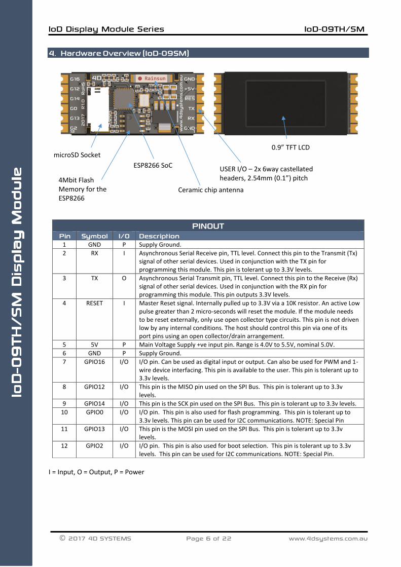
Hardware Overview (IoD-09SM)
I = Input, O = Output, P = Power
PINOUT Pin Symbol I/O Description
1 GND P Supply Ground.
2 RX I Asynchronous Serial Receive pin, TTL level. Connect this pin to the Transmit (Tx) signal of other serial devices. Used in conjunction with the TX pin for programming this module. This pin is tolerant up to 3.3V levels.
3 TX O Asynchronous Serial Transmit pin, TTL level. Connect this pin to the Receive (Rx) signal of other serial devices. Used in conjunction with the RX pin for programming this module. This pin outputs 3.3V levels.
4 RESET I Master Reset signal. Internally pulled up to 3.3V via a 10K resistor. An active Low pulse greater than 2 micro-seconds will reset the module. If the module needs to be reset externally, only use open collector type circuits. This pin is not driven low by any internal conditions. The host should control this pin via one of its port pins using an open collector/drain arrangement.
5 5V P Main Voltage Supply +ve input pin. Range is 4.0V to 5.5V, nominal 5.0V.
6 GND P Supply Ground.
7 GPIO16 I/O I/O pin. Can be used as digital input or output. Can also be used for PWM and 1-wire device interfacing. This pin is available to the user. This pin is tolerant up to 3.3v levels.
8 GPIO12 I/O This pin is the MISO pin used on the SPI Bus. This pin is tolerant up to 3.3v levels.
9 GPIO14 I/O This pin is the SCK pin used on the SPI Bus. This pin is tolerant up to 3.3v levels.
10 GPIO0 I/O I/O pin. This pin is also used for flash programming. This pin is tolerant up to 3.3v levels. This pin can be used for I2C communications. NOTE: Special Pin
11 GPIO13 I/O This pin is the MOSI pin used on the SPI Bus. This pin is tolerant up to 3.3v levels.
12 GPIO2 I/O I/O pin. This pin is also used for boot selection. This pin is tolerant up to 3.3v levels. This pin can be used for I2C communications. NOTE: Special Pin.
microSD Socket
USER I/O – 2x 6way castellated headers, 2.54mm (0.1”) pitch
Ceramic chip antenna
4Mbit Flash Memory for the ESP8266
ESP8266 SoC
0.9” TFT LCD
IoD Display Module Series IoD-09TH/SM
© 2017 4D SYSTEMS Page 7 of 22 www.4dsystems.com.au
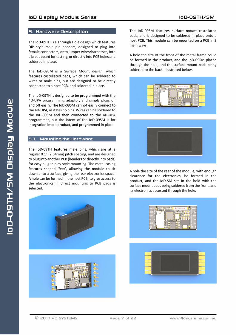
Hardware Description The IoD-09TH is a Through Hole design which features DIP style male pin headers, designed to plug into female connectors, onto jumper wires/harnesses, into a breadboard for testing, or directly into PCB holes and soldered in place. The IoD-09SM is a Surface Mount design, which features castellated pads, which can be soldered to wires or male pins, but are designed to be directly connected to a host PCB, and soldered in place. The IoD-09TH is designed to be programmed with the 4D-UPA programming adaptor, and simply plugs on and off easily. The IoD-09SM cannot easily connect to the 4D-UPA, as it has no pins. Wires can be soldered to the IoD-09SM and then connected to the 4D-UPA programmer, but the intent of the IoD-09SM is for integration into a product, and programmed in place.
Mounting the Hardware The IoD-09TH features male pins, which are at a regular 0.1” (2.54mm) pitch spacing, and are designed to plug into another PCB (headers or directly into pads) for easy plug ’n play style mounting. The metal casing features shaped ‘feet’, allowing the module to sit down onto a surface, giving the rear electronics space. A hole can be formed in the host PCB, to give access to the electronics, if direct mounting to PCB pads is selected.
The IoD-09SM features surface mount castellated pads, and is designed to be soldered in place onto a host PCB. This module can be mounted on a PCB in 2 main ways. A hole the size of the front of the metal frame could be formed in the product, and the IoD-09SM placed through the hole, and the surface mount pads being soldered to the back. Illustrated below.
A hole the size of the rear of the module, with enough clearance for the electronics, be formed in the product, and the IoD-SM sits in the hold with the surface mount pads being soldered from the front, and its electronics accessed through the hole.
IoD Display Module Series IoD-09TH/SM
© 2017 4D SYSTEMS Page 8 of 22 www.4dsystems.com.au
Hardware Interface - Pins This section describes in detail the hardware interface pins of the device.
Serial Port – TTL Level Serial
The ESP8266 Processor has a hardware asynchronous serial ports that can be accessed via the headers on the IoD-09 module. The serial port can be used to communicate with external serial devices.
The primary features are:
• Full-Duplex 8 bit data transmission and reception.
• Data format: 8 bits, No Parity, 1 Stop bit.
• Independent Baud rates from 300 baud up to 921600 baud.
• Single byte transmits and receives or a fully buffered service. The buffered service feature runs in the background capturing and buffering serial data without the user application having to constantly poll any of the serial ports. This frees up the application to service other tasks.
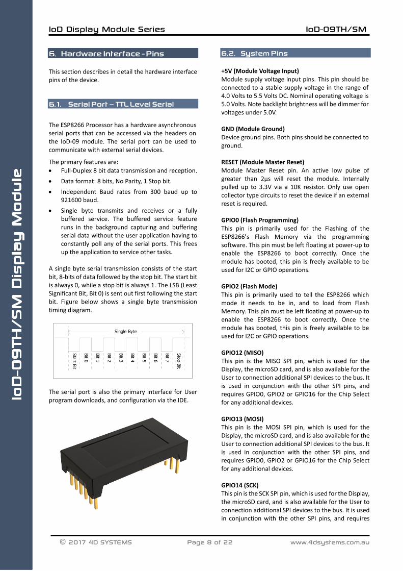
A single byte serial transmission consists of the start bit, 8-bits of data followed by the stop bit. The start bit is always 0, while a stop bit is always 1. The LSB (Least Significant Bit, Bit 0) is sent out first following the start bit. Figure below shows a single byte transmission timing diagram.
The serial port is also the primary interface for User program downloads, and configuration via the IDE.
System Pins +5V (Module Voltage Input) Module supply voltage input pins. This pin should be connected to a stable supply voltage in the range of 4.0 Volts to 5.5 Volts DC. Nominal operating voltage is 5.0 Volts. Note backlight brightness will be dimmer for voltages under 5.0V. GND (Module Ground) Device ground pins. Both pins should be connected to ground. RESET (Module Master Reset) Module Master Reset pin. An active low pulse of greater than 2μs will reset the module. Internally pulled up to 3.3V via a 10K resistor. Only use open collector type circuits to reset the device if an external reset is required. GPIO0 (Flash Programming) This pin is primarily used for the Flashing of the ESP8266’s Flash Memory via the programming software. This pin must be left floating at power-up to enable the ESP8266 to boot correctly. Once the module has booted, this pin is freely available to be used for I2C or GPIO operations. GPIO2 (Flash Mode) This pin is primarily used to tell the ESP8266 which mode it needs to be in, and to load from Flash Memory. This pin must be left floating at power-up to enable the ESP8266 to boot correctly. Once the module has booted, this pin is freely available to be used for I2C or GPIO operations. GPIO12 (MISO) This pin is the MISO SPI pin, which is used for the Display, the microSD card, and is also available for the User to connection additional SPI devices to the bus. It is used in conjunction with the other SPI pins, and requires GPIO0, GPIO2 or GPIO16 for the Chip Select for any additional devices. GPIO13 (MOSI) This pin is the MOSI SPI pin, which is used for the Display, the microSD card, and is also available for the User to connection additional SPI devices to the bus. It is used in conjunction with the other SPI pins, and requires GPIO0, GPIO2 or GPIO16 for the Chip Select for any additional devices. GPIO14 (SCK) This pin is the SCK SPI pin, which is used for the Display, the microSD card, and is also available for the User to connection additional SPI devices to the bus. It is used in conjunction with the other SPI pins, and requires

IoD Display Module Series IoD-09TH/SM
© 2017 4D SYSTEMS Page 9 of 22 www.4dsystems.com.au
GPIO0, GPIO2 or GPIO16 for the Chip Select for any additional devices. GPIO16 (User GPIO) Input/Output available to the user. This pin can be used as a digital input or digital output to connect to sensors, relays etc. This pin can also be used for ‘1-wire’ protocol devices and as a PWM output, or it can be used as the Chip Select for the SPI bus.
SPI There is 1 hardware SPI channel (HWSPI) which is used to drive the screen, and the SD card. The SPI channel is capable to communicate at speeds up to 80Mhz. The SPI channel is Master only, and can be used by the User for additional SPI devices, however is shared with the Display and the SD Card. An additional GPIO is required for each additional SPI device to be added to the bus, to act as Chip Select. When communications to the Display are taking place, the SPI bus must not exceed 39Mhz, due to this being the maximum stable speed it can operate. When communications to the SD card are taking place, the SPI bus must not exceed 30Mhz, due to this being the maximum stable speed it can operate. This may need to be reduced further depending on the capabilities of the SD card being used. This is configurable in the GFX4dIoD09 library.
Note: The SPI channel (HWSPI) is dedicated to memory card, and screen. The HWSPI channel cannot be reconfigured for alternate uses, as Display and SD card would then be inoperable.
I2C I2C is available on the IoD-09, using GPIO0 and GPIO2. Take note however that these pins must be left to be pulled high during startup, in order for the ESP8266 to boot correctly. Pull up resistors are present on the IoD-09 so it boots correctly, which is also required for I2C. The IoD-09 is compatible with 100kbit/s and 400kbit/s bus speeds, (higher may be possible, refer ESP8266 documentation). The TX and RX serial UART pins on the IoD-09 (ESP8266) are also compatible with I2C, if these are desired to be used instead. No pull-up resistors are built in to the IoD-09 for these pins.
1–Wire 1-Wire communications are available on GPIO0, GPIO2 or GPIO16, for communicating with Delas 1-wire
compatible devices. A library for the IoD-09 has been created to aid using this communication bus type.
ESP8266 SoC The module is designed around the ESP8266 SoC from Espressif. The ESP8266 is a 32bit RISC Microcontroller with built in WiFi controller, and GPIO capability, however some GPIO are utilised for on board features, such as the TFT LCD and microSD card. The TFT-LCD display interfaces to the ESP8266 using SPI, along with the microSD card. This enables high speed transfers for these peripherals, providing fast graphics and fast SD card access. Powerful graphics, text, image, animation, internet access and countless more features are available to the user via the 4D Systems GFX4dIoD09 library and 4D Systems Workshop 4 IDE. Alternatively, the Arduino IDE can be used, and the User is able to write drivers/software for the module as they require.
SD/SDHC Memory Cards The IoD-09 module supports microSD memory cards via the on-board micro-SD connector. The memory card is used for all multimedia file retrieval such as images, animations and data files. The memory card can also be used as general-purpose storage for data logging applications. Support is available for off-the-shelf high capacity HC memory cards (4GB and above). Memory cards up to 32GB is size can be used, as FAT16 or FAT32, however it must be noted that only a portion of this can be utilised by the FAT16 file system.
IoD Display Module Series IoD-09TH/SM
© 2017 4D SYSTEMS Page 10 of 22 www.4dsystems.com.au
Display/Module Precautions
• Avoid having to display the same image/object on the screen for lengthy periods of time. This can cause a burn-in which is a common problem with all types of display technologies. Implement a screen saver feature if possible, to prevent this from occurring, or considerably slow the process. LCD’s suffer considerably less than OLED displays, however it is still recommended to implement a screen saver if possible.
• Moisture and water can damage the display. If water is to enter the display either from the front or from the rear, or come in contact with the PCB, damage will certainly occur. Wipe off any moisture gently or let the display dry before usage. If using this display module in an environment where it can get wet, ensure an appropriate enclosure is used.
• Dirt from fingerprint oil and fat can easily stain the surface of the display. Gently wipe off any stains with a soft lint-free cloth.
• The performance of the display will degrade under elevated temperature and humidity. Avoid such conditions when storing.
• Displays are susceptible to mechanical shock and any force exerted on the module may result in deformed zebra stripes, a cracked display cell and broken backlight
• Display modules have a finite life, which is typically dictated by the display itself, more specifically the backlight. The backlight contains LED’s, which fade over time. In the Specifications section is a figure for the typical life of the display, and the criteria are listed.
Hardware Tools The following hardware tools are required for full control of the IoD-09 Display Modules.
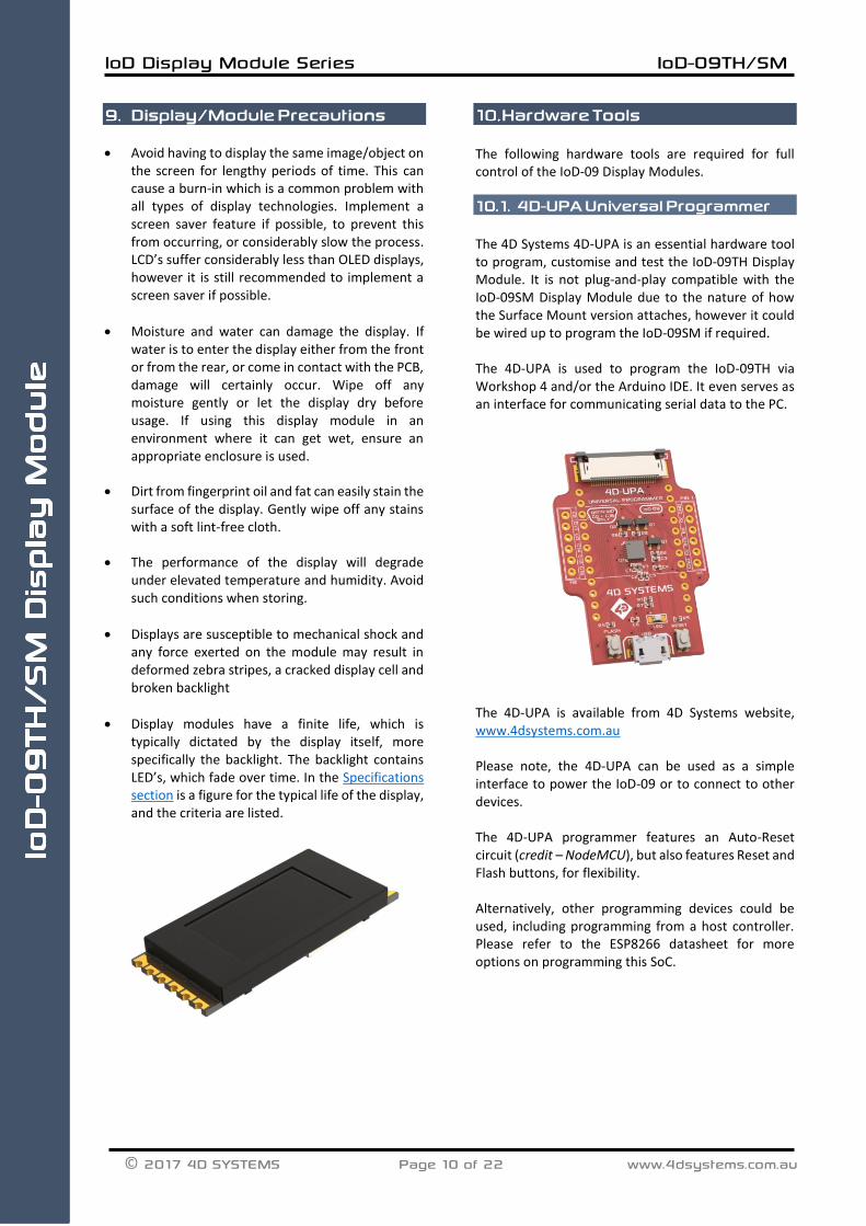
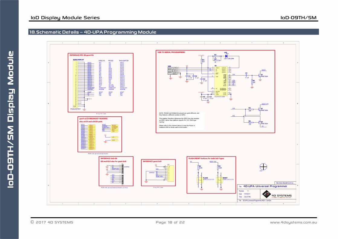
4D-UPA Universal Programmer The 4D Systems 4D-UPA is an essential hardware tool to program, customise and test the IoD-09TH Display Module. It is not plug-and-play compatible with the IoD-09SM Display Module due to the nature of how the Surface Mount version attaches, however it could be wired up to program the IoD-09SM if required. The 4D-UPA is used to program the IoD-09TH via Workshop 4 and/or the Arduino IDE. It even serves as an interface for communicating serial data to the PC.
The 4D-UPA is available from 4D Systems website, www.4dsystems.com.au Please note, the 4D-UPA can be used as a simple interface to power the IoD-09 or to connect to other devices. The 4D-UPA programmer features an Auto-Reset circuit (credit – NodeMCU), but also features Reset and Flash buttons, for flexibility. Alternatively, other programming devices could be used, including programming from a host controller. Please refer to the ESP8266 datasheet for more options on programming this SoC.
IoD Display Module Series IoD-09TH/SM
© 2017 4D SYSTEMS Page 11 of 22 www.4dsystems.com.au
Programming the IoD There are two IDE’s available to program the IoD-09. Using the Arduino IDE, or using the 4D Systems Workshop4 IDE. Using the Workshop4 IDE provides additional graphical benefits over using the Arduino IDE, however the Worskhop4 IDE is only Windows based (unless via a Virtual Machine). If using the Workshop4 IDE, Workshop4 installation will call the Arduino IDE in the background for programming the board (handled automatically and invisibly). Some minor setup is required to install the board into the Arduino IDE, using the Board Manager and installing the JSON file. See the following section. If the Workshop4 IDE is not going to be used at all, then the IoD board needs to be added into the Arduino IDE in the same way, using the Arduino Board Manager. More details below.
Arduino IDE The IoD-09 is Arduino IDE compatible. The IoD can be directly programmed via Arduino IDE like any other ESP8266/Arduino module. The IoD must be added to the Arduino IDE. This is typically done using the Boards Manager, however the ‘STABLE’ ESP8266 core is not regularly updated by the ESP8266 community, so the IoD board is not yet available via the JSON file method. The easiest way to install the IoD into the Arduino IDE, is by installing the Stable release JSON file. This is done by starting up the Arduino IDE, going File, Preferences, and entering the following line into the ‘Additional Boards Manager URLs’ field. If you already have a listing in there, simply add a comma after the last one, and paste this new URL in at the end: http://arduino.esp8266.com/stable/package_esp8266com_index.json Click OK on the preferences window to close it. Go up to Tools, Board, and click on Board Manager.
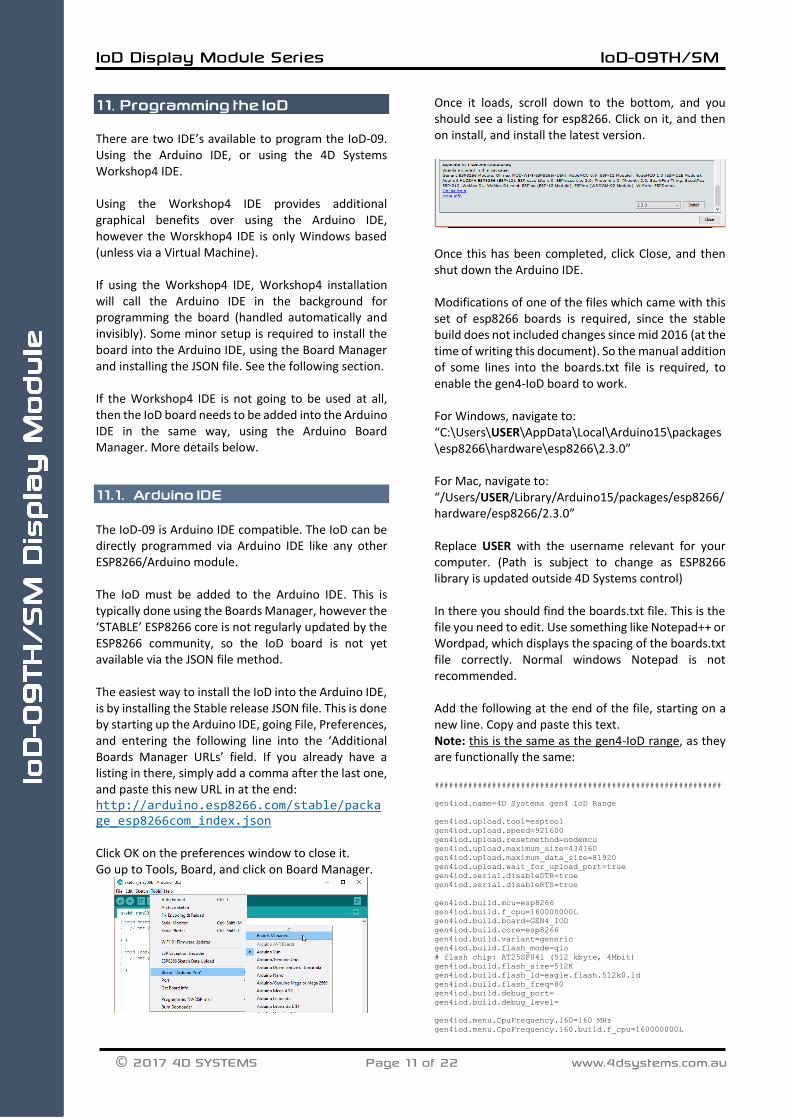
Once it loads, scroll down to the bottom, and you should see a listing for esp8266. Click on it, and then on install, and install the latest version.
Once this has been completed, click Close, and then shut down the Arduino IDE. Modifications of one of the files which came with this set of esp8266 boards is required, since the stable build does not included changes since mid 2016 (at the time of writing this document). So the manual addition of some lines into the boards.txt file is required, to enable the gen4-IoD board to work. For Windows, navigate to: “C:\Users\USER\AppData\Local\Arduino15\packages\esp8266\hardware\esp8266\2.3.0” For Mac, navigate to: “/Users/USER/Library/Arduino15/packages/esp8266/hardware/esp8266/2.3.0” Replace USER with the username relevant for your computer. (Path is subject to change as ESP8266 library is updated outside 4D Systems control) In there you should find the boards.txt file. This is the file you need to edit. Use something like Notepad++ or Wordpad, which displays the spacing of the boards.txt file correctly. Normal windows Notepad is not recommended. Add the following at the end of the file, starting on a new line. Copy and paste this text. Note: this is the same as the gen4-IoD range, as they are functionally the same: ############################################################
gen4iod.name=4D Systems gen4 IoD Range
gen4iod.upload.tool=esptool
gen4iod.upload.speed=921600
gen4iod.upload.resetmethod=nodemcu
gen4iod.upload.maximum_size=434160
gen4iod.upload.maximum_data_size=81920
gen4iod.upload.wait_for_upload_port=true
gen4iod.serial.disableDTR=true
gen4iod.serial.disableRTS=true
gen4iod.build.mcu=esp8266
gen4iod.build.f_cpu=160000000L
gen4iod.build.board=GEN4_IOD
gen4iod.build.core=esp8266
gen4iod.build.variant=generic
gen4iod.build.flash_mode=qio
# flash chip: AT25SF041 (512 kbyte, 4Mbit)
gen4iod.build.flash_size=512K
gen4iod.build.flash_ld=eagle.flash.512k0.ld
gen4iod.build.flash_freq=80
gen4iod.build.debug_port=
gen4iod.build.debug_level=
gen4iod.menu.CpuFrequency.160=160 MHz
gen4iod.menu.CpuFrequency.160.build.f_cpu=160000000L

IoD Display Module Series IoD-09TH/SM
© 2017 4D SYSTEMS Page 12 of 22 www.4dsystems.com.au
gen4iod.menu.CpuFrequency.80=80 MHz
gen4iod.menu.CpuFrequency.80.build.f_cpu=80000000L
gen4iod.menu.UploadSpeed.115200=115200
gen4iod.menu.UploadSpeed.115200.upload.speed=115200
gen4iod.menu.UploadSpeed.9600=9600
gen4iod.menu.UploadSpeed.9600.upload.speed=9600
gen4iod.menu.UploadSpeed.57600=57600
gen4iod.menu.UploadSpeed.57600.upload.speed=57600
gen4iod.menu.UploadSpeed.256000.windows=256000
gen4iod.menu.UploadSpeed.256000.upload.speed=256000
gen4iod.menu.UploadSpeed.230400.linux=230400
gen4iod.menu.UploadSpeed.230400.macosx=230400
gen4iod.menu.UploadSpeed.230400.upload.speed=230400
gen4iod.menu.UploadSpeed.460800.linux=460800
gen4iod.menu.UploadSpeed.460800.macosx=460800
gen4iod.menu.UploadSpeed.460800.upload.speed=460800
gen4iod.menu.UploadSpeed.512000.windows=512000
gen4iod.menu.UploadSpeed.512000.upload.speed=512000
gen4iod.menu.UploadSpeed.921600=921600
gen4iod.menu.UploadSpeed.921600.upload.speed=921600 Save the file, and open the Arduino IDE. You should then see at the end of the ESP8266 boards listing, a new entry for ‘4D Systems IoD Range’. Select the board.
The Arduino IDE should then be set up to start using the IoD. NOTE: For advanced users, the Github repository for the Arduino esp8266 core (non-stable version) contains all of the above, so no manual modifications are required, however this is not classed as being stable by Espressif. Use at your own risk. https://github.com/esp8266/Arduino Follow the instructions on their Github readme. NOTE: The ESP8266 Core is not maintained or created by 4D Systems. It belongs to esp8266.com Check out the GFX4dIoD09 library from the 4D Systems github page: https://github.com/4dsystems Which contains the library specifically for the IoD and some demo applications. This library can be downloaded and added to the Arduino IDE, like any normal library. Navigate to https://github.com/4dsystems/GFX4dIoD9 And download the repository, using the download/clone button. Save the zip file to your PC.
Open the Arduino IDE, and go to Sketch – Include Library – Add Zip Library
The library will then be installed, and will be available for you to use. There are example applications available in the examples folder.
4D Systems - Workshop 4 IDE Workshop 4 is a comprehensive software IDE that provides an integrated software development platform for all 4D Systems Intelligent Display Modules, including the IoD. Workshop4 allows rapid development of applications, and on the IoD can take full advantage of the available extended graphics functions. The Workshop IDE can create/edit Arduino code and verify/compile and then load the code into the IoD’s ESP8266 processor, without having to use the Arduino IDE directly. It makes it possible to create both simple and complex graphical user interfaces. When Workshop4 is started, it presents the User with a screen to start a new project, or to load a project. Upon selecting to start a new project, another screen is displayed, presenting the wide range of 4D Systems products available to be programmed or configured by the Workshop4 IDE. The Workshop4 IDE can be used to program the IoD-09, just as the Arduino IDE does. This is possible due to the integration of the Arduino compiler via the Arduino IDE, which allows Arduino sketches to be written and compiled from within the Workshop4 IDE, which then provides WS4 the benefit of adding graphical widgets and features to the IoD, which would otherwise not be available when using the Arduino IDE. If you use the Workshop4 IDE, you can program the IoD module and have the opportunity to create graphics which you can call using Arduino code via the GFX4dIoD09 library. Many options are possible.

IoD Display Module Series IoD-09TH/SM
© 2017 4D SYSTEMS Page 13 of 22 www.4dsystems.com.au
Note: Workshop requires the Arduino IDE to be installed as Workshop calls the Arduino IDE for compiling the Arduino sketches. The Arduino IDE however is not required to be opened or modified to program the IoD, once it has been set up. Please follow the steps found in the previous section to install and add the IoD to the Arduino IDE, prior to installing the Workshop4 IDE.
Starter Kit 4D Systems highly recommends all first-time buyers of 4D Systems’ displays, to purchase the Starter Kit when purchasing their first 4D Systems display solution. The Starter Kit provides all the hardware that is required to get the User up and running. Not all development environments and features will be needed by every User. However, by purchasing the display solution in a Starter Kit allows you to take full advantage of all of the features of the 4D Systems Display Solution and try out each of the 4D Woskshop4 Environments prior to settling with the preferred feature-set. Starter Kits typically include:
• IoD Display Module
• 4D-UPA Programmer
• 4GB micro-SD Card Please refer to the 4D Systems website for current components included in the Starter Kit, if available. Simply select the Starter Kit option when purchasing the chosen display module on the 4D Systems shopping cart, or from your local distributor.
Display Module Part Numbers The following is a breakdown on the part numbers and what they mean.
Example: IoD-09TH IoD - IoD (Internet of Displays) Family 09 - Display size (0.9”) TH - Through Hole version SM - Surface Mount version
IoD Display Module Series IoD-09TH/SM
© 2017 4D SYSTEMS Page 14 of 22 www.4dsystems.com.au
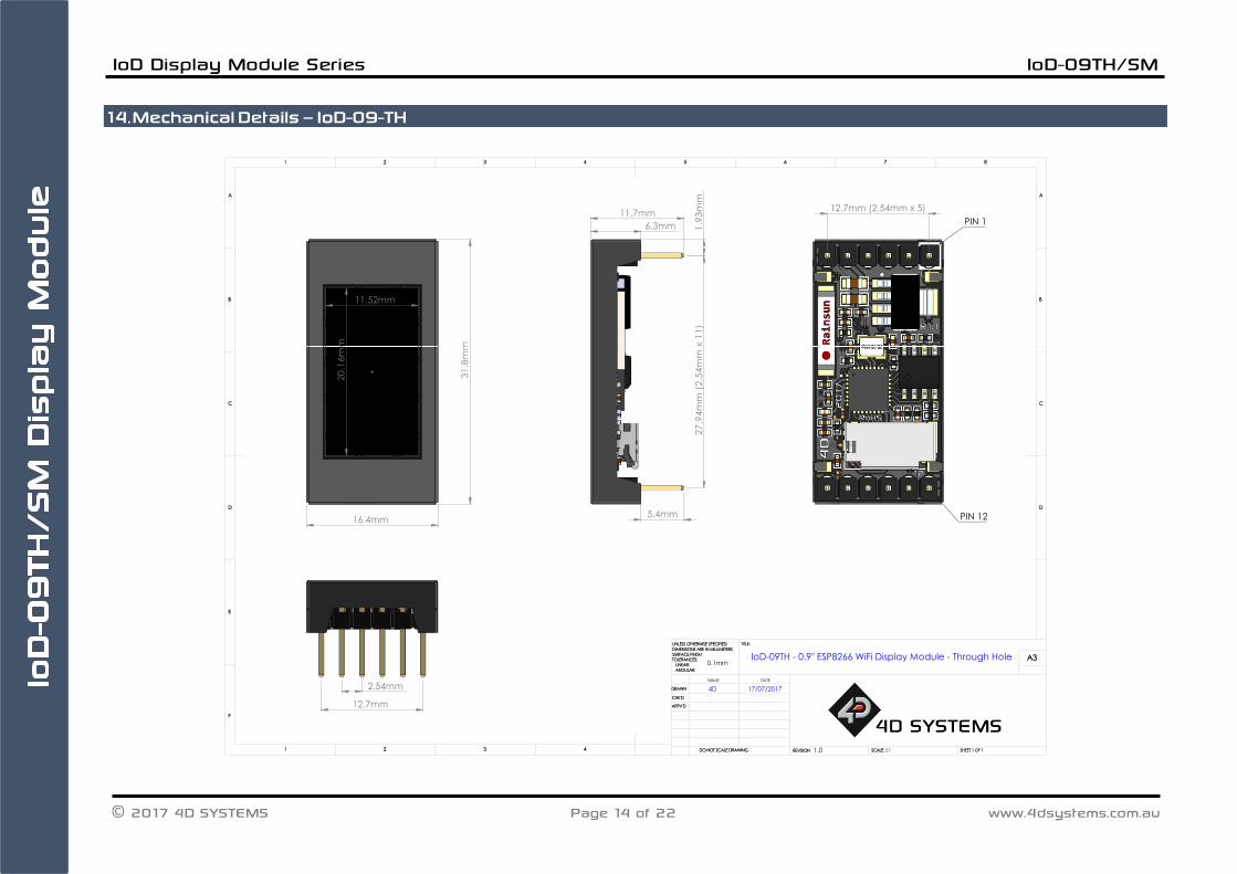
Mechanical Details – IoD-09-TH

IoD Display Module Series IoD-09TH/SM
© 2017 4D SYSTEMS Page 15 of 22 www.4dsystems.com.au
Mechanical Details – IoD-09-SM
IoD Display Module Series IoD-09TH/SM
© 2017 4D SYSTEMS Page 16 of 22 www.4dsystems.com.au
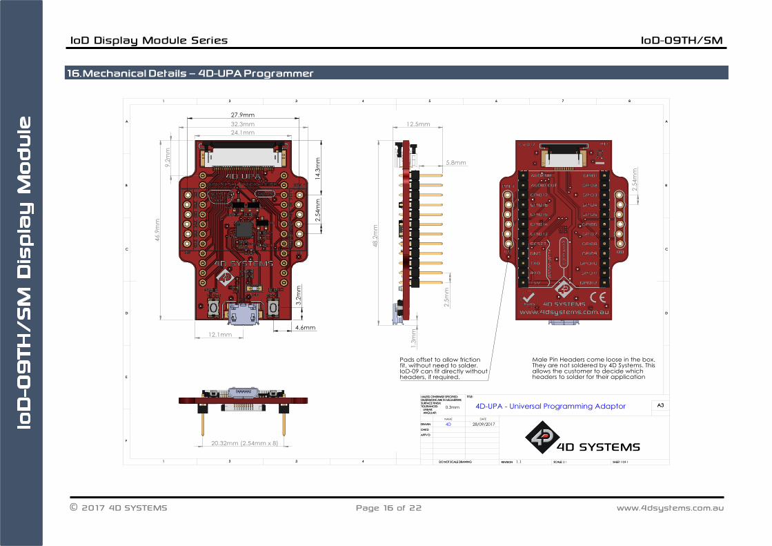
Mechanical Details – 4D-UPA Programmer
IoD Display Module Series IoD-09TH/SM
© 2017 4D SYSTEMS Page 17 of 22 www.4dsystems.com.au
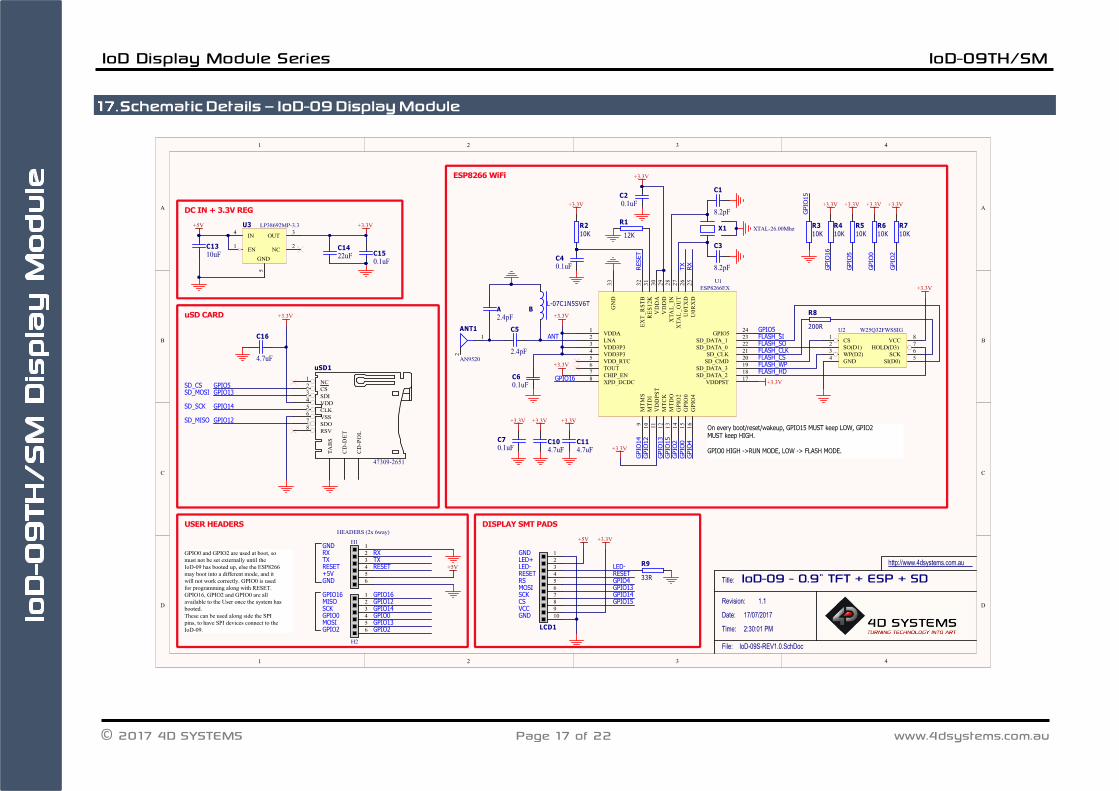
Schematic Details – IoD-09 Display Module
IoD Display Module Series IoD-09TH/SM
© 2017 4D SYSTEMS Page 18 of 22 www.4dsystems.com.au
Schematic Details – 4D-UPA Programming Module
IoD Display Module Series IoD-09TH/SM
© 2017 4D SYSTEMS Page 19 of 22 www.4dsystems.com.au
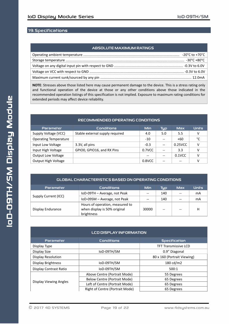
Specifications
ABSOLUTE MAXIMUM RATINGS
Operating ambient temperature ................................................................................................... -20°C to +70°C
Storage temperature .......................................................................................................................... -30°C +80°C
Voltage on any digital input pin with respect to GND ....................................................................... -0.3V to 6.0V
Voltage on VCC with respect to GND ................................................................................................. -0.3V to 6.0V
Maximum current sunk/sourced by any pin .............................................................................................. 12.0mA
NOTE: Stresses above those listed here may cause permanent damage to the device. This is a stress rating only and functional operation of the device at those or any other conditions above those indicated in the recommended operation listings of this specification is not implied. Exposure to maximum rating conditions for extended periods may affect device reliability.
RECOMMENDED OPERATING CONDITIONS
Parameter Conditions Min Typ Max Units Supply Voltage (VCC) Stable external supply required 4.0 5.0 5.5 V
Operating Temperature -10 -- +60 °C
Input Low Voltage 3.3V, all pins -0.3 -- 0.25VCC V
Input High Voltage GPIO0, GPIO16, and RX Pins 0.7VCC -- 3.3 V
Output Low Voltage -- -- 0.1VCC V
Output High Voltage 0.8VCC -- -- V
GLOBAL CHARACTERISTICS BASED ON OPERATING CONDITIONS
Parameter Conditions Min Typ Max Units
Supply Current (ICC) IoD-09TH – Average, not Peak -- 140 -- mA
IoD-09SM – Average, not Peak -- 140 -- mA
Display Endurance Hours of operation, measured to when display is 50% original brightness
30000 -- -- H
LCD DISPLAY INFORMATION
Parameter Conditions Specification
Display Type TFT Transmissive LCD
Display Size IoD-09TH/SM 0.9” Diagonal
Display Resolution 80 x 160 (Portrait Viewing)
Display Brightness IoD-09TH/SM 180 cd/m2
Display Contrast Ratio IoD-09TH/SM 500:1
Display Viewing Angles
Above Centre (Portrait Mode) 55 Degrees
Below Centre (Portrait Mode) 65 Degrees
Left of Centre (Portrait Mode) 65 Degrees
Right of Centre (Portrait Mode) 65 Degrees
IoD Display Module Series IoD-09TH/SM
© 2017 4D SYSTEMS Page 20 of 22 www.4dsystems.com.au
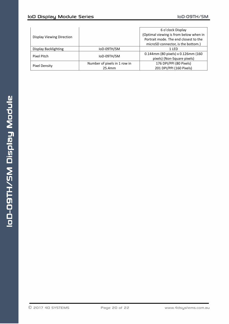
Display Viewing Direction
6 o’clock Display (Optimal viewing is from below when in
Portrait mode. The end closest to the microSD connector, is the bottom.)
Display Backlighting IoD-09TH/SM 1 LED
Pixel Pitch IoD-09TH/SM 0.144mm (80 pixels) x 0.126mm (160
pixels) (Non-Square pixels)
Pixel Density Number of pixels in 1 row in
25.4mm 176 DPI/PPI (80 Pixels)
201 DPI/PPI (160 Pixels)
IoD Display Module Series IoD-09TH/SM
© 2017 4D SYSTEMS Page 21 of 22 www.4dsystems.com.au
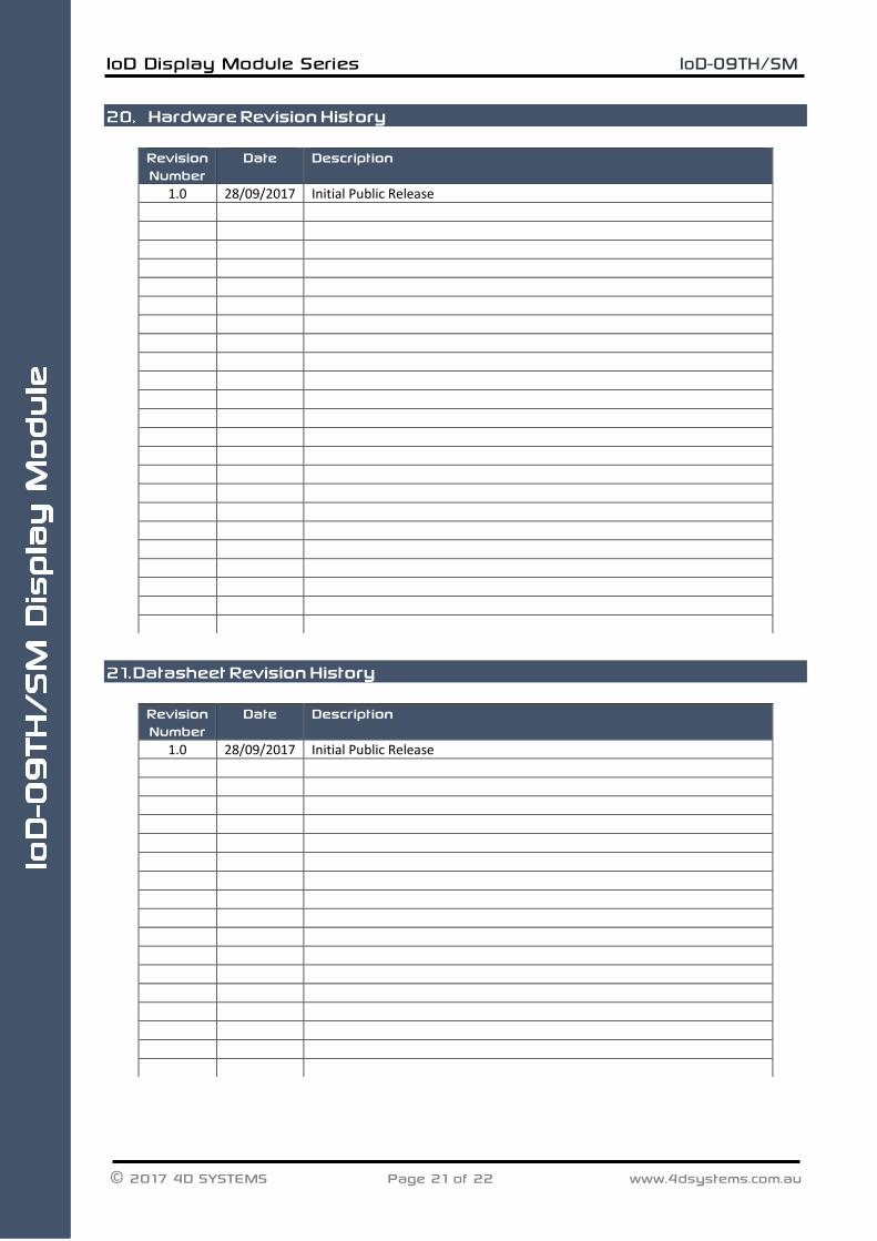
Hardware Revision History
Datasheet Revision History
Revision Number
Date Description
1.0 28/09/2017 Initial Public Release
Revision Number
Date Description
1.0 28/09/2017 Initial Public Release
IoD Display Module Series IoD-09TH/SM
© 2017 4D SYSTEMS Page 22 of 22 www.4dsystems.com.au
Legal Notice Proprietary Information The information contained in this document is the property of 4D Systems Pty. Ltd. and may be the subject of patents pending or granted, and must not be copied or disclosed without prior written permission. 4D Systems endeavours to ensure that the information in this document is correct and fairly stated but does not accept liability for any error or omission. The development of 4D Systems products and services is continuous and published information may not be up to date. It is important to check the current position with 4D Systems. 4D Systems reserves the right to modify, update or makes changes to Specifications or written material without prior notice at any time. All trademarks belong to their respective owners and are recognised and acknowledged. Disclaimer of Warranties & Limitation of Liability 4D Systems makes no warranty, either expressed or implied with respect to any product, and specifically disclaims all other warranties, including, without limitation, warranties for merchantability, non-infringement and fitness for any particular purpose. Information contained in this publication regarding device applications and the like is provided only for your convenience and may be superseded by updates. It is your responsibility to ensure that your application meets with your specifications. Images and graphics used throughout this document are for illustrative purposes only. All images and graphics used are possible to be displayed on the 4D Systems range of products, however the quality may vary. In no event shall 4D Systems be liable to the buyer or to any third party for any indirect, incidental, special, consequential, punitive or exemplary damages (including without limitation lost profits, lost savings, or loss of business opportunity) arising out of or relating to any product or service provided or to be provided by 4D Systems, or the use or inability to use the same, even if 4D Systems has been advised of the possibility of such damages. 4D Systems products are not fault tolerant nor designed, manufactured or intended for use or resale as on line control equipment in hazardous environments requiring fail – safe performance, such as in the operation of nuclear facilities, aircraft navigation or communication systems, air traffic control, direct life support machines or weapons systems in which the failure of the product could lead directly to death, personal injury or severe physical or environmental damage (‘High Risk Activities’). 4D Systems and its suppliers specifically disclaim any expressed or implied warranty of fitness for High Risk Activities. Use of 4D Systems’ products and devices in 'High Risk Activities' and in any other application is entirely at the buyer’s risk, and the buyer agrees to defend, indemnify and hold harmless 4D Systems from any and all damages, claims, suits, or expenses resulting from such use. No licenses are conveyed, implicitly or otherwise, under any 4D Systems intellectual property rights.
Contact Information
For Technical Support: www.4dsystems.com.au/support
For Sales Support: [email protected]
Website: www.4dsystems.com.au
Copyright 4D Systems Pty. Ltd. 2000-2017.
Related Documents