RoboClaw Series Brushed DC Motor Controllers RoboClaw 2x5A RoboClaw 2x7A RoboClaw 2x15A RoboClaw 2x30A RoboClaw 2x45A RoboClaw 2x45A ST RoboClaw 2x60A Roboclaw 2x60HV User Manual Firmware 4.1.16 and Newer Hardware V3, V4 and V5 User Manual Revision 5.1 (c) 2014, 2015 Ion Motion Control. All Rights Reserved

Welcome message from author
This document is posted to help you gain knowledge. Please leave a comment to let me know what you think about it! Share it to your friends and learn new things together.
Transcript

RoboClaw Series Brushed DC Motor Controllers RoboClaw 2x5A RoboClaw 2x7A RoboClaw 2x15A RoboClaw 2x30A RoboClaw 2x45A RoboClaw 2x45A ST RoboClaw 2x60A Roboclaw 2x60HV
User Manual Firmware 4.1.16 and Newer Hardware V3, V4 and V5 User Manual Revision 5.1
(c) 2014, 2015 Ion Motion Control. All Rights Reserved

RoboClaw Series Brushed DC Motor Controllers
RoboClaw Series User Manual 2
ContentsRoboClaw Revision History .................................................................................6
Precautions .........................................................................................................7Motor Selection ............................................................................................. 7Stall Current ................................................................................................. 7Running Current ............................................................................................ 7Wire Lengths ................................................................................................. 7Run Away ..................................................................................................... 8Power Sources ............................................................................................... 8Logic Power .................................................................................................. 8Optical Encoders ............................................................................................ 8Easy to use Libraries ...................................................................................... 8
Header Overview ................................................................................................9Logic Battery (LB IN) ...................................................................................... 9BEC Source (LB-MB) ...................................................................................... 9Encoder Power (+ -) ...................................................................................... 9Encoder Inputs (EN1 / EN2 - 1B / 1A / 2B / 2A) ................................................. 9Control Inputs (S1 / S2 / S3 / S4 /S5) ............................................................ 10Main Battery Screw Terminals ........................................................................ 10Disconnect .................................................................................................. 10Motor Screw Terminals ................................................................................. 10
Basic Wiring ......................................................................................................11
Status and Error LEDs .......................................................................................12Error and Warning States .............................................................................. 12Firmware Update LED State ........................................................................... 13Automatic Battery Detection on Startup .......................................................... 13
RoboClaw Modes ...............................................................................................14Configuring RoboClaw Modes ......................................................................... 15Mode Options .............................................................................................. 16Standard Serial and Packet Serial Mode Options ............................................... 16Battery Cut Off Settings ................................................................................ 17 Battery Options .......................................................................................... 17Manual Voltage Settings................................................................................ 17
USB Connection ................................................................................................19USB Power .................................................................................................. 19USB Comport and Baudrate ........................................................................... 19
RC Mode ............................................................................................................21RC Mode With Mixing .................................................................................... 21Using RC Mode with feedback for velocity/position control ................................. 21RC Mode Options ......................................................................................... 21Pulse Ranges ............................................................................................... 22RC Wiring Example ...................................................................................... 23RC Control - Arduino Example ....................................................................... 24

RoboClaw Series Brushed DC Motor Controllers
RoboClaw Series User Manual 3
Analog Mode .....................................................................................................26Analog Mode With Mixing .............................................................................. 26Using Analog Mode with feedback for velocity/position control ............................ 26Analog Mode Options .................................................................................... 26Analog Wiring Example ................................................................................. 27
Standard Serial Mode ........................................................................................29Serial Mode Baud Rates ................................................................................ 29Standard Serial Command Syntax .................................................................. 29Standard Serial Wiring Example ..................................................................... 30Standard Serial Mode With Slave Select .......................................................... 31Standard Serial - Arduino Example ................................................................. 32
Packet Serial Mode............................................................................................34Address ...................................................................................................... 34Packet Modes .............................................................................................. 34Packet Serial Baud Rate ................................................................................ 34
Serial Mode Options ..........................................................................................34Packet Timeout ............................................................................................ 35Packet Acknowledgement .............................................................................. 35CRC16 Checksum Calculation ........................................................................ 35Packet Serial Wiring ..................................................................................... 37Multi-Unit Packet Serial Wiring ....................................................................... 38Commands 0 - 7 Compatibility Commands ...................................................... 390 - Drive Forward M1 .................................................................................... 391 - Drive Backwards M1 ................................................................................ 392 - Set Minimum Main Voltage (Command 57 Preferred) .................................. 393 - Set Maximum Main Voltage (Command 57 Preferred) .................................. 404 - Drive Forward M2 .................................................................................... 405 - Drive Backwards M2 ................................................................................ 406 - Drive M1 (7 Bit) ..................................................................................... 407 - Drive M2 (7 Bit) ..................................................................................... 40Commands 8 - 13 Mixed Mode Compatibility Commands ................................... 418 - Drive Forward ......................................................................................... 419 - Drive Backwards ..................................................................................... 4110 - Turn right ............................................................................................. 4111 - Turn left ............................................................................................... 4112 - Drive Forward or Backward (7 Bit) ........................................................... 4113 - Turn Left or Right (7 Bit) ........................................................................ 41Arduino Example ......................................................................................... 42
RoboClaw Series Brushed DC Motor Controllers
RoboClaw Series User Manual 4
Advance Packet Serial .......................................................................................4521 - Read Firmware Version .......................................................................... 4624 - Read Main Battery Voltage Level ............................................................. 4625 - Read Logic Battery Voltage Level ............................................................. 4626 - Set Minimum Logic Voltage Level ............................................................. 4627 - Set Maximum Logic Voltage Level ............................................................ 4648 - Read Motor PWM values ......................................................................... 4749 - Read Motor Currents .............................................................................. 4757 - Set Main Battery Voltages ...................................................................... 4758 - Set Logic Battery Voltages ...................................................................... 4759 - Read Main Battery Voltage Settings ......................................................... 4760 - Read Logic Battery Voltage Settings ......................................................... 4768 - Set M1 Default Duty Acceleration ............................................................ 4769 - Set M2 Default Duty Acceleration ............................................................ 4874 - Set S3, S4 and S5 Modes ....................................................................... 4875 - Get S3, S4 amd S5 Modes ...................................................................... 4876 - Set DeadBand for RC/Analog controls ...................................................... 4877 - Read DeadBand for RC/Analog controls .................................................... 4880 - Restore Defaults ................................................................................... 4981 - Read Default Duty Acceleration Settings ................................................... 4982 - Read Temperature ................................................................................. 4983 - Read Temperature 2 .............................................................................. 4990 - Read Status.......................................................................................... 5091 - Read Encoder Mode ............................................................................... 5092 - Set Motor 1 Encoder Mode ...................................................................... 5093 - Set Motor 2 Encoder Mode ...................................................................... 5094 - Write Settings to EEPROM ...................................................................... 5195 - Read Settings from EEPROM ................................................................... 5198 - Set Standard Config Settings .................................................................. 5299 - Read Standard Config Settings ................................................................ 53100 - Set CTRL Modes .................................................................................. 53101 - Read CTRL Modes ................................................................................ 53102 - Set CTRL1 .......................................................................................... 54103 - Set CTRL2 .......................................................................................... 54104 - Read CTRL Settings ............................................................................. 54133 - Set M1 Max Current Limit ..................................................................... 54134 - Set M2 Max Current Limit ..................................................................... 54135 - Read M1 Max Current Limit ................................................................... 54136 - Read M2 Max Current Limit ................................................................... 55148 - Set PWM Mode .................................................................................... 55149 - Read PWM Mode .................................................................................. 55
Quadrature Encoders ........................................................................................57
Absolute Encoder ..............................................................................................58Velocity Calibration Procedure ........................................................................ 59Position Calibration Procedure ........................................................................ 59Auto Tuning ................................................................................................ 60Encoder Commands ..................................................................................... 6116 - Read Encoder Count/Value M1 ................................................................ 6117 - Read Quadrature Encoder Count/Value M2 ................................................ 6218 - Read Encoder Speed M1 ......................................................................... 6219 - Read Encoder Speed M2 ......................................................................... 62
RoboClaw Series Brushed DC Motor Controllers
RoboClaw Series User Manual 5
20 - Reset Quadrature Encoder Counters ........................................................ 6222 - Set Quadrature Encoder 1 Value .............................................................. 6323 - Set Quadrature Encoder 2 Value .............................................................. 6330 - Read Raw Speed M1 .............................................................................. 6331 - Read Raw Speed M2 .............................................................................. 6378 - Read Encoder Counters .......................................................................... 6379 - Read ISpeeds Counters .......................................................................... 63
Advanced Motor Control ....................................................................................6428 - Set Velocity PID Constants M1 ................................................................ 6529 - Set Velocity PID Constants M2 ................................................................ 6532 - Drive M1 With Signed Duty Cycle ............................................................ 6533 - Drive M2 With Signed Duty Cycle ............................................................ 6634 - Drive M1 / M2 With Signed Duty Cycle ..................................................... 6635 - Drive M1 With Signed Speed ................................................................... 6736 - Drive M2 With Signed Speed ................................................................... 6737 - Drive M1 / M2 With Signed Speed ........................................................... 6738 - Drive M1 With Signed Speed And Acceleration ........................................... 6739 - Drive M2 With Signed Speed And Acceleration ........................................... 6840 - Drive M1 / M2 With Signed Speed And Acceleration ................................... 6841 - Buffered M1 Drive With Signed Speed And Distance ................................... 6842 - Buffered M2 Drive With Signed Speed And Distance ................................... 6943 - Buffered Drive M1 / M2 With Signed Speed And Distance ........................... 6944 - Buffered M1 Drive With Signed Speed, Accel And Distance .......................... 6945 - Buffered M2 Drive With Signed Speed, Accel And Distance .......................... 7046 - Buffered Drive M1 / M2 With Signed Speed, Accel And Distance................... 7047 - Read Buffer Length ................................................................................ 7050 - Drive M1 / M2 With Signed Speed And Individual Acceleration ..................... 7151 - Buffered Drive M1 / M2 With Signed Speed, Individual Accel And Distance .... 7152 - Drive M1 With Signed Duty And Acceleration ............................................. 7153 - Drive M2 With Signed Duty And Acceleration ............................................. 7254 - Drive M1 / M2 With Signed Duty And Acceleration ..................................... 7255 - Read Motor 1 Velocity PID and QPPS Settings............................................ 7256 - Read Motor 2 Velocity PID and QPPS Settings............................................ 7261 - Set Motor 1 Position PID Constants .......................................................... 7262 - Set Motor 2 Position PID Constants .......................................................... 7363 - Read Motor 1 Position PID Constants ....................................................... 7364 - Read Motor 2 Position PID Constants ....................................................... 7365 - Buffered Drive M1 with signed Speed, Accel, Deccel and Position ................. 7366 - Buffered Drive M2 with signed Speed, Accel, Deccel and Position ................. 7367 - Buffered Drive M1 & M2 with signed Speed, Accel, Deccel and Position ......... 74Arduino Example ......................................................................................... 75
RoboClaw Electrical Specifications ....................................................................80
Warranty ..........................................................................................................81Copyrights and Trademarks ..............................................................................81Disclaimer .........................................................................................................81Contacts ............................................................................................................81Discussion List ..................................................................................................81Technical Support .............................................................................................81

RoboClaw Series Brushed DC Motor Controllers
RoboClaw Series User Manual 6
RoboClaw Revision HistoryRoboClaw is an actively maintained product. New firmware features will be available from time to time. The table below outlines key revisions that could affect the version of RoboClaw you currently own.
Revision Description
4.1.16 • Adjusted RC/Analog controlled Velocity and Position Control functions.
• Fixed Sync Motor option in Position Settings window.
4.1.15 • Adjusted auto tuner loop.
• Changed currentpos reset to only execute when not running a position command.
• Fixed analog mode powerup calibration issue.
4.1.14 • Added Roboclaw 2x7A.
• Fixed MixedSpeedAccel/MixedSpeedAccelDistamce accel arguments.
• S3 mode setting on power up is now loaded correctly. Wasn’t getting set until a second ReadNVM or manually set.
• Changed Position accel/deccel handler to take into account existing motion when a new command is executed.
• Added responsiveness slider to Autotuner. After autotuning the slider can be used to easily adjust the tuned settingsfor responsiveness.
4.1.13 • Adjusted Roboclaw 2x60A deadtime
4.1.12 • Changed communication checksum to CRC-CCITT(CRC16 xmodem, polynomial 0x1021).
• Home signal falling edge triggers motor stop and encoder zero.
• Added manual homing option, does not automatically home on start. User must move motor until home signal is triggered top zero encoders.
• Fixed unsigned value underflow in Analog filter function.
• Changed E-Stop to OR instead of AND when using multiple E-Stop inputs. Note if any signal is a Latching E-STOP all E-STOPs are latching E-STOPs.
• Added option to swap encoder channels.
• Added Home signal states to status word(see updated manual).
• Added open drain enable for S2(multi-unit mode).
• Added adjustable +(forward) and -(backward) deadbands for RC / Analog modes.
• Fixed a hardware reset bug in xmega. USBCAL values being updated in main loop caused reset if USB was connected and a 5v signal was on S1.
• Added USB reset on USB suspend(caused by usbser.sys not handling IN errors properly).
• Added GETENCODERS(Reads both encoder values in one call).
• Added GETISPEEDS(Reads both ispeed values in on call).
RoboClaw Series Brushed DC Motor Controllers
RoboClaw Series User Manual 7
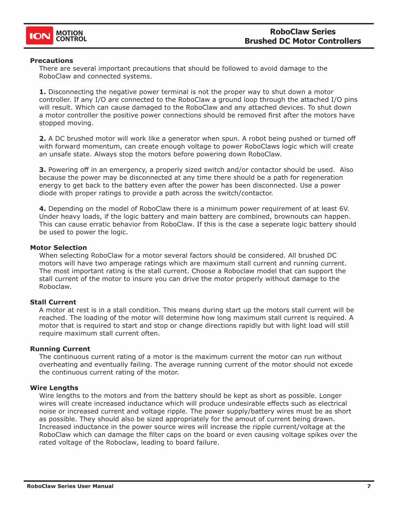
PrecautionsThere are several important precautions that should be followed to avoid damage to the RoboClaw and connected systems.
1. Disconnecting the negative power terminal is not the proper way to shut down a motor controller. If any I/O are connected to the RoboClaw a ground loop through the attached I/O pins will result. Which can cause damaged to the RoboClaw and any attached devices. To shut down a motor controller the positive power connections should be removed first after the motors have stopped moving.
2. A DC brushed motor will work like a generator when spun. A robot being pushed or turned off with forward momentum, can create enough voltage to power RoboClaws logic which will create an unsafe state. Always stop the motors before powering down RoboClaw.
3. Powering off in an emergency, a properly sized switch and/or contactor should be used. Also because the power may be disconnected at any time there should be a path for regeneration energy to get back to the battery even after the power has been disconnected. Use a power diode with proper ratings to provide a path across the switch/contactor.
4. Depending on the model of RoboClaw there is a minimum power requirement of at least 6V. Under heavy loads, if the logic battery and main battery are combined, brownouts can happen. This can cause erratic behavior from RoboClaw. If this is the case a seperate logic battery should be used to power the logic.
Motor SelectionWhen selecting RoboClaw for a motor several factors should be considered. All brushed DC motors will have two amperage ratings which are maximum stall current and running current. The most important rating is the stall current. Choose a Roboclaw model that can support the stall current of the motor to insure you can drive the motor properly without damage to the Roboclaw.
Stall CurrentA motor at rest is in a stall condition. This means during start up the motors stall current will be reached. The loading of the motor will determine how long maximum stall current is required. A motor that is required to start and stop or change directions rapidly but with light load will still require maximum stall current often.
Running CurrentThe continuous current rating of a motor is the maximum current the motor can run without overheating and eventually failing. The average running current of the motor should not excede the continuous current rating of the motor.
Wire LengthsWire lengths to the motors and from the battery should be kept as short as possible. Longer wires will create increased inductance which will produce undesirable effects such as electrical noise or increased current and voltage ripple. The power supply/battery wires must be as short as possible. They should also be sized appropriately for the amout of current being drawn. Increased inductance in the power source wires will increase the ripple current/voltage at the RoboClaw which can damage the filter caps on the board or even causing voltage spikes over the rated voltage of the Roboclaw, leading to board failure.

RoboClaw Series Brushed DC Motor Controllers
RoboClaw Series User Manual 8
Run AwayDuring development of your project caution should be taken to avoid run away conditions. The wheels of a robot should not be in contact with any surface until all development is complete. If the motor is embedded, ensure you have a safe and easy method to remove power from RoboClaw as a fail safe.
Power SourcesA battery is recommended as the main power source for RoboClaw. Some linear power supplies can also be used without additional hardware if they have built in voltage clamps. Most Linear and Switching power supplies are not capable of handling the regeneration energy generated by DC motors. The regeneration creates voltage spikes which most power sipplies are not designed to handle. Switching power supplies will momentarily reduce voltage and or shut down, causing brown outs which will leave RoboClaw in an unsafe state. The Roboclaws minimum and maximum voltage levels can be set to prevent some of these voltage spikes, however this will cause the motors to brake when slowing down too quickly in an attempt to reduce the over voltage spikes. This will also limit power output when accelerating motors or when the load changes to prevent undervoltage conditions.
Logic PowerWhen powering external devices from RoboClaw ensure the maximum BEC output rating is not exceeded. This can cause RoboClaw to suffer logic brown out which will cause erratic behavior. Some low quality encoders can cause excessive noise being put on the +5VDC rail of the RoboClaw. This excessive noise will cause unpredictable behavior.
Optical EncodersRoboClaw features dual channel quadrature/absolute decoding. When wiring encoders make sure the direction of spin is correct to the motor direction. Incorrect encoder connections can cause a run away state. Refer to the encoder section of this user manual for proper setup.
Easy to use LibrariesSource code and Libraries are available on the Ion Motion Control website. Libraries are available for Arduino(C++), C# on Windows(.NET) or Linux(Mono) and Python(Raspberry Pi, Linux, OSX, etc).

RoboClaw Series Brushed DC Motor Controllers
RoboClaw Series User Manual 9
Header OverviewRoboClaw share the same header and screw terminal pinouts accross the models covered in this user manual. The main control I/O are arranged for easy connectivity to control devices such as RC controllers. The headers are also arranged to provide easy access to ground and power for supplying power to external controllers.
Pin Headers Screw Terminals Screw Terminal Encoder
Logic Battery (LB IN)The logic side of RoboClaw can be powered from a secondary battery wired to LB IN. The positive (+) terminal is located at the board edge and ground (-) is the inside pin closest to the heatsink. Remove the LB-MB jumper if a secondary battery for logic will be used.
BEC Source (LB-MB)RoboClaw logic requires 5VDC which is provided from the on board BEC circuit. The BEC source input is set with the LB-MB jumper. Install a jumper on the 2 pins labeled LB-MB to use the main battery as the BEC power source. Remove this jumper if using a separate logic battery. On models without this jumper the power source is selected automatically.
Encoder Power (+ -) The pins labeled + and - are the source power pins for encoders. The positive (+) is located at the board edge and supplies +5VDC. The ground (-) pin is near the heatsink. On ST models all power must come from the single 5v screw terminal and the single GND screw terminal
Encoder Inputs (EN1 / EN2 - 1B / 1A / 2B / 2A)EN1 and EN2 are the inputs from the encoders on pin header versions of RoboClaw. 1B, 1A, 2B and 2A are the encoders inputs on screw terminal versions of RoboClaw. Channel A of both EN1 and EN2 are located at the board edge on the pin header. Channel B pins are located near the heatsink on the pin header. The A and B channels are labeled appropriately on screw terminal versions.
When connecting the encoder make sure the leading channel for the direction of rotation is connected to A. If one encoder is backwards to the other you will have one internal counter counting up and the other counting down. Refer to the data sheet of the encoder you are using for channel direction. Which encoder is used on which motor can be swapped via a software setting.
S1S2S3
EN2EN1++
--
LB-MBLB IN
+ -
S4S5
S1S2
S3S4
S5LB
GN
D5+
2A1B
1A2B

RoboClaw Series Brushed DC Motor Controllers
RoboClaw Series User Manual 10
Control Inputs (S1 / S2 / S3 / S4 /S5)S1, S2, S3, S4 and S5 are setup for standard servo style headers I/O(except on ST models), +5V and GND. S1 and S2 are the control inputs for serial, analog and RC modes. S3 can be used as a flip switch input when in RC or Analog modes. In serial mode S3, S4 and S5 can be used as emergency stop inputs or as voltage clamp control outputs. When set as E-Stop inputs they are active when pulled low and have internal pullups so they will not accidentally trip when left floating. S4 and S5 can also optionally be used as home signal inputs. The pins closest to the board edge are the I/0s, center pin is the +5V and the inside pins are ground. Some RC receivers have their own supply and will conflict with the RoboClaw’s 5v logic supply. It may be necessary to remove the +5V pin from the RC receivers cable in those cases.
Main Battery Screw TerminalsThe main power input can be from 6VDC to 34VDC on a standard RoboClaw and 10.5VDC to 60VDC on an HV (High Voltage) RoboClaw. The connections are marked + and - on the main screw terminal. The plus (+) symbol marks the positive terminal and the negative (-) marks the negative terminal. The main battery wires should be as short as possible.
Do not reverse main battery wires. Roboclaw will be permenantly damaged.
DisconnectThe main battery should have a disconnect in case of a run away situation and power needs to be cut. The switch must be rated to handle the maximum current and voltage from the battery. This will vary depending on the type of motors and or power source you are using. A typically solution would be an inexpensive contactor which can be source from sites like Ebay. A power diode rated for the maximum current the battery will deliver should be placed across the switch/contactor to provide a path back to the battery when disconnected while the motors are spinning. The diode will provice a path back to the battery for regenerative power even if the switch is opened.
Motor Screw TerminalsThe motor screw terminals are marked with M1A / M1B for channel 1 and M2A / M2B for channel 2. For both motors to turn in the same direction the wiring of one motor should be reversed from the other in a typical differential drive robot. The motor and battery wires should be as short as possible. Long wires can increase the inductance and therefore increase potentially harmful voltage spikes.

RoboClaw Series Brushed DC Motor Controllers
RoboClaw Series User Manual 11
Basic WiringThe wiring diagrahm below illustrates the basic battery and motor connections for RoboClaw. M1A and M1B is motor channel 1 with M2A and M2B as motor channel 2.
Never disconnect the negative battery lead before disconnecting the positive!
Motor 1
Motor 2
M1A
M1B
M2B
M2A
Negative -
Positive +
+-
Battery
RoboClaw
D1
SW1

RoboClaw Series Brushed DC Motor Controllers
RoboClaw Series User Manual 12
Status and Error LEDsThe RoboClaw has three LEDs. Two status LEDs marked STAT1 and STAT2 and an error LED marked ERR. When RoboClaw is first powered up all 3 LEDs should flash briefly to indicate all LEDs are functional. LEDs will behave differently depending on the mode RoboClaw is set to. During normal operation the status 1 LED will remain on continuously or blink when data is received in RC Mode or Serial Modes. The status 2 LED will light when either drive stage is active.
Error and Warning StatesWhen an error occurs both motor channel outputs will be disabled and RoboClaw will stop any further actions until the unit is reset, or in the case of non-latching E-Stops, the error state is cleared. When warnings occur both motor channel outputs will be controlled automatically depending on the warning condition(s).
LED Status Condition Type Description
All three LEDs lit. E-Stop Error Motors are stopped by braking.
Error LED lit while condition is active.
Over 85c Temperature Warning Motor current limit is recalculated based on temperature.
Error LED blinks once with short delay. Other LEDs off.
Over 100c Temperature Error Motors freewheel while condition exist.
Error LED lit while condition is active.
Over Current Warning Motor power is automatically limited.
Error LED blinking twice. STAT1 or STAT2 indicates channel.
Driver Fault Error Motors freewheel. MCP has detected damage.
Error LED blinking three times.
Logic Battery High Error Motors freewheel until MCP is reset.
Error LED blinking four times. Logic Battery Low Error Motors freewheel until MCP is reset.
Error LED blinking five times. Main Battery High Error Motors are stopped by braking until MCP is reset.
Error LED lit while condition is active.
Main Battery High Warning Motors are stopped by braking while condition exist.
Error LED lit while condition is active.
Main Battery Low Warning Motors freewheel while condition exist.
Error LED lit while condition is active.
M1 or M2 Home Warning Motor is stopped and encoder is reset to 0
ERR
STA
T2
STA
T1

RoboClaw Series Brushed DC Motor Controllers
RoboClaw Series User Manual 13
Firmware Update LED StateIf all three LEDs begin to cycle on and off after powering on, the Roboclaw has been set to install new firmware. Use IonMotion on a Windows PC to install the new firmware to clear this state.
Automatic Battery Detection on StartupIf the automatic battery detection mode is enabled the Stat2 LED will blink to indicate the detected battery type. Each blink indicates the number of LIPO cells detected. If automatic detection is used the number of cells detected should be confirmed on power up before running the unit.
Undercharged or overcharged batteries can cause invalid autodetection.

RoboClaw Series Brushed DC Motor Controllers
RoboClaw Series User Manual 14
RoboClaw ModesThere are 4 main modes with variations totaling 14 modes in all. Each mode enables RoboClaw to be controlled in a very specific way. The following list explains each mode and the ideal application.
USB can be connected in any mode. When the Roboclaw is not in packet serial mode USB packet serial commands can be used to read status information and set configuration settings, however motor movement commands will not function. When in packet serial mode if another device such as an Arduino is connected to S1 and S2 pins and sending commands to the RoboClaw, both those commands and USB packet serial commands will execute.
1. RC Mode 1 & 2 - With RC mode RoboClaw can be controlled from any hobby RC radio system. RC input mode also allows low powered microcontrollers such as a Basic Stamp to control RoboClaw. RoboClaw expects servo pulse inputs to control the direction and speed. Very similar to how a regular servo is controlled. RC mode can use encoders if properly setup(See Encoder section).
2. Analog Mode 3 & 4 - Analog mode uses an analog signal from 0V to 2V to control the speed and direction of each motor. RoboClaw can be controlled using a potentiometer or filtered PWM from a microcontroller. Analog mode is ideal for interfacing RoboClaw with joystick positioning systems or other non microcontroller interfacing hardware. Analog mode can use encoders if properly setup(See Encoder section).
3. Standard Serial Mode 5 & 6 - In standard serial mode RoboClaw expects TTL level RS-232 serial data to control direction and speed of each motor. Standard serial is typically used to control RoboClaw from a microcontroller or PC. If using a PC, a MAX232 or an equivilent level converter circuit must be used since RoboClaw only works with TTL level inputs. Standard serial includes a slave select mode which allows multiple RoboClaws to be controlled from a signal RS-232 port (PC or microcontroller). Standard serial is a one way format, RoboClaw only receives data. Encoders are not supported with Standard Serial mode.
4. Packet Serial Mode 7 through 14 - In packet serial mode RoboClaw expects TTL level RS-232 serial data to control direction and speed of each motor. Packet serial is typically used to control RoboClaw from a microcontroller or PC. If using a PC a MAX232 or an equivilent level converter circuit must be used since RoboClaw only works with TTL level input. In packet serial mode each RoboClaw is assigned a unique address. There are 8 addresses available. This means up to 8 RoboClaws can be on the same serial port. Encoders are support in Packet Serial mode(See Encoder section).
5. USB Control - USB can be connected in any mode. When the Roboclaw is not in packet serial mode USB packet serial commands can be used to read status information and/or set configuration settings, however motor movement commands will not function. When in packet serial mode if another device, for example an Arduino, is connected to the S1 and S2 pins and sending commands to the Roboclaw both those commands and USB packet serial commands will execute.

RoboClaw Series Brushed DC Motor Controllers
RoboClaw Series User Manual 15
Configuring RoboClaw ModesThe 3 buttons on RoboClaw are used to set the different configuration options. The MODE button sets the interface method such as Serial or RC modes. The SET button is used to configure the options for the mode. The LIPO button doubles as a save button and configuring the low battery voltage cut out function of RoboClaw. To set the desired mode follow the steps below:
1. Press and release the MODE button to enter mode setup. The STAT2 LED will begin to blink out the current mode. Each blink is a half second with a long pause at the end of the count. Five blinks with a long pause equals mode 5 and so on.
2. Press SET to increment to the next mode. Press MODE to decrement to the previous mode.
3. Press and release the LIPO button to save this mode to memory.
ModesMode Description
1 RC mode
2 RC mode with mixing
3 Analog mode
4 Analog mode with mixing
5 Standard Serial
6 Standard Serial with slave pin
7 Packet Serial Mode - Address 0x80
8 Packet Serial Mode - Address 0x81
9 Packet Serial Mode - Address 0x82
10 Packet Serial Mode - Address 0x83
11 Packet Serial Mode - Address 0x84
12 Packet Serial Mode - Address 0x85
13 Packet Serial Mode - Address 0x86
14 Packet Serial Mode - Address 0x87
LIPOSETMODE

RoboClaw Series Brushed DC Motor Controllers
RoboClaw Series User Manual 16
Mode OptionsAfter the desired mode is set and saved press and release the SET button for options setup. The STAT2 LED will begin to blink out the current option setting. Press SET to increment to the next option. Press MODE to decrement to the previous option. Once the desired option is selected press and release the LIPO button to save the option to memory.
RC and Analog Mode OptionsOption Description
1 TTL Flip Switch
2 TTL Flip and Exponential Enabled
3 TTL Flip and MCU Enabled
4 TTL Flip and Exp and MCU Enabled
5 RC Flip Switch
6 RC Flip and Exponential Enabled
7 RC Flip and MCU Enabled
8 RC Flip and Exponential and MCU Enabled
Standard Serial and Packet Serial Mode OptionsOption Description
1 2400bps
2 9600bps
3 19200bps
4 38400bps
5 57600bps
6 115200bps
7 230400bps
8 460800bps
RoboClaw Series Brushed DC Motor Controllers
RoboClaw Series User Manual 17
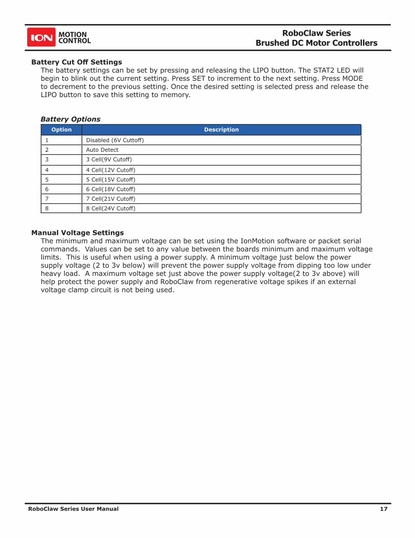
Battery Cut Off SettingsThe battery settings can be set by pressing and releasing the LIPO button. The STAT2 LED will begin to blink out the current setting. Press SET to increment to the next setting. Press MODE to decrement to the previous setting. Once the desired setting is selected press and release the LIPO button to save this setting to memory.
Battery OptionsOption Description
1 Disabled (6V Cuttoff)
2 Auto Detect
3 3 Cell(9V Cutoff)
4 4 Cell(12V Cutoff)
5 5 Cell(15V Cutoff)
6 6 Cell(18V Cutoff)
7 7 Cell(21V Cutoff)
8 8 Cell(24V Cutoff)
Manual Voltage SettingsThe minimum and maximum voltage can be set using the IonMotion software or packet serial commands. Values can be set to any value between the boards minimum and maximum voltage limits. This is useful when using a power supply. A minimum voltage just below the power supply voltage (2 to 3v below) will prevent the power supply voltage from dipping too low under heavy load. A maximum voltage set just above the power supply voltage(2 to 3v above) will help protect the power supply and RoboClaw from regenerative voltage spikes if an external voltage clamp circuit is not being used.

RoboClaw Series Brushed DC Motor Controllers
RoboClaw Series User Manual 18
USB CONTROL

RoboClaw Series Brushed DC Motor Controllers
RoboClaw Series User Manual 19
USB ConnectionWhen RoboClaw is connected, it will automatically detect it has been connected to a powered USB master and will enable USB communications. USB can be connected in any mode. When the Roboclaw is not in packet serial mode USB packet serial commands can be used to read status information and set configuration settings, however motor movement commands will not function. When in packet serial mode if another device such as an Arduino is connected to S1 and S2 pins and sending commands to the RoboClaw, both those commands and USB packet serial commands will execute.
USB PowerThe USB RoboClaw is self powered. This means it receives no power from the USB cable. The USB RoboClaw must be externally powered to function.
USB Comport and BaudrateThe RoboClaw will be detected as a CDC Virtual Comport. When connected to a Windows PC a driver must be installed. The driver is available for download from our website. On Linux or OSX the RoboClaw will be automatically detected as a virtual comport and an appropriate driver will be automatically loaded.
Unlike a real comport the USB CDC Virtual Comport does not need a baud rate to be set correctly. It will always communicate at the fastest speed the master and slave device can reach. This will typically be around 1mb/s.

RoboClaw Series Brushed DC Motor Controllers
RoboClaw Series User Manual 20
RC MODE

RoboClaw Series Brushed DC Motor Controllers
RoboClaw Series User Manual 21
RC ModeRC mode is typically used when controlling RoboClaw from a hobby RC radio. This mode can also be used to simplify driving RoboClaw from a microcontroller using servo pulses. In this mode S1 controls the direction and speed of motor 1 and S2 controls the direction and speed of motor 2.
RC Mode With MixingThis mode is the same as RC mode with the exception of how S1 and S2 controls the attached motors. When used with a differentially steered robot, mixing mode allows S1 to control the speed forward and backward and S2 to control steering left and right.
Using RC Mode with feedback for velocity/position controlRC Mode can be used with encoders. Velocity and/or Position PID constants must be calibrated for proper operation first. Once calibrated values have been set and saved into Roboclaws eeprom memory, encoder support using velocity or position PID control can be enabled. Use IonMotion control software or Packet Serial commands, enable encoders for RC/Analog modes(See General Settings in IonMotion).
RC Mode OptionsOption Function Description
1 TTL Flip Switch Flip switch triggered by low signal.
2 TTL Flip and Exponential Enabled Softens the center control position. This mode is ideal with tank style robots. Making it easier to control from an RC radio. Flip switch triggered by low signal.
3 TTL Flip and MCU Enabled Continues to execute last pulse received until new pulse received. Disables Signal loss fail safe and auto calibration. Flip switch triggered by low signal.
4 TTL Flip and Exponential and MCU Enabled Enables both options. Flip switch triggered by low signal.
5 RC Flip Switch Enabled Same as mode 1 with flip switch triggered by RC signal.
6 RC Flip and Exponential Enabled Same as mode 2 with flip switch triggered by RC signal.
7 RC Flip and MCU Enabled Same as mode 3 with flip switch triggered by RC signal.
8 RC Flip and Exponential and MCU Enabled Same as mode 4 with flip switch triggered by RC signal.
RoboClaw Series Brushed DC Motor Controllers
RoboClaw Series User Manual 22
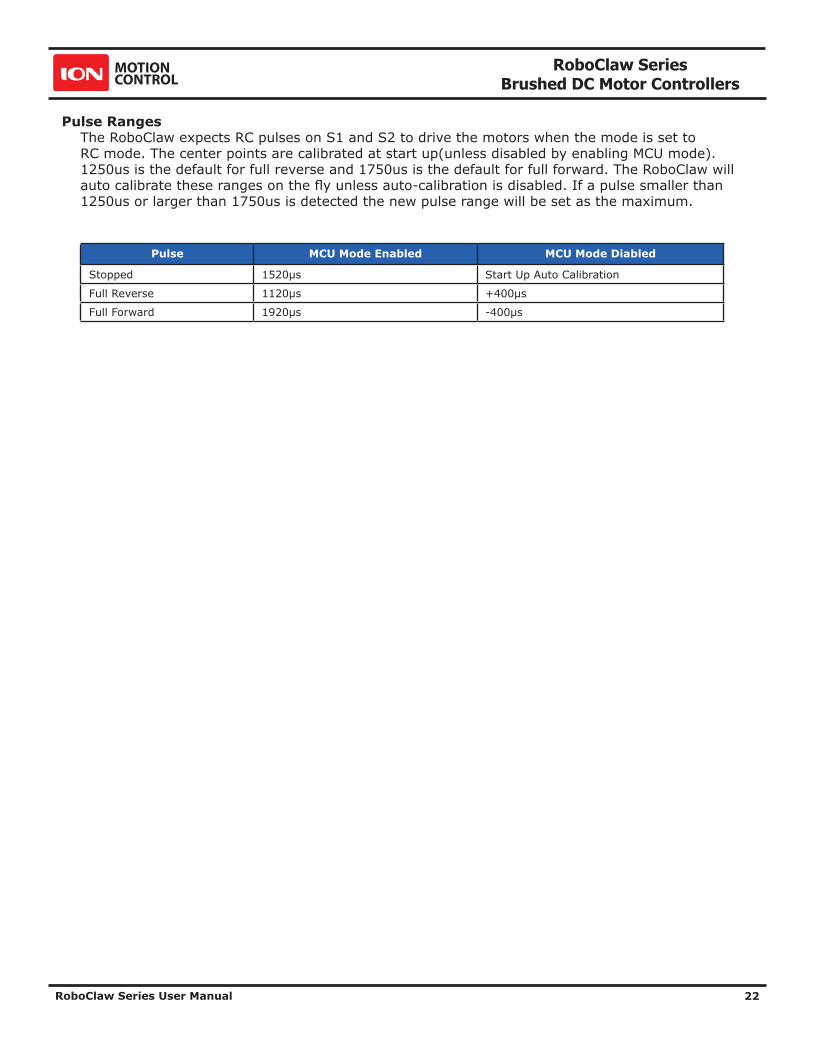
Pulse RangesThe RoboClaw expects RC pulses on S1 and S2 to drive the motors when the mode is set to RC mode. The center points are calibrated at start up(unless disabled by enabling MCU mode). 1250us is the default for full reverse and 1750us is the default for full forward. The RoboClaw will auto calibrate these ranges on the fly unless auto-calibration is disabled. If a pulse smaller than 1250us or larger than 1750us is detected the new pulse range will be set as the maximum.
Pulse MCU Mode Enabled MCU Mode Diabled
Stopped 1520μs Start Up Auto Calibration
Full Reverse 1120μs +400μs
Full Forward 1920μs -400μs

RoboClaw Series Brushed DC Motor Controllers
RoboClaw Series User Manual 23
RC Wiring ExampleConnect the RoboClaw as shown below. Set mode 1 with option 1. Before powering up, center the control sticks on the radio transmitter, turn the radio on first, then the receiver, then RoboClaw. It will take RoboClaw about 1 second to calibrate the neutral positions of the RC controller. After RC pulses start to be received and calibration is complete the Stat1 LED will begin to flash indicating signals from the RC receiver are being received.
M1A
M1B
M2B
M2A
Negative -
Positive +
+-
Battery
S1 Signal
S2 Signal
5VDC
Channel 1
Channel 2
GROUND5VDC
GROUND
Receiver
RoboClaw
Motor 1
Motor 2
D1
SW1

RoboClaw Series Brushed DC Motor Controllers
RoboClaw Series User Manual 24
RC Control - Arduino ExampleThe example will drive a 2 motor 4 wheel robot in reverse, stop, forward, left turn and then right turn. The program was written and tested with a Arduino Uno and P5 connected to S1, P6 connected to S2. Set mode 2 with option 4.
//RoboClaw RC Mode //Control RoboClaw with servo pulses from a microcontroller. //Mode settings: Mode 2(RC mixed mode) with Option 4(MCU with Exponential). #include <Servo.h> #define MIN 1250 #define MAX 1750 #define STOP 1500 Servo myservo1; // create servo object to control a RoboClaw channel Servo myservo2; // create servo object to control a RoboClaw channel int pos = 0; // variable to store the servo position void setup() { myservo1.attach(5); // attaches the RC signal on pin 5 to the servo object myservo2.attach(6); // attaches the RC signal on pin 6 to the servo object } void loop() { myservo1.writeMicroseconds(STOP); //Stop myservo2.writeMicroseconds(STOP); //Stop delay(2000); myservo1.writeMicroseconds(MIN); //full forward delay(1000); myservo1.writeMicroseconds(STOP); //stop delay(2000); myservo1.writeMicroseconds(MAX); //full reverse delay(1000); myservo1.writeMicroseconds(STOP); //Stop delay(2000); myservo2.writeMicroseconds(MIN); //full turn left delay(1000); myservo2.writeMicroseconds(STOP); //Stop delay(2000); myservo2.writeMicroseconds(MAX); //full turn right delay(1000); }
RoboClaw Series Brushed DC Motor Controllers
RoboClaw Series User Manual 25
ANALOG MODE

RoboClaw Series Brushed DC Motor Controllers
RoboClaw Series User Manual 26
Analog ModeAnalog mode is used when controlling RoboClaw from a potentiometer or a filtered PWM signal. In this mode S1 and S2 are set as analog inputs. The voltage range is 0V = Full reverse, 1V = Stop and 2V = Full forward.
Analog Mode With MixingThis mode is the same as Analog mode with the exception of how S1 and S2 control the attached motors. When used with a differentially steered robot, mixing mode allows S1 to control the speed forward and backward and S2 to control steering left and right.
Using Analog Mode with feedback for velocity/position controlAnalog Mode can be used with encoders. Velocity and/or Position PID constants must be calibrated for proper operation. Once calibrated values have been set and saved into Roboclaws eeprom, encoder support using velocity or position PID control can be enabled. Use IonMotion control software or PacketSerial commands to enable encoders for RC/Analog modes( see General Settings in IonMotion).
Analog Mode OptionsOption Function Description
1 TTL Flip Switch Flip switch triggered by low signal.
2 TTL Flip and Exponential Enabled Softens the center control position. This mode is ideal with tank style robots. Making it easier to control from an RC radio. Flip switch triggered by low signal.
3 TTL FLip and MCU Enabled Continues to execute last pulse received until new pulse received. Disables Signal loss fail safe and auto calibration. Flip switch triggered by low signal.
4 TTL FLip and Exponential and MCU Enabled
Enables both options. Flip switch triggered by low signal.
5 RC Flip Switch Enabled Same as mode 1 with flip switch triggered by RC signal.
6 RC Flip and Exponential Enabled Same as mode 2 with flip switch triggered by RC signal.
7 RC Flip and MCU Enabled Same as mode 3 with flip switch triggered by RC signal.
8 RC Flip and Exponential and MCU Enabled Same as mode 4 with flip switch triggered by RC signal.

RoboClaw Series Brushed DC Motor Controllers
RoboClaw Series User Manual 27
Analog Wiring ExampleRoboClaw uses a high speed 12 bit analog converter. Its range is 0 to 2V. The analog pins are protected and 5V tolerant. The potentiometer range will be limited if 5V is utilized as the reference voltage. A simple resistor divider circuit can be used to reduce the on board 5V to 2V for use with a potentiometer(POT). See the below schematic. The POT acts as one half of the resistor divider. If using a 5k potentiometer R1 / R2 = 7.5k, If using a 10k potentiometer R1 / R2 = 15k and if using a 20k potentiometer R1 / R2 = 30k. Set mode 3 with option 1. Center the potentiometers before applying power. The S1 potentiometer will control the motor 1 direction and speed. The S2 potentiometer will control the motor 2 direction and speed.
S2 Signal5VDC
GROUNDPot 2
S1 Signal5VDC
GROUNDPot 1 M1A
M1B
M2B
M2A
Negative -
Positive +
+-
Battery
RoboClaw
Motor 1
Motor 2
R2
R1
D1
SW1

RoboClaw Series Brushed DC Motor Controllers
RoboClaw Series User Manual 28
STANDARD SERIAL

RoboClaw Series Brushed DC Motor Controllers
RoboClaw Series User Manual 29
Standard Serial ModeIn this mode S1 accepts TTL level byte commands. Standard serial mode is one way serial data. RoboClaw can receive only. A standard 8N1 format is used. Which is 8 bits, no parity bits and 1 stop bit. If you are using a microcontroller you can interface directly to RoboClaw. If you are using a PC a level shifting circuit (eg: Max232) is required. The baud rate can be changed using the SET button once a serial mode has been selected.
Standard Serial communications has no error correction. It is recommended to use Packet Serial mode instead for more reliable communications.
Serial Mode Baud RatesOption Description
1 2400
2 9600
3 19200
4 38400
5 57600
6 115200
7 230400
8 460800
Standard Serial Command SyntaxThe RoboClaw standard serial is setup to control both motors with one byte sized command character. Since a byte can be any value from 0 to 255(or -128 to 127) the control of each motor is split. 1 to 127 controls channel 1 and 128 to 255(or -1 to -127) controls channel 2. Command value 0 will stop both channels. Any other values will control speed and direction of the specific channel.
Character Function
0 Shuts Down Channel 1 and 2
1 Channel 1 - Full Reverse
64 Channel 1 - Stop
127 Channel 1 - Full Forward
128 Channel 2 - Full Reverse
192 Channel 2 - Stop
255 Channel 2 - Full Forward
RoboClaw Series Brushed DC Motor Controllers
RoboClaw Series User Manual 30
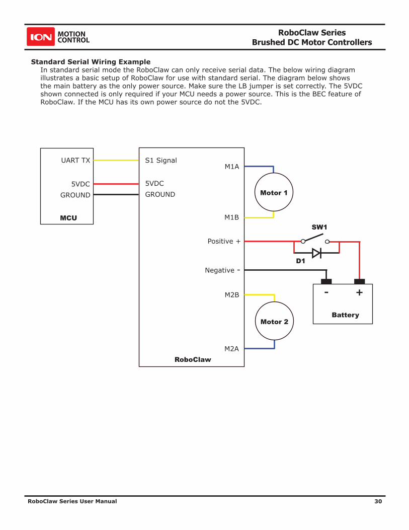
Standard Serial Wiring ExampleIn standard serial mode the RoboClaw can only receive serial data. The below wiring diagram illustrates a basic setup of RoboClaw for use with standard serial. The diagram below shows the main battery as the only power source. Make sure the LB jumper is set correctly. The 5VDC shown connected is only required if your MCU needs a power source. This is the BEC feature of RoboClaw. If the MCU has its own power source do not the 5VDC.
M1A
M1B
M2B
M2A
Negative -
Positive +
+-
Battery
S1 Signal
5VDC
UART TX
GROUND5VDC
GROUND
MCU
RoboClaw
Motor 1
Motor 2
D1
SW1

RoboClaw Series Brushed DC Motor Controllers
RoboClaw Series User Manual 31
Standard Serial Mode With Slave SelectSlave select is used when more than one RoboClaw is on the same serial bus. When slave select is set to ON the S2 pin becomes the select pin. Set S2 high (5V) and RoboClaw will execute the next set of commands sent to S1 pin. Set S2 low (0V) and RoboClaw will ignore all received commands.
Any RoboClaw connected to a bus must share a common signal ground (GND) shown by the black wire. The S1 pin of RoboClaw is the serial receive pin and should be connected to the transmit pin of the MCU. All RoboClaw’s S1 pins will be connected to the same MCU transmit pin. Each RoboClaw S2 pin should be connected to a unique I/O pin on the MCU. S2 is used as the control pin to activate the attached RoboClaw. To enable a RoboClaw hold its S2 pin high otherwise any commands sent are ignored.
The diagram below shows the main battery as the only power source. Make sure the LB jumper is set correctly. The 5VDC shown connected is only required if your MCU needs a power source. This is the BEC feature of RoboClaw. If the MCU has its own power source do not connect the 5VDC.
M1A
M1B
M2B
M2A
Negative -
Positive +
+-
Battery
S1 Signal
S2 Signal
5VDC
UART TX
OUT 1
GROUND5VDC
GROUND
MCU
RoboClaw
Motor 1
Motor 2
OUT 2
Connect to S2 of next RoboClaw
Connect to S1 of next RoboClaw
D1
SW1

RoboClaw Series Brushed DC Motor Controllers
RoboClaw Series User Manual 32
Standard Serial - Arduino ExampleThe following example will start both channels in reverse, stop, forward, stop, turn left, stop turn right stop. The program was written and tested with a Arduino Uno and Pin 11 connected to S1 and pin 10 connected to S2.
//Roboclaw simple serial example. Set mode to 5. Option to 4(38400 bps) #include "BMSerial.h" BMSerial mySerial(10,11); void setup() { mySerial.begin(38400); } void loop() { mySerial.write(1); mySerial.write(-127); delay(2000); mySerial.write(64); delay(1000); mySerial.write(127); mySerial.write(-1); delay(2000); mySerial.write(-64); delay(1000); mySerial.write(1); mySerial.write(-1); delay(2000); mySerial.write(0); delay(1000); mySerial.write(127); mySerial.write(-127); delay(2000); mySerial.write(0); delay(1000); }

RoboClaw Series Brushed DC Motor Controllers
RoboClaw Series User Manual 33
PACKET SERIAL

RoboClaw Series Brushed DC Motor Controllers
RoboClaw Series User Manual 34
Packet Serial ModePacket serial is a buffered bidirectional serial mode. More sophisticated instructions can be sent to RoboClaw. The basic command structures consist of an address byte, command byte, data bytes and a CRC16 16bit checksum. The amount of data each command will send or receive can vary.
AddressPacket serial requires a unique address when used with TTL serial pins(S1 and S2). With up to 8 addresses available you can have up to 8 RoboClaws bussed on the same RS232 port when properly wired. There are 8 packet modes 7 to 14. Each mode has a unique address. The address is selected by setting the desired packet mode using the MODE button.
NOTE: When using packet serial commands via the USB connection the address byte can be any value from 0x80 to 0x87 since each USB connection is already unique.
Packet Modes
Mode Description
7 Packet Serial Mode - Address 0x80 (128)
8 Packet Serial Mode - Address 0x81 (129)
9 Packet Serial Mode - Address 0x82 (130)
10 Packet Serial Mode - Address 0x83 (131)
11 Packet Serial Mode - Address 0x84 (132)
12 Packet Serial Mode - Address 0x85 (133)
13 Packet Serial Mode - Address 0x86 (134)
14 Packet Serial Mode - Address 0x87 (135)
Packet Serial Baud RateWhen in serial mode or packet serial mode the baud rate can be changed to one of four different settings in the table below. These are set using the SET button as covered in Mode Options.
Serial Mode OptionsOption Description
1 2400
2 9600
3 19200
4 38400
5 57600
6 115200
7 230400
8 460800

RoboClaw Series Brushed DC Motor Controllers
RoboClaw Series User Manual 35
Packet TimeoutWhen sending a packet to RoboClaw, if there is a delay longer than 10ms between bytes being received in a packet, RoboClaw will discard the entire packet. This will allow the packet buffer to be cleared by simply adding a minimum 10ms delay before sending a new packet command in the case of a communications error. This can usually be accomodated by having a 10ms timeout when waiting for a reply from the RoboClaw. If the reply times out the packet buffer will have been cleared automatically.
Packet AcknowledgementRoboClaw will send an acknowledgment byte on write only packet commands that are valid. The value sent back is 0xFF. If the packet was not valid for any reason no acknowledgement will be sent back.
CRC16 Checksum CalculationRoboclaw uses a CRC(Cyclic Redundancy Check) to validate each packet it receives. This is more complex than a simple checksum but prevents errors that could otherwise cause unexpected actions to execute on the Roboclaw.
The CRC can be calculated using the following code(example in C):
//Calculates CRC16 of nBytes of data in byte array messageunsigned int crc16(unsigned char *packet, int nBytes) { for (int byte = 0; byte < nBytes; byte++) { crc = crc ^ ((unsigned int)packet[byte] << 8); for (unsigned char bit = 0; bit < 8; bit++) { if (crc & 0x8000) { crc = (crc << 1) ^ 0x1021; } else { crc = crc << 1; } } } return crc;}
CRC16 Checksum Calculation for Received dataThe CRC16 calculation can also be used to validate received data from the Roboclaw. The CRC16 value should be calculated using the sent Address and Command byte as well as all the data received back from the Roboclaw except the two CRC16 bytes. The value calculated will match the CRC16 sent by the Roboclaw if there are no errors in the data sent or received.
Easy to use LibrariesSource code and Libraries are available on the Ion Motion Control website that already handle the complexities of using packet serial with the Roboclaw. Libraries are available for Arduino(C++), C# on Windows(.NET) or Linux(Mono) and Python(Raspberry Pi, Linux, OSX, etc).

RoboClaw Series Brushed DC Motor Controllers
RoboClaw Series User Manual 36
Handling values larger than a byteMany Packet Serial commands require values larger than a byte can hold. In order to send or receive those values they need to be broken up into 2 or more bytes. There are two ways this can be done, high byte first or low byte first. Roboclaw expects the high byte first. All command arguments and values are either single bytes, words (2 bytes) or longs (4 bytes). All arguments and values are integers (signed or unsigned). No floating point values (numbers with decimal places) are used in Packet Serial commands.
To convert a 32bit value into 4 bytes you just need to shift the bits around:
unsigned char byte3 = MyLongValue>>24; //High byteunsigned char byte2 = MyLongValue>>16;unsigned char byte1 = MyLongValue>>8;unsigned char byte0 = MyLongValue; //Low byte
The same applies to 16bit values:
unsigned char byte1 = MyWordValue>>8; //High byteunsigned char byte0 = MyWordValue; //Low byte
The oposite can also be done. Convert several bytes into a 16bit or 32bit value:
unsigned long MyLongValue = byte3<<24 | byte2<<16 | byte1<<8 | byte0;
unsigned int MyWordValue = byte1<<8 | byte0;
Packet Serial commands, when a value must be broken into multiple bytes or combined from multple bytes it will be indicated either by (2 bytes) or (4 bytes).

RoboClaw Series Brushed DC Motor Controllers
RoboClaw Series User Manual 37
Packet Serial WiringIn packet serial mode the RoboClaw can transmit and receive serial data. A microcontroller with a UART is recommended. The UART will buffer the data received from RoboClaw. When a request for data is made to RoboClaw the return data will have at least a 1ms delay after the command is received if the baudrate is set at or below 38400. This will allow slower processors and processors without UARTs to communicate with RoboClaw.
The diagram below shows the main battery as the only power source. Make sure the LB jumper is set correctly. The 5VDC shown connected is only required if your MCU needs a power source. This is the BEC feature of RoboClaw. If the MCU has its own power source do not connect the 5VDC.
M1A
M1B
M2B
M2A
Negative -
Positive +
+-
Battery
S1 Signal
S2 Signal
5VDC
UART TX
UART RX
GROUND5VDC
GROUND
MCU
RoboClaw
Motor 1
Motor 2
D1
SW1

RoboClaw Series Brushed DC Motor Controllers
RoboClaw Series User Manual 38
Multi-Unit Packet Serial WiringIn packet serial mode up to eight Roboclaw units can be controlled from a single serial port. The wiring diaghram below illustrates how this is done. Each Roboclaw must have multi-unit mode enabled and have a unique packet serial address set(see General Settings in IonMotion). Wire the S1 and S2 pins directly to the MCU TX and RX pins. Install a pullup resistor (R1) on the MCU RX pin. A 1K to 4.7K resistor value is recommended.
S1 Signal
S2 Signal
5VDCGROUND
RoboClaw 2
S1 Signal
S2 Signal
5VDCGROUND
RoboClaw 3
S1 Signal
S2 Signal
5VDCGROUND
RoboClaw 1
UART TX
UART RX
5VDCGROUND
MCU
R1
RoboClaw Series Brushed DC Motor Controllers
RoboClaw Series User Manual 39
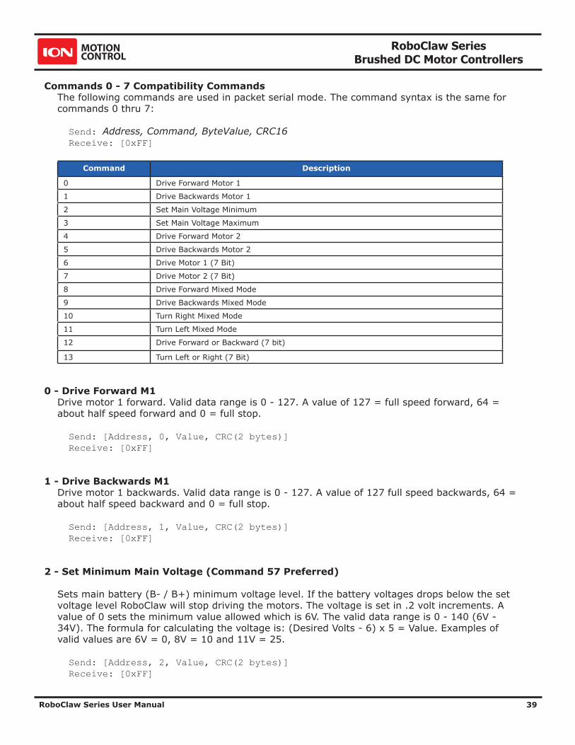
Commands 0 - 7 Compatibility CommandsThe following commands are used in packet serial mode. The command syntax is the same for commands 0 thru 7:
Send: Address, Command, ByteValue, CRC16 Receive: [0xFF]
Command Description
0 Drive Forward Motor 1
1 Drive Backwards Motor 1
2 Set Main Voltage Minimum
3 Set Main Voltage Maximum
4 Drive Forward Motor 2
5 Drive Backwards Motor 2
6 Drive Motor 1 (7 Bit)
7 Drive Motor 2 (7 Bit)
8 Drive Forward Mixed Mode
9 Drive Backwards Mixed Mode
10 Turn Right Mixed Mode
11 Turn Left Mixed Mode
12 Drive Forward or Backward (7 bit)
13 Turn Left or Right (7 Bit)
0 - Drive Forward M1Drive motor 1 forward. Valid data range is 0 - 127. A value of 127 = full speed forward, 64 = about half speed forward and 0 = full stop.
Send: [Address, 0, Value, CRC(2 bytes)] Receive: [0xFF]
1 - Drive Backwards M1 Drive motor 1 backwards. Valid data range is 0 - 127. A value of 127 full speed backwards, 64 = about half speed backward and 0 = full stop.
Send: [Address, 1, Value, CRC(2 bytes)] Receive: [0xFF]
2 - Set Minimum Main Voltage (Command 57 Preferred)
Sets main battery (B- / B+) minimum voltage level. If the battery voltages drops below the set voltage level RoboClaw will stop driving the motors. The voltage is set in .2 volt increments. A value of 0 sets the minimum value allowed which is 6V. The valid data range is 0 - 140 (6V - 34V). The formula for calculating the voltage is: (Desired Volts - 6) x 5 = Value. Examples of valid values are 6V = 0, 8V = 10 and 11V = 25.
Send: [Address, 2, Value, CRC(2 bytes)] Receive: [0xFF]

RoboClaw Series Brushed DC Motor Controllers
RoboClaw Series User Manual 40
3 - Set Maximum Main Voltage (Command 57 Preferred)
Sets main battery (B- / B+) maximum voltage level. The valid data range is 30 - 175 (6V - 34V). During regenerative breaking a back voltage is applied to charge the battery. When using a power supply, by setting the maximum voltage level, RoboClaw will, before exceeding it, go into hard braking mode until the voltage drops below the maximum value set. This will prevent overvoltage conditions when using power supplies. The formula for calculating the voltage is: Desired Volts x 5.12 = Value. Examples of valid values are 12V = 62, 16V = 82 and 24V = 123.
Send: [Address, 3, Value, CRC(2 bytes)] Receive: [0xFF]
4 - Drive Forward M2Drive motor 2 forward. Valid data range is 0 - 127. A value of 127 full speed forward, 64 = about half speed forward and 0 = full stop.
Send: [Address, 4, Value, CRC(2 bytes)] Receive: [0xFF]
5 - Drive Backwards M2 Drive motor 2 backwards. Valid data range is 0 - 127. A value of 127 full speed backwards, 64 = about half speed backward and 0 = full stop.
Send: [Address, 5, Value, CRC(2 bytes)] Receive: [0xFF]
6 - Drive M1 (7 Bit) Drive motor 1 forward or reverse. Valid data range is 0 - 127. A value of 0 = full speed reverse, 64 = stop and 127 = full speed forward.
Send: [Address, 6, Value, CRC(2 bytes)] Receive: [0xFF]
7 - Drive M2 (7 Bit) Drive motor 2 forward or reverse. Valid data range is 0 - 127. A value of 0 = full speed reverse, 64 = stop and 127 = full speed forward.
Send: [Address, 7, Value, CRC(2 bytes)] Receive: [0xFF]
RoboClaw Series Brushed DC Motor Controllers
RoboClaw Series User Manual 41
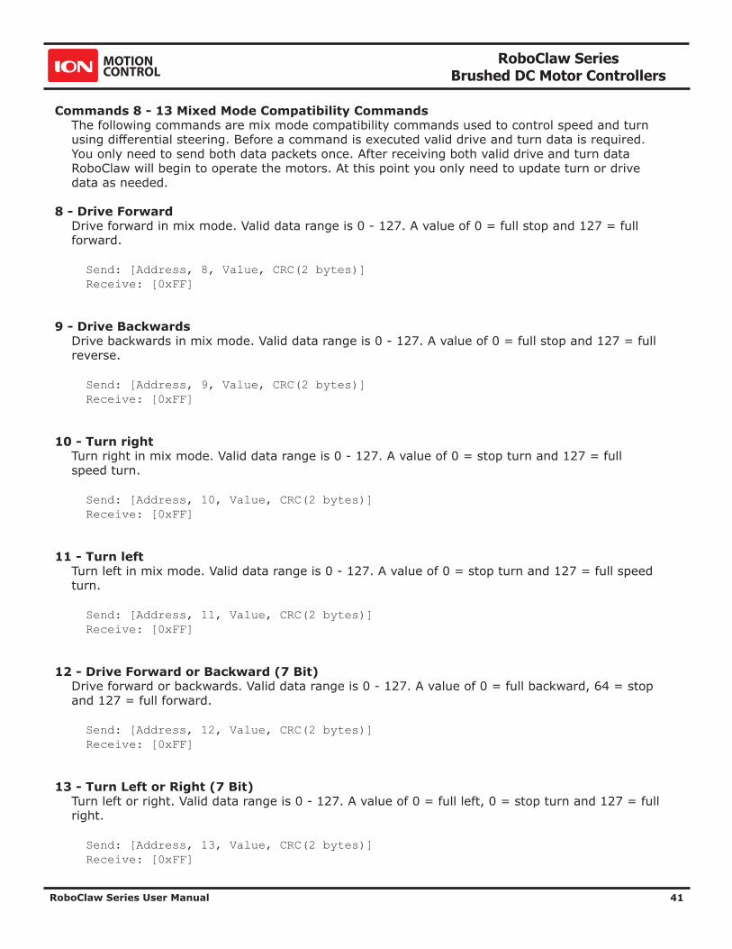
Commands 8 - 13 Mixed Mode Compatibility CommandsThe following commands are mix mode compatibility commands used to control speed and turn using differential steering. Before a command is executed valid drive and turn data is required. You only need to send both data packets once. After receiving both valid drive and turn data RoboClaw will begin to operate the motors. At this point you only need to update turn or drive data as needed.
8 - Drive ForwardDrive forward in mix mode. Valid data range is 0 - 127. A value of 0 = full stop and 127 = full forward.
Send: [Address, 8, Value, CRC(2 bytes)] Receive: [0xFF]
9 - Drive BackwardsDrive backwards in mix mode. Valid data range is 0 - 127. A value of 0 = full stop and 127 = full reverse.
Send: [Address, 9, Value, CRC(2 bytes)] Receive: [0xFF]
10 - Turn rightTurn right in mix mode. Valid data range is 0 - 127. A value of 0 = stop turn and 127 = full speed turn.
Send: [Address, 10, Value, CRC(2 bytes)] Receive: [0xFF]
11 - Turn leftTurn left in mix mode. Valid data range is 0 - 127. A value of 0 = stop turn and 127 = full speed turn.
Send: [Address, 11, Value, CRC(2 bytes)] Receive: [0xFF]
12 - Drive Forward or Backward (7 Bit)Drive forward or backwards. Valid data range is 0 - 127. A value of 0 = full backward, 64 = stop and 127 = full forward.
Send: [Address, 12, Value, CRC(2 bytes)] Receive: [0xFF]
13 - Turn Left or Right (7 Bit)Turn left or right. Valid data range is 0 - 127. A value of 0 = full left, 0 = stop turn and 127 = full right.
Send: [Address, 13, Value, CRC(2 bytes)] Receive: [0xFF]
RoboClaw Series Brushed DC Motor Controllers
RoboClaw Series User Manual 42
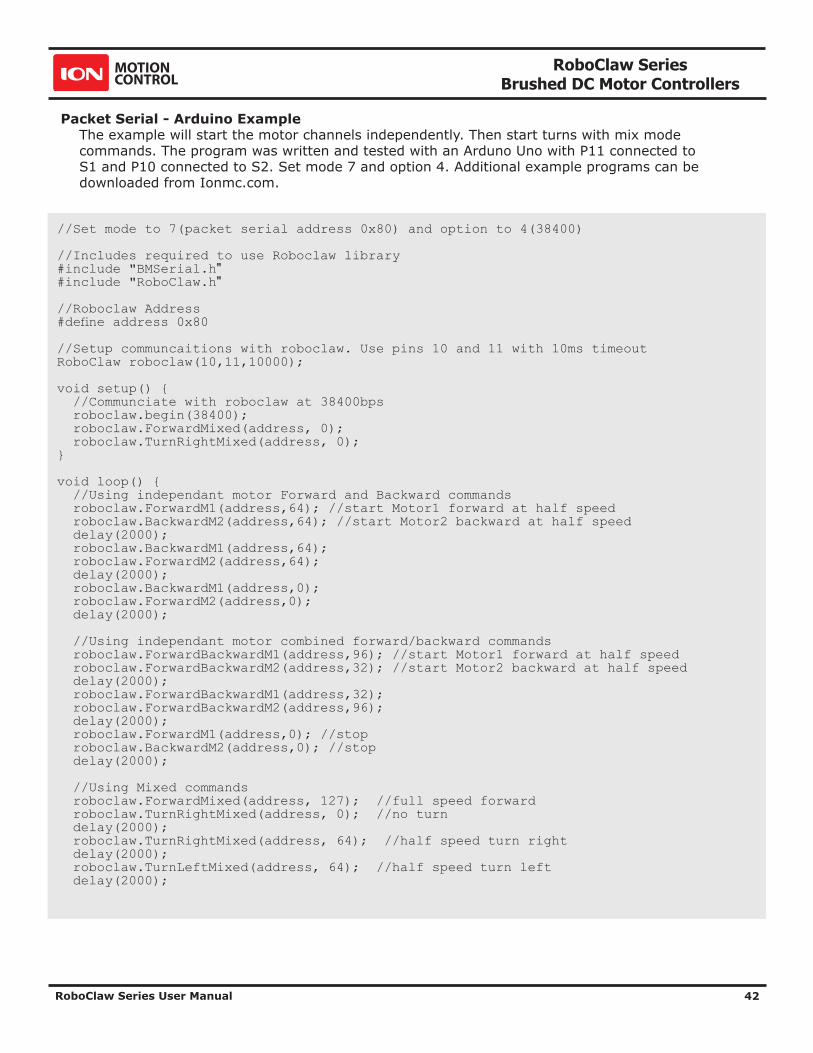
Packet Serial - Arduino ExampleThe example will start the motor channels independently. Then start turns with mix mode commands. The program was written and tested with an Arduno Uno with P11 connected to S1 and P10 connected to S2. Set mode 7 and option 4. Additional example programs can be downloaded from Ionmc.com.
//Set mode to 7(packet serial address 0x80) and option to 4(38400) //Includes required to use Roboclaw library #include "BMSerial.h" #include "RoboClaw.h" //Roboclaw Address #define address 0x80 //Setup communcaitions with roboclaw. Use pins 10 and 11 with 10ms timeout RoboClaw roboclaw(10,11,10000); void setup() { //Communciate with roboclaw at 38400bps roboclaw.begin(38400); roboclaw.ForwardMixed(address, 0); roboclaw.TurnRightMixed(address, 0); } void loop() { //Using independant motor Forward and Backward commands roboclaw.ForwardM1(address,64); //start Motor1 forward at half speed roboclaw.BackwardM2(address,64); //start Motor2 backward at half speed delay(2000); roboclaw.BackwardM1(address,64); roboclaw.ForwardM2(address,64); delay(2000); roboclaw.BackwardM1(address,0); roboclaw.ForwardM2(address,0); delay(2000); //Using independant motor combined forward/backward commands roboclaw.ForwardBackwardM1(address,96); //start Motor1 forward at half speed roboclaw.ForwardBackwardM2(address,32); //start Motor2 backward at half speed delay(2000); roboclaw.ForwardBackwardM1(address,32); roboclaw.ForwardBackwardM2(address,96); delay(2000); roboclaw.ForwardM1(address,0); //stop roboclaw.BackwardM2(address,0); //stop delay(2000); //Using Mixed commands roboclaw.ForwardMixed(address, 127); //full speed forward roboclaw.TurnRightMixed(address, 0); //no turn delay(2000); roboclaw.TurnRightMixed(address, 64); //half speed turn right delay(2000); roboclaw.TurnLeftMixed(address, 64); //half speed turn left delay(2000);

RoboClaw Series Brushed DC Motor Controllers
RoboClaw Series User Manual 43
roboclaw.TurnLeftMixed(address, 0); //stop turn roboclaw.BackwardMixed(address, 127); //half speed backward delay(2000); roboclaw.TurnRightMixed(address, 64); //half speed turn right delay(2000); roboclaw.TurnLeftMixed(address, 64); //half speed turn left delay(2000); roboclaw.ForwardMixed(address, 0); //stop going backward roboclaw.TurnRightMixed(address, 64); //half speed right turn delay(2000); roboclaw.TurnLeftMixed(address, 64); //half speed left turn delay(2000); roboclaw.TurnRightMixed(address, 0); //stop turn(full stop) delay(2000); }

RoboClaw Series Brushed DC Motor Controllers
RoboClaw Series User Manual 44
ADVANCED PACKET SERIAL

RoboClaw Series Brushed DC Motor Controllers
RoboClaw Series User Manual 45
Advance Packet SerialThe following commands are used to read board status, version information and set/read configuration values.
Command Description
21 Read Firmware Version
24 Read Main Battery Voltage
25 Read Logic Battery Voltage
26 Set Minimum Logic Voltage Level
27 Set Maximum Logic Voltage Level
48 Read Motor PWMs
49 Read Motor Currents
57 Set Main Battery Voltages
58 Set Logic Battery Voltages
59 Read Main Battery Voltage Settings
60 Read Logic Battery Voltage Settings
68 Set default duty cycle acceleration for M1
69 Set default duty cycle acceleration for M2
74 Set S3,S4 and S5 Modes
75 Read S3,S4 and S5 Modes
76 Set DeadBand for RC/Analog controls
77 Read DeadBand for RC/Analog controls
80 Restore Defaults
81 Read Default Duty Cycle Accelerations
82 Read Temperature
83 Read Temperature 2
90 Read Status
91 Read Encoder Modes
92 Set Motor 1 Encoder Mode
93 Set Motor 2 Encoder Mode
94 Write Settings to EEPROM
95 Read Settings from EEPROM
98 Set Standard Config Settings
99 Read Standard Config Settings
100 Set CTRL Modes
101 Read CTRL Modes
102 Set CTRL1
103 Set CTRL2
104 Read CTRLs
133 Set M1 Maximum Current
134 Set M2 Maximum Current
135 Read M1 Maximum Current
136 Read M2 Maximum Current
148 Set PWM Mode
149 Read PWM Mode

RoboClaw Series Brushed DC Motor Controllers
RoboClaw Series User Manual 46
21 - Read Firmware VersionRead RoboClaw firmware version. Returns up to 48 bytes(depending on the Roboclaw model) and is terminated by a line feed character and a null character.
Send: [Address, 21] Receive: [“RoboClaw 10.2A v4.1.11”,10,0, CRC(2 bytes)]
The command will return up to 48 bytes. The return string includes the product name and firmware version. The return string is terminated with a line feed (10) and null (0) character.
24 - Read Main Battery Voltage LevelRead the main battery voltage level connected to B+ and B- terminals. The voltage is returned in 10ths of a volt(eg 300 = 30v).
Send: [Address, 24] Receive: [Value(2 bytes), CRC(2 bytes)]
25 - Read Logic Battery Voltage LevelRead a logic battery voltage level connected to LB+ and LB- terminals. The voltage is returned in 10ths of a volt(eg 50 = 5v).
Send: [Address, 25] Receive: [Value.Byte1, Value.Byte0, CRC(2 bytes)]
26 - Set Minimum Logic Voltage LevelNote: This command is included for backwards compatibility. We recommend you use command 58 instead.
Sets logic input (LB- / LB+) minimum voltage level. RoboClaw will shut down with an error if the voltage is below this level. The voltage is set in .2 volt increments. A value of 0 sets the minimum value allowed which is 6V. The valid data range is 0 - 140 (6V - 34V). The formula for calculating the voltage is: (Desired Volts - 6) x 5 = Value. Examples of valid values are 6V = 0, 8V = 10 and 11V = 25.
Send: [Address, 26, Value, CRC(2 bytes)] Receive: [0xFF]
27 - Set Maximum Logic Voltage LevelNote: This command is included for backwards compatibility. We recommend you use command 58 instead.
Sets logic input (LB- / LB+) maximum voltage level. The valid data range is 30 - 175 (6V - 34V). RoboClaw will shutdown with an error if the voltage is above this level. The formula for calculating the voltage is: Desired Volts x 5.12 = Value. Examples of valid values are 12V = 62, 16V = 82 and 24V = 123.
Send: [Address, 27, Value, CRC(2 bytes)] Receive: [0xFF]

RoboClaw Series Brushed DC Motor Controllers
RoboClaw Series User Manual 47
48 - Read Motor PWM values Read the current PWM output values for the motor channels. The values returned are +-32767. The duty cycle percent is calculated by dividing the Value by 327.67.
Send: [Address, 48] Receive: [M1 PWM(2 bytes), M2 PWM(2 bytes), CRC(2 bytes)]
49 - Read Motor CurrentsRead the current draw from each motor in 10ma increments. The amps value is calculated by dividing the value by 100.
Send: [Address, 49] Receive: [M1 Current(2 bytes), M2 Currrent(2 bytes), CRC(2 bytes)]
57 - Set Main Battery VoltagesSet the Main Battery Voltage cutoffs, Min and Max. Min and Max voltages are in 10th of a volt increments. Multiply the voltage to set by 10.
Send: [Address, 57, Min(2 bytes), Max(2bytes, CRC(2 bytes)] Receive: [0xFF]
58 - Set Logic Battery VoltagesSet the Logic Battery Voltages cutoffs, Min and Max. Min and Max voltages are in 10th of a volt increments. Multiply the voltage to set by 10.
Send: [Address, 58, Min(2 bytes), Max(2bytes, CRC(2 bytes)] Receive: [0xFF]
59 - Read Main Battery Voltage SettingsRead the Main Battery Voltage Settings. The voltage is calculated by dividing the value by 10
Send: [Address, 59] Receive: [Min(2 bytes), Max(2 bytes), CRC(2 bytes)]
60 - Read Logic Battery Voltage SettingsRead the Logic Battery Voltage Settings. The voltage is calculated by dividing the value by 10
Send: [Address, 60] Receive: [Min(2 bytes), Max(2 bytes), CRC(2 bytes)]
68 - Set M1 Default Duty AccelerationSet the default acceleration for M1 when using duty cycle commands(Cmds 32,33 and 34) or when using Standard Serial, RC and Analog PWM modes.
Send: [Address, 68, Accel(4 bytes), CRC(2 bytes)] Receive: [0xFF]

RoboClaw Series Brushed DC Motor Controllers
RoboClaw Series User Manual 48
69 - Set M2 Default Duty AccelerationSet the default acceleration for M2 when using duty cycle commands(Cmds 32,33 and 34) or when using Standard Serial, RC and Analog PWM modes.
Send: [Address, 69, Accel(4 bytes), CRC(2 bytes)] Receive: [0xFF]
74 - Set S3, S4 and S5 Modes Set modes for S3,S4 and S5.
Send: [Address, 74, S3mode, S4mode, S5mode, CRC(2 bytes)] Receive: [0xFF]
Mode S3mode S4mode S5mode
0 Default Disabled Disabled
1 E-Stop(latching) E-Stop(latching) E-Stop(latching)
2 E-Stop E-Stop E-Stop
3 Voltage Clamp Voltage Clamp Voltage Clamp
4 M1 Home M2 Home
Mode Description:Disabled: pin is inactive.Default: Flip switch if in RC/Analog mode or E-Stop(latching) in Serial modes.E-Stop(Latching): causes the Roboclaw to shutdown until the unit is power cycled.E-Stop: Holds the Roboclaw in shutdown until the E-Stop signal is cleared.Voltage Clamp: Sets the signal pin as an output to drive an external voltage clamp circuitHome(M1 & M2): will trigger the specific motor to stop and the encoder count to reset to 0.
75 - Get S3, S4 amd S5 Modes Read mode settings for S3,S4 and S5. See command 74 for mode descriptions
Send: [Address, 75] Receive: [S3mode, S4mode, S5mode, CRC(2 bytes)]
76 - Set DeadBand for RC/Analog controlsSet RC/Analog mode control deadband percentage in 10ths of a percent. Default value is 25(2.5%). Minimum value is 0(no DeadBand), Maximum value is 250(25%).
Send: [Address, 76, Reverse, Forward, CRC(2 bytes)] Receive: [0xFF]
77 - Read DeadBand for RC/Analog controls Read DeadBand settings in 10ths of a percent.
Send: [Address, 77] Receive: [Reverse, SForward, CRC(2 bytes)]

RoboClaw Series Brushed DC Motor Controllers
RoboClaw Series User Manual 49
80 - Restore DefaultsReset Settings to factory defaults.
Send: [Address, 80] Receive: [0xFF]
81 - Read Default Duty Acceleration SettingsRead M1 and M2 Duty Cycle Acceleration Settings.
Send: [Address, 81]Receive: [M1Accel(4 bytes), M2Accel(4 bytes), CRC(2 bytes)]
82 - Read TemperatureRead the board temperature. Value returned is in 10ths of degrees.
Send: [Address, 82] Receive: [Temperature(2 bytes), CRC(2 bytes)]
83 - Read Temperature 2Read the second board temperature(only on supported units). Value returned is in 10ths of degrees.
Send: [Address, 83] Receive: [Temperature(2 bytes), CRC(2 bytes)]

RoboClaw Series Brushed DC Motor Controllers
RoboClaw Series User Manual 50
90 - Read StatusRead the current unit status.
Send: [Address, 90] Receive: [Status, CRC(2 bytes)]
Function Status Bit Mask
Normal 0x0000
M1 OverCurrent Warning 0x0001
M2 OverCurrent Warning 0x0002
E-Stop 0x0004
Temperature Error 0x0008
Temperature2 Error 0x0010
Main Battery High Error 0x0020
Logic Battery High Error 0x0040
Logic Battery Low Error 0x0080
M1 Driver Fault 0x0100
M2 Driver Fault 0x0200
Main Battery High Warning 0x0400
Main Battery Low Warning 0x0800
Termperature Warning 0x1000
Temperature2 Warning 0x2000
M1 Home 0x4000
M2 Home 0x8000
91 - Read Encoder ModeRead the encoder mode for both motors.
Send: [Address, 91] Receive: [Enc1Mode, Enc2Mode, CRC(2 bytes)]
Encoder Mode bits Bit 7 Enable RC/Analog Encoder support Bit 6-1 N/A Bit 0 Quadrature(0)/Absolute(1)
92 - Set Motor 1 Encoder ModeSet the Encoder Mode for motor 1. See command 91.
Send: [Address, 92, Mode, CRC(2 bytes)]Receive: [0xFF]
93 - Set Motor 2 Encoder ModeSet the Encoder Mode for motor 2. See command 91.
Send: [Address, 93, Mode, CRC(2 bytes)]Receive: [0xFF]

RoboClaw Series Brushed DC Motor Controllers
RoboClaw Series User Manual 51
94 - Write Settings to EEPROMWrites all settings to non-volatile memory. Values will be loaded after each power up.
Send: [Address, 94]Receive: [0xFF]
95 - Read Settings from EEPROMRead all settings from non-volatile memory.
Send: [Address, 95]Receive: [Enc1Mode, Enc2Mode, CRC(2 bytes)]

RoboClaw Series Brushed DC Motor Controllers
RoboClaw Series User Manual 52
98 - Set Standard Config SettingsSet config bits for standard settings.
Send: [Address, 98, Config(2 bytes), CRC(2 bytes)]Receive: [0xFF]
Function Config Bit Mask
RC Mode 0x0000
Analog Mode 0x0001
Simple Serial Mode 0x0002
Packet Serial Mode 0x0003
Battery Mode Off 0x0000
Battery Mode Auto 0x0004
Battery Mode 2 Cell 0x0008
Battery Mode 3 Cell 0x000C
Battery Mode 4 Cell 0x0010
Battery Mode 5 Cell 0x0014
Battery Mode 6 Cell 0x0018
Battery Mode 7 Cell 0x001C
Mixing 0x0020
Exponential 0x0040
MCU 0x0080
BaudRate 2400 0x0000
BaudRate 9600 0x0020
BaudRate 19200 0x0040
BaudRate 38400 0x0060
BaudRate 57600 0x0080
BaudRate 115200 0x00A0
BaudRate 230400 0x00C0
BaudRate 460800 0x00E0
FlipSwitch 0x0100
Packet Address 0x80 0x0000
Packet Address 0x81 0x0100
Packet Address 0x82 0x0200
Packet Address 0x83 0x0300
Packet Address 0x84 0x0400
Packet Address 0x85 0x0500
Packet Address 0x86 0x0600
Packet Address 0x87 0x0700
Slave Mode 0x0800
Relay Mode 0X1000
Swap Encoders 0x2000
Swap Buttons 0x4000
Multi-Unit Mode 0x8000
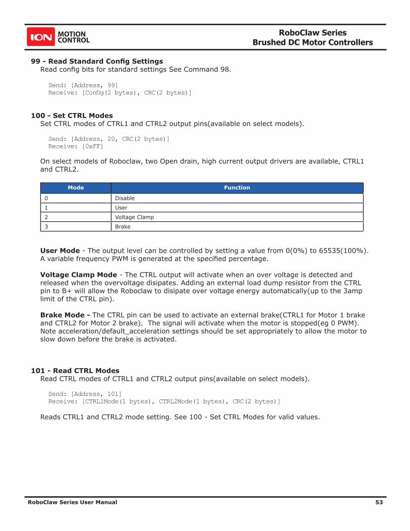
RoboClaw Series Brushed DC Motor Controllers
RoboClaw Series User Manual 53
99 - Read Standard Config SettingsRead config bits for standard settings See Command 98.
Send: [Address, 99]Receive: [Config(2 bytes), CRC(2 bytes)]
100 - Set CTRL ModesSet CTRL modes of CTRL1 and CTRL2 output pins(available on select models).
Send: [Address, 20, CRC(2 bytes)]Receive: [0xFF]
On select models of Roboclaw, two Open drain, high current output drivers are available, CTRL1 and CTRL2.
Mode Function
0 Disable
1 User
2 Voltage Clamp
3 Brake
User Mode - The output level can be controlled by setting a value from 0(0%) to 65535(100%). A variable frequency PWM is generated at the specified percentage.
Voltage Clamp Mode - The CTRL output will activate when an over voltage is detected and released when the overvoltage disipates. Adding an external load dump resistor from the CTRL pin to B+ will allow the Roboclaw to disipate over voltage energy automatically(up to the 3amp limit of the CTRL pin).
Brake Mode - The CTRL pin can be used to activate an external brake(CTRL1 for Motor 1 brake and CTRL2 for Motor 2 brake). The signal will activate when the motor is stopped(eg 0 PWM). Note acceleration/default_acceleration settings should be set appropriately to allow the motor to slow down before the brake is activated.
101 - Read CTRL ModesRead CTRL modes of CTRL1 and CTRL2 output pins(available on select models).
Send: [Address, 101]Receive: [CTRL1Mode(1 bytes), CTRL2Mode(1 bytes), CRC(2 bytes)]
Reads CTRL1 and CTRL2 mode setting. See 100 - Set CTRL Modes for valid values.
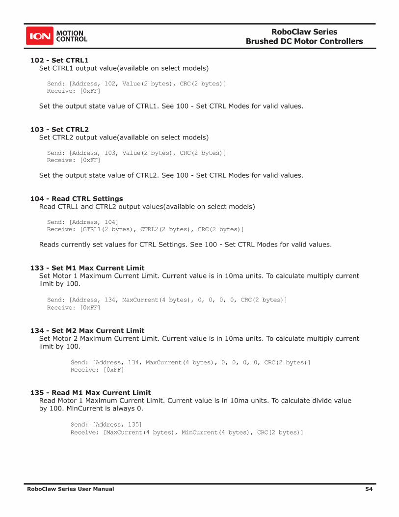
RoboClaw Series Brushed DC Motor Controllers
RoboClaw Series User Manual 54
102 - Set CTRL1Set CTRL1 output value(available on select models)
Send: [Address, 102, Value(2 bytes), CRC(2 bytes)]Receive: [0xFF]
Set the output state value of CTRL1. See 100 - Set CTRL Modes for valid values.
103 - Set CTRL2Set CTRL2 output value(available on select models)
Send: [Address, 103, Value(2 bytes), CRC(2 bytes)]Receive: [0xFF]
Set the output state value of CTRL2. See 100 - Set CTRL Modes for valid values.
104 - Read CTRL SettingsRead CTRL1 and CTRL2 output values(available on select models)
Send: [Address, 104]Receive: [CTRL1(2 bytes), CTRL2(2 bytes), CRC(2 bytes)]
Reads currently set values for CTRL Settings. See 100 - Set CTRL Modes for valid values.
133 - Set M1 Max Current LimitSet Motor 1 Maximum Current Limit. Current value is in 10ma units. To calculate multiply current limit by 100.
Send: [Address, 134, MaxCurrent(4 bytes), 0, 0, 0, 0, CRC(2 bytes)]Receive: [0xFF]
134 - Set M2 Max Current LimitSet Motor 2 Maximum Current Limit. Current value is in 10ma units. To calculate multiply current limit by 100.
Send: [Address, 134, MaxCurrent(4 bytes), 0, 0, 0, 0, CRC(2 bytes)] Receive: [0xFF]
135 - Read M1 Max Current LimitRead Motor 1 Maximum Current Limit. Current value is in 10ma units. To calculate divide value by 100. MinCurrent is always 0.
Send: [Address, 135] Receive: [MaxCurrent(4 bytes), MinCurrent(4 bytes), CRC(2 bytes)]

RoboClaw Series Brushed DC Motor Controllers
RoboClaw Series User Manual 55
136 - Read M2 Max Current LimitRead Motor 2 Maximum Current Limit. Current value is in 10ma units. To calculate divide value by 100. MinCurrent is always 0.
Send: [Address, 136] Receive: [MaxCurrent(4 bytes), MinCurrent(4 bytes), CRC(2 bytes)]
148 - Set PWM ModeSet PWM Drive mode. Locked Antiphase(0) or Sign Magnitude(1).
Send: [Address, 148, Mode, CRC(2 bytes)] Receive: [0xFF]
149 - Read PWM ModeRead PWM Drive mode. See Command 148.
Send: [Address, 149] Receive: [PWMMode, CRC(2 bytes)]

RoboClaw Series Brushed DC Motor Controllers
RoboClaw Series User Manual 56
ENCODERS

RoboClaw Series Brushed DC Motor Controllers
RoboClaw Series User Manual 57
Quadrature EncodersRoboClaw is capable of reading two quadrature encoders, one for each motor channel. The main RoboClaw header provides two +5VDC connections with dual A and B input signals for each encoder.
In a robot with two motor configurations one motor will spin clock wise (CW) while the other motor will spin counter clock wise (CCW). The A and B inputs for one of the encoders must be reversed as shown. If both encoder are connected with leading edge pulse to channel A one will count up and the other down. This will cause commands like Mix Drive Forward to not work as expected.
The diagram below shows the main battery as the only power source. Make sure the LB jumper is set correctly. The 5VDC shown connected is only required if your MCU needs a power source. This is the BEC feature of RoboClaw. If the MCU has its own power source do not the 5VDC.
M1A
M1B
M2B
M2A
Negative -
Positive +
+-
Battery
S1 Signal
S2 Signal
5VDC
UART TX
UART RX
GROUND5VDC
GROUND
MCU
RoboClaw
Motor 1
Motor 2
Encoder 1
AB
GND+5V
EN1 AEN1 B
5VDCGROUND
Encoder 2
AB
GND+5V
EN2 BEN2 A
5VDCGROUND
D1
SW1

RoboClaw Series Brushed DC Motor Controllers
RoboClaw Series User Manual 58
Absolute EncoderRoboClaw is capable of reading absolute encoders that output an analog voltage. Like the Analog input modes for controlling the motors, the absolute encoder voltage must be between 0v and 2v. If using standard potentiometers as absolute encoders the 5v from the RoboClaw can be divided down to 2v at the potentiometer by adding a resistor from the 5v line on the RoboClaw to the potentiometer. For a 5k pot R1 / R2 = 7.5k, for a 10k pot R1 / R2 = 15k and for a 20k pot R1 / R2 = 30k.
The diagram below shows the main battery as the only power source. Make sure the LB jumper is set correctly. The 5VDC shown connected is only required if your MCU needs a power source. This is the BEC feature of RoboClaw. If the MCU has its own power source do not connect the 5VDC.
Encoder Calibration for Velocity and Position ControlTo control motors speed and/or position with encoders correctly the Roboclaw must have its settings calibrated for the specific motors/encoders being used. The IonMotion software makes calibrating manually easy and also offers an autotune function for both velocity and position control modes.
Once the calibration settings for the specific mode you will be using(velocity, position or a cascaded velocity/position control) are set and working correctly within the IonMotion software the settings can be saved to the RoboClaw eeprom and will be loaded each time the unit powers up.
Motor 1
AGND+2V
M1A
M1B
Positive +
+-
Battery
S1 Signal
S2 Signal
5VDC
UART TX
UART RX
GROUND5VDC
GROUND
RoboClaw
Motor 2
EN1 A
5VDCGROUND
Pot 2A
GND+2V
EN2 A
5VDCGROUND
Pot 1
R1
R2
M2B
M2A
Negative -D1
SW1

RoboClaw Series Brushed DC Motor Controllers
RoboClaw Series User Manual 59
Velocity Calibration Procedure1. Determine the quadrature pulses per second(QPPS) value for your motor. The simplest method to do this is to run the Motor at 100% duty using IonMotion and read back the speed value from the encoder attached to the motor. If you are unable to run the motor like this due to physical constraints you will need to estimate the maximum speed in encoder counts the motor can produce.
2. Set the initial P,I and D values in the Velocity control window to 1,0 and 0. Try moving the motor using the slider controls in IonMotion. If the motor does not move it may not be wired correctly or the P value needs to be increased. If the motor immediately runs at max speed when you change the slider position you probably have the motor or encoder wires reversed. The motor is trying to go at the speed specified but the encoder reading is coming back in the opposite direction so the motor increases power until it eventually hits 100% power. Reverse the encoder or motor wires(not both) and test again.
3. Once the motor has some semblance of control you can set a moderate speed. Then start increasing the P value until the speed reading is near the set value. If the motor feels like it is vibrating at higher P values you should reduce the P value to about 2/3rds that value. Move on to the I setting.
4. Start increasing the I setting. You will usually want to increase this value by .1 increments. The I value helps the motor reach the exact speed specified. Too high an I value will also cause the motor to feel rough/vibrate. This is because the motor will over shoot the set speed and then the controller will reduce power to get the speed back down which will also under shoot and this will continue oscillating back and forth form too fast to too slow, causing a vibration in the motor.
5. Once P and I are set reasonably well usually you will leave D = 0. D is only required if you are unable to get reasonable speed control out of the motor using just P and I. D will help dampen P and I over shoot allowing higher P and I values, but D also increases noise in the calculation which can cause oscillations in the speed as well.
Position Calibration Procedure1. Position mode requires the Velocity mode QPPS value be set as described above. For simple Position control you can set Velocity P, I and D all to 0.
2. Set the Position I and D settings to 0. Set the P setting to 2000 as a reasonable starting point. To test the motor you must also set the Speed argument to some value. We recommend setting it to the same value as the QPPS setting(eg maximum motor speed). Set the minimum and maximum position values to safe numbers. If your motor has no dead stops this can be +-2 billion. If your motor has specific dead stops(like on a linear actuator) you will need to manually move the motor to its dead stops to determine these numbers. Leave some margin infront of each deadstop. Note that when using quadrature encoders you will need to home your motor on every power up since the quadrature readings are all relative to the starting position unless you set/reset the encoder values.
3. At this point the motor should move in the appropriate direction and stop, not necessarily close to the set position when you move the slider. Increase the P setting until the position is over shooting some each time you change the position slider. Now start increasing the D setting(leave I at 0). Increasing D will add dampening to the movement when getting close to the set position. This will help prevent the over shoot. D will usually be anywhere from 5 to 20 times larger than P but not always. Continue increasing P and D until the motor is working reasonably well. Once it is you have tuned a simple PD system.
RoboClaw Series Brushed DC Motor Controllers
RoboClaw Series User Manual 60
4. Once your position control is acting relatively smoothly and coming close to the set position you can think about adjusting the I setting. Adding I will help reach the exact set point specified but in most motor systems there is enough slop in the gears that instead you will end up causing an oscillation around the specified position. This is called hunting. The I setting causes this when there is any slop in the motor/encoder/gear train. You can compensate some for this by adding deadzone. Deadzone is the area around the specified position the controller will consider to be equal to the position specified.
5. One more setting must be adjusted in order to use the I setting. The Imax value sets the maximum wind up allowed for the I setting calculation. Increasing Imax will allow I to affect a larger amount of the movement of the motor but will also allow the system to oscillate if used with a badly tuned I and/or set too high.
Auto TuningIonMotion includes the option to autotune velocity and or position values. To use these options you should first make sure your encoder and motor are running in the correct direction and that basic PWM control of the motor works as expected. To do this go to the PWM Settings screen in IonMotion. Slide the motor slider up to start moving the motor forward. Check the encoder is increasing in value. If it is not either reverse the motor wires or the encoder wires.
If you are using autotune for Position control you must first set the motors QPPS value. Unlike Velocity autotune the QPPS value will not be automatically measured. This is because most position control systems have a limited range of movement. Once you have manually set the motors QPPS value(eg the maximum speed the motor can run at) you can continue with Position autotuning.
Then just click the autotune button for the motor you want to tune. The autotune function will try to determine the best settings for the motor. In the Velocity settings window it will autotune for velocity. In the Position Settings window you have the option to tune a simple PD position controller, a PID position controller or a cascaded Position/Velocity controller(PIV). The cascaded tune will determine both the velocity and position values for the motor but still requires the QPPS be manually set for the motor before starting. Autotune functions usually return reasonable values but in most cases you will still need to manually adjust them for optimum performance.
If the motor or encoder are wired incorrectly, the autotune function can lock up and RoboClaw will become unresponsive. Correct the wiring problem and reset RoboClaw to continue.
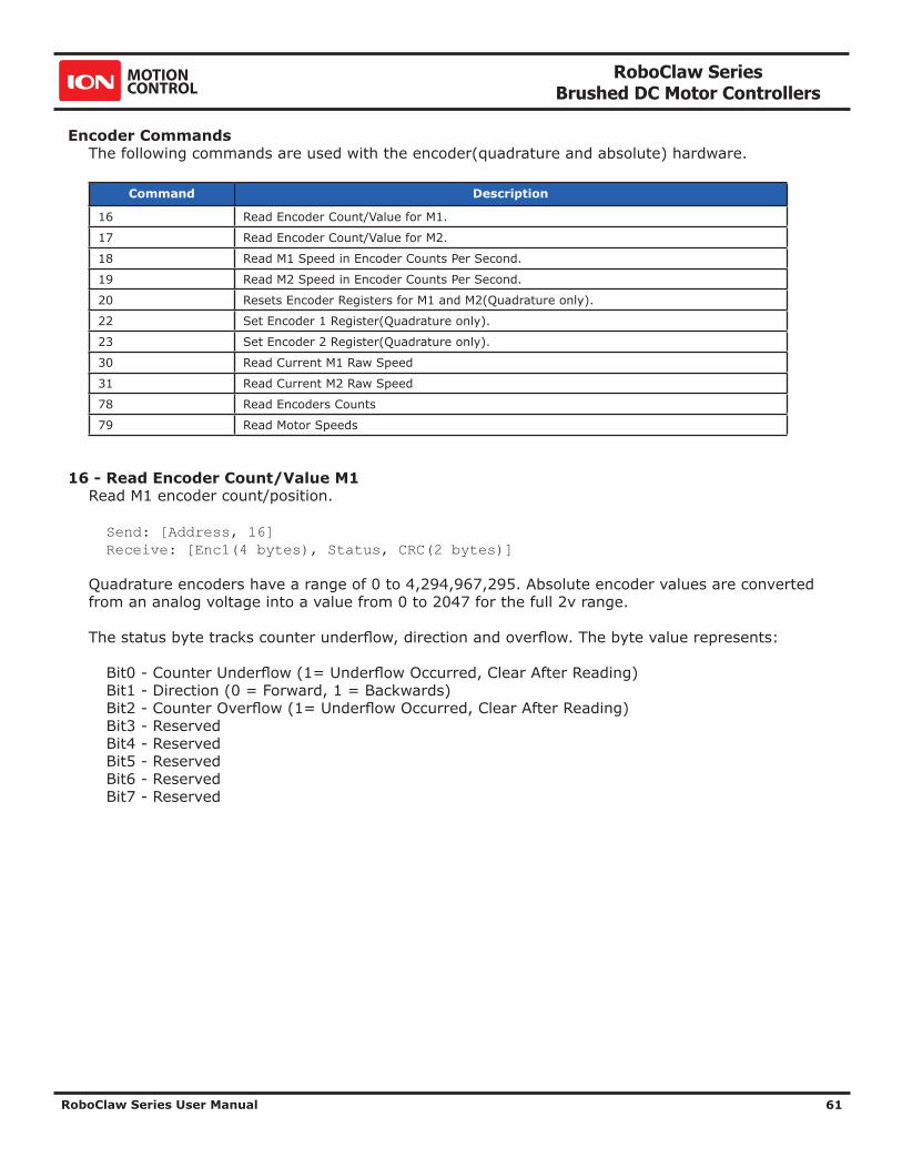
RoboClaw Series Brushed DC Motor Controllers
RoboClaw Series User Manual 61
Encoder CommandsThe following commands are used with the encoder(quadrature and absolute) hardware.
Command Description
16 Read Encoder Count/Value for M1.
17 Read Encoder Count/Value for M2.
18 Read M1 Speed in Encoder Counts Per Second.
19 Read M2 Speed in Encoder Counts Per Second.
20 Resets Encoder Registers for M1 and M2(Quadrature only).
22 Set Encoder 1 Register(Quadrature only).
23 Set Encoder 2 Register(Quadrature only).
30 Read Current M1 Raw Speed
31 Read Current M2 Raw Speed
78 Read Encoders Counts
79 Read Motor Speeds
16 - Read Encoder Count/Value M1Read M1 encoder count/position.
Send: [Address, 16] Receive: [Enc1(4 bytes), Status, CRC(2 bytes)]
Quadrature encoders have a range of 0 to 4,294,967,295. Absolute encoder values are converted from an analog voltage into a value from 0 to 2047 for the full 2v range.
The status byte tracks counter underflow, direction and overflow. The byte value represents:
Bit0 - Counter Underflow (1= Underflow Occurred, Clear After Reading) Bit1 - Direction (0 = Forward, 1 = Backwards) Bit2 - Counter Overflow (1= Underflow Occurred, Clear After Reading) Bit3 - Reserved Bit4 - Reserved Bit5 - Reserved Bit6 - Reserved Bit7 - Reserved
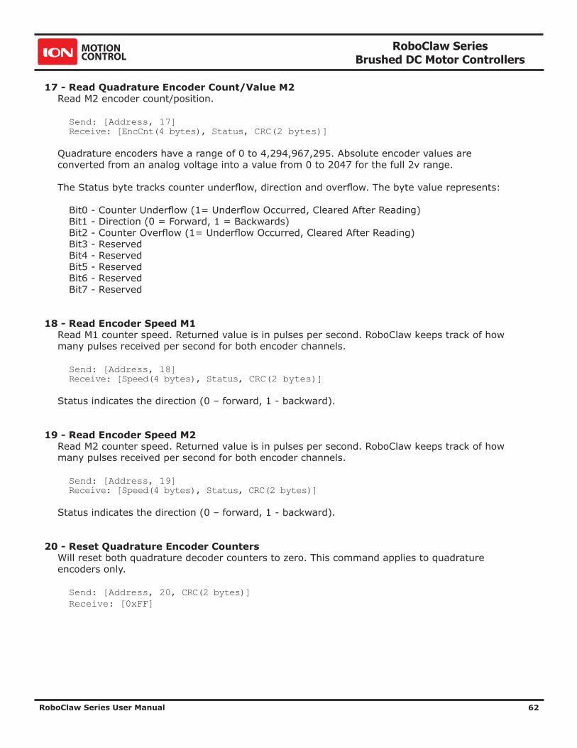
RoboClaw Series Brushed DC Motor Controllers
RoboClaw Series User Manual 62
17 - Read Quadrature Encoder Count/Value M2Read M2 encoder count/position.
Send: [Address, 17] Receive: [EncCnt(4 bytes), Status, CRC(2 bytes)]
Quadrature encoders have a range of 0 to 4,294,967,295. Absolute encoder values are converted from an analog voltage into a value from 0 to 2047 for the full 2v range.
The Status byte tracks counter underflow, direction and overflow. The byte value represents:
Bit0 - Counter Underflow (1= Underflow Occurred, Cleared After Reading) Bit1 - Direction (0 = Forward, 1 = Backwards) Bit2 - Counter Overflow (1= Underflow Occurred, Cleared After Reading) Bit3 - Reserved Bit4 - Reserved Bit5 - Reserved Bit6 - Reserved Bit7 - Reserved
18 - Read Encoder Speed M1Read M1 counter speed. Returned value is in pulses per second. RoboClaw keeps track of how many pulses received per second for both encoder channels.
Send: [Address, 18] Receive: [Speed(4 bytes), Status, CRC(2 bytes)]
Status indicates the direction (0 – forward, 1 - backward).
19 - Read Encoder Speed M2Read M2 counter speed. Returned value is in pulses per second. RoboClaw keeps track of how many pulses received per second for both encoder channels.
Send: [Address, 19] Receive: [Speed(4 bytes), Status, CRC(2 bytes)]
Status indicates the direction (0 – forward, 1 - backward).
20 - Reset Quadrature Encoder CountersWill reset both quadrature decoder counters to zero. This command applies to quadrature encoders only.
Send: [Address, 20, CRC(2 bytes)] Receive: [0xFF]

RoboClaw Series Brushed DC Motor Controllers
RoboClaw Series User Manual 63
22 - Set Quadrature Encoder 1 ValueSet the value of the Encoder 1 register. Useful when homing motor 1. This command applies to quadrature encoders only.
Send: [Address, 22, Value(4 bytes), CRC(2 bytes)] Receive: [0xFF]
23 - Set Quadrature Encoder 2 ValueSet the value of the Encoder 2 register. Useful when homing motor 2. This command applies to quadrature encoders only.
Send: [Address, 23, Value(4 bytes), CRC(2 bytes)] Receive: [0xFF]
30 - Read Raw Speed M1Read the pulses counted in that last 300th of a second. This is an unfiltered version of command 18. Command 30 can be used to make a independent PID routine. Value returned is in encoder counts per second.
Send: [Address, 30] Receive: [Speed(4 bytes), Status, CRC(2 bytes)]
The Status byte is direction (0 – forward, 1 - backward).
31 - Read Raw Speed M2Read the pulses counted in that last 300th of a second. This is an unfiltered version of command 19. Command 31 can be used to make a independent PID routine. Value returned is in encoder counts per second.
Send: [Address, 31] Receive: [Speed(4 bytes), Status, CRC(2 bytes)]
The Status byte is direction (0 – forward, 1 - backward).
78 - Read Encoder CountersRead M1 and M2 encoder counters. Quadrature encoders have a range of 0 to 4,294,967,295. Absolute encoder values are converted from an analog voltage into a value from 0 to 2047 for the full 2V analog range.
Send: [Address, 78]Receive: [Enc1(4 bytes), Enc2(4 bytes), CRC(2 bytes)]
79 - Read ISpeeds CountersRead M1 and M2 instantaneous speeds. Returns the speed in encoder counts per second for the last 300th of a second for both encoder channels.
Send: [Address, 79]Receive: [ISpeed1(4 bytes), ISpeed2(4 bytes), CRC(2 bytes)]

RoboClaw Series Brushed DC Motor Controllers
RoboClaw Series User Manual 64
Advanced Motor ControlThe following commands are used to control motor speeds, acceleration distance and position using encoders.
Command Description
28 Set Velocity PID Constants for M1.
29 Set Velocity PID Constants for M2.
32 Drive M1 With Signed Duty Cycle. (Encoders not required)
33 Drive M2 With Signed Duty Cycle. (Encoders not required)
34 Drive M1 / M2 With Signed Duty Cycle. (Encoders not required)
35 Drive M1 With Signed Speed.
36 Drive M2 With Signed Speed.
37 Drive M1 / M2 With Signed Speed.
38 Drive M1 With Signed Speed And Acceleration.
39 Drive M2 With Signed Speed And Acceleration.
40 Drive M1 / M2 With Signed Speed And Acceleration.
41 Drive M1 With Signed Speed And Distance. Buffered.
42 Drive M2 With Signed Speed And Distance. Buffered.
43 Drive M1 / M2 With Signed Speed And Distance. Buffered.
44 Drive M1 With Signed Speed, Acceleration and Distance. Buffered.
45 Drive M2 With Signed Speed, Acceleration and Distance. Buffered.
46 Drive M1 / M2 With Signed Speed, Acceleration And Distance. Buffered.
47 Read Buffer Length.
50 Drive M1 / M2 With Individual Signed Speed and Acceleration
51 Drive M1 / M2 With Individual Signed Speed, Accel and Distance
52 Drive M1 With Signed Duty and Accel. (Encoders not required)
53 Drive M2 With Signed Duty and Accel. (Encoders not required)
54 Drive M1 / M2 With Signed Duty and Accel. (Encoders not required)
55 Read Motor 1 Velocity PID Constants
56 Read Motor 2 Velocity PID Constants
61 Set Position PID Constants for M1.
62 Set Position PID Constants for M2
63 Read Motor 1 Position PID Constants
64 Read Motor 2 Position PID Constants
65 Drive M1 with Speed, Accel, Deccel and Position
66 Drive M2 with Speed, Accel, Deccel and Position
67 Drive M1 / M2 with Speed, Accel, Deccel and Position
68 Set default duty cycle acceleration for M1
69 Set default duty cycle acceleration for M2

RoboClaw Series Brushed DC Motor Controllers
RoboClaw Series User Manual 65
28 - Set Velocity PID Constants M1Several motor and quadrature combinations can be used with RoboClaw. In some cases the default PID values will need to be tuned for the systems being driven. This gives greater flexibility in what motor and encoder combinations can be used. The RoboClaw PID system consist of four constants starting with QPPS, P = Proportional, I= Integral and D= Derivative. The defaults values are:
QPPS = 44000 P = 0x00010000 I = 0x00008000 D = 0x00004000
QPPS is the speed of the encoder when the motor is at 100% power. P, I, D are the default values used after a reset. Command syntax:
Send: [Address, 28, D(4 bytes), P(4 bytes), I(4 bytes), QPPS(4 byte), CRC(2 bytes)]Receive: [0xFF]
29 - Set Velocity PID Constants M2Several motor and quadrature combinations can be used with RoboClaw. In some cases the default PID values will need to be tuned for the systems being driven. This gives greater flexibility in what motor and encoder combinations can be used. The RoboClaw PID system consist of four constants starting with QPPS, P = Proportional, I= Integral and D= Derivative. The defaults values are:
QPPS = 44000 P = 0x00010000 I = 0x00008000 D = 0x00004000
QPPS is the speed of the encoder when the motor is at 100% power. P, I, D are the default values used after a reset. Command syntax:
Send: [Address, 29, D(4 bytes), P(4 bytes), I(4 bytes), QPPS(4 byte), CRC(2 bytes)]Re-ceive: [0xFF]
32 - Drive M1 With Signed Duty CycleDrive M1 using a duty cycle value. The duty cycle is used to control the speed of the motor without a quadrature encoder.
Send: [Address, 32, Duty(2 Bytes), CRC(2 bytes)]Receive: [0xFF]
The duty value is signed and the range is -32767 to +32767 (eg. +-100% duty).

RoboClaw Series Brushed DC Motor Controllers
RoboClaw Series User Manual 66
33 - Drive M2 With Signed Duty CycleDrive M2 using a duty cycle value. The duty cycle is used to control the speed of the motor without a quadrature encoder. The command syntax:
Send: [Address, 33, Duty(2 Bytes), CRC(2 bytes)]Receive: [0xFF]
The duty value is signed and the range is -32768 to +32767 (eg. +-100% duty).
34 - Drive M1 / M2 With Signed Duty CycleDrive both M1 and M2 using a duty cycle value. The duty cycle is used to control the speed of the motor without a quadrature encoder. The command syntax:
Send: [Address, 34, DutyM1(2 Bytes), DutyM2(2 Bytes), CRC(2 bytes)]Receive: [0xFF]
The duty value is signed and the range is -32768 to +32767 (eg. +-100% duty).

RoboClaw Series Brushed DC Motor Controllers
RoboClaw Series User Manual 67
35 - Drive M1 With Signed SpeedDrive M1 using a speed value. The sign indicates which direction the motor will turn. This command is used to drive the motor by quad pulses per second. Different quadrature encoders will have different rates at which they generate the incoming pulses. The values used will differ from one encoder to another. Once a value is sent the motor will begin to accelerate as fast as possible until the defined rate is reached.
Send: [Address, 35, Speed(4 Bytes), CRC(2 bytes)]Receive: [0xFF]
36 - Drive M2 With Signed SpeedDrive M2 with a speed value. The sign indicates which direction the motor will turn. This command is used to drive the motor by quad pulses per second. Different quadrature encoders will have different rates at which they generate the incoming pulses. The values used will differ from one encoder to another. Once a value is sent, the motor will begin to accelerate as fast as possible until the rate defined is reached.
Send: [Address, 36, Speed(4 Bytes), CRC(2 bytes)]Receive: [0xFF]
37 - Drive M1 / M2 With Signed SpeedDrive M1 and M2 in the same command using a signed speed value. The sign indicates which direction the motor will turn. This command is used to drive both motors by quad pulses per second. Different quadrature encoders will have different rates at which they generate the incoming pulses. The values used will differ from one encoder to another. Once a value is sent the motor will begin to accelerate as fast as possible until the rate defined is reached.
Send: [Address, 37, SpeedM1(4 Bytes), SpeedM2(4 Bytes), CRC(2 bytes)]Receive: [0xFF]
38 - Drive M1 With Signed Speed And AccelerationDrive M1 with a signed speed and acceleration value. The sign indicates which direction the motor will run. The acceleration values are not signed. This command is used to drive the motor by quad pulses per second and using an acceleration value for ramping. Different quadrature encoders will have different rates at which they generate the incoming pulses. The values used will differ from one encoder to another. Once a value is sent the motor will begin to accelerate incrementally until the rate defined is reached.
Send: [Address, 38, Accel(4 Bytes), Speed(4 Bytes), CRC(2 bytes)]Receive: [0xFF]
The acceleration is measured in speed increase per second. An acceleration value of 12,000 QPPS with a speed of 12,000 QPPS would accelerate a motor from 0 to 12,000 QPPS in 1 second. Another example would be an acceleration value of 24,000 QPPS and a speed value of 12,000 QPPS would accelerate the motor to 12,000 QPPS in 0.5 seconds.
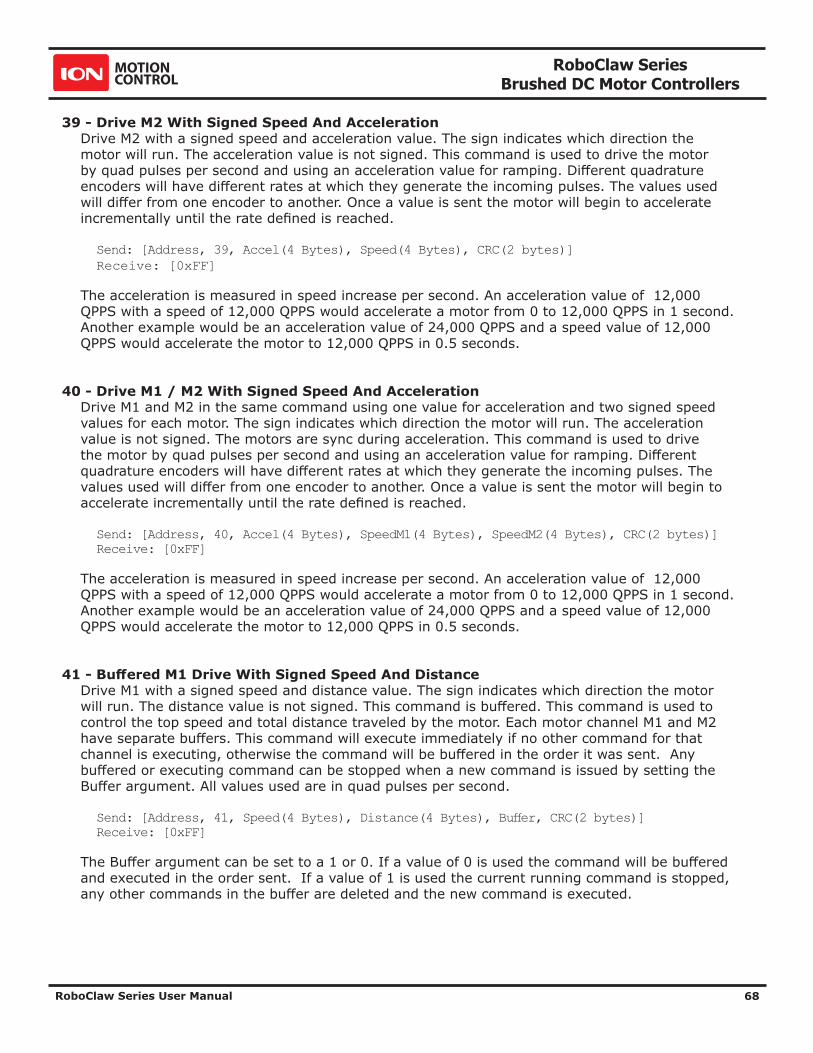
RoboClaw Series Brushed DC Motor Controllers
RoboClaw Series User Manual 68
39 - Drive M2 With Signed Speed And AccelerationDrive M2 with a signed speed and acceleration value. The sign indicates which direction the motor will run. The acceleration value is not signed. This command is used to drive the motor by quad pulses per second and using an acceleration value for ramping. Different quadrature encoders will have different rates at which they generate the incoming pulses. The values used will differ from one encoder to another. Once a value is sent the motor will begin to accelerate incrementally until the rate defined is reached.
Send: [Address, 39, Accel(4 Bytes), Speed(4 Bytes), CRC(2 bytes)] Receive: [0xFF]
The acceleration is measured in speed increase per second. An acceleration value of 12,000 QPPS with a speed of 12,000 QPPS would accelerate a motor from 0 to 12,000 QPPS in 1 second. Another example would be an acceleration value of 24,000 QPPS and a speed value of 12,000 QPPS would accelerate the motor to 12,000 QPPS in 0.5 seconds.
40 - Drive M1 / M2 With Signed Speed And AccelerationDrive M1 and M2 in the same command using one value for acceleration and two signed speed values for each motor. The sign indicates which direction the motor will run. The acceleration value is not signed. The motors are sync during acceleration. This command is used to drive the motor by quad pulses per second and using an acceleration value for ramping. Different quadrature encoders will have different rates at which they generate the incoming pulses. The values used will differ from one encoder to another. Once a value is sent the motor will begin to accelerate incrementally until the rate defined is reached.
Send: [Address, 40, Accel(4 Bytes), SpeedM1(4 Bytes), SpeedM2(4 Bytes), CRC(2 bytes)]Receive: [0xFF]
The acceleration is measured in speed increase per second. An acceleration value of 12,000 QPPS with a speed of 12,000 QPPS would accelerate a motor from 0 to 12,000 QPPS in 1 second. Another example would be an acceleration value of 24,000 QPPS and a speed value of 12,000 QPPS would accelerate the motor to 12,000 QPPS in 0.5 seconds.
41 - Buffered M1 Drive With Signed Speed And DistanceDrive M1 with a signed speed and distance value. The sign indicates which direction the motor will run. The distance value is not signed. This command is buffered. This command is used to control the top speed and total distance traveled by the motor. Each motor channel M1 and M2 have separate buffers. This command will execute immediately if no other command for that channel is executing, otherwise the command will be buffered in the order it was sent. Any buffered or executing command can be stopped when a new command is issued by setting the Buffer argument. All values used are in quad pulses per second.
Send: [Address, 41, Speed(4 Bytes), Distance(4 Bytes), Buffer, CRC(2 bytes)]Receive: [0xFF]
The Buffer argument can be set to a 1 or 0. If a value of 0 is used the command will be buffered and executed in the order sent. If a value of 1 is used the current running command is stopped, any other commands in the buffer are deleted and the new command is executed.

RoboClaw Series Brushed DC Motor Controllers
RoboClaw Series User Manual 69
42 - Buffered M2 Drive With Signed Speed And DistanceDrive M2 with a speed and distance value. The sign indicates which direction the motor will run. The distance value is not signed. This command is buffered. Each motor channel M1 and M2 have separate buffers. This command will execute immediately if no other command for that channel is executing, otherwise the command will be buffered in the order it was sent. Any buffered or executing command can be stopped when a new command is issued by setting the Buffer argument. All values used are in quad pulses per second.
Send: [Address, 42, Speed(4 Bytes), Distance(4 Bytes), Buffer, CRC(2 bytes)]Receive: [0xFF]
The Buffer argument can be set to a 1 or 0. If a value of 0 is used the command will be buffered and executed in the order sent. If a value of 1 is used the current running command is stopped, any other commands in the buffer are deleted and the new command is executed.
43 - Buffered Drive M1 / M2 With Signed Speed And DistanceDrive M1 and M2 with a speed and distance value. The sign indicates which direction the motor will run. The distance value is not signed. This command is buffered. Each motor channel M1 and M2 have separate buffers. This command will execute immediately if no other command for that channel is executing, otherwise the command will be buffered in the order it was sent. Any buffered or executing command can be stopped when a new command is issued by setting the Buffer argument. All values used are in quad pulses per second.
Send: [Address, 43, SpeedM1(4 Bytes), DistanceM1(4 Bytes), SpeedM2(4 Bytes), DistanceM2(4 Bytes), Buffer, CRC(2 bytes)]Receive: [0xFF]
The Buffer argument can be set to a 1 or 0. If a value of 0 is used the command will be buffered and executed in the order sent. If a value of 1 is used the current running command is stopped, any other commands in the buffer are deleted and the new command is executed.
44 - Buffered M1 Drive With Signed Speed, Accel And DistanceDrive M1 with a speed, acceleration and distance value. The sign indicates which direction the motor will run. The acceleration and distance values are not signed. This command is used to control the motors top speed, total distanced traveled and at what incremental acceleration value to use until the top speed is reached. Each motor channel M1 and M2 have separate buffers. This command will execute immediately if no other command for that channel is executing, otherwise the command will be buffered in the order it was sent. Any buffered or executing command can be stopped when a new command is issued by setting the Buffer argument. All values used are in quad pulses per second.
Send: [Address, 44, Accel(4 bytes), Speed(4 Bytes), Distance(4 Bytes), Buffer, CRC(2 bytes)]Receive: [0xFF]
The Buffer argument can be set to a 1 or 0. If a value of 0 is used the command will be buffered and executed in the order sent. If a value of 1 is used the current running command is stopped, any other commands in the buffer are deleted and the new command is executed.
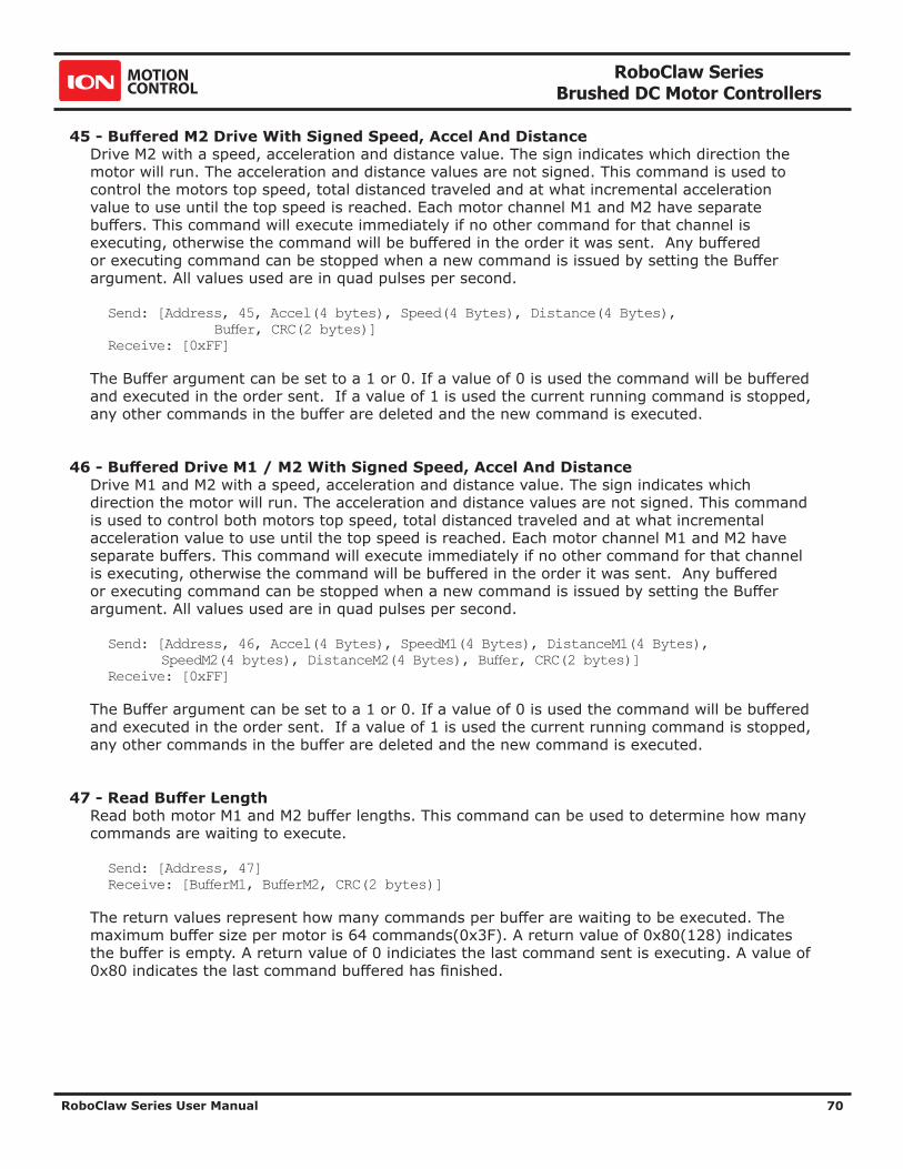
RoboClaw Series Brushed DC Motor Controllers
RoboClaw Series User Manual 70
45 - Buffered M2 Drive With Signed Speed, Accel And DistanceDrive M2 with a speed, acceleration and distance value. The sign indicates which direction the motor will run. The acceleration and distance values are not signed. This command is used to control the motors top speed, total distanced traveled and at what incremental acceleration value to use until the top speed is reached. Each motor channel M1 and M2 have separate buffers. This command will execute immediately if no other command for that channel is executing, otherwise the command will be buffered in the order it was sent. Any buffered or executing command can be stopped when a new command is issued by setting the Buffer argument. All values used are in quad pulses per second.
Send: [Address, 45, Accel(4 bytes), Speed(4 Bytes), Distance(4 Bytes), Buffer, CRC(2 bytes)]Receive: [0xFF]
The Buffer argument can be set to a 1 or 0. If a value of 0 is used the command will be buffered and executed in the order sent. If a value of 1 is used the current running command is stopped, any other commands in the buffer are deleted and the new command is executed.
46 - Buffered Drive M1 / M2 With Signed Speed, Accel And DistanceDrive M1 and M2 with a speed, acceleration and distance value. The sign indicates which direction the motor will run. The acceleration and distance values are not signed. This command is used to control both motors top speed, total distanced traveled and at what incremental acceleration value to use until the top speed is reached. Each motor channel M1 and M2 have separate buffers. This command will execute immediately if no other command for that channel is executing, otherwise the command will be buffered in the order it was sent. Any buffered or executing command can be stopped when a new command is issued by setting the Buffer argument. All values used are in quad pulses per second.
Send: [Address, 46, Accel(4 Bytes), SpeedM1(4 Bytes), DistanceM1(4 Bytes), SpeedM2(4 bytes), DistanceM2(4 Bytes), Buffer, CRC(2 bytes)]Receive: [0xFF]
The Buffer argument can be set to a 1 or 0. If a value of 0 is used the command will be buffered and executed in the order sent. If a value of 1 is used the current running command is stopped, any other commands in the buffer are deleted and the new command is executed.
47 - Read Buffer LengthRead both motor M1 and M2 buffer lengths. This command can be used to determine how many commands are waiting to execute.
Send: [Address, 47]Receive: [BufferM1, BufferM2, CRC(2 bytes)]
The return values represent how many commands per buffer are waiting to be executed. The maximum buffer size per motor is 64 commands(0x3F). A return value of 0x80(128) indicates the buffer is empty. A return value of 0 indiciates the last command sent is executing. A value of 0x80 indicates the last command buffered has finished.
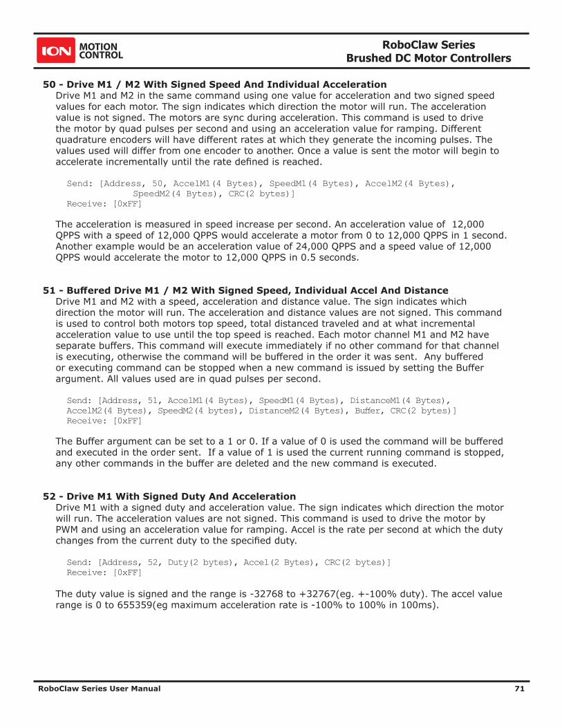
RoboClaw Series Brushed DC Motor Controllers
RoboClaw Series User Manual 71
50 - Drive M1 / M2 With Signed Speed And Individual AccelerationDrive M1 and M2 in the same command using one value for acceleration and two signed speed values for each motor. The sign indicates which direction the motor will run. The acceleration value is not signed. The motors are sync during acceleration. This command is used to drive the motor by quad pulses per second and using an acceleration value for ramping. Different quadrature encoders will have different rates at which they generate the incoming pulses. The values used will differ from one encoder to another. Once a value is sent the motor will begin to accelerate incrementally until the rate defined is reached.
Send: [Address, 50, AccelM1(4 Bytes), SpeedM1(4 Bytes), AccelM2(4 Bytes), SpeedM2(4 Bytes), CRC(2 bytes)]Receive: [0xFF]
The acceleration is measured in speed increase per second. An acceleration value of 12,000 QPPS with a speed of 12,000 QPPS would accelerate a motor from 0 to 12,000 QPPS in 1 second. Another example would be an acceleration value of 24,000 QPPS and a speed value of 12,000 QPPS would accelerate the motor to 12,000 QPPS in 0.5 seconds.
51 - Buffered Drive M1 / M2 With Signed Speed, Individual Accel And DistanceDrive M1 and M2 with a speed, acceleration and distance value. The sign indicates which direction the motor will run. The acceleration and distance values are not signed. This command is used to control both motors top speed, total distanced traveled and at what incremental acceleration value to use until the top speed is reached. Each motor channel M1 and M2 have separate buffers. This command will execute immediately if no other command for that channel is executing, otherwise the command will be buffered in the order it was sent. Any buffered or executing command can be stopped when a new command is issued by setting the Buffer argument. All values used are in quad pulses per second.
Send: [Address, 51, AccelM1(4 Bytes), SpeedM1(4 Bytes), DistanceM1(4 Bytes), AccelM2(4 Bytes), SpeedM2(4 bytes), DistanceM2(4 Bytes), Buffer, CRC(2 bytes)]Receive: [0xFF]
The Buffer argument can be set to a 1 or 0. If a value of 0 is used the command will be buffered and executed in the order sent. If a value of 1 is used the current running command is stopped, any other commands in the buffer are deleted and the new command is executed.
52 - Drive M1 With Signed Duty And AccelerationDrive M1 with a signed duty and acceleration value. The sign indicates which direction the motor will run. The acceleration values are not signed. This command is used to drive the motor by PWM and using an acceleration value for ramping. Accel is the rate per second at which the duty changes from the current duty to the specified duty.
Send: [Address, 52, Duty(2 bytes), Accel(2 Bytes), CRC(2 bytes)]Receive: [0xFF]
The duty value is signed and the range is -32768 to +32767(eg. +-100% duty). The accel value range is 0 to 655359(eg maximum acceleration rate is -100% to 100% in 100ms).

RoboClaw Series Brushed DC Motor Controllers
RoboClaw Series User Manual 72
53 - Drive M2 With Signed Duty And AccelerationDrive M1 with a signed duty and acceleration value. The sign indicates which direction the motor will run. The acceleration values are not signed. This command is used to drive the motor by PWM and using an acceleration value for ramping. Accel is the rate at which the duty changes from the current duty to the specified dury.
Send: [Address, 53, Duty(2 bytes), Accel(2 Bytes), CRC(2 bytes)]Receive: [0xFF]
The duty value is signed and the range is -32768 to +32767 (eg. +-100% duty). The accel value range is 0 to 655359 (eg maximum acceleration rate is -100% to 100% in 100ms).
54 - Drive M1 / M2 With Signed Duty And AccelerationDrive M1 and M2 in the same command using acceleration and duty values for each motor. The sign indicates which direction the motor will run. The acceleration value is not signed. This command is used to drive the motor by PWM using an acceleration value for ramping. The command syntax:
Send: [Address, CMD, DutyM1(2 bytes), AccelM1(4 Bytes), DutyM2(2 bytes), AccelM1(4 bytes), CRC(2 bytes)]Receive: [0xFF]
The duty value is signed and the range is -32768 to +32767 (eg. +-100% duty). The accel value range is 0 to 655359 (eg maximum acceleration rate is -100% to 100% in 100ms).
55 - Read Motor 1 Velocity PID and QPPS SettingsRead the PID and QPPS Settings.
Send: [Address, 55]Receive: [P(4 bytes), I(4 bytes), D(4 bytes), QPPS(4 byte), CRC(2 bytes)]
56 - Read Motor 2 Velocity PID and QPPS SettingsRead the PID and QPPS Settings.
Send: [Address, 56]Receive: [P(4 bytes), I(4 bytes), D(4 bytes), QPPS(4 byte), CRC(2 bytes)]
61 - Set Motor 1 Position PID ConstantsThe RoboClaw Position PID system consist of seven constants starting with P = Proportional, I= Integral and D= Derivative, MaxI = Maximum Integral windup, Deadzone in encoder counts, MinPos = Minimum Position and MaxPos = Maximum Position. The defaults values are all zero.
Send: [Address, 61, D(4 bytes), P(4 bytes), I(4 bytes), MaxI(4 bytes), Deadzone(4 bytes), MinPos(4 bytes), MaxPos(4 bytes), CRC(2 bytes)]Receive: [0xFF]
Position constants are used only with the Position commands, 65,66 and 67 or when encoders are enabled in RC/Analog modes.

RoboClaw Series Brushed DC Motor Controllers
RoboClaw Series User Manual 73
62 - Set Motor 2 Position PID ConstantsThe RoboClaw Position PID system consist of seven constants starting with P = Proportional, I= Integral and D= Derivative, MaxI = Maximum Integral windup, Deadzone in encoder counts, MinPos = Minimum Position and MaxPos = Maximum Position. The defaults values are all zero.
Send: [Address, 62, D(4 bytes), P(4 bytes), I(4 bytes), MaxI(4 bytes), Deadzone(4 bytes), MinPos(4 bytes), MaxPos(4 bytes), CRC(2 bytes)]Receive: [0xFF]
Position constants are used only with the Position commands, 65,66 and 67 or when encoders are enabled in RC/Analog modes.
63 - Read Motor 1 Position PID ConstantsRead the Position PID Settings.
Send: [Address, 63]Receive: [P(4 bytes), I(4 bytes), D(4 bytes), MaxI(4 byte), Deadzone(4 byte), MinPos(4 byte), MaxPos(4 byte), CRC(2 bytes)]
64 - Read Motor 2 Position PID ConstantsRead the Position PID Settings.
Send: [Address, 64]Receive: [P(4 bytes), I(4 bytes), D(4 bytes), MaxI(4 byte), Deadzone(4 byte), MinPos(4 byte), MaxPos(4 byte), CRC(2 bytes)]
65 - Buffered Drive M1 with signed Speed, Accel, Deccel and PositionMove M1 position from the current position to the specified new position and hold the new position. Accel sets the acceleration value and deccel the decceleration value. QSpeed sets the speed in quadrature pulses the motor will run at after acceleration and before decceleration.
Send: [Address, 65, Accel(4 bytes), Speed(4 Bytes), Deccel(4 bytes), Position(4 Bytes), Buffer, CRC(2 bytes)]Receive: [0xFF]
66 - Buffered Drive M2 with signed Speed, Accel, Deccel and PositionMove M2 position from the current position to the specified new position and hold the new position. Accel sets the acceleration value and deccel the decceleration value. QSpeed sets the speed in quadrature pulses the motor will run at after acceleration and before decceleration.
Send: [Address, 66, Accel(4 bytes), Speed(4 Bytes), Deccel(4 bytes), Position(4 Bytes), Buffer, CRC(2 bytes)] Receive: [0xFF]
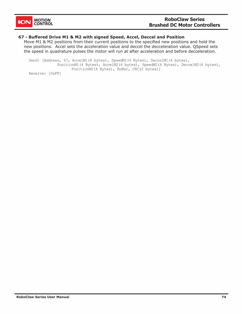
RoboClaw Series Brushed DC Motor Controllers
RoboClaw Series User Manual 74
67 - Buffered Drive M1 & M2 with signed Speed, Accel, Deccel and PositionMove M1 & M2 positions from their current positions to the specified new positions and hold the new positions. Accel sets the acceleration value and deccel the decceleration value. QSpeed sets the speed in quadrature pulses the motor will run at after acceleration and before decceleration.
Send: [Address, 67, AccelM1(4 bytes), SpeedM1(4 Bytes), DeccelM1(4 bytes), PositionM1(4 Bytes), AccelM2(4 bytes), SpeedM2(4 Bytes), DeccelM2(4 bytes), PositionM2(4 Bytes), Buffer, CRC(2 bytes)]Receive: [0xFF]

RoboClaw Series Brushed DC Motor Controllers
RoboClaw Series User Manual 75
Reading Quadrature Encoder - Arduino ExampleThe example was tested with an Arduino Uno using packet serial wiring and quadrature encoder wiring diagrams. The example will read the speed, total ticks and direction of each encoder. Connect to the program using a terminal window set to 38400 baud. The program will display the values of each encoders current count along with each encoder status bit in binary and the direction bit. As the encoder is turned it will update the screen. Additional example programs can be downloaded from Ionmc.com.
//Set mode to 7(packet serial address 0x80) and option 4(38400) //Includes required to use Roboclaw library #include "BMSerial.h" #include "RoboClaw.h" //Roboclaw Address #define address 0x80 //Definte terminal for display. Use hardware serial pins 0 and 1 BMSerial terminal(0,1); //Setup communcaitions with roboclaw. Use pins 10 and 11 with 10ms timeout RoboClaw roboclaw(10,11,10000); void setup() { //Open terminal and roboclaw at 38400bps terminal.begin(57600); roboclaw.begin(38400); } void loop() { uint8_t status1,status2,status3,status4; bool valid1,valid2,valid3,valid4; //Read all the data from Roboclaw before displaying on terminal window //This prevents the hardware serial interrupt from interfering with //reading data using software serial. int32_t enc1= roboclaw.ReadEncM1(address, &status1, &valid1); int32_t enc2 = roboclaw.ReadEncM2(address, &status2, &valid2); int32_t speed1 = roboclaw.ReadSpeedM1(address, &status3, &valid3); int32_t speed2 = roboclaw.ReadSpeedM2(address, &status4, &valid4); terminal.print("Encoder1:"); if(valid1){ terminal.print(enc1,HEX); terminal.print(" "); terminal.print(status1,HEX); terminal.print(" "); } else{ terminal.print("invalid "); } terminal.print("Encoder2:"); if(valid2){ terminal.print(enc2,HEX); terminal.print(" "); terminal.print(status2,HEX); terminal.print(" "); } else{ terminal.print("invalid "); } terminal.print("Speed1:");

RoboClaw Series Brushed DC Motor Controllers
RoboClaw Series User Manual 76
if(valid3){ terminal.print(speed1,HEX); terminal.print(" "); } else{ terminal.print("invalid "); } terminal.print("Speed2:"); if(valid4){ terminal.print(speed2,HEX); terminal.print(" "); } else{ terminal.print("invalid "); } terminal.println(); delay(100); }

RoboClaw Series Brushed DC Motor Controllers
RoboClaw Series User Manual 77
Speed Controlled by Quadrature Encoders - Arduino ExampleThe following example was written using an Arduino UNO using packet serial wiring and quadrature encoder wiring diagrams. The example will command a 4wheel robot to move forward, backward, right turn and left turn slowly. You can change the speed by adjusting the value of Speed and Speed2 variables. Additional example programs can be downloaded from Ionmc.com.
//Set mode 7(packet serial address 0x80) and mode 4(38400) //Includes required to use Roboclaw library #include "BMSerial.h" #include "RoboClaw.h" #define SPEED 12000 #define SPEED2 12000 //Roboclaw Address #define address 0x80 //Velocity PID coefficients #define Kp 1.0 #define Ki 0.5 #define Kd 0.25 #define qpps 44000 //Definte terminal for display. Use hardware serial pins 0 and 1 BMSerial terminal(0,1); //Setup communcaitions with roboclaw. Use pins 10 and 11 with 10ms timeout RoboClaw roboclaw(10,11,10000); long speed; long speed2; void setup() { //Open terminal and roboclaw serial ports terminal.begin(57600); roboclaw.begin(38400); speed = SPEED; speed2 = SPEED2; //Set PID Coefficients roboclaw.SetM1VelocityPID(address,Kd,Kp,Ki,qpps); roboclaw.SetM2VelocityPID(address,Kd,Kp,Ki,qpps); }

RoboClaw Series Brushed DC Motor Controllers
RoboClaw Series User Manual 78
void displayspeed(void) { uint8_t status1,status2,status3,status4; bool valid1,valid2,valid3,valid4; int32_t enc1= roboclaw.ReadEncM1(address, &status1, &valid1); int32_t enc2 = roboclaw.ReadEncM2(address, &status2, &valid2); int32_t speed1 = roboclaw.ReadSpeedM1(address, &status3, &valid3); int32_t speed2 = roboclaw.ReadSpeedM2(address, &status4, &valid4); terminal.print("Encoder1:"); if(valid1){ terminal.print(enc1,DEC); terminal.print(" "); terminal.print(status1,HEX); terminal.print(" "); } else{ terminal.print("invalid "); } terminal.print("Encoder2:"); if(valid2){ terminal.print(enc2,DEC); terminal.print(" "); terminal.print(status2,HEX); terminal.print(" "); } else{ terminal.print("invalid "); } terminal.print("Speed1:"); if(valid3){ terminal.print(speed1,DEC); terminal.print(" "); } else{ terminal.print("invalid "); } terminal.print("Speed2:"); if(valid4){ terminal.print(speed2,DEC); terminal.print(" "); } else{ terminal.print("invalid "); } terminal.println(); }

RoboClaw Series Brushed DC Motor Controllers
RoboClaw Series User Manual 79
void loop() { roboclaw.SpeedM1(address,speed); roboclaw.SpeedM2(address,speed); for(uint8_t i = 0;i<100;i++){ displayspeed(); delay(10); } roboclaw.SpeedM1(address,-speed); roboclaw.SpeedM2(address,-speed); for(uint8_t i = 0;i<100;i++){ displayspeed(); delay(10); } roboclaw.SpeedM1(address,0); roboclaw.SpeedM2(address,0); delay(2000); roboclaw.SpeedM1(address,speed2); roboclaw.SpeedM2(address,-speed2); for(uint8_t i = 0;i<100;i++){ displayspeed(); delay(10); } roboclaw.SpeedM1(address,-speed2); roboclaw.SpeedM2(address,speed2); for(uint8_t i = 0;i<100;i++){ displayspeed(); delay(10); } roboclaw.SpeedM1(address,0); roboclaw.SpeedM2(address,0); delay(2000); }

RoboClaw Series Brushed DC Motor Controllers
RoboClaw Series User Manual 80
RoboClaw Electrical Specifications
Characteristic Model Min Typ Max Rating
Pulse Per Second All 0 19,660800 QPPS
Logic Battery All 6 12 34 VDC
Main Battery 2x5A 6 34 VDC
2x7A 6 34 VDC
2x15A 6 34 VDC
2x30A 6 34 VDC
2x45A 6 34 VDC
2x60A 6 34 VDC
2x60A HV 10.5 60 VDC
Maximum External Current Draw (BEC) 2x5A 200 mA
2x7A 200 mA
2x15A 3 A
2x30A 3 A
2x45A 3 A
2x60A 3 A
2x60A HV 200 mA
Motor Current Per Channel 2x5A 5(2) 10(1) A
2x7A 7(2) 15(1) A
2x15A 15(2) 30(1)
2x30A 30(2) 60(1)
2x45A 45(2) 60(1)
2x60A 60(2) 120(1)
2x60A HV 60(2) 120(1)
Logic Circuit All 30 mA
I/O Input All 0 5 VDC
I/O Output All 0 3.3 VDC
Analog Voltage Range All 0 2 VDC
Tempature Range All -40 40 +100 C
Notes:1. Peak current is automatically reduced to the typical current limit as temperature approaches 85C.2. Current is limited by maximum temperature. Starting at 85c, the current limit is reduced on a slope with a maximum temperature of
100c, which will reduce the current to 0 amps.

RoboClaw Series Brushed DC Motor Controllers
RoboClaw Series User Manual 81
WarrantyIon Motion Control warranties its products against defects in material and workmanship for a period of 1 year. If a defect is discovered, IonMC will, at our discretion, repair, replace, or refund the purchase price of the product in question. Contact us at [email protected]. No returns will be accepted without the proper authorization.
Copyrights and TrademarksCopyright© 2014,2015 by Ion Motion Control, Inc. All rights reserved. RoboClaw and USB RoboClaw are registered trademarks of Ion Motion Control, Inc. Other trademarks mentioned are registered trademarks of their respective holders.
DisclaimerIon Motion Control cannot be held responsible for any incidental, or consequential damages resulting from use of products manufactured or sold by Ion Motion Control or its distributors. No products from Ion Motion Control should be used in any medical devices and/or medical situations. No product should be used in a life support situation.
Contacts
Email: [email protected] Tech support: [email protected] Web: http://www.ionmc.com
Discussion ListA web based discussion board is maintained at http://forums.ionmc.com.
Technical SupportTechnical support is available by sending an email to [email protected], by opening a support ticket on the Ion Motion Control website or by calling 800-535-9161 during normal operating hours. All email will be answered within 48 hours.
Related Documents