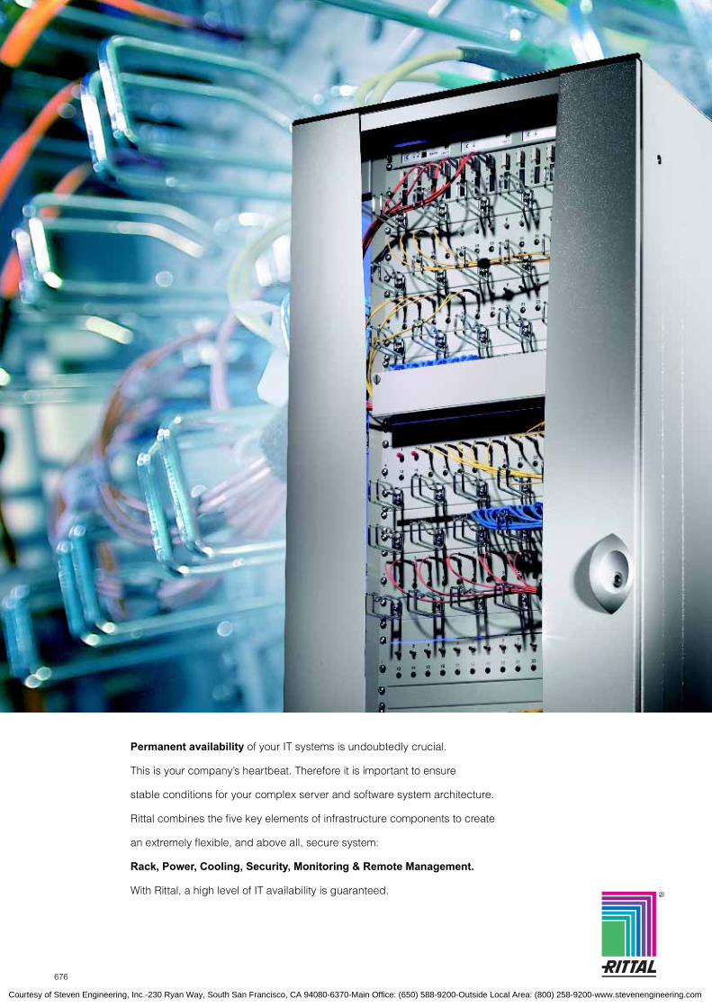
676 R Permanent availability of your IT systems is undoubtedly crucial. This is your company’s heartbeat. Therefore it is important to ensure stable conditions for your complex server and software system architecture. Rittal combines the five key elements of infrastructure components to create an extremely flexible, and above all, secure system: Rack, Power, Cooling, Security, Monitoring & Remote Management. With Rittal, a high level of IT availability is guaranteed. Courtesy of Steven Engineering, Inc.-230 Ryan Way, South San Francisco, CA 94080-6370-Main Office: (650) 588-9200-Outside Local Area: (800) 258-9200-www.stevenengineering.com

Welcome message from author
This document is posted to help you gain knowledge. Please leave a comment to let me know what you think about it! Share it to your friends and learn new things together.
Transcript
676
R
Permanent availability of your IT systems is undoubtedly crucial.
This is your company’s heartbeat. Therefore it is important to ensure
stable conditions for your complex server and software system architecture.
Rittal combines the five key elements of infrastructure components to create
an extremely flexible, and above all, secure system:
Rack, Power, Cooling, Security, Monitoring & Remote Management.
With Rittal, a high level of IT availability is guaranteed.
Courtesy of Steven Engineering, Inc.-230 Ryan Way, South San Francisco, CA 94080-6370-Main Office: (650) 588-9200-Outside Local Area: (800) 258-9200-www.stevenengineering.com

677Rittal Handbook 31/Networking Solutions
B
5.
IT S
olut
ions
IT SolutionsNetworking From page 680Features.......................................................................................... 680Network enclosures, based on Rittal TE 7000, width 600 mm (23.6″)...................................................................... 682Network enclosures, based on Rittal TE 7000, width 800 mm (31.5″)...................................................................... 685Network enclosures, based on Rittal TS8, pre-configured ............. 687Network enclosures, based on Rittal TS8, types 1 and 2 ............... 693Network enclosures, based on Rittal TS8, 15 – 20U ...................... 695Network enclosures, based on Rittal flexRack(i), pre-configured ... 703Network enclosures, based on Rittal flexRack(i) ............................ 705Distributor racks, based on Rittal Data Rack .................................. 708Mobile workstation, Rittal RiLab ..................................................... 711Features.......................................................................................... 714RNC enclosure ............................................................................... 716RNC universal enclosure ................................................................ 717Wall-mounted enclosure, based on Rittal QuickBox, 6 – 21U ........ 718
Wall-mounted enclosure, based on Rittal AE, with pull-out frame.. 721Wall-mounted enclosure, based on Rittal AE ................................. 722Office distributor, 2 and 4U, for fiber-optic and copper cables........ 723Small fiber-optic distributors ........................................................... 724Small fiber-optic distributors, based on Rittal AE............................ 725Fiber-optic marshalling enclosure................................................... 726Small fiber-optic distributor, polycarbonate..................................... 727Wall-mounted enclosure, based on Rittal EL, 3-part, pre-configured...................................... 728Wall-mounted enclosure, based on Rittal EL, 3-part, with system bars .................................. 729Wall-mounted enclosure, based on Rittal EL, 3-part, with mounting panel ............................. 730Wall-mounted enclosure, based on Rittal EL, 2-part, with swing frame .................................. 732
Server racks From page 734Features.......................................................................................... 734Based on Rittal TE 7000, 1000 mm (39.4″) deep ........................... 736Based on Rittal TS8, pre-configured............................................... 737
Based on Rittal flexRack(i), 1000 and 1200 mm (39.4 and 47.2″) deep, pre-configured....................................................................... 738Monitoring ....................................................................................... 739Monitoring system SSC .................................................................. 741
Power From page 742Features.......................................................................................... 742Power Distribution Rack PDR......................................................... 743Power System Module PSM ........................................................... 744Connection cable ............................................................................ 745Voltage supply ................................................................................ 746
UPS systemsFeatures.......................................................................................... 750UPS, single-phase, output range 1 – 6 kVA ................................... 752UPS, three-phase, output range 10 – 120 kVA per rack ................ 754Modular UPS concept..................................................................... 755Redundant UPS concept ................................................................ 756Scalable UPS concept .................................................................... 757
Rittal IT cooling From page 758Perfect solutions for every application ............................................ 758
Monitoring From page 762Rittal CMC-TC – Security management concept ............................ 762Sensor units .................................................................................... 764Monitoring system processing unit ................................................. 766Additional units ............................................................................... 767Master monitoring system............................................................... 769Connection tables ........................................................................... 770Cables/mounting accessories ......................................................... 771
Internal security .............................................................................. 773External security ............................................................................. 777Individual security ........................................................................... 779Access systems .............................................................................. 781Monitoring of climate control units .................................................. 785Speed-monitored/controlled fan system/DC ................................... 786Software.......................................................................................... 788
Terminals From page 790Information and service anytime, anywhere ................................... 790ITS Arc-Line II ................................................................................. 792ITS Opti-Line II................................................................................ 793ITS Opti-Desk ................................................................................. 794ITS Opti-Wall .................................................................................. 795
ITS Alpha-Line ................................................................................ 796ITS Out-Line Wall ........................................................................... 797ITS Out-Line Pro............................................................................. 798ITS PC systems .............................................................................. 799Keyboards....................................................................................... 800
Telecom From page 802Features.......................................................................................... 802Rack system, based on Rittal TC-Rack .......................................... 803Accessories for the Rittal TC-Rack ................................................. 804FM small distributors....................................................................... 806
Modular FM wall-mounted distributor ............................................. 807Modular FM distributor racks .......................................................... 808Accessories for FM distributor racks............................................... 809
Courtesy of Steven Engineering, Inc.-230 Ryan Way, South San Francisco, CA 94080-6370-Main Office: (650) 588-9200-Outside Local Area: (800) 258-9200-www.stevenengineering.com

678 Rittal Handbook 31/Networking Solutions
RimatriX5The data center of the future
B
5.
Rim
atriX
5
Rittal has the solution: RimatriX5 – the comprehensive,
scalable, efficient system solution for high levels of IT
performance, with the added benefits and cost advantages
of modularity.
New software, increasing computer performance, high levels of availability –
these are the new challenges placed on the physical IT infrastructure.
Whether your company is small, medium-sized or large, the requirements on IT performance are growing. Highly complex
applications, faster processors, and round-the-clock information and communication – all this demands a physical infra-
structure which is robust. This leads to a number of elementary questions:
● Will the climate control of individual racks, entire server rooms and data centers withstand the rising heat generated?
● Is the power supply and back-up designed for a high level of availability?
● How can the existing space be used to optimum efficiency, even with expansion?
● Are the applications and servers protected from physically-induced failures?
● Can all functions be efficiently managed via a perfect monitoringand remote system?
● Is uninterrupted expansion possible at any time?
● Are the costs under control?
The RimatriX5 concept solves all these tasks. The complete solution from Rittal, for the data center of the future.
RimatriX5
Courtesy of Steven Engineering, Inc.-230 Ryan Way, South San Francisco, CA 94080-6370-Main Office: (650) 588-9200-Outside Local Area: (800) 258-9200-www.stevenengineering.com

Rittal Handbook 31/Networking Solutions
B
5.
Rim
atriX
5
With the perfectly coordinated components of rack, power, cooling, security and monitoring/remote management, you get
an integrated, comprehensive solution for the IT infrastructure. Added value is provided by RimatriX5 with its globally
available, local service: Configuration and monitoring support via software, precise risk analysis, application-tailored
installation and maintenance service and a rapid escalation service.
With RimatriX5, Rittal offers comprehensive solutions for a reliable, available and efficient IT infrastructure.
Be it server room or data center, high or exceptional availability – the individual modules of RimatriX5 adapt at any time to suit
the individual requirements. They grow along with requirements:
PowerThe Power module within the RimatriX5 concept ensures a constant and consistent power supply. From plug & play power distri-bution in the IT rack, to power distribution within the space, and onto power supply back-up with requirement-based UPS, the Power module of RimatriX5 offers optimum power performance for a high level of availability.
See page 742.
CoolingWith the climate control con-cepts of RimatriX5, investment costs are minimized, and invest-ment security is maximized. From fans to active liquid cool-ing, the climate control solu-tions may be tailored to actual requirements. This minimizes investment costs and offers adequate scope for future expansions.
See page 758.
RackAs one of the world’s leading manufacturers of server and network enclosures, Rittal offers an extensive selection with a unique range of acces-sories. This allows you to create the requirements for high-end individual expansion of your IT infrastructure with greater freedom, more flexibility, and enhanced security.
See page 680.
The modular principle for the physical IT infrastructure
means system solutions rather than piecework – scalable,
flexible and tailored to your application:
RimatriX5 – Driving IT performance
availability is enhanced. For example, com-prehensive monitoring, measurement and control tasks via the CMC module reduce the risk of failure and facilitate preventive inter-vention.
Monitoring & Remote ManagementThanks to simple operation and administration with the Monitoring & Remote Management module of RimatriX5, maintenance and ope-rating costs may be permanently reduced in day-to-day operation, while overall
SecurityDue to modules for physical rack security and room protec-tion within RimatriX5, a high level of protection of the IT infrastructure is guaranteed. For example, when it comes to physical rack security, tem-perature, smoke and vibration sensors coupled with modern access control solutions and tested enclosure extinguisher systems provide reliable pro-tection against external influ-ences.
See page 762.
R
RimatriX5
Courtesy of Steven Engineering, Inc.-230 Ryan Way, South San Francisco, CA 94080-6370-Main Office: (650) 588-9200-Outside Local Area: (800) 258-9200-www.stevenengineering.com

680 Rittal Handbook 31/Networking Solutions
NetworkingFeatures
B
5.1
Net
wor
king
TE 7000
Two 482.6 mm (19″) mounting levels in the multi-functional section create a solid framework. Load capacity 400 kg (882 lb).
The benefits of this rack without an enclosure frame: Optimum accessibility, maximum use of the interior space, and super-fast assembly.
482.6 mm (19″) distance between levels:Tailored to premium accessories in 50 mm (2.0″) increments, or fully depth-adjustable with the slot attachment.
TS8
An ingenious symmetrical concept with baying on all sides. With two levels, the frame profile makes infinite assembly diversity possible.
Fully depth-adjustable interior installation creates flexibility for installed equipment. Fast assembly by simply locating and securing.
Climate controlFor example, a fan unit integrated into the TS8 twin wall for targeted air routing in the lower part of the enclosure.
Rittal system comparison TE 7000 TS8 FR(i) Rittal system comparison TE 7000 TS8 FR(i)
One platform for all requirements in the IT market
One platform for allrequirements in theIT market
Load capacity Lock systemUp to 400 kg (881.8 lb) � � � � � � � � � 2-point � � � � � � � � �
Up to 1000 kg (2204.6 lb) � � � � � � 4-point � � �
Baying SecuritySide � � � � � � � � � Access control � � � � � � � � �
In all levels � � � Climate control � � � � � � � � �
Climate control Dismantling � � � � �
Fan � � � � � � � � � Interior installationClimate control device � � � � � Depth-adjustable � � � � � �
Air/water heat exchanger � � � Partial installation � � �
CPU liquid cooling � � � � � � 2-level principle � � � �
Wiring Design � � � � � � �
Cable space � � � � � � � Standards IEC 60 297-1/2 � � � � � � � � �
Cable management � � � � � � � � � Note: The more � the greater the compatibility.
Define your requirements – Rittal has the solution.
A variety of system platforms will accommodate your
various requirements in the networking sector.
While your network grows in line with new tasks, the flexibility
of its systems allow Rittal to offer future-safe solutions.
Courtesy of Steven Engineering, Inc.-230 Ryan Way, South San Francisco, CA 94080-6370-Main Office: (650) 588-9200-Outside Local Area: (800) 258-9200-www.stevenengineering.com

681Rittal Handbook 31/Networking Solutions
NetworkingFeatures
B
5.1
Net
wor
king
flexRack(i)
Cable managementCables may be routed and system accessories integrated within the hollow area of the frame section.
Power management integrated directly into the frame section. Three-phase infeed using the plug & play system, with no loss of enclosure volume.
Liquid coolingThe profile of the flexRack(i) allows integration of the intake and return lines for targeted, safe liquid cooling.
DataRack
A second mounting level for heavy equipment or double panel assembly. Compatible with Rittal system accessories.
Cable management
Gland plate module with brush strip for cable entry in the base area.
Cable clamp rail, depth-adjustableThe cable clamp rails may be located directly between two mounting frames.
Cable management 482.6 mm (19″)
The extra cable holder may be attached to all support strips or to system chassis and rails with the 25 mm (1.0″) system hole pattern.
Cable routing panel 482.6 mm (19″) with groovesTo hold the patching cables.
Fiber-optic shunting ringsStrain relief and bending radii are guaranteed by the special design.
RiLab
Supporting column with two vertical tapped strips for flexible mounting on a 32 mm (1.25″) height system hole pattern. The 6-way power strip with switch may be integrated into the power column.
Courtesy of Steven Engineering, Inc.-230 Ryan Way, South San Francisco, CA 94080-6370-Main Office: (650) 588-9200-Outside Local Area: (800) 258-9200-www.stevenengineering.com

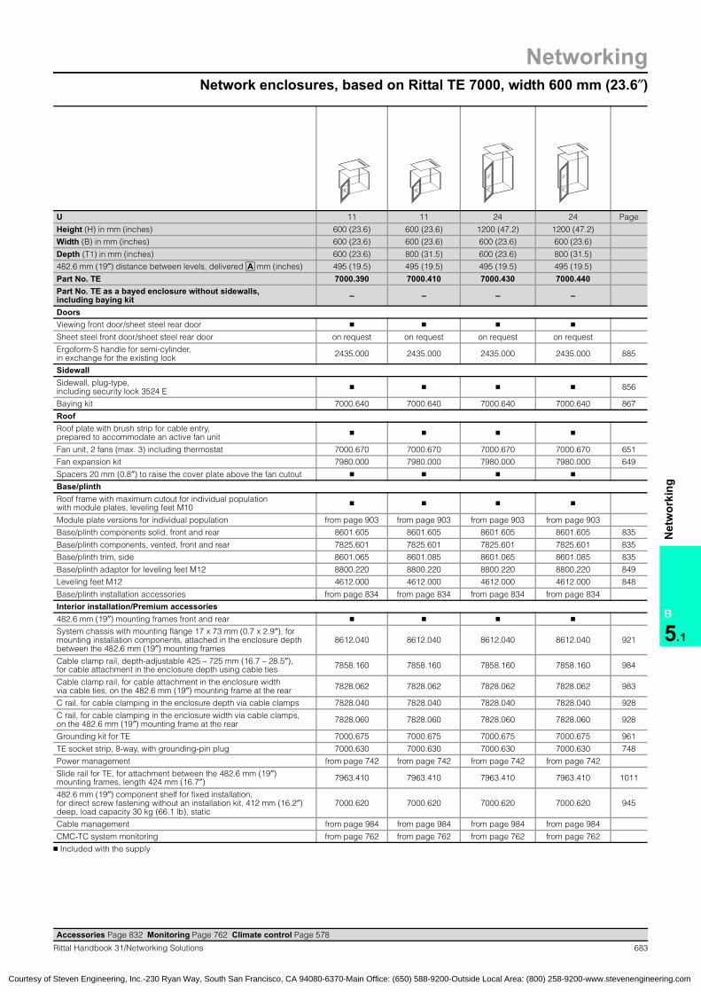
NetworkingNetwork enclosures, based on Rittal TE 7000, width 600 mm (23.6″)
682 Rittal Handbook 31/Networking Solutions
B
5.1
Net
wor
king
T1
H
B
HE
19˝
A
B = WidthT = DepthHE = U
Benefits: ● Coordinated accessories
for fast installation in the delivered state
● No frame structure, optimum accessibility
● Load capacity up to 400 kg (882 lb).
Material:Sheet steel
Finish:Mounting frame: Electrophoretic dipcoat-primedEnclosure panels: Powder-coated, RAL 7035 (light gray)/RAL 9005 (jet black).
Configuration:Self-supporting 482.6 mm (19″) frame structure, viewing door at
the front, two-point locking rod, recessed handle and security lock 3524 E, sheet steel door at rear, two-point locking rod, recessed handle and security lock 3524 E, pluggable sidewalls with security lock 3524 E,base frame with maximum cutout (for optional population
with module plates), roof plate for cable entry with covered cutout for fan, leveling feet, spacers for raising the cover plate.
Detailed drawing,available on the Internet, log onto www.rittal-corp.com.
Accessories Page 832 Monitoring Page 762 Climate control Page 578
Network enclosures:based on Rittal TE 7000TE 7000:Network enclosures
495 mm (19.5″) – that is the distance between the two 482.6 mm (19″) levels in the delivered state for all enclosure formats. Corresponds to TS8 nominal size, depth 400 mm (15.7″), inner level.
Pitch spacing 50 mm (2.0″). The distance between the two 482.6 mm (19″) levels may be varied in 50 mm (2.0″) increments (445 to 695 mm (17.5 to 27.4″)).
Distance from door: 52.5 mm (2.1″) for depth 600 (23.6″); 152.5 mm (6.0″) for depth 800 (31.5″).
The mounting distance in a rear mounting frame, hori-zontal, corresponds to the frame mounting dimensions of a 600 mm (23.6″) wide TS8 (inner level, 512 mm (20.2″)).
= – 120 mm (4.7″)The distance between levelsis freely selectable with slot fastening.
All key mounting components – system chassis with mounting flanges, divider kits, slide rails, and component shelves – are available in various depths.
German registered design no. 403 07 489
C
A
D
E
B
D
800 600
A
600 600
D
A
U 11 11 24 24 42 42 47 47
Height (H) in mm (inches) 600 (23.6) 600 (23.6) 1200 (47.2) 1200 (47.2) 2000 (78.7) 2000 (78.7) 2200 (86.6) 2200 (86.6)
Width (B) in mm (inches) 600 (23.6) 600 (23.6) 600 (23.6) 600 (23.6) 600 (23.6) 600 (23.6) 600 (23.6) 600 (23.6)
Depth (T1) in mm (inches) 600 (23.6) 800 (31.5) 600 (23.6) 800 (31.5) 600 (23.6) 800 (31.5) 600 (23.6) 800 (31.5)
482.6 mm (19″) distance between levels in its delivered state 495 (19.5) 495 (19.5) 495 (19.5) 495 (19.5) 495 (19.5) 495 (19.5) 495 (19.5) 495 (19.5)
Part No. TE 7000.390 7000.410 7000.430 7000.440 7000.500 7000.510 7000.560 7000.570Part No. TE as a bayed enclosure without sidewalls, includes baying kit – – – – 7000.502 – 7000.562 –
Part No. TE includes. sidewalls, RAL 9005 (jet black) – – – – 7000.505 7000.515 – –
A
A
B
C
D
E A
= Defined mounting distance for Premium accessories, see below.
A
Courtesy of Steven Engineering, Inc.-230 Ryan Way, South San Francisco, CA 94080-6370-Main Office: (650) 588-9200-Outside Local Area: (800) 258-9200-www.stevenengineering.com
Network enclosures, based on Rittal TE 7000, width 600 mm (23.6″)
Networking
683Rittal Handbook 31/Networking Solutions
B
5.1
Net
wor
king
U 11 11 24 24 Page
Height (H) in mm (inches) 600 (23.6) 600 (23.6) 1200 (47.2) 1200 (47.2)
Width (B) in mm (inches) 600 (23.6) 600 (23.6) 600 (23.6) 600 (23.6)
Depth (T1) in mm (inches) 600 (23.6) 800 (31.5) 600 (23.6) 800 (31.5)
482.6 mm (19″) distance between levels, delivered mm (inches) 495 (19.5) 495 (19.5) 495 (19.5) 495 (19.5)
Part No. TE 7000.390 7000.410 7000.430 7000.440Part No. TE as a bayed enclosure without sidewalls,including baying kit – – – –
DoorsViewing front door/sheet steel rear door � � � �
Sheet steel front door/sheet steel rear door on request on request on request on request
Ergoform-S handle for semi-cylinder,in exchange for the existing lock 2435.000 2435.000 2435.000 2435.000 885
SidewallSidewall, plug-type,including security lock 3524 E � � � � 856
Baying kit 7000.640 7000.640 7000.640 7000.640 867
RoofRoof plate with brush strip for cable entry,prepared to accommodate an active fan unit � � � �
Fan unit, 2 fans (max. 3) including thermostat 7000.670 7000.670 7000.670 7000.670 651
Fan expansion kit 7980.000 7980.000 7980.000 7980.000 649
Spacers 20 mm (0.8″) to raise the cover plate above the fan cutout � � � �
Base/plinthRoof frame with maximum cutout for individual populationwith module plates, leveling feet M10 � � � �
Module plate versions for individual population from page 903 from page 903 from page 903 from page 903
Base/plinth components solid, front and rear 8601.605 8601.605 8601.605 8601.605 835
Base/plinth components, vented, front and rear 7825.601 7825.601 7825.601 7825.601 835
Base/plinth trim, side 8601.065 8601.085 8601.065 8601.085 835
Base/plinth adaptor for leveling feet M12 8800.220 8800.220 8800.220 8800.220 849
Leveling feet M12 4612.000 4612.000 4612.000 4612.000 848
Base/plinth installation accessories from page 834 from page 834 from page 834 from page 834
Interior installation/Premium accessories482.6 mm (19″) mounting frames front and rear � � � �
System chassis with mounting flange 17 x 73 mm (0.7 x 2.9″), for mounting installation components, attached in the enclosure depth between the 482.6 mm (19″) mounting frames
8612.040 8612.040 8612.040 8612.040 921
Cable clamp rail, depth-adjustable 425 – 725 mm (16.7 – 28.5″),for cable attachment in the enclosure depth using cable ties 7858.160 7858.160 7858.160 7858.160 984
Cable clamp rail, for cable attachment in the enclosure widthvia cable ties, on the 482.6 mm (19″) mounting frame at the rear 7828.062 7828.062 7828.062 7828.062 983
C rail, for cable clamping in the enclosure depth via cable clamps 7828.040 7828.040 7828.040 7828.040 928
C rail, for cable clamping in the enclosure width via cable clamps, on the 482.6 mm (19″) mounting frame at the rear 7828.060 7828.060 7828.060 7828.060 928
Grounding kit for TE 7000.675 7000.675 7000.675 7000.675 961
TE socket strip, 8-way, with grounding-pin plug 7000.630 7000.630 7000.630 7000.630 748
Power management from page 742 from page 742 from page 742 from page 742
Slide rail for TE, for attachment between the 482.6 mm (19″) mounting frames, length 424 mm (16.7″) 7963.410 7963.410 7963.410 7963.410 1011
482.6 mm (19″) component shelf for fixed installation,for direct screw fastening without an installation kit, 412 mm (16.2″) deep, load capacity 30 kg (66.1 lb), static
7000.620 7000.620 7000.620 7000.620 945
Cable management from page 984 from page 984 from page 984 from page 984
CMC-TC system monitoring from page 762 from page 762 from page 762 from page 762
� Included with the supply
A
Accessories Page 832 Monitoring Page 762 Climate control Page 578
Courtesy of Steven Engineering, Inc.-230 Ryan Way, South San Francisco, CA 94080-6370-Main Office: (650) 588-9200-Outside Local Area: (800) 258-9200-www.stevenengineering.com

NetworkingNetwork enclosures, based on Rittal TE 7000, width 600 mm (23.6″)
684 Rittal Handbook 31/Networking Solutions
B
5.1
Net
wor
king
U 42 42 47 47 Page
Height (H) in mm (inches) 2000 (78.7) 2000 (78.7) 2200 (86.6) 2200 (86.6)
Width (B) in mm (inches) 600 (23.6) 600 (23.6) 600 (23.6) 600 (23.6)
Depth (T1) in mm (inches) 600 (23.6) 800 (31.5) 600 (23.6) 800 (31.5)
482.6 mm (19″) distance between levels, delivered mm (inches) 495 (19.5) 495 (19.5) 495 (19.5) 495 (19.5)
Part No. TE 7000.500 7000.510 7000.560 7000.570Part No. TE as a bayed enclosure without sidewalls,including baying kit 7000.502 – 7000.562 –
DoorsViewing front door/sheet steel rear door � � � �
Sheet steel front door/sheet steel rear door on request on request on request on request
Ergoform-S handle for semi-cylinder,in exchange for the existing lock 2435.000 2435.000 2435.000 2435.000 885
SidewallSidewall, plug-type,including security lock 3524 E � (7000.500 only) � � (7000.560 only) � 856
Baying kit � (7000.502 only) 7000.640 � (7000.562 only) 7000.640 867
RoofRoof plate with brush strip for cable entry,prepared to accommodate an active fan unit � � � �
Fan unit, 2 fans (max. 3) including thermostat 7000.670 7000.670 7000.670 7000.670 651
Fan expansion kit 7980.000 7980.000 7980.000 7980.000 649
Spacers 20 mm (0.8″) to raise the cover plate above the fan cutout � � � � 904
Base/plinthRoof frame with maximum cutout for individual populationwith module plates, leveling feet M10 � � � �
Module plate versions for individual population from page 903 from page 903 from page 903 from page 903
Base/plinth components solid, front and rear 8601.605 8601.605 8601.605 8601.605 835
Base/plinth components, vented, front and rear 7825.601 7825.601 7825.601 7825.601 835
Base/plinth trim, side 8601.065 8601.085 8601.065 8601.085 835
Base/plinth adaptor for leveling feet M12 8800.220 8800.220 8800.220 8800.220 849
Leveling feet M12 4612.000 4612.000 4612.000 4612.000 848
Base/plinth installation accessories from page 834 from page 834 from page 834 from page 834
Interior installation/Premium accessories482.6 mm (19″) mounting frames front and rear � � � �
System chassis with mounting flange 17 x 73 mm (0.7 – 2.9″), for mounting installation components, attached in the enclosure depth between the 482.6 mm (19″) mounting frames
8612.040 8612.040 8612.040 8612.040 921
Cable clamp rail, depth-adjustable 425 – 725 mm (16.7 – 28.5″),for cable attachment in the enclosure depth using cable ties 7858.160 7858.160 7858.160 7858.160 984
Cable clamp rail, for cable attachment in the enclosure width via cable ties, on the 482.6 mm (19″) mounting frame at the rear 7828.062 7828.062 7828.062 7828.062 983
C rail, for cable clamping in the enclosure depth via cable clamps 7828.040 7828.040 7828.040 7828.040 928
C rail, for cable clamping in the enclosure width via cable clamps, on the 482.6 mm (19″) mounting frame at the rear 7828.060 7828.060 7828.060 7828.060 928
Grounding kit for TE 7000.675 7000.675 7000.675 7000.675 961
TE socket strip, 8-way, with grounding-pin plug 7000.630 7000.630 7000.630 7000.630 748
Power management from page 742 from page 742 from page 742 from page 742
Slide rail for TE, for attachment between the 482.6 mm (19″) mounting frames, length 424 mm (16.7″) 7963.410 7963.410 7963.410 7963.410 1011
482.6 mm (19″) component shelf for fixed installation,for direct screw fastening without an installation kit, 412 mm (16.2″) deep, load capacity 30 kg (66.1 lb), static
7000.620 7000.620 7000.620 7000.620 945
Cable management from page 984 from page 984 from page 984 from page 984
CMC-TC system monitoring from page 762 from page 762 from page 762 from page 762
� Included with the supply.
A
Accessories Page 832 Monitoring Page 762 Climate control Page 578
Courtesy of Steven Engineering, Inc.-230 Ryan Way, South San Francisco, CA 94080-6370-Main Office: (650) 588-9200-Outside Local Area: (800) 258-9200-www.stevenengineering.com

Network enclosures, based on Rittal TE 7000, width 800 mm (31.5″)
Networking
685Rittal Handbook 31/Networking Solutions
B
5.1
Net
wor
king
T1
H
B
19˝
HE A
B = WidthT = DepthHE = U
Benefits: ● Coordinated accessories
for fast installation in the delivered state
● No frame structure, optimum accessibility
● Load capacity up to 400 kg (882 lb).
Material:Sheet steel
Finish:Mounting frame: Electrophoretic dipcoat-primedEnclosure panels: Powder coated, RAL 7035 (light gray)RAL 9005 (jet black).
Configuration:Self-supporting 482.6 mm (19″) frame structure, viewing door at
the front, two-point lock rod, recessed handle and security lock 3524 E, sheet steel door at rear, two-point lock rod, recessed handle and security lock 3524 E, pluggable sidewalls with security lock 3524 E,base frame with maximum cutout (for optional population
with module plates), roof plate for cable entry with covered cutout for fan, leveling feet, spacers for raising the cover plate.
Detailed drawing,available on the Internet, log onto www.rittal-corp.com.
Accessories Page 832 Monitoring Page 762 Climate control Page 578
495 mm (19.5″) – that is the distance between the two 482.6 mm (19″) level in the delivered state for all enclosure formats. Corresponds to TS8 nominal size, depth 400 mm (15.7″), inner level.
50 mm (2.0″) hole spacing. The distance between the two 482.6 mm (19″) levels may be varied in 50 mm (2.0″) increments (445 to 695 mm (17.5 to 27.4″)).
Distance from door: 52.5 mm (2.1″) for depth 600 mm (23.6″), 152.5 mm (6.0″) for depth 800 mm (31.5″).
The mounting distance in a rear mounting frame, hori-zontal, corresponds to the frame mounting dimensions of a 600 mm (23.6″) wide TS8 (outer level, 525 mm (20.7″)).= – 120 mm (4.7″)
The distance between levels is freely selectable with the system holes.
All key components – system chassis with mounting flanges, divider kits, slide rails, compo-nent shelves – are also avail-able in variable depth.
German registered design no. M 403 07 48
C
E
A
B
DD
800 800
A
D
600 800
A
U 24 24 42 42 47 47
Height (H) in mm (inches) 1200 (47.2) 1200 (47.2) 2000 (78.7) 2000 (78.7) 2200 (86.6) 2200 (86.6)
Width (B) in mm (inches) 800 (31.5) 800 (31.5) 800 (31.5) 800 (31.5) 800 (31.5) 800 (31.5)
Depth (T1) in mm (inches) 600 (23.6) 800 (31.5) 600 (23.6) 800 (31.5) 600 (23.6) 800 (31.5)
482.6 mm (19″) distance between levels, delivered mm (inches) 495 (19.5) 495 (19.5) 495 (19.5) 495 (19.5) 495 (19.5) 495 (19.5)
Part No. TE 7000.450 7000.4601) 7000.520 7000.5301) 7000.580 7000.590Part No. TE as bayed enclosure without sidewalls, including baying kit – – – 7000.5321) – 7000.592Part No. TE includes sidewalls, RAL 9005 (jet black) – – 7000.525 7000.535 – –
1) Model No. TE pre-configured with base/plinth, grounding and accessory kit: Height 1200 mm (47.2″): 7000.840. Height 2000 mm (78.7″): With sidewall 7000.850, without sidewall 7000.852.
A
A
B
C
D
E A
= Defined mounting distance for Premium accessories, see below.
A
Courtesy of Steven Engineering, Inc.-230 Ryan Way, South San Francisco, CA 94080-6370-Main Office: (650) 588-9200-Outside Local Area: (800) 258-9200-www.stevenengineering.com

NetworkingNetwork enclosures, based on Rittal TE 7000, width 800 mm (31.5″)
686 Rittal Handbook 31/Networking Solutions
B
5.1
Net
wor
king
Network enclosures:based on Rittal TE 7000TE 7000:Network enclosures
U 24 24 42 42 47 47 Page
Height (H) in mm (inches) 1200 (47.2) 1200 (47.2) 2000 (78.7) 2000 (78.7) 2200 (86.6) 2200 (86.6)
Width (B) in mm (inches) 800 (31.5) 800 (31.5) 800 (31.5) 800 (31.5) 800 (31.5) 800 (31.5)
Depth (T1) in mm (inches) 600 (23.6) 800 (31.5) 600 (23.6) 800 (31.5) 600 (23.6) 800 (31.5)
482.6 mm (19″) distance between levels, delivered mm (inches) 495 (19.5) 495 (19.5) 495 (19.5) 495 (19.5) 495 (19.5) 495 (19.5)
Part No. TE 7000.450 7000.4601) 7000.520 7000.5301) 7000.580 7000.590Part No. TE as a bayed enclosure without sidewalls,including baying kit – – – 7000.5321) – 7000.592
DoorsViewing front door/sheet steel rear door � � � � � �
Sheet steel front door/sheet steel rear door on request on request on request on request on request on request
Ergoform-S handle for semi-cylinder,in exchange for the existing lock 2435.000 2435.000 2435.000 2435.000 2435.000 2435.000 885
SidewallSidewall, plug-type, including security lock 3524 E � � � � (7000.530
only) � � (7000.590 only) 856
Baying kit 7000.640 7000.640 7000.640 � (7000.532 only) 7000.640 � (7000.592
only) 867
RoofRoof plate with brush strip for cable entry,prepared to accommodate an active fan unit � � � � � �
Fan unit, 2 fans (maximum 3) including thermostat 7000.670 7000.670 7000.670 7000.670 7000.670 7000.670 651
Fan expansion kit 7980.000 7980.000 7980.000 7980.000 7980.000 7980.000 649
Spacers 20 mm (0.8″) to raise the cover plate above the fan cutout � � � � � � 904
Base/plinthRoof frame with maximum cutout for individual populationwith module plates, leveling feet M10 � � � � � �
Module plate versions for individual population from p. 903 from p. 903 from p. 903 from p. 903 from p. 903 from p. 903
Base/plinth components, solid, front and rear 8601.805 8601.805 8601.805 8601.805 8601.805 8601.805 835
Base/plinth components, vented, front and rear 7825.801 7825.801 7825.801 7825.801 7825.801 7825.801 835
Base/plinth trim, side 8601.065 8601.085 8601.065 8601.085 8601.065 8601.085 835
Base/plinth adaptor for leveling feet M12 8800.220 8800.220 8800.220 8800.220 8800.220 8800.220 849
Leveling feet M12 4612.000 4612.000 4612.000 4612.000 4612.000 4612.000 848
Interior installation/Premium accessories482.6 mm (19″) mounting frames front and rear � � � � � �
System chassis with mounting flange 17 x 73 mm (0.7 x 2.9″), for mounting installation components, attached in the enclosure depth between the 482.6 mm (19″) mounting frames
8612.040 8612.040 8612.040 8612.040 8612.040 8612.040 921
Cable clamp rail, depth-adjustable 425 – 725 mm (16.7 x 28.5″),for cable attachment in the enclosure depth using cable ties 7858.160 7858.160 7858.160 7858.160 7858.160 7858.160 984
Cable clamp rail, for cable attachment in the enclosure widthvia cable ties, on the 482.6 mm (19″) mounting frame at the rear 7828.062 7828.062 7828.062 7828.062 7828.062 7828.062 983
C rail, for cable clamping in the enclosure depth via cable clamps 4943.000 4943.000 4943.000 4943.000 4943.000 4943.000 928
C rail, for cable clamping in the enclosure width via cable clamps, on the 482.6 mm (19″) mounting frame at the rear 7828.060 7828.060 7828.060 7828.060 7828.060 7828.060 928
Grounding kit for TE 7000.675 7000.675 7000.675 7000.675 7000.675 7000.675 961
TE socket strip, 8-way, with grounding-pin plug 7000.630 7000.630 7000.630 7000.630 7000.630 7000.630 748
Power management from p. 742 from p. 742 from p. 742 from p. 742 from p. 742 from p. 742
Slide rail for TE, for attachment between the 482.6 mm (19″) mounting frames, length 424 mm (16.7″) 7963.410 7963.410 7963.410 7963.410 7963.410 7963.410 1011
482.6 mm (19″) component shelf for fixed installation,for direct screw fastening without an installation kit, 412 mm (16.2″) deep, load capacity 30 kg (66.1 lb), static
7000.620 7000.620 7000.620 7000.620 7000.620 7000.620 945
Cable management from p. 984 from p. 984 from p. 984 from p. 984 from p. 984 from p. 984
CMC-TC system monitoring from p. 762 from p. 762 from p. 762 from p. 762 from p. 762 from p. 762
� Included with the supply. 1) Model No. TE pre-configured with base/plinth, grounding and accessory kit:
Height 1200 mm (47.2″): 7000.840. Height 2000 mm (78.7″): With sidewall 7000.850, without sidewall 7000.852.
A
Accessories Page 832 Monitoring Page 762 Climate control Page 578
Courtesy of Steven Engineering, Inc.-230 Ryan Way, South San Francisco, CA 94080-6370-Main Office: (650) 588-9200-Outside Local Area: (800) 258-9200-www.stevenengineering.com

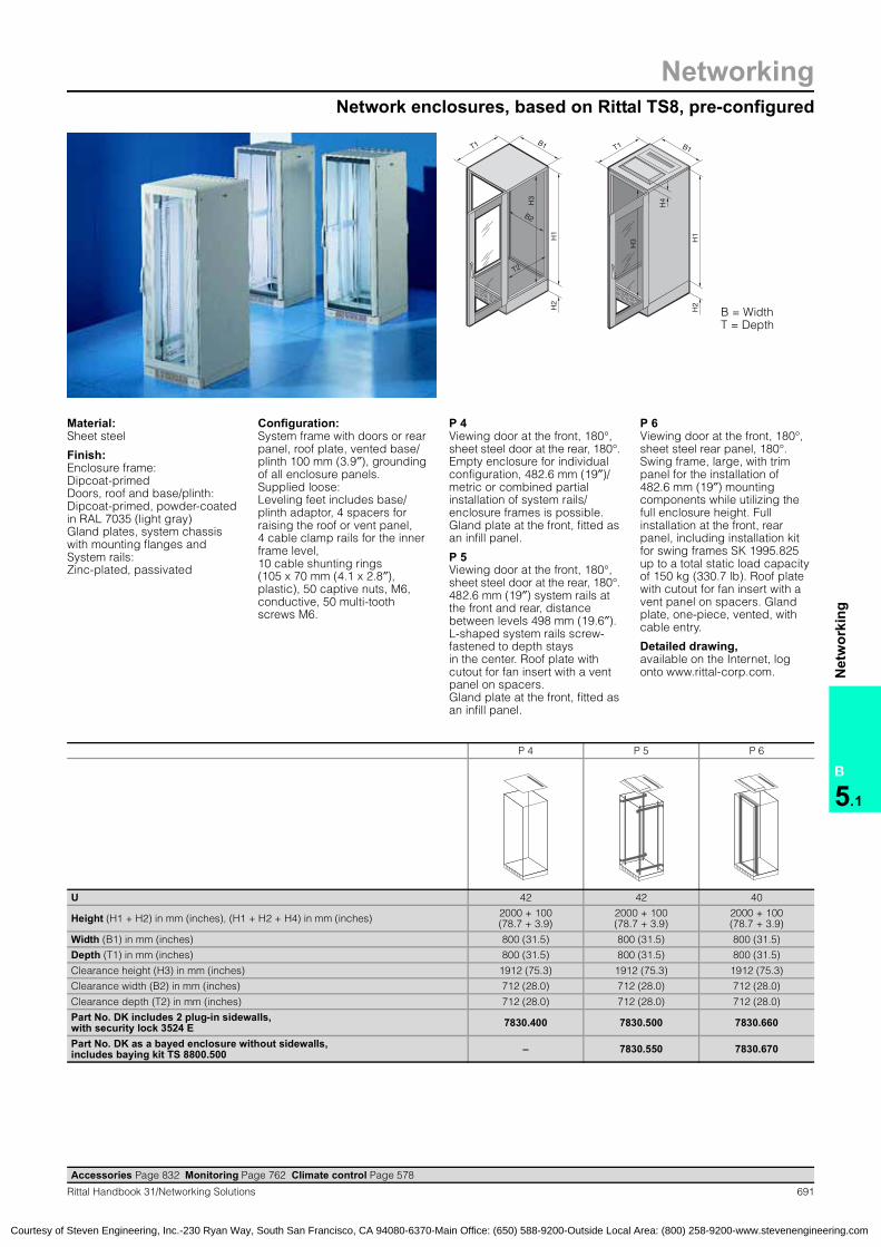
NetworkingNetwork enclosures, based on Rittal TS8, pre-configured
B
5.1
Net
wor
king
687Rittal Handbook 31/Networking Solutions
T1
H1
H2
B1 T1 B1
H1
H2
H3
T2
H3
B2
B = WidthT = Depth
Accessories Page 832 Monitoring Page 762 Climate control Page 578
Network enclosures:Based on Rittal TS8TS:Network enclosures
Material:Sheet steel
Finish:Enclosure frame: Dipcoat-primedDoors, roof and base/plinth: Dipcoat-primed, powder-coated in RAL 7035 (light gray) Gland plates, system chassis with mounting flanges and System rails: Zinc-plated, passivated
Configuration:System frame with doors or rear panel, roof plate, vented base/plinth 100 mm (3.9″), grounding of all enclosure panels.Supplied loose: Leveling feet includes base/plinth adaptor, 4 spacers, for raising the roof, 4 cable clamp rails for the inner frame level, 10 cable shunting rings, (105 x 70 mm, (4.1 x 2.8″) plastic), 50 captive nuts, M6, conductive, 50 multi-tooth screws M6.
P 1Viewing door at the front, 180°, sheet steel door at the rear, 130°. 482.6 mm (19″) system rails, front, fitted approximately 150 mm (5.9″) behind the frame front edge, screw-fastened to the TS system chassis with mounting flange as depth stays. Gland plate, one-piece, vented, with cable entry.
P 2Viewing door at the front, 180°, sheet steel door at the rear, 130°.482.6 mm (19″) system rails at the front and rear, distance between levels 498 mm (19.6″). C-shaped system rails screw-fastened to installation brackets approximately 150 mm (5.9″) behind the frame front edge. Gland plate at the front, fitted as an infill panel.
Detailed drawing,available on the Internet, log onto www.rittal-corp.com.
P 1 P 2 P 2 P 2
U 24 38 42 47
Height (H1 + H2) in mm (inches) 1200 + 100 (47.2 + 3.9)
1800 + 100 (70.9 + 3.9)
2000 + 100 (78.7 + 3.9)
2200 + 100 (86.6 + 3.9)
Width (B1) in mm (inches) 600 (23.6) 800 (31.5) 800 (31.5) 800 (31.5)
Depth (T1) in mm (inches) 600 (23.6) 800 (31.5) 800 (31.5) 800 (31.5)
Clearance height (H3) in mm (inches) 1112 (43.8) 1712 (67.4) 1912 (75.3) 2112 (83.1)
Clearance width (B2) in mm (inches) 512 (20.2) 712 (28.0) 712 (28.0) 712 (28.0)
Clearance depth (T2) in mm (inches) 512 (20.2) 712 (28.0) 712 (28.0) 712 (28.0)
Part No. DK including 2 plug-in sidewalls, with security lock 3524 E 7830.100 7830.800 7830.200 7830.220
Part No. DK as a bayed enclosure without sidewalls, includes baying kit TS 8800.500 – 7830.850 7830.250 7830.270
Courtesy of Steven Engineering, Inc.-230 Ryan Way, South San Francisco, CA 94080-6370-Main Office: (650) 588-9200-Outside Local Area: (800) 258-9200-www.stevenengineering.com

NetworkingNetwork enclosures, based on Rittal TS8, pre-configured
B
5.1
Net
wor
king
688 Rittal Handbook 31/Networking Solutions
P 1 P 2 P 2 P 2 Page
U 24 38 42 47
Height (H1 + H2) in mm (inches) 1200 + 100 (47.2 + 3.9)
1800 + 100 (70.9 + 3.9)
2000 + 100 (78.7 + 3.9)
2200 + 100 (86.6 + 3.9)
Width (B1) in mm (inches) 600 (23.6) 800 (31.5) 800 (31.5) 800 (31.5)
Depth (T1) in mm (inches) 600 (23.6) 800 (31.5) 800 (31.5) 800 (31.5)
Part No. DK includes 2 plug-in sidewalls, with security lock 3524 E 7830.100 7830.800 7830.200 7830.220
Part No. DK as bayed enclosure without side-walls, includes baying kit TS 8800.500 – 7830.850 7830.250 7830.270
DoorsViewing front door/sheet steel rear door � � � �
Various door options from page 869 from page 869 from page 869 from page 869
180° hinges for sheet steel rear door 8800.190 8800.190 8800.190 8800.190 893
SidewallSidewall, plug-in, IP 20 � � (7830.800 only) � (7830.200 only) �/– (7830.220 only)
Lock for sidewall, plug-in, 3524 E � � � �
Internal latch for sidewall, plug-in 7824.510 7824.510 7824.510 7824.510 855
Sidewall, screw-fastened, IP 55 8170.235 8188.235 8108.235 8128.235 853
Baying from page 861 from page 861 from page 861 from page 861
RoofRoof plate for cable entry � � � �
Roof plate, vented 7826.766 7826.788 7826.788 7826.788 902
Roof plate, vented, for cable entry 7826.669 7826.889 7826.889 7826.889 902
Fan roof, modular see page 651 see page 651 see page 651 see page 651
Fan mounting plate, active, with controller 7966.035 7988.035 7988.035 7988.035 649
DC fan mounting plate with FCS speed control – 7858.488 7858.488 7858.488 650
Spacers, 50 mm (2.0″) 7967.000 7967.000 7967.000 7967.000 904
Base/plinthBase/plinth components, solid, front and rear 8601.605 8601.805 8601.805 8601.805 835
Gland plate, multi-piece – 7825.382 7825.382 7825.382 852
Gland plate versions from page 851 from page 851 from page 851 from page 851
Castors see page 848 see page 848 see page 848 see page 848
Interior installation482.6 mm (19″) system rails, C-shaped (for network technology)
� (front)
� (front and rear)
� (front and rear)
� (front and rear)
System chassis with mounting flange, interior installation, rail systems from page 917 from page 917 from page 917 from page 917
Cable clamp rails, C rails see page 980 see page 980 see page 980 see page 980
Grounding/potential equalization � � � �
Socket strips, power management from page 742 from page 742 from page 742 from page 742
Component shelves from page 939 from page 939 from page 939 from page 939
482.6 mm (19″) installation system from page 1010 from page 1010 from page 1010 from page 1010
Cable management from page 984 from page 984 from page 984 from page 984
CMC-TC system monitoring from page 762 from page 762 from page 762 from page 762
� Included with the supply.
Accessories Page 832 Monitoring Page 762 Climate control Page 578
Courtesy of Steven Engineering, Inc.-230 Ryan Way, South San Francisco, CA 94080-6370-Main Office: (650) 588-9200-Outside Local Area: (800) 258-9200-www.stevenengineering.com

NetworkingNetwork enclosures, based on Rittal TS8, pre-configured
B
5.1
Net
wor
king
689Rittal Handbook 31/Networking Solutions
Accessories Page 832 Monitoring Page 762 Climate control Page 578
P 3 P 3 P 3 P 3 P 3
U 24 42 42 47 47
Height (H1 + H2) in mm (inches) 1200 + 100(47.2 + 3.9)
2000 + 100(78.7 + 3.9)
2000 + 100(78.7 + 3.9)
2200 + 100(86.6+ 3.9)
2200 + 100(96.6 + 3.9)
Width (B1) in mm (inches) 800 (31.5) 800 (31.5) 800 (31.5) 800 (31.5) 800 (31.5)
Depth (T1) in mm (inches) 900 (35.4) 900 (35.4) 1000 (39.4) 900 (35.4) 1000 (39.4)
Clearance height (H3) in mm (inches) 1112 (43.8) 1912 (75.3) 1912 (75.3) 2112 (83.1) 2112 (83.1)
Clearance width (B2) in mm (inches) 712 (28.0) 712 (28.0) 712 (28.0) 712 (28.0) 712 (28.0)
Clearance depth (T2) in mm (inches) 812 (32.0) 812 (32.0) 912 (35.9) 812 (32.0) 912 (35.9)
Part No. DK including 2 plug-in sidewalls, with security lock 3524 E 7830.120 7830.300 7830.330 7830.320 7830.340
Part No. DK as a bayed enclosure withoutsidewalls, includes baying kit TS 8800.500 – 7830.350 7830.335 7830.370 7830.380
T1
H1
H2
B1 T1 B1
H1
H2
H3
T2
H3
B2
B = WidthT = Depth
Material:Sheet steel
Finish:Enclosure frame: Dipcoat-primedDoors, roof and base/plinth: Dipcoat-primed,powder-coated in RAL 7035 (light gray)Gland plates, system chassis with mounting flanges and System rails: Zinc-plated, passivated
Configuration:System frame with doors or rear panel, roof plate, vented base/plinth 100 mm (3.9″), grounding of all enclosure panels.Supplied loose: Leveling feet includes base/plinth adaptor, 4 spacers, for raising the roof, 4 cable clamp rails for the inner frame level, 10 cable shunting rings (105 x 70 mm, (4.1 x 2.8″) plastic), 50 captive nuts, M6, conductive, 50 multi-tooth screws M6.
P 3Viewing door, vented, at the front, 180°, sheet steel door, vented, at the rear, 180°. 482.6 mm (19″) system rails at the front and rear, distance between levels 740 mm (29.1″). L-shaped system rails screw-fastened to 2 or 3 depth stays respectively. Gland plate, one-piece, vented, with cable entry.
Detailed drawing,available on the Internet, log onto www.rittal-corp.com.
Courtesy of Steven Engineering, Inc.-230 Ryan Way, South San Francisco, CA 94080-6370-Main Office: (650) 588-9200-Outside Local Area: (800) 258-9200-www.stevenengineering.com

NetworkingNetwork enclosures, based on Rittal TS8, pre-configured
B
5.1
Net
wor
king
690 Rittal Handbook 31/Networking Solutions
P 3 P 3 P 3 P 3 P 3 Page
U 24 42 42 47 47
Height (H1 + H2) in mm (inches) 1200 + 100(47.2 + 3.9)
2000 + 100(78.7 + 3.9)
2000 + 100(78.7 + 3.9)
2200 + 100(86.6+ 3.9)
2200 + 100(96.6 + 3.9)
Width (B1) in mm (inches) 800 (31.5) 800 (31.5) 800 (31.5) 800 (31.5) 800 (31.5)
Depth (T1) in mm (inches) 900 (35.4) 900 (35.4) 1000 (39.4) 900 (35.4) 1000 (39.4)
Part No. DK includes 2 plug-in sidewalls, with security lock 3524 E 7830.120 7830.300 7830.330 7830.320 7830.340
Part No. DK as bayed enclosure without side-walls, includes baying kit TS 8800.500 – 7830.350 7830.335 7830.370 7830.380
DoorsViewing front door/sheet steel rear door, vented � � � � �
Various door options from page 869 from page 869 from page 869 from page 869 from page 869
SidewallSidewall, plug-in, IP 20 � � (7830.300 only) � (7830.330 only) � (7830.320 only) � (7830.340 only)
Lock for sidewall, plug-in, 3524 E � � � � �
Internal latch for sidewall, plug-in 7824.510 7824.510 7824.510 7824.510 7824.510 855
Sidewall, screw-fastened, IP 55 – 8109.235 8100.235 8129.235 – 853
Baying from page 861 from page 861 from page 861 from page 861 from page 861
RoofRoof plate for cable entry � � � � �
Roof plate, vented 7826.789 7826.789 7826.780 7826.789 7826.780 902
Roof plate, vented, for cable entry 7826.899 7826.899 7826.809 7826.899 7826.809 902
Fan roof, modular see page 651 see page 651 see page 651 see page 651 see page 651
Fan mounting plate, active, with controller 7988.035 7988.035 7988.035 7988.035 7988.035 649
DC fan mounting plate with FCS speed control 7858.488 7858.488 7858.488 7858.488 7858.488 650
Spacers, 50 mm (2.0″) 7967.000 7967.000 7967.000 7967.000 7967.000 904
Base/plinthBase/plinth components, solid,front and rear 8601.805 8601.805 8601.805 8601.805 8601.805 835
Gland plate versions from page 851 from page 851 from page 851 from page 851 from page 851
Castors see page 848 see page 848 see page 848 see page 848 see page 848
Interior installation482.6 mm (19″) system rails, L-shaped (for server technology) � � (front and rear) � (front and rear) � (front and rear) � (front and rear)
System chassis with mounting flange,interior installation, rail systems from page 917 from page 917 from page 917 from page 917 from page 917
Cable clamp rails, C rails see page 980 see page 980 see page 980 see page 980 see page 980
Grounding/potential equalization � � � � �
Socket strips, power management from page 742 from page 742 from page 742 from page 742 from page 742
Component shelves from page 939 from page 939 from page 939 from page 939 from page 939
482.6 mm (19″) installation system from page 1010 from page 1010 from page 1010 from page 1010 from page 1010
Cable management from page 984 from page 984 from page 984 from page 984 from page 984
CMC-TC system monitoring from page 762 from page 762 from page 762 from page 762 from page 762
� Included with the supply.
Accessories Page 832 Monitoring Page 762 Climate control Page 578
Courtesy of Steven Engineering, Inc.-230 Ryan Way, South San Francisco, CA 94080-6370-Main Office: (650) 588-9200-Outside Local Area: (800) 258-9200-www.stevenengineering.com
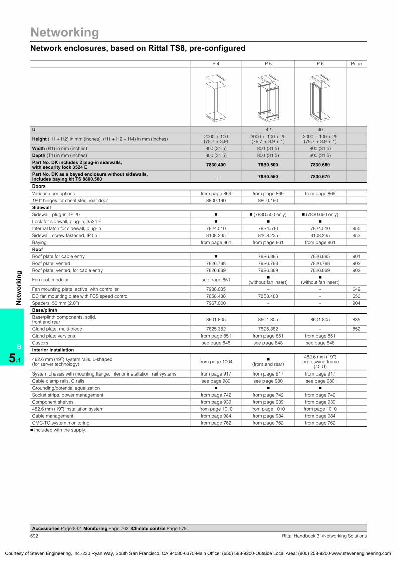
NetworkingNetwork enclosures, based on Rittal TS8, pre-configured
B
5.1
Net
wor
king
691Rittal Handbook 31/Networking Solutions
Accessories Page 832 Monitoring Page 762 Climate control Page 578
P 4 P 5 P 6
U 42 42 40
Height (H1 + H2) in mm (inches), (H1 + H2 + H4) in mm (inches) 2000 + 100 (78.7 + 3.9)
2000 + 100(78.7 + 3.9)
2000 + 100 (78.7 + 3.9)
Width (B1) in mm (inches) 800 (31.5) 800 (31.5) 800 (31.5)
Depth (T1) in mm (inches) 800 (31.5) 800 (31.5) 800 (31.5)
Clearance height (H3) in mm (inches) 1912 (75.3) 1912 (75.3) 1912 (75.3)
Clearance width (B2) in mm (inches) 712 (28.0) 712 (28.0) 712 (28.0)
Clearance depth (T2) in mm (inches) 712 (28.0) 712 (28.0) 712 (28.0)
Part No. DK includes 2 plug-in sidewalls, with security lock 3524 E 7830.400 7830.500 7830.660
Part No. DK as a bayed enclosure without sidewalls, includes baying kit TS 8800.500 – 7830.550 7830.670
T1
H1
H2
B1
T2
H3
B2
T1 B1
H1
H2
H3
H4
B = WidthT = Depth
Material:Sheet steel
Finish:Enclosure frame: Dipcoat-primedDoors, roof and base/plinth: Dipcoat-primed, powder-coated in RAL 7035 (light gray)Gland plates, system chassis with mounting flanges and System rails: Zinc-plated, passivated
Configuration:System frame with doors or rear panel, roof plate, vented base/plinth 100 mm (3.9″), grounding of all enclosure panels.Supplied loose: Leveling feet includes base/plinth adaptor, 4 spacers for raising the roof or vent panel, 4 cable clamp rails for the inner frame level, 10 cable shunting rings (105 x 70 mm (4.1 x 2.8″), plastic), 50 captive nuts, M6, conductive, 50 multi-tooth screws M6.
P 4Viewing door at the front, 180°, sheet steel door at the rear, 180°. Empty enclosure for individual configuration, 482.6 mm (19″)/ metric or combined partial installation of system rails/enclosure frames is possible. Gland plate at the front, fitted as an infill panel.
P 5Viewing door at the front, 180°, sheet steel door at the rear, 180°. 482.6 mm (19″) system rails at the front and rear, distance between levels 498 mm (19.6″). L-shaped system rails screw-fastened to depth stays in the center. Roof plate with cutout for fan insert with a vent panel on spacers.Gland plate at the front, fitted as an infill panel.
P 6Viewing door at the front, 180°, sheet steel rear panel, 180°. Swing frame, large, with trim panel for the installation of 482.6 mm (19″) mounting components while utilizing the full enclosure height. Full installation at the front, rear panel, including installation kit for swing frames SK 1995.825 up to a total static load capacity of 150 kg (330.7 lb). Roof plate with cutout for fan insert with a vent panel on spacers. Gland plate, one-piece, vented, with cable entry.
Detailed drawing,available on the Internet, log onto www.rittal-corp.com.
Courtesy of Steven Engineering, Inc.-230 Ryan Way, South San Francisco, CA 94080-6370-Main Office: (650) 588-9200-Outside Local Area: (800) 258-9200-www.stevenengineering.com
NetworkingNetwork enclosures, based on Rittal TS8, pre-configured
B
5.1
Net
wor
king
692 Rittal Handbook 31/Networking Solutions
P 4 P 5 P 6 Page
U – 42 40
Height (H1 + H2) in mm (inches), (H1 + H2 + H4) in mm (inches) 2000 + 100 (78.7 + 3.9)
2000 + 100 + 25(78.7 + 3.9 + 1)
2000 + 100 + 25(78.7 + 3.9 + 1)
Width (B1) in mm (inches) 800 (31.5) 800 (31.5) 800 (31.5)
Depth (T1) in mm (inches) 800 (31.5) 800 (31.5) 800 (31.5)
Part No. DK includes 2 plug-in sidewalls, with security lock 3524 E 7830.400 7830.500 7830.660
Part No. DK as a bayed enclosure without sidewalls, includes baying kit TS 8800.500 – 7830.550 7830.670
DoorsVarious door options from page 869 from page 869 from page 869
180° hinges for sheet steel rear door 8800.190 8800.190 –
SidewallSidewall, plug-in, IP 20 � � (7830.500 only) � (7830.660 only)
Lock for sidewall, plug-in, 3524 E � � �
Internal latch for sidewall, plug-in 7824.510 7824.510 7824.510 855
Sidewall, screw-fastened, IP 55 8108.235 8108.235 8108.235 853
Baying from page 861 from page 861 from page 861
RoofRoof plate for cable entry � 7826.885 7826.885 901
Roof plate, vented 7826.788 7826.788 7826.788 902
Roof plate, vented, for cable entry 7826.889 7826.889 7826.889 902
Fan roof, modular see page 651 � (without fan insert)
� (without fan insert)
Fan mounting plate, active, with controller 7988.035 – – 649
DC fan mounting plate with FCS speed control 7858.488 7858.488 – 650
Spacers, 50 mm (2.0″) 7967.000 – – 904
Base/plinthBase/plinth components, solid,front and rear 8601.805 8601.805 8601.805 835
Gland plate, multi-piece 7825.382 7825.382 – 852
Gland plate versions from page 851 from page 851 from page 851
Castors see page 848 see page 848 see page 848
Interior installation
482.6 mm (19″) system rails, L-shaped (for server technology) from page 1004 �
(front and rear)
482.6 mm (19″)large swing frame
(40 U)
System chassis with mounting flange, interior installation, rail systems from page 917 from page 917 from page 917
Cable clamp rails, C rails see page 980 see page 980 see page 980
Grounding/potential equalization � � �
Socket strips, power management from page 742 from page 742 from page 742
Component shelves from page 939 from page 939 from page 939
482.6 mm (19″) installation system from page 1010 from page 1010 from page 1010
Cable management from page 984 from page 984 from page 984
CMC-TC system monitoring from page 762 from page 762 from page 762
� Included with the supply.
Accessories Page 832 Monitoring Page 762 Climate control Page 578
Courtesy of Steven Engineering, Inc.-230 Ryan Way, South San Francisco, CA 94080-6370-Main Office: (650) 588-9200-Outside Local Area: (800) 258-9200-www.stevenengineering.com

NetworkingNetwork enclosures, based on Rittal TS8, types 1 and 2
B
5.1
Net
wor
king
693Rittal Handbook 31/Networking Solutions
T2
H2
T1
B2
H1
B1 T1 B1
H1
B = WidthT = Depth
Type 1Aluminum viewing door at the front (180°), with 3 mm (0.1”) single-pane safety glass, comfort handle for semi-cylinder and security lock 3524 E; sheet steel door at the rear (130°) with handle and security lock 3524 E.
Type 2Sheet steel door at the front (180°), with comfort handle for semi-cylinder and security lock 3524 E; sheet steel door at the rear (130°) with handle and security lock 3524 E.
Material:Sheet steel
Finish:Enclosure frame: Dipcoat-primedDoors and roof: Dipcoat-primed,powder-coated in RAL 7035 (light gray)Base plates and system chassis with mounting flanges: Zinc-plated, passivated
Configuration:Enclosure frame with doors, roof plate, multi-piece gland plate, 2 system chassis with mounting flanges in the enclosure depth.
Certifications, see page 82.
Detailed drawing,available on the Internet, log onto www.rittal-corp.com.
U 15 20 20 24 24 24 24 24
Height (H1) in mm (inches) 800 (31.5) 1000 (39.4) 1000 (39.4) 1200 (47.2) 1200 (47.2) 1200 (47.2) 1200 (47.2) 1200 (47.2)
Width (B1) in mm (inches) 600 (23.6) 600 (23.6) 800 (31.5) 600 (23.6) 800 (31.5) 800 (31.5) 800 (31.5) 800 (31.5)
Depth (T1) in mm (inches) 600 (23.6) 600 (23.6) 600 (23.6) 600 (23.6) 600 (23.6) 800 (31.5) 900 (35.4) 1000 (39.4)
Clearance height (H2) in mm (inches) 712 (28.0) 912 (35.9) 912 (35.9) 1112 (43.8) 1112 (43.8) 1112 (43.8) 1112 (43.8) 1112 (43.8)
Clearance width (B2) in mm (inches) 512 (20.2) 512 (20.2) 712 (28.0) 512 (20.2) 712 (28.0) 712 (28.0) 712 (28.0) 712 (28.0)
Clearance depth (T2) in mm (inches) 512 (20.2) 512 (20.2) 512 (20.2) 512 (20.2) 512 (20.2) 712 (28.0) 812 (32.0) 912 (35.9)
Part No. DK, Type 1 with viewing door at the front 7820.100 7820.200 7820.240 7820.300 7820.340 7820.350 7820.355 7820.360
Part No. DK, Type 2 with sheet steel door at the front 7821.100 7821.200 7821.240 7821.300 7821.340 – 7821.355 –
U 29 29 29 33 33 33 38 38
Height (H1) in mm (inches) 1400 (55.1) 1400 (55.1) 1400 (55.1) 1600 (63.0) 1600 (63.0) 1600 (63.0) 1800 (70.9) 1800 (70.9)
Width (B1) in mm (inches) 600 (23.6) 600 (23.6) 800 (31.5) 600 (23.6) 600 (23.6) 800 (31.5) 600 (23.6) 600 (23.6)
Depth (T1) in mm (inches) 600 (23.6) 800 (31.5) 600 (23.6) 600 (23.6) 800 (31.5) 600 (23.6) 600 (23.6) 800 (31.5)
Clearance height (H2) in mm (inches) 1312 (51.7) 1312 (51.7) 1312 (51.7) 1512 (59.5) 1512 (59.5) 1512 (59.5) 1512 (59.5) 1712 (67.4)
Clearance width (B2) in mm (inches) 512 (20.2) 512 (20.2) 712 (28.0) 712 (28.0) 512 (20.2) 712 (28.0) 712 (28.0) 512 (20.2)
Clearance depth (T2) in mm (inches) 512 (20.2) 712 (28.0) 512 (20.2) 512 (20.2) 712 (28.0) 512 (20.2) 512 (20.2) 712 (28.0)
Part No. DK, Type 1 with viewing door at the front 7820.400 7820.410 7820.440 7820.500 7820.510 7820.540 7820.600 7820.610
Part No. DK, Type 2 with sheet steel door at the front 7821.400 7821.410 7821.440 7821.500 7821.510 7821.540 7821.600 7821.610
Accessories Page 832 Monitoring Page 762 Climate control Page 578
Courtesy of Steven Engineering, Inc.-230 Ryan Way, South San Francisco, CA 94080-6370-Main Office: (650) 588-9200-Outside Local Area: (800) 258-9200-www.stevenengineering.com

NetworkingNetwork enclosures, based on Rittal TS8, types 1 and 2
B
5.1
Net
wor
king
694 Rittal Handbook 31/Networking Solutions
T2
H2
T1
B2
H1
B1 T1 B1
H1
B = WidthT = Depth
Type 1Aluminum viewing door at the front (180°), with 3 mm (0.1″) single-pane safety glass, comfort handle for semi-cylinder and security lock 3524 E; sheet steel door at the rear (130°) with handle and security lock 3524 E.
Type 2Sheet steel door at the front (180°), with comfort handle for semi-cylinder and security lock 3524 E; sheet steel door at the rear (130°) with handle and security lock 3524 E.
Material:Sheet steel
Finish:Enclosure frame: Dipcoat-primedDoors and roof: Dipcoat-primed, powder-coated in RAL 7035 (light gray)Base plates and system chassis with mounting flanges:Zinc-plated, passivated
Configuration:Enclosure frame with doors, roof plate, multi-piece gland plate, 2 system chassis with mounting flanges in the enclosure depth.
Certifications, see page 82.
Detailed drawing,available on the Internet, log onto www.rittal-corp.com.
U 38 38 38 38 42 42 42 42
Height (H1) in mm (inches) 1800 (70.9) 1800 (70.9) 1800 (70.9) 1800 (70.9) 2000 (78.7) 2000 (78.7) 2000 (78.7) 2000 (78.7)
Width (B1) in mm (inches) 600 (23.6) 800 (31.5) 800 (31.5) 800 (31.5) 600 (23.6) 600 (23.6) 800 (31.5) 800 (31.5)
Depth (T1) in mm (inches) 900 (35.4) 600 (23.6) 800 (31.5) 1000 (39.4) 600 (23.6) 800 (31.5) 600 (23.6) 800 (31.5)
Clearance height (H2) in mm (inches) 1712 (67.4) 1712 (67.4) 1712 (67.4) 1712 (67.4) 1912 (75.3) 1912 (75.3) 1912 (75.3) 1912 (75.3)
Clearance width (B2) in mm (inches) 512 (20.2) 712 (28.0) 712 (28.0) 712 (28.0) 712 (28.0) 512 (20.2) 512 (20.2) 712 (28.0)
Clearance depth (T2) in mm (inches) 812 (32.0) 512 (20.2) 712 (28.0) 912 (35.9) 512 (20.2) 712 (28.0) 512 (20.2) 712 (28.0)
Part No. DK, Type 1 with viewing door at the front 7820.620 7820.640 7820.650 7820.670 7820.700 7820.710 7820.740 7820.750
Part No. DK, Type 2 with sheet steel door at the front 7821.620 7821.640 7821.650 7821.670 7821.700 7821.710 7821.740 7821.750
U 42 42 47 47 47 47 47 47
Height (H1) in mm (inches) 2000 (78.7) 2000 (78.7) 2200 (86.6) 2200 (86.6) 2200 (86.6) 2200 (86.6) 2200 (86.6) 2200 (86.6)
Width (B1) in mm (inches) 800 (31.5) 800 (31.5) 600 (23.6) 600 (23.6) 800 (31.5) 800 (31.5) 800 (31.5) 800 (31.5)
Depth (T1) in mm (inches) 900 (35.4) 1000 (39.4) 600 (23.6) 800 (31.5) 600 (23.6) 800 (31.5) 900 (35.4) 1000 (39.4)
Clearance height (H2) in mm (inches) 1912 (75.3) 1912 (75.3) 2112 (83.1) 2112 (83.1) 2112 (83.1) 2112 (83.1) 2112 (83.1) 2112 (83.1)
Clearance width (B2) in mm (inches) 712 (28.0) 712 (28.0) 712 (28.0) 512 (20.2) 512 (20.2) 712 (28.0) 712 (28.0) 712 (28.0)
Clearance depth (T2) in mm (inches) 812 (32.0) 912 (35.9) 512 (20.2) 712 (28.0) 512 (20.2) 712 (28.0) 812 (32.0) 912 (35.9)
Part No. DK, Type 1 with viewing door at the front 7820.760 7820.770 7820.800 7820.810 7820.840 7820.850 7820.860 7820.870
Part No. DK, Type 2 with sheet steel door at the front 7821.760 7821.770 7821.800 7821.810 7821.840 7821.850 7821.860 7821.870
Accessories Page 832 Monitoring Page 762 Climate control Page 578
Courtesy of Steven Engineering, Inc.-230 Ryan Way, South San Francisco, CA 94080-6370-Main Office: (650) 588-9200-Outside Local Area: (800) 258-9200-www.stevenengineering.com

Network enclosures, based on Rittal TS8, 15 – 20U
Networking
695Rittal Handbook 31/Networking Solutions
B
5.1
Net
wor
king
Accessories Page 832
Type 1 Type 2 Type 1 Type 2 Type 1 Type 2 Page
U 15 20 20
Height (H1) in mm (inches) 800 (31.5) 1000 (39.4) 1000 (39.4)
Width (B1) in mm (inches) 600 (23.6) 600 (23.6) 800 (31.5)
Depth (T1) in mm (inches) 600 (23.6) 600 (23.6) 600 (23.6)
Part No. DK 7820.100 7821.100 7820.200 7821.200 7820.240 7821.240DoorsViewing front door/sheet steel rear door � – � – � –
Sheet steel front door/sheet steel rear door – � – � – �
Various door options from page 869 from page 869 from page 869
180° hinges for sheet steel rear door 8800.190 8800.190 8800.190 893
SidewallSidewall, plug-in, IP 20, NEMA Type 1 7824.086 7824.106 7824.106 855
Lock for sidewall, plug-in 7824.500 7824.500 7824.500 855
Internal latch for sidewall, plug-in, 3524 E 7824.510 7824.510 7824.510 855
Sidewall, screw-fastened,IP 55, NEMA Type 12 8173.235 8174.235 8174.235 853
Baying from page 861 from page 861 from page 861
RoofRoof plate, solid � � �
Roof plate, vented 7826.766 7826.766 7826.786 902
Roof plate, for cable entry 7826.665 7826.665 7826.865 901
Roof plate, vented, for cable entry 7826.669 7826.669 7826.869 902
Fan mounting plate, active, with controller 7966.035 7966.035 7986.035 649
Fan roof, modular see page 651 see page 651 see page 651
Spacers, 20 mm (0.8″) 2423.000 2423.000 2423.000 904
Spacers, 50 mm (2.0″) 7967.000 7967.000 7967.000 904
Climate control see page 579 see page 579 see page 579
Base/plinthBase/plinth components, vented, front and rear, H = 100 mm (3.9″) 7825.601 7825.601 7825.601 835
Base/plinth components, solid,front and rear, H = 100 mm (3.9″) 8601.605 8601.605 8601.805 835
Base/plinth trim panels, side, H = 100 mm (3.9″) 8601.065 8601.065 8601.065 835
Gland plate versions from page 851 from page 851 from page 851
Castors see page 848 see page 848 see page 848
Interior installation482.6 mm (19″) system rails, C-shaped(for network technology) 7827.080 7827.100 7827.100 1004
482.6 mm (19″) system rails, L-shaped (for server technology) 7827.081 7827.101 7827.101 1004
Depth stays for system rails 8612.060 8612.060 7827.600 1008
Installation brackets for system rails – – 7827.480 1009
Cable clamp rails see page 980 see page 980 see page 980
Grounding/potential equalization from page 960 from page 960 from page 960
Power strips/power management from page 742 from page 742 from page 742
Component shelves from page 939 from page 939 from page 939
482.6 mm (19″) installation system from page 1010 from page 1010 from page 1010
Cable management from page 984 from page 984 from page 984
CMC-TC system monitoring from page 762 from page 762 from page 762
� Included with the supply.
Courtesy of Steven Engineering, Inc.-230 Ryan Way, South San Francisco, CA 94080-6370-Main Office: (650) 588-9200-Outside Local Area: (800) 258-9200-www.stevenengineering.com

NetworkingNetwork enclosures, based on Rittal TS8, 24U
696 Rittal Handbook 31/Networking Solutions
B
5.1
Net
wor
king
Accessories Page 832
Type 1 Type 2 Type 1 Type 2 Type 1 Type 1 Type 2 Type 1 Page
U 24 24 24 24 24
Height (H1) in mm (inches) 1200 (47.2) 1200 (47.2) 1200 (47.2) 1200 (47.2) 1200 (47.2)
Width (B1) in mm (inches) 600 (23.6) 800 (31.5) 800 (31.5) 800 (31.5) 800 (31.5)
Depth (T1) in mm (inches) 600 (23.6) 600 (23.6) 800 (31.5) 900 (35.4) 1000 (39.4)
Part No. DK 7820.300 7821.300 7820.340 7821.340 7820.350 7820.355 7821.355 7820.360DoorsViewing front door/sheet steel rear door � – � – � � – �
Sheet steel front door/sheet steel rear door – � – � – – � –
Various door options from page 869 from page 869 from page 869 from page 869 from page 869
180° hinges for sheet steel rear door 8800.190 8800.190 8800.190 8800.190 8800.190 893
SidewallSidewall, plug-in, IP 20, NEMA Type 1 7824.126 7824.126 7824.128 7824.129 7824.120 855
Lock for sidewall, plug-in 7824.500 7824.500 7824.500 7824.500 – 855
Internal latch for sidewall, plug-in, 3524 E 7824.510 7824.510 7824.510 7824.510 – 855
Sidewall, screw-fastened, IP 55, NEMA Type 12 8170.235 8170.235 8175.235 – 8176.235 853
Baying from page 861 from page 861 from page 861 from page 861 from page 861
RoofRoof plate, solid � � � � �
Roof plate, vented 7826.766 7826.786 7826.788 7826.789 7826.780 902
Roof plate, for cable entry 7826.665 7826.865 7826.885 7826.895 7826.805 901
Roof plate, vented, for cable entry 7826.669 7826.869 7826.889 7826.899 7826.809 902
Fan mounting plate, active, with controller 7966.035 7986.035 7988.035 7988.035 7988.035 649
Fan roof, modular see page 651 see page 651 see page 651 see page 651 see page 651
Spacers, 20 mm (0.8″) 2423.000 2423.000 2423.000 2423.000 2423.000 904
Spacers, 50 mm (2.0″) 7967.000 7967.000 7967.000 7967.000 7967.000 904
Climate control see page 579 see page 579 see page 579 see page 579 see page 579
Base/plinthBase/plinth components, vented, front and rear, H = 100 mm (3.9″) 7825.601 7825.801 7825.801 7825.801 7825.801 835
Base/plinth components, solid,front and rear, H = 100 mm (3.9″) 8601.605 8601.805 8601.805 8601.805 8601.805 835
Base/plinth trim panels, side, H = 100 mm (3.9″) 8601.065 8601.065 8601.085 8601.095 8601.015 835
Gland plate versions from page 851 from page 851 from page 851 from page 851 from page 851
Castors see page 848 see page 848 see page 848 see page 848 see page 848
Interior installation482.6 mm (19″) system rails, C-shaped (for network technology) 7827.120 7827.120 7827.120 7827.120 7827.120 1004
482.6 mm (19″) system rails,L-shaped (for server technology) 7827.121 7827.121 7827.121 7827.121 7827.121 1004
Depth stays for system rails 8612.060 7827.600 7827.800 7827.900 7827.000 1008
Installation brackets for system rails – 7827.480 7827.480 7827.480 7827.480 1009
Cable clamp rails see page 980 see page 980 see page 980 see page 980 see page 980
Grounding/potential equalization from page 960 from page 960 from page 960 from page 960 from page 960
Power strips/power management from page 742 from page 742 from page 742 from page 742 from page 742
Component shelves from page 939 from page 939 from page 939 from page 939 from page 939
482.6 mm (19″) installation system from page 1010 from page 1010 from page 1010 from page 1010 from page 1010
Cable management from page 984 from page 984 from page 984 from page 984 from page 984
CMC-TC system monitoring from page 762 from page 762 from page 762 from page 762 from page 762
� Included with the supply.
Courtesy of Steven Engineering, Inc.-230 Ryan Way, South San Francisco, CA 94080-6370-Main Office: (650) 588-9200-Outside Local Area: (800) 258-9200-www.stevenengineering.com

Network enclosures, based on Rittal TS8, 29 – 33U
Networking
697Rittal Handbook 31/Networking Solutions
B
5.1
Net
wor
king
Accessories Page 832
Type 1 Type 2 Type 1 Type 2 Type 1 Type 1 Type 2 Type 1 Page
U 29 29 29 33
Height (H1) in mm (inches) 1400 (55.1) 1400 (55.1) 1400 (55.1) 1600 (63.0)
Width (B1) in mm (inches) 600 (23.6) 600 (23.6) 800 (31.5) 600 (23.6)
Depth (T1) in mm (inches) 600 (23.6) 800 (31.5) 600 (23.6) 600 (23.6)
Part No. DK 7820.400 7821.400 7820.410 7821.410 7820.440 7821.440 7820.500 7821.500DoorsViewing front door/sheet steel rear door � – � – � – � –
Sheet steel front door/sheet steel rear door – � – � – � – �
Various door options from page 869 from page 869 from page 869 from page 869
180° hinges for sheet steel rear door 8800.190 8800.190 8800.190 8800.190 893
SidewallSidewall, plug-in, IP 20, NEMA Type 1 7824.146 7824.148 7824.146 7824.166 855
Lock for sidewall, plug-in 7824.500 7824.500 7824.500 7824.500 855
Internal latch for sidewall, plug-in, 3524 E 7824.510 7824.510 7824.510 7824.510 855
Sidewall, screw-fastened, IP 55, NEMA Type 12 8146.235 8148.235 8146.235 8166.235 853
Baying from page 861 from page 861 from page 861 from page 861
RoofRoof plate, solid � � � �
Roof plate, vented 7826.766 7826.768 7826.786 7826.766 902
Roof plate, for cable entry 7826.665 7826.685 7826.865 7826.665 901
Roof plate, vented, for cable entry 7826.669 7826.689 7826.869 7826.669 902
Fan mounting plate, active, with controller 7966.035 7968.035 7986.035 7966.035 649
Fan roof, modular see page 651 see page 651 see page 651 see page 651
Spacers, 20 mm (0.8″) 2423.000 2423.000 2423.000 2423.000 904
Spacers, 50 mm (2.0″) 7967.000 7967.000 7967.000 7967.000 904
Climate control see page 579 see page 579 see page 579 see page 579
Base/plinthBase/plinth components, vented, front and rear, H = 100 mm (3.9″) 7825.601 7825.601 7825.801 7825.601 835
Base/plinth components, solid,front and rear, H = 100 mm (3.9″) 8601.605 8601.605 8601.805 8601.605 835
Base/plinth trim panels, side, H = 100 mm (3.9″) 8601.065 8601.085 8601.065 8601.065 835
Gland plate versions from page 851 from page 851 from page 851 from page 851
Castors see page 848 see page 848 see page 848 see page 848
Interior installation482.6 mm (19″) system rails, C-shaped (for network technology) 7827.140 7827.140 7827.140 7827.160 1004
482.6 mm (19″) system rails, L-shaped (for server technology) 7827.141 7827.141 7827.141 7827.161 1004
Depth stays for system rails 8612.060 8612.080 7827.600 8612.060 1008
Installation brackets for system rails – – 7827.480 – 1009
Cable clamp rails see page 980 see page 980 see page 980 see page 980
Grounding/potential equalization from page 960 from page 960 from page 960 from page 960
Power strips/power management from page 742 from page 742 from page 742 from page 742
Component shelves from page 939 from page 939 from page 939 from page 939
482.6 mm (19″) installation system from page 1010 from page 1010 from page 1010 from page 1010
Cable management from page 984 from page 984 from page 984 from page 984
CMC-TC system monitoring from page 762 from page 762 from page 762 from page 762
� Included with the supply.
Courtesy of Steven Engineering, Inc.-230 Ryan Way, South San Francisco, CA 94080-6370-Main Office: (650) 588-9200-Outside Local Area: (800) 258-9200-www.stevenengineering.com

NetworkingNetwork enclosures, based on Rittal TS8, 33 – 38U
698 Rittal Handbook 31/Networking Solutions
B
5.1
Net
wor
king
Accessories Page 832
Type 1 Type 2 Type 1 Type 2 Type 1 Type 2 Type 1 Type 2 Page
U 33 33 38 38
Height (H1) in mm (inches) 1600 (63.0) 1600 (63.0) 1800 (70.9) 1800 (70.9)
Width (B1) in mm (inches) 600 (23.6) 800 (31.5) 600 (23.6) 600 (23.6)
Depth (T1) in mm (inches) 800 (31.5) 600 (23.6) 600 (23.6) 800 (31.5)
Part No. DK 7820.510 7821.510 7820.540 7821.540 7820.600 7821.600 7820.610 7821.610DoorsViewing front door/sheet steel rear door � – � – � – � –
Sheet steel front door/sheet steel rear door – � – � – � – �
Various door options from page 869 from page 869 from page 869 from page 869
180° hinges for sheet steel rear door 8800.190 8800.190 8800.190 8800.190 893
SidewallSidewall, plug-in, IP 20, NEMA Type 1 7824.168 7824.166 7824.186 7824.188 855
Lock for sidewall, plug-in 7824.500 7824.500 7824.500 7824.500 855
Internal latch for sidewall, plug-in, 3524 E 7824.510 7824.510 7824.510 7824.510 855
Sidewall, screw-fastened, IP 55, NEMA Type 12 8168.235 8166.235 8186.235 8188.235 853
Baying from page 861 from page 861 from page 861 from page 861
RoofRoof plate, solid � � � �
Roof plate, vented 7826.768 7826.786 7826.766 7826.768 902
Roof plate, for cable entry 7826.685 7826.865 7826.665 7826.685 901
Roof plate, vented, for cable entry 7826.689 7826.869 7826.669 7826.689 902
Fan mounting plate, active, with controller 7968.035 7986.035 7966.035 7968.035 649
Fan roof, modular see page 651 see page 651 see page 651 see page 651
Spacers, 20 mm (0.8″) 2423.000 2423.000 2423.000 2423.000 904
Spacers, 50 mm (2.0″) 7967.000 7967.000 7967.000 7967.000 904
Climate control see page 579 see page 579 see page 579 see page 579
Base/plinthBase/plinth components, vented, front and rear, H = 100 mm (3.9″) 7825.601 7825.801 7825.601 7825.601 835
Base/plinth components, solid,front and rear, H = 100 mm (3.9″) 8601.605 8601.805 8601.605 8601.605 835
Base/plinth trim panels, side, H = 100 mm (3.9″) 8601.085 8601.065 8601.065 8601.085 835
Gland plate versions from page 851 from page 851 from page 851 from page 851
Castors see page 848 see page 848 see page 848 see page 848
Interior installation482.6 mm (19″) system rails, C-shaped (for network technology) 7827.160 7827.160 7827.180 7827.180 1004
482.6 mm (19″) system rails, L-shaped (for server technology) 7827.161 7827.161 7827.181 7827.181 1004
Depth stays for system rails 8612.080 7827.600 8612.060 8612.080 1008
Installation brackets for system rails – 7827.480 – – 1009
Cable clamp rails see page 980 see page 980 see page 980 see page 980
Grounding/potential equalization from page 960 from page 960 from page 960 from page 960
Power strips/power management from page 742 from page 742 from page 742 from page 742
Component shelves from page 939 from page 939 from page 939 from page 939
482.6 mm (19″) installation system from page 1010 from page 1010 from page 1010 from page 1010
Cable management from page 984 from page 984 from page 984 from page 984
CMC-TC system monitoring from page 762 from page 762 from page 762 from page 762
� Included with the supply.
Courtesy of Steven Engineering, Inc.-230 Ryan Way, South San Francisco, CA 94080-6370-Main Office: (650) 588-9200-Outside Local Area: (800) 258-9200-www.stevenengineering.com

Network enclosures, based on Rittal TS8, 38U
Networking
699Rittal Handbook 31/Networking Solutions
B
5.1
Net
wor
king
Accessories Page 832
Type 1 Type 2 Type 1 Type 2 Type 1 Type 2 Type 1 Type 2 Page
U 38 38 38 38
Height (H1) in mm (inches) 1800 (70.9) 1800 (70.9) 1800 (70.9) 1800 (70.9)
Width (B1) in mm (inches) 600 (23.6) 800 (31.5) 800 (31.5) 800 (31.5)
Depth (T1) in mm (inches) 900 (35.4) 600 (23.6) 800 (31.5) 1000 (39.4)
Part No. DK 7820.620 7821.620 7820.640 7821.640 7820.650 7821.650 7820.670 7821.670DoorsViewing front door/sheet steel rear door � – � – � – � –
Sheet steel front door/sheet steel rear door – � – � – � – �
Various door options from page 869 from page 869 from page 869 from page 869
180° hinges for sheet steel rear door 8800.190 8800.190 8800.190 8800.190 893
SidewallSidewall, plug-in, IP 20, NEMA Type 1 7824.189 7824.186 7824.188 7824.180 855
Lock for sidewall, plug-in 7824.500 7824.500 7824.500 7824.500 855
Internal latch for sidewall, plug-in, 3524 E 7824.510 7824.510 7824.510 7824.510 855
Sidewall, screw-fastened, IP 55, NEMA Type 12 8189.235 8186.235 8188.235 8180.235 853
Baying from page 861 from page 861 from page 861 from page 861
RoofRoof plate, solid � � � �
Roof plate, vented 7826.769 7826.786 7826.788 7826.780 902
Roof plate, for cable entry 7826.695 7826.865 7826.885 7826.805 901
Roof plate, vented, for cable entry 7826.699 7826.869 7826.869 7826.809 902
Fan mounting plate, active, with controller 7968.035 7986.035 7988.035 7988.035 649
Fan roof, modular see page 651 see page 651 see page 651 see page 651
Spacers, 20 mm (0.8″) 2423.000 2423.000 2423.000 2423.000 904
Spacers, 50 mm (2.0″) 7967.000 7967.000 7967.000 7967.000 904
Climate control see page 579 see page 579 see page 579 see page 579
Base/plinthBase/plinth components, vented, front and rear, H = 100 mm (3.9″) 7825.601 7825.801 7825.801 7825.801 835
Base/plinth components, solid,front and rear, H = 100 mm (3.9″) 8601.605 8601.805 8601.805 8601.805 835
Base/plinth trim panels, side, H = 100 mm (3.9″) 8601.095 8601.065 8601.085 8601.015 835
Gland plate versions from page 851 from page 851 from page 851 from page 851
Castors see page 848 see page 848 see page 848 see page 848
Interior installation482.6 mm (19″) system rails, C-shaped (for network technology) 7827.180 7827.180 7827.180 7827.180 1004
482.6 mm (19″) system rails, L-shaped (for server technology) 7827.181 7827.181 7827.181 7827.181 1004
Depth stays for system rails 8612.090 7827.600 7827.800 7827.000 1008
Installation brackets for system rails – 7827.480 7827.480 7827.480 1009
Cable clamp rails see page 980 see page 980 see page 980 see page 980
Grounding/potential equalization from page 960 from page 960 from page 960 from page 960
Power strips/power management from page 742 from page 742 from page 742 from page 742
Component shelves from page 939 from page 939 from page 939 from page 939
482.6 mm (19″) installation system from page 1010 from page 1010 from page 1010 from page 1010
Cable management from page 984 from page 984 from page 984 from page 984
CMC-TC system monitoring from page 762 from page 762 from page 762 from page 762
� Included with the supply.
Courtesy of Steven Engineering, Inc.-230 Ryan Way, South San Francisco, CA 94080-6370-Main Office: (650) 588-9200-Outside Local Area: (800) 258-9200-www.stevenengineering.com

NetworkingNetwork enclosures, based on Rittal TS8, 42U
700 Rittal Handbook 31/Networking Solutions
B
5.1
Net
wor
king
Accessories Page 832
Type 1 Type 2 Type 1 Type 2 Type 1 Type 2 Type 1 Type 2 Page
U 42 42 42 42
Height (H1) in mm (inches) 2000 (78.7) 2000 (78.7) 2000 (78.7) 2000 (78.7)
Width (B1) in mm (inches) 600 (23.6) 600 (23.6) 800 (31.5) 800 (31.5)
Depth (T1) in mm (inches) 600 (23.6) 800 (31.5) 600 (23.6) 800 (31.5)
Part No. DK 7820.700 7821.700 7820.710 7821.710 7820.740 7821.740 7820.750 7821.750DoorsViewing front door/sheet steel rear door � – � – � – � –
Sheet steel front door/sheet steel rear door – � – � – � – �
Various door options from page 869 from page 869 from page 869 from page 869
180° hinges for sheet steel rear door 8800.190 8800.190 8800.190 8800.190 893
SidewallSidewall, plug-in, IP 20, NEMA Type 1 7824.206 7824.208 7824.206 7824.208 855
Lock for sidewall, plug-in 7824.500 7824.500 7824.500 7824.500 855
Internal latch for sidewall, plug-in, 3524 E 7824.510 7824.510 7824.510 7824.510 855
Sidewall, screw-fastened, IP 55, NEMA Type 12 8106.235 8108.235 8106.235 8108.235 853
Baying from page 861 from page 861 from page 861 from page 861
RoofRoof plate, solid � � � �
Roof plate, vented 7826.766 7826.768 7826.786 7826.788 902
Roof plate, for cable entry 7826.665 7826.685 7826.865 7826.885 901
Roof plate, vented, for cable entry 7826.669 7826.689 7826.869 7826.889 902
Fan mounting plate, active, with controller 7966.035 7968.035 7986.035 7988.035 649
Fan roof, modular see page 651 see page 651 see page 651 see page 651
Spacers, 20 mm (0.8″) 2423.000 2423.000 2423.000 2423.000 904
Spacers, 50 mm (2.0″) 7967.000 7967.000 7967.000 7967.000 904
Climate control see page 579 see page 579 see page 579 see page 579
Base/plinthBase/plinth components, vented, front and rear, H = 100 mm (3.9″) 7825.601 7825.601 7825.801 7825.801 835
Base/plinth components, solid,front and rear, H = 100 mm (3.9″) 8601.605 8601.605 8601.805 8601.805 835
Base/plinth trim panels, side, H = 100 mm (3.9″) 8601.065 8601.085 8601.065 8601.085 835
Gland plate versions from page 851 from page 851 from page 851 from page 851
Castors see page 848 see page 848 see page 848 see page 848
Interior installation482.6 mm (19″) system rails, C-shaped (for network technology) 7827.200 7827.200 7827.200 7827.200 1004
482.6 mm (19″) system rails, L-shaped (for server technology) 7827.201 7827.201 7827.201 7827.201 1004
Depth stays for system rails 8612.060 8612.080 7827.600 7827.800 1008
Installation brackets for system rails – – 7827.480 7827.480 1009
Cable clamp rails see page 980 see page 980 see page 980 see page 980
Grounding/potential equalization from page 960 from page 960 from page 960 from page 960
Power strips/power management from page 742 from page 742 from page 742 from page 742
Component shelves from page 939 from page 939 from page 939 from page 939
482.6 mm (19″) installation system from page 1010 from page 1010 from page 1010 from page 1010
Cable management from page 984 from page 984 from page 984 from page 984
CMC-TC system monitoring from page 762 from page 762 from page 762 from page 762
� Included with the supply.
Courtesy of Steven Engineering, Inc.-230 Ryan Way, South San Francisco, CA 94080-6370-Main Office: (650) 588-9200-Outside Local Area: (800) 258-9200-www.stevenengineering.com

Network enclosures, based on Rittal TS8, 42 – 47U
Networking
701Rittal Handbook 31/Networking Solutions
B
5.1
Net
wor
king
Accessories Page 832
Type 1 Type 2 Type 1 Type 2 Type 1 Type 2 Type 1 Type 2 Page
U 42 42 47 47
Height (H1) in mm (inches) 2000 (78.7) 2000 (78.7) 2200 (86.6) 2200 (86.6)
Width (B1) in mm (inches) 800 (31.5) 800 (31.5) 600 (23.6) 600 (23.6)
Depth (T1) in mm (inches) 900 (35.4) 1000 (39.4) 600 (23.6) 800 (31.5)
Part No. DK 7820.760 7821.760 7820.770 7821.770 7820.800 7821.800 7820.810 7821.810DoorsViewing front door/sheet steel rear door � – � – � – � –
Sheet steel front door/sheet steel rear door – � – � – � – �
Various door options from page 869 from page 869 from page 869 from page 869
180° hinges for sheet steel rear door 8800.190 8800.190 8800.190 8800.190 893
SidewallSidewall, plug-in, IP 20, NEMA Type 1 7824.209 7824.200 7824.226 7824.228 855
Lock for sidewall, plug-in 7824.500 7824.500 7824.500 7824.500 855
Internal latch for sidewall, plug-in, 3524 E 7824.510 7824.510 7824.510 7824.510 855
Sidewall, screw-fastened, IP 55, NEMA Type 12 8109.235 8100.235 8126.235 8128.235 853
Baying from page 861 from page 861 from page 861 from page 861
RoofRoof plate, solid � � � �
Roof plate, vented 7826.789 7826.780 7826.766 7826.768 902
Roof plate, for cable entry 7826.895 7826.805 7826.665 7826.685 901
Roof plate, vented, for cable entry 7826.899 7826.809 7826.669 7826.689 902
Fan mounting plate, active, with controller 7988.035 7988.035 7966.035 7968.035 649
Fan roof, modular see page 651 see page 651 see page 651 see page 651
Spacers, 20 mm (0.8″) 2423.000 2423.000 2423.000 2423.000 904
Spacers, 50 mm (2.0″) 7967.000 7967.000 7967.000 7967.000 904
Climate control see page 579 see page 579 see page 579 see page 579
Base/plinthBase/plinth components, vented, front and rear, H = 100 mm (3.9″) 7825.801 7825.801 7825.601 7825.601 835
Base/plinth components, solid,front and rear, H = 100 mm (3.9″) 8601.805 8601.805 8601.605 8601.605 835
Base/plinth trim panels, side, H = 100 mm (3.9″) 8601.095 8601.015 8601.065 8601.085 835
Gland plate versions from page 851 from page 851 from page 851 from page 851
Castors see page 848 see page 848 see page 848 see page 848
Interior installation482.6 mm (19″) system rails, C-shaped (for network technology) 7827.200 7827.200 7827.220 7827.220 1004
482.6 mm (19″) system rails, L-shaped (for server technology) 7827.201 7827.201 7827.221 7827.221 1004
Depth stays for system rails 7827.900 7827.000 8612.060 8612.080 1008
Installation brackets for system rails 7827.480 7827.480 – – 1009
Cable clamp rails see page 980 see page 980 see page 980 see page 980
Grounding/potential equalization from page 960 from page 960 from page 960 from page 960
Power strips/power management from page 742 from page 742 from page 742 from page 742
Component shelves from page 939 from page 939 from page 939 from page 939
482.6 mm (19″) installation system from page 1010 from page 1010 from page 1010 from page 1010
Cable management from page 984 from page 984 from page 984 from page 984
CMC-TC system monitoring from page 762 from page 762 from page 762 from page 762
� Included with the supply.
Courtesy of Steven Engineering, Inc.-230 Ryan Way, South San Francisco, CA 94080-6370-Main Office: (650) 588-9200-Outside Local Area: (800) 258-9200-www.stevenengineering.com

NetworkingNetwork enclosures, based on Rittal TS8, 47U
702 Rittal Handbook 31/Networking Solutions
B
5.1
Net
wor
king
Accessories Page 832
Type 1 Type 2 Type 1 Type 2 Type 1 Type 2 Type 1 Type 2 Page
U 47 47 47 47
Height (H1) in mm (inches) 2200 (86.6) 2200 (86.6) 2200 (86.6) 2200 (86.6)
Width (B1) in mm (inches) 800 (31.5) 800 (31.5) 800 (31.5) 800 (31.5)
Depth (T1) in mm (inches) 600 (23.6) 800 (31.5) 900 (35.4) 1000 (39.4)
Part No. DK 7820.840 7821.840 7820.850 7821.850 7820.860 7821.860 7820.870 7821.870DoorsViewing front door/sheet steel rear door � – � – � – � –
Sheet steel front door/sheet steel rear door – � – � – � – �
Various door options from page 869 from page 869 from page 869 from page 869
180° hinges for sheet steel rear door 8800.190 8800.190 8800.190 8800.190 893
SidewallSidewall, plug-in, IP 20, NEMA Type 1 7824.226 7824.228 7824.229 7824.220 855
Lock for sidewall, plug-in 7824.500 7824.500 7824.500 7824.500 855
Internal latch for sidewall, plug-in, 3524 E 7824.510 7824.510 7824.510 7824.510 855
Sidewall, screw-fastened, IP 55, NEMA Type 12 8126.235 8128.235 8129.235 – 853
Baying from page 861 from page 861 from page 861 from page 861
RoofRoof plate, solid � � � �
Roof plate, vented 7826.786 7826.788 7826.789 7826.780 902
Roof plate, for cable entry 7826.865 7826.885 7826.895 7826.805 901
Roof plate, vented, for cable entry 7826.869 7826.889 7826.899 7826.809 902
Fan mounting plate, active, with controller 7986.035 7988.035 7988.035 7988.035 649
Fan roof, modular see page 651 see page 651 see page 651 see page 651
Spacers, 20 mm (0.8″) 2423.000 2423.000 2423.000 2423.000 904
Spacers, 50 mm (2.0″) 7967.000 7967.000 7967.000 7967.000 904
Climate control see page 579 see page 579 see page 579 see page 579
Base/plinthBase/plinth components, vented, front and rear, H = 100 mm (3.9″) 7825.801 7825.801 7825.801 7825.801 835
Base/plinth components, solid,front and rear, H = 100 mm (3.9″) 8601.805 8601.805 8601.805 8601.805 835
Base/plinth trim panels, side, H = 100 mm (3.9″) 8601.065 8601.085 8601.095 8601.015 835
Gland plate versions from page 851 from page 851 from page 851 from page 851
Castors see page 848 see page 848 see page 848 see page 848
Interior installation482.6 mm (19″) system rails, C-shaped (for network technology) 7827.220 7827.220 7827.220 7827.220 1004
482.6 mm (19″) system rails, L-shaped (for server technology) 7827.221 7827.221 7827.221 7827.221 1004
Depth stays for system rails 7827.600 7827.800 7827.900 7827.000 1008
Installation brackets for system rails 7827.480 7827.480 7827.480 7827.480 1009
Cable clamp rails see page 980 see page 980 see page 980 see page 980
Grounding/potential equalization from page 960 from page 960 from page 960 from page 960
Power strips/power management from page 742 from page 742 from page 742 from page 742
Component shelves from page 939 from page 939 from page 939 from page 939
482.6 mm (19″) installation system from page 1010 from page 1010 from page 1010 from page 1010
Cable management from page 984 from page 984 from page 984 from page 984
CMC-TC system monitoring from page 762 from page 762 from page 762 from page 762
� Included with the supply.
Network enclosures:based on Rittal TS8TS:Network enclosures
Courtesy of Steven Engineering, Inc.-230 Ryan Way, South San Francisco, CA 94080-6370-Main Office: (650) 588-9200-Outside Local Area: (800) 258-9200-www.stevenengineering.com

NetworkingNetwork enclosures, based on Rittal flexRack(i), pre-configured
703Rittal Handbook 31/Networking Solutions
B
5.1
Net
wor
king
T2
H2
B2
T2
H2
T1
B2
H1
B1
H2
B = WidthT = Depth
Material:Vertical frame sections: Extruded aluminum sectionBase, roof frame, base/plinth, panels: Sheet steel.
Finish:Enclosure panels: painted in RAL 7035 (light gray), Frame sections and doors:RAL 9006 (white aluminum),Lock panels:RAL 7035 (light gray),Viewing window: Tinted, Parsol gray,Gland plates, 482.6 mm (19″) System rails: Zinc-plated, passivated.
Configuration:Multi-platform frame FR(i) with designer viewing door at front (130°), sheet steel door at rear (130°). Roof plate, sidewalls, vented base/plinth, gland plate, interior installation depending on design, see table on page 704. Grounding of all enclosure panels, comfort handles for semi-cylinders with security lock 12321, front and rear.
Property rights: German patent no. 103 11 376 German Registered Designno. 403 04 312 and 401 03 180 British Registered Design no. 301 54 31 and 210 49 77 US Design Patent no. 479,241 Detailed drawing, available on the Internet, log onto www.rittal-corp.com.
Accessories Page 832 Monitoring Page 762 Climate control Page 578
U 11 11 24 42 42
Height (H1 + H2) in mm (inches) 600 (23.6) 600 (23.6) 1200 (47.2) 2000 (78.7)+ 100 (3.9)
2000 (78.7)+ 100 (3.9)
Width (B1) in mm (inches) 600 (23.6) 600 (23.6) 600 (23.6) 800 (31.5) 800 (31.5)
Depth (T1) in mm (inches) 805 (31.7) 1005 (40.0) 1005 (40.0) 805 (31.7) 1005 (40.0)
Depth absolute, includes handles and roof curvature (T1) in mm (inches) + 90 (3.5″) 895 (35.2) 1095 (43.1) 1095 (43.1) 895 (35.2) 1095 (43.1)
Part No. FR(i) as single enclosure includes 2 sidewalls 7855.480 7855.500 7855.510 7855.550 7855.570Part No. FR(i) as bayed enclosure without sidewalls, includes baying kit – – – 7855.540 7855.560
Network enclosures:based on Rittal flexRack(i)flexRack(i):Network enclosures
Courtesy of Steven Engineering, Inc.-230 Ryan Way, South San Francisco, CA 94080-6370-Main Office: (650) 588-9200-Outside Local Area: (800) 258-9200-www.stevenengineering.com

704 Rittal Handbook 31/Networking Solutions
NetworkingNetwork enclosures, based on Rittal flexRack(i), pre-configured
B
5.1
Net
wor
king
U 11 11 24 42 42 Page
Height (H1 + H2) in mm (inches) 600 (23.6) 600 (23.6) 1200 (47.2) 2000 (78.7) + 100 (3.9)
2000 (78.7) + 100 (3.9)
Width (B1) in mm (inches) 600 (23.6) 600 (23.6) 600 (23.6) 800 (31.5) 800 (31.5)
Depth (T1) in mm (inches) 805 (31.7) 1005 (40.0) 1005 (40.0) 805 (31.7) 1005 (40.0)
Depth absolute, includes handles and roof curvature (T1) in mm (inches) + 90 (3.5″) 895 (35.2) 1095 (43.1) 1095 (43.1) 895 (35.2) 1095 (43.1)
Part No. FR(i) as single enclosure includes 2 sidewalls 7855.480 7855.500 7855.510 7855.550 7855.570Part No. FR(i) as bayed enclosure without sidewalls, includes baying kit – – – 7855.540 7855.560
DoorsDesigner viewing front door/sheet steel rear door � � � � �
Various door versions, based on TS8, available on request – – – – –
SidewallSidewall, plug-type,includes security lock 12321 � � � �
(7855.550 only) �
(7855.570 only) 856
Internal latch for sidewall, plug-in � � � � � 855
Baying from page 861 from page 861 from page 861 from page 861 from page 861
RoofDesigner roof plate, solid � � � – –
Designer roof plate for cable entry, two-piece – – – � � 901
Various roof plate versions, based on TS8 from page 901 from page 901 from page 901 from page 901 from page 901
Base/plinthBase/plinth components solid, front and rear 8601.605 8601.605 8601.605 8601.805 8601.805 835
Base/plinth components, vented, front and rear 7825.601 7825.601 7825.601 � � 835
Base/plinth trim, side 8601.085 8601.015 8601.015 � � 835
Base/gland plate, mounted at front as infill panel,rear part open – – – � �
Gland plate, one-piece, vented � � � – – 851
Gland plate versions, based on TS8 from page 851 from page 851 from page 851 from page 851 from page 851
Interior installation482.6 mm (19″″) system rails, L-shaped at front � � � – – 1005
Additional 482.6 mm (19″) system rails, L-shaped 7856.800 7856.800 7856.803 7856.809 7856.809 1005
482.6 mm (19″) mounting frames, front and rear – – – � � 1007
Additional 482.6 mm (19″) mounting frame 7856.710 7856.710 7856.713 7856.719 7856.719 1007
System chassis, interior installation of rail systems from page 917 from page 917 from page 917 from page 917 from page 917
Cable clamp rails from page 980 from page 980 from page 980 from page 980 from page 980
Grounding/potential equalization from page 960 from page 960 from page 960 from page 960 from page 960
Power strips/power management from page 742 from page 742 from page 742 from page 742 from page 742
Component shelves from page 939 from page 939 from page 939 from page 939 from page 939
482.6 mm (19″) installation system from page 1010 from page 1010 from page 1010 from page 1010 from page 1010
4 cable clamp rails include system adaptor, supplied loose, for cable clamping in the enclosure depth – – – � � 983
10 cable shunting rings 105 x 70 mm (4.1 x 2.9″), supplied loose – – – � � 984
50 cage nuts and hexagon socket screws, supplied loose – – – � � 936
Cable management from page 984 from page 984 from page 984 from page 984 from page 984
CMC-TC system monitoring from page 762 from page 762 from page 762 from page 762 from page 762
� Included with the supply.
Accessories Page 832 Monitoring Page 762 Climate control Page 578
Courtesy of Steven Engineering, Inc.-230 Ryan Way, South San Francisco, CA 94080-6370-Main Office: (650) 588-9200-Outside Local Area: (800) 258-9200-www.stevenengineering.com
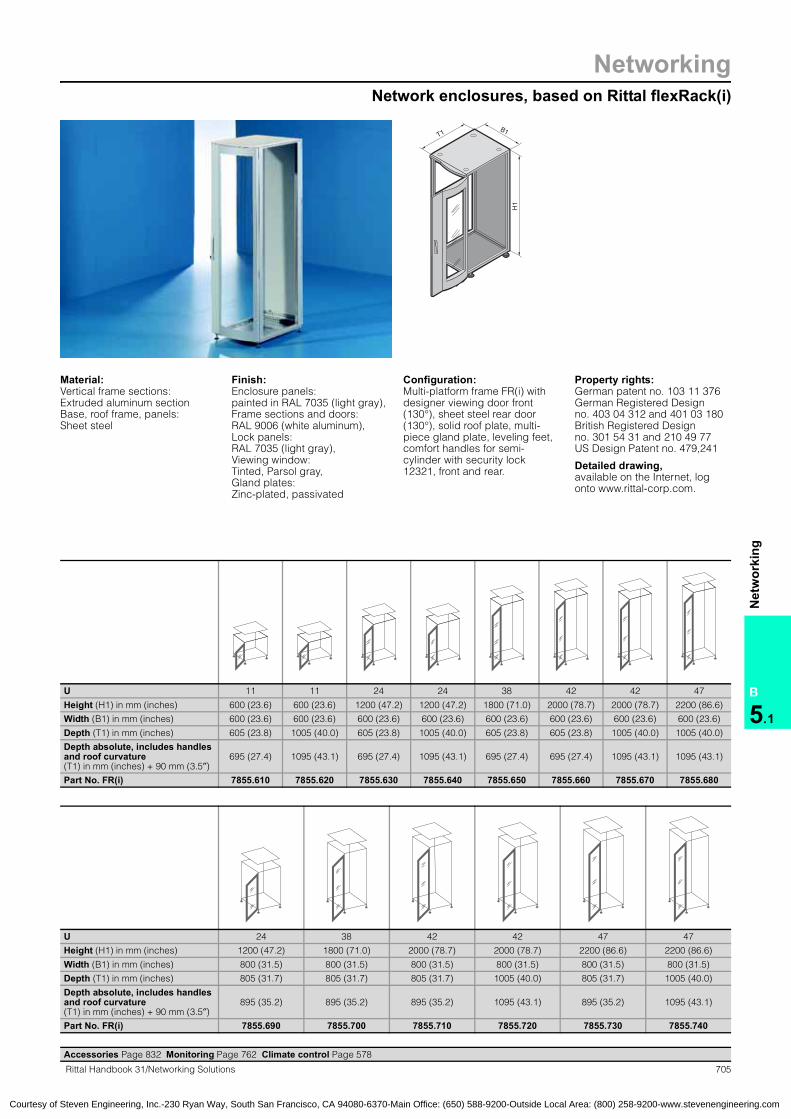
NetworkingNetwork enclosures, based on Rittal flexRack(i)
705Rittal Handbook 31/Networking Solutions
B
5.1
Net
wor
king
T1
H1
B1
Material:Vertical frame sections: Extruded aluminum section Base, roof frame, panels: Sheet steel
Finish:Enclosure panels: painted in RAL 7035 (light gray),Frame sections and doors: RAL 9006 (white aluminum),Lock panels:RAL 7035 (light gray), Viewing window: Tinted, Parsol gray, Gland plates: Zinc-plated, passivated
Configuration:Multi-platform frame FR(i) with designer viewing door front (130°), sheet steel rear door (130°), solid roof plate, multi-piece gland plate, leveling feet, comfort handles for semi-cylinder with security lock 12321, front and rear.
Property rights: German patent no. 103 11 376 German Registered Designno. 403 04 312 and 401 03 180 British Registered Design no. 301 54 31 and 210 49 77 US Design Patent no. 479,241 Detailed drawing, available on the Internet, log onto www.rittal-corp.com.
U 11 11 24 24 38 42 42 47
Height (H1) in mm (inches) 600 (23.6) 600 (23.6) 1200 (47.2) 1200 (47.2) 1800 (71.0) 2000 (78.7) 2000 (78.7) 2200 (86.6)
Width (B1) in mm (inches) 600 (23.6) 600 (23.6) 600 (23.6) 600 (23.6) 600 (23.6) 600 (23.6) 600 (23.6) 600 (23.6)
Depth (T1) in mm (inches) 605 (23.8) 1005 (40.0) 605 (23.8) 1005 (40.0) 605 (23.8) 605 (23.8) 1005 (40.0) 1005 (40.0)
Depth absolute, includes handles and roof curvature (T1) in mm (inches) + 90 mm (3.5″)
695 (27.4) 1095 (43.1) 695 (27.4) 1095 (43.1) 695 (27.4) 695 (27.4) 1095 (43.1) 1095 (43.1)
Part No. FR(i) 7855.610 7855.620 7855.630 7855.640 7855.650 7855.660 7855.670 7855.680
Accessories Page 832 Monitoring Page 762 Climate control Page 578
U 24 38 42 42 47 47
Height (H1) in mm (inches) 1200 (47.2) 1800 (71.0) 2000 (78.7) 2000 (78.7) 2200 (86.6) 2200 (86.6)
Width (B1) in mm (inches) 800 (31.5) 800 (31.5) 800 (31.5) 800 (31.5) 800 (31.5) 800 (31.5)
Depth (T1) in mm (inches) 805 (31.7) 805 (31.7) 805 (31.7) 1005 (40.0) 805 (31.7) 1005 (40.0)
Depth absolute, includes handles and roof curvature (T1) in mm (inches) + 90 mm (3.5″)
895 (35.2) 895 (35.2) 895 (35.2) 1095 (43.1) 895 (35.2) 1095 (43.1)
Part No. FR(i) 7855.690 7855.700 7855.710 7855.720 7855.730 7855.740
Courtesy of Steven Engineering, Inc.-230 Ryan Way, South San Francisco, CA 94080-6370-Main Office: (650) 588-9200-Outside Local Area: (800) 258-9200-www.stevenengineering.com

706 Rittal Handbook 31/Networking Solutions
NetworkingNetwork enclosures, based on Rittal flexRack(i)
B
5.1
Net
wor
king
U 11 11 24 24 38 42 42 47 Page
Height (H1) in mm (inches) 600 (23.6) 600 (23.6) 1200 (47.2) 1200 (47.2) 1800 (71.0) 2000 (78.7) 2000 (78.7) 2200 (86.6)
Width (B1) in mm (inches) 600 (23.6) 600 (23.6) 600 (23.6) 600 (23.6) 600 (23.6) 600 (23.6) 600 (23.6) 600 (23.6)
Depth (T1) in mm (inches) 605 (23.8) 1005 (40.0) 605 (23.8) 1005 (40.0) 605 (23.8) 605 (23.8) 1005 (40.0) 1005 (40.0)
Depth absolute, includes handles and roof curvature (T1) in mm (inches) + 90 (3.5″)
695 (27.4) 1095 (43.1) 695 (27.4) 1095 (43.1) 695 (27.4) 695 (27.4) 1095 (43.1) 1095 (43.1)
Part No. FR(i) 7855.610 7855.620 7855.630 7855.640 7855.650 7855.660 7855.670 7855.680DoorsDesigner viewing front door/sheet steel rear door � � � � � � � �
Various door versions, based on TS8, available on request – – – – – – – –
SidewallSidewall, plug-typeincludes security lock 12321 7856.660 7856.663 7856.666 7856.672 7856.675 7856.681 7856.687 7856.696 856
Internal latch for sidewall,plug-in 7856.700 7856.700 7856.700 7856.700 7856.700 7856.700 7856.700 7856.700 855
Baying from page 861 from page 861 from page 861 from page 861 from page 861 from page 861 from page 861 from page 861
RoofDesigner roof plate, solid � � � � � � � �
Various roof plate options, based on TS8 from page 901 from page 901 from page 901 from page 901 from page 901 from page 901 from page 901 from page 901
Base/plinthBase/plinth components, solid, front and rear 8601.605 8601.605 8601.605 8601.605 8601.605 8601.605 8601.605 8601.605 835
Base/plinth components, vented, front and rear 7825.601 7825.601 7825.601 7825.601 7825.601 7825.601 7825.601 7825.601 835
Base/plinth trim, side 8601.065 8601.015 8601.065 8601.015 8601.065 8601.065 8601.015 8601.015 835
Multi-piece gland plate � � � � � � � �
Gland plate versions, based on TS8 from page 851 from page 851 from page 851 from page 851 from page 851 from page 851 from page 851 from page 851
Interior installation482.6 mm (19″) system rails, L-shaped 7856.800 7856.800 7856.803 7856.803 7856.806 7856.809 7856.809 7856.812 1005
482.6 mm (19″) mounting frame 7856.710 7856.710 7856.713 7856.713 7856.716 7856.719 7856.719 7856.722 1007
System chassis with mounting flanges, interior installation, rail systems
from page 917 from page 917 from page 917 from page 917 from page 917 from page 917 from page 917 from page 917
Cable clamp rails from page 980 from page 980 from page 980 from page 980 from page 980 from page 980 from page 980 from page 980
Grounding/potential equalization from page 960 from page 960 from page 960 from page 960 from page 960 from page 960 from page 960 from page 960
Power strips/power management from page 742 from page 742 from page 742 from page 742 from page 742 from page 742 from page 742 from page 742
Component shelves from page 939 from page 939 from page 939 from page 939 from page 939 from page 939 from page 939 from page 939
482.6 mm (19″) installation system from page 1010 from page 1010 from page 1010 from page 1010 from page 1010 from page 1010 from page 1010 from page 1010
Cable management from page 984 from page 984 from page 984 from page 984 from page 984 from page 984 from page 984 from page 984
CMC-TC system monitoring from page 762 from page 762 from page 762 from page 762 from page 762 from page 762 from page 762 from page 762
� Included with the supply.
Accessories Page 832 Monitoring Page 762 Climate control Page 578
Courtesy of Steven Engineering, Inc.-230 Ryan Way, South San Francisco, CA 94080-6370-Main Office: (650) 588-9200-Outside Local Area: (800) 258-9200-www.stevenengineering.com
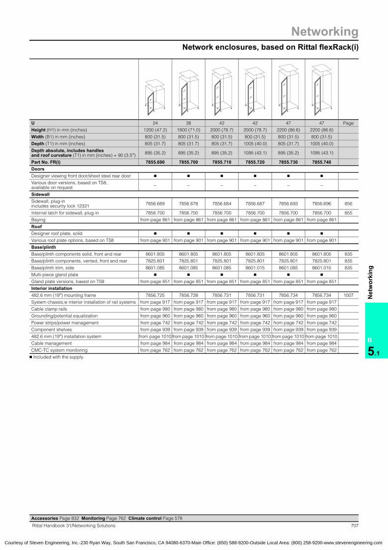
NetworkingNetwork enclosures, based on Rittal flexRack(i)
707Rittal Handbook 31/Networking Solutions
B
5.1
Net
wor
king
U 24 38 42 42 47 47 Page
Height (H1) in mm (inches) 1200 (47.2) 1800 (71.0) 2000 (78.7) 2000 (78.7) 2200 (86.6) 2200 (86.6)
Width (B1) in mm (inches) 800 (31.5) 800 (31.5) 800 (31.5) 800 (31.5) 800 (31.5) 800 (31.5)
Depth (T1) in mm (inches) 805 (31.7) 805 (31.7) 805 (31.7) 1005 (40.0) 805 (31.7) 1005 (40.0)
Depth absolute, includes handles and roof curvature (T1) in mm (inches) + 90 (3.5″) 895 (35.2) 895 (35.2) 895 (35.2) 1095 (43.1) 895 (35.2) 1095 (43.1)
Part No. FR(i) 7855.690 7855.700 7855.710 7855.720 7855.730 7855.740DoorsDesigner viewing front door/sheet steel rear door � � � � � �
Various door versions, based on TS8, available on request – – – – – –
SidewallSidewall, plug-inincludes security lock 12321 7856.669 7856.678 7856.684 7856.687 7856.693 7856.696 856
Internal latch for sidewall, plug-in 7856.700 7856.700 7856.700 7856.700 7856.700 7856.700 855
Baying from page 861 from page 861 from page 861 from page 861 from page 861 from page 861
RoofDesigner roof plate, solid � � � � � �
Various roof plate options, based on TS8 from page 901 from page 901 from page 901 from page 901 from page 901 from page 901
Base/plinthBase/plinth components solid, front and rear 8601.805 8601.805 8601.805 8601.805 8601.805 8601.805 835
Base/plinth components, vented, front and rear 7825.801 7825.801 7825.801 7825.801 7825.801 7825.801 835
Base/plinth trim, side 8601.085 8601.085 8601.085 8601.015 8601.085 8601.015 835
Multi-piece gland plate � � � � � �
Gland plate versions, based on TS8 from page 851 from page 851 from page 851 from page 851 from page 851 from page 851
Interior installation482.6 mm (19″) mounting frame 7856.725 7856.728 7856.731 7856.731 7856.734 7856.734 1007
System chassis,w interior installation of rail systems from page 917 from page 917 from page 917 from page 917 from page 917 from page 917
Cable clamp rails from page 980 from page 980 from page 980 from page 980 from page 980 from page 980
Grounding/potential equalization from page 960 from page 960 from page 960 from page 960 from page 960 from page 960
Power strips/power management from page 742 from page 742 from page 742 from page 742 from page 742 from page 742
Component shelves from page 939 from page 939 from page 939 from page 939 from page 939 from page 939
482.6 mm (19″) installation system from page 1010 from page 1010 from page 1010 from page 1010 from page 1010 from page 1010
Cable management from page 984 from page 984 from page 984 from page 984 from page 984 from page 984
CMC-TC system monitoring from page 762 from page 762 from page 762 from page 762 from page 762 from page 762
� Included with the supply.
Accessories Page 832 Monitoring Page 762 Climate control Page 578
Network enclosures:based on Rittal flexRack(i)flexRack(i):Network enclosures
Courtesy of Steven Engineering, Inc.-230 Ryan Way, South San Francisco, CA 94080-6370-Main Office: (650) 588-9200-Outside Local Area: (800) 258-9200-www.stevenengineering.com
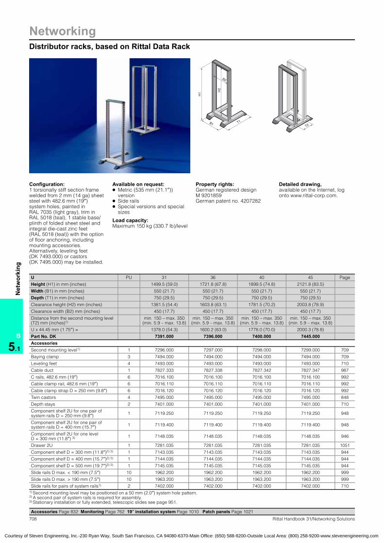
NetworkingDistributor racks, based on Rittal Data Rack
B
5.1
Net
wor
king
708 Rittal Handbook 31/Networking Solutions
T1
H1
B1
H2
B2
T2
Configuration:1 torsionally stiff section frame welded from 2 mm (14 ga) sheet steel with 482.6 mm (19″) system holes, painted in RAL 7035 (light gray), trim in RAL 5018 (teal), 1 stable base/plinth of folded sheet steel and integral die-cast zinc feet (RAL 5018 (teal)) with the option of floor anchoring, including mounting accessories. Alternatively, leveling feet (DK 7493.000) or castors (DK 7495.000) may be installed.
Available on request: ● Metric (535 mm (21.1″))
version● Side rails● Special versions and special
sizes
Load capacity: Maximum 150 kg (330.7 lb)/level
Property rights: German registered design M 9201859German patent no. 4207282
Detailed drawing, available on the Internet, log onto www.rittal-corp.com.
Accessories Page 832 Monitoring Page 762 19″ installation system Page 1010 Patch panels Page 1021
U PU 31 36 40 45 Page
Height (H1) in mm (inches) 1499.5 (59.0) 1721.8 (67.8) 1899.5 (74.8) 2121.8 (83.5)
Width (B1) in mm (inches) 550 (21.7) 550 (21.7) 550 (21.7) 550 (21.7)
Depth (T1) in mm (inches) 750 (29.5) 750 (29.5) 750 (29.5) 750 (29.5)
Clearance height (H2) mm (inches) 1381.5 (54.4) 1603.8 (63.1) 1781.5 (70.2) 2003.8 (78.9)
Clearance width (B2) mm (inches) 450 (17.7) 450 (17.7) 450 (17.7) 450 (17.7)
Distance from the second mounting level (T2) mm (inches)1)
min. 150 – max. 350(min. 5.9 – max. 13.8)
min. 150 – max. 350(min. 5.9 – max. 13.8)
min. 150 – max. 350(min. 5.9 – max. 13.8)
min. 150 – max. 350(min. 5.9 – max. 13.8)
U x 44.45 mm (1.75″) = 1378.0 (54.3) 1600.2 (63.0) 1778.0 (70.0) 2000.3 (78.8)
Part No. DK 7391.000 7396.000 7400.000 7445.000AccessoriesSecond mounting level1) 1 7296.000 7297.000 7298.000 7299.000 709
Baying clamp 3 7494.000 7494.000 7494.000 7494.000 709
Leveling feet 4 7493.000 7493.000 7493.000 7493.000 710
Cable duct 1 7827.333 7827.338 7827.342 7827.347 987
C rails, 482.6 mm (19″) 6 7016.100 7016.100 7016.100 7016.100 992
Cable clamp rail, 482.6 mm (19″) 6 7016.110 7016.110 7016.110 7016.110 992
Cable clamp strap D = 250 mm (9.8″) 6 7016.120 7016.120 7016.120 7016.120 992
Twin castors 4 7495.000 7495.000 7495.000 7495.000 848
Depth stays 2 7401.000 7401.000 7401.000 7401.000 710
Component shelf 2U for one pair of system rails D = 250 mm (9.8″) 1 7119.250 7119.250 7119.250 7119.250 948
Component shelf 2U for one pair of system rails D = 400 mm (15.7″) 1 7119.400 7119.400 7119.400 7119.400 948
Component shelf 2U for one level D = 300 mm (11.8″) 3) 1 7148.035 7148.035 7148.035 7148.035 946
Drawer 2U 1 7281.035 7281.035 7281.035 7281.035 1051
Component shelf D = 300 mm (11.8″)2) 3) 1 7143.035 7143.035 7143.035 7143.035 944
Component shelf D = 400 mm (15.7″)2) 3) 1 7144.035 7144.035 7144.035 7144.035 944
Component shelf D = 500 mm (19.7″)2) 3) 1 7145.035 7145.035 7145.035 7145.035 944
Slide rails D max. < 190 mm (7.5″) 10 1962.200 1962.200 1962.200 1962.200 999
Slide rails D max. > 190 mm (7.5″) 10 1963.200 1963.200 1963.200 1963.200 999
Slide rails for pairs of system rails1) 2 7402.000 7402.000 7402.000 7402.000 710 1) Second mounting level may be positioned on a 50 mm (2.0″) system hole pattern.2) A second pair of system rails is required for assembly.3) Stationary installation or fully extended, telescopic slides see page 951.
Distributor racks:Data RackData Rack
Courtesy of Steven Engineering, Inc.-230 Ryan Way, South San Francisco, CA 94080-6370-Main Office: (650) 588-9200-Outside Local Area: (800) 258-9200-www.stevenengineering.com

NetworkingAccessories for Rittal Data Rack
B
5.1
Net
wor
king
709Rittal Handbook 31/Networking Solutions
Second mounting levelIn order to accommodate 482.6 mm (19″) net-work components or for the attachment of compo-nent shelves, slide rails and telescopic rails. The mounting level may be positioned on a 50 mm (2.0″) system hole pattern.Minimum distance between levels 150 mm (5.9″).Maximum distance between levels 350 mm (13.8″).
Material:Sheet steel, 2 mm (14 ga)
Color:RAL 7035 (light gray)
Configuration:1 torsionally stiff section frame including assem-bly hardware. 482.6 mm (19″) punched profile at the front, hole center distance 465 mm (18.3″) (470 mm (18.5″) at the rear), tailored to the attach-ment of patch panels and cable routing rails.
Detailed drawing, available on the Internet, log onto www.rittal-corp.com.
50 mm (2.0″) system hole pattern
min. 150 mm (5.9″) – max. 350 mm (13.8″)
U Part No. DK31 7296.00036 7297.00040 7298.00045 7299.000
Baying connectorFor assembling rows of distributor frames, or for cable routing between data racks.
Technical specifications:Length: 53 mm (2.1″)
Color:RAL 7035 (light gray)
Baying connector:for Data Rack
PU Part No. DK3 7494.000
Roof plate for cable routingFor optimized use of the Data Rack as a cable entry panel or cable management rack. By moving the guide plates, the individual cableways can be separately sized, thus enabling structured cable routing in data highways, even in the roof area. On all Data Racks, the roof plate can be attached with two mounting levels and a distance between the levels of 350 mm (13.8″).
Material:Sheet steel, painted
Color:RAL 7035 (light gray)
Configuration:Roof plate including assembly hardware
Cable routing:for Data RackRoof plates:for Data Rack
PU Part No. DK1 7411.000
System accessories:for Rittal Data RackSystem accessories:for Rittal Data Rack
Courtesy of Steven Engineering, Inc.-230 Ryan Way, South San Francisco, CA 94080-6370-Main Office: (650) 588-9200-Outside Local Area: (800) 258-9200-www.stevenengineering.com

NetworkingAccessories for Rittal Data Rack
B
5.1
Net
wor
king
710 Rittal Handbook 31/Networking Solutions
Depth staysFor securing and stabilizing two pairs of 482.6 mm (19″) system rails in the data rack. The length of the depth stay is adjustable, and can accommodate system rails at various depths.
Color:RAL 7035 (light gray)
Depths stays:for Data Rack
Depth staysPU Part No. DK2 7401.000
Continuous slide railFor two pairs of system rails, 482.6 mm (19″) The continuous slide rail is used to support heavy installed equipment in the Data Rack. The mounting dimensions of the slide rails were selected to enable them to be combined with 500 mm (19.7″) deep, 482.6 mm (19″) component shelves. The mounting distance of the 482.6 mm (19″) system rails is 350 mm (13.8″).
Requirements:Second pair of system rails
Material:Sheet steel, zinc-plated, passivated
Accessories:Component shelf, 500 mm (19.7″) deep, DK 7145.035, see page 944.
Slide rails:for Data Rack
PU Part No. DK2 7402.000
Leveling feetTo compensate for height differences with uneven floors. The leveling feet are attached to the die-cast zinc feet of the base/plinth.
Configuration:4 leveling feet M12,leveling range 40 mm (1.6″).
Leveling feet:for Data RackFeet
PU Part No. DK4 7493.000
System accessories:for Rittal Data RackSystem accessories:for Rittal Data RackData RackDistributor racks:Data Rack
Courtesy of Steven Engineering, Inc.-230 Ryan Way, South San Francisco, CA 94080-6370-Main Office: (650) 588-9200-Outside Local Area: (800) 258-9200-www.stevenengineering.com
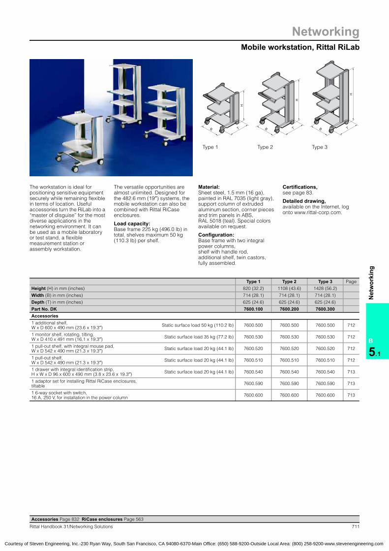
NetworkingMobile workstation, Rittal RiLab
B
5.1
Net
wor
king
711Rittal Handbook 31/Networking Solutions
H
B T
H
B T
H
B T
Type 1 Type 2 Type 3
The workstation is ideal for positioning sensitive equipment securely while remaining flexible in terms of location. Useful accessories turn the RiLab into a “master of disguise” for the most diverse applications in the networking environment. It can be used as a mobile laboratory or test stand, a flexible measurement station or assembly workstation.
The versatile opportunities are almost unlimited. Designed for the 482.6 mm (19″) systems, the mobile workstation can also be combined with Rittal RiCase enclosures.
Load capacity: Base frame 225 kg (496.0 lb) in total, shelves maximum 50 kg (110.3 lb) per shelf.
Material:Sheet steel, 1.5 mm (16 ga), painted in RAL 7035 (light gray), support column of extruded aluminum section, corner pieces and trim panels in ABS, RAL 5018 (teal). Special colors available on request.
Configuration:Base frame with two integral power columns, shelf with handle rod, additional shelf, twin castors, fully assembled.
Certifications, see page 83.
Detailed drawing, available on the Internet, log onto www.rittal-corp.com.
Accessories Page 832 RiCase enclosures Page 563
Type 1 Type 2 Type 3 Page
Height (H) in mm (inches) 820 (32.2) 1108 (43.6) 1428 (56.2)
Width (B) in mm (inches) 714 (28.1) 714 (28.1) 714 (28.1)
Depth (T) in mm (inches) 625 (24.6) 625 (24.6) 625 (24.6)
Part No. DK 7600.100 7600.200 7600.300Accessories1 additional shelf,W x D 600 x 490 mm (23.6 x 19.3″) Static surface load 50 kg (110.2 lb) 7600.500 7600.500 7600.500 712
1 monitor shelf, rotating, tilting,W x D 410 x 491 mm (16.1 x 19.3″) Static surface load 35 kg (77.2 lb) 7600.530 7600.530 7600.530 712
1 pull-out shelf, with integral mouse pad,W x D 542 x 490 mm (21.3 x 19.3″) Static surface load 20 kg (44.1 lb) 7600.520 7600.520 7600.520 712
1 pull-out shelf,W x D 542 x 490 mm (21.3 x 19.3″) Static surface load 20 kg (44.1 lb) 7600.510 7600.510 7600.510 712
1 drawer with integral identification strip,H x W x D 96 x 600 x 490 mm (3.8 x 23.6 x 19.3″) Static surface load 20 kg (44.1 lb) 7600.540 7600.540 7600.540 713
1 adaptor set for installing Rittal RiCase enclosures, tiltable 7600.590 7600.590 7600.590 713
1 6-way socket with switch, 16 A, 250 V, for installation in the power column 7600.600 7600.600 7600.600 713
RiLab mobile workstationMobile workstation:see RiLab mobile workstation
Courtesy of Steven Engineering, Inc.-230 Ryan Way, South San Francisco, CA 94080-6370-Main Office: (650) 588-9200-Outside Local Area: (800) 258-9200-www.stevenengineering.com

NetworkingAccessories for Rittal RiLab
B
5.1
Net
wor
king
712 Rittal Handbook 31/Networking Solutions
RiLab shelfWith a raised safety edge around the perimeter. Reduces the risk of assemblies slipping off.
Technical specifications:Load capacity 50 kg (110.2 lb) surface load, static
Material:Sheet steel, 1.5 mm (16 ga), RAL 7035 (light gray),Decorative trims of ABS, RAL 5018 (teal).
Configuration:1 shelf, including assembly hardware
Shelf:for RiLab
H x W x D mm (inches) PU Part No. DK
32 x 600 x 490(1.3 x 23.6 x 19.3) 1 7600.500
Pull-out RiLab shelfThe pull-out shelf is fastened to the supporting pillars via telescopic slides. It guarantees and extension of up to 300 mm (11.8″). The shelf can be locked in an inserted and extended position via two locating points.
Technical specifications:Load capacity 20 kg (44.1 lb) surface load, static
Material:Sheet steel, 1.5 mm (16 ga), RAL 7035 (light gray),Decorative trims of ABS, RAL 5018 (teal).
Configuration:1 shelf with telescopic slides, including assembly hardware
Shelf:for RiLab
H x W x D mm (inches) PU Part No. DK
48 x 542 x 490(1.9 x 21.3 x 19.3) 1 7600.510
Pull-out RiLab shelf with mouse padThe pull-out shelf with integral mouse pad offers ideal accommodation for the mouse and keyboard. The maximum extension is 295 mm (11.6″).
Technical specifications:Load capacity 20 kg (44.1 lb) surface load, static
Material:Sheet steel, 1.5 mm (16 ga), RAL 7035 (light gray),Decorative trims of ABS, RAL 5018 (teal).
Configuration:1 shelf with telescopic slides and integral mouse pad,including assembly hardware
H x W x Dmm (inches) PU Part No. DK
64 x 542 x 490(2.5 x 21.3 x 19.3) 1 7600.520
Rotating, tilting monitor shelfThe monitor shelf has got an all-round safety edge. It can be tilted with infinite variation through ±15°. Horizontally, the shelf can be rotated by 70° with infinite variation, and locked.
Technical specifications:Load capacity 35 kg (77.2 lb) surface load, static
Material:Sheet steel, 1.5 mm (16 ga), RAL 7035 (light gray),Decorative trims of ABS, RAL 5018 (teal).
Configuration:1 monitor shelf with hinge and cable retainer, including assembly hardware
Rotating, tilting monitor shelf
H x W x Dmm (inches) PU Part No. DK
32 x 410 x 491(1.3 x 16.1 x 19.3) 1 7600.530
System accessories:for Rittal RiLab
Courtesy of Steven Engineering, Inc.-230 Ryan Way, South San Francisco, CA 94080-6370-Main Office: (650) 588-9200-Outside Local Area: (800) 258-9200-www.stevenengineering.com

NetworkingAccessories for Rittal RiLab
B
5.1
Net
wor
king
713Rittal Handbook 31/Networking Solutions
DrawerThe drawer, which is open at the top, offers a practical solution for storing documents and equipment, and also features a front identification strip. The drawer can be closed at the top via a shelf fitted above it.
Technical specifications:Load capacity 20 kg (44.1 lb) static surface load
Material:1.0 mm (19 ga) sheet steel on the outside, polystyrene on the inside, RAL 7035 (light gray), trim and corner pieces of ABS, RAL 5018 (teal). Telescopic ball bearings slide.
Configuration:1 drawer, including assembly hardware
Drawers:for RiLab
H x W x Dmm (inches) PU Part No. DK
96 x 600 x 490(3.8 x 23.6 x 19.3) 1 7600.540
Adaptor setFor Rittal RiCase enclosures, 600 mm (23.6″) wideThe adaptor set allows RiCase enclosures with a width of 600 mm (23.6″) to be integrated into the base frame. This achieves optimum synergy between the flexibility of the mobile workstation, and the mounting opportunities of the RiCase enclosure. The adaptor set is designed in such a way that the enclosure can be locked in five stages within a tilting range of ±15°.
Technical specifications:Load capacity maximum enclosure weight 50 kg (110.3 lb).
Material:Sheet steel, 2.0 mm (14 ga), RAL 7035 (light gray)
Configuration:1 adaptor set, consisting of two mounting brackets, including mounting accessories.
Adaptor set:for RiLab
PU Part No. DK1 set 7600.590
6-way outlet strip with switchThe outlet strip has a 3 m (118″) long connection cable, and is conveniently housed in the power column of the mobile workstation. This permits direct on-site power supply over short distances without taking up any additional space.
Technical specifications:Power strip with switch, 16 A, 250 V, 3 m (118.0″) connection cable, manufactured to CEI 884-1, tested to VDE.
Material:Aluminum section with polycarbonate cover, self-extinguishing to UL 94-V0.
Configuration:1 outlet strip, including assembly hardware
Socket strips:RiLab
PU Part No. DK1 7600.600
System accessories:for Rittal RiLabRiLab mobile workstationMobile workstation:see RiLab mobile workstation
Courtesy of Steven Engineering, Inc.-230 Ryan Way, South San Francisco, CA 94080-6370-Main Office: (650) 588-9200-Outside Local Area: (800) 258-9200-www.stevenengineering.com
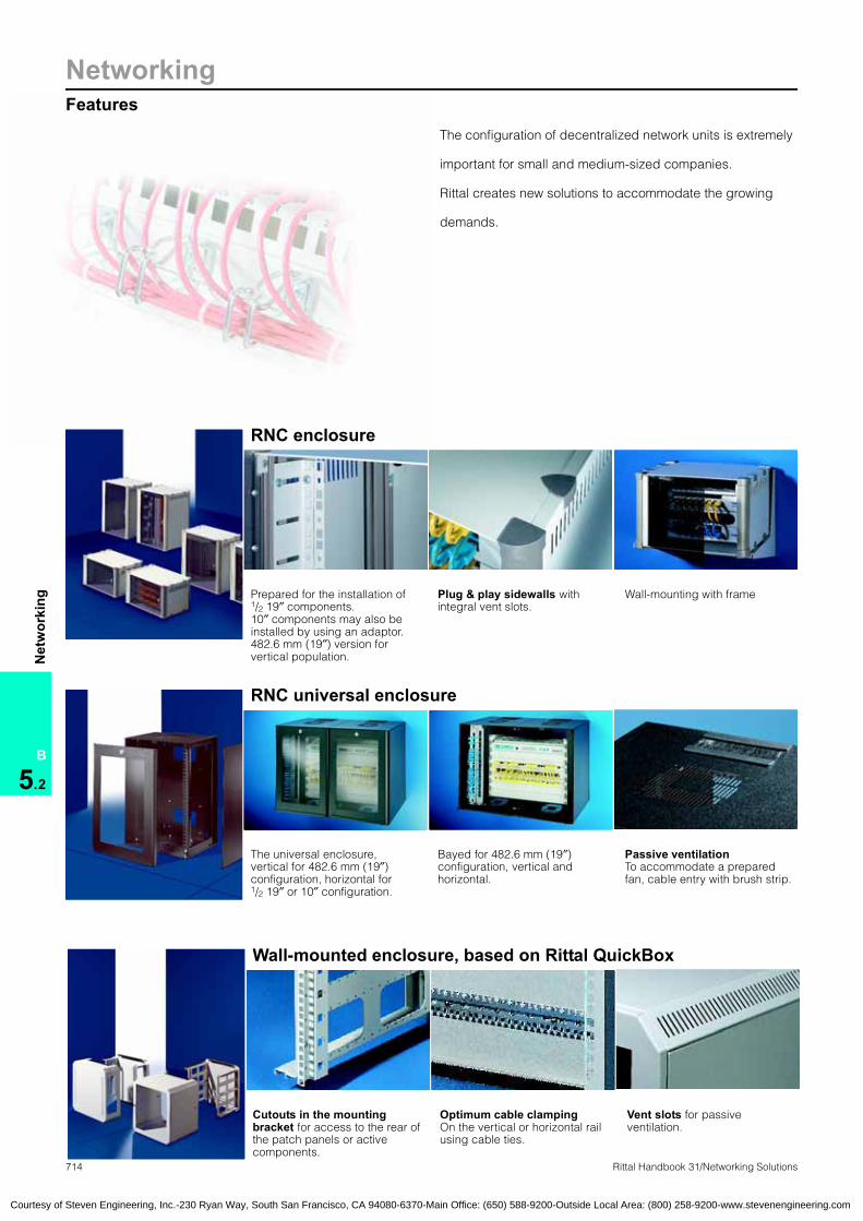
714 Rittal Handbook 31/Networking Solutions
NetworkingFeatures
B
5.2
Net
wor
king
The configuration of decentralized network units is extremely
important for small and medium-sized companies.
Rittal creates new solutions to accommodate the growing
demands.
RNC enclosure
Prepared for the installation of1/2 19″ components. 10″ components may also be installed by using an adaptor. 482.6 mm (19″) version for vertical population.
Plug & play sidewalls with integral vent slots.
Wall-mounting with frame
RNC universal enclosure
The universal enclosure,vertical for 482.6 mm (19″) configuration, horizontal for 1/2 19″ or 10″ configuration.
Bayed for 482.6 mm (19″) configuration, vertical and horizontal.
Passive ventilationTo accommodate a prepared fan, cable entry with brush strip.
Wall-mounted enclosure, based on Rittal QuickBox
Cutouts in the mounting bracket for access to the rear of the patch panels or active components.
Optimum cable clamping On the vertical or horizontal rail using cable ties.
Vent slots for passive ventilation.
Courtesy of Steven Engineering, Inc.-230 Ryan Way, South San Francisco, CA 94080-6370-Main Office: (650) 588-9200-Outside Local Area: (800) 258-9200-www.stevenengineering.com

715Rittal Handbook 31/Networking Solutions
NetworkingFeatures
B
5.2
Net
wor
king
Wall-mounted and distribution enclosures
Wall-mounted enclosure based on AE with pull-out frame or depth-adjustable 482.6 mm (19″) level.
Office distributorComprehensive wiring for one floor can be achieved with the Office distributor. The vertical arrangement of the 482.6 mm (19″) level guarantees a very slimline construction.
Small fiber-optic distributorsAs a corridor and intermediate distributor of fiber-optic cables.
Small fiber-optic distributor, based on AEThe ideal enclosure for break-out applications.
Fiber-optic marshalling enclosureTwo access areas: Separate doors and security locks: 1. For splicing cassette mounting2. For the patching chamber.
Small fiber-optic distributors,polycarbonate for extreme conditions: The small plastic enclosure with a high protection category of IP 66 to EN 60 529/10.91.
Wall-mounted enclosure, based on Rittal EL, 3-part/2-part
Optimum accessibility, due to 3-part or 2-part vertically hinged construction.
2-part enclosure with swing frame. Facility for installing subracks and electronic components.
Equipped with Mini comfort handle (3 – 15U), comfort handle (18 and 21U) and replaceable cable gland plates.
Courtesy of Steven Engineering, Inc.-230 Ryan Way, South San Francisco, CA 94080-6370-Main Office: (650) 588-9200-Outside Local Area: (800) 258-9200-www.stevenengineering.com

716 Rittal Handbook 31/Networking Solutions
NetworkingRNC enclosure
B
5.2
Net
wor
king
H
T2
BT1
Rittal-Net.com is the passive platform for the fast, future-proof assembly of communi-cations networks in the small office sector.Three designer enclosures, for population with connection cables, patch cables and distributor panels, are tailored to the specific criteria of the SOHO market. Work groups may be set up quickly and easily.
Material:1.5 mm (16 ga) sheet steelSmoked gray acrylic windowCorner sections of aluminum Corner feet made from thermoplastic foam
Color:Enclosure panels: RAL 7035 (light gray)Corner sections: RAL 7030 (stone gray)
Further information on the RNC distribution channel may be found at www.rittal-net.com (pages in German only)
Detailed drawing, available on the Internet, log onto www.rittal-corp.com.
Accessories Page 832
RNC enclosureWall-mounted enclosures
U PU 4 8 6
Height (H) in mm (inches) 215 (8.5) 390 (15.4) 490 (19.3)
Width (B) in mm (inches) 342 (13.5) 342 (13.5) 342 (13.5)
Depth (T1) in mm (inches) 280 (11.0) 280 (11.0) 400 (15.7)
Maximum installation depth (T2) mm (inches) 250 (9.8) 250 (9.8) 335 (13.2)
Part No. DK empty enclosure, individual 1 7870.100 7870.200 7870.300
Part No. DK, bulk pack24 7870.500 – –
18 – 7870.510 –
12 – – 7870.520
Version 42 HP(1/2 19″)
42 HP(1/2 19″)
84 HP(19″)
Installation position horizontal horizontal vertical
Accessory kitsTelephone distributor, including patch cable
Telephone VF Cat. 3, 10 ports, UTP, LSA, modular, including 8 patch cables with RJ 45 connector, on both sides, extruded insulation, cable design in blue, cable length 0.25 m (9.8″)
Single 1 7870.802 7870.802 –
Bulk pack 6 7870.582 7870.582 –
Telephone VF Cat. 3, 8 ports, UTP, modular, including 8 patch cables with RJ 45 connector, on both sides, extruded insulation, cable design in blue, cable length 0.25 m (9.8″)
Single 1 7870.800 7870.800 –
Bulk pack 6 7870.580 7870.580 –
Telephone VF Cat. 3, 25 ports, UTP, LSA, including 12 patch cables with RJ 45 connector, on both sides, extruded insulation, MegaLine 526 SC flex 4P, cable design in blue, cable length 0.6 m (23.6″)
Single 1 – – 7870.810
Bulk pack 6 – – 7870.590
Data distributor, including patch cableVF Cat. 5, 8 ports, STP, LSA, including 8 patch cables with RJ 45 connector, on both sides, extruded insulation, cable design in yellow, cable length 0.25 m (9.8″)
Single 1 7870.822 7870.822 –
Bulk pack 6 7870.597 7870.597 –
VF Cat. 5, 8 ports, UTP, modular, including 8 patch cables with RJ 45 connector, on both sides, extruded insulation, cable design in yellow, cable length 0.25 m (9.8″)
Single 1 7870.820 7870.820 –
Bulk pack 6 7870.595 7870.595 –
VF Cat. 6, 24 ports, STP, LSA, including 12 patch cables with RJ 45 connector, on both sides, extruded insulation, cable design in yellow, cable length 0.6 m (23.6″)
Single 1 – – 7870.830
Bulk pack 6 – – 7870.600
Courtesy of Steven Engineering, Inc.-230 Ryan Way, South San Francisco, CA 94080-6370-Main Office: (650) 588-9200-Outside Local Area: (800) 258-9200-www.stevenengineering.com

NetworkingRNC universal enclosure
717Rittal Handbook 31/Networking Solutions
B
5.2
Net
wor
king
H
T2
BT1
A contemporary design in black, with compact dimensions and a viewing door with tinted safety glass. Central locking with just one lock, the sidewalls cannot be removed while the front door is latched.
Suitable for use both as a stand-alone model and for wall-mount-ing. The plug-in sidewalls ensure rapid access and plenty of scope when mounting. Optional 1/2 19″, 10″ or 19″ com-ponents may be installed.
Simple baying is supported, both horizontally and vertically, using the connector kit supplied loose.
Passive ventilation through openings in the rear frame and perforations in the roof and gland plate, prepared to accommodate a fan expansion kit DK 7980.100. Cable entry option through the rear panel, roof or base. All frame parts and panels are prepared for grounding.
Material:Sheet steel, ESG
Color:Black, similar to RAL 9011 (black)
Configuration:Enclosure with viewing door, Baying kit,Brush strips for cable entry,482.6 mm (19″) mounting level at front.
Property rights:German patents No. 10 210 481No. 10 210 482 Detailed drawing, available on the Internet, log onto www.rittal-corp.com.
Data and telephone distributor Page 807
RNC enclosure:Universal enclosure
269.2 mm (1/2 19″) PU 10 Page
U 482.6 mm (19″) 5
Height (H) in mm (inches) 500 (19.7)
Width (B) in mm (inches) 350 (13.8)
Depth (T1) in mm (inches) 350 (13.8)
Maximum installation depth (T2) mm (inches) 270 (10.6)
Part No. DK 1 7870.350Part No. DK 12 7870.530AccessoriesPower strip 3-way, without switch 1 7240.110 746
Power strip 7-way, without switch, for 482.6 mm (19″) level 1 7240.210 746
Power strip 7-way, with switch, for 482.6 mm (19″) level 1 7240.220 746 1/2 19″ component shelf 1 7502.600 948
Cable management panel 1 7502.610 989 1/2 19″ blanking panel 2 7870.720 1025 1/2 19″ cable entry panel 2 7870.730 989
Blanking panel 1U 2 7151.035 1025
Blanking panel 2U 2 7152.035 1025
Blanking panel 3U 2 7153.035 1025
Combination rail, length 200 mm (7.9″) 6 7502.302 980
Adaptor for 10″ system, 1U 1 7870.760 1019
Adaptor for 10″ system, 4U 1 7870.765 1019
Phillips-head screw M5, with plastic washer 100 2099.500 1019
Phillips-head screw M6, with plastic washer 100 2089.000 1019
Captive nuts M5, with contact 50 2094.500 1020
Captive nuts M6, with contact 50 2094.200 1020
Courtesy of Steven Engineering, Inc.-230 Ryan Way, South San Francisco, CA 94080-6370-Main Office: (650) 588-9200-Outside Local Area: (800) 258-9200-www.stevenengineering.com

718 Rittal Handbook 31/Networking Solutions
NetworkingWall-mounted enclosure, based on Rittal QuickBox, 6 – 12U
B
5.2
Net
wor
king
H2
T2B2
H1
T1 B1
H1
T1 B1
Perfect handling during installation and servicing, due to a removable cover.
Material:Wall-mounting plate with mounting brackets: 2.0 mm (14 ga) sheet steelEnclosure cover: 1.0 mm (19 ga) sheet steelDoor: Sheet steel door or viewing door with sheet steel frame and safety glass ESG 3 mm (0.1″)
Finish:Powder-coatedEnclosure: RAL 7035 (light gray)
Configuration:Wall section: Pre-configured mounting bracket, brush strip for cable entry at the bottom/top, cable clamp rail
Enclosure cover: Consisting of base and cover tray with vent slots, brush strip for cable entry at the top/bottom, 2 side security locks, sheet steel door/viewing door with security lock, 482.6 mm (19″) system rails, infinitely depth-variable.
Property rights: German patentNo. 198 11 711 German utility modelNo. 298 23 843 European Patent No. 1 064 709 with validity for BE, ES, FR, GB, IT, NL, SE Taiwanese Patent No. NI 123 288 Russian Patent No. 2190912 Australian Patent No. 733078South Korean patentNo. 10-0375062 US patent no. 6,435,364
Detailed drawing, available on the Internet, log onto www.rittal-corp.com.
Accessories Page 832
Wall-mounted enclosures:QuickBoxQuickBox wall-mounted enclosures
U/SU PU 6/10 6/10 6/10 9/15 9/15 9/15 12/20 12/20 12/20 Page
Enclosure coverin mm (inches)
Height (H1) 362 (14.3) 362 (14.3) 362 (14.3) 495 (19.5) 495 (19.5) 495 (19.5) 628 (24.7) 628 (24.7) 628 (24.7)
Width (B1) 600 (23.6) 600 (23.6) 600 (23.6) 600 (23.6) 600 (23.6) 600 (23.6) 600 (23.6) 600 (23.6) 600 (23.6)
Depth (T1) 300 (11.8) 400 (15.7) 600 (23.6) 300 (11.8) 400 (15.7) 600 (23.6) 400 (15.7) 500 (19.7) 600 (23.6)
Wall sectionin mm (inches)
Height (H2) 355 (14.0) 355 (14.0) 355 (14.0) 488 (19.2) 488 (19.2) 488 (19.2) 621 (24.4) 621 (24.4) 621 (24.4)
Width (B2) 595 (23.4) 595 (23.4) 595 (23.4) 595 (23.4) 595 (23.4) 595 (23.4) 595 (23.4) 595 (23.4) 595 (23.4)
Depth (T2) 230 (9.1) 330 (13.0) 530 (20.9) 230 (9.1) 330 (13.0) 530 (20.9) 330 (13.0) 430 (16.9) 530 (20.9)
Part No. with viewing door 1 7502.013 7502.014 7502.016 7502.023 7502.024 7502.026 7502.034 7502.035 7502.036Part No. with sheet steel door 1 – 7502.114 – 7502.123 7502.124 7502.126 7502.134 – 7502.136AccessoriesSystem rails, 482.6 mm (19″) 2 7502.201 7502.201 7502.201 7502.202 7502.202 7502.202 7502.203 7502.203 7502.203 1005
System rails, metric 2 7502.211 7502.211 7502.211 7502.212 7502.212 7502.212 7502.213 7502.213 7502.213 1005
Solid gland plate 2 7502.310 7502.310 7502.310 7502.310 7502.310 7502.310 7502.310 7502.310 7502.310 970
Wall-mounting bracket, 10 mm (0.4″) 1 2508.000 2508.000 2508.000 2508.000 2508.000 2508.000 2508.000 2508.000 2508.000 905
Wall-mounting bracket, 40 mm (1.6) 1 2503.000 2503.000 2503.000 2503.000 2503.000 2503.000 2503.000 2503.000 2503.000 905
Combination rails for enclosure width 6 7502.304 7502.304 7502.304 7502.304 7502.304 7502.304 7502.304 7502.304 7502.304 980
Combination railsfor enclosure depthin mm (inches)
300/400 (11.8/15.7)6
7502.302 7502.302 7502.302 7502.302 7502.302 7502.302 7502.302 7502.302 7502.302 980
500/600 (19.7/23.6) 7502.304 7502.304 7502.304 7502.304 7502.304 7502.304 7502.304 7502.304 7502.304 980
Slide railsfor enclosure depthin mm (inches)
300 (11.8)
2
7063.000 7063.000 7063.000 7063.000 7063.000 7063.000 7063.000 7063.000 7063.000 1011
400 (15.7) 7063.300 7063.300 7063.300 7063.300 7063.300 7063.300 7063.300 7063.300 7063.300 1011
500/600 (19.7/23.6) 7063.400 7063.400 7063.400 7063.400 7063.400 7063.400 7063.400 7063.400 7063.400 1011
Grounding kit 1 7502.240 7502.240 7502.260 7502.240 7502.240 7502.260 7502.240 7502.260 7502.260 962
Quick-release fastener 2 7502.220 7502.220 7502.220 7502.220 7502.220 7502.220 7502.220 7502.220 7502.220 891
Courtesy of Steven Engineering, Inc.-230 Ryan Way, South San Francisco, CA 94080-6370-Main Office: (650) 588-9200-Outside Local Area: (800) 258-9200-www.stevenengineering.com

NetworkingWall-mounted enclosure, based on Rittal QuickBox, 15 – 21U
719Rittal Handbook 31/Networking Solutions
B
5.2
Net
wor
king
H2
T2B2
H1
T1 B1
H1
T1 B1
Perfect handling during installation and servicing, due to a removable cover.
Material:Wall-mounting plate with mounting brackets: 2.0 mm (14 ga) sheet steelEnclosure cover: 1.0 mm (19 ga) sheet steelDoor: Sheet steel door or viewing door with sheet steel frame and single-pane safety glass, 3 mm (0.1″)
Finish:Powder-coatedEnclosure: RAL 7035 (light gray)
Configuration:Wall section: Pre-configured mounting bracket, brush strip for cable entry at the bottom/top, cable clamp rail
Enclosure cover: Consisting of base and cover tray with vent slots, brush strip for cable entry at the top/bottom, 2 side security locks, sheet steel door/viewing door with security lock, 482.6 mm (19″) system rails, infinitely depth-variable.
Property rights: German patentNo. 198 11 711 German utility modelNo. 298 23 843 European Patent No. 1 064 709 with validity for BE, ES, FR, GB, IT, NL, SE Taiwanese Patent No. NI 123 288 Russian Patent No. 2190912 Australian Patent No. 733078South Korean patentNo. 10-0375062 US patent no. 6,435,364
Detailed drawing, available on the Internet, log onto www.rittal-corp.com.
Accessories Page 832
U/SU PU 15/26 15/26 15/26 18/31 18/31 18/31 21/36 21/36 Page
Enclosure coverin mm (inches)
Height (H1) 762 (30.0) 762 (30.0) 762 (30.0) 895 (35.2) 895 (35.2) 895 (35.2) 1028 (40.5) 1028 (40.5)
Width (B1) 600 (23.6) 600 (23.6) 600 (23.6) 600 (23.6) 600 (23.6) 600 (23.6) 600 (23.6) 600 (23.6)
Depth (T1) 400 (15.7) 500 (19.7) 600 (23.6) 400 (15.7) 500 (19.7) 600 (23.6) 400 (15.7) 600 (23.6)
Wall sectionin mm (inches)
Height (H2) 755 (29.7) 755 (29.7) 755 (29.7) 888 (35.0) 888 (35.0) 888 (35.0) 1021 (40.2) 1021 (40.2)
Width (B2) 595 (23.4) 595 (23.4) 595 (23.4) 595 (23.4) 595 (23.4) 595 (23.4) 595 (23.4) 595 (23.4)
Depth (T2) 330 (13.0) 430 (16.9) 530 (20.9) 330 (13.0) 430 (16.9) 530 (20.9) 330 (13.0) 530 (20.9)
Part No. with viewing door 1 7502.044 7502.045 7502.046 7502.054 7502.055 7502.056 7502.064 7502.066Part No. with sheet steel door 1 7502.144 – 7502.146 – – – – 7502.166AccessoriesSystem rails, 482.6 mm (19″) 2 7502.204 7502.204 7502.204 7502.205 7502.205 7502.205 7502.206 7502.206 1005
System rails, metric 2 7502.214 7502.214 7502.214 7502.215 7502.215 7502.215 7502.216 7502.216 1005
Solid gland plate 2 7502.310 7502.310 7502.310 7502.310 7502.310 7502.310 7502.310 7502.310 970
Wall-mounting bracket, 10 mm (0.4″) 1 2508.000 2508.000 2508.000 2508.000 2508.000 2508.000 2508.000 2508.000 905
Wall-mounting bracket, 40 mm (1.6″) 1 2503.000 2503.000 2503.000 2503.000 2503.000 2503.000 2503.000 2503.000 905
Combination rails for enclosure width 6 7502.304 7502.304 7502.304 7502.304 7502.304 7502.304 7502.304 7502.304 980
Combination railsfor enclosure depthin mm (inches)
300/400 (11.8/15.7)6
7502.302 7502.302 7502.302 7502.302 7502.302 7502.302 7502.302 7502.302 980
500/600 (19.7/23.6) 7502.304 7502.304 7502.304 7502.304 7502.304 7502.304 7502.304 7502.304 980
Slide railsfor enclosure depthin mm (inches)
300 (11.8)
2
7063.000 7063.000 7063.000 7063.000 7063.000 7063.000 7063.000 7063.000 1011
400 (15.7) 7063.300 7063.300 7063.300 7063.300 7063.300 7063.300 7063.300 7063.300 1011
500/600 (19.7/23.6) 7063.400 7063.400 7063.400 7063.400 7063.400 7063.400 7063.400 7063.400 1011
Grounding kit 1 7502.240 7502.260 7502.260 7502.240 7502.260 7502.260 7502.240 7502.260 962
Quick-release fastener 2 7502.220 7502.220 7502.220 7502.220 7502.220 7502.220 7502.220 7502.220 891
Courtesy of Steven Engineering, Inc.-230 Ryan Way, South San Francisco, CA 94080-6370-Main Office: (650) 588-9200-Outside Local Area: (800) 258-9200-www.stevenengineering.com

720 Rittal Handbook 31/Networking Solutions
NetworkingWall-mounted enclosure, based on Rittal QuickBox with vertical 482.6 mm (19″) level
B
5.2
Net
wor
king
T2B2
H2
H1
T1 B1
Optimum use of the interior space utilizing side installation of the 482.6 mm (19″) components. Status monitoring through side viewing window.
Material:Wall-mounting plate with mounting brackets: 2.0 mm (14 ga) sheet steelEnclosure cover: 1.0 mm (19 ga) sheet steel with side single-pane safety glass, 3 mm (0.1″)
Finish:Painted in RAL 7035 (light gray)
Configuration:Wall section: With pre-configured 482.6 mm (19″) mounting brackets for side accommodation of mounting components and brush strip for cable entry from the bottom and top.
Enclosure cover: With side vent slots to support passive climate control. The enclosure is secured via two security locks positioned at the sides.
Detailed drawing,available on the Internet, log onto www.rittal-corp.com.
Accessories Page 832
Wall-mounted enclosures:QuickBoxQuickBox wall-mounted enclosures
U vertical PU 3 6 Page
Enclosure cover
Height (H1) in mm (inches) 631 (24.8) 631 (24.8)
Width (B1) in mm (inches) 600 (23.6) 600 (23.6)
Depth (T1) in mm (inches) 210 (8.3) 360 (14.2)
Wall section
Height (H2) in mm (inches) 630.3 (24.8) 630.3 (24.8)
Width (B2) in mm (inches) 595 (23.4) 595 (23.4)
Depth (T2) in mm (inches) 198 (7.8) 348 (13.7)
Part No. DK 1 7502.630 7502.660AccessoriesGland plates, solid 2 7502.310 7502.310 970
Wall-mounting bracket, 10 mm (0.4″) 1 2508.000 2508.000 905
Wall-mounting bracket, 40 mm (1.6″) 1 2503.000 2503.000 905
Combination rails for vertical mounting on the wall section QB 6 7502.302 7502.302 980
Combination rails for horizontal mounting 6 7502.304 7502.304 980
Mounting and cable management panelfor cable routing and the attachment of small equipment 1 7502.270 7502.270 988
System rails, 482.6 mm (19″) for front mounting, 12U 2 7502.203 7502.203 1005
Courtesy of Steven Engineering, Inc.-230 Ryan Way, South San Francisco, CA 94080-6370-Main Office: (650) 588-9200-Outside Local Area: (800) 258-9200-www.stevenengineering.com

Wall-mounted enclosure, based on Rittal AE, with pull-out frame
Networking
721Rittal Handbook 31/Networking Solutions
B
5.2
Net
wor
king
350
204
600
600
520
450 52
5
Wall mounted distributor with 482.6 mm (19″) pull-out frame. Side and front installation with 482.6 mm (19″) components in a vertical mounting position. Horizontal installation also with front support option. Status monitoring through a side viewing window. Pull-out frame with snap fasteners may be removed for population. Passive cooling with pre-installed outlet filter, may be upgraded to active. Ground rod DK 7113.000 may be attached vertically on the pull-out frame.
Material:Sheet steel
Finish:Enclosure painted,RAL 7035 (light gray)Pull-out frame zinc-plated,passivated.
Configuration:1 wall-mounted distributor enclosure with sheet steel door, cam lock and double-bit insert. Pull-out frame attached to telescopic slides. Outlet filter in enclosure base and on left-hand side. Viewing window on right-hand side. Combination rail for cable clamping behind the cable entry. Additional cable clamp rail for mounting on the pull-out frame.
Protection ratings:IP 43 to EN 60 529/10.91
Available on request: ● Fully modified wall-mounted
distributors● Special designs
Detailed drawing, available on the Internet, log onto www.rittal-corp.com.
Accessories Page 832
Wall-mounted enclosures:based on Rittal AE, with pull-out frame
Height in mm (inches) PU 600 (23.6) Page
Width in mm (inches) 600 (23.6)
Depth in mm (inches) 350 (13.8)
Part No. DK 1 7644.000Side 482.6 mm (19″) level, vertical 4U
Front 482.6 mm (19″) level, vertical and horizontal 10U
AccessoriesPlastic cable gland plates with pre-punched PG holes 5 2563.000 966
Wall-mounting bracket, 10 mm (0.4″) 1 2508.000 905
Wall-mounting bracket, 40 mm (1.6″) 1 2503.000 905
Shelf 1 7644.400 949
Component shelf, 1U 1 7119.140 947
Ground rod, horizontal 1 7113.000 962
Fan expansion kit 220 V (may only be used at the bottom) 1 set 7980.100 649
Lock systemsPlastic handle, version B, see page 886.
Standard double-bit lock insert may be exchanged for 27 mm (1.1″) lock inserts, type A, see page 888.
Courtesy of Steven Engineering, Inc.-230 Ryan Way, South San Francisco, CA 94080-6370-Main Office: (650) 588-9200-Outside Local Area: (800) 258-9200-www.stevenengineering.com

NetworkingWall-mounted enclosure, based on Rittal AE
722 Rittal Handbook 31/Networking Solutions
B
5.2
Net
wor
king
T1
T2
B
H
Wall-mounted distributor with infinitely depth-variable 482.6 mm (19″) mounting level at the front. The ideal solution for small networks or corridor distributors. Maximum attainable protection category up to IP 55 to EN 60 529/10.91, NEMA Type 12, when using the pre-punched plastic cable gland plates 2563.000 (optional).
Material:Sheet steel
Finish:Painted in RAL 7035 (light gray)
Configuration:1 wall-mounted distributor enclosure with sheet steel door, cam lock and double-bit insert. Gland plate with brush strip for cable entry at the bottom,2 system rails, 482.6 mm (19″), depth-adjustable 1 C-rail for cable routing,1 metal bracket for optional installation of a ground rod or 482.6 mm (19″) power strip.
Available on request: ● Fully modified wall-mounted
distributors● Special designs
Certifications, see page 85.
Detailed drawing, available on the Internet, log onto www.rittal-corp.com.
Accessories Page 832
Wall-mounted enclosures:based on Rittal AE
U PU 8 13 16 Page
Height (H) in mm (inches) 380 (15.0) 600 (23.6) 760 (29.9)
Width (B) in mm (inches) 600 (23.6) 600 (23.6) 600 (23.6)
Depth (T1) in mm (inches) 350 (13.8) 350 (13.8) 350 (13.8)
Maximum installation depth (T2) mm (inches) 310 (12.2) 310 (12.2) 310 (12.2)
Part No. DK 1 7641.000 7643.000 7645.000AccessoriesPlastic cable gland plates with pre-punched PG holes 5 2563.000 2563.000 2563.000 966
Wall-mounting bracket, 10 mm (0.4″) 1 2508.000 2508.000 2508.000 905
Wall-mounting bracket, 40 mm (1.6″) 1 2503.000 2503.000 2503.000 905
Viewing door, 34 mm (1.3″) profile depth 1 2730.000 2731.000 2732.000 878
Viewing door, 60 mm (2.4″) profile depth 1 2760.000 2761.000 2762.000 878
Rain canopy of sheet steel, RAL 7035 (light gray) 1 2511.500 2511.500 2511.500 899
Component shelf 2U, fixed installation, 250 mm (9.8″) 1 7119.250 7119.250 7119.250 948
Swing frame, RAL 7035 (light gray) 1 2026.200 2027.200 2034.200 1002
Ground rod 1 7113.000 7113.000 7113.000 962
Lock systemsPlastic handle, version B, see page 886.
Standard double-bit lock insert may be exchanged for 27 mm (1.1″) lock inserts, type A, see page 888.
Courtesy of Steven Engineering, Inc.-230 Ryan Way, South San Francisco, CA 94080-6370-Main Office: (650) 588-9200-Outside Local Area: (800) 258-9200-www.stevenengineering.com

Office distributor, 2 and 4U, for fiber-optic and copper cables
Networking
723Rittal Handbook 31/Networking Solutions
B
5.2
Net
wor
king
T
H
B
The super-slimline design of this corridor distributor is achieved due to the vertical arrangement of the patch level. The 2U or 4U mounting level may be populated with patch panels and/or active components. Cable entry with brush strips in the left-side of the enclosure. The right-hand part offers a large opening for cable bundles and the option of attaching cable glands.
Material:Sheet steel, 1.5 mm (16 ga)
Color:RAL 7035 (light gray)
Configuration:Office distributor, fully assembled, with security lock.
Available on request: ● Other versions● Separate access authorization
available on request
Detailed drawing, available on the Internet, log onto www.rittal-corp.com.
Patch panels for fiber-optic and copper technology see page 1021 to 1025
Wall-mounted enclosures:Office distributorOffice distributor
U PU 2 4
Height (H) in mm (inches) 504 (19.8) 504 (19.8)
Width (B) in mm (inches) 400 (15.7) 400 (15.7)
Depth (T) in mm (inches) 106 (4.2) 195 (7.7)
Part No. DK 1 7245.000 7245.400
Courtesy of Steven Engineering, Inc.-230 Ryan Way, South San Francisco, CA 94080-6370-Main Office: (650) 588-9200-Outside Local Area: (800) 258-9200-www.stevenengineering.com

NetworkingSmall fiber-optic distributor
724 Rittal Handbook 31/Networking Solutions
B
5.2
Net
wor
king
T1
H
B1
B2
T2
Material:Sheet steel, 1.5 mm (16 ga)
Finish:Powder-coated in RAL 7035 (light gray)
Configuration:1 enclosure, two-part, in two designs to accommodate a maximum of 48 or 96 optical fibers respectively, 1 wall section: With mounting holes for wall- mounting, 11/16 shunting rings: For patching cables/fiber stock, 1/2 splicing cassette holders: To accommodate a maximum of 8 splicing cassettes,
2 comb strips: For cable clamping, and brush inserts to provide protection against dust,1 cover: With suspension device and two cam locks.
Note:When the small fiber-optic distributor is used without a patch panel, 1/2 splicing cassette holders may be retrofitted (maximum splicing cassette accommodation 16/32).
Available on request: ● Special designs
Property rights:German patent no. 44 10 795
Detailed drawing, available on the Internet, log onto www.rittal-corp.com.
Accessories Page 832
Wall-mounted enclosures:Small fiber-optic distributorsFiber-optic:Small distributor;Small distributor:fiber-optic
Height (H) in mm (inches) PU 500 (19.7) 900 (35.4) Page
Width (B1) in mm (inches) 500 (19.7) 500 (19.7)
Depth (T1) in mm (inches) 120 (4.7) 120 (4.7)
Width of cable entry (B2) in mm (inches) 395 (15.6) 395 (15.6)
Depth of cable entry (T2) in mm (inches) 29 (1.1) 29 (1.1)
Part No. DK 1 7452.035 7453.035Number of fibers (when using patch panels) 1 – 48 1 – 96
Accessories
Patch panels with 12/24 locations for fiber-optic couplings Maximum population2 patch panels
Maximum population4 patch panels
F-SMA 6.5 mm, 24 locations 2 7456.0351) 7456.0351) –
F-SMA 7.5 mm, 24 locations 2 7457.0351) 7457.0351) –
ST, 24 locations 2 7458.035 7458.035 –
DIN 47 256, 24 locations 2 7459.0351) 7459.0351) –
SC-, E-2000-, E-2000-Duplex, 24/12 locations 2 7460.0351) 7460.0351) –
SC duplex, 12 locations 2 7460.1351) 7460.1351) –
Splicing cassette holder for retrofitting 1 7450.035 7450.035 1026
Lock systemsT handle without lock insert 1 2572.000 2572.000 887
T handle with lock insert no. 3524 E 1 2575.000 2575.000 887
Lock “15” (Zeiß-Ikon) 2 7059.0351) 7059.0351) 891
Key “15” (Zeiß-Ikon) 1 7059.1001) 7059.1001) 891
Plastic handle with lock no. 3524 E 1 2576.000 2576.000 886
Plastic handle 1 2533.000 2533.000 886
Standard double-bit lock insert may be exchanged for 27 mm (1.1″) lock inserts, type A, see page 888.1) Extended delivery times.
Courtesy of Steven Engineering, Inc.-230 Ryan Way, South San Francisco, CA 94080-6370-Main Office: (650) 588-9200-Outside Local Area: (800) 258-9200-www.stevenengineering.com

Small fiber-optic distributors, based on Rittal AE
Networking
725Rittal Handbook 31/Networking Solutions
B
5.2
Net
wor
king
T1B1
H1
B2
H2
Layout of the small fiber-optic distributor:Basic enclosure: With cable shunting rings to accommodate the fiber stock and a strain relief system for incoming and outgoing cables.
Mounting panel: With accommodation for 4 splicing cassettes and4 patch panels.
Patch panels: There are 4 patch panels available with varying cutouts. Other special versions available on request.
Material:Sheet steel
Finish:Painted in RAL 7035 (light gray)
Color:RAL 7035 (light gray)
Protection ratings:IP 55 (to EN 60 529/10.91)NEMA Type 12,when using suitable cable gland plates.
Configuration:1 enclosure of sheet steel with2 gland plates of sheet steel, sides,1 gland plate, bottom7 cable shunting rings70 x 44 mm (2.8 x 1.7″ or 1U), 2 strain relief clips,1 cable clamp rail, double,1 door of sheet steel, with double-bit locks, with 2 hinges on the right, 1 mounting panel of sheet steel with 6 cable shunting rings70 x 44 mm (2.8 x 1.7″ or 1U), 4 recesses for patch panels,1 splicing cassette holder.
Detailed drawing, available on the Internet, log onto www.rittal-corp.com.
Accessories Page 832
Fiber-optic:Small distributor;Small distributors:fiber-optic
Width (B1) in mm (inches) PU 400 (15.7) Page
Height (H1) in mm (inches) 500 (19.7)
Depth (T1) in mm (inches) 155 (6.1)
Mounting panel height (H2) mm (inches) 455 (17.9)
Mounting panel width (B2) mm (inches) 355 (14.0)
Part No. DK 1 7454.000Number of fibers (when using patch panels) 1 – 48
AccessoriesPatch panel, maximum population with 4 patch panels Locations
Patch panel for 7.5 mm F-SMA couplings 12 2 7461.000
Patch panel for ST couplings 12 2 7462.000
Patch panel for SC, E-2000, E-2000 duplex couplings 12/6 2 7463.100
Patch panel for SC duplex couplings 6 2 7463.200
Cable gland with 2 half-shells, cable diameter from 8 – 36 mm (0.3 – 1.4″), for mounting at the bottom, reduced protection category 1 2400.000 974
Plastic cable gland plates, PG size 13.5, for side-mounting 5 1581.000 967
Plastic cable gland plates, PG size 13.5/16/21, for side-mounting 5 1582.000 967
Wall-mounting bracket, 40 mm (1.6″) 1 2503.000 905
Wall-mounting bracket, 10 mm (0.4″) 1 2508.000 905
Lock systemsPlastic handle 1 2533.000 886
Plastic handle with security cylinder insert 1 2576.000 886
Security cylinder insert no. 3524 E 1 2571.000 889
Standard double-bit lock insert may be exchanged for 27 mm (1.1″) lock inserts, type A, see page 888.
Courtesy of Steven Engineering, Inc.-230 Ryan Way, South San Francisco, CA 94080-6370-Main Office: (650) 588-9200-Outside Local Area: (800) 258-9200-www.stevenengineering.com

NetworkingFiber-optic marshalling enclosure
726 Rittal Handbook 31/Networking Solutions
B
5.2
Net
wor
king
H
60
800B
T
Patch panels are easily fastened to the gap frame piece. A door to cover and lock the splicing cassette accommodation, with separate lock. A second door to cover and lock the chamber/splicing cassette holder, with separate lock.
Material:Sheet steel, 1.0 mm (19 ga)
Color:RAL 7035 (light gray)
Configuration:1 enclosure to accommodate a maximum of 24 optical fibers, wall section with mounting holes for wall-mounting, 2 doors with different locks, for separate access, 4 shunting rings, 70 x 44 mm(2.8 x 1.7″ or 1U), 2 splicing cassette holderseach for 2 splicing cassettes,4 rubber seals for cable entry, 4 comb strips for cable clamping.
Note:If the marshalling enclosure is used without patch panels, 4 splicing cassettes,2 per side, may be integrated.
Property rights:German patentNo. 195 47 135European patent no. 0 867 058with validity for NLEuropean patent no. 0 867 059with validity for DE, FR, GB, IT
Available on request: ● Other versions
Detailed drawing, available on the Internet,log onto www.rittal-corp.com.
Accessories Page 832
Wall-mounted enclosures:Fiber-optic marshalling enclosuresFiber-optic:marshalling enclosures;Marshalling enclosure, fiber-optic
Height (H) in mm (inches) PU 250 (9.8) Page
Width (B) in mm (inches) 400 (15.7)
Depth (T) in mm (inches) 120 (4.7)
Part No. DK 1 7247.000Number of fibers (when using patch panels) 1 – 24
AccessoriesPatch panel for 24 ST couplings 1 7247.010 Patch panel for 24 SC, E -2000 couplings1) 1 7247.020 Patch panel for 12 SC duplex couplings 1 7247.030
1) 12 E-2000 duplex couplings may be accommodated.
Courtesy of Steven Engineering, Inc.-230 Ryan Way, South San Francisco, CA 94080-6370-Main Office: (650) 588-9200-Outside Local Area: (800) 258-9200-www.stevenengineering.com

Small fiber-optic distributor, polycarbonate
Networking
727Rittal Handbook 31/Networking Solutions
B
5.2
Net
wor
king
H
244
169.
5
170
145
B
T
ConfigurationSmall fiber-optic distributor:Mounting panel: With accommodation for one or two splicing cassettes, whereby the width of the cassettes may vary from 92 to 120 mm (3.6 – 4.7″).
Dividing plate: Serves to cover the splicing cassettes and separates them from the patch cables. Accommodation for patch panels and a cable clamp are also integrated.
Patch panels: Patch panels forF-SMA, E-2000-ST couplings, E-2000 duplex andSC and SC-duplex couplings are available. Other special versions available on request.
Cable entry: For cable entry, there are pre-punchings for PG cable glands integrated into the small fiber-optic distributor. The cable glands (12 x PG 7 and 1 x PG 16) are included with the supply. Pre-assembled connectors will also fit through the knockout apertures (for diameters, see below). The cable may be held in the pre-punched knockouts by a 2-piece cable entry or by cable entry grommets, depending on the diameter. The two-part cable entry and the grommets are not included with the supply, due to the different cable diameters.Diameter of the pre-punched knockouts: 12 x 12.5 mm (0.5″)2 x 22.5 mm (0.9″)
Color:RAL 7035 (light gray)
Protection ratings:IP 66 to EN 60 529/10.91.
Configuration:1 enclosure and lid of fiberglass-reinforced polycarbonate to accommodate splicing cassettes and patch panels,1 enclosure lid with 2 hinges, knockouts for PG glands are integrated into the enclosure, 12 x cable glands PG 7,1 x cable gland PG 16,1 mounting panel with variable accommodation of 2 splicing cassettes and integral anti-twist guard,1 dividing plate to cover the splicing cassette, accommodation for 2 patch panels and comb strip for cable clamping, 2 lid screws of polyamide with option of preparing for a lead seal, polyamide insulating plugs for wall-mounting screws.Foamed-on PU seal around the perimeter.
Detailed drawing,available on the Internet, log onto www.rittal-corp.com.
Accessories Page 832
Wall-mounted enclosures:Small fiber-optic distributorsFiber-optic:Small distributor, polycarbonate;Small distributors:polycarbonate
Height (H) in mm (inches) PU 254 (10.0) Page
Width (B) in mm (inches) 180 (7.1)
Depth (T) in mm (inches) 90 (3.5)
Part No. DK 1 7451.000Number of fibers (when using patch panels) 1 – 24
AccessoriesLocations
per patch panelLocations
per enclosure
Patch panel for 7.5 mm (0.3″) F-SMA couplings 12 24 2 7461.000
Patch panel for ST couplings 12 24 2 7462.000
Patch panel for SC, E-2000,E-2000 duplex couplings 12/6 24/12 2 7463.100
Patch panel for SC duplex couplings 6 12 2 7463.200
Wall-mounting brackets 40 9583.000 103
Courtesy of Steven Engineering, Inc.-230 Ryan Way, South San Francisco, CA 94080-6370-Main Office: (650) 588-9200-Outside Local Area: (800) 258-9200-www.stevenengineering.com

NetworkingWall-mounted enclosure, based on Rittal EL, 3-part, pre-configured, depth 573 mm (22.6″)
728 Rittal Handbook 31/Networking Solutions
B
5.2
Net
wor
king
H1
H2
T1
B1
T4
T3
T2
B2
Material:Wall and hinged part: Sheet steel, 1.5 mm (16 ga)Viewing window: 3 mm (1″) safety glass.
Color:Wall and hinged part painted in RAL 7035 (light gray), Viewing door RAL 7035 (light gray)/RAL 7015 (slate gray).
Protection ratings:IP 43 to EN 60 529/10.91for 77XX.735
Configuration:Wall section: With vertical system bars and C rail mounted horizontally for cable clamping, top cable gland plate solid, bottom cable gland plate with brush strips, grounding rail with star grounding, wall-mounting bracket 10 mm (0.4″).
Hinged part: With 25 mm (1.0″) system hole pattern in the front and rear frame; Two 482.6 mm (19″) system rails mounted on C rails, infinitely depth-variable, one outlet filter each on the left and right side.
Designer viewing door: With 3 mm (1″) safety glass or slotted plate, 9 + 15U with mini comfort handle for lock inserts, 21U with comfort handle and 2-point locking, including lock 3524 E.
On request, fitted ex works: ● Fully modified wall-mounted
distributors.● Viewing door with aluminum
frame1) ● Sheet steel door, solid1)
Certifications, see page 86.
Detailed drawing, available on the Internet, log onto www.rittal-corp.com.
Accessories Page 832
EL wall-mounted enclosureWall-mounted enclosures:EL
U PU 9 15 21 Page
Height (H1) in mm (inches) 478 (18.8) 746 (29.4) 1012 (39.8)
Width (B1) in mm (inches) 600 (23.6) 600 (23.6) 600 (23.6)
Depth (T1) in mm (inches) 573 (22.6) 573 (22.6) 573 (22.6)
Clearance height (H2) mm (inches) 417 (16.4) 684 (26.9) 951 (37.4)
Clearance width (B2) mm (inches) 502 (19.8) 502 (19.8) 502 (19.8)
Depth of wall section (T2) mm (inches) 135 (5.3) 135 (5.3) 135 (5.3)
Depth of hinged part (T3) mm (inches) 416 (16.4) 416 (16.4) 416 (16.4)
Maximum installation depth (T4) mm (inches) 520 (20.5) 520 (20.5) 520 (20.5)
Part No. DK viewing door 1 7709.735 7715.735 7721.735Part No. DK slotted metal doo1) 1 7709.835 7715.835 7721.835Load capacity, hinged part (kg) 45 (99.2) 75 (165.3) 75 (165.3)
AccessoriesSolid gland plate 1 2235.135 2235.135 2235.135 970
Gland plate with brush insert 1 7705.035 7705.035 7705.035 970
Gland plate for metric cable glands 1 7705.235 7705.235 7705.235 970
Fan expansion kit, 230 V 1 7980.100 7980.100 7980.100 649
Spare filter mats 5 3322.700 3322.700 3322.700 670
Wall-mounting bracket, 40 mm (1.6″) 1 2503.000 2503.000 2503.000 905
Lock inserts see page 888
Component shelf 2U, fixed installation orfully extendible, 300 mm (11.8″) deep 1 7148.035 7148.035 7148.035 946
Component shelf 2U, static installation, 250 mm (9.8″) 1 7119.250 7119.250 7119.250 948 1) Extended delivery times.
Courtesy of Steven Engineering, Inc.-230 Ryan Way, South San Francisco, CA 94080-6370-Main Office: (650) 588-9200-Outside Local Area: (800) 258-9200-www.stevenengineering.com

Wall-mounted enclosure, based on Rittal EL, 3-part, with system bars, depth 473 mm (18.6″)
Networking
729Rittal Handbook 31/Networking Solutions
B
5.2
Net
wor
king
H1
H2
T1
B1
T4
T3
T2
B2
Material:Wall and hinged part: Sheet steel, 1.5 mm (16 ga)Viewing window: 3 mm (1.1″) safety glass.
Color:Wall and hinged part painted in RAL 7035 (light gray), Viewing door RAL 7035 (light gray)/RAL 7015 (slate gray).
Protection ratings:IP 55 to EN 60 529/10.91,NEMA Type 12.
Configuration:Wall section: With vertical system bars and C rail mounted horizontally for cable clamping, solid cable gland plate top and bottom, wall-mounting bracket 10 mm (0.4″).
Hinged part: With 25 mm (1.0″) system hole pattern in the front and rear frame;Two 482.6 mm (19″) system rails mounted on C rails, infinitely depth-variable.
Designer viewing door: 6U – 15U with mini comfort handle for lock inserts, 18U – 21U with comfort handle and 2-point locking, including lock 3524 E.
On request, fitted ex works: ● Fully modified wall-mounted
distributors● Special sizes1)
(T = depth = 373, 573 mm (14.7, 22.6″))
● Viewing door with aluminum frame1)
● Sheet steel door, solid1)
Certifications, see page 86.
Detailed drawing, available on the Internet, log onto www.rittal-corp.com.
Accessories Page 832
U PU 6 9 12 15 18 21 Page
Height (H1) in mm (inches) 345 (13.6) 478 (18.8) 612 (24.1) 746 (29.4) 878 (34.6) 1012 (39.8)
Width (B1) in mm (inches) 600 (23.6) 600 (23.6) 600 (23.6) 600 (23.6) 600 (23.6) 600 (23.6)
Depth (T1) in mm (inches) 473 (18.6) 473 (18.6) 473 (18.6) 473 (18.6) 473 (18.6) 473 (18.6)
Clearance height (H2) mm (inches) 284 (11.2) 417 (16.4) 551 (21.7) 684 (26.9) 817 (32.2) 951 (37.4)
Clearance width (B2) mm (inches) 502 (19.8) 502 (19.8) 502 (19.8) 502 (19.8) 502 (19.8) 502 (19.8)
Depth of wall section (T2) mm (inches) 135 (5.3) 135 (5.3) 135 (5.3) 135 (5.3) 135 (5.3) 135 (5.3)
Depth of hinged part (T3) mm (inches) 316 (12.4) 316 (12.4) 316 (12.4) 316 (12.4) 316 (12.4) 316 (12.4)
Maximum installation depth (T4) mm (inches) 420 (16.5) 420 (16.5) 420 (16.5) 420 (16.5) 420 (16.5) 420 (16.5)
Part No. DK 1 7706.135 7709.135 7712.135 7715.135 7718.135 7721.135Load capacity, hinged part (kg) 30 (66.1) 45 (99.2) 60 (132.3) 75 (165.3) 75 (165.3) 75 (165.3)
AccessoriesGland plate with brush insert 1 7705.035 7705.035 7705.035 7705.035 7705.035 7705.035 970
Gland plate for metric cable glands 1 7705.235 7705.235 7705.235 7705.235 7705.235 7705.235 970
Wall-mounting bracket, 40 mm (1.6″) 1 2503.000 2503.000 2503.000 2503.000 2503.000 2503.000 905
Lock inserts see page 888
Earth rail, horizontal 1 7113.000 7113.000 7113.000 7113.000 7113.000 7113.000 962
Component shelf 2U, static installation and fully extendible 1 7148.035 7148.035 7148.035 7148.035 7148.035 7148.035 946
Component shelf 2U, static installation 1 7119.250 7119.250 7119.250 7119.250 7119.250 7119.250 948
Component shelf 1U, static installation, 140 mm (5.5″) 1 7119.140 7119.140 7119.140 7119.140 7119.140 7119.140 947 1) Extended delivery times.
Courtesy of Steven Engineering, Inc.-230 Ryan Way, South San Francisco, CA 94080-6370-Main Office: (650) 588-9200-Outside Local Area: (800) 258-9200-www.stevenengineering.com

NetworkingWall-mounted enclosure, based on Rittal EL, 3-part, mounting panel, depth 373 mm (14.7″)
730 Rittal Handbook 31/Networking Solutions
B
5.2
Net
wor
king
H1
H2
T1
B1
T4
T3
T2
B2
B3
H3
Material:Wall and hinged part: 1.5 mm (16 ga) sheet steelMounting panel: 2.5 mm (12 ga) sheet steel, zinc-plated, passivatedViewing window: 3 mm (1.1″) safety glass
Color:Wall and hinged part painted in RAL 7035 (light gray), Viewing door RAL 7035 (light gray)/RAL 7015 (slate gray).
Protection ratings:IP 55 to EN 60 529/10.91,NEMA Type 12.
Configuration:Wall section: With 2 cable gland plates,1 mounting panel supplied loose, assembly hardware.
Hinged part: With 2 system rails, 482.6 mm (19″), fitted at the front, assembly hardware.
Designer viewing door: 3U – 15U with mini comfort handle for lock inserts, 18U – 21U with comfort handle and 2-point locking, including lock 3524 E.
On request, fitted ex works: ● Special sizes and
colors1) ● Viewing door with aluminum
frame1) ● Sheet steel door, solid1)
Certifications, see page 87.
Detailed drawing, available on the Internet, log onto www.rittal-corp.com.
Accessories Page 832
U PU 3 6 9 12 15 18 21 Page
Height (H1) in mm (inches) 212 (8.3) 345 (13.6) 478 (18.8) 612 (24.1) 746 (29.4) 878 (34.6) 1012 (39.8)
Width (B1) in mm (inches) 600 (23.6) 600 (23.6) 600 (23.6) 600 (23.6) 600 (23.6) 600 (23.6) 600 (23.6)
Depth (T1) in mm (inches) 373 (14.7) 373 (14.7) 373 (14.7) 373 (14.7) 373 (14.7) 373 (14.7) 373 (14.7)
Clearance height (H2) mm (inches) 151 (5.9) 284 (11.2) 417 (16.4) 551 (20.1) 684 (26.9) 817 (32.2) 951 (37.4)
Clearance width (B2) mm (inches) 502 (19.8) 502 (19.8) 502 (19.8) 502 (19.8) 502 (19.8) 502 (19.8) 502 (19.8)
Depth of wall section (T2) mm (inches) 135 (5.3) 135 (5.3) 135 (5.3) 135 (5.3) 135 (5.3) 135 (5.3) 135 (5.3)
Depth of hinged part (T3) mm (inches) 216 (8.5) 216 (8.5) 216 (8.5) 216 (8.5) 216 (8.5) 216 (8.5) 216 (8.5)
Maximum installation depth (T4) mm (inches) 320 (12.6) 320 (12.6) 320 (12.6) 320 (12.6) 320 (12.6) 320 (12.6) 320 (12.6)
Height of mounting panel (H3) mm (inches) 165 (6.5) 299 (11.8) 432 (17.0) 565 (22.2) 699 (27.5) 832 (32.8) 965 (38.0)
Width of mounting panel (B3) mm (inches) 485 (19.1) 485 (19.1) 485 (19.1) 485 (19.1) 485 (19.1) 485 (19.1) 485 (19.1)
Part No. EL 1 2243.605 2246.605 2249.605 2252.605 2255.605 2258.605 2261.605Load capacity, hinged part (kg) 15 (33.0) 30 (66.1) 45 (99.2) 60 (132.3) 75 (165.3) 75 (165.3) 75 (165.3)
AccessoriesWall-mounting bracket– 10 mm (0.4″) – 40 mm (1.6″) 1 2508.000
2503.0002508.0002503.000
2508.0002503.000
2508.0002503.000
2508.0002503.000
2508.0002503.000
2508.0002503.000 905
Gland plate– With brush strip– For metric cable glands 1 7705.035
7705.2357705.0357705.235
7705.0357705.235
7705.0357705.235
7705.0357705.235
7705.0357705.235
7705.0357705.235
970 970
Screwed cable glands see page 972
Lock inserts see page 888
Slide rails 10 2240.000 2240.000 2240.000 2240.000 2240.000 2240.000 2240.000 1011
C rails 4 2238.000 2238.000 2238.000 2238.000 2238.000 2238.000 2238.000 929
Blanking plates 3 see page 1013 1) Extended delivery times.
Courtesy of Steven Engineering, Inc.-230 Ryan Way, South San Francisco, CA 94080-6370-Main Office: (650) 588-9200-Outside Local Area: (800) 258-9200-www.stevenengineering.com

Wall-mounted enclosure, based on Rittal EL, 3-part, mounting panel, depth 473 mm (18.6″)
Networking
731Rittal Handbook 31/Networking Solutions
B
5.2
Net
wor
king
H1
H2
T1
B1
T4
T3
T2
B2
B3
H3
Material:Wall and hinged part: 1.5 mm (16 ga) sheet steelMounting panel: 2.5 mm (12 ga) sheet steel, zinc-plated, passivatedViewing window: 3 mm (1.1″) safety glass
Color:Wall and hinged part painted in RAL 7035 (light gray), Viewing door RAL 7035 (light gray)/RAL 7015 (slate gray).
Protection ratings:IP 55 to EN 60 529/10.91,NEMA Type 12.
Configuration:Wall section: With 2 cable gland plates,1 mounting panel supplied loose, assembly hardware.
Hinged part: With 2 system rails, 482.6 mm (19″), fitted, assembly hardware.
Designer viewing door: 3U – 15U with mini comfort handle for lock inserts, 18U – 21U with comfort handle and 2-point locking, including lock 3524 E.
On request, fitted ex works: ● Special sizes and colors1) ● Viewing door with aluminum
frame1) ● Sheet steel door, solid1)
Certifications, see page 87.
Detailed drawing, available on the Internet, log onto www.rittal-corp.com.
Accessories Page 832
U PU 3 6 9 12 15 18 21 Page
Height (H1) in mm (inches) 212 (8.3) 345 (13.6) 478 (18.8) 612 (24.1) 746 (29.4) 878 (34.6) 1012 (39.8)
Width (B1) in mm (inches) 600 (23.6) 600 (23.6) 600 (23.6) 600 (23.6) 600 (23.6) 600 (23.6) 600 (23.6)
Depth (T1) in mm (inches) 473 (18.6) 473 (18.6) 473 (18.6) 473 (18.6) 473 (18.6) 473 (18.6) 473 (18.6)
Clearance height (H2) mm (inches) 151 (5.9) 284 (11.2) 417 (16.4) 551 (21.7) 684 (26.9) 817 (32.2) 951 (37.4)
Clearance width (B2) mm (inches) 502 (19.8) 502 (19.8) 502 (19.8) 502 (19.8) 502 (19.8) 502 (19.8) 502 (19.8)
Depth of wall section (T2) mm (inches) 135 (5.3) 135 (5.3) 135 (5.3) 135 (5.3) 135 (5.3) 135 (5.3) 135 (5.3)
Depth of hinged part (T3) mm (inches) 316 (12.4) 316 (12.4) 316 (12.4) 316 (12.4) 316 (12.4) 316 (12.4) 316 (12.4)
Maximum installation depth (T4) mm (inches) 420 (16.5) 420 (16.5) 420 (16.5) 420 (16.5) 420 (16.5) 420 (16.5) 420 (16.5)
Width of mounting panel (B3) mm (inches) 485 (19.1) 485 (19.1) 485 (19.1) 485 (19.1) 485 (19.1) 485 (19.1) 485 (19.1)
Height of mounting panel (H3) mm (inches) 165 (6.5) 299 (11.8) 432 (17.0) 565 (22.2) 699 (27.5) 832 (32.8) 965 (38.0)
Part No. EL 1 2253.605 2256.605 2259.605 2262.605 2265.605 2268.605 2271.605Load capacity, hinged part (kg (lb)) 15 (33.1) 30 (66.1) 45 (99.2) 60 (132.3) 75 (165.3) 75 (165.3) 75 (165.3)
AccessoriesWall-mounting bracket– 10 mm (0.4″) – 40 mm (1.6″) 1 2508.000
2503.0002508.0002503.000
2508.0002503.000
2508.0002503.000
2508.0002503.000
2508.0002503.000
2508.0002503.000 905
Lock inserts see page 888
Gland plate– With brush strip– For metric cable glands 1 7705.035
7705.2357705.0357705.235
7705.0357705.235
7705.0357705.235
7705.0357705.235
7705.0357705.235
7705.0357705.235
970 970
Screwed cable glands see page 972
Slide rails 10 2250.000 2250.000 2250.000 2250.000 2250.000 2250.000 2250.000 1011
C rails 4 2239.000 2239.000 2239.000 2239.000 2239.000 2239.000 2239.000 929
Blanking plates 3 see page 1013 1) Extended delivery times.
Courtesy of Steven Engineering, Inc.-230 Ryan Way, South San Francisco, CA 94080-6370-Main Office: (650) 588-9200-Outside Local Area: (800) 258-9200-www.stevenengineering.com

NetworkingWall-mounted enclosure, based on Rittal EL, 2-part, with swing frame, depth 369 mm (14.5″)
732 Rittal Handbook 31/Networking Solutions
B
5.2
Net
wor
king
H1
B1
T1
T2
T3
B2
H2
Material:Enclosure: 1.5 mm (16 ga) sheet steelSwing frame: Sheet steelFront door: Extruded aluminum section, 3 mm (1.1″) acrylic window
Finish:Enclosure and swing frame:Electrophoretic dipcoat-primed and powder-coated RAL 7035 (light gray)Front door: Dark brown anodized
Protection ratings:IP 55 to EN 60 529/10.91, NEMA Type 12.
Configuration:Enclosure, front door, fitted swing frame, including assembly hardware.
Available on request: ● Special sizes and
colors
Certifications, see page 87.
Detailed drawing, available on the Internet, log onto www.rittal-corp.com.
Accessories Page 832
EL wall-mounted enclosureWall-mounted enclosures:ELWall-mounted enclosures
U PU 6 11 14 Page
Height (H1) in mm (inches) 380 (15.0) 600 (23.6) 760 (29.9)
Width (B1) in mm (inches) 600 (23.6) 600 (23.6) 600 (23.6)
Depth (T1) in mm (inches) 369 (14.5) 369 (14.5) 369 (14.5)
Clearance height (H2) mm (inches) 317 (12.5) 537 (21.1) 697 (27.4)
Clearance width (B2) mm (inches) 537 (21.1) 537 (21.1) 537 (21.1)
Distance from viewing door to swing frame (T2) mm (inches)
67 – 97(2.6 – 3.8)
67 – 97 (2.6 – 3.8)
67 – 97 (2.6 – 3.8)
Maximum installation depth (T3) mm (inches) 270 (10.6) 270 (10.6) 270 (10.6)
Part No. EL 1 1919.500 1920.500 1926.500Weight in kg (lb) 20.8 (46.3) 26.7 (59.5) 31.2 (68.3)
AccessoriesWall-mounting bracket, 10 mm (0.4″) 1 2508.000 2508.000 2508.000 905
Wall-mounting bracket, 40 mm (1.6″) 1 2503.000 2503.000 2503.000 905
Gland plates with hole 5 2563.000 2563.000 2563.000 966
Blanking plates 3 see page 1013
Standard swing frame with double-bit lock insert may be exchanged for 27 mm (1.1″) lock inserts, type A, see page 888.
Courtesy of Steven Engineering, Inc.-230 Ryan Way, South San Francisco, CA 94080-6370-Main Office: (650) 588-9200-Outside Local Area: (800) 258-9200-www.stevenengineering.com

Networking
B
5.2
Net
wor
king
Courtesy of Steven Engineering, Inc.-230 Ryan Way, South San Francisco, CA 94080-6370-Main Office: (650) 588-9200-Outside Local Area: (800) 258-9200-www.stevenengineering.com

734 Rittal Handbook 31/Networking Solutions
Server RacksFeatures
B
5.3
Serv
er R
acks
Each individual rack makes an important contribution to the
physical security of your IT infrastructure. Our comprehen-
sive range of benefits is based on more than 40 years of rack
expertise, far-ranging experience in energy management,
and the development of pioneering climate concepts. For this
reason, Rittal server racks offer the ideal conditions to fuse all
the relevant technologies into complete IT infrastructure
solutions.
TS8
VentilationVia perforated front and rear door with free surface area of 78 % in the perforated plate part.
Lock systemWith comfort handleand 4-point locking.
The ingenious symmetrical conceptOf the frame offers baying on all sides. With two levels, the frame section affords infinite assembly diversity.
The new designer doorUnites functionality with aesthetics.
Robust 482.6 mm (19″) mounting frame. Load capacity 1000 kg (2204 lb).
Optimized stabilityFor optimum operational reliability.
flexRack(i)
Rittal system comparison TE 7000 TS8 FR(i) Rittal system comparison TE 7000 TS8 FR(i)
One platform for all requirements in the IT market
One platform for all requirements in theIT market
Load capacity Lock-systemUp to 400 kg (881.8 lb) � � � � � � � � � 2-point � � � � � � � � �
Up to 1000 kg (2204.6 lb) � � � � � � 4-point � � �
Baying SecuritySide � � � � � � � � � Access control � � � � � � � � �
In all levels � � � Climate control � � � � � � � � �
Climate control Dismantling � � � � �
Fan � � � � � � � � � Interior installationClimate control device � � � � � Depth-variable � � � � � �
Air/water heat exchanger � � � Partial installation � � �
CPU liquid cooling � � � � � � 2-level principle � � � �
Wiring Design � � � � � � �
Cable space � � � � � � � Standards IEC 60 297-1/2 � � � � � � � � �
Cable management � � � � � � � � � Note: The more � the greater the compatibility.
Courtesy of Steven Engineering, Inc.-230 Ryan Way, South San Francisco, CA 94080-6370-Main Office: (650) 588-9200-Outside Local Area: (800) 258-9200-www.stevenengineering.com

735Rittal Handbook 31/Networking Solutions
Server RacksFeatures
B
5.3
Serv
er R
acks
Power
Power Distribution Module PDR/PDMPower sub-distribution in482.6 mm (19″) format. May be retrofitted while the system is operational.
Power System Module PSMPower management up to 96 A or 48 A with redundant circuit. Shock-hazard protected.
Socket stripsAvailable in various length versions with various functional elements.
Cooling
Processor climate controlEnclosure climate control for heat loss of 13 kW – 22 kW
Rack-mounted recooling systemLiquid-cooled computers are supplied via the shortest route via six cooling circuits.
Fully vented front and rear door. Two-point locking rod, optionally with Ergoform-S handle system.
TE 7000
Universal server installation kit for integration of the most common server types, using the original installation accessories.
Depth-variable slide rail for flexible adaptation to the existing distance between levels.
Component shelves, two-part Two tower format servers may be moved independently of one another.
Server integration
Courtesy of Steven Engineering, Inc.-230 Ryan Way, South San Francisco, CA 94080-6370-Main Office: (650) 588-9200-Outside Local Area: (800) 258-9200-www.stevenengineering.com

Server RacksBased on Rittal TE 7000, 1000 mm (39.4″) deep
736 Rittal Handbook 31/Networking Solutions
B
5.3
Serv
er R
acks
HE = U
T1
H
B
T2
HE
19˝
Benefits: ● No frame structure,
optimum accessibility
Material:Sheet steel
Finish:Mounting frame: Dipcoat-primedEnclosure panels: Powder-coated, RAL 7035 (light gray)/RAL 9005 (black).
Configuration:Self-supporting 482.6 mm (19″) frame structure;Vented sheet steel door front and rear, two-point locking rod, recessed handle (front) and security lock 3524 E, roof plate for cable entry in corners with
concealed cut-out for integrating fans, with leveling feet.
Detailed drawing,available on the Internet.
U 42 42 42 42
Height (H) in mm (inches) 2000 (78.7) 2000 (78.7) 2000 (78.7) 2000 (78.7)
Width (B) in mm (inches) 600 (23.6) 600 (23.6) 800 (31.5) 800 (31.5)
Depth (T1) in mm (inches) 1000 (39.4) 1000 (39.4) 1000 (39.4) 1000 (39.4)
482.6 mm (19″) distance between levels in its delivered state (T2) mm (inches) 740 (29.1) 740 (29.1) 740 (29.1) 740 (29.1)
Part No. TEas bayed enclosure without sidewalls, including baying kit
Light gray 7000.882 – 7000.892 – Black – 7000.885 – 7000.895
DoorsSheet steel doors, fully vented, front and rear � � � �
RoofRoof plate including concealed cut-outs for cable entry in corners and foroptimum population with active fan units � � � �
BaseBase frame with maximum cut-outs for cable entry in corners for optional population with solid modular plates, passively vented, or for cable entry � � � �
Interior installation482.6 mm (19″) mounting frames front and rear � � � �
AccessoriesSidewalls, pluggable, including security lock 3524 E 7000.653 7000.663 7000.653 7000.663Ergoform-S handle for semi-cylinder,in exchange for the existing lock 2435.000 2435.000 2435.000 2435.000
Fan unit, with 2 fans and thermostat, prewired ready for connection 7000.670 7000.670 7000.670 7000.670
Stabilizer On request. On request. On request. On request.
Transport kit, 4 castors including assembly hardware 7000.672 7000.672 7000.672 7000.672
C-rail, for cable clamping in the enclosure widthvia cable clamps, on the 482.6 mm (19″) mounting frame at the rear 7828.060 7828.060 7828.060 7828.060
Cable clamp rail, depth variable 425 – 725 mm (16.7 – 28.5″),for cable attachment in the enclosure depth using cable ties 7858.160 7858.160 7858.160 7858.160
Cable clamp rail for cable attachment in the enclosure widthvia cable ties, on the 482.6 mm (19″) mounting frame at the rear 7828.062 7828.062 7828.062 7828.062
Grounding kit for TE 7000.675 7000.675 7000.675 7000.675
Socket strip, 8-way, grounding-pin plug 7000.630 7000.630 7000.630 7000.630
� Included with the supply.
Server racks:Based on Rittal TE 7000TE 7000:Server enclosures
Cable routing Page 964 Power management Page 742 CMC-TC system monitoring Page 762
Courtesy of Steven Engineering, Inc.-230 Ryan Way, South San Francisco, CA 94080-6370-Main Office: (650) 588-9200-Outside Local Area: (800) 258-9200-www.stevenengineering.com

Based on Rittal TS8, pre-configured
Server Racks
737Rittal Handbook 31/Networking Solutions
B
5.3
Serv
er R
acks
T1
H1
B1
1
Material:Sheet steel
Finish:Enclosure frame: Dipcoat-primedEnclosure panels: Dipcoat-primed, powder-coated in
RAL 7035 (light gray)/RAL 9005 (black) System rails and system chassis with mounting flanges: Zinc-plated, passivated
Configuration:Enclosure frame TS8 with sheet
steel doors front and rear, vented, with 130° hinges, L-shaped, depth-variable fitted system rails and/or 482.6 mm (19″) mounting frame, leveling feet, comfort handle with security lock and 4-point lock.
Detailed drawing,available on the Internet, log onto www.rittal-corp.com.
Optimized air flow1
Number of front and rear doors 1 1 1 1 1 1 2 2 (vertically divided) 4 1
U 24 24 42 42 42 47 2 x 21 2 x 21 4 x 10 47
Height (H1) in mm (inches) 1200 (47.2) 1200 (47.2) 2000 (78.7) 2000 (78.7) 2000 (78.7) 2200 (86.6) 2200 (86.6) 2200 (86.6) 2200 (86.6) 2200 (86.6)
Width (B1) in mm (inches) 600 (23.6) 600 (23.6) 600 (23.6) 600 (23.6) 800 (31.5) 600 (23.6) 600 (23.6) 600 (23.6) 600 (23.6) 600 (23.6)
Depth (T1) in mm (inches) 900 (35.4) 1000 (39.4) 900 (35.4) 1000 (39.4) 1000 (39.4) 900 (35.4) 900 (35.4) 900 (35.4) 900 (35.4) 1000 (39.4)
Part No. DKas bayed enclosure without sidewalls in colors:
Light gray 7831.431 7831.433 7831.436 7831.438 7831.446 7831.440 7831.450 7831.457 7831.460 7831.442
Black 7831.432 7831.434 7831.437 7831.439 – 7831.441 7831.451 7831.458 7831.461 7831.443DoorsSheet steel doors, vented, front and rear1) � � � � � � � � � �
RoofWith openings for cable entry � � � � � � � � � �
Base/plinthLeveling feet � � � � � � – – – �
Interior installation482.6 mm (19″) levels, front and rear � � � � � � – – – �
L-shaped system rails � � � � – � – – – �
System rails attached to depth stays � � � � – � � � � �
482.6 mm (19″) mounting frames front and rear – – – – � – – – – –
Panel grounding, fitted � � � � � � – – – �
Individual compartments, partitioned – – – – – – � � � –
Protected, separate cable routing per compartment – – – – – – � � � –
AccessoriesSidewalls, plug-type,with T lock in colors:
Light gray 7824.129 7824.120 7824.209 7824.200 7824.200 7824.229 7824.229 7824.229 7824.229 7824.220
Black 7816.129 7816.120 7816.209 7816.200 – 7816.229 7816.229 7816.229 7816.229 7816.220
Security lock for sidewalls 7824.500 7824.500 7824.500 7824.500 7824.500 7824.500 7824.500 7824.500 7824.500 7824.500
Base attachment bracket 8800.210 8800.210 8800.210 8800.210 8800.210 8800.210 8800.210 8800.210 8800.210 8800.210
Depth-variable slide rail, 1U 7063.880 7063.880 7063.880 7063.880 7063.880 7063.880 7063.878 7063.878 7063.878 7063.880
Stabilizer, pull-out 7825.200 7825.250 7825.200 7825.250 7825.250 7825.200 7825.200 7825.200 7825.200 7825.250
� Included with the supply 1) Free space in perforated plate part 78%
Server racks:Based on Rittal TS8TS:Server racks
Accessories Page 832 Liquid Cooling Page 672
Design features● Firmly linked frame structure● Front and rear door fully
vented; free vented surface area 78% in the perforated plate part
● 4-point locking,2-point locking with multiple door versions
● Door hinge may be swapped to opposite side without any machining
● Cable entry via the roof and base/plinth
● Bayable at all levels● Load capacity up to 1000 kg
(2204.6 lb)
Courtesy of Steven Engineering, Inc.-230 Ryan Way, South San Francisco, CA 94080-6370-Main Office: (650) 588-9200-Outside Local Area: (800) 258-9200-www.stevenengineering.com

Server RacksBased on Rittal flexRack(i), 1000 and 1200 mm (39.4 and 47.2″) deep, pre-configured
738 Rittal Handbook 31/Networking Solutions
B
5.3
Serv
er R
acks
T1 B1
H1
T2
T3
Design features● Enclosure system may be
dismantled because the vertical sections are screw-fastened to the roof and base frame
● Aluminum vertical section with multi-functional system channel
● Vented front and rear door with free surface area of 64% in the perforated plate part
● 2-point locking● Cable entry via the roof and
base
● Pull-out stabilizer● Suitable for baying● Load capacity up to 1000 kg
(2204.6 lb)
Material:Vertical frame sections: Extruded aluminum section. Roof frame, panels: Sheet steel
Finish:Enclosure panels/door trim panel: Painted in RAL 7035 (light gray),
Frame sections, perforated plate of door: RAL 9006 (black)482.6 mm (19″) system rails: Zinc-plated, passivated
Configuration:System frame section FR(i)1) with designer door, vented, sheet steel door at rear, vented, leveling feet, stabilizer, grounding of all enclosure panels, comfort handles for semi-cylinders with security lock 12321.
Property rights: German patentno. 103 11 376German registered design no. 403 04 312 and 401 03 180 British Registered Design no. 301 54 31 and 210 49 77 US Design Patent no. 479,241 Detailed drawing,available on the Internet, log onto www.rittal-corp.com
U 24 24 42 42
Height (H1) in mm (inches) 1200 (47.2) 1200 (47.2) 2000 (78.7) 2000 (78.7)
Width (B1) in mm (inches) 600 (23.6) 600 (23.6) 600 (23.6) 600 (23.6)
Depth (T1) in mm (inches) 1005 (39.6) 1205 (47.4) 1005 (39.6) 1205 (47.4)
Depth absolute, including handles and roof curvature (T1) + 90 mm (3.5″) 1095 (43.1) 1295 (51.0) 1095 (43.1) 1295 (51.0)
Maximum distance between levels (T2) mm (inches) 829 (32.6) 1029 (40.5) 829 (32.6) 1029 (40.5)
Distance between the 482.6 mm (19″) levels (T3) mm (inches) 750 (29.5) 850 (33.5) 750 (29.5) 850 (33.5)
Part No. FR(i) as bayed enclosure without sidewalls 7855.310 7855.312 7855.330 7855.332DoorsDesigner door, front, vented2) � � � �
Sheet steel door, rear, vented2) � � � �
RoofSolid roof plate � � – –
Roof plate with cable entry openings – – � �
Base frameLeveling feet � � � �
Stabilizer � � � �
Interior installation482.6 mm (19″) system rails, front � � � �
482.6 mm (19″) mounting frame, rear � � � �
GroundingGrounding of all enclosure panels on the enclosure frame � � � �
1 central grounding point fitted at the rear of the base frame � � � �
Accessories2 designer sidewalls with beading, including security lock 12321 7856.672 7856.673 7856.687 7856.688
Transport kit, 4 castors including assembly hardware 7825.900 7825.900 7825.900 7825.9001) The system frame FR(i) is generally suitable for the installation of TS8 accessories. 2) Free space in the perforated plate part 64%. � Included with the supply.
Server racks:Based on Rittal flexRack(i)flexRack(i):Server enclosures
Accessories Page 832 Liquid Cooling Page 672
Courtesy of Steven Engineering, Inc.-230 Ryan Way, South San Francisco, CA 94080-6370-Main Office: (650) 588-9200-Outside Local Area: (800) 258-9200-www.stevenengineering.com
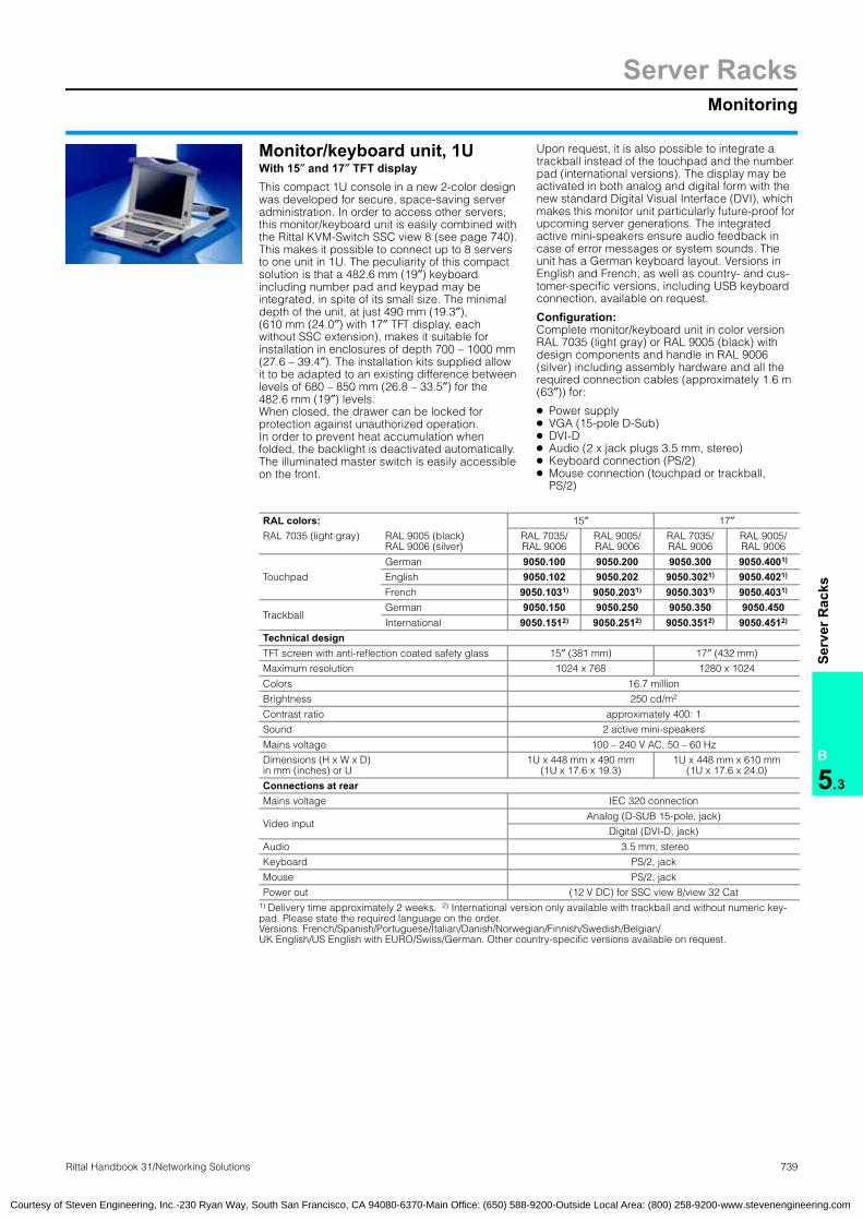
Server RacksMonitoring
739Rittal Handbook 31/Networking Solutions
B
5.3
Serv
er R
acks
Monitor/keyboard unit, 1UWith 15″ and 17″ TFT displayThis compact 1U console in a new 2-color design was developed for secure, space-saving server administration. In order to access other servers, this monitor/keyboard unit is easily combined with the Rittal KVM-Switch SSC view 8 (see page 740). This makes it possible to connect up to 8 servers to one unit in 1U. The peculiarity of this compact solution is that a 482.6 mm (19″) keyboard including number pad and keypad may be integrated, in spite of its small size. The minimal depth of the unit, at just 490 mm (19.3″), (610 mm (24.0″) with 17″ TFT display, each without SSC extension), makes it suitable for installation in enclosures of depth 700 – 1000 mm (27.6 – 39.4″). The installation kits supplied allow it to be adapted to an existing difference between levels of 680 – 850 mm (26.8 – 33.5″) for the 482.6 mm (19″) levels. When closed, the drawer can be locked for protection against unauthorized operation. In order to prevent heat accumulation when folded, the backlight is deactivated automatically. The illuminated master switch is easily accessible on the front.
Upon request, it is also possible to integrate a trackball instead of the touchpad and the number pad (international versions). The display may be activated in both analog and digital form with the new standard Digital Visual Interface (DVI), which makes this monitor unit particularly future-proof for upcoming server generations. The integrated active mini-speakers ensure audio feedback in case of error messages or system sounds. The unit has a German keyboard layout. Versions in English and French, as well as country- and cus-tomer-specific versions, including USB keyboard connection, available on request.
Configuration:Complete monitor/keyboard unit in color version RAL 7035 (light gray) or RAL 9005 (black) with design components and handle in RAL 9006 (silver) including assembly hardware and all the required connection cables (approximately 1.6 m (63″)) for:
● Power supply● VGA (15-pole D-Sub)● DVI-D● Audio (2 x jack plugs 3.5 mm, stereo)● Keyboard connection (PS/2)● Mouse connection (touchpad or trackball,
PS/2)
Monitor/keyboard unit, 1U
RAL colors: 15″ 17″RAL 7035 (light gray) RAL 9005 (black)
RAL 9006 (silver)RAL 7035/RAL 9006
RAL 9005/RAL 9006
RAL 7035/RAL 9006
RAL 9005/RAL 9006
Touchpad
German 9050.100 9050.200 9050.300 9050.4001)
English 9050.102 9050.202 9050.3021) 9050.4021)
French 9050.1031) 9050.2031) 9050.3031) 9050.4031)
TrackballGerman 9050.150 9050.250 9050.350 9050.450International 9050.1512) 9050.2512) 9050.3512) 9050.4512)
Technical designTFT screen with anti-reflection coated safety glass 15″ (381 mm) 17″ (432 mm)
Maximum resolution 1024 x 768 1280 x 1024
Colors 16.7 million
Brightness 250 cd/m2
Contrast ratio approximately 400: 1
Sound 2 active mini-speakers
Mains voltage 100 – 240 V AC, 50 – 60 Hz
Dimensions (H x W x D) in mm (inches) or U
1U x 448 mm x 490 mm(1U x 17.6 x 19.3)
1U x 448 mm x 610 mm(1U x 17.6 x 24.0)
Connections at rearMains voltage IEC 320 connection
Video inputAnalog (D-SUB 15-pole, jack)
Digital (DVI-D, jack)
Audio 3.5 mm, stereo
Keyboard PS/2, jack
Mouse PS/2, jack
Power out (12 V DC) for SSC view 8/view 32 Cat1) Delivery time approximately 2 weeks. 2) International version only available with trackball and without numeric key-pad. Please state the required language on the order. Versions: French/Spanish/Portuguese/Italian/Danish/Norwegian/Finnish/Swedish/Belgian/UK English/US English with EURO/Swiss/German. Other country-specific versions available on request.
Courtesy of Steven Engineering, Inc.-230 Ryan Way, South San Francisco, CA 94080-6370-Main Office: (650) 588-9200-Outside Local Area: (800) 258-9200-www.stevenengineering.com
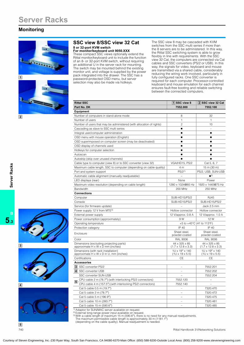
740 Rittal Handbook 31/Networking Solutions
Server RacksMonitoring
B
5.3
Serv
er R
acks
SSC view 8/SSC view 32 Cat 8 or 32-port KVM switch For monitor/keyboard unit 9050.XXXThese compact SSC views optionally extend the Rittal monitor/keyboard unit to include the function of an 8- or 32-port KVM switch, without requiring an additional U in the server rack for mounting. The switch may be mounted behind the existing monitor unit, and voltage is supplied by the power pack integrated into the drawer. The SSC has a password-protected OSD menu, but server selection may also be made via hotkeys.
The SSC view 8 may be cascaded with KVM switches from the SSC multi series if more than the 8 servers are to be administered. In this way, the Rittal SSC switching system is able to grow flexibly in line with requirements. With the SSC view 32 Cat, the computers are connected via Cat cables and SSC converters (PS/2 or USB). In this way, the signals for video, keyboard and mouse are transmitted via a shared cable, considerably reducing the wiring work involved, particularly in fully configured racks. One SSC converter is required for each computer. Processor-controlled keyboard and mouse emulation for each channel ensures fault-free booting and reliable switching between the connected computers.
SSC view 8/SSC view 32 Cat
1
2
3
4
5
Rittal SSC SSC view 8 SSC view 32 CatPart No. DK 7552.000 7552.100EquipmentNumber of computers in stand-alone mode 8 32
Number of users 1 1
Number of users that may be administered (with allocation of rights) 2 10
Cascading as slave to SSC multi series � –
Integral user/computer administration � �
OSD menu with mouse operation (English) � �
OSD superimposed on computer screen (may be deactivated) � �
OSD display of channels used � �
Hotkeys for computer selection � �
Autoscan � �
Autoskip (skip over unused channels) � �
Cable type to computer (view 8) or to SSC converter (view 32) VGA/HD15, PS/2 Cat 5, 6, 7
Maximum cable length, SSC to computer (depending on cable quality) 4 m 15 m (30 m)
Port and system support PS/21) PS/2, USB, SUN-USB
Automatic cable alignment (manually readjustable) – �3)
LED displays (rear) None Power
Maximum video resolution (depending on cable length) 1280 x 1024@85 Hz 1920 x 1440@75 Hz
Bandwidth 200 MHz 250 MHz
ConnectionsComputer SUB-HD15/PS/2 RJ45
Console SUB-HD15/PS/2 SUB-HD15/PS/2
Service (for firmware update) – Jack 2.5 mm
Power supply 12 V from MTE3) Hollow connector Hollow connector
External power supply 12 V/approx. 0.8 A 12 V/approx. 1.0 A
Power consumption (approximately) 9 W 12 W
Operating temperature +5 to +45°C (41 to 113°F)
Protection category IP 40 IP 40
Enclosure Sheet steel,powder-coated
Sheet steel,powder-coated
Color RAL 9006 RAL 9006
Dimensions (excluding projecting parts) approximate H x W x D mm (inches)
44 x 325 x 85(1.7 x 12.8 x 3.3)
44 x 325 x 85(1.7 x 12.8 x 3.3)
Dimensions (with rack installation)approximate H x W x D in U, mm (inches)
1U x 19″ x 140(1U x 19 x 5.5)
1U x 19″ x 140(1U x 19 x 5.5)
Certifications CE CE
AccessoriesSSC converter PS/2 – 7552.201
SSC converter USB – 7552.202
SSC converter SUN-USB – 7552.204
CPU cable 2 m (78.7″) (with interlocking PS/2 connectors) 7552.120 –
CPU cable 4 m (157.5″) (with interlocking PS/2 connectors) 7552.140 –
Cat 5 cable 0.5 m (19.7″) – 7320.470
Cat 5 cable 2 m (78.7″) – 7320.472
Cat 5 cable 5 m (196.9″) – 7320.475
Cat 5 cable 10 m (393.7″) – 7320.481
Cat 5 cable 15 m (590.6″) – 7320.4851) Adaptor for SUN/MAC server available on request.2) External long-range power input available on request.3) With a cable length of maximum 15 m (590.6″), there is no need for any manual readjustments.
The maximum permissible cable length is approximately 30 m (1181.1″)(depending on the cable quality). Manual readjustment is needed.
1 2
34
5
Courtesy of Steven Engineering, Inc.-230 Ryan Way, South San Francisco, CA 94080-6370-Main Office: (650) 588-9200-Outside Local Area: (800) 258-9200-www.stevenengineering.com

Server RacksMonitoring system SSC
B
5.3
Serv
er R
acks
Monitoring system:SSC
Courtesy of Steven Engineering, Inc.-230 Ryan Way, South San Francisco, CA 94080-6370-Main Office: (650) 588-9200-Outside Local Area: (800) 258-9200-www.stevenengineering.com
Rittal SSCmini/SSCmultiBy using the Rittal SSC, the number of key-boards, monitors and mice required is reduced to just one. Computer access becomes easier, more effective and more cost-efficient. As the number of computers increases, the SSC easily grows with it by cascading. The basic version, the SSCmini, offers 4 channels and an integral hotkey function. The SSCmulti, the multi-talented all-rounder, addi-tionally has 4/8/16 channels, an OSD menu, auto scan, auto skip and multi-platform capabilities. The multi-console feature supports a second Cat 5 console on the SSCmulti. As a hardware changeover switch, the Rittal SSC utilizes the key-board, monitor and mouse interfaces of the com-puter, irrespective of the software and operating system.
The SSCmulti is ideal for use in a heterogeneous server environment with different platforms such as PS/2 and IBM-compatible, HP 9000, sgi, SUN, RS 6000 and laptops.
Dimensions: (H x W x D) 44 x 482.6 x 245 mm (1.7 x 19 x 9.6″)
Material:Enclosure: Sheet steel
Finish:Painted in RAL 7035 (light gray)
Available on request: ● Converter for Apple Mac and USB interface. ● Distance bridging via fiber-optics. ● Global access for remote server maintenance.
741Rittal Handbook 31/Networking Solutions
Rittal Server Switch Control SSC SSCmini 4 SSCmulti 4 SSCmulti 8 SSCmulti 16
Part No. DK 7551.000 7551.010 7551.020 7551.030Number of computers in stand-alone mode 4 4 8 16
Number of computers in cascade configuration (identical types/maximum) –/64 16/64 64/128 256/256
Number of local operating consoles 1 1 1 1
Additional remote consoles (concurrent) 1 1 1 1
Integral remote control booster, Cat 5 port – � � �
Status displays LEDs OSD menu OSD menu OSD menu
On-screen display (OSD) (�) � � �
Keyboard hotkey operation � � � �
Auto scan/auto skip (�) � � �
Free server name allocation (�) � � �
Password protection (�) � � �
Allocation of user rights (�) � � �
Keyboard and mouse emulation by 1 processor in each case � � � �
Combined operation of various different server platforms is supported � � � �
Direct connection of Sun servers (MiniDIN 8/SUN-VGA) – no adaptor required – � � �
Independent from the software and operating system � � � �
Stay live function in case of power loss � � � �
Power supply via Keyboard output Mains cable Mains cable Mains cable
Maximum video resolution (depending on distance) at 85 Hz 1600 x 1200 1600 x 1200 1600 x 1200 1600 x 1200
Bandwidth 250 MHz 250 MHz 250 MHz 250 MHz
AccessoriesCPU cable for video (HD15), PS/2 keyboard and PS/2 mouse,2) 1 m (39.4″) 7551.110 7551.110 7551.110 7551.110
CPU cable for video (HD15), PS/2 keyboard and PS/2 mouse,2) 2 m (78.7″) 7551.120 7551.120 7551.120 7551.120
CPU cable for video (HD15), PS/2 keyboard and PS/2 mouse,2) 4 m (157.5″) 7551.140 7551.140 7551.140 7551.140
CPU cable for video (HD15), PS/2 keyboard and PS/2 mouse,2) 6 m (236.2″) 7551.160 7551.160 7551.160 7551.160
CPU cable for video (HD15), PS/2 keyboard and PS/2 mouse,2) 9 m (354.3″) 7551.190 7551.190 7551.190 7551.190
CPU cable for SUN video (HD15), miniDIN 8 keyboard/mouse, 1 m (39.4″) – 7551.111 7551.111 7551.111
CPU cable for SUN video (HD15), miniDIN 8 keyboard/mouse, 2 m (78.7″) – 7551.121 7551.121 7551.121
CPU cable for SUN video (HD15), miniDIN 8 keyboard/mouse, 4 m (157.5″) – 7551.141 7551.141 7551.141
CPU cable for SUN video (HD15), miniDIN 8 keyboard/mouse, 6 m (236.2″) – 7551.161 7551.161 7551.161
CPU cable for SUN video (HD15), miniDIN 8 keyboard/mouse, 9 m (354.3″) – 7551.191 7551.191 7551.191
230 V connection cable with grounding-pin plug and IEC 320 connector, version D – 7200.210 7200.210 7200.210
Remote console receiver module, desktop, transmission via 1 x Cat 5, up to 200 m (656 ft) – 7551.900 7551.900 7551.900
Transmission kit (sender and receiver) up to 200 m (656 ft)(Cat 5)/up to 300 m (984 ft) (coax) on request on request on request on request
Console cable kit (HD15,2 x RS/2) for passive extension, 2, 5, 7, 10 m (32.8″) on request on request on request on request2) Adaptor for serial mouse and DIN 5 keyboard enclosed (�) in conjunction with a SSCmulti.

742 Rittal Handbook 31/Networking Solutions
PowerFeatures
B
5.4
Pow
er
2 3
3
31
z
z
z The availability of IT is a crucial consideration for you.
For this reason, you need to ensure highly available, stable
electric power supply to your complex server and software
system architecture. Create the framework conditions to
ensure that all business processes operate on schedule with
exceptionally high-level security parameters for the physical
IT infrastructure.
Power Distribution Rack, PDR
Power Distribution Module, PDM
Power System Module, PSM
1
2
3
Power Distribution PDR/PDM
Power Distribution Rack To accommodate a maximum of 8 PDMs. A maximum of 32 server racks may be connected.
Power Distribution Module PDM482.6 mm (19″) subrack for power distribution up to 40 kW in server and network enclosures.
Power System Module PSM
BusbarFully wired, shock-hazard protected, load capacity up to 96 A or 48 A, with redundant circuit.
Plug-in modules For busbars, various country versions. May be retrofitted while the system is operating.
Active Power System Module PSMRemote administration of the power supply, editing and monitoring of remote limits, SNMP trap message in case of alarm.
Power Modular Concept PMC – UPS systems
ModularityHigh level of flexibility through modular expansion, depending on the UPS capacity requirements.
RedundancyMulti-server configurations are protected by the redundant Rittal UPS concept.
ScalabilityIn large output categories, output and autonomy times may be scaled.
Courtesy of Steven Engineering, Inc.-230 Ryan Way, South San Francisco, CA 94080-6370-Main Office: (650) 588-9200-Outside Local Area: (800) 258-9200-www.stevenengineering.com

PowerPower Distribution Rack PDR
743Rittal Handbook 31/Networking Solutions
B
5.4
Pow
er Power Distribution Module
PDM● 482.6 mm (19″) Power Distribution Module
mechanically locked in the rack● Scalable● Including master switch, optional RC circuit-
breaker● 4 fused 3-phase outlets to the rack● 3 x 230 V/16 A per outlet● Connected load 400 V/3 AC, max. 63 A
Configuration:482.6 mm (19″) module, 3U
Power Distribution Module PDM
2 Version Part No. DKPDM 482.6 mm (19″), 4 outlets per 10 kW 7857.320
PDM 19″, 4 outlets, project-specific 7857.350Connection cable
with 32 A CEEkon connector 7857.321
Plug & play connection cableTo the server enclosuresPlug & play connection cableConnection cable:Plug & play
Lengthm (inches) PU Part No. DK
3 (118.1) 1 7857.1305 (196.9) 1 7857.1508 (315.0) 1 7857.1809 (354.3) 1 7857.190
1
2
● Power Distribution Rack to accommodate a maximum of 8 PDMs
● Height 1.20 m (47.2″) for 4 PDMs and 2 m (78.7″) height for 8 PDMs
● PDM may be retrofitted while operational
● A maximum of 32 racks may be fitted to the sub-distributor
● Fully shock-hazard protected● Main switch available in
various options1):− Isolator switch− On-load isolator− Power circuit-breakers− RC circuit-breaker
● Low-voltage distribution up to 250 A
1) Depending on the standards of the local power supply company
Note:Observe the standards of the local power companies. Material:Sheet steel
Finish:Enclosure frame: Dipcoat-primedDoors, roof and base/plinth: Dipcoat-primed, powder-coated
in RAL 7035 (light gray)Gland plates, system chassis with mounting flanges and system rails: Zinc-plated, passivated
Configuration:Enclosure frame with door (without tubular door frame), rear panel, sidewalls and roof plate, leveling feet including base/plinth adaptor, grounding of all enclosure panels, busbars shock-hazard protected, main switch integrated.
Extended delivery times.
Additional parts needed:
Power Distribution Module PDM,see page 743.
Detailed drawing,available on the Internet, log onto www.rittal-corp.com.
Power Distribution Rack PDR
Power Distribution Rack PDR PU
Possible number of PDM modules 4 8
Dimensions in mm (inches)HWD
1200 (47.2)800 (31.5)500 (19.7)
2000 (78.7)800 (31.5) 500 (19.7)
Part No. DK 1 7857.310 7857.300Accessories
Base/plinth componentsfront and rear in mm (inches)
Height 100 (3.9) 1 set 8601.800 8601.800
Height 200 (7.9) 1 set 8602.800 8602.800
Base/plinth side trimin mm (inches)
Height 100 (3.9) 1 set 8601.050 8601.050
Height 200 (7.9) 1 set 8602.050 8602.050
1 1
Courtesy of Steven Engineering, Inc.-230 Ryan Way, South San Francisco, CA 94080-6370-Main Office: (650) 588-9200-Outside Local Area: (800) 258-9200-www.stevenengineering.com
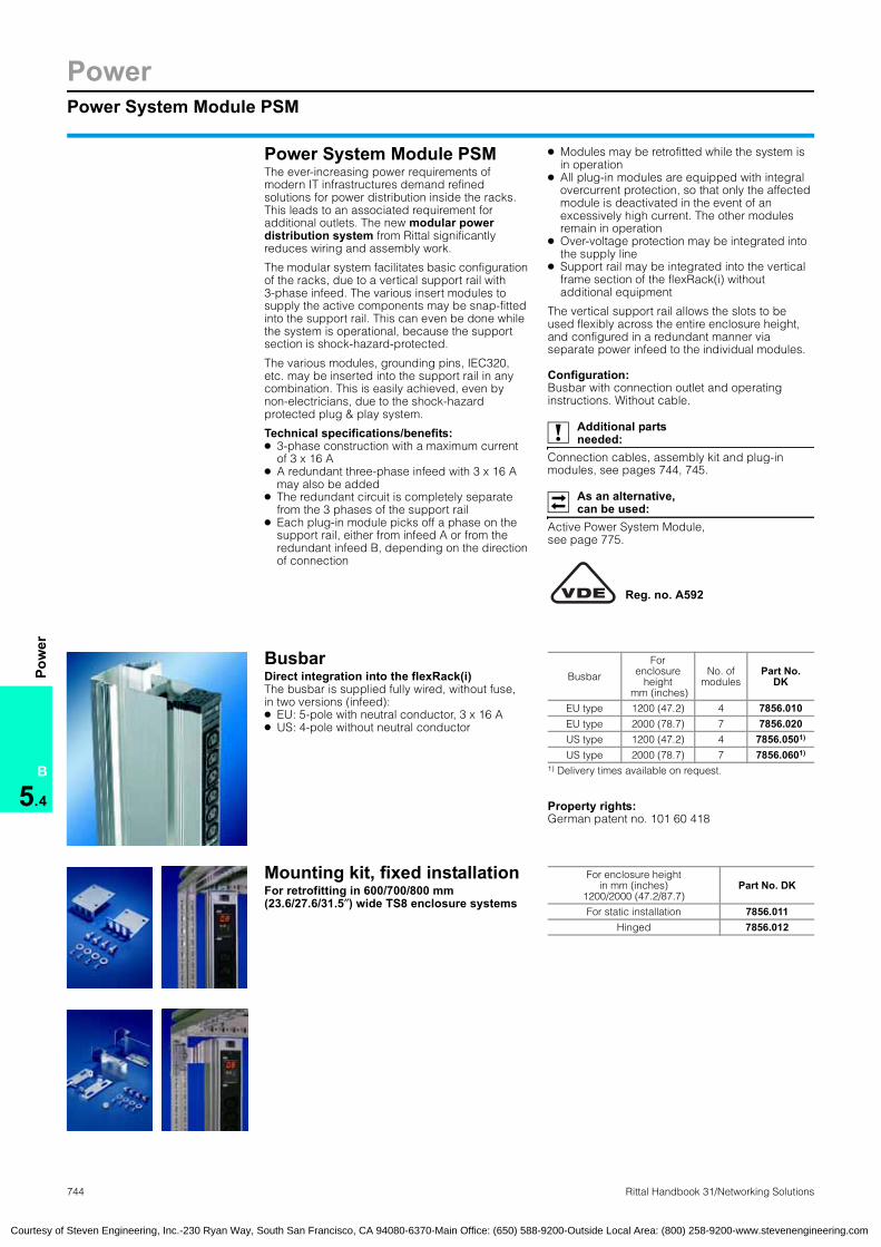
744
PowerPower System Module PSM
B
5.4
Pow
er
Courtesy of Steven Engineering, Inc.-230 Ryan Way, South San Francisco, CA 94080-6370-Main Office: (650) 588-9200-Outside Local Area: (800) 258-9200-www.stevenengineering.com
Power System Module PSMThe ever-increasing power requirements of modern IT infrastructures demand refined solutions for power distribution inside the racks. This leads to an associated requirement for additional outlets. The new modular power distribution system from Rittal significantly reduces wiring and assembly work.
The modular system facilitates basic configuration of the racks, due to a vertical support rail with 3-phase infeed. The various insert modules to supply the active components may be snap-fitted into the support rail. This can even be done while the system is operational, because the support section is shock-hazard-protected.
The various modules, grounding pins, IEC320, etc. may be inserted into the support rail in any combination. This is easily achieved, even by non-electricians, due to the shock-hazard protected plug & play system.
Technical specifications/benefits: ● 3-phase construction with a maximum current
of 3 x 16 A● A redundant three-phase infeed with 3 x 16 A
may also be added● The redundant circuit is completely separate
from the 3 phases of the support rail● Each plug-in module picks off a phase on the
support rail, either from infeed A or from the redundant infeed B, depending on the direction of connection
● Modules may be retrofitted while the system is in operation
● All plug-in modules are equipped with integral overcurrent protection, so that only the affected module is deactivated in the event of an excessively high current. The other modules remain in operation
● Over-voltage protection may be integrated into the supply line
● Support rail may be integrated into the vertical frame section of the flexRack(i) without additional equipment
The vertical support rail allows the slots to be used flexibly across the entire enclosure height, and configured in a redundant manner via separate power infeed to the individual modules.
Configuration:Busbar with connection outlet and operating instructions. Without cable.
Additional parts needed:
Connection cables, assembly kit and plug-in modules, see pages 744, 745.
As an alternative, can be used:
Active Power System Module,see page 775.
Power System Module PSM
Reg. no. A592
BusbarDirect integration into the flexRack(i)The busbar is supplied fully wired, without fuse, in two versions (infeed):● EU: 5-pole with neutral conductor, 3 x 16 A● US: 4-pole without neutral conductor
Busbar
Property rights:German patent no. 101 60 418
Busbar
Forenclosure
height mm (inches)
No. ofmodules
Part No. DK
EU type 1200 (47.2) 4 7856.010EU type 2000 (78.7) 7 7856.020US type 1200 (47.2) 4 7856.0501)
US type 2000 (78.7) 7 7856.0601)
1) Delivery times available on request.
Mounting kit, fixed installation For enclosure height
Rittal Handbook 31/Networking Solutions
For retrofitting in 600/700/800 mm (23.6/27.6/31.5″) wide TS8 enclosure systems
Mounting kit:for busbar
in mm (inches)1200/2000 (47.2/87.7)
Part No. DK
For static installation 7856.011Hinged 7856.012
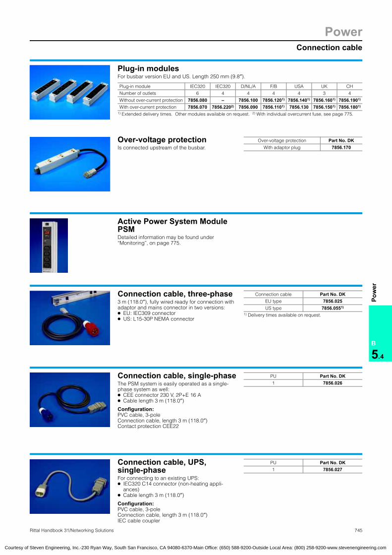
PowerConnection cable
745Rittal Handbook 31/Networking Solutions
B
5.4
Pow
er
Active Power System Module PSMDetailed information may be found under “Monitoring”, on page 775.
Active Power System Module PSM
Connection cable, three-phase3 m (118.0″), fully wired ready for connection with adaptor and mains connector in two versions:● EU: IEC309 connector● US: L15-30P NEMA connector
Three-phase connection cableConnection cable:three-phase
Connection cable Part No. DKEU type 7856.025US type 7856.0551)
1) Delivery times available on request.
Connection cable, single-phaseThe PSM system is easily operated as a single-phase system as well: ● CEE connector 230 V, 2P+E 16 A● Cable length 3 m (118.0″)
Configuration:PVC cable, 3-poleConnection cable, length 3 m (118.0″)Contact protection CEE22
Single-phase connection cableConnection cable:single-phase
PU Part No. DK1 7856.026
Connection cable, UPS,single-phaseFor connecting to an existing UPS: ● IEC320 C14 connector (non-heating appli-
ances)● Cable length 3 m (118.0″)
Configuration:PVC cable, 3-poleConnection cable, length 3 m (118.0″)IEC cable coupler
Connection cable:UPS, single-phase
PU Part No. DK1 7856.027
Courtesy of Steven Engineering, Inc.-230 Ryan Way, South San Francisco, CA 94080-6370-Main Office: (650) 588-9200-Outside Local Area: (800) 258-9200-www.stevenengineering.com
Plug-in modulesFor busbar version EU and US. Length 250 mm (9.8″).
Plug-in modules for busbar
Plug-in module IEC320 IEC320 D/NL/A F/B USA UK CH
Number of outlets 6 4 4 4 4 3 4
Without over-current protection 7856.080 – 7856.100 7856.1201) 7856.1401) 7856.1601) 7856.1901)
With over-current protection 7856.070 7856.2202) 7856.090 7856.1101) 7856.130 7856.1501) 7856.1801)
1) Extended delivery times. Other modules available on request. 2) With individual overcurrent fuse, see page 775.
Over-voltage protectionIs connected upstream of the busbar.
Over-voltage protection Part No. DKWith adaptor plug 7856.170
Overvoltage protection
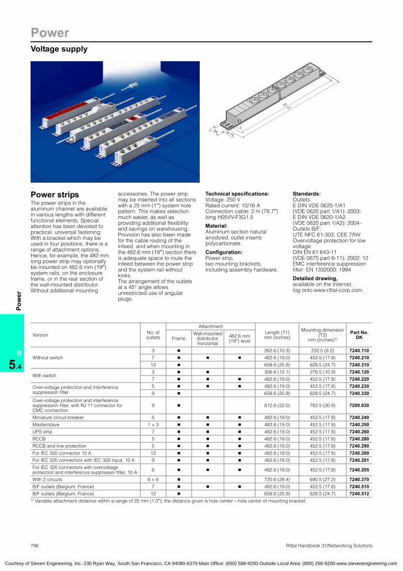
746 Rittal Handbook 31/Networking Solutions
PowerVoltage supply
B
5.4
Pow
erVoltage supplySystem accessories:for voltage supply
31.7544
44
T2T1
Power stripsThe power strips in the aluminum channel are available in various lengths with different functional elements. Special attention has been devoted to practical, universal fastening: With a bracket which may be used in four positions, there is a range of attachment options. Hence, for example, the 482 mm long power strip may optionally be mounted on 482.6 mm (19″) system rails, on the enclosure frame, or in the rear section of the wall-mounted distributor. Without additional mounting
accessories. The power strip may be inserted into all sections with a 25 mm (1″) system hole pattern. This makes selection much easier, as well as providing additional flexibility and savings on warehousing. Provision has also been made for the cable routing of the infeed, and when mounting in the 482.6 mm (19″) section there is adequate space to route the infeed between the power strip and the system rail without kinks.The arrangement of the outlets at a 45° angle allows unrestricted use of angular plugs.
Technical specifications:Voltage: 250 VRated current: 10/16 AConnection cable: 2 m (78.7″) long H05VV-F3G1.5
Material:Aluminum section natural anodized, outlet inserts polycarbonate.
Configuration:Power strip,two mounting brackets,including assembly hardware.
Standards: Outlets: E DIN VDE 0620-1/A1 (VDE 0620 part 1/A1): 2003- E DIN VDE 0620-1/A2 (VDE 0620 part 1/A2): 2004- Outlets B/F: UTE NFC 61-303, CEE 7/NV Overvoltage protection for low voltage: DIN EN 61 643-11 (VDE 0675 part 6-11): 2002: 12 EMC interference suppression filter: EN 1332000: 1994
Detailed drawing,available on the Internet, log onto www.rittal-corp.com.
Power strips
Version No. ofoutlets
AttachmentLength (T1)mm (inches)
Mounting dimension (T2)
mm (inches)1)
Part No. DKFrame
Wall-mounted distributor,horizontal
482.6 mm(19″) level
Without switch
3 � 262.6 (10.3) 232.5 (9.2) 7240.1107 � � � 482.6 (19.0) 452.5 (17.8) 7240.21012 � 658.6 (25.9) 628.5 (24.7) 7240.310
With switch3 � � 306.6 (12.1) 276.5 (10.9) 7240.1207 � � � 482.6 (19.0) 452.5 (17.8) 7240.220
Over-voltage protection and interferencesuppression filter
5 � � � 482.6 (19.0) 452.5 (17.8) 7240.2309 � 658.6 (25.9) 628.5 (24.7) 7240.330
Over-voltage protection and interferencesuppression filter, with RJ 11 connector for CMC connection
9 � 812.6 (32.0) 782.5 (30.8) 7200.630
Miniature circuit-breaker 5 � � � 482.6 (19.0) 452.5 (17.8) 7240.240Master/slave 1 + 3 � � � 482.6 (19.0) 452.5 (17.8) 7240.250UPS strip 7 � � � 482.6 (19.0) 452.5 (17.8) 7240.260RCCB 5 � � � 482.6 (19.0) 452.5 (17.8) 7240.280RCCB and line protection 5 � � � 482.6 (19.0) 452.5 (17.8) 7240.290For IEC 320 connector 10 A 12 � � � 482.6 (19.0) 452.5 (17.8) 7240.200For IEC 320 connectors with IEC 320 input, 10 A 9 � � � 482.6 (19.0) 452.5 (17.8) 7240.201For IEC 320 connectors with overvoltage protection and interference suppressor filter, 10 A 6 � � � 482.6 (19.0) 452.5 (17.8) 7240.205
With 2 circuits 6 + 6 � 720.6 (28.4) 690.5 (27.2) 7240.370B/F outlets (Belgium, France) 7 � � � 482.6 (19.0) 452.5 (17.8) 7240.510B/F outlets (Belgium, France) 12 � 658.6 (25.9) 628.5 (24.7) 7240.512
1) Variable attachment distance within a range of 25 mm (1.0″), the distance given is hole center – hole center of mounting bracket.
Courtesy of Steven Engineering, Inc.-230 Ryan Way, South San Francisco, CA 94080-6370-Main Office: (650) 588-9200-Outside Local Area: (800) 258-9200-www.stevenengineering.com

PowerVoltage supply
747Rittal Handbook 31/Networking Solutions
B
5.4
Pow
er
Versions: Rocker switch Illuminated, 2-pole switch. The safety bars prevent accidental contact.
Master/slave 2-pole electronic automatic switching unit. The operating point may be set from 9 W to 35 W. Equipment which switches to energy-saving or stand-by mode when switched on cannot be used as the master device. In the ON state, the master device must draw 9 W, and must not draw more than 35 W in the OFF state.
Overvoltage protection and interference suppression filter The connected equipment is protected from voltage peaks in the mains and switching operations by the power suppliers. The EMC interference suppression filter provides protection from high-frequency interference voltage from both directions – the mains and the connected equipment.The green ready light is extinguished in the event of disconnection or malfunctions. Connected equipment remains disconnected.
Overvoltage protection device (SPD), type 3 Maximum continuous voltage Uc: 280 V ACRated load current IL: 16 AMaximum overvoltage protection at the mains end:LS:B16A or 16AgL/gG Protection level Up: 1.5 kVCombined surge Uco (L-N): 5 kVCombined surge Uco (L/N-PE): 6 kVRated discharge current In (L-N): 3.0 kARated discharge current In (L/N-PE): 6.5 kAArrester disconnect: Permanently disconnects SPD and equipment from the mainsStatus display: Green ready light turns off upon disconnection.
Overvoltage protection and interference suppression filter, with RJ 11 connector for connection to the CMC. With the relay message contact, undervoltage and any failures caused by overvoltage can be reported via the CMC in the network using an SNMP trap.Relay alarm output: RJ 11 jackLoad capacity of relay: 50 V DC, 100 mA
Miniature circuit-breaker Protects cables from short-circuit and overload. 2-pole switching (thermal/magnetic). Tripping characteristic B.
UPS strip With red outlet inserts. These indicate the items of equipment protected by a UPS.Connection cable with IEC 320 connector.Cable: H05VV-F3G1.0/rated current: 10 A
2 circuits Two circuits with two separate connection cables, 2.5 m (98.4″).
RCCB For personal protection. With residual-current circuit-breaker I∆n 30 mA to DIN VDE 0664 part 1/85.
RCCB and line protection A combination of personal, overload and short-circuit protection. With residual-current circuit-breaker I∆n 30 mA to DIN VDE 0664 part 1/85 and residual-current circuit-breaker to DIN VDE 0641/A 4/11.88 16 A/250 V~.
Version B/F (Belgium/France) With 7 or 12 outlets to CEE 7-VUTE, with child-proof system.
IEC connector With connection outlets to IEC 320, connection cable, 2 m (78.7″) or IEC 320 input in the connector panel. Cable: H05VV-F3G1.0/rated current: 10 A
DK 7240.110
31.7
5
276.5
44
306.6
31.7
5
232.5
44
262
DK 7240.200 – DK 7240.290/DK 7240.510
31.7
5
44
452.5
482.6
DK 7240.370
31.7
5
44
690.5
720.6
DK 7240.200
482.6
452.5
(32.3) 97 88 88 88 57
44
(32.3)
482.6
44
(32.3) 141 110 110 57 (32.3)
452.5
DK 7240.205
482.6
452.5
(32.3) 273 88 57 (32.3)
44
482.6
(32.3) 119 44 44 44 44 44 44 35 (32.3)
44
452.5
DK 7240.120
DK 7240.201
DK 7240.510
Courtesy of Steven Engineering, Inc.-230 Ryan Way, South San Francisco, CA 94080-6370-Main Office: (650) 588-9200-Outside Local Area: (800) 258-9200-www.stevenengineering.com

748 Rittal Handbook 31/Networking Solutions
PowerVoltage supply
B
5.4
Pow
er
Power strips 230 VTechnical specifications:Rated voltage 250 V AC,maximum loadCH 10 A, GB 13 A.
Material:Plastic, halogen-freeConnection cable, 2 m (78.7″) long, without plugH05VV-F3G1 (CH) H05VV-F3G1.5 (GB) Unrestricted use, includingangular plugs, due to the long row arrangement of plug-type contacts.
Power strips
UK, CH version Part No. DKUK version
Part No. DKCH versionNo. of
outletsLength
mm (inches)With
rocker switch
6 470 (18.5)1) 7404.000 7604.0002) 8 553 (21.8) 7406.510 7606.5102) 12 793 (31.2) 7408.510 7608.5102) 16 1033 (40.7) 7409.5102) 7609.5102) 18 1153 (45.4) 7412.5102) 7612.5102) 5 470 (18.5)1) � 7405.000 7605.0002)
1) The power strips can be mounted horizontally at the rear of the DK wall-mounted distributor based on EL/AE. 2) Extended delivery times.
Power strips● Loading up to 16 A/maximum 250 V AC● Plastic, self-extinguishing to UL 94-V0● Connection cable without plug,
2 m (78.7″) long● Various national versions available
Power strips
Versionsfor
No. ofoutlets Part No. VR
D 16 A/250 V 4 3850.500GB 13 A/250 V 4 3851.500F/B 16 A/250 V 4 3852.500CH 10 A/250 V 4 3853.500
USA/CDN15 A/125 V 6 3854.500
Power strips for IEC 320 connectorssee page 746.
TE power strip8-way power strip for grounding-pin plug/version D. The strip is made of plastic and may be mounted vertically on the TE frame or in the rear 482.6 mm (19″) profile. In the 482.6 mm (19″) profile, more than 2U of space is required. The outlets are arranged at an angle of 45° so that angular plugs can also easily be used. The power strip is supplied with a 2 m (78.7″) connection cable. The connection cable is contacted in a terminal slot in the strip. The terminal slot is equipped with a separate cover, so that this connection point can always be quickly and easily accessed. Replacement of the connection cable is just as simple. Furthermore, the power strip has external terminals for separate grounding.
Technical specifications:Rated voltage: 230 Volt AC Rated current: max. 16 AConnection cable: Length 2 m (78.7″), H05VV-F3G 1.5 mm2, without plug with wire end ferrules
TE power stripPower strips:TE
TE power strip Part No. DK8-way, grounding-pin 7000.630
Courtesy of Steven Engineering, Inc.-230 Ryan Way, South San Francisco, CA 94080-6370-Main Office: (650) 588-9200-Outside Local Area: (800) 258-9200-www.stevenengineering.com
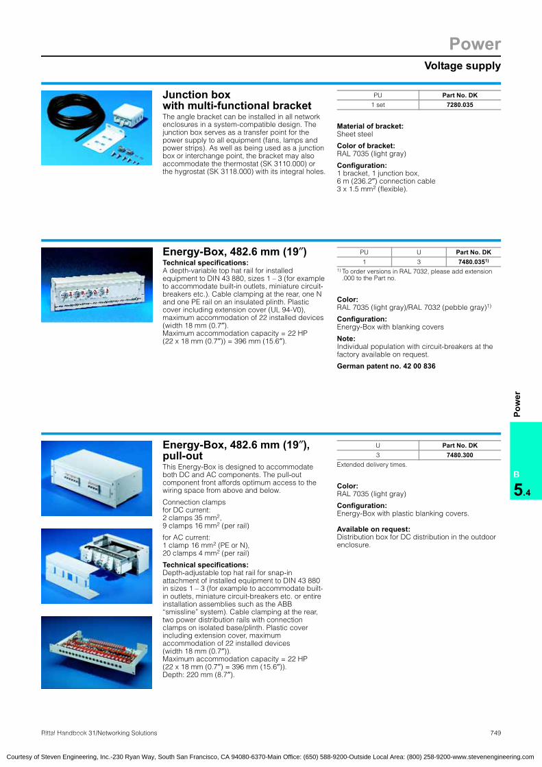
PowerVoltage supply
749Rittal Handbook 31/Networking Solutions
B
5.4
Pow
er
System accessories:for voltage supplyVoltage supply
Junction boxwith multi-functional bracketThe angle bracket can be installed in all network enclosures in a system-compatible design. The junction box serves as a transfer point for the power supply to all equipment (fans, lamps and power strips). As well as being used as a junction box or interchange point, the bracket may also accommodate the thermostat (SK 3110.000) or the hygrostat (SK 3118.000) with its integral holes.
Material of bracket: Sheet steel
Color of bracket: RAL 7035 (light gray)
Configuration:1 bracket, 1 junction box, 6 m (236.2″) connection cable3 x 1.5 mm2 (flexible).
Junction box with multi-functional bracket
PU Part No. DK1 set 7280.035
Energy-Box, 482.6 mm (19″)Technical specifications:A depth-variable top hat rail for installed equipment to DIN 43 880, sizes 1 – 3 (for example to accommodate built-in outlets, miniature circuit-breakers etc.). Cable clamping at the rear, one N and one PE rail on an insulated plinth. Plastic cover including extension cover (UL 94-V0), maximum accommodation of 22 installed devices (width 18 mm (0.7″). Maximum accommodation capacity = 22 HP(22 x 18 mm (0.7″)) = 396 mm (15.6″).
Color:RAL 7035 (light gray)/RAL 7032 (pebble gray)1)
Configuration:Energy-Box with blanking covers
Note:Individual population with circuit-breakers at the factory available on request.
German patent no. 42 00 836Energy-Box
PU U Part No. DK1 3 7480.0351)
1) To order versions in RAL 7032, please add extension.000 to the Part no.
Energy-Box, 482.6 mm (19″), pull-outThis Energy-Box is designed to accommodate both DC and AC components. The pull-out component front affords optimum access to the wiring space from above and below.
Connection clampsfor DC current: 2 clamps 35 mm2, 9 clamps 16 mm2 (per rail)
for AC current: 1 clamp 16 mm2 (PE or N), 20 clamps 4 mm2 (per rail)
Technical specifications:Depth-adjustable top hat rail for snap-in attachment of installed equipment to DIN 43 880 in sizes 1 – 3 (for example to accommodate built-in outlets, miniature circuit-breakers etc. or entire installation assemblies such as the ABB “smissline” system). Cable clamping at the rear, two power distribution rails with connection clamps on isolated base/plinth. Plastic cover including extension cover, maximum accommodation of 22 installed devices (width 18 mm (0.7″)).Maximum accommodation capacity = 22 HP(22 x 18 mm (0.7″) = 396 mm (15.6″)). Depth: 220 mm (8.7″).
Color:RAL 7035 (light gray)
Configuration:Energy-Box with plastic blanking covers.
Available on request: Distribution box for DC distribution in the outdoor enclosure.
Energy-Box
U Part No. DK3 7480.300
Extended delivery times.
Courtesy of Steven Engineering, Inc.-230 Ryan Way, South San Francisco, CA 94080-6370-Main Office: (650) 588-9200-Outside Local Area: (800) 258-9200-www.stevenengineering.com

750 Rittal Handbook 31/Networking Solutions
UPS SystemsFeatures
B
5.4
UPS
Sys
tem
s
Rittal Modular Power Concept PMC – ApplicationsThe modular Rittal UPS concept meets the versatile data center requirements and is easily expanded with additional UPS
modules. High initial investments for the first-time installation are avoided due to the modular design concept, since UPS
capacities may be upgraded at any time as and when required. The modular concept allows customers to invest as their
business expands, and avoids unnecessary electrical installation.
Output range 1 – 6 kVA
2U UPS with integral battery pack(1/1.5 kVA).
2U UPS with2U battery pack (2/3 kVA).
UPS floor standing enclosure with integral battery pack(6/1.5 kVA).
One PMC module10 – 40 kVA with batteriesin a TS8 enclosure.
Two PMC modules10 – 40 kVA eachwith batteriesin a TS8 enclosure.
Three PMC modules10 – 40 kVA eachwith separate battery enclosure.
Output range 10 – 120 kVA
RedundancyMulti-server configurations are protected by the redundant Rittal UPS concept. This guarantees a high degree of availability and continuous operation.
ModularityHigh level of flexibility through modular expansion, depending on the current/future UPS capacity requirements.
ScalabilityIn large output categories, output and autonomy times may be scaled, while in small output categories autonomy times may be scaled.
Power Modular Concept PMCModular Power Concept PMC
Courtesy of Steven Engineering, Inc.-230 Ryan Way, South San Francisco, CA 94080-6370-Main Office: (650) 588-9200-Outside Local Area: (800) 258-9200-www.stevenengineering.com

1
4
2
5
6
3
UPS SystemsFeatures
751Rittal Handbook 31/Networking Solutions
B
5.4
UPS
Sys
tem
s
UPS application areaThe Rittal Modular Power Concept (PMC) covers a broad application area in the IT infrastructure.
UPS safeguards the access system to the building.
UPS safeguards the company’s CAD system.
UPS for stand-alone applications.
Automatic system shutdown with administration option.
Central back-up of computer centers with redundant UPS functions.
Scalable UPS system for output and autonomy times.
1 2 3 4 5 6
Courtesy of Steven Engineering, Inc.-230 Ryan Way, South San Francisco, CA 94080-6370-Main Office: (650) 588-9200-Outside Local Area: (800) 258-9200-www.stevenengineering.com

752 Rittal Handbook 31/Networking Solutions
UPS SystemsUPS, single-phase, output range 1 – 6 kVA
B
5.4
UPS
Sys
tem
s
Benefits of the Rittal Modular Power Concept (PMC)● High-quality double
transformer technology with perfect sinusoidal output voltage
● Electronic bypass● Autonomy time may be
extended with battery expansion
● Integral battery management, self-test and fast-charge system
● Sealed, maintenance-free lead gel battery, 5 year service life under Eurobat
● Clear LED display● Alarm function● Serial interface (RS-232)● Optional relay, SNMP or
AS 400 slide-in board● Compatible with the Rittal
CMC-TC monitoring system
Technical featuresDouble-conversion technologyThis technology is also known as online technology. The electronics with isolating transformer supplies connected equipment with a perfect sinusoidal output voltage.
Bypass functionThe Rittal UPS system is equipped with an internal electronic bypass. This protects the UPS system from damage resulting from overload.
Intelligent battery managementThe integral charging control checks the readiness of the battery units and ensures constant system availability. The battery remains protected from overcharging or exhaustive discharge.
Battery packAll Rittal UPS systems may be equipped with additional battery packs. The battery packs serve to extend the autonomy time. For UPS output categories 2 kVA and 3 kVA at least one battery pack is needed, since the control unit and battery are divided into separate enclosures here.
SoftwareThe Rittal UPS software is included with the supply of UPS systems. It operates in the background and communicates with the Rittal UPS in an event-oriented manner via a serial interface. As soon as a malfunction is identified, a freely configurable shutdown routine may be used to shut down the systems automatically. All current operating systems are supported. Several network servers may be controlled simultaneously via the software.
For each additional server, only an RCCMD (remote control command) licence is needed. The software also contains professional UPS management with the option of sending individual messages via e-mail, fax or mobile phone. A diverse spectrum of information is documented in the event memory.
Software benefits: ● Software compatible with all
standard operating systems, included with the supply
● HPOpenView plug-in for Windows included in the software package
● If several servers are shut down via RCCMD, permanent polling of the servers is not necessary, which considerably reduces the system load. Each additional server requires an RCCMD licence
peaks or similar disruptions. Thanks to the active-power factor
generated by the batteries/transformers, terminals are
supplied with a constant quality power. The system conforms
to the UPS classification based on operating response in
accordance with standard IEC 62 040-3 and VDE 0558
part 530. The Rittal UPS carries the classification code
VFI-SS-111. The UPS software included as standard with the
supply also facilitates the fully automated shutdown of
systems and servers, as well as visualization of the operating
status.
The Rittal UPS with double conversion technology protects
the IT infrastructure from hardware damage, data loss and
operational stop, triggered by power failures, voltage
Courtesy of Steven Engineering, Inc.-230 Ryan Way, South San Francisco, CA 94080-6370-Main Office: (650) 588-9200-Outside Local Area: (800) 258-9200-www.stevenengineering.com

UPS SystemsUPS, single-phase, output range 1 – 6 kVA
753Rittal Handbook 31/Networking Solutions
B
5.4
UPS
Sys
tem
s
T2
T1
H1
H2
B2
B1
H1
H2
T1
T2B2
B1
Rittal Modular Power Concept (PMC)Configuration:1-phase UPS systems based on the double-conversion technology with/without battery pack.
Available on request: Replacement batteries,AS 400 interface adaptor.
Additional parts needed:
Slide racks for mounting in 19″ racks, see pages 1010 – 1011. Country-specific connection cables are required to operate the UPS systems. Part no. see page 771.
USV application examples Page 750 UPS, 3-phase Page 754
Stored energy times (in minutes) in the event of a power failure at 100%/50% load:
UPS type230 V
Supplied stateStandard version
Additional battery packs
1 2 3 4 5
1 kVA 7/16 35/76 53/122 – – –
1.5 kVA 5/14 26/67 46/125 – – –
2 kVA 0/0 10/22 24/55 45/102 58/141 80/178
3 kVA 0/0 6/15 13/34 25/63 36/86 50/124
6 kVA 8/23 38/88 60/141 – – –
UPS for 482.6 mm (19″) racks UPS floor-stand-ing enclosure with integral batteryUPS with integral battery UPS control unit
Part No. DK 7857.401 7857.402 7857.4031) 7857.4041) 7857.405Battery packs required, 2U – – 7857.408 7857.408 –
Maximum number of additional battery packs 2 2 5 5 2
PowerVA 1000 1500 2000 3000 6000
Watts 700 1050 1400 2100 4200
InputRated voltage 230 V (160 – 276 V) AC ± 3%
Frequency 50/60 Hz ± 5%, automatic selection
Output
Voltage 220/230/240 ± 3%
Frequency, synchronized 50/60 Hz ± 0.5% (sine)
Frequency, asynchronous 50/60 Hz ± 5% (sine)
Rated current (maximum) 4 A 5.7 A 7.7 A 12 A 29.6 A
Power factor to IEC 555-2 > 0.95
Crest factor 3 : 1
Overload response 110% – 130% for 10 sec., > 130% ± 10% for 1.5 sec.
Dimensions and weightsHeight (H1) in U, mm (inches) 2U 710 (28.0)
Width (B1) in mm (inches) 482.6 (19″) 260 (10.2)
Depth (T1) in mm (inches) 410 (16.1) 493 (19.4) 410 (16.1) 460 (18.1) 555 (21.9)
Weight in kg (lb) 17 20 8 11 91
Input socket-contacts 1 x IEC 320 C 13 1 x IEC 320 C 19 Clamps
Output socket-contacts 4 x IEC 320 C 13 1 x IEC 320 C 19 Clamps
Battery packsPart No. DK extension kit for UPS 7857.406 7857.407 7857.408 7857.408 7857.409Height (H2) in U, mm (inches) 2U 705 (27.8)
Width (B2) in mm (inches) 482.6 (19″) 260 (10.2)
Depth (T2) in mm (inches) 460 (18.1) 555 (21.9)
Weight in kg (lb) 23 (50.7) 29 (63.9) 29 (63.9) 29 (63.9) 125 (275.6)
Accessories PU
Alarm relay slide-in card 1 7857.400RCCMD licence (Remote Control Command) 1 7857.4212) SNMP slide-in card Ethernet, FTP, Telnet … 1 7857.4202)
1) At least one battery pack 2/3 kVA 7857.408 must be ordered at the same time, because the UPS control units do not contain any batteries.
2) Extended delivery times
Battery: Maintenance-free lead battery, service life approx. 5 years according to EURO-BAT. Operating environments: Temperature: 10°C – 40°C (50°F– 104°F) to 1500 m NN Relative humidity: 20 – 90%, non-condensing
Courtesy of Steven Engineering, Inc.-230 Ryan Way, South San Francisco, CA 94080-6370-Main Office: (650) 588-9200-Outside Local Area: (800) 258-9200-www.stevenengineering.com
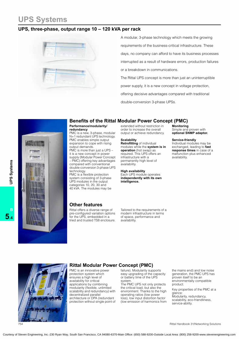
754 Rittal Handbook 31/Networking Solutions
UPS SystemsUPS, three-phase, output range 10 – 120 kVA per rack
B
5.4
UPS
Sys
tem
s
A modular, 3-phase technology which meets the growing
requirements of the business-critical infrastructure. These
days, no company can afford to have its business processes
interrupted as a result of hardware errors, production failures
or a breakdown in communications.
The Rittal UPS concept is more than just an uninterruptible
power supply, it is a new concept in voltage protection,
offering decisive advantages compared with traditional
double-conversion 3-phase UPSs.
Benefits of the Rittal Modular Power Concept (PMC)Performance/modularity/redundancyPMC is a new, 3-phase, modular N+1 redundant UPS technology. PMC enables simple output expansion to cope with rising output demands. PMC is more than just a UPS – it is a new concept in power supply (Modular Power Concept – PMC) offering key advantages compared with conventional double-conversion 3-phase UPS technology.PMC is a flexible protection system consisting of 3-phaseUPS modules in the output categories 10, 20, 30 and 40 kVA. The modules may be
extended without restriction in order to increase the overall output or achieve redundancy.
ScalabilityRetrofitting of individual modules while the system is in operation (hot swap) as required. This UPS offers an infrastructure with a permanently high level of availability.
High availabilityEach UPS module operates independently with its own intelligence.
MonitoringSimple and proven with optional SNMP adaptor.
Service-friendlyIndividual modules may be exchanged, leading to fast response times in case of a malfunction plus enhanced availability.
Other featuresRittal offers a diverse range of pre-configured variation options for the UPS, embedded in a tried and trusted TS8 enclosure.
Tailored to the requirements of a modern infrastructure in terms of space, performance and availability.
Rittal Modular Power Concept (PMC)PMC is an innovative power protection system which ensures a high level of availability for critical applications by combining modularity (flexible, unlimited scalability and redundancy) with decentralized parallel architecture or DPA (redundant protection without single point of
failure). Modularity supports easy upgrading of the capacity or battery time of the UPS system. The PMC UPS not only protects the critical load, but also the environment. Thanks to the high operating ratios (low power loss), low input distortion factor (low emission of harmonics from
the mains end) and low noise generation, the PMC UPS has proven itself to be an environmentally compatible product.
Key properties of the PMC at a glance: Modularity, redundancy, scalability, eco-friendliness, service-ability.
Courtesy of Steven Engineering, Inc.-230 Ryan Way, South San Francisco, CA 94080-6370-Main Office: (650) 588-9200-Outside Local Area: (800) 258-9200-www.stevenengineering.com

UPS SystemsModular UPS concept
755Rittal Handbook 31/Networking Solutions
B
5.4
UPS
Sys
tem
s
PMC module● Every individual UPS module
contains a rectifier/booster, inverter, a static bypass and a separate CPU which monitors and controls all parts and coordinates parallel communication with the other modules
● The modules are available in the output sizes 10, 20, 30 and 40 kVA and are prepared for easy 482.6 mm (19″) integration into the Rittal TS8 UPS enclosure
● The weight of the modules ranges from 40 kg (88.2 lb) (10/20 kVA) to 59 kg (130.1 lb) (40 kVA)
● In conjunction with the batteries, a diverse range of combinations may be quickly and easily compiled
● Parallel connection occurs within the enclosure, thus facilitating a space-saving configuration of the UPS system
UPS classificationIn order to facilitate comparability of UPS appliances from different manufacturers, a classification has been developed on the basis of operating response.
Modules bearing the code VFI-SS-1111) under the new IEC 62 040-3 classification are truly outstanding.
These UPS modules are transformerless, genuine online, double-conversion UPSs with static bypass.
1) New standard of high availability to protect the server environment.
Modular Power Concept
The Rittal Modular Power Concept (PMC) allows easy
adaptation to customer-specific requirements, due to its
modular character, combined with investment security and
a high level of availability.
The modules are integrated into prepared Rittal TS8 UPS
enclosures, where they may be extended while the system is
operational.
UPS modules
Main line input
Amplifier
Bypass
InverterRectifier
Battery Battery charging system
Equipment output
UPS application examples Page 750 UPS, 1-phase Page 752
Courtesy of Steven Engineering, Inc.-230 Ryan Way, South San Francisco, CA 94080-6370-Main Office: (650) 588-9200-Outside Local Area: (800) 258-9200-www.stevenengineering.com

756 Rittal Handbook 31/Networking Solutions
UPS SystemsRedundant UPS concept
B
5.4
UPS
Sys
tem
s
New standard of high availability to protect the server environment
Parallel connection of UPS systems:
● Increase capacity to enable the system
to supply a greater load than a single installation
● Redundancy, to increase UPS availability
The fault-tolerant DPA (Distributed Parallel Architecture)
design protects against “single point of failure”, and,
therefore, ensures permanent availability.
Rittal PMC (2 modules and battery)This enclosure has been developed for 2 modules with n+1 redundancy with a battery with a short autonomy time, in order to achieve the smallest possible basic surface area.
Modules are available in10, 20, 30 and 40 kVA.
What is Distributed Parallel Architecture (DPA)?The decentralized parallel architecture (DPA) of the modules includes integrated control electronics (CPU) for a rectifier, booster, inverter and static bypass. The CPU of each UPS module also has its own parallel intelligence. The commonalities of a complete UPS system with several modules are confined to control of the parallel bus connection.
DPA guarantees supply of UPS power as long as the UPS power is higher than or equal to the critical load. This occurs without the UPS switching to bypass.
Switching to bypass only occurs if there is an overload or a short-circuit on the load side.
To consistently increase the availability, DPA is an extension of the bypass, so as to protect or ensure the supply of the critical load in the event of a short-circuit or overload.
High availabilityRedundancy means that at least two or more modules always share the critical load equally.In the event of failure of a UPS module, the other will assume the entire connected load without interruption.
UPS application examples Page 750 UPS, 1-phase Page 752
One PMC module10 – 40 kVA with batteriesin a TS8 enclosure.
Two PMC modules10 – 40 kVA eachwith batteries in a TS8 enclosure.
Three PMC modules10 – 40 kVA eachwith separate battery enclosure.
Courtesy of Steven Engineering, Inc.-230 Ryan Way, South San Francisco, CA 94080-6370-Main Office: (650) 588-9200-Outside Local Area: (800) 258-9200-www.stevenengineering.com

UPS SystemsScalable UPS concept
757Rittal Handbook 31/Networking Solutions
B
5.4
UPS
Sys
tem
s
Integration of up to three modulesin one enclosureThis achieves maximum flexibility.
Your output may be easily extended by adding a further UPS module.
This can occur as a “hot swap” with the system in operation, without needing to switch the system to bypass.
For this configuration, an additional battery enclosure is always required. The autonomy times may be flexibly adapted to your requirements.
Environmentally compatible UPS concept High level of efficiency● Due to the transformerless
technology and the ESIS (Energy Saving Inverter Switching) technology, a 5% higher efficiency is achieved, on average, than with conventional UPS systems. With efficiencies of up to 96% operating costs are reduced, as is heat dissipation into the environment.
Low noise levels● The noise level is dependent
on the load; at <70% of the nominal load the level is significantly reduced. This leads to a pleasant, user-friendly noise level in the environment.
Battery protection and battery managementThe batteries are protected from overcharging by ripple-free charging electronics. The electronics regulate the charge current depending on the ambient temperatures. The built-in flexible battery management (FBM) periodically checks the “fitness” of the batteries and automatically generates alarms in case of irregularities.
Power Modular Concept PMCModular Power Concept PMC
Extend your system at the same speed as your business.
The challenges faced by your infrastructure not only include
the current circumstances, but also in particular the
requirements of the future. Thanks to the scalable concept,
your installation is easily extended.
UPS application examples Page 750 UPS, 1-phase Page 752
Courtesy of Steven Engineering, Inc.-230 Ryan Way, South San Francisco, CA 94080-6370-Main Office: (650) 588-9200-Outside Local Area: (800) 258-9200-www.stevenengineering.com

758 Rittal Handbook 31/Networking Solutions
Rittal IT CoolingPerfect solutions for every application
B
5.5
Ritt
al IT
Coo
ling
From passive air climate control to active liquid cooling of
high-performance CPUs, Rittal offers the full range of
components and systems. They are designed precisely
according to your requirements and application spectrum.
Not only for the conditions inside the rack, but also the
ambient conditions are taken into considertion.
Software-assisted planning helps to minimize investment
costs and also offers peace of mind.
Diagram Horizontal cooling: 2 doors with high air throughput (78% free space per door)
Diagram Vertical cooling: via vented base/plinthand roof ventilation
See page 759.
1
2
Passive cooling(use of the ambient air) The air cooled using the regular ambient air or with the building’s air-conditioning system is routed into the raised floor for rack cooling.
Doors with 78% open surface area (diagram 1) or openings in the base/plinth and roof (diagram 2) ensure maximum air throughput using convection assisted by fans.
Active cooling (use of the ambient air) Fan systems for active cooling (diagram 1) amplify the air exchange inside the rack and use ambient air for cooling.
Active, rack-related coolingBy contrast, rack-related, active cooling (diagram 2) is capable of reducing the interior temperature of the rack to below the ambient temperature. This cooling technique is very effective with an appropriate room volume and in industrial environments.
High-performance cooling (liquid cooling, independent of the ambient air)With liquid, under the same volumetric flow, approximately one thousand times as much heat loss may be dissipated as with air. This opens up a brand new dimension in cooling.
Liquid cooling systems for rack coolingExtremely high heat loads are dissipated with air/water heat exchanger systems (diagram 2) from the racks (diagram 1).
Liquid cooling systems (4) for component coolingCPUs, as well as power packs, hard disk drives and other electronic components are cooled directly – effectively and quietly.
1
2
1
2
12
1
4
3
Diagram Fan systems,see page 759.
Diagram Air conditioners and rack-mounted 19″ chiller system, see page 760.
1
2
Diagram Server racks
Diagram LCP (Liquid Cooling Package)
Diagram Air/water heat exchanger
Diagram CPU cooling
See page 760.
1
23
4
IT cooling
Courtesy of Steven Engineering, Inc.-230 Ryan Way, South San Francisco, CA 94080-6370-Main Office: (650) 588-9200-Outside Local Area: (800) 258-9200-www.stevenengineering.com

759Rittal Handbook 31/Networking Solutions
B
5.5
Ritt
al IT
Coo
ling
Passive Cooling (Use Of The Ambient Air)
Horizontal ventilationA high air throughput, stylish design and outstanding security are provided by the doors (with 78% free surface area per door) of the server racks.
Vertical ventilationVentilation base/plinth, roof vent and slotted component shelves ensure heat dissipation.
Air baffle systemCool air from the hollow base is routed over the base/plinth and distributed via the door in a targeted manner.
Fan cross memberFor the perforated door of TS8 server racks. Air throughput up to 1200 m3/h (706 cfm), see page 652.
Internal fan mounting panelfor TS8 enclosures. For improved air blending and heat dissipation, see page 653.
Internal fanTo avoid hot spots and support climate control components,see page 653.
Active cooling (use of the ambient air)
Fan roofsVarious designs and outputs, extendible with fan kits. Fast assembly tailored to racks,see page 647.
Roof-mounted fansQuiet performance (1500 m3/h (883 cfm)) for office applications, wired ready for connection, easy assembly, see page 647.
Centrifugal fan/rack-mounted fanCentrifugal fan,Rack-mounted fan,Vario rack-mounted fan,see page 645.
The perforations in the doors or openings in the base/plinth and roof ensure maximum air throughput using convection assisted by the equipment fans.
Fan systems to reinforce air exchange
Rittal filter-fan units,see page 636.
Fan systems to reinforce air exchange and circulation inside the rack
Courtesy of Steven Engineering, Inc.-230 Ryan Way, South San Francisco, CA 94080-6370-Main Office: (650) 588-9200-Outside Local Area: (800) 258-9200-www.stevenengineering.com

760 Rittal Handbook 31/Networking Solutions
B
5.5
Ritt
al IT
Coo
ling
Active, Rack-Related Cooling
Roof-mounted air conditioner(office application)Useful cooling output 1100 W (3756 BTU) at an extremely low noise level, see page 590.
Rack-mounted air conditioners 482.6 mm (19″)Useful cooling output 1000 W (3415 BTU), simple installation in the 482.6 mm (19″) level, see page 644.
Rack-mounted chiller system 482.6 mm (19″)Liquid-cooled computers are supplied directly via 6 cooling circuits. Cooling output 1000 W (3415 BTU), see page 673.
Cooling of the rack interior to below the ambient temperatureThe three systems shown opposite are specifically designed for the cooling of servers, IT and electronic components.
Rittal roof-mounted and wall-mounted air conditioners,see page 590.
Cooling circuit distributor for racksPack 1 for 20, pack 2 for 40 CPU cooling circuits. Enclosure heights 1200 and 2000 mm(47.2 and 78.7″), see page 674.
Cooling circuit distributor 482.6 mm (19″)Complete kit or individual distributors with drip-free connection of up to 10 servers,see page 675.
High-performance cooling (independent from ambient air)
Liquid cooling packageThis cooling rack is fitted with up to 3 cooling modules (air/water heat exchangers), see page 672.
It is bayed with one or two TS8 server racks (H 2000 x D 1000 mm (78.7 x 39.4″)). Useful cooling output per module 4000 W (13,661 BTU) , (max. 12000 W (40,982 BTU)), see page 672.
Air/water heat exchangerInstallation: Roof-mounting, wall-mounting and as TS8 sidewall (H 1800 x D 600 mm (70.9″ x 23.6″)). Useful cooling output from 600 W to 4000 W (2049 to 13,661 BTU), see page 626.
Liquid cooling systems to dissipate high heat loadsAlso suitable for use in closed rooms without air-conditioning by using external chiller systems.
Chiller systems for liquid cooling, see page 608.
Liquid cooling systems for component coolingCPUs, as well as power packs, hard disk drives and other electronic components are cooled directly – effectively and quietly.
Courtesy of Steven Engineering, Inc.-230 Ryan Way, South San Francisco, CA 94080-6370-Main Office: (650) 588-9200-Outside Local Area: (800) 258-9200-www.stevenengineering.com

761Rittal Handbook 31/Networking Solutions
B
5.5
Ritt
al IT
Coo
ling
1
2
3
3
4
1
2
2
Chiller systems MiniSmart design, simple assembly,cooling output from 960 W to 4500 W (2379 to 15,368 BTU), see pages 608 – 609.
Chiller systems in theTS8 Top enclosure systemCompact design,bayable with TS8 racks,cooling output from 6000 W to 25000 W, (20,491 to 85,379 BTU), see pages 615 – 616.
Chiller systems in freestanding and industrial enclosures Cooling media water or oil,cooling output from 2100 to 172000 W (7172 to 58,741 BTU), see page 617.
Background Technology: Chiller Systems
Chiller systems ensure central cooling and supply of the cooling medium for liquid cooling systems. This makes it possible to achieve spatial separation between the generation of cold air and cooling itself, for the temperature-neutral expansion of data centers.
Chillers solve all cooling tasks by using a cooling pipes system.As well as IT and electronic components, production processes, machines and systems are also cooled. A range of products from960 W to 172 kW (2379 BTU to 587,411 BTU) meets all cooling requirements.
Advice, calculation, planning● Software Rittal Therm
Simple calculation of heat loss, calculation of dissipation via the surface, device selection
● CFD (Computer Fluid Dynamics) offers system reliability, because the temperature, pressure and flow speed at every point of the calculated space are simulated at the planning phase
● Eliminate risks through thermography. Even with the prototype of your plant or machine, the Rittal thermography service offers precise imaging of the real temperature conditions on site
● SupportProject planning, tests and measurementsin the Rittal climate laboratory, commissioning, maintenance
Chiller system
Air/water heat exchanger, roof-mounted
Air/water heat exchanger, wall-mounted
Further cooling options
1
2
3
4
IT cooling
Courtesy of Steven Engineering, Inc.-230 Ryan Way, South San Francisco, CA 94080-6370-Main Office: (650) 588-9200-Outside Local Area: (800) 258-9200-www.stevenengineering.com

762 Rittal Handbook 31/Networking Solutions
MonitoringRittal CMC-TC – Security management concept
B
5.6
Mon
itorin
g
Climate Control
Consistent low temperatures for electronics are a key safety factor in the network and in the production process. Monitoring
of the internal rack temperature and the control of climate technology to reliably dissipate heat loss is provided by the
Rittal CMC-TC security system to minimize operating costs.
Effective prevention, comprehensive security and central
organization of rack security. The new, modular CMC-TC
facilitates the implementation of highly individual security
solutions. Its modular plug & play system affords a high level
of protection for your investments.
More detailed information can be found at:www.cmc-tc.com
Power Management
Power requirements are on the increase, and there is a growing need for maximum availability of modern IT infrastructures.
Rittal addresses the associated additional requirement for redundant power supply with a new, intelligent power
distribution system which may be integrated with no loss of enclosure internal rack volume.
Access Control
Access authorization is one of the most important security factors in any company. With the CMC-TC, this is registered for the entire network. In case of
an unauthorized access attempt, the system sounds the alarm. For example, doors may be opened by authorized individuals with a numerical
code, magnetic card, smartcard, or the latest security technology.
Monitoring
Courtesy of Steven Engineering, Inc.-230 Ryan Way, South San Francisco, CA 94080-6370-Main Office: (650) 588-9200-Outside Local Area: (800) 258-9200-www.stevenengineering.com

MonitoringRittal CMC-TC – Security management concept
763Rittal Handbook 31/Networking Solutions
B
5.6
Mon
itorin
g
Sensor unit I/O unit Climate unit Access unit Sensors/actuators: Lock/reader:
7320.500 Temperature sensor � � 7320.700 Elec.-magn. Ergoform-S FR/PS/TC/TE �
7320.510 Humidity sensor � 7320.710 Elec.-magn. Ergoform-S QR �
7320.520 Analog sensor input module“4 – 20 mA” � 7320.721 Electro-magnetic TS8 handle
with master key function �
7320.530 Access sensor1) � � 7320.730 Universal lock �
7320.540 Vandalism sensor � 7320.740 Relay output module for room door �
7320.550 Airflow monitor � � 7320.750 Smart card reader �
7320.560 Smoke alarm � � 7320.760 Magnetic card reader �
7320.570 Motion sensor � � 7320.770 Coded lock �
7320.580 Digital input module � � 7320.530 Access sensor1) �
7320.590 Digital relay output module � 7320.580 Digital input module for door release �
7320.600 Voltage monitor � � 7320.900 7320.910 7320.920 7320.930
Lock FR(i) � 7320.610 Voltage monitor with switch output �
7320.620 48 V voltage monitor � �
7320.630 Leakage sensor � 7320.950 Universal handle �
7320.811 Fan Alarm System FAS � 1) Up to a maximum of 5 sensors may be connected in series.
● The processing unit (PU) forms the basis of the monitoring system
● The system can be incorporated directly into the user network with a network interface 10BaseT, TCP/IP, SNMP
● The system has an integrated web server, through which the system can be configured
● The system may be linked to the CMC-TC master with a network interface
● The monitoring functions are determined by the sensor units or sensors/actuators linked to the PU, and can therefore be flexibly selected
● Up to 4 sensor units may be connected in any given combination (I/O, access, climate, FCS)
The sensor units (SU)
Processingunit (PU)
Master unit
Universal I/O unit ● The I/O unit is the
measurement and alarm module
● Alarm sensors may be connected (e.g. motion detector)
● Analog measurements can be transmitted and monitored (temperature, humidity, 4 – 20 mA)
● The system is capable of switching relay output modules
● The unit has 4 universal ports for 4 sensors/actuators
● The I/O unit must be connected to the PU, thus providing data exchange and energy supply to electronics.
Climate unit ● The climate unit serves to
control the fans and hence regulate the temperature
● The physical airflow of the fan is monitored considering the controller
● If no temperature sensor or airflow sensor is used, the two universal ports can also be fitted with other sensors (see table)
● Simple fan connection with IEC socket
● The unit is designed for one fan system
● The climate unit must be connected to the PU
Access unit ● The access unit serves to
control door systems ● The doors can be opened
remotely via the network● The doors can also be
opened by selected individuals with a coded lock, magnetic card or smartcard
● The doors of enclosures or rooms can be monitored and activated
● The unit is designed for two separate door systems
● The access unit must be connected to the PU. This provides data exchange and power supply to the electronics
● The CMC-TC master is required in all situations where it is necessary to monitor large numbers of security-relevant factors or where high demands are placed on the system
● The CMC-TC master offers high performance and conserves IP resources
● A PU with sensor units is always required for monitoring
● Up to 10 processing units (PUs) may be connected to a sub-network as slaves
● The master offers a 10/100BaseT interface to the user network and comprises all monitoring variables on HTTPS and SNMP
● The system can be connected and operated directly via the Rittal SSC
Courtesy of Steven Engineering, Inc.-230 Ryan Way, South San Francisco, CA 94080-6370-Main Office: (650) 588-9200-Outside Local Area: (800) 258-9200-www.stevenengineering.com

764 Rittal Handbook 31/Networking Solutions
MonitoringSensor units
B
5.6
Mon
itorin
g
There is a choice of 4 sensor units:I/O unit: The alarm and measurement module
Access unit: For controlling door systems
Climate unit: For fan control and monitoring
FAN Control System FCS for DC fans Benefits: ● Choice of functions because of 4 sensor units
(active PSM, RTT I/O unit, RLCP on request)● Open to customer-specific sensors/actuators● Automatic sensor detection● Simple installation with the plug & play system● No additional power pack required● Choice of mounting on the enclosure frame or
482.6 mm (19″) system rails● I/O unit: Freely selectable sensors/actuators● Access unit: Personalized access detection● Climate unit: Fan control with airflow monitor
Interface for the sensor unit and processing unit connection. Used for data communication and power supply. Cable 7320.470/.472/.481
Just one press of the button, and the system automatically reconfigures itself
Up to 3 modules may be integrated into the 1U mounting unit: Part no. 7320.440
Technical specifications:The sensors/actuators are set up with an automatic electronic ID system. Because it is installed using a flexible plug & play system, there is no need for time-consuming programming and wiring. Power is supplied centrally via the connection cable to the PU.
Technical specifications:H x W x D: 44 mm (1.7″/1U) x 136 mm (5.4″) x 129 mm (5.1″)Temperature application range: +5°C to +45°C (41°F to 113°F)Humidity application range: 5% to 95% relative humidity,non-condensing
Protection ratings:IP 40 to EN 60 529
1
2
3
1
2
3
CMC-TC sensor unit I/O unitThis sensor unit allows alarm messages, status messages and measurements to be forwarded or remote actions to be executed with relay output modules. The I/O unit has 4 universal inputs/outputs. The sensors/actuators listed below can be operated here. The interface to the user network is via the PU (processing unit), which is always required tooperate the system.
Control key for detection/set-up of the sensors/actuators
Alarm LED signals alarms or configuration changes
Mounting fixture for 7320.440 or 7320.450
RJ 12, 4 inputs for sensors/actuators(see table)
RJ 45, connection to PU 7320.100 via connection cable 7320.470/.472/.475/.481/.485 (The unit is also supplied with power via this connection.)
Sensor unit:I/O unit;CMC-TC sensor unit:I/O unit
For selection aid, see page 770.
CCMC-TC
I/O Unit
1 2 3
1
2
3
4 5
1 2 3 4
I/O
4
5
Sensor unit I/O unit Part No. DK4 universal inputs or outputs 7320.210
Additional parts needed:
Sensors/actuators Max. Part No. DK Page
Temperature sensor 4 7320.500 773
Humidity sensor 4 7320.510 773
Analog sensor inputmodule “4 – 20 mA” 4 7320.520 779
Access sensor1) 4 x 5 7320.530 777
Vandalism sensor 4 7320.540 777
Airflow monitor 4 7320.550 774
Smoke alarm 4 7320.560 773
Motion sensor 4 7320.570 778
Digital input module 4 7320.580 779
Digital relay output module 4 7320.590 779
Voltage monitor 4 7320.600 774
Voltage monitor with switch output 2 – 4 7320.610 774
48 V voltage monitor 4 7320.620 775
Leakage sensor 4 7320.630 778
Fan Alarm System FAS 4 7320.811 787 1) Up to a maximum of 5 sensors may be connected
in series.
Courtesy of Steven Engineering, Inc.-230 Ryan Way, South San Francisco, CA 94080-6370-Main Office: (650) 588-9200-Outside Local Area: (800) 258-9200-www.stevenengineering.com

MonitoringSensor units
765Rittal Handbook 31/Networking Solutions
B
5.6
Mon
itorin
g
CMC-TC sensor unitAccess unitWith this sensor unit, one or two cabinet doors may be released for access via the network, or personalized opening via a read system (e.g. smartcard reader). The system also monitors the status of the door, handle or latch. Authorized access codes can be set up via HTTP. The sensors/actuators/readers listed below can be operated here. In order to operate the unit, at least one access sensor and at least one latch (e.g. handle) per door system must always be used.
Control key for detection/set-up of the sensors/actuators
Alarm LED signals alarms or configuration changes
Mounting fixture for 7320.440 or 7320.450
Inputs for access sensor, handles Latch system 1 (see table)
Inputs for access sensor, handles Latch system 2 (see table)
I2C bus for reader units Door system 1 and 2 (see table)
RJ 45 connection to PU 7320.100 via connection cable 7320.470/.472/.475/.481/.485 (The unit is also supplied with power via this connection.)
Sensor unit:Access unit;CMC-TC sensor unit:Access unit
For selection aid, see page 770.
1 2 3
CCMC-TC
Access Unit
1
2
3
4
1
5 6 7
2
4
5
6
7
Sensor unit access unit Part No. DKControl of 2 door systems 7320.220
Additional parts needed:
Sensors/actuators Max. Part No. DK Page
Access sensor1) 2 x 5 7320.530 777
Digital input module for door release 2 7320.580 779
Latch/readerElectromagnetic Ergoform-S FR/PS/TC/TE 2 7320.700 781
Electromagnetic Ergoform-S QR 2 7320.710 781
Electromagnetic TS8 handle Master key 2 7320.721 781
Universal lock 2 7320.730 783
Digital relay output module for room door 2 7320.740 780
Lock FR(i) 27320.900 /.910 / .920 /
.930783
Universal handle 2 7320.950 784
Smartcard reader for door release 2 7320.750 782
Magnetic card reader for door release 2 7320.760 782
Coded lock for door release 2 7320.770 782
1) Up to a maximum of 5 sensors may be connected in series.
CMC-TC sensor unitClimate unitA temperature control circuit is installed with this sensor unit. Temperature setpoints are set via the PU, and these are compared with the actual temperature. Depending on the comparison, the fan system is activated. The function of the fans can also be monitored with an airflow sensor. Monitoring is only active while fan is in operation. Other sensors may optionally connect to the unit. In order to operate the unit as a temperature fan control circuit, at least one temperature sensor must always be used.
Control key for detection/set-up of the sensors/actuators
Alarm LED signals alarms or configuration changes
Mounting fixture for 7320.440 or 7320.450
Input for fan supply 115/230 V AC, cable 7200.210 – .215
Output to fan with cable 7200.215
RJ 12, 2 inputs for sensors/actuators (see table)
RJ 45 connection to PU 7320.100 via connection cable 7320.470/.472/.475/.481/.485 (The unit is also supplied with power via this connection.)
For selection aid, see page 770.
Sensor unit:Climate unit;CMC-TC sensor unit:Climate unit
1 2 3
CCMC-TC
Climate Unit
1
2
3
4 5 6 7
4
5
6
7
Sensor unit climate unit Part No. DKControl of a fan system 7320.230
Additional parts needed:
Sensors Max. Part No. DK Page
Temperature sensor 2 7320.500 773
Access sensor1) 2 x 5 7320.530 777
Airflow monitor 2 7320.550 774
Smoke alarm 2 7320.560 773
Motion sensor 2 7320.570 778
Digital input module 2 7320.580 779
Voltage monitor 2 7320.600 774
48 V voltage monitor 2 7320.620 775 1) Up to a maximum of 5 sensors may be connected
in series.
Courtesy of Steven Engineering, Inc.-230 Ryan Way, South San Francisco, CA 94080-6370-Main Office: (650) 588-9200-Outside Local Area: (800) 258-9200-www.stevenengineering.com

766 Rittal Handbook 31/Networking Solutions
MonitoringMonitoring system processing unit
B
5.6
Mon
itorin
g
CCMC-TC
Processing Unit
1 2 3 4IOIOI
1 2 3 7654
1 123 4
Power
P-I2CIOIOI
24 V DCmax. 2 A
8 9 10 11 12
Benefits: ● Freely selectable monitoring
functions● Sensor/actuator ports
extendible● Network connection
TCP/IP SNMP● Integrated web server for
configuration● Automatic menu generation● Simple installation based on
the plug & play system● Alarm continues to record
even in the event of a network failure
● Built-in real-time clock● May be used with a power
supply unit for 115/230V AC or 48 V DC
● Choice of mounting on the enclosure frame or 482.6 mm (19″) system rails
● The protocol for the master/slave system is TCP/IP SNMP
● May be used for large data centers or small individual applications
The processing unit forms the basis of the CMC-TC system. This unit is required for every monitoring application.
Interface to the customer:The PU can be incorporated directly into the user network by 10BaseT. The PU can also be linked to the master 7320.000 per interface (TCP/IP, SNMP).
Interface to the sensors/actuators:The PU provides 4 open ports for sensor units. The sensor units determine the function of the PU. There is a choice of 4 different sensor units (I/O, access, climate, FCS) with varying functions. In this way, the monitoring functions may be freely combined.
Fast, easy programming and installation:The sensors/actuators are set up with an automatic electronic ID system. Installation is via a flexible plug & play system. This eliminates the need for time-consuming programming and wiring.
Power supply:Power is supplied centrally with a power pack in the PU. This way the connected sensor units and all connected sensors are supplied with power. There is a choice of two input voltages (AC power pack 7320.425 and DC power pack 7320.435).
Part No. DK 7320.100H x W x D in mm (inches) 44 (1U) x 136 x 129 (1.7″ (1U) x 5.4 x 5.1″)
Network interface Ethernet to IEEE 802.3 via 10BaseT half-duplex 10 Mbit/s
Protocols TCP/IP, SNMP V1.0, TELNET, FTP, HTTP
Rated voltage 24 V DC
Serial interfaces RS 232
Ports for sensor units 4 jacks RJ 45, shielded
Bus system Power I2C for extension unit voltage AC 7200.520
Alarm relay output Change-over contact max. 24 V DC 1 A
Audio display Piezo signal generator
Time function Real-time clock
Temperature application range +5°C to +45°C (41°F to 113°F)
Humidity application range 5% to 95% relative humidity, non-condensing
IP protection category IP 40 to EN 60 529
Additional parts needed:
For selection aid, see page 770.
Control keyThe control key is used for sensor/actuator detection, set-up of the system and acknowledgement.
Alarm LED The LED signals alarms or configuration changes.
Link/Traffic LEDThe LED indicates the status of the 10BaseT network interface.
RS 232 interfaceRJ 10For programming via a serial PC interface.
LEDs channels of the sensor units The LEDs indicate the status of the attached sensor units.
Audio alarmThere is an audio alarm signalling device integrated into the PU.
Mounting attachment For attachment with individual bracket 7320.450 or 1U mounting units 7320.440.
Monitoring system:Processing unitCMC-TC:Processing unit
Inputs for the RJ 45 sensor unitsUp to 4 sensor units may be connected to the PU with the 4 inputs. The sensor units determine the function of the PU. There is a choice of 4 sensor units: – I/O unit 7320.210– Access unit 7320.220– Climate unit 7320.230– FCS 7320.810 Connection cable7320.470/.472/.475/.481/.485Other connections available on request:RTT I/O unit, see page 764 active PSM, see page 775 RLCP, see page 672.
Power I2C bus RJ 45Up to 2 voltage extension units 7200.520 may be connected with the power I2C Bus. Up to three AC voltages may be monitored with every extension unit. Connection cable7320.470/.472/.475/.481/.485
Alarm relay RJ 12/RS 232 RJ 12The upper RJ 12 jack provides a change-over contact for the PU alarm relay. Connection cable 7200.430. The lower RJ 12 jack provides a serial interface (display unit/GSM module/ ISDN unit).
Ethernet 10BaseT RJ 45Integral Ethernet interface to IEEE 802.3 via 10BaseT half-duplex 10 MBit/s.
Voltage supplyThe voltage for the PU is 24 V DC. There is a choice of power packs with varying primary voltages. AC power pack 7320.425.
1
2
3
4
5
6
7
8
9
10
11
12
Courtesy of Steven Engineering, Inc.-230 Ryan Way, South San Francisco, CA 94080-6370-Main Office: (650) 588-9200-Outside Local Area: (800) 258-9200-www.stevenengineering.com

MonitoringAdditional units
767Rittal Handbook 31/Networking Solutions
B
5.6
Mon
itorin
g
CMC-TC display unitFor the local representation of CMC alarm and status messages on the rack.The CMC-TC display unit is designed for connection to processing unit 7320.100. It comprises 2 lines each with 20 characters. The character height is 3 mm (1/8″). The display is illuminated in order to ensure legibility even in poor light conditions. It is mounted in the 1U component support 7320.440 or with the individual mounting unit 7320.450. Power supply is via the processing unit. The display is also ideal for use as a service tool for commissioning.
LCD display illuminates 2 x 20 characters
“Change” for selection
“Enter” to confirm
“Clear” to delete/acknowledge
RJ 12 jack for connecting to the serial interface of the PU
The GSM unit may optionally be supplied with 24 V DC, 150 mA via this input. For applications with the PU, this is not necessary.
Technical specifications:● Plug & play installation via RJ 12 connector● 2 x 20 characters● Character height 3 mm (0.1″)● Illuminated
Configuration:CMC-TC display module, connection cable for connection to the processing unit, operating instructions, assembly hardware.
Note:Only one tool, either “Display”, “ISDN Unit” or “GSM Unit”, may be connected to one PU.
Additional unit:Display unit;CMC-TC additional unit:DisplayUnit
1 4
CMC-TC
2 3
CDisplay
1
2
3
4
5 6
Power
24 V DCmax. 2 A
5
6
CMC-TC display unit Part No. DKAlarm text display 7320.490
Additional parts needed:
Components Part No. DKProcessing unit 7320.100
CMC-TC GSM unitIn order to configure a redundant transmission channel or if there is no LAN infrastructure available, the unit may be used for alarm forwarding. The alarm signal is designed in SMS format. The GSM unit is linked to the processing unit 7320.100 via a serial interface. The power supply is likewise achieved via the connection cable. The only other thing needed to operate the module is a SIM card. This may either be a “data only” card or a conventional SIM card. The GSM unit operates in the 900/1800 MHz frequency range – in other words, either D or E network cards may be used.Up to four target call numbers may be set and allocated to the various events. To activate CMC-TC switch outputs, an SMS message may be sent to the modem via any commercially available mobile phone, for actions executed via this route. The aerial included with the supply has a connection cable of 2.8 m (110″). Voltage supply is achieved via the processing unit.
Other functions, where offered by the provider:● Voice mail
Alarm LED
GSM LED
Mounting fixture for 7320.440 or 7320.450
SIM card rack mountAerial system RJ 12 jack for connecting to the serial interface of the PU
The GSM unit may optionally be supplied with 24 V DC, 500 mA via this input. For applications with the PU, this is not necessary.
A commercially available SIM card for D or E networks must be provided by the customer.
Note:Only one tool, either “GSM Unit”, “ISDN Unit” or “Display”, may be connected to one PU.
Additional unit:GSM unit;CMC-TC additional unit:GSM unit
1 2 3
CCMC-TC
GSM Modul
1
2
3
4 5 6 7
Power
24 V DCmax. 2 A
4
5
6
7
GSM unit Part No. DKSMS function 7320.820
Additional parts needed:
Components Part No. DKProcessing unit 7320.100
Courtesy of Steven Engineering, Inc.-230 Ryan Way, South San Francisco, CA 94080-6370-Main Office: (650) 588-9200-Outside Local Area: (800) 258-9200-www.stevenengineering.com

768 Rittal Handbook 31/Networking Solutions
MonitoringAdditional units
B
5.6
Mon
itorin
g
CMC-TC ISDN unitIn order to configure a redundant transmission channel or if there is no LAN infrastructure available, the unit may be used for alarm forwarding. The alarm signal is designed in SMS format. The ISDN unit is linked to the processing unit 7320.100 using a serial interface. The power supply is also achieved with the connection cable. An ISDN connection is required in order to operate the module (the requirements for an ISDN connection). Up to four target call numbers may be set and allocated to the various events. This version of alarm reporting may also be used in countries with SMS in the fixed network. Furthermore, with SMS in the fixed network, it is also possible to control switch outputs with an SMS. Power supply is via the processing unit.
Other functions, where offered by the provider:● Voice mail
Alarm LED
Status ISDN-LED
Mounting fixture for 7320.440 or 7320.450
RJ 45 ISDN jack
RJ 12 jack for connecting to the serial interface of the PU
The ISDN unit may optionally be supplied with 24 V DC, 80 mA via this input. For applications with the PU, this is not necessary.
Requirements for the ISDN connection: ● DSS1 (Euro-ISDN) must also be provided when
connecting to the ISDN system● Point-to-multi-point configuration
Note:Only one tool, either “ISDN Unit”, “GSM Unit” or “Display”, may be connected to one PU.
Additional unit:ISDN unit;CMC-TC additional unit:ISDN unit
1 3
CMC-TCISDN UNITISDN
2
1
2
3
5 64
PowerIOIOIISDN
24 V DCmax. 80 mA
4
5
6
Components Part No. DKISDN unit 7320.830
Additional parts needed:
Components Part No. DKProcessing unit 7320.100
Courtesy of Steven Engineering, Inc.-230 Ryan Way, South San Francisco, CA 94080-6370-Main Office: (650) 588-9200-Outside Local Area: (800) 258-9200-www.stevenengineering.com

MonitoringMaster monitoring system
769Rittal Handbook 31/Networking Solutions
B
5.6
Mon
itorin
g
1 2 3 4 5 6 7 8 9 10
CMC-TCMaster
1 2 3 4 5 6 7 8
9 10 11 12 13 14 15 16 17
Benefits: ● Centralized administration● Network connection
10/100BaseT● Central web server for
configuration● Local administration via PS2/
VGA console● Logging function for alarm
messages● Link for USB camera● Free function selection for
monitoring● Ideal for large data centers● Web access via SSL 3.0
128-bit encryption ● Remote administration via
SSH. The master system may be connected between the processing unit and the user network. There are ten 10BaseT network inputs available for the processing units (PU). The PUs transmit all monitoring-related data and messages to the master system via TCP/IP, SNMP. The master has a 10BaseT/100BaseT network interface for the user network.
All monitoring data is provided in a separate MIB via TCP/IP, SNMP. The system may optionally be configured remotely, with the integral web server, or directly, with a local console. Basic settings can also be implemented serially via RS 232 or Telnet. A Telnet routing function to the individual processing units is also pre-installed. This provides the user with a clear central monitoring facility. For example, up to 160 temperature sensors may be accessed or up to 80 enclosures doors may be monitored and activated with one IP address. Combined applications are also possible, and may be compiled individually from processing units and sensor units. Further functional scope for the CMC-TC master is available on request in the form of a software update. Images may be archived on the hard drive with an optional web camera. USB web camera available on request.
Part No. DK 7320.000W x D in mm (inches) 1U x 200 (7.9)
Network interface Ethernet to IEEE 802.3 via 10BaseT/100BaseT, 10/100 Mbit/s
Protocols TCP/IP, SNMP V1.0, TELNET, SSH, TFTP, HTTPS
Voltage 100 – 240 Volt AC, 50/60 Hz
Ports for processing unit 10 jacks RJ 45, shielded, 10BaseT, TCP/IP, SNMP
Serial interfaces RJ 10 jack RS 232 menu program, 2 D-SUB 9 jacks RS 232
USB Standard 1.1 for Rittal web cameras
Infrared interface1) IrDA 1.0 (SIR) on the front
PCMCIA1) 2 x type I/II or 1x type III for applications with Rittal modem
Relay output module Change-over contact, max. load capacity 24 V DC, 1 A
Time function Real-time clock
Temperature application range +5°C to +40°C (41°F to 104°F)
Humidity application range 5% to 95% relative humidity, non-condensing
IP protection category IP 40 to EN 60 529
KeyOffset system reset key with contact hazard protection.
Input for microphone1) 3.5 mm (0.1″) jack socket.
Output for speaker1) 3.5 mm (0.1″) jack socket.
Status LEDsLED 1 Alarm – Alarm system message. LED 2 changeover 10/100 Mbit/s, network interface user network. LED 3 Link/Activity, network interface user network.
LEDs for the 10 network inputs of the processing units 7320.100.
IrDA1) Infrared interface.
RJ 10RS 232 interface for CMC-TC menu program.
Audio alarmThere is an audio alarm signalling device integrated into the master.
Monitoring system:MasterCMC-TC:Master unit
Voltage supplyThe IEC jack supplies the system with power, connection cables 7200.210 to .215.
Alarm relays RJ 12 socket with changeover contact.
Keyboard/mousePS2 jacks for keyboard and mouse.
RS 232Two serial D-SUB 9 interfaces.
VGA interface HD15Connection for monitor or Rittal SSC.
USB interfacesStandard 1.1, for applications with Rittal camera.
Ethernet 10/100BaseTRJ 45 jack network interface, user network Ethernet 10BaseT/100BaseT, IEEE 802.3 (10/100 Mbit/s), TCP/IP.
Ethernet 10BaseT (internal)Ten RJ 45 jacks, network inputs for the processing units 7320.100Ethernet 10BaseT, IEEE 802.3 (10/100 Mbit/s), TCP/IP.
PCMCIA1) Two PCMCIA ports for applications with the Rittal modem.
1) These functions are prepared for specific customer application, on request.
1
2
3
4
5
6
7
8
9
10
11
12
13
14
15
16
17
Additional parts needed:
For selection aid, see page 770.
Property rights:German registered design no. 402 02 444
Camera available on request.
Courtesy of Steven Engineering, Inc.-230 Ryan Way, South San Francisco, CA 94080-6370-Main Office: (650) 588-9200-Outside Local Area: (800) 258-9200-www.stevenengineering.com
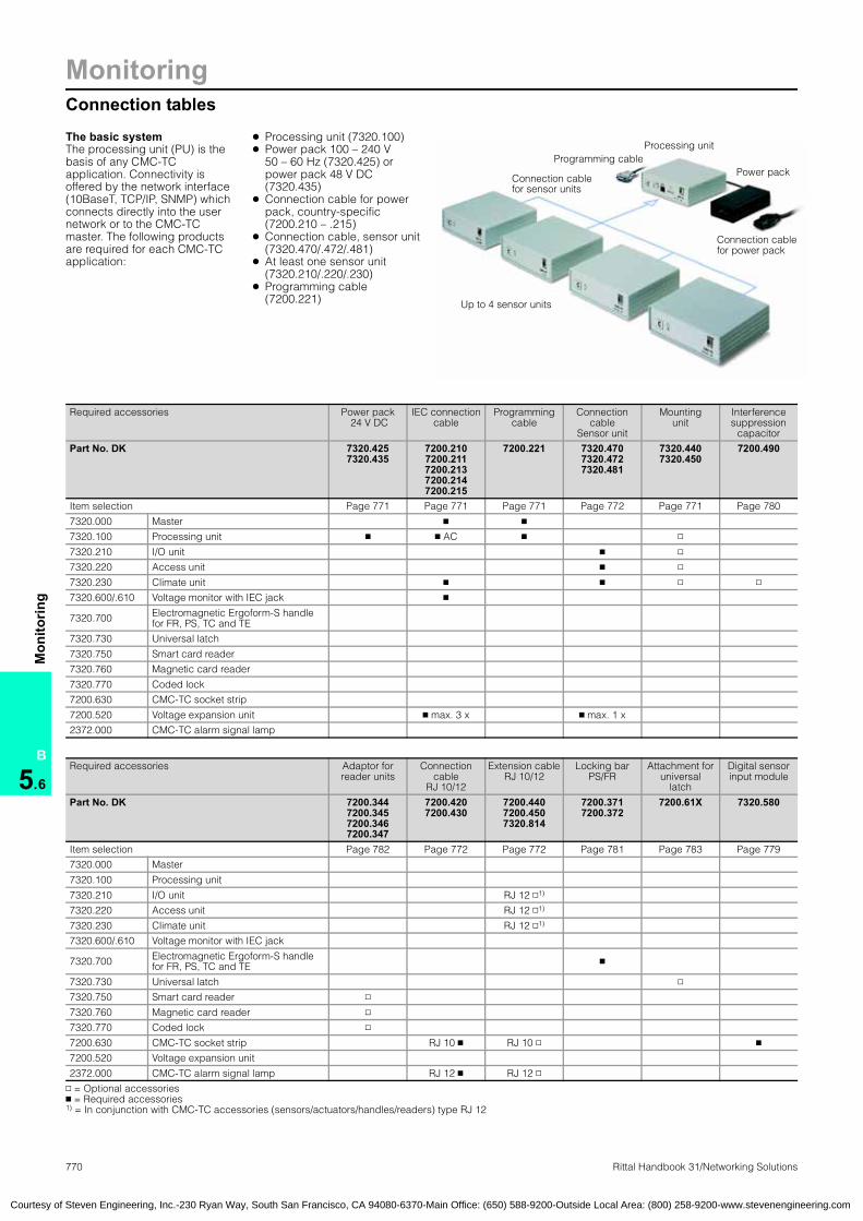
770 Rittal Handbook 31/Networking Solutions
MonitoringConnection tables
B
5.6
Mon
itorin
g
Programming cableProcessing unit
Power pack
Connection cablefor power pack
Connection cable for sensor units
Up to 4 sensor units
The basic systemThe processing unit (PU) is the basis of any CMC-TC application. Connectivity is offered by the network interface (10BaseT, TCP/IP, SNMP) which connects directly into the user network or to the CMC-TC master. The following products are required for each CMC-TC application:
Connection tables
● Processing unit (7320.100)● Power pack 100 – 240 V
50 – 60 Hz (7320.425) or power pack 48 V DC (7320.435)
● Connection cable for power pack, country-specific (7200.210 – .215)
● Connection cable, sensor unit (7320.470/.472/.481)
● At least one sensor unit (7320.210/.220/.230)
● Programming cable (7200.221)
Required accessories Power pack 24 V DC
IEC connection cable
Programming cable
Connection cable
Sensor unit
Mounting unit
Interference suppression
capacitor
Part No. DK 7320.425 7320.435
7200.210 7200.211 7200.213 7200.214 7200.215
7200.221 7320.470 7320.472 7320.481
7320.440 7320.450
7200.490
Item selection Page 771 Page 771 Page 771 Page 772 Page 771 Page 780
7320.000 Master � �
7320.100 Processing unit � � AC � ▫
7320.210 I/O unit � ▫
7320.220 Access unit � ▫
7320.230 Climate unit � � ▫ ▫
7320.600/.610 Voltage monitor with IEC jack �
7320.700 Electromagnetic Ergoform-S handle for FR, PS, TC and TE
7320.730 Universal latch
7320.750 Smart card reader
7320.760 Magnetic card reader
7320.770 Coded lock
7200.630 CMC-TC socket strip
7200.520 Voltage expansion unit � max. 3 x � max. 1 x
2372.000 CMC-TC alarm signal lamp
Required accessories Adaptor for reader units
Connection cable
RJ 10/12
Extension cable RJ 10/12
Locking bar PS/FR
Attachment for universal
latch
Digital sensor input module
Part No. DK 7200.344 7200.345 7200.346 7200.347
7200.420 7200.430
7200.440 7200.450 7320.814
7200.371 7200.372
7200.61X 7320.580
Item selection Page 782 Page 772 Page 772 Page 781 Page 783 Page 779
7320.000 Master
7320.100 Processing unit
7320.210 I/O unit RJ 12 ▫1)
7320.220 Access unit RJ 12 ▫1)
7320.230 Climate unit RJ 12 ▫1)
7320.600/.610 Voltage monitor with IEC jack
7320.700 Electromagnetic Ergoform-S handle for FR, PS, TC and TE �
7320.730 Universal latch ▫
7320.750 Smart card reader ▫
7320.760 Magnetic card reader ▫
7320.770 Coded lock ▫
7200.630 CMC-TC socket strip RJ 10 � RJ 10 ▫ �
7200.520 Voltage expansion unit
2372.000 CMC-TC alarm signal lamp RJ 12 � RJ 12 ▫
▫ = Optional accessories � = Required accessories 1) = In conjunction with CMC-TC accessories (sensors/actuators/handles/readers) type RJ 12
Courtesy of Steven Engineering, Inc.-230 Ryan Way, South San Francisco, CA 94080-6370-Main Office: (650) 588-9200-Outside Local Area: (800) 258-9200-www.stevenengineering.com

MonitoringCables/mounting accessories
771Rittal Handbook 31/Networking Solutions
B
5.6
Mon
itorin
g
Connection cable/extensionThe cable is used to connect to:● CMC-TC master● 24 V power pack for PU● Active fan unit for TE● Climate unit (connected fan)● Voltage monitor● Voltage expansion unit
Technical specifications:PVC cable, 3-pole, with IEC connector (non-heating appliances) with contact protection CEE22.
Configuration:1 connection cable
Connection cable:Extension
Country version Voltage Part No.
DKD/F/B 230 7200.210GB 230 7200.211CH 230 7200.213
USA/CDN 115 7200.214IEC 320 extension 230/115 7200.215
Power pack for PU, FCS, FASA 24 V DC power pack is required to supply the processing unit with power. There are two versions available:● The 100 – 240 VAC power pack requires an IEC
connection cable to supply the voltage● An alternative power pack is designed for the
telecommunications sector (48 V battery voltages) and is hardwired at the input end via a terminal block
Both power packs include an output cable, 1.65 m (65.0″) long.
Technical specifications 7320.425:Voltage: 100 – 240 VAC, 50/60 HzRated current: maximum 1.5 A Secondary range: 24 V DC, 3 A
Technical specifications 7320.435:Voltage: 20 – 72 V DC Rated current: maximum 2.5 A Secondary range: 24 V DC, 1.3 A
Additional parts needed:
Connection cable for DK 7320.425 power pack, see page 771.
Power pack:for PU, FCS, FAS
Primary input voltage Output voltage Part No.
DK100 – 240 VAC/
50/60 Hz 24 V DC 7320.425
48 V DC 24 V DC 7320.435
Programming cableThe interface cable is used to configure the network parameters in the processing unit and the master unit. The RJ 10 connector is connected to the front jack of the PU/master, whilst the 9-pole SUB-D connector is connected to a serial PC interface.
Programming cable
PU Part No. DK1 7200.221
Mounting unit 1UThe mounting unit can accommodate up to 3 sensor units or processing units in the 482.6 mm (19″) attachment level. Cable clamp straps 7610.000 or 7611.000 can be used for cable clamping.
Material:Sheet steel, painted
Color:RAL 7035 (light gray)
Accessories:Cable clamp strap, see page 985.
Mounting unit 1U
PU Part No. DK1 7320.440
Courtesy of Steven Engineering, Inc.-230 Ryan Way, South San Francisco, CA 94080-6370-Main Office: (650) 588-9200-Outside Local Area: (800) 258-9200-www.stevenengineering.com
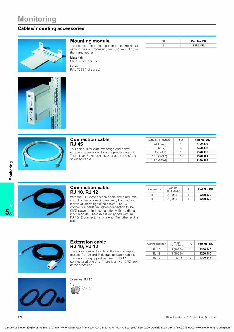
772 Rittal Handbook 31/Networking Solutions
MonitoringCables/mounting accessories
B
5.6
Mon
itorin
g
Mounting moduleThe mounting module accommodates individual sensor units or processing units, for mounting on the frame section.
Material:Sheet steel, painted
Color:RAL 7035 (light gray)
Mounting module
PU Part No. DK1 7320.450
Connection cable RJ 45This cable is for data exchange and power supply to a sensor unit via the processing unit. There is an RJ 45 connector at each end of the shielded cable.
Connection cable:RJ 45
Length m (inches) PU Part No. DK0.5 (19.7) 4 7320.4702.0 (78.7) 4 7320.4725.0 (196.9) 1 7320.47510.0 (393.7) 1 7320.48115.0 (590.6) 1 7320.485
Connection cableRJ 10, RJ 12With the RJ 12 connection cable, the alarm relay output of the processing unit may be used for individual alarm lights/indicators. The RJ 10 connection cable facilitates connection to the CMC power strip in conjunction with the digital input module. The cable is equipped with an RJ 10/12 connector at one end. The other end is open.
Connection cable:RJ 10, RJ 12
Connector Lengthm (inches) PU Part No. DK
RJ 10 5 (196.9) 4 7200.420RJ 12 5 (196.9) 4 7200.430
Extension cableRJ 10, RJ 12The cable is used to extend the sensor supply cables (RJ 12) and individual actuator cables. The cable is equipped with an RJ 10/12 connector at one end. There is an RJ 10/12 jack at the other end. Extension cable RJ 11, RJ 12
61
Example: RJ 12
Connector/jack Lengthm (inches) PU Part No. DK
RJ 10 5 (196.9) 4 7200.440RJ 12 5 (196.9) 4 7200.450RJ 12 1 (39.4) 2 7320.814
Courtesy of Steven Engineering, Inc.-230 Ryan Way, South San Francisco, CA 94080-6370-Main Office: (650) 588-9200-Outside Local Area: (800) 258-9200-www.stevenengineering.com
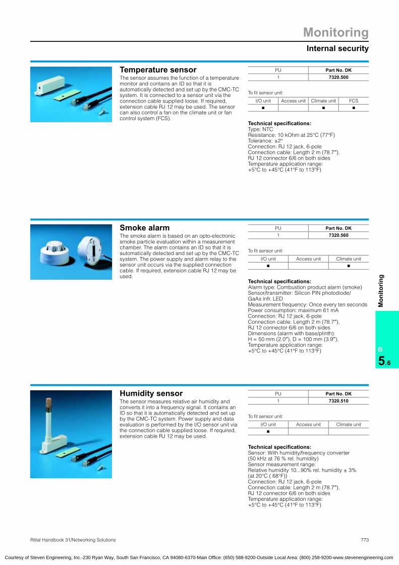
MonitoringInternal security
773Rittal Handbook 31/Networking Solutions
B
5.6
Mon
itorin
g
Temperature sensorThe sensor assumes the function of a temperature monitor and contains an ID so that it is automatically detected and set up by the CMC-TC system. It is connected to a sensor unit via the connection cable supplied loose. If required, extension cable RJ 12 may be used. The sensor can also control a fan on the climate unit or fan control system (FCS).
To fit sensor unit:
Technical specifications:Type: NTC Resistance: 10 kOhm at 25°C (77°F)Tolerance: ±2°Connection: RJ 12 jack, 6-pole Connection cable: Length 2 m (78.7″),RJ 12 connector 6/6 on both sidesTemperature application range: +5°C to +45°C (41°F to 113°F)
Temperature sensorSensor:for temperature
PU Part No. DK1 7320.500
I/O unit Access unit Climate unit FCS
� � �
Smoke alarmThe smoke alarm is based on an opto-electronic smoke particle evaluation within a measurement chamber. The alarm contains an ID so that it is automatically detected and set up by the CMC-TC system. The power supply and alarm relay to the sensor unit occurs via the supplied connection cable. If required, extension cable RJ 12 may be used.
To fit sensor unit:
Technical specifications:Alarm type: Combustion product alarm (smoke) Sensor/transmitter: Silicon PIN photodiode/ GaAs infr. LED Measurement frequency: Once every ten seconds Power consumption: maximum 61 mAConnection: RJ 12 jack, 6-pole Connection cable: Length 2 m (78.7″),RJ 12 connector 6/6 on both sidesDimensions (alarm with base/plinth): H = 50 mm (2.0″), D = 100 mm (3.9″), Temperature application range:+5°C to +45°C (41°F to 113°F)
Smoke alarmSensor:for smoke
PU Part No. DK1 7320.560
I/O unit Access unit Climate unit
� �
Humidity sensorThe sensor measures relative air humidity and converts it into a frequency signal. It contains an ID so that it is automatically detected and set up by the CMC-TC system. Power supply and data evaluation is performed by the I/O sensor unit via the connection cable supplied loose. If required, extension cable RJ 12 may be used.
To fit sensor unit:
Technical specifications:Sensor: With humidity/frequency converter(50 kHz at 76 % rel. humidity) Sensor measurement range: Relative humidity 10...90% rel. humidity ± 3% (at 20°C ( 68°F)) Connection: RJ 12 jack, 6-pole Connection cable: Length 2 m (78.7″),RJ 12 connector 6/6 on both sidesTemperature application range: +5°C to +45°C (41°F to 113°F)
Humidity sensorSensor:for humidity
PU Part No. DK1 7320.510
I/O unit Access unit Climate unit
�
Courtesy of Steven Engineering, Inc.-230 Ryan Way, South San Francisco, CA 94080-6370-Main Office: (650) 588-9200-Outside Local Area: (800) 258-9200-www.stevenengineering.com

774 Rittal Handbook 31/Networking Solutions
MonitoringInternal security
B
5.6
Mon
itorin
g
Airflow monitorThe airflow monitor determines whether the fan is achieving its full operating capacity. Storage damage, dirty filter mats or jammed fan blades are promptly detected and reported by the sensor. The sensor contains an ID so that it is automatically detected and set up by the CMC-TC system. Its switch point is adjustable. The power supply and data exchange to the sensor unit occurs via the attached connection cable. If required, extension cable RJ 12 may be used.
Technical specifications:Connection: RJ 12 jack, 6-pole on the cableConnection cable: Length 2 m (78.7″)Temperature application range:+5°C to +45°C (41°F to 113°F)
To fit sensor unit:
Note:The sensor can be operated with temperature-controlled fan via the climate unit sensor unit.
Accessories:Connection cable RJ 12, see page 772.
Airflow monitorSensor:for airflow
PU Part No. DK1 7320.550
I/O unit Access unit Climate unit
� �
Voltage monitorThe voltage monitor picks up a mains voltage to be monitored via the mains cable, and reports its status to a sensor unit: Voltage ON or voltage OFF. The monitor contains an ID so that it is automatically detected and set up by the CMC-TC system. The connection cable, supplied loose, should be used for connection to the sensor unit. If required, extension cable RJ 12 may be used.
Voltage monitorSensor:for voltage
To fit sensor unit:
Technical specifications:Monitored voltage: 230 VAC 50/60 HzConnections: IEC connector, RJ 12 jack, 6-poleConnection cable: Length 2 m (78.7″),RJ 12 connector 6/6 on both sidesTemperature application range: +5°C to +45°C (41°F to 113°F)
Protection ratings:IP 40
Additional parts needed:
For selection aid, see page 770.
PU Part No. DK1 7320.600
I/O unit Access unit Climate unit
� �
Voltage monitorwith IEC switch output This sensor is used in conjunction with the CMC-TC to monitor voltage limits. The limits may be set via the WEB interface or SNMP. As an additional option, this voltage may also be switched on and off via the module, in order to reboot connected equipment via Ethernet. It is connected via standard, commercially available IEC320 connectors as the input signal, and an IEC320 socket to connect the equipment.
Technical specifications: ● Plug & play installation via IEC320 connector● The switching operation may be initiated in a
time or event-based manner or via SNMP or WEB
● The maximum and minimum limits of voltage measurement are freely selectable
● Measurement range 100 – 250 VAC, 50/60 Hz● Maximum switching load 250 VAC and 8 A
at cosphi = 1● Tolerance: ±5% at 20 – 30°C (68 – 86°F)
Note:The system has two functions. Each function occupies one input of the I/O unit. 1st function: Voltage measurement2nd function: Relay switching
To fit sensor unit:
Additional parts needed:
For selection aid, see page 770.
Available options:IEC connection cable 7200.210, German version.IEC extension cable 7200.215 for connecting the equipment.
Voltage monitor
PU Part No. DK1 7320.610
I/O unit Access unit Climate unit
�
Courtesy of Steven Engineering, Inc.-230 Ryan Way, South San Francisco, CA 94080-6370-Main Office: (650) 588-9200-Outside Local Area: (800) 258-9200-www.stevenengineering.com
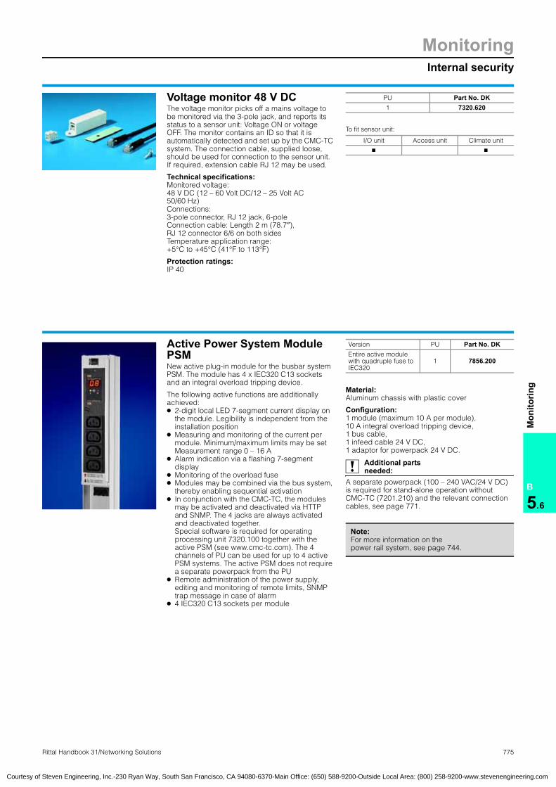
MonitoringInternal security
775Rittal Handbook 31/Networking Solutions
B
5.6
Mon
itorin
g
Voltage monitor 48 V DCThe voltage monitor picks off a mains voltage to be monitored via the 3-pole jack, and reports its status to a sensor unit: Voltage ON or voltage OFF. The monitor contains an ID so that it is automatically detected and set up by the CMC-TC system. The connection cable, supplied loose, should be used for connection to the sensor unit. If required, extension cable RJ 12 may be used.
Technical specifications:Monitored voltage: 48 V DC (12 – 60 Volt DC/12 – 25 Volt AC 50/60 Hz)Connections: 3-pole connector, RJ 12 jack, 6-poleConnection cable: Length 2 m (78.7″),RJ 12 connector 6/6 on both sidesTemperature application range: +5°C to +45°C (41°F to 113°F)
Protection ratings:IP 40
To fit sensor unit:
Voltage monitor
PU Part No. DK1 7320.620
I/O unit Access unit Climate unit
� �
Active Power System Module PSMNew active plug-in module for the busbar system PSM. The module has 4 x IEC320 C13 sockets and an integral overload tripping device.
The following active functions are additionally achieved:● 2-digit local LED 7-segment current display on
the module. Legibility is independent from the installation position
● Measuring and monitoring of the current per module. Minimum/maximum limits may be set Measurement range 0 – 16 A
● Alarm indication via a flashing 7-segment display
● Monitoring of the overload fuse● Modules may be combined via the bus system,
thereby enabling sequential activation● In conjunction with the CMC-TC, the modules
may be activated and deactivated via HTTP and SNMP. The 4 jacks are always activated and deactivated together. Special software is required for operating processing unit 7320.100 together with the active PSM (see www.cmc-tc.com). The 4 channels of PU can be used for up to 4 active PSM systems. The active PSM does not require a separate powerpack from the PU
● Remote administration of the power supply, editing and monitoring of remote limits, SNMP trap message in case of alarm
● 4 IEC320 C13 sockets per module
Material:Aluminum chassis with plastic cover
Configuration:1 module (maximum 10 A per module),10 A integral overload tripping device,1 bus cable,1 infeed cable 24 V DC,1 adaptor for powerpack 24 V DC.
Additional parts needed:
A separate powerpack (100 – 240 VAC/24 V DC) is required for stand-alone operation without CMC-TC (7201.210) and the relevant connection cables, see page 771.
Active Power System Module PSMPower System Module PSM, active
Version PU Part No. DKEntire active module with quadruple fuse to IEC320
1 7856.200
Note:For more information on the power rail system, see page 744.
Courtesy of Steven Engineering, Inc.-230 Ryan Way, South San Francisco, CA 94080-6370-Main Office: (650) 588-9200-Outside Local Area: (800) 258-9200-www.stevenengineering.com
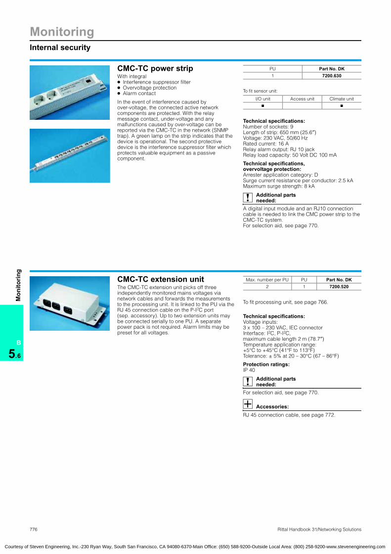
776 Rittal Handbook 31/Networking Solutions
MonitoringInternal security
B
5.6
Mon
itorin
g
CMC-TC power stripWith integral● Interference suppressor filter● Overvoltage protection● Alarm contact
In the event of interference caused by over-voltage, the connected active network components are protected. With the relay message contact, under-voltage and any malfunctions caused by over-voltage can be reported via the CMC-TC in the network (SNMP trap). A green lamp on the strip indicates that the device is operational. The second protective device is the interference suppressor filter which protects valuable equipment as a passive component.
CMC-TC:Power stripPower strips:CMC
To fit sensor unit:
Technical specifications:Number of sockets: 9Length of strip: 650 mm (25.6″)Voltage: 230 VAC, 50/60 HzRated current: 16 ARelay alarm output: RJ 10 jackRelay load capacity: 50 Volt DC 100 mA
Technical specifications, overvoltage protection: Arrester application category: DSurge current resistance per conductor: 2.5 kAMaximum surge strength: 8 kA
Additional parts needed:
A digital input module and an RJ10 connection cable is needed to link the CMC power strip to the CMC-TC system. For selection aid, see page 770.
PU Part No. DK1 7200.630
I/O unit Access unit Climate unit
� �
CMC-TC extension unitThe CMC-TC extension unit picks off three independently monitored mains voltages via network cables and forwards the measurements to the processing unit. It is linked to the PU via the RJ 45 connection cable on the P-I2C port (sep. accessory). Up to two extension units may be connected serially to one PU. A separate power pack is not required. Alarm limits may be preset for all voltages.
To fit processing unit, see page 766.
Technical specifications:Voltage inputs: 3 x 100 – 230 VAC, IEC connectorInterface: I2C, P-I2C, maximum cable length 2 m (78.7″)Temperature application range: +5°C to +45°C (41°F to 113°F)Tolerance: ± 5% at 20 – 30°C (67 – 86°F)
Protection ratings:IP 40
Additional parts needed:
For selection aid, see page 770.
Accessories:RJ 45 connection cable, see page 772.
CMC-TC:Extension unitExtension unit, CMC-TC
Max. number per PU PU Part No. DK2 1 7200.520
Courtesy of Steven Engineering, Inc.-230 Ryan Way, South San Francisco, CA 94080-6370-Main Office: (650) 588-9200-Outside Local Area: (800) 258-9200-www.stevenengineering.com

MonitoringExternal security
777Rittal Handbook 31/Networking Solutions
B
5.6
Mon
itorin
g
Vandalism sensorThe sensor contains a position-insensitive alarm contact and an ID so that it is automatically detected and set up by the CMC-TC system. It is connected to the I/O sensor unit by the connection cable supplied loose. If required, extension cable RJ 12 may be used. The sensitivity of the sensor may be set using the PU software.
To fit sensor unit:
Technical specifications:Mercury-free contact, position-insensitiveConnection: RJ 12 jack, 6-pole Connection cable: Length 2 m (78.7″),RJ 12 connector 6/6 on both sides
Vandalism sensorSensor:for vandalism
PU Part No. DK1 7320.540
I/O unit Access unit Climate unit
�
Access sensorThe access sensors monitor doors, sidewalls or windows in the enclosure. The magnet is secured to the moving parts (for example the sidewall), while the dry reed contact is fastened to the stationary parts (enclosure frame). The permanent magnet holds the dry reed contact in a closed position. When the door is opened or the sidewall removed, the dry reed contact drops off and opens the circuit. This triggers an alarm in the CMC-TC. The sensor contains an ID so that it is automatically detected and set up by the CMC-TC system. It is connected to a sensor unit via the connection cable supplied loose. Up to five access sensors may be connected in series to one monitoring line, if necessary with an extension cable RJ 12. A jumper plug is inserted at the end.
To fit sensor unit:
Technical specifications:2 magnets (mounted on the moving part, directly adjacent to)2 sensors with dry reed contact(mounting on the enclosure frame)Connection 1: RJ 12 jack, 6-pole (connection to the sensor unit)Connection 2: RJ 12 socket, 6-pole (series connection with other access sensors, or finished with the jumper plug)2 jumper plugs RJ 12 at the end2 connection cables: Length 2 m (78.7″),RJ 12 connector 6/6 on both sides
Access sensorSensor:for access
PU Part No. DK2 7320.530
I/O unit Access unit Climate unit
� � �
Courtesy of Steven Engineering, Inc.-230 Ryan Way, South San Francisco, CA 94080-6370-Main Office: (650) 588-9200-Outside Local Area: (800) 258-9200-www.stevenengineering.com

778 Rittal Handbook 31/Networking Solutions
MonitoringExternal security
B
5.6
Mon
itorin
g
Water leak sensorThe leakage sensor is equipped with an optical sensor head. If this sensor head becomes wet with moisture, it reports a leakage alarm. The sensor head may be mounted facing the floor. If water collects there and comes into contact with the sensor head, the alarm is triggered. The sensor contains an ID so that it is automatically detected and set up by the CMC-TC system. The connection cable, supplied loose, should be used for connection to the sensor unit. If required, extension cable RJ 12 may be used.
To fit sensor unit:
Technical specifications:Monitoring: VisualConnection: RJ 12 jack, 6-pole Connection cable: Length 2 m (78.7″),RJ 12 connector 6/6 on both sidesTemperature application range: +5°C to +45°C (41°F to 113°F)
Protection ratings:IP 40
Leakage sensorSensor:for leakage
PU Part No. DK1 7320.630
I/O unit Access unit Climate unit
�
CMC-TC motion detectorThe motion detector may be used in enclosures or in rooms. Any modifications to the enclosure, such as opening a door or sidewall, are indicated. The motion detector can also detect persons in the room or in front of the data cabinet. The alarm contains an ID so that it is automatically detected and set up by the CMC-TC system. The power supply and data exchange to the sensor unit occurs via the connection cable, supplied loose. If required, extension cable RJ 12 may be used.
To fit sensor unit:
Technical specifications:Alarm type: Infrared (IR) detectorRange: max. 7 m (23 ft)Power consumption: max. 30 mA/24 V DCConnection: RJ 12 jack, 6-pole Connection cable: Length 2 m (78.7″),RJ 12 connector 6/6 on both sidesDimensions: H x W x D: 102 x 59 x 32 mm (4.0 x 2.3 x 1.3″)CMC-TC:Motion detectorMotion detector, CMC-TCInfrared motion detector
PU Part No. DK1 7320.570
I/O unit Access unit Climate unit
� �
Courtesy of Steven Engineering, Inc.-230 Ryan Way, South San Francisco, CA 94080-6370-Main Office: (650) 588-9200-Outside Local Area: (800) 258-9200-www.stevenengineering.com
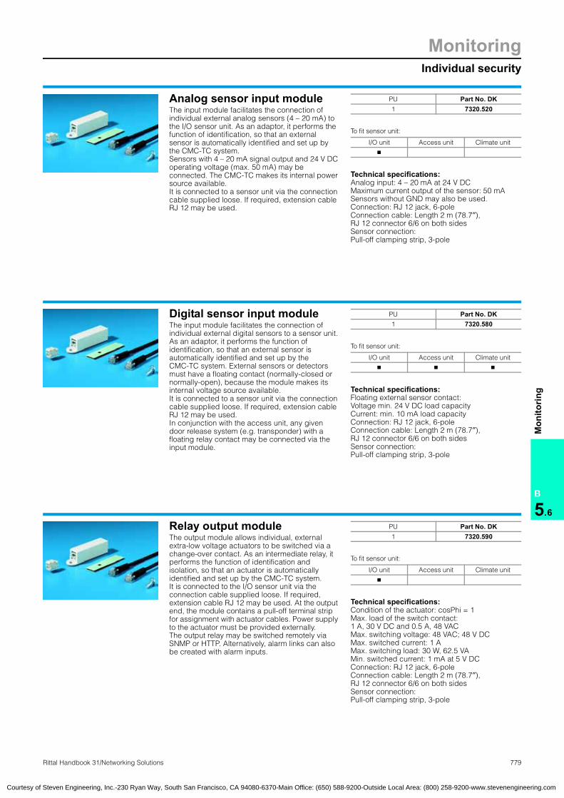
MonitoringIndividual security
779Rittal Handbook 31/Networking Solutions
B
5.6
Mon
itorin
g
Analog sensor input moduleThe input module facilitates the connection of individual external analog sensors (4 – 20 mA) to the I/O sensor unit. As an adaptor, it performs the function of identification, so that an external sensor is automatically identified and set up by the CMC-TC system. Sensors with 4 – 20 mA signal output and 24 V DC operating voltage (max. 50 mA) may be connected. The CMC-TC makes its internal power source available. It is connected to a sensor unit via the connection cable supplied loose. If required, extension cable RJ 12 may be used.
To fit sensor unit:
Technical specifications:Analog input: 4 – 20 mA at 24 V DC Maximum current output of the sensor: 50 mASensors without GND may also be used. Connection: RJ 12 jack, 6-pole Connection cable: Length 2 m (78.7″),RJ 12 connector 6/6 on both sidesSensor connection: Pull-off clamping strip, 3-pole
Analog sensor input moduleInput module:for analog sensor
PU Part No. DK1 7320.520
I/O unit Access unit Climate unit
�
Digital sensor input moduleThe input module facilitates the connection of individual external digital sensors to a sensor unit. As an adaptor, it performs the function of identification, so that an external sensor is automatically identified and set up by the CMC-TC system. External sensors or detectors must have a floating contact (normally-closed or normally-open), because the module makes its internal voltage source available. It is connected to a sensor unit via the connection cable supplied loose. If required, extension cable RJ 12 may be used. In conjunction with the access unit, any given door release system (e.g. transponder) with a floating relay contact may be connected via the input module.
To fit sensor unit:
Technical specifications:Floating external sensor contact: Voltage min. 24 V DC load capacityCurrent: min. 10 mA load capacityConnection: RJ 12 jack, 6-pole Connection cable: Length 2 m (78.7″),RJ 12 connector 6/6 on both sidesSensor connection: Pull-off clamping strip, 3-pole
Digital sensor input moduleInput module:for digital sensor
PU Part No. DK1 7320.580
I/O unit Access unit Climate unit
� � �
Relay output moduleThe output module allows individual, external extra-low voltage actuators to be switched via a change-over contact. As an intermediate relay, it performs the function of identification and isolation, so that an actuator is automatically identified and set up by the CMC-TC system. It is connected to the I/O sensor unit via the connection cable supplied loose. If required, extension cable RJ 12 may be used. At the output end, the module contains a pull-off terminal strip for assignment with actuator cables. Power supply to the actuator must be provided externally. The output relay may be switched remotely via SNMP or HTTP. Alternatively, alarm links can also be created with alarm inputs.
To fit sensor unit:
Technical specifications:Condition of the actuator: cosPhi = 1Max. load of the switch contact: 1 A, 30 V DC and 0.5 A, 48 VACMax. switching voltage: 48 VAC; 48 V DCMax. switched current: 1 AMax. switching load: 30 W, 62.5 VAMin. switched current: 1 mA at 5 V DCConnection: RJ 12 jack, 6-pole Connection cable: Length 2 m (78.7″),RJ 12 connector 6/6 on both sidesSensor connection: Pull-off clamping strip, 3-pole
Relay output module
PU Part No. DK1 7320.590
I/O unit Access unit Climate unit
�
Courtesy of Steven Engineering, Inc.-230 Ryan Way, South San Francisco, CA 94080-6370-Main Office: (650) 588-9200-Outside Local Area: (800) 258-9200-www.stevenengineering.com

780 Rittal Handbook 31/Networking Solutions
MonitoringIndividual security
B
5.6
Mon
itorin
g
Room door output moduleThe room door output module allows external door opener systems to be switched via a change-over contact. As an intermediate relay, it performs the function of identification and isolation, so that a door opener is automatically identified and set up by the CMC-TC system. It is connected to the access unit via the connection cable supplied loose. If required, extension cable RJ 12 may be used. At the output end, the module contains a pull-off terminal strip for assignment with actuator cables. Power supply to the door opener must be provided externally.
To fit sensor unit:
Technical specifications:Condition of the actuator: cosPhi = 1Maximum load of the switch contact: 1 A, 30 V DC and 0.5 A, 48 VACMaximum switching voltage: 48 VAC; 48 V DCMaximum switched current: 1 AMaximum switching load: 30 W; 62.5 VAMinimum switched current: 1 mA at 5 V DCConnection: RJ 12 jack, 6-pole Connection cable: Length 2 m (78.7″),RJ 12 connector 6/6 on both sidesSensor connection: Pull-off clamping strip, 3-pole
Note:One access sensor 7320.530 is always needed for each output module.
Room door output moduleOutput module for room door
PU Part No. DK1 7320.740
I/O unit Access unit Climate unit
�
CMC-TC alarm signal lampThe alarm signal lamp serves as a collective fault signal for all alarms in the CMC-TC. Example: Temperature exceeded, fan defect, smoke alarm etc. The CMC-TC provides a user-friendly menu allowing the operator to select which message will affect the CMC-TC alarm relay. The alarm signal lamp is activated with the alarm relay. The lamp may be attached to the network enclosure or any other desired position, for example in the corridor. The RJ 12 connection cable is required for connection to the PU.
To fit processing unit, see page 766.
Technical specifications:Rated operating voltage: 24 V DCRated current: 60 mA
Additional parts needed:
For selection aid, see page 770.
CMC-TC:Alarm signal lampAlarm signal lamp, CMC-TC
Item Part No. SZLED steady light component
24 V DC, red 2372.000
Connection component 2368.010
Interference suppression capacitorsFor fansThe capacitors are used for the interference suppression of fans with self-starting shaded pole motors. One capacitor should be connected directly parallel to the mains voltage for each fan unit. The capacitors are equipped with a terminal, allowing it to be easily fitted to the fan cable.
Technical specifications:Dielectric strength: 275 VACCapacity: 100 nFType: X2
Interference suppression capacitors for fans
Version PU Part No. DK100 nF 20 7200.490
Courtesy of Steven Engineering, Inc.-230 Ryan Way, South San Francisco, CA 94080-6370-Main Office: (650) 588-9200-Outside Local Area: (800) 258-9200-www.stevenengineering.com

MonitoringAccess systems
781Rittal Handbook 31/Networking Solutions
B
5.6
Mon
itorin
g
Comfort handle for TS8 unitwith master key functionThe handle assumes the function of a door lock and lever handle monitoring. The TS8 handle 7320.721 includes the master key function. This means that the handle can always be opened with the master key, independently of the control system. A semi-cylinder is supplied loose, but a semi-cylinder 40 or 45 mm (1.6 or 2.0″) overall length to DIN 18 254 may also be used. An access sensor (DK 7320.530) must be connected to the corresponding door for each handle. If the lever handle is closed, the locking mechanism integrated into the handle latches automatically. The handle may be released via the CMC-TC system in the network or via optional add-on systems, such as smartcard readers etc. The handle is locked in the unstressed mode (without electrical connection). The push-button may be depressed following electrical release and then opens the lever automatically. The opening process must be completed within 15 seconds. Opening by key will always override, which means the enclosure may always be opened with a key even when locked electronically and in the event of a power failure (emergency opening).
To fit sensor unit:
Technical specifications:Rated voltage: 24 V DCRated current: maximum 100 mAConnection cable: Length 3 m (118″), RJ 12 connectorConnection cable: Length 2 m (78.7″), RJ 12/RJ 12 connectorCoupling for extension: RJ 12/RJ 12 jackTemperature application range: +5°C to +40°C (41°F to 104°F)
Protection ratings:IP 40
Additional parts needed:
For selection aid, see page 770.
Comfort handle:with master key functionHandles:Comfort handle master key
Handle system Part No. DKTS8 comfort handle master key 7320.721
I/O unit Access unit Climate unit
�
Electromagnetic handle systemThe lock unit consists of a Rittal handle system whose handle is electromagnetically locked. It contains an identifier so that it is automatically detected and set up by the CMC-TC system. The power supply and data exchange to the access unit occurs via the attached connection cable. An access sensor (DK 7320.530) is always required for door monitoring. With the door closed and the clip-down handle locked home, latching is activated by switching on the lock magnet. The CMC-TC enables the handle to be pulled out by deactivating the lock magnet, thereby allowing the door to be opened. This deactivation can be initiated via an access unit such as a smartcard reader, magnetic card reader, coded lock and/or network management systems. The handle system also contains handle monitoring. The CMC-TC reports an alarm if the handle is not swung in and latched after closing the door. The push-button insert supplied can also be exchanged for lock inserts.Note:When using the Ergoform-S handle, an additional hole is required.
Additional hole for electronic lock (PS/FR/QR/VR/TC/TE)
To fit sensor unit:
Note:For PS and FR viewing doors, the locking bars listed below are required:
Locking bars
Technical specifications:Rated voltage: 24 V DCRated current: maximum 100 mAConnection cable: Length 3 m (118″), RJ 12 connectorConnection cable: Length 2 m (78.7″), RJ 12/RJ 12 connectorCoupling for extension: RJ 12/RJ 12 jackTemperature application range: +5°C to +40°C (41°F to 104°F)
Protection ratings:IP 40
Additional parts needed:
For selection aid, see page 770.
Handle systems:with electromagnetic lock
4242
79.2
+ 0
.1
5050
87
8
18 ± 0.1
6
1
1
Handle system Part No. DKErgoform-S handle for FR, PS, TC, VR, TE 7320.700
Ergoform-S handle for QR 7320.710
I/O unit Access unit Climate unit
�
Version Part No. DKLower door locking bar for 2000 mm (78.7″) high PS enclosures 7200.371
Lower door locking bar for 2000 mm (78.7″) high FR enclosures 7200.372
Lower door locking bar for TE enclosures on request
Other sizes available on request.
Courtesy of Steven Engineering, Inc.-230 Ryan Way, South San Francisco, CA 94080-6370-Main Office: (650) 588-9200-Outside Local Area: (800) 258-9200-www.stevenengineering.com

782 Rittal Handbook 31/Networking Solutions
MonitoringAccess systems
B
5.6
Mon
itorin
g
Smartcard reader/ magnetic card reader/coded lockThe door handle is released to authorized persons who have identified themselves with a smartcard/magnetic card/combination code. Smartcard readers/magnetic readers/coded locks are installed above the enclosure handle and can also function as a central unit for releasing several doors. The entire access procedure can also be registered with the CMC-TC where there is network connection.
Technical specifications:Rated voltage: 24 V DCRated current: maximum 20 mAMagnetic card type: Magnetic strip card with data on track 2. The read system is designed for cards with both a high and a low level of magnetism.
Smartcard readerMagnetic card readerCoded lock
To fit sensor unit:
Note:Smartcard readers/magnetic card readers/coded locks may only be used in conjunction with the CMC-TC and an electric lock. 3 cards are supplied with the smartcard reader/magnetic card reader. Each card contains a four-digit code, which is different on all three cards. All cards are access-authorized. The code may be input directly on the coded lock. Authorized codes may be set in the CMC-TC via WEB. The input code is transmitted to the CMC-TC and, where applicable, to the network management system, via the I2C bus. A mounting adaptor for a TS aluminum viewing door is supplied loose with every reader.
25
190
50
120
166
83
8.5
4
35
190
50
120
166
83
8.5
4
25
190
50
120
166
83
8.5
4
Read system Part No. DKSmart card reader 7320.750Magnetic card reader 7320.760Coded lock 7320.770
I/O unit Access unit Climate unit
�
Adaptor for reader unitsThe adaptors are used to install the reader units. They are screw-fastened between the design section of the door frame and the reader unit. No adaptor is required for shallow mounting levels. For TS aluminum viewing doors, an adaptor is supplied loose with every reader unit. One adaptor is required for each reader unit.
Adaptor:for reader unitsReader unit adaptor
Viewing doorenclosure type PU Part No. DK
VR 10 7200.344PC 10 7200.345PS 10 7200.346TS design 10 7200.347
Type PC: For PC viewing doorsType VR: For VR viewing doors and VR sheet steel doorsType PS: For PS aluminum viewing door
More lock systemsCan be found under system accessories, starting on page 881.
Courtesy of Steven Engineering, Inc.-230 Ryan Way, South San Francisco, CA 94080-6370-Main Office: (650) 588-9200-Outside Local Area: (800) 258-9200-www.stevenengineering.com
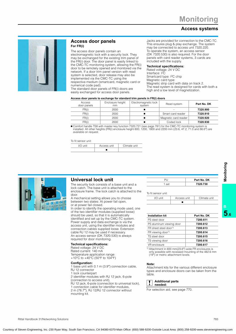
MonitoringAccess systems
783Rittal Handbook 31/Networking Solutions
B
5.6
Mon
itorin
g
Access door panelsFor FR(i)The access door panels contain an electromagnetic lock with a security lock. They may be exchanged for the existing trim panel of the FR(i) door. The door panel is easily linked to the CMC-TC monitoring system, allowing the FR(i) door to be remotely opened and monitored via the network. If a door trim panel version with read system is selected, door release may also be implemented via the CMC-TC using the respective medium (smartcard, magnetic card or numerical code pad). The standard door panels of FR(i) doors are easily exchanged for access door panels.
Jacks are provided for connection to the CMC-TC. This ensures plug & play exchange. The system may be connected to access unit 7320.220. To operate the system, an access sensor (DK 7320.530) is also required. For the door panels with card reader systems, 3 cards are included with the supply.
Technical specifications:Rated voltage: 24 V DCInterface: I2C Smartcard type: I2C chip Magnetic card type: Magnetic strip card with data on track 2. The read system is designed for cards with both a high and a low level of magnetization.
To fit sensor unit:
Access door panels for FR(i)
Access door panels to exchange for standard trim panels in FR(i) doors
Access door panels
Enclosure heightmm
Electromagnetic lock system Read system Part No. DK
FR(i) 2000 � – 7320.900FR(i) 2000 � Smart card reader 7320.910FR(i) 2000 � Magnetic card reader 7320.920FR(i) 2000 � Coded lock 7320.930
� Comfort handle TS8 with master key function 7320.721 (see page 781) for the CMC-TC monitoring system is installed. All other heights (FR(i) enclosure height 600, 1200, 1800 and 2200 mm (23.6, 47.2, 71.0 and 86.6″) are available on request.
I/O unit Access unit Climate unit
�
Universal lock unitThe security lock consists of a base unit and a lock catch. The base unit is attached to the enclosure frame. The lock catch is attached to the door. A mechanical setting allows you to choose between two states: At power fail open, or at power fail closed. In order to identify the operating mode used, one of the two identifier modules (supplied loose) should be used, so that it is automatically identified and set up by the CMC-TC system. Power supply and data exchange is via the access unit, using the identifier modules and connection cables supplied loose. Extension cable RJ 12 may be used if necessary. An access sensor (DK 7320.530) is always required for door monitoring.
Technical specifications:Rated voltage: 24 V DCRated current: 140 mATemperature application range: +10°C to +40°C (50°F to 104°F)
Configuration:1 base unit with 0.1 m (3.9″) connection cable, RJ 12 connector 1 lock counterpart2 identifier modules with RJ 12 jack, 6-pole (connection to access unit), RJ 12 jack, 6-pole (connection to universal lock), 1 connection cable for identifier modules, 2 m (78.7″), RJ 12/RJ 12 connector without mounting kit.
To fit sensor unit:
Note:Attachment kits for the various different enclosure types and enclosure doors can be taken from the table.
Additional parts needed:
For selection aid, see page 770.
Universal lock unit
PU Part No. DK 1 set 7320.730
I/O unit Access unit Climate unit
�
Installation kit Part No. DKPS steel door 7200.611PS aluminum viewing door 7200.612FR sheet steel door1) 7200.613FR viewing door1) 7200.614TS steel door 7200.615TS viewing door 7200.616VR enclosure 7200.617
1) Attachment in 600 mm(23.6″) wide FR enclosures is only possible with recessed mounting of the 482.6 mm (19″) or metric attachment levels.
Courtesy of Steven Engineering, Inc.-230 Ryan Way, South San Francisco, CA 94080-6370-Main Office: (650) 588-9200-Outside Local Area: (800) 258-9200-www.stevenengineering.com

784 Rittal Handbook 31/Networking Solutions
MonitoringAccess systems
B
5.6
Mon
itorin
g
Handle system for universal installation With electromagnetic lock for the CMC-TC monitoring systemThe universal handle is equipped with a hole pattern of mounting holes which will fit many existing door systems. This handle is ideal for retrofitting to projects with varying enclosure types and versions. The new handle may be connected to the CMC-TC system using plug & play. In addition, an access sensor (DK 7320.530) must always be used to enable polling of the door status. The handle is equipped with a connection cable and an RJ 12 connector, which may be plugged into the access unit 7320.220 of the CMC-TC system. The handle is equipped with a push-button insert which may be depressed when the electromagnetic lock is released.
Technical specifications:Rated voltage: 24 V DCRated current: maximum 100 mAConnection cable: Length 5 m (196.9″), RJ 12 connector
Handle systems:for universal installation
To fit sensor unit:
33.5
5050
239
36
50 +
0.2
5050
+ 0
.2
25 + 0.2
112
z
z
7
7
Note! The handle only fits into the cut-out shown in the drawing. For other hole patterns, additional adaptors are needed, and/or machining of the door. Solutions provided on request.
Type Part No. DKElectro-magnetic handle CMC-TC 7320.950
Extended delivery times.
I/O unit Access unit Climate unit
�
TS8 transponder handleWith integrated transponder release system from Simons & VossThe electromagnetic TS8 transponder handle may be retrofitted in the doors of TS8 enclosures. The handle is equipped with an integral radio transponder. The transponder receiver with battery is integrated into the handle housing. Apart from the transponder transmitter, no additional accessories, such as additional electronics, cables, power pack etc., are required. The handle is easily exchanged without the need for wiring. If battery servicing is required, this is indicated acoustically. The handle is supplied in the zero state, so that it may be opened with any transponder transmitter.
Use with hand-held transmitter: The transponder transmitter is actuated from the handle, as a result of which the latter is unlatched for a specified time window and may be opened by pressing the push-button.
Use with the CMC-TC transmitter: The transponder transmitter is linked to the CMC-TC system via the room door output 7320.740 and the access unit. The transmitter is placed in the enclosure frame, near the handle. In this way, the door may be released via the CMC-TC system. Additionally, an access sensor (DK 7320.530) should always be used to enable polling of the door status.
Use of the programmable transponder: The programmable transponder allows the individual transponder transmitters to be allocated to individual handles. Matrix programming is supported.
Benefits: ● No cables on the handle, because the
electronics and battery are integrated into the handle
● Several users may be set for one handle● Plug & play installation both mechanical and
electrical● Individual control of the transponders and the
set-up of each transponder is possible for up to 3 locking systems
● With additional overlay to automatically block the old transponder in the event of reprogramming
● Counterfeit-proof data communication is achieved via radio using crypto-codes
● The challenge response procedure ensures protection against surveillance
● The standard interface means that connections to other access and monitoring systems are not a problem
The lock and organization sytem is graded in the highest category with respect to unlocking protection to BSI 7500.
Systems with extra electronics and access control from Simons & Voss available on request.
Transponder handle TS8Handles:Transponder handleTS:Transponder handle
Type Part No. DK
Electromagnetic handle
Transponder, stand-alone application
7320.960
Transponder transmitter
Hand-held transmitter 7320.961
Transponder transmitter
CMC-TC transmitter 7320.962
Programmable transponder programming 7320.963
Extended delivery times.
Courtesy of Steven Engineering, Inc.-230 Ryan Way, South San Francisco, CA 94080-6370-Main Office: (650) 588-9200-Outside Local Area: (800) 258-9200-www.stevenengineering.com

MonitoringMonitoring of climate control units
785Rittal Handbook 31/Networking Solutions
B
5.6
Mon
itorin
g
Monitoring of climate control unitsBenefits: ● All data for the climate control units via the WEB
browser● Setpoints may be set via WEB, SNMP, Telnet,
RS232● Automatic alarm messages in the network via
SNMP● SMS text messages via GSM (optional)
The “Monitoring of climate control units” set provides all the modules required for monitoring Rittal TopTherm air conditioners with a comfort control. Temperatures, messages, alarms etc. may be displayed directly on the Web interface in the intranet or Internet. Trap alarms are sent automatically to assigned SNMP network management systems. SMS text messages are optionally possible via the Rittal GSM module.
Extensions/configuration:The processing unit PU has 4 channels for 4inter-face cards climate control unit RTT I/O unit. An RTT-I/O unit is supplied with the set. Three RTT-I/O may optionally be added. Each RTT-I/O unit is capable of monitoring one master TopTherm air conditioner, each with 9 slave climate control units. The set allows you to monitor up to 10 air conditioners, and with extensions up to a maximum of 40 air conditioners. The I/O unit and climate unit may also be connected instead of the interface card. This facilitates additional monitoring of smoke, humidity, air flow etc.
PLC X2 Optocoupler alarm Outputs for SPS
LAN LED Internal communication
COM LED Status of serial interfaces
RJ 45 for connecting to processing unit 7320.100
RS-485 Interface
RS-232 For set-up with a serial PC interface (for example Hyperterm)
Mounting fixture for 7320.440 or 7320.450
The ISDN unit has the option to be supplied with 24 V DC, 160 mA via this input. For applications with the processing unit, this is not necessary.
RES Reset key
MEM Eeprom fault
Changeover switch Serial interface
LAN Connection to the master air conditioner with comfort control
Functions/settings: ● Setpoint temperature for enclosure● Alarm temperature value for enclosure● Warning temperature value for enclosure● Filter mat monitoring
Warnings/alarms: ● Internal temperature too high● Icing● High-pressure sensor● Leakage● Condenser/fan defect● Evaporator coil/fan defect● Compressor defect● Sensor failure, internal temperature● Sensor failure, internal temperature● Sensor failure, icing sensor● Sensor failure, condensate level● Sensor failure, internal temperature● Phase missing or incorrect● EEPROM defect
Configuration:Processing unit PU with firmware/software for applications with climate control units,interface card, climate control unit RTT-I/O unit (SK 3124.200) power pack 24 V DC, input100 – 240 VAC (DK 7320.425), connection cable D with IEC320 connector (DK 7200.210), Cat5 connection cable, 2 m (78.7″),for connecting the RTT-I/O unit to the processing unit PU,data cable RS232, 2 m (78.7″), for connecting the RTT-I/O unit to the RTT climate control unit with comfort control.
Monitoring of climate control units
1 2 3 4 5 6 7
RTT I/O unit
PLC X2
G + -
RS-485LAN COM RS-232
1
2
3
4
5
6
7
8 9 10 1211
Power
1 2 3 424 V DCmax. 160 mA
RES MEMLAN
8
9
10
11
12
Monitoring of climate control unit Part No. DKSet 7320.120
Accessories:
Description Part No. DK Page
Programming cableProgramming cable for setting up the PU
7200.221 771
CMC-TC 1U mounting unit 7320.440 771
Interface card RTT-I/O unit (maximum of 3 additioanl cards) 3124.200 662
Connection cable GB 230 VAC 7200.211 771
Connection cable CH 230 VAC 7200.213 771
Connection cableUSA/CDN 230/115 VAC 7200.214 771
IEC 320 extension230 115 VAC 7200.215 771
GSM unit for SMS alarm message for TopTherm air conditioners with comfort control
7320.820 767
Courtesy of Steven Engineering, Inc.-230 Ryan Way, South San Francisco, CA 94080-6370-Main Office: (650) 588-9200-Outside Local Area: (800) 258-9200-www.stevenengineering.com

786 Rittal Handbook 31/Networking Solutions
MonitoringSpeed monitored/controlled fan system
B
5.6
Mon
itorin
g Fan Control System FCSSpeed-monitored fan systemThe Fan Control System regulates and controls the speed of up to 6 fans 7320.812, 24 V DC. This helps to save energy and reduce the noise level of the fans, as well as extending the service life of the fans. The failure of one or more fans is detected and notified in the form of a collective fault signal via LED display, beeper and integral alarm relay (floating change-over contact). Control is temperature-based using an external temperature sensor 7320.500. The temperature setpoint is set via a switch on the front. The system may also optionally be set and monitored via the network (Web/SNMP). It is connected directly to the CMC-TC (processing unit) 7320.100.
Functions: ● Speed-regulated speed control● Fan speed monitoring● Optional connection via Web/SNMP● Redundant fan control; the air throughput of all
fans is automatically increased in the event of a system failure
● Plug & play installation via RJ 12 connector system
● 482.6 mm (19″) mounting is possible via 7320.440
Note:Supplied pre-configured on request: The FCS system may be fitted in Rittal fan roofs and doors.
Supply with 24 V/48 V DC via
– Supply connection cable direct 7320.813 – CMC 24 V power pack 100 – 230 VAC (input) 7320.425
– CMC 24 V power pack 48 V DC (input) 7320.435 For operation with 48 V DC, fans with 48 V DC must be used
RJ 45 jack for connecting to the processing unit 7320.100 (optional) (Cat5 cable)CMC-TC temperature sensor 7320.500
Alarm relay output 24/48 V DC, 1 A (floating change-over contact)Fan with speed monitoring 7320.812 (24V DC). 48 V DC fans may optionally be used
Fan Control System FCS
12
3
4
5
FCS To fitprocessing unit Part No. DK
Without fan � 7320.810
FCS fitted in fan roof, see page 650.
1
2
3
4
5
Benefits: ● Excellent air throughput at a
high operating ratio● Monitoring of fan speed● Plug and play compatibility
system● Easily installed in Rittal fan
roofs● Long service life● Noise minimisation/speed
control● Alarm message via the CMC-
TC in the network optionally possible
● Open supply system 24/48 V DC/100 – 230 VAC
● EMC compatibility via DC fan systems
Equipment
Properties Part No. FCSDK 7320.810
Part No. FASDK 7320.811
Fan speed monitoring � �
Pre-selectable speed �
Non-temperature dependent speed �
Speed increase in the event of a fan failure �
Collective fault signal � �
Floating change-over contact � �
LAN connection via PU �
LAN via I/O unit + PU �
Configurable via LAN �
Alarm output Beeper, LED, relay, RJ 45 output for PU
Beeper, LED, relay, RJ 12 output for I/O unit
FCS example: Control system with fan regulation and monitoring
FAS example: Control system with fan monitoring
Description Requiredpacks of
Part No. DK
Fan Control System FCS 1 7320.810
CMC-TC power pack 24 V, input 100 – 230 VAC 1 7320.425
CMC-TC temperature sensor 1 7320.500
Fan 24 V DC (packs of 2)with speed monitoring 3 7320.812
RJ 12 extensionfor DC fans, 1 m (packs of 2) 3 7320.814
CMC connection cable D 230 VAC 1 7200.210
Description Required packs of
Part No. DK
Fan Alarm System FAS 1 7320.811
CMC-TC power pack 24 V, input 100 – 230 VAC 1 7320.425
Fan 24 V DC (packs of 2)with speed monitoring 3 7320.812
RJ 12 extensionfor DC fans, 1 m (packs of 2) 3 7320.814
CMC connection cable D 230 VAC 1 7200.210
Courtesy of Steven Engineering, Inc.-230 Ryan Way, South San Francisco, CA 94080-6370-Main Office: (650) 588-9200-Outside Local Area: (800) 258-9200-www.stevenengineering.com

MonitoringSpeed monitored/controlled fan system
787Rittal Handbook 31/Networking Solutions
B
5.6
Mon
itorin
g
Fan Alarm System FASSpeed-controlled fan systemThe Fan Alarm System monitors the speed of up to 6 fans 7320.812, 24 V DC. The failure of one or more fans is detected and notified in the form of a collective fault signal via LED display, beeper and integral alarm relay (floating change-over contact). The system is designed as a plug & play system. The system may also be optionally monitored via the network (Web/SNMP). It is connected directly to the CMC-TC (the I/O unit) 7320.210.
Functions: ● Fan speed monitoring● Optional connection via Web/SNMP● Plug & play installation via RJ 12 connector
system● 482.6 mm (19″) mounting is possible via
7320.440
To fit sensor unit:
Note:Supplied pre-configured on request: The FAS system may be supplied fitted in all Rittal fan roofs.
Supply with 24 V/48 V DC via
– Supply connection cable direct 7320.813 – CMC 24 V power pack 100 – 230 VAC (input) 7320.425
– CMC 24 V power pack 48 V DC (input) 7320.435 For operation with 48 V DC, fans with 48 V DC must be used.
RJ 12 jack for connecting to the I/O unit 7320.210 (optional)
Alarm relay output 48 V DC, 1 A (floating change-over contact)
Fan with speed monitoring 7320.812 (24 V DC). 48 V DC fans may optionally be used.
Fan Alarm System FAS
1
23
4
FAS Part No. DKWithout fan 7320.811
I/O unit Access unit Climate unit
�
1
2
3
4
Fan 24 V DCWith speed monitoringFan with integral speed monitoring with RJ 12 connector/connection cable 0.6 m for connecting to FCS 7320.810 and FAS 7320.811.
Technical specifications:Rated voltage: 24 V DCRated current: 0.28 A (max.)Rated output: 6.72 W (max.)Air throughput (unimpeded air flow): 165 m3/h (97.1 cfm)Speed: 2650 rpmNoise level: 41 dB (A)
Note:Fan version with 48 V DC available on request.
Fan 24 V DC with speed control
PU Part No. DK2 7320.812
RJ 12 extensionFor 24 V DC fan, 1 m (39.4″)The DC fans DK 7320.812 are equipped with a 0.6 m (23.6″) connection cable. If this length is not sufficient to connect to the FCS or FAS, the cable may be extended by 1 m using the RJ 12 coupling included in the set.
Technical specifications:Coupling: RJ 12 jacks 6/6 at both endsConnection cable: Length 1 m (39.4″),RJ 12 connector 6/6 on both sidesTemperature application range:+5°C to +45°C (41°F to 113°F)
RJ 12 extensionExtension RJ 12
Fan extension PU Part No. DK1 m (39.4″) 2 7320.814
Supply connection cableFor FCS/FASIf the customer has access to 24 V or 48 V DC, the FCS/FAS systems may be supplied with power (max. 48 V DC) via the supply connection cable. No power packs are then required for the application. Length: 2 m (78.7″)
Supply connection cable for FCS/FAS
PU Part No. DK1 7320.813
Courtesy of Steven Engineering, Inc.-230 Ryan Way, South San Francisco, CA 94080-6370-Main Office: (650) 588-9200-Outside Local Area: (800) 258-9200-www.stevenengineering.com

788 Rittal Handbook 31/Networking Solutions
MonitoringSoftware
B
5.6
Mon
itorin
g
Network management systemsBy using SNMP network management systems (NMS) such as HP Open View or Novell Manage Wise, it is possible to incorporate and address the CMC-TC system via SNMP. The required MIB is included with the processing unit. The MIB is easily incorporated by simply copying. Standard MIB-II (RFC 1213) is also supported. It is included with the supply of the NMS. The private MIB contains all the required system variables, and is easily linked to the functions of the software HP Open View, Novell Manage Wise etc.
Note:The MIB is also available from the Internet atwww.rittal-corp.com or www.cmc-tc.comas a download, and is included with the supply of every CMC-TC system.
CMC-TC:Software;Software:for CMC-TCNetwork management systems
Management system Aprisma Spectrum Enterprise ManagerThe graphical user interface for the Spectrum Enterprise Manager covers every conceivable requirement. The MIB variables are arranged on the interface in a user-friendly configuration. This professional software package combines the highlights of the CMC-TC monitoring system with the Aprisma product. The management module for Rittal CMC-TC, developed by DICOS, facilitates the integration of all information sent out by the CMC-TC agent into the Spectrum management platform. It also supports configuration of the threshold values being monitored. The SpectroServer receives all the information from the CMC-TC and provides users with an opportunity to visualize, control and configure Rittal racks direclty via the central Spectrum console. Integration into the enterprise management system supports central processing of alarms, so that these may be forwarded, for examples via a voice mail system, or used as the basis for the automatic generation of a trouble ticket.
Note:Further information can be found on the Internet at: www.dicos.de or by sending an order by e-mail to [email protected] Management system Aprisma Spectrum Enterprise Manager
CMC-TC configuratorThe CMC-TC configurator automatically compiles all the modules and accessories required for a CMC project. The user simply enters the monitoring requirements and the ambient conditions. The result is a list containing all the item numbers required for the project. In this way a project can be compiled quickly and effectively. This software requires MS Excel, Version 97 or higher.
Note:The CMC-TC configurator is available on theInternet at www.rittal-corp.com, www.cmc-tc.com and may be downloaded free of charge.
CMC-TC:Configurator
Courtesy of Steven Engineering, Inc.-230 Ryan Way, South San Francisco, CA 94080-6370-Main Office: (650) 588-9200-Outside Local Area: (800) 258-9200-www.stevenengineering.com

MonitoringSoftware
789Rittal Handbook 31/Networking Solutions
B
5.6
Mon
itorin
g
CMC-TC ManagerThe new CMC-TC Manager allows all Rittal SNMP agents to be managed in a single software package.● CMC II (7200.100)● PCU Web sockets (7200.000)● CMC-TC processing unit (7320.100)
The graphical interface reproduces information from the system and offers the opportunity of configuring systems via SNMP.Only the Java Runtime Environment JRE 1.3 (or higher version) must be installed on the relevant PC system. Java may be downloaded from the Internet at www.sun.com. The various products (PCU, CMC II, CMC-TC) may be sorted on the basis of type or location. All important alarm messages enter the built-in trap receiver, and can be recorded with the logging function. The alarm messages can be forwarded directly using the e-mail function. The search function is used to distinguish and automatically list the SNMP agents.
Benefits: ● Open to operating systems via Java (Windows/
Linux).● Graphical information and operator interface
for: − CMC II− Web socket strip PCU− CMC-TC/processing unit
● Full integration of the management information base (MIB) of Rittal systems.
● Trap receiver with logging function. ● E-mails sent in the event of trap alarm
messages. ● User-oriented system listing according to
locations.
CMC-TC:ManagerCMC-TC:Software;Software:for CMC-TC
Note:The software is available free of charge from the Internet. www.rittal.com, www.cmc-tc.com
Plug-in for HP Open ViewThanks to its integration into HP Open View NNM, StableNetTM CMC-TC is centrally and permanently available. The management functions of HP Open View have been extended to optimum effect: NNM monitors the traps occurring in CMC-TCs and forwards them to StableNetTM CMC-TC. The MIB of processing unit 7320.100 of the CMC-TC system has been incorporated.
Functions: ● Integral trap manager● Various alarm functions, e.g. e-mail, SMS, etc.● Integral MIB browser (cf. illustration)● Graphical display of the monitored values with
diagrams and tables● Individual representation and organisation of
the monitoring tools● Pre-configured graphical interface for the
CMC-TC● Microsoft® Outlook® “look and feel”● Non-platform-dependent (JAVA)
Other products from the StableNetTM suite with the option of integrating the StableNetTM CMC-TC manager:
StableNetTM ARC Advanced Router Configuration ● Management of all network components and
CMC-TCs from within HP Open View NNM● Efficient management of routers and switches
StableNetTM PME Performance Management Engine ● Evaluation of the data obtained with Stable-
NetTM CMC-TCs by means of comprehensive reporting functions
● Diverse opportunities for measuring network performance
Note:Further information can be found on the Internet at: www.infosim.net or by sending an e-mail enquiry to [email protected] Plug-in for HP Open View
SNMP-OPC ServerThe OPC Server allows all variables in the CMC-TC (MIB) to be integrated into control desk interfaces. Be it industrial automation technology or building automation, with OLE for Process Control (OPC) “OLE: Object Linking and Embedding” you get the ideal interface between your control desk software and the CMC-TC system. Software available on request. www.cmc-tc.com
Note:Further information can be found on the Internet at: www.obermeier-software.de or by sending an e-mail inquiry to info@obermeier-software
SNMP-OPC serverMonitoring
Courtesy of Steven Engineering, Inc.-230 Ryan Way, South San Francisco, CA 94080-6370-Main Office: (650) 588-9200-Outside Local Area: (800) 258-9200-www.stevenengineering.com

790 Rittal Handbook 31/Networking Solutions
KiosksInformation and service anytime, anywhere
B
5.7
Kio
sks
New markets, new application areas, new opportunities.
Kiosks are on hand 24 – 7 to provide up-to-the-minute
information, attract interest, and receive requests, messages,
reservations and orders. Sports, arts, entertainment,
administration, transport, industry, trade and hotels – suitable
applications are everywhere! Located directly at the point
where they are needed, offering a high standard of quality
and an elegant design, kiosks represent valuable “partners”
for information and business.
Kiosks
Arc-Line II
User-friendly TFT touchscreen display or . . .
. . . perfectly integrated into a keyboard bay.
Which design do you prefer? painted sheet steel or stainless steel?
Opti-Line II
Keyboard: A new design in a smart aluminum cover.
Small door, optimum operation of the built-in PC-technology.
Large lid, easy to service and readily customized.
Opti-Desk
Various keyboard versions may be integrated, for example in stainless steel.
Design line A: The worktop and base plate are harmoniously curved inwards.
Design line B: The worktop and base plate are curved outwards, adding a dynamic touch.
Courtesy of Steven Engineering, Inc.-230 Ryan Way, South San Francisco, CA 94080-6370-Main Office: (650) 588-9200-Outside Local Area: (800) 258-9200-www.stevenengineering.com

791Rittal Handbook 31/Networking Solutions
KiosksInformation and service anytime, anywhere
B
5.7
Kio
sks
Alpha-Line
Powerful: The kiosk PC-systems. The door makes servicing work easy.
For stability combined with striking elegance.
Simplicity to inspire you: Alpha-Line keyboard.
Out-Line Wall
The transparent trim panel and rain canopy ensure optimum operation.
Integrated speaker option, with speakers located on the bot-tom, without affecting the protec-tion category.
High-quality materials such as aluminum and stainless steel facilitate semi-outdoor use.
Out-Line Pro
The base/plinth is attached to the ground for stability.
Protection against vandalism also extends to the robust stainless steel keyboard with trackball.
A high protection category of IP 55, NEMA Type 12, is achieved, due to a sealing frame and lock system.
Opti-Wall
The optional electronic height adjustment also makes it easy for children and wheelchair users to access the multimedia world.
The speakers are protected by integration into the kiosk.
Compact, low-noise PCtechnology: The connections are easily accessible.
Courtesy of Steven Engineering, Inc.-230 Ryan Way, South San Francisco, CA 94080-6370-Main Office: (650) 588-9200-Outside Local Area: (800) 258-9200-www.stevenengineering.com
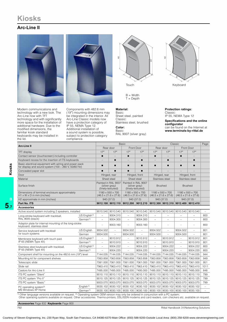
792 Rittal Handbook 31/Networking Solutions
KiosksArc-Line II
B
5.7
Kio
sks
Arc-Line IIBasic Classic Page
Rear door Front Door Rear door Front Door
TFT display 17″ 17″ 17″ 17″ 17″ 17″ 17″ 17″
Contact sensor (touchscreen) including controller � – � – � – � –
Keyboard recess for the insertion of ITS keyboards – � – � – � – �
Basic electrical equipment with wiring and power pack for display and sound system (100 – 260 V, 50/60 Hz) � � � � � � � �
Concealed paper slot � � � � – – – –
Door Hinged, rear Hinged, front Hinged, rear Hinged, front
Material Sheet steel Sheet steel Stainless steel Stainless steel
Surface finishPainted in RAL 9007
(silver gray)(finely-textured)
Painted in RAL 9007(silver gray)
(finely-textured)Brushed Brushed
Dimensions of terminal enclosure approximately H1 x W x D in mm (inches)
1180 x 550 x 700(46.5 x 21.6 x 27.6)
1180 x 550 x 700(46.5 x 21.6 x 27.6)
1180 x 550 x 700(46.5 x 21.6 x 27.6)
1180 x 550 x 700(46.5 x 21.6 x 27.6)
H2 approximate in mm (inches) 940 (37.0) 940 (37.0) 940 (37.0) 940 (37.0)
Part No. ITS 9012.100 9012.110 9012.200 9012.210 9012.300 9012.310 9012.400 9012.410AccessoriesActive sound system including 2 speakers, installed 9010.540 9010.540 9010.540 9010.540 9010.540 9010.540 9010.540 9010.540 –
Long-stroke keyboard with trackball, RAL 9005 (black)
US English1) – 9004.310 – 9004.310 – – – – 800
German1) – 9004.300 – 9004.300 – – – – 800
Adaptor plate for internal mounting of the long-stroke keyboard, stainless steel – 9003.160 – 9003.160 – – – – 800
Service keyboard with trackball for touch systems
US English 9004.502 – 9004.502 – 9004.502 – 9004.502 – 801
German 9004.500 – 9004.500 – 9004.500 – 9004.500 – 801
Membrane keyboard with touch pad, IP 65 (NEMA Type 4X)
US English1) – 9010.912 – 9010.912 – 9010.912 – 9010.912 801
German1) – 9010.910 – 9010.910 – 9010.910 – 9010.910 801
Stainless steel keyboard with trackball, IP 65 (NEMA Type 4X)
US English1) – 9004.222 – 9004.222 – 9004.222 – 9004.222 800
German1) – 9004.220 – 9004.220 – 9004.220 – 9004.220 800
Component shelf for mounting on the 482.6 mm (19″) level 7144.035 7144.035 7144.035 7144.035 7144.035 7144.035 7144.035 7144.035 944
Mounting kit for component shelves 7063.858 7063.858 7063.858 7063.858 7063.858 7063.858 7063.858 7063.858 949
Telescopic slide 7061.000 7061.000 7061.000 7061.000 7061.000 7061.000 7061.000 7061.000 951
Slide rail 7963.410 7963.410 7963.410 7963.410 7963.410 7963.410 7963.410 7963.410 1011
Castors for Arc-Line II 7495.000 7495.000 7495.000 7495.000 7495.000 7495.000 7495.000 7495.000 848
ITS PC system “Silent” 9010.110 9010.110 9010.110 9010.110 9010.110 9010.110 9010.110 9010.110 799
ITS PC system “Pro II” 9010.125 9010.125 9010.125 9010.125 9010.125 9010.125 9010.125 9010.125 799
ITS PC system “Basic” 9003.070 9003.070 9003.070 9003.070 9003.070 9003.070 9003.070 9003.070 799
PC operating system2) MS Windows XP Home
English1) 9030.102 9030.102 9030.102 9030.102 9030.102 9030.102 9030.102 9030.102 –
German1) 9030.100 9030.100 9030.100 9030.100 9030.100 9030.100 9030.100 9030.100 –1) Other language versions available on request. 2) Operating system OEM version may only be ordered in conjunction with a PC system;
Other operating systems available on request. Other accessories: Thermo-printers, DSL/ISDN modems and card readers, coin checkers etc. available on request.
TB
H1
H2
TB
H1
H2
B = WidthT = Depth
Modern communications and technology with a new look. The Arc-Line now with TFT technology and with significantly more space for the installation of additional hardware. Due to the modified dimensions, the familiar kiosk standard keyboards may be installed in the lid.
Components with 482.6 mm (19″) mounting dimensions may be integrated in the interior. All Arc-Line Classic models now have a protection category of IP 55, NEMA Type 12.Additional installation of a sound system is possible, subject to protection category compliance.
Material:Basic: Sheet steel, paintedClassic: Stainless steel, brushed
Color:Basic: RAL 9007 (silver gray)
Protection ratings:Classic: IP 55, NEMA Type 12
Specifications and the online configuratorcan be found on the Internet atwww.terminals-by-rittal.de
Kiosks:Arc-Line II
Accessories Page 832 Keyboards Page 800
Courtesy of Steven Engineering, Inc.-230 Ryan Way, South San Francisco, CA 94080-6370-Main Office: (650) 588-9200-Outside Local Area: (800) 258-9200-www.stevenengineering.com
Touch
Keyboard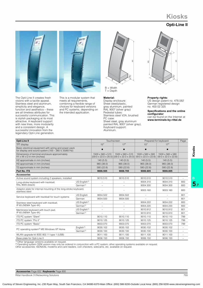
KiosksOpti-Line II
793Rittal Handbook 31/Networking Solutions
B
5.7
Kio
sks
T1B
H1
H2
T1B
H1
T2
H2
H3
The Opti-Line II creates fresh visions with a tactile appeal. Stainless steel and aluminum, simplicity and elegance, function and aesthetics – these are all timeless attributes for successful communication. This is stylish packaging at its most attractive. A keyboard support with new lines, more modularity and a consistent design. A successful innovation from the legendary Opti-Line generation.
This is a modular system that meets all requirements, combining a flexible range of choices for keyboard versions and PC systems, depending on the intended application.
Material:Display enclosure: Sheet steel/plastic, gray aluminum, paintedRAL 9007 (silver gray)Pedestal tubes: Stainless steel V2A, brushedPC case: Sheet steel, gray aluminumpainted RAL 9007 (silver gray), Keyboard support: Aluminum.
Property rights: US design patent no. 478,582 German registered design no. 400 02 325
Specifications and the online configurator can be found on the Internet atwww.terminals-by-rittal.de
Kiosks:Opti-Line II
Accessories Page 832 Keyboards Page 800
Opti-Line II Touchscreen Prepared for keyboard Page
TFT display 15″ 17″ 15″ 17″Basic electrical equipment with wiring and power pack for display and sound system (100 – 260 V, 50/60 Hz) � � � �
Dimensions of terminal enclosure approximately H1 x W x D in mm (inches)
1500 x 560 x 510(59.0 x 22.0 x 20.0)
1500 x 560 x 510(59.0 x 22.0 x 20.0)
1500 x 560 x 58059.0 x 22.0 x 22.8)
1500 x 560 x 58059.0 x 22.0 x 22.8)
H2 approximate in mm (inches) 140 (5.5) 140 (5.5) 140 (5.5) 140 (5.5)
H3 approximate in mm (inches) 965 (38.0) 965 (38.0) 965 (38.0) 965 (38.0)
T2 approximate in mm (inches) 580 (22.8) 580 (22.8) 580 (22.8) 580 (22.8)
Part No. ITS 9006.505 9006.705 9006.605 9006.805AccessoriesActive sound system including 2 speakers, installed 9010.510 9010.510 9010.510 9010.510 –
Long-stroke keyboard with trackball,RAL 9005 (black)
US English1) – – 9004.310 9004.310 800
German1) – – 9004.300 9004.300 800
Adaptor plate for internal mounting of the long-stroke keyboard, stainless steel – – 9003.160 9003.160 800
Service keyboard with trackball for touch systemsUS English 9004.502 9004.502 – – 801
German 9004.500 9004.500 – – 801
Stainless steel keyboard with trackball, IP 65 (NEMA Type 4X)
US English1) – – 9004.222 9004.222 800
German1) – – 9004.220 9004.220 800
Membrane keyboard with touch pad, IP 65 (NEMA Type 4X)
US English1) – – 9010.912 9010.912 801
German1) – – 9010.910 9010.910 801
ITS PC system “Silent” 9010.110 9010.110 9010.110 9010.110 799
ITS PC system “Pro II” 9010.125 9010.125 9010.125 9010.125 799
ITS PC system “Basic” 9003.070 9003.070 9003.070 9003.070 799
PC operating system2) MS Windows XP Home English1) 9030.102 9030.102 9030.102 9030.102 –
German1) 9030.100 9030.100 9030.100 9030.100 –
WLAN upgrade kit IEEE 802.11 type 1 (USB) 9011.100 9011.100 9011.100 9011.100 –
Base plate for Opti-Line II 9006.150 9006.150 9006.150 9006.150 –1) Other language versions available on request. 2) Operating system OEM version may only be ordered in conjunction with a PC system; other operating systems available on request. Other accessories: ISDN/DSL modems and card readers, coin checkers, webcams, etc. available on request.
B = Width T = Depth
Courtesy of Steven Engineering, Inc.-230 Ryan Way, South San Francisco, CA 94080-6370-Main Office: (650) 588-9200-Outside Local Area: (800) 258-9200-www.stevenengineering.com

794 Rittal Handbook 31/Networking Solutions
KiosksOpti-Desk
B
5.7
Kio
sks
TB
H
TB
H
The Opti-Desk is designed as a stylish freestanding PC workstation for the office environment and for use in the administrative sector. The generous worktop offers plenty of work space, and its successful design blends harmoniously into any environment where effective advice, information and presentations are needed.
The PC hardware is housed in the lockable lower cabinet, where other equipment such as printers, scanners etc. may also be integrated on additional built-in component shelves. Several workstations may be bayed or sited in groups via optional worktops.
Material:Display enclosure: Sheet steel, paintedStainless steelWorktop: MDF
Color:Body: RAL 9006Display enclosure: RAL 9006 Worktop/base plate: RAL 9007Design elements: RAL 9007RAL 9007: Gray aluminiumRAL 9006: Jet Black
Property rights: German registered design no. 403 02 344 Specifications and the online configurator can be found on the Internet atwww.terminals-by-rittal.de
Opti-Desk Worktop curved inwards Worktop curved outwards Page
TFT display 15″ 17″ 15″ 17″Basic electrical equipment with wiring and power pack for display(100 – 260 V, 50/60 Hz) � � � �
Component shelf mounted in the bottom cupboard � � � �
Base plate with slides � � � �
Dimensions approximately H x W x D in mm (inches) 1500 x 1000 x 800 (59.1 x 39.4 x 31.5)
Dimensions of bottom cupboard with front door only approximately H x W x D in mm (inches) 1000 x 435 x 530 (39.4 x 17.1 x 20.9)
Part No. ITS 9021.250 9021.270 9021.255 9021.275AccessoriesActive sound system including 2 speakers, fitted 9010.510 9010.510 9010.510 9010.510 –
Long-stroke keyboard with trackball, RAL 9005 (jet black)
US English1) 9004.310 9004.310 9004.310 9004.310 800
German1) 9004.300 9004.300 9004.300 9004.300 800
Adaptor plate for long-stroke keyboard with trackball, stainless steel 9003.160 9003.160 9003.160 9003.160 800
Stainless steel keyboard with trackball, IP 65/IP 54 (NEMA Type 4X/12)
US English1) 9004.222 9004.222 9004.222 9004.222 800
German1) 9004.220 9004.220 9004.220 9004.220 800
Membrane keyboard with touch pad,IP 65 (NEMA Type 4X)
US English1) 9010.912 9010.912 9010.912 9010.912 801
German1) 9010.910 9010.910 9010.910 9010.910 801
Component shelf for lower cupboard 9021.600 9021.600 9021.600 9021.600 –
Set of castors (2 with locks) to exchange for leveling feet 9021.650 9021.650 9021.650 9021.650 –
ITS PC system “Silent” 9010.110 9010.110 9010.110 9010.110 799
ITS PC system “Pro II” 9010.125 9010.125 9010.125 9010.125 799
ITS PC system “Basic” 9003.070 9003.070 9003.070 9003.070 799
PC operating system 2) MS Windows XP HomeEnglish1) 9030.102 9030.102 9030.102 9030.102 –
German1) 9030.100 9030.100 9030.100 9030.100 –
WLAN upgrade kit IEEE 802.11 type 1 (USB) 9011.100 9011.100 9011.100 9011.100 –1) Other language versions available on request. 2) Operating system OEM version may only be ordered in conjunction with a PC system; other operating systems available on request. Further accessories such as DSL/ISDN modem, card reader and coin checker, webcam etc. available on request.
Kiosks:Opti-Desk
Accessories Page 832 Keyboards Page 800
B = Width T = Depth
Courtesy of Steven Engineering, Inc.-230 Ryan Way, South San Francisco, CA 94080-6370-Main Office: (650) 588-9200-Outside Local Area: (800) 258-9200-www.stevenengineering.com

KiosksOpti-Wall
795Rittal Handbook 31/Networking Solutions
B
5.7
Kio
sks
H1
T
B
H2
B = Width H = Height T = Depth
This new compact kiosk for wall mounting was developed on the basis of the successful Opti-Line design. This wall-mounted kiosk system, designed for representative indoor applications, is sure to impress, not only with its refined design, but with the benefits of internal space utilization. Despite the minimal dimensions of this kiosk, there is a range of different configuration versions available. You decide which TFT, PC or
keyboard you require for your specific application.There is a choice of two PC systems, specifically tailored to the intended application in terminal systems. In order to make it easier for children and wheelchair users to use a multimedia kiosk, the accessories for the Opti-Wall include an electric height adjuster which may be adjusted to the user’s requirements via controls.
Opti-Wall Touchscreen Prepared for keyboard Page
TFT display 15″ 17″ 15″ 17″Basic electrical equipment with wiring and power pack for display(100 – 260 V, 50/60 Hz) � � � �
Dimensions of terminal enclosure approximately H x W x D mm (inches) 1000 x 560 x 200 (39.4 x 22.0 x 7.9)
Part No. ITS 9020.150 9020.170 9020.250 9020.270AccessoriesActive sound system including 2 speakers, installed 9010.510 9010.510 9010.510 9010.510 –
Long-stroke keyboard with trackball, RAL 9005 (black)
US English1) – – 9004.310 9004.310 800
German1) – – 9004.300 9004.300 800
Adaptor plate for long-stroke keyboard, stainless steel (required for the installation of 9004.300/.310) – – 9003.160 9003.160 800
Service keyboard with trackball for touch systemsUS English 9004.502 9004.502 – – 801
German 9004.500 9004.500 – – 801
US English1) – – 9004.222 9004.222 800
Stainless steel keyboard with trackball, IP 65/IP 54 (NEMA 4X/12)
US English1) – – 9004.222 9004.222 800
German1) – – 9004.220 9004.220 800
Membrane keyboard with mouse pad, IP 65 (NEMA 4X)
US English1) – – 9010.912 9010.912 801
German1) – – 9010.910 9010.910 801
Electric height adjuster for Opti-Wall kiosk, H2 in mm (inches): 400 (15.7) 9020.500 9020.500 9020.500 9020.500 –
ITS PC system “Silent” 9010.110 9010.110 9010.110 9010.110 799
ITS PC system “Pro II” 9010.125 9010.125 9010.125 9010.125 799
PC operating system2) MS Windows XP Home German1) 9030.100 9030.100 9030.100 9030.100 –
English1) 9030.102 9030.102 9030.102 9030.102 –
WLAN upgrade kit IEEE 802.11 type 1 (USB) 9011.100 9011.100 9011.100 9011.100 –1) Other language versions available on request. 2) Operating system OEM version may only be ordered in conjunction with a PC system; other operating systems available on request. Further accessories such as DSL/ISDN modem, webcam etc. available on request.
Kiosks:Opti-Wall
Material:Sheet steel, painted Stainless steel
Color:RAL 9007 (grey aluminium (display enclosure))RAL 9006 (white aluminium (basic enclosure))
Property rights: German registered design no. 403 02 344 Specifications and the online configurator can be found on the Internet atwww.terminals-by-rittal.de
Accessories Page 832 Keyboards Page 800
Courtesy of Steven Engineering, Inc.-230 Ryan Way, South San Francisco, CA 94080-6370-Main Office: (650) 588-9200-Outside Local Area: (800) 258-9200-www.stevenengineering.com

796 Rittal Handbook 31/Networking Solutions
KiosksAlpha-Line
B
5.7
Kio
sks
T1B
H1
T1
T2
B
H1
H2
The kiosk for tomorrow’s world. Here, communication becomes an experience. Two ambitious objectives are united in a single kiosk: The traditional and the mundane have given way to lightness and design. Rounded shapes add rhythm and style, ensuring a powerful impact from any perspective. Eye-catching and out of the ordinary. Simply unusual.
Suitable for the installation of compact and powerful PC systems (Silent and Pro) as well as your choice of keyboard. Navigate your way into the future with a touchscreen or keyboard.
Material:Monitor housing: Sheet steel, gray aluminum RAL 9007 (gray aluminum), painted Pedestal: MDF, gray aluminum RAL 9007 (gray aluminum), painted, with stainless steel trim Base plate: MDF, painted RAL 9005 (black)
Keyboard support: AluminumDesign-elements: painted RAL 9005 (jet black)
Property rights: German registered designno. 402 06 035 Japanese registered design no. 1181196 Brazilian registered design no. DI6202609 Chinese registered design no. ZL 02338459 GB registered design no. 3006546 IR registered design no. DM/062 638 US design patent no.US D480,731
Specifications and the online configurator can be found on the Internet atwww.terminals-by-rittal.de
Alpha-Line Touchscreen Prepared for keyboard Page
TFT display 15″ 15″Basic electrical equipment with wiring and power pack for display and sound system (100 – 260 V, 50/60 Hz) � �
Dimensions including base plate and viewing guard approximately H1 x W x D in mm (inches)
1300 x 580 x 540(51.2 x 22.8 x 21.3)
1300 x 580 x 640(51.2 x 22.8 x 25.2)
H2 approximate in mm (inches) 1010 (39.8) 1010 (39.8)
T2 approximate in mm (inches) 620 (24.4) 620 (24.4)
Part No. ITS 9007.105 9007.205AccessoriesActive sound system including 2 speakers, installed 9010.510 9010.510 –
Long-stroke keyboard with trackball, RAL 9005 (black)
US English1) – 9004.310 800
German1) – 9004.300 800
Adaptor plate for long-stroke keyboard with trackball, stainless steel – 9003.160 800
Service keyboard with trackball for touch systemsUS English 9004.502 – 801
German 9004.500 – 801
Stainless steel keyboard with trackball, IP 65/IP 54 (NEMA Type 4X/12)
US English1) – 9004.222 800
German1) – 9004.220 800
Membrane keyboard with touch pad, IP 65 (NEMA Type 4X)
US English1) – 9010.912 801
German1) – 9010.910 801
ITS PC system “Silent” 9010.110 9010.110 799
ITS PC system “Pro II” 9010.125 9010.125 799
PC operating system2) MS Windows XP HomeEnglish1) 9030.102 9030.102 –
German1) 9030.100 9030.100 –1) Other language versions available on request. 2) Operating system OEM version may only be ordered in conjunction with a PC system; other operating systems available on request.
Kiosks:Alpha-Line
Accessories Page 832 Keyboards Page 800
B = Width T = Depth
Courtesy of Steven Engineering, Inc.-230 Ryan Way, South San Francisco, CA 94080-6370-Main Office: (650) 588-9200-Outside Local Area: (800) 258-9200-www.stevenengineering.com

KiosksOut-Line Wall
797Rittal Handbook 31/Networking Solutions
B
5.7
Kio
sks
H2H
1
T
B2
B1
H2H
1
T
B2
B1
The new Out-Line Wall is a further development of the Opti-Wall kiosk for the semi-outdoor sector (+5 to +40°C). Despite the minimal dimensions of this kiosk, there is a range of different configuration versions available.
Options include, an outdoor-compatible sound system with protection category IP 55, NEMA Type 12. Climate control kits, consisting of a heater and fan-and-filter units, are also available. In addition to the accessories listed here, other versions are also possible, together with various color versions as customer-specific complete systems.
Color:RAL 9007 (silver gray)
Various paints, including anti-graffiti spray finish, available on request.
Protection ratings:IP 55, NEMA Type 12.
Specifications and the online configurator can be found on the Internet atwww.terminals-by-rittal.de
Out-Line Wall with protection category IP 55, NEMA Type 12 Touchscreen Prepared for keyboard Page
TFT display (high brightness for outdoor applications) 15″ 17″ 15″ 17″Basic electrical equipment with wiring and power pack for display and sound system (100 – 260 V, 50/60 Hz) � � � �
Wall bracket � � � �
Dimensions of enclosure body approximatelyH1 x W x D in mm (inches)
1100 x 480 x 305(43.3 x 18.9 x 12.0)
1100 x 480 x 365(43.3 x 18.9 x 14.4)
Enclosure dimensions including all projecting parts approximate H1 x W x D in mm (inches)
1360 x 600 x 305(53.5 x 23.6 x 12.0)
1360 x 600 x 365(53.5 x 23.6 x 14.4)
Part No. ITS 9023.150 9023.170 9023.250 9023.270AccessoriesActive sound system including 2 speakers, installed 9010.540 9010.540 9010.540 9010.540 –
Service keyboard with trackball for touch systemsUS English 9004.502 9004.502 – – 801
German 9004.500 9004.500 – – 801
Stainless steel keyboard with trackball, IP 65/IP 54 (NEMA Type 4X/12)
US English1) – – 9004.222 9004.222 800
German1) – – 9004.220 9004.220 800
Membrane keyboard with touch pad, IP 65 (NEMA Type 4X)
US English1) – – 9010.912 9010.912 801
German1) – – 9010.910 9010.910 801
ITS PC system “Pro II” 9010.125 9010.125 9010.125 9010.125 799
ITS PC system “Silent” 9010.110 9010.110 9010.110 9010.110 799
PC operating system2) MS Windows XP Home English1) 9030.102 9030.102 9030.102 9030.102 –
German1) 9030.100 9030.100 9030.100 9030.100 –
Climate control kit for Out-Line Wall 3)
Type 1 (mains voltage: 115 V, 50/60 Hz) 9010.331 9010.331 9010.331 9010.331 –
Type 2 (mains voltage: 230 V, 50/60 Hz) 9010.332 9010.332 9010.332 9010.332 –
1) Other language versions available on request. 2) Operating system OEM version may only be ordered in conjunction with a PC system; other operating systems available on request. 3) Detailed knowledge of the conditions on-site exactly is required to dimension the climate control kit accurately.
Kiosks:Out-Line Wall
Accessories Page 832 Keyboards Page 800
B = Width T = Depth
Courtesy of Steven Engineering, Inc.-230 Ryan Way, South San Francisco, CA 94080-6370-Main Office: (650) 588-9200-Outside Local Area: (800) 258-9200-www.stevenengineering.com

798 Rittal Handbook 31/Networking Solutions
KiosksOut-Line Pro
B
5.7
Kio
sks
H2
B1
T1
B2
H1
T2
This outdoor kiosk is designed for multimedia in an outdoor setting. Based on Rittal’s expertise in the outdoor sector, this twin-walled aluminum kiosk offers a high level of security in terms of protection from a wide variety of climatic and physical conditions, including protection against vandalism.
Internally, the enclosure may be configured with other components from the Rittal range of accessories, such as component shelves, etc. Special displays suitable for outdoor use with high levels of light intensity are used in complete systems.
Material:Aluminum, paintedTubes: Stainless steel
Color:RAL 9007 (silver gray)
Various paints, including anti-graffiti paint, available on request.
Protection ratings:IP 55, NEMA Type 12.
Property rights: German registered design no. 403 02 344 Specifications and the online configurator can be found on the Internet atwww.terminals-by-rittal.de
Out-Line Pro Touchscreen Prepared for keyboard Page
TFT display (suitable for outdoor use with an increased light intensity) 15″ 17″ 15″ 17″
Basic electrical equipment with wiring and power pack fordisplay and sound system (100 – 260 V, 50/60 Hz) � � � �
Base/plinth with stabilizers, may be screw-fastened to the ground. � � � �
Dimensions of terminal enclosure approximately H1 x W x D in mm (inches)
2000 x 650 x 400(78.7 x 25.6 x 15.7)
2000 x 650 x 400(78.7 x 25.6 x 15.7)
Dimensions of terminal including roof approximately H2 x W x D in mm (inches)
2400 x 1000 x 1000(64.5 x 39.4 x 39.4)
2400 x 1000 x 1000(64.5 x 39.4 x 39.4)
Part No. ITS 9022.150 9022.170 9022.250 9022.270AccessoriesActive sound system including 2 speakers, installed 9010.540 9010.540 9010.540 9010.540 –
Service keyboard with trackball for touch systems
US English 9004.502 9004.502 – – 801
German 9004.500 9004.500 – – 801
Stainless steel keyboard with trackball, IP 65 (NEMA Type 4X)
US English1) – – 9004.222 9004.222 800
German1) – – 9004.220 9004.220 800
Membrane keyboard with touch pad, IP 65 (NEMA Type 4X)
US English1) – – 9010.912 9010.912 801
German1) – – 9010.910 9010.910 801
ITS PC system “Silent” 9010.110 9010.110 9010.110 9010.110 799
ITS PC system “Pro II” 9010.125 9010.125 9010.125 9010.125 799
PC operating system2) MS Windows XP Home English1) 9030.102 9030.102 9030.102 9030.102 –
German1) 9030.100 9030.100 9030.100 9030.100 –
WLAN upgrade kit IEEE 802.11, type 2 (PCI card with external outdoor aerial for the PC system “Pro” and “Basic”) 9011.110 9011.110 9011.110 9011.110 –
Climate control kit for outdoor terminals3)
Type 1 (mains voltage: 115 V) 9010.311 9010.311 9010.311 9010.311 –
Type 2 (mains voltage: 230 V) 9010.312 9010.312 9010.312 9010.312 –
1) Other language versions available on request. 2) Operating system OEM version may only be ordered in conjunction with a PC system; other operating systems available on request. 3) Detailed knowledge of the conditions on-site is required to dimension the climate control kit accurately.Operation at –20 to +40°C (4 – 104°F) in Central Europe is possible under the conditions defined in IEC 68.Further accessories such as card reader, coin checker as well as climate control units available on request.
Kiosks:Out-Line Pro
Accessories Page 832 Keyboards Page 800
B = Width T = Depth
Courtesy of Steven Engineering, Inc.-230 Ryan Way, South San Francisco, CA 94080-6370-Main Office: (650) 588-9200-Outside Local Area: (800) 258-9200-www.stevenengineering.com

KiosksPC systems
799Rittal Handbook 31/Networking Solutions
B
5.7
Kio
sks
Kiosks Mini-PC systemRittal now offers innovative PC technology to match the kiosk systems which is specifically tailored to the requirements of the kiosk sector. There is a choice of three PC systems which are ideally suited for use in all terminal systems in terms of noise emission, system performance and compact
design. With the PC system “Silent″, the designers focussed their attention on a noise- and heat loss-reducing design. In this way, we have managed to dispense with the use of active fans for the power pack and for cooling the PCU.
Mini-PC configuration1) Silent Pro II Basic4)
Fanless PC (Mini-ITX, VIA Eden CPU), 633 MHz � – –
Intel Pentium M CPU min. 1.6 GHz with active fan – � –
Intel Celeron CPU min. 2.0 GHz with active fan – – �
Main memory 256 MB 256 MB 256 MB
Hard disk (minimum capacity, approximately) 40 GB 40 GB 40 GB
CD-ROM � – �
DVD-ROM – � –
Part No. ITS 9010.110 9010.125 9003.070InterfacesPS/2 (keyboard and mouse) � � �
VGA (onboard) � � �
Sound (onboard, 6-way surround sound 5.1, AC97 codec) connections in/out 2/1 1/1 –
Sound (onboard AC97 codec) connections in/out – – 2/1
Ethernet 10 and 100 Mbit/s (RJ 45) � � �
Serial (RS232, D-Sub 9 pin) 1 x 1 x 1 x
Parallel (ECP/EPP, D-Sub 25 pin) 1 x – 1 x
USB 2 x 2 x 4 x rear/2 x front
Firewire (IEEE 1394) 2 x – –
SP-DIF out (RCA, if TV-out is not used) � – –
TV-out (PAL & NTSC) (RCA, if SP-DIF is not used) � – –
Extension slot PCI – – 2 x/1 x AGP Low Profile
External power pack (prim.: 100 – 240 V, 50/60 Hz/sec. 12 V, 60 – 80 W) � � –
Internal power pack (100 – 240 V, 50/60 Hz) – – �
Dimensions approximately H x W x D in mm (inches) 55 x 300 x 300(2.2 x 11.8 x 11.8)
55 x 300 x 300(2.2 x 11.8 x 11.8)
95 x 350 x 385(3.7 x 13.8 x 15.2)
Accessories1)
PC operating system2) MS Windows XP Home
German3) 9030.100 9030.100 9030.100
English3) 9030.102 9030.102 9030.102
French3) 9030.103 9030.103 9030.103
Spanish3) 9030.104 9030.104 9030.1041) We reserve the right to make configuration changes in line with technical progress. 2) Operating system OEM version may only be ordered in conjunction with a PC system. 3) Other language versions available on request. 4) PC system Basic not for use in: ITS Alpha-Line, ITS Opti-Wall, ITS Out-Line Wall and ITS Out-Line Pro. Other PC configurations available on request.
Kiosks:PC systemsPC systems kiosks
Kiosks computer
Accessories Page 832 Keyboards Page 800
Courtesy of Steven Engineering, Inc.-230 Ryan Way, South San Francisco, CA 94080-6370-Main Office: (650) 588-9200-Outside Local Area: (800) 258-9200-www.stevenengineering.com

800 Rittal Handbook 31/Networking Solutions
KiosksKeyboards
B
5.7
Kio
sks
Long-stroke keyboardWith trackballSuper-slimline, compact long-stroke keyboard (83/84 keys) with top-quality 16 mm (0.6″) trackball. Available in two different colors and several country layouts.
For independent installation into the keyboard supports or keyboard recesses, in addition an adaptor plate is required.
Mechanical specifications: Key buttons in an 18 mm (0.7″) hole patternTrackball Ø 16 mm (0.6″)Weight: 720 g (25.4 oz)Storage temperature: –20 to +60°C (-4 to 140°F)Operating temperature: 0 to +50°C (32 to 122°F)Dimensions H x W x D: 138.5 x 370 x 20 mm (5.5 x 14.6 x 0.8″).
Electrical specifications: Connections: PS/2 for keyboard and trackballOperating voltage: 5 V DC type 18 mA
USB version available on request.
Material:Plastic
Long-stroke keyboardAdaptor plateITS:Keyboards
Language1)Part No. ITS
RAL 9005(jet black)
RAL 7032(pebble gray)
US English 9004.310 9004.330German 9004.300 9004.320French 9004.303 9004.323Spanish 9004.304 9004.324
1) Other language versions available on request.
Part No. ITSAdaptor plate in brushed stainless steel 9003.160
Adaptor plate, sheet steel, RAL 9005 (jet black) 9003.170
Stainless steel keyboardWith trackballThe stainless-steel full-stroke keys (86 keys) with a stroke of 3.5 mm (0.1″) are laser-engraved and protected against being twisted out or snapped off. The keyboard conforms to CE requirements.
Mechanical specifications: Actuator travel: 3.5 mm (0.1″)Actuator force: 0.56 N, tactileService life: > 10 million actuationsStorage temperature: –40 to +70°C (104 to 158°F)Operating temperature: –20 to +60°C (-4 to 140°F)Dimensions H x W x D: 155 x 432 x 34 mm (6.1 x 17.0 x 1.3″)(R = 10 mm (0.4″)).
Electrical specifications: Connections: PS/2 for keyboard and trackballOperating voltage: 5 V DC, maximum 50 mA
USB version available on request.
Protection ratings:Keyboard and trackballIP 65 (idle) (NEMA Type 4X)IP 54 (in motion) (NEMA Type 12)
Stainless steel keyboards:for kiosksITS:KeyboardsKeyboard:for kiosks
Language1) Part No. ITSUS English 9004.222German 9004.220French 9004.223Spanish 9004.224Finnish 9004.226Swedish 9004.227
1) Other language versions available on request.
Courtesy of Steven Engineering, Inc.-230 Ryan Way, South San Francisco, CA 94080-6370-Main Office: (650) 588-9200-Outside Local Area: (800) 258-9200-www.stevenengineering.com

KiosksKeyboards
801Rittal Handbook 31/Networking Solutions
B
5.7
Kio
sks
Service keyboardWith trackballCompact keyboard with integral trackball for mobile on-site service use with kiosk systems. This keyboard makes maintenance work and software installation easier for kiosk systems with a touchscreen which do not have their own keyboard. This keyboard is not essential for operation of the terminals, but in many terminals it may remain inside the enclosure, due to the minimal dimensions. This keyboard also has 18 multimedia keys.
Mechanical specifications: Actuator travel: 2.2 mm (0.1″)Trackball: Ø 19 mm (0.7″)Service life: 1 million actuationsOperating temperature: 0 to +50°C (32 to 122°F)Dimensions H x W x D: 152 x 316 x 21 mm (6.0 x 12.4 x 0.8″).
Electrical specifications: Connections: PS/2 for keyboard and trackball
USB version available on request.
Material:Plastic
Protection ratings:IP 20
Service keyboardKeyboard:for kiosksITS:Keyboards
Language Part No. ITSGerman 9004.500US English 9004.502
Membrane keyboardWith touch padMembrane keyboard with 86 keys and integrated touch pad in MF-II/WIN-compatible layout for integration into the keyboard support of all kiosk systems.
Mechanical specifications: Actuator travel: 0.5 mm (0.02″)Actuator force: 2.55 N (9.2 ozf) ± 0.65 N (2.3 ozf)Service life: >1 million actuationsTouchpad: Active area 62 x 47 mm (2.4 x 1.9″)Dimensions H x W x D: 155 x 432 x 18 mm (6.1 x 17.0 x 0.7″)Front film: Resistant polyesterKeys: With key edge embossingCarrier plate: Metal.
Electrical specifications: Connections: PS/2 for keyboard and trackball
USB version available on request.
Protection ratings:IP 65, NEMA Type 4X.
Membrane keyboardITS:KeyboardsKiosks
Language1) Part No. ITSUS English 9010.912German 9010.910French 9010.913Spanish 9010.914Finnish 9010.916Swedish 9010.917
1) Other language versions available on request.
Example of a customer-specific terminal solution with 4000-page thermo-printer.
Courtesy of Steven Engineering, Inc.-230 Ryan Way, South San Francisco, CA 94080-6370-Main Office: (650) 588-9200-Outside Local Area: (800) 258-9200-www.stevenengineering.com

802 Rittal Handbook 31/Networking Solutions
TelecomFeatures
B
5.8
Tele
com
Modern telecommunications continuously place new
demands on racks and enclosures. Above all, maximum
flexibility is crucial to conform with the various standards.
Combined with creative scope, you get cost-effective
solutions for your individual requirements.
TC rack
Rear/sidewallTo finish off a complete enclosure unit.
Roof and base/plinth insertThe inserts may be fitted as required in the roof or base/plinth.
Option of installing all standard 482.6 mm (19″) or metric (535 mm (21.1″)) components.
Small FM distributors
FM universal mounting brackets for LSA-Plus, VS-Standard and other common connection systems.
Prepared for mounting LSA cable retainers or routing troughs.
Cable entryTop and bottom. With 2 cradle strips for cable clamping.
Modular FM distribution enclosures
Wall-mounted and bayed enclosuresRittal diversity, from small distributors, to FM wall-mounted distributors, to two-door bayed enclosures.
FM system strips For DIN strips, dividing strips 71 and FM universal mounting brackets.
FM system rods For LSA-Plus-Profile modules 2/10.
Courtesy of Steven Engineering, Inc.-230 Ryan Way, South San Francisco, CA 94080-6370-Main Office: (650) 588-9200-Outside Local Area: (800) 258-9200-www.stevenengineering.com
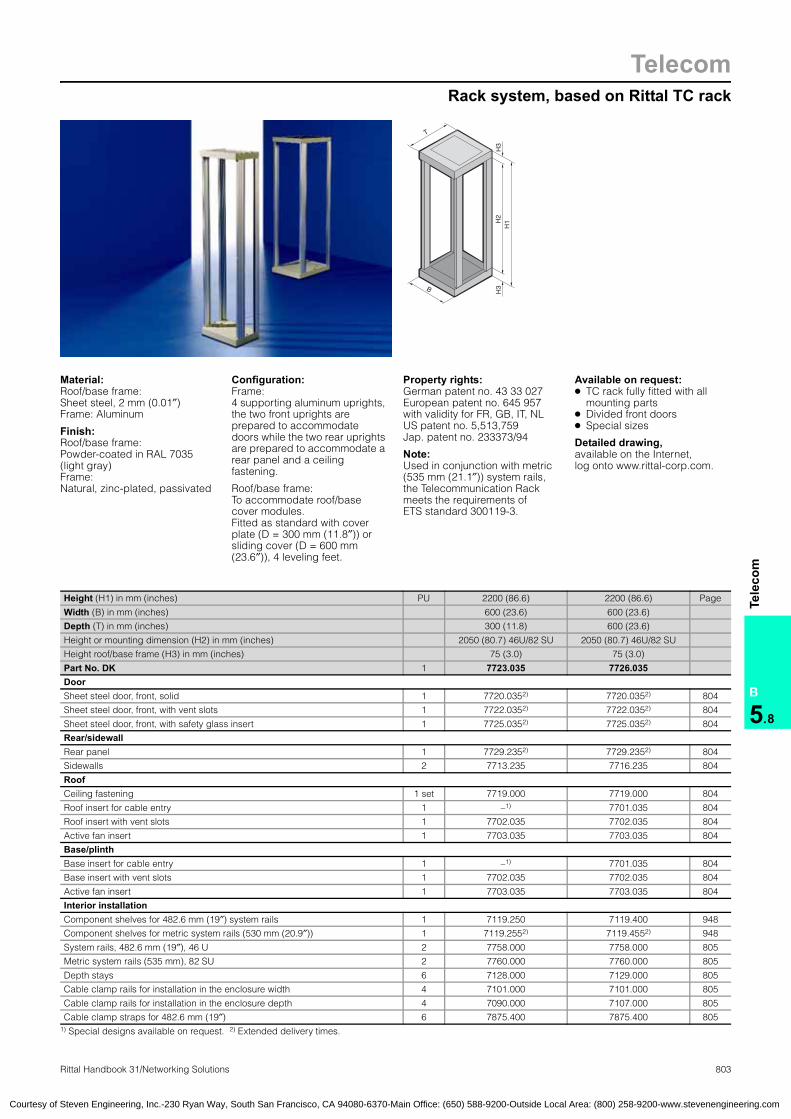
TelecomRack system, based on Rittal TC rack
B
5.8
Tele
com
803Rittal Handbook 31/Networking Solutions
T
H1H
2H
3 H
3
B
Material:Roof/base frame: Sheet steel, 2 mm (0.01″)Frame: Aluminum
Finish:Roof/base frame: Powder-coated in RAL 7035 (light gray)Frame: Natural, zinc-plated, passivated
Configuration:Frame: 4 supporting aluminum uprights, the two front uprights are prepared to accommodate doors while the two rear uprights are prepared to accommodate a rear panel and a ceiling fastening.
Roof/base frame: To accommodate roof/base cover modules. Fitted as standard with cover plate (D = 300 mm (11.8″)) or sliding cover (D = 600 mm (23.6″)), 4 leveling feet.
Property rights: German patent no. 43 33 027European patent no. 645 957with validity for FR, GB, IT, NLUS patent no. 5,513,759Jap. patent no. 233373/94 Note:Used in conjunction with metric (535 mm (21.1″)) system rails, the Telecommunication Rack meets the requirements of ETS standard 300119-3.
Available on request:● TC rack fully fitted with all
mounting parts● Divided front doors● Special sizes
Detailed drawing, available on the Internet,log onto www.rittal-corp.com.
ETSI rackTC rack systemTelecom rack
Height (H1) in mm (inches) PU 2200 (86.6) 2200 (86.6) Page
Width (B) in mm (inches) 600 (23.6) 600 (23.6)
Depth (T) in mm (inches) 300 (11.8) 600 (23.6)
Height or mounting dimension (H2) in mm (inches) 2050 (80.7) 46U/82 SU 2050 (80.7) 46U/82 SU
Height roof/base frame (H3) in mm (inches) 75 (3.0) 75 (3.0)
Part No. DK 1 7723.035 7726.035DoorSheet steel door, front, solid 1 7720.0352) 7720.0352) 804
Sheet steel door, front, with vent slots 1 7722.0352) 7722.0352) 804
Sheet steel door, front, with safety glass insert 1 7725.0352) 7725.0352) 804
Rear/sidewallRear panel 1 7729.2352) 7729.2352) 804
Sidewalls 2 7713.235 7716.235 804
RoofCeiling fastening 1 set 7719.000 7719.000 804
Roof insert for cable entry 1 –1) 7701.035 804
Roof insert with vent slots 1 7702.035 7702.035 804
Active fan insert 1 7703.035 7703.035 804
Base/plinthBase insert for cable entry 1 –1) 7701.035 804
Base insert with vent slots 1 7702.035 7702.035 804
Active fan insert 1 7703.035 7703.035 804
Interior installationComponent shelves for 482.6 mm (19″) system rails 1 7119.250 7119.400 948
Component shelves for metric system rails (530 mm (20.9″)) 1 7119.2552) 7119.4552) 948
System rails, 482.6 mm (19″), 46 U 2 7758.000 7758.000 805
Metric system rails (535 mm), 82 SU 2 7760.000 7760.000 805
Depth stays 6 7128.000 7129.000 805
Cable clamp rails for installation in the enclosure width 4 7101.000 7101.000 805
Cable clamp rails for installation in the enclosure depth 4 7090.000 7107.000 805
Cable clamp straps for 482.6 mm (19″) 6 7875.400 7875.400 805 1) Special designs available on request. 2) Extended delivery times.
Courtesy of Steven Engineering, Inc.-230 Ryan Way, South San Francisco, CA 94080-6370-Main Office: (650) 588-9200-Outside Local Area: (800) 258-9200-www.stevenengineering.com

TelecomAccessories for Rittal TC Rack
B
5.8
Tele
com
804 Rittal Handbook 31/Networking Solutions
DoorFor front mounting, with 180° hinges, locking rod, double-bit lock insert (may be exchanged for Ergoform-S lock system).
Material:Sheet steel
Color:RAL 7035 (light gray)
Doors:for Rittal TC Rack
Sheet steel door at front Part No. DKSolid 7720.0351)
With vent slots 7722.0351)
With safety glass insert 7725.0351)
Lock system Part No. SZErgoform-S handleRAL 7035 (light gray) 2435.000
Lock no. 3524 E 2467.0001) Extended delivery times. Available on request.
Rear/sidewallTo finish off a complete enclosure unit, including assembly material.
Material:Sheet steel
Color:RAL 7035 (light gray)
For sidewalls DK 7713.235 and DK 7716.235:
German patent no. 43 33 025US patent no. 5,584,406
Walls:for Rittal TC Rack
Forenclosure
depthmm (inches)
PU Part No. DK
Sidewall 300 (11.8) 2 7713.235Sidewall 600 (23.6) 2 7716.235
For enclosure width
mm (inches)Part No. DK
Rear panel 600 (23.6) 7729.2351)
1) Extended delivery times.
Ceiling fasteningInfinitely height-adjustable for ceiling fastening of free-standing Rittal TC Racks and for cable routing. Maximum mounting height of vertical stays: 550 mm (21.7″)
Material:Sheet steel, zinc-plated, passivated
Configuration:2 vertical stays, 1 horizontal rail,2 cable shunting rings,including assembly hardware.
Ceiling fastening:for Rittal TC Rack
Part No. DK 7719.000
Roof and base/plinth insertThe inserts may be fitted in the roof or base/plinth as required.
Material:Sheet steel
Color:RAL 7035 (light gray)
Roof insert:for Rittal TC RackBase/plinth insert:for Rittal TC Rack
Roof and base/plinth insert Part No. DKFor cable entry1) 7701.035With vent slots 7702.035With active fan insert 7703.035
1) For Rittal TC Rack DK 7726.035. Special design for DK 7723.035 available on request.
System accessories:for Rittal TC Rack
Courtesy of Steven Engineering, Inc.-230 Ryan Way, South San Francisco, CA 94080-6370-Main Office: (650) 588-9200-Outside Local Area: (800) 258-9200-www.stevenengineering.com

TelecomAccessories for Rittal TC Rack
B
5.8
Tele
com
805Rittal Handbook 31/Networking Solutions
System rails on a U/SU hole pattern and T channel system rails, 482.6 mm (19″)/metric (535 mm (21.1″)) The system rails are simply screwed to the rack upright; a combination of 482.6 mm (19″) andmetric (535 mm (21.1″)) system rails is also possible. Also available in a T channel version. The system rails are depth-adjustable including mounting material.
System rails:for Rittal TC Rack
Material:Aluminum, clear-chromated
Accessories:Captive nuts M5 /M6, spring nuts, screws M5 /M6,see page 1019.
PU
Part No. DKU hole pattern
system rails
SU hole pattern
system rails
T channel system rails
46U 2 7758.000 – 7758.10082 SU 2 – 7760.000 7760.100
Depth staysFor infinitely variable adjustment of metric (535 mm (21.1″)) or 482.6 mm (19″) system rails across the entire enclosure depth, or for attach-ment of a second pair of 482.6 mm (19″) system rails at the rear.
Material:Sheet steel, zinc-plated, passivated
Configuration:Depth stays, including assembly hardware.
Depth stays:for Rittal TC Rack
Enclosure depthmm (inches) PU Part No. DK
300 (11.8) 6 7128.000600 (23.6) 6 7129.000
Cable clamp railsFor installation in the enclosure width and depth. Fully height-adjustable for cable clamping with rear or side cable routing.
Material:Sheet steel, zinc-plated, passivated
Configuration:Cable clamp rails,including assembly hardware.
Cable clamp rails:for Rittal TC Rack
Enclosure widthmm (inches) PU Part No. DK
600 (23.6) 4 7101.000
Enclosure depthmm (inches) PU Part No. DK
300 (11.8) 4 7090.000600 (23.6) 4 7107.000
Clip-on nutsFor variable interior installation of TC racks. Simply clip onto one of the two channels, for infinitely variable component mounting.
German patent no. 195 24 648European patent no. 0 836 679Japanese patent no. 28 91 779US patent no. 5,897,276Clip-on nut:for Rittal TC Rack
Accessories:M6 assembly screws,see page 1019.
PU Part No. FR50 2102.500
Cable clamp strapFor system-compatible cable routing in the TC Rack, behind a pair of 482.6 mm (19″) system rails.
Material:Sheet steel, zinc-plated, passivated
Cable clamp strap:for Rittal TC Rack
Depthmm (inches) PU Part No. DK
100 6 7875.400
ETSI rackSystem accessories:for Rittal TC RackTC rack systemTelecom rack
Courtesy of Steven Engineering, Inc.-230 Ryan Way, South San Francisco, CA 94080-6370-Main Office: (650) 588-9200-Outside Local Area: (800) 258-9200-www.stevenengineering.com

TelecomSmall FM distributors
B
5.8
Tele
com
806 Rittal Handbook 31/Networking Solutions
T1
H
B1
B2
T2
Material:Sheet steel, 1.5 mm (16 ga)
Finish:Powder-coated in RAL 7035 (light gray)
Configuration:Two-part enclosure
Wall section: With mounting holes for wall mounting, 2 comb strips for cable clamping and brush insert for cable entry, shunting ring for system-compatible routing of telecommunications cables.
Cover: Retaining device and two cam locks with double-bit lock insert.
Property rights: German patent no. 44 10 795 Detailed drawing, available on the Internet,log onto www.rittal-corp.com
FM:Distribution enclosures;Distribution enclosures:FM
Height (H) in mm (inches) PU 500 (19.7) 500 (19.7) 700 (27.6) 700 (27.6) Page
Width (B1) in mm (inches) 300 (11.8) 500 (19.7) 500 (19.7) 900 (35.4)
Depth (T1) in mm (inches) 120 (4.7) 120 (4.7) 120 (4.7) 120 (4.7)
Width of cable entry (B2) in mm (inches) 195 (7.7) 395 (15.5) 395 (15.5) 795 (31.3)
Depth of cable entry (T2) in mm (inches) 29 (1.1) 29 (1.1) 29 (1.1) 29 (1.1)
Part No. DK 1 7052.035 7053.035 7054.035 7055.035Max. number of adjacent cable retainers or mounting troughs (LSA) 1 2 2 4
Max. accommodation when using cable retainers or mounting troughs (LSA) 100 DA 200 DA 400 DA 800 DA
Shunting ring, plastic, 70 x 44 mm (inches) (2.8 x 1.7″) 2 3 3 5
AccessoriesFM universal mounting brackets type A, L = 275 mm (10.8″), LSA-Plus 1 set 7031.100 7031.100 7031.100 7031.100 811
FM universal mounting brackets type B, L = 275 mm (10.8″), VS-Standard 1 set 7031.101 7031.101 7031.101 7031.101 811
Lock systems“15” locks (Zeiss-Ikon) 2 7059.0351) 7059.0351) 7059.0351) 7059.0351) 891
“15” key (Zeiss-Ikon) 1 7059.1001) 7059.1001) 7059.1001) 7059.1001) 891
T handle without lock insert 1 2572.000 2572.000 2572.000 2572.000 887
T handle with lock insert no. 3524 E 1 2575.000 2575.000 2575.000 2575.000 887
Plastic handle with lock no. 3524 E 1 2576.000 2576.000 2576.000 2576.000 886
Plastic handle 1 2533.000 2533.000 2533.000 2533.000 886
Standard double-bit lock insert may be exchanged for 27 mm lock inserts, version A, see page 888. 1) Extended delivery times.
Courtesy of Steven Engineering, Inc.-230 Ryan Way, South San Francisco, CA 94080-6370-Main Office: (650) 588-9200-Outside Local Area: (800) 258-9200-www.stevenengineering.com
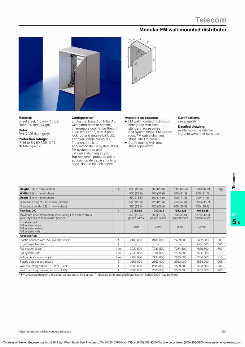
TelecomModular FM wall-mounted distributor
807Rittal Handbook 31/Networking Solutions
B
5.8
Tele
com
T1
B2
B1
H1H
2
Material:Sheet steel, 1.5 mm (16 ga)Door: 2.0 mm (14 ga)
Color:RAL 7035 (light gray)
Protection ratings:IP 55 to EN 60 529/10.91,NEMA Type 12.
Configuration:Enclosure: Based on Rittal AEwith gland plate at bottom, changeable door hinge (height 1200 mm (47.1″) with 3-point lock rod and double-bit lock), earth rail, cable clamp rail, 2 punched rails to accommodate FM system strips, FM system rods andFM cable shunting strips. Top horizontal punched rail to accommodate cable shunting rings, double-bit lock inserts.
Available on request: ● FM wall-mounted distributor
configured with Rittal standard accessories (FM system strips, FM system rods, FM cable shunting strips, etc.) to order.
● Cable routing with brush strips top/bottom.
Certifications,see page 92.
Detailed drawing,available on the Internet,log onto www.rittal-corp.com.
Height (H1) in mm (inches) PU 600 (23.6) 760 (29.9) 1000 (39.4) 1200 (47.2) Page
Width (B1) in mm (inches) 600 (23.6) 600 (23.6) 800 (31.5) 800 (31.5)
Depth (T1) in mm (inches) 350 (13.8) 300 (11.8) 300 (11.8) 300 (11.8)
Clearance height (H2) in mm (inches) 560 (22.0) 720 (28.4) 960 (37.8) 1160 (45.7)
Clearance width (B2) in mm (inches) 560 (22.0) 720 (28.4) 760 (29.9) 760 (29.9)
Part No. DK 1 7011.535 7012.535 7013.535 7014.535Maximum accommodation when using FM system stripswith trays or FM rods in mm (inches)
340 (13.4)paired wires
500 (19.7)paired wires
990 (39.0)paired wires
1170 (46.1)paired wires
Installation ofFM system stripsFM system towersFM system rods
2 set 2 set 3 set 3 set
AccessoriesPlastic handles with lock cylinder insert 1 2439.000 2439.000 2439.000 2439.000 886
Ergoform-S handle 1 – – – 2435.000 885
FM system strips1) 1 set 7032.500 7033.500 7034.500 7035.500 809
FM system rods 1 set 7533.000 7534.000 7535.000 7536.000 810
FM cable shunting strips 1 set 7233.000 7234.000 7235.000 7236.000 810
Plastic cable gland plates 5 2563.000 2563.000 2563.000 2563.000 966
Wall mounting bracket, 10 mm (0.4″) 1 2508.000 2508.000 2508.000 2508.000 905
Wall mounting bracket, 40 mm (1.6″) 1 2503.000 2503.000 2503.000 2503.000 905 1) FM universal mounting bracket, VS standard, DIN strips, 71 dividing strip and distributor system series 5000 may be fitted.
FM:Wall-mounted distributor;Wall-mounted distributor, FM
Courtesy of Steven Engineering, Inc.-230 Ryan Way, South San Francisco, CA 94080-6370-Main Office: (650) 588-9200-Outside Local Area: (800) 258-9200-www.stevenengineering.com

808 Rittal Handbook 31/Networking Solutions
TelecomModular FM distributor racks
B
5.8
Tele
com
T2
B2
H2
T1
H1
B1
Material:Sheet steel,Enclosure frame, roof, rear panel and gland plates: 1.5 mm (16 ga)Door: 2 mm (14 ga)
Color:RAL 7035 (light gray)
Protection ratings:IP 55 to EN 60 529/10.91,NEMA Type 12.
Configuration:Enclosure frame with door or2 doors, without side panels, comfort handle with security lock, three-piece gland plate, rear panel and roof plate, 3 system bars to accommodate FM system strips, FM system rods, FM cable shunting strips, 1 top horizontal system bar to accommodate cable shunting rings, cable clamp rail, ground rod.
Available on request: ● FM distributor racks
configured with Rittal standard accessories (FM system strips, FM system rods, FM cable shunting strips, etc.) to order
● FM distributor racks in special sizes
Approvals,see page 92.
Detailed drawing,available on the Internet,log onto www.rittal-corp.com.
Accessories Page 832
Height (H1) in mm (inches) PU 2000 (78.7) 2000 (78.7) 2000 (78.7) Page
Width (B1) in mm (inches) 600 (23.6) 800 (31.5) 1200 (47.2)
Depth (T1) in mm (inches) 400 (15.7) 400 (15.7) 400 (15.7)
Clearance height (H2) in mm (inches) 1912 (75.3) 1912 (75.3) 1912 (75.3)
Clearance width (B2) in mm (inches) 512 (20.2) 712 (28.0) 1112 (43.8)
Clearance depth (T2) in mm (inches) 312 (12.3) 312 (12.3) 312 (12.3)
Part No. DK 1 7834.060 7834.080 7834.120Maximum accommodation when using FM system stripswith trays or FM rods in mm (inches)
1300 (51.2)paired wires
1950 (76.7)paired wires
3250 (128.0)paired wires
Installation ofFM system stripsFM system towersFM system rods
2 3 5
AccessoriesFM system strips1) 1 set 7038.500 7038.500 7038.500 809
FM system rods 1 set 7538.000 7538.000 7538.000 810
FM cable shunting strips 1 7238.000 7238.000 7238.000 810
Cable shunting ring in mm (inches)
120 x 90 (4.7 x 3.5) 10 7111.900 7111.900 7111.900 810
120 x 60 (4.7 x 2.3) 10 7111.000 7111.000 7111.000 810
80 x 40 (3.1 x 1.5) 10 7112.000 7112.000 7112.000 810
Side panels 2 8104.235 8104.235 8104.235 853
Quick-fit baying clamps 6 8800.500 8800.500 8800.500 863
Roof plate for cable entry 1 7826.6452) 7826.8452) 7826.2452) 901
Height 100 mm (3.9″), base/plinth components front/rear 1 set 8601.600 8601.800 8601.200 835
Height 100 mm (3.9″), base/plinth components sides 400 mm (15.7″) 1 set 8601.040 8601.040 8601.040 835
Height 200 mm (7.9″), base/plinth components front/rear 1 set 8602.600 8602.800 8602.200 835
Height 200 mm (7.9″), base/plinth components sides 400 mm (15.7″) 1 set 8602.040 8602.040 8602.040 835 1) FM universal mounting bracket, VS standard, DIN strips, 71 dividing strip and distributor system series 5000 may be fitted. 2) Extended delivery times.
Distributor racks:Modular FM distributor racksFM:Distributor racks
Courtesy of Steven Engineering, Inc.-230 Ryan Way, South San Francisco, CA 94080-6370-Main Office: (650) 588-9200-Outside Local Area: (800) 258-9200-www.stevenengineering.com

Accessories for FM distribution racks
Telecom
809Rittal Handbook 31/Networking Solutions
B
5.8
Tele
com
FM system stripsFor user-specific solutions or modular FM enclosure assembly. The following connection systems may be mounted on the FM system strips:● DIN connector strips to DIN 47 614, type B;
soldering lugs to DIN 41 499, LSA-Plus connector strips 1/20 to DIN 47 608 with 170 mm (6.7″) mounting dimension, vertical (with 2 FM system strips, horizontal mounting is possible).
● Cable retainers or routing troughs for LSA connection technology.
● Dividing strip 71.● Corning series 5000 distribution system for
professional assembly of modern distributors with plug-type Faston technology.
The FM system strip features a 25 mm (1.0″) DIN hole pattern (DIN 43 660). Shunting rings of plastic or metal may be fitted here for cable routing. As an alternative to this, however, FM cable shunting strips may also be used.
Version:Installation height: 120 mm (4.7″)Installation width: 75 mm (3.0″)Material:Sheet steel, zinc-plated, passivated
Configuration:1 FM system strip, 2 shunting rings (105 x 70 mm (4.1 x 2.8″)), including assembly hardware.
Accessories:FM universal mounting bracket,see page 811. Shunting ring (plastic) DK 7218.035, DK 7219.035,see page 984. Shunting ring (metal) DK 7111.000, DK 7111.900, DK 7112.000, see page 810. FM cable shunting strips,see page 810.
FM:System stripsSystem accessories:for FM distribution racksSystem strips, FMSystem lights, FM
Population opportunities for DIN, LSA and dividing stripsPart No. DK
FM system strips 7032.5001) 7033.5001) 7034.5001) 7035.5001) 7038.500 7039.500Length mm (inches) 425 (16.7) 625 (24.6) 825 (32.5) 975 (38.4) 1625 (64.0) 1825 (71.9)
Connection system Maximum population1) paired wires
DIN connector strip 20 60 80 100 160 180
LSA connector strip 170 250 330 390 650 730
Dividing strip 71 100 200 200 300 500 6001) Based on the following mounting dimensions:
– DIN connector strip 170 mm (6.7″)– LSA connector strip 25 mm (1.0″)– Dividing strip 71: 290 mm (11.4″)
Population opportunities for Corning distributor system series 5000Part No. DK
FM system strips 7032.5001) 7033.5001) 7034.5001) 7035.5001) 7038.500 7039.500Length mm (inches) 425 (16.7) 625 (24.6) 825 (32.5) 975 (38.4) 1625 (64.0) 1825 (71.9)
L dimensions in mm (inches) No. of blocks per FM system strip
Block 128 p. wires, L = 218 ( 8.6)Block 100 p. wires, L = 152 (6.0)
1 1
1 2
1 3
2 2
3 5
3 6
Block 384 p. wires, L = 640 (25.2) Block 600 p. wires, L = 925 (36.4)
– –
– –
– –
– –
1 1
1 1
Block 104 p. wires, L = 180 (7.1) 2 3 4 5 8 9
Block 128 p. wires, L = 218 (8.6) 1 2 3 4 7 8
Block 200 p. wires, L = 333 (13.1) 1 1 2 2 4 5
Block 1000 p. wires, L = 1690 (66.5) – – – – – 1
Population opportunities for FM universal mounting bracketPart No. DK
FM system strips 7032.5001) 7033.5001) 7034.5001) 7035.5001) 7038.500 7039.500Length mm (inches) 425 (16.7) 625 (24.6) 825 (32.5) 975 (38.4) 1625 (64.0) 1825 (71.9)
Maximum packs of mounting brackets 1 2 2 3 5 6
Vertical bracket distance in mm (inches) – 50 (2.0) 50 (2.0) 50 (2.0) 50 (2.0) 35 (1.4)
Connection system
Hole patterndistance
mm (inches)No. of strips per system strip
LSA-Plus 22.5 (0.9) 12 (0.5) 24 (0.9) 24 (0.9) 36 (1.4) 60 (2.3) 72 (2.8)
VS-Standard 25 (1.0) 11 (0.4) 22 (0.9) 22 (0.9) 33 (1.3) 55 (2.1) 66 (2.6)
Other connection systems
22.5 (0.9) 12 (0.5) 24 (0.9) 24 (0.9) 36 (1.4) 60 (2.3) 72 (2.8)
17.5 (0.7) 15 (0.6) 30 (1.2) 30 (1.2) 45 (1.8) 75 (3.0) 90 (3.5)
16 (0.6) 17 (0.7) 34 (1.4) 34 (1.4) 51 (2.0) 85 (3.3) 102 (4.0)1) Extended delivery times.
Courtesy of Steven Engineering, Inc.-230 Ryan Way, South San Francisco, CA 94080-6370-Main Office: (650) 588-9200-Outside Local Area: (800) 258-9200-www.stevenengineering.com

TelecomAccessories for FM distribution racks
810 Rittal Handbook 31/Networking Solutions
B
5.8
Tele
com
FM system rodsFor user-specific solutions or modular FM enclosure assembly. LSA-Plus profile modules 2/10 may be mounted on the FM system rods. The rod diameter is 12 mm (0.5″) and the rod spacing 95 mm (3.7″). The FM system rods may be supplemented with FM cable shunting strips, to permit the accommodation of patching cables.
Version:Installation height: 120 mm (4.7″)Installation width: 110 mm (4.3″)Material:Round steel, clear-chromated
Configuration:2 rods, 2 rod holders, plus (with 650 paired wires and more) an additional rod spacer, 2 shunting rings (105 x 70 mm (4.1 x 2.8″)), including assembly hardware.
FM:system rods
LSA-Plus1)
profilemodule 2/10
Lengthmm (inches) PU Part No.
DK
170 DA 425 (16.7) 1 set 7533.000250 DA 625 (24.6) 1 set 7534.000330 DA 825 (32.5) 1 set 7535.000390 DA 975 (38.4) 1 set 7536.000650 DA 1625 (64.0) 1 set 7538.000730 DA 1825 (71.9) 1 set 7539.000
1) Refers to LSA strip hole pattern of 25 mm (1.0″).
FM cable shunting stripsFor user-specific solutions or modular FM enclo-sure assembly. FM cable shunting strips allow shunting between the connection systems. The FM cable shunting strips are supplementary to FM system strips and FM system rods, and are designed for routing patch cables. They are mounted on the sides, next to the FM system strips or FM system rods.
Version:Installation height: 132 mm (5.2″)Installation width: 70 mm (2.7″) Shunting ring: 105 x 70 mm (4.1 x 2.8″)
Material:Sheet steel, zinc-plated, passivated
Configuration:1 system bar, shunting rings,including mounting accessories.
FM:Cable shunting strips
ShuntingRing
Lengthmm (inches) PU Part No.
DK2 425 (16.7) 1 set 7233.0001)
3 625 (24.6) 1 set 7234.0001)
4 825 (32.5) 1 set 7235.0001)
5 975 (38.4) 1 set 7236.0001)
7 1625 (64.0) 1 set 7238.0008 1825 (72.0) 1 set 7239.000
1) Extended delivery times.
Cable shunting ringFor flexible and system-compatible cable routing on FM system strips, FM distribution enclosures or at the sides on 482.6 mm (19″) system rails.
Material:Sheet steel, zinc-plated, passivated
Configuration:Locating plate and assembly hardware.
German patent no. 38 13 002
FM:Cable shunting ringCable shunting ring:FM
Dimensionsmm (inches) PU Part No.
DK120 x 90 (4.7 x 3.5) 10 7111.900120 x 60 (4.7 x 2.3) 10 7111.00080 x 40 (3.1 x 1.6) 10 7112.000
Courtesy of Steven Engineering, Inc.-230 Ryan Way, South San Francisco, CA 94080-6370-Main Office: (650) 588-9200-Outside Local Area: (800) 258-9200-www.stevenengineering.com

Accessories for FM distribution racks
Telecom
811Rittal Handbook 31/Networking Solutions
B
5.8
Tele
com
FM:Distributor racksDistributor racks:Modular FM distributor racks
FM universal mounting bracketThe universal mounting brackets consist of 2 brackets that can be combined with the connection systems of other manufacturers, depending on how they are positioned next to each other. The brackets may be slid flexibly against each other so that strips with different lengths can be used. The mounting brackets can be mounted in FM distribution enclosures or on FM system strips.
Material:Sheet steel, zinc-plated, passivated
Configuration:2 mounting brackets, support strips, assembly hardware. Mounting bracket, type A for LSA-Plus strips(8 or 10 p. wires) and other commercially available connection systems. Mounting bracket, type B for VS-Standard and other commercially available connection systems.
FM:Universal mounting bracketSystem accessories:for FM distribution racksUniversal mounting bracket FM
Mounting bracket
Lengthmm
(inches)
Connection system
LSA- Plus
VS standard
Other connection systems
PU Part No. DKHole pattern
in mm (inches) 22.5 (0.9) 25 (1.0) 22.5 (0.9) 17.5 (0.7) 16 (0.7)
Type A 275 (10.8) No. of strips 12 – – 15 – 1 set 7031.100Type B 275 (10.8) No. of strips – 11 12 – 17 1 set 7031.1011)
1) Extended delivery times.
Courtesy of Steven Engineering, Inc.-230 Ryan Way, South San Francisco, CA 94080-6370-Main Office: (650) 588-9200-Outside Local Area: (800) 258-9200-www.stevenengineering.com
Related Documents