The 13th International Workshop on Targetry and Target Chemistry Proceedings Edited by : Samar Haroun , SFU, TRIUMF; Alex Givskov and Mikael Jensen , Risø DTU Risø-R-1787(EN) June 2011 Risø-R-Report

Welcome message from author
This document is posted to help you gain knowledge. Please leave a comment to let me know what you think about it! Share it to your friends and learn new things together.
Transcript
The 13th International Workshopon Targetry and Target ChemistryProceedings
Edited by :Samar Haroun , SFU, TRIUMF; Alex Givskov andMikael Jensen , Risø DTURisø-R-1787(EN)June 2011
Ris
ø-R
-Rep
ort
Author: Samar Haroun, SFU, TRIUMF; Alex Givskov and Mikael Jensen, Risø DTU Title: The 13th International Workshop on Targetry and Target Chemistry Proceedings Division: Division
Risø-R-1787(EN) June 2011
Abstract: This report contains the complete proceedings of the 13th International Workshop on Targetry and Target Chemistry. The Workshop was held at Risø National Laboratory for Sustainable Energy on July 26-28 2010. The workshop deals with the development of methods and systems for efficient production of radioactive isotopes with accelerators. The WTTC series of workshops was initiated for the purpose of exchanging information about the problems and solutions associated with the production of radioisotopes for biomedical research and their applications to the diagnosis and treatment of disease. The goal of the WTTC is to advance the science associated with radioisotope production targetry. The Workshops are designed to bring experienced targetry scientists together with newcomers to the field, both from industry and academia, to discuss issues of targetry and target chemistry and approaches to exploring in situ target chemistry and the engineering required to optimize production yields. In the workshop, experience, ideas and information are freely and openly shared; learning and collaborations are fostered, with active participation by all attendees. This participation includes both formal and informal sessions. The present proceedings captures both submitted abstracts and the actual presentations showed during the very successful workshop meeting number 13 in the row, the WTTC13.
ISSN 0106-2840 ISBN 978-87-550-3920-9
Contract no.:
Group's own reg. no.: (Føniks PSP-element)
Sponsorship:
Cover :
Pages: Tables: References:
Information Service Department Risø National Laboratory for Sustainable Energy Technical University of Denmark P.O.Box 49 DK-4000 Roskilde Denmark Telephone +45 46774005 [email protected] Fax +45 46774013 www.risoe.dtu.dk

II
The WTTC13 is grateful for the support from the following sponsors without whom the workshop
would have been impossible:
www.siemens.com/healthcare
www.gehealthcare.com/tracercenter
Von Gahlen
www.vongahlen.nl
Arizona Carbon Foils
www.techexpo.com/firms/acf-
metl.html
Canberra
www.canberra.com
Best Cyclotron Systems Inc.
www.teambest.com
Bruce Technologies, Inc.
www.brucetech-targets.com
IBA
www.iba-
worldwide.com/gateway
Comecer
www.comecer.com

III
ACKNOWLEDGEMENTS
The workshop has been organised by the following “regional”
cross boundary group of cyclotronists:
Mikael Jensen (Chairman), Hevesy Lab, Risø-DTU Anders Sandell, Skaane Sygehus, Lund
Holger Jan Jensen, Rigshospitalet, Copenhagen Søren B. Hansen, Århus PET Center, Århus
Our Institutions have contributed effort to the benefit of this
meeting.
IV
TABLE OF CONTENTS PREFACE ...................................................................................................................................................... I
SPONSORS .................................................................................................................................................. II
ACKNOWLEDGEMENTS ....................................................................................................................... III
PROGRAMME .......................................................................................................................................... IV
EXTENDING A SCINTILLATION COUNTER’S DYNAMIC RANGE L. Carroll
Abstract .................................................................................................................................................. 1 Presentation ............................................................................................................................................ 3
DEVELOPMENT OF A TARGET SYSTEM AT THE BABY CYCLOTRON BC1710 FOR IRRADIATION OF SOLIDS AND GASES AND THE ADAPTATION OF EXISTING TARGET SYSTEMS TO THE EXTERNAL BEAMLINE AT THE INJECTOR OF COSY B. Scholten, S. Spellerberg, W. Bolten, H. H. Coenen
Abstract .................................................................................................................................................14 Presentation ...........................................................................................................................................16
SEARCH FOR THE IDEAL CYCLOTRON STRIPPER FOIL J. O. Stoner, Jr.
Abstract .................................................................................................................................................19 Presentation ...........................................................................................................................................20
NEW GASEOUS XENON TARGET FOR 123I PRODUCTION J. J. Čomor, Ð. Jovanović, J. Geets, B. Lambert
Abstract .................................................................................................................................................23 Presentation ...........................................................................................................................................24
MASS PRODUCTION OF 64CU WITH 64Ni(p,n)64Cu NUCLEAR K. S. Chun, H. Park, J. Kim
Abstract .................................................................................................................................................28 Presentation ...........................................................................................................................................30
ACTIVITY DELIVERY SYSTEM D. B. Mackay, C. Lucatelli, R. van Ham, M. Willemsen, P. Thoonen, B. Kummeling, J. C. Clark
Abstract .................................................................................................................................................34 Presentation ...........................................................................................................................................36
INTEGRATED GMP PET RADIOTRACER PRODUCTION AND DISPENSING FACILITY C. Lucatelli, D. B. Mackay, G. Mokosa, C. Arth, R. C. van Ham, M. A. B. Willemsen, J. C. Clark
Abstract .................................................................................................................................................40 Presentation ...........................................................................................................................................42
SYNTHESIS OF 4-[18F]FLUOROBENZALDEHYDE IN A CPCU FOR PEPTIDE LABELING V. M. Lara-Camacho, J. C. Manrique-Arias, E. Zamora-Romo, A. Zarate-Morales, A. Flores-Moreno, M. A. Avila-Rodriguez
Abstract .................................................................................................................................................45 Presentation ...........................................................................................................................................46
A COMPARISON OF Nb, Pt, Ta, Ti, Zr, AND ZrO2-SPUTTERED HAVAR FOILS FOR THE HIGH-POWER CYCLOTRON PRODUCTION OF REACTIVE [18F]F-
K. Gagnon, J. S. Wilson, S. A. McQuarrie Abstract .................................................................................................................................................49
V
Presentation ...........................................................................................................................................51 A SIMPLE CALIBRATION-INDEPENDENT METHOD FOR MEASURING THE BEAMENERGY OF A CYCLOTRON K. Gagnon, M. Jensen, H. Thisgaard, J. Publicover, S. Lapi, S. A. McQuarrie, T. J. Ruth
Abstract .................................................................................................................................................54 Presentation ...........................................................................................................................................56
THERMAL MODELLING OF A SOLID CYCLOTRON TARGET USING FINITE ELEMENT ANALYSIS: AN EXPERIMENTAL VALIDATION K. Gagnon, J. S. Wilson, S. A. McQuarrie
Abstract .................................................................................................................................................60 Presentation ...........................................................................................................................................62
RDS-111 TO ECLIPSE HP UPGRADING WITH IMPROVEMENT IN 18F PRODUCTION A. Zarate-Morales, A. Flores-Moreno, J. C. Manrique-Arias, E. Zamora-Romo, M. A. Avila-Rodriguez
Abstract .................................................................................................................................................65 Presentation ...........................................................................................................................................66
CYCLOTECH – A METHOD FOR DIRECT PRODUCTION OF 99MTc USING LOW ENERGY MEDICAL CYCLOTRONS R. R. Johnson, Wm. Gelbart, M. Benedict, L. Cunha, L. F. Metello
Abstract .................................................................................................................................................69 Presentation ...........................................................................................................................................71
EFFECTS OF THE TANTALUM AND SILVER TARGETS ON THE YIELD OF FDG PRODUCTION IN THE EXPLORA AND CPCU CHEMISTRY MODULES J. C. Manrique-Arias, E. Zamora-Romo, A. Zarate-Morales, A. Flores-Moreno, M. A. Avila-Rodriguez
Abstract .................................................................................................................................................81 Presentation ...........................................................................................................................................82
FULLY AUTOMATED SYSTEM FOR THE PRODUCTION OF [123I] AND [124I]-IODINE LABELLED PEPTIDES AND ANTIBODIES P. Bedeschi, S. Bosi, M. Montroni, G. Brini, S. Caria, M. Fulvi, G. Calisesi
Abstract .................................................................................................................................................85 Presentation ...........................................................................................................................................87
ROUTINE AUTOMATED PRODUCTION OF 18F-LABELLED RADIOPHARMACEUTICALS ON IBA SYNTHERA® MULTI-PURPOSE PLATFORM B. Lambert, J. Cavelier, G. Gauron, C. Sauvage, C. Kech, T. Neal, M. Kiselev, D. Caron, A. Shirvan, I. Ziv
Abstract .................................................................................................................................................91 Presentation ...........................................................................................................................................93
ROUTINE PRODUCTION OF Cu-61 AND Cu-64 AT THE UNIVERSITY OF WISCONSIN J. W. Engle, T. E. Barnhart, R. J. Nickles
Abstract .................................................................................................................................................97 Presentation ...........................................................................................................................................99
SUSTAINABLE PET TRACER PRODUCTION AT WISCONSIN T. E. Barnhart, J. W. Engle, P. Larsen, B. T. Christian, D. Murali, D. Wooten, O. T. DeJesus, A. Hillmer, R. J. Nickles
Abstract ...............................................................................................................................................105 Presentation .........................................................................................................................................107
VI
PRODUCTION OF CL-34M VIA THE (d,α) REACTION ON AR-36 GAS AT 8.4 MEV J. W. Engle, T. E. Barnhart, O. DeJesus, R. J. Nickles
Abstract ...............................................................................................................................................110 Presentation .........................................................................................................................................112
OPTIMISATION OF AN ELECTROPLATING PROCESS TO PREPARE A SOLID TARGET FOR (p,n) BASED PRODUCTION OF COPPER-64 C. Jeffery, S. Chan, D. Cryer, A. Asad, RAPID Group, R. I. Price
Abstract ...............................................................................................................................................115 STREAMLINED MEASUREMENT OF THE SPECIFIC RADIOACTIVITY OF IN TARGET PRODUCED [11C]METHANE BY ON-LINE CONVERSION TO [11C]HYDROGEN CYANIDE J. Koziorowski, N. Gillings
Abstract ...............................................................................................................................................117 Presentation .........................................................................................................................................119
RECENT ADVANCES AND DEVELOPMENTS IN IBA CYCLOTRONS J-M. Geets, B. Nactergal, M. Abs, C. Fostier, E. Kral
Abstract ...............................................................................................................................................122 Presentation .........................................................................................................................................123
PRODUCTION OF THERAPEUTIC QUANTITIES OF 64Cu AND 119Sb FOR RADIONUCLIDE THERAPY USING A SMALL PET CYCLOTRON H. Thisgaard, M. Jensen, D. R. Elema
Abstract ...............................................................................................................................................128 Presentation .........................................................................................................................................130
THE CHEMISTRY OF HIGH TEMPERATURE GAS PHASE PRODUCTION OF METHYLIODIDE L. van der Vliet, G. Westera
Abstract ...............................................................................................................................................134 Presentation .........................................................................................................................................136
TARGET PERFORMANCE – [11C]CO2 AND [11C]CH4 PRODUCTION S. Helin, E. Arponen, J. Rajander, J. Aromaa, O. Solin
Abstract ...............................................................................................................................................140 Presentation .........................................................................................................................................142
A SOLID 114MIn TARGET PROTOTYPE WITH ONLINE THERMAL DIFFUSION ACTIVITY EXTRACTION-WORK IN PROGRESS J. Siikanen, A. Sandell
Abstract ...............................................................................................................................................146 Presentation .........................................................................................................................................148
UPGRADE OF A CONTROL SYSTEM FOR A SCANDITRONIX MC 17 CYCLOTRON J. Siikanen, K. Ljunggren, A. Sandell
Abstract ...............................................................................................................................................152
NEW SOFTWARE FOR THE TRACERLAB MX D. Fontaine, D. Le Bars, D. Martinot, V. Tadino, F. Tedesco, G. Villeret
Abstract ...............................................................................................................................................153 Presentation .........................................................................................................................................155
PRODUCTION OF NO CARRIER ADDED 64Cu & 55Co FROM A NATURAL NICKEL SOLID TARGET USING AN 18MEV CYCLOTRON ON PROTON BEAM A. H. Asad, C. Jeffery, S. V. Smith, S. Chan, D. Cryer, R. I. Price
Abstract ...............................................................................................................................................159
VII
Presentation .........................................................................................................................................161
REPORT BACK FROM ITHEMBA LABS: SOME TALES OF BROKEN TARGETS, SPLIT BEAMS AND PARTICLE TRACKING C. Vermeulen, G. F. Steyn, N. Stodart, J. L. Conradie, A. Buffler, I. Govender
Abstract ...............................................................................................................................................167 Presentation .........................................................................................................................................169
TECHNICAL PITFALLS IN THE PRODUCTION OF 64CU WITH HIGH SPECIFIC ACTIVITY J. Rajander, J. Schlesinger, M. Avila-Rodriguez, O. Solin
Abstract ...............................................................................................................................................173 Presentation .........................................................................................................................................175
SUPPORTED FOIL SOLUTION FOR LEGACY HELIUM-COOLED TARGETS WHEN AN ALTERNATIVE TO HAVAR FOIL MATERIAL IS DESIRED B. R. Bender, G. L. Watkins
Abstract ...............................................................................................................................................178 Presentation .........................................................................................................................................180
A SIMPLE TARGET MODIFICATION TO ALLOW FOR 3-D BEAM J. S. Wilson, K. Gagnon, S. A. McQuarrie
Abstract ...............................................................................................................................................184 Presentation .........................................................................................................................................185
EVOLUTION OF A HIGH YIELD GAS PHASE 11CH3I RIG AT LBNL J. P. O’Neil, J. Powell, M. Janabi
Abstract ...............................................................................................................................................188 Presentation .........................................................................................................................................190
ONE YEAR EXPERIENCE WITH A IBA 18/9 CYCLOTRON OPERATION FOR F-18 FDG RUTIN PRODUCTION J. Nicolini, J. Ciliberto, M. A. Nicolini, M. E. Nicolini, G. Baró, G. Casale, R. Caro, G. Guerrero, C. Hormigo, H. Gutiérrez, P. Pace, L. Silva
Abstract ...............................................................................................................................................194 Presentation .........................................................................................................................................195
COMPARISON OF [11C]CH3I YIELDS FROM 2 IN-HOUSE METHYL IODIDE PRODUCTION SYSTEMS – DOES SIZE MATTER? S. Jivan, K. R. Buckley, W. English, J. P. O’Neil
Abstract ...............................................................................................................................................200 Presentation .........................................................................................................................................202
CYCLOTRON PRODUCTION OF 99MTc VIA THE 100Mo(p,2n)99MTc REACTION K. Gagnon, F. Bénard, M. Kovacs, T.J. Ruth, P. Schaffer, S. A. McQuarrie
Abstract ...............................................................................................................................................205 Presentation .........................................................................................................................................207
CYCLOTRON PRODUCTION OF 99MTc A. Zyuzin, B. Guérin, E. van Lier, S. Tremblay, S. Rodrigue, J. A. Rousseau, V. Dumulon-Perreault, R. Lecomte, J. E. van Lier
Abstract ...............................................................................................................................................210 Presentation .........................................................................................................................................212
TARGETS FOR CYCLOTRON PRODUCTION OF TC-99M E. J. van Lier, J. Garret, B. Guerin, S. Rodrigue, J. E. van Lier, S. McQuarrie, J. Wilson, K. Gagnon, M. S. Kovacs, J. Burbee, A. Zyuzin
Abstract ...............................................................................................................................................216
VIII
Presentation .........................................................................................................................................218
A FURTHER EXPLORATION OF THE MERITS OF A NIOBIUM/NIOBIUM VS NIOBIUM/HAVAR TARGET BODY/FOIL COMBINATION FOR [18F]FLUORIDE PRODUCTION: A DETAILED HP γ-SPECTROMETRY STUDY J. Sunderland, G. L. Watkins, C. E. Erdahl, L. Sensoy, A. Konik
Abstract ...............................................................................................................................................222 Presentation .........................................................................................................................................224
A MULTI-WIRE PROPORTIONAL COUNTER FOR MEASUREMENT OF POSITRON-EMITTING RADIONUCLIDES DURING ON-LINE BLOOD SAMPLING H. T. Sipila, A. Roivainen, S-J. Heselius
Abstract ...............................................................................................................................................227 Presentation .........................................................................................................................................229
LIQUID TARGET SYSTEM FOR PRODUCTION OF 86Y J. Ráliš, O. Lebeda, J. Kučera
Abstract ...............................................................................................................................................234 Presentation .........................................................................................................................................236
CAN HALF-LIFE MEASUREMENTS ALONE DETERMINE RADIONUCLIDIC PURITY OF F-18 COMPOUNDS? T. Jørgensen, M. A. Micheelsen, M. Jensen
Abstract ...............................................................................................................................................240 Presentation .........................................................................................................................................242
PC-CONTROLLED RADIOCHEMISTRY SYSTEM FOR PREPARATION OF NCA 64CU L. Adam Rebeles, P. Van den Winkel, L. De Vis, R. Waegeneer
Abstract ...............................................................................................................................................246 Presentation .........................................................................................................................................247
PRODUCTION OF 124I, 64CU AND [11C]CH4 ON AN 18/9 MEV CYCLOTRON M. Leporis, M. Reich, P. Rajec, O. Szöllős
Abstract ...............................................................................................................................................252 Presentation .........................................................................................................................................254
A SIMPLE AND FLEXIBLE DEVICE FOR LABVIEW APPLICATIONS A. Hohn, E. Schaub, S. Ebers, R. Schibli
Abstract ...............................................................................................................................................258 Presentation .........................................................................................................................................260
THREE YEARS EXPERIENCE IN OPERATION AND MAINTENANCE OF THE [18F]F2 PROTON TARGET AT THE ROSSENDORF CYCLONE® 18/9 CYCLOTRON St. Preusche, F. Fuechtner, J. Steinbach
Abstract ...............................................................................................................................................262 Presentation .........................................................................................................................................264
NON-HPLC METHODS FOR THE PRODUCTION OF F-18, C-11 AND GA-68 PET TRACERS A. Yordanov, D. Stimson, D. Le Bars, S. Shulman, M. J. Combs, A. Soylu, H. Bagci, M. Mueller
Abstract ...............................................................................................................................................268 Presentation .........................................................................................................................................270
EVALUATION ON METALLIC Sc AS TARGET FOR THE PRODUCTION OF 44Ti ON HIGH ENERGY PROTONS K. Zhernosekov, A. Hohn, M. Ayranov, D. Schumann, R. Schibli, A. Türler
Abstract ...............................................................................................................................................276
IX
OPERATING RBCL TARGETS BEYOND THE BOILING POINT? – WORK IN PROGRESS F. M. Nortier, H. T. Bach, M. Connors, K. D. John, J. W. Lenz, F. O. Valdez, J. W. Weidner
Abstract ...............................................................................................................................................278 Presentation .........................................................................................................................................280
[18O]WATER TARGET DESIGN FOR PRODUCTION OF [18F]FLUORIDE AT HIGH IRRADIATION CURRENTS A. D. Givskov, M. Jensen
Abstract ...............................................................................................................................................283 Presentation .........................................................................................................................................285
DIRECT PRODUCTION OF GA-68 FROM PROTON BOMBARDMENT OF CONCENTRATED AQUEOUS SOLUTIONS OF [ZN-68] ZINC CHLORIDE M. Jensen, J. Clark
Abstract ...............................................................................................................................................288 Presentation .........................................................................................................................................290
USING THE NEUTRON FLUX FROM p,n REACTIONS FOR n,p REACTIONS ON MEDICAL CYCLOTRONS J. Siikanen, A. Sandell
Abstract ...............................................................................................................................................293 Presentation .........................................................................................................................................294
REPAIRING WATER LEAKS IN THE TR-19 CYCLOTRON: A CASE STUDY IN WHAT NOT TO DO M. J. Schueller, D. J. Schlyer
Abstract ...............................................................................................................................................298 IMPROVED HIGH CURRENT LIQUID AND GAS TARGETS FOR CYCLOTRON PRODUCED RADIOISOTOPES I. AlJammaz, A. AlRayyes, J. Chai, F. Ditroi, M. Jensen, D. Kivrakdal, J. Nickles, T. Ruth, D. Schlyer, H. Schweickert, O. Solin, P. Winke, M. Haji-Saeid, M. Pillai
Abstract ...............................................................................................................................................299 120+ μA SINGLE 18F- TARGET AND BEAM PORT UPGRADE FOR THE RDS/ECLIPSE M. H. Stokely, T. M. Stewart, B. W. Wieland
Abstract ...............................................................................................................................................300
AUTHOR INDEX ......................................................................................................................................302
TOPIC INDEX ..........................................................................................................................................305

G.H. White “The Generation of Random-Time Pulses at an Accurately Known Mean1
Rate and Having a Nearly Perfect Poisson Distribution” J. Sci Instrum. 1964, Vol 41
W.R. Leo; Chapter 14.6 in Techniques for Nuclear and Particle Physics Experiments: 2
A How-To Approach, Springer Verlag, ISBN 0-387-57280. New York, Berlin, Heidelberg, 1994
Extending a Scintillation Counter’s Dynamic Range
Lewis CarrollCarroll & Ramsey Associates
Berkeley, CA, USA
Introduction Our compact, solid-state scintillation probes are widely used as HPLC / GC radiationdetectors for quality assurance in PET/nuclear medicine research labs and radio-pharmacies. Thedetector probes operate in AC-coupled, pulse-counting mode, with a threshold discriminator toexclude noise and to minimize baseline fluctuation and drift.
The threshold discriminator is followed by an analog ratemeter to produce a voltage signal that isproportional to the time-rate of photon-induced pulses which exceed the pre-set threshold. Usingthis scheme, the ability to discern and evaluate the smallest radio-chromatography peaks – theminimum detectable signal – is governed by fluctuations in the base-line from ambient radiationbackground in the lab which, in turn, requires that the detector probe be well shielded so that it‘sees’ only the radiation emanating from a loop of flow-tubing placed in tight proximity to the probe.
While this scheme is optimum for detection at low-to-moderate levels of radioactivity encounteredin a typical quality-assurance radio-assay, pulse-counting detectors generally suffer from saturationeffects due to counting system dead-time when exposed to high levels of radioactivity. In an effortto broaden the potential application of our scintillation detector products, we are engaged in anongoing development program to enhance detector system linearity and dynamic range byreducing saturation effects at the ‘high-end’ while preserving system sensitivity at the ‘low end’.
Stress-Testing at high count-rates To facilitate our development, we use home-made randompulse generators operating in parallel. Each pulse generator drives its own light-emitting diode1
to simulate scintillation pulses (pulse width ~ 200 nsec) from a CsI(Tl) scintillator crystal. The fixed-amplitude, random light-pulses are pre-set to match the 511 KeV principal peak in our 1 cm3
crystal, and are directed at a 1 cm Si PIN diode + charge-integrating preamplifier (to include the2
effects of electronic noise inherent in a room-temperature semiconductor diode detector) all placedinside a light-tight enclosure to emulate our scintillation detector probe’s ‘front end’. Eachgenerator delivers pulses at Poisson random intervals with an adjustable mean rate covering arange of ~100 pulses per second up to ~125K pulses per second. A pair of generators canproduce a mean rate up to ~250K pulses per second, providing a convenient, readily-controllablesource of detector system excitation over a wide range of count-rates, without having to handlelarge quantities of radioactive material. The ‘Poisson-ness’ of our random pulse generators wasvalidated by recording the distribution of inter-pulse waiting times for various mean rates, usinga calibrated time-to-amplitude converter plus multi-channel analyzer.
Extending Dynamic range In a radiation counter, input pulses which exceed a pre-determinedthreshold generate corresponding output pulses of fixed amplitude which, in turn, are eithercounted digitally or time-averaged in an analog rate-meter circuit. A different solution, now underdevelopment, entails giving up on the notion of pulse ‘counting’, per se, and replacing thestandard threshold discriminator with a new circuit combining the functions of a thresholddiscriminator, a pedestal generator, and a linear gate . The sketch below compares the input-2
output characteristic of a standard discriminator versus our new circuit.
The output of a standard discriminator circuit is zero for input pulses less than the threshold, andsteps to a fixed, pre-determined value for input pulses which exceed the threshold. In the newcircuit, the output is again zero for input pulses which are less than the threshold; when the inputpulse exceeds the threshold, the output steps, then linearly follows the amplitude of the input.
The analog time-averaged (analog rate-meter) output signal from this circuit is proportional to thetime-average of energy absorbed (i.e., dose-rate) in the detector probe. The new circuit retainsthe noise-reducing and drift-reducing advantages of a standard threshold discriminator at low countrates, but with the added advantage that integrated energy/amplitude information contained in
1
kmje
Typewritten Text
Abstract 001
Knoll, Glenn F; Chapter 3, sec. VII in Radiation Detection and Measurement; John3
Wiley and Sons New York, 1979.
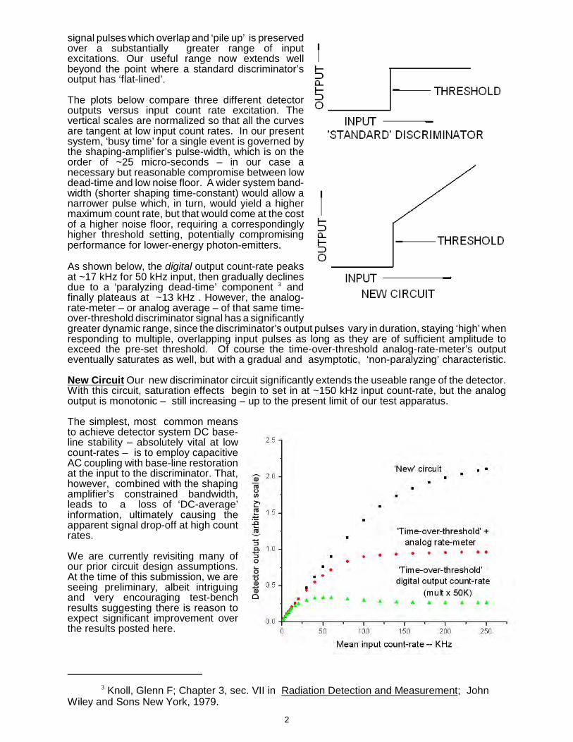
signal pulses which overlap and ‘pile up’ is preservedover a substantially greater range of inputexcitations. Our useful range now extends wellbeyond the point where a standard discriminator’soutput has ‘flat-lined’. The plots below compare three different detectoroutputs versus input count rate excitation. Thevertical scales are normalized so that all the curvesare tangent at low input count rates. In our presentsystem, ‘busy time’ for a single event is governed bythe shaping-amplifier’s pulse-width, which is on theorder of ~25 micro-seconds – in our case anecessary but reasonable compromise between lowdead-time and low noise floor. A wider system band-width (shorter shaping time-constant) would allow anarrower pulse which, in turn, would yield a highermaximum count rate, but that would come at the costof a higher noise floor, requiring a correspondinglyhigher threshold setting, potentially compromisingperformance for lower-energy photon-emitters.
As shown below, the digital output count-rate peaksat ~17 kHz for 50 kHz input, then gradually declinesdue to a ‘paralyzing dead-time’ component and3
finally plateaus at ~13 kHz . However, the analog-rate-meter – or analog average – of that same time-over-threshold discriminator signal has a significantlygreater dynamic range, since the discriminator’s output pulses vary in duration, staying ‘high’ whenresponding to multiple, overlapping input pulses as long as they are of sufficient amplitude toexceed the pre-set threshold. Of course the time-over-threshold analog-rate-meter’s outputeventually saturates as well, but with a gradual and asymptotic, ‘non-paralyzing’ characteristic.
New Circuit Our new discriminator circuit significantly extends the useable range of the detector.With this circuit, saturation effects begin to set in at ~150 kHz input count-rate, but the analogoutput is monotonic – still increasing – up to the present limit of our test apparatus.
The simplest, most common meansto achieve detector system DC base-line stability – absolutely vital at lowcount-rates – is to employ capacitiveAC coupling with base-line restorationat the input to the discriminator. That,however, combined with the shapingamplifier’s constrained bandwidth,leads to a loss of ‘DC-average’information, ultimately causing theapparent signal drop-off at high countrates.
We are currently revisiting many ofour prior circuit design assumptions.At the time of this submission, we areseeing preliminary, albeit intriguingand very encouraging test-benchresults suggesting there is reason toexpect significant improvement overthe results posted here.
2

Extending a Scintillation g
Counter’s D
ynamic R
angey
g
By
Li
Cll
Lewis C
arrollC
arroll & R
amsey A
ssociatesB
erkeley, CA
US
AForo
XIII W
orkshop on Targetry and Target Chem
istryR
oskildeD
enmark
July2010
Roskilde, D
enmark July, 2010
Oursolid-state
radiationO
ur solid-state radiation detectorproducts
aredetector products are categorized
accordingto
two
categorizedaccording to tw
o distinct
modes
ofSignal
distinct modes of S
ignal P
rocessing:P
rocessing:
1)Pulse m
ode )2)D
C-current m
ode )
2
Pulsem
odeentails
processingPulse m
odeentails processing
eachdetected
photonevent
each detectedphoton event –
pulseby
pulsepulse by pulse.
3
Thisperm
itsthe
useofa
This permits the use of a
thresholddiscrim
inatortothreshold
discriminatorto
eliminate
noiseand
tom
inimize
eliminate noise
and to minim
ize base-line
fluctuationand
drift.base
line fluctuation and drift.
4
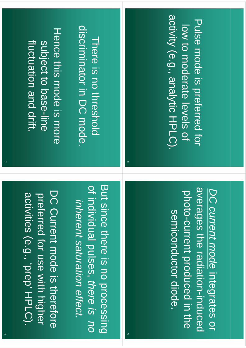
Pulse m
ode is preferred for low
to moderate levels of
activity (e.g., analytic HP
LC).
5
CD
C current m
odeintegrates or
thdi
tii
dd
averages the radiation-induced h
tt
dd
ith
photo-current produced in the i
dt
did
semiconductor diode.
6
Thereis
nothreshold
There is no threshold discrim
inatorinD
Cm
odediscrim
inator in DC
mode.
Hence
thism
odeis
more
Hence this m
ode is more
subjecttobase-line
subject to baseline
fluctuation and drift.
7
Bt
ith
ii
But since there is no processing fi
diid
ll
thi
of individual pulses, there is no inherentsaturation
effectinherent saturation effect.
DC
Currentm
odeis
thereforeD
C C
urrent mode is therefore
preferredforuse
with
higherpreferred for use w
ith higher activities
(eg
‘prep’HP
LC)
activities (e.g., prep H
PLC
).
8
910
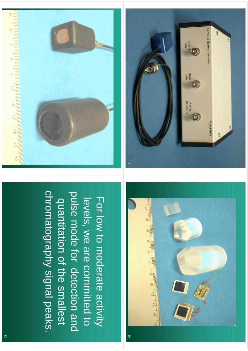
For low to m
oderate activity ylevels, w
e are comm
itted to pulse m
ode for detection and quantitation of the sm
allest chrom
atography signal peaks.
12
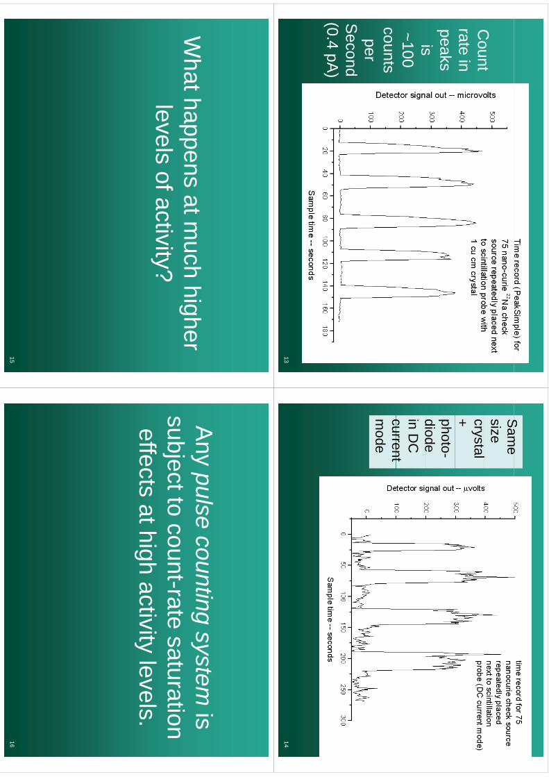
Count
Count
rate in peaks
isis~100
counts perper
Second
(04
A)
(0.4 pA)
13
Sam
eS
ame
size crystal + photo-diodediode in D
C
currentcurrent m
ode
14
What happens at m
uch higher pp
glevels of activity?y
15
Al
tit
iA
ny pulse counting system is
bjtt
tt
tti
subject to count-rate saturation effects
athighactivity
levelseffects at high activity levels.
16
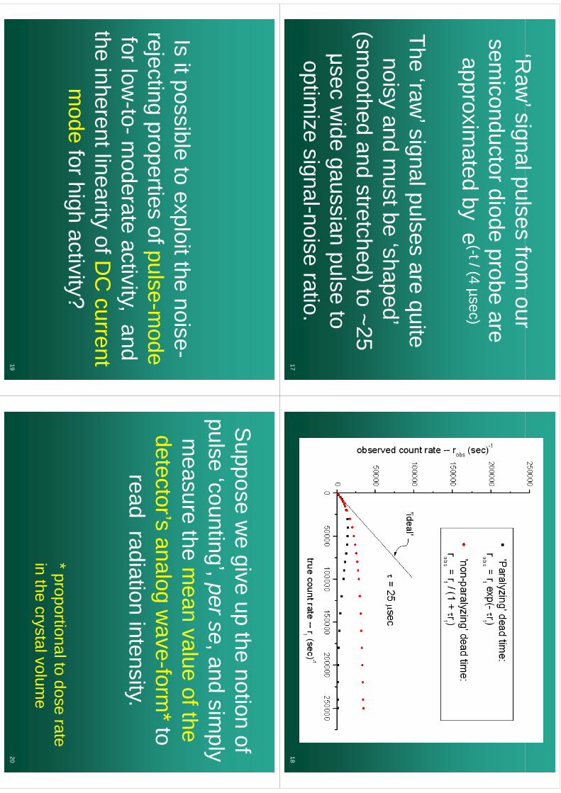
‘Raw
’signalpulsesfrom
ourR
aw signal pulses from
our sem
iconductordiodeprobe
aresem
iconductor diode probe are approxim
atedby
e(-t / (4 µsec)
approximated by e
The ‘raw’ signal pulses are quite
noisy and must be ‘shaped’
(smoothed and stretched) to ~25
idi
lt
μsec wide gaussian pulse to
optimize
signalnoiseratio
optimize signal-noise ratio.
1718
Isitpossible
toexploitthe
noiseIs it possible to exploit the noise-
rejectingproperties
ofpulse-mode
rejecting properties of pulse-mode
forlow-to-m
oderateactivity
andfor low
tom
oderate activity, and the inherent linearity of D
C current
ym
odefor high activity?
gy
19
Suppose
we
giveup
thenotion
ofS
uppose we give up the notion of
pulse‘counting’
perseand
simply
pulse counting, per se, and sim
ply m
easurethe
mean
valueofthe
measure the m
ean value of the detector’s analog w
ave-form*to
gread radiation intensity.
*ti
ltd
t* proportional to dose rate in the cr ystal volum
ey
20
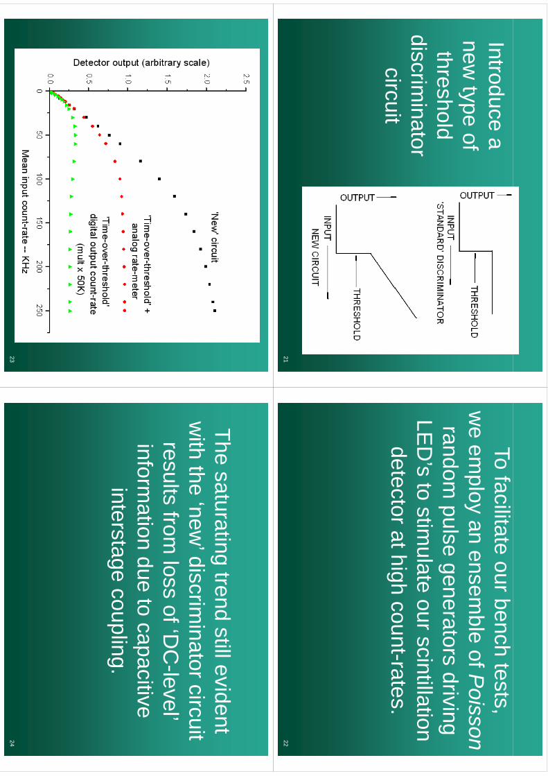
Introduce a new
type of threshold
dii
it
discriminator
circuitcircuit
21
To facilitate our bench tests, l
blfP
iw
e employ an ensem
ble of Poisson
randompulse
generatorsdriving
random pulse generators driving
LED
’sto
stimulate
ourscintillationLE
Ds to stim
ulate our scintillation detectorathigh
count-ratesdetector at high countrates.
22
23
The saturating trend still evident w
ith the ‘new’ discrim
inator circuit results from
loss of ‘DC
-level’ i
fti
dt
itiinform
ation due to capacitive interstage
couplinginterstage coupling.
24
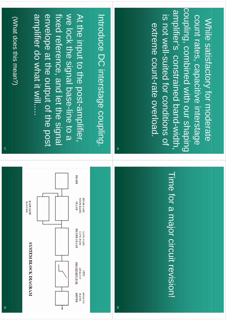
Whil
if
fd
While satisfactory for m
oderate t
titi
it
tcount rates, capacitive interstage
couplingcom
binedw
ithourshaping
coupling, combined w
ith our shaping am
plifier’sconstrained
band-width
amplifiers constrained band
width,
isnotw
ell-suitedforconditions
ofis not w
ellsuited for conditions of extrem
e count-rate overload.
25
fTim
e for a major circuit revision!
26
IntroduceD
Cinterstage
coupling.Introduce D
C interstage coupling.
At the input to the post-am
plifier, w
e lock the signal base-line to a fixed reference, and let the signal
ltth
tt
ftht
envelope at the output of the post am
plifierdow
hatitwill
amplifier do w
hat it will.....
(Whatdoes
thism
ean?)(W
hat does this mean?)
2728
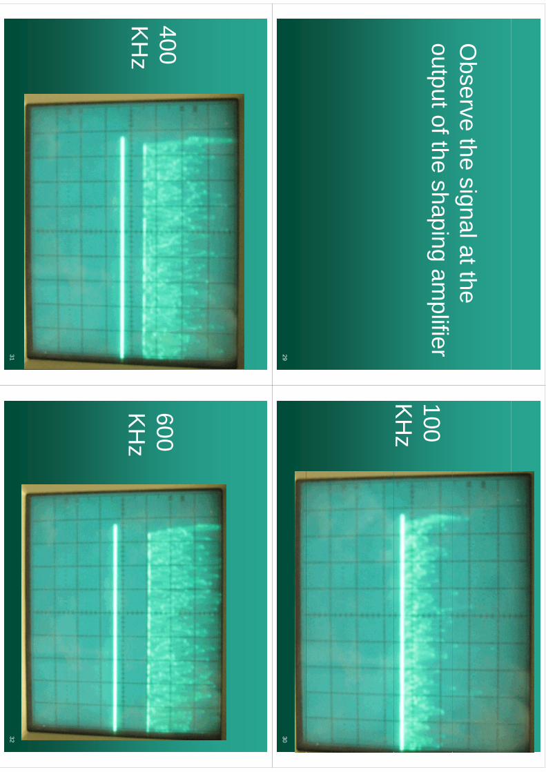
Observe the signal at the
output of the shaping amplifier
29
100 K
Hz
30
400 K
Hz
31
600 K
Hz
32
800800 K
HK
Hz
33
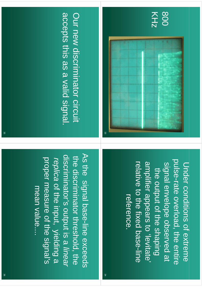
Ud
diif
Under conditions of extrem
e l
tl
dth
tipulse-rate overload, the entire signalenvelope
observedat
signal envelope observed at the
outputoftheshaping
the output of the shapingam
plifierappearsto
‘levitate’am
plifier appears to levitate
relative to the fixed base-line reference.
34
Ournew
discriminatorcircuit
Our new
discriminator circuit
acceptsthis
asa
validsignal
accepts this as a valid signal.
35
Ah
ilb
lid
As the signal base-line exceeds
thdi
ii
tth
hld
ththe discrim
inator threshold, the discrim
inator’soutputis
alinear
discriminators output is a
linear replica
oftheinput
yieldinga
replicaof the input, yielding a
propermeasure
ofthesignal’s
proper measure of the signals
mean value....
36

As
ifwe
areoperating
in...A
s if we are operating in
DC
currentmode*
!D
C current m
ode !
37
* A “stabilized base-line” and“D
C current m
ode” are t
lll
im
utually exclusive….
38
A stabilized base-line, in j
tiith
thh
ldconjunction w
ith a threshold discrim
inatoris
essentialfordiscrim
inator, is essential for noise-free
detectionatlow
noise-free detection at low
excitationsbutitis
notexcitations, but it is not com
patible with true D
C
pcurrent m
ode operation.p
39
Recap:
, including a threshold p
gdiscrim
inator, is preferred at very low excitations
dueto
‘cleaner’base-lineand
betterdetectabilitydue to cleaner base
line and better detectabilityfor w
eak signal peaks. doesn’t
saturateand
istherefore
preferredforvery
highsaturate, and is therefore preferred for very high excitations.
40
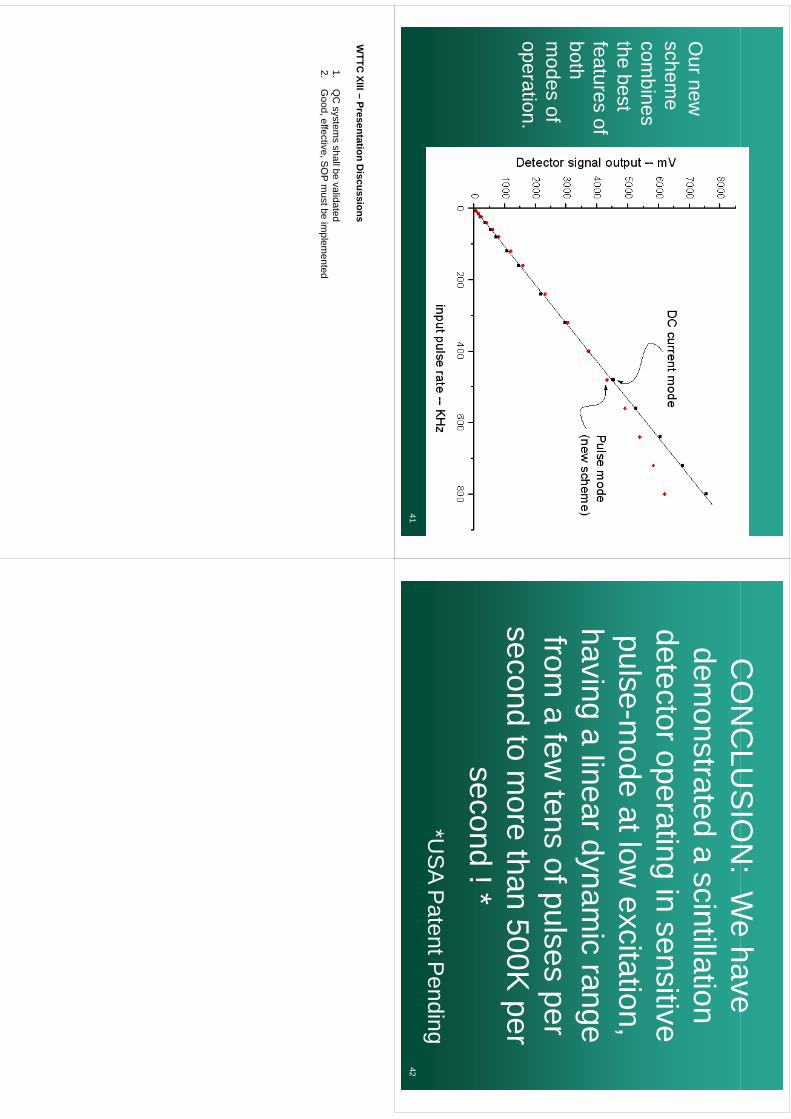
Ournew
Our new
schem
e com
bines the best features of bothboth m
odes of operationoperation.
41
CO
NC
LUS
ION
:W
ehave
CO
NC
LUS
ION
: We have
demonstrated
ascintillation
demonstrated a scintillation
detector operating in sensitive p
gpulse-m
ode at low excitation,
phaving a linear dynamic range
from a few
tens of pulses per d
tth
500Ksecond to m
ore than 500K per
second!*
second ! **U
SA
Pt
tPdi
*US
A Patent P
ending42
WTTC
XIII –Presentation D
iscussions
1.Q
C system
s shall be validated2.
Good, effective, S
OP m
ust be implem
ented
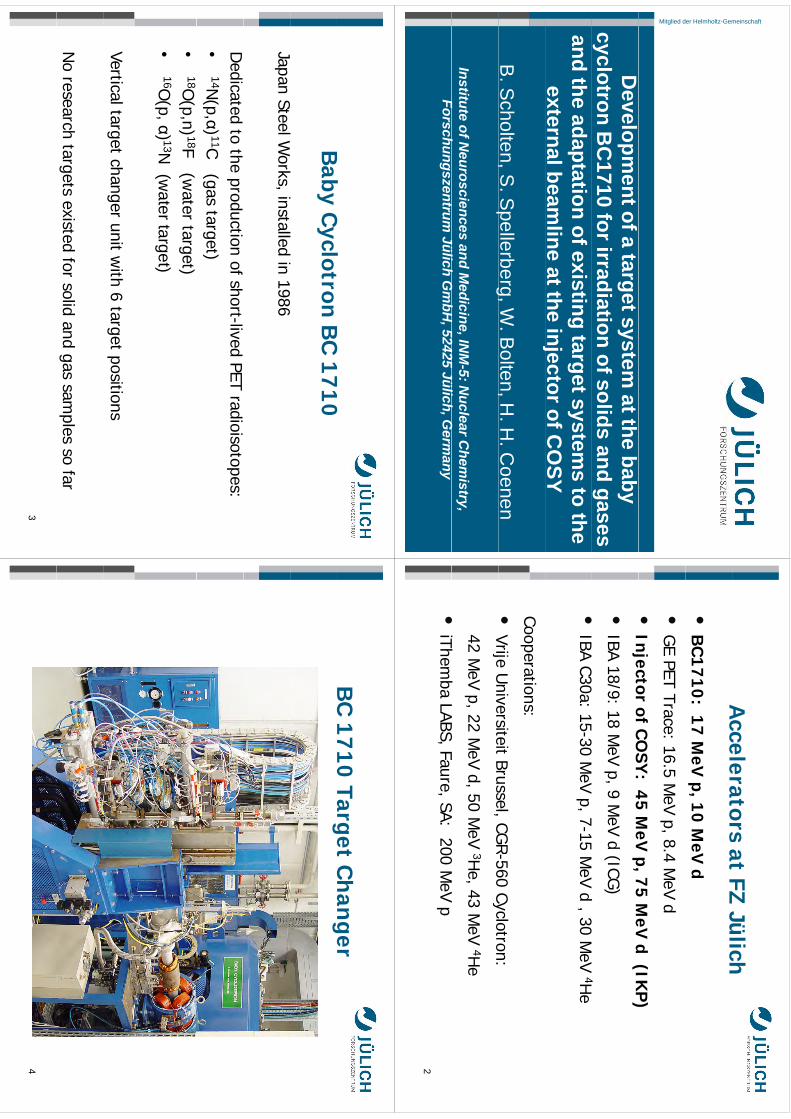
Development of a target system at the baby cyclotron BC1710 for
irradiation of solids and gases and the adaptation of existing target
systems to the external beamline at the injector of COSY
B. Scholten, S. Spellerberg, W. Bolten, H. H. Coenen
Institute of Neurosciences and Medicine, INM-5: Nuclear Chemistry, Forschungszentrum Jülich GmbH, 52425 Jülich, Germany
In former years most of our radionuclide development studies were done at the compact cyclotron CV 28 of the Forschungszentrum Jülich. Several dedicated target systems were constructed to irradiate solid and gaseous targets, either for cross section measurements or for production of radionuclides [1-16 ].
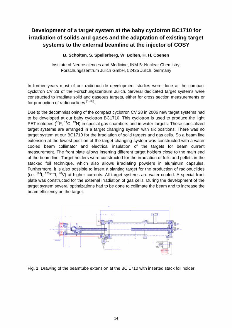
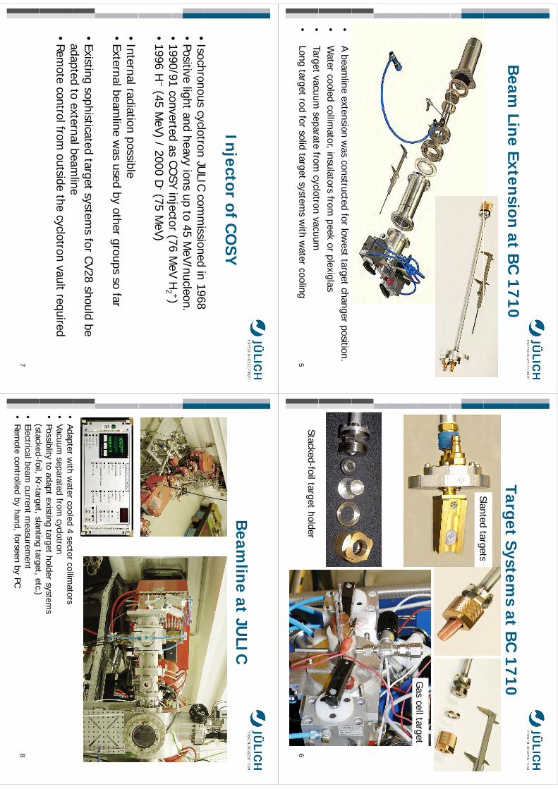
Due to the decommissioning of the compact cyclotron CV 28 in 2006 new target systems had to be developed at our baby cyclotron BC1710. This cyclotron is used to produce the light PET isotopes (18F, 11C, 13N) in special gas chambers and in water targets. These specialized target systems are arranged in a target changing system with six positions. There was no target system at our BC1710 for the irradiation of solid targets and gas cells. So a beam line extension at the lowest position of the target changing system was constructed with a water cooled beam collimator and electrical insulation of the targets for beam current measurement. The front plate allows inserting different target holders close to the main end of the beam line. Target holders were constructed for the irradiation of foils and pellets in the stacked foil technique, which also allows irradiating powders in aluminum capsules. Furthermore, it is also possible to insert a slanting target for the production of radionuclides (i.e. 124I, 120g+mI, 48V) at higher currents. All target systems are water cooled. A special front plate was constructed for the external irradiation of gas cells. During the development of the target system several optimizations had to be done to collimate the beam and to increase the beam efficiency on the target.
Fig. 1: Drawing of the beamtube extension at the BC 1710 with inserted stack foil holder.
14
kmje
Typewritten Text
Abstract 002
kmje
Typewritten Text
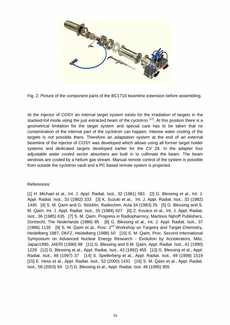
Fig. 2: Picture of the component parts of the BC1710 beamline extension before assembling.
At the injector of COSY an internal target system exists for the irradiation of targets in the stacked-foil mode using the just extracted beam of the cyclotron [17]. At this position there is a geometrical limitation for the target system and special care has to be taken that no contamination of the internal part of the cyclotron can happen. Intense water cooling of the targets is not possible there. Therefore an adaptation system at the end of an external beamline of the injector of COSY was developed which allows using all former target holder systems and dedicated targets developed earlier for the CV 28. In the adapter four adjustable water cooled sector absorbers are built in to collimate the beam. The beam windows are cooled by a helium gas stream. Manual remote control of the system is possible from outside the cyclotron vault and a PC based remote system is projected.
References:
[1] H. Michael et al., Int. J. Appl. Radiat. Isot., 32 (1981) 581 [2] G. Blessing et al., Int. J. Appl. Radiat. Isot., 33 (1982) 333 [3] K. Suzuki et al., Int. J. Appl. Radiat. Isot., 33 (1982) 1445 [4] S. M. Qaim and G. Stöcklin, Radiochim. Acta 34 (1983) 25 [5] G. Blessing and S. M. Qaim, Int. J. Appl. Radiat. Isot., 35 (1984) 927 [6] Z. Kovács et al., Int. J. Appl. Radiat. Isot., 36 (1985) 635 [7] S. M. Qaim, Progress in Radiopharmcy, Martinus Nijhoff Publishers, Dortrecht, The Nederlands (1986) 85 [8] G. Blessing et al., Int. J. Appl. Radiat. Isot., 37 (1986) 1135 [9] S. M. Qaim et al., Proc. 2nd Workshop on Targetry and Target Chemistry, Heidelberg 1987, DKFZ, Heidelberg (1988) 50 [10] S. M. Qaim, Proc. Second International Symposium on Advanced Nuclear Energy Research - Evolution by Accelerators, Mito, Japan1990, JAERI (1990) 98 [11] G. Blessing and S.M. Qaim, Appl. Radiat. Isot., 41 (1990) 1229 [12] G. Blessing et al., Appl. Radiat. Isot., 43 (1992) 455 [13] G. Blessing et al., Appl. Radiat. Isot., 48 (1997) 37 [14] S. Spellerberg et al., Appl. Radiat. Isot., 49 (1998) 1519 [15] E. Hess et al., Appl. Radiat. Isot., 52 (2000) 1431 [16] S. M. Qaim et al., Appl. Radiat. Isot., 58 (2003) 69 [17] G. Blessing et al., Appl. Radiat. Isot. 46 (1995) 955
15
meinschaftder Helmholtz-GemMitglied d
Developm
ent of a target system at the baby
cyclotron BC
1710 for irradiation of solids and gases and the adaptation of existing target system
s to the external beam
line at the injector of CO
SYj
B. S
cholten, S. Spellerberg, W
. Bolten, H
. H. C
oenen,
pg,
,
Institute of Neurosciences and M
edicine, INM
-5: Nuclear C
hemistry,
Fh
tJüli
hG
bH52425
Jülih
GForschungszentrum
Jülich Gm
bH, 52425 Jülich, G
ermany
Accelerators
atFZ
JülichA
cceleratorsat
FZ Jülich
•B
C1710: 17 M
eV p, 10 M
eV d
•G
E PET Trace: 16.5 MeV p, 8.4 M
eV d
•In
jectorof
CO
SY:
45M
eVp,75
MeV
d(IK
P)
Injector of C
OSY
: 45 MeV
p, 75 MeV
d (IKP
)
•IBA 18/9: 18 M
eV p, 9 MeV d (ICG
)
IBAC30
1530
MV
715
MV
d30
MV
4H•
IBA C30a: 15-30 MeV p, 7-15 M
eV d , 30 MeV 4H
e
Cooperations:
•Vrije
Universiteit
Brussel,CGR-560
Cyclotron:Vrije U
niversiteit Brussel, CGR
560 Cyclotron:
42 MeV p, 22 M
eV d, 50 MeV 3H
e, 43 MeV 4H
e
•iTh
bLABS
FSA
200M
V•
iThemba
LABS, Faure, SA: 200 MeV p
2
Bb
Cl
tB
C1710
Baby C
yclotron BC
1710
JS
lWk
ill
di
1986Japan Steel W
orks, installed in 1986
Dedicated to the production of short-lived PET radioisotopes:
•14N
(p,α) 11C (gas target)•
18O(p,n) 18F (w
atertarget)
•16O
(p,α) 13N (w
atertarget)
Vertical target changer unit with 6 target positions
No research targets existed for solid and gas sam
ples so far
3
BC
1710 Target Ch
anger
C0
aget
Ca
ge
4
Beam
LineExtension
atB
C1710
Beam
Line Extension at BC
1710
•A
beamline
extensionw
asconstructed
forlow
esttarget
changerposition.
•W
atercooled
collimator,
insulatorsfrom
peekor
plexiglasTarget
vacuumseparate
fromcyclotron
vacuum•
Targetvacuum
separatefrom
cyclotronvacuum
•Long
targetrod
forsolid
targetsystem
sw
ithw
atercooling
5
Tt
St
tB
C1710
Target Systems at B
C 1710
Slantedtargets
Slanted targets
Gas
celltargetG
as cell target
Stacked-foiltarget holder6
Injector ofC
OSY
Ih
lt
JULIC
ii
di
1968•
Isochronous cyclotron JULIC com
missioned in 1968
•Positive light and heavy ions up to 45 M
eV/nucleon. •
1990/91converted
asCO
SYinjector
(76M
eVH
2 +)1990/91 converted as CO
SY injector (76 MeV H
2)
•1996 H
−(45 M
eV) / 2000 D-(75 M
eV)
•Internal radiation possible
•External beam
line was used by other groups so far
•Existing sophisticated target system
s for CV28 should be adapted
toexternalbeam
lineadapted to external beam
line•
Remote control from
outside the cyclotron vault required
7
Beam
lineat
JULIC
Beam
line atJU
LIC
Adt
itht
ld
4t
llit
•Adapter w
ith water cooled 4 sector
collimators
•Vacuum
separatedfrom
cyclotron•
Possiblity to adapt existing target holder systems
(stackedfoil
Krtarget
slantingtarget
etc)
(stacked-foil, Kr-target, slanting target, etc.) •
Electrical beam current m
easurement
•Rem
ote controlled by hand, forseen by PC 8
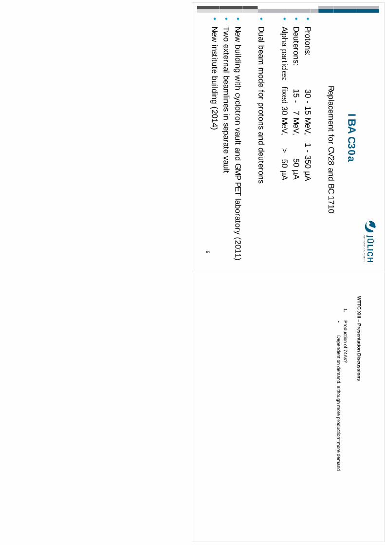
IBA
C30a
Rl
tf
CV28d
BC1710
Replacement
for CV28 and BC 1710
Pt
3015
MV
1350
A•
Protons: 30 -15 M
eV, 1-
350 µA•
Deuterons: 15 -
7 MeV, 50 µA
f•
Alpha particles: fixed30 M
eV, > 50
µA
•D
ual beam m
ode for protons and deuterons
•N
ew building w
ith cyclotron vault and GM
P PET laboratory (2011)•
Two external beam
lines in separate vault•
New
institutebuilding
(2014)9
WTTC
XIII –Presentation D
iscussions
1.P
roduction of 74As?
•D
ependent on demand, although m
ore production=more dem
and

Search for the ideal cyclotron stripper foil John O. Stoner, Jr. ACF-Metals, The Arizona Carbon Foil Co., Inc. 2239 E. Kleindale Road Tucson, Arizona 85719-2440 U.S.A. <[email protected]> Although carbon stripper foils can now be obtained in any thickness desired by the cyclotron user, it is still necessary to replace foils occasionally because of their finite lifetimes. Limits on lifetime occur because of poor mounting, vacuum disasters, mechanical shock, nuclear collisions (causing violent atomic displacements), thickening, nuclear and electronic heating with resulting evaporation and diffusion, erosion by residual gas, and many other effects. Beam currents are increasing steadily; this trend is expected to continue. Most problems are accentuated at higher beam currents. ACF-Metals is searching through foil compositions, allotropes and mounting methods to identify promising routes to obtaining longer-lasting foils.
19
kmje
Typewritten Text
Abstract 003

Carbon Foils:
ffeatureThickness <1 nm
to >20 µm
Am
orphous, graphitic, or pyrolyticLow
Z, High strength
,g
gW
ithstand high temperature
AC
FM
lA
CF-M
etals2239 E. K
leindale Road
Tucson AZ 85719
<metalfoil @
cox.net>@
Wh
AC
FM
tl
?W
hy AC
F-Metals?
High quality foils; experienced g
qy
;p
personnel.Flexible
productionofunusualtypes.
Flexible production of unusual types.Q
uantity production of standard foils.C
ontinuingresearch
toim
prove:C
ontinuing research to improve:
Materials &
frames
Fill
iFoil longevityO
peration in extreme conditions
2
SNS
SNS
(Oak R
idge)Stripper
Accum
ulator
Ring to
Target
Stripper Foil
Ring
Target B
eam
Transfer
High E
nergy B
eam
Transport≈ 60 m
eters(R
TB
T)
line
Transport (H
EB
T) line
meters
1.3 GeV
H-
beam from
L
i
Target area
Linac
area
Accelerator C
ost: approx. 1B $ (1 G
$)pp
$(
$)Stripper foil ~1 cm
x 5 cmO
ne carbon stripper foil cost: approx. $3003
Research:
Better
mountingsfor
longerlifetim
esB
etter mountings for longer lifetim
esE
xample: Fiber-m
ounted foils for SNS and other
acceleratorsaccelerators.
4
3i
Cf
ilt
tf
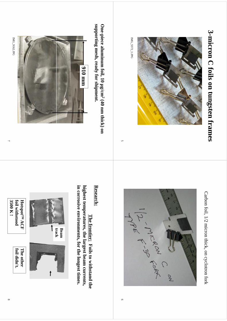
3-micron C
foils on tungsten frames
IMG
_5572_1.JPG
5
Carbon foil, 1/2 m
icron thick, on cyclotron fork
6
One-piece alum
inum foil, 10 µg/cm
2(40 nm thick) on
supporting mesh, ready for shipm
ent.
910 mm
IMG
9162JPG
IMG
_9162.JPG
7
Research:
The frontier:
Foils to withstand the
highest temperatures, the largest beam
currents, in corrosive environm
ents, for the longest times.
BBeam
track
Hotspot™
AC
F foil w
ithstood T
he other foil didn't.
3500 K !
8

Carbon Foils:
ffeatureThickness <1 nm
to >20 µm
Am
orphous, graphitic, or pyrolyticLow
Z, High strength
,g
gW
ithstand high temperature
AC
F-Metals
2239E.K
leindaleR
oad2239 E. K
leindale Road
Tucson AZ 85719
<metalfoil@
coxnet>
<metalfoil@
cox.net>
9
WTTC
XIII–Presentation
Discussions
WTTC
XIII –Presentation D
iscussions
1.Foil m
aintenance•
Ram
pup
beamslow
ly•
Ram
p up beam slow
ly•
Storage: D
esiccators/refrigerators not needed
New Gaseous Xenon Target for 123I Production
Jožef J. Čomor 1, ðuro Jovanovi ć1, Jean-Michel Geets 2, Bernard Lambert 3
1ELEX Commerce, Hilandarska 28, 11000 Belgrade, Serbia 2IBA Molecular, Chemin du Cyclotron 3, 1348 Louvain-la-Neuve, Belgium 3IBA Molecular Europe, Le christ de Saclay B.P. 32, 91192 Gif-Sur-Yvette, France
123I is one of the best suited radionuclides for SPECT (Single Photon Emission Computed Tomography) due to its short half life (13.2 h) and low absorbed dose in patients for its low energy gamma emission (154 keV), which is ideal for detection by common scintillation detectors. It is most commonly produced in gaseous Xe targets irradiating highly enriched 124Xe by 30 MeV protons and exploiting the indirect production path via 123Xe. This technology is well established and performed in several cyclotron centers; however radiation safety aspects and the danger of losing the expensive target material are always a concern. Thus, every effort is needed to ensure that the target remains tight during irradiation, while the service and maintenance should be quick and reliable in order to reduce the dose received by the personnel. The most critical part of every gaseous target is the double window system, there are two possible approaches in handling this issue: hard bolting the windows via flanges and metal seals to the target body, or using window packages, which can be remotely replaced prior failure of elastomer seals. The first approach allows for long periods between scheduled replacements of the target assembly (approx. once in 12 months); however the radiation dose received by the operator during this maintenance is substantial. Moreover, one needs at least two complete targets for uninterrupted production (one in operation while the other is cooling down for maintenance). The second approach requires more frequent replacement of the window package (approx. once in 3 months) without any radiation hazard for the operators. It is obvious that this second approach is more favorable, thus the new target station has been developed following this concept, with the aim to provide more reliable operation than what the existing target stations can provide. To this end a new mechanism for window foil package replacement has been designed. Unlike the previous target stations, it has no robotic arm. Moreover, there are no sliding seal based connections for compressed air and helium, thus the reliability of the window package replacement mechanism is greatly increased and in the same time the possibility of losing the target material from the helium cooling loop in case of window burst is negligible. In addition, the target locking mechanism has been also improved: previous designs relied on uninterrupted compressed air supply, thus in case of accidental burst of supply tubing during the irradiation the enriched target material would be lost and the vault would be heavily contaminated. The new locking mechanism keeps the target chamber normally locked. Compressed air is needed only for unlocking the target chamber for window package replacement, i.e. the safety of the target station does not depend on external factors. The target is patent pending and detailled design will be presented later on (at time of conference).
23
kmje
Typewritten Text
Abstract 004

&E
LEX
ELE
XCOMMERCE
New
Gaseous
XenonTargetfor
Xenon Target for 123I Production
JožefČom
orJožef Č
omor
Đuro Jovanović
Jean-Michel G
eetsB
ernard Lambert
State of the art
Irradiation of gaseous 124Xe is the m
ost cost effective w
ay for large-scale 123I production
There
aretw
ocom
mon
approachesto
thetarget
There are tw
o comm
on approaches to the target design:
Hd
blt
dfl
fii
thi
dt
th
Hard bolted flanges fixing the w
indows to the
target body (R. R
obertson, D.C
. Stuart,
US
4622
201W
ZG
lbt
RA
PS
KU
S4,622,201; W
.Z. Gelbart, R
.A. P
avan, S.K
. Zeisler, C
A2691484)
W
indows pre-assem
bled into remotely
exchangeable packages (V. B
echtold, H.
gp
g(
Schw
eickert, US
4,945,251 and the KIP
RO
S target
station)
© 2006
ELE
X COMMERCE
&2
Nordion/Trium
f/AC
SI approach
The good:
V
ery high current acceptance and yield
Infrequent (annual) target m
aintenance
The
bad:
The bad:
A
t least two target sets are needed for norm
al ti
operation
V
ery high dose delivered to the operators during y
gp
gm
aintenance
© 2006
ELE
X COMMERCE
&3
KIPR
OS approach
The good:
H
igh current acceptance and yield
R
emote target m
aintenance –m
inimum
dose to the operators
A
ffordable replacement w
indow packages
Th
bd
The bad:
The sliding seals used in the robotic arm
might fail
gg
unexpectedly due to radiation damage
© 2006
ELE
X COMMERCE
&4
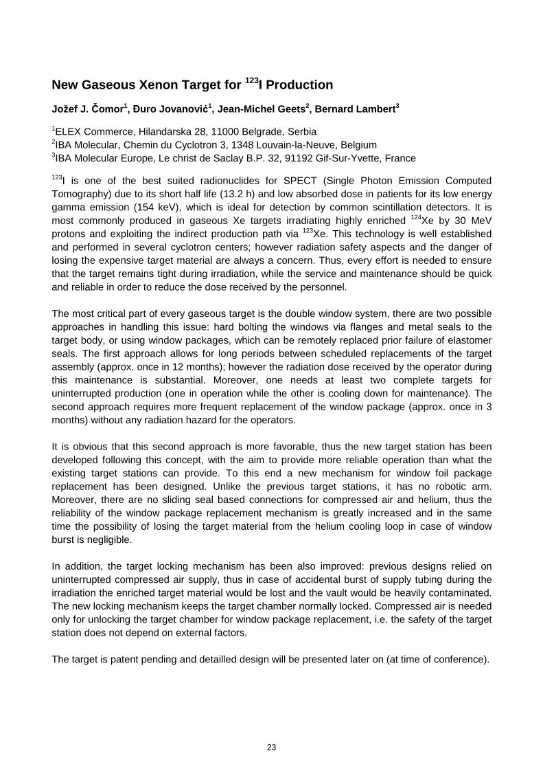
What if a new
system is to be designed?
The rem
ote exchange of window
packages is a great advantage (A
LAR
A principle)
Therefore
followthis
principleand
inaddition:
Therefore, follow
this principle and in addition:
S
implify the w
indow package replacem
ent h
im
echanism
D
esigna
fool-proofinsertionprinciple
(theD
esign a foolproof insertion principle (the orientation of the double w
indow insert is crucial)
Di
fl
fttl
kih
i
Design a fool-proof target locking m
echanism
© 2006
ELE
X COMMERCE
&5
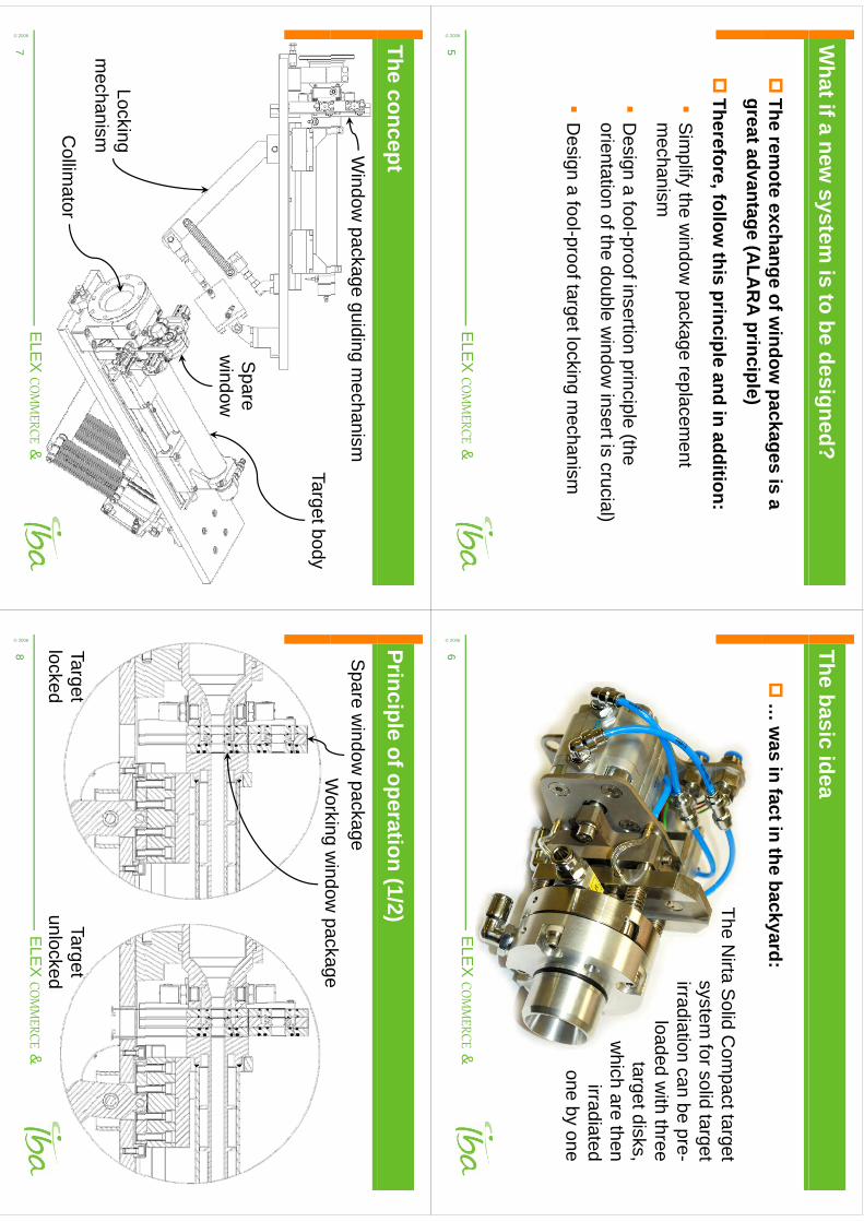
The basic idea
…
was in fact in the backyard:
The Nirta S
olid Com
pact targetsystem
for solid targetirradiation can be pre-
loaded with three
target disks,hi
hth
which are then
irradiatedb
one by one
© 2006
ELE
X COMMERCE
&6
The conceptWindow
package guiding mechanism
Target body
Spare
window
Lockingm
echanismCollim
ator
mechanism
© 2006
ELE
X COMMERCE
&7
Principle of operation (1/2)
Working
window
packageS
pare window
packageW
orking window
package
Target locked
Target unlocked
© 2006
ELE
X COMMERCE
&8 locked
unlocked
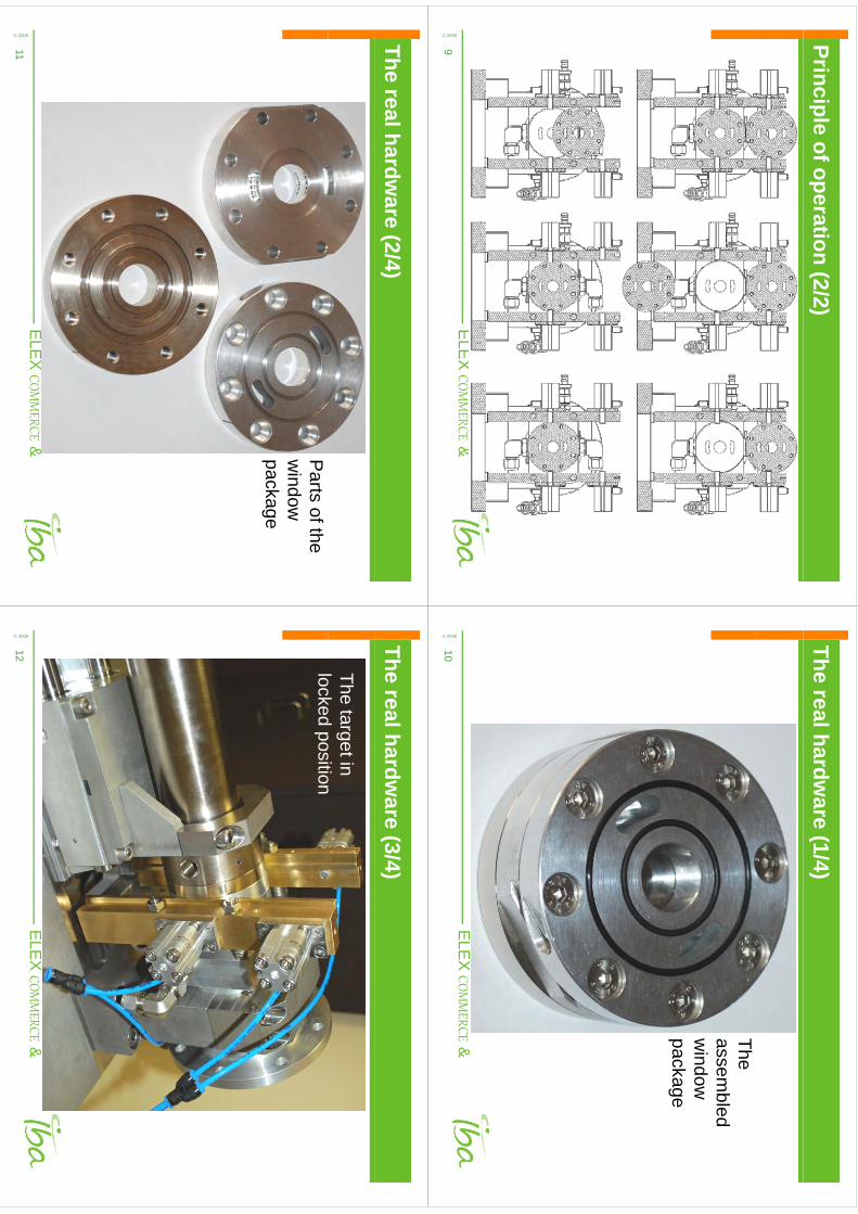
Principle of operation (2/2)© 2006
ELE
X COMMERCE
&9
The real hardware (1/4)
The assem
bled w
indow
package
© 2006
ELE
X COMMERCE
&10
The real hardware (2/4)
Parts of the
window
package
© 2006
ELE
X COMMERCE
&11
The real hardware (3/4)
The target in l
kd
itilocked position
© 2006
ELE
X COMMERCE
&12
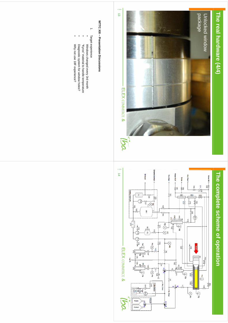
The real hardware (4/4)
Unlocked w
indow
kpackage
© 2006
ELE
X COMMERCE
&13
The complete schem
e of operation
© 2006
ELE
X COMMERCE
&14
WTTC
XIII–Presentation
Discussions
WTTC
XIII –Presentation D
iscussions
1.Target experience•
Window
schanged
every3rd
month
•W
indows changed every 3rd m
onth•
“Kyros” m
aterial to handle temperature
•D
iagnostic system for w
indow holes?
•W
hynotuse
18Fexperience?
•W
hy not use 18F experience?
Mass Production of 64Cu with 64Ni(p,n)64Cu Nuclear Reaction
Kwon Soo Chun*, Hyun Park, Jaehong Kim
Korea Institute of Radiological and Medical Sciences, Seoul, Korea
* Corresponding author: [email protected]
Introduction
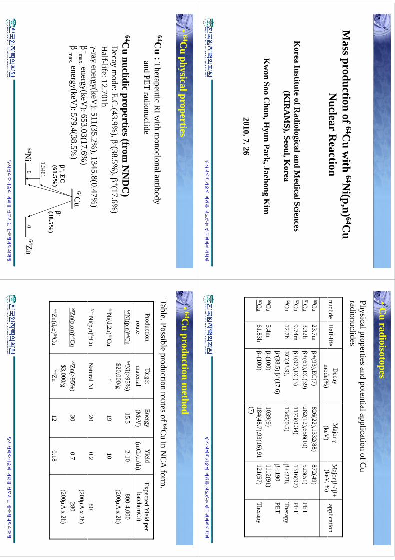
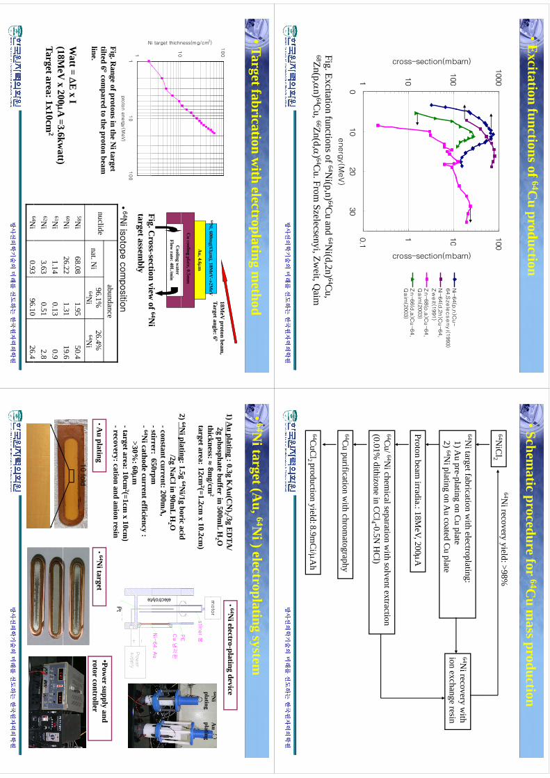
64Cu (T1/2 = 12.7h, β- decay: 40%, β+ decay: 19%, E.C. decay: 41%) is one of the most useful radioisotope in nuclear medicine due to its multiple decay mode and the intermediate half-life. Several nuclear reactions, i.e., 64Ni(p,n)64Ni, 68Zn(p,αn)64Cu and 64Ni(d,2n)64Cu have been investigated for 64Cu production[1,2]. The highest production yield could be obtained with proton irradiation on the enriched 64Ni target. Therefore for mass and routine production, the 64Ni target fabrication by using electroplating[3], the reliable chemical separation of 64Cu from the irradiated 64Ni target and the effective recovery process for the recycling of very expensive enriched material ( 64Ni enrichment : 96%, $20,000/g) and so on are absolutely necessary to be established. In this work, we report our mass production method of 64Cu with enriched 64Ni and Cyclone-30 accelerator.
Methods
64Cu was produced with high current cyclotron via 64Ni(p,n)64Cu nuclear reaction at 200μA, 18MeV proton beam. Nickel target was prepared by electro-plating of enriched 64Ni (25% of enrichment) on Au coated Cu cooling plate. After proton beam irradiation, Ni target was dissolved with circulation of 50ml of 5N HCl on the dissolving device (home made) and 90°C heating. Water was added to 64Ni solution to dilute the normality of hydrochloric acid to 0.5N. Radiochemical separation of 64Cu from Ni target solution was performed with 0.01% dithizone in CCl4 solvent extraction and back extraction with 7N HCl[4]. Purification of back extracted 64Cu solution was carried out with AG1-x8 (Bio-Rad) anion exchange resin. For 64Ni recycling, 64Ni from the aqueous phase of solvent extraction and the electrolyte of electroplating was recovered by using AG1-x8 anion and AG50w-x8 (Bio-Rad) cation resin[5].
Results
With the electroplating cell designed by ourselves and the electrolyte, consisting of 1.5g 64Ni(25% enrichment), 1.0g boric acid and 2.0g NaCl in 90ml distilled water, the smooth and uniformed Ni target (thickness : > 50mg/cm2, area: 1 x 10cm2) was obtained with applying 200mA of constant current on the cathode for 5hrs. The cathode current efficiency was about 50%. There was no damage on Ni surface during more than 200μA proton beam irradiation. The chemical separation yield of 64Cu with solvent extraction and anion exchange resin was more than 90% and the radionuclidic purity was more than 99% 1 day after bombardment. The 64Ni recovery yield was quantitative and measured with 57Ni activity produced with 58Ni(p,2p)57Ni nuclear reaction and AA spectroscopy.
Conclusion
28
kmje
Typewritten Text
Abstract 005
64Cu production yield was about 9mCi/μAh corrected on 96% enrichment at EOB with 64Ni(p,n)64Cu nuclear reaction and Cyclone-30. The chemical separation yield and the radionuclidic purity of the final 64Cu solution was more than 90% and 99%, respectively. The 64Ni recovery yield performed with ion exchange resin was more than 98%.
References
[1] V.S. Smith, Molecular Imaging with Copper-64, J. Inorg. Biochem., Vol. 98, p.1874-1901, 2004
[2] F. Szelecscenyi, G. Blessing and S.M. Qaim, Excitation Functions of Proton Induced Nuclear Reactions on Enriched 61Ni and 64Ni: Possibility of Production of No-carrier-added 61Cu and 64Cu at a small Cyclotron, Appl. Radiat. Isot., Vol.44, p575-580, 1993
[3] IAEA Technical Report Series No. 432. “Standardized High Current Solid Targets for Cyclotron Production of Diagnostic and Therapeutic Radionuclieds” IAEA, Vienna, 2004
[4] A.K. Dasgupta, L.F. Mausner and S.C. Srivastava, A New Separation Procedure for 67Cu from Proton Irradiated Zn, Appl. Radiat. Isot. Vol. 42, p.371-376, 1991
[5] N. Saito, Selected data on ion exchange separations in Radioanalytical Chemistry, Pure & Appl. Chem., Vol. 56, p.523-539, 1984
29
Md
tif
64Cith
64Ni(
) 64CM
ass production of 64Cu w
ith 64Ni(p,n) 64C
u N
uclear Reaction
Korea Institute of R
adiological and Medical Sciences
(KIR
AM
S),Seoul,Korea
(KIR
AM
S), Seoul, Korea
Kw
onSoo
Chun,H
yunPark,Jaehong
Kim
Kw
on Soo Chun, H
yun Park, Jaehong Kim
2010. 7. 26
방사선의학기술의
방사선의학기술의미래를
미래를선도하는
선도하는한국원자력의학원
한국원자력의학원
•Cu radioisotopes
Physical properties and potential application of Cu
radionuclides
nuclideH
alf-lifeD
ecay d
(%)
Major
(kV
)M
ajor -/ + (keV
%)
applicationm
ode(%)
(keV)
(keV, %)
pp
60Cu
61C23.7m3
32h+(93),EC
(7)+(61)EC
(39)826(22),1332(88)282(12)656(10)
872(49)523(51)
PET61C
u62C
u64C
u
3.32h9.74m12.7h
+(61),EC(39)
+(97),EC(3)
EC(43.9),
282(12),656(10)1173(0.34)1345(0.5)
523(51)1316(97)+:278,
PETPETTherapy
Cu
66Cu
12.7h
5.4m
EC(43.9),
-(38.5)
+(17.6)-(100)
1345(0.5)
1039(9)
:278,
-:1901112(91)
TherapyPET
67Cu
61.83h-(100)
184(48.7),93(16),91(7)
121(57)Therapy
방사선의학기술의
방사선의학기술의미래를
미래를선도하는
선도하는한국원자력의학원
한국원자력의학원
•64C
u physical properties
64Cu :Therapeutic R
I with m
onoclonal antibody and PET radionuclide
64Cu nuclidic properties (from
NN
DC
)D
ecay mode: E.C
.(43.9%),
-(38.5%),
+(17.6%)
Half-life: 12.701h
-ray energy(keV): 511(35.2%
), 1345.8(0.47%)
+m
ax. energy(keV): 653.03(17.6%
)
-max. energy(keV
): 579.4(38.5%)
64Cu
-
(38.5%)
+, E
C(61.5%
)
64Zn64N
i0
1.3461
0
방사선의학기술의
방사선의학기술의미래를
미래를선도하는
선도하는한국원자력의학원
한국원자력의학원
•64C
u production method
Table. Possible production routes of 64Cu in N
CA
form.
64i(
)64
i() 64
Expected Yield per
batch(mC
i)Y
ield(m
Ci/A
h)Energy(M
eV)
Targetm
aterialProduction
route
800-4,000(200A
x 2h)2-10
10
15.5
19
64Ni(>95%
)$20,000/g
64Ni(p,n) 64C
u
64Ni(d
2n) 64Cu
80
100.2
1920N
atural Ni
Ni(d,2n)
Cu
Nat.N
i(p,n) 64Cu
(200A x 2h)
2800.7
3068Zn(>95%
)68Zn(p,n) 64C
u(200A
x 2h)0.18
12$3,000/g
66Zn66Zn(d,) 64C
u
방사선의학기술의
방사선의학기술의미래를
미래를선도하는
선도하는한국원자력의학원
한국원자력의학원
•Excitation functions of 64C
u production
1000
100
100
barn)
10
barn)
Ni
64(
)C100
ction(mb
10
ction(mb
Ni-
64(p
,n)C
u-
64,S
zele
csenyi(1
993)
Ni-
64(d
,2n)C
u-64,
Zw
eit(1
991)
Zn-68(p
a)C
u-64
10
ross-sec
1
ross-sec
Zn-68(p
,a)C
u-64,
Qaim
(2003)
Zn-66(d
,a)C
u-64,
Qaim
(2003)
c
c
1
010
20
30
ener g
y(M
eV)
0.1
gy
Fig. Excitation functions of 64Ni(p,n) 64C
u and 64Ni(d,2n) 64C
u, 68Zn(p,n) 64C
u, 66Zn(d,) 64Cu. From
Szelecsenyi, Zweit, Q
aim
방사선의학기술의
방사선의학기술의미래를
미래를선도하는
선도하는한국원자력의학원
한국원자력의학원
•Schematic procedure for 64C
u mass production
64NiC
l264N
i recovery yield: >98%
64Ni target fabrication w
ith electroplating: 1)A
upre-plating
onC
uplate
64Ni recovery w
ith i
hi
1) Au pre
plating on Cu plate
2) 64Ni plating on A
u coated Cu plate
ion exchange resin
Proton beam irradia.: 18M
eV, 200A
64Cu/ 64N
i chemical separation w
ith solvent extraction (0.01%
dithizone in CC
l4 -0.5N H
Cl)
64Cu purification w
ith chromatography
64CuC
l2 production yield:8.9mC
i/Ah
방사선의학기술의
방사선의학기술의미래를
미래를선도하는
선도하는한국원자력의학원
한국원자력의학원
2 py
•Target fabrication with electroplating m
ethod
100
)
64Ni
600mg(63m
)18M
eV
2MeV
18MeV
proton beam,
Target angle: 6
10
ness(mg/cm2
Au, 4.6m
Ni, 600m
g(63m), 18M
eV
2MeV
Cu cooling plate, 0.5m
m
10
i target thichn
Cooling w
aterFlow
rate: 40L/m
in
FigC
rosssection
viewof
64Ni
1
110
100
pro
ton
energ
y(M
eV)
N
Fig. Cross-section view
of 64Ni
target assembly
•64N
iis
oto
pe
com
positio
npro
ton e
nerg
y(M
eV)
Fig. Range of protons in the N
i target tilted 6com
pared to the proton beam
line.nuclide
abundance
natN
i96.1%
26.4%
Ni is
oto
pe c
om
positio
n
line.
Watt = E
x I(18M
V200
A3
6ktt)
nat. Ni
64Ni
64Ni
58Ni
60Ni
68.0826.22
1.951.31
50.419.6
(18MeV
x 200A =3.6kw
att)Target area: 1x10cm
261N
i62N
i64N
i
1.143.630
93
0.130.51
9610
0.92.8
264
방사선의학기술의
방사선의학기술의미래를
미래를선도하는
선도하는한국원자력의학원
한국원자력의학원
64Ni
0.9396.10
26.4
•64N
i target (Au, 64N
i ) electroplating system
moto
r
1) Au plating
: 0.3g KA
u(CN
)2 /3g ED
TA/
2g phosphate bufferin 500m
L H2 O
thickness:8m
g/cm2
Au
64Ni
•64N
i electro-plating device
stirre
r 봉
PE
thickness: 8m
g/cm2
target area:12cm
2(=1.2cm x 10.2cm
)
2)64N
iplating:15g
64Ni/1g
boricacid
platingplating
Cu 냉
각판
PE
도금N
i-64, A
u
2) N
i plating: 1.5g N
i/1g boric acid/2g N
aClin 90m
L H2 O
-constant current: 200mA
, - stirrer:
650rpm
electrolyt
백금
봉
액stirrer: 650rpm
-64N
i cathode current efficiency : >30%
: 60m-target area: 10cm
2(=1cm x 10cm
)
te
백금
봉g
()
-recovery: cation and anion resin
•Au plating
•64N
i target•Pow
er supply and rotor controller
Pt
10 fo
ld
/
방사선의학기술의
방사선의학기술의미래를
미래를선도하는
선도하는한국원자력의학원
한국원자력의학원
8/2
0
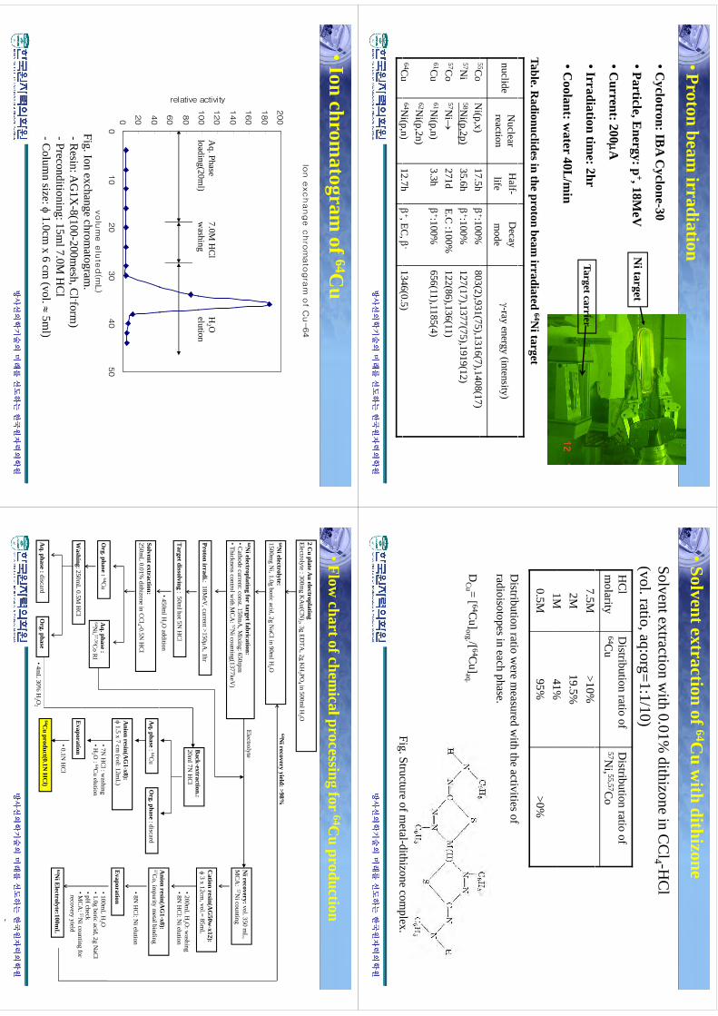
•Proton beam irradiation
•Cyclotron: IB
A C
yclone-30
•Particle,Energy:p
+,18MeV
Ni target
Particle, Energy: p
, 18MeV
•Current: 200A
ii
i2
g
•Irradiation time: 2hr
•Coolant: w
ater 40L/m
inTarget carrier
Table. Radionuclides in the proton beam
irradiated 64Ni target
nuclideN
uclear reaction
Half-
lifeD
ecay m
ode-ray energy (intensity)
55Co
Ni(p
x)17
5h
+:100%803(2)931(75)1316(7)1408(17)
55Co
57Ni
57Co
Ni(p,x)
58Ni(p,2p)
57Ni
17.5h35.6h271d
+:100%
+:100%E.C
:100%
803(2),931(75),1316(7),1408(17)127(17),1377(75),1919(12)122(86),136(11)
61Cu
64Cu
61Ni(p,n)
62Ni(p,2n)
64Ni(p
n)
3.3h
127h
+:100%
+
EC
-
656(11),1185(4)
1346(05)
방사선의학기술의
방사선의학기술의미래를
미래를선도하는
선도하는한국원자력의학원
한국원자력의학원
Cu
Ni(p,n)
12.7h
, EC,
1346(0.5)
•Solvent extraction of 64Cu w
ith dithizone
Solvent extraction with 0.01%
dithizone in CC
l4 -HC
l(vol. ratio, aq:org=1:1/10)
HC
l m
olarityD
istribution ratio of 64C
uD
istribution ratio of 57N
i, 55,57Co
7.5M2M1M
>10%19.5%41%
1M0.5M
41%95%
>0%
Di
ibi
id
ihh
iii
fD
istribution ratio were m
easured with the activities of
radioisotopes in each phase.
DC
u = [ 64Cu]org. /[ 64C
u]aq.
FigStructure
ofmetal-dithizone
complex
방사선의학기술의
방사선의학기술의미래를
미래를선도하는
선도하는한국원자력의학원
한국원자력의학원
Fig. Structure of metal-dithizone com
plex.
•Ion chromatogram
of 64Cu
Ion e
xchange c
hro
mato
gra
m o
f Cu-64
200
160
180
100
120
140
activity
Aq. Phase
loading(20ml)
7.0M H
Cl
washing
H2 O
elution
60
80
relative
g()
g
0
20
400
010
20
30
40
50
volu
me e
lute
d(m
L)
Fig. Ion exchange chromatogram
.g
gg
-Resin: A
G1X
-8(100-200mesh, C
l -form)
-Preconditioning: 15ml 7.0M
HC
l-C
olumn
size:1
0cmx
6cm
(vol
5ml)
방사선의학기술의
방사선의학기술의미래를
미래를선도하는
선도하는한국원자력의학원
한국원자력의학원
Colum
n size: 1.0cm
x 6 cm (vol.
5ml)
•Flow chart of chem
ical processing for 64Cu production
2 Cu plate A
u electroplatingElectrolyte : 300m
g KA
u(CN
)2 , 3g EDTA
, 2g KH
2 PO4 in 500m
l H2 O
64Ni electrolyte:
64Ni recovery yield: >98%
64Ni electroplating for target fabrication:
•Cathode current: const. 150m
A, M
ixing: 650rpm
1500mg N
i, 1.0g boric acid, 2g NaC
l in 90ml H
2 O
ElectrolyteN
i recovery:vol. 350 mL,
MC
A:
57Nicounting
•Thickness control with M
CA
: 57Ni counting(1377keV
)
Proton irradi.: 18MeV
, current >150A,1hr
Back
extraction:
Cation resin(A
G50w
-x12):
3 x 12cm,vol.= 85m
L
MC
A:
Ni counting
Target dissolving : 50m
l hot 5N H
Cl
•450ml H
2 O addition
Back-extraction.:
20ml 7N
HC
l•200m
L H2 O
: washing
•8N H
Cl: N
i elution
Anion resin(A
G1-x8):
Solvent extraction:250m
L 0.01% dithizone in C
Cl4 -0.5N
HC
l
Anion resin(A
G1-x8):
()
57Co, im
purity metal binding
•8N H
Cl: N
i elution
Org. phase
: discardA
q. phase: 64C
u
1.5 x 7 cm
(vol: 12mL)
Org. phase :
64Cu
Aq. phase :
64Ni, 57,56C
o RI
•7N H
Cl : w
ashing•H
2 O : 64C
u elution
Evaporation
•100mL H
2 O
•1.0g boric acid, 2g NaC
l•pH
checkM
CA
57Ni
if
Washing: 250m
L 0.5M H
Cl
Evaporation
•MC
A: 57N
i counting for recovery yield
64Ni E
lectrolyte:100mL
•0.1N H
Cl
64Cu
product(0.1NH
Cl)
Oh
Ah
did
방사선의학기술의
방사선의학기술의미래를
미래를선도하는
선도하는한국원자력의학원
한국원자력의학원
Cu product(0.1N
HC
l)O
rg. phaseA
q. phase :discard•4m
L 30% H
2 O2
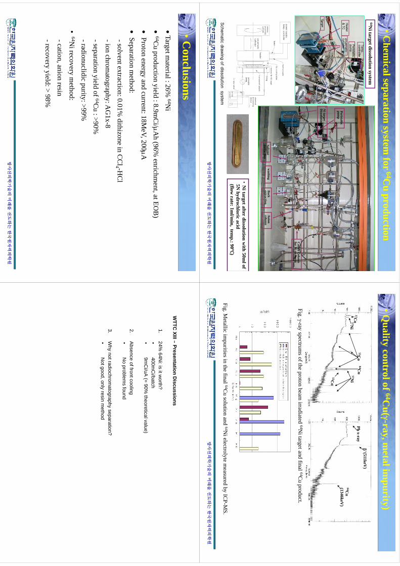
•Chem
ical separation system for
64Cu production
Peris
taltic
Tem
p.
contro
ller
64Ni target dissolution system
Heate
r &
TC
pnuem
atic
cylin
der
Peris
taltic
pum
p
Peristalticpum
p
Target
Ni target
Dissolution system
Cation C
olumn
for Ni recovery
Oring
rota
tary
heater
pow
er s
upply
tem
p. c
ontro
ller
therm
ocouple
Cu c
oolin
g p
late
enrih
ed N
i-64 ta
rget
Solventw
ashingB
ackA
nion
Ni
fdi
li
ih50
lf
O-ring
transpare
nt p
lastic
peristaltic pum
p
heate
rpnuem
atic
cylin
der
rota
tary
pnuem
atic
cylin
der
chem
ical
pro
cessin
g
devic
e
Solvent extraction
gextraction
column
•N
itargetafterdissolution
with
50mlof
5Nhydrochloric
acid(flow
rate:1ml/m
in,tem
p.:90)
way va
lve
pp
Ni-
64
solu
tion
방사선의학기술의
방사선의학기술의미래를
미래를선도하는
선도하는한국원자력의학원
한국원자력의학원
Schem
atic
dra
win
g o
f dis
solu
tion s
yste
m
•Quality control of 64C
u(-ray, metal im
purity)
Pb x-ray
+(511keV)
57Co57N
i
55Co
57Ni
64Cu
64Cu
(1346keV)
57Ni
57Ni
55Co
Co
Fig. -ray spectrums of the proton beam
irradiated 64Ni target and final 64C
u product.
FigM
etallicim
puritiesinthe
final64C
usolution
and64N
ielectrolytem
easuredby
ICP-M
S
방사선의학기술의
방사선의학기술의미래를
미래를선도하는
선도하는한국원자력의학원
한국원자력의학원
Fig. Metallic im
purities in the final C
u solution and N
i electrolyte measured by IC
PM
S.
•Conclusions
Target m
aterial : 26% 64N
i
64C
u production yield : 8.9mC
i/Ah (96%
enrichment, at EO
B)
py
(
,)
Proton energy and current: 18M
eV, 200A
Separation
method:
Separation m
ethod:
-solvent extraction: 0.01% dithizone in C
Cl4 -H
Cl
ih
hA
G1
8-ion chrom
atography: AG
1x-8
-separation yield of 64Cu : >90%
-radionuclidic purity: >99%
•64N
i recovery method:
-cation, anion resin
-recoveryyield:>
98%recovery yield:
98%
방사선의학기술의
방사선의학기술의미래를
미래를선도하는
선도하는한국원자력의학원
한국원자력의학원
WTTC
XIII–Presentation
Discussions
WTTC
XIII –Presentation D
iscussions
1.24%
64Ni: is it w
orth?•
400mC
i/batch•
400mC
i/batch•
9mC
i/uA(= 90%
theoretical value)
2A
bsenceoffrontcooling
2.A
bsence of front cooling•
No problem
s found
3W
hynotradiochrom
atographyseparation?
3.W
hy not radiochromatography
separation?•
Not good, only resin m
ethod
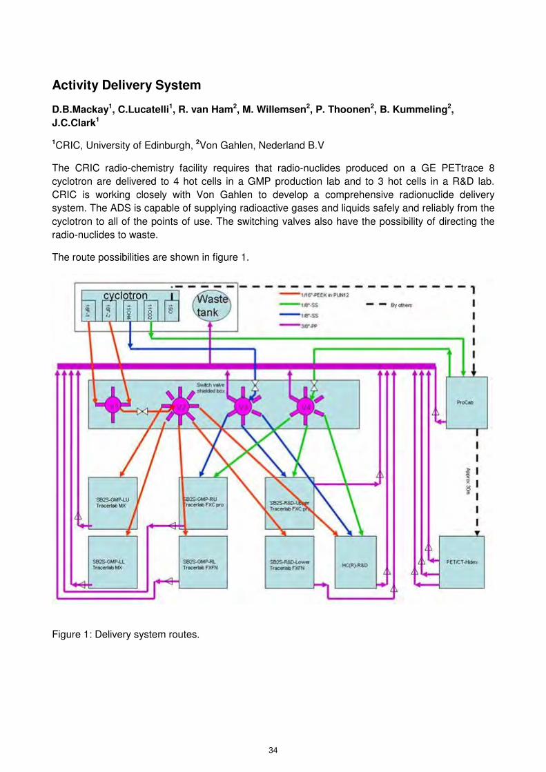
Activity Delivery System
D.B.Mackay1, C.Lucatelli1, R. van Ham2, M. Willemsen2, P. Thoonen2, B. Kummeling2,
J.C.Clark1
1CRIC, University of Edinburgh, 2Von Gahlen, Nederland B.V
The CRIC radio-chemistry facility requires that radio-nuclides produced on a GE PETtrace 8
cyclotron are delivered to 4 hot cells in a GMP production lab and to 3 hot cells in a R&D lab.
CRIC is working closely with Von Gahlen to develop a comprehensive radionuclide delivery
system. The ADS is capable of supplying radioactive gases and liquids safely and reliably from the
cyclotron to all of the points of use. The switching valves also have the possibility of directing the
radio-nuclides to waste.
The route possibilities are shown in figure 1.
Figure 1: Delivery system routes.
34
kmje
Typewritten Text
Abstract 006
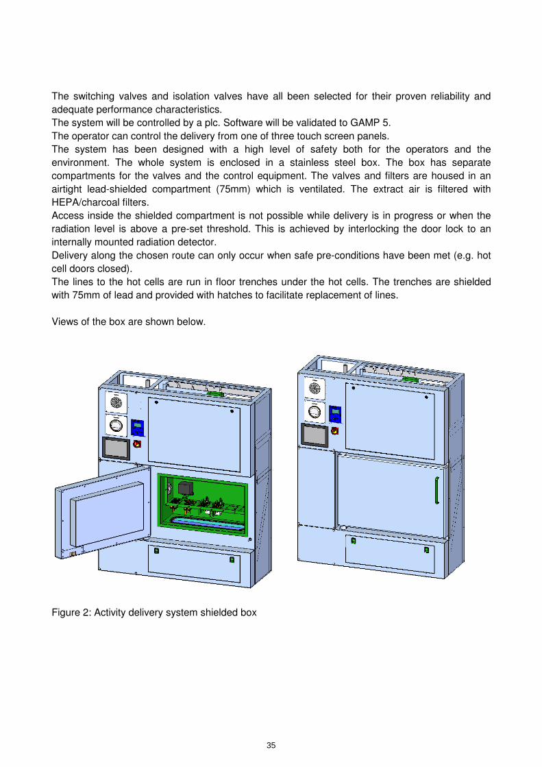
The switching valves and isolation valves have all been selected for their proven reliability and
adequate performance characteristics.
The system will be controlled by a plc. Software will be validated to GAMP 5.
The operator can control the delivery from one of three touch screen panels.
The system has been designed with a high level of safety both for the operators and the
environment. The whole system is enclosed in a stainless steel box. The box has separate
compartments for the valves and the control equipment. The valves and filters are housed in an
airtight lead-shielded compartment (75mm) which is ventilated. The extract air is filtered with
HEPA/charcoal filters.
Access inside the shielded compartment is not possible while delivery is in progress or when the
radiation level is above a pre-set threshold. This is achieved by interlocking the door lock to an
internally mounted radiation detector.
Delivery along the chosen route can only occur when safe pre-conditions have been met (e.g. hot
cell doors closed).
The lines to the hot cells are run in floor trenches under the hot cells. The trenches are shielded
with 75mm of lead and provided with hatches to facilitate replacement of lines.
Views of the box are shown below.
Figure 2: Activity delivery system shielded box
35

Activity
Delivery
Activity
Delivery
Activity D
elivery A
ctivity Delivery
SystemSystem
D.B
. Mackay
D.B
. Mackay
Risoe, 27 July 2010Risoe, 27 July 2010
11
The CR
IC Facility, Edinburgh
The CR
IC Facility, Edinburgh
G
EP
ETtrace
8cyclotron
ina
vaultG
EP
ETtrace
8cyclotron
ina
vault
GE
PE
Ttrace 8 cyclotron in a vault. G
E P
ETtrace 8 cyclotron in a vault.
G
MP
lab with 4 hot cells.
GM
P lab w
ith 4 hot cells. Facilities
fordispensingand
sterilisingeitherby
Facilitiesfordispensing
andsterilising
eitherby
Facilities for dispensing and sterilising either by Facilities for dispensing and sterilising either by autoclave or aseptic filtration.autoclave or aseptic filtration.S
tR
&D
lb
ith3
ht
llS
tR
&D
lb
ith3
ht
ll
Separate R
&D
lab with 3 hot cells.
Separate R
&D
lab with 3 hot cells.
P
ET/C
T, CT and 3T M
RI scanners.
PE
T/CT, C
T and 3T MR
I scanners.
22
33
The GM
P hot cell labThe G
MP hot cell lab
4 P
roduction hot cells (2xVon G
ahlen SB
2S)
4 Production hot cells (2xV
on Gahlen S
B2S
)C
lli
dith
GE
thi
(2T
lb
Cll
id
ithG
Eth
i(2
Tl
b
Cells equipped w
ith GE
synthesisers (2x Tracerlab C
ells equipped with G
E synthesisers (2x Tracerlab
MX
,1x FXC
Pro, 1x FX
FNM
X,1x FX
C P
ro, 1x FXFN
GE
Ftl
bdi
/t
iliG
EF
tlb
di/
tili
G
E Fastlab dispenser/sterilizer
GE
Fastlab dispenser/sterilizer
Aseptic dispensing facility (V
on Gahlen D
PB
)A
septic dispensing facility (Von G
ahlen DP
B)
Integrated filter integrity testIntegrated filter integrity test
P
roductsfrom
all4hotcells
canbe
Products
fromall4
hotcellscan
beP
roducts from all 4 hot cells can be
Products from
all 4 hot cells can be transferred to either dispensing celltransferred to either dispensing cell
H
PLC
cabinetH
PLC
cabinet
HP
LC cabinet
HP
LC cabinet
44
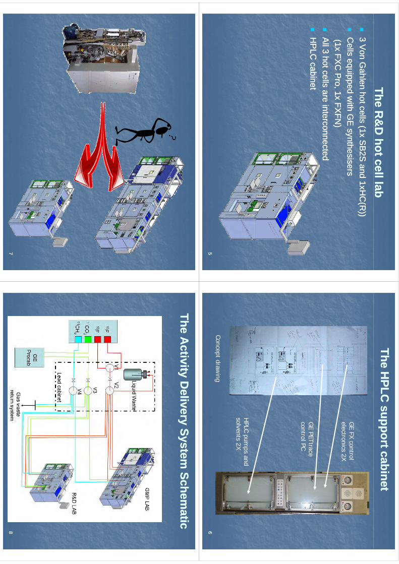
The R&
D hot cell lab
The R&
D hot cell lab
3 V
on Gahlen hot cells (1x S
B2S
and 1xHC
(R))
3 Von G
ahlen hot cells (1x SB
2S and 1xH
C(R
))C
lli
dith
GE
thi
Cll
id
ithG
Eth
i
Cells equipped w
ith GE
synthesisersC
ells equipped with G
E synthesisers
(1x FXC
Pro, 1x FX
FN)
(1x FXC
Pro, 1x FX
FN)
A
ll 3 hot cells are interconnectedA
ll 3 hot cells are interconnected
HP
LC cabinet
HP
LC cabinet
55
The HPLC
support cabinetThe H
PLC support cabinet
GE
FXcontrol
GE FX control
electronics 2X
GE
PETtraceG
E PETtrace control PC
HPLC
pumps
andH
PLC pumps and
solvents 2X
66Concept draw
ing
77
The Activity D
elivery System Schem
aticThe A
ctivity Delivery System
Schematic
88
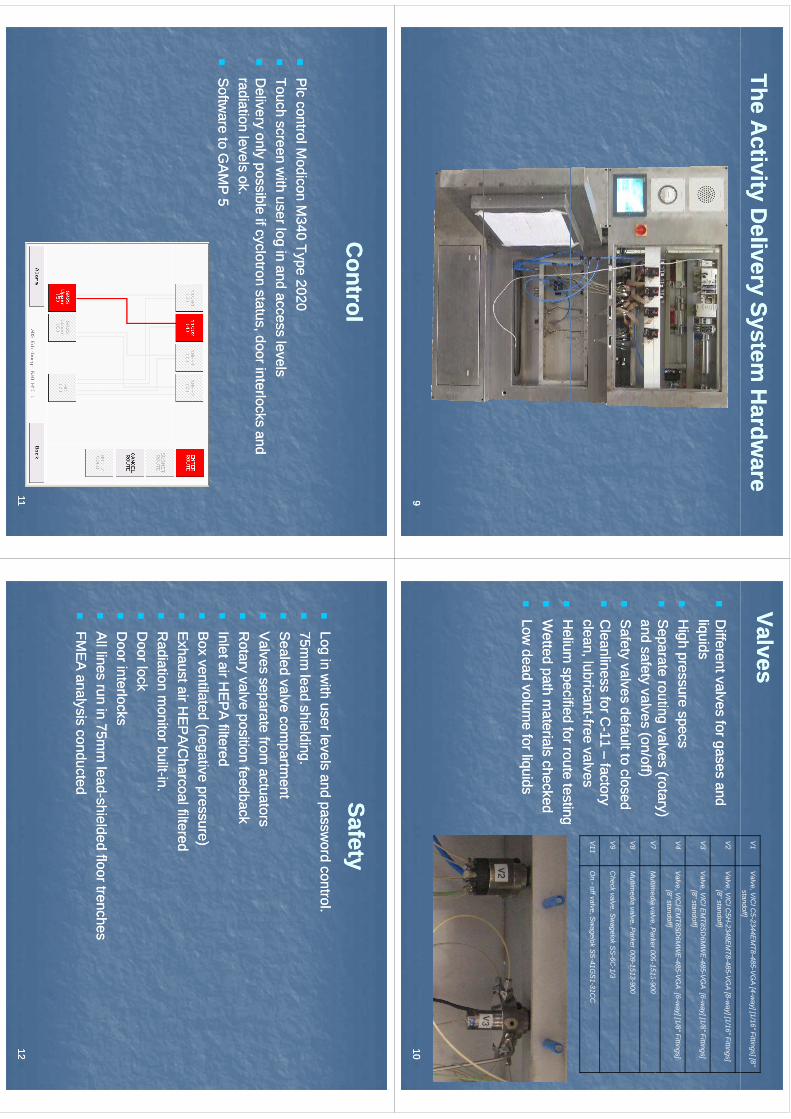
The Activity D
elivery System H
ardware
The Activity D
elivery System H
ardware
99
ValvesValves
V1
Valve, V
ICI C
5-2344EM
T8-485-VG
A [4-w
ay] [1/16" Fittings] [8" standoff]
D
ifferent valves for gases and D
ifferent valves for gases and li quidsliquids
V2
Valve, V
ICI C
5H-2348E
MT8-485-V
GA
[8-way] [1/16" Fittings]
[8" standoff]
V3
Valve, V
ICI E
MT8S
D6M
WE
-485-VG
A [6-w
ay] [1/8" Fittings] qq
H
igh pressure specsH
igh pressure specs
Separate routing valves (rotary)
Separate routing valves (rotary)
[8" standoff]
V4
Valve, V
ICI E
MT8S
D6M
WE
-485-VG
A [6-w
ay] [1/8" Fittings] [8" standoff]
V7
Mlti
dil
Pk
0091513
900p
g(
y)p
g(
y)and safety valves (on/off)and safety valves (on/off)
S
afety valves default to closedS
afety valves default to closed
V7
Multim
edia valve, Parker 009-1513-900
V8
Multim
edia valve, Parker 009-1513-900
V9
Check
valveS
wagelok
SS
6C1/3
C
leanliness for CC
leanliness for C--11 11 ––
factory factory
clean, lubricantclean, lubricant--free valves
free valvesH
liifi
df
tt
tiH
liifi
df
tt
ti
V9
Check valve, S
wagelok S
S-6C
-1/3
V11
On -off valve, S
wagelok S
S-41G
S1-31C
C
H
elium specified for route testing
Helium
specified for route testing
Wetted path m
aterials checked W
etted path materials checked
Low
deadvolum
eforliquids
Lowdead
volume
forliquids
Low dead volum
e for liquidsLow
dead volume for liquids
1010
Control
Control
Plc
controlModicon
M340
Type2020
Plc
controlModicon
M340
Type2020
P
lc control Modicon M
340 Type 2020P
lc control Modicon M
340 Type 2020
Touch screen with user log in and access levels
Touch screen with user log in and access levels
D
eliveryonly
possibleifcyclotron
statusdoorinterlocks
andD
eliveryonly
possibleifcyclotron
statusdoorinterlocks
and
Delivery only possible if cyclotron status, door interlocks and
Delivery only possible if cyclotron status, door interlocks and
radiation levels ok.radiation levels ok.
S
oftware to G
AM
P 5
Softw
are to GA
MP
5
1111
SafetySafetyyy
Log in w
ith user levels and password control.
Log in with user levels and passw
ord control.
75mm
leadshielding
75mm
leadshielding
75m
m lead shielding.
75mm
lead shielding.
Sealed valve com
partment
Sealed valve com
partment
V
alvesseparate
fromactuators
Valves
separatefrom
actuators
Valves separate from
actuatorsV
alves separate from actuators
R
otary valve position feedbackR
otary valve position feedback
Inlet air HE
PA
filteredInlet air H
EP
A filtered
B
ox ventilated (negative pressure)B
ox ventilated (negative pressure)
Exhaust air H
EP
A/C
harcoal filteredE
xhaust air HE
PA
/Charcoal filtered
R
adiation monitor built
Radiation m
onitor built--in.in.
D
oor lockD
oor lock
Door interlocks
Door interlocks
A
ll lines run in 75mm
leadA
ll lines run in 75mm
lead--shielded floor trenchesshielded floor trenches
FM
EA
analysis conductedFM
EA
analysis conducted
1212
Conclusion…
Conclusion…
FlexibleFlexible
FlexibleFlexible
E
xpandableE
xpandableS
afeS
afe
Safe
Safe
R
eliableR
eliable
Affordable
Affordable
1313
Authors and
acknowledgem
ents
University
ofEdinburgh
University
ofEdinburgh
University of E
dinburghU
niversity of Edinburgh
Prof J.C
. Clark
Prof J.C
. Clark
Dr.C
.LucatelliD
r.C.Lucatelli
Dr. C
. LucatelliD
r. C. Lucatelli
K. W
ilsonK
. Wilson
Von G
ahlenV
on Gahlen
R. van H
amR
. van Ham
M. W
illemsen
M. W
illemsen
P. Thoonen
P. Thoonen
B. K
umm
eling B
. Kum
meling
1414
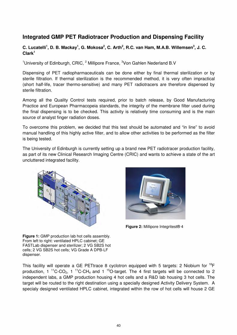
Integrated GMP PET Radiotracer Production and Dispensing Facility
C. Lucatelli1, D. B. Mackay1, G. Mokosa2, C. Arth2, R.C. van Ham, M.A.B. Willemsen3, J. C.
Clark1
1University of Edinburgh, CRIC, 2 Millipore France, 3Von Gahlen Nederland B.V
Dispensing of PET radiopharmaceuticals can be done either by final thermal sterilization or by
sterile filtration. If thermal sterilization is the recommended method, it is very often impractical
(short half-life, tracer thermo-sensitive) and many PET radiotracers are therefore dispensed by
sterile filtration.
Among all the Quality Control tests required, prior to batch release, by Good Manufacturing
Practice and European Pharmacopeia standards, the integrity of the membrane filter used during
the final dispensing is to be checked. This activity is relatively time consuming and is the main
source of analyst finger radiation doses.
To overcome this problem, we decided that this test should be automated and “in line” to avoid
manual handling of this highly active filter, and to allow other activities to be performed as the filter
is being tested.
The University of Edinburgh is currently setting up a brand new PET radiotracer production facility,
as part of its new Clinical Research Imaging Centre (CRIC) and wants to achieve a state of the art
uncluttered integrated facility.
Figure 1: GMP production lab hot cells assembly. From left to right: ventilated HPLC cabinet; GE FASTLab dispenser and sterilizer; 2 VG SB2S hot cells; 2 VG SB2S hot cells; VG Grade A DPB-LF dispenser.
Figure 2: Millipore Integritest® 4
This facility will operate a GE PETtrace 8 cyclotron equipped with 5 targets: 2 Niobium for 18F
production, 1 11C-CO2, 1 11C-CH4 and 1 15O-target. The 4 first targets will be connected to 2
independent labs, a GMP production housing 4 hot cells and a R&D lab housing 3 hot cells. The
target will be routed to the right destination using a specially designed Activity Delivery System. A
specialy designed ventilated HPLC cabinet, integrated within the row of hot cells will house 2 GE
40
kmje
Typewritten Text
Abstract 007
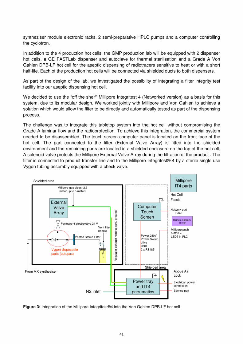
syntheziser module electronic racks, 2 semi-preparative HPLC pumps and a computer controlling
the cyclotron.
In addition to the 4 production hot cells, the GMP production lab will be equipped with 2 dispenser
hot cells, a GE FASTLab dispenser and autoclave for thermal sterilisation and a Grade A Von
Gahlen DPB-LF hot cell for the aseptic dispensing of radiotracers sensitive to heat or with a short
half-life. Each of the production hot cells will be connected via shielded ducts to both dispensers.
As part of the design of the lab, we investigated the possibility of integrating a filter integrity test
facility into our aseptic dispensing hot cell.
We decided to use the “off the shelf” Millipore Integritest 4 (Networked version) as a basis for this
system, due to its modular design. We worked jointly with Millipore and Von Gahlen to achieve a
solution which would allow the filter to be directly and automatically tested as part of the dispensing
process.
The challenge was to integrate this tabletop system into the hot cell without compromising the
Grade A laminar flow and the radioprotection. To achieve this integration, the commercial system
needed to be disassembled. The touch screen computer panel is located on the front face of the
hot cell. The part connected to the filter (External Valve Array) is fitted into the shielded
environment and the remaining parts are located in a shielded enclosure on the top of the hot cell.
A solenoid valve protects the Millipore External Valve Array during the filtration of the product . The
filter is connected to product transfer line and to the Millipore Integritest® 4 by a sterile single use
Vygon tubing assembly equipped with a check valve.
N2 inlet
External
Valve
Array
Power tray
and IT4
pneumatics
Computer
Touch Screen
Remote network
printer
Above Air
Lock
Hot Cell
Fascia
Vygon disposable
parts (octopus)
Shielded area
From MX synthesiser
Permanent electrovalve 24 V
Vented Sterile Filter
Vent filter needle
Millipore gas pipes (2.5 meter up to 5 meter)
Electrical power connection
Power 240VPower Switch drive
USB2 x RS485
Shielded area
Service port
Millipore push button +
LED? In PLC
Millipore
IT4 parts
Network port RJ45
Re
gula
tor
exh
aust re
mo
te p
ort
/ c
rea
ted
Figure 3: Integration of the Millipore Integritest®4 into the Von Gahlen DPB-LF hot cell.
41

Integrated GM
P PET Radiotracer Production
and Dispensing Facility
pg
y
C. Lucatelli 1, B
. Mackay
1, G. M
okosa2, C
. Arth
2, R.C
. van Ham
3, M
.A.B
.Willem
sen3and
J.C.C
lark1
M.A
.B. W
illemsen
and J. C. C
lark
1CR
IC, U
niversity of Edinburgh,2 M
illipore, France p
,3 VonG
ahlen, Netherlands
1
Introduction
Dispensing and sterilisation of PET di
hti
lb
dith
bt
il
radiopharmaceuticals can be done either by term
inal therm
al sterilizationor by aseptic sterile filtration.
Although
thermalsterilization
isthe
recomm
endedA
lthough thermal sterilization is the recom
mended
method, it is very often im
practical (short half-life, therm
osensitive
tracers)andm
anyPET
radiotracerstherm
o-sensitive tracers) and many PET radiotracers
are therefore dispensed by aseptic sterile filtration.
2
Am
ong the Quality C
ontrol tests required, prior to batch
releaseby
Good
Manufacturing
Practiceand
batch release, by Good M
anufacturing Practice and European Pharm
acopoeia standards, the integrityof the
mem
branefilterused
duringthe
terminalsterilisation
mem
brane filter used during the terminal sterilisation
and dispensing must to be checked. This activity can be
cumbersom
e time consum
ing and is the main source of
ganalyst finger radiation doses.
3
To overcome this problem
, we decided that this
test should be automated and “in line” to avoid
manual handling of this highly active filter, and to
allow other activities to be perform
ed as the filter is being tested.
As part of the design of our new
lab, we
investigated the possibility of integrating a filter f
integrity test facilityinto our aseptic dispensing
hot cell.
4
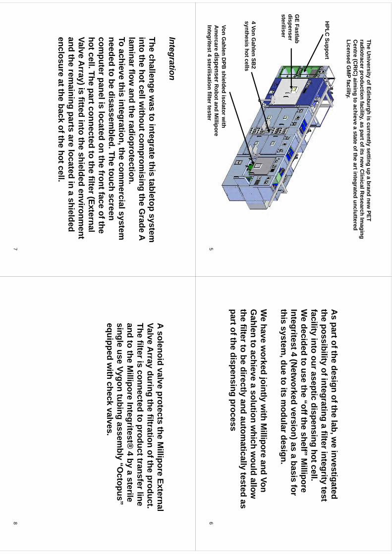
The University of Edinburgh is currently setting up a brand new
PET y
gy
gp
radiotracer production facility, as part of its new C
linical Research Im
aging C
entre (CR
IC) aim
ing to achieve a state of the art integrated uncluttered Licensed G
MP facilit y.y
HPLC
Supportpp
GE Fastlab
dispenser sterilisersteriliser
4 Von Gahlen SB
2 synthesis hot cells
Von Gahlen D
PB shielded isolator w
ith A
mercare dispenser
Robot and M
illipore Integritest 4 sterilisation filter tester
5
As part of the design of the lab, w
e investigated the
possibilityofintegrating
afilterintegrity
testthe possibility of integrating a filter integrity test facility into our aseptic dispensing hot cell.W
edecided
touse
the“offthe
shelf”M
illiporeW
e decided to use the off the shelf
Millipore
Integritest 4 (Netw
orked version) as a basis for this
systemdue
toits
modulardesign
this system, due to its m
odular design.
We
havew
orkedjointly
with
Millipore
andVon
We have w
orked jointly with M
illipore and Von G
ahlen to achieve a solution which w
ould allow
thefilterto
bedirectly
andautom
aticallytested
asthe filter to be directly and autom
atically tested as part of the dispensing process
6
IntegrationIntegration
Thechallenge
was
tointegrate
thistabletop
systemThe challenge w
as to integrate this tabletop system
into the hot cell without com
promising the G
rade A lam
inar flow and the radioprotection.
aa
oa
dt
ead
opotecto
To achieve this integration, the comm
ercial system
needed to be disassembled. The touch screen
computer panel is located on the front face of the
hot cell. The part connected to the filter (External (
Valve Array) is fitted into the shielded environm
ent and the rem
aining parts are located in a shielded enclosure at the back of the hot cell.
7
A solenoid valve protects the Millipore External
ValveA
rrayduring
thefiltration
oftheproduct
Valve Array during the filtration of the product.
The filter is connected to product transfer line and
tothe
Millipore
Integritest®4
bya
sterileand to the M
illipore Integritest® 4 by a sterile
single use Vygon tubing assembly “O
ctopus” equipped
with
checkvalves.
equipped with check valves.
8
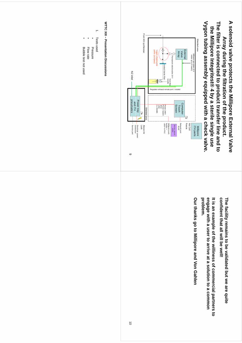
A solenoid valve protects the M
illipore External Valve A
di
thfilt
tifth
dt
Array during the filtration of the product.
The filter is connected to product transfer line and to th
Milli
It
itt®
4b
til
il
the Millipore Integritest®
4 by a sterile single use Vygon tubing assem
bly equipped with a check valve.
Hot C
ell
Shielded area
Millipore gas pipes
(2.5 m
eter up to 5 meter)
Millipore
IT4 parts
External V
alve A
rrayC
omputer
Touch S
creenR
emote
network
Fascia
Netw
ork port R
J45
created
Rem
otenetw
orkprinter
Perm
anent electrovalve24 V
Vented S
terile Filter Vent filter
needlePow
er 240VP
ower
Sw
itch d
i
Millipore push
button + LE
D? In P
LC
ust remote port /
Vygon
disposableparts (octopus)
driveU
SB
2 x RS
485
Regulator exha
Pow
er tray d
IT4
Above A
ir Lock
From M
X synthesiser
Electrical pow
er connection
Shielded area
N2
inletand IT
4 pneum
aticsconnection
Service port
9
Thefacility
remains
tobe
validatedbutw
eare
quiteThe facility rem
ains to be validated but we are quite
confident that all will be w
ell!
Itisan
example
ofthew
illinessofcom
mercialpartners
toIt is an exam
ple of the williness of com
mercial partners to
engage with a user to arrive at a solution to a com
mon
problem.
Our thanks go to M
illipore and Von Gahlen
10
WTTC
XIII–Presentation
Discussions
WTTC
XIII –Presentation D
iscussions
1.Tests used•
Pressure
•P
ressure•
Flow rate
•Bubble test not used
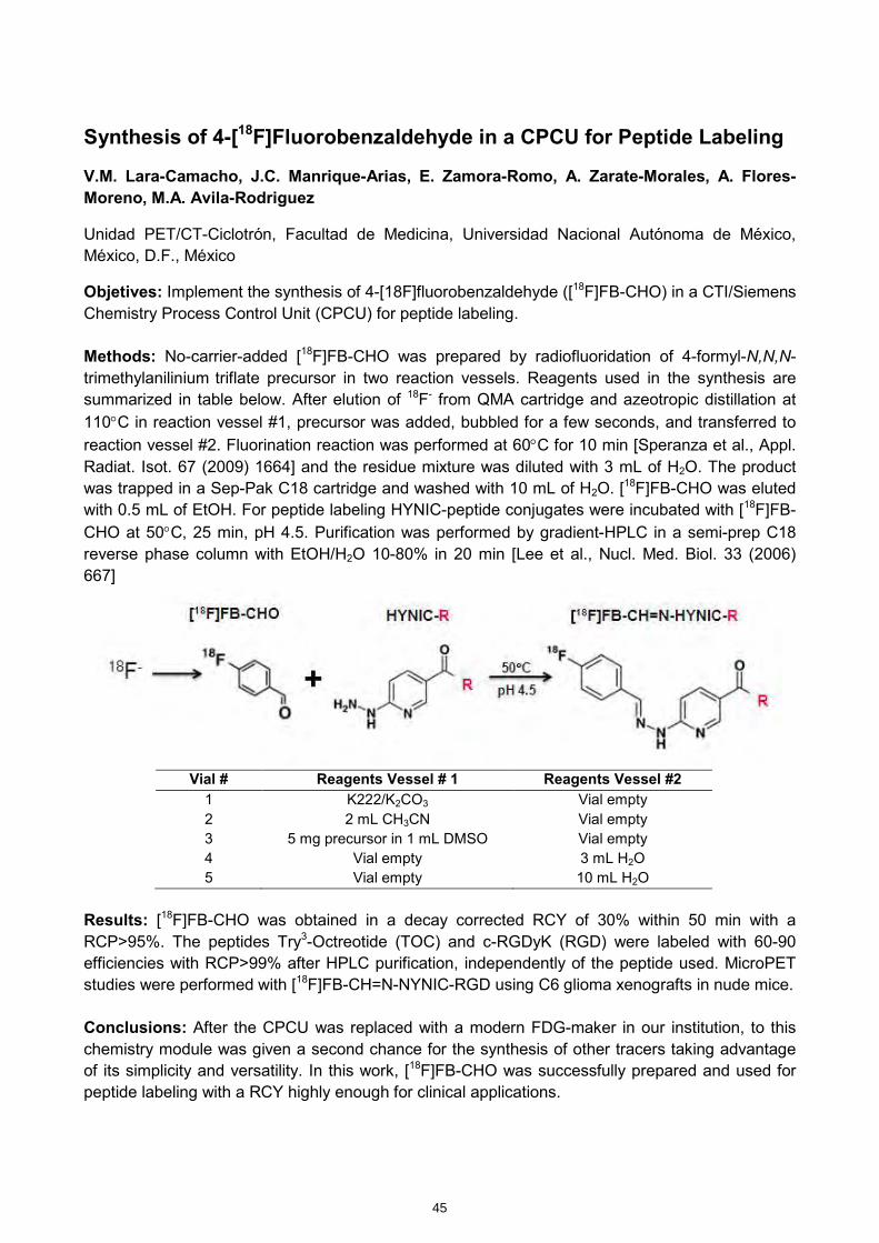
Synthesis of 4-[18F]Fluorobenzaldehyde in a CPCU for Peptide Labeling
V.M. Lara-Camacho, J.C. Manrique-Arias, E. Zamora-Romo, A. Zarate-Morales, A. Flores-Moreno, M.A. Avila-Rodriguez
Unidad PET/CT-Ciclotrón, Facultad de Medicina, Universidad Nacional Autónoma de México, México, D.F., México
Objetives: Implement the synthesis of 4-[18F]fluorobenzaldehyde ([18F]FB-CHO) in a CTI/Siemens Chemistry Process Control Unit (CPCU) for peptide labeling. Methods: No-carrier-added [18F]FB-CHO was prepared by radiofluoridation of 4-formyl-N,N,N-trimethylanilinium triflate precursor in two reaction vessels. Reagents used in the synthesis are summarized in table below. After elution of 18F- from QMA cartridge and azeotropic distillation at 110°C in reaction vessel #1, precursor was added, bubbled for a few seconds, and transferred to reaction vessel #2. Fluorination reaction was performed at 60°C for 10 min [Speranza et al., Appl. Radiat. Isot. 67 (2009) 1664] and the residue mixture was diluted with 3 mL of H2O. The product was trapped in a Sep-Pak C18 cartridge and washed with 10 mL of H2O. [18F]FB-CHO was eluted with 0.5 mL of EtOH. For peptide labeling HYNIC-peptide conjugates were incubated with [18F]FB-CHO at 50°C, 25 min, pH 4.5. Purification was performed by gradient-HPLC in a semi-prep C18 reverse phase column with EtOH/H2O 10-80% in 20 min [Lee et al., Nucl. Med. Biol. 33 (2006) 667]
Vial # Reagents Vessel # 1 Reagents Vessel #2
1 K222/K2CO3 Vial empty 2 2 mL CH3CN Vial empty 3 5 mg precursor in 1 mL DMSO Vial empty 4 Vial empty 3 mL H2O 5 Vial empty 10 mL H2O
Results: [18F]FB-CHO was obtained in a decay corrected RCY of 30% within 50 min with a RCP>95%. The peptides Try3-Octreotide (TOC) and c-RGDyK (RGD) were labeled with 60-90 efficiencies with RCP>99% after HPLC purification, independently of the peptide used. MicroPET studies were performed with [18F]FB-CH=N-NYNIC-RGD using C6 glioma xenografts in nude mice. Conclusions: After the CPCU was replaced with a modern FDG-maker in our institution, to this chemistry module was given a second chance for the synthesis of other tracers taking advantage of its simplicity and versatility. In this work, [18F]FB-CHO was successfully prepared and used for peptide labeling with a RCY highly enough for clinical applications.
45
kmje
Typewritten Text
Abstract 008
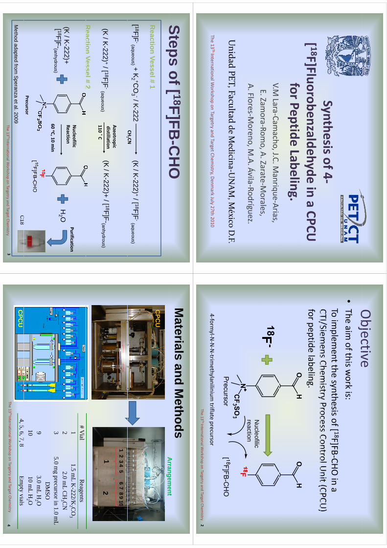
Synthesis of 4‐[ 18F]Fluorobenzaldehyde
in a CPCU
for Peptide Labeling. V.M
Lara‐Camacho, J.C. M
anrique‐Arias, E. Zam
ora‐Romo, A. Zarate‐M
orales,A. Flores‐M
oreno, M.A. Ávila‐Rodríguez.
Unidad PET, Facultad
de Medicina‐U
NAM, M
éxico D.F.
The 13Th International W
orkshop on Targetryand Target Chem
istry, Denmark July 27th 2010
Objective
Objective
•The aim
of this work is:
To implem
ent the synthesis of [ 18F]FB‐CHO in a
CTI/SiemensChem
istryProcessControlU
nit(CPCU)
CTI/Siemens Chem
istry Process Control Unit (CPCU
) for peptide labeling.
Nl
filiN
ucleofilicreaction
4‐formyl‐N
‐N‐N‐trim
ethylanilinium triflate
precursor The 13
Th International Workshop on Targetry
and Target Chemistry
2
Steps of [ 18F]FB-C
HO
Stepso
[]
CO
Reaction Vessel # 1
[ 18F]F-(aqueous) + K
2 +CO
3 -/ K-222
(K / K
-222) +/ [ 18F]F-
(aqueous)CH
3 CN3
Azeotropicdistillation
(K/K
222)+/[ 18F]F
(K/K
222) +/[ 18F]F110 ˚ C
(K / K
-222)+ / [ 18F]F-(anhydrous) (K
/ K-222) +/ [ 18F]F
-(aqueous)
Reaction
Vessel#2
Nucleofilic
Reaction (K
/K-222)+
Reaction Vessel # 2
HO
Purification
60 oC, 10 min
(K / K
222)+ [ 18F]F-(anhydrous)
H2 O
PrecursorC
18M
ethodadapted
fromS
peranzaet al. 2009
C18
The 13ThInternational W
orkshop on Targetryand Target Chem
istry 3
Materials and M
ethodsA
rrangement
CPC
U
Arrangem
ent
12
34
56
78
910
12
12
# Vial
Reagents
11.5 m
LK
-222/K2 C
O3
22
0m
LC
HC
N2
2.0 mL
CH
3 CN
35.0 m
g precursor in 1.0 mL
DM
SO9
3.0 mL
H2 O
1010 m
LH
2 O
45
67
8E
il
CPC
U4, 5, 6, 7, 8
Empty vials
The 13ThInternational W
orkshop on Targetryand Target Chem
istry 4
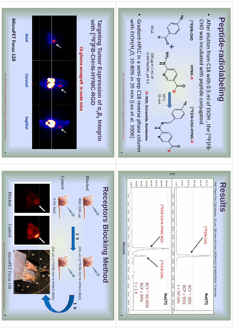
Peptide-radiolabelingp
g•After elution from
C18 with 0.5 m
l of EtOH, the [ 18F]FB‐
CHO was incubated w
ith peptide conjugated.[ 18F]FB
CHOHYN
ICR
[ 18]
HYNIC
R[ 18F]FB‐CHO
‐HYNIC‐R
[ 18F]FB‐CHOHYN
IC‐R
+50˚C, 25 m
in
R= RGD, Octreotide, Bom
besine50 µL
100 µg in 1 mLof
0.5M NaO
AC, pH 4.5
•Gradient‐HPLC in a sem
i‐prep C18 reverse phase column
with
EtOH/H
2 O,10‐80%
in20
min[Lee
etal.2006].with EtO
H/H2 O, 10
80% in 20 m
in [Lee et al. 2006]. The 13
ThInternational Workshop on Targetry
and Target Chemistry
5
Results
YM
C-P
ack Pro C
18 column, 10 m
, 250 mm
x10 mm
, EtO
H:H
2 O 10-80%
EtO
H, 3 m
L/min
NaI(Tl)
[ 18F]FBCHO
NaI(Tl)
[ 18F]FB‐CHO
RCY ~ 30%RCP > 95%t = 50 m
in
mV
NaI(Tl)
[ 18F]FB‐CHO[ 18F]FB‐CH=N
‐HYNIC‐RGD
RCY ~ 60‐90%RCP > 99%t = 1 h
Minutes
6
Tti
TE
if
βI
ti
Targeting Tumor Expression of α
v β3 Integrin
with [ 18F]FB
-CH
=N-H
YNIC
-RG
D
C6 gliomaxenograft
in nude mice
AxialCoronal
SagittalAxial
CoronalSagittal
MicroPET
Focus120MicroPET
Focus 120The 13
ThInternational Workshop on Targetry
and Target Chemistry
7
Receptors B
locking Method
g
RG
D (100 g)
200 Ci([
18F]FB-C
H=
N-H
YNIC-R
GD
)
h1
h
Blocked
1 h
1 h
Cl
0.9% N
aCl
Control
200 Ci([
18F]FB-C
H=
N-H
YNIC-R
GD
)
([]
)
microPET
Focus 120C
ontrolB
lockedThe 13
ThInternational Workshop on Targetry
and Target Chemistry
8

Conclusions
Conclusions
•The
synthesisof[ 18F]FBCHO
wassuccessfully
•The synthesis of [ 18F]FB‐CHO
was successfully
achieved in the CPCU.•[ 18F]FB‐CHO
was used for peptide labeling.
•The
synthesisof[ 18F]FBCHO
representsasecond
•The synthesis of [ 18F]FB‐CHO
represents a second chance for the CPCU
module in the preparation of
hother tracers.
–[ 18F]Fluorothym
idineis another tracer synthesized in
thCPCU
ithRCY
30%ith
10fBO
Cthe CPCU
with a RCY >30%
, with 10 m
g of BOC‐precursor.
The 13ThInternational W
orkshop on Targetryand Target Chem
istry 9
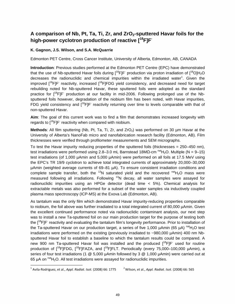
A comparison of Nb, Pt, Ta, Ti, Zr, and ZrO2-sputtered Havar foils for the high-power cyclotron production of reactive [18F]F-
K. Gagnon, J.S. Wilson, and S.A. McQuarrie
Edmonton PET Centre, Cross Cancer Institute, University of Alberta, Edmonton, AB, CANADA
Introduction: Previous studies performed at the Edmonton PET Centre (EPC) have demonstrated that the use of Nb-sputtered Havar foils during [18F]F- production via proton irradiation of [18O]H2O decreases the radionuclidic and chemical impurities within the irradiated water1. Given the improved [18F]F- reactivity, increased [18F]FDG yield consistency, and decreased need for target rebuilding noted for Nb-sputtered Havar, these sputtered foils were adopted as the standard practice for [18F]F- production at our facility in mid-2006. Following prolonged use of the Nb-sputtered foils however, degradation of the niobium film has been noted, with Havar impurities, FDG yield consistency and [18F]F- reactivity returning over time to levels comparable with that of non-sputtered Havar.
Aim: The goal of this current work was to find a film that demonstrates increased longevity with regards to [18F]F- reactivity when compared with niobium.
Methods: All film sputtering (Nb, Pt, Ta, Ti, Zr, and ZrO2) was performed on 30 µm Havar at the University of Alberta’s NanoFab micro and nanofabrication research facility (Edmonton, AB). Film thicknesses were verified through profilometer measurements and SEM micrographs. To test the Havar impurity reducing properties of the sputtered foils (thicknesses = 250–450 nm), test irradiations were performed using 2.8–3.0 mL Barnstead 18MΩ-cm natH2O. Multiple (N = 9–15) test irradiations (of 1,000 µAmin and 5,000 µAmin) were performed on all foils at 17.5 MeV using the EPC’s TR 19/9 cyclotron to achieve total integrated currents of approximately 20,000–30,000 µAmin (weighted average currents of 69–81 µA). To ensure consistent irradiation conditions and complete sample transfer, both the 13N saturated yield and the recovered natH2O mass were measured following all irradiations. Following 13N decay, all water samples were assayed for radionuclidic impurities using an HPGe detector (dead time < 5%). Chemical analysis for extractable metals was also performed for a subset of the water samples via inductively coupled plasma mass spectroscopy (ICP-MS) at the Exova Lab (Edmonton, AB).
As tantalum was the only film which demonstrated Havar impurity-reducing properties comparable to niobium, the foil above was further irradiated to a total integrated current of 80,000 µAmin. Given the excellent continued performance noted via radionuclidic contaminant analysis, our next step was to install a new Ta-sputtered foil on our main production target for the purpose of testing both the [18F]F- reactivity and evaluating the tantalum film’s longevity performance. Prior to installation of the Ta-sputtered Havar on our production target, a series of five 1,000 µAmin (65 µA) natH2O test irradiations were performed on the existing (previously irradiated to ~980,000 µAmin) 400 nm Nb-sputtered Havar foil to establish a baseline to which the tantalum results could be compared. A new 900 nm Ta-sputtered Havar foil was installed and the produced [18F]F- used for routine production of [18F]FDG, [18F]FAZA, and [18F]FLT. Periodically (every 75,000–100,000 μAmin), a series of four test irradiations (1 @ 5,000 μAmin followed by 3 @ 1,000 μAmin) were carried out at 65 μA on natH2O. All test irradiations were assayed for radionuclidic impurities. 1 Avila‐Rodriguez, et al., Appl. Radiat. Isot. (2008) 66: 1775 2 Wilson, et al., Appl. Radiat. Isot. (2008) 66: 565
49
kmje
Typewritten Text
Abstract 009
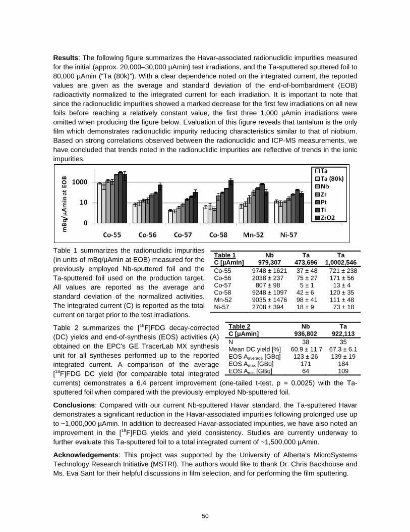
Results: The following figure summarizes the Havar-associated radionuclidic impurities measured for the initial (approx. 20,000–30,000 µAmin) test irradiations, and the Ta-sputtered sputtered foil to 80,000 µAmin (“Ta (80k)”). With a clear dependence noted on the integrated current, the reported values are given as the average and standard deviation of the end-of-bombardment (EOB) radioactivity normalized to the integrated current for each irradiation. It is important to note that since the radionuclidic impurities showed a marked decrease for the first few irradiations on all new foils before reaching a relatively constant value, the first three 1,000 μAmin irradiations were omitted when producing the figure below. Evaluation of this figure reveals that tantalum is the only film which demonstrates radionuclidic impurity reducing characteristics similar to that of niobium. Based on strong correlations observed between the radionuclidic and ICP-MS measurements, we have concluded that trends noted in the radionuclidic impurities are reflective of trends in the ionic impurities.
Table 1 summarizes the radionuclidic impurities (in units of mBq/µAmin at EOB) measured for the previously employed Nb-sputtered foil and the Ta-sputtered foil used on the production target. All values are reported as the average and standard deviation of the normalized activities. The integrated current (C) is reported as the total current on target prior to the test irradiations.
Table 2 summarizes the [18F]FDG decay-corrected (DC) yields and end-of-synthesis (EOS) activities (A) obtained on the EPC's GE TracerLab MX synthesis unit for all syntheses performed up to the reported integrated current. A comparison of the average [18F]FDG DC yield (for comparable total integrated currents) demonstrates a 6.4 percent improvement (one-tailed t-test, p = 0.0025) with the Ta-sputtered foil when compared with the previously employed Nb-sputtered foil.
Conclusions: Compared with our current Nb-sputtered Havar standard, the Ta-sputtered Havar demonstrates a significant reduction in the Havar-associated impurities following prolonged use up to ~1,000,000 µAmin. In addition to decreased Havar-associated impurities, we have also noted an improvement in the [18F]FDG yields and yield consistency. Studies are currently underway to further evaluate this Ta-sputtered foil to a total integrated current of ~1,500,000 µAmin.
Acknowledgements: This project was supported by the University of Alberta’s MicroSystems Technology Research Initiative (MSTRI). The authors would like to thank Dr. Chris Backhouse and Ms. Eva Sant for their helpful discussions in film selection, and for performing the film sputtering.
Table 1 Nb Ta TaC [µAmin] 979,307 473,696 1,0002,546Co-55 9748 ± 1621 37 ± 48 721 ± 238Co-56 2038 ± 237 75 ± 27 171 ± 56 Co-57 807 ± 98 5 ± 1 13 ± 4 Co-58 9248 ± 1097 42 ± 6 120 ± 35 Mn-52 9035 ± 1476 98 ± 41 111 ± 48 Ni-57 2708 ± 394 18 ± 9 73 ± 18
Table 2 Nb TaC [μAmin] 936,802 922,113N 38 35 Mean DC yield [%] 60.9 ± 11.7 67.3 ± 6.1EOS Aaverage [GBq] 123 ± 26 139 ± 19 EOS Amax [GBq] 171 184 EOS Amin [GBq] 64 109
50
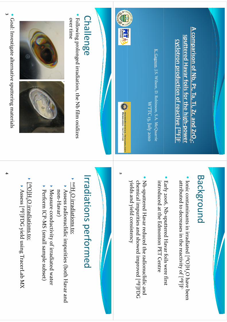
K. G
agnon, J.S. Wilson, D
. Robinson, S.A. M
cQuarrie
lW
TTC 13, July 2010
BackgroundBackgroundIonic contam
inants in irradiated [ 18O]H
O have been
Ionic contam
inants in irradiated [ 18O]H
2 O have been
attributed to decreases in the reactivity of [ 18F]F‐
Early 2006, N
b‐sputtered Havar foils w
ere first y
,p
introduced at the Edmonton PET C
entre
Nb‐sputtered H
avar reduced the radionuclidic and h
il i
iti
d hd i
d [ 18F]FDG
chemical im
purities and showed im
proved [ 18F]FDG
yields and yield consistency
2
ChallengeChallengeFollow
ing prolonged irradiation, the Nbfilm
oxidizes gp
gover tim
e
Gl I
i l
i
i
il
Goal: Investigate alternative sputtering m
aterials3
Irradiationsperformed
Irradiations performed
tHO
idi
i
natH
2 Oirradiations to:
Assess radionuclidic im
purities (both Havar and
non‐Havar)
Measure conductivity of irradiated w
aterMeasure conductivity of irradiated w
aterPerform
ICP‐M
S (small sam
ple subset)
[ 18O
]H2 O irradiations to:
Assess[ 18F]FD
G yield using TracerLab
MX
4
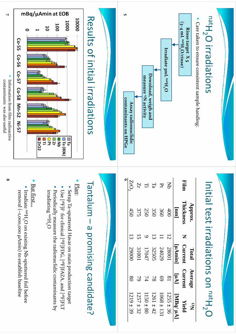
natHOirradiations
H2 O
irradiationsCare taken to ensure consistent sam
ple handing:p
g
Rinse target X
5(
L
natHO/i
)(3–4 m
LnatH
2 O/rinse)
Irradiate 3mL natH
2 O
Dow
nload, weigh and
measure 13N
activitymeasure 13N
activity
A
dilidi
Assay radionuclidic
contaminants on H
PGe
5
InitialtestirradiationsonnatH
OInitial test irradiations on
H2 O
FilmA
pprox. T
hicknessN
TotalC
urrentAverageC
urrent
13NY
ieldFilm
Thickness[nm
]N
Current
[μAm
in]C
urrent[μA
]Y
ield[M
Bq/ μA
]N
b400
1228001
811255
±36
Nb
40012
2800181
1255±
36Pt
36011
2402969
1068±
131Ta
35013
3250578
1261±
42Ti
2509
1704774
1150±
80Ti
2509
1704774
1150±
80Zr
37515
3100179
1257±
32Z
O450
1329000
801219
±39
ZrO2
45013
2900080
1219±
396
ResultsofinitialirradiationsResults of initial irradiations
Inform
ation from film
radioactive contam
inants was also useful
7
Tantalum–aprom
isingcandidate?
Tantalum –a prom
ising candidate?Plan:
Plan: Setup Ta‐sputtered H
avar on main production target
Use [ 18F]F
‐for clinical [ 18F]FDG, [ 18F]FA
ZA, and [ 18F]FLT
Periodically m
easure the radionuclidic contaminants by
yy
irradiating natH2 O
But first...
Idi
t natH
O
iti
Nb
ttd f
il bf
Irradiate natH
2 O on existing N
b‐sputtered foil before rem
oval (~1,000,000 μAmin) to establish baseline
8
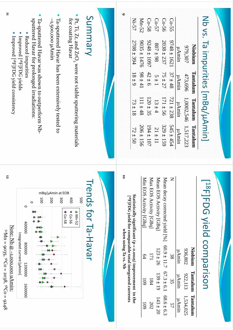
Nbvs
Taim
purities[mBq/μAm
in]Nbvs. Ta im
purities [mBq/μAm
in]N
iobiumTantalum
TantalumTantalum
Niobium
TantalumTantalum
Tantalum979,307
Ai
473,696A
i1,0002,546
Ai
1,517,223A
iμA
min
μAm
inμA
min
μAm
inC
o-559748
±1621
37±
48721
±238
545±
454C
o-562038
±237
75±
27171
±56
329±
159C
o-57807
±98
5±
113
±4
21±
11C
o57
807±
985±
113
±4
21±
11C
o-589248
±1097
42±
6120
±35
194±
107M
529035
147698
41111
48206
156M
n-529035
±1476
98±
41111
±48
206±
156N
i-572708
±394
18±
973
±18
72±
50
9
[ 18F]FDGyield
comparison
[F]FDG yield com
parisonN
iobiumTantalum
TantalumN
iobium936,802
Ai
Tantalum922,113
Ai
Tantalum1,534,025
Ai
μAm
inμA
min
μAm
inN
3835
57M
eandecay
correctedyield
[%]
60.9 ±11.7
67.3 ±6.1
68.6 ±6.3
Mean
EOS
Activity
[GB
q]123 ±
26139 ±
19143 ±
20M
axEO
SA
ctivity[G
Bq]
171184
202M
inEO
SA
ctivity[G
Bq]
64109
109M
inEO
SA
ctivity[G
Bq]
64109
109
Statisticallysignificant (p = 0.0025) im
provement in the
[8F]FD
G ild f
bl
l i
d
[ 18F]FDG yield for com
parable total integrated currents when usin
g Ta vs. Nb
10
Summary
Summary
Pt Ti Zr and ZrO
were not viable sputtering m
aterials Pt, Ti, Zr, and ZrO
2 were not viable sputtering m
aterials for coating H
avar
Ta‐sputtered H
avar has been extensively tested to ~1500
000 μAmin
~1,500,000 μAmin
Ta‐sputtered H
avar was show
n to outperform N
b‐Ta‐sputtered H
avar was show
n to outperform N
b‐sputtered H
avar for prolonged irradiations:Reduced im
puritiesReduced im
puritiesIm
proved [ 18F]FDG yields
Im
proved [ 18F]FDG yield consistency
Im
proved [ 18F]FDG yield consistency
11
TrendsforTa‐HavarTrends for Ta‐Havar
500Mn52
400
OB
Mn‐52
Co‐56Co‐58
200
300
min at E
Co58
100
200
mBq/µA
00
400000800000
12000001600000
m
0400000
8000001200000
1600000Integrated current [µAm
in]
Note: N
b@ ~1,000,000 uA
min:
52Mn = 9035, 56C
o = 2038, 58Co = 9248
12
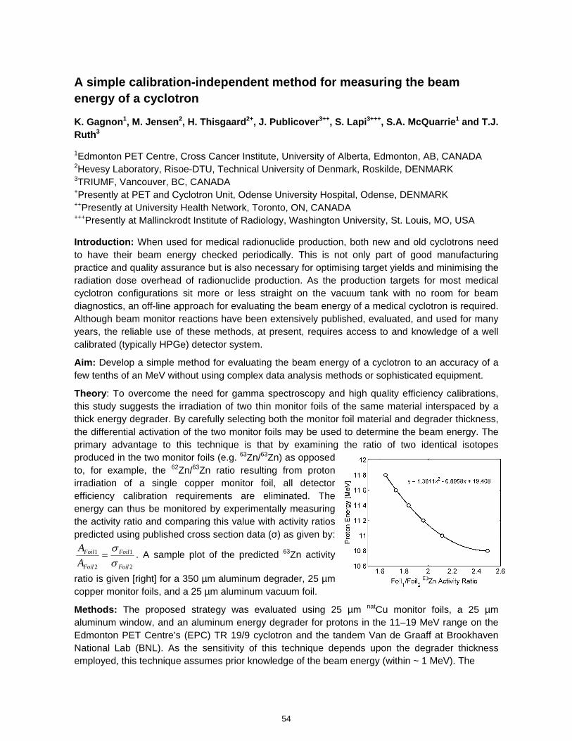
A simple calibration-independent method for measuring the beam energy of a cyclotron
K. Gagnon1, M. Jensen2, H. Thisgaard2+, J. Publicover3++, S. Lapi3+++, S.A. McQuarrie1 and T.J. Ruth3
1Edmonton PET Centre, Cross Cancer Institute, University of Alberta, Edmonton, AB, CANADA 2Hevesy Laboratory, Risoe-DTU, Technical University of Denmark, Roskilde, DENMARK 3TRIUMF, Vancouver, BC, CANADA +Presently at PET and Cyclotron Unit, Odense University Hospital, Odense, DENMARK ++Presently at University Health Network, Toronto, ON, CANADA +++Presently at Mallinckrodt Institute of Radiology, Washington University, St. Louis, MO, USA
Introduction: When used for medical radionuclide production, both new and old cyclotrons need to have their beam energy checked periodically. This is not only part of good manufacturing practice and quality assurance but is also necessary for optimising target yields and minimising the radiation dose overhead of radionuclide production. As the production targets for most medical cyclotron configurations sit more or less straight on the vacuum tank with no room for beam diagnostics, an off-line approach for evaluating the beam energy of a medical cyclotron is required. Although beam monitor reactions have been extensively published, evaluated, and used for many years, the reliable use of these methods, at present, requires access to and knowledge of a well calibrated (typically HPGe) detector system.
Aim: Develop a simple method for evaluating the beam energy of a cyclotron to an accuracy of a few tenths of an MeV without using complex data analysis methods or sophisticated equipment.
Theory: To overcome the need for gamma spectroscopy and high quality efficiency calibrations, this study suggests the irradiation of two thin monitor foils of the same material interspaced by a thick energy degrader. By carefully selecting both the monitor foil material and degrader thickness, the differential activation of the two monitor foils may be used to determine the beam energy. The primary advantage to this technique is that by examining the ratio of two identical isotopes produced in the two monitor foils (e.g. 63Zn/63Zn) as opposed to, for example, the 62Zn/63Zn ratio resulting from proton irradiation of a single copper monitor foil, all detector efficiency calibration requirements are eliminated. The energy can thus be monitored by experimentally measuring the activity ratio and comparing this value with activity ratios predicted using published cross section data (σ) as given by:
2
1
2
1
Foil
Foil
Foil
Foil
A
A
. A sample plot of the predicted 63Zn activity
ratio is given [right] for a 350 µm aluminum degrader, 25 µm copper monitor foils, and a 25 µm aluminum vacuum foil.
Methods: The proposed strategy was evaluated using 25 µm natCu monitor foils, a 25 µm aluminum window, and an aluminum energy degrader for protons in the 11–19 MeV range on the Edmonton PET Centre’s (EPC) TR 19/9 cyclotron and the tandem Van de Graaff at Brookhaven National Lab (BNL). As the sensitivity of this technique depends upon the degrader thickness employed, this technique assumes prior knowledge of the beam energy (within ~ 1 MeV). The
54
kmje
Typewritten Text
Abstract 010
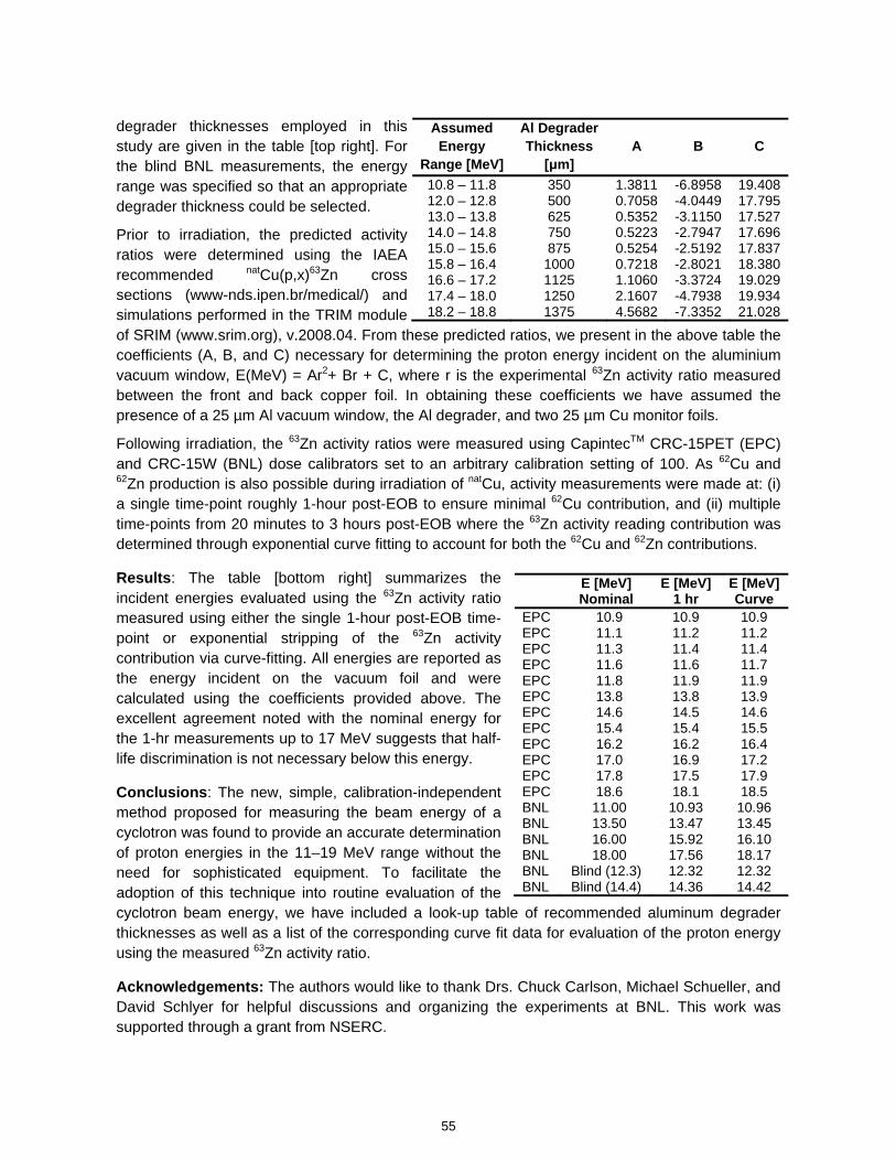
degrader thicknesses employed in this study are given in the table [top right]. For the blind BNL measurements, the energy range was specified so that an appropriate degrader thickness could be selected.
Prior to irradiation, the predicted activity ratios were determined using the IAEA recommended natCu(p,x)63Zn cross sections (www-nds.ipen.br/medical/) and simulations performed in the TRIM module of SRIM (www.srim.org), v.2008.04. From these predicted ratios, we present in the above table the coefficients (A, B, and C) necessary for determining the proton energy incident on the aluminium vacuum window, E(MeV) = Ar2+ Br + C, where r is the experimental 63Zn activity ratio measured between the front and back copper foil. In obtaining these coefficients we have assumed the presence of a 25 µm Al vacuum window, the Al degrader, and two 25 µm Cu monitor foils.
Following irradiation, the 63Zn activity ratios were measured using CapintecTM CRC-15PET (EPC) and CRC-15W (BNL) dose calibrators set to an arbitrary calibration setting of 100. As 62Cu and 62Zn production is also possible during irradiation of natCu, activity measurements were made at: (i) a single time-point roughly 1-hour post-EOB to ensure minimal 62Cu contribution, and (ii) multiple time-points from 20 minutes to 3 hours post-EOB where the 63Zn activity reading contribution was determined through exponential curve fitting to account for both the 62Cu and 62Zn contributions.
Results: The table [bottom right] summarizes the incident energies evaluated using the 63Zn activity ratio measured using either the single 1-hour post-EOB time-point or exponential stripping of the 63Zn activity contribution via curve-fitting. All energies are reported as the energy incident on the vacuum foil and were calculated using the coefficients provided above. The excellent agreement noted with the nominal energy for the 1-hr measurements up to 17 MeV suggests that half-life discrimination is not necessary below this energy.
Conclusions: The new, simple, calibration-independent method proposed for measuring the beam energy of a cyclotron was found to provide an accurate determination of proton energies in the 11–19 MeV range without the need for sophisticated equipment. To facilitate the adoption of this technique into routine evaluation of the cyclotron beam energy, we have included a look-up table of recommended aluminum degrader thicknesses as well as a list of the corresponding curve fit data for evaluation of the proton energy using the measured 63Zn activity ratio.
Acknowledgements: The authors would like to thank Drs. Chuck Carlson, Michael Schueller, and David Schlyer for helpful discussions and organizing the experiments at BNL. This work was supported through a grant from NSERC.
Assumed Energy
Range [MeV]
Al Degrader Thickness
[μm] A B C
10.8 – 11.8 350 1.3811 -6.8958 19.408 12.0 – 12.8 500 0.7058 -4.0449 17.795 13.0 – 13.8 625 0.5352 -3.1150 17.527 14.0 – 14.8 750 0.5223 -2.7947 17.696 15.0 – 15.6 875 0.5254 -2.5192 17.837 15.8 – 16.4 1000 0.7218 -2.8021 18.380 16.6 – 17.2 1125 1.1060 -3.3724 19.029 17.4 – 18.0 1250 2.1607 -4.7938 19.934 18.2 – 18.8 1375 4.5682 -7.3352 21.028
E [MeV] Nominal
E [MeV] 1 hr
E [MeV] Curve
EPC 10.9 10.9 10.9 EPC 11.1 11.2 11.2 EPC 11.3 11.4 11.4 EPC 11.6 11.6 11.7 EPC 11.8 11.9 11.9 EPC 13.8 13.8 13.9 EPC 14.6 14.5 14.6 EPC 15.4 15.4 15.5 EPC 16.2 16.2 16.4 EPC 17.0 16.9 17.2 EPC 17.8 17.5 17.9 EPC 18.6 18.1 18.5 BNL 11.00 10.93 10.96 BNL 13.50 13.47 13.45 BNL 16.00 15.92 16.10 BNL 18.00 17.56 18.17 BNL Blind (12.3) 12.32 12.32 BNL Blind (14.4) 14.36 14.42
55
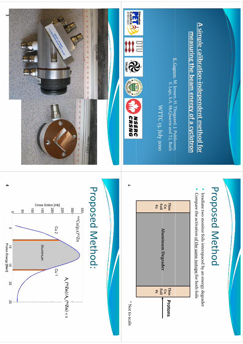
K Gagnon
M Jensen
H Thisgaard
J Publicover K. G
agnon, M. Jensen, H
. Thisgaard, J. Publicover, S. Lapi, S.A
. McQ
uarrieand T.J. Ruth
WTTC
J
l
WTTC
13, July 2010
ProposedMethod
Proposed Method
Irradiate tw
o monitor foils interspaced by an energy degrader
py
gyg
Com
pare the activation of the same isotope for both foils
ThinCu F
il
ThinCu F
il Alum
inum D
egraderProtons
Foil #2
Foil #1
Alum
inum D
egrader
* Not to scale
2
3
ProposedMethod:
Proposed Method:
natCu(p,x) 63Zn
A( 63Zn)/A
( 63Zn) = 1A
( 63Zn)/A( 63Zn) > 1
A( 63Zn)/A
( 63Zn) < 1A
1 ( 63Zn)/A2 ( 63Zn) = 1
A1 ( 63Zn)/A
2 ( 63Zn) > 1A
1 ( 63Zn)/A2 ( 63Zn) < 1
4
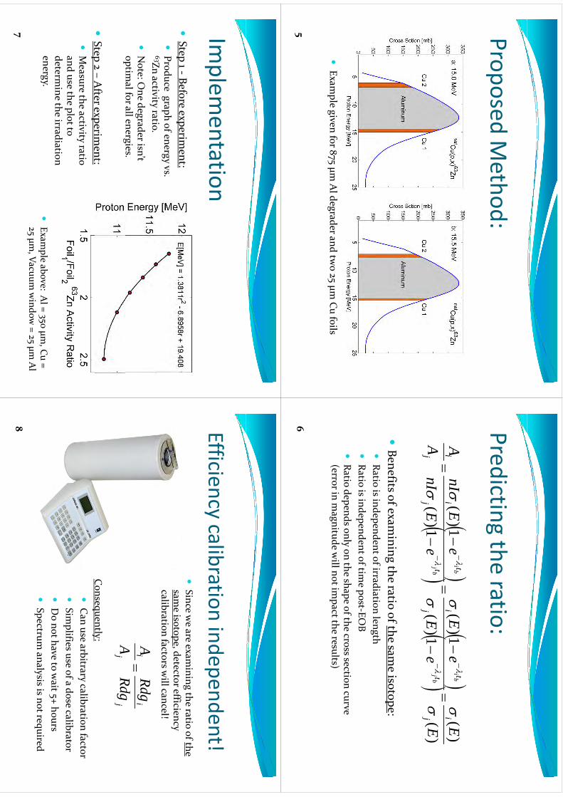
ProposedMethod:
Proposed Method:
Exam
ple given for 875 μm Al degrader and tw
o 25 μm Cu foils
5
Predictingthe
ratio:Predicting the ratio:
)(
)(
1)(
1)(
1)(
1)(
E E
E
eE
EI
eE
nI
A Ai
t ti
t ti
i
bj bi
bj bi
)(
1)(
1)(
Ee
Ee
EnI
Aj
tj
tj
jb
jb
j
Benefits of exam
ining the ratio of the same isotope:
Ratio is independent of irradiation length
Ratio is independent of irradiation length
Ratio is independent of tim
e post‐EOB
Ratio depends only on the shape of the cross section curve
Ratio depends only on the shape of the cross section curve (error in m
agnitude will not im
pact the results)
6
Implem
entationIm
plementation
St
Bf
i
t
Step 1 ‐Before experiment:
Produce graph of energy vs. 63Zn activity ratio3Zn activity ratio.
Note: O
ne degrader isn’t o ptim
al for all energies.p
g
Step 2 –
After experim
ent:Step 2
After experim
ent:
Measure the activity ratio
and use the plot to determ
ine the irradiation energy.
Exam
ple above: Al = 350 μm
, Cu =
V id
Al
725 μm
, Vacuum window
= 25 μm Al
Efficiencycalibration
independent!Efficiency calibration independent!
Since w
e are examining the ratio of the
gsam
e isotope, detector efficiency calibration factors w
ill cancel!
ii
Rdg
Rdg
A A
Consequently:
jj
Rdg
A
Cq
y
Can use arbitrary calibration factor
Sim
plifies use of a dose calibratorp
Do not have to w
ait 5+ hours
Spectrum analysis is not required
8
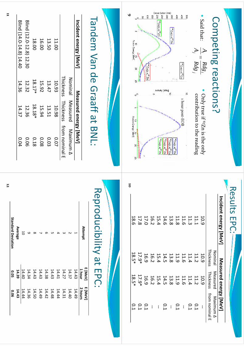
Competing
reactions?Com
peting reactions?Said that:
ii
Rdg
AOnly true if 63Zn is the only
Said that:
j i
j i
Rdg g
A
Only true if
Zn is the only contribution to the reading
1 hour post‐EOB
9
Results EPC:Incident energy [M
eV]Measured
energy [MeV]
Nom
inalMeasured
Maxim
umΔ
Nom
inal Thickness
Measured
ThicknessMaxim
um Δ
from nom
inal E
109
109
109
‐‐10.9
10.910.9
‐‐11.1
11.211.2
0.111
311
411
401
11.311.4
11.40.1
11.611.6
11.6‐‐
11.811.9
11.90.1
11.811.9
11.90.1
13.813.8
13.8‐‐
14.614.5
14.50.1
15.415.4
15.4‐‐
16.216.2
16.2‐‐
17.016.9
16.90.1
17.817.9*
17.9*0.1
18.618.5*
18.5*0.1
10
TandemVan
deGraaffatBN
L:Tandem
Van de Graaff at BNL:
Incident energy [MeV]
Measured
energy [MeV]
Nom
inal Measured
Maxim
um Δ
ThicknessThickness
from nom
inal E11.00
10.9310.98
0.0713.50
13.4713.51
0.0316
0015
9215
94008
16.0015.92
15.940.08
18.0018.17*
18.18*0.18
Blind(12
012
8)1230
1232
1236
006
Blind (12.0‐12.8) 12.3012.32
12.360.06
Blind (14.0‐14.8) 14.4014.36
14.370.04
11
Reproducibility at EPC:p
yAttem
ptE[M
eV]1hour
E[M
eV]2hours
1 hour2 hours
114.43
14.492
14.3714.40
314.27
14.314
14.4114.44
514.43
14.486
14.3814.42
714
4314
497
14.4314.49
814.43
14.509
14.3414.36
914.34
14.3610
14.4014.44
Average14.39
14.43Standard Deviation
0.050.06
12
Summary
Summary
Evaluated a new
method for m
easuring EEvaluated a new
method for m
easuring Ep
Method is independent of detector calibration
Method is independent of detector calibration
Mth
d i i
l t
f
i
it
hd
Method is sim
ple to perform using equipm
ent on hand
hd i
iii
ll i
i i
il f
il Method is insensitive to sm
all variations in nominal foil
thickness and shows good reproducibility and
agreement w
ith the nominal energies
agreement w
ith the nominal energies
Ft
k O
th
? D
t?
Future w
ork: Other energy ranges? D
euterons?13
WTTC
XIII –Presentation D
iscussions
1.C
areful with Foil thickness error
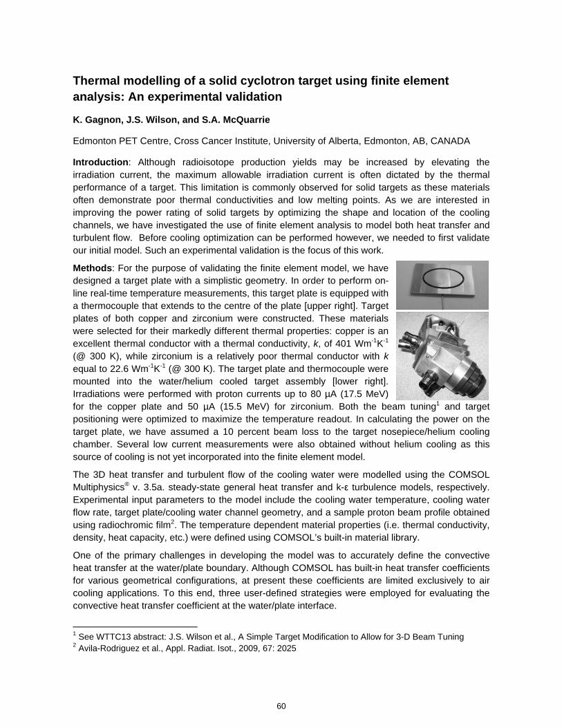
Thermal modelling of a solid cyclotron target using finite element analysis: An experimental validation
K. Gagnon, J.S. Wilson, and S.A. McQuarrie
Edmonton PET Centre, Cross Cancer Institute, University of Alberta, Edmonton, AB, CANADA
Introduction: Although radioisotope production yields may be increased by elevating the irradiation current, the maximum allowable irradiation current is often dictated by the thermal performance of a target. This limitation is commonly observed for solid targets as these materials often demonstrate poor thermal conductivities and low melting points. As we are interested in improving the power rating of solid targets by optimizing the shape and location of the cooling channels, we have investigated the use of finite element analysis to model both heat transfer and turbulent flow. Before cooling optimization can be performed however, we needed to first validate our initial model. Such an experimental validation is the focus of this work.
Methods: For the purpose of validating the finite element model, we have designed a target plate with a simplistic geometry. In order to perform on-line real-time temperature measurements, this target plate is equipped with a thermocouple that extends to the centre of the plate [upper right]. Target plates of both copper and zirconium were constructed. These materials were selected for their markedly different thermal properties: copper is an excellent thermal conductor with a thermal conductivity, k, of 401 Wm-1K-1
(@ 300 K), while zirconium is a relatively poor thermal conductor with k equal to 22.6 Wm-1K-1 (@ 300 K). The target plate and thermocouple were mounted into the water/helium cooled target assembly [lower right]. Irradiations were performed with proton currents up to 80 µA (17.5 MeV) for the copper plate and 50 µA (15.5 MeV) for zirconium. Both the beam tuning1 and target positioning were optimized to maximize the temperature readout. In calculating the power on the target plate, we have assumed a 10 percent beam loss to the target nosepiece/helium cooling chamber. Several low current measurements were also obtained without helium cooling as this source of cooling is not yet incorporated into the finite element model.
The 3D heat transfer and turbulent flow of the cooling water were modelled using the COMSOL Multiphysics® v. 3.5a. steady-state general heat transfer and k-ε turbulence models, respectively. Experimental input parameters to the model include the cooling water temperature, cooling water flow rate, target plate/cooling water channel geometry, and a sample proton beam profile obtained using radiochromic film2. The temperature dependent material properties (i.e. thermal conductivity, density, heat capacity, etc.) were defined using COMSOL’s built-in material library.
One of the primary challenges in developing the model was to accurately define the convective heat transfer at the water/plate boundary. Although COMSOL has built-in heat transfer coefficients for various geometrical configurations, at present these coefficients are limited exclusively to air cooling applications. To this end, three user-defined strategies were employed for evaluating the convective heat transfer coefficient at the water/plate interface.
1 See WTTC13 abstract: J.S. Wilson et al., A Simple Target Modification to Allow for 3-D Beam Tuning 2 Avila-Rodriguez et al., Appl. Radiat. Isot., 2009, 67: 2025
60
kmje
Typewritten Text
Abstract 011
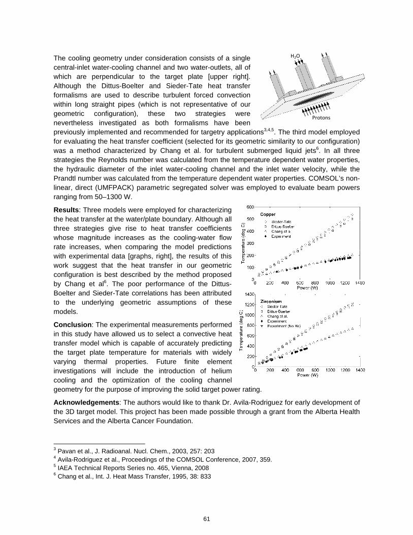
The cooling geometry under consideration consists of a single central-inlet water-cooling channel and two water-outlets, all of which are perpendicular to the target plate [upper right]. Although the Dittus-Boelter and Sieder-Tate heat transfer formalisms are used to describe turbulent forced convection within long straight pipes (which is not representative of our geometric configuration), these two strategies were nevertheless investigated as both formalisms have been previously implemented and recommended for targetry applications3,4,5. The third model employed for evaluating the heat transfer coefficient (selected for its geometric similarity to our configuration) was a method characterized by Chang et al. for turbulent submerged liquid jets6. In all three strategies the Reynolds number was calculated from the temperature dependent water properties, the hydraulic diameter of the inlet water-cooling channel and the inlet water velocity, while the Prandtl number was calculated from the temperature dependent water properties. COMSOL’s non-linear, direct (UMFPACK) parametric segregated solver was employed to evaluate beam powers ranging from 50–1300 W.
Results: Three models were employed for characterizing the heat transfer at the water/plate boundary. Although all three strategies give rise to heat transfer coefficients whose magnitude increases as the cooling-water flow rate increases, when comparing the model predictions with experimental data [graphs, right], the results of this work suggest that the heat transfer in our geometric configuration is best described by the method proposed by Chang et al6. The poor performance of the Dittus-Boelter and Sieder-Tate correlations has been attributed to the underlying geometric assumptions of these models.
Conclusion: The experimental measurements performed in this study have allowed us to select a convective heat transfer model which is capable of accurately predicting the target plate temperature for materials with widely varying thermal properties. Future finite element investigations will include the introduction of helium cooling and the optimization of the cooling channel geometry for the purpose of improving the solid target power rating.
Acknowledgements: The authors would like to thank Dr. Avila-Rodriguez for early development of the 3D target model. This project has been made possible through a grant from the Alberta Health Services and the Alberta Cancer Foundation.
3 Pavan et al., J. Radioanal. Nucl. Chem., 2003, 257: 203 4 Avila-Rodriguez et al., Proceedings of the COMSOL Conference, 2007, 359. 5 IAEA Technical Reports Series no. 465, Vienna, 2008 6 Chang et al., Int. J. Heat Mass Transfer, 1995, 38: 833
H2O
Protons
61
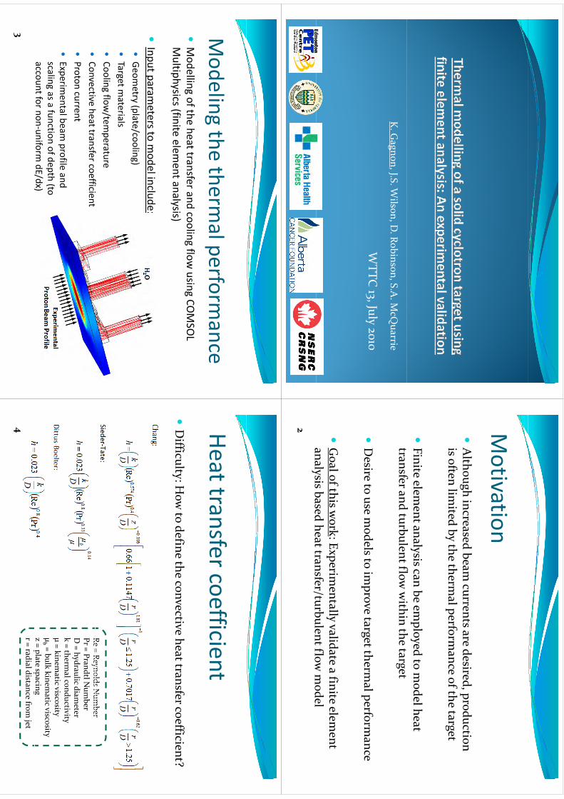
K. G
agnon, J.S. Wilson, D
. Robinson, S.A. M
cQuarrie
WTTC
J
l
WTTC
13, July 2010
Motivation
Motivation
Although increased beam
currents are desired production
Although increased beam
currents are desired, production is often lim
ited by the thermal perform
ance of the target
Finite elem
ent analysis can be employed to m
odel heat f
d b
l fl
ihi
h
transfer and turbulent flow within the target
Desire to use m
odels to improve target therm
al performance
Goal of this w
ork: Experimentally validate a finite elem
ent analysis based heat transfer/turbulent flow
model
analysis based heat transfer/turbulent flow m
odel2
Modeling
thetherm
alperformance
Modeling the therm
al performance
Modelling of the heat transfer and cooling flow
using COMSO
L g
gg
Multiphysics(finite elem
ent analysis)
ll
Input param
eters to model include::
Geom
etry (plate/cooling)Target m
aterialsCooling flow
/temperature
Ci
hf
ffii
Convective heat transfer coefficient
Proton current
Eperim
entalbeamprofile
andExperim
ental beam profile and
scaling as a function of depth (to account for non‐uniform
dE /dx)/
)
3
HeattransfercoefficientHeat transfer coefficient
Difficulty: H
ow to define the convective heat transfer coefficient?
Re = Reynolds Num
berRe = Reynolds N
umber
Pr = PrandtlNum
berD = hydraulic diam
eterk = therm
al conductivityk therm
al conductivityμ = kinem
atic viscosityμb = bulk kinem
atic viscosityz = plate spacing
pp
gr = radial distance from
jet4
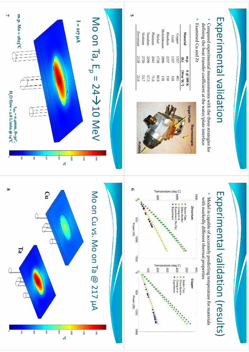
Experimentalvalidation
Experimental validation
Com
pared experimental m
easurements w
ith the three strategies for defining the heat transfer coefficient at the w
ater/plate interface
Examined Cu and Zr
Material
m.p.
(K)
k@
300 K[W
m-1K
-1]C
opper1357
401G
old1337
318R
hodium2237
150M
olybdenum2896
139N
ickel1728
90.9Platinum
204171
6Platinum
204171.6
Tantalum3290
57.5N
iobium2750
53.7i
i2128
226
Zirconium2128
22.6
5
Experimentalvalidation
(results)Experim
ental validation (results)
Model is capable of accurately predicting tem
perature for materials
with m
arkedly different thermal properties
6
Moon
TaE
=24
10MeV
Mo on Ta, E
p = 2410 M
eV I = 22 I = 22 μμAAI = 44 I = 44 μμAAI = 65 I = 65 μμAAI = 87 I = 87 μμAAI = 108 I = 108 μμAAI = 130 I = 130 μμAAI = 151 I = 151 μμAAI = 173 I = 173 μμAAI = 195 I = 195 μμAAI = 217 I = 217 μμAA
ttMM= 0
4mm
= 04m
m θθ=30=30°°
m.p
m.p. M
o = 2623. M
o = 2623°°C
C
7
ttMo
Mo = 0.4m
m,
= 0.4mm, θθ=30
=30, ,
HH22 O flow
= 2.8 L/min @
14O flow
= 2.8 L/min @
14°°C
C
Moon
Cuvs
Moon
Ta@
217μA
Mo on Cu vs. M
o on Ta @ 217 μA
Cu
Ta
8
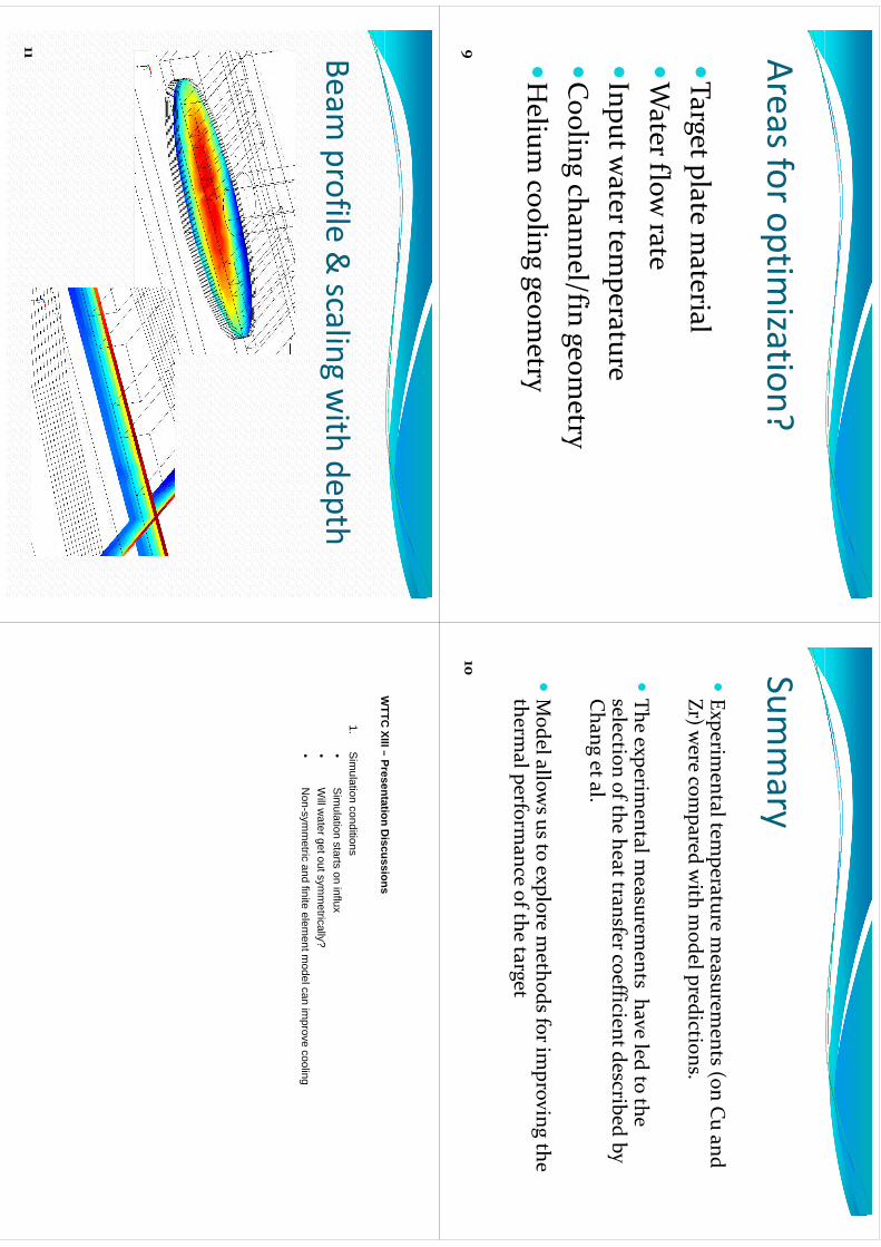
Areasforoptimization?
Areas for optimization?
Target plate material
Water flow
rateInput w
ater temperature
lh
lf
Cooling channel/fin geom
etryH
li
li
tH
elium cooling geom
etry
9
Summary
Summary
Experim
ental temperature m
easurements (on Cu and
Zr) were com
pared with m
odel predictions.
The experim
ental measurem
ents have led to the The experim
ental measurem
ents have led to the selection of the heat transfer coefficient described by Chan g et al.
g
Model allow
s us to explore methods for im
proving the Model allow
s us to explore methods for im
proving the therm
al performance of the target
10
Beamprofile
&scaling
with
depthBeam
profile & scaling w
ith depth
11
WTTC
XIII–Presentation
Discussions
WTTC
XIII –Presentation D
iscussions
1.S
imulation conditions
•S
imulation
startson
influx•
Sim
ulation starts on influx•
Will w
ater get out symm
etrically?•
Non-sym
metric and finite elem
ent model can im
prove cooling
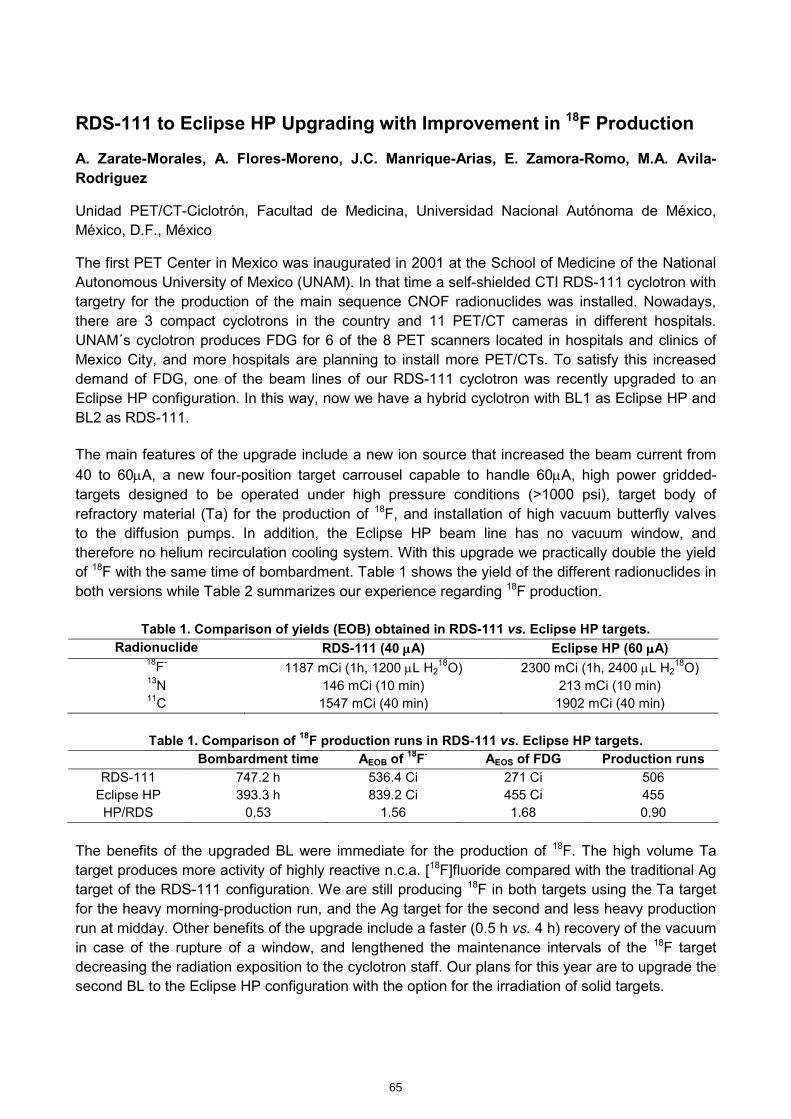
RDS-111 to Eclipse HP Upgrading with Improvement in 18F Production
A. Zarate-Morales, A. Flores-Moreno, J.C. Manrique-Arias, E. Zamora-Romo, M.A. Avila-Rodriguez
Unidad PET/CT-Ciclotrón, Facultad de Medicina, Universidad Nacional Autónoma de México, México, D.F., México
The first PET Center in Mexico was inaugurated in 2001 at the School of Medicine of the National Autonomous University of Mexico (UNAM). In that time a self-shielded CTI RDS-111 cyclotron with targetry for the production of the main sequence CNOF radionuclides was installed. Nowadays, there are 3 compact cyclotrons in the country and 11 PET/CT cameras in different hospitals. UNAM´s cyclotron produces FDG for 6 of the 8 PET scanners located in hospitals and clinics of Mexico City, and more hospitals are planning to install more PET/CTs. To satisfy this increased demand of FDG, one of the beam lines of our RDS-111 cyclotron was recently upgraded to an Eclipse HP configuration. In this way, now we have a hybrid cyclotron with BL1 as Eclipse HP and BL2 as RDS-111. The main features of the upgrade include a new ion source that increased the beam current from 40 to 60µA, a new four-position target carrousel capable to handle 60µA, high power gridded-targets designed to be operated under high pressure conditions (>1000 psi), target body of refractory material (Ta) for the production of 18F, and installation of high vacuum butterfly valves to the diffusion pumps. In addition, the Eclipse HP beam line has no vacuum window, and therefore no helium recirculation cooling system. With this upgrade we practically double the yield of 18F with the same time of bombardment. Table 1 shows the yield of the different radionuclides in both versions while Table 2 summarizes our experience regarding 18F production.
Table 1. Comparison of yields (EOB) obtained in RDS-111 vs. Eclipse HP targets. Radionuclide RDS-111 (40 µµµµA) Eclipse HP (60 µµµµA)
18F- 1187 mCi (1h, 1200 µL H218O) 2300 mCi (1h, 2400 µL H2
18O) 13N 146 mCi (10 min) 213 mCi (10 min) 11C 1547 mCi (40 min) 1902 mCi (40 min)
Table 1. Comparison of 18F production runs in RDS-111 vs. Eclipse HP targets.
Bombardment time AEOB of 18F- AEOS of FDG Production runs
RDS-111 747.2 h 536.4 Ci 271 Ci 506 Eclipse HP 393.3 h 839.2 Ci 455 Ci 455 HP/RDS 0.53 1.56 1.68 0.90
The benefits of the upgraded BL were immediate for the production of 18F. The high volume Ta target produces more activity of highly reactive n.c.a. [18F]fluoride compared with the traditional Ag target of the RDS-111 configuration. We are still producing 18F in both targets using the Ta target for the heavy morning-production run, and the Ag target for the second and less heavy production run at midday. Other benefits of the upgrade include a faster (0.5 h vs. 4 h) recovery of the vacuum in case of the rupture of a window, and lengthened the maintenance intervals of the 18F target decreasing the radiation exposition to the cyclotron staff. Our plans for this year are to upgrade the second BL to the Eclipse HP configuration with the option for the irradiation of solid targets.
65
kmje
Typewritten Text
Abstract 012
kmje
Typewritten Text
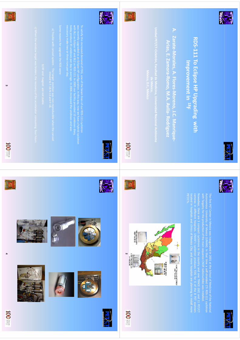
RDS‐111 ToEclipse HP U
pgradingwith
Improvem
entin 18Fp
A.Zarate‐M
orales,A.Flores‐Moreno,J.C.M
anrique‐A.
ZarateMorales, A. Flores
Moreno, J.C.M
anriqueArias, E. Zam
ora‐Romo, M
.A.Avila‐Rodriguez
Unidad PET/CT‐Ciclotrón, Facultad de M
edicina, Universidad N
acional Autónoma
de México,
México
DF
México
México, D.F., M
éxico
ThefirstPET
CenterinMexico
was
inauguratedin2001
attheSchoolofM
edicineofthe
National
Autonomous
University
ofMexico
(UNAM
).Inthat
timeaself‐shielded
CTIRDS‐111cyclotron
with
Targetryforthe
productionofthe
main
sequenceCN
OFradionuclidesw
asinstalled.Now
adaysthere
are3com
pactcyclotrons
inthe
countryand
oneTRACE
(GE)and
11PET/CT
Now
adays,thereare
3com
pactcyclotrons
inthe
countryand
oneTRACE
(GE)and
11PET/CT
cameras
indifferent
hospitals.UNAM
´scyclotron
producesFDG
for6of
the8PET
scannerslocated
inhospitals
andclinics
ofMexico
City,andmore
hospitalsare
planningto
installmore
PET/CTs.
2
Tosatisfy
thisincreaseddem
andofFDG,one
ofthebeam
linesofourRDS‐111cyclotron
tld
dt
Eli
HPfi
tiIthi
hhbid
lt
wasrecently
upgradedto
anEclipse
HPconfiguration.In
thisway,now
wehave
ahybrid
cyclotronwith
BL1asEclipse
HPand
BL2asRDS‐111.In
2005ourfacility
provided10
unidosesdiary,today
produce35
unidosesperdayinaverage.In
2006increased
theunidosesand
was
neccesarymake
twoorthree
runsperday.y
py
Somereasonsforupgrade
theRDS
were:
a)Troublewith
caruselsystemThe
targetposition
wasnon
reproduciblewhen
thecarusel
a) Troublewith
caruselsystem. The
target position wasnon‐reproducible w
henthe
caruselmoved to
F‐18‐N‐13 and F‐18.
b) RF and magnet
are notstable.
c) When
thewindow
target wasbroken, the
recoveryof the
accelaratorconsum
ingfourhours
34
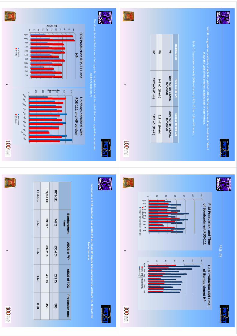
With this upgrade w
e practically double the yield of F‐18 with the sam
e time of bom
bardment. Table 1
shows the yield of the different radionuclide in both version.
Table 1. Comparison of yields (EO
B) obtained in RDS‐111 vs. Eclipse HP targets.
Radionuclide
Radionuclide
RD
SR
DS--111 (40
111 (40 μμA)
A)
Eclipse HP (60
Eclipse HP (60 μμA
)A
)
1818FF1187
Ci(1h
1200L
1187C
i(1h1200
L2300
Ci(1h
2400L
2300C
i(1h2400
L1818FF
--1187 m
Ci (1h, 1200 μL
1187 mC
i (1h, 1200 μL HH
22 1818O)E
OB
O)E
OB
2300 mC
i (1h, 2400 μL, 2300 m
Ci (1h, 2400 μL,
HH22 1818O
)EO
BO
)EO
B
1313NN146 m
Ci (10 m
in) 146 m
Ci (10 m
in) 213 m
Ci (10 m
in)213 m
Ci (10 m
in)(
)(
)(
)(
)
1111C
C
1547 mC
i (40 min)
1547 mC
i (40 min)
1902 mC
i (40 min)
1902 mC
i (40 min)
5
RESULTS
F‐18Production
andTim
eF18
Productionand
Time
120
F‐18 Production and Time
of Bombardm
ent RDS‐111120
F‐18 Production and Time
of Bombardm
ent HP
80
100
80
100
60 80
60 80
4040
0 20
ilynulgptvcnb
0 20
ApriMayJunJuAugSepOcNovDecJanFeb
Activity (Ci)Tim
e of Bombardm
ent RDS (h)
AprilJun
AugOct
DecFeb
Time of Bom
bardment …
Activity (Ci)
6
Thedoses obtained
beforeand afterupgrade. In the
data are notincluded
thedoses applied
in ournuclear medicine
laboratorymedicine laboratory
FDG Production RDS‐111 and Unidosesobtained
with
40 45 50HP
600
RDS‐111 and HP version
30 35 40
y (Ci)
400
500s number
15 20 25
Activity
200
300Doses
0 5 10
l
y
n
l
g
p
t
v
c
n
b
0
100
Apri
May
Jun
Ju
Aug
Sep
Oct
Nov
Dec
Jan
Feb
RDS‐FDGHP FDG
RDS dosesHP doses
7
Comparison of F‐18 production runs in RDS‐111 vs. Eclipse HP targets.Bom
bardment tim
e AEOB of F‐18. AEO
S of FDG p
pp
gProduction runs
Bom
bardment
Bom
bardment
titiA
EOB
of A
EOB
of 1818FF--
AEO
S of FDG
AEO
S of FDG
Production runsProduction runs
time
time
RD
SR
DS
--111111
747.2 h747.2 h
536.4 Ci
536.4 Ci
271 Ci
271 Ci
506506
Eclipse H
PE
clipse HP
393.3 h393.3 h
839.2 Ci
839.2 Ci
455 Ci
455 Ci
455455
HP
/RD
SH
P/R
DS
0.530.53
1.561.56
1.681.68
0.900.90
8

Conclusion: Benefits of the RDS Eclipse
Thebenefitsofthe
upgradedBL1
were
immediate
fortheproduction
ofF‐18:
•The
highvolum
eTa
targetproduces
more
activityof
highlyreactive
n.c.a.[F18]fluoride
compared
with
thetraditionalAg
targetoftheRDS‐111configuration.
•Weare
stillproducing
F‐18
inboth
targetsusing
theTa
targetfor
theheavy
morning‐
pg
gg
gy
gproduction
run,andthe
Agtargetforthe
secondand
lessheavyproduction
runatm
idday.
•Otherbenefits
oftheupgrade
includeafaster(0.5
hvs.4
h)recoveryofthe
vacuumin
caseof
therupture
ofawindow,and
lengthenedthe
maintenance
intervalsof
theF‐18
targetof
therupture
ofawindow,and
lengthenedthe
maintenance
intervalsof
theF18
targetdecreasing
theradiation
expositionto
thecyclotron
staff.
•The
RDSEclipse
upgradeallow
sthe
routineproduction
of40
unidosesof
FDGwith
ahigh
degreeofsuccess
addedofproduction
of(N‐13)Am
oniaand
(C‐11)‐Acetateand
(F‐18)FLTdegree
ofsuccess,addedofproduction
of(N13)Am
oniaand
(C11)
Acetateand
(F18)FLT.
9
Upgrade of 2
ndBeam Line in 2011
Wih
lidi
dii
iWith solid target irradiation option
10
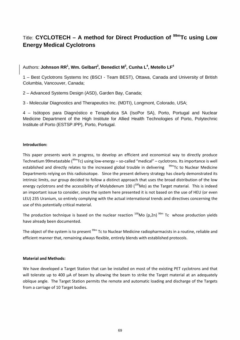
Title: CYCLOTECH – A method for Direct Production of 99mTc using Low Energy Medical Cyclotrons
Authors: Johnson RR 1, Wm. Gelbart 2, Benedict M 3, Cunha L 4, Metello LF 4
1 – Best Cyclotrons Systems Inc (BSCI - Team BEST), Ottawa, Canada and University of British Columbia, Vancouver, Canada;
2 – Advanced Systems Design (ASD), Garden Bay, Canada;
3 - Molecular Diagnostics and Therapeutics Inc. (MDTI), Longmont, Colorado, USA;
4 – Isótopos para Diagnóstico e Terapêutica SA (IsoPor SA), Porto, Portugal and Nuclear Medicine Department of the High Institute for Allied Health Technologies of Porto, Polytechnic Institute of Porto (ESTSP.IPP), Porto, Portugal.
Introduction:
This paper presents work in progress, to develop an efficient and economical way to directly produce
Technetium 99metastable (99m
Tc) using low-energy – so-called “medical” – cyclotrons. Its importance is well
established and directly relates to the increased global trouble in delivering 99m
Tc to Nuclear Medicine
Departments relying on this radioisotope. Since the present delivery strategy has clearly demonstrated its
intrinsic limits, our group decided to follow a distinct approach that uses the broad distribution of the low
energy cyclotrons and the accessibility of Molybdenum 100 (100
Mo) as the Target material. This is indeed
an important issue to consider, since the system here presented it is not based on the use of HEU (or even
LEU) 235 Uranium, so entirely complying with the actual international trends and directives concerning the
use of this potentially critical material.
The production technique is based on the nuclear reaction 100
Mo (p,2n) 99m
Tc whose production yields
have already been documented.
The object of the system is to present 99m
Tc to Nuclear Medicine radiopharmacists in a routine, reliable and
efficient manner that, remaining always flexible, entirely blends with established protocols.
Material and Methods:
We have developed a Target Station that can be installed on most of the existing PET cyclotrons and that
will tolerate up to 400 μA of beam by allowing the beam to strike the Target material at an adequately
oblique angle. The Target Station permits the remote and automatic loading and discharge of the Targets
from a carriage of 10 Target bodies.
69
kmje
Typewritten Text
Abstract 013
kmje
Typewritten Text
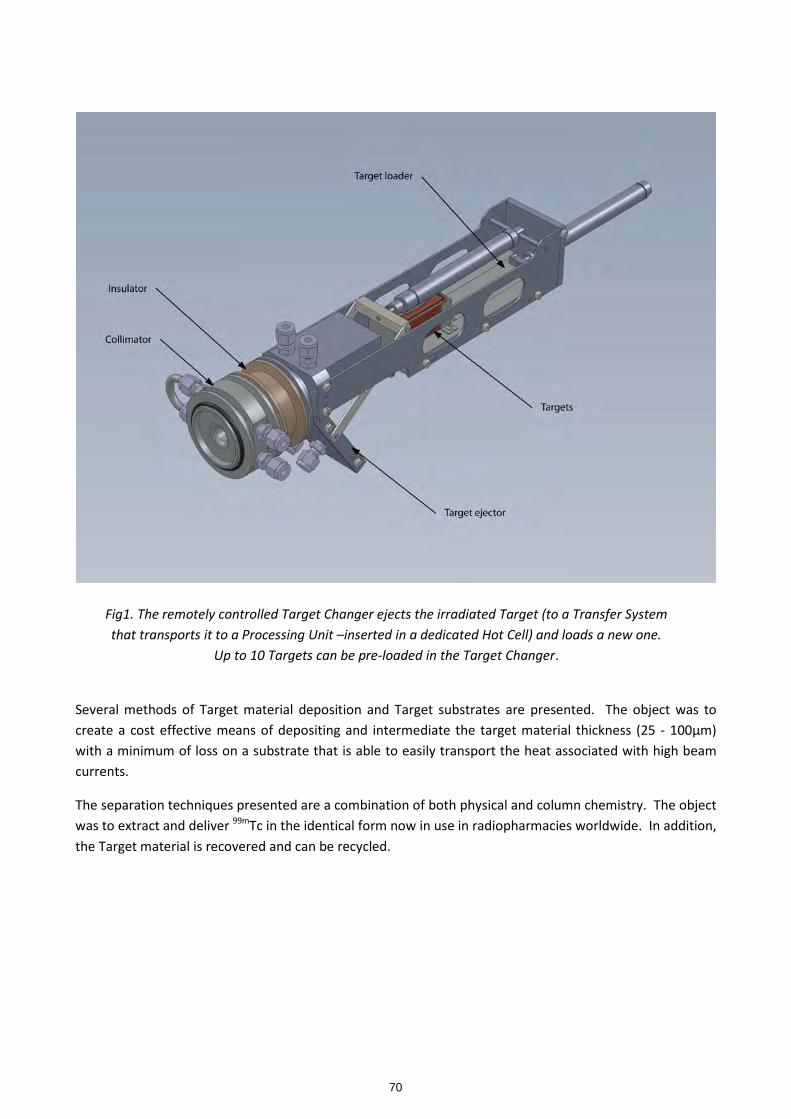
Fig1. The remotely controlled Target Changer ejects the irradiated Target (to a Transfer System
that transports it to a Processing Unit –inserted in a dedicated Hot Cell) and loads a new one.
Up to 10 Targets can be pre-loaded in the Target Changer.
Several methods of Target material deposition and Target substrates are presented. The object was to
create a cost effective means of depositing and intermediate the target material thickness (25 - 100μm)
with a minimum of loss on a substrate that is able to easily transport the heat associated with high beam
currents.
The separation techniques presented are a combination of both physical and column chemistry. The object
was to extract and deliver 99m
Tc in the identical form now in use in radiopharmacies worldwide. In addition,
the Target material is recovered and can be recycled.
70
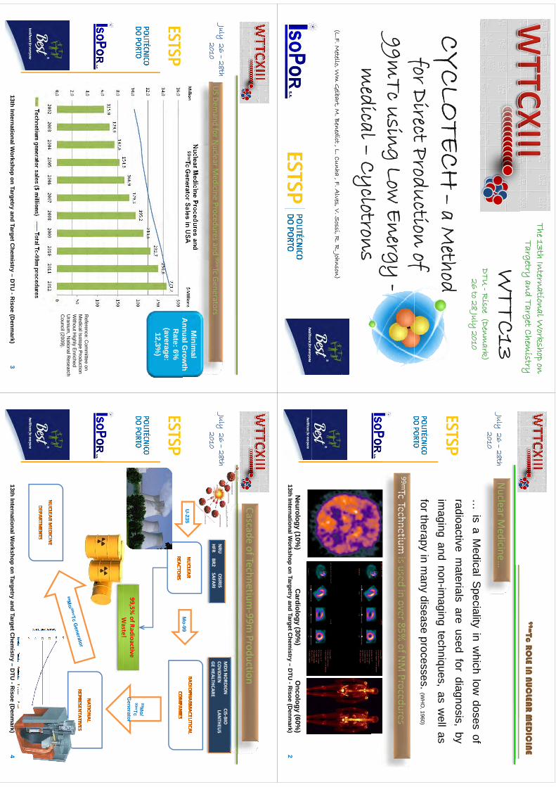
The 13th International Workshop on
Targetry and Target Chemistry
WTTC13
DTU -R
isoe(Denm
ark) 26 to 28 July
2010
CYCLO
TECH–
a Method
for Direct Production of i
99mTc using Low Energy -edi
al C
lt
medical –
Cyclotrons(L.F. M
etello, Wm
Gelbart, M
. Benedict, L. Cunha , F. A
lves, V. Sossi, R
. R. Johnson)
99m99mTc R
OLE IN
NU
CLEA
R M
EDIC
INE
Tc RO
LE IN N
UC
LEAR
MED
ICIN
E
July26 –
28th 2010
Nuclear M
edicine…2010
…is
aM
edicalSpecialityin
which
lowdoses
ofradioactive
materials
areused
fordiagnosis
byradioactive
materials
areused
fordiagnosis,
byim
agingand
non-imaging
techniques,as
well
as
99mTc‐Technetiumisused
inover85%
ofNM
Procedures
fortherapyin
many
diseaseprocesses.
(WH
O,1960)
Tc‐Technetiumis used in over 85%
of NM Procedures
213th International W
orkshop on Targetryand Target C
hemistry –
DTU
-Risoe
(Denm
ark)N
eurology (10%)
Cardiology (30%
)O
ncology (60%)
July26 –
28th 2010
US Dem
and for Nuclear M
edicine Procedures and 99mTc Generators2010
Minim
alA
nnualGrow
thA
nnual Grow
th R
ate: 6%(average:
12,3%)
Reference: C
omm
ittee on M
edical Isotope Production
Without H
ighly Enriched
Uranium
, National R
esearch C
il(2009)C
ouncil (2009).
313th International W
orkshop on Targetryand Target C
hemistry –
DTU
-Risoe
(Denm
ark)
Cascade of Technetium‐99m
Production
July26 –
28th 2010
MDS N
ORDIO
N CIS‐BIO
COVIDIEN
LANTHEU
SGE
HEALTHCARENRU
OSIRIS
HFRBR2
SAFARI2010
Mo-99
GE HEALTHCAREHFR BR2 SAFARI
U-235
Mo
99
99,5% of Radioactive Waste!
99Mo/
99mTc G
eneratorWaste!
413th International W
orkshop on Targetryand Target C
hemistry –
DTU
-Risoe
(Denm
ark)
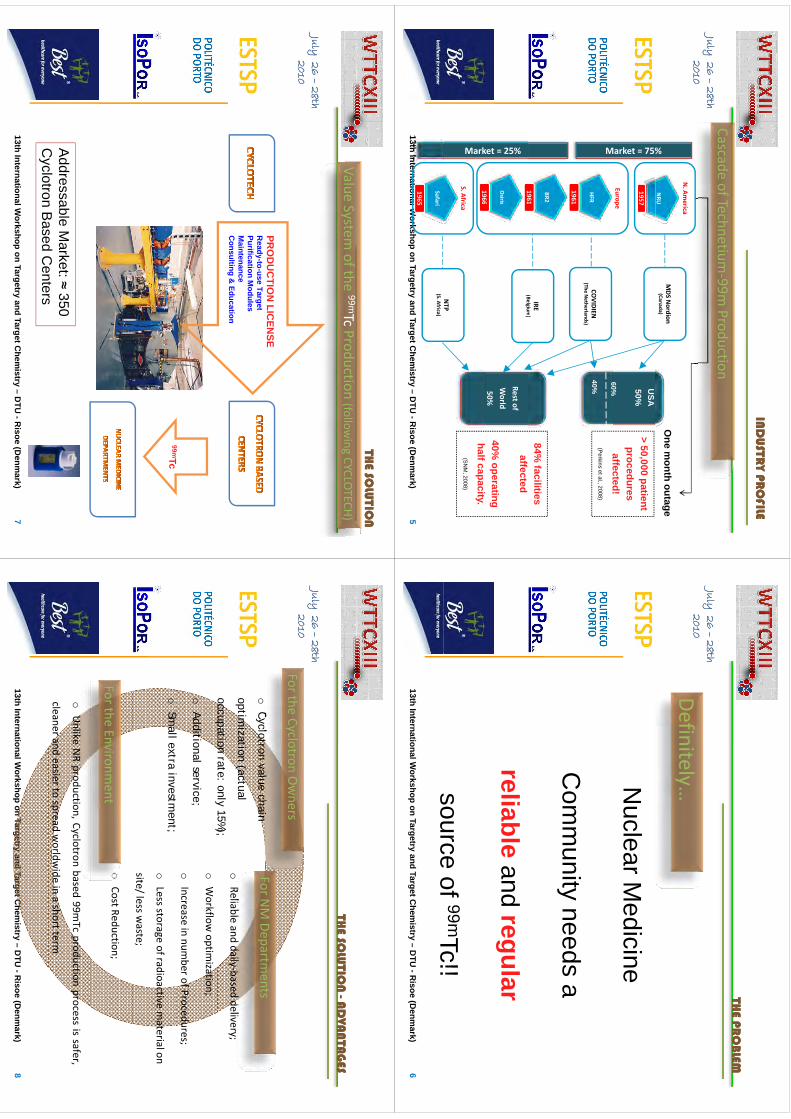
IND
USTR
Y PRO
FILEIN
DU
STRY PR
OFILE
July26 –
28th 2010
Cascade of Technetium‐99m
Production2010
%
NRU
N. Am
erica
MDS N
ordion(Canada)
One m
onth outage
Market = 75%
Europe
> 50,000 patient procedures
affected!
1957U
SA50%
60%
M
HFR
1961
affected!(P
erkins et al., 2008)CO
VIDIEN(The
Netherlands)
60%
40%
BR2
196184%
facilities IRE
(Belgium)
Osiris
1966
1961affected
40% operating
(Belgium)
Rest of World50%
ket = 25%
1966half capacity.
(SN
M, 2008)
S. Africa
NTP
Mark
513th International W
orkshop on Targetryand Target C
hemistry –
DTU
-Risoe
(Denm
ark)
Safari
1965
(S. Africa)
THE PR
OBLEM
THE PR
OBLEM
July26 –
28th 2010
THE PR
OBLEM
THE PR
OBLEM
2010Definitely…N
uclear Medicine
Com
munity
needsa
Com
munity needs a
reliable andregular
sourceof
99mTc!!6
13th International Workshop on Targetry
and Target Chem
istry –D
TU -R
isoe(D
enmark)
source of Tc!!
THE SO
LUTIO
N
THE SO
LUTIO
N
ValueSystem
ofthe99mTc
Production(follow
ingCYCLOTECH)
July26 –
28th 2010
Value System of the
TcProduction (follow
ing CYCLOTECH)
2010
PRO
DU
CTIO
N LIC
ENSE
Ready
touse
TargetR
eady-to-use TargetPurification M
odulesM
aintenanceC
onsulting & Education
99mT99mTc
Addressable M
arket: ≈ 350 C
yclotronB
asedC
enters
713th International W
orkshop on Targetryand Target C
hemistry –
DTU
-Risoe
(Denm
ark)
Cyclotron B
ased Centers
THE SO
LUTIO
N
THE SO
LUTIO
N
AD
VAN
TAG
ESA
DVA
NTA
GES
July26 –
28th 2010
THE SO
LUTIO
N
THE SO
LUTIO
N --A
DVA
NTA
GES
AD
VAN
TAG
ES
2010
oCyclotron value chain
For the Cyclotron Owners
For NM Departm
entso
Cyclotron value chain
optimization (actual
occupation rate: only 15%);o
Reliable and daily‐based delivery;
For NM Departm
ents
occupation rate: only 15%);
oAdditional service;
Sll
t i
tt
oWorkflow
optimization;
oIncrease in num
ber of Procedures;o
Small extra investm
ent;o
Less storage of radioactive material on
site/ less waste;
oCost Reduction;
For the Environment
oUnlike
NRproduction,Cyclotron
based99m
Tcproduction
processissafer,
cleanerandeasierto
spreadworldw
ideinashortterm
813th International W
orkshop on Targetryand Target C
hemistry –
DTU
-Risoe
(Denm
ark)
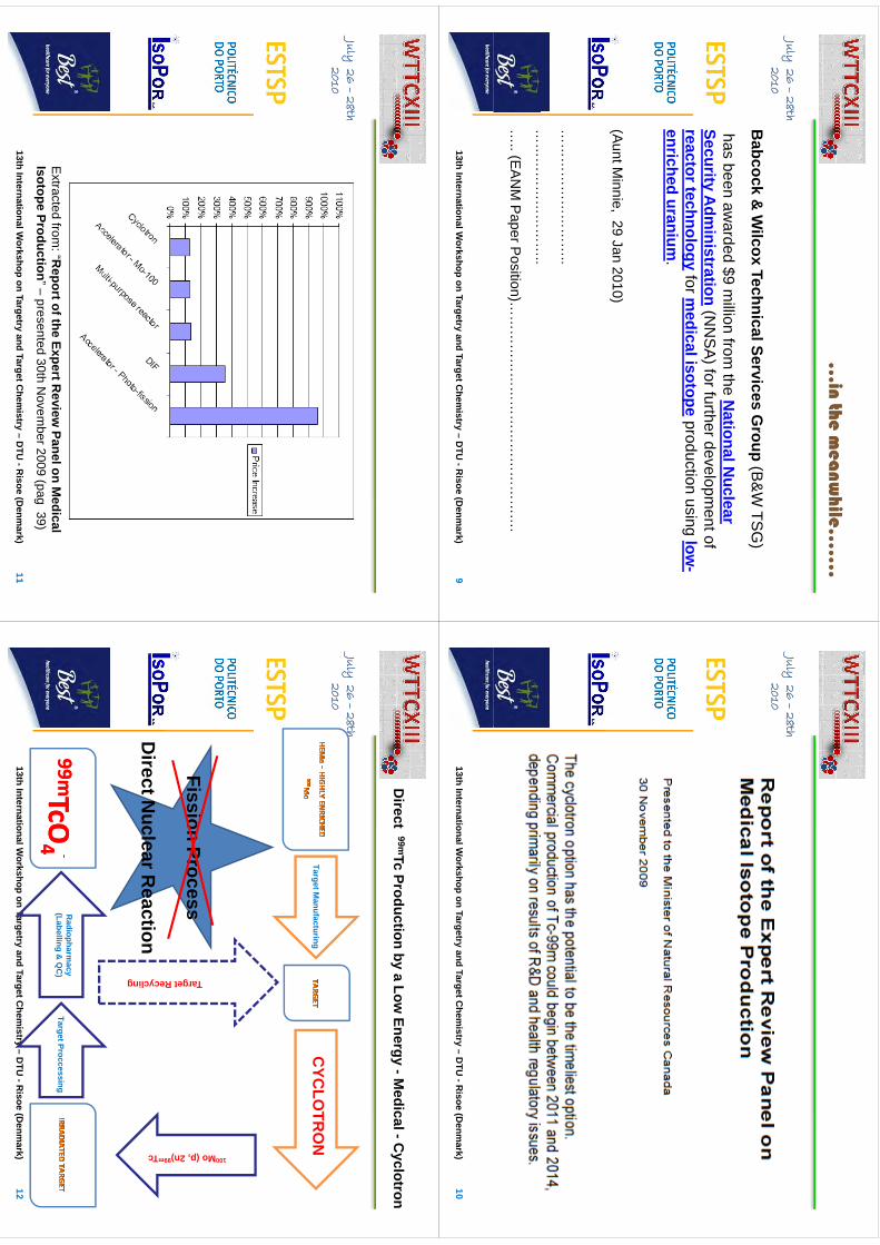
…in the m
eanw
hile……
.…
in the mea
nwhile…
….
July26 –
28th 20102010
Babcock &
Wilcox Technical Services G
roup(B
&W
TSG
)
hasbeen
awarded
$9m
illionfrom
theN
ationalNuclear
has been awarded $9 m
illion from the N
ational Nuclear
Security Adm
inistration(N
NS
A) for further developm
ent of reactor technology
for medical isotope
production using low-
enriched uranium.
(Aunt M
innie, 29 Jan 2010)
……
……
……
……
…..
……
……
……
……
…..
….. (E
AN
M P
aper Position)…
……
……
……
……
……
……
……
….
913th International W
orkshop on Targetryand Target C
hemistry –
DTU
-Risoe
(Denm
ark)
July26 –
28th 20102010
1013th International W
orkshop on Targetryand Target C
hemistry –
DTU
-Risoe
(Denm
ark)
July26 –
28th 20102010
Extracted
from:“R
eportoftheExpertR
eviewPanelon
Medical
1113th International W
orkshop on Targetryand Target C
hemistry –
DTU
-Risoe
(Denm
ark)
Extracted from
: Report of the Expert R
eview Panel on M
edical Isotope Production” –
presented 30th Novem
ber 2009 (pag 39)
Direct 99mTc Production by a Low
Energy -Medical -C
yclotron
July26 –
28th 20102010
TargetManufacturing
CYC
LOTR
ON
FissionProcess
100Mo (p
Ta
Fission Process
DirectN
uclearReaction
p, 2n)99mTc
arget Recyc
Direct N
uclear Reaction
cling
TargetProccessingR
adiopharmacy
(Labelling&
QC
)99m99mTcO
TcO44
‐‐
1213th International W
orkshop on Targetryand Target C
hemistry –
DTU
-Risoe
(Denm
ark)
TcOTcO
44
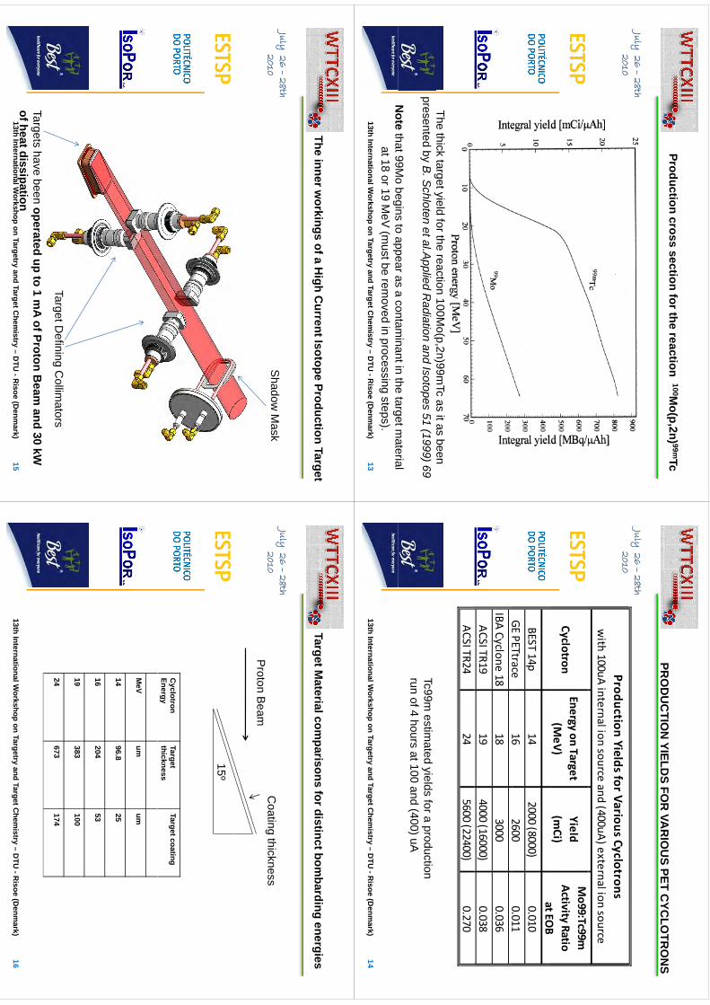
Production cross section for the reaction 100Mo(p,2n) 99mTc
July26 –
28th 20102010
The thick target yield for the reaction 100Mo(p,2n)99m
Tc as it as been g
y(p,
)presented by B
. Schloten et al.A
pplied Radiation and Isotopes 51 (1999) 69
Note
that99Mo
beginsto
appearasa
contaminantin
thetargetm
aterial1313th International W
orkshop on Targetryand Target C
hemistry –
DTU
-Risoe
(Denm
ark)
Note
that 99Mo begins to appear as a contam
inant in the target material
at 18 or 19 MeV
(must be rem
oved in processing steps).
PRO
DU
CTIO
NYIELD
SFO
RVA
RIO
US
PETC
YCLO
TRO
NS
July26 –
28th 2010
PRO
DU
CTIO
N YIELD
S FOR
VAR
IOU
S PET CYC
LOTR
ON
S
2010Production Yields for Various Cyclotrons
with 100uA internal ion source and (400uA) external ion source
CyclotronEnergy on Target
(MeV)
Yield(m
Ci)
Mo99:Tc99m
Activity RatioatEO
Bat EO
BBEST 14p
142000 (8000)
0.010GE
PETtrace16
26000.011
GE PETtrace16
26000.011
IBA Cyclone 1818
30000.036
ACSI TR1919
4000 (16000)0.038
ACSI TR2424
5600 (22400)0.270
Tc99m estim
ated yields for a production run of 4 hours at 100 and (400) uA
1413th International W
orkshop on Targetryand Target C
hemistry –
DTU
-Risoe
(Denm
ark)
The inner workings of a H
igh Current Isotope Production Target
July26 –
28th 2010
Shadow
Mask
2010S
hadow M
ask
Target Defining C
ollimators
1513th International W
orkshop on Targetryand Target C
hemistry –
DTU
-Risoe
(Denm
ark)
Targets have been operated up to 1 mA of Proton B
eam and 30 kW
of heat dissipation
Target Material com
parisons for distinct bombarding energies
July26 –
28th 2010
Coating
thickness2010
Coating thickness
Proton B
eam
15º
Cyclotron
Energy Target thickness
Target coating
MeV
um
um
1496
825
14 96.8
25
16 204
53
19 383
100
24 673
174
1613th International W
orkshop on Targetryand Target C
hemistry –
DTU
-Risoe
(Denm
ark)
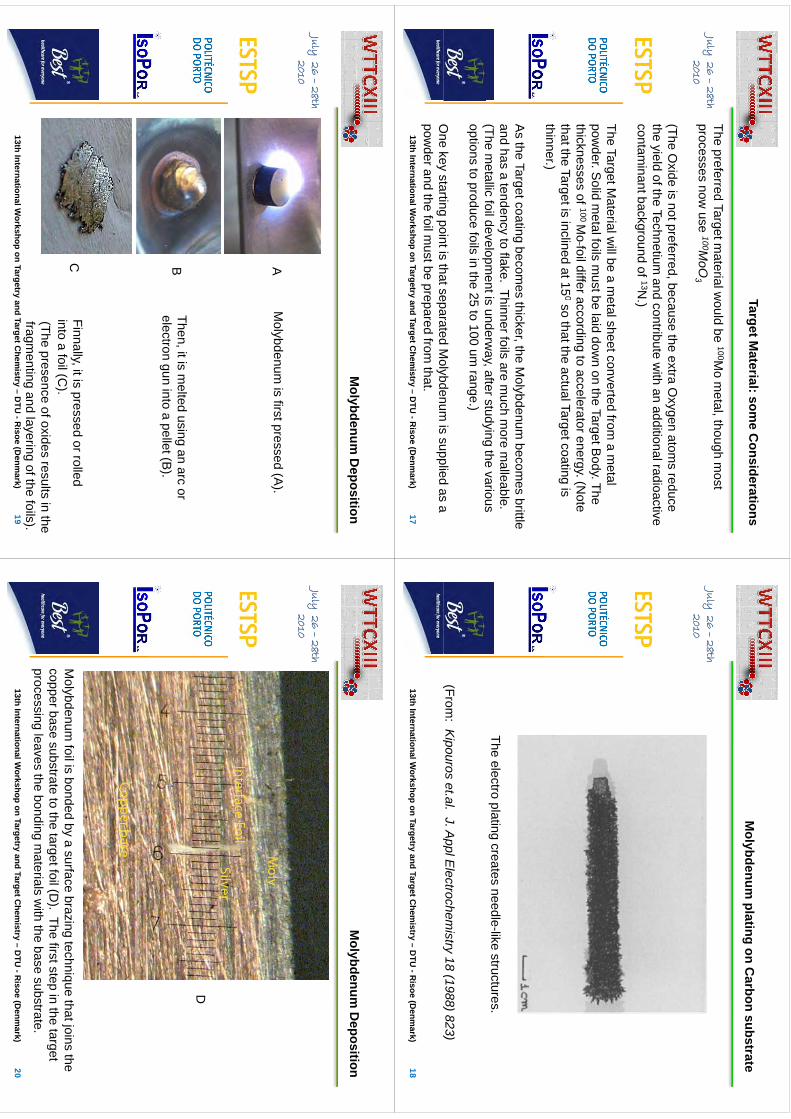
Target Material: som
e Considerations
July26 –
28th 2010
The preferred Target material w
ould be 100Mo m
etal, though most
processes now use 100M
oO3
2010p
3
(The Oxide is not preferred, because the extra O
xygen atoms reduce
theyield
oftheTechnetium
andcontribute
with
anadditionalradioactive
the yield of the Technetium and contribute w
ith an additional radioactive contam
inant background of 13N.)
TheTargetM
aterialwillbe
am
etalsheetconvertedfrom
am
etalThe Target M
aterial will be a m
etal sheet converted from a m
etal pow
der. Solid m
etal foils must be laid dow
n on the Target Body. The
thicknesses of 100 Mo
foil differ according to accelerator energy. (Note
0that the Target is inclined at 15
0so that the actual Target coating is thinner.)
As the Target coating becom
es thicker, the Molybdenum
becomes brittle
and has a tendency to flake. Thinner foils are much m
ore malleable.
(Them
etallicfoildevelopm
entisunderw
ay,afterstudyingthe
various(The m
etallic foil development is underw
ay, after studying the various options to produce foils in the 25 to 100 um
range.)
One
keystarting
pointisthatseparated
Molybdenum
issupplied
asa
1713th International W
orkshop on Targetryand Target C
hemistry –
DTU
-Risoe
(Denm
ark)
One key starting point is that separated M
olybdenum is supplied as a
powder and the foil m
ust be prepared from that.
Molybdenum
plating on Carbon substrate
July26 –
28th 20102010
The electro plating creates needle-like structures.
(From: K
ipouros et.al. J. Appl E
lectrochemistry 18 (1988) 823)
1813th International W
orkshop on Targetryand Target C
hemistry –
DTU
-Risoe
(Denm
ark)
(p
ppy
()
)
Molybdenum
Deposition
July26 –
28th 20102010
AM
olybdenum is first pressed (A
).
BThen, it is m
elted using an arc or B
gelectron gun into a pellet (B
).
CFinnally, it is pressed or rolled into a foil (C
).(Th
fid
lti
th1913th International W
orkshop on Targetryand Target C
hemistry –
DTU
-Risoe
(Denm
ark)
(The presence of oxides results in the fragm
enting and layering of the foils).
Molybdenum
Deposition
July26 –
28th 20102010
D
Molybdenum
foil is bonded by a surface brazing technique that joins the copper base substrate to the target foil (D
). The first step in the target
2013th International W
orkshop on Targetryand Target C
hemistry –
DTU
-Risoe
(Denm
ark)
ppg
()
pg
processing leaves the bonding materials w
ith the base substrate.
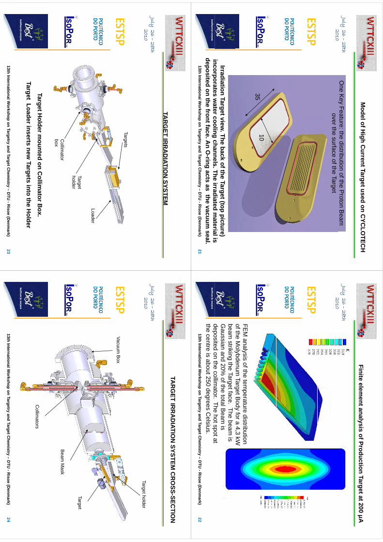
Model of H
igh Current Target used on C
YCLO
TECH
July26 –
28th 2010
One K
ey Feature: the distribution of the Proton B
eam
2010over the surface of the Target
103535
Irradiation Target view. The back of the Target (top picture)
incorporatesw
atercoolingchannels
Theirradiated
materialis
2113th International W
orkshop on Targetryand Target C
hemistry –
DTU
-Risoe
(Denm
ark)
incorporates water cooling channels. The irradiated m
aterial is deposited on the front face. A
n O-ring acts as the vacuum
seal.
Finite element analysis of Production Target at 200 μA
July26 –
28th 2010
yg
μ
2010
FEM
analysis of the temperature distribution
of the Molybdenum
Target Body for a 4,3 kW
y
gy
,beam
striking the Target face. The beam is
Gaussian and 20%
of the total Beam
is deposited
onthe
collimator
Thehotspotat
2213th International W
orkshop on Targetryand Target C
hemistry –
DTU
-Risoe
(Denm
ark)
deposited on the collimator. The hot spot at
the centre is about 250 degrees Celsius.
TAR
GET
IRR
AD
IATION
SYSTEM
July26 –
28th 2010
TAR
GET IR
RA
DIATIO
N SYSTEM
2010
TargetsTargets
Loader
Target holder
Collim
ator box
Target Holder m
ounted on Collim
ator Box.
Target Loader inserts new Targets into the H
older
2313th International W
orkshop on Targetryand Target C
hemistry –
DTU
-Risoe
(Denm
ark)
TAR
GET IR
RA
DIATIO
N SYSTEM
CR
OSS-SEC
TION
July26 –
28th 20102010
Target holder
Vacuum B
ox
Target
Beam
Mask
Collim
ators
2413th International W
orkshop on Targetryand Target C
hemistry –
DTU
-Risoe
(Denm
ark)
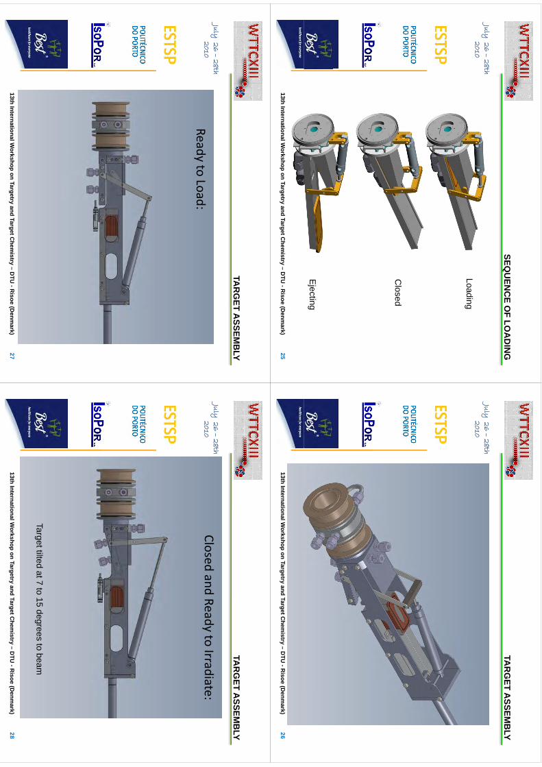
SEQU
ENC
EO
FLO
AD
ING
July26 –
28th 2010
SEQU
ENC
E OF LO
AD
ING
2010Loading
Closed
Ejecting
2513th International W
orkshop on Targetryand Target C
hemistry –
DTU
-Risoe
(Denm
ark)
TAR
GET
ASSEM
BLY
July26 –
28th 2010
TAR
GET A
SSEMB
LY
2010
2613th International W
orkshop on Targetryand Target C
hemistry –
DTU
-Risoe
(Denm
ark)
TAR
GET
ASSEM
BLY
July26 –
28th 2010
TAR
GET A
SSEMB
LY
2010Ready to Load:
2713th International W
orkshop on Targetryand Target C
hemistry –
DTU
-Risoe
(Denm
ark)
TAR
GET
ASSEM
BLY
July26 –
28th 2010
TAR
GET A
SSEMB
LY
Closedand
Readyto
Irradiate:2010
Closed and Ready to Irradiate:
Target tilted at 7 to 15 degrees to beam
2813th International W
orkshop on Targetryand Target C
hemistry –
DTU
-Risoe
(Denm
ark)
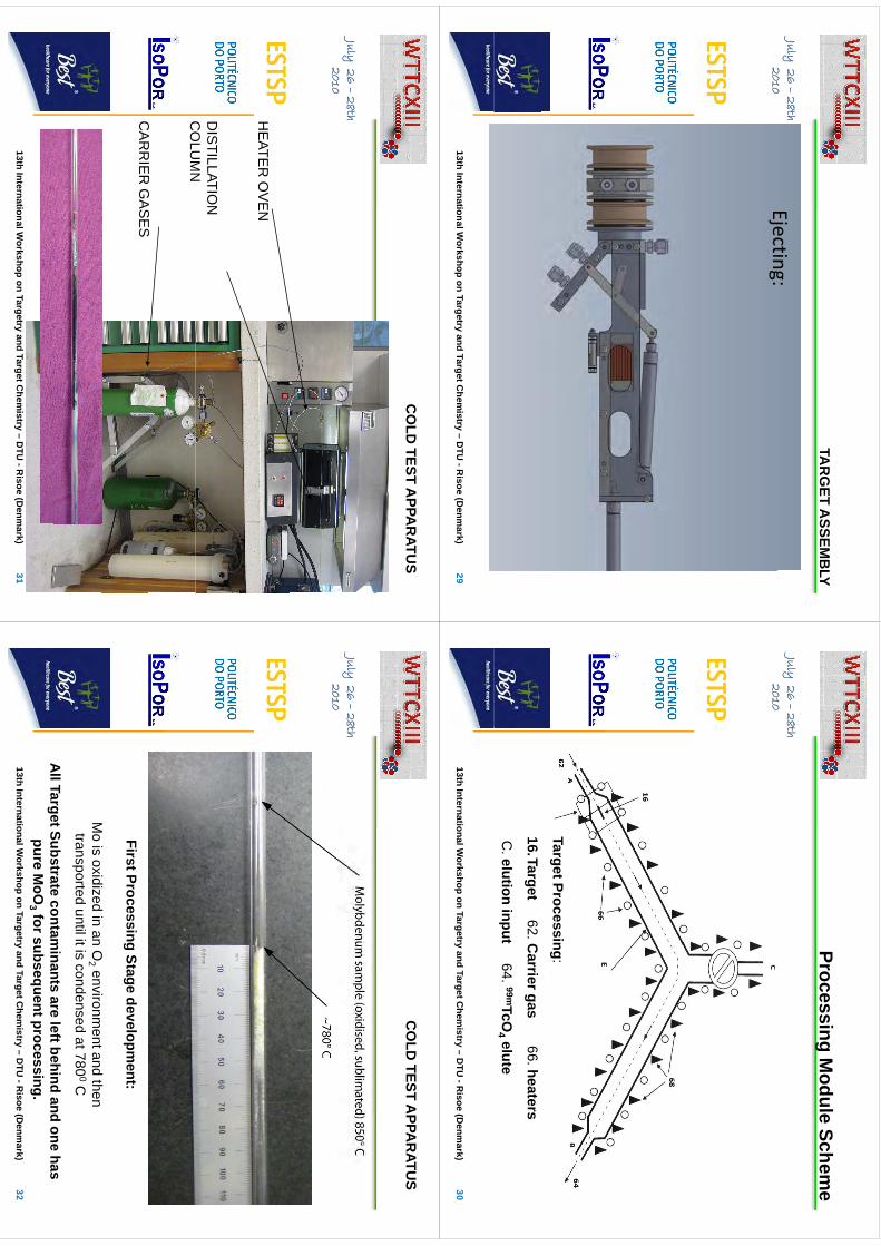
TAR
GET
ASSEM
BLY
July26 –
28th 2010
TAR
GET A
SSEMB
LY
Ejecting:2010
Ejecting:
2913th International W
orkshop on Targetryand Target C
hemistry –
DTU
-Risoe
(Denm
ark)
ProcessingM
oduleSchem
eJuly
26 –28th
2010
Processing Module Schem
e
2010
Target Processing:
16.Target62. C
arrier gas66. heaters
C. elution input
64. 99mTcO4 elute
3013th International W
orkshop on Targetryand Target C
hemistry –
DTU
-Risoe
(Denm
ark)
CO
LD TEST A
PPAR
ATUS
July26 –
28th 20102010
HE
ATER
OV
EN
DIS
TILLATION
C
OLU
MN
CO
LUM
N
CA
RR
IER
GA
SE
SC
AR
RIE
R G
AS
ES
3113th International W
orkshop on Targetryand Target C
hemistry –
DTU
-Risoe
(Denm
ark)
CO
LD TEST A
PPAR
ATUS
July26 –
28th 20102010
First Processing Stage development:
Mi
idid
iO
it
dth
Mo is oxidized in an O
2 environment and then
transported until it is condensed at 7800C
AllTargetSubstrate
contaminants
areleftbehind
andone
has
3213th International W
orkshop on Targetryand Target C
hemistry –
DTU
-Risoe
(Denm
ark)
All Target Substrate contam
inants are left behind and one has pure M
oO3 for subsequent processing.
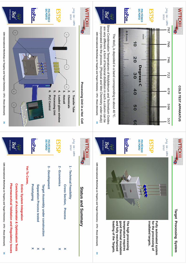
CO
LD TEST A
PPAR
ATUS
July26 –
28th 20102010
TheM
oOis
depositedin
aband
correspondingto
about400C
The MoO
3 is deposited in a band corresponding to about 40 0C.
Since C
ondensation Temperatures of M
olybdenum and Technetium
Oxides
arevery
differenta
formoffractionaldistillation
insuch
acolum
ncan
be3313th International W
orkshop on Targetryand Target C
hemistry –
DTU
-Risoe
(Denm
ark)
are very different, a form of fractional distillation in such a colum
n can be incorporated into the process. (P
hysical and Wet C
hemistry under study)
Target Processing System
July26 –
28th 20102010
Fully automated system
f
thi
ffor the processing of irradiated targets.
The high processing tem
peraturerequires
temperature requires
good thermal insulation
and fully mechanized
ldi
fthT
tloading of the Targets.34
13th International Workshop on Targetry
and Target Chem
istry –D
TU -R
isoe(D
enmark)
ProcessingU
nitina
Hot
Cell
July26 –
28th 2010
Processing Unit in a H
ot Cell
1.Transfer Tube
20102.
Chem
icals
3.H
otcell
4.Leaded glass w
indow
5.Processing U
nit
6.PLC
Control
3513th International W
orkshop on Targetryand Target C
hemistry –
DTU
-Risoe
(Denm
ark)
Statusand
Summ
ary
July26 –
28th 2010
Status and Summ
ary
1T
hi
lFibilit
20101 -Technical Feasibility
Cross Section, Process X
2 -Economics X
3 -Developm
ent
Target Assem
bly under construction X
Separation Process tested X
Protot ypingX
ypg
Yet To Com
e,EntireSystem
IntegrationEntire System
Integration
Conclusion of A
ccelerator & O
ptimization Tests
PharmaceuticalValidation
andR
egulatoryIssues36
13th International Workshop on Targetry
and Target Chem
istry –D
TU -R
isoe(D
enmark)
Pharmaceutical Validation and R
egulatory Issues

WTTC
XIII–Presentation
Discussions
WTTC
XIII Presentation D
iscussions
1.M
oO3 to M
o reduction•
InH
environment
In H environm
ent
2.P
roduction of 99 Mo? P
roduction in positive ion machine?
•M
oreenergy
andhigh
currentsneeded
•M
ore energy and high currents needed
3.Target deposition techniques•
Sputtering
onlygood
fortoothin
25umneeded!
•S
puttering only good for too thin… 25um
needed!•
Plasma deposition does not w
ork
4Financing
4.Financing•
99Tc from cyclotron: 3 or 4 x m
ore expensive than today•
99Tc prize: not the ultimate factor
•A
ctualchemistry
andim
agingequipm
entcanbe
useddirectly
•A
ctual chemistry and im
aging equipment can be used directly
80
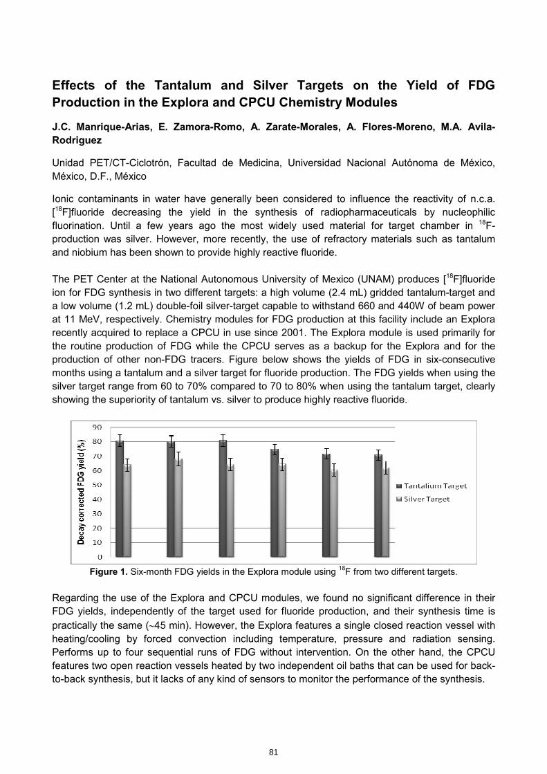
Effects of the Tantalum and Silver Targets on the Yield of FDG Production in the Explora and CPCU Chemistry Modules
J.C. Manrique-Arias, E. Zamora-Romo, A. Zarate-Morales, A. Flores-Moreno, M.A. Avila-Rodriguez
Unidad PET/CT-Ciclotrón, Facultad de Medicina, Universidad Nacional Autónoma de México, México, D.F., México
Ionic contaminants in water have generally been considered to influence the reactivity of n.c.a. [18F]fluoride decreasing the yield in the synthesis of radiopharmaceuticals by nucleophilic fluorination. Until a few years ago the most widely used material for target chamber in 18F- production was silver. However, more recently, the use of refractory materials such as tantalum and niobium has been shown to provide highly reactive fluoride. The PET Center at the National Autonomous University of Mexico (UNAM) produces [18F]fluoride ion for FDG synthesis in two different targets: a high volume (2.4 mL) gridded tantalum-target and a low volume (1.2 mL) double-foil silver-target capable to withstand 660 and 440W of beam power at 11 MeV, respectively. Chemistry modules for FDG production at this facility include an Explora recently acquired to replace a CPCU in use since 2001. The Explora module is used primarily for the routine production of FDG while the CPCU serves as a backup for the Explora and for the production of other non-FDG tracers. Figure below shows the yields of FDG in six-consecutive months using a tantalum and a silver target for fluoride production. The FDG yields when using the silver target range from 60 to 70% compared to 70 to 80% when using the tantalum target, clearly showing the superiority of tantalum vs. silver to produce highly reactive fluoride.
Figure 1. Six-month FDG yields in the Explora module using 18F from two different targets.
Regarding the use of the Explora and CPCU modules, we found no significant difference in their FDG yields, independently of the target used for fluoride production, and their synthesis time is practically the same (∼45 min). However, the Explora features a single closed reaction vessel with heating/cooling by forced convection including temperature, pressure and radiation sensing. Performs up to four sequential runs of FDG without intervention. On the other hand, the CPCU features two open reaction vessels heated by two independent oil baths that can be used for back-to-back synthesis, but it lacks of any kind of sensors to monitor the performance of the synthesis.
81
kmje
Typewritten Text
Abstract 014

Effects of the Tantalum and
Effects of the Tantalum and
SilverTargetson
theYield
ofFDG
SilverTargetson
theYield
ofFDG
Silver Targets on the Yield of FDG
Silver Targets on the Yield of FD
G
Production in the Production in the Ex plora
Exploraand C
PCU
and C
PCU
pp
Chem
istry Modules
Chem
istry Modules
J.C.M
anrique-Arias, E. Zam
ora-Rom
o, A. Zarate-M
orales, A
FlM
MA
Ail
Rd
íA
. Flores-Moreno, M
.A.Avila-R
odríguez
Unidad
PE
TFacultad
deM
edicinaU
niversidadN
acionalAutónom
ade
México
MÉ
XIC
OU
nidad PET, Facultad de Medicina, U
niversidad Nacional A
utónoma de M
éxico, MÉ
XIC
O
Targetry and Target Chem
istry -WTTC
13
Cl
t i
C
lt
i M
iM
iC
yclotrons in C
yclotrons in Mexico
Mexico
2
PET in Mexico
(2001‐2010)4 Cyclotrons
Facultad de Medicina, U
NAM
(México, D.F)
Hospital Ángeles (México, D.F.)
()
Oca Hospital (M
onterrey, N.L)
Guadalajara PET (Zapopan, Jal.)
12PET/CT
Flt
dd
Mdi
iUNAM
(Méi
DF)
12 PET/CT Facultad de M
edicina, UNAM
(México, D.F)
Instituto Nacional de Cancerología (M
éxico, D.F.)Hospital de M
arina (México, D.F.)
Hospital Médica Sur (M
éxico, D.F.)Hospital ABC (M
éxico, D.F.)CT Scanner de M
éxico (México, D.F.)
(,
)Hospital Ángeles Pedregal (M
éxico, D.F.)Hospital Ángeles Lom
as (México, D.F.)
HospitalÁngelesPuebla(Puebla
Puebla)Hospital Ángeles Puebla (Puebla, Puebla)Oca Hospital (M
onterrey, N.L.)
Guadalajara PET (Zapopan, Jal.)HospitalSan
José(M
onterreyNL)
Hospital San José (Monterrey, N
.L.)
3 Coincidencedetection
ISSEMYM
(Toluca, Edo. México)
HospitalGeneralMGG
(México
DF)
Hospital General M.G.G. (M
éxico, D.F.)Instituto N
acional de Cardiología (México, D.F.)
3
ProductionofFD
GatU
NA
M´s
PETC
enterProduction of FD
G at U
NA
Ms PET C
enter
Produces FDG
from M
onday to Saturday
Produces FDG
for 9 of the 11 PET C
enters in México C
ity
More than 8,000 unidoses/year
T
d
d
Two production runs per day
Other tracers:
Other tracers:
[ 18F]FLT[ 18F]N
aF[ 11C
]A[ 11C
]Acetate
[ 13N]A
mm
onia
4
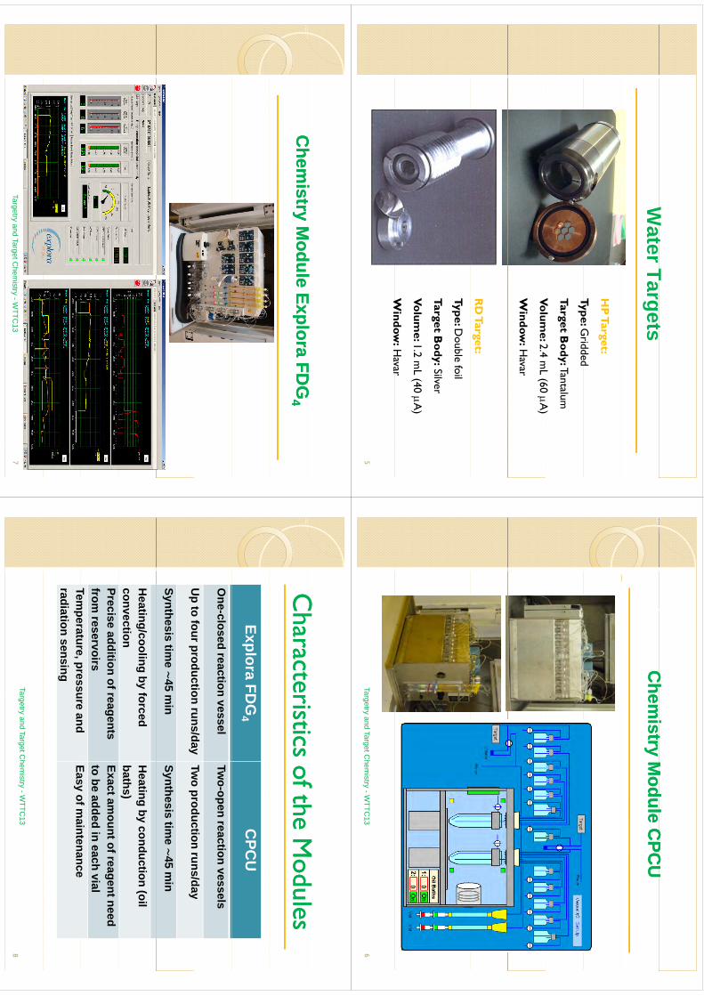
Wt
Tt
WaterTargets
HP
Target:
Type: Gridded
Type: Gridded
Target Body:Tantalum
Vl
24
L(60
A)
Volume: 2.4 m
L(60 A
)
Window
:Havar
RD
Target:
Type: Double foil
Tar get Body:Silver
gy
Volume: 1.2 m
L(40 A
)
Window
:Havar
Window
:Havar
5
Ch
it
Md
lC
PCU
Ch
it
Md
lC
PCU
Chem
istry Module C
PCU
Chem
istry Module C
PCU
Targetry and Target Chem
istry -WTTC
136
Ch
it
Md
lC
hi
tM
dl
El
El
FDG
FDG
Chem
istry Module
Chem
istry Module Explora
ExploraFD
GFD
G44
Targetry and Target Chem
istry -WTTC
137
Ch
ti
ti
f th M
dl
Ch
ti
ti
f th M
dl
Characteristics of the M
odulesC
haracteristics of the Modules
Explora FDG
4C
PCU
One-closed
reaction vesselTw
o-open reaction vessels
Up
tofourproduction
runs/dayTw
oproduction
runs/dayU
p to four production runs/dayTw
oproduction runs/day
Synthesis time ∼
45 min
Synthesis time ∼
45 min
Heating/cooling by forced
convectionH
eating by conduction (oil baths)
Preciseaddition ofreagents
from reservoirs
Exact amount of reagent need
to beadded in each vial
Temperature
pressureand
Easyofm
aintenanceTem
perature, pressure and radiation sensing
Easyof m
aintenance
Targetry and Target Chem
istry -WTTC
138
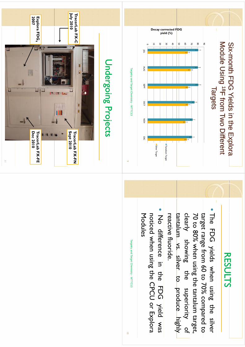
Six
Six--m
onthm
onthFD
GFD
GYieldsYields
ininthethe
Explora
Explora
Six
Six
month
month
FDG
FD
G YieldsYields
in in the
theE
xplora E
xplora M
odule M
odule Using
Using
1818F F fromfrom
Two
Two
Different
Different
Tt
Tt
TargetsTargets
9070 8050 60
FDG
30 40
rrected Feld (%)
Tantalium
Target
10 20
Decay coyie
Silver Target
0
JUL
AU
GSEPT
OC
TN
OV
DIC
Targetry and Target Chem
istry -WTTC
139
RESU
LTS
RESU
LTS
RESU
LTS
RESU
LTS
T
heFD
Gyields
when
usingthe
silvertarget
rangefrom
60to
70%com
paredto
targetrange
from60
to70%
compared
to70
to80%
when
usingthe
tantalumtarget,
clearlyshow
ingthe
superiorityof
tantalumvs.
silverto
producehighly
tantalumvs.
silverto
producehighly
reactivefluoride.
N
odifference
inthe
FDG
yieldw
asnoticed
when
usingthe
CPC
Uor
Exploranoticed
when
usingthe
CPC
Uor
ExploraM
odules
Targetry and Target Chem
istry -WTTC
1310
Undergoing
Undergoing
ProjectsProjects
Undergoing
Undergoing
ProjectsProjects
TracerLabFX
-CJuly 2010
TracerLabFX
-FNSept 2010
Explora
FDG
42007
TracerLabFX
-FED
ec 2010
11
FULLY AUTOMATED SYSTEM FOR THE PRODUCTION OF [123I] AND [124I]-IODINE
LABELLED PEPTIDES AND ANTIBODIES.
P. Bedeschia, S. Bosia, M. Montronia, G.Brinib, S.Cariab, M.Fulvib, G. Calisesib
a Comecer, Castel Bolognese (RA), Italy
a Nuclear Specialists Associated, Ardea (Roma), Italy.
Radiolabelled amino acids, peptides and monoclonal antibodies are certainly a useful non- invasive diagnostic tools to detect malignant tumours, infectious and inflammatory lesions 1,2. In combination with the potential of Positron Emission Tomography (PET), the aim of the present study was to develop a fully automated system for the radiolabelling of these new tracers, that avoids any direct manipulation by operators from target production and recovery, to synthesis and purification of the final product.
Nowadays radionuclides used for PET-imaging are generally short- lived isotopes, such as [18F]-fluorine (t1/2 = 110 min), but recently the growing need for alternative positron emitters focuses the attention on the long- lived radiohalogen [124I]-iodine (t1/2 = 4.17 d). [124I]-Iodine, is a suitable radionuclide for both diagnostic, such as Positron Emission Tomography and therapeutic applications, it decays by positron emission (23.3%) and electron capture (76.7%). Its long half- life permits this isotope to be imaged for more than 4 days, which makes it possible to study the labeled molecule over a longer time period. Furthermore the promising clinical aspect of [124I]-iodine leads research institution and commercial company seeking to produce multi-millicurie quantities for distribution purposes3, that means a wider geographical area.
A variety of radioiodination methods is supported by a large amount of literature 4,5, preferentially a radioiodine atom is incorporated in a vinylic or aromatic moiety, due to the high strength of the carbon-iodine bond. Therefore, the radioiodination is often implemented by nucleophilic or electrophilic substitution and is more or less predicted by the structural feature of the molecule 6. Obviously this kind of chemistry is applicable to any iodine isotopes, therefore in addition to [124I]-iodine, our attention is focused on [123I]-iodine too.
[123I]-Iodine has a half- life of 13.2 h, decays by electron capture and its medium energy (Eγ = 159 keV) is ideal for planar imaging and for Single Photo Emission Computed Tomography (SPECT), a lower cost diagnostic tool compared to PET.
The production of both [123I] and [124I]-iodine radionuclides is based on a low-energy (p, n) reaction at a small-sized (14 MeV) cyclotron, using TeO2-target technology and dry distillation
1 Journal of Labelled Compdounds & Radiopharmaceuticals, 2008, 51, 48-53
2 International Journal of Cancer, 19991, 47, 3, 344-347
3 Applied Radiation and Isotopes, 2007, 65, 407-412
4 Bolton, 2002; Glaser et al., 2003; Adam & Wilbur, 2005
5 Bioconjugate Chem., 1990, 1, 154-161
6 Journal of Labelled Compounds and Radiopharmaceuticals, 2005, 48, 241-257
85
kmje
Typewritten Text
Abstract 015
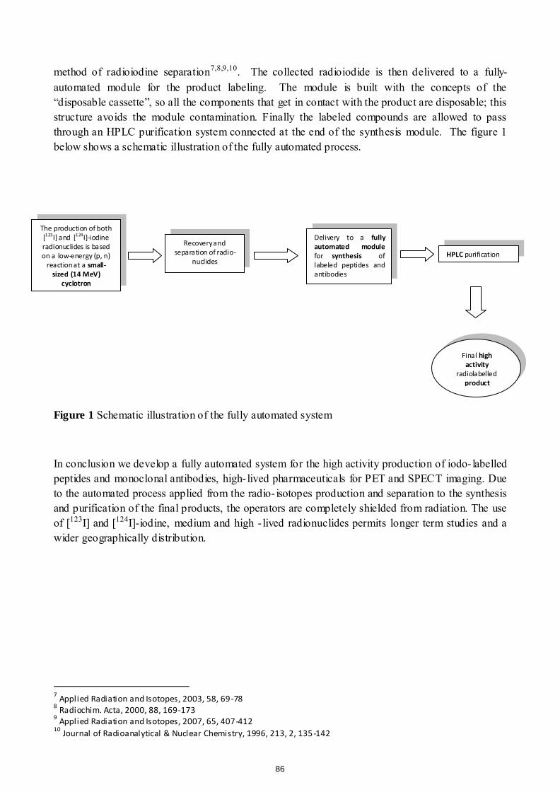
method of radioiodine separation7,8,9,10. The collected radioiodide is then delivered to a fully-automated module for the product labeling. The module is built with the concepts of the “disposable cassette”, so all the components that get in contact with the product are disposable; this structure avoids the module contamination. Finally the labeled compounds are allowed to pass through an HPLC purification system connected at the end of the synthesis module. The figure 1 below shows a schematic illustration of the fully automated process.
Figure 1 Schematic illustration of the fully automated system
In conclusion we develop a fully automated system for the high activity production of iodo- labelled peptides and monoclonal antibodies, high- lived pharmaceuticals for PET and SPECT imaging. Due to the automated process applied from the radio- isotopes production and separation to the synthesis and purification of the final products, the operators are completely shielded from radiation. The use of [123I] and [124I]-iodine, medium and high - lived radionuclides permits longer term studies and a wider geographically distribution.
7 Applied Radiation and Isotopes, 2003, 58, 69-78
8 Radiochim. Acta, 2000, 88, 169-173
9 Applied Radiation and Isotopes, 2007, 65, 407-412
10 Journal of Radioanalytical & Nuclear Chemistry, 1996, 213, 2, 135-142
The production of both [123I] and [124I]-iodine radionuclides is based on a low-energy (p, n)
reaction at a small-sized (14 MeV)
cyclotron
Recovery and separation of radio-
nuclides
Delivery to a fully automated module for synthesis of labeled peptides and antibodies
HPLC purification
Final high activity
radiolabelled product
86
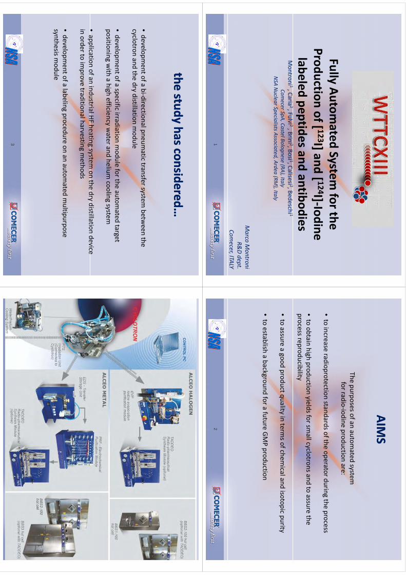
Fll
At
tdS
tf
thFully Autom
ated System for the
Productionof[ 123I]and
[ 124I]‐IodineProduction of [
I] and [I]Iodine
labeled peptides and antibodiesMontroni 1, Caria
2 , Fulvi 2, Brini 2, Bosi 1, Calisesi 2, Bedeschi 1Comecer Sp
A, Castel B
olognese (R
A), Ita
lyNSA
Nuclea
r Specia
lists Asso
ciated
, Ardea
(RM), Ita
ly
MM
iMarco
Montro
ni
R&D dept.
Comecer, ITA
LY
1
AIMS
AIMS
AIMS
AIMS
The purposes of an automated system
for radio‐iodine production are:
•to increase radioprotection standards of the operator during the process
•to obtain high production yields for sm
all cyclotrons and to assure the process reproducibility
•to assure a good product quality in term
s of chemical and isotopic purity
•to establish a background for a future GM
P production
2
thestudy
hasconsideredthe
studyhasconsidered
the study has considered…the study has considered…
•developm
ent of a bi‐directional pneumatic transfer system
between the
cyclotronand
thedry
distillationmodule
cyclotron and the dry distillation module
•developm
ent of a specific irradiation module for the autom
ated target positioning w
ith a high efficiency water and helium
cooling system
•application
ofanindustrialHF
heatingsystem
onthe
drydistillation
deviceapplication of an industrial HF heating system
on the dry distillation device in order to im
prove traditional harvesting methods
•developm
ent of a labeling procedure on an automated m
ultipurpose synthesis m
odule
3
4
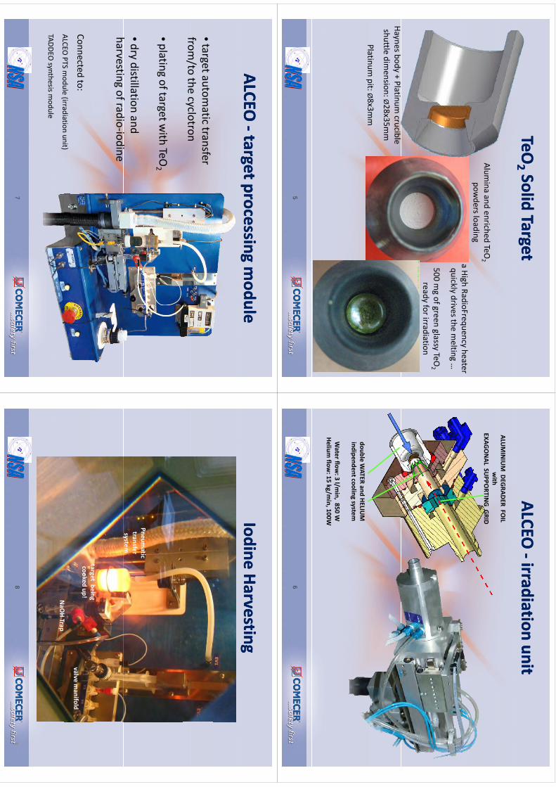
TeOTeO
22 Solid TargetSolid Target
22gg
Alumina and enriched TeO
2pow
ders loadinga High RadioFrequency
heater
500 mg of green glassy TeO
2
gq
yquickly drives the m
elting …
ready for irradiation
Haynes body + Platinum crucible
shuttle dimension: Ø28x35m
m
Platinumpit:Ø8x3m
mPlatinum
pit: Ø8x3mm
5
ALCEO
ALCEO ‐‐irradiationirradiation
unitunit
ALUMINIUM DEGRADER FO
ILwith
EXAGONAL SU
PPORTIN
G GRID
double WATER and HELIU
Mindipendentcooling system
Water flow
: 3 l/min, 850 W
Helium flow
: 15 kg/min, 100W
6
ALCEO
ALCEO ‐‐target processing target processing m
odulemodule
gp
gg
pg
•target automatic transfer
from/to the cyclotron
•plating of target with TeO
2
•dry distillation andh
if
diidi
harvesting of radio‐iodine
Connectedto:
ALCEOPTS
module
(irradiationunit)
ALCEO PTS m
odule(irradiation
unit)
TADDEO synthesis m
odule
7
IodineIodine
HarvestingHarvestinggg
Pneumatic
transfersystem
targetbeing
y
NOHT
target beingcooked
up!valve m
anifold
NaO
HTrap
8
8
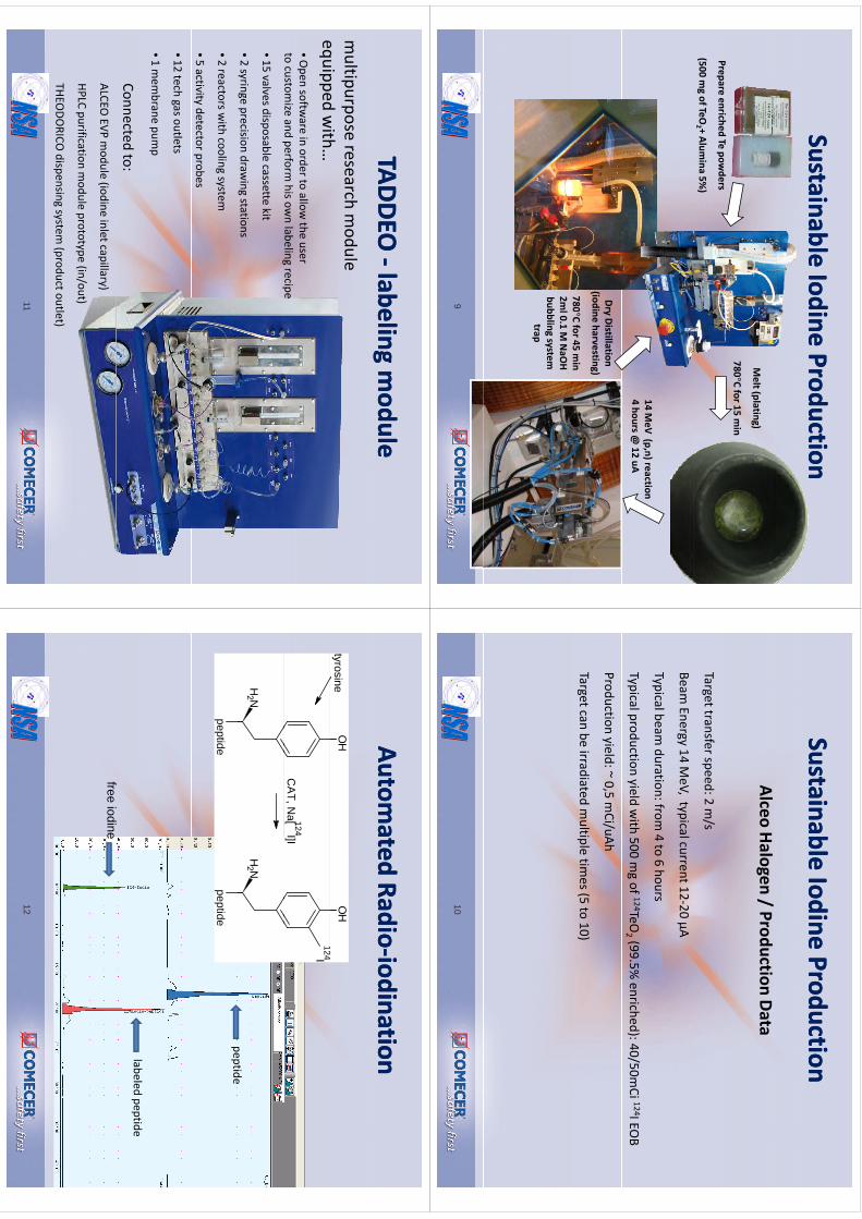
SustainableSustainable
IodineIodine
ProductionProduction
l(l
)
Prepareenriched
Te powders
Melt(plating)
780°C for15 min
(500 mg ofTeO
2 + Alumina 5%
)
14 MeV
(p,n) reaction4 hours @
12 uA
Dry Distillation (iodine harvesting)
780°Cfor45
min
780C for 45 m
in2m
l 0.1 M NaO
Hbubbling system
trap
9
SustainableSustainable
IodineIodine
ProductionProduction
AlceoHalogen
/Production
DataAlceo Halogen / Production Data
/Target transfer speed: 2 m
/s
Beam Energy 14 M
eV, typical current 12‐20 µA
Typical beam duration: from
4 to 6 hours
Typical production yield with 500 m
g of 124TeO2 (99.5%
enriched): 40/50mCi 124I EO
B
Production yield: ~ 0,5 mCi/uAh
Target can be irradiated multiple tim
es (5 to 10)
10
TADDEO
TADDEO ‐‐labelinglabeling
module
module
ggmultipurpose research m
odule equipped
with
equipped with…
•Open softw
are in order to allow the user
to customize and perform
his own labeling recipe
pg
p
•15 valves disposable cassette kit
•2 syringe precision drawing stations
•2 reactors with cooling system
•5 activity detector probes
•12 tech gas outlets
•1 mem
brane pump
Connectedto:
ALCEO EVP m
odule(iodine
inletcapillary)(
py)
HPLC purification module prototype (in/out)
THEODO
RICO dispensing system
(product outlet)
11
Automated
Automated
RadioRadio‐‐iodination
iodinationO
HO
H124
tyrosine124I
CA
T, Na[ 124I]I
peptideN
H2
NH
2peptide
peptidepeptide
labeled peptide
free iodine
12
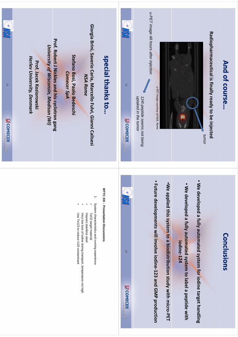
And And ofofcourse…
course…
Radiopharmaceuticalisfinally
readyto
beinjected
Radiopharmaceutical is finally ready to be injectedtum
or
u‐PET
imagecourtesy
ofNSA
, Rome
u-PE
T image 48 hours after injection
124I-peptide seems not being
uptaked in the tumor
13
13
ConclusionsConclusions
•Wedeveloped
afully
automated
systemforiodine
targethandlingWe developed a fully autom
ated system for iodine target handling
•We developed a fully autom
ated system to label a peptide w
ith p
yy
pp
iodine‐124
•We applied this system
to a biodistributionstudy w
ith micro‐PET
•Future developments w
ill involve iodine‐123 and GMP production
14
14
special thanks to…special thanks to…pp
GiorgiaBrini,Saverio
Caria,Marcello
Fulvi,GianniCalisesiGiorgia
Brini, SaverioCaria, M
arcello Fulvi, Gianni CalisesiNSA Rom
e
Stefano Bosi, Paolo BedeschiCom
ecer SpAp
Prof. Robert J Nicklesand his cyclotron gang
University of W
isconsin, Madison (W
I)
Prof. JacekKoziorow
skiHerlev
University, Denm
ark
15
15
WTTC
XIII–Presentation
Discussions
WTTC
XIII –Presentation D
iscussions
1.S
ystem characteristics and running experience
•TeO
2targetm
aterial•
TeO2 target m
aterial•
Haynes stainless steel
•Very low
loss of iodine during transport, temperature not high
•U
seTe123
toreduce
I125contam
inant•
Use Te123 to reduce I125 contam
inant
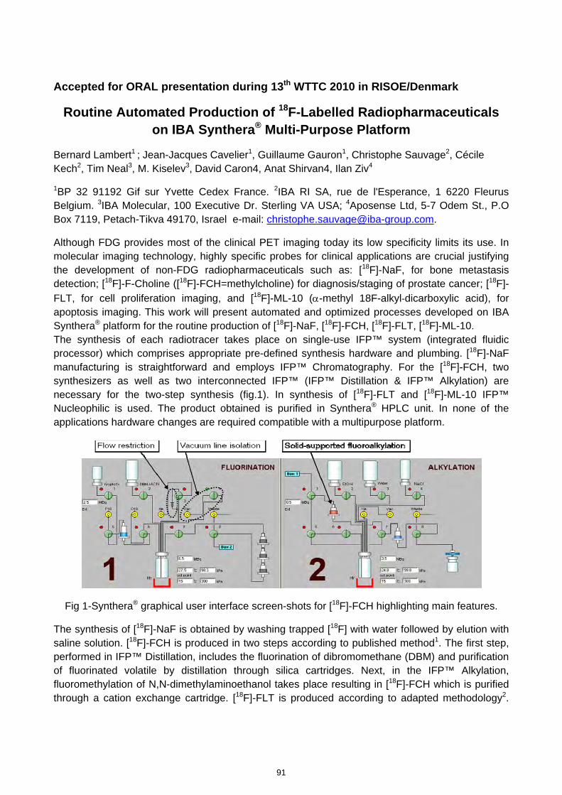
Accepted for ORAL presentation during 13th WTTC 2010 in RISOE/Denmark
Routine Automated Production of 18F-Labelled Radiopharmaceuticals on IBA Synthera® Multi-Purpose Platform
Bernard Lambert1 ; Jean-Jacques Cavelier1, Guillaume Gauron1, Christophe Sauvage2, Cécile Kech2, Tim Neal3, M. Kiselev3, David Caron4, Anat Shirvan4, Ilan Ziv4
1BP 32 91192 Gif sur Yvette Cedex France. 2IBA RI SA, rue de l'Esperance, 1 6220 Fleurus Belgium. 3IBA Molecular, 100 Executive Dr. Sterling VA USA; 4Aposense Ltd, 5-7 Odem St., P.O Box 7119, Petach-Tikva 49170, Israel e-mail: [email protected].
Although FDG provides most of the clinical PET imaging today its low specificity limits its use. In molecular imaging technology, highly specific probes for clinical applications are crucial justifying the development of non-FDG radiopharmaceuticals such as: [18F]-NaF, for bone metastasis detection; [18F]-F-Choline ([18F]-FCH=methylcholine) for diagnosis/staging of prostate cancer; [18F]-FLT, for cell proliferation imaging, and [18F]-ML-10 (α-methyl 18F-alkyl-dicarboxylic acid), for apoptosis imaging. This work will present automated and optimized processes developed on IBA Synthera® platform for the routine production of [18F]-NaF, [18F]-FCH, [18F]-FLT, [18F]-ML-10. The synthesis of each radiotracer takes place on single-use IFP™ system (integrated fluidic processor) which comprises appropriate pre-defined synthesis hardware and plumbing. [18F]-NaF manufacturing is straightforward and employs IFP™ Chromatography. For the [18F]-FCH, two synthesizers as well as two interconnected IFP™ (IFP™ Distillation & IFP™ Alkylation) are necessary for the two-step synthesis (fig.1). In synthesis of [18F]-FLT and [18F]-ML-10 IFP™ Nucleophilic is used. The product obtained is purified in Synthera® HPLC unit. In none of the applications hardware changes are required compatible with a multipurpose platform.
Fig 1-Synthera® graphical user interface screen-shots for [18F]-FCH highlighting main features.
The synthesis of [18F]-NaF is obtained by washing trapped [18F] with water followed by elution with saline solution. [18F]-FCH is produced in two steps according to published method1. The first step, performed in IFP™ Distillation, includes the fluorination of dibromomethane (DBM) and purification of fluorinated volatile by distillation through silica cartridges. Next, in the IFP™ Alkylation, fluoromethylation of N,N-dimethylaminoethanol takes place resulting in [18F]-FCH which is purified through a cation exchange cartridge. [18F]-FLT is produced according to adapted methodology2.
91
kmje
Typewritten Text
Abstract 016
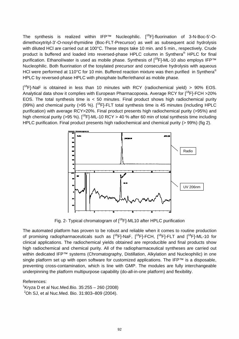
The synthesis is realized within IFP™ Nucleophilic. [18F]-fluorination of 3-N-Boc-5’-O-dimethoxytrityl-3’-O-nosyl-thymidine (Boc-FLT-Precursor) as well as subsequent acid hydrolysis with diluted HCl are carried out at 100°C. These steps take 10 min. and 5 min., respectively. Crude product is buffered and loaded into reversed-phase HPLC column in Synthera® HPLC for final purification. Ethanol/water is used as mobile phase. Synthesis of [18F]-ML-10 also employs IFP™ Nucleophilic. Both fluorination of the tosylated precursor and consecutive hydrolysis with aqueous HCl were performed at 110°C for 10 min. Buffered reaction mixture was then purified in Synthera® HPLC by reversed-phase HPLC with phosphate buffer/ethanol as mobile phase.
[18F]-NaF is obtained in less than 10 minutes with RCY (radiochemical yield) > 90% EOS. Analytical data show it complies with European Pharmacopoeia. Average RCY for [18F]-FCH >20% EOS. The total synthesis time is < 50 minutes. Final product shows high radiochemical purity (99%) and chemical purity (>95 %). [18F]-FLT total synthesis time is 45 minutes (including HPLC purification) with average RCY>20%. Final product presents high radiochemical purity (>95%) and high chemical purity (>95 %). [18F]-ML-10 RCY > 40 % after 60 min of total synthesis time including HPLC purification. Final product presents high radiochemical and chemical purity (> 99%) (fig 2).
Radio
UV 206nm
Fig. 2- Typical chromatogram of [18F]-ML10 after HPLC purification
The automated platform has proven to be robust and reliable when it comes to routine production of promising radiopharmaceuticals such as [18F]-NaF, [18F]-FCH, [18F]-FLT and [18F]-ML-10 for clinical applications. The radiochemical yields obtained are reproducible and final products show high radiochemical and chemical purity. All of the radiopharmaceutical syntheses are carried out within dedicated IFP™ systems (Chromatography, Distillation, Alkylation and Nucleophilic) in one single platform set up with open software for customized applications. The IFP™ is a disposable, preventing cross-contamination, which is line with GMP. The modules are fully interchangeable underpinning the platform multipurpose capability (do-all-in-one platform) and flexibility.
References: 1Kryza D et al Nuc.Med.Bio. 35:255 – 260 (2008) 2Oh SJ, et al Nuc.Med. Bio. 31:803–809 (2004).
92
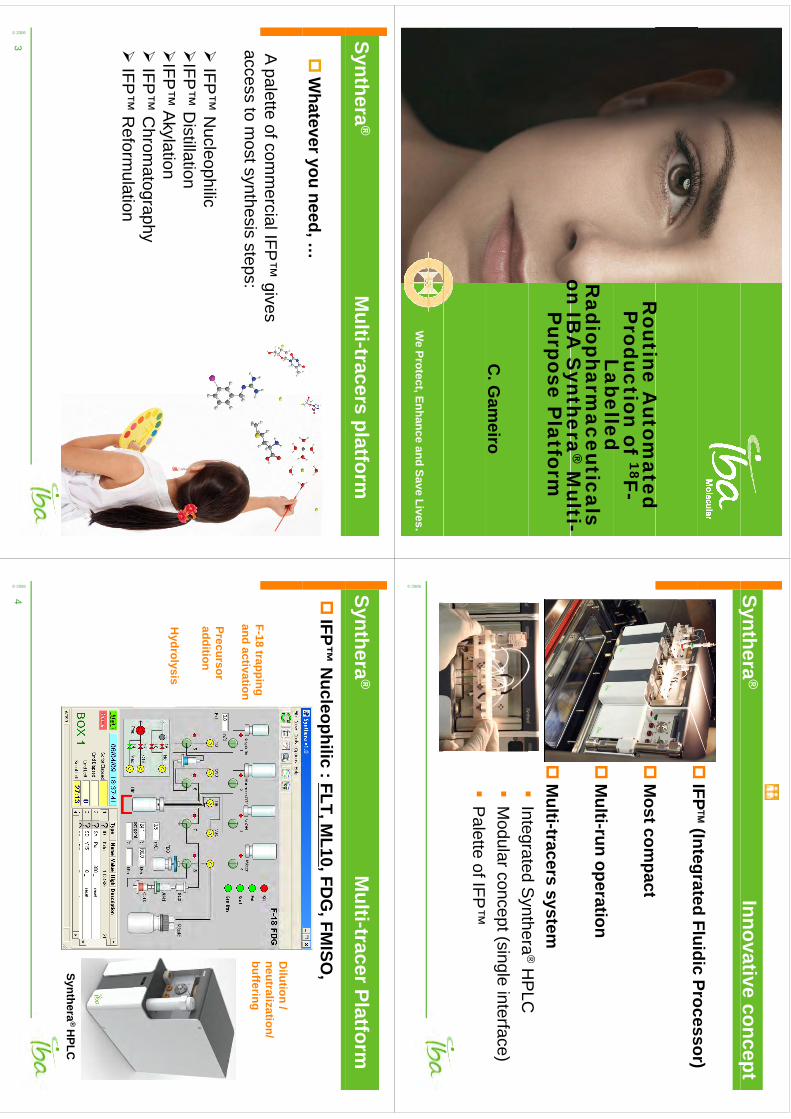
Rti
At
td
Routine A
utomated
Production of 18F-
Labelled Labelled
Radiopharm
aceuticals on IB
A S
ynthera®
Multi-
on IBA
Synthera
Multi-
Purpose P
latform
C. G
ameiro
We Protect, Enhance and Save Lives.
Synthera®
Innovative concepty
p
IFP
(Integrated
FluidicProcessor)
IFP
(Integrated Fluidic Processor)
M
tt
M
ost compact
M
ulti-run operation
M
ulti-tracers system
IntegratedS
ynthera®
HP
LC
Integrated Synthera
®H
PLC
M
odular concept (single interface)
Palette of IFP
™
© 2006
Synthera®
Multi-tracers platform
W
hatever you need, …
A palette of comm
ercial IFP™
gives access to m
ost synthesis steps:
IFP
™ N
ucleophilic
IFP™
Distillation
IFP
™ A
kylation
IFP™
Chrom
atography
IFP™
Rf
lti
IFP
™ R
eformulation
© 2006
3
Synthera®
Multi-tracer Platform
IFP™
Nucleophilic : FLT, M
L10, FDG
, FMISO
,
F18
trapping
Dilution /
neutralization/ ff
F-18 trapping and activation
Precursor
buffering
Precursor addition
Hydrolysis
Hydrolysis
Synthera®
HPLC
© 2006
4
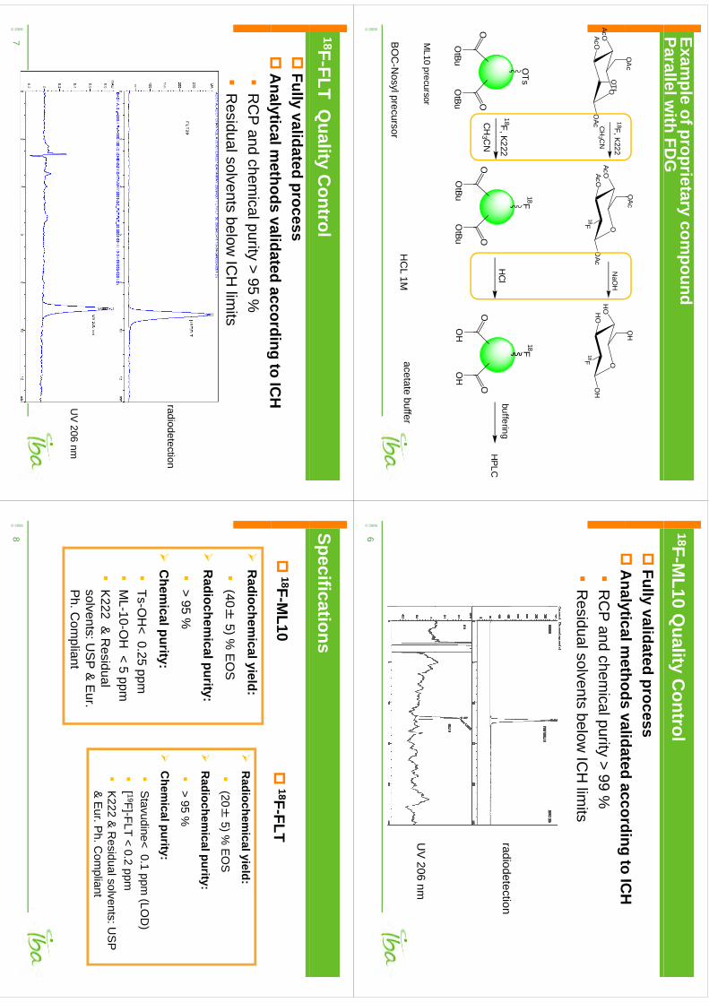
Example of proprietary com
pound Parallel w
ith FDG
OA
cO
Ac
OH
OAcOAcO
OTf
OAc
OAcOAcO
OAc
18F
OH
OHO
OH
18F
18F,K222
CH
3 CN
NaO
H
FF
OTs
18F18F
OO
OO
18F,K222
CH
3 CN
buffering
OO
HC
lH
PLC
OtBu
OtBu
OtBu
OtBu
OH
OH
ML10
precursor
BO
CN
lH
CL 1M
acetate buffer
© 2006
BO
C-N
osyl precursor
18F-ML10 Q
uality Control
Fully validated process
A
nalyticalmethods
validatedaccording
toIC
H
Analytical m
ethods validated according to ICH
R
CP
and chemical purity > 99 %
Rid
ll
tb
lIC
Hli
it
Residual solvents below
ICH
limits
radiodetection
UV
206 nm
© 2006
6
18F-FLT Quality C
ontrol
Fully validated process
Analyticalm
ethodsvalidated
accordingto
ICH
A
nalytical methods validated according to IC
H
RC
P and chem
ical purity > 95 %
Residualsolvents
belowIC
Hlim
its
Residual solvents below
ICH
limits
radiodetection
UV
206 nm
© 2006
7
Specifications
18F-M
L10
18F-FLT
Radiochem
ical yield:
(40±
5)%E
OS
R
adiochemicalyield:
(40
±5) %
EO
S
R
adiochemical purity:
(20
±5) %
EO
S
R
adiochemicalpurity:
> 95 %
C
hemical purity:
> 95 %
C
hemicalpurity:
py
Ts-O
H< 0.25 ppm
M
L-10-OH
< 5 ppm
S
tavudine< 0.1 ppm (LO
D)
[ 19F]-FLT < 0.2 ppm
ML
10O
H
5 ppm
K222 &
Residual
solvents: US
P &
Eur.
K
222 & R
esidualsolvents: US
P
& E
ur. Ph. C
ompliant
Ph. C
ompliant
© 2006
8
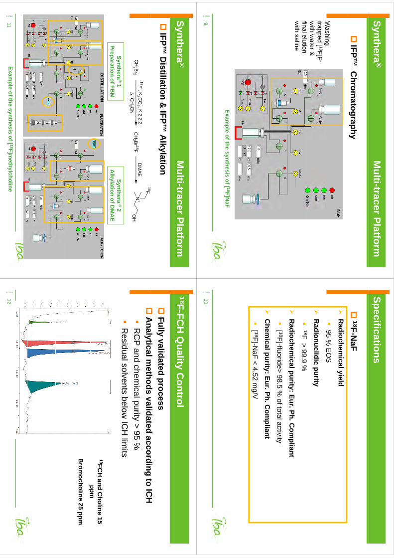
Synthera®
Multi-tracer Platform
IFP™
Chrom
atography
Washing
Washing
trapped [ 18F]F-
with w
ater &
finalelutionfinal elution w
ith saline
Example of the synthesis of [ 18F]N
aF
© 2006
9
Specifications
18F-N
aF
Radiochem
ical yield
95%
EO
S95 %
EO
S
R
adionuclidic purity18F
>99
9%
18F > 99.9 %
R
adiochemical purity: Eur. Ph. C
ompliant
[ 18F]-fluoride> 98.5 %
of total activity
C
hemical purity: Eur. Ph. C
ompliant
[ 19F]-N
aF < 4.52 mg/V
© 2006
10
Synthera®
Multi-tracer Platform
IFP™
Distillation &
IFP™ A
lkylation
CH
2 Br218F
-, K2 C
O3 , K.2.2.2
, CH
3 CN
CH
2 Br 18F
DM
AE
N+
OH
18F
Synthera®
1Preparation of FB
MSynthera
®2
Alkylation of D
MA
E
3
DISTILLATIO
N
© 2006
11Exam
ple of the synthesis of [ 18F]methylcholine
18F-FCH
Quality C
ontrol
Fully validated process
A
lti
lth
dlid
td
dit
ICH
A
nalytical methods validated according to IC
H
RC
P and chem
ical purity > 95 %
Residual solvents below
ICH
limits
19FCH
and Choline
15 ppm
Brom
ocholine 25 ppm
© 2006
12

Specifications
18F-FC
H
Radiochem
ical yield:
(20
±2)%
EO
S(20
±2) %
EO
S
R
adiochemical purity:
>95
%
> 95 %
C
hemical purity:
D
BM
< 0.1 ppm
[ 19F]-FCH
< 4 ppm
DM
AE
< 1500 ppm
Choline < 20 ppm
Brom
ocholine < 0.1 ppm
K222 &
Residual solvents: U
SP
& E
ur. Ph. C
ompliant
© 2006
13
Synthera®
Multi-tracers Platform
Extend your capabilities
•FD
G,FLT, FM
ISO
, FES
,ML10…
IFP
™N
ucleophilic
•FB
M, click-chem
istry precursorIFP
™D
istillationy
p
FCH
IFP™
Alkylation
•FC
H,…
IFP
™A
lkylation
IFP™
•N
aF,…
IFP™
Chrom
atography
•M
ore complex tracers, AV-45
IFP™
Reform
ulation
© 2006
14
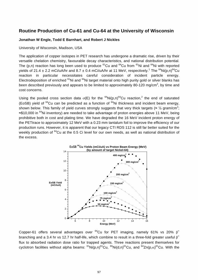
Routine Production of Cu-61 and Cu-64 at the University of Wisconsin
Jonathan W Engle, Todd E Barnhart, and Robert J Nickles
University of Wisconsin, Madison, USA
The application of copper isotopes in PET research has undergone a dramatic rise, driven by their versatile chelation chemistry, favourable decay characteristics, and national distribution potential. The (p,n) reaction has long been used to produce 61Cu and 64Cu from 61Ni and 64Ni with reported yields of 21.4 ± 2.2 mCi/uA/hr and 8.7 ± 0.4 mCi/uA/hr at 11 MeV, respectively.1 The 64Ni(p,n)64Cu reaction in particular necessitates careful consideration of incident particle energy. Electrodeposition of enriched 61Ni and 64Ni target material onto high purity gold or silver blanks has been described previously and appears to be limited to approximately 80-120 mg/cm2, by time and cost concerns.
Using the pooled cross section data σ(E) for the 64Ni(p,n)64Cu reaction,2 the end of saturated (EoSB) yield of 64Cu can be predicted as a function of 64Ni thickness and incident beam energy, shown below. This family of yield curves strongly suggests that very thick targets (≈ ½ gram/cm2; ≈$10,000 in 64Ni inventory) are needed to take advantage of proton energies above 11 MeV, being prohibitive both in cost and plating time. We have degraded the 16 MeV incident proton energy of the PETtrace to approximately 12 MeV with a 0.23 mm tantalum foil to improve the efficiency of our production runs. However, it is apparent that our legacy CTI RDS 112 is still far better suited for the weekly production of 64Cu at the 0.5 Ci level for our own needs, as well as national distribution of the excess.
0
2
4
6
8
10
12
14
6 8 10 12 14 16
EoSB 64Cu Yields (mCi/uA) vs Proton Beam Energy (MeV)(by amount of target Nickel-64)
EoSB Yield (mCi/uA)
Energy (MeV)
50 mg/cm2
75 mg/cm2
100 mg/cm2
150 mg/cm2
200 mg/cm2
300 mg/cm2
400 mg/cm2
Copper-61 offers several advantages over 64Cu for PET imaging, namely 61% vs 20% β+ branching and a 3.4 hr vs 12.7 hr half-life, which combine to result in a three-fold greater useful β+
flux to absorbed radiation dose ratio for trapped agents. Three reactions present themselves for cyclotron facilities without alpha beams: 61Ni(p,n)61Cu, 60Ni(d,n)61Cu, and 64Zn(p,α)61Cu. With the
97
kmje
Typewritten Text
Abstract 017
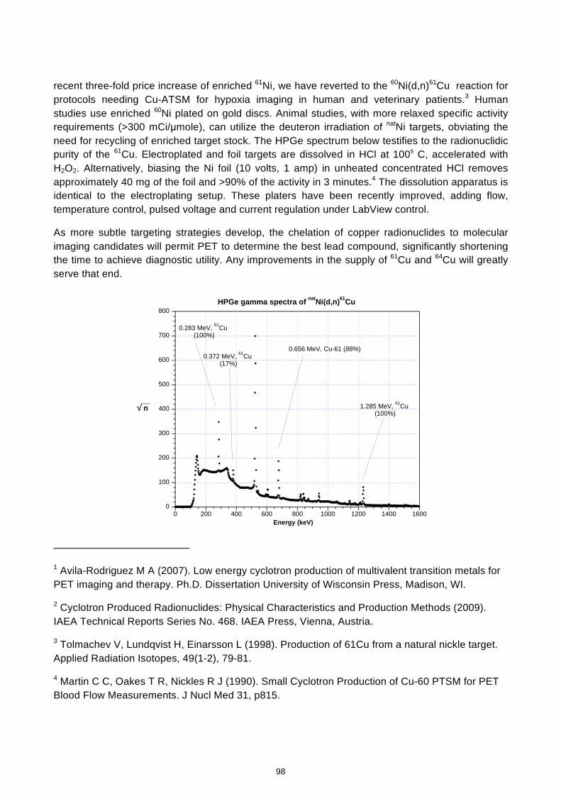
recent three-fold price increase of enriched 61Ni, we have reverted to the 60Ni(d,n)61Cu reaction for protocols needing Cu-ATSM for hypoxia imaging in human and veterinary patients.3 Human studies use enriched 60Ni plated on gold discs. Animal studies, with more relaxed specific activity requirements (>300 mCi/µmole), can utilize the deuteron irradiation of natNi targets, obviating the need for recycling of enriched target stock. The HPGe spectrum below testifies to the radionuclidic purity of the 61Cu. Electroplated and foil targets are dissolved in HCl at 100s C, accelerated with H2O2. Alternatively, biasing the Ni foil (10 volts, 1 amp) in unheated concentrated HCl removes approximately 40 mg of the foil and >90% of the activity in 3 minutes.4 The dissolution apparatus is identical to the electroplating setup. These platers have been recently improved, adding flow, temperature control, pulsed voltage and current regulation under LabView control.
As more subtle targeting strategies develop, the chelation of copper radionuclides to molecular imaging candidates will permit PET to determine the best lead compound, significantly shortening the time to achieve diagnostic utility. Any improvements in the supply of 61Cu and 64Cu will greatly serve that end.
0
100
200
300
400
500
600
700
800
0 200 400 600 800 1000 1200 1400 1600
HPGe gamma spectra of natNi(d,n)61Cu
__√ n
Energy (keV)
1.285 MeV, 61Cu (100%)
0.656 MeV, Cu-61 (88%)0.372 MeV, 61Cu
(17%)
0.283 MeV, 61Cu (100%)
1 Avila-Rodriguez M A (2007). Low energy cyclotron production of multivalent transition metals for PET imaging and therapy. Ph.D. Dissertation University of Wisconsin Press, Madison, WI.
2 Cyclotron Produced Radionuclides: Physical Characteristics and Production Methods (2009). IAEA Technical Reports Series No. 468. IAEA Press, Vienna, Austria.
3 Tolmachev V, Lundqvist H, Einarsson L (1998). Production of 61Cu from a natural nickle target. Applied Radiation Isotopes, 49(1-2), 79-81.
4 Martin C C, Oakes T R, Nickles R J (1990). Small Cyclotron Production of Cu-60 PTSM for PET Blood Flow Measurements. J Nucl Med 31, p815.
98
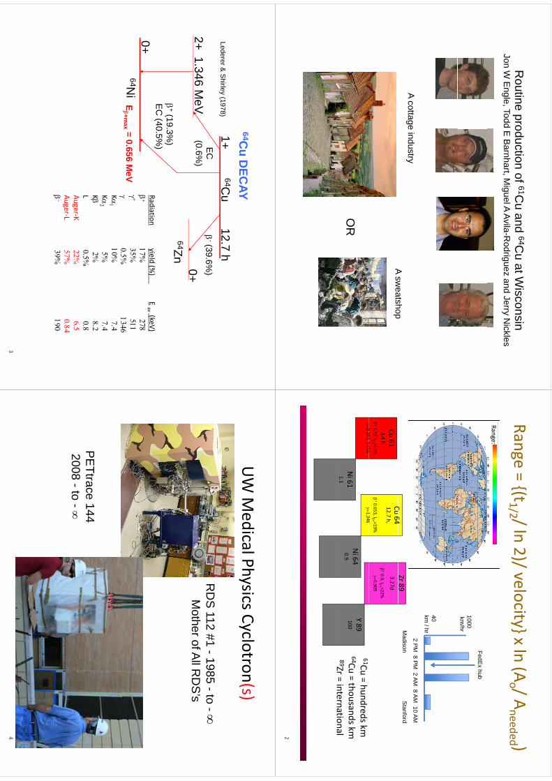
Routine
productionof
61Cu
and64C
uatW
isconsinR
outine production of C
u and C
u at Wisconsin
Jon W E
ngle, Todd E B
arnhart, Miguel A Avila-R
odriguez and Jerry Nickles
A cottage industryA
sweatshop
A sweatshop
OR
Range=(t1/2 /ln
2)/velocityxln(A
/Ad
d )Range
(t1/2 / ln 2)/ velocity x ln (Ao / A
needed )Range:
1000km
/hr
FedEx hub
40 k
/h
Zr 89C
64
2 PM
8 PM
2 AM
8 AM
10 AM
km / hrM
adison Stanford
+0.9, I+ =22%0.909
3.27d
+0.653, I+ =19%
1346
Cu 6412.7 h,
+1.22, I+ =62%0283
0656
Cu 613.4 h
Y 89100
1.346
Ni 640.9
0.283, 0.656
Ni 611.1
61Cu = hundreds km64Cu = thousands km89Zr=
internationalZr = international2
64Cu
DEC
AY64C
u12.7 h
1+
(396%
)E
CLederer &
Shirley (1978)
Cu D
ECAY
-(39.6%
)0+64Z
2+1.346 M
eVE
C(0.6%
)
Radiationyield
(%)
E(keV)
64Zn
+(19.3%)
EC
(40.5%)
Radiationyield (%
)E
av (keV)
0+64N
iE+m
ax = 0.656 MeV
K
K
K
K
L
Auger‐K
Au ger‐L
g
3
UW M
edical Physics Cyclotron(s)y
y()
RD
S112
#11985
to
RD
S 112 #1 -1985 -to -
Mother of A
ll RD
S’s
PE
Tt144
PE
Ttrace 1442008 -to -
4
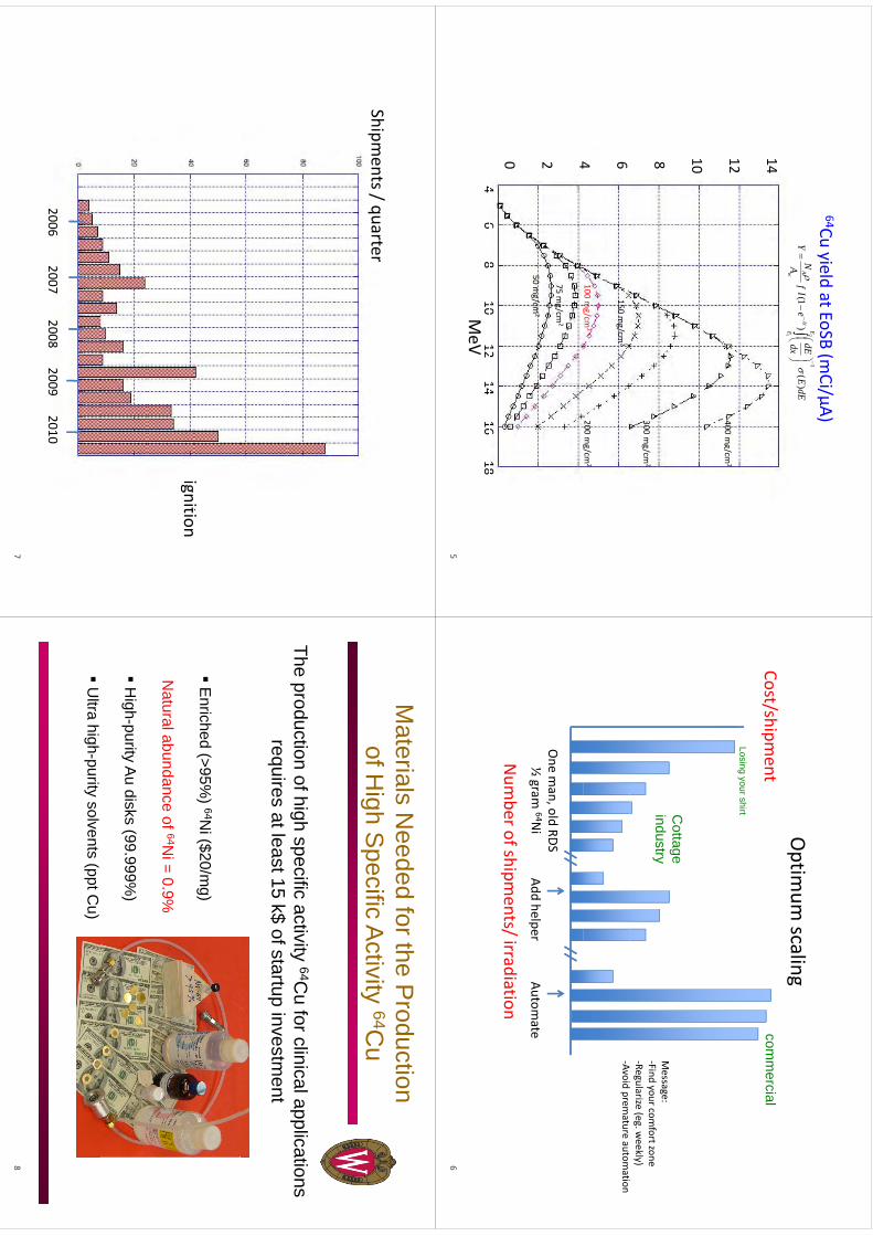
64Cu yield at EoSB (mCi/µA)
14
y(
µ)
21
)(
)1(
1EE
t
w AdE
Edx
dEe
If
A NY
400 mg/cm
2
1412g
10
300 mg/cm
28
100 mg/cm
2
150 mg/cm
2
200 mg/cm
2
64
50mg/cm
2
75 mg/cm
2
gg
4250 m
g/cm2
46
810
1214
1618
04 6 8 10 12 14 16 18
MeV
5
Optim
um scaling
Cost/shipment
comm
ercialCost/shipm
entcom
mercial
Losing your shirtCottage
Message:
‐Find your comfort zone
‐Regularize (eg. weekly)
d
Cottage
industry
‐Avoid premature autom
ation
One m
an, old RDS½gram
64Ni
Addhelper
Automate
Num
ber of shipments/ irradiation
½ gram
64Ni
Add helperAutom
ate
6
Shit/
tShipm
ents / quarter
iiti
ignition
20062007
20082009
20102006 2007 2008 2009 2010
7
Materials N
eeded for the Production
fHi
hS
ifiA
tiit
64Cof H
igh Specific A
ctivity 64Cu
The production of high specific activity 64Cu for clinical applications
requires at least 15 k$ of startup investment
E
nriched (>95%) 64N
i ($20/mg)
Natural abundance of 64N
i = 0.9%
H
igh-purity Au disks (99.999%
)
U
ltra high-purity solvents (ppt Cu)
8
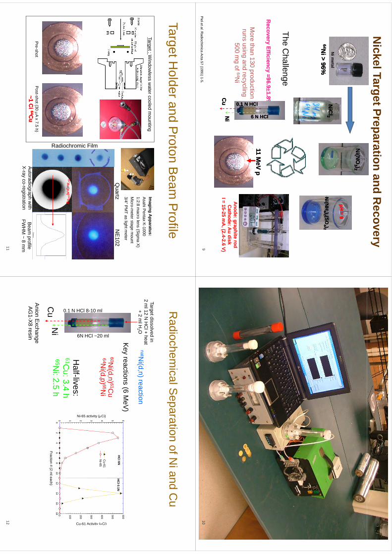
Nickel Target Preparation and R
ecoveryN
i(NO
Ni(N
O33 ))22
Ni(N
HN
i(NH
44 ))22 (SO(SO
44 ))22N
i metal
pH = 9
pH = 9
NiC
lN
iCl22
6464Ni>
96%N
i>96%
((44 ))22 ((
44 ))226464N
i > 96%N
i > 96%
TheC
hallengeThe C
hallenge
Recovery Efficiency
Recovery Efficiency ==96.9
96.91.81.8%%
HClHCl
11 MeV p
11 MeV p
6 N H6 N H
1 N HCl1 N HCl
More than 130 production
runs using and recycling
Ni
Ni
Cu
Cu
Anode: graphite rodC
athode: Au disk
I = 15-25 mA
, (2.4-2.6 V)
0.10.1
500 mg of 64N
i
Piel et al.R
adiochimica A
cta 57 (1991) 1-5.9
10
TargetHolderand
Proton
Beam
Profile
Target Holder and P
roton Beam
Profile
Imaging
Apparatus:
Target:Window
lessw
atercooledm
ountingIm
aging Apparatus:
Asahi P
entax K-1000
1:2:8 macro lens (S
igma X)
Micro-m
eter stage mount
Target : Window
less water cooled m
ounting
Quartz
NE
1023/4” P
MT as light m
eter
Filmchromic
197Au(p,n) 197H
g
Radio
Pre-shot
Post-shot (30 A x 7.5 h)
~1 Ci
~1 Ci 6464C
uC
uD
istance
Autoradiograph w
ithX
rayco
registrationB
eam profile
FWH
M~
8m
mX-ray co-registration
FWH
M ~ 8 m
m11
Radiochem
icalSeparation
ofNiand
Cu
Target dissolved in
Radiochem
ical Separation of N
i and Cu
g2 m
l 12 N H
Cl + heat
+ 2 ml H
2 OnatN
i(d,n) reaction
500
600
5 6
HC
l 6NH
Cl 0.1N
l
Key reactions (6 M
eV)
60Ni(d,n) 61C
u
Activity (Ci)
300
400
activity (Ci)
3 4C
u-61 N
i-65
8-10 ml
HCl ~20 m
(,
)64N
i(d,p) 65Ni
Cu-61 A
100
200
Ni-65 a
1 2.1 N HCl 8
6N H
Half-lives:
61Cu:3
4h
Fraction # (2 ml each)
02
46
810
1214
1618 0
0
Ni
0
Cu
61Cu: 3.4 h
65Ni: 2.5 h
Anion E
xchangeA
G1-X
8 resin
12
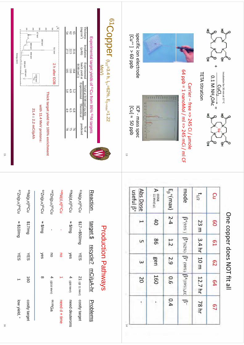
CuCl2Cu
Incubation for 30 min at 37 oC
+=
0.1 M NH4 OAc
+=
TETAtitration
TETA titration
Carrier–free
=>245
Ci/µmole
Carrier free => 245 Ci / µm
ole64 ppb = 1 nanoM
ol / ml => 245 m
Ci / ml CF
specificion
electrodeICP
‐massspec
specific ion electrode[Cu
++] > 60 ppb ICP
mass spec
[Cu] ≈ 50 ppb13
14
61Copper (t1/2 =3.4 h, I+ =62%
, E+m
ax =1.22 pp
(1/2
,+
,+m
ax
MeV
)
Yield at EO
B (m
Ci/A
h) Thickness (m
g/cm2)
Irradiation (µA
h) Experim
ental batch yield at
Experimental
Theoretical%
of predicted
Experim
ental target yields of 61Cu from
86% 61N
i targets
(g
)(µ
)y
EOB
(mC
i) Experim
ental Theoretical
p
65 31.6
164 5.2
6.8 76
62 22.5
110 4.9
6.5 75
5427
5105
38
49
7854
27.5 105
3.8 4.9
78 600
511keV
N
2h
afterEO
B
Thick target yield for 100% enrichm
ent
with
114
MeV
protons:400
500
283 keV
511 keV2 h after E
OB
with 11.4 M
eV protons:
21.4 2.2 m
Ci/µA
h200
30067 keV
656 keV
1332 keV 60C
u589 keV
Energy (keV)
0
1001185 keV
909 keV
15
Pd
iP
hP
roduction Pathw
aysR
tit
t$l
?C
i/A
hP
blR
eactiontarget $
recycle?m
Ci/µA
-hrP
roblems
61Ni(p
n) 61Cu
$17>$50/m
gY
ES
21(@
11M
V)
costlytarget
61Ni(p,n) 61C
u$17->$50/m
gY
ES
21 (@ 11 M
eV)
costly target
60Ni(d,n) 61C
u≈ $/m
gyes
4 (@8 M
eV)
need deuterons
natNi(d,n) 61C
u-
no1
need d + time
natZn(p,) 61Cu
-no
4 (@16 M
eV)
66,68Ga
64Zn(p,) 61Cu
≈ $/mg
yes8
(p,)$
gy
64Ni(p
n) 64Cu
$17/mg
YE
S160
costlytarget
Ni(p,n)
Cu
$17/mg
YE
S160
costly target
67Zn(p,) 64Cu
≈ $10/mg
YE
S1
low yield, “
16
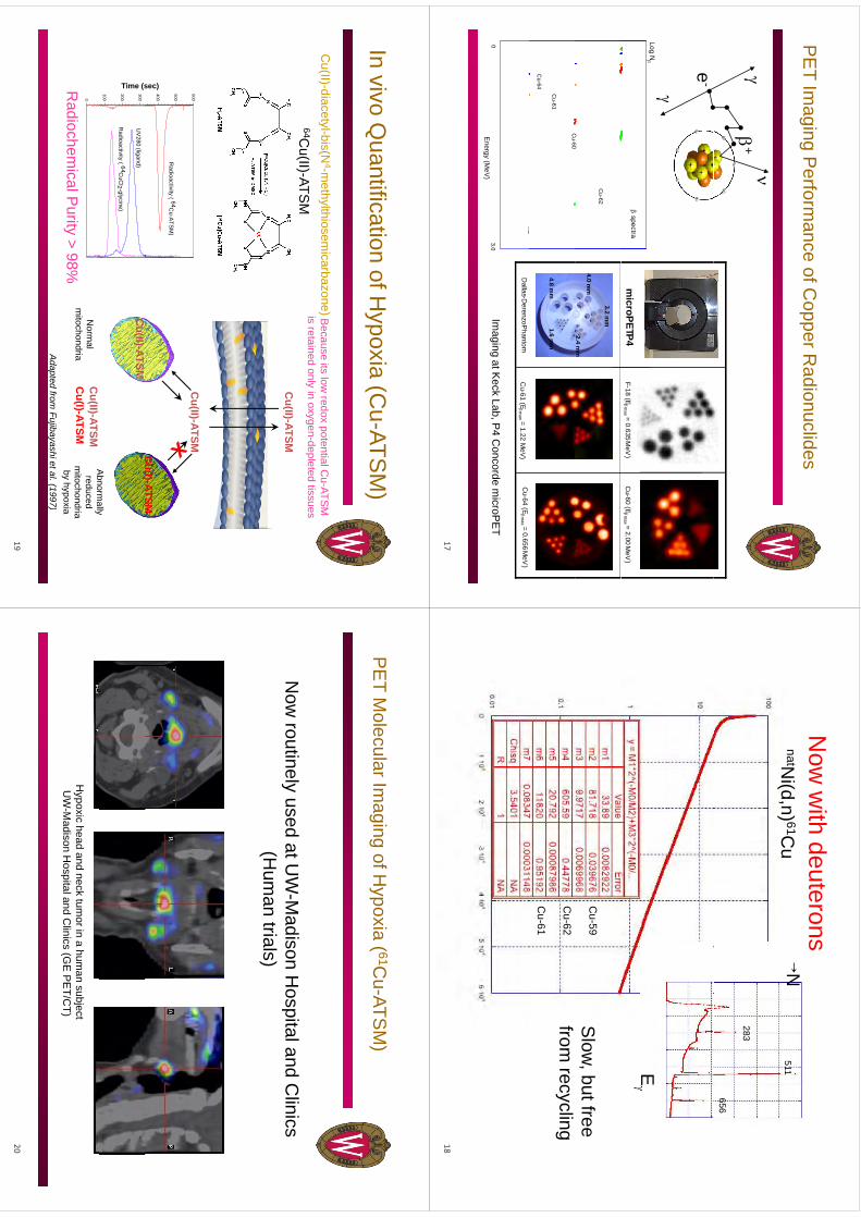
PE
TIm
agingP
erformance
ofCopperR
adionuclidesP
ET Im
aging Perform
ance of Copper R
adionuclides
+e-
Log N
spectram
icroPETP4F-18 (E
max = 0.635 M
eV)
Cu-60 (E
max = 2.00 M
eV)
Cu-62
Cu
60
4.0 mm
3.2 mm
2.4 mm
Cu-60
Cu-61
Cu-64
4.8 mm
1.6 mm
Energy (M
eV)
3.00
Cu-61 (E
max = 1.22 M
eV)
Cu-64 (E
max = 0.656 M
eV)
Dallas-D
erenzoPhantom
Imaging at K
eck Lab, P4 C
oncorde microP
ET
17
Now
with deuterons
natNi(d,n) 59,61,62 Cu
N511
natNi(d,n) 61C
u
283
656
E
Cu‐59C
u-59S
low, but free
Cu‐62
Cu‐61
Cu-62
Cu-61
from recycling
18
Invivo
Quantification
ofHypoxia
(Cu-ATS
M)
In vivo Quantification of H
ypoxia (Cu-ATS
M)
C(II)
dit
lbi(N
4th
lthii
b)
64Cu(II)-ATS
MB
ecause its low redox potential C
u-ATSM
is retained only in oxygen-depleted tissuesC
u(II)-diacetyl-bis(N4-m
ethylthiosemicarbazone)
Cu(II)-ATSM
()
600C
u(II)-ATSM
sec)
400
500R
adioactivity ( 64Cu-ATS
M)
Cu(II)ATSM
Cu(I)-ATSM
Time (s
100
200
300U
V280 (ligand)
Radioactivity ( 64C
uCl2 -glycine)
Cu(II)-ATSM
Cu(I)ATSM
Abnorm
ally0
Radiochem
ical Purity > 98%
Adapted
fromFujibayashietal
(1997)
Cu(II)-ATSM
Cu(I)-ATSM
Abnorm
allyreduced
mitochondria
by hypoxia
Norm
alm
itochondriaAdapted from
Fujibayashi et al. (1997)
19
PE
TM
olecularImaging
ofHypoxia
( 61Cu-ATS
M)
PE
T Molecular Im
aging of Hypoxia (
Cu
ATSM
)
Now
routinely used at UW
-Madison H
ospital and Clinics
yp
(Hum
an trials)
Hypoxic head and neck tum
or in a human subject
UW
-Madison H
ospital and Clinics (G
E P
ET/C
T)
20
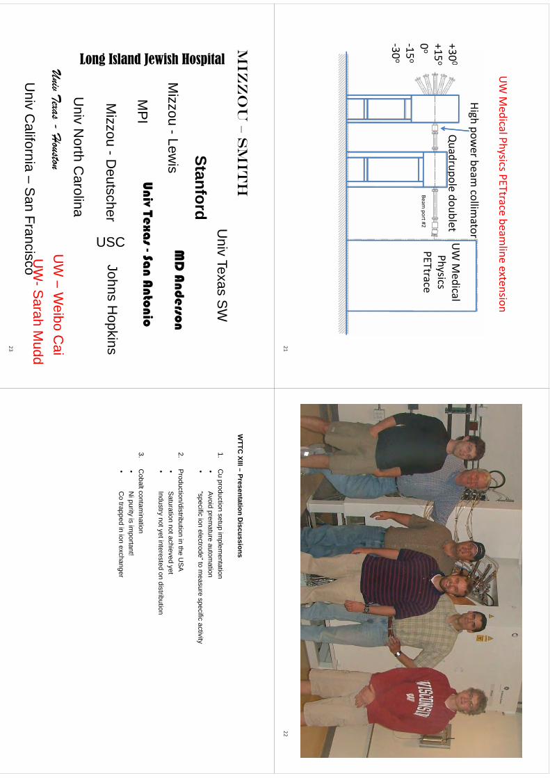
UW M
edical Physics PETtrace beamline extension
UW
Medical
Qd
ld
bl
High power beam
collimator
300
UW M
edicalPhysicsPETtrace
Quadrupole doublet
+300
+15o
0o
PETtraceBeam
port #20o
‐15o
30o
‐30o
2122
Miz
zo
u –
Sm
ith
ital
Univ Texas S
WM
izz
ou
S
mit
h
Stanford
Hospi
MD
And
erson
ewish
Mizzou -Lew
isM
D A
nderson
Ui
T
S A
ti
and Je
MP
I
C
Univ Texa
s -San A
ntonio
ng Isla
Mizzou -D
eutscher
USC
Johns Hopkins
Lon
Univ N
orth Carolina
UW
Wib
Ci
Univ Texas -H
ouston
Ui
Clif
iS
Fi U
W –
Weibo C
aiU
W-S
arahM
uddU
niv California –
San Francisco U
WS
arah Mudd
23
WTTC
XIII–Presentation
Discussions
WTTC
XIII –Presentation D
iscussions
1.C
u production setup implem
entation•
Avoid
premature
automation
•A
void premature autom
ation•
“specific ion electrode” to measure specific activity
2P
roduction/distributionin
theU
SA
2.P
roduction/distribution in the US
A•
Saturation not achieved yet•
Industry not yet interested on distribution
3.C
obalt contamination
•N
i purity is important!
•C
otrapped
inion
exchanger•
Co trapped in ion exchanger
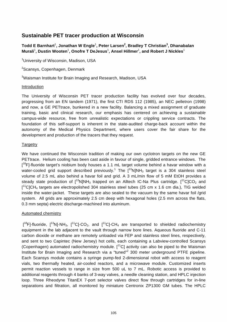
Sustainable PET tracer production at Wisconsin
Todd E Barnhart1, Jonathan W Engle1, Peter Larsen2, Bradley T Christian3, Dhanabalan Murali1, Dustin Wooten1, Onofre T DeJesus1, Ansel Hillmer1, and Robert J Nickles1
1University of Wisconsin, Madison, USA 2Scansys, Copenhagen, Denmark 3Waisman Institute for Brain Imaging and Research, Madison, USA
Introduction
The University of Wisconsin PET tracer production facility has evolved over four decades, progressing from an EN tandem (1971), the first CTI RDS 112 (1985), an NEC pelletron (1998) and now, a GE PETtrace, bunkered in a new facility. Balancing a mixed assignment of graduate training, basic and clinical research, our emphasis has centered on achieving a sustainable campus-wide resource, free from unrealistic expectations or crippling service contracts. The foundation of this self-support is inherent in the state-audited charge-back account within the autonomy of the Medical Physics Department, where users cover the fair share for the development and production of the tracers that they request.
Targetry
We have continued the Wisconsin tradition of making our own cyclotron targets on the new GE PETtrace. Helium cooling has been cast aside in favour of single, gridded entrance windows. The [18F]-fluoride target’s niobium body houses a 1.1 mL target volume behind a havar window with a water-cooled grid support described previously.1 The [13N]NH3 target is a 304 stainless steel volume of 2.5 mL also behind a havar foil and grid. A 3 mL/min flow of 5 mM EtOH provides a steady state production of [13N]NH3 trapped on an Alltech IC-Na Plus cartridge. [11C]CO2 and [11C]CH4 targets are electropolished 304 stainless steel tubes (25 cm x 1.6 cm dia.), TIG welded inside the water-jacket. These targets are also sealed to the vacuum by the same havar foil /grid system. All grids are approximately 2.5 cm deep with hexagonal holes (2.5 mm across the flats, 0.3 mm septa) electric discharge-machined into aluminum.
Automated chemistry [18F]-fluoride, [13N]-NH3, [11C]-CO2, and [11C]-CH4 are transported to shielded radiochemistry equipment in the lab adjacent to the vault through narrow bore lines. Aqueous fluoride and C-11 carbon dioxide or methane are remotely unloaded via FEP and stainless steel lines, respectively, and sent to two Capintec (New Jersey) hot cells, each containing a Labview-controlled Scansys (Copenhagen) automated radiochemistry module. [11C] activity can also be piped to the Waisman Institute for Brain Imaging and Research via a “tuned”2 300 meter underground PTFE pipeline. Each Scansys module contains a syringe pump-fed 2-dimensional robot with access to reagent vials, two thermally heated, air-cooled reactors, and a microwave module. Customized inserts permit reaction vessels to range in size from 500 uL to 7 mL. Robotic access is provided to additional reagents through 4 banks of 3-way valves, a needle cleaning station, and HPLC injection loop. Three Rheodyne TitanEX 7-port selector valves direct flow through cartridges for in-line separations and filtration, all monitored by miniature Centronix ZP1300 GM tubes. The HPLC
105
kmje
Typewritten Text
Abstract 018
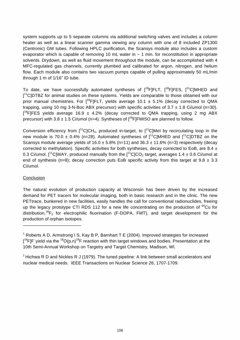
system supports up to 5 separate columns via additional switching valves and includes a column heater as well as a linear scanner gamma viewing any column with one of 8 included ZP1300 (Centronic) GM tubes. Following HPLC purification, the Scansys module also includes a custom evaporator which is capable of removing 10 mL water in ~ 1 min. for reconstitution in appropriate solvents. Drydown, as well as fluid movement throughout the module, can be accomplished with 4 MFC-regulated gas channels, currently plumbed and calibrated for argon, nitrogen, and helium flow. Each module also contains two vacuum pumps capable of pulling approximately 50 mL/min through 1 m of 1/16” ID tube. To date, we have successfully automated syntheses of [18F]FLT, [18F]FES, [11C]MHED and [11C]DTBZ for animal studies on these systems. Yields are comparable to those obtained with our prior manual chemistries. For [18F]FLT, yields average 10.1 ± 5.1% (decay corrected to QMA trapping, using 10 mg 3-N-Boc ABX precursor) with specific activities of 3.7 ± 1.8 Ci/umol (n=30). [18F]FES yields average 16.9 ± 4.2% (decay corrected to QMA trapping, using 2 mg ABX precursor) with 3.8 ± 1.5 Ci/umol (n=4). Syntheses of [18F]FMISO are planned to follow. Conversion efficiency from [11C]CH4, produced in-target, to [11C]MeI by recirculating loop in the new module is 70.0 ± 0.4% (n=28). Automated syntheses of [11C]MHED and [11C]DTBZ on the Scansys module average yields of 16.0 ± 5.8% (n=11) and 36.3 ± 11.6% (n=3) respectively (decay corrected to methylation). Specific activities for both syntheses, decay corrected to EoB, are 8.4 ± 0.3 Ci/umol. [11C]WAY, produced manually from the [11C]CO2 target, averages 1.4 ± 0.6 Ci/umol at end of synthesis (n=8); decay correction puts EoB specific activity from this target at 9.8 ± 3.3 Ci/umol. Conclusion The natural evolution of production capacity at Wisconsin has been driven by the increased demand for PET tracers for molecular imaging, both in basic research and in the clinic. The new PETtrace, bunkered in new facilities, easily handles the call for conventional radionuclides, freeing up the legacy prototype CTI RDS 112 for a new life concentrating on the production of 64Cu for distribution,18F2 for electrophilic fluorination (F-DOPA, FMT), and target development for the production of orphan isotopes.
1 Roberts A D, Armstrong I S, Kay B P, Barnhart T E (2004). Improved strategies for increased [18F]F- yield via the 18O(p,n)18F reaction with thin target windows and bodies. Presentation at the 10th Semi-Annual Workshop on Targetry and Target Chemistry, Madison, WI.
2 Hichwa R D and Nickles R J (1979). The tuned pipeline: A link between small accelerators and nuclear medical needs. IEEE Transactions on Nuclear Science 26, 1707-1709.
106
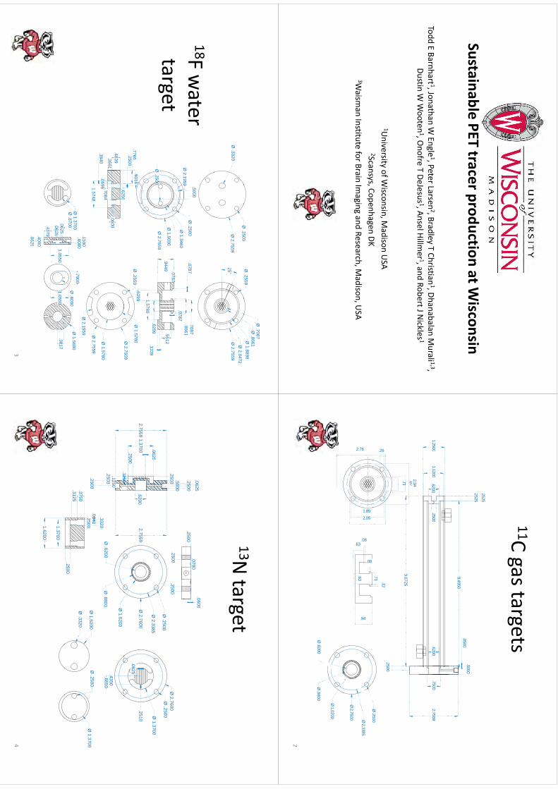
Sustainable PET tracer production at Wisconsin
Tdd
EB
ht 1
Jth
WE
l1Pt
L2B
dlTCh
iti1Dh
bl
Mli 1
3Todd E Barnhart 1, Jonathan W
Engle1, Peter Larsen
2, Bradley T Christian1, Dhanabalan M
urali 1,3, Dustin W
Wooten
1, Onofre T DeJesus 1, Ansel Hillm
er 1, and Robert J Nickles 1
1University of W
isconsin, Madison U
SA2Scansys
CopenhagenDK
2Scansys, Copenhagen DK3W
aisman Institute for Brain Im
aging and Research, Madison, U
SA
11Ct
t11C gas targets
.5000.0500
.2525
.2525
2.7559
9.4950
.75001.2500
6200.2500
.62001.1200
2.7559
9.6725
1.2500.6200
.2500.6200
.71.87
2.34
1.1200
.2500
Ø.2500
.26
.12
.71
Ø 2.7600 Ø
2.3385
Ø .2500
.94
1.892.05
2.76
.08.63
.08
.63
Ø .8800
Ø 1.0200
Ø .6200
2
Ø 1.8898
Ø .2559
Ø .8661
Ø .7087
Ø2500
25°Ø
2.7559Ø
2.0472
Ø 2.7559
Ø .2500
Ø .3320
18F water
.0787.8661.7087
Ø .2500
Ø2.1959 .5000
target.9449 .0787
.5512
.0787
6299Ø
2.7559
Ø 1.5000
Ø 1.3460
Ø .2500
Ø 2.1959
.6299 1.5780.1339
.6299
Ø .2559
Ø 2.7559
Ø 1.5780
.2500.7766
.9016
6256
Ø2
7559
Ø 1.5780
.2661.4839
15748
.1840.7084
.6256
.0600
.0696
Ø 2.1959 Ø
2.7559
.1590.6000
.7900Ø
.6000Ø
1.5680Ø
1.3700Ø
.8700
1.5748
.4000
.0625.0625
1.0550
.4379
.38171.0550
.0625
3
13Nt
t13N
target
.2500
.0625.0700
.0600
.2500
.5000
Ø2
3385
Ø .2500
.2500.2500
0625
.2503
Ø1
3700
Ø .2500
Ø 2.7600
2.7559Ø
2.7600
Ø 2.3385
.62002.7559
.0625
.25001253
1.3700
Ø 1.3700
.2510.0625
Ø .8800
Ø 1.0200
Ø .6200
.1250
.1253
.2503.4350.6850
Ø0840
.3320
.2500
Ø .3320
Ø 1.6200
Ø 1.3700
Ø .2500
.2500
.0840.2500
.3750.3125
1.3700
1.6200
4
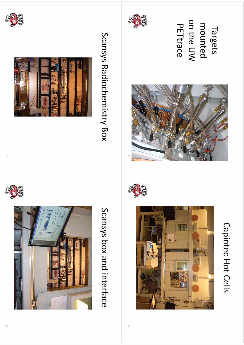
TargetsTargets mounted
mounted
onthe
UW
on the UW
PETtrace
5
Cit
HtC
llCapintec Hot Cells
6
SR
dih
itB
Scansys Radiochemistry Box
7
Sb
dit
fScansys box and interface
8

WTTC
XIII–Presentation
Discussions
WTTC
XIII –Presentation D
iscussions
1.M
anufactured targets•
Cheaper
•C
heaper•
Same yields
•S
tainless steel target experience
109
Production of Cl-34m via the (d,α) reaction on Ar-36 gas at 8.4 MeV.
Jonathan W. Engle, Todd E. Barnhart, Onofre DeJesus, and Robert J. Nickles
University of Wisconsin, Madison, USA
Introduction
The radioisotope 34mCl (β+, t1/2=32.2 m) is of interest to the medical community, especially in drug development. However, 34mCl production is currently limited to facilities capable of accelerating alpha particles.1 Proton-only accelerators can make use of reasonable yields for enriched 34S targets, but must contend with the poor thermal and electrical properties of sulphur and its compounds, which reach the molten state at even limited beam currents. The utility of the 20Ne(d,α)18F reaction2 suggests an alternative route to 34mCl via the corresponding noble gas, argon. The excitation function and yield measurements for 36Ar(d,α)34mCl near 8.4 MeV, the nominal deuteron energy on a PETtrace cyclotron, elude a careful search of the literature.
Test Irradiations of natArgon
A gas target (21 cm x 1.4 cm ID) was built with removable endplates for rapid removal of a quartz tube with trapped 38,34mCl- from 40,36Ar(d,α). Exploratory deuteron irradiations were conducted on a thick target of natAr 130 psig. Following irradiation, the target was “cooled” briefly to allow the overwhelming 511 keV gammas from 16O(d,n)17F in the quartz tube to decay and then flushed twice into a 1 L syringe to remove 41Ar prior to target disassembly and analysis. The quartz tube was removed and assayed with an HPGe detector (spectra shown below). Gamma spectroscopy revealed the production of 0.9 ± 0.1 mCi/uA of 38Cl (t1/2=37.2 m) and 5.1 ± 0.4 mCi/uA of 41Ar (t1/2=109 m) at end of saturated bombardment (EoSB). More importantly, the production of 34mCl in approximately 1:300 ratio with 38Cl mirrors the abundance ratios of their target isotopes.
Yield Measurements with 36Argon
Enriched 36Ar (99.993%, 1 L at STP) was obtained from Isoflex (San Francisco). The high cost (~$5000/L) of the target material necessitated cryotrapping 36Ar post-irradiation in a 50 mL stainless steel vessel.3 Vacsorb greatly improved the cryorecovery of argon at -196°C (<1 mm Hg) compared to vapor pressures achievable in its absence (0.3 atm), in agreement with the Clausius-Clapeyron relation’s prediction. A second target (21 cm x 1.9 cm ID) better accomodated the width of our deuteron beam, albeit at some cost in target pressure. The 36Ar-filled target was irradiated at an initial pressure of 68 ± 1 psig by beam currents between 5 and 20 uA for 30 minutes. After the run, 10 minutes of cryotrapping recovered >99.5% of target material at -196°C. The target was vented and the quartz insert removed for analysis. To date, 12 irradiations have been completed, revealing radionuclidically clean production of desired 34mCl trapped in the quartz tube. EoSB yields and decay over more than 3 decades are shown below, averaging 1.8 ± 0.2 mCi/uA for thick-target runs, reflecting the larger ID target’s accomodation of the PETtrace deuteron beam. The target appears to thin beyond 10 uA, reducing effective yield. Phosphor plate imaging of the quartz tubes’ adsorbed activity confirms this hypothesis, as the activity peak progresses steadily towards the back of the target with increased beam currents.
110
kmje
Typewritten Text
Abstract 019
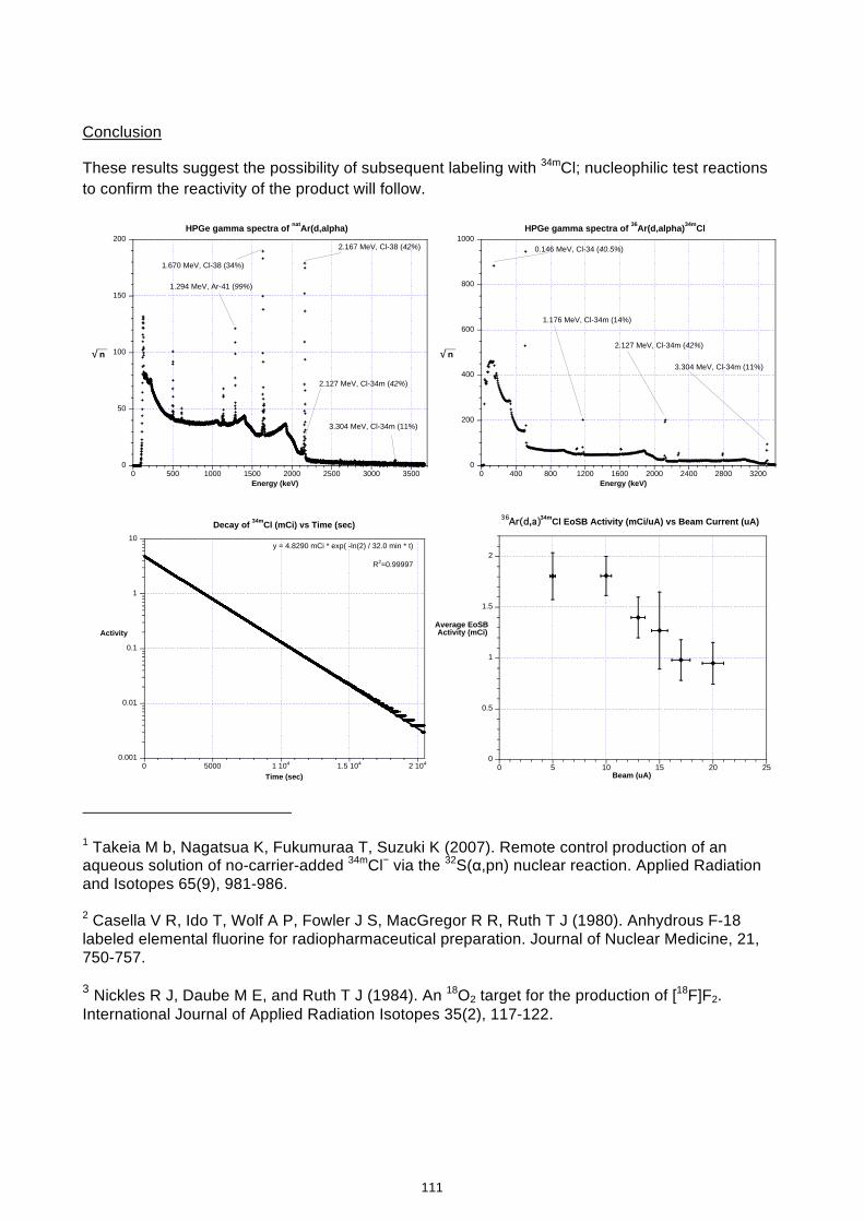
Conclusion
These results suggest the possibility of subsequent labeling with 34mCl; nucleophilic test reactions to confirm the reactivity of the product will follow.
0
50
100
150
200
0 500 1000 1500 2000 2500 3000 3500
HPGe gamma spectra of natAr(d,alpha)
__√ n
Energy (keV)
2.167 MeV, Cl-38 (42%)
1.670 MeV, Cl-38 (34%)
1.294 MeV, Ar-41 (99%)
3.304 MeV, Cl-34m (11%)
2.127 MeV, Cl-34m (42%)
0
200
400
600
800
1000
0 400 800 1200 1600 2000 2400 2800 3200
HPGe gamma spectra of 36Ar(d,alpha)34mCl
__√ n
Energy (keV)
3.304 MeV, Cl-34m (11%)
2.127 MeV, Cl-34m (42%)
1.176 MeV, Cl-34m (14%)
0.146 MeV, Cl-34 (40.5%)
0.001
0.01
0.1
1
10
0 5000 1 104 1.5 104 2 104
Decay of 34mCl (mCi) vs Time (sec)
Activity
Time (sec)
y = 4.8290 mCi * exp( -ln(2) / 32.0 min * t)
R2=0.99997
0
0.5
1
1.5
2
0 5 10 15 20 25
36Ar(d,a)34mCl EoSB Activity (mCi/uA) vs Beam Current (uA)
Average EoSB Activity (mCi)
Beam (uA)
1 Takeia M b, Nagatsua K, Fukumuraa T, Suzuki K (2007). Remote control production of an aqueous solution of no-carrier-added 34mCl− via the 32S(α,pn) nuclear reaction. Applied Radiation and Isotopes 65(9), 981-986. 2 Casella V R, Ido T, Wolf A P, Fowler J S, MacGregor R R, Ruth T J (1980). Anhydrous F-18 labeled elemental fluorine for radiopharmaceutical preparation. Journal of Nuclear Medicine, 21, 750-757. 3 Nickles R J, Daube M E, and Ruth T J (1984). An 18O2 target for the production of [18F]F2. International Journal of Applied Radiation Isotopes 35(2), 117-122.
111
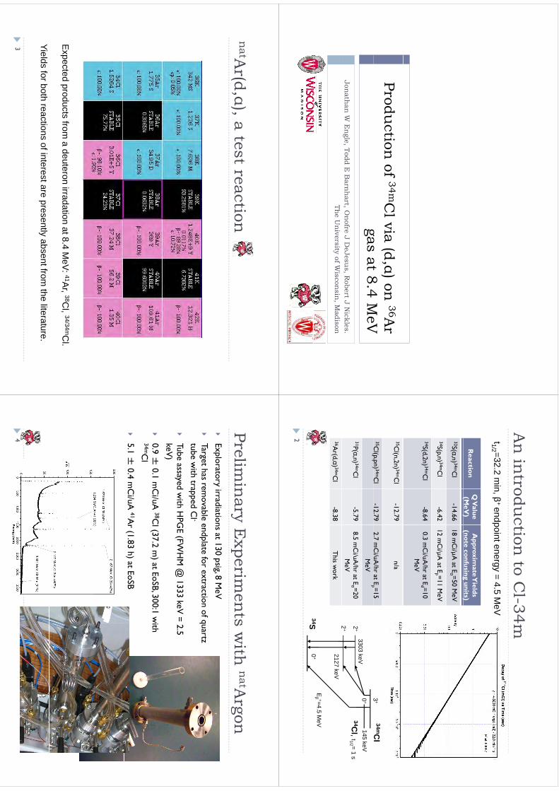
Production
of 34mCl via (d,α) on
36Ar
gas at 84 M
eVgas at 8.4 M
eVJon
athan
W E
ngle, Todd E
Barn
hart, O
nofre J D
eJesus, R
obert J Nickles.
g,
,,
The U
niversity of W
isconsin
, Madison
A i
td
ti t
Cl
34A
n in
troduction
to Cl-34m
t1/2 =32.2 min, β
+ endpoint energy = 4.5 MeV
Reaction
Q V
alue (M
eV)
Approxim
ate Yields
(note confusing units)
1/2,β
pgy
()
(g
)32S(α,n) 34mC
l -14.66
18 mC
i/µA at E
α =50 MeV
34S(p,n) 34mCl
-6.4212 m
Ci/µA
at Ep =11 M
eV
34S(d,2n) 34mCl
-8.640.3 m
Ci/uA
/hr at Ed =10
MeV
35Cl(n,2n) 34mC
l-12.79
n/a
35Cl(p,pn) 34mC
l-12.79
2.7 mC
i/uA/hr at E
p =15 34mC
l3
+(p,p
)p
MeV
31P(α,n) 34mCl
-5.798.5 m
Ci/uA
/hr at Eα =20
MeV
3303 keV0
+
2+
2+
145 keV34C
l, t1/2 = 1 s
36Ar(d,α) 34mC
l-8.38
This w
ork2127 keV
34SEβ +=4.5 M
eV0
+
2
34S0
2
natA
(d)
tt
tin
atAr(d,α), a test reaction
Expected
productsfrom
adeuteron
irradationat8
4M
eV:41A
r38C
l34/34mC
lE
xpected products from a deuteron irradation at 8.4 M
eV: A
r, C
l, C
l.
Yields for both reactions of interest are presently absent from the literature.
3
Pli
i E
it
ith
natA
Prelimin
ary Experim
ents w
ith n
atArgon
Exploratory irradiations at 130 psig, 8 M
eVp
yp
g
Target has rem
ovable endplate for extraction of quartz tube w
ith trapped Cl -
Tube assayed w
ith HPG
E (FWH
M @
1333 keV= 2.5
keV)
0
9 ±0
1 mC
i/uA38C
l (372 m
) at EoSB 300:1 w
ith
0.9 ±0.1 m
Ci/uA
Cl (37.2 m
) at EoSB, 300:1 with
34mCl
5.1 ±
0.4 mC
i/uA41A
r (1.83 h) at EoSB
4
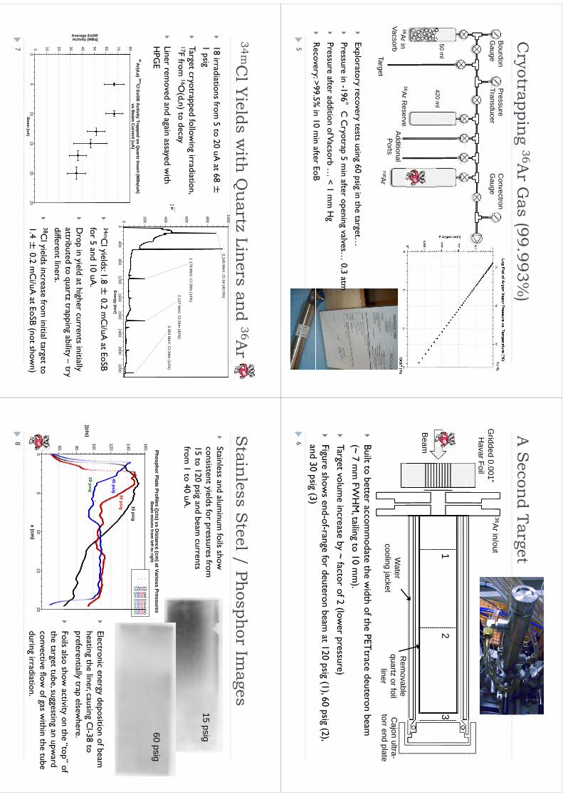
Ct
i 36A
G (99
993%)
Cryotrappin
g 36Ar G
as (99.993%)
Bourdon
Convectron
Pressure
Gauge
Gauge
Transducer
50 ml
420m
l
3636A
R
420 ml
36Ar in Vacsorb
Target
36Ar Reserve
Additional P
ortsnatAr
Exploratory recovery tests using 60 psig in the target…
P
i
196°
C C
t 5
i
ft
i
l 0
3 t
Pressure in -196
C C
ryotrap 5 min after opening valves…
0.3 atm
Pressure after addition of Vacsorb …
< 1 mm
Hg
R
ecovery: >995%
in 10 min after EoB
R
ecovery: >99.5% in 10 m
in after EoB
5
A S
d Tt
A S
econd Target
36Arin/out
Gridded 0.001” H
avar Foil
36Ar in/out1
23
Beam
Rbl
Rem
ovable quartz or foil
liner
Water
cooling jacketC
ajon ultra-torr end plate
Built to better accom
modate the w
idth of the PETtrace
deuteron beam
(~ 7 mm
FWH
M, tailing to 10 m
m).
Target volum
e increase by ~ factor of 2 (lower pressure)
Figure show
s end-of-range for deuteron beam at 120 psig (1), 60 psig (2),
d 30 i
(3) and 30 psig (3)
6
34mCl Yi
ld
ith Q
t Li
d 36A
34mCl Yields w
ith Q
uartz Lin
ers and 36A
r
18 irradiations from 5 to 20 uA
at 68 ±1000
0.146 MeV
, Cl-34 (40.5%
)
18 irradiations from
5 to 20 uA at 68 ±
1 psig
Target cryotrapped follow
ing irradiation, 600
800
1.176 MeV
, Cl-34m
(14%)
17F from 16O
(d,n) to decay
Liner rem
oved and again assayed with
HPG
E400
__¦ n
3.304 MeV
, Cl-34m
(11%)
2.127 MeV
, Cl-34m
(42%)
HPG
E
0
200
80
36Ar(d,a)
34mCl EoSB
Activity Trapped on Q
uartz Insert (MB
q/uA)
vs Beam
Current (uA
)
00
400800
12001600
20002400
28003200
Energy (keV)
50 60 70
SB q)
34mC
l yields: 1.8 ±0.2 m
Ci/uA
at EoSB f
5 d 10
A
30 40 50
Average EoSActivity (MBq
for 5 and 10 uA.
D
rop in yield at higher currents initially attributed to quartz trapping ability –
try
0 10 20
qpp
gy
ydifferent liners.
38C
l yields increase from initial target to
14 ±
02
Ci/
A
t ESB (
t h
)0
05
1015
2025
Beam
(uA)
1.4 ±0.2 m
Ci/uA
at EoSB (not shown)
7
St
il
St
l / Phh
IS
tainless S
teel / Phosph
or Images
Stainless and alum
inum foils show
15 psigconsistent yields for pressures from
15 to 120 psig and beam
currents from
1 to 40 uA.
Phosphor Plate Profiles (¦cts) vs Distance (cm
) at Various Pressures60
psig
from 1 to 40 uA
.
140
160
p(¦
)(
)B
eam m
oves from left to right
15 psi (counts)30 psi (counts)45 psi (counts)59 psi (counts)
15 psig
60 psig
100
12045 psig
30 psig
Electronic energy deposition of beam
80
100
¦(cts)59 psig
heating the liner, causing Cl-38 to
preferentially trap elsewhere.
Foils also show
activity on the “top” of
40 60
05
1015
20(
)
Foils also show
activity on the top
of the target tube, suggesting an upw
ard convective flow
of gas within the tube
di
idi
i
x (cm)
during irradiation.
8

[ 38/34mCl]M
Cl A
tt
ti[ 38/34mC
l]MeC
l: A test reaction
W
ash stainless foil with 40 m
l water, load onto Q
MA
prepped with 0.6 m
l KH
CO
3and 5 m
l water.
Elute w
ith 0.5 ml K
2,2,2 , 1 ml M
eCN
A
dd 0.1 ml 1 N
HC
l (carrier) and 0.1 ml T
EAO
H, azeotropically distill w
ith 2 x 1ml M
eCN
at 90°
C
C
ool to < 80°
C and add 1 m
l MeC
N and 0.1 m
l MeI
C
ool to 80
C and add 1 m
l MeC
N and 0.1 m
l MeI
Flush product into syringes by bubbling low
psi argon through sealed vessel. Analyze by G
C.
Poropak Q
column (80/100, 6’ x 0.125” x 0.085” SS), Shim
adzu 8610B running 0.5 ml/m
in He at 110°
C
D
ecay Corrected Y
ield 82 ±8%
(max 9.4 m
Ci follow
ing a 30 min, 20 uA
bombardm
ent).
03
0.32G
C (TC
D) of [ 34mC
l]MeC
l / Standard Co-Injection
022
0.24
0.26
0.28
0.3
TCD (V)
0.220
200400
600800
1000tim
e (sec)
3000
s
0
1000
2000
0200
400600
8001000
counts
0200
400600
8001000
time (sec)
9
Ft
Di
tiFu
ture D
irections
Electrophilic or In-target chem
istry to increase the utility
Electrophilic or In-target chemistry to increase the utility
of the cyclotron product imm
ediately?
Sll
il i
i t
b
th
tth
f th C
lC
Sm
all animal im
aging to probe the strength of the Cl-C
bond?
10
Cl
i
d Ak
ld
tC
onclu
sions an
d Ackn
owledgem
ents
To our know
ledge, this work is the first dem
onstration of the 36A
r(d,alpha) 34mCl w
ith useful yields. Using these
te
(,a
pa)
C w
t use
u y
es. U
sg t
ese m
ethods, more than 50 m
Ci 34mC
l has been produced in radionuclidically clean form
suitable for further chemistry.
radionuclidically clean form suitable for further chem
istry.
W
fll
k
ld
h
f NIH
G
W
e gratefully acknowledge the support of N
IH G
rant N
S054933 (OT
D) and N
IH R
adiological Sciences Training G
rant T32 C
A009206 (T
JH).
11
WTTC
XIII–Presentation
Discussions
WTTC
XIII –Presentation D
iscussions
1.P
ros and Cons
•N
o[ 34mC
l]ArC
lsignsobserved
•N
o [ 34mCl]A
rClsigns observed
•C
lchemistry easier than F
•H
igh 24mCl positron energy
2.C
hallenge: cross sections measurem
ent
OPTIMISATION OF AN ELECTROPLATING PROCESS TO PREPARE A SOLID TARGET FOR (p,n) BASED PRODUCTION OF COPPER-64 C. Jeffery1,2, S. Chan1, D. Cryer1, A. Asad1, RAPID Group1; R.I. Price1,3
1Medical Technology and Physics, Sir Charles Gairdner Hospital; 2Chemistry & 3Surgery, University of WA, Perth, Western Australia Introduction Research into the production of copper-64 from a nickel-64 solid target utilising a semi-automated solid target assembly coupled to an IBA 18/9 MeV proton cyclotron is ongoing. The target is prepared using an electroplating method adapted from McCarthy et al (1997), which uses a solution of nickel ammonium sulfate (adjusted to pH 9 with ammonium hydroxide) to plate nickel onto a gold substrate. While this method of production is sometimes very successful, it has also proved unreliable, producing poorly plated disks in approximately 50% of experiments. The irregularities observed in the nickel surface include - flaking, crazing, formation of spheres or pits, loose/powdery Ni, poorly adhered Ni, a lack of ‘lustre’ and a black deposit forming on the anode. An article from Kim et al (2009) described the black anode deposit, and suggested that ammonium hydroxide and/or ammonium sulfate added to counter residual acidity in the nickel ammonium sulphate solution was the cause. Kim et al suggested an electroplating method to resolve this issue. Further work was carried out to optimise our electroplating procedure, based on their method. Aim To develop a method that reliably and reproducibly generates a solid target for copper-64 production by electroplating nickel-64 onto gold; and to optimise the electroplating conditions to enable maximum nickel deposition for minimal time and use of nickel-64. Method Preparation of purified NiSO4 [adapted from Kim et al (2009)] Nickel metal is dissolved in nitric acid and evaporated to dryness. The solid is treated with sulfuric acid and dried to a yellow solid. The residue is dissolved in milliQ water and recrystallised by adding acetone. The solid is collected by vacuum filtration, and dried over vacuum for two hours, followed by drying in an oven at 120°C for a minimum of two hours. The resulting yellow-green solid is NiSO4. Preparation of electroplating solution Purified NiSO4 (0.13770g to 0.30079g) was dissolved in milliQ water (5mL, 10mL, or 15mL). Ammonium sulfate (~0.06g) was also dissolved into the solution. Electroplating experimental conditions Anode: initially carbon rod (rotating), then platinum rod (non-rotating) Cathode: initially 2mm x 20mm gold disk, then 125µm x 15mm gold foil Solution: initially nickel ammonium sulfate, pH 9, with ammonium sulfate buffer, Ni concentration ~3mg/mL (McCarthy et al, 1997); then nickel sulfate, pH 4.5, with ammonium sulfate buffer, Ni concentration ~5mg/mL (Kim et al, 2009) Plating area: 10mm diameter, 78mm2 Current: Constant 6mA Time: 12 hours (10 experiments, varying masses of NiSO4), plus 6 experiments with time varied from 12-96 hours (constant mass of NiSO4)
115
kmje
Typewritten Text
Abstract 020
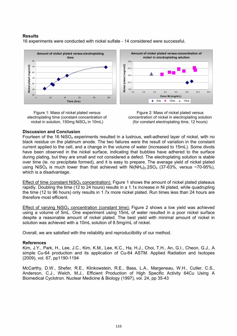
Results 16 experiments were conducted with nickel sulfate - 14 considered were successful.
Amount of nickel plated versus electroplating
time
20
25
30
35
40
45
50
0 20 40 60 80 100
Time (hrs)
Nickel plated (mg/cm2)
Amount of nickel plated versus concentration of
nickel in electroplating solution
15.0
20.0
25.0
30.0
35.0
0.0 2.0 4.0 6.0 8.0 10.0 12.0 14.0
Conc Ni (mg/mL)
Nickel plated (mg/cm2)
5mL 10mL 15mL
Figure 1: Mass of nickel plated versus
electroplating time (constant concentration of nickel in solution, 150mg NiSO4 in 10mL)
Figure 2: Mass of nickel plated versus concentration of nickel in electroplating solution (for constant electroplating time, 12 hours)
Discussion and Conclusion Fourteen of the 16 NiSO4 experiments resulted in a lustrous, well-adhered layer of nickel, with no black residue on the platinum anode. The two failures were the result of variation in the constant current applied to the cell, and a change in the volume of water (increased to 15mL). Some divots have been observed in the nickel surface, indicating that bubbles have adhered to the surface during plating, but they are small and not considered a defect. The electroplating solution is stable over time (ie. no precipitate formed), and it is easy to prepare. The average yield of nickel plated using NiSO4 is much lower than that achieved with Ni(NH4)2.2SO4 (37-63%, versus ~70-95%), which is a disadvantage. Effect of time (constant NiSO4 concentration): Figure 1 shows the amount of nickel plated plateaus rapidly. Doubling the time (12 to 24 hours) results in a 1.1x increase in Ni plated, while quadrupling the time (12 to 96 hours) only results in 1.7x more nickel plated. Run times less than 24 hours are therefore most efficient. Effect of varying NiSO4 concentration (constant time): Figure 2 shows a low yield was achieved using a volume of 5mL. One experiment using 15mL of water resulted in a poor nickel surface despite a reasonable amount of nickel plated. The best yield with minimal amount of nickel in solution was achieved with a 10mL solution of 8.5mg/mL of nickel. Overall, we are satisfied with the reliability and reproducilbility of our method. References Kim, J.Y., Park, H., Lee, J.C., Kim, K.M., Lee, K.C., Ha, H.J., Choi, T.H., An, G.I., Cheon, G.J., A simple Cu-64 production and its application of Cu-64 ASTM. Applied Radiation and Isotopes (2009), vol. 67, pp1190-1194 McCarthy, D.W., Shefer, R.E., Klinkowstein, R.E., Bass, L.A., Margeneau, W.H., Cutler, C.S., Anderson, C.J., Welch, M.J., Efficient Production of High Specific Activity 64Cu Using A Biomedical Cyclotron. Nuclear Medicine & Biology (1997), vol. 24, pp 35-43
116
Streamlined measurement of the specific radioactivity of in target produced [11C]methane by on-line conversion to [11C]hydrogen cyanide. 1) Jacek Koziorowski and 2) Nic Gillings 1) Herlev Hospital Copenhagen University, Denmark, 2) Copenhagen University Hospital, Rigshospitalet Abstract A simple method for the direct measurement of in-target produced [11C]methane specific radioactivity is described. The method is also suitable for the production of [11C]cyanide for radiosynthesis. Specific activities up to 13 000 GBq/μmol are reported. Introduction For monitoring and optimization of the specific radioactivity of in-target produced [11C]methane it is desirable to have a simple method for measurement of the mass of carbon without having to performed a complete radiosynthesis. Quantification of [11C]methane using gas chromatography (GC) is rather cumbersome and if using a flame ionisation detector (FID) it is necessary to wait until the activity has decayed before performing the measurement. Such a delay gives rise to the possibility of losses of methane, thus leading to an over-estimation of the specific activity. Furthermore, a reliable measurement of such small masses of methane is challenging. [11C]hydrogen cyanide can be easily produced on-line from [11C]cyanide by passing over platinum at 1000 °C in the presence of ammonia. Since ammonia is produced in situ during irradiation of the [11C]methane target by the radiolysis of nitrogen in the presence of hydrogen, this further simplifies the procedure. Cyanide can be quantified down to ppb levels by HPLC using an electrochemical detector (1) or by the use of colorimetric methods. Experimental Target The target consists of a water cooled, quartz lined aluminium body (length 250 mm, i.d. 19.8 mm) (2). The target volume is 75 mL. Irradiations Irradiations were performed using the Scanditronix MC-32 cyclotron at Copenhagen University Hospital, Rigshospitalet. H- ions were accelerated to 17.2 MeV, giving an target entrance energy of ca. 16 MeV. The target gas consisted of ultra pure gases of 10% hydrogen in nitrogen (AGA, Sweden, grade 6.0 [>99.99995%]) . The target fill pressure was 26 bar giving a gas volume of 2L at NTP.
117
kmje
Typewritten Text
Abstract 021
Analysis Following irradiations, the gases were released from the target by simply opening a valve and transferred to a hotcell. A mass-flow controller was set at 100mL/min and the gasses were passed over 3.37g of platinum wire (20m L x 0.1mm Ø) in a 6mm ID quartz tube at 1000°C. The produced [11C]cyanide was trapped in a 20mL vial containing 20mL of pure water. After the vial an Ascarite trap (for measuring cyanide trapping efficiency) and a gas collection bag (to prevent the escape of radioactive gasses) was attached. After decay the amount of cyanide was measured using the pyridine-barbituric acid colorimetric test (Koenig reaction, EPA method 335.4-1) (3,4). Results Not optimized conversion from [11C]methane to [11C]cyanide were 50%. Trapping was quantitative (no radioactivity was found in the Ascarite trap) and 20GBq (n=4) of activity was trapped and the concentration of cyanide in the solution was below the detection limit (2μg/L = 77nM/L). This corresponds to a specific activity of >13 000 GBq/mol (EOB). For radiosynthesis the residual ammonia is easily removed by a trap filled with Dowex 50W (200-400 mesh) followed by Sicapent (to dry / remove water), for multi-runs, or a smoke tube (Draeger air current tube; silica impregnated with fuming sulfuric acid) for a single run. Outlook Experiments to increase the conversion and minimize the trapping volume are planned. References 1) ) Direct determination of free cyanide in drinking water by ion chromatography with pulsed amperometric detection T.T. Christison, J.S. Rohrer, J. Chromatogr. A 1155, 2007, 31–39. 2) A flexible [11C]methane target,Jacek Koziorowski, Peter Larsen, Holger Jensen and Nic Gillings, Proceedings of the 12th International Workshop on Targetry and Target Chemistry, July 21-24, 2008Seattle, Washington 3) Stable reagents for the colorimetric determination of cyanide by modified König reactions, Jack L. Lambert, Jothi Ramasamy and Joseph V. Paukstells, Analytical Chemistry, Vol. 47, No. 6, 1975, pp916-8. 4) Method 335.4, Determination of total cyanide by semi-automated colorimetry, Rev.1.0 ,James W. O'Dell (Ed.) Inorganic Chemistry Branch, Chemistry Research Division, August 1993
118

Streamlin
ed M
easurem
ent of Sp
ecific Stream
lined
Measu
remen
t of Specific
Rad
ioactivity of in T
arget Prod
uced
R
adioactivity of in
Target P
rodu
ced
[[ 1111C]M
hb
OC
]Mh
bO
liC
ili
Ci
[[ 1111C]M
ethan
e by O
nC
]Meth
ane b
y On
--line C
onversion
to lin
e Con
version to
[[ 1111C]H
dC
idC
]Hd
Cid
[[ 1111C]H
ydrogen
Cyan
ide
C]H
ydrogen
Cyan
ide
Ni
Gilli
&J
kK
iki
Ni
Gilli
&J
kK
iki
Nic G
illings &
Jacek Koziorow
skiN
ic Gillin
gs & Jacek K
oziorowski
Wh
MS
ifiA
tiit
?W
hM
Sifi
Ati
it?
Wh
y Measu
re Specific A
ctivity?W
hy M
easure Sp
ecific Activity?
H
igh affinity neuroreceptor ligands labelled with
High affinity neuroreceptor ligands labelled w
ith bb
11i
hih
SAi
did
11i
hih
SAi
did
carboncarbon--11 require high SA
in order to avoid 11 require high SA
in order to avoid occu pancy of binding sites w
ith the cold ligand.occupancy of binding sites w
ith the cold ligand.p
yg
gp
yg
g
Less than 5%
occupancy is normally used as a
Less than 5% occupancy is norm
ally used as a cutcut--offfor
offfortracertracerstudies
studiescutcutoff for
off for tracertracerstudies.
studies.
2
NL
id
Bi
di
NL
id
Bi
di
Neu
roreceptor L
igand
Bin
din
gN
eurorecep
tor Ligan
d B
ind
ing
Non-radioactive
compound
willcom
peteforactive
bindingsites
Non
radioactive compound w
ill compete for active binding sites
3
Sifi
Ati
itf
[S
ifiA
tiit
f[
1111C]M
thC
]Mth
Specific A
ctivity of [Sp
ecific Activity of [
1111C]M
ethan
eC
]Meth
ane
Theoretical m
aximum
: 341 TBq/Theoretical m
aximum
: 341 TBq/µmol
µmol
M
aximum
we
havem
easured:9TBq/µm
ol(EO
B)M
aximum
we
havem
easured:9TBq/µm
ol(EO
B)
Maxim
um w
e have measured: 9 TBq/µm
ol (EO
B)M
aximum
we have m
easured: 9 TBq/µmol (E
OB)
1212C/C/
1111C ratio: 38:1C ratio: 38:1
M
fth
0143
Mf
th0
143(b
d50
GB
)(b
d50
GB
)
Mass of m
ethane: 0.143 M
ass of methane: 0.143 µgµg
(based on 50 GBq)
(based on 50 GBq)
4

Mt
fS
ifiA
tiit
Mt
fS
ifiA
tiit
Measu
remen
t of Specific A
ctivityM
easurem
ent of Sp
ecific Activity
D
irect quantification of methane in target gas at end of
Direct quantification of m
ethane in target gas at end of bom
bardmentusing
gaschromatogrphy
with
FIDbom
bardmentusing
gaschromatogrphy
with
FIDbom
bardment using gas chrom
atogrphy with FID
bom
bardment using gas chrom
atogrphy with FID
(Steel et al. 8th W
TTC, 1999) or Pulsed Discharge
(Steel et al. 8th WTTC, 1999) or Pulsed D
ischarge D
etectorD
etectorD
etectorD
etector
Ci
Ci
1111Ch
lidid
difi
iC
hli
didd
ifii
Conversion to [Conversion to [ 1111C]m
ethyl iodide and quantification C]m
ethyl iodide and quantification w
ith HPLC
with H
PLC
Conversion
toa
[Conversion
toa
[ 1111C]C]--labelledcom
poundand
labelledcom
poundand
Conversion to a [Conversion to a [
C]C]labelled compound and
labelled compound and
quantification with H
PLC quantification w
ith HPLC
5
Specific
Activity
Specific
Activity
Specific A
ctivitySp
ecific Activity
Sifi
ii
dfb
bd
(EO
B)S
ifii
id
fbb
d(E
OB)
Specific activity at end of bombardm
ent (EO
B) Specific activity at end of bom
bardment (E
OB)
based on measurem
ent of [based on m
easurement of [ 1111C]C]--labelled tracers
labelled tracers [[
]]using H
PLC with U
V detection.
using HPLC w
ith UV
detection.
New
Target
New
TargetG
as
Gas
PurifierN
ew Target
Gas
Gas PurifierInstalled
Figure from: K
oziorowski J, Larsen P, G
illings N. A quartz-lined carbon-11 target: striving for
increased yield and specific activity, Nucl M
ed Biol 2010, accepted m
anuscript6
Mt
fS
ifiA
tiit
Mt
fS
ifiA
tiit
Measu
remen
t of Specific A
ctivityM
easurem
ent of Sp
ecific Activity
A
im: A
simple m
ethod to determine SA
of target gas without the
Aim
: A sim
ple method to determ
ine SA of target gas w
ithout the need to perform
a full radiosynthesis.need to perform
a full radiosynthesis.p
yp
y
Solution: O
nSolution: O
n--line conversion to [line conversion to [ 1111C]CN
C]CN[[
]]
Q
uantification of cyanide: Colorimetric m
ethods or HPLC w
ith Q
uantification of cyanide: Colorimetric m
ethods or HPLC w
ith Q
yQ
yfluorom
etric or electrochemical detection
fluorometric or electrochem
ical detection
Sensitivity: Sensitivity:
Cyanide Test Kit
Cyanide Test Kit --2 2 µg/L
µg/Lyy
µg/µg/
HPLC (
HPLC (fluorom
etricfluorom
etric) ) ––LO
D: 0.05 µg/L
LOD
: 0.05 µg/LH
PLC(electrochem
ical)H
PLC(electrochem
ical)––LO
D:0.27
µg/LLO
D:0.27
µg/LH
PLC (electrochemical)
HPLC (electrochem
ical) LO
D: 0.27 µg/L
LOD
: 0.27 µg/L
7
Ei
tlS
tE
it
lSt
Exp
erimen
tal SetE
xperim
ental Set--u
pu
p
Mass
Pt O
ven
Wt
10% H
2 in N2
FlowC
ontroller
980 ºC[ 11C
]Methane
Target100 m
l/min
AscariteW
aste
[ 11C]M
ethane Target
20m
l20 m
lColorim
etric test (K
önig reaction)
Jacek(artists im
pression)8

Pli
iR
ltP
lii
Rlt
Prelim
inary R
esults
Prelim
inary R
esults
Irradiation 20 Irradiation 20 µA
for 20 min (n=
4)µA
for 20 min (n=
4)
[[ 1111C]CN
yield: 20 C]CN
yield: 20 GBq
GBq
(EO
B) in 20 ml w
ater (ca. (E
OB) in 20 m
l water (ca.
[[]
Ny
]N
yqq
()
w(
()
w(
50% conversion, quantitative trapping)
50% conversion, quantitative trapping)
Cyanide concentration: <
2 µg/L (<0.04 µg total)
Cyanide concentration: <2 µg/L (<
0.04 µg total)y
µg/(
µg)
yµg/
(µg
)
//
Specific Activity: >
13000 Specific A
ctivity: >13000 G
BqG
Bq/µmol
/µmol
9
Cl
iC
li
Con
clusion
sC
onclu
sions
O
nO
n--line conversion to cyanide is a simple and
line conversion to cyanide is a simple and
convenientmethod
fordetermination
ofspecificconvenientm
ethodfordeterm
inationofspecific
convenient method for determ
ination of specific convenient m
ethod for determination of specific
activityactivity
Specific
activityoftargetgasappearsto
bevery
Specificactivity
oftargetgasappearstobe
very
Specific activity of target gas appears to be very Specific activity of target gas appears to be very high (>
13000 high (>
13000 GBq
GBq/µm
ol)/µm
ol)
M
oresensitive
methodsforanalysisofcyanide
More
sensitivem
ethodsforanalysisofcyanide
More sensitive m
ethods for analysis of cyanide M
ore sensitive methods for analysis of cyanide
are required to truly quantify SA of target gas
are required to truly quantify SA of target gas
10
Pti
Pti
Persp
ectivesP
erspectives
Trapping [Trapping [ 1111C]cyanide in a sm
aller volume can be
C]cyanide in a smaller volum
e can be achieved
bytrapping
firstina
cryotrapthen
achievedby
trappingfirstin
acryotrap
thenachieved by trapping first in a cryotrap then achieved by trapping first in a cryotrap then transferring to a sm
all vial with a low
helium flow
transferring to a small vial w
ith a low helium
flow
A
more quantitative estim
ation of specific activity may
A m
ore quantitative estimation of specific activity m
ay h
bibl
hb
iblthen be possiblethen be possible
Repeat experim
ents to test the effect of different target Repeat experim
ents to test the effect of different target param
ters(e.g.beamcurrent)on
specificactivity
may
paramters(e.g.beam
current)onspecific
activitym
ayparam
ters (e.g. beam current) on specific activity m
ay param
ters (e.g. beam current) on specific activity m
ay be possible w
ith this method
be possible with this m
ethod
11
WTTC
XIII –Presentation D
iscussions
1.P
roduction of oxides•
Important factor affecting conversion rate
•G
o through the system to avoid it
2.U
V vs
visual inspection?R
esultsalw
aysbellow
detectionlim
it•
Results alw
ays bellow detection lim
it
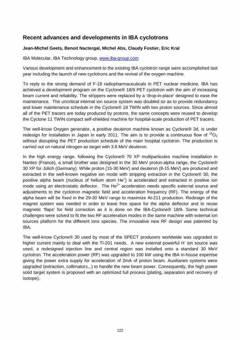
Recent advances and developments in IBA cyclotrons
Jean-Michel Geets, Benoit Nactergal, Michel Abs, Claudy Fostier, Eric Kral
IBA Molecular, IBA Technology group, www.iba-group.com
Various development and enhancement to the existing IBA cyclotron range were accomplished last year including the launch of new cyclotrons and the revival of the oxygen machine.
To reply to the strong demand of F-18 radiopharmaceuticals in PET nuclear medicine, IBA has achieved a development program on the Cyclone® 18/9 PET cyclotron with the aim of increasing beam current and reliability. The strippers were replaced by a ‘drop-in-place’ designed to ease the maintenance. The uncritical internal ion source system was doubled so as to provide redundancy and lower maintenance schedule in the Cyclone® 18 TWIN with two proton sources. Since almost all of the PET tracers are today produced by protons, the same concepts were reused to develop the Cyclone 11 TWIN compact self-shielded machine for hospital-scale production of PET tracers.
The well-know Oxygen generator, a positive deuteron machine known as Cyclone® 3d, is under redesign for installation in Japan in early 2011. The aim is to provide a continuous flow of 15O2 without disrupting the PET production schedule of the main hospital cyclotron. The production is carried out on natural nitrogen as target with 3.6 MeV deuteron.
In the high energy range, following the Cyclone® 70 XP multiparticules machine installation in Nantes (France), a small brother was designed in the 30 MeV proton-alpha range, the Cyclone® 30 XP for Jülich (Germany). While proton (15-30 MeV) and deuteron (8-15 MeV) are produced and extracted in the well-known negative ion mode with stripping extraction in the Cyclone® 30, the positive alpha beam (nucleus of helium atom He+) is accelerated and extracted in positive ion mode using an electrostatic deflector. The He2+ acceleration needs specific external source and adjustments to the cyclotron magnetic field and acceleration frequency (RF). The energy of the alpha beam will be fixed in the 29-30 MeV range to maximize At-211 production. Redesign of the magnet system was needed in order to leave free space for the alpha deflector and to reuse magnetic ‘flaps’ for field correction as it is done on the IBA-Cyclone® 18/9. Some technical challenges were solved to fit the two RF acceleration modes in the same machine with external ion sources platform for the different ions species. The innovative new RF design was patented by IBA.
The well-know Cyclone® 30 used by most of the SPECT producers worldwide was upgraded to higher current mainly to deal with the Tl-201 needs. A new external powerful H- ion source was used, a redesigned injection line and central region was installed onto a standard 30 MeV cyclotron. The acceleration power (RF) was upgraded to 100 kW using the IBA in-house expertise giving the power extra supply for acceleration of 2mA of proton beam. Auxiliaries systems were upgraded (extraction, collimators,..) to handle the new beam power. Consequently, the high power solid target system is proposed with an optimized full process (plating, separation and recovery of isotope).
122
kmje
Typewritten Text
Abstract 22
WTTC
#13R
iD
kR
isoe, Dk
Recentadvance
andR
ecentadvanceand
development
inIB
Acyclotrons
in IBA cyclotrons
Geets
Jean-Michel
Geets Jean
Michel
© 2006
1
The Oxygen
generator
R
evival of the Cyclone®
3D3
6S
3.6 M
eV D
+ beam, E
SD
extraction
One gaz target
14N(d,n)15O
Im
provements
fromthe old
design (ref. Turku)
4 machines sold
–> discontinued
in 90’s
© 2006
2
15O generator : M
ain specifications
© 2006
3
Redesign
of the main system
s
Machine w
ithvertical plane, self resonating
RF on top, no valleys
© 2006
4
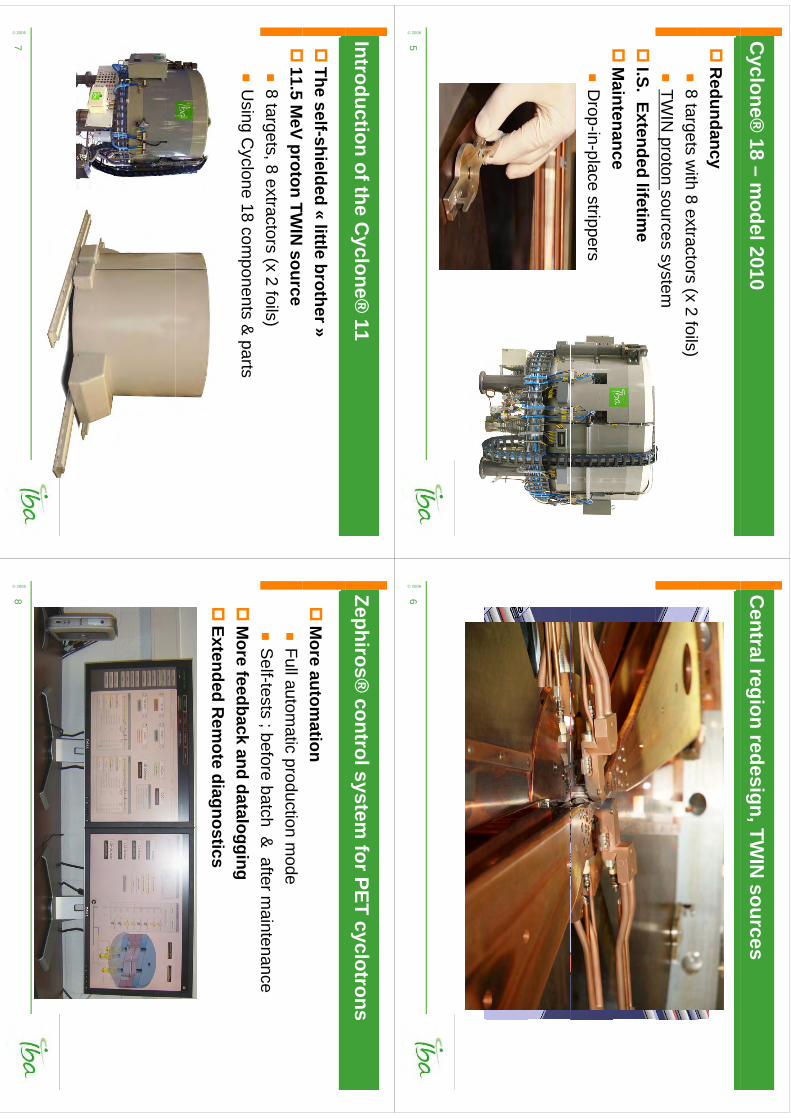
Cyclone®
18 –m
odel 2010
R
edundancy8
8(
2f
)
8 targetsw
ith8 extractors
(x 2 foils)
TWIN
proton sources system
I.S. Extended
lifetime
M
aintenance
Maintenance
Drop-in-place strippers
© 2006
5
Central region
redesign, TWIN
sources
© 2006
6
Introduction of the Cyclone®
11
The self-shielded
«little
brother»
11
11.5 MeV proton TW
IN source
8 targets, 8 extractors
(x 2 foils)
Using
Cyclone 18 com
ponents & parts
© 2006
7
Zephiros® control system
for PET cyclotrons
M
ore automation
Full autom
aticproduction m
ode
Self-tests ; before
batch & afterm
aintenance;
M
ore feedback and datalogging
ExtendedR
emote
diagnostics
ExtendedR
emote
diagnostics© 2006
8
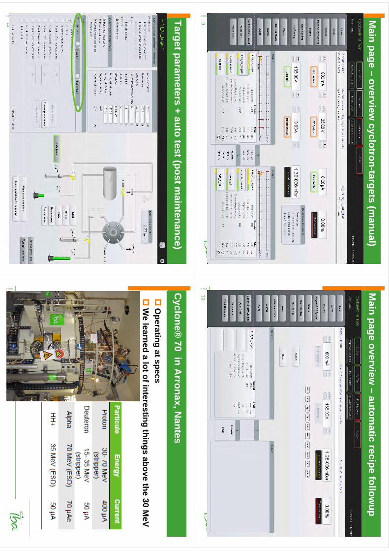
Main page –
overview cyclotron-targets (m
anual)© 2006
9
Main page overview
–autom
atic recipe followup
© 2006
10
Target parameters + auto test (post m
aintenance)
© 2006
11
Cyclone®
70 in Arronax, N
antes
O
perating atspecs
f30
W
elearned
a lot of interestingthings
abovethe 30 M
eV
© 2006
12
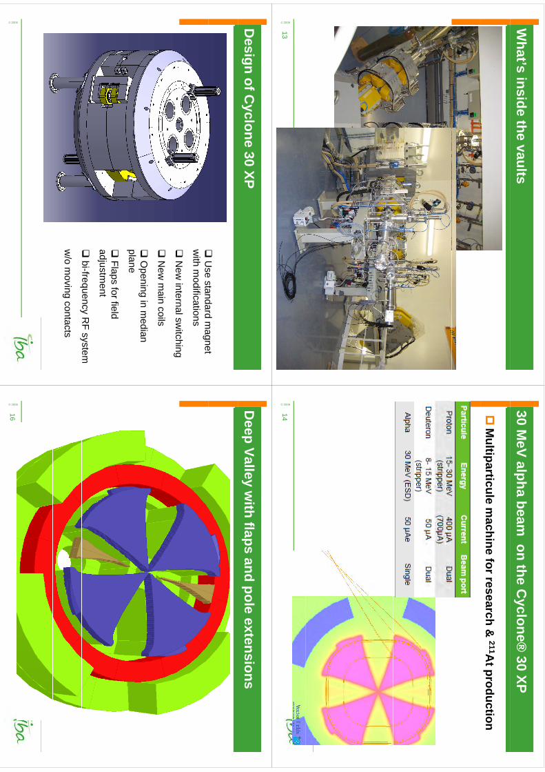
What’s
insidethe vaults
© 2006
13
30 MeV alpha beam
on the Cyclone®
30 XP
M
ultiparticulem
achine for research&
211At production
© 2006
14
Design of C
yclone 30 XP
U
sestandard
magnet
U
se standard magnet
with
modifications
N
ewinternalsw
itching
New
internalswitching
N
ew m
ain coils
O
peningin m
edianplane
Flaps
for fieldadjustm
ent
bi-frequency
RF system
w/o m
ovingcontacts
© 2006
Deep
Valleyw
ithflaps
and pole extensions
© 2006
16
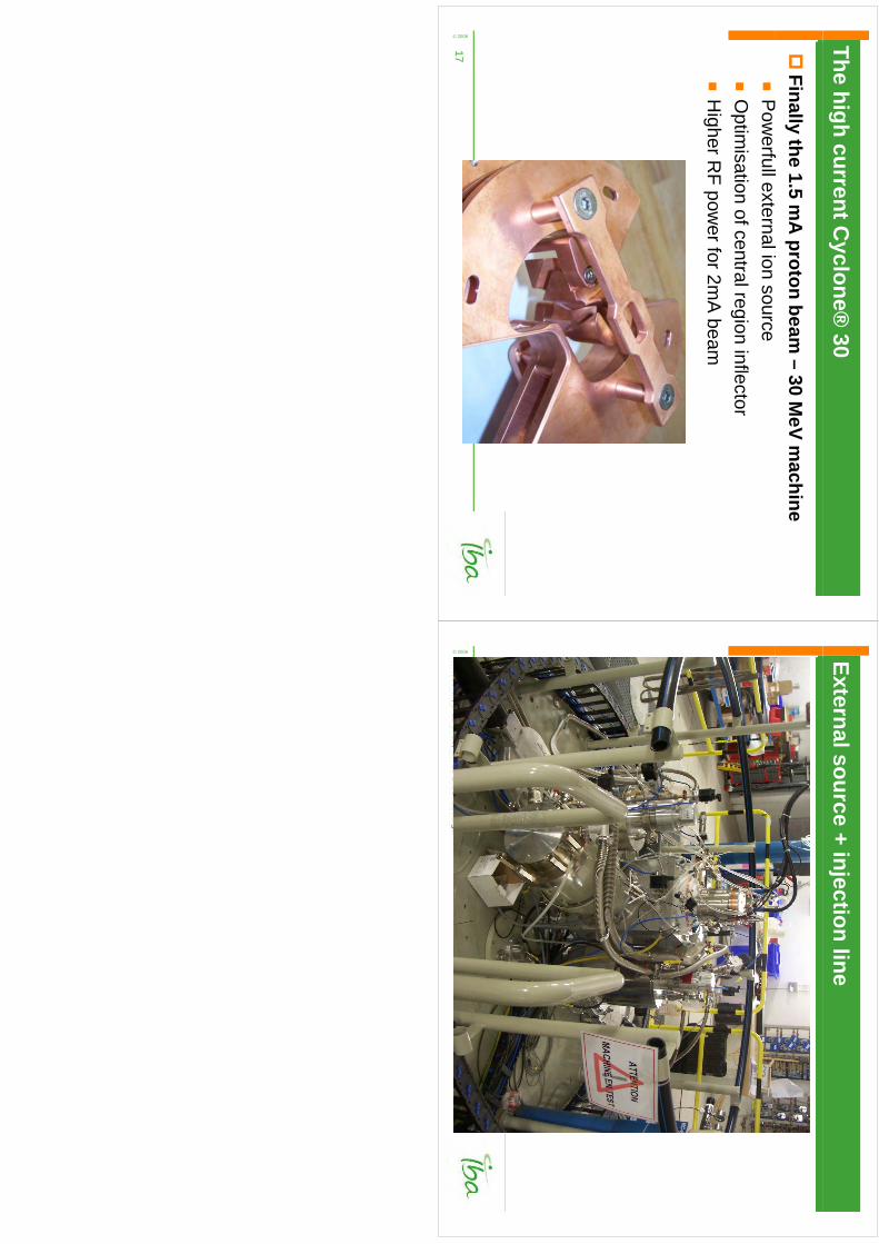
The highcurrentC
yclone® 30
Finally
the 1.5 mA
proton beam–
30 MeV m
achinef
P
owerfullexternalion source
O
ptimisation of central region
inflector
HigherR
F power for 2m
A beam
© 2006
17
Externalsource + injection line
© 2006
18
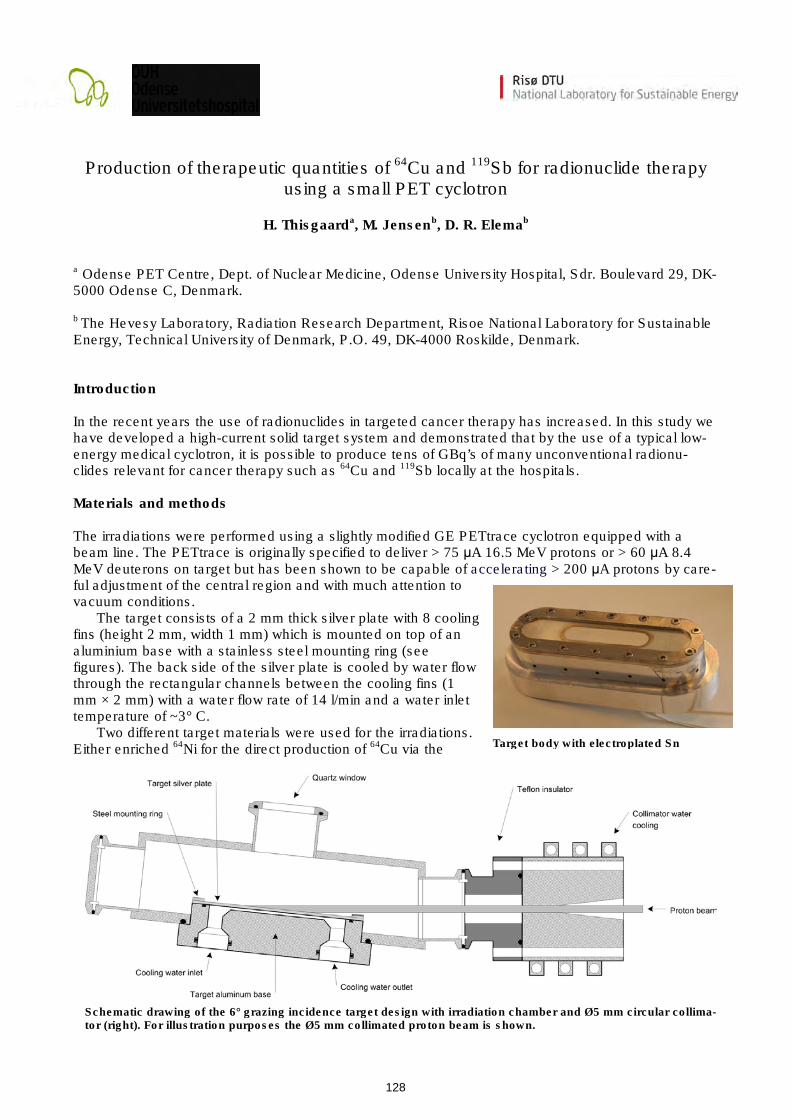
Target body with electroplated Sn
Schematic drawing of the 6° grazing incidence target design with irradiation chamber and Ø5 mm circular collima-tor (right). For illustration purposes the Ø5 mm collimated proton beam is shown.
Production of therapeutic quantities of 64Cu and 119Sb for radionuclide therapy using a small PET cyclotron
H. Thisgaarda, M. Jensenb, D. R. Elemab
a Odense PET Centre, Dept. of Nuclear Medicine, Odense University Hospital, Sdr. Boulevard 29, DK-5000 Odense C, Denmark. b The Hevesy Laboratory, Radiation Research Department, Risoe National Laboratory for Sustainable Energy, Technical University of Denmark, P.O. 49, DK-4000 Roskilde, Denmark. Introduction In the recent years the use of radionuclides in targeted cancer therapy has increased. In this study we have developed a high-current solid target system and demonstrated that by the use of a typical low-energy medical cyclotron, it is possible to produce tens of GBq’s of many unconventional radionu-clides relevant for cancer therapy such as 64Cu and 119Sb locally at the hospitals. Materials and methods The irradiations were performed using a slightly modified GE PETtrace cyclotron equipped with a beam line. The PETtrace is originally specified to deliver > 75 µA 16.5 MeV protons or > 60 µA 8.4 MeV deuterons on target but has been shown to be capable of accelerating > 200 µA protons by care-ful adjustment of the central region and with much attention to vacuum conditions.
The target consists of a 2 mm thick silver plate with 8 cooling fins (height 2 mm, width 1 mm) which is mounted on top of an aluminium base with a stainless steel mounting ring (see figures). The back side of the silver plate is cooled by water flow through the rectangular channels between the cooling fins (1 mm × 2 mm) with a water flow rate of 14 l/min and a water inlet temperature of ~3° C.
Two different target materials were used for the irradiations. Either enriched 64Ni for the direct production of 64Cu via the
128
kmje
Typewritten Text
Abstract 23
kmje
Typewritten Text
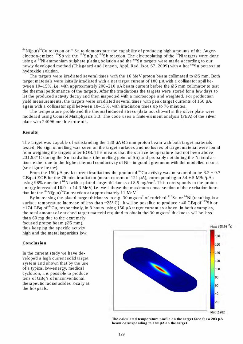
The calculated temperature profile on the target face for a 203 µA beam corresponding to 180 µA on the target.
64Ni(p,n)64Cu reaction or natSn to demonstrate the capability of producing high amounts of the Auger-electron-emitter 119Sb via the 119Sn(p,n)119Sb reaction. The electroplating of the 64Ni targets were done using a 64Ni ammonium sulphate plating solution and the natSn targets were made according to our newly developed method (Thisgaard and Jensen, Appl. Rad. Isot. 67, 2009) with a hot natSn potassium hydroxide solution.
The targets were irradiated several times with the 16 MeV proton beam collimated to Ø5 mm. Both target materials were initially irradiated with a net target current of 180 µA with a collimator spill be-tween 10–15%, i.e. with approximately 200–210 µA beam current before the Ø5 mm collimator to test the thermal performance of the targets. After the irradiations the targets were stored for a few days to let the produced activity decay and then inspected with a microscope and weighted. For production yield measurements, the targets were irradiated several times with peak target currents of 150 µA, again with a collimator spill between 10–15%, with irradiation times up to 76 minutes.
The temperature profile and the thermal induced stress (data not shown) in the silver plate were modelled using Comsol Multiphysics 3.3. The code uses a finite-element analysis (FEA) of the silver
plate with 24096 mesh elements.
Results The target was capable of withstanding the 180 µA Ø5 mm proton beam with both target materials tested. No sign of melting was seen on the target surfaces and no losses of target material were found from weighing the targets after EOB. This means that the surface temperature had not been above 231.93° C during the Sn irradiations (the melting point of Sn) and probably not during the Ni irradia-tions either due to the higher thermal conductivity of Ni – in good agreement with the modelled results (see figure below).
From the 150 µA peak current irradiations the produced 64Cu activity was measured to be 8.2 ± 0.7 GBq at EOB for the 76 min. irradiation (mean current of 121 µA), corresponding to 54 ± 5 MBq/µAh using 98% enriched 64Ni with a plated target thickness of 8.5 mg/cm2. This corresponds to the proton energy interval of 16.0 → 14.3 MeV, i.e. well above the maximum cross section of the excitation func-tion for the 64Ni(p,n)64Cu reaction at approximately 11 MeV.
By increasing the plated target thickness to e.g. 30 mg/cm2 of enriched 119Sn or 64Ni (resulting in a surface temperature increase of less than ~25° C) , it will be possible to produce ~46 GBq of 119Sb or ~174 GBq of 64Cu, respectively, in 3 hours using 150 µA target current as above. In both examples, the total amount of enriched target material required to obtain the 30 mg/cm2 thickness will be less than 60 mg due to the extremely focused proton beam (Ø5 mm), thus keeping the specific activity high and the metal impurities low. Conclusion In the current study we have de-veloped a high current solid target system and shown that by the use of a typical low-energy, medical cyclotron, it is possible to produce tens of GBq’s of unconventional therapeutic radionuclides locally at the hospitals.
129
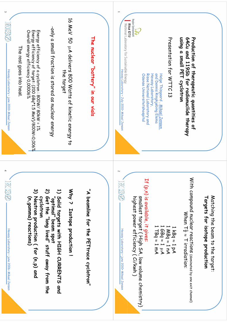
Production of therapeutic quantities of 64Cu and 119Sb for radionuclide therapy64Cu and 119Sb for radionuclide therapyusing a sm
all PET cyclotron
Presentation for WTTC 13
Helge Thisgaard , M
ikael Jensen and D
ennis Ringkjøbing Elema
Hevesy Laboratory
H
evesy Laboratory, Risoe N
ational Laboratory andO
dense Universitetshospital
Hevesy Laboratory •July 2010•M
ikael Jensen1
Matching the beam
to the target:Targets for isotope productionM
atching the beam to the target:
With com
pound nuclear reactions (dominated by one exit channel)
½W
hen T½ T irradiation:
1 kB
1 A
1 kBq 1 pA
1 MBq
1 nA1 GB
1
A1 GBq
1 A1 TBq
1 mA
If (p,n) is available, it gives:sm
allest target ( High SA
low volume chem
istry)sm
allest target ( High SA
, low volume chem
istry)highest power efficiency ( Ci/kwh )
Hevesy Laboratory •june 2010•M
ikael Jensen2
The nuclear ”battery” in our vials
16 MeV 50 A
delivers 800 Watts of kinetic energy to
the tar get g
-only a small fraction is stored as nuclear energy
ygy
Energy efficiency of a cyclotron : 800W/ 80kW
= 1%Energy efficiency of a cyclotron : 800W
/ 80kW = 1%
Energy efficiency of target: (200 GBq*1.5 MeV)/800W
=0,006%O
verall energy efficiency 0,00006%
The rest goes into heat.
Hevesy Laboratory •june 2010•M
ikael Jensen3
”A beam
line for the PETtrace cyclotron”A beam
line for the PETtrace cyclotron
Why ? Isotope production !
1)Solid targets with H
IGH CU
RRENTS and
”optimal” beam
spotp
p2)
Get the ”long lived” stuff away from the
cyclotron3)
Neutron production ( for (n,p) and
(n,gamma) reactions)
Hevesy Laboratory •june 2006•M
ikael Jensen4
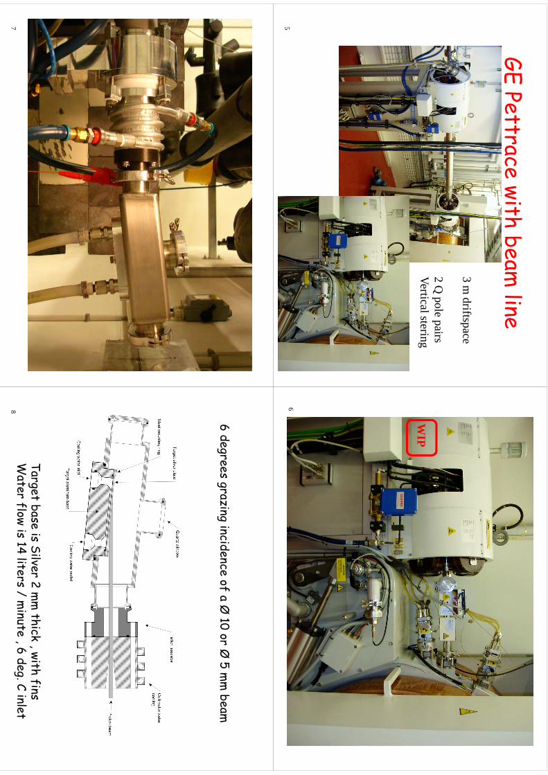
GE Pettrace with beam line
GE Pettrace with beam line
3 m driftspace
2 Q pole pairs
VerticalsteringVertical stering
5
WIP
WIP
6
7
6 degrees grazing incidence of a Ø 10 or Ø
5 mm
beam
Target base is Silver 2 mm
thick with finsTarget base is Silver 2 m
m thick , with fins
Water flow is 14 liters / m
inute , 6 deg. C inlet8
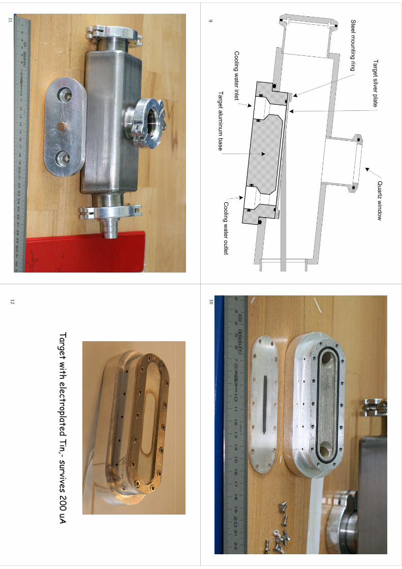
910
11
Target with electroplated Tin,-survives 200 uA
12
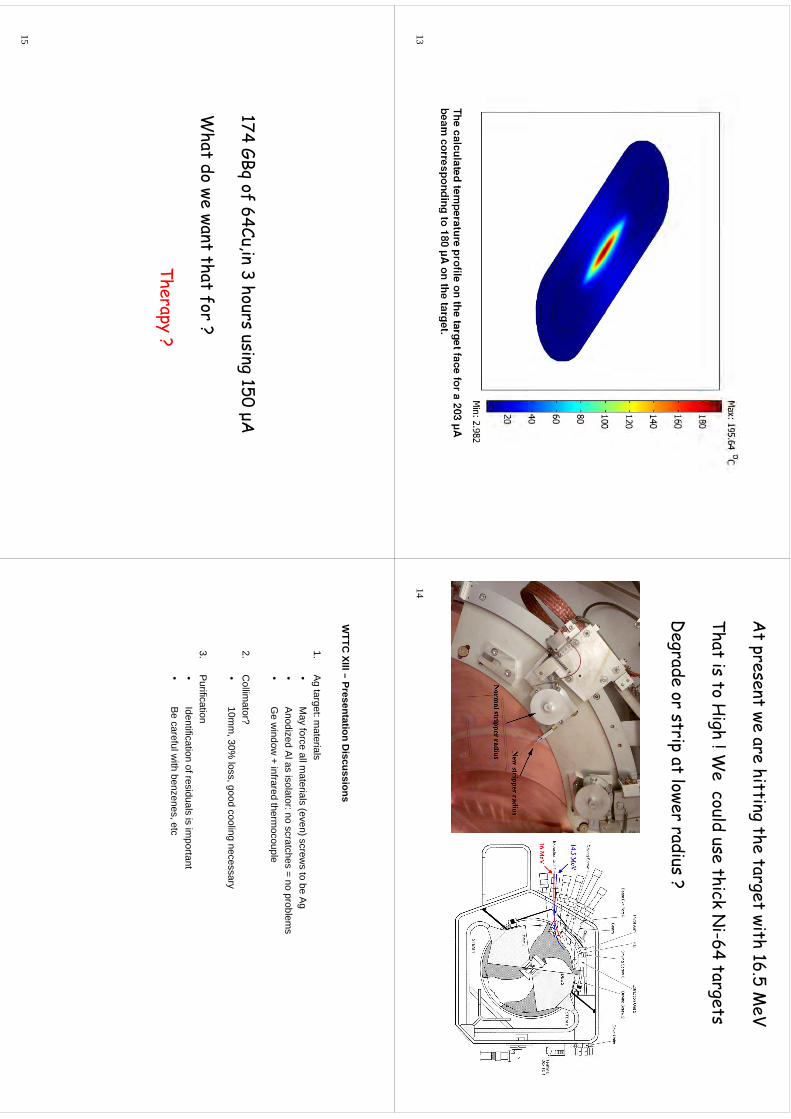
13
At present we are hitting the target with 16.5 M
eV
That is to High ! W
e could use thick Ni-64 targets
Degrade or strip at lower radius ?
14
174 GBq of 64Cu,in 3 hours using 150 μA
What do we want that for ?
Therapy ?
15
WTTC
XIII–Presentation
Discussions
WTTC
XIII –Presentation D
iscussions
1.A
g target: materials
•M
ayforce
allmaterials
(even)screws
tobe
Ag•
May force all m
aterials (even) screws to be Ag
•Anodized A
l as isolator: no scratches = no problems
•G
ew
indow + infrared therm
ocouple
2.C
ollimator?
•10m
m, 30%
loss, good cooling necessary
3.P
urification•
Identification of residuals is important
•Be
carefulwith
benzenesetc
•Be careful w
ith benzenes, etc
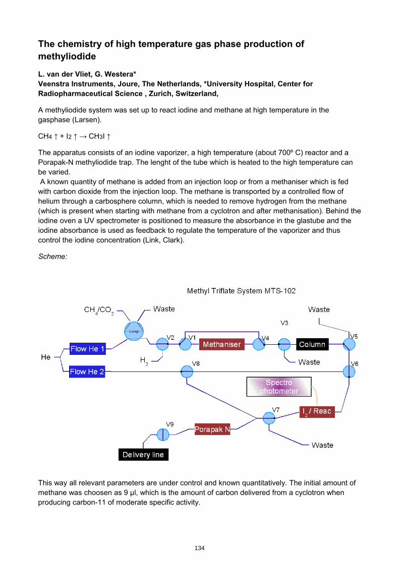
The chemistry of high temperature gas phase production of methyliodide
L. van der Vliet, G. Westera*Veenstra Instruments, Joure, The Netherlands, *University Hospital, Center for Radiopharmaceutical Science , Zurich, Switzerland,
A methyliodide system was set up to react iodine and methane at high temperature in the gasphase (Larsen).
CH4 ↑ + I2 ↑ → CH3I ↑
The apparatus consists of an iodine vaporizer, a high temperature (about 700º C) reactor and a Porapak-N methyliodide trap. The lenght of the tube which is heated to the high temperature can be varied. A known quantity of methane is added from an injection loop or from a methaniser which is fed with carbon dioxide from the injection loop. The methane is transported by a controlled flow of helium through a carbosphere column, which is needed to remove hydrogen from the methane (which is present when starting with methane from a cyclotron and after methanisation). Behind the iodine oven a UV spectrometer is positioned to measure the absorbance in the glastube and the iodine absorbance is used as feedback to regulate the temperature of the vaporizer and thus control the iodine concentration (Link, Clark).
Scheme:
This way all relevant parameters are under control and known quantitatively. The initial amount of methane was choosen as 9 µl, which is the amount of carbon delivered from a cyclotron when producing carbon-11 of moderate specific activity.
134
kmje
Typewritten Text
Abstract 024
kmje
Typewritten Text
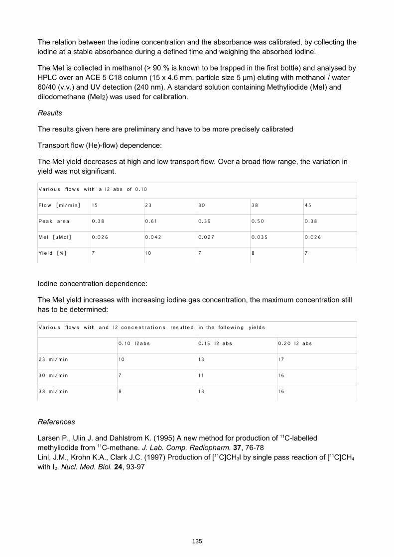
The relation between the iodine concentration and the absorbance was calibrated, by collecting the iodine at a stable absorbance during a defined time and weighing the absorbed iodine.
The MeI is collected in methanol (> 90 % is known to be trapped in the first bottle) and analysed by HPLC over an ACE 5 C18 column (15 x 4.6 mm, particle size 5 µm) eluting with methanol / water 60/40 (v.v.) and UV detection (240 nm). A standard solution containing Methyliodide (MeI) and diiodomethane (MeI2) was used for calibration.
Results
The results given here are preliminary and have to be more precisely calibrated
Transport flow (He)-flow) dependence:
The MeI yield decreases at high and low transport flow. Over a broad flow range, the variation in yield was not significant.
Va r i o u s flow s wi t h a I2 ab s of 0. 10
Fl o w [ml/mi n] 15 23 30 38 45
Pe a k ar e a 0.38 0.6 1 0.39 0.50 0.38
Me I [uMo l] 0.026 0.042 0.027 0.035 0.026
Yi e l d [%] 7 10 7 8 7
Iodine concentration dependence:
The MeI yield increases with increasing iodine gas concentration, the maximum concentration still has to be determined:
Va r i o u s flow s wi t h an d I2 co n c e n t r a t i o n s res u l t e d in the fol l o w i n g yi e l d s
0. 10 I2a b s 0. 15 I2 ab s 0.20 I2 ab s
23 ml/mi n 10 13 17
30 ml/mi n 7 1 1 16
38 ml/mi n 8 13 16
References
Larsen P., Ulin J. and Dahlstrom K. (1995) A new method for production of 11C-labelled methyliodide from 11C-methane. J. Lab. Comp. Radiopharm. 37, 76-78Linl, J.M., Krohn K.A., Clark J.C. (1997) Production of [11C]CH3I by single pass reaction of [11C]CH4
with I2. Nucl. Med. Biol. 24, 93-97
135

Thh
it
fthhi
ht
tThe chem
istry of the high temperature gas
phaseproduction
ofmethyliodide
(MeI)
phase production of methyliodide (M
eI)
dVli
GF
dik
GW
*VI
JTh
L. van der Vliet, G. Frederiks, G
. Westera *Veenstra Instrum
ents, Joure, The
Netherlands, *U
niversity Hospital, C
enter for Radiopharm
aceutical Science , Zurich,
Switzerland,
Switzerland,
Aim
Aim
•B
etterunderstandingofthe
chemistry
•B
etter understanding of the chemistry
•B
etterDevice
Better D
evice
2
BetterD
eviceB
etter Device
•Longerusage
oftheIodine
•Longer usage of the Iodine
•Low
heatdissipationLow
heat dissipation•
Dim
ensions of the reaction oven•
Sm
all footprintR
bti
•R
obust in usage
3
BetterU
nderstandingC
hemistry
Better U
nderstanding Chem
istry•
Criticalpoints
Critical points
–H
2
–P
arameters: I2 ,T
r ,Flow, ...
–C
oncentration methane
–S
pecificactivity
–S
pecific activity•
Single pass
Mlti
•M
ulti pass
4
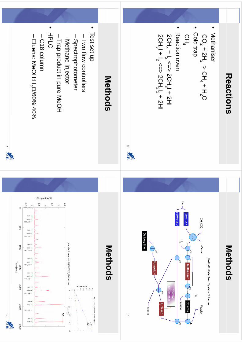
Reactions
Reactions
•M
ethaniser•
Methaniser
CO
2 + 2H2 -> C
H4 + H
2 O2
24
2
•C
old trapC
HC
H4
•R
eaction oven2C
H4 + I2 <=> 2C
H3 I + 2H
I2C
HI+
I<
>2C
HI
+2H
I2C
H3 I + I2 <=> 2C
H2 I2 + 2H
I
5
Methods
Methods
6
Methods
Methods
•Testsetup
•Test set up–
Two flow
controllers–
Spectrophotom
eter–
Methane
InjectorM
ethane Injector–
Trap product in pure MeO
H•
HP
LC–
C18
column
C18 colum
n–
Eluens: M
eOH
:H2 O
/60%:40%
7
Methods
8
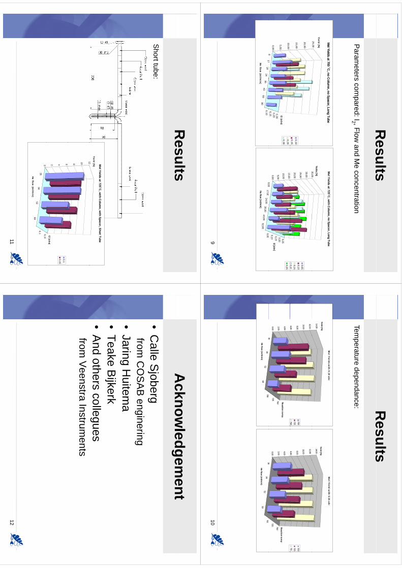
Results
Results
Param
eterscom
pared:I2 ,Flowand
Me
concentrationP
arameters com
pared: I2 , Flow and M
e concentration
25,00
Yield (%)
MeI Yields at 700
˚C, no C
olumn, no Spacer, Long Tube
35,00
Yields [%]
MeI Yields at 725˚C
, with C
olumn, no Spacer, Long Tube
15,00
20,00
0,10
0,1520,00
25,00
30,00
35,00
0,050,10
0,150,20
817
0,150,200,30
0,00
5,00
10,00
I2 (abs)
0,20
0,30
800
1700
005
0,10
0,150,200,25
0,00
5,00
10,00
15,00
I2 [abs]
0,200,25
817
1824
3543
5990
0,10
He flow (m
l/min)
8,0017,00
24,0035,00
43,0052,00
0,05
He flow [m
l/min]
9
Results
Results
Temperature
dependance:Tem
perature dependance:
14,00
Yield (%)
MeI Yields w
ith 0.10 abs
14,00
Yield (%)
MeI Yield w
ith 0.15 abs
6,00
8,00
10,00
12,00
700
725
7506,00
8,00
10,00
12,00
700
725750
35
725 750
0,00
2,00
4,00
,
Reaction temp.
35
725 750
0,00
2,00
4,00
,
Reaction temp
3534
5259
700
He flow (m
l/min)
3534
5259
700
He flow (m
l/min)
10
Results
Results
Shorttube:
Short tube:
12
Yield (%) MeI Yields at 725˚C
, with C
olumn, w
ith Spacer, Short Tube
8
10
12
2 4 6
I2 (abs)
0,10,15
3534
5259
0,1 0,150
He flow (m
l/min)
11
Acknow
ledgement
Acknow
ledgement
•C
alleS
joberg•
Calle S
joberg from
CO
SA
B enginering
•Jaring H
uitema
•Teake
Bijkerk
•Teake B
ijkerk•
And others collegues
from V
eenstra Instruments
12

WTTC
XIII–Presentation
Discussions
WTTC
XIII –Presentation D
iscussions
1.C
hallenge: Why not m
ake a nano-reactor?
139
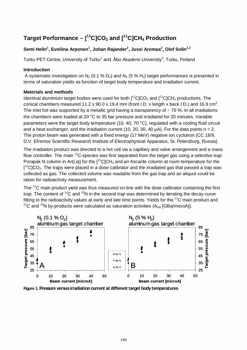
Target Performance – [11C]CO2 and [11C]CH4 Production
Semi Helin1, Eveliina Arponen1, Johan Rajander2, Jussi Aromaa2, Olof Solin1,2
Turku PET Centre, University of Turku1 and Åbo Akademi University2, Turku, Finland
Introduction
A systematic investigation on N2 (0.1 % O2) and N2 (5 % H2) target performances is presented interms of saturation yields as function of target body temperature and irradiation current.
Materials and methods
Identical aluminium target bodies were used for both [11C]CO2 and [11C]CH4 productions. Theconical chambers measured 11.2 x 90.0 x 19.4 mm (front I.D. x length x back I.D.) and 16.9 cm3.The inlet foil was supported by a metallic grid having a transparency of ~ 70 %. In all irradiationsthe chambers were loaded at 20 °C to 35 bar pressure and irradiated for 20 minutes. Variableparameters were the target body temperature (10, 40, 70 °C), regulated with a cooling fluid circuitand a heat exchanger, and the irradiation current (10, 20, 30, 40 µA). For the data points n = 2.The proton beam was generated with a fixed energy (17 MeV) negative ion cyclotron (CC 18/9,D.V. Efremov Scientific Research Institute of Electrophysical Apparatus, St. Petersburg, Russia).
The irradiation product was directed to a hot cell via a capillary and valve arrangement and a massflow controller. The main 11C-species was first separated from the target gas using a selective trap:Porapak N column in Ar(Liq) for the [11C]CH4 and an Ascarite column at room temperature for the[11C]CO2. The traps were placed in a dose calibrator and the irradiated gas that passed a trap wascollected as gas. The collected volume was readable from the gas trap and an aliquot could betaken for radioactivity measurement.
The 11C main product yield was thus measured on-line with the dose calibrator containing the firsttrap. The content of 11C and 13N in the second trap was determined by iterating the decay curvefitting to the radioactivity values at early and late time points. Yields for the 11C main product and11C and 13N by-products were calculated as saturation activities (Asat [GBq/microA]).
Figure 1. Pressure versus irradiation current at different target body temperatures
25
35
45
55
65
75
85
0 10 20 30 40 50Beam current [microA]
Ta
rge
t p
res
su
re [
ba
r]
25
35
45
55
65
75
85
0 10 20 30 40 50Beam current [microA]
Ta
rge
t p
res
su
re [
ba
r]
10 ºC
40 ºC
70 ºC
N2 (0.1 % O2)aluminum gas target chamber
N2 (5 % H2)aluminum gas target chamber
A B25
35
45
55
65
75
85
0 10 20 30 40 50Beam current [microA]
Ta
rge
t p
res
su
re [
ba
r]
25
35
45
55
65
75
85
0 10 20 30 40 50Beam current [microA]
Ta
rge
t p
res
su
re [
ba
r]
10 ºC
40 ºC
70 ºC
N2 (0.1 % O2)aluminum gas target chamber
N2 (5 % H2)aluminum gas target chamber
A B
140
kmje
Typewritten Text
Abstract 025
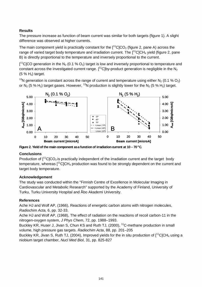
Results
The pressure increase as function of beam current was similar for both targets (figure 1). A slightdifference was observed at higher currents.
The main component yield is practically constant for the [11C]CO2 (figure 2, pane A) across therange of varied target body temperature and irradiation current. The [11C]CH4 yield (figure 2, paneB) is directly proportional to the temperature and inversely proportional to the current.
[11C]CO generation in the N2 (0.1 % O2) target is low and inversely proportional to temperature andconstant across the investigated current range. [11C]by-product generation is negligible in the N2
(5 % H2) target.13N generation is constant across the range of current and temperature using either N2 (0.1 % O2)or N2 (5 % H2) target gases. However, 13N production is slightly lower for the N2 (5 % H2) target.
Figure 2. Yield of the main component as a function of irradiation current at 10 – 70 °C.
Conclusions
Production of [11C]CO2 is practically independent of the irradiation current and the target bodytemperature, whereas [11C]CH4 production was found to be strongly dependent on the current andtarget body temperature.
Acknowledgement
The study was conducted within the "Finnish Centre of Excellence in Molecular Imaging inCardiovascular and Metabolic Research" supported by the Academy of Finland, University ofTurku, Turku University Hospital and Åbo Akademi University.
References
Ache HJ and Wolf AP, (1966), Reactions of energetic carbon atoms with nitrogen molecules,Radiochim Acta, 6, pp. 32-33.Ache HJ and Wolf AP, (1968), The effect of radiation on the reactions of recoil carbon-11 in thenitrogen-oxygen system, J Phys Chem, 72, pp. 1988–1993.Buckley KR, Huser J, Jivan S, Chun KS and Ruth TJ, (2000), 11C-methane production in smallvolume, high pressure gas targets. Radiochim Acta, 88, pp. 201–205Buckley KR, Jivan S, Ruth TJ, (2004), Improved yields for the in situ production of [11C]CH4 using aniobium target chamber, Nucl Med Biol, 31, pp. 825-827
0.00
1.00
2.00
3.00
4.00
5.00
0 10 20 30 40 50Beam current [microA]
Asat [G
Bq
/mic
roA
]
10º40º70ºLinear (70º)Linear (40º)Linear (10º) 0.00
1.00
2.00
3.00
4.00
5.00
0 10 20 30 40 50Beam current [microA]
Asat [G
Bq
/mic
roA
]
N2 (0.1 % O2) N2 (5 % H2)
A B0.00
1.00
2.00
3.00
4.00
5.00
0 10 20 30 40 50Beam current [microA]
Asat [G
Bq
/mic
roA
]
10º40º70ºLinear (70º)Linear (40º)Linear (10º) 0.00
1.00
2.00
3.00
4.00
5.00
0 10 20 30 40 50Beam current [microA]
Asat [G
Bq
/mic
roA
]
N2 (0.1 % O2) N2 (5 % H2)
A B
141
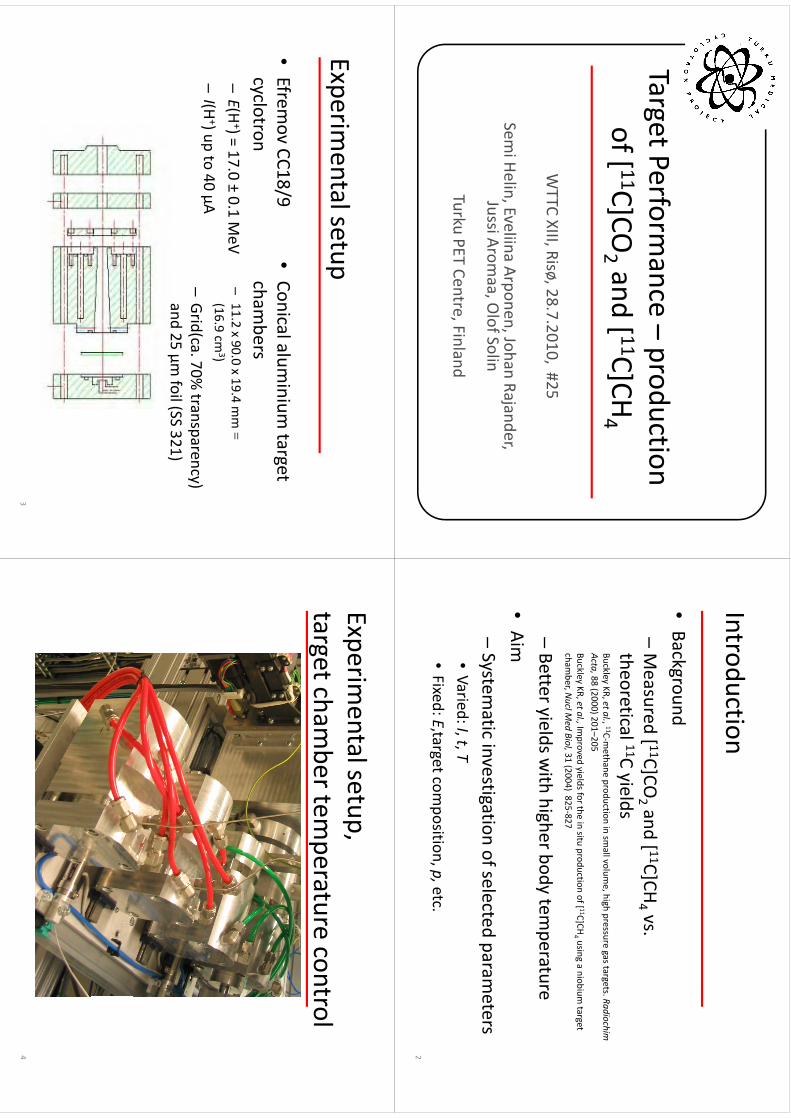
TargetPerformance
–production
Target Performance
production of[ 11C]CO
2 and[ 11C]CH
4of [
C]CO2 and [
C]CH4
WTTC XIII, Risø, 28.7.2010, #25
Semi Helin, Eveliina Arponen, Johan Rajander,
Jussi Aromaa , O
lof Solin,
Turku PET Centre, Finland
It
dti
Introduction
•Background
Md[ 11C]CO
d[ 11C]CH
–Measured [ 11C]CO
2 and [ 11C]CH4 vs.
theoretical 11C yieldsBuckley KR, et a
l., 11C‐methane
production in small volum
e, high pressure gas targets. Radiochim
Acta
,88(2000)201–205
Buckley KR, et al.,Im
proved yields for the in situ production of[ 11C]CH4 using a niobium
target h
bN
lMdBil31
(2004)825
827cham
ber,Nucl M
ed Biol, 31
(2004) 825‐827
–Better yields w
ith higher body temperature
•Aim
–System
aticinvestigation
ofselectedparam
etersSystem
atic investigation of selected parameters
•Varied: I, t, TFi
dE
ii•Fixed: E,target com
position, p,etc.
2
Ei
tl
tExperim
ental setup
•Efrem
ov CC18/9 cyclotron
•Conical alum
inium target
chambers
cyclotron –E(H
+) = 17.0 ±0.1 M
eVcham
bers–
11.2 x 90.0 x 19.4 mm =
(169cm
3)–I(H
+) up to 40 µA (16.9 cm
)
–Grid(ca. 70%
transparency) and
25µm
foil(SS321)
and 25 µm foil (SS 321)
3
Experimental setup,
pp,
target chamber tem
perature control
4
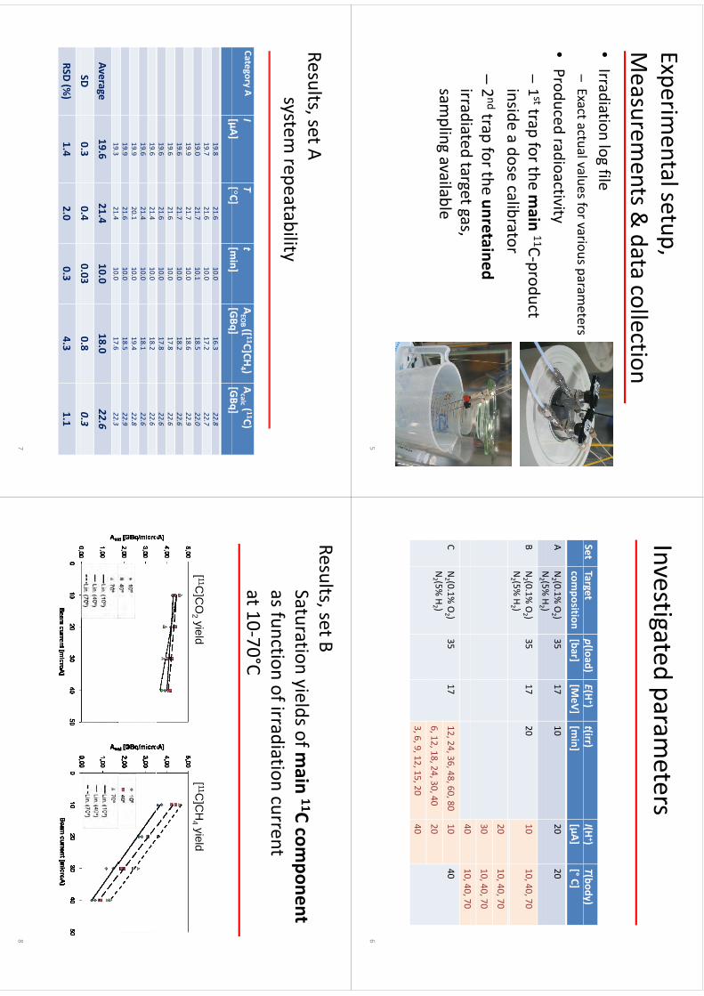
Experimental setup,
pp,
Measurem
ents & data collection
•Irradiation log file
Exactactualvaluesforvariousparameters
–Exact actual values for various param
eters
•Produced radioactivity–1sttrap for the m
ain11C‐product
insideadose
calibratorinside a dose calibrator
–2ndtrap for the unretained
idi
tdt
tirradiated target gas, sam
pling available
5
Investigatedparam
etersInvestigated param
eters
SetTarget
p(load) E(H
+) t(irr)
I(H+)
T(body) g
composition
p()
[bar](
)[M
eV](
)[m
in](
)[µA]
(y)
[°C]A
N2 (0.1%
O2 )
N(5%
H)
3517
1020
20N2 (5%
H2 )
BN2 (0.1%
O2 )
N2 (5%
H2 )
3517
2010
10, 40, 70
2010, 40, 70
3010, 40, 70
4010
4070
4010, 40, 70
CN2 (0.1%
O2 )
N2 (5%
H2 )
3517
12,24, 36, 48, 60, 8010
40
612
1824
3040
206, 12, 18, 24, 30,40
20
3, 6, 9, 12, 15, 2040
6
Results, set A,
system repeatability
Category AI [μA]
T[°C]t[m
in]AEO
B ([ 11C]CH4 )
[GBq]Acalc ( 11C)
[GBq][μA]
[C]
[min]
[GBq][GBq]
19.821.6
10.016.3
22.8
19.721.6
10.017.2
22.7
19.021.7
10.118.5
22.0
19.921.7
10.018.6
22.9
19.621.7
10.018.2
22.6
19.621.6
10.017.8
22.6
19.621.6
10.017.8
22.6
19.621.4
10.018.2
22.6
19.621.4
10.018.1
22.6
19.920.1
10.019.4
22.8
19.921.6
10.018.5
22.9
19.321.4
10.017.6
22.3
Average19.6
21.410.0
18.022.6
SD0.3
0.40.03
0.80.3
RSD (%)
1.42.0
0.34.3
1.1
7
Results, set BSt
tiild
fi
11Ct
Saturation yields of main 11C com
ponentas function of irradiation current at 10‐70°C
[ 11C]C
O2 yield
[ 11C]C
H4 yield
[]
2 y[
]4 y
8
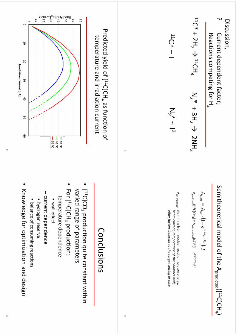
Discussion,?
Ctd
dtf
t?
Current dependent factor; Reactions com
peting for H2
pg
2
11C*+2H
→11CH
N*+3H
→2N
H11C* + 2H
2 → 11CH
4N2 * + 3H
2 → 2N
H3
11C*
~I
N2 *
~I 2
C
IN
2
I
9
Sith
til
dlfth
A([ 11C]CH
)Sem
itheoretical model of the A
predicted ([ 11C]CH4 )
Ie
AA
Tt
satE
OB
irr
½/
2ln
1
([ 11]
)(
)*(l2*t/T½)*
Apredicted ([ 11C]CH
4 ) = Asat‐m
odified (I,T)*(1 –eln2*t/T½)*I
Asat‐m
odified : stemming from
nuclear reaction, proton energy, beam cu
rrent, tem
pera
ture o
f the ch
amber w
all,
thf
tih
tt
tht
ttti
iother fa
ctors in
heren
t to th
e target settin
g in ca
se.
10
Predicted yield of [ 11C]CH4 as function of
y[
]4
temperature and irradiation current
7050 60
GBq]40 50
1C]CH4 [G
10 ºC40 ºC70
ºC
20 30
Yield of [1
70 C
0 10
Y
010
2030
4050
60Irradiation current [uA]
11
Cl
iConclusions
•[ 11C]CO
2 production quite constant within
variedrange
ofparameters
varied range of parameters
•For [ 11C]CH
4 production: 4
–tem
perature dependence•walleffect
wall effect
–current dependence
hd
•hydrogen reserve
•balance of consum
ing reactions
•Know
ledge for optimization and design
12

Ak
ld
tAcknow
ledgements
Thisstudywasconducted
within
theThis study w
as conducted within the
“Centre o
f Excellence in
Molecu
lar
Imaging in Cardiovascu
lar a
nd
Meta
bolic R
esearch
”
supported by the Academ
y of Finland, University of Turku,
Turku University Hospital and
ÅboAkadem
iUniversity
Åbo Akademi U
niversity.
13
WTTC
XIII–Presentation
Discussions
WTTC
XIII –Presentation D
iscussions
1.Low
yield•
Can
11CH
beproduced
butstayin
targetwalls?
•C
an 11CH
4 be produced but stay in target walls?
•C
an gas quality/quantity or temperature help?
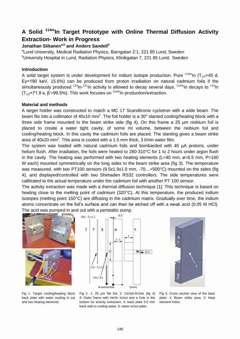
A Solid 114mIn Target Prototype with Online Thermal Diffusion Activity
Extraction- Work in Progress Jonathan Siikanena,b and Anders Sandellb aLund University, Medical Radiation Physics, Barngatan 2:1, 221 85 Lund, Sweden bUniversity Hospital in Lund, Radiation Physics, Klinikgatan 7, 221 85 Lund, Sweden Introduction
A solid target system is under development for indium isotope production. Pure 114mIn (T1/2=45 d, Eγ=190 keV, 15.6%) can be produced from proton irradiation on natural cadmium foils if the simultaneously produced 110In-111In activity is allowed to decay several days. 114mIn decays to 114In (T1/2=71.9 s, β-=99.5%). This work focuses on 114mIn production/extraction. Material and methods
A target holder was constructed to match a MC 17 Scanditronix cyclotron with a wide beam. The beam fits into a collimator of 40x10 mm2. The foil holder is a 30° slanted cooling/heating block with a three side frame mounted to the beam strike side (fig 4). On this frame a 25 µm niobium foil is placed to create a water tight cavity, of some ml volume, between the niobium foil and cooling/heating block. In this cavity the cadmium foils are placed. The slanting gives a beam strike area of 40x20 mm2. This area is cooled with a 1.5 mm thick, 3 l/min water film. The system was loaded with natural cadmium foils and bombarded with 45 µA protons, under helium flush. After irradiation, the foils were heated to 280-310°C for 1 to 2 hours under argon flush in the cavity. The heating was performed with two heating elements (L=40 mm, ø=6.5 mm, P=160 W each) mounted symmetrically on the long sides to the beam strike area (fig 3). The temperature was measured, with two PT100 sensors (9.5x1.9x1.0 mm, -70…+500°C) mounted on the sides (fig 4), and displayed/controlled with two Shimaden RS32 controllers. The side temperatures were calibrated to the actual temperature under the cadmium foil with another PT 100 sensor. The activity extraction was made with a thermal diffusion technique [1]. This technique is based on heating close to the melting point of cadmium (320°C). At this temperature, the produced indium isotopes (melting point 150°C) are diffusing in the cadmium matrix. Gradually over time, the indium atoms concentrate on the foil’s surface and can then be etched off with a weak acid (0.05 M HCl). The acid was pumped in and out with a peristaltic pump.
Fig 1. Target cooling/heating block back plate with water cooling in out and two heating elements.
Fig 2. 1: 25 µm Nb foil, 2: Cd-foil-Al-fork (fig 4) 3: Outer frame with He/Ar in/out and a hole in the bottom for activity extraction, 4: back plate 0.5 mm back wall to cooling water, 5: water in/out plate.
Fig 3. Cross section view of the back plate: 1: Beam strike area. 2: Heat element holes.
2 1 3 4 5
1
A-extraction (mm)
2
2
0.5
146
kmje
Typewritten Text
Abstract 026
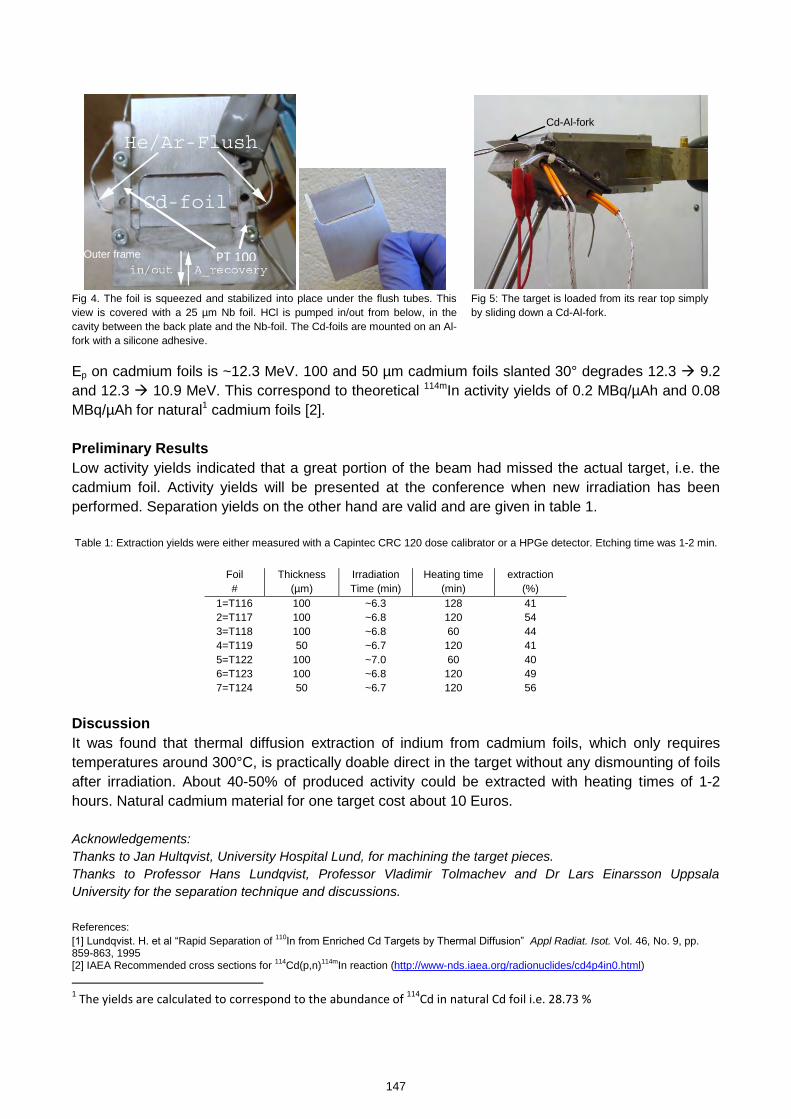
Fig 4. The foil is squeezed and stabilized into place under the flush tubes. This view is covered with a 25 µm Nb foil. HCl is pumped in/out from below, in the cavity between the back plate and the Nb-foil. The Cd-foils are mounted on an Al-fork with a silicone adhesive.
Fig 5: The target is loaded from its rear top simply by sliding down a Cd-Al-fork.
Ep on cadmium foils is ~12.3 MeV. 100 and 50 µm cadmium foils slanted 30° degrades 12.3 9.2 and 12.3 10.9 MeV. This correspond to theoretical 114mIn activity yields of 0.2 MBq/µAh and 0.08 MBq/µAh for natural1 cadmium foils [2]. Preliminary Results
Low activity yields indicated that a great portion of the beam had missed the actual target, i.e. the cadmium foil. Activity yields will be presented at the conference when new irradiation has been performed. Separation yields on the other hand are valid and are given in table 1. Table 1: Extraction yields were either measured with a Capintec CRC 120 dose calibrator or a HPGe detector. Etching time was 1-2 min.
Foil #
Thickness (µm)
Irradiation Time (min)
Heating time (min)
extraction (%)
1=T116 100 ~6.3 128 41 2=T117 100 ~6.8 120 54 3=T118 100 ~6.8 60 44 4=T119 50 ~6.7 120 41 5=T122 100 ~7.0 60 40 6=T123 100 ~6.8 120 49 7=T124 50 ~6.7 120 56
Discussion
It was found that thermal diffusion extraction of indium from cadmium foils, which only requires temperatures around 300°C, is practically doable direct in the target without any dismounting of foils after irradiation. About 40-50% of produced activity could be extracted with heating times of 1-2 hours. Natural cadmium material for one target cost about 10 Euros. Acknowledgements: Thanks to Jan Hultqvist, University Hospital Lund, for machining the target pieces. Thanks to Professor Hans Lundqvist, Professor Vladimir Tolmachev and Dr Lars Einarsson Uppsala University for the separation technique and discussions. References: [1] Lundqvist. H. et al “Rapid Separation of 110
In from Enriched Cd Targets by Thermal Diffusion” Appl Radiat. Isot. Vol. 46, No. 9, pp. 859-863, 1995 [2] IAEA Recommended cross sections for 114Cd(p,n)114mIn reaction (http://www-nds.iaea.org/radionuclides/cd4p4in0.html) 1 The yields are calculated to correspond to the abundance of
114Cd in natural Cd foil i.e. 28.73 %
PT 100
Cd-Al-fork
Outer frame
147

A Solid 114mIn Target Prototype with O
nline Therm
al Diffusion Activity Extraction W
kiP
‐Work in Progress
hk
bd
dd
ll bJonathan Siikanen
a,band Anders Sandell baLund U
niversity, Medical Radiation Physics, Barngatan
2:1,22185
Lund, Sweden
bUniversity
Hospital in Lund, Radiation Physics, Klinikgatan7,221 85 Lund, Sw
eden
The13th
InternationalWorkshop
onTargetry
andTargetChem
istryWTTC
13Risoe
Denmark
The 13th International Workshop on Targetry
and Target Chemistry ‐W
TTC 13, Risoe, Denmark,
2010, 25‐28 July
Background
•Long lived isotope for therapy. 114mIn is listed by IAEA
ith
tii
tas an em
erging therapeutic isotope•A solid tar get system
for 114mIng
y•Rem
ote activity handling to decrease dose burden to personnelpersonnel
2
Background114mIn (T
1/2 = 49. 5 d)
•114mIn/
114In(
1/295d)
EC = 3.3 %IT = 96.7 %
114In (T1/2 = 72 s)
114(
bl)
114d(
bl)
Β‐= 99.5 %
EC = 0.5 %114Sn (Stable)
114Cd (Stable)
Z48
4950
114I(T
495d)
114I(T
72)
114mIn (T1/2 = 49.5 d)
114In (T1/2 = 72 s)
RadiationsEnergy (keV)
Intensity (%)
Energy (keV)Intensity (%
)Auger e K
19‐206.4
Auger e L2.7‐2.8
68Conversion e
162‐19080
Beta779
199
5Beta
77999.5
X‐ray L23‐27
37X‐ray K
3.1‐3.35
19015
6γ
19015.6
γ558
3.2γ
7253.2
Data only given when
intensity > 1 %, 1Average energy,
Data is from: N
uclear Decay Data in the MIRD Form
at (http://w
ww.nndc.bnl.gov/m
ird/)3
Target
•natCd
(p,n)114mIn
(29 % 114Cd)
•100 µm
cadmium
foils•mounted
toan
aluminum
forkwith
ahigh
mounted to an alum
inum fork w
ith a high tem
perature resistant silicon adhesive (316 °C) T
1•Target m
ass ~1 gRecommended cross sections for 114Cd(p,n) 114mIn reaction
(http://www‐nds.iaea.org/radionuclides/cd4p4in0.htm
l)4
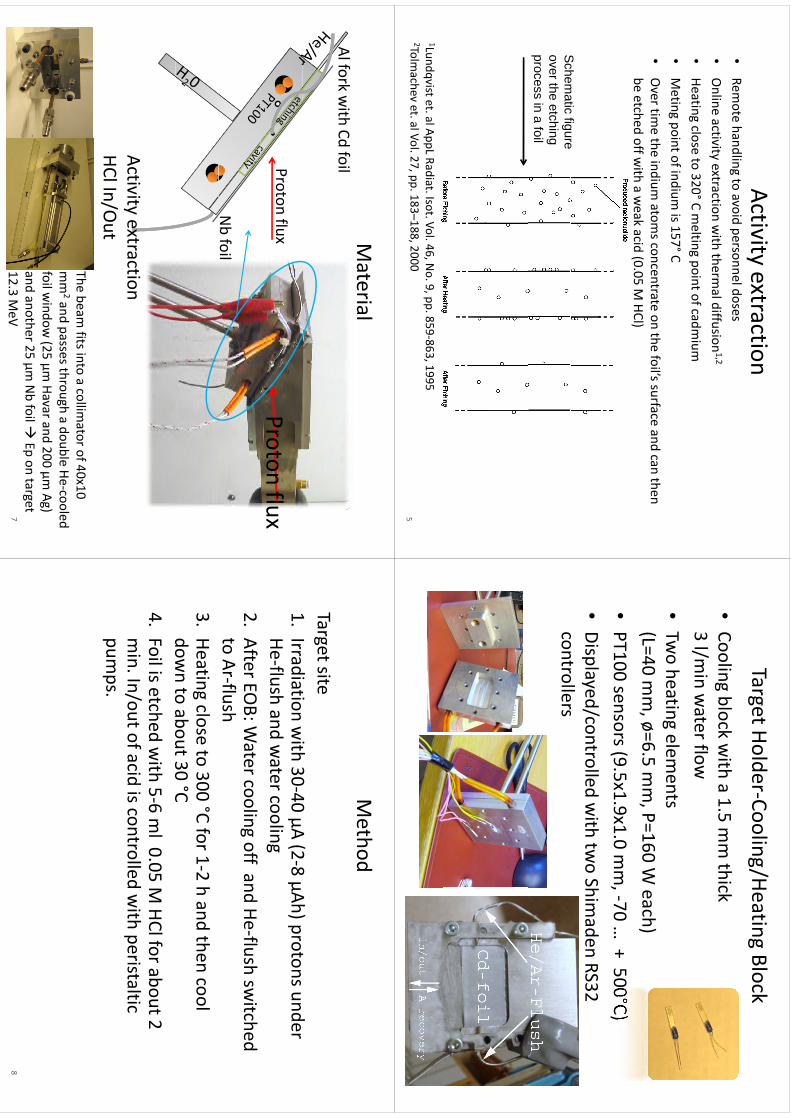
Activity extractionR
th
dlit
idld
•Rem
ote handling to avoid personnel doses•
Online activity extraction w
ith thermal diffusion
1,2
•Heating
closeto
320°Cmelting
pointofcadmium
•Heating close to 320°C m
elting point of cadmium
•Meting point of indium
is 157°C•
Overtim
ethe
indiumatom
sconcentrateon
thefoil’ssurface
andcan
then•
Over tim
e the indium atom
s concentrate on the foils surface and can then be etched off w
ith a weak acid (0.05 M
HCl)
Schem
aticfigure
Schem
atic figure over the etching process in a foil
1Lundqvistet. al AppL Radiat. Isot. Vol. 46, No. 9, pp. 859‐863, 1995
2Tolmachev et. al Vol. 27, pp. 183–188, 2000
5
Target Holder‐Cooling/Heating Block•Cooling block w
ith a 1.5 mm thick
3l/m
inwaterflow
3 l/min w
ater flow•Tw
o heating elements
(h)
(L=40 mm, ø=6.5 m
m,P=160 W
each)•PT100 sensors (9.5x1.9x1.0 m
m, ‐70 …
+ 500°C) (
,)
•Displayed/controlled w
ith two Shim
adenRS32
controllerscontrollers
6
Material
Alforkwith
Cdfoil
Al fork with Cd
foilProton fluxProton flux
Nbfoil
Activityextraction
Activity extractionHClIn/O
utThe beam
fits into a collimator of 40x10
mm
2and passes through a double He‐cooled foilw
indow(25
µmHavarand
200µm
Ag)foil w
indow (25 µm
Havarand 200 µm Ag)
and another 25 µm Nbfoil
Epon target
12.3 MeV
7
Method
Target site1
Idi
tiith
3040
A(2
8Ah)
td
1.Irradiation w
ith 30‐40 µA (2‐8 µAh) protons under He‐flush and w
ater cooling2.
After EOB: W
ater cooling off and He‐flush switched
to Ar‐flush 3.
Heating close to 300 °C for 1‐2 h and then cool dow
nto
about30°C
down to about 30 C
4.Foil is etched w
ith 5‐6 ml 0.05 M
HClfor about 2 min
In/outofacidiscontrolled
with
peristalticmin. In/out of acid is controlled w
ith peristaltic pum
ps.
8
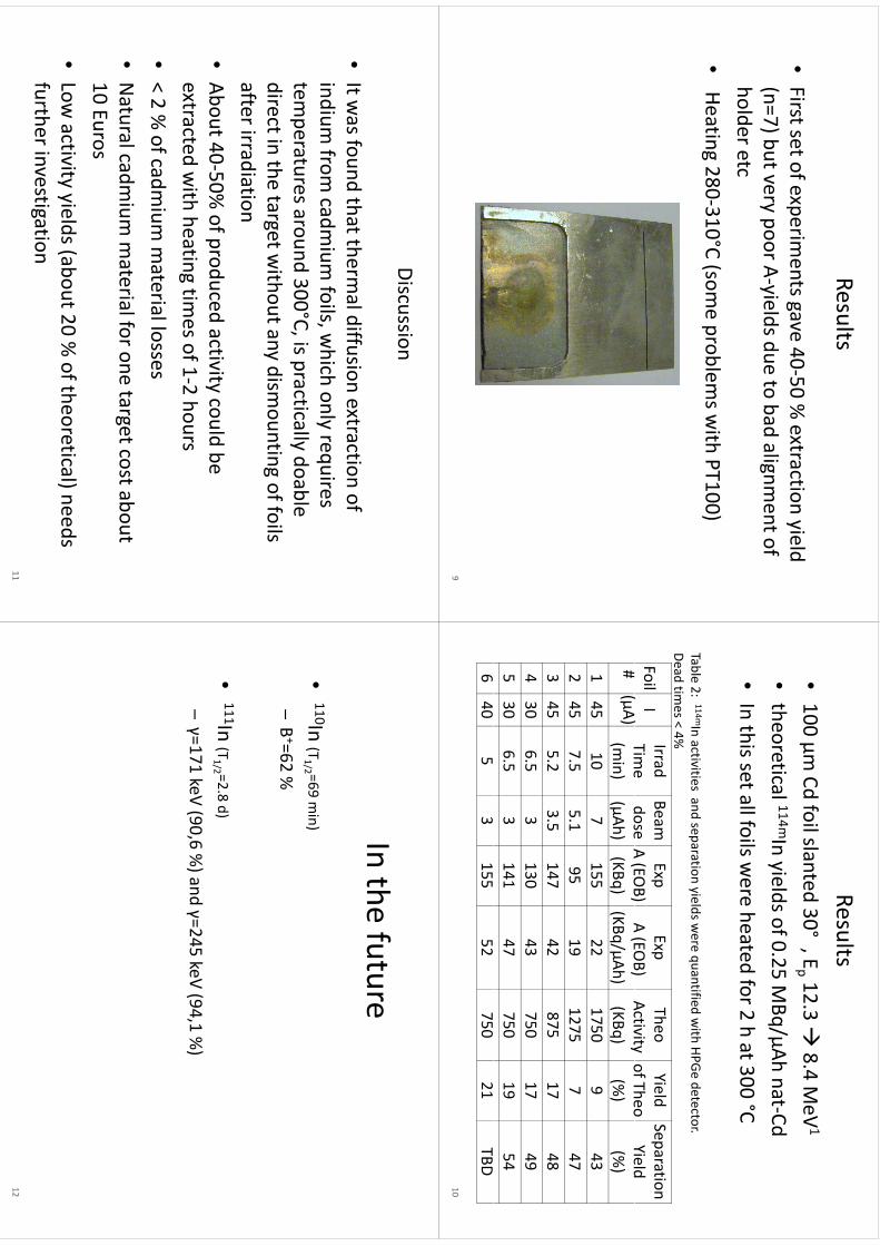
Results
•First set of experim
ents gave 40‐50 % extraction yield
(7)b
tA
ild
dt
bd
lit
f(n=7) but very poor A‐yields due to bad alignm
ent of holder etc
•Heating 280‐310°C (som
e problems w
ith PT100)
9
Results•100 µm
Cdfoil slanted 30°
, Ep 12.3
8.4 MeV
1
•theoretical
114mInyieldsof0
25MBq/µAh
nat‐Cdtheoretical
In yields of 0.25 MBq/µAh nat
Cd•In this set all foils w
ere heated for 2 h at 300 °C
Table 2: 114mIn activities and separation yields were quantified w
ith HPGedetector.
Ddti
4%Dead tim
es < 4%
FoilI
()
IrradTim
eBeamdose
ExpA(EO
B)Exp
A(EO
B)TheoActivity
YieldofTheo
Separation Yield
# (µA)
Time
(min)
dose(µAh) A (EO
B)(KBq)
A (EOB)
(KBq/µAh) Activity(KBq)
of Theo(%
)Yield(%
)1
4510
7155
221750
943
245
7.55.1
9519
12757
473
455.2
3.5147
42875
1748
430
6.53
13043
75017
495
306.5
3141
47750
1954
640
53
15552
75021
TBD
10
Discussion
•It w
as found that thermal diffusion extraction of
indium from
cadmium
foils, which only requires
temperatures around 300°C, is practically doable
direct in the target without any dism
ounting of foils afterirradiationafter irradiation
•About 40‐50%
of produced activity could be t
td
ithh
titi
f12h
extracted with heating tim
es of 1‐2 hours•< 2 %
of cadmium
material losses
•Natural cadm
ium m
aterial for one target cost about 10
Euros10 Euros
•Low
activity yields (about 20 % of theoretical) needs
further investigation11
Ith
ft
In the future
•110In (T
1/2 =69 min)
B+62
%–B+=62 %
•111In (T
1/2 =2.8 d)
–γ=171
keV(90
6%)and
γ=245keV
(941%)
–γ=171 keV
(90,6 %)and γ=245 keV
(94,1 %)
12

WTTC
XIII–Presentation
Discussions
WTTC
XIII –Presentation D
iscussions
1.W
hy not a Niobium
target?•
Nottried
•N
ot tried
2.D
iffusion/extraction•
Process
known
inR
ussianliterature
•P
rocess known in R
ussian literature•
Stack could be used, but difficult to get the acid in there
151
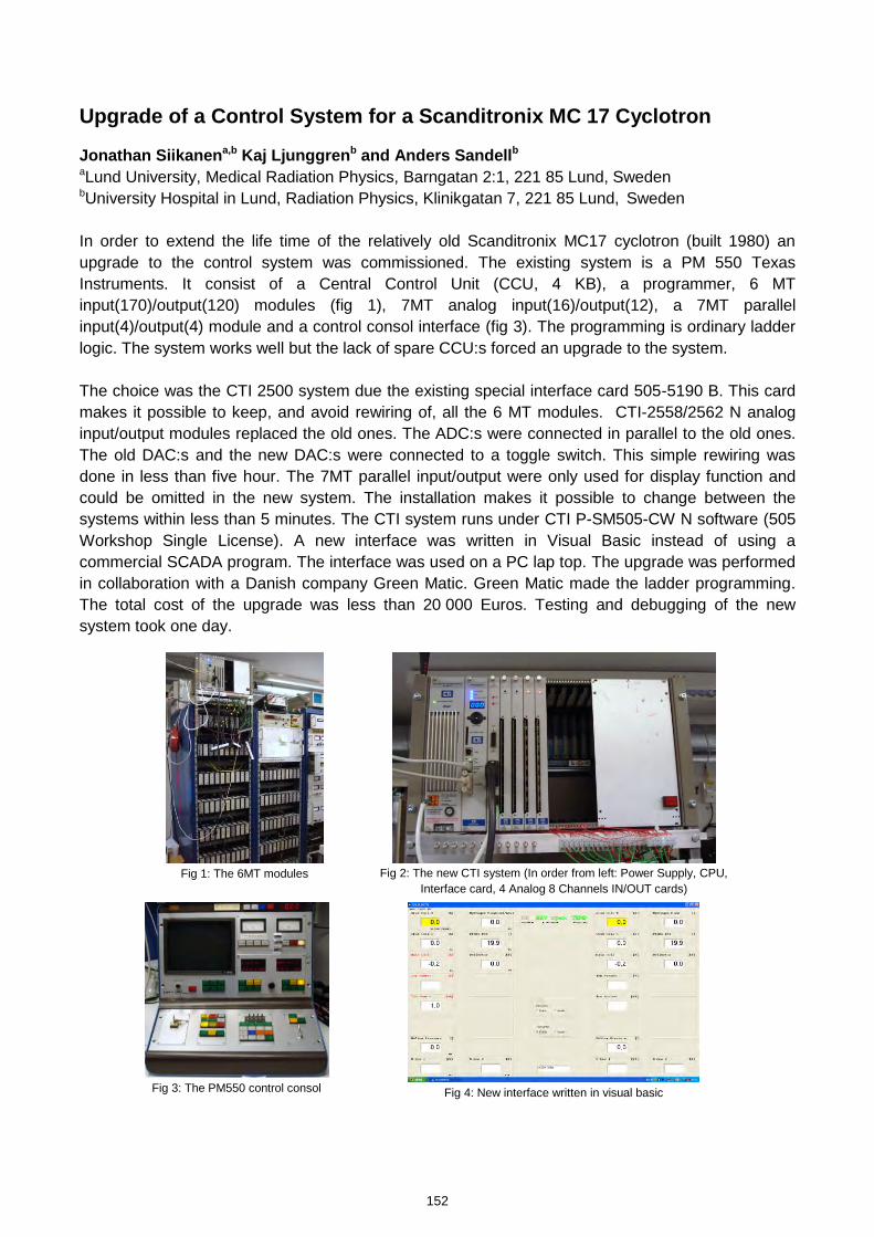
Upgrade of a Control System for a Scanditronix MC 17 Cyclotron
Jonathan Siikanena,b Kaj Ljunggrenb and Anders Sandellb aLund University, Medical Radiation Physics, Barngatan 2:1, 221 85 Lund, Sweden bUniversity Hospital in Lund, Radiation Physics, Klinikgatan 7, 221 85 Lund, Sweden In order to extend the life time of the relatively old Scanditronix MC17 cyclotron (built 1980) an upgrade to the control system was commissioned. The existing system is a PM 550 Texas Instruments. It consist of a Central Control Unit (CCU, 4 KB), a programmer, 6 MT input(170)/output(120) modules (fig 1), 7MT analog input(16)/output(12), a 7MT parallel input(4)/output(4) module and a control consol interface (fig 3). The programming is ordinary ladder logic. The system works well but the lack of spare CCU:s forced an upgrade to the system. The choice was the CTI 2500 system due the existing special interface card 505-5190 B. This card makes it possible to keep, and avoid rewiring of, all the 6 MT modules. CTI-2558/2562 N analog input/output modules replaced the old ones. The ADC:s were connected in parallel to the old ones. The old DAC:s and the new DAC:s were connected to a toggle switch. This simple rewiring was done in less than five hour. The 7MT parallel input/output were only used for display function and could be omitted in the new system. The installation makes it possible to change between the systems within less than 5 minutes. The CTI system runs under CTI P-SM505-CW N software (505 Workshop Single License). A new interface was written in Visual Basic instead of using a commercial SCADA program. The interface was used on a PC lap top. The upgrade was performed in collaboration with a Danish company Green Matic. Green Matic made the ladder programming. The total cost of the upgrade was less than 20 000 Euros. Testing and debugging of the new system took one day.
Fig 1: The 6MT modules
Fig 2: The new CTI system (In order from left: Power Supply, CPU,
Interface card, 4 Analog 8 Channels IN/OUT cards)
Fig 3: The PM550 control consol
Fig 4: New interface written in visual basic
152
kmje
Typewritten Text
Abstract 027
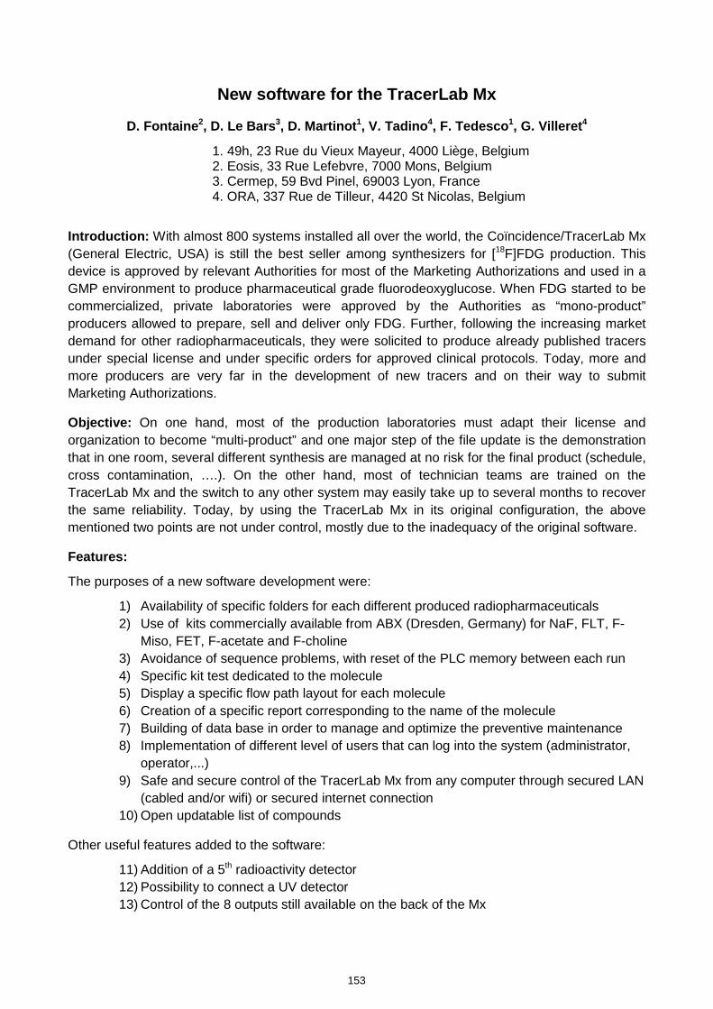
New software for the TracerLab Mx
D. Fontaine2, D. Le Bars3, D. Martinot1, V. Tadino4, F. Tedesco1, G. Villeret4
1. 49h, 23 Rue du Vieux Mayeur, 4000 Liège, Belgium 2. Eosis, 33 Rue Lefebvre, 7000 Mons, Belgium 3. Cermep, 59 Bvd Pinel, 69003 Lyon, France 4. ORA, 337 Rue de Tilleur, 4420 St Nicolas, Belgium
Introduction: With almost 800 systems installed all over the world, the Coïncidence/TracerLab Mx (General Electric, USA) is still the best seller among synthesizers for [18F]FDG production. This device is approved by relevant Authorities for most of the Marketing Authorizations and used in a GMP environment to produce pharmaceutical grade fluorodeoxyglucose. When FDG started to be commercialized, private laboratories were approved by the Authorities as “mono-product” producers allowed to prepare, sell and deliver only FDG. Further, following the increasing market demand for other radiopharmaceuticals, they were solicited to produce already published tracers under special license and under specific orders for approved clinical protocols. Today, more and more producers are very far in the development of new tracers and on their way to submit Marketing Authorizations.
Objective: On one hand, most of the production laboratories must adapt their license and organization to become “multi-product” and one major step of the file update is the demonstration that in one room, several different synthesis are managed at no risk for the final product (schedule, cross contamination, ….). On the other hand, most of technician teams are trained on the TracerLab Mx and the switch to any other system may easily take up to several months to recover the same reliability. Today, by using the TracerLab Mx in its original configuration, the above mentioned two points are not under control, mostly due to the inadequacy of the original software.
Features:
The purposes of a new software development were:
1) Availability of specific folders for each different produced radiopharmaceuticals 2) Use of kits commercially available from ABX (Dresden, Germany) for NaF, FLT, F-
Miso, FET, F-acetate and F-choline 3) Avoidance of sequence problems, with reset of the PLC memory between each run 4) Specific kit test dedicated to the molecule 5) Display a specific flow path layout for each molecule 6) Creation of a specific report corresponding to the name of the molecule 7) Building of data base in order to manage and optimize the preventive maintenance 8) Implementation of different level of users that can log into the system (administrator,
operator,...) 9) Safe and secure control of the TracerLab Mx from any computer through secured LAN
(cabled and/or wifi) or secured internet connection 10) Open updatable list of compounds
Other useful features added to the software:
11) Addition of a 5th radioactivity detector 12) Possibility to connect a UV detector 13) Control of the 8 outputs still available on the back of the Mx
153
kmje
Typewritten Text
Abstract 028
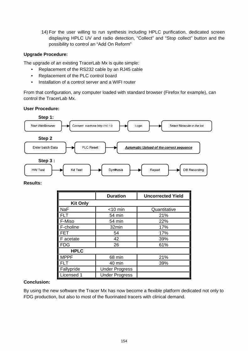
14) For the user willing to run synthesis including HPLC purification, dedicated screen displaying HPLC UV and radio detection, “Collect” and “Stop collect” button and the possibility to control an “Add On Reform”
Upgrade Procedure:
The upgrade of an existing TracerLab Mx is quite simple: • Replacement of the RS232 cable by an RJ45 cable • Replacement of the PLC control board • Installation of a control server and a WIFI router
From that configuration, any computer loaded with standard browser (Firefox for example), can control the TracerLab Mx.
User Procedure:
Step 1:
Step 2
Step 3 :
Results:
Duration Uncorrected Yield
Kit Only NaF <10 min Quantitative FLT 54 min 21% F-Miso 54 min 22% F-choline 32min 17% FET 54 17% F acetate 42 39% FDG 26 61%
HPLC MPPF 68 min 21% FLT 40 min 39% Fallypride Under Progress Licensed 1 Under Progress
Conclusion:
By using the new software the Tracer Mx has now become a flexible platform dedicated not only to FDG production, but also to most of the fluorinated tracers with clinical demand.
154
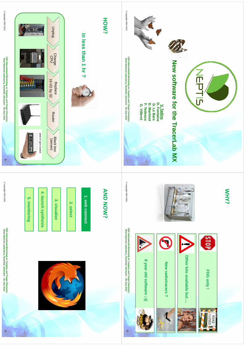
Nft
fth
TL
bM
XN
ew softw
are for the TracerLabM
X
VT
diV. Tadino
D. Fontaine
D. Le B
arsD
Martinot
D. M
artinotF. TedescoG
. Villeret
© copyright O
RA
201013th International W
orkshop on Targetryand Target C
hemistry
Risø
National Laboratory, R
oskilde, Denm
ark –26 July 2010
WHY?
WHY?
FDG
only!
Otherkits available
but ...
New
radiotracers?
8 yearoldsoftw
are ;-((
© copyright O
RA
201013th International W
orkshop on Targetryand Target C
hemistry
Risø
National Laboratory, R
oskilde, Denm
ark –26 July 2010
2
HOW?
HOW?in less
than1 hr?
Ul
Change
Replace
Rt
Black
boxU
nplugC
hange C
PU
p16 I/O
by 32R
outerB
lack box (server)
© copyright O
RA
201013th International W
orkshop on Targetryand Target C
hemistry
Risø
National Laboratory, R
oskilde, Denm
ark –26 July 2010
3
ANDNOW?
AND N
OW?
1. web connect
2. select
3. visualize
4. launchsynthesisy
5.monitoring
5. monitoring
© copyright O
RA
201013th International W
orkshop on Targetryand Target C
hemistry
Risø
National Laboratory, R
oskilde, Denm
ark –26 July 2010
4
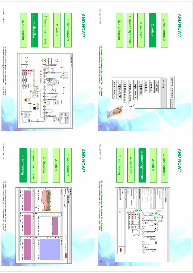
ANDNOW?
AND N
OW?
1. web connect
2. select
3. visualize
4. launchsynthesisy
5.monitoring
5. monitoring
© copyright O
RA
201013th International W
orkshop on Targetryand Target C
hemistry
Risø
National Laboratory, R
oskilde, Denm
ark –26 July 2010
5
ANDNOW?
AND N
OW?
1. web connect
2. select
3. launchsynthesis
4. visualize
5. monitoringg
© copyright O
RA
201013th International W
orkshop on Targetryand Target C
hemistry
Risø
National Laboratory, R
oskilde, Denm
ark –26 July 2010
6
ANDNOW?
AND N
OW?
1. web connect
2. select
3. launchsynthesis
4. visualize
5. monitoringg
© copyright O
RA
201013th International W
orkshop on Targetryand Target C
hemistry
Risø
National Laboratory, R
oskilde, Denm
ark –26 July 2010
7
ANDNOW?
AND N
OW?
1. web connect
2. select
3. visualize
4. launchsynthesisy
5.monitoring
5. monitoring
© copyright O
RA
201013th International W
orkshop on Targetryand Target C
hemistry
Risø
National Laboratory, R
oskilde, Denm
ark –26 July 2010
8
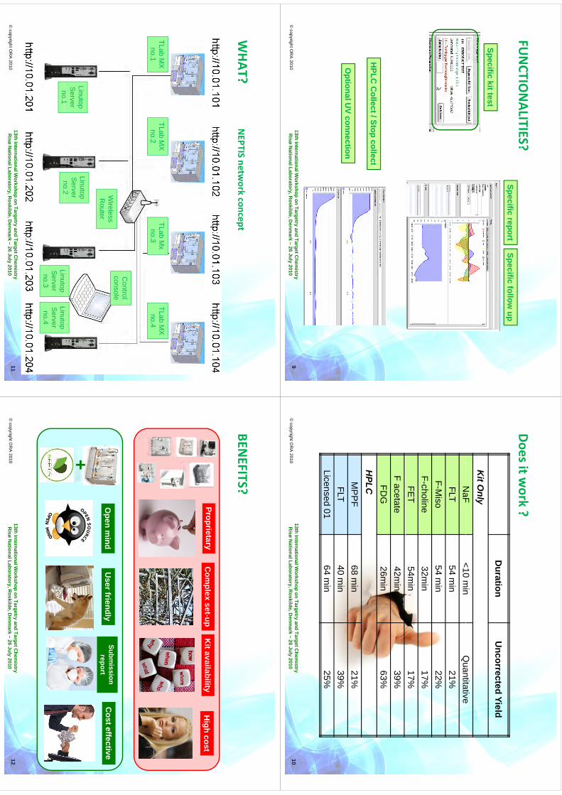
FUNCTIO
NALITIES?
FUNCTIO
NALITIES?
Specificreport
Specificfollow
up
Specifickit test
HPLC
Cll
t/Stll
t
OptionalU
Vconnection
HPLC
Collect/ Stop collect
OptionalU
V connection
© copyright O
RA
201013th International W
orkshop on Targetryand Target C
hemistry
Risø
National Laboratory, R
oskilde, Denm
ark –26 July 2010
9
Dit
k?
Duration
Uncorrected
Yield
Doesitwork
?
Duration
Uncorrected Yield
Kit O
nlyN
aF<10
min
Quantitative
NaF
<10 min
Quantitative
FLT54 m
in21%
F-Miso
54m
in22%
FM
iso54 m
in22%
F-choline32m
in17%
FET
54min
17%F acetate
42min
39%FD
G26m
in63%
HPLCM
PP
F68 m
in21%
FLT40 m
in39%
Licensed 0164 m
in25%
© copyright O
RA
201013th International W
orkshop on Targetryand Target C
hemistry
Risø
National Laboratory, R
oskilde, Denm
ark –26 July 2010
10
WHAT?
WHAT? N
EPTIS network concept
TLabM
X
1TLab
MX
2
TLabM
x3
TLabM
X
4
Control
no.1no.2
no.3no.4
Control
consoleW
irelessR
outer
LinutopS
erverno
1
LinutopS
erverno
2Li
tLi
tno.1
no.2LinutopS
erverno.3
LinutopS
erverno.4
© copyright O
RA
201013th International W
orkshop on Targetryand Target C
hemistry
Risø
National Laboratory, R
oskilde, Denm
ark –26 July 2010
11
BENEFITS?
BENEFITS?
Com
plexset-up
ProprietaryK
it availabilityH
igh cost
Open m
indC
osteffectiveU
ser friendlySubm
issionreport
+
© copyright O
RA
201013th International W
orkshop on Targetryand Target C
hemistry
Risø
National Laboratory, R
oskilde, Denm
ark –26 July 2010
12
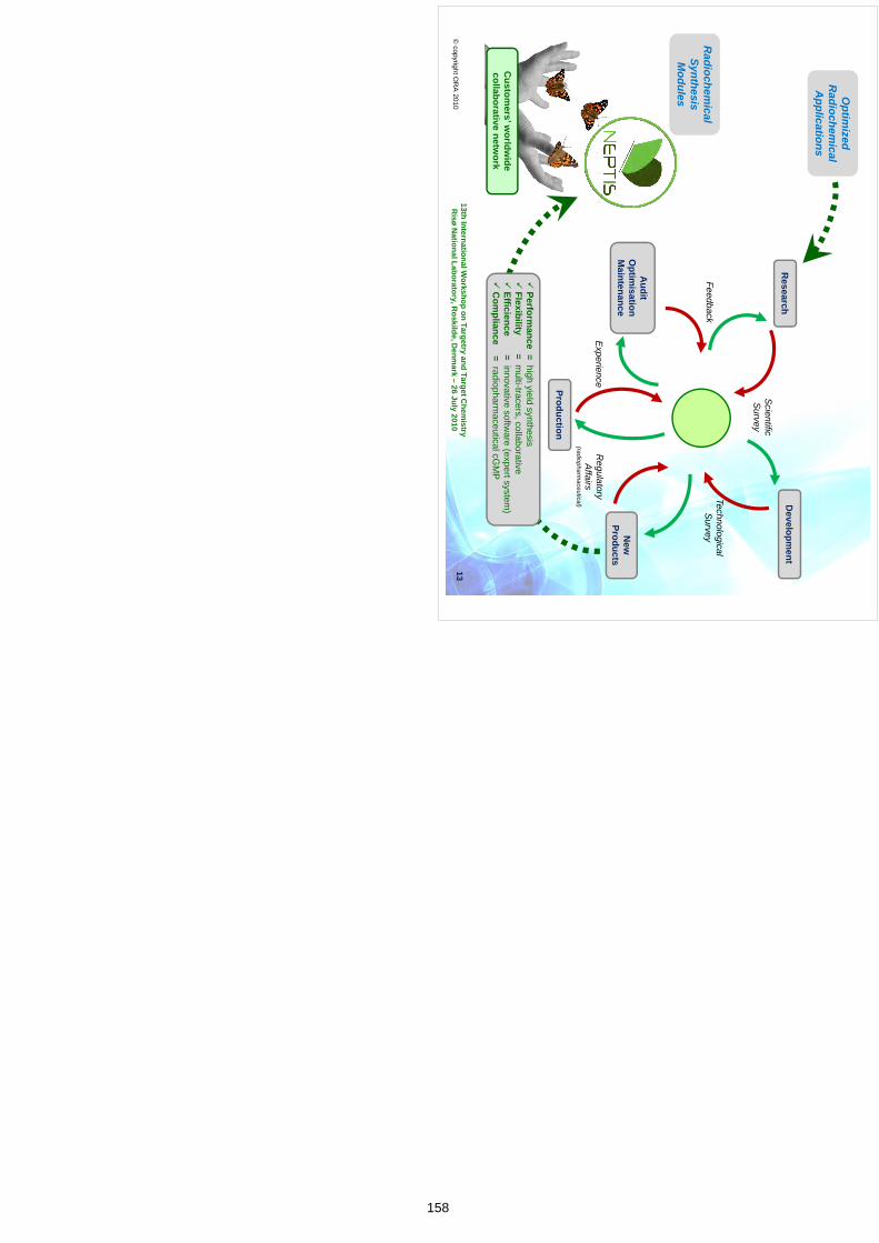
Optim
izedR
adiochemical
Ali
tiA
pplications
Research
Developm
ent
ScientificS
urvey
TechnologicalS
urveyFeedback
Radiochem
icalSynthesisM
odules
Audit
Oti
iti
Modules
New
Products
Optim
isationM
aintenance
RegulatoryA
ffairsE
xperience
Production
Affairs
(radiopharmaceutical)
Custom
ers’ worldw
idecollaborative netw
ork
Perform
ance = highyield
synthesis
Flexibility= m
ulti-tracers, collaborative
Efficience = innovativesoftw
are (expert system)
C
ompliance
= radiopharmaceuticalcG
MP
© copyright O
RA
201013th International W
orkshop on Targetryand Target C
hemistry
Risø
National Laboratory, R
oskilde, Denm
ark –26 July 2010
Com
pliance radiopharm
aceuticalcGM
P
13
158
PRODUCTION OF NO CARRIER ADDED 64
Cu & 55
Co FROM A NATURAL
NICKEL SOLID TARGET USING AN 18MeV CYCLOTRON PROTON BEAM
A. H. Asad1,2
, C. Jeffery1, S.V. Smith
3, S. Chan
1, D. Cryer
1 & R. I. Price
1,4
1Radiopharmaceutical Production & Development (RAPID) Laboratory, Medical Technology and Physics, Sir Charles Gairdner Hospital, Perth, Australia 2Imaging and Applied Physics, Curtin University of Technology, Perth, Australia 3Australian Nuclear Science and Technology Organisation (ANSTO), Sydney, Australia 4School of Physics, University of Western Australia, Perth, Australia
INTRODUCTION: There is growing interest in the Australian research community for new PET radioisotopes with relatively long half lives. 64Cu is a candidate, since; (i) it can be produced in cyclotrons found in a medical setting; (ii) the translational energy of its emitted positron is moderate (0.65MeV), and; (iii) its half life is sufficiently long (12.7h) to be used to radiolabel a range of molecular targeting agents (including monoclonal antibodies) and for the isotope to be transported across continents.
The RAPID Lab produces [18F]FDG on a daily basis (~4500 doses per year), plus other clinical radiopharmaceuticals based on biogenic PET isotopes. The radioisotopes for these products are produced using standard targetry of an 18/9 MeV IBA cyclotron. As the productions of 64Cu and 89Zr both require an external beam, the RAPID team has devised a purpose built solid targetry system to suit this setting. The new targetry system consists of a 30cm long external beam line fitted with a 50μm Havar vacuum window plus an independent vacuum and cooling system (chilled water plus helium) for the target and beam degrader. Proton energies and currents can be controlled between 4–17.3MeV (using beam degraders) and 10-30μA, respectively.
The preferred approach for the production of 64Cu using a medium-energy cyclotron uses enriched 64Ni as the target in the reaction 64Ni(p,n)64Cu. A yield of 248MBq/μA.h has been reported [2]. However, for a natural nickel (natNi) target the yield is considerably less, since the abundance of 64Ni in natNi is only 0.91%. This study investigated the production and purification of the radionuclides 64Cu, 55Co and 57Co, (the latter two arising from 58,60Ni[p,]55,57Co) using a natNi thin-foil target, as a preliminary ‘proof-of-principle’ study prior to the bombardment of more expensive isotopically enriched targets formed by electroplating 64Ni onto a gold substrate.
METHODS: A high purity natNi foil (99.99%) of nominal thickness 50μm and 15mm diameter was weighed on a 5-decimal-place balance to determine true average thickness prior to proton bombardment. Three separate runs were performed. The target foil was cooled by both chilled water and helium. The accessible proton beam energy of 17.3 MeV was moderated to 11.7MeV at the target surface by using a 1020μm graphite degrader placed in the collimator of the solid targetry beam line.
Bombardment elapsed times were 8, 19, and 20 minutes with beam currents of 10.4, 19.1 and 14 μA, respectively. Beam currents were uncorrected for secondary electron emission. At end of bombardment (EOB) the irradiated nickel target was left to decay for 3-4 hours to remove the short half-life radioisotopes 60Cu & 61Cu.
The target was then dissolved in concentrated acids at 100oC and then loaded on to either a cation or an anion exchange column (1x 20cm). Nickel from the target plus Cu and Co radioisotopes were separately eluted using a range of solvents mixed with
159
kmje
Typewritten Text
Abstract 029
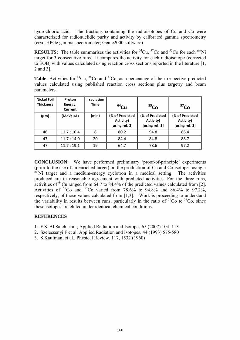
hydrochloric acid. The fractions containing the radioisotopes of Cu and Co were characterized for radionuclidic purity and activity by calibrated gamma spectrometry (cryo-HPGe gamma spectrometer; Genie2000 software).
RESULTS: The table summarises the activities for 64Cu, 57Co and 55Co for each natNi target for 3 consecutive runs. It compares the activity for each radioisotope (corrected to EOB) with values calculated using reaction cross sections reported in the literature [1, 2 and 3].
Table: Activities for 64Cu, 55Co and 57Co, as a percentage of their respective predicted values calculated using published reaction cross sections plus targetry and beam parameters.
Nickel Foil Thickness
Proton Energy; Current
Irradiation Time
64Cu
55Co
57Co
(m) (MeV; A) (min) (% of Predicted Activity)
[using ref. 2]
(% of Predicted Activity)
[using ref. 1]
(% of Predicted Activity)
[using ref. 3]
46 11.7 ; 10.4 8 80.2 94.8 86.4
47 11.7 ; 14.0 20 84.4 84.8 88.7
47 11.7 ; 19.1 19 64.7 78.6 97.2
CONCLUSION: We have performed preliminary ‘proof-of-principle’ experiments (prior to the use of an enriched target) on the production of Cu and Co isotopes using a natNi target and a medium-energy cyclotron in a medical setting. The activities produced are in reasonable agreement with predicted activities. For the three runs, activities of 64Cu ranged from 64.7 to 84.4% of the predicted values calculated from [2]. Activities of 55Co and 57Co varied from 78.6% to 94.8% and 86.4% to 97.2%, respectively, of those values calculated from [1,3]. Work is proceeding to understand the variability in results between runs, particularly in the ratio of 55Co to 57Co, since these isotopes are eluted under identical chemical conditions.
REFERENCES
1. F.S. Al Saleh et al., Applied Radiation and Isotopes 65 (2007) 104–113 2. Szelecsenyi F et al, Applied Radiation and Isotopes. 44 (1993) 575-580 3. S.Kaufman, et al., Physical Review. 117, 1532 (1960)
160

ProductionofN
oCarrierAdded
64Cu&
55CoProduction of N
o Carrier Added 64Cu & 55Co
From a N
atural Nickel Solid Target U
sing an 18M
eV Cyclotron Proton Beam
A. H
. Asad
1,2, C. Jeffery
1, S.V. Sm
ith 3, S. Chan
1, D. C
ryer 1& R
. I. Price1,4
1Radiopharmaceutical Production &
Developm
ent (RAPID) Laboratory, M
edical Technology and Physics, Sir Charles G
airdner Hospital, Perth, Australia
2Ii
dA
lid
Phi
Cti
Ui
itf
Th
lP
thA
tli
2Imaging and Applied Physics, Curtin U
niversity of Technology, Perth, Australia 3Australian N
uclear Science and Technology Organisation (AN
STO), Sydney, Australia
4School of Physics, University of W
estern Australia, Perth, Australia
Ali A
sad; Radiation Physicist &
PhD C
andidate in Applied Physics
The 13
thIn
ternation
al Worksh
op on Targetry an
d Target Ch
emistry -
WTTC
13
Introduction
•Rapid
advancesin
radioimm
uno-diagnosis&
-therapyRapid advances in radioim
muno
diagnosis &
therapy techniques have focused interest on different production strategies for the longer lived PET isotopes such as 64Cu
gg
p89Zr &
124I.
•The three decay paths of 64Cu [t1/2 =
12.7hr], namely EC,
β+
and β-
makes it an attractive radionuclide for PET
imaging as w
ell as targeted radiotherapy.
•O
ver the past two decades, cyclotron-based production of
64Cu has been optimized, and 64Cu is now
being produced t
ldi
ld
hf
ilitiat several m
edical and research facilities (Szelecsenyi et al., 1993, M
cCarthy et al., 1997 & Avila et al.,2007).
22
Excitation Functions () for Selected 64Cu Production Strategies
Excitation functions for production 64Cu
100064N
i(d,2n) 64Cu
100
b)
64Ni(p ,n ) 64Cu
68Zn(p,x) 64Cu64Zn(d,2p) 64Cu
10
CS (mb
Zn(d,2p)Cu
6664
1
66Zn(d,a) 64Cu
02
46
810
1214
1618
2022
2426
2830
32
Proton or Deuteron Energy(MeV)
33
64Cu64Cu
64Cu decays via two paths
•64N
i (stable) with em
ission of β(17.86%
) & EC
(42.63%)
and(42.63%
) and
•64Zn (stable) w
ith emission of β
-(39.03%)
•The m
ost comm
on path for the production of 64Cu is
•64N
i(p,n)64C
u
•It
requiresa
medium
energycyclotron;
oftenavailable
ina
major
It requires a medium
energy cyclotron; often available in a major
hospital
•Th
64Nii
fl
bd
(1%)
dt
bi
hd
it
•The 64N
i is of low abundance (1%
) and must be enriched prior to
use.
•U
se of natNi targets yields m
ore complex m
ixture of radioisotopes.44
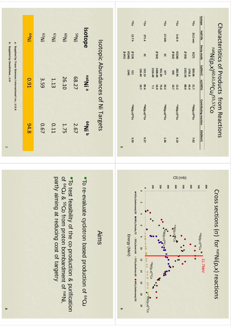
Characteristics of Products from Reactions
natNi(p,x) 60,61,64Cu/ 55,57Co
IsotopeHalf‐life
Decay mode
Eγ(MeV)
Iγ(100%)
Contributing reaction Eth(M
eV)
60Cu23.2 m
in EC(7)
826.0621.7
60Ni(p,n) 60Cu
7.021791.6
45.4β⁺(93)
1322.5088.0
61Cu3.41 h
EC(38)282.95
12.261N
i(p,n) 61Cu3.10
β⁺(62)656
10.7
55Co17.54h
EC477
20.258N
i(p,α) 55Co1.36
931.3075.0
β⁺(62)1408.40
16.91316.40
7.1
57Co271 d
EC122.13
85.660N
i(p,α) 57Co0.27
136.4010.7
64Cu12.7 h
β⁺(19)511
64Ni(p,n) 64Cu
3.50C(40)
134
55
E C(40)1345
β‐(41)
Crosssections()for
natNi(p
x)reactionsCross sections () for
Ni(p,x) reactions
80011
7MeV
600
700
11.7MeV
64Ni(p,n) 64Cu
500
600
(mb)
300
400
CS (
61Ni(p,n) 61Cu
200
60Ni(p,n) 60Cu
0
100
02
46
810
1214
1618
20
58Ni(p,a) 55Co
60Ni(p,a) 57Co
02
46
810
1214
1618
20
61Cu,Szelecsenyi,9360Cu,Tanaka,72
55Co,Ewart,64
57Co,Kaufman,60
64Cu,Szelecsenyi,93
Energy(M
eV)
66
Energy (MeV)
IsotopicAbundancesofN
iTargetsIsotopic Abundances of N
i Targets
ti
64ib
IsotopenatN
ia
64Ni b
58Ni
6827
267
58Ni
68.272.67
60Ni
2610
175
Ni
26.101.75
61Ni
1.130.11
62Ni
3.590.67
64Ni
0.9194.8
a: Supplied by Trace Sciences International Inc., U.S.A
77b: Supplied by G
oodfellow., U
.K
Aims
Aims
•To re-evaluate cyclotron based production of 64Cu•To test feasibility of the co-production &
purification of
64Cu&
55Cofrom
protonbom
bardment
ofnatN
iof 64Cu &
55Co from proton bom
bardment of natN
i, partly aim
ing at reducing cost of targetry
88
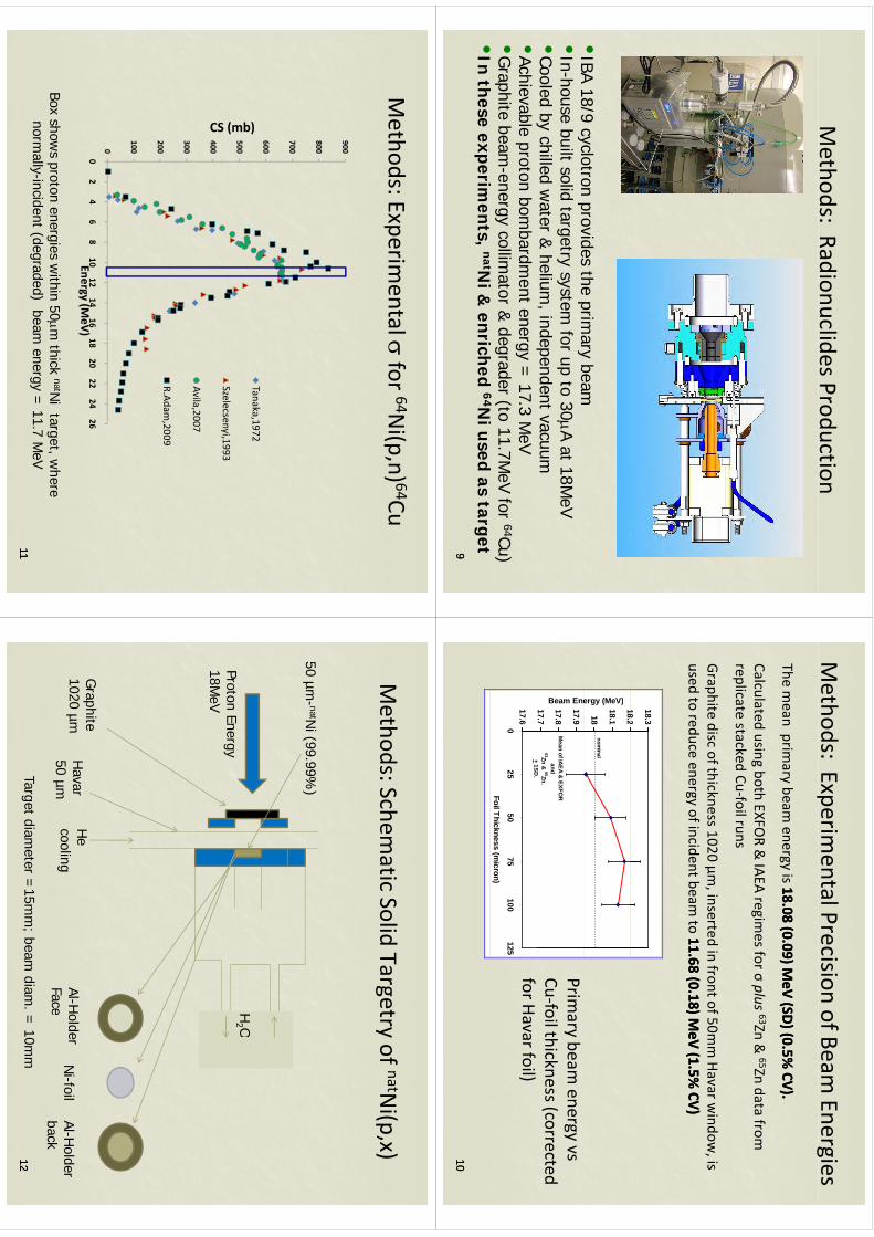
Methods: Radionuclides Production
•IBA
18/9cyclotron
providesthe
primary
beamIBA 18/9 cyclotron provides the prim
ary beam•
In-house built solid targetry system for up to 30A at 18M
eV•
Cooled by chilled water &
helium, independent vacuum
y,
p•
Achievable proton bombardm
ent energy = 17.3 M
eV•
Graphite beam
-energy collimator &
degrader (to 11.7MeV for 64Cu)
•I
thi
ttN
i&i
hd
64Ni
dt
t•
In th
ese experiments, natN
i & en
riched 64N
i used as target 99
Methods: Experim
ental Precision of Beam Energies
pg
The mean prim
ary beam energy is 18.08 (0.09) M
eV (SD) (0.5% CV).
18.08 (0.09) MeV (SD) (0.5%
CV).
Calculated using both EXFOR &
IAEA regimes for σ
plus63Zn &
65Zn data from
replicate stacked Cu‐foil runs
Graphite disc of thickness 1020 μm, inserted in front of 50m
m Havar w
indow, is
used to reduce energy of incident beam to 11.68 (0.18) M
eV (1.5% CV)
11.68 (0.18) MeV (1.5%
CV)
182
18.318
18.1
18.2
ergy (MeV)
nominal
17.7
17.8
17.9
Beam Ene
Mean of IAEA &
EXFOR
and 63Zn &
65Zn.+
1SD
Primary beam
energy vs Cu‐foil thickness (corrected
17.60
2550
75100
125Foil Thickness (m
icron)
+ 1SD.
for Havar foil)
1010
Methods: Experim
ental for 64N
i(p,n) 64Cu
900
700
800
500
600
mb)
Tanaka,1972
400
500
CS (m
Szelecsenyi,1993
Avila,2007
200
300Avila,2007
R.Adam,2009
0
100
02
46
810
1214
1618
2022
2426
Energy (MeV)
Boxshow
sproton
energiesw
ithin50m
thicknatN
itarget
where
1111
Box shows proton energies w
ithin 50m thick
Ni target, w
here norm
ally-incident (degraded) beam energy =
11.7 MeV
Methods:Schem
aticSolid
Targetryof
natNi(p,x)
Methods: Schem
atic Solid Targetry of Ni(p,x)
50 µm- natN
i (99.99%)
H2 O
Proton Energy18M
eV
H2 O
Graphite
1020 µmH
avar50 µm
He
coolingAl-H
olderFace
Al-Holder
backN
i-foilµ
Faceback
Target diameter =
15mm
; beam diam
. = 10m
m1212
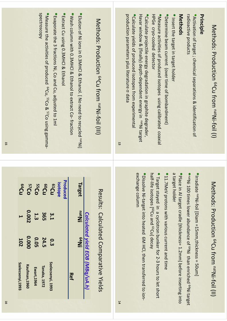
Methods:Production
64Cufrom
natNi‐foil(I)
Methods: Production
Cu from
Nifoil (I)
Principlecpe
•Activation of target ; chemical separations &
identification of radioactive
productsradioactive products
Methods
•Insert the target in target holder
•Determine beam
current (over time of bom
bardment)
•Measure activities of produced isotopes using calibrated coaxial
HPGe cryo‐cooled detectory
•Calculate projectile energy degradation in graphite degrader, Havarw
indow&(finally)depth‐dependentenergy
innatN
itargetHavar w
indow & (finally) depth
dependent energy in Ni target
•Calculate yields of produced isotopes from experim
ental production
parametersplusliterature
data
production parameters plus literature
data
1313
Methods:Production
64Cufrom
natNi‐foil(II)
Methods: Production
Cu from
Nifoil (II)
•Irradiate natNi‐foil [Diam
=15mm,thickness = 50um
]
•natN
i100tim
eslowerabundance
of64N
ithan
enriched64N
itargetNi 100 tim
es lower abundance of
Ni than enriched
Ni target
•Place in Al target cradle [thickness= 1.2mm] before inserting into
hld
a target holder
•11.7MeV protons w
ith various current and time
•Target stayed in a cyclotron bunker for 2‐3 hours to let short
half‐lifeisotopes[ 60Cu
and61Cu]decay
half‐life isotopes [Cu and
Cu] decay
•Dissolve Ni‐target into heated 6M
HCl, then transferred to ion‐h
lexchange colum
n
1414
Methods:Production
64Cufrom
natNifoil(III)
Methods: Production 64Cu from
natNi‐foil (III)
•Elution of Ni ions in 0.3M
HCl & Ethanol. [ N
o need to recycled natNi]
•Wash colum
n with 0.3M
HCl & Ethanol to extract Co‐fraction
•ExtractCuusing
03M
HCl&Ethanol
Extract Cu using 0.3MHCl &
Ethanol
•Evaporate the 3 fractions Ni, Co and Cu, adjusted to 1m
l
•Measure the activities of produced 64Cu, 55Co &
57Co using gamma‐
spectroscopy
1515
Results:Calculated
Comparative
YieldsResults: Calculated Com
parative Yields
Calculatedyield
EOB(M
Bq/uAh)
Calculated yield EOB (M
Bq/uA.h)Target
natNi
64Ni
RefProduced isotope61Cu
3.10.3
Szelecsenyi,19933.1
0.3Szelecsenyi, 1993
60Cu365
24.5Tanaka, 1972
55C13
005
55Co1.3
0.05Ew
art,196457Co
0.0020.000
Kaufman,1960
,64Cu
1102
Szelecsenyi,1993
1616
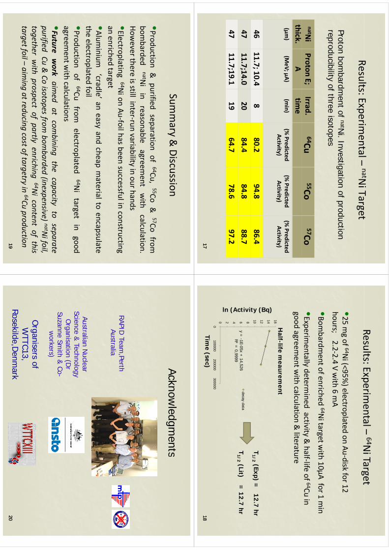
Rlt
Ei
tl
natNiT
tResults: Experim
ental –natN
i Target
Pt
bb
dt
fnatN
iI
titi
fd
tiProton bom
bardment of natN
i. Investigation of production reproducibility of three isotopes
natNi
Proton E;Irrad.
64Cu55Co
57Cothick.
Atim
e(µm
)(M
eV; µA)(m
in)(%
Predicted A
tiit
)(%
Predicted A
tiit
)(%
Predicted A
tiit
)Activity)
Activity)Activity)
4611.7; 10.4
880.2
94.886.4
4711.7;14.0
2084.4
84.888.7
4711.7;19.1
1964.7
78.697.21717
Results:Experimental–
64NiTarget
Results: Experimental
Ni Target
•25mgof
64Ni(<95%
)electroplatedon
Au‐diskfor12
25 mg of
Ni (<95%
) electroplated on Audisk for 12
hours; 2.2‐2.4 V with 6 m
A
•Bb
dt
fih
d64N
itt
ith10
Af
1i
•Bombardm
ent of enriched 64Ni target w
ith 10μA for 1 min
•Experimentally determ
ined activity & half‐life of 64Cu in
good agreement w
ith calculation & literature
Half
lifem
eaurement
12 14 16H
alf-life meaurem
ent
(Bq)
y = -1E-05x +
14,5266 8 10
decay data
ctivity (
T1/2
(Exp) = 12.7 hr
T1/2
(Lit) = 12.7 hr
R² = 0,9999
0 2 4
ln (Ac
T1/2
(Lit) 12.7 hr
0100000
200000300000
Time (sec)
1818
Summary
&Discussion
Summary &
Discussion
•Production&
purifiedseparation
of64Cu,
55Co&
57Cofrom
pp
bombarded
natNiin
reasonableagreem
entwith
calculation.How
everthereisstill
inter‐runvariability
inourhands
•Electroplating64N
ionAu‐foilhas
beensuccessfulin
constructingan
enrichedtarget
g•Alum
inium‘cradle’an
easyand
cheapmaterialto
encapsulatethe
electroplatedfoil
theelectroplated
foil•Production
of64Cu
fromelectroplated
64Nitarget
ingood
agreementw
ithcalculations
agreementw
ithcalculations
•Futurework
aim
edatcombining
the
capacity
tosep
arate
purified
Cu&Coiso
topes
from
bombarded
(inexp
ensive)
natNifoil
purified
Cu&Coiso
topes
from
bombarded
(inexp
ensive)
natNifoil,
togeth
erwith
prospect
ofpartly
enrich
ing
64Niconten
tofthis
target
foil–
aim
ingatred
ucin
gcostoftargetry
in64Cuproductio
ntarget
foil
aim
ingatred
ucin
gcostoftargetry
inCuproductio
n1919
Acknowledgm
entsAcknow
ledgments
RAPID Team
,PerthAustralia
AustralianN
uclearAustralian N
uclear Science &
Technology O
r ganisation (Dr
g(
Suzanne Smith &
Co-w
orkers)
Organisers of W
TTC13W
TTC13, Rosekilde,D
enmark
2020

WTTC
XIII–Presentation
Discussions
WTTC
XIII –Presentation D
iscussions
1.(p,n) reaction•
117
MeV
toreduce
isotopicim
purities•
11,7 MeV
to reduce isotopic impurities
•E
nergy degradation by graphite (1020 um)
•64N
i electroplated on gold
2.S
eparation: ethanol method
•Separates N
i, Co, C
u (checked by gamm
a spectroscopy)•
Colum
nas
bigas
20x
1•
Colum
n as big as 20 x 1
3.W
hy not (the cheaper) natNi?
•Less
productionm
oreproblem
s•
Less production, more problem
s•
OK
only for testing
4G
raphitedegradator?
Whatkind
ofgraphite?4.
Graphite degradator? W
hat kind of graphite?•
Less beam divergence (M
onte Carlo)
•Pyro? B
etter heat transfer, more expensive
5.W
hy keep using He flow
?•
Keep oxidation (air!) away
WTTC
XIII–Presentation
Discussions
WTTC
XIII –Presentation D
iscussions
6.Target m
aterial direct to cyclotron vacuum?
•D
angerous:Niis
magnetic
•D
angerous: Ni is m
agnetic
7.Target irradiation on line verification?•
Possible
byneutrons
butonlyto
11MeV
(16MeV
toom
uch)•
Possible by neutrons, but only to 11M
eV (16MeV
too much)
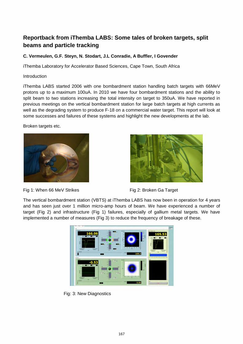
Reportback from iThemba LABS: Some tales of broken targets, split
beams and particle tracking
C. Vermeulen, G.F. Steyn, N. Stodart, J.L Conradie, A Buffler, I Govender
iThemba Laboratory for Accelerator Based Sciences, Cape Town, South Africa
Introduction
iThemba LABS started 2006 with one bombardment station handling batch targets with 66MeV protons up to a maximum 100uA. In 2010 we have four bombardment stations and the ability to split beam to two stations increasing the total intensity on target to 350uA. We have reported in previous meetings on the vertical bombardment station for large batch targets at high currents as well as the degrading system to produce F-18 on a commercial water target. This report will look at some successes and failures of these systems and highlight the new developments at the lab.
Broken targets etc.
Fig 1: When 66 MeV Strikes Fig 2: Broken Ga Target
The vertical bombardment station (VBTS) at iThemba LABS has now been in operation for 4 years and has seen just over 1 million micro-amp hours of beam. We have experienced a number of target (Fig 2) and infrastructure (Fig 1) failures, especially of gallium metal targets. We have implemented a number of measures (Fig 3) to reduce the frequency of breakage of these.
Fig: 3: New Diagnostics
167
kmje
Typewritten Text
Abstract 030
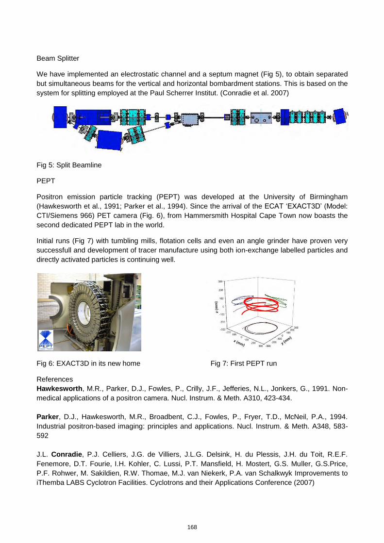
Beam Splitter
We have implemented an electrostatic channel and a septum magnet (Fig 5), to obtain separated but simultaneous beams for the vertical and horizontal bombardment stations. This is based on the system for splitting employed at the Paul Scherrer Institut. (Conradie et al. 2007)
Fig 5: Split Beamline
PEPT
Positron emission particle tracking (PEPT) was developed at the University of Birmingham (Hawkesworth et al., 1991; Parker et al., 1994). Since the arrival of the ECAT ‘EXACT3D’ (Model:
CTI/Siemens 966) PET camera (Fig. 6), from Hammersmith Hospital Cape Town now boasts the second dedicated PEPT lab in the world.
Initial runs (Fig 7) with tumbling mills, flotation cells and even an angle grinder have proven very successfull and development of tracer manufacture using both ion-exchange labelled particles and directly activated particles is continuing well.
Fig 6: EXACT3D in its new home Fig 7: First PEPT run
References Hawkesworth, M.R., Parker, D.J., Fowles, P., Crilly, J.F., Jefferies, N.L., Jonkers, G., 1991. Non-medical applications of a positron camera. Nucl. Instrum. & Meth. A310, 423-434. Parker, D.J., Hawkesworth, M.R., Broadbent, C.J., Fowles, P., Fryer, T.D., McNeil, P.A., 1994. Industrial positron-based imaging: principles and applications. Nucl. Instrum. & Meth. A348, 583-592 J.L. Conradie, P.J. Celliers, J.G. de Villiers, J.L.G. Delsink, H. du Plessis, J.H. du Toit, R.E.F. Fenemore, D.T. Fourie, I.H. Kohler, C. Lussi, P.T. Mansfield, H. Mostert, G.S. Muller, G.S.Price, P.F. Rohwer, M. Sakildien, R.W. Thomae, M.J. van Niekerk, P.A. van Schalkwyk Improvements to iThemba LABS Cyclotron Facilities. Cyclotrons and their Applications Conference (2007)
168
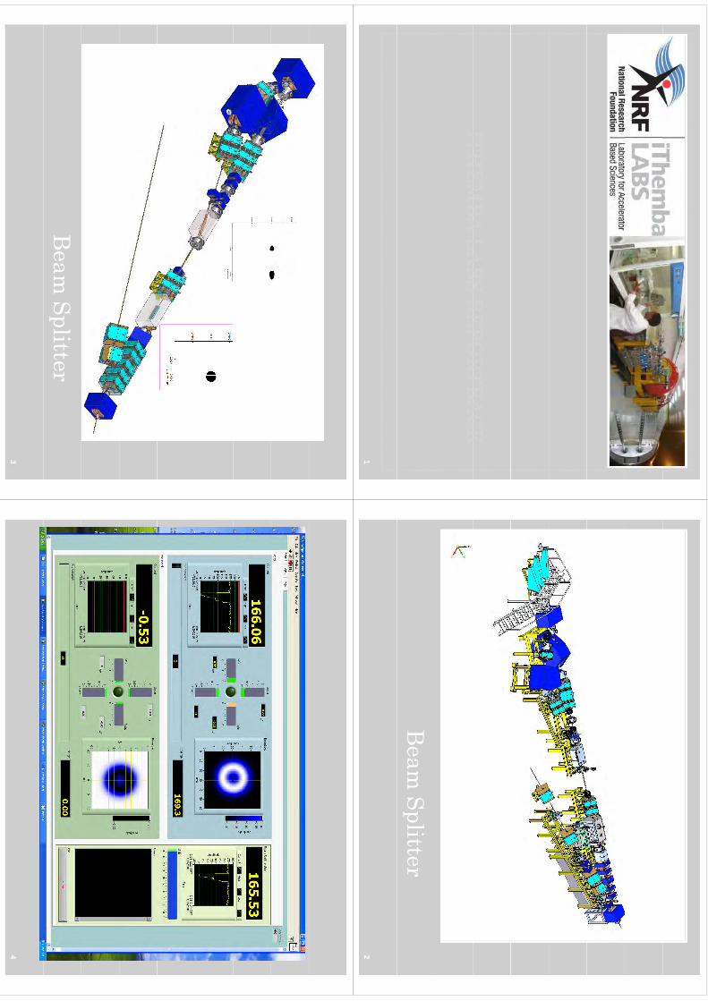
ITHEM
BAITH
EMBA
LABS LABS REPO
RTBACKREPO
RTBACKITH
EMBA
ITHEM
BALABS LABS REPO
RTBACKREPO
RTBACK
1
Beam Splitter
22
Beam Splitter
33
44
This Beam Bites!!!
55
66
More H
oles
77
8
S
9
Vertical Target Station
910
1111
•N
ew Cyclotron Facility
12
13
172
Technical pitfalls in the production of 64Cu with high specific activity
J. Rajander1, J. Schlesinger1, M. Avila-Rodriguez1,2 and O. Solin1
1Turku PET Centre, Turku University and Åbo Akademi University, Finland
2Unidad PET/CT-Ciclotrón, Facultad de Medicina, Universidad Nacional Autónoma de México,Mexico-City, Mexico
Introduction
In 2008, we initiated production of 64Cu aiming at high specific activities and high quantities.Routine production of 64Cu as well as the reproducible and economical preparation of the 64Nitarget material with ultra-low metal contamination was established. Some technical pitfalls had thento be overcome. We faced a) aggressive corrosion by concentrated acid solutions, b) flaking of thetarget material during the irradiation, c) contamination of the target material with cooling water, d)formation of insoluble [64Ni]NiO during the irradiation and e) incomplete dissolution of the irradiatedtarget material.
Methods
Using the 64Ni(p,n)64Cu reaction with an optimized beam profile and proton energy (13.0±0.2 MeV),we routinely produce high quantities of 64Cu (10-38 GBq) on our CC 18/9 cyclotron (EfremovScientific Research Institute of Electrophysical Apparatus, St. Petersburg, Russia) as previouslydescribed (Avila-Rodriguez et al., 2008). A semiautomatic processing of the irradiated 64Ni targetmaterial and a remote controlled separation of 64Ni and 64Cu has been developed, which yields64Cu with a high specific activity of 3 TBq/µmol. Using four miniature Geiger-Müller tubes, whichare placed within the processing module, we monitor the distribution of activity and control theseparation process of 64Cu (Rajander et al., 2009). The recovery of the 64Ni target material and thepreparation of the 64Ni electrolyte solution are done in a dedicated rotary evaporator. The computercontrolled electrochemical deposition of the 64Ni target material starts with a stepwise increase ofthe deposition voltage from 2.0 V to 2.5 V within 5 h, followed by a constant voltage of 2.5 V for40 h.
Results
a) The use of concentrated acid solutions for preparing the 64Ni electrolyte solution as well as forseparating 64Ni/64Cu caused serious corrosion problems in the fume hood and in the hot cell. Thisproblem was partly solved by using a closed and remote-controlled module for the processing ofthe irradiated 64Ni target material, which includes dissolution, separation of 64Ni/64Cu andconcentration of the acidic 64Cu fraction. For recovery of the 64Ni target material from theconcentrated hydrochloric acid solution, a dedicated rotary evaporator is used inside a fume hood.Acidic vapour from the evaporation process is neutralized by passing the vapours through analkaline aqueous solution in a flask.
b) Flaking of the 64Ni material from the Au-backing was twice observed during the irradiation. Thus,we included an additional cleaning step for the gold disk in the target preparation procedure. After
173
kmje
Typewritten Text
Abstract 031
cleaning with Deconex®, the gold disk is briefly soaked in 6 M HNO3 and then rinsed subsequentlywith DI water to efficiently remove traces of metallic and organic contamination from the goldsurface. After this step was included in target processing, no flaking of 64Ni target material from thegold surface during the irradiation has occurred. Also the electroplating process is controlled with acomputer program in order to obtain more reproducible results in the target preparation.
c) Due to scratches on the back of the gold disk and thus, insufficient sealing of the O-ring againstthe cooling water, contamination of the target material with cooling water was twice observed afterthe irradiation. Due to this, lower specific activities were obtained for 64Cu. In order to solve thisproblem, the gold disks were henceforth visually inspected and serious scratches were removed bysanding.
d) A first series of targets was irradiated under ambient atmosphere. We then observed twice theformation of insoluble, greenish [64Ni]NiO particles on the target material surface, resulting from anoxidation of 64Ni during the irradiation. In order to avoid oxidation of nickel in the presence ofatmospheric oxygen, we henceforth applied a stream of helium on the target material duringirradiation. Subsequently, we have not observed formation of [64Ni]NiO.
e) In some cases, a thermal treatment of the irradiated target material with 10 M HCl at 100 °C for20 min was insufficient to dissolve the target material. This might be a result of a passivation of the64Ni surface during the irradiation. This problem was solved by applying a stream of helium on thetarget material during irradiation, and also by extending the period of thermal treatment withconcentrated HCl from 20 to 40 min.
Acknowledgement
The study was conducted within the "Finnish Centre of Excellence in Molecular Imaging inCardiovascular and Metabolic Research" supported by the Academy of Finland, University ofTurku, Turku University Hospital and Åbo Akademi University. This work was also supported by theEU-FP7 integrated project BetaImage contract no.: 222980.
References
M.A. Avila-Rodriguez, J. Rajander, S. Johansson, P.O. Eriksson, T. Wickström, S. Vauhkala, E.Kokkomäki, J. Schlesinger, O. Solin, Production of 64Cu on the CC18/9 Cyclotron at TPC, a work inprogress, 12th International Workshop on Targetry and Target Chemistry, July 21-24, 2008,Seattle, Washington.
J. Rajander, J. Schlesinger, M. A. Avila-Rodriguez and O. Solin, Increasing specific activity in Cu-64 production by reprocessing the Ni-64 target material, J. Label. Comp. Radioph.52 (2009) S234
174

Turku PET Centre
Technical pitfalls in the production of 64C
ith hih
ifi tiit
64Cu with high specific activityW
TTCXIII, Risø, 26-28.7 2010 J. Rajander 1, J. Schlesinger 1, M. Avila-Rodriguez 1,2and O. Solin 1
1 Turku PET Centre, Turku, Finland2Unidad PET/CT-Ciclotrón, Universidad Nacional Autónoma de México, Mexico-City, Mexico
64C
dti
64Cu production
•Highspecific activity
•Economical large scale production (>37 GBq)
64Cu routine production
Supported by:(>37 GBq)
production
•High effective specific activity
64Cu-labeling•
Post-and prelabeling techniquesCu-labeling
•Micro-PET studies in vivo
Preclinical •
Metabolite analysis•
Receptor binding assays
Preclinical investigations
EU 7
thFramew
ork Programm
e
•Automated processing/labeling/purification for a future GMP production
Automated radiosynthesis
Turku PET Centre2
64C
dti
64Cu production
•Reproducible 64Ni-target preparation with ultra
low •
Semiautomated 64Ni/ 64Cu separation yields 64Cu with
preparation with ultra-low metal contamination
separation yields 64Cu with high specific activity (3000 GB
/l)
•Adapted proton energy and beam profile yields
GBq/µmol)•
Recycling of 64Ni for an p
y64Cu in high quantities (38 GBq)
yg
economical 64Cu production (95%
recovery rate)GBq)
(95% recovery rate)
64Ni-Target preparation64Ni-Target preparation
Proton Irradiation in
Cyclotron
Proton Irradiation in
CyclotronSeparation of 64Cu from 64NiSeparation of 64Cu from 64Ni
Quality Control of 64Cu
Quality Control of 64Cu
Recycling of 64Ni
Recycling of 64Ni
Turku PET Centre3
Th
il itfll
Technical pitfalls
•aggressive corrosion by concentrated acid solutionsflki
f th t
t t
il di
th i
diti•
flaking of the target material during the irradiation•
contamination of the tar get material with cooling waterg
g•
formation of insoluble [ 64Ni]NiO during the irradiation i
lt dilti
f th i
ditd tt
til
•incomplete dissolution of the irradiated target material
Turku PET Centre4
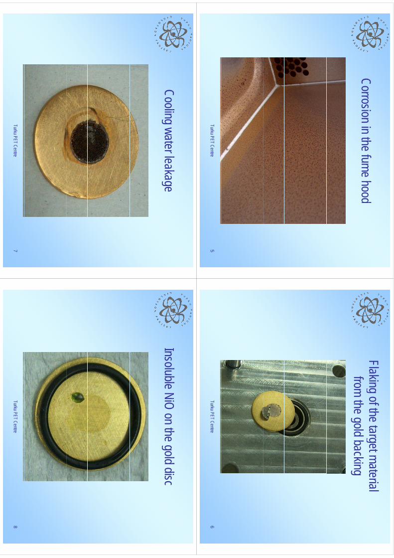
Ci
i th f
hd
Corrosion in the fume hood
Turku PET Centre5
Flaking of the target material g
gfrom the gold backing
Turku PET Centre6
Cli
t
lk
Cooling water leakage
Turku PET Centre7
Ilbl NiO
th
ld diInsoluble NiO on the gold disc
Turku PET Centre8
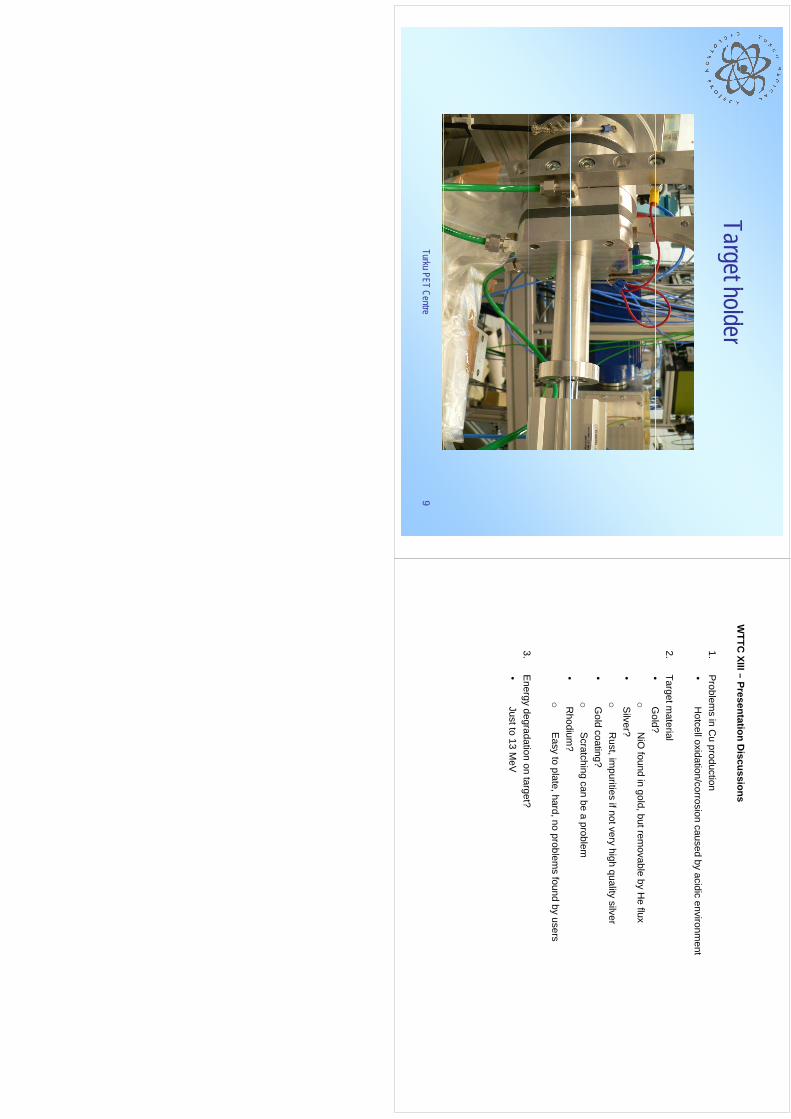
Tt h
ldTarget holder
Turku PET Centre9
WTTC
XIII–Presentation
Discussions
WTTC
XIII –Presentation D
iscussions
1.P
roblems in C
u production•
Hotcelloxidation/corrosion
causedby
acidicenvironm
ent•
Hotcelloxidation/corrosion caused by acidic environm
ent
2.Target m
aterial•
Gold?
•G
old?o
NiO
found in gold, but removable by H
e flux•
Silver?
oR
ustim
puritiesifnotvery
highquality
silvero
Rust, im
purities if not very high quality silver•
Gold coating?
oS
cratching can be a problem•
Rhodium
?•
Rhodium
?o
Easy to plate, hard, no problem
s found by users
3E
nergydegradation
ontarget?
3.E
nergy degradation on target?•
Just to 13 MeV
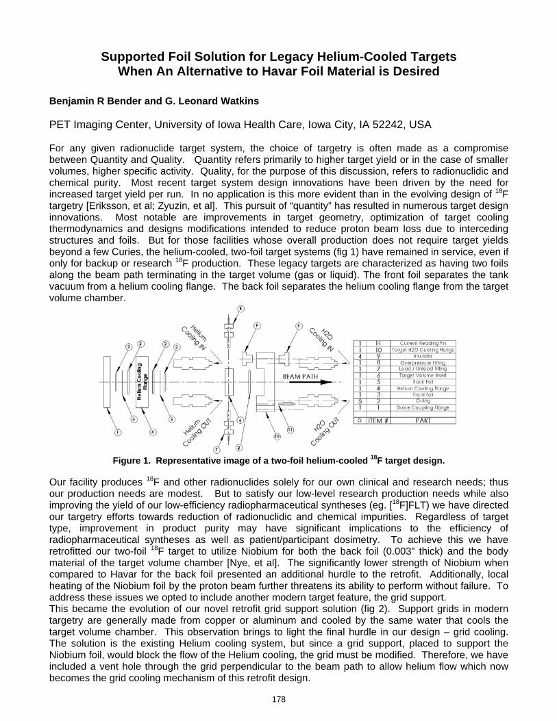
Supported Foil Solution for Legacy Helium-Cooled Targets When An Alternative to Havar Foil Material is Desired
Benjamin R Bender and G. Leonard Watkins PET Imaging Center, University of Iowa Health Care, Iowa City, IA 52242, USA For any given radionuclide target system, the choice of targetry is often made as a compromise between Quantity and Quality. Quantity refers primarily to higher target yield or in the case of smaller volumes, higher specific activity. Quality, for the purpose of this discussion, refers to radionuclidic and chemical purity. Most recent target system design innovations have been driven by the need for increased target yield per run. In no application is this more evident than in the evolving design of 18F
targetry [Eriksson, et al; Zyuzin, et al]. This pursuit of “quantity” has resulted in numerous target design innovations. Most notable are improvements in target geometry, optimization of target cooling thermodynamics and designs modifications intended to reduce proton beam loss due to interceding structures and foils. But for those facilities whose overall production does not require target yields beyond a few Curies, the helium-cooled, two-foil target systems (fig 1) have remained in service, even if only for backup or research 18F production. These legacy targets are characterized as having two foils along the beam path terminating in the target volume (gas or liquid). The front foil separates the tank vacuum from a helium cooling flange. The back foil separates the helium cooling flange from the target volume chamber.
Figure 1. Representative image of a two-foil helium-cooled 18F target design.
Our facility produces 18F and other radionuclides solely for our own clinical and research needs; thus our production needs are modest. But to satisfy our low-level research production needs while also improving the yield of our low-efficiency radiopharmaceutical syntheses (eg. [18F]FLT) we have directed our targetry efforts towards reduction of radionuclidic and chemical impurities. Regardless of target type, improvement in product purity may have significant implications to the efficiency of radiopharmaceutical syntheses as well as patient/participant dosimetry. To achieve this we have retrofitted our two-foil 18F target to utilize Niobium for both the back foil (0.003” thick) and the body material of the target volume chamber [Nye, et al]. The significantly lower strength of Niobium when compared to Havar for the back foil presented an additional hurdle to the retrofit. Additionally, local heating of the Niobium foil by the proton beam further threatens its ability to perform without failure. To address these issues we opted to include another modern target feature, the grid support. This became the evolution of our novel retrofit grid support solution (fig 2). Support grids in modern targetry are generally made from copper or aluminum and cooled by the same water that cools the target volume chamber. This observation brings to light the final hurdle in our design – grid cooling. The solution is the existing Helium cooling system, but since a grid support, placed to support the Niobium foil, would block the flow of the Helium cooling, the grid must be modified. Therefore, we have included a vent hole through the grid perpendicular to the beam path to allow helium flow which now becomes the grid cooling mechanism of this retrofit design.
178
kmje
Typewritten Text
Abstract 032
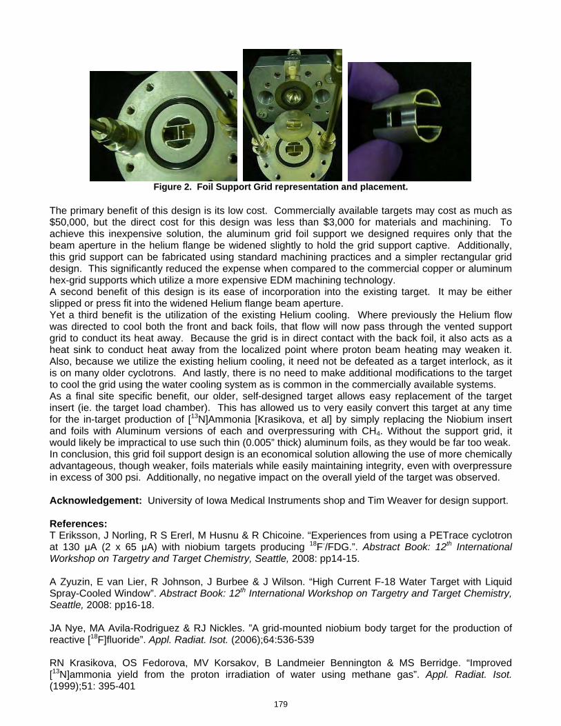
Figure 2. Foil Support Grid representation and placement.
The primary benefit of this design is its low cost. Commercially available targets may cost as much as $50,000, but the direct cost for this design was less than $3,000 for materials and machining. To achieve this inexpensive solution, the aluminum grid foil support we designed requires only that the beam aperture in the helium flange be widened slightly to hold the grid support captive. Additionally, this grid support can be fabricated using standard machining practices and a simpler rectangular grid design. This significantly reduced the expense when compared to the commercial copper or aluminum hex-grid supports which utilize a more expensive EDM machining technology. A second benefit of this design is its ease of incorporation into the existing target. It may be either slipped or press fit into the widened Helium flange beam aperture. Yet a third benefit is the utilization of the existing Helium cooling. Where previously the Helium flow was directed to cool both the front and back foils, that flow will now pass through the vented support grid to conduct its heat away. Because the grid is in direct contact with the back foil, it also acts as a heat sink to conduct heat away from the localized point where proton beam heating may weaken it. Also, because we utilize the existing helium cooling, it need not be defeated as a target interlock, as it is on many older cyclotrons. And lastly, there is no need to make additional modifications to the target to cool the grid using the water cooling system as is common in the commercially available systems. As a final site specific benefit, our older, self-designed target allows easy replacement of the target insert (ie. the target load chamber). This has allowed us to very easily convert this target at any time for the in-target production of [13N]Ammonia [Krasikova, et al] by simply replacing the Niobium insert and foils with Aluminum versions of each and overpressuring with CH4. Without the support grid, it would likely be impractical to use such thin (0.005” thick) aluminum foils, as they would be far too weak. In conclusion, this grid foil support design is an economical solution allowing the use of more chemically advantageous, though weaker, foils materials while easily maintaining integrity, even with overpressure in excess of 300 psi. Additionally, no negative impact on the overall yield of the target was observed. Acknowledgement: University of Iowa Medical Instruments shop and Tim Weaver for design support. References: T Eriksson, J Norling, R S Ererl, M Husnu & R Chicoine. “Experiences from using a PETrace cyclotron at 130 μA (2 x 65 μA) with niobium targets producing 18F-/FDG.”. Abstract Book: 12th International Workshop on Targetry and Target Chemistry, Seattle, 2008: pp14-15. A Zyuzin, E van Lier, R Johnson, J Burbee & J Wilson. “High Current F-18 Water Target with Liquid Spray-Cooled Window”. Abstract Book: 12th International Workshop on Targetry and Target Chemistry, Seattle, 2008: pp16-18. JA Nye, MA Avila-Rodriguez & RJ Nickles. ”A grid-mounted niobium body target for the production of reactive [18F]fluoride”. Appl. Radiat. Isot. (2006);64:536-539 RN Krasikova, OS Fedorova, MV Korsakov, B Landmeier Bennington & MS Berridge. “Improved [13N]ammonia yield from the proton irradiation of water using methane gas”. Appl. Radiat. Isot. (1999);51: 395-401
179

Supported Foil Solution for Legacy H
elium-C
ooled TargetsW
henA
nA
lternativeto
Havar
FoilMaterialisD
esiredW
hen An A
lternative to Havar
Foil Material is D
esired
Benjam
in R B
ender , G. L
eonard Watkins
University of Iow
a Health C
are, Iowa C
ity, Iowa, U
SA
Introduction
Target Selection Criteria
Quantity:
•Higher Target Yields•HigherSpecific
Activity•Higher Specific Activity
Quality:
•Reduced radionuclidic& nonradionuclidic
impurities
2
Introduction
Target Improvem
ents
Quantity:
•Better Target Geometry
•BetterTargetCooling•Better Target Cooling•Few
er Target Foils
liQuality:
•Purer Target Load Material
•More
Chemically
Compatible
Target&FoilM
aterialsMore Chem
ically Compatible Target &
Foil Materials
3
Introduction
Target Choice
Quantity: (new
er target designs)•Com
mercial Radionuclide Production Facilities
•HighVolum
eIn
HouseClinicalN
eeds
[Eriksson, et al; Zyuzin, et al]
•High Volume In‐House Clinical N
eeds•Higher Synthesis Production
•for low‐efficiency radiopharm
aceutical syntheses**
(startwith
more
>endwith
more)
** (start w
ith m
ore ==> en
d with
more)
Quality:
(modify
existingtarget)
Quality:
(modify existing target)
•Higher Synthesis Production•for low
‐efficiency radiopharmaceutical syntheses
** (start w
ith m
ore ==> en
d with
more)
•improves efficiency in any synthesis w
here havarmetal ions com
pete
4
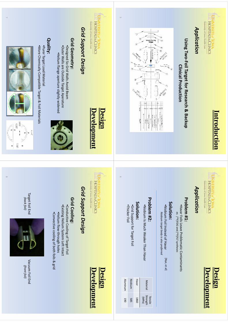
Introduction
Application
Using Tw
o‐Foil Target for Research & Backup
Clinical Production
5
Designg
Developm
entApplication
Problem #1:
•HavarFoils Leave Problematic Contam
inants ex
[ 18F]FD
Gand[ 18F]FLT
syntheses
ex. [F]FD
G and [
F]FLT syntheses
Solution:•Niobium
FoilInsteadofHavar
[Nye, et al]
Niobium
Foil Instead of HavarNiobium ta
rget b
ody is a
lso preferred
Problem #2:
•Niobium
Is Much W
eaker Than HavarMaterial
Tensile Strength (M
Pa)
Solution:•Grid Support for Target Foil•ThickerFoil
Havar1860
Niobium
585•Thicker Foil
Aluminum
1906
Designg
Developm
entGrid Support Design
Grid Geometry:
•Designed So Grid Walls Avoid Beam
•OuterW
allsareOutside
TargetAperature•Outer W
alls are Outside Target Aperature
•Helium flange aperture slightly w
idened
liQuality:
•Purer Target Load Material
•More
Chemically
Compatible
Target&FoilM
aterialsMore Chem
ically Compatible Target &
Foil Materials
7
Designg
Developm
entGrid Support Design
Grid Cooling:•Conductive Cooling of Target Foil•Existing
HeliumSystem
LeftIntact•Existing Helium
System Left Intact
•Helium flow
‐through holes•Convective cooling of both foils &
grid
Target Foil End(b
kfil)
Vacuum Foil End
(ffil)
(back fo
il)(fro
nt fo
il)
8
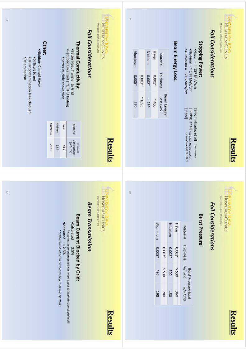
Results
Foil Considerations
Stopping Power:
•Havar= ~ 157 M
eV/cm•Niobium
=~144
MeV/cm
[Shiomi‐Tsuda, et al]
[Burkigetal]
*extrapolated
*bd
Al
ti•Niobium
= 144 M
eV/cm•Alum
inum = 60.6 M
eV/cm[Burkig, et al][Janni]
*based
on Al co
mparative
data co
llected @
19.8 M
eV
Beam Energy Loss:
Beam Energy
Material
Thicknessgy
Loss(keV)
Havar0.001”
~ 400 .
Niobium
0.002”~ 730 .
0.003”~ 1095 .
Aluminum
0.005”770 .
9
Results
Foil Considerations
Burst Pressure:
BtP
(i)
Material
ThicknessBurst Pressure (psi)w/ Grid
w/o
Grid
H0001”
>530
360Havar
0.001”> 530
360
Niobium
0.002”300
150
0003”
>530
2800.003
> 530280
Aluminum
0.005”430
190
10
Results
Foil Considerations
Thermal Conductivity:
•Better Heat Transfer to Grid•Reduced
Localized[ 18O
]HOboiling
Material
Thermal
Conductivity(W
/m*K)
•Reduced Localized [8O]H
2 O boiling
•Better nuclide conversionHavar
14.7
Niobium
53.7
Other:
Aluminum
237.0
•Niobium
‐Coated Havar•Difficult to get•Havarcontam
ination leak‐throughg•Delam
ination
11
Results
Beam Transm
ission
Beam Current Blocked by Grid:
•Calculated 3.5%*Assu
mes
beam
homogeneity
betw
eenupper
&lower
horizo
ntalgrid
walls
Assu
mes b
eam homogeneity b
etween
upper &
lower h
orizo
ntal grid
walls
•Measured < 2.5%
* Reflects th
e 2.5% beam cu
rrent rea
ding reso
lutio
n @
20 uA
12

Conclusions
Benefits of Grid Design
Cost:•Low‐Cost M
achining Techniques Used
•vsexp
ensive
EDM
machiningmeth
odsused
forhex
grid
vsexp
ensive ED
M m
achining m
ethods u
sed fo
r hex g
rid
in co
mmercia
l targets
•Modification Far M
ore Inexpensive Than New
Target
Ease of Implem
entation:•Sim
ple Design•Grid Fits in Helium
Flange with Slip‐or Press‐Fit
•Target Not Significantly M
odified
13
Conclusions
Benefits of Grid Design
Better Foil Cooling:•Conducitve
Cooling of Foil (by co
ntact w
ith grid
)
•RetainsHeliumConvective
FoilCooling•Retains Helium
Convective Foil Cooling
Adaptation of Design:•Can Be Adapted to O
ther Target Types•like [ 1
3N]Ammonia [K
rasiko
va, et a
l] usin
g Al fo
il & Al ta
rget b
ody
Other:
•Early Testing Shows no Discernable Effect on Production Yields
14
ReferencesT Eriksson, J N
orling, RS Ererl, M
Husnu
& R
Chicoine. “Experiences from
using a PETracecyclotron at 130 μA
(2 x 65 μA) w
ith niobium targets producing 18F
-/FDG
”. Abstract B
ook: 12th
International Workshop on T
argetryand T
arget Chem
istry, Seattle,2008: pp14-15.
AZyuzin
Evan
LierR
JohnsonJB
urbee&
JWilson
“High
CurrentF-18
WaterTargetw
ithLiquid
Spray-A
Zyuzin, E van Lier, R Johnson, J B
urbee&
J Wilson.
High C
urrent F18 W
ater Target with Liquid Spray
Cooled W
indow”. A
bstract Book: 12
thInternational W
orkshop on Targetry
and Target C
hemistry, Seattle.(2008):
pp16-18.
JA N
ye, MA
Avila-R
odriguez & R
J Nickles. ”A
grid-mounted niobium
body target for the production of reactive 18
flid
ld
()
[ 18F]fluoride”. Appl. R
adiat. Isot.(2006);64:536-539
RN
Krasikova, O
S Fedorova, MV
Korsakov, B
LandmeierB
ennington & M
S Berridge. “Im
proved [ 13N]am
monia
yield from the proton irradiation of w
ater using methane gas”. A
ppl. Radiat. Isot.(1999);51: 395-401
JF Janni,. AFW
L-TR-65-150. K
irtland Air Force B
ase Technical Rep. (1966); (unpublished)
VC
Burkig, K
R M
acKenzie. “Stopping Pow
er of Some M
etallic Elements for 19.8-M
eV Protons” Physical R
eview
(1957); Vol. 106, N
o. 5: 848 –851
N Shiom
i-Tsuda, N Sakam
oto, H O
gawa, M
Tanaka, T Goto, Y
Nagata. “Stopping pow
ers of havarfor protons from
4.0 to 13.0 MeV
”. Nuclear Instrum
ents and Methods in Physics R
esearch: (1996); B 117: 343 –
346
15
WTTC
XIII–Presentation
Discussions
WTTC
XIII –Presentation D
iscussions
1.W
hich one is the best foil?•
Nivs
Havar:no
yielddifference
•N
i vs. Havar: no yield difference
•C
areful with im
purities in foil material
•Ti can be used, Va
trapped in Sep-pak
•N
iobiumH
avarpreferredto
Niobium
Niobium
(experience)•
Niobium
-Havarpreferred to N
iobium-N
iobium (experience)
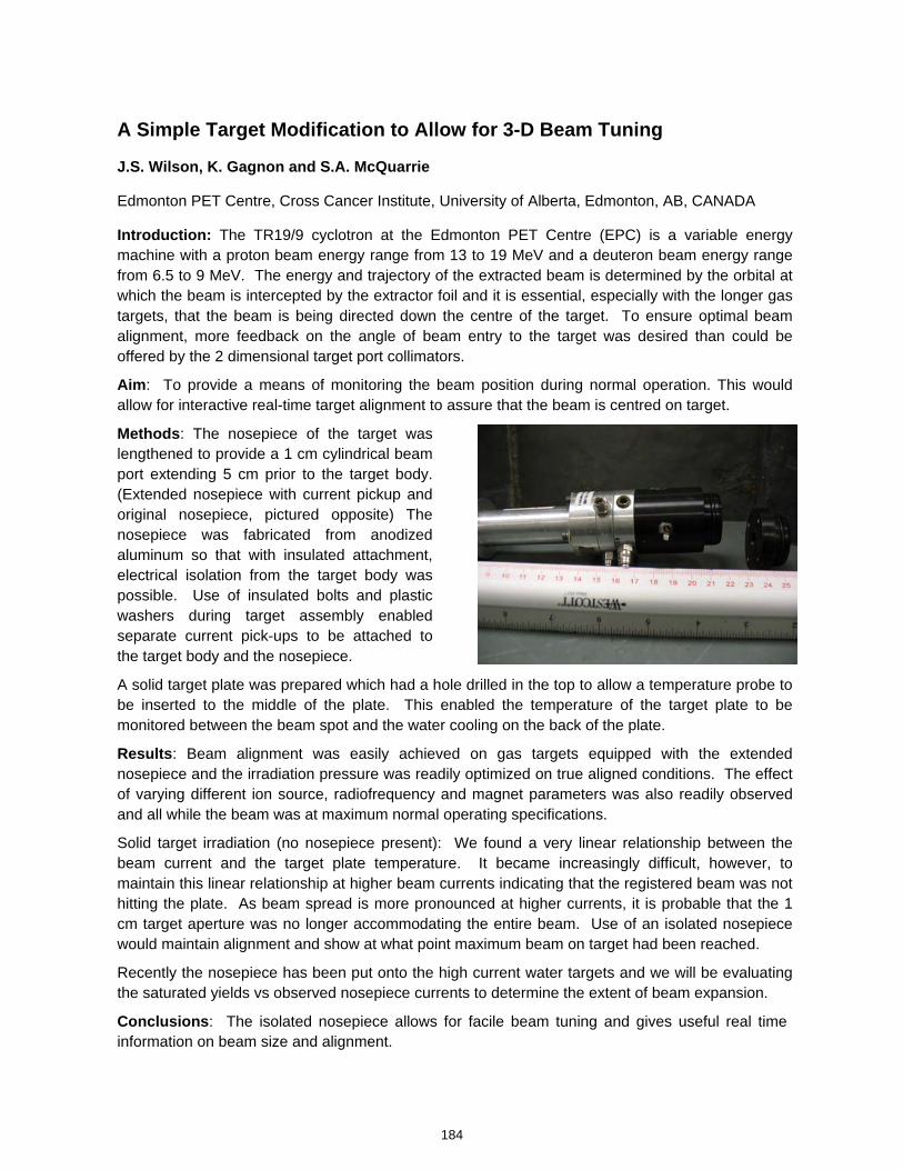
A Simple Target Modification to Allow for 3-D Beam Tuning
J.S. Wilson, K. Gagnon and S.A. McQuarrie
Edmonton PET Centre, Cross Cancer Institute, University of Alberta, Edmonton, AB, CANADA
Introduction: The TR19/9 cyclotron at the Edmonton PET Centre (EPC) is a variable energy machine with a proton beam energy range from 13 to 19 MeV and a deuteron beam energy range from 6.5 to 9 MeV. The energy and trajectory of the extracted beam is determined by the orbital at which the beam is intercepted by the extractor foil and it is essential, especially with the longer gas targets, that the beam is being directed down the centre of the target. To ensure optimal beam alignment, more feedback on the angle of beam entry to the target was desired than could be offered by the 2 dimensional target port collimators.
Aim: To provide a means of monitoring the beam position during normal operation. This would allow for interactive real-time target alignment to assure that the beam is centred on target.
Methods: The nosepiece of the target was lengthened to provide a 1 cm cylindrical beam port extending 5 cm prior to the target body. (Extended nosepiece with current pickup and original nosepiece, pictured opposite) The nosepiece was fabricated from anodized aluminum so that with insulated attachment, electrical isolation from the target body was possible. Use of insulated bolts and plastic washers during target assembly enabled separate current pick-ups to be attached to the target body and the nosepiece. A solid target plate was prepared which had a hole drilled in the top to allow a temperature probe to be inserted to the middle of the plate. This enabled the temperature of the target plate to be monitored between the beam spot and the water cooling on the back of the plate.
Results: Beam alignment was easily achieved on gas targets equipped with the extended nosepiece and the irradiation pressure was readily optimized on true aligned conditions. The effect of varying different ion source, radiofrequency and magnet parameters was also readily observed and all while the beam was at maximum normal operating specifications.
Solid target irradiation (no nosepiece present): We found a very linear relationship between the beam current and the target plate temperature. It became increasingly difficult, however, to maintain this linear relationship at higher beam currents indicating that the registered beam was not hitting the plate. As beam spread is more pronounced at higher currents, it is probable that the 1 cm target aperture was no longer accommodating the entire beam. Use of an isolated nosepiece would maintain alignment and show at what point maximum beam on target had been reached.
Recently the nosepiece has been put onto the high current water targets and we will be evaluating the saturated yields vs observed nosepiece currents to determine the extent of beam expansion.
Conclusions: The isolated nosepiece allows for facile beam tuning and gives useful real time information on beam size and alignment.
184
kmje
Typewritten Text
Abstract 033
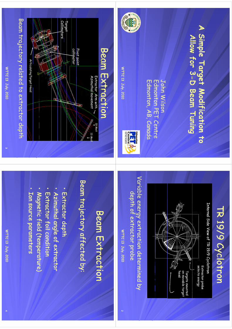
l
Mdf
A Sim
ple Target Modification to
Allow for 3-D
Beam Tuning
Allow for 3-D
Beam Tuning
John Wilson
Edmonton PET Centre
Edmonton PET Centre
Edmonton, A
B, Canada
WTTC 13 July, 2010
WTTC 13 July, 2010
TR 19/9 CyclotronTR 19/9 CyclotronTR 19/9 CyclotronTR 19/9 Cyclotron
Variable energy extraction determined by
depth of extractor probeW
TTC 13 July, 2010W
TTC 13 July, 2010
pf
p22
Beam Extraction
Beam Extraction
Beam Extraction
Beam Extraction
Extractor Arm
with A
zimuthalm
ovement
19 MeV
13 MeV
Extractor Arm
with A
zimuthalm
ovement
19 MeV
13 MeV
Pivot pointPivot point
pcollim
ator
Target
pcollim
ator
Target Collim
atorsCollim
ators
ArticulatingTarget
Head
ArticulatingTarget
Head
Beam trajectory related to extractor depth
WTTC 13 July, 2010
WTTC 13 July, 2010
33
Beam Extraction
Beam Extraction
Beam Extraction
Beam Extraction
Beam trajectory affected by:
Beam trajectory affected by:
••Extractor depthExtractor depthExtractor depthExtractor depth
••A
zimuthal angle of extractor
Azim
uthal angle of extractor••
Extractor foil conditionExtractor foil condition
••M
agnetic field (temperature)
Magnetic field (tem
perature)••
Magnetic field (tem
perature)M
agnetic field (temperature)
••Ion source param
etersIon source param
eters
WTTC 13 July, 2010
WTTC 13 July, 2010
44

Beam Collim
ationBeam
Collimation
Beam Collim
ationBeam
Collimation
Pivot point and target collimators are
diid
d it
4 t
h
ith divided into 4 sectors each with separate current pickup
pp
pBoth have a 1 cm
circular aperture12 cm
between the 2 collimators
Sufficient beam position m
onitoring?Sufficient beam
position monitoring?
WTTC 13 July, 2010
WTTC 13 July, 2010
55
Extended Isolated Nosepiece
p
1 cm
••Target nosepiece extended from 1 cm
to 5 cm in
Target nosepiece extended from 1 cm
to 5 cm in
length with 1 cm cylindrical hole
length with 1 cm cylindrical hole
gy
gy
••Anodized alum
inum for electrical isolation
Anodized alum
inum for electrical isolation
••Two current pickups used Two current pickups used
WTTC 13 July, 2010
WTTC 13 July, 2010
Two current pickups used Two current pickups used
66
Extended Nosepiece
Extended Nosepiece
Intended for gas targets to provide more
space at target head and to confirm target
space at target head and to confirm target
alignment.
the effect of varying different ion source
the effect of varying different ion source, radiofrequency and m
agnet parameters was
also readily observed and all while the beam
also readily observed and all while the beam
was at maxim
um norm
al operating specificationsspecifications.A
ll targets were subsequently fitted with the t
iextension
WTTC 13 July, 2010
WTTC 13 July, 2010
77
ResultsResultsResultsResults
C-11 gas target rupturedd
lh
l
ld
–M
aximized pressure on slightly m
isaligned target
gW
ater targets were fairly aligned.-
routine saturated yield determination
Beam alignm
ent fast and accuratem
gm
fPressure m
aximization
WTTC 13 July, 2010
WTTC 13 July, 2010
88
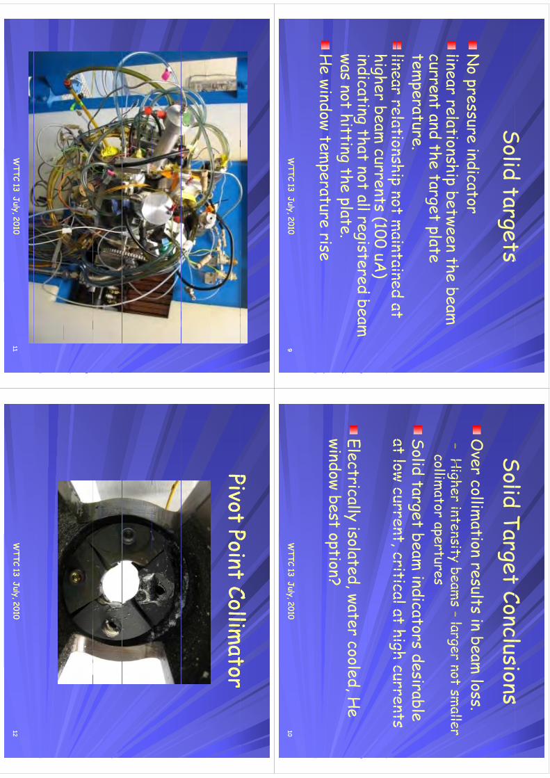
Solid tarets
Solid targetsN
o pressure indicatorli
l
tihi
bt
th b
linear relationship between the beam
current and the target plate
gp
temperature.
linear relationship not maintained at
linear relationship not maintained at
higher beam currents (100 uA
) i
diti
tht
t ll
it
d b
indicating that not all registered beam
was not hitting the plate.g
pH
e window temperature rise
WTTC 13 July, 2010
WTTC 13 July, 2010
99
Solid Taret Conclusions
Solid Target ConclusionsO
ver collimation results in beam
loss.–
Higher intensity beam
s –larger not sm
aller –
Higher intensity beam
s –larger not sm
aller collim
ator aperturesSolid target beam
indicators desirable at low current
critical at high currents at low current, critical at high currents
Electrically isolated, water cooled, He
id
bst
ti?
window best option?
WTTC 13 July, 2010
WTTC 13 July, 2010
1010
WTTC 13 July, 2010
WTTC 13 July, 2010
1111
Pivot Point Collimator
Pivot Point Collimator
Pivot Point Collimator
Pivot Point Collimator
WTTC 13 July, 2010
WTTC 13 July, 2010
1212
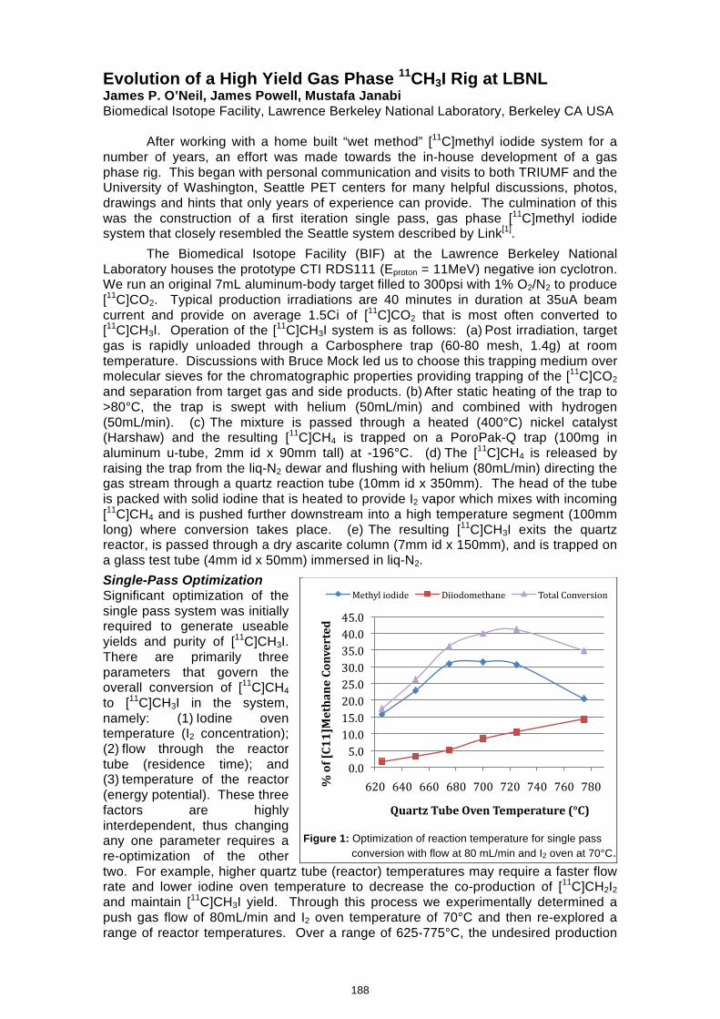
Evolution of a High Yield Gas Phase 11CH3I Rig at LBNL James P. O’Neil, James Powell, Mustafa Janabi Biomedical Isotope Facility, Lawrence Berkeley National Laboratory, Berkeley CA USA
After working with a home built “wet method” [11C]methyl iodide system for a number of years, an effort was made towards the in-house development of a gas phase rig. This began with personal communication and visits to both TRIUMF and the University of Washington, Seattle PET centers for many helpful discussions, photos, drawings and hints that only years of experience can provide. The culmination of this was the construction of a first iteration single pass, gas phase [11C]methyl iodide system that closely resembled the Seattle system described by Link[1].
The Biomedical Isotope Facility (BIF) at the Lawrence Berkeley National Laboratory houses the prototype CTI RDS111 (Eproton = 11MeV) negative ion cyclotron. We run an original 7mL aluminum-body target filled to 300psi with 1% O2/N2 to produce [11C]CO2. Typical production irradiations are 40 minutes in duration at 35uA beam current and provide on average 1.5Ci of [11C]CO2 that is most often converted to [11C]CH3I. Operation of the [11C]CH3I system is as follows: (a) Post irradiation, target gas is rapidly unloaded through a Carbosphere trap (60-80 mesh, 1.4g) at room temperature. Discussions with Bruce Mock led us to choose this trapping medium over molecular sieves for the chromatographic properties providing trapping of the [11C]CO2 and separation from target gas and side products. (b) After static heating of the trap to >80°C, the trap is swept with helium (50mL/min) and combined with hydrogen (50mL/min). (c) The mixture is passed through a heated (400°C) nickel catalyst (Harshaw) and the resulting [11C]CH4 is trapped on a PoroPak-Q trap (100mg in aluminum u-tube, 2mm id x 90mm tall) at -196°C. (d) The [11C]CH4 is released by raising the trap from the liq-N2 dewar and flushing with helium (80mL/min) directing the gas stream through a quartz reaction tube (10mm id x 350mm). The head of the tube is packed with solid iodine that is heated to provide I2 vapor which mixes with incoming [11C]CH4 and is pushed further downstream into a high temperature segment (100mm long) where conversion takes place. (e) The resulting [11C]CH3I exits the quartz reactor, is passed through a dry ascarite column (7mm id x 150mm), and is trapped on a glass test tube (4mm id x 50mm) immersed in liq-N2. Single-Pass Optimization Significant optimization of the single pass system was initially required to generate useable yields and purity of [11C]CH3I. There are primarily three parameters that govern the overall conversion of [11C]CH4 to [11C]CH3I in the system, namely: (1)_Iodine oven temperature (I2 concentration); (2)_flow through the reactor tube (residence time); and (3)_temperature of the reactor (energy potential). These three factors are highly interdependent, thus changing any one parameter requires a re-optimization of the other two. For example, higher quartz tube (reactor) temperatures may require a faster flow rate and lower iodine oven temperature to decrease the co-production of [11C]CH2I2 and maintain [11C]CH3I yield. Through this process we experimentally determined a push gas flow of 80mL/min and I2 oven temperature of 70°C and then re-explored a range of reactor temperatures. Over a range of 625-775°C, the undesired production
Figure 1: Optimization of reaction temperature for single pass conversion with flow at 80 mL/min and I2 oven at 70°C.
0.0 5.0 10.0 15.0 20.0 25.0 30.0 35.0 40.0 45.0
620 640 660 680 700 720 740 760 780 % of [C11]Methane Converted
Quartz Tube Oven Temperature (°C)
Methyl iodide Diiodomethane Total Conversion
188
kmje
Typewritten Text
Abstract 034
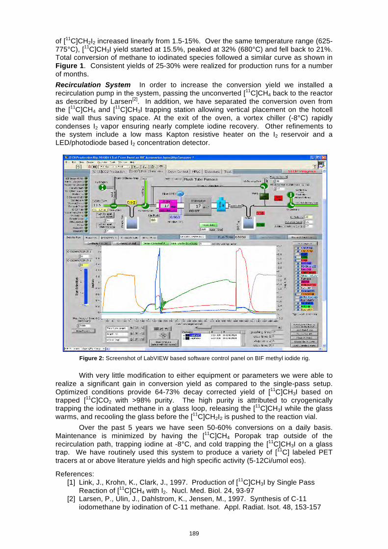
of [11C]CH2I2 increased linearly from 1.5-15%. Over the same temperature range (625-775°C), [11C]CH3I yield started at 15.5%, peaked at 32% (680°C) and fell back to 21%. Total conversion of methane to iodinated species followed a similar curve as shown in Figure 1. Consistent yields of 25-30% were realized for production runs for a number of months. Recirculation System In order to increase the conversion yield we installed a recirculation pump in the system, passing the unconverted [11C]CH4 back to the reactor as described by Larsen[2]. In addition, we have separated the conversion oven from the [11C]CH4 and [11C]CH3I trapping station allowing vertical placement on the hotcell side wall thus saving space. At the exit of the oven, a vortex chiller (-8°C) rapidly condenses I2 vapor ensuring nearly complete iodine recovery. Other refinements to the system include a low mass Kapton resistive heater on the I2 reservoir and a LED/photodiode based I2 concentration detector.
With very little modification to either equipment or parameters we were able to
realize a significant gain in conversion yield as compared to the single-pass setup. Optimized conditions provide 64-73% decay corrected yield of [11C]CH3I based on trapped [11C]CO2 with >98% purity. The high purity is attributed to cryogenically trapping the iodinated methane in a glass loop, releasing the [11C]CH3I while the glass warms, and recooling the glass before the [11C]CH2I2 is pushed to the reaction vial.
Over the past 5 years we have seen 50-60% conversions on a daily basis. Maintenance is minimized by having the [11C]CH4 Poropak trap outside of the recirculation path, trapping iodine at -8°C, and cold trapping the [11C]CH3I on a glass trap. We have routinely used this system to produce a variety of [11C] labeled PET tracers at or above literature yields and high specific activity (5-12Ci/umol eos).
References:
[1] Link, J., Krohn, K., Clark, J., 1997. Production of [11C]CH3I by Single Pass Reaction of [11C]CH4 with I2. Nucl. Med. Biol. 24, 93-97
[2] Larsen, P., Ulin, J., Dahlstrom, K., Jensen, M., 1997. Synthesis of C-11 iodomethane by iodination of C-11 methane. Appl. Radiat. Isot. 48, 153-157
Figure 2: Screenshot of LabVIEW based software control panel on BIF methyl iodide rig.
189
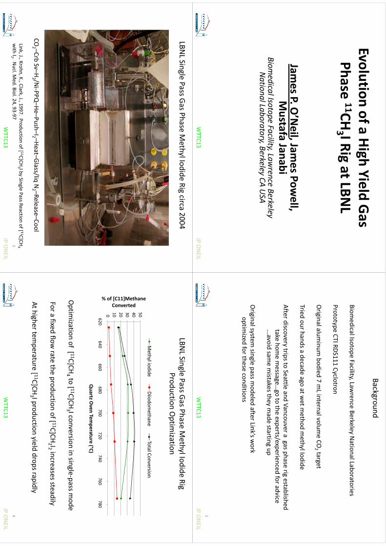
Evolutionofa
HighYield
GasEvolution of a High Yield Gas Phase 11CH
3 I Rig at LBNL
aseC
3ga
James P. O
’Neil, Jam
es Powell,
Mustafa Janabi
Biomedica
l Isotope Fa
cility, Lawren
ce Berkeley
Natio
nal La
boratory, B
erkeley CA USA
JP ONEIL
WTTC13
Background
Biomedical Isotope Facility, Law
rence Berkeley National Laboratories
Prototype CTI RDS111 Cyclotron
Originalalum
inumbodied
7mLinternalvolum
eCO
targetOriginal alum
inum bodied 7 m
Linternal volum
e CO2 target
Tried our hands a decade ago at wet m
ethod methyl Iodide
gy
After discovery trips to Seattle and Vancouver a gas phase rig establishedtake
homemessage
goto
theexperts/experienced
foradvicetake hom
e message…
go to the experts/experienced for advice ...avoid sam
e mistakes they m
ade starting up
Original system
single pass modeled after Link’s w
orkoptim
ized for these conditions
JP ONEIL
WTTC13
2
LBNL Single Pass Gas Phase M
ethyl Iodide Rig circa 2004
CO2 –Crb
Sv–H2 /N
i‐PPQ–He–Push–I2 –Heat–Glass/liq
N2 –Release–Cool
Link, J., Krohn, K., Clark, J., 1997. Production of [ 11C]CH3 I by Single Pass Reaction of [ 11C]CH
4with I2 . N
ucl. Med. Biol. 24, 93‐97
JP ONEIL
WTTC13
3
LBNL Single Pass Gas Phase M
ethyl Iodide RigProduction O
ptimization
Methyliodide
Diiodomethane
TotalConversion
p
30 40 50
Methane rted
Methyl iodide
Diiodomethane
Total Conversion
0 10 20 30
of [C11]MConver
0
620640
660680
700720
740760
780
% Quartz O
ven Temperature (°C)
Optim
ization of [ 11C]CH4 to [ 11C]CH
3 I conversion in single‐pass mode
For a fixed flow rate the production of [ 11C]CH
2 I2 increases steadily
At higher temperature [ 11C]CH
3 I production yield drops rapidly
JP ONEIL
WTTC13
4
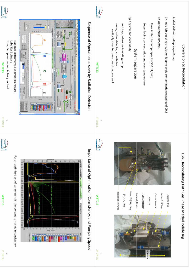
Conversion to Recirculation
Added KNF m
icro‐diaphragm Pum
p
CHtrap
leftoutofrecirculationloop
toavoid
contamination/trapping
ofCHI
CH4 trap left out of recirculation loop to avoid contam
ination/trapping of CH3 I
Re‐Optim
ized parameters
Flow lim
ited by pump capacity (500 m
L/min)
Lower iodine concentration and oven tem
perature
St
tiSystem
separationSplit system
for space utility
cold trap, valves, recirculatingpum
p
ovens,iodinedetector,ascarite
trapovens, iodine detector, ascarite
trapvertically m
ounted oven board on cave wall
JP ONEIL
WTTC13
5
LBNL Recirculating
Path Gas Phase Methyl Iodide Rig
AscariteTrap
Iodine Cold Trap
Furnace
Quartz Reactor
350 mm
KaptonI2 Heater
I2 Conc. Detector
KaptonI2 Heater
Glass [ 11C]CH3 I Trap
[ 11C]CH4Trap
Recirculation Pump
JP ONEIL
WTTC13
6
Sequence of Operation as seen by Radiation Detectors
National Instrum
ents FieldPointHardware
LabVIEWSoftw
are
JP ONEIL
WTTC13
LabVIEWSoftw
areTim
e, Temperature and Activity control
7
Importance of O
ptimization, Consistency, and Pum
ping Speed
For an optimized set of param
eters it is important to m
aintain consistency
JP ONEIL
WTTC13
8
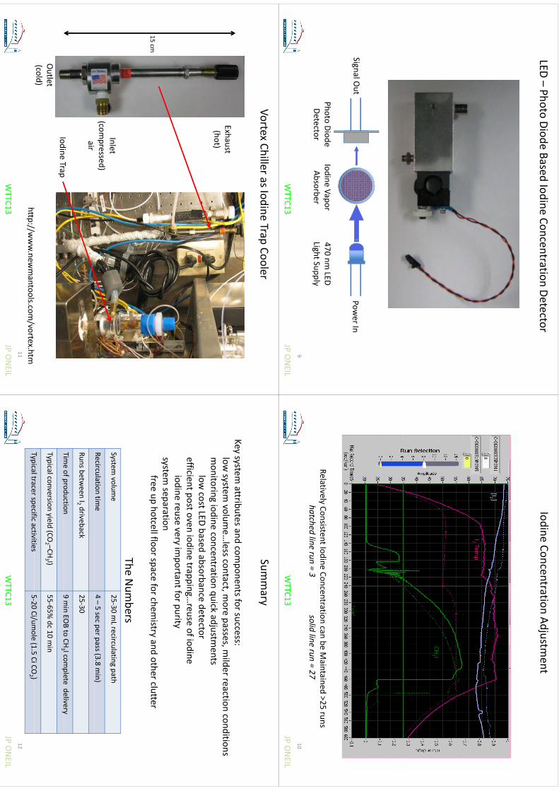
LED –Photo Diode Based Iodine Concentration Detector
Power In
Signal Out
470 nm LED
Light SupplyPhoto DiodeDetector
Iodine VaporAbsorber
gpp
y
JP ONEIL
WTTC13
9
Iodine Concentration Adjustment
[I2 ][I2 ]
I2 Temp
CH3 I3
Relatively Consistent Iodine Concentration can be Maintained >25 runs
hatch
edlinerun
3solid
linerun
27
hatch
ed lin
e run = 3
solid lin
e run = 2
7
JP ONEIL
WTTC13
10
Vortex Chiller as Iodine Trap Cooler
Exhaust(hot)(
)
1515 cm
Inlet(com
pressed)iair
IodineTrap
Outlet
(cold)h
//l
/h
Iodine Trap
JP ONEIL
WTTC13
http://www.new
mantools.com
/vortex.htm11
Summary
Key system attributes and com
ponents for success:low
system volum
e…less contact, m
ore passes, milder reaction conditions
monitoring
iodineconcentration
quickadjustm
entsmonitoring iodine concentration quick adjustm
entslow
cost LED based absorbance detectorefficient post oven iodine trapping…
reuse of iodineiodine reuse very im
portant for puritysystem
separationfree
uphotcellfloorspace
forchemistry
andotherclutter
free up hotcellfloor space for chemistry and other clutter
The Num
bersSystem
volume
25‐30 mLrecirculating
path
Recirculation time
4 –5 sec per pass (3.8 m
in)p
p(
)
Runs between I2 driveback
25‐30
Timeofproduction
9minEO
Bto
CH3 Icom
pletedelivery
Timeof production
9 min EO
Bto CH
3 I complete delivery
Typical conversion yield (CO2 –CH
3 I)55‐65%
dc 10 min
Typicaltracerspecificactivities
520
Ci/umole
(15CiCO
)
JP ONEIL
WTTC13
Typical tracer specific activities5‐20 Ci/um
ole(1.5
CiCO2 )
12
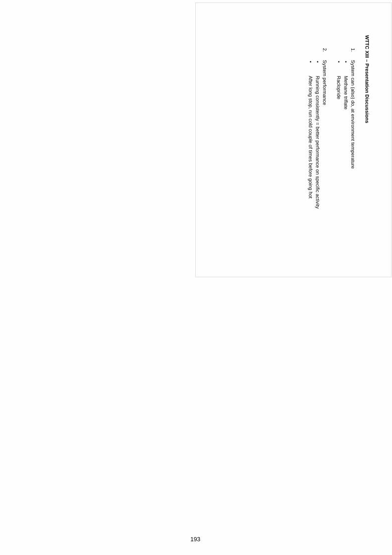
WTTC
XIII–Presentation
Discussions
WTTC
XIII –Presentation D
iscussions
1.S
ystem can (also) do, at environm
ent temperature
•M
ethanetriflate
•M
ethane triflate•
Raclopride
2S
ystemperform
ance2.
System
performance
•R
unning consistently = better performance on specific activity
•A
fter long stop, run cold couple of times before going hot
193
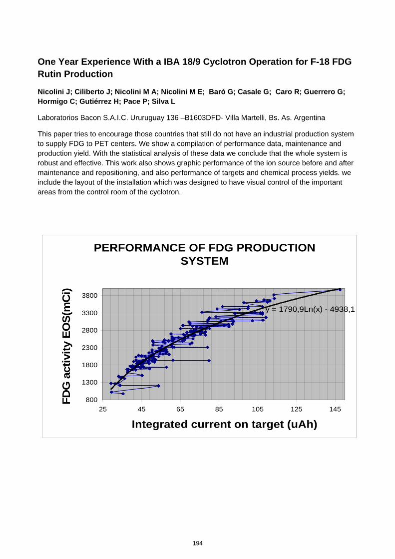
One Year Experience With a IBA 18/9 Cyclotron Operation for F-18 FDG Rutin Production
Nicolini J; Ciliberto J; Nicolini M A; Nicolini M E; Baró G; Casale G; Caro R; Guerrero G; Hormigo C; Gutiérrez H; Pace P; Silva L
Laboratorios Bacon S.A.I.C. Ururuguay 136 –B1603DFD- Villa Martelli, Bs. As. Argentina
This paper tries to encourage those countries that still do not have an industrial production system to supply FDG to PET centers. We show a compilation of performance data, maintenance and production yield. With the statistical analysis of these data we conclude that the whole system is robust and effective. This work also shows graphic performance of the ion source before and after maintenance and repositioning, and also performance of targets and chemical process yields. we include the layout of the installation which was designed to have visual control of the important areas from the control room of the cyclotron.
PERFORMANCE OF FDG PRODUCTION SYSTEM
y = 1790,9Ln(x) - 4938,1
800
1300
1800
2300
2800
3300
3800
25 45 65 85 105 125 145
Integrated current on target (uAh)
FDG
act
ivity
EO
S(m
Ci)
194
kmje
Typewritten Text
Abstract 035

One
One--Year Experience
Year Experience w
ith an IBA
18/9 w
ith an IBA
18/9 C
yclotron Operation
Cyclotron O
peration for Ffor F--18 FD
G R
outine 18 FD
G R
outine ProductionProduction
TheC
clotronFacilit
TheC
clotronFacilit
The Cyclotron Facility
The Cyclotron Facility
Facility D
iagramFacility D
iagram
The Bunker
The Bunker
The Cyclotron
The Cyclotron
The C
yclotronThe C
yclotron
Hot C
ellH
ot Cell
otCe
otCe
Chem
istry Synthesis U
nitChem
istry Synthesis U
nit
The TargetThe Target
22
Gro
ndLa
ot
Gro
ndLa
ot
Ground Layout
Ground Layout
33
ControlR
oomC
ontrolRoom
Control R
oomC
ontrol Room
D
esigned to have D
esigned to have visual contact w
ith visual contact w
ith visual contact w
ith visual contact w
ith the Pow
er Unit and
the Power U
nit and H
ot ells at the
Hot
ells at the H
ot cells at the H
ot cells at the Radiochem
istry Radiochem
istry Laboratory Laboratory
44
Undergro
ndLa
ot
Undergro
ndLa
ot
Underground Layout
Underground Layout
55
TheB
nkerThe
Bnker
The Bunker
The Bunker
Designed to shield
Designed to shield
neutron and neutron and neutron and neutron and gam
ma radiation.
gamm
a radiation. W
alls are made of
Walls are m
ade of W
alls are made of
Walls are m
ade of concrete (density concrete (density 2
35 g/cm2
35 g/cm33))
2,35 g/cm2,35 g/cm
).).
During the
During the
irradiation the irradiation the irradiation the irradiation the bunker is closed by bunker is closed by a 14a 14
ton concrete ton concrete
a 14a 14--ton concrete
ton concrete door.door.
66
The shields are The shields are designed in order designed in order to lim
it the dose to to lim
it the dose to the w
orkers to the w
orkers to 00..5 5 m
Sv/ year.
mSv/year.
yy
The ventilation The ventilation system
keeps a system
keeps a system
keeps a system
keeps a depression greater depression greater than than 100
100 Pa.Pa.
than than 100
100 Pa.Pa.
The safety system
The safety system
locks the door if locks the door if locks the door if locks the door if the dose rate the dose rate inside the bunker inside the bunker inside the bunker inside the bunker is greater than is greater than 100
100 µS
v/hµS
v/hµS
v/hµS
v/h77
TheC
clotronThe
Cclotron
The Cyclotron
The Cyclotron
Cyclone
Cyclone
®18/918/9--
HC
HC
(high current) (high current) (high current) (high current) m
odel.m
odel.
Energy:Energy:18 M
eV Protons
18 MeV
Protons18 M
eV Protons
18 MeV
Protons9 M
eV D
euterons.9 M
eV D
euterons.
88
Synthesizing Hot cell
Synthesizing Hot cell
The H
EPA filter and
The HEPA
filter and charcoal filter are charcoal filter are built to filter the built to filter the exhaust air.exhaust air.
A continuous
A continuous
A continuous
A continuous
radiation air radiation air m
onitoring systemm
onitoring systemm
onitoring system.
monitoring system
.
Front lead Front lead shielding 75m
m
shielding 75mm
shielding 75m
m
shielding 75mm
thickness. thickness. Sid
d b
k Sid
d b
k
Side and back
Side and back
shielding shielding 60 m
m
60 mm
hi
khi
kthickness.thickness.
99
Dispensing
HO
Tcell
Dispensing
HO
Tcell
Dispensing H
OT cell
Dispensing H
OT cell
Ventilation
Ventilation
systems: 70%
system
s: 70%
systems: 70%
system
s: 70%
recycling.recycling.Com
pletely Com
pletely
Com
pletely Com
pletely efficient efficient H
EPA
HEPA
filters (H
EPA>
filters (H
EPA>
filters (H
EPA>
filters (H
EPA>
99,999).99,999).60
Pb hi
ld i
60 Pb
hild i
60 mm
Pb shield in 60 m
m Pb shield in
the front, 50 mm
the front, 50 m
m
Pb hi
ld S
id
Pb hi
ld S
id
Pb shield at Side,
Pb shield at Side,
behind, bottom
behind, bottom
ddand topand top
1010
Chem
istrS
nthesisU
nitC
hemistr
Snthesis
Unit
Chem
istry Synthesis U
nitC
hemistry S
ynthesis Unit
Synthera
Synthera
®
® nucleophilic nucleophilic
sustitucionsustitucionsustitucion.sustitucion.
FD
G S
yntesis time
FDG
Syntesis tim
e <
25 min.
<25 m
in.
Yield EOS 60%
(70%
Yield EOS 60%
(70%
Yield EO
S 60%
(70%
Yield EOS 60%
(70%
corrected yield).corrected yield).I
tt
d Flidi
I
tt
d Flidi
Integrated Fluidic Integrated Fluidic Prossesor (IFPProssesor (IFP
TMTM))
Single use
Single use
1111
Adj
stableP
arameters
Adj
stableP
arameters
Adjustable P
arameters
Adjustable P
arameters
Reactor: tem
perature Reactor: tem
perature
Reactor: tem
perature Reactor: tem
perature 3030--150
150C
.C
.P
P
002 2 bb
Pressure: Pressure: 00--2 2 bar.
bar.
Timing: each step
Timing: each step
gp
gp
adjustable adjustable
1212
WaterTarget
WaterTarget
Water Target
Water Target
IBA
il t
tIB
A
il t
t
IBA com
ercial targetIB
A com
ercial target
Niobium
bodyN
iobium body
obu
bodyob
ubody
Large volum
e 2,4 ml
Large volume 2,4 m
l0
fld
0f
ld
50 µm H
avar foild 50 µm
Havar foild
window
window
Filling volum
e 2 ml
Filling volume 2 m
l 98%
enriched water
98% enriched w
ater98%
enriched water
98% enriched w
ater
1313
TargetCare
TargetCare
Target Care
Target Care
Keep the pressure
Keep the pressure
between
between 2727--30
30 Bar
Bar
between
between 2727
30 30 B
arBar
keep the Tgt/Tgt +
Coll
keep the Tgt/Tgt + C
oll current ratio above current ratio above 9090%%current ratio above current ratio above 9090%%
Replace the o’ring and
Replace the o’ring and
foils window
s at foils w
indows at 5000
5000 foils w
indows at
foils window
s at 5000 5000
μμAh
Ah
Not use recycled
Not use recycled
N
ot use recycled N
ot use recycled enriched w
ater to fill the enriched w
ater to fill the target target target target
1414
TargetPerform
anceTargetP
erformance
Target Perform
anceTarget P
erformance
Water Target Yield
10000
12000
Theoretical Saturation Line
8000
EOB (mCi)
Experimental Saturation Line
y = 2884,9Ln(x) - 7834,2R
2 = 0,92144000
6000
F-18 activity
0
2000
F
00
2040
6080
100120
140160
Integrated current on Target (uAh)
1515
Perform
ance of FDG
Production
Perform
ance of FDG
Production
System
System
3300
3800
Ci)
y = 1790,9Ln(x) - 4938,12800
3300
EOS(mC1800
2300
activity
800
1300
FDG a
80025
4565
85105
125145
Integrated current on target (uAh)
1616
Sm
mar
Sm
mar
Sum
mary
Sum
mary
M
ore than 200 runsM
ore than 200 runs
Average daily production of FD
G:
Average daily production of FD
G:
2300 mCi
2300 mCi
2300 mCi.
2300 mCi.
M
aximun FD
G activity obtained in
Maxim
un FDG
activity obtained in one run: 3970 m
Ci (147,54 µA
h in one run: 3970 m
Ci (147,54 µA
h in 3
5 h)3
5 h)3,5 h).3,5 h).
1717
199
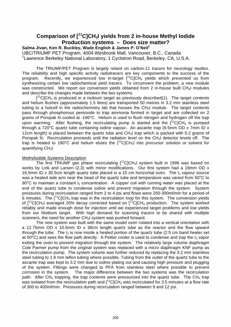
Comparison of [11C]CH3I yields from 2 in-house Methyl Iodide Production systems – Does size matter?
Salma Jivan, Ken R. Buckley, Wade English & James P. O’Neil1 UBC/TRIUMF PET Program, 4004 Wesbrook Mall, Vancouver, B.C., Canada 1Lawrence Berkeley National Laboratory, 1 Cyclotron Road, Berkeley, CA, U.S.A.
The TRIUMF/PET Program is largely reliant on carbon-11 tracers for neurology studies. The reliability and high specific activity radiotracers are key components to the success of the program. Recently, we experienced low in-target [11C]CH4 yields which prevented us from synthesizing certain low radiochemical yield tracers. To circumvent the problem, a new module was constructed. We report our conversion yields obtained from 2 in-house built CH3I modules and describe the changes made between the two systems. [11C]CH4 is produced in a niobium target as previously described(1). The target contents and helium flushes (approximately 1.5 litres) are transported 50 metres in 3.2 mm stainless steel tubing to a hotcell in the radiochemistry lab that houses the CH3I module. The target contents pass through phosphorous pentoxide to trap ammonia formed in target and are collected on 2 grams of Poropak N cooled at -196°C. Helium is used to flush nitrogen and hydrogen off the trap upon warming. After flushing, the recirculating pump is started and the [11C]CH4 is pumped through a 720°C quartz tube containing iodine vapour. An ascarite trap (9.5mm OD x 7mm ID x 12cm length) is placed between the quartz tube and CH3I trap which is packed with 0.2 grams of Poropak N. Recirculation proceeds until the radiation level on the CH3I detector levels off. The trap is heated to 180°C and helium elutes the [11C]CH3I into precursor solution or solvent for quantifying CH3I. Methyliodide Systems Description The first TRIUMF gas phase recirculating [11C]CH3I system built in 1996 was based on works by Link and Larsen (2,3) with minor modifications. Our first system had a 19mm OD x 16.5mm ID x 30.5cm length quartz tube placed in a 15 cm horizontal oven. The I2 vapour source was a heated side arm near the head of the quartz tube and temperature was varied from 50°C to 90°C to maintain a constant I2 concentration. A copper coil with running water was placed at the end of the quartz tube to condense iodine and prevent migration through the system. System pressures during recirculation ranged from 2 to 4 psi and flows were 250-300ml/min for a period of 6 minutes. The [11C]CH4 trap was in the recirculation loop for this system. The conversion yields of [11C]CH3I averaged 20% decay corrected based on [11C]CH4 production. The system worked reliably and made enough dose for injection until we experienced target problems and low yields from our Niobium target. With high demand for scanning tracers to be shared with multiple scanners, the need for another CH3I system was pushed forward.
The new system was built with the same model oven rotated into a vertical orientation with a 12.75mm OD x 10.5mm ID x 38cm length quartz tube as the reactor and the flow upward through the tube. The I2 is now inside a heated portion of the quartz tube (2.5 cm band heater set at 50°C) and sees the flow path directly. A Peltier cooler is used to condense and trap the I2 vapor exiting the oven to prevent migration through the system. The relatively large volume diaphragm Cole Parmer pump from the original system was replaced with a micro diaphragm KNF pump as the recirculation pump. The system volume was further reduced by replacing the 3.2 mm stainless steel tubing to 1.6 mm teflon tubing where possible. Tubing from the outlet of the quartz tube to the ascarite trap was kept to 3.2 mm due to iodine plating out and causing high pressure and plugging of the system. Fittings were changed to PFA from stainless steel where possible to prevent corrosion in the system. The major difference between the two systems was the recirculation path. After CH4 trapping, the trap contents were pressurized into the quartz tube. The CH4 trap was isolated from the recirculation path and [11C]CH4 was recirculated for 3.5 minutes at a flow rate of 300 to 400ml/min. Pressures during recirculation ranged between 9 and 12 psi.
200
kmje
Typewritten Text
Abstract 036
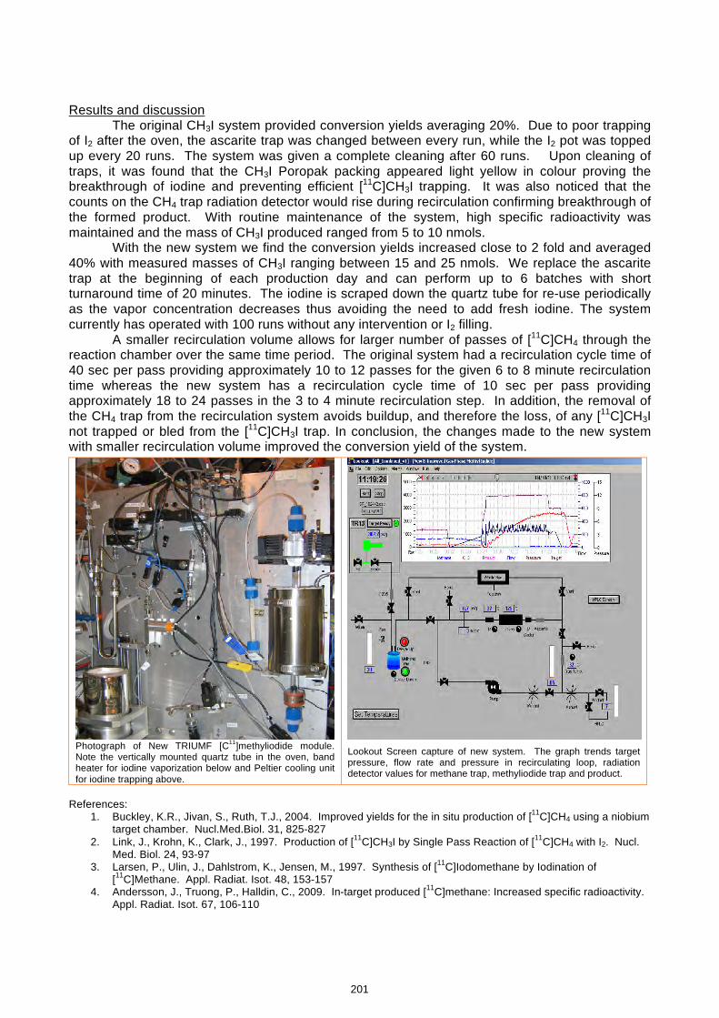
Results and discussion The original CH3I system provided conversion yields averaging 20%. Due to poor trapping
of I2 after the oven, the ascarite trap was changed between every run, while the I2 pot was topped up every 20 runs. The system was given a complete cleaning after 60 runs. Upon cleaning of traps, it was found that the CH3I Poropak packing appeared light yellow in colour proving the breakthrough of iodine and preventing efficient [11C]CH3I trapping. It was also noticed that the counts on the CH4 trap radiation detector would rise during recirculation confirming breakthrough of the formed product. With routine maintenance of the system, high specific radioactivity was maintained and the mass of CH3I produced ranged from 5 to 10 nmols.
With the new system we find the conversion yields increased close to 2 fold and averaged 40% with measured masses of CH3I ranging between 15 and 25 nmols. We replace the ascarite trap at the beginning of each production day and can perform up to 6 batches with short turnaround time of 20 minutes. The iodine is scraped down the quartz tube for re-use periodically as the vapor concentration decreases thus avoiding the need to add fresh iodine. The system currently has operated with 100 runs without any intervention or I2 filling.
A smaller recirculation volume allows for larger number of passes of [11C]CH4 through the reaction chamber over the same time period. The original system had a recirculation cycle time of 40 sec per pass providing approximately 10 to 12 passes for the given 6 to 8 minute recirculation time whereas the new system has a recirculation cycle time of 10 sec per pass providing approximately 18 to 24 passes in the 3 to 4 minute recirculation step. In addition, the removal of the CH4 trap from the recirculation system avoids buildup, and therefore the loss, of any [11C]CH3I not trapped or bled from the [11C]CH3I trap. In conclusion, the changes made to the new system with smaller recirculation volume improved the conversion yield of the system.
References:
1. Buckley, K.R., Jivan, S., Ruth, T.J., 2004. Improved yields for the in situ production of [11C]CH4 using a niobium target chamber. Nucl.Med.Biol. 31, 825-827
2. Link, J., Krohn, K., Clark, J., 1997. Production of [11C]CH3I by Single Pass Reaction of [11C]CH4 with I2. Nucl. Med. Biol. 24, 93-97
3. Larsen, P., Ulin, J., Dahlstrom, K., Jensen, M., 1997. Synthesis of [11C]Iodomethane by Iodination of [11C]Methane. Appl. Radiat. Isot. 48, 153-157
4. Andersson, J., Truong, P., Halldin, C., 2009. In-target produced [11C]methane: Increased specific radioactivity. Appl. Radiat. Isot. 67, 106-110
Photograph of New TRIUMF [C11]methyliodide module. Note the vertically mounted quartz tube in the oven, band heater for iodine vaporization below and Peltier cooling unit for iodine trapping above.
Lookout Screen capture of new system. The graph trends target pressure, flow rate and pressure in recirculating loop, radiation detector values for methane trap, methyliodide trap and product.
201
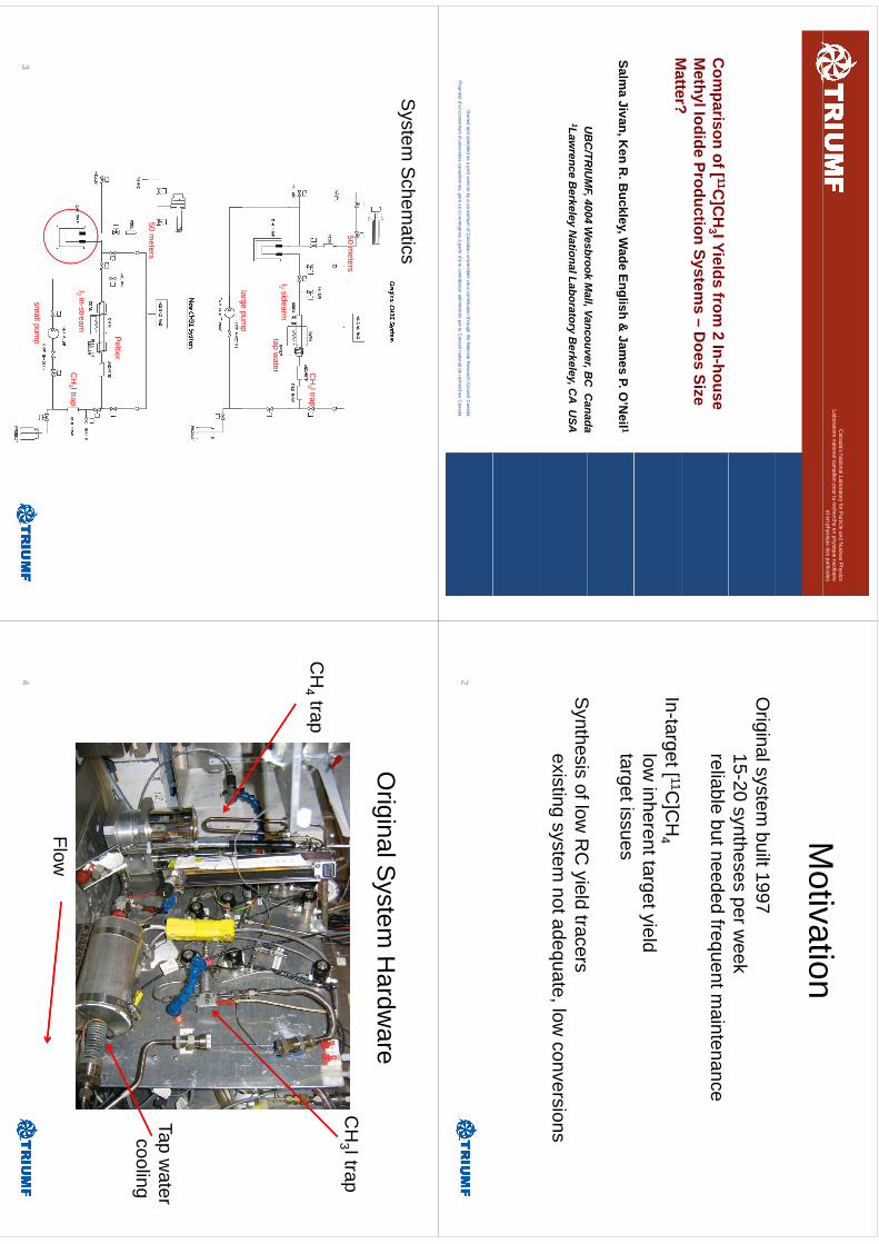
Canada’s N
ational Laboratory for Particle and N
uclear Physics
Laboratoirenational canadien
pour la rechercheen physique nucléaire
et en physique des particules
Com
parison of [ 11C]C
H3 I Yields from
2 In-house M
ethyl Iodide Production Systems –
Does Size
Matter?
Matter?
Salma Jivan, K
en R. B
uckley, Wade English &
James P. O
’Neil 1
UB
C/TR
IUM
F4004
Wesbrook
Mall
VancouverB
CC
anadaU
BC
/TRIU
MF, 4004 W
esbrookM
all, Vancouver, BC
Canada
1Lawrence B
erkeley National Laboratory B
erkeley, CA U
SA
Ow
ned and operated as a joint venture by a consortium of C
anadian universities via a contribution through the National R
esearch Council C
anada
Propriété
d’un consortium d’universités
canadiennes, géréen co-entreprise
àpartird’une
contribution administrée
par le Conseilnational de recherches
Canada
Motivation
Motivation
Original system
built 199715-20 syntheses per w
eekreliable but needed frequent m
aintenance
In-target [ 11C]C
H4
low inherent target yield
target issues
Sth
ifl
RC
ild
tS
ynthesis of low R
C yield tracers
existing system not adequate, low
conversions
2
System
Schem
atics
50 meters
CH
3 I trap
I2 sidearmtap w
ater
largepum
plarge pum
p
50 meters
Peltier
I2 in-streamC
H3 I trap
small pum
p3
OriginalS
ystemH
ardware
Original S
ystem H
ardware
CH
3 I trap
CH
4 trap
Tap waterli
cooling
FlowFlow
4
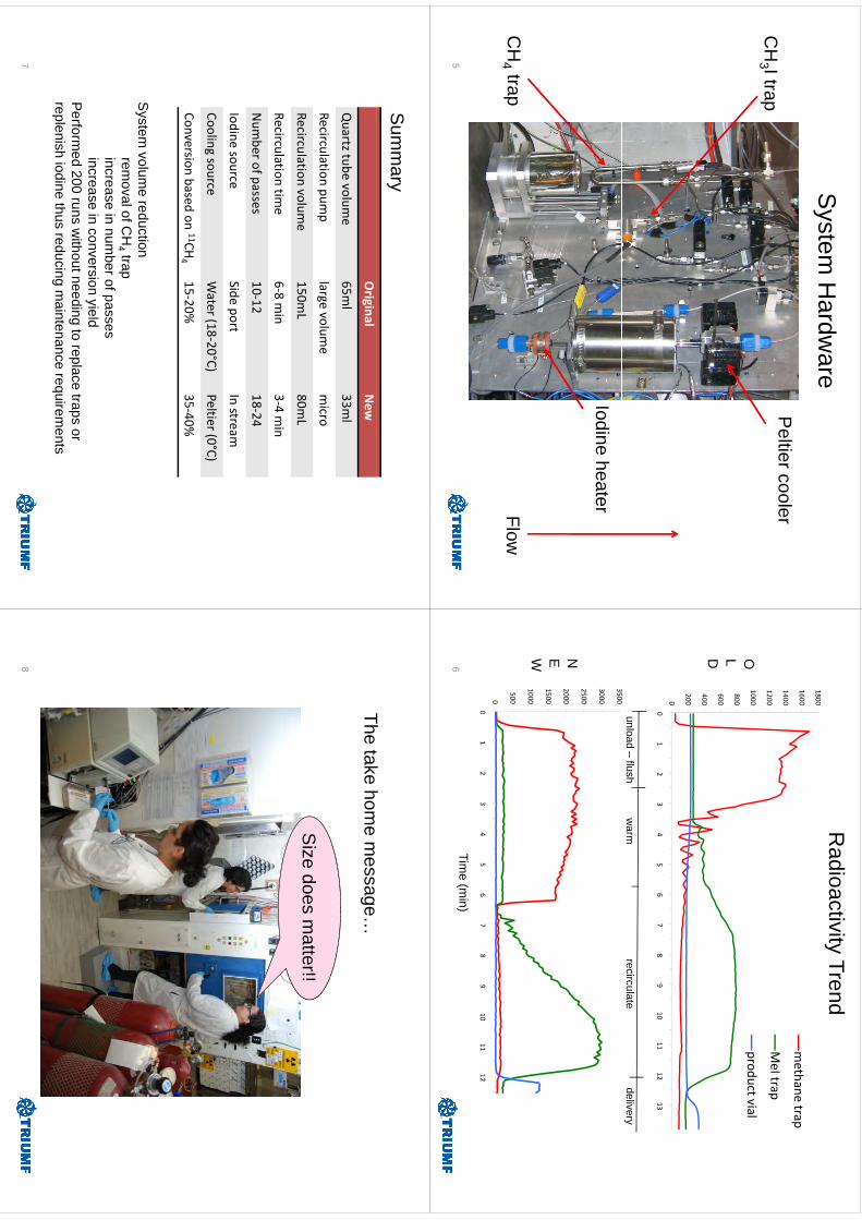
System
Hardw
areP
eltiercoolerC
H3 I trap3
Iodine heaterFlowC
H4 trap
5
Radioactivity Trend
1800
1200
1400
1600methane trap
MeI trap
600
800
1000product vial
OLD
0
200
400D
3500
01
23
45
67
89
1011
1213
unload –flush
warm
recirculatedelivery
2500
3000
3500
N
1000
1500
2000NEW
0
500
1000
01
23
45
67
89
1011
120
12
34
56
78
910
1112
Time (m
in)6
Sum
mary
Original
New
Quartz tube volum
e65m
l33m
l
Recirculation pump
largevolum
emicro
Recirculation volume
150mL
80mL
il
ii
68
i3
iRecirculation
time
6‐8 min
3‐4 min
Num
ber of passes10‐12
18‐24
Idi
Sidt
It
Iodine sourceSide port
In stream
Cooling sourceWater (18‐20°C)
Peltier(0°C)
Conersion
basedon
11CH15
20%35
40%Conversion based
on 11CH4
15‐20%35‐40%
System
volume
reductionS
ystem volum
e reduction rem
oval of CH
4 trapincrease in num
ber of passesincrease in conversion yield
Perform
ed 200 runs without needing to replace traps or
replenish iodine thus reducing maintenance requirem
entsp
gq
7
Tht
kh
The take home m
essage…
Size does m
atter!!
8
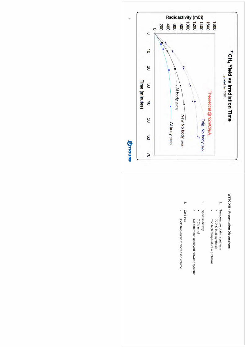
9
WTTC
XIII–Presentation
Discussions
WTTC
XIII –Presentation D
iscussions
1.Tem
perature during synthesis•
720ºCin
allsynthesis•
720 C
in all synthesis•
Too high temperature = problem
s
2S
pecificactivity
2.S
pecific activity•
7 Ci/ um
ol•
No difference observed betw
een systems
3.C
old trap•
Cold trap outside: decreased volum
e
Cyclotron production of 99mTc via the 100Mo(p,2n)99mTc reaction
K. Gagnon1, F. Bénard2, M. Kovacs3, T.J. Ruth4, P. Schaffer4, and S.A. McQuarrie1
1 Edmonton PET Centre, Cross Cancer Institute, University of Alberta, Edmonton, AB, CANADA 2 BC Cancer Agency, Vancouver, BC, CANADA 3 Lawson Health Research Institute, London, ON, CANADA 4 TRIUMF, Vancouver, BC, CANADA
Introduction: In light of the current world-wide shortage of reactor-produced 99Mo/99mTc, there is a
growing interest in exploring the large-scale cyclotron production of 99mTc via the 100Mo(p,2n)99mTc
reaction (a method first proposed by Beaver and Hupf, J Nucl Med, 1971, 12: 739). In producing 99mTc, knowledge of the cross sections and theoretical yields are essential for optimizing the high-
current irradiation conditions and verifying the processing/recovery techniques. A review of the
existing published cross section data for the 100Mo(p,2n)99mTc reaction however reveals large
discrepancies in these measured values.
Aim: Given the large cross section discrepancies in the current literature, the goal of this work was
to re-evaluate the cross sections for the 100Mo(p,2n)99mTc and 100Mo(p,pn)99Mo reactions.
Methods: The 99mTc and 99Mo cross sections were evaluated using both natural abundance (7.5
mg/cm2) and 100Mo enriched (97.42%, 7.4–11.1 mg/cm2) foils. Foils were individually irradiated with
proton energies up to 18 MeV for 600 seconds on the Edmonton PET Centre’s TR 19/9 variable
energy cyclotron (Advanced Cyclotron Systems Inc., Richmond, BC). A copper foil was in place for
all irradiations for the purpose of monitoring the beam energy and irradiation current. Unless
otherwise noted, all decay data were obtained from the NuDat 2.5 database.
The molybdenum foils were assayed multiple times (from a few hours to several days post-EOB)
using an HPGe detector (sample distance ≥ 25 cm, dead time < 7%). The detector was calibrated
using standard sources of 22Na, 54Mn, 57Co, 60Co, 109Cd, 133Ba and 137Cs. The 99Mo activity was
determined using a weighted average of the 181 keV and 739 keV peaks. In determining the 99mTc
activity, the non-resolved 140/142 keV peak (89.06%/ 0.02%) was measured. Two additional
contributing sources to the 140 keV peak were subtracted prior to evaluation of the direct 99mTc
cross section. Firstly, as 99Mo decays to 99mTc, the 99Mo associated 99mTc activity at the start of
counting was determined from the measured 99Mo activity using the radioactive parent-daughter
relationship described by Attix (Introduction to Radiological Physics and Radiation Dosimetry,
2004, pp. 105–106) with the branching ratio to 99mTc taken as 87.6% (Alfassi et al., Appl Radiat
Isot, 2005 63: 37). Next, as 99Mo gives rise to a 140 keV (4.52%) gamma ray upon decay, this
peak contribution was calculated from the measured 99Mo activity of each respective foil. Cross
sections were calculated using the standard activation formula (Krane, Introductory Nuclear
Physics, 1988, pp. 169–170) with values normalized to 100 percent 100Mo enrichment.
Thick target yields were calculated from the measured 99mTc cross sections assuming 100 percent 100Mo and fitting the cross-section data with a 2nd order polynomial. Values are reported for 1810
MeV, and 2210 MeV (cross sections extrapolated to 22 MeV from a polynomial curve fit).
Results: The following figures compare the evaluated cross sections for the direct production of 99mTc and 99Mo to previously published cross section data. For the purpose of comparison, we
have normalized the 99mTc data of Challan et al. (Nucl Rad Phys, 2007, 2: 1) to 100 percent 100Mo
by dividing by 9.63%. For both reactions, our results are in good agreement to values published by
Levkovskij (1991). Good 99mTc cross section agreement is also noted up to Ep ~12 MeV when
205
kmje
Typewritten Text
Abstract 037
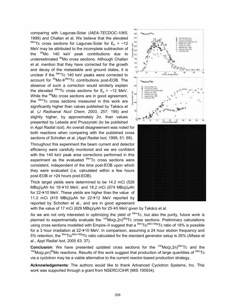
comparing with Lagunas-Solar (IAEA-TECDOC-1065,
1999) and Challan et al. We believe that the elevated 99mTc cross sections for Lagunas-Solar for Ep > ~12
MeV may be attributed to the incomplete subtraction of
the 99Mo 140 keV peak contributions due to
underestimated 99Mo cross sections. Although Challan
et al. mention that they have corrected for the growth
and decay of the metastable and ground states, it is
unclear if the 99mTc 140 keV peaks were corrected to
account for 99Mo99mTc contributions post-EOB. The
absence of such a correction would similarly explain
the elevated 99mTc cross sections for Ep > ~12 MeV.
While the 99Mo cross sections are in good agreement,
the 99mTc cross sections measured in this work are
significantly higher than values published by Takács et
al. (J Radioanal Nucl Chem, 2003, 257: 195) and
slightly higher, by approximately 2σ, than values
presented by Lebeda and Pruszynski (to be published
in Appl Radiat Isot). An overall disagreement was noted for
both reactions when comparing with the published cross
sections of Scholten et al. (Appl Radiat Isot, 1999, 51: 69).
Throughout this experiment the beam current and detector
efficiency were carefully monitored and we are confident
with the 140 keV peak area corrections performed in this
experiment as the evaluated 99mTc cross sections were
consistent, independent of the time post-EOB upon which
they were evaluated (i.e. calculated within a few hours
post-EOB or >24 hours post-EOB).
Thick target yields were determined to be 14.2 mCi (526
MBq)/µAh for 1810 MeV, and 18.2 mCi (674 MBq)/µAh
for 2210 MeV. These yields are higher than the value of
11.2 mCi (415 MBq)/µAh for 2212 MeV reported by
reported by Scholten et al., and are in good agreement
with the value of 17 mCi (629 MBq)/µAh for 255 MeV given by Takács et al.
As we are not only interested in optimizing the yield of 99mTc, but also the purity, future work is
planned to experimentally evaluate the 100Mo(p,2n)99gTc cross sections. Preliminary calculations
using cross sections modelled with Empire–II suggest that a 99mTc/99m+99gTc ratio of 18% is possible
for a 3 hour irradiation at 2210 MeV. In comparison, assuming a 24 hour elution frequency and
5% retention, the 99mTc/99m+99gTc ratio calculated for the standard generator setup is 26% (Alfassi et
al., Appl Radiat Isot, 2005 63: 37).
Conclusion: We have presented updated cross sections for the 100Mo(p,2n)99mTc and the 100Mo(p,pn)99Mo reactions. Results of this work suggest that production of large quantities of 99mTc
via a cyclotron may be a viable alternative to the current reactor-based production strategy.
Acknowledgements: The authors would like to thank Advanced Cyclotron Systems, Inc. This
work was supported through a grant from NSERC/CIHR (MIS 100934).
206
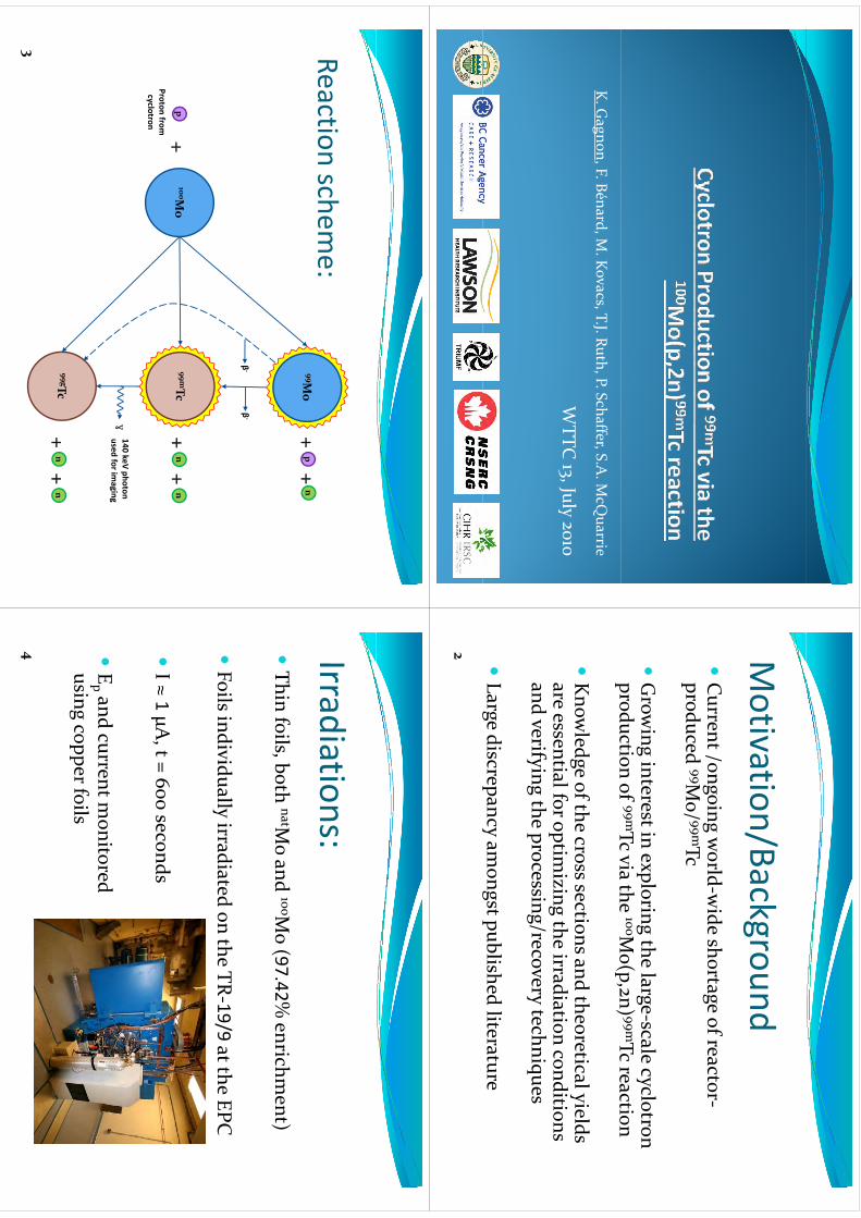
K. G
agnon, F. Bénard, M. K
ovacs, T.J. Ruth, P. Schaffer, S.A. M
cQuarrie
WTTC
J
l
WTTC
13, July 2010
Motivation/Background
Motivation/Background
Current /ongoing w
orldwide shortage of reactor
Current /ongoing w
orld‐wide shortage of reactor‐
produced 99Mo/ 99mTc
Grow
ing interest in exploring the large‐scale cyclotron production of 99mTc via the 100M
o(p,2n) 99mTc reactionproduction of
Tc via the Mo(p,2n)
Tc reaction
Know
ledge of the cross sections and theoretical yields ow
edgeo
tecosssect
osa
dteo
etcayeds
are essential for optimizing the irradiation conditions
and verif ying the processing/recovery techniquesy
gp
gy
q
Large discrepancy am
ongst published literatureg
py
gp
2
Reactionschem
e:Reaction schem
e:99M
o+
n+
p
β‐
β‐
p100M
oProton from
cyclotron
99mTc+
n+
n+
γ140 keV photon used for im
aging
99gTc+
n+
n
3
++
Irradiations:Irradiations:Thin foils
both natMoand 100M
o (9742%
enrichment)
Thin foils, both natM
oand 100M
o (97.42% enrichm
ent)
Foils individually irradiated on the TR‐19/9
at the EPC
I ≈ 1
μA, t = 600 seconds
Ep and current m
onitored Ep and current m
onitored using copper foils
4
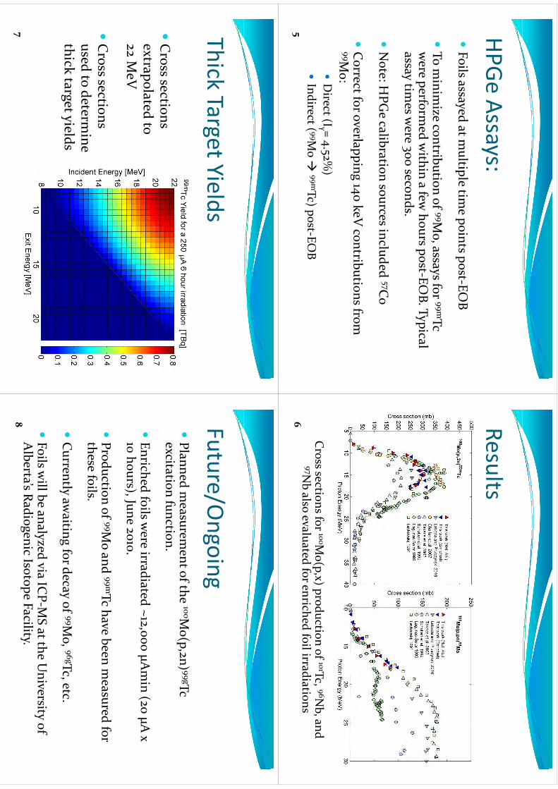
HPGeAssays:
HPGe Assays:Foils assayed at m
ultiple time points post
EOB
Foils assayed at m
ultiple time points post‐EO
B
To m
inimize contribution of 99M
o, assays for 99mTc ,
ywere perform
ed within a few
hours post‐EOB. Typical
assa y times w
ere 300 seconds.y
3
Note: H
PGe calibration sources included 57C
o
Correct for overlapping 140 keV
contributions from
99Mo:
99Mo:Direct (Iγ = 4.52%
)Indirect ( 99M
o 99mTc) post
EOB
Indirect ( 99M
o 99mTc) post‐EO
B5
ResultsResults
Cross sections for 100M
o(p,x) production of 101Tc, 96Nb, and
6
pp
97Nb also evaluated for enriched foil irradiations
ThickTargetYields
Thick Target Yields
Cross sections
ld
extrapolated to 22 M
eV
Cross sections
used to determine
thick target yieldsg
y
7
Future/Ongoing
Future/Ongoing
Planned m
easurement of the 100M
o(p2n) 99gTc
Planned m
easurement of the
Mo(p,2n) 99gTc
excitation function.
Enriched foils w
ere irradiated ~12,000 μAmin
(20 μA x
10 hours), June 2010.
Production of 99M
o and 99mTc have been measured for
th f
ilthese foils.
Currently aw
aiting for decay of 99Mo, 96gTc, etc.
Currently awaiting for decay of
Mo,
Tc, etc.
Foils w
ill be analyzed via ICP‐M
S at the University of
Alberta’s Radiogenic Isotope Facility.
8
Summary
Summary
hd
dd
fh
We have presented updated cross sections for the
100Mo(p,2n) 99mTc and 100M
o(p,pn) 99Mo reactions
Calculated thick target yields suggest that
gy
ggproduction of large quantities of 99mTc via a cyclotron m
ay be a feasible alternative to the y
ycurrent reactor‐based strategy
Experim
ents are underway to evaluate the
100Mo(p,2n) 99gTc excitation function(p,
)9
WTTC
XIII–Presentation
Discussions
WTTC
XIII –Presentation D
iscussions
1.R
esolve g/m states by neutron counting?
•N
eutronm
easurements
difficultinthin
foilmethodology
•N
eutron measurem
ents difficult in thin foil methodology
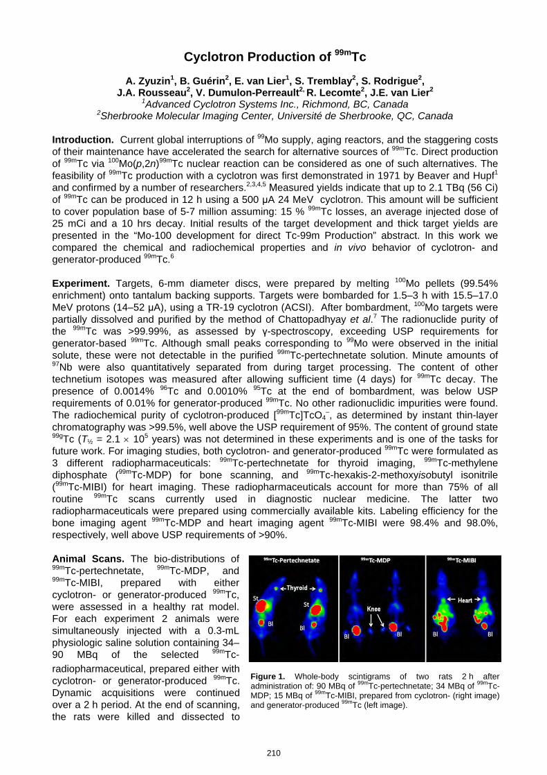
Figure 1. Whole-body scintigrams of two rats 2 h after administration of: 90 MBq of 99mTc-pertechnetate; 34 MBq of 99mTc-MDP; 15 MBq of 99mTc-MIBI, prepared from cyclotron- (right image) and generator-produced 99mTc (left image).
Cyclotron Production of 99mTc
A. Zyuzin1, B. Guérin2, E. van Lier1, S. Tremblay2, S. Rodrigue2, J.A. Rousseau2, V. Dumulon-Perreault2, R. Lecomte2, J.E. van Lier2
1Advanced Cyclotron Systems Inc., Richmond, BC, Canada 2Sherbrooke Molecular Imaging Center, Université de Sherbrooke, QC, Canada
Introduction. Current global interruptions of 99Mo supply, aging reactors, and the staggering costs of their maintenance have accelerated the search for alternative sources of 99mTc. Direct production of 99mTc via 100Mo(p,2n)99mTc nuclear reaction can be considered as one of such alternatives. The feasibility of 99mTc production with a cyclotron was first demonstrated in 1971 by Beaver and Hupf1 and confirmed by a number of researchers.2,3,4,5 Мeasured yields indicate that up to 2.1 TBq (56 Ci) of 99mTc can be produced in 12 h using a 500 μA 24 MeV cyclotron. This amount will be sufficient to cover population base of 5-7 million assuming: 15 % 99mTc losses, an average injected dose of 25 mCi and a 10 hrs decay. Initial results of the target development and thick target yields are presented in the “Mo-100 development for direct Tc-99m Production” abstract. In this work we compared the chemical and radiochemical properties and in vivo behavior of cyclotron- and generator-produced 99mTc.6
Experiment. Targets, 6-mm diameter discs, were prepared by melting 100Mo pellets (99.54% enrichment) onto tantalum backing supports. Targets were bombarded for 1.5–3 h with 15.5–17.0 MeV protons (14–52 μA), using a TR-19 cyclotron (ACSI). After bombardment, 100Mo targets were partially dissolved and purified by the method of Chattopadhyay et al.7 The radionuclide purity of the 99mTc was >99.99%, as assessed by γ-spectroscopy, exceeding USP requirements for generator-based 99mTc. Although small peaks corresponding to 99Mo were observed in the initial solute, these were not detectable in the purified 99mTc-pertechnetate solution. Minute amounts of 97Nb were also quantitatively separated from during target processing. The content of other technetium isotopes was measured after allowing sufficient time (4 days) for 99mTc decay. The presence of 0.0014% 96Tc and 0.0010% 95Tc at the end of bombardment, was below USP requirements of 0.01% for generator-produced 99mTc. No other radionuclidic impurities were found. The radiochemical purity of cyclotron-produced [99mTc]TcO4
–, as determined by instant thin-layer chromatography was >99.5%, well above the USP requirement of 95%. The content of ground state 99gTc (T½ = 2.1 × 10⁵ years) was not determined in these experiments and is one of the tasks for future work. For imaging studies, both cyclotron- and generator-produced 99mTc were formulated as 3 different radiopharmaceuticals: 99mTc-pertechnetate for thyroid imaging, 99mTc-methylene diphosphate (99mTc-MDP) for bone scanning, and 99mTc-hexakis-2-methoxyisobutyl isonitrile (99mTc-MIBI) for heart imaging. These radiopharmaceuticals account for more than 75% of all routine 99mTc scans currently used in diagnostic nuclear medicine. The latter two radiopharmaceuticals were prepared using commercially available kits. Labeling efficiency for the bone imaging agent 99mTc-MDP and heart imaging agent 99mTc-MIBI were 98.4% and 98.0%, respectively, well above USP requirements of >90%. Animal Scans. The bio-distributions of 99mTc-pertechnetate, 99mTc-MDP, and 99mTc-MIBI, prepared with either cyclotron- or generator-produced 99mTc, were assessed in a healthy rat model. For each experiment 2 animals were simultaneously injected with a 0.3-mL physiologic saline solution containing 34–90 MBq of the selected 99mTc-radiopharmaceutical, prepared either with cyclotron- or generator-produced 99mTc. Dynamic acquisitions were continued over a 2 h period. At the end of scanning, the rats were killed and dissected to
210
kmje
Typewritten Text
Abstract 038
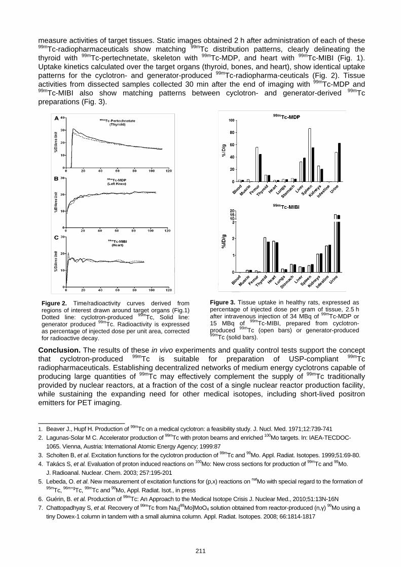
measure activities of target tissues. Static images obtained 2 h after administration of each of these 99mTc-radiopharmaceuticals show matching 99mTc distribution patterns, clearly delineating the thyroid with 99mTc-pertechnetate, skeleton with 99mTc-MDP, and heart with 99mTc-MIBI (Fig. 1). Uptake kinetics calculated over the target organs (thyroid, bones, and heart), show identical uptake patterns for the cyclotron- and generator-produced 99mTc-radiopharma-ceuticals (Fig. 2). Tissue activities from dissected samples collected 30 min after the end of imaging with 99mTc-MDP and 99mTc-MIBI also show matching patterns between cyclotron- and generator-derived 99mTc preparations (Fig. 3).
Conclusion. The results of these in vivo experiments and quality control tests support the concept that cyclotron-produced 99mTc is suitable for preparation of USP-compliant 99mTc radiopharmaceuticals. Establishing decentralized networks of medium energy cyclotrons capable of producing large quantities of 99mTc may effectively complement the supply of 99mTc traditionally provided by nuclear reactors, at a fraction of the cost of a single nuclear reactor production facility, while sustaining the expanding need for other medical isotopes, including short-lived positron emitters for PET imaging. _____________________ 1. Beaver J., Hupf H. Production of 99mTc on a medical cyclotron: a feasibility study. J. Nucl. Med. 1971;12:739-741 2. Lagunas-Solar M C. Accelerator production of 99mTc with proton beams and enriched 100Mo targets. In: IAEA-TECDOC-
1065. Vienna, Austria: International Atomic Energy Agency; 1999:87 3. Scholten B, et al. Excitation functions for the cyclotron production of 99mTc and 99Mo. Appl. Radiat. Isotopes. 1999;51:69-80. 4. Takács S, et al. Evaluation of proton induced reactions on 100Mo: New cross sections for production of 99mTc and 99Mo.
J. Radioanal. Nuclear. Chem. 2003; 257:195-201 5. Lebeda, O. et al. New measurement of excitation functions for (p,x) reactions on natMo with special regard to the formation of
95mTc, 96m+gTc, 99mTc and 99Mo, Appl. Radiat. Isot., in press 6. Guérin, B. et al. Production of 99mTc: An Approach to the Medical Isotope Crisis J. Nuclear Med., 2010;51:13N-16N 7. Chattopadhyay S, et al. Recovery of 99mTc from Na2[99Mo]MoO4 solution obtained from reactor-produced (n,γ) 99Mo using a
tiny Dowex-1 column in tandem with a small alumina column. Appl. Radiat. Isotopes. 2008; 66:1814-1817
Figure 2. Time/radioactivity curves derived from regions of interest drawn around target organs (Fig.1) Dotted line: cyclotron-produced 99mTc, Solid line: generator produced 99mTc. Radioactivity is expressed as percentage of injected dose per unit area, corrected for radioactive decay.
Figure 3. Tissue uptake in healthy rats, expressed as percentage of injected dose per gram of tissue, 2.5 h after intravenous injection of 34 MBq of 99mTc-MDP or15 MBq of 99mTc-MIBI, prepared from cyclotron-produced 99mTc (open bars) or generator-produced99mTc (solid bars).
211
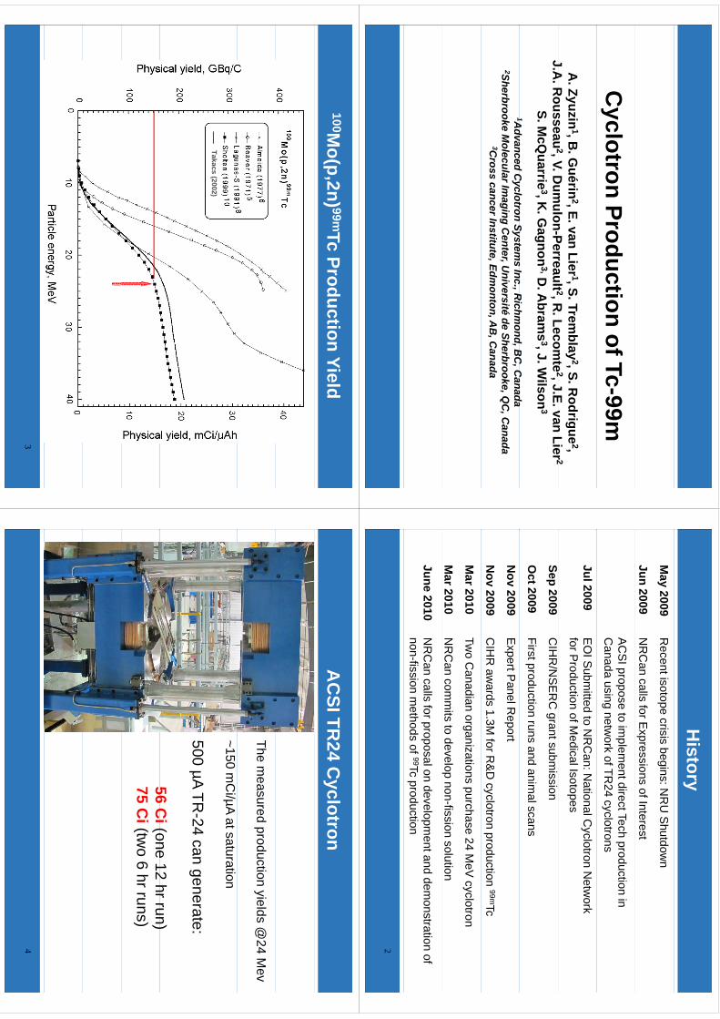
Cyclotron Production of Tc-99m
A
. Zyuzin1, B
. Guérin
2, E. van Lier 1, S. Tremblay
2, S. Rodrigue
2,J
AR
ousseau2
VD
umulon
Perreault 2R
Lecomte
2J
Evan
Lier 2J.A
. Rousseau
2, V. Dum
ulon-Perreault 2, R. Lecom
te2, J.E. van Lier 2
S. McQ
uarrie3, K
. Gagnon
3,D. A
brams
3, J. Wilson
3
1Advanced
Cyclotron
Systems
IncR
ichmond
BC
Canada
1Advanced C
yclotron Systems Inc., R
ichmond, B
C, C
anada2Sherbrooke M
olecular Imaging C
enter, Université de Sherbrooke, Q
C, C
anada3C
ross cancer Institute, Edmonton, A
B, C
anada
History
May 2009
Recent isotope crisis begins: N
RU
Shutdow
n
Jun 2009N
RC
an calls for Expressions of Interest
AC
SI propose to im
plement direct Tech production in
Canada using netw
ork of TR24 cyclotrons
Jul 2009E
OI S
ubmitted to N
RC
an: National C
yclotron Netw
ork for P
roduction of Medical Isotopes
Sep 2009C
IHR
/NS
ER
C grant subm
ission
Oct 2009
First production runs and animal scans
Nov 2009
Expert P
anel Report
Nov 2009
CIH
R aw
ards 1.3M for R
&D
cyclotron production 99mTc
Mar 2010
Two C
anadian organizations purchase 24 MeV
cyclotron
Mar 2010
NR
Can com
mits to develo p non-fission solution
p
June 2010N
RC
an calls for proposal on development and dem
onstration of non-fission m
ethods of 99Tc production
2
100Mo(p,2n) 99mTc Production Yield
Takacs (2002)
3
AC
SI TR24 C
yclotron
The measured production yields @
24 Mev
~150 mC
i/µA at saturation
500µA
TR24
cangenerate:
500 µA TR-24 can generate:
56C
i(one12
hrrun)56 C
i(one 12 hr run)75 C
i(two 6 hr runs)
4
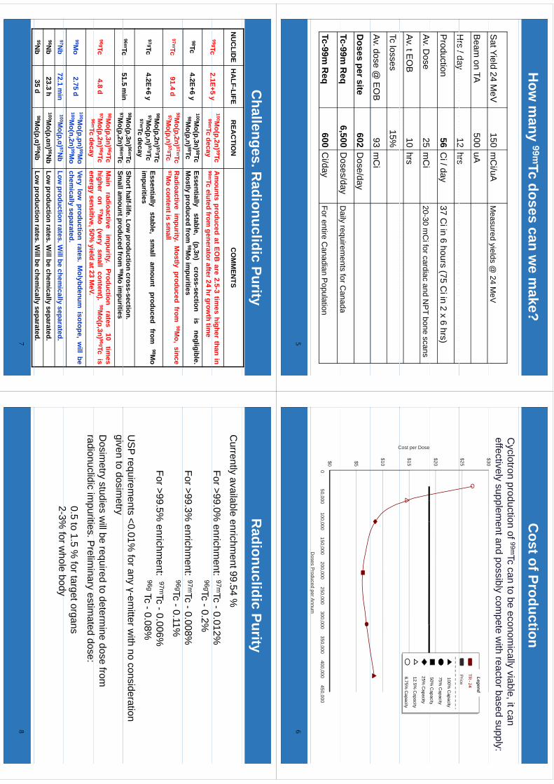
How
many 99mTc doses can w
e make?
Sat Yield 24 M
eV150
mC
i/uAM
easured yields @ 24 M
eVy
@
Beam
on TA500
uA
Hrs
/day12
hrsH
rs / day12
hrs
Production
56C
i / day37 C
i in 6 hours (75 Ci in 2 x 6 hrs)
AD
25C
iAv. D
ose25
mC
i20-30 m
Ci for cardiac and N
PT bone scans
Av. t EO
B10
hrs
Tc losses15%
Av. dose @ E
OB
93 mC
i
Doses per site
602D
ose/day
Tc-99m R
eq6,500
Doses/day
Daily
requirements
forCanada
c99
eq,
yD
aily requirements for C
anada
Tc-99m R
eq600 C
i/dayFor entire C
anadian Population
5
Cost of Production
Cyclotron production of 99mTc can to be econom
ically viable, it can effectively supplem
ent and possibly compete w
ith reactor based supply:$30
$25
$30
TR-24
Price
Legend
$2075%
Capacity
50% C
apacity
100% C
apacity
$15
Cost per Dose
py
12.5% C
apacity
6.75% C
apacity
25% C
apacity
$10
C
$5$00
50,000100,000
150,000200,000
250,000300,000
350,000400,000
450,000
Doses P
roduced per Annum
p
6
Challenges. R
adionuclidic PurityN
UC
LIDE
HA
LF-LIFER
EAC
TION
CO
MM
ENTS
99gTc2
1E+5y
100Mo(p,2n) 99Tc
Am
ountsproduced
atEO
Bare
2.5-3tim
eshigher
thanin
gTc2.1E+5 y
99mTcdecay
99mTceluted
fromgeneratorafter24
hrgrowth
time
98Tc4.2E+6 y
100Mo(p,3n) 98Tc
98Mo(p,n) 98Tc
Essentiallystable,
(p,3n)cross-section
isnegligible.
Mostly
producedfrom
98Mo
impurities
97mTc91.4 d
98Mo(p,2n) 97mTc
97Mo(p,n) 97gTc
Radioactive
impurity.
Mostly
producedfrom
98Mo,
since97M
ocontentis
small
98Mo(p,2n) 97gTc
Essentiallystable
small
amount
producedfrom
98Mo
97gTc4.2E+6 y
97Mo(p,n) 97gTc
97mTc decay
Essentiallystable,
small
amount
producedfrom
98Mo
impurities
96mTc51.5
min
98Mo(p,3n) 96mTc
9796
Shorthalf-life.Lowproduction
cross-section.98
Tc51.5 m
in97M
o(p,2n) 96mTcSm
allamountproduced
from98M
oim
purities
96gTc4.8 d
98Mo(p,3n) 96gTc
97Mo(p,2n) 96gTc
96mTd
Main
radioactiveim
purity.Production
rates10
times
higheron
97Mo
(verysm
allcontent).
98Mo(p,3n) 96gTc
isiti
50%i
ldt23
MV
96mTc decayenergy
sensitive,50%yield
at23M
eV.
99Mo
2.75 d100M
o(p,pn) 99Mo
100Mo(n,2n) 99M
oVery
lowproduction
rates.M
olybdenumisotope,
will
bechem
icallyseparated.
97Nb
72.1 min
100Mo(p,α) 97N
bLow
productionrates.W
illbechem
icallyseparated.
96Nb
23.3 h100M
o(p,αn) 96Nb
Lowproduction
rates.Willbe
chemically
separated.95N
b35 d
98Mo(p,α) 95N
bLow
productionrates.W
illbechem
icallyseparated.
(p)
py
p
7
Radionuclidic Purity
Currently available enrichm
ent 99.54 %
For >99.0% enrichm
ent:97mTc -0.012%96gTc -0.2%
For >99.3% enrichm
ent:97mTc -0.008%96gTc -0.11%
For >99.5% enrichm
ent: 97mTc -0.006%96gTc -0.08%
US
P requirements <0.01%
for any γ-emitter w
ith no consideration i
td
it
given to dosimetry
Dosim
etry studies will be required to determ
ine dose from
dilidi
iiti
Pli
iti
td
dradionuclidic im
purities. Prelim
inary estimated dose:
0.5 to 1.5 % for target organs
23%
forwhole
body2-3%
for whole body
8
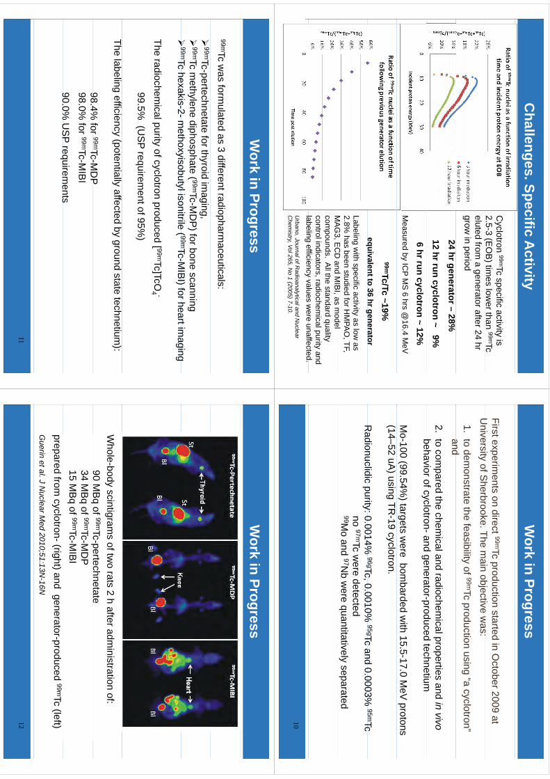
Challenges. Specific A
ctivity
Cyclotron 99mTc specific activity is
2.5-3 (EO
B) tim
es lower than 99mTc
()
eluted from a generator after 24 hr
grow in period
24 hr generator –28%
12 hr run cyclotron ~ 9%
6 hr run cyclotron ~ 12%M
easured by ICP M
S 6 hrs @
16.4 MeV
99mTc/Tc ~19%equivalent to 36 hr generator
qg
Labeling with specific activity as low
as 2.8%
has been studied for HM
PAO
, TF, M
AG
3E
CD
andM
IBI
asm
odelM
AG
3, EC
D and M
IBI, as m
odel com
pounds. All the standard quality
control indicators, radiochemical purity and
labelingefficiency
valuesw
ereunaffected
labeling efficiency values were unaffected.
Urbano, Journal of R
adioanalytical and Nuclear
Chem
istry, Vol 265, No 1 (2005) 7-10.
Work in Progress
First experiments on direct 99mTc production started in O
ctober 2009 at U
niversityofS
herbrookeThe
main
objectivew
as:U
niversity of Sherbrooke. The m
ain objective was:
1.to dem
onstrate the feasibility of 99mTc production using “a cyclotron” andand
2.to com
pared the chemical and radiochem
ical properties and in vivo behaviorofcyclotron-and
generator-producedtechnetium
behavior of cyclotron-and generator-produced technetium
Mo-100 (99.54%
) targets were bom
barded with 15.5-17.0 M
eV protons
(14–52 uA) using TR
-19 cyclotron.
Radionuclidic
purity:00014%
96gTc0
0010%95gTc
and0
0003%95mTc
Radionuclidic purity: 0.0014%
gTc,0.0010%
gTc and 0.0003%
Tc
no 97mTc were detected
99Mo and 97N
b were quantitatively separated
10
Work in Progress
99mTc was form
ulated as 3 different radiopharmaceuticals:
99mTc-pertechnetate for thyroid im
aging,
99mTc methylene diphosphate ( 99mTc-M
DP
) for bone scanning
99mTchexakis
2m
ethoxyisobutylisonitrile( 99mTc
MIB
I)forheartimaging
99mTc hexakis-2-m
ethoxyisobutyl isonitrile ( 99mTc-MIB
I) for heart imaging
The radiochemical purity of cyclotron produced [ 99mTc]TcO
4 -
99.5% (U
SP requirem
ent of 95%)
The labeling efficiency (potentially affected by ground state technetium):
984%
for99mTc-M
DP
98.4% for
TcM
DP
98.0% for 99mTc-M
IBI
90.0%U
SP
requirements
90.0% U
SP requirem
ents
11
Work in Progress
Whole-body
scintigrams
oftwo
rats2
hafteradm
inistrationof:
90M
Bq
of99mTc-pertechnetate
qp
34M
Bq
of99mTc-M
DP
15M
Bq
of99mTc-M
IBI
preparedfrom
cyclotron-(right)andgenerator-produced
99mTc(left)
Guerin
etal.JN
uclearMed
2010;51:13N-16N
12
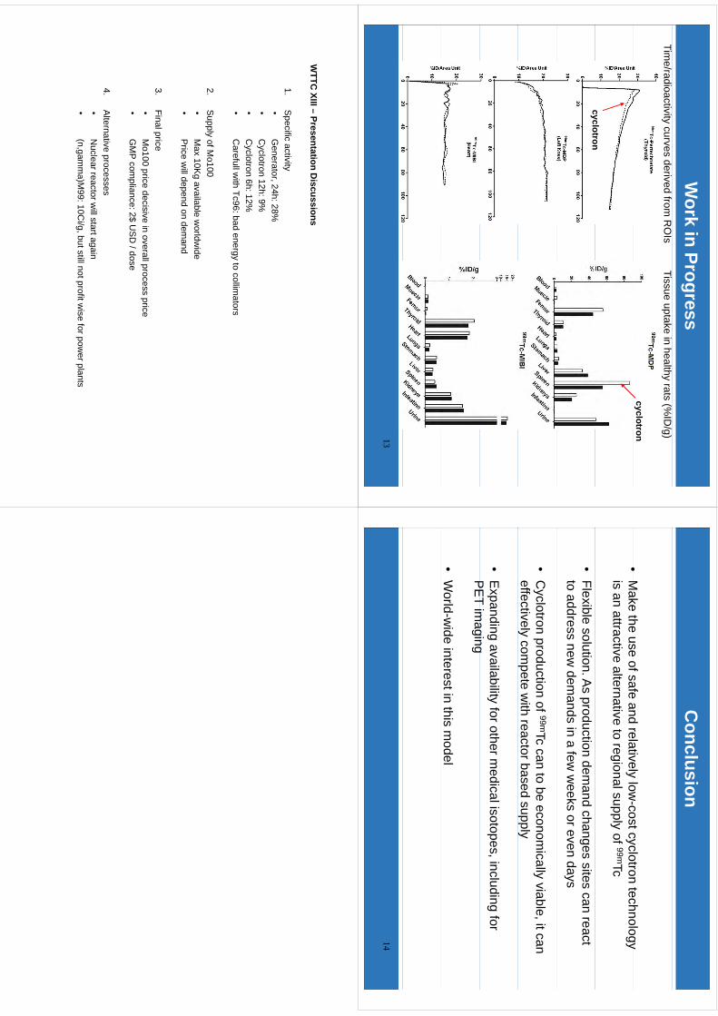
Work in Progress
Tissue uptake in healthy rats (%ID
/g)
cyclotron
Time/radioactivity curves derived from
RO
Is
cyclotroncyclotron
13
Conclusion
•M
akethe
useofsafe
andrelatively
lowcostcyclotron
technology•
Make the use of safe and relatively low
-cost cyclotron technology is an attractive alternative to regional supply of 99mTc
•Flexible solution. A
s production demand changes
sites can react to address new
demands in a few
weeks or even days
•C
yclotron production of 99mTc can to be economically viable, it can
effectively compete w
ith reactor based supply
•E
xpanding availability for other medical isotopes, including for
PE
Tim
agingP
ET im
aging
•W
orld-wide interest in this m
odel
14
WTTC
XIII–Presentation
Discussions
WTTC
XIII –Presentation D
iscussions
1.S
pecific activity•
Generator
24h:28%•
Generator, 24h: 28%
•C
yclotron 12h: 9%•
Cyclotron 6h: 12%
•C
arefullwith
Tc96:badenergy
tocollim
ators•
Carefullw
ith Tc96: bad energy to collimators
2.S
upply of Mo100
•M
ax10K
gavailable
worldw
ide•
Max 10K
g available worldw
ide•
Price will depend on dem
and
3Finalprice
3.Final price•
Mo100 price decisive in overall process price
•G
MP
compliance: 2$ U
SD
/ dose
4.A
lternative processes•
Nuclear reactor w
ill start again(n
gamm
a)M99:10C
i/gbutstillnotprofitw
iseforpow
erplants•
(n,gamm
a)M99: 10C
i/g, but still not profit wise for pow
er plants
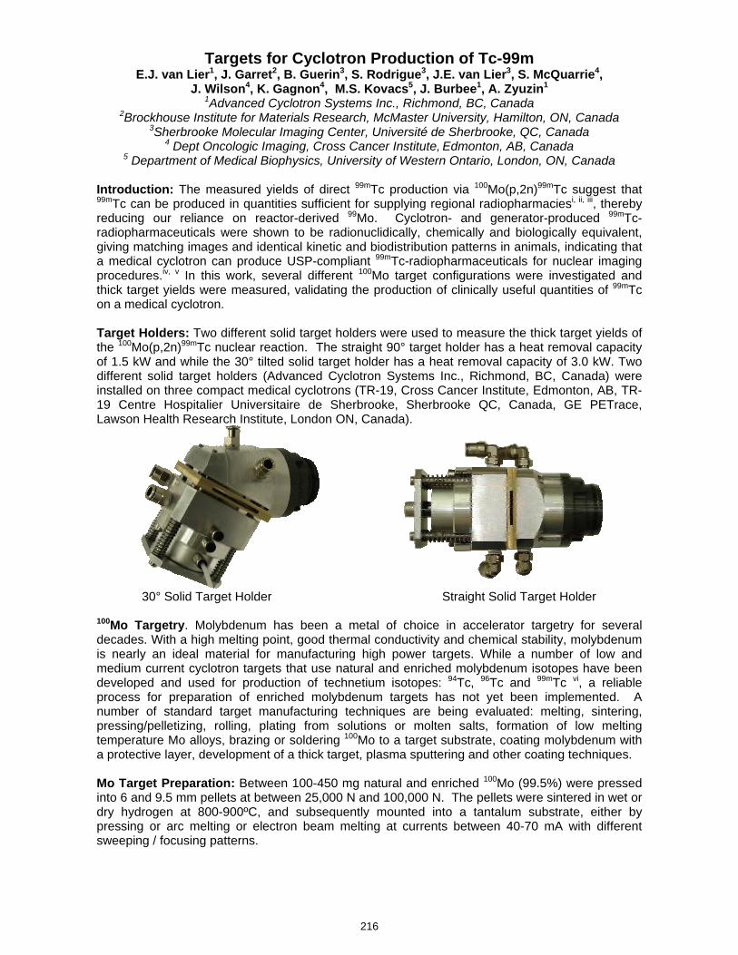
Targets for Cyclotron Production of Tc-99m E.J. van Lier1, J. Garret2, B. Guerin3, S. Rodrigue3, J.E. van Lier3, S. McQuarrie4,
J. Wilson4, K. Gagnon4, M.S. Kovacs5, J. Burbee1, A. Zyuzin1 1Advanced Cyclotron Systems Inc., Richmond, BC, Canada
2Brockhouse Institute for Materials Research, McMaster University, Hamilton, ON, Canada 3Sherbrooke Molecular Imaging Center, Université de Sherbrooke, QC, Canada
4 Dept Oncologic Imaging, Cross Cancer Institute, Edmonton, AB, Canada 5 Department of Medical Biophysics, University of Western Ontario, London, ON, Canada
Introduction: The measured yields of direct 99mTc production via 100Mo(p,2n)99mTc suggest that 99mTc can be produced in quantities sufficient for supplying regional radiopharmaciesi, ii, iii, thereby reducing our reliance on reactor-derived 99Mo. Cyclotron- and generator-produced 99mTc-radiopharmaceuticals were shown to be radionuclidically, chemically and biologically equivalent, giving matching images and identical kinetic and biodistribution patterns in animals, indicating that a medical cyclotron can produce USP-compliant 99mTc-radiopharmaceuticals for nuclear imaging procedures.iv, v In this work, several different 100Mo target configurations were investigated and thick target yields were measured, validating the production of clinically useful quantities of 99mTc on a medical cyclotron. Target Holders: Two different solid target holders were used to measure the thick target yields of the 100Mo(p,2n)99mTc nuclear reaction. The straight 90° target holder has a heat removal capacity of 1.5 kW and while the 30° tilted solid target holder has a heat removal capacity of 3.0 kW. Two different solid target holders (Advanced Cyclotron Systems Inc., Richmond, BC, Canada) were installed on three compact medical cyclotrons (TR-19, Cross Cancer Institute, Edmonton, AB, TR-19 Centre Hospitalier Universitaire de Sherbrooke, Sherbrooke QC, Canada, GE PETrace, Lawson Health Research Institute, London ON, Canada).
30° Solid Target Holder Straight Solid Target Holder 100Mo Targetry. Molybdenum has been a metal of choice in accelerator targetry for several decades. With a high melting point, good thermal conductivity and chemical stability, molybdenum is nearly an ideal material for manufacturing high power targets. While a number of low and medium current cyclotron targets that use natural and enriched molybdenum isotopes have been developed and used for production of technetium isotopes: 94Tc, 96Tc and 99mTc vi, a reliable process for preparation of enriched molybdenum targets has not yet been implemented. A number of standard target manufacturing techniques are being evaluated: melting, sintering, pressing/pelletizing, rolling, plating from solutions or molten salts, formation of low melting temperature Mo alloys, brazing or soldering 100Mo to a target substrate, coating molybdenum with a protective layer, development of a thick target, plasma sputtering and other coating techniques. Mo Target Preparation: Between 100-450 mg natural and enriched 100Mo (99.5%) were pressed into 6 and 9.5 mm pellets at between 25,000 N and 100,000 N. The pellets were sintered in wet or dry hydrogen at 800-900ºC, and subsequently mounted into a tantalum substrate, either by pressing or arc melting or electron beam melting at currents between 40-70 mA with different sweeping / focusing patterns.
216
kmje
Typewritten Text
Abstract 039
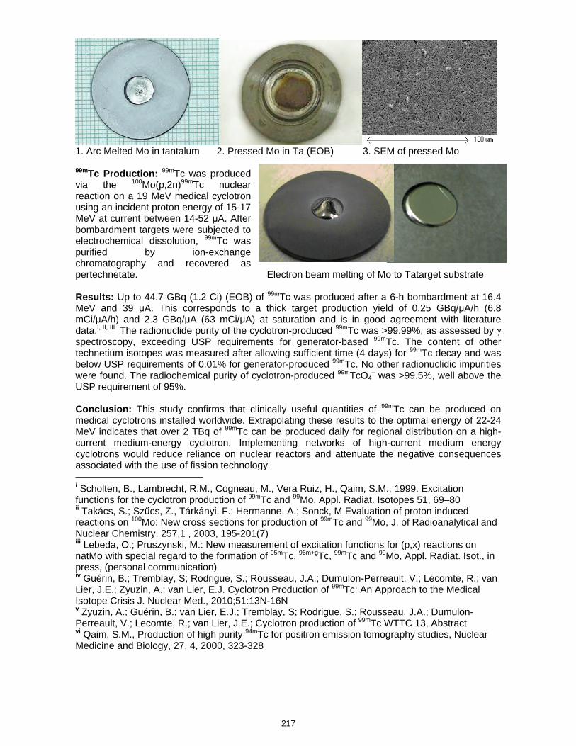
1. Arc Melted Mo in tantalum 2. Pressed Mo in Ta (EOB) 3. SEM of pressed Mo 99mTc Production: 99mTc was produced via the 100Mo(p,2n)99mTc nuclear reaction on a 19 MeV medical cyclotron using an incident proton energy of 15-17 MeV at current between 14-52 μA. After bombardment targets were subjected to electrochemical dissolution, 99mTc was purified by ion-exchange chromatography and recovered as pertechnetate. Electron beam melting of Mo to Tatarget substrate Results: Up to 44.7 GBq (1.2 Ci) (EOB) of 99mTc was produced after a 6-h bombardment at 16.4 MeV and 39 μA. This corresponds to a thick target production yield of 0.25 GBq/μA/h (6.8 mCi/μA/h) and 2.3 GBq/μA (63 mCi/μA) at saturation and is in good agreement with literature data.I, II, III The radionuclide purity of the cyclotron-produced 99mTc was >99.99%, as assessed by γ spectroscopy, exceeding USP requirements for generator-based 99mTc. The content of other technetium isotopes was measured after allowing sufficient time (4 days) for 99mTc decay and was below USP requirements of 0.01% for generator-produced 99mTc. No other radionuclidic impurities were found. The radiochemical purity of cyclotron-produced 99mTcO4
– was >99.5%, well above the USP requirement of 95%. Conclusion: This study confirms that clinically useful quantities of 99mTc can be produced on medical cyclotrons installed worldwide. Extrapolating these results to the optimal energy of 22-24 MeV indicates that over 2 TBq of 99mTc can be produced daily for regional distribution on a high-current medium-energy cyclotron. Implementing networks of high-current medium energy cyclotrons would reduce reliance on nuclear reactors and attenuate the negative consequences associated with the use of fission technology. i Scholten, B., Lambrecht, R.M., Cogneau, M., Vera Ruiz, H., Qaim, S.M., 1999. Excitation functions for the cyclotron production of 99mTc and 99Mo. Appl. Radiat. Isotopes 51, 69–80 ii Takács, S.; Szűcs, Z., Tárkányi, F.; Hermanne, A.; Sonck, M Evaluation of proton induced reactions on 100Mo: New cross sections for production of 99mTc and 99Mo, J. of Radioanalytical and Nuclear Chemistry, 257,1 , 2003, 195-201(7) iii Lebeda, O.; Pruszynski, M.: New measurement of excitation functions for (p,x) reactions on natMo with special regard to the formation of 95mTc, 96m+gTc, 99mTc and 99Mo, Appl. Radiat. Isot., in press, (personal communication) iv Guérin, B.; Tremblay, S; Rodrigue, S.; Rousseau, J.A.; Dumulon-Perreault, V.; Lecomte, R.; van Lier, J.E.; Zyuzin, A.; van Lier, E.J. Cyclotron Production of 99mTc: An Approach to the Medical Isotope Crisis J. Nuclear Med., 2010;51:13N-16N v Zyuzin, A.; Guérin, B.; van Lier, E.J.; Tremblay, S; Rodrigue, S.; Rousseau, J.A.; Dumulon-Perreault, V.; Lecomte, R.; van Lier, J.E.; Cyclotron production of 99mTc WTTC 13, Abstract vi Qaim, S.M., Production of high purity 94mTc for positron emission tomography studies, Nuclear Medicine and Biology, 27, 4, 2000, 323-328
217
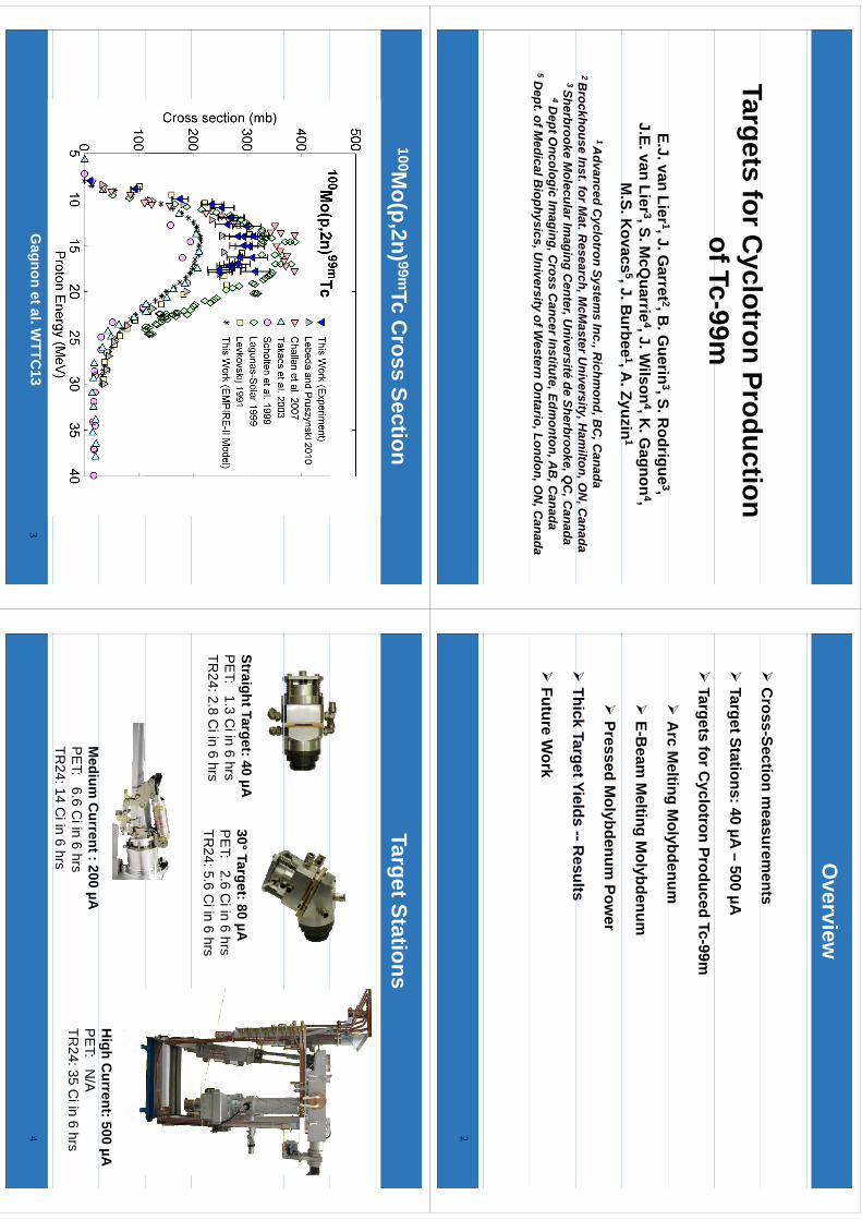
Tt
fC
lt
Pd
tiTargets for C
yclotron Production ofTc-99mof Tc
99m
EJ
Li1
JG
t 2B
Gi
3S
Rd
i3
E.J. van Lier 1, J. Garret 2, B
. Guerin
3, S. Rodrigue
3, J.E. van Lier 3, S. M
cQuarrie
4, J. Wilson
4, K. G
agnon4,
M.S.K
ovacs5,J.B
urbee1,A
.Zyuzin1
M.S. K
ovacs, J. B
urbee, A
. Zyuzin1 A
dvanced Cyclotron System
s Inc., Richm
ond, BC
, Canada
2 Brockhouse Inst. for M
at. Research, M
cMaster U
niversity, Ham
ilton, ON
, Canada
3 Sherbrooke Molecular Im
aging Center, U
niversité de Sherbrooke, QC
, Canada
4Dept O
ncologic Imaging, C
ross Cancer Institute, Edm
onton, AB
, Canada
5Dept. of M
edical Biophysics, U
niversity of Western O
ntario, London, ON
, Canada
Overview
C
ross-Section measurem
ents
Target Stations: 40 µA –
500 µA
Targets for C
yclotron Produced Tc-99m
A
rcM
eltingM
olybdenum
Arc M
elting Molybdenum
E-B
eam M
elting Molybdenum
Pressed M
olybdenum Pow
er
Thick
TargetYields--R
esults
Thick Target Yields R
esults
Future W
ork
2
100Mo(p,2n) 99mTc C
ross Section
Gagnon et al. W
TTC13
3
Target Stations
Straight Target: 40 µA30°Target:80
µAP
ET: 1.3 C
i in 6 hrsTR
24: 2.8 Ci in 6 hrs
30Target: 80 µA
PE
T: 2.6 Ci in 6 hrs
TR24: 5.6 C
i in 6 hrs
High C
urrent: 500 µAM
edium C
urrent : 200 µAP
ET: 6.6 C
i in 6 hrsTR
24: 14 Ci in 6 hrs
PE
T: N/A
TR24: 35 C
i in 6 hrs4
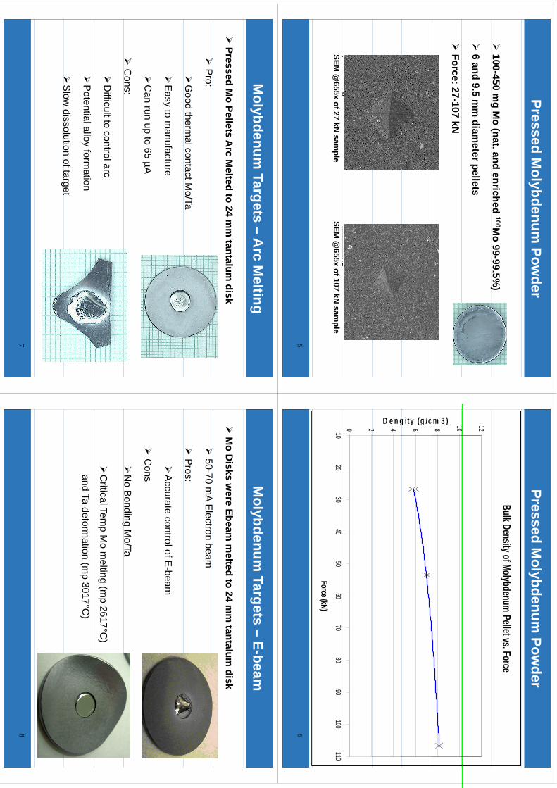
Pressed Molybdenum
Powder
100-450 m
g Mo (nat. and enriched 100M
o 99-99.5%)
g(
)
6 and 9.5 m
m diam
eter pellets
Force: 27-107 kN
SEM @
655x of 27 kN sam
pleSEM
@655x of 107 kN
sample
5
Pressed Molybdenum
Powder
Bulk Density of Molybdenum Pellet vs. Force
10 128 10m 3 )6g ity (g /c2 4D e n g0 21020
3040
5060
7080
90100
110
Force (kN)
6
Molybdenum
Targets –A
rc Melting
Pressed M
o Pellets Arc M
elted to 24 mm
tantalum disk
P
ro:
G
ood thermal contact M
o/Ta
E
asy to manufacture
C
an run up to 65 µA
C
ons:
D
ifficult to control arc
P
otential alloy formation
S
lowdissolution
oftarget
Slow
dissolution of target
7
Molybdenum
Targets –E-beam
M
o Disks w
ere Ebeam m
elted to 24 mm
tantalum disk
50-70 m
A Electron beam
P
ros:
A
ccurate control of E-beam
C
ons
N
o Bondin g M
o/Tag
C
ritical Temp M
o melting (m
p 2617°C)
and Ta deformation (m
p 3017°C)
8
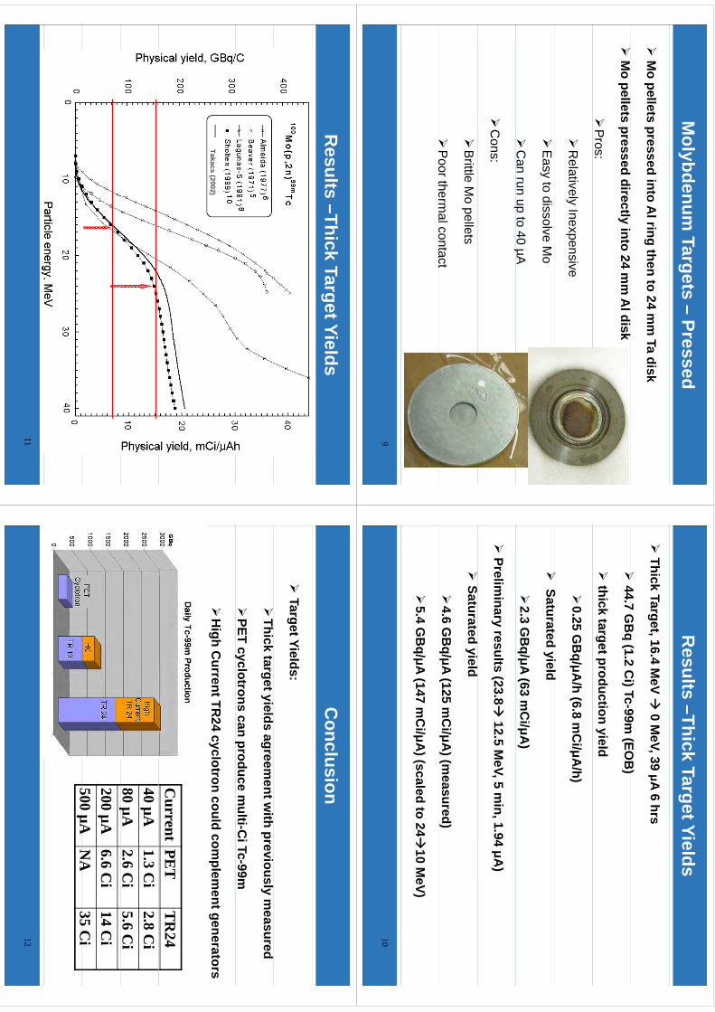
Molybdenum
Targets –Pressed
M
o pellets pressed into Al ring then to 24 m
m Ta disk
M
o pellets pressed directly into 24 mm
Al disk
P
ros:
R
elatively Inexpensive
E
asy to dissolve Mo
C
an run u p to 40 µAp
µ
C
ons:
B
rittle Mo pellets
P
oorthermalcontact
P
oor thermal contact
9
Results –Thick Target Yields
Thick Target, 16.4 M
eV 0 M
eV, 39 μA 6 hrs
44
7G
Bq
(12
Ci)Tc
99m(EO
B)
44.7 G
Bq (1.2 C
i) Tc-99m (EO
B)
thick target production yield
0.25 G
Bq/μA
/h (6.8 mC
i/μA/h)
S
tt
di
ld
Saturated yield
2.3 G
Bq/μA (63 m
Ci/μA
)
Prelim
inary results (23.8
12.5 MeV, 5 m
in, 1.94 μA)
Saturated yield
4.6 G
Bq/μA (125 m
Ci/μA
) (measured)
5.4 G
Bq/μA (147 m
Ci/μA
) (scaled to 24
10 MeV)
10
Results –Thick Target Yields
Takacs (2002)
11
Conclusion
Target Yields:
Thick target yields agreem
ent with previously m
easured
PET c yclotrons can produce m
ulti-Ci Tc-99m
yp
H
igh Current TR
24 cyclotron could complem
ent generators
Current
PET
TR
2440 µA
1.3 Ci
2.8 Ci
80 µA2.6 C
i5.6 C
iµ
200 µA6.6 C
i14 C
i500
µAN
A35
Ci
500 µAN
A35 C
i12

Future Work
C
ontinue to study targets:
Pressed Targets
Ebeam
/Arc M
eltin gg
Foils
Plating
Vapor deposition / plasm
a sprayp
pp
py
Select m
ost appropriate method
C
ost effective
R
eliable/R
obust
Reliable / R
obust
Scalable w
ith overall process integration
13
WTTC
XIII–Presentation
Discussions
WTTC
XIII –Presentation D
iscussions
1.Tc/M
o separation?•
Nextstep
•N
ext step.
2.C
yclotrons needed to replace nuclear production of Tc99m?
•5
8TR
24forC
anada10x
more
fortheU
SA
•5-8 TR
-24 for Canada, 10x m
ore for the US
A•
But: 500uA cyclotrons…
•FD
A approval? It w
as approved 3 decades ago…
A further exploration of the merits of a Niobium/Niobium vs Niobium/Havar target body/foil combination for [18F]Fluoride production: A detailed HP γ-spectrometry study
John Sunderland, G Leonard Watkins, Colbin E Erdahl, Levent Sensoy, Arda Konik PET Imaging Center, University of Iowa Health Care, Iowa City, IA 52242, USA In the current nuclear medicine environment, both the Molybdenum crisis and FDA regulation, are driving the PET community to look more closely at the production of [18F]NaF for PET imaging. This situation has led the University of Iowa to design and construct a targetry unit and a synthesis/purification module designed to obtain highest purity [18F]NaF. In this study we investigate the radionuclidic purity of [18F]NaF from this module with [18F]NaF produced from both a Nb/Havar and Nb/Nb target/body combination. The rationale for the targetry comes from the recent observations of the Wisconsin and Edmonton groups1, 2, 3.
As can be seen from the schematic in Figure 2 [18O]H2O was irradiated in a Nb target body equipped with either a Nb or Havar front foil. The target water was emptied into a target collection vessel (TCV). Under N2 overpressure the contents were passed sequentially through a CM cation SPE cartridge and a QMA anion SPE cartridge to an [18O]H2O recovery vessel. Any non-anionic material was then flushed from the QMA with water (5 mL) to waste. The [18F]NaF and any other anionic species were the eluted into the final product vial with isotonic saline (15 mL).
To assess radionuclidic purity, the Nb/Niobium body/foil combination was bombarded at 30 µA for 5, 10, 20 and 80 minutes. The Nb/Havar body/foil combination was bombarded at 30 µA for 80 minutes. In all cases the TCV, CM, QMA, and Product Vial were quantitatively assessed for radionuclidic content using an GEM20P4-70. ORTEC GEM Coaxial P-type HPGe Gamma-Ray Detector. Results are summarized in Figure 2.
The Nb-Nb body/foil combination spectrum was simple; 30 µA for 10 minutes created minute quantities of 56,57,58Co and 52Mn (<0.1 nCi) from the trace quantities of iron and chromium in the Nb foil, but approximately 1 µCi of 93mMo from the 93Nb(p,n)93mMo reaction (Figure 1). The CM cation cartridge quantitatively bound the cobalt isotopes, while the 93mMo, initially trapped by the QMA anion cartridge, eluted quantitatively with the [18F]NaF. Under similar conditions, the Nb/Havar body/foil created 12 radionuclides at 10-100 nCi levels. The CM/QMA cartridge combination served to eliminate 6 of 12 contaminants, and reduce the quantities of the remaining nuclides substantially, but not completely. The product vial from the Nb/Nb combination had only 93mMo, while the product vial from the Nb/Havar target resulted in [18F]NaF with 51Cr, 95,96Tc,181,182Re, and 93mMo (from Nb target body) contaminants with activities ranging from 1-30 nCi.
References: 1. SJA Nye, MA Avila-Rodriguez & RJ Nickles. ”A grid-mounted niobium body target for the production of reactive [18F]fluoride”. Appl. Radiat. Isot. (2006);64:536-539
2. JS Wilson, MA Avila-Rodriguez, & SA McQuarrie. “Ionic contaminants in irradiated [18O]water generated with Havar and Havar-Nb foils”. Abstract Book: 12th International Workshop on Targetry and Target Chemistry, Seattle, 2008: pp31-33.
3. MA Avila-Rodriguez, JS Wilson and SA McQuarrie. "A quantitative and compararative study of radionuclidic and chemical impurities in water samples irradiated in a niobium target with Havar vs niobium-sputtered Havar as entrance foils". Appl. Radiat. Isot. (2008);66: 1777-1780
222
kmje
Typewritten Text
Abstract 040
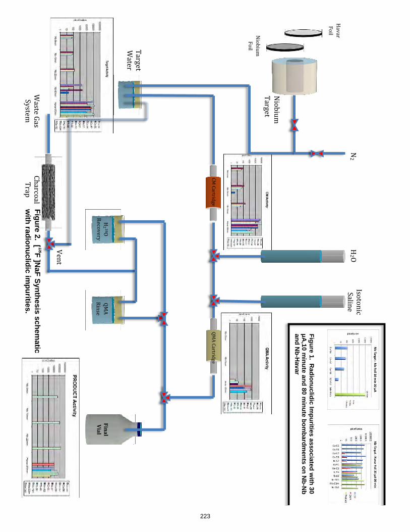
!
!
"#$%#&'!
()*+,-!
"#$%#&'!
.$#/!
0)1)*!
.$#/!
02345!
6,7$1,*8!
9:!9)*-*#;
+,!
<:=!9)*-*#;
+,!
<:=!
6#>?,!
@)?-,!A)?!
B8?-,'!
9C)*7$
)/!
(*)D!
E,>-!
!"#$%&
'"$%&
02 5!
F?$-$>#7!
B)/#>,!
"2!
()*+,-!
@)-,*!
Figure 1. Radionuclidic Im
purities associated with 30
!A,10 m
inute and 80 minute bom
bardments on N
b-Nb
and Nb-H
avar&
Figure 2. [ 18F ]NaF Synthesis schem
atic w
ith radionuclidic impurities.
223
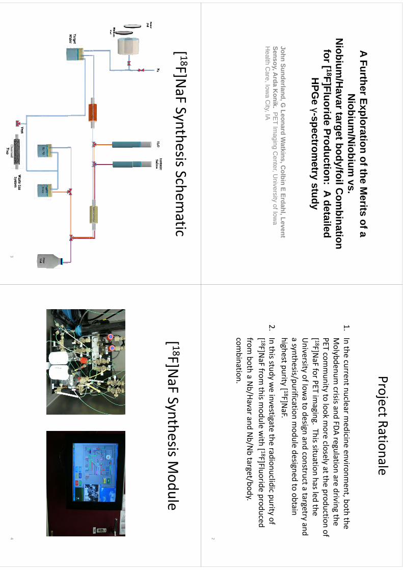
A Further Exploration of the Merits of a
Niobium
/Niobium
vs.N
iobium/H
avar target body/foil Com
bination g
yfor [ 18F]Fluoride Production: A detailed
HPG
eγ-spectrom
etrystudy
HPG
eγ
spectrometry study
John Sunderland, G Leonard W
atkins, Colbin E Erdahl, Levent
Sensoy, Arda K
onik. PE
T Imaging C
enter, University of Iow
a H
lthC
IC
itIA
Health C
are, Iowa C
ity, IA
Project Rationalej
1.In the current nuclear m
edicine environment, both the
Molybdenum
crisisandFDA
regulationare
drivingthe
Molybdenum
crisis and FDA regulationare driving the
PET community to look m
ore closely at the production of [ 18F]N
aF for PET imaging. This situation has led the
[]
gg
University of Iow
a to design and construct a targetry and a synthesis/purification m
odule designed to obtain y
pg
highest purity [ 18F]NaF.
2.In this stud y w
e investigate the radionuclidic purity of y
gp
y[ 18F]N
aF from this m
odule with [ 18F]Fluoride produced
fromboth
aNb/Havarand
Nb/N
btarget/body.
from both a N
b/Havarand Nb/N
btarget/body.
combination.
2
[ 18F]NaF Synthesis Schem
atic[
]a
SytessSc
eatc
3
[ 18F]NFS
thiM
dl
[ 18F]NaF Synthesis M
odule
4
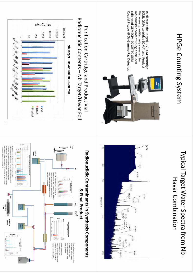
HPGC
tiS
tHPGe
Counting System
In all cases theTarget(TCV), CM
cartiridge(CM
), QMA cartridge (Q
MA) and Product
Vialwere
quantitativelyassessed
forVial w
ere quantitatively assessed for radionuclidic content using a
shielded calibrated GEM
20P4‐70 ORTEC GEM
CoaxialP
typeHPGe
GammaRay
DetectorCoaxial P‐type HPGe
Gamma‐Ray Detector.
5
Typical Target Water Spectra from
Nb‐
ypg
pHavar Com
bination
6
Purification Cartridge and Product Vial g
Radionuclidic Contents –NbTarget/Havar Foil
7
Radionuclidic Contaminants in Synthesis Com
ponents & Final Product
SeveralanionicspeciesfromSeveral anionic species from
the Havar foil rem
ained trapped in the Q
MA
following elution w
ith isotonic saline.
The CM cartridge w
as effective at rem
ovin g the lion’s share of the anionic
From the N
b/Nb
combination, no
measureable quantities of
radionuclidic impurities
remained
inthe
QMA
gradionuclidic contam
inants from the
target water for both N
b/Nband N
bHavar com
binations.
remained in the Q
MA.
TheNb/N
bcom
binationresulted
inonly
Coand
Mo
The Nb/N
bcom
bination resulted in only Co and Mo
radionuclidic contaminants. The Co radionuclides resulted
from trace im
purities in the Nbfoil, w
hile the Mo‐93m
resulted from
the (p,n) reaction on Nb. The havarfoil spaw
ned radionuclidic contam
inants were on the order of 100 –
1000X the absolute quantities from
Nbfoil
8

Cl
iConclusions
1.The U
niversity of Iowa [ 18F]N
aF synthesis/purification system produced
a final product with acceptable radionuclidic purity regardless of w
hether the N
b-Nb
or Nb/H
avar target body/foil combination w
as used.
2.O
rderofmagnitude
calculationssuggestthatadditionalradiation
dose2.
Order of m
agnitude calculations suggest that additional radiation dose resulting from
the picoCurie
levels of radionuclidic contaminants w
ill result in substantially less than 1 m
Radditional w
hole body radiation dose
forbothtargetbody/foilcom
binationsusing
highlyconservative
dose for both target body/foil combinations using highly conservative
assumptions that.
a)A
ll particulate and gamm
a radiation emitted in the body are
bb
dabsorbed.
b)B
iological half-lives are infinite.c)
No attem
pt to model biodistribution w
as included in the calculation.
9
Cl
iConclusions
3.It is N
OT clear w
hich of the two target body/foil system
s is optimal.
Mo-93m
has a short half-life (6.85 hours) but it also has three relatively energetic gam
ma em
issions of approximately 1 M
eV. The radionuclides from
Havar have generally longer half-lives, but
lesserquantitiesH
avarhasthe
additionaladvantageofhaving
lesser quantities. Havar has the additional advantage of having
more desirable physical properties that m
ake it the foil of choice for m
any targetry applications.
4.A
s the University of Iow
a [ 18F]NaF synthesis/purification system
rem
oves the vast majority of radionuclidic contam
inants from
Havar, and the system
fails to remove the M
o-93m produced by the
Nb
foilfromthe
finalproductItis
likelythatw
ew
illreverttothe
Nb
Nb
foil from the final product. It is likely that w
e will revert to the N
btarget body/H
avar foil model due to the physical robustness of the
system.
10
WTTC
XIII–Presentation
Discussions
WTTC
XIII –Presentation D
iscussions
1.W
hich one is the best foil?•
Nivs
Havar:no
yielddifference
•N
i vs. Havar: no yield difference
•C
areful with im
purities in foil material
•Ti can be used, Va
trapped in Sep-pak
•N
iobiumH
avarpreferredto
Niobium
Niobium
(experience)•
Niobium
-Havarpreferred to N
iobium-N
iobium (experience)
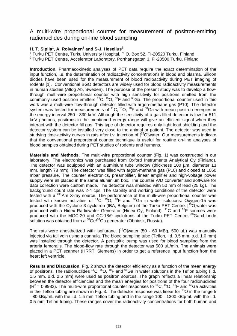
A multi-wire proportional counter for measurement of positron-emitting radionuclides during on-line blood sampling H. T. Sipila1, A. Roivainen1 and S-J. Heselius2 1 Turku PET Centre, Turku University Hospital, P.O. Box 52, FI-20520 Turku, Finland 2 Turku PET Centre, Accelerator Laboratory, Porthansgatan 3, FI-20500 Turku, Finland Introduction. Pharmacokinetic analyses of PET data require the exact determination of the input function, i.e. the determination of radioactivity concentrations in blood and plasma. Silicon diodes have been used for the measurement of blood radioactivity during PET imaging of rodents [1]. Conventional BGO detectors are widely used for blood radioactivity measurements in human studies (Allog Ab, Sweden). The purpose of the present study was to develop a flow-through multi-wire proportional counter with high sensitivity for positrons emitted from the commonly used positron emitters 11C, 15O, 18F and 68Ga. The proportional counter used in this work was a multi-wire flow-through detector filled with argon-methane gas (P10). The detector system was tested for measurements of 11C, 15O, 18F and 68Ga with mean positron energies in the energy interval 250 - 830 keV. Although the sensitivity of a gas-filled detector is low for 511 keV photons, positrons in the mentioned energy range will give an efficient signal when they interact with the detector fill gas. This type of detector requires only light lead shielding and the detector system can be installed very close to the animal or patient. The detector was used in studying time-activity curves in rats after i.v. injection of [15O]water. Our measurements indicate that the conventional proportional counter technique is useful for routine on-line analyses of blood samples obtained during PET studies of rodents and humans. Materials and Methods. The multi-wire proportional counter (Fig. 1) was constructed in our laboratory. The electronics was purchased from Oxford Instruments Analytical Oy (Finland). The detector was equipped with an aluminium tube window (thickness 100 µm, diameter 13 mm, length 78 mm). The detector was filled with argon-methane gas (P10) and closed at 1060 mbar pressure. The counter electronics, preamplifier, linear amplifier and high-voltage power supply were all placed in the same aluminium box. The counter A/D converter and software for data collection were custom made. The detector was shielded with 50 mm of lead (25 kg). The background count rate was 2-4 cps. The stability and working conditions of the detector were tested with a 241Am X-ray source. The performance of the multi-wire proportional counter was tested with known activities of 11C, 15O, 18F and 68Ga in water solutions. Oxygen-15 was produced with the Cyclone 3 cyclotron (IBA, Belgium) of the Turku PET Centre. [15O]water was produced with a Hidex Radiowater Generator (Hidex Oy, Finland). 11C and 18F sources were produced with the MGC-20 and CC-18/9 cyclotrons of the Turku PET Centre. 68Ga-chloride solution was obtained from a 68Ge/68Ga generator (Obninsk, Russia). The rats were anesthetized with isoflurane. [15O]water (50 - 60 MBq, 500 µL) was manually injected via tail vein using a cannula. The blood sampling tube (Teflon, i.d. 0.5 mm, o.d. 1.0 mm) was installed through the detector. A peristaltic pump was used for blood sampling from the arteria femoralis. The blood-flow rate through the detector was 500 µL/min. The animals were placed in a PET scanner (HRRT, Siemens) in order to get a reference input function from the heart left ventricle. Results and Discussion. Fig. 2 shows the detector efficiency as a function of the mean energy of positrons. The radionuclides 11C, 15O, 18F and 68Ga in water solutions in the Teflon tubing (i.d. 1.5 mm, o.d. 2.5 mm) were used as positron sources. The graph reflects a linear relationship between the detector efficiencies and the mean energies for positrons of the four radionuclides (R2 = 0.9982). The multi-wire proportional counter responses to 11C, 15O, 18F and 68Ga activities in the Teflon tubing are shown in Fig. 3. The detector response was linear for 15O in the range 5 - 80 kBq/mL with the i.d. 1.5 mm Teflon tubing and in the range 100 - 1300 kBq/mL with the i.d. 0.5 mm Teflon tubing. These ranges cover the radioactivity concentrations for both human and
227
kmje
Typewritten Text
Abstract 041
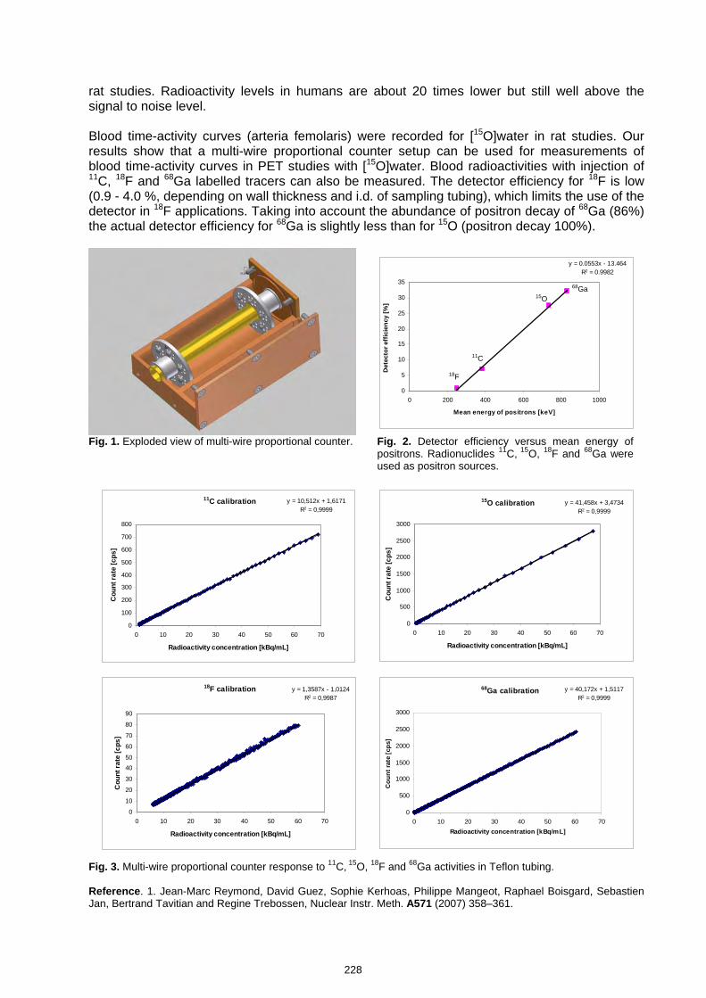
rat studies. Radioactivity levels in humans are about 20 times lower but still well above the signal to noise level. Blood time-activity curves (arteria femolaris) were recorded for [15O]water in rat studies. Our results show that a multi-wire proportional counter setup can be used for measurements of blood time-activity curves in PET studies with [15O]water. Blood radioactivities with injection of 11C, 18F and 68Ga labelled tracers can also be measured. The detector efficiency for 18F is low (0.9 - 4.0 %, depending on wall thickness and i.d. of sampling tubing), which limits the use of the detector in 18F applications. Taking into account the abundance of positron decay of 68Ga (86%) the actual detector efficiency for 68Ga is slightly less than for 15O (positron decay 100%).
y = 0.0553x - 13.464R2 = 0.9982
0
5
10
15
20
25
30
35
0 200 400 600 800 1000
Mean energy of positrons [keV]
Det
ecto
r eff
icie
ncy
[%]
18F
11C
15O
68Ga
Fig. 1. Exploded view of multi-wire proportional counter. Fig. 2. Detector efficiency versus mean energy of positrons. Radionuclides 11C, 15O, 18F and 68Ga were used as positron sources.
11C calibration y = 10,512x + 1,6171R2 = 0,9999
0
100
200
300
400
500
600
700
800
0 10 20 30 40 50 60 70
Radioactivity concentration [kBq/mL]
Cou
nt ra
te [c
ps]
15O calibration y = 41,458x + 3,4734R2 = 0,9999
0
500
1000
1500
2000
2500
3000
0 10 20 30 40 50 60 70
Radioactivity concentration [kBq/mL]
Cou
nt ra
te [c
ps]
Fig. 3. Multi-wire proportional counter response to 11C, 15O, F and 68Ga activities in Teflon tubing. Reference. 1. Jean-Marc Reymond, David Guez, Sophie Kerhoas, Philippe Mangeot, Raphael Boisgard, Sebastien Jan, Bertrand Tavitian and Regine Trebossen, Nuclear Instr. Meth. A571 (2007) 358–361.
18F calibration y = 1,3587x - 1,0124R2 = 0,9987
0
10
20
30
4050
60
70
80
90
0 10 20 30 40 50 60 70
Radioactivity concentration [kBq/mL]
Cou
nt ra
te [c
ps]
68Ga calibration y = 40,172x + 1,5117R2 = 0,9999
0
500
1000
1500
2000
2500
3000
0 10 20 30 40 50 60 70Radioactivity concentration [kBq/mL]
Cou
nt ra
te [c
ps]
18
228
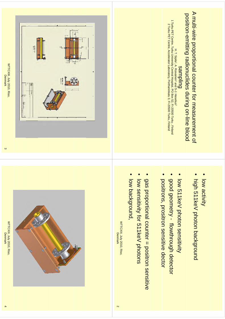
A multi-w
ire proportional counter for measurem
ent of positron-em
ittingradionuclides
duringon-line
bloodpositron
emitting radionuclides during on
line blood sam
plingH
. T. Sipila
1, A. R
oivainen1and S
-J. Heselius
2p
,1 Turku P
ET C
entre, Turku University C
entral Hospital, P
O B
ox 52, FI-20500 Turku , Finland2 Turku P
ET C
entre, Accelerator Laboratory, P
orthaninkatu 3, FI-20500 Turku, Finland
•low
activity•
high 511keV photon background
•low
511keV photon sensitivity
•good geom
etry -flow
through detector •
positronsprositron
sensitivedector
positrons, prositron sensitive dector
•gas proportional counter = positron sensitive
•low
sensitivityfor511keV
photonslow
sensitivity for 511keV photons
•low
background, WTTC
XIII, July 2010, R
iso, D
enmark
2
WTTC
XIII, July 2010, R
iso, D
enmark
3W
TTCX
III, July 2010, Riso,
Denm
ark4
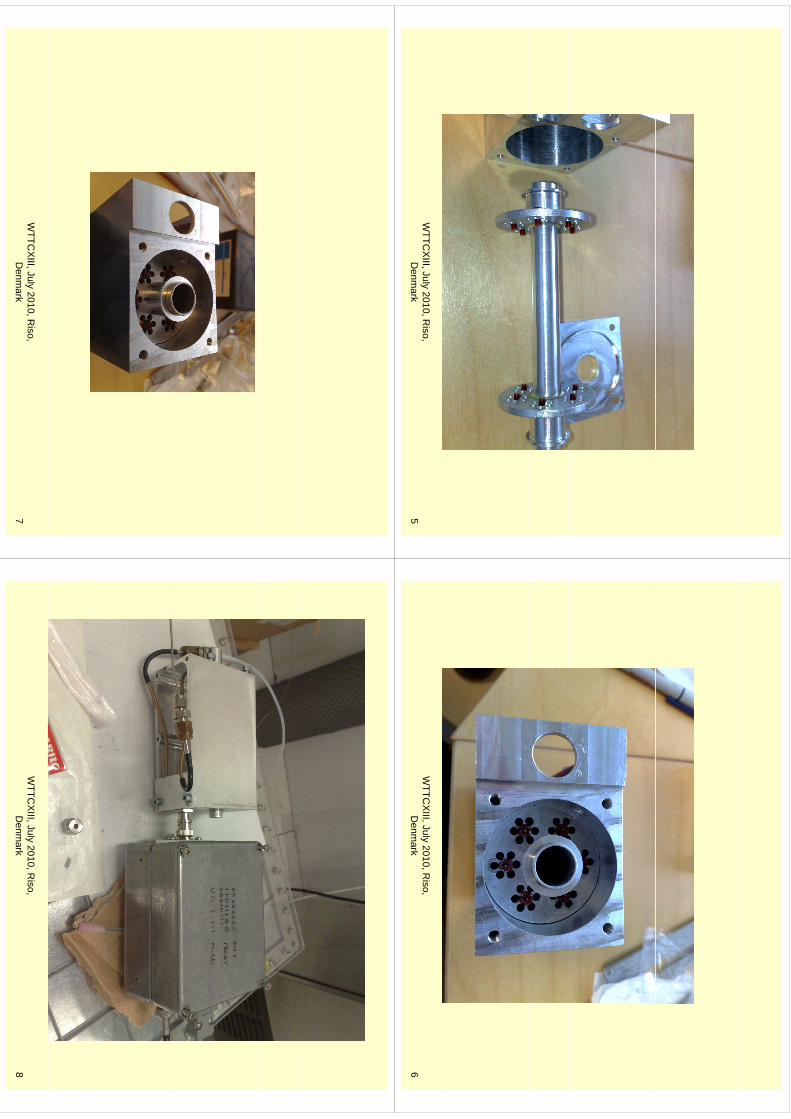
WTTC
XIII, July 2010, R
iso, D
enmark
5W
TTCX
III, July 2010, Riso,
Denm
ark6
WTTC
XIII, July 2010, R
iso, D
enmark
7W
TTCX
III, July 2010, Riso,
Denm
ark8
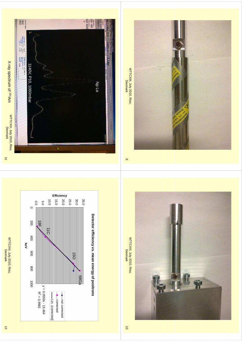
WTTC
XIII, July 2010, R
iso, D
enmark
9W
TTCX
III, July 2010, Riso,
Denm
ark10
Np Lα
1140V, P10, 1060m
bar
X-ray spectrum
of 241Am
WTTC
XIII, July 2010, R
iso, D
enmark
11
Detectorefficiency
vsm
eanenergy
ofpositronsD
etector efficiency vs. mean energy of positrons
35.068G
a
25.0
30.0
y
15O68G
a
15.0
20.0
Efficiency
not correctedcorrected
y = 0.0553x - 13.4642
5.0
10.0E
Lin. (corrected)
18F
11C
R2 = 0.9982
0.00
200400
600800
1000
18F
keV
WTTC
XIII, July 2010, R
iso, D
enmark
12
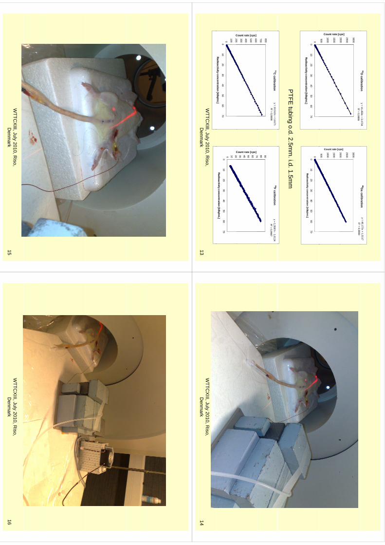
15O calibration
y = 41,458x + 3,473468G
a calibrationy = 40,172x + 1,5117
R2 = 0,9999
2000
2500
3000cps]
R2 = 0,9999
2000
2500
3000
ps]
500
1000
1500
Count rate [c
500
1000
1500
Count rate [cp
00
1020
3040
5060
70
Radioactivity concentration [kBq/mL]
00
1020
3040
5060
70Radioactivity concentration [kBq/m
L]
PTFE
tubing o.d. 2.5mm
. i.d. 1.5mm
11C calibrationy = 10,512x + 1,6171
R2 = 0,9999
700
800
18F calibrationy = 1,3587x - 1,0124
R2 = 0,9987
70 80 90
200
300
400
500
600
Count rate [cps]
20 30 40 50 60 70
Count rate [cps]
0
100
200
010
2030
4050
6070
Radioactivity concentration [kBq/mL]
C
0 10 20
010
2030
4050
6070
Radioactivity concentration [kBq/mL]
C
WTTC
XIII, July 2010, R
iso, D
enmark
13W
TTCX
III, July 2010, Riso,
Denm
ark14
WTTC
XIII, July 2010, R
iso, D
enmark
15W
TTCX
III, July 2010, Riso,
Denm
ark16
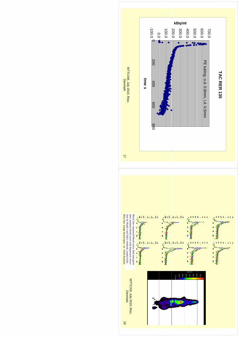
TAC R
ER 135
7000
600.0
700.0P
E tubing. o.d. 0.8m
m, i.d. 0,5m
m
400.0
500.0
ml
200.0
300.0
kBq/m
00
100.0
-100.0
0.00
200400
600800
titime s
WTTC
XIII, July 2010, R
iso, D
enmark
17
6000
700.0
300.0
400.0
500.0
600.0
[k B q/m l]
0.0
100.0
200.0
Black
line:measured
bloodcurve;R
edand
greenB
lack line: measured blood curve; R
ed and green plot: m
easure blood curve with dispersion correc-
tion by Munk’s and Iida’s m
ethods, respectively. B
lue line: Image based input. by N
obu Kudom
i
WTTC
XIII, July 2010, R
iso, D
enmark
18
1
Liquid target system for production of 86Y
Jan Ráliš, Ondřej Lebeda and Josef Kučera
Nuclear Physics Institute of the Academy of Sciences of the Czech Republic, public research institution, Husinec-Řež 130, 250 68 Husinec-Řež, Czech Republic
Introduction Radionuclide 90Y is a widely used tool for cancer therapy due to its suitable half-life, ready availability in high specific activities at relatively low cost. As it is a pure β−- emitter with no associated γ rays, there is a need for a tracer of 90Y. Promising candidate for these purposes is 86Y, since it is a positron emitter with half-life of 14.74 h. This radionuclide has been usually produced by the (p,n) reaction on enriched 86Sr solid targets (SrCO3) [1]. Handling and processing of those targets have several disadvantages. There is an interesting alternative to this approach, namely irradiation of a liquid target filled with aqueous solution of strontium nitrate [2]. It makes the target processing significantly easier and allows for automation of the process. Separation step can be also simplified, since usual electrolysis can be replaced by filtration of yttrium colloid in alkaline milieu [3]. Materials and methods Strontium carbonate (96.3% 86Sr) was purchased from JV Isoflex, Moscow. Trace select ultra grade HNO3, HCl and NH4OH were purchased from Sigma-Aldrich. Puratronic grade (NH4)2CO3 was purchased from AlfaAesar. High purity de-ionized water was used (specific resistance 18.2 MΩ/cm).
The main part of target asembly was water cooled chamber (volume 2.4 ml) made out of pure Nb with Ti entrance foil. The concentration of irradiated solution of strontioum nitrate was 35% (w/w). After irradiation, the solution was transfered to separation unit, target was washed with 10 mM nitric acid and water. All parts were collected together, pH was set to 10, filtered through PVDF filter and washed with 50 ml water. Filtrate was collected for Sr recovery. Yttrium was eluted from the filter with 10 ml 1M HCl. Eluate was evaporated to dryness and re-disolved in 100–300 µl of 0.05M HCl as a stock solution for labelling.
Radionuclidic purity and activity of produced yttrium was measured with γ-ray spectrometry (HPGe detector GMX45, Ortec).
Content of chemical impurities (for 86Y – Fe, Cu, Zn, Al, 86Sr) was determined via ICP-MS at the Institute of Chemical Technology Prague. We used two alternative methods for determination of the purity of the produced 86Y: differential pulse voltametry and labelling efficiency of DOTATOC. Ca. 40 MBq of 86Y stock solution was mixed with 20 µg of DOTATOC in 300 µl of 0.4 M sodium acetate and heated in for 30 min at 80 °C. The labelling yield was monitored with TLC, using silica gel plates (Merck, Germany) developed with 10 % NH4OAc aq. / MeOH = 1:1, Rf = 0.46, and measured on a Cyclone autoradiography system (Perkin-Elmer).
Enriched 86Sr was recovered by precipitation of strontium carbonate with ammonium carbonate [1]. The precipitate was decanted with water and acetone. Strontium carbonate was than dissolved in concentrated nitric acid, evaporated to dryness and re-dissolved in water for further irradiations. Results The yield of irradiation was 33 MBq/µAh. It corresponds well to the published data [1] and given content of 86Sr in the target matrix. Radionuclide purity was excellent (86Y>99.4 %, 87Y<0.55 %, 88Y<0.025 %). Separation yield was more than 90 %, about 4–5 % is left on the filter. Less than 0.1 % of 86Y stays in filtrate. Also losses during evaporation of 1M HCl are under 1 %. Table 1 shows comparison of methods used for determination of copper concentration as a example of impurity. Labelling efficiency reflects well the copper concentration.
234
kmje
Typewritten Text
Abstract 042
inventor
Sticky Note
Accepted set by inventor
inventor
Stamp
2
TABLE 1 Comparison of different analytical methods for estimating the copper content in the product
Batch Polarography [µg/ml]
ICP-MS [µg/ml]
Labelling efficiency
1 8.7 8.9 51.0 % 2 5.7 5.3 77.3 % 3 0.5 0.4 96.6 %
Recovery of enriched strontium was nearly quantitative, all solution used in recycling
process were collected and reprocessed.
Discussion/Conclusion This work presents a compact, fully automated system for production of 86Y in activity and quality suitable for radiopharmaceuticals production. Transport of irradiated target matrix via a capillary to a separation unit minimizes problematic handling of radioactive material and losses of expensive enriched 86Sr. It also reduces significantly personnel radiation burden.
Acknowledgement The project was supported by Nuclear Physics Institute under the NPI research plan AV0Z10480505 and Ministery of Education, Youth and Sports, grant no. 2B061665. [1] Rösch F, Qaim SM, Stöcklin G (1993): Appl. Radiat. Isot. 44(4): 677-681. [2] Vogg, A.T.J., Scheel, Solbach, C., Neumaier, B. (2007): J. Label. Compounds and
Radiopharmaceuticals 50, S105 [3] Kurbatov, J.D., Kurbatov, M.H. (1942): J. Phys. Chem. 46, 441
235
inventor
Sticky Note
Accepted set by inventor
inventor
Stamp
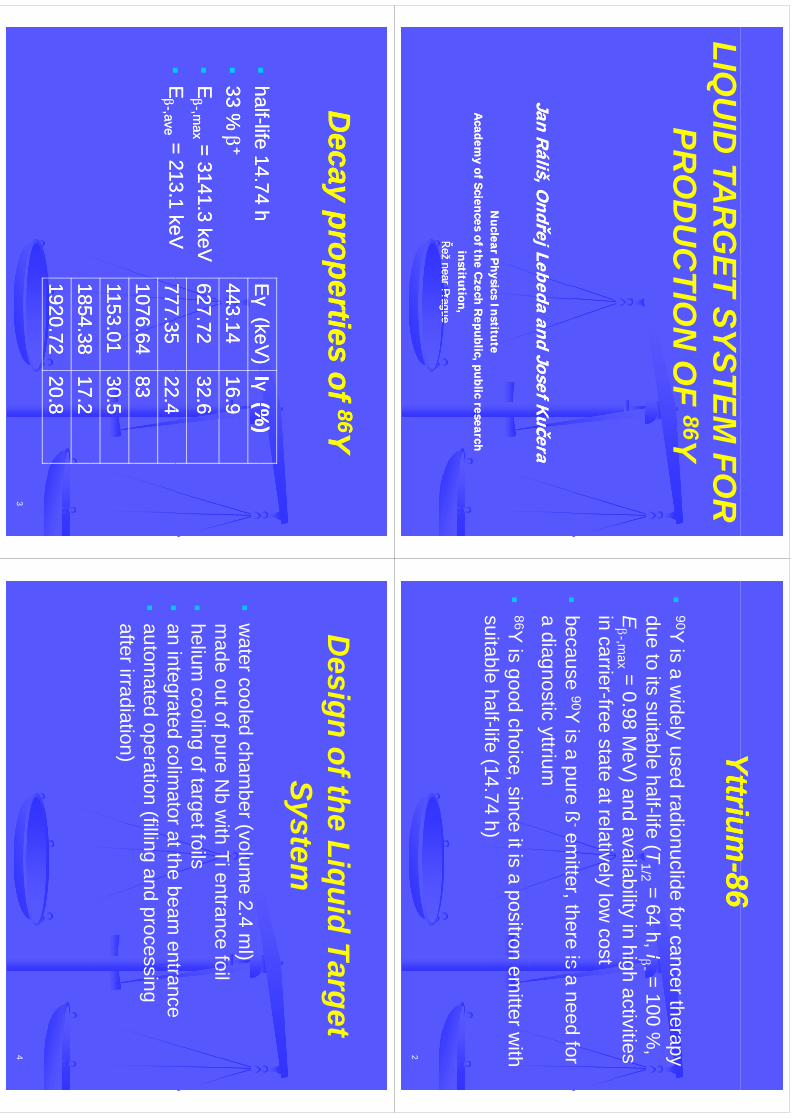
LIQU
ID TA
RG
ET SYSTEM FO
R86
PRO
DU
CTIO
NO
F 86Y
JJananR
áliš, OR
áliš, OndřejndřejLebeda
Lebedaand Josef K
učeraand Josef K
učera
Nuclear P
hysics Institute N
uclear Physics Institute
Academ
y of Sciences of the Czech R
epublicA
cademy of Sciences of the C
zech Republic, , public research
public researchinstitution,institution,
ŘežŘež
nearnear
PrPragueague
Řež Řež near
nearPrPrague
ague
YttriumYttrium
8686YttriumYttrium
--8686
90Y
is a widely used radionuclide for cancer therapy
dueto
itssuitable
halflife(T
=64
hI
=100
%due to its suitable half-life (T
1/2 = 64 h, I- = 100 %,
E-,m
ax = 0.98 MeV
)andavailability in high activities
fin carrier-free state atrelatively low
cost
because
90Yis
apure
ß-em
itterthere
isa
needfor
because
Yis a pure ß
emitter, there is a need for
a diagnostic yttrium
86Y
is good choice, since it is a positron emitter w
ith suitable
half-life(14.74
h)suitable halflife (14.74 h)
2
Deca
propertiesof
Deca
propertiesof
8686YYD
ecay properties of D
ecay properties of 8686YY
EEγγ
(keV)
(keV)
IIγγ(%
)(%
)
halfhalf--life
1474
hlife
1474
hEEγγ
(keV)
(keV) IIγγ
(%)
(%)
443.14443.14
16.916.9
halfhalf--life 14.74 h
life 14.74 h
33 %
33 %
++
627.72627.72
32.632.6
77735
77735
224
224
EE--,m
ax,m
ax = 3141.3 keV= 3141.3 keV
EE
=213
1keV
=213
1keV
777.35777.35
22.422.4
1076.641076.64
8383
EE--,,ave
ave = 213.1 keV= 213.1 keV
1153.01 1153.01
30.530.5
185438
185438
172
172
1854.381854.38
17.217.2
1920.721920.72
20.820.8
3
Di
fthLi
idT
tD
esign of the LiquidTarget
SystemSystem
w
ater cooled chamber (volum
e 2.4 ml)
made
outofpureN
bw
ithTientrance
foilm
ade out of pure Nb w
ith Tientrance foil
helium cooling of target foils
an
integratedcolim
atoratthebeam
entrance
an integrated colimator at the beam
entrance
automated operation (filling and processing
fti
diti
)after irradiation)
4
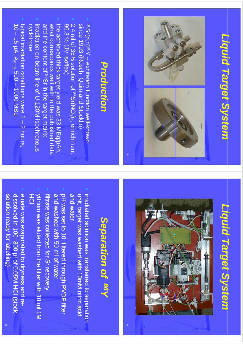
LiquidTargetSystem
LiquidTarget System
5
LiquidTargetSystem
LiquidTarget System
6
Prodction
Production
86Sr(p,n) 86Y
–excitation function w
ell-known
since1993
(Rösch
Qaim
andS
töcklin)since 1993 (R
ösch, Qaim
and Stöcklin)
2.4 m
l of 35% solution of
86Sr(N
O3 )2 , enrichm
ent96
3%
(JVIsoflex)
96.3 %(JV
Isoflex)
theachieved thick target yield w
as 33M
Bq/µA
h,h
td
llith
tth
blih
dd
tw
hatcorresponds wellw
ith to the published dataand the content of 86S
r in the target matrix
irradiation on beam
line of U-120M
isochronous c yclotroney
typical irradiation conditions w
ere 1 –2 hours,
10–
15µA
AE
OB
500–
1000M
Bq
7
10 15 µA
, AE
OB
500 1000 M
Bq
Separationtion
ofof8686YY
Separationtion
of of 8686YY
irradiatirradiateded
solution was transferred to separation
solution was transferred to separation
unittargetw
asw
ashedw
ith10m
Mnitric
acidunit
targetwas
washed
with
10mM
nitricacid
unit, target was w
ashed with 10m
M nitric acid
unit, target was w
ashed with 10m
M nitric acid
and water
and water
pH
was set to 10, filtered through P
VD
F filter pH
was set to 10, filtered through P
VD
F filter and w
ashed with 50 m
l of water
and washed w
ith 50 ml of w
ater
ffiltrate was collected for S
r recoveryiltrate w
as collected for Sr recovery
ttil
td
fth
filtith
10l1M
ttil
td
fth
filtith
10l1M
yyttrium
was eluted from
the filter with 10 m
l 1M
ttrium w
as eluted from the filter w
ith 10 ml 1M
H
Cl
HC
l
eeluate was evaporated to dryness and re
luate was evaporated to dryness and re--
dissolvedin
100dissolved
in100––300
μlof005M
HC
l(stock300
μlof005M
HC
l(stock8
dissolved in 100dissolved in 100––300 μl of 0.05M
HC
l (stock 300 μl of 0.05M
HC
l (stock solution ready for labelling)solution ready for labelling)
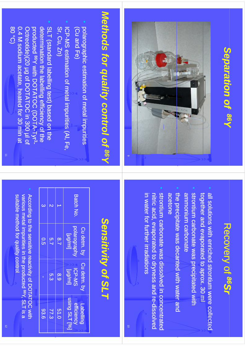
Separationtion
ofof8686YY
Separationtion
of of 8686YY
9
Reco
erof
Reco
erof
8686SrSrR
ecovery of R
ecovery of 8686SrSr
all solutions with e
all solutions with enriched
nriched strontium w
ere collected strontium
were collected
togethertogetherand
evaporatedto
aprox30
ml
andevaporated
toaprox
30m
ltogethertogetherand evaporated to aprox. 30 m
land evaporated to aprox. 30 m
l
strontium carbonate w
as strontium
carbonate was precipitat
precipitatededw
ith w
ith am
monium
carbonateam
monium
carbonate
ttheprecipitate
was
decantedw
ithw
aterandhe
precipitatew
asdecanted
with
waterand
tthe precipitate was decanted w
ith water and
he precipitate was decanted w
ith water and
acetoneacetonet
tib
tdi
ld
it
tib
tdi
ld
it
td
tt
d
sstrontium carbonate w
as dissolved introntium
carbonate was dissolved in
concentrated concentrated
nitric acid, evaporated to dryness and renitric acid, evaporated to dryness and re--dissolved
dissolved in w
ater for further irradiationsin w
ater for further irradiations
10
Methods
forqualitycontrolof
86YM
ethods for quality control of 86Y
polarographic estim
ation of metal im
purities polarographic estim
ation of metal im
purities (C
u and Fe)(C
u and Fe)
IC
PIC
PM
Sestim
ationofm
etalimpurities
(Al
FeM
Sestim
ationofm
etalimpurities
(Al
Fe
ICP
ICP
--MS
estimation of m
etal impurities (A
l, Fe, M
S estim
ation of metal im
purities (Al, Fe,
Sr, C
u, Zn)S
r, Cu, Zn)
S
LT (standard labelling test) based on the S
LT (standard labelling test) based on the determ
inationthe
labellingefficiency
ofthedeterm
inationthe
labellingefficiency
ofthedeterm
ination the labelling efficiency of the determ
ination the labelling efficiency of the producted producted 8686Y
with D
OTA
TOC
(DO
TAY
with D
OTA
TOC
(DO
TA--TyrTyr 33--
Octreotide)(
Octreotide)(20
µgofD
OTA
TOC
in300
µlof20
µgofD
OTA
TOC
in300
µlofO
ctreotide)(O
ctreotide)(20 µg of DO
TATO
C in 300 µl of
20 µg of DO
TATO
C in 300 µl of
0.4 M sodium
acetate0.4 M
sodium acetate, , heated for 30 m
in at heated for 30 m
in at 8080
°°CC))
11
80 80 °°CC
))
Siti
itfSLT
Siti
itfSLT
Sensitivity of SLTSensitivity of SLT
Cu detm
. byC
u detm. by
Cu detm
. byC
u detm. by
Labelling Labelling
Batch N
o.B
atch No.
yypolarography polarography
[[μμg/ml]
g/ml]
yyIC
PIC
P--M
SM
S[[μμg/m
l]g/m
l]
ggefficiency efficiency
usin g SLT
using SLT [%
][%
][[μμg/
]g/
][[μμg/
]g/
]gg
[]
[]
118.78.7
8.98.9
51.051.0
225.75.7
5.35.3
77.377.3
330.50.5
--93.693.6
A
ccording to the sensitive reactivity of DO
TATOC
with
According to the sensitive reactivity of D
OTATO
C w
ith g
yg
yvarious m
etal impurities in the producted
various metal im
purities in the producted 8686Y, SLT is
Y, SLT is
aasuitable m
ethod for quality control suitable m
ethod for quality control
12
qy
qy

Concl
sionC
onclusion
fully automated system
for production of fully autom
ated system for production of 8686Y
in Y
in am
ountsand
qualityappropriate
tousual
amounts
andquality
appropriateto
usualam
ounts and quality appropriate to usual am
ounts and quality appropriate to usual requirem
ents for labellingrequirem
ents for labellingvery
fastandefficient
veryfastand
efficient
very fast and efficientvery fast and efficient
possibility tpossibility transport of irradiated target m
atrix via ransport of irradiated target m
atrix via a capillary to a separation unita capillary to a separation unit
m
inimizes problem
atic handling of radioactive m
inimizes problem
atic handling of radioactive p
gp
gm
aterial and losses of expensive enriched m
aterial and losses of expensive enriched 8686Sr
Sr
iitalso
reducessignificantly
personnel’sradiation
talsoreduces
significantlypersonnel’s
radiationiit also reduces significantly personnels radiation t also reduces significantly personnels radiation burdenburden
13
Acknow
ledgements
Departm
ent of Radiopharm
aceuticalsD
epartment of A
ccelarators
MS
c. K. E
igner Henke
MS
c. Ondře j Lebeda, P
h.D.
MS
c. Jan Štursa
MS
cJan
Kučera
j,
MS
c. Jan Kučka
Assoc. P
rof. František Melichar, D
.Sc .
MS
c. Jan Kučera
Vk
Ph
Theprojectw
assupported
bythe
Academ
yof
Vakuum Praha s.r.o.
Theprojectw
assupported
bythe
Academ
yof
Sciencesofthe
Czech
Republic
underthe
NPI
researchplan
AV0Z10480505and
bythe
Mi
it
fEdti
Yth
dS
tt
Ministry
ofEducation,Youthand
Sports,grantno.2B
061665.
14
WTTC
XIII–Presentation
Discussions
WTTC
XIII –Presentation D
iscussions
1.W
hat happens to nitrates?•
Som
e“hydrolyses”
•S
ome hydrolyses
•Som
e stays in the solution•
No salt precipitation from
high concentration
15
Can Half-life Measurements Alone Determine Radionuclidic
Purity of F-18 Compounds?
Thomas Jørgensen1, Mille Ankerstjerne Micheelsen2, and Mikael Jensen1
1Hevesy Lab, Risoe-DTU,Technical University of Denmark, DK-4000 Roskilde, Denmark2Dept.Clinical Physiology and Nuclear Medicine, Koege Hospital, DK-4600 Koege, Denmark
Current revisions of monographs for F-18 pharmaceuticals in the European Pharma-copoeia call for a radionuclidic purity (RNP) of or better than 99.9%. If (debatably)this requirement is put at end of shelf life, typically 10 hours EOS , the requirement canbe very difficult to assure by actual measurements, if all possible radionuclide contam-inations should be considered. Clearly, gamma spectroscopy can do much, but only ifthe contaminant has strong gamma emissions above 511 keV. We have tried to analysemathematically to what extent that half-life measurements alone can establish RNP forF-18 compounds. The method could in principle be extended to other isotopes. Thecurrent method of half-life determination in the Ph.Eur with two measurements at 6hinterval is not sufficient nor effective for testing the required RNP level.
We present a theoretical model leading to a practical procedure for testing RNP ofF-18 compounds with a confidence of 95%.
We look at a batch of F-18 contaminated with one other isotope with a half-life ofβT18F . The contamination level is α at time 0. The recorded number of counts, N(t),for a sample, that contains one other isotope, is described by
N(t) =N(0)
(1 + α)
((1
2
)t/T18F+ α
(1
2
)t/βT18F)
with N(0) as the total number of counts at t = 0.RNP is defined by the expression
RNP =A18F
Atot⇒ RNP (0) =
1
1 + α' 1− α, α =
A18F (0)
Aother(0)
If all measured impulses are converted to initial point values (t = 0 min.), the curveshould give a straight line with constant value (the initial value of counts) for a pureF-18 sample. Due to the stochastic nature of the F-18 nuclide, the data points willdeviate from this line. If the sample is contaminated the curve will increase rapidly.The condition for the pure and unpure curves to be separated is, the difference of the
1
240
kmje
Typewritten Text
Abstract 043
inventor
Stamp
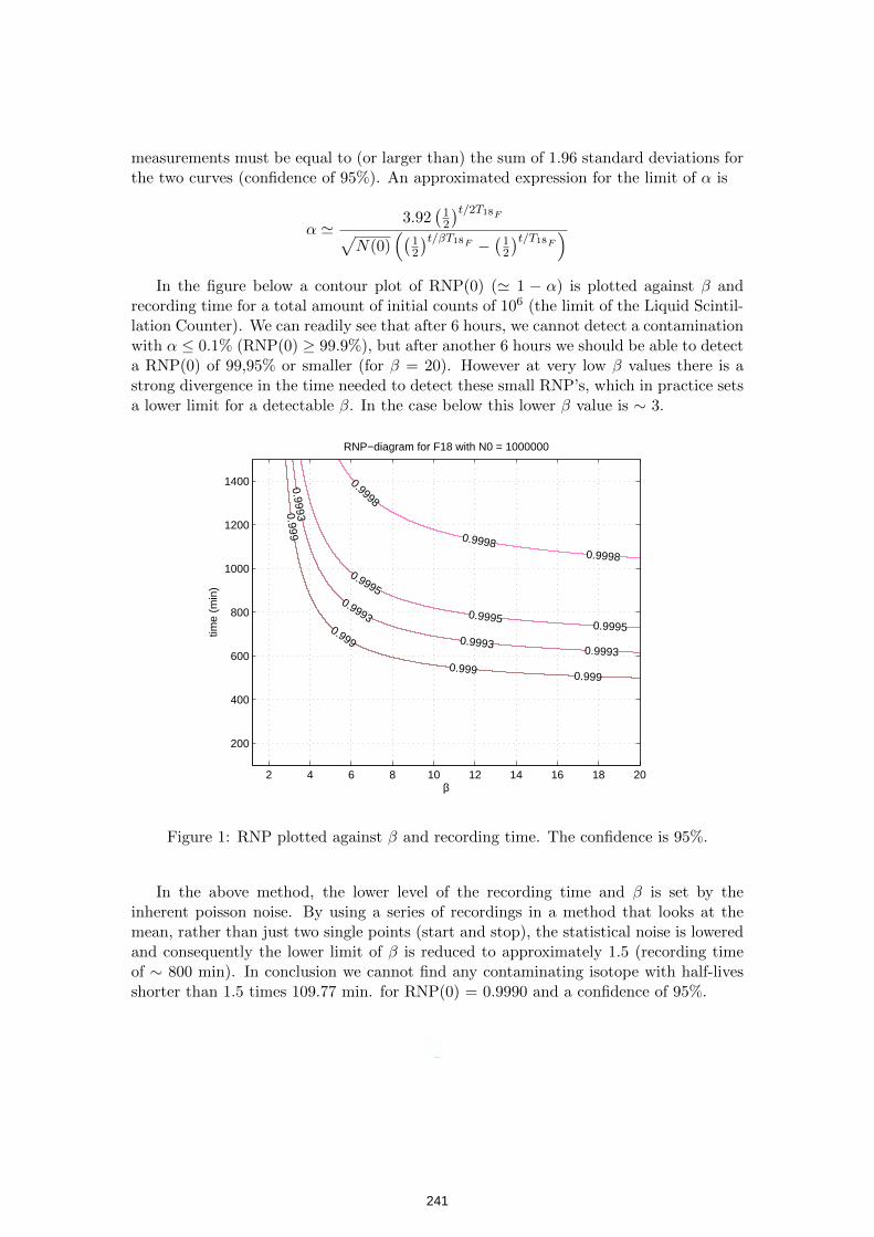
measurements must be equal to (or larger than) the sum of 1.96 standard deviations forthe two curves (confidence of 95%). An approximated expression for the limit of α is
α '3.92
(12
)t/2T18F√N(0)
((12
)t/βT18F − (12)t/T18F )In the figure below a contour plot of RNP(0) (' 1 − α) is plotted against β and
recording time for a total amount of initial counts of 106 (the limit of the Liquid Scintil-lation Counter). We can readily see that after 6 hours, we cannot detect a contaminationwith α ≤ 0.1% (RNP(0) ≥ 99.9%), but after another 6 hours we should be able to detecta RNP(0) of 99,95% or smaller (for β = 20). However at very low β values there is astrong divergence in the time needed to detect these small RNP’s, which in practice setsa lower limit for a detectable β. In the case below this lower β value is ∼ 3.
0.9990.999
0.999
0.999
0.99930.9993
0.9993
0.9993
0.99950.9995
0.9995
0.9998
0.9998
0.9998
RNP−diagram for F18 with N0 = 1000000
β
time
(min
)
2 4 6 8 10 12 14 16 18 20
200
400
600
800
1000
1200
1400
Figure 1: RNP plotted against β and recording time. The confidence is 95%.
In the above method, the lower level of the recording time and β is set by theinherent poisson noise. By using a series of recordings in a method that looks at themean, rather than just two single points (start and stop), the statistical noise is loweredand consequently the lower limit of β is reduced to approximately 1.5 (recording timeof ∼ 800 min). In conclusion we cannot find any contaminating isotope with half-livesshorter than 1.5 times 109.77 min. for RNP(0) = 0.9990 and a confidence of 95%.
2
241
inventor
Stamp
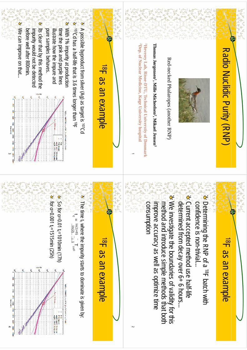
Radio Nuclidic Purity (RNP)
Red-necked Phalaropes (another R
NP)
Thom
as Jørgensen1, M
ille Micheelsen
2, Mikael Jensen
1
1Hevesey L
ab, Risoe-D
TU
, Technical Universtiy of D
enmark
2Dep. of N
uclear Medicine, K
øge University hospital
p,
gy
p1
18F as an example
Determining the RNP of a 18F batch with Determining the RNP of a
F batch with confidence is non-trivial... Current accepted method use half-life determined from decay over 6+ 6 hours...
yW
e investigate the boundaries of validity for this method and introduce simple methods that both method and introduce simple methods that both improve accuracy as well as optimize time consumption
2
18F as an example
A possible byproduct from silver (Ag) as target is 107CdA possible byproduct from silver (Ag) as target is
Cd107Cd has a half-life that is 3.6 times longer than 18FW
ith 1% impurity at production
With 1%
impurity at productiontime the pink and purple lines illustrate how the impure and illustrate how the impure and pure samples behaves. It l
tht b
thi th
d thIts clear that by this method theimpurity would not be detected before well after 800minbefore well after 800min.W
e can improve on that...
3
18F as an example
The time tc where the impurity starts to dominate is given by:The time tc where the impurity starts to dominate is given by:
tc=
ln(1=®)
ln(2)¯
¯¡
1 T1
8F
So for α=0.01 tc =1010min (17h)for α=0.001 tc =1515min (25h)
4
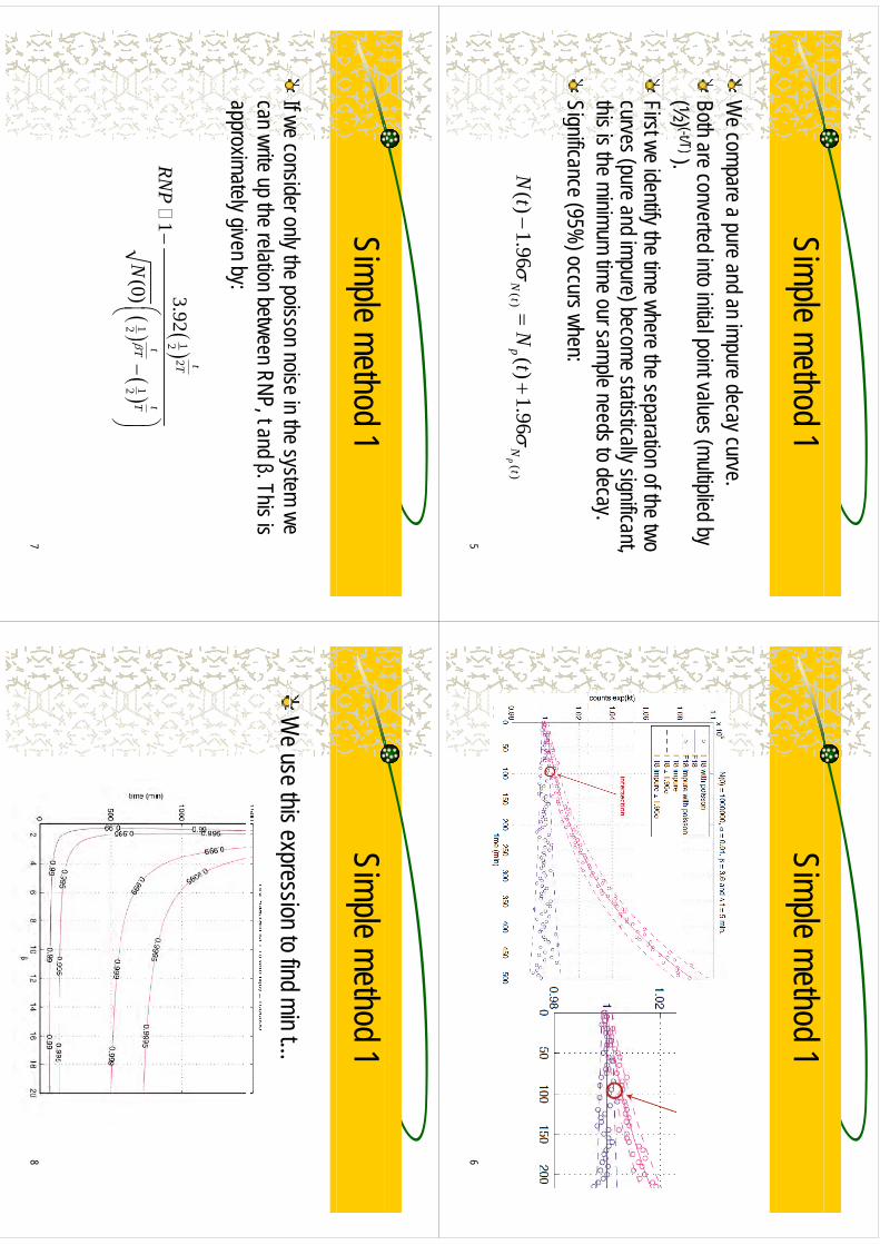
Simple method 1
We compare a pure and an impure decay curve
We compare a pure and an impure decay curve.
Both are converted into initial point values (multiplied by (½) (-t/T)) (½) (t/T)). First we identify the time where the separation of the two
(
d i) b
ttitill i
ifit
curves (pure and impure) become statistically significant, this is the minimum time our sample needs to decay. Significance (95%
) occurs when:
)(
)(
96.1
)(
96.1
)(
tN
pt
Np
tN
tN
5
Simple method 1
6
Simple method 1
If we consider only the poisson noise in the system we If we consider only the poisson noise in the system we can write up the relation between RNP, t and β. This is approximately given by:approximately given by:
t
12
23.92
1
tT
tt
RN
P
11
22
(0)T
TN
7
Simple method 1
We use this expression to find min t
We use this expression to find min t…
8
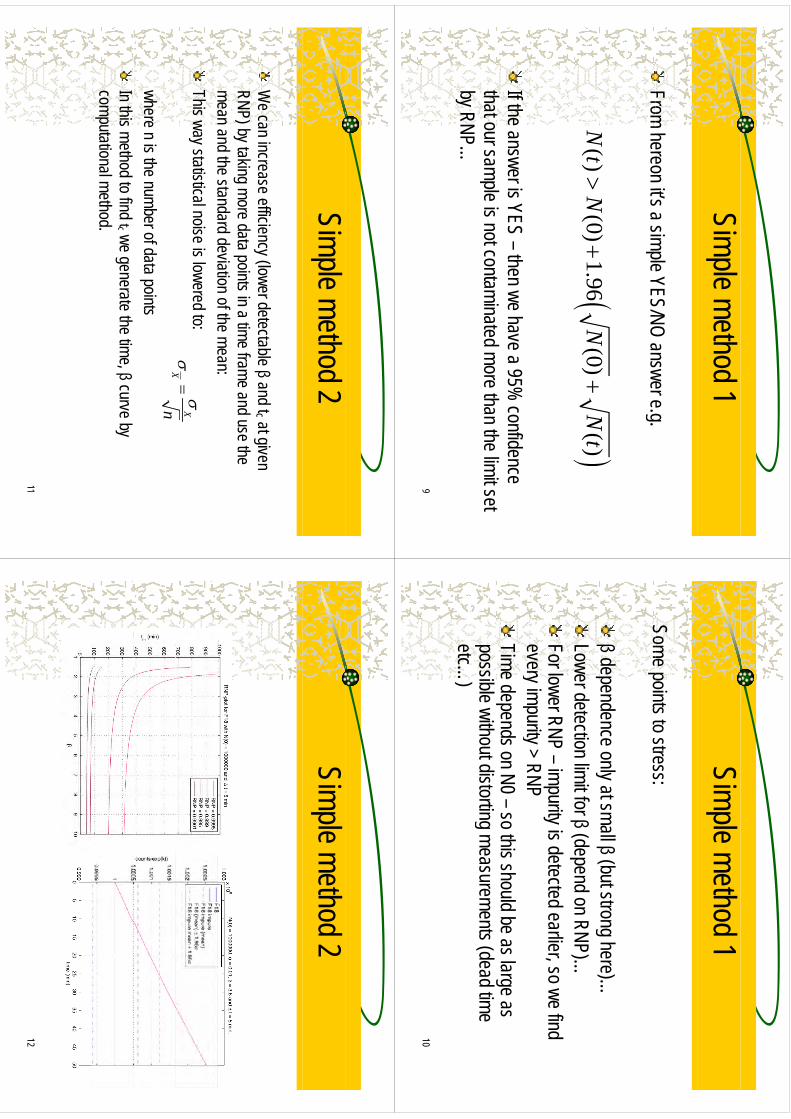
Simple method 1
From hereon it’s a simple YES/NO answer egFrom hereon its a simple YES/NO answer e.g.
()
(0)1.96
(0)(
)N
tN
NN
t
If the answer is YES –then we have a 95% confidence
that our sample is not contaminated more than the limit set that our sample is not contaminated more than the limit set by RNP…
9
Simple method 1
Some points to stress:Some points to stress:
β dd
l t
ll β (bt t
h)
β dependence only at small β (but strong here)…Lower detection limit for β (depend on RNP)…
β(p
)For lower RNP –impurity is detected earlier, so we find every impurity > RNPevery impurity
RNPTime depends on N0 –so this should be as large as possible without distorting measurements (dead time possible without distorting measurements (dead time etc…
)
10
Simple method 2
We can increase efficiency (lower detectable βand tc at given
We can increase efficiency (lower detectable βand tc at given
RNP) by taking more data points in a time frame and use the mean and the standard deviation of the mean:mean and the standard deviation of the mean:This way statistical noise is lowered to:
XX
where n is the number of data pointsX
n
In this method to find tc we generate the time, βcurve by computational method.
11
Simple method 2
12
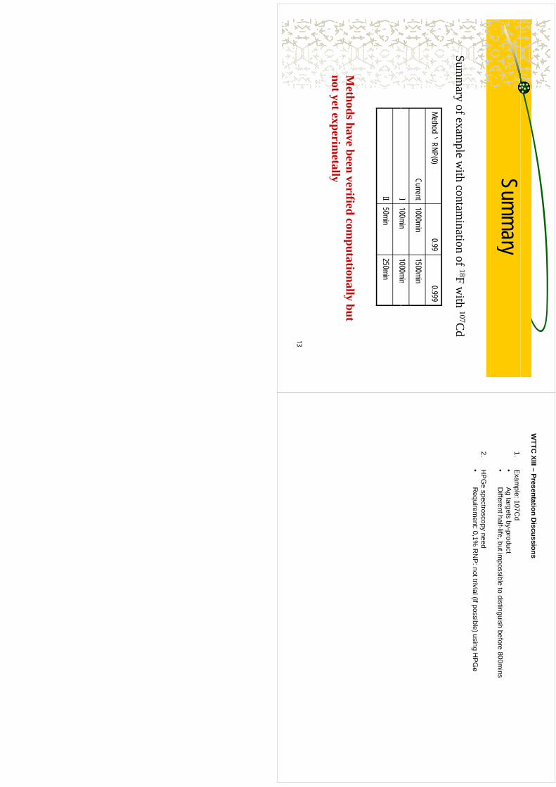
Summary
Summ
aryofexam
plew
ithcontam
inationof
18Fw
ith107C
d
Method \RNP(0)0.99
0.999
Summ
ary of example w
ith contamination of 18F w
ith 107Cd
()
Current1000min
1500min
I100min
1000minI
100min1000min
II50min
250min
Methods have been verified com
putationally but not yet experim
etally
13
WTTC
XIII –Presentation D
iscussions
1.E
xample: 107C
d•
Ag targets by-product•
Different half-life, but im
possible to distinguish before 800mins
2.H
PG
espectroscopy need
•R
equirement: 0,1%
RN
P: not trivial (if possible) using H
PG
e
PC-controlled radiochemistry system for preparation of NCA 64Cu
Adam Rebeles R., Van den Winkel P., De Vis L., Waegeneer R.
Cyclotron Laboratory, Vrije Universiteit Brussel (VUB), Brussels, Belgium
Due to the rapid increase of the use of nuclear medicine techniques in modern clinical diagnosis and in a selected series of therapies, researchers’ efforts are focusing for the standardization and optimization of different production routes for a series of emerging radioisotopes like 64Cu, 67Cu, 114mIn, 211At. In particular the EC/β+/β- decay of 64Cu makes it a promising candidate for both PET imaging and internal targeted radio therapy. In the last decades several groups studied different production routes like for this radio nuclide, i.e. 64Ni(p,n), 64Ni(d,2n),64Zn(d,2p). Taking into account the wider availability of the medium energy proton beam machines, the (p,n) reaction on 64Ni seems to be the most attractive one, although 64Zn(d,2p) may be considered as an alternative where lower activity is necessary, as it may require less investment in enriched material. The production of large activities of 64Cu on regular basis requires a fast and reliable chemistry system. Based on the experience gathered in the last decades in our laboratory we present here and efficient, remote controlled chemistry system for production of the non carrier added 64Cu via 64Ni(p,n) reaction. To avoid excessive investment in a gold target carrier, a good practice is to coat the copper target carrier with a thin inert material, i.e. 5-6 μm of gold, followed by electrodeposition of the 64Ni target layer. In that way, the cross contamination of the non carrier added 64Cu with the copper present in the target carrier is excluded. In general the irradiations are performed with protons having incident energy of about 15 MeV, and, depending on irradiation condition, may lead to curie amount of induced activity of 64Cu. To reduce the thickness of the 64Ni target layer, and, as consequence, to minimize the problems related with the plating and dissolution of the target layer, a low beam/target angle geometry (6 degrees) is desired. Nevertheless, the separation of target / activation product is required. Upon irradiation, our chemistry system proposes the dissolution of the 64Ni layer in a heated flow trough stripper by means of diluted nitric acid. Next, the non carrier added 64Cu is selective extracted into benzene (containing 0.1 M benzoylacetone) at pH 4.5, leaving the enriched 64Ni and possible Co induced isotopes in the inorganic phase. The back extraction of 64Cu is done in a small volume of diluted hydrochloric acid (6 N). The final purification step is achieved using an anion exchange column Dowex 1X8. Finally, the NCA 64Cu is eluted with a small volume (10 ml), diluted hydrochloric acid (1 N). The overall yield of the chemistry is estimated as being higher than 95% with a short total chemistry time, less than 2 hours, while the gold plated target carriers can be reused as long as the thin gold layer remains intact, meaning that scratches and cracking by careless handling are avoided.
246
kmje
Typewritten Text
Abstract 044
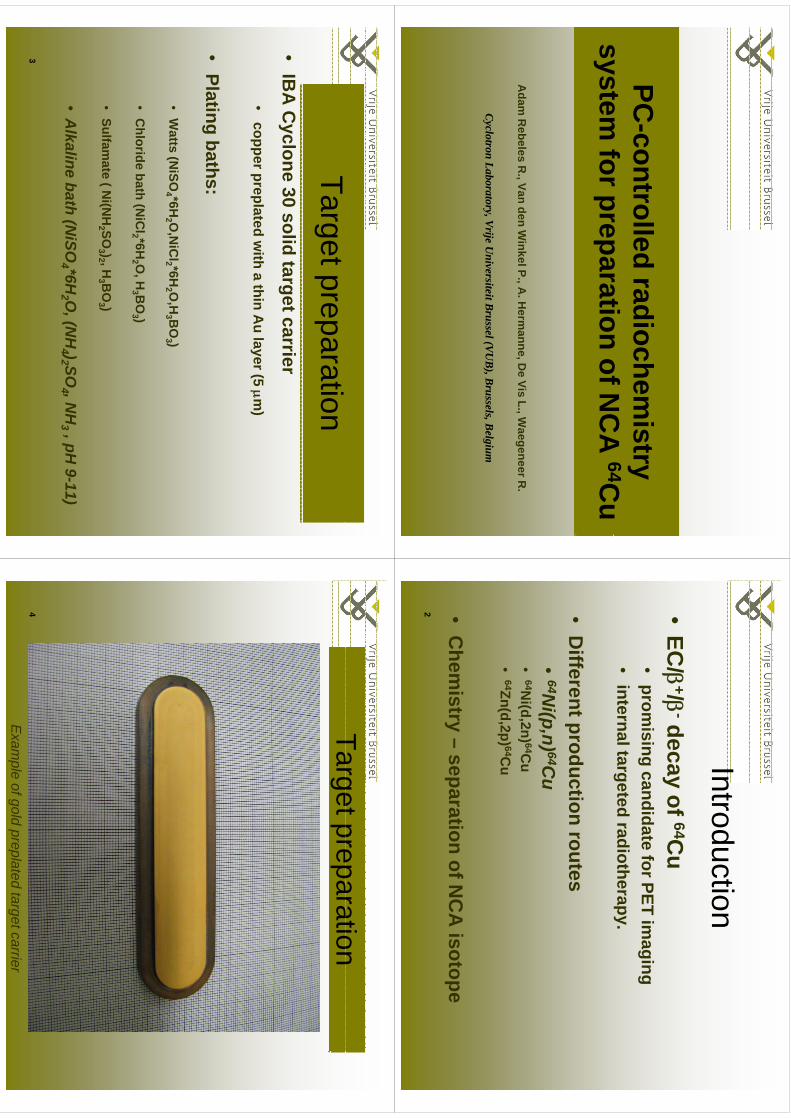
PC-controlled radiochem
istry system
forpreparationofN
CA
64Cu
system for preparation of N
CA
64Cu
Adam
Rebeles R
., Van den Winkel P., A
. Herm
anne, De Vis L., W
aegeneer R.
CyclotronLaboratory,Vrije
UniversiteitBrussel(VU
B),Brussels,BelgiumCyclotron Laboratory,Vrije U
niversiteit Brussel (VUB), Brussels, Belgium
Introduction•
EC/
+/-decay of 64C
u •
promising candidate for PET im
aging •
internal targeted radiotherapy.
•D
ifferentproductionroutes
Different production routes
•64N
i(p,n) 64Cu
64Ni(d
2n) 64C•
64Ni(d,2n) 64C
u•
64Zn(d,2p) 64Cu
•C
hemistry –
separation of NC
A isotope
2
Target preparation•
IBA
Cyclone 30 solid target carrier copperpreplated
with
athin
Au
layer(5m
)•
copper preplated with a thin A
u layer (5 m)
Plti
bth
•Plating baths:
Watts
(NiSO
*6HO
NiC
l*6HO
HB
O)
•W
atts (NiSO
4 *6H2 O
,NiC
l2 *6H2 O
,H3 B
O3 )
•C
hloride bath (NiC
l2 *6H2 O
, H3 B
O3 )
(2
23
3 )
•Sulfam
ate ( Ni(N
H2 SO
3 )2 , H3 B
O3 )
•A
lkaline bath (NiSO
4 *6H2 O
, (NH
4 )2 SO4 , N
H3 , pH
9-11)
3
TargetpreparationTarget preparation
Exam
ple of gold preplated target carrier4
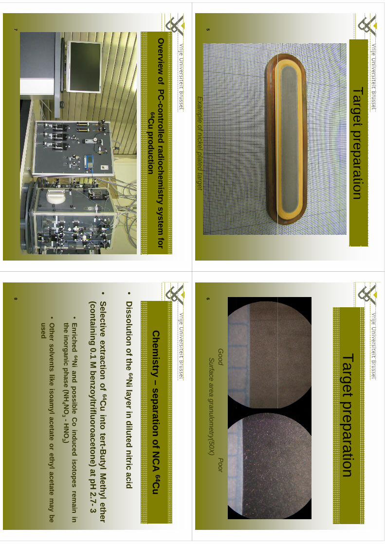
TargetpreparationTarget preparation
Exam
ple of nickel plated target 5
Target preparation
Good P
oorS
urface area granulometry(50X
) 6
Overview
of PC-controlled radiochem
istry system for
64Cu production
p
7
Chem
istry –separation of N
CA
64Cu
•D
issolutionofthe
64Nilayerin
dilutednitric
acidD
issolutionofthe
Nilayerin
dilutednitric
acid
Sl
tit
tif
64Ci
tt
tBt
lMth
lth
•Selective
extractionof
64Cu
intotert-B
utylMethylether
(containing0.1
Mbenzoyltrifluoroacetone)atpH
2.7-3
•Enriched
64Ni
andpossible
Co
inducedisotopes
remain
inthe
inorganicphase
(NH
4 NO
3 -HN
O3 )
theinorganic
phase(N
H4 N
O3
HN
O3 )
•O
thersolvents
likeisoam
ylacetateor
ethylacetatem
aybe
usedused
8
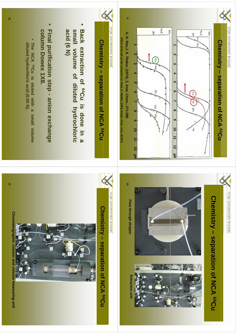
Chem
istryseparation
ofNC
A64C
uC
hemistry –
separation of NC
A 64C
u
1 2 3 4 5 6 7 8 9 10 11 12 pH
1 2 3 4 5 6 7 8 9 10 11 12 pH
Effect of the pH on the extraction (J. Starý, E. H
ladký, (1963) Analyt. C
him. A
cta, 28:227)
G. N
. Rao,J. S. Thakur, (1974), Z. A
nal. Chem
., 271:2869
Chem
istry –separation of N
CA
64Cu
Et
tiit
Flow through stripper
Extraction unit10
Ch
it
tifN
CA
64CC
hemistry –
separation of NC
A 64C
u
•B
ackextraction
of64C
uis
donein
asm
allvolum
eof
dilutedhydrochloric
acid(6
N)
()
•Finalpurification
step-anion
exchangecolum
nD
owex
1X8.•
TheN
CA
64Cu
iseluted
with
asm
allvolum
ediluted
hydrochloricacid
(005
N)
dilutedhydrochloric
acid(0.05
N).
11
Chem
istryseparation
ofNC
A64C
uC
hemistry –
separation of NC
A 64C
u
Ch
thi
ld
li
itC
hromatographic colum
n and volume m
easuring unit 12

Ch
it
tifN
CA
Chem
istry –separation of N
CA
64C
u64C
u
13
Conclusions
•B
asedon
theexperience
gatheredin
ourlaboratory
indevelopm
entson
solid
targetchem
istrysystem
sa
robustm
odularsystem
forthe
separationof
NC
Atarget
chemistry
systems,
arobust
modular
systemfor
theseparation
ofN
CA
64Cu
was
developed.
•A
nalytical separation techniques:
–solvent/solvent extraction
–ion exchange chrom
atography
•H
igh chemistry yield >95%
•Total chem
istry time <2 hours
•The
userfriendlyVisualB
asicinterface
-allows
thefullcontrolovereach
stepof
The user friendly Visual Basic interface
allows the full control over each step of
the chemistry w
ith a minim
um risk of operator errors and of radiation exposure
for the staff.
14
Acknow
ledgements
g
•The authors w
ould like to thank the IBA
-Ion Beam
Applications -
Louvain-la-Neuve
company
forprovidingthe
enriched64N
iLouvain-la-N
euve company for providing the enriched 6
Ni
15
Conclusions
•B
asedon
theexperience
gatheredin
ourlaboratory
indevelopm
entson
solid
targetchem
istrysystem
sa
robustm
odularsystem
forthe
separationof
NC
Atarget
chemistry
systems,
arobust
modular
systemfor
theseparation
ofN
CA
64Cu
was
developed.
•A
nalytical separation techniques:
–solvent/solvent extraction
–ion exchange chrom
atography
•H
igh chemistry yield >95%
•Total chem
istry time <2 hours
•The user friendly Visual B
asic interface -allows the full control over each step of
the chemistry w
ith a minim
um risk of operator errors and of radiation exposure
for the staff.
16

WTTC
XIII–Presentation
Discussions
WTTC
XIII –Presentation D
iscussions
1.Fe?•
Extracted
inion
exchanger•
Extracted in ion exchanger
2.R
euse of golden plated back•
Reused
10xw
ithoutbigactivation
•R
eused 10x, without big activation
•C
areful: Cu/A
u dissolve in each other: hotspots=activation•
Worst: C
u dissemination = low
specific activity
251
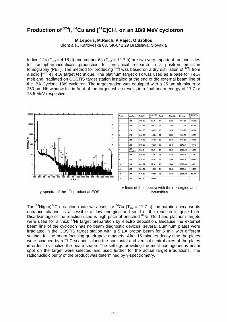
Production of 124I, 64Cu and [11C]CH4 on an 18/9 MeV cyclotron
M.Leporis, M.Reich, P.Rajec, O.Szöllős Biont a.s., Karloveska 63, SK-842 29 Bratislava, Slovakia
Iodine-124 (T1/2 = 4.18 d) and copper-64 (T1/2 = 12.7 h) are two very important radionuclides for radiopharmaceuticals production for preclinical research in a positron emission tomography (PET). The method for producing 124I was based on a dry distillation of 124I from a solid [124Te]TeO2 target technique. The platinum target disk was used as a base for TeO2 melt and irradiated on COSTIS target station installed at the end of the external beam line of the IBA Cyclone 18/9 cyclotron. The target station was equipped with a 25 µm aluminum or 250 µm Nb window foil in front of the target, which results in a final beam energy of 17.7 or 13.5 MeV respective.
γ-spectra of the 124I product at EOS
Peak Nuclide E, keV Intensity,
% Peak Nuclide E, keV Intensity, %
1 123I 158.97 83.3 14 123I 687.95 0.0267
2 123I 247.96 0.071 15 124I 722.78 10.35
3 123I 281.03 0.079 16 123I 735.78 0.062
4 123I 346.35 0.126 17 123I 783.59 0.059
5 123I 440.02 0.428 18 124I 968.22 0.435
6 123I 505.33 0.316 19 124I 1045.0 0.441
7 124I (annih.) 511.0 46.0 20 124I 1325.50 1.561
8 123I 528.96 1.39 21 124I 1376.0 1.75
9 123I 538.54 0.382 22 124I 1488.9 0.199
10 124I 602.72 62.9 23 124I 1509.49 3.13
11 123I 624.57 0.083 24 124I 1559.8 0.165
12 124I 645.82 0.988 25 124I 1691.02 10.88
13 124I 662.4 0.056
γ-lines of the spectra with their energies and
intensities
The 64Ni(p,n)64Cu reaction route was used for 64Cu (T1/2 = 12.7 h) preparation because its entrance channel is accessible at low energies and yield of the reaction is quite high. Disadvantage of the reaction used is high price of enriched 64Ni. Gold and platinum targets were used for a thick 64Ni target preparation by electro deposition. Because the external beam line of the cyclotron has no beam diagnostic devices, several aluminum plates were irradiated in the COSTIS target station with a 5 µA proton beam for 5 min with different settings for the beam focusing quadrupole magnets. After 15 minutes decay time the plates were scanned by a TLC scanner along the horizontal and vertical central axes of the plates in order to visualize the beam shape. The settings providing the most homogeneous beam spot on the target were selected and used further for the actual target irradiations. The radionuclidic purity of the product was determined by γ-spectrometry.
252
kmje
Typewritten Text
Abstract 045
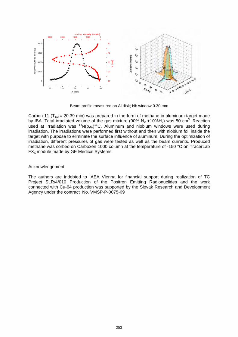
10 20 30 40 50
0
2000
4000
6000
8000
8000 6000 4000 2000 0
10
20
30
40
50
rela
tive
inte
nsity
[cou
nts]
X [mm]
relative intensity [counts]
Y [m
m]
Beam profile measured on Al disk; Nb window 0.30 mm Carbon-11 (T1/2 = 20.39 min) was prepared in the form of methane in aluminum target made by IBA. Total irradiated volume of the gas mixture (90% N2 +10%H2) was 50 cm3. Reaction used at irradiation was 14N(p,α)11C. Aluminum and niobium windows were used during irradiation. The irradiations were performed first without and then with niobium foil inside the target with purpose to eliminate the surface influence of aluminum. During the optimization of irradiation, different pressures of gas were tested as well as the beam currents. Produced methane was sorbed on Carboxen 1000 column at the temperature of -150 °C on TracerLab FXC module made by GE Medical Systems. Acknowledgement The authors are indebted to IAEA Vienna for financial support during realization of TC Project SLR/4/010 Production of the Positron Emitting Radionuclides and the work connected with Cu-64 production was supported by the Slovak Research and Development Agency under the contract No. VMSP-P-0075-09
253
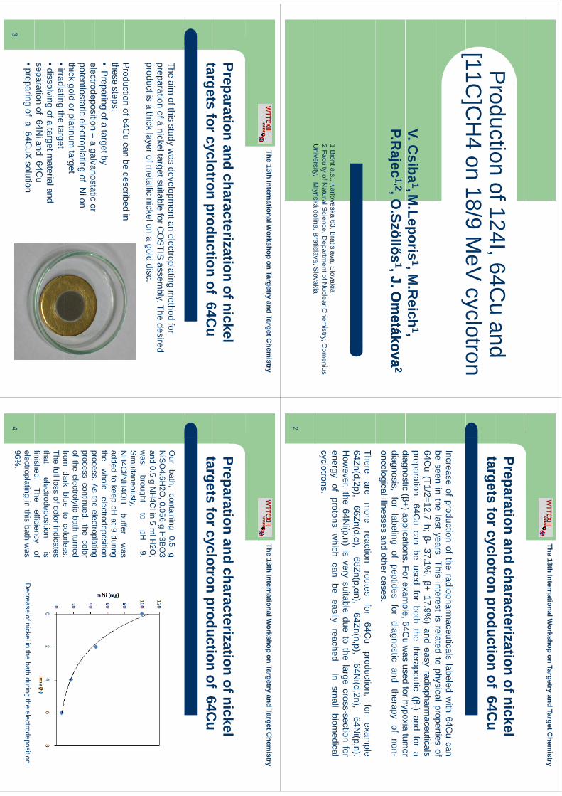
Production
of124I64C
uand
Production of 124I, 64C
u and [11C
]CH
4 on 18/9 MeV
cyclotron[
C]C
o8/9
ecyc
oo
V. Csiba
1,M.Leporis
1, M.R
eich1,
pP.R
ajec1,2, O
.Szöllős1, J. O
metákova
J. Om
etákova22
1 Biont a.s., K
arloveska 63, Bratislava, S
lovakia2 Faculty of N
atural Science, D
epartment of N
uclear Chem
istry, Com
enius U
niversityM
lynskádolina
BratislavaSlovakia
University, M
lynská dolina, Bratislava, S
lovakia
The13th
InternationalWorkshop
onTargetry and
TargetChem
istry
Preparation and characterization of nickel t
tf
lt
dti
f64C
targets for cyclotron production of 64Cu
Increaseof
productionof
theradiopharm
aceuticalslabeled
with
64Cu
canbe
seenin
thelast
years.This
interestis
relatedto
physicalpropertiesof
beseen
inthe
lastyears.
Thisinterest
isrelated
tophysicalproperties
of64C
u(T1/2=12.7
h;β-
37.1%,β+
17.9%)
andeasy
radiopharmaceuticals
preparation.64C
ucan
beused
forboth
thetherapeutic
(β-)and
fora
diagnostic(β+)applications
Forexample
64Cu
was
usedforhypoxia
tumor
diagnostic(β+)applications.Forexam
ple,64Cu
was
usedforhypoxia
tumor
diagnosis,for
labelingof
peptidesfor
diagnosticand
therapyof
non-oncologicalillnesses
andothercases.
Thereare
more
reactionroutes
for64C
uproduction,
forexam
ple64Zn(d,2p),
66Zn(d,α),68Zn(p,αn),
64Zn(n,p),64N
i(d,2n),64N
i(p,n).H
owever
the64N
i(pn)
isvery
suitabledue
tothe
largecross-section
forH
owever,
the64N
i(p,n)is
verysuitable
dueto
thelarge
cross-sectionfor
energyof
protonsw
hichcan
beeasily
reachedin
small
biomedical
cyclotrons.
2
The13th
InternationalWorkshop
onTargetry and
TargetChem
istry
Preparation and characterization of nickel t
tf
lt
dti
f64C
targets for cyclotron production of 64Cu
The aim of this study w
as development an electroplating m
ethod for preparation of a nickel target suitable for C
OS
TIS assem
bly. The desired product is a thick layer of m
etallic nickel on a gold disc.
Production
of64Cu
canbe
describedin
Production of 64C
u can be described in these steps: •
Preparing of a
target by electrodeposition
agalvanostatic
orelectrodeposition –
agalvanostatic or
potentiostatic electroplating of Ni on
thick gold or platinum target
•irradiating the target•dissolving of a target m
aterial and separation of 64N
i and 64Cu
•preparing of a 64CuX
solution 3
The13th
InternationalWorkshop
onTargetry and
TargetChem
istry
Preparation and characterization of nickel t
tf
lt
dti
f64C
targets for cyclotron production of 64Cu
Our
bath,containing
0.5g
NiS
O4.6H
2O,0.056
gH
3BO
3d
05
NH
4Cli
5lH
2Oand
0.5g
NH
4Clin
5m
lH2O
,w
asbrought
topH
9.S
imultaneously,
NH
4Cl/N
H4O
Hbuffer
was
NH
4Cl/N
H4O
Hbuffer
was
addedto
keeppH
at9during
thew
holeelectrodeposition
processA
sthe
electroplatingprocess.A
sthe
electroplatingprocess
continued,the
colorof
theelectrolytic
bathturned
fromdark
blueto
colorlessfrom
darkblue
tocolorless.
Thefullloss
ofcolorindicatesthat
electrodepositionis
finished.The
efficiencyof
finished.The
efficiencyof
electroplatingin
thisbath
was
96%.
Decrease of nickel in the bath during the electrodeposition
4
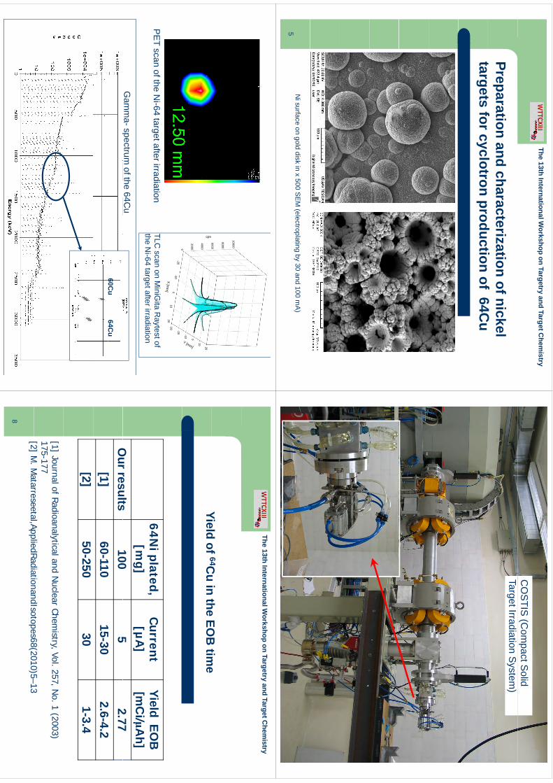
The13th
InternationalWorkshop
onTargetry and
TargetChem
istry
Preparation and characterization of nickel t
tf
lt
dti
f64C
targets for cyclotron production of 64Cu
Ni surface on gold disk in x 500 S
EM
(electroplating by 30 and 100 mA
)5
CO
STIS
(Com
pact Solid
Target Irradiation System
)
6000
8000
10000
0
2000
4000
6000
-10 0
10
20
cps
Y [mm]
0-20
-100
1020
-30 -20
X [mm
]
PE
T scan of the Ni-64 target after irradiation
TLC scan on M
iniGita R
aytest of g
the Ni-64 target after irradiation
Gam
ma-spectrum
of the 64Cu
p
60Cu
64Cu
The13th
InternationalWorkshop
onTargetry and
TargetChem
istry
Yieldof
64Cu
inthe
EOB
time
Yield of 64Cu in the EO
B tim
e
64Niplated
Current
YieldEO
B64N
i plated,[m
g]C
urrent[µ
A]
Yield EOB
[mC
i/μAh]
Ourresults
1005
277
Our results
1005
2.77[1]
60-11015-30
2.6-4.2[2]
50-25030
1-3.4
[1] Journal of Radioanalytical and Nuclear Chem
istry, Vol. 257, No. 1 (2003)
175-177[2]
MM
atarreseetalAppliedRadiationandIsotopes68(2010)5–13[2] M
. Matarreseetal,AppliedRadiationandIsotopes68(2010)5–13
8
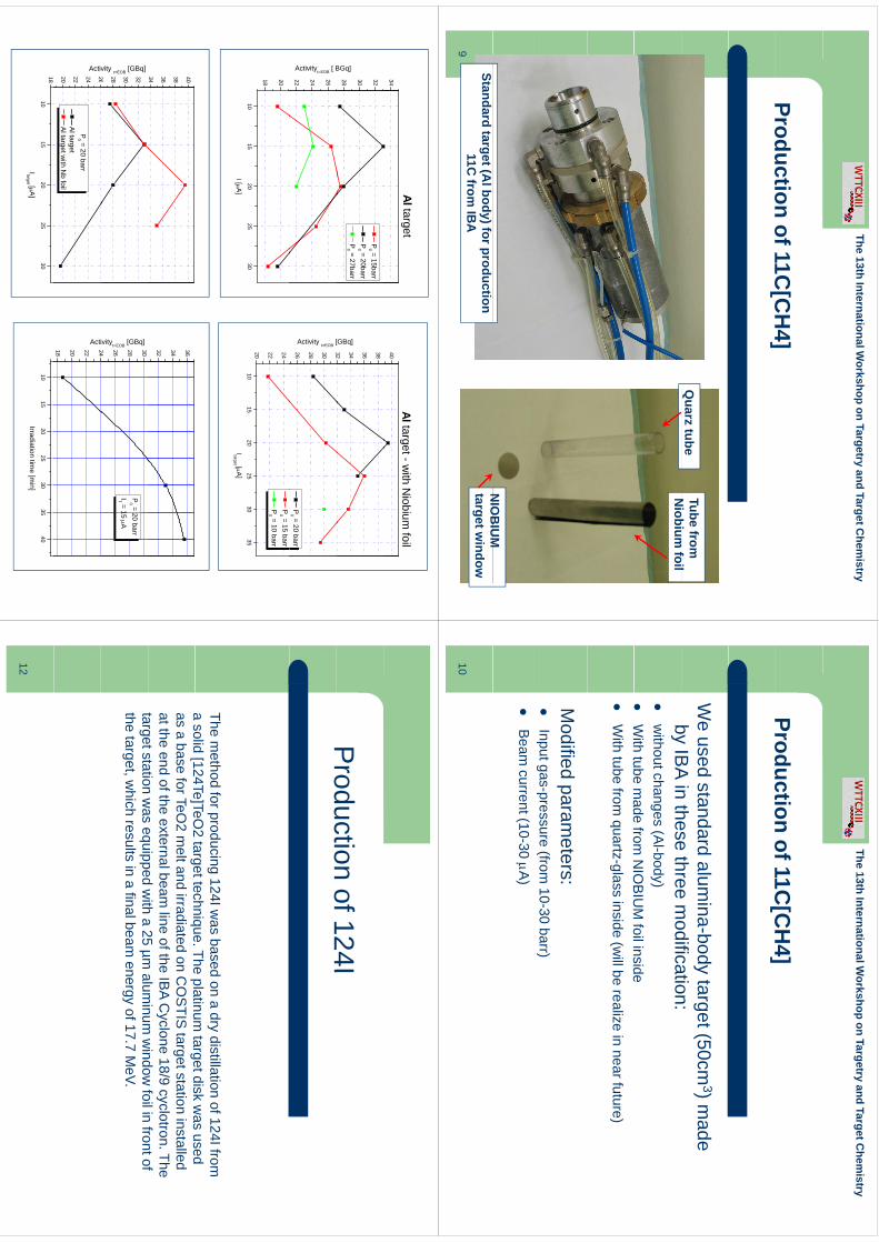
The13th
InternationalWorkshop
onTargetry and
TargetChem
istry
Productionof11C
[CH
4]Production of 11C
[CH
4]
Quarz tube
Tube from
Ni
bif
ilN
iobium foil
NIO
BIU
MN
IOB
IUM
target w
indowStandard target (A
l body) for production 11C
from IB
A9
The13th
InternationalWorkshop
onTargetry and
TargetChem
istry
Productionof11C
[CH
4]Production of 11C
[CH
4]
We used standard alum
ina-body target (50cm3) m
ade by
IBA
inthese
threem
odification:by IB
A in these three m
odification:
without changes (A
l-body)
With
tubem
adefrom
NIO
BIU
Mfoilinside
W
ith tube made from
NIO
BIU
M foil inside
W
ith tube from quartz-glass inside (w
ill be realize in near future)
Modified param
eters:
Inputgas-pressure(from
10-30barr)
Input gaspressure (from
1030 barr)
B
eam current (10-30 A
)
10
40
Al target - with N
iobium foil
34
Al target
32 34 36 38
[GBq]
28 30 32
BGq]
P0 = 15barr
P0 = 20barr
P0 = 27barr
26 28 30 32
Activity t=EOB
[
P0 = 20 barr
22 24 26
Activityt=EOB [ B
1015
2025
3035
20 22 24 P
0 = 15 barr P
0 = 10 barr
1015
2025
30
18 20
Itarget [A]
I [A]
32 34 36
34 36 38 40
24 26 28 30
ivityt=EOB [GBq]
P0 = 20 barr
IT = 15 A
26 28 30 32
vity t=EOB [GBq]
18 20 22 24
Acti
20 22 24 26
Activ
P0 = 20 barr
Al target Al target w
ith Nb foil
1015
2025
3035
40
Irradiation time [m
in]10
1520
2530
18
Itarget [A]
Production
of124IP
roduction of 124I
The method for producing 124I w
as based on a dry distillation of 124I from
asolid
[124Te]TeO2
targettechniqueThe
platinumtargetdisk
was
useda solid [124Te]TeO
2 target technique. The platinum target disk w
as used as a base for TeO
2 melt and irradiated on C
OS
TIS target station installed
at the end of the external beam line of the IB
A Cyclone 18/9 cyclotron. The
targetstationw
asequipped
with
a25
µmalum
inumw
indowfoilin
frontoftarget station w
as equipped with a 25 µm
aluminum
window
foil in front of the target, w
hich results in a final beam energy of 17.7 M
eV.
12
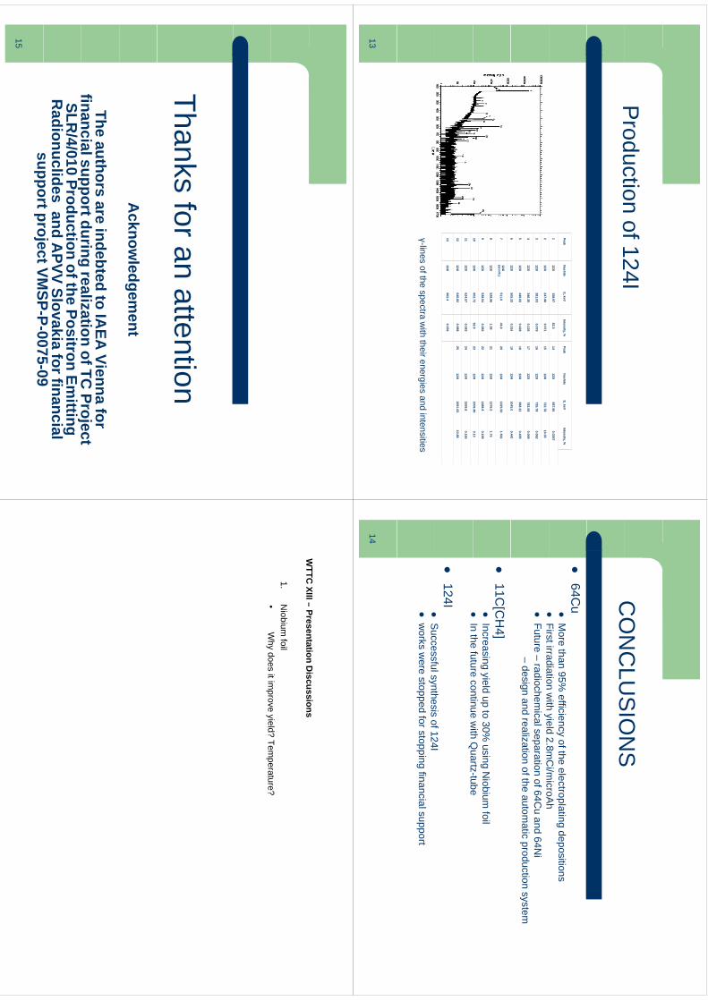
Production
of124IP
roduction of 124I
PeakN
uclideE, keV
Intensity, %Peak
Nuclide
E, keVIntensity, %
1123I
158.9783.3
14123I
687.950.0267
2123I
247.960.071
15124I
722.7810.35
3123I
281.030.079
16123I
735.780.062
4123I
346.350.126
17123I
783.590.059
5123I
440.020.428
18124I
968.220.435
6123I
505.330.316
19124I
1045.00.441
6123I
505.330.316
19124I
1045.00.441
7124I (annih.)
511.046.0
20124I
1325.501.561
8123I
528.961.39
21124I
1376.01.75
9123I
538.540.382
22124I
1488.90.199
10124I
602.7262.9
23124I
1509.493.13
11123I
624.570.083
24124I
1559.80.165
12124I
645.820.988
25124I
1691.0210.88
13124I
662.40.056
γ-lines of the spectra with their energies and intensities
13
CO
NC
LUS
ION
SC
ON
CLU
SIO
NS
64C
u
More than 95%
efficiency of the electroplating depositions
Firstirradiationw
ithyield
28m
Ci/m
icroAh
First irradiation w
ith yield 2.8mC
i/microA
h
Future –radiochem
ical separation of 64Cu and 64N
i –
design and realization of the automatic production system
11C
[CH
4]
Increasing yield up to 30% using N
iobium foil
In
thefuture
continuew
ithQ
uartz-tube
In the future continue with Q
uartz-tube
124I
S
uccessfulsynthesisof124I
S
uccessful synthesis of 124I
works w
ere stopped for stopping financial support
14
Thk
ftt
tiThanks for an attention
Acknow
ledgement
The authors are indebted to IAEA
Vienna for financialsupportduring
realizationofTC
Projectfinancial support during realization of TC
Project SLR
/4/010 Production of the Positron Emitting
Radionuclides and A
PVV Slovakia for financial supportprojectVM
SPP
007509
support project VMSP-P-0075-09
15
WTTC
XIII–Presentation
Discussions
WTTC
XIII –Presentation D
iscussions
1.N
iobium foil
•W
hydoes
itimprove
yield?Tem
perature?•
Why does it im
prove yield? Temperature?
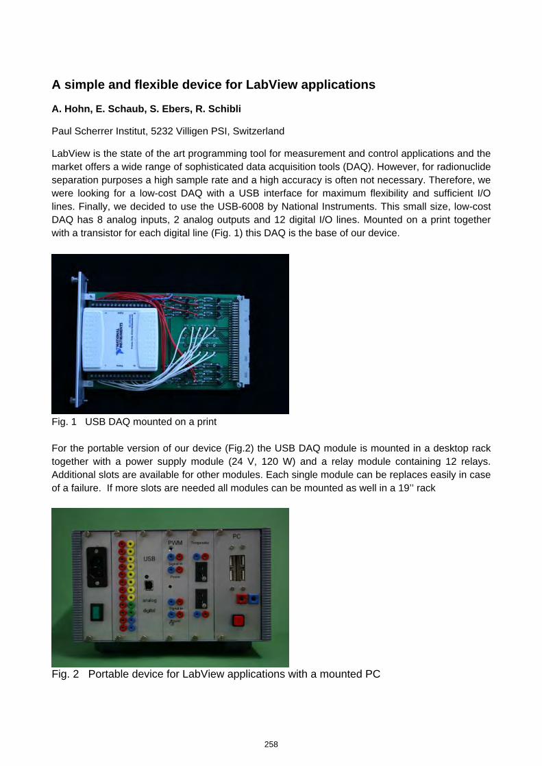
A simple and flexible device for LabView applications
A. Hohn, E. Schaub, S. Ebers, R. Schibli
Paul Scherrer Institut, 5232 Villigen PSI, Switzerland
LabView is the state of the art programming tool for measurement and control applications and the market offers a wide range of sophisticated data acquisition tools (DAQ). However, for radionuclide separation purposes a high sample rate and a high accuracy is often not necessary. Therefore, we were looking for a low-cost DAQ with a USB interface for maximum flexibility and sufficient I/O lines. Finally, we decided to use the USB-6008 by National Instruments. This small size, low-cost DAQ has 8 analog inputs, 2 analog outputs and 12 digital I/O lines. Mounted on a print together with a transistor for each digital line (Fig. 1) this DAQ is the base of our device.
Fig. 1 USB DAQ mounted on a print For the portable version of our device (Fig.2) the USB DAQ module is mounted in a desktop rack together with a power supply module (24 V, 120 W) and a relay module containing 12 relays. Additional slots are available for other modules. Each single module can be replaces easily in case of a failure. If more slots are needed all modules can be mounted as well in a 19’’ rack
Fig. 2 Portable device for LabView applications with a mounted PC
258
kmje
Typewritten Text
Abstract 046
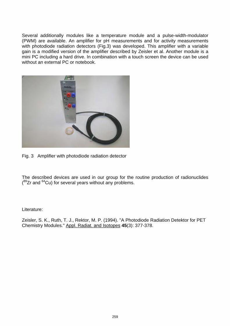
Several additionally modules like a temperature module and a pulse-width-modulator (PWM) are available. An amplifier for pH measurements and for activity measurements with photodiode radiation detectors (Fig.3) was developed. This amplifier with a variable gain is a modified version of the amplifier described by Zeisler et al. Another module is a mini PC including a hard drive. In combination with a touch screen the device can be used without an external PC or notebook.
Fig. 3 Amplifier with photodiode radiation detector The described devices are used in our group for the routine production of radionuclides (89Zr and 64Cu) for several years without any problems. Literature: Zeisler, S. K., Ruth, T. J., Rektor, M. P. (1994). "A Photodiode Radiation Detektor for PET Chemistry Modules." Appl. Radiat. and Isotopes 45(3): 377-378.
259
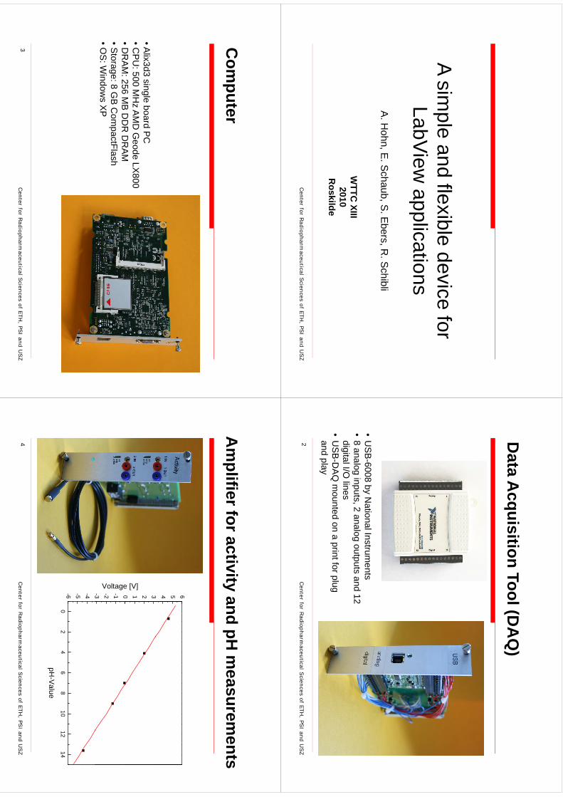
A simple and flexible device for pLabView
applicationsA
. Hohn, E
. Schaub, S
. Ebers, R
. Schibli
WTTC
XIII20102010
Roskilde
Center for R
adiopharmaceutical S
ciencesof ETH
, PSI and U
SZ
Data A
cquisition Tool (DA
Q)
•U
SB
-6008 by National Instrum
ents•
8 analog inputs, 2 analog outputs and 12 digitalI/O
linesdigital I/O
lines•
US
B-D
AQ
mounted on a print for plug
and play
Center
for Radiopharm
aceutical Sciences
ofETH
, PSI and
USZ
2
Com
puter
•Alix3d3 single board P
C•C
PU
: 500 MH
z AM
D G
eode LX800
•DR
AM
:256M
BD
DR
DR
AM
•DR
AM
: 256 MB
DD
R D
RA
M•S
torage: 8 GB
Com
pactFlash •O
S: W
indows X
P
Center for R
adiopharmaceutical S
ciencesof ETH
, PSI and U
SZ
3
Am
plifier for activity and pH m
easurements
3 4 5 60 1 2 3
e [V]
-3 -2 -1 0
Voltage
02
46
810
1214
-6 -5 -4
02
46
810
1214
pH-V
alue
Center for R
adiopharmaceutical S
ciencesof ETH
, PSI and U
SZ
4
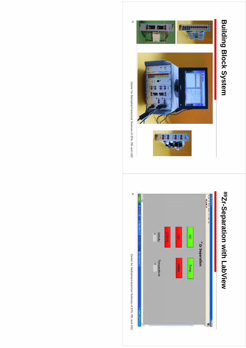
Building B
lock System
Center for R
adiopharmaceutical S
ciencesof ETH
, PSI and U
SZ
5
89Zr-Separation with LabView
Center for R
adiopharmaceutical S
ciencesof ETH
, PSI and U
SZ
6
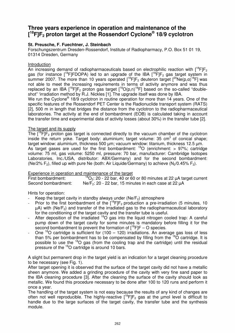
Three years experience in operation and maintenance of the [18F]F2 proton target at the Rossendorf Cyclone® 18/9 cyclotron St. Preusche, F. Fuechtner, J. Steinbach Forschungszentrum Dresden-Rossendorf, Institute of Radiopharmacy, P.O. Box 51 01 19, 01314 Dresden, Germany Introduction An increasing demand of radiopharmaceuticals based on electrophilic reaction with [18F]F2 gas (for instance [18F]FDOPA) led to an upgrade of the IBA [18F]F2 gas target system in summer 2007. The more than 10 years operated [18F]F2 deuteron target [20Ne(p,α)18F] was not able to meet the increasing requirements in terms of activity anymore and was thus replaced by an IBA [18F]F2 proton gas target [18O(p,n)18F] based on the so-called “double-shot” ‘irradiation method by R.J. Nickles [1]. The upgrade itself was done by IBA. We run the Cyclone® 18/9 cyclotron in routine operation for more than 14 years. One of the specific features of the Rossendorf PET Center is the Radionuclide transport system (RATS) [2], 500 m in length that bridges the distance from the cyclotron to the radiopharmaceutical laboratories. The activity at the end of bombardment (EOB) is calculated taking in account the transfer time and experimental data of activity losses (about 30%) in the transfer tube [2]. The target and its supply The [18F]F2 proton gas target is connected directly to the vacuum chamber of the cyclotron inside the return yoke. Target body: aluminium; target volume: 35 cm3 of conical shape; target window: aluminium, thickness 500 µm; vacuum window: titanium, thickness 12.5 µm. As target gases are used for the first bombardment: 18O (enrichment: > 97%; cartridge volume: 75 ml, gas volume: 5250 ml, pressure: 70 bar, manufacturer: Cambridge Isotopes Laboratories, Inc./USA, distributor: ABX/Germany) and for the second bombardment: (Ne/2% F2), filled up with pure Ne (both: Air Liquide/Germany) to achieve (N2/0.45% F2). Experience in operation and maintenance of the target First bombardment: 18O2: 20 - 22 bar, 40 or 60 or 80 minutes at 22 µA target current Second bombardment: Ne/F2: 20 - 22 bar, 15 minutes in each case at 22 µA Hints for operation: - Keep the target cavity in standby always under (Ne/F2) atmosphere - Prior to the first bombardment of the [18F]F2 production a pre-irradiation (5 minutes, 10
µA) with (Ne/F2) and transfer of the irradiated gas to the radiopharmaceutical laboratory for the conditioning of the target cavity and the transfer tube is useful.
- After deposition of the irradiated 18O gas into the liquid nitrogen cooled trap: A careful pump down of the target cavity for some minutes is mandatory before filling it for the second bombardment to prevent the formation of [18F]F – O species.
- One 18O cartridge is sufficient for (100 – 120) irradiations. An average gas loss of less than 5% per bombardment has to be compensated by filling from the 18O cartridge. It is possible to use the 18O gas (from the cooling trap and the cartridge) until the residual pressure of the 18O cartridge is around 10 bars.
A slight but permanent drop in the target yield is an indication for a target cleaning procedure to be necessary (see Fig. 1). After target opening it is observed that the surface of the target cavity did not have a metallic sheen anymore. We added a grinding procedure of the cavity with very fine sand paper to the IBA cleaning procedure [3]. After the cleaning the surface of the cavity should look as metallic. We found this procedure necessary to be done after 100 to 120 runs and perform it once a year. The handling of the target system is not easy because the results of any kind of changes are often not well reproducible. The highly-reactive [18F]F2 gas at the µmol level is difficult to handle due to the large surfaces of the target cavity, the transfer tube and the synthesis module.
262
kmje
Typewritten Text
Abstract 047
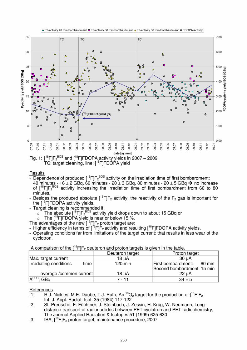
0
5
10
15
20
25
30
35
07
.09
07
.10
07
.11
07
.12
08
.01
08
.02
08
.03
08
.04
08
.05
08
.06
08
.07
08
.08
08
.09
08
.10
08
.11
08
.12
09
.01
09
.02
09
.03
09
.04
09
.05
09
.06
09
.07
09
.08
09
.09
09
.10
09
.11
09
.12
10
.01
date [yy.mm]
F2-a
cti
vit
y y
ield
BO
S [
GB
q]
0,00
1,00
2,00
3,00
4,00
5,00
6,00
7,00
FD
OP
A-a
cti
vit
y y
ield
EO
S [
GB
q]
F2-activity 40 min bombardment F2-activity 60 min bombardment F2-activity 80 min bombardment FDOPA-activity
TCTCTC
[18
F]FDOPA yield [%]
Fig. 1: [18F]F2
BOS and [18F]FDOPA activity yields in 2007 – 2009, TC: target cleaning, line: [18F]FDOPA yield Results - Dependence of produced [18F]F2
BOS activity on the irradiation time of first bombardment: 40 minutes - 16 ± 2 GBq, 60 minutes - 20 ± 3 GBq, 80 minutes - 20 ± 5 GBq no increase of [18F]F2
BOS activity increasing the irradiation time of first bombardment from 60 to 80 minutes,
- Besides the produced absolute [18F]F2 activity, the reactivity of the F2 gas is important for the [18F]FDOPA activity yields.
- Target cleaning is recommended if: o The absolute [18F]F2
BOS activity yield drops down to about 15 GBq or o The [18F]FDOPA yield is near or below 15 %.
The advantages of the new [18F]F2 proton target are: - Higher efficiency in terms of [18F]F2 activity and resulting [18F]FDOPA activity yields, - Operating conditions far from limitations of the target current; that results in less wear of the
cyclotron. A comparison of the [18F]F2 deuteron and proton targets is given in the table.
Deuteron target Proton target Max. target current 18 µA 30 µA Irradiating conditions time
average /common current
120 min
18 µA
First bombardment: 60 min Second bombardment: 15 min
22 µA
AEOB, GBq 7 - 11 34 ± 5 References [1] R.J. Nickles, M.E. Daube, T.J. Ruth; An 18O2 target for the production of [18F]F2
Int. J. Appl. Radiat. Isot. 35 (1984) 117-122 [2] St. Preusche, F. Füchtner, J. Steinbach, J. Zessin, H. Krug, W. Neumann; Long- distance transport of radionuclides between PET cyclotron and PET radiochemistry, The Journal Applied Radiation & Isotopes 51 (1999) 625-630 [3] IBA, [18F]F2 proton target, maintenance procedure, 2007
263

Cancer R
esearch
Three years experience in operation and m
aintenance of the [ 18F]F2 /[ 18O
]O2 -gas target
[]
2 []
2g
gat the R
ossendorf Cyclone
® cyclotron
StPreusche
FFüchtner
JSteinbach
St. Preusche, F. Füchtner, J. Steinbach
Institute of Radiopharm
acy
St. P
reusche et al. w
ww
.fzd.de
Mem
ber of the Leibniz Association
Cancer R
esearch[ 18F]F
2 /[ 18O]O
2 -gas target
Content
1.Introduction
2The
targetandits
supply2.
The target and its supply
3.E
xperience in operation and maintenance of the target
4.R
esults
5R
f5.
References
[ 6. Som
e more details]
[]
Institute of Radiopharm
acy S
t. Preusche et al.
ww
w.fzd.de
July 2010-WTTC
132
Cancer R
esearch[ 18F]F
2 /[ 18O]O
2 -gas target
1. Introduction
Why
changefrom
[ 18F]Fdeuteron
targetto[ 18F]F
protontarget?
Why change from
[ 18F]F2 -deuteron target to [ 18F]F
2 -proton target?•increasing dem
and of radiopharmaceuticals based on electrophilic
reaction with [ 18F]F
2 gas (for instance [ 18F]FDO
PA)
2
Not enough [ 18F]F
2 activity with [ 18F]F
2 deuteron target [ 20Ne(d,α) 18F]
Measure
Measure
•[ 18F]F2 /[ 18O
]O2 -gas target [ 18O
(p,n) 18F]: “double-shot” ‘irradiation m
ethod by R.J. N
ickles [1] d
db
IBA
•upgrade done by IBA
Rossendorf conditions
•500 m R
N transport system
: losses of [ 18F]F2 activity ~ 30%
[2] •routine operation of C
yclone®
18/9for 14 years
Institute of Radiopharm
acy S
t. Preusche et al.
ww
w.fzd.de
July 2010-WTTC
133
Cancer R
esearch[ 18F]F
2 /[ 18O]O
2 -gas target
2. The target and its supply
[18F]F2-target[ 18F]F
2 /[ 18O]O
2 -gas targetconnected directly to vacuum
cham
ber
target body: aluminium
target volume: 35 cm
3of conical shapetarget w
indow: alum
inium, thickness 500 µm
vacuum w
indow: titanium
, thickness 12.5 µm
Institute of Radiopharm
acy S
t. Preusche et al.
ww
w.fzd.de
July 2010-WTTC
134
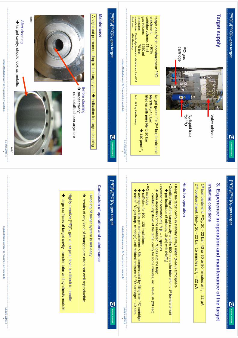
Cancer R
esearch[ 18F]F
2 /[ 18O]O
2 -gas target
Valve tableauTarget supply
18Ogas
N2 -liquid trap
for 18O18O
gas cartridge
target gas for 1stbom
bardment: 18O
enrichment: > 97%
cartrid ge volume: 75 m
l
target gases for 2ndbom
bardment:
Ne/2%
F2 (4.5 bar)
filledup
with
pureN
eto
20bar
ggas volum
e: 5250 ml
pressure: 70 barm
anufacturer: Cam
bridge Isotopes Laboratories, Inc./US
A di
tibt
AB
X/G
filled up with pure N
e to 20 bar
140 µmol F
2
both: Air Liquide/G
ermany
Institute of Radiopharm
acy S
t. Preusche et al.
ww
w.fzd.de
July 2010-WTTC
135
distributor: AB
X/Germ
any
Cancer R
esearch[ 18F]F
2 /[ 18O]O
2 -gas target
3. Experience in operation and maintenance of the target
Irradiatingconditions
1stbom
bardment:
18O2 : 20 -22 bar, 40 or 60 or 80 m
inutes at IT= 22 µA
2ndbom
bardment:N
e/F:20
22bar
15m
inutesatI
=22
µA
Irradiating conditions
2nd bom
bardment:N
e/F2 : 20 -22 bar, 15 m
inutes at IT= 22 µA
Hints
foroperation
•K
eep the target cavity in standby always under (N
e/F2 ) atm
osphereC
ff
t
Hints for operation
•Conditioning of the target cavity and the 500 m
transfer tube prior to 1stbom
bardment
pre-irradiation (5 m
inutes, 10 µA) w
ith (Ne/F
2 )•P
revent the formation of [ 18F]F –
O species
A
fter deposition of the irradiated 18O gas into the trap:
careful pump dow
n of the target cavity for some m
inutes, incl. Ne-flush (20 sec)
•18O
cartridge g
sufficient for 100 -120 irradiations
average gas loss per bom
bardment: < 5%
, compensated by filling from
18O cartridge
use of 18O
gas (trap, cartridge) until residual pressure of 18O cartridge: ~ 10 bars.
Institute of Radiopharm
acy S
t. Preusche et al.
ww
w.fzd.de
July 2010-WTTC
136
g(
pg
)p
g
Cancer R
esearch[ 18F]F
2 /[ 18O]O
2 -gas target
Maintenance
A slight but permanent drop in the target yield
indication for target cleaning
Before cleaning
targetcavity:
target cavity: no m
etallic sheen anymore
frontAfter cleaning
target cavity: should look as metallic
Institute of Radiopharm
acy S
t. Preusche et al.
ww
w.fzd.de
July 2010-WTTC
137
rear
Cancer R
esearch[ 18F]F
2 /[ 18O]O
2 -gas target
Conclusion of operation and m
aintenance
Handling
oftargetsystemis
noteasyH
andling of target system is not easy
results of any kind of changes are often not w
ell reproducible
Highly-reactive [ 18F]F
2 gas at the µmol level is difficult to handle
large surfaces of target cavity, transfer tube and synthesis m
odule
Institute of Radiopharm
acy S
t. Preusche et al.
ww
w.fzd.de
July 2010-WTTC
138
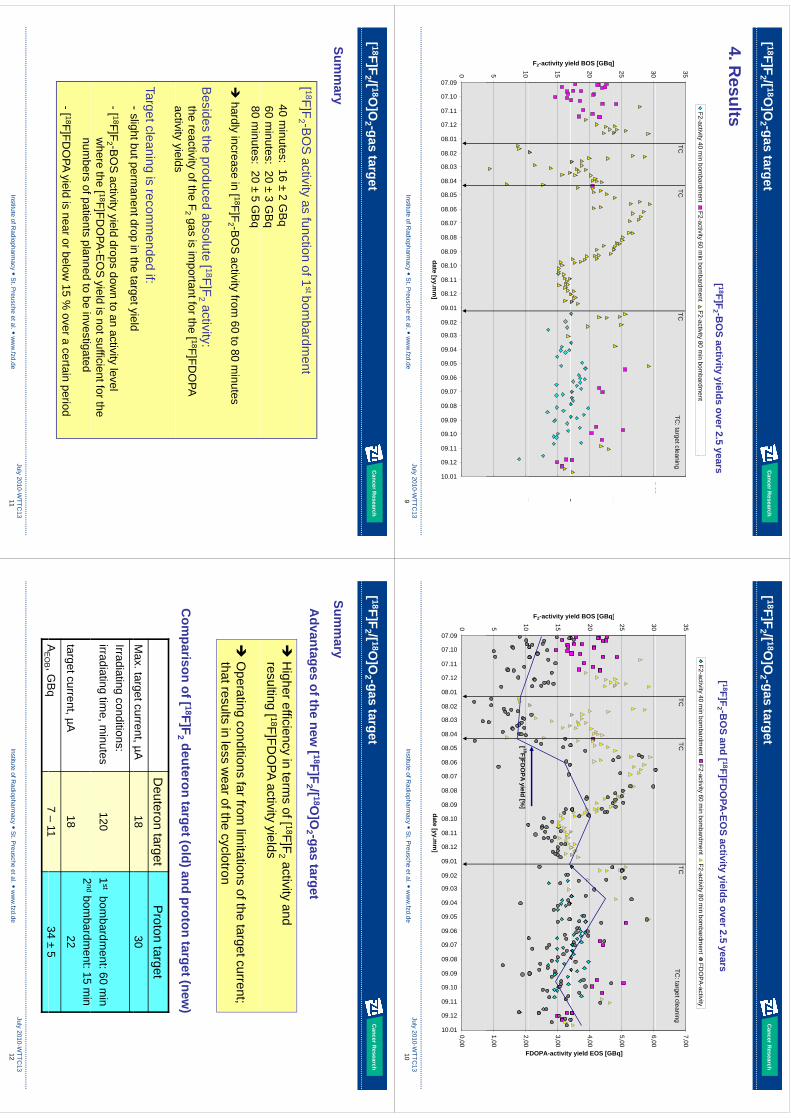
Cancer R
esearch[ 18F]F
2 /[ 18O]O
2 -gas target
4R
ltF2-activity 40 min bom
bardment
F2-activity 60 min bom
bardment
F2-activity 80 min bom
bardment
FDO
PA-activity
4. Results
[ 18F]F2 -B
OS activity yields over 2.5 years
30 35
600
7,00
yy
yy
TCTC
TCTC
: target cleaning
25 30
]
5,00
6,00
Bq]
20
eld BOS [GBq]
4,00
y yield EOS [GB
15
F2-activity yie
3,00
FDOPA-activity
5 10
1,00
2,00
F
0
07.09
07.10
07.11
07.12
08.01
08.02
08.03
08.04
08.05
08.06
08.07
08.08
08.09
08.10
08.11
08.12
09.01
09.02
09.03
09.04
09.05
09.06
09.07
09.08
09.09
09.10
09.11
09.12
0.01 0,00
Institute of Radiopharm
acy S
t. Preusche et al.
ww
w.fzd.de
July 2010-WTTC
139
0
0
0
0
0
0
0
0
0
0
0
0
0
0
0
0
0
0
0
0
0
0
0
0
0
0
0
0
1
date [yy.mm
]
Cancer R
esearch[ 18F]F
2 /[ 18O]O
2 -gas target
F2-activity 40 min bom
bardment
F2-activity 60 min bom
bardment
F2-activity 80 min bom
bardment
FDO
PA-activity
[ 18F]F2 -B
OS and [ 18F]FD
OPA
-EOS activity yields over 2.5 years
30 35
600
7,00
yy
yy
TCTC
TCTC
: target cleaning
25 30
]
5,00
6,00
Bq]
20
eld BOS [GBq]
4,00
y yield EOS [GB
10 15
F2-activity yi
200
3,00
FDOPA-activity
5 10
1,00
2,00
F
[ 18F]FDO
PA yield [%]
0
07.09
07.10
07.11
07.12
08.01
08.02
08.03
08.04
08.05
08.06
08.07
08.08
08.09
08.10
08.11
08.12
09.01
09.02
09.03
09.04
09.05
09.06
09.07
09.08
09.09
09.10
09.11
09.12
10.01 0,00
Institute of Radiopharm
acy S
t. Preusche et al.
ww
w.fzd.de
July 2010-WTTC
1310
0
0
0
0
0
0
0
0
0
0
0
0
0
0
0
0
0
0
0
0
0
0
0
0
0
0
0
0
1
date [yy.mm
]
Cancer R
esearch[ 18F]F
2 /[ 18O]O
2 -gas target
[ 18F]F2 -B
OS
activityas
functionof1
st bombardm
ent
Summ
ary
[F]F
2B
OS
activity as function of 1bom
bardment
40 minutes: 16 ±
2 GB
q 60 m
inutes: 20 ±3 G
Bq
80 minutes: 20 ±
5 GB
q
hardly increase in [ 18F]F
2 -BO
S activity from
60 to 80 minutes
Besides the produced absolute [ 18F]F
2 activity:the reactivity of the F
2 gas is important for the [ 18F]FD
OPA
activityyields
activity yields
Target cleaning is recomm
ended if: -
slightbutpermanentdrop
inthe
targetyieldslight but perm
anent drop in the target yield
-[ 18F]F2 -B
OS activity yield drops dow
n to an activity level w
here the [ 18F]FDO
PA-EO
S yield is not sufficient for the
bf
il
db
ii
dnum
bers of patients planned to be investigated
-[ 18F]FDO
PA yield is near or below 15 %
over a certain period
Institute of Radiopharm
acy S
t. Preusche et al.
ww
w.fzd.de
July 2010-WTTC
1311
Cancer R
esearch[ 18F]F
2 /[ 18O]O
2 -gas target
Advantages of the new
[ 18F]F2 /[ 18O
]O2 -gas target
Summ
aryH
igher efficiency in terms of [ 18F]F
2 activity and resulting [ 18F]FD
OPA activity yields
O
perating conditions far from lim
itations of the target current; that results in less w
ear of the cyclotron
Com
parisonof[ 18F]F
2 deuterontarget(old)and
protontarget(new
)
Deuteron target
Proton target
Max. target current, µA
1830
g,µ
Irradiating conditions:irradiating tim
e, minutes
1201
stbom
bardment: 60 m
in2
dbb
dt
15i
target current, µA18
2ndbom
bardment: 15 m
in22
AE
OB ,G
Bq
7–
1134
±5
Institute of Radiopharm
acy S
t. Preusche et al.
ww
w.fzd.de
July 2010-WTTC
1312
AE
OB , G
Bq
7 11
34 ±5
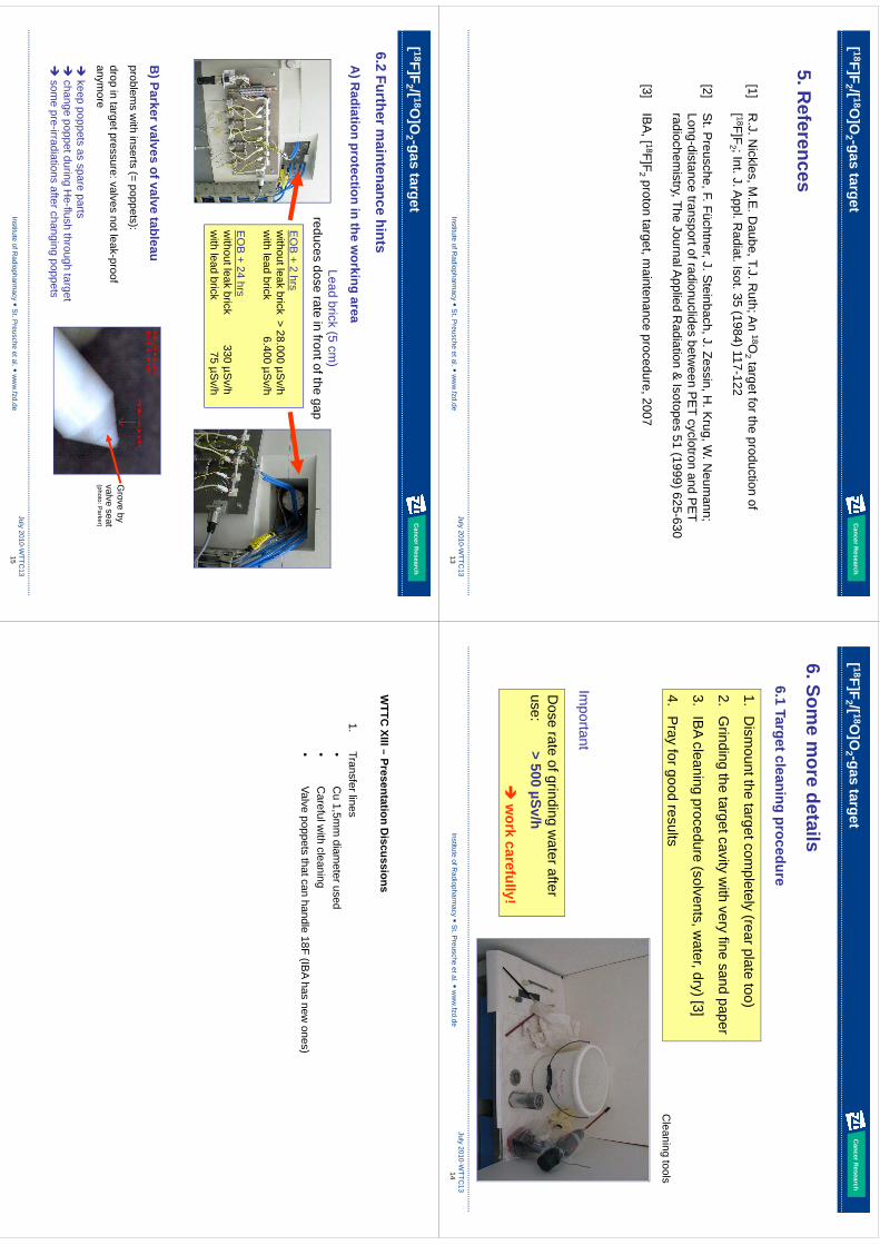
Cancer R
esearch[ 18F]F
2 /[ 18O]O
2 -gas target
5. References
[1]R
.J. Nickles, M
.E. D
aube, T.J. Ruth; A
n 18O2 target for the production of
[ 18F]F2 ; Int. J. A
ppl. Radiat. Isot. 35 (1984) 117-122
[2]S
t. Preusche, F. Füchtner, J. S
teinbach, J. Zessin, H. K
rug, W. N
eumann;
Long-distance transport of radionuclides between P
ET cyclotron and P
ET
&(
)radiochem
istry, The Journal Applied R
adiation & Isotopes 51 (1999) 625-630
[3]IB
A, [ 18F]F
2 proton target, maintenance procedure, 2007
Institute of Radiopharm
acy S
t. Preusche et al.
ww
w.fzd.de
July 2010-WTTC
1313
Cancer R
esearch[ 18F]F
2 /[ 18O]O
2 -gas target
6.1Targetcleaning
procedure
6. Some m
ore details6.1 Target cleaning procedure
1.D
ismount the target com
pletely (rear plate too)
2.G
rinding the target cavity with very fine sand paper
3.IB
A cleaning procedure (solvents, water, dry) [3]
4.P
ray for good resultsC
leaning tools
It
tIm
portant
Dose rate of grinding w
ater after 500
S/h
use:> 500 µSv/h
w
ork carefully!
Institute of Radiopharm
acy S
t. Preusche et al.
ww
w.fzd.de
July 2010-WTTC
1314
Cancer R
esearch
62
Fth
it
hit
[ 18F]F2 /[ 18O
]O2 -gas target
6.2 Further maintenance hints
Ld
bi
k(5
)
A) R
adiation protection in the working area
Lead brick (5 cm)
reduces dose rate in front of the gap
EO
B + 2 hrs
without leak brick > 28.000 µS
v/hw
ith lead brick 6.400 µSv/h
EO
B+
24hrs
EO
B + 24 hrsw
ithout leak brick 330 µSv/h
with lead brick 75 µS
v/h
B) Parker valves of valve tableau)
problems w
ith inserts (= poppets):
drop in target pressure: valves not leak-proof anym
ore
Grove by
valve seat (photo:P
arker)anym
ore
keep poppets as spare parts
change poppet during H
e-flush through target
some
pre-irradiationsafterchanging
poppets
(photo: Parker)
Institute of Radiopharm
acy S
t. Preusche et al.
ww
w.fzd.de
July 2010-WTTC
1315
som
e pre-irradiations after changing poppets
WTTC
XIII–Presentation
Discussions
WTTC
XIII –Presentation D
iscussions
1.Transfer lines•
Cu
15m
mdiam
eterused•
Cu 1,5m
m diam
eter used•
Careful w
ith cleaning•
Valve poppetsthat can handle 18F (IB
A has new ones)
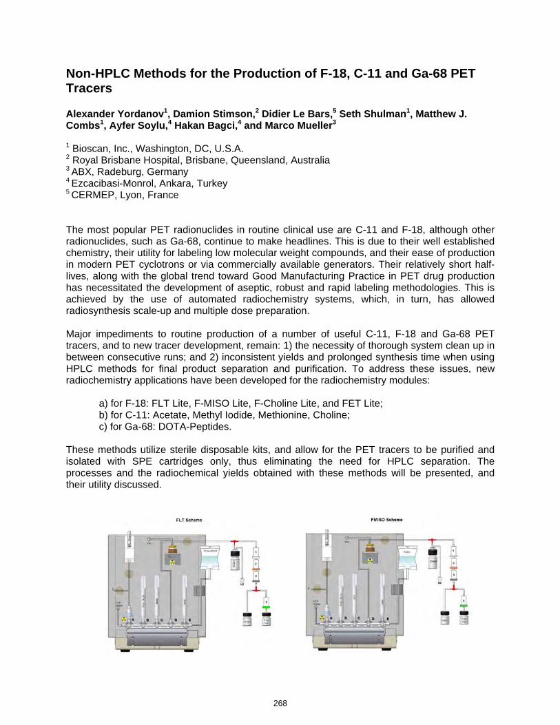
Non-HPLC Methods for the Production of F-18, C-11 and Ga-68 PET Tracers Alexander Yordanov1, Damion Stimson,2 Didier Le Bars,5 Seth Shulman1, Matthew J. Combs1, Ayfer Soylu,4 Hakan Bagci,4 and Marco Mueller3
1 Bioscan, Inc., Washington, DC, U.S.A. 2 Royal Brisbane Hospital, Brisbane, Queensland, Australia 3 ABX, Radeburg, Germany 4 Ezcacibasi-Monrol, Ankara, Turkey 5 CERMEP, Lyon, France The most popular PET radionuclides in routine clinical use are C-11 and F-18, although other radionuclides, such as Ga-68, continue to make headlines. This is due to their well established chemistry, their utility for labeling low molecular weight compounds, and their ease of production in modern PET cyclotrons or via commercially available generators. Their relatively short half-lives, along with the global trend toward Good Manufacturing Practice in PET drug production has necessitated the development of aseptic, robust and rapid labeling methodologies. This is achieved by the use of automated radiochemistry systems, which, in turn, has allowed radiosynthesis scale-up and multiple dose preparation. Major impediments to routine production of a number of useful C-11, F-18 and Ga-68 PET tracers, and to new tracer development, remain: 1) the necessity of thorough system clean up in between consecutive runs; and 2) inconsistent yields and prolonged synthesis time when using HPLC methods for final product separation and purification. To address these issues, new radiochemistry applications have been developed for the radiochemistry modules: a) for F-18: FLT Lite, F-MISO Lite, F-Choline Lite, and FET Lite; b) for C-11: Acetate, Methyl Iodide, Methionine, Choline; c) for Ga-68: DOTA-Peptides. These methods utilize sterile disposable kits, and allow for the PET tracers to be purified and isolated with SPE cartridges only, thus eliminating the need for HPLC separation. The processes and the radiochemical yields obtained with these methods will be presented, and their utility discussed.
268
kmje
Typewritten Text
Abstract 048
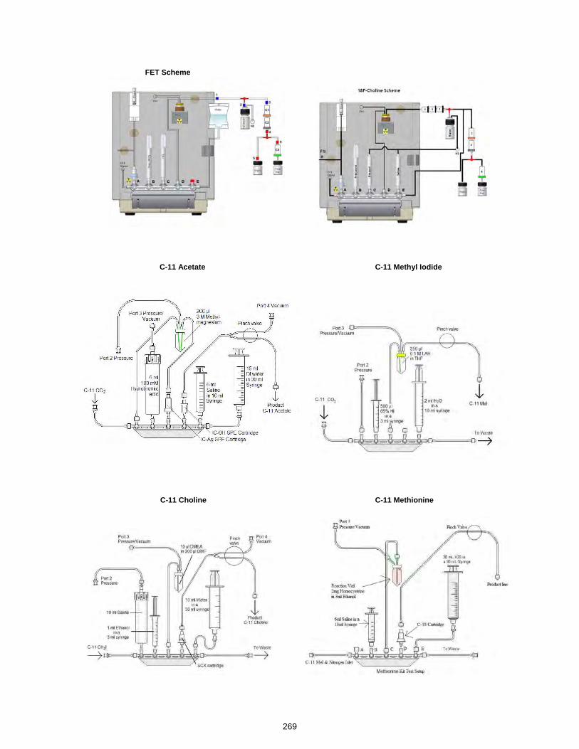
FET Scheme
C-11 Acetate C-11 Methyl Iodide
C-11 Choline C-11 Methionine
269
Non
HPLC
Methods
fortheN
on-HPLC
Methods for the
Production of F-18, C-11, G
a-68, Cu-
64 and Sc-44 Radiopharm
aceuticals
•A
. Yordanov, M. C
ombs, S
. Shulm
an B
ioscan, Inc., Washington D
C, U
.S.A
.g
•D
. Stim
son, Royal B
risbane Hospital, B
risbane, Q
ueenslandA
ustraliaQ
ueensland, Australia
•M
. Müller-A
BX
Gm
bH, R
adeberg, Germ
any
•H
. Bağci, A
. Soylu
-Eczacibasi-M
onrol, Ankara,
Turkey
•D
. LeBars, C
ER
ME
P, Lyon, France
Disclaim
er
This presentation is solely intended to provide and dissem
inate the authors’ scientific results, interpretation and view
s ,
pin the nuclear m
edicine comm
unity. It does
notconstitutean
endorsementof
does not constitute an endorsement of
any Bioscan or other com
mercial
manufacturers’products
listeddisplayed
manufacturers
products listed, displayed on m
entioned hereof.
2
2010 –G
ood Year for the P
ET
Radiopharm
aceutical Industry
•W
ILEX
-IBA M
olecular Phase III C
linical T
il
fRE
DE
CTA
NE
(R)
fll
Trial of RE
DE
CTA
NE
(R) w
as successfully com
pleted; ND
A filing expected by the beginning of year
•Lantheus
Phase
IIIclinicaltrialtobegin
•Lantheus P
hase III clinical trial to begin
•AV
ID P
hase III clinical trial near ase
cca
ta
eacom
pletion
•B
ayer Schering P
harma A
G P
hase III
3
2010 –G
ood Year for P
ET R
adiopharmaceutical
pIndustry (cont.)
•IB
AM
olecularA
posenseP
haseIII
•IB
A Molecular –
Aposense P
hase III C
linical Trial
•Fluoropharm
a
•N
uView P
harmaceuticals
•Lantheus
AVID
–nextleads
inthe
•Lantheus, AV
ID –
next leads in the pipeline
•M
ore PE
T Tracer Start-ups
4
Is There Future for New
Radionuclides
in Imaging
gg
and Therapy?
•Yes if (am
ong other factors) the radionuclide:
*has a convenient half-life
*is
availablein
comm
ercialquantities*
is available in comm
ercial quantities and at reasonable cost
*has optim
al radio-labeling chemistry
*has established an optim
al target –targeting vector –
radionuclide match
gg
5
Is There Future for New
Radionuclides
in Imaging
gg
and Therapy (cont.)?
•Yes if (am
ong other factors) the imaging or
therapeuticdrug
candidate:therapeutic drug candidate:
*is m
anufactured by a process easy to s
au
actued
bya
pocess
easyto
scale up
*has dem
onstrated sufficient in vitro and in vivo stability y
*provides high quality im
age or superior th
tiff
ttherapeutic effect
*clinicalindication
with
fewalternatives
clinical indication with few
alternatives6
Is There Future for New
Radionuclides
in Imaging
gg
and Therapy (cont.)?
•A
nd last but not least :
*enterpreneurship
(the right person doing the right thing at the right tim
e)do
gt
eg
ttg
atte
gtt
e)
*availability of funding for clinical trials
*it is a trial-and-error process (out of every 12
radiolabeledm
oleculesonly
onew
ill12 radiolabeled m
olecules only one will
become a drug on the m
arket)
7
Radionuclides
Status from
Industry Point of
yView
•E
xisting or under construction manufacturing
network
C11
N13
O15
F18
I124C
unetw
ork –C
-11, N-13, O
-15, F-18, I-124, Cu-
64, Zr-89, Tc-99m, I-123, I-131, Y-90
•M
anufacturing issues that are expected to be solved
duringthe
nextfewyears
-forGa-68
solved during the next few years -for G
a-68, R
e-188, Y-86, At-211, C
u-67, Ho-166, Lu-177,
Bi213
Bi-213
•O
therradionuclidesnotm
entionedhere
–m
ayO
ther radionuclidesnot m
entioned here m
ay be available in large quantities in 10 years or m
orem
ore 8
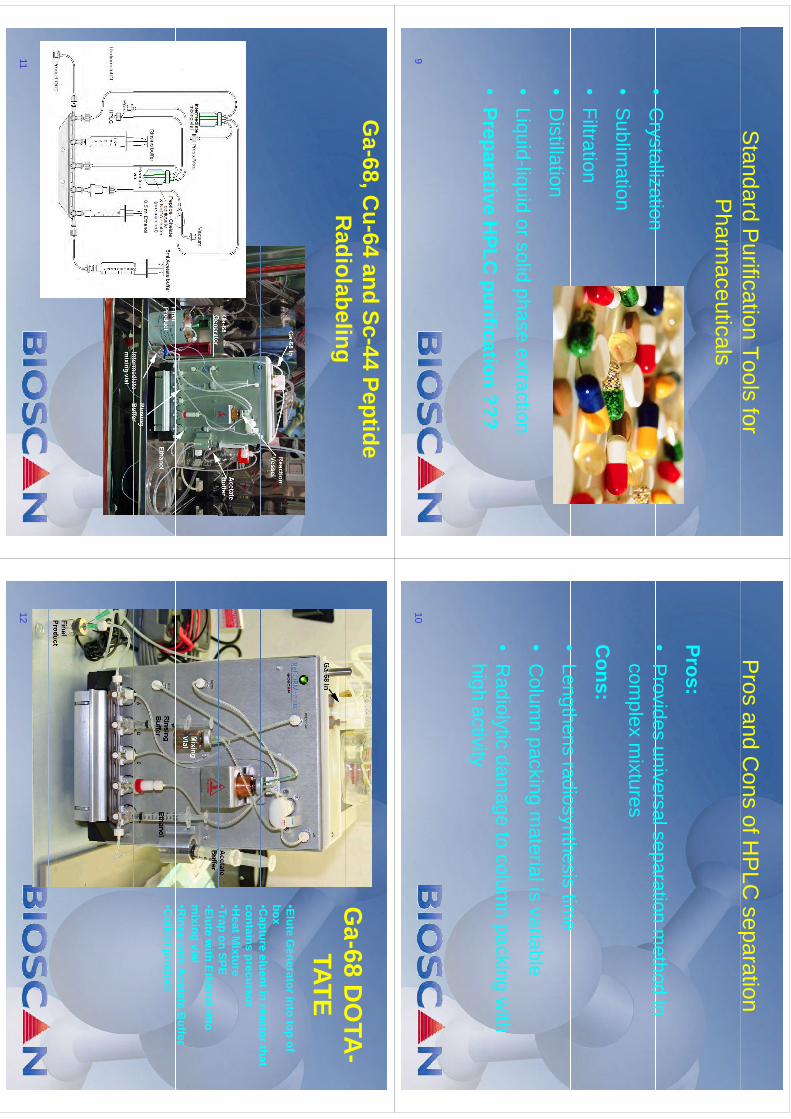
Standard P
urification Tools for P
harmaceuticals
•C
rystallization•
Crystallization
•S
ublimation
•Filtration
•D
istillation
Liid
liid
lidh
tti
•Liquid-liquid or solid phase extraction
•Preparative
HPLC
purification???
Preparative HPLC
purification ???
9
Pros and C
ons of HP
LC separation
p
PPros:•
Provides
universalseparationm
ethodin
Provides universal separation m
ethod in com
plex mixtures
Cons:
•Lengthens
radiosynthesistim
e•
Lengthens radiosynthesis time
•C
olumn packing m
aterial is variablep
g
•R
adiolytic damage to colum
n packing with
hih
tiit
high activity
10
Ga-68, C
u-64 and Sc-44 Peptide R
adiolabelingR
adiolabeling
11
Ga-68
DO
TA-
Ga
68 DO
TATATE
•Elute Generator into top of
box• C
aptureeluentin
reactorthatC
apture eluent in reactor that contains precursor•H
eat Mixture
•Trap on SPEp
•Elute with Ethanol into
mixing vial
•Rinse w
ith Acetate B
uffe r•C
ollect product
12
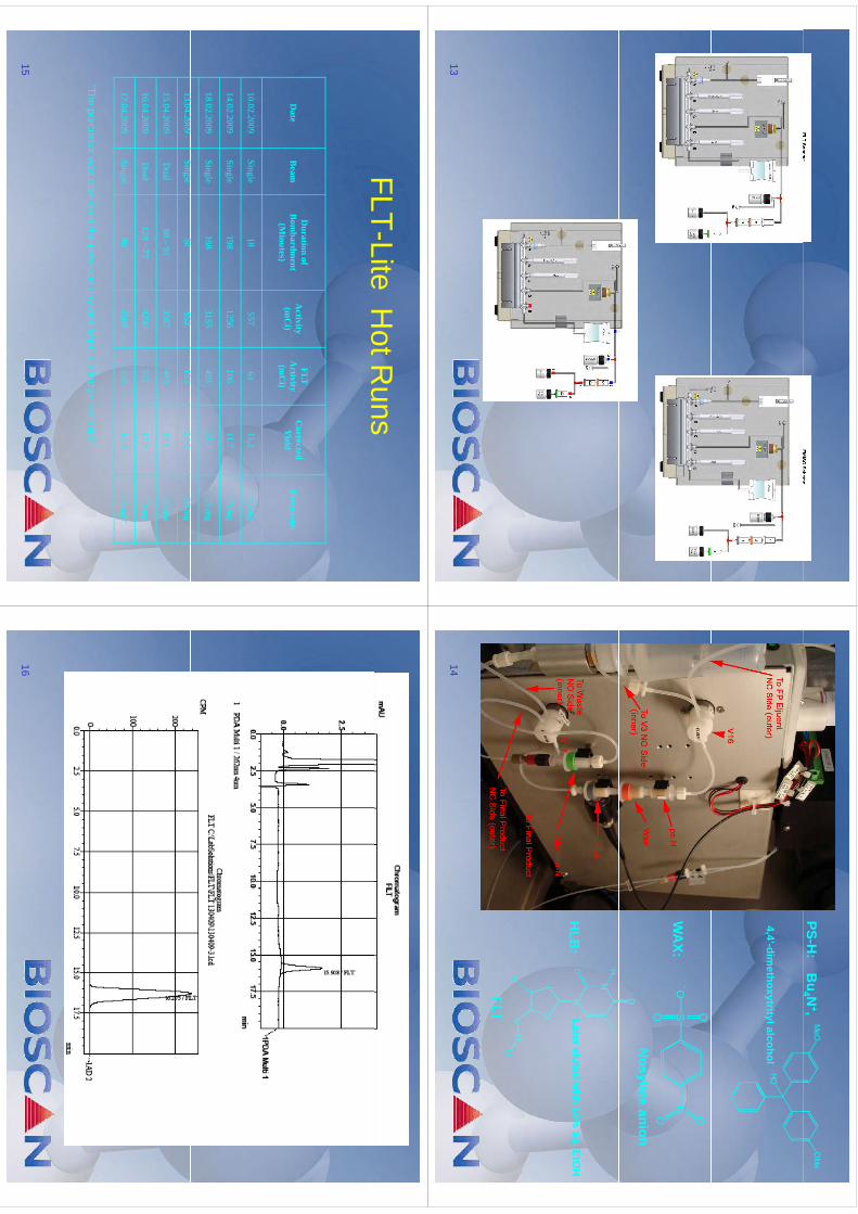
13
Bu
4 N+,
PS-H:
4,4’-dimethoxytrityl alcohol
-W
AX:
Nosylate anion
HLB
:Latereluted
with
10%aq.EtO
HH
LB:
Later eluted with 10%
aq. EtOH
18F
FLT
14
FLT-LiteH
otRuns
FLTLite
Hot R
uns
Date
Beam
Duration of
Bom
bardment
(Minutes)
Activity
(mC
i)
FLT A
ctivity (m
Ci)
Corrected Y
ieldPrecursor
(Minutes)
(mC
i)
10.02.2009Single
18557
6115,2
25 mg
14.02.2009Single
1981256
10611,7
25 mg
18.02.2009Single
1683155
49321,4
25 mg
1304
2009Si
l50
852153
248
2013.04.2009
Single50
852153
24,820 m
g
15.04.2009D
ual88 –
913587
49319,1
25 mg
1604
2009D
ual128
–77
4290531
179
20m
g16.04.2009
Dual
128 –77
4290531
17,920 m
g
17.04.2009Single
902509
23512,9
20 mg*
*The precursor was dissolved the previous day and kept in a fridge overnight
1516
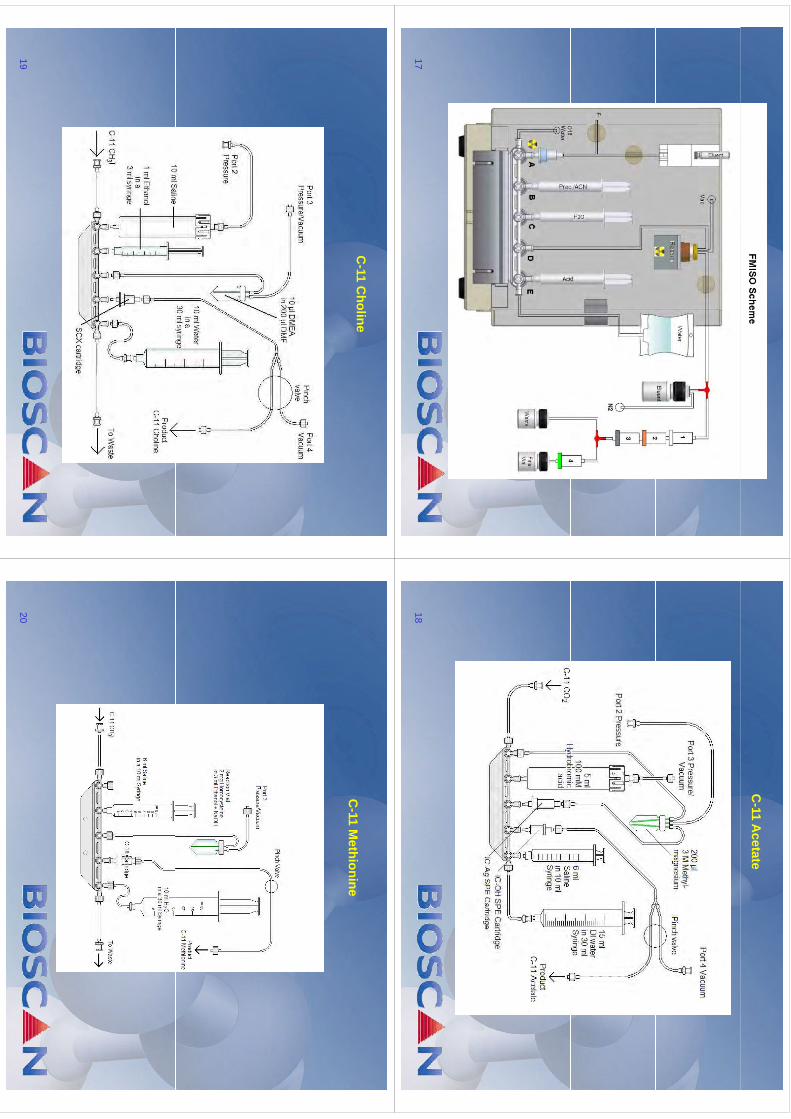
17
C-11 A
cetate
18
C-11 C
holine
19
C-11 M
ethionine
20
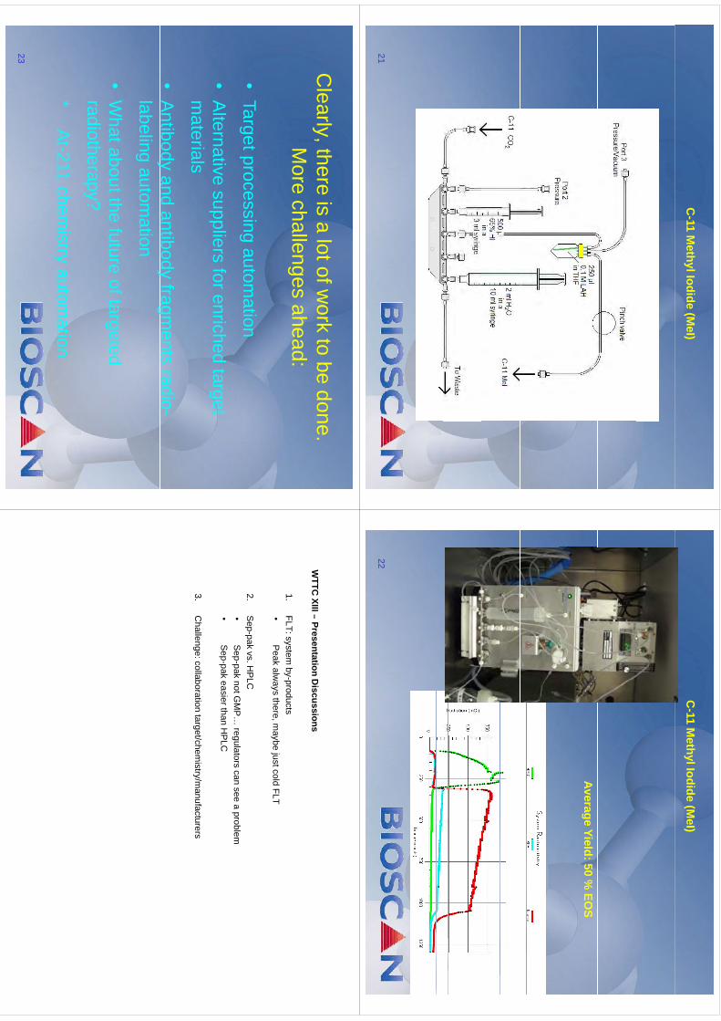
C-11 M
ethyl Iodide (MeI)
21
C-11 M
ethyl Iodide (MeI)
Average Yield: 50 % EO
S
22
Clearly, there is a lot of w
ork to be done.y,M
ore challenges ahead:
•Target processing autom
ation
•A
lternative suppliers for enriched target m
aterialsm
aterials
•A
ntibody and antibody fragments radio-
yy
glabeling
automation
Wh
tb
tthf
tft
td
•W
hat about the future of targeted radiotherapy?
*A
t-211 chemistry autom
ation
23
WTTC
XIII–Presentation
Discussions
WTTC
XIII –Presentation D
iscussions
1.FLT: system
by-products•
Peak
always
therem
aybejustcold
FLT•
Peak alw
ays there, maybe just cold FLT
2.S
ep-pakvs. H
PLC
•S
eppak
notGM
Pregulators
cansee
aproblem
•S
ep-paknot G
MP…
regulators can see a problem•
Sep-pakeasier than H
PLC
3C
hallenge:collaborationtarget/chem
istry/manufacturers
3.C
hallenge: collaboration target/chemistry/m
anufacturers
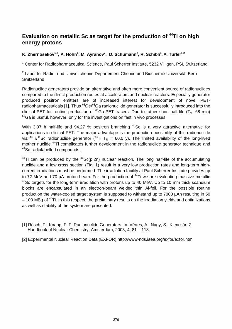
Evaluation on metallic Sc as target for the production of 44Ti on high energy protons K. Zhernosekov 1,2, A. Hohn 1, M. Ayranov 2, D. Schumann 2, R. Schibli 1, A. Türler 1,2
1 Center for Radiopharmaceutical Science, Paul Scherrer Institute, 5232 Villigen, PSI, Switzerland
2 Labor für Radio- und Umweltchemie Departement Chemie und Biochemie Universität Bern Switzerland
Radionuclide generators provide an alternative and often more convenient source of radionuclides compared to the direct production routes at accelerators and nuclear reactors. Especially generator produced positron emitters are of increased interest for development of novel PET-radiopharmaceuticals [1]. Thus 68Ge/68Ga radionuclide generator is successfully introduced into the clinical PET for routine production of 68Ga-PET tracers. Due to rather short half-life (T½ 68 min) 68Ga is useful, however, only for the investigations on fast in vivo processes.
With 3.97 h half-life and 94.27 % positron branching 44Sc is a very attractive alternative for applications in clinical PET. The major advantage is the production possibility of this radionuclide via 44Ti/44Sc radionuclide generator (44Ti T½ = 60.0 y). The limited availability of the long-lived mother nuclide 44Ti complicates further development in the radionuclide generator technique and 44Sc-radiolabelled compounds.
44Ti can be produced by the 45Sc(p,2n) nuclear reaction. The long half-life of the accumulating nuclide and a low cross section (Fig. 1) result in a very low production rates and long-term high-current irradiations must be performed. The irradiation facility at Paul Scherrer Institute provides up to 72 MeV and 70 µA proton beam. For the production of 44Ti we are evaluating massive metallic 45Sc targets for the long-term irradiation with protons up to 40 MeV. Up to 10 mm thick scandium blocks are encapsulated in an electron-beam welded thin Al-foil. For the possible routine production the water-cooled target system is supposed to withstand up to 7000 µAh resulting in 50 – 100 MBq of 44Ti. In this respect, the preliminary results on the irradiation yields and optimizations as well as stability of the system are presented.
[1] Rösch, F., Knapp, F. F. Radionuclide Generators. In: Vértes, A., Nagy, S., Klencsár, Z. Handbook of Nuclear Chemistry. Amsterdam, 2003; 4: 81 – 118;
[2] Experimental Nuclear Reaction Data (EXFOR) http://www-nds.iaea.org/exfor/exfor.htm
276
kmje
Typewritten Text
Abstract 049
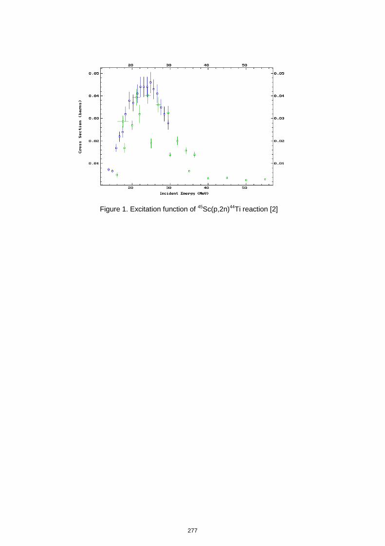
Figure 1. Excitation function of 45Sc(p,2n)44Ti reaction [2]
277
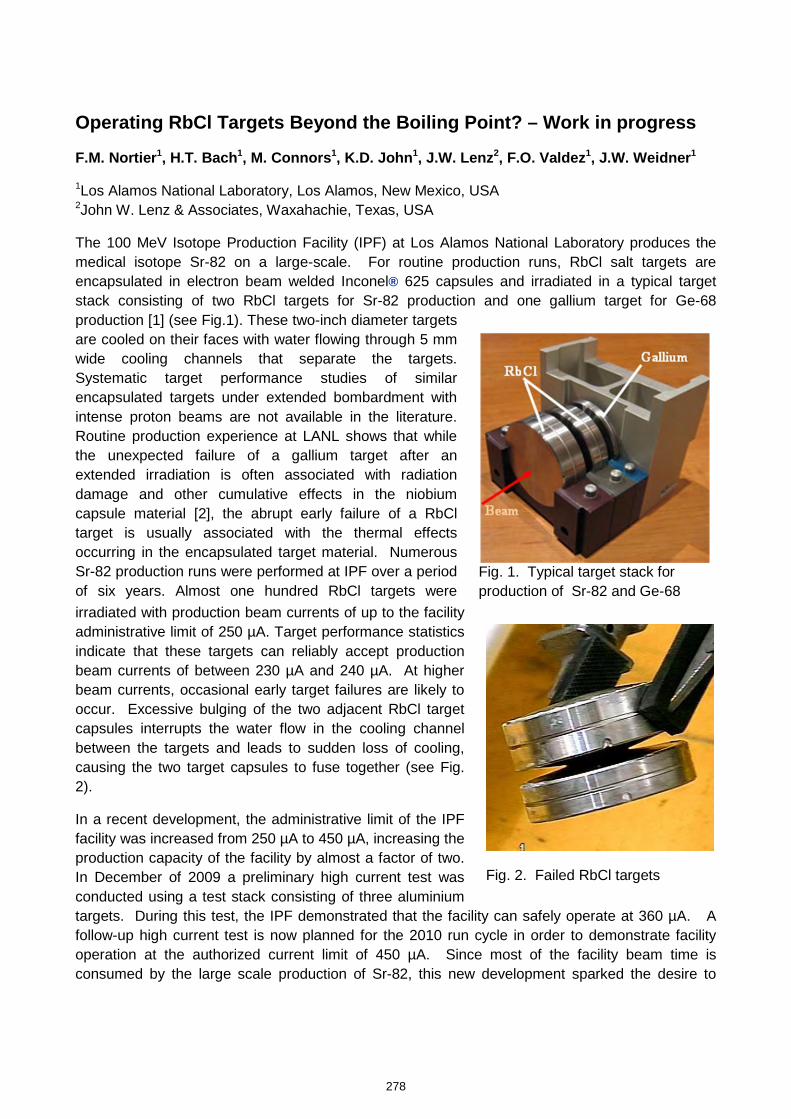
Operating RbCl Targets Beyond the Boiling Point? – Work in progress
F.M. Nortier1, H.T. Bach1, M. Connors1, K.D. John1, J.W. Lenz2, F.O. Valdez1, J.W. Weidner1
1Los Alamos National Laboratory, Los Alamos, New Mexico, USA 2John W. Lenz & Associates, Waxahachie, Texas, USA
The 100 MeV Isotope Production Facility (IPF) at Los Alamos National Laboratory produces the medical isotope Sr-82 on a large-scale. For routine production runs, RbCl salt targets are encapsulated in electron beam welded Inconel® 625 capsules and irradiated in a typical target stack consisting of two RbCl targets for Sr-82 production and one gallium target for Ge-68 production [1] (see Fig.1). These two-inch diameter targets are cooled on their faces with water flowing through 5 mm wide cooling channels that separate the targets. Systematic target performance studies of similar encapsulated targets under extended bombardment with intense proton beams are not available in the literature. Routine production experience at LANL shows that while the unexpected failure of a gallium target after an extended irradiation is often associated with radiation damage and other cumulative effects in the niobium capsule material [2], the abrupt early failure of a RbCl target is usually associated with the thermal effects occurring in the encapsulated target material. Numerous Sr-82 production runs were performed at IPF over a period of six years. Almost one hundred RbCl targets were irradiated with production beam currents of up to the facility administrative limit of 250 µA. Target performance statistics indicate that these targets can reliably accept production beam currents of between 230 µA and 240 µA. At higher beam currents, occasional early target failures are likely to occur. Excessive bulging of the two adjacent RbCl target capsules interrupts the water flow in the cooling channel between the targets and leads to sudden loss of cooling, causing the two target capsules to fuse together (see Fig. 2).
In a recent development, the administrative limit of the IPF facility was increased from 250 µA to 450 µA, increasing the production capacity of the facility by almost a factor of two. In December of 2009 a preliminary high current test was conducted using a test stack consisting of three aluminium targets. During this test, the IPF demonstrated that the facility can safely operate at 360 µA. A follow-up high current test is now planned for the 2010 run cycle in order to demonstrate facility operation at the authorized current limit of 450 µA. Since most of the facility beam time is consumed by the large scale production of Sr-82, this new development sparked the desire to
Fig. 1. Typical target stack for production of Sr-82 and Ge-68
Fig. 2. Failed RbCl targets
278
kmje
Typewritten Text
Abstract 050
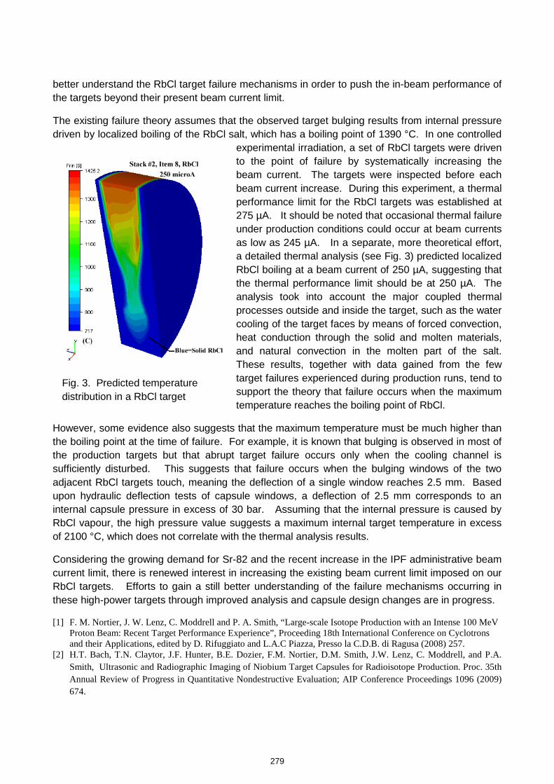
better understand the RbCl target failure mechanisms in order to push the in-beam performance of the targets beyond their present beam current limit.
The existing failure theory assumes that the observed target bulging results from internal pressure driven by localized boiling of the RbCl salt, which has a boiling point of 1390 °C. In one controlled
experimental irradiation, a set of RbCl targets were driven to the point of failure by systematically increasing the beam current. The targets were inspected before each beam current increase. During this experiment, a thermal performance limit for the RbCl targets was established at 275 µA. It should be noted that occasional thermal failure under production conditions could occur at beam currents as low as 245 µA. In a separate, more theoretical effort, a detailed thermal analysis (see Fig. 3) predicted localized RbCl boiling at a beam current of 250 µA, suggesting that the thermal performance limit should be at 250 µA. The analysis took into account the major coupled thermal processes outside and inside the target, such as the water cooling of the target faces by means of forced convection, heat conduction through the solid and molten materials, and natural convection in the molten part of the salt. These results, together with data gained from the few target failures experienced during production runs, tend to support the theory that failure occurs when the maximum temperature reaches the boiling point of RbCl.
However, some evidence also suggests that the maximum temperature must be much higher than the boiling point at the time of failure. For example, it is known that bulging is observed in most of the production targets but that abrupt target failure occurs only when the cooling channel is sufficiently disturbed. This suggests that failure occurs when the bulging windows of the two adjacent RbCl targets touch, meaning the deflection of a single window reaches 2.5 mm. Based upon hydraulic deflection tests of capsule windows, a deflection of 2.5 mm corresponds to an internal capsule pressure in excess of 30 bar. Assuming that the internal pressure is caused by RbCl vapour, the high pressure value suggests a maximum internal target temperature in excess of 2100 °C, which does not correlate with the thermal analysis results.
Considering the growing demand for Sr-82 and the recent increase in the IPF administrative beam current limit, there is renewed interest in increasing the existing beam current limit imposed on our RbCl targets. Efforts to gain a still better understanding of the failure mechanisms occurring in these high-power targets through improved analysis and capsule design changes are in progress.
[1] F. M. Nortier, J. W. Lenz, C. Moddrell and P. A. Smith, “Large-scale Isotope Production with an Intense 100 MeV Proton Beam: Recent Target Performance Experience”, Proceeding 18th International Conference on Cyclotrons and their Applications, edited by D. Rifuggiato and L.A.C Piazza, Presso la C.D.B. di Ragusa (2008) 257.
[2] H.T. Bach, T.N. Claytor, J.F. Hunter, B.E. Dozier, F.M. Nortier, D.M. Smith, J.W. Lenz, C. Moddrell, and P.A. Smith, Ultrasonic and Radiographic Imaging of Niobium Target Capsules for Radioisotope Production. Proc. 35th Annual Review of Progress in Quantitative Nondestructive Evaluation; AIP Conference Proceedings 1096 (2009) 674.
Fig. 3. Predicted temperature distribution in a RbCl target
279

Operating R
bCl Targets B
eyond the B
oiling Point? A w
ork in progress
FM
Nti
1F.M
. Nortier 1
H.T. B
ach1, M
.A. C
onnors1, M
.S. Gulley
1, K.D
. John1, J.W
. L
2E
RO
li1
FO
Vld
1J
WW
id1
Lenz2, E.R
Olivas
1, F.O. Valdez
1, J.W. W
eidner 1
1Los Alam
os National Laboratory, Los A
lamos, N
ew M
exico, US
A2Facility
forRare
IonB
eams
EastLansing
Michigan
US
AFacility for R
are Ion Beam
s, East Lansing, M
ichigan, US
A
Operated by Los A
lamos N
ational Security, LLC
for the U.S
. Departm
ent of Energy’s N
NS
A
WTTC
13, July 2010LA
UR
10-04781
IPFT
tF
tIPF Targetry Facts
G
enerally targets are irradiated with
100 MeV protons up to 250 µA
.
Production occurs sim
ultaneously in 3 energy ranges
Three targets in a stack w
ith cooling channels in betw
een
PrototypeStack
Pulsed beam
with ring-shaped beam
profile
RbC
lG
a
Prototype StackB
eamThe im
age cannot be displayed. Your computer m
ay not have enough mem
ory to open the image, or the im
age may have been corrupted. Restart your com
puter, and then open the file again. If the red x still appears, you may have to delete the im
age and then insert it again.
RbC
lG
a
Operated by Los A
lamos N
ational Security, LLC
for the U.S
. Departm
ent of Energy’s N
NS
A
WTTC
13, July 2010LA
UR
10-047812
S82
dG
68d
tif
tSr-82 and G
e-68 production facts
R
bCltargets
areencapsulated
ininconeland
RbC
lG
allium
RbC
l targets are encapsulated in inconel and G
a target is encapsulated in niobium
Sr-82 production consum
es more than 90%
of p
available beam tim
e
R
ecently demonstrated that beam
currents up to 360 A
ilbl
(f4
0A
)ki
df
hiB
eamµA
available (future 450 µA) –
taking advantage of this w
ill open up beam tim
e for R&
D isotopes
Therm
al performance of R
bClsalt targets is significantly
lowerthan
mostm
etalslow
er than most m
etals
R
outine productions use beam currents betw
een 230 and 240 µA
–occasional failures beyond 240 µA
Operated by Los A
lamos N
ational Security, LLC
for the U.S
. Departm
ent of Energy’s N
NS
A
WTTC
13, July 2010LA
UR
10-047813
Ii
RbC
lSltT
tPf
Improving R
bCl Salt Target Perform
ance
What to do?
U
nderstand what is going on
Learn how
to control each individual param
eter in order of decreasing significancesignificance
Success!!!!!
Success!!!!!
Operated by Los A
lamos N
ational Security, LLC
for the U.S
. Departm
ent of Energy’s N
NS
A
WTTC
13, July 2010LA
UR
10-047814
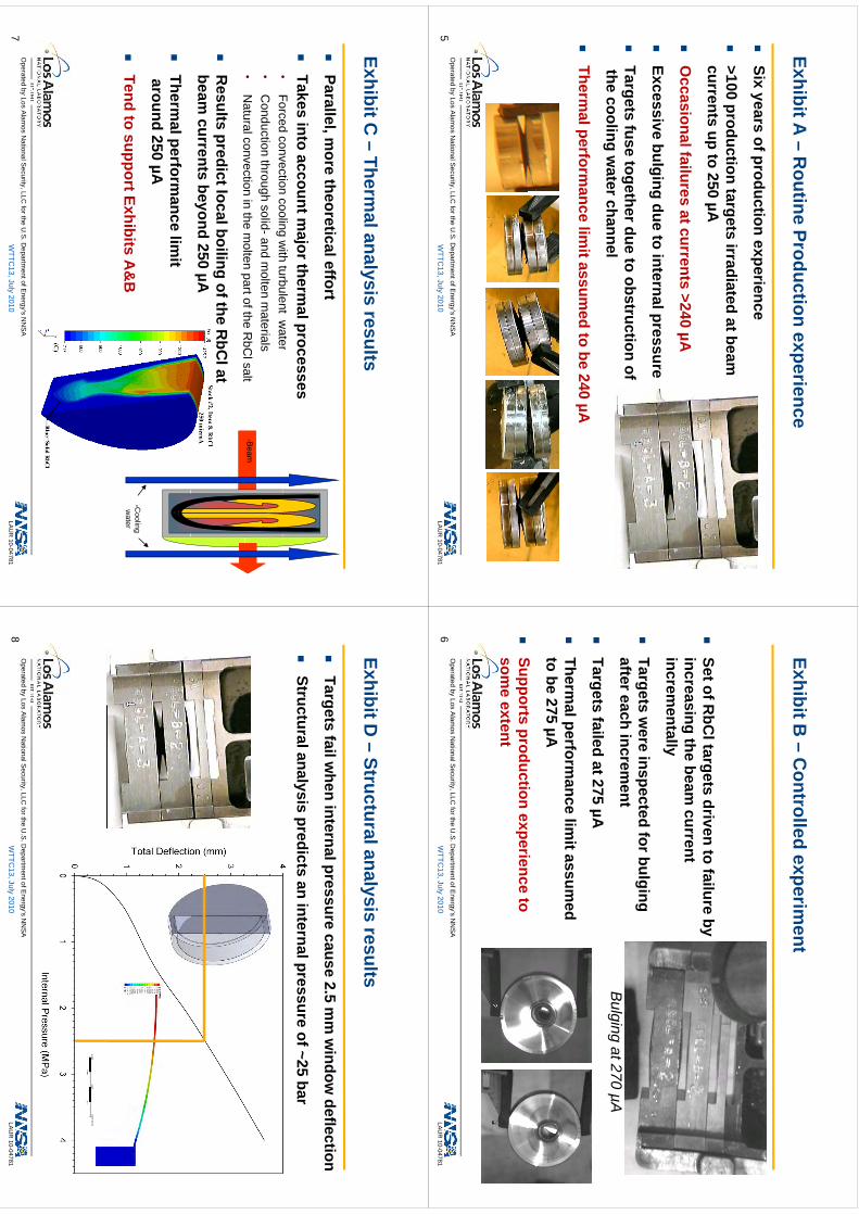
EhibitA
Rti
Pd
tii
Exhibit A –
Routine Production experience
Six
yearsofproduction
experience
Six years of production experience
>100 production targets irradiated at beam
currents
upto
250µA
currents up to 250 µA
O
ccasional failures at currents >240 µA
Excessive bulging due to internal pressure
Targets fuse together due to obstruction of the cooling w
ater channel
Therm
al performance lim
it assumed to be 240 µA
Operated by Los A
lamos N
ational Security, LLC
for the U.S
. Departm
ent of Energy’s N
NS
A
WTTC
13, July 2010LA
UR
10-047815
EhibitB
Ct
lld
it
Exhibit B –
Controlled experim
ent
St
fRbC
ltt
di
tf
ilb
Set of R
bCl targets driven to failure by
increasing the beam current
incrementall yy
Targets w
ere inspected for bulging after each increm
entB
li
t270A
Targets failed at 275 µA
Thl
fli
itd
Bulging at 270 µA
Therm
al performance lim
it assumed
to be 275 µA
St
dti
it
Supports production experience to som
e extent
Operated by Los A
lamos N
ational Security, LLC
for the U.S
. Departm
ent of Energy’s N
NS
A
WTTC
13, July 2010LA
UR
10-047816
EhibitC
Thl
li
ltExhibit C
–Therm
al analysis results
Parallel
more
theoreticaleffort
Parallel, more theoretical effort
Takes into account m
ajor thermal processes
•Forced
convectioncooling
with
turbulentw
ater•
Forced convection cooling with turbulent w
ater•
Conduction through solid-and m
olten materials
•N
atural convection in the molten part of the R
bCl salt
Beam
R
esults predict local boiling of the RbC
l at beam
currents beyond 250 µA
Therm
al performance lim
itaround 250 µA
Tend to support Exhibits A
&B
Cooling
water
Operated by Los A
lamos N
ational Security, LLC
for the U.S
. Departm
ent of Energy’s N
NS
A
WTTC
13, July 2010LA
UR
10-047817
EhibitD
Stt
ll
ilt
Exhibit D –
Structural analysis results
Targets
failwhen
internalpressurecause
25
mm
window
deflection
Targets fail when internal pressure cause 2.5 m
m w
indow deflection
Structural analysis predicts an internal pressure of ~25 bar
Operated by Los A
lamos N
ational Security, LLC
for the U.S
. Departm
ent of Energy’s N
NS
A
WTTC
13, July 2010LA
UR
10-047818
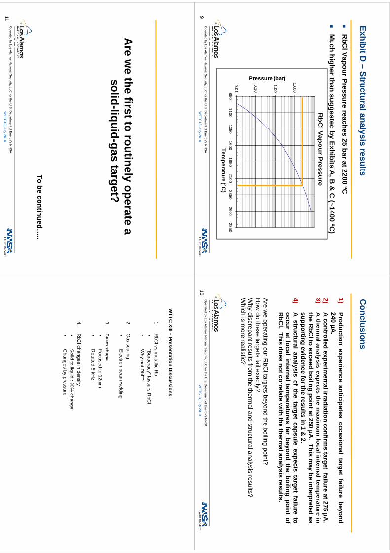
EhibitD
Stt
ll
ilt
Exhibit D –
Structural analysis results
R
bClVapourPressure
reaches25
barat2200ºC
R
bClVapourPressure reaches 25 bar at 2200 C
M
uch higher than suggested by Exhibits A, B
& C
(~1400 ºC)
RbC
l Vapour Pressure
10.00
ar)
1.00
ssure (ba
0.10
Pres
0.018501100
13501600
18502100
23502600
2850
Temperature (°C
)
Operated by Los A
lamos N
ational Security, LLC
for the U.S
. Departm
ent of Energy’s N
NS
A
WTTC
13, July 2010LA
UR
10-047819
Cl
iC
onclusions
1)Production
experienceanticipates
occasionaltarget
failurebeyond
240µA
.2)
Acontrolled
experimentalirradiation
confirms
targetfailure
at275µA
.)
pg
µ3)
Atherm
alanalysisexpects
them
aximum
localinternaltemperature
inthe
RbC
ltoexceed
boilingpointat250
µA.
Thism
aybe
interpretedas
supportingevidence
fortheresults
in1
&2
supportingevidence
fortheresults
in1
&2.
4)A
structuralanalysis
ofthe
targetcapsule
expectstarget
failureto
occurat
localinternal
temperatures
farbeyond
theboiling
pointof
RbC
lThis
doesnotcorrelate
with
thetherm
alanalysisresults
RbC
l.This
doesnotcorrelate
with
thetherm
alanalysisresults.
Are
we
operatingourR
bCltargets
beyondthe
boilingpoint?
f?
How
dothese
targetsfailexactly?
Why
discrepantresultsfrom
thetherm
alandstructuralanalysis
results?W
hichis
more
realistic?
Operated by Los A
lamos N
ational Security, LLC
for the U.S
. Departm
ent of Energy’s N
NS
A
WTTC
13, July 2010LA
UR
10-0478110
Are
we
thefirstto
routinelyoperate
aA
re we the first to routinely operate a
solid-liquid-gas target?
To be continued…..
Operated by Los A
lamos N
ational Security, LLC
for the U.S
. Departm
ent of Energy’s N
NS
A
WTTC
13, July 2010LA
UR
10-0478111
WTTC
XIII–Presentation
Discussions
WTTC
XIII –Presentation D
iscussions
1.R
bClvs
metallic R
b•
“Burocracy”favours
RbC
l•
Burocracy
favoursR
bCl
•W
hy not RbF?
2G
assealing
2.G
as sealing•
Electron beam w
elding
3B
eamshape
3.B
eam shape
•Focused to 12m
m•
Rotated 5 kH
z
4.R
bClchanges in density
•Solid to liquid : 30%
changeC
hangesby
pressure•
Changes by pressure
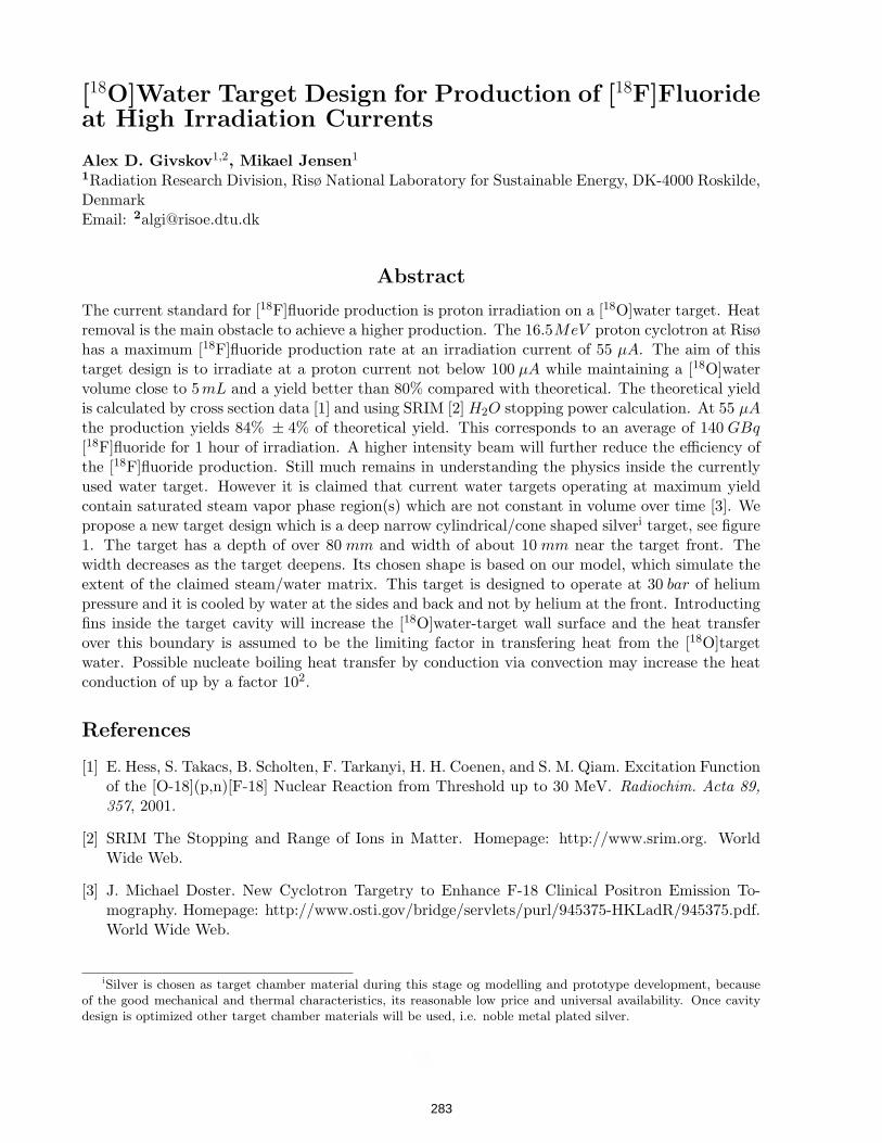
[18O]Water Target Design for Production of [18F]Fluorideat High Irradiation Currents
Alex D. Givskov1,2, Mikael Jensen1
1Radiation Research Division, Risø National Laboratory for Sustainable Energy, DK-4000 Roskilde,DenmarkEmail: [email protected]
Abstract
The current standard for [18F]fluoride production is proton irradiation on a [18O]water target. Heatremoval is the main obstacle to achieve a higher production. The 16.5MeV proton cyclotron at Risøhas a maximum [18F]fluoride production rate at an irradiation current of 55 µA. The aim of thistarget design is to irradiate at a proton current not below 100 µA while maintaining a [18O]watervolume close to 5mL and a yield better than 80% compared with theoretical. The theoretical yieldis calculated by cross section data [1] and using SRIM [2] H2O stopping power calculation. At 55 µA
the production yields 84% ± 4% of theoretical yield. This corresponds to an average of 140 GBq
[18F]fluoride for 1 hour of irradiation. A higher intensity beam will further reduce the efficiency ofthe [18F]fluoride production. Still much remains in understanding the physics inside the currentlyused water target. However it is claimed that current water targets operating at maximum yieldcontain saturated steam vapor phase region(s) which are not constant in volume over time [3]. Wepropose a new target design which is a deep narrow cylindrical/cone shaped silveri target, see figure1. The target has a depth of over 80 mm and width of about 10 mm near the target front. Thewidth decreases as the target deepens. Its chosen shape is based on our model, which simulate theextent of the claimed steam/water matrix. This target is designed to operate at 30 bar of heliumpressure and it is cooled by water at the sides and back and not by helium at the front. Introductingfins inside the target cavity will increase the [18O]water-target wall surface and the heat transferover this boundary is assumed to be the limiting factor in transfering heat from the [18O]targetwater. Possible nucleate boiling heat transfer by conduction via convection may increase the heatconduction of up by a factor 102.
References
[1] E. Hess, S. Takacs, B. Scholten, F. Tarkanyi, H. H. Coenen, and S. M. Qiam. Excitation Functionof the [O-18](p,n)[F-18] Nuclear Reaction from Threshold up to 30 MeV. Radiochim. Acta 89,
357, 2001.
[2] SRIM The Stopping and Range of Ions in Matter. Homepage: http://www.srim.org. WorldWide Web.
[3] J. Michael Doster. New Cyclotron Targetry to Enhance F-18 Clinical Positron Emission To-mography. Homepage: http://www.osti.gov/bridge/servlets/purl/945375-HKLadR/945375.pdf.World Wide Web.
iSilver is chosen as target chamber material during this stage og modelling and prototype development, because
of the good mechanical and thermal characteristics, its reasonable low price and universal availability. Once cavity
design is optimized other target chamber materials will be used, i.e. noble metal plated silver.
1
283
kmje
Typewritten Text
Abstract 051
inventor
Stamp
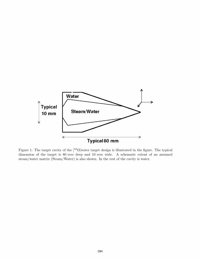
Figure 1: The target cavity of the [18O]water target design is illustrated in the figure. The typicaldimension of the target is 80 mm deep and 10 mm wide. A schematic extent of an assumedsteam/water matrix (Steam/Water) is also shown. In the rest of the cavity is water.
2
284
inventor
Stamp
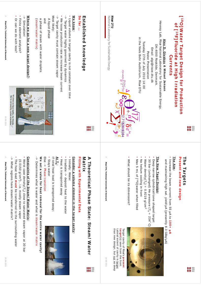
[1
8O]W
ater Target D
esign
for Prod
uction
f [1
8F]Flid
t H
ih
Id
iti
of [
18F]Flu
oride at H
igh
Irradiation
C
urren
tsA
lex D. G
ivskov&
Mikael Jen
senH
evesy Lab, Risø
National Laboratory for S
ustainable Energy,D
K-4000 Roskilde, Denm
ark.D
K4000 Roskilde, D
enmark.
Email: algi@
risoe.dtu.dkPoster Presentation
Td
27h
f Jl
2010 1400
Tuesday 27th of July 2010 14:00in the N
ielsBohr A
uditorium, R
isøD
TU
The Targ
etsP
resent an
d n
ew d
esign
The A
im:
•Increase the beam
current from 55 µA
to 10
0+
µA
and maintaining high sat
yield/µA (presently 8
3 GBq/µA
)and m
aintaining high sat. yield/µA (presently 8.3 G
Bq/µA
)
The N
ew Tag
et Desig
n:
•D
eep narrow cylindrical/cone shaped target
•30 bar (unchanged) H
e pressure (Tb
= 234˚C
)•
Water density(T
b ) = 0
8219 g/cm3
•W
ater density(Tb ) =
0.8219 g/cm•
No helium
cooling in front•
Max 5 m
L of [ 18O]w
ater when filled
•W
hat should be its dimensions?
Target cavityof R
isø’sp
resent
Target cavityof R
isøs
presen
ttarg
et(s) seenfrom
the front. Lateral extent
of cavityis larger
thannew
design, but notas deep
Risø D
TU, Tech
nical U
niversity of D
enm
arkR
isø DTU
, Techn
ical Un
iversity of Den
mark
10-06-20112
Establish
ed kn
owled
ge
So far …
We kn
ow:
•Liquid volum
e in target cavity is not constant over time
> Target w
ater highly governed by dynamics
-> Target w
ater highly governed by dynamics
•W
e loose production rate as increase beam current
-> Target cavity m
ust contain steam vapor
Most likely:A liquid
phaseandanda phase of steam
with w
aterdroplets
(steam/w
aterm
atrix)
Wh
ere we g
o for a new
target d
esign
?:->
Sim
ulation!•
Finite element analysis?
•O
r can we do w
ith less?
Risø D
TU, Tech
nical U
niversity of D
enm
arkR
isø DTU
, Techn
ical Un
iversity of Den
mark
10-06-20113
A Th
eoretical Ph
ase State: S
team/
Water
/M
atrixFittin
g w
ith Exp
erimen
tal Data
Con
sider a volu
me elem
ent in
the targ
et cavity:•
Initially: Water
Irradiate >
deposit heat to the water
•Irradiate ->
deposit heat to the water
•H
eat is transported away
At T
b :If total heat load is transported aw
ay:•
Stays w
aterElse ->
Phase transitionElse
> Phase transition
We set a valu
e for heat rem
oval for the en
tire water cavity!
-> D
etermines w
hat is water and w
hat is steam/w
ater matrix
Con
straints of th
e Steam
/W
ater Matrix:
•W
orst case densit y(Tb ) close to saturated steam
vapor at 30 bary(
b )p
(0.0150 g/cm3)
, i.e. mostly steam
vapor•
The heat load mu
stbe transferred to the surrounding w
ater>
What regions have steam
/water m
atrix?
Risø D
TU, Tech
nical U
niversity of D
enm
arkR
isø DTU
, Techn
ical Un
iversity of Den
mark
-> W
hat regions have steam/w
ater matrix?
10-06-20114
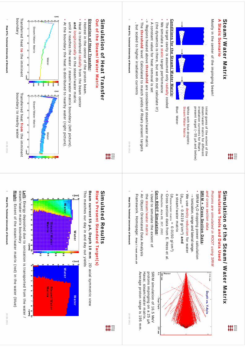
Steam
/W
ater Matrix
A S
tatic Scen
ario
Mostly in the center of the im
pinging beam!
Initial guess of the extent of the steam
/water m
atrix for different steam
/water m
atrix for different irradiation currents for R
isø’s present target (~
55 µA and below
)
White w
ith blue droplets: Steam
/Water M
atrix
Blue: W
aterC
ond
itions for th
e Steam
/W
ater Matrix:
•The target cavity is assum
ed only radiallycooled B
lue: Water
•W
e simulate a static
target performance
(the dynamics is there, but w
e do not calculate it!)•
A constant value for heat rem
oval is set->
Regions heated above thresh
oldare considered steam
/water m
atrix•
The thresh
oldlevel: C
alculatedto m
atch yieldsof R
isø’s present targets but scaled to higher irradiation
currents
Risø D
TU, Tech
nical U
niversity of D
enm
arkR
isø DTU
, Techn
ical Un
iversity of Den
mark
, but scaled to higher irradiationcurrents
10-06-20115
Sim
ulation
of the S
team/
Water M
atrixS
imu
lation Tools an
d D
ata Used
Protons aresim
ulatedin R
OO
T usingSRIM
and crosssection
dataS
RIM
+ C
ross Section
Data:
SR
IM +
Cross S
ection D
ata:•
SRIM
H2 O
stopping power calculation
→ Ionization, range and lateral range.
•W
euse
desityreduction
for water
(ρw
ater = 0.8219 g/cm
3) and
a steam/w
aterm
atrixa steam
/water
matrix
(ρsteam
/water
matrix
= 0.0150 g/cm
3)•
Cross section data from
E. Hess et al.
Radiochim
. Acta
89, 357, 2001
Cern
RO
OT S
imu
lation:
•U
sedto sim
ulatethe extent
ofSRIM
simulation of 16.5 M
eV
the steam/w
aterm
atrix•
An O
bject Orientated D
ata Analysis
Framew
ork H
omepage: h
//h
protons impinging
ona 25 μA
Havar, steam
/water m
atrix. Average proton range is 195 m
m.
Risø D
TU, Tech
nical U
niversity of D
enm
arkR
isø DTU
, Techn
ical Un
iversity of Den
mark
Framew
ork. Hom
epage: http
://
root.cern.ch
10-06-20116
Sim
ulation
of Heat Tran
sferO
ut of th
e Steam
/W
ater Matrix
Direction
of Heat Tran
sfer:•
Hottest in the center of the proton beam
.H
eat is transfered radially from the beam
center•
Heat is transfered radially from
the beam center
and
longitutionallyin the steam
/water m
atrixuntil it reaches the w
ater / steam/w
ater matrix boundary (left picture).
•At the boundary
the heat is distributedto nearby
water
(right picture).
Water
Water
Steam
/Water
Matrix
Steam
/Water
Matrix
Transferredheat to
the imm
inent boundary
Transferredheat from
the imm
inent boundary
to nearbyw
ater
Risø D
TU, Tech
nical U
niversity of D
enm
arkR
isø DTU
, Techn
ical Un
iversity of Den
mark
10-06-20117
Sim
ulated
Resu
ltsR
isø’sP
resent S
tand
ard Targ
et(s)
Beam
curren
t 55
µA
, Dep
th 1
0 m
m , 2D
axial symm
etric viewThis
matches our
dayin and day
out yields
Water
Water
Water
Water
Steam
/W
aterM
atrixS
team/
Water
Matrix
Left: Energy deposited due to ionization is transported from the w
ater / steam
/water m
atrix boundaryR
igh
t: Extent of the steam/w
ater matrix (red) in the w
ater (blue)
Risø D
TU, Tech
nical U
niversity of D
enm
arkR
isø DTU
, Techn
ical Un
iversity of Den
mark
10-06-20118 R
igh
t: Extent of the steam/w
ater matrix (red) in the w
ater (blue)
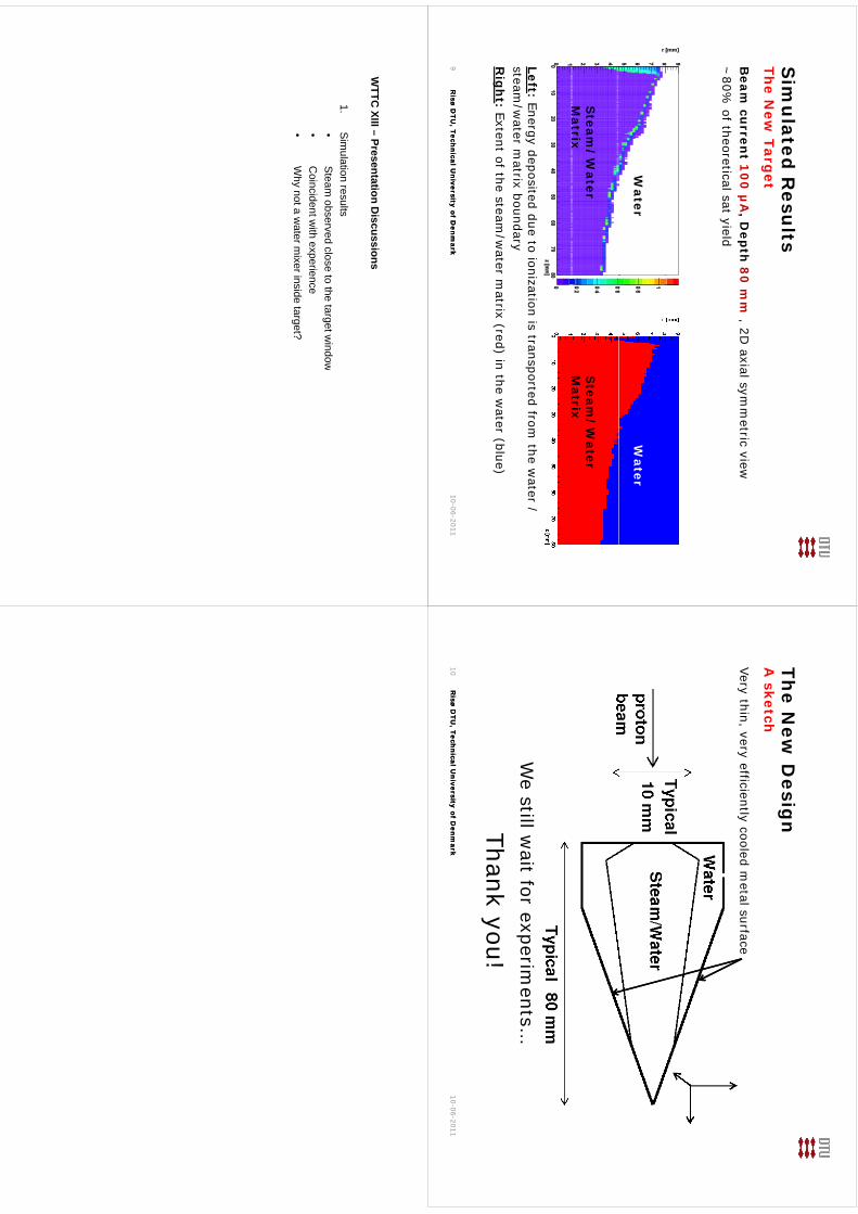
Sim
ulated
Resu
ltsTh
e New
Target
Beam
curren
t 10
0µ
A, D
epth
80
mm
, 2D axial sym
metric view
~80%
of theoreticalsat yield
Water
Water
Steam
/W
aterM
atrixS
team/
Water
Matrix
Left: Energy deposited due to ionization is transported from the w
ater /
Matrix
Matrix
gyp
p/
steam/w
ater matrix boundary
Rig
ht : Extent of the steam
/water m
atrix (red) in the water (blue)
Risø D
TU, Tech
nical U
niversity of D
enm
arkR
isø DTU
, Techn
ical Un
iversity of Den
mark
10-06-20119
The N
ew D
esign
A sketch
Very thin, very efficiently cooled metal surface
We
still wait
for experiments
We
still wait
for experiments…
Thank you!R
isø DTU
, Techn
ical Un
iversity of Den
mark
Risø D
TU, Tech
nical U
niversity of D
enm
ark10-06-2011
10
WTTC
XIII–Presentation
Discussions
WTTC
XIII –Presentation D
iscussions
1.S
imulation results
•S
teamobserved
closeto
thetargetw
indow•
Steam
observed close to the target window
•C
oincident with experience
•W
hy not a water m
ixer inside target?
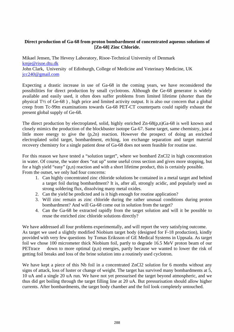
Direct production of Ga-68 from proton bombardment of concentrated aqueous solutions of
[Zn-68] Zinc Chloride. Mikael Jensen, The Hevesy Laboratory, Risoe-Technical University of Denmark [email protected] John Clark, University of Edinburgh, College of Medicine and Veterinary Medicine, UK [email protected] Expecting a drastic increase in use of Ga-68 in the coming years, we have reconsidered the possibilities for direct production by small cyclotrons. Although the Ge-68 generator is widely available and easily used, it often does suffer problems from limited lifetime (shorter than the physical T½ of Ge-68 ) , high price and limited activity output. It is also our concern that a global creep from Tc-99m examinations towards Ga-68 PET-CT counterparts could rapidly exhaust the present global supply of Ge-68. The direct production by electroplated, solid, highly enriched Zn-68(p,n)Ga-68 is well known and closely mimics the production of the blockbuster isotope Ga-67. Same target, same chemistry, just a little more energy to give the (p,2n) reaction. However the prospect of doing an enriched electroplated solid target, bombardment, etching, ion exchange separation and target material recovery chemistry for a single patient dose of Ga-68 does not seem feasible for routine use. For this reason we have tested a “solution target”, where we bombard ZnCl2 in high concentration in water. Of course, the water does “eat up” some useful cross section and gives more stopping, but for a high yield “easy” (p,n) reaction and with a short lifetime product, this is certainly possible. From the outset, we only had four concerns:
1. Can highly concentrated zinc chloride solutions be contained in a metal target and behind a target foil during bombardment? It is, after all, strongly acidic, and popularly used as strong soldering flux, dissolving many metal oxides.
2. Can the yield be predicted and is it high enough for routine application? 3. Will zinc remain as zinc chloride during the rather unusual conditions during proton
bombardment? And will Ga-68 come out in solution from the target? 4. Can the Ga-68 be extracted rapidly from the target solution and will it be possible to
reuse the enriched zinc chloride solutions directly? We have addressed all four problems experimentally, and will report the very satisfying outcome. As target we used a slightly modified Niobium target body (designed for F-18 production), kindly provided with very few questions by Tomas Eriksson of GE Medical Systems in Uppsala. As target foil we chose 100 micrometer thick Niobium foil, partly to degrade 16.5 MeV proton beam of our PETtrace down to more optimal (p,n) energies, partly because we wanted to lower the risk of getting foil breaks and loss of the brine solution into a routinely used cyclotron. We have kept a piece of this Nb foil in a concentrated ZnCl2 solution for 6 months without any signs of attack, loss of luster or change of weight. The target has survived many bombardments at 5, 10 uA and a single 20 uA run. We have not yet pressurised the target beyond atmospheric, and we thus did get boiling through the target filling line at 20 uA. But pressurisation should allow higher currents. After bombardments, the target body chamber and the foil look completely untouched.
288
kmje
Typewritten Text
Abstract 052
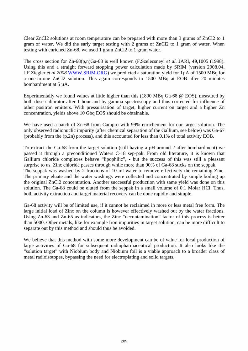
Clear ZnCl2 solutions at room temperature can be prepared with more than 3 grams of ZnCl2 to 1 gram of water. We did the early target testing with 2 grams of ZnCl2 to 1 gram of water. When testing with enriched Zn-68, we used 1 gram ZnCl2 to 1 gram water. The cross section for Zn-68(p,n)Ga-68 is well known (F.Szelecsneyi et al. JARI, 49,1005 (1998). Using this and a straight forward stopping power calculation made by SRIM (version 2008.04, J.F.Ziegler et al 2008 WWW.SRIM.ORG) we predicted a saturation yield for 1µA of 1500 MBq for a one-to-one ZnCl2 solution. This again corresponds to 1500 MBq at EOB after 20 minutes bombardment at 5 µA. Experimentally we found values at little higher than this (1800 MBq Ga-68 @ EOS), measured by both dose calibrator after 1 hour and by gamma spectroscopy and thus corrected for influence of other positron emitters. With pressurisation of target, higher current on target and a higher Zn concentration, yields above 10 Gbq EOS should be obtainable. We have used a batch of Zn-68 from Campro with 99% enrichement for our target solution. The only observed radionuclic impurity (after chemical separation of the Gallium, see below) was Ga-67 (probably from the (p,2n) process), and this accounted for less than 0.1% of total activity EOB. To extract the Ga-68 from the target solution (still having a pH around 2 after bombardment) we passed it through a preconditioned Waters C-18 sep-pak. From old literature, it is known that Gallium chloride complexes behave “lipophilic”, - but the success of this was still a pleasant surprise to us. Zinc chloride passes through while more than 90% of Ga-68 sticks on the seppak. The seppak was washed by 2 fractions of 10 ml water to remove effectively the remaining Zinc. The primary eluate and the water washings were collected and concentrated by simple boiling up the original ZnCl2 concentration. Another successful production with same yield was done on this solution. The Ga-68 could be eluted from the seppak in a small volume of 0.1 Molar HCl. Thus, both activity extraction and target material recovery can be done rapidly and simple. Ga-68 activity will be of limited use, if it cannot be reclaimed in more or less metal free form. The large initial load of Zinc on the column is however effectively washed out by the water fractions. Using Zn-63 and Zn-65 as indicators, the Zinc “decontamination” factor of this process is better than 5000. Other metals, like for example Iron impurities in target solution, can be more difficult to separate out by this method and should thus be avoided. We believe that this method with some more development can be of value for local production of large activities of Ga-68 for subsequent radiopharmaceutical production. It also looks like the “solution target” with Niobium body and Niobium foil is a viable approach to a broader class of metal radioisotopes, bypassing the need for electroplating and solid targets.
289
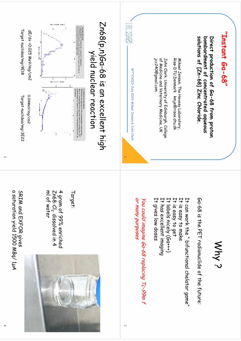
“It
t G68”
Direct production of Ga
68 from proton
“Instant Ga-68” Direct production of Ga-68 from
proton bom
bardment of concentrated aqueous
solutions of [Zn68] Zinc Chloride
solutions of [Zn-68] Zinc Chloride.
Mikael Jensen, The H
evesy Laboratory, Risø-D
TU,D
enmark km
RisøD
TU,D
enmark km
John Clark, University of Edinburgh, College
of Medicine and Veterinary M
edicine U
K of M
edicine and Veterinary Medicine, U
K jcc240@
gmail.com
WTTCX
III•July 2010•Mikael Jensen & John Clark
1
Why ?y
Ga68 is the PET radionuclide of the future:
Ga-68 is the PET radionuclide of the future:
It can work the “ bifunctionalchelatorgam
e”It can work the bifunctionalchelator
game
It is easy to make
It is easy to getIt is easy to getIt labels nicely (Ga+++)It has excellent im
aging It has excellent im
aging It gives low doses
You could imagine Ga-68 replacing Tc-99m
for m
any purposesy
pp
2
Z68(
)G68 i
llt hi
h Zn68(p,n)Ga-68 is an excellent high
yield nuclear reactionyield nuclear reaction
JARI,49,1005,1998
F.SZELECSENYI,T.E.BO
OTH
E,S.TAKA
CS,F.TARKA
NYI,
ETA
VAN
O) E
lt
dss
sti
d thik
tt
ild
dt
f
(J,NIM
/B,211,169,2003)Validation and upgrade of the recom
mended cross section
data of charged particle reactions used for production PET E.TA
VAN
O) Evaluated
crosssection
and thicktarget yield
data of Zn+p
processesfor practicalapplications
data of charged particle reactions used for production PET radioisotopes (S.Takacs,F.Tarkanyi,A
.Herm
anne,R.Paviottide Corcuera)
dE/dx=0.025 M
eV/mg/cm
20.04M
eV/mg/cm
2g
.M
V/mg/cm
Target nuclides/mg=9E18
Target nuclides/mg=3E22
3
Target:
4 gram of 99%
enriched Zn68-Cl2 dissolved in 4 Zn68
Cl2 dissolved in 4 m
l of water
SRIM and EX
FOR gives
a saturation yield 1500 MBq/
1µAa saturation yield 1500 M
Bq/1µA
4
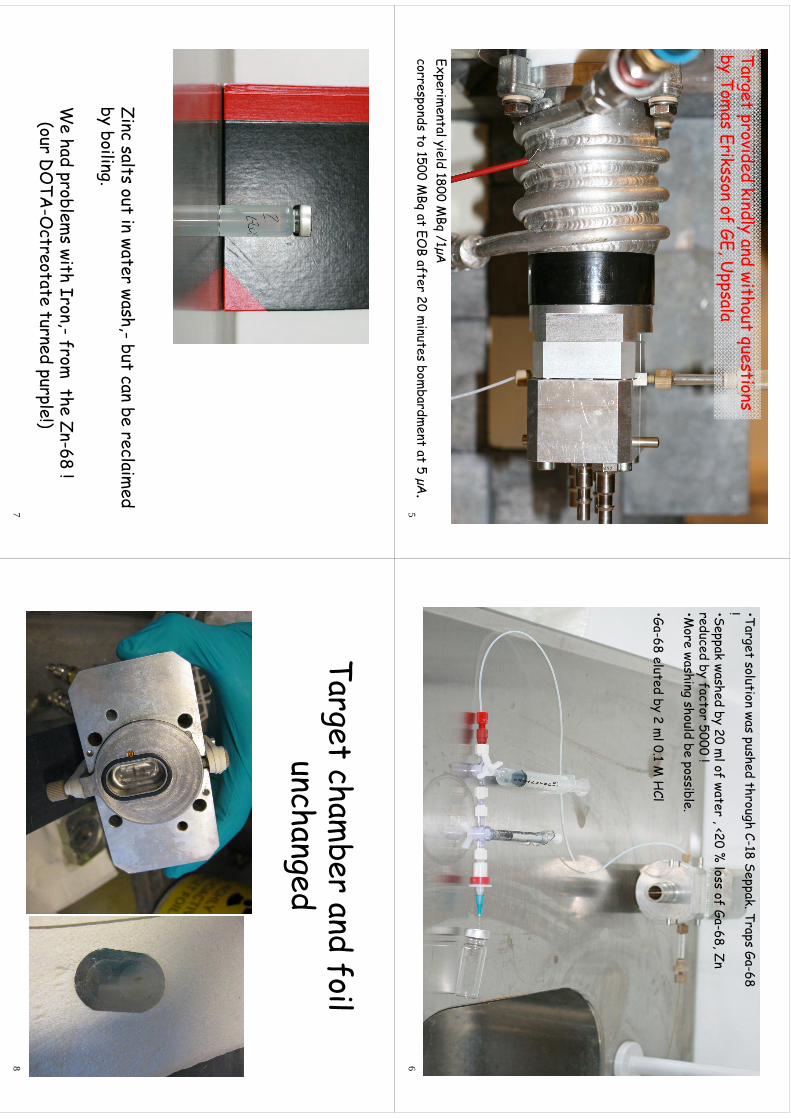
Target provided kindly and without questionsg
py
qby Tom
as Eriksson of GE, Uppsala
Expim
ntl
ild 1800 M
B/1
AExperim
ental yield 1800 MBq
/1µAcorresponds to 1500 M
Bqat EO
B after 20 minutes bom
bardment at 5 µA.
5
•Target solution waspushed
throughC-18 Seppak. Traps
Ga-68 !•Seppak
washedby 20 m
l of water, <20 %
lossof Ga-68, Zn
reducedby factor 5000 ! y
•More washing
shouldbe
possible.
• Ga-68 elutedby 2 m
l 01 M
HCl
Ga68 eluted
by 2 ml 0.1 M
HCl
6
Zi
lt
t i
t
hb
t b
l
id
Zinc salts out in water wash,-but can be reclaimed
by boiling.
We had problem
s with Iron,-from
the Zn-68 !(our D
OTA
Octreotate
turned purple!)(our D
OTA
-Octreotate
turned purple!)7
Target chamber and foil
Target chamber and foil
unchangedunchanged
8

WTTC
XIII–Presentation
Discussions
WTTC
XIII –Presentation D
iscussions
1.Irradiation conditions and yields•
10uAO
K;20uA
=boiling•
10uA O
K; 20uA
=boiling•
10GB
q in saturation
292
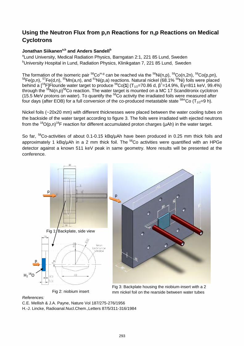
Using the Neutron Flux from p,n Reactions for n,p Reactions on Medical
Cyclotrons
Jonathan Siikanena,b and Anders Sandellb aLund University, Medical Radiation Physics, Barngatan 2:1, 221 85 Lund, Sweden bUniversity Hospital in Lund, Radiation Physics, Klinikgatan 7, 221 85 Lund, Sweden The formation of the isomeric pair 58Com,g can be reached via the 58Ni(n,p), 59Co(n,2n), 59Co(p,pn), 58Fe(p,n), 57Fe(d,n), 55Mn(a,n), and 61Ni(p,a) reactions. Natural nickel (68.1% 58Ni) foils were placed behind a [18F]Flouride water target to produce 58Co[1] (T1/2=70.86 d, β+=14.9%, Eγ=811 keV, 99.4%) through the 58Ni(n,p)58Co reaction. The water target is mounted on a MC 17 Scanditronix cyclotron (15.5 MeV protons on water). To quantify the 58Co activity the irradiated foils were measured after four days (after EOB) for a full conversion of the co-produced metastable state 58mCo (T1/2=9 h). Nickel foils (~20x20 mm) with different thicknesses were placed between the water cooling tubes on the backside of the water target according to figure 3. The foils were irradiated with ejected neutrons from the 18O(p,n)18F reaction for different accumulated proton charges (µAh) in the water target. So far, 58Co-activities of about 0.1-0.15 kBq/µAh have been produced in 0.25 mm thick foils and approximately 1 kBq/µAh in a 2 mm thick foil. The 58Co activities were quantified with an HPGe detector against a known 511 keV peak in same geometry. More results will be presented at the conference.
Fig 1: Backplate, side view
Fig 3: Backplate housing the niobium-insert with a 2 mm nickel foil on the rearside between water tubes
Fig 2: niobium insert
References: C.E. Mellish & J.A. Payne, Nature Vol 187/275-276/1956 H.-J. Lincke, Radioanal.Nucl.Chem.,Letters 87/5/311-316/1984
p p
p
H2 18O
293
kmje
Typewritten Text
Abstract 053

The 1
3th Intern
atio
nal W
orksh
op on Ta
rgetry
and Ta
rget C
hem
istry ‐WTTC
13, R
isø, D
enmark, 2
010, 25‐28 Ju
ly
Using the N
eutron Flux from p,n
Reactions for n,p
Jth
Siikab
dA
dS
dll b
Reactions on Medical Cyclotrons
Jonathan Siikanena,band Anders Sandell b
aLundUniversity, M
edical Radiation Physics, Barngatan2:1,221
85Lund, Sw
eden bUniversity
Hospital in Lund, Radiation Physics, Klinikgatan7,221 85 Lund, Sw
eden
Backgroundg
•Wewere
askedifw
ecould
produce58Co
activity•We w
ere asked if we could produce 58Co activity
•Can be used for labeling of organo
metallic
compounds for biom
edical studies•Available
isaMC17
Scanditronixcyclotron
Available is a MC 17 Scanditronix
cyclotron
2
Introduction
•Routesto
58Coproduction:
•Routes to 58Co production:59Co
(100 %) (n,2n), 59Co
(100 %) (p,pn), 58Fe
(0.28 %) (p,n),
()
()
()
57Fe(2.2 %
) (d,n), 55Mn(100 %
) (a,n), 61Ni(1.14 %
) (p,a) and 58N
i(6808
%) (n,p)
(68.08 %) (
,p)
Thf
db
d57F
•The preferred w
ay may be d,n
on 57Fe•Requires enriched 57Fe (only 2.2 %
abundance) and a dedicated target
•Wecurrently
haveno
accesstodeuterons
•We currently have no access to deuterons
3
Introduction
•Curiosity
abouttheejected
neutronsfrompn‐
Curiosity about the ejected neutrons from p,n
reactions•Forthose
who
haveroutine
productiontargetsa
For those who have routine production targets a
parasitic/hitch hiking n,p‐mode can be useful
•[ 18F]Flouride
targetarenorm
allythe
mostused
[F]Flouride
target are normally the m
ost used•Natural N
i(68.08 % Ni‐58) (n,p)
58Com,g
58mCo (T1/2 = 9.04 h)
58Co (T1/2 = 70.86 d)
IT = 100 %
58Fe (Stable)EC
Β+(14.9 %
)
Z26
274
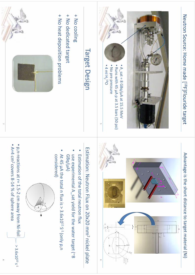
Neutron Source: Hom
e made [ 18F]Flouride
target[
]g
•Asat= 8 GBq/µA at 15.5 M
eV_
q/µ•Runs w
ith 45 µA p at 3.5 bars (50 psi)•N
o pre pressure•4 m
l H2 18O
5
Advantage is the short distance to target material (N
i)
6
Target Design g
g+Nocooling
+ No cooling
+ No dedicated target
+ No heat deposition problem
s
7
Estimation: N
eutron Flux on 20x20 mm
2 nickel plate•Estim
ation of the total neutron fluxi
tlA
tildf
tht
tt(
8
p
•use experim
ental A_satyield for the water target (~8
GBq/µA)•At 45 µA the total n flux is > 3.6x10
11 S‐1 (only p,n
considered)
•p,n‐reactions at r= 1.5‐2 cm aw
ay from Ni‐foil
•A=4cm
2 covers8‐14%ofsphere
area> 3.6x10
10s ‐1A=4 cm
covers 814 %
of sphere area
8
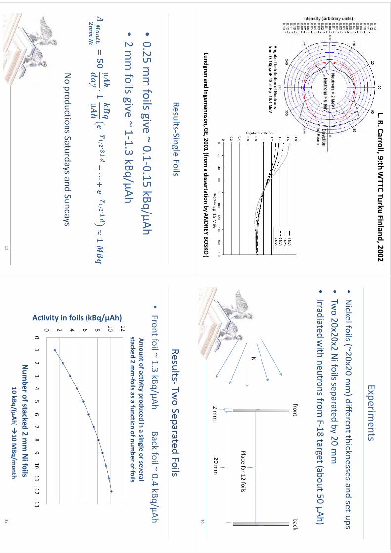
L. R. Carroll, 9:th WTTC Turku Finland, 2002
Lundgren and Ingemannson, GE, 2001 (from
a dissertation by ANDREY BO
SKO )
Ep=15 Mev
Experiments
•Nickel foils (~20x20 m
m) different thicknesses and set‐ups
()
p•Tw
o 20x20x2 Ni foils separated by 20 m
m (
)•Irradiated w
ith neutrons from F‐18 target (about 50 µAh)
frontback
N
Place for 12 foils
20 mm
2 mm
10
Results‐Single Foils
025
fil
i~01015
kB/Ah
•0.25 m
m foils give ~ 0.1‐0.15 kBq/µAh
•2mm
foilsgive~113kBq/µAh
•2 m
m foils give
1‐1.3 kBq/µAh
NoproductionsSaturdaysand
SundaysNo productions Saturdays and Sundays
11
Results‐Two Separated Foils
p
•Front foil ~ 1.3 kBq/µAh
Back foil ~ 0.4 kBq/µAhAm
ount of activity produced in a single or several stacked 2 m
m‐foils as a function of num
ber of foils
10 12
µAh)6 8
(kBq/µ4 6
n foils (
0 2
ivity in
0
01
23
45
67
89
1011
1213
Acti
Num
berofstacked2mm
Nifoils
Num
ber of stacked 2 mm Ni foils
10 kBq/(µAh) 10 M
Bq/month
12

WTTC
XIII–Presentation
Discussions
WTTC
XIII –Presentation D
iscussions
1.Irradiation conditions•
Nifoils
and“a
usualF18target”
•N
i foils and a usual F18 target•
45uA : neutron flux > 3,6 x 10¹¹ S
r-1 (from p,n
alone)
2O
therisotopes?2.
Other isotopes?
•C
o58, Co57, C
o60
3Therm
alisation?3.
Thermalisation?
•W
ould produce Ni59, N
i60•
1010 neutrons: too little
297

Repairing water leaks in the TR-19 cyclotron: A case study in what not to do. MJ Schueller, DJ Schlyer. Medical Department, Brookhaven National Laboratory, Upton, NY 11973, USA. In early September, 2009, a water leak opened up in one of the dees of BNL's ACSI TR-19/9 cyclotron. Attempts to patch the leak in place failed, so the dee was removed, repaired and replaced. After a week of operation, a nearly identical leak opened in the other dee. This began a chain of failures in the cyclotron, leading to approximately 8 months of down time in the human PET program at BNL. Multiple water leaks, burned internal components, and two new dees later, the machine is back to running stably. A time sequence of events will be presented, with cascading problems, and a discussion of what steps were taken and why, with a particular focus on in house repairs that "seemed like a good idea at the time." Some highlights:
The first leak, in an elbow near the dee stem.
Fingerstock shouldn't look like this. When we opened the vacuum tank and smelled burned flux we knew we had a problem. This issue was finally resolved with ACSI providing a replacement part with factory-soldered fingerstock.
An attempt by BNL to replace burned fingerstock in situ failed. The cold solder joint held for a few weeks.
The new lower dee was installed and aligned, then removed to replace the burned fingerstock. At some point, it became bent ~2mm at the dee tip. Made of 7mm copper, it did not bend back easily. The cause is unknown.
298
kmje
Typewritten Text
Abstract 054
Improved High Current Liquid and Gas Targets for Cyclotron Produced Radioisotopes
AlJammaz I., AlRayyes A., Chai J., Ditroi F., Jensen M., Kivrakdal D., Nickles J., Ruth T., Schlyer D., H. Schweickert., Solin O., Winkel P., M.Haji-Saeid, M. Pillai
Coordinated Research Project, International Atomic Energy Agency P.O. Box 100, Wagramer Straße 5, A-1400 Vienna
Radiopharmaceuticals utilizing cyclotron produced radionuclides have already been shown to be extremely valuable in basic medical research, disease diagnosis and radiotherapy. IAEA Member States world-wide have acquired more than 600 cyclotrons employed for nuclear medicine applications and the number is growing every year. In the past, cyclotrons and the related targetry systems were mainly operated by dedicated professionals situated either within academic physics research institutions, large university hospitals or industrial scale radionuclide manufacturers. However, because of the rapidly spreading use of PET and PET/CT, the number of cyclotron installations is rapidly growing and target technology needs to be appreciated by a much larger group of professionals. Although many of the new cyclotrons are primarily erected for the production of a single isotope (F-18) in the form of a single, well defined radiopharmaceutical (FDG) a sizeable fraction of these new installations have declared and started active research programs in C-11 and other non-traditional positron emitting radiotracers. As part of International Atomic Energy Agency (IAEA) activities to disseminate knowledge for member states, a three year Coordinated Research Project (CRP) was organized. The overall goal of this CRP was the development of new and reliable cyclotron targetry technology for the production of high specific radioactivity for the most widely used radionuclides. Significant advances have been made under this CRP in the development and standardization of high power gas and liquid targets. The primary focus of this CRP was to develop targets and methods to increase specific activity, radionuclidic purity and production reliability for several radionuclides including F-18, C-11, I-123, and Rb-81/Kr-81m. These advances applied in several facilities have minimized the unnecessarily operator exposure to radiation. A particular area of interest for this group was the recovery and characterization of enriched H2
18O focusing on the reuse of the water and several important conclusions were reached. It was determined that the tritium introduced by the inevitable nuclear reactions does not pose any health physics problems either during the tracer manufacturer or during potential water reclamation. It was further determined that radionuclides produced in the metal foil during irradiation are found in the target water at very low concentrations. These impurities can be essentially eliminated by using noble metal plated foils and by the separation used for fluorine extraction from the O-18 water. In no case were the radionuclides produced in the foil found in the final product. Moreover, a survey of target maintenance procedures has been carried out and the results of this survey are reported in this CRP. In spite of these findings, the knowledge that has been gained needs to be transferred to the countries and facilities where it will help to optimize the production of radionuclides used for PET and SPECT. In this regard, a book will be published focusing on two of the most widely used target systems (F-18 and C-11) and including both fundamental knowledge and practical advice on the operation of these target systems. In addition to this book, lectures have been planned to convey both the knowledge gained in this CRP and the problems identified by the expert panel to the wider radionuclide production community with the idea that further research on these problems will benefit all the member states and the community in general.
299
kmje
Typewritten Text
Abstract 055
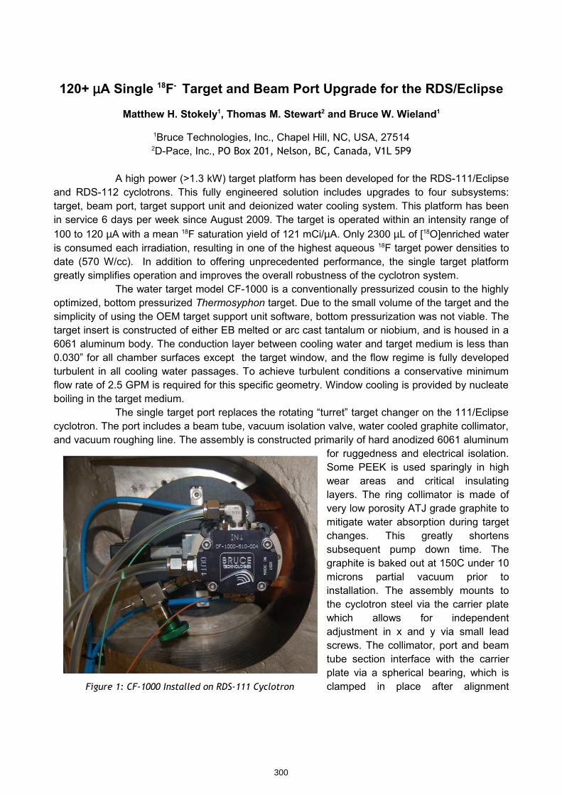
120+ µA Single 18F- Target and Beam Port Upgrade for the RDS/Eclipse
Matthew H. Stokely1, Thomas M. Stewart2 and Bruce W. Wieland1
1Bruce Technologies, Inc., Chapel Hill, NC, USA, 275142D-Pace, Inc., PO Box 201, Nelson, BC, Canada, V1L 5P9
A high power (>1.3 kW) target platform has been developed for the RDS-111/Eclipse and RDS-112 cyclotrons. This fully engineered solution includes upgrades to four subsystems: target, beam port, target support unit and deionized water cooling system. This platform has been in service 6 days per week since August 2009. The target is operated within an intensity range of 100 to 120 µA with a mean 18F saturation yield of 121 mCi/µA. Only 2300 µL of [18O]enriched water is consumed each irradiation, resulting in one of the highest aqueous 18F target power densities to date (570 W/cc). In addition to offering unprecedented performance, the single target platform greatly simplifies operation and improves the overall robustness of the cyclotron system.
The water target model CF-1000 is a conventionally pressurized cousin to the highly optimized, bottom pressurized Thermosyphon target. Due to the small volume of the target and the simplicity of using the OEM target support unit software, bottom pressurization was not viable. The target insert is constructed of either EB melted or arc cast tantalum or niobium, and is housed in a 6061 aluminum body. The conduction layer between cooling water and target medium is less than 0.030” for all chamber surfaces except the target window, and the flow regime is fully developed turbulent in all cooling water passages. To achieve turbulent conditions a conservative minimum flow rate of 2.5 GPM is required for this specific geometry. Window cooling is provided by nucleate boiling in the target medium.
The single target port replaces the rotating “turret” target changer on the 111/Eclipse cyclotron. The port includes a beam tube, vacuum isolation valve, water cooled graphite collimator, and vacuum roughing line. The assembly is constructed primarily of hard anodized 6061 aluminum
for ruggedness and electrical isolation. Some PEEK is used sparingly in high wear areas and critical insulating layers. The ring collimator is made of very low porosity ATJ grade graphite to mitigate water absorption during target changes. This greatly shortens subsequent pump down time. The graphite is baked out at 150C under 10 microns partial vacuum prior to installation. The assembly mounts to the cyclotron steel via the carrier plate which allows for independent adjustment in x and y via small lead screws. The collimator, port and beam tube section interface with the carrier plate via a spherical bearing, which is clamped in place after alignment Figure 1: CF-1000 Installed on RDS-111 Cyclotron
300
kmje
Typewritten Text
Abstract 056
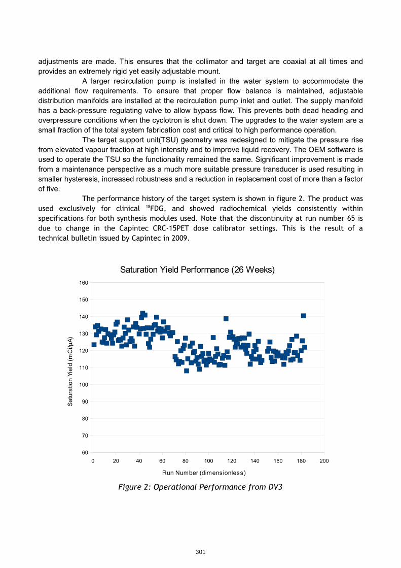
adjustments are made. This ensures that the collimator and target are coaxial at all times and provides an extremely rigid yet easily adjustable mount.
A larger recirculation pump is installed in the water system to accommodate the additional flow requirements. To ensure that proper flow balance is maintained, adjustable distribution manifolds are installed at the recirculation pump inlet and outlet. The supply manifold has a back-pressure regulating valve to allow bypass flow. This prevents both dead heading and overpressure conditions when the cyclotron is shut down. The upgrades to the water system are a small fraction of the total system fabrication cost and critical to high performance operation.
The target support unit(TSU) geometry was redesigned to mitigate the pressure rise from elevated vapour fraction at high intensity and to improve liquid recovery. The OEM software is used to operate the TSU so the functionality remained the same. Significant improvement is made from a maintenance perspective as a much more suitable pressure transducer is used resulting in smaller hysteresis, increased robustness and a reduction in replacement cost of more than a factor of five.
The performance history of the target system is shown in figure 2. The product was used exclusively for clinical 18FDG, and showed radiochemical yields consistently within specifications for both synthesis modules used. Note that the discontinuity at run number 65 is due to change in the Capintec CRC-15PET dose calibrator settings. This is the result of a technical bulletin issued by Capintec in 2009.
Figure 2: Operational Performance from DV3
0 20 40 60 80 100 120 140 160 180 20060
70
80
90
100
110
120
130
140
150
160
Saturation Yield Performance (26 Weeks)
Run Number (dimensionless)
Sat
urat
ion
Yiel
d (m
Ci/µ
A)
301
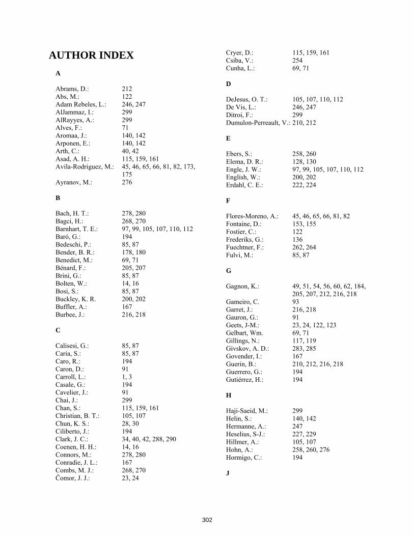
AUTHOR INDEX
A
Abrams, D.: 212 Abs, M.: 122 Adam Rebeles, L.: 246, 247 AlJammaz, I.: 299 AlRayyes, A.: 299 Alves, F.: 71 Aromaa, J.: 140, 142 Arponen, E.: 140, 142 Arth, C.: 40, 42 Asad, A. H.: 115, 159, 161 Avila-Rodriguez, M.: 45, 46, 65, 66, 81, 82, 173, 175 Ayranov, M.: 276 B
Bach, H. T.: 278, 280 Bagci, H.: 268, 270 Barnhart, T. E.: 97, 99, 105, 107, 110, 112 Baró, G.: 194 Bedeschi, P.: 85, 87 Bender, B. R.: 178, 180 Benedict, M.: 69, 71 Bénard, F.: 205, 207 Brini, G.: 85, 87 Bolten, W.: 14, 16 Bosi, S.: 85, 87 Buckley, K. R. 200, 202 Buffler, A.: 167 Burbee, J.: 216, 218 C
Calisesi, G.: 85, 87 Caria, S.: 85, 87 Caro, R.: 194 Caron, D.: 91 Carroll, L.: 1, 3 Casale, G.: 194 Cavelier, J.: 91 Chai, J.: 299 Chan, S.: 115, 159, 161 Christian, B. T.: 105, 107 Chun, K. S.: 28, 30 Ciliberto, J.: 194 Clark, J. C.: 34, 40, 42, 288, 290 Coenen, H. H.: 14, 16 Connors, M.: 278, 280 Conradie, J. L.: 167 Combs, M. J.: 268, 270 Čomor, J. J.: 23, 24
Cryer, D.: 115, 159, 161 Csiba, V.: 254 Cunha, L.: 69, 71 D
DeJesus, O. T.: 105, 107, 110, 112 De Vis, L.: 246, 247 Ditroi, F.: 299 Dumulon-Perreault, V.: 210, 212 E
Ebers, S.: 258, 260 Elema, D. R.: 128, 130 Engle, J. W.: 97, 99, 105, 107, 110, 112 English, W.: 200, 202 Erdahl, C. E.: 222, 224
F
Flores-Moreno, A.: 45, 46, 65, 66, 81, 82 Fontaine, D.: 153, 155 Fostier, C.: 122 Frederiks, G.: 136 Fuechtner, F.: 262, 264 Fulvi, M.: 85, 87
G
Gagnon, K.: 49, 51, 54, 56, 60, 62, 184, 205, 207, 212, 216, 218 Gameiro, C. 93 Garret, J.: 216, 218 Gauron, G.: 91 Geets, J-M.: 23, 24, 122, 123 Gelbart, Wm. 69, 71 Gillings, N.: 117, 119 Givskov, A. D.: 283, 285 Govender, I.: 167 Guerin, B.: 210, 212, 216, 218 Guerrero, G.: 194 Gutiérrez, H.: 194
H
Haji-Saeid, M.: 299 Helin, S.: 140, 142 Hermanne, A.: 247 Heselius, S-J.: 227, 229 Hillmer, A.: 105, 107 Hohn, A.: 258, 260, 276 Hormigo, C.: 194 J
302
Janabi, M.: 188, 190 Jeffery, C.: 115, 159, 161 Jensen, M.: 54, 56, 128, 130, 240, 242, 283, 285, 288, 290, 299 Jivan, S. 200, 202 John, K. D.: 278, 280 Johnson, R. R.: 69, 71 Jovanović, Ð. 23, 24 Jørgensen, T.: 240, 242 K
Kech, C.: 91 Kim, J.: 28, 30 Kiselev, M.: 91 Kivrakdal, D.: 299 Konik, A.: 222, 224 Kovacs, M. S.: 205, 207, 216, 218 Koziorowski, J.: 117, 119 Kral, E.: 122 Kučera, J.: 234, 236 Kummeling, B.: 34 L
Lambert, B.: 23, 24, 91 Lapi, S.: 54, 56 Lara-Camacho, V.M.: 45, 46 Larsen, P.: 105, 107 Le Bars, D.: 153, 155, 268, 270 Lebeda, O.: 234, 236 Lecomte, R.: 210, 212 Lenz, J. W.: 278, 280 Leporis, M.: 252, 254 Ljunggren, K.: 152 Lucatelli, C.: 34, 40, 42 M
Mackay, D. B. 34, 36, 40, 42 Manrique-Arias, J. C. 45, 46, 65, 66, 81 Martinot, D.: 153, 155 McQuarrie, S. A.: 49, 51, 54, 56, 60, 62, 184, 205, 207, 212, 216, 218 Metello, L. F.: 69, 71 Micheelsen, M. A.: 240, 242 Mokosa, G.: 40, 42 Montroni, M.: 85, 87 Mueller, M.: 268, 270 Murali, D.: 105, 107
N
Nactergal, B.: 122 Neal, T.: 91
Nickles, R. J.: 97, 99, 105, 107, 110, 112, 299 Nicolini, J.: 194 Nicolini, M. A.: 194 Nicolini, M. E.: 194 Nortier, F. M.: 278, 280 O
Ometákova, J.: 254 O’Neil, J. P.: 188, 190, 200, 202 P
Pace, P.: 194 Park, H.: 28, 30 Preusche, St.: 262, 264 Pillai, M.: 299 Powell, J.: 188, 190 Price, R. I.: 115, 159, 161 Publicover, J.: 54, 56
R
Rajec, P.: 252, 254 Rajander, J.: 140, 142, 173, 175 Ráliš, J.: 234, 236 Reich, M.: 252, 254 Robinson, D.: 51, 62 Rodrigue, S.: 210, 212, 216, 218 Roivainen, A. 227, 229 Rousseau, J. A.: 210, 212 Ruth, T. J.: 54, 56, 205, 207, 299
S
Sandell, A.: 146, 148, 152, 293, 294 Sauvage, C.: 91 Schaffer, P.: 205, 207 Schaub, E.: 258, 260 Schibli, R.: 258, 260, 276 Schlesinger, J.: 173, 175 Schlyer, D.: 299 Schlyer, D. J.: 298 Scholten, B.: 14, 16 Schueller, M. J.: 298 Schumann, D.: 276 Schweickert, H.: 299 Sensoy, L.: 222, 224 Shirvan, A.: 91 Shulman, S.: 268, 270 Siikanen, J.: 146, 148, 152, 293, 294 Silva, L.: 194 Sipila, H. T., 227, 229 Smith, S. V.: 159, 161 Solin, O.: 140, 142, 173, 175, 299
303
Sossi, V.: 71 Soylu, A.: 268, 270 Spellerberg, S.: 14, 16 Steinbach, J.: 262, 264 Stewart, T. M.: 300 Steyn, G. F.: 167 Stimson, D.: 268, 270 Stodart, N.: 167 Stokely, M. H.: 300 Stoner, J. O. (Jr.) 19 Sunderland, J.: 222, 224 Szöllős, O. 252, 254 T
Tadino, V.: 153, 155 Tedesco, F.: 153, 155 Thisgaard, H.: 54, 56, 128, 130 Thoonen, P. 34 Tremblay, S.: 210, 212 Türler, A.: 276 V
Valdez, F. O.: 278, 280 Van den Winke, P.: 246, 247 van der Vliet, L.: 134, 136 van Ham, R. C. 34, 40, 42 van Lier, E. J.: 210, 212, 216, 218 van Lier, J. E.: 210, 212, 216, 218
Vermeulen, C.: 167 Villeret, G.: 153, 155
W
Waegeneer, R.: 246, 247 Watkins, G. L.: 178, 180, 222, 224 Weidner, J. W.: 278, 280 Westera, G.: 134, 136 Wieland, B. W.: 300 Willemsen, M. A. B.: 34, 40, 42 Wilson, J. S.: 49, 51, 60, 62, 184, 185, 212, 216, 218 Winke, P.: 299 Wooten, D.: 105, 107 Y
Yordanov, A.: 268, 270
Z
Zamora-Romo, E.: 45, 46, 65, 66, 81, 82 Zarate-Morales, A.: 45, 46, 65, 66, 81, 82 Zhernosekov, K.: 276 Zyuzin, A.: 210, 212, 216, 218
Ziv, I.: 91
304
TOPIC INDEX A Antimony-114: 128 – 129, 148 Argon-36: 110 – 114 B Beam Energy: 54 – 55, 189, 97, 159, 163,
182, 184, 205, 252, 256 C Carbon-11: 14 , 16, 38, 40, 65, 67 –
68, 82, 105 – 107, 117 – 121, 134 – 136, 140 – 145, 186, 188 – 191, 200 – 203, 227 – 228, 231 – 232, 252 – 254, 256 – 257, 268 – 271, 274 – 275, 299
Chlorine-34m: 110 – 114 Copper-61: 29 – 30, 97 – 104 Copper-62: 30, 55, 104 Copper-64: 28 – 33, 63 – 64, 97 – 104,
106, 115, 128 – 130, 133, 159 – 161, 246 – 247, 252, 270 – 271
Copper-66: 30 Copper-67: 29 – 30 Counter: (see Detector) Cyclotron advances: 122 – 127 D Detector: 1 – 3, 7 – 8, 13, 23, 35, 49,
54, 57, 59, 110, 115, 117, 120, 189, 191 – 192, 201, 205 – 206, 225 – 229, 231, 259
F FASTLab: 36, 40 – 41 FDG: 49 – 53, 65 – 68, 81 – 84,
91, 93 – 94, 96, 153 – 155, 157, 159, 181, 183, 194 – 195, 197 – 199, 299, 301
Fluorine-18: 14, 27, 40, 45 – 53, 63, 65 – 68, 81, 82, 84 – 85, 91 – 96, 105 – 107, 110 – 112, 122, 153 – 155, 157, 159, 167, 178 – 179, 181, 183,
194 – 195, 197 – 199, 266, 271, 299, 301
G Gallium-66: 102 Gallium-68: 102, 227 – 228, 231 – 232,
268, 270 – 272, 276, 288 – 291
Germanium-68: 227, 276, 278, 280
I Indium-110: 146, 147, 150 Indium-111: 146, 150 Indium-114m: 84, 86, 146 – 148, 150,
246 Iodine-123: 23 – 24,84 – 87, 90, 252,
257, 271, 299 Iodine-124: 85 – 86, 88 – 90, 252, 254,
256 – 257, 271
L Labview: 98, 105, 189, 191, 258,
206 – 261 M Methyl iodide: 134 – 137, 188 – 192, 200
– 203, 268 – 269, 275 Molybdenum-99: 71, 74, 80, 205 – 211, 213,
216 – 218 Molybdenum-100: 69, 73 – 75, 205 – 219 N Nickel-64: 24, 28 – 33, 97, 99 – 102,
115, 128 – 129, 133, 159, 166, 173 – 175, 246 – 248, 250, 252, 254 – 255, 257
Niobium: General 40, 49 – 53, 63, 81, 105,
141 – 142, 146, 147, 149, 151, 178 – 179, 181 – 183, 198, 200 – 201, 222 – 226, 234, 236, 252 – 253, 256 – 257, 278 – 280, 288 – 289, 293, 300
Niobium-95 213 Niobium-96 208, 213 Niobium-97 208, 210, 213 - 214
Nitrogen-13: 14, 105 – 107, 271
305
O Oxygen-15: 122 – 123, 227 – 228, 231
– 232, 271 Oxygen-18: 16, 49, 51, 65, 67, 106,
111, 182, 222, 262, 264 – 267, 283 – 285, 293, 295, 299 – 300
S Scintillation: 1, 3, 8, 13, 23, 241 Stripping Foil:
Carbon 19 – 22, 75 Strontium-86 234 – 235, 237 – 239 T Target:
Gas 14 , 16, 23 – 24, 38, 40, 65, 67 – 68, 82, 84 – 90, 105 – 107, 110 – 114, 117 – 121, 134 – 136, 140 – 145, 186, 188 – 191, 200 – 203, 227 – 228, 231 – 232, 252 – 254, 256 – 257, 268 – 271, 274 – 275, 299
Liquid 14, 16, 27, 40, 45 – 53, 63, 65 – 68, 81, 82, 84 – 85, 91 – 96, 105 – 107, 110 – 112, 122, 153 – 155, 157, 159, 167, 178 – 179, 181, 183, 194 – 195, 197 – 199, 266, 271, 299, 301
Solid 28 – 33, 55, 63 – 64, 69 – 75, 78, 80, 84, 86, 97 – 104, 106, 115, 128 – 130, 133, 146 – 148, 150, 159 – 161, 205 – 220, 222, 227 – 228, 231 – 232, 234 – 236, 238 – 239, 246 – 247, 252, 254, 259, 261, 268, 270 – 272, 276, 278, 280, 288 – 291
Target foil: Copper 54 – 55, 178, 205, 207 Havar 181 Niobium (see Niobium: General)
Technetium-95: 210, 222 Technetium-96: 222 Technetium-95 m: 211, 214, 217 Technetium-99: 80, 212 – 213 Technetium-99m: 69 – 74, 78, 205 – 218,
220 TracerLab: 36, 50, 51, 84, 153 – 155,
253
X Xenon-124: 23 – 24 Y Ytrium-86: 234 – 236, 238 – 239 Z Zinc-64: 99, 102, 246 – 247, 254 Zinc-66: 30 – 31, 161, 254 Zinc-68: 28, 30 – 31, 161, 254, 288
– 291 Zirconium-89: 99, 159, 161, 259, 261,
271
306

Risø DTU is the National Laboratory for Sustainable Energy. Our research focuses on development of energy technologies and systems with minimal effect on climate, and contributes to innovation, education and policy. Risø has large experimental facilities and interdisciplinary research environments, and includes the national centre for nuclear technologies.
Risø DTU National Laboratory for Sustainable Energy Technical University of Denmark Frederiksborgvej 399 PO Box 49 DK-4000 Roskilde Denmark Phone +45 4677 4677 Fax +45 4677 5688 www.risoe.dtu.dk
Related Documents