ABSTRACT: This paper gives the results of the risk-based safety analysis of the seismic resistance of the NPP (Nuclear Power Plants) in Slovakia. The probabilistic assessment of NPP safety analysis is presented. On the base of the geophysical and seismological monitoring of locality the peak ground acceleration and the uniform hazard spectrum of the acceleration was defined for the return period 10 000 years using the Monte Carlo simulations. There is showed summary of calculation models and calculation methods for the probability analysis of the structural safety considering load, material and model uncertainties. The numerical simulations were realized in the system ANSYS. The results from the reliability analysis of the NPP structures are presented. KEY WORDS: Earthquake; NPP; Probability; Safety; ANSYS. 1 INTRODUCTION The IAEA (International Atomic Energy Agency) set up a program [4 - 6] to give guidance to its member states on the many aspects of the safety of nuclear power reactors. The risk of the NPP performance from the point of the safety must be calculated by consideration of the impact of the all effects during plant operation. The PSA (Probabilistic Safety Analysis) is one from the effective methods to analyze the safety and reliability of the NPP. The international standard NUREG-1150 [19] defines the principal steps for the calculation of the risk of the NPP performance by LHS probabilistic method • Accident frequency (systems) analysis • Accident progression analysis • Radioactive material transport (source term) analysis • Offsite consequence analysis • Risk integration. The accidents caused by the earthquake even are the critical emergencies from the point of the NPP performance. This paper gives the experiences from the seismic analysis of the operated NPP in Slovakia [7, 8, 9, 10, 11, 12, 13, 14, 15 and 22]. The earthquake resistance analysis of NPP buildings in Slovakia were based on the recommends of international organization IAEA in Vienna to get international safety level of the nuclear power plants [5]. Seismic safety evaluation programs of the NPP structures should contain three important parts [12] • The assessment of the seismic hazard as an external event, specific to the seismic-tectonic and soil conditions of the site, and of the associated input motion; • The safety analysis of the NPP resulting in an identification of the selected structures, systems and components appropriate for dealing with a seismic event with the objective of a safe shutdown; • The evaluation of the plant specific seismic capacity to withstand the loads generated by such an event, possibly resulting in upgrading. 2 SEISMIC SAFETY METHODOLOGY On the base of the experience from the re-evulation programs in the membership countries IAEA in Vienna the seismic safety standard No.28 was established at 2003 [6]. Seismic safety evaluation programs should contain three important parts • The assessment of the seismic hazard as an external event, specific to the seismo-tectonic and soil conditions of the site, and of the associated input motion; • The safety analysis of the NPP resulting in an identification of the SSSCs (Selected Structures, Systems and Components) appropriate for dealing with a seismic event with the objective of a safe shutdown; • The evaluation of the plant specific seismic capacity to withstand the loads generated by such an event, possibly resulting in upgrading. 2.1 Seismic Hazards The assessment of the seismic hazards specific to the seismo- tectonic conditions at a site is performed on the following bases: • IAEA Safety Guides [4-6], • Use of current internationally recognized methods and criteria [12, 19, 20, 21], • New data [2 and 16]. Two levels of the seismic load are defined in the standards [4]. SL-1 (First level) is coincident with the design earthquake and SL-2 (second level) corresponds to the maximum design earthquake. On the base of the IAEA requirements the NPP structures of the first category have been resistance due to seismic level SL-2. This seismic level [4] should be updated in accordance with the above bases in the event that a reason for this has appeared since the evaluation of the SL-2 design level and should be used in the evaluation. In particular, the PGA (Peak Ground Acceleration) of the RLE (Review Level of Earthquake) should not be less than 0.1g. The level of the seismic risk is characterized by the probability level (return Risk-Based Safety Analysis of the Seismic Resistance of the NPP Structures Juraj Králik 1 1 Department of Structural Mechanics, FCE, STU Bratislava, Radlinského 11, 813 68 Bratislava email: [email protected] Proceedings of the 8th International Conference on Structural Dynamics, EURODYN 2011 Leuven, Belgium, 4-6 July 2011 G. De Roeck, G. Degrande, G. Lombaert, G. M¨ uller (eds.) ISBN 978-90-760-1931-4 292

Welcome message from author
This document is posted to help you gain knowledge. Please leave a comment to let me know what you think about it! Share it to your friends and learn new things together.
Transcript
ABSTRACT: This paper gives the results of the risk-based safety analysis of the seismic resistance of the NPP (Nuclear Power Plants) in Slovakia. The probabilistic assessment of NPP safety analysis is presented. On the base of the geophysical and seismological monitoring of locality the peak ground acceleration and the uniform hazard spectrum of the acceleration was defined for the return period 10 000 years using the Monte Carlo simulations. There is showed summary of calculation models and calculation methods for the probability analysis of the structural safety considering load, material and model uncertainties. The numerical simulations were realized in the system ANSYS. The results from the reliability analysis of the NPP structures are presented.
KEY WORDS: Earthquake; NPP; Probability; Safety; ANSYS.
1 INTRODUCTION The IAEA (International Atomic Energy Agency) set up a program [4 - 6] to give guidance to its member states on the many aspects of the safety of nuclear power reactors. The risk of the NPP performance from the point of the safety must be calculated by consideration of the impact of the all effects during plant operation. The PSA (Probabilistic Safety Analysis) is one from the effective methods to analyze the safety and reliability of the NPP. The international standard NUREG-1150 [19] defines the principal steps for the calculation of the risk of the NPP performance by LHS probabilistic method • Accident frequency (systems) analysis • Accident progression analysis • Radioactive material transport (source term) analysis • Offsite consequence analysis • Risk integration. The accidents caused by the earthquake even are the critical emergencies from the point of the NPP performance. This paper gives the experiences from the seismic analysis of the operated NPP in Slovakia [7, 8, 9, 10, 11, 12, 13, 14, 15 and 22]. The earthquake resistance analysis of NPP buildings in Slovakia were based on the recommends of international organization IAEA in Vienna to get international safety level of the nuclear power plants [5]. Seismic safety evaluation programs of the NPP structures should contain three important parts [12] • The assessment of the seismic hazard as an external event, specific to the seismic-tectonic and soil conditions of the site, and of the associated input motion; • The safety analysis of the NPP resulting in an identification of the selected structures, systems and components appropriate for dealing with a seismic event with the objective of a safe shutdown; • The evaluation of the plant specific seismic capacity to withstand the loads generated by such an event, possibly resulting in upgrading.
2 SEISMIC SAFETY METHODOLOGY On the base of the experience from the re-evulation programs in the membership countries IAEA in Vienna the seismic safety standard No.28 was established at 2003 [6]. Seismic safety evaluation programs should contain three important parts • The assessment of the seismic hazard as an external event, specific to the seismo-tectonic and soil conditions of the site, and of the associated input motion; • The safety analysis of the NPP resulting in an identification of the SSSCs (Selected Structures, Systems and Components) appropriate for dealing with a seismic event with the objective of a safe shutdown; • The evaluation of the plant specific seismic capacity to withstand the loads generated by such an event, possibly resulting in upgrading.
2.1 Seismic Hazards The assessment of the seismic hazards specific to the seismo-tectonic conditions at a site is performed on the following bases: • IAEA Safety Guides [4-6], • Use of current internationally recognized methods and criteria [12, 19, 20, 21], • New data [2 and 16]. Two levels of the seismic load are defined in the standards [4]. SL-1 (First level) is coincident with the design earthquake and SL-2 (second level) corresponds to the maximum design earthquake. On the base of the IAEA requirements the NPP structures of the first category have been resistance due to seismic level SL-2. This seismic level [4] should be updated in accordance with the above bases in the event that a reason for this has appeared since the evaluation of the SL-2 design level and should be used in the evaluation. In particular, the PGA (Peak Ground Acceleration) of the RLE (Review Level of Earthquake) should not be less than 0.1g. The level of the seismic risk is characterized by the probability level (return
Risk-Based Safety Analysis of the Seismic Resistance of the NPP Structures
Juraj Králik1
1 Department of Structural Mechanics, FCE, STU Bratislava, Radlinského 11, 813 68 Bratislava email: [email protected]
Proceedings of the 8th International Conference on Structural Dynamics, EURODYN 2011Leuven, Belgium, 4-6 July 2011G. De Roeck, G. Degrande, G. Lombaert, G. Muller (eds.)ISBN 978-90-760-1931-4
292
period) and the peak ground accelerations values, which are the typical free field zero period acceleration values at the ground surface. The comparison of the ground motion input level for new plants is presented in the Table 1.
Table 1. Comparison of the PGA in various countries Probability/
Return Period
Peak Ground Acceleration*
Bulgaria 10-4 0,20g Canada 10-3 to 10-4 Czech Republic
10-4 0,10g
Germany 10-4 to 10-5 0,10g - 0,20g Japan S1 10-4 0,20g - 0,45g S2 0,38g - 0,60g Korea 10-3 to 10-4 Slovak Republic
10-4 0,14g - 0,34g
Sweden 10-3 Schwitzerland 10-4 UK 10-4 US Design 0,30g Margin 0,50g
The practice/guidance [12] that was referred to by a number of countries generally fall under the broad headings of a number of organizations, specifically ASME, IAEA, IEEE, NRC, and, in some cases, local national regulations, as presented in Table 2. Table 2. Practice/Guidance use in re-evaluation process ASME IAEA IEEE NRC National
Belgium ☺ Bulgaria ☺ Czech Repub. ☺ ☺ Slovak Repub. ☺ ☺ Spain ☺ Schwitzerland ☺ ☺ ☺ ☺ US ☺
Existing nuclear facilities throughout the world are being subjected to investigation of their safety in the event of an earthquake. In the United States, there have been several licensing and safety review issues for which industry and regulatory agencies have cooperated to develop rational and economically feasible criteria for resolving the issues. Currently, all operating nuclear power plants in the United States are conducting an Individual Plant Examination of External Events, including earthquakes beyond the design basis. Western European countries also have been re-evaluating their older nuclear power plants for seismic events often adapting the criteria developed in the United States. With the change in the political systems in Eastern Europe, there is a strong emphasis from their Western European neighbors to evaluate and upgrade the safety of their operating nuclear power plants. Finally, nuclear facilities in Asia are also being evaluated for seismic vulnerabilities.
3 SEISMIC RE-EVALUATION PROGRAM IN SR A re-assessment of the seismic hazard specific to the seismo-tectonic conditions at the site was considered by the SAV (Slovak Academy of Sciences) based on IAEA NUSS SO-SG-S1 and S8 [4]; US NRC-RG 1.60 and NUREG/CR-0098 [18]. IAEA is providing technical assistance to the Slovak regulatory authorities for reviewing the work results. Therefore the RLE (Review Level Earthquake) should correspond to the SL-2 level (Second Seismic Level), directly related to ultimate safety requirements. This is a level of extreme ground motion that shall have a very low probability of being exceeded during the plant lifetime and represents the maximum level of ground motion to be used for design and re-evaluation purposes. For the probability of occurrence a typical value of 10-4/yr is usually used and for the ground response spectra an elastic one is selected.
As formulated by the Slovak authorities, the main objective of the seismic re-evaluation programs of NPP is to enhance the seismic safety of the plant to the level generally accepted by the international community and in compliance with the valid standards and recognized practice. These programs should have three important components: (i) the re-assessment of the seismic hazard as an external event, specific to the site seismo-tectonic conditions; (ii) the evaluation of the plant specific seismic capacity to withstand the loads generated by such event; (iii) upgrading if necessary.
Regarding the first component (i), the geological stability and the ground motion parameters should be assessed according to specific site conditions and in compliance with criteria and methods valid for new facilities. In relation to the second component of the programs (ii) and considering that the plant has been originally designed for an earthquake level lower than the one would preliminarily be established for the site in compliance with IAFA NUSS 50-SG-S1 [4]. On the base of the results of the seismic analysis of the structure capacity the upgrade concept (iii) will be designed.
3.1 Safety Aspects The decision should be made early on whether either the SPSA (Seismic Probabilistic Safety Assessment), SMA (Seismic Margin Assessment), or EPRI (Electric Power Research Institute) seismic safety evaluation methods are to be used [12, 19-21]. These methods have an advantage in that the entire plant may be evaluated as an integrated unit, including system and spatial interactions, common cause failure, human actions, non-seismic failures and operating procedures. The seismic resistance of the existing building structures as well as the technological equipment can be executed by the SMA method, especially its variant known as CDFM (Conservative Deterministic Failure Margin) depending on HCLPF (High Confidence Low Probability of Failure) determination of the seismic margin values. The CDFM method is based on an assumption that all the building structures and all the technological equipment components were designed properly for any non-seismic loads and conditions.
Proceedings of the 8th International Conference on Structural Dynamics, EURODYN 2011 293
3.2 Acceptance Criteria The individual seismic resistance re-evaluation of each
building structure and each single component of NPP, technological equipment needs to be executed in the following way: • seismic margin assessment of the equipment structure or component in the existing state, which means the seismic margin HCLPF values determination in the existing state, • projection of seismic modifications (measures), if necessary – if the seismic margin HCLPF value is calculated > ZPA, • seismic margin assessment of the equipment structure or component in the so-called fixed state after the projected modifications were executed, which means the seismic margin HCLPF values determination for this state.
The HCLPF seismic margin value is calculated for the PGA for the review level of earthquake (RLE = SL-2) and it is defined mathematically as 95% probability that an earthquake will cause violation, SME (Seismic Margin Earthquake), in less than 5% of cases. The condition is to have the SME value greater than RLE (ergo SL-2) value; in other words to gain HCLPF seismic margin values greater than PGARLE=SL-2.
3.3 High Confidence Low Probability of Failure The concept of the HCLPF (High Confidence Low
Probability Failure) capacity is used in the SMA (Seismic Margin Assessment) reviews to quantify the seismic margins of NPPs. In simple terms it corresponds to the earthquake level at which, with high confidence (≥ 95%) it is unlikely that failure of a system, structure or component required for safe shutdown of the plant will occur (< 5% probability).
Estimating the HCLPF seismic capacity of a system, structure and component requires an estimation of the response, conditional on the occurrence of the RLE. Two candidate procedures to determine the HCLPF seismic capacities for NPP's structures and equipment components have been developed:
(1) the Fragility Analysis (FA), and (2) the Conservative Deterministic Failure Margin (CDFM)
method. The HCLPF approach or an equivalent method may be used to verify the seismic capacity of Mochovce NPP. The general criteria for CDFM approach is contained in [1].
The value of the HCLPF parameter depends on the equipment structure or component resistance (R) and the corresponding effect of action (E) using elastic or inelastic behavior. The following equation follows for the strength and response (R/E) in respect to linear elasticity
(R/E)el = R / [(ESi2 + ESa
2)1/2 + ENS] (1)
where ESi, or ESa is the seismic response to RLE (SL-2) inertial actions, or corresponding different seismic support movement, respectively, calculated according to linear elasticity. Then ENS is a total response to all the co-incidental non-seismic bearings in the given combinations. Analogically, considering the elastic-plastic effect
(R/E)ep = R / {[(ESi / kD)2 + (ESa · kD)2]1/2 + ENS)} (2)
where kD is ductility coefficient (kD ≥ 1.0). The partial seismic response ESa in equation (2) is really multiplied, not divided, by the ductility coefficient. If SME is greater than RLE (SL-
2), then (R/E)ep is greater than 1.0 and vice-versa. However, the (R/E)el and (R/E)ep ratios do not define the multiplication factors for RLE (SL-2) to gain the HCLPF seismic margin value. These factors are calculated as follows:
(FS)el = (R - ENS) / (ESi2 + ESa
2)1/2 (3)
(FS)ep = (R - ENS) / (ESi / kD)2 + (ESa · kD)2]1/2 (4)
The equation (4) is valid provided that (FS)ep > (FS)el and it can be significantly simplified if the ESa response to different seismic support movement as a result of RLE (SL-2) is negligible or it does not need to be considered. Then
(FS)ep = (FS)el · kD (5)
Generally it follows
HCLPF (CDFM) = (FS)ep · PGARLE=SL-2 (6)
and this value must always be HCLPF > PGA. The HCLPF seismic margin value can also be determined
via a non-linear elastic-plastic calculation (e.g. limit analysis defined in the ASME BPVC Section III (ed. 92) – Mandatory Appendix XIII). Generally, such calculation needs to be repeated several times before the seismic margin value is reached. No ductility coefficient is used in these non-linear calculations, of course (ductility coefficients are used only in linear elastic calculations).
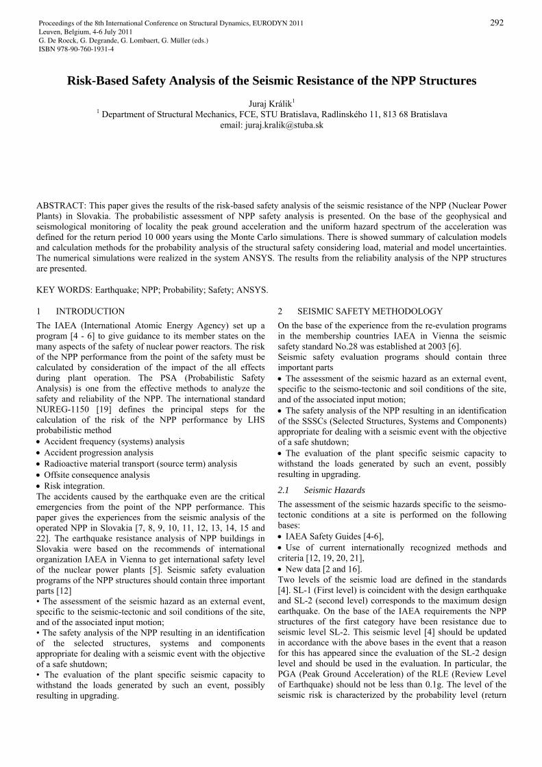
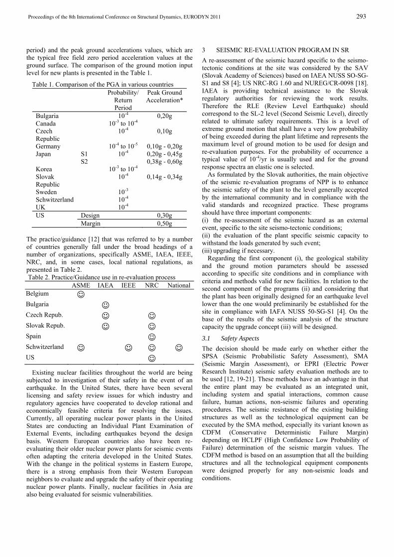
3.4 Seismic Input Data The seismic response can be calculated in the frequency (spectrum response analysis) or time domain (transient analysis) [12].
Figure 1. Comparison of the horizontal acceleration response
spectrum NUREG and GRS.
Figure 2. Comparison of the horizontal acceleration response
for various probability values.
Proceedings of the 8th International Conference on Structural Dynamics, EURODYN 2011 294
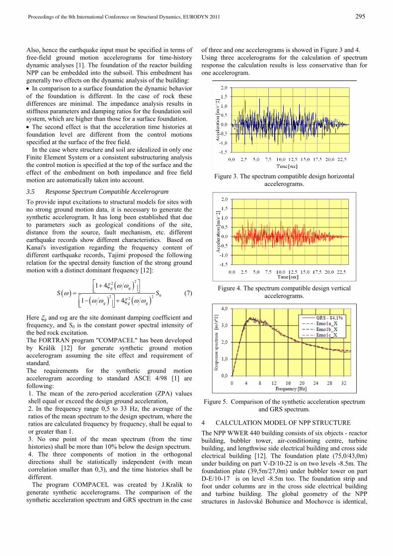
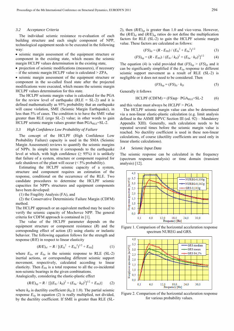
Also, hence the earthquake input must be specified in terms of free-field ground motion accelerograms for time-history dynamic analyses [1]. The foundation of the reactor building NPP can be embedded into the subsoil. This embedment has generally two effects on the dynamic analysis of the building: • In comparison to a surface foundation the dynamic behavior of the foundation is different. In the case of rock these differences are minimal. The impedance analysis results in stiffness parameters and damping ratios for the foundation soil system, which are higher than those for a surface foundation. • The second effect is that the acceleration time histories at foundation level are different from the control motions specified at the surface of the free field.
In the case where structure and soil are idealized in only one Finite Element System or a consistent substructuring analysis the control motion is specified at the top of the surface and the effect of the embedment on both impedance and free field motion are automatically taken into account.
3.5 Response Spectrum Compatible Accelerogram To provide input excitations to structural models for sites with no strong ground motion data, it is necessary to generate the synthetic accelerogram. It has long been established that due to parameters such as geological conditions of the site, distance from the source, fault mechanism, etc. different earthquake records show different characteristics. Based on Kanai's investigation regarding the frequency content of different earthquake records, Tajimi proposed the following relation for the spectral density function of the strong ground motion with a distinct dominant frequency [12]:
( )( )
( ) ( )
22
02 22
1 4
1 4
g g
g g g
S Sξ ω ω
ωω ω ξ ω ω
⎡ ⎤+⎢ ⎥⎣ ⎦=⎡ ⎤− +⎢ ⎥⎣ ⎦
(7)
Here ξg and ωg are the site dominant damping coefficient and frequency, and S0 is the constant power spectral intensity of the bed rock excitation. The FORTRAN program "COMPACEL" has been developed by Králik [12] for generate synthetic ground motion accelerogram assuming the site effect and requirement of standard. The requirements for the synthetic ground motion accelerogram according to standard ASCE 4/98 [1] are following: 1. The mean of the zero-period acceleration (ZPA) values shell equal or exceed the design ground acceleration, 2. In the frequency range 0,5 to 33 Hz, the average of the ratios of the mean spectrum to the design spectrum, where the ratios are calculated frequency by frequency, shall be equal to or greater than 1. 3. No one point of the mean spectrum (from the time histories) shall be more than 10% below the design spectrum. 4. The three components of motion in the orthogonal directions shall be statistically independent (with mean correlation smaller than 0,3), and the time histories shall be different.
The program COMPACEL was created by J.Kralik to generate synthetic accelerograms. The comparison of the synthetic acceleration spectrum and GRS spectrum in the case
of three and one accelerograms is showed in Figure 3 and 4. Using three accelerograms for the calculation of spectrum response the calculation results is less conservative than for one accelerogram.
Figure 3. The spectrum compatible design horizontal
accelerograms.
Figure 4. The spectrum compatible design vertical
accelerograms.
Figure 5. Comparison of the synthetic acceleration spectrum
and GRS spectrum.
4 CALCULATION MODEL OF NPP STRUCTURE The NPP WWER 440 building consists of six objects - reactor building, bubbler tower, air-conditioning centre, turbine building, and lengthwise side electrical building and cross side electrical building [12]. The foundation plate (75,0/43,0m) under building on part V-D/10-22 is on two levels -8.5m. The foundation plate (39,5m/27,0m) under bubbler tower on part D-E/10-17 is on level -8.5m too. The foundation strip and foot under columns are in the cross side electrical building and turbine building. The global geometry of the NPP structures in Jaslovské Bohunice and Mochovce is identical,
Proceedings of the 8th International Conference on Structural Dynamics, EURODYN 2011 295
but the bracing system and the section area of the steel elements are different.
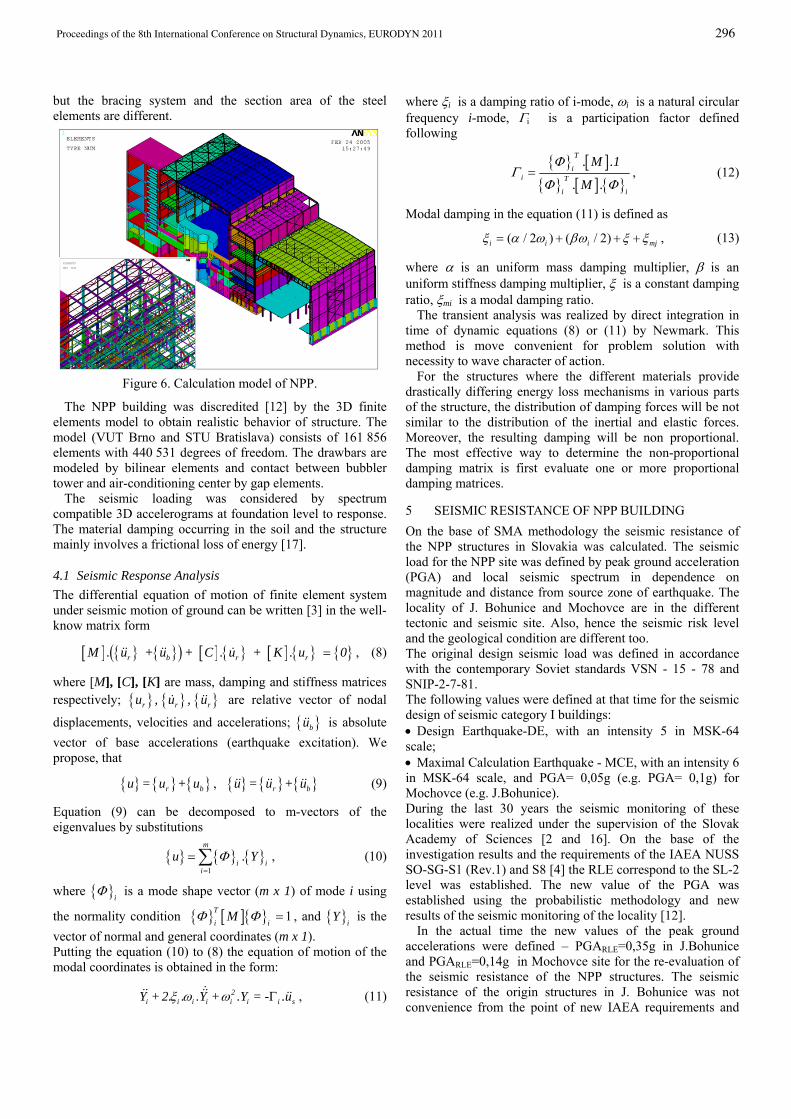
Figure 6. Calculation model of NPP.
The NPP building was discredited [12] by the 3D finite elements model to obtain realistic behavior of structure. The model (VUT Brno and STU Bratislava) consists of 161.856 elements with 440.531 degrees of freedom. The drawbars are modeled by bilinear elements and contact between bubbler tower and air-conditioning center by gap elements.
The seismic loading was considered by spectrum compatible 3D accelerograms at foundation level to response. The material damping occurring in the soil and the structure mainly involves a frictional loss of energy [17].
4.1 Seismic Response Analysis The differential equation of motion of finite element system under seismic motion of ground can be written [3] in the well-know matrix form
[ ] { } { }( ) [ ] { } [ ] { } { }r b r rM . u + u + C . u + K . u 0=&& && & , (8)
where [M], [C], [K] are mass, damping and stiffness matrices respectively; { } { } { }r r ru , u , u& && are relative vector of nodal
displacements, velocities and accelerations; { }bu&& is absolute vector of base accelerations (earthquake excitation). We propose, that
{ } { } { }r bu = u + u , { } { } { }r bu = u + u&& && && (9)
Equation (9) can be decomposed to m-vectors of the eigenvalues by substitutions
{ } { } { }1
m
i ii
u . YΦ=
= ∑ , (10)
where { }iΦ is a mode shape vector (m x 1) of mode i using
the normality condition { } [ ]{ } 1T
i iMΦ Φ = , and { }i
Y is the vector of normal and general coordinates (m x 1). Putting the equation (10) to (8) the equation of motion of the modal coordinates is obtained in the form:
2i i i i i i i sY + 2. . .Y + .Y = - .uξ ω ω Γ&&& && && , (11)
where ξi is a damping ratio of i-mode, ωi is a natural circular frequency i-mode, Γi is a participation factor defined following
{ } [ ]
{ } [ ] { }
T
ii T
i i
. M .1
. M .
ΦΓ
Φ Φ= , (12)
Modal damping in the equation (11) is defined as
( / 2 ) ( / 2)i i i mjξ α ω βω ξ ξ= + + + , (13)
where α is an uniform mass damping multiplier, β is an uniform stiffness damping multiplier, ξ is a constant damping ratio, ξmi is a modal damping ratio.
The transient analysis was realized by direct integration in time of dynamic equations (8) or (11) by Newmark. This method is move convenient for problem solution with necessity to wave character of action.
For the structures where the different materials provide drastically differing energy loss mechanisms in various parts of the structure, the distribution of damping forces will be not similar to the distribution of the inertial and elastic forces. Moreover, the resulting damping will be non proportional. The most effective way to determine the non-proportional damping matrix is first evaluate one or more proportional damping matrices.
5 SEISMIC RESISTANCE OF NPP BUILDING On the base of SMA methodology the seismic resistance of the NPP structures in Slovakia was calculated. The seismic load for the NPP site was defined by peak ground acceleration (PGA) and local seismic spectrum in dependence on magnitude and distance from source zone of earthquake. The locality of J. Bohunice and Mochovce are in the different tectonic and seismic site. Also, hence the seismic risk level and the geological condition are different too. The original design seismic load was defined in accordance with the contemporary Soviet standards VSN - 15 - 78 and SNIP-2-7-81. The following values were defined at that time for the seismic design of seismic category I buildings: • Design Earthquake-DE, with an intensity 5 in MSK-64 scale; • Maximal Calculation Earthquake - MCE, with an intensity 6 in MSK-64 scale, and PGA= 0,05g (e.g. PGA= 0,1g) for Mochovce (e.g. J.Bohunice). During the last 30 years the seismic monitoring of these localities were realized under the supervision of the Slovak Academy of Sciences [2 and 16]. On the base of the investigation results and the requirements of the IAEA NUSS SO-SG-S1 (Rev.1) and S8 [4] the RLE correspond to the SL-2 level was established. The new value of the PGA was established using the probabilistic methodology and new results of the seismic monitoring of the locality [12].
In the actual time the new values of the peak ground accelerations were defined – PGARLE=0,35g in J.Bohunice and PGARLE=0,14g in Mochovce site for the re-evaluation of the seismic resistance of the NPP structures. The seismic resistance of the origin structures in J. Bohunice was not convenience from the point of new IAEA requirements and
Proceedings of the 8th International Conference on Structural Dynamics, EURODYN 2011 296
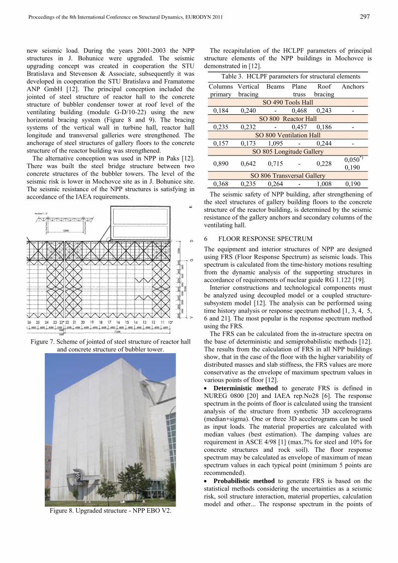
new seismic load. During the years 2001-2003 the NPP structures in J. Bohunice were upgraded. The seismic upgrading concept was created in cooperation the STU Bratislava and Stevenson & Associate, subsequently it was developed in cooperation the STU Bratislava and Framatome ANP GmbH [12]. The principal conception included the jointed of steel structure of reactor hall to the concrete structure of bubbler condenser tower at roof level of the ventilating building (module G-D/10-22) using the new horizontal bracing system (Figure 8 and 9). The bracing systems of the vertical wall in turbine hall, reactor hall longitude and transversal galleries were strengthened. The anchorage of steel structures of gallery floors to the concrete structure of the reactor building was strengthened.
The alternative conception was used in NPP in Paks [12]. There was built the steel bridge structure between two concrete structures of the bubbler towers. The level of the seismic risk is lower in Mochovce site as in J. Bohunice site. The seismic resistance of the NPP structures is satisfying in accordance of the IAEA requirements.
Figure 7. Scheme of jointed of steel structure of reactor hall
and concrete structure of bubbler tower.
Figure 8. Upgraded structure - NPP EBO V2.
The recapitulation of the HCLPF parameters of principal structure elements of the NPP buildings in Mochovce is demonstrated in [12].
Table 3. HCLPF parameters for structural elements Columnsprimary
Vertical bracing
Beams Plane truss
Roof bracing
Anchors
SO 490 Tools Hall 0,184 0,240 - 0,468 0,243 -
SO 800 Reactor Hall 0,235 0,232 - 0,457 0,186 -
SO 800 Ventilation Hall 0,157 0,173 1,095 - 0,244 -
SO 805 Longitude Gallery
0,890 0,642 0,715 - 0,228 0,050*) 0,190
SO 806 Transversal Gallery 0,368 0,235 0,264 - 1,008 0,190
The seismic safety of NPP building, after strengthening of the steel structures of gallery building floors to the concrete structure of the reactor building, is determined by the seismic resistance of the gallery anchors and secondary columns of the ventilating hall.
6 FLOOR RESPONSE SPECTRUM The equipment and interior structures of NPP are designed using FRS (Floor Response Spectrum) as seismic loads. This spectrum is calculated from the time-history motions resulting from the dynamic analysis of the supporting structures in accordance of requirements of nuclear guide RG 1.122 [19].
Interior constructions and technological components must be analyzed using decoupled model or a coupled structure-subsystem model [12]. The analysis can be performed using time history analysis or response spectrum method [1, 3, 4, 5, 6 and 21]. The most popular is the response spectrum method using the FRS.
The FRS can be calculated from the in-structure spectra on the base of deterministic and semiprobabilistic methods [12]. The results from the calculation of FRS in all NPP buildings show, that in the case of the floor with the higher variability of distributed masses and slab stiffness, the FRS values are more conservative as the envelope of maximum spectrum values in various points of floor [12]. • Deterministic method to generate FRS is defined in NUREG 0800 [20] and IAEA rep.No28 [6]. The response spectrum in the points of floor is calculated using the transient analysis of the structure from synthetic 3D accelerograms (median+sigma). One or three 3D accelerograms can be used as input loads. The material properties are calculated with median values (best estimation). The damping values are requirement in ASCE 4/98 [1] (max.7% for steel and 10% for concrete structures and rock soil). The floor response spectrum may be calculated as envelope of maximum of mean spectrum values in each typical point (minimum 5 points are recommended). • Probabilistic method to generate FRS is based on the statistical methods considering the uncertainties as a seismic risk, soil structure interaction, material properties, calculation model and other... The response spectrum in the points of
Proceedings of the 8th International Conference on Structural Dynamics, EURODYN 2011 297

floor is calculated using the transient analysis of the structure from group of synthetic 3D accelerograms [12]. In the case of the rock soil the median and variation of the input accelerograms must be equivalent to values of seismic risk for this locality. The FRS may be calculated as statistical envelope (median+sigma) of the spectrum values in all typical point. The statistical characteristic of input and output parameters are investigated for lognormal distribution. • Semi-probabilistic method to generate FRS is based on the combination of deterministic and probabilistic methods. The total variation is calculated from the variation of the input loads, material properties and response in various typical points on the floor.
The uncertainties of the soil-structure interaction effects and calculation model can be considered by broadening and lowering of in-structure time history motion n accordance of requirements of standard ASCE 4/98 [1]. In the case of deterministic method the FRS ordinates are equal to envelope of maximum values in five or more points on the floor. The response spectrum ordinates in one point are equal to mean value from two or more values obtained from the time response analysis.
Figure 9 No-smoothing horizontal and vertical FRS in the Box
PG NPP at level -6,5m.
Figure 10. No-smoothing horizontal and vertical FRS in the
Box PG NPP at level +18,9m.
The semi-probabilistic method is based on the statistical envelope (median+sigma) of the response spectrum ordinates
in eleven or more points from three or more input accelerograms. The ordinates of the input response spectrum accelerograms must be compatible with the ordinates of input response spectrum (median). The lognormal distribution function for calculation the statistical envelope of response spectrum in floor points is proposed. In the case of lognormal distribution the median+sigma (84,1% probability) can be calculated from the simplified relation [12] x84 = xm . ew (14) where w is a variation of the lognormal distribution, xm is a median of the input simples. In the case that the variation is higher than 20% this relation is conservative. For higher values of variation then 20% must be used the more precise relation ( )( )2
84 842exp ln 1
1meanx
x u ww
= ++
(15)
where u84 is a quantile of the random variable for normal distribution function, xmean is mean value, w (w=σ/xmean) is variation coefficient of variable x depended on standard deviation σ. If we use the simple relation (14) for variation w=50% (e.g. 60%) the value of x84 is higher up 15% (e.g. 23%). In figures 11-14 are imagined the results from the comparison FRS and GRS spectrum (median+sigma) with FRS for RLE (median) values in the box PG and the Reactor hall NPP on floor level from -5m to 20m. There are presented the conservative values due to use the simplified relation (14).
Figure 11. Comparison of ratio GRS/RLE floor response
X-spectrum GRS/RLE in the Box PG NPP.
Figure 12. Comparison of ratio GRS/RLE floor response
Z-spectrum in the Box PG NPP.
The results from the calculation of FRS in all NPP buildings show, that in the case of the floor with the higher variability of distributed masses and slab stiffness, the FRS values are more
Proceedings of the 8th International Conference on Structural Dynamics, EURODYN 2011 298
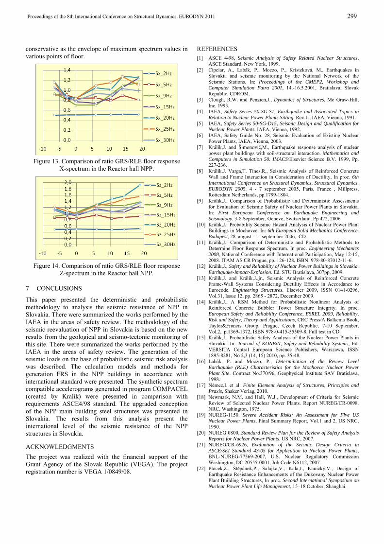
conservative as the envelope of maximum spectrum values in various points of floor.
Figure 13. Comparison of ratio GRS/RLE floor response
X-spectrum in the Reactor hall NPP.
Figure 14. Comparison of ratio GRS/RLE floor response
Z-spectrum in the Reactor hall NPP.
7 CONCLUSIONS
This paper presented the deterministic and probabilistic methodology to analysis the seismic resistance of NPP in Slovakia. There were summarized the works performed by the IAEA in the areas of safety review. The methodology of the seismic reevaluation of NPP in Slovakia is based on the new results from the geological and seismo-tectonic monitoring of this site. There were summarized the works performed by the IAEA in the areas of safety review. The generation of the seismic loads on the base of probabilistic seismic risk analysis was described. The calculation models and methods for generation FRS in the NPP buildings in accordance with international standard were presented. The synthetic spectrum compatible accelerograms generated in program COMPACEL (created by Kralik) were presented in comparison with requirements ASCE4/98 standard. The upgraded conception of the NPP main building steel structures was presented in Slovakia. The results from this analysis present the international level of the seismic resistance of the NPP structures in Slovakia.
ACKNOWLEDGMENTS The project was realized with the financial support of the Grant Agency of the Slovak Republic (VEGA). The project registration number is VEGA 1/0849/08.
REFERENCES [1] ASCE 4-98, Seismic Analysis of Safety Related Nuclear Structures,
ASCE Standard, New York, 1999. [2] Cipciar, A., Labák, P., Moczo, P., Kristeková, M., Earthquakes in
Slovakia and seismic monitoring by the National Network of the Seismic Stations. In: Proceedings of the CMEP2, Workshop and Computer Simulation Fatra 2001, 14.-16.5.2001, Bratislava, Slovak Republic. CDROM.
[3] Clough, R.W. and Penzien,J., Dynamics of Structures, Mc Graw-Hill, Inc. 1993.
[4] IAEA, Safety Series 50-SG-S1, Earthquake and Associated Topics in Relation to Nuclear Power Plants Sitting. Rev.1., IAEA, Vienna, 1991.
[5] IAEA, Safety Series 50-SG-D15, Seismic Design and Qualification for Nuclear Power Plants. IAEA, Vienna, 1992.
[6] IAEA, Safety Guide No. 28, Seismic Evaluation of Existing Nuclear Power Plants, IAEA, Vienna, 2003.
[7] Králik,J. and Šimonovič,M., Earthquake response analysis of nuclear power plant buildings with soil-structural interaction. Mathematics and Computers in Simulation 50. IMACS/Elsevier Science B.V. 1999, Pp. 227-236.
[8] Králik,J. Varga,T. Tines,R,, Seismic Analysis of Reinforced Concrete Wall and Frame Interaction in Consideration of Ductility, In proc. 6th International Conference on Sructural Dynamics, Structural Dynamics. EURODYN 2005. 4 - 7 september 2005, Paris, France , Millpress, Rotterdam Netherlands, pp.1799-1804.
[9] Králik,J., Comparison of Probabilistic and Deterministic Assessments for Evaluation of Seismic Safety of Nuclear Power Plants in Slovakia. In: First European Conference on Earthquake Engineering and Seismology. 3-8 September, Geneve, Switzerland. Pp 422, 2006.
[10] Králik,J.: Probability Seismic Hazard Analysis of Nuclear Power Plant Buildings in Mochovce. In: 6th European Solid Mechanics Conference. Budapest, 28. august – 1. september 2006, CD.
[11] Králik,J.: Comparison of Deterministic and Probabilistic Methods to Determine Floor Response Spectrum. In proc. Engineering Mechanics 2008, National Conference with International Participation, May 12-15, 2008. ITAM AS CR Prague, pp. 126-128, ISBN: 978-80-87012-11-6.
[12] Králik,J., Safety and Reliability of Nuclear Power Buildings in Slovakia. Earthquake-Impact-Explosion. Ed. STU Bratislava, 307pp, 2009.
[13] Králik,J. and Králik,J.,jr., Seismic Analysis of Reinforced Concrete Frame-Wall Systems Considering Ductility Effects in Accordance to Eurocode. Engineering Structures. Elsevier 2009, ISSN 0141-0296, Vol.31, Issue 12, pp. 2865 - 2872, December 2009.
[14] Králik,J., A RSM Method for Probabilistic Nonlinear Analysis of Reinforced Concrete Bubbler Tower Structure Integrity. In proc. European Safety and Reliability Conference, ESREL 2009, Reliability, Risk and Safety, Theory and Applications, CRC Press/A.Balkema Book, Taylor&Francis Group, Prague, Czech Republic, 7-10 September, Vol.2, p.1369-1372, ISBN 978-0-415-55509-8, Full test in CD.
[15] Králik,J., Probabilistic Safety Analysis of the Nuclear Power Plants in Slovakia. In: Journal of KONBiN, Safety and Reliability Systems, Ed. VERSITA Central European Science Publishers, Warszawa, ISSN 1895-8281, No 2,3 (14, 15) 2010, pp. 35-48.
[16] Labák, P. and Moczo, P., Determination of the Review Level Earthquake (RLE) Characteristics for the Mochovce Nuclear Power Plant Site. Contract No.370/96, Geophysical Institute SAV Bratislava, 1998.
[17] Němec,I. et al: Finite Element Analysis of Structures, Principles and Praxis, Shaker Verlag, 2010.
[18] Newmark, N.M. and Hall, W.J., Development of Criteria for Seismic Review of Selected Nuclear Power Plants. Report NUREG/CR-0098. NRC, Washington, 1975.
[19] NUREG-1150. Severe Accident Risks: An Assessment for Five US Nuclear Power Plants, Final Summary Report, Vol.1 and 2, US NRC, 1990.
[20] NUREG 0800, Standard Review Plan for the Review of Safety Analysis Reports for Nuclear Power Plants. US NRC, 2007.
[21] NUREG/CR-6926, Evaluation of the Seismic Design Criteria in ASCE/SEI Standard 43-05 for Application to Nuclear Power Plants, BNL-NUREG-77569-2007, U.S. Nuclear Regulatory Commission Washington, DC 20555-0001, Job Code N6112, 2007.
[22] Plocek,Z., Štěpánek,P., Salajka,V., Kala,J., Kanický,V., Design of Earthquake Resistance Enhancements of the Dukovany Nuclear Power Plant Building Structures, In proc. Second International Symposium on Nuclear Power Plant Life Management, 15–18 October, Shanghai.
Proceedings of the 8th International Conference on Structural Dynamics, EURODYN 2011 299
Related Documents