1 The Rife Machine Report A History of Rife’s Instruments and Frequencies Updated 02/04/2012 This article from its first writing has been an evolving document. When original Rife in- struments or schematics have been found it has been updated according to the information that was obtained. This paper was updated in 2010 because at that time an original 1938 Beam Ray Corporation Clinical Instrument had been found and analyzed. At that time the analyzing of that instrument finally showed where the audio frequency instruments came from which Dr. Rife used in the 1950’s. This update clarifies some previous information and also adds more in- formation about Dr. Gruner’s Rife machine and the Beam Ray Clinical instrument that Dr. John- son, M.D used. The last revision of this paper was on 11/22/2011 and we will continue to update this paper when new information is obtained about Dr. Rife’s instruments. www.rife.org www.rife.org www.rife.org www.rife.org www.rife.org

Welcome message from author
This document is posted to help you gain knowledge. Please leave a comment to let me know what you think about it! Share it to your friends and learn new things together.
Transcript
1
The Rife Machine Report
A History of Rife’s Instruments and Frequencies
Updated 02/04/2012 This article from its first writing has been an evolving document. When original Rife in-struments or schematics have been found it has been updated according to the information that was obtained. This paper was updated in 2010 because at that time an original 1938 Beam Ray Corporation Clinical Instrument had been found and analyzed. At that time the analyzing of that instrument finally showed where the audio frequency instruments came from which Dr. Rife used in the 1950’s. This update clarifies some previous information and also adds more in-formation about Dr. Gruner’s Rife machine and the Beam Ray Clinical instrument that Dr. John-son, M.D used. The last revision of this paper was on 11/22/2011 and we will continue to update this paper when new information is obtained about Dr. Rife’s instruments.
www.rife.org www.rife.org www.rife.org www.rife.org www.rife.org

2
In this report we will examine the way Dr. Rife’s instruments were built. We will look at the evi-dence by quoting the sources such as Dr. Rife, John Crane, John Marsh, Dr. Couche, Dr. Lara, Dr. Stafford and Bertrand L. Comparet (Dr. Rife’s attorney in the 1939 Beam Ray Corporation trial, and later John Crane’s attorney for Life Labs’ trial in 1961). Hopefully anyone who reads this article will have a better understanding about Dr. Rife and the methods he used. Our goal is to try to give people information so that they will know how Dr. Rife’s equipment worked so that they will not be fooled by all the misinformation that has been published on this subject. This will be explained in layman’s terms. This report is also online at www.rifevideos.com. All of the documentation is linked in the online report for those who want to look at the documents used to back up the quotes used in this report.
www.rife.org www.rife.org www.rife.org www.rife.org www.rife.org
3
The Rife Machine Report table of contents
Chapter 1 - What is a ray tube and how does it work? .................................................................................. 4 Chapter 2 - What power levels did Dr. Rife use in his Rife Machines? ......................................................... 7 Chapter 3 - Is it necessary to use a Ray tube to output the frequencies? ..................................................... 9 Chapter 4 - Are Dr. Rife’s RF frequencies safe to use? .............................................................................. 13 Chapter 5 - Did Dr. Rife use audio frequencies? ......................................................................................... 15 Chapter 6 - Dr. Rife’s 1920 to 1922 Rife Ray #1 Rife Machine ................................................................... 17 Chapter 7 - 1934 Rife Ray #3 Rife Machine used in the 1934 clinic ........................................................... 19 Dr. Rife’s misread lab note frequencies from before 1935 (Chart) ........................................... 37 Chapter 8 - 1935 Rife Ray #4 Rife Machine ................................................................................................ 38 Rife Ray #4 sine wave high RF frequencies (Chart) ................................................................. 44 Chapter 9 - 1938 to 1939 Beam Ray Corporation Clinical Rife Machine ..................................................... 45 The Beam Ray Clinical instrument sideband sine wave audio frequencies based on a 3.8 MHz carrier (Chart) ............................................................................................................ 70 Beam Ray instrument sideband sine wave audio frequencies (Chart) .................................... 71 Oscilloscope waveform readings of the original Beam Ray Clinical instrument ...................... 72 Original Beam Ray spectrum analyzer graphs for microorganisms .................................... 73-79 Upper harmonic frequency charts for Microorganisms ....................................................... 80-81 Chapter 10 - The Gruner schematic of Philip Hoyland’s Beam Ray laboratory instrument .......................... 82 The initial Gruner schematic work done 3 years ago .............................................................. 84 Deciphering Dr. Gruner’s Beam Ray instrument schematic .................................................... 85 Rebuilding Philip Hoyland’s Beam Ray Laboratory instrument ............................................... 86 The modulated Audio Frequency pulsing circuit ..................................................................... 89 Mr. Peters’ photos of the rebuilt Beam Ray Laboratory instrument ......................................... 92 Second machine photos of the rebuilt Beam Ray Laboratory instrument .......................... 93-95 Beam Ray Clinical instrument Schematic ............................................................................... 96 Chapter 11 - Aubrey Scoon’s Beam Ray replica Rife Machine Re-evaluation ............................................. 97 Aubrey Scoon’s sideband audio frequencies reconciled to Rife’s original high frequency M.O.R.s. (Chart) .................................................................................................................... 103 Aubrey Scoon’s Beam Ray replica spectrum analyzer graphs for microorganisms ....... 105-112 Photos of the rebuilt Aubrey Scoon Beam Ray Clinical instrument ....................................... 113 Aubrey Scoon’s Beam Ray Clinical replica schematic .......................................................... 114 Chapter 12 - Dr. Rife and Verne Thompson’s 1950’s AZ-58 Beam Ray replica Rife Machine ................... 115 Original 1950’s AZ-58 frequencies used by Dr. Robert P. Stafford M.D. (Chart) .................. 127 1950’s Beam Ray Clinical instrument optimum sideband square wave audio frequencies based on a 4.68 MHz carrier (Chart) ..................................................................................... 127 Photos of the rebuilt AZ-58 Beam Ray Clinical instrument ................................................... 129 AZ-58 Beam Ray Clinical instrument schematic ................................................................... 130 Chapter 13 - Rife Machine Harmonic Audio Frequency Misunderstanding ................................................ 131 AZ-58 M.O.R. audio frequencies square wave harmonics (Chart) ........................................ 133 Chapter 14 - Life Labs 1950’s pad instrument (without ray tube) ............................................................... 134 Chapter 15 - John Marsh’s 1970’s Beam Ray replica Rife Machine .......................................................... 138 John Marsh’s Beam Ray Clinical instrument sideband square wave audio frequencies based on a 4.122 MHz carrier (Chart) .................................................................................. 142 John Marsh’s Beam Ray Clinical instrument higher sideband square wave audio frequencies based on a 4.122 MHz carrier (Chart) ............................................................... 142 Chapter 16 - John Marsh’s 1980’s Ray Tube Rife Machine ....................................................................... 143 Chapter 17 - Summary ............................................................................................................................... 145 Rife’s M.O.R. frequencies and audio sideband frequencies (Chart) ..................................... 148
www.rife.org www.rife.org www.rife.org www.rife.org www.rife.org
4
Chapter #1
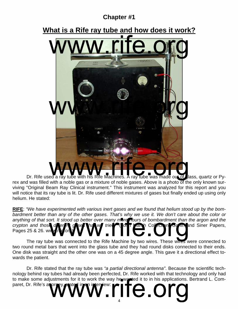
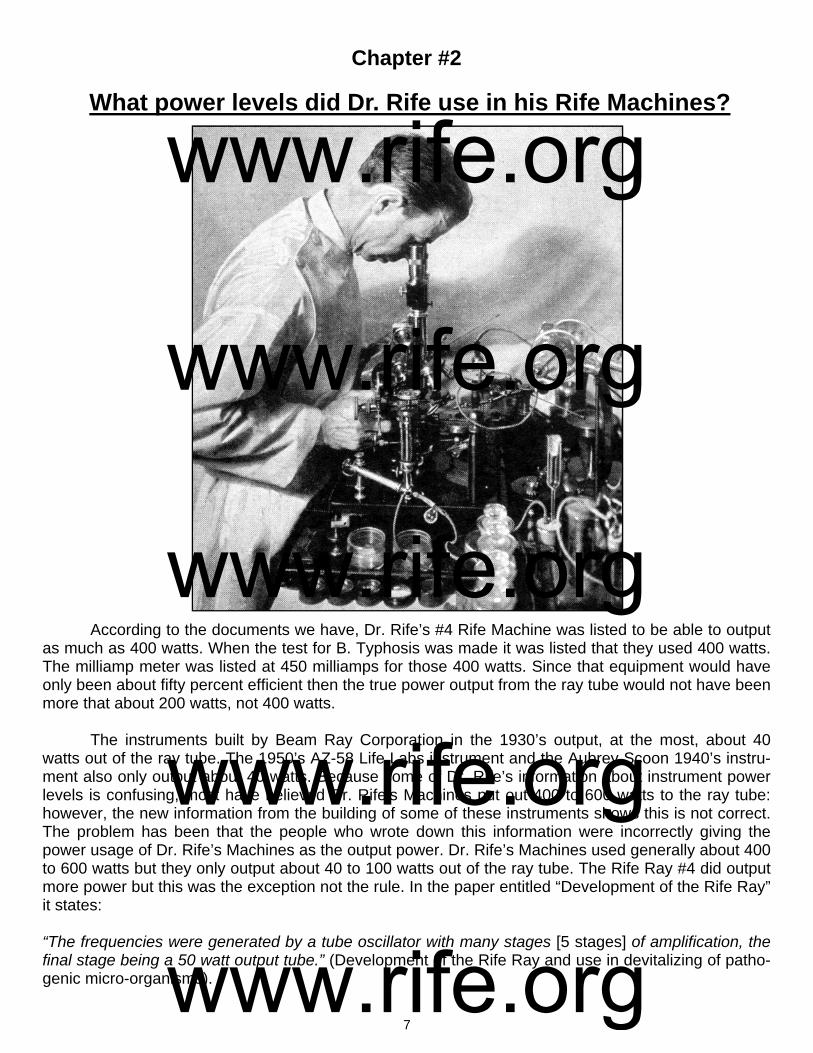
What is a Rife ray tube and how does it work? Dr. Rife used a ray tube with his Rife Machines. A ray tube was made out of glass, quartz or Py-rex and was filled with a noble gas or a mixture of noble gases. Above is a photo of the only known sur-viving "Original Beam Ray Clinical instrument." This instrument was analyzed for this report and you will notice that its ray tube is lit. Dr. Rife used different mixtures of gases but finally ended up using only helium. He stated: RIFE: “We have experimented with various inert gases and we found that helium stood up by the bom-bardment better than any of the other gases. That’s why we use it. We don’t care about the color or anything of that sort. It stood up better over many more hours of bombardment than the argon and the crypton and those different gases that we tried.” (John Marsh Collection, Gonin and Siner Papers, Pages 25 & 26. www.rife.org). The ray tube was connected to the Rife Machine by two wires. These wires were connected to two round metal bars that went into the glass tube and they had round disks connected to their ends. One disk was straight and the other one was on a 45 degree angle. This gave it a directional effect to-wards the patient. Dr. Rife stated that the ray tube was “a partial directional antenna". Because the scientific tech-nology behind ray tubes had already been perfected, Dr. Rife worked with that technology and only had to make some adjustments for it to work the way he wanted it to in his applications. Bertrand L. Com-paret, Dr. Rife’s attorney, stated in an interview:
www.rife.org www.rife.org www.rife.org www.rife.org www.rife.org
5
COMPARET: “Now, the original instrument had a tube, like an X-ray tube. That was the way in which Rife developed it. You see, all the X-ray work necessarily was done with a beam projected from a tube. So, Rife worked on the same basis.” (1970’s Bertrand Comparet Interview #32). Many people believe that ray tubes are just as efficient as metal antennas and this may be true. They also believe that the energy emitted from a ray tube will actually travel farther with less loss than a metal antenna. Since there are no actual scientific tests comparing the output of ray tubes to metal antennas it is hard to know for sure if these assumptions are correct. For this report we will go on what is known, not what is un-known. Therefore we will compare ray tubes to metal antennas since they both are designed to emit frequencies. There are limitations to metal antennas that need to be under-stood and this has to do with the laws of physics. It is referred to as the "Inverse-Square Law". This law deals with power loss and distance. We will give a simple explanation which should suffice since we are trying to stay in layman's terms and make it easy for the average person to understand. When a circuit is properly tuned metal antennas are very efficient. About 100% of the energy that you put into a metal antenna comes out, but only if the impedance is matched correctly. Dr. Rife’s #3 instrument information that has been obtained from the Rife documents list that about 50 RF watts was input into ray tube. If we compare this to a metal antenna this means about 50 watts would have passed through and come out of the ray tube. When it comes to metal antennas and the inverse-square law on signal loss this would mean that you would have to divide the 50 watts that come out of the metal antenna by four for every foot that you move away from the antenna. The exact power loss of a ray tube, as stated before, is not known but if a ray tube is equally as efficient as a metal antenna then the same laws of physics would also apply to it. Since no actual scientific tests have been done with ray tubes demonstrating that they are ex-empt from the inverse-square law then we are left with only one conclusion, this law does apply to ray tubes. Because of this we will use this inverse-square law of power loss for a ray tube. Therefore, at one foot away from the ray tube you only have 12.5 watts. At two feet you only have 3.125 watts and at 3 feet you only have about .78 of a watt. The laws of physics are important to understand because Dr. Rife and the doctors that used his equipment put the ray tube within a foot or so of the patient’s body. Dr. Couche said that he would sometimes touch the body of the patient in the area that needed to be treated. When we discussed this with Dr. Robert P. Stafford, he said that when he treated cancer patients he would put the ray tube within a few inches of the body and treat a 6 inch square area. He would move the ray tube up and down and back and forth so that the whole 6 inch area was treated. He said that he did this because of the way the phanotron (ray tube nickname) ray tube worked. The design of a phanotron ray tube makes it partially directional and concentrates its energy or power into a small area. With the power loss from the ray tube it is easy to understand why Dr. Stafford, Dr. Couche, Dr. Rife and the other doctors used the ray tube right next to the body. We built both the Aubrey Scoon Beam Ray replica ray tube instrument and the 1950’s AZ-58 Beam Ray replica ray tube Rife Machine. The AZ-58 (a 1950’s Rife instrument made by Life Labs) was built from schematics that are on Stan Truman’s site, http://www.rife.org, under AZ-58 research infor-mation. This AZ-58 instrument is nearly the same as the original Beam Ray instrument and schematics can be found at http://www.scoon.co.uk/Electrotherapy/Rife/BeamRay/index.htm. Both Aubrey Scoon’s instrument and the original Beam Ray instrument we have use sine wave audio frequencies and the 1950’s AZ-58 uses square wave audio frequencies. We tested the AZ-58 and Aubrey Scoon’s replica for penetration and found that at about 32 inches from the body full penetration of the carrier frequency emitted from the ray tube was lost. This test was done in this manner. A B&K frequency counter was used and the antenna was put in a fold of body tissue on the front of the body. The ray tube was put behind the person and move backwards until the carrier frequency could no longer be read through the person’s body. John Crane listed the AZ-58 as outputting 14 watts out of the ray tube but we tested it
www.rife.org www.rife.org www.rife.org www.rife.org www.rife.org

6
and found it outputs at least 30 to 40 watts. The 1940’s Aubrey Scoon instrument puts out about 40 watts also. Another test was made using a crystal for testing resonance. The audio frequencies broadcast out of the ray tube from both these machines could only resonate a crystal designed to test resonance through about two inches of tissue. From the tests made, it takes a carrier frequency of at least 0.125 watts to penetrate all the way through the body. It could take an output of 50 watts from a ray tube to resonate a crystal through 14 inches of tissue. These tests showed that it takes more power to pene-trate all the way through the body when modulating an audio frequency on a carrier frequency than when a single un-modulated frequency is used. The tests were done using the AZ-58 replica and the Aubrey Scoon replica Rife machines using a phanotron ray tube outputting about 30 to 40 watts. Another interesting thing worth noting is when we turned the ray tube more than 45 degrees ei-ther to the right or the left of center we could not resonate the crystal. Another test showed we could not resonate the crystal at all on the backside of the phanotron ray tube proving what Dr. Rife said: “The ray tube is a partially directional antenna.” One interesting fact worth noting is the ray tubes that do not use the internal electrodes like the phanotron ray tube have a higher field strength reading which indicates they have a greater output. These ray tubes use copper collars or wire wrapping around the ray tube. Below are two more photos of Dr. Rife's ray tubes.
www.rife.org www.rife.org www.rife.org www.rife.org www.rife.org
7
Chapter #2
What power levels did Dr. Rife use in his Rife Machines?
According to the documents we have, Dr. Rife’s #4 Rife Machine was listed to be able to output as much as 400 watts. When the test for B. Typhosis was made it was listed that they used 400 watts. The milliamp meter was listed at 450 milliamps for those 400 watts. Since that equipment would have only been about fifty percent efficient then the true power output from the ray tube would not have been more that about 200 watts, not 400 watts. The instruments built by Beam Ray Corporation in the 1930’s output, at the most, about 40 watts out of the ray tube. The 1950’s AZ-58 Life Labs instrument and the Aubrey Scoon 1940’s instru-ment also only output about 40 watts. Because some of Dr. Rife’s information about instrument power levels is confusing, most have believed Dr. Rife’s Machines put out 400 to 600 watts to the ray tube: however, the new information from the building of some of these instruments shows this is not correct. The problem has been that the people who wrote down this information were incorrectly giving the power usage of Dr. Rife’s Machines as the output power. Dr. Rife’s Machines used generally about 400 to 600 watts but they only output about 40 to 100 watts out of the ray tube. The Rife Ray #4 did output more power but this was the exception not the rule. In the paper entitled “Development of the Rife Ray” it states: “The frequencies were generated by a tube oscillator with many stages [5 stages] of amplification, the final stage being a 50 watt output tube.” (Development of the Rife Ray and use in devitalizing of patho-genic micro-organisms).
www.rife.org www.rife.org www.rife.org www.rife.org www.rife.org
8
This part of the description is of his pre-1935 instrument. The output tube was not the ray tube. It appears from the documents that Dr. Rife’s pre-1935 instruments did not output any more power than about 50 watts out of the ray tube. He said he lit the tube from another power source then input the frequencies into the ray tube. When Dr. Rife, John Crane and John Marsh were working on sea water conversion - a process that used frequencies - they boosted the output power in the instrument. Concerning that instrument and some 1930’s Beam Ray instruments that Dr. Yale had increased the power level on, Dr. Rife said the following: RIFE: “Now this outfit here - the way we have it boosted up here now with an extreme lot of power be-hind the actual output that is coming out of the thing...I wouldn’t want to use this - or I wouldn’t want to use this instrument here the way it is souped up there for this salt water proposition to treat a patient with.” GONIN: “No.” RIFE: “You can get beyond the limit.” GONIN: “Yes, quite.” CRANE: “That’s what Dr. Yale did. You see, he stepped it up and up and up…” RIFE: “When Verne Thompson used to go down there and take care of Yale’s machines - when he be-gan stepping them up and so...where you get up into that extreme power…oh yes, that is not good. With the power that is in these [40 to 100 watts of power coming out of the ray tube], there is absolutely no harm because I had my microscope here - I had my tube [ray tube] right here in front of it - oh, about 11 or 12 inches away from the slide in the microscope and here I was with this thing all around like that and that tube going here and my specimens and the microscope year after year tuning that thing and it never harmed me any.” (1950’s Gonin, Rife, Crane and Marsh Paper #27-32). Because Dr. Yale’s 1936-39 Beam Ray Corporation Rife Machines were modified they were putting out a lot more power than Dr. Rife felt was safe. We do not know how Dr. Yale had his ma-chines modified so it is not possible to know the exact power output they had. But he must have been exceeding the power output of the Rife Ray #4 which could output more than 200 watts (true power). It may be that Dr. Rife was just overly cautious but his statement should be considered when anyone starts using power levels in excess of 200 watts true power output.
www.rife.org www.rife.org www.rife.org www.rife.org www.rife.org

9
Chapter #3
Is it necessary to use a Ray tube to output the frequencies?
We really shouldn’t care if an instrument uses a ray tube or a pad as long as it will devitalize the microorganism we desire. In the strictest sense of the word just because a ray tube is used doesn’t mean it’s “Rife”. By the time you read this whole report you will find out that very few are doing exactly what Dr. Rife did. But does this mean that these instruments don’t work? Most of those who are build-ing pad instruments are not using ray tubes, and most are not using Dr. Rife’s original frequencies. Those who are building ray tube instruments are also not using Dr. Rife’s original frequencies or meth-ods. We have quite a paradox. This is the problem we face. If we were to build a ray tube Rife Machine that worked exactly the way Dr. Rife’s did and use frequencies from 139,200 to 1,604,000 Hertz then we would have an instrument that could cause interference with AM radio stations if we were too close to them. These ray tube instruments may have to be used with a Faraday cage which is a conducting cage used to stop electromagnetic fields. We could use them as long as we do not operate them within one half of a mile of a radio station on that stations particular wavelength or call number. We can build a pad instrument that will use all the frequencies Dr. Rife's Machines used but then we are not using a ray tube. When we consider the problems we face today with building instruments, the least expensive instrument we can build is a pad instrument. This type of instrument can produce all of Dr. Rife’s fre-quencies output by his Rife Machine. Therefore we should look at this method carefully and not reject it out of personal bias. As we already said, it really shouldn’t matter if an instrument uses pads or a ray tube as long as it works. With this in mind let’s look at the reasons why pad instruments were built in the first place. John Crane and John Marsh had really good reasons why they built pad instruments. After nearly 50 years of research and use, there is enough evidence that a pad instrument works just as well as a ray tube instrument, as long as there is sufficient power used. In some cases, because of the electrical stimulation like a T.E.N.S. instrument, they may work even better than a ray tube on some problems. We will now take a look at some of the reasons that prompted John Crane and John Marsh to use pads: RIFE: “But the principle of this thing is basically built on a coordinative vibration. Just like one tuning fork pitched to the C. Another one here—you strike this one and this one vibrates.”
www.rife.org www.rife.org www.rife.org www.rife.org www.rife.org

10
DR. LARA: “What kind of vibration is it? Electromagnetic vibration?”
RIFE: “We won’t say magnetic, we will say electronic frequency vibration. The same as put out on a broadcasting station for the radio. The same thing you know, only it’s transmitted into a tube. And the tube acts as a partial directional antenna you see.” (John Marsh Rife CDs - CD 6 track 2). In the John Marsh papers describing his trip to Ohio we read a statement made by Dr. Rife: RIFE: “You know we had an idea when we had our Clinic in La Jolla, of course that was battery and motor generator operated that set, you know, and boy it would sure raise the devil with all the radios so we had a couple of cars that was equipped with car radios and we sent them out and we would take the switch of that thing, and had a code you know like an S.O.S., and one of them went up north, and one of them went south from La Jolla. Before we started in we wanted to see how far we were going to disturb things with it you know, and incidentally we had it in a steel room, a steel lined vault about this size at the old Ellen Scripp’s home. It was the vault in the library of the Scripp’s home where they kept their valuable manuscripts and books in all steel lined and a door on it like a safe. We had the thing in-side of that too, but it didn’t make much difference, but we started in, and one car lost the pick up on top of Torry Pines, and the other one half ways through Mission Beach picked it up, and then they could go a hundred feet and lose and then they would have to pick it up again. Old Henry [Henry Siner] the boy that was with us out there, one of the lab boys, boy he went up in the air. He says, “By God” he says “look, we’re going to fix them up right. At two o’clock we’ll hook this up to a big radio station, a big transmitting station, and at two o’clock next week we’ll broadcast for tuberculosis, and at half past three the week after we will broadcast for cancer, and everybody at the radio will pick it up”. See, boy I said Henry that really is an idea.” (1957 John Marsh Trip to Ohio Paper #24). One of Dr. Rife's close friends, Ben Cullen, stated in a talk given in 1960 the following: CULLEN: The fact is, had it not been for certain very, very unpleasant circumstances, Dr. Rife would've had an arrangement with KFI or KFSD [Radio stations] where he would have been broadcasting out over quite a large radius from each broadcasting station the rays which are responsible for eradicating these various viruses, which we now know as being "killing" viruses. Just imagine as you walked around shopping downtown, or out in the street, you would receive the rays of this wonderful cur-rent." (Ben Cullen's 1960 talk given at the First International Convention of the Rife Virus Microscope #G) These two statements made by Dr. Rife and Ben Cullen were made over 20 years after the 1934 clinic. Dr. Rife knew that the frequencies would broadcast from a metal antenna just as well as from a ray tube. The fact that he felt that Henry Siner’s idea was a good idea even after more than 20 years indicates that Dr. Rife knew a metal antenna would give the same results as a ray tube. It is ap-parent from what we have read that Dr. Rife believed it was the frequency that was devitalizing the or-ganism and the method of application really didn’t matter. He understood that the frequencies could be broadcast by a radio station, using a metal antenna, if they had enough power. When John Crane and John Marsh, Dr. Rife’s two business partners in the 1950’s, came to un-derstand this, they eliminated the ray tube and used pads or hand cylinders to apply the frequencies. The pads and hand cylinders work just like an antenna except you do not want too much power so that they are safe to use. The body also becomes an antenna when you hold the hand cylinders or use the pads and this is why pad instruments work. Bertrand Comparet stated this in his interview: COMPARET: “Now, Crane said “Well now look, Rife himself admits that no matter how much tube and ray, and so on, you have, you can’t get any results unless you’ve got the right frequency. Therefore the real clue to the thing is the frequency and not the means by which you deliver it.” Comparet also said:
www.rife.org www.rife.org www.rife.org www.rife.org www.rife.org
11
“Well, Crane originally was, with more modern techniques, duplicating the Rife machine, tube and all for early experiments. And, as I say, he came to the conclusion that you just weren’t getting anything additional by the use of the tube. If you didn’t get the frequency, you could run the rest of it indefinitely and nothing happened. So, what Crane did, he got an audio frequency generator. Now, you could make them up yourself by an awful lot of work, or you could buy a Heathkit audio frequency generator and get all the same results with a lot less time and effort. So he was using these Heathkit generators. Now, instead of a beam projected from a tube, a ray, he simply had two wires. I think they were alumi-num knobs on the end of them, which would be used. They would be put on the body in such a position that the natural flow of the current from one to the other would go through the diseased area, and he got astonishing results.” (1970’s Bertrand Comparet Interview #33 & 47).
These pads or hand cylinders act just like an antenna when in contact with the body, but only if you have an RF carrier frequency. This is where John Crane and John Marsh made a critical error, we believe, and the reason Dr. Rife probably did not like their pad instrument. Without an RF carrier fre-quency the audio frequencies will only go through the connective tissue and not the cell. There are ex-ceptions to this and they have to do with the waveform of the frequency. If a square wave audio fre-quency is used then the higher harmonics produced from this waveform may penetrate the cell to some degree. How much power from these harmonics penetrates the cell is not known. But this may explain why instruments that do not use an RF carrier frequency also seem to work well. Dr. Rife expressed his dislike for John Crane and John Marsh’s instrument that did not use a carrier frequency when Bertrand Comparet asked him about it:
COMPARET: “And I asked Rife, because I thought Rife would certainly say that the way Crane was working on it then was still using the Rife principle, but he indignantly denied it.” (1970's Comparet in-terview papers #32).
We know that Dr. Rife knew that a metal antenna would work and we also know that the pad in-strument worked on this principle. Logically it must have been the fact that it did not use an RF carrier frequency that upset Dr. Rife. Pad instruments that do not use a carrier frequency are limited in power. The highest power output that can be safely used from a non RF carrier pad instrument is about 1/5 of one watt (0.20 to 0.40). Any more power than this and the muscles of the body will begin to lock up. If you use an RF carrier frequency then you can output a hundred times more power safely. It is apparent that it was the lack of power that concerned Dr. Rife. All of Dr. Rife’s original frequencies were in the RF (Radio frequency) broadcast band of frequencies. We will cover these frequencies and the audio frequencies along with the importance of a carrier frequency later in this article.
Some people have thought that it was the light from the ray tube that made the Rife Machine work. But the evidence doesn’t seem to support that concept either because in the Gonin Papers of John Marsh, Dr. Rife said this with regard to the light that came from the ray tube:
RIFE: “We don’t care about the color or anything of that sort.” (John Marsh Collection, Gonin Papers, Page 25, www.rife.org)
Dr. Couche, while visiting Dr. Rife’s lab with some other men, said:
DR. COUCHE: “There was fifteen inches of concrete on the floor so as to stop any earthquake shocks from interfering with his work. And in his laboratory upon the ground floor he had a microscope with a slide on it that this group of people and myself looked at. And this was not stained, there was no killing of the bacteria on it. It was just a fresh culture of the colon bacillus…..Well we all went down under the stairs into the cellar right immediately under the microscope upon the floor above us and the Rife ma-chine was down in underneath there, under the culture in the cellar probably I suppose about ten feet away, eight or ten feet away. And he turned the machine on and gave it less than a half minute’s fre-
www.rife.org www.rife.org www.rife.org www.rife.org www.rife.org

12
quency for the colon bacillus...Then he turned the machine off and we all came upstairs and waited for ten or fifteen minutes. And presently he came back to his microscope and he said, “Well gentlemen come and look at the slide now.” Well to my astonishment the bacilli all had been killed and they were all stacked up on the slide.” (John Marsh Rife CDs - CD 3 track 1).
There is no possible way the light from the ray tube of the Rife Machine could have penetrated that fifteen inch concrete floor. It is obvious that the light didn’t make any difference but that it was the frequencies that were broadcast through the ray tube. It is easy to see that there is more than one way to deliver the frequencies. The ray tube could be easily replaced with metal hand cylinders and foot pads. It is interesting to note here that Dr. Rife said Abrams’ Oscilloclast would devitalize the BX can-cer virus and it was a contact type device. The wave form the Oscilloclast produced is shown in Dr. Rife’s 1936 film. John Crane and John Marsh probably used this contact method because of the suc-cess of Abrams’ instrument. The Abrams’ instrument proved that a contact type device would work and it was used before Dr. Rife even started using a ray tube. In fact Abrams’ contact instrument predates all of Dr. Rife’s work. Pad instruments like Abrams’ instrument came in contact with the body. Abrams instrument worked on the same RF principles as Dr. Rife’s instruments. Pad instruments with an RF carrier turn the body into an antenna and work on the same principle as a metal antenna or ray tube. People have been using pad instruments without an RF carrier for almost 50 years now and have had very good results. But, in order to work the way the ray tube instruments do, an RF carrier frequency is necessary.
www.rife.org www.rife.org www.rife.org www.rife.org www.rife.org
13
Chapter #4
Are Dr. Rife’s RF frequencies safe to use?
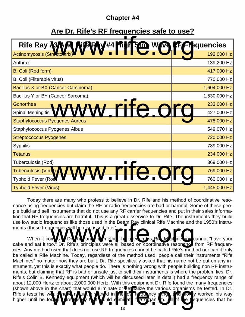
Today there are many who profess to believe in Dr. Rife and his method of coordinative reso-nance using frequencies but claim the RF or radio frequencies are bad or harmful. Some of these peo-ple build and sell instruments that do not use any RF carrier frequencies and put in their sales informa-tion that RF frequencies are harmful. This is a great disservice to Dr. Rife. The instruments they build use low audio frequencies like those used in the Beam Ray clinical Rife Machine and the 1950’s instru-ments (these frequencies will be discussed later). When it comes to Dr. Rife and the method he used in his Rife Machine you cannot “have your cake and eat it too.” Dr. Rife’s principles were all based on coordinative resonance from RF frequen-cies. Any method used that does not use RF frequencies cannot be called Rife’s method nor can it truly be called a Rife Machine. Today, regardless of the method used, people call their instruments “Rife Machines” no matter how they are built. Dr. Rife specifically asked that his name not be put on any in-strument, yet this is exactly what people do. There is nothing wrong with people building non RF instru-ments, but claiming that RF is bad or unsafe just to sell their instruments is where the problem lies. Dr. Rife’s Colin B. Kennedy equipment (which will be discussed later in detail) had a frequency range of about 12,000 Hertz to about 2,000,000 Hertz. With this equipment Dr. Rife found the many frequencies (shown above in the chart) that would eliminate or devitalize the various organisms he tested. In Dr. Rife’s tests he would have naturally started in the low frequency range and slowly worked his way higher until he found a frequency that would eliminate the organism. All of the frequencies that he
Actinomycosis (Streptothrix) 192,000 Hz
Anthrax 139,200 Hz
B. Coli (Rod form) 417,000 Hz
B. Coli (Filterable virus) 770,000 Hz
Bacillus X or BX (Cancer Carcinoma) 1,604,000 Hz
Bacillus Y or BY (Cancer Sarcoma) 1,530,000 Hz
Gonorrhea 233,000 Hz
Spinal Meningitis 427,000 Hz
Staphylococcus Pyogenes Aureus 478,000 Hz
Staphylococcus Pyogenes Albus 549,070 Hz
Streptococcus Pyogenes 720,000 Hz
Syphilis 789,000 Hz
Tetanus 234,000 Hz
Tuberculosis (Rod) 369,000 Hz
Typhoid Fever (Rod) 760,000 Hz
Rife Ray #3 And Rife Ray #4 High Sine Wave RF Frequencies
Tuberculosis (Virus) 769,000 Hz
Typhoid Fever (Virus) 1,445,000 Hz
www.rife.org www.rife.org www.rife.org www.rife.org www.rife.org

14
found were in the RF range. They went from 139,200 Hertz for Anthrax to 1,604,000 Hertz for the BX cancer virus. It was only these frequencies that Dr. Rife found that would resonate the organisms and devitalize them. Since Dr. Rife found that only these RF frequencies would resonate and kill the organ-ism then it is impossible to separate RF from coordinative resonance. It would also be impossible to build an instrument that truly worked on Dr. Rife’s principles without the use of RF or radio frequencies. In order to prove the safety of Dr. Rife’s work we must quote him since he is the person that everyone believes in. Below are two of his quotes on the safety of using RF frequencies in the range and power level that he used in his Rife Machines. The first quote comes from a letter sent to Dr. Stein in 1956: RIFE: “I have operated the frequency instrument since 1921. I have watched it advance in style and performance with the advancement of electronics. In the many years I have used this equipment in my research, I have never suffered an injury or any ill effects whatsoever. I found it reliable in performance and efficient in results.” (Letter from Dr. Rife to Dr. Justin Stein, July 2, 1956). On the John Marsh, Rife audio CDs Dr. Rife also made this statement about his RF frequency instrument: RIFE: “I stood in front of that thing for thirty years finding these different frequencies that devitalize these different bacteria. And that thing [RF ray tube] was shooting on me right here [his chest], but it is absolutely harmless to normal tissue and each individual bacteria requiring a different frequency to de-vitalize.” (John Marsh Rife CDs). Dr. Milbank Johnson, M.D. also used the RF Rife Machine for many years and conducted clinics and found the instrument safe to use. Dr. James B. Couche, M.D. used the instrument in his private practice for over 22 years and also said he found the instrument safe to use. Dr. Tully, D.D.S. pur-chased one of Dr. Couche’s instruments and used it for several years and found it completely safe to use. Dr. Robert P. Stafford, M.D. used the frequency instrument for over 5 years and also expressed that he found the instrument completely safe to use. These statements along with Dr. Rife’s that we quoted above show that Dr. Rife found that his RF frequencies, in the ranges he used, were as safe to use as the frequencies output by any radio station. These frequencies are broadcast through the air day and night passing through our homes without any harm to the human body. There may be some people with RF sensitivity but this does not mean that RF is unsafe to use. This only means that these people are sensitive to RF and should avoid it if they find a problem using it.
www.rife.org www.rife.org www.rife.org www.rife.org www.rife.org
15
Chapter #5
Did Dr. Rife use audio frequencies?
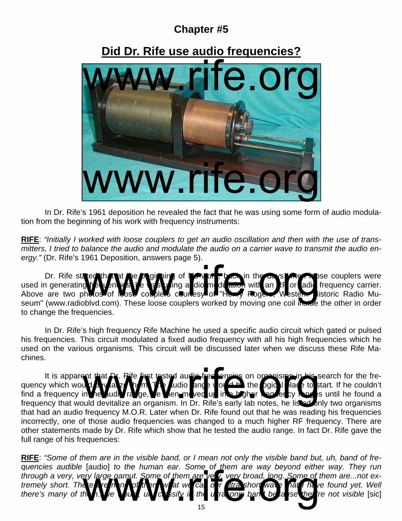
In Dr. Rife’s 1961 deposition he revealed the fact that he was using some form of audio modula-tion from the beginning of his work with frequency instruments: RIFE: “Initially I worked with loose couplers to get an audio oscillation and then with the use of trans-mitters, I tried to balance the audio and modulate the audio on a carrier wave to transmit the audio en-ergy.” (Dr. Rife’s 1961 Deposition, answers page 5). Dr. Rife stated that at the beginning of his work, back in the days when loose couplers were used in generating frequencies, he was using audio modulation with an RF or radio frequency carrier. Above are two photos of loose couplers courtesy of "Henry Rogers, Western Historic Radio Mu-seum" (www.radioblvd.com). These loose couplers worked by moving one coil inside the other in order to change the frequencies. In Dr. Rife’s high frequency Rife Machine he used a specific audio circuit which gated or pulsed his frequencies. This circuit modulated a fixed audio frequency with all his high frequencies which he used on the various organisms. This circuit will be discussed later when we discuss these Rife Ma-chines.
It is apparent that Dr. Rife first tested audio frequencies on organisms in his search for the fre-quency which would devitalize them. The audio range would be the logical place to start. If he couldn’t find a frequency in the audio range, he then moved up into higher frequency ranges until he found a frequency that would devitalize an organism. In Dr. Rife’s early lab notes, he listed only two organisms that had an audio frequency M.O.R. Later when Dr. Rife found out that he was reading his frequencies incorrectly, one of those audio frequencies was changed to a much higher RF frequency. There are other statements made by Dr. Rife which show that he tested the audio range. In fact Dr. Rife gave the full range of his frequencies:
RIFE: “Some of them are in the visible band, or I mean not only the visible band but, uh, band of fre-quencies audible [audio] to the human ear. Some of them are way beyond either way. They run through a very, very large gamut. Some of them are very, very broad, long. Some of them are...not ex-tremely short. There are none of them what we call our ultra short wave that I have found yet. Well there’s many of them...we would, uh, classify in the ultrasonic band because they’re not visible [sic]
www.rife.org www.rife.org www.rife.org www.rife.org www.rife.org
16
with the human ear. They’re way beyond you know. And some of them are even in the broadcast band. Your cancer is very high [1,604,000 Hertz]. You can’t hear it, the oscillation. But now you take your T.B. [Tuberculosis Rod 369,000 Hertz & Virus 769,000 Hertz]. Now that’s down. A little more you see...if you don’t have an absolute coordinative resonance, you have nothing. One tenth of one meter off and you have nothing. Its got to be absolutely correct for that individual organism. It’s got to be precise...the virus of cancer has a certain frequency. And it has to be there, otherwise if it’s a little one way or the other, no good, no good for nothing. Infrared will penetrate, yes, but the heat is not the thing because the heat is not the frequency, it’s [Infrared] way down in the very low band of frequencies and the labo-ratory rate of the BX is up into the high band.” (John Marsh Rife CDs - CD 5 track 2, CD 6 track 2, CD 7 track 1 and CD 9 track 1).
In these statements Dr. Rife clearly explains the broad range of his frequencies. Some were au-dio and could be heard by the human ear; others were in the ultrasonic range, and some were even in the broadcast band. Cancer he said was very high. He states the frequencies have to be very accurate to work. One tenth of one meter off and they would not work at all. We will talk about this later. Here are two additional statements that also verify that Dr. Rife’s Machine's could output a modulated audio frequency:
RIFE: “You know we had an idea when we had our [1934] Clinic in La Jolla, of course that was battery and motor generator operated that set, you know, and boy it would sure raise the devil with all the ra-dios so we had a couple of cars that was equipped with car radios and we sent them out and we would take the switch of that thing, and had a code you know like an S.O.S., and one of them went up north, and one of them went south from La Jolla. Before we started in we wanted to see how far we were go-ing to disturb things” (John Marsh Collection, Trip to Ohio Papers, Page 7, www.rife.org).
In order to be able to put out an S.O.S. type signal he would have had to modulate the audio fre-quency onto a carrier in order for the car radios to pick up the signal. This audio frequency would also create a problem with radio stations. On the John Marsh Collection of Dr. Rife’s audio CDs, Dr. Couche makes an interesting comment about the #3 instrument. He was present at the 1934 clinic sponsored by Dr. Johnson and the University of Southern California. He stated:
DR. COUCHE: “They gave him a treatment of the Rife frequencies which are in the auditory band.” (John Marsh Rife CDs - CD 3 track 1).
The cancer (1,604,000 Hertz) and tuberculosis (Rod 369,000 Hertz and Virus 769,000 Hertz) frequencies used in the 1934 clinic were not audio frequencies. Why would Dr. Couche make this statement? The evidence shows that Dr. Couche was getting things mixed up. The Beam Ray Clinical Rife Machine which Dr. Couche used for over 22 years used audio frequencies to create the proper sideband spacing to hit the high RF frequency M.O.R (Mortal Oscillitory Rate or the frequency that will kill or devitalize an organism). Dr. Couche purchased two or three of these clinical Rife Machines and used them until 1952 when he retired. We will cover this instrument later in this paper. Everything which we have quoted shows that the Rife Machines from 1934 and earlier could output audio frequen-cies and that Dr. Rife tested audio frequencies right from the beginning of his work in 1920. Although we have been able to prove that Dr. Rife tested the audio range of frequencies, as any good scientist would have done, it should be pointed out that by 1935 when the Rife Ray #4 Rife Ma-chine was built, he no longer felt that he needed to test audio frequencies any longer. This is indicated by the fact that no variable audio oscillator was included in this new frequency instrument. The Rife Ray #4 Rife Machine will be discussed later in this article.
www.rife.org www.rife.org www.rife.org www.rife.org www.rife.org
17
Chapter #6
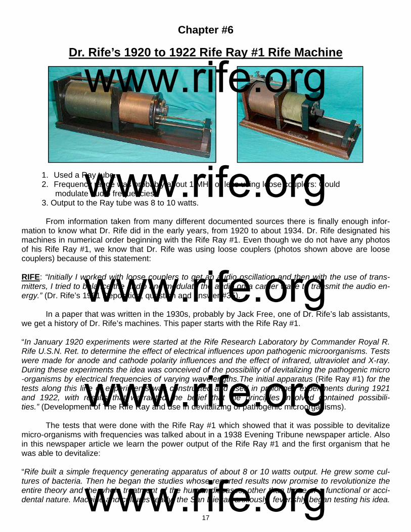
Dr. Rife’s 1920 to 1922 Rife Ray #1 Rife Machine
1. Used a Ray tube. 2. Frequency range was probably about 1 MHz or less using loose couplers: Could modulate audio frequencies. 3. Output to the Ray tube was 8 to 10 watts.
From information taken from many different documented sources there is finally enough infor-mation to know what Dr. Rife did in the early years, from 1920 to about 1934. Dr. Rife designated his machines in numerical order beginning with the Rife Ray #1. Even though we do not have any photos of his Rife Ray #1, we know that Dr. Rife was using loose couplers (photos shown above are loose couplers) because of this statement: RIFE: “Initially I worked with loose couplers to get an audio oscillation and then with the use of trans-mitters, I tried to balance the audio and modulate the audio on a carrier wave to transmit the audio en-ergy.” (Dr. Rife’s 1961 Deposition, question and answer #35). In a paper that was written in the 1930s, probably by Jack Free, one of Dr. Rife’s lab assistants, we get a history of Dr. Rife’s machines. This paper starts with the Rife Ray #1. “In January 1920 experiments were started at the Rife Research Laboratory by Commander Royal R. Rife U.S.N. Ret. to determine the effect of electrical influences upon pathogenic microorganisms. Tests were made for anode and cathode polarity influences and the effect of infrared, ultraviolet and X-ray. During these experiments the idea was conceived of the possibility of devitalizing the pathogenic micro-organisms by electrical frequencies of varying wavelengths.The initial apparatus (Rife Ray #1) for the tests along this line of experiments was constructed and used in prolonged experiments during 1921 and 1922, with results that warranted the belief that the principles involved contained possibili-ties.” (Development of The Rife Ray and use in devitalizing of pathogenic microorganisms). The tests that were done with the Rife Ray #1 which showed that it was possible to devitalize micro-organisms with frequencies was talked about in a 1938 Evening Tribune newspaper article. Also in this newspaper article we learn the power output of the Rife Ray #1 and the first organism that he was able to devitalize: “Rife built a simple frequency generating apparatus of about 8 or 10 watts output. He grew some cul-tures of bacteria. Then he began the studies whose reported results now promise to revolutionize the entire theory and the whole treatment of the human diseases, other than those of a functional or acci-dental nature. Machine and cultures ready, the San Diegan anxiously, feverishly began testing his idea.
www.rife.org www.rife.org www.rife.org www.rife.org www.rife.org
18
Would those minute killers of men die under the frequency bombardment? It would be a patience-wracking task, for there was no way to measure what wave length or frequencies the organism might have. In the quiet loneliness of the laboratory, Rife simply had to turn and turn and turn the tuning dials of his machine and check after each bombardment the conditions of the disease organisms in his cul-tures to see if anything had happened to them. He just had to hunt by trial and error a frequency, which might do something to a certain organism. Then, if he found one for that disease, he would have to start all over again on the next kind. The scientist took first a culture of b. coli, the organisms, which always seem to accompany the agency of typhoid fever yet apparently, are harmless themselves. He prepared microscope slides from the cul-ture and saw that his little subjects were alive. Then he turned the ray on them, tuned it to a certain fre-quency, then took the slide back to the microscope to see if anything had happened. He did this time after time and the b. coli still remained discouragingly healthy. Then one day, Rife recounted, a culture of the organisms which had been bombarded with a certain frequency [417,000 Hertz] appeared differ-ent under the microscope. They seemed lifeless! He tried to get them to grow, to reproduce in their laboratory media. He tried that same frequency on culture after culture of b. coli and always the results were the same. The organisms were dead. "It did kill them!" Rife told himself. And probably, cool, con-servative scientists though he is, he allowed himself to hope that he, Royal Raymond Rife, had found that 'bullet" which scientist have sought for years, that "magic bullet' which would surely, certainly slay mankind's diseases.” (Dread Disease Germs Destroyed By Ray, Claim Of S.D. Scientist-Cancer Blow Seen After 18-year Toil by Rife, The Evening Tribune, May 6, 1938). These few statements that we have just read are about all that is known about the Rife Ray #1. The most important development that was accomplished with the Rife Ray #1 was Dr. Rife was able to test and prove that micro-organisms could be killed or devitalized using RF frequencies. By 1923 Dr. Rife assembled his next Rife Machine called the Rife Ray #2 using off-the-shelf fre-quency generators. The same equipment that was used with the Rife Ray #2 was also used with the Rife Ray #3. The changes made to the Rife Ray #2 to create the Rife Ray #3 appear to be mostly an increase in the output power of the instrument through the ray tube. Since the full details of the changes are not known and the same equipment that was used with the Rife Ray #2 was used with the Rife Ray #3 we will jump to the Rife Ray #3 in the next chapter.
www.rife.org www.rife.org www.rife.org www.rife.org www.rife.org
19
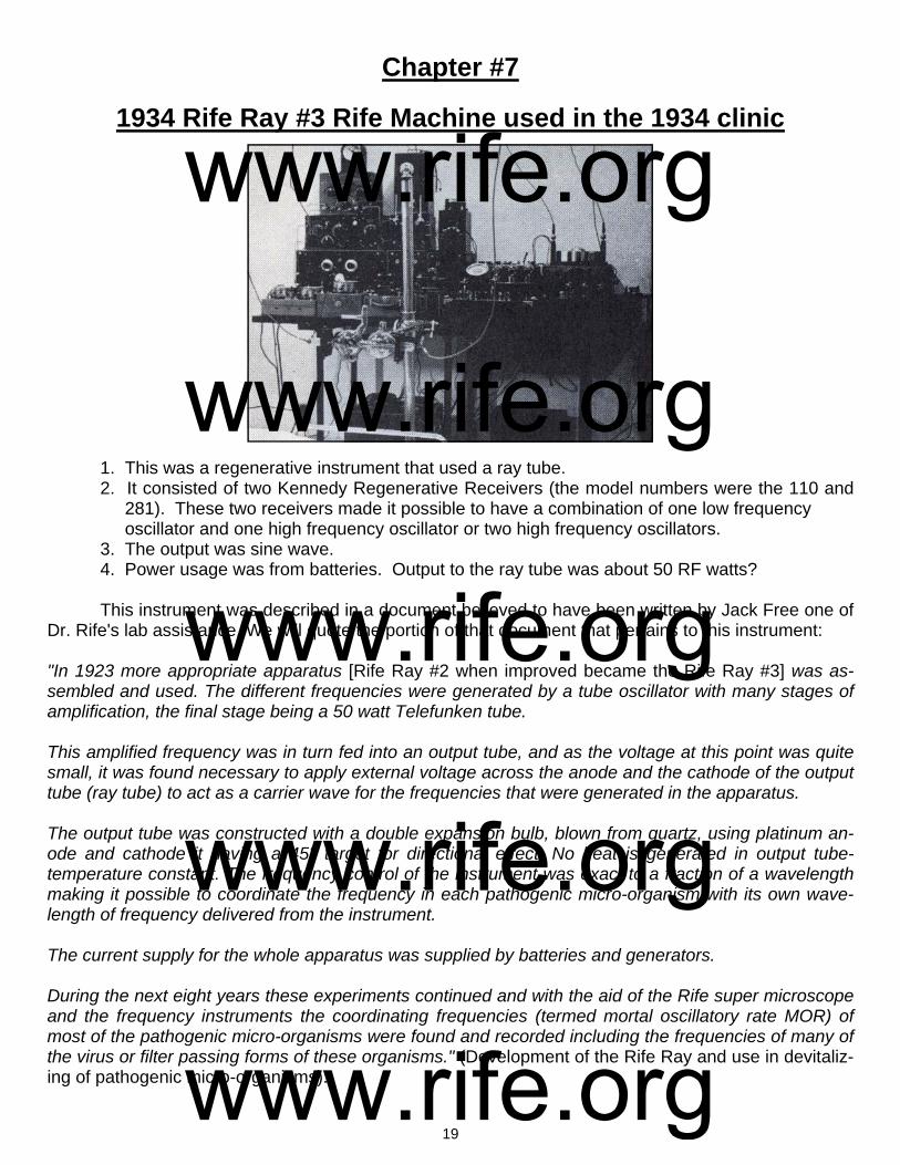
Chapter #7
1934 Rife Ray #3 Rife Machine used in the 1934 clinic
1. This was a regenerative instrument that used a ray tube. 2. It consisted of two Kennedy Regenerative Receivers (the model numbers were the 110 and 281). These two receivers made it possible to have a combination of one low frequency oscillator and one high frequency oscillator or two high frequency oscillators. 3. The output was sine wave. 4. Power usage was from batteries. Output to the ray tube was about 50 RF watts? This instrument was described in a document believed to have been written by Jack Free one of Dr. Rife's lab assistance. We will quote the portion of that document that pertains to this instrument: "In 1923 more appropriate apparatus [Rife Ray #2 when improved became the Rife Ray #3] was as-sembled and used. The different frequencies were generated by a tube oscillator with many stages of amplification, the final stage being a 50 watt Telefunken tube. This amplified frequency was in turn fed into an output tube, and as the voltage at this point was quite small, it was found necessary to apply external voltage across the anode and the cathode of the output tube (ray tube) to act as a carrier wave for the frequencies that were generated in the apparatus. The output tube was constructed with a double expansion bulb, blown from quartz, using platinum an-ode and cathode it having a 45° target for directional effect. No heat is generated in output tube-temperature constant. The frequency control of the instrument was exact to a fraction of a wavelength making it possible to coordinate the frequency in each pathogenic micro-organism with its own wave-length of frequency delivered from the instrument. The current supply for the whole apparatus was supplied by batteries and generators. During the next eight years these experiments continued and with the aid of the Rife super microscope and the frequency instruments the coordinating frequencies (termed mortal oscillatory rate MOR) of most of the pathogenic micro-organisms were found and recorded including the frequencies of many of the virus or filter passing forms of these organisms." (Development of the Rife Ray and use in devitaliz-ing of pathogenic micro-organisms).
www.rife.org www.rife.org www.rife.org www.rife.org www.rife.org

20
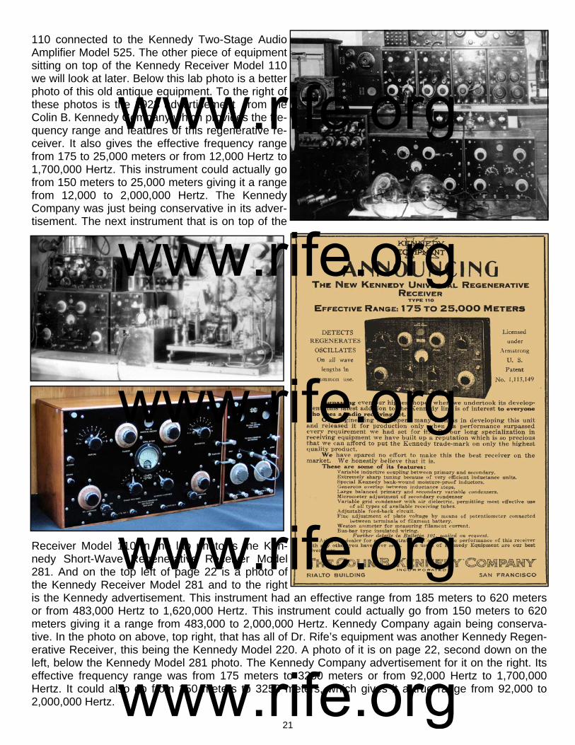
Dr. Rife was asked by Dr. Milbank Johnson M.D. to write a description of his Rife Ray #3 instru-ment in 1935. Dr. Rife had Jack Free, his lab assistant; include this description in a letter that Jack Free wrote to Dr. Milbank Johnson. Below is Dr. Rife's description. RIFE: "The basic principle of this devise is the control of a desired frequency. These frequencies vary-ing upon the organisms being treated. The frequency is set which controls the initial oscillator, which in turn is run thru six stages of amplifica-tion, the last stage driving a 50 watt output tube. The frequency with its carrier wave is transmitted into an output tube similar to the standard X-ray tube, but filled with a different inert gas. This tube acts as a directional antenna. The importance in the variable control of these frequencies is that each pathogenic organism being treated is of a different chemical consistency, the consequence being they carry a different molecular vibratory rate. Each one in turn under these conditions requires a different frequency or vibratory rate to destroy." (Letter from Jack Free to Dr. Milbank Johnson M.D., December 17, 1935). This Rife Machine was used in the 1934 clinic by Dr. Milbank Johnson. If you look at the bottom of the photo on the previous page you can see part of the bed railing and mattress where they treated the patients. If you look at the table you can see that the instrument was not a one piece instrument but had many components. This instrument has always been considered the best instrument used by Dr. Rife because it produced the results of the 1934 cancer and tuberculosis clinic. Those interested in the work of Dr. Rife have always wanted to know how this instrument worked. They have also wondered what equipment he used. This has been one of the biggest Rife mysteries. There has been all kinds of speculation on how his first instrument worked. What was its waveform? What was the frequency range? Could it generate audio frequencies? Was it super-regenerative (as he wrote on his lab notes), or was it just regenerative? All of these things have remained mysteries for over fifty years. It was gen-erally believed that the 1934 instrument was custom made for Dr. Rife. However, if the equipment had not been custom made, the mystery would be over. And today, thanks to some great detective work done by Mr. Peters, the mystery, in fact, is now over. The instruments were not custom made. They were standard off-the-shelf frequency generating equipment that Dr. Rife purchased. The equipment and frequency ranges are now known. A better photo of the equipment Dr. Rife used appears on the top right of page 21. He most likely stacked it all up on a table and took a picture of it after he started to use the newer equipment built for him in 1935. This photo, amongst others, made it possible to figure out the equipment Dr. Rife used. This photo has been provided courtesy of Mr. Ringas of Rife Research Group of Canada. Here in this paper you will be able to see the actual equipment along with the selling advertisements of the 1920’s that give the specifications of the equipment. We will now look at each piece of equipment and take an in-depth look at the specifications of each. All pieces of equipment except the ray tubes and possibly the five stage amplifier were consid-ered off-the-shelf equipment. This means that this was standard frequency generation equipment which could be purchased from companies in the 1920’s. Although they are regenerative receivers, they could output whatever frequency Dr. Rife wanted to use when the regenerative circuit was turned up. Dr. Rife used top-of-the-line Kennedy equipment from the Colin B. Kennedy Company, which built some of the most accurate, high quality equipment that could be purchased in 1923. It was also some of the most expensive equipment to purchase. The first photo of this equipment we will look at is on page 21, top left. It is one of several pho-tos of Dr. Rife’s lab instruments. The bottom two pieces of equipment are the Kennedy Receiver Model
www.rife.org www.rife.org www.rife.org www.rife.org www.rife.org
21
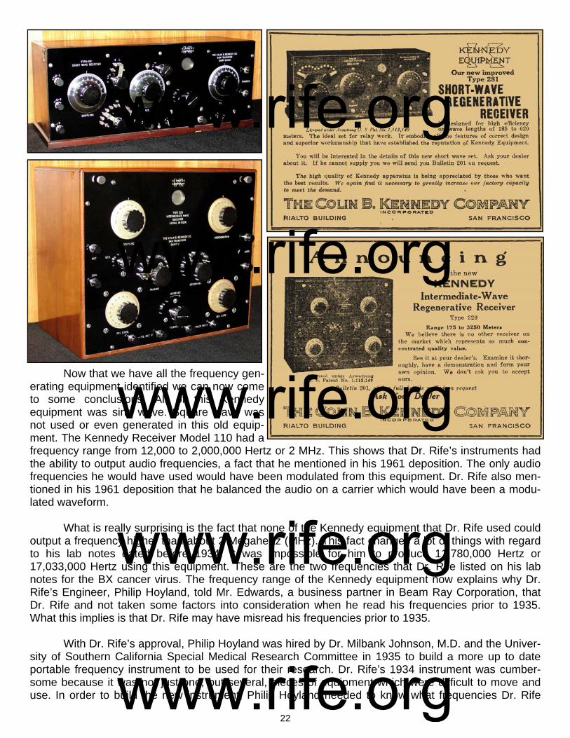
110 connected to the Kennedy Two-Stage Audio Amplifier Model 525. The other piece of equipment sitting on top of the Kennedy Receiver Model 110 we will look at later. Below this lab photo is a better photo of this old antique equipment. To the right of these photos is the 1923 advertisement from the Colin B. Kennedy Company which provides the fre-quency range and features of this regenerative re-ceiver. It also gives the effective frequency range from 175 to 25,000 meters or from 12,000 Hertz to 1,700,000 Hertz. This instrument could actually go from 150 meters to 25,000 meters giving it a range from 12,000 to 2,000,000 Hertz. The Kennedy Company was just being conservative in its adver-tisement. The next instrument that is on top of the
Receiver Model 110 in the lab photo is the Ken-nedy Short-Wave Regenerative Receiver Model 281. And on the top left of page 22 is a photo of the Kennedy Receiver Model 281 and to the right is the Kennedy advertisement. This instrument had an effective range from 185 meters to 620 meters or from 483,000 Hertz to 1,620,000 Hertz. This instrument could actually go from 150 meters to 620 meters giving it a range from 483,000 to 2,000,000 Hertz. Kennedy Company again being conserva-tive. In the photo on above, top right, that has all of Dr. Rife’s equipment was another Kennedy Regen-erative Receiver, this being the Kennedy Model 220. A photo of it is on page 22, second down on the left, below the Kennedy Model 281 photo. The Kennedy Company advertisement for it on the right. Its effective frequency range was from 175 meters to 3250 meters or from 92,000 Hertz to 1,700,000 Hertz. It could also go from 150 meters to 3250 meters, which gives it a true range from 92,000 to 2,000,000 Hertz.
www.rife.org www.rife.org www.rife.org www.rife.org www.rife.org
22
Now that we have all the frequency gen-erating equipment identified we can now come to some conclusions. All of this Kennedy equipment was sine wave. Square wave was not used or even generated in this old equip-ment. The Kennedy Receiver Model 110 had a frequency range from 12,000 to 2,000,000 Hertz or 2 MHz. This shows that Dr. Rife’s instruments had the ability to output audio frequencies, a fact that he mentioned in his 1961 deposition. The only audio frequencies he would have used would have been modulated from this equipment. Dr. Rife also men-tioned in his 1961 deposition that he balanced the audio on a carrier which would have been a modu-lated waveform. What is really surprising is the fact that none of the Kennedy equipment that Dr. Rife used could output a frequency higher than about 2 Megahertz (MHz). This fact changes a lot of things with regard to his lab notes dated before 1934. It was impossible for him to produce 11,780,000 Hertz or 17,033,000 Hertz using this equipment. These are the two frequencies that Dr. Rife listed on his lab notes for the BX cancer virus. The frequency range of the Kennedy equipment now explains why Dr. Rife’s Engineer, Philip Hoyland, told Mr. Edwards, a business partner in Beam Ray Corporation, that Dr. Rife and not taken some factors into consideration when he read his frequencies prior to 1935. What this implies is that Dr. Rife may have misread his frequencies prior to 1935. With Dr. Rife’s approval, Philip Hoyland was hired by Dr. Milbank Johnson, M.D. and the Univer-sity of Southern California Special Medical Research Committee in 1935 to build a more up to date portable frequency instrument to be used for their research. Dr. Rife’s 1934 instrument was cumber-some because it was not just one, but several, pieces of equipment which were difficult to move and use. In order to build the new instrument, Philip Hoyland needed to know what frequencies Dr. Rife
www.rife.org www.rife.org www.rife.org www.rife.org www.rife.org
23
was using. This is where the story gets interesting. Dr. Rife had many lab notes which had the frequen-cies written down on them for the various microorganisms. Dr. Rife could have just given Philip Hoy-land a copy of the frequency ranges that the lab notes covered and he could have built the instrument from that information. But this is not what happened. Philip Hoyland brought his standard master oscil-lator into the laboratory and then Dr. Rife and Philip Hoyland went through the long process of putting many organisms under the microscope and checking to see what the frequency was when it was devi-talized. If Dr. Rife had been confident that his original frequencies were correct on his lab notes this testing would not have been necessary. It is apparent that there were probably some questions in Dr. Rife's mind about the accuracy of his initial readings and frequencies which made this retesting of the organisms and there M.O.R. frequencies necessary. Keeping this in mind it was difficult to read the correct frequencies prior to this time unless you were very proficient at doing it. Philip Hoyland apparently wanted to know exactly what frequencies Dr. Rife was using in order to build the new instrument. While testifying on the stand in the 1939 Beam Ray trial, Philip Hoyland stated the following about how he obtained the frequencies. (1939 Beam Ray Trial Manuscript #778): HOYLAND: “They were taken off the last machine [the Kennedy equipment] that was built by Dr. Rife. I transferred them from one machine to another.” At another point during the trial the transcript reads as follows. (#905-916): COMPARET: “In June of 1935 was when you made an agreement with the [transcript missing words] medical research to build a Rife Ray machine, [the Rife Ray #4] you did build it soon after that?” HOYLAND: “Yes.” COMPARET: “You had an agreement with them that all work was to be done under Dr. Rife’s direc-tion?” HOYLAND: “That’s what the contract called for.” COMPARET: “Did you do this work without getting the frequencies from Dr. Rife?” HOYLAND: “I recalibrated the machine according to the bacteria.” COMPARET: “What specifically did you do that constituted this recalibration?” HOYLAND: “I used a standard oscillator against his machine to see what frequencies he was using.” COMPARET: “He set his machine and you measured his frequencies?” HOYLAND: “Yes.” COMPARET: “Did you make any memorandum of these particular frequencies?” HOYLAND: “Yes, I gave Dr. Johnson and Dr. Rife a list of them.” Later during the trial Dr. Rife was asked where the frequencies came from. (#1290-1293): JUDGE KELLY: “When you constructed this Beam Ray machine [from Kennedy equipment] you had a dial representing the frequencies or harmonics?”
www.rife.org www.rife.org www.rife.org www.rife.org www.rife.org

24
RIFE: “We had many dials on the original machine [Kennedy Model 110].” JUDGE KELLY: “Is that the machine Mr. Hoyland got the frequencies from?” RIFE: “Yes, he took them off that old machine [Kennedy Model 110].” From the court testimony given by Dr. Rife and Philip Hoyland we see the frequencies were read by Philip Hoyland off of the Kennedy Model 110 and 281 and used in the next instrument which was the Rife Ray #4 (We will be discussing this instrument next). Now let’s continue on reading the court testimony (#1553-1556): COMPARET: “Now going back to your assumption that Dr. Rife knew the frequencies, had Mr. Hoy-land ever told you that Dr. Rife knew them?” EDWARDS: “No, he told me that Dr. Rife only thought he had them.” COMPARET: “What did you think that meant?” EDWARDS: “Well, Mr. Hoyland told me about that time [1934 and before], that Dr. Rife measured the frequencies only by the length of the wire and that he did not take other factors into consideration.” Here in the court testimony we just read that Dr. Rife had not read the frequencies correctly when he measured them. This would have been a mistake easy to make in the 1920’s and 1930’s. The frequencies which Philip Hoyland read off of Dr. Rife’s #3 instrument, which consisted of the Kennedy equipment, were different from the earlier lab note frequencies recorded by Dr. Rife. This has caused a lot of confusion because the frequencies that Philip Hoyland read were all lower than 2,000,000 Hertz. Dr. Rife had written down on his lab notes frequencies as high as 11,780,000 and 17,033,000 Hertz for the BX cancer virus. However, the Kennedy Models 110, 220 and 281 could not output these high fre-quencies. It is apparent that Philip Hoyland was absolutely correct when he told Mr. Edwards that Dr. Rife had misread his frequencies. Also, Philip Hoyland testified in court that he gave both Dr. Rife and Dr. Johnson a list of the correct frequencies he read off of the Kennedy Model 110. This verifies the truth of what Philip Hoyland said in court. There is another verification that Dr. Rife had misread his frequencies. On the Rife audio CDs, Henry Siner, Dr. Rife’s lab assistant, read from a lab note of the BX cancer virus. All the information was the same as Dr. Rife’s earlier pre-1935 lab notes except the frequencies. On that corrected lab note Henry Siner read 187 meters for the wave length and 1,604,000 Hertz for the cycles per second frequency for the BX cancer virus. Both the meter frequency and the cycles per second measurement being the same frequency. However, on the pre-1935 lab note, both were different. One frequency was 11,780,000 and the other was 17.6 meters or 17,033,000 Hertz. Henry Siners reading of this corrected lab note also verifies that Dr. Rife had not read his frequencies correctly. At the end of that discussion about the BX cancer virus and the Lab note Henry Siner made this statement, quote: SINER: “That was a long time ago, but, and remember, I was just copying what he (Dr. Rife) dictated.” (John Marsh Rife CDs - MP3 track 11). This information from the Rife CDs shows that Dr. Rife made the corrections to the lab note, not Henry Siner. The frequency of 1,604,000 Hertz was the frequency Philip Hoyland read and gave to Dr. Rife and Dr. Johnson and it was used in the new instrument built in 1935 called the Rife Ray #4. There is one thing we need to consider. Dr. Rife could have read a harmonic of the frequency instead of the correct frequency. It appears this is in fact what Dr. Rife did. Dr. Rife understood how
www.rife.org www.rife.org www.rife.org www.rife.org www.rife.org

25
easy it was to read a harmonic frequency instead of the correct frequency and recognized that he may not have had true fundamental frequencies. He stated: RIFE: “I’ve talked to you [John Crane] and Verne [Verne Thompson] and other people too that there may be some of the frequencies that we are using that may be harmonics, you know...It’s not an im-possibility that some of those frequencies may be a harmonic. We may not know the true frequencies of some of them. But it does the business. Maybe if we had the true frequency it would do it better be-cause it has more power than a harmonic.” (John Marsh Rife CDs - CD 7 track 2). The frequency that Philip Hoyland read off of Dr. Rife’s 1934 instrument was 1,604,000 Hertz. Dr. Rife had written two frequencies down on his pre-1934 lab notes. One was 11,780,000 Hertz and the other was 17,033,000 Hertz. The seventh harmonic of 1,604,000 is 11,228,000 which is close to the 11,780,000 especially if you consider that Dr. Rife was not reading his frequencies correctly. We now know Dr. Rife was not even reading the harmonic correctly. Now the eleventh harmonic of 1,604,000 is 17,644,000 which is close also to 17,033,000 Hertz. Had Dr. Rife read the frequencies correctly then both the meter frequency and the cycles per second frequency should have been the same. This was the case with the new lab note when it was corrected by Dr. Rife and read by Henry Siner in the 1950’s. The evidence is absolutely overwhelming that Dr. Rife was not reading his frequen-cies correctly because the frequencies Philip Hoyland read were used in the next instrument which was called the Rife Ray #4. In the space of about 60 days all Dr. Rife’s frequencies changed. We wondered where these harmonics that Dr. Rife read might of come from. Did the Kennedy Model 110 have harmonics in its waveform? Did it output a sine wave waveform? Was the waveform distorted? The only way to answer these questions was to find a working Kennedy 110 and put it on a spectrum analyzer. Mr. Ringas of the Rife Research Group of Canada and I contacted Henry Rogers the owner of the Western Historic Radio Museum (www.radioblvd.com) who owns two Kennedy 110s that are still operational. Henry Rogers knew nothing about Dr. Rife but agreed to let me come visit his location to check the readings of the Kennedy Model 110. He also owns a Kennedy 220 and a Ken-nedy Model 281, both of which are also in working condition. The Kennedy Company built top-of-the-line equipment and we were surprised to find out, even after over 80 years, they still worked as well as they did when they were new. Very little attention is ever needed to get these instruments back in work-ing condition because of the quality of their construction. So with spectrum analyzer in hand, I went to see Henry Rogers and we put the Kennedy 110 on the spectrum analyzer to get the answers to our questions. Below is the reading of the waveform of the Kennedy Model 110 at 417,000 Hertz using a PicoScope 3205 spectrum analyzer. On the left is the waveform which proves that Dr. Rife was using sine wave. That question was finally answered.
The spectrum analyzing of the frequency revealed that there were no harmonics in the wave-form. The noise which shows up as little spikes are from the power supply. These old receivers ran on batteries and when they are hooked up to batteries the noise in the circuit is greatly reduced. The amazing thing about the Kennedy Model 110 sine wave waveform was that it was picture perfect. This amazed us because everyone believed that the equipment that Dr. Rife used would have had a dis-torted waveform. No one that I have ever talked with believed that this old equipment was capable of producing a nearly-perfect waveform. It was as good as we can do today with our sophisticated mod-
Kennedy Model 110 at 417,000 Hertz
www.rife.org www.rife.org www.rife.org www.rife.org www.rife.org
26
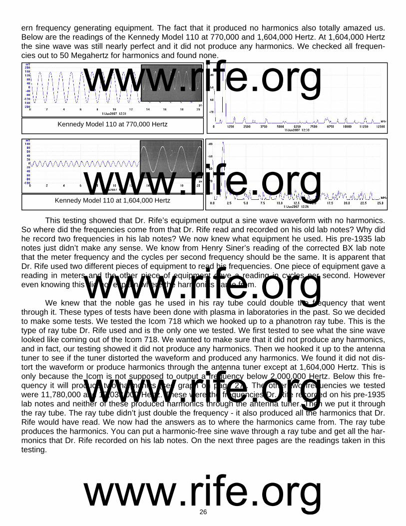
ern frequency generating equipment. The fact that it produced no harmonics also totally amazed us. Below are the readings of the Kennedy Model 110 at 770,000 and 1,604,000 Hertz. At 1,604,000 Hertz the sine wave was still nearly perfect and it did not produce any harmonics. We checked all frequen-cies out to 50 Megahertz for harmonics and found none.
This testing showed that Dr. Rife’s equipment output a sine wave waveform with no harmonics. So where did the frequencies come from that Dr. Rife read and recorded on his old lab notes? Why did he record two frequencies in his lab notes? We now knew what equipment he used. His pre-1935 lab notes just didn’t make any sense. We know from Henry Siner’s reading of the corrected BX lab note that the meter frequency and the cycles per second frequency should be the same. It is apparent that Dr. Rife used two different pieces of equipment to read his frequencies. One piece of equipment gave a reading in meters and the other piece of equipment gave a reading in cycles per second. However even knowing this did not explain where the harmonics came from. We knew that the noble gas he used in his ray tube could double the frequency that went through it. These types of tests have been done with plasma in laboratories in the past. So we decided to make some tests. We tested the Icom 718 which we hooked up to a phanotron ray tube. This is the type of ray tube Dr. Rife used and is the only one we tested. We first tested to see what the sine wave looked like coming out of the Icom 718. We wanted to make sure that it did not produce any harmonics, and in fact, our testing showed it did not produce any harmonics. Then we hooked it up to the antenna tuner to see if the tuner distorted the waveform and produced any harmonics. We found it did not dis-tort the waveform or produce harmonics through the antenna tuner except at 1,604,000 Hertz. This is only because the Icom is not supposed to output a frequency below 2,000,000 Hertz. Below this fre-quency it will produce two harmonics (see graph on page 27). The other two frequencies we tested were 11,780,000 and 17,033,000 Hertz. These were the frequencies Dr. Rife recorded on his pre-1935 lab notes and neither of these produced harmonics through the antenna tuner. Then we put it through the ray tube. The ray tube didn’t just double the frequency - it also produced all the harmonics that Dr. Rife would have read. We now had the answers as to where the harmonics came from. The ray tube produces the harmonics. You can put a harmonic-free sine wave through a ray tube and get all the har-monics that Dr. Rife recorded on his lab notes. On the next three pages are the readings taken in this testing.
Kennedy Model 110 at 770,000 Hertz
Kennedy Model 110 at 1,604,000 Hertz
www.rife.org www.rife.org www.rife.org www.rife.org www.rife.org
27
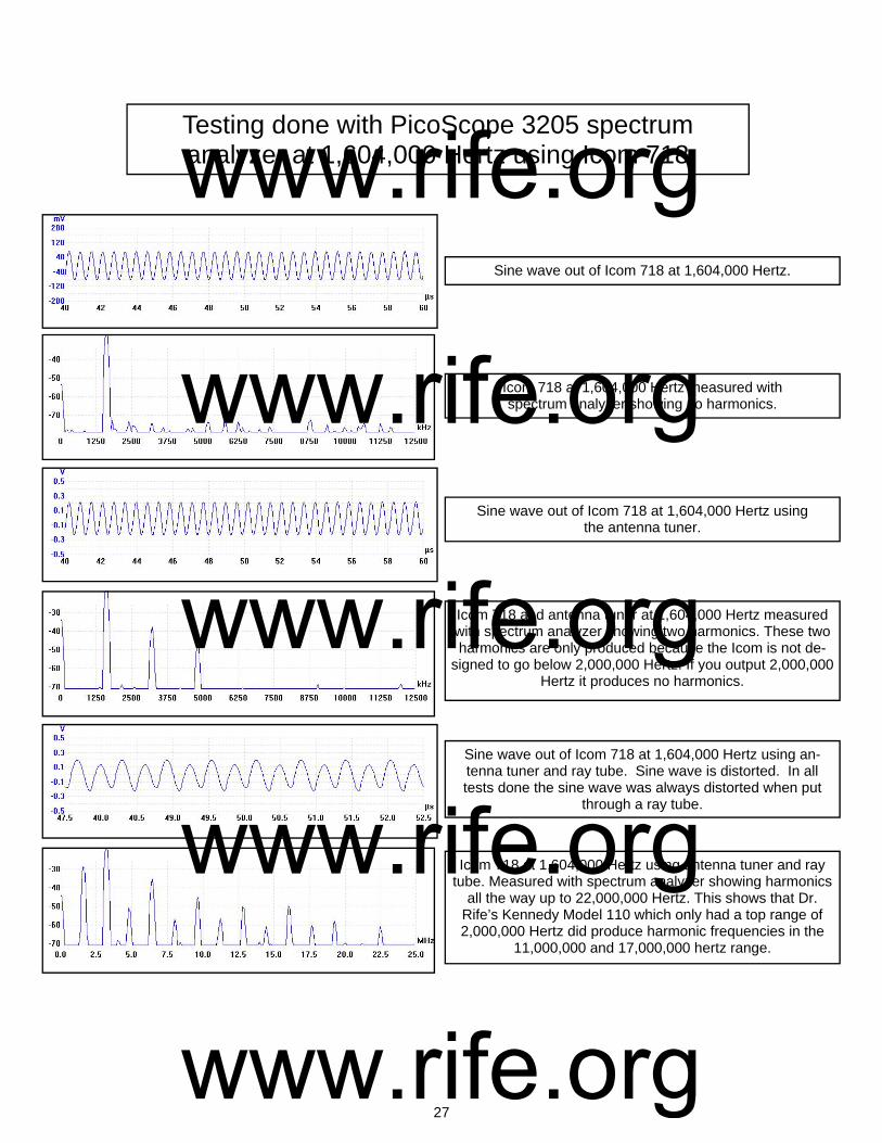
Sine wave out of Icom 718 at 1,604,000 Hertz.
Icom 718 and antenna tuner at 1,604,000 Hertz measured with spectrum analyzer showing two harmonics. These two harmonics are only produced because the Icom is not de-
signed to go below 2,000,000 Hertz. If you output 2,000,000 Hertz it produces no harmonics.
Sine wave out of Icom 718 at 1,604,000 Hertz using the antenna tuner.
Icom 718 at 1,604,000 Hertz measured with spectrum analyzer showing no harmonics.
Sine wave out of Icom 718 at 1,604,000 Hertz using an-tenna tuner and ray tube. Sine wave is distorted. In all tests done the sine wave was always distorted when put
through a ray tube.
Icom 718 at 1,604,000 Hertz using antenna tuner and ray tube. Measured with spectrum analyzer showing harmonics
all the way up to 22,000,000 Hertz. This shows that Dr. Rife’s Kennedy Model 110 which only had a top range of 2,000,000 Hertz did produce harmonic frequencies in the
11,000,000 and 17,000,000 hertz range.
Testing done with PicoScope 3205 spectrum analyzer at 1,604,000 Hertz using Icom 718
www.rife.org www.rife.org www.rife.org www.rife.org www.rife.org

28
Below are the measurements taken with the PicoScope 3205 spectrum analyzer from the Icom 718 using the antenna tuner and ray tube at 11,780,000 Hertz. This was the first frequency Dr. Rife listed on his pre-1934 lab notes which was later changed to 1,604,000 Hertz.
Sine wave out of Icom 718 at 11,780,000 Hertz.
Icom 718 and antenna tuner at 11,780,000 Hertz measured with spectrum analyzer showing no harmonics.
Sine wave out of Icom 718 at 11,780,000 Hertz using the antenna tuner.
Icom 718 at 11,780,000 Hertz measured with spectrum analyzer showing no harmonics.
Sine wave out of Icom 718 at 11,780,000 Hertz using an-tenna tuner and ray tube. The sine wave does not look like a sine wave. In all cases the sine wave is distorted to some
degree when put through a ray tube.
Icom 718 at 11,780,000 Hertz using antenna tuner and ray tube. Measured with spectrum analyzer showing harmonics
all the way up to 50 MHz.
Testing done with PicoScope 3205 spectrum analyzer at 11,780,000 hertz using Icom 718
www.rife.org www.rife.org www.rife.org www.rife.org www.rife.org

29
Below are the measurements taken with the PicoScope 3205 spectrum analyzer from the Icom 718 using the antenna tuner and ray tube at 17,033,000 Hertz. This was the second frequency on his pre-1934 lab notes which was recorded in meters. This was later changed to 187 meters which would give us a frequency of about 1,604,000 Hertz. This confirms that Dr. Rife was just reading a harmonic at 17,033,000.
Sine wave out of Icom 718 at 17,033,000 Hertz. Some distortion was in the sine wave.
Icom 718 and antenna tuner at 17,033,000 Hertz measured to 50 MHz with spectrum analyzer showing no harmonics.
Sine wave out of Icom 718 at 17,033,000 Hertz using the antenna tuner. Same slight distortion noticed.
Icom 718 at 17,033,000 Hertz measured to 50 MHz with spectrum analyzer showing no harmonics.
Sine wave out of Icom 718 at 17,033,000 Hertz using an-tenna tuner and ray tube. Sine wave was distorted even
more when put through a ray tube.
Icom 718 at 17,033,000 Hertz using antenna tuner and ray tube. Measured with spectrum analyzer showing harmonics
all the way up to 50 MHz.
Testing done with PicoScope 3205 spectrum analyzer at 17,033,000 hertz using Icom 718
www.rife.org www.rife.org www.rife.org www.rife.org www.rife.org
30
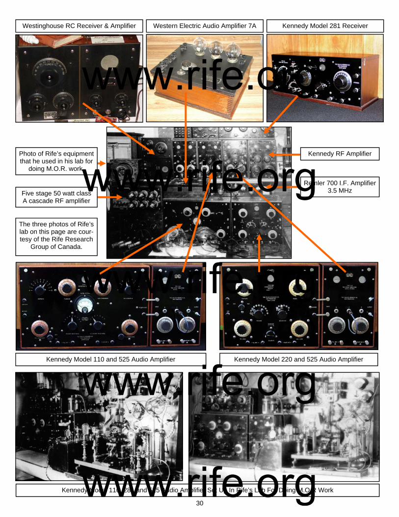
Westinghouse RC Receiver & Amplifier Western Electric Audio Amplifier 7A Kennedy Model 281 Receiver
Kennedy Model 110 and 525 Audio Amplifier Kennedy Model 220 and 525 Audio Amplifier
Kennedy RF Amplifier
Remler 700 I.F. Amplifier 3.5 MHz
Kennedy Model 110, 281 and 525 Audio Amplifier Set Up In Rife’s Lab For Doing M.O.R Work
Photo of Rife’s equipment that he used in his lab for
doing M.O.R. work.
The three photos of Rife’s lab on this page are cour-tesy of the Rife Research
Group of Canada.
Five stage 50 watt class A cascade RF amplifier
www.rife.org www.rife.org www.rife.org www.rife.org www.rife.org
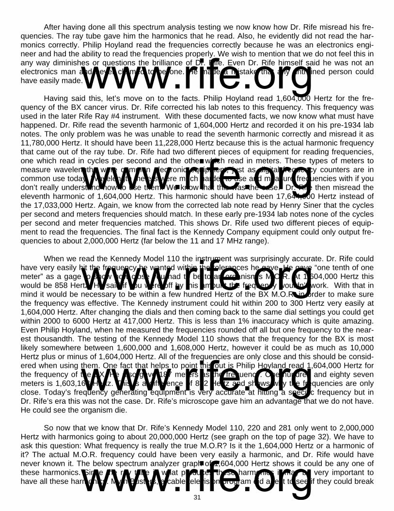
31
After having done all this spectrum analysis testing we now know how Dr. Rife misread his fre-quencies. The ray tube gave him the harmonics that he read. Also, he evidently did not read the har-monics correctly. Philip Hoyland read the frequencies correctly because he was an electronics engi-neer and had the ability to read the frequencies properly. We wish to mention that we do not feel this in any way diminishes or questions the brilliance of Dr. Rife. Even Dr. Rife himself said he was not an electronics man and never claimed to be one. He made a mistake that any untrained person could have easily made. Having said this, let’s move on to the facts. Philip Hoyland read 1,604,000 Hertz for the fre-quency of the BX cancer virus. Dr. Rife corrected his lab notes to this frequency. This frequency was used in the later Rife Ray #4 instrument. With these documented facts, we now know what must have happened. Dr. Rife read the seventh harmonic of 1,604,000 Hertz and recorded it on his pre-1934 lab notes. The only problem was he was unable to read the seventh harmonic correctly and misread it as 11,780,000 Hertz. It should have been 11,228,000 Hertz because this is the actual harmonic frequency that came out of the ray tube. Dr. Rife had two different pieces of equipment for reading frequencies, one which read in cycles per second and the other which read in meters. These types of meters to measure wavelengths were common electronic equipment, just as digital frequency counters are in common use today. Wavelength meters were much harder to use and measure frequencies with if you don’t really understand how to use them. We know that this was the case. Dr. Rife then misread the eleventh harmonic of 1,604,000 Hertz. This harmonic should have been 17,644,000 Hertz instead of the 17,033,000 Hertz. Again, we know from the corrected lab note read by Henry Siner that the cycles per second and meters frequencies should match. In these early pre-1934 lab notes none of the cycles per second and meter frequencies matched. This shows Dr. Rife used two different pieces of equip-ment to read the frequencies. The final fact is the Kennedy Company equipment could only output fre-quencies to about 2,000,000 Hertz (far below the 11 and 17 MHz range). When we read the Kennedy Model 110 the instrument was surprisingly accurate. Dr. Rife could have very easily hit the frequency he wanted within the tolerances he gave. He gave “one tenth of one meter” as a gage to show how close you had to be to an organism’s M.O.R. At 1,604,000 Hertz this would be 858 Hertz. He said if you were off by this amount the frequency wouldn’t work. With that in mind it would be necessary to be within a few hundred Hertz of the BX M.O.R. in order to make sure the frequency was effective. The Kennedy instrument could hit within 200 to 300 Hertz very easily at 1,604,000 Hertz. After changing the dials and then coming back to the same dial settings you could get within 2000 to 6000 Hertz at 417,000 Hertz. This is less than 1% inaccuracy which is quite amazing. Even Philip Hoyland, when he measured the frequencies rounded off all but one frequency to the near-est thousandth. The testing of the Kennedy Model 110 shows that the frequency for the BX is most likely somewhere between 1,600,000 and 1,608,000 Hertz, however it could be as much as 10,000 Hertz plus or minus of 1,604,000 Hertz. All of the frequencies are only close and this should be consid-ered when using them. One fact that helps to point this out is Philip Hoyland read 1,604,000 Hertz for the frequency of the BX. He also gave 187 meters as the frequency. One hundred and eighty seven meters is 1,603,168 Hertz. This is a difference of 832 Hertz and shows why the frequencies are only close. Today’s frequency generating equipment is very accurate at hitting a specific frequency but in Dr. Rife’s era this was not the case. Dr. Rife’s microscope gave him an advantage that we do not have. He could see the organism die. So now that we know that Dr. Rife’s Kennedy Model 110, 220 and 281 only went to 2,000,000 Hertz with harmonics going to about 20,000,000 Hertz (see graph on the top of page 32). We have to ask this question: What frequency is really the true M.O.R? Is it the 1,604,000 Hertz or a harmonic of it? The actual M.O.R. frequency could have been very easily a harmonic, and Dr. Rife would have never known it. The below spectrum analyzer graph of 1,604,000 Hertz shows it could be any one of these harmonics. Since the ray tube is what produces these harmonics it may be very important to have all these harmonics. Myth Busters, a cable television program did a test to see if they could break
www.rife.org www.rife.org www.rife.org www.rife.org www.rife.org
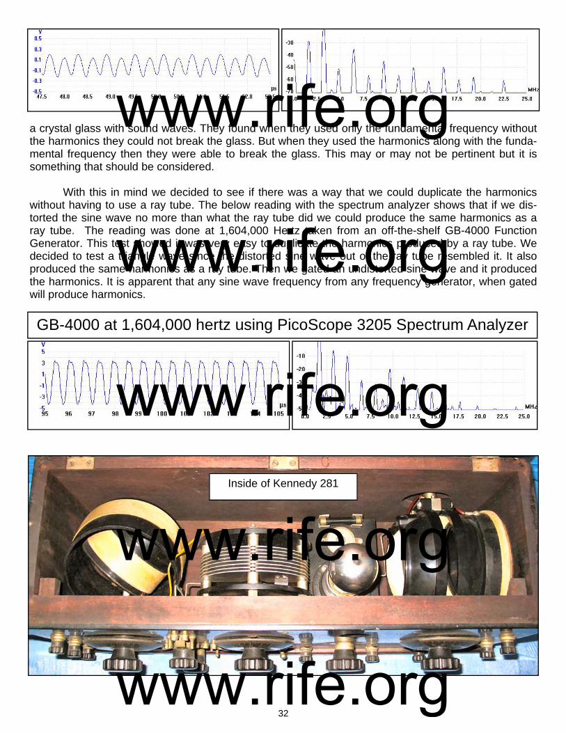
32
a crystal glass with sound waves. They found when they used only the fundamental frequency without the harmonics they could not break the glass. But when they used the harmonics along with the funda-mental frequency then they were able to break the glass. This may or may not be pertinent but it is something that should be considered. With this in mind we decided to see if there was a way that we could duplicate the harmonics without having to use a ray tube. The below reading with the spectrum analyzer shows that if we dis-torted the sine wave no more than what the ray tube did we could produce the same harmonics as a ray tube. The reading was done at 1,604,000 Hertz taken from an off-the-shelf GB-4000 Function Generator. This test showed it was very easy to duplicate the harmonics produced by a ray tube. We decided to test a triangle wave since the distorted sine wave out of the ray tube resembled it. It also produced the same harmonics as a ray tube. Then we gated an undistorted sine wave and it produced the harmonics. It is apparent that any sine wave frequency from any frequency generator, when gated will produce harmonics.
GB-4000 at 1,604,000 hertz using PicoScope 3205 Spectrum Analyzer
Inside of Kennedy 281
www.rife.org www.rife.org www.rife.org www.rife.org www.rife.org
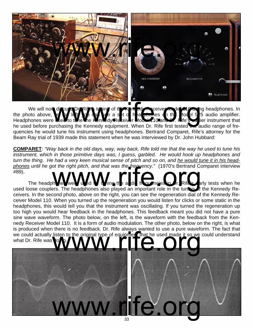
33
We will now discuss Dr. Rife’s tuning of the Kennedy Receiver Model 110 using headphones. In the photo above, on the left, you can see a set of headphones on the Model 525 audio amplifier. Headphones were used to tune the Kennedy Receiver Model 110 and Dr. Rife’s earlier instrument that he used before purchasing the Kennedy equipment. When Dr. Rife first tested the audio range of fre-quencies he would tune his instrument using headphones. Bertrand Comparet, Rife’s attorney for the Beam Ray trial of 1939 made this statement when he was interviewed by Dr. John Hubbard: COMPARET: “Way back in the old days, way, way back, Rife told me that the way he used to tune his instrument, which in those primitive days was, I guess, garbled. He would hook up headphones and turn the thing. He had a very keen musical sense of pitch and so on, and he would tune it in his head-phones until he got the right pitch, and that was the frequency.” (1970’s Bertrand Comparet interview #89). The headphones were used for tuning the audio frequencies in Dr. Rife’s early tests when he used loose couplers. The headphones also played an important role in the tuning of the Kennedy Re-ceivers. In the second photo, above on the right, you can see the regeneration dial of the Kennedy Re-ceiver Model 110. When you turned up the regeneration you would listen for clicks or some static in the headphones, this would tell you that the instrument was oscillating. If you turned the regeneration up too high you would hear feedback in the headphones. This feedback meant you did not have a pure sine wave waveform. The photo below, on the left, is the waveform with the feedback from the Ken-nedy Receiver Model 110. It is a form of audio modulation. The other photo, below on the right, is what is produced when there is no feedback. Dr. Rife always wanted to use a pure waveform. The fact that we could actually listen to the original type of equipment that he used made it so we could understand what Dr. Rife was doing.
www.rife.org www.rife.org www.rife.org www.rife.org www.rife.org

34
We will now discuss Dr. Rife’s multi-stage-amplifier that he used with the Kennedy equipment. This was most likely a class A RC coupling cascade style amplifier. Daven Company started building this type of amplifier back in about 1925. Dr. Rife may have had Daven custom build his multi-stage-amplifier but we cannot be sure. The two photos, at the bottom of this page, are Daven amplifiers. One is a three stage amplifier and the other is a four stage amplifier. The Kennedy Receiver Model 110 only output about 1.5 to 3 volts. Dr. Rife needed to be able to amplify the signal to a high enough power level to make it effective. In the three old lab photos above we see Dr. Rife’s multi-stage-amplifier. In the above photo, bottom right, you can see the type of tubes he would have used in the early to mid 1920’s. These tubes would have made it so Dr. Rife could amplify the signal from the Kennedy Re-ceiver Model 110 to about 50 watts in multi-stages. If you look at the above three photos of Dr. Rife’s multi-stage-amplifier you will see five switches. These five switches (representing five-stages) made it so he could choose different power levels determined by how many stages of amplification he wanted
www.rife.org www.rife.org www.rife.org www.rife.org www.rife.org
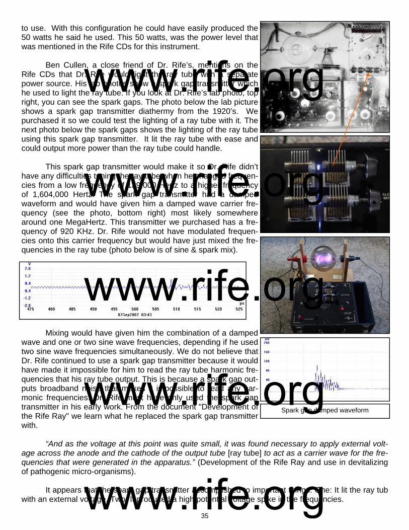
35
to use. With this configuration he could have easily produced the 50 watts he said he used. This 50 watts, was the power level that was mentioned in the Rife CDs for this instrument. Ben Cullen, a close friend of Dr. Rife’s, mentions on the Rife CDs that Dr. Rife would light the ray tube with a separate power source. His lab photos show a spark gap transmitter which he used to light the ray tube. If you look at Dr. Rife’s lab photo, top right, you can see the spark gaps. The photo below the lab picture shows a spark gap transmitter diathermy from the 1920’s. We purchased it so we could test the lighting of a ray tube with it. The next photo below the spark gaps shows the lighting of the ray tube using this spark gap transmitter. It lit the ray tube with ease and could output more power than the ray tube could handle. This spark gap transmitter would make it so Dr. Rife didn’t have any difficulties tuning the ray tube when he changed frequen-cies from a low frequency of 139,000 Hertz to a higher frequency of 1,604,000 Hertz. The spark gap transmitter had a damped waveform and would have given him a damped wave carrier fre-quency (see the photo, bottom right) most likely somewhere around one MegaHertz. This transmitter we purchased has a fre-quency of 920 KHz. Dr. Rife would not have modulated frequen-cies onto this carrier frequency but would have just mixed the fre-quencies in the ray tube (photo below is of sine & spark mix).
Mixing would have given him the combination of a damped wave and one or two sine wave frequencies, depending if he used two sine wave frequencies simultaneously. We do not believe that Dr. Rife continued to use a spark gap transmitter because it would have made it impossible for him to read the ray tube harmonic fre-quencies that his ray tube output. This is because a spark gap out-puts broadband noise that makes it impossible to read any har-monic frequencies. Dr. Rife must have only used the spark gap transmitter in his early work. From the document "Development of the Rife Ray" we learn what he replaced the spark gap transmitter with. “And as the voltage at this point was quite small, it was found necessary to apply external volt-age across the anode and the cathode of the output tube [ray tube] to act as a carrier wave for the fre-quencies that were generated in the apparatus.” (Development of the Rife Ray and use in devitalizing of pathogenic micro-organisms). It appears that the spark gap transmitter accomplished to important things. One: It lit the ray tub with an external voltage. Two: It produced a high potential voltage spike in the frequencies.
Spark gap damped waveform
www.rife.org www.rife.org www.rife.org www.rife.org www.rife.org
36
To better understand the reason why a high potential voltage spike is important we need to jump forward in the history of Dr. Rife's instruments to 1936-1937. The Beam Ray Laboratory instrument built by Philip Hoyland was built at this time and it had a fixed audio frequency pulsing circuit. The au-dio frequency that it produced was modulated with the RF frequencies it output. This audio pulsing cir-cuit would have given Dr. Rife’s frequencies a very high potential voltage spike almost identical to the damped wave of the spark gap. John Crane made this statement when he was narrating Dr. Rife’s lab film. CRANE: “Now the spikes that you see on the frequencies are the lethal part that kill and devitalize the virus. They are the resonant peaks of the frequencies which increase the voltage to a very high poten-tial which the cells of the virus wall can not tolerate and they break up into many pieces and are de-stroyed.” (Dr. Rife’s Lab Film Narrated by John Crane in the 1970’s). The modulated audio frequency in the 1936-1937 Beam Ray Laboratory instrument was in the shape of a damped wave. With both the Rife Ray #4 and the Beam Ray Laboratory instruments having waveforms in the shape of a damped wave doesn't seem like a coincidence. When Dr. Rife discontin-ued using the spark gap and replaced it with an external high voltage current to act as a carrier fre-quency he would have had to develop a new method of creating this high potential voltage rise in his frequencies. It appears, with the help of Lee Deforest, that Dr. Rife must have developed this audio fre-quency pulsing circuit for his instruments. It is apparent that this pulsing of the M.O.R frequencies is the reason why Dr. Rife was able to devitalize the many microorganisms he tested. Dr. Rife described the method he used to find these frequencies on the Rife audio CDs. RIFE: “Because when I check on that thing and look through that microscope hour after hour day after day, tuning that damn thing [Kennedy 110] to find something that will kill that bug. And every hour or half an hour, whatever is required, I put a new fresh culture under the microscope and keep that on and I find something that folds it up, alright!” (John Marsh Rife CDs - CD 7 track 2). It was a very tedious task to find a frequency that would devitalize and organism. Dr. Rife re-corded all his frequencies on lab notes. Even though he misread his frequencies many people want to know those frequencies anyway. On the next page in a chart are the misread lab note frequencies which he recorded prior to 1935. Each lab note had two frequencies. One was listed in cycles per sec-ond and the second was listed in meters. For the purpose of making this report easier to understand the meter wave lengths on Dr. Rife’s lab notes have been converted to cycles per second or Hertz. You will notice that there are two audio frequencies listed for organisms that are above 12,000 Hertz. They are the only audio frequencies ever listed by Dr. Rife for any organisms. One of them was changed to a higher RF frequency when Philip Hoyland read the correct frequencies in 1935 when he built the Rife Ray #4. Most likely the other audio frequency was really a higher RF frequency.
www.rife.org www.rife.org www.rife.org www.rife.org www.rife.org
37
Microorganism First Frequency
In Hertz Second Frequency
Meters To Hertz
Actinomycosis (Streptothrix) 678,000 Hz 186,554 Hz
Anthrax 900,000 Hz 272,539 Hz
Anthrax Symptomatic 400,000 Hz 16,655 Hz
B. Coli (Rod form) 683,000 Hz 317, 914 Hz
B. Coli (Filterable virus) 8,581,000 Hz 11,103,424 Hz
Bacillus X Cancer 11,780,000 Hz 17,033,662 Hz
Bubonic Plague 160,000 Hz 512,466 Hz
Catarrh 1,800,000 Hz 1,713,100 Hz
Cholera Spirillum 851,000 Hz 960,873 Hz
Contagious Conjunctivitis 1,206,000 Hz 2,025,625 Hz
Diphtheria 800,000 Hz 1,090,154 Hz
Glanders 986,000 Hz 736,591 Hz
Gonorrhea 600,000 Hz 150,649 Hz
Influenza 1,674,000 Hz 1,946,704 Hz
Leprosy 743,000 Hz 251,926 Hz
Pneumonia 1,200,000 Hz 381,901 Hz
Spinal Meningitis 927,800 Hz 1,795,164 Hz
Staphylococcus Pyogenes Aureus 998,740 Hz 555,171 Hz
Staphylococcus Pyogenes Albus Found in Dr. Rife’s papers 549,070 Hz
Streptococcus Pyogenes 1,214,000 Hz 2,111,214 Hz
Syphilis (Treponema Pallidum) 900,000 Hz 2,775,856 Hz
Tetanus 700,000 Hz 15,779 Hz
Tuberculosis (Rod form) 583,000 Hz 541,142 Hz
Typhoid Fever (Rod form) 900,000 Hz 868,964 Hz
Typhoid Fever (Filter passing) 9,680,000 Hz 13,943,835 Hz
Dr. Rife’s Misread Lab Note Frequencies From Before 1935
www.rife.org www.rife.org www.rife.org www.rife.org www.rife.org

38
Chapter #8
1935 Rife Ray #4 Rife Machine
1. Used a ray tube. 2. Had two separate oscillators so it could output two frequencies at a time. Frequency range was from 87,000 Hertz to 22.5 MHz. 3. Power usage was about 450 to 600 watts. Output to the ray tube was variable (50 to 200 RF watts). Some have asked how we can be sure these photos we have are of the Rife Ray #4 Rife Ma-chine. It is a simple process of deductive reasoning. John Crane, one of Dr. Rife’s 1950’s business partners, incorrectly dated the Rife Ray #4 as a 1942 Rife Machine and this has led to the confusion which we will now attempt to clear up. In the photo above on the right we see Dr. Rife using the instru-ment which John Crane dated as built in 1942. However, the lab film this picture was taken from was made in the summer of 1936 for use at a conference which Dr. Rife planned to attend in the autumn of that same year. He was presenting this film at this conference to demonstrate the isolation of the BX cancer virus. This properly dates the instrument as having been built before the summer of 1936 and indicates that John Crane was incorrect. In the background of this photo, behind the instrument Dr. Rife is using, we see his Kennedy Company equipment back against the wall. Therefore this instrument would have been built in late 1935 or early 1936. The Rife Ray #4 documents show it was completed in the fall of 1935. This logically dates the Rife Machine he is using in the 1936 film as the Rife Ray #4. Bertrand Comparet, Dr. Rife’s attorney, said three experimental machines were built. With the proper dating of this Rife Machine, which shows it is the Rife Ray #4, we will now discuss it in detail. Of the three experimental machines it appears that two were Rife Ray #4's and the third was the Beam Ray experimental instrument which was used in a clinic in 1937. We will cover the Beam Ray Clinical instrument later. `Dr. Johnson's machine was the first Rife Ray #4 that was built in 1935. After Dr. Johnson's in-strument was built we find that the second #4 instrument was soon to be built for Dr. Rife: DR. JOHNSON: "While you have the machine [Dr. Johnson's Rife Ray #4] down there, I hope you and Jack are working on those bananas so we can get an M.O.R. for them, if possible. As soon as you send Phil and the machine back, I am going to start Phil on making your Machine." (Letter from Dr. Johnson to Dr. Rife, November 15, 1936).
www.rife.org www.rife.org www.rife.org www.rife.org www.rife.org

39
Now that we have established the fact that both Dr. Milbank Johnson and Dr. Rife had their own Rife Ray #4 instrument we can continue with the history of this instrument. As pointed out earlier in this report Philip Hoyland eventually became Dr. Rife's engineer and business partner. Philip Hoyland was the one who measured Dr. Rife's frequencies when he came to Dr. Rife's lab in 1935. We will also point out that the frequencies used in this instrument were transferred from the Rife Ray #3 to the Rife Ray #4 after Philip Hoyland read the correct frequencies. We have in the document "Development of the Rife Ray" a description of this instrument: “In 1935 in entirely new application of the old principle was incorporated in an instrument built under the direction of Commander Rife by Philip Hoyland of Pasadena California. The new instrument was light socket powered and had an output of 500 Watts. Designated #4 (Rife Ray #4) [Many of the power output measurements of Dr. Rife’s equipment were misread]. Furthermore it was equipped to deliver two distinct frequencies simultaneously and both variable. This apparatus proved to be more efficient with decidedly fewer factors of error in the laboratory tests using 75 pounds of horse meat.” (Development of the Rife Ray and use in devitalizine pathogenic micro-organisms).
In the laboratory tests that were performed with the Rife Ray #4 they made many tests to deter-mine its capability. Dr. Johnson talked about the many different aspects of the machine they had to test in a letter:
DR. JOHNSON: "Also, about this time, the new Rife Ray Machine [#4] had arrived at its point of con-struction when elaborate tests had to be made in order to synchronize the M.O.R. produced by it with the M.O.R. produced by the old machine [#3]. Now, we are in the throes of accurately charting the 14,000 possible settings on the new machine. Our next process, beginning next week, is to test its penetration, the time required in the different exposures, the different depths of lesions. So, take it alto-gether we are just about as busy as a bear in berrytime." (Letter from Dr. Johnson to Dr. Schram, dated September 25, 1935).
The Rife Ray #4 instrument documents show it could put out two RF or radio frequencies simul-taneously. Dr. Rife’s previous Kennedy Model 110 when connected to the Model 281 could output two frequencies simultaneously like the Rife Ray #4. It is apparent that Dr. Rife still wanted this capability in this new instrument. Dr. Rife from time to time would run two frequencies or M.O.R’s simultaneously on two different organisms. This is pointed out by Dr. Rife on the John Marsh Rife audio CDs:
RIFE: "We found the frequency of the virus, we found the frequency of the rod, which we had for years of course. But if we use the two of them simultaneously over the same carrier wave, the patient gets well and the Guinea pig gets well, but if you use one or either individually you either kill the patient or you don't do nothing."
This statement from Dr. Rife also shows that each organism only requires a single frequency to devitalize it. The rod form of tuberculosis requires a different frequency than the virus form. In the above quote from Dr. Rife he clearly states "frequency" for each organism, not frequencies. Since his instrument could only output two frequencies at the same time this clearly shows that each organism has a single frequency as its M.O.R. In another statement when Dr. Rife was talking to John Crane about tuberculosis he said:
CRANE: "We have the frequency that will devitalize E. coli, don't we?"
RIFE: "We have yes. And we have the frequency also that will devitalize the filterable form of B. coli which is not necessary. There is only one organism that we have to use two frequencies simultane-ously, and that as we've spoken of before John, and that is the Bacillus of tuberculosis, where it has
www.rife.org www.rife.org www.rife.org www.rife.org www.rife.org
40
that so-called poison molecule of Von that is released by any known methods of devitalizing the organ-ism and that's it." (Marsh collection, Rife audio CDs).
Many have thought it took two frequencies to devitalize a single organism since Dr. Rife had two frequencies listed for each organism on his pre-1935 lab notes. From the reading of these documents we can see this is not the case. It was Dr. Rife's misreading of his frequencies, prior to 1935, which lead to this misunderstanding. To further make the point that it only takes a single frequency to devital-ize an organism we will read more statements made by Dr. Rife on the Rife Audio CDs:
RIFE: "The frequency of each bacteria is absolutely individual. They run through a very, very large gamut. Some of them are very, very broad, long. Some of them are not extremely short. There’s none of them what we call our ultra short wave that I have found yet." (Marsh collection, Rife audio CDs).
DR. DICKLAND: "Is there a different frequency between cancer and tuberculosis?"
RIFE: "Oh much. Every organism requires a different frequency owing to its own chemical constituents or its premodel cell or predominate chemical factor. " (Marsh collection, Rife audio CDs).
RIFE: "We found the frequency of the virus, we found the frequency of the rod, which we had for years of course." (Marsh collection, Rife audio CDs).
RIFE: "So we’re throwing an electronic frequency through the tissues of the body that simply devital-izes the bacteria with no harm to normal tissue." (Marsh collection, Rife audio CDs).
These statements clearly show again that each organism has its own frequency and that it only takes a single frequency to kill, devitalize or render it harmless. As we read other statements or docu-ments you will easily be able to see that this understanding was plainly understood by Dr. Rife and all the other doctors that used his equipment.
Because this is a very important point that needs to be understood we will read a few more documents which contain added information on this subject. When the Rife Ray #4 was finally com-pleted Dr. Johnson wrote a letter to Dr. Rife in which he made this observation:
DR. JOHNSON: "Maybe these Much glands are another form of the T.B. [tuberculosis] corresponding to our filter passing form and we will have to get an M.O.R. for them so as to destroy them at the same time that we do the rod form of tuberculosis....Now that we have a machine in which we can give two M.O.Rs at one time, it would be easy to treat all forms of tuberculosis, both for the tubercle bacilli and the Much granules." (Letter from Dr. Johnson to Dr. Rife dated, September, 12 1935. Page 3).
Since the Rife Ray #4 only had two variable oscillators and each one was set on a different M.O.R. frequency then it would only take one frequency to devitalize each organism. In another letter this same understanding is given:
DR. JOHNSON: "I would suggest that you set up a slide with a hanging drop planted with the crypto-myces pleomorphia. Set your machine and the microscope together. After it gets growing, start out and set on of the groups to the MOR of BX. Then with the other group, start with a certain switch on Group 2 beginning at zero. Give one minute exposure, wait about fifty minutes, and then see if there is any change. Then move the dial of Group 2 up to ten and give another exposure, waiting about fifty min-utes and the examining it carefully. Go on that way throughout the dial and you will get through about one switch a day. Pretty soon you will find some setting that will kill the organism. Mind you, you are running at every exposure Group 1 on the BX MOR. If you got this setting started, Jack could do the microscope work and if he got any change, he could call your attention to it. That would save your eyes
www.rife.org www.rife.org www.rife.org www.rife.org www.rife.org
41
and your time. It is very important that we find the MOR of this fungus before I start in with the clinical work in the hospital with this new machine." (Letter from Dr. Johnson to Dr. Rife dated, October 10, 1935).
When this letter was written they already had the frequency for the BX cancer virus and they were trying to find the frequency for the cryptomyces pleomorphia fungi. It is clearly pointed out that one oscillator was set on the BX organism and the second oscillator was being used to try and find the frequency for the cryptomyces pleomorphia fungi. Dr. Rife when speaking about the BX virus clearly states that it had a certain frequency not frequencies:
RIFE: "If you don’t have an absolute coordinative resonance, you have nothing. One tenth of one meter off and you have nothing. It's got to be absolutely correct for that individual organism. It’s got to be pre-cise...the virus of cancer has a certain frequency. And it has to be there, otherwise if it’s a little one way or the other, no good, no good for nothing." (John Marsh Rife CDs - CD 5 track 2, CD 6 track 2, CD 7 track 1 and CD 9 track 1).
There are even more documented examples which show that only one frequency is needed for each organism. From the horse meat tests done with the Rife Ray #4 we read:
"The test being ready, the No. 4 Rife Ray Machine was set for the MOR of B. Typhosis (rod) and also for the filter-passing form. It was turned on for an exposure of three minutes at 400 watts..." (Test of the No. 4 Rife Ray Machine, Page 2).
The frequency listed on the Rife Ray #4 documents for B. Typhosis rod form is 760,000 Hertz and the frequency for the B. Typhosis filter-passing virus form is 1,445,000 Hertz. This document also confirms that only one frequency is needed for each organism to devitalize it.
There is one more document that we will look at. This document has the misread frequency of 11,780,000 Hertz for the BX frequency. The correct frequency that was read by Philip Hoyland was 1,604,000 Hertz. It is apparent that Dr. Rife was reading the 7th harmonic of 1,604,000 Hertz incor-rectly. The correct 7th harmonic frequency of 1,604,000 Hertz is 11,228,000 Hertz. Had Dr. Rife read the 7th harmonic correctly this frequency would have been on his lab note. Regardless of this mistake Dr. Rife listed only one frequency for devitalizing the BX virus. Below is his statement:
RIFE: "Since experiments show that the Bacillus X [BX cancer virus] in form A exists in malignant tis-sue, it is theoretically possible to change the cycle to form B by application of the Argon Ray and vac-uum conditions. After the cycle change has been accomplished (in theory), the application of the oscil-lative ray at a cycles per second vibration of 11,780,000 [correct frequency measured in 1935 was 1,604,000] should completely destroy the B.X. in the malignant tissue." (Rife Research Laboratory lab note on the BX).
So that no one misunderstands this quote. It was the change of the Bacillus form from A to B using the Argon Ray and vacuum conditions that was the "theory" not the destroying of the B.X. using the 11,780,000 (corrected frequency of 1,604,000) Hertz. All these document show that Dr. Rife found that only one frequency is required for each organism.
There is one other thing that apparently needs to be combined with the M.O.R. frequency and that is the pulsing of the waveform. When we discussed the Rife Ray #3 we talked about a fixed audio frequency pulsing circuit. The Rife Ray #4 also had a fixed audio frequency pulse circuit. The waveform that it output was shown in Dr. Rife’s lab film and is the next photo, shown at the top of the next page on the right.
www.rife.org www.rife.org www.rife.org www.rife.org www.rife.org

42
The other photo, at the top on the left, is a clearer photo of what a damped wave looks like. The drawing below both of these photos show what a continuous damped wave looks like. How Dr. Rife created this waveform was not known until a circuit from an original Beam Ray Laboratory Rife Ma-chine was rebuilt. This circuit will be discussed in detail later in this paper when we cover that instru-ment. Though we will discuss the building of this circuit later the importance of that fixed audio fre-quency pulsing circuit will be discussed now. The reason for this is without this pulsing circuit no organ-ism could have been devitalized. This pulsing circuit was the secret to making Dr. Rife’s high RF fre-quency instruments work. Bertrand Comparet, Dr. Rife’s attorney said this in his 1970’s interview: COMPARET: “The whole secret of the Rife thing was the audio frequency because Rife, way back in the old days, way, way back, Rife told me that the way he used to tune his instrument…he would hook up headphones and turn the thing. He had a very keen musical sense of pitch and so on, and he would tune it in his headphones until he got the right pitch, and that was the frequency.” (1970's Bertrand Comparet interview paper #89). This audio frequency pulsing circuit was put into the Rife Ray #4 Rife Machine as a fixed audio frequency. It was not a variable audio frequency circuit. The Rife Ray #4 instrument documents show the #4 instrument had no variable audio oscillator which indicates that Dr. Rife believed that it was no longer necessary for M.O.R. work. All of the frequencies that Philip Hoyland read from the Kennedy Model 110 and transferred to the Rife Ray #4 were RF frequencies. The lowest frequency was for An-thrax at 139,200 Hertz; the highest was 1,604,000 Hertz for the BX organism that caused cancer. The Rife Ray #4 would have also been a sine wave instrument just as the Kennedy Company equipment was. Since the Rife Ray #4 had two high RF frequency oscillators it would allow for the oscillators to be set at two different M.O.R.s. This instrument was probably built much like the Beam Ray Laboratory instrument which connected the ray tube between the two RF oscillator tank coils. The reason for this is the fact that the bandwidth of the RF tank coils could only pass a frequency of about 250,000 Hertz and Dr. Rife was using frequencies much higher than this. We will now discuss Dr. Rife's use of a carrier wave in his instruments. This next statement by Dr. Rife’s verifies the fact that with the Kennedy equipment or Rife ray #3 he used a carrier wave.
www.rife.org www.rife.org www.rife.org www.rife.org www.rife.org

43
RIFE: "We found the frequency of the virus, we found the frequency of the rod, which we had for years of course. But if we use the two of them simultaneously over the same carrier wave, the patient gets well and the Guinea pig gets well, but if you use one or either individually you either kill the patient or you don't do nothing". (Marsh collection, Rife audio CDs ). Dr. Rife's mention of a carrier wave has lead to some confusion in the past because when we think of a carrier wave we think of a higher RF frequency that the lower RF or audio frequencies would ride on. But the documents show this was not the case. The "Development of the Rife Ray" document tells us what that carrier wave was: "And as the voltage at this point was quite small, it was found necessary to apply external voltage across the annode and cathod of the output tube to act as a carrier wave for the frequencies that were generated in the apparatus." (Development of the Rife Ray and use in devitalizing of pathogenic micro-organisms). Dr. Rife's carrier wave was just an external high voltage current that was used as a means to light the ray tube. The use of this high voltage current as a carrier wave was also used with the Rife Ray #4 and was not remove from the instruments until the summer of 1936 when the new Beam Ray Clinical instrument was built. This will be covered later. Dr. Rife used the Rife Ray #4 Rife Machine in his lab for years. Dr. Johnson used his Rife Ray #4 instrument in until the summer of 1936. At this time Philip Hoyland finish the next style of Rife instru-ment. Dr. Johnson always had his patients sign a release card in order to be treated with the frequen-cies output by the Rife Ray instrument that he used. On the next page in a chart are the sine wave frequencies read off of the Kennedy Company equipment and used in the Rife Ray #4 instrument. We now know these frequencies were the frequen-cies used in the 1934 clinic since they were taken off of the Rife Ray #3 which was used in that clinic. The chart was made from The Rife Ray #4 document. This same document along with its additional page was mentioned in a letter written by Dr. Milbank Johnson to Dr. Rife dated Oct. 15, 1935: DR. JOHNSON: I am also inclosing a copy of a chart prepared for me by Phil [Philip Hoyland] which show the frequencies in kilocycles of the different M.O.R.’s we have worked with. Opposite these fre-quencies you will find the proper switch and settings on both groups. Now, in looking over the frequen-cies representing the M.O.R. of certain organisms, I find that the typhoid rod has 760 kc. And just above that you will find that the typhoid filter passing has 1445 kc. - that is almost an exact harmonic of the rod. Assuming that the banana might represent the rod form of the cryptomyces pleomorphia - on the same plan let us assume that the B.X. is the filter passing form of this organism. If that is so, we should kill the rod, it being the harmonic of the rod form, at 800 kc. [this statement verifies that the BX M.O.R. frequency was 1.604 kc. - or 1,604,000 Hertz]. This 800 kc. Will come in group No. 2 on switch 6. A reference to the proper chart under Group No. 2 would give the exact setting to get 800 kc. This is just a chance and I have no assurance that it will work out, but I think it is worth trying so I think I would try on switch 6 in Group N. 2 for your first effort to kill the fungus, or rather to kill the bananas. (Letter from Dr. Milbank Johnson to Dr. Rife, October 15, 1935). This letter and the Rife Ray #4 document confirm that Dr. Rife had misread his frequencies prior to 1935 and that each organism only has a single frequency as its M.O.R. The letter also shows that they were using the corrected frequencies read by Philip Hoyland when he came to Dr. Rife's lab to read the Rife Ray #3 in 1935. The frequencies used in Rife Ray #4 were used to create the next ver-sion of Dr. Rife's machine. We will look at that machine in the next chapter.
www.rife.org www.rife.org www.rife.org www.rife.org www.rife.org

44
Rife Ray #4 Sine Wave High RF Frequencies
Actinomycosis (Streptothrix) 192,000 Hz
Anthrax 139,200 Hz
B. Coli (Rod form) 417,000 Hz
B. Coli (Filterable virus) 770,000 Hz
Bacillus X or BX Virus (Cancer Carcinoma) 1,604,000 Hz
Bacillus Y or BY Virus (Cancer Sarcoma) This frequency was not on the Rife Ray #4 document because it was not found at that time. It was in 1936 when this viruses frequency was obtained and it was used in the Beam Ray Clinical machine. We included it here with this explanation.
1,530,000 Hz
Gonorrhea 233,000 Hz
Spinal Meningitis 427,000 Hz
Staphylococcus Pyogenes Aureus 478,000 Hz
Streptococcus Pyogenes 720,000 Hz
Syphilis 789,000 Hz
Tetanus 234,000 Hz
Tuberculosis (Rod) 369,000 Hz
Tuberculosis (Virus) ?769,000 Hz
Typhoid Fever (Rod) 760,000 Hz
Typhoid Fever (Virus) 1,445,000 Hz
www.rife.org www.rife.org www.rife.org www.rife.org www.rife.org
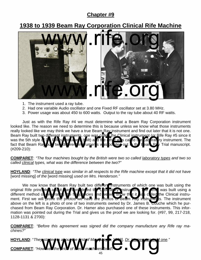
45
Chapter #9
1938 to 1939 Beam Ray Corporation Clinical Rife Machine 1. The instrument used a ray tube. 2. Had one variable Audio oscillator and one Fixed RF oscillator set at 3.80 MHz. 3. Power usage was about 450 to 600 watts. Output to the ray tube about 40 RF watts. Just as with the Rife Ray #4 we must determine what a Beam Ray Corporation instrument looked like. The reason we need to determine this is because unless we know what those instruments really looked like we may think we have a true Beam Ray instrument and find out later that it is not one. Beam Ray built two different instruments, one was called the Clinical instrument (or Rife Ray #5 since it was the 5th style of Dr. Rife’s instrument built) and the other was called the Laboratory instrument. The fact that Beam Ray built two different instruments was pointed out in the Beam Ray Trial manuscript.(#209-210): COMPARET: “The four machines bought by the British were two so called laboratory types and two so called clinical types, what was the difference between the two?” HOYLAND: “The clinical type was similar in all respects to the Rife machine except that it did not have [word missing] of the [word missing] used on Mrs. Henderson.” We now know that Beam Ray built two different instruments of which one was built using the original Rife principles and it was considered the Laboratory instrument. The other was built using a different method of generating the frequencies and we will show that it was called the Clinical instru-ment. First we will prove the photos we have are photos of Beam Ray instruments. The instrument above on the left is a photo of one of two instruments owned by Dr. James B. Couche which he pur-chased from Beam Ray Corporation. Dr. Hamer also purchased one of these instruments. This infor-mation was pointed out during the Trial and gives us the proof we are looking for. (#97, 99, 217-218, 1128-1131 & 2700): COMPARET: “Before this agreement was signed did the company manufacture any Rife ray ma-chines?” HOYLAND: “They started to about the first of May [May 1, 1938]. Dr. Hamer was sold one.” COMPARET: “How was the price of these machines fixed?”
www.rife.org www.rife.org www.rife.org www.rife.org www.rife.org

46
HOYLAND: “The price was decided from the costs of what it cost to manufacture the first machine that was sold to Dr. Hamer.” COMPARET: “Were the clinical machines the same as were made for Dr. Hamer?” HOYLAND: “Yes.” COMPARET: “Was that the same as the machine used on Mrs. Henderson?” HOYLAND: “No, but the same type.” SAPIRO: “These machines are perfectly good, they are just the same as the [Dr.] Couche machine and the one that gave Mrs. Henderson such relief.” These quotes show that Beam Ray sold the Clinical style Machines to Dr. Hamer and Dr. Couche. Dr. Couche sold one of his Beam Ray Clinical instruments to Dr. Tully in 1951. This photo shown above, on the left, is a photo of Dr. Couche’s instrument which he sold to Dr. Tully. Since this is an original Beam Ray instrument we can make comparisons against it when looking at other instruments. The above photo, on the right, is of Dr. Rife and Philip Hoyland his engineer and business partner in Beam Ray Corporation. In this photo is an instrument. We will prove that this in-strument is also a Beam Ray instrument by making some comparisons with other Beam Ray machines. This photo of Dr. Rife and Philip Hoyland was taken for a May 6, 1938 newspaper article published by the San Diego Tribune. In the newspaper the caption below the photo said: “Royal Raymond Rife, left
www.rife.org www.rife.org www.rife.org www.rife.org www.rife.org

47
and Philip Hoyland with Rife ray apparatus”. On May 1, 1938 Beam Ray Corporation started selling its instruments to doc-tors and this front page newspaper article had the capability of selling many instruments. It is only logical they would have photographed the instrument they were selling. The two photos on the bottom of the previous page are close-up photos of these instruments. You will notice the similarities of these two instruments. They are almost exactly alike except for the case. Dr. Couche’s instrument was in a case that extended all the way down to the floor. It had handles on the side and wheels on the bottom which would make it very easy to move around. Both instruments have one oscillator dial which is located on the left side of the front panel. Below that dial on Dr. Couche’s instrument was a four position band switch and on the other instrument is a fine tuning dial. The fine tuning dial was replace with the four position band switch. The second dial, in the center of both instruments, goes to 100 and was the amplitude dial. Above that dial on both instruments is a tuning eye for calibrating the instrument’s RF carrier frequency. In the photo on the right is one of these tuning eye tubes. Both instruments have a milliamp power meter located all the way over to the right next to where the ray tube is connected. Dr. Couche’s instrument had a timer below the power meter to help him make sure he treated the patient for the correct amount of time. Along the bottom are the filament, sweep and output switches which are not clearly marked on Couche’s instrument but we can see what appears to be three different switches, two below the center amplitude dial and one below the timer. The comparison we have just made with Dr. Couche’s Beam Ray instrument shows they are both Beam Ray instruments. They just put this Clinical machine into two different cases. In the document "Development of the Rife Ray" we have a description of this Beam Ray Clinical instrument: "In the early part of 1936 Commander Rife and Mr. Hoyland spent much time collaborating on revising some of the applications of the fundamentals of the instruments due to the advancement that had taken place in the application of electronics and it was found that the carrier wave used in the previous instruments could be eliminated. During the summer of 1936 further experiments were carried on, which resulted in an entirely new method of generating the desired frequencies and produced a constant input and output in the instru-ments. During this work several new test appliances were built for further studying the different frequencies and waveforms noteworthy among these was a 9 inch Cathode-Ray oscillograph of high sensitivity, built for the purpose of photographing the different frequencies on motion picture film and thereby al-lowing the numerous waves to be studied at will. During the fall of 1936 Dr. Couche of San Diego and Jack Free assistant to Commander Rife conducted a clinic with one of the frequency machines treating experimentally cases of carcinoma and senile cataract..." (Development of the Rife Ray and use in de-vitalizing pathogenic micro-organisms). The first thing that we learn from this document is the high voltage current carrier wave that was used to light the ray tube in the Rife Ray #3 and Rife Ray #4 was no longer used or needed with the new Beam Ray Clinical instrument. The second thing we learn is that this instrument was working on an entirely new method of generating the M.O.R. frequencies. This method has been referred to over the years as harmonics. But it is more complex that what was originally believed.
Tuning Eye AM 1, 1936/37
www.rife.org www.rife.org www.rife.org www.rife.org www.rife.org

48
This new method that was used to generate the frequencies has been a mystery for the past 75 years. Finally with location and purchase of an original Beam Ray Clinical instrument and the use of spectrum analysis the method that Philip Hoyland used has been discovered.
The above photo, on the left, as shown before, is the Beam Ray instrument that Dr. Rife and Philip Hoyland were photographed with for the 1938 newspaper article. Above on the right is a photo of an original Beam Ray instrument. This instrument was obtained from Dr. Larry Low. He has owned it for over 25 years. It was used by a Medical Doctor who died in the mid 1960’s. We would like to thank him for allowing us to get this instrument so we could analyze it. It is a low audio frequency instrument. This Beam Ray instrument is very important. The significance of this instrument is the fact that it is the only known original Beam Ray Clinical instrument to exist. This proves beyond any doubt that Philip Hoyland was the one who first built the low audio frequency instrument. The next two photos, shown below are of Beam Ray instruments.
www.rife.org www.rife.org www.rife.org www.rife.org www.rife.org

49
The instrument photo on the bottom left, on the previous page (page 48) was found inside the case of this original Beam Ray instrument obtained from Dr. Larry Low. The photo, on the bottom right, on the previous page is Dr. Couche’s Beam Ray instrument. Both of these instruments are in the same case. If you look closely you will notice that both instruments have the same metal arm attached to the top of the instrument which holds the ray tube. In every detail the cases are the same. The only differ-ence is the layout of the front panel which is different in the photo on the left. It appears when Beam Ray built their first instrument which was shown in the May 1938 newspaper photo they had no band switches dividing out the audio frequency range. The doctors that used these instruments complained about the accuracy problems. It is apparent from the Beam Ray Trial testimony that a four position band switch was added to help stabilize the audio oscillator and hopefully solve this problem. The origi-nal Beam Ray instrument that we obtained has a band switch with four settings. Aubrey Scoon’s Beam Ray replica also has a four position band switch. We will fully evaluate the Aubrey Scoon instrument later in this paper but we will refer to it from time to time as needed as we look at this original Beam Ray Clinical instrument. The 1950’s AZ-58 Beam Ray replica, which we will evaluate later in this paper, had a three position band switch because they used audio frequencies which were ten times lower than the original Beam Ray Clinical instrument. To further analyze these instruments we will now do a comparison of the faceplates of the two original instruments shown on page 48. The first close up photos are of the variable audio oscillator control. The photo, above on the left, is the May 1938 photo. The photo, on the right, is the original instrument we obtained. Normally the dial should only go 180 degrees from 0 to 100 as shown on the May 1938 dial. Our instrument does not have the original dial because it goes from 0 to 100 in 270 degrees. You will also notice that our dial is bigger than the original dial and partially covers where the old fine adjustment dial was located. When they added the four position band switch the fine adjustment was no longer needed. Our Beam Ray Clinical instrument, like Aubrey Scoon’s instrument, had four bands that cover these fre-quency ranges. Band 1: 160 Hertz to 820 Hertz. Band 2: 594 Hertz to 3,190 Hertz. Band 3: 2,440 Hertz to 12,930 Hertz. Band 4: 9,430 Hertz to 42,600 Hertz.
www.rife.org www.rife.org www.rife.org www.rife.org www.rife.org
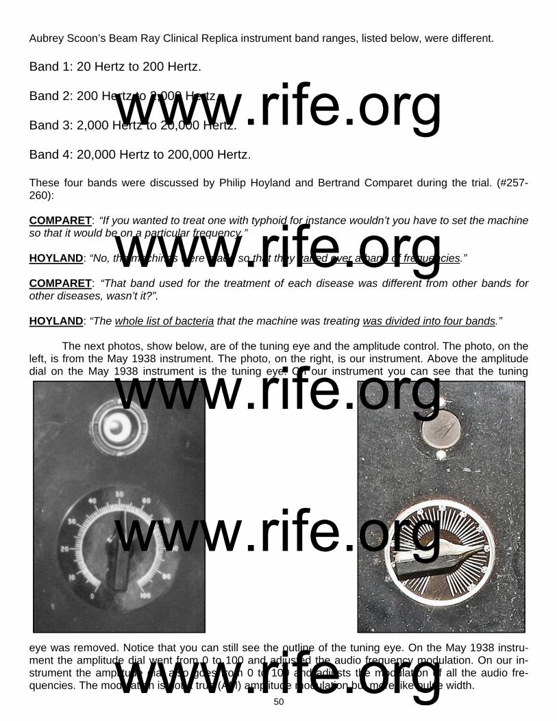
50
Aubrey Scoon’s Beam Ray Clinical Replica instrument band ranges, listed below, were different. Band 1: 20 Hertz to 200 Hertz. Band 2: 200 Hertz to 2,000 Hertz. Band 3: 2,000 Hertz to 20,000 Hertz. Band 4: 20,000 Hertz to 200,000 Hertz. These four bands were discussed by Philip Hoyland and Bertrand Comparet during the trial. (#257-260): COMPARET: “If you wanted to treat one with typhoid for instance wouldn’t you have to set the machine so that it would be on a particular frequency.” HOYLAND: “No, the machines were made so that they varied over a band of frequencies.” COMPARET: “That band used for the treatment of each disease was different from other bands for other diseases, wasn’t it?”. HOYLAND: “The whole list of bacteria that the machine was treating was divided into four bands.” The next photos, show below, are of the tuning eye and the amplitude control. The photo, on the left, is from the May 1938 instrument. The photo, on the right, is our instrument. Above the amplitude dial on the May 1938 instrument is the tuning eye. On our instrument you can see that the tuning
eye was removed. Notice that you can still see the outline of the tuning eye. On the May 1938 instru-ment the amplitude dial went from 0 to 100 and adjusted the audio frequency modulation. On our in-strument the amplitude dial also goes from 0 to 100 and adjusts the modulation of all the audio fre-quencies. The modulation is not a true (AM) amplitude modulation but more like pulse width.
www.rife.org www.rife.org www.rife.org www.rife.org www.rife.org
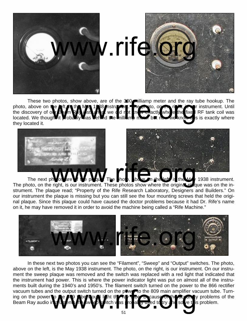
51
These two photos, show above, are of the 300 milliamp meter and the ray tube hookup. The photo, above on the left, is the May 1938 instrument. The photo, on the right, is our instrument. Until the discovery of our Beam Ray instrument we did not know exactly where the fixed RF tank coil was located. We thought it probably was behind the milliamp meter but now we know this is exactly where they located it. The next photos are of the plaque. The photo, above on the left, is the May 1938 instrument. The photo, on the right, is our instrument. These photos show where the original plaque was on the in-strument. The plaque read; “Property of the Rife Research Laboratory, Designers and Builders.” On our instrument the plaque is missing but you can still see the four mounting screws that held the origi-nal plaque. Since this plaque could have caused the doctor problems because it had Dr. Rife’s name on it, he may have removed it in order to avoid the machine being called a “Rife Machine.” In these next two photos you can see the “Filament”, “Sweep” and “Output” switches. The photo, above on the left, is the May 1938 instrument. The photo, on the right, is our instrument. On our instru-ment the sweep plaque was removed and the switch was replaced with a red light that indicated that the instrument had power. This is where the power indicator light was put on almost all of the instru-ments built during the 1940’s and 1950’s. The filament switch turned on the power to the 866 rectifier vacuum tubes and the output switch turned on the power to the 809 main amplifier vacuum tube. Turn-ing on the power to the 809 tube would light the ray tube. Because of the accuracy problems of the Beam Ray audio instruments the sweep switch was probably used to try and solve this problem.
www.rife.org www.rife.org www.rife.org www.rife.org www.rife.org

52
The sweep switch appears to have been removed when the band switch was added. Above the output plaque on our instrument we see a 15 minute timer for setting the desired runtime for each fre-quency that was used. The Original Beam Ray instrument photo does not have a timer but Dr. Couche’s Beam Ray instrument shows that his instrument had a timer on the front panel. These photos show that a timer was put in many of the original Beam Ray instruments. This photo, above, is of the inside of the Beam Ray instrument. The RF tank coil was set at 3.80 MHz. The 809 was the main output power tube. There were two 866 rectifier tubes. The audio section consists of 2 6F6G tubes and one 6SJ7 tube. All of the Philip Hoyland audio instrument designs built from 1936 through the 1950’s AZ-58 resemble each other and anyone looking at the different instru-ments can see that they are all built almost in the same way. Tubes may vary, such as the 812a even-tually replaced the 809, but the workings of all the instruments are similar. Both this original Beam Ray Clinical instrument and Aubrey Scoon’s instrument have Hewlett Packard sine wave audio oscillators. Mr. Peter’s and I was able to repair the audio oscillator and read the different frequency band settings (see page 49). The readings for this pa-per was done with the original Beam Ray instrument along with Aubrey Scoon’s and the AZ-58 replicas that we built. They all work identically the same as this original instrument. This Beam Ray instrument did not come with any paperwork with the dial settings for the various audio frequencies it used. The photo, bottom right, is the under side of the chassis showing both the audio section and part of the RF section.
www.rife.org www.rife.org www.rife.org www.rife.org www.rife.org
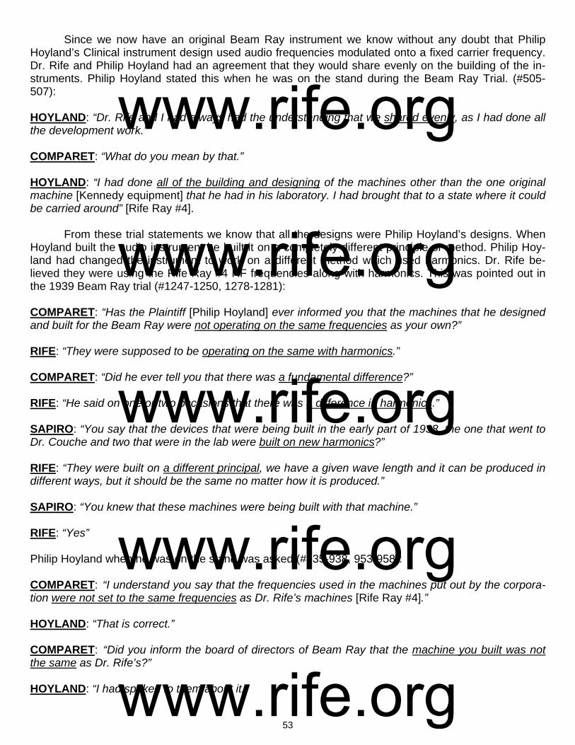
53
Since we now have an original Beam Ray instrument we know without any doubt that Philip Hoyland’s Clinical instrument design used audio frequencies modulated onto a fixed carrier frequency. Dr. Rife and Philip Hoyland had an agreement that they would share evenly on the building of the in-struments. Philip Hoyland stated this when he was on the stand during the Beam Ray Trial. (#505-507): HOYLAND: “Dr. Rife and I had always had the understanding that we shared evenly, as I had done all the development work.” COMPARET: “What do you mean by that.” HOYLAND: “I had done all of the building and designing of the machines other than the one original machine [Kennedy equipment] that he had in his laboratory. I had brought that to a state where it could be carried around” [Rife Ray #4]. From these trial statements we know that all the designs were Philip Hoyland’s designs. When Hoyland built the audio instrument he built it on a completely different principle or method. Philip Hoy-land had changed the instrument to work on a different method which used harmonics. Dr. Rife be-lieved they were using the Rife Ray #4 RF frequencies along with harmonics. This was pointed out in the 1939 Beam Ray trial (#1247-1250, 1278-1281): COMPARET: “Has the Plaintiff [Philip Hoyland] ever informed you that the machines that he designed and built for the Beam Ray were not operating on the same frequencies as your own?” RIFE: “They were supposed to be operating on the same with harmonics.” COMPARET: “Did he ever tell you that there was a fundamental difference?” RIFE: “He said on one or two occasions that there was a difference in harmonics.” SAPIRO: “You say that the devices that were being built in the early part of 1938, the one that went to Dr. Couche and two that were in the lab were built on new harmonics?” RIFE: “They were built on a different principal, we have a given wave length and it can be produced in different ways, but it should be the same no matter how it is produced.” SAPIRO: “You knew that these machines were being built with that machine.” RIFE: “Yes” Philip Hoyland when he was on the stand was asked (#935-938, 953-958): COMPARET: “I understand you say that the frequencies used in the machines put out by the corpora-tion were not set to the same frequencies as Dr. Rife’s machines [Rife Ray #4].” HOYLAND: “That is correct.” COMPARET: “Did you inform the board of directors of Beam Ray that the machine you built was not the same as Dr. Rife’s?” HOYLAND: “I had spoken to them about it.”
www.rife.org www.rife.org www.rife.org www.rife.org www.rife.org
54
COMPARET: “Then it was during the period between September and November that you told Edwards at his home that the machines you were building were not putting out the same frequencies as Dr. Rife’s machines?” HOYLAND: “Yes.” COMPARET: “How did you explain that?” HOYLAND: “In the summer of 1936 I designed a new machine, or rather I checked it there at the lab [The Beam Ray Clinical instrument]. I had designed it in Pasadena, and we tested it out then and the frequencies were not the same as on Dr. Rife’s machine.” COMPARET: “Did you tell him how great the difference it was?” HOYLAND: “I explained that there was quite a fundamental difference.” [Harmonic frequencies] Comparet when asked a question by Judge Kelly made this statement. (#2673 & 2685): COMPARET: “Hoyland has said that the design and the frequencies of the machine itself is not that of a Rife Ray machine, and that the machine is in fact different. The company will have to have these ma-chines junked, must draw up new designs according to Dr. Rife’s ideas, must have Dr. Rife ok these designs, etc…Dr. Rife is not going to be a party to a fraud, and if the machines we sell are not the true Rife machines they are a fraud.” (Beam Ray Trial Papers). When Edwards was on the stand he stated. (#1384-1385): COMPARET: “Did Mr. Hoyland tell you at any time in the fall of last year that the machines he was manufacturing for Beam Ray corporation operated on a principle fundamentally different from Dr. Rife’s machine?” EDWARDS: “No, Mr. Hoyland told me at one time that Dr. Rife thought that he had the frequencies but he didn’t have them [Here Edwards is talking about the Beam Ray Corporation instruments not the Rife Ray #4 instrument because Philip Hoyland said, on the stand, that he gave the Rife Ray #4 frequen-cies to Dr. Johnson and Dr. Rife in 1935].” (Beam Ray Trial Papers). Philip Hoyland also stated this when he was on the stand. (#800): HOYLAND: “Regarding the frequencies of the machine [Beam Ray Corporation Clinical instrument], you will remember me telling you that the frequencies used are not the same ones on the Rife machine [The Rife Ray #4]. They [Meaning the Rife Ray #4 frequencies] were in the upper bands [139,000 to 1,604,000 Hertz].” (Beam Ray Trial Papers) In a letter which he sent to Dr. Gonin in 1939, there are indications that Dr. Rife wanted the so-called harmonics removed: RIFE: “I spoke only Friday evening to a Mr. John Chamblin, a radio man now connected with Beam Ray Inc., about the redesign and building of a device according to the old Rife Ray principles; as the present instrument has been so deviated away from that old principle that it is nowhere near the same...those devices which you have are merely working on a harmonic and not a true frequency; and in our research on electronics, we definitely know that there is no possible way of controlling electrical harmonics of a frequency.” (Letter from Dr. Rife to Dr. Gonin, May 14, 1939. Page 1 of 3).
www.rife.org www.rife.org www.rife.org www.rife.org www.rife.org

55
We have just read a lot of trial testimony about how this Beam Ray instrument worked on har-monic frequencies. Also, in the trial testimony it is mentioned that these Beam Ray audio machines were tested in Dr. Rife’s lab to see if they would devitalize microorganisms. It was Philip Hoyland who made the tests using Dr. Rife’s organisms. From the documents we know that Philip Hoyland put a lot of work into this instrument and didn’t finish it until late 1936 or early 1937. Benjamin Cullen said Philip Hoyland spent a lot of time at the lab and stated the following in a taped interview in the 1950’s: CULLEN: “Philip Hoyland was in there quite a lot...Hoyland developed some few items in the lab...Hoyland seemed to help quite a lot and he got into the bacteriology side with Rife a good deal be-cause Rife had so much to work out...he finally got to the point where he [Dr. Rife] had to delegate some of the work.” (John Marsh Rife CDs, CD 6 track 1). In the Beam Ray Trial manuscript we also read the following. (#91 & 93): COMPARET: “Were any experimental activities carried on in the lab?” HOYLAND: “Yes.” From the trial we learn that Philip Hoyland developed and tested his harmonic instrument in the lab. How could Philip Hoyland have tested it unless he put micro-organisms under the microscope? From the "Development of the Rife Ray" document we learned that: "During the fall of 1936 Dr. Couche of San Diego and Jack Free assistant to Commander Rife con-ducted a clinic with one of the frequency machines treating experimentally cases of carcinoma and se-nile cataract..." (Development of the Rife Ray and use in devitalizing pathogenic micro-organisms). From the trial papers we learn that Philip Hoyland didn’t tell Dr. Rife what frequencies he was using in the instruments. Dr. Rife thought the instruments were using his frequencies (the upper band frequencies) but with harmonics because this is what Philip Hoyland told him. The information that we now have obtained from this original Beam Ray Clinical instrument shows that Philip Hoyland’s instru-ment was working on Dr. Rife’s principles and on his frequencies but in a different manner than Dr. Rife was used to using. This is the reason that the instrument worked so well. Philip Hoyland was still using Dr. Rife’s principle of coordinative resonance but hid the truth from Dr. Rife to protect his ownership in-terest. Philip Hoyland was a business man and Dr. Rife was not. The fact that these tests were done along with the fact that these instruments were used by many doctors with incredible results show that this instrument which used audio frequencies modulated on an RF carrier did devitalize microorganisms. Though Dr. Rife did not like the method of harmonic frequencies that Philip Hoyland used it was pointed out in the trial that Dr. Rife knew there were changes and Dr. Rife also didn’t think that these changes would make much of a difference. (#2700): SAPIRO: “Dr. Rife said that he knew there were changes made in his machine and that they were not changes that would make any difference. Dr. Rife is a genius but he didn’t know how to put the ma-chines in a form that could be used in offices of doctors. These machine are perfectly good, they are just the same as the [Dr.] Couche machine and the one that gave Mrs. Henderson such relief.” It was only with the release of the complete Beam Ray Trial manuscript and other Rife docu-ments; found in California a few years ago that we now know why Dr. Rife continued to have this style of instrument built even in the 1950’s. Though Dr. Rife originally did not like Philip Hoyland’s Beam Ray Clinical design instrument, because of the use of harmonics, he later tested it in his laboratory and found it would work as well as his original instruments that did not use harmonics. We will quote the complete letter since all of this information is important:
www.rife.org www.rife.org www.rife.org www.rife.org www.rife.org
56
RIFE: “My first association with Dr. Yale came through an organization known as the Beam Ray Corpo-ration. In order to acquaint you with the details of the formation of this corporation I shall bring in a little background. My assistant at that time (1934) in the laboratory was Philip Hoyland whom I met through Dr, Milbank Johnson M.D., Medical Director for the Pacific Mutual Life Insurance Company. I consid-ered Hoyland as a capable electronic engineer and brought him to my laboratory in Point Loma on Al-cott Street, San Diego, Calif. Hoyland became associated with a promoter named Hutcheson and Dr. James B. Couche M.D. They came to me with the idea or forming the Beam Ray Corporation to manu-facture and distribute the Frequency Instrument to the medical profession. I gave this considerable thought and came to the conclusion that if these instruments were manufactured and placed into the hands of legitimate and bonafide medical practitioners, my efforts, over a period of years would derive exceedingly more benefits, so I gave this corporation permission to manufacture these devices on two stipulated conditions (1) that they would adhere decidedly to the original basic principles of the Fre-quency Instrument and (2) that each Frequency Instrument would be thoroughly tested before delivery to determine its true devitalizing power and effect on pathogenic bacteria. And so they went ahead. Three instruments were built. The first two were shipped to England (unwired as Hoyland wanted a trip to England) and the third went to Dr. Hamer M.D. at the Paradise Valley Sanitarium and Hospital. Dr. Hamer was the superintendent there I believe. Hoyland was like many men with whom I have associ-ated over a period of years. In a short time he began changing the basic principles of these instruments according to his own ideas. About this time he became associated with Dr. Yale and Yale ordered and received another or the Fourth Frequency Instrument. Since I was out of the city or San Diego at the time, all of these devices were delivered without being tested by myself. At a much later period, I called on Dr. Yale at 333 Plaza in San Diego which was the address of his clinic at that time and told him that I did not feel that the Frequency Instrument had been calibrated properly so that it would not work. In the interim, I became associated with another electronist by the name of Verne Thompson, of San Diego. Under my supervision, Thompson rebuilt Dr Yale's Fre-quency Instrument which I tested in my research laboratory on pathogenic bacteria and the Frequency Instrument proved effective. Then later at different times I had this instrument checked and found it lacking in its ability to devitalize anything. I later learned that Dr. Yale had ideas of his own and would have somebody change the Frequency Instrument to suit his individual whims. I will state here defi-nitely that I have never been associated in any way with Dr. Yale outside of the interest that I have taken in some of the patients of Dr. Yale.” (Letter written by Dr. Rife, March 22, 1958). This document shows that Dr. Rife, after the shutdown of Beam Ray Corporation, eventually tested Philip Hoyland's Beam Ray Clinical design and found that it would devitalize all the microorgan-isms it was used on. This also confirms that Philip Hoyland's statement that he tested it out in the labo-ratory was a truthful statement. With this information taken from the Rife documents we now know why Dr. Rife considered the Beam Ray Clinical machine his instrument and knew it worked. Add to this the fact that all of the doc-tors who used it had a great deal of success with this Beam Ray Clinical instrument design. This is why Dr. Rife, John Crane and John Marsh built this Rife Machine in the 1950’s and called it the AZ-58. The AZ-58 was a replica of Dr. Couche's and Dr. Tully's machine which were original Beam Ray Clinical instruments. In a letter dated July 6, 1956 this fact was pointed out: “The Frequency Instruments used by Dr. Tully and Dr. Couche were built in 1938 and do not apply to this code. However the Frequency Instrument currently built are a copy of these earlier Frequency In-struments and are labeled "For Investigational Use Only" at the present time.” (Application letter for ap-proval of device in compliance with California Pure Drugs Act. Page 2). Since we now know this instrument worked we will go back to the harmonic method used by Philip Hoyland. From the documents that we have read we know that Hoyland’s machine worked on
www.rife.org www.rife.org www.rife.org www.rife.org www.rife.org

57
harmonics. The problem with the Beam Ray instrument is it has to be built a certain way in order for it to work on the correct harmonics. It was from the analyzing of this original Beam Ray Clinical instru-ment that the mystery of how it worked was discovered. We will show how it worked after we read an-other important quote. Bertrand Comparet, Rife’s attorney who eventually defended Dr. Rife against Philip Hoyland in the 1939 Beam Ray trial said this about Philip Hoyland’s Beam Ray Clinical instru-ment. COMPARET: “Well, none of us know enough about it. Now, I remember at that time Rife saying that Hoyland had not used a simple straight forward circuit, as Rife had used, but he thought he had a short cut, through use of harmonics and so on, and Rife had no faith in Hoyland’s circuit”. (1970’s Bertrand Comparet interview #28). This statement by Bertrand Comparet completely sums up their understanding of this instru-ment. This confusion of how the instrument worked still remained throughout the building of the 1940’s and 1950’s Beam Ray replica instruments including up until today. It appears that Dr. Rife really didn’t know how this instrument worked. The trial testimony shows that Philip Hoyland would not tell anyone in the Beam Ray Corporation the frequencies used with the Clinical instrument or explain how it worked on harmonics. John Crane and John Marsh who worked with Dr. Rife didn’t understand how it really worked. If Dr. Rife had really known how it worked then he would not have allowed John Crane and John Marsh to have a variable carrier frequency in the instrument. John Crane and John Marsh put a variable capacitor in the instrument so that they could tune the carrier frequency. By doing this it made it so they could change the carrier frequency from about 4.9 MHz to about 2.2 MHz. This change showed that they did not understand how the instrument worked. They mistakenly believed that the au-dio frequencies were the M.O.R.s or the frequencies that would devitalize the microorganisms and that the carrier frequency was not important. This belief clearly shows that they did not understand how the Beam Ray Clinical instrument worked. If they had really understood how it worked they would have never called any of the audio frequencies M.O.R.s. Philip Hoyland had very good reasons to hide how this instrument worked. He became Dr. Rife’s Engineer in 1935 when he built the Rife Ray #4. In 1936 Philip Hoyland also began building the Beam Ray Clinical instrument that would be sold in 1938 by Beam Ray Corporation. Philip Hoyland was wor-ried about keeping the original frequencies a secret because he felt people would try to steal their tech-nology. This concern of Philip Hoyland’s was not unfounded because Mr. Parsons of the British Group did try to steal their instrument. From the trial transcript we learn they had no way to patent the instru-ment because everything they were doing was in public domain in regards to the frequency generating equipment. Philip Hoyland felt that he had to come up with a way to keep anyone from finding out what the true frequencies were. So he built the instrument a different way using harmonics to hit the har-monic frequencies of the Rife Ray #4 and Kennedy equipment. Until a genuine Beam Ray instrument could be found and tested, we would never know for sure how Philip Hoyland generated and used the harmonics in his instrument. Even though Aubrey Scoon’s instrument is a Beam Ray replica no one knew for sure that it really was one. This confusion and the lack of having the chronological history of when and what type of instrument was built made it very hard to find the truth. Not only would Philip Hoyland not tell anyone how his instrument worked he also would not let anyone know the new frequencies he was using. Everything he did hid the frequencies. In the trial manuscript we read that he always used a code to give the frequencies. This code would work with the dials. No digital readout was available in those days like we have today. Since no one was ever given the frequencies from Philip Hoyland this has led to many problems. Some of the Beam Ray Clinical in-strument replicas have different audio frequencies and this has led to a lot of confusion. Even John Crane was sending people different audio frequencies than the standard set he used with the AZ-58. Because of the different audio frequencies used in these Beam Ray replicas we didn’t know which set of audio frequencies Philip Hoyland really used. So we could not use any of these frequency sets and come to any reasonable conclusions.
www.rife.org www.rife.org www.rife.org www.rife.org www.rife.org

58
When we obtained this original Beam Ray Clinical instrument we had to put aside all the fre-quency lists and thinking of the past in order to figure out how the instrument worked. From everything we had read about Philip Hoyland’s instrument we had come to the conclusion that the answer would be found in the math. However Hoyland came up with his idea it had to be a mathematical method. Like many others we tried to reconcile the audio frequencies as lower harmonics of Dr. Rife’s original high RF frequencies. We tested the frequencies that were used in Aubrey Scoon’s instrument and they didn’t match. We did the same with the AZ-58 audio frequencies and they didn’t match. We took the other audio frequencies that Crane had a list of and they also didn’t match. There is an instrument known as the 1947 instrument which we tried to reconcile with no success. With all these audio fre-quencies only a few were close harmonic matches. If all these audio frequencies were true harmonics of Dr. Rife’s original high RF frequencies then they would harmonically match up, but they do not. Once we put all this aside and began to analyze this instrument we found out how it worked. This Beam Ray Clinical instrument is truly a harmonic instrument. The fact that both the audio fre-quency and the RF carrier frequency were sine wave did not make it easy to understand. How could it be a harmonic instrument when it used a sine wave waveform for both the audio and the RF frequen-cies? The 1950’s AZ-58 Beam Ray replica worked on square wave audio frequencies and the harmon-ics came from the square wave. But this is not how the Beam Ray Clinical instrument was suppose to work. The 1950’s square wave method has been used ever since that time. But how can an instrument that uses sine wave audio frequencies be a harmonic instrument? With this understanding we knew that the audio frequencies could never be the true M.O.R.s. But how did they work in the instrument? The harmonic square wave method has been an accepted method for many years. For many years almost everyone has understood and generally accepted that you can take a square wave audio frequency and the harmonics it creates and hit a higher frequency M.O.R. through those harmonics. These audio frequencies are usually many hundreds of harmonic steps lower that the higher M.O.R. frequency. This harmonic method must be kept in mind as well as the fact that not once, but several times, in the Beam Ray Trial manuscript and other documents everything said about this machine showed that it was using the harmonic method. We must remember that Dr. Rife said that he believed that many of his frequencies were sub-harmonics of a higher frequency. He said if we knew the true higher frequency it may even work better. Because of how this instrument works it is logical to conclude that Philip Hoyland understood this concept and apparently found that all of Dr. Rife’s fre-quencies were sub-harmonics of higher frequencies. With this understanding he built the Beam Ray instrument. Here is what we found when we analyzed the Beam Ray Clinical instrument.
The graph, above on the left, is of the harmonics from the 3.80 MHz carrier frequency coming from the ray tube of our original Beam Ray instrument. It was taken using a PicoScope 3205 spectrum analyzer. The photos, above on the right, come from Dr. Rife’s lab film and oscilloscope readings that we took of the waveform of the Beam Ray instrument. You will notice the similarity of the waveforms. All the M.O.P.A. carrier waveforms we have tested look like this. When you put a non harmonic sine wave into a ray tube you will always see a distortion of the sine wave which will produce both odd and
Photo one: From Rife’s lab film. Photo two: Beam Ray carrier before ray tube.
Photo one: From Rife’s Lab film. Photo two: Beam Ray carrier after ray tube.
www.rife.org www.rife.org www.rife.org www.rife.org www.rife.org
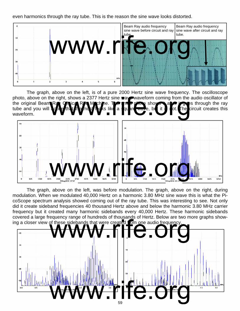
59
even harmonics through the ray tube. This is the reason the sine wave looks distorted.
The graph, above on the left, is of a pure 2000 Hertz sine wave frequency. The oscilloscope photo, above on the right, shows a 2377 Hertz sine wave waveform coming from the audio oscillator of the original Beam Ray Clinical Rife Machine. The small photo shows it after it goes through the ray tube and you will notice that it almost looks like a square wave, but it is not. The circuit creates this waveform.
The graph, above on the left, was before modulation. The graph, above on the right, during modulation. When we modulated 40,000 Hertz on a harmonic 3.80 MHz sine wave this is what the Pi-coScope spectrum analysis showed coming out of the ray tube. This was interesting to see. Not only did it create sideband frequencies 40 thousand Hertz above and below the harmonic 3.80 MHz carrier frequency but it created many harmonic sidebands every 40,000 Hertz. These harmonic sidebands covered a large frequency range of hundreds of thousands of Hertz. Below are two more graphs show-ing a closer view of these sidebands that were created from one audio frequency.
Beam Ray audio frequency sine wave after circuit and ray tube.
Beam Ray audio frequency sine wave before circuit and ray tube.
www.rife.org www.rife.org www.rife.org www.rife.org www.rife.org

60
The graph, on the bottom of the previous page (page 59), on the left, is with a 50,000 Hertz sine wave frequency. The other graph, on the bottom of the previous page, on the right, is with a 100,000 Hertz sine wave frequency. This was done with a 2.4 MHz harmonic sine wave carrier frequency so you can see a closer view of these sidebands. When we saw this we knew there was only one way this Beam Ray instrument could work on Dr. Rife’s frequencies and method. We will now explain how Philip Hoyland’s Rife Machine worked using a fixed RF carrier fre-quency of 3.80 MHz and a variable audio frequency. Understanding harmonics and knowing that all Dr. Rife’s M.O.R. frequencies were sub-harmonics of much higher frequencies it appears Philip Hoyland went up in harmonics with each organisms frequency until he had the highest harmonic frequency clos-est to 3.80 MHz. For an example we will take the Rife Ray #4 frequency for Streptothrix which is 192,000 Hertz. Philip Hoyland multiplied 192,000 Hertz by 20 which gives us the 20th harmonic fre-quency of 3,840,000 Hertz. Since the RF carrier frequency of the Beam Ray Clinical instrument was fixed at 3,800,000 Hertz the difference would only be 40,000 Hertz between the two frequencies. All Philip Hoyland had to do was use an audio frequency of 40,000 Hertz to create a sideband frequency that would hit the harmonic M.O.R. frequency of 3,840,000 Hertz. Pages 68-74 show all the M.O.R. graphs. What needs to be pointed out here is this IMPORTANT fact that came from the analyzing of this Beam Ray instrument. Neither the 3.8 megahertz carrier frequency nor the audio frequencies will do anything by themselves. But when the 3.8 megahertz harmonic carrier frequency and the audio fre-quencies are combined together they will produce many sideband frequencies. And one of these side-band frequencies will line up with the true Rife M.O.R frequency and devitalize or render harmless the harmful microorganism. To re-emphasize this so that no one misunderstands. If you just use the audio frequencies by themselves you will get nothing. If you just use the 3.8 megahertz carrier without the audio frequencies you will get nothing. The audio frequencies used in this instrument must have the RF carrier frequency of 3.8 megahertz or they are useless. This is the reason the 1950’s Beam Ray Clini-cal instrument called the AZ-58 did not work properly. We know that Philip Hoyland was trying to hide the true M.O.R. frequency of the organism from anyone who used the equipment. Twice in the Beam Ray Trial it was mentioned that Dr. Rife had no ability to patent the Rife ray tube instrument. The only secret was the frequencies and Philip Hoyland was trying to protect his and Beam Ray Corporations interests. With this in mind Philip Hoyland could have just divided the 40,000 Hertz by two and used a 20,000 Hertz audio frequency. Then you would have one sideband at 3,820,000 Hertz and another harmonic sideband at 3,840,000 Hertz which would hit the 20th harmonic of 192,000 Hertz. He could have divided it by three and used a 13,333 Hertz fre-quency. He also could have divided it by 4 and used a 10,000 Hertz frequency. If he would have di-vided it by five we would get a 8,000 Hertz frequency. Divided by six he could have used a 6666 Hertz frequency. I could go on but anyone can see the many variable frequencies that could have been used. Also, because of the “one tenth of one meter” factor that Dr. Rife mentioned you could add many Hertz to each frequency without changing the frequency enough to make it so it would not work. This means you could change the 6,666 Hertz to 6,669 Hertz just to make things a little more confusing. Dr. Couche said that he had to sweep the frequency dial in order to get the instrument to work properly. This is understandable since the 3.80 MHz carrier frequency will wander a few thousand Hertz. The audio frequency oscillator also varied. Bertrand Comparet in his 1970’s interview said this about the Beam Ray Clinical instrument inherent frequency drift: COMPARET: “Well, as they warmed up they’d shift frequency...Now, whether this was Hoyland’s in-ability to do better, or whether it was just inevitable in those days, I don’t know, but Hoyland’s devices did have that frequency shift as they warmed up. So, they had their problems. Now what Couche did, see, he would have cases where he would get an instantaneous cure, like that, and other times when the treatment just didn’t produce any results, because of the frequency shift. So, he would start in, he
www.rife.org www.rife.org www.rife.org www.rife.org www.rife.org
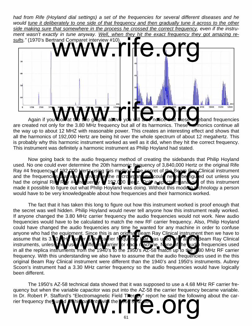
61
had from Rife (Hoyland dial settings) a set of the frequencies for several different diseases and he would tune it deliberately to one side of that frequency and then gradually tune it across to the other side making sure that somewhere in the process he crossed the correct frequency, even if the instru-ment wasn’t exactly in tune anyway. Well, when they hit the exact frequency they got amazing re-sults.” (1970’s Bertrand Comparet interview #10).
Again if you look at the two graphs above you will also notice that these sideband frequencies are created not only for the 3.80 MHz frequency but all of its harmonics. These harmonics continue all the way up to about 12 MHZ with reasonable power. This creates an interesting effect and shows that all the harmonics of 192,000 Hertz are being hit over the whole spectrum of about 12 megahertz. This is probably why this harmonic instrument worked as well as it did, when they hit the correct frequency. This instrument was definitely a harmonic instrument as Philip Hoyland had stated. Now going back to the audio frequency method of creating the sidebands that Philip Hoyland used. No one could ever determine the 20th harmonic frequency of 3,840,000 Hertz or the original Rife Ray #4 frequency of 192,000 Hertz using this method. The secret of the Beam Ray Clinical instrument and the frequencies that would devitalize the microorganisms could never be figured out unless you had the original Rife Ray #4 frequency of 192,000 Hertz. Only a spectrum analysis of this instrument made it possible to figure out what Philip Hoyland was doing. Without this modern technology a person would have to be very knowledgeable about how frequencies and their harmonics worked. The fact that it has taken this long to figure out how this instrument worked is proof enough that the secret was well hidden. Philip Hoyland would never tell anyone how this instrument really worked. If anyone changed the 3.80 MHz carrier frequency the audio frequencies would not work. New audio frequencies would have to be calculated to match the new RF carrier frequency. Also, Philip Hoyland could have changed the audio frequencies any time he wanted for any machine in order to confuse anyone who had the equipment. Since this is an original Beam Ray Clinical instrument then we have to assume that its 3.80 MHz carrier is the carrier frequency that was used with all the Beam Ray Clinical instruments, unless they used a different carrier for each machine. None of the audio frequencies used in all the replica instruments from the 1940’s to the 1950’s AZ-58 match up to the 3.80 MHz RF carrier frequency. With this understanding we also have to assume that the audio frequencies used in the this original Beam Ray Clinical instrument were different than the 1940’s and 1950’s instruments. Aubrey Scoon’s instrument had a 3.30 MHz carrier frequency so the audio frequencies would have logically been different. The 1950’s AZ-58 technical data showed that it was supposed to use a 4.68 MHz RF carrier fre-quency but when the variable capacitor was put into the AZ-58 the carrier frequency became variable. In Dr. Robert P. Stafford’s “Electromagnetic Field Therapy” report he said the following about the car-rier frequency they used on his patients with the 1950’s AZ-58:
www.rife.org www.rife.org www.rife.org www.rife.org www.rife.org
62
DR. STAFFORD: “Radio Wave transmission is used as a carrier wave. We use between 3100 KC [3.1 MHz] and 3300 KC [3.3 MHz] (This does not appear to be a critical value). The carrier wave is modified with specific cycles per second modulations. We believe that the CPS is a critical value and it actually may prove to be the most important factor which this research may offer.” You will notice that Dr. Stafford like John Crane and John Marsh did not think that the setting of the carrier frequency was important to how the instrument worked. Dr. Stafford would have gotten his understanding from them. We now know that the proper setting of the carrier frequency was important. The audio frequencies they used with the AZ-58 Rife Machine should have been different because its carrier frequency was different. None of AZ-58 audio frequencies will create the correct sideband spac-ing that will match up to the harmonic Rife Ray #4 frequencies. This is probably why Dr. Robert P. Staf-ford could not get the AZ-58 to devitalize any microorganisms. Here are two of his statements: DR. STAFFORD: “Please excuse my format in the following letter for I intend to ramble a bit and forget strict grammatical dictum. I am writing you at this time partially because John Marsh informs me in a recent letter that you may be somewhat disheartened or at least worried about your role in the experi-mentations with the Rife Machine. Believe me, Dr. Edward I know how you feel for I too have been through this same feeling with this matter. I have observed clinical results after treatments with this gadget which I can scarcely believe myself. Yet, despite these good results, I have been confused by some rather simple failures such as a recent experiment which I conducted at Good Samaritan Hospi-tal where we used the machine to treat some cultures of Staph Aureus and Strept. Fecalis. In this work we failed to inhibit growth at all or influence the cultures with the Rife Rx. I sent the results to John Marsh and asked for clarification and to be very frank I am not satisfied with John’s excuse of the fail-ure as described by Dr. Rife. I am afraid I’m not a very good apostle for I’m getting some ideas myself on how this thing may work. I really wonder if this ultrasonic kills bacteria and virus at all or does it work like other forms of ultrasonic and merely stimulate the tissue in some unusual manner thereby improv-ing the circulation and secondarily enhancing the body’s defenses against infection…To summarize some of this rambling: I feel that the Rife Ultrasonic Therapy has a very definitely beneficial effect on the human (and canine) body...I furthermore feel that we, as doctors of medicine, using this machine must remain constantly alert to the condition of our patient and vary the Rx as indicated.” (Dr. Stafford letter to Dr. Jeppson April, 1 1958). DR. STAFFORD: “As yet, we have failed to “cure” any case of advanced, terminal malignancy. It ap-pears in several instances that we may have impressed the disease favorably, temporarily. It is difficult to rule out the psychological, morale booster effect to the terminal patient when some definitive effort is made again in his behalf. However, several improvements have appeared to be more physical than emotional...All the patients in the series were treated with the same frequencies (e.g., 728 - 784 - 880 - 2008 - 2128). Perhaps these frequencies may be wrong, or only nearly correct.” (John Marsh Collec-tion, Dr. Stafford’s Report on using the AZ-58, page 4, www.rife.org) If the correct audio frequencies were not used with the 3.1 MHz to 3.3 MHz RF carrier frequency what Dr. Stafford M.D. reported is exactly what would have happened. From Dr. Stafford’s statement we know that he did not think the RF carrier frequency was critical. If Dr. Rife had fully understood how Philip Hoyland had designed the instrument he would have never allowed John Crane or John Marsh to put a variable capacitor in its circuit. He also e would have made sure that Dr. Stafford knew that the carrier frequency was critical. They also would have been using the correct audio frequencies that would create the proper sideband spacing. If John Crane and John Marsh really understood how this instrument worked they never would have wanted to change the 4.68 MHz carrier frequency. It is obvi-ous they never really understood how the instrument worked or how the audio frequencies interacted with the carrier frequency to produce the M.O.R.s which would devitalize the organisms. They, like us, were under the false belief that the audio frequencies they were using were the M.O.R.s. They un-knowingly promoted this idea because Philip Hoyland would never tell anyone how the instrument
www.rife.org www.rife.org www.rife.org www.rife.org www.rife.org

63
worked. We know that Dr. Rife knew that this Beam Ray Clinical machine worked on his frequencies with harmonics but it is apparent that no one but Philip Hoyland really understood the sideband method used in the instrument. With the variable capacitor that John Crane and John Marsh put into the AZ-58 they could change the RF carrier frequency from about 2.4 MHz to about 4.9 MHz. Dr. Stafford told me personally, when I talked to him, that it did not make any difference which carrier frequency he used, they all worked the same. We will probably never know the full story of how these mistakes were made but it is obvious that no one but Philip Hoyland had the proper understanding of how the instrument worked. Since the AZ-58 was used in a different manner than the sideband method then it would have been better if Dr. Rife, John Crane and John Marsh had used the true mathematical lower square wave au-dio frequency harmonics of the Rife Ray #4 frequencies. Using the correct sub-harmonic audio fre-quencies derived from the higher RF frequencies with a square wave waveform probably would have worked better than the 1950’s audio frequencies they were using in the AZ-58. We should do the same today with our frequencies. All that we have discovered with the analyzing of this original Beam Ray Clinical instrument shows that the audio frequencies used with this equipment are not true M.O.R.s but just the frequen-cies needed to produce the proper sideband spacing in order to hit the correct RF harmonic M.O.R. fre-quency. If the audio frequencies were the frequencies that would devitalize the microorganisms then logically all Dr. Rife’s frequencies would have been audio frequencies. Dr. Rife always said that almost all his frequencies were in the upper bands which match the Rife Ray #4 frequencies. It is interesting to note that this Beam Ray Clinical instrument did not have a dedicated fixed au-dio pulsing circuit. This is also the case with the 1950’s AZ-58. Aubrey Scoon mentions a sixty Hertz feed back pulse into the circuit of his instrument but he could not determine if the instrument was in-tended to work this way or if it was just a malfunction. When we built his instrument we could not get our instrument to work in the same manner as his did in producing this feedback, therefore we believe that it most likely was malfunctioning and was not intended to work in that manner either. Since this Beam Ray Clinical Rife Machine that we obtained didn’t work in this manner and none of the other rep-lica instruments work this way we believe that our conclusion is correct. We know that Dr. Rife’s high RF frequency instruments such as the Rife Ray #3 and Rife Ray #4 used a fixed audio frequency pulsing circuit which was modulated onto the high frequencies. We have shown already in this report that this pulsed waveform was needed to devitalize the various mi-croorganisms that Dr. Rife tested. The Beam Ray Clinical instrument did not use this circuit. The logical reason it did not us this circuit is the modulated waveform must have been sufficient to create the ef-fect. The variable audio frequencies, which created the sidebands, would pulse the waveform and this must have been sufficient to accomplish the same result. From this we can conclude that all that is needed is a modulated or pulsed waveform with the proper M.O.R. high RF frequency to devitalize mi-croorganisms. In the photo below is shown the Beam Ray Clinical instrument waveform. It looks almost like a square wave modulated waveform but it is not produced with a square wave. This waveform is pro-duced using a sine wave audio frequency.
www.rife.org www.rife.org www.rife.org www.rife.org www.rife.org
64
The Beam Ray instrument uses sine wave audio frequencies modulated onto a sine wave RF carrier frequency. It is the unique design of the Beam Ray Clinical circuit that produces this waveform. The M.O.P.A (Master Oscillator Power Amplifier) circuit that Philip Hoyland used was built in a different manner than would normally be used. Instead of using one vacuum tube for the oscillator section and a second vacuum tube for the amplifier section he only used one vacuum tube for both sections. Be-cause he used only one vacuum tube the circuit over oscillates and shuts off for half the cycle. This shutting off for half the cycle makes the waveform look almost like a square wave. This new waveform replaced the damped wave waveform that was used in the Rife Ray #4 instrument. In the 1950's AZ-58 Beam Ray Clinical instrument the variable sine wave audio frequency waveform was replaced with a variable square wave waveform. Had they really understood how the AZ-58 instrument was really sup-posed to work on the sideband method they probably would have not made this change. What must be kept in mind is the treatment frequencies were not the audio frequencies. It was the sideband frequencies created by the audio frequencies combined with the 3.8MHz carrier fre-quency that were the treatment frequencies. Using a square wave would not have hurt the way the Beam Ray Clinical instrument would have worked. But in the 1950’s they were under the false assump-tion that the audio frequencies were the treatment frequency. Now we will discuss the variable audio frequencies used in the Beam Ray Clinical instrument. When we figured out how this instrument worked on the sideband method we did not choose the opti-mum audio frequencies. We just used audio frequencies that would show how the instrument worked. There are better audio frequencies that could be used for optimum performance to hit the Rife Ray #4 higher harmonic frequencies. For most of the audio frequencies that we used to create the sideband spacing frequencies we divided by the difference between the 3.8MHz carrier frequency and Hoyland's new upper harmonic M.O.R which was derived from Dr. Rife's original frequencies. In most cases we divided by 5 but the BX was divided by 15. The BX higher M.O.R. harmonic frequency based on the Rife Ray #4 frequencies is 3,208,000 Hertz and this frequency is only the second harmonic so it would still work just as well as all the other frequencies. One must remember the modern square wave audio frequency harmonics are projected to hit frequencies hundreds of harmonics up. This Beam Ray instru-ment has far more power in its harmonic sidebands than any square wave harmonic. And it only has to go to the 15th lower sideband to hit the M.O.R. frequency, not hundreds of harmonics like a square wave. This Philip Hoyland method would be far superior to using low square wave audio frequencies since the harmonics would all be 40 harmonic steps or less. Some of the following information was originally part of Chapter 8 but after restudying the Rife documents we found that this information, including the additional documents we found, actually be-longed in this chapter. When Dr. Johnson and Philip Hoyland were testing the first proto-type of the Rife Ray #5 or Beam Ray Clinical instrument in the summer of 1936 they had an interesting effect take place. At that time they were at Dr. Johnson’s laboratory testing different bands of frequencies on the various microorganisms. Dr. Johnson wrote about what happened at his laboratory in a letter he sent to Dr. Gruner and Dr. Rife on November 4, 1936:
DR. JOHNSON: “Last summer, in hunting for the M.O.R. for the other two reproductive forms of the cryptomyces pleomorphia, we ran into a new band of oscillations which introduced itself to us by killing all three forms - those that we called BX, our filter-passing form; then a transitional form such as you found in the monocytes in the blood; and then the third or highly developed form coming from the spo-rangius forming from the hyphas of the mycelium. At the same time that this new wave band arrived, we broke all the glass in the laboratory of a certain shape, not only in the room where we were working but in all the other rooms...we had been troubled a great deal with a mold because in the microscope room there were no windows, but this band not only destroyed that mold, which was growing on the leather objects in the room, but every bacteriological culture that we had in the laboratory! It cleaned us out completely so we had to start from scratch and replace our losses. In fact, we were all so surprised
www.rife.org www.rife.org www.rife.org www.rife.org www.rife.org

65
that we began to feel each other’s pulses to see if we were still alive. As no harm had been done to us, we proceeded to test the new band out on mice, rats, rabbits, guinea pigs and dogs. So far as we were able to discover, it is not at all destructive or injurious to normal cell tissue. While we have been forced to modify our machine so as to produce this new band, still it is so much more effective clinically that we look upon it as a very advantageous discovery. However, our experience has forced us to do all of our experimenting with the new ray [Rife Ray #5 or Beam Ray Clinical instrument] completely outside of our laboratory building or abandon all form of bacteriological experiments, because it instantly kills them all.” (Letter from Dr. Johnson to Dr. Gruner (copy sent to Dr. Rife) dated, November 4, 1936).
Dr. Johnson clearly points out in this letter that this was done with a new Rife Ray. Dr. Johnson had been using the Rife Ray #4 since the summer of 1935 on his patients but here he points out that they were using a new Rife Ray machine and that it was clinically more effective than the machine he had been using up until this time. In the Beam Ray Trial documents Philip Hoyland stated that he had built a new Rife Ray instrument in the summer of 1936: HOYLAND: “In the summer of 1936 I designed a new machine, or rather I checked it there at the lab. I had designed it in Pasadena, and we tested it out then.” (Beam Ray Trial Papers #956). Also in another document called "Development of the Rife Ray" we have supporting evidence that a new Rife Ray was built in 1936: "In the early part of 1936 Commander Rife and Mr. Hoyland spent much time collaborating on revising some of the applications of the fundamentals of the instruments due to the advancement that had taken place in the application of electronics and it was found that the carrier wave used in the previous instruments could be eliminated. During the summer of 1936 further experiments were carried on, which resulted in an entirely new method of generating the desired frequencies and produced a con-stant input and output in the instruments.” With the Rife documents showing that Philip Hoyland built the new Rife Ray or Beam Ray Clini-cal instrument in the summer of 1936 we know that this was the machine that Dr. Johnson was refer-ring to in his letter. In that letter Dr. Johnson clearly states that during the summer of 1936 they had tested this new machine in his laboratory. Dr. Johnson’s statement also confirms Philip Hoyland’s statement given in the Beam Ray Trial documents that the machine was tested in the laboratory. The documents all support each other showing that it was the Rife Ray #5 or Beam Ray Clinical instrument that they were using which produced this amazing effect. In this same letter Dr. Johnson stated, not once, but twice that this work was done with the new Rife Ray machine. Here is his other statement: DR. JOHNSON: “I can assure you that no one, not even myself, could help but be astounded at the results we are now obtaining with the assistance of our new machines and our new band of MOR’s.” This letter was written in November of 1936 a few months after the laboratory testing was com-pleted on this new Rife Ray machine. They now had built more than one of these new machines as pointed out by Dr. Johnson when he said “our new machines.” Again Dr. Johnson points out that this is a new style of machine and it has a “new band of MOR’s.” In the Beam Ray Trial documents Philip Hoyland’s complete statement reveals that he was using different frequencies than Dr. Rife: HOYLAND: “In the summer of 1936 I designed a new machine, or rather I checked it there at the lab. I had designed it in Pasadena, and we tested it out then and the frequencies were not the same as on Dr. Rife’s machine.” (Beam Ray Trial Papers #956). This statement made by Philip Hoyland about the frequencies not being the same as Dr. Rife’s original frequencies is confirmed by Dr. Johnson. Dr. Johnson’s statement in his letter clearly shows
www.rife.org www.rife.org www.rife.org www.rife.org www.rife.org
66
that he understands that this new machine is using different M.O.R.s than what Dr. Rife was using. Dr. Johnson points out that these new M.O.R.s are more effective than the original M.O.R.s found origi-nally by Dr. Rife. Today we now know that these new M.O.R.s that Philip Hoyland was using were based on Dr. Rife’s original M.O.R.s. They were just higher, more powerful, harmonics of Dr. Rife’s original frequencies. From the Beam Ray Trial we know that Philip Hoyland stated that the frequencies he was using in this machine were not the same as the frequencies that Dr. Rife originally found. This however does not change the fact that all Philip Hoyland did was multiply Dr. Rife’s original frequencies up in harmonic steps to use them with this new Rife Ray #5 or Beam Ray Clinical instrument. Without Dr. Rife’s original frequencies Philip Hoyland would have had nothing. Probably the most important fact is the higher harmonics seemed to work better at devitalizing the organisms. As mentioned before, Dr. Johnson indicates in his letter that this new machine works better than any of the previous machines they had used up until that time (Rife Ray #3 and #4). His letter shows that he is very impressed with the results they were obtaining with it. Another important fact we learn from this letter is Dr. Johnson now had the M.O.R. for the cryptomyces pleomorphia fungi. He had been trying to get Dr. Rife to find this M.O.R. for many months without success. But now he had the ability to produce its frequency with the new machine. Another thing that Dr. Johnson pointed out was the fact that they had killed all the bacteriological specimens in his laboratory with the new Rife Ray machine and that they had to use it outside of the laboratory or it would kill all the new replacement specimens they had to obtain. Dr. Johnson in this same letter to Dr. Gruner said the following about this new Rife Ray ma-chine: DR. JOHNSON: “We are having a great time out here. I have opened a clinic in the Pasadena Home for the Aged and am having excellent luck. Of course, what I am trying to do is to experiment with the effect of the Rife Ray on bacteria in vivo. Our laboratory work has demonstrated pretty conclusively what it will do in vitro. The clinic is held three mornings a week, Tuesday, Thursday and Saturday. Yes-terday I had eighteen patients. Among them were two cases of pulmonary tuberculosis, three cases of carcinoma, two cases of old chronic varicose ulcers of the leg, and sundry other cases of more or less definite infectious origins…I certainly wish that you were here to work with me because I am afraid that even you, who know what we are trying to do, will not believe some of the yarns that I would have to tell you as to what is occurring in the clinic without actually seeing them for yourself.” (Letter from Dr. Johnson to Dr. Gruner (copy sent to Dr. Rife) dated, November 4, 1936). Many people believe that Philip Hoyland’s Rife Ray #5 or Beam Ray Clinical machine was somehow inferior to Dr. Rife’s previous instruments in effectiveness in devitalizing microorganisms. But Dr. Johnson points out that this instrument was working better than any previous instrument they had used in the past. In another letter to Dr. Meyer, M.D. Dr. Johnson again talks about the effectiveness of this new Beam Ray Clinical machine: DR. JOHNSON: “I am conducting a very interesting clinic three times a week with the Rife Ray, treat-ing about twenty two patients a session, and we are obtaining much valuable information from our work. We are encountering many physical problems in the production of the Ray, the greatest difficulty being to obtain uniform results from the apparatus which we have. At times the results of the Ray are absolutely astounding, causing an instantaneous sterilization of the wounds whether interior or exterior. But owing to the slight changes in the temperature of the room and apparatus, the same setting of the dials does not give us the same output, and hence our results are unsatisfactory. However, we believe now that we have developed it to a point where we can very greatly diminish the errors in output and substantially increase the beneficial results or the effect of the apparatus.” (Letter from Dr. Johnson to Dr. Karl F. Meyer dated, December 7, 1936).
www.rife.org www.rife.org www.rife.org www.rife.org www.rife.org

67
Even with the calibration problems with the instrument Dr. Johnson was still impressed with how well the instrument was working. If Dr. Johnson only would have had the ability that we have today to measure the frequency correctly, rather that relying on dial settings, he would have always had consis-tent results. With modern technology we can accurately measure a frequency regardless of any changes that the climate may make. Dr. Johnson only had the dial settings to work with back in the 1930’s. The limits of the 1930’s technology would have given him the problems he talked about in his letter. Even with the limits of the 1930’s technology Dr. Johnson stated they had solved many of their problems with the instrument and this helped them to obtain better results. During this same clinic which Dr. Johnson was conducting he was also using this new Rife Ray on 30 cataract patients. In a letter that Dr. Johnson wrote to Dr. Joseph Heitger he stated the following: DR. JOHNSON: “I closed my clinic on May 28, having been running it for eight months. Our special ef-fort this past winter has been working on cataracts, and while we have treated a number of other infec-tious conditions (if cataract is an infection), still our principal work has been on the eye. We have had about thirty cases of cataract...Every case that we have treated, with the exception of one which was a traumatic cataract where the lens was absolutely opaque and of recent origin, has been benefited...The application of the Rife Ray as we have used it , does, in the great majority of cases restore the full vis-ual function of the eye; that is, that portion of the visual disturbance due to opacities in the lens. How it does it and why it does it, I do not know, but the above statement is an actual fact, supported by many cases…Oh Lord; How I wish we could get together and go over this work! I believe it will result in ep-ochal changes in the profession’s handling of cataract cases.” (Letter from Dr. Johnson to Dr. Joseph D. Heitger dated, June 1, 1937). In this letter to Dr. Heitger, Dr. Johnson again points out how well this instrument worked. In this letter he also talked about the calibration problems they were having with this new Rife Ray machine. The Beam Ray Clinical machine was known for its calibration problems. The Beam Ray Trial testimony and other documents show that this instrument had calibration problems. Eventually Philip Hoyland di-vided the audio frequency range of the Beam Ray Clinical instrument into four bands. This helped but did not solve the problems completely. By the early 1940’s the audio oscillator was replaced by the new stable Hewlett Packard audio oscillator. This Hewlett Packard audio oscillator was far superior to the original RC (Resistor Capacitor) style audio oscillator used by Philip Hoyland. Even with the new oscillator it appears that they did not understand that whenever you modulate any frequency onto the RF carrier frequency of this instrument the carrier will shift from about 30,000 Hertz to 50,000 Hertz. This problem was the main reason for the calibration problems. Had they had a modern frequency counter they could have easily solved this problem by reading the carrier frequency during modulation and then adjusting it to the correct carrier frequency. Today if anyone builds this instrument they would want to have the ability to check the carrier frequency so that they will have consistent results. Next we will explain how this instrument had the ability to devitalize so many organisms as de-scribed by Dr. Johnson in his letter. He stated in his letter of November 4, 1936 that it was done using a “new band of oscillations.” This happened at the time they were testing this new Rife Ray #5 or Beam Ray Clinical instrument at Dr. Johnson’s laboratory. Since it was a proto-type machine we do not know what the original frequency range of the audio oscillator was when this happened. What we do know is the original Beam Ray Clinical instrument which we obtained from Dr. Low had four frequency bands which covered a frequency range from 160 Hertz to about 42,000 Hertz. Whether it was one of the lower bands or one of the higher bands we do not know. But this we do know, Dr. Johnson would have had this band put into the new instrument because he stated this: DR. JOHNSON: “While we have been forced to modify our machine so as to produce this new band, still it is so much more effective clinically that we look upon it as a very advantageous discov-ery.” (Letter from Dr. Johnson to Dr. Gruner (copy sent to Dr. Rife) dated, November 4, 1936).
www.rife.org www.rife.org www.rife.org www.rife.org www.rife.org

68
This statement from Dr. Johnson leaves no question that this band of oscillations was included in the new Rife Ray machine which eventually became the finished product that was sold by Beam Ray Corporation. Why this new machine was able to kill all the organisms that Dr. Johnson talked about is easy to explain since we now know how this instrument worked. From the spectrum analysis of the Beam Ray Clinical machine we know it produced many sideband frequencies simultaneously (sometimes over 100) and this explains how this effect happened. Dr. Johnson did not say that it was a single frequency that killed the organisms. He stated that it was a band of frequencies. By the word “band” we know that they must have been turning the frequency dial of the audio oscillator looking for a frequency that would kill the “two reproductive forms of the cryptomyces pleomorphia” organism. These two forms of this disease were found to be a factor in cancers and Dr. Johnson wanted the M.O.R. for these organisms. If the dial of this instrument was turned slowly, as they would have done, then you would be sweeping the frequency. Even though you are only sweeping a single audio frequency you are also sweeping as many as 100 harmonic sideband frequencies simultaneously which that single audio frequency created. For an example we will explain how this works. It must be kept in mind that if you sweep an audio frequency in the Beam Ray Clinical instrument from 6000 Hertz down to 500 Hertz all of the RF sidebands produced from the RF carrier frequency will start with a distance of 6000 Hertz apart and as you sweep down to 500 Hertz these sidebands will slowly close until they are only 500 Hertz apart. During this sweep every frequency between these sidebands will be hit. Not only are the sidebands closing closer together but they are also moving in towards the RF carrier frequency. Both the upper sidebands and the lower sidebands produced by the audio frequency close in towards the RF carrier frequency. This produces a large broadband sweep, with these many sideband frequencies, that can cover up to 1 Megahertz or 1 million Hertz. This instrument would be very advantageous to use on patients but in a laboratory setting it would be your worst nightmare be-cause it could very easily kill all your specimens as described by Dr. Johnson: DR. JOHNSON: “experience has forced us to do all of our experimenting with the new ray completely outside of our laboratory building or abandon all form of bacteriological experiments, because it in-stantly kills them all.” We know that Philip Hoyland used different carrier frequencies with his Beam Ray Clinical in-struments. We also know from the Rife documents that Dr. Couche’s Beam Ray Clinical instrument carrier frequency was set to 3.3 Megahertz. The audio frequencies went from 1200 Hertz for Tetanus to 21275 Hertz for the BX Cancer virus. These audio frequencies produced the correct sideband which hit the correct frequency for each organism. It is easy to understand that if all of Dr. Rife’s frequencies for the various organisms are covered over this range from 1200 Hertz to 21,275 Hertz then a slow sweep over this range would cover all the organisms’ M.O.R.s. or frequencies. It is also logical to con-clude that if any organism’s frequency is located between about 40,000 Hertz up to about 1.8 Mega-hertz it would also be hit at some point during this sweep. This is because any organism’s frequency could be multiplied up in harmonics so that it would be as close to 3.3 Megahertz as you can get. With this understanding it would also be logical to assume that a sweep through that complete frequency range down to about 500 Hertz would cover all Rife’s frequency M.O.R.s both known and unknown. During the Beam Ray Trial it was pointed out that Dr. Rife had found the M.O.R.s. for about 40 more organisms that were not included in the Beam Ray Clinical Machine. Here is that statement: HUTCHINSON: “There are about 40 frequencies discovered by Dr. Rife that have not yet been re-leased to the public, and have not been included in the machine.” (Beam Ray Trial Papers #1689) Those 40 frequencies could have been put into the Beam Ray Clinical machine had Dr. Rife un-derstood how Philip Hoyland built the machine using the sideband method. Though they were never put into the instrument using a dial setting this does not change the fact that the instrument could out-put those frequencies. Since they would have been within this same sweep range then it is reasonable
www.rife.org www.rife.org www.rife.org www.rife.org www.rife.org
69
to assume that this same sweep would also hit all of these organisms’ frequencies. This is why we said “All Rife’s M.O.R.s. both known and unknown.” If you wanted to cover an even larger frequency range you could sweep from 40,000 Hertz down to about 500 Hertz. The mathematical calculations show that to hit each organism’s M.O.R. with sufficient time a sweep should not cover more than 25,000 Hertz in 4 hours. One important fact that should be realized is when this sweep is done from 25,000 Hertz down to about 500 Hertz each organ-ism’s frequency is hit more than 20 times. To understand how this is possible requires the understand-ing that as these sidebands close and move in toward the carrier frequency each organism’s frequency is hit with multiple sidebands. To explain how this happens we will take the BX Cancer virus frequency of 21275 Hertz as an example. It is the fourth lower sideband that first hits the BX Cancer virus fre-quency of 3,214,900 Hertz (1,607,450 X2 = 3,214,900) when it hits 21,275 Hertz. The fifth lower side-band again hits 3,214,900 Hertz at 17,020 Hertz. The sixth hits it at 14,183 Hertz and the seventh at 12,157 Hertz. This continues on until each organism is hit by more than 20 sidebands. What has just been explained is why Dr. Johnson had the experience of this instrument killing all the organisms in his laboratory. Just a sweep through one of these four frequency bands with the Beam Ray Clinical instrument could wipe out a great many organisms because the sidebands would hit many organisms’ M.O.R.s one right after another. This is because there can be nearly 100 sidebands generated at the same time. There is no schematic supplied for this original Beam Ray Clinical instrument since the Aubrey Scoon Beam Ray Clinical replica schematic is available and will work. Aubrey Scoon’s instrument car-rier frequency has been discovered even though his instrument was malfunctioning. He originally gave a 3.33 MHz carrier frequency using an 812a tube. Then he realized it probably used an 809 tube and replaced the 812a with the 809. The problem with the instrument malfunctioning is what made it hard to determine the true carrier frequency. Without having the correct RF carrier frequency it makes it very hard to verify the audio frequencies it used. Having done a lot of work with this style of instrument and knowing how harmonics can shift the carrier frequency I decided to test a 3.3 MHz carrier to see if it was the correct frequency it used. This 3.3 MHz carrier frequency would have been a more logical choice to use especially when it comes to making the correct sideband frequencies. The results of that decision will be shown later when we take a look at Aubrey Scoon’s 1940’s Beam Ray Clinical replica instrument built by Verne Thompson. On the next page is a chart showing the “Rife Ray #4 Frequencies” with their “Higher Harmonic Frequencies” along with the “Carrier Difference Frequencies” and the “1/10 tenth Of One Meter” men-tioned by Dr. Rife, converted to Hertz. Also included in this chart are “Beam Ray Clinical Frequencies” which are audio frequencies that would work with the Beam Ray Clinical instrument. It also includes “Aubrey Scoon’s Frequencies” for a comparison even though we have not yet examined Aubrey’s Beam Ray replica machine. After you have read about Aubrey Scoon’s instrument this information will be even more understandable. You will notice in the chart on the next page that many of the Beam Ray Clinical instrument au-dio frequencies, when divided with some numbers are very close to the audio frequencies used by Au-brey Scoon’s Beam Ray replica. It is easy to see the correlation between these two machines and the sideband method used by Philip Hoyland to hit the proper high frequency M.O.R. harmonics of the Rife Ray #4 frequencies. There could be many more audio frequency sets depending how you divide the “*Carrier Difference Frequencies.” The best audio frequency set would be a list with the highest fre-quencies so that you have the lowest number of sideband harmonics. The reason for this is power loss: the more sidebands the less power in each sideband. The power loss after about 40 sidebands is so great, when looking on a spectrum analyzer, it is doubtful the sideband frequencies would work.
www.rife.org www.rife.org www.rife.org www.rife.org www.rife.org

70
As it was mentioned on the previous page the higher the audio frequency used the more power there is in the sidebands. For this reason we have put in the chart on the next page (page 71) a list of the optimum Beam Ray Clinical instrument audio frequencies to be used with a 3.8 MHz RF carrier fre-quency and a 40,000 Hertz audio frequency oscillator. This would give the lowest number of sideband harmonics and the greatest power in each sideband. On the page 72 you will find oscilloscope images of the original Beam Ray Clinical instrument. On pages 73 through 79 you will find the spectrum analyzer graphs showing the sideband frequencies for each organism using the Beam Ray Clinical instrument 3.8 MHz carrier frequency. These graphs show which sideband frequency is hitting the Harmonic Rife Ray #4 frequency that is closest to the 3.8 MHz carrier frequency. These graphs show clearly how this instrument worked. On pages 80 and 81 are two charts that show the Rife Ray #4 frequencies and their M.O.R. har-monics so you can see the progression of harmonic frequencies as they go up in harmonics to the fre-quencies that were used by Philip Hoyland in this Beam Ray Clinical instrument. With these charts you can do the same math that we did to determine the audio frequencies that will produce the proper side-band spacing. You will notice on the chart, on the previous page, that our list of audio frequencies for the Beam Ray Clinical instrument are in all four bands of frequencies. Philip Hoyland said: “The whole list of bacteria that the machine was treating was divided into four bands.” You will notice that Aubrey Scoon’s Beam Ray replica frequencies are only in three bands. This shows that his carrier frequency is different than ours. The first band which covered from 20 Hertz to 200 Hertz is not used. With a carrier
The Beam Ray Clinical Instrument Sideband Sine Wave Audio Frequencies Based On A 3.80 MHz Carrier
Microorganism Rife Ray #4
Frequencies
Higher Harmonic
Frequencies
*Carrier Difference
Frequencies
1/10 Of One
Meter Freq.
Number of Sideband
Harmonics
Aubrey Scoon’s
Frequencies
Beam Ray Clinical
Frequencies
Actinomycosis or Strepto-thrix
192,000 Hz 3,840,000 or 20th 40,000 Hz 12 Hz 4 7,870 Hz 10,000 Hz
Anthrax 139,200 Hz 3,758,400 or 27th 41,600 Hz 6 Hz 5 8,320 Hz
B or E Coli Rod 417,000 Hz 3,753,000 or 9th 47,000 Hz 58 Hz 6 8,020 Hz 7,833 Hz
B or E Coli Virus 770,000 Hz 3,850,000 or 5th 50,000 Hz 198 Hz 3 17,220 Hz 16,667 Hz
BX Virus Carcinoma 1,604,000 Hz 3,208,000 or 2nd 592,000 Hz 858 Hz 15 21,275 Hz 39,467 Hz
BY Sarcoma ?1,530,000 Hz 3,060,000 or 2nd 740,000 Hz 780 Hz 20 20,080 Hz 37,000 Hz
Gonorrhea 233,000 Hz 3,728,000 or 16th 72,000 Hz 18 Hz 5 14,400 Hz
Pneumonia or Spinal Meningitis
427,000 Hz 3,843,000 or 9th 43,000 Hz 61 Hz 5 7,660 Hz 8,600 Hz
Staphylococcus Pyogenes Aureus
478,000 Hz 3,824,000 or 8th 24,000 Hz 76 Hz 3 7,270 Hz 8,000 Hz
Streptococcus Pyogenes 720,000 Hz 3,600,000 or 5th 200,000 Hz 173 Hz 24 8,450 Hz 8,333 Hz
Syphilis 789,000 Hz 3,945,000 or 5th 145,000 Hz 207 Hz 22 6,600 Hz 6,591 Hz
Tetanus 234,000 Hz 3,744,000 or 16th 56,000 Hz 18 Hz 5 1,200 Hz 11,200 Hz
Tuberculosis Rod 369,000 Hz 3,690,000 or 10th 110,000 Hz 45 Hz 13 8,300 Hz 8,462 Hz
Tuberculosis Virus ?769,000 Hz 3,845,000 or 5th 45,000 Hz 197 Hz 3 16,000 Hz 15,000 Hz
Typhoid Rod 760,000 Hz 3,800,000 or 5th 0 Hz 192 Hz 1 6,900 Hz 100 Hz
Typhoid Virus 1,445,000 Hz 4,335,000 or 3rd 535,000 Hz 694 Hz 14 18,620 Hz 38,214 Hz
Worms 2,400 Hz
www.rife.org www.rife.org www.rife.org www.rife.org www.rife.org
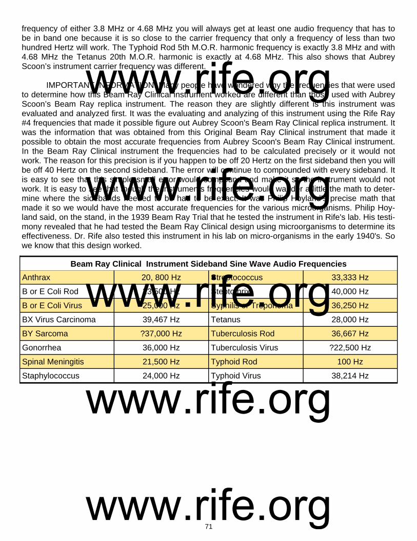
71
frequency of either 3.8 MHz or 4.68 MHz you will always get at least one audio frequency that has to be in band one because it is so close to the carrier frequency that only a frequency of less than two hundred Hertz will work. The Typhoid Rod 5th M.O.R. harmonic frequency is exactly 3.8 MHz and with 4.68 MHz the Tetanus 20th M.O.R. harmonic is exactly at 4.68 MHz. This also shows that Aubrey Scoon’s instrument carrier frequency was different. IMPORTANT INFORMATION: Many people have wondered why the frequencies that were used to determine how this Beam Ray Clinical instrument worked are different than those used with Aubrey Scoon’s Beam Ray replica instrument. The reason they are slightly different is this instrument was evaluated and analyzed first. It was the evaluating and analyzing of this instrument using the Rife Ray #4 frequencies that made it possible figure out Aubrey Scoon's Beam Ray Clinical replica instrument. It was the information that was obtained from this Original Beam Ray Clinical instrument that made it possible to obtain the most accurate frequencies from Aubrey Scoon's Beam Ray Clinical instrument. In the Beam Ray Clinical instrument the frequencies had to be calculated precisely or it would not work. The reason for this precision is if you happen to be off 20 Hertz on the first sideband then you will be off 40 Hertz on the second sideband. The error will continue to compounded with every sideband. It is easy to see that this simple small error would compound and make it so the instrument would not work. It is easy to see that though the instruments frequencies would wander a little the math to deter-mine where the sidebands needed to be had to be exact. It was Philip Hoyland’s precise math that made it so we would have the most accurate frequencies for the various microorganisms. Philip Hoy-land said, on the stand, in the 1939 Beam Ray Trial that he tested the instrument in Rife's lab. His testi-mony revealed that he had tested the Beam Ray Clinical design using microorganisms to determine its effectiveness. Dr. Rife also tested this instrument in his lab on micro-organisms in the early 1940's. So we know that this design worked.
Beam Ray Clinical Instrument Sideband Sine Wave Audio Frequencies
Anthrax 20, 800 Hz Streptococcus 33,333 Hz
B or E Coli Rod 23,500 Hz Steptothrix 40,000 Hz
B or E Coli Virus 25,000 Hz Syphilis or Treponema 36,250 Hz
BX Virus Carcinoma 39,467 Hz Tetanus 28,000 Hz
BY Sarcoma ?37,000 Hz Tuberculosis Rod 36,667 Hz
Gonorrhea 36,000 Hz Tuberculosis Virus ?22,500 Hz
Spinal Meningitis 21,500 Hz Typhoid Rod 100 Hz
Staphylococcus 24,000 Hz Typhoid Virus 38,214 Hz
www.rife.org www.rife.org www.rife.org www.rife.org www.rife.org

72
3.8 MHz carrier frequency before ray tube. 3.8 MHz carrier frequency after ray tube.
Oscilloscope Readings Of The Original Beam Ray Clinical Instrument
18,630 hertz frequency from audio oscillator. 40,980 hertz frequency from audio oscillator.
2,377 hertz frequency from audio oscillator. 9,360 hertz frequency from audio oscillator.
Original Beam Ray modulated waveform. Aubrey Scoon’s Beam Ray replica modulated waveform.
www.rife.org www.rife.org www.rife.org www.rife.org www.rife.org
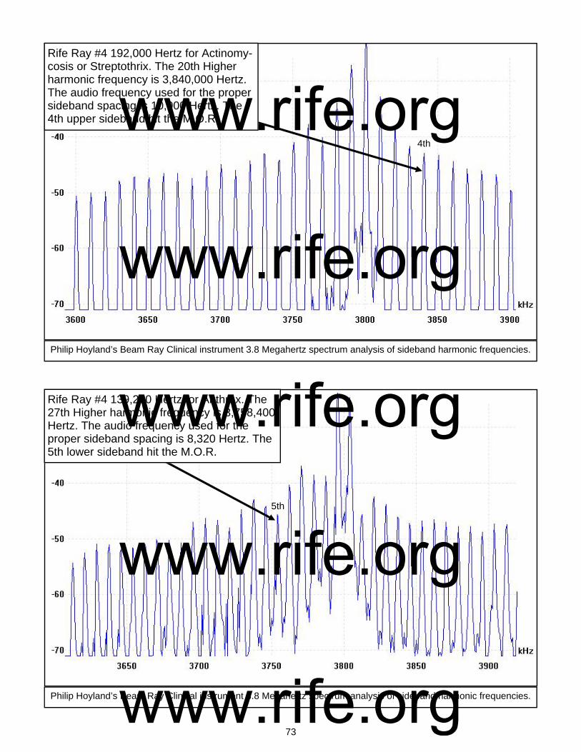
73
Rife Ray #4 192,000 Hertz for Actinomy-cosis or Streptothrix. The 20th Higher harmonic frequency is 3,840,000 Hertz. The audio frequency used for the proper sideband spacing is 10,000 Hertz. The 4th upper sideband hit the M.O.R.
Philip Hoyland’s Beam Ray Clinical instrument 3.8 Megahertz spectrum analysis of sideband harmonic frequencies.
4th
Philip Hoyland’s Beam Ray Clinical instrument 3.8 Megahertz spectrum analysis of sideband harmonic frequencies.
Rife Ray #4 139,200 Hertz for Anthrax. The 27th Higher harmonic frequency is 3,758,400 Hertz. The audio frequency used for the proper sideband spacing is 8,320 Hertz. The 5th lower sideband hit the M.O.R.
5th
www.rife.org www.rife.org www.rife.org www.rife.org www.rife.org
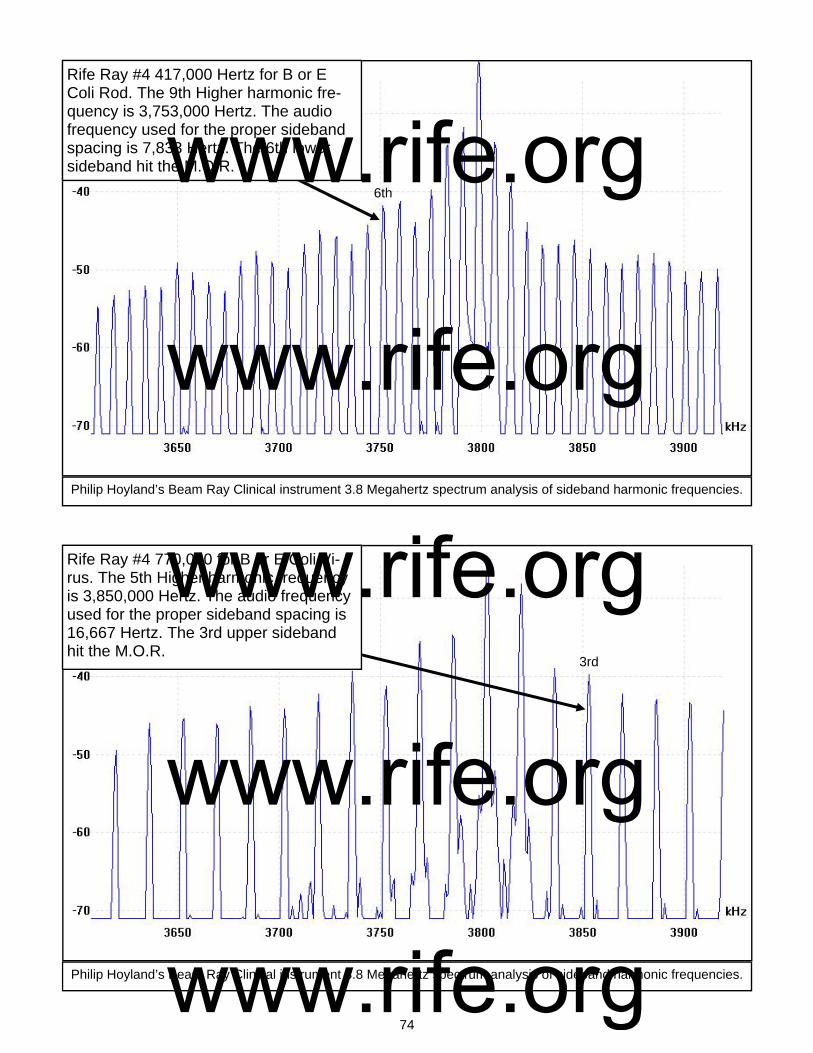
74
Rife Ray #4 417,000 Hertz for B or E Coli Rod. The 9th Higher harmonic fre-quency is 3,753,000 Hertz. The audio frequency used for the proper sideband spacing is 7,833 Hertz. The 6th lower sideband hit the M.O.R.
Philip Hoyland’s Beam Ray Clinical instrument 3.8 Megahertz spectrum analysis of sideband harmonic frequencies.
Philip Hoyland’s Beam Ray Clinical instrument 3.8 Megahertz spectrum analysis of sideband harmonic frequencies.
Rife Ray #4 770,000 for B or E Coli Vi-rus. The 5th Higher harmonic frequency is 3,850,000 Hertz. The audio frequency used for the proper sideband spacing is 16,667 Hertz. The 3rd upper sideband hit the M.O.R.
6th
3rd
www.rife.org www.rife.org www.rife.org www.rife.org www.rife.org
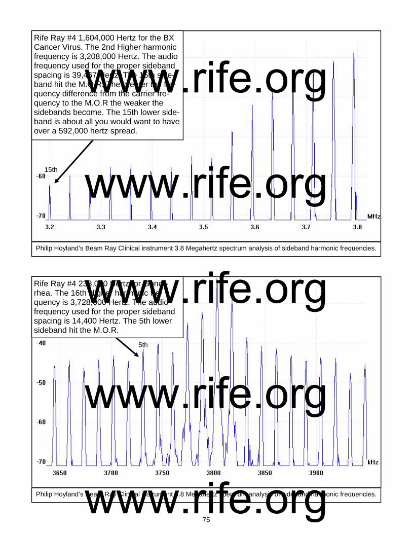
75
Rife Ray #4 1,604,000 Hertz for the BX Cancer Virus. The 2nd Higher harmonic frequency is 3,208,000 Hertz. The audio frequency used for the proper sideband spacing is 39,467 Hertz. The 15th side-band hit the M.O.R. The greater the fre-quency difference from the carrier fre-quency to the M.O.R the weaker the sidebands become. The 15th lower side-band is about all you would want to have over a 592,000 hertz spread.
Philip Hoyland’s Beam Ray Clinical instrument 3.8 Megahertz spectrum analysis of sideband harmonic frequencies.
Philip Hoyland’s Beam Ray Clinical instrument 3.8 Megahertz spectrum analysis of sideband harmonic frequencies.
Rife Ray #4 233,000 Hertz for Gonor-rhea. The 16th Higher harmonic fre-quency is 3,728,000 Hertz. The audio frequency used for the proper sideband spacing is 14,400 Hertz. The 5th lower sideband hit the M.O.R.
15th
5th
www.rife.org www.rife.org www.rife.org www.rife.org www.rife.org

76
Rife Ray #4 427,000 Hertz for Spinal Meningitis. The 9th Higher harmonic fre-quency is 3,843,000 Hertz. The audio frequency used for the proper sideband spacing is 8,600 Hertz. The 5th upper sideband hit the M.O.R.
Philip Hoyland’s Beam Ray Clinical instrument 3.8 Megahertz spectrum analysis of sideband harmonic frequencies.
Philip Hoyland’s Beam Ray Clinical instrument 3.8 Megahertz spectrum analysis of sideband harmonic frequencies.
Rife Ray #4 478,000 Hertz for Staphylo-coccus Pyogenes Aureus. The 8th Higher harmonic frequency is 3,824,000 Hertz. The audio frequency used for the proper sideband spacing is 8,000 Hertz. The 3rd upper sideband hit the M.O.R.
5th
3rd
www.rife.org www.rife.org www.rife.org www.rife.org www.rife.org
77
Rife Ray #4 720,000 Hertz for Streptococ-cus Pyogenes. The 5th Higher harmonic frequency is 3,600,000 Hertz. The audio frequency used for the proper sideband spacing is 8,333 Hertz. The 24th lower sideband hit the M.O.R. The smaller the difference between the M.O.R. frequency and the carrier frequency the greater the number of sideband frequencies that can be used with power.
Philip Hoyland’s Beam Ray Clinical instrument 3.8 Megahertz spectrum analysis of sideband harmonic frequencies.
Philip Hoyland’s Beam Ray Clinical instrument 3.8 Megahertz spectrum analysis of sideband harmonic frequencies.
Rife Ray #4 789,000 Hertz for Syphilis. The 5th Higher harmonic frequency is 3,945,000 Hertz. The audio frequency used for the proper sideband spacing is 6,591 Hertz. The 22nd upper sideband hit the M.O.R.
24th
22nd
www.rife.org www.rife.org www.rife.org www.rife.org www.rife.org
78
Rife Ray #4 234,000 Hertz for Tetanus. The 16th Higher harmonic frequency is 3,744,000 Hertz. The audio frequency used for the proper sideband spacing is 11,200 Hertz. The 5th lower sideband hit the M.O.R.
Philip Hoyland’s Beam Ray Clinical instrument 3.8 Megahertz spectrum analysis of sideband harmonic frequencies.
Philip Hoyland’s Beam Ray Clinical instrument 3.8 Megahertz spectrum analysis of sideband harmonic frequencies.
Rife Ray #4 369,000 Hertz for Tubercu-losis Rod. The 10th Higher harmonic fre-quency is 3,690,000 Hertz. The audio frequency used for the proper sideband spacing is 8,462 Hertz. The 13th lower sideband hit the M.O.R.
5th
13th
www.rife.org www.rife.org www.rife.org www.rife.org www.rife.org

79
Rife Ray #4 760,000 Hertz for Typhoid Rod. The 5th Higher harmonic frequency is 3,800,000 Hertz. The audio frequency used for the proper sideband spacing is 100 Hertz. The sidebands, when only 200 Hertz apart, look like one frequency hit the M.O.R.
Philip Hoyland’s Beam Ray Clinical instrument 3.8 Megahertz spectrum analysis of sideband harmonic frequencies.
Philip Hoyland’s Beam Ray Clinical instrument 3.8 Megahertz spectrum analysis of sideband harmonic frequencies.
Rife Ray #4 1,445,000 Hertz for Typhoid Virus. The 3rd Higher harmonic fre-quency is 4,335,000 Hertz. The audio frequency used for the proper sideband spacing is 38,214 Hertz. The 14th upper sideband hit the M.O.R.
14th
www.rife.org www.rife.org www.rife.org www.rife.org www.rife.org
80
1 139
200
2 278
400
3 417
600
4 556
800
5 696
000
6 835
200
7 974
400
8 111
3600
9 125
2800
10 139
2000
11 153
1200
12 167
0400
13 180
9600
14 194
8800
15 208
8000
16 222
7200
17 236
6400
18 250
5600
19 264
4800
20 278
4000
21 292
3200
22 306
2400
23 320
1600
24 334
0800
25 348
0000
26 361
9200
27 375
8400
28 389
7600
29 403
6800
30 417
6000
31 431
5200
32 445
4400
33 459
3600
34 473
2800
1 192
000
2 384
000
3 576
000
4 768
000
5 960
000
6 115
2000
7 134
4000
8 153
6000
9 172
8000
10 192
0000
11 211
2000
12 230
4000
13 249
6000
14 268
8000
15 288
0000
16 307
2000
17 326
4000
18 345
6000
19 364
8000
20 384
0000
21 403
2000
22 422
4000
23 441
6000
24 460
8000
25 480
0000
26 499
2000
27 518
4000
28 537
6000
29 556
8000
30 576
0000
31 595
2000
32 614
4000
33 633
6000
34 652
8000
1 770
000
2 154
0000
3 231
0000
4 308
0000
5 385
0000
6 462
0000
7 539
0000
8 616
0000
9 693
0000
10 770
0000
11 847
0000
12 924
0000
13 100
10000
14 107
80000
15 115
50000
16 123
20000
17 130
90000
18 138
60000
19 146
30000
20 154
00000
21 161
70000
22 169
40000
23 177
10000
24 184
80000
25 192
50000
26 200
20000
27 207
90000
28 215
60000
29 223
30000
30 231
00000
31 238
70000
32 246
40000
33 254
10000
34 261
80000
1 160
4000
2 320
8000
3 481
2000
4 641
6000
5 802
0000
6 962
4000
7 112
28000
8 128
32000
9 144
36000
10 160
40000
11 176
44000
12 192
48000
13 208
52000
14 224
56000
15 240
60000
16 256
64000
17 272
68000
18 288
72000
19 304
76000
20 320
80000
21 336
84000
22 352
88000
23 368
92000
24 384
96000
25 401
00000
26 417
04000
27 433
08000
28 449
12000
29 465
16000
30 481
20000
31 497
24000
32 513
28000
33 529
32000
34 545
36000
1 233
000
2 466
000
3 699
000
4 932
000
5 116
5000
6 139
8000
7 163
1000
8 186
4000
9 209
7000
10 233
0000
11 256
3000
12 279
6000
13 302
9000
14 326
2000
15 349
5000
16 372
8000
17 396
1000
18 419
4000
19 442
7000
20 466
0000
21 489
3000
22 512
6000
23 535
9000
24 559
2000
25 582
5000
26 605
8000
27 629
1000
28 652
4000
29 675
7000
30 699
0000
31 722
3000
32 745
6000
33 768
9000
34 792
2000
1 427
000
2 854
000
3 128
1000
4 170
8000
5 213
5000
6 256
2000
7 298
9000
8 341
6000
9 384
3000
10 427
0000
11 469
7000
12 512
4000
13 555
1000
14 597
8000
15 640
5000
16 683
2000
17 725
9000
18 768
6000
19 811
3000
20 854
0000
21 896
7000
22 939
4000
23 982
1000
24 102
48000
25 106
75000
26 111
02000
27 115
29000
28 119
56000
29 123
83000
30 128
10000
31 132
37000
32 136
64000
33 140
91000
34 145
18000
Streptothrix
Anthrax
B or E
Coli R
od B
or E C
oli Viurs
BX
Cancer V
irus G
onorrhea S
pinal Meningitis
1 417
000
2 834
000
3 125
1000
4 166
8000
5 208
5000
6 250
2000
7 291
9000
8 333
6000
9 375
3000
10 417
0000
11 458
7000
12 500
4000
13 542
1000
14 583
8000
15 625
5000
16 667
2000
17 708
9000
18 750
6000
19 792
3000
20 834
0000
21 875
7000
22 917
4000
23 959
1000
24 100
08000
25 104
25000
26 108
42000
27 112
59000
28 116
76000
29 120
93000
30 125
10000
31 129
27000
32 133
44000
33 137
61000
34 141
78000
www.rife.org www.rife.org www.rife.org www.rife.org www.rife.org

81
1 478
000
2 956
000
3 143
4000
4 191
2000
5 239
0000
6 286
8000
7 334
6000
8 382
4000
9 430
2000
10 478
0000
11 525
8000
12 573
6000
13 621
4000
14 669
2000
15 717
0000
16 764
8000
17 812
6000
18 860
4000
19 908
2000
20 956
0000
21 100
38000
22 105
16000
23 109
94000
24 114
72000
25 119
50000
26 124
28000
27 129
06000
28 133
84000
29 138
62000
30 143
40000
31 148
18000
32 152
96000
33 157
74000
34 162
52000
1 720
000
2 144
0000
3 216
0000
4 288
0000
5 360
0000
6 432
0000
7 504
0000
8 576
0000
9 648
0000
10 720
0000
11 792
0000
12 864
0000
13 936
0000
14 100
80000
15 108
00000
16 115
20000
17 122
40000
18 129
60000
19 136
80000
20 144
00000
21 151
20000
22 158
40000
23 165
60000
24 172
80000
25 180
00000
26 187
20000
27 194
40000
28 201
60000
29 208
80000
30 216
00000
31 223
20000
32 230
40000
33 237
60000
34 244
80000
1 789
000
2 157
8000
3 236
7000
4 315
6000
5 394
5000
6 473
4000
7 552
3000
8 631
2000
9 710
1000
10 789
0000
11 867
9000
12 946
8000
13 102
57000
14 110
46000
15 118
35000
16 126
24000
17 134
13000
18 142
02000
19 149
91000
20 157
80000
21 165
69000
22 173
58000
23 181
47000
24 189
36000
25 197
25000
26 205
14000
27 213
03000
28 220
92000
29 228
81000
30 236
70000
31 244
59000
32 252
48000
33 260
37000
34 268
26000
1 234
000
2 468
000
3 702
000
4 936
000
5 117
0000
6 140
4000
7 163
8000
8 187
2000
9 210
6000
10 234
0000
11 257
4000
12 280
8000
13 304
2000
14 327
6000
15 351
0000
16 374
4000
17 397
8000
18 421
2000
19 444
6000
20 468
0000
21 491
4000
22 514
8000
23 538
2000
24 561
6000
25 585
0000
26 608
4000
27 631
8000
28 655
2000
29 678
6000
30 702
0000
31 725
4000
32 748
8000
33 772
2000
34 795
6000
1 369
000
2 738
000
3 110
7000
4 147
6000
5 184
5000
6 221
4000
7 258
3000
8 295
2000
9 332
1000
10 369
0000
11 405
9000
12 442
8000
13 479
7000
14 516
6000
15 553
5000
16 590
4000
17 627
3000
18 664
2000
19 701
1000
20 738
0000
21 774
9000
22 811
8000
23 848
7000
24 885
6000
25 922
5000
26 959
4000
27 996
3000
28 103
32000
29 107
01000
30 110
70000
31 114
39000
32 118
08000
33 121
77000
34 125
46000
1 760
000
2 152
0000
3 228
0000
4 304
0000
5 380
0000
6 456
0000
7 532
0000
8 608
0000
9 684
0000
10 760
0000
11 836
0000
12 912
0000
13 988
0000
14 106
40000
15 114
00000
16 121
60000
17 129
20000
18 136
80000
19 144
40000
20 152
00000
21 159
60000
22 167
20000
23 174
80000
24 182
40000
25 190
00000
26 197
60000
27 205
20000
28 212
80000
29 220
40000
30 228
00000
31 235
60000
32 243
20000
33 250
80000
34 258
40000
1 144
5000
2 289
0000
3 433
5000
4 578
0000
5 722
5000
6 867
0000
7 101
15000
8 115
60000
9 130
05000
10 144
50000
11 158
95000
12 173
40000
13 187
85000
14 202
30000
15 216
75000
16 231
20000
17 245
65000
18 260
10000
19 274
55000
20 289
00000
21 303
45000
22 317
90000
23 332
35000
24 346
80000
25 361
25000
26 375
70000
27 390
15000
28 404
60000
29 419
05000
30 433
50000
31 447
95000
32 462
40000
33 476
85000
34 491
30000
Staph P
yo Aureus
Strept P
yogenes S
yphilis T
etanus T
uberculosis Rod
Typhoid R
od T
yphoid Virus
www.rife.org www.rife.org www.rife.org www.rife.org www.rife.org

82
Chapter #10
The Gruner Schematic and Philip Hoyland’s Beam Ray Laboratory Rife Machine
1. Used a ray tube. 2. Had one RF oscillators which was set on a fix frequency. 3. Had a fix audio pulsing circuit. 4. Power usage was about 450 to 600 watts. Output to the ray tube was probably about 40 watts. In this chapter we will cover two instruments. First, Dr. Gruner’s Rife machine and second, the Beam Ray Laboratory Rife machine. The reason for this is the work done on the Gruner instrument lead too many discoveries of how Dr. Rife’s machines worked. The first instrument we will discuss is the Gruner Rife Machine. From some recent documents that were found by Mr. Ringas we have found it necessary to change some of the information in this chapter which deals with Dr. Gruner’s Rife instru-ment. The new documents that were found by Mr. Ringas reveal the fact that the Gruner Rife machine had one fixed RF oscillator. It was previously believed that this instrument was a Beam Ray laboratory instrument which had two high RF frequency oscillators. We now know from these documents that this was an incorrect assumption. The new information comes from two letters written to John Crane back in 1953 from Dr. O. C. Gruner. John Crane at that time was inquiring about the status of Dr. Gruner’s Rife machine that was sent to him in 1942 by Dr. Milbank Johnson M.D.:
www.rife.org www.rife.org www.rife.org www.rife.org www.rife.org
83
DR. GRUNER: “You refer, I suppose, to the ray machine which Milbank Johnson sent “in bits” to me in Montreal [Canada]. Vergil Neher assembled it, but actually I had to purchase a large amount of the ra-dio material to be able to get it completed. I used this machine quite a bit, and it was very successful at first; but after about six months it “faded”, first the tubes seemed all right. The only reason would have been changes in the glass of the globe [ray tube] as a result of the discharges… I could send the plan [schematic] of the apparatus.” (Letter from Dr. Gruner to John Crane, March 31, 1953). DR. GRUNER: “I enclosed the diagram [schematic] of the Ray Machine as made here in 1942. So I hope it will be of interest to you. It will not be necessary to return it. It is to be noted that it was made only for one frequency; obviously it would be necessary to alter the design to enable many frequencies to be used.” (Letter from Dr. Gruner to John Crane, April 29, 1953). These two letters changed all our understanding of this instrument. John Crane had altered the schematic and put a second Hartley oscillator on the schematic which confused us when we originally built the instrument. This second Hartley oscillator, added by John Crane made it so the instrument would have had one fixed RF oscillator and a second variable oscillator. This second variable oscillator, that John Crane added to the schematic, would make it so that instrument could output many different frequencies. Logically this is what Dr. Rife, John Crane and John Marsh wanted in an instrument. But this is not how Dr. Gruner’s original instrument worked. From the analyzing of the original Beam Ray Clinical instrument, which was built by Philip Hoy-land, we know that it had the capability of variable frequencies. We need to point out here that Dr. Gruner’s ray tube instrument did not work on the Beam Ray Clinical instrument harmonic sideband method. From these two letters we now know that Dr. Gruner’s instrument work on the same principles as the Rife Ray #4 instrument. That instrument output the specific frequencies directly from its two vari-able RF oscillators. Because the Rife Ray #4 put out specific frequencies it also used a modulated au-dio pulsing circuit to pulse the high RF frequencies that were used to devitalize the various microorgan-isms. This modulated audio frequency pulsing method was used with the Rife Ray #3 and Rife Ray #4 instruments. The Gruner schematic which has this modulated audio frequency pulsing circuit reveals how Dr. Rife used this pulsing method in his instruments. With this understanding we now have a clearer understanding of how these four instruments, Rife Ray #3, Rife Ray #4, Beam Ray Laboratory and Gruner Rife machine really worked. As we pointed out when we initially looked at Dr. Gruner’s schematic, over three years ago, we were under the wrong assumption, because John Crane altered the schematic by adding the second Hartley oscillator to Dr. Gruner’s schematic. But that wrong assumption actually caused us to build an instrument that worked almost exactly as the Rife Ray #4. Except the instrument that we built from Dr. Gruner’s schematic did not have as high a frequency range as the Rife Ray #4. Because of what we have just explained we feel that the information that we obtained from the initial building of the Gruner schematic, three years ago, should be kept in this report. What was learned, even under the wrong as-sumption, revealed how the Rife Ray #4 was built and will be of interest to those who may want to build this instrument. The Beam Ray Laboratory instrument would have worked like the Gruner instrument and the Rife Ray #4 instrument since both of these were to be used in laboratory work. An instrument that worked like the Beam Ray Clinical instrument, which worked on the harmonic sideband method, would have been useless in any laboratory work since you could never know the exact frequency that killed, devitalize or rendered harmless an organism. For this reason the Beam Ray Laboratory instrument is still included in this information about Dr. Gruner’s Rife instrument.
www.rife.org www.rife.org www.rife.org www.rife.org www.rife.org

84
The initial Gruner schematic work done 3 years ago.
In one of the previous version of this report we dealt with the concept that the Gruner instrument was a heterodyning instrument. We now know that this method was not used in the Gruner Rife Ma-chine therefore the heterodyning concept was removed from a previous rewriting of this document. Though the Rife Ray #4 Rife Machine could output two frequencies at the same time, heterodyning those two frequencies in the ray tube, this was a byproduct of the instrument not the method used to produce the M.O.R. frequencies needed to devitalize or render harmless the microorganisms. The knowledge that we gained through our testing of this concept is the reason much of the history and work that we did at that time is still included in this report. It was that testing which gave us the under-standing of how the Rife Ray #4 worked and how the Beam Ray Laboratory Rife Machine would have worked. We do not have a picture of Dr. Gruner's Rife instrument so we have no idea what it looked like. This however did not affect building the instrument from the schematic. The Rife Machine in the photo shown at the beginning of this chapter is probably a photo of the Beam Ray Laboratory instrument built by Philip Hoyland. John Crane dated that instrument as being built in 1935 but we know that the Rife Ray #4 was built in 1935. The knowledge of the Laboratory instrument came from the Beam Ray Trial manuscript. A complete copy of this transcript was provided when Steven Ross allowed us to scan it. I would like to acknowledge his generous contribution of this information which has given us a great deal of understanding so that we could figure out the history of how and when the instruments were built. After reading for the first time the complete Beam Ray Trial manuscript I found there was men-tion of a Laboratory instrument. It appeared that this Laboratory instrument was probably to be used by those who would be working in laboratories with microorganisms for testing. Dr. O. C. Gruner worked in a laboratory with organisms and worked with Dr. Rife on the organism called Cryptomyces Pleomorpha fungi. The Laboratory instrument was mentioned two or three times but no real information was given about it. Below are statements made by Bertrand Comparet and Philip Hoyland in the Beam Ray Trial that gives us some important information about this instrument. (#209-210, 217-222): COMPARET: “The four machines bought by the British were two so-called laboratory types and two so-called clinical types, what was the difference between the two.” HOYLAND: “The clinical type was similar in all respects to the Rife machine except that it did not have [word missing] of the [word missing] used on Mrs. Henderson.” COMPARET: “How was the price of these machines fixed.” HOYLAND: “The price was decided from the costs of what it cost to manufacture the first machine that was sold to Dr. Hamer.” COMPARET: “How much was that?” HOYLAND: “I think it was four hundred dollars plus the royalty.” COMPARET: “Wasn’t it five hundred dollars plus royalty on the clinical type and six plus royalty on the lab type.” HOYLAND: “I don’t remember.” Since this instrument was for Laboratory work it would have worked like the Rife Ray #4 but be-cause the case was smaller it probably had a smaller frequency range. The Rife Ray #4 had nine fre-
www.rife.org www.rife.org www.rife.org www.rife.org www.rife.org
85
quency bands that covered from 87,000 Hertz to 22.5MHz (22,500,000 Hertz). The first four bands of the #4 covered from 87,000 Hertz to 2,140,000 Hertz. These four frequency bands would cover the whole list of Dr. Rife’s disease organisms listed on the Rife Ray #4 documents. With this understanding we know that the Laboratory instrument at least covered this frequency range. We will not speculate if it had a higher frequency range because we really do not know.
Deciphering Dr. Gruner’s Beam Ray instrument schematic Three years ago a group of us had been looking at the Gruner schematic in hopes of trying to figure out how it worked. I had built and tested both the 1950’s AZ-58 Beam Ray Clinical instrument and 1940’s Aubrey Scoon, Beam Ray Clinical replica instruments. To our knowledge none of these in-struments ever obtained the same results as the original Beam Ray Clinical Rife Machine built by the original 1938 Beam Ray Corporation. All the documentation we had showed that there were changes made to the original Beam Ray design which compromised the1950’s AZ-58, and possibly 1940’s Au-brey Scoon, Verne Thompson instruments. John Crane, over the years told many people that the AZ-58 and the audio frequencies it used were Dr. Rife’s original frequencies. The Rife documents we have show that what John Crane claimed was not correct. Dr. Rife was not using audio frequencies in 1934 as John Crane and John Marsh claimed. Rebuild of the 1950's AZ-58 and Aubrey Scoon's instrument partially made the rediscovery of the Beam Ray Laboratory instrument possible. At the 2003 Rife Conference, a gentleman put up the Gruner schematic of an original Beam Ray instrument. From reading the Rife documents I knew that this schematic existed because John Crane had mentioned it in his papers. John Crane said that the AZ-58 was built from that schematic. When I saw it I knew it was important, so I took still photos of it with my video camera. Because the video cam-era only had a one mega-pixel capability I took many up close photos knowing I could put it back to-gether at a later date. Back in 2004 I gave this schematic to Aubrey Scoon and his British Rife group in hopes that they could look it over and correct any mistakes that may have been made. They redrew the schematics, without fully correcting them, and put them up on their web site. This information was re-leased because we wanted everyone to have access to it. Back on July 27, 2007 a Mr. Andrews, who was one of the British Rife group and I got into an-other conversation about the Gruner schematic. He asked me to send him another copy of the original Gruner schematic so he could look it over again. An email conversation began at that time which in-cluded Mr. Peters, Mr. Ringas, Mr. Andrews, Mr. Berger and myself. Mr. Peters immediately noticed that the schematic that had been redrawn by the British group had some errors in it. Discussions con-tinued on and off for a few months until one day Mr. Peters noticed an over sight when looking over the schematic again. At the time we thought it had to do with the heterodyning method. But now we under-stand that this oversight was one of the keys to understanding how the Rife Ray #4 and Beam Ray Laboratory Rife Machines would have worked. Mr. Peters sent Mr. Ringas and I an email. He mentioned that a possible test could be made that would determine if this observation of his was the key to understanding how the Beam Ray Laboratory instrument really worked. I called Mr. Peters and had a discussion with him and he told me how we could make these tests. I told him that we did not need to do the test with solid state frequency genera-tors because I had conducted a similar test back when John Bedini and I were working on the AZ-58 tests. John Bedini and I knew that the original Rife Ray #4 instrument was a lot more powerful than the AZ-58 because of the Rife documents. After more accurate testing we found the AZ-58 only output about 40 watts from the ray tube. I told him that I still had my 1940’s Aubrey Scoon replica and several AZ-58’s on the shelf. I told John Bedini that the original Beam Ray Clinical instrument, from the docu-mentation that we had, may have output about 50 to 60 watts from the ray tube. He told me how I could make a test, by putting two AZ-58s together, which would give me at least 60 watts out of the ray tube. I didn’t know it at that time but that test was probably the way the Rife Ray #4 and Beam Ray Labora-
www.rife.org www.rife.org www.rife.org www.rife.org www.rife.org
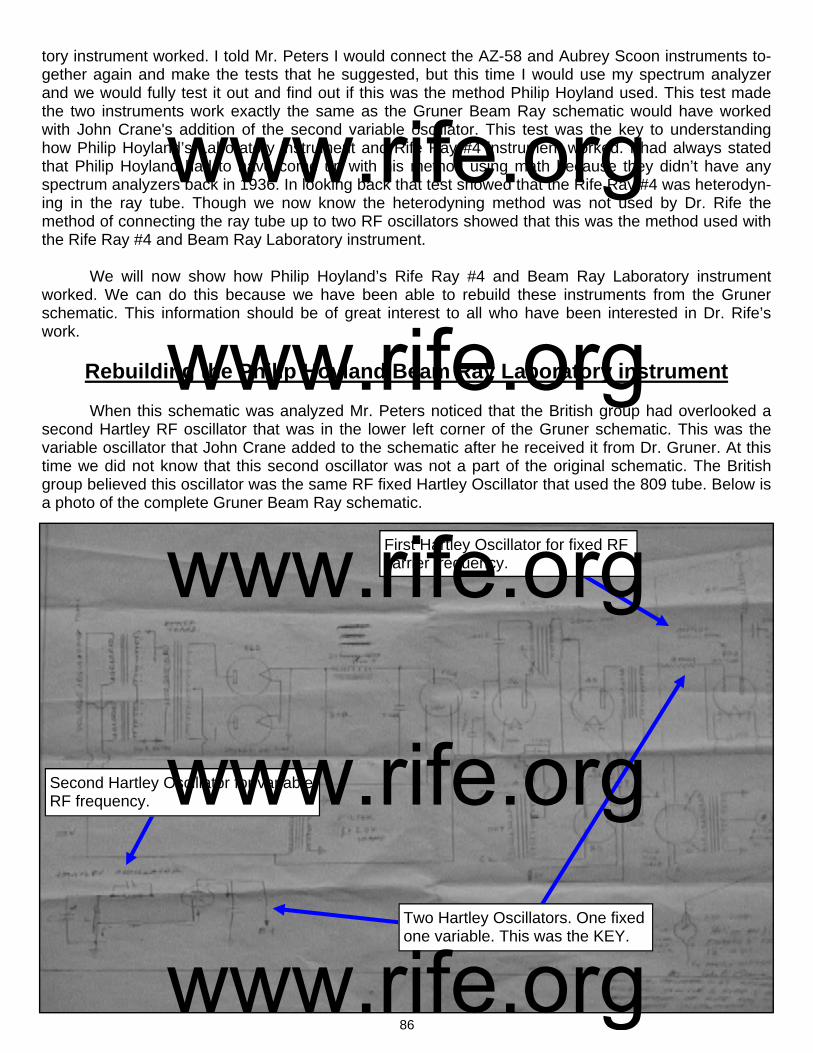
86
First Hartley Oscillator for fixed RF carrier frequency.
Second Hartley Oscillator for variable RF frequency.
Two Hartley Oscillators. One fixed one variable. This was the KEY.
tory instrument worked. I told Mr. Peters I would connect the AZ-58 and Aubrey Scoon instruments to-gether again and make the tests that he suggested, but this time I would use my spectrum analyzer and we would fully test it out and find out if this was the method Philip Hoyland used. This test made the two instruments work exactly the same as the Gruner Beam Ray schematic would have worked with John Crane's addition of the second variable oscillator. This test was the key to understanding how Philip Hoyland’s Laboratory instrument and Rife Ray #4 instrument worked. I had always stated that Philip Hoyland had to have come up with his method using math because they didn’t have any spectrum analyzers back in 1936. In looking back that test showed that the Rife Ray #4 was heterodyn-ing in the ray tube. Though we now know the heterodyning method was not used by Dr. Rife the method of connecting the ray tube up to two RF oscillators showed that this was the method used with the Rife Ray #4 and Beam Ray Laboratory instrument. We will now show how Philip Hoyland’s Rife Ray #4 and Beam Ray Laboratory instrument worked. We can do this because we have been able to rebuild these instruments from the Gruner schematic. This information should be of great interest to all who have been interested in Dr. Rife’s work.
Rebuilding the Philip Hoyland Beam Ray Laboratory instrument When this schematic was analyzed Mr. Peters noticed that the British group had overlooked a second Hartley RF oscillator that was in the lower left corner of the Gruner schematic. This was the variable oscillator that John Crane added to the schematic after he received it from Dr. Gruner. At this time we did not know that this second oscillator was not a part of the original schematic. The British group believed this oscillator was the same RF fixed Hartley Oscillator that used the 809 tube. Below is a photo of the complete Gruner Beam Ray schematic.
www.rife.org www.rife.org www.rife.org www.rife.org www.rife.org
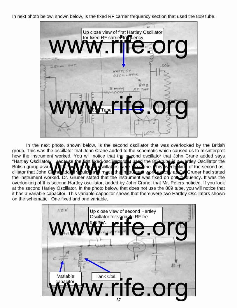
87
809 Tube
Up close view of first Hartley Oscillator for fixed RF carrier frequency.
Up close view of second Hartley Oscillator for variable RF fre-quency.
Variable capacitor.
Tank Coil.
In next photo below, shown below, is the fixed RF carrier frequency section that used the 809 tube. In the next photo, shown below, is the second oscillator that was overlooked by the British group. This was the oscillator that John Crane added to the schematic which caused us to misinterpret how the instrument worked. You will notice that the second oscillator that John Crane added says “Hartley Oscillator.” Because the first fixed oscillator that used the 809 tube is a Hartley Oscillator the British group assumed that both of these oscillators were the same. This overlooking of the second os-cillator that John Crane added would have made the instrument work exactly as Dr. Gruner had stated the instrument worked. Dr. Gruner stated that the instrument was fixed on one frequency. It was the overlooking of this second Hartley oscillator, added by John Crane, that Mr. Peters noticed. If you look at the second Harley Oscillator, in the photo below, that does not use the 809 tube, you will notice that it has a variable capacitor. This variable capacitor shows that there were two Hartley Oscillators shown on the schematic. One fixed and one variable.
www.rife.org www.rife.org www.rife.org www.rife.org www.rife.org

88
Negative
Tank Coil
Positive
Ray Tube
The next photo, shown below, shows that the first fixed Hartley Oscillator was connected from the tank coil to the negative side of the ray tube. If you look closely at the photo you will notice that the positive side of the ray tube was also to be connected to a Hartley Oscillator. If you hooked the positive side of the ray tube back up to the same fixed Hartley Oscillator it would have only output one frequency as described by Dr. Gruner. This adding of the second oscillator, by John Crane, is why there was confusion on how this instrument worked. The positive side of the ray tube was supposed to be hooked back up to the same fixed oscillator. But with the adding of the sec-ond variable Hartley Oscillator, by John Crane, would mean that the positive side of the ray tube would have been hooked up to the second Hartley oscillator. This would have made it so the ray tube would be connected between the two Hartley Oscillators. The negative side of the ray tube connected to one oscillator and the positive side of the ray tube connected to the other oscillator. The second Hartley Oscillator was also an RF Oscillator. It had a tank coil and a variable capaci-tor for changing the RF frequencies. Anyone looking at this schematic will notice that it does not have any variable audio oscillator. Philip Hoyland’s Beam Ray Gruner instrument was using an RF frequency not an audio frequency. This would logically mean that Dr. Gruner was using one of the Rife Ray #4 frequencies. Because Dr. Gruner was working on the cancer organism of Cryptomyces Pleomorpha fungi his instrument was most likely set on that organisms frequency. Because we did not know that John Crane had added this second oscillator we came to the con-clusion that the logical way to build the instrument would have been to have had two Hartley Oscillators using the 809 tubes. So this is the way that we rebuilt the instrument. By using the method of connect-
www.rife.org www.rife.org www.rife.org www.rife.org www.rife.org
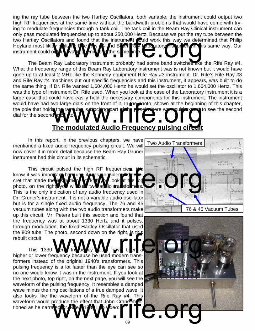
89
ing the ray tube between the two Hartley Oscillators, both variable, the instrument could output two high RF frequencies at the same time without the bandwidth problems that would have come with try-ing to modulate frequencies through a tank coil. The tank coil in the Beam Ray Clinical instrument can only pass modulated frequencies up to about 250,000 Hertz. Because we put the ray tube between the two Hartley Oscillators and found that the instrument could work this way we determined that Philip Hoyland most likley built the Rife Ray #4 and Beam Ray Laboratory instrument in this same way. Our instrument could output two frequencies at the same time. The Beam Ray Laboratory instrument probably had some band switches like the Rife Ray #4. What the frequency range of this Beam Ray Laboratory instrument was is not known but it would have gone up to at least 2 MHz like the Kennedy equipment Rife Ray #3 instrument. Dr. Rife’s Rife Ray #3 and Rife Ray #4 machines put out specific frequencies and this instrument, it appears, was built to do the same thing. If Dr. Rife wanted 1,604,000 Hertz he would set the oscillator to 1,604,000 Hertz. This was the type of instrument Dr. Rife used. When you look at the case of the Laboratory instrument it is a large case that could have easily held the necessary components for this instrument. The instrument would have had two large dials on the front of it. In the photo, shown at the beginning of this chapter, the pole that holds the ray tube is blocking part of the panel where we would expect to see the second dial for the second oscillator.
The modulated Audio Frequency pulsing circuit In this report, in the previous chapters, we have mentioned a fixed audio frequency pulsing circuit. We will now cover it in more detail because the Beam Ray Gruner instrument had this circuit in its schematic. This circuit pulsed the high RF frequencies. We know it was important because it was considered the se-cret that made the instrument work. If you look at the top photo, on the right, you will see two audio transformers. This is the only indication of any audio frequency used in Dr. Gruner’s instrument. It is not a variable audio oscillator but is for a single fixed audio frequency. The 76 and 45 vacuum tubes along with the two audio transformers make up this circuit. Mr. Peters built this section and found that the frequency was at about 1330 Hertz and it pulses, through modulation, the fixed Hartley Oscillator that used the 809 tube. The photo, second down on the right, is this rebuilt circuit. This 1330 Hertz frequency could have been a higher or lower frequency because he used modern trans-formers instead of the original 1940's transformers. This pulsing frequency is a lot faster than the eye can see so no one would know it was in the instrument. If you look at the next photo, top right, on the next page, you will see the waveform of the pulsing frequency. It resembles a damped wave minus the ring oscillations of a true damped wave. It also looks like the waveform of the Rife Ray #4. This waveform would produce the effect that John Crane men-tioned as he narrated Dr. Rife’s 1936 Lab video:
Two Audio Transformers
76 & 45 Vacuum Tubes
www.rife.org www.rife.org www.rife.org www.rife.org www.rife.org
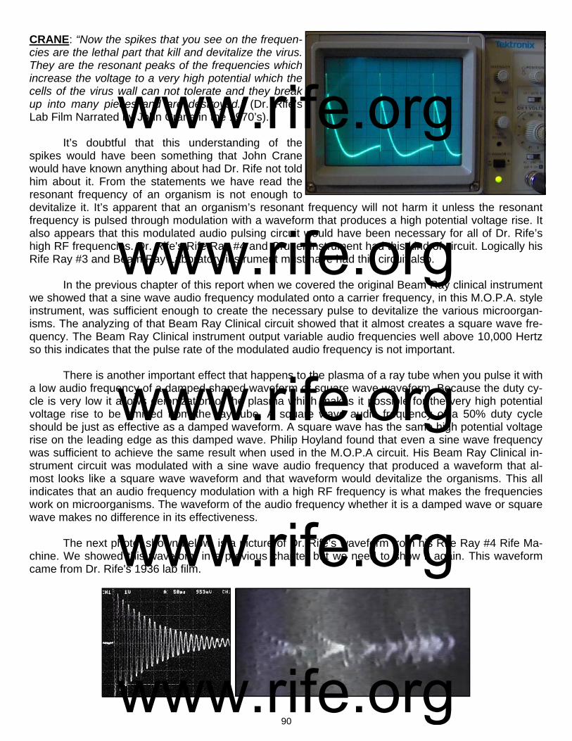
90
CRANE: “Now the spikes that you see on the frequen-cies are the lethal part that kill and devitalize the virus. They are the resonant peaks of the frequencies which increase the voltage to a very high potential which the cells of the virus wall can not tolerate and they break up into many pieces and are destroyed.” (Dr. Rife’s Lab Film Narrated by John Crane in the 1970’s). It’s doubtful that this understanding of the spikes would have been something that John Crane would have known anything about had Dr. Rife not told him about it. From the statements we have read the resonant frequency of an organism is not enough to devitalize it. It’s apparent that an organism’s resonant frequency will not harm it unless the resonant frequency is pulsed through modulation with a waveform that produces a high potential voltage rise. It also appears that this modulated audio pulsing circuit would have been necessary for all of Dr. Rife’s high RF frequencies. Dr. Rife's Rife Ray #4 and Gruner instrument had this kind of circuit. Logically his Rife Ray #3 and Beam Ray Laboratory instrument must have had this circuit also. In the previous chapter of this report when we covered the original Beam Ray clinical instrument we showed that a sine wave audio frequency modulated onto a carrier frequency, in this M.O.P.A. style instrument, was sufficient enough to create the necessary pulse to devitalize the various microorgan-isms. The analyzing of that Beam Ray Clinical circuit showed that it almost creates a square wave fre-quency. The Beam Ray Clinical instrument output variable audio frequencies well above 10,000 Hertz so this indicates that the pulse rate of the modulated audio frequency is not important. There is another important effect that happens to the plasma of a ray tube when you pulse it with a low audio frequency of a damped shaped waveform or square wave waveform. Because the duty cy-cle is very low it allows deionization of the plasma which makes it possible for the very high potential voltage rise to be emitted from the ray tube. A square wave audio frequency of a 50% duty cycle should be just as effective as a damped waveform. A square wave has the same high potential voltage rise on the leading edge as this damped wave. Philip Hoyland found that even a sine wave frequency was sufficient to achieve the same result when used in the M.O.P.A circuit. His Beam Ray Clinical in-strument circuit was modulated with a sine wave audio frequency that produced a waveform that al-most looks like a square wave waveform and that waveform would devitalize the organisms. This all indicates that an audio frequency modulation with a high RF frequency is what makes the frequencies work on microorganisms. The waveform of the audio frequency whether it is a damped wave or square wave makes no difference in its effectiveness. The next photo, shown below, is a picture of Dr. Rife’s waveform from his Rife Ray #4 Rife Ma-chine. We showed this waveform in a previous chapter but we need to show it again. This waveform came from Dr. Rife's 1936 lab film.
www.rife.org www.rife.org www.rife.org www.rife.org www.rife.org

91
The lab film shows that he put a metal plate about 3” X 8” under the ray tube and ran his oscillo-scope lead to it so he could read the frequencies. This photo shows the type of waveform he was using to devitalize organisms. It also matches the waveform produced by the 76 and 45 vacuum tubes in the Gruner instrument we are looking at in this chapter. We now know from the rebuilding of Dr. Gruners instrument and from the analyzing of the Beam Ray Clinical instrument, the two waveforms that were used, how they were created, and the method that should be used for doing M.O.R research. Both Mr. Peters and I rebuilt the Gruner instrument using two variable RF oscillators. We did not put in the various bands in it like the Rife Ray #4 or the Beam Ray Laboratory instrument because we first believed it was a heterodyning instrument. Now that we know that Philip Hoyland’s Beam Ray Clinical instrument used upper harmonics of the Rife Ray #4 frequencies it doesn’t seem necessary that we put the different bands into the instrument. Our instruments will probably be adjusted so we can cover a range from about 1 MHz to about 4 or 5 MHz. Then we will multiply up the Rife Ray #4 frequen-cies into these ranges, like Philip Hoyland did with the Beam Ray Clinical instrument, and use them with this instrument. Other than John Crane adding the second Hartley oscillator the Gruner schematic was a complete schematic. The pulsing circuit was drawn correctly and worked. It also showed how Dr. Rife produced the damped waveform which pulsed his high RF frequencies in his instruments. Mr. Peters built his instrument using 805 tubes and I built my instrument using 812A tubes. The AZ-58 Beam Ray Clinical replica RF section was almost exactly the same (809 vacuum tube replaced with the more powerful 812A tube) as the Gruner circuit. The reason I built the Gruner instrument using the 812A tubes is because the 809 is no longer being manufactured. We were also able to replace the modulated pulsing circuit consisting of the 45 & 76 tubes with a single high voltage switching transistor driven with a function generator which outputs the 1330 Hertz pulse frequency. With the use of this transistor we can use any other frequency we want to use. Using this transistor we believe makes the design better because we can output all the lower audio frequencies including the original audio fre-quencies used in the AZ-58. My instrument has two Vernier dials which allows me to output two high RF frequencies at the same time like the Rife Ray #4 did. The ray tube is connected to both tank coils instead of having one side of the ray tube go to ground. Please note: There is a modern instrument built today that is called the "Beam Ray." It works nothing like this original 1930’s Beam Ray Laboratory instrument built by Philip Hoyland. We are not trying to be negative about the modern Beam Ray instrument but some people have asked us if these instruments work the same and they do not. We have only given this information so people are not con-fused about these two instruments. On pages 92 through 95 are the photos of the Gruner instrument that we built. Because John Crane altered the schematic by adding the second oscillator we built this instrument with two oscilla-tors. I built mine with two variable RF oscillators which made it work like the Rife Ray #4 and the Beam Ray Laboratory instrument. For this reason we refer to this instrument, in the photos, as the Laboratory instrument. On page 96 is a redrawn schematic of this design. We replaced the smaller vacuum tube of the second Hartley Oscillator with the 809 tube. The layout of the electronic parts of this instrument is very important because of the inherent interference problems that come with RF oscillators. Anyone wanting to build this instrument should have a good understanding of old tube technology. Some parts of this circuit use up to 2000 volts DC with substantial current and can easily kill anyone not experienced in working with this kind of current or voltage. We take no responsibility for anyone who builds this instru-ment. We recommend that you have professional help.
www.rife.org www.rife.org www.rife.org www.rife.org www.rife.org

92
Mr. Peters’ photos of the rebuilt Beam Ray Laboratory instrument
www.rife.org www.rife.org www.rife.org www.rife.org www.rife.org
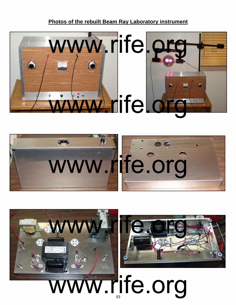
93
Photos of the rebuilt Beam Ray Laboratory instrument
www.rife.org www.rife.org www.rife.org www.rife.org www.rife.org

94
www.rife.org www.rife.org www.rife.org www.rife.org www.rife.org
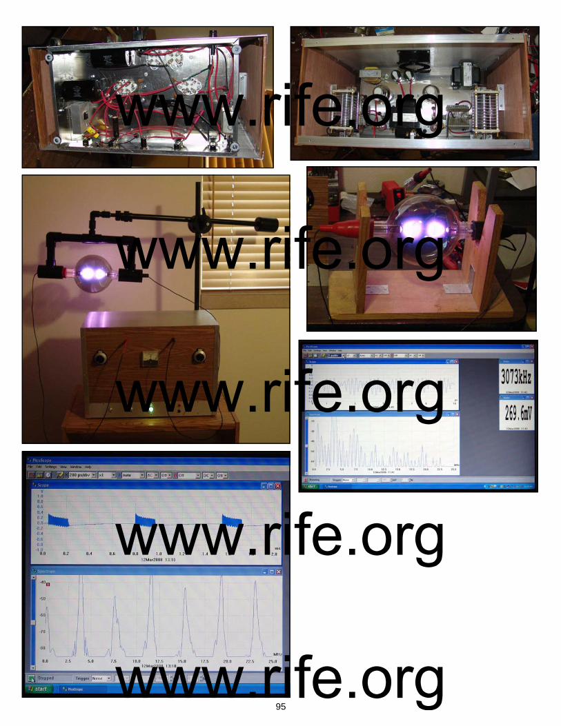
95
www.rife.org www.rife.org www.rife.org www.rife.org www.rife.org

96
www.rife.org www.rife.org www.rife.org www.rife.org www.rife.org
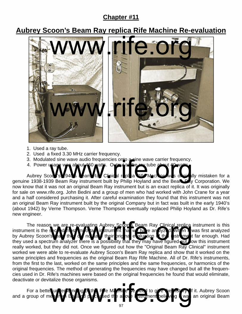
97
Chapter #11
Aubrey Scoon’s Beam Ray replica Rife Machine Re-evaluation
1. Used a ray tube. 2. Used a fixed 3.30 MHz carrier frequency. 3. Modulated sine wave audio frequencies onto a sine wave carrier frequency. 4. Power usage was about 460 watts. Output to the ray tube about 40 watts. Aubrey Scoon’s 1940’s Beam Ray Clinical replica Rife Machine was originally mistaken for a genuine 1938-1939 Beam Ray instrument built by Philip Hoyland and the Beam Ray Corporation. We now know that it was not an original Beam Ray instrument but is an exact replica of it. It was originally for sale on www.rife.org. John Bedini and a group of men who had worked with John Crane for a year and a half considered purchasing it. After careful examination they found that this instrument was not an original Beam Ray instrument built by the original Company but in fact was built in the early 1940’s (about 1942) by Verne Thompson. Verne Thompson eventually replaced Philip Hoyland as Dr. Rife’s new engineer. The reason we are re-evaluating Aubrey Scoon's Beam Ray Clinical replica instrument is this instrument is the second most important instrument that we have analyzed. When it was first analyzed by Aubrey Scoon's team they did not take their original evaluation of this instrument far enough. Had they used a spectrum analyzer there is a possibility that they may have figured out how this instrument really worked, but they did not. Once we figured out how the "Original Beam Ray Clinical" instrument worked we were able to re-evaluate Aubrey Scoon's Beam Ray replica and show that it worked on the same principles and frequencies as the original Beam Ray Rife Machine. All of Dr. Rife's instruments, from the first to the last, worked on the same principles and the same frequencies, or harmonics of the original frequencies. The method of generating the frequencies may have changed but all the frequen-cies used in Dr. Rife's machines were based on the original frequencies he found that would eliminate, deactivate or devitalize those organisms. For a better understanding of this Rife Machine we need to give the history of it. Aubrey Scoon and a group of men from England purchased the above instrument believing it was an original Beam
www.rife.org www.rife.org www.rife.org www.rife.org www.rife.org

98
Ray Clinical instrument. The original Beam Ray Clinical instrument was known to be working on har-monics. Without really knowing it, they purchased a replica of the Beam Ray Clinical instrument! At that time no original instrument had been located. Because of this and the fact that we had no absolute concrete evidence that Philip Hoyland built this style of audio frequency instrument it was not accepted as a genuine Rife instrument. Not even the 1950’s AZ-58 Beam Ray Clinical replica was accepted as a genuine Rife instrument either. A few years ago, before Aubrey passed away, I was communicating with him about this instru-ment. In the course of our communications he told me that he had used the wrong main output tube in the instrument when they worked on it. Because they had used the wrong vacuum tube the carrier fre-quency had parasitic oscillations which created harmonics. He said that when they discovered this mis-take they put the proper tube (809) in and most of harmonics from the parasitic oscillations were gone. Aubrey Scoon mentions the change of this tube (809) on his web site but they did not change the photos of the waveforms. All of the photos of the waveforms on his web site are of an instrument that has parasitic oscillations. Using the wrong tube was a simple mistake that anyone could make but it led to a great deal of confusion causing many to believe, including myself, that this instrument was an origi-nal Beam Ray Clinical instrument that was built by the original 1938 Beam Ray Corporation. Both Jim Berger and I separately built Aubrey Scoon’s instrument with the correct tubes and found using an oscilloscope that the RF output was clean of the harmonics from the malfunctioning cir-cuit. This confirmed to us what Aubrey had said about using the proper tube. It also showed that it did-n't have the reported harmonics which the genuine Beam Ray Clinical instrument was supposed to have. Little did we know, at that time, that the harmonic concept we were looking for was there but we didn’t really understand how the instrument was supposed to work. This wrongly convinced both Jim Berger and myself that Aubrey Scoon's instrument was not a genuine Beam Ray instrument. Neverthe-less, this mistake does not change the fact that we now know that this instrument is a Beam Ray Clini-cal instrument replica. The original Beam Ray Clinical instrument that we obtained did not have any frequency list that came with it showing what band or dial settings should be used for the various microorganisms. How-ever Aubrey Scoon’s Beam Ray replica instrument built by Verne Thompson came with a list of fre-quencies for the various organisms. We know from the previous documents that we have read in this report that Dr. Rife had Verne Thompson were rebuilding and repairing these instruments. We also read that Dr. Rife had Verne Thompson rebuild Dr. Yale’s machine. Because Verne Thompson became Dr. Rife’s engineer he would periodically repaired Dr. Couche's and Dr. Tulley’s machines. We also know that Verne Thompson was making copies of Dr. Couche's Beam Ray Clinical instrument for other doctors. With this understanding we know that Verne Thompson was the one who would have written down these audio frequencies that were used in Aubrey Scoon's Beam Ray Clinical instrument. Also with this understanding we know that the same audio frequencies used in Aubrey Scoon's Beam Ray Clinical instrument were used in Dr. Couche's Beam Ray Clinical instrument. This information is very important. The importance of this information will become very clear as we continue to look at this in-strument and the 1950's AZ-58 Beam Ray Clinical Replica instrument. Since this paper was updated on 9/20/2010 we decided to test a 3.3 MHz carrier frequency be-lieving that it could have been the correct carrier frequency. When Aubrey Scoon tested the instrument, he listed 3.33 MHz as the RF carrier frequency on his website. Knowing how parasitic oscillations in a carrier frequency could easily have shifted the carrier frequency 30,000 Hertz, it was thought that a 3.3 MHz carrier frequency would have been a more logical frequency to use. This assumption was correct. In the summer of 2011 we obtained more of John Marsh’s documents from his nurse. In one of these documents dated November 20, 1967 John Marsh stated the following:
www.rife.org www.rife.org www.rife.org www.rife.org www.rife.org

99
MARSH: John Crane’s, a simple oscillator, which can be obtained easily for about $33.00. It produces a fuzzy band. He experimented with hooking up wires with an ordinary radio speaker and produced a different musical note for each frequency. The large instrument [Beam Ray Clinical replica instrument] is a RF frequency generator which carriers wave oscillations at 3300 kilocycles (3.3 Megahertz) on the marine band. Pre-auditory sound waves. (John Marsh 1967 document about Dr. Robert P. Stafford). This letter of John Marsh’s confirms that the carrier frequency in Dr. Couche’s original Beam Ray Clinical instrument, which Dr. Rife, John Crane and John Marsh made a replica of in the 1950’s, was set at 3.3 MHz. As mentioned before, Aubrey Scoon's instrument had four bands. These four bands were men-tioned by Philip Hoyland in the Beam Ray Trial. He stated that they covered all the frequencies for the various organisms this instrument treated. The frequency range of each band are as follows: Band 1: 20 Hertz to 200 Hertz. Band 2: 200 Hertz to 2000 Hertz. Band 3: 2000 Hertz to 20,000 Hertz. Band 4: 20,000 Hertz to 200,000 Hertz. Our original Beam Ray Clinical instrument, along with Aubrey Scoon’s Beam Ray replica instru-ment, predates John Crane and John Marsh and this reveals that the audio frequencies came from Philip Hoyland. This Aubrey Scoon Beam Ray replica instrument also shows a connection to the origi-nal Beam Ray Clinical Rife Machine and the audio frequencies that were used in the 1950’s AZ-58. The 1950’s AZ-58 Beam Ray replica instrument used almost the same frequencies as Aubrey Scoon’s instrument except Rife, Crane and Marsh divided them down by a factor of 10 and used these lower audio frequencies. We will discuss this later when we look at the AZ-58. Below is a chart that has the audio sideband frequencies that were used in Aubrey Scoon's Beam Ray Clinical replica instrument. We will reconcile these frequencies to Dr. Rife's original high RF frequencies that were used in the Rife Ray #3 and Rife Ray #4 Rife Machines in this section of this report. Before we do this we need to com-pare Aubrey Scoon's Beam Ray Clinical replica to the original Beam Ray Clinical Rife Machine. Below is the chart listing Aubrey Scoon’s Beam Ray replica sine wave audio frequencies used in this early 1940’s instrument with a 3.3 MHz carrier frequency. Testing the 3.3 MHz carrier frequency
Aubrey Scoon’s Beam Ray Clinical Replica Audio Sideband Frequencies B or E Coli Rod 8,020 Hz Syphilis or Treponema 6,600 Hz
B or E Coli Virus 17,220 Hz Tetanus 1,200 Hz
BX Virus Carcinoma 21,275 Hz Tuberculosis Rod 8,300 Hz
BY Sarcoma 20,080 Hz Tuberculosis Virus 16,000 Hz
Pneumonia or Spinal Meningitis
7,660 Hz Typhoid Rod 6,900 Hz
Staphylococcus 7,270 Hz Typhoid Virus 18,620 Hz
Streptococcus 8,450 Hz Worms 2,400 Hz
Streptothrix 7,870 Hz
www.rife.org www.rife.org www.rife.org www.rife.org www.rife.org

100
866 Rectifier tubes
809 tube
shows that this was the correct carrier frequency for this instrument because using it in combination with the audio frequencies produced the correct sideband frequencies that hit the Rife Ray #4 harmonic frequencies. What needs to be pointed out here is this IMPORTANT fact that came from the analyzing of the original Beam Ray Clinical instrument. This information also applies to Aubrey Scoon's Beam Ray replica instrument. Neither the 3.3 megahertz carrier frequency nor the audio frequencies will do anything by themselves. But when the 3.3 megahertz harmonic carrier frequency and the audio fre-quencies are combined together they will produce many sideband frequencies. And one of these side-band frequencies will line up with the true Rife M.O.R frequency and devitalize or render harmless the harmful microorganism. To re-emphasize this so that no one misunderstands. If you just use the audio frequencies by themselves you will get nothing. If you use the 3.3 megahertz carrier without the audio frequencies you will get nothing. The audio frequencies used in this instrument must have the RF car-rier frequency of 3.3 megahertz or they are useless. This is the reason the 1950’s Beam Ray Clinical instrument called the AZ-58 did not work properly. The two photos below show Aubrey Scoon's RF section. The electronic components are almost identical to our original Beam Ray Clinical instrument. It used the same 866 rectifier tubes (two used) along with the same 809 vacuum tube (one used).
www.rife.org www.rife.org www.rife.org www.rife.org www.rife.org
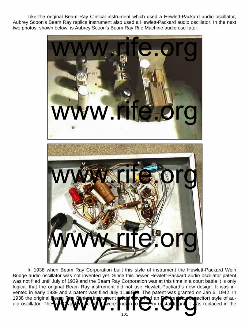
101
Like the original Beam Ray Clinical instrument which used a Hewlett-Packard audio oscillator, Aubrey Scoon's Beam Ray replica instrument also used a Hewlett-Packard audio oscillator. In the next two photos, shown below, is Aubrey Scoon's Beam Ray Rife Machine audio oscillator.
In 1938 when Beam Ray Corporation built this style of instrument the Hewlett-Packard Wein Bridge audio oscillator was not invented yet. Since this newer Hewlett-Packard audio oscillator patent was not filed until July of 1939 and the Beam Ray Corporation was at this time in a court battle it is only logical that the original Beam Ray instrument did not use Hewlett-Packard’s new design. It was in-vented in early 1939 and a patent was filed July 11, 1939. The patent was granted on Jan 6, 1942. In 1938 the original Beam Ray Clinical instrument would have had an RC (resistor capacitor) style of au-dio oscillator. These RC audio oscillators were known to be very unstable and it was replaced in the
www.rife.org www.rife.org www.rife.org www.rife.org www.rife.org
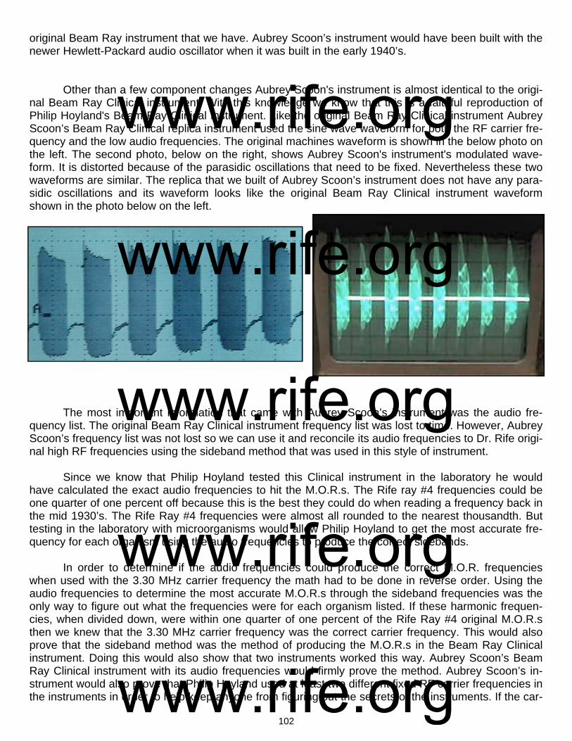
102
original Beam Ray instrument that we have. Aubrey Scoon’s instrument would have been built with the newer Hewlett-Packard audio oscillator when it was built in the early 1940’s. Other than a few component changes Aubrey Scoon's instrument is almost identical to the origi-nal Beam Ray Clinical instrument. With this knowledge we know that this is a faithful reproduction of Philip Hoyland's Beam Ray Clinical instrument. Like the original Beam Ray Clinical instrument Aubrey Scoon’s Beam Ray Clinical replica instrument used the sine wave waveform for both the RF carrier fre-quency and the low audio frequencies. The original machines waveform is shown in the below photo on the left. The second photo, below on the right, shows Aubrey Scoon's instrument's modulated wave-form. It is distorted because of the parasidic oscillations that need to be fixed. Nevertheless these two waveforms are similar. The replica that we built of Aubrey Scoon’s instrument does not have any para-sidic oscillations and its waveform looks like the original Beam Ray Clinical instrument waveform shown in the photo below on the left.
The most important information that came with Aubrey Scoon’s instrument was the audio fre-quency list. The original Beam Ray Clinical instrument frequency list was lost to time. However, Aubrey Scoon’s frequency list was not lost so we can use it and reconcile its audio frequencies to Dr. Rife origi-nal high RF frequencies using the sideband method that was used in this style of instrument. Since we know that Philip Hoyland tested this Clinical instrument in the laboratory he would have calculated the exact audio frequencies to hit the M.O.R.s. The Rife ray #4 frequencies could be one quarter of one percent off because this is the best they could do when reading a frequency back in the mid 1930’s. The Rife Ray #4 frequencies were almost all rounded to the nearest thousandth. But testing in the laboratory with microorganisms would allow Philip Hoyland to get the most accurate fre-quency for each organism using the audio frequencies to produce the correct sidebands. In order to determine if the audio frequencies could produce the correct M.O.R. frequencies when used with the 3.30 MHz carrier frequency the math had to be done in reverse order. Using the audio frequencies to determine the most accurate M.O.R.s through the sideband frequencies was the only way to figure out what the frequencies were for each organism listed. If these harmonic frequen-cies, when divided down, were within one quarter of one percent of the Rife Ray #4 original M.O.R.s then we knew that the 3.30 MHz carrier frequency was the correct carrier frequency. This would also prove that the sideband method was the method of producing the M.O.R.s in the Beam Ray Clinical instrument. Doing this would also show that two instruments worked this way. Aubrey Scoon’s Beam Ray Clinical instrument with its audio frequencies would firmly prove the method. Aubrey Scoon’s in-strument would also prove that Philip Hoyland used at least two different fixed RF carrier frequencies in the instruments in order to help keep anyone from figuring out the secrets of the instruments. If the car-
www.rife.org www.rife.org www.rife.org www.rife.org www.rife.org

103
rier frequency is different then the audio frequencies will also be different. Below is a comparison chart of Aubrey Scoon’s Beam Ray Clinical replica instrument. In the “Rife Ray #4 Frequencies In Hertz” column are the correct M.O.R.s found by Dr. Rife. In the “Aubrey Scoon’s Sideband Audio Frequencies In Hertz” column are the audio frequencies used to create the correct sideband frequencies to hit the harmonic Rife Ray #4 frequencies. In the “Rife Ray #4 Frequen-cies Based on Scoon’s Audio Frequencies” column we see the M.O.R. frequencies that these audio frequencies produce. You will notice in the “Rife Ray #4 Frequencies In Hertz” column that the fre-quency for Actinomycosis or Streptothrix is 192,000 Hertz and in the “Rife Ray #4 Frequencies Based on Scoon’s Audio Frequencies” column is the frequency of 191,803 Hertz. There is only a 197 Hertz difference between these frequencies. If you compare both of these columns you will notice how closely these frequencies match up. All the frequencies which are in the column “Rife Ray #4 Frequen-cies Based On Scoon’s Audio Frequencies” are less than one quarter of one percent off of the “Rife
Ray #4 Frequencies In Hertz.” We will now give a simple description of how we reconciled these audio frequencies to Dr. Rife’s original high RF frequencies which were used in the Rife Ray #3 and Rife Ray #4 Rife Machines. The Rife Ray #4 paperwork gives us the Streptothrix frequency of 192,000 Hertz. Since we know that Philip Hoyland used the higher harmonic frequency closest to the carrier frequency in these instruments what we have to do is multiply 192,000 Hertz by 17 to get the closest frequency to the 3,300,000 Hertz. The
Microorganism *These frequencies were not included in Aubrey Scoon’s instrument.
Rife Ray #4
Frequencies In Hertz
Higher Rife Ray #4
Harmonic Frequencies
In Hertz
Aubrey Scoon’s
Sideband Audio
Frequencies In Hertz
Higher Rife Ray #4 Harmonic Frequencies in Hertz Based On Scoon’s Audio Frequency and 3.3 MHz Carrier
*Carrier Difference Frequency
Number of Sideband
Harmonics
Rife Ray #4
Frequencies Based On Scoon’s Audio
Frequencies
Actinomycosis or Streptothrix
192,000 Hz 3,264,000 or 17th 7,870 Hz 3,260,650 or 17th 39,350 Hz 5 191,803 Hz
Anthrax 139,200 Hz 3,340,800 or 24th *10,200 Hz 3,340,800 or 24th 40,800 Hz 4 139,200 Hz
B or E Coli Rod 417,000 Hz 3,336,000 or 8th 8,020 Hz 3,332,080 or 8th 32,080 Hz 4 416,510 Hz
B or E Coli Virus 770,000 Hz 3,080,000 or 4th 17,220 Hz 3,076,140 or 4th 223,860 Hz 13 769,035 Hz
BX Virus Carcinoma 1,604,000 Hz 3,208,000 or 2nd 21,275 Hz 3,214,900 or 2nd 85,100 Hz 4 1,607,450 Hz
BY Sarcoma 1,530,000 Hz 3,059,040 or 2nd 20,080 Hz 3,059,040 or 2nd 240,960 Hz 12 1,529,520 Hz
Gonorrhea 233,000 Hz 3,262,000 or 14th *9,500 Hz 3,262,000 or 14th 38,000 Hz 4 233,000 Hz
Pneumonia or Spinal Meningitis
427,000 Hz 3,416,000 or 8th 7,660 Hz 3,414,900 or 8th 114,900 Hz 15 426,862 Hz
Staphylococcus Pyogenes Aureus
478,000 Hz 3,346,000 or 7th 7,270 Hz 3,343,620 or 7th 43,620 Hz 6 477,660 Hz
Streptococcus Pyogenes
720,000 Hz 3,600,000 or 5th 8,450 Hz 3,595,750 or 5th 295,750 Hz 35 719,150 Hz
Syphilis 789,000 Hz 3,156,000 or 4th 6,600 Hz 3,154,800 or 4th 145,200 Hz 22 788,700 Hz
Tetanus 234,000 Hz 3,276,000 or 14th
1,200 Hz 3,276,000 or 14th 24,000 Hz 20 234,000 Hz
Tuberculosis Rod 369,000 Hz 3,321,000 or 9th 8,300 Hz 3,324,897 or 9th 24,897 Hz 3 369,433 Hz
Tuberculosis Virus 769,000 Hz 3,076,000 or 4th 16,000 Hz 3,076,000 or 4th 224,000 Hz 14 769,000 Hz
Typhoid Rod 760,000 Hz 3,040,000 or 4th 6,900 Hz 3,037,800 or 4th 262,200 Hz 38 759,450 Hz
Typhoid Virus 1,445,000 Hz 2,890,000 or 2nd 18,620 Hz 2,890,360 or 2nd 409,640 Hz 22 1,445,180 Hz
Worms ? 2,400 Hz
Aubrey Scoon’s Sideband Audio Frequencies Reconciled To Rife’s Original High Frequency M.O.R.s.
www.rife.org www.rife.org www.rife.org www.rife.org www.rife.org
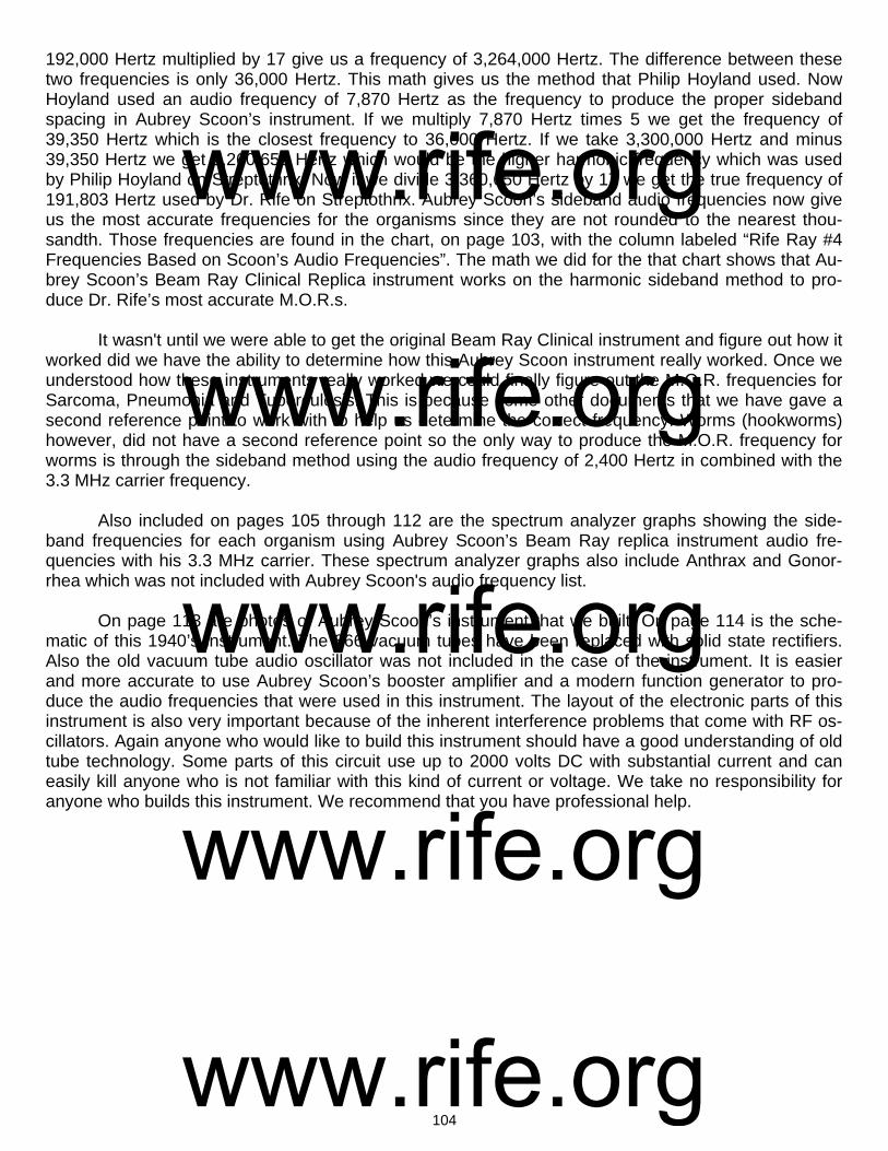
104
192,000 Hertz multiplied by 17 give us a frequency of 3,264,000 Hertz. The difference between these two frequencies is only 36,000 Hertz. This math gives us the method that Philip Hoyland used. Now Hoyland used an audio frequency of 7,870 Hertz as the frequency to produce the proper sideband spacing in Aubrey Scoon’s instrument. If we multiply 7,870 Hertz times 5 we get the frequency of 39,350 Hertz which is the closest frequency to 36,000 Hertz. If we take 3,300,000 Hertz and minus 39,350 Hertz we get 3,260,650 Hertz which would be the higher harmonic frequency which was used by Philip Hoyland on Streptothrix. Now if we divide 3,360,650 Hertz by 17 we get the true frequency of 191,803 Hertz used by Dr. Rife on Streptothrix. Aubrey Scoon’s sideband audio frequencies now give us the most accurate frequencies for the organisms since they are not rounded to the nearest thou-sandth. Those frequencies are found in the chart, on page 103, with the column labeled “Rife Ray #4 Frequencies Based on Scoon’s Audio Frequencies”. The math we did for the that chart shows that Au-brey Scoon’s Beam Ray Clinical Replica instrument works on the harmonic sideband method to pro-duce Dr. Rife’s most accurate M.O.R.s. It wasn't until we were able to get the original Beam Ray Clinical instrument and figure out how it worked did we have the ability to determine how this Aubrey Scoon instrument really worked. Once we understood how these instruments really worked we could finally figure out the M.O.R. frequencies for Sarcoma, Pneumonia and Tuberculosis. This is because some other documents that we have gave a second reference point to work with to help us determine the correct frequency. Worms (hookworms) however, did not have a second reference point so the only way to produce the M.O.R. frequency for worms is through the sideband method using the audio frequency of 2,400 Hertz in combined with the 3.3 MHz carrier frequency. Also included on pages 105 through 112 are the spectrum analyzer graphs showing the side-band frequencies for each organism using Aubrey Scoon’s Beam Ray replica instrument audio fre-quencies with his 3.3 MHz carrier. These spectrum analyzer graphs also include Anthrax and Gonor-rhea which was not included with Aubrey Scoon's audio frequency list. On page 113 are photos of Aubrey Scoon’s instrument that we built. On page 114 is the sche-matic of this 1940’s instrument. The 866 vacuum tubes have been replaced with solid state rectifiers. Also the old vacuum tube audio oscillator was not included in the case of the instrument. It is easier and more accurate to use Aubrey Scoon’s booster amplifier and a modern function generator to pro-duce the audio frequencies that were used in this instrument. The layout of the electronic parts of this instrument is also very important because of the inherent interference problems that come with RF os-cillators. Again anyone who would like to build this instrument should have a good understanding of old tube technology. Some parts of this circuit use up to 2000 volts DC with substantial current and can easily kill anyone who is not familiar with this kind of current or voltage. We take no responsibility for anyone who builds this instrument. We recommend that you have professional help.
www.rife.org www.rife.org www.rife.org www.rife.org www.rife.org
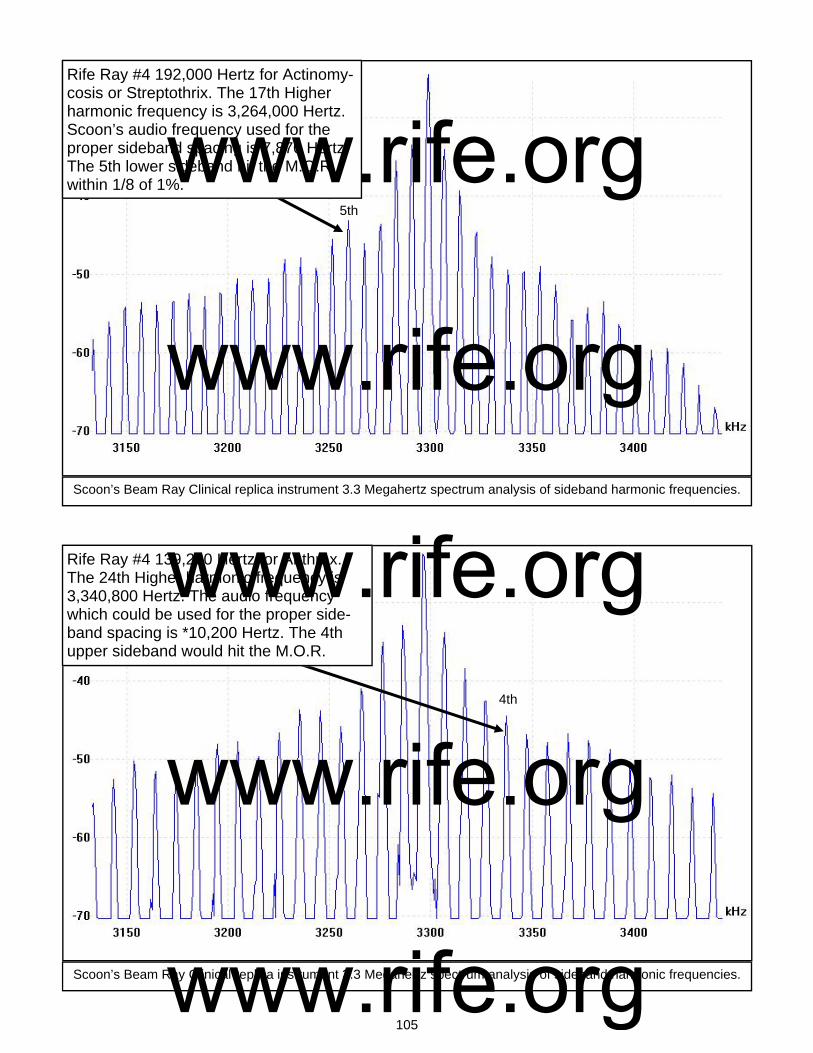
105
Rife Ray #4 192,000 Hertz for Actinomy-cosis or Streptothrix. The 17th Higher harmonic frequency is 3,264,000 Hertz. Scoon’s audio frequency used for the proper sideband spacing is 7,870 Hertz. The 5th lower sideband hit the M.O.R within 1/8 of 1%.
Scoon’s Beam Ray Clinical replica instrument 3.3 Megahertz spectrum analysis of sideband harmonic frequencies.
Scoon’s Beam Ray Clinical replica instrument 3.3 Megahertz spectrum analysis of sideband harmonic frequencies.
Rife Ray #4 139,200 Hertz for Anthrax. The 24th Higher harmonic frequency is 3,340,800 Hertz. The audio frequency which could be used for the proper side-band spacing is *10,200 Hertz. The 4th upper sideband would hit the M.O.R.
5th
4th
www.rife.org www.rife.org www.rife.org www.rife.org www.rife.org

106
Rife Ray #4 417,000 Hertz for B or E Coli Rod. The 8th Higher harmonic frequency is 3,336,000 Hertz. Scoon’s audio fre-quency used for the proper sideband spacing is 8,020 Hertz. The 4th upper sideband hit the M.O.R within 1/8 of 1%.
Scoon’s Beam Ray Clinical replica instrument 3.3 Megahertz spectrum analysis of sideband harmonic frequencies.
Scoon’s Beam Ray Clinical replica instrument 3.3 Megahertz spectrum analysis of sideband harmonic frequencies.
Rife Ray #4 770,000 Hertz for B or E Coli Virus. The 4th Higher harmonic frequency is 3,080,000 Hertz. Scoon’s audio fre-quency used for the proper sideband spac-ing is 17,220 Hertz. The 13rth lower side-band hit the M.O.R Within 1/8 of 1%.
4th
13th
www.rife.org www.rife.org www.rife.org www.rife.org www.rife.org

107
Rife Ray #4 1,604,000 for the BX Cancer Carcinoma Virus. The 2nd Higher har-monic frequency is 3,208,000 Hertz. Scoon’s audio frequency used for the proper sideband spacing is 21,275 Hertz. The 4th lower sideband hit the M.O.R within 1/4 of 1%.
Scoon’s Beam Ray Clinical replica instrument 3.3 Megahertz spectrum analysis of sideband harmonic frequencies.
Scoon’s Beam Ray Clinical replica instrument 3.3 Megahertz spectrum analysis of sideband harmonic frequencies.
? Rife Ray #4 1,530,000 Hertz for BY Cancer Sarcoma. The 2nd Higher har-monic frequency is 3,060,000 Hertz. Scoon’s audio frequency used for the proper sideband spacing is 20,080 Hertz. The 12th lower sideband hit the M.O.R within 1/30 of 1%.
4th
12th
www.rife.org www.rife.org www.rife.org www.rife.org www.rife.org
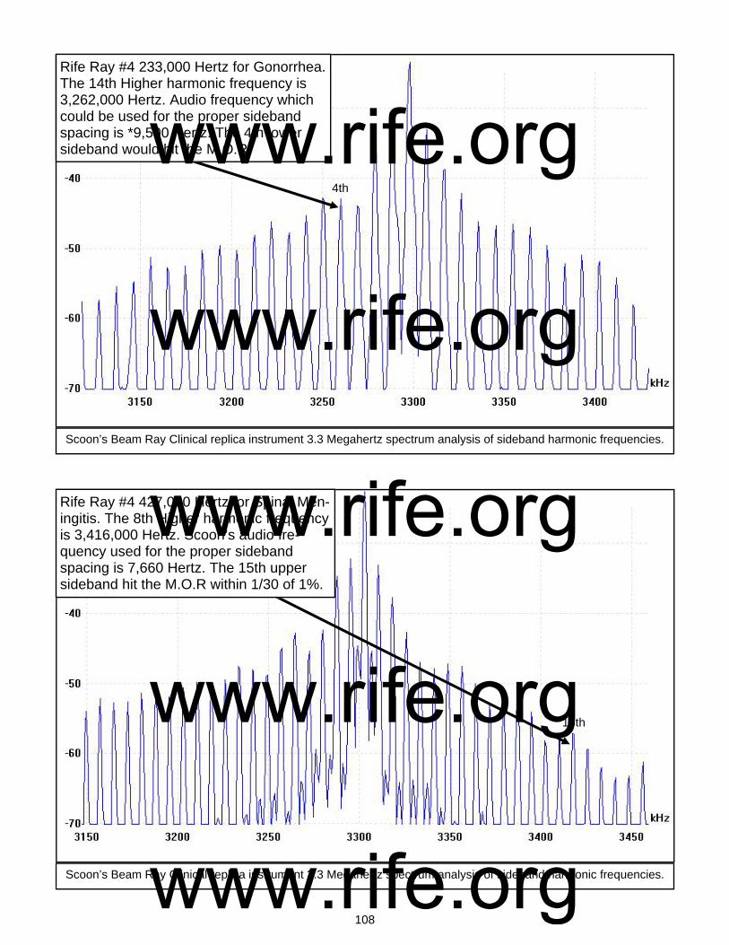
108
Rife Ray #4 233,000 Hertz for Gonorrhea. The 14th Higher harmonic frequency is 3,262,000 Hertz. Audio frequency which could be used for the proper sideband spacing is *9,500 Hertz. The 4th lower sideband would hit the M.O.R.
Scoon’s Beam Ray Clinical replica instrument 3.3 Megahertz spectrum analysis of sideband harmonic frequencies.
Scoon’s Beam Ray Clinical replica instrument 3.3 Megahertz spectrum analysis of sideband harmonic frequencies.
Rife Ray #4 427,000 Hertz for Spinal Men-ingitis. The 8th Higher harmonic frequency is 3,416,000 Hertz. Scoon’s audio fre-quency used for the proper sideband spacing is 7,660 Hertz. The 15th upper sideband hit the M.O.R within 1/30 of 1%.
4th
15th
www.rife.org www.rife.org www.rife.org www.rife.org www.rife.org
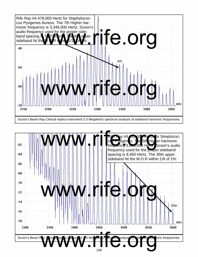
109
Rife Ray #4 478,000 Hertz for Staphylococ-cus Pyogenes Aureus. The 7th Higher har-monic frequency is 3,346,000 Hertz. Scoon’s audio frequency used for the proper side-band spacing is 7,270 Hertz. The 6th upper sideband hit the M.O.R within 1/14 of 1%.
Scoon’s Beam Ray Clinical replica instrument 3.3 Megahertz spectrum analysis of sideband harmonic frequencies.
Scoon’s Beam Ray Clinical replica instrument 3.3 Megahertz spectrum analysis of sideband harmonic frequencies.
Rife Ray #4 720,000 Hertz for Streptococ-cus Pyogenes. The 5th Higher harmonic frequency 3,600,000 Hertz. Scoon’s audio frequency used for the proper sideband spacing is 8,450 Hertz. The 35th upper sideband hit the M.O.R within 1/8 of 1%.
6th
35th
www.rife.org www.rife.org www.rife.org www.rife.org www.rife.org

110
Rife Ray #4 789,000 Hertz for Syphilis. The 4th Higher harmonic frequency is 3,156,000 Hertz. Scoon’s audio frequency used for the proper sideband spacing is 6,600 Hertz. The 22nd lower sideband hit the M.O.R within 1/26 of 1%.
Scoon’s Beam Ray Clinical replica instrument 3.3 Megahertz spectrum analysis of sideband harmonic frequencies.
Scoon’s Beam Ray Clinical replica instrument 3.3 Megahertz spectrum analysis of sideband harmonic frequencies.
Rife Ray #4 234,000 Hertz for Tetanus. The 14th Higher harmonic frequency Is 3,276,000 Hertz. Scoon’s audio fre-quency used for the proper sideband spacing is 1,200 Hertz. The 20th lower sideband hit the M.O.R exactly.
22nd
20th
www.rife.org www.rife.org www.rife.org www.rife.org www.rife.org
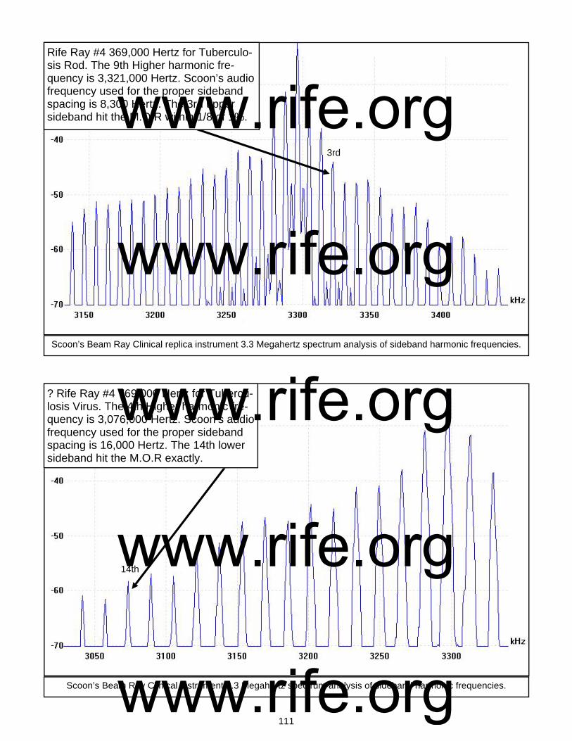
111
Rife Ray #4 369,000 Hertz for Tuberculo-sis Rod. The 9th Higher harmonic fre-quency is 3,321,000 Hertz. Scoon’s audio frequency used for the proper sideband spacing is 8,300 Hertz. The 3rd upper sideband hit the M.O.R within 1/8 of 1%.
Scoon’s Beam Ray Clinical replica instrument 3.3 Megahertz spectrum analysis of sideband harmonic frequencies.
Scoon’s Beam Ray Clinical instrument 3.3 Megahertz spectrum analysis of sideband harmonic frequencies.
? Rife Ray #4 769,000 Hertz for Tubercu-losis Virus. The 4th Higher harmonic fre-quency is 3,076,000 Hertz. Scoon’s audio frequency used for the proper sideband spacing is 16,000 Hertz. The 14th lower sideband hit the M.O.R exactly.
3rd
14th
www.rife.org www.rife.org www.rife.org www.rife.org www.rife.org
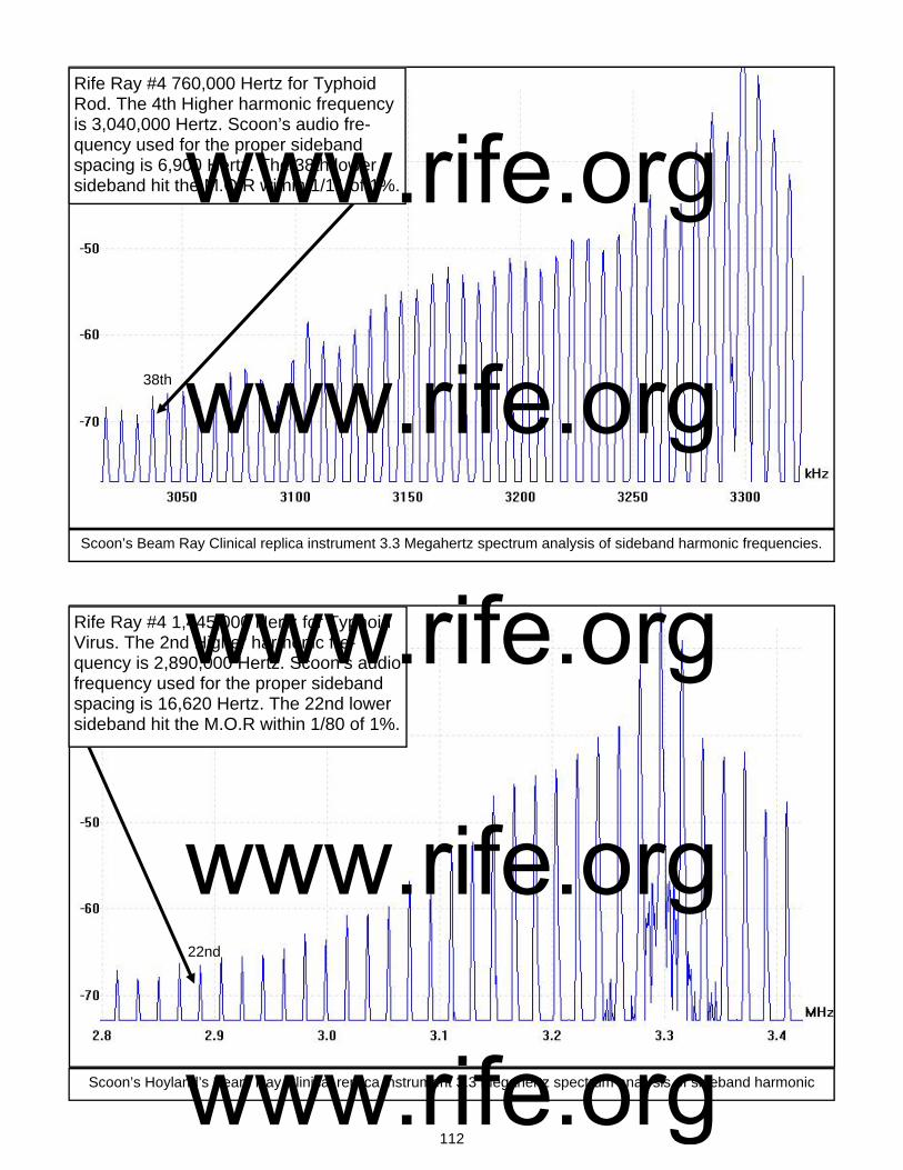
112
Rife Ray #4 760,000 Hertz for Typhoid Rod. The 4th Higher harmonic frequency is 3,040,000 Hertz. Scoon’s audio fre-quency used for the proper sideband spacing is 6,900 Hertz. The 38th lower sideband hit the M.O.R within 1/11 of 1%.
Scoon’s Beam Ray Clinical replica instrument 3.3 Megahertz spectrum analysis of sideband harmonic frequencies.
Scoon’s Hoyland’s Beam Ray Clinical replica instrument 3.3 Megahertz spectrum analysis of sideband harmonic
Rife Ray #4 1,445,000 Hertz for Typhoid Virus. The 2nd Higher harmonic fre-quency is 2,890,000 Hertz. Scoon’s audio frequency used for the proper sideband spacing is 16,620 Hertz. The 22nd lower sideband hit the M.O.R within 1/80 of 1%.
22nd
38th
www.rife.org www.rife.org www.rife.org www.rife.org www.rife.org

113
Photos of the rebuilt Aubrey Scoon Beam Ray Clinical instrument
www.rife.org www.rife.org www.rife.org www.rife.org www.rife.org

114
www.rife.org www.rife.org www.rife.org www.rife.org www.rife.org
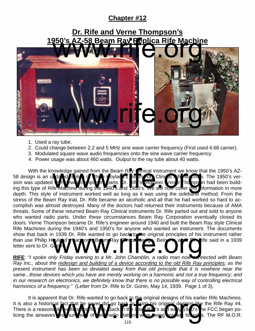
115
Chapter #12
Dr. Rife and Verne Thompson’s 1950’s AZ-58 Beam Ray Replica Rife Machine
1. Used a ray tube. 2. Could change between 2.2 and 5 MHz sine wave carrier frequency (First used 4.68 carrier). 3. Modulated square wave audio frequencies onto the sine wave carrier frequency. 4. Power usage was about 460 watts. Output to the ray tube about 40 watts. With the knowledge gained from the Beam Ray Clinical instrument we know that the 1950’s AZ-58 design is an updated replica of Philip Hoyland's Beam Ray Clinical Rife Machine. The 1950’s ver-sion was updated with newer component parts. Dr. Rife’s engineer, Verne Thompson had been build-ing this type of Rife Machine during the 1940’s and 1950’s. We will now cover this information in more depth. This style of instrument worked well as long as it was using the sideband method. From the stress of the Beam Ray trial, Dr. Rife became an alcoholic and all that he had worked so hard to ac-complish was almost destroyed. Many of the doctors had returned their instruments because of AMA threats. Some of these returned Beam Ray Clinical instruments Dr. Rife parted out and sold to anyone who wanted radio parts. Under these circumstances Beam Ray Corporation eventually closed its doors. Verne Thompson became Dr. Rife’s engineer around 1940 and built the Beam Ray style Clinical Rife Machines during the 1940’s and 1950’s for anyone who wanted an instrument. The documents show that back in 1939 Dr. Rife wanted to go back to the original principles of his instrument rather than use Philip Hoyland’s harmonic Beam Ray Clinical design. Below is what Dr. Rife said in a 1939 letter sent to Dr. Gonin: RIFE: “I spoke only Friday evening to a Mr. John Chamblin, a radio man now connected with Beam Ray Inc., about the redesign and building of a device according to the old Rife Ray principles; as the present instrument has been so deviated away from that old principle that it is nowhere near the same...those devices which you have are merely working on a harmonic and not a true frequency; and in our research on electronics, we definitely know that there is no possible way of controlling electrical harmonics of a frequency.” (Letter from Dr. Rife to Dr. Gonin, May 14, 1939. Page 1 of 3). It is apparent that Dr. Rife wanted to go back to the original designs of his earlier Rife Machines. It is also a historical fact that he never did go back to using his original designs like the Rife Ray #4. There is a reasonable explanation for this. Back in the late 1930’s and early 1940’s the FCC began po-licing the airwaves and hundreds of new radio stations were being granted licenses. The RF M.O.R.
www.rife.org www.rife.org www.rife.org www.rife.org www.rife.org
116
frequencies which were output by the Kennedy equipment, Rife Ray #4 and Beam Ray Laboratory in-strument were almost all in the A.M. radio band of frequencies and would interfere with these new broadcasting stations. These events probably brought about the continued use of Philip Hoyland’s Beam Ray Clinical Rife Machine. In Chapter 9 of this report we also read that Dr. Rife tested Philip Hoyland's instrument, in about 1940, when he had Verne Thompson rebuild Dr. Yale's Beam Ray Clini-cal instrument. In those tests Dr. Rife found that Philip Hoyland's design would devitalize all the micro-organisms. The tests that were done by Dr. Rife showed that this style of instrument worked and meant that he really didn't need to go back to his earlier designs even though he may have wanted too. There are a few important facts that should be pointed out. Dr. Rife at any time could have had an original Ray tube instrument built. He had a Rife Ray #4 in his lab that could have been copied. I am sure that he also had access to the Beam Ray Laboratory instrument. These facts, I believe show that it was probably because he knew that Philip Hoyland's design was a good design that he contin-ued to use it. It could also be because of the FCC regulations Dr. Rife either had to use the Beam Ray Clinical design instrument or no longer build one. We know, from the documents, that Verne Thompson was coping Dr. Couche's instrument with its fixed carrier frequency of 3.3 MHz. This carrier frequency was well above the A.M. band of radio stations. Since the Beam Ray Clinical instrument used the higher harmonics of the original Rife Ray #4 frequencies this would not cause any problems with the A.M. radio stations. The FCC was, at the least, a contributing factor in why Dr. Rife continued to use the Beam Ray Clinical design. With the understanding of this information let us continue on with the history of Dr. Rife’s instru-ments. John Crane met Dr. Rife in 1950 when he inquired about purchasing a drafting set that Dr. Rife was selling. John Marsh met John Crane in 1952 when they were both working at Convair. They both went to see Dr. Rife in 1953 to see if Dr. Rife would be willing to help with the cancer of John Marsh’s wife. In Dr. Rife’s 1961 deposition #123-125 he said he gave John Crane his frequencies in 1950: COMPARET: “Did you ever explain to John F. Crane, one of the defendants in this case, the principles upon which your electronic frequency-generator is used in the treatment of diseases?” RIFE: “Yes in 1950.” COMPARET: “Did you also inform him of the particular frequencies which you had found to be effective in the treatment of various diseases?” RIFE: “Yes. Verne Thompson and I gave the frequencies to John Crane.” COMPARET: “When did you furnish him with this information?” RIFE: “In 1950.” Dr. Rife always said that almost all his frequencies were in the upper bands (139,200 Hertz to 1,607,450 Hertz) so we know that he gave these high RF frequencies to John Crane in 1950. These frequencies would have been the frequencies used in the Rife Ray #4. The audio frequencies that were used in Dr. Couche's Beam Ray Clinical instrument was probably also given to John Crane at this time. There is an interesting correlation of these audio frequencies that needs to be mentioned at this time which ties these machines together. The audio frequencies used in the early 1940’s Aubrey Scoon, Verne Thompson Beam Ray Clinical instrument, which gave the sideband spacing, were about 10 times higher than those used in the Verne Thompson 1950’s AZ-58 Beam Ray Clinical replica. It is ap-parent that these higher audio frequencies were lowered in the 1950’s by Dr. Rife, John Crane and John Marsh and were used in the AZ-58 replica instrument. This gives us the knowledge that these au-dio frequencies came from Verne Thompson’s reading of one of these Beam Ray Clinical instruments.
www.rife.org www.rife.org www.rife.org www.rife.org www.rife.org
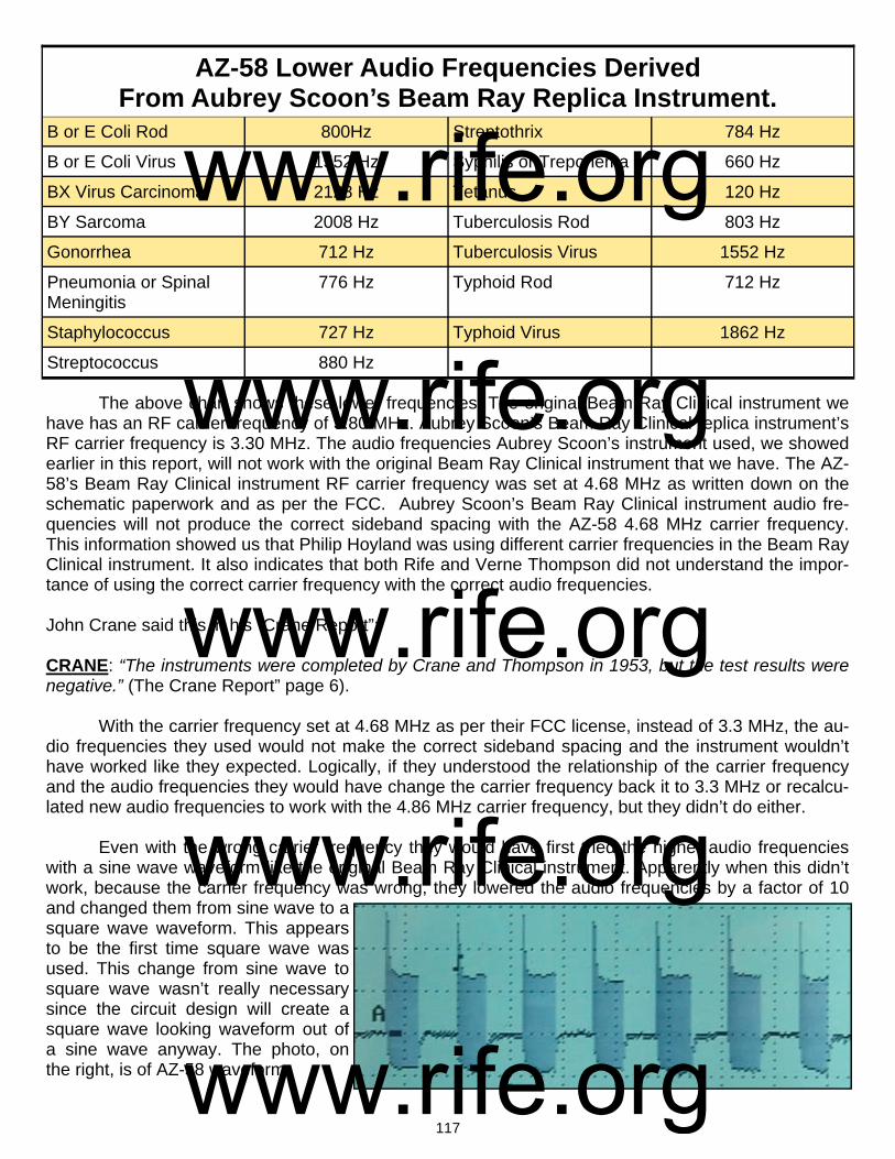
117
The above chart shows these lower frequencies. The original Beam Ray Clinical instrument we have has an RF carrier frequency of 3.80 MHz. Aubrey Scoon’s Beam Ray Clinical replica instrument’s RF carrier frequency is 3.30 MHz. The audio frequencies Aubrey Scoon’s instrument used, we showed earlier in this report, will not work with the original Beam Ray Clinical instrument that we have. The AZ-58’s Beam Ray Clinical instrument RF carrier frequency was set at 4.68 MHz as written down on the schematic paperwork and as per the FCC. Aubrey Scoon’s Beam Ray Clinical instrument audio fre-quencies will not produce the correct sideband spacing with the AZ-58 4.68 MHz carrier frequency. This information showed us that Philip Hoyland was using different carrier frequencies in the Beam Ray Clinical instrument. It also indicates that both Rife and Verne Thompson did not understand the impor-tance of using the correct carrier frequency with the correct audio frequencies. John Crane said this in his “Crane Report”: CRANE: “The instruments were completed by Crane and Thompson in 1953, but the test results were negative.” (The Crane Report” page 6). With the carrier frequency set at 4.68 MHz as per their FCC license, instead of 3.3 MHz, the au-dio frequencies they used would not make the correct sideband spacing and the instrument wouldn’t have worked like they expected. Logically, if they understood the relationship of the carrier frequency and the audio frequencies they would have change the carrier frequency back it to 3.3 MHz or recalcu-lated new audio frequencies to work with the 4.86 MHz carrier frequency, but they didn’t do either. Even with the wrong carrier frequency they would have first tried the higher audio frequencies with a sine wave waveform like the original Beam Ray Clinical instrument. Apparently when this didn’t work, because the carrier frequency was wrong, they lowered the audio frequencies by a factor of 10 and changed them from sine wave to a square wave waveform. This appears to be the first time square wave was used. This change from sine wave to square wave wasn’t really necessary since the circuit design will create a square wave looking waveform out of a sine wave anyway. The photo, on the right, is of AZ-58 waveform.
AZ-58 Lower Audio Frequencies Derived From Aubrey Scoon’s Beam Ray Replica Instrument.
B or E Coli Rod 800Hz Streptothrix 784 Hz
B or E Coli Virus 1552 Hz Syphilis or Treponema 660 Hz
BX Virus Carcinoma 2128 Hz Tetanus 120 Hz
BY Sarcoma 2008 Hz Tuberculosis Rod 803 Hz
Gonorrhea 712 Hz Tuberculosis Virus 1552 Hz
Pneumonia or Spinal Meningitis
776 Hz Typhoid Rod 712 Hz
Staphylococcus 727 Hz Typhoid Virus 1862 Hz
Streptococcus 880 Hz
www.rife.org www.rife.org www.rife.org www.rife.org www.rife.org

118
John Crane mentions that this is when the instrument started to work better. So we are left to assume that he was referring to the use of the square wave waveform. It is ironic that they used a square wave that produces harmonics in order to get the instrument to even begin to give them any re-sults. Had they really understood how the audio frequencies interacted with the carrier frequency they would have recalculated the audio frequencies to work with the new 4.68 MHz carrier frequency in-stead of lowering the audio frequencies by a factor of ten. Then the square wave change would not have been necessary. These important things that have been pointed out show they did not understand the relationship between the carrier frequency and the audio frequencies and how neither the carrier frequency nor the audio frequencies will do anything by themselves. Had they understood how the au-dio frequencies and the carrier frequency interacted together to produce sidebands they would have understood how one of these sideband frequencies lined up with the true Rife M.O.R frequency and devitalize or render harmless the harmful microorganism. Instead of understanding this they change the sine wave waveform to square wave waveform and used this method. This change from sine wave to square wave also created a whole new methodology of using fre-quencies. Instead of relying on the interaction of the sine wave audio frequency with the sine wave RF carrier frequency to produce the correct sideband harmonic M.O.R. to devitalize the organisms they were now depending only on the harmonics from the square wave waveform to hit the correct M.O.R. frequency. This change also is another indication that they didn’t understand how the Beam Ray Clini-cal instrument worked. Another thing that shows that they did not understand how the Beam Ray in-strument worked is the fact that they didn’t recalculate the audio frequencies to properly use the square wave harmonics to hit the high frequency M.O.R.s. This shows that they believed that the audio fre-quencies were the M.O.R.s of the organisms even though they had no harmonic relationship with the original M.O.R.s used in the Rife Ray #4. In many of the documents we find that both John Crane and John Marsh firmly believed that the audio frequencies were the M.O.R. frequencies that would devitalize the organisms. Even Dr. Rife ap-pears to have believed that the audio frequencies were the M.O.R.s as long as they were used with Philip Hoyland’s Beam Ray Clinical design. In Dr. Rife’s original equipment like the Rife Ray #4 and the Kennedy equipment he knew that the M.O.R. frequencies were the high RF frequencies. But since Dr. Rife didn’t really understand exactly how Philip Hoyland’s instrument worked it appears that he ac-cepted the concept that the audio frequencies were the M.O.R.s as long as they were used with that style of instrument. Without understanding these facts it is hard to understand the rest of the history of Dr. Rife’s instruments. The fact that they believed that the audio frequencies were the M.O.R.s compro-mised the effectiveness of the AZ-58 Beam Ray Clinical replica. Below are three photos of instruments Verne Thompson built. The first instrument, going from left to right was Aubrey Scoon’s early 1940’s Beam Ray replica. The second instrument is believed to have been built in the mid to late 1940’s but some of the transformers are 1960’s vintage which may indicate it was built in the 1950’s or 1960’s. The audio frequencies used in it were even lower than the 1950’s AZ-58. The third instrument is one of the AZ-58 instruments built by Verne Thompson in the 1950’s for Dr. Rife, John Crane and John Marsh of Life Labs Co.
www.rife.org www.rife.org www.rife.org www.rife.org www.rife.org

119
All three of these instruments, like the Beam Ray Clinical instrument, had the fixed Hartley Oscil-lator section. Verne Thompson changed the 809 tube to the 812 tube as he updated the instruments from the 1940’s to the 1950’s. All three also had one main frequency dial for adjusting the audio fre-quencies. The other two smaller dials were for adjusting the modulation amplitude of the audio frequen-cies and changing the audio frequency bands. The bands would take you through various audio fre-quencies. The AZ-58 was limited to about 6000 Hertz because they lowered the audio frequencies. The original Beam Ray Clinical instrument went to just over 40,000 Hertz and the 1940’s Scoon Beam Ray Clinical replica instrument could go to about 200,000 Hertz. There is very little difference in the way these instruments work. We built two of the three, tested them, and found no significant difference other than the use of sine or square wave audio frequencies. At any time the AZ-58 could have been changed to work on the original Beam Ray Clinical sideband method just by recalculating the audio fre-quencies to work with the 4.68 carrier frequency. We made some tests with the spectrum analyzer to see if square wave could be used instead of sine wave in creating the proper sideband spacing and found that it works just as well as sine wave. The basic design of Philip Hoyland’s Beam Ray Clinical instrument is very apparent when you compare the schematics. Six of the 1950’s AZ-58s were originally built by Dr. Rife, John Crane and John Marsh. We decided to test the AZ-58 with the spectrum analyzer. Below in the graph you can see the results of these tests. The instrument called the AZ-58 is significant because we have more information about what took place in the 1950’s than any period before this. At this time in the 1950’s John Crane and John Marsh recorded interviews with Dr. Rife, Dr. Couche, Ben Cullen, Henry Siner and many other individu-als who were key players in the early years of Dr. Rife’s work.
Testing done with PicoScope 3205 spectrum analyzer at 2,400,000 Hertz using AZ-58
Sine wave out of AZ-58 at 2,400,000 Hertz.
AZ-58 without ray tube at 2,400,000 Hertz meas-ured with spectrum analyzer showing no real
harmonics.
Sine wave carrier out of AZ-58 at 2,400,000 Hertz using ray tube. Sine wave carrier was always dis-
torted when put through a ray tube.
AZ-58 at 2,400,000 Hertz using ray tube. Meas-ured with spectrum analyzer showing harmonics
all the way up to 20,000,000 Hertz.
AZ-58 at 2,400,000 Hertz using ray tube. Show-ing 50% square wave audio frequency modula-tion. The square wave shows some distortion.
www.rife.org www.rife.org www.rife.org www.rife.org www.rife.org

120
We will now cover in more detail the history of the instruments in the 1950’s so we have a little more information. Some of the information comes from the John Marsh Collection of Rife audio CDs. As we said, in 1950 John Crane met Dr. Rife and in 1952-53 he met John Marsh. John Marsh became John Crane’s supervisor at Convair Aeronautics when John Marsh moved from Tucson, Arizona to California. John Marsh’s wife had cancer and they were not able to help her in Tucson. The doctors recommended that he take her to San Diego for specialized care. John Marsh and John Crane became friends. John Crane told John Marsh about Dr. Rife and they then went to see him. Dr. Rife gave them an old instrument which they had Verne Thompson repair. John Crane and John Marsh then used this instrument on John Marsh’s wife and after several treatments John Marsh said she fully recovered. Here are John Marsh’s statements which he made in 1976 and 1986: MARSH: (1976) “I met this Rife. I said Dr. Rife, I said, my name is John Marsh, I’ve got a wife that’s dy-ing. She’s got cancer of the uterus.” Dr. Rife said: “I won’t touch that thing with a 20 yard pole.” After some discussion Dr. Rife said: RIFE: “I have an old instrument down here in the basement.” MARSH: “I dug up that old instrument and of course it had tubes in it, antique stuff, and so I rebuilt the darn thing.” (John Marsh Rife CDs, CD 10 track 1) MARSH: (1986) “I went to see him [Dr. Rife], and I talked with him and he said he didn’t want to have any part of it...I said look, I got a wife that’s dying and I need your help! And so I got him out of his co-coon, so to speak, and we took an old instrument and rebuilt it. And I treated my wife and by darn all the pain left her and she got well.” In another part of the tape he said: “I discovered that this Dr. Rife was a very great individual...I told John [Crane], I said look if we have any of those old instruments lay-ing around loose, let’s rejuvenate one of them and see if we can get my wife well. Well Verne Thomp-son who was with the San Diego police department radios, uh, radio expert, uh, had built some instru-ments and they were antiques when I saw them.” (John Marsh Rife CDs, CD 2 track 3). John Marsh and John Crane then decided they would like to work with Dr. Rife and try to get the frequency instruments built and back into doctors’ hands. They wanted to help people who were suffer-ing from many incurable diseases. From earlier quotes we learned that Verne Thompson had worked on Dr. Yale’s Beam Ray Corporation Rife Machines. He knew these instruments inside and out and this is why John Marsh and John Crane had him repair the instrument that Dr. Rife gave them. It is appar-ent that Verne Thompson knew this instrument’s circuit designs well but he didn’t understand how the Beam Ray Clinical instrument was using sideband harmonics to hit the harmonic M.O.R. of the various organisms. From a patent application that Dr. Rife and Verne Thompson filed we know that Verne Thompson also believed the audio frequencies were the M.O.R.s. This document leads us to only one conclusion, no one understood how Philip Hoyland’s sideband spacing design worked. John Crane in his later years (1970's & 1980’s) was not very truthful in some of his statements. He said this in his paper titled "The Crane Report": CRANE: "Unfortunately, Rife had enlisted the help of electronic experts in the '30's who never wrote down the details of the instruments. Rife was unable to duplicate the marvels of his earlier Frequency instruments." (The Crane Report, page 6). The documents we have read in this report have shown that Dr. Rife was having Verne Thomp-son build and repair the Beam Ray instruments. For this reason John Crane’s statement does not ring true. The facts have shown that this instrument design came from Philip Hoyland. It was Verne Thomp-son who updated the Beam Ray Clinical instrument for Dr. Rife, John Crane and John Marsh in the
www.rife.org www.rife.org www.rife.org www.rife.org www.rife.org
121
1950’s. Others have felt that John Crane took advantage of Dr. Rife. This may be true in some things that took place later on in the late 1960’s, 1970’s and 1980’s but the evidence does not support this in the 1950’s and early 1960’s. Here is a quote from the John Marsh Collection "Trip to Dayton Ohio Pa-pers" and Gonin Papers. Dr. Rife, John Marsh and John Crane were talking at great length about John Marsh’s trip to Ohio to see Dr. Stafford. In the Gonin papers they talked about the frequencies. I would recommend that everyone read these papers because they show that Dr. Rife, John Crane and John Marsh worked as a team and John Marsh and John Crane considered the frequencies to be Dr. Rife’s, and the AZ-58 Beam Ray replica instrument to be Dr. Rife’s instrument. The following statements con-firm this: RIFE: “Well I have lived my life for the benefit of humanity, and it is the end result of the accomplish-ment.” MARSH: “Yes, now here is what I did tell them. They wondered where I fit into the picture. I told them I had lay outs at the base, I designed part of it. You would say that I was possibly not an exactly an in-ventor, but I think we are all co-inventors of a sort by adding what we think would make the instrument better and if they try to validified [verify] any of the statements that I have said to them please don’t let me down, and say no this isn’t so, which might upset what might be the truth to them. I mean just by accident. Now what I mean by that is this. I don’t think that I have in my own right lied to them. I did [didn’t] try to impress them with the idea that I was the one that did it. I did impress that you [Dr. Rife], John Crane and myself had worked together on this thing, but that you [Dr. Rife] were inventor and John [John Crane] was the designer and inventor, co-inventor and myself for putting this thing together and making it. They asked if I helped putting this thing together and making it from time to time. I could-n’t tell them that I didn’t, because if I had built up a feeling in them that I knew nothing about what I was doing; psychologically that could have torn down, or have caused delay the foundation that now is laid. Now I think we have a solid footing there. I under no circumstances would want that torn down, and I will not under any circumstances accept the credit for this instrument as being invented, because it is Rife’s instrument as printed on the plate in front and that is one of the reasons in building you up to them, which I don’t think is unwarranted; not by a darn sight, and that is why they want you there. They want to hear you talk, and they also want to know your past experiences with the people of La Jolla and also I was very happy to have received the paper concerning the Dr. etc., because I’m sure Stafford will contact every blooming Dr. that you had given him to me and I turned over all the letters to him, be-cause I didn’t want anything to stand in the way if he could contact him, now whether he would do that, before he would talk to the group, and I do not know. I suppose he will, but he wants the truth as badly as you do. Now I don't know an easier way it can be done. I don't think there is going to be an easy way to get it on, but I think I’ve outlined this thing. I studied the moves I was going to make before I ever went there. I studied what I was going to do if I had the opportunity to do so, which I did.” RIFE: “Well I think that you did a very excellent job.” (1957 John Marsh trip to Dayton, Ohio #8, 9 and 16) And in the John Marsh Collection, Gonin Papers we read: CRANE: “So the frequencies [audio] we have written down. I will give you those or Rife will give them to you. I think you ought to have them. Each one [organism] has a different frequency, you see. I don’t remember any of them off-hand. I should memorize them all, but I haven’t yet. I’ve just written them down and they are in the lab.” GONIN: “Those frequencies that you have written down, would only apply to your own machine [AZ-58], wouldn’t it?”
www.rife.org www.rife.org www.rife.org www.rife.org www.rife.org
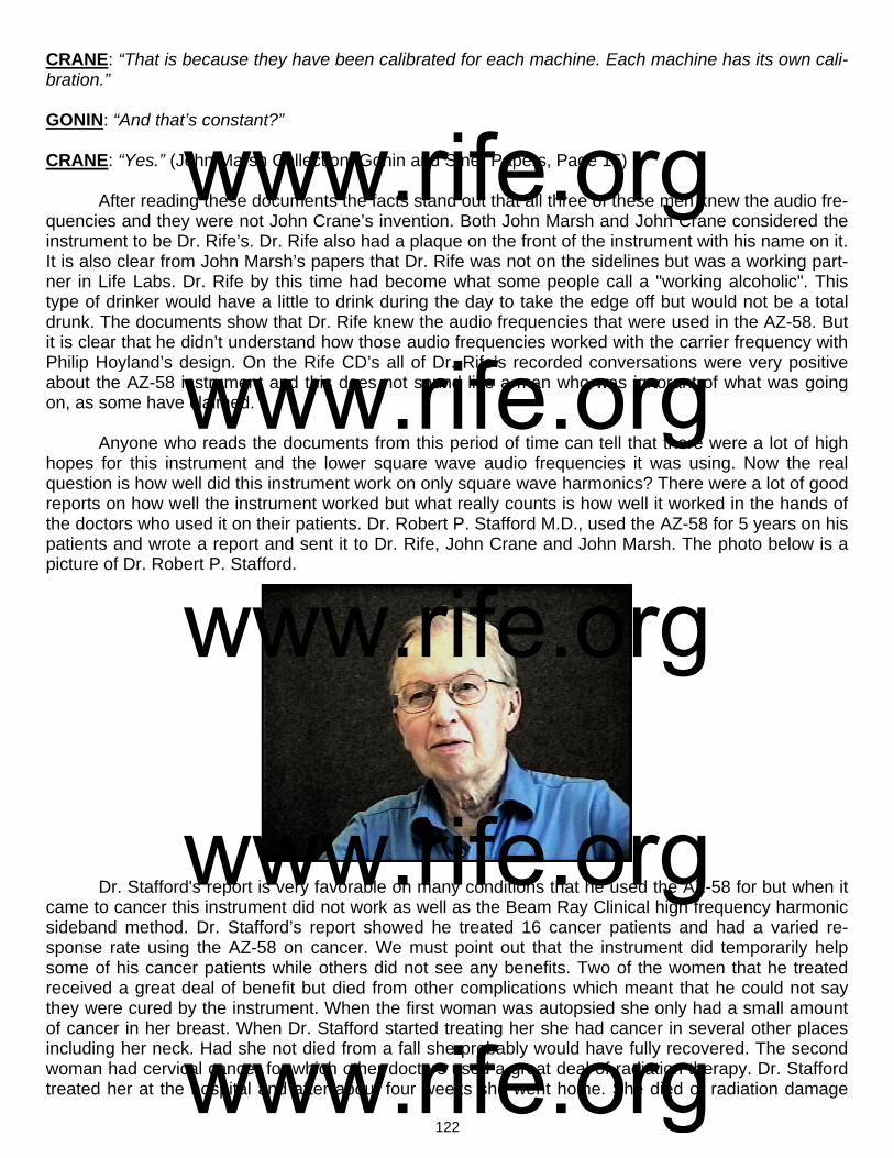
122
CRANE: “That is because they have been calibrated for each machine. Each machine has its own cali-bration.” GONIN: “And that’s constant?” CRANE: “Yes.” (John Marsh Collection, Gonin and Siner Papers, Page 15) After reading these documents the facts stand out that all three of these men knew the audio fre-quencies and they were not John Crane’s invention. Both John Marsh and John Crane considered the instrument to be Dr. Rife’s. Dr. Rife also had a plaque on the front of the instrument with his name on it. It is also clear from John Marsh’s papers that Dr. Rife was not on the sidelines but was a working part-ner in Life Labs. Dr. Rife by this time had become what some people call a "working alcoholic". This type of drinker would have a little to drink during the day to take the edge off but would not be a total drunk. The documents show that Dr. Rife knew the audio frequencies that were used in the AZ-58. But it is clear that he didn’t understand how those audio frequencies worked with the carrier frequency with Philip Hoyland’s design. On the Rife CD’s all of Dr. Rife’s recorded conversations were very positive about the AZ-58 instrument and this does not sound like a man who was ignorant of what was going on, as some have claimed. Anyone who reads the documents from this period of time can tell that there were a lot of high hopes for this instrument and the lower square wave audio frequencies it was using. Now the real question is how well did this instrument work on only square wave harmonics? There were a lot of good reports on how well the instrument worked but what really counts is how well it worked in the hands of the doctors who used it on their patients. Dr. Robert P. Stafford M.D., used the AZ-58 for 5 years on his patients and wrote a report and sent it to Dr. Rife, John Crane and John Marsh. The photo below is a picture of Dr. Robert P. Stafford. Dr. Stafford's report is very favorable on many conditions that he used the AZ-58 for but when it came to cancer this instrument did not work as well as the Beam Ray Clinical high frequency harmonic sideband method. Dr. Stafford’s report showed he treated 16 cancer patients and had a varied re-sponse rate using the AZ-58 on cancer. We must point out that the instrument did temporarily help some of his cancer patients while others did not see any benefits. Two of the women that he treated received a great deal of benefit but died from other complications which meant that he could not say they were cured by the instrument. When the first woman was autopsied she only had a small amount of cancer in her breast. When Dr. Stafford started treating her she had cancer in several other places including her neck. Had she not died from a fall she probably would have fully recovered. The second woman had cervical cancer for which other doctors used a great deal of radiation therapy. Dr. Stafford treated her at the hospital and after about four weeks she went home. She died of radiation damage
www.rife.org www.rife.org www.rife.org www.rife.org www.rife.org
123
that was done to the tubes that go from the kidneys to the bladder. When she was autopsied they found no cancer cells in her abdomen. In this case the cancer was completely gone. Since neither of these women lived for at least five years they could not be considered cured. So he could never say that he had cured anyone of a terminal malignancy. Dr. Stafford said this about the AZ-58 square wave audio frequency instrument: DR. STAFFORD: “As yet, we have failed to “cure” any case of advanced, terminal malignancy. It ap-pears in several instances that we may have impressed the disease favorably, temporarily. It is difficult to rule out the psychological, morale booster effect to the terminal patient when some definitive effort is made again in his behalf. However, several improvements have appeared to be more physical than emotional...All the patients in the series were treated with the same frequencies (e.g., 728 - 784 - 880 - 2008 - 2128). Perhaps these frequencies may be wrong, or only nearly correct.” (John Marsh Collec-tion, Dr. Stafford’s Report on using the AZ-58, page 4).
It is clear that Dr. Stafford was questioning the accuracy of the square wave audio frequencies and felt that something was wrong. Everyone who has been around Rife technology for a long time has seen the very same results as Dr. Stafford. From time to time we see that someone has an amazing experience of recovery from cancer but for the majority this does not happen. Today these frequencies 728, 784, 880, 2008 and 2128 Hertz which Dr. Stafford used are used by just about everyone for can-cer.
Many have wondered why the AZ-58 worked well for a few patients and not for others. We be-lieve we know the reason why. The carrier frequency is the reason it worked. The AZ-58 carrier fre-quency was set at the new 4.68 MHz to comply with the new 1950's FCC license. Dr. Stafford changed the carrier frequency using the variable capacitor to operate between 3.1 MHz to 3.3 MHz with the two women who were treated for cancer. He also used this same carrier frequency with some of his other patients. If per chance the carrier frequency was at about 3.2 MHz it would have been only about 15,000 Hertz off of the second harmonic of the BX which was 3,214,900 Hertz. This second harmonic of the BX (3,214,900 Hertz) was the primary frequency used by Philip Hoyland in the Beam Ray Clini-cal instrument for the BX. If a sideband frequency of 2128 Hertz (AZ-58 BX audio frequency) was used it would have only been the 7th sideband harmonic spacing that would have hit the harmonic BX fre-quency of 3,214,900 Hertz. We need to keep in mind that Dr. Stafford use 728, 784, 880 and 2008 Hertz also. It would have been almost impossible for him not to hit the BX frequency of 3,214,900 Hertz with one of the sidebands from all these frequencies. If we also take into account the “one tenth of one meter” tolerance frequency of 858 Hertz it gives room for the frequency to be off a few hundred Hertz and still work.
We also know that Dr. Stafford tried other RF carrier frequencies. Once he changed the carrier frequency the instrument would have been relying completely on the harmonics from the square wave waveform of the audio frequency. This would have greatly affected the outcome of his testing. The fact is the square wave harmonics method did not work as well as the Beam Ray Clinical sideband spacing method. The real problem is almost everyone believes the square wave audio frequencies are Dr. Rife’s true M.O.R. frequencies. The evidence shows that John Crane and John Marsh believed the au-dio frequencies were the true M.O.R. frequencies and they had given this understanding to Dr. Staf-ford. Without the correct understanding of how the instrument worked Dr. Stafford would not have un-derstood how important the fixed carrier frequency was. If he changed it off of the 3.2 MHz carrier fre-quency many of the 16 cancer patients could have been affected negatively. Dr. Stafford followed these 16 people over many years and in some cases things looked good at first, but the people eventu-ally died from their cancer anyway. One thing that needs to be pointed out is we do not know if Dr. Staf-ford treated many of these people over a long enough time period as Dr. Couche and the other doctors did.
www.rife.org www.rife.org www.rife.org www.rife.org www.rife.org
124
In the 1934 clinic 16 patients who had cancer and tuberculosis were treated and considered clinically cured. This is quite a contrast; 100% success in 1934 using Dr. Rife’s high RF frequency method and a very limited success rate on cancer for the low square wave audio frequency harmonic method combined accidently with some of the sideband method. Dr. Stafford used the AZ-58 instru-ment for a little over five years and sent his report to John Marsh. I am sure John Crane received it also. The big question that needs to be asked is, why did John Crane and John Marsh continue to tell people these audio frequencies were the frequencies which Dr. Rife used in the 1934 clinic when the medical proof showed they didn’t work as well as the high RF frequencies? This clearly shows they did not understand the sideband method. Why do people today continue to say these frequencies cure cancer even after they have seen the same results? Could it be because having had a few good results they ignored the evidence and fooled themselves? By the time all the evidence was available, John Marsh and John Crane were in jail on three or four different legal counts, one of which was for treating a woman without a medical license.
Dr. Rife did not want to have anything to do with all the legal trouble they were in. He was able to avoid it because he never made any claims and he would never treat anyone. The legal problems shut down Life Labs. Had this not happened I wonder if Dr. Rife would have ignored this evidence? I do not believe he would have. He would have realized that the changes they made to the instrument de-pending solely on square wave audio frequency harmonics compromised its effectiveness. I think Dr. Rife would have eventually realized that they didn’t fully understand how the Beam Ray Clinical Rife Machine worked and he would have gone back to the higher audio frequencies and put the carrier fre-quency back on 3.3MHz. We will never know what he would have done because I do not think Dr. Rife ever read Dr. Stafford’s report because John Marsh received it after he and John Crane were released from jail.
The troubling thing is this, because so few really understand Dr. Rife’s early instruments and how Philip Hoyland’s Beam Ray Clinical Rife Machine worked almost all frequency generators have been built on this limited square wave audio frequency harmonic instrument. The people who purchase these square wave audio frequency instruments believe it is the same type of instrument used in the 1934 clinic. All because we didn’t know the truth. Are people today just fooling themselves also? Are we trying to get these same square wave audio frequency harmonic type instruments and the frequen-cies they use to do what Dr. Stafford could not get them to do? Cure cancer? We know there have been incredibly good results on many other conditions using audio frequencies which show this type of instrument and method is of great worth but the truth is sometimes hard to accept.
As we have already read, Dr. Stafford came to suspect that the audio frequencies were not true M.O.R.s. Another letter written by Dr. Stafford to Dr. Edward Jeppson in Salt Lake City also confirms his concerns. He wrote this letter to Dr. Jeppson because he was having the same type of results. Here is his statement from his letter:
DR. STAFFORD: “Please excuse my format in the following letter for I intend to ramble a bit and forget strict grammatical dictum. I am writing you at this time partially because John Marsh informs me in a recent letter that you may be somewhat disheartened or at least worried about your role in the experi-mentations with the Rife Machine. Believe me, Dr. Edward I know how you feel for I too have been through this same feeling with this matter. I have observed clinical results after treatments with this gadget which I can scarcely believe myself. Yet, despite these good results, I have been confused by some rather simple failures such as a recent experiment which I conducted at Good Samaritan Hospital where we used the machine to treat some cultures of Staph Aureus and Strept. Fecalis. In this work we failed to inhibit growth at all or influence the cultures with the Rife Rx. I sent the results to John Marsh and asked for clarification and to be very frank I am not satisfied with John’s excuse of the failure as described by Dr. Rife. I am afraid I’m not a very good apostle for I’m getting some ideas myself on how this thing may work. I really wonder if this ultrasonic kills bacteria and virus at all or does it work like
www.rife.org www.rife.org www.rife.org www.rife.org www.rife.org

125
other forms of ultrasonic and merely stimulate the tissue in some unusual manner thereby improving the circulation and secondarily enhancing the body’s defenses against infection…To summarize some of this rambling: I feel that the Rife Ultrasonic Therapy has a very definitely beneficial effect on the hu-man (and canine) body...I furthermore feel that we, as doctors of medicine, using this machine must remain constantly alert to the condition of our patient and vary the Rx as indicated.” (Letter from Dr. Stafford to Dr. Edward Jeppson dated, April 1, 1958).
Clearly Dr. Stafford didn’t believe the audio frequencies were correct. Little did he know they were not the same frequencies used with the Rife Ray #4 or Kennedy Rife Ray #3 equipment? The AZ-58 could have output the higher harmonic sideband frequencies that Philip Hoyland used in his Beam Ray Clinical instrument if they had only understood how it really worked. Whatever was told to Dr. Staf-ford by Dr. Rife through John Marsh it did not satisfy Dr. Stafford's concern. Dr. Rife, John Crane and John Marsh probably felt that Dr. Stafford had just made some errors in his work. The one thing that Dr. Stafford did inadvertently find out was the AZ-58 using the square wave audio frequency harmonic method did not kill organisms in laboratory conditions at the hospital.
In the 1950’s Dr. Rife no longer had a lab for testing any microorganisms. There is no evidence they ever tested just the square wave audio frequencies with Dr. Rife's microscopes. So they did the only thing they could. They let the doctors use the AZ-58 and tell them how well it worked. We must re-member the instrument Dr. Rife gave to John Marsh and John Crane was an original Beam Ray Clini-cal instrument which used the correct higher audio frequencies and the correct 3.3 MHz carrier fre-quency. This instrument apparently worked because John Marsh said it cured his wife of cancer. Again the fact is the AZ-58 Beam Ray Clinical instrument using square wave audio frequency harmonics never worked as well as Philip Hoyland’s Beam Ray Clinical instrument using the sideband method. It also didn’t work as well as the Rife Ray #4 or Kennedy instruments. The square wave harmonic method used in the AZ-58 produced very good results on many conditions but not the results hoped for on cancer. But still even with the changes the AZ-58 worked very well on just about everything else but cancer. These square wave audio frequencies are what people have been using for the past 50 years believing they were Dr. Rife’s true M.O.R.s, all the while not knowing they were not Dr. Rife’s original frequencies which he used in his earlier instruments built in the 1920’s and 1930’s. Not until the papers from the 1939 Beam Rays Trial, John Marsh Papers, Kennedy Company equipment spectrum analysis and Philip Hoyland Beam Ray Clinical Rife Machine spectrum analysis came to light did we have the ability to finally figure out where all these frequencies came from. This information finally reveals which frequencies were the correct M.O.R.s. Notwithstanding the various setbacks Dr. Stafford was still amazed at the wonderful results he achieved with the AZ-58. Since we were able to obtain access to John Marsh’s papers we were also able to discover that in 1976 John Marsh had some of these low square wave audio frequencies tested on microorganisms by a laboratory using his Beam Ray Clinical ray tube instrument replica. Keep in mind that this instru-ment was miscalibrated like all the 1950’ AZ-58 Beam Ray Clinical instruments. He paid for these tests and they were carried out between May 1976 and March 1977. The University that did the tests specifi-cally stated that, whatever the outcome of the tests, John Marsh could not use their name in any way to endorse his equipment. These tests were similar to the tests Dr. Stafford conducted at Good Samaritan Hospital. Dr. Stafford’s tests showed that these low audio frequencies, which did not produce the cor-rect sideband M.O.R. frequencies, would not devitalize any organisms. John Marsh’s tests which he had done at this laboratory also showed that the low audio frequencies will not devitalize any organ-isms. Both Dr. Stafford’s and John Marsh’s tests convincingly show the low square wave audio fre-quencies are not true M.O.R.s. Unless these instruments use the higher audio frequencies with a 3.3 MHz carrier frequency they will not devitalize anything. No one that reads this information should in any way believe that his mean that Dr. Rife's method of coordinative resonance is without merit. What this laboratory tests show is that it is abso-
www.rife.org www.rife.org www.rife.org www.rife.org www.rife.org
126
lutely necessary that the instrument work on the same principles and frequencies as the original instru-ments that produce the true M.O.R. frequencies use in the Rife Ray #3, Rife Ray #4 and the Beam Ray Clinical instrument. These 1950's AZ-58 Beam Ray Clinical instruments were not calibrated correctly and they used the wrong audio frequencies. This miscalibration made it so the instruments did not work on the original sideband principles which produced Dr. Rife’s frequencies. Because they were not cali-brated correctly it rendered the instruments incapable of devitalizing any microorganism using just low audio frequencies and square wave harmonics. Even after these tests proved that the low square wave audio frequencies would not devitalize any microorganisms John Marsh continued to hold on to the false notion that these low square wave audio frequencies would devitalize microorganisms. He never would consider that something was wrong with the instruments. Today we understand that a simple correction would have solved all the problems. To read the documents about this laboratory tests click on this link. (John Marsh’s tests per-formed by: Brigham Young University Microbiology Department) To sum things up only a few changes were made to the Beam Ray Clinical instrument which produced the 1950’s AZ-58 Beam Ray Clinical replica. Dr. Rife and Verne Thompson kept the original Hartley oscillator but changed the fixed carrier frequency from 3.80 MHz to 4.68 Megahertz as per the FCC license. The RF carrier frequency section did not significantly changed with the use of the 812a vacuum tube instead of the 809 vacuum tube. They kept the variable audio oscillator which produced the low audio frequencies but lowered its range of frequencies using only three bands with a top audio frequency range of about 6000 Hertz. They then lowered the 1940’s audio frequencies by a factor of about 10 times and used these lower audio frequencies in the AZ-58. Then they changed the audio fre-quency waveform from sine wave to square wave and depended on the harmonics produced by the square wave waveform instead of the sidebands. It is interesting that Philip Hoyland found that a modu-lated sine wave waveform when put thought his M.O.P.A. circuit was sufficient to devitalize organisms because it creates a wave form that looks almost like a square wave waveform. It appears that a damped wave is not really necessary. When you compare the original Beam Ray Clinical instrument and Aubrey Scoon’s 1940’s Beam Ray Clinical instrument to the 1950’s AZ-58 Beam Ray Clinical rep-lica they are almost identical. When we built both of these instruments, Scoon’s and the AZ-58, and compared them we found the AZ-58 replica appears to be the better design since it is the newer design which uses the 812a tube. At the top of the next page, in the chart, is a list of the “Original 1950’s AZ-58 Frequencies” used by Dr. Stafford. The column to the right of the "Original 1950’s AZ-58 Frequencies" is based on a 4.68 MHz carrier and is labeled “4.68 Correct Sideband Frequencies”. They would be the correct sideband frequencies to make the AZ-58 instrument work like the original Beam Ray Clinical instrument, but, the problem is the large “Number of Sideband Harmonics”. Almost all of the frequencies exceed more than 40 sideband spacing steps to hit the high frequency M.O.R. The large “Number of Sideband Harmonics” means that the power level of the correct sideband that hit the higher harmonic M.O.R. would be so weak that it would never work. If the “Number of Side-band Harmonics” go over about 40 sideband steps the power level on a spectrum analyzer shows that they become too weak to work. You will notice how closely these two sets correspond to each other. The problem is when Dr. Rife, John Crane and John Marsh lowered the audio frequencies they com-promised the AZ-58. The BX audio frequency that Dr. Stafford used was 2128 Hertz and the RF carrier frequency was about 3.2 MHz. The sideband spacing to the “Higher Harmonic Frequency” M.O.R. took only a few sidebands which had enough power to work. This appears to be the reason why the two women and a few others that he treated had such amazing results. The problem is most of the organ-isms far exceed the 40 sideband harmonics with the use of these low audio frequencies. This will hap-pen even if you use a 3.2 MHz or 4.68 RF carrier frequency.
www.rife.org www.rife.org www.rife.org www.rife.org www.rife.org
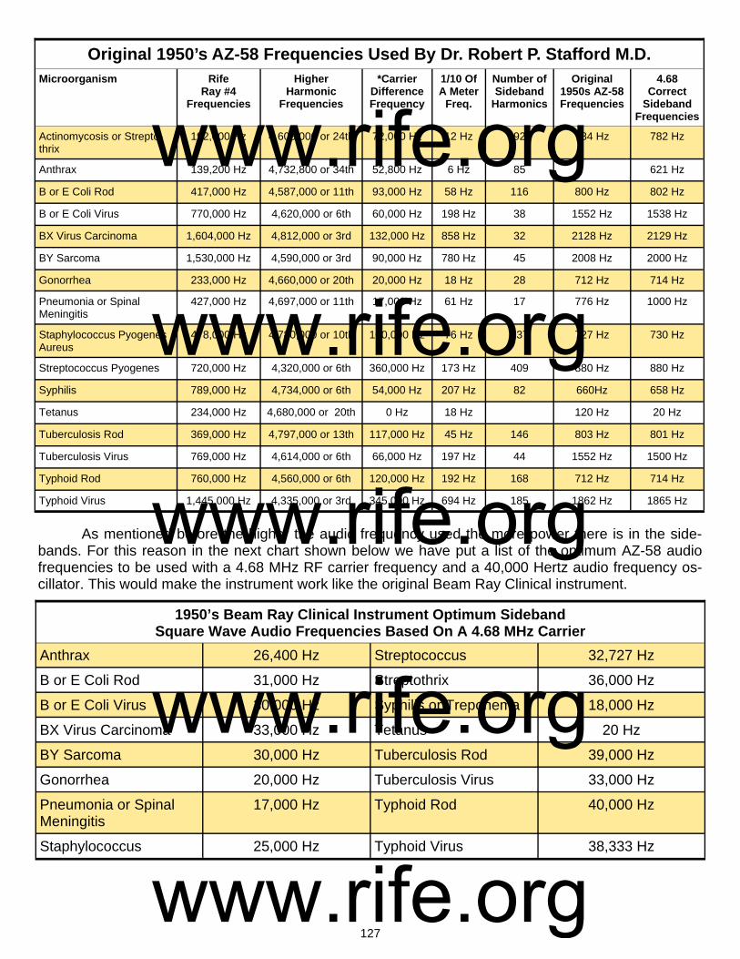
127
As mentioned before the higher the audio frequency used the more power there is in the side-bands. For this reason in the next chart shown below we have put a list of the optimum AZ-58 audio frequencies to be used with a 4.68 MHz RF carrier frequency and a 40,000 Hertz audio frequency os-cillator. This would make the instrument work like the original Beam Ray Clinical instrument.
Microorganism Rife Ray #4
Frequencies
Higher Harmonic
Frequencies
*Carrier Difference Frequency
1/10 Of A Meter
Freq.
Number of Sideband
Harmonics
Original 1950s AZ-58 Frequencies
4.68 Correct
Sideband Frequencies
Actinomycosis or Strepto-thrix
192,000 Hz 4,608,000 or 24th 72,000 Hz 12 Hz 92 784 Hz 782 Hz
Anthrax 139,200 Hz 4,732,800 or 34th 52,800 Hz 6 Hz 85 621 Hz
B or E Coli Rod 417,000 Hz 4,587,000 or 11th 93,000 Hz 58 Hz 116 800 Hz 802 Hz
B or E Coli Virus 770,000 Hz 4,620,000 or 6th 60,000 Hz 198 Hz 38 1552 Hz 1538 Hz
BX Virus Carcinoma 1,604,000 Hz 4,812,000 or 3rd 132,000 Hz 858 Hz 32 2128 Hz 2129 Hz
BY Sarcoma 1,530,000 Hz 4,590,000 or 3rd 90,000 Hz 780 Hz 45 2008 Hz 2000 Hz
Gonorrhea 233,000 Hz 4,660,000 or 20th 20,000 Hz 18 Hz 28 712 Hz 714 Hz
Pneumonia or Spinal Meningitis
427,000 Hz 4,697,000 or 11th 17,000 Hz 61 Hz 17 776 Hz 1000 Hz
Staphylococcus Pyogenes Aureus
478,000 Hz 4,780,000 or 10th 100,000 Hz 76 Hz 137 727 Hz 730 Hz
Streptococcus Pyogenes 720,000 Hz 4,320,000 or 6th 360,000 Hz 173 Hz 409 880 Hz 880 Hz
Syphilis 789,000 Hz 4,734,000 or 6th 54,000 Hz 207 Hz 82 660Hz 658 Hz
Tetanus 234,000 Hz 4,680,000 or 20th 0 Hz 18 Hz 120 Hz 20 Hz
Tuberculosis Rod 369,000 Hz 4,797,000 or 13th 117,000 Hz 45 Hz 146 803 Hz 801 Hz
Tuberculosis Virus 769,000 Hz 4,614,000 or 6th 66,000 Hz 197 Hz 44 1552 Hz 1500 Hz
Typhoid Rod 760,000 Hz 4,560,000 or 6th 120,000 Hz 192 Hz 168 712 Hz 714 Hz
Typhoid Virus 1,445,000 Hz 4,335,000 or 3rd 345,000 Hz 694 Hz 185 1862 Hz 1865 Hz
Original 1950’s AZ-58 Frequencies Used By Dr. Robert P. Stafford M.D.
1950’s Beam Ray Clinical Instrument Optimum Sideband Square Wave Audio Frequencies Based On A 4.68 MHz Carrier
Anthrax 26,400 Hz Streptococcus 32,727 Hz
B or E Coli Rod 31,000 Hz Streptothrix 36,000 Hz
B or E Coli Virus 30,000 Hz Syphilis or Treponema 18,000 Hz
BX Virus Carcinoma 33,000 Hz Tetanus 20 Hz
BY Sarcoma 30,000 Hz Tuberculosis Rod 39,000 Hz
Gonorrhea 20,000 Hz Tuberculosis Virus 33,000 Hz
Pneumonia or Spinal Meningitis
17,000 Hz Typhoid Rod 40,000 Hz
Staphylococcus 25,000 Hz Typhoid Virus 38,333 Hz
www.rife.org www.rife.org www.rife.org www.rife.org www.rife.org
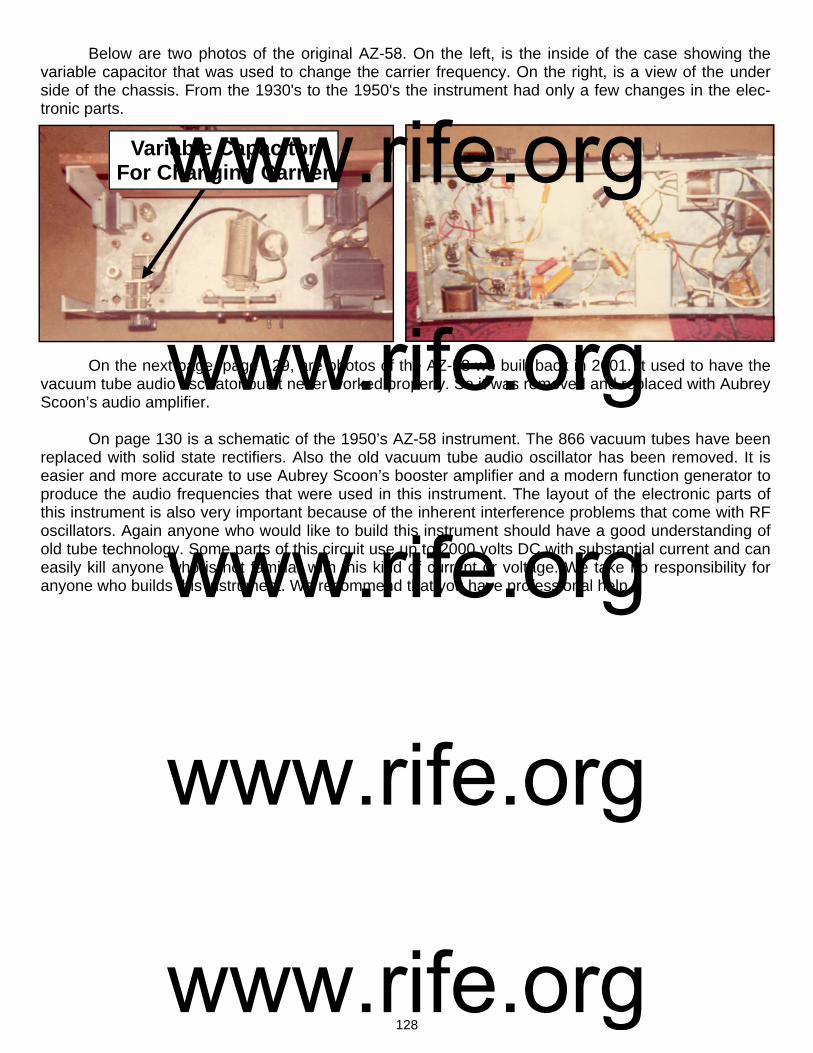
128
Variable Capacitor For Changing Carrier
Below are two photos of the original AZ-58. On the left, is the inside of the case showing the variable capacitor that was used to change the carrier frequency. On the right, is a view of the under side of the chassis. From the 1930's to the 1950's the instrument had only a few changes in the elec-tronic parts. On the next page, page 129, are photos of the AZ-58 we built back in 2001. It used to have the vacuum tube audio oscillator but it never worked properly. So it was removed and replaced with Aubrey Scoon’s audio amplifier. On page 130 is a schematic of the 1950’s AZ-58 instrument. The 866 vacuum tubes have been replaced with solid state rectifiers. Also the old vacuum tube audio oscillator has been removed. It is easier and more accurate to use Aubrey Scoon’s booster amplifier and a modern function generator to produce the audio frequencies that were used in this instrument. The layout of the electronic parts of this instrument is also very important because of the inherent interference problems that come with RF oscillators. Again anyone who would like to build this instrument should have a good understanding of old tube technology. Some parts of this circuit use up to 2000 volts DC with substantial current and can easily kill anyone who is not familiar with this kind of current or voltage. We take no responsibility for anyone who builds this instrument. We recommend that you have professional help.
www.rife.org www.rife.org www.rife.org www.rife.org www.rife.org

129
Photos of the rebuilt AZ-58 Beam Ray Clinical instrument
Variable Capacitor For Changing Carrier
www.rife.org www.rife.org www.rife.org www.rife.org www.rife.org

130
www.rife.org www.rife.org www.rife.org www.rife.org www.rife.org

131
Chapter #13
Rife Machine Harmonic Audio Frequency Misunderstanding
There is a belief that the audio frequencies that were used in the original Beam Ray Clinical Rife Machine and its 1940’s and 1950’s AZ-58 replica Rife Machines are harmonic M.O.R. frequencies de-rived by dividing Dr. Rife’s original high RF frequencies down in octave steps until you reach the audio range of frequencies. For this to be true all of the audio frequencies would have to be true harmonics of the higher RF frequencies. But this is not the case. All the documents we have quoted and the understanding we now have prove as a myth the long believed concept that the audio frequencies used in the 1950’s were created by John Crane and John Marsh by dividing Dr. Rife’s high frequency M.O.R.s down by harmonic steps until they reached the audio range of frequencies. If we take the correct frequency for the BX of 1,607,450 Hertz read by Philip Hoyland and divide it down by harmonics we do not get 2008 Hertz or 2128 Hertz. In fact, we do not get the higher 1940’s audio frequencies of 20080 Hertz or 21275 Hertz either. This clearly proves John Crane and John Marsh did not create the audio frequencies by just dividing down Dr. Rife’s higher RF M.O.R. frequencies. The fact is we know that the origin of these audio frequencies came from the sideband harmonic method used by Philip Hoyland in the original Beam Ray Clinical instru-ment. The documented information we have shows that Dr. Rife’s true M.O.R.s that would resonate organisms were the higher RF frequencies (139,200 Hertz to 1,607,450 Hertz) used in the Kennedy Models 110, 281 and Rife Ray #4 Rife Machine and the higher harmonic frequencies used in the Beam Ray Clinical Rife Machine. All of Dr. Rife's Machines worked on RF frequencies not audio frequencies. From the spectrum analysis of Philip Hoyland’s Beam Ray Rife Machine we know that it used audio fre-
www.rife.org www.rife.org www.rife.org www.rife.org www.rife.org
132
quencies for one purpose only, to create the method of sideband harmonic spacing to hit the higher harmonic frequencies which were the true RF M.O.R.s. Henry Siner reported Philip Hoyland’s design killed the organisms under microscope observation. Add to this the list of doctors who used the instru-ments and said they had many diseases cured. This shows that Philip Hoyland’s harmonic method works beyond question. Dr. Robert P. Stafford was not able to kill any organisms using just the square wave audio fre-quency harmonics with a fixed RF carrier. He did his tests under microscope observation. Today, like Dr. Stafford many have tried to kill the organisms which these audio frequencies correspond to, with no success. If these audio frequencies, as some have claimed, were really harmonic frequencies derived from the higher RF M.O.R. frequencies then they should be able to kill the microorganism they corre-spond to. If an audio frequency harmonic of Dr. Rife’s RF M.O.R. will not devitalize an organism under microscope observation, can the harmonic association be valid? No rational person would believe this. Yet today this is exactly what most people believe because they do not have all of the facts. The evidence we have given in this report shows that if the RF M.O.R. frequency is lowered by too much it will lose its ability to devitalize an organism even though it is a harmonic frequency. Dr. Stafford and many others found when they treated the organism with the audio frequency that was sup-posed to devitalize it the organism continued to grow. Then when they transferred it from one culture to another it still grew on the new medium they used. Can there be any greater scientific proof than this? Even Dr. Rife would not have argued with this method of determining true M.O.R.s, because this is the method he used. This is the greatest proof, along with the fact that almost all the audio frequencies are not true harmonics of the original high RF frequencies. We know many other people who have made the same tests on microorganisms as Dr. Stafford and they told us they obtained the same results he did. John Marsh said on the Rife CDs that they came up with the frequencies using math. If every audio frequency was a perfect harmonic match to its higher RF M.O.R. then we could say they were all de-rived from the RF M.O.R.s, but they are not. Even if the audio frequencies were derived from the RF M.O.R.s, and they do not devitalize the organism in the same way, is the principle valid? What the evidence in this report certainly proves is, without really knowing it, Dr. Rife, John Crane and John Marsh discovered that these lower square wave audio frequencies are beneficial. Since they will not devitalize the organism they correspond to under microscope observation, then how can it be that they seem to help people? From Dr. Stafford’s statement we read that he also wondered why they would work on some conditions and not others. He felt that these audio frequencies stimu-lated the adrenal glands and immune system much like ultrasonic frequencies do. And this stimulation is why the frequencies help even though they do not work like a true RF M.O.R. frequency would. The fact is we really don’t know why the audio frequencies are beneficial, but for some unknown reason they are. Though the method of modulating a square wave audio frequency onto a fixed RF carrier did not work as well as Dr. Rife’s original method did, or Philip Hoyland's sideband method, nevertheless it works very well on many conditions. Even though the audio frequencies are beneficial in many ways, this still does not prove the idea that the 1950’s audio frequencies are harmonic M.O.R.s. What needs to be kept in mind is how the original Beam Ray Clinical instruments worked. Nei-ther the 3.3 or the 3.8 megahertz carrier frequency nor the audio frequencies will do anything by them-selves. But when the 3.3 or the 3.8 megahertz harmonic carrier frequency and the audio frequencies are combined together they will produce many sideband frequencies. And one of these sideband fre-quencies will line up with the true Rife M.O.R frequency and devitalize or render harmless the harmful microorganism. If you just use the audio frequencies by themselves you will get nothing. If you use the 3.3 or the 3.8 megahertz carrier without the audio frequencies you will get nothing. The audio frequen-cies used in this style of instrument must have the RF carrier frequency of 3.3 or 3.8 megahertz or they are useless. This is the reason the 1950’s AZ-58 Beam Ray Clinical instrument did not work properly.
www.rife.org www.rife.org www.rife.org www.rife.org www.rife.org
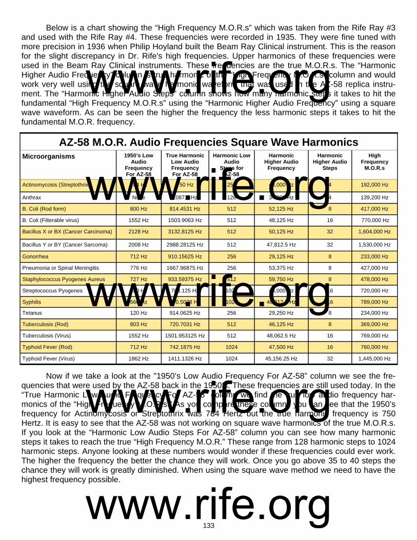
133
Below is a chart showing the “High Frequency M.O.R.s” which was taken from the Rife Ray #3 and used with the Rife Ray #4. These frequencies were recorded in 1935. They were fine tuned with more precision in 1936 when Philip Hoyland built the Beam Ray Clinical instrument. This is the reason for the slight discrepancy in Dr. Rife's high frequencies. Upper harmonics of these frequencies were used in the Beam Ray Clinical instruments. These frequencies are the true M.O.R.s. The “Harmonic Higher Audio Frequency” column is true harmonic of the “High Frequency M.O.R.s” column and would work very well using the square wave harmonic waveform that was used in the AZ-58 replica instru-ment. The “Harmonic Higher Audio Steps” column shows how many harmonic steps it takes to hit the fundamental “High Frequency M.O.R.s” using the “Harmonic Higher Audio Frequency” using a square wave waveform. As can be seen the higher the frequency the less harmonic steps it takes to hit the fundamental M.O.R. frequency.
Now if we take a look at the "1950’s Low Audio Frequency For AZ-58” column we see the fre-quencies that were used by the AZ-58 back in the 1950’s. These frequencies are still used today. In the “True Harmonic Low Audio Frequency For AZ-58” column we find the true low audio frequency har-monics of the “High Frequency M.O.R.s.” As you compare these columns you can see that the 1950’s frequency for Actinomycosis or Streptothrix was 784 Hertz but the true harmonic frequency is 750 Hertz. It is easy to see that the AZ-58 was not working on square wave harmonics of the true M.O.R.s. If you look at the “Harmonic Low Audio Steps For AZ-58” column you can see how many harmonic steps it takes to reach the true “High Frequency M.O.R.” These range from 128 harmonic steps to 1024 harmonic steps. Anyone looking at these numbers would wonder if these frequencies could ever work. The higher the frequency the better the chance they will work. Once you go above 35 to 40 steps the chance they will work is greatly diminished. When using the square wave method we need to have the highest frequency possible.
AZ-58 M.O.R. Audio Frequencies Square Wave Harmonics Microorganisms 1950’s Low
Audio Frequency For AZ-58
True Harmonic Low Audio Frequency For AZ-58
Harmonic Low Audio
Steps for AZ-58
Harmonic Higher Audio
Frequency
Harmonic Higher Audio
Steps
High Frequency
M.O.R.s
Actinomycosis (Streptothrix) 784 Hz 750 Hz 256 48,000 Hz 4 192,000 Hz
Anthrax None 1087.5 Hz 128 34,800 Hz 4 139,200 Hz
B. Coli (Rod form) 800 Hz 814.4531 Hz 512 52,125 Hz 8 417,000 Hz
B. Coli (Filterable virus) 1552 Hz 1503.9063 Hz 512 48,125 Hz 16 770,000 Hz
Bacillus X or BX (Cancer Carcinoma) 2128 Hz 3132.8125 Hz 512 50,125 Hz 32 1,604,000 Hz
Bacillus Y or BY (Cancer Sarcoma) 2008 Hz 2988.28125 Hz 512 47,812.5 Hz 32 1,530,000 Hz
Gonorrhea 712 Hz 910.15625 Hz 256 29,125 Hz 8 233,000 Hz
Pneumonia or Spinal Meningitis 776 Hz 1667.96875 Hz 256 53,375 Hz 8 427,000 Hz
Staphylococcus Pyogenes Aureus 727 Hz 933.59375 Hz 512 59,750 Hz 8 478,000 Hz
Streptococcus Pyogenes 880 Hz 703.125 Hz 1024 45,000 Hz 16 720,000 Hz
Syphilis 660 Hz 770.5078 Hz 1024 49,312.5 Hz 16 789,000 Hz
Tetanus 120 Hz 914.0625 Hz 256 29,250 Hz 8 234,000 Hz
Tuberculosis (Rod) 803 Hz 720.7031 Hz 512 46,125 Hz 8 369,000 Hz
Tuberculosis (Virus) 1552 Hz 1501.953125 Hz 512 48,062.5 Hz 16 769,000 Hz
Typhoid Fever (Rod) 712 Hz 742.1875 Hz 1024 47,500 Hz 16 760,000 Hz
Typhoid Fever (Virus) 1862 Hz 1411.1326 Hz 1024 45,156.25 Hz 32 1,445,000 Hz
www.rife.org www.rife.org www.rife.org www.rife.org www.rife.org
134
Chapter #14
Life Labs 1950’s Pad Instrument without Ray Tube
1. Used round disks that came in contact with the body. Later changed in the 1960’s to hand cylinders or foot pads. 2. Had no RF carrier frequency. 3. Used the square wave audio frequencies used in the AZ-58. It was about 1957 when John Crane and John Marsh began building instruments without a ray tube. Earlier in this article Bertrand Comparet was quoted as saying: COMPARET: “Now, Crane said “Well now look, Rife himself admits that no matter how much tube and ray, and so on, you have, you can’t get any results unless you’ve got the right frequency. Therefore the real clue to the thing is the frequency and not the means by which you deliver it.” (1970’s Bertrand Comparet Interview #33). John Crane and John Marsh replaced the ray tube with a type of pad that they developed which came in contact with the body. As we pointed out earlier in this report it is interesting to note that Dr. Rife said Abrams’ Oscilloclast would devitalize the BX cancer virus and it was a contact type device. John Crane and John Marsh probably used this contact method because of the success of Abrams’ in-strument. From the documented information we have it was also the high cost of building ray tube in-struments that caused them to look at doing things in a different way. In addition to being expensive to build, the ray tube could break very easily. They had many problems with them. I don’t believe Dr. Rife, at least in his early years, ever had a reason to look at doing things differently. John Crane and John Marsh did! They didn’t have the kind of money to spend that Dr. Rife did. "Necessity is the mother of invention!" John Crane and John Marsh used a Heathkit function generator to produce the frequencies. These Heathkit function generators had no built-in carrier frequency on which to modulate the audio frequencies. Therefore, the carrier frequency was no longer used. The fact that they didn’t feel the RF carrier frequency was necessary shows that they totally believed that the audio frequencies were the M.O.R. frequencies. This also shows beyond doubt that they never knew the importance of the RF car-rier frequency or had any understanding of the harmonic sideband method used in the original Beam Ray Clinical Rife Machine. They could have made a pad instrument work like the Beam Ray Clinical Rife Machine if they would have used a harmonic sine wave RF carrier frequency at 3,300,000 Hertz. It
www.rife.org www.rife.org www.rife.org www.rife.org www.rife.org

135
appears that the removal of the ray tube was not as important as the removal of the RF carrier fre-quency. Dr. Rife would have never approved of using an instrument without a carrier frequency since he knew that Philip Hoyland’s sideband method somehow needed an RF carrier frequency to make it work properly. Though Dr. Rife didn’t fully understand Philip Hoyland’s instrument he clearly understood the importance of the carrier frequency. The positive part of using a Heathkit function generator in this way is they were inexpensive ($200) and a lot more people could afford one. Many people can thank John Crane and John Marsh for this innovative method. John Crane and John Marsh proved that the audio frequencies worked the same whether applied through a ray tube or pads if sufficient power is used. Many people think that John Crane and John Marsh built the pad instrument without Dr. Rife being fully informed about it. But this was not the case. John Crane and John Marsh had talked for some time about building a smaller ray tube instrument but instead of building it they built the pad instrument. In John Marsh’s Trip to Ohio Papers we read this: RIFE: “That is the only way that it can be handled properly.” MARSH: “Maybe we can sell small instruments for the purpose of small diseases like colds, flu and stuff like that, which are minor, which the Dr.s prefer not treating those kind anyway, because they are chronic, and there isn’t anything they can do with them. People keep coming in and coming in and they take up his time where he could spend it taking care of a bad case, or something or other. Dr. Stafford said that he would prefer that a small instrument would be made...What do you think John? I've been doing a lot of talking not even giving you a chance to get a word in edgewise.” CRANE: “There is no doubt there is going to be an awful lot of development on this design…” (1957 John Marsh trip to Dayton, Ohio #36-38). From these statements we learn that Dr. Rife knew that they wanted to build small instruments. Also we learn that it was John Marsh and John Crane’s idea to build the pad instruments, not Dr. Rife’s. We know that Dr. Rife was upset with John Crane and John Marsh over some of these changes because he expressed it to Bertrand Comparet during his 1961 deposition. Comparet said: COMPARET: “And I asked Rife, because I thought Rife would certainly say that the way Crane was working on it then was still using the Rife principle, but he indignantly denied it.”
HUBBARD: "All right, I see. But, getting back, you say that Rife was very indignant, that the machine that Crane was building was really his [Cranes] idea. I suppose he did not compromise on that, did he?
COMPARET: "Oh no, he just blew up." (1970’s Bertrand Comparet interview #32 & 40).
At this time John Crane and John Marsh were working on both the ray tube instrument and the pad instrument. We know that Dr. Rife considered the ray tube instrument to be his. This ray tube in-strument used an RF carrier frequency on which the square wave audio frequencies were modulated. It’s clear that the pad instrument without a carrier frequency is what Dr. Rife was upset about. Because they didn’t use a carrier frequency the instrument no longer worked on Dr. Rife's principle of coordina-tive resonance. The instrument only worked on low audio frequencies not his high RF frequencies. However, John Marsh and John Crane’s innovation with a pad instrument proved that the ray tube could be removed. This made it possible for more people to have access to Dr. Rife’s technology. To-day all the frequencies which Dr. Rife used can be produced by any function generator with the proper frequency range of at least 1 Hertz to 2,000,000 Hertz.
www.rife.org www.rife.org www.rife.org www.rife.org www.rife.org
136
It appears the reason why John Crane and John Marsh didn’t use a carrier frequency is the Heathkit function generator that they used didn’t have the capability of using a Megahertz (MHz) carrier frequency. Audio frequencies will not broadcast, therefore, they are modulated upon the carrier fre-quency so that they will penetrate the body. In laymen’s terms, modulation is piggy-backing one or more low frequencies on another higher frequency. The frequencies travel together but still keep the components of both waveforms. Almost all the so called "Rife Machines" built today do not use a car-rier frequency even though Dr. Rife’s Beam Ray and AZ-58 Rife Machines did. If Dr. Rife could have removed the carrier frequencies from his instrument and gotten the same results, I believe he would have. As it is, Dr. Rife never removed the carrier frequency from any of his instruments. It was John Crane and John Marsh who did this. If a person wants to try and obtain the results which Dr. Rife did, then a carrier frequency should be considered and used in any audio frequency instrument. We realize that there are ray tube instruments today that do not use a carrier frequency. These use a high electromagnetic field which will transfer the energy into the body. They appear to work very well with low square wave audio frequencies. We do not doubt that these instruments work. We know people that are using these instruments and say that they are getting very good results. But what we are talking about in this article is the way that Dr. Rife used RF frequencies and an RF carrier fre-quency modulated with an audio frequency to produce the proper sideband method. Some of these EM ray tube instrument builders like to compare EM devices to RF devices. This is like comparing apples and oranges. There is no comparison. The EM devices work on a high electromagnetic field, the stronger the better. RF devices work on radio frequencies and the power output is measured in watts. Dr. Rife’s instruments were all RF instruments and could resonate an organism when the proper RF frequency was used. EM devices use low audio frequencies because they cannot output RF frequen-cies. RF versus EM or apples and oranges cannot be compared because they are two totally different principles. EM devices are also limited in their frequency range. Usually they can only output frequen-cies to about 20,000 Hertz where Dr. Rife's RF devices were putting out frequencies in the millions of Hertz. Some people believe that audio frequencies when used in a pad instrument without a carrier will only travel along the skin of the body, and won’t penetrate it. The skin effect has nothing to do with hu-man tissue or human skin. It has to do with the skin of a metal conductor such as a copper wire. If the human body was made of metal then this would apply. In scientific studies on Bioelectric Impedance Analysis in the body it has been shown that sine wave audio frequencies will enter the body but will only travel in the connective tissues around the cells. Also in these scientific studies it has been shown that the closer you get to 1 Megahertz the greater the penetration of the current through the cell. At 1 Megahertz the current of the frequency will go through the cell and fully penetrate the body. These type of tests show why it is very important that a carrier frequency be used. A virus can enter a cell. An RF frequency can enter the cell where it can do the most good. These kinds of scientific studies and their importance were not understood by John Crane and John Marsh in the 1950’s and 1960’s. Dr. Rife’s instruments always used a high RF frequency or a carrier frequency. Pad type audio frequency instruments have done a lot of good over the years. But without a 3,300,000 Hertz carrier frequency and the use of Philip Hoyland's audio frequencies the sideband method cannot be used unless other carrier frequencies are properly match with new audio frequen-cies. These instruments need to have a carrier frequency or the ability to output the exact frequency that Dr. Rife used. We know from the documents that Dr. Rife preferred using the exact frequency rather than Philip Hoyland’s sideband method, but either method will work. Dr. Rife’s frequency range included both the audio range and the RF range of frequencies from 1 Hertz to 2,000,000 Hertz. The so called "Rife Machines” which are sold today that cannot produce this frequency range cannot produce Dr. Rife's results. Make sure that the frequency generator you purchase can produce both the audio and RF frequencies that Dr. Rife used.
www.rife.org www.rife.org www.rife.org www.rife.org www.rife.org
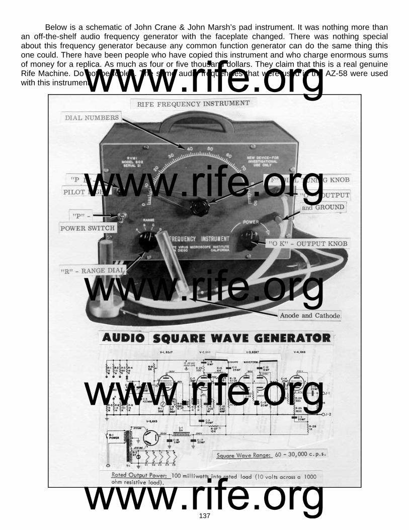
137
Below is a schematic of John Crane & John Marsh’s pad instrument. It was nothing more than an off-the-shelf audio frequency generator with the faceplate changed. There was nothing special about this frequency generator because any common function generator can do the same thing this one could. There have been people who have copied this instrument and who charge enormous sums of money for a replica. As much as four or five thousand dollars. They claim that this is a real genuine Rife Machine. Do not be fooled. The same audio frequencies that were used in the AZ-58 were used with this instrument. www.rife.org
www.rife.org www.rife.org www.rife.org www.rife.org

138
John Marsh’s 1970’s Beam Ray replica Rife Machine
1. Used a ray tube. 2. Carrier frequency was 4.122 MHz. 3. Modulated sine and square wave audio frequencies onto the sine wave carrier frequency. 4. Power usage was about 460 watts. Output to the ray tube about 40 watts. John Marsh built this ray tube instrument model # JLMSQ-1A back in the early 1970’s. He and John Crane were under court order not to associate with each other. Because of this they went their separate ways but communicated through phone calls and letters often. John Crane stayed in Califor-nia and John Marsh went to Colorado but eventually settled back in SLC, Utah until his death in 1987. All of his Rife instruments and Rife information were given to his nurse at his death. She allowed us to take photos of this instrument of his. We wish to thank her for allowing us to do this. The photo below shows the two chassis that were connected by wires. This instrument was a mix of both tube technology and modern solid state components.
www.rife.org www.rife.org www.rife.org www.rife.org www.rife.org
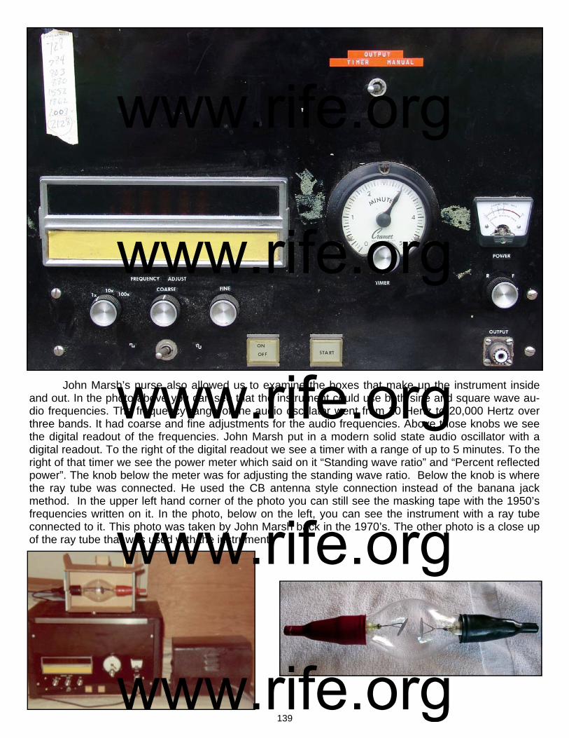
139
John Marsh’s nurse also allowed us to examine the boxes that make up the instrument inside and out. In the photo above you can see that the instrument could use both sine and square wave au-dio frequencies. The frequency range of the audio oscillator went from 20 Hertz to 20,000 Hertz over three bands. It had coarse and fine adjustments for the audio frequencies. Above those knobs we see the digital readout of the frequencies. John Marsh put in a modern solid state audio oscillator with a digital readout. To the right of the digital readout we see a timer with a range of up to 5 minutes. To the right of that timer we see the power meter which said on it “Standing wave ratio” and “Percent reflected power”. The knob below the meter was for adjusting the standing wave ratio. Below the knob is where the ray tube was connected. He used the CB antenna style connection instead of the banana jack method. In the upper left hand corner of the photo you can still see the masking tape with the 1950’s frequencies written on it. In the photo, below on the left, you can see the instrument with a ray tube connected to it. This photo was taken by John Marsh back in the 1970’s. The other photo is a close up of the ray tube that was used with the instrument.
www.rife.org www.rife.org www.rife.org www.rife.org www.rife.org

140
The top photo, above and on the left, is looking at the front of the instrument. The top photo, above right, looking at the back of the instrument. The top photo, above left, shows the solid state au-dio oscillator. To the left of the audio oscillator is the 5 minute timer. The second photo above, bottom left, shows the underside of the chassis where you can see the RF tank coil that was fixed at 4.122 MHz. The three photos of vacuum tubes, above on the right, shows a clear view of the 811a, 6L6GC and 6GK6 vacuum tubes and their placement into the chassis. The photo, below on the left, shows a side view of the audio oscillator. The photo, below on the right shows a side view of the 811a tube. You can also see the RF choke right in front of the 811a tube.
www.rife.org www.rife.org www.rife.org www.rife.org www.rife.org
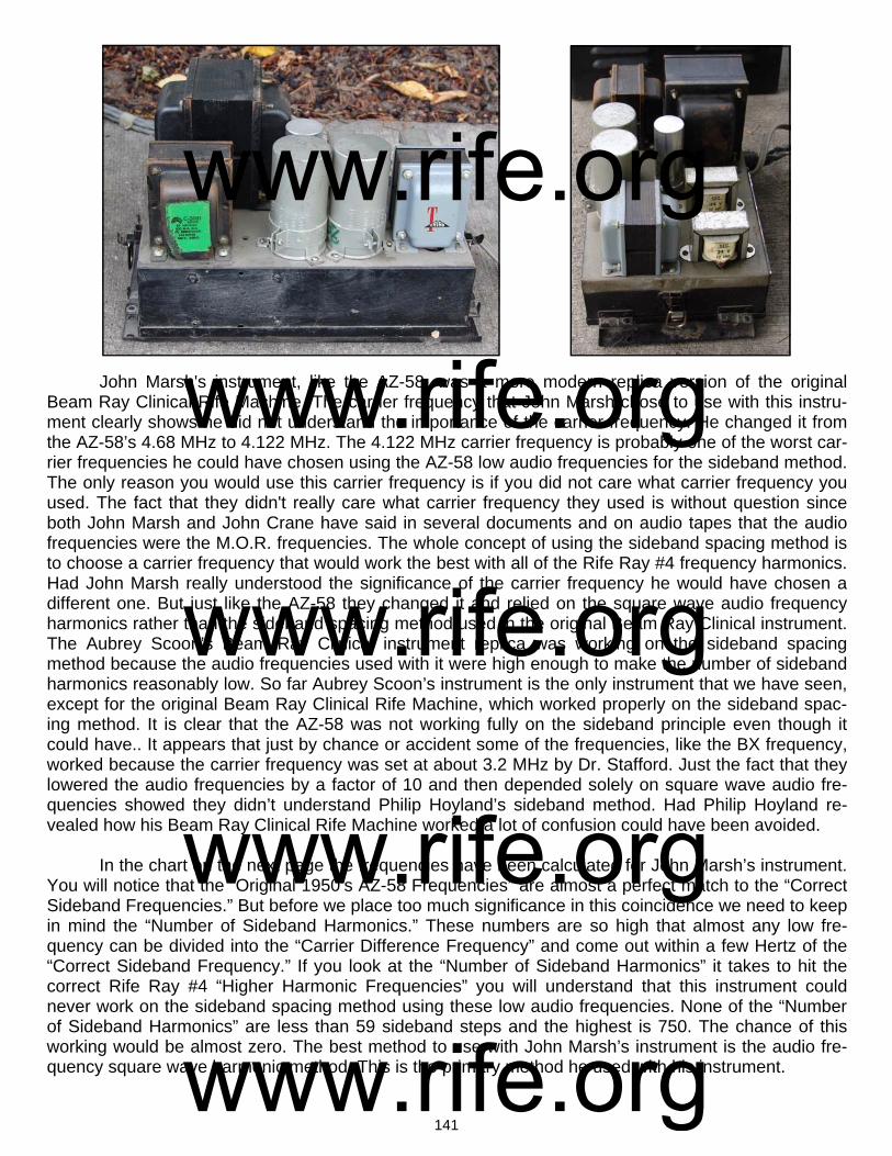
141
John Marsh's instrument, like the AZ-58, was a more modern replica version of the original Beam Ray Clinical Rife Machine. The carrier frequency that John Marsh chose to use with this instru-ment clearly shows he did not understand the importance of the carrier frequency. He changed it from the AZ-58’s 4.68 MHz to 4.122 MHz. The 4.122 MHz carrier frequency is probably one of the worst car-rier frequencies he could have chosen using the AZ-58 low audio frequencies for the sideband method. The only reason you would use this carrier frequency is if you did not care what carrier frequency you used. The fact that they didn't really care what carrier frequency they used is without question since both John Marsh and John Crane have said in several documents and on audio tapes that the audio frequencies were the M.O.R. frequencies. The whole concept of using the sideband spacing method is to choose a carrier frequency that would work the best with all of the Rife Ray #4 frequency harmonics. Had John Marsh really understood the significance of the carrier frequency he would have chosen a different one. But just like the AZ-58 they changed it and relied on the square wave audio frequency harmonics rather than the sideband spacing method used in the original Beam Ray Clinical instrument. The Aubrey Scoon’s Beam Ray Clinical instrument replica was working on the sideband spacing method because the audio frequencies used with it were high enough to make the number of sideband harmonics reasonably low. So far Aubrey Scoon’s instrument is the only instrument that we have seen, except for the original Beam Ray Clinical Rife Machine, which worked properly on the sideband spac-ing method. It is clear that the AZ-58 was not working fully on the sideband principle even though it could have.. It appears that just by chance or accident some of the frequencies, like the BX frequency, worked because the carrier frequency was set at about 3.2 MHz by Dr. Stafford. Just the fact that they lowered the audio frequencies by a factor of 10 and then depended solely on square wave audio fre-quencies showed they didn’t understand Philip Hoyland’s sideband method. Had Philip Hoyland re-vealed how his Beam Ray Clinical Rife Machine worked a lot of confusion could have been avoided. In the chart on the next page the frequencies have been calculated for John Marsh’s instrument. You will notice that the “Original 1950’s AZ-58 Frequencies” are almost a perfect match to the “Correct Sideband Frequencies.” But before we place too much significance in this coincidence we need to keep in mind the “Number of Sideband Harmonics.” These numbers are so high that almost any low fre-quency can be divided into the “Carrier Difference Frequency” and come out within a few Hertz of the “Correct Sideband Frequency.” If you look at the “Number of Sideband Harmonics” it takes to hit the correct Rife Ray #4 “Higher Harmonic Frequencies” you will understand that this instrument could never work on the sideband spacing method using these low audio frequencies. None of the “Number of Sideband Harmonics” are less than 59 sideband steps and the highest is 750. The chance of this working would be almost zero. The best method to use with John Marsh’s instrument is the audio fre-quency square wave harmonic method. This is the primary method he used with his instrument.
www.rife.org www.rife.org www.rife.org www.rife.org www.rife.org

142
Below in the chart is a list of the higher audio frequencies, 40,000 Hertz or below, that could be used with John Marsh’s instrument and make it work using the harmonic sideband method. Many dif-ferent audio frequencies could be calculated to work. The fact that John Marsh built these Beam Ray replica Rife Machines and used different carrier frequencies with the same audio frequencies conclu-sively proves that he never understood how the instrument was really suppose to work. This also shows that John Crane didn't really know how the instrument was supposed to work because he was doing the same thing as John Marsh. The fact that Philip Hoyland did not reveal how the Beam Ray Clinical instrument really worked has affected Rife's work in a negative way to this vey day.
John Marsh’s Beam Ray Clinical Instrument Sideband Square Wave Audio Frequencies Based On A 4.122 MHz Carrier
Organism Rife Ray #4
Frequencies
Higher Harmonic
Frequencies
*Carrier Difference Frequency
1/10 Of A Meter
Freq.
Number of Sideband
Harmonics
Original 1950’s AZ-58 Frequencies
Correct Sideband
Frequencies
Actinomycosis or Streptothrix 192,000 Hz 4,032,000 or 21st 90,000 Hz 12 Hz 115 784 Hz 782 Hz
Anthrax 139,200 Hz 4,176,000 or 30th 54,000 Hz 6 Hz 87 621 Hz
B or E Coli Rod 417,000 Hz 4,170,000 or 10th 48,000 Hz 58 Hz 60 800 Hz 800 Hz
B or E Coli Virus 770,000 Hz 3,850,000 or 5th 272,000 Hz 198 Hz 175 1552 Hz 1554 Hz
BX Virus Carcinoma 1,604,000 Hz 4,812,000 or 3rd 690,000 Hz 858 Hz 324 2128 Hz 2129 Hz
BY Sarcoma ?1,530,000 Hz 4,590,000 or 3rd 480,000 Hz 780 Hz 239 2008 Hz 2008 Hz
Gonorrhea 233,000 Hz 4,194,000 or 18th 72,000 Hz 18 Hz 101 712 Hz 713 Hz
Pneumonia or Spinal Meningitis
427,000 Hz 4,270,000 or 10th 148,000 Hz 61 Hz 148 776 Hz 1000 Hz
Staphylococcus Pyogenes Aureus
478,000 Hz 4,302,000 or 10th 180,000 Hz 76 Hz 247 727 Hz 728 Hz
Streptococcus Pyogenes 720,000 Hz 4,320,000 or 6th 360,000 Hz 173 Hz 409 880 Hz 880 Hz
Syphilis 789,000 Hz 3,945,000 or 5th 177,000 Hz 207 Hz 268 660Hz 660 Hz
Tetanus 234,000 Hz 4,212,000 18th 90,000 Hz 18 Hz 750 120 Hz 120 Hz
Tuberculosis Rod 369,000 Hz 4,059,000 or 11th 63,000 Hz 45 Hz 78 803 Hz 808 Hz
Tuberculosis Virus 769,000 Hz 3,845,000 or 5th 277,000 Hz 197 Hz 178 1552 Hz 1556 Hz
Typhoid Rod 760,000 Hz 3,800,000 or 5th 322,000 Hz 192 Hz 452 712 Hz 712 Hz
Typhoid Virus 1,445,000 Hz 4,335,000 or 3rd 213,000 Hz 694 Hz 114 1862 Hz 1868 Hz
John Marsh’s Beam Ray Clinical Instrument Higher Sideband Square Wave Audio Frequencies Based On A 4.122 MHz Carrier
Anthrax 13,500 Hz Streptococcus 36,000 Hz
B or E Coli Rod 12,000 Hz Steptothrix 15,000 Hz
B or E Coli Virus 27,200 Hz Syphilis or Treponema 22,125 Hz
BX Virus Carcinoma 38,333 Hz Tetanus 18,000 Hz
BY Sarcoma 39,000 Hz Tuberculosis Rod 15,750 Hz
Gonorrhea 14,400 Hz Tuberculosis Virus 27,700 Hz
Pneumonia or Spinal Meningitis
29,600 Hz Typhoid Rod 32,200 Hz
Staphylococcus 22,500 Hz Typhoid Virus 35,500 Hz
www.rife.org www.rife.org www.rife.org www.rife.org www.rife.org
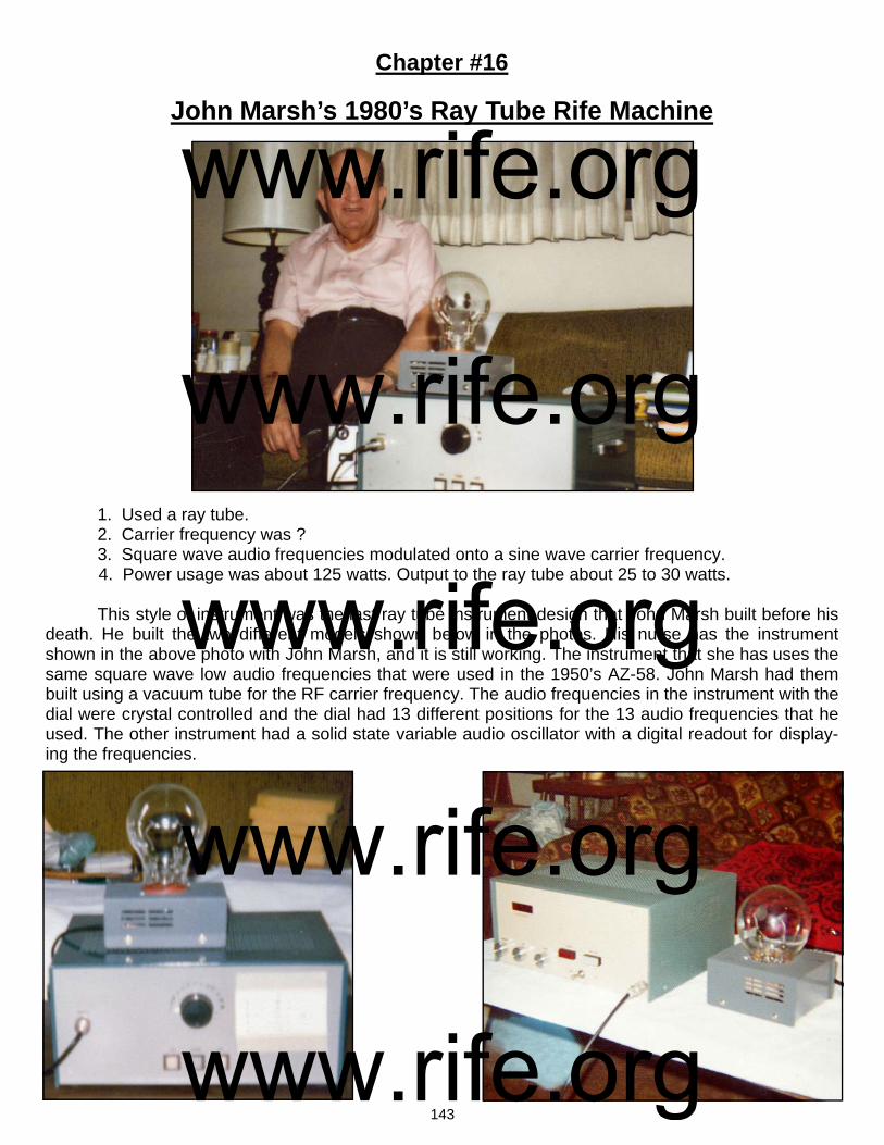
143
Chapter #16
John Marsh’s 1980’s Ray Tube Rife Machine 1. Used a ray tube. 2. Carrier frequency was ? 3. Square wave audio frequencies modulated onto a sine wave carrier frequency. 4. Power usage was about 125 watts. Output to the ray tube about 25 to 30 watts. This style of instrument was the last ray tube instrument design that John Marsh built before his death. He built the two different models shown below in the photos. His nurse has the instrument shown in the above photo with John Marsh, and it is still working. The instrument that she has uses the same square wave low audio frequencies that were used in the 1950’s AZ-58. John Marsh had them built using a vacuum tube for the RF carrier frequency. The audio frequencies in the instrument with the dial were crystal controlled and the dial had 13 different positions for the 13 audio frequencies that he used. The other instrument had a solid state variable audio oscillator with a digital readout for display-ing the frequencies.
www.rife.org www.rife.org www.rife.org www.rife.org www.rife.org
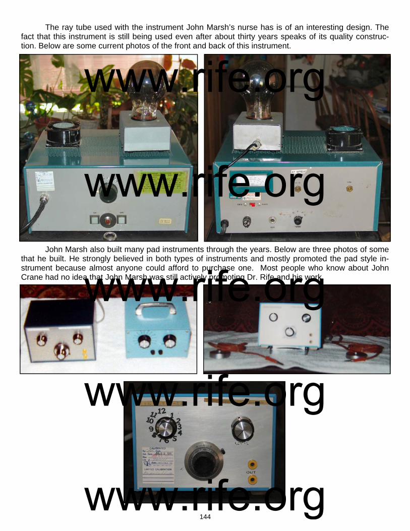
144
The ray tube used with the instrument John Marsh’s nurse has is of an interesting design. The fact that this instrument is still being used even after about thirty years speaks of its quality construc-tion. Below are some current photos of the front and back of this instrument.
John Marsh also built many pad instruments through the years. Below are three photos of some that he built. He strongly believed in both types of instruments and mostly promoted the pad style in-strument because almost anyone could afford to purchase one. Most people who know about John Crane had no idea that John Marsh was still actively promoting Dr. Rife and his work.
www.rife.org www.rife.org www.rife.org www.rife.org www.rife.org
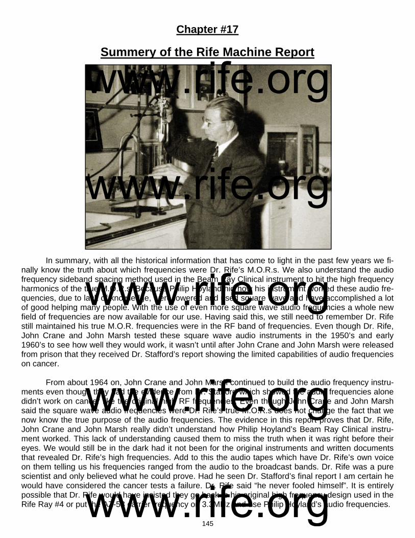
145
Chapter #17
Summery of the Rife Machine Report
In summary, with all the historical information that has come to light in the past few years we fi-nally know the truth about which frequencies were Dr. Rife’s M.O.R.s. We also understand the audio frequency sideband spacing method used in the Beam Ray Clinical instrument to hit the high frequency harmonics of the true M.O.R.s. Because Philip Hoyland hid how his instrument worked these audio fre-quencies, due to lack of knowledge, were lowered and used square wave and have accomplished a lot of good helping many people. With the use of even more square wave audio frequencies a whole new field of frequencies are now available for our use. Having said this, we still need to remember Dr. Rife still maintained his true M.O.R. frequencies were in the RF band of frequencies. Even though Dr. Rife, John Crane and John Marsh tested these square wave audio instruments in the 1950’s and early 1960’s to see how well they would work, it wasn’t until after John Crane and John Marsh were released from prison that they received Dr. Stafford’s report showing the limited capabilities of audio frequencies on cancer. From about 1964 on, John Crane and John Marsh continued to build the audio frequency instru-ments even though they had the evidence from Dr. Stafford which showed the audio frequencies alone didn’t work on cancer like the original high RF frequencies. Even though John Crane and John Marsh said the square wave audio frequencies were Dr. Rife’s true M.O.R.s does not change the fact that we now know the true purpose of the audio frequencies. The evidence in this report proves that Dr. Rife, John Crane and John Marsh really didn’t understand how Philip Hoyland’s Beam Ray Clinical instru-ment worked. This lack of understanding caused them to miss the truth when it was right before their eyes. We would still be in the dark had it not been for the original instruments and written documents that revealed Dr. Rife’s high frequencies. Add to this the audio tapes which have Dr. Rife’s own voice on them telling us his frequencies ranged from the audio to the broadcast bands. Dr. Rife was a pure scientist and only believed what he could prove. Had he seen Dr. Stafford’s final report I am certain he would have considered the cancer tests a failure. Dr. Rife said “he never fooled himself”. It is entirely possible that Dr. Rife would have insisted they go back to his original high frequency design used in the Rife Ray #4 or put the AZ-58 carrier frequency on 3.3MHz and use Philip Hoyland’s audio frequencies.
www.rife.org www.rife.org www.rife.org www.rife.org www.rife.org

146
The most important information that has been obtained from the original Beam Ray Clinical in-strument and Aubrey Scoon’s Beam Ray replica instrument is the fact that the audio frequencies used in these instruments had nothing to do with the treatment of disease. To put it bluntly, all of us have been led down the primrose path because we did not understand how the Beam Ray Clinical instru-ment worked. The mistakes made have major implications since the audio frequencies used with the AZ-58 (120, 660, 712, 727, 776, 784, 800, 803, 880, 1552, 1862, 2008 and 2128 Hertz) have no ability to eliminate the diseases we thought they would eliminate. In all reality these audio frequencies should be replaced with audio frequencies that are true harmonics of Dr. Rife’s original high frequency M.O.R.s instead of clinging to the old dogma. Those who are really trying to do what Dr. Rife did should no longer promote the concept that these AZ-58 audio frequencies are M.O.R.s and by so doing put many people at risk. The best frequencies to use would always be the original high frequency M.O.R.s followed by lower audio frequencies that are exact lower harmonics of the high RF frequencies. For the most accurate list of Dr. Rife’s original high RF frequencies go to the chart on page 98 and read the column labeled “Rife Ray #4 Frequencies Based On Scoon’s Audio Frequencies.” These frequencies were set by Philip Hoyland in Dr. Rife’s lab using his microscope. Hopefully this information will help make a change and in the future we will begin to see what Dr. Rife’s original high frequency M.O.R.s will do. Many helpful sources have provided the records and re-sources so this new information could be brought to light: the release of the John Marsh information from John Marsh’s nurse; the Beam Ray Trial Papers from Steven Ross; the many photos from Jason Ringas of the Rife Research Group of Canada; the great benefit from Dr. Larry Low who allowed us to purchase the original Beam Ray Clinical instrument; the British Rife group and their work on the Aubrey Scoon replica instrument; the help of James Cunningham along with the great detective work done by James Peters in figuring out that Dr. Rife was using the Kennedy company Model 110, 220 and 281 receivers. We also want to recognize the great work Jim Peters did on the schematic of Dr. Gruners original Beam Ray Laboratory instrument. His recognition of the second variable Hartley Oscillator made it possible to rebuild an instrument that works like the original Beam Ray Laboratory instrument. The spectrum analyzing of these machines has finally given us the answers to how all these dif-ferent instruments really worked. I believe the recognition of the Kennedy equipment and the locating of the 1930’s Beam Ray Clinical instrument along with the Gruner instrument schematic correction and rebuilding are three of the greatest pieces of information we have yet discovered about Dr. Rife. No longer are we guessing in the dark. We have purchased the Kennedy Company equipment Models 110, 220 and 281 along with the original Beam Ray Clinical instrument. We plan on doing more exten-sive spectrum analysis work on this equipment. We have built, into one case, the Beam Ray Clinical and Laboratory instrument designs. We wish also to give special thanks to Henry Rogers the owner of the Western Historic Radio Museum (www.radioblvd.com). He allowed us the opportunity to come and test the Kennedy receivers that he owns. As more information comes out we will update this article as necessary. For those who would like a complete list of Dr. Rife’s frequencies output by the Kennedy equip-ment, Rife Ray #4, Philip Hoyland Beam Ray Clinical instrument and Aubrey Scoon’s 1940’s Beam Ray replica instrument we have a chart of them on page 142. Also included on page 41 is a chart of the audio frequencies that can be used with Philip Hoyland’s 3.3 Megahertz carrier frequency to produce Dr. Rife’s M.O.R. frequencies. None of the sets of the low audio frequencies are true M.O.R.s and were originally used to cre-ate the proper sideband spacing frequencies. The square wave audio frequencies used by the AZ-58 were used in a different manner or method relying only upon the harmonics from the square wave waveform. This method has been used with very good results over the past 50 years by many people, but, these audio frequencies have never produced the true M.O.R. effect of devitalizing organisms. The correct high RF M.O.R.s are the frequencies that should be used since we know what these frequen-
www.rife.org www.rife.org www.rife.org www.rife.org www.rife.org

147
cies are. If people are determined to use the lower audio and ultrasonic range of frequencies below 50,000 Hertz then they should at least use the highest harmonic frequency of the true M.O.R. that they can use within the limits of the equipment they are using. At the very least we should make sure that all frequencies used are true harmonics of the fundamental M.O.R.s that Dr. Rife found.
www.rifevideos.com Copyright © 2003 & 2011
All rights reserved.
www.rife.org www.rife.org www.rife.org www.rife.org www.rife.org
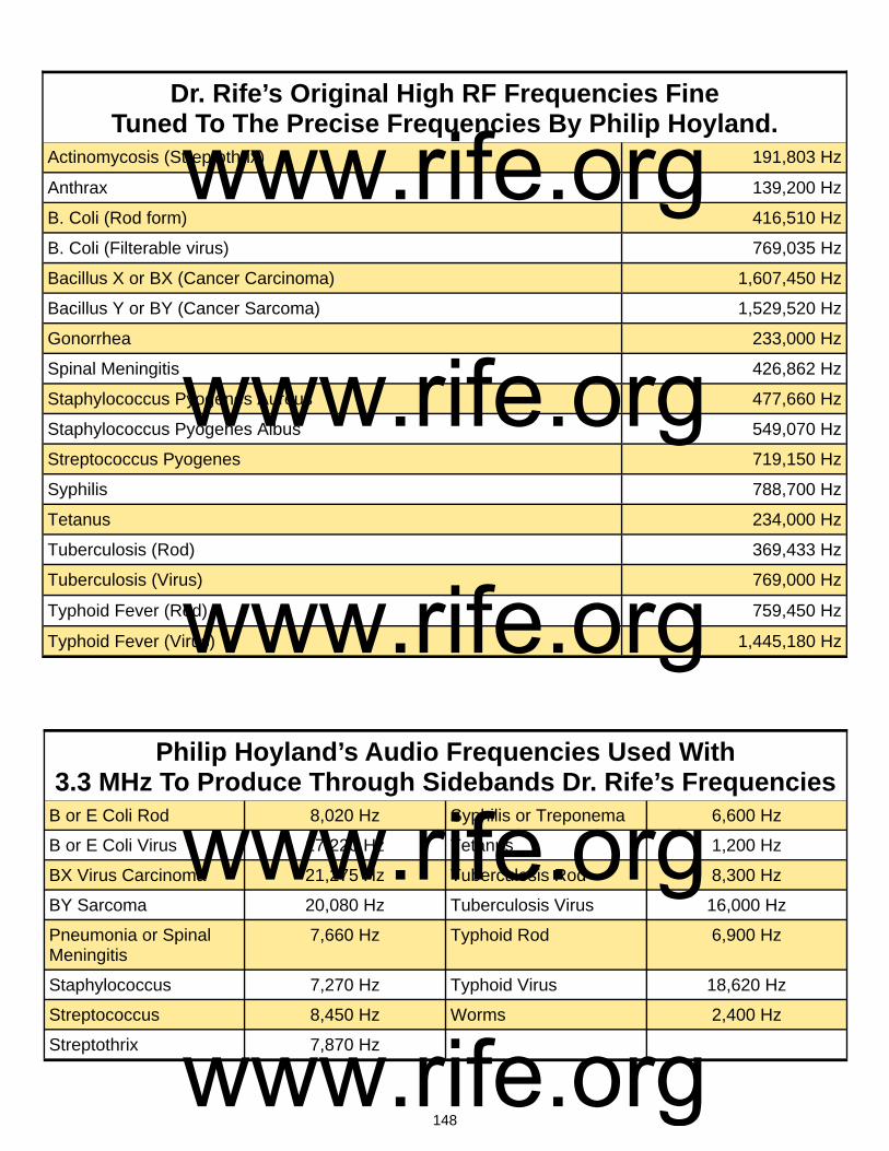
148
Actinomycosis (Streptothrix) 191,803 Hz
Anthrax 139,200 Hz
B. Coli (Rod form) 416,510 Hz
B. Coli (Filterable virus) 769,035 Hz
Bacillus X or BX (Cancer Carcinoma) 1,607,450 Hz
Bacillus Y or BY (Cancer Sarcoma) 1,529,520 Hz
Gonorrhea 233,000 Hz
Spinal Meningitis 426,862 Hz
Staphylococcus Pyogenes Aureus 477,660 Hz
Staphylococcus Pyogenes Albus 549,070 Hz
Streptococcus Pyogenes 719,150 Hz
Syphilis 788,700 Hz
Tetanus 234,000 Hz
Tuberculosis (Rod) 369,433 Hz
Typhoid Fever (Rod) 759,450 Hz
Dr. Rife’s Original High RF Frequencies Fine Tuned To The Precise Frequencies By Philip Hoyland.
Tuberculosis (Virus) 769,000 Hz
Typhoid Fever (Virus) 1,445,180 Hz
Philip Hoyland’s Audio Frequencies Used With 3.3 MHz To Produce Through Sidebands Dr. Rife’s Frequencies
B or E Coli Rod 8,020 Hz Syphilis or Treponema 6,600 Hz
B or E Coli Virus 17,220 Hz Tetanus 1,200 Hz
BX Virus Carcinoma 21,275 Hz Tuberculosis Rod 8,300 Hz
BY Sarcoma 20,080 Hz Tuberculosis Virus 16,000 Hz
Pneumonia or Spinal Meningitis
7,660 Hz Typhoid Rod 6,900 Hz
Staphylococcus 7,270 Hz Typhoid Virus 18,620 Hz
Streptococcus 8,450 Hz Worms 2,400 Hz
Streptothrix 7,870 Hz
www.rife.org www.rife.org www.rife.org www.rife.org www.rife.org

149
Philip Hoyland’s New M.O.R.s. Used In The Beam Ray Clinical Instrument.
B or E Coli Rod 3,332,080 Hz Streptothrix 3,260,650 Hz
B or E Coli Virus 3,076,140 Hz Syphilis or Treponema 3,154,800 Hz
BX Virus Carcinoma 3,214,900 Hz Tetanus 3,276,000 Hz
BY Sarcoma 3,059,040 Hz Tuberculosis Rod 3,324,897 Hz
Gonorrhea 3,262,000 Hz Tuberculosis Virus 3,076,000 Hz
Pneumonia or Spinal Meningitis
3,414,900 Hz Typhoid Rod 3,037,800 Hz
Staphylococcus 3,343,620 Hz Typhoid Virus 2,890,360 Hz
Streptococcus 3,595,750 Hz
www.rife.org www.rife.org www.rife.org www.rife.org www.rife.org
Related Documents