RHD 128-Channel Headstage www.intantech.com ● [email protected] 1 intan TECHNOLOGIES, LLC RHD 128-Channel Headstage 24 February 2015; updated 31 January 2020 Features ♦ Small (35 mm x 21 mm x 4 mm), lightweight (2.05 g) circuit board containing two RHD2164 64-channel amplifier chips from Intan Technologies ♦ Waveforms from 128 electrode channels (electrodes not included) are digitized and transferred over a single serial peripheral interface (SPI) cable ♦ Integrated electrode impedance measurement capability ♦ In situ constant-voltage or constant-current electroplating capability using optional RHD Electroplating Board ♦ Compatible with UCLA silicon microprobes; open board design with inexpensive connectors permit other electrodes to be adapted to board ♦ Dual mounting holes for mechanical stability Applications ♦ High density neural recording ♦ High-channel-count electrode characterization and electroplating Description The RHD 128-channel headstage is the highest density recording module available from Intan Technologies. It is compatible with the RHD Recording System, which can support multiple boards operating simultaneously. Each 128 channel headstage requires only one serial peripheral interface (SPI) cable to provide power and data communication with an RHD controller. (Although the RHD USB interface board has four SPI interface connecters, it can support only two of these 128-channel headstages due to the 256 channel count limit imposed by the bandwidth limit of the USB 2.0 connection to the host computer. The 512- channel RHD recording controller can support four of these headstages; the 1024-channel RHD recording controller can support eight.) This 35 mm x 21 mm x 4 mm device weighs 2.05 grams and contains two Intan Technologies RHD2164 64-channel digital electrophysiology interface chips. These chips amplify, filter, and digitize microvolt-level waveforms from 128 electrode channels, serialize this data, and transfer it over a thin SPI cable where it can be viewed and recorded using open-source software from Intan Technologies. The chips also permit in situ measurements of all electrode impedances. Two standard 64-pin Molex connectors provide connection points for an electrode array. Reference and/or ground electrodes may be connected to one of two solder holes on the board. A 12-pin Omnetics connector at the rear of the board provides a connection point for a standard Intan SPI interface cable. Two mounting holes with a center-to-center spacing of 6.0 mm provide a mechanical connection point. These holes each have a diameter of 60 mils (1.52 mm). intan TECHNOLOGIES, LLC

Welcome message from author
This document is posted to help you gain knowledge. Please leave a comment to let me know what you think about it! Share it to your friends and learn new things together.
Transcript

RHD 128-Channel Headstage
www.intantech.com ● [email protected] 1
intan TECHNOLOGIES, LLC
RHD
128-Channel Headstage
24 February 2015; updated 31 January 2020
Features ♦ Small (35 mm x 21 mm x 4 mm), lightweight (2.05 g)
circuit board containing two RHD2164 64-channel amplifier chips from Intan Technologies
♦ Waveforms from 128 electrode channels (electrodes not included) are digitized and transferred over a single serial peripheral interface (SPI) cable
♦ Integrated electrode impedance measurement capability
♦ In situ constant-voltage or constant-current electroplating capability using optional RHD Electroplating Board
♦ Compatible with UCLA silicon microprobes; open board design with inexpensive connectors permit other electrodes to be adapted to board
♦ Dual mounting holes for mechanical stability
Applications ♦ High density neural recording ♦ High-channel-count electrode characterization and
electroplating
Description The RHD 128-channel headstage is the highest density recording module available from Intan Technologies. It is compatible with the RHD Recording System, which can support multiple boards operating simultaneously. Each 128 channel headstage requires only one serial peripheral interface (SPI) cable to provide power and data communication with an RHD controller. (Although the RHD USB interface board has four SPI interface connecters, it can support only two of these 128-channel headstages due to the 256 channel count limit imposed by the bandwidth limit of the USB 2.0 connection to the host computer. The 512-channel RHD recording controller can support four of these headstages; the 1024-channel RHD recording controller can support eight.)
This 35 mm x 21 mm x 4 mm device weighs 2.05 grams and contains two Intan Technologies RHD2164 64-channel digital electrophysiology interface chips. These chips amplify, filter, and digitize microvolt-level waveforms from 128 electrode channels, serialize this data, and transfer it over a thin SPI cable where it can be viewed and recorded using open-source software from Intan Technologies. The chips also permit in situ measurements of all electrode impedances.
Two standard 64-pin Molex connectors provide connection points for an electrode array. Reference and/or ground electrodes may be connected to one of two solder holes on the board. A 12-pin Omnetics connector at the rear of the board provides a connection point for a standard Intan SPI interface cable. Two mounting holes with a center-to-center spacing of 6.0 mm provide a mechanical connection point. These holes each have a diameter of 60 mils (1.52 mm).
intan TECHNOLOGIES, LLC

RHD 128-Channel Headstage
www.intantech.com ● [email protected] 2
intan TECHNOLOGIES, LLC
Electroplating Capability Because few commercially-available 128-channel electrode arrays currently exist, this headstage was built to support in situ electroplating of electrodes to support users building or customizing their own electrodes. Electroplating is a common electrochemical process used to lower the impedance of microelectrodes by depositing a metal coating onto recording sites from an ionic solution. Common metals used in the electroplating of microelectrodes include gold, platinum, and iridium.
A six-pin Omnetics connector near the SPI connector connects to the optional RHD Electroplating Board, which provides constant-voltage pulses (in the range of ±3.3V) or
constant-current pulses (in the range of ±10 µA) that are steered to individual electrode sites to facilitate electroplating. Intan Technologies has developed free, automated, GUI-controlled software for plating electrodes to desired impedances. The software operates on Windows or Mac. The datasheet for the RHD Electroplating Board (available at the Intan Technologies website) describes operation of the electroplating software in detail.
If pre-electroplated electrodes are being used with the 128-channel headstage then there is no need for the RHD Electroplating Board and associated software. All that is needed is an RHD controller and an SPI interface cable.
Top View
The RHD 128-channel headstage is shown here with key components labeled. Two 64-pin Molex connectors are used for electrode connections. The amplifier channel order (indexed from 0 to 127 to remain consistent with Intan data acquisition software) is marked on the circuit board at the four corner pins of each connector. The connectors used on the headstage are Molex SlimStack board-to-board connectors with 0.4-mm pitch and a height of 1.0 mm (Molex part number 502426-6410; Digi-Key part number WM24076-ND). The corresponding mating connectors to be used on an electrode board are Molex part number 502430-6410 (Digi-Key part number WM24084-ND; Mouser Electronics part number 538-502430-6410). The center-to-center spacing of these two connectors is 8.8646 mm (0.349 inches). A printed circuit board with 2-mil (50 µm) traces and 2-mil spacing is required to route signals from the RHD2164 chips to these connectors.
It is important to note that these Molex connectors, like virtually all small, dense connectors on the market today, are only rated for a small number of plug-unplug cycles (i.e., 15-20). These numbers cited by the manufacturer are typically very conservative, and Intan adds epoxy to the ends of these connectors to further strengthen them. Still, it is recommended to minimize the number of plug-unplug cycles on these connectors in order to maximize the life of the headstage.

RHD 128-Channel Headstage
www.intantech.com ● [email protected] 3
intan TECHNOLOGIES, LLC
Bottom View
The bottom of the RHD 128-channel headstage contains a 74HC4053 integrated circuit containing three CMOS switches used for electroplating control. It also contains part R0: a zero-ohm jumper that shorts the reference electrode (REF) to ground (GND). Note that this part must remain in place during electroplating. This jumper may be removed for recordings if an independent reference is desired, but most users of Intan headstages obtain excellent recording quality with this part in place (i.e., the reference electrode shorted to ground). Soldering tweezers are the best tool for de-soldering or re-soldering this part.
The RHD 128-channel headstage contains solder holes for connecting reference and/or ground electrodes. A low-impedance reference electrode (typically a platinum or Ag/AgCl wire) should be used for all recording configurations. If R0 has been removed, then the tissue should also be connected to ground (GND) somehow (e.g., a skull screw). During electroplating, the ionic plating solution bath must be connected to REF, not to GND. For more information, see the RHD Electroplating Board datasheet.
The power supply voltage of approximately +3.3V is available at the VDD solder hole. This can be used to add an LED or other active device to the headstage, though devices that pull large amounts of current may cause excessive voltage drops over long SPI cables. For more information, see the RHD Application Note: Adding an LED to headstages.
Two mounting holes are available for mechanical attachment. Although they are metal plated, they are electrically isolated from the circuitry in the board.
Probe Design The photo on the right shows a 128-channel UCLA silicon microprobe developed by Prof. Sotiris Masmanidis. The probe is wire-bonded and epoxied to a printed circuit board with two Molex SlimStack 502430-6410 connector spaced exactly 8.8646 mm (0.349 inches) apart. This probe mates with the RHD 128-channel headstage.
See https://masmanidislab.neurobio.ucla.edu/ technology.html for more information.

RHD 128-Channel Headstage
www.intantech.com ● [email protected] 4
intan TECHNOLOGIES, LLC
The photo above shows a 64-channel UCLA silicon microprobe. One of these probes may be connected to either Molex connector on the RHD 128-channel headstage.
The photo above shows a 256 channel UCLA silicon microprobe. Two RHD 128-channel headstages may be connected to this probe (one on either side) to fully instrument all 256 recording sites.
Circuit Design Serial Peripheral Interface The RHD 128-channel headstage uses all 12 wires in the SPI interface cable to power and communicate with two RHD2164 chips. The diagram below shows a simplified version of the LVDS (low voltage differential signaling) SPI buses used on the board. Both chips receive the same commands, but they send data back on two MISO (master in, slave out) paths. More information on this communication method may be found in the RHD2000 Series Datasheet, the RHD2164 Datasheet, and the RHD SPI cable/connector specification. All documents may be found on the Downloads page at the Intan Technologies website.
RHD 128-Channel Headstage
www.intantech.com ● [email protected] 5
intan TECHNOLOGIES, LLC
Electroplating Control The above diagram shows circuit connections that are relevant for the electroplating capability of the RHD 128-channel headstage. The VESD pin of each RHD2164 chip is tied to the positive power supply (VDD) which allows the DC input levels at each electrode to range between ground and +3.3 V without activating the on-chip ESD (electrostatic discharge) protection diodes. A 74HC4053 integrated circuit on the bottom of the circuit board contains three CMOS switches that are used for electroplating control. The RHD Electroplating Board provides two analog signals (bath V and plating V/I) and three digital signals (ref select, A select, and B select) to the headstage.
The A select and B select signals connect the elec_test pin from either RHD2164 chip to the plating V/I pin, which supplies a DC voltage or current used for electroplating. (A select and B select should never be high at the same time, and they should both be low during normal amplifier operation or impedance measurement.) The voltage on plating V/I should always remain between ground and +3.3 V. Switches internal to each RHD2164 chip route the signal from plating V/I to one selected electrode. See the RHD2000 Series datasheet for more details.
The ref select signal connects the amplifier reference input, as well as the electroplating solution (which should be connected to the REF pin with a low-impedance wire) to the analog voltage bath V. This voltage must be set between ground and +3.3 V, which allows the electrodes to be plated used negative voltages (with respect to the plating solution). The ref select signal should always be low during normal amplifier operation or impedance measurement. See the RHD Electroplating Board datasheet for more information on these procedures.
The headstage contains pull-down resistors to ensure that the CMOS switches remain in the positions shown above when the electroplating control cable is unconnected. These default positions disable plating and allow the chips to operate normally for amplifier and impedance measurement functions when not connected to the electroplating control board.
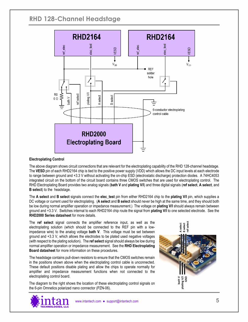
The diagram to the right shows the location of these electroplating control signals on the 6-pin Omnetics polarized nano connector (PZN-06).

RHD 128-Channel Headstage
www.intantech.com ● [email protected] 6
intan TECHNOLOGIES, LLC
Related RHD System Documentation The following supporting datasheets may be found at http://www.intantech.com/downloads:
♦ RHD2000 Series Digital Electrophysiology Interface Chips
♦ RHD2164 Digital Electrophysiology Interface Chip ♦ RHD Electroplating Board ♦ RHD Recording System User Guide ♦ RHD USB/FPGA Interface: Rhythm ♦ RHD SPI Cable/Connector Specification Application Notes:
♦ RHD Application Note: Data File Formats ♦ RHD Application Note: I/O Voltage Level Shifting ♦ RHD Application Note: Adapting SPI Cables to a
Commutator ♦ RHD Application Note: Adding an LED to
Headstages Schematics of all circuit boards are available from Intan Technologies.
Contact Information
This datasheet is meant to acquaint engineers and scientists with the RHD 128-channel headstage developed at Intan Technologies. We value feedback from potential end users. We can discuss your specific needs and suggest a solution tailored to your applications.
For more information, contact Intan Technologies.
www.intantech.com [email protected]
© 2015-2020 Intan Technologies, LLC Information furnished by Intan Technologies is believed to be accurate and reliable. However, no responsibility is assumed by Intan Technologies for its use, nor for any infringements of patents or other rights of third parties that may result from its use. Specifications subject to change without notice. Intan Technologies assumes no liability for applications assistance or customer product design. Customers are responsible for their products and applications using Intan Technologies components. To minimize the risks associated with customer products and applications, customers should provide adequate design and operating safeguards.
Intan Technologies’ products are not authorized for use as critical components in life support devices or systems. A critical component is any component of a life support device or system whose failure to perform can be reasonably expected to cause the failure of the life support device or system, or to affect its safety or effectiveness.
intan TECHNOLOGIES, LLC
Related Documents