This document is downloaded from DR‑NTU (https://dr.ntu.edu.sg) Nanyang Technological University, Singapore. Review of selective laser melting : materials and applications Yap, Chor Yen; Chua, Chee Kai; Dong, Zhi Li; Liu, Zhong Hong; Zhang, Dan Qing; Loh, Loong Ee; Sing, Swee Leong 2015 Yap, C. Y., Chua, C. K., Dong, Z. L., Liu, Z. H., Zhang, D. Q., Loh, L. E., & Sing, S. L. (2015). Review of selective laser melting : materials and applications. Applied Physics Reviews, 2(4), 041101‑. doi:10.1063/1.4935926 https://hdl.handle.net/10356/87847 https://doi.org/10.1063/1.4935926 © 2015 AIP Publishing LLC. This paper was published in Applied Physics Reviews and is made available as an electronic reprint (preprint) with permission of AIP Publishing LLC. The published version is available at: [http://dx.doi.org/10.1063/1.4935926]. One print or electronic copy may be made for personal use only. Systematic or multiple reproduction, distribution to multiple locations via electronic or other means, duplication of any material in this paper for a fee or for commercial purposes, or modification of the content of the paper is prohibited and is subject to penalties under law. Downloaded on 26 Jan 2022 23:40:39 SGT

Welcome message from author
This document is posted to help you gain knowledge. Please leave a comment to let me know what you think about it! Share it to your friends and learn new things together.
Transcript

This document is downloaded from DR‑NTU (https://dr.ntu.edu.sg)Nanyang Technological University, Singapore.
Review of selective laser melting : materials andapplications
Yap, Chor Yen; Chua, Chee Kai; Dong, Zhi Li; Liu, Zhong Hong; Zhang, Dan Qing; Loh, LoongEe; Sing, Swee Leong
2015
Yap, C. Y., Chua, C. K., Dong, Z. L., Liu, Z. H., Zhang, D. Q., Loh, L. E., & Sing, S. L. (2015).Review of selective laser melting : materials and applications. Applied Physics Reviews,2(4), 041101‑. doi:10.1063/1.4935926
https://hdl.handle.net/10356/87847
https://doi.org/10.1063/1.4935926
© 2015 AIP Publishing LLC. This paper was published in Applied Physics Reviews and ismade available as an electronic reprint (preprint) with permission of AIP Publishing LLC.The published version is available at: [http://dx.doi.org/10.1063/1.4935926]. One print orelectronic copy may be made for personal use only. Systematic or multiple reproduction,distribution to multiple locations via electronic or other means, duplication of any materialin this paper for a fee or for commercial purposes, or modification of the content of thepaper is prohibited and is subject to penalties under law.
Downloaded on 26 Jan 2022 23:40:39 SGT
APPLIED PHYSICS REVIEWS—FOCUSED REVIEW
Review of selective laser melting: Materials and applications
C. Y. Yap,1,2,a) C. K. Chua,1,b) Z. L. Dong,3,c) Z. H. Liu,1,d) D. Q. Zhang,1,e) L. E. Loh,1,f)
and S. L. Sing1,g)
1Singapore Centre for 3D Printing, School of Mechanical and Aerospace Engineering,Nanyang Technological University, 50 Nanyang Avenue, Block N3.1 - B2c - 01, Singapore 6397982Energy Research Institute @ NTU, Interdisciplinary Graduate School, Nanyang Technological University,50 Nanyang Avenue, Block S2 - B3a - 01, Singapore 6397983School of Materials Science & Engineering, Nanyang Technological University, 50 Nanyang Avenue,Block N4.1, Singapore 639798
(Received 14 July 2015; accepted 23 October 2015; published online 9 December 2015)
Selective Laser Melting (SLM) is a particular rapid prototyping, 3D printing, or Additive
Manufacturing (AM) technique designed to use high power-density laser to melt and fuse metallic
powders. A component is built by selectively melting and fusing powders within and between layers.
The SLM technique is also commonly known as direct selective laser sintering, LaserCusing, and
direct metal laser sintering, and this technique has been proven to produce near net-shape parts up to
99.9% relative density. This enables the process to build near full density functional parts and has
viable economic benefits. Recent developments of fibre optics and high-power laser have also
enabled SLM to process different metallic materials, such as copper, aluminium, and tungsten.
Similarly, this has also opened up research opportunities in SLM of ceramic and composite materials.
The review presents the SLM process and some of the common physical phenomena associated with
this AM technology. It then focuses on the following areas: (a) applications of SLM materials and
(b) mechanical properties of SLM parts achieved in research publications. The review is not meant to
put a ceiling on the capabilities of the SLM process but to enable readers to have an overview on
the material properties achieved by the SLM process so far. Trends in research of SLM are also
elaborated in the last section. VC 2015 AIP Publishing LLC. [http://dx.doi.org/10.1063/1.4935926]
TABLE OF CONTENTS
I. INTRODUCTION . . . . . . . . . . . . . . . . . . . . . . . . . . . . 1
A. Background on selective laser melting . . . . . 2
B. Scope. . . . . . . . . . . . . . . . . . . . . . . . . . . . . . . . . . 3
II. PHYSICAL PHENOMENA IN SLM . . . . . . . . . . . 3
A. Laser and material interaction. . . . . . . . . . . . . 3
B. Balling. . . . . . . . . . . . . . . . . . . . . . . . . . . . . . . . . 4
C. Thermal fluctuation and its effects . . . . . . . . . 5
III. METALS IN SLM AND THEIR
APPLICATION . . . . . . . . . . . . . . . . . . . . . . . . . . . . . 6
A. Steel and iron-based alloys . . . . . . . . . . . . . . . 6
1. Applications . . . . . . . . . . . . . . . . . . . . . . . . . 7
2. Properties . . . . . . . . . . . . . . . . . . . . . . . . . . . 8
B. Titanium and its alloys. . . . . . . . . . . . . . . . . . . 9
1. Applications . . . . . . . . . . . . . . . . . . . . . . . . . 9
2. Properties . . . . . . . . . . . . . . . . . . . . . . . . . . . 10
C. Inconel and nickel-based alloys . . . . . . . . . . . 10
1. Applications . . . . . . . . . . . . . . . . . . . . . . . . . 10
2. Properties . . . . . . . . . . . . . . . . . . . . . . . . . . . 11
D. Other metals. . . . . . . . . . . . . . . . . . . . . . . . . . . . 11
1. Applications . . . . . . . . . . . . . . . . . . . . . . . . . 12
2. Properties . . . . . . . . . . . . . . . . . . . . . . . . . . . 13
d. Micro-hardness . . . . . . . . . . . . . . . . . . . . 13
IV. CERAMICS . . . . . . . . . . . . . . . . . . . . . . . . . . . . . . . . 13
A. Applications . . . . . . . . . . . . . . . . . . . . . . . . . . . . 13
1. Medical and dental applications. . . . . . . . . 13
B. Properties . . . . . . . . . . . . . . . . . . . . . . . . . . . . . . 14
1. Relative density . . . . . . . . . . . . . . . . . . . . . . 14
2. Strength . . . . . . . . . . . . . . . . . . . . . . . . . . . . . 14
3. Surface roughness. . . . . . . . . . . . . . . . . . . . . 14
V. COMPOSITES . . . . . . . . . . . . . . . . . . . . . . . . . . . . . . 14
A. Applications . . . . . . . . . . . . . . . . . . . . . . . . . . . . 14
1. Medical implants . . . . . . . . . . . . . . . . . . . . . 15
2. Aerospace and automotive . . . . . . . . . . . . . 15
3. Other applications . . . . . . . . . . . . . . . . . . . . 15
B. Properties . . . . . . . . . . . . . . . . . . . . . . . . . . . . . . 15
1. Relative density . . . . . . . . . . . . . . . . . . . . . . 15
2. Strength . . . . . . . . . . . . . . . . . . . . . . . . . . . . . 15
3. Micro-hardness and wear rate . . . . . . . . . . 15
VI. SUMMARY AND REAEARCH TRENDS . . . . . 16
a)[email protected])Author to whom correspondence should be addressed. Electronic mail:
[email protected]. Ph. +65 6790 5486c)[email protected])[email protected])[email protected])[email protected])[email protected]
1931-9401/2015/2(4)/041101/21/$30.00 VC 2015 AIP Publishing LLC2, 041101-1
APPLIED PHYSICS REVIEWS 2, 041101 (2015)
I. INTRODUCTION
A. Background on selective laser melting
Selective Laser Melting (SLM) is an additive manufac-
turing process developed by Dr. M. Fockele and Dr. D.
Schwarze of F & S Stereolithographietechnik GmbH, with
Dr. W. Meiners, Dr. K. Wissenbach, and Dr. G. Andres of
Fraunhofer ILT to produce metal components from metallic
powders. It is a powder bed fusion process that uses high in-
tensity laser as an energy source to melt and fuse selective
regions of powder, layer by layer, according to computer
aided design (CAD) data. The patent for this technology was
first applied in 1997 to the German Patent and Trade Mark
Office and published in 1998.1 In 2001, patent was also filed
by Das and Beaman based on their pioneering works in
direct selective laser sintering (SLS).2
The SLM process consists of a series of steps from CAD
data preparation to removal of fabricated component from
the building platform. Before the CAD data are uploaded to
the SLM machine for production of components, the
STereoLithography (STL) files have to be processed by soft-
ware, such as Magics, to provide support structures for any
overhanging features and to generate slice data for laser
scanning of individual layers. The building process starts
with laying a thin layer of metal powder on a substrate plate
in a building chamber. After the powder is laid, a high
energy density laser is used to melt and fuse selected areas
according to the processed data. Once the laser scanning is
completed, the building platform is lowered, a next layer of
powder is deposited on top and the laser scans a new layer.
The process is then repeated for successive layers of powder
until the required components are completely built.3 Process
parameters, such as laser power, scanning speed, hatch spac-
ing, and layer thickness, are adjusted such that a single melt
vector can fuse completely with the neighbouring melt vec-
tors and the preceding layer. Once the laser scanning process
is completed, loose powders are removed from the building
chamber and the component can be separated from the sub-
strate plate manually or by electrical discharge machining
(EDM). Besides the data preparation and removal of fabri-
cated component from the building platform, the entire pro-
cess is automated. Figure 1 illustrates the concept of the
SLM building process.
During the SLM process, the building chamber is often
filled with nitrogen gas or argon gas to provide an inert
atmosphere to protect the heated metal parts against oxida-
tion. Furthermore, some of the SLM machines are capable of
providing pre-heating either to the substrate plate or the
entire building chamber. The thickness of the layer usually
ranges from 20 to 100 lm. This is chosen as a balance
between achieving fine resolution and allowing for good
powder flowability.4 Powders with larger particulate sizes
result in poor resolution and build tolerance, while smaller
powders have the tendency to agglomerate together easily
due to van der Waals forces, resulting in poor powder flow-
ability and hence poor powder deposition.
Literatures have shown that SLM is capable of fully
melting the powder material, producing fully dense near
net-shape components without the need for post-processing,
other than the removal of parts and supports from substrate
plate. This makes SLM a superior Additive Manufacturing
(AM) process compared to SLS, which binds powder mate-
rials via solid state sintering or melting of binding agents,
resulting in parts with high porosity and low strength. Post-
processing, such as heat treatment and material infiltration,
usually needed to improve the SLS components, is time
consuming and significantly lengthens the process. In
SLM, full melting of powder is achieved by the use of
high-intensity laser and binder materials are not required,
eliminating the need for the above-mentioned downstream
processes. The current SLM technology provides improve-
ments in product quality, processing time, and manufactur-
ing reliability compared to binder-based laser sintering AM
processes.
In addition to direct manufacturing, SLM has also been
adapted to perform repairs on damaged components. The
Direct Digital Manufacturing Lab at Georgia Tech has devel-
oped Scanning Laser Epitaxy (SLE) for additive repair of
FIG. 1. Concept of SLM process. (i) High-power laser melts selective areas of the powder bed. (ii) Process is repeats for successive layers. (iii) Loose powder
removed and finished part revealed.
041101-2 Yap et al. Appl. Phys. Rev. 2, 041101 (2015)
nickel-based alloys CMSX-4,5,6 Rene 80,7 and IN100.8 SLE
requires a small amount of powder for repair, enough to
cover the surface of the damaged part up to 2 mm in powder
thickness. A high power Nd:YAG laser is then deployed to
melt the powder material, covering cracks and holes in the
damaged component.
Other additive manufacturing processes, such as
LaserCusing and Direct Metal Laser Sintering (DMLS), are
essentially the same as SLM. In order to keep this review
focused, publications in which manufacturing processes
involve complete melting of powder bed by laser will be
included and SLM will be the term used to represent these
processes.
B. Scope
This review first presents some of the physical phenom-
ena commonly mentioned in SLM literatures. Sections II–V
are organized according to the materials used, mainly metals,
ceramics and composite materials. Under the category of
metals, the materials are further divided into “steel and iron-
based alloys,” “titanium and its alloys,” “Inconel and nickel-
based alloys,” and “other metals.”
Under each material group, applications of the SLM
materials are elaborated. Moreover, the best properties
achieved, such as highest relative density, highest strength,
highest hardness, and lowest surface roughness, are also
compiled and tabulated for readers to have a quick glance
and for ease of comparison. Relative density of SLM parts is
often examined to determine if all the powders in the compo-
nent have been melted. Strength and hardness are basic ma-
terial properties that can be compared to cast parts to
indicate the suitability of SLM parts for various applications.
Surface roughness determines if post-processes, such as
grinding and polishing, are required. However, it is to note
that these figures do not show the limits of the technology.
Instead, they are meant to demonstrate the progress of
research in the SLM process. Section VI illustrates the trend
of research in SLM and its future outlook.
II. PHYSICAL PHENOMENA IN SLM
SLM involves the heating and melting of powder mate-
rial with laser beam and rapid solidification of the melted ma-
terial to form the desired component. There are several
physical phenomena that are important to the process, such as
the absorptivity of the powder material to laser irradiation, the
balling phenomena that disrupt the formation of continuous
melts, and the thermal fluctuation experienced by the material
during the process that can lead to crack formation and com-
ponent failure. In this section, investigations on these aspects
of SLM are presented to shed light on the physics involved in
the SLM process. Literatures on simulation and numerical
analysis of SLM are beyond the scope of this review.
A. Laser and material interaction
SLM was designed with the intent to heat up and melt
metallic materials. The laser systems for SLM progressed
from CO2 laser (k� 10.6 lm), adapted from the selective
laser sintering process to Nd:YAG fibre laser (k� 1.06 lm)
and subsequently to Yb: YAG fibre laser. This is due to the
higher absorptance of metallic powders to radiation of such
wavelengths in the infrared region. Furthermore, compared
to the commonly used Nd:YAG crystal, Yb:YAG crystal has
a larger absorption bandwidth to reduce thermal manage-
ment requirements for diode lasers, a longer upper-state life-
time, and a lower thermal loading per unit pump power.
Yb:YAG crystal is expected to replace Nd:YAG crystal for
high power diode-pumped lasers and other potential applica-
tions. The advancements in laser technology will continue to
bring about higher energy efficiency to the SLM process.
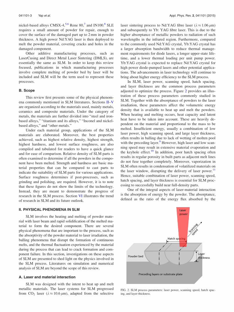
In SLM, laser power, scanning speed, hatch spacing,
and layer thickness are the common process parameters
adjusted to optimize the process. Figure 2 provides an illus-
tration of these process parameters commonly studied in
SLM. Together with the absorptance of powders to the laser
irradiation, these parameters affect the volumetric energy
density that is available to heat up and melt the powders.
When heating and melting occurs, heat capacity and latent
heat have to be taken into account. These are heavily de-
pendent on the material and proportional to the mass to be
melted. Insufficient energy, usually a combination of low
laser power, high scanning speed, and large layer thickness,
often results in balling due to lack of wetting of molten pool
with the preceding layer.9 However, high laser and low scan-
ning speed may result in extensive material evaporation and
the keyhole effect.10 In addition, poor hatch spacing often
results in regular porosity in built parts as adjacent melt lines
do not fuse together completely. Moreover, vaporization in
SLM often results in condensation of volatilized materials on
the laser window, disrupting the delivery of laser power.11
Hence, suitable combination of laser power, scanning speed,
hatch spacing, and layer thickness is essential for SLM proc-
essing to successfully build near full-density parts.
One of the integral aspects of laser-material interaction
is the absorption of energy by the powder. The absorptance,
defined as the ratio of the energy flux absorbed by the
FIG. 2. SLM process parameters: laser power, scanning speed, hatch spac-
ing, and layer thickness.
041101-3 Yap et al. Appl. Phys. Rev. 2, 041101 (2015)

material to the energy flux incident upon the material, affects
the energy efficiency of the SLM process. It can even deter-
mine the feasibility of processing materials with a specific
laser. Physicists have studied the absorptivity of various
materials to irradiation of different wavelengths. However,
few of these works are done with powder materials. In SLM,
laser is irradiated onto a thin powder bed and the absorptivity
of powder materials to laser irradiation can be drastically dif-
ferent from their corresponding bulk materials. Tolochko
et al. investigated the absorptance of powder materials to
infrared irradiation of CO2 laser (wavelength, k¼ 10.6 lm)
and Nd-YAG laser (k¼ 1.06 lm).12 In comparison to the ab-
sorptance of bulk materials with smooth surfaces, powder
materials have significantly higher absorptance regardless of
the wavelength of irradiation. For instance, at k¼ 1.06 lm,
the absorptance of titanium bulk material is 30%,13 while
that of titanium powder is 77%.12
The high absorptance of powder material can be
explained by the multiple reflections of the laser beam in the
powder bed, which also result in higher optical penetration
depth.13 Wang et al. studied this phenomenon with a 2D op-
tical ray tracing model, taking into account the geometry and
structure of the powder.14 In an attempt to model the SLM
process, Gusarov and Kruth compared the effective absorp-
tance of powder bed with the absorptance of bulk material
and match experimental data with both the isotropic specular
reflection model and diffuse reflection model.15 The model,
substantiated by the data, allows for prediction of the absorp-
tance of powder bed based on that of bulk material Figure 3.
Their work provide models to calculate the ratio of the total
absorption with respect to the material absorption and to pre-
dict the optimal laser parameters with which to process a
particular material.
In addition to the studies on absorptance of irradiation
with various materials, there are also research works that
examine the effects of the energy distribution profile of lasers
and the difference between pulsed and continuous lasers. Loh
et al. used AA6061, an aluminium alloy, to examine the differ-
ent effects of Gaussian beam profile and uniform beam profile
in SLM. Their investigation found that a uniform beam laser
was able to achieve a larger melt width for similar amount of
melt penetration. Hence, a uniform beam laser could be used
to increase the productivity of SLM by reducing the hatch
spacing in the process.16 Furthermore, a simplified modelling
of the SLM process based on AA6061 has also been devel-
oped. The numerical model takes into account the volumetric
shrinkage and material loss due to vaporization of the
process.17
Mumtaz and Hopkinson18 reported a study on SLM of
Inconel 625 with pulsed laser. Using the pulsed laser allowed
them to add another dimension of control to the SLM process
as the laser pulse could be adjusted for different pulse dura-
tions, frequencies, and pulse shapes. Their results showed
that a ramp-down pulse shape lowered the surface roughness
of the top surface but was detrimental to that of the side
surfaces. However, the effects of pulse shape on other prop-
erties, such as hardness and strength, were yet to be tested.
Moreover, it is noted that the scanning speed of this system
was limited to 400 mm/s, possibly restricted by the highest
frequency and longest pulse duration attainable for a contin-
uous melt track.
In addition to laser parameters, powder size and powder
distribution also have effects on the required process param-
eters. However, there are few published works on this. A
study by Bourell et al. suggests that smaller 316L stainless
steel powders with D50 of 15 lm and 28 lm require a lower
energy density to achieve 99.0% density than steel powders
with D50 of 38 lm.19 Another study by Liu et al. confirmed
that existence of smaller powders allows high density parts
to be built with lower laser energy intensity and better sur-
face finish.20 However, powders with narrow range of parti-
cle size flow better and generate parts with higher strength
and hardness. These studies only showed some of the possi-
ble effects of powder size and size distribution on the
required SLM processing parameters. The effects of powder
size or size distribution on the processing envelope of differ-
ent materials are still unclear as they have yet to be investi-
gated independently. Moreover, universality of their effects
across different materials is also not established.
B. Balling
Balling is a particular phenomenon in SLM where mol-
ten metal forms spheroidal beads due to insufficient wetting
of the preceding layer and surface tension.11,21 It obstructs
the formation of continuous melt lines, forming rough and
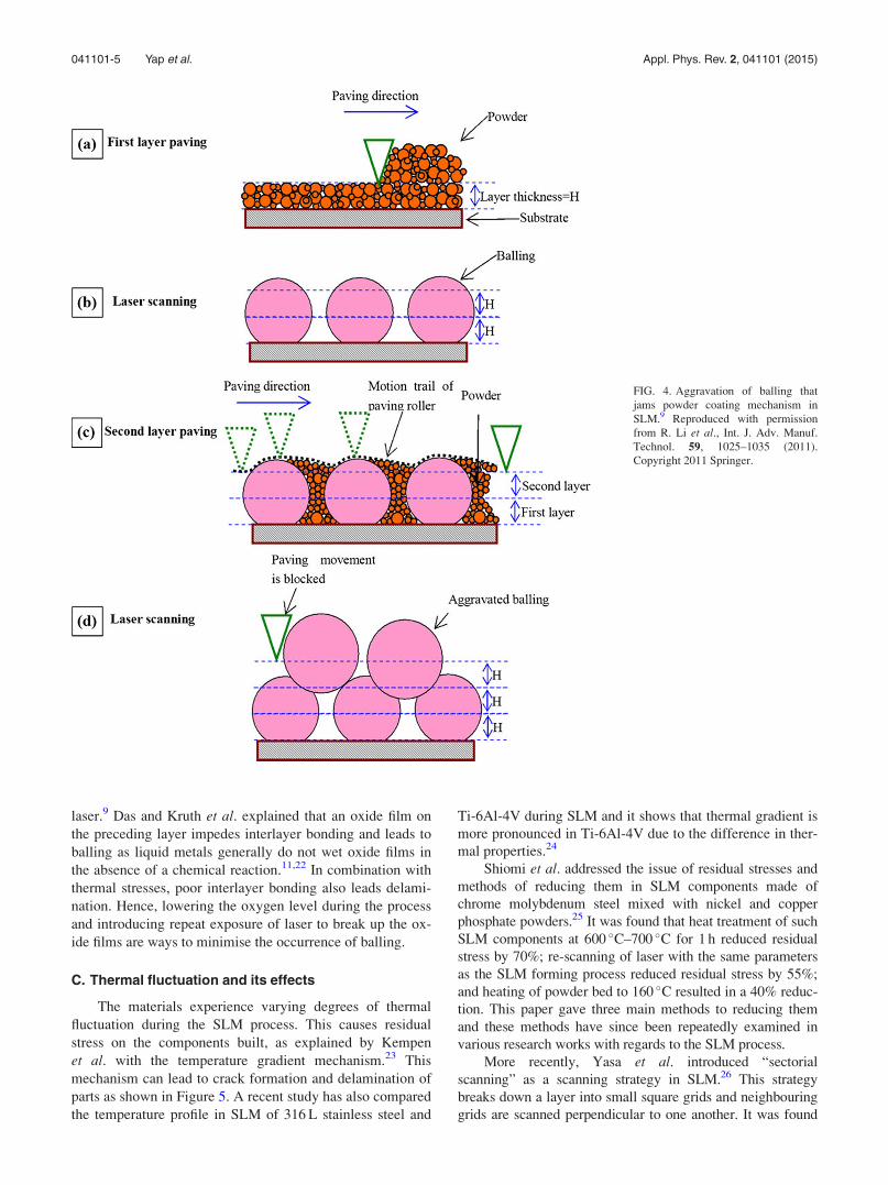
bead-shaped surfaces. In more severe cases, balling may ag-
gravate in subsequent layers and cause the SLM process and
jam the powder coating mechanism with large metallic beads
that extend above the powder bed (Figure 4).9
In Li et al.’s study of the balling phenomenon, it is
shown that balling could be reduced significantly by keeping
oxygen level at 0.1%, applying a combination high laser
power and low scanning speed or applying re-scanning of
FIG. 3. Effective absorptance of powder bed vs absorptance of bulk mate-
rial; with experiment data (data points) and prediction by isotropic specular
reflection model (solid line) and diffuse reflection model (dotted line).15
Reproduced with permission from A. V. Gusarov and J. P. Kruth, Int. J.
Heat Mass Transfer 48, 3423–3434 (2005). Copyright 2005 Elsevier.
041101-4 Yap et al. Appl. Phys. Rev. 2, 041101 (2015)
laser.9 Das and Kruth et al. explained that an oxide film on
the preceding layer impedes interlayer bonding and leads to
balling as liquid metals generally do not wet oxide films in
the absence of a chemical reaction.11,22 In combination with
thermal stresses, poor interlayer bonding also leads delami-
nation. Hence, lowering the oxygen level during the process
and introducing repeat exposure of laser to break up the ox-
ide films are ways to minimise the occurrence of balling.
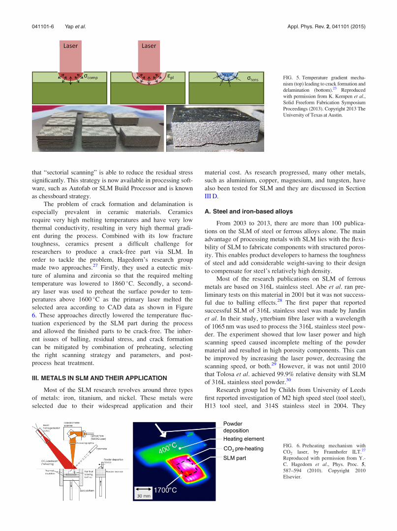
C. Thermal fluctuation and its effects
The materials experience varying degrees of thermal
fluctuation during the SLM process. This causes residual
stress on the components built, as explained by Kempen
et al. with the temperature gradient mechanism.23 This
mechanism can lead to crack formation and delamination of
parts as shown in Figure 5. A recent study has also compared
the temperature profile in SLM of 316 L stainless steel and
Ti-6Al-4V during SLM and it shows that thermal gradient is
more pronounced in Ti-6Al-4V due to the difference in ther-
mal properties.24
Shiomi et al. addressed the issue of residual stresses and
methods of reducing them in SLM components made of
chrome molybdenum steel mixed with nickel and copper
phosphate powders.25 It was found that heat treatment of such
SLM components at 600 �C–700 �C for 1 h reduced residual
stress by 70%; re-scanning of laser with the same parameters
as the SLM forming process reduced residual stress by 55%;
and heating of powder bed to 160 �C resulted in a 40% reduc-
tion. This paper gave three main methods to reducing them
and these methods have since been repeatedly examined in
various research works with regards to the SLM process.
More recently, Yasa et al. introduced “sectorial
scanning” as a scanning strategy in SLM.26 This strategy
breaks down a layer into small square grids and neighbouring
grids are scanned perpendicular to one another. It was found
FIG. 4. Aggravation of balling that
jams powder coating mechanism in
SLM.9 Reproduced with permission
from R. Li et al., Int. J. Adv. Manuf.
Technol. 59, 1025–1035 (2011).
Copyright 2011 Springer.
041101-5 Yap et al. Appl. Phys. Rev. 2, 041101 (2015)
that “sectorial scanning” is able to reduce the residual stress
significantly. This strategy is now available in processing soft-
ware, such as Autofab or SLM Build Processor and is known
as chessboard strategy.
The problem of crack formation and delamination is
especially prevalent in ceramic materials. Ceramics
require very high melting temperatures and have very low
thermal conductivity, resulting in very high thermal gradi-
ent during the process. Combined with its low fracture
toughness, ceramics present a difficult challenge for
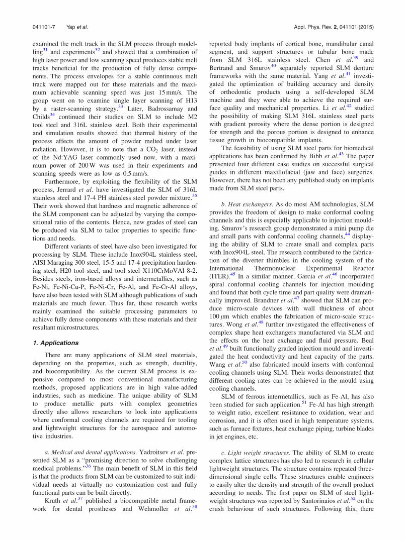
researchers to produce a crack-free part via SLM. In
order to tackle the problem, Hagedorn’s research group
made two approaches.27 Firstly, they used a eutectic mix-
ture of alumina and zirconia so that the required melting
temperature was lowered to 1860 �C. Secondly, a second-
ary laser was used to preheat the surface powder to tem-
peratures above 1600 �C as the primary laser melted the
selected area according to CAD data as shown in Figure
6. These approaches directly lowered the temperature fluc-
tuation experienced by the SLM part during the process
and allowed the finished parts to be crack-free. The inher-
ent issues of balling, residual stress, and crack formation
can be mitigated by combination of preheating, selecting
the right scanning strategy and parameters, and post-
process heat treatment.
III. METALS IN SLM AND THEIR APPLICATION
Most of the SLM research revolves around three types
of metals: iron, titanium, and nickel. These metals were
selected due to their widespread application and their
material cost. As research progressed, many other metals,
such as aluminium, copper, magnesium, and tungsten, have
also been tested for SLM and they are discussed in Section
III D.
A. Steel and iron-based alloys
From 2003 to 2013, there are more than 100 publica-
tions on the SLM of steel or ferrous alloys alone. The main
advantage of processing metals with SLM lies with the flexi-
bility of SLM to fabricate components with structured poros-
ity. This enables product developers to harness the toughness
of steel and add considerable weight-saving to their design
to compensate for steel’s relatively high density.
Most of the research publications on SLM of ferrous
metals are based on 316L stainless steel. Abe et al. ran pre-
liminary tests on this material in 2001 but it was not success-
ful due to balling effects.28 The first paper that reported
successful SLM of 316L stainless steel was made by Jandin
et al. In their study, ytterbium fibre laser with a wavelength
of 1065 nm was used to process the 316L stainless steel pow-
der. The experiment showed that low laser power and high
scanning speed caused incomplete melting of the powder
material and resulted in high porosity components. This can
be improved by increasing the laser power, decreasing the
scanning speed, or both.29 However, it was not until 2010
that Tolosa et al. achieved 99.9% relative density with SLM
of 316L stainless steel powder.30
Research group led by Childs from University of Leeds
first reported investigation of M2 high speed steel (tool steel),
H13 tool steel, and 314S stainless steel in 2004. They
FIG. 5. Temperature gradient mecha-
nism (top) leading to crack formation and
delamination (bottom).23 Reproduced
with permission from K. Kempen et al.,Solid Freeform Fabrication Symposium
Proceedings (2013). Copyright 2013 The
University of Texas at Austin.
FIG. 6. Preheating mechanism with
CO2 laser, by Fraunhofer ILT.27
Reproduced with permission from Y.-
C. Hagedorn et al., Phys. Proc. 5,
587–594 (2010). Copyright 2010
Elsevier.
041101-6 Yap et al. Appl. Phys. Rev. 2, 041101 (2015)
examined the melt track in the SLM process through model-
ling31 and experiments32 and showed that a combination of
high laser power and low scanning speed produces stable melt
tracks beneficial for the production of fully dense compo-
nents. The process envelopes for a stable continuous melt
track were mapped out for these materials and the maxi-
mum achievable scanning speed was just 15 mm/s. The
group went on to examine single layer scanning of H13
by a raster-scanning strategy.33 Later, Badrossamay and
Childs34 continued their studies on SLM to include M2
tool steel and 316L stainless steel. Both their experimental
and simulation results showed that thermal history of the
process affects the amount of powder melted under laser
radiation. However, it is to note that a CO2 laser, instead
of the Nd:YAG laser commonly used now, with a maxi-
mum power of 200 W was used in their experiments and
scanning speeds were as low as 0.5 mm/s.
Furthermore, by exploiting the flexibility of the SLM
process, Jerrard et al. have investigated the SLM of 316L
stainless steel and 17-4 PH stainless steel powder mixture.35
Their work showed that hardness and magnetic adherence of
the SLM component can be adjusted by varying the compo-
sitional ratio of the contents. Hence, new grades of steel can
be produced via SLM to tailor properties to specific func-
tions and needs.
Different variants of steel have also been investigated for
processing by SLM. These include Inox904L stainless steel,
AISI Maraging 300 steel, 15-5 and 17-4 precipitation harden-
ing steel, H20 tool steel, and tool steel X110CrMoVAl 8-2.
Besides steels, iron-based alloys and intermetallics, such as
Fe-Ni, Fe-Ni-Cu-P, Fe-Ni-Cr, Fe-Al, and Fe-Cr-Al alloys,
have also been tested with SLM although publications of such
materials are much fewer. Thus far, these research works
mainly examined the suitable processing parameters to
achieve fully dense components with these materials and their
resultant microstructures.
1. Applications
There are many applications of SLM steel materials,
depending on the properties, such as strength, ductility,
and biocompatibility. As the current SLM process is ex-
pensive compared to most conventional manufacturing
methods, proposed applications are in high value-added
industries, such as medicine. The unique ability of SLM
to produce metallic parts with complex geometries
directly also allows researchers to look into applications
where conformal cooling channels are required for tooling
and lightweight structures for the aerospace and automo-
tive industries.
a. Medical and dental applications. Yadroitsev et al. pre-
sented SLM as a “promising direction to solve challenging
medical problems.”36 The main benefit of SLM in this field
is that the products from SLM can be customized to suit indi-
vidual needs at virtually no customization cost and fully
functional parts can be built directly.
Kruth et al.37 published a biocompatible metal frame-
work for dental prostheses and Wehmoller et al.38
reported body implants of cortical bone, mandibular canal
segment, and support structures or tubular bone made
from SLM 316L stainless steel. Chen et al.39 and
Bertrand and Smurov40 separately reported SLM denture
frameworks with the same material. Yang et al.41 investi-
gated the optimization of building accuracy and density
of orthodontic products using a self-developed SLM
machine and they were able to achieve the required sur-
face quality and mechanical properties. Li et al.42 studied
the possibility of making SLM 316L stainless steel parts
with gradient porosity where the dense portion is designed
for strength and the porous portion is designed to enhance
tissue growth in biocompatible implants.
The feasibility of using SLM steel parts for biomedical
applications has been confirmed by Bibb et al.43 The paper
presented four different case studies on successful surgical
guides in different maxillofacial (jaw and face) surgeries.
However, there has not been any published study on implants
made from SLM steel parts.
b. Heat exchangers. As do most AM technologies, SLM
provides the freedom of design to make conformal cooling
channels and this is especially applicable to injection mould-
ing. Smurov’s research group demonstrated a mini pump die
and small parts with conformal cooling channels,44 display-
ing the ability of SLM to create small and complex parts
with Inox904L steel. The research contributed to the fabrica-
tion of the diverter thimbles in the cooling system of the
International Thermonuclear Experimental Reactor
(ITER).45 In a similar manner, Garcia et al.46 incorporated
spiral conformal cooling channels for injection moulding
and found that both cycle time and part quality were dramati-
cally improved. Brandner et al.47 showed that SLM can pro-
duce micro-scale devices with wall thickness of about
100 lm which enables the fabrication of micro-scale struc-
tures. Wong et al.48 further investigated the effectiveness of
complex shape heat exchangers manufactured via SLM and
the effects on the heat exchange and fluid pressure. Beal
et al.49 built functionally graded injection mould and investi-
gated the heat conductivity and heat capacity of the parts.
Wang et al.50 also fabricated mould inserts with conformal
cooling channels using SLM. Their works demonstrated that
different cooling rates can be achieved in the mould using
cooling channels.
SLM of ferrous intermetallics, such as Fe-Al, has also
been studied for such application.51 Fe-Al has high strength
to weight ratio, excellent resistance to oxidation, wear and
corrosion, and it is often used in high temperature systems,
such as furnace fixtures, heat exchange piping, turbine blades
in jet engines, etc.
c. Light weight structures. The ability of SLM to create
complex lattice structures has also led to research in cellular
lightweight structures. The structure contains repeated three-
dimensional single cells. These structures enable engineers
to easily alter the density and strength of the overall product
according to needs. The first paper on SLM of steel light-
weight structures was reported by Santorinaios et al.52 on the
crush behaviour of such structures. Following this, there
041101-7 Yap et al. Appl. Phys. Rev. 2, 041101 (2015)
have been more research works that investigated the quasi-
static and blast response,53 compressive properties,54 shock
response,55 failure mechanism56 of the steel lattice struc-
tures. In most of these works, 316L stainless steel was used.
The cellular lattice structure can be deployed as the core
of a sandwich structure which makes it lightweight and
strong. However, few investigations of the sandwich
structure with SLM steel lattice core have been pub-
lished. Only Shen et al.57 studied the compressive behav-
iour and failure mechanisms of the sandwich structure
and Mines et al.58 examined its drop-weight impact
behaviour.
Besides cellular lattice structures, honeycomb-like struc-
tures have also been studied. Rehme and Emmelmann59
investigated the SLM steel honeycomb structure with nega-
tive Poisson’s ratio, where the material is required to show
high compressibility and minimum resistance to compres-
sion. This structure can be applied as crash impact absorbers
in bullet proof vest and artificial intervertebral discs.
Usually, the wall or strut thicknesses of these lattice
structures is in the range of 100 lm. This is due to the limita-
tions of laser spot diameter and the resultant melt profile cre-
ated by the laser. However, Shen’s group managed to create
micro-scale pores with walls thinner than 1 lm.60 This was
achieved by adding 0.1 wt. % of H3BO3 and KBF4. The pores
and walls were created as a result of the gas generated by the
additives. Similar results were also achieved with NH4HCO3
as additives.61 The drawback is that the pores and wall struc-
tures cannot be controlled.
d. Other applications. In other SLM applications of steel
or iron-based alloys, Milovanovic et al.62 made a case study
for AM of tyre tread ring segment mould with H20 tool steel.
Feuerhahn et al.63 studied the SLM of a high hardness tool
steel X110CrMoVAl 8-2 for applications in micro-tooling.
Their studies showed that SLM was able to produce a part
with very high hardness with fine structure at the same time.
This cannot be achieved by conventional methods, such as
spray forming or forging. Production of fine-structured
porous stainless steel filter elements by SLM was studied by
Yadroitsev et al.64
2. Properties
a. Relative density. Relative density is often used as an
indicator of the quality of the SLM parts. Relative density
is the ratio of the density attained with SLM and the theo-
retical density of the bulk material. The theoretical density
can be calculated from the atomic weight and crystal
structure of the material. One may also refer to the ASM
International material data sheet for the materials’ den-
sities. Most of the SLM steel or iron-based materials have
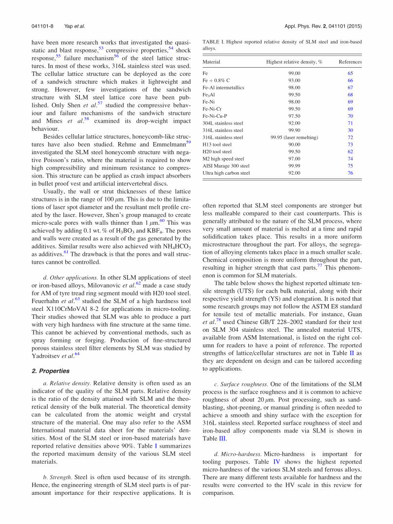
reported relative densities above 90%. Table I summarizes
the reported maximum density of the various SLM steel
materials.
b. Strength. Steel is often used because of its strength.
Hence, the engineering strength of SLM steel parts is of par-
amount importance for their respective applications. It is
often reported that SLM steel components are stronger but
less malleable compared to their cast counterparts. This is
generally attributed to the nature of the SLM process, where
very small amount of material is melted at a time and rapid
solidification takes place. This results in a more uniform
microstructure throughout the part. For alloys, the segrega-
tion of alloying elements takes place in a much smaller scale.
Chemical composition is more uniform throughout the part,
resulting in higher strength that cast parts.77 This phenom-
enon is common for SLM materials.
The table below shows the highest reported ultimate ten-
sile strength (UTS) for each bulk material, along with their
respective yield strength (YS) and elongation. It is noted that
some research groups may not follow the ASTM E8 standard
for tensile test of metallic materials. For instance, Guan
et al.78 used Chinese GB/T 228–2002 standard for their test
on SLM 304 stainless steel. The annealed material UTS,
available from ASM International, is listed on the right col-
umn for readers to have a point of reference. The reported
strengths of lattice/cellular structures are not in Table II as
they are dependent on design and can be tailored according
to applications.
c. Surface roughness. One of the limitations of the SLM
process is the surface roughness and it is common to achieve
roughness of about 20 lm. Post processing, such as sand-
blasting, shot-peening, or manual grinding is often needed to
achieve a smooth and shiny surface with the exception for
316L stainless steel. Reported surface roughness of steel and
iron-based alloy components made via SLM is shown in
Table III.
d. Micro-hardness. Micro-hardness is important for
tooling purposes. Table IV shows the highest reported
micro-hardness of the various SLM steels and ferrous alloys.
There are many different tests available for hardness and the
results were converted to the HV scale in this review for
comparison.
TABLE I. Highest reported relative density of SLM steel and iron-based
alloys.
Material Highest relative density, % References
Fe 99.00 65
Fe þ 0.8% C 93.00 66
Fe-Al intermetallics 98.00 67
Fe3Al 99.50 68
Fe-Ni 98.00 69
Fe-Ni-Cr 99.50 69
Fe-Ni-Cu-P 97.50 70
304L stainless steel 92.00 71
316L stainless steel 99.90 30
316L stainless steel 99.95 (laser remelting) 72
H13 tool steel 90.00 73
H20 tool steel 99.50 62
M2 high speed steel 97.00 74
AISI Marage 300 steel 99.99 75
Ultra high carbon steel 92.00 76
041101-8 Yap et al. Appl. Phys. Rev. 2, 041101 (2015)

B. Titanium and its alloys
In the last decade, the number of publications of SLM of
titanium is second to that of steel. Almost all of these papers
are based on commercially pure titanium (cpTi) or Ti-6Al-
4 V alloy (Ti64). Titanium in the liquid state is highly reac-
tive and sensitive to oxygen, nitrogen, hydrogen, and carbon,
making it difficult for conventional processes, such as cast-
ing. In the SLM process, an inert gas, such as argon, is used
to flush out atmospheric air and provide a layer of protective
gas. Moreover, small localized heating and rapid cooling in
SLM reduce the pick-up of interstitial elements, such as
hydrogen, carbon, and oxygen. Other titanium based alloys,
such as Ti-6Al-7Nb, Ti-24Nb-4Zr-8Sn, Ti-13Zr-Nb, and Ti-
13Nb-13Zr, have also been investigated for the SLM
process.
1. Applications
a. Medical and dental applications. Most research on tita-
nium and its alloys is driven by its potential application as
body prostheses or dental implants due to their biocompati-
bility. Moreover, they have high specific strength and elastic
moduli closer to bone than Co-Cr alloys and stainless steel.87
Research into titanium body implants has been done by sev-
eral groups. Shiomi’s group has built bone and dentals
crowns using SLM cpTi.88 Mullen’s group investigated a
unit-cell approach89 and various scanning strategies90 to
make porous biocompatible constructs for orthopaedic appli-
cations using cpTi. Lin et al.91 studied the structure and me-
chanical properties of a Ti64 cellular inter-body fusion cage,
Murr et al.92 focused their attention on the microstructure
and mechanical properties of SLM Ti64 for biomedical
applications and Warnke et al.93 conducted cell experiments
and showed that SLM Ti64 porous scaffolds allow total
overgrowth of osteoblasts (bone cells). Vandenbroucke and
Kruth94 and Chen et al.39 separately examined the dimen-
sional accuracy of the SLM process for fabrication of dental
frameworks. In some of the latest studies, Biemond et al.95
examined the bone in-growth potential of trabecular-like
implant surfaces produced by SLM of Ti64 in goats and con-
cluded that the SLM produced parts showed good bone in-
growth characteristics after 15 weeks. In Brazil, Jardini
et al.96 reported the use of EOSINT M270 system to fabri-
cate titanium implant for a right cranio-maxillo-facial sur-
gery. The custom-built implant fitted the patient well and
allowed the surgery duration to be reduced due to pre-op
planning with correct geometrical and anatomical details.
Furthermore, there were recent studies that seek to
replace cpTi and Ti64 with other titanium based alloys.
Chlebus et al.97 studied the possibility of using Ti-6Al-7Nb
for medical implants as it replaces vanadium with niobium
in its chemical composition and this alloy has higher corro-
sion resistance and bio-tolerance compared to Ti64. Further
studies on this novel titanium alloy were done by Marcu
et al.98 on endosseous implant and Dybala et al.99 on cranio-
maxillo-facial implants. Szymczyk et al.100 also examined
cultured cell growth of Staphylocuccus aureus on Ti-6Al-
7Nb scaffold and have demonstrated the potential of this tita-
nium alloy in this application. SLM of Ti-24Nb-4Zr-8Sn has
been examined by Zhang and Sercombe101 as an improve-
ment over Ti64 as a low modulus alloy. This would result in
a reduced difference of moduli between implant and
TABLE II. Highest reported tensile strengths of SLM steel and iron-based alloys.
Material UTS (MPa) YS (MPa) Elongation (%) References Material UTS (MPa)
Fe 411.5 305.3 … 65 225
Fe-Ni 600 … … 69 …
Fe-Ni-Cr 1100 … … 69 …
Fe-Ni-Cu-P 505 425 … 70 …
15-5 PH steel 1450 1297 12.53 79 1317
15-5 PH steel 1470 1100 15.00 80 1317
304 stainless steel 717 570 42.80 78 579
316L stainless steel 760 650 30.00 19 558
Maraging steel 1290 1214 13.30 81 1930
TABLE III. Lowest reported surface roughness values of SLM steel and
iron-based alloys.
Material Surface roughness, Ra (lm) References
Fe-Ni 10 69
Fe-Ni-Cr 10 69
304L stainless steel 25.7 71
316L stainless steel 5.82 82
316L stainless steel 5.00 (sand blasting) 19
316L stainless steel 2.00 (laser re-melting) 72
H20 tool steel 3.78 (shot-peening) 62
Ultra high carbon steel 18.0 76
TABLE IV. Highest micro-hardness of SLM steel and iron-based alloys.
Material Micro-hardness (HV) References
Fe-Al intermetallic 800 83
Fe3Al 353 68
Fe-Ni 232 (from 220 HB) 69
Fe-Ni-Cr 450 84
Fe-Ni-Cu-P 230 70
304L stainless steel 217 71
316L stainless steel 279 85
316L stainless steel 272 (from 104 HRB) 82
H20 tool steel 336 (from 34 HRC) 62
M2 high speed steel 900 86
Maraging steel 412 (from 42 HRC) 81
X110CrMoVAl 8-2 tool steel 493 63
Ultra high carbon steel 475 76
041101-9 Yap et al. Appl. Phys. Rev. 2, 041101 (2015)
surrounding bone, thus preventing bone resorption, which
causes implant loosening. Zielinski et al.102 presented Ti-
13Zr-Nb as an alloy with better biocompatibility and longer
lifetime for load-bearing implants. Speirs et al.103 also stud-
ied another low modulus titanium alloy in Ti-13Nb-13Zr for
medical applications.
b. Light weight structures and other applications. Besides
allowing individualized medical implants to be built with
low customization cost, SLM also enabled the fabrication of
lightweight titanium scaffold structures for both medical and
aeronautical applications. Wang et al.104 fabricated cpTi po-
rous structure by using a blend of TiH2 and cpTi powders.
Sun et al.105 proposed an octahedral cell design for the con-
struction of cell structure with SLM. Gorny et al.106 charac-
terized the deformation and failure behaviour and Brenne
et al.107 separately studied the uniaxial loading and bending
load behaviour of SLM Ti64 porous structures. Xiao et al.108
examined the compressive strength of high porosity (70%)
lattice structures made of SLM titanium. Hasan et al.109 stud-
ied the behaviour of SLM Ti64 micro-struts and proposed a
heat treatment process to improve the properties of these
structures. Mines et al.58 tested the drop weight impact
behaviour of sandwich structures with micro-lattice cores
made via SLM of Ti64.
Besides applications in medical implants and light
weight structures, SLM of Ti64 was first studied for fabrica-
tion of guidance section housing for the Sidewinder mis-
sile110 and SLM of titanium has been investigated for
fabrication of waveguide filters for radio frequency applica-
tions.111 Caiazzo et al.112 analysed the potential of SLM
Ti64 in the production of aircraft engine turbine blade with
internal channels or cavities which conventional manufactur-
ing methods cannot achieve easily. In motorsports, Cooper
et al.113 reported that Red Bull Technology used laser AM
technology to build thin wall hydraulic channels and exam-
ined how freedom of design would enable both component
weight reduction and fluid flow improvement.
2. Properties
a. Relative density. SLM of titanium and titanium-based
alloys has been very positive in terms of the relative density
attained by various researchers. At early stages of research,
Santos’s group already achieved relative densities of 98%
for cpTi.114 Subsequent research works on titanium and
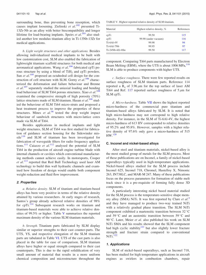
titanium-based materials were able to achieve relative den-
sities of 99.5% or higher. Table V summarizes the reported
maximum density of the various SLM titanium materials.
b. Strength. Titanium parts fabricated by SLM display
similar or superior strengths to their cast counter-parts. The
UTS, YS, and respective elongation of the SLM titanium
parts are tabulated in Table VI. UTS of the cast parts is also
placed in the table for ease of comparison. SLM titanium
alloys have higher or equal strength compared to their cast
counterparts. This is due to the rapid solidification of very
small amount of material that results in a more uniform
chemical composition and microstructure throughout the
component. Comparing Ti64 parts manufactured by Electron
Beam Melting (EBM), where the UTS is about 1006 MPa,118
SLM is able to produce components with higher UTS.
c. Surface roughness. There were few reported results on
surface roughness of SLM titanium parts. Reference 114
reported a Ra of 3.96 lm for the top surface of laser AM
Ti64 and Ref. 117 reported surface roughness of 5 lm for
SLM cpTi.
d. Micro-hardness. Table VII shows the highest reported
micro-hardness of the commercial pure titanium and
titanium-based alloys fabricated by SLM. It is noted that
high micro-hardness may not correspond to high relative
density. For instance, in the SLM of Ti-6Al-4V, the highest
micro-hardness of 613 HV corresponded to relative densities
of 95.2% and 95.8%. However, samples with a higher rela-
tive density of 97.6% only gave a micro-hardness of 515
HW.120
C. Inconel and nickel-based alloys
After steel and titanium materials, nickel-based alloy is
the most studied group of metals for the SLM process. Most
of these publications are on Inconel, a family of nickel-based
superalloys typically used in high-temperature applications.
Nickel-based alloys studied for the SLM process include
Inconel 625, Inconel 718, Chromel, Hastelloy X, Nimonic
263, IN738LC, and MAR-M 247. Many of these publications
focus on the process parameters for formation of stable melt
track since it is a pre-requisite of forming fully dense 3D
components.
A particularly interesting nickel based material studied
for the SLM process is the temperature-sensitive shape mem-
ory alloy (SMA) NiTi. It was first reported by Clare et al.4
and they have managed to produce two-way trained NiTi
with a relatively gradual phase transition. The SLM NiTi
component exhibited a martensitic transition between 32 �Cand 59 �C and an austenitic transition between 59 �C and
90 �C. Later, Meier et al. also published his work on SLM
NiTi SMA and his results showed that the SLM component
had high cyclic stability121 but also slightly lower fracture
strength and fracture strain compared to conventional
NiTi.122
1. Applications
SLM of nickel-based superalloys, such as Inconel 718,
has been studied for high temperature applications in aircraft
engines as swirlers in combustion chambers, repair
TABLE V. Highest reported relative density of SLM titanium.
Material Highest relative density, % References
cpTi 99.50 115
cpTi 99.90 (under vacuum) 116
Ti-6Al-4V 99.98 94
Ti-6Al-7Nb 99.95 97
Ti-24Nb-4Zr-8Sn 99.50 117
041101-10 Yap et al. Appl. Phys. Rev. 2, 041101 (2015)

patches,123 gas turbine blades, and turbocharger rotors.124
Inconel 718’s excellent corrosion resistance and strength at
high temperatures, fatigue resistance, wear resistance, and
good weldability125 have allowed it to be applied in these
areas. In a review of manufacturing technologies for com-
plex turbine blades by Lu et al.,126 it was highlighted that
Fraunhofer ILT and the MCP company had used SLM to
produce turbine blades. These turbine blades had dense
microstructure, high definition, and high surface quality.
Moreover, a patent for manufacturing of a hollow turbine
blade by SLM was applied for on 31 March 2011 in the
USA.
Hastelloy X has high oxidation resistance and good
high-temperature strength127 and has possible applications in
aircraft engines. Nimonic 263 is suitable for medium temper-
ature structural applications and it has good fatigue proper-
ties and high oxidation resistance.128 Rickenbacher et al.129
also recommended IN738LC as a suitable material for
heavy-duty gas turbine components. Combined with the
advantages of SLM, such as freedom of design and high re-
solution, engine components can be made with complex in-
ternal structures to increase cooling efficiency or to reduce
weight and bring about fuel savings for the airlines.
In addition to high-temperature related applications,
SLM of nickel-based alloys has been studied for applications
as die models for bevel gear130 and porous filtration media.64
Clare et al.4 and Habijan et al.131 studied the SLM of NiTi
for potential applications in micro-electro-mechanical sys-
tems (MEMS) and smart carrier material for human mesen-
chymal stem cells (hMSC) to enhance bone growth and
healing for critical bone defects, respectively.
2. Properties
a. Relative density. SLM Inconel 718, Hastelloy X, and
Nimonic 263 have achieved near 100% relative density
while there are room for improvement for SLM Inconel 625
and Chomel as shown in Table VIII.
b. Strength. Nickel-based alloys fabricated by SLM fol-
low a similar trend to titanium-based alloys. They display
higher UTS compared to their cast counterparts. Table IX
shows the UTS, YS, and corresponding elongation of the
SLM nickel-based alloys.
c. Surface roughness. There have been very few reports
on the surface roughness of SLM nickel-based alloys.
However, the reported figures have shown that these SLM
parts have good surface roughness which is smaller than
10 lm. For instance, Mumtaz and Hopkinson138 reported
that surface roughness of SLM Inconel 625 can be as low as
4 lm for the top surface and Wang et al.127 reported Ra of
6 lm with contour scanning.
d. Micro-hardness. In SLM nickel-based components,
only a few reports on the micro-hardness can be found. It is
shown that the micro-hardness can be improved by application
of aging treatment. This can be shown by comparing the works
of Wang et al. and Sanz and Navas as shown in Table X.
D. Other metals
Besides steel, titanium, and nickel, other metals, such as
aluminium, copper, magnesium, cobalt-chrome, tungsten,
and gold have also been studied for the SLM process.
However, publications on each of these metals are signifi-
cantly fewer. Hence, in this review, they are grouped to-
gether in this section.
Most of the works on SLM of aluminium alloys are
based on AlSi10Mg, a common casting alloy. In a process
optimization study conducted by Kempen et al.,139 it was
found that the quality of SLM component is dependent on
powder morphology and content, besides the processing pa-
rameters. Small and spherical powders with higher silicon
content gave a higher relative density in the SLM component
than larger and irregularly-shaped powders. Other literatures
on SLM of aluminium and its alloys also include pure alu-
minium, Al6061, AlSi12, and AlMg.
In the SLM of copper, there were early works on pure
copper. Pogson et al.140 attempted to process copper and H13
tool steel to make a multi-component mould tool with
increased cooling rate. However, there was difficulty in
TABLE VI. Highest reported tensile strengths of SLM titanium.
Material UTS (MPa) YS (MPa) Elongation (%) References Material UTS (MPa)
cpTi 654 522 17.0 119 655
Ti-6Al-4V 1250 1125 6.00 94 1055
Ti-6Al-7Nb 1515 1440 1.40 97 1000
Ti-24Nb-4Zr-8Sn 665 563 13.8 117 …
TABLE VII. Highest micro-hardness of SLM titanium.
Material Micro-hardness (HV) References
cpTi 308 116
Ti-6Al-4V 613 120
Ti-6Al-7Nb 464 97
Ti-24Nb-4Zr-8Sn 225 117
TABLE VIII. Highest reported relative density of SLM Inconel and nickel-
based alloys.
Material Highest relative density, % References
Inconel 625 95.00 132–134
Inconel 718 99.98 135
Chomel 88.00 130
Hastelloy X 99.75 136
Nimonic 263 99.70 128
041101-11 Yap et al. Appl. Phys. Rev. 2, 041101 (2015)

preventing the embrittlement of the H13 tool steel by copper
even with scanning speed as high as 400 mm/s. Due to cop-
per’s relatively low absorptivity to both Nd:YAG laser (63%)
and CO2 laser (32%) irradiation,12 the energy consumption of
the SLM process increased when fabricating copper parts.
Moreover, the SLM of copper was also a challenge due to
copper’s high reactivity to atmospheric oxygen, even at low
concentrations. Gu and Shen141 addressed the issue of oxida-
tion by using a copper-based powder mixture with 60 wt. %
copper, 30 wt. % Cu10Sn, and 10 wt. % Cu8.4P. The additive
phosphorus acted as a fluxing agent against oxidation of cop-
per. SLM of other copper alloys, such as CuNi10, K220, and
C18400, has also been published.
First paper on SLM of pure magnesium was published
in 2010 by Ng’s group142 from The Hong Kong Polytechnic
University. The challenge of processing magnesium with
SLM comes from its high reactivity to oxygen and flamma-
bility. They approached this problem by building a SLM sys-
tem containing a shielding box with circulating argon gas to
lower the partial pressure oxygen level to less than 2 bars.
However, their laser system had a maximum power of 28 W
and they were only able to achieve single line melt tracks at
a low scanning speed of 20 mm/s.
Tungsten has also been studied for the SLM process. Its
high melting point of 3422 �C and low wettability presented a
unique challenge for the SLM process. Tungsten is very hard
and brittle, making it difficult to machine into complex
shapes.143 Fabricating tungsten alloys through conventional
powder metallurgy is also costly as it requires expensive and
dedicated tools. SLM provides a feasible alternative to proc-
essing of tungsten and widens its applications. SLM of pure
tungsten and tungsten-nickel144 alloys has also been
examined.
Other metals, such as gold, silver, tantalum, and cobalt-
chromium alloy, have also been reported in SLM literatures.
However, journal publications on each of these metals are few
and they are mostly focused on process optimization for these
materials. Pauly et al.145 presented SLM as a feasible process-
ing technique for the production of bulk metallic glass due to
the high cooling rate inherent in the process. Metallic glass
has many desirable characteristics, such as near-theoretical
strength, low Young’s modulus, and high elasticity.
Conventional methods have limited the shape of metallic
glass to rods or ribbons, whereas SLM will be able to produce
bulk metallic glass and widen its field of applications.
1. Applications
a. Biomedical and dental applications. Cobalt-chrome has
been studied by various groups for dental applications. Faure
et al.146 recorded results of 7000 dental elements produced
over a span of 6 months. Averyanova et al.147 studied the
fabrication of 99% dense Co-Cr dental crown and bridges
over a period of 14 months and concluded that SLM has
good repeatability and these parts made by SLM meet the
traditions standards. Oyague et al.148 and Kim et al.149 sepa-
rately evaluated the fit of dental prostheses produced by
SLM and reached different conclusions about the suitability
of SLM technology in producing dental prostheses. In terms
of hardness, elastic modulus, and strength, Ayyildiz et al.150
concluded that SLM Co-Cr is suitable for dental applica-
tions. Bioactive and biodegradable magnesium orthopaedic
implants by SLM have also been examined.151
b. Heat exchangers. One of the common applications for
SLM copper is in the area of heat exchangers. This is due to
copper’s high thermal conductivity of 401 W/(m K). Pogson
et al.152 suggested that SLM of copper can be applied to
micro heat-exchangers where wall thickness of about
100 lm is required. Becker153 published an online article
about tool inserts with internal cooling channels made from
K220 copper alloy by SLM technology. Researchers have
also tested SLM aluminium for heat transfer devices, such as
heat sink48 and arterial wick heat pipes.154
c. Other applications. Aluminium alloys have been
tested for applications in waveguide filters alongside with
SLM titanium.111 Vilaro et al.155 used SLM to build the
water-pump of a race car to demonstrate the capability of
SLM to create medium size parts. However, the water-pump
has yet to be tested in a race car. Manfredi et al.156 examined
the possibility of creating lightweight structural parts for
robotics applications and built a first finger exoskeleton.
Tungsten’s high density, high melting temperature, and
good corrosion resistance made it a suitable material for ki-
netic energy projectiles, radiation shielding, and mass balance
in aircrafts.157 The ability of SLM to manufacture micro-scale
TABLE IX. Highest reported tensile strengths of SLM Inconel and nickel-based alloys.
Material UTS (MPa) YS (MPa) Elongation (%) References Material UTS (MPa)
Inconel 625 1030 800 10.0 137 1000
Inconel 718 1148 907 25.9 125 1000
IN738LC 1184 933 8.40 129 1096
Hastelloy X 930.5 814 35.0 136 785
Nimonic 263 1085 818 24.0 128 940
TABLE X. Highest micro-hardness of SLM Inconel and nickel-based
alloys.
Material Micro-hardness (HV) References
Inconel 625 163 (from HRA) 133,134
Inconel 718 365 125
Inconel 718 470 (after aging treatment) 135
Chomel 740 130
Nimonic 263 370 128
041101-12 Yap et al. Appl. Phys. Rev. 2, 041101 (2015)

structure also allowed Deprez et al.158 to study tungsten as a
magnetic resonance compatible multi-pinhole collimator.
SLM of precious metals, such as gold and silver, is of
interest to the jewellery industry.159 It allows the making of
jewellery and ornaments with complex designs otherwise not
feasible with conventional methods. Moreover, it helps to
reduce the cost of production by out-phasing the use of ex-
pensive moulds and dies and by allowing unused powder to
be reused for the next batch of production.160
2. Properties
a. Relative density. In terms of relative density, the fig-
ures attained for aluminium alloys and cobalt-chrome are
above 96%. However, the relative densities range from 82%
to 95% for other metals. Hence, there is still room for
improvement in achieving near-full density parts for these
metals. Table XI shows the highest reported relative density
for each material processed by SLM.
b. Strength. The highest tensile strength reported for
AlSi10Mg was 400 MPa, with a corresponding YS of
220 MPa and a breaking elongation of 11%.162 There is little
information about the UTS of other metals. This is probably
because researchers have yet to produce near full-dense
parts. High porosity usually means compromised internal
structure, leading to a much lower strength and ductility.
This is evident in the results reported by Sustarsic et al., who
obtained relatively low strength of 400 MPa for CuNi15
alloy with 92.00% relative density.69
c. Surface roughness. There are very few reports on the
surface roughness of these metals produced by SLM.
Calignano et al.170 reported Ra of 14.35 lm for SLM
AlSi10Mg. The surface roughness improved to 2.5 lm by
shot-peening. Savalani et al. reported surface roughness of
20 lm for SLM magnesium parts171 and Sustarsic et al.achieved Ra of 9 lm for CuNi15 alloy.69
d. Micro-hardness. Micro-hardness of SLM parts has
been reported for some aluminium alloys, cobalt-chrome,
magnesium, and gold. Jerrard et al.161 found that hardness of
the SLM part increased greatly when copper powder was
added to the Al6061 powder at 30 wt. %. They have attrib-
uted this to the formation of AlCu2 during the SLM process
when these powders are mixed. Table XII shows the highest
reported micro-hardness of the various SLM metals.
IV. CERAMICS
Ceramic materials studied for the SLM process included
Li2O-Al2O3-SiO2 (LAS) glass, alumina (Al2O3), silica
(SiO2), yttria-stabilized zirconia (YSZ), tri-calcium-phos-
phate (TCP), alumina-zirconia mixtures, dental porcelain,
alumina-silica mixture, silicon carbide, and silicon monox-
ide. In most of the experiments, CO2 lasers (k� 10.6 lm)
were used due to the higher absorptivity with ceramic mate-
rials. This is different from most experiments with metallic
powders, where Nd:YAG or Yb:YAG (k� 1.06 lm) lasers
were used. Although ceramic materials generally have a
higher coupling efficiency with CO2 lasers, Yap et al.172
have shown that full melting of SiO2 was still possible with
Nd:YAG fibre laser. Their experiments on single track melt-
ing of SiO2 resulted in glass-like rods with white SiO2 pow-
ders adhering to the sides.
Generally, there are more challenges in the SLM of
ceramics than that of metals. Ceramics are generally less
dense than metals. Hence, ceramic powders have poor flow-
ability, which does not allow a thin layer of ceramic powders
to be spread evenly on the building platform. Nevertheless,
Mapar et al.173 improved the flowability of alumina-zirconia
powder mixture by spray-drying and this allowed a thin layer
to be deposited on to the building platform.
Furthermore, ceramics have a combination of high melt-
ing temperatures and low ductility. During the SLM process,
a high energy input is required to increase the temperature to
melting point. As the laser sweeps across the powder bed, the
joint parts will experience high temperature fluctuation, creat-
ing high thermal stresses. Combined with the low ductility of
ceramic materials, cracks can form. Wissenbach’s research
group overcame this problem by lowering the melting temper-
ature and providing areal heating with a secondary CO2 laser.
A. Applications
1. Medical and dental applications
Wissenbach’s group has been working on SLM of ce-
ramic materials for medical and dental applications. Wilkes
TABLE XI. Highest reported relative density of SLM aluminium, copper,
magnesium, tungsten, gold, and cobalt-chrome.
Material Highest relative density, % References
Al6061 96.50 161
AlSi10Mg 99.50 162
Cu þ Cu10Sn þ Cu8.4P powder 84.00 163
Cu based powder 95.00 164
Cu10Sn þ Cu8.4P þ Ni 95.20 165
CuNi15 92.00 69
C18400 96.74 166
K220 99.90 167
Mg þ 9 wt. % Al 82.00 168
Tungsten 89.92 158
24 Carat gold 89.60 169
CoCr 99.94 135
TABLE XII. Highest micro-hardness of SLM aluminium, copper, magne-
sium, gold, and cobalt-chrome.
Material Micro-hardness (HV) References
Al6061 50 161
Al6061 þ 30 wt. % Cu 200 161
AlSi10Mg 149 162
CuNi15 116 (from 110 HB) 69
K220 192 167
Mg þ 9 wt. % Al 75 168
24 Carat gold 29.3 159
CoCr 482 150
041101-13 Yap et al. Appl. Phys. Rev. 2, 041101 (2015)

et al.174 published papers on a SLM-produced dental restora-
tion with zirconia and a bioresorbable bone substitute
implant with TCP. Under light optical microscopy, the speci-
men was shown to be of high density but contained numer-
ous cracks. TCP bone substitute implant was made by using
alkaline borosilicate glass as binder. This allowed a lower
melting temperature and kept TCP as the dominant phase in
the part. However, the part was highly porous and had a low
compressive strength of 8 MPa. Works on dental restoration
bridge were reported by Hagedorn et al. who deployed a sec-
ondary laser as a source of pre-heating. However, the part
built had poor surface finish with Rz of 150 lm.175
SLM also provides the capability to fabricate ceramic
scaffolds. Liu176 used silica solution-hydroxyapatite (HA)
slurry to build bone scaffold for tissue engineering and eval-
uated its bioactivity with microculture tetrazolium test. The
results concluded that the scaffold was suitable for cell cul-
ture and had potential for tissue engineering.
a. Other applications. Wang’s group studied the laser
melting of silica sand for applications in metal casting
moulds.177 The laser-melted parts had high porosity and
rough surfaces. Hence, silicate infiltration was used as a
post-process method to improve the density, strength, and
surface roughness of the moulds. It was reported that the
rapid casting process, enabled by direct laser sintering, pro-
vided a shorter and simpler alternative to conventional
mould making and shortened the time required of the sand
casting process.
Bertrand et al.178 investigated the potential of SLM on
yttria-zirconia by building thin wall structures, part of tur-
bine blade, and nozzle. It was also suggested that SLM of
alumina-zirconia can be applied to electrical or thermal insu-
lation or wear resistant coating.179
B. Properties
1. Relative density
The inherent properties of ceramics make them chal-
lenging materials to fabricate with SLM. High melting tem-
peratures and brittle nature of ceramics lead to crack
formation when the parts undergo high temperature fluctua-
tion during the process. Hence, achieving high relative den-
sity with ceramic materials is difficult as shown in Table
XIII. Hagedorn et al. were able to achieve near full relative
density by using a secondary laser for heating to reduce the
temperature fluctuation of the SLM process.27
2. Strength
There is no report on the UTS or stress-strain behaviour
of SLM ceramics. However, there are reports on the four-
point bending strength (4PBS) and flexural strengths (FS) of
SLM ceramics and these results are tabulated in Table XIV.
Furthermore, Ref. 181 also reported a compressive strength
of 15.5 MPa for direct laser sintered silica and Ref. 182
achieved 0.8 MPa for TCP.
3. Surface roughness
The lowest reported figure for Ra of direct laser sintering
or melting of ceramics is 19 lm.181 Liu achieved Ra of
25 lm with silicate-HA mixture.176 Hagedorn et al. deployed
a secondary laser to solve the problem of crack formation
and achieve high relative density. However, it also led high
surface roughness. The reported Rz values were no lower
than 150 lm.175
V. COMPOSITES
General interests in SLM of composite materials have
caught on in the past few years. However, there are pioneering
works in this area by Das et al. Their works involved nickel
superalloy Mar-M-247, cobalt braze alloy Amdry 788, and
boron nitride and aluminium oxide coated in titanium.184 In
most cases, SLM processing of composite materials involves
melting a mixture of two or more type of powders, with one
of the powder acting as the matrix material and the other as
the reinforcing particle, usually a ceramic. For instance, tita-
nium carbide (TiC) has been used with titanium and stainless
steel to create SLM composite materials.
There were also research works that involved in-situ for-
mation of reinforcement particles during the SLM process. Gu
et al. carried out SLM for a powder mixture containing tita-
nium powder and silicon nitride (Si3N4) with a composition
molar ratio of 9:1. During the SLM process, an in-situ reac-
tion took place: 9TiþSi3N4¼ 4TiNþTi5Si3. Microstructural
analysis showed a Ti5Si3 matrix reinforced by granular
TiN.185 Their work displayed another possibility of the SLM
process where the processed components had different com-
pounds compared to the original powder material.
A. Applications
There are many applications of SLM composite materi-
als, depending on the properties of the composite and the
TABLE XIII. Highest reported relative density of SLM ceramic materials.
Material Highest relative density, % References
ZrO2-Y2O3 56 178
Al2O3-SiO2 95 180
Al2O3-ZrO2 100 (close to) 27
Silicate/hydroxyapatite 72 176
TABLE XIV. Four-point bending strength and flexural strength of SLM ce-
ramic materials.
Material
Four-point bending strength
(4PBS) or flexural strength
(FS) (MPa) References
ZrO2 9.79 (4PBS) 182
Al2O3-ZrO2 500 (4PBS) 27
Silicate and hydroxyapatite 4.7 (4PBS) 176
Dental porcelain 31 (4PBS) 183
Al2O3-SiO2 120 (FS) 180
Al2O3-ZrO2 538.1 (FS) 174
041101-14 Yap et al. Appl. Phys. Rev. 2, 041101 (2015)
demands of the applications. Most of the applications are in
high value-added industries, such as aerospace, automotive,
and medicine. Some research has been motivated by specific
applications, such as heat resistant coating in engines,186
load-bearing bone implants,187 biodegradable implants,188
and light-weight, high temperature structural materials.189
1. Medical implants
Hao et al. examined the SLM processing of HA and
stainless steel for load bearing bone implants. This implant
exploits the strength of steel and the ability of HA to stimu-
late bone and tissue re-growth at the interface of the implant
and bone tissue in the human body.187 Lindner et al. proc-
essed a high density, biodegradable composite material from
b-tri-calcium phosphate and poly(D,L)-lactide reaching four-
point bending strength of 23 MPa.188 Shishkovskii et al. also
experimented with HA and they processed it with NiTi. This
material has the potential to function as porous implants or
drug delivery system as NiTi has high strength, high corro-
sion resistance, biocompatibility, and a unique shape mem-
ory effect.190 Polymer drug delivery systems built by SLS
have been examined by Salmoria et al.191 and current SLM
technology will be able to produce metallic and composite
counterparts.
2. Aerospace and automotive
For applications in the aerospace and the automotive
industries, research has focused on high temperature perform-
ance and light-weight structures. Das et al used nickel based
super alloy cermet to study the SLM production of abrasive
turbine blade tips to minimize gas leakage and improve effi-
ciency of gas turbines.192 Mumtaz and Hopkinson186 explored
functionally graded zirconia reinforced WaspaloyTM
, a nickel
based superalloy for high temperature applications, thermal
structures, or heat resistant coating in engines. The function-
ally graded composite had layer-wise increasing concentration
of zirconia from 0% to 10% and this would reduce the thermal
coefficient mismatch between the substrate material and the
thermal coating. Dadbakhsh et al.193 focused on aluminium
based metal matrix composites for aerospace and automotive
applications to exploit the light-weight, high specific strength,
and thermal conductivity of aluminium.
Gu et al. have studied titanium-based composites for in-
termediate and high temperature applications.194 Titanium
nitride (TiN)195 and TiC (Ref. 189) reinforcements were
added to titanium silicide (Ti5Si3) to improve its fracture
toughness for high temperature structural applications. TiC
reinforced titanium-aluminium matrix was also examined for
intermediate temperature aerospace and power generation
applications as the alloy matrix is lighter compared to mod-
ern nickel based superalloys.196 SLM of pure titanium rein-
forced by TiC was also examined to increase its wear
resistance for aerospace applications.197
3. Other applications
Gu also worked with Meiners198 on SLM of tungsten-
nickel-graphite powder mixture to attain in situ tungsten
carbide (WC) reinforced Ni2W4C(M6C) for applications in
machining tools and moulds with improved micro-hardness.
Tungsten reinforced copper was explored by Li et al.199 for
applications in heavy duty electrical contacts, arcing resist-
ance electrodes, and blocking material for microwave pack-
ages of microelectronic devices. The reinforced copper was
reported to have superior thermal management properties
and higher microwave absorption capacity.
B. Properties
1. Relative density
Reported relative densities of SLM composites range
from 82% to 99.66% with an average of about 95%, as
shown in Table XV.
2. Strength
Strength of SLM composite materials has been reported
for a few early researches. However, the type of strength
requirement varies according to the intended application.
Besides the UTS, fracture toughness and four-point bending
strength have also been reported for some SLM composite
materials. For instance, Kim and Creasy obtained a fracture
toughness of 95 MPa for Nylon 6 reinforced with clay nano-
particles.208 Hon and Gill achieved UTS of 31 MPa for poly-
amide/SiC composite by using 50 wt.% SiC and laser energy
density of 0.04 J/mm (Refs. 2 and 209). Hao et al. achieved
UTS of 95 MPa for HA/stainless steel composite, adequately
strong enough for loading bearing bone implant functions.187
Gu and Shen attained UTS of 270 MPa for tungsten carbide-
cobalt reinforced copper MMC.210 Song et al. reported UTS
of 764 MPa and YS of 302 MPa with silicon carbide rein-
forced iron matrix, highest of all composite materials
reported thus far.207 Lindner et al. reported a maximum four-
point bending strength of 23 MPa for b-tricalcium phos-
phate/poly(D,L)-lactide composite intended for non-load
bearing or low-load bearing implants.188
3. Micro-hardness and wear rate
Composite materials have improved hardness due to the
inherent properties of the reinforcement materials. For tooling
TABLE XV. Highest reported relative density of SLM composite materials.
Material
Highest relative
density, % References
ZrO2/WaspaloyTM
99.66 186
TiC/Invar36 90.00 200
WC/Ni2W4C(M6C) 96.30 198
WC/Ni 90.40 201
WC-Co/Cu 94.30 202
WC/Cu 95.70 203
b-tricalcium phosphate/poly(D,L)-lactide 98.00 188
TiC/Ti5Si3 96.90 189
FeO3/AlSi10Mg 82.00 204
TiC/Ti 98.30 205
TiN/Ti5Si3 97.70 206
SiC/Fe 99.20 207
041101-15 Yap et al. Appl. Phys. Rev. 2, 041101 (2015)
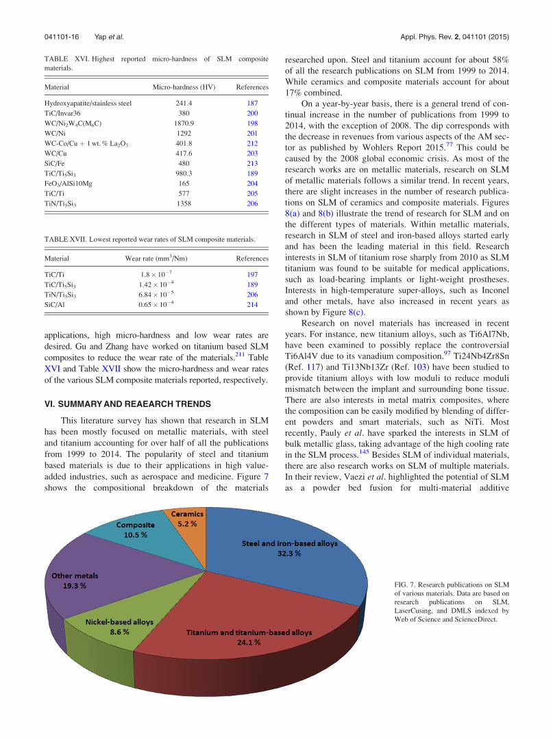
applications, high micro-hardness and low wear rates are
desired. Gu and Zhang have worked on titanium based SLM
composites to reduce the wear rate of the materials.211 Table
XVI and Table XVII show the micro-hardness and wear rates
of the various SLM composite materials reported, respectively.
VI. SUMMARY AND REAEARCH TRENDS
This literature survey has shown that research in SLM
has been mostly focused on metallic materials, with steel
and titanium accounting for over half of all the publications
from 1999 to 2014. The popularity of steel and titanium
based materials is due to their applications in high value-
added industries, such as aerospace and medicine. Figure 7
shows the compositional breakdown of the materials
researched upon. Steel and titanium account for about 58%
of all the research publications on SLM from 1999 to 2014.
While ceramics and composite materials account for about
17% combined.
On a year-by-year basis, there is a general trend of con-
tinual increase in the number of publications from 1999 to
2014, with the exception of 2008. The dip corresponds with
the decrease in revenues from various aspects of the AM sec-
tor as published by Wohlers Report 2015.77 This could be
caused by the 2008 global economic crisis. As most of the
research works are on metallic materials, research on SLM
of metallic materials follows a similar trend. In recent years,
there are slight increases in the number of research publica-
tions on SLM of ceramics and composite materials. Figures
8(a) and 8(b) illustrate the trend of research for SLM and on
the different types of materials. Within metallic materials,
research in SLM of steel and iron-based alloys started early
and has been the leading material in this field. Research
interests in SLM of titanium rose sharply from 2010 as SLM
titanium was found to be suitable for medical applications,
such as load-bearing implants or light-weight prostheses.
Interests in high-temperature super-alloys, such as Inconel
and other metals, have also increased in recent years as
shown by Figure 8(c).
Research on novel materials has increased in recent
years. For instance, new titanium alloys, such as Ti6Al7Nb,
have been examined to possibly replace the controversial
Ti6Al4V due to its vanadium composition.97 Ti24Nb4Zr8Sn
(Ref. 117) and Ti13Nb13Zr (Ref. 103) have been studied to
provide titanium alloys with low moduli to reduce moduli
mismatch between the implant and surrounding bone tissue.
There are also interests in metal matrix composites, where
the composition can be easily modified by blending of differ-
ent powders and smart materials, such as NiTi. Most
recently, Pauly et al. have sparked the interests in SLM of
bulk metallic glass, taking advantage of the high cooling rate
in the SLM process.145 Besides SLM of individual materials,
there are also research works on SLM of multiple materials.
In their review, Vaezi et al. highlighted the potential of SLM
as a powder bed fusion for multi-material additive
TABLE XVII. Lowest reported wear rates of SLM composite materials.
Material Wear rate (mm3/Nm) References
TiC/Ti 1.8� 10�7 197
TiC/Ti5Si3 1.42� 10�4 189
TiN/Ti5Si3 6.84� 10�5 206
SiC/Al 0.65� 10�4 214
TABLE XVI. Highest reported micro-hardness of SLM composite
materials.
Material Micro-hardness (HV) References
Hydroxyapatite/stainless steel 241.4 187
TiC/Invar36 380 200
WC/Ni2W4C(M6C) 1870.9 198
WC/Ni 1292 201
WC-Co/Cu þ 1 wt. % La2O3 401.8 212
WC/Cu 417.6 203
SiC/Fe 480 213
TiC/Ti5Si3 980.3 189
FeO3/AlSi10Mg 165 204
TiC/Ti 577 205
TiN/Ti5Si3 1358 206
FIG. 7. Research publications on SLM
of various materials. Data are based on
research publications on SLM,
LaserCusing, and DMLS indexed by
Web of Science and ScienceDirect.
041101-16 Yap et al. Appl. Phys. Rev. 2, 041101 (2015)
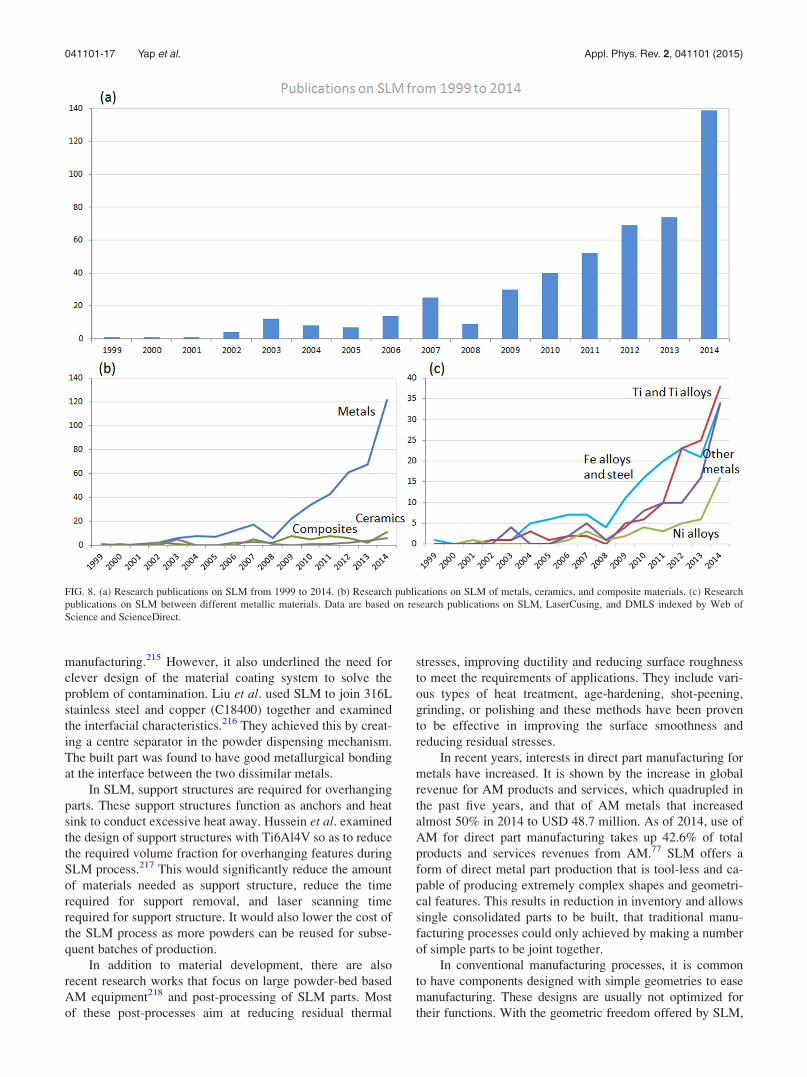
manufacturing.215 However, it also underlined the need for
clever design of the material coating system to solve the
problem of contamination. Liu et al. used SLM to join 316L
stainless steel and copper (C18400) together and examined
the interfacial characteristics.216 They achieved this by creat-
ing a centre separator in the powder dispensing mechanism.
The built part was found to have good metallurgical bonding
at the interface between the two dissimilar metals.
In SLM, support structures are required for overhanging
parts. These support structures function as anchors and heat
sink to conduct excessive heat away. Hussein et al. examined
the design of support structures with Ti6Al4V so as to reduce
the required volume fraction for overhanging features during
SLM process.217 This would significantly reduce the amount
of materials needed as support structure, reduce the time
required for support removal, and laser scanning time
required for support structure. It would also lower the cost of
the SLM process as more powders can be reused for subse-
quent batches of production.
In addition to material development, there are also
recent research works that focus on large powder-bed based
AM equipment218 and post-processing of SLM parts. Most
of these post-processes aim at reducing residual thermal
stresses, improving ductility and reducing surface roughness
to meet the requirements of applications. They include vari-
ous types of heat treatment, age-hardening, shot-peening,
grinding, or polishing and these methods have been proven
to be effective in improving the surface smoothness and
reducing residual stresses.
In recent years, interests in direct part manufacturing for
metals have increased. It is shown by the increase in global
revenue for AM products and services, which quadrupled in
the past five years, and that of AM metals that increased
almost 50% in 2014 to USD 48.7 million. As of 2014, use of
AM for direct part manufacturing takes up 42.6% of total
products and services revenues from AM.77 SLM offers a
form of direct metal part production that is tool-less and ca-
pable of producing extremely complex shapes and geometri-
cal features. This results in reduction in inventory and allows
single consolidated parts to be built, that traditional manu-
facturing processes could only achieved by making a number
of simple parts to be joint together.
In conventional manufacturing processes, it is common
to have components designed with simple geometries to ease
manufacturing. These designs are usually not optimized for
their functions. With the geometric freedom offered by SLM,
FIG. 8. (a) Research publications on SLM from 1999 to 2014. (b) Research publications on SLM of metals, ceramics, and composite materials. (c) Research
publications on SLM between different metallic materials. Data are based on research publications on SLM, LaserCusing, and DMLS indexed by Web of
Science and ScienceDirect.
041101-17 Yap et al. Appl. Phys. Rev. 2, 041101 (2015)

components can be designed to the same functional specifica-
tions with less materials. In 2014, Airbus unveiled a cabin
bracket optimized for weight saving without sacrificing func-
tionality. With metal AM, Airbus aims to produce aircraft
parts which weight 30%–55% less, while reducing raw mate-
rial used by 90%.219 The geometrical freedom in metal AM
also allows for manufacturing of lattice structures for weight
savings and designing of parts for improved fluid dynamics.
For instance, Croft Filters, a manufacturer of bespoke filters,
used SLM to produce new filters that only require one-step
production. Conventionally, filter production involves cutting,
welding, and lengthy labour processes.220,221
Besides the technical benefits of reduced tooling and
freedom of design, SLM can also bring a change to the man-
ufacturing sector in terms of economics. Together with the
advancement in information technology and the internet,
manufacturing can be decentralized. The economies of scale
brought about by high-volume, centralized assembly lines
are reduced.
However, there are still many challenges, besides legal
concerns regarding copyrights, trade secret, patents, and gov-
ernment regulations as highlighted by Esmond and Phero
et al.,222 for SLM to be deemed mature and reliable for the
industry to fully adopt it. The cost of materials and machines is
high as producers, such as machine manufacturers tries to re-
coup investments in research and development. However, the
unit price of machine is expected to decrease drastically when
the machines are produced in larger volumes and when their
related patents expire and market competition sets in. This is
especially applicable for SLM, which the associated European
patent was filed in 1998. The relatively low throughput and
small build volume are also limitations that SLM has. In order
to address this, SLM has developed the SLM 500 HL to double
the build volume to 280 mm� 500 mm� 325 mm.
Given the market trend of direct part production via AM
and increasing trend of research in the past decade, interests
in SLM and similar technologies will continue to rise. The
benefits brought about by SLM will further generate more
applications that require direct part manufacturing. Hence,
SLM is a technology that will stay relevant and important in
the AM industry in the foreseeable future.
ACKNOWLEDGMENTS
The authors would like to acknowledge Interdisciplinary
Graduate School, Nanyang Technological University for
funding the Ph.D. studies.
1W. Meiners, K. D. Wissenbach, and A. D. Gasser, “Shaped body espe-
cially prototype or replacement part production,” U.S. patent
DE19649849C1 (1998).2S. Das and J. J. Beaman, “Direct selective laser sintering of metals,” U.S.
patent US6676892B2 (2004).3C. K. Chua and K. F. Leong, 3D Printing and Additive Manufacturing:Principles and Applications, 4th ed. (World Scientific, Singapore, 2014),
p. 518.4A. T. Clare, P. R. Chalker, S. Davies, C. J. Sutcliffe, and S. Tsopanos, Int.
J. Mech. Mater. Des. 4, 181–187 (2007).5R. Acharya, R. Bansal, J. J. Gambone, and S. Das, Metall. Mater. Trans. B
45, 2247–2261 (2014).6R. Acharya, R. Bansal, J. J. Gambone, and S. Das, Metall. Mater. Trans. B
45, 2279–2290 (2014).
7R. Acharya, R. Bansal, J. J. Gambone, M. A. Kaplan, G. E. Fuchs, N. G.
Rudawski, and S. Das, Adv. Eng. Mater. 17, 942–950 (2015).8R. Acharya and S. Das, Metall. Mater. Trans. A 46, 3864–3875 (2015).9R. Li, J. Liu, Y. Shi, L. Wang, and W. Jiang, Int. J. Adv. Manuf. Technol.
59, 1025–1035 (2011).10P. Krakhmalev and I. Yadroitsev, Intermetallics 46, 147–155 (2014).11S. Das, Adv. Eng. Mater. 5, 701–711 (2003).12N. K. Tolochko, Y. V. Khlopkov, S. E. Mozzharov, M. B. Ignatiev, T.
Laoui, and V. I. Titov, Rapid Prototyping J. 6, 155–161 (2000).13P. Fischer, V. Romano, H. P. Weber, N. P. Karapatis, E. Boillat, and R.
Glardon, Acta Mater. 51, 1651–1662 (2003).14X. Wang, T. Laoui, J. Bonse, J.-P. Kruth, B. Lauwers, and L. Froyen, Int.
J. Adv. Manuf. Technol. 19, 351–357 (2002).15A. V. Gusarov and J. P. Kruth, Int. J. Heat Mass Transfer 48, 3423–3434
(2005).16L. E. Loh, Z. H. Liu, D. Q. Zhang, M. Mapar, S. L. Sing, C. K. Chua, and
W. Y. Yeong, Virtual Phys. Prototyping 9, 11–16 (2014).17L.-E. Loh, C.-K. Chua, W.-Y. Yeong, J. Song, M. Mapar, S.-L. Sing, and
D.-Q. Zhang, Int. J. Heat Mass Transfer 80, 288–300 (2015).18K. Mumtaz and N. Hopkinson, Rapid Prototyping J. 16, 248–257 (2010).19D. Bourell, A. B. Spierings, N. Herres, and G. Levy, Rapid Prototyping J.
17, 195–202 (2011).20B. Liu, R. Wildman, C. Tuck, I. Ashcroft, and R. Hague, in International
Solid Freeform Fabrication Symposium: An Additive Manufacturing
Conference (University of Texas at Austin, Austin, 2011), pp. 227–238.21N. K. Tolochko, S. E. Mozzharov, I. A. Yadroitsev, T. Laoui, L.
Froyen, V. I. Titov, and M. B. Ignatiev, Rapid Prototyping J. 10, 78–87
(2004).22J. P. Kruth, L. Froyen, J. Van Vaerenbergh, P. Mercelis, M. Rombouts,
and B. Lauwers, J. Mater. Process. Technol. 149, 616–622 (2004).23K. Kempen, B. Vrancken, L. Thijs, S. Buls, J. Van Humbeeck, and J.-P.
Kruth, in Solid Freeform Fabrication Symposium Proceedings, 2013,
Austin, TX, USA (The University of Texas at Austin).24I. Yadroitsev and I. Yadroitsava, Virtual Phys. Prototyping 10(2), 67–76
(2015).25M. Shiomi, K. Osakada, K. Nakamura, T. Yamashita, and F. Abe, CIRP
Ann. 53, 195–198 (2004).26E. Yasa, J. Deckers, J.-P. Kruth, M. Rombouts, and J. Luyten, in ASME
2010 10th Biennial Conference on Engineering Systems Design andAnalysis (ASME, 2010), pp. 695–703.
27Y.-C. Hagedorn, J. Wilkes, W. Meiners, K. Wissenbach, and R. Poprawe,
Phys. Proc. 5, 587–594 (2010).28F. Abe, K. Osakada, M. Shiomi, K. Uematsu, and M. Matsumoto,
J. Mater. Process. Technol. 111, 210–213 (2001).29G. Jandin, J. M. Bertin, L. Dembinski, and C. Coddet, Manufacture of
Stainless Steel Parts by Selective Laser Melting Process (CRC Press,
2005), pp. 431–434.30I. Tolosa, F. Garciandia, F. Zubiri, F. Zapirain, and A. Esnaola, Int. J.
Adv. Manuf. Technol. 51, 639–647 (2010).31T. H. C. Childs, C. Hauser, and M. Badrossamay, CIRP Ann. 53,
191–194 (2004).32T. H. C. Childs, C. Hauser, and M. Badrossamay, Proc. Inst. Mech. Eng.,
Part B 219, 339–357 (2005).33T. H. C. Childs and C. Hauser, Proc. Inst. Mech. Eng., Part B 219,
379–384 (2005).34M. Badrossamay and T. H. C. Childs, Int. J. Mach. Tools Manuf. 47,
779–784 (2007).35P. G. E. Jerrard, L. Hao, and K. E. Evans, Proc. Inst. Mech. Eng., Part B
223, 1409–1416 (2009).36I. Yadroitsev, P. Bertrand, B. Laget, and I. Smurov, in Annals of DAAAM
for 2008 and Proceedings of the 19th International DAAAM Symposium(DAAAM International, Vienna, 2008), pp. 1535–1536.
37J. P. Kruth, B. Vandenbroucke, J. Van Vaerenbergh, and I. Naert, Digital
Manufacturing of Biocompatible Metal Frameworks for Complex Dental
Prostheses by Means of SLS/SLM (Taylor & Francis, 2005), pp.
139–145.38M. Wehmoller, P. H. Warnke, C. Zilian, and H. Eufinger, CARS:
Computer Assisted Radiology and Surgery (Elsevier, 2005), pp.
690–695.39G. X. Chen, X. Y. Zeng, Z. M. Wang, K. Guan, and C. W. Peng,
Equipment Manufacturing Technology and Automation (Trans Tech
Publications, 2011), Pts. 1–3, pp. 174–178.40P. Bertrand and I. Smurov, in International Conference on Lasers,
Applications, and Technologies 2007: Laser-Assisted Micro- and
041101-18 Yap et al. Appl. Phys. Rev. 2, 041101 (2015)
Nanotechnologies (International Society for Optics and Photonics, 2007),
p. H7320.41Y. Q. Yang, J. B. Lu, Z. Y. Luo, and D. Wang, Rapid Prototyping J. 18,
482–489 (2012).42R. D. Li, J. H. Liu, Y. S. Shi, M. Z. Du, and Z. Xie, J. Mater. Eng.
Perform. 19, 666–671 (2010).43R. Bibb, D. Eggbeer, P. Evans, A. Bocca, and A. Sugar, Rapid
Prototyping J. 15, 346–354 (2009).44I. Yadroitsev, I. Yadroitsava, and I. Smurov, Laser-Based Micro- and
Nanopackaging and Assembly V (International Society for Optics and
Photonics, 2011).45I. Yadroitsev, P. Bertrand, B. Laget, and I. Smurov, J. Nucl. Mater. 362,
189–196 (2007).46M. A. Garcia, C. Garcia-Pando, and C. Marto, Conformal Cooling in
Moulds With Special Geometry (CRC Press, 2012), p. 409–412.47J. J. Brandner, E. Hansjosten, E. Anurjew, W. Pfleging, and K. Schubert,
Laser-Based Micro- and Nanopackaging and Assembly (International
Society for Optics and Photonics, 2007), p. 45911.48M. Wong, S. Tsopanos, C. Sutcliffe, and E. Owen, Rapid Prototyping J.
13, 291–297 (2007).49V. E. Beal, P. Erasenthiran, C. H. Ahrens, and P. Dickens, Proc. Inst.
Mech. Eng., Part B 221, 945–954 (2007).50L. Wang, Q. S. Wei, Y. S. Shi, and P. J. Xue, Adv. Mater. Res. 502,
67–71 (2012).51B. Song, S. J. Dong, H. L. Liao, and C. Coddet, Mater. Res. Innovations
16, 321–325 (2012).52M. Santorinaios, W. Brooks, C. J. Sutcliffe, and R. A. W. Mines, High
Performance Structures and Materials III (WIT Press, 2006), pp.
481–490.53M. Smith, W. J. Cantwell, Z. Guan, S. Tsopanos, M. D. Theobald, G. N.
Nurick, and G. S. Langdon, J. Sandwich Struct. Mater. 13, 479–501 (2011).54K. Ushijima, W. J. Cantwell, R. A. W. Mines, S. Tsopanos, and M.
Smith, J. Sandwich Struct. Mater. 13, 303–329 (2011).55E. J. Harris, R. E. Winter, M. Cotton, M. Swan, and J. Maw,
Shock Compression of Condensed Matter—2011 (AIP, 2012), Pts. 1
and 2.56Y. Shen, W. J. Cantwell, R. Mines, and K. Ushijima, Materials and
Manufacturing Technologies XIV (Trans Tech Publications, 2012), pp.
386–391.57Y. Shen, S. McKown, S. Tsopanos, C. J. Sutcliffe, R. A. W. Mines, and
W. J. Cantwell, J. Sandwich Struct. Mater. 12, 159–180 (2010).58R. A. W. Mines, S. Tsopanos, Y. Shen, R. Hasan, and S. T. McKown, Int.
J. Impact Eng. 60, 120–132 (2013).59O. Rehme and C. Emmelmann, J. Laser Micro Nanoeng. 4, 128–134
(2009).60Y. F. Shen, D. D. Gu, and P. Wu, Mater. Sci. Technol. 24, 1501–1505
(2008).61Z. Y. Wang, Y. F. Shen, and D. D. Gu, Powder Metall. 54, 225–230
(2011).62J. Milovanovic, M. Stojkovic, and M. Trajanovic, J. Sci. Ind. Res. 68,
1038–1042 (2009).63F. Feuerhahn, A. Schulz, T. Seefeld, and F. Vollertsen, Lasers in
Manufacturing (Trans Tech Publications, 2013), pp. 836–841.64I. Yadroitsev, I. Shishkovsky, P. Bertrand, and I. Smurov, Appl. Surf. Sci.
255, 5523–5527 (2009).65B. Song, S. Dong, S. Deng, H. Liao, and C. Coddet, Opt. Laser Technol.
56, 451–460 (2014).66M. Rombouts, J. P. Kruth, L. Froyen, and P. Mercelis, CIRP Ann. 55,
187–192 (2006).67B. Song, S. J. Dong, P. Coddet, H. L. Liao, and C. Coddet, Surf. Coat.
Technol. 206, 4704–4709 (2012).68G. Rolink, S. Vogt, L. Sencekova, A. Weisheit, R. Poprawe, and M.
Palm, J. Mater. Res. 29, 2036–2043 (2014).69B. Sustarsic, S. Dolinsek, M. Jenko, and V. Leskov�sek, Mater. Manuf.
Process. 24, 837–841 (2009).70Y. Wang, J. Bergstrom, and C. Burman, Mater. Sci. Eng., A 513–514,
64–71 (2009).71K. Abd-Elghany and D. L. Bourell, Rapid Prototyping J. 18, 420–428
(2012).72E. Yasa, J. Deckers, and J.-P. Kruth, Rapid Prototyping J. 17, 312–327
(2011).73C. S. Wright, M. Youseffi, S. P. Akhtar, T. H. C. Childs, C. Hauser, P.
Fox, and J. Xie, Advanced Materials Forum III (Trans Tech Publications,
2006), Pts. 1 and 2, pp. 516–523.
74Z. H. Liu, D. Q. Zhang, C. K. Chua, and K. F. Leong, Mater. Charact. 84,
72–80 (2013).75C. Casavola, S. L. Carnpanelli, and C. Pappalettere, J. Strain Anal. Eng.
Des. 44, 93–104 (2009).76M. A. Taha, A. F. Yousef, K. A. Gany, and H. A. Sabour, Materialwiss.
Werkstofftech. 43, 913–923 (2012).77T. Wohlers, Wohlers Report (Wohlers Associates, 2015).78K. Guan, Z. M. Wang, M. Gao, X. Y. Li, and X. Y. Zeng, Mater. Des. 50,
581–586 (2013).79H. K. Rafi, T. L. Starr, and B. E. Stucker, Int. J. Adv. Manuf. Technol.
69, 1299–1309 (2013).80A. B. Spierings, T. L. Starr, and K. Wegener, Rapid Prototyping J. 19,
88–94 (2013).81K. Kempen, E. Yasa, L. Thijs, J. P. Kruth, and J. Van Humbeeck, in
Lasers in Manufacturing 2011: Proceedings of the Sixth InternationalWlt Conference on Lasers in Manufacturing (Elsevier, 2011), Vol. 12, Pt.
A, pp. 255–263.82J. Delgado, J. Ciurana, and C. A. Rodriguez, Int. J. Adv. Manuf. Technol.
60, 601–610 (2012).83B. Song, S. J. Dong, H. L. Liao, and C. Coddet, Int. J. Adv. Manuf.
Technol. 69, 1323–1330 (2013).84A. Amanov, S. Sasaki, I. S. Cho, Y. Suzuki, H. J. Kim, and D. E. Kim,
Mater. Des. 47, 386–394 (2013).85D. Wang, Y. Q. Yang, X. B. Su, and Y. H. Chen, Int. J. Adv. Manuf.
Technol. 58, 1189–1199 (2012).86Z. H. Liu, C. K. Chua, K. F. Leong, K. Kempen, L. Thijs, E. Yasa,
and J. P. Kruth, in 5th International Conference on Advanced
Research in Virtual and Rapid Prototyping, 2011, Leiria, Portugal
(CRC Press).87F. Abe, E. C. Santos, Y. Kitamura, K. Osakada, and M. Shiomi, Proc.
Inst. Mech. Eng., Part C 217, 119–126 (2003).88T. Laoui, E. Santos, K. Osakada, M. Shiomi, M. Morita, S. K. Shaik, and
M. Takahashi, Proc. Inst. Mech. Eng., Part C 220, 857–863 (2006).89L. Mullen, R. C. Stamp, W. K. Brooks, E. Jones, and C. J. Sutcliffe,
J. Biomed. Mater. Res., Part B 89B, 325–334 (2009).90R. Stamp, P. Fox, W. O’Neill, E. Jones, and C. Sutcliffe, J. Mater. Sci.
Mater. Med. 20, 1839–1848 (2009).91C. Y. Lin, T. Wirtz, F. LaMarca, and S. J. Hollister, J. Biomed. Mater.
Res., Part A 83A, 272–279 (2007).92L. E. Murr, S. A. Quinones, S. M. Gaytan, M. I. Lopez, A. Rodela, E. Y.
Martinez, and R. B. Wicker, J. Mech. Behav. Biomed. Mater. 2, 20–32
(2009).93P. H. Warnke, T. Douglas, P. Wollny, E. Sherry, M. Steiner, S. Galonska,
and S. Sivananthan, Tissue Eng., Part C 15, 115–124 (2009).94B. Vandenbroucke and J. P. Kruth, Rapid Prototyping J. 13, 196–203
(2007).95J. E. Biemond, G. Hannink, N. Verdonschot, and P. Buma, J. Mater. Sci.
Mater. Med. 24, 745–753 (2013).96A. L. Jardini, M. A. Larosa, C. A. de Carvalho Zavaglia, L. F. Bernardes,
C. S. Lambert, P. Kharmandayan, and R. Maciel Filho, Virtual Phys.
Prototyping 9, 115–125 (2014).97E. Chlebus, B. Kuznicka, T. Kurzynowski, and B. Dybala, Mater.
Charact. 62, 488–495 (2011).98T. Marcu, M. Todea, L. Maines, D. Leordean, P. Berce, and C. Popa,
Powder Metall. 55, 309–314 (2012).99B. Dybala and E. Chlebus, Titanium Scaffolds for Custom CMF
Restorations (ASME, 2013), pp. 517–520.100P. Szymczyk, A. Junka, G. Ziolkowski, D. Smutnicka, M. Bartoszewicz,
and E. Chlebus, Acta Bioeng. Biomech. 15, 69–76 (2013).101L. C. Zhang and T. B. Sercombe, Powder Metallurgy of Titanium:
Powder Processing, Consolidation and Metallurgy of Titanium (Trans
Tech Publications, 2012), pp. 226–233.102A. Zielinski, S. Sobieszczyk, W. Serbinski, T. Seramak, and A.
Ossowska, Environmental Degradation of Engineering & MaterialsEngineering and Technologies (Trans Tech Publications, 2012), pp.
225–232.103M. Speirs, J. Van Humbeeck, J. Schrooten, J. Luyten, and J. P. Kruth, in
First CIRP Conference on Biomanufacturing (Elsevier, 2013), pp. 79–82.104Y. Wang, Y. F. Shen, Z. Y. Wang, J. L. Yang, N. Liu, and W. R. Huang,
Mater. Lett. 64, 674–676 (2010).105J. F. Sun, Y. Q. Yang, and D. Wang, Mater. Des. 49, 545–552
(2013).106B. Gorny, T. Niendorf, J. Lackmann, M. Thoene, T. Troester, and H. J.
Maier, Mater. Sci. Eng., A 528, 7962–7967 (2011).
041101-19 Yap et al. Appl. Phys. Rev. 2, 041101 (2015)

107F. Brenne, T. Niendorf, and H. J. Maier, J. Mater. Process. Technol. 213,
1558–1564 (2013).108D. M. Xiao, Y. Q. Yang, X. B. Su, D. Wang, and J. F. Sun, Biomed.
Mater. Eng. 23, 433–445 (2013).109R. Hasan, R. Mines, and P. Fox, in 11th International Conference on the
Mechanical Behavior of Materials, 2011, Villa Erba, Como, Italy
(Elsevier).110S. Das, M. Wohlert, J. J. Beaman, and D. L. Bourell, Mater. Des. 20,
115–121 (1999).111J. A. Lorente, M. M. Mendoza, A. Z. Petersson, L. Pambaguian, A. A.
Melcon, and C. Ernst, Single Part Microwave Filters Made FromSelective Laser Melting (IEEE, 2009), pp. 1421–1424.
112F. Caiazzo, F. Cardaropoli, V. Alfieri, V. Sergi, and L. Cuccaro, in 2012
XIX International Symposium on High-Power Laser Systems and
Applications, 2013, Istanbul, Turkey (SPIE).113D. E. Cooper, M. Stanford, K. A. Kibble, and G. J. Gibbons, Mater. Des.
41, 226–230 (2012).114E. C. Santos, K. Osakada, M. Shiomi, Y. Kitamura, and F. Abe, Proc.
Inst. Mech. Eng., Part C 218, 711–719 (2004).115D. D. Gu, Y. C. Hagedorn, W. Meiners, G. B. Meng, R. J. S. Batista, K.
Wissenbach, and R. Poprawe, Acta Mater. 60, 3849–3860 (2012).116B. C. Zhang, H. L. Liao, and C. Coddet, Vacuum 95, 25–29 (2013).117L. C. Zhang, D. Klemm, J. Eckert, Y. L. Hao, and T. B. Sercombe, Scr.
Mater. 65, 21–24 (2011).118Y. Kok, X. Tan, S. B. Tor, and C. K. Chua, Virtual Phys. Prototyping 10,
13–21 (2015).119A. Barbas, A. S. Bonnet, P. Lipinski, R. Pesci, and G. Dubois, J. Mech.
Behav. Biomed. Mater. 9, 34–44 (2012).120L. S. Bertol, W. Kindlein, F. P. da Silva, and C. Aumund-Kopp, Mater.
Des. 31, 3982–3988 (2010).121H. Meier, C. Haberland, J. Frenzel, and R. Zarnetta, Selective Laser
Melting of NiTi Shape Memory Components (CRC Press, 2010), pp.
233–238.122H. Meier, C. Haberland, and J. Frenzel, Structural and Functional
Properties of NiTi Shape Memory Alloys Produced by Selective LaserMelting (CRC Press, 2012), pp. 291–296.
123I. Kelbassa, P. Albus, J. Dietrich, and J. Wilkes, in Proceedings of the 3rd
Pacific International Conference on Application of Lasers and Optics,
2008, Beijing, China (Laser Institute of America).124K. N. Amato, S. M. Gaytan, L. E. Murr, E. Martinez, P. W. Shindo, J.
Hernandez, and F. Medina, Acta Mater. 60, 2229–2239 (2012).125Z. Wang, K. Guan, M. Gao, X. Li, X. Chen, and X. Zeng, J. Alloys
Compd. 513, 518–523 (2012).126Z. L. Lu, J. W. Cao, H. Jing, T. Liu, F. Lu, D. X. Wang, and D. C. Li,
Virtual Phys. Prototyping 8, 87–95 (2013).127F. Wang, X. Wu, and D. Clark, Mater. Sci. Technol. 27, 344–356 (2011).128T. Vilaro, C. Colin, J. D. Bartout, L. Naz�e, and M. Sennour, Mater. Sci.
Eng., A 534, 446–451 (2012).129L. Rickenbacher, T. Etter, S. H€ovel, and K. Wegener, Rapid Prototyping
J. 19, 282–290 (2013).130K. Osakada and M. Shiomi, Int. J. Mach. Tools Manuf. 46, 1188–1193
(2006).131T. Habijan, C. Haberland, H. Meier, J. Frenzel, J. Wittsiepe, C. Wuwer,
and M. K€oller, Mater. Sci. Eng.,: C 33, 419–426 (2013).132S. Das, M. Wohlert, J. Beaman, and D. Bourell, in Proceedings to the
Solid Freeform Fabrication Symposium, 1997, Austin, TX, USA
(University of Texas at Austin).133S. Das, J. J. Beama, M. Wohlert, and D. L. Bourell, Rapid Prototyping J.
4, 112–117 (1998).134S. Das, M. Wohlert, J. J. Beaman, and D. L. Bourell, J. Miner. Met.
Mater. Soc. 50, 17–20 (1998).135C. Sanz and V. G. Navas, J. Mater. Process. Technol. 213, 2126–2136
(2013).136F. Wang, Int. J. Adv. Manuf. Technol. 58, 545–551 (2011).137I. Yadroitsev, A. Gusarov, I. Yadroitsava, and I. Smurov, J. Mater.
Process. Technol. 210, 1624–1631 (2010).138K. Mumtaz and N. Hopkinson, Rapid Prototyping J. 15, 96–103
(2009).139K. Kempen, L. Thijs, E. Yasa, M. Badrossamay, W. Verheecke, and J.
Kruth, “Process optimization and microstructural analysis for selective
laser melting of AlSi10Mg,” in Solid Freeform Fabrication Symposium,
2011, University of Texas at Austin, Austin, TX, USA, pp. 484–495.140S. Pogson, P. Fox, and W. O’Neill, “The effect of varying laser scanning
speed on DMLR processed metal parts,” in Fourth National Conference
on Rapid and Virtual Prototyping and Applications (Professional
Engineering Publications, Lancaster, UK, 2003), pp. 43–50.141D. D. Gu and Y. F. Shen, Powder Metall. 49, 258–264 (2006).142C. C. Ng, M. M. Savalani, H. C. Man, and I. Gibson, Virtual Phys.
Prototyping 5, 13–19 (2010).143D. Zhang, Q. Cai, and J. Liu, Mater. Manuf. Process. 27, 1267–1270
(2012).144D. Q. Zhang, Z. H. Liu, Q. Z. Cai, J. H. Liu, and C. K. Chua, Int. J.
Refract. Met. Hard Mater. 45, 15–22 (2014).145S. Pauly, L. L€ober, R. Petters, M. Stoica, S. Scudino, U. K€uhn, and J.
Eckert, Mater. Today 16, 37–41 (2013).146S. P. Faure, L. Mercier, P. Didier, R. Roux, J. F. Coulon, and S. Garel,
Laser Sintering Process Analysis: Application to Chromium-Cobalt
Alloys For Dental Prosthesis Production (ASME, 2012), pp. 9–15.147M. Averyanova, P. Bertrand, and B. Verquin, Virtual Phys. Prototyping
6, 179–185 (2011).148R. C. Oyague, A. Sanchez-Turrion, J. F. Lopez-Lozano, J. Montero, A.
Albaladejo, and M. J. Suarez-Garcia, Odontology 100, 249–253 (2012).149K. B. Kim, W. C. Kim, H. Y. Kim, and J. H. Kim, Dental Mater. 29,
E91–E96 (2013).150S. Ayyildiz, E. H. Soylu, S. Ide, S. Kilic, C. Sipahi, B. Piskin, and H. S.
Gokce, J. Adv. Prosthodontics 5, 471–478 (2013).151C. C. Ng, M. Savalani, and H. C. Man, Rapid Prototyping J. 17, 479–490
(2011).152S. Pogson, P. Fox, C. Sutcliffe, and W. O’Neill, Rapid Prototyping J. 9,
334–343 (2003).153D. Becker, “SLM components made from copper alloy powder open up
new opportunities” (March 9, 2011).154M. Ameli, B. Agnew, P. S. Leung, B. Ng, C. J. Sutcliffe, J. Singh, and R.
McGlen, Appl. Therm. Eng. 52, 498–504 (2013).155T. Vilaro, S. Abed, and W. Knapp, in Proceedings of the 12th European
Forum on Rapid Prototyping, 2008.156D. Manfredi, F. Calignano, E. P. Ambrosio, M. Krishnan, R. Canali, S.
Biamino, and C. Badini, Metall. Italiana 10, 15–24 (2013).157D. Zhang, Q. Cai, J. Liu, and R. Li, J. Mater. Eng. Perform. 20,
1049–1054 (2010).158K. Deprez, S. Vandenberghe, K. Van Audenhaege, J. Van Vaerenbergh,
and R. Van Holen, Med. Phys. 40, 012501 (2013).159M. Khan and P. Dickens, Rapid Prototyping J. 18, 81–94 (2012).160J. Jhabvala, E. Boillat, and R. Glardon, Gold Bull. 44, 113–118
(2011).161P. Jerrard, L. Hao, S. Dadbakhsh, and K. Evans, in Proceedings of the
36th International MATADOR Conference (Springer, 2010), pp.
487–490.162D. Buchbinder, H. Schleifenbaum, S. Heidrich, W. Meiners, and J.
Bultmann, in Lasers in Manufacturing 2011: Proceedings of the Sixth
International Wlt Conference on Lasers in Manufacturing (Elsevier,
2011), Vol. 12, Pt. A, pp. 271–278.163D. Gu and Y. Shen, J. Mater. Process. Technol. 182, 564–573 (2007).164W. H. Wu, Y. Q. Yang, and Y. L. Huang, Chin. Opt. Lett. 5, 37–40
(2007).165D. D. Gu, Y. F. Shen, and Z. J. Lu, Mater. Des. 30, 2099–2107 (2009).166D. Zhang, Z. Liu, and C. Chua, in High Value Manufacturing:
Advanced Research in Virtual and Rapid Prototyping: Proceedings of
the 6th International Conference on Advanced Research in Virtual
and Rapid Prototyping, Leiria, Portugal, 1–5 October 2013 (CRC Press,
2013), p. 285.167D. Q. Zhang, Z. H. Liu, S. Li, M. Muzzammil, C. H. Wong, and C. K.
Chua, Selective Laser Melting: On The Study of Microstructure of K220(Research Publishing, 2014), pp. 176–184.
168B. Zhang, H. Liao, and C. Coddet, Mater. Des. 34, 753–758 (2012).169M. Khan and P. Dickens, Gold Bull. 43, 8 (2010).170F. Calignano, D. Manfredi, E. P. Ambrosio, L. Iuliano, and P. Fino, Int. J.
Adv. Manuf. Technol. 67, 2743–2751 (2013).171M. M. Savalani, C. C. Ng, and H. C. Man, Selective Laser Melting of
Magnesium for Future Applications in Medicine (IEEE, 2010).172C. Yap, C. Chua, Z. Dong, Z. Liu, and D. Zhang, in High Value
Manufacturing: Advanced Research in Virtual and Rapid Prototyping:Proceedings of the 6th International Conference on Advanced Researchin Virtual and Rapid Prototyping, Leiria, Portugal, 1–5 October 2013(CRC Press, 2013), p. 261.
173M. Mapar, D. Zhang, Z. Liu, W. Yeong, C. Chua, B. Tay, and F. Wiria,
in High Value Manufacturing: Advanced Research in Virtual and RapidPrototyping: Proceedings of the 6th International Conference on
041101-20 Yap et al. Appl. Phys. Rev. 2, 041101 (2015)

Advanced Research in Virtual and Rapid Prototyping, Leiria, Portugal,1–5 October 2013 (CRC Press, 2013), p. 267.
174J. Wilkes, Y. C. Hagedorn, W. Meiners, and K. Wissenbach, Rapid
Prototyping J. 19, 51–57 (2013).175Y. C. Hagedorn, N. Balachandron, W. Meiners, K. Wissenbach, and R.
Poprawe, in SFF Symposium, 2011, Austin, TX, USA (University of
Texas at Austin).176F.-H. Liu, J. Sol-Gel Sci. Technol. 64, 704–710 (2012).177X. H. Wang, J. Y. H. Fuh, Y. S. Wong, and Y. X. Yang, Int. J. Adv.
Manuf. Technol. 21, 1015–1020 (2003).178P. Bertrand, F. Bayle, C. Combe, P. Goeuriot, and I. Smurov, Appl. Surf.
Sci. 254, 989–992 (2007).179I. Shishkovsky, I. Yadroitsev, P. Bertrand, and I. Smurov, Appl. Surf. Sci.
254, 966–970 (2007).180P. Regenfuss, A. Streek, F. Ullmann, C. K€uhn, L. Hartwig, M. Horn, and
H. Exner, Interceramics 56, 420–422 (2007).181Y. Tang, J. Y. H. Fuh, H. T. Loh, Y. S. Wong, and L. Lu, Mater. Des. 24,
623–629 (2003).182J. Wilkes and K. Wissenbach, “Rapid manufacturing of ceramic compo-
nents for medical and technical applications via selective laser melting,”
in Euro-uRapid 2007 International User’s Conference on RapidPrototyping & Rapid Tooling & Rapid Manufacturing (Fraunhofer,
Frankfurt, Germany, 2007).183X. Tian, B. Sun, J. G. Heinrich, and D. Li, Int. J. Adv. Manuf. Technol.
64, 239–246 (2012).184S. Das, N. Harlan, G. Lee, J. J. Beaman, D. L. Bourell, J. W. Barlow, and
K. Sargent, Mater. Manuf. Process. 13, 241–261 (1998).185D. Gu, Y. Shen, and Z. Lu, Mater. Lett. 63, 1577–1579 (2009).186K. A. Mumtaz and N. Hopkinson, J. Mater. Sci. 42, 7647–7656 (2007).187L. Hao, S. Dadbakhsh, O. Seaman, and M. Felstead, J. Mater. Process.
Technol. 209, 5793–5801 (2009).188M. Lindner, S. Hoeges, W. Meiners, K. Wissenbach, R. Smeets, R. Telle,
and H. Fischer, J. Biomed. Mater. Res., Part A 97, 466–471 (2011).189D. Gu, Y.-C. Hagedorn, W. Meiners, K. Wissenbach, and R. Poprawe,
Surf. Coat. Technol. 205, 3285–3292 (2011).190I. V. Shishkovskii, I. A. Yadroitsev, and I. Y. Smurov, Powder Metall.
Metal Ceram. 50, 275–283 (2011).191G. V. Salmoria, P. Klauss, K. Zepon, L. A. Kanis, C. R. M. Roesler, and
L. F. Vieira, Virtual Phys. Prototyping 7, 107–115 (2012).192S. Das, T. P. Fuesting, G. Danyo, L. E. Brown, J. J. Beaman, and D. L.
Bourell, Mater. Des. 21, 63–73 (2000).193S. Dadbakhsh, L. Hao, P. G. E. Jerrard, and D. Z. Zhang, Powder
Technol. 231, 112–121 (2012).194D. Gu, Y. Shen, and G. Meng, Mater. Lett. 63, 2536–2538 (2009).195D. D. Gu and Y. F. Shen, Acta Metall. Sin. 46, 761–768 (2010).
196D. Gu, Z. Wang, Y. Shen, Q. Li, and Y. Li, Appl. Surf. Sci. 255,
9230–9240 (2009).197D. Gu, Y.-C. Hagedorn, W. Meiners, K. Wissenbach, and R. Poprawe,
Compos. Sci. Technol. 71, 1612–1620 (2011).198D. Gu and W. Meiners, Mater. Sci. Eng., A 527, 7585–7592 (2010).199R. Li, Y. Shi, J. Liu, Z. Xie, and Z. Wang, Int. J. Adv. Manuf. Technol.
48, 597–605 (2009).200A. Gaard, P. Krakhmalev, and J. Bergstr€om, J. Alloys Compd. 421,
166–171 (2006).201J. S. Chen, Y. H. Huang, X. S. Gao, B. Qiao, J. M. Yang, and Y. Q. He,
Adv. Compos. Mater. 20, 277–287 (2011).202D. Gu and Y. Shen, Appl. Surf. Sci. 254, 3971–3978 (2008).203D. D. Gu and Y. F. Shen, J. Mater. Res. 24, 3397–3406 (2009).204S. Dadbakhsh and L. Hao, J. Alloys Compd. 541, 328–334 (2012).205D. Gu, G. Meng, C. Li, W. Meiners, and R. Poprawe, Scr. Mater. 67,
185–188 (2012).206D. D. Gu, C. Hong, and G. B. Meng, Metall. Mater. Trans. A 43A,
697–708 (2012).207B. Song, S. J. Dong, P. Coddet, G. S. Zhou, S. Ouyang, H. L. Liao, and
C. Coddet, J. Alloys Compd. 579, 415–421 (2013).208J. H. Kim and T. S. Creasy, in Solid Freeform Fabrication Symposium
(University of Texas at Austin, 2002), p. 224.209K. K. B. Hon and T. J. Gill, CIRP Ann. 52, 173–176 (2003).210D. Gu and Y. Shen, Mater. Sci. Eng., A 435–436, 54–61 (2006).211D. Gu and G. Zhang, Virtual Phys. Prototyping 8, 11–18 (2013).212D. Gu, Y. Shen, L. Zhao, J. Xiao, P. Wu, and Y. Zhu, Mater. Sci. Eng., A
445–446, 316–322 (2007).213C. K. Srinivasa, C. S. Ramesh, and S. K. Prabhakar, Rapid Prototyping J.
16, 258–267 (2010).214S. K. Ghosh and P. Saha, Mater. Des. 32, 139–145 (2011).215M. Vaezi, S. Chianrabutra, B. Mellor, and S. Yang, Virtual Phys.
Prototyping 8, 19–50 (2013).216Z. H. Liu, D. Q. Zhang, S. L. Sing, C. K. Chua, and L. E. Loh, Mater.
Charact. 94, 116–125 (2014).217A. Hussein, L. Hao, C. Z. Yan, R. Everson, and P. Young, J. Mater.
Process. Technol. 213, 1019–1026 (2013).218S. F. Wen, C. Z. Yan, Q. S. Wei, L. C. Zhang, X. Zhao, W. Zhu, and Y.
S. Shi, Virtual Phys. Prototyping 9, 213–223 (2014).219Airbus. Printing the future: Airbus expands its applications of the revolu-
tionary additive layer manufacturing process, 2014.220N. Burns, Filtration þ Separation 51, 42–43 (2014).221L. Nickels, “Meeting the mainstream,” Metal Powder Report, Special
Feature (2015).222R. W. Esmond and G. C. Phero, Virtual Phys. Prototyping 10, 9–12
(2014).
041101-21 Yap et al. Appl. Phys. Rev. 2, 041101 (2015)
Related Documents