FATIGUE ANALYSIS IN SELECTIVE LASER MELTING: REVIEW AND INVESTIGATION OF THIN-WALLED ACTUATOR HOUSINGS Hanns A. Stoffregen 1,2 , Katja Butterweck 1 , Eberhard Abele 1,2 1 Institute of Production Management, Technology, and Machine Tools (PTW), Technische Universität Darmstadt, Darmstadt, Germany 2 LOEWE Research Center AdRIA, Darmstadt, Germany Abstract The versatile applicable selective laser melting (SLM) is a promising manufacturing technology that allows 3-dimensional design freedom for complex and challenging load bearing parts. A specific application of SLM is the production of thin-walled housings for piezoceramic actuators which induce cyclic loads. Although there are investigations on the fatigue behavior of SLM-specimens, wide acceptance of SLM is limited by a lack of knowledge concerning the operating behavior of actual parts. This paper presents a review on existing studies about fatigue life analysis in SLM as well as results from uniaxial high cycle fatigue (HCF) tests of 1.4542 stainless steel as-built and machined specimens with a stress ratio of R = 0. Due to a lower surface roughness machined specimens show significantly higher fatigue strength compared to as-built ones. The obtained fatigue strength at 10 7 cycles of as-built specimens is used as input for fatigue tests of thin-walled actuator housings. Numerical simulation is used to determine the stress distribution of thin-walled as-built actuator housings under specific loads. Results indicate that the thin-walled as-built actuator housing withstand higher peak stresses compared to as-built specimens due to a high stress gradient. 1. Introduction Additive manufacturing (AM) is an emerging field in manufacturing technologies that has the common principle of building up solid parts directly from 3D CAD data by adding material layer by layer. Part-specific tools are not required in these technologies. Additive manufacturing technologies allow the generation of parts which fulfil the properties of final products (Gibson et al., 2010; Huang et al., 2013; Zhai et al., 2014). Among AM technologies, selective laser melting (SLM) has become a relevant production method for manufacturing ready-to-use parts made from metals such as stainless steel, nickel, titanium, and aluminum alloys (Gu et al., 2012). As AM technology SLM enables the following key advantages for innovative products: function optimized and application tailored product design, function integration, mass customization, resource efficiency, and shortened time to market (Grzesiak et al., 2011; Petrovic et al., 2011; Campbell et al., 2012). In SLM process development relevant research has been conducted to increase the parts’ density since it positively affects mechanical properties such as strength and hardness. High density SLM process parameters were developed for various materials such as stainless steel (Kruth et al., 2010), aluminium (Buchbinder et al., 2011), titanium (Kong et al., 2011), and nickel based alloys (Mumtaz et al., 2008). Static material properties of SLM generated parts are comparable to those of conventionally manufactured ones (Zhai et al., 2014). However, as a powder bed based layerwise process SLM parts are accompanied by a high surface roughness which is a critical factor under cyclical loading (Huang and Leu, 2014). The surface roughness of SLM parts is caused by three main effects: (1) the process inherent stair case effect, (2) partially melted powder particles sticking to the surface, and (3) instability of the melt pool (Thijs et al., 2010; Pyka et al., 2013). Post processing operations such as milling or (electrochemical) polishing allow a smoothening of the surface roughness. Nevertheless, any additional process step is contrary to the direct manufacturing principle underlying AM. In addition, for complex parts with internal features a post processing may not be applicable in any case. To exploit the SLM technique as single-step and near net shape manufacturing route, a knowledge base about fatigue behavior of SLM generated parts in their as-built condition is required. So far limited studies on fatigue 635

Welcome message from author
This document is posted to help you gain knowledge. Please leave a comment to let me know what you think about it! Share it to your friends and learn new things together.
Transcript

FATIGUE ANALYSIS IN SELECTIVE LASER MELTING: REVIEW AND INVESTIGATION OF
THIN-WALLED ACTUATOR HOUSINGS
Hanns A. Stoffregen1,2
, Katja Butterweck1, Eberhard Abele
1,2
1 Institute of Production Management, Technology, and Machine Tools (PTW), Technische Universität
Darmstadt, Darmstadt, Germany 2 LOEWE Research Center AdRIA, Darmstadt, Germany
Abstract
The versatile applicable selective laser melting (SLM) is a promising manufacturing technology that
allows 3-dimensional design freedom for complex and challenging load bearing parts. A specific application of
SLM is the production of thin-walled housings for piezoceramic actuators which induce cyclic loads. Although
there are investigations on the fatigue behavior of SLM-specimens, wide acceptance of SLM is limited by a lack
of knowledge concerning the operating behavior of actual parts. This paper presents a review on existing studies
about fatigue life analysis in SLM as well as results from uniaxial high cycle fatigue (HCF) tests of 1.4542
stainless steel as-built and machined specimens with a stress ratio of R = 0. Due to a lower surface roughness
machined specimens show significantly higher fatigue strength compared to as-built ones. The obtained fatigue
strength at 107 cycles of as-built specimens is used as input for fatigue tests of thin-walled actuator housings.
Numerical simulation is used to determine the stress distribution of thin-walled as-built actuator housings under
specific loads. Results indicate that the thin-walled as-built actuator housing withstand higher peak stresses
compared to as-built specimens due to a high stress gradient.
1. Introduction
Additive manufacturing (AM) is an emerging field in manufacturing technologies that has the common
principle of building up solid parts directly from 3D CAD data by adding material layer by layer. Part-specific
tools are not required in these technologies. Additive manufacturing technologies allow the generation of parts
which fulfil the properties of final products (Gibson et al., 2010; Huang et al., 2013; Zhai et al., 2014). Among
AM technologies, selective laser melting (SLM) has become a relevant production method for manufacturing
ready-to-use parts made from metals such as stainless steel, nickel, titanium, and aluminum alloys (Gu et al.,
2012). As AM technology SLM enables the following key advantages for innovative products: function
optimized and application tailored product design, function integration, mass customization, resource
efficiency, and shortened time to market (Grzesiak et al., 2011; Petrovic et al., 2011; Campbell et al., 2012).
In SLM process development relevant research has been conducted to increase the parts’ density since it
positively affects mechanical properties such as strength and hardness. High density SLM process parameters
were developed for various materials such as stainless steel (Kruth et al., 2010), aluminium (Buchbinder et al.,
2011), titanium (Kong et al., 2011), and nickel based alloys (Mumtaz et al., 2008). Static material properties of
SLM generated parts are comparable to those of conventionally manufactured ones (Zhai et al., 2014).
However, as a powder bed based layerwise process SLM parts are accompanied by a high surface roughness
which is a critical factor under cyclical loading (Huang and Leu, 2014). The surface roughness of SLM parts is
caused by three main effects: (1) the process inherent stair case effect, (2) partially melted powder particles
sticking to the surface, and (3) instability of the melt pool (Thijs et al., 2010; Pyka et al., 2013). Post processing
operations such as milling or (electrochemical) polishing allow a smoothening of the surface roughness.
Nevertheless, any additional process step is contrary to the direct manufacturing principle underlying AM. In
addition, for complex parts with internal features a post processing may not be applicable in any case. To
exploit the SLM technique as single-step and near net shape manufacturing route, a knowledge base about
fatigue behavior of SLM generated parts in their as-built condition is required. So far limited studies on fatigue
635
dlb7274
Typewritten Text
REVIEWED

analysis of as-built specimens or actual parts exist. The lack of knowledge concerning the fatigue behavior of
as-built SLM parts under operational loads represents a barrier of entry for industry into SLM technology.
The aim of this study is to increase the knowledge base about fatigue life of SLM generated as-built
specimens and actual parts. Experiments using as-built and machined SLM 1.4542 stainless steel specimens are
used to determine the Wöhler-curves up to 107 cycles. The fatigue strength in the high cycle fatigue (HCF)
regime between these two conditions is compared. Based on fatigue testing of as-built specimens the fatigue
behavior of SLM generated thin-walled actuator housings1 in their as-built condition will be analyzed. To
estimate the stress distribution within the thin-walled SLM housings under defined loads a numerical simulation
model will be used. Prior to the experiments a comprehensive overview about fatigue analysis in selective laser
melting of metal parts is given.
2. Review of fatigue analysis in selective laser melting
Over the last decade studies in the field of selective laser melting were primarily focused on process
qualification, development of new materials and applications. Examples are studies which investigate the
application of SLM for manufacturing medical implants with tailored properties (e.g. porosity) (Murr et al.,
2009; Bartolo et al., 2012). Only in recent years studies on fatigue analysis of SLM manufactured specimens
have been published and set up a further research area.
Fig. 1 summarizes the results form fatigue analysis using Wöhler tests which have been conducted by
various research groups. Each data point represents the characteristic knee point of the obtained S-N curves
towards the long life fatigue regime. The analysis of existing studies (Table 1) allows the following
conclusions:
- The present studies are limited towards the material selection. Most fatigue analysis is focused on
stainless steel followed by studies on the SLM well approved Ti6Al4V alloy. Both for AlSi10Mg
and Hastelloy®
X one study is known. Independently conducted studies on machined 1.4542 (17-4
PH) stainless steel performed by Sehrt and Witt (2010) as well as by Starr et al. (2011) show good
accordance. Similarly, results of Rafi et al. (2013) and Spierings et al. (2013) on machined 1.4540
1 Function integration is a key advantage of AM technologies. A novel process has been developed to structurally integrate
piezoceramic multilayer actuators using the SLM technology (Stoffregen et al., 2013). In this process the actuators are fully integrated
into a metallic, monolithic SLM housing. Since the actuator induces cyclic loads knowledge about the fatigue strength of the
surrounding housing is required.
Fig. 1. Summary of knee points (S-N values) from relevant studies on the fatigue life of SLM manufactured specimens.
105
106
107
0
200
400
600
800
Stainless Steel (SST)
1.4404 vertical sand-blasted (Spierings et al., 2013), n=7
1.4404 vertical machined (Spierings et al., 2013), n=15
1.4540 vertical machined HT (Rafi et al., 2013), n=15
1.4540 vertical machined HT (Spierings et al., 2013), n=12
1.4542 horizontal polished (Sehrt and Witt, 2010), n=40*
1.4542 vertical machined (Starr et al., 2011), n=10
Titanium alloy
Ti6Al4V 45° polished HT (Wycisk et al., 2013), n=12
Ti6Al4V 45° as-built HT (Wycisk et al., 2013), n=12
Ti6Al4V vertical sand-blasted HT (Gong et al., 2012), n=9
Other alloy
AlSi10Mg vertical machined HT (Brandl et al., 2012), n=10
Hastelloy X vertical machined (Wang, 2011), n=6
Hastelloy X vertical machined HIPed (Wang, 2011), n=6
Maxim
um
str
ess a
t knee p
oin
t (
ma
x,k)
(MP
a)
Number of cycles at knee point (Nk)
* rotating bending test; conversion factor: 1.15 (Lee, 2005)
n = sample size; HT = heat treatment; HIP = hot isostatic pressing
636

(15-5 PH) are comparable towards the fatigue strength at 107 cycles and the knee point.
- Studies are primarily focused on the fatigue analysis of post processed SLM specimens. In most
cases for post processing a surface finishing such as turning and polishing was applied. In addition,
some studies investigate the influence of subsequent heat treatments. Only three studies on as-built
specimens, specifically without surface finishing, could be identified. Spierings et al. (2013)
investigated different surface treatments on fatigue life of 1.4404 (316L) stainless steel. Between
polished and machined specimens no significant difference has been found. In contrast, the as-built
specimens showed a lower fatigue strength due to the high surface roughness (Ra ≈ 10 µm). Results
of Wycisk et al. (2013) on Ti6Al4V specimens showed a significant difference in fatigue life
between as-built and polished specimens as well. The fatigue strength of sand-blasted (Gong et al.,
2012) and turned (Rafi et al., 2013) Ti6Al4V specimens show similar values to the results of Wycisk
et al. (2013) (finished). The number of cycles at the knee points however shows a variance. One
reason might be the low sample number of the studies which leads to statistical uncertainty. The
research group of Leuders et al. (2013) investigated different heat treatments on the fatigue life of
Ti6Al4V specimens. A significant positive influence of subsequent heat treatment was observed. In
addition, the application of hot isostatic pressing (HIP) could further extend the fatigue life due to
reduction of porosity. A similar research design was applied by Riemer et al. (2014) on 1.4404
(316L) stainless steel specimens. Besides a heat treatment and a HIP process of machined specimens
a set of specimens in their as-built condition was tested. Due to the high surface roughness as-built
specimens showed the lowest fatigue strength compared to machined ones. The heat treatment had a
positive influence on fatigue life; specimens undergoing a HIP process showed best results. The
positive influence of a HIP treatment of SLM generated specimens on fatigue life could be found as
well for Hastelloy®
X by Wang (2012). For AlSi10Mg the fatigue strength was determined with and
without heat treatment (peak-hardening) on machined specimens (Brandl et al., 2012). A significant
positive influence of peak-hardening was observed.
- The reviewed studies predominantly investigated SLM specimens manufactured vertically under a
polar angle of 0°. Brandl et al. (2012) studied three different polar angles (0°, 45°, 90°) combined
with a variation of heat treatment and platform temperature using a DoE approach. The orientation
of the specimens had a significant influence on fatigue strength depending on the other two
parameters. Above maximum stresses of 600 MPa Hastelloy®
X specimens showed a higher fatigue
resistance when horizontally oriented compared to vertically oriented. Below this stress level the
difference was not significant (Wang, 2012). A study on Ti6Al4V specimens manufactured in x, y,
and z orientation showed qualitatively better fatigue performance for horizontally than for vertically
oriented specimens. However, due to porosity and residual stresses this effect was not quantified
(Edwards and Ramulu, 2014).
- The fatigue life of finished SLM specimens is comparable to conventionally manufactured
specimens. For 1.4404 (316L) little difference in fatigue strength between SLM and conventional
specimens was observed (Spierings et al., 2013). A similar conclusion is provided by Sehrt and Witt
(2010) for 1.4540 (15-5 PH) stainless steel. The study of Rafi et al. (2013) on Ti6Al4V showed a
higher fatigue strength for SLM specimens compared to cast and annealed specimens due to a fine
lamellar microstructure resulting from the SLM process. In general, when comparing fatigue
strength of SLM specimens with conventionally manufactured specimens the surface and heat
treatment need to be considered (Rafi et al., 2013).
- Studies on the fatigue behavior of SLM specimens were primarily carried out in the high cycle
fatigue regime (5 ∙ 104 < N ≤ 10
7). Table 1 summarizes the identified studies with corresponding
cycle limits and stress ratios. Only the study of Brandl et al. (2012) investigated a cycle limit beyond
107.
- The sample size for fatigue tests is between 5 to 15 specimens in one condition. One exception is the
study of Sehrt and Witt (2010) which used 40 specimens made from 1.4542 (17-4 PH) stainless
steel.
Aside of the tests on fatigue strength, studies on the fatigue crack growth were performed by Riemer et
al. (2014) on 1.4404 (316L) specimens and the research groups of Leuders et al. (2013) and van Hooreweder et
637

al. (2012) on Ti6Al4V specimens. In addition, fatigue analysis on additively manufactured polymers were
conducted by van Hooreweder et al. (2010), van Hooreweder et al. (2013), Blattmeier et al. (2012), and Lee and
Huang (2013).
A recent study of Lipinski et al. (2013) is the only known research work on fatigue analysis of actual
parts manufactured using SLM. In their work two different sample sets made from commercially pure grade 2
titanium (CPG2Ti) were tested: 1) thin-walled tube specimens with (w) and without (wo) heat treatment; 2)
porous specimens (complex 3D lattice structures with geometrical defined porosity characteristic as bone
substitutes (Barbas et al., 2012)). S-N curves for thin-walled tube samples with (n = 18) and without (n = 40)
heat treatment were obtained using a stress ratio of R = 0.1. The heat treatment showed a negative influence on
fatigue limit due to a relaxation of compressive residual stresses. In general, fatigue stress amplitudes between
65.7 MPa (w) and 74.5 MPa (wo) at N = 107 found to be relatively low compared to the CPG2Ti bulk material
properties. The high surface roughness and SLM specific defects/imperfections were claimed as reasons
therefore. For tests on two different porous specimens different cyclic load levels were applied which lead to
variations in stress ratio and amplitude. Using this experimental setting a method based on the stress gradient of
the structure was developed to define a fatigue criterion for geometrical defined porous structures.
Table 1. Overview of studies on fatigue analysis in selective laser melting.
Study Material SLM System Specimens Research design Cycle limit /
stress ratio
(Sehrt and Witt,
2010)
SST 1.4542
(17-4 PH)
EOS M270 ASTM E466
circular 1
rotating bending test (Wöhler) /
polished, horizontally
manufactured, without heat
treatment / sample size: 40
N = 107
R = -1
(Starr et al.,
2011)
SST 1.4542
(17-4 PH)
EOS M270 ASTM E466
circular 2
tension-tension test (Wöhler) /
machined, vertically manufactured,
without heat treatment / sample
size: 10
N = 107
R = 0.1
(Brandl et al.,
2012)
AlSi10Mg TrumaForm
LF130
ASTM E466
circular 2
tension-tension test (Wöhler) /
machined, DoE research design
with parameters: (1) building
direction (0°, 45°, 90°), (2)
platform temperature (30°C,
300°C), (3) heat treatment (no, yes
PH T6) / sample size: 9-10 for each
condition
N = 3 ∙ 107
R = 0.1
(Gong et al.,
2012)
Ti6Al4V EOS M270 ASTM E466
circular 2
tension-tension test (Wöhler) / as-
built, sand-blasted, with heat
treatment / sample size: 9
N = 107
R = 0.1
(Wang, 2012) Hastelloy® X EOS M270 ASTM E466
circular /
rectangular 1
a) four-point bending test (Wöhler)
/ machined, vertically and
horizontally manufactured, with
and without HIP treatment / sample
size: 6-9 for each condition
b) tension-tension test (Wöhler) /
machined, vertically manufactured,
with and without HIP treatment /
sample size: 6 for each condition
N = 107
R = 0.1
N = 107
R = 0.1
(Chan et al.,
2013)
Ti6Al4V ELI EOS M270 rectangular three-point bending test (constant
stress amplitude)
/ two different surface conditions
(fully EDM machined/side as-
built), horizontally oriented,
without heat treatment / sample
size: 10 for each condition
N = n/a
R = 0.1
638

Study Material SLM System Specimens Research design Cycle limit /
stress ratio
(Leuders et al.,
2013)
Ti6Al4V SLM 250HL ASTM E466
circular
tension-compression (constant
stress amplitude) / machined,
vertically manufactured, four
different heat treatments / sample
size: not specified
N = 2 ∙ 106
R = -1
(Rafi et al.,
2013)
Ti6Al4V
EOS M270
ASTM E466
tension-tension test (Wöhler) /
machined, vertically manufactured,
with heat treatment / sample size: 9
N = 107
R = 0.1
SST 1.4540
(15-5 PH)
EOS M270 ASTM E466 tension-tension test (Wöhler) /
machined, vertically manufactured,
with heat treatment / sample size:
15
N = 107
R = 0.1
(Spierings et al.,
2013)
SST 1.4404
(316L)
Concept Laser
M1
ASTM E466
circular 2
tension-tension test (Wöhler) / three
different surface conditions (as-
built, machined, polished),
vertically manufactured, without
heat treatment / sample size: 8-15
N = 107
R = 0.1
SST 1.4540
(15-5 PH)
EOS M270 ASTM E466
circular 2
tension-tension test (Wöhler) /
machined, vertically manufactured,
with heat treatment / sample size:
12
N = 107
R = 0.1
(Wycisk et al.,
2013)
Ti6Al4V EOS M270 ASTM E466
circular 2
tension-tension test (Wöhler) / three
different surface conditions (as-
built, polished, shot-peening), polar
angle 45°, with heat treatment /
sample size: 12 for each condition
N = 107
R = 0.1
(Edwards and
Ramulu, 2014)
Ti6Al4V MTT 250 rectangular tension-compression (constant
stress amplitude) / as-built and
machined surface condition, three
different building orientations (x, y,
z), without heat treatment / sample
size: at least 5 for each condition
N = 2 ∙ 106
R = -0.2
(Riemer et al.,
2014)
SST 1.4404
(316L)
SLM 250HL ASTM E466
circular
tension-compression (constant
stress amplitude) / 1) as-built, 3-4)
machined, vertically manufactured,
three different heat treatment
conditions (without, 650°C, HIPed)
/ sample size: 5 for each condition
N = 2 ∙ 106
R = -1
The review of studies on fatigue analysis in selective laser melting indicates potential research areas for
future work. So far research in the following areas has been of subordinate importance:
- Investigation of the behavior of SLM parts in the very high cycle fatigue (VHCF) regime: Load
bearing parts in the automotive and aerospace industry are often exposed to cyclic loads beyond 107
cycles. However, the determination of S-N curves in the HCF regime, which is predominantly
existent with respect to SLM, does not necessarily allow an estimation of the very high cycle fatigue
behavior since the asymptote must not be horizontally (Bathias, 1999; Marines I. et al., 2003;
Sonsino, 2007; Pyttel et al., 2011; Stanzl-Tschegg, 2014). The references indicate that the course of
the S-N curves is material dependent. When a so-called “endurance limit” is used for design, the
safety against a declining S-N curve in the VHCF regime will decrease (Sonsino, 2007). Based on
applications of SLM manufactured parts with loads beyond 107 cycles relevant studies have to be
performed which allow a statistical significant assessment of fatigue strength in this regime.
639

- Studies on repeatability of fatigue characteristics: As shown in Table 1 most Wöhler tests were
performed based on 6 to 15 samples which is at the lower end of the recommendation of 12 to 24
samples for design allowable and reliability tests (Lee et al., 2005). With increasing sample size the
confidence of the fatigue strength can be increased (Beretta et al., 1995; Martin et al., 2011). In
addition, the influence of build direction and position as well as inter and intra batch comparisons
have not been studied systematically so far. This might be of further interest, since it is known from
other studies that the SLM process is accompanied by anisotropy (Tolosa et al., 2010; Chlebus et al.,
2011; Spierings et al., 2013; Thijs et al., 2013) which may also affect the fatigue behavior.
- Studies on actual parts manufactured by SLM under operational loads: Present studies follow a
standard protocol using uniaxial or bending tests based on specimens. Test series to assess the
fatigue behavior of SLM generated parts also under complex (multiaxial, stochastic and/or
operational) stress-strain scenarios have not been conducted. In addition, limited knowledge on the
fatigue behavior of as-built specimens (e.g. high surface roughness) is present which is of special
interest to use SLM as direct single-step manufacturing technology.
3. Research methodology
3.1 System and material
For the purpose of this study all specimens were manufactured on an EOS M270 SLM system with a
200 W Yb-fibre laser (continuous wave, wave length λ = 1064 nm, Gaussian beam profile), using commercially
available 1.4542 (17-4 PH) stainless steel powder (d50 ≈ 28 µm; d90 ≈ 41 µm). The system integrated beam
expander was set to a laser spot diameter ds ≈ 140 µm. PRIMES Focus/Beam Monitor is used to verify the laser
power output and laser spot diameter. For all specimens, the layer thickness was fixed to 20 µm, representing
the default value for the combination of material used and the SLM system. All specimens were manufactured
using a meander-shaped stripe exposure which rotates along the z-axis. A qualified exposure parameters which
lead to fully dense parts (laser power P = 195 W; scan speed vs = 1000 mm/s; hatch distance h = 0.1 mm) was
applied.
3.2 Uniaxial fatigue test of SLM manufactured specimens
As test geometry for fatigue analysis common round un-notched specimens (Kt = 1.0) according to
ASTM E466-07 with tangentially blending fillets between the test section and the ends have been chosen. The
nominal diameter was set to 6 mm, the length of the constant test section to 11 mm. All specimens were
manufactured vertically oriented. 39 specimens were manufactured in net-shape to be tested as-built, 20
specimens were manufactured with 1 mm allowance and machined afterwards. The as-built specimens were
manufactures in two batches. Fatigue tests were performed on an Instron servohydraulic Hydropuls MHF test
system at ambient conditions. A uniaxial test setup with a stress-ratio of R = 0 (pulsating tension) and N = 107
cycles as the maximum number of cycles was selected. The test frequency was varied between 70 Hz and
140 Hz depending on the applied load. In this regime a significant influence of the test frequency is not
expected due to the absence of corrosion induced degradation effects and temperature rise of the specimens
(Bargel and Schulze, 2005; Spickenreuther, 2007).
The routine test (Weibull, 1961) in combination with the staircase method (Lin et al., 2001; Morrissey
and Nicholas, 2006) was used to determine the S-N curves and the fatigue strength at N = 107 cycles. The initial
stress of 500 MPa for as-built and 600 MPa for machined specimens has been reduced stepwise until no failure
occurred. Afterwards the staircase tests were performed for as-built and machined specimens. Since the as-built
specimens were manufactured in two batches the staircase method has been applied for each batch separately.
To determine the statistical distribution of the S-N curve each stress horizon has been tested twice for machined
and five times for as-built specimens (three from batch one, two from batch two). Analysis of fatigue tests was
carried out with a survival probability of 10%, 50%, and 90% using a Gaussian probability grid and the formula
of Rossow (1964). The staircase tests were evaluated based on the method proposed by Hück (1983) which
takes account of the step interval and the stress horizon of all valid data points. The width of the scatter band
has been assumed to be constant after the knee point (Sonsino, 2008).
640

The roughness of three machined and three as-built specimens has been determined using a contact
surface measurement system (Perthometer).
3.3 Uniaxial fatigue test of SLM manufactured thin-walled as-built actuator housings
In previous research a process has been developed to fully integrate piezoceramic actuators into a
metallic, monolithic housing by means of SLM. The main advantage is an application tailored housing design,
particularly the stiffness of the housing (Stoffregen et al., 2013). Therefore, the housing shown Fig. 5a has three
design parameters, wall thickness t, housing radius r, and angle of bellow α, which can be adjusted to obtain
proper stiffness characteristics. A numerical simulation model has been used to determine the stress distribution
within the housings under specific loads. Three different housings have been tested. The selection was based on
the fatigue strength obtained from the as-built specimens and the resulting stress distribution under application
relevant loads. Application relevant loads were derived from typical blocking forces of integrated actuators
(maximum value 1.5 to 2 kN). Fatigue analysis of the thin-walled housings is referred to the peak stress.
The selected housings were tested similarly to the specimens (section 3.2). A uniaxial test setup with a
stress-ratio of R = 0 was chosen and corresponds to the load scenario induced by integrated actuators. The
maximum number of cycles to be performed was set to N = 107 cycles. The test frequency was set to 133 Hz for
all thin-walled housings due the low applied forces. For all three housing geometries a routine test method was
used. For two housing types 10 samples were tested, for the other one 29 samples. In addition to the routine test
the staircase method was used for the latter. Analysis corresponds to the procedure described under section 3.2.
4. Results
4.1 Fatigue strength of as-built and machined specimens
The arithmetical mean deviation of the roughness profile for as-built specimens is on average Ra =
13.7 µm, the maximum height of the roughness profile is on average Rz = 86.0 µm. For machined specimens
the roughness parameters are Ra = 0.2 µm and Rz = 1.7 µm. Fig. 2 shows the results of the fatigue tests of as-
built and machined specimens. Corresponding survival probability levels are included for 10%, 50%, and 90%
probability. The calculated fatigue strength at 107 cycles is σmax = 219 MPa for as-built specimens, which
corresponds to a stress amplitude of σa = 110 MPa. For machined specimens the maximum stress at 107 cycles
is σmax = 492 MPa (σa = 246 MPa). Table 2 summarizes the characteristic parameters of the obtained S-N
curves. The slope in the finite life region is significant flatter for machined compared to as-built specimens.
Fig. 3 illustrates the results of the staircase testing method. A fictive test result has been added for as-
Fig. 2. S-N curves with survival probability for as-built and machined specimens (log-log scale).
105
106
107
100
200
300
400
500
600
700 as-built #1 run out
as-built #1 failure
as-built #2 run out
as-built #2 failure
machined run out
machined failure
as-built P50
as-built P10
as-built P90
machined P50
machined P10
machined P90
Maxim
um
str
ess (
ma
x)
(MP
a)
Number of cycles to failure (Nf)
Stress ratio R = 0
641
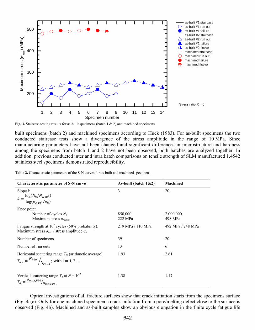
built specimens (batch 2) and machined specimens according to Hück (1983). For as-built specimens the two
conducted staircase tests show a divergence of the stress amplitude in the range of 10 MPa. Since
manufacturing parameters have not been changed and significant differences in microstructure and hardness
among the specimens from batch 1 and 2 have not been observed, both batches are analyzed together. In
addition, previous conducted inter and intra batch comparisons on tensile strength of SLM manufactured 1.4542
stainless steel specimens demonstrated reproducibility.
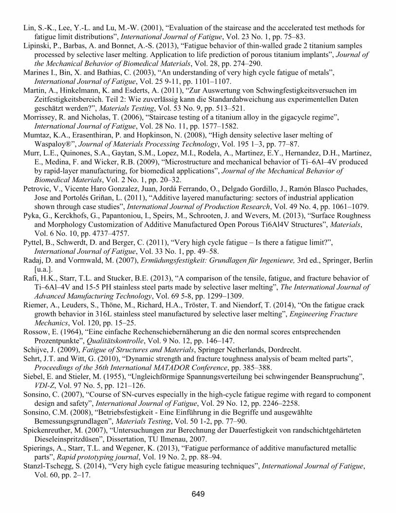
Table 2. Characteristic parameters of the S-N curves for as-built and machined specimens.
Characteristic parameter of S-N curve As-built (batch 1&2) Machined
Slope k
( )
( )
3 20
Knee point
Number of cycles Nk
Maximum stress σmax,k
850,000
222 MPa
2,000,000
498 MPa
Fatigue strength at 107 cycles (50% probability):
Maximum stress σmax / stress amplitude σa
219 MPa / 110 MPa 492 MPa / 248 MPa
Number of specimens 39 20
Number of run outs 13 6
Horizontal scattering range TN (arithmetic average)
⁄
1.93 2.61
Vertical scattering range Tσ at N = 107
⁄
1.38 1.17
Optical investigations of all fracture surfaces show that crack initiation starts from the specimens surface
(Fig. 4a,c). Only for one machined specimen a crack initiation from a pore/melting defect close to the surface is
observed (Fig. 4b). Machined and as-built samples show an obvious elongation in the finite cycle fatigue life
Fig. 3. Staircase testing results for as-built specimens (batch 1 & 2) and machined specimens.
1 2 3 4 5 6 7 8 9 10 11 12 13 14
200
300
400
500
Stress ratio R = 0
as-built #1 staircase
as-built #1 run out
as-built #1 failure
as-built #2 staircase
as-built #2 run out
as-built #2 failure
as-built #2 fictive
machined staircase
machined run out
machined failure
machined fictive
Maxim
um
str
ess (
ma
x)
(MP
a)
Specimen number
642

regime. For as-built samples under a load above σmax = 300 MPa (σa = 150 MPa) multiple cracks on the surface
can be detected. The final fracture zone for as-built specimens in the HCF range is straight due to a lower stress
amplitude and longer crack propagation (Fig. 4c). Contrary, for machined specimens a semi-circular shape is
observed (Fig. 4a). Prepared micrographs of machined and as-built specimens showed no significant influence
of the post-processing on the microstructure (e.g. surface hardening), which may influence the fatigue strength.
4.2 Fatigue strength of thin-walled as-built actuator housings
The fatigue strength results at 107 cycles of as-built specimens are used as input for the fatigue analysis
of thin-walled as-built actuator housings. An ANSYS mechanical simulation model of the housings is used to
determine the geometrical dependent stress distribution under application relevant loads. The design parameters
of the housing are wall thickness t, housing radius r, and angle of bellow α (Fig. 5a). Three different housing
designs are tested. The selection criterion is based on operational loads which result in a maximum stress (von
Mises) close to the fatigue strength at N = 107 cycles of as-built samples (σmax = 219 MPa). Micrographs of the
bellow fold are used to determine the as-produced wall thickness (Fig. 5b). The numerically obtained stress
distribution displaying position and value of the maximum stress is shown in Fig. 5c exemplarily for housing 2.
Since it is assumed that the housing design results in a notch effect which reduces the fatigue strength one initial
housing test is performed with an operational load resulting in a lower maximum stress. Due to a divergence
between simulated (kh,sim) and experimentally determined (kh,exp) housing stiffness a correction of the test load
Ftest following the equation
( ) (
) (1)
is conducted. Using this equation a maximum test load can be calculated from an expected maximum
peak stress σmax,p. An approximate linear relationship between load and maximum stress is shown during FE
analysis. Table 3 summarizes the initial test load for the thin-walled housing as well as relevant design
Fig. 4. Microscopic images of lower fracture surfaces. a) machined specimen (Nf = 860,739; σmax = 495 MPa), b) machined specimen (Nf =
8,092,655; σmax = 495 MPa), c) as-built specimen (Nf = 525,654; σmax = 260 MPa).
Crack initiation
Final fracture
(a) (b)
Crack initiation
(c)
Crack initiation
Final fracture
1
2
3
4
(a) (b) (c)
Fig. 5. (a) Cross section of the thin-walled actuator housing and design parameters. Numbers indicate position of the bellow. Blue marked are inner
folds, red marked is the outer fold at which the numerical simulation shows the highest peak stress. (b) Micrograph of a bellow fold (housing 2);
black: cross section of the fold, grey: embedding resin. (c) FEA result of stress distribution in an outer bellow fold for housing 2.
643

parameters.
Table 3. Initial test setup for thin-walled actuator housings and corresponding housing design parameters.
Housing Test load Ftest Stress (v. Mises)* Stiffness kh,sim Stiffness kh,exp Design parameter (t, r, α)
1 1.85 kN 213 MPa 93 N/µm 84 N/µm 0.6 mm, 8.5 mm, 160°
2 0.76 kN 213 MPa 34 N/µm 25 N/µm 0.5 mm, 10.0 mm, 137.5°
3 0.82 kN 182 MPa 44 N/µm 35 N/µm 0.6 mm, 8.5 mm, 137.5°
* maximum peak stress ( ) based on FEA
Fig. 6 shows the results of the fatigue tests of the three different housings designs. The maximum stress
(peak stress at notch root) is calculated from the test load using equation (1). The knee point for all tested
housings is in the range of 7.5 to 10 ∙ 105 cycles and therewith in a higher cycle regime than the tested as-built
specimens. In contrast, the scattering range is below the tested as-built specimens, both horizontally (TN) and
vertically (Tσ). The slopes in the finite life region show little variance among the three housings. Compared to
the fatigue strength at N = 107 cycles of the as-built specimens the housings withstand a higher maximum stress.
When exhibiting failure the cracks occur at one of the three inner folds (Fig. 5a). A predominantly position of
the crack among the three inner folds is not observed. Table 4 summarizes the parameters of the S-N curves for
the thin-walled housings.
5. Discussion
A strong divergence between the fatigue behavior of as-built and machined SLM 1.4542 stainless steel
specimens in the HCF regime is observed. For the machined specimens the fatigue strength at N = 107 cycles is
492 MPa and accounts 51% of the measured ultimate tensile strength (Rm = 961 MPa). This finding is in
accordance to the studies of Sehrt and Witt (2010) and Starr et al. (2011) which obtain values of 52%
respectively 56%. It is also to notice that the S-N curves in this two studies show comparable parameters (slope,
knee point) to the one in this research work. Therefore, reproducibility of fatigue properties of SLM generated
specimens can be assumed. The results of Wu and Lin (2002) on conventionally manufactured 1.4542 stainless
steel show fatigue strength values in the same magnitude. This finding supports comparability of fatigue
Fig. 6. S-N curves with survival probability for thin-walled actuator housings 1-3 (log-log scale). Maximum peak stress is based on v. Mises
stress at the notch root.
105
106
107
100
200
300
400
500
600
700
Stress ratio R = 0
housing 1 run out
housing 1 failure
housing 2 run out
housing 2 failure
housing 3 run out
housing 3 failure
housing 1 P50
housing 1 P10
housing 1 P90
housing 2 P10
housing 2 P50
housing 2 P90
housing 3 P50
housing 3 P10
housing 3 P90
Maxim
um
peak s
tress (
ma
x,p)
(MP
a)
Number of cycles to failure (Nf)
644

behavior between machined SLM generated specimens and conventional manufactured ones.
For as-built specimens the fatigue strength at N = 107 cycles is with 219 MPa significantly below the
value of machined specimens. The fatigue strength accounts only 23% of the ultimate tensile strength. The
reason can be found in the high surface roughness of as-built specimens and the therewith associated notch
effect (Arola and Williams, 2002; Radaj and Vormwald, 2007; Chan et al., 2013). The surface roughness due to
partially melted powder particles and the inconsistency of the melt pool causes micro notches at the specimen’s
surface which lead to a stress intensity during cyclical loadings. The analysis of the fracture surface shows that
crack initiation occurs at defects on the specimen’s surface and supports this assumption. Based on the fatigue
results an experimentally determined surface roughness reduction factor γ in the HCF regime can be calculated:
(2)
For as-built specimens a significant divergence between the two batches is not assumed. The following
reasoning underlies this procedure: (1) Divergence between the two batches is only present above 9 ∙ 105 cycles.
In the finite life region the results indicate random scattering. (2) Manufacturing parameters have not been
changed and significant differences in microstructure and hardness among the specimens from batch 1 and 2
have not been observed. (3) The vertical scattering Tσ = 1.38 in the HCF regime of the combined analysis of
batch 1 & 2 is in the range of cast and sintered steel (Sonsino, 2007).
The slope in the finite life region k as well as the cycle number at the knee point Nk of machined
specimens is typical for un-notched cast and sintered steel with medium strength (Sonsino, 2007). Machined
specimens (slope k = 20) show a higher sensitivity towards stresses in the finite life region compared to as-built
specimens (slope k = 3). With increasing notch effect (e.g. surface roughness) the slope becomes steeper and the
sensitivity towards stress variations decreases (Lee et al., 2005; Radaj and Vormwald, 2007). This finding is
true for the as-built specimens which show a significant steeper slope compared to machined ones; in case of as-
built specimens crack propagation mechanisms are dominant.
The fatigue analysis of the thin-walled housings shows that the maximum stress at the notch root is
significantly above the value of as-built specimens (σmax = 219 MPa). The fatigue strength of the housings at N
= 107 cycles is between 343 MPa for housing 1 and 425 MPa for housing 2. A potential explanation can be
found in the stress gradient. For the parameters shown in Table 3 an FEA is applied to determine the stress
Table 4. Characteristic parameters of the S-N curves for thin-walled actuator housings.
Characteristic parameter of S-N curve Housing 1 Housing 2 Housing 3
( )
( )
Slope k 4.8 4.8 5.0
Knee point
Number of cycles Nk
Maximum stress σmax,k
950,000
348 MPa
750,000
437 MPa
1,000,000
372 MPa
Fatigue strength at 107 cycles (50% probability):
Maximum peak stress (v. Mises) σmax,p /
Peak stress amplitude (v. Mises) σa,p
343 MPa /
172 MPa
425 MPa /
213 MPa
355 MPa /
178 MPa
Number of specimens 29 10 10
Number of run outs 5 2 1
⁄
Horizontal scattering range TN (arithmetic average) 1.31 1.63 1.28
⁄
Vertical scattering range Tσ at N = 107 1.07 1.19 1.05
645

distribution at the folds. The stress gradient at the notch root is calculated according to (Siebel and Stieler, 1955;
Filippini, 2000):
|
(3)
The stress gradient and distribution for the three housings are shown in Fig. 7. The stress gradient
determines how steep the stress decreases with distance from the notch’s root. A low stress gradient results in a
higher average stress in the local damage zone. Based on the stress gradient concept higher stress gradients
increase fatigue strength since it decreases the volume fraction of highly stressed material (Siebel and Stieler,
1955; Kuguel, 1961; Lee et al., 2005; Adib-Ramezani and Jeong, 2007; Schijve, 2009). For the tested housing
the order of the stress gradients is χ1 < χ3 < χ2. This result implies that housing 1 should have the lowest fatigue
strength and housing 2 respectively the highest fatigue strength which is in accordance to the obtained S-N
curves in Fig. 6. Therefore, besides peak stresses the stress gradient needs to be considered for fatigue analysis
of the thin-walled as-built actuator housings.
Of practical relevance is the little scattering of the test results for the thin-walled actuator housings.
Both, horizontal and vertical scattering, are significantly below the ranges of the as-built and machined
specimens. This allows a fatigue life approach with a low safety factor.
Based on the FEA results indicating a maximum peak stress at the top outer fold (Fig. 5a, position 4) a
failure is assumed to occur at the same position. Contrary when exhibiting failure it occurred at one of the three
inner folds (Fig. 5a, positions 1-3). Crack initiation starts from the outer side from one of the three inner folds.
A potential explanation is the geometry of the thin-walled housing. Outer folds are characterized by a larger
diameter compared to inner folds while having the same wall thickness. Consequently, outer folds have a larger
cross section compared to inner folds which results in a lower average stress. The latter might be the reason why
the thin-walled housings exhibit failure at the inner folds.
The thin-walled housings demonstrate fatigue strength at N = 107 cycles for loads up to 1.5 kN which
fulfils the requirements of the proposed application (integration of piezoceramic actuators). For housing 1
fatigue strength at 107 cycles exists even for loads up to 2.5 kN.
6. Summary and outlook
The present work shows a review of fatigue analysis in selective laser melting. Within this comparably
new research field studies are conducted almost exclusively on the basis of specimens. The studies focus on
SLM approved stainless steel (e.g. 1.4542, 316L) or Ti6Al4V alloy which are predominantly tested in post
processed conditions (e.g. machining, heat treatment) in the HCF regime (N ≤ 107 cycles); the fatigue behavior
of as-built specimens has not been investigated intensively. Therefore, valid material values for the fatigue life
approach of as-built specimens and SLM parts do not exist. However, for machined specimens fatigue strength
is in the range of conventionally manufactured specimens. Standardized fatigue test conditions and
Fig. 7. Stress distribution (v. Mises) of the three different housings under the loads shown in Table 3. Stress distribution is shown in radial
direction using FEA. Stress gradient is calculated for notch root (x = 0 mm). Dashed line represents polynomial fit of third order.
0.0 0.1 0.2 0.3 0.4 0.5 0.6 0.7
60
80
100
120
140
160
180
200
220
0.0 0.1 0.2 0.3 0.4 0.5 0.6 0.7
60
80
100
120
140
160
180
200
220
0.0 0.1 0.2 0.3 0.4 0.5 0.6 0.7
60
80
100
120
140
160
180
200
220
Str
ess (
v.
Mis
es)
(MP
a)
Distance (mm)
Housing 1
χ = 3.7 χ = 4.9χ = 5.9
Housing 2
Distance (mm)
Housing 3
Distance (mm)
646

documentation (e.g. sample size, test method, statistical analysis, build direction, post processing) for SLM
generated specimens might be helpful to ensure comparability between conducted studies.
Experiments on the fatigue behavior of 1.4542 stainless steel as-built and machined specimens as well as
of thin-walled as-built actuator housings were performed. A uniaxial test setup with a stress-ratio of R = 0
(pulsating tension) and test runs up to N = 107 cycles was selected. From the results the following conclusions
can be drawn:
- The fatigue strength at N = 107 cycles of as-built specimens (σmax = 219 MPa, σa = 110 MPa) is
significantly lower than of machined specimens (σmax = 492 MPa, σa = 246 MPa) due to a high
surface roughness. The experimentally determined surface roughness reduction factor γ is 0.44.
- Crack initiation starts for as-built and machined specimens from the surface. Therefore,
manufacturing defects in the inside of the SLM generated specimens are not the reason for fatigue
failure.
- Machined specimens show a higher sensitivity towards stress in the finite life region compared to as-
built specimens. This relation is shown through the slopes of the S-N curves in the relevant cycle
regime.
- The endurable peak stress of thin-walled as-built actuator housings at 107 cycles is significantly
above the fatigue strength of as-built specimens (factor 1.57 to 1.94). An explanation can be found in
the stress gradient within the thin-walls due to the geometry. Stress gradients χ above 3.7 indicate
that only a small volume fraction is exposed to high stresses; on average, the stress is significantly
below the peak stress. S-N curves support the stress gradient concept that with increasing stress
gradient the fatigue strength increases.
- The thin-walled actuator housings demonstrate fatigue strength at N = 107 cycles under application
relevant loads. In addition, vertical and horizontal scattering of the S-N curves are below the values
of the specimens. This allows an approach of fatigue life with a low safety factor.
Future research should be extended to thin-walled housings with other design parameters to prove the
stress gradient concept. It is also desired to obtain valid assessment models for fatigue behavior of SLM
generated parts without conducting extensive test series.
Acknowledgments
This work was funded by the LOEWE Research Center AdRIA “Adaptronic Research, Innovation,
Application”, grant number III L 4 – 518/14.0004 (2008). The authors would like to thank the Hessen State
Ministry of Higher Education, Research and the Arts for the funding.
References
Adib-Ramezani, H. and Jeong, J. (2007), “Advanced volumetric method for fatigue life prediction using stress
gradient effects at notch roots”, Computational Materials Science, Vol. 39 No. 3, pp. 649–663.
Arola, D. and Williams, C. (2002), “Estimating the fatigue stress concentration factor of machined surfaces”,
International Journal of Fatigue, Vol. 24 No. 9, pp. 923–930.
Barbas, A., Bonnet, A.-S., Lipinski, P., Pesci, R. and Dubois, G. (2012), “Development and mechanical
characterization of porous titanium bone substitutes”, Journal of the Mechanical Behavior of Biomedical
Materials, Vol. 9, pp. 34–44.
Bargel, H.-J. and Schulze, G. (2005), Werkstoffkunde, 9., bearb. Aufl, Springer, Berlin [u.a.].
Bartolo, P., Kruth, J.-P., Silva, J., Levy, G., Malshe, A., Rajurkar, K., Mitsuishi, M., Ciurana, J. and Leu, M.
(2012), “Biomedical production of implants by additive electro-chemical and physical processes”, CIRP
Annals - Manufacturing Technology, Vol. 61 No. 2, pp. 635–655.
Bathias, C. (1999), “There is no infinite fatigue life in metallic materials”, Fatigue & Fracture of Engineering
Materials and Structures, Vol. 22 No. 7, pp. 559–565.
Beretta, S., Clerici, P. and Matteazzi, S. (1995), “The Effect of Sample Size on the Confidence of Endurance
Fatigue Tests”, Fatigue & Fracture of Engineering Materials and Structures, Vol. 18 No. 1, pp. 129–139.
647

Blattmeier, M., Witt, G., Wortberg, J., Eggert, J. and Toepker, J. (2012), “Influence of surface characteristics on
fatigue behaviour of laser sintered plastics”, Rapid prototyping journal, Vol. 18 No. 2, pp. 161–171.
Brandl, E., Heckenberger, U., Holzinger, V. and Buchbinder, D. (2012), “Additive manufactured AlSi10Mg
samples using Selective Laser Melting (SLM): Microstructure, high cycle fatigue, and fracture behavior”,
Materials & Design, Vol. 34, pp. 159–169.
Buchbinder, D., Schleifenbaum, H., Heidrich, S., Meiners, W. and Bültmann, J. (2011), “High Power Selective
Laser Melting (HP SLM) of Aluminum Parts. Lasers in Manufacturing 2011 - Proceedings of the Sixth
International WLT Conference on Lasers in Manufacturing”, Physics Procedia, Vol. 12 No. 0, pp. 271–278.
Campbell, I., Bourell, D. and Gibson, I. (2012), “Additive manufacturing: rapid prototyping comes of age”,
Rapid prototyping journal, Vol. 18 No. 4, pp. 255–258.
Chan, K.S., Koike, M., Mason, R.L. and Okabe, T. (2013), “Fatigue Life of Titanium Alloys Fabricated by
Additive Layer Manufacturing Techniques for Dental Implants”, Metallurgical and Materials Transactions
A, Vol. 44 No. 2, pp. 1010–1022.
Chlebus, E., Kuźnicka, B., Kurzynowski, T. and Dybała, B. (2011), “Microstructure and mechanical behaviour
of Ti―6Al―7Nb alloy produced by selective laser melting”, Materials Characterization, Vol. 62 No. 5, pp.
488–495.
Edwards, P. and Ramulu, M. (2014), “Fatigue Performance Evaluation of Selective Laser Melted Ti-6Al-4V”,
Materials Science and Engineering: A, Vol. 598, pp. 327–337.
Filippini, M. (2000), “Stress gradient calculations at notches”, International Journal of Fatigue, Vol. 22 No. 5,
pp. 397–409.
Gibson, I., Rosen, D.W. and Stucker, B. (2010), Additive manufacturing technologies: Rapid prototyping to
direct digital manufacturing, Springer, New York, NY.
Gong, H., Rafi, K., Starr, T. and Stucker, B. (2012), “Effect of Defects on Fatigue Tests of As-built Ti-6Al-4V
Parts Fabricated by Selective Laser Melting”, Proceedings Solid Freeform Fabrication Symposium 2012,
Austin, Texas, pp. 499–506.
Grzesiak, A., Becker, R. and Verl, A. (2011), “The Bionic Handling Assistant: a success story of additive
manufacturing”, Assembly Automation, Vol. 31 No. 4, pp. 329–333.
Gu, D.D., Meiners, W., Wissenbach, K. and Poprawe, R. (2012), “Laser additive manufacturing of metallic
components: materials, processes and mechanisms”, International Materials Reviews, Vol. 57 No. 3, pp.
133–164.
Huang, S.H., Liu, P., Mokasdar, A. and Hou, L. (2013), “Additive manufacturing and its societal impact: a
literature review”, The International Journal of Advanced Manufacturing Technology, Vol. 67 5-8, pp.
1191–1203.
Huang, Y. and Leu, M.C. (2014), Frontiers of Additive Manufacturing Research and Education: An NSF
Additive Manufacturing Workshop Report - July 11 and 12, 2013.
Hück, M. (1983), “Ein verbessertes Verfahren für die Auswertung von Treppenstufenversuchen”,
Materialwissenschaft und Werkstofftechnik, Vol. 14 No. 12, pp. 406–417.
Kong, C.-J., Tuck, C.J., Ashcroft, I.A., Wildman, R.D. and Hague, R. (2011), “High Density Ti6Al4V via SLM
Processing: Microstructure and Mechanical Properties”, Proceedings Solid Freeform Farbrication
Symposium 2011, Austin, Texas, Vol. 22, pp. 475–483.
Kruth, J.-P., Badrossamay, M., Yasa, E., Deckers, J., Thijs, L. and van Humbeeck, J. (2010), “Part and material
properties in selective laser melting of metals”, Proceedings of the 16th International Symposium on
Electromachining.
Kuguel, A. (1961), “A relation between theoretical stress concentrationf actor and fatigue notch factor deduced
from the concept of highly stressed volume”, ASTM Proceedings, Vol. 61, pp. 732–744.
Lee, J. and Huang, A. (2013), “Fatigue analysis of FDM materials”, Rapid prototyping journal, Vol. 19 No. 4,
pp. 291–299.
Lee, Y.-L., Pan, J., Hathaway, R.B. and Barkey, M.E. (2005), Fatigue testing and analysis: Theory and
practice, Elsevier Butterworth-Heinemann, Burlington, Mass.
Leuders, S., Thöne, M., Riemer, A., Niendorf, T., Tröster, T., Richard, H. and Maier, H. (2013), “On the
mechanical behaviour of titanium alloy TiAl6V4 manufactured by selective laser melting: Fatigue resistance
and crack growth performance”, International Journal of Fatigue, Vol. 48, pp. 300–307.
648
Lin, S.-K., Lee, Y.-L. and Lu, M.-W. (2001), “Evaluation of the staircase and the accelerated test methods for
fatigue limit distributions”, International Journal of Fatigue, Vol. 23 No. 1, pp. 75–83.
Lipinski, P., Barbas, A. and Bonnet, A.-S. (2013), “Fatigue behavior of thin-walled grade 2 titanium samples
processed by selective laser melting. Application to life prediction of porous titanium implants”, Journal of
the Mechanical Behavior of Biomedical Materials, Vol. 28, pp. 274–290.
Marines I., Bin, X. and Bathias, C. (2003), “An understanding of very high cycle fatigue of metals”,
International Journal of Fatigue, Vol. 25 9-11, pp. 1101–1107.
Martin, A., Hinkelmann, K. and Esderts, A. (2011), “Zur Auswertung von Schwingfestigkeitsversuchen im
Zeitfestigkeitsbereich. Teil 2: Wie zuverlässig kann die Standardabweichung aus experimentellen Daten
geschätzt werden?”, Materials Testing, Vol. 53 No. 9, pp. 513–521.
Morrissey, R. and Nicholas, T. (2006), “Staircase testing of a titanium alloy in the gigacycle regime”,
International Journal of Fatigue, Vol. 28 No. 11, pp. 1577–1582.
Mumtaz, K.A., Erasenthiran, P. and Hopkinson, N. (2008), “High density selective laser melting of
Waspaloy®”, Journal of Materials Processing Technology, Vol. 195 1–3, pp. 77–87.
Murr, L.E., Quinones, S.A., Gaytan, S.M., Lopez, M.I., Rodela, A., Martinez, E.Y., Hernandez, D.H., Martinez,
E., Medina, F. and Wicker, R.B. (2009), “Microstructure and mechanical behavior of Ti–6Al–4V produced
by rapid-layer manufacturing, for biomedical applications”, Journal of the Mechanical Behavior of
Biomedical Materials, Vol. 2 No. 1, pp. 20–32.
Petrovic, V., Vicente Haro Gonzalez, Juan, Jordá Ferrando, O., Delgado Gordillo, J., Ramón Blasco Puchades,
Jose and Portolés Griñan, L. (2011), “Additive layered manufacturing: sectors of industrial application
shown through case studies”, International Journal of Production Research, Vol. 49 No. 4, pp. 1061–1079.
Pyka, G., Kerckhofs, G., Papantoniou, I., Speirs, M., Schrooten, J. and Wevers, M. (2013), “Surface Roughness
and Morphology Customization of Additive Manufactured Open Porous Ti6Al4V Structures”, Materials,
Vol. 6 No. 10, pp. 4737–4757.
Pyttel, B., Schwerdt, D. and Berger, C. (2011), “Very high cycle fatigue – Is there a fatigue limit?”,
International Journal of Fatigue, Vol. 33 No. 1, pp. 49–58.
Radaj, D. and Vormwald, M. (2007), Ermüdungsfestigkeit: Grundlagen für Ingenieure, 3rd ed., Springer, Berlin
[u.a.].
Rafi, H.K., Starr, T.L. and Stucker, B.E. (2013), “A comparison of the tensile, fatigue, and fracture behavior of
Ti–6Al–4V and 15-5 PH stainless steel parts made by selective laser melting”, The International Journal of
Advanced Manufacturing Technology, Vol. 69 5-8, pp. 1299–1309.
Riemer, A., Leuders, S., Thöne, M., Richard, H.A., Tröster, T. and Niendorf, T. (2014), “On the fatigue crack
growth behavior in 316L stainless steel manufactured by selective laser melting”, Engineering Fracture
Mechanics, Vol. 120, pp. 15–25.
Rossow, E. (1964), “Eine einfache Rechenschiebernäherung an die den normal scores entsprechenden
Prozentpunkte”, Qualitätskontrolle, Vol. 9 No. 12, pp. 146–147.
Schijve, J. (2009), Fatigue of Structures and Materials, Springer Netherlands, Dordrecht.
Sehrt, J.T. and Witt, G. (2010), “Dynamic strength and fracture toughness analysis of beam melted parts”,
Proceedings of the 36th International MATADOR Conference, pp. 385–388.
Siebel, E. and Stieler, M. (1955), “Ungleichförmige Spannungsverteilung bei schwingender Beanspruchung”,
VDI-Z, Vol. 97 No. 5, pp. 121–126.
Sonsino, C. (2007), “Course of SN-curves especially in the high-cycle fatigue regime with regard to component
design and safety”, International Journal of Fatigue, Vol. 29 No. 12, pp. 2246–2258.
Sonsino, C.M. (2008), “Betriebsfestigkeit - Eine Einführung in die Begriffe und ausgewählte
Bemessungsgrundlagen”, Materials Testing, Vol. 50 1-2, pp. 77–90.
Spickenreuther, M. (2007), “Untersuchungen zur Berechnung der Dauerfestigkeit von randschichtgehärteten
Dieseleinspritzdüsen”, Dissertation, TU Ilmenau, 2007.
Spierings, A., Starr, T.L. and Wegener, K. (2013), “Fatigue performance of additive manufactured metallic
parts”, Rapid prototyping journal, Vol. 19 No. 2, pp. 88–94.
Stanzl-Tschegg, S. (2014), “Very high cycle fatigue measuring techniques”, International Journal of Fatigue,
Vol. 60, pp. 2–17.
649

Starr, T., Scherzer, C. and Smith, A. (2011), Tensile and Fatigue Performance of Laser Sintered Stainless
Steels, SAMPE Direct Part Manufacturing Workshop, Dayton, OH, USA.
Stoffregen, H.A., Abele, E., Flaschenträger, D. and Melz, T. (2013), “Additive Manufacturing of Reliable
Piezoelectric Actuator Modules”, paper presented at 4th Scientific Symposium, CRC/Transregio 39 (PT-
PIESA), 26.-27.03.2013, Nürnberg.
Thijs, L., Montero Sistiaga, Maria Luz, Wauthle, R., Xie, Q., Kruth, J.-P. and van Humbeeck, J. (2013), “Strong
morphological and crystallographic texture and resulting yield strength anisotropy in selective laser melted
tantalum”, Acta Materialia, Vol. 61 No. 12, pp. 4657–4668.
Thijs, L., Verhaeghe, F., Craeghs, T., van Humbeeck, J. and Kruth, J.-P. (2010), “A study of the microstructural
evolution during selective laser melting of Ti–6Al–4V”, Acta Materialia, Vol. 58 No. 9, pp. 3303–3312.
Tolosa, I., Garciandía, F., Zubiri, F., Zapirain, F. and Esnaola, A. (2010), “Study of mechanical properties of
AISI 316 stainless steel processed by “selective laser melting”, following different manufacturing
strategies”, The International Journal of Advanced Manufacturing Technology, Vol. 51 5-8, pp. 639–647.
van Hooreweder, B., Coninck, F. de, Moens, D., Boonen, R. and Sas, P. (2010), “Microstructural
characterization of SLS-PA12 specimens under dynamic tension/compression excitation”, Polymer Testing,
Vol. 29 No. 3, pp. 319–326.
van Hooreweder, B., Moens, D., Boonen, R., Kruth, J.-P. and Sas, P. (2012), “Analysis of Fracture Toughness
and Crack Propagation of Ti6Al4V Produced by Selective Laser Melting”, Advanced Engineering
Materials, Vol. 14 1-2, pp. 92–97.
van Hooreweder, B., Moens, D., Boonen, R., Kruth, J.-P. and Sas, P. (2013), “On the difference in material
structure and fatigue properties of nylon specimens produced by injection molding and selective laser
sintering”, Polymer Testing, Vol. 32 No. 5, pp. 972–981.
Wang, F. (2012), “Mechanical property study on rapid additive layer manufacture Hastelloy® X alloy by
selective laser melting technology”, The International Journal of Advanced Manufacturing Technology,
Vol. 58 5-8, pp. 545–551.
Weibull, W. (1961), Fatigue testing and analysis of results, Bergamon Press, Oxford.
Wu, J.-H. and Lin, C.-K. (2002), “Tensile and fatigue properties of 17-4 PH stainless steel at high
temperatures”, Metallurgical and Materials Transactions A, Vol. 33 No. 6, pp. 1715–1724.
Wycisk, E., Emmelmann, C., Siddique, S. and Walther, F. (2013), “High Cycle Fatigue (HCF) Performance of
Ti-6Al-4V Alloy Processed by Selective Laser Melting”, Advanced Materials Research, 816-817, pp. 134–
139.
Zhai, Y., Lados, D.A. and LaGoy, J.L. (2014), “Additive Manufacturing: Making Imagination the Major
Limitation”, JOM, Vol. 66 No. 5, pp. 808–816.
650
Related Documents