Retinal, anterior segment and full eye imaging using ultrahigh speed swept source OCT with vertical-cavity surface emitting lasers Ireneusz Grulkowski, 1 Jonathan J. Liu, 1 Benjamin Potsaid, 1,2 Vijaysekhar Jayaraman, 3 Chen D. Lu, 1 James Jiang, 2 Alex E. Cable, 2 Jay S. Duker, 4 and James G. Fujimoto 1,* 1 Department of Electric Engineering and Computer Science and Research Laboratory of Electronics, Massachusetts Institute of Technology, Cambridge, MA, USA 2 Advanced Imaging Group, Thorlabs Inc., Newton, NJ, USA 3 Praevium Research Inc., Santa Barbara, CA, USA 4 New England Eye Center, Tufts University, Boston, MA, USA *[email protected] Abstract: We demonstrate swept source OCT utilizing vertical-cavity surface emitting laser (VCSEL) technology for in vivo high speed retinal, anterior segment and full eye imaging. The MEMS tunable VCSEL enables long coherence length, adjustable spectral sweep range and adjustable high sweeping rate (50–580 kHz axial scan rate). These features enable integration of multiple ophthalmic applications into one instrument. The operating modes of the device include: ultrahigh speed, high resolution retinal imaging (up to 580 kHz); high speed, long depth range anterior segment imaging (100 kHz) and ultralong range full eye imaging (50 kHz). High speed imaging enables wide-field retinal scanning, while increased light penetration at 1060 nm enables visualization of choroidal vasculature. Comprehensive volumetric data sets of the anterior segment from the cornea to posterior crystalline lens surface are also shown. The adjustable VCSEL sweep range and rate make it possible to achieve an extremely long imaging depth range of ~50 mm, and to demonstrate the first in vivo 3D OCT imaging spanning the entire eye for non-contact measurement of intraocular distances including axial eye length. Swept source OCT with VCSEL technology may be attractive for next generation integrated ophthalmic OCT instruments. © 2012 Optical Society of America OCIS codes: (110.4500) Optical coherence tomography; (120.4640) Optical instruments; (140.3600) Lasers, tunable; (170.4460) Ophthalmic optics and devices; (170.4470) Ophthalmology. References and links 1. D. Huang, E. A. Swanson, C. P. Lin, J. S. Schuman, W. G. Stinson, W. Chang, M. R. Hee, T. Flotte, K. Gregory, C. A. Puliafito, and J. G. Fujimoto, “Optical coherence tomography,” Science 254(5035), 1178–1181 (1991). 2. J. Schuman, C. A. Puliafito, and J. Fujimoto, eds., Optical Coherence Tomography of Ocular Diseases, 2nd ed. (Slack Inc., Thorofare, 2004), pp. 1–250. 3. Y. Wang, A. Lu, J. Gil-Flamer, O. Tan, J. A. Izatt, and D. Huang, “Measurement of total blood flow in the normal human retina using Doppler Fourier-domain optical coherence tomography,” Br. J. Ophthalmol. 93(5), 634–637 (2009). 4. M. Pircher, C. K. Hitzenberger, and U. Schmidt-Erfurth, “Polarization sensitive optical coherence tomography in the human eye,” Prog. Retin. Eye Res. 30(6), 431–451 (2011). 5. J. A. Izatt, M. R. Hee, E. A. Swanson, C. P. Lin, D. Huang, J. S. Schuman, C. A. Puliafito, and J. G. Fujimoto, “Micrometer-scale resolution imaging of the anterior eye in vivo with optical coherence tomography,” Arch. Ophthalmol. 112(12), 1584–1589 (1994). 6. M. Doors, T. T. Berendschot, J. de Brabander, C. A. B. Webers, and R. M. Nuijts, “Value of optical coherence tomography for anterior segment surgery,” J. Cataract Refract. Surg. 36(7), 1213–1229 (2010). (C) 2012 OSA 1 November 2012 / Vol. 3, No. 11 / BIOMEDICAL OPTICS EXPRESS 2733 #172948 - $15.00 USD Received 20 Jul 2012; revised 1 Oct 2012; accepted 1 Oct 2012; published 3 Oct 2012

Welcome message from author
This document is posted to help you gain knowledge. Please leave a comment to let me know what you think about it! Share it to your friends and learn new things together.
Transcript
Retinal, anterior segment and full eye imaging using ultrahigh speed swept source OCT with
vertical-cavity surface emitting lasers Ireneusz Grulkowski,1 Jonathan J. Liu,1 Benjamin Potsaid,1,2 Vijaysekhar Jayaraman,3
Chen D. Lu,1 James Jiang,2 Alex E. Cable,2 Jay S. Duker,4 and James G. Fujimoto1,* 1Department of Electric Engineering and Computer Science and Research Laboratory of Electronics,
Massachusetts Institute of Technology, Cambridge, MA, USA 2Advanced Imaging Group, Thorlabs Inc., Newton, NJ, USA
3Praevium Research Inc., Santa Barbara, CA, USA 4New England Eye Center, Tufts University, Boston, MA, USA
Abstract: We demonstrate swept source OCT utilizing vertical-cavity surface emitting laser (VCSEL) technology for in vivo high speed retinal, anterior segment and full eye imaging. The MEMS tunable VCSEL enables long coherence length, adjustable spectral sweep range and adjustable high sweeping rate (50–580 kHz axial scan rate). These features enable integration of multiple ophthalmic applications into one instrument. The operating modes of the device include: ultrahigh speed, high resolution retinal imaging (up to 580 kHz); high speed, long depth range anterior segment imaging (100 kHz) and ultralong range full eye imaging (50 kHz). High speed imaging enables wide-field retinal scanning, while increased light penetration at 1060 nm enables visualization of choroidal vasculature. Comprehensive volumetric data sets of the anterior segment from the cornea to posterior crystalline lens surface are also shown. The adjustable VCSEL sweep range and rate make it possible to achieve an extremely long imaging depth range of ~50 mm, and to demonstrate the first in vivo 3D OCT imaging spanning the entire eye for non-contact measurement of intraocular distances including axial eye length. Swept source OCT with VCSEL technology may be attractive for next generation integrated ophthalmic OCT instruments. © 2012 Optical Society of America OCIS codes: (110.4500) Optical coherence tomography; (120.4640) Optical instruments; (140.3600) Lasers, tunable; (170.4460) Ophthalmic optics and devices; (170.4470) Ophthalmology.
References and links 1. D. Huang, E. A. Swanson, C. P. Lin, J. S. Schuman, W. G. Stinson, W. Chang, M. R. Hee, T. Flotte, K. Gregory,
C. A. Puliafito, and J. G. Fujimoto, “Optical coherence tomography,” Science 254(5035), 1178–1181 (1991). 2. J. Schuman, C. A. Puliafito, and J. Fujimoto, eds., Optical Coherence Tomography of Ocular Diseases, 2nd ed.
(Slack Inc., Thorofare, 2004), pp. 1–250. 3. Y. Wang, A. Lu, J. Gil-Flamer, O. Tan, J. A. Izatt, and D. Huang, “Measurement of total blood flow in the
normal human retina using Doppler Fourier-domain optical coherence tomography,” Br. J. Ophthalmol. 93(5), 634–637 (2009).
4. M. Pircher, C. K. Hitzenberger, and U. Schmidt-Erfurth, “Polarization sensitive optical coherence tomography in the human eye,” Prog. Retin. Eye Res. 30(6), 431–451 (2011).
5. J. A. Izatt, M. R. Hee, E. A. Swanson, C. P. Lin, D. Huang, J. S. Schuman, C. A. Puliafito, and J. G. Fujimoto, “Micrometer-scale resolution imaging of the anterior eye in vivo with optical coherence tomography,” Arch. Ophthalmol. 112(12), 1584–1589 (1994).
6. M. Doors, T. T. Berendschot, J. de Brabander, C. A. B. Webers, and R. M. Nuijts, “Value of optical coherence tomography for anterior segment surgery,” J. Cataract Refract. Surg. 36(7), 1213–1229 (2010).
(C) 2012 OSA 1 November 2012 / Vol. 3, No. 11 / BIOMEDICAL OPTICS EXPRESS 2733#172948 - $15.00 USD Received 20 Jul 2012; revised 1 Oct 2012; accepted 1 Oct 2012; published 3 Oct 2012

7. D. Huang, J. S. Duker, J. G. Fujimoto, B. Lumbroso, J. S. Schuman, and R. N. Weinreb, Imaging the Eye from Front to Back with RTVue Fourier-Domain Optical Coherence Tomography (Slack Inc., Thorofare, 2010), pp. 1–268.
8. B. J. Kałuzny, J. J. Kaluzny, A. Szkulmowska, I. Gorczyńska, M. Szkulmowski, T. Bajraszewski, P. Targowski, and A. Kowalczyk, “Spectral optical coherence tomography: a new imaging technique in contact lens practice,” Ophthalmic Physiol. Opt. 26(2), 127–132 (2006).
9. M. L. Tang, Y. Li, and D. Huang, “An intraocular lens power calculation formula based on optical coherence tomography: a pilot study,” J. Refract. Surg. 26(6), 430–437 (2010).
10. C. K. S. Leung and R. N. Weinreb, “Anterior chamber angle imaging with optical coherence tomography,” Eye (Lond.) 25(3), 261–267 (2011).
11. J. Santodomingo-Rubido, E. A. H. Mallen, B. Gilmartin, and J. S. Wolffsohn, “A new non-contact optical device for ocular biometry,” Br. J. Ophthalmol. 86(4), 458–462 (2002).
12. A. F. Fercher, K. Mengedoht, and W. Werner, “Eye-length measurement by interferometry with partially coherent light,” Opt. Lett. 13(3), 186–188 (1988).
13. A. F. Fercher, C. K. Hitzenberger, G. Kamp, and S. Y. Elzaiat, “Measurement of intraocular distances by backscattering spectral interferometry,” Opt. Commun. 117(1-2), 43–48 (1995).
14. R. Leitgeb, C. K. Hitzenberger, and A. F. Fercher, “Performance of fourier domain vs. time domain optical coherence tomography,” Opt. Express 11(8), 889–894 (2003).
15. M. A. Choma, M. V. Sarunic, C. H. Yang, and J. A. Izatt, “Sensitivity advantage of swept source and Fourier domain optical coherence tomography,” Opt. Express 11(18), 2183–2189 (2003).
16. J. F. de Boer, B. Cense, B. H. Park, M. C. Pierce, G. J. Tearney, and B. E. Bouma, “Improved signal-to-noise ratio in spectral-domain compared with time-domain optical coherence tomography,” Opt. Lett. 28(21), 2067–2069 (2003).
17. B. Potsaid, I. Gorczynska, V. J. Srinivasan, Y. L. Chen, J. Jiang, A. Cable, and J. G. Fujimoto, “Ultrahigh speed spectral/Fourier domain OCT ophthalmic imaging at 70,000 to 312,500 axial scans per second,” Opt. Express 16(19), 15149–15169 (2008).
18. I. Grulkowski, M. Gora, M. Szkulmowski, I. Gorczynska, D. Szlag, S. Marcos, A. Kowalczyk, and M. Wojtkowski, “Anterior segment imaging with Spectral OCT system using a high-speed CMOS camera,” Opt. Express 17(6), 4842–4858 (2009).
19. B. E. Bouma, G. J. Tearney, B. J. Vakoc, and S. H. Yun, “Optical frequency domain imaging,” in Optical Coherence Tomography: Technology and Applications, W. Drexler and J. G. Fujimoto, eds. (Springer-Verlag, Berlin, 2008), pp. 209–237.
20. R. I. MacDonald, “Frequency domain optical reflectometer,” Appl. Opt. 20(10), 1840–1844 (1981). 21. T. Bajraszewski, M. Wojtkowski, M. Szkulmowski, A. Szkulmowska, R. Huber, and A. Kowalczyk, “Improved
spectral optical coherence tomography using optical frequency comb,” Opt. Express 16(6), 4163–4176 (2008). 22. S. R. Chinn, E. A. Swanson, and J. G. Fujimoto, “Optical coherence tomography using a frequency-tunable
optical source,” Opt. Lett. 22(5), 340–342 (1997). 23. S. H. Yun, C. Boudoux, G. J. Tearney, and B. E. Bouma, “High-speed wavelength-swept semiconductor laser
with a polygon-scanner-based wavelength filter,” Opt. Lett. 28(20), 1981–1983 (2003). 24. S. H. Yun, C. Boudoux, M. C. Pierce, J. F. de Boer, G. J. Tearney, and B. E. Bouma, “Extended-cavity
semiconductor wavelength-swept laser for biomedical imaging,” IEEE Photon. Technol. Lett. 16(1), 293–295 (2004).
25. M. A. Choma, K. Hsu, and J. A. Izatt, “Swept source optical coherence tomography using an all-fiber 1300-nm ring laser source,” J. Biomed. Opt. 10(4), 044009 (2005).
26. R. Huber, M. Wojtkowski, K. Taira, J. G. Fujimoto, and K. Hsu, “Amplified, frequency swept lasers for frequency domain reflectometry and OCT imaging: design and scaling principles,” Opt. Express 13(9), 3513–3528 (2005).
27. B. D. Goldberg, S. M. Motaghian Nezam, P. Jillella, B. E. Bouma, and G. J. Tearney, “Miniature swept source for point of care optical frequency domain imaging,” Opt. Express 17(5), 3619–3629 (2009).
28. W. Y. Oh, B. J. Vakoc, M. Shishkov, G. J. Tearney, and B. E. Bouma, “>400 kHz repetition rate wavelength-swept laser and application to high-speed optical frequency domain imaging,” Opt. Lett. 35(17), 2919–2921 (2010).
29. R. Huber, M. Wojtkowski, and J. G. Fujimoto, “Fourier Domain Mode Locking (FDML): A new laser operating regime and applications for optical coherence tomography,” Opt. Express 14(8), 3225–3237 (2006).
30. W. Wieser, B. R. Biedermann, T. Klein, C. M. Eigenwillig, and R. Huber, “Multi-megahertz OCT: High quality 3D imaging at 20 million A-scans and 4.5 GVoxels per second,” Opt. Express 18(14), 14685–14704 (2010).
31. N. Fujiwara, R. Yoshimura, K. Kato, H. Ishii, F. Kano, Y. Kawaguchi, Y. Kondo, K. Ohbayashi, and H. Oohashi, “140-nm quasi-continuous fast sweep using SSG-DBR lasers,” IEEE Photon. Technol. Lett. 20(12), 1015–1017 (2008).
32. M. P. Minneman, J. Ensher, M. Crawford, and D. Derickson, “All-Semiconductor High-Speed Akinetic Swept-Source for OCT,” Proc. SPIE 8311, 831116, 831116-10 (2011).
33. A. Q. Liu and X. M. Zhang, “A review of MEMS external-cavity tunable lasers,” J. Micromech. Microeng. 17(1), R1–R13 (2007).
34. K. Iga, “Vertical-cavity surface-emitting laser: its conception and evolution,” Jpn. J. Appl. Phys. 47(1), 1–10 (2008).
(C) 2012 OSA 1 November 2012 / Vol. 3, No. 11 / BIOMEDICAL OPTICS EXPRESS 2734#172948 - $15.00 USD Received 20 Jul 2012; revised 1 Oct 2012; accepted 1 Oct 2012; published 3 Oct 2012

35. J. S. Harris, T. O'Sullivan, T. Sarmiento, M. M. Lee, and S. Vo, “Emerging applications for vertical cavity surface emitting lasers,” Semicond. Sci. Technol. 26(1), 014010 (2011).
36. K. D. Choquette, D. F. Siriani, A. M. Kasten, M. P. Tan, J. D. Sulkin, P. O. Leisher, J. J. Raftery, and A. J. Danner, “Single Mode Photonic Crystal Vertical Cavity Surface Emitting Lasers,” Adv. Opt. Technol. 2012, 280920 (2012).
37. V. Jayaraman, J. Jiang, H. Li, P. J. S. Heim, G. D. Cole, B. Potsaid, J. G. Fujimoto, and A. Cable, “OCT imaging up to 760 kHz axial scan rate using single-mode 1310 nm MEMS-tunable VCSELs with >100 nm tuning range,” in Conference on Lasers and Electro-Optics, Technical Digest (CD), (Optical Society of America, 2011), paper PDPB2.
38. B. Potsaid, V. Jayaraman, J. G. Fujimoto, J. Jiang, P. J. S. Heim, and A. E. Cable, “MEMS tunable VCSEL light source for ultrahigh speed 60 kHz-1 MHz axial scan rate and long range centimeter class OCT imaging,” Proc. SPIE 8213, 82130M, 82130M-8 (2012).
39. B. Golubovic, B. E. Bouma, G. J. Tearney, and J. G. Fujimoto, “Optical frequency-domain reflectometry using rapid wavelength tuning of a Cr4+:forsterite laser,” Opt. Lett. 22(22), 1704–1706 (1997).
40. Y. Yasuno, V. D. Madjarova, S. Makita, M. Akiba, A. Morosawa, C. Chong, T. Sakai, K. P. Chan, M. Itoh, and T. Yatagai, “Three-dimensional and high-speed swept-source optical coherence tomography for in vivo investigation of human anterior eye segments,” Opt. Express 13(26), 10652–10664 (2005).
41. Y. Yasuno, Y. Hong, S. Makita, M. Yamanari, M. Akiba, M. Miura, and T. Yatagai, “In vivo high-contrast imaging of deep posterior eye by 1-μm swept source optical coherence tomography and scattering optical coherence angiography,” Opt. Express 15(10), 6121–6139 (2007).
42. Y. Okabe, Y. Sasaki, M. Ueno, T. Sakamoto, S. Toyoda, S. Yagi, K. Naganuma, K. Fujiura, Y. Sakai, J. Kobayashi, K. Omiya, M. Ohmi, and M. Haruna, “200 kHz swept light source equipped with KTN deflector for optical coherence tomography,” Electron. Lett. 48(4), 201–202 (2012).
43. T. Klein, W. Wieser, C. M. Eigenwillig, B. R. Biedermann, and R. Huber, “Megahertz OCT for ultrawide-field retinal imaging with a 1050 nm Fourier domain mode-locked laser,” Opt. Express 19(4), 3044–3062 (2011).
44. D. C. Adler, W. Wieser, F. Trepanier, J. M. Schmitt, and R. A. Huber, “Extended coherence length Fourier domain mode locked lasers at 1310 nm,” Opt. Express 19(21), 20930–20939 (2011).
45. T. Amano, H. Hiro-Oka, D. Choi, H. Furukawa, F. Kano, M. Takeda, M. Nakanishi, K. Shimizu, and K. Ohbayashi, “Optical frequency-domain reflectometry with a rapid wavelength-scanning superstructure-grating distributed Bragg reflector laser,” Appl. Opt. 44(5), 808–816 (2005).
46. B. Potsaid, B. Baumann, D. Huang, S. Barry, A. E. Cable, J. S. Schuman, J. S. Duker, and J. G. Fujimoto, “Ultrahigh speed 1050nm swept source/Fourier domain OCT retinal and anterior segment imaging at 100,000 to 400,000 axial scans per second,” Opt. Express 18(19), 20029–20048 (2010).
47. K. Totsuka, K. Isamoto, T. Sakai, A. Morosawa, and C. H. Chong, “MEMS scanner based swept source laser for optical coherence tomography,” Proc. SPIE 7554, 75542Q, 75542Q-5 (2010).
48. K. Totsuka, K. Isamoto, T. Sakai, T. Suzuki, A. Morosawa, and C. Chong, “140 kHz optical coherece tomography imaging by MEMS scanner based swept source laser,” in Biomedical Optics, Technical Digest (CD) (Optical Society of America, 2010), paper BTuD108p.
49. ANSI, American National Standard for Safe Use of Lasers, ANSI Z136.1–2007 (Laser Institute of America, Orlando, 2007), pp. 1–249.
50. J. Jungwirth, B. Baumann, M. Pircher, E. Götzinger, and C. K. Hitzenberger, “Extended in vivo anterior eye-segment imaging with full-range complex spectral domain optical coherence tomography,” J. Biomed. Opt. 14(5), 050501 (2009).
51. M. Gora, K. Karnowski, M. Szkulmowski, B. J. Kaluzny, R. Huber, A. Kowalczyk, and M. Wojtkowski, “Ultra high-speed swept source OCT imaging of the anterior segment of human eye at 200 kHz with adjustable imaging range,” Opt. Express 17(17), 14880–14894 (2009).
1. Introduction
Optical coherence tomography (OCT) is a non-invasive and non-contact imaging modality that enables two-dimensional cross-sectional and three-dimensional volumetric imaging of tissue architecture [1]. OCT is analogous to B-mode ultrasound, measuring the echo time delay and intensity of reflected or backscattered light from internal tissue structures. Coherence gating enables micrometer axial resolution without the need for confocal detection. OCT is well suited to image semi-transparent objects and was first applied in ophthalmology, where it has become a clinical standard for diagnosing disease and monitoring treatment.
The largest ophthalmic application of OCT is retinal imaging and therefore clinical procedures for retinal diagnosis are well established [2]. Commercial retinal OCT instruments operate near 840 nm wavelength and at axial scan rates up to 52 kHz. OCT enables imaging morphology of the retina including the fovea and optic disk for diagnosis and monitoring of therapeutic response in major diseases such as age related macular degeneration, glaucoma
(C) 2012 OSA 1 November 2012 / Vol. 3, No. 11 / BIOMEDICAL OPTICS EXPRESS 2735#172948 - $15.00 USD Received 20 Jul 2012; revised 1 Oct 2012; accepted 1 Oct 2012; published 3 Oct 2012

and diabetic retinopathy. Moreover, functional imaging using motion (blood flow) and polarization properties are possible and may enhance diagnostic applications [3,4].
OCT imaging of the anterior segment of the eye has received considerable attention since its first demonstration in 1994 [5]. Commercial OCT devices dedicated to anterior segment imaging achieve axial scan rates of 26-30 kHz and use light sources in the 840 nm or 1310 nm wavelength range [6]. OCT of the anterior segment is valuable for diagnosis of corneal disorders such as keratoconus, and for pre- and post-operative assessment during surgical procedures such as keratomileusis (LASIK), phototherapeutic keratectomy (PTK), astigmatic keratotomy and lamellar keratoplasty [7]. Contact lens fitting and intraocular lens (IOL) power calculation can be performed using volumetric OCT data [8,9]. In addition, OCT is used in anterior chamber angle evaluation for glaucoma diagnosis and management [10].
Low-coherence interferometry is another technique which is used clinically for ocular biometry, the measurement of intraocular distances [11–13]. This technique is non-contact and allows measurement of the central depth profile of the eye, offering higher resolution than traditional ultrasound. Quantitative assessment of axial eye length and anterior chamber depth is crucial for proper intraocular lens power calculation.
The future of OCT is strongly influenced by technological advances. Innovations in core technologies are essential for advances and include: (1) development of new broadband low-coherence and tunable light sources, (2) high speed detection and data acquisition systems and (3) methods for processing and visualization of large volumetric data sets.
OCT can be performed using different methods which detect the magnitude and time delay of light. Early OCT systems used time domain detection with an interferometer and broadband light source. In time domain detection, interferometric fringes are recorded in time, while the interferometer reference arm mechanically scans the optical path delay. Limitations on reference arm scanning speeds and detection sensitivity limit the speed of time-domain OCT (TD-OCT) [1]. A dramatic increase in speed and detection sensitivity can be achieved by utilizing Fourier domain detection and two general implementations of Fourier domain detection are possible: spectral/Fourier domain and swept source/Fourier domain detection.
In spectral/Fourier domain OCT (SD-OCT), a broadband light source is used and light is detected with a spectrometer and line scan camera that record the interferometric signal as a function of wavelength or frequency in the spectral domain. The interferometric signal is then Fourier transformed to generate an axial scan. Since the entire signal is measured simultaneously, a significant detection efficiency advantage can be achieved over time domain detection [14–16]. In addition, advances in high speed CCD and CMOS technology allowed speed increases by up to two orders of magnitude faster than TD-OCT [17,18]. SD-OCT quickly became a standard technology for clinical ophthalmic OCT instruments.
In contrast to SD-OCT, swept source/Fourier domain OCT (SS-OCT) uses a frequency swept light source and a single or dual balanced detector with a high speed A/D converter [19]. SS-OCT detects the interference signal as a function of time as the light source is swept in frequency and achieves similar sensitivity advantages to SD-OCT [15,20]. SS-OCT avoids the need for bulky spectrometers and line scan cameras, but requires a high speed, narrow line with swept light source. In SD-OCT, spectrometers have limited spectral resolution from grating resolving power, beam spot size and finite pixel dimensions of the line-scan camera [21]. This limited resolving power limits the imaging depth range, producing a sensitivity roll-off versus depth. In contrast, in SS-OCT the spectral resolution is determined by the instantaneous linewidth, or coherence length, of the frequency swept light source, combined with the A/D acquisition rate. The spectral resolution in SS-OCT can be much higher than in SD-OCT, enabling extended depth range imaging with significantly reduced sensitivity roll-off. SS-OCT also has many other advantages including: reduced fringe wash-out effects from sample motion or rapid transverse scanning, better light detection efficiency since there are no diffraction grating losses and photodetectors have better quantum efficiency than cameras, ease of implementing dual balanced detection to cancel excess light source noise and ease of
(C) 2012 OSA 1 November 2012 / Vol. 3, No. 11 / BIOMEDICAL OPTICS EXPRESS 2736#172948 - $15.00 USD Received 20 Jul 2012; revised 1 Oct 2012; accepted 1 Oct 2012; published 3 Oct 2012

implementing multichannel detection methods used in polarization sensitive detection. Finally, SS-OCT has the advantage that the light source frequency sweep range and repetition rate can be adjusted to tailor the resolution, imaging range and axial scan repetition rate for the specific imaging application.
The important light source parameters for SS-OCT include: rapid sweep repetition rates over a wide frequency/wavelength range, single longitudinal mode operation (narrow instantaneous linewidth) for long coherence length, low excess noise and adjustable laser operation parameters. Table 1 shows a summary of swept source laser technology development in OCT. SS-OCT was demonstrated as early as 1997 using a semiconductor laser with a galvanometer tuned grating external cavity at 10 Hz rate and 840 nm wavelength [22]. Dramatic increases in speed were achieved using external cavity tunable lasers employing resonant scanning mirrors, diffraction gratings, dispersion prisms, rotating polygons, and scanning filters [23–27]. Although initial sweep rates were slow, current designs achieve up to a few hundreds of kHz [28]. However, conventional external cavity tunable lasers use bulk optics or fiber components, which makes resonators relatively long. Hence, it is difficult to achieve single longitudinal mode operation and the coherence length is limited. Moreover, the sweep rate is limited because the long cavity requires time for amplified spontaneous emission to reach gain saturation as the laser frequency is swept. This limitation was overcome using Fourier-domain mode locking (FDML) [29]. FDML lasers have a gain medium, a long optical fiber delay and a tunable fiber Fabry-Perot filter, such that
Table 1. Swept light source technology in OCT applications
Tuning configuration Effective A-scan rate
Central wavelength
Tuning range
Coherence length Year Refs.
Macroscopic external cavity lasers Scanning mirror with grating 10 Hz 840 nm 20 nm N/A 1997 [22]
Dispersion prisms 2 kHz 1235 nm 75 nm 0.35 mm 1997 [39] Rotating polygon mirror 15.7 kHz 1320 nm 90 nm ~7.6 mm 2003 [23] Rotating polygon (Santec) 28 kHz 1060 nm 72 nm 6 mm 2005 [40,41] Resonant galvanometer scanning mirror 15.3 kHz 1340 nm 75 nm 3.5 mm 2009 [27]
Rotating polygon mirror 403 kHz 1280 nm 104 nm 5 mm 2010 [28] Electro-optic deflector 200 kHz 1335 nm 80 nm 7 mm 2012 [42]
Fiber ring lasers
Intracavity fiber Fabry-Perot tunable filter 27 kHz 1300 nm 110 nm 11 mm 2005 [26]
Fourier-domain mode locking lasers
290 kHz 5.2 MHz (16x) 1300 nm 105 nm
(80 nm) >14 mm (4 mm)
2006 (2010) [29,30]
684 kHz (4x) (1.37 MHz (8x)) 1050 nm 72 nm
(43 nm) 0.7 mm 2011 [43]
200 kHz 1310 nm 115 nm 21 mm 2011 [44] Distributed Bragg reflector lasers
Superstructure-grating distributed Bragg reflector 250 Hz 1550 nm 41 nm >25 m 2005 [45]
Superstructure-grating distributed Bragg reflector 2.86 kHz 1580 nm 143 nm N/A 2008 [31]
Vernier-tuned distributed Bragg reflector (Insight Photonics Solutions)
200 kHz 1310 nm 1550 nm 100 nm >40 mm 2011-
2012 [32]
Short cavity MEMS-tunable lasers MEMS Fabry-Perot tunable
filter (Axsun) 100 kHz 1060 nm 110 nm 24 mm 2010 [46]
MEMS mirror with grating (Santec)
35.9 kHz (140 kHz)
1304 nm (1330 nm)
143 nm (104 nm)
2.5 mm (N/A) 2010 [47,48]
MEMS mirror with grating (Exalos) 150 kHz 1060 nm 90 nm 5 mm 2011 N/A
MEMS-VCSEL (Praevium/Thorlabs) 60 kHz-1.2 MHz 1310 nm 110 nm >100 mm 2011-
2012 [37,38]
(C) 2012 OSA 1 November 2012 / Vol. 3, No. 11 / BIOMEDICAL OPTICS EXPRESS 2737#172948 - $15.00 USD Received 20 Jul 2012; revised 1 Oct 2012; accepted 1 Oct 2012; published 3 Oct 2012
the frequency sweep propagates in the optical fiber delay and returns to the filter as it is tuned synchronously. FDML lasers can achieve ultrahigh sweep rates of up to 5.2 MHz by buffering or multiplexing the sweeps [30]. FDML works optimally at 1.3 μm and 1.5 μm wavelengths where optical fiber dispersion and loss are negligible. However, dispersion can be compensated using fiber Bragg gratings to improve performance at 1 μm and 1.3 μm wavelengths [31,32].
Recently, external cavity tunable lasers have been miniaturized using microelectromechanical systems (MEMS) technology [33]. This led to an increase in sweep rates enabling OCT imaging up to 150 kHz axial scan rates. Commercial devices are available at wavelengths around 840 nm, 1060 nm, 1310 nm and 1550 nm and an overview of specifications is presented in Table 1. However, most technologies require that the MEMS filter bandwidth be broad enough to tune multiple longitudinal modes in order to reduce excess noise associated with mode competition. Consequently, the coherence length of MEMS-tunable short cavity lasers can be limited. The reduction of laser cavity length to achieve single longitudinal mode operation significantly improves SS-OCT performance. This can be achieved using vertical-cavity surface emitting laser (VCSEL) technology. Although VCSELs were developed in late 1970s, applications were limited to photonics [34–36]. Recently, OCT imaging using MEMS-tunable VCSELs at 1300 nm was reported [37,38].
In this paper, we demonstrate VCSEL light source technology at 1060 nm wavelengths for high speed ophthalmic OCT imaging. We examine VCSEL specifications which make the light source suitable for OCT imaging and enable integration of multiple ophthalmic imaging modes into a single instrument. The operating modes of the device include: ultrahigh speed, high resolution retinal and choroidal imaging; high speed, high resolution anterior segment imaging and long depth range full eye imaging. The extremely long imaging depth range enables the first in vivo 3D OCT imaging spanning the entire eye from the cornea to the retina. This full eye imaging enables measurement of intraocular distances including anterior chamber depth and total axial eye length.
2. Methods
2.1. VCSEL and its properties
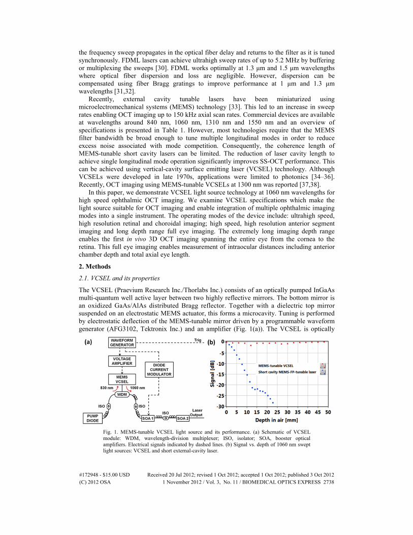
The VCSEL (Praevium Research Inc./Thorlabs Inc.) consists of an optically pumped InGaAs multi-quantum well active layer between two highly reflective mirrors. The bottom mirror is an oxidized GaAs/AlAs distributed Bragg reflector. Together with a dielectric top mirror suspended on an electrostatic MEMS actuator, this forms a microcavity. Tuning is performed by electrostatic deflection of the MEMS-tunable mirror driven by a programmable waveform generator (AFG3102, Tektronix Inc.) and an amplifier (Fig. 1(a)). The VCSEL is optically
Fig. 1. MEMS-tunable VCSEL light source and its performance. (a) Schematic of VCSEL module: WDM, wavelength-division multiplexer; ISO, isolator; SOA, booster optical amplifiers. Electrical signals indicated by dashed lines. (b) Signal vs. depth of 1060 nm swept light sources: VCSEL and short external-cavity laser.
(C) 2012 OSA 1 November 2012 / Vol. 3, No. 11 / BIOMEDICAL OPTICS EXPRESS 2738#172948 - $15.00 USD Received 20 Jul 2012; revised 1 Oct 2012; accepted 1 Oct 2012; published 3 Oct 2012
pumped using an 830 nm laser diode and generates light centered around 1060 nm wavelength, which is directed to semiconductor booster amplifiers (SOA). A second waveform generator channel is used to modulate the first SOA current (FM2.5, Messtec Power Converter GmbH). The output of the second SOA is greater than 20 mW, which allows use of a high splitting ratio 80/20 coupler in the OCT interferometer for increased system sensitivity.
The VCSEL has several features which are well suited for OCT applications. First, the short cavity length means that only one longitudinal mode overlaps the laser gain bandwidth. Single mode operation and lack of mode hopping makes the laser coherence length extremely long, and significantly reduces sensitivity roll-off with imaging range. The coherence lengths of the VCSEL operating at 50 kHz sweep rate with 45 nm tuning range versus a MEMS Fabry-Perot tunable short cavity laser (Axsun Technologies, Inc.) were measured by acquiring interference traces from a Mach-Zehnder interferometer using two high-speed 1.2 GHz InGaAs photodetectors and a 1 GHz bandwidth oscilloscope (DPO7104, Tektronix Inc.). Figure 1(b) plots signal versus depth, where total path delay is two times the depth. The coherence length is usually defined as the full width at −3 dB amplitude (or −6 dB intensity). The coherence length of VCSEL exceeds 200 mm (measurement limited by the oscilloscope bandwidth), whereas a MEMS Fabry-Perot tunable short cavity laser has ~24 mm coherence length. In addition, MEMS technology enables adjustable sweep rate. Along with adjustable and wide frequency sweep range, this enables adjustment of imaging speed, axial resolution and depth range. Finally, the VCSEL can be driven by custom waveforms which linearize the sweep to optimize imaging range, light exposure and A/D bandwidth utilization.
2.2. Prototype OCT instrument
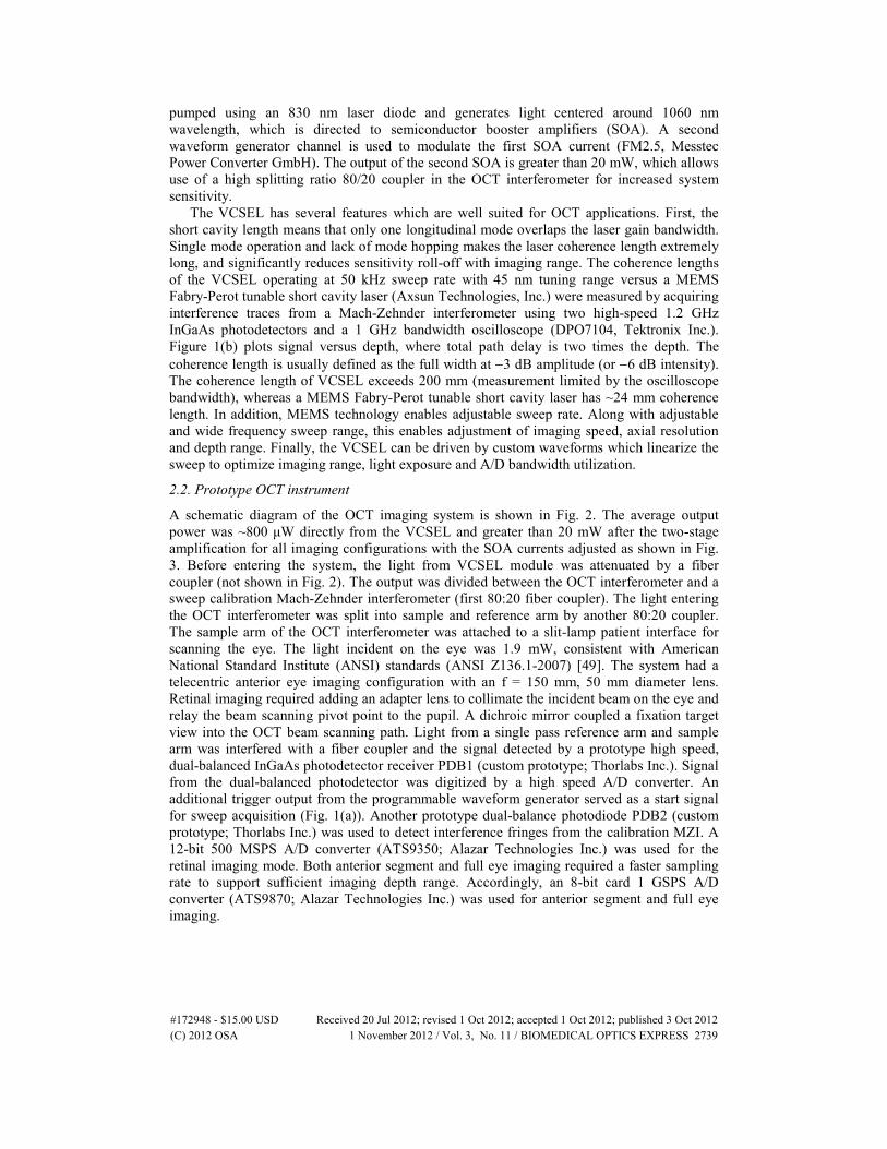
A schematic diagram of the OCT imaging system is shown in Fig. 2. The average output power was ~800 μW directly from the VCSEL and greater than 20 mW after the two-stage amplification for all imaging configurations with the SOA currents adjusted as shown in Fig. 3. Before entering the system, the light from VCSEL module was attenuated by a fiber coupler (not shown in Fig. 2). The output was divided between the OCT interferometer and a sweep calibration Mach-Zehnder interferometer (first 80:20 fiber coupler). The light entering the OCT interferometer was split into sample and reference arm by another 80:20 coupler. The sample arm of the OCT interferometer was attached to a slit-lamp patient interface for scanning the eye. The light incident on the eye was 1.9 mW, consistent with American National Standard Institute (ANSI) standards (ANSI Z136.1-2007) [49]. The system had a telecentric anterior eye imaging configuration with an f = 150 mm, 50 mm diameter lens. Retinal imaging required adding an adapter lens to collimate the incident beam on the eye and relay the beam scanning pivot point to the pupil. A dichroic mirror coupled a fixation target view into the OCT beam scanning path. Light from a single pass reference arm and sample arm was interfered with a fiber coupler and the signal detected by a prototype high speed, dual-balanced InGaAs photodetector receiver PDB1 (custom prototype; Thorlabs Inc.). Signal from the dual-balanced photodetector was digitized by a high speed A/D converter. An additional trigger output from the programmable waveform generator served as a start signal for sweep acquisition (Fig. 1(a)). Another prototype dual-balance photodiode PDB2 (custom prototype; Thorlabs Inc.) was used to detect interference fringes from the calibration MZI. A 12-bit 500 MSPS A/D converter (ATS9350; Alazar Technologies Inc.) was used for the retinal imaging mode. Both anterior segment and full eye imaging required a faster sampling rate to support sufficient imaging depth range. Accordingly, an 8-bit card 1 GSPS A/D converter (ATS9870; Alazar Technologies Inc.) was used for anterior segment and full eye imaging.
(C) 2012 OSA 1 November 2012 / Vol. 3, No. 11 / BIOMEDICAL OPTICS EXPRESS 2739#172948 - $15.00 USD Received 20 Jul 2012; revised 1 Oct 2012; accepted 1 Oct 2012; published 3 Oct 2012
Fig. 2. Experimental setup. Retinal imaging was performed by adding ocular lens to anterior segment configuration and adjusting the fixation target path. SC – galvanometric scanners, FT – fixation target, DM – dichroic mirror, DC – dispersion compensation glass, RR – retroreflector, PDB1/PDB2 – balanced photodetectors, MZI – Mach-Zehnder interferometer.
2.3. Sweep optimization
The VCSEL was driven by a periodic signal, producing forward and backward sweeps during each drive period. Figure 3 shows various signals, including the VCSEL MEMS drive signal, booster current modulation, sweep trigger and MZI calibration fringes. The integrated spectra of VCSEL output were measured by an optical spectrum analyzer and had larger amplitude at the edges of the sweeps where the sweep speed was slower. The three operating modes were achieved using MEMS sinusoidal drive signals at 50 kHz, 100 kHz and 290 kHz. Other signals at 200 kHz are not shown in Fig. 3. The MEMS-tunable VCSEL itself can sweep ~100 nm [38]. However, the SOA technology used for this study did not support the full bandwidth, which limited the sweep range to about 85 nm and compromises axial resolution. Broader bandwidth SOAs are currently being developed and it is expected that a 100 nm amplified output can ultimately be achieved.
Data was only acquired during using the forward sweep for the 50 kHz, 100 kHz and 200 kHz operating modes. The backward sweeps were removed by modulating the first SOA stage current. This optimized ocular exposure and sensitivity, since the power during the forward sweep could be increased for a given average power. The sweep duty cycle was 51% at 50 kHz and increased to 60% at 100 kHz (Fig. 3, second row). The change in duty cycle resulted from an asymmetry of the forward and backward sweeps due to nonlinear MEMS behavior when the sweep rate was not at the MEMC resonance frequency. When the MEMS-VCSEL was driven at its resonance frequency of 290 kHz, it had a sinusoidal sweep and nearly 100% duty cycle, so the effective imaging speed was doubled. We have previously shown that a MEMS VCSEL can be driven with customized waveforms that compensate sweep nonlinearity and linearize the frequency sweep and increase high duty cycle for more effectively use of A/D bandwidth [38]. Although sweep linearization is possible, small
(C) 2012 OSA 1 November 2012 / Vol. 3, No. 11 / BIOMEDICAL OPTICS EXPRESS 2740#172948 - $15.00 USD Received 20 Jul 2012; revised 1 Oct 2012; accepted 1 Oct 2012; published 3 Oct 2012

Fig. 3. Signals in VCSEL module (module driving signal, SOA current waveforms, sweep trigger), MZI fringe and integrated spectrum for selected tuning frequencies: 290 kHz, 100 kHz and 50 kHz.
deviations from a perfectly linear sweep exist and it is still necessary to re-scale the sweep so that it is linear in frequency or wavenumber before Fourier transforming.
Sweep-to-sweep variations in the VCSEL frequency/wavelength scanning are noticeable and a single calibration MZI trace could not be used, except when the VCSEL was operated at resonance. Our previous work with VCSELs for OCT used optical clocking methods to clock the A/D converter at a varying frequency clock signal derived from an interferometer, in order to sample the signal so that it is linear in frequency or wavenumber [38]. Optical clocking compensated sweep-to-sweep variation and worked up to 400 MSPS in these previous studies. However, there is currently no A/D card that can reliably clock up to 1 GSPS. In order to perform the extended imaging range experiments in these studies, dual channel acquisition with an MZI trace obtained on the second channel was used to perform individual sweep-by-sweep calibration. Limitations with the A/D card bus speeds when acquiring large data sets with dual channels prevented acquiring both the forwards and backwards sweeps for all operating modes, except for when the VCSEL was operated at resonance. On resonance,
(C) 2012 OSA 1 November 2012 / Vol. 3, No. 11 / BIOMEDICAL OPTICS EXPRESS 2741#172948 - $15.00 USD Received 20 Jul 2012; revised 1 Oct 2012; accepted 1 Oct 2012; published 3 Oct 2012
where sweep-to-sweep repeatability is high and a single calibration trace acquired before imaging could be applied to all of the sweeps so that only one channel of A/D was required.
2.4. System performance and in vivo OCT imaging
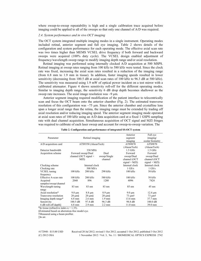
The OCT system integrated multiple imaging modes in a single instrument. Operating modes included retinal, anterior segment and full eye imaging. Table 2 shows details of the configuration and system performance for each operating mode. The effective axial scan rate was two times higher than MEMS VCSEL drive frequency if both forward and backward sweeps were acquired (100% duty cycle). The VCSEL design enabled adjustment of frequency/wavelength sweep range to modify imaging depth range and/or axial resolution.
Retinal imaging was performed using internally clocked A/D acquisition at 500 MSPS. Retinal imaging at sweep rates ranging from 100 kHz to 580 kHz were tested. Since the clock rate was fixed, increasing the axial scan rates resulted in a reduction of the imaging range (from 6.8 mm to 1.9 mm in tissue). In addition, faster imaging speeds resulted in lower sensitivity (decreasing from 100.5 dB at axial scan rates of 100 kHz to 96.3 dB at 580 kHz). The sensitivity was measured using 1.9 mW of optical power incident on a test mirror with a calibrated attenuator. Figure 4 shows sensitivity roll-off for the different operating modes. Similar to imaging depth range, the sensitivity 6 dB drop depth becomes shallower as the sweep rate increases. The axial image resolution was ~9 μm.
Anterior segment imaging required modification of the patient interface to telecentrically scan and focus the OCT beam onto the anterior chamber (Fig. 2). The estimated transverse resolution of this configuration was ~75 μm. Since the anterior chamber and crystalline lens span a longer axial range than the retina, the imaging range must be extended by trading off axial resolution and/or reducing imaging speed. The anterior segment imaging mode operated at axial scan rates of 100 kHz using an A/D data acquisition card at a fixed 1 GSPS sampling rate with dual channel acquisition. Simultaneous acquisition of OCT signal and MZI fringes was required to calibrate of each laser sweep and account for sweep-to-sweep variation. The
Table 2. Configuration and performance of integrated SS-OCT system
Parameter Retinal imaging Anterior
segment imaging
Full eye imaging/
ocular biometry A/D acquisition card ATS9350 (AlazarTech) ATS9870
(AlazarTech) ATS9870
(AlazarTech) Detector bandwidth 330 MHz 1.5 GHz 1.5 GHz Acquisition scheme Forward sweep/Dual
channel (OCT signal + MZI)
Dual sweep/Single
channel
Forward sweep/Dual
channel (OCT signal + MZI)
Forward sweep/Dual
channel (OCT signal + MZI)
Clocking scheme Internal clock Internal clock Internal clock Clocking rate 500 MS/s 1 GS/s 1 GS/s VCSEL tuning frequency
100 kHz 200 kHz 290 kHz 100 kHz 50 kHz
Effective A-scan rate 100 kHz 200 kHz 580 kHz 100 kHz 50 kHz Acquired samples/sweep/channel
2048 896 1280 4096 7424
Wavelength tuning range
83 nm 83 nm 83 nm 85 nm 45 nm
Axial resolution* 9.0 μm 8.8 μm 8.9 μm 9.0 μm 12.4 μm Transverse resolution 20 μm§ 20 μm§ 20 μm§ 73 μm† 73 μm† Imaging depth range* 6.8 mm 2.6 mm 1.9 mm 13.6 mm 37.7 mm Sensitivity 100.5 dB 97.4 dB 96.3 dB 98.8 dB 100.0 dB 6 dB roll-off depth‡ 6.8 mm 2.9 mm 2.2 mm 11.0 mm 39.0 mm
*In tissue (refractive index n = 1.35). §Estimated based on aberration-free model eye. †Measured using a beam profiler. ‡In air.
(C) 2012 OSA 1 November 2012 / Vol. 3, No. 11 / BIOMEDICAL OPTICS EXPRESS 2742#172948 - $15.00 USD Received 20 Jul 2012; revised 1 Oct 2012; accepted 1 Oct 2012; published 3 Oct 2012
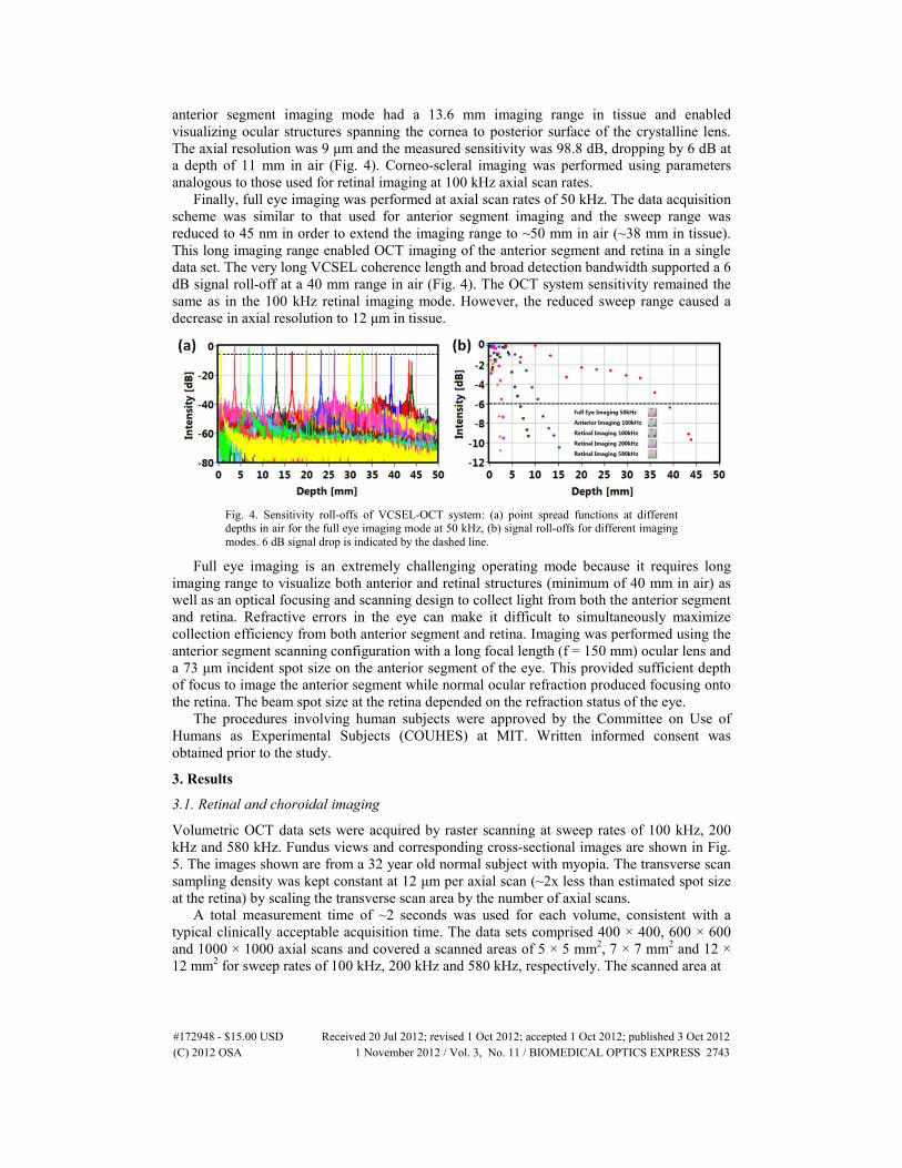
anterior segment imaging mode had a 13.6 mm imaging range in tissue and enabled visualizing ocular structures spanning the cornea to posterior surface of the crystalline lens. The axial resolution was 9 μm and the measured sensitivity was 98.8 dB, dropping by 6 dB at a depth of 11 mm in air (Fig. 4). Corneo-scleral imaging was performed using parameters analogous to those used for retinal imaging at 100 kHz axial scan rates.
Finally, full eye imaging was performed at axial scan rates of 50 kHz. The data acquisition scheme was similar to that used for anterior segment imaging and the sweep range was reduced to 45 nm in order to extend the imaging range to ~50 mm in air (~38 mm in tissue). This long imaging range enabled OCT imaging of the anterior segment and retina in a single data set. The very long VCSEL coherence length and broad detection bandwidth supported a 6 dB signal roll-off at a 40 mm range in air (Fig. 4). The OCT system sensitivity remained the same as in the 100 kHz retinal imaging mode. However, the reduced sweep range caused a decrease in axial resolution to 12 μm in tissue.
Fig. 4. Sensitivity roll-offs of VCSEL-OCT system: (a) point spread functions at different depths in air for the full eye imaging mode at 50 kHz, (b) signal roll-offs for different imaging modes. 6 dB signal drop is indicated by the dashed line.
Full eye imaging is an extremely challenging operating mode because it requires long imaging range to visualize both anterior and retinal structures (minimum of 40 mm in air) as well as an optical focusing and scanning design to collect light from both the anterior segment and retina. Refractive errors in the eye can make it difficult to simultaneously maximize collection efficiency from both anterior segment and retina. Imaging was performed using the anterior segment scanning configuration with a long focal length (f = 150 mm) ocular lens and a 73 μm incident spot size on the anterior segment of the eye. This provided sufficient depth of focus to image the anterior segment while normal ocular refraction produced focusing onto the retina. The beam spot size at the retina depended on the refraction status of the eye.
The procedures involving human subjects were approved by the Committee on Use of Humans as Experimental Subjects (COUHES) at MIT. Written informed consent was obtained prior to the study.
3. Results
3.1. Retinal and choroidal imaging
Volumetric OCT data sets were acquired by raster scanning at sweep rates of 100 kHz, 200 kHz and 580 kHz. Fundus views and corresponding cross-sectional images are shown in Fig. 5. The images shown are from a 32 year old normal subject with myopia. The transverse scan sampling density was kept constant at 12 μm per axial scan (~2x less than estimated spot size at the retina) by scaling the transverse scan area by the number of axial scans.
A total measurement time of ~2 seconds was used for each volume, consistent with a typical clinically acceptable acquisition time. The data sets comprised 400 × 400, 600 × 600 and 1000 × 1000 axial scans and covered a scanned areas of 5 × 5 mm2, 7 × 7 mm2 and 12 × 12 mm2 for sweep rates of 100 kHz, 200 kHz and 580 kHz, respectively. The scanned area at
(C) 2012 OSA 1 November 2012 / Vol. 3, No. 11 / BIOMEDICAL OPTICS EXPRESS 2743#172948 - $15.00 USD Received 20 Jul 2012; revised 1 Oct 2012; accepted 1 Oct 2012; published 3 Oct 2012
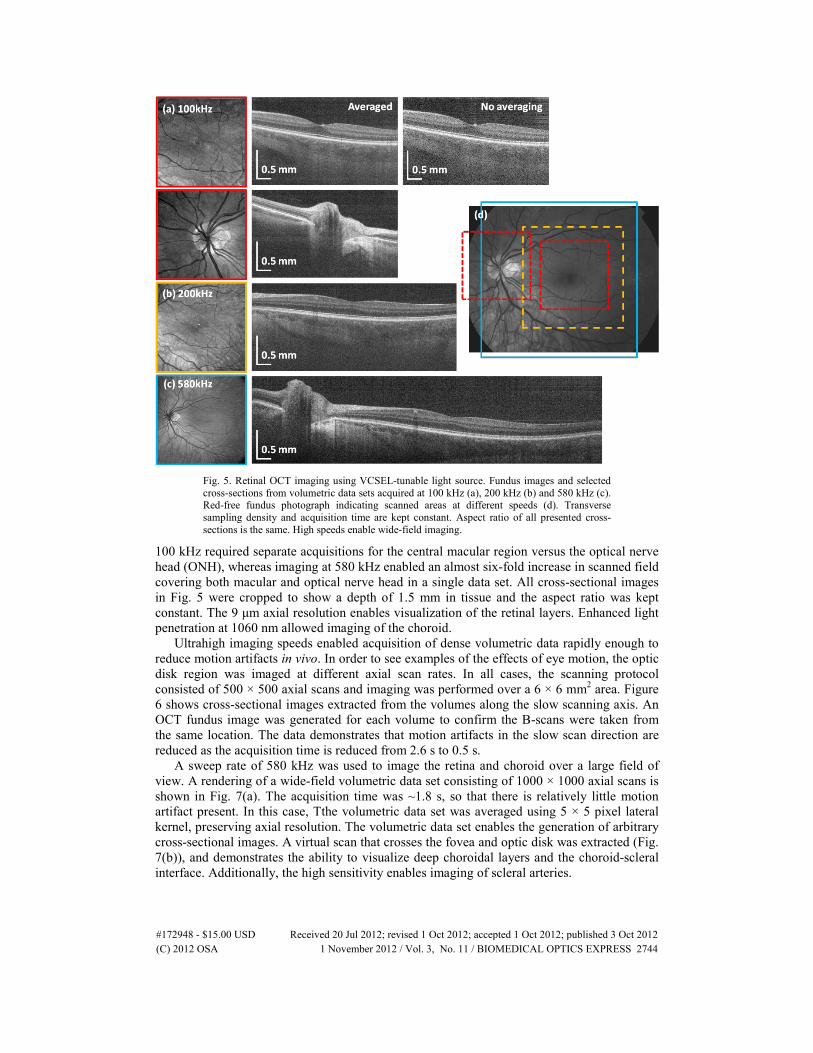
Fig. 5. Retinal OCT imaging using VCSEL-tunable light source. Fundus images and selected cross-sections from volumetric data sets acquired at 100 kHz (a), 200 kHz (b) and 580 kHz (c). Red-free fundus photograph indicating scanned areas at different speeds (d). Transverse sampling density and acquisition time are kept constant. Aspect ratio of all presented cross-sections is the same. High speeds enable wide-field imaging.
100 kHz required separate acquisitions for the central macular region versus the optical nerve head (ONH), whereas imaging at 580 kHz enabled an almost six-fold increase in scanned field covering both macular and optical nerve head in a single data set. All cross-sectional images in Fig. 5 were cropped to show a depth of 1.5 mm in tissue and the aspect ratio was kept constant. The 9 μm axial resolution enables visualization of the retinal layers. Enhanced light penetration at 1060 nm allowed imaging of the choroid.
Ultrahigh imaging speeds enabled acquisition of dense volumetric data rapidly enough to reduce motion artifacts in vivo. In order to see examples of the effects of eye motion, the optic disk region was imaged at different axial scan rates. In all cases, the scanning protocol consisted of 500 × 500 axial scans and imaging was performed over a 6 × 6 mm2 area. Figure 6 shows cross-sectional images extracted from the volumes along the slow scanning axis. An OCT fundus image was generated for each volume to confirm the B-scans were taken from the same location. The data demonstrates that motion artifacts in the slow scan direction are reduced as the acquisition time is reduced from 2.6 s to 0.5 s.
A sweep rate of 580 kHz was used to image the retina and choroid over a large field of view. A rendering of a wide-field volumetric data set consisting of 1000 × 1000 axial scans is shown in Fig. 7(a). The acquisition time was ~1.8 s, so that there is relatively little motion artifact present. In this case, Tthe volumetric data set was averaged using 5 × 5 pixel lateral kernel, preserving axial resolution. The volumetric data set enables the generation of arbitrary cross-sectional images. A virtual scan that crosses the fovea and optic disk was extracted (Fig. 7(b)), and demonstrates the ability to visualize deep choroidal layers and the choroid-scleral interface. Additionally, the high sensitivity enables imaging of scleral arteries.
(C) 2012 OSA 1 November 2012 / Vol. 3, No. 11 / BIOMEDICAL OPTICS EXPRESS 2744#172948 - $15.00 USD Received 20 Jul 2012; revised 1 Oct 2012; accepted 1 Oct 2012; published 3 Oct 2012
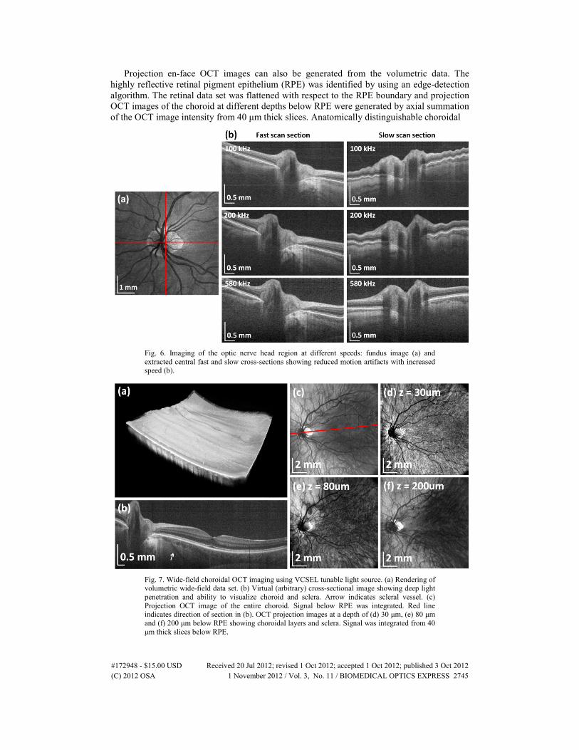
Projection en-face OCT images can also be generated from the volumetric data. The highly reflective retinal pigment epithelium (RPE) was identified by using an edge-detection algorithm. The retinal data set was flattened with respect to the RPE boundary and projection OCT images of the choroid at different depths below RPE were generated by axial summation of the OCT image intensity from 40 μm thick slices. Anatomically distinguishable choroidal
Fig. 6. Imaging of the optic nerve head region at different speeds: fundus image (a) and extracted central fast and slow cross-sections showing reduced motion artifacts with increased speed (b).
Fig. 7. Wide-field choroidal OCT imaging using VCSEL tunable light source. (a) Rendering of volumetric wide-field data set. (b) Virtual (arbitrary) cross-sectional image showing deep light penetration and ability to visualize choroid and sclera. Arrow indicates scleral vessel. (c) Projection OCT image of the entire choroid. Signal below RPE was integrated. Red line indicates direction of section in (b). OCT projection images at a depth of (d) 30 μm, (e) 80 μm and (f) 200 μm below RPE showing choroidal layers and sclera. Signal was integrated from 40 μm thick slices below RPE.
(C) 2012 OSA 1 November 2012 / Vol. 3, No. 11 / BIOMEDICAL OPTICS EXPRESS 2745#172948 - $15.00 USD Received 20 Jul 2012; revised 1 Oct 2012; accepted 1 Oct 2012; published 3 Oct 2012
layers such as the choriocapillaris, Sattler’s layer and Haller’s layer are visible and characterized by blood vessels of different size, as shown in Figs. 7(d)-7(f).
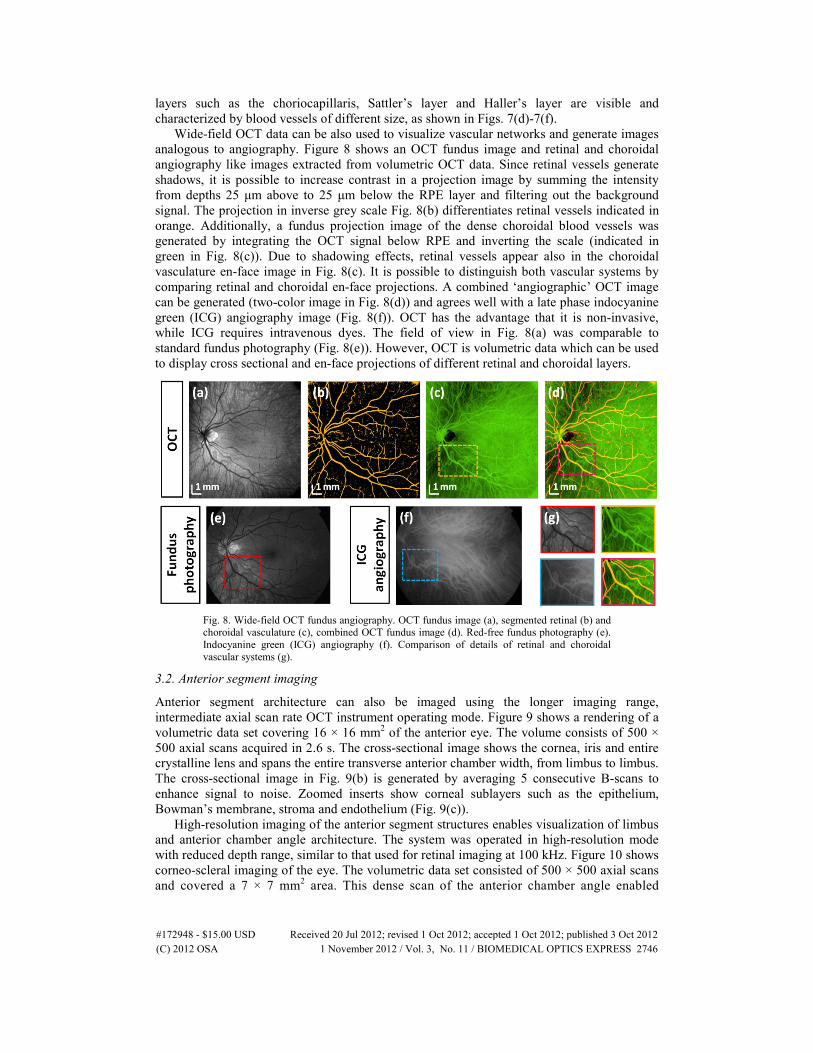
Wide-field OCT data can be also used to visualize vascular networks and generate images analogous to angiography. Figure 8 shows an OCT fundus image and retinal and choroidal angiography like images extracted from volumetric OCT data. Since retinal vessels generate shadows, it is possible to increase contrast in a projection image by summing the intensity from depths 25 μm above to 25 μm below the RPE layer and filtering out the background signal. The projection in inverse grey scale Fig. 8(b) differentiates retinal vessels indicated in orange. Additionally, a fundus projection image of the dense choroidal blood vessels was generated by integrating the OCT signal below RPE and inverting the scale (indicated in green in Fig. 8(c)). Due to shadowing effects, retinal vessels appear also in the choroidal vasculature en-face image in Fig. 8(c). It is possible to distinguish both vascular systems by comparing retinal and choroidal en-face projections. A combined ‘angiographic’ OCT image can be generated (two-color image in Fig. 8(d)) and agrees well with a late phase indocyanine green (ICG) angiography image (Fig. 8(f)). OCT has the advantage that it is non-invasive, while ICG requires intravenous dyes. The field of view in Fig. 8(a) was comparable to standard fundus photography (Fig. 8(e)). However, OCT is volumetric data which can be used to display cross sectional and en-face projections of different retinal and choroidal layers.
Fig. 8. Wide-field OCT fundus angiography. OCT fundus image (a), segmented retinal (b) and choroidal vasculature (c), combined OCT fundus image (d). Red-free fundus photography (e). Indocyanine green (ICG) angiography (f). Comparison of details of retinal and choroidal vascular systems (g).
3.2. Anterior segment imaging
Anterior segment architecture can also be imaged using the longer imaging range, intermediate axial scan rate OCT instrument operating mode. Figure 9 shows a rendering of a volumetric data set covering 16 × 16 mm2 of the anterior eye. The volume consists of 500 × 500 axial scans acquired in 2.6 s. The cross-sectional image shows the cornea, iris and entire crystalline lens and spans the entire transverse anterior chamber width, from limbus to limbus. The cross-sectional image in Fig. 9(b) is generated by averaging 5 consecutive B-scans to enhance signal to noise. Zoomed inserts show corneal sublayers such as the epithelium, Bowman’s membrane, stroma and endothelium (Fig. 9(c)).
High-resolution imaging of the anterior segment structures enables visualization of limbus and anterior chamber angle architecture. The system was operated in high-resolution mode with reduced depth range, similar to that used for retinal imaging at 100 kHz. Figure 10 shows corneo-scleral imaging of the eye. The volumetric data set consisted of 500 × 500 axial scans and covered a 7 × 7 mm2 area. This dense scan of the anterior chamber angle enabled
(C) 2012 OSA 1 November 2012 / Vol. 3, No. 11 / BIOMEDICAL OPTICS EXPRESS 2746#172948 - $15.00 USD Received 20 Jul 2012; revised 1 Oct 2012; accepted 1 Oct 2012; published 3 Oct 2012

Fig. 9. Anterior segment imaging with VCSEL-OCT: (a) rendering of the volume, (b) central averaged cross-sectional image, (c) zoomed fragments of the B-scan showing details of the corneal and the crystalline lens.
Fig. 10. Corneo-scleral imaging: (a) cross-sectional OCT image presenting details of the anterior chamber angle (S – sclera, CB – ciliary body, C – cornea, I – iris); (b) zoomed portion of the image showing aqueous outflow structures (SC – Schlemm’s canal, TM – trabecular meshwork) (c) en-face view of the volumetric data set (red line indicates extracted section presented in (a)); (d) En-face visualization of scleral vessels. Scleral interface was segmented and 1 mm thick slice was integrated.
visualization of the limbal region along with landmarks such as the corneo-scleral junction and rich scleral vasculature. Elements of the outflow system such as Schlemm’s canal could be also identified (Figs. 10(a)-10(b)). The corneo-scleral junction could be distinguished since scleral tissue is more scattering than corneal tissue. The enhanced penetration of 1060 nm light enabled visualization of deeper structures such as the ciliary body. OCT volumetric data were also used to visualize the scleral vascular system (Fig. 10(d)). The scleral interface was segmented and a projection image from a 1 mm deep slice is shown.
(C) 2012 OSA 1 November 2012 / Vol. 3, No. 11 / BIOMEDICAL OPTICS EXPRESS 2747#172948 - $15.00 USD Received 20 Jul 2012; revised 1 Oct 2012; accepted 1 Oct 2012; published 3 Oct 2012
3.3. Full eye imaging and axial eye length measurement
Intraocular distances such as axial eye length or anterior chamber depth are essential for accurate intraocular lens (IOL) calculation. The long imaging range needed to span axial eye length was achieved by reducing the laser sweep range, trading off axial resolution.
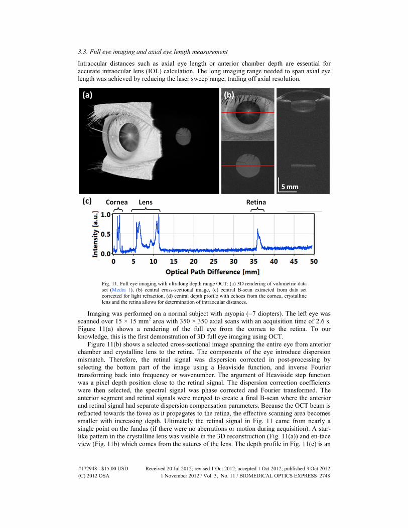
Fig. 11. Full eye imaging with ultralong depth range OCT: (a) 3D rendering of volumetric data set (Media 1), (b) central cross-sectional image, (c) central B-scan extracted from data set corrected for light refraction, (d) central depth profile with echoes from the cornea, crystalline lens and the retina allows for determination of intraocular distances.
Imaging was performed on a normal subject with myopia (−7 diopters). The left eye was scanned over 15 × 15 mm2 area with 350 × 350 axial scans with an acquisition time of 2.6 s. Figure 11(a) shows a rendering of the full eye from the cornea to the retina. To our knowledge, this is the first demonstration of 3D full eye imaging using OCT.
Figure 11(b) shows a selected cross-sectional image spanning the entire eye from anterior chamber and crystalline lens to the retina. The components of the eye introduce dispersion mismatch. Therefore, the retinal signal was dispersion corrected in post-processing by selecting the bottom part of the image using a Heaviside function, and inverse Fourier transforming back into frequency or wavenumber. The argument of Heaviside step function was a pixel depth position close to the retinal signal. The dispersion correction coefficients were then selected, the spectral signal was phase corrected and Fourier transformed. The anterior segment and retinal signals were merged to create a final B-scan where the anterior and retinal signal had separate dispersion compensation parameters. Because the OCT beam is refracted towards the fovea as it propagates to the retina, the effective scanning area becomes smaller with increasing depth. Ultimately the retinal signal in Fig. 11 came from nearly a single point on the fundus (if there were no aberrations or motion during acquisition). A star-like pattern in the crystalline lens was visible in the 3D reconstruction (Fig. 11(a)) and en-face view (Fig. 11b) which comes from the sutures of the lens. The depth profile in Fig. 11(c) is an
(C) 2012 OSA 1 November 2012 / Vol. 3, No. 11 / BIOMEDICAL OPTICS EXPRESS 2748#172948 - $15.00 USD Received 20 Jul 2012; revised 1 Oct 2012; accepted 1 Oct 2012; published 3 Oct 2012

averaged axial scan from the central 100 axial scans (central 10 × 10 axial scans). This enables measurement of intraocular distances after correcting for the refractive index of each ocular component. The axial resolution was 12 μm over almost 40 mm in tissue. The intensity peaks in Fig. 11(c) can be identified as reflections from the anterior and posterior surfaces of the cornea, anterior and posterior interfaces of the crystalline lens, and retina. The standard measurement of axial eye length requires finding the distance between corneal vertex and RPE/Bruch’s membrane. The same eye was also measured with two clinical instruments, the gold standard of partial coherence interferometry (PCI) (IOL Master, Carl Zeiss Meditec) and an immersion A-scan ultrasound biometer (Axis II PR, Quantel Medical). Comparison of intraocular distances measured using our OCT prototype instrument, partial coherence interferometry and A-scan ultrasound biometer is shown in Table 3.
Table 3. Comparison of ocular biometry measurements using VCSEL-OCT, partial coherence interferometry and immersion ultrasound
Biometric parameter VCSEL-OCT PCI (IOL Master)
Immersion ultrasound
(Axis II PR) Central corneal thickness 0.52 mm N/A N/A Anterior chamber depth 3.70 mm 3.74 mm 3.80 mm
Lens thickness 3.88 mm N/A 3.94 mm Axial eye length 25.77 mm 25.93 mm 25.81 mm
4. Discussion
Ophthalmic swept source/Fourier domain OCT using VCSEL light source technology enables the integration of multiple imaging modalities into a single instrument. The prototype 1060 nm SS-OCT system demonstrated in this manuscript has operating modes that enable comprehensive retinal and anterior segment diagnostics. Along with full eye imaging capability, this instrument can be regarded as a 3-in-1 OCT imaging device.
The VCSEL light source reported here uses dual stage SOA post amplification. Sweep bandwidth was limited because of mismatch between amplifiers, reducing axial image resolution. Dual stages were used because the prototype 1060 nm SOAs had lower gains due to coupling losses, compared with expected values from 1300 nm SOAs. SOAs are currently being fabricated which has higher gains and match the VCSEL bandwidth of ~100 nm.
The ultrahigh speed axial scan rate of 580 kHz demonstrated here is ~10 to 20x faster than clinical OCT devices. High speed imaging enables acquisition of more axial scans covering larger areas of the retina without sacrificing the ability to visualize small focal features. The transverse scan range of the wide-field OCT images is similar to the field of view of fundus photography. OCT fundus images correlate well with red-free fundus photography and ICG angiography. However, OCT provides dense, isotropically sampled 3D volumetric structural information on the retina. Volumetric data also can be used to generate arbitrary cross-sectional images or projection en-face images. In addition, high speed imaging minimizes motion artifacts, enabling more reproducible measurement of markers of disease progression (e.g. retinal nerve fiber layer thickness) or ocular structures parameter (e.g. corneal thickness and refractive power). The imaging speed is currently limited by the MEMS resonant frequency, but may be increased by using a stiffer MEMS design. Operation at axial scan rates of up to 1.2 MHz have been demonstrated with 1300 μm MEMS-VCSEL devices [37,38]. Higher imaging speeds have also been demonstrated using multiplexed FDML light sources [30,43]. However, imaging speeds will ultimately be limited by signal to noise constraints.
The system operates at wavelengths around 1060 nm. Most retinal OCT instruments use light sources at 840 nm and anterior segment instruments image mostly at 1310 nm, which cannot be used for retinal imaging because of vitreal absorption. Retinal and anterior segment imaging with the same light source is possible at 1060 nm wavelength. Although bandwidth at 1060 nm is limited by vitreal absorption and axial resolution is reduced compared with 840
(C) 2012 OSA 1 November 2012 / Vol. 3, No. 11 / BIOMEDICAL OPTICS EXPRESS 2749#172948 - $15.00 USD Received 20 Jul 2012; revised 1 Oct 2012; accepted 1 Oct 2012; published 3 Oct 2012

nm, there is less scattering than shorter wavelengths. Longer wavelengths are less attenuated by ocular opacities such as cataracts and enable imaging the choroid or anterior angle.
The single longitudinal mode operation of the VCSEL gives a narrow instantaneous linewidth and the coherence length is therefore at least 10x longer than most other swept lasers used in OCT. This can significantly simplify scanning procedures in the clinical setting because sensitivity roll-off with axial range is no longer an issue in patient alignment. This would be especially helpful in intraoperative OCT. Furthermore, the long coherence length enables new imaging applications in the anterior segment that require long depth range. Long depth range OCT imaging of the anterior eye can provide comprehensive topographic and keratometric information. SD-OCT systems require special full-range techniques in order to perform long range anterior segment imaging [18,50]. In contrast, SS-OCT with VCSEL light sources can image the entire anterior segment without complex instrument modifications. However, light collection efficiency across a deep axial range must still be optimized using a long focal depth (confocal parameter) beam. In addition, long depth range imaging with SS-OCT requires special attention to system design. Parasitic reflections from optical elements or fiber interfaces can act as etalons and produce beat frequencies which generate lines or fixed pattern noise in the OCT images.
The extremely long coherence length supports an ultralong range imaging mode for full eye visualization and axial eye length measurement. Currently, axial eye length is measured using low-coherence interferometry and the commercial IOL Master is the clinical standard for IOL fitting. Previous methods to extend OCT imaging range included full-range techniques or multiple reference mirrors, however to date these methods have not shown full eye images. Although full eye OCT imaging in small animals has been reported, imaging the human eye is challenging because of its long length. This paper demonstrates what we believe is the first 3D high speed in vivo full eye imaging in humans. Measurements of intraocular distances using SS-OCT were compared with clinical optical and ultrasound biometry, and good correspondence was found. Volumetric data sets allow measurement of intraocular distances as well as keratometry values. These parameters are important for calculating IOL power. These results are preliminary and it is important to note here that precise calibration of the imaging depth range has an impact on the reproducibility of intraocular measurements and their correlation with current clinical standard devices.
Another advantage of SS-OCT using VCSEL light sources is its adjustability, making it possible to dynamically configure the axial scan rate, resolution and imaging range to utilize available A/D bandwidth. Depth range adjustment by changing the sweep range was previously demonstrated using an FDML-based SS-OCT system, however the sweep repetition rate in FDML lasers must be equal to a harmonic of the cavity round trip [51]. VCSEL technology enables adjustment of both sweep repetition rate and sweep range. Both the forward and backward sweeps can be used to achieve almost 100% duty cycle without buffering/multiplexing. Buffering can also be used to obtain unidirectional sweeps or multiply the sweep repetition rate, in a manner similar to FDML lasers. However, there are constraints on the MEMS drive amplitude which limit the short duty cycle required for high multiplexing of the sweep repetition rate. In addition, VCSEL stability is reduced when operating at sweep rates away from the resonance frequency. For this reason, dual channel acquisition, with an MZI channel as a calibration trace for each sweep was required. When the VCSEL operated at resonance frequency (290 kHz), it was possible to use a single calibration trace, acquired before OCT data acquisition, to calibrate all sweeps in the OCT data set. In the future, it should be possible to use direct optical clocking of the A/D to acquire OCT signals which are calibrated in frequency or wavenumber at high 1 GSPS speeds. This avoids the computationally expensive step of MZI recalibration and reduces data rate and memory requirements. The long coherence length of the VCSEL should also provide a stable optical clock signal. Selected data in preliminary studies was acquired using optical clocking with a 400 MSPS card, but currently available GHz bandwidth A/D cards do not support optically
(C) 2012 OSA 1 November 2012 / Vol. 3, No. 11 / BIOMEDICAL OPTICS EXPRESS 2750#172948 - $15.00 USD Received 20 Jul 2012; revised 1 Oct 2012; accepted 1 Oct 2012; published 3 Oct 2012

clocked acquisition. Therefore, the data reported here was acquired using dual channel acquisition on both cards for consistency.
5. Summary and conclusions
To summarize, this manuscript demonstrates swept source OCT utilizing VCSEL technology for ophthalmic imaging at 1060 nm. The MEMS tunable VCSEL has a long coherence length with adjustable sweep repetition rates (50 kHz-580 kHz axial scan rate) and adjustable frequency/wavelength sweep range. This enables adjustment of the imaging speed, resolution and depth range and integration of multiple ophthalmic applications into a single instrument. The instrument can perform ultrahigh speed retinal and choroidal imaging, long depth range anterior segment imaging and ultralong depth range full eye imaging. Wide field retinal and choroidal imaging was demonstrated. Comprehensive volumetric data of the anterior segment from the cornea to the posterior crystalline lens surface were presented. Full eye 3D-OCT imaging from the cornea to the retina was also demonstrated. Swept source OCT using VCSEL technology promises to enable the development of integrated OCT instruments which reduce patient chair/visit time and save clinical space. The high performance of SS-OCT using VCSEL technology promises to enable new applications for OCT imaging of retinal, optic nerve head and choroidal pathologies as well as ocular biometry.
Acknowledgments
The authors would like to express their gratitude to Yuankai Tao, Ph.D., WooJhon Choi and Byungkun Lee from MIT, as well as Jason Y. Zhang and Ahmad A. Alwassia from New England Eye Center for discussions and assistance during experiments. The study is supported by the National Institutes of Health (R01-EY011289-26, R01-EY013178-12, R01-EY013516-09, R01-EY019029-03, R01-CA075289-15, R01-NS057476-05, R44-CA101067-05), Air Force Office for Scientific Research (FA9550-10-1-0551 and FA9550-10-1-0063). Praevium Inc./Thorlabs Inc. provided VCSEL technology for these studies. I. Grulkowski acknowledges the KOLUMB Fellowship from the Foundation for Polish Science (KOL/3/2010-I). I. Grulkowski is a visiting scientist from Optical Biomedical Imaging Group at the Institute of Physics, Nicolaus Copernicus University, Torun, Poland.
(C) 2012 OSA 1 November 2012 / Vol. 3, No. 11 / BIOMEDICAL OPTICS EXPRESS 2751#172948 - $15.00 USD Received 20 Jul 2012; revised 1 Oct 2012; accepted 1 Oct 2012; published 3 Oct 2012
Related Documents