Resident Physics Lectures Christensen, Chapter 8 Grids Grids George David Associate Professor Department of Radiology Medical College of Georgia

Welcome message from author
This document is posted to help you gain knowledge. Please leave a comment to let me know what you think about it! Share it to your friends and learn new things together.
Transcript
Resident Physics Lectures
Christensen, Chapter 8
GridsGrids
George DavidAssociate ProfessorDepartment of RadiologyMedical College of Georgia

PurposeDirectional filter for
photonsIdeal grid
passes all primary photons photons coming from
focal spotblocks all secondary
photons photons not coming from
focal spot Film
Patient
“Good” photon
“Bad” photon
GridX
FocalSpot
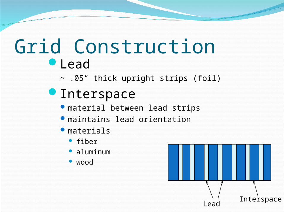
Grid ConstructionLead
~ .05“ thick upright strips (foil)
Interspacematerial between lead stripsmaintains lead orientationmaterials
fiber aluminum wood
LeadInterspace
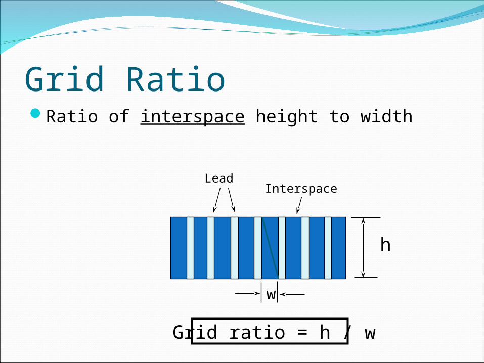
Grid RatioRatio of interspace height to width
h
w
Grid ratio = h / w
LeadInterspace

Grid RatioExpressed as X:1Typical values
8:1 to 12:1 for general work3:1 to 5:1 for mammography
Grid function generally improves with higher ratios
h
w
Grid ratio = h / w

Lines per Inch# lead strips per inch grid widthTypical: 103
25.4Lines per inch = ------------ W + w
w = thickness of interspace (mm)
W = thickness of lead strips (mm)
w
W


Grid PatternsOrientation of lead strips as seen from
aboveTypes
LinearLinearCross hatchedCross hatched
2 stacked linear grids ratio is sum of ratios of two linear grids very sensitive to positioning & tilting Rare; only found in specials

• Parallel
• Focused
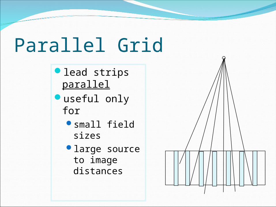
Parallel Gridlead strips
paralleluseful only for
small field sizes
large source to image distances
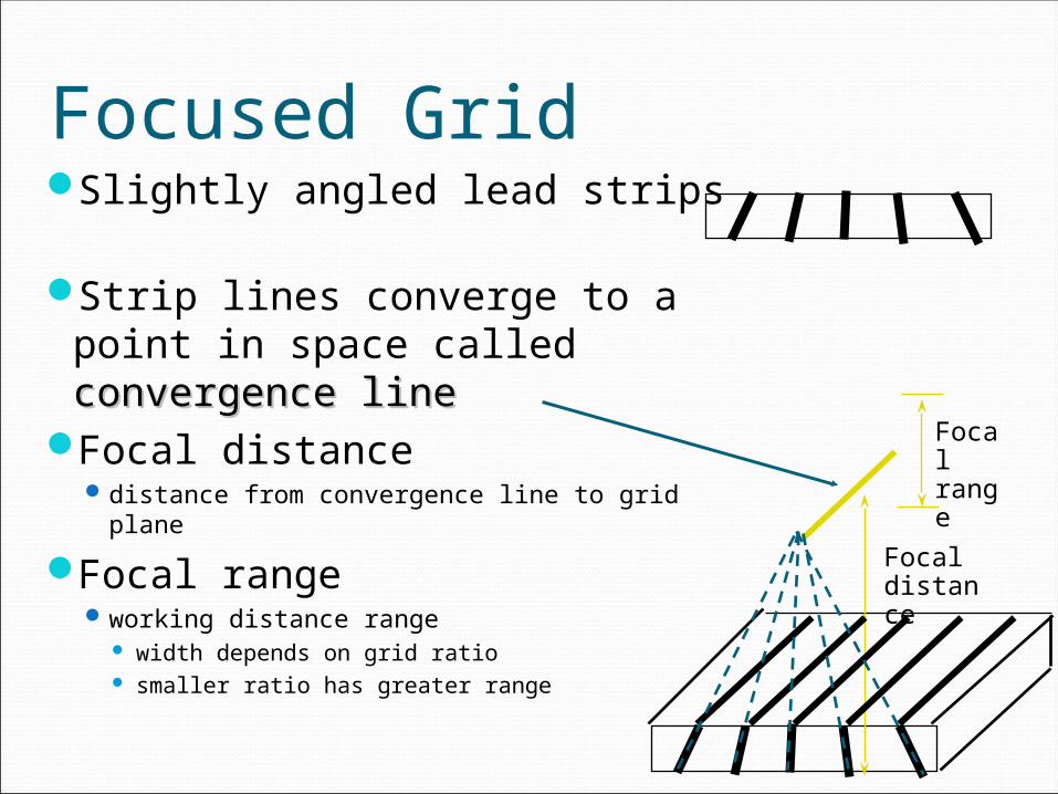
Focused GridSlightly angled lead strips
Strip lines converge to a point in space called convergence convergence lineline
Focal distancedistance from convergence line to grid plane
Focal rangeworking distance range
width depends on grid ratio smaller ratio has greater range
Focal range
Focal distance

Ideal Gridpasses all primary radiation
Reality: lead strips block some primary
LeadInterspace
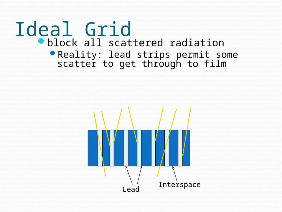
Ideal Gridblock all scattered radiation
Reality: lead strips permit some scatter to get through to film
LeadInterspace

Primary TransmissionFraction of a scatter-free beam
passed by gridIdeally 100% (never achieved)
LeadInterspace
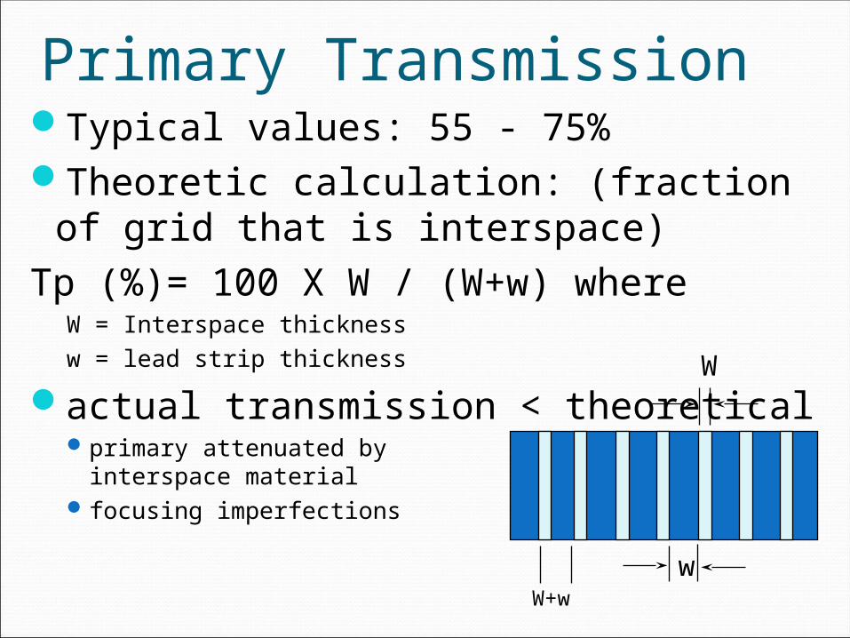
Primary TransmissionTypical values: 55 - 75%Theoretic calculation: (fraction of grid
that is interspace)Tp (%)= 100 X W / (W+w) where
W = Interspace thicknessw = lead strip thickness
actual transmission < theoreticalprimary attenuated by
interspace material focusing imperfections
w
W
W+w
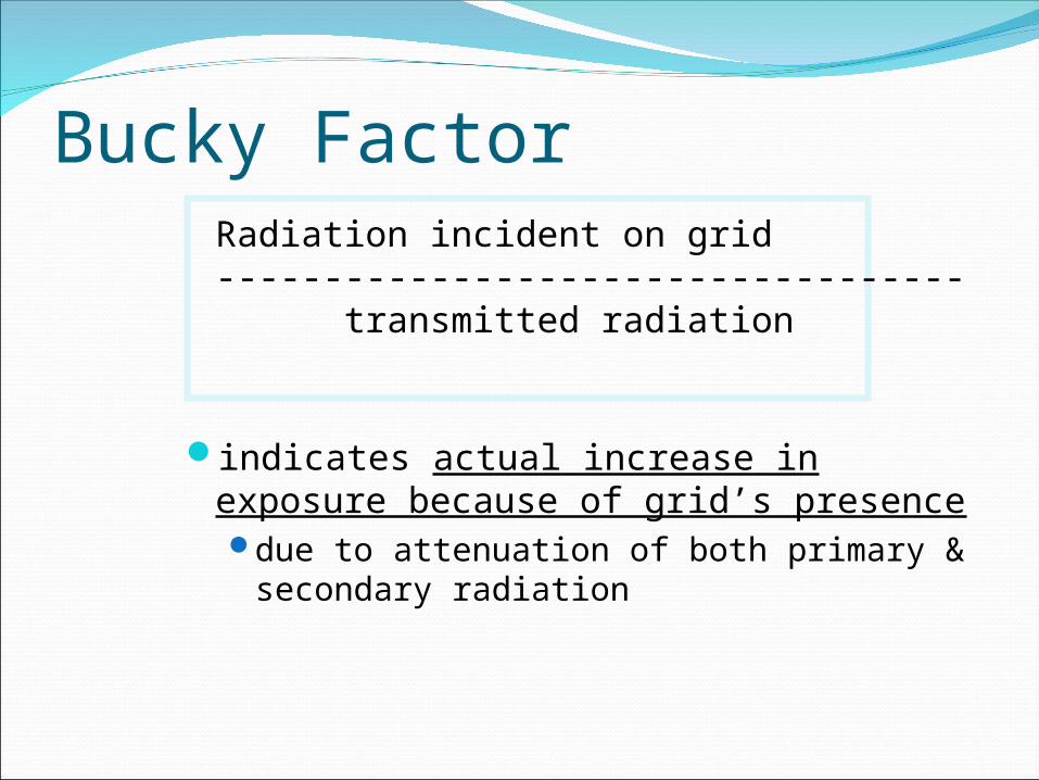
Bucky FactorRadiation incident on grid----------------------------------- transmitted radiation
indicates actual increase in exposure because of grid’s presence due to attenuation of both primary &
secondary radiation
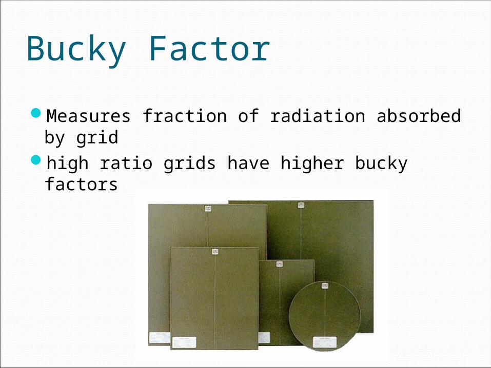
Bucky Factor
Measures fraction of radiation absorbed by gridhigh ratio grids have higher bucky factors
Bucky FactorHigher bucky factor means
higher x-ray techniquehigher patient dose
typically 3-6
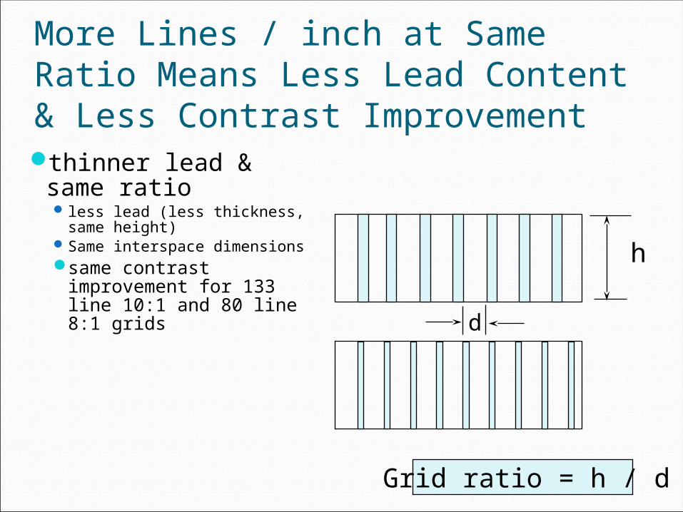
More Lines / inch at Same Ratio Means Less Lead Content & Less Contrast Improvementthinner lead & same
ratio less lead (less thickness, same
height)Same interspace dimensionssame contrast
improvement for 133 line 10:1 and 80 line 8:1 grids
h
d
Grid ratio = h / d

Grid Disadvantages
Increased patient dosePositioning critical
poor positioning results in grid cutoff loss of primary radiation because images of
lead strips projecte wider

Grid Cutofffocused grids used upside downlateral decentering (or angulation)focus- grid distance decenteringcombined lateral & focus-grid distance
decentering
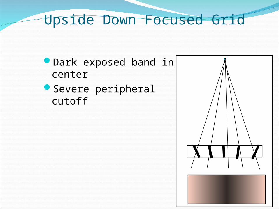
Upside Down Focused Grid
Dark exposed band in center
Severe peripheral cutoff
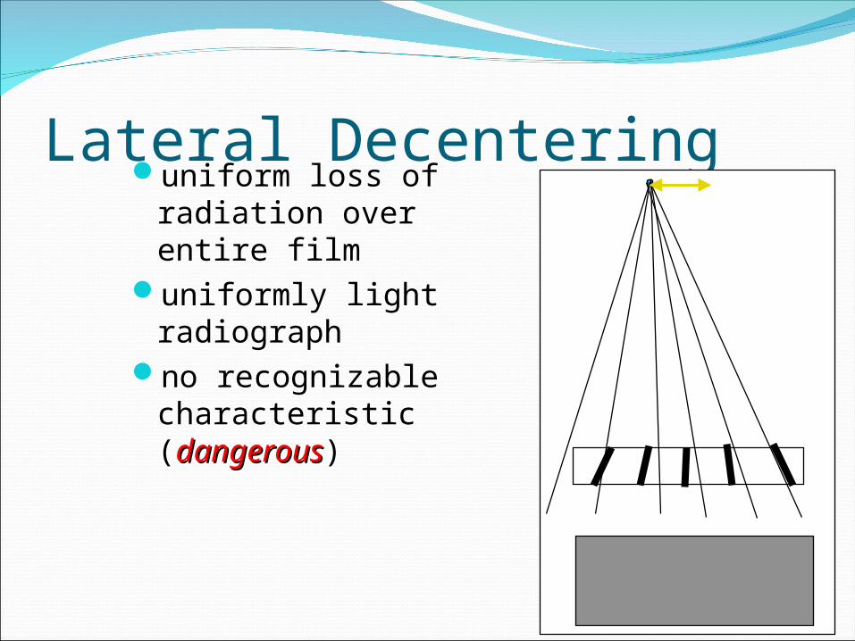
Lateral Decenteringuniform loss of
radiation over entire film
uniformly light radiograph
no recognizable characteristic (dangerousdangerous)
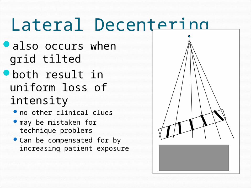
Lateral Decenteringalso occurs when
grid tiltedboth result in
uniform loss of intensityno other clinical cluesmay be mistaken for technique
problemsCan be compensated for by
increasing patient exposure

Lateral DecenteringSignificant problem in portable
radiographyCompensate by over-exposing patient
exact centering not possibleminimizing lateral decentering
low ratio gridslong focal distances

Distance DecenteringGrid too close or too far from focal spotDarker centerAll parallel grids have some degree of
distance decenteringFocused to infinity

Far focus-grid decentering
•Near focus-grid decentering
•cutoff at periphery
•dark center•cutoff proportional to
•grid ratio•decentering distance

Minimizing Distance Decentering Cutoff
low grid ratio small fields

Combined lateral and focus-grid distance decentering
Easy to recognizeuneven exposurefilm light on one
side, dark on the other

Moving Grids
Motion starts with second trigger Grids move ~1- 3 inches
must be fast enough not to see grid lines for short exposures
Motion blurs out lead strip shadows

Moving Grid Disadvantages
$$$Vibration PotentialMay limit minimum exposure timeIncreases patient dose
lateral decentering from motion up to 20% loss of primary
evenly distributes radiation on film stationary grid makes interspace gaps darker for
same amount of radiation
Grid Tradeoff Advantage
cleanup / scatter rejectionDisadvantage
increased patient doseincreased exposure timeincrease tube loadingpositioning & centering more critical$$$
Grid Selectionuse low ratios for low kVp, high ratios for
high kVpbook recommends
8:1 below 90 kVp12:1 above 90 kVp
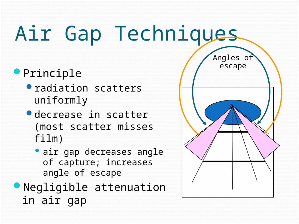
Air Gap Techniques
Principleradiation scatters uniformlydecrease in scatter (most
scatter misses film) air gap decreases angle of
capture; increases angle of escape
Negligible attenuation in air gap
Angles ofescape

Air Gapair gap very effective in removing scatter
originating closest to filmmuch of scatter nearest tube doesn’t reach
film
Much attenuationof scatter in the body
Air gap decreasescapture angle

Air Gap ApplicationsMagnification Radiography including
mammographygeometry causes air gap
Grid not used with air gap

Mammo Cellular Grid
Related Documents