IAEA-147 RESEARCH REACTOR UTILIZATION PROCEEDINGS OF A STUDY GROUP MEETING ON RESEARCH REACTOR UTILIZATION SPONSORED BY THE INTERNATIONAL ATOMIC ENERGY AGENCY AND HELD IN BANDUNG, INDONESIA. FROM 2 TO 6 AUGUST 1971 A TECHNICAL REPORT PUBLISHED BY THE INTERNATIONAL ATOMIC ENERGY AGENCY, VIENNA, 1972

Welcome message from author
This document is posted to help you gain knowledge. Please leave a comment to let me know what you think about it! Share it to your friends and learn new things together.
Transcript

IAEA-147
RESEARCH REACTOR UTILIZATION
PROCEEDINGS OF A STUDY GROUP MEETING ON RESEARCH REACTOR UTILIZATION
SPONSORED BY THE INTERNATIONAL ATOMIC ENERGY AGENCY AND HELD IN BANDUNG, INDONESIA.
FROM 2 TO 6 AUGUST 1971
A TECHNICAL REPORT PUBLISHED BY THE INTERNATIONAL ATOMIC ENERGY AGENCY, VIENNA, 1972

T h e IA E A does not m aintain stocks o f reports in th is series. How ever, m icrofiche copies o f these reports can be obta ined from
IN IS M icro fich e C learinghouse In ternational A tom ic Energy Agency Kärntner R ing 11 P .O . Box 590 A - 1011 V ienna, A u stria
on prepaym ent o f US $ 0 .6 5 or aga in st one IA E A m icrofiche serv ice coupon.

PLEASE BE AWARE THAT ALL OF THE MISSING PAGES IN THIS DOCUMENT
WERE ORIGINALLY BLANK
This Study Group Meeting on research reactor utilization was the
first such meeting held "by the IAEA in Indonesia. The meeting was convened
in Bandung from 2 - 6 August 1971* A total of 36 scientists and engineers
from 10 countries, including three lecturers from Australia, Prance and the
U.S.A. participated.
Of special interest is the fact that among the subjects discussed
at this meeting the topic of engineering studies was included in an Agency
study group meeting on research reactor utilization for the first time.
These proceedings constitute an informal record of the meeting and
of the main points "brought out during the discussions. Pinal preparation
of these proceedings has "been done by the Agency’s staff. While the papers
have not "been submitted to the authors for a final check, in the interest
of expediting early publication, the papers have "been reviewed carefully and
edited accordingly.
It is expected that this record of the meeting will provide useful
information regarding possibilities and new approaches in carrying out
engineering and physics studies in research reactors typical of the smaller
research centre.
The Agency wishes to express its appreciation to the Government of
Indonesia for hosting the meetings to Prof.G.A. Siwabessy, Mr. B. Sudarsono,
Mr. S. Soepadi and their collaborators from the Indonesian Atomic Energy
Commission for their many efforts in the organizing of the meeting; to the
session chairmen Mr. B. Sudarsono, Dr. R. Ramaflna and Dr. L. Ibe; and,
finally, to all the Study Group participants for helping to ensure a productive
and useful meeting.
Foreword.
Status Reports:
Research and. Development in the Indian Nuclear Energy Power Programme, R. Ramanna, India
Status Report on the Current Activities and Future Plans of the Office of Atomic Energy for Peace, Bangkok, 1971» R* Pumlek, Thailand
A Report on the Status and. Functions of the TSING-HUA Open Pool Reactor. Chen-Hwa Cheng and. Chio-Min Yang, Republic of China
Status Report of the Bandung Reactor Centre.S. Soepadi, I. Subki, and. A. J. Surjadi,Indonesia
Utilization of Pakistan’s Research Reactor (PARR). N. M. Butt, Pakistan
Status Report on PRR-1. L.D. Ibe, Philippines
Research Reactor Utilization in Engineering:
Status Report of the Engineering Programmes and Proposed Use of the Korean TRIGA Research Reactors in Support of Power Reactor Fuel Development.B. Whie Lee, Korea
Certain Engineering Problems in the Thai Research Reactor. R. Pumlek, Thailand
The Boron-Stainless Steel Shim Safety Rodsand their Worths in TRR-I Core as Compared to theB^C-Filled Rods. S. P. Kasemsanta, Thailand
Engineering et Utilisation des Reacteurs de Recherche au Centre d fEtudes Nucléaires de Grenoble, (original version). F. Merchie, France
Engineering and Use of Research Reactors at the Grenoble Nuclear Research Centre (English translation). F. Merchie, Prance
Utilization of a Research Reactor as Preparation for the Introduction of Nuclear Power. A.C. Wood, Australia
Engineering Programmes Involving Research Reactors. L. J. Koch, USA

Research Reactor Utilization Engineering Work in Support of a Nuclear Power Programme.S. K. Mehta and. S. R. Sastry, India
Power Upgrading of the TRIGA Mark II Reactor from 25O kW to 1000 kW. S. Soepadi, I. Subki and K. Linggoatmadjo, Indonesia.
Operating Experience with PRR-1. L. D. Ibe, Philippines
Six Years Operating Experience with the TRIGA Mark II Reactor at the Bandung Reactor Centre.I. Subki and K. Linggoatmadjo, Indonesia
Vietnam TRIGA Mark II Reactor Maintenance:Troubles with the Rotary Specimen Rack Assembly. Ton-That-Con and Ngo-Dinh-Long, South Vietnam
Use of Reactor Neutron Beams for Research:
Current Studies Utilizing the Neutron Crystal Spectrometer. S. Chatraphom and T. Nimwanadon, Thailand
Status Report on Experiments Utilizing Reactor Neutron Beams at AERI. H. J. Kim, Korea
Plan for the Construction of Slow Neutron Spectrometers in the AERI (Design of an Inverted Filter Spectrometer). H. J. Kim, H. K. Kim and B. G. Yoon, Korea
Neutron Beam Experiments at Trombay.B. A. Dasannacharya, India
Neutron Crystal Spectrometers at the Bandung Reactor Centre. K. Linggoatmadjo and Z. Amilius, Indonesia
Design and Possible Utilization of a Neutron Guide Tube Bi-Filter on a Beam Hole Experiment at the 1 MW TRIGA Mark II Reactor. S. Jatiman, A. J. Surjadi and S. Supadi, Indonesia
Neutron Spectrometry Research at PARC. M.G. Natera and Q. 0. Navarro, Philippines
A Report on the Beam Ports Utilization of the TSING HUA Open Pool Research Reactor. Chen-Hwa Cheng and Chio-Min Yang, Republic of China
Conclusions and Recommendations
249
259
271
281
289
295
301
323
331
3 53
363
373
377
List of Participants 383

Research and Development in the IndianUnclear Energy Power Programme
by R. Ramanna
Bhabha Atomic Research Centre
Trombay, Bombay-85
ABSTRACT
The status of the entire Indian nuclear research and develop
ment programme ie outlined. The present status and the 10 year
profile of the nuclear power programme is described. Existing
and planned facilities, research and development activities and
manpower requirements are discussed. Research reactors at
Trorabay, nuclear power reactors in India; and the characteristics
of a variable energy cyclotron (under construction), a pulsed
fast reactor (under design) and a fast breeder test reactor are
listed.
In describing the status of reactor utilization in India,
I would like to outline the status of our entire nuclear power
programme, so that the work on the utilization of research reac
tors is seen in the proper context of the entire programme of
nuclear power we have set ourselves for the next 10 years. A
more detailed status situation concerning the utilization of
research reactors in engineering and use of neutron beams in
physics will be given by my colleagues Mr. S. K. Mehta and Dr.
B. A. Dasannacharya.
I will first describe very briefly the present status of
our programme and'the 10 year profile which describes our nuclear power programme up to the year 198O. I will then indicate how
the Bhabha Atomic Research Centre has played a vital role in its
development and point out the R & D effort required for the ful
fillment of the 10 year profile.
As you may know from previous reports, the Bhabha Atomic
Research Centre is the national centre for all matters concerning
research and development of nuclear energy. Another centre near
Madras called the Reactor Research Centre is now being set up
and this centre will be mainly devoted to research and develop
ment in fast reactors in all its aspects.

The Bhabha Atomic Research Centre is now more than 15 years
old and has strong groups in the basic sciences such as Physics,
Biology and Chemistry, but its immediate value to the reactor
programme is the fact that it has divisions working in problems
of Fuel Development^Reprocessing, Heavy Water production, Health
Physics, Waste Treatment and Technical Physics (High Vacuum
Technology, Development of special materials, etc.)- I do not
make any mention of our production activities like Isotopes,
Electronics, etc., as they are not directly connected with the
reactor research and development programme as such.
Existing Facilities and the 10 Year Profiles
At the moment there are three research reactors operating
at Trombay. Besides these, a fast reactor facility is in an
advanced stage of construction and an isotope producing reactor
is under design. The design details and the utilization of these
five reactors are summarized in Appendix I. Some details of the
six nuclear power reactors, two in operation, the other four
under construction are given in Appendix II. Other special
radiation facilities being mainly created for university research
are given in Appendix III. These include a Variable Energy
Cyclotron (60 MeV protons) and a Pulsed Fast Reactor (both
entirely built in India). The first project of our fast reactor
programme will be a Fast Breeder Test Reactor, work on which has
already started at Kalpakkam, near Madras. Some details of this
reactor are given in Appendix IV.
It is seen that by 1975 India will have about 1200 Mwe of
nuclear power out of the country's total of about 23,000 Mwe.
While the Tarapur station was a turnkey contract awarded to
General Electric, USA, and the Indian participation in its construc
tion was mainly in the form of sub-contracts, it has been estimated
that nearly 40% of the components made for the Rajasthan station
will be of Indian origin and the Madras station will have about
80$ of its components of indigenous origin. A programme of this
magnitude calls for a special effort of R & D both from our
research institutions like Bhabha Atomic Research Centre and
Indian industries.
Since the plan essentially envisages the setting up of
natural U - DgO reactors, much of the research and development

revolves around, fuel development using zirconium alloy cladding,
the economic production of D2®’ coolant technology, the develop
ment of reactor control systems, water chemistry, waste manage
ment and safety. The recovery and utilization of Pu produced in
the fuel calls for another programme of research and development,
especially if it is related to the development of fuel for fast
breeder type reactors.
The ten year programme of nuclear power is summarized in
Appendix V and the cost estimates are given in Appendix VI.
It is seen from Appendix V, that a self sufficient nuclear
power programme with a target of 2J00 Mwe involves the construc
tion of several additional facilities such as opening of new
mines, heavy water plants, a nuclear fuel complex, etc.
Research and Development
I now mention some research and development problems with
reference to fuel development, reprocessing and waste treatment.
Other engineering problems are referred to in the paper by
Mr. Mehta.
Research and development in reactor fuels covers a wide
range of activities since it involves fundamental studies on the
materials of interest to the entire nuclear energy programme.
The studies carried out at Bhabha Atomic Research Centre include
the beneficiation of low grade uranium ores, development of
ceramic nuclear fuels, production technology of reactor grade
zirconium and zircaloys, development of suitable zirconium—base
alloys with desired mechanical properties and studies in corro
sion behaviour of alloys of interest. An important part of the
work on fuel development is the fabrication of plutonium oxide
fuel elements for the fast reactor facility, pulsed fast reactor
and the fast reactor programme in general and the fabrication of
Plutonium - Aluminium alloy fuel elements for Swimming pool reactors.
From the experience gained from the beneficiation of ores
and extraction of materials like zirconium, vanadium, niobium,
etc., a plant has been set up at Hyderabad for the large scale
production of zirconium. Fundamental studies on the behaviour
of metals and their alloys have been carried out to evaluate
their suitability in reactor environment. The development of

zircaloy and. the new zirconium based alloys is an important part
of the programme.
The reprocessing programme commenced, with the setting up
of the demonstration reprocessing plant at Trombay for recovery
of plutonium from the irradiated fuel from CIRUS a 40 MW heavy
water moderated research reactor. This plant has been in
operation since 1965» The setting up of this plant was pre
ceded by a very limited amount of studies on the partitioning
of uranium and plutonium carried out on micrograms scale. The
operation of the plant, however, indicated the need for develop
ment in process and engineering aspects pertaining to reprocessing.
Thus the development work in reprocessing followed the setting
up of a large scale facility as contrasted with the usual pattern
of preceding it. With the setting up of the power stations at
Tarapur, Ranapratapsagar and Kalpakkam the necessity for inten
sive development work in reprocessing of thermal reactor fuels
was felt. Apart from collection of equilibrium data and stage-
wise separation information pertaining to the co-extraction of
uranium and plutonium from fuel solutions obtained from boiling
water reactor fuel and candu type fuel, the work so far carried
out and in progress includes investigations on the preparation
and use of uranous nitrate for the partition of plutonium from
uranium, the use of TLA for extraction of the plutonium, the
recovery of neptunium from irradiated fuel solutions and the
separation of uranium-233 from irradiated thorium and thorium
oxide.
The future programme in research and development in the
field of reprocessing will be mainly oriented towards reprocessing
of fast reactor fuel and the long term programme in the reprocessing
of fast reactor fuels include the studies on non-aqueous methods
like salt metal reduction transfer, fluoride volatility and
electrolytic reduction.
Since we are interested in the Molten Salt Breeder Reactor
concept, wherein reprocessing of fuel on line is a basic design
feature, studies on these aspects particularly in view of the
fact that our Molten Salt Breeder Reactor fuel cycle has to be
started with Pu, is in progress.

Por the purpose of investigations in the advanced, areas
of reprocessing especially pertaining to fast breeder fuel
reprocessing a development laboratory is being constructed at
the Reactor Research Centre.
Research and Development work in the field of radioactive
waste management was initiated even in the early stages of the
Centre's development. Initial studies were in the field of
ion exchange and chemical treatment for decontamination of low
active effluents. Several Indian clay minerals were studied
for their use in separation of cesium from the active effluent
streams by ion exchange - these studies included a complete
analysis of their physical and chemical properties, their cation
exchange capacities, and their mineralogical characteristics.
Removal of strontium and other hazardous isotopes from the
active streams was studied through laboratory investigations and
chemical precipitation techniques including pilot plant models
under various process conditions. As a result of these studies
a 50*000 gallons/day plant has been set up, using a combined chemical précipitâtion-cum-ion exchange process. Research and
Development activities were also initiated during this period
in the fields of gas cleaning, solid waste management and decon
tamination of materials.
Subsequent phases of research have been directed towards
insolubilization of intermediate and high active wastes in
stable, solid media for ultimate disposal. A method has been
developed to incorporate intermediate level liquid wastes in
bituminous or high density polyethylene matrices, and on the
basis of laboratory studies, that included product evaluation
for leaching and radiation stability, a plant is proposed to be
put up at Tarapur to handle active effluents from the Power
Reactor Fuel Reprocessing Plant. Towards solidification of very
highly radioactive effluents, various glass compositions have
been developed for a wide range of waste compositions expected
at the power reactor sites and their properties under possible
conditions of operation and storage have been studied with

respect to environmental surveillance aspects. Research is
also in progress on recovery of fission products like cesium
and. strontium from the high active waste streams for possible
use as heat and power sources.
Manpower
The manpower growth of the Bhabha Atomic Research Centre
organization is shown in figure 1. It is seen that it generally
follows an S curve as is expected of such organizations leading
to a growth rate given by
§ ■=* " C o - " )
Nearly 50% of the graduate staff of the organization has been
provided by the Bhabha Atomic Research Centre Training School
started in 1957» In the case of power projects or production
plants the growth rate follows the shape given in figure 2. If
one knows the staff requirements at the initiation of the project,
its peak period of construction and its final maintenance staff
level, it is possible to estimate the manpower required in various
disciplines for such projects. A computer analysis making use
of available data on the start time of projects, transfers,
promotions and resignations, etc., to obtain the size of our
manpower requirements in the next few years is given in figure 3*We believe our universities, the new institutes of technology,
and our training school can provide the necessary trained personnel.

Appendix I RESEARCH R EACTORS AT TROMBAY
NAME OF REACTOR
D A T E OF CRITICALITY
T Y P E(F U E L ,MOD. & COOLANT)
POWER( t h e r m a l )
PEAK CORE FLUX
FACILITIESAVAILABLE
U S E S
A P S A R A AUGUST 1 9 5 6
E N R IC H E D U (¿0 7 . ) , L IG H T W A T E R M O DERATED iC O O L E D S W IM M IN G POOL T Y P E
1 MW ~10,3n/cm2/
sec.
7 NEUTRON BEAMS FAST NEUTRON IRR -ADiATiON FACIUTY ( lO ^ fn /c m ^ /s e c ) , THERMAL COLUMN, S H IE L D IN G CORNER
IS O T O P E PR O D U C T IO N SOLID STATES FISSION PH YSICS R E S E A R C H W IT H NEUTRON BEAMS
Cl R U S JULY 1 9 6 0 NAT.(J-D20 MODERATED
H20 c o o l e d40MW 6x10t3n/cm2/
sec
7 LOOP POSITIONS IN CORE25 NEUTRON SEAMS THERMAL COLUMN R A P ID IRRADIATION FACILITY
ISOTOPE PRODUCTION S O L ID STATE &NUCLEAR PH YSICS RESEARCH W IT H N EUTRO N BEAM S. A LSO N U C LEA R CHEMISTRY Z ENGINEERING LO O P E X P E R IM E N T S
Z E R L IN A JA N . 1 9 6 1 N A T. U -0 20 MODERATED,
(N O C O O LA N T )
ZERO POWER (¿100 watts)
Í108 n/cm2/ sec
U S E D FOR STUDYING N A T. U - D 2 0 L ATTiCELS
O F IN T E R E S T TO T H E IN D IA N A T O M IC
ENERGY P R O G R A M
FA S T CRITICAL
f a c i l i t y
OCT. 1.971(e x p e c t e d )
P u -0 2 .FU£tLEp-
ZE R O E N ER G Y FA S T R E A C T O R ( 3 L ITR E COR E )
ZERO POWER (^ 1 0 watts)
Sl09fn/cm2/sec
ZERO ENERGY M O C K UP OF
P R O P O S E D P U L S E D F A S T REACTOR
IS O TO P EPRODUCTIONr e a c t o r
i r r a d i a t i o n
•j w e i i o t . , -
L A T E 19 74 (S C H E D U L E D )
NAT.U-D20 MODERATED
H20 o r D20C O O L A N T
100 MW —B E IN G S E T UP TO A U G M E N T G R O W IN G R A D IO IS O T O P E P R O D U C T IO N AND IRRADIATION PROGRAM

Appendix I I N U C L E A R POWER R E A C T O R S IN INDIA
NAME LOCATION D A T E O F CRITICALl TY
POWER( E L E C T R I C )
T Y P EF U E L MODERATOR C O O L A N T
TAPP I
TAPP n
TARAPUR (NEAR BOMBAY MAHARASTRA)
APRIL ,1969
AUGUST,1969
200 MW(e)
200 MWIe)
ENRICHED
U 0 2
it
BOILING LIGHT WATER
11 1 «
RAPP I
RAPP II
RANAPRATAPSAGA (NEAR KOTA R AJASTHAN)
R
LATE 1971
LATE 19 7 3
200 MW (e)
200 MW (e)
Nat. U O 2
11
d 2o
s *
PRESSURISEDd 2o
J*
MAPP I
M APPII
K A L P A K K A M (n e a r MADRAS
TAMIL NADU)LATE 1974
LATE 1975
235 MWie)
235 MW( e)
Nat. U02
Ü
0 20
JJ
PRESSURISEDD2O
J4

Appendix III-A
VARIABLE ENERGY CYCLOTRON (UNDER CONSTRUCTION)
Location
Proton Energy
Beam Current w "
Magnet Pole Diameter
Magnet Pole Gap
Total Weight of Main Magnet
Spiral Sectors (Pole tips)
Magnetic Field (azimuthally varying)
RF System Frequency Range .
Energy gain per turn
Oscillator Power
Ion source filament current
Expected Date of Commissioning
Total Project Cost :
Uses :
Calcutta
6 - 6 0 MeV
Internal s 1 ma External : 100/u A
224 cm (88")
min = 19 cm, max = 30 cm ✓— > 27O tonnes
3 nos. 55° max. angle each
I7.I KG (average)
5.5 MHz I6.5 MHz 140 KeV (max value)
400 KW (max)
5OO A (max)
1973
^ R s . 6 Crores
NUclear Reactions Radiation Damage Studies Proton Rich Isotope Production Radiation Biology
Appendix III-B
PULSED FAST REACTOR (UNDER DESIGN)
Location
Type
Fuel
Mode of Pulsing
Coolant
Average Power
Peak Power
Pulse Width
Repetition Rate
Yield per Burst
Expected Date of Criticality
Cost Estimate
Reactor Research Centre, Kalpakkam, Tamil Nadu
Repetatively Pulsed Fast Reactor
Plutonium Oxide
Reflector rotation
Forced air
30 KW
14 MW
*■* 50 sec
50 pulses/sec 13■— '2 x 10
1974
Rs. 2 Crores
neutrons

FAST BREEDER TEST REACTOR
Location
Type
Fuel & Enrichment
CoolantThermal Power Electrical Output Volume of Core Critical Mass
Blanket (radial and axial) Reflector (radial) Breeding Ratio
Reactor Vessel Control Rods
Expected date of criticality Estimated Cost
: Reactor Research Centre, Kalpakkam,Tamil Nadu
: Liquid Metal Cooled Fast Breeder Reactor (LMFBR)
: UO2 -PUO2 (weight percent of PuO£ is 30%) u235^u233 enrichment in uranium 5. 6% Pu239+Pu241 enrichment in plutonium /*-'74% Liquid sodium 42. 5 MW(t)
13 MW(e)55 litres (62 fissile sub assemblies)
40 Kg of fissile plutonium and 6 Kg of fissile uranium isotopesTh02 (414 sub assemblies)Ni (138 sub assemblies)
internalexternal
= .0 3 = .47
total = . 50 (breeds mainly U233)
236 cm dia x650 cm ht, (stainless steel)6 nos, made of enriched boron carbide
1975R5. 35 crores
The reactor is designed to serve more as a materials and engineering test reactor and for obtaining experience with sodium coolant rather than for breeding more fuel. However a small quantity of U^33 ^11 be produced as shown by the breeding ratio figure above.


LEGENDPREPARATION
CONSTRUCTION
COMMISSIONING
- OPERATION

COST ESTIMATES OF THE ATOMIC ENERGY PROGRAMME
Funds Requiredo. no. i»m -
1970-80 1970-76 1976-80
(Figures in Rs. erares)1. 2700 MWe
a) 1000 MWe constructed or under construction 130.00 101.00 29.00b) 1700 MWe new
3 x 235 MWe 230.00 44.00 186.002 x 500 MWe 275.00 5.00 270.00
2. Design of 500 MWe advanced thermal reactors .. 5.00* 5.00 —
3. Fast Breeder Test Reactor 8 Reactor Research Centre
a) Fast Breeder Test Reactorb) Sodium Coolant Technology > 50.00* 29.00 21.00c) Thorium Bred U 233 fuel Jd) Reprocessing .. .. .. .. 5 .00 3.0 0 2.0 0
Heavy Water 400 T/year including 167 under construction and 233 additional .. 95.00 75.00 20.00
6. 500 MWo Fast Breeder Reactor .. . . .. 125.00 — 125.00
6. Development of gas centrifuge technology and special materials (carbon filament) . . . . 110.00* 10.00 100.00
7. Development of Narwapahar Uranium Mines .. 18.00 4 .00 14.00
8. Nuclear Fuel Complex .. . . . . .. 13.00 13.00 —
9. Fuel Reprocessing Plants for Plutonium .. .. 23.00 9 .0 0 14.00
10. Bhabha Atomie Research Centre .. .. .. 165.00 65.00 100.00
11. Isotope Applications .. .. . . .. 6.00* 2 .00 4 .0 0
Total .. .. 1250 .DO 365.00 885.00
* Ad hoc estimates.
1.2.
3.
4.
Anticipated Revenue from industrial Projects in a Full Year
Rs. Crores126.00
20.00
Sale of power
Heavy Water
Fuel Production
Plutonium
Total
20.004 .0 0
170.00

STAF
F ST
RENG
TH4500 r*
t4 0 0 0
3500
3000
2500
2000
1500
1000
500
-TECHNICAL•SCIENTIFIC•ADMINISTRATIVE■MAINTENANCE & AUXILIARY
y
y
t
yy
1959 '60 '61 '62 '63 *64 *65
YEAR*66 '67 '68 '69 '70 '71 '72
Figure 1

NUMBER OF SCIENTIFIC OFFICIERS frOR ALL THE DISCIPLINES ÀT THE END OF EACH YEAR FOR POWER PROJECT MAPP-I1 (2 35 Mffl
cn
YEAR
Figure 2

NUM
BER
OF OF
FICE
RS
( » SC
í )
NUMBER OF OFFICERS AT THE END OF EACH YEAR FOR THE PROJECTS (RAPP I* II,MAPP M I, HWPK 100, HWPB 70, NFC, RRC )
DISCIPLINE WISE
BOO
YEAR
Figure 3

STATUS REPORT ON THE CURRENT ACTIVITIES AND FUTURE PLANS OF THE OFFICE OF ATOMIC ^¡NERGY FOR PEACE, BANGKOK, 1971
R» PumlekOffice of the Atomic Energy for Peace
Bangkok, Thailand
a b s t r a c t
This report provides information concerning the current scientific
activities and future plans utilizing the Thai Research Reactor (TRR-l).
Presently radioisotope production seems to be the main utilization of the reactor.
I. Reactor Operation
The Tahi Research Reactor is routinely operated 8 hours per day, 5
days per week. However, continuous (24 hrs) runs for 3 or 4 consecutive days
per week had been performed when requested by the users. Our long-term planning
is being contemplated with continuous operation.
As the requirements for sample irradiations are increasing both in
number and in the level of activity involved, it is felt that the installation
of more irradiation facilities with good accessibility are needed in the
reactor core.
II. The Research Reactor as a graining Facility
Thailand is planning to acquire a nuclear power plant in the near
future. Realizing that the technical personnel in the field of nuclear
technology would be inadequate, the Office of Atomic Energy for Peace (OAEP)
together with the Electricity Generating Authority of Thailand (EGAT) and
Chulalongkorn University set up jointly a basic nuclear training programme
to produce personnel with the preliminary technical training for the super
vision and operation of the nuclear power plant. A one year nuclear training
course began in 1970 and the training programme included main subjects such as nuclear physics, reactor theory, reactor instrumentation and control, nuclear
electronics and instrumentation, reactor materials, thermal aspects of nuclear
power plants, health physics and reactor shielding. Experiments on radiation
measurement and reactor physics are also included in the course. The experi
ments on radiation measurement are designed to familiarize the trainees
with radiation counting techniques using various kinds of radiation detectors
and nuclear electronic equipment. The reactor physics laboratories are aimed
at providing students with background on reactor physics measurements.
17

Several topics on reactor laboratories such as neutron flux measurements,
void coefficient measurement, and control rod calibration have been included.
III. Chemi str.y
The activities of the Chemistry Division in utilizing the TRR-I
for neutron activation analysis (NAA) may be divided into two general areas:
research and service. Chemists at the OAEP have been working in closed
cooperation with those in other Government laboratories to meet requirements
in their scientific investigations.
The current work on NAA is briefly stated below:
Rice-Soi1-Plant Study
Na. Al, Mn, Cu, and Zn are determined from agricultural samples.
It is expected that Ga, As, Co and Mo will be included in the analysis of
future routine samples.
Inorganic Contents in Human Stones and other Biological Samples
Ca, Mg, Na and P were determined in the human stones in the milligram
per gram range. The amount of Hg and Se were also found in the human stones
in the microgram range. The analysis of phosphate in urine of calculi-suspected
patients is being continued.
Archeological Samples
We had been requested to perform NAA on small samples of archeological
value, particularly pieces of 0.2 to 0.5 g from Buddha images of different
periods.
Human Hair
Occasionally, the Chemistry Division was called upon to perform hair
matching for the Police Department. This is being systematically studied as
it requires more time to gain experience.
FUTURE PROGRAMME
The Chemistry Division plans to concentrate and strengthen work on the
following areas:
1. Producing more qualified scientists and technicians to work on NAA.
2. Implementation of work in the field of forensic activation analysis.
3. Application of nuclear reactions based on secondarily produced
particles and using the delayed neutrons counting technique for mineralogy and
geochemistry.

4. Development of fast radiochemical separation.
5« Cooperation with other laboratories on projects of analyticalquality control services.
IV. Radioisotopes Production
The utilization of the TRR for radioisotope production began in I962
when the reactor first went critical. Presently radioisotope production seems
to be the main utilization of the reactor at OAEP and more than half of the
amount of the radioisotopes needed in the country are produced locally.
The radioisotopes routinely produced include Br-82 in an aqueous NH^Br
sterilized solution, Au-198 in form of gold grains. 1-131 in the form of Nal in
a dilute NaOH or ^ 2820^ solution is the most requested radioisotope and is
delivered in gelatine capsuls. P-32 in the form of Na^PO^ in an isotonic
phosphate buffer solution. K-42 in the form of KCL in an isotonic solution and
Na-24 in an isotonic solution of NaCL are also common radioisotopes requested
from other laboratories in the country. In 1970, the total capacity of radio
isotope production was 21.313 curies. The amount of radioisotopes produced is
limited by the number of irradiation facilities and the operating time of the
reactor. By mid 1972, a new hot cell will be installed for the sole production
of 1-131 in order to meet the increasing demand of this particular isotope in
the country.
V. Future Plans
Reactor Instrumentation. Since semiconductor components are gaining
ground in electronic circuit designs, the OAEP plans to transistorize the
reactor control system in the near future. A programmable control system
utilizing digital equipments is also of interest.
Industrial Application. Attempts have also been made to utilize the
reactor in the study of neutron radiography to complement the activity of the
X and Y ray radiographic service which is already available at the OAEP.
Neutron radiography will be helpful for the quality control of dry cell
production in the country.
Counting Techniques. The OAEP is planning to set up a computer-based
pulse height analyzer using solid state detectors. A fast pneumatic irradiation
facility will be installed thus providing an analytical tool with higher
sensitivity and rapidity in neutron activation analysis.

A REPORT ON THE STATUS AND FUNCTIONS OP THE TSING-HUA OPEN-POOL REACTOR
BY CHEN-HWA CHENG and CHIO-MIN YANG
NATIONAL TSING HUA UNIVERSITY, HSINCHU, TAIWAN, REPUBLIC OP CHINA
ABSTRACT
This is a report on the various functions and applications of
the Tsing Hua Open-pool Reactor which has "been in use in Taiwan since
I96I. The report is divided into three sections discussing the three
main functions of the reactor:
(1) education and training purposes,
(2) research and development,
(3) practical applications, especially radioisotope
production and irradiation services.
Details are given under each of these headings and a list of
thesis work "based on use of the reactor is given in an appendix.
At the National Tsing Hua University in Taiwan, for the past ten
years we have been utilizing the nuclear reactor bothfor educational and
practical purposes. The Tsing Hua Open-pool Reactor (THOR) reached its
initial criticality in April 1961. Its first core used 20$ enriched uranium,
and the present core enrichment is 90$» Since its initial operation THOR
has been used for training and education, research and development, radio
isotope production and irradiation services. A brief account of these three
functions is given below:
(i) Education and Training:
The Institute of Nuclear Science at. the National Tsing Hua University
was established in 1956* It began by offering M.S. courses in Nuclear Physics,
Nuclear Chemistry and Nuclear Engineering. THOR has been used extensively
after its completion for their laboratory work and research for theses in
connection with these courses. As the faculty grew larger, the burden of teaching
courses was transfered to newly established branches of the Tsing Hua University
and the Institute was able to concentrate on more special programs. The new
branches of the university were the Institute of Physics, the Institute of
Chemistry and the Institute of Nuclear Engineering. They were established

in 1966, 1968 and 1970 respectively. In addition, the undergraduate Department
of Nuclear Engineering was established in 1964» Reactor Laboratory is a
required course both for senior students majoring in nuclear engineering and
for graduate students who did not specialize in nuclear engineering as
undergraduates. As prerequisites for this course in Reactor Laboratory,
students must pass courses in principles of Nuclear Engineering and Reactor
Physics. The course itself consists of the following;
1) Reactor operation and control,
2) Reactor Engineering and Technology,
3) Reactor Physics,
4) Neutron Moderation and Diffusion, and
5) Neutron Physics.
There are twenty experiments included within these categories,
however only twelve of them are offered to all students. The rest are
only carried out as special projects (for details see Appendix A).
The Institute of Nuclear Science continued to offer training courses
of special kinds to other branches of the university responsible for the formal
academic program. These were in fields not covered by the academic courses
of the university and were designed to meet various practical needs. To give
you an idea about what sort of courses there were I have listed some of them.
1.) Health Physics Training Course, 2.) Radio-isotope Basic
Technique Course, 3») Radiation Instrument Maintenance Training Course,
4«) College Students Summer Seminar on Atomic Energy and 5«) Nuclear Power
Technology Training Course. All these training courses need a reactor for
the experiments. The Nuclear Power Technology Training course is especially
worth mentioning. Its contents includes Elementary Reactor Physics, Energy
Removal in Reactor, Reactor Kinetics, Reactor Control and Instrumentation,
Reactor fuel, Reactor Safety and Reactor Laboratory besides Nuclear science
fundamentals, applied mathematics and electronics, (for details see appendix B).
The duration of the course is six months, however, each session varies according
to its special requirement.

Number of classes Number of Studentsor Sessions______ or Trainees
Nuclear Engineering Undergraduate Students
Nuclear Engineering Graduate Students
Radiation Instrument Basic Technique Training Course
Radiation Instrument Maintenance Training Course
Nuclear Power TechnologyTraining Course
College Students Summer Seminar on Atomic Energy
Health Physics Training Course
II. Research and Development
Besides using the reactor in the ordinary course work for the
training of our students, we have also applied it to experiments and programs
aimed at research and development. Prom the beginning we had two aims in mind
for the reactor. The first was the general upgrading of our science education.
This included the use of the reactor for the training of students in the ways
I have just discussed and also included use for research and development which
will be the next topic.
Following are some of the activities which have been or are carried
out at THOR:
1.) Reactor Operation and Control16
a. Feasibility study using the N power meter as a power
control channel.
b. A quick and precise technique to determine control rod
worth.
c. Reactor loading effect.
d. Transfer-function study.
e. Optimal control for a nuclear reactor in a distributed
parameter model.
4
11
152
174
14
3
5
5
2
144
67
139
260
58

2.) Fuel Management
a. Neutron flux measurement and fuel burn up calculation.
b. Spent fuel b u m —up study.
(i) by measuring the fission neutrons in the thermal column
(ii) by measuring delayed neutrons
(iii) by measuring the change of reactivity
(iv) by mass spectrometer
_ c. Spent fuel handling technique and transportation.
3.) In Pile Dosimetry
a. Neutron energy spectrum.study using
(i) Activation detectors/ \ 6( n ) Li semi-conductor
(iii) He^ spectrometer
(iv) Fission track detectors
b. Neutron Temperature Measurement Using
(i) Activation detectors .
(ii) Danger coefficient method
(.iii) Mass spectrometer
(iv) Fission track detectors
4.) Reactor Physics
a. Noise analysis
b. Rossi-Alpha Method
. 5») Neutron Moderation, Diffusion and Absorption.
To measure the age, diffusion coefficient, diffusion length
and absorption cross section on some special materials such
as deuterium compound.
6.) Reactor Engineering and Technology
a. Heat Transfer Study
b. Neutron Irradiation Facilities Study
(i) Under water irradiation container design
(ii) Cooling system design for irradiation tube.
M.S. theses work carried out by graduate students since 1961 are
listed in appendix C.

III. Radio-isotope Production and Irradiation Services:
Ever since its establishment one of the main functions of the
Institute of Nuclear Science has been to act as a national laboratory in
the field of nuclear science. In this capacity it has applied THOR to many
practical uses mainly in the field of radioisotope production and irradiation
Services.
Since 1962, one year after the completion of the reactor, the
institute has been engaged in the production and supply of short— }.ived
radio-isotopes to domestic users. At present the following nuclei are
regularly produced and supplied locally: F-l8, Na-24, Mg-28, P-I32, S-35, K-42,
CA-45, Cr-51, Fe-59, Cu-64, Zn-65, AS-76, Br-82, Rb-86, Tc-99, Mo-99, 1-131,
RISA, ROSE BENGAL, Hg-197, Au-198 (colloid), and Hg-203.
Neutron Irradiation is also an important service rendered by THOR.
The Institute had always been busy answering requests from all over the
country to utilize the THOR for irradiation purposes. They include seed
irradiation for mutation purposes, rice boar and fruit fly for eradication
study, solid state physics-material damage by irradiation. Neutron physics -
capture gamma study, Hot atom chemistry - applied to isotope production,
EÖgineering study - engine wear study, electrical wire characteristic change
stude, In-pile dosimetry study.
Activation analysis is also a very important application of THOR.
At present, the following tasks are being carried out through the use of THOR:
1.) Ancient bromee analysis - in cooperation with the National
Palace Museum,
2.) Tunna fish mercury content analysis - in cooperation with
the Food Processing Research Institute,
Mercury content in rice to determine its origin - in cooperation
with .the Agriculture College, National Taiwan University,
Analyzing Cu, Zn, Cr, As contents in human tissue - in
cooperation with Naval Medical Research Unit No. 2
5 .) Surface water and air pollution study - in cooperation with
the Taiwan Institute of Environmental Sanitation
6.) Fissile mineral determination by using the delayed neutron
countering method.

Prom the work described above it is quite clear that experiments
utilizing the reactor are indispensible in our nuclear program. Because of
the multi-function nature of THOR, its operation schedule is quite busy.
The regular scheme is as follows:
Monday - student reactor laboratory,
Tuesday through Wednesday - continuous full power operation for
radioisotope production, irradiation services and
experiments requiring high power level.
Thursday and Friday - Research and theses work, the operation
procedure is determined by experimenter’s requirements.
Saturday - Preventive maintenance.
Sunday - Cooling period for low power reactor laboratory .
Four weeks are allocated for overhaul annually, usually two weeks
each time during both summer and winter vacations. This operation schedule
proved to be satisfactory. However, the present overloaded situation could
be improved if some of the students reactor laboratory and training courses
laboratory were shifted to use a sub-critical assembly. Reactor power
upgrading is also under study. The main idea is to increase the available
flux: and machine time for research work to cope with future needs.
APPENDIX A
REACTOR LABORATORY
A. Reactor operation and control
1.#* Approach to critical experiment of THOR
2. Determination of the exact critical mass
3.#* Calibration of the regulating blade worth
4. * Negative reactivity measurement by the blade drop method
5.#* The Measurement of in-core neutron flux by the induced activity
method and power level calibration
6. Measurement of the transfer function of THOR by means of a pile
oscillator.
B. Reactor engineering and technology
7. * Measurement of the reactor importance function
8. * Measurement of the absorption cross section by the danger
coefficient method.

C. Reactor physics
9. Uranium-235 delayed neutron parameters
10. * Past fission factor.
D. Neutron moderation and diffusion
11. Measurement of neutron and gamma attenuations in water
12.# «Measurement of thermal neutron diffusion length in water
13.#* Age of Pu-Be neutron source
14« Measurement of the neutron temperature
15. * Removal cross section and fast neutron shielding.
E. Neutron physics
16. * Total neutron cross section by the transmission method
17.#* Resonance absorption integral
18. Threshold detectors for fast neutrons
19» Neutron time-of-flight spectrometry
20. Neutron diffraction.
APPENDIX B
NUCLEAR POWER TECHNOLOGY TRAINING COURSE
1. Introductory atomic and nuclear physics ( 30 hrs
2. Introduction of radiation with matter ( 20 hrs
3. Reactor chemistry ( 30 hrs
4. Physics of nuclear detectors ( 15 hrs
5. Basic nuclear electronics ( 20 hrs
6. Introductory reactor physics ( 40 hrs
7. Thermal aspects of reactors ( 30 hrs8. Reactor heat transfer ( 20 hrs
9. Reactor tonetics ( 40 hrs
10. Reactor control and control instrumentation ( 30 hrs
11. Radiation protection and monitoring ( 30 hrs
12. Reactor shielding ( 20 hrs
13. Reactor safety ( 30 hrs
# 6 experiments for nuclear power technology training course.
* 12 experiments offered to all students.

14. Applied mathematics ( 60 hrs. )
15. Digital computer ( 30 hrs. )
16. English (100 hrs. )
17. Electronics laboratory *
18. Radiation measurement laboratory **
19» Chemistry laboratory
20. Health physics laboratory
21. Reactor laboratory
22. Reactor operation ( l8 hrs. )
Electronics laboratory -*
(1) Oscilloscope operation
(2) Transistor and diode characteristics
(3) Pulse amplifiers
(4) Power supplies
(5) Regulators
(6) Pulse shaping
(7) Rate Meters
(8) Scaler
(9) Discriminators
(10) Coincidence and Anticoincidence circuits.
RADIATION MEASUREMENT LABORATORY **
(1) Characteristics of a G-M counter.
(2) Gas-flow proportional counter.
(3) Beta range determination.
(4) Neutron detection by a long counter.
(5) Gamma-ray spectrum and calibration of a multichannel analyzer.
(6) Single channel analyzer gamma-ray spectrometer.
(7) Absorption of gamma-rays.
(8) Characteristics of scintillation counters.
(9) Semiconductor detectors.
(10) +Neutron flux mapping by foil and wire activation.
(11) +Absolute counting by 2 IT proportional, G-M, and scintillation counters.(12) Positron anihilation by 2 scintillation detectors.

(13) +Beta-thickness gauge. •
(14) Delayed neutron measurement.
(15) Time to pulse-heigh converter measurement.
Those with + take two afternoons, the rest take one afternoon for each experiment.
HEALTH PHYSICS EXPERIMENTS ***
(1) Environment monitoring for a reactor facility.
(2) Radiation survey and detection for a reactor facility.
(3) Calibration and application of survey meters.
(4) Reading of Tsing Hua film badge.
(5) Urinalysis.
(6) Gamma-ray attenuation experiment.
(7 ) Fast neutron dose evaluation.
The number of students for each experiment is limited to six.
APPENDIX C
M. S. THESES BY GRADUATE STUDENTS
1961 Class:
1. Determination of Dysprosium and Samarlium in Bare Earth Minerals by Activation Analysis
2. Calorimetric Dosimetry of Gamma Radiation by Thermistors
3. A Study of thermal Aspect of Tsing Hua Nuclear Reactor
4. Measurements of Neutron Spectra by Threshold Detectors
5. Angular Distribution of Fission Fragments from U-238 with Neutrons of Moderate Energy
6. Ellipsoidal Reactor Analysis
1962 Class:
7. Measurements of Neutron Spectra of Tsing Hua 1 MW Open» pool Type Research Reactor
8. Investigation of Neutron Inelastic Scattering
9. Szilard-Chalmers Reactions on Copper Compounds
Yu-Wen Yu Pei-Hsin Yu
Hsing-Chi Yu
Chang-Ping Wang
Chi-Chung Wang Sheh-Chun Chou
Shau-Jin Chang Yuan-Li Wang
Tien-Chen Liu Chung-Ching Liu
Ching Lu-Shiu Hua-Ching Tong
Ko Ton
Yin Moon-Lung Chov-Kin-Lian

10. Absolute Determination of Neutron Source Strength and the Measurement of the Space Distribution of Theraal-Neutron Flux
11. A Study of Tsing Hua Reactor Operation Characteristics
12. A Study of fuel Element Geometry
13» Study of Natural Convection betveen Parallel Plates for Steady Uniform Wall Heat Flux
14. Measurement of Transfer Function of the Tsing Hua Reactor
1963 Class*
15» Experimental Studies of Energy Responses of a Boron- compound Neutron Scintillator
16. Measuring of the Effect of Void on the Thermal Diffusion Length
17. Calculation of the Themal Flux and Importance Function of the Tsing Hua Beactor
18. Determination of the Tsing Hua Beactor Neutron Temperature
19. Investigation of Neutron Inelastic Scattering
1964 Classt
20. Neutron Inelastic Scattering up to 10 Mev by the Ellipsoidal Rotator
21. Fast Neutron Spectrometer
22. The Measurement of the Energy Spectrum of Neutron Beam from the Reactor Beam Port
23» The measurement of Neutron Temperature in Tsing Hua Reactor Core mrd the Study of Its Deviation due to Neutron Leakage
24, A Study of Resonance Escape Probability in Various System
25, A General Investigation of Nuclear Properties of Fuel- moderator Mixture
26, A Study of Natural Convection in Thin Channel with known Heat Flux Input
1965 Class:
27, Themal Neutron Absorption Cross Sections by Modified Two Group Danger Coefficient Method
28, Determination of Tairig Hua Nuclear Reactor Transfer Function and Transient Analysis by Analog Computer
Weng Pao-Shan
Lu Yang-Shen
Chen-Hu-HsiULiu-Yang-Kan
Hsu Kuan-Ling Chen-Ka-Wei
Yang Chio-Min
Che-Wen Mao
Hsing-Shou Cheng
Chian-Yeh Ho
Su-Tien Hsu
Ma Ta-Tao
Ghhi-Chong Wu
Hsin-YÜ Wang
Chin-Kuei Wen
Jium-Kuen Koo
Chei-Chung Ho
Kueng Yeh
Nai-Chen Ho
Chi-Kang Cheng
Yeh-Chin Ko

29« Study of Theimal Neutron Energy Spectrum in the Reactor Core
30. Thé Analysis of Gamma Bays Spectra
31* Flux Monitoring Fuel Element
1966 Classt
31. Gamma Ray Penetration Through & Backscattering from Concrete Slabs
33« Convective Heat Transfer in Parallel Plate Channel with Sinusoidal Heat Flux Distribution
34. Shielding Design for a 300 Mw Thermal Pressurized Water Reactor
35» A Study of y -Ray Dosimetry by Polarographie Method
1967 Class:
36. The Effects of Fast Neutron Irradiation on Transistors
37» Studies of Reactor Transients Using an Electronic Simulator
38. Measurement of Themal Neutron Spectrum by Using a Slow Neutron Chopper
39* The Effects of Gamma Radiation on Transistors
1968 Class:
40. Chemical Behavior of Iron-59 Recoil Atoms
41. Chemical Behavior of Chromium -51 Recoil Atoms
1969 Class:
42. Feasibility Study of Fuel Burn-up Measurement in the THOR Thermal Column
43# Optimal Control for a Nuclear Reactor in Distributed Parameter Model
1970 Class:
44. Effects of Irradiation Damage by Ganaaa-rays in Silicon Surface-barrier Detector
45. The Measurements of THOR Fast Neutron Spectrum at E-l Beamport by Li® Semi-conductor Spectrometer
46. The Feasibility Study of Fast Neutron Conversion
Kuo-Hung Chang
Sy-Ming Shy
Tsu-Chung Wu
K. C. Wu
Shing-Tai Chen
Cheng-Min Tseng
Sung-Tsuen Liu
Ynng-Chau Yen
Lung-Rui Huang
Wei-Hsiang Teng
J. B. Shao
Yih-Hsiung Chen
Ting Gann
Hwei-Yen Yang
Baw-Lin Liu
Shin-Shyong Wu
Chen-Sbyong Yeh
Si-Jzei Yang

47. Beactor Noise Analysis
48. A Study of the Intermediate Neutron Energy Spectrum
49. Measurements of Thermal and Fast Neutron Fluxes in Beactor with Nuclear Track Detector
50. Determination of Fuel Bttm-up by Using Flux Variation Method
51. A Statistical Feature of Nuclear Beactor Transfer Function
52. Fuel Bura-up Measurement by Perturbation Theory
Tzun-Ben Chang
Ming-Huei Lee
Taer-Fu .Huang
Hsien-Mo Lee
Kuo-Ting Tao
Ta-Ming Lai
I97I Class:
53* Neutron Activation Analysis on Some Chinese Antique Pieces
Ha i-Yung Huang
54. The Effects of Gamma-rays on the Function Field Effect Jen-Shien Chung Transistors
55. Bas si- &L Experiment
56* Investigation of Thermal Neutron Energy Spectrum of THOB
Yang-Ho Sun
Hung-Jen Yang
STATUS REPORT OP THE BANDUNG REACTOR CENTRE
by
S. Soepadi, I. Subki, A. J. Surjadi Bandung Reactor Centre
Bandung-Indonesia
Abstract
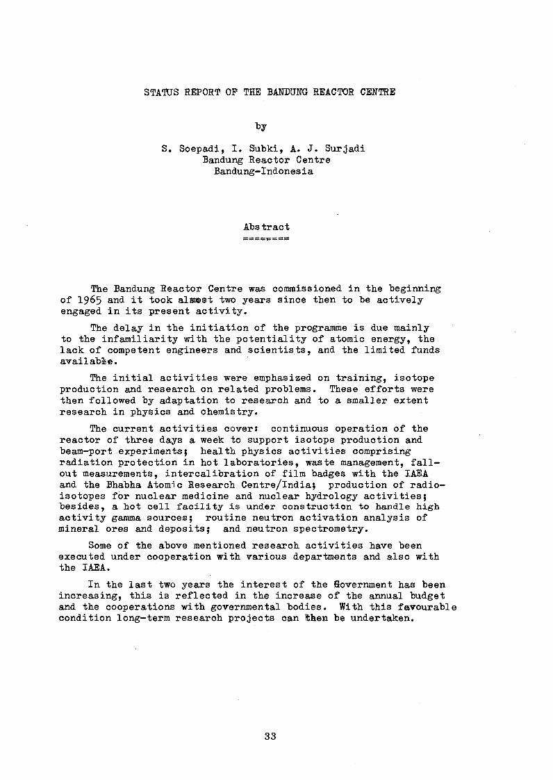
The Bandung Reactor Centre was commissioned in the beginning of 1965 and it took alraœst two years since then to be actively engaged in its present activity.
The delay in the initiation of the programme is due mainly to the infamiliarity with the potentiality of atomic energy, the lack of competent engineers and scientists, and the limited funds available.
The initial activities were emphasized on training, isotope production and research on related problems. These efforts were then followed by adaptation to research and to a smaller extent research in physics and chemistry.
The current activities cover: continuous operation of thereactor of three days a week to support isotope production and beam-port experiments; health physics activities comprising radiation protection in hot laboratories, waste management, fallout measurements, intercalibration of film badges with the IAEA and the Bhabha Atomic Research Centre/lndia; production of radioisotopes for nuclear medicine and nuclear hydrology activities; besides, a hot cell facility is under construction to handle high activity gamma sources; routine neutron activation analysis of mineral ores and deposits; and neutron spectrometry.
Some of the above mentioned research activities have been executed under cooperation with various departments and also with the IAEA.
In the last two years the interest of the Sovernment has been increasing, this is reflected in the increase of the annual budget and the cooperations with governmental bodies. With this favourable condition long-term research projects can then be undertaken.

Introduction
The Bandung Reactor Centre has been commissioned in the be
ginning of 1965 and it took almost two years since then to be
actively engaged in its present activity.
All those developing countries facing multifacetted problems
and activities in the field of science and technology will un
doubtedly encounter the same epxerience as we did during the two
years before we started with our activities. The many problems
which arose compelled us to determine a definite choice of activi
ties, bearing in mind the existing needs and the available faci
lities.
At the early start of our programme it was felt necessary to
start activities in different fields. This was mainly due to the
infamiliarity with the potential uses of atomic energy. It re
quires constant efforts and patience to convince the responsible
people about the potentiality of nuclear energy and at the same
time to adopt the basic modern nuclear techniques.
Apart from the facts mentioned and the limited funds available,
the incorporation of competent engineers and scientists to the pro
gramme also requires a tireless and continuous effort.
Gradually the situation became more favourable and it was
realised that nuclear energy was of great significance for the overall
development of the country. The government took steps to raise the
annual budget which entailed the upgrading programme of our reactor,
and the inflow of trained scientists and engineers from abroad is
making the utilization of nuclear energy in Indonesia rather promising.
After three successive years during which all our activities were
directed toward the practical application of atomic energy, and the
training of scientists and engineers was being accomplished, time has
finally come to start with fundamental research and undertake long-term
projects.

As the first reactor was being installed in this country the main
objectives have been to explore existing problems for initial activities
with emphasis on training, research and isotope production, and studies
on related problems. ,
Training geared for this purpose has produced qualified engineers
and technicians through long term university education or short
courses for professionals wishing to adopt nuclear techniques to their
respective disciplines.
Bearing in mind the general climate that prevails and the need that
has been felt, all efforts are directed to adaptation research, and in
a smaller proportion research in physics and chemistry has also been
carried on, and simultaneously familiarization with nuclear instruments.
Anyhow, these phases have enabled the development of researchers and
made it possible to carry on research at a higher level in various fields.
The isotope production with its initially limited programme is
expanding rapidly, this is attributable to the adaptation research
mentioned earlier; the quality and quantity of isotope needed for the
different studies depend heavily on the capabilities of our upgraded
TRIGA Mark-II reactor being the only reactor existing in this country.
Current Activities
The reactor has been scheduled to run on a weekly programmes
Monday through Wednesday continuous operation, Thursday and Friday
8 hours operation and Saturday is left for maintenance work.
Other activities are described elsewhere.
The Health Physics Division is routinely engaged in basic radiation
protection work, e.g. radiation protection in hot laboratories, radio
active waste management, calibration of Health Physics instruments,
radioactive fall-out measurements and it also maintains a film badge
service for the users exposed to radiation outside the centre.
Among other scientific activities which have already been carried
on in the past we mention the followings

1 . film badge intercalibration services wiîbïi the IAEA and the
B.A.R.C./lndiaj
2. intercomparisonal glass dosimetry with the IAEA.
Above all the production of radioisotopes for domestic use in
the field of medicine, hydrology, and research has been emphasized.
A hot cell equipped with accessories, capable of handling up to 100 Ci
equivalent Co-60 is under construction, this laboratory enables us to
produce high activity isotopes. Routinely 30 kinds of isotopes and
their labelled compounds have been produced with a net activity of
about 145 curies last year, most of which were used for experiments in
Hydrology and Medicine.
It was hard to accomplish a rapid increase in isotope utilization
without a close cooperation with the organizations or bodies concerned
with their use.
An agreement has been reached with the Ministry of Public Works
and the Ministry of Health to establish a close collaboration on
radio-isotope applications in the fields of Hydrology and Nuclear
Medicine.
In the last three years 10 research projects on discharge measure-
mentff, dam seepage investigation, permeability mapping and sediment
gauging, have been successfully conducted.
A research contract on isotopic methods in tropical soil hydrology
has been granted by the IAEA and work on that subject is being carried out.
Last year on the premises of the centre, while waiting for the
completion of the building in the general hospital, a clinical ward was
officially inaugurated, including a variety of activities such as
uptake studies, liver, brain and renal scanning studies, therapy of
cases of hyperthyroidism and carcinoma. A number of 649 patients
received treatment during that period and various isotopes with a total
activity of 3*7 Ci were used.
The reactor has also been routinely used for irradiation purposes,
e. g. neutron activation analysis; among the targets that have been
irradiated are mineral ores ar deposits. The availability of a Ge-Li
detector encouraged us to start our programme of instrumental neutron
activation analysis.

At the present time a research contract on "Geochemical and Geo-
botanical Prospecting for Gold and Copper by Neutron Activation Analysis"
has been granted by the IAEA. While another research contract on
"Some Aspects of the Utilization of Tritium" has just been completed.
Neutron spectrometry has been initiated in this country since the
participation of our staff members in the I.P.A* projects. The results
of this project are reported elsewhere.
Apart from this, neutron radiography and in-pile dosimetry are
being carried out.
The programme on radiobiology has emphasized mainly agricultural
and allied branches of science using the Standard Triga Irradiation
Facility (STIF). Mutation breeding studies on rice grain and soy beans
are being carried out, and at the same time the possibility of achieving
pest control is being studied.
A variety of subjects in the nuclear sciences have been proposed to
the various faculties of the Bandung Institute of Technology making
available the facilities of the Centre to the students from the
Institute to carry on research leading to study reports or theses.
Some members of the Centre are given the opportunity to teach at
the Institute, and annually 35 students on the average complete their
study reports and/or theses.
Programme and Resources
The Bandung Reactor Centre is staffed with 38 scientists, 32 technicians,
and 61 administrative officers, twice the number at the time of
commissioning.
Though a sound scientific tradition does not prevail yet, in
general it can be said that recruitment of additional personnel pro
ceeds smoothly without difficulty; concurrently these people may either
choose a far better paid job and yet they remain and contribute with
their full dedication to the centre. Most of the staff members have
* I.P.A. India-Philippines-IAEA regional research cooperation agreement

received their professional training abroad, however a more specialized
training is needed. Young graduates for specialized training are
generally supplied by the universities.
The basic instrumentation which is available at the centre was
supplied by a U.S. Government grant. More sophisticated instruments
designed to be used for advanced studies were required during the last
few years.
Since the nuclear centre is a governmental establishment, the
sources of income are from the government funds and are therefore
dependent on national events and development; and this may some time
hamper further planning for development.
The government has taken more interest and provided better support
for research and development, including atomic energy matters during the
last years.
In 1969, the first neutron diffractometer set up was ready for use
and the first experiment on elastic scattering was carried out.
In the light of the upgrading programme, studies on inelastic
scattering are made feasible using a specially predesigned Beryllium
Detector System, which the IAEA decided to support through a project of
regional cooperation.
The engineering aspects that have been covered to date are:
- neutron radiography, a vertical beamport has been designed and its
construction is underway;
- design of the secondary cooling tower for 1000 kW operation;
- programming for reactor code applications and for research reactor
control ;
- reactor chemistry, accentuated on coolant chemistry and failed
fuel element detection.
A further engineering programme should be selected appropriately,
the selection of which depends upon joint efforts with other national
authorities involved with the nuclear power programme. But the
general interest will cover the following topics: reactor chemistry,
materials study, instrumentation development and thermal hydraulics.
The basic requirements for advancement and development of the
centre are well established.
The results of the studies on the use of isotopes and radiation
were promising, this is reflected in the confidence and the increase
of the annual budget and the contracts with other governmental bodies.
However,a large increase in the annual budget should not be
expected within the next few years. It can be expected that the govern
ment will finance quick yielding research studies while the financing
of long term research projects should be secured from other sources.
Utilization of Pakistan’s Research Reactor (PARR)
by S. M. Butt
(Neutron Diffraction Group)
Pakistan Institute of Nuclear Science and Technology
Nilore, Rawalpindi, Pakistan
ABSTRACT
The research programme under execution at PARR (Pakistan
Research Reactor) at the Pakistan Institute of Nuclear Science
and Technology, in Nilore, Rawalpindi is described.
The utilization of the 5 MW Swimming Pool Research Reactor
in the field of Solid State Physics, Nuclear Physics, Radio
isotope production and activation analysis is discussed.
Some recent results of the various research projects
currently under investigation are reported.
Further research work envisaged is briefly mentioned.
Introduction
The Pakistan Atomic Energy Commission started its programme
with a lot of vigour and enthusiasm after Dr. I. N. Usmani, the
present chairman, took over this organization. The object was
the peaceful uses of atomic energy.
Several Atomic Energy Centres were planned and the Pakistan
Institute of Nuclear Science and Technology (PINSTECH), was
started at Nilore, about 15 miles outside Rawalpindi/Islamabad,
the capital.
The country’s first reactor, the 5 MW Swimming Pool research
reactor was planned at this Institute. The reactor became
critical in December 1965 and the full power of 5 MW was
attained in June 1966.
The maximum thermal neutron flux at the core at full powern S g Ô 2
is about 3 x 10 n/cm sec. and more than 10 n/cm sec at the
wall of the reactor on a typical radial beam tube.

Reactor Facilities and Utilization (Fig. l)
Beam Tubes (Fig. 2)
There are six horizontal radial beam tubes with one through
tube passing tangentially at the reactor-core and ending on the
opposite faces of the reactor shield.
Three of the radial tubes are 6" in diameter and the other
three are 8" in diameter.
Vertical Tube
This is a 2.4 inch diameter aluminium tube filled with water
and extends from the reactor grid-plate to the reactor bridge.
The tube can be inserted in any hole of the grid-plate so that
any desired flux could irradiate the sample placed in this tube.
The tube is used for irradiation of small samples with a1 2
flux of the order of 10 n/cm sec.
Thermal Column
A graphite thermal column of 4'x4' cross section and 5'
depth is provided. The thermal column is closed by a M g
concrete door of 5'x5' cross section and 5' deep having four
wheels which move on parallel rails. The door has four holes
of 6" diameter each, which are normally closed with removable
concrete plugs.
The thermal column is used where thermal neutrons are
required for some irradiations. It offers a high cadmium ratio^
about 5OO at the graphite face.8 / 2
The thermal neutron flux at the graphite face is 10 n/cm-
sec. By removing some graphite a thermal flux of as much as10 2
10 n/cm sec can be obtained. It is intended to set up a
single axis/double axis crystal neutron spectrometer at the
thermal column, mainly for the measurement of total neutron
cross sections of materials.
Pneumatic Rabbit System
This system has two stations, one near the Hot Cell and the
other in the Chemistry and Isotope Laboratory at the ground floor
of the rector-hall. The system consists of a net-work of 2”
diameter aluminium tubes connecting the stations to the places13 13 2
near the core, where fluxes of about 1 x 10 and 6.5 xlO n/cm
sec can be obtained.

This facility is used for making radioisotopes and also to
study some short lived isotopes. A polythine tube known as
"Rabbit" of 2" diameter with a sliding contact on the inner of
aluminium tubes, carries the material of which the radioisotope
is to be made and is transmitted to the core with pneumatic
control and moves with a speed of 30 to 40 feet/sec. A maximum
weight of the rabbit can be 16 ounces including the material.
The system is used for making radioisotopes and for delayed
neutron fission experiments.
Hot Cell
It is a 9 by 6 feet heavily shielded room provided with a
facility of slave manipulators. The inside of the room is
visible through a lead-glass. The room is connected through
the transfer-port to the reactor pool so that big irradiations
can be handled. Large amounts of materials can be irradiated
in the reactor-pool and then transported to the Hot-Cell through
the mechanism of transfer-port of 2’x2’ cross section, the 3
feet thick heavy density wall of the hot cell permits safe
handling of about 1000 curies of radioactive samples.
Utilization for Research and Training
The research programme around the reactor at the beam ports
is mainly being carried in Physics. However, in addition some
activation-analysis of some materials after irradiation in the
reactor is being carried out by the Nuclear Chemistry Division.
We shall now discuss the Physics programme in some detail.
Physics
The physics research programme consists mainly of two branches,
namely, the Solid State Physics and Nuclear Physics. There are
four main research groups in existence at present which are
engaged in these fields. The Nuclear Physics groups engaged in
Fission Physics and Neutron Capture Gamma Ray Spectroscopy, started
their programme in 1966 soon after the reactor became critical.
The Solid State Physics groups engaged in neutron diffraction
and scattering from solids and liquids and the radiation damage
studies started somewhat later.

Nuclear Physics
Fission Studies (G.D. Alam, M. A. Shaukat,T. A. Khan, M. Zafarullah Khan)
The group has the following programme of research: '
1. Studies of tertiary fission.
2. Study of X-rays from the fission fragments.
3. Study o f Y - rays from the fission fragments.
The group has recently done an experiment on ’’fission
fragment energy-correlation measurements for thermal and reson
ance energy neutron induced fission of Pu”. Experimental results
of the double energy measurements using solid-state detectors
are obtained for thermal and resonance energy neutron induced
fission of Pu. A monoenergetic neutron beam of 0.297 e.v was
obtained through reflection of the incident neutron beam from
the (002) planes of the Zinc single crystal. Mass and energy
distributions have been obtained containing 1.6 x 10 events4
for thermal fission and 4 x 10 events for resonance fission.
Preliminary results indicate increase in the symmetric
yield for resonance fission compared to thermal fission.
Introduction
Low energy neutron induced fission cross-sections show
pronounced resonances in the electron volt region. These resonances
may correspond to different "transition states of the compound
nucleus. According to the theoretical ideas of Wheeler based
on the collective model, the compound nucleus undergoing fission
is relatively ’’cold" due to large deformations involved, conse
quently few well defined rotational and vibrational quantum
states are available for the fission process. On this basis low
energy neutron induced fission could occur mainly through a
well defined quantum state. It is, therefore, of interest to
investigate fission induced by monoenergetic neutrons of resonance
energies and to study the variations of the mass yields from
level to level.
Experimental Procedure and Data Analysis
A schematic diagram of the experimental set-up and elec
tronics is shown in figure 3- A monoenergetic neutron beam was obtained through the Bragg reflection of the 1” diameter collimated neutron beam from tne (002)—plane of the Zn single

crystal mounted on a simple single axis spectrometer system. The
diffracted neutron beam was ftirther collimated with a lMxl" Soller
collimator. The overall energy resolution was sacrificed to
obtain a higher flux from the resolved neutron beam.
239The Pu target and two heavy ion surface barrier detec
tors (D^ jD^) facing the target were placed in a small aluminium
chamber having thin front and back aluminium windows to avoid
excessive scattering of the neutrons. The O .297 eV resonance
was identified by varying the Bragg angle of the crystal and
measuring the fission rate as well as monitoring the neutron
flux with a small BF3 detector placed immediately behind the
chamber. The fission rate normalized to the neutron flux is
shown in figure 4* The maximum of the normalized count rate
falls at a neutron energy of 0.297 eV corresponding to the peak
in the fission cross-section resonance. The Bragg angle was
adjusted corresponding to the maximum of the fission rate.2 -JQ 2
The Pu target was 70/^gm/cm deposited on 3 inch thick
nickel foil and had the following isotopic composition:
239Pu, 99.10$; 24°Pu, 0.888$; 241Pu, 0.014$.
Details of the electronic system (figure 3 ) used in this
experiment, are self explanatory. The data was stored in the
4096 channel multi-parameter analyzer in a 64 x 64 mode. Close
watch was kept on the gain of the system. Stability of the
gain of the system was checked every few hours, by taking puiser
measurements and adjusting the gain of the amplifier and Zero
level of the analyzer for small gain shifts. The data punched
on paper tape after the end of each run was finally processed
on an IBM 360/40 computer. In order to eliminate grid fluctua
tions in the transformed data the H (x^,x^) events of the corre
lated pulse heights in a given position (x^,X£) of the array were
treated as N independent events and were processed separately,
by adding random numbers distributed between -0.5 and +0.5 to
each pulse height. The pulse heights were converted to mass9
and energy by the mass dependent calibration and mass and momentum
conservation.
Result and Discussion
The interim results are summarized below:

The fragment mass distirubtion and average total kinetic
energy E . as a function of the provisional mass, for resonance
as well as thermal neutron induced fission are shown in figure 5*5
The thermal and the resonance runs respectively contain 1.7 x 10⁴
and 4 x 10 events. A lisir of average total kinetic energies,
light and heavy fragment masses and the distribution widths is
given in table I. For reference, also are included the corres-239 Í
ponding values for thermal fission of Pu, obtained previously.
Within the resolution, the average total kinetic energy, light and
heavy fragment masses are in agreement. However, due to poorer
resolution of 64x64 channels, the mass distribution width is
higher and the peak to valley ratio is lower in the present
experiment.
The mass distributions for the two cases are plotted on a
log scale in figure 6: to show the variations in symmetry.
These results indicate an increase of symmetric neutron induced
fission compared to the thermal fission. The relative variations
are given by
R - <p/vLs / <p/¥Wwhere (P/v) res and (p/v ) Th are respectively the peak-to-valley
ratios for resonance and thermal fission yields. These values
are,
<p/v>ReS. " 45 i 10<P/V W . ' 97 ± 10
The yield at symmetry is approximately twice compared to the
thermal run. Similarly, the results show deviations in the
average total kinetic energy as a function of mass. The (Ej^p g
is effectively larger than in the symmetric parts of the
mass distribution. Although the measurements clearly indicate
the dependence of fission yield on the state of the compound
nucleus at the saddle point, these results are in disagreement
with the previous radiochemical measurements of Regier and his
co-uorkers.

Neutron Capture Gamma Spectroscopy (A.M. Khan, Irahad Mohammad,J. A. Mirza, Anwarul Islan,C. A. Majid).
The research programme of the group consists of:
Nuclear structure studies involving the accurate
determination of energies and intensities of neutron
capture gamma-rays, measurement of angular correlation
and polarization correlation of cascading (n, f) radia
tion and the measurement of life-times of the low lying
nuclear levels.
The equipment at present available with the group consists
of a 30 cc Ge (Li) detector, two 3"x3" Nal(Tl) detectors, ORTEC
modular electronics and a 4096 channel analyser. The germanium
detector and the associated electronics give a resolution of 3«7
kev at I .32 Mev. A 6”x6" split Nal(Tl), annular detector, now on
order, will be used together with the germanium detector as a
pair spectrometer.
The experiment is being set up on â 6" diameter tangential
tube. The neutron beam brought out through a service of lead7 2
and paraffin wax collimators has a flux of 1.5x10 n/cm . sec, at
the target position at full reactor power. The cadmium ratio
is 10 and the gamma ray dose is 0.5 r/h.
Preliminary measurements made with a 2 cc Ge (Li) detector
on an Fe-target are shown in figure 7- Modifications are being
made in the system to incorporate the 30 cc Ge (Li) detector
and the Nal annulus when it is received.
Solid State Physics
Neutron Diffraction and Scattering Studies (N.M. Butt, Q.H. Khan,M.M. Beg, Javed Aslam, Miss Attika Rabbani,A.A.Z. Ahmed, M. Afzal).
The work is being pursued by the Neutron Diffraction Group
of this institute.
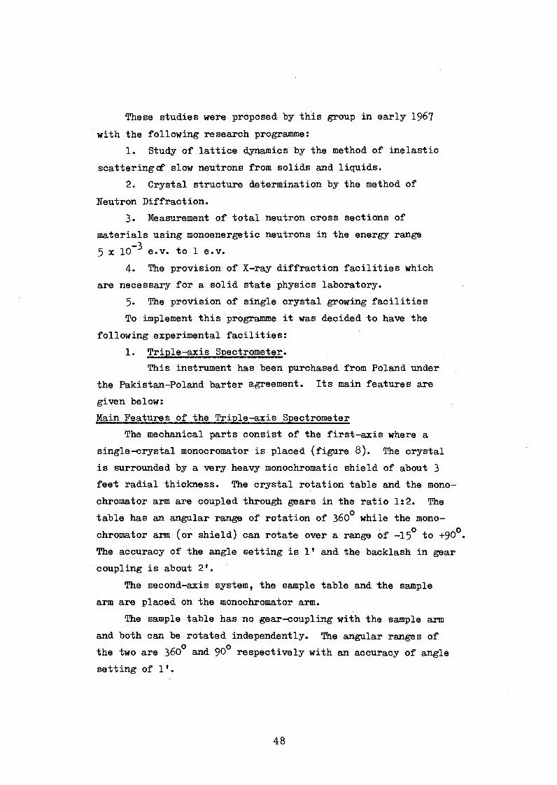
These studies were proposed by this group in early 19^7
with the following research programme:
1. Study of lattice dynamics by the method of inelastic
scatteringcf slow neutrons from solids and liquids.
2. Crystal structure determination by the method of
Heutron Diffraction.
3. Measurement of total neutron cross sections of
materials using monoenergetic neutrons in the energy range
5 x 10 3 e.v. to 1 e.v.
4» The provision of X-ray diffraction facilities which
are necessary for a solid state physics laboratory.
5- The provision of single crystal growing facilities
To implement this programme it was decided to have the
following experimental facilities:
1. Triple-axis Spectrometer.
This instrument has been purchased from Poland under
the Pakistan—Poland barter agreement. Its main features are
given below:
Main Features of the Triple-axis Spectrometer
The mechanical parts consist of the first-axis where a
single-crystal monocromator is placed (figure 8). The crystal
is surrounded by a very heavy monochromatic shield of about 3
feet radial thickness. The crystal rotation table and the mono
chromator arm are coupled through gears in the ratio 1:2. The
table has an angular range of rotation of 360° while the mono
chromator arm (or shield) can rotate over a range of -15° to +90°.
The accuracy of the angle setting is 1* and the backlash in gear
coupling is about 2*.
The second-axis system, the sample table and the sample
arm are placed on the monochromator arm.
The sample table has no gear-coupling with the sample arm
and both can be rotated independently. The angular ranges of
the two are 360° and 90° respectively with an accuracy of angle setting of 1'.

The third-axis, analyser table and the analyser arm are
placed on the sample arm and are coupled with a gear ratio ofo
1:2. The angular range of the table is 360 while that of the
analyser arm is 160°.
The angles of all the sixes can be set automatically by a
programmed paper tape.
The spectrometer operate§ in the automatic mode through
a logic system of the control electronics.
The spectrometer can be used for three different fields in
diffraction studies namely study of lattice dynamics in the
triple-axis mode; structure determination in the double-axis
mode and for determination of total neutron cross sections in
the single-axis mode.
Experiments on the Triple-axis Spectrometer
Before starting the installation of the spectrometer an
in-pile collimator (figure 9) was installed in the Beam tube
No. 3» The collimator provides a beam cross section of 2"x2”.
The collimator is provided with a water-shutter (a stainless
steel rectangular tube of 2"x2” cross section and 4 feet length which can be filled or emptied by water with remote system), a
cooling jacket for the Bi-filter (which can be cooled by circu
lating liquid nitorgen from outside) and a mechanical-shutter
with an eccentric 2l,x2" hole- The mechanical-shutter can be
operated with remote control from the chain-pulley system.
When the water-shutter and the mechanical shutters are
closed, the neutron and gamma radiation background in the
working area of the spectrometer is quite below the safety
limits. After the installation of the spectrometer in May,
1971 the following three experiments have been performed:
1. Diffraction pattern of Mn Pe2 0^
The spectrometer was used in the double-axis mode. A
Zn (OOOl) monochromator of 0.8"x2.5”x7” was used.
The monochromator arm was set for neutrons of 1.22A0
wave-length. The Mh Fe2 O4 powder was filled in an empty

aluminium cylinder of 1 cm diameter and 4 cm high and was
mounted on the sample table. It was adjusted to be completely
covered by the incident neutron beam.
The diffraction pattern obtained is given in figure 10.
The idea of this diffraction pattern was to compare
the positions and the intensities of the peaks already obtained
on a similar spectrometer in Poland. The results agree well
to substantiate a good calibration of our spectrometer.
2. Phonon dispersion-relation for Al(lll)
A single crystal A1 sphere (2" diameter) was used at
the sample table. Neutrons of wave-length 1.22A° (or an energy
of 0.055 e.v) idffracted by a Zn(000l) monochrometer were used
for the inelastic scattering from the sample. The phonon peaks
were obtained along the symmetry direction Al(lll) of the sample
for q-values of 0.06A° \ 0.08a° 0.12A*"* \ and 0.18a ° \
figure 11 (a,b). The phonon dispersion curve thus obtained is
given in figure 12.
This experiment was also done to caliberate the spectro
meter in the triple-axis mode. The dispersion curve obtained
was in agreement with the one already obtained with a similar
spectrometer installed at the nuclear centre of Swierk, Poland.
Mosaic spread and reflectivity of crystals
For any single crystal grown in a laboratory, the mosaic
spread is not in an accurate control of the experimenter. Only
by experience one may grow crystals in the neighbourhood of the
stipulated mosaic spread.
Therefore it is necessary to know these parameters of the
crystal by experimentation after these have been grown. The
present experiments on the measurement of the mosaic spread and
the reflectivity of Zn, Cu, Al, Pb, and Ge single crystals will
be carried out.
Al(lll) Single Crystal
An Al single crystal plate of dimensions 6"x3"xl" with
(ill) planes parallel to the flat surface was placed at the
sample table.

The incident neutron "beam falls at an angle 0 = 12.34°
on the crystal and is diffracted at an angle 2© in which
direction the detector is placed. The crystal was adjusted
to get maximum reflection. By keeping the detector fixed at
20, the crystal was rotated over its reflection range.
Results
Figure 13(a) gives the geometrical divergence of the inci
dent beam due to the collimators.
Figure 13(b) gives the diffraction peak of the Al(lll)
reflection obtained for neutrons of wave-length =1A° (energy
O.O82 e.v). Two overlapping peaks are observed which indicate
that this piece of the crystal is not one single crystal but
is divided into two parts each being a good single crystal.
Further investigations to verify this explanation are in progress.
The incident divergence of the neutron beam is 13* while
the full widths at half height of the observed diffraction peaks
are about 18*. A mosaic spread of 5’ can be attributed to the
crystal. However, these are very preliminary measurements and
further detailed investigations of the mosaic spread and the
reflectivity of this crystal are still in progress.
Investigations on neutron shielding materials
(a) Borated Paraffin:
Although borated paraffin is widely used as a neutron shield
the data is not easily available for a systematic study of the
effect of varying percentage of Boron in paraffin. A systematic
study on these lines was made.
A good collimation set up was arranged at the thermal
column as shown in figure 14* Blocks of 1” thickness and 4"x4"
in cross section and varying in Boric acid concentration from
10$ to 80$ by weight, were made.The attenuation curves thus obtained are given in figure 15»

(b) Shielding properties of indigenous wood
Wood contains a considerable amount of dydrocarbons and
is expected to be a good neutron shield. Also it is convenient
to make various sizes and shapes of wood for shielding purposes
in experiments around the reactor beamports. The results are
shown in figure 16. It is concluded that though borated
paraffin is the best neutron shield among these* nevertheless,
"gurgan"(one kind of wood) is also a good shield. Another kind,
"chir", which is rather cheaper than gurgan and is easily avail
able in the country is rather a more suitable material if wood
shielding blocks are to be used in the experiments.
Radiation Damage Studies (S. Mansoor Ali, K.A. Shoaib, S.U.Cheema, P. H. Hashmi*)
This group has been working for the last three years. It
has undertaken to study the effect of fast neutrons on the
electrical properties of the low mobility semiconductors with
special emphasis on Zr0o and Th 0_. A fluence of the order of19
10 nvt will be needed so as to have the density of the irradia
tion induced defects comparable to the density of a free charge
carrier. The following programme will be pursued:
(1) Electrical resistivity as a function of temperature.
(2) Linear heating before irradiation quenching and cold
work.
(3) Linear heating after introducing defects.
(4) Isochronal heating measurements.
(5) Isothermal heating measurements.
Reactor Utilization other than Physics
Radioisotope production (Matiur Rehman, M.Y. Mirza,M. Bashiruzzaman, H. M. Karim)
The programme of isotope production is expanding. A
separate plant for processing bulk quantities of 1-131, S-35, and
P-32, as large as 10 Ci/run is being installed.

At present the isotopes are being supplied mainly to medical
centres, industries and training centres in Pakistan. During
1969-TO, the following supplies were made:
Isotope
Ir-192
Na-24
K -42
Co-58Br-82
Cr-51
Au-198 ) In-ll6m) 1-128 )
Supplied to:
Spancers (Pak) Ltd.
SEATO Cholera Lab, Dacca
SEATO Cholera Lab, Dacca
Atomic Energy Centre, Lahore
Atomic Energy Centre, Lahore
Atomic Energy Medical Centre, Karachi
Reactor School, Pinstech
Strength
2 Ci
60 mCi
35 roCi
2 mCi
20 mCi
2 mCi
Severallow activitysources
In addition to meeting the demands of local users in
Pakistan, this division is planning the export of isotopes on
competitive international rates. After the full scale working
of the above mentioned plants, the division hopes to be able to
export the surplus material.
Further, the research and development programme for the
production and processing of other radioisotopes like Au-198,
Tc-99m, Co-58 and Cr-51 is also being pursued.
Activation Analysis
The reactor is also used by the Nuclear Chemistry Division
is determining the composition of materials by the neutron
activation analysis. The samples are irradiated in the
neutron flux near the core of the reactor through the rabbit
control system. From the spectrum of radiation emitted, one
can infer about the composition of the material.
Reactor School
The school looks after the training requirements of the
operators as well as the engineers for the power reactor programme
of the PAEC in Pakistan. Since its start about 4 years ago,
the Reactor School has organized one year’s course for the

reactor operators which were mostly menât for the 137 MW KAJJUPP
reactor (Karachi Nuclear Power Project) and the 200 MW reactor
for Roopur, East Pakistan. The former reactor has just 'become
critical while the latter is under the active programme of the
PAEC.
For the last three years, the reactor school has concen
trated on the training of nuclear engineers with a one year
extensive programme consisting of lecture courses in physics,
health physics, engineering and nuclear engineering. Also
several experiments in physics and nuclear engineering are
conducted in a laboratory. In addition to several nuclear physics
and neutron physics experiments, the following experiments on
the 5 MW research reactor are conducted:
(1) Start up experiment on the Pakistan Research Reactor
(PARR) at PINSTECH.
(2) Control rod calibration of the PARR.
(3) Reactivity effect of the thermal column and beam tube
flooding.
(4) To obtain the diffraction pattern of reactor neutrons
and use the monoenergetic neutrons for the determina
tion of the total neutron cross section of Cobalt and
Indium, etc.
The reactor school trainees who are basically either physics
graduates or engineering graduates, get a MSc degree (Nuclear
Technology) from the University of Islamabad. In the 1970-71
batch of trainees there are more than 30 persons. The University
of Islamabad is responsible for conducting the examination and
for the award of degrees to the successful candidates.
The reactor school also has the provision of imparting
training to the candidates from other countries who have
expressed interest in it.
In addition to the five permanent members of the Reactor
School staff, an IAEA expert and scientists and engineers from
several other disciplines like physics, chemistry, health physics,
electronics, nuclear engineering, etc., give specialized courses
to the trainees.

Concluding Remarks
The utilization of the research reactor at Pinstech is
being made for various disciplines. The activities are further
being expanded by setting more experiments at the remaining
beam tubes and using the irradiation facilities in the Reactor
School.
Recently an arrangement is being made with the University
of Islamabad where the students of the Universities can use the
reactor facility for studies leading to the degree of M.Phil
and Ph.D. of this University.
Acknowledgement
The author is grateful to Mr. Ahmed Ali, Technical Officer
and other technical members of the Neutron Diffraction Group and
to the Workshop Staff for help in technical matters.
Useful discussions with Dr. M. A. Shaukat and Dr. G. D. Alam
are also acknowledged.

TABLE I
Mean Values and Widths of Distributions
..... .... — ................— —" “■ ...—1 — .. T, rn n- , « -
239™.Pu + N Thermal 239 NPu resonance
Quantity This work Ref A*
Ek (MeV) I78.3+2.O I7 7.7+I .8 I76.9+2.O
K (MeV) 12.1 12.2 12.1
“L101.2 100.34 IOO.9
mH 139.6 139.66 I39.2
mL =fflH 6.7 6.01 6.7
*with neutron emission correction
Ref. A.: J. N. Heiler, P. J. Walter and H. W. Schmitt.Phys. Rev. 149, No. 3, 894 (1966).
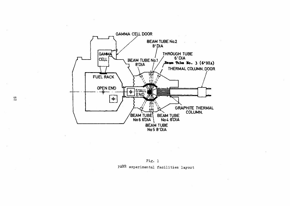
GAMMA CEIL DOOR
OPEN END•“* ------
BEAM TUBE No.2 8* DIA
BEAM TUBE No.1 8'DIA
THROUGH TUBE 6 'DIA
/Beam Tübe Ho. 3 (6 ’ DIA)
THERMAL COLUMN. DOOR
rh STALLiÜIPe n d JWn
n \\
BEAM TUBE No 6 6TDIA
BEAM TUBE No 5 8'DIA
GRAPHITE THERMAL COLUMN.
BEAM TUBE No U S'DIA
Fig. 1
pARR experimental facilities layout

FIGURE 2. TYPICAL BEAM TUBE SKETCH AT PAKISTA M RESEARCH REACTOR
ta
'
«*■ 1
Éa ..
Ia
1
ACORE
*— -c -
1
C----- (i B
1
1LEAD PLATE-''
>
^-FINISHED POOL WALL LEAD PLATE- ^1
DIMENSIONS ARE IN INCHES
r* g n
BEAM TUBE DIMENSIONS TABLE
BEAM TUBES PLUGS
BE
AM
TU
BE
No
NO
MIN
ALD
IA a b C d e f g ,(app.)
LEAD PLUG A CONCRETE PLUGB CONCRETE PLUG C
DIA LENGTH No OF DIA LENGTH No OF DIA LENGTH No OF
1 8 15.0C 10.00 8.56 13 37.00 63.00 70 U.81 10.43 1 9181 11.81 3 8.31 13.31 22 8 15.00 10.00 8.56 13 37.00 62.00 70 U.81 10.43 1 9.81 11.81 3 8.31 13.31 23 6 H . 75 9.50 6.50 12 37.50 68.50 70 U.50 10.31 1 9.00 12.00 3 6.00 13.50 24 6 H.75 9.50 6.50 12 37.50 62.50 70 U.50 10.31 1 9.00 1100 3 6.00 13.50 25 8 15.00 10.00 8.56 13 37.00 60.50 70 U.81 1(K3 1 9.81 11.81 3 8.31 13.31 26 6 K.75 9.50 6.50 12 37.50 60.75 70 U.50 10.31 1 9.00 12.00 3 6.00 13.50 2
THRUTUBE 6 12.00 10.00 6.00 13 33.50 — 70 U.50 10.31 2 9.00 12.00 6 6.00 13.50 U

FIG .3. BLOCK DIAGRAM OF CIRCUIT AND SCHEME OF EXPERIMENTAL SET UP

100 200 300 400 500 600NEUTRON ENERGY (MeV) — ►
F1G¿ NORMALISED FISSION RATE AS A FUNCTION ON NEUTRON ENERGY.
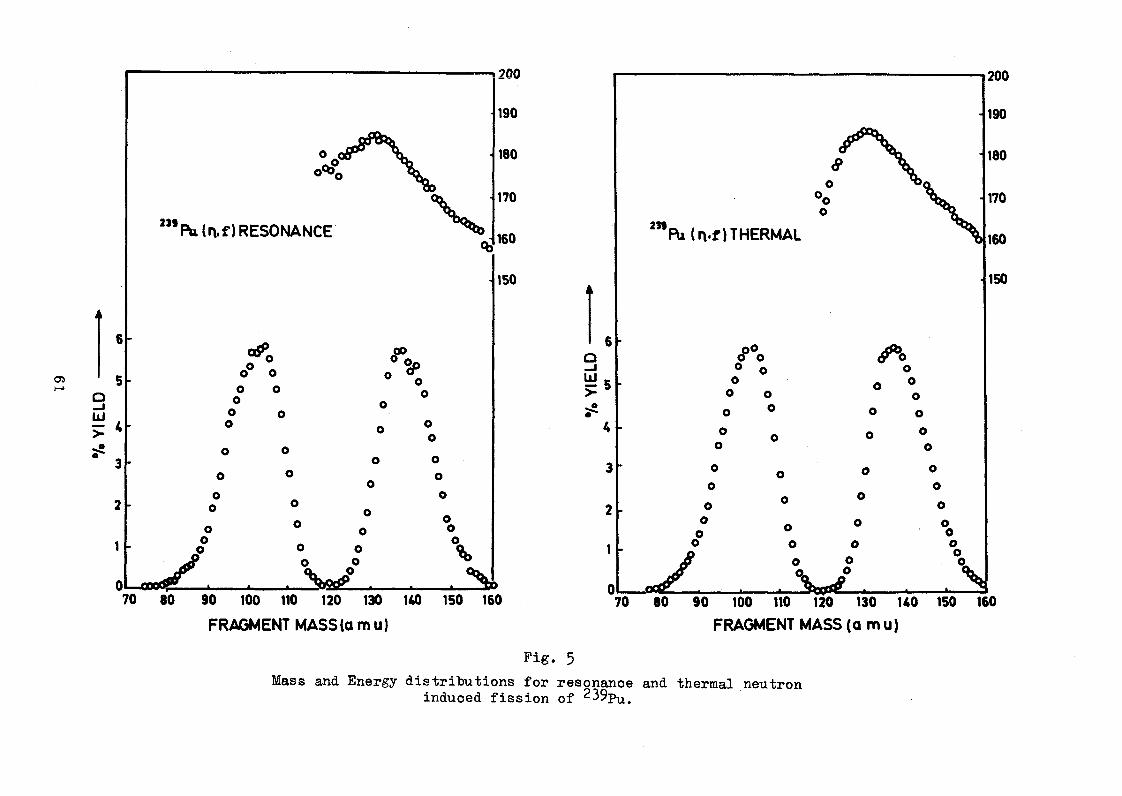
90 100 110 120 130 140
FRAGMENT MASS (a mu)
Fig. 5
Mass and Energy distributions for resonance and thermal neutroninduced fission of 2^9pu#

7. YI
ELD 0.1
0.01:
0.001
/r s
\ >
V
•o
o
•o
•O
oY v
oo
oo
o m
• » •o •
o
* oo
239 Pu RESONANCE ENERGY NEUTRON INDUCED FISSION YIELD o
Pu THERMAL ENERGY NEUTRON INDUCED •» FISSION YIELD
o 239
oo
ooo
60 70 80 90 100 110 120 130FRAGMENT MASS (am u) -
U0 150 160 170 180
Pig. 6
Provisional mass distribution for resonance and thermal neutron induced fission of 239Pu, plotted on
a Log/Linear scale.

COUN
TS/C
HAN
NEL
PE
R H
OUR
CHANNEL NUMBER
Fig. 7

REACTOR CORE MONOCHROMATOR (IST-AXIS)
Fig. 8
Layout of the Triple-axis spectrometer.

FIG.9 SHIELDING EXPERIMENTAL SET UP AT THERMAL COLUMN.
180


COUN
TS/1
000
sec
ENERGY TRANSFER 10” rad/sec (w ) -------------- >
FIG.11 (a) PHONONS IN AL(111) DIRECTION,OF SINGLE CRYSTAL SPHERE
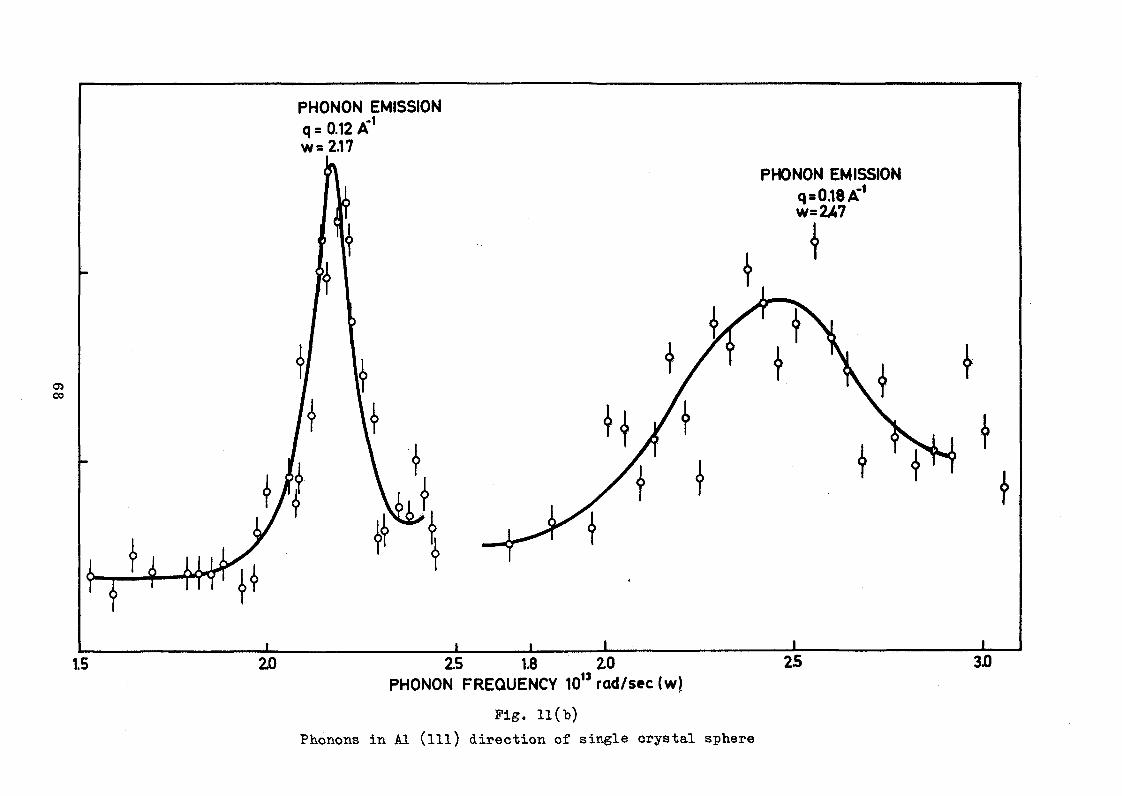
PHONON FREQUENCY 10 rad/sec (w)
Pig. 11(b)
Phonons in A1 (ill) direction of single crystal sphere

10 ra
d/se
c
FIG. 12 PHONON DISPERSION CURVE FOR AL(111)

COUN
TS
x 107
2
sec
ANGULAR POSITION OF THE DETECTOR (1 DIV= 2.16)FIG. 13 (a)GEOMETRICAL RESOLUTION OF THE INCIDENT
NEUTRON BEAM

COUN
TS/2
0 se
c
5660 5680 5700 5720 (1 DIV=2.16'IANGULAR POSITION CRYSTAL
FIG. 13(b) REFLECTION PEAK O F A LΠD FO R NEUTRON WAVELENGTH = 1 A#

Fig. 14
Experimental set up to study the neutron shielding properties of indigenous wood .
CON
CRET
E

CURVE 1 PURE WAX CURVE 2 10 7. BORIC ACID CURVE 3 20 BORIC ACID CURVE U 30 7. BORIC ACID CURVE 5 40 7. BORIC ACID CURVE 6 50 7* BORATED WAX
12 15 18
Thermal neutron atenuation of pure wax and horated wax


STATUS REPORT ON PRR-l *
byLibrado D. Ibe
Acting Commissioner Philippine Atomic Energy Commission
A BSTRACT
The PRR-1 is the principal facility used in the furtherance of atomic energy activities in the Philippines. It is utilized for isotope production* sample irradiations, and conduct of experiments in the nuclear sciences and engineering and training of personnel. Researches aimed at increasing the utility of PRR*-l and insuring its safety are currently undertaken.
Introduction
The Philippine Research Reactor PRR-1, an open pool type
facility, is the first nuclear reactor in the country. It is located
within the campus of the state-owned University of the Philippines
and is operated and maintained by the Philippine Atomic Energy
Commission. The reactor became critical for the first time on
26 August 1963.
Reactor Utilization
Since the attainment of initial criticality, the PRR-1 has been
the main facility used in the furtherance of atomic energy activities
in the country, particularly in the production of radioisotopes; trace
element determination in different samples; investigations and
* To be read in the IAEA Study Group Meeting on ResearchReactor Utilization in Bandung, Indonesia from 2 to 6 August, 1971

experiments in nuclear sciences and engineering; and the train
ing in nuclear techniques of scientific and technical personnel of
the Commission as well as other agencies, including university
faculty and students.
The PRR-1 has been operated at different power levels up
to one megawatt for various durations in order to accommodate
requests for sample irradiations and physics experiments. As
of June 1971, the PRR-1 had generated a total of about 1, 200
megawatt-hours of thermal energy and completed more than 4,200
sample irradiations. Isotope production accounted for the majority
of irradiation requests, followed closely by those submitted by the
neutron activation analysis group. The experimental facilities
often used for this purpose include the beam ports, two pneumatic
tubes, in-core radiation baskets and two vertical 2-inch dry
pipes. The dry pipes were added only about two years ago in
order to meet the increasing irradiation requests.
Two of the six beam ports are permanently tied up with
the two neutron crystal spectrometers used for physics experi
ments. These spectrometers were utilized in the India-Philippines-
Agency (IPA) project, where a number of physicists from Taiwan,
Thailand, Korea, Indonesia and the Philippines received training
in neutron spectrometry. This project was terminated in late 1969.
Another occasional use of the reactor is in the conduct of
experiments or demonstrations given in connection with training
courses for scientific and technical personnel of the various institu
tions, including faculty and student members from local universi
ties and colleges. A special training program in reactor engineer
ing was conducted recently for the engineers of the Manila Electric
Company (MERALCO). The MERALCO, the largest private electric
utility in the country, is seriously considering putting up a nuclear
power plant in the very near future.
Fuel Management
Up to the early part of 1971, the PRR-1 was still using the
original 20% enriched fuel elements loaded ih 1963» The long
period of utilization of these fuel elements could be attributed
to the fuel management procedure adopted by the reactor opera
tions personnel. For maximum utilization of the fuel, the
reactor operating schedules were programmed to permit simul
taneous servicing of the irradiation requests submitted by the
research and service units, as well as the isotope production
group. Ten to twelve hours operation at a rated power of one
megawatt were normally scheduled for four days a week with one
day set aside for 100 KW operation. This schedule also afforded
the use of the reactor for fatst neutron irradiation of seeds

with the aid of the IAEA-supplied Standard Neutron Irradiation
Facility(SNIF). Occasionally, full power operation lasting as
much as 40 hours continuously as requested by the reactor
users is also performed.
In 1968, the twenty 93°f< enriched fuel elements fabricated
in the United States arrived. These were intended for partial
replacement of the spent original fuel elements. As mentioned
above, it was only early this year when partial reloading of
the PRR-1 core was donet In the reloading schedule, the out-in
method was adopted. Ten of the 20f enriched elements in the
central section of the core were retired and some of the peripheral
elements brought in. The ten new 93% enriched fuel elements
added were initially mounted on the outer sections of the core.
With this new core configuration and fuel composition, it became
necessary to perform another series of flux and reactivity measure
ments as well as recalibration of the nuclear instruments.
In the planned second phase of care reloading another set
of ten original fuel elements will be replaced and the remaining
ten new fuel elements brought in. No time schedule has yet been
set for this phase.
Current Researches
Aside from operating the reactor, the PRR-1 operating

personnel are currently engaged in a number of research activi
ties all of which are aimed at insuring the safety and increasing
the usefullness of the facility. Some of the projects in progress
include:
1. Reactor stability experiment;
2. Improvement of the pool dewatering system; and
3f Transistorizing of the reactor instrumentation system.
In the reactor stability experiment, the objectives are to
(1) measure the fission neutron lifetime in the core, (2) deter
mine the effect of temperature on the neutron lifetime, and
(3) determine the reactor transfer function. A reactor oscillator
will be used to introduce the sinusoidally varying excess re
activity in the core.
The slow draining of the pool water in the low-power
section has presented problems on the sealing of the bulkhead
gate« Studies on the rapid dewatering or filling up of the pool
with the use of a centrifugal pump and some means of establish
ing adequate sealing pressure between the gate and pool divider
wall are being undertaken.
On the instrumentation system, our experience has been
that the reactor iostTttzne&tis not completely transistorized
could not offer prolonged trouble-free services due to heavy

current drain and er pensive heat generated in the vacuum tubes.
In contrast, the fully-transistorized logic and trip actuator
amplifiers of the scram circuit have been giving smooth and
satisfactory performance up to the present» Thus the gradual
conversion of the reactor instrumentation from the vacuum tube
to a solid-state system was decided. The initial phase of the
project involves the transistorizing of the two start-up channels
and the log N and period amplifiers. The conversion of the high
voltage power supplies and gamma radiation remote area monitors
will follow.
In addition to the above, improvement of existing experi
mental facilities to increase their usefullness is in progress.
This includes the modification of some of the beam ports to ac
commodate experimental apparatus and the introduction of flexible
handling mechanisms in the vertical dry pipes to permit simul
taneous and uniform irradiation of several small samples.
Conclusion
Since its initial operation, the PRR-1 has played a major
role in the development and promotion of the atomic energy
program in the Philippines. Besides its scientific and technical
uses, it has helped to generate active interest and awareness in
science from the public so that the Center attends to an average

of 7,000 visitors yearly. These visitors, mainly students from
the high schools and colleges all over the country, are also
briefed on the research, development and training activities of
the PAEC, The PRR-1 also serves as a ready device for the
training of a pool of technical personnel with reactor expertise
and experience, so essential in a country that is already seriously
considering the establishment of a nuclear power plant.
#

Status Report of the Engineering Programs and Proposed
Use of the Korean TRIGA Research Reactors in support of
Power Reactor Fuel Development
Byoung Whie Lee Atomic Energy Research Institute
Office of Atomic Energy Seoul, Korea
-ABSTRACT
The current status of the engineering programs on the use of Korean
TRIGA research reactors is summarized.
The major effort of the research and development for Nuclear Power
in Korea is the power reactor fuel development. In this connection, the
method for the activated sintering of UO2 pellets by TiOg addition was
developed. In order to test any adverse effect on radiation stability and
behaviour of UO^ pellets due to TÍO2 addition, the TRIGA Mark III King
Furnace is proposed for this application.
The paper describes the method for activated sintering and discusses
the prospect of the in-core irradiation using the TRIGA Mark III reactor,
particularly on the effect of TÍO2 addition to UOg.
Introduction rThe Korean Nuclear effort was initiated approximately twelve years
ago when the Atomic Energy Research Institute was first activated under the
Office of Atomic Energy with the purpose of peaceful uses of Atomic Energy.
The first research reactor, TRIGA Mark II, went critical on March,
1962. The power level of the TRIGA Mark II reactor was subsequently upgraded
from 100 Kw to 250 Kwdue to the increase in demand for radioisotope production
and the need for higher neutron flux.
The upgrading of power level was achieved by the following means:
1.) The insertion of six additional fuel elements,
2.) The relocation of control rods,

3.) The capacity increase of the cooling tower, heat exchanger and pumping system,
4») The recalibration of indicators and control instrumentation.
The demand for radioisotopes increased steadily, through the
years. The total number of nuclides produced in the past amounts to
thirtyfour. The production of radioisotopes in this year amounts to
about 18 Ou. A noteworthy trend in radioisotope consumption is the
gradual shift of demand from medical to industrial use. As yet,
approximately SOfo of the total production is used for medical purposes.
However, when the TRIGA Mark III reactor will go critical- in spring 1972,
most radioisotopes for industrial application such as Ir for radiography
will be produced locally. Then, the consumption trend of radioisotopes
would rapidly shift to industrial use. Not only the radiographical
application of radioisotopes, but the tracer and gauging applications
of radioisotopes are expected to increase since the petrochemical, cement,
fertilizer, integrated steel work, related metal working^automotive and
and electronic industries are growing rapidly.
Being a country with short natural energy resources, Korea has
to rely for its major energy supply on imported primary fuel. 'The dependency
on imported fuel would "become more pronounced in the future unless other
domestic energy resources are found. The main source of domestic energy
supply is the anthracite coal deposit for which the economically feasible
maximum supply is only limited to twentyfour million tons annually. The
prospect of the fuel supply and demand in Korea is tabulated in Table I.
Table I.Prospect of the Energy Supply-and Deaand (Unit: 1000 tons of coal eqruiv. )
Year i m . 1980 1985 1990 1995 2000
Total demand 65,200 100,900 146,800 215,800 302,700 424,500
Domestic supply 27,190 28,250 28,050 28,200 28,150 28,500
Coal 21,700 24,000 24,000 24,000 24,000 24,000
Hydropower 1,430 2,250 3,050 3,700 4,150 4,500
Fire wood 4,460 2,000 1,000 500 - -
Fuel to be imported 38,010 72,650 118,750 187,600 274,550 396,000
Fraction ofimported energyto total demand^) 58.3 72 81 87 91 93

Because of the forest preservation effort, the domestic supply
coming from fire wood would decrease rapidly and become nil in 1995.
In view of the large amount of fuel to lie imported, nuclear power
has a definite advantage over the import of oil in the following aspects.
1. Electricity generated from nuclear power is cheaper than
that from conventional imported fuel oil fired in thermal
power plants.
2. Ease of transportation and storage.
3. Less air pollution and public hazards.
Due to the aforementioned advantages of nuclear power over the thermal
power from imported fuel oil, the future increase in electricity demand would
be likely to be met by nuclear power as much as possible. The electricity
demand forecast and the prospect of installed capacity of nuclear power are
tabulated in Table II.
Table II
Year 1975 lgeo 1985 *990 1995 2000
Max.demand (MW) 4,185 7,330 11,590 17,670 25,960 37,270
Installedcapacity (W) 4,604 8,063 12,749 19*437 29,556 40,997
Required new installation
(MW) 2,868 3,459 4,725 6,998 9,384 13,436
New nuclearpower (MW) 600 700 2,600 4,500 8,000 12,800
New conventional power (MW) 2,268 1,759 2,125 2,498 1,354
Total installed capacity of nuclear power(MW) 600 2,300 4,900 9,400 17,400 30,200
Fraction of mxcl. power to total demand (<f0) 13.0 28.5 .38,5 48.2 61 74
As shown in Table II, nuclear power will play à major role in
generating electric power as a base load plant. This role would become more
important in the future. In the year 2000, 74 per cent of the total electric
power demand is estimated to be met by nuclear power plants.
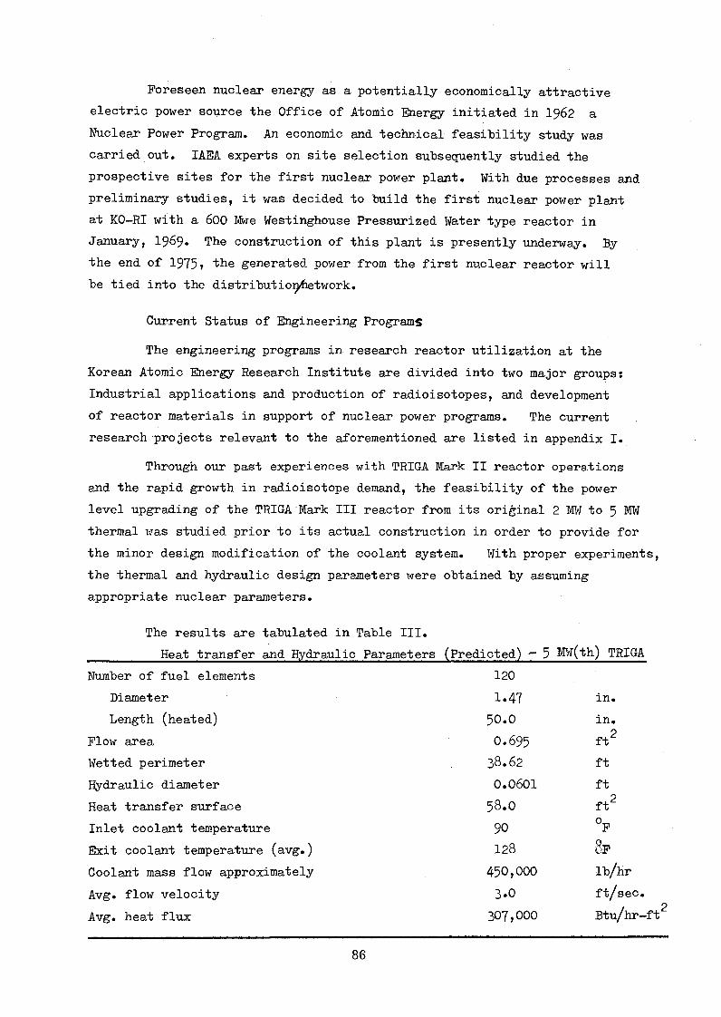
Foreseen nuclear energy as a potentially economically attractive
electric power source the Office of Atomic Energy initiated in 1962 a
Nuclear Power Program. An economic and technical feasibility study was
carried out. IAEA experts on site selection subsequently studied the
prospective sites for the first nuclear power plant. With due processes and
preliminary studies, it was decided to build the first nuclear power plant
at KO-RÏ with a 600 Mwe Westinghouse Pressurized Water type reactor in
January, 1969» The construction of this plant is presently underway. By
the end of 1975» the generated power from the first nuclear reactor will be tied into the distributiorj^etwork.
Current Status of Engineering Programs
The engineering programs in research reactor utilization at the
Korean Atomic Energy Research Institute are divided into two major groups:
Industrial applications and production of radioisotopes, and development
of reactor materials in support of nuclear power programs. The current .
research projects relevant to the aforementioned are listed in appendix I.
Through our past experiences with TRIGA Mark II reactor operations
and the rapid growth in radioisotope demand, the feasibility of the power
level upgrading of the TRIGA Mark III reactor from its original 2 MW to 5 MW
thermal was studied prior to its actual construction in order to provide for
the minor design modification of the coolant system. With proper experiments,
the thermal and hydraulic design parameters were obtained by assuming
appropriate nuclear parameters.
The results are tabulated in Table III.
Heat transfer and Hydraulic Parameters (Predicted) ~ 5 MW(th) TRIGA
Number of fuel elements 120
Diameter 1.47 in.
Length (heated) 5O.O in.
Flow area. 0.695 ft2Wetted perimeter 38.62 ft
Hydraulic diameter 0.0601 ft
Heat transfer surface 58.O ft2
Inlet coolant temperature 90 °F
Exit coolant temperature (avg.) 128 8f
Coolant mass flow approximately 450,000 lb/hr
Avg. flow velocity 3.O ft/sec.
Avg. heat flux 307,000 Btu/hr-ft
Por Optimum operation of the TRIGA Mark II reactor at the power
level of 5 Mw thermal, the required estimated coolant velocity is 3.0 ft/sec.
with a maximum coolant temperature of 128° F. Therefore, 5 Mw thermal
operation of the TRIGA Mark III reactor is not possible with the coolant
natural convection, thus forced convection is required, and in order to
achieve this, three 8 inch down-flow pipes were installed at the "bottom
of the reactor tank.
Fuel Development in support of Nuclear Power
Since nuclear power is expected to play a major role in generating
electricity as a "base load plant in the future, the current engineering
program should be formulated in such a way to support the nuclear power program.
In formulating such a program, the socioeconomic as well as industrial capa
bility of the country has to be well taken into consideration.
Korean metal producing and metal working industries are now in a stage
of development. Therefore, it would be some time before Korea will be capable
of economically manufacturing the major parts of a nuclear power plant. However,
the fabrication of fuel is estimated to be technically feasible based on the
present state of the art and know-how in Korea. Moreover, the fabrication cost
of fuel is an appreciably large portion of the nuclear power generating cost.
As a result of this philosophy, the fuel fabrication program was started
in 1968 at laboratory scale with assistance from Argonne national Laboratory.
In due course, the method for the activated sintering of U02 pellets by Ti02
addition tías developed. In future, irradiation experiments have to be made
in order to test any adverse effect on radiation stability of U02 pellets due
to Ti02 addition. For this purpose, the use of the TRIGA Mark III King Furnace
is proposed.
Method of Activated Sintering of U02 by Ti02 Addition*
1.) Preparation of U09 powder for cold compaction; As received the U0?
powder is reduced in hydrogen atmosphere at 850°C for 24 hours to
attain a stoichiometric compound usually of U02 0.05 w/o Ti02
powder is mixed to the UOg and 1 w/o polyvinyl alcohol is added as a
binder. Then, the U02 powder is granulated to approximately 20 mesh
size by mechanical mixing. 0.2 w/o of zinc stearate is added and the
UOp is then cold pressed to form a green compact with the density of
6.5 to 7 g/cm .

2.) Presintering of green compact;
The green compact is presintered in a hydrogen atmoshphere furnace
at 850°C for 24 hours in order to drive off the volatile materials
such as binder and lubricant. The density of presintered pellet
decreases about 2'fo from green density.
3.) Pellet sintering;
The presintered pellet is sintered in a hydrogen atmosphere furnace
at 1430°C for 8 hours to form a pellet with the density of 10.1 to
1 0 .3 g /c n A
Comparison of the results:
1.) Sintering temperature suppression due to TÍO2 addition ;
By the addition of 0.05 w/o TÍO2J "the sintering temperature of
UO2 pellets could be lowered as much as 170°C in obtaining the high
density pellets.
2.) Effect of TÍO2 addition on mechanical properties;
There seems to be no apparent adverse effect on compressive stress
of UO2 pellets due to TÍO2 addition.
Proposed use of the TRIGA Mark III King Furnace to test any adverse
effects on radiation stability of UO2 pellets due to TiOg addition :
1.) Description of the TRIGA King Furnace;
The in-core furnace is shown schematically in Figure 1 indicating
the significant parts and components.The heater element (shown in Figure 2),
is an 8-in. long graphite tube, 1-in. 0D x 3/4 in. ID heated by a saturable
core transformer. Surrounding the graphite heater element are two 10-mil
thick molybdenum radiation shields. Outside the shield is the aluminum
containment vessel which is in contect with the reactor pool water. The
dimension and configuration of the outer aluminum containment are the same
as those of the TRIGA fuel elements facilitating the location of the furnace
in a fuel element position. The center of the heater is on the horizontal
center line of the core.

The outer containment tube extends upward from the core to
approximately 5 ft above the water level of the reactor. Inside the
outer containment tube is a concentric aluminum access tube which connects
at the bottom with the graphite heater element and ends at the top with a
flange which provides a viewing window for temperature measurements. The
axial centerline of the graphites heater element coincides with the axial
center line in the TRIGA fuel elements. Samples to be irradiated are
placed inside a graphite container whose inside dimensions are l/2 in. in
diameter and up to 3 in. long. The container is lowered into the furnace
with a special tool. The furnace is constructed so that the lower section
can be disassembled to permit replacement of the graphite heater element
or molybdenum thermal shield. Figures 3,4, 5» 6 show the assembly of
the principal components of the lower heating section. Note in particular
how the molybdenum shield, graphite heater element and lower section of the
furnace itself can be disassembled.
The upper section of the furnace is equipped with an apparatus to
permit temperature measurements. Figure 7 is a close-up view of an apparatus
used in steady-state irradiation with an optical pyrometer to measure the
temperature. An alternative top section is available (not shown) which has
been designed specifically for use with a photomultiplier for temperature
measurements when the sample is exposed to pulsed irradiation. The output
from the photomultiplier tube can be displayed on an oscilloscope which can
then be photographed to provide a permanent record of temperature versus time.
With a dual trace scope, a concurrent trace of the reactor pulse can
also be obtained.
The design of the furnace is arranged so that a sample can be purged
with an inert gas such as helium or run at a static gas pressure during
irradiation. Notice the gauge in Figure 7» Directly behind the gauge,which
records both inches of mercury vacuum and gas pressure, is the vacuum port
and helium fill line. In operation, the furnace is first evacuated and then
purged with helium (also see Figure 1).
2.) Proposed test program using the TRIGA King Furnace;
Since the King Furnace is capable of heating a sample as high as
2000°C, the irradiation of U02 pellets is proposed to be performed at

temperatures from abient to 1500°C at an appropriate constant power level
during one hour to yield 10'*' fissions. The data on fission gas release
as a function of temperature would be obtained and the effect of TiC^
addition on fission gas release could be studied. Through metallographies!
examination and the measurement of irradiated UOg pellets, the effect of
TÍO2 additions on the dimensional stability would be studied.
Summary
The current engineering program at KAERI in utilization of TRIGA
reactors can be summarized as the radioisotope production and the development
of fuel in support of the Korean nuclear power program. If the results of
irradiation experiments on activated sintered fuel are favorable, the
developed fuel would be applicable for nuclear power plants and the application
of the developed method for commercial fuel production would contribute to the
decrease in nuclear fuel costs.
References
1. G.T. Schnürer, A.T. McMain, and P.U. Fischer: IAEA Proceedings N0.I3O
on Engineering Programs in Research Reactors, 231, IAEA, Vienna, 1971
2. E.E. Anderson, S. Langer, N.L. Baldwin, and F.E. Vanslager: •
Nuclear Technology, Vol.11, 259-265, 1971»
3. Hj. Matzke: Journal of Nuclear Materials, Vol.20, 328-331, 1966.
4. S. Naymark and C.N. Spalarist Proceedings of Third International
Conference on the peaceful uses of Atomic energy, Vol.11, 425-435»
United Nations, New York, 1965.

List of Research Projects in Support of Engineering Programsat the A.E.R.I.
I. Research and Development in Applications of Radio-Isotopes
1. Preparation of fiber "board,
2. Industrial radiation source production and development,
3. Radiation grafting on textiles and fibres,60
4. Management of tihe Co gamma irradiation facility,
5. Syntheses of radio chemicals,
6. Radiochemical studies on the Szilard-Chalmers process,
7. Construction and applications of a RI excited X-ray source,
8. A study on the syntheses or tritium luminous compounds,
9. Development of a fire alarm applying radio-isotopes,
10. Development of a radioisotopic power generator.
II* Research and Development of Reactor Materials
1. Measurement of neutron total cross sections of reactor materials,
2. Badiative capture cross section measurements of reactor materials,
3. Past critical assembly criticality calculations,
4. Calculation and measurement of fast neutron energy spectrum and flux,
5. Measurements of reactor parameters by means of a pulsed neutron generator,
6. Heat transfer studies in fast breeder reactors,
7« System design of FCAfs control and instrumentation system,
8. Kinetic studies of fast critical assemblies,
9. Research on fast breeder reactor instrumentation system,
10. Past neutron detector development for FCA,
11. Fuel fabrication for fast breeder reactors,
12. Preparation of nuclear fuels,
13. Fuel cycle analysis for fast critical assemblies,
14. Studies on reactor shielding using domestic minerals (for neutronshielding materials),
15. Nuclear magnetic resonance in UO2 + x
16. Study of microscopic dynamics in reactor materials by neutron scatteringj
17. Structure analysis of reactor materials for FCA’s by neutron scattering,
18. Study of the gamma ray energy level of ferrous oxide by the
Mbssbauer effect,
19. TL effect of natural calcium fluoride,
20. Study to correlate the colour centre and thermoluminescence in LiF,
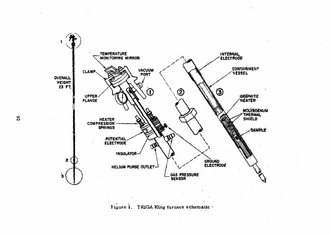
OVERALL WEfGHT
23 PT.
TËMPÊRATURÊ MONITORfNG MIRROR
CLAMP
UPPERFLANGE
HEATERCOMPRESSION
SPRINGS
POfÈMftÂL ELECTRODE
mSÜLÀTOrt
HÊLÏUM PuftGÈ ÔÜTLÊT
iNTtBNÂλELECTftOÖf
V ë SSÊL
GÀS ÊRÊSSUftE SENSOR
' î » ,
ï . ITIUGA ÏCiftg itittiâce sehetssatite

Figure 2. Furnace section of TRIGA King furnace

Figure 3. TRIGA King furnace--furnace section disassembled
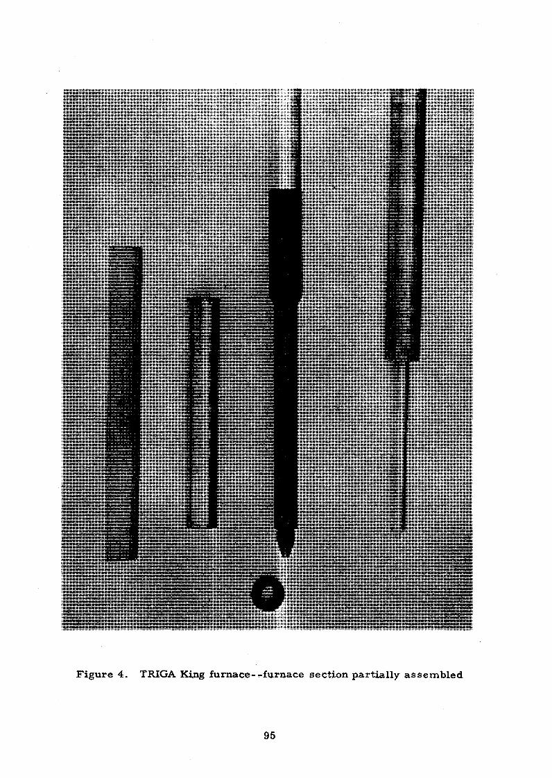
Figure 4. TRIGA King furnace-^furnace section partially assembled


Figure 6. TRIGA King furnace--furnace section assembled
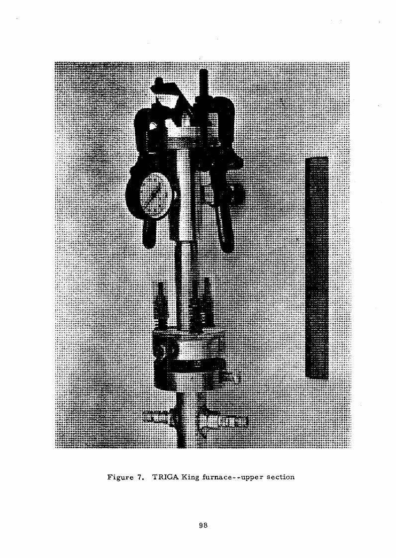

CERTAIN ENGINEERING PROBLEMS IN THE THAI RESEARCH REACTOR
"by 'Ratana Pumlek
Chief, Reactor Operation Division,Office of Atomic Energy for Peace .
Bangkok, Thailand'
ABSTRACT
Temporary means were performed to put the reactor back into operation
when the critical components were defective. The real problem was spare parts
shortage because the original supplier was no longer in the reactor business.
A brief description on the replacement of the Curtiss-Wright designed shim-
safety rods and reactor magnets with solid boron stainless steel rods and
RMG type magnets respectively is given.
The Tahi Research Reactor (TRR-l) is an open pool type facility designed
by the Curtiss-Wright Corporation, USA for operation at a maximum power of 1 MW,
it was made critical on 27 October 1962. Prom the first criticality up till now
two significant problems had occurred.
(1) The swelling of B^ C - filled shim-safety rods which resulted in
the jamming of the rods in the guide track of the corresponding fuel elements.
A brief description of the occurence and subsequent corrective action is
described in a separate report presented at this meeting.
(2) Failures of underwater reactor magnets. Two types of control rod
are used in the TRR-l, namely the shim-safety rods and the regulating rod.
Three shim-safety rods are magnetically coupled to three rod drive systems.
Upon power failure or on receiving a scram signal, the exciting current of
the coupling magnets will be cut off and the rods will fall freely into the
core. The regulating rod is bolted directly to the rod drive assembly instead
of being connected through a magnetic coupling.
Curtiss-Wright Reactor Magnets: Three reactor magnets and a spare
were originally supplied by CW for the TRR-l. The magnet has a spherical
magnet face with a 26 inches radius of curvature through which the magnetic
coupling force is applied to a convex armature with a spherical radius of
26 inches, which is in turn bolted to the top end of a shim-safety rod;
the detailed magnet data is shown in Table I. Magnet currents are supplied
by the magnet amplifier incorporated in the safety amplifier (Honeywell type1908-A8).

On October 30, 1967» "tbe safety rod magnet in the rod drive system
No . 3 was found defective and was replaced by the spare magnet.
On November 5 » 1967» "the safety rod magnet in the rod drive system
No.2 was found during functional testing to have one -side of its coil grounded
to its casing. Since no more spare magnets were available, the safety
amplifier had to be modified to have a floated ground i.e. all its internal
ground wires were connected together but disconnected from its chassis and
from the system ground. The modification successfully served as a temporary
measure to make the defective magnet work^ as proved by subsequent functional
tests of the rod drive system.
The magnet in the SR-drive No.2 failed completely on November 11, 1967
thus putting the reactor out of operation. The magnet problems had been noticed
for some time before the failure took place. Since the ffiagnet of CW original
design was no longer available, we had been forced to study some techniques to
repair our defective magnets at the OAEP. In the meantime, it was necessary
to devise temporary means to put the reactor back into operation as soon as
possible. Direct coupling of the SR-2 to the drive system was considered,that is,
to replace the magnet with an aluminum alloy rod. The particular SR then
could not be dropped when a reactor scram was called for and thus reactor
scramming would be achieved by the only two remaining SRs. The assessment
of the risk involved in such operation was as follows. '
Prom previous rod calibration experiments, it had. been established
that in any core configuration ever employed in the TRR-1, the core excess
reactivity was always less than the shutdown worth of each safety rod.
Particularly with the configuration currently in use at that time, the core
excess reactivity was 2.84$ and the rod worth of each SR was experimentally
found to be 2*SQffo. Prom this reasoning and from actual operating experience,
it was clear that one of the two remaining SR which could be scrammed had
enough negative reactivity to shutdown the reactor. Direct coupling was
therefore adopted as the short-term means of solving the immediate problem.
The first attempt to repair the defective magnet was done by
rewinding the magnet coil with the best locally available #36 SWG enamelled
wire and potting the coil with 3M insulation resin Uo.4« The whole magnet
was again assembled and sealed with the same potting resin. After testing,
it was found that its electrical property was unchanged. This first repaired
magnet last only 59 hours in operation. The major cause of failure was
found to be a leak in the coupling seal. The second attempt was done in
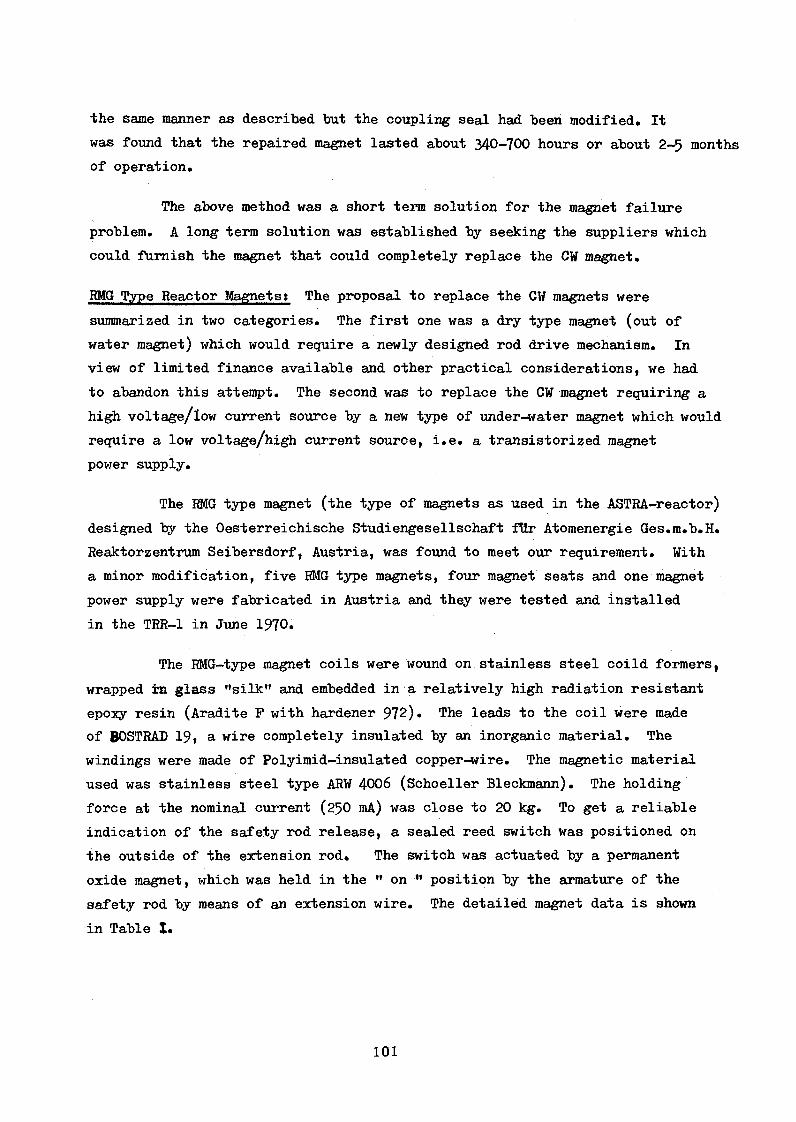
•the same manner as described but the coupling seal had been modified. It
was found that the repaired magnet lasted about 340-700 hours or about 2-5 months
of operation.
The above method was a short term solution for the magnet failure
problem. A long term solution was established by seeking the suppliers which
could furnish the magnet that could completely replace the CW magnet.
RMG Type Reactor Magnets: The proposal to replace the CW magnets were
summarized in two categories. The first one was a dry type magnet (out of
water magnet) which would require a newly designed rod drive mechanism. In
view of limited finance available and other practical considerations, we had
to abandon this attempt. The second was to replace the CW magnet requiring a
high voltage/low current source by a new type of under-water magnet which would
require a low voltage/high current source, i.e. a transistorized magnet
power supply.
The RMG type magnet (the type of magnets as used in the ASTRA-reactor)
designed by the Oesterreichische Studiengesellschaft für Atomenergie Ges.m.b.H.
Reaktorzentrum Seibersdorf, Austria, was found to meet our requirement. With
a minor modification, five RMG type magnets, four magnet seats and one magnet
power supply were fabricated in Austria and they were tested and installed
in the TRR-1 in June 1970.
The RMG-type magnet coils were wound on stainless steel coild formers,
wrapped in glass ’’silk" and embedded in a relatively high radiation resistant
epoxy resin (Aradite P with hardener 972). The leads to the coil were made
of BOSTRAD 19» a wire completely insulated by an inorganic material. The
windings were made of Polyimid-insulated copper-wire. The magnetic material
used was stainless steel type ARW 4006 (Schoeller Bleckmann). The holding
force at the nominal current (250 mA) was close to 20 kg. To get a reliable
indication of the safety rod release, a sealed reed switch was positioned on
the outside of the extension rod. The switch was actuated by a permanent
oxide magnet, which was held in the " on M position by the armature of the
safety rod by means of an extension wire. The detailed magnet data is shown
in Table I .

In order to supply a much higher current for the three HMG-type magnets the
magnet current power supply section of the original Honeywell safety amplifier
was replaced by a new magnet current supply of transistorized design with a
built-in pulse generator (O'- 100 m.sec.) for testing magnet release times. This
new magnet current supply was also provided by the Oesterreichische Studien
gesellschaft fUr Atomenergie and is known as the Magnet Current Supply type
Mg Str. vs. To retain the original safety features, the a.c. power supply
for the Mg Str Vs magnet current supply was connected via the same series
of slow scram contacts. In the fast scram mode, the supply would be scrammed
by any of the three fast scram signals from two safety channels and the
Log-N period amplifier.
Conclusion The RMG type magnet is an "open" type magnet, thus
avoiding the complicated sealing techniques. The coil could be easily
repaired and replaced.
The EMG type magnet in the SR-drive No.l failed on May 3» 1971 and
the spare magnet was installed. Upon investigation it was found that the
magnet failure was due to the break down of the lead wire insulation by
corrosion but the coil itself was still in good condition. The defective
magnet had been continuously in use for over 10 months.
Table I Shim-gfefety Rod Magnet Data
CW magnet RMG magnet
Coil former Lenin bakeliteCoil data Triple-layer enameled Copper #33
Stainless steel Polyimid-insulated copper
Number of turra 10,000 Max.resistance: 85O ohms Max. current 50 mA potted in Aradite CN 502
wire (0.36 mm dia). No.of turns: 1,000Max.resistance 75 ohmsMax, current 300 mA potted in Aradite P withhardener 972
Yoke Armco magnetic ingot iron Stainless steel type ARW 4OO6 (Schoeller Bleckmann)
Magnet seat Armco magnetic ingot iron with a nickel Stainless steel typeplated curvature surface (26" radius) ARW 4006, self-aligning
Can Stainless steel 304 None
THE BORON-STAINLESS STEEL SHIM-SAFETY RODS AND
THEIR WORTHS IN "TRR-1 " CORE AS COMPARED TO THE B.C-FILLED4
RODS
Sobhak P. Kasemsantá Office of Atomic Energy for Peace
Bangkok, Thailand
Abstract
Swelling of the B^C-filled shim safety rods originally
supplied by Curtiss Wright for the TRR-1 reactor is discussed.
The approach taken to replace these safety rods by rods of a
superior design and the experiments to determine the rod worths
of the new shim-rods are described.
I . Deformations of the B^C-Filled Rods
**The shim-safety rods originally supplied by CW for TRR-1
were of laminated construction, consisting of a stainless steel outer shell and a cadmium inner shell fitted with appropriate endpieces; the cavity inside the cadmium inner shell was filled with boron carbide powder.
Swelling of B.C-filled shim-safety rods which led eventually to jamming of the rod in the guide track of corresponding fuel element were experienced in the operation of some swimming pool reactors (see; for example, Refs. (l-2)). For TRR-1, the first experience of this nature was encountered with SR-3, after 32 months of operation, around the end of July 1965; details of the incident and temporary measures taken to solve the problem were reported in the RSC Meeting on 5 August 1965 (3). Again, around mid-September of 1965, SR-1 began to show similar symptoms; it was taken out of the system, compressed to reduce swelling and replaced in the system (as reported in Ref. (4) )•
* Presently with the IAEA, Division of Research and Laboratories
** Curtiss Wright Corp., USA
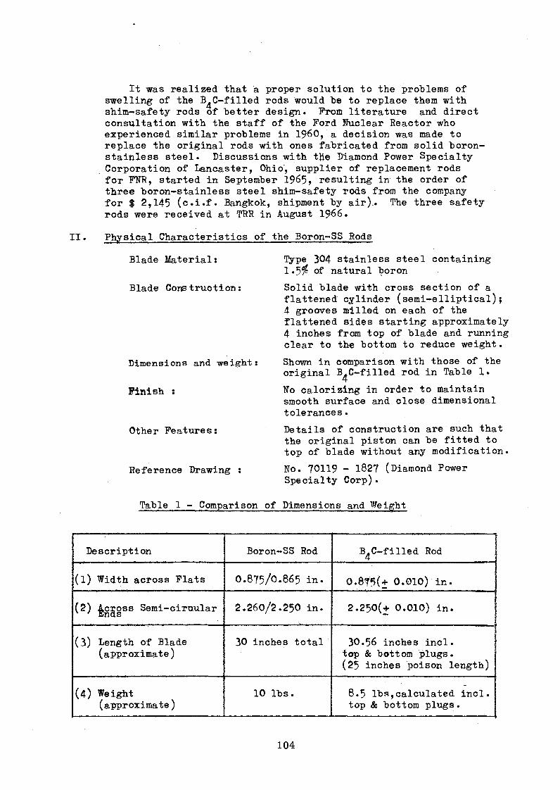
It was realized that a proper solution to the problems of swelling of the B-C-filled rods would be to replace them with shim-safety rods of better design. Prom literature and direct consultation with the staff of the Ford Nuclear Reactor who experienced similar problems in I960, a decision was made to replace the original rods with ones fabricated from solid boron- stainless steel. Discussions with t#e Diamond Power Specialty Corporation of Lancaster, Ohio', supplier of replacement rods for Ff¥TR, started in September 1965, resulting in the order of three boron-stainless steel shim-safety rods from the company for $ 2,145 (c.i.f. Bangkok, shipment by air).. The three safety rods were received at TRR in August 1966.
I I . Physical Characteristics of the Boron-SS Rods
Tÿpe 304 stainless steel containing 1.5$ of natural boron
Solid blade with cross section of a flattened cylinder (semi-elliptical);4 grooves milled on each of the flattened sides starting approximately 4 inches from top of blade and running clear to th« bottom to reduce weight.
Shown in comparison with those of the original B^C-filled rod in Table 1.
No calorizing in order to maintain smooth surface and close dimensional tolerances.
Details of construction are such that the original piston can be fitted to top of blade without any modification.
No. 70119 - 1827 (Diamond Power Specialty Corp).
Table 1 - Comparison of Dimensions and Weight
Description Boron-SS Rod B.C-filled Rod 4
(l) Width across Flats 0.875/0*865 in. 0.8?5(+ 0.010) in.
(2) begoss Semi-circular 2 .260/2.250 in. 2 .250(+ 0.010) in.
(3) Length of Blade (approximate)
30 inches total 30.56 inches incl. top & bottom plugs.(25 inches poison length)
(4) Weight(approximate)
10 lbs. 8.5 lbs,calculated incl. top & bottom plugs.
Blade Material:
Blade Construction:
Dimensions and weight:
Finish :
Other Features:
Reference Drawing :

Ill. Comparison of Rod Forths
In December 1966, excessive friction between the SR-3 and its guide track within the corresponding fuel element was again observed. Moreover, the SR-1 could only be moved freely up to about 23 inches a.bove its insert limit*; beyond that it inadvertently dropped with a normal magnet current of 40-45 mA again, showing a sign of deformation. The absormal behavior of the SR-1 did not interfere with normal operation; however, since the SR-1 and the SR-3 are diagonally opposite and they are normally calibrated against each other when a rod calibration experiment is performed, it was decided to perform a s e ^ e s of experiments befere the deformation in either rod became/serious to carry out such experiments.
Consequently, the reactor was shut-down from 22-26 December to allow sufficient decay of the shorter half-life poisons.On December 27, the SR-3 was calibrated against the SR-1, employing the standard inhour method. On December 28-29, the original SR— 3 was removed from the system and the original B^C-filled blade was replaced by one of the new Boron-SS blade. After reassembly,the new SR-3 was tested for free movement in the guide track of the same fuel element and the whole magnet drive system was also run through standard functional test procedures. After making certain that the new SR-3 with a Boron-SS blade worked properly,the new SR-3 was calibrated against the SR-1 on 30 December,employing the same set of parameters in the experiments.
The results of the two experiments are plotted on the same co-ordinatés in term of the integral rod worth of the SR-3 as shown in Fig. 1.
With the original blade the reactor went critical when the SR-3 was at 12.75 inches; the critical position of the SR-3 shifted to 11.45 inches with the new blade while other control rods were at the same positions (practically at withdrawal limits). The shifting of the critical position of the SR-3 clearly indicates that the Boron-SS blade has less rod worth than the original B.C-filled blade. The core configuration used in the experiments was the configuration No. 5-Gl(a). The remaining core excess reactivity determined from both experiments were 1.81$ and 1.82$ respectively; this agreement of results is a proof of the consistency of the experiments and clearly indicates that the shorter half-life poisons had decayed sufficiently and did not interfere with the measurements.
Comparative worths of the new and original blade can be estimated from Fig. 1, taking only the range from 12.75 to 24 inches.In this range :
The integral worth of B.C-filled rod is 1.81$The integral worth of Boron-SS rod is approximately
(1.82-0.3)$ or 1.52$
Therefore, the loss in the control rod worth when changing from the B C filled to the Boron-SS rod is, in percent of original worth, approximately equal to (0.3/l»8l) x 100 or 16.57$ of original worth.
* Normal travel of control and safety rods in TRR-l is 24 inches.
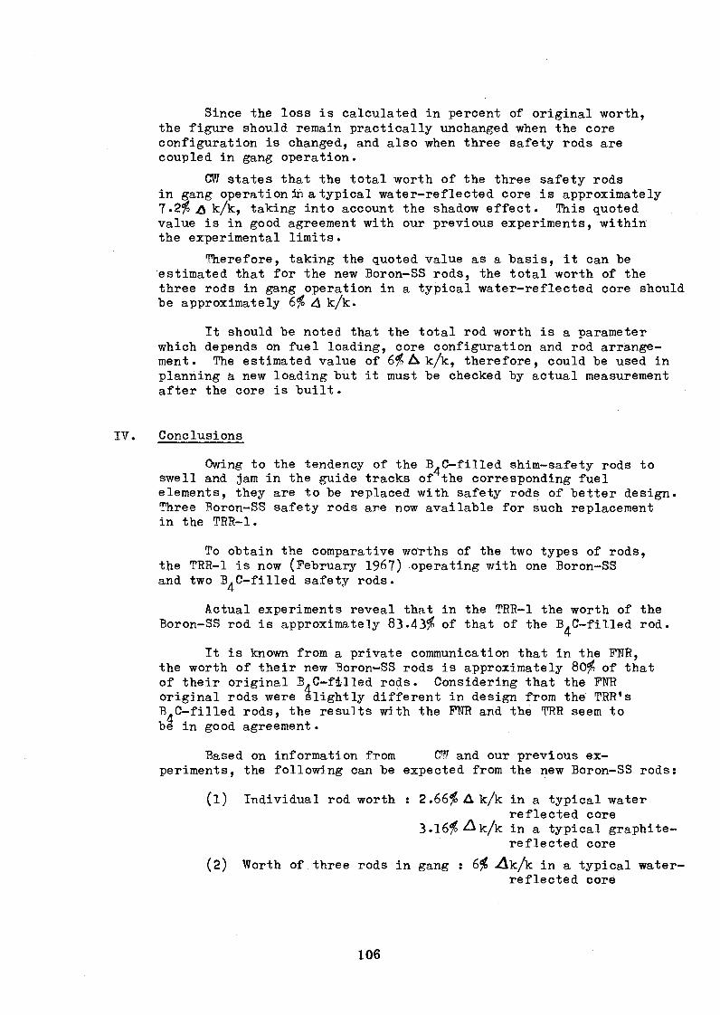
Since the loss is calculated in percent of original worth, the figure should remain practically unchanged when the core configuration is changed, and also when three safety rods are coupled in gang operation.
CW states that the total worth of the three safety rods in gang operation in a typical water-reflected core is approximately 7.2$ £ k/k, taking into account the shadow effect. This quoted value is in good agreement with our previous experiments, within the experimental limits.
Therefore, taking the quoted value as a basis, it can be estimated that for the new Boron-SS rods, the total worth of the three rods in gang operation in a typical water-reflected core should be approximately 6$ 4 k/k.
It should be noted that the total rod worth is a parameter which depends on fuel loading, core configuration and rod arrangement. The estimated value of 6$ A k/k, therefore, could be used in planning a new loading but it must be checked by actual measurement after the core is built.
IV. Conclusions
Owing to the tendency of the B^C-filled shim-safety rods to swell and jam in the guide tracks of the corresponding fuel elements, they are to be replaced with safety rods of better design. Three Boron-SS safety rods are now available for such replacement in the TRR-1.
To obtain the comparative woTths of the two types of rods, the TRR-1 is now (February 1967) operating with one Boron-SS and two B^C-filled safety rods.
Actual experiments reveal that in the TRR-1 the worth of the Boron-SS rod is approximately 83.43$ of that of the B^C-filied rod.
It is known from a private communication that in the FNR, the worth of their new Boron-SS rods is approximately 80$ of that of their original B^C-filled rods. Considering that the FNR original rods were slightly different in design from the TRR's B^C-filled rods, the results with the FNR and the TRR seem to be in good agreement.
Based on information from CW and our previous experiments, the following can be expected from the new Boron-SS rods:
(1) Individual rod worth : 2.66% A k/k in a typical waterreflected core
3.16$ A k/k in a typical graphite- reflected core
(2) Worth of three rods in gang : 6$ ^Ak/k in a typical water-reflected core

1 Ricker, C.W. & Dunbar, W.R., "FNR Shim-Safety Rod Deformations”, Nuclear Science and Engineering, Vol. 9, 1961, 410-411.
2 Morris, P.A. "Reactor Safety & Construction Practice”, Reactor Safety & Hazards Evaluation Techniques, Vol.l, 203-204;Proc. Sym., Vienna, 14-18 May, 62
3 Kasemsanta, S.P., ’’Partial Jamming of a Shim-Safety Rod in Control Element Guide Tube", Report to RSC Meeting, Thai AEC,2/25O8 , 5 August 1965» (in Thai)
4 Kasemsanta, S.P., B.I. Report No. 2*, "Back-up Informationin Support of the SS Material Balance Report", 31 March 1966, page 3-5*
*) B.I. Reports are submitted regularly to the Agency at 6-months interval under the Safeguard Agreement.)

ROD
WORTH
(•/•
Ak/fc)
Fig.1. INTEGRA! WORTH O f SR-3 (PARTIAL)

fiBBHfift. M . ™EN GINEERING ET UTI LI S A T I O N DES REACTEURS DE RECHERCHE
A U CENTRE D*ETUDES NUCLEAIRES DE GRENOBLE
par
P. MERCHIE
Chef de l a Section d * Exploitation des Réacteurs
Centre d*Etudes Nucléa ir es - GRENOBLE
RESUM E
L a presque totalité des programmes français
d ' i r ra di at io n est réalisée dans des réacteurs d u type piscine*
Après avoir rappelé les caractéristiques
avantageuses des réacteurs pisoine dans le développement des
techniques nucléaires, nous présentons les caractéristiques
générales des réacteurs SILOE, MELUSINE, SILOETTE du Centre
d 1Etudes Nucléaires de GRENOBLE,
N o u s indiquons les améliorations successives qui
ont été apportées à ces réacteurs et notamment les di fférentes
augmentations de puissance que nàus avons effectuées*
Enfin, nous développons les possibilités
expérimentales offertes, ainsi que les pr in ci p a u x types de
dispositifs d ’irradiation qui ont été réalisés et leur
u t i l i s a t i o n s u cours de ces dernières années.
P o u r terminer, nou s évoquons l a collabo ra ti on que
n o u s avons aveo d'autres pays dans los domaines de
1 ' e ng inaering ot de l ’utilis a t i o n des réacteurs de reaheroho.

Plusieurs dizaines do réacteurs do recherche du
typo pisci ne fonctionnant actuellement dans lo mondo entier.
Conçus à 1 1origino sans objeotif précis, mais so situant
dans dos perspectives essentiellement universitaires et do
r ec herche fondamontalo f l'expérience a montré depuis quo cos
réacteurs convenaient également très b i o n à l a recherche
appliquée ou technologique. C'est ainsi qu'en líLÚJtfCE, l a
p r e s q u e totalité des programmes d ’irradiation est réalisée dan©
dos réacteurs du typ© piscine,
„ T R IT ON et HELUSINE, construits e n 1958 p o u r uno puissance
do 1 MW, fonctionnant actuellement respectivement à 6 et
8 MW.
- SILOS, mise e n service en 1963 à 15 M W et modifiée on 1967
p o u r fo nctionner à 30 MW, représente une amélioration
importante dos pilos piscines dos années 50*»60 ot sort do
r é a d t e u r d* essais do matériaux*
•* P o u r OSIRIS (1 9 6 5 ), le changement do sens do oiroulation do
l ' e a u do refroidissement du c o e u r et certains changements
do s tr ucture d o l a pisc in e ont permis d*atteindre une
p u i s sa nc e do 70 MW,
Cos r é a c t e u r s , auxquels il convient d*ajouter
PEGASE, spécialisé dans les irradiations do grosses boucles,
con stituent u n ensemble complet pour les oseáis de matériaux
sous ra yonnement ot sont l a source d'une expérience très
largo dans le domaine do l'emploi des piles de recherche«
Il ressort de cetto expérience que, p o u r los pays dont
les progra mme s nucléaires sont en cours de définition, ou
d o n t los program mes déjà établis entrent dans leu r phase d©
réalisation* l a p oss e s s i o n d * u n réacteur piscine présente
b e a uc ou p d*intérêt et constitue u n solide point d*ancrage
potar lo développement des techniques nucléaires.

Après avoir b rièvement développé los oaraotérietiquos
générales et originales de ces réaoteurs telles q u J elles
apparaissent à l ‘usage, nous décrirons plus pa rt iculièrement
l eô réacteurs de GRENOBLE ; nous présenterons ensuite
1 *u ti li s a t i o n qui en est faite e n recherohe fondamentale ot
on rocb.croh.0 appliquée et technologique et p o u r lesquelles
des dispositifs d ’irradiation hautement epéçialisés ont été
réalisés*
Nous évoquerons également la collaboration qui existe
depuis de nombreuses années avec plusieurs paye é t r a n g e r s ,
not am me nt dos pa ys dont les programmes nucléaires s ‘élaborent
ot se développent et ceci dans les domaines de 1 * exploitation,
d u développement ot do l ’utilisat io n des réadteurs»
No us présenterons les ligaas générales do notre
collaboration, ainsi que les raisons q u i nous ont conduit
à réaliser u n projet de réacteur, spécialement destiné a ux
pays en v oi e de développement, a f i n d'y promou vo ir l a technologie
nucléaire,
2. P ROPRIETES flENlïïRAJÆg Tfl8S REACTEURS PISCINE
Le SHCoès remarquable dos réaoteurs de recherche
du type pisc ine s'explique p a r 1 ’ensemble des qualités qu'ils
présentent ot qui se sont révélées ou confirmées à l'usage f
— simplicité et sûreté de fonctionnement
— souplesse et polyvalence dans l e u r u t ili sa ti on (recherohe
fo nd amentale appliquée et technologique)
♦X h aut es performances depuis quelques années
— faible p r i x de co ns truction et d *exploitation et p a r
conséquent faible p r i x de r e v i e n t des expériences ot dos
irradiat ions

2.1 » Simplicité öt sûreté
Comparés aux réactours de rocherche à e au lotir do
ou d u type tank, co sont en effet des ré act ours plus simples,
dans lesquels o n ne r encontre pas les installations
particulières, généralement sources de difficulté© que sont
p a r exemple t
-» le cha r gement—déchargement des éléments oombuetibles et
des dispositifs expérimentaux
— l a commande dos barres do contrôle
*• le s installations propres à l*eau lourde | circuits de
p u r i f i c a t i o n et couverture gazeuse au n i v e a u supérieur do l a
cuve, étanchéité totale dos circuits et risques triti um
p e n da nt les opérations d' entretien et de démontage», etc..
— l a pressiorisation des circuits do refroidissement, les
oircuits auxiliaires tels quo refroidissement à l ’arrô-fc,
r ef ro idissement des protection© ou de l a piscine.
L a grande disponibilité et l a bonne sûreté de
foncti onn em en t dos ré ac teurs piscine résultent p o u r vine
bonne par t do l e u r simplicité do r é al is at ion à laquelle
s ’ajoutent des facteurs intrinsèques de sûreté b i o n connus»
Les nombreuses études de développement et do sûreté
effectuées e n M I A N CE, à GRENOBLE (neutronique, thermique,
mécanique, hydraulique) et à CÀDARACHE avec le r é a c t e u r CABRI
(excursions de puissance, accidents de réfrigération, oto..)
ont débouché s u r u n o connaissance approfondie de ce type
do réacteur, oe qui perme t de los u t i l i s e r aveo le m a x i m u m/
d o re ndement ot de s û r e t é •
Cooi s * illustre p a r les améliorations et les
augmenta ti on s de p ui ssance successives réalisées sur les
différents réacteurs français*
2 .2 . Souplesse d 1emploi ot n o l w a l o n o o dans leu r
ut il is a t i o n
L a grande s o u p l e s s e de leurs structures le ur permet
de s ’adapter facilement et rapidement aux besoins variés des
expérimentateurs* L a modifi ca ti on des structures du c oeur ou
112

1 *a djonction d *équipements supplémentaires (cuve à eau lourde,
source froide, oanaux,, e t c ,. ) ne présen te nt pas do difficultés
particulières oar le ur bonne accessibilité perme t des démontages
ot dos interventions faciles ot rapides, môme sous plusieurs
mètres d ’eau»
P a r ailleurs, le grand volume immédiatement
disponi bl e autour d u fcoour permet aux dispositifs d'irradiation
ot a u x expérionoes particulières de cohabiter en très grand
nomb re ot facilite beaucoup l e u r manutention*
Ii*absence de cuve ou de ta nk autour du coeur y
ajoute los p r in cip au x avantages suivants s
-• possibilité de réal is er toute configuration d u coeur qui
convient le m i e u x aux besoins des expérimentateurs
- v isibilité totale et accessibilité remarquable d u coeur,
verticalement ou latéralement, ce qui explique l a rapidité
des interventions sur le coeur (chargement des éléments
combustibles d u coeur e n quelques heures p a r exemple)
** acoès direct des canaux tout contre le coeur et grand
nombre d 1 emplacements périphériques à flux élevés sans
at ténuation n i dégr ad at io n des flux p a r les parois d ’u n
oaisson séparant le c oeur de s o n réflecteur
~ simplicité et facilité de chargement et do déchargement des
dispositifs oaepé riment aux dont certaine sont notanmont
effectuée ¡réacteur en fonctionnement* Sans p én aliser les
irradiations on cours p a r arrôt d u réacteur, cette d e m i è è e
possibilité autorise le retrait ou l a mise on p lace dos
radioéléments^ de certains dispositifs en pajme ou dont
l ’irradia ti on commence ou se termine au cours d ’u n cycle
do fonctionnement, dos boucles froides souvent utilisées
p o u r les irradiations de recherche fondamentale de durée
relativement courte, des dispositifs dont o n veut suivre
pas à pas l ’évolution p a r neutrographie (exemple : examens
suooossifs on cours d ’irradiation de la formation du t r o u
cen tr al dans les crayons combustibles UOg ~ PuOg de l a
filière r a p i d e )*

Cet-fce remarquable souplesse d'emploi explique
l' utilisation polyvalent g des réacteurs pisc in e t
— p r o d u c t i o n de radioéléments
— recheroho fondamentale avec les canaux, boucles froides,
cuve à eau lourde, tubes p n e u m a t i q u e s , etc.*
— recheroho appliquée ou technologique avec des dispositifs
expérimentaux spécialement développés à cet usage (fours et
boucles do différents types décrits ci-aprèB)*
2*3* Ha utes •performances
Los performances atteintes vont également dans le
sens de la polyvalence. Construits à l'origine pour des
puissances relativement faibles, leur ut il i s a t i o n était
principalement réservée à l a recherche f o n d a m e n t a l e • P a r
suite de l'amélioration continue de leurs performances, les
réaotours piscine ont réalisé une remarquable pe rcée ve rs les
flux élevés, ce qui explique l e u r succès e n recherche appliquée
et technologique. Ces réacteurs s'adaptent donc parfaitement
aux programmes évolutifs et peuvent fr anchir p a r étapes des pu is »
sanees de pl us en plus élevées, de quelques M W à quelques
dizaines de M W p o u r répondre à l ’évolution des b e so in s dos
u t i l i s a t e u r s •
P a r exemple, les f l u x disponibles dans SILOE à 30 MW
sont les suivants t
14 i 2— flu x thermique I 4,7 * 10 n / c m »sec
A A Q .
» f l u x rapide f (B > 1 MeV) : 2,3*10 n / o m .soc. (flux rapide
directomont utili sab le à l ‘intérieur d ' u n dispositif
d 1ir radiation placé dans le coeur).
2.4* F aible coftt do construction et d 'exploitation
Enfin, du fait de le ur simplicité ot de l eur grande
disponibilité, ces réacteurs n e sont pas coûteux » "une étude
effectuée en 1969 avec ac tualisation dos p r i x au 1er janvier
1 969 a montré que l es p r i x de construction des réacteurs piscine
étaient les p l u s b a s et que leurs frais d ’exploitation étaient
les plus faibles*
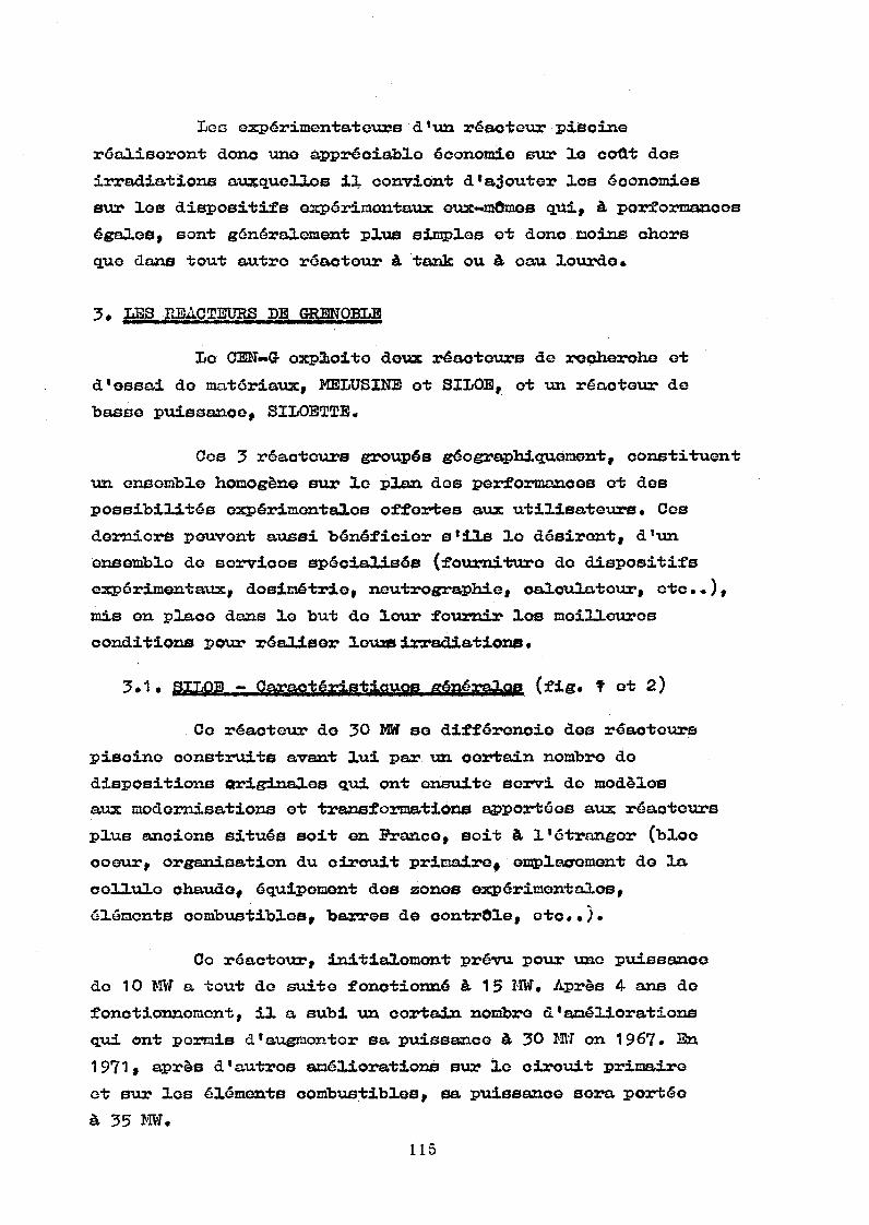
L g d expérimentât ours d ‘ tua réacteur piscine
réaliseront donc uno appréciable économie e ur le coût des
irradiations auxquelles il convient d ’ajouter los économies
s ur les dispositifs expérimentaux eux-mômes qui, à performances
égales, sont généralement plus simples ot donc moins chers
que dans tout autre ré ac teu r à ta nk ou à oau lourde»
3* LES REACTEURS D E GRENOBLE
L o CEN-G- exploite de ux réaoteurs do recherohe et
d ’ossai do matériaux, MEL US INE et SILOE, ot u n réacteur de
b as se puissance, SILOETTE.
Ces 3 réacteurs groupés géographiquement, constituent
u n ensemble h o m o gè ne s u r le p l a n dos performances et des
poss ib il ité s expérimentales offortes a ux u t i l i s a t e u r s • Ces
derniers peuvent aussi bé né fi ci er s ’ils lo désirent, d ’u n
ensemble do eorvicos spécialisés (fourniture do dispositifs
expérimentaux, dosimétrio, neutrographie, calculateur, etc.«),
mis e n p lace dans lo but do l o u r fournir los meilleures
conditions pou r r é a l i s e r louas irradiations «
3*1« SILQB - Caractéristiques générales (fig. f ot 2)
Co r é a c te ur de 30 MW se différonoie dos réaotcura
p i s c i n e construits avant l u i p a r u n certa in nomb ro do
dispositions originales qui ont ensuite servi de modèles
aux modernisations et transformations apportées a u x réaoteurs
p l u s anciens situés soit e n Prance, soit à l ’étranger (bloc
coeur, o rg an isation d u circuit primaire* omplacroment de l a
cellule chaude, équipement dos zones expérimentales,
éléments combustibles, b a r res d e contrôle, etc..).
Ce réacteur, initialement p r é v u p o u r une p ui ssance
do 10 M W a tout do suite fonotionné à 15 MW» Après 4 ans de
fonctionnement, il a subi u n cortain nombre d ’améliorations
qui. ont p e rm is d ’augmenter s a p ui ssance à 30 Mtf o n 1967. E n
1 9 7 1 , après d ’autres améliorations sur le circuit primaire
et soar les éléments combustibles, sa p ui ssance s e r a p or té e
à 35 MW.

Lo coeur, do géométrie rectangulaire avoc plusieurs
crénoaux, ost formé d ’éléments combustibles do différents
typos fabriqués p a r l a Compagnie d 1Etudes ot do R é a l i sations
de Combustibles Atomiques (CERCA) avec le concours d u C.E,A.
Ces àlénonts sont tous à plaquas planes»
a) éléments st andard comportant 2 3 plaquos chargées avoc do
l ’ur a n i u m enrichi à 93 $
b) éléments de contrôle à 1 7 plaques dons lesquels se déplacent
les barres do contrôle du type "fourchetteM
o) éléments spéciaux d 'i rradiation dont les plaquos
combustibles entourent 1 ou 2 emplacements d *irradiation
riches en flux rapides ot dans lesquels viennent se p la ce r
des dispositifs e xpérimentaux (fig* 3)»
Le coeur ost plaoé sur u n tabouret p ar l'intermédiaire
d ’une grille qui comporte 100 positions dont u n e quarantaine
environ est occupée p a r les éléments combustibles ot les
éléments réflecteurs en b e r y l li um qui sont disposés sur une
face d u coeur. Les emplacements qui restent peuvent ôtre
occupés p a r des dispositifs expérimentaux* L 'év ol u t i o n do ces
dispositifs a été t elle q u' il est maintenant courant do p la co r
4 dispositifs dans u n môm e emplacement d ’irradiation, co qui
multiplie d ’autant les positions d ' i rr adi at io n et notamment
les pos it ion s à flux élevés*
L'étude noutronique, h ydraulique et thermique du
coeur ost p ar ticulièrement poussée a f i n do réduiro les portos
de charge du coeur et d ’extraire le m a xi mu m do puissance dos
éléments p o u r obtenir des fl ux élevés (P ^ ~ 270 k W / l -P ' m o y e n '
- 125 w / o n
Le refroidissement d u coour ost assuré p a r l a
c irc ul at io n do l 'e au do la piscine entre les plaquos dos3
éléments oombu stibies à u n débit de 2200 m /h environ. A l a
sortie d u cooUr, cette © a u traverse dos bacs do dé sactivation
et se refroidit ensuite dans dos échangeurs classiques avant
do re to ur ner dans l a p i sc ine dont l a température ost stable
au tour do 3 0 °C*

C g débit p ri ma i r e as s vir o en môme temps <ye lo
re froidissement du coeur celui do t o u s les dispositifs
expérimentaux placés dans ou autour du coeur»
Los fonctionnements à des puissances passant do
15 M W à 30 et 35 M W sont possibles car n oue avons t
•- réduit lo p ic do puissance dans lo coeur
— optimisé les éléments combustibles
•• augmenté lo débit prima ir e do 1500 m^/h, à 15 M W jusqu'à*7
2200 m / h p o u r 35 MW. L a limite os* dans ce cas imposée
p a r 1 ’augmentation de l a porte do charge du coeur et los
ris qu oo de oavitation dos pompes primaires« L*accroissornent
à 3 5 M W de l a capacité d'échange thermique du circuit
pr imaire s'est effectué en rajoutant 3 échangeurs de
chaleur i&ûtt&dqttQS tvux 3 échange rus de chaleur existante à 15 MW*
*• augmenté le débit secondaire do 1200 m ^ / h à 1 5 0 0 m ^ / h
(l*eau froide d u oircuit secondaire est extraite de l a
nappe phréatique à une température no dépassant jamais 13°C ;
elle est ensuite rojotée dans l a rivière qui passe à
p r o x i m i t é )•
L a ré du ction d u p ic de puissance est obtenue on
réduisant la largeur des canaux dans lesquels se déplacent
los barro s do contrôle. U n n o u v e l élément do contrôle et u n
n o u v e a u type de b arre de contrôle, appelé "barre fourchotte"
ont été développés. L lan cienne ba rr e do contrôle d'épaisseur
21 m m est remplacée p a r deu x plaques absorbantes d' épaisseur
3 m m fsituées latéralement dans le n o u v e l élément combustible.
L a distanoo entre les plaques combustibles situées de part
et d * autre du canal de barre est ainsi notablement réduite
avec comme conséquence direoto l a ré du ct io n des pics de
p u i s sa nc e qui se situont toujours sur cos plaques combustiblesy
lorsque l a barre de contrôle est retirée» Les plaques
absorbantes sont o n A g- In — Cd avec u n rovôtemont do N i ck el
électrolytiquo ou b i e n on H a f n i u m qui n la p as b e s o i n d'ôtro
prot ég é contre l a corrosion (fig* 4)«
Les barres "fourchettes“ offrent p a r al lie vira une
me illeure efficaoité que les barres centrales« Ainsi, en
maintena nt le môme nombre de barres de contrôle, il a été
p o s s i b l e d ’augmenter l a charge en TJ5 des éléments combustibles
et du ooeuTt
i
L 'o pt im is at ion de l'élément combustible a oonsisté
dans l a diminution de l a largeur du canal de refroidissement
qui est passé de 2 , 9 m m à 2 , 1 m m ; ainsi, avec l a môme
gé om ét ri e extérieure, le n ouvel élément standard oomporte
23 plaques a u l i e u de 18 et le nouv el élément de contrôle en
comporte 1 7 au l i e u de 1 2 . L ’augmentation du nombre do plaques
et 1 1 au gm entation simultanée de l a oharge en U 5 des plaques
(qui est passée de 1 0 , 9 gr à 1 2 , 2 1 gr ou 1 4 , 7 2 gr suivant les
éléments ou l a p o s iti on dos plaques dans les é l é m e n t ^
signifient que l a oharge t o t a l e en U 5 de l'élément est fortement
augmentée (280 gr — 3 3 0 gr ou 3 4 0 gr suivant lo type d'élément
standard contre 196 gr dans IL'élémeirfc à, 18 plaquos)*
Il e s t ainsi possible d 'o bt en ir des b u m —up très
élevés, de l'ordre do 50 $, ce qui représente dos économies
importantes dans le coût d'exploitation du réacteur»
Les nombreuses études thermiques cffeotuées sur
des boucles ho rs -pile à GRENOBLE ou aveo le ré ac teu r CABRI à
CADARACHE, ont pe rmis do b i e n connaître les phénomènes
da ng e r e u x que sont 1 'ébullition looale ot le renve rs em en t de
débit conduisant au b u m - o u t . Coci nous a permis de mieux
déf in ir les marges de sécurité e n marche normale et d 1 écrire
des codes et des programmes do calcul très préois qui dorment
en f o n ct io n dos différents paramètres d ' u n réacteur les flux
calorifiquos d' ébu llition looale et de renversement de débit*
Enfin, il faut mentionner que le problème de
l'activ it é en surface do la piscine a été résolu dès l a
cons tr uc tio n en maintenant a u sommet do l a piscine une couche
d 1oau ohaudo d'épai ss eu r comprise entre 1 et 2 mètres et dont
l a t em pérature est supérieure de quelques degrés à l a température
d u reste de l a piscine. Cotte couche d ' e a u ohaudo arrôte les

los mouvomontß ascendants d'eau ohaudeactive on provenance
du voisinage du coeur et réduit ainsi l ’aotivité ambiante
à l a surface de la piscine d'u n f a o t e u r 20, Getto méthode a
été également appliquée p a r l a suite auz autres réacteurs
p i s o i n e d u C.E.A* (MELUSINE - TRITON - O S I RI S).
3*2. Possibji 1 -îté« oypérimn ^ a.jir»f> et services spécialisés
offerts aux, utilisateurs de SILOE
SILOE a été conçue pour les expérimentateurs en
tenant compte de 1 *importante expérience acquise avec MELUSINE
dont le chargement on expériences était à saturation avant l a
cons tr uc tio n de S ILOE en 1961.
Les surfaces offertes aux expérimentateurs sont
importantes ot réparties sur 4 niveaux. L'équipement de ces
zones expérimentales a été poussée a u m a x im um p o u r faciliter
1 1 installation des expériences : ali mentation élootrique à
pa r t i r d u r éso au secour u et du résea u à sûreté totale,
li aisons de séourité avec le t a b l e a u de contrôle d u r é a o t o u r
et aveo le calculateur, al im entation en fluides divers,
évacuation d*effluents de toute nature, etc,«
A 30 MW, les flux offerts a u x expérimentateurs sont
les suivants t
a) flux^rapidea^ (E > ^ 1 M o V 2
- 6 emplacements dans les éléments d 'irradiation d u coeur
avec des flux utiles dans les dispositifs d ’irradiation14 / 2
compris entre 1 , 8 ot 2 ,3 * 1 0 n / o m soc
« parmi les emplacements autour d u coeur, une quinzaine ont13 1 4 / 2
des flux dans l ' e a u compris entre 2 ,5 . 1 0 et 1 ,5 * 1 0 n / o m sec*
b) fltux thermiques
Parmi tous les emplacements utilisables, u n o
vi ng ta in e ont des fl ux compris entre 1 , 5 et 4 , 7 * 1 0 ^ n/cm^ sec.
o) Bdhauffement gamma
Les emplacements d u coour o u immédiatornent au tour
d u coour ont des éohauffementa compris entre 2 et 12 Vf/g
(dans le graphite)*
D o u x carnuz sont installés p oux la re cherche
fonda me nta le j situés derrière l a face d u ooeur réfléohie
p a r le béryllium, ils libèrent les trois autres faces p o u r les
dispositifs d'irradia ti on verticaux» Les flux thermiques
disponibles à l a sortie dos collimateurs (S = 70 X 30 mm) sont 8 2
de 3,5 à 4.10 n / o m sec. Les canaux sont actuellement
u t i lis és p o u r l a D i f fr ao ti on Neutroniq.ue (2 goniomètres p ar
canal). L'un des goniomètres est adapté à l ’étude des
Btruotures cristallines de eubstanoos organiques à p a rt ir do
monocristaux, les trois autres sont destinés à l'étude de
substances magnétiques, soit sur monocristaux, soit soir
poudres. Dans ce dernier cas, le trav ail est largement
facilité p a r 1 ' emploi do m u l t i d é t e c t e u r s • L e h a l l et les
bâ ti me nt s extérieurs permettent de travailler on temps do vol
si nécessaire,
3 ,2,2 , Tubes d ’irradia tion
U n tube p ne umatique à deu x v oies d 'irradiation, dont
l a distance d u coeur est réglable, est relié à doux laboratoires
situés hors do l ’enceinte du réacteur. Ce tube est utilisé pou r
les beso in s do l ’analyse p a r activation, de la Chimie
N u c l é a i r e , e t c •,
3*2,3» Boucl es f r oides à azote liquide
Ces boucles peuv en t occuper des positions fixes
sur une f a c e du coeur et permettent des irradiations dans des13 1 4 / 2
f l u x thermiques compris entre 1 , 1 0 et 2 ,3 » 1 0 n / o m .sec et12 1 3 / 2
des fl ux rapides compris entre 1 , 1 0 et 2 ,8 , 1 0 n / o m .soc,
C o b b o u c le s s o n t m is e s e n p l a c e o u r e t i r é e s d u c o e u r , r é a c t e u r
on f o n c t i o n n e m e n t . Le d é f o u m e m o n t des échantillons se fait de
f a ç o n se mi -automatique et sans réchauffement, afin de maintenir
et de p o u vo ir étudier les défauts créés p a r les neutrons
r a p i d e s ,

Do n ombreuses études de Physique du Solide sont
effectuées e ux dos m ét au x purs, s emi— cond uc te urs , eto. •
(traînage magnétique, frottement interne, eto). E n reoherohe
technologique, oes b o u d e s permettent l'étude des propriétés
des ma tériaux irradiés et utilisés à basse température
(source froide du réacteur à Ha ut —Plux, supra-conducteurs)*
3»2*4* Cellule ohaudo
Sa conception originale, directement en por te -à -
fau x et ouverte s u r l a piscine, l a rond extrêmement facile
d ’utilisation, L'opération, généralement diffioile, qui
consiste à transférer les objets actifs d'un r éacteur vers la
c e llu le chaude peut se faire directement sans rupture do
protection, sans l'intermédiaire d ' u n sas, eto.«, oe qui
appo rt e u n gain de temps appréciable avec une meilleure
sécurité.
S o n équipement interne est adapté aux différentes
opérations qui doivont s* y dérouler t travaux sur les
conteneurs de radio-éléments, interventions, réparations ot
démontages de dispositifs d'irradiation, démantèlement des
dispo si tif s usagés, défournemont ot enfournement spécialisés
(ex. échantillons de matériaux do structure ou do combustible
irradiés dans du Na£), examens métrologiques, eto.,
3.2.5. H outr o g raphie
U n appareil do nsutrographio immergé offre â.
l'expérimentateur l a possibilité d' un examen d u type r a di o-
graphique de s o n disposit if expérimental à tout moment a u cours
do son irradiation, quelle qu'en soit l'activité, D 'uno qualité
identique à celle do l a radiographie X o u de la gammagraphie
olassiquo (impuissantes dans ce cas étant donnée l'aotivité y
des échantillons), ce contrôle v i s u e l permet d'une part do
suivre l'évolution d'uno expérience en oourô d'irradiation
(fissures, gonflements, déformations des échantillons, état
dos pièces mécaniques d u dispositif, eto) et d'autre part de
p r é p a r e r les examens physiques à effectuer on laboratoire
chaud. L a d ime ns io n de la photographie est de 3 0 4 0 cm et
p e rm et de couvrir en une ou do ux images l a totalité do l a aono
irradiée» L a dtirée d ' u n examen est d 'environ 30 minutes (Pig.5-6) •
121

U n calculateur spécialement consacré aus: expériences
assure notamment lo pilotage et la surveillance des dispositifs
ot soulage l ’expérimentateur d'un grand nombre de préoccupations
ot de travaux longs ot fastidieux.
E n effet, ce calculateur travaille on temps ré el
ot peut centraliser environ 500 mesures en provenance dos
dispositifs, mesures qu'il surveille et régule p ar a ction directe
s u r les baies de contrôle et do commande associées à chaque
dispositif. A chaque instant, l'expérimentateur peut aussi
interroger le calculateur sur 1 1 état de son <H spositif ot du
ré ac te ur au m o y e n d 'interrogateurs-répondeurs ot, pa r
ailleurs, le calculateur lui fournit systématiquement les
relevés horaires do chacune de ses mesures ; il peut aussi
tracer 3.os courbes d ' évo lu ti on des paramètres mesurés (fig. 7)*
Enfin, on temps partagé, le calculateur effectue
le dépouillement do certaines mesures, p a r exemple* les
m e sur es de dosimétrie associées aux expériences*
Le calculateur est très p e u connecté au réacteur
l u i - m ô m e . S on rôle est alors, par exemple, de f o u rn ir à chaque
e xpérimentateur les informations générales qui complètent ses
informations p articulières : information générale telle que
l a p uis sance du r é a c te ur , directement calculée à p a rt ir des
signaux délivrés p a r les capteurs d u réacteur.
Depuis quelques mois, nous développons dos baies de
co ntrôle numérique, p o u r l a survoillance et l a régulat io n
des dispositifs expérimentaux«.
3»3« Conclusions
Depuis s a mise e n service, Siloé a rendu d ’importants
services si l' on o n juge p a r le nombro important do dispositifs
irradiés. Il a subi dos transformations qui ont sensiblement
amélioré ses performances et il est possible que co réacteur
qui n * a pas encore atteint ses limites supérieures reçoive
d'autres améliorations dans u n proc he avenir»
122
4. LES REACTEURS D E GRENOBLE t MELUSINE
4.1• Caractéristiques
E n 1958, MELUSINE était 1 g premier r éacteur du type
pisci na à ooour ouvert construit on PRANCE.
Depuis cott g dato, los flux disponibles ont été
progressivement augmentés en faisant p a ss er l a puissance à
4 M W (déo. 1 9 6 5 ) et do 4 à 8 M W on sept. 1970.
De nombreuses modifications ont été apportées au
réa ot ou r p o u r fa ci liter s on exploitation du point de vue de
l a sûreté et de l a régularité de fonctionnement et pour
au gm enter ses performances et sos possibilités expérimentales t t a bl ea u do contrôle - circuit do refroidissement - bloc coour —
cuvolage d 'étanchéi t é - accès expérimentaux - h a l l étanche.
L a piscine oomporte trois compartiments t
— lo compartiment coeur, équipé de 3 canaux ho rizontaux
ra d ia ux et d*u n canal tangentiol à doux accès
*- lo compartins©nt m é d ian qui sert do dégagement ot qui pout
Ôtro utilisé p o u r des irradiations sous flux gamma en
utilisant los éléments combustibles irradiés déchargés du
coour (exemple t étude du comportement o n dynamique do
roulements et graisse)
- lo compartiment arrière pou r stockage, essais hors flux ot
d é f o u m o m o n t s dos dispositifs d'irradiation*
Les conditions d'irradiation demandées p a r les
expérimentateurs ont beaucoup évolué depuis 1 ' entrée on
service do MELUSINE. Ceci a conduit à adapter plusieurs fois
lo coour aux besoins ot aux moyens d'irradiation.
Lo coour est actuellement composé d 'uno trentaine
d'éléments combustibles comportant 23 plaques chargéos d'U
enrichi à 93 Uno face du coour est réfléchie p a r du
b é r y l l i u m derrière le quel se trouvent les nea dos canaux.

A I'or&giJXG, l e 0&ÔV& éttë&t .¿&mpoïxâ3X -à ¡utiJpOïit mobile, -ce qui o n diminuait considérablement 1 ’ acc e ss ib ili té *
Depuis 1965, loa é lé me n t s cot»bu£ t ib ie s posés .sur'-iun
t a b o u r e t p a r 1 1 intormédiaire d ’une j£i?l¡y& à. 110 positions
(77 "X 81 îom).« ¿De-débit priaeià^ô d e ï?@froîdies ein ont est d o
5^0 nP/h. {écoulement .descendant).
- -lie coeur, s n f or me gré&êrale e.arrée, compoarte - -
quelques c r é n e a u x on périphérie» A u centre d u coeur, des
é l é men ts spéciaux d ’irradiation, permettent d ’obtenir des"13 2flux rapides relativement élovée ( 0 7*5*10 21/cm #a)
(fig. 3)« ■ -
4»2. ^m eliorations successives ot augmentations do puissance
On tr ouvera ci—dessous 1* h i s torique des principales
modifications ot améliorations apportées a u réac teu r MELTTSIUE.
lïous dirons ensuite quelques mot s s u r l a récente
au gm entation do pu is sa nce de 4 M W à 8 M W (essais effectués
jusqu'à 10,5 MW).
1959 - D é m arrage à 1 M W
1960 — A ug me n t a t i o n à 1,4 M W
1961 — A u g m e n t a t i o n à 2 M W - Au gm en t a t i o n .du débit e t mise
en place d ’u n 2ème échangera?
1 9 6 5 - A u g m e n t a t i o n à 4 M W ~ Mise e n place do vola nts d ’inertie
sur les pompes primaires. A u g m e n t a t i o n du débit
secondaire. I nst allation d ’une couche chaude.
M o di fi ca ti on des structures de l a piscine, d u coeur,
du tableau do contrôle.
1968 - Montage d ’une nouvelle tuyauterie sortie coeur. Mis e
on place dos barres " f o u r o h o t t e s * (fie. 4)
19 7 0 -* Mod if ic at ion complète du -circuit de ré frigération
1971 - Marche n o rm ale à 8 MW,
Coi:-to dernière augmentai;ion de puissance a été
envisagée dans lo contexte suivant t
enveloppo budgétaire : 300.000 F
«*• r éalisation des travaux pendant l a période annuelle d 1 arrôt
du réa ct eu r (août 1970)
*• modifications mineures des dispositifs expérimentaux pou r
les a d a pte r au doublement de puissance*
4.2,1« Etudes__et réali sa tio n de ^ a u g m e n t a t i o n d©
p u i s san oo à 8 M WM « t m » m * m * mm mm m» mm mm.mm mm mm
Les objectifs fixés plus haut ont été atteints
essentiellement p a r la refonte complète de l a partie hors
p i l e du ciresuit de r éfrigération afin d 1 obtenir u n débit
globa l dans lo coeur de 560 m ^ / h et vine capacité de transfert
de 1 * échangeur de chaleur de 8 MW. Cependant l ’étude d u
coour a dû ôtre reprise.
4.2.1.1. Coeug
L a configuration d u coeur a subi de légères
modifications p o u r obtenir le flux max im um cfens les dispositifs
exp ér iment aus:.
1) Les doux boîtes d'irradiation dans le coeur sont remplacées
p a r do ux éléments combustibles avec cavité double
d ' á -rrra d ia -fc io n , d ’ où. u n g a i n d o l ' o r d r e do 2 0 s u r l e s
f l u x r a p i d e s .
2) Les éléments oombustiblos neufs sont placés on p é ri ph éri e
ot n o n plus a u contre du coeur. Le gain sur le flux
thermique autour d u coeur est de 6 % en moyenne. Lo gain
sur le flux rapide autour d u coeur est de 20 % en moyenne*
E n contre-partie le chargement d u ooeur avec
élémontB neufs on périphérie nécessite, à réactivité constante»
vin apport supplémentaire d* U 235 de 10

Lee p ri nc i p a u x résultats des calculs thormiquos
d u coeur sont indiqués dans le tableau suivant p o u r le débit
pri ma ir e n o r m a l * 5 6 0 m /h^et po ur le débit do sécurité i
450 m /h, avec u ne p i sci ne à 30°C.
Tempé ra tur e de gaîne au p o i n t le plus chaud p o u r P s= 8 MW,
= 560 m - V h
C a lc ul avec les valeurs nominales
Ca lc ul avec cumul des coefficients d 1incertitude au point ohaud
83°C 109°C
Puissan ce correspondant à 1 1 é bullition au point chaud
<
§«a*es
15,7 Mtf 10 M W
« &S-4-Icy*'
14,3 M W 8, 75 M W
P u i s s a n c e correspondant à l a r e d i s tr ib uti on de déb it dans le canal ohaud
-c" s
§1
CLG f
20,4 M W 11,4 M W
es?-*•
t0.O
16,3 M W
I
9,3 M W
4.2.1.2. Ech an ge r^
D e u x options furent envisagées t ajou te r u n
tr oi sième éc hangeur ou installer u n échangeur uniq ue do 8 MW.
Cette dernière solution avec u n échangeur à plaques a été
r e t e n u e p o u r les raisons suivantes t
- fa cilité d' im plantation dans u n local exigu. Ce type
d 1é changeur ost très remarquable p a r sa compacité (volume
de l a partie active î 1 m )

- gai n financier important p a r rapport à la première s olution
p a r suite do l a simplification oxtrômo doe tuyauteries
— faible duréo do montage
Cos échangeurs à plaques sont intéressants aussi
à d ’autres points de vue t
- possibilité d ’augmenter l a capacité d'échange en rajoutant
des plaques sur le môme bâti
- coefficient d'échange important, d ’où faible consommation
d' ea u indus tri olie (pour une surface d'échange et une
différence do température primaire-secondairo données)
— faible encrassement grâce aux turbulences provoquées p a r
le dessiii des plaques
— exam en et nettoyage aisés des plaques côtés p rimaire et
secondaire t les plaques sont serrées dans u n b â t i p a r s i x
tiges filetées*
le problème d'étanchéité, lié aux joints entre
p l a q u e s i paraît parfaitement résolu. L a mise en communication
du primaire ot du secondaire, p a r rupture d'un joint, est
rendue impossible p a r la présence de 2 joints entre les
circuits avec mise à l ’air libre de l'espace entre ces
2 joint«*
4 . 2 , 1 , 3 , Pomps s ^ e £ ¿ i r c u i t p r i m a i r e
Les groupes moto-pompes utilisés sont les azxoiene
groupes Siloé 15 MW* Caractéristiques nominales d ’une pompe :
560 m /h— 19 m de CE. Moment d'inertie du volant t 20 m kg.
D e u x pompes sont installées t une en servia©, l ’autre on
secours.
Toutes les conduites d ’origine (fi 150) extérieures
a u bloc piscine ont été remplacées p a r des conduites do ¡6 250
et 0 3 0 0 p o u r réduire les pertes do charge ot ainsi r é a lis er
lo débit ôésiré tout en évitant l a mise en dépres si on du bac
do désactivation.
U n n o u v e a u diffuseur de re tour pisoine a é t 6
installé p o u r obtenir u n e faible vitesse de sortio do l ’eau
(25 om/s) ot évite r ainsi de p e r t ur be r l a oouoho chaude»
L ’utilisa ti on d'une seule pompe entraîne, en oas do
r u pt ur e de l ’aooouploment entre pompe ot volant d ’inertie,
l ’annul a t i o n brutale d u débit, donc le passage on convection
naturelle, quelques secondes après l a chute dos barres
p r o v oq ué e p a r les sécurités “manque débit". L a pu is sance
résiduelle, b i e n q u ’inférieure à 1 M i ost encore rela ti ve me nt
importante. C'est p o u r retarder d'une minute le ronvorsomont
d u débit dans le coeur qu'un bao t a mp on do 1 m a été placé
à l a sortio du bao do désactivation. Ce bac est à une altitude
comprise entre H (hauteur du p l a n d ’eau de l a piscine) oto
H o «A H (AH t pertes de charge entre le coeur et le b ac d©
d é s a o t i v a t i o n ) , L e b ac ta mpon est donc vide en marche normale
et se remplit à l ’arrôt du primaire, jouant ainsi le rôle do
nv o l a n t d 1e a u”.
4,2,1,4. R ésultat!»
Les essais ot les mesures thermiques ont été
effectués dans les conditions nominales do fonctionnement du
r é a c t e u r on déplaçant notamment dans le ooeur trois éléments
combustibles équipés c h a cun do p lu sieurs thermocouples qui
d o nn en t les températures de gaine des p l a qu es combustibles
(un élément de chaque type t élément standard, do contrôle
et d'irradiation),
XI on ost ainsi à chaque augmentation do puissance,
que ce soit à M EL US I N E ou à SILOE,
Les mesures ont confirmé l a po si t i o n dos points
chauds ot la validité des calculs et elles ont montré que la
m a r g e p a r rapport à 1* ébullition locale (128°C) était
importante.
Des ossais o n surpuissanoe (10,5 MVi) ont permis de
s ’assurer que les conditions de sécurité étaient satisfaites.

L ’augmentation de puissance de MELUSINE, son
adaptati on à 1 ' environnement expérimental, ses possibilités
de transformations n o n encore épuisées, illustrent les
princi pal es qualités des réacteurs de recherche d u type
pis ci ne î simplicité, souplesse et polyvalence.
4*3* Possibilités expérimentales de MELUSINS
Melusine est u n réac teu r dont l a po lyvalence est
b i e n marquée. Ses caractéristiques de flux, ses équipements
tels que canaux, cuve à eau lourde, tubes pneumatiques,
boucl es froides, sa souplesse do fonctionnement, lo rendait
très attrayant pour l a recherche fondamentale et p o u r la
recherche appliquée. Depuis s a construction, d'importants
aménagements ont été réalisés pour lo rendre aussi complet
que p ossible p a r rapport aux besoins des utilisateurs*
Parmi le a emplacements utilisables simultanément
a uto ur d u coeur, les créneaux fournissent à l 'i ntérieur de
mandrins d 'aluminium représentant les expériences des flux13 2
thermiques atteignant 6 à 7*10 n / c m ,s et des flux rapides
entre 2 et 4 , 3 * 1 0 ^ n / c m 2 s (E > 1 MeV).
E n p remière rangée autour d u coeur, le flux14 / 2
thermique varie entre 3 et 1.10 n / o m , s, tandis que le
flux gamma donne des échauffements compris éntre 0,6 et
1,6 w /g dans le g r a p h i t e •
Des écrans en plomb de 2 cm d'épaisseur ont été
insérés entre le c oeur et oertains dispositifs expérimentaux
p o u r réduire 1 1échauffement gamma d ' u n facteur 2 environ»
4*3*1• Canaux
Les canaux radiaux comportent depuis 1965 u n e
"chaussette1* amovible* Nous donnons ci-après leur utili sat io n
pr in ci p a l e on 1970, uti li s a t i o n qui va ri e évidemment avec
les programmes de r e c h e r c h e en oours.

-* Canal ra dial n° 1 i faisceau sorti équipable d'un, dispositif
de "ähauffage” des neutrons pour le diffractomètre à
neutrons polarisés (fig. 8).
« Canal r ad ia l n° 3 î neutrographie industrielle à énergies
à neutrons variableô (êpithermiques, thermiques et froids)
réservée à l'examen n o n destructif d'objets n o n iri*adiég
pou r lesquels l a radiographie et l a gammagraphie sont
inadaptées (fig* 9). le faisceau de neutrons froids, un ique
en so n genre, ouvre de nouvelles perspectives dans l ’examen
des aciers et la recherche des matériaux sous forme de traces.
— Canal r a dia l n° 2 : faisceau sorti potar l ’expérimentation
d'une méthode visant à améliorer la résolution dos mesures
p a r temps de vol.
- Canal teoigenticl s u n diffuseur (béryllium) placé dans le
canal au n i v e a u du coeur permet d'augmenter l'intensité du
flux do neutrons thermiques, les flux do neutrons rapides
et gamma restant relativement faibles»
L a sortie T2 â u canal tangentiel est équipée d'un
collimateur très efficace* Le fai sc ea u est utilisé pour deux
études préliminaires concernant le r é a ct eu r à haut flux franco*»
allemand (mise au point de mono chromât eurs ot étude de l'effet
M O S S B A U E R ) .
L a soirfci© sert à l'étude dos produits de fission
à vie courte au m o y e n d ' u n fouir associé à u n spootromètre de
masse.
4.3»2* Cuve à e au lourde
U n e cuve à eau lourde est plaoée à 8 cm d ’u n e face
d u coeur« Lo flux dans l a cuve est riohe en neutrons
thermiques et p résente u n b o n rapport ^CG ^ ^ P P 03^
variant de 86 à 250 suivant les emplacements d ’irradiation)«
U n tube pneumatique et une boucle à n é o n liquide
sont associés à cette cuve. U n faisceau, caractérisé p a r des rapporte
<p_j_ /<p et élevés pe ut Ôtre sorti verticalement de la
cuve«

4 « 3 »3 » T ubos p n e u m a tiques
Srois -tubes pneumatiques sont roliés au Laboratoire
do Moyenne Activité (LMA) o ù sont implantés plusieurs
laboratoires d u CEN— G *
~ tube à aocès direct dans l a ouve à eau lourde, utilisé d'une
fa ço n très intensive p o u r les analyses p a r activat io n p a r
neut ro ns thermiques
« tube à accès direct contre le coeur dans l ’eau légère,
utilisé do façon classique
Oes doux tubes sont pourvus d ' u n système pneumatique de
ro t a t i o n de óa r t o u ches afi n d ’homogénéiser les doses reçues
dans tout le volume des é c ha nti ll on s•
*• tube de transfert connecté à u n e machine de chargement
automatique on p a rt ie immergée dans le compartiment médian»
Ce tube permet d 1 expédier a u Laboratoire de Moye nn e
Ao ti vi té après u n certain temps de désactivation on p i s o i n e 9 les échantillons irradiés dans dos containers type r a di o
éléments } il supprime ainsi toutes les contraintes liées
aux transports de ces radioéléments p a r chateaux do plomb»
4.3.4» Boucles — Dispositifs d 'irradiation -»
Neutrographie
— Sans qu'il soit besoin d 'arrôtor 1© réaotour, los bouclas
froides sont mises en plaoe ou retirées do leu r p o s i t i o n
d ' i rr ad ia ti on et les défournements se font de façon
semi-automatique et sans réchauffement des échantillons»
A u nombre do trois, elles sont u til isées p o u r des études
fondamentales en p hysique chimie, eto...<1 A O
. 1 boucle à H é l i u m liquide (5°K - cp_ »= 2*10 n / c m s)
(E > 1 MeV)
• 10 o. 1 b o u d e à n é o n liquide (28°K — = 9,5.10 n / c m s)
^th ~ 6» 1 0 ^ n / c m 2 s)
1 9 O» 1 boucl e à azote liquide (78°K - a 9>5»10 n / o m s)
( 9 ^ = 6 , 1 0 ^ n / c m 2 s)
131

(Rappelons qu'une bouol o à, n é o n liquidé est également en
service dans la cuve à eau lourde).
- P o u r les beso in s de l a Physique d u Solide, dos fours
spéciaux sont en service (T° de 30 à 50Ç°C), équipés de
solénoSdes créant des champs magnétiques de l'ordre de
5000 oersteds.
<*« Enfin, p o u r les irradiations technologiques, les lispositifs
d ’irradiation classiques (fours CHOUCA, HEBE, HP, etc..)
ocoupont les différentes positions autour ou dans lo coeur
(voir description et performances des dispositifs plus l oi n
dans ce rapport)
— Comme à SILOE, u n a ppareil de noutrographio de mSmo
caractéristiques, immergé dans lo compartiment milieu,
est principalement réservé à l ’examen dos dispositifs
d*irradiation,
4 » 3 « 5* Cell u les^chaudes
Deu x cellules chaudes ont été installées p o u r
effectuer certains trava ux (examen, découpage, conditionnement,
réparation) sur les échantillons, les dispositifs d *irradiation
et le combustible. L a plus importante cellule est blindée
p o u r des activités (y de 1 MeV) de 10 kCuries. L a p l u s
p et it e est principalement utilisée p o u r les radioéléments,
q u ’elle reçoit directement à p a r t i r du dessus piscine.
4.4. Conclusion
Mélusine, grâce à l a di sposition p ar ti culière de
ses équipements a ut ou r d u coeur, offre des neutrons de
caractéristiques, spectres et flux, adaptées à une large -,
gamme d ’oxpéri. enees à l a fois de recherche fondamentale et de
recherche appliquée.
Tout en conservant ces qualités, des flu x d e plias
en pl us intenses sont proposés aux utilisateurs p a r
au gm entation successive de l a puissance de fonctionnemont,
comme cel a v i e n t d ’être encore le cas en 1970~*1971»

Ceoi on fait u n réaoteur particulièrement
intéressant et dont les possibilités sont complémentaires do
oelles d© SBiloé, oes deux réaoteurs constituant ainsi toa
ensemble homogène et o o m p l e t .*
5. SILOETTE
Ce rapide tableau des réacteurs do Grenoble serait
inoomplet sans u n mot sur le réacteur Siloette.
N e dépassant pas 100 kW, les servioes rendus ot
offerts p a r oe réa ct eu r maquette sont irremplaçables» Toutes
les études o o n o e m a n t les coeurs de Siloé et d© Hélusino
sont offeotuées dans Siloette, ce qui évi£e leur im mo bilisation
périod iqu e i études des configurations, établissement dos
cartes dô flux, étude de l ’effet des dispositifs d'irradi at ion
(réactivité, dépression de flux, oto..).
Dans le oadre môme du projet de ré acteur à h a u t flux frano o— a l l em an d, Siloette a permis d 1étudier l'intérôt d'une
source ohaude et de différentes sour oes froides p o u r la
modif ic ati on des spectres de neutrons. Les doux canaux Offrent
des possibilités intéressantes : expérienoos sur conduits do
neutrons, études de choppers de différents types, n e u t r o graphies
d * o b jets n o n irradiés, etc., (fig. 10),
C * est également u n excellent outil mis à l a
d isp os it io n des u.-fcxlxsateurs pour los éirudeS d * app aareilZLages
n o u ve au x | appareils de mesure de flux, de radio-protection,
chaînes d ’éleotr o n i q u e , e t c . .
L a d o u b l e v o o a t i o n de Siloette p eut ainsi se
r é s u m e r de l a f a ç o n suivante : support des réactours
pr in o i p a u x d' irradiation et collaboration aveo les ut ilis at eure
intéressés p a r u n réaoteur aux flux relativement p e u intenses
ma is au ré gime de fonctionnement très souple.
6. DISPOSITIFS D »IRRADIATION P O U R L À R E CH ERCHE TECHNOLOGIQUE
Outre les dispositifs simples spécialement adaptée
à l a p r o d u c t i o n do n o m br eu x radioéléments et n ot amment du
133

cobalt, du nitrure de magnésium, ote, les dispositifs
d * i r ra dia ti on proprement dits occupent les 3 faces libres du
coour, L eu r nombr e m o y e n autour d'un coeur est d ’une
quarantaine environ (fig* 1l)fc- û ¿
Avant mise en pile, les dispositifs peuvent être
essayés dans des installations hors piscine ou en piscine
a f i n de vér if ier leurs caractéristiques de fonctionnement
(débit de refroidissement, caractéristiques de chauffage
p a r e x e m p l e ) «
Des postes do travail sont aménagés autour des
p i s c i n e s de façon à permettre le stockage et l'intervention
sur les dispositifs irradiés ou à effectuer les défournements
des porte-échantillons en fin d'irradiation. Ces défournements
se font alors à l'aide de hottes ou de chateaux de plomb
spécialement adaptés pou r le transfert en cellule chaude, pour
le transfert vers les laboratoires chauds sur le site do
GRENOBLE, on M lA NC E ou à l'étr an ge r (fig. 12).
Nous décrivons ci-dessous les dispositifs
pol yv a l e n t s les plus fréquemment utilisés ot qui sont également
u t i l i s é s dans les autres réacteurs français et étrangers.
D'autres dispositifs expérimentaux originaux
seraient à citer, tels que : boucles à liquides organiques,
bo u c l e s à gaz, boucl es à sodium, fours à lame de gaz,
spectromètre do résonance magnétique, fours spécialisés de
Phy si qu e du Solide avec ou sans champ magnétique, boucle à
n à o n et hydrogène liquidos, bouclo à h é l i u m liquide, etc,
ot qui sont légalement utilisés dans ces réacteurs.
6.1. Recherche effectuée avec les fourB CHOUCA
Les fours CHOUCA sont utilisés pour l'irradiation
de ma té ri au x de structure ou d ’échantillons combustibles à dos ,,
températures allant do 150 4 1000°C. L a température ost
r é g ul ée p a r 6 éléments chauffantb indépendants à — 2°C et
1 ’écart relatif maxi mal do température sur la longueur utile
d u f o u r ost de l ’ordre do 1 fo,

L a longueur utile est de 400 m m ot pout atteindre
600 m m si l ‘uniformité de température est moins impérative » Le
diamètre utile est de 2 5 cm» L a p r e ssi on intérieur*© est réglable
de 0 à 8 0 bars* Le contrôle du chauffage est fait p a r 12
thermocouples et 1*implantation de 18 thermocouples est prévue
p o u r les échantillons *
Le tableau oi-dessous récapitule quelques expériences
réalisées aveo ces dispositifs dont 200 exemplaires ont été
fabriqués à ce jour et utilisés dans los réacteurs français
et é t r a n g e r s •
M a t é r i a u irradié But de l ’expérienceNatu re p o r t e é chant ilions
A c i e r inox
Cylindre de graphite
Fils d'acier inox
Be, Mg, Zr, Fe, A l
Eprouvettes de résilience
Métrologie avant et après irradiation (effet Wigner)
Eprouvettes de traction
Eprouvettes de traotion
P ort e - éc hantil— Ions simples
Combustibles dispersés
2Graphite C0
Graphite bore
Silice sous CO2
Comportement sous flux rétention des gas do fission
E tude de oorrosion r ad io — lytique
Etude de l a fabrication do l ’héli u m créé
Comportement eous f l u x
Capsules à gaa
A c i e r inox Zr, Cu, Be
A c i e r boré
Carbure d ’uran i u m
P l u t o n i u m m ag nésium
Pastilles d 1U r a ni um
Mesures de résilience résistance à l a traotion conductibilité thermique
Examens métallurgiques après irradiation
Etude de d if fusion du P l u t on iu m ûans le mag né si um
Etude des déformations sous contrainte et sous flux
Capsules N a K
Graphite U r a n i u m
A c i e r
Métrologie sous flux
Effet Wigner-oroissanoe fluage en traction
Dispositifs de p a l p a g o à cavité réson na nte

De prin ci pe analogue a ux fours CHOUCA, ils ont u n
diamètre u tile plus grand (53 m m ou 49 m m suivant qu * ils sont
u t i l i s é s avec ou sans éc ran thermique)* Ile permettent ainsi
1 * irradi ati on de quantités plus importantes de mat ér ia ux et
1 1échauffenent nucléaire permet d'obtenir des températures
élevées, de 350°C à 1400°C. Le chauffage électrique d ’appoint
est obtenu p a r 4 éléments chauffants. L a longueur u til e est de
4 00 mm* L a p r e s si on peut v a ri er de 0 à 60 bars.
Ces fours servent à l ’irradiation de ma tériaux de
structure l graphite à haute t e m p é r a t u r e * gluoine (BeO) à
1300°C, maté riaux réfractaires divers, stéatite à 250 et 450°C,
etc.., et de petits équipements S capteurs de pression, câbles
coaxiaux, relais électriques, microrupteurs, chambres à
fission, etc«*
6.3* Rec her ch e effeotufle avec les fours CYELfiHO
Ces dispositifs sont destinés à l ’irradiation de
combustibles à haute puissance linéaire (1700 W / c m ) • Ils
sont é quipés d ' u n dispositif de mesure de l a p ui ssance nucléaire
d é ga gé e p a r 1 1 échantillon* Les irradiations se font sous des
conditions do puissance, do température et de pr es s i o n
équivalentes à celles des réacteurs de puissance« Le«
échantillons sont placés dans d u N a K ou du so dium afin de
b i e n assu re r les échanges thermiques et la ba rrière thermique
p r i n c i p a l e est constituée p a r une é pa isseur d'inox fritté
et une lame do gaz. L a p r e s s i o n p e u t être choisie entre 1 et
60 bars*
Ces dispositifs permettent de régler la température
do gaine de l ’échantillon combustible p o u r une puissance
dégagée imposée, ou d' évacuer l a puissance maximale possible
p o u r une température de gaine imposée.
Exemplasd' ut ili sa ti on de ces dispositifs dont 80
exemplaires ont été réalisés } v o i r tableau on page suivante.

N o m expér. EchantillonsPuissancelinéaire
Température P ression But expérience
CÏRANO 1 à 7 U 02 gainé ino x ou Zr Cvj/
350 à 500 w/cm
Gaine 6 0 0°C Coeur 2000 °C
60 bMesure d u taux de libéra tio n dos gaz do fission» M esure de l'intégrale do conductibilité thermiqua
ICARE U C gainé inox
I7 OO w/ om Gaine 650°C Co e u r 1200°C
2 0 b
CYPRES et CIRCE
U 02 gainé Zr Cu
4 5O W/cm Gaine 600°C 60 b Mesure da p r e ss io n interne du combustible (gaz de fission) et mé tr o l o g i e sous flux (mesure de v a r i a t i o n de longueur) à l'aide d ' u n c a p t e u r de déplacement à cavité résonnante
N AD IA et V ENCA
Combustibles à évents
50 0 à 600 W/cm
G-aine 300° C à 600°C
0 , 8 b Etude d u déchargement dos gaz de fis si on dejas tua b a i n de sodium
P A C U02 gainé Zr 9 5O W/cm G-aine 330 °C 40 b Compo rt emont sous flux d ' u n combustible avec f u s i o n à 0 0 b u t
POL¥CARPE U 02 gainé ino x
600 W/cm G-aine 650°C 2 b 6 crayons irradiés simultanément étude d u comportement do différents types de combustibles
CÜRSUM U 02 ot U02-Pu02 Gaine inox o u Zr
4 0 0 w/cm à 600 W/c m
G-aine 450- 500°C
2 b Mesure do dé formation directement s u r le combustible» A v e c o u sans contrainte ot mesure conductibilité thermique

Ces fours, chauffés p ar haut© fréquence, permettent
d© réa li se r ot d© r é g u l e r sous flu x nucléaire de -très hautes
températures atteignant 2000°C. U n inducteur alimenté on
courant alternatif (50 à 500 kHz) engendro dans u n blindage
dos courants qui. induisent à leur t o u r dans u n suscopteur qui
pe ut Ôtro 1 1 échantillon lui-môme ou une partie d u p o r to -
échantillons* Lo diamètre des porto-échantillons varie do 16
à 21 m m ; l a puissance H P atteint 200 W p a r centimètre do
h a u t e u r ot l a puissance nucléaire 400 W / c m ; l a r ég ul ati on de4*
température peut 8tre faite à 5°C ou — 0|5°C selon les
spé c i f i c a t i o n s •
Exemples d ’expériences réalisées 1
a) Etudes do d if fusion des gaz de f i s s i o n hors des combustible»,
les gaz de f i s s i o n étant entraînés p a r u n courant d * h él ium et
analysés hors pi le (combustibles U02, combustibles TJC,
combustibles dispersés)*
b) Essais d 1endurance et d© vieillissement acoéléré de s
graphite, combustibles U02 ou TJC, combustibles spéciaux
p o u r conversion t h e r m o- io ni que •
c) Etudo et réa li s a t i o n d'une source de neutrons chauds p ar
chauffage H P d ’u n cylindre de graphite à 2300°E*
6*5* Re ch erche effectuée avec les cavités résonnantes
Le comportement dimensionnel des ma té riaux de
structure ou des combustibles soumis a ux rayonnements résulte
d© l ’action de divers phénomènes tels que t le fluage, la
croissance* le gonflement (des combustibles p a r e x , ), l a
de nsification (silice vitreuse p a r ex.), les cyolages,
1*effet Wigner, etc**
Dans beaucoup de cas, ces mesures sont faites
après irradiation avec tous les désavantages que cela comporte
(interprétation d u phénomène plus délioate, nécessité do
m u l t i p l i o r les essais p o u r obtenir plusieurs p o i n t s )*

L a miso a u point d'un appareillage qui permet de
mes ur er directement sous flu x les variations dimensionnoU.es
dos é c h a n t i l l o n s , élimine les inconvénients cités plus haut.
Les déformations de 1 1 échantillons pendant l'irrad ia ti on provoquent
u n changement do volume d'une cavité résonnante on hyper-
fréquonoe, oavité associée à l'échantillon p a r l'intermédiaire
d ' u n piston. L a mesure consiste alors à mesurar la v a r i a t i o n
de l a fréquence do résonanoc do la oavité, v a r i a ti on qui ost
direotomont liée à l a déformation do l ’échantillon, - Le
prooédé de mesura a les caractéristiques suivantes :
— gamme do mesure * 0 à 1 m m et 0 à 20 m m
— p o u v o i r de ré so lu ti on : < 0,01 % do la gamme do mesure
— p r é c i s i o n t < 0,05 $ de l a gamme do mesure
— sensibilité j < 1 mi cron
6,6, R oc horche effectuée avoo 1 ^ f< p our études
do fluago
Les cellules de fluago sont utilisées p o u r des
irradiations d 'éprouvettes maintenues en tr ac ti on ou oc mprossion
avec mesure on oontinu des paramètres suivants : température,
oontrainto, flux noutronique, variations dimonsiormelles et
vite ss e do fluage.
Ces cellules comportent u n vér in de traction o u de
co mpression à soufflet métallique déformablo, dos thermocouples,
dos détecteurs de flux noutronique, u n captour do déplacement
à oavité résonnante* L a compensation des déformations
élastiques ot dos effets do d ilatation dus aux températures
est a s s u r é e « L 1h omo gé né is at ion dos températures peu t 8tro
ré alisée p a r remplissage de m étal liquide (NaZ) .
Ces oollulos snt permis jusqu*à présent des études
do fluago sur : aoier inoxydable, graphite, tube en p ression
i n t e r n o .

Le circuit sodium à thermopompe est destiné à
ir radier dos éléments combustibles dans des conditions
theriviiques analogues à celles dos réacteurs rapides do
p u i s g anco*
L ’utilisa ti on d' un t el dispositif en r é a o te ur do
re c h e r c h e doit Ôtre compatible avec les accès exp é mont aux
disponibles ot la sûreté générale des installations (pile
et expérimentations voisines).
De ux éléments sont importants t la circulation du
sodium est a s s u r é e p a r des éléments spéciaux thermopompes
qui présentant une grande sécurité intrinsèque de fonctionnement
car ils ne nécessitent aucune alimentation électrique ou
l i a i s o n hors pile et p a r ailleurs, lo sodium est en tout point
séparé du mili eu extérieur (notamment de 1' eau dans u n r é a c t e u r
type picicino o u tank) p a r u ne double paroi d ’acier ino ydablo.
Caractéristiques^techniques
- puissance totale évacuable
— s e ct io n d ’essai
- température du s o d i u m
— vitesse du s o d ium
7. COI-LABORATIOU AVE C D ’AUTRES PAYS
L'u ti li sa tio n intensive des réacteurs d u C.E.A.,
tant en recherche fondamentale q u ’on recherche appliquée»
illustre b i e n l'intérôt présenté p a r les réaotcurs piscines
po ur lo développement des techniques nucléaires*
Depuis do n ombreuses années, ooci fait l ’objet d'une
co ll ab oration aveo plusieurs pays étrangers dont dos pays
en voie do développement, coopération qui s ’exerce dans
pl us ieurs domaines.
60 k W
0 20 mm, longueur 1400 mm
300 à 700°C
2 à 5 m/s

a) A c o u o i l do stagiaires (ingénieurs, universitaires) soit
dans u n but préois do formation aux problèmes do construction
et d 1 exploitation dos réacteurs et dos dispositifs
expérimentaux, soit dans des perspectives plus largos do
pa rt ic ip ati on directe au travail dos équipos do réacteurs
ou do p ré par at io n de thèses universitaires. C'est ainsi
que oortaines améliorations techniques originales ou
certaines mé thodes de nosuro ou de calcul ont été
développées o u r é a liséos p a r dos collaborateurs étrangers p o u r
lo mei lle ur profit mutuel*
b) Rô le do conseiller tochnique principalement dans l a
construction, l'exploitation et l'amélioration dos
po rf ormancos dos réacteurs pisoino. Disposant d'une large
expérience dans oo domaine, ot notamment dans les réalisations
d' au gmentation de puissance, nous participons aux projets
correspondant do plusieurs pays étrangers qui veulent
adaptor, transformer ou améliorer leur réacteur po ur on
faire 3.‘outil de base de leur programme de développement
des techniques nucléaires.
U n e coopération étroite et régulière est particulièrement
établie avoo plusieurs pays d'Amérique du Sud»
û) U n exemple intéressant de coopération pout Ötro citó I c'est celui du jomolag© entrepris dopuis p lu sieurs années
avec u n contre Su d-Américain po ur réaliser plusieurs
objectifs : améliorer Igb performances d u r éacteur de oe
contre, l'utiliser pour dém ar rer u n programmo do ph ysique
du solide, constituer une é q u i p o mixte do physiciens du
solido travaillant da no une première phase sous l a d i r e c t i o n
eciontifiquo ot avec d u maté ri el dos laboratoires
correspondants do G-ronoblo, ot devant évoluer, clans une
deuxième phase, vers l a fo rmation d'un laboratoire autonome
et préparé à défini«? ses propres programmes ot à mottro
on oouvro sos propres moyens de roohorcho*
d) Enfin, les actions do collaboration quo nous avons menées
n o u s conduisent à précon is er u n type do réa ct eu r spécialement
adapté aux pays en voie de développement ot p o u r l e q u e l nous
avons établi u n p rojet de base.
141

Il s'ag it d ' u n ré acteur p i sci ne do 100 k W a u d é p a r t ,
comportant 6 ca naux et oonçu pou r p o u vo ir fonctionner j u s q u’à
5 M W dans une étape ultérieure. L ’augmentation de puissance
de 100 k W à 5 M W no r e m e t pas o n cause ni le bloo piscine,
n i 1 ' architecture générale des installations ot peut
i n t e r v e n i r facilement et aux moindres frais, uniquement en
remplaçant oertains matériels et en complétant quelques
installations «
Dans une première phase, la puissance de 100 k W
est h abi tuellement considérée comme suffisante p o u r le
la nc ement d ’u n programme nucléaire de formation do spécialistes,
do p r o d u c t i o n de radio-isotopes à vie courte, de recherche do
p h y s i q u e de réacteurs et d 1 applications d i v e r s e s •
Dans u n e deuxième phase, une puissance de 1 à 5 M W
pe rm et l ’extension du programme ini tia l à dos rocherohes et
des cssaiB d ’irradiation s ’intégrant dans u n pr og ramme général
plus avancé ot plus orienté de développement dos techniques
nucléaires* Los performances à 5 M W sont alors voisines de
cellos de MELUSINE et TRITON, ce qui offre dono les mômes
po ss i b i l i t é s d ’utilisation.
L a troisième phase qui consiste à réa li se r u n
programme de re che rc he ot d ’irradiations technologiques très
évolué néoossito la mise o n service de r é a c t e u r s de recherche
et d 'essais à hautes p e r f o r m a n c e s , type SIL0E ou OSIRIS ;
elle no peut guère ôtre envisagée dans des pays no disposant
p a s d ’une infrastructure scientifique et teohnique
suffisamment développée et préparée.
Au tr ement dit, l ’économie des deux p re mières phases
ost difficile à concevoir avant de p a s s e r à l a dernière phase.
Dans le cadre de possibilités financières modestes,
ce p r o je t fournit u n môme outil do trava il po ur los doux
p re mi èr es phases, ce qui permet donc do faire avanoor plus
r api de me nt le programme de développement sans Ôtro retardé
p a r 1 1 a ttribution de crédits plus importants pour le passage
do l a première à l a deuxième phase.

E n of fot, l a conception initial© d u r é a c t e u r ost
tollo quo 1* augmentation do puissance do 100 k W à 5 M W peut
se faire a u x moindres frais tandis que la plu s- v a l u e payée
au départ p o u r b én éf i c i e r ensuito do oot important avantage ost
p o u élevée, contrairement aux a p p a re no o s *
XI v a de soi que le réacteur peut également Ôtr©
oonstruit p o u r une puissanoe initiale comprise entro 0 et 5 MW,
Sa conception, qui résulte do l'expérience acquise
depuis do longues années, en fait u n réacteur simple, oonpaot
et spécialement pensé p o u r constituer l'élément do base a u
début d*un programme nucléaire do recherohe fondamentale ot do
roohoroho appliquée. ,
8 * CONCLUSIONS GENERALES
Le groupement des 3 réacteurs Mélusine, Siloé,
Siloette sur u n môme sito mot à la disposition des
exp éri mont at ours une gamme do possibilités capable do satisfaire
sin on l a totalité, du moins une bonne partió de lours besoins
d ’irradiation»
Cependant, et indépendamment de l a reoherch©
continuelle de l'amélioration des performances des réaoteurs,
il faut aussi p o u vo ir orienter 1 * expérimentateur dans la
me il leure façon d ’utiliser les réacteurs mis à le ur disposition»
Ceci peu t se faire en lo ur proposant u no gamme de services
complémentaires et spécialisé» qui ont tua double b u t *
- les aider dans la ré alisation de dispositifs ot d o mesures
spécifiques aux réacteurs
- les libérer ainsi de préoccupations techniques avec lesquelles
ils no sont pas toujours familiarisés.
C 'ost dans oos perspectives que lo Sorvioo dos
Pilos d u CEN-G- a mis l ' accent sur le développement }

a) d'équipements et do dispositifs d' irradiation adaptes aux
réaoteurs ot à la mageure p artie des besoins usuols dea
expórinentatGU2vs
b) de méthodes de dosimétrie neutrons et y adaptées aux
dispositifs
o) d'examens tels q u e la n e u t r o graphie
d) de la E3urvoillan.ee et de la régulation des oxpérienoes
par oaloulateur
e) do d é f o u m o m e n t s d'échantillons, oto,.«
Et finalement, nous pouvons dire que les nombreux
p r o gr ès réalisés on matière d'irradiations depuis plusieurs
années sont le fruit de oe courant d 1 éohange incessant entre
les Qzsp é riment at ours et les Piles.

AT THE GRENOBLE NUCLEAR RESEARCH CENTRE
PRESENTED AT THE IAEA STUDY GROUP
MEETING ON RESEARCH REACTOR UTILIZATION
BANDUNG, INDONESIA, 2-6 AUGUST 1971
*>y
P. MerchieChief of the Reactor Operation Section Nuclear Research Centre Grenoble, Prance
ABSTRACT
Almost all irradiation programmes in Prance are carried
out in swimmingpool-type reactors.
After-summarizing those characteristics of swimming
pool reactors which are advantageous in the development of
nuclear techniques, we give the general characteristics of
the SILOE, MELUSINE and SILOETTE reactors at the Grenoble
Nuclear Research Centre.
We mention the successive improvements made in these
reactors and, in particular, in their power.
Lastly, we elaborate on the experimental possibilities
which they offer and on the principal types of irradiation
devices which have been developed over the last few years,
together with the uses to which they have been put.
In conclusion, we describe our collaboration with other
countries in the engineering and use of research reactors.
1. INTRODUCTION
Several dozens of swimming-pool-type research reactors are now
in operation in the world. Although not designed originally for any
specific purpose, "but being suitable essentially for university work
and basic research, these reactors have since been found by experience
to be highly useful also for applied Or technological research. Thus,a great
part <f the irradiation programmes in Prance are carried out in swimming
pool reactors, for example :
- TRITON and MELUSINE, built in 1958 with a power of 1 MSf,
are now operating at 6 and 8 MSf respectively.
- SILOE, commissioned in 1963 with 15 MW and modified in 196?
to operate at 30 MW, is a great improvement on the swimming
pool type of the 1950-1960 period and is used for materials
testing.
- la OSIRIS (1965), it has been possible to attain a power
of 70 MW by changing the direction of circulation of the cooling
water for the core and by carrying out some structural changes in
the pool.
These reactors, including also PEGASE, which is specialized in
irradiating large loops, form a complete range of facilities for
materials testing under irradiation and provide a source of wide
experience in the use of research reactors.
The experience gained shows that, in the case of countries
which are in the process of defining their nuclear programmes or
whose programmes, having already been prepared, are entering the
stage of implementation, the possession of a swimming-pool reactor is
of great interest and acts as a sound basis for developing nuclear
techniques.
After dealing briefly with the general and special character
istics of these reactors, as they appear in practice, we shall give
a more specific description of the Grenoble reactors. We shall then

describe the use of these reactors in basic, applied, and. technological
research, for which purpose highly specialized, irradiation devices
have been designed.
We shall also describe the collaboration existing over a number
of years with several foreign countries, especially those whose nuclear
programmes are being prepared and implemented in regard to the operation,
development and use of reactors.
We shall give the general lines on which this collaboration is
carried out together with the reasons that led us to implement a
reactor project intended specially for promoting nuclear technology
in developing countries.
2. GENERAL PROPERTIES OF SWIMMING-POOL REACTORS
The remarkable success of swimming-pool research reactors is
due to the combination of properties which they possess and which
have been demonstrated or confirmed in practice :
- operational simplicity and safety;
- flexibility and multiplicity of use (basic, applied and
technological research);
- high performance for several years;
- low construction and operating costs and hence low cost of
experiments and irradiation runs.
2.1. Simplicity and Safety
In comparison with heavy-water or tank-type research reactors,
swimming-pool reactors are simpler, having no special facilities
(which are generally sources of trouble) such as those for :
- loading and unloading fuel elements and experimental devices;
- control rod devices;
- in the case of heavy water facilities : purification circuits
and gas blanket at the upper level of the vessel, full leak-
proofing of circuits and tritium hazards during maintenance
and dismantling operations, etc.;

- pressurisation of cooling circuits, auxiliary circuits such as ’
cooling at shut-down, cooling of shielding or of tbs jpooi;
The high degree of availabilityand "the operational safety .of
swiannicg-pool-reactors is due largely to the ^sigiplicity -öf -theit .
design and tb the existénçe of well-^known Intrinsic s a f e t y factors, *•
The numerous development and safety stu&iee-carried Out in
Prance and particularly at Grenoble (neutron, thermal., mechaftical and hydrau
lic studies ) and at Cadarache with the -C4BRÏ. reactor (power excursions,
cooling accidents, etc.) have yielded extensive information on this
type of reactor, enabling us to use it with .the maximum efficiency .
said safety.
This is reflected in the successive improvements and power
increases effected in the various French realtors.
2.2. Flexibility and multiplicity of use
The high structural flexibility of swimming-pool reactors makes
it possible to adapt them easily and rapidly to the diverse needs of
researchers. Structural modifications in the core or the addition
of supplementary equipment (heavy-water vessel, cold source, channels,
etc.) do not entail particular difficulties, since the good accessib
ility permits dismantling and easy and rapid intervention even under
several meters of water. i
Furthermore, because of the readily available large volume around
the core, irradiation devices and devices for special experiments can
be operated simultaneously in large numbers and can be handled quite
easily.
The following advantages further accrue from the absence of a
vessel or tank around the core s
- the core configuration most suitable for the needs x>f the
researcher can be arranged;
- full visibility and high accessibility of the -core, vertically
or laterally, which explains the speed with which operation
can be carried out on the core (fuel elements can he loaded
in a few hours, for example);

- direct access to the channels right against the core and a
large number of peripheral high-flux sites without flux
attenuation or thin-down due to vessel walls separating the
core from the reflector;
- simplicity and facility of loading and unloading experimental rigs
and loops,some of such jobs are carried out when the reactor
is in operation. Without upsetting the irradiations under
way by shutting down the reactor, it is thus possible to remove
or introduce radioisotopes, rigs which are out of order
or whose irradiation begins or ends during an operating cycle,
cold loops often used for relatively short irradiations in
basic research, devices whose behaviour has to be studied step
by step by n e u t r o n ^ M ? S y (e.g. successive examination, during
irradiation, of the formation of a central hole in UO^-PuO^
fuel pins of the fast-reactor type, etc. )
This remarkable flexibility explains the multiple use of swimming
pool reactors :
- Production of isotopes;
- Basic research with channels, cold loops, heavy-water vessel,
irradiation facilities, etc.
- Applied or technological research with experimental devices
developed specially for this purpose (furnaces and loops of
different types described hereafter).
2.3* High performance
The performance achieved likewise promotes multiple use.
These reactors were built originally for relatively low power, and were
intended chiefly for basic research. However, as result of continuous
improvement in their performance, they have achieved a remarkable
break-through in regard to high fluxes, and this accounts for their
success in applied and technological research. These reactors are perfectly
therefore /suited to expanding programmes and can gradually attain in
creasing high powers, from a few MW to several tens of MS1/, in keeping
with the increasing needs of users.

Por example, the fluxes available in SILOE at 30 MW are :
- Thermal flux : 4*7 x 1 0 ^ n/cm sec;
- Past flux (E ^ 1 MeV) : 2.3 x 1 0 ^ n/cm? sec (the fast
flux can be used directly inside an irradiation rig
placed in the core).
2.4« Low construction and operating costs
Because of their simplicity and high degree of availability,
these reactors are not costly. A study carried out in 1969, with
prices converted to the level of 1 January 1969, showed that the
construction and operating costs of swimming-pool reactors were the
lowest.
Researchers using a swimming-pool reactor will therefore make
an appreciable saving on the cost of irradiation work and also on
the experimental devices which, for the same performance, are generally
simpler, and consequently cheaper, than those in any other tank - or
heavy—water—type reactor.
3. THE GRENOBLE REACTORS
The Grenoble Nuclear Research Centre operates two research and
materials testing reactors, MELUSINE and. SILOE, and a low-power reactor,
SILOETTE.
These three reactors, which are grouped in the same area, con
stitute a homogeneous complex from the standpoint of performance and
the experimental possibilities offered to users. The latter, if they
so desire, can also benefit from a complex of specialized services
(supply of experimental devices, dosimetry, neutronfgraphy, computer, etc.),
which are made available so as to ensure the best conditions for carrying
out their irradiations.
3*1• SILOE ; General characteristics (Figures 1 and 2)
This 30-MW reactor differs from the earlier swimming-pool reactors
in that it contains a number of novel features, which later acted as
models for modernizing and transforming the older reactors in Prance
and abroad (core block, arrangement of the primary circuit, site of
the hot cell, equipment of experiméntal zones, fuel elements, control
rods e t c .) .

This reactor, which was initially designed for a power of 10 MW,
operated immediately at 15 MW. After four years operation it underwent
various improvements, which enabled its power to be increased to
30 Wf in 1967• in 1971» after further improvements to the primary
circuit arnd-.fuel elements, its power will-be raised t o -35 MW.
;r. -The oôrei having a ïectanguiar geometry with several indentations
is composed of fuel eietoettts öf différent types made by the Compagnie
d*Etudes et de Réalisations de Combustibles Atomiques (CERCA).They all have
plane plates* -
(a) Standard elements containing 23 plates loaded with 93$~enriched
uranium; -
(b) Control elements with 17 plates, in which the-*fork"- type
control rods move ; .
(c) Special irradiation elements, the fuel plates of which surround
one or two irradiation sites rich in fast fluxes and in which
experimental devices are placed (Pig. 3)«
The core is placed on a raised platform over a grid containing
100 positions, about 40 of which are occupied by fuel elements and
beryllium reflector elements located on one face of the core. The
remaining sites can be used for experimental devices. These devices
have been developed in such a manner that it is now usual to place
four devices in one irradiation site, providing a correspondingly
increased number of irradiation positions, especially high-flux
positions.
The neutron, hydraulic and thermal design of the core is
particularly thorough so as to reduce piessure losses from the core
and obtain the maximum power from the elements with a view to achieving
high fluxes (P _ 270/®tf/litre, j » 125 W/cm ). iH6stn / ni8>x
The core is cooled by circulating water from the pool between
the fuel element plates at a rate of approximately 2200 m^/h. On
leaving the core, this water passes through decay tanks and
is then cooled in conventional heat-exchangers before returning to the
pool, which has a stable temperature of about 30°C.

This primary flow ensures cooling of the cote and also of all
the experimental devices placed inside or around i t .
Operations at powers increasing from 15 MW to 30 and 35 MW
are possible because we have î
- reduced the power peak in the core;
- optimized the fuel elements;
- increased the primary flow from 1500 m^/h at 15 MW to
. 2200 m^/h at 35 MW. The limit in this case is imposed
by the increasing pressure loss from the core and by cavitation
hazards in the primary pumps. The increase of the primary
circuit heat exchange capacity to 35 MW is effected by adding
three heat-exchangers identical to the three used for 15 MW;
- increased the secondary flow from 1200 m^/h "to 1500 m^/h
(the cold water from the secondary circuit is drawn from the
ground water source at a temperature never exceeding 13°C;
it is later discharged into the nearby river).
The power peak is reduced by decreasing the width of the channels
in which the control rods move. A new control element and a new type
of control rod* called a "fork" rod, have been developed. The old
control rod 21 mm in thickness is replaced by two absorbent plates
3 mm thick placed laterally in the new fuel element. The distance
between the fuel plates situated on either side of the rod channel is
thus decreased appreciably, the direct result being a reduction of the
power peaks, which are always found on these fuel plates when the control
rod is withdrawn. The absorbent plates are made of Ag-In-Cd with
electrolytic nickel coating or else are fabricated of hafnium, which
needs no protection against corrosion (Figure 4)•
The "fork" rods also offer better efficiency than central rods.
With the same number of control rods it was thus possible to increase
the TJ charge of the fuel elements and of the core.
Optimization of the fuel elements consisted in reducing the
width of the cooling channel from 2.9 mm to 2.1 mm. Thus the new
standard element, with the same external geometry, contains 23 plates
instead of 18, and the new control element 17 plates instead of 12.

The increase in the number of plates and the simultaneous increase
in their U,. weight (from 10.9 g to 12.21 g or 1 4 »72 g, depending on
the elemeits or the position of the plates in the elements) mean that
the total U^ weight of the element is raised considerably (280 g to
330 g or 340 g, depending on the type of standard element, as compared
to 196 g in the 18-plate element).
It is thus possible to obtain very high burn-ups of the order
of 50$ - representing considerable saving in reactor operating cost.
The numerous thermal studies carried out on the out-of-pile
loops at Grenoble or with the CABRI reactor at Cadarache have enabled
us to obtain a better knowledge of t>e hazardous phenomena of local
boiling and reversal of flow (or flow reduction) leading to burn-out. This
has permitted a better definition of the safety margins in normal operation
and enabled us to write very precise codes and calculation programmes
giving the calorific fluxes of local boiling and reversal of flow
as functions of the different reactor parameters.
Lastly, it should be mentioned that the problem of activity at
the pool surface was solved at the construction stage by maintaining
at the top of the pool a hot-water layer 1-2 m thick with a temperature
a few degrees warmer than that of the remainder of the pool. This
layer stops ascending movements of the active hot water coming from
the neighbourhood of the core and thus reduces environmental activity
at the pool surface by a factor of 20. This méthod was applied sub
sequently to the other swimming-pool reactors operated by the French
Atomic Energy Commission (MELUSINE, TRITON and. OSIRIS).
3.2. Experimental possibilities and specialized services offered
to the users of SILOE
SILOE was designed for use by researchers on the basis of the wide
experience obtained with MELUSINE, whose experimental load had reached the
saturation point before SILOE was built in 1961.
The areas offered to researchers are large and are distributed
over four levels. These experimental zones were equipped as elaborately
as possible in order to facilitate the setting up of experiments -
electric supply from the normal grid with stand-by arrangements and from

the total reliability network, safety connections with the reactor
control panel and. the computer, supply of various fluids, removal of
effluents of all kinds, etc.
At 30 MW, the fluxes available to researchers are :
(a) Fast fluxes (E 1 MeV) :
- six sites in the irradiation elements of the core with useful
fluxes between 1.8 and 2.3 x 10 n/cm. sec in the irradiation
devices.
- of the sites around the core, about 15 have fluxes between
2.5 x 10¹³ and 1.5 x 1 0 ^ n/cm? sec in water.
(b) Thermal fluxes t
Of the usable sites, about 20 have fluxes between 1.5 and14 / 2
4.7 x 10 n/cm. sec.
(c) Gamma heating :
The sites in the core or immediately round it have heating
between 2 and 12 W/g (in graphite).
3 .2.I. Channels
Two channels are installed for basic research. Situated behind
the core face reflected by beryllium, they make available three other
faces for vertical irradiation devices. The thermal fluxes available8 2
at the collimator exit (S « 70 x 30 mm) are 3.5 - 4 x 10 n/cm. sec.
The channels are now utilized for neutron diffraction (2 goniometers
per channel). One of the goniometers is adapted, to the study of the
crystal structure of organic substances, using single crystals, the
other three being intended for magnetic substances, using single
crystals or powders. In the latter case, the work is made much easier
by the use of multidetectors. The reactor hall and the ancillary
buildings make it possible to use the time-of-flight method,if needed.
3.2.2. Pneumatic irradiation facility
A pneumatic irradiation facility with two irradiation channels
(with adjustable distance from the core) is connected to two laboratories
located outside the reactor enclosure. The pneumatic facility is used
in activation analysis, nuclear chemistry, etc.
154

3.2.3. Liquid nitrogen cold loops
These loops can occupy fixed positions on one face of the core
and permit irradiations in thermal fluxes between 1 x 10 and
2.3 x 10¹⁴ n/cm? sec and fast fluxes between 1 x 1 0 ^ and 2.8 x lO^^n/m^si«»
These loops can be introduced into or withdrawn from the core when the
reactor is in operation. Samples are unloaded semi-automatically and
without heating in order to preserve and leave available for study the
defects caused by fast neutrons.
A large number of solid-state studies have been carried out
on pure metals, semiconductors, etc. (magnetic viscosity, internal
friction and so on). In technological research, these loops provide
the means for studying the properties of materials which are irradiated
and used at low temperature (cold source of the high-flux reactor and
supe r-conduc t ors).
3.2.4. Hot cell
Its novel design, directly overhanging and opening on to the
pool, makes it extremely easy to use. The generally difficult operation
of tranferring active objects from a reactor to the hot cell can be
carried out directly without removing the shielding or without the use
of an airlock and so on. This gives an appreciable saving of time
together with greater safety.
Its internal equipment is adapted to the different operations
to be carried out - work on radioisotope containers, tunnels, inter
ventions, repair and dismantling of irradiation devices, dismantling
of worn-out devices, specialized loading and unloading operations (for
example, samples of structural materials or of fuels irradiated in
NaK), metrological examinations, etc.
3.2.5* Neutron radiographyradio-
An immersed neutron/graphy aparatus offers the researcher the
possibility of carrying out a radiographic-type examination of his
experimental devices at any time during irradiation, regardless of
the activity. This visual check, the quality of which is identical

to that of conventional X- or gamma-radiography (which cannot be
carried out in this case because of the gamma activity of the samples),
makes it possible to follow the course of an experiment during
irradiation (cracks, swelling, deformation of samples, state of the
mechanical parts of the devices, etc.) and to prepare the physical
checks to be carried out in the hot laboratory. The dimension of the
photographs is 20 x 40 cm, and the whole of the irradiated zone can
be covered by one or two pictures. The duration of the examination
is about 30 minutes (Figures 5 and 6).
3*2.6. Computer
A computer assigned specially to the experiments carries out,
in particular, regulation and monitoring of the devices and relieves
the researcher of much trouble and long and tedious work.
The computer operates in real time and can centralize about
500 measurements from the devices. It monitors and replaces these
measurements by directly acting on the monitoring and control pannels
attached to each device. The researcher can interrogate the computer
at any moment on the state of his device and of the reactor through
the question - answer stations. Furthermore, the computer routinely
provides himyliourly extracts from each measurement process. It can also
plot curves showing the development of the parameters measured ( W g . 7).
Lastly, operating in shared time, the computer analyses certain
measurements, for example, dosimetric measurements associated with
the experiments.
It is not normally connected to the reactor itself. When it is
so connected, its role is, for example, to provide each researcher with
general information supplementing his own special data, such as reactor
power calculated directly from the signals obtained by the reactor sensors.
For some months we have been developing digital control pannels
for the monitoring and regulation of experimental devices.
3«3* Conclusions
Since its commissioning, SILOE has been of great service, as
attested by the large number of devices irradiated. It has undergone
changes which have appreciably improved its performance. It has not
yet reached full potential and it is possible that further improvemets
will be effected in the near future.
156

4. THE GRENOBLE REACTORS: MELUSINE
4*1 Characteristics
In 1958» MELUSINE was the first open--core swimming-pool type
reactor in Prance.
Since then, the fluxes available have "been increased progressively,
raising the power to 4 MW (December 1965) an<l from 4 to 8 MW in
September 1970.
A large number of modifications have been made in the reactor
to facilitate its use from the standpoint of operational safety and
reliability and to improve its performance and experimental
facilities. These modifications include the control panel, cooling
circuit, core block, leakproof lining, experimental access ports
and leakproof reactor hall.
The pool consists of three compartments:
- Core compartment, equipped with three radial horizontal channels
and a tangential channel with two access ports;
- Middle compartment, which is used for relief of congestion and
can also be employed for gamma irradiations using the irradiated
fuel elements unloaded from the core (for example, dynamic
study of the behaviour of bearings and grease);
- Rear compartment used for storage, out-of-flux testing, and
unloading of irradiation devices.
The irradiation conditions required by researchers have changed
much since MELUSINE went into operation. This has meant that several
times the core has been adapted to the irradiation requirements and
facilities.
The core now consists of about 30 fuel elements comprising 23
plates loaded with 93Í° enriched uranium. One face of the core is
reflected by beryllium, behind which are the channel ends.
The core was originally suspended from a travelling crane, and
this considerably restricted accessibility. Since 1965» the fuel
elements have been placed on a raised platform over a grille with
110 positions (77 x 8l mm). The primary coolant flow is 560 m^/h
(descending flow).
The core, the general shape of which is square, contains some
indentations at the edge. Special irradiation elements at the centre
of the core make it possible to obtain relatively high fast fluxes
(0r = 7*5 x lO1^ n/cm2 sec) (Fig. 3).
4.2 Successive improvements and power increases
Below we give a chronological description of the principal
modifications and improvements made in the MELUSINE reactor. We shall
then say a few words on the recent power increase from 4 to 8 MW
(tests were carried out up to 10.5 MW).
1959 - Start-up at 1 MW
1960 - Increase to 1 .4 MW
1961 - Increase to 2 MW. Increase of flow rate and installation
of a second heat-exchanger.
1965 - Increase to 4 MW. Installation of flying wheels in
primary pumps. Increase of the secondary flow rate.
Introduction of a hot^î^fir. Structural modifications
to the pool, core and control panel.
1968 - Installation of a new piping system at the core outlet.
Installation of "fork" rods (Fig. 4).
1970 - Complete modification of the cooling circuit.
1971 - Normal operation at 8 MW.

The last power increase was planned in the following context:
- within a budgetary allocation of 300 000 francs, .
- the work had to be carried out during the annual shutdown of
the reactor (August 1970),
- minor modifications in the experimental devices in order to
adapt them to the doubling of power.
4.2.1. Planning and execution of power increase to 8 MW
The objectives set forth above were attained essentially by
completely redesigning the out-of-pile part of the cooling circuit
in order to obtain an overall flow of 5^0 m^/h in the core and a
heat transfer capacity of 8 MW. The core had, however, to undergo
some design modifications.
4*2.1.1. Core
The configuration of the core was slightly modified to yield the
maximum flux in the experimental devices.
(1) The two irradiation boxes in the core were replaced by two fuel
elements with a double irradiation cavity, providing a gain of the
order of 20$ on the fast fluxes.
(2) The new fuel elements were placed at the edge and not at the
centre of* the core. The average gain on the thermal flux around the
core was &fo and that on the fast flux 20$.
On the other hand, the location of new elements at the edge of thep *5 c
core requires, for the same reactivity, a 10$ increase in U.
The principal results of the thermal calculations of the core are
given in the following table for a normal primary flow of 560 m^/h and
a safety flow of 450 m^/h with the pool at 30°C.

Cladding temperature at the hotte
point for P = 8 MW, Qp = 5^0 m^/
c+ Calculation
viith rated
values
Calculation
with
cumulation of
uncertainty
coefficients at
the hot point
83°C 109°C
Power corresponding to "boiling
S'*#sLO,11
15.7 MW 10 MW
at the hot pointeo
n
I4 .3 MW 8.75 MW
Power corresponding to
so
VOLO,Hc#1
20.4 MW II .4 MW
redistribution of flow in ~
the hot channel 6OLPi
II
16.3 MW 9.3 MW
4.2.1.2. Heat-exchangers
Two options were considered - addition of a third exchanger or
installation of a single 8-MW exchanger. The latter solution with
a plate-type heat-exchanger was adopted for the following reasons:
- facility of installation in a small area. This type of exchanger
is highly compact (volume of the active part 1 m^),
- high financial saving in comparison with the first solution
owing to extreme simplification in the piping, .
- short assembly time.
The plate-type heat-exchangers are interesting also from other
standpoints:
- the exchange capacity can be increased by addition of more plates
to the same frame,
- the high exchange coefficient and hence low consumption of
industrial water (for a given exchange surface and a given
primary-secondary temperature difference).
- low sediment formation as a result of the turbulence due to the
plate design.
- easy inspection and cleaning of plates on the primary and
secondary sides; the plates are arranged in the frame in groups
of six threaded rods.
The problem of making the joints between plates leakproof appears
to have been fully solved. Communication between the primary and
secondary through a broken joint is ruled out, because the circuits are
separated by two joints with an air gap “between them.
4.2.1.3. Pumps and the primary circuit
The motor-pump groups ased are those of the old 15-MW SILOE. The
rated characteristics of a pump are 5^0 m^/h with a 19~m water head.2
The moment of the inertial mass is 20 m kg. Two pumps are installed,
one in operation and the other on stand-by.

The original external piping (0 150) in the pool block was fully
replaced by <f> 250 and 0 300 pipes to reduce losses of head and obtain
the desired flow without causing a pressure loss in the decay
tank.
A new diffuser for return to the pool was installed in order to
obtain a low water outflow (25 cm/sec) and thus prevent disturbanceof the hot layer.
The use of a single pump, in the case of breakdown of the coupling
between the pump and the flying wheel leads to sudden stoppage of
flow and hence to transition to natural convection a few seconds after
the fall of the rods following triggering of the "no flow" safety
systems. The residual power, although less than 1 MW, is still
relatively high. In order to delay the reversal of flow in the core
by one minute, a 1-m^ buffer tank was placed at the outlet of the
deactivation tank. This tank is at a heig&fc between Hq (height of
water surface in the pool) and Hq-AH ( A H represents losses of head
between the core and the deactivation tank). The buffer tank therefore
remains empty in normal operation and is filled when the primary stops,
thus playing the role of an "inërtial mass" of water.
4.2.2. Results
The thermal tests and measurements were carried out under the
normal operating conditions of the reactor by moving about in the core
three fuel elements, each equipped with several thermocouples giving
the temperatures of the füel plate cladding (the three elements
comprised one standard, one control and one irradiation type element).
The same operation was performed for each power increase in
MELUSINE and SILOE.
The measurements confirmed the positions of the hot points and
proved the validity of the calculations, demonstrating the high margin
over local boiling (l28°C).

Tests at over-power (l0.5 MW) showed that the safety conditions
were satisfactory.
The power increase in MELUSINE, its adaptability to the experimental
environment and its still-unexploited potential for modification
illustrate the principal qualities of swimming-pool research reactors
- simplicity, flexibility and versatility,,
4*3» Experimental possibilities for MELUSINE
MELUSINE is a reactor with pronounced versatility. Its flux
characteristics, equipment such as channels, heavy-water vessel, rabbits
and cold loops, and its operational flexibility make it very attractive
in basic and applied research. Since its construction, it has been
subjected to considerable modification to make it as complete as possible
in regard to users' needs.
Among the sites around the core which can be used simultaneously,1 2
the indentations supply thermal fluxes of up to 6 - 7 x 10 n/cm .secI 2
and fast fluxes between 2 and 4*3 1 10 n/cm .sec (E >■ 1 MeV) inside
aluminium mandrels representing the experiments.
In the first row around the core, the thermal flux varies between
3 and 1 x 10'*'4 n/cm2 .sec, while the gamma flux produces heating between
0.6 and 1.6 W/g in the graphite.
Lead shields, 2 cm in thickness, have been inserted between the
core and some of the experimental devices in order to reduce gamma
heating approximately by a factor of 2.
4.3*1» Channels
Since 1965 the radial channels have contained a removable "thimble".
Below we describe the main use of these channels in 1970, which
obviously varies with the research programmes in hand:

- Radial channel No. 1: ejected beam, can be equipped with a
neutron "heating" device for the polarized-neutron diffracto
meter (Fig. 8).radio-
- Radial channel No. 3s industrial neutron/graphy at variable
neutron energies (epithermal, thermal and cold) for non-destructive
testing of unirradiated objects, to which X- and gamma-radiography
cannot be applied (Fig. 9)» The cold-neutron beam, the only of
its kind, opens up new prospects for the testing of steels and
for research on trace materials.
- Radial channel No. 2: ejected beam, for testing a method to
improve the resolution of measurements by time of flight.
- Tangential channel: a (beryllium) diffuser placed in the
channel at the level of the core makes it possible to increase
the intensity of the thermal neutron flux, the fast-neutron and
gamma fluxes remaining relatively low. Outlet T2 of the
tangential channel is equipped with a very efficient collimator.
The beam is used for two preliminary studies relating to the
Franco-German high-flux reactor (development of monochromators
and study of the Mossbauer effect). Outlet T1 is used for
studying short-lived fission products with a furnace connected
to a mass spectrometer.
4.3.2. Heavy-water vessel
A heavy-water vessel is placed at a distance of 8 cm from one face
of the core. The flux in the vessel is rich in thermal neutrons and
shows a good <P V . j . ratio (this ratio varies from 86 to 250,
depending on the irradiation sites).
A pneumali/ancLa a^iqu^d-ne^n^l&op are connected with this vessel. A
beam with high <P ,, / , and 9 <P ratios can be extractedun rasx un y
vertically from the vessel.

4.3.3. Pneumatic irradiation facilities
Three pneumatic irradiation facilities are connected to the Medium
Activity Laboratory area, where several laboratory facilities of the
Grenoble Nuclear Research Centre are located :
- A pneumatic facility with direct access to the heavy-water
vessel and used intensively for thermal neutron activation
analysis ;
- A pneumatic facility with direct access to the core in the
light water and used in the conventional manner.
These two facilities are provided with a pneumatic system for
rotating the cartridges in order to homogenize the doses in the whole
volume of the samples.
- A pneumatic transfer facility connected with an automatic
loading machine partly immersed in the middle compartment.
This facility makes it possible to convey irradiated samples
in standard radioisotope containers to the Medium Activity
Laboratory after a period of cooling in the pool. It thus
removes the limitations imposed on the transport of such
radioisotopes in lead containers.
4.3.4. Loops, irradiation devices and neutron Tsatliography
Without shutting down the reactor* the cold loops can be
introduced or withdrawn from their irradiation position, and unloading
can be carried out semi- automatically without heating the samples.
These loops, which are used for basic studies in physics, chemistry,
etc., are three in number:
- 1 liquid-helium loop (5°K - 7 faQ^ = 2 x lO^2 n/cm2 .secj ’ E > 1 MeV)
* 1 liquid-neon loop (2 8°K - f = 9 .5 x 1 0 12 n/cm2 .sec;
f1^ = 6 x lO"*- n/cm2.sec)
- 1 liquid-nitrogen loop (78°K - ? fag± = 9*5 * 1 0 12 n/cm2 .sec;
f ^ = 6 x lO1^ n/cm2 .sec)
(it may be recalled that a liquid-neon loop is also in operation
in the heavy-water vessel).
- Special furnaces (T° 30-500°C) equipped with solenoids to generate
magnetic fields of the order of 5000 Oe are available for solid-
state physics investigations.
- Lastly, for technological irradiations, the conventional irradiation rigs
ard loops(CHOUCA, HEBE, high-frequency furnaces, etc.) occupy
different positions around or in the core (see the description
and performance of devices presented later in this article.
radi o—- As in SILOE, a neutron/graphy aparatus with the same characteristics
and immersed in the middle compartment, is used mainly for testing
irradiation devices. „
4.3«5» Hot cells
Two hot cells were installed in order to carry out certain
operations (examination, cutting, processing and repair) on samples,
irradiation devices and fuel. The larger cell is shielded for activities
(l MeV gamma) of 10 kCi. The smaller is used mainly for radioisotopes,
which it receives directly from the top of the pool.
4 »4» Conclusion
Because of the special layout of the equipment around the core,
MELUSINE produces neutrons with characteristics, spectra and flux
suitable for a wide range of experiments for both basic and applied
research.
Fluxes of increasing intensity, without detriment to these
qualities, have beèn offered to users by successively increasing the
operating power, and this continued to be done in 1970-71.
As a result, MELUSINE is a particularly interesting reactor
offering facilities complementary to those of SILOE, the two reactors
thus constituting a homogeneous and complete set.

This rapid survey of the Grenoble reactors would be incomplete
without some reference to SILOETTE.
The services rendered by this model reactor of power not exceeding
100 kW are vital. All the core layout studies for SILOE and MELUSINE
are carried out in SILOETTE without the need to shut the former down
periodically - configuration studies, plotting of macroscopic flux
variations, study of the effect of irradiation devices (reactivity,
flux depression, etc.).
Under the Franco-German high flux reactor project SILOETTE provided
the means for studying the importance of a hot source and various cold
sources for modifying neutron spectra. The two channels offer
interesting possibilities - experiments on neutron channels, studies of
choppers of various types, neutron^frapSy of non-irradiated objects,
etc. (Fig.10).
In this reactor users also find an excellent tool for studying new
equipment including flux measurement and radiation protection devices,
electronic chains, etc.
The two-fold purpose of SILOETTE can be summed up as follows:
support of the main irradiation reactors and collaboration with users
interested in a reactor of relatively low flux intensity and very
flexible operating conditions.

6. IRRADIATION BIGS AM) LOOPS FOR TECHNOLOGICAL RESEARCH
Apart from the simple devices specifically designed for producing
various radioisotopes and in particular cobält, magnesium nitride, etc* the
irradiation devices proper occupy the three free faces of the core. The
average number of such devices around the core is about 40 (Fig. 11) ,in S ILOE.
Before being placed in the reactor, the devices can be tested
in facilities in or outside the pool in order to check their operating
characteristics (e.g. cooling rate and heating characteristics).
The work stations are located around the reactor pools in such
a way as to permit storage of and work on irradiated devices or unloading
of sample holders at the end of irradiation. The latter operation is carried
out by means of hood-type unloading devices or lead containers specially
adapted for transfer in the hot cell or for transport to the hot laboratories
at the Grenoble site or elsewhere in Prance or abroad (Fig.12).
Below we describe the multi-purpose devices, which are used
most frequently in French and foreign reactors.
We should also mention other novel experimental devices, such
as organic-liquid loops, gas loops, sodium loops, gas-film furnaces, magnetic
resonance spectrometer, specialized furnaces for solid-state studies with
or without a magnetic field, liquid-neon and-hydrogen loop, liquid-ljelium
loop, etc., which are also used in these reactors.
6.1 Research with the CHOUCA furnaces
The CHOUCA furnaces are used for irradiation of structural materials
or fuel samples at temperatures from 150 to 1000°C. The temperature is regulated
by means of six independent heating elements to within +_ 2°C and the maximum
relative temperature deviation over the effective length of the furnace is
of the order of 1$.
The effective length is 400 mm and can be increased to 600 mm if a
strictly uniform temperature is not required. The effective diameter is 25mm.
The internal pressure can be regulated from 0 to 80 bars. Heating is monitored
by means of 12 thermocouples, and 18 thermocouples are provided for the samples.
The table below summarizes some experiments carried out with these
devices, 200 which have so far been produced and used in French and foreign
reactors.
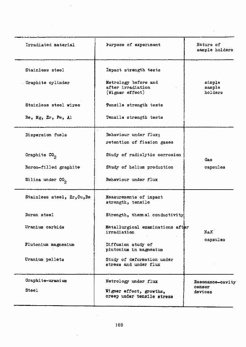
Irradiated, material Hirpose of experiment Nature of sample holders
Stainless steel Impact strength tests
. Graphite cylinder Metrology before and after irradiation (Wigner effect)
simplesampleholders
Stainless steel wires Tensile strength tests
Be, Mg, Zr, Pe, Al Tensile strength tests
Dispersion fuels Behaviour under flux;
retention of fission gases
Graphite COg Study of radiolytic corrosionGas
Boron-filled graphite Study of helium production capsules
Silica under CO^ ’ Behaviour under flux
Stainless steel, Zr,Cu,Be Measurements of impact strength, tensile
Boron steel Strength, thermal conductivity!
i
Metallurgical examinations after irradiation 1 NaX
Uranium carbide
Plutonium magnesium Diffusion study of plutonium in magnesium
capsules
Uranium pellets Study of deformation under stress and under flux
Graphi t e-urani urn
Steel
Metrology under flux
Wigner effect, growths, creep under tensile stress
Resonance—cavitjcensordevices

These furnaces, which operate on the same principle as CHOUCA
furnaces, have a bigger effective diameter (53 or 49 mm, depending on
whether they are used with or without a heat shield). They thus permit the
irradiation of larger amounts of material, and nuclear heating makes it
possible to obtain high temperatures, from 350° to 1400°C. Additional
electrical heating is provided by 4 heating elements. The effective length
is 400 mm, and the pressure can be varied from 0 to 60 bars.
These furnaces are used for irradiating structural materials
(high-temperature graphite, glucine (BeO) at 1300°C, various refractory
materials, steatite at 250° and 450°C, etc0) and small items of equipment
(pressure sensors , co-axial tables, electrical relays, micro— circuit-
breakers, fission chambers, etc.).
6.3 Research with the CYRANO furnaces
These devices are designed for irradiation of fuels at high linear
power (17OO W/cm). They are equipped with a device for measuring the
nuclear power released by the sample. Irradiation is carried out under
power, temperature and pressure conditions equivalent to those obtaining
in power reactors. The samples are placed in NaK or in sodium in order to
ensure heat exchange, the main heat barrier being constituted by a layer
of sintered stainless steel and a gas film. The pressure can be selected
between 1 and 60 bars.
These devices make it possible to regulate the fuel sample cladding
temperature for a given power release or to extract the maximum possible
power for a given cladding temperature.
Examples showing the use of these devices, of which 80 have been
made, are given in the following table.
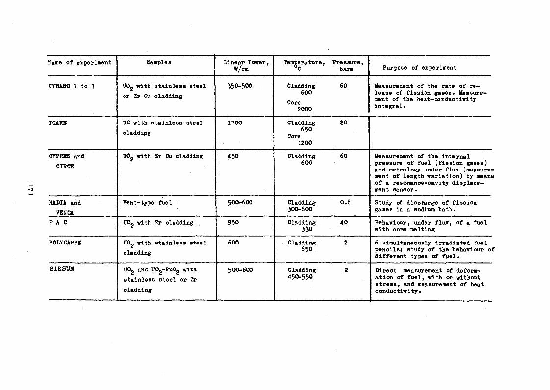
Name of experiment Samples Linear Power, W/cm
Temgerature, Pressure,bars Purpose of experiment
CYBAHO 1 to 7 UOg with stainless steel or Zr Cu cladding
35O-5OO Cladding600
Core2000
60 Measurement of the rate of release of fission gases. Measurement of the heat-conductivity integral•
ICARE UC with stainless steel cladding
1700 Cladding65O
Core1200
20
CYPRES and CIRCE
UOg with Zr Cu cladding 450 Cladding600
60 Ifeasuremènt of the internal pressure of fuel (fission gases) and metrology under flux (measurement of length variation) by means of a resonance-cavity displacement sensor.
NADIA and VENCA
Vent-type fuel 500-600 Cladding300-600
0.8 Study of discharge of fission gases in a sodium bath.
P A C UOg with Zr cladding 950 Cladding330
40 Behaviour, under flux, of a fuel with core melting
POLYCARPE UOg with stainless steel cladding
600 Cladding65O
2 6 simultaneously irradiated fuel pencilsj study of the behaviour of different types of fuel.
SIR SUM IJOg and UOg-PuOg with stainless steel or 2r cladding
500-600 Cladding45O-55O
2 Direct measurement of deformation of fuel, with or without stress, and measurement of heat conductivity.

6o 4 Besearch with high frequency furnaces
These furnaces with high-frequency heating make it possible to
obtain and regulate, under nuclear flux, very high temperatures of up
to 2000°C. An alternating-current inductor (50-500 kHz) generates, in a
shield, currents which in turn induce currents in a susceptor, which can "be
the sample itself or a part of the sample holder. The latter*s diameter
varies "between 16 and 21 ram; the high-frequency power attains a value
of 200 W per centimetre of height and the nuclear power a value of 400 W/cm;
the temperature can be regulated to within 5°C or +_ 0.5°C, according
to specifications.
Examples of experiments:
(a) study of fission gas diffusion outside fuels, the fission
gases being entrained by a helium stream and analysed outside the reactor
(UOg, UC and dispersion fuels).
(b) Endurance and accelerated-aging tests of graphite, U02
or UC fuels and special fuels for itermoiordc conversion.
(c) Design and production of a hot neutron source by hi^i-
frquency heating of a graphite cylinder at 2300°IC.
6.5 Besearch with resonance cavities
The dimendional behaviour of structural material or fuels
exposed to radiation results from the action of various phenomena such
as creep, growth, swelling (of fuels, for example), compacting (vitreous
silica, for example) cycling, Wigner effect, etc.
In many cases, these measurements are carried out after irradiation
with all the disadvantages that this involves (interpretation of the finer
phenomena and the need to multiply tests in order to obtain a number of
points).
The disadvantages mentioned above can be eliminated by developing
an apparatus which can be used for direct measurement, under flux, of the
dimensional variations of samples. The deformation of a sample during
irradiation causes a change in the volume of a hyper-frequency resonance
cavity, the latter being connected to the sample by means of a piston.
The process consists of measuring the variation of the resonance frequency
of the cavity, and this variation is related directly to the deformation
of the sample. The measurement procedure has the following characteifcistics*
measurement range : 0 to 1 mm and 0 to 20 mm;
resolutions : ¿.0.01# of the measurement range
accuracy : ^ 0 .05$ of the measurement range;
- sensitivity s K * 1 ]im.
6*6. Research with cells for creep studies
The creep cells are used for irradiation of samples kept under
tension or compression with continuous measurement of the following
parameters •: temperature, stress, neutron flux, dimensional variations
and creep rate.
The cells contain a tension or compression jack with deformable
metal bellows, thermocouples, neutron-flux detectors and a resonance-
cavity displacement sensor. Elastic deformations and the effects
of temperature expansion are compensated. The temperatures can be
homogenized by liquid metal filling (NaK).
These cells have so far made it possible to carry out creep
studies on stainless steel, graphite and tubes under internal pressure.
6.7* Sodium loop
This loop is intended for irradiating fuel elements under
heat conditions similar to those of fast power reactors.
The use of such a device in a research reactor should be
subject to compatability with the access parts available for ex
periments and with the general safety of the facilities (reactor and
experiments) in the vicinity.
Two aspects are important : the circulation of the sodium is
ensured by special heat-pump elements, which provide a high degree of
intrinsic operational safety since they need no electric supply or
connection outside the reactor; in addition, the sodium is separated
at all points from the external medium (especially from the water in
a swimming-pool or tank-type reactor) by a double stainless steel wall.
Technical characteristics :
Total extractable power
Test section
Sodium temperature
Sodium flow-rate
60 kW
p 20 mm, length 1400 mm
300-700°C
2-5 m/sec

7. COLLABORATION WITH OTHER COUNTRIES
The intensive use made of the reactors belonging to the French
Atomic Energy Commission for both basic and applied research,
illustrates the importance of swimming-pool reactors in
the development of nuclear techniques.
For many years past, this development has been the subject of
collaboration with several foreign countries, including developing
countries, in a number of fields :
(a) Training of engineers and university graduates either specifically
in the problems of construction and operation of reactors and ex
perimental devices or, within a wider framework through direct part
icipation in the work of reactor teams or through provision of facilities
for preparation of university theses. In this manner, various novel
technical improvements or measurement and calculation methods have been
developed by, or entrusted to, foreign collaborators with the greatest
mutual benefit-
(b) Supply of technical advice mainly in the construction, operation
and improvement of the performance of swimming-pool reactors. With our
wide expérience in this field and particularly in effecting power in
creases, we participate in the relevant projects of several foreign
countries which wish to adapt, modify or improve their reactors with
a view to securing thereby a basic tool for their programmes on the
development of nuclear techniques. Close and regular co-operation has
been established in particular with several South American countries.
(c) An interesting example of co-operation can be cited here - that
of a joint project in progress for several years past in collaboration
with a South American research centre for the purpose of improving the
performance of the reactor operated by the centre, using it for launch
ing a solid-state physics programme and forming a mixed team of solid-
state physicists, working in the first phase under the scientific
direction and with the equipment of the corresponding laboratories
at Grenoble. One aim, in the second phase, is to establish an in
dependent laboratory capable of defining its own programmes and de
veloping its own research facilities.

(d) Lastly, based on the experience of our collaboration activities, we
are in a position to recommend a type of reactor which is particularly
suitable for developing countries, and for which we have developed a
basic project.
This is a 100-kW swimming-pool reactor with six channels,
designed to operate at a power of up to. 5 MW at Itelater stage. The
power increase from 100 kW does not affect either the pool block or
the general layout of the facilities and can be easily achieved
at minimum cost by merely replacing certain items of equipment and
supplementing a number of others.
In the initial phase of operation, a power of 100 kW is usually
considered to be adequate for launching a nuclear programme involving
training of personnel, production of short-lived radioisotopes, re
search in reactor physics, and various applications.
In the second phase, a power between 1 and 5 MW enables the
initial programme to be extended to irradiation research and tests
within the framework of a more advanced general programme with emphasis
on the development of nuclear techniques. The performance at 5 MW is
close to those of MELUSINE and TRITON, and the possibilities of use
are therefore the same.
The third phase, which consists in carrying out an extensive
technical research and irradiation programme, requires the commission
ing of high-performance research and test reactors of the SILOE or
OSIRIS type. This can hardly be considered feasible in countries without a sufficiently developed and equipped scientific and technical
infrastructure.
In other words, the economy of the first two phases is difficult
to evaluatebefore proceeding to the last phase.
Within modest financial means, this project envisages one and
the same working tool for the first two phases, thus making it possible
to accelerate the development programme without awaiting the grant of
substantial financial allocations to permit the transition from the first
to the second phase.

The initial design of the reactor is such that the power can be
increased from 100 kW to 5 MW at very low cost, while the extra ex
penditure incurred at the outset in order to benefit subsequently from
this valuable feature is, contrary to appearances, not high.
The reactor can naturally also be built for an initial power
of between 0 and 5 MW*
Because of its design, which is the result of many years of
experience, this reactor is simple, compact and specifically adapted
for constituting the foundation of a basic and applied nuclear re
search programme.
8. GENERAL CONCLUSIONS
The grouping of three reactors - MELUSINE, SILOE and SILOETTE -
at the same site makes available to researchers a range of facilities
which can satisfy, if not the whole, at least a good part of their
irradiation requirements.
Independently of continuous research aimed at improving the
performance of reactors, there must, however, also be provision for
guiding researchers in making the best use of the reactors placed at
their disposal. This can be achieved by offering them a range of
additional special services for the double purpose of s
- assisting them in the matter of designing devices and taking
measurements specific to the reactors; and
- relieving them thereby of technical details with which they
are not always familiar.
It is with these objectives in mind that the Reactor Service of
the Grenoble Nuclear Research Centre has stressed on the development
of (a) equipment and irradiation devices to suit the reactors and to
meet most of the usual needs of researchers; (b) neutron and gamma
dosimetric methods adapted to the devices; (c) examination methods such
as neutron radiography; (d) computerized monitoring and regulation of
experiments; (e) unloading*©f samples, etc.
In conclusion, it can be said that the considerable progress
achieved in the sphere of irradiation over the past few years is the
result of this continuous collaboration between researchers and reactor
personnel.
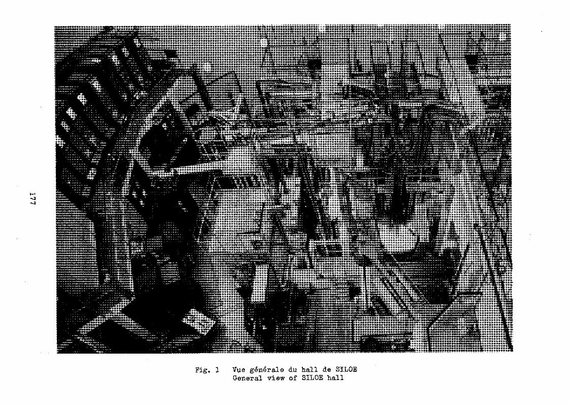
Pig. 1 Vue générale du hall de SILOE General view of SILOE hall

Fig. 2 Tableau de contrôle de SILOE Control panel of SILOE
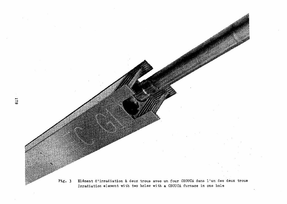
Elément d'irradiation à deux trous avec un four CHOUCA dans l'un des deux trous
Irradiation element with two holes with a CHOUCA furnace in one hole

Pig. 4 Barre fourchette dans l’élément de contrôle Pork rod in the control element

Pig. 5 Neutrographie d’une rose, illustrant la sensibilitéde cette méthode dans l'examen non destructif des matériaux hydrogénés, un des aspects parmi d'autres de la complémentarité de la neutrographie et de la radiographie.
Neutron radiography of a rose, illustrating the sensitivity of the method in the non-destractive examination of hydrogenated materia, one aspect of the complementary nature of neutron radiography and radiography.

Dispositif d'irradiation à examiner
Collimateur
Vérin de blocage du dispositif
Diaphragme
Fig. 6 Neutrographie d'un dispositif d'irradiation trèsradioactif
Dispositif d ' étanchéitè
( p a r joint d « glaceou élastique )
Vérin de mise en place de la cassette porte- convertisseur
Parois neutrophages
fenêtre1 5 0 x 4 0 0 Mél. 3 0 0 X 4 0 0 Sil .
Cd + In
A P P A R E I L DE N E U T R O G RAP HIE I M M E R G É ( Siloé - Mélusine)
CONTROLE DE DISPOSITIFS RA D IO A C TIFS

Fig» 6 Neutron radiography of a highly radioactive irradiation device
JACKING FOR CLAMPING THE DEVICE
DIAPHRAGM 8-30 mm
Cd*In NEUTRON ABSORPTION WALLS
SCALING DEVICE (WITH FROZEN OR
LASTIC PACKING)
IM M E R S E D N E U TR O N R A D IO G R A P H Y (S IL O E M E L U S I N E )
CHECKING OF RADIOACTIVE DEVICES
'JACK FOR POSITIONING HE CONVERTER HOLDER
CASSETTEWINDOW 150 x 400 Mel 300x400 Sil
A P P A R A T U S
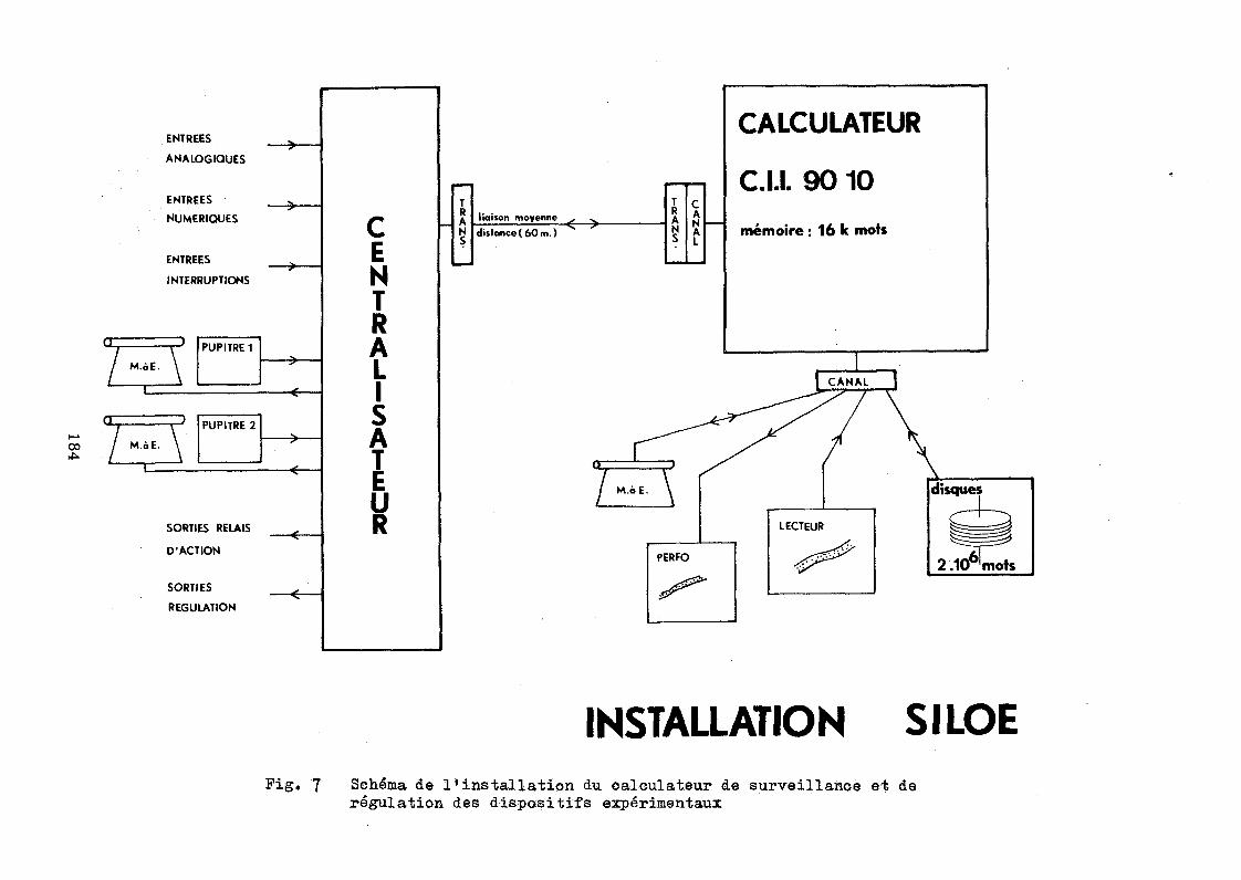
INSTALLATION SILOEPig. 7 Schéma de l'installation du calculateur de surveillance et de
régulation des dispositifs expérimentaux

SHOE FACILITYPig. 7 Sohematio layout of the computer for monitoring and regulating experimental devices

Fig» 8 Diffractomètre à neutrons polarisés sur un canal radial de MELUSINE
Polarized-neutron diffractometer on a radial channel of MELUSINE

Pig. 9
Industrial neutron
radiography faoility
on the
HSLUSIIiE channel
G EN ER A L LAYOUT OF APPARATUS
MOVABLE FILTER BISM UTH SIN G LE CR YSTAL
M O VABLE DIAPHRAGM / 5 a 20 m m
R E A C TO RE N C L O S U R E
• • &K.A ♦ A
! -X &*. • .
* A ’ * * •â .
BORON
FILTRE FOR THERMAL NEUTRON BEAM
INDUSTRIAL NEUTRON RADIOGRAP
INSULATIO N G AP G A S E O S U S N2 O UTLET
&Cd + ln
E X H A U S T FO R (p f j CON TACT B ETW EEN ÍS
m m mBORON'
LEAD
m i mLIQUID N GAP
FILTER FOR COLD NEUTRON BEAM
HY APPARATUS MELUSINE 1969GRENOBLE NUCLEAR RESEARCH CENTRE(FRANCE)

Pig. 9
Installation de
neutrograpMe
industrielle
sur le
canal de
MELUSIHE
I M P L A N T A T I O N G E N E R A L E DE L ’ A P P A R E I L
Diaphragme mobile
Filtre amovi.ble m o n o c r is ta l b ism uth
enceinte ¿ *:.dur é a c t e u r '
A * * ' • ' ^ ¿
FILTRE P O U R F A IS C E A U D E N E U T R O N S THERMIQUES
V id e d ’ isolement
A r r i v é e N? liquide
D épart N 2 g a z
iJ. ¿‘..j
Bore !
PlombA spirationcontact entre les fenêtres « M
FILTRE POUR FAIS CEAU DE N E U T R O N S FROIDS
APPAREIL DE NEUTROGRAPHIE I N DU S T RIE L LE * ME LU S 1NE* 196 9 *I C e n t r e d étu d e s nucléaires dé G R E N O B L E ( F f a n ç t ï |

Pig. 10 Montage de la source chaude dans sa cuve à eau lourde a SILOETTEInstallation of the hot source in a heavy-water vessel in SILOETTE

Pig. 11 Dispositifs expérimentaux autour du coeur de SILOE
Experimental devices around the SILOE core

Fig, 12 Chateau de transport des parties inférieures irradiées des dispositifs expérimantaux standards
Lead container for transporting the lower irradiated parts of standard irradiation devices

TITLE: Utilisation of a Research Reactor as preparation for the introductionof Nuclear Power.
by A.C. Wood
Bandung, Indonesia, 2-6th August 1971
Category: Engineering
(b) Engineering work in support of a nuclear power programme.
ABSTRACTIn order to successfully introduce nuclear power a developing country needs
a group of project oriented experienced nuclear engineers. Because the national
institutions are usually scientifically oriented and the conventional power station
engineers are not familiar with nuclear problems it is desirable to form a
composite team which is given a project as a prelude to the construction of the
nuclear power station.
A number of project types are described briefly in the paper ranging from
the construction of a small prototype power station to an engineering loop. An
example is given of a project concerning a modification to the Australian
research reactor HIFAR. Emphasis is laid on the need for a project to result in
new hardware or a change to existing hardware if the experience obtained is to be
relevant to the construction and operation of a nuclear power station.
This meeting is concerned with Engineering programmes as applied to the utilisation
of research reactors. All the developing countries represented here possess research
reactors and most countries see themselves either in the short term or the long termA
as users of nuclear power.

In order to make the best decisions in relation to the choice of reactor, choice
of site, quality assurance during construction and later, the problems of operation of
nuclear power plants, it is necessary to make use of expert engineering judgement at
each stage. Because most countries would prefer to draw on their nationals for this
expertise rather than rely on foreign sources, there is a strong incentive to use
existing research reactors as a vehicle for the training of engineers. It is our
objective here to propose and discuss possible Engineering programmes which might
further this end. My personal view on how this may best be accomplished is offered.
In introducing the panel on "Engineering Programmes in Research Reactors" sponsored
by the IAEA in Vienna in July 1970, Kolbasov and Gonzales - Montes observed that "most
national institutes begin their nuclear activity with strong emphasis on the scientific
aspects of nuclear energy programmes". The panel however was asked "to focus its
attention on seeking ways of helping developing countries to train the engineering
specialists needed
(1) To act as good customers and operators in the case where the
intent is to buy turnkey plants.
(2) To develop the countries' capacity to launch appropriate facets
of their domestic nuclear ability".
One might ask whether the latter two objectives can be accomplished at all by
undertaking engineering programmes in a research reactor at a scientific institution.
In those developed countries where power reactors are designed and constructed
locally this question does not arise because there are enough engineers continually
employed on design, construction and operation of reactors as well as in the support
ing industries for adequate project oriented expertise to be available to a potential
reactor purchaser. J.A.L. Robertson of Canada noted in his comments on the papers
presented to the IAEA panel of July 1970 that "the best person to assess a power
reactor is someone experienced enough to design the reactor itself". In the
developed countries the research engineers and scientists at the national institutions

provide in depth support to the designers, constructors and operators. A very high
level of skill can be brought to bear in the national scientific laboratories on a
specific problem when the aid of these specialists is enlisted.
On the other hand in a developing country without an existing nuclear power
programme one would not expect to find an experienced group of project oriented
nuclear engineers. There is likely to be a group of engineers with some experience
in the construction and operation of conventional power stations and another group
of engineer-scientists at the research institution with little experience in the
problems of design, construction and operation of large reactors, but quite a
detailed knowledge of the scientific aspects of heat transfer, materials compatibility,
reactor theory and so on.
There is no cheap solution to the problem of acquiring this essential experienced
group of project oriented engineers. Some overseas experience is essential because one
must have first hand knowledge of the engineering details of the reactors and the type
and magnitude of the problems regularly encountered. However overseas experience on
an attachment basis is not sufficient because one tends to be insulated from the
rigours of the actual decision making process. At all levels of engineering there is
no substitute for experience in the line of command where decisions have to be made to
a schedule and where the decisions have considerable financial and safety implications.
One suggestion is to simulate on a smaller scale a project which will confront
people with the type of problems they would be expected to solve if they were expert
advisers in their respective fields. Ideally one woúld recruit both conventional
power station engineers and reactor engineers from research institutions, and from these
form a team with the specific responsibility of undertaking a small nuclear project.
A suitable engineering project for such a team would be the design and construction of
a small prototype power generating reactor but such a project would be expensive and
might be beyond the means of most developing countries. A less ambitious plan would be to
design and construct a research reactor, because the project would offer experience in

all the engineering aspects of a power reactor except for the turbo-generating stage.
I believe Argentina has successfully conducted such a project. All the countries
represented here have at least one research reactor of foreign design and in many
cases of foreign construction. If the justification exists to construct another
research reactor, every opportunity should be taken to maximise local participation
at all levels and to minimise the degree of foreign assistance.
Finally, modification of an existing reactor to provide for power uprating, the
use of a new type of fuel element or the replacement of the safety circuitry could
provide extensive Engineering training relevant to power reactors. The opportunity
to do this might arise from the need to provide higher fluxes for experimental
purposes or for more flexible and efficient operation. A competent engineering group
can thereby broaden their training in reactor engineering and in turn save large sums
of money through making wise decisions when nuclear power is introduced. Such training
will not be of great use unless the project involves provision of new hardware or
significant changes to existing hardware in spite of a cost incentive to stop short of
this phase. Programmes which yield no new hardware or changes to existing hardware but
instead result in an interesting scientific paper (such as many of those proposed by
the IAEA panel of July 1970) are useful only in demonstrating the existence of
technical specialists who are available for consultation. While this is a necessary
requirement for a local nuclear power industry, it is not a sufficient requirement.
The first line of engineering expertise necessary for countries interested in becoming
"good customers and operators" must consist of project oriented engineers.
To demonstrate that worthwhile engineering projects can be formulated about
modifications to existing reactors, this paper is devoted to describing an example
concerning a modification to the Australian research reactor HIFAR.
This particular modification stimulated a complete review of the safety of HIFAR.
A sum of $45,000 was spent on improvements to plant as a result of the study. A

number of engineers and scientists received valuable experience of the type appropriate
to project nuclear engineering.
HIFAR is a 10 MW heavy water moderated and cooled reactor using fully enriched
uranium fuel and is almost identical in design to the English DIDO reactor. The
reactor vessel operates at atmospheric pressure and is constructed of half inch
aluminium plate. It contains several re-entrant tubes in the horizontal plane and one
horizontal through tube. These tubes are used for neutron beam experiments and
self-service isotope production. Vertical experiments may be loaded into experimental
tubes located outside the core in the heavy water reflector or inside the core within
hollow fuel elements.
The original fuel elements known as Mark II were of the standard MTR box con
figuration containing 10 parallel and slightly curved plates. Each fuel element
contained 110g of 235jj metal in aluminium alloy. The Mark II type of fuel element
was replaced by the Mark III, when fast flux irradiation facilities were required.
The main feature of the Mark III fuel element was a 2" diameter unfuelled central
tube to contain the experiments, surrounded by a 4" diameter unfuelled outer tube.
The 10 fuel plates were arranged in a helical pattern in the annulus and the 235u
fuel loading was increased to 150g in each fuel element.
To increase the power of this type of reactor from 10 to 20 MW a first
requirement was modification of the fuel element. The Mark III fuel element had
insufficient heat transfer area, giving an excessively high heat flux for a twofold
increase in power level. In addition the pressure drop across the element was
excessive and any substantial improvement in coolant flow rate through the element
would require an excessive pressure in the plenum area in the lower vessel region.
Turbulence was also observed on the free heavy water surface from currents arising
from the exit coolant flow from the fuel elements<, The control rods are of a
blade type which fall between rows of fuel elements after the manner of railway

signal arms and the currents unnecessarily extended the control rod drop times
following a reactor scram by impeding their free fall.
The UK engineers designed a new fuel element designated Mark IV using
concentric tube geometry. It superseded the Mark III fuel element and was intended
to offer improvements in the areas mentioned above. It retained the outer 4"
diameter unfuelled tube and consisted of 4 concentric fuelled tubes with a total
of 507. increase in heat transfer area. The inlet nozzle was redesigned to a
venturi shape, resulting in a considerable reduction in pressure drop across the
element. The outlet porting was also considerably modified with a consequent
reduction in heavy water surface turbulence, which reduced the control rod drop
times by 257. compared with those of the Mark III element. The construction of
the new fuel element was much less rigid and some structural failures occurred
during its development. Nevertheless successive modifications had resulted in
a high level of reliability for completing a four month operational life which
was expected to be its normal irradiation period (slides 1 and 2).
Careful loading of the new Mark IV fuel element was necessary because failure
to load an inner thimble would result in by-passing coolant around the fuel plates.
This problem did not arise with the old Mark III type element because the inner
unfuelled tube was an integral part of the element.
Another feature of the geometry of the Mark IV fuel element is the poor
conduction heat transfer path from the fuelled tubes to the outer tube. This
has two important effects on safety, viz
(1) An irradiated element held in stagnant air would reach a
higher temperature from decay heating than would an
equivalent Mark III element. Fuel is unloaded from the
reactor by using a 20 ton shielded transport flask. Care
has to be exercised to avoid fuel melting during the fuel
unload operation, either by ensuring that air cooling on the

fuel element transport flask is guaranteed or that fuel
unloading is deferred until air cooling is no longer
required to prevent fuel meltdown.
(2) In the original design concept a seal was provided between
the fuel element nozzle and the plenum chamber at the bottom
of the vessel to prevent a fuel meltdown in the event of a
primary circuit rupture. Even if a pipe ruptured, the reactor
vessel could only drain to the level of the outlet ports of
the fuel elements. Sufficient heat could then be conducted
along the fuel plates to the outer surface of the fuel elements
and thence to the water in the reactor vessel to prevent
melting (Slide 3)» The Mark III fuel element design reduced
the efficiency of this heat removal process by removing
one-half of the heat conduction path and the problem was
further aggravated in the new Mark IV fuel element design*,
We were not able to convince ourselves that catastrophic
failure of the reactor pipework was incredible although we
believed that it was extremely unlikely. Our accident
analysis then had to take into account a full core meltdown
and to show that sufficient engineered safety features
existed to minimise the off-site exposure to acceptable levels.
The escape mechanism and the escape route of the fission products from the
primary circuit into the reactor building and then into the atmosphere were
defined for a hypothetical accident as follows. After the coolant had drained
from the interior of the fuel elements through the pipe rupture, the fuel plates
would melt within a matter of minutes. Molten fuel would then slump to the bottom
of each fuel element where much of it would be in contact with the unfuelled
outer tubes. This heat would boil off the water remaining in the vessel and the

steam generated would contain fission products, particularly I. The steam would
vent through the ruptured pipe into the heavy water plant room and thence into
the building.
The reactor sealed building offers the main line of defence against fission
products released from the ruptured circuit escaping into the environment.
Ideally a reactor building should be held at slight negative pressure during
this phase of a fission break accident but this is very difficult to achieve
as the air pumped from the building to maintain the negative pressure has to be
discharged somewhere and this air contains fission products. HIFAR has a fairly
airtight sealed containment building of mild steel, capable of withstanding an
over-pressure of 1.5 p.s.i. with a leak rate of about 17. per day. When sealed
it is particularly sensitive to inleakage of compressed air from air operated
instruments and sources of heat which would raise the internal pressure. The
main normal sources of heat in the building are
(1) Decay heat of the fission products contained in the
irradiated fuel.
(2) Heat stored in the coolant-moderator and reactor shield
at their operating temperatures.
(3) Heat dissipated from electrical instruments.
(4) High pressure hot water ducted to the space conditioners
for air temperature control within the building.
The main heat sinks in the building are
(1) The mass of structural steel in the crane bridge and the
steel floor joists and plating.
(2) The space conditioner system referred to earlier which is
supplied with chilled water from refrigeration plants
outside. (Each space conditioner consists of a box
containing a fan which draws air over two sets of coils.

Hot water circulates through one set of coils and chilled
water circulates through the other. The flow rates of
hot and chilled water are automatically regulated to the
demand for heating or cooling as sensed by a thermometer).
The rate of heat injection to the building was calculated assuming that the heat
was transported in the manner described earlier. We conducted experiments in
which heat was released into the building to determine what fraction appeared as
sensible heat to cause overpressure and what fraction was absorbed by the steel
work. The experiments were undertaken with the space conditioner system in
operation and also in the "failed" condition. The space conditioner system was
shown to be very effective in reducing the overpressure, but on the other hand
it was shown that without the space conditioner system, the building pressure
would rise to approximately 2 p.s.i.g. and there is no effective mechanism to
reduce this pressure. The thermal insulation on the interior of the building
necessary to make the air conditioning effective works against heat removal by
free air convection on the outside. A calculation of the fission product release
resulting from this overpressure showed that the release would be unacceptably
high. Thus it was shown that the space conditioner system must play a major
role in minimising the consequences of this unlikely but credible accident.
We then looked at the design of our space conditioner system to determine
whether the design met the high standard of reliability required for an engineered
safety feature. Slide 4 shows the original circuit which on examination reveals
that although there is adequate redundancy in that we have six space conditioners
and three refrigeration-compressor units, these units are virtually not independent
and consequently a failure of any one of several critical items could render the
whole system ineffective. A typical critical item would be a thermostat or even
the pipework itself, which could fail, discharging all the chilled water.

In the modified system shown in the next slide we have three completely
independent refrigeration units, each one served by two space conditioners.
Provision has been made for third units to be installed on each of the three
systems. So far it has not been found necessary to do this. Tests under simulated
accident conditions have shown that two space conditioners and one refrigeration-
compressor unit are well matched for capacity and effectively reduce the overpressure.
In fact it was shown that three space conditioners under accident conditions could
overload a single refrigeration-compressor unit and cause it to trip itself out
on high refrigerant pressure. If the third space conditioner were ever to be
installed it would be necessary to provide a load sharing and limiting device.
Another aspect investigated by the test under simulated accident conditions was
the reliability of the electric motors and the heat exchanger coils in an
atmosphere of saturated steam. Electric motors were found to be unaffected by
prolonged operation (one week) and that condensate lying between the fins of the
heat exchanger coils did not markedly affect their efficiency.
We now believe that we have three reliable systems and that one of these
systems can be down for maintenance at any time. Either one of the remaining two
has sufficient capacity to reduce the heat load to the extent that 131x release
in an accident will be within prescribed limits.
The space conditioner systems though essential, form only part, of the
containment building line of defence. It has been found necessary to explore
the reliability of the system to seal the ventilation trunking if an accident
should occur. The mechanisms to seal the ventilation trunking, its sensors,
its activators and its monitoring, should all contain redundancy and independence
necessary for a well engineered safety feature. Other aspects to consider are
fixed penetrations (power cables, communications, water, effluent, rabbit facilities
and other experimental tubes) and airlocks for personnel and vehicle access.
Regular pressure testing of the sealed building is necessary to establish
confidence that the acceptable leak rate of 17. volume per day exists for most of

the time. Our experience has been that even static seals deteriorate and a high
level of supervision is required on maintenance and modifications to building
penetrations to ensure that seals are still intact when work has been done in the
vicinity. This type of supervision can easily be overlooked, resulting in a
reduction in the effectiveness of engineered safety features.
The example of the HTFAR modification quoted here is typical of the type of
project which can be undertaken in training of engineers. Design and construction
of a high pressure water loop similar to the one under construction by the AAEC
would also be a suitable project. Even if the small reactors owned by most of
the developing countries could not accommodate such a loop many larger foreign
reactors have vacant space which can be hired out. In design and construction
it has many of the characteristics of a reactor and also it would permit
engineering experiments to be undertaken. The loop could be locally designed,
constructed and operated out of pile. When thoroughly tested it could be
dismantled and shipped to the foreign reactor centre. A small team could be sent
overseas to assist in its re-assembly and operation. The final experimental results
together with in-pile components could then be returned for evaluation.
None of the proposed solutions for the development of engineering ability are
inexpensive. This is because project oriented engineers are not going to become
proficient through undertaking low cost applied physics experiments in small
research reactors. If the intention is to undertake pure scientific work with the
object of extending man's knowledge, then many low cost experiments could probably
be proposed. On the other hand if the developing country is concerned about its
capacity to write a specification for a nuclear power plant, to make a sensible evaluation of a wide variety of claims by vendors when tenders are evaluated, to
ensure that the quality specified is in fact provided and finally to operate the
plant in an efficient manner it should be understood that the acquisition of
experience is expensive. It requires participation of key personnel in overseas

large reactor design and construction projects and it requires local projects
where engineers are given a decision making role in smaller construction,
modification, and operation phases of the use of nuclear reactors.
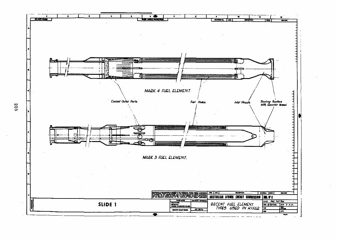
205
MAßk. 3 PULL LLÍMÍNJ.
S ta lin g Surfoc*' utocfor Kraswt.
4M m MVJO ■»yy.f »y ,» « w i*«MW O» M 4
>•*•55*2H s H
3 E EAUÎMLUI ATIIIIC BK1SY CIHHIUIOI
T = S T
o*rc
SLIDE 1 QZCZNT FULL QLÍMÍNT 7YP£5 USED IN UffAÛ.
SCMS *<Hf fuH SfUMM dCtrttM. |fi*n 9 7-ft._i---- \nr----

206
1 * 1 » ----1 ««■»». I U>cT~....OONOTSCAI*
MAÛIC 2 FULL ¡LLLMLNT.
MARI' 5 FULL LUM LNT MhtUi 4 FULL £L£M£NT.
c o w w y w w gg »— n » tm m m m i ai— miw aIM« MAVW*. VMM 8 TM| MCMtnr 0* IM Al____a WXVN OH tK W«piHil«1M ft**»« «JP jiJ !
~n«T MAWW I MOO I tCMAMIAISTIALIAM ATOMIC EffiUY C6HHISSI0N oarc
SLIDE 2RACnONSt
uNua oTHKvn ttAtm C/BOSS SECTIONS OfH I FAQ. FU£L £L£M£NTS.
iCMI ?Utl 3*1*1 If. Ctrksk“

207
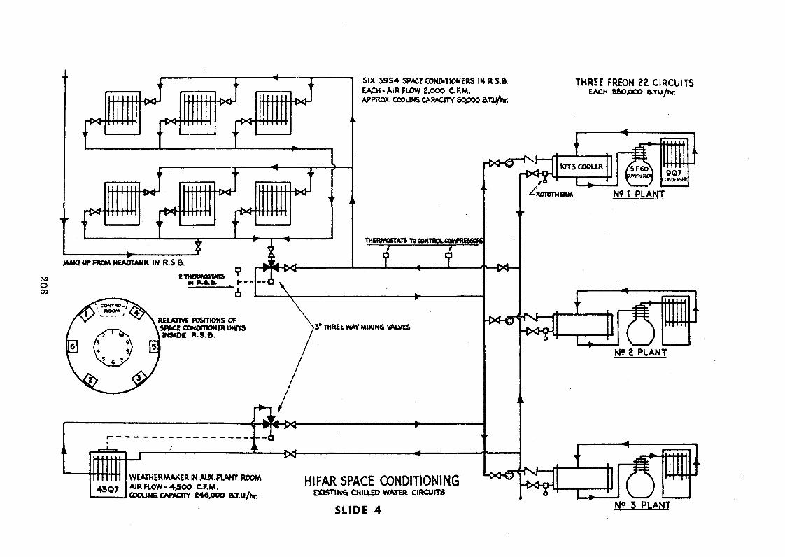
208
SIX 3 9 S 4 SPACE CONDITIONERS IN R.S.& EACH-AIR FLOW 2,000 C.F.M.APPROX. COOLING CAPACITY 8Q000 Ä U ^ w .
THREE FREON 22 CIRCUITSEACH t&O.OOO STu/hr.
WEATHERMAKER IN AL5C PLANT ROOM AIR R O W -4 ,5 0 0 C.F.M.COOUN6 CAiP^crrY 646,000 &.T.U/fr.
HIFAR SPACE CONDITIONINGe x i s t i n g c h il l e d w a t e r c ir c u i t s
SLIDE 4 N? 3 PLANT

209
SYSTEM N? Z
C H IU E D W ATER WkAKEUP FROM SEPARATE HEADTANKS EXTERNAL t o R .S .B ------------ ÿ
THREE PAIRS OF THERMOSTATS IN R.S.B.
Ï ® ©
— L C*3—
N? g PLANTTHERMOSTATS CONTROLLING COMPRESSORS
f + T t P T l f + W 6
SYSTEM N? 3
-crS~:- M -
43Q 7
— u
~©
WtATH ER MAKER IN AIK. PLANT ROOW AIRFLOW - 4,500 C.F.M.COOL1N6 CAPACITY ■ 246,000 B-T.u/hr.
L « M-{X J— i
N? 3 PLANT
HI FAR SPACE CONDITIONINGPROPOSED CHILLED WATER CIRCUITS.
SLIDE 5
RELATIVE PC6ITI0NS OF SPACE CONDITIONER UNITS
INSIDE P .S .B . --------- »

Leonard J. Koch .Senior Engineer
“ÍCArgonne National Laboratory Argonne, Illinois, U. S. A.
ABSTRACT
Research reactors provide an effective focal point for a broad spectrum of nuclear engineering activities. Many of these activities can provide excellent reactor engineering preparation for the introduction of nuclear power systems. Effective engineering programs include the participation of engineers in all the activities related to the research reactor program.These activities should include: maintenance, improvement and modification of the reactor and experimental facilities; engineering development of "non-engineering" reactor experiments; and a broad program of engineering experiments. A program of this type will assure the participation of the engineering staff at the research reactor facility (irrespective of the number of engineers in the group) in virtually all of the activities at the facility. This will result in the best utilization of the total technical staff and the best preparation of the engineering staff for future reactor engineering responsibility. It should also result in the most effective utilization of the research reactor and the most productive research program.
INTRODUCTION
Research reactor operations and programs play an important role in nuclear research and development. This is particularly true in the early or formative phases of a country's nuclear program. A research reactor provides a unique focus for the various participants in the program and plays an important role in coordinating their activities. Research reactors, as their name implies, are used to perform research-oriented experiments and this focus tends to emphasize
Work performed under the auspices of the U. S. Atomic Energy Commission.

scientific research rather than engineering development. It is the purpose of this paper to discuss methods of increasing the emphasis of research reactor engineering programs, particularly as these programs may contribute to preparing the members of an organization's staff for future participation in nuclear power programs.
It is customary to conduct the engineering development program at a research reactor in much the same manner as the physical or biological sciences research programs. As a result, the main emphasis tends to be placed on developing engineering experiments to be performed in research reactors. However, because of the limited capability of small research reactors, it is often difficult to devise meaningful engineering experiments which can produce solutions to major engineering problems. Proposed engineering experiments must be carefully evaluated to ensure that they will produce the desired results. Such evaluations should consider the optimum utilization of engineering resources, particularly where they are limited. The available engineering resources should be allocated to: maintenance, improvement, and modification of the reactor and experimental facilities; engineering development of "non-engineering" reactor experiments; and a broad program of engineering activities and experiments which emphasize the effective and efficient utilization of the reactor. These steps will result in direct participation of engineers in the reactor program; the engineering staff will make larger contributions as participants or collaborators in the various experimental programs and will simultaneously become more knowledgeable engineers with broader experience. This will result because the engineer must not only understand the reactor and the engineering problems associated with its use, but he must also understand the experiments to the extent that he can translate the experiment requirements into engineering requirements for the reactor and the experiment.
In this paper, I will discuss engineering activities related to research reactor operations and programs within the broad scope defined above. I will attempt to emphasize the application of this perspective to the CP-5 and JANUS research reactors at Argonne National Laboratory. In describing the activities related to these reactors, I hope to describe a philosophy which can be applied to the variety of research reactors in the countries of the participants at this meeting. I hope also that these experiences will suggest additional programs which may be conducted on your reactors and which will stimulate increased participation by your engineers.
Most engineering experiments in research or experimental reactors are performed to solve specific problems involving nuclear reactor technology. In most instances, it is necessary (or at least very desirable) to simulate the operating environment which will exist in a new reactor under development. This requirement has resulted in the development of large, high powered, sophisticated test reactors because most of the engineering problems are related to power reactors. In many respects, these engineering test reactors have become as complex as the power reactors which they are supporting. Also, many of them have been designed to provide solutions for very specific problems. As a result, special purpose test reactors with very specialized operating conditions and characteristics have evolved. A rather common characteristic of these reactors is that they are expensive and they require the application of advanced technology and manufacturing capabilities.
The United States Atomic Energy Commission (US-AEC) has supported the construction and operation of a large number of engineering test reactors which have been concerned primarily with the solution of engineering problems related to water-cooled power reactors. A similar program is now underway to develop experimental reactor facilities to solve engineering problems related to the sodium- cooled fast breeder power reactors.
1. The primary operating emphasis of EBR-n, a 62. 5-MWt experimental power reactor station, has been shifted to experimental fuel and material irradiation and a large facility for examination of irradiated fuel is being added to EBR-II,
2. The SEFOR reactor, a 20-MWt sodium-cooled fast test reactor is operating to demonstrate and measure the Doppler coefficient in oxide-fueled fast reactors.
3. The Fast Test Reactor, a 400-MWt sodium-cooled fast test reactor incorporating closed sodium loops and open instrumented test positions is under construction.
These facilities and programs have a strong engineering orientation and emphasis. They require large staffs of engineers to develop the facilities, to define the experiments and to analyze the results. The results produced by these programs may be of interest to the participants at this conference, but they contribute very little to the subject of this conference except to the extent that they serve to place one aspect of engineering experiments into some perspective.

Engineering experiments in small research reactors tend to fall in the following catagories:
1. The development or verification of basic engineering data.
2. Testing and evaluation of concepts or components.
3. The development and testing of basic experimental or operational techniques.
Some of these programs may have as their objective the solution of problems applicable to higher flux, higher power reactor systems. These problems can be solved in a low flux reactor if they are amenable to extrapolation to high flux conditions or if the problems involve low flux conditions and the small research reactor can provide a reasonable simulation. The following are possible examples of engineering experiments in each catagory.
Engineering Data
1. Determine irradiation effects on relatively sensitive materials which normally will be used in relatively low flux regions of a reactor such as: electronic components, semiconductors, plastics, electrical insulation, thermal insulation, lubricants, coatings, etc.
2. Determine irradiation effects on properties that are relatively well known and understood in the absence of radiation, such as: effect of irradiation on nucleate boiling in water or superheat in sodium, effects of irradiation on materials conductivity, corrosion, or physical properties.
Testing Concepts or Components
1. Develop concepts for reactor or test facilities, such as: producing specific irradiation environments of neutron and gamma for seed mutations, biological irradiations, etc.
2. Test radiation monitoring instrumentation, self-powered detectors, and low level instrumentation for power reactors.
3. Test effectiveness of shield materials and combinations.
Testing Experimental or Operational Techniques
1. Develop and evaluate low power testing techniques for application to high power reactors, su ch as: low power flux mapping to determine power generation distribution,

danger coefficient measurement techniques to determine material worths, and subcritical monitoring techniques to improve safety during fuel handling.
2. Develop methods of reactor control, including automatic systems with feedback and simulated malfunctions.
3. Develop methods of identifying and controlling the distribution of fission products released from fuel elements.
REACTOR MAINTENANCE, IMPROVEMENT AND MODIFICATION
Maintaining a research reactor so that it will provide efficient and effective service to the experimenters is an important function. It should include improvements and modifications which will upgrade the facility and permit the performance of new and better experiments. In the extreme, these activities may include major modifications and reconstruction of large segments of the reactor. Argonne National Laboratory recently completed two such major modifications to the CP-5 and JANUS research reactors.
CP-5 had operated approximately 15 years as the basic research reactor at Argonne for physical research. During that period, obsolesence and deterioration had occurred in many systems and components and, as a result, the reactor was taken out of service at the beginning of 1969 for more than 1-1/2 years for a complete "rehabilitation." Major rearrangements of facilities and systems were made and to the extent practicable, they were modernized. For example, the instrumentation system was essentially replaced in total and updated to modern standards. The primary D2O system was rearranged and the reliability of the emergency cooling system was improved to include earthquake and tornado considerations. Services and facilities used by experiments were improved and, to a large extent, separated from those used for reactor operation. The entire (approximately eight-man) engineering staff of the facility was involved in these modifications and approximately $2 million was expended in completing this undertaking. During this same period, the experimenters modified and updated their experimental equipment and a detailed review was conducted of the interaction between each experiment and the reactor. Although we have no active plans for the design or construction of a new research reactor, there is no doubt that this experience has greatly increased the capability of our staff to design, build, and operate research reactors of increased complexity and sophistication. CP-5 has been back in operation at 5 MW for almost a year and the improvements have been very effective.
During essentially this same period, the JANUS reactor was shut down for major modifications. This is a much smaller reactor (200 kw) for biological research. The modification of this facility was quite different than that for CP-5 and involved only the experimental facilities; the reactor was essentially unchanged. Modifications were made to improve the irradiation characteristics for biological experimentation and involved the redesign of the high flux irradiation room, the neutron shutters, attenuator and converter. Figure 1 is a photograph of a model of JANUS which shows a section through the facility. Figure 2 is a drawing which identifies the major components. The modifications involved the very close collaboration of engineers, physicists, and biologists. It required sophisticated neutron physics and shielding analysis as well as dosimetry to produce controllable and measurable doses to the animals and specimens.
Although JANUS must be characterized as a "special purpose" research reactor, some of the experience with it is particularly applicable to this meeting because: (1) it is a 200-kw reactor which places it well within the power range of most small research reactors, and (2) it is used for biological research and some of the information obtained can be applied to biological research with other reactors.
The JANUS modification program was directed at two basic objectives:
1. To provide a flux of fission neutrons at a uniform intensity over a large volume (a room approximately 7' x 15' x 6 - 1 / 2 ’).
2. To reduce unwanted background radiation (low energy neutrons and gammas) to the lowest practicable levels.
Fission neutrons are produced in a curved converter plate approximately 147" long and 39" high. The converter contains approximately 34 kg of highly enriched uranium in thin stainless-steel-clad plates. The neutron flux from the reactor incident on the converter plate varies in intensity by a factor of about 6 from the center to the edge of the converter. A "graded " attenuator plate is positioned between the reactor and the converter to "flatten" the neutron flux to the converter. The attenuator consists of a curved aluminum plate (approximately the same size as the converter) to which are fastened 1-inch- square plates of boral. The boral plates are non-uniformly spaced to vary the neutron absorption and provide uniform flux upon the converter plate. Figure 3 is a photograph of the attenuator plate. The spacing of the boral squares was developed with a computer program which produced a punched tape used directly in the machine for drilling the irregularly-spaced locating holes for the squares.
This procedure avoided the necessity for a tedious process of dimensioning and locating during manufacture of the attenuator.
The high flux irradiation room required extensive modification to reduce background radiation to acceptable levels. The room was originally constructed with concrete floor, walls and ceiling. The neutron spectrum in the room was softened by the moderating effect of the hydrogen in the concrete. Neutrons captured in the concrete produced prompt gamma radiation which complicated the interpretation of the experiments. Activation of the concrete made it impracticable to enter the room for at least ten minutes after an irradiation. To correct this condition, the entire room was lined with a 4" thickness of lead. A 4 " layer of borated hardboard was placed behind the lead on the floor and walls, while an 8 " thick layer of special concrete made with bauxite and boron carbide was placed behind the lead on the ceiling. The ceiling construction presented a challenging structural problem since approximately 15 tons of lead is supported by a steel and aluminum framework, as shown in Fig. 4. Aluminum studs were cast into the lead bricks and aluminum was used extensively in the support structure to minimize capture gamma radiation.
The JANUS modifications were very extensive and the reactor was shutdown for approximately 1-1/2 years. The extent of the task was influenced very much by the size of the experimental irradiation area—the size of the face and the volume of the room. It was designed to accommodate the simultaneous irradiation of at least 500 mice at one time (see Fig. 5), and an extensive long-term irradiation program is now in progress.
The specific details of the JANUS modifications are, of course, applicable to that specific reactor facility design. However, the design principles and procedures are probably applicable to other reactor facilities in which radiation biology experiments are performed. Also this experience demonstrates the importance (in fact, the necessity) of achieving effective interaction between the different disciplines involved and the central responsibility that the engineer must fulfill in such an undertaking.
ENGINEERING OF REACTOR EXPERIMENTS
Virtually all experiments performed in and with research reactors involve some interaction with the reactor and/or require the use of extensive apparatus. Either of these requirements provides the opportunity for active participation by engineers. The engineer can be particularly effective if he participates as a collaborator because this encourages his involvement in the planning, conduct,

and results of the experiment. This is not a simple relationship to establish and it differs considerably depending upon the personal characteristics of the people involved. It is an important relationship to achieve, however, and it is very important to achieve on relatively small projects.
The following are a few examples of classes of experiments in which engineers should participate. Also, they should participate as members of the experimental "team" involved in planning, evaluation, decision making, and reporting. Referring again to our experience with the JANUS modification, the program proceeded rather slowly and ineffectively until a project team was organized. It was a relatively small group (less than six people) but they interacted and combined their skills very effectively. This kind of interaction can be applied to the following types of programs (even when only two people are involved) :
1. Cross-section measurements—time of flight, neutron "choppers," etc. These can be relatively sophisticated experiments involving complex mechanisms, precision structures, and sophisticated instrumentation. The engineer has expertise in these fields and their interactions.
2. Activation analysis is becoming a very important diagnostic tool. Reactor neutrons will probably continue to be the most convenient and flexible radiation source for these analyses. A larger variety of special irradiation capabilities will be required to accommodate the large variety of samples which will be involved. The ecological programs at Argonne have generated a large increase in water samples and marine life samples. New low-temperature irradiation facilities are being developed for CP-5 to irradiate these samples in the frozen state.These facilities and the equipment and procedures for handling the samples are being developed by the CP-5 engineering group.
3. There is a continuing need for the production of isotopes.This need is dependent somewhat upon the availability of "packaged" isotopes when needed. In the more isolated regions of the world where they may be less avail

able, it would seem that even the more common isotopes should be produced locally. Of course, it is always necessary to produce the short-lived isotopes locally.Development of the facilities and procedures for producing, packaging, and handling these materials should be included in the engineering program at research reactors. A very important part of such a program involves the preparation of new isotopes or new forms of the isotope for new applications.Here again, effective dialogue is required between the potential user of the isotopes and the producer of the isotopes to ensure that the user is aware of what can be produced and the producer is aware of what the user may need.
4. The development of beam facilities and "tailored" fluxes can generate difficult engineering problems that require the participation of the engineering staff. These projects traditionally require a very high level of collaboration and cooperation between scientist and engineer because of the variety of options and constraints to be considered.
5. Virtually all experiments involve some instrumentation and circuitry and most of them require very sophisticated systems.They provide a fertile field for the instrumentation engineer and participation in such tasks provide invaluable experience for future application to instrumentation and control of reactors.
Radiobiology experiments in small research reactors provide an excellent example of the opportunities available for the engineer to contribute to reactor experiments. Figure 6 shows an animal exposure arrangement described by Ainsworth, et al.* adapted to a Triga Mark-F reactor. For neutron irradiation, a void tank was interposed between the reactor and the exposure tube, as shown in view A, to provide an air path for the neutrons from the reactor to the animal exposure volume. The exposure tube was shielded with 2" of lead and 1 /4" of boral. For gamma irradiation, the void tank was removed to increase the ratio of gamma-ray to neutron dose as shown in view B. The mice were placed inside a cannister (see Fig. 7). Within the cannister the mice were placed on a retaining board with dosimeters as shown in Fig. 8. The loaded cannister _ _ _ _ _ _ _ _ _ _ _ _ _ _ _ _ _ _ _ _ _ _ _ _ _ _ _ _ _ _ _ _ _ _ _ _ _
E. J. Ainsworth, G. F. Leong, K. Kendall, and E. L. Alpen, "The Lethal Effects of Pulsed Neutron or Gamma Irradiation in Mice," Radiation Research 21, 75-85 (1964).

assembly was loaded into the exposure tube with a building crane. Figure 9 is a photograph of such a facility in the reactor tank while Fig. 10 is a photograph of the external portions of the facility. As can be seen, it is a relatively simple facility and illustrates how this kind of capability can be added to a conventional research reactor.
It should be noted that much of the radiobiological experimental research in the U. S. and elsewhere is conducted in facilities of this type. JANUS is an excellent facility and provides a unique capability for this type of research, but excellent work can be performed (on a significantly smaller scale) in much simpler and less expensive facilities. The "engineering program" at virtually all research reactor facilities could include the development of facilities of this kind for their reactors.
CONCLUSIONS
It is not the purpose of this paper to promote the construction of specific facilities or promote specific programs. I have used experimental radiobiology as an example because it lends itself nicely to my principle theme that engineers can enhance the experimental capability of research reactors and can contribute to the experimental program. Hopefully, the examples cited here will stimulate and encourage such activity. I do not believe that such activities by engineers at research reactors detracts from their capability or interest in performing engineering experiments in the reactor. On the contrary, the engineers will generate better engineering experiments because they have a better understanding of the reactor and have been exposed to an environment in which they are continually attempting to perform new or improved experiments in and with the reactor.
Finally, the success of these programs is very dependent upon the cooperation and coordination of all participants. This should be encouraged in every way possible including the organizational structure and the procedural requirements for the operation. At CP-5, where there are a large number of experimenters, we have found that an experimenter's committee and an experimental review procedure are effective in encouraging communication and discussion between the experimenters and the engineers and operators, Achieving effective dialogue should be an objective of the program along with achieving efficient operations and meaningful experimental results.

221
Fig. 1. JANUS M o d e l - -R e a c t o r and High F lu x R o o m
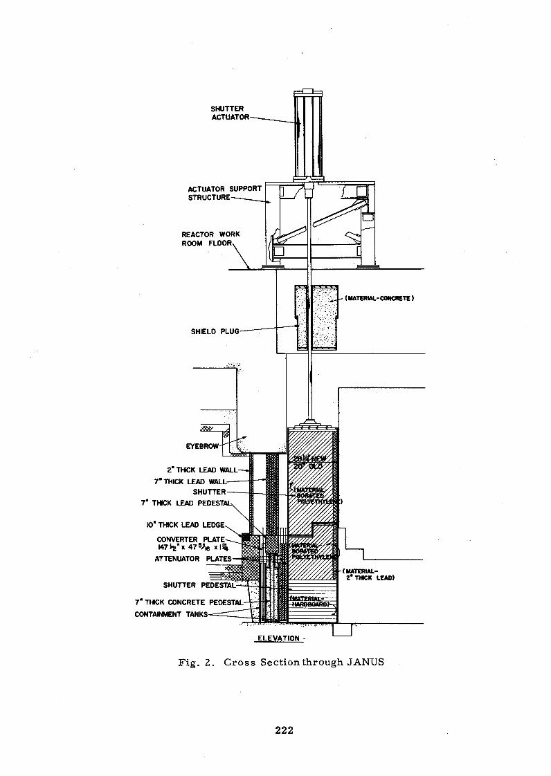
SHUTTERACTUATOR
ACTUATOR SUPPORT STRUCTURE
REACTOR WORK ROOM FLOOR
EYEBROW
2“ THICK LEAD WALL
7" THICK LEAD WALLSHUTTER
7" THICK LEAD PEDEST/
10" THICK LEAD LEDGE
CONVERTER PLATE 147 ^ " x 47V|6 x IÜ4
ATTENUATOR PLATES
SHUTTER PEDESTAL
7" THICK CONCRETE PEDESTAL
CONTAINMENT TANKS
ELEVATION

223
F ig . 3. JANUS G raded Attenuator

224
F ig . 4. JANUS Irradiation R o o m Ceiling


22
6
ALUMINUM TUBE , 10* 0.0. *9$" 1.0.
2 INCH LE AO PUIS I INCH BORAL
ANIMAL EXPOSURE VOLUME
Fig. 6 . Animal Exposure Arrangem ent--A for Neutrons, B for Gamma
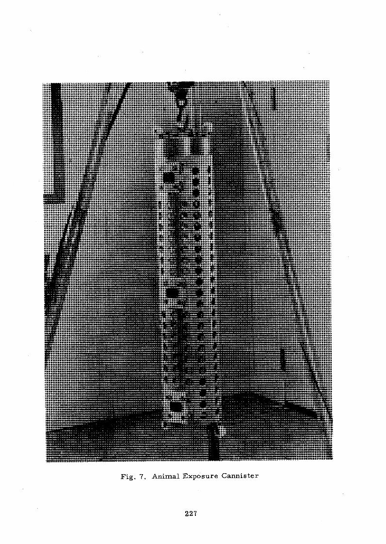
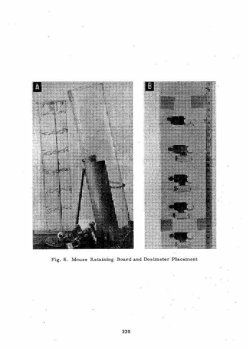
F ig . 8. M ouse Retain ing B oa rd and D o s im e te r P la ce m e n t
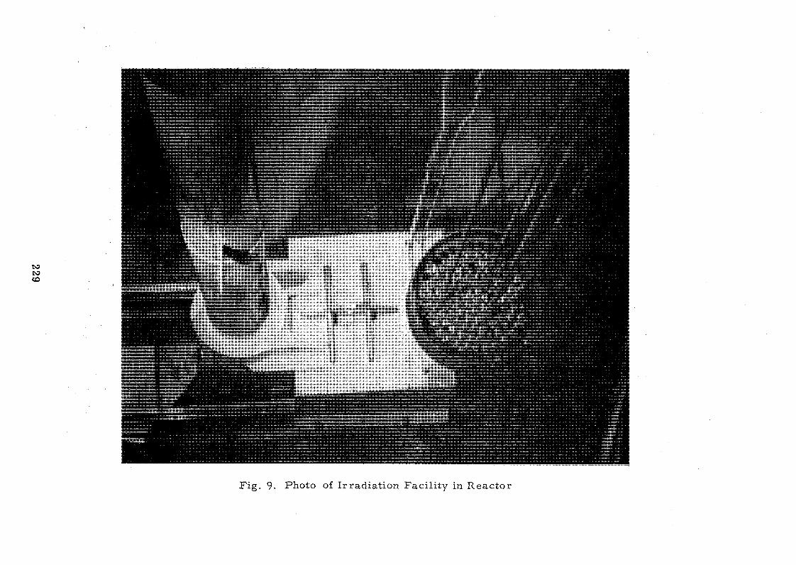
229
F ig . 9. Photo of Irradiat ion F a c i l i ty in R e a c t o r


RESEARCH REACTOR UTILIZATION
ENGINEERING WORK IN SUPPORT OF A NUCLEAR POWER PROGRAMME
by
. S.K. Mehta and S.R. Sastry
Reactor Engineering Division
Bhabha Atomic Research Centre, Trombay,
Bombay, India.
A B S T R A C T
The Department of Atomic Energy of India has committed itself to
a definite programme of building a series of nuclear power plants in India.
This programme calls for a supporting development programme. This report
highlights the facilities available at Trombay for carrying our in*reactor
engineering experiments. The utilization of these facilities so far and
the programmes on hand are outlined.
Introduction
The Department of Atomic Energy of India has committed itself to a
definite programme of building a series of nuclear power plants in India.
The power reactors under construction and proposed to be constructed in
the near future are heavy water moderated, natural uranium f u e M and
pressurized heavy water cooled, i.e. the CANDU-PHW type. The power reactor
programme to be carried out would necessitate maximum indigenous effort.
Such an effort calls for a good research and development programme. This paper discusses the role of the utilization of the research reactors at
Bhabha Atomic Research Centre for engineering studies in support of the
overall power reactor programme.
Research Reactors at Trombay
There are three research reactors currently available at Trombay.
They are:
a) 40 MWt CIRUS Reactor (similar to the original NRX of the AECL,Canada),
b) 1 MWt Apsara Reactor
c) Zero energy ZERLINA Reactor.
Various engineering facilities available in these reactors are elaborated
belowî

a) 40 MWt CIRUS Reactor
This is a heavy water moderated natural uranium metal fueled reactor
with light water in the closed primary heat transport system. The reactor
was built in technical collaboration with the AECL, Canada. Apart from the
thermal columns and the self serve holes there ares
i) 25 horizontal holes of various sizes available for experiments.
These holes extend from the outer face of the biological shielding
.. to the calandria. These horizontal holes are being mainly used for
physics experiments.
ii) Six vertical holes in the calandria, each having a diameter of
approximately 10 cms, which may be used to accommodate test
sections to conduct in-pile engineering experiments. The positions
of the holes in the lattice are shown in figure-1.
iii) One Central experimental hole approximately 13*75 cms i*1 diameter
and called the central thimble for use where high neutron flux is
required and where a relatively large sample or experimental assembly
can be accommodated.
b) 1 MWt Apsara Reactor
Apsara is a swimming pool type reactor with enriched uranium in the form
of MTR type fuel plate assembly. The core is suspended from a movable trolley
and can take various positions in the pool, thus facilitating various types
of experiments to be carried out. There are eight beam holes provided for
conducting a variety of experiments pertaining to nuclear physics, radiation
damage, and biological studies.
In addition there is a shielding corner where the properties of various
shielding materials can be studied.
c) ZERLINA •
ZERLINA is a zero energy pile for lattice studies and has all the
flexibilities to study the lattice parameters of various cores or assemblies.
Engineering Programmes in the Research Reactors
The existing research reactor facilities at Trombay can be used mainly
for the studies in the field of:
i) Fuel Development,
ii) Material testing,
iii) Coolant Chemistry and
iv) Studies in Apsara and ZERLINA

i) Fuel Development
a) Facilities
Mainly the six vertical holes and the central thimble available in the CIRUS reactor, as shown in figure-1, are of immense use to this programme. In
position N-I9» at present, we are installing a "Pressurized Water Loop".
Table-1 gives the details of this loop while figure-2 gives a simplified flow
sheet. Appendix-1 gives a brief description of the loop.
The main loop was designed and supplied by the Atomic Energy Canada
Limited; while the auxiliary facilities were engineered by our organization.
A detailed hazard evaluation of the loop was carried out by us. The hazards
evaluated include the effects ofi
a) equipment failures
b) control failures
c) sequential power systems failures
d) loss of coolant flow
e) loss of coolant
f) in reactor failure of the pressure tube
g) failure of the jacket cooling and the safety of thereactor calandria tube.
The analyses indicated that with no jacket cooling (i.e. loss of
cooling water), the loop operating at the rated conditions of temperature,
and the reactor moderator dumped, the reactor calandria tube temperature is
likely to differentially rise to a stage where it might damage it. As a
safeguard, provision has been made to automatically bring down the loop coolant
temperature to a safe level in a short time. Also the jacket cooling water
system has been connected to the reactor emergency cooling system.
It is obvious that the reactor and the loop by themselves are not
enough to carry out a fuel development programme. The programme in addition
calls for
1) Facilities for the fabrication of test fuel. elements of different enrichments. At present
we are contemplating putonium enrichment for test irradiations.
2) Post irradiation handling and transport equipment and facilities.
3) Hot cells for metallurgical and radio-chemical examination.
For obvious reasons we have chosen to use plutonium enrichment for
test irradiations. We have commissioned our facilities for the fabrication

of mixed oxide fuel pins with stainless steel cladding. The standardization
of procedures for fabricating the pins to the required specifications either
by selective assembly procedures or otherwise has been accomplished. We are
also in the process of equipping the facilities for fabricating Zircaloy clad
fuel pins.
The suspension assemblies, for irradiation of the test specimens in
the loop have been designed and fabricated. The procedure for irradiation and
the loop operation have been decided.
The post irradiation handling equipment calls for procedures and
equipment for the withdrawal of irradiated test pins from the loop, facilities
for post irradiation cooling prior to transportation and transport facilities.
Such facilities for handling irradiated assemblies from the pressurzied water
loop have been designed and fabricated.
For carrying out the post irradiation examination we are commissioning
the hot metallurgical cells. These will be available soon. There are six
hot cells for carrying out the meta,llurgical examinations providing a total
floor area of about 50 square meters. These are provided with the necessary
support facilities. Procedures for loading, unloading, material flow and
testing operations have been worked out. The examinations that can be carried
out are shown in Table-2.
The above facilities in short cater to the needs of loop irradiations.
In addition we have worked out a conceptual design to use some of the vertical
10 cms holes in the CIRUS reactor to carry out capsule irradiations. These
locations are well suited for such irradiation set ups as,, the reactor coolant
itself can be used as the coolant for the specimens and the instrument leads
can be taken out conveniently from the top. The experimental set ups would
be similar to the basket facilities in ETR and MTR. The facilities in the
CIRUS reactor are planned to be used mainly for irradiation of test fuel
specimens to study swelling of fuel elements (both restrained and unrestrained)
fission gas release from the fuel etc., for irradiation of structural materials
at various temperatures and the study of realtor coolants. For the instru
mentation during irradiation, particularly for fuel and clad temperatures, and
the fission gas pressure, it is most desirable to study the detailed behavious
of test specimens under irradiation. The instrumentation of the test specimens
is being planned at a later date, even though this xvould increase the recurring
cost of the experiments.

b) Fuel Development Programme:
Using the above facilities we have chalked out a consolidated fuel
development programme to cater to our immediate needs. Though we have a
working design available with us for the CANDU type reactors we have to keep
up with the changing needs and technology and to equip ourselves to answer the
outcome of operational experience.
Our immediate programme includes loop irradiations (on low enrichment,
up to 4$, mixed UC^- PuC^ samples). The enrichment is added to accelerate
the tests and to achieve the required ratings. The irradiation programme
should be geared to give sufficient data to formulate theoretical models for
design codes. The irradiations should cover standard operating as well as off
standard conditions. The total fuel development programme engulfs the factors
as shown in fugre-3 while Table-3 shows the immediate development programme,
utilizing the "Pressurized Water Loop" in the CIRUS reactor.
To supplement the in-reactor irradiation programme, we also have an
out-of-pile testing programme. We are also developing the fuel design computer
codes. Some of these codes are operative and the rest are being made. The
main points of study requiring a deep understanding in the fuel behaviour are:
1
2
3
4
5
67
89
10
11
1213
14
15
Fuel relocation
Fuel slumping
Plutonium migration or seggregation
Fuel plasticity
Swelling and grain growth
Long terra creep of fuel pins
Dimensional stability
Fuel structure, crack formation and propagation
Void migration
Fission gas release and migration
Fuel ratchetting
Gas plenum temperatures and methods of reducing it
Ridge formation
Long term corrosion and
Effect of fluence on Zircaloy-2 mechanical properties.
ii) Material Testing:
We mainly intend to study the behaviour of clad material, Zircaloy-2,
being used in the CANDU type povjer reactors. Zircaloy-2 so far, has been tirell

established as a cladding material for pressurized and boiling water cooled
reactors. It is still essential to study and understand fully the "behaviour
of zircaloy-2 under various conditions of coolant chemistry, heat flux,
temperature and irradiation. This calls for study of aspects like texture,
hydride orientation, effect of heat flux, temperature and other parameters
especially from the point of view of fracture mechanics. The inpile irradiation
study of clad materials should include:
a) the effect of fuel clad clearances
b) fuel clad interaction
c) the ridge formation
d) the inpile corrosion
e) effect of the water chemistry
f) the effect of irradiation on mechanical properties(creep, fatigue, nil - ductility transition)
Zr - 2 1/2'fo 1Tb alloys hold promise as the pressure tube material. Following data on the in reactor "behaviour is desirable.
a) mechanical properties
b) creep data
c) corrosion properties
The Nuclear Fuel Complex in India will be producing Zircaloy-2 ,
pressure tube. The plant can be utilized for the production of Zr M Nb
pressure tube.
Even though irradiation of the pressure tube (or any structural
material) in CIRUS to a desired level will take a long time, it would be
possible to check the material behaviour after a reasonable irradiation.
However, the Fast Breeder Test Reactor, under design in India, will provide a
better facility for in-reactor material testing of reactor structural materials.
iii) Coolant Chemistry
The water chemistry conditions in a water (pressurized or boiling)
cooled reactor can affect the corrosion behaviour of various components as
well as the behaviour of carrying the activity from the core to the other
components. The study of the behaviour of crud formation on the fuel pins
is of great significance. The coolant chemistry studies programme would
generally include î
a) Methods of water chemistry control,
236

b) Development of techniques for accurate and reliable analysis of samples
c) Studies on the kinetics of reactions of various system component materials including fuel clad under various water chemistry conditions.
Also attempts may be made to develop on line instrumentation for conductivity and pH. Purification systems suitable for high temperature operation could be of great interest.
Various out of pile experiments will have to proceed before inpile experiments on water chemistry are conducted. At present we are studying the methods of water chemistry control and corrosion of zircaloy-2, monel etc. in two out-of-pile water loops. Both loops are designed for 100 bars and 280°C. One of the loops is mainly used for the out of pile acceptance test of the Rajasthan Atomic Power Station fuel bundles and the other for conducting boiling heat transfer experiments.
The inpile experiments are planned to be conducted in the Pressurized Water Loop in CIRUS, described earlier.
iv) Studies in Apsara and ZERLIMA ReactorsThe Apsara reactor was used for various studies on reactor instru—
mentation* irradiation studies on chemical compounds and other non-engineering studies. Por instance studies on the radiation effects on organic coolants (terphenyls) were carried out using one of the beam holes in the reactor.The studies were carried out by irradiating the samples in the temperature range of 200 - 400°C. This was achieved by using a high temperature >irradiation assembly with heaters. Necessary driving mechanisms, temperature control features and cooling arrangements.were provided in the assembly (2,3)«
In the field of reactor instrumentation considerable work has been . carried out by the Electronics Group on ionization chambers, burst fuel element detection, and solid state logic employing Apsara as a tool (2, 4» 5» 6, & 7)»
Void coefficient Measurements:
The design of a heavy water moderated boiling water cooled reactor requires a lot of experimental data on the void coefficient of reactivity.These studies can be carried out in the Zero energy ZERLINA reactor by simulating the voids and their distribution in the unit cell.
Poison Injection System
The present 200 MWe CAIflXJ type reactors adopt dumping of moderator as a safety measure in Case of a failure of the reactor regulating system. In the large stations of 500 MWe capacity it is difficult to achieve the required dumping rates. An emergency poison injection system is used to achieve the objective. Studies on the effectiveness of such an emergency poison injection system are planned to be carried out in the Zero energy reactor ZERLINA. The methods of injection, the rates of injection and their effectiveness are to be studied in detail.
Testing of materials and components under low radiation fields
In the CANDU type reactors, the components of fuelling machines and some of other equipment are housed in areas of low radiation fields. The suitability of the various materials and components such as hoses, seals, drive mechanisms etc. need to be established over their life time. The ■behaviour of such materials can be studied utilizing the Apsara and the CIRUS reactors.
Beferenoe»»
1, Canada India Reactor, AECL 1443
2, Utilisation of a Research Reactor t
10 years of Apsara
3, K. ÏJàrayana Rao et.al«
"Studies on the Pyrolytic and Badiolytic Stabilities of Organio Coolants”AEET/ÖD/20
4« Satyanarayana £, and Bao S.V.R."Ionization Chambers for Reactor Control*1
Paper 37o.CN 22/59» IAEA Conference onHuclear Electronics , Bombay, Hot. 22 - 26 (1965)
5» Prabhakar, B.S. et. al
"Design of an Electrostatic PrecipitatorMonitoring System for Ruptured Fuel Element Detection"»
Third U.K. International Conference on the Peaceful uses of Atonde Energy, Geneva, Aug« 31 - Sept« 9 (1964)

6« Kaaargod S,V*, and Bao K,R.,ttSemi-conductor logic for Reaotor Safety and Interlock Systems"
Report AJEET/SD/SQ/y8 (1963)
7* Kasargod S.V.,
"Solid State Logio for Reaotor Safety System”
Paper Fo. CU/22/40, IAEAConference on Nuclear Electronicst Bombay
Hwrember 22 - 26 (1965)
APPENDIX 1
The pressurized water loop^Fig.^is mainly intended to be used for testing various reactor fuels and to a lesser extent for the evaluation of mechanical components, instrumentation and studies on coolant.chemistry. The loop is installed to investigate the following aspects which affect the fuel elements operating in a power reactor.
a) To study the dimensional and structural stability of various fuel elements.
b) To develop corrosion resistant cladding materials for fuel elements.
c) To investigate the effect of dissolved gases in high pressure, high temperature water on the corrosion of various metals for use in various power reactors.
d) To develop pressure tube and other structural materials used in a power reactor.
The loop is being installed in one of the 10 cms experimental positions (N-19) in the CIRUS reactor. The loop is an installation in which the coolant is recirculated at a preset temperature and pressure over an experimental fuel stringer or any other testing material held in the in-reactor pressure tube or any where in the loop outside the reactor.
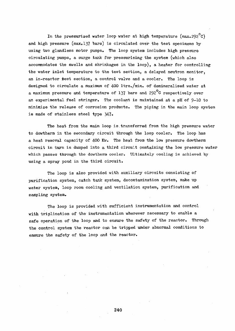
In the pressurized water loop water at high temperature (max.292°C)
and high pressure (max. 137 "bars) is circulated over the test specimens byusing two glandless motor pumps. The loop system includes high pressuré
circulating pumps, a surge tank for pressurizing the system (which also
accommodates the swells and shrinkages in the loop), a heater for controlling
the water inlet temperature to the test section, a delayed neutron monitor,
an in-reactor test section, a control valve and a cooler. The loop is
designed to circulate a maximum of 400 ltrs./min. of demineralised water at
a maximum pressure and temperature of 137 bars and 292°C respectively over
an experimental fuel stringer. The coolant is maintained at a pH of 9-10 to
minimize the release of corrosion products. The piping in the main loop system
is made of stainless steel type 347»
The heat from the main loop is transferred from the high pressure water
to dowtherm in the secondary circuit through the loop cooler. The loop has
a heat removal capacity of 400 Kw. The heat from the low pressure dowtherm
circuit in turn is dumped into a third circuit containing the low pressure water
which passes through the dowtherm cooler. Ultimately cooling is achieved "by using a spray pond in the third circuit.
The loop is also provided with auxiliary circuits consisting of
purification system, catch tank system, decontamination system, make up
water system, loop room cooling and ventilation system, purification and
sampling system.
The loop is provided with sufficient instrumentation and control
with triplication of the instrumentation wherever necessary to enable a
safe operation of the loop and to ensure the safety of the reactor. Through
the control system the reactor can be tripped under abnormal conditions to
ensure the safety of the loop and the reactor.
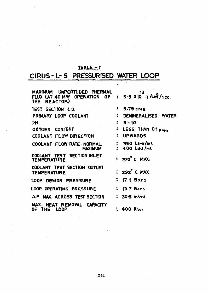
t a b l e - 1
C I R U S - L - 5 PRESSURISED WATER LOOP
MAXIMUM UNPERTÜBED THERMAL 13 2 : 5*5 X10 h /cm/sec.FLUX CAT 40 MW OPERATION OF
THE REACTOR) TEST SECTION 1. D. * 5.79 cmsPRIMARY LOOP COOLANT : DEMINERALISED WATERPH : 9 - 1 0OXYGEN CONTENT • LESS THAN 0*1 i»pmCOOLANT FLOW DIRECTION : UPWARDS
COOLANT FLOW RATE: NORMAL : 350 Ltrs/mlMAXIMUM : 400 Lti-s/m*
COOLANT TEST SECTION INLET 0TEMPERATURE s 270 C MAX.
COOLANT TEST SECTION OUTLET TEMPERATURE : 292° C MAX.
LOOP DESIGN PRESSURE * 17 1 Bams
LOOP OPERATING PRESSURE : 13 7 Bars
A P MAX. ACROSS TEST SECTION : 30*5 itvWi
MAX. HEAT REMOVAL CAPACITY OF THE LOOP : 400 Kw.

242
T A B L E - 2
POST IRRADIATION EXAMINATIONS
A. NON-DESTRUCTIVE INSPECTION
<*) VISUAL INSPECTION BY PERISCOPE
AND TELES C O P E.
Q ULTRASONIC INSPECTION,
c) DIMENSIONAL MEASUREMENTS
LENGTHS UPTO 48* WITH
t/64 QUICK READINGS.
DIAMETERS UPTO 2* WITH AN
ACCURACY OF ± 0 001;
B. DESTRUCTIVE EXAMINATION
a ) FISSION GAS COLLECTION.
b) DECANNING THE FU EL AND
EXAMINATION OF FUEL.
c) COLLECTION OF FUEL SAMPLES
TO DETERMINE BURN-UP ETC.
<L) METALLOGRAPHY.
MICROHARDNESS TESTING
DENSITY MEASUREMENT AND
ELECTRICAL RESISTIVITY
MEASUREMENT.

243
FUEL DEVELOPMENT PROGRAMME
EXPT. d e sc r ip tio n ano PIN tim e OF IRR. DATA TO BE POST IRR. EXAM. RESULTS EXPECTED ORN a PURPOSE INSTRUMENTATION N REACTOR COLLECTED R E M A R K S
MWD* DURWG IRR.
M AT UOxPM CANDU SIZE — . . 1000 OIMENSIONAL CHECK, MAMLY TO ESTABLISH ALL THE50 CvftLONC ONE PM EXAMINATION OF CLAD, TECHNIQUES OF POST «RADIATION
0-521 Cm O IA ) PLUG, WELDS ETC, EXAMINATION.
<$CALORMETRtC FISSION GAS RELEASE
DATA PUNCTURE TEST,
METALLOGRAPHY TOOEOOE CENTRAL
TEtffERATUPE, P » -
V) LOOP WATER DISTRIBUTION-ANALYSIS
CHEMISTRY FOR BURN UP-
2. SAME AS ABOVE WITH TWO « ) ONE PIN SURFACE 4 0 0 0 SAME AS ABOVE SAME AS ABOVE, PERFORMANCE OF SURFACE TEMP.PINS-W ITH ONE W STRU- TEMR ♦ PIN SURFACE THERMOCOUPLES-CONFIDENCE IN
MENTEO PIN $ FLUX MONITORS TEMP. EXTRA-POLATtON IN REASONABLE
(FOILS) LIMITS.
3. U0»-4% Pa 0 » SAME SIZE - d o - 4 0 0 0 SAME AS ABOVE SAME AS ABOVE + EFFECT OF HEAT RATING AND BURN
AS ABOVE DETAILED ANALYSIS OF UP ON METALLURGICAL STRUCTURE,
«9THREE PINS WITH VARY X« AND Kr + GRAIN GRAIN GROWTH AND SWELLING
ING INITIAL FUEL CLAD GROWTH AND SWELLING
GAPS. STUDY.

THER
MAL
C
OLU
MN
SCHEMATIC LA TTIC E DIAGRAM FOR C1R.
M »<eN « a o - n n t n « K c o i o ~ n n < t s « A ------------ -------------- — --------------N G t f l i t M N N I M O f O K M C . T .
©
FIG. 1
C E N TR A L THIM BLE
PRESSURISED WATER
L O O P .
IQ CM. VERTICAL HOLES

245
L 5 - PRESSURIZED WATER LOOP SIMPLIFIED FLOW SHEET
■f lG;2L
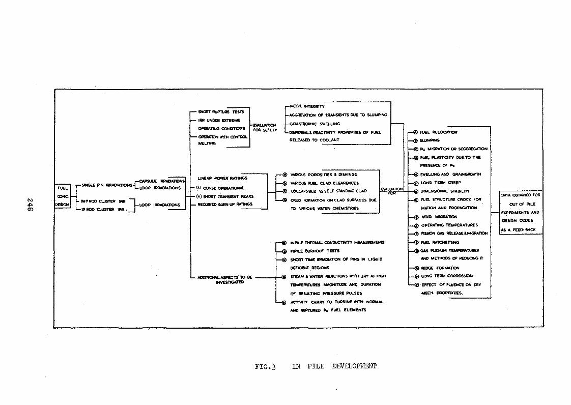
246
FUEL
CDNC.
DESGN
r-p-SftJGLE PIN «¡RADIATIONS-|_
CAPSULE IRRADIATIONS LOOP IRRADIATIONS
- JA7ROO CLUSTER IRR.LOOP IRRADIATIONS
*— t* BOD CLUSTER IRA . __ ] -------------
• SHORT RUPTURE TESTS
IRR. UNDER EXTREME
OPERATING CONDITIONS
• OPERATION WITH CONTROL
MELTING
~£\*LUAT?ON FOR SEFETY
UNEAR POWER RATINGS
* ( « CONST. OPERATIONAL
- ( « ) SHORT TRANSIENT PEAKS
- REQUIRED BURN UP RATINGS
• ADDITIONAL ASPECTS TO BE INVESTIGATED
— MECH. INTEGRITY
—AGGRE VATlON OF TRANS£NTS DUE TO SLUMPING
. — CATASTROPHIC SWELLING
- DISPERSAL t REACTIVITY PROPERTIES OF FUEL
RELEASED TO COOLANT
r— (?) VARIOUS POROSITIES ft DISHINGS
— <D VARIOUS FUEL CLAD CLEARENCES
— © COLLAPSIBLE VtSELF STANDING CLAD
— @ CRUO FORMATION ON CLAD SURFACES DUE
TO VARIOUS WATER CHEMISTRIES
EVALUATION--flST-
p— © INPftX THERMAL CONDUCTIVITY MEASUREMENT»
— Q MPtLE ÖURNOUT TESTS
— (D SHORT TIME IRRAOIAHON OF PINS IN LIQUID
OEFtOENT REGIONS
STEAM * WATER REACTIONS WITH ZRY AT WGH
TEMPERATURES MAGNITUDE AND DURATION
OF RESULTING PRESSURE PULSES
ACTIVITY CARRY TO TURBINE WITH NORMAL
ANO RUPTURED P« FUEL ELEMENTS
r— <§> FUEL RELOCATION
— <g) SLUMPING
— © Pu MIGRATION OR SEGGREGATION
— FUEL PLASTICITY DUE TO THE
PRESENCE OF P»
SWELLING AND GRAIN GROWTH
— 0 LONG TERM CREEP
-Q DIMENSIONAL STABILITY
__ (g) FUEL STRUCTURE CROCK FOR
MATION AND p r o p a g a tio n
— VOI D m ig r a tio n
__Q) OPERATING TEMPERATURES
— ($ ftSSON GAS RELEASE ft MK5RATION
— FUEL RATCHETTMG
— O GAS PLENUM TEMPERATURES
ANO METHODS OF REDUCING IT
— ® RIDGE FORMATION
__ Q LONG TERM CORROSSION
— ® EFFECT OF FLUENCE ON ZRY
MECH. PROPERTIES.
DATA OBTAINED FOR
OUT OF PILE
EXPERIMENTS AND
DESIGN CODES
AS A FEED-BACK
FIG.3 IN PILE DEVELOPMENT

to£>■-J
HOSE COHN.
DECONTAMINAN! PURGE PUMP
L 5 -P -1 0
----!SAMPLE {
FAST FILL PUMP jrL S -P -5 ^
DISPOSAL AREA
* /f f t PROCESS AIR LINES------------------M AK E-UP S Y S TE M L IN E S-------------------CATCH TANK S Y S T E M Llf lES
-frfa------- VALVE WITH EXTENSION HANDLE
S C A -£ -/ / .T ¿ .
LRçln ~ F-S05Cm$2F.
■ewus SERVICE w a te r
L-5 P R E S S U R IZ E D WATE.R LD DP S IM P L IF IE D FLOW S H E E T
ù k N . \X.Hk 'D.\a PP'D ;
\r>M.S. S.
FIGURE 4

POWER UPGRADING OP THE TRIGA MARK II REACTOR
PROM 25O kW TO 1000 kW
by
Soetarjo Soepadi,Ijos Subki, and Karsono Linggoatmodjo
Bandung Reactor Centre Indonesia
Abstract
The current utilization of the TRIGA Mark II reactor and its future programme are described» Upgrading the reactor power to 1000 kW, will increase its capacity to supply isotopes for various applications and significantly support the research and engineering programmes related to the reactor.
The major modifications to the reactor as well as the phases of the upgrading are also described. The modifications, installations, criticality and commissioning tests will be executed by the local staff.
1. INTRODUCTION
The Triga Mark II research reactor at the Bandung Reactor
Centre, National Atomic Energy Agency, has been in operation for
more than 6 years. Since its first criticality and commissioning
in October 1964, the reactor has been available for operation up to
25O kW maximum power.
The reactor has been utilized for isotope production, research
and training purposes. The current applications of the reactor
have been briefly described in reference /l/.

The present reactor operating power level will not be sufficient
to supply the foreseen isotope demand for various applications. More
over, the present power and neutron flux could not properly support
the neutron inelastic scattering research as well as the engineering
programme related to the reactor.
Feasibility studies were conducted and it was concluded to
upgrade the reactor to 1000 kW with no appreciable changes to the
reactor systems.
II. MAJOR CHANGES FOR UPGRADING
The programme to upgrade the reactor from 250 kW to 1000 kw is
aimed at obtaining a higher flux to accomodate new research using
neutron beams including engineering research, but with the following
constraints in mind, that the cost of upgrading as well as the reactor
operating costs would be minimal.
This requires at least the following changes to be undertaken.
Core and core components
The present fuel of the TRIGA Mark II reactor is aluminium
cladded UZrH^ q fuel, which is limited to a steady-state operating
power of 25O kW. The reason for this is that UZrHn _ has a phase1 *u
transition at approximately 530 C. In order to avoid any dimensional
changes of the fuel which may occur at this phase transition tempera
ture, the reactor is limited to operation at a maximum power level
of 25O kW.
For reactor operations above 250 kW, a new stainless steel
cladded UZriL , core would be required. This fuel has a singleo
phase up to temperatures above 1000 C. As a result, the operation
is not limited by a phase transition such as the UZrH^ q fuel.
By retaining the present F-ring grid plate with 85 fuel positions,
the operating flexibility as well as the irradiation positions would
be more limited as compared to the use of a G-ring plate. Therefore,
we will install a new larger G-ring plate,/'wl®^ will be able to accomo
date 121 fuel positions. The use of this grid has the following ad
vantages: it permits the reactor to be run fou an extended period of

time and additional fuel elements can be added as required without
necessitating the removal of fuel elements, the larger fuel-to-fuel
distance in the central positions (B-ring) permits better cooling,
this hexagonal central section in addition to two groups of 3
elements are removable allowing larger samples to be inserted in
in-core positions.
The use of 4 fuelled follower control rods (FFCR) will permit
a smaller compact core arrengement, and assist further in extending
the core lifetime.
It is also necessary to replace the existing reflector with
a reflector having a larger inside diameter so as to permit the
installation of the larger size grid plate. This new reflector has
been designed to permit the utilization of the existing rotary
specimen rack. *
Cooling systems
The 1000 kW reactor will still use natural convection cooling,
but operation at powers higher than 1000 kW will need forced cooling
to piieclude incipient boiling in the core.
The new primary cooling system will use 4” diameter aluminium
piping with a 15 hp stainless steel pump to drive a flow rate of the
order of 350 gpm, while the secondary system will use 6 M steel piping
with two 20 hp pumps in series, and a new 1000 kW cooling tower which
will also be installed. The system will keep the bulk coolant tem
perature below 45° C.
Control system
As has been mentioned earlier the use of fuelled follower control
rods will be quite advantageous. It will then onty require an additional
control rod drive and the corresponding position indicator on the con
sole.
Other modification to the console will include the adjustment
of the linear, logarithmic and percent power indicator to the 1000 kW
full scale.

Adequate preparation and procedures have been laid down to
assist the personnel in the execution of the upgrading programme.
The outline of the operations will be described.
Removal of TRIGA Fuel
The irradiated fuel in the tank will be removed to the bulk
shielding facility (temporary storage) using the shielded fuel
transfer cask. Special care should be exercised to eliminate any
possible over-exposure to the personnel during the fuel removal and
to prevent any possible criticality in the temporary storage.
Dismantling of basic reactor components
The basic reactor components should be subsequently dismantled,
these consist of: central channel assembly, control rod drives, pneu
matic system, rotary specimen rack, central channel plate and central
thimble.
The reactor pool water will then be drained through the waste
treatment tank, a careful survey will be exercised since radiation
still exists due to activation of reactor components. Then the
following procedures will be executed: dismantling and lifting of
the piercing beam port!s bellow assembly and reflector. All active
components will be placed in the storage pit.
Dismantling of the cooling system
The preparatory work will proceed with the dismantling of the
primary cooling system, the purification system, and the secondary
cooling system with its existing cooling tower.
The upgrading phases will now be started with a thorough in
spection of the reactor tank?surface, welds, beamports, and the
thermal column to check any damage or crack.
Core assembly
The core reflector assembly will be assembled outside the
reactor tank, this work will cover installation of the ion chamber

guide tubes and securing the top and bottom grid plates. The re
flector assembly will then be lowered into the tank and set on
the tank bottom. The top grid plate will be levelled, and the re
flector assembly port aligned with the piercing beamport. The core
assembly will then be completed after the execution of the bellow
assembly leak test.
Cooling systems
The piping for the primary as well as secondary systems will be
installed without any welding, since the piping will be coupled
together using flexible connections. The basic diagrams of the pri
mary and secondary systems are shown in Figs. 2 and 3 . The installa
tion of the cooling systems will be completed with watertightness and
flow rate tests.
Control systems
As has been mentioned earlier there are no major changes in the
control systems except for the followings use is made of 4 fuelled
follower control rods instead of the 3 existing control rodsj the
linear, logarithmic and per cent power channels will be adjusted to
the 1000 kW full scale and an additional position indicator will be
placed in the control console.
Pre-operational and operational tests
Prior to the criticality experiments all the control channels,
safety systems, interlocks, and control rod drives will be
thoroughly checked out. The neutron source for reactor start-up
is a 3.56 Gi Am-Be source.
After the criticality experiments the reactor will then be
loaded with 82 stainless steel clad fuels to achieve an excess re
activity of around $ 7»0
Control rods calibration will then proceed to obtain the
calibration cruves of the rods and determine the available excess
reactivity.
Power calibration will be followed step by step at power tests
up to 1000 kW, the instruments linearity, and the reactor tank

water temperature rise will be observed; and health physics sur
veys around the reactor deck, the reactor bridge, the piping system
and the demineralizer should be carried out. The particulate air
monitor should also be on line throughout the tests to detect any
possible fuel leak.
Since the reactor will be capable of operation at 1000 kW,
more attention should be given to reactor safety aspects to limit
any possible hazard to the surrounding and to the personnel.
Accordingly, new operating procedures and regulations are being
adopted.
17. SUMMARY
The power upgrading of the TRIGA Mark II reactor at the Bandung
Reactor Centre from 2^0 kW to 1000 kW has started with the prepara
tion of procedures and necessary tools to expedite the execution
of the programme. Prior to this activity close communication with
Gulf Energy & Environmental Systems (GE & ES) has been conducted in
order to obtain technical information and to procure the necessary com
ponents .
The upgrading programme will be executed by the local staff
and it will be completed in approximately six weeks time.
The upgraded reactor will not pose any special safety problems,
major probable accidents and their consequences have been evaluated
in the Reactor Safeguards Analysis Report.
References
/l/ Ijos Subki et al.,
"Six Year Operating Experience with the TRIGA Mark II
Reactor at .Bandung Reactor Centre"
Proceedings of the IAEA Study Group Meeting on Research
Reactor Utilization convened in 1971 in Bandung.

Irradiation Space
Source
IternateSoureeLocation
Irradiation¡pace
PneumaSystem (Rabbit)In - core Terminus o Standard Fuel
Element
Graphite Dummy Element
G-ring grid plate
Control Rod

TEMPERATURE
s «PILL
PUMP
X J
TEMPERATURE - ®p i ™ i
.WATER SURFACE SKIMMER
l-Dí XVENT —
sHOLES
DIFFUSERCONE
r.1- RES» j SUPPLY
V I CONDUCTI
©20 a m ,l-l n r
VITI CELL ]
u 'f i r L ------- !— iyjEMINERALlZERI
T *> I CONDUCTIVITY CELL |I • — ----1- ■■■ -II____ J (i- iRESINDISCHARGE
REACTOR
350 gpm
I
-JÄJ-
FLOW METER
vept ff.ll
i
CUSTOMER* IFURNISHED ,
-fCTi
! STORAGE TANK | I (OPTIONAL)
110° F
AHEAT EXCHANGER
20_£ CUSTOMERFURNISHED
I. SECONDARY ,
COOLING , 80 Pj__SYSTEM I
90* F
J--------1 I f-
350 GPM ^ 4 IN
ríaFI*. 2
L E S E N D --- ---
THROTTLING VALVE
s h u t - Off v a l v e
^ o r i f i c e
^ PRESSURE GAGE
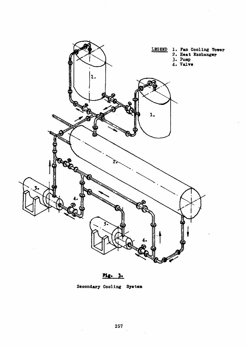
LBQBKD 1. Fan Cooling Tower 2» Heat Exohanger 3. Pump 4« Valve
n * .
Secondary Cooling System

byLibrado D. Ibe
Acting Commissioner Philippine Atomic Energy Commission
andGuillermo C. Corpus
Head, Reactor Operations Department Philippine Atomic Research Center
ABSTRACT
The Philippine research reactor PRR-1 became critical in 1963. After one year of testing and low-power operation, the reactor was .brought to full power of one megawatt. The PRR-1 is utilized for radioisotope production, sample irradiations, physics experiments and training of personnel. Some operational difficulties encountered are also discussed.
INTRODUCTION
The Philippine research reactor PRR-1 is an open-pool type
facility designed for an initial operation up to one megawatt thermal
power level. It is operated by the Philippine Atomic Energy
Commission. The reactor facility is located within a 9-hectare lot
inside the campus of the University of the Philippines in Diliman,
Quezon City.
The PRR-1 reactor core is made up of 30 MTR type full ele
ments arranged in a 5 x 6 array and completely surrounded on the
sides by graphite reflector elements. Four 10 5 /8 inches wide
boral coarse control blades virtually divide the core into three
blocks - a central block of 3 x 6 array and two side blocks each, of 1 x 6
array. For fine and automatic control, a regulating rod is provided.

Radiation baskets, of the game s iz e and shape fuel and reflector ele
ments, are also provided to permit irradiations in the reactor core
and reflector regions. Other in-core experimental facilities include
two 2 -inch vertical dry-pipes.
The reactor assembly is submerged in an aluminum-lined
concrete pool and supported by a suspension frame attached to a
movable bridge mounted on top of the pool parapet« The pool is
divided into three sections - a high power section where reactor
operation up to one megawatt is possible, a transition section and a
low-power section where the reactor could be operated up to 100 KW
only. Draining of the low-power or high-power perol section, could
be accomplished with the aid of a portable bulkhead, gate and suitable
pumps.
Most of the fixed experimental facilities are located in the high
power pool section. These include six radial beam tubes, two pneu
matic tube systems and a graphite-filled thermal column.
Initial Operation of PRR-1
The construction of the reactor building and reactor pool was
started in late 19él. When the structure was almost complete, the
facility major equipment were brought inside and installed at their
respective places. The assembly of the reactor core components
took place immediately thereafter. On August 26, 1963, the PRR-1
became critical for the first time.
During the whole period of construction, radiation surveys
to establish background levels were conducted at various stations

around the reactor site up to a radius of 10 m iles. Radiation moni
toring was continued even during reactor operation at regular inter
vals. The results showed absolutely no increase in the environmental
radioactivity levels in all areas outside the reactor facility compound.
The first year of reactor operation after attainment of initial
criticality was mostly utilized in the instrument checkout, equipment
performance tests experimental determination and verification of
reactor parameters, core flux mapping, and reactor operator train
ing. During this period, reactor operation was kept raised at
practically zero power level and later on to not more than 100 KW.
Utilization of PRR-1
In August 11, 1964 the reactor power level was brought to
one megawatt. Since then, the PRR-1 has been operated at different
power levels up to one megawatt to meet the demands and requests
for (a) production of radioisotopes, (b) irradiation of samples,
(c) physics experiments and (d) training courses.
Two of the experimental beam ports are presently tied up
with the two neutron crystal spectrometers used for the physics
experiments. These spectrometers were initially utilized in the
India-Philippines-Agency (IPA) project on neutron spectrometry.
This project lasted for five years and was terminated in late 1969.
The PRR-1 is further utilized in the training of local scien
tists and technologists in reactor engineering. These trainees
consist mainly of university faculty and technical personnel of
electric power utilities. A specific course on reactor operation
was recently conducted for the engineers of the Manila Electric261
Company (MERALCO). MERALCO, the largest private electric
utility in the country, has shown active interest in putting a nuclear
power plant in the very near future.
On« important investigation that was made possible with the
use of PRR-1 is the verification of the U-235 contents of the 20 new
fuel elements for the second-core received from the fabricator* s
shop in the United States. By placing a new fuel element at a
specified position in the reactor core of given configuration and
measuring the change in resulting reactivity, the corresponding
U-235 content of said element was calculated. With this method,
the experimental values obtained for all the new fuel elements
were found to he very close to the figures supplied by the fabrica
tor, the discrepancies ranging from 0. 2 to 2. 5 per cent. These
results made us conclude that no appreciable impurities with
"poison** characteristics have been introduced in the fabrication
of said fuel elements.
Operating Problems Met
The performance and utilization of PRR-1 has so far been very
satisfactory, with no incidence of any nuclear accident. Its almost
perfect operation is marred only by occasional unscheduled shut
downs due to equipment failure, instrumentation difficulties, and
power outages. Some of the operational difficulties encountered
are:
1. Rattling and/or failure of the heat exchanger tubes;
2. Vibration of control blades;
3. Abrasion of detector cord;
4. Failure of the compensated ionization chambers;
5. Dropping of control blades without an instrument scram;and
6 . Power measurements.
Failure of Heat Exchanger Tubes
The heat exchanger used in the reactor cooling system is a
1-Z shell-and-tube type designed to cool 170© gpm of primary water o °
from 114 F to 110 F. It contains 266 3 /4 - inch aluminum tubes bent
in a U-shape form with the ends welded to a single tube sheet which
is an integral part of the primary water manifold. The tube bundles
are supported throughout their lengths by the tube sheet and 4 equally-
spaced cross baffles. A 120-ft head centrifugal pump circulates
1700 gpm water in the primary side and another pump forces 1250
gpm on the secondary side outside the tube bundle. During the
testing of the heat exchanger for the calibration of the primary
and secondary flow instruments, the following observations were
noted:
a. With no flow on the primary side, the equipment started
to rattle at a secondary flow of about 500 gpm. The
rattling intensity increased as the flow rate was in
creased.
b. Although the secondary flow rate was kept steady, the
sound came on and off with no apparent regularity. The
bursts of sound were generally short and abrupt. Longer
and louder bursts were heard at secondary flow rate of
about 1300 gpm.

c . With the secondary shell drained completely and prim ary
•water allowed to flow into the tubes, no rattling noise
was heard.
d. With flow in the primary and secondary sides, the same
observations in (a) and (b) above w ere again noted.
The cause of rattling was pinpointed to the tube bank itself. Upon
inspection, the U-tubes were found to be loosely supported at the
baffles and could vibrate. In addition, the tube bundle itself seemed
to have been factory-installed 180 out of alignment with respect
to the inlet and outlet secondary water connections. On the sus
picion that said factory defect could be the principal contributory
cause of the vibrations, the heat exchanger was reassembled witho
the bundle rotated 180 # After one-and-a half years of operation,
the tube bundle has to be pulled out again due to intermixing of
secondary and prim ary water. Six (6) U-tubes on the side closest
to the secondary inlet opening were found leaking, establishing
the failure caused by repeated pounding of the tubes on the baffle
holes. These tubes were subsequently plugged. To minimize
further damage to the other tubes, a rubber band was wrapped
around the bundle to minimize their movement in the baffle holes.
As there was no access to the inner tubes, the rubber band could
only protect the peripheral tubes. Operation of the heat exchang
er was thereafter relatively more quiet, but 3 years later a tube
situated 3 layers inside the bundle failed again due to vibration.
It appears that the rubber banding of the outer tubes helped to
some extent in minimizing tube failures.264

Vibration of Control Blades
Another vibration problem encountered is that of the four
control blades whose movements are guided by an aluminum
shroud. Each blade is 3 /8 n thick, 10 5 /8 " wide x 54 l / 8 " long.
The shroud is made 1 / 4 inch wider to give a clear 1 / 8 inch space
on either face of the blade. Trouble starts when reactor control
is on automatic mode at power levels in excess of 100 KW. Under this
condition of operation, the primary coolant flow of 1 7 0 0 gpm causes
the four blades to vibrate within the shroud and results in power
fluctuation. As initially set, the servo system, corrects the power
thru the movement of the regulating blade at power variations ex
ceeding 2%. This condition caused too much strain on the regulating
blade drive motor which had to keep on changing its direction of
rotation as many as 50 times a minute. The motor temperature ex
ceeded allowable lim its and the blade drive actuating relay suffered
frequent breakdowns. As it was not deemed advisable to reduce the
free space between the control blades and the shrouds since the
emergency dropping of the blades by gravity may be affected, the
remedial measure resorted to was to adjust the automatic response
of the servo system to ^ 4% of operating power. For irradiations
requiring very close degree of neutron flux control, regulating
blade operation is done in the manual mode.
Sealing of Pool Bulkhead Gate
The reactor pool has been designed and constructed so that
an aluminum bulkhead gate with a pheripheral rubber seal could
be installed between any two adjacent pool sections for dewatering
265

a section of the pool. Before a section could be dewatered, the
rubber seal must first be made to press tightly against the gate
seat after which a 20-gpm portable centrifugal pump gradually
pumps the water out. Establishment of the water seal for evacua
tion of the high power pool section is easily accomplished by utili
zing an 8-inch prim ary coolant pipe to discharge by gravity flow
the high power pool water into a 15,000-gallon retention tank. The
dewatering of the transition and low-power pool sections, however,
is not as easy. There is no big drain pipe in these sections which
could be utilized to discharge water fast enough and establish the
necessary seating head. In order to effect the sealing of the bulk
head gate, the water level in the pool is first lowered by about one
foot, then a gate valve in the 8-inch return pipe from the pool to a
3000-gallon holdup tank is closed to prevent pool water from flow
ing back into this tank. The 1700 - gpm primary coolant pump is
switched on for about 10 seconds to suck water from the holdup
tank and discharge into the high power pool section. The large
volume of water that goes into this pool section provides the dif
ferential head to seal the gate. A portable pump pool section to be
drained is subsequently operated to complete the dewatering opera
tion. To avoid collapse of the holdup tank due to negative pressure,
all drain and vent pipes connected to it are kept open and serve as
passages for the on rushing replacement air. Although the scheme
has worked successfully several times in the past, the operation
is still not totally satisfactory in view of the strain, on the holdup
tank. Another method whereby a portable tank in the section to266

be dewatered will be pulled up by the existing overhead crane for
the establishment of the required sealing head is under considera
tion* In addition, the 20-gpm pump is planned to be replaced by
a bigger semi-portable dewatering pump.
Abrasion of Detector Cords
In the PRR-1, there are two startup channels with movable
neutron detectors for a wider coverage of startup power. A s power
increases the detectors are raised towards the region of low neutron
flux. The BF 3 startup detector is moved by remote control from
the control room while position of the other detector (fission chamber)
is adjusted manually. After five (5) years of operation, the BF 3
channel failed due to abrasion of the flexible cord connecting the
detector to the external terminals at the top end of the core suspension
frame. The cord insulation was damaged by the constant rubbing of
the cord with the detector drive stem and against the housing. To
correct this defect, the detector cord was made to pass thru a small
stainless steel pipe and both detector and pipe caused to move as a
unit. A hole on the top of the suspension frame guides the pipe in
proper position. With this arrangement rubbing of the cord against
the drive stem or housing was eliminated.
Failure of CIG*s
Two of the compensated ionization chambers that send power
signals to the two safety channels and the log N channel have already
failed due to water leaks into the chamber terminals. Apparently,
the 25 feet head of pool water acting on the submerged cable and

plastic seals is high enough to force water into the chamber. When
the first CIC was damaged, the installation was modified by screw
ing the chamber onto a long dry pipe. This pipe extends beyond the
pool water surface and the cables were ran through this pipe.
The field-repaired CIC lasted for about two years and then
failed again. It was decided to return it to the manufacturer for
factory inspection and repair.
Early this year, another CIC also failed, giving symptoms
similar to that of the first CIC. In order to ascertain the real
cause of trouble and because of the urgency of the situation, it was
decided to open the chamber in the field and try to make the neces
sary repairs, if possible. Our findings show the chamber failure
to have been caused by the cracking of the ceramic insulator at
the cable connectors. A substitute sleeve assembly is being fab
ricated at present and, as soon as reconnections are made, field
welding of the aluminum chamber housing will be done. In the
meantime, the reactor operation up to 500 KW is allowed with the
use of the remaining two CIC*s in the safety channels and the BF 3
detector utilized for period indications.
Dropping of Control Blades
We experienced some incidents where all four (4) control
blades would just drop without instrument scram, despite the
cleanliness of the magnet armature in contact with the electro
magnet. The cause readily escaped detection due to its transient
nature and there is no visible indication in the annunciation panel

except the "blade disengaged” light. At one instance, the same .
event happened and, in addition to the "blade disengaged" light,
the'fcoolant gate" light also went on. This made us to suspect
that the 24-volt D. C. circuit serving the coolant flap gates was
at times momentarily noisy and would cause the dropping of the
blades without a scram. These flap gates, installed one each
on the inlet and outlet primary coolant pipes, are connected to
float switches. They are normally half-closed but are fully
opened when the coolant flow is about 1700 gpm. The setting of
the float switch could be unstable especially since the movement
from half-closed to fully open flap gate position is extremely
small. To remedy the situation, the flap gates were re-adjusted.
Power Measurement
Due to the semi«enclosed nature of the primary cooling
system of the reactor, no reliable power measurement could be
made from temperature changes of the coolant. Besides, the re»
actor power is too low for thermal power measurements. In order
to provide a neutron-flux-independent power instrument, the gamma
sensitive detectors mounted on the thermal column and in the pri
mary cooling pipe were calibrated against reactor power. At full
power operations, reading of these remote area monitors were
found to be constant. Hence the instruments are used regularly
to check the neutron flux power.
CONCLUSION
The current experience with PRR-1 is believed not unique
to the Philippines but may be typical for a developing country.
269

The reactor facility not only provided with a modern tool for
research but also afforded opportunities for the advancement of
science and technology in the country. Perhaps the greatest
accomplishment of PRR»-1 is in the conditioning of the public
mind regarding the safety of an operating reactor. The PRR-1,
once feared, is now practically accepted by our people. This
experience could influence to some extent the eventual establish
ment of nuclear power plants in the country.

SIX YEARS OPERATING EXPERIENCE WITH THE
TRIGA MARK II REACTOR AT THE BANDUNG REACTOR CENTRE
by
I. Subki and K. Linggoatmodjo
Bandung Reactor Centre Bandung - Indonesia
Abstract
The utilization, operation and maintenance of the TRIGA Mark II reactor at the Bandung Reactor Centre is described. The reactor is utilized for isotope production and its research application is increasing steadily every year. The main reactor operation problems come from instrument failure or from the rotary specimen rack. No safety hazard to the surrounding population and personnel has occurred since its first criticality in 1964*
The total integrated reactor power up to the present is about 2 x 10 kW-hours.
I. INTRODUCTION
J The TRIGA Mark II reactor at the Bandung Reactor Centre,
National Atomic Energy Agency, has been operating regularly since
1965. This reactor uses aluminium cladded cylindrical fuel, con
sisting of 8 Wt io uranium, 20 $ enriched in U-235» homogeneously
mixed with zirconium hydride as moderator. The MARK II reactor is
of the above ground and fixed core type, with four beamports, one
thermal column and one bulk shielding facility, available for various
experiments.
The first criticality was achieved in October 1964» and no
major troubles were encountered during the execution of the tests.
After the calibrations and the power tests were completed, the reactor
has been available for operation up to 250 kW maximum power level.
Up to the present (l5 June 1971) the reactor has logged a total
integrated power of about two million kW-hours or 83.5 MW-days. '
,-1,'he Physics Division has been using the tangential beamport for
neutron diffraction studies with a crystal spectrometer, which in
cludes crystallography, magnetism and alloysystems. This project
has picked up a great momentum since the arrival of our physicists
from their training abroad in 1969• Future upgrading of the reactor
power to 1000 kW will enable the execution of meaningful research in
inelastic scattering using a Beryllium Detector System.
The Reactor Physics Division is working on the measurements of
reactor data, in-pile dosimetry, flux mapping and establishment of
power and control rod calibration methods, all of which have been
quite useful in the safe operation of the reactor. Work on reactor
noise in the frequency and time domain is in progress.
The reactor has been used by the Chemistry Division for research
in hot atom chemistry and activation analysis. Hundreds of
samples of crude oil. tin ores, fertilizers, hairs of kwashiorkor
children^, and other mineral ores have been irradiated in the
reactor for analysis.
A group of researchers from the Biology Division uses one
beamport for the irradiation of drosophylla and various insect
pests. Their work is directed towards integral pest control.
Another group of researchers uses the bulk shielding facility
for thermal neutron irradiation of seeds and seedlings, and the
Standard TRIGA Irradiation Facility (STIF) in the thermal column
for fast neutron irradiation in the mutation breeding project.
The use of the reactor for training purposes has increased
every year. The Reactor Operator's training has been conducted
four times, most of the trainees consist of members of the local
staff and students of the Bandung Institute of Technology. A
course in radiochemistry and neutron activation analysis was con
ducted in 1970, staff members from various companies and local
staff as well as chemistry students from the Institute attended
this course. A course in reactor technology is regularly conducted
to upgrade the operation and reactor physics staff; it also serves
as a part of the graduate study at the Institute of Technology.

By far the most intensive use of the reactor is in the production
of short lived radioisotopes to supply various research needs and
which find its applications in industry, hydrology and nuclear
medicine. At present 26 different radioisotopes are produced regu
larly.
The reactor utilization for research pruposes has been increasing
annually, nevertheless it is still far from saturation. Utilization
of the reactor by universities and other research institutes is still
meagre. Furthermore, it should be noted that diversification of re
search and other applications of the reactor is limited by the present
available neutron flux.
III. OPERATING EXPERIENCE
Operating data
The reactor has been operated at steady state power only, mostly
at 25O kW. The pulsing operation will be included in the future up
grading programme. The reactor core performance has been quite satis
factory, no fuel element has been found to leak during the 6 years of
operation, fuel bowing and elongation pose no problem, this among
others might be due to the fact that we are not operating in the
pulsing mode.
At the present time, the reactor is utilized for isotope pro
duction and research work from Monday through Friday, while it is
reserved on each Saturday for weekly check and nuclear reactor ex
periments for graduate students. As a normal practice, the reactor
is operated continuously 72 hours per week.
This schedule is supported by the operating crew on a 3 shift
basis, each shift consisting of one supervisor and 2 operators.
Table I shows operating data and reactor utilization from 1965
to I97O. In I97O, it can be seen that reactor utilization time for
isotope production is 10Q $ while for research and training it is
approximately 50 Ía ami 25 i<> respectively.

Table I
Operating data from 1965 to 1970
Year 1965 19 6 6 1967 1 9 6 8 1969 1970
Total operating time 242 427 826 IO99 2965 3252(hours)
Total energy generated 4 8 , 5 8 6 91,766 182,927 2 6 9 , 0 6 5 540,350 577,775(kW hours)
Burn-up U-235 (grams) 2.5 4-5 . 9-6 13.98 28.0 30.0Utilization time fors
(hours)- isotope production 242 427 826 1099 2466 3252- research - 107 207 330 1245 1 6 2 6- training 50 64 124 265 741 813
Core physics data
Reactor operation began to be very intensive in 1968/1969 when the demand for isotopes increased significantly. In 1969 the reactor
could not operate continuously at 250 kW for more than 11 hours,
the main reason was the loss of reactivity due to fuel burn-up,
eventhough Xe-poisoning and temperature effects contributed to this
reactivity loss. It was then decided to procure new fuel from
Gulf General Atomic.
In September 1970 the reactor was reloaded in the central position
with 4 new stainless-steel clad, high hydride fuels. The core excess
reactivity of the reloaded core was measured to be $ 3.90. With the
present measured reactivity loss of 2.50 cents per MW-day, we pre
dicted that the reactor would be able to operate continuously at
25O kW for 72 days. This turned out to be true.
The control rod worth is calibrated routinely by the inhour as
well as by the rod drop techniques. During the six years of operation
the worth of each control rod did not change more than 10
Power calibration is done routinely by the heat generation measure
ment method to check instrument drift in the Í» power channel as well as
in the linear channel. This calibration was frequently done due to
the frequent unloading of the Rotary Specimen Rack (R.S.R.). Under
the unloaded condition (the R.S.R. diassembled) the chamber's sensi
tivity is reduced significantly due to the modified flux distribution

in the core. Under these circumstances operating the reactor at 80 ’fo
as indicated by the meter will mean that the actual reactor power
would be 4OO kW instead of 200 kW. Thus in this case power calibra
tion is a necessity to insure safe operation of the reactor.
IV. MAINTENANCE PROBLEMS •
Instrument troubles
As far as core performance is concerned the reactor has been
operating quite satisfactorily. The reactor's availability is
dependent only upon the performance of the instruments, auxiliary
systems and the irradiation devices.
The control instrumentation has caused a lot of operating delays
and reactor shutdowns. In brief, the causes may be classified as:
imperfect design, lack of locally available spare parts and environ
mental conditions.
The dual-pen Westronics recorder for linear and logarithmic
power indication has failed frequently. Bad contact in the slide
wire caused oscillations and frequently spurious scrams. Routine
cleaning of thfe slide wire could only relieve the symptoms. We have
replaced this slide wire with a locally made substitute. The
synchrovèrters and electrometers should be replaced periodically,
but they are not locally available. Other source of problems are
the input signals that this instrument feeds to the period meter and
to the servo system. We also think that the recorder scram setting is
not necessary since it does not insure safety, it has also been veri
fied that the period channel scram has a much faster response to
start-up accidents. ■
Troubles in the rod position indicators have also been noticed,
this was mainly due to failures of the interstage transfôrmer
(Triad TY55^) and transistors (2N652).
One compensated ion chamber (Westinghouse) was replaced with a
spare chamber after operating for more than 5 years. This chamber
feeds the log N recorder.

The rod drive assembly for the safety rod was replaced due to a
serious damage in the pinion-rack system. Ho major trouble has ocurred
after the replacement.
Minor troubles such as cable leaks, worn-out switches, etc.
have occurred in the period and log count rate circuits. Such
troubles also cause start-up delays because they are sometimes diffi
cult to detect.
The neutron source is related to the instrument's sensitivity.
The Po-Be neutron source which was installed in 1964» does not supply
sufficient neutrons for start-up. However, since our operation
schedule is rather intensive, we could start-up the reactor safely
with the available photo-neutrons, provided we know beforehand the
critical positions of the control rods.
Auxiliary system troubles
No major difficulties have been encountered with the primary
as well as secondary cooling system. However, the Weinmann pump in
the primary circuit has been replaced, due to a small leak through
a graphite gland seal. The primary cooling water is maintained at
pH values of 5*5 - 6 . 5 and the conductivity value is about
1 micromhos.
Routine maintenance work on the secondary cooling water system
(city water) is done every six months to prevent algae and mud de
position in the heat exchanger. For this purpose we have used a
cleaning solvent called VEC0M-200 made by Vecom International, Belgium.
The results have been satisfactory. Fig. 1 shows the performance
of the cooling system when the deposit exists in the heat exchanger
(upper curve), the curve shows a faster increase in bulk coolant
temperature as well as a higher equilibrium temperature; the lower
curve shows a better performance of the exchanger. Fig. 2 shows the
performance of the heat exchanger (after cleaning) at peak power level
of 25O kW, the temperature of the coolant is kept below 50° C.
Irradiation device
The rotary specimen rack (Lazy Susan) began to fail in the second
year of operation. The main problems we have encountered are the dry

■ban-bearing, the loose drive shaft joints and the locking shaft.
The first Lazy Susan was disassembled four times due to the dry
ball-bearing and the drive chain. Galling of the lubricant under high
temperature and irradiation might be the cause of the trouble. Every
time the Lazy Susan was taken out of the core, it was cleaned with
acetone and thereafter reinstalled into the reactor. In 1968 galling
again occurred, and unfortunately, the lower joint of the drive shaft
broke. The Lazy Susan was irreparable because the breach occurred
in an inacessible area. For almost one year we used bent aluminium
pipes for sample irradiations and isotope production until a new
Lazy Susan was available in 1969» This second Lazy Susan was dis
assembled in February 1971 due to failure in the locking shaft. At
that time the shaft could not be inserted into its locking position,
careful examination showed that the "oilite" bushing which guides
the shaft, underwent mechanical deformation. This was easily reparable,
without undue radiation exposure to the maintenance personnel.
Since 1967 we have adopted a maintenance procedure for the Lazy
Susan using light oil NERO-358 (Standard Oil Company) every six months
or whenever the Lazy Susan gets sticky. Both Lazy Susans are not
equipped with a motor drive.
V. RADIATION SAFETY ASPECTS
Eventhough the TRIGA reactor is an inherently safe system as
has been experienced by many operators, the radiation safety aspects
have been given serious attention.
This health physics programme covers: Personnel Monitoring
where every staff member is equipped with a beta-gamma film dosimeter,
Air Monitoring in the Reactor Area required to maintain constant
surveillance of particulare air activity around the operating reactor,
Area Monitoring consisting of GM-counters in the reactor building and
Sampling of Vegetation etc. to check any contamination due to reactor
operation.
Up to the present there has been no unusual occurrence which lead
to health physics implications.

The TRIGA Mark II reactor at the Bandung Reactor Centre has been
in operation for more than 6 years. Utilization of the reactor for
isotope production and research and training purposes has increased
every year demanding higher availability of the reactor.
The reactor core performance has been quite satisfactory. Much
of the operational troubles have come mainly from the control
instrument's failures and frequent Rotary Specimen Rack bindings.
Nevertheless since 1 9 6c the reactor has been in operation on a quite
intensive basis, this last point is a credit to the well coordinated
effort of the operating and maintenance personnel as well as
experimenters.

BULK COOLAKT TEMPERATURE RISE

Reaotor powert 250 feW
Pig.2 .
BULK COOLANT TEMPERATURE RISE
(H X Cleaned with YECOM - 200)

Troubles with the Rotary Specimen Rack Assembly
by: Tôn-Thât-Coh and Ngô-Dinh-Long
Dalat Nuclear Research Center
Dalat, Vietnam
ABSTRACT
This report deals with the many difficulties encountered
in operating the Rotary Specimen Rack (RSR) of the Triga Mark
II Reactor installed in the Dalat Nuclear Research Center which
resulted in the decision to replace it with a new RSR. Diagnosis
of troubles, the vain attempt to repair it, and the steps
followed to install a new RSR are described.
Introduction
This modest report limits itself to one phase of the main
tenance of a research reactor: the TRIGA MARK II. Figure 1
shows a vertical section of this low cost, high flux and inherently
safe reactor. This solid-homogeneous, tank-type reactor is
manufactured by the General Atomic Division of the General
Dynamics Corporation, and is used, as its name TRIGA implies,
for Training, Research, and Isotope production. It is particularly
popular among small research institutes and universities. In
Asia and the Far East we can see TRIGA reactors installed and
exploited in South Korea, Indonesia, Japan and Vietnam. Because
of this reason we think that our present report on "Maintenance
Problems" could be of interest to members from other nuclear
research centers and to the participants of this study group
meeting.
The content of our report concerns the problems encountered
in the Rotary Specimen Rack (a radioisotope production facility)
which is a ring-shaped}seal-welded aluminum housing surrounding
the reactor core. Inside there is a rotating rack, which is
commonly known as the "lazy susan", and which provides 40 tubular
recpetacles for specimen containers. The lazy susan is supported
on bearings and its motion is driven from the top of the reactor
through a drive shaft to a sprocket-and-chain drive in the RSR
housing. This is the main component of the isotope production
facility. There are two accesses to reach the RSR from the
reactor platform. One is the specimen-loading-and-removal tube
assembly which is curved to avoid radiation streaming from the
core. The other is the straight tube-and-shaft assembly which
consists of a driving shaft and a locking shaft. Shielding is
provided in this assembly by 5 feet of polystyrene enclosed
within the tubing. The two tube assemblies are located l80°
from each other. Through the drive shaft, the lazy susan can
be driven either manually or by a motor. In our case, the
lazy susan has been since the beginning operated manually. It
seems that manual operation, coupled with some imperfections
in the design of the lazy susan's assembly, had been the main
cause of its breakdown.
Troubles and DiagnosisLate in 1964, during a one-week continuous reactor opera
tion, we found that the rotation of the lazy susan was getting
harder. As more torque was applied, the roll pin at the mid
tank junction of the drive shaft apparently broke. After
evacuating the water to half level and upon dismounting the
weatherhead joint, we found no roll pin at the coupling, instead
broken bits of a l/l6 in. drill tip were observed. It appeared
that the mechanic from General Atomic had not inserted the roll
pin and the hole was not even drilled through. The coupling was
subsequently securely, fixed.
Until early in 1966, when the lazy susan came again to a real
state of inertia, repeated tries to rotate it back and forth a
small angle resulted in the driving shaft getting loose. We did
not have the opportunity to diagnose this fact until March 1966. Upon dismantling the upper coupling we found that we could raise
the lower drive shaft, which meant that the roll pin on the lower
coupling was indeed broken. The shaft was then completely
removed and closely examined. The dose rate measured at 10 cm
from the lower end of the shaft was about 15 mr/hr.Subsequent discussions resulted in the following courses
of action:

- For the time being, we could go ahead using the only hole
available in the RSR for limited isotope production.
- Consultations to be carried out with General Atomic and
other institutions which own TRIGA reactors on the radiation
hazards condition involved upon removing the RSR, and on the
repair operation.
Attempt to Repair the Rotary Specimen Rack
Subsequent correspondence through May-July 1966 brought back
valuable reports from Prof. Jauho, Director of the Reactor Labora
tory, Technical University of Helsinki, Finland; from the Nuclear
Reactor Laboratory, University of Illinois, USA; and from the
General Atomic Co. It appeared that similar troubles with the
RSR had been experienced in a number of TRIGA reactors in several
institutions, especially in Finland where the TRIGA reactor had
drive shaft failures on three occasions. Their sharing of
experience in the repair of their RSR proved to be helpful to
us. Mr. A. P. Graff, Manager, Triga Reactor Program, General
Atomic Company, also acknowledged some weaknesses in the design
of the lazy susan system, and sent us a new design "dowel pin
conversion". The dowel pins would replace the roll pins at the
couplings to strengthen the drive shaft mechanism.
With the arrival, late in 1966, of the dowel pins and the
safety sleeves, we decided in December to take the RSR out of the
reactor tank for repair.
The RSR was then taken down to the ground floor and positioned
at a specially prepared place surrounded with lead bricks for
shielding purposes. The radiation level monitored at 1 ft. from
around the RSR without shielding was about 0.5 - 1 r/hr. Part
of this high dose rate was due to a small Co-60 source which was
still trapped in the RSR. We started work on removing the lower
weatherhead joint of the drive shaft tube assembly. We could
therefore try to turn on the short part of the drive shaft which
protruded from the RSR. Impossibility to turn this shaft more
than a few degrees confirmed the suspicion that the rack got
stuck inside the housing. We then proceeded to flush the RSR
with petroleum either in order to dissolve any sticky lubricating
oil which had frozen the proper motion of the ring bearings.

No improvement, even after we had left the petroleum ether
inside for three days. Repeated attempts to turn the shaft
with stronger torsional forces resulted in turning it loose,
without having the rack moved.
At this áage there was little hope for us to repair it,
since the work is very difficult as reported by Prof. Jauho.
One must cut a small opening at the side of the aluminum
housing to replace the broken roll pin from the sprocket, and
we had no facility for aluminum welding. Furthermore, it is
recommended, according to the manual GA-3510» that the RSR be
replaced with a new unit if it becomes inoperative because of
internal mechanical difficulties. We did nevertheless cut a
small hole to remove the Co-60 source and then decided the following:
- A new rotary specimen rack was definitely needed. And how
to finance it was also a problem.
- For the time being we could use the fishing method for
radioisotope production: irradiation of chemical targets placed
in watertight aluminum containers positioned close to the core.
Difficulties in searching for financial resources to pay
for the RSR, coupled with disruption of activities at the Dalat
Nuclear Research Center by the Viet-Cong Tet offensive in 1968,
and loss of personnel due to the military draft — without men
tioning in passing a certain degree of indifference shown by the
government regarding nuclear researches — all this somehow
explained the state of operation of the reactor until now.
Installation of the new Rotary Specimen Rack
Early in 1971 "the new RSR was finally delivered in Saigon
and then transported to Dalat. And in April we proceeded to
install it in the reactor core. The work took three full days —
day and night — and was achieved by a staff of seven people
following the steps described below:
Step 1 :
- Test run to check the reactor working condition.
- Shuffling of fuel and graphite elements: interchange
of positions between the six fuel elements from the innermost
ring in the core, and the graphite elements from the outermost
ring.
- Test run in these conditions to check subcriticality
with all three control rods completely up (out of the core).
Step 2:
- Dismounting of the three rod drives.
- Control rods raised, disconnected from upper extension
rods, then reinserted into the core for safety.
- Central thimble and rabbit tube removed and hung against
the tank wall.
Step 3 ?
- Lower part of the drive shaft and the locking shaft
fixed to the RSR. Aluminum sleeves are fixed around the couplings
to insure that the dowel pins are always held in place.
- Tube assemblies (for lazy susan drive and sample inser
tion and removal) fixed, and epoxy applied around the weather-
head joints.
Step 4 :
- Water evacuated from the tank to half level (part to
fill up the bulk shielding tank, part must be drained outside).
The water volume evacuated is about eight cubic meters.
- Radiation levels measured at reactor platform and at
water level in the tank are less than 0.5 mr/hr.
- Water tightness test of RSR and tube assemblies, with
soap film applied around weatherhead joints: OK with 15 psi
air pressure.
steP 5*
- The RSR is hoisted down to be flush with the water level.
- Pour lead bricks - each weighing 3«75 kgs and tightly
wrapped in polyethylene sheets - are then lowered and positioned
evenly on the RSR to overcome its buoyancy.
- The RSR is carefully guided to its proper position in
the core, displacing the control rods when necessary. For
safety reasons we made sure that at least one control rod should
at any moment be present in the core.
- The RSR was then securely clamped down to core, using a
long-handled wrench operated from the reactor platform.
- Lead bricks and guiding ropes were removed, and all
three control rods were then reinserted in the core.
During the execution of this operation, we experienced some difficulties in keeping the RSR in perfect equilibrium and in positioning as well as in clamping it down. But careful and patient work proved to be fruitful.
Step 6;- A working platform was hoisted down close to the water
level. The platform is prevented from possible lateral displacement by using wooden planks clamped against the tank wall.
- Wrapping paper was placed in the form of a funnel at the mid-tank opening of the drive tube assembly for protection when drilling the shafts.
- Fixing the mid-tank couplings of the drive and locking shaft s.
- Fixing the mid-tank drive tube assembly weatherhead .joint; and that of the specimen removal-and-insertion tube assembly.
- Epoxy was then applied at the joints.
Step 7?
- Mounting of the specimen lifting assembly.- Mounting of the drive-and-indicator assembly.- Mounting of the rabbit tube and central thimble.- Mounting of the three control rod drives and the control
rods. For secure connection between the upper and lower extension rods of the control rods: a short piece of aluminum solidwire is inserted through the 0 . 2 5 in. diameter roll pin and bent around the rod.
Step 8:- Check up-and-down motion of the three control rod drives,
with and without control rods.- Overall check and cleaning.
Until the reactor is again filled up with distilled water the fuel and graphite elements will be brought back to their initial positions, then the reactor will be ready for test runs and for power recalibration. And back to its full working condition. Our new RSR is also to be motorized.

Comments
Out of our own experience, and from what we have heard
from Finland, it seems that the troubles with the Rotary Speci
men Rack Assembly arise from:
- excessive use of lubricating oil which, under intense
and prolonged irradiation, became sticky and caused the rack to
rotate with more and more difficulty until complete failure
occurred;
- rusting on the rack bearings, as reported in Finland,
which contributed to worsening the situation;
- a certain degree of imperfection in the design of the
ring bearings, the motion of which being too easily affected by
oil stickiness; and
- mechanical weaknesses in the drive shaft couplings.
We would therefore recommend, as a preventive measure, for
TRIGA reactors which are lucky enough to have their RSR still in
working condition, the following points:
- The RSR should be frequently rotated by using a motorized
drive, which would help to overcome any tendency of the RSR to
get stuck.
- Check the humidity in the RSR by the use of silica gel
to prevent rusting of the bearings.
- Restrict the use of lubricating oil to a minimum; and
when lubrication is absolutely required, the radiation-
resistant oil type NRRO-358 is strongly recommended.

288
( A
B U L K - S H I E L D I N G E X P E R IM E N T A L T A N K '
B O R AL
Fig. 1. VERTICAL SECTION OF THE TRIGA MARK II REACTOR (250 kW)
-DOOR
HEAVYDOOR
PLUG
C O N CR ET E ON TRACK

Current Studies Utilizing the Neutron Crystal Spectrometer
fcy
S. Chatraphorn ajid T. NimwanadonPhysics Division, OAEP, Bangkok, Tahiland, 1971
ABSTRACT
The present status of the research group utilizing the neutron
crystal spe'ctrometer is described. The influence of the collimator geometry
to the flux at the specimen position is studied. The experimental results
agree very well with the calculations.
Introduction
A neutron crystal spectrometer was set up at the Thai Research
Reactor in 1968. Since then the spectrometer has been used to study the
magnetic structure of binary intermetallic compounds. Single crystal
growing is now being initiated in order to obtain more details of the magnetic
properties of the samples. A liquid nitrogen plant is now being set up at-X-
the OAEP, which would permit further studies of the magnetic properties of
alloys at low temperature.
A study of the influence of the spectrometer geometry to the
resolution and neutron flux at the specimen position is carried out in order
to obtain the majcimum spectrometer efficiency (resolution and flux). The
effect of collimator geometry on neutron flux was studied by Sabine and
Weinstock (1969) and their experimental results agreed very well with the
calculations. This method has been employed in the study of the effect
of collimator geometry on neutron flux.
The effect of collimator geometry onngutron flux
Experiment and result:
Pour pieces of circular gold foil, 0.5 cm in diameter, weighing
about 60 mg, were placed 2 feet apart along the monochromatic beam. The
foils were exposed for 21 hours. The activity of the nearest foil was
measured by a solid cylinder 3 in. x 3 in. Nal(Tl) detector and the relative
activity of the foils was measured by a well-type 2 in. x 2 in.Nal(Tl)
*) OAEP Office of Atomic Energy for Peace

detector. The neutron flux was calculated employing the neutron cross
section at the energy of the monochromatic neutron and the calculated neutron
flux was obtained as given by Sabine and Weinstock:
0 (d) = ÖRmc*2 ml2"ïs 'C'i +T+ d)2
where "0 (d) " is the flux at a distance "d" from the monochromator, is
the source emissivity, " Rm " is the reflectivity of the monochromator,
" a(m " is the angular divergence of the collimator which is defined by the
diameter divided by the length, "1 " is the length of the collimator, and
" z " is the distance from the outer end of the collimator to the monochromator.
The values öf the parameters are shown in Figure I.
The source emissivity is assumed to be equal to the flux at the
outermost fuel element of the reactor core. The reflectivity of the Al-111
monochromator with 1 in. x 3 inx. x 5 in * is assumed to be 1 percent.
The experimental and calculated results axe tabulated in Table I and
represented in Figure II.
Table I
d (in.) 0 (measured) 0 (calculated)
22.25 2.04 x 10⁵ I.5O x 105
46.25 1.24 x 10⁵ 1.02 x 10⁵
70.25 0.645 x 10⁵ O .76 x 105
94.25 0.462 x 10⁵ O .56 x 105
Conclusion;
The disagreement between the calculated and measured fluxes may be
considered due to several approximations taken in the calculation. Since
there was a void of a distance of 30*7 inches between the source and the entrance of the collimator, the inverse square law was assumed in the
determination of the source emissivity at the entrance of the collimator,
the curves in Fig. II showed that the disagreement at small "d" is greater
than at large "d". The experimental curve corresponded to Sabine’s cal
culation when the ratio of collimator length "1 " to the distance from the
collimator to the monochromator " z " was large, while the calculated curve

corresponded to the small value of " 1 11 / " z 11. This effect was also
found in the Sabine and Weinstock's report.
A further experiment has been planned in order to improve the
efficiency of the spectrometer.
Note This work was initiated by Dr. T.M. Sabine in his survey of the
spectrometer neutron flux at various centres in the S.E. Asian countries.
Reference: Sabine, T.M. ajnd Weinstock, E.V. J. Applied Cryst.(1969) 2 H I .

292
REACTORCORE
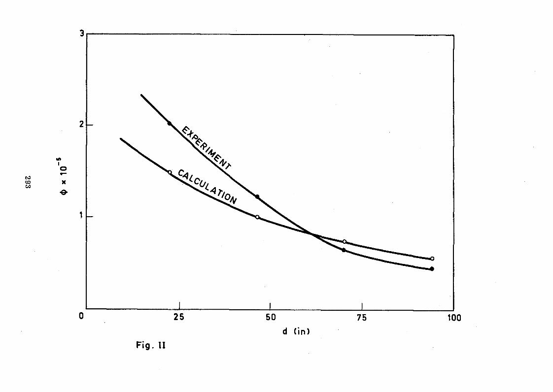
293
u>»
X■0-
25 50 75 tood (in)
Fig. II

STATUS REPORT ON EXPERIMENTS UTILIZING
REACTOR NEUTRON BEAMS AT AERI
by H.J. Kim
Atomic Energy Research Institute, Seoul, Korea.
ABSTRACT
This report briefly describes the limitations encountered in AERI
to perform experimental work on neutron and solid state physics with the
TRIGA Mark II reactor and refers to the TRIGA Mark III reactor presently
under construction. Progresses and present status of the activities carried
on related to the transfer of research equipment to the Mark III reactor by
the groups devoted to radiative capture spectrometry, neutron diffraction,
neutron scatterirg, and neutron radiography are reported.
Introduction
Since the TRIGA Mark II reactor (100 few) was put into operation in
1962, 'several groups in the physics division have been engaged in experimental
work using reactor neutron beams in the field of nuclear physics and solid
state physics. The low reactor flux limited their activities to the extent
that most of the work performed viere review studies. However, owing to their
endeavor for neutron economics and instrumentation problems they gained many
valuable experiences in neutron spectroscopy.
In order to meet the continuous growth of research activity a 2 MW
Triga Mark III reactor (thermal neutron flux : 4 x lO^n/cm^/sec) is under
construction and it will be critical in 1972« Therefore, these groups are
now preparing to transfer the instruments at the present reactor to the
new reactor. Progress and present status of the respective groups are
briefly outlined below.
A. Radiative Capture Spectrometry
Since 1967» this group has been engaged in the investigation of thermal neutron capture gamma-rays utilizing Ge(li) diodes fabricated at
their own laboratory. During the first 2-3 years, their efforts have been
concentrated on improvement in system resolution by suppressing electronic noise
and diode leakage current and also to increase the detection efficiency by
fabricating diodes with large sentitive volumes. Beside these efforts attempts
were also made to deduce a semi-empirical formula for the full energy peak

detection efficiency of the Ge(li) diode for the precise determination
of gamma-ray intensities from (n, T) reactions.
However, for the weak gamma-rays with the energies between 500 -
2000 keV it was very difficult to determine their -intensities with reasonable accuracy due to the high Compton background imposed by gamma-rays with high
energies. For the suppression of Compton background, a total absorption
type gamma-ray spectrometer using Ge(li) diode in combination with Nal (Tl)
mantle detectors was constructed and tested for complex gamma-ray analysis.
However, it was recognized that there are serious limitations on practical
applications for (n,"$ experiments due to appreciable coincidence loss and
necessary expensive and complex electronic equipment. As an alternative way,
a gamma-ray diffraction technique was considered. Due to its low system
efficiency and relatively low neutron flux, spectrometry with curved crystal
spectrometer was disregarded and a final decision was made to construct a
single flat crystal monochromator in combination with a large volume Ge(li)
diode at the external target geometry. The usefulness of the single flat
spectrometer of this type were reported by several workers very recently.
However, our single flat spectrometer differs from theirs in target geometry.
The advantages of our external target geometry over internal target geometry
adopted by those workers ares
1.) relatively small amount of ëample is required,
2.) the monochromator crystal does not see directly the reactor
core,
3.) gamma-gamma coincidence measurements, especially coincidence
of reflected gamma-rays in certain energy intervals selected
by a monochromator crystal with unreflected gamma-rays, can
be done.
The results of the test run of our spectrometer showed very promising
characteristics in suppressing Compton background and selecting the desired
energy region variably even though the usable neutron flux provided by TRIGA
Mark II (25O k tí) reactor is not sufficient.
Based upon the experience we obtained by the successful application
of the small scale single flat crystal gamma-ray spectrometer, a more
developed version of this spectrometer is now under construction for thermal
neutron radiative capture gamma spectroscopy utilizing the TRIGA Mark III
reactor.

Since a double axis neutron diffractometer was installed at the
TRIGA Mark II reactor, several review works have been done:
1.) anomalus absoprtion of calcium fluoride (Cai^).
2.) structure analysis of graphite, sodium cyanide (NaCN)
and sodium trisulphate pentahydrate (Na2S20^.5H20).
3.) determination of the magnetic moment of manganese ion in
manganese aluminum alloy (MnAl).
Although the reactor power level has been upgraded to 250 kW in
1969, the monochromatic beam intensity is so low that the researchers can
not study any competitive work using this instrument. Now the researchers
prefer to use an X-ray unit and single crystal structure analysis of
homatropine hydrobromide is under way.
In view of our new reactor, the mechanical part of another double
axis neutron diffractometer (NX-1320 MITSUBISH, Japan) was recently purchased.
The present effort of this group is devoted to the design of control electronics
for this instrument and transfer of the present neutron diffractometer to the
new reactor in order to be ready to operate when the reactor reaches criticality.
C. Neutron Scattering
Because of low reactor flux studies in the field of neutron scattering
were more limited. A double crystal monochromator with incident beam energy
of 15 to I50 meV was fabricated and was mainly used for transmission measurements at the tangential beam port. Recently titanium hydride and deuteride
were prepared and their total cross-sections were measured in the above energy
range. In order to study the chemical binding effect in neutron scattering
they also measured the average energies of scattered beams at various scattering
angles by taking the transmissions through the gold foil. Similar experiments
will follow with other hydrogeneous substances. This line of measurements
will give some information for the study of neutron thermalization planned
by other groups using the neutron generator.
This group also fabricated a slow beam chopper (2" dia. linear slit
type) and using this instrument they measured the higher order contents in
the beam from a crystal monochromator and the thermal neutron energy distri-
bution of the pile "beam. Even though the chopper was not very effective with
linear slit and poor resolution mainly due to unstable rotational velocity,
they gained many experience through the experiments for the performance
of the time-of-flight technique and instrumentation.
In order to study neutron inelastic scattering in solids and liquids
with the TRIGA Mark III reactor this group has projected to build spectro
meters, and a rotating crystal spectrometer and an inverted filter spectro
meter were chosen as reasearch tools to meet the requirements for a variety
of experiments involving high resolution small energy transfer and large
energy transfer. Therefore, the present effort of this group is for the
fabrication of these spectrometers. However, they have technical difficulties
as stated below:
1. Fabrication of liquid nitrogen cryostat for the sample
and the Be filter: through the several fabrication attempts
we found some difficulties with aluminum welding for the vacuum.
2. Design of some part in the automatic control unit of the
inverted filter spectrometer.
3. Fabrication of a power amplifier for a 400 Hz synchronous motor:
we fabricated the crystal rotor using a small pneumatic motor
in combination with a pressure regulator and an air compressor,
and attained up to 12,000 rpm with very nruch improved rotational
velocity compared to the ordinary ac/dc high speed motor. It
was found, however, that there is still a periodic fluctuation
in velocity caused from the automatic unloading system of the
compressor. We also found this method is inconvenient for long
run of the crystal rotor and therefore we axe considering to
replace this pneumatic motor by a 400 Hrz, hysteresis synchronous
motor. In this case as a 400 Hrz. power source is not available,
it is desirable to fabricate an adequate power amplifier to
operate the crystal rotor with a signaJ generator.
4* Construction of some mechanical part in the inverted filter
spectrometer.
In connection with these matters this group is expecting two
experts from Bhabha Atomic Research Centre, India, under the
programme of the Collaborating Joint Project.

D. Thermal Neutron Radiography
Nuclear reactor is one of the promising sources for neutron
radiography and many techniques have been developed in the fields of
routine nondestructive test and nuclear industry. In an attempt to develop
neutron radiography as a practical tool some investigations are proceeding (in
our laboratory). At present, we are studying image transfer method and
direct exposure method using indium foil and 2 enriched B coated on an
aluminum plate as image convert screens. In the course of experiments, we
have found various conditions not only such as pile beam quality, beam
collimation, preparation of convert screen, but also exposure of transfer
time. The choice of film and development are practically very important,
and currently our efforts are to find the optimum conditions for improving
the resolving power and gamma-ray fogging at the thermal column of the reactor.
Meantime, we have compared the results taken with the objects containing
partly hydrogenous substances or heavy metals such as lead, tungsten with192
the results obtained by X-ray and Ir gamma-ray sources. Also we have
located some internal defects in UC>2 pellets which was prepared by the
metallurgy group. Since the neutron radiography with the image transfer
method has great advantages for testing irradiated nuclear fuels over X-ray
and gamma radiography, our investigation will be very useful for this
purpose when the remote handling system becomes available in the future.
We are planning to study other methods and also to extend our
facilities by adding an image intensifier etc. in order to establish
many efficient procedures which will be necessary' for the various nature
of the testing object.

PLAN FOR THE CONSTRUCTION OF SLOW NEUTRON SPECTROMETERSIN THE AERI
(DESIGN OF AN INVERTED FILTER SPECTROMETER)
"by
H.J. Kim, H.K. Kim and B.G. Yoon Nuclear Physics Division
Atomic Energy Research Institute Seoul, Korea
ABSTRACT
The design work for the inverted filter spectrometer, which
is currently under construction and will "be installed at the TRIGA
MARK III reactor in the AERI, is outlined. Using a copper crystal
monochromator the instrumental parameters are determined, and some
characteristics, e.g. energy resolution, incident "beam flux at the
specimen position and the second order content are estimated. Also,
some considerations for the analyzing filter and the correction of
second order contamination are discussed.
1. Introduction
As presented in thé status report, two slow neutron spectrometers,
a rotating crystal spectrometer and an inverted filter spectrometer,
are designed and currently under construction in AERI. These
instruments will "be installed at the radial "beam ports of the
TRIGA MARK III reactor (2 MW) which will "be critical in April 1972
to investigate neutron inelastic scattering in solids and liquids.
This paper describes some of our design work, on the inverted filter
spectrometer.
In designing the instrument, many factors have to "be considered,
for example, resolution, intensity, mechanical fabrication, counting
system, data collection and auxiliary equipment, etc. However, the
"basic problem is the proper choice of the instrumental parameters to
obtain the desired characteristics on resolution and intensity. This
is especially important when the reactor power is modest. The other
factors are mostly subjected to available money and laboratory
techniques. We shall restrict our discussion, therefore, mainly to
the physical problems related to resolution, intensity, etc.

After a "brief review of the inverted filter method, the general
features of our design and instrumental parameters will be given.
Then estimations on resolution, intensity and second order content
will follow. Finally, some discussion on the dimension of analyzing
filter and correction for the order contamination will be given.
2. Principle and General Remarks
The principle of the inverted filter spectrometer is shown
schematically in Fig. 1. A beam of monochromatic neutrons, E q, is
scattered by the specimen into a neutron counter which is shielded with
an analyzing filter, e.g. polycrystalline beryllium. Therefore only
those scattered neutrons with final energies, E ’, less than the filter
cut-off energy, E^, are able to reach the counter. Taking account of
the filter transmission which increases from zero at zero neutron
energy to a maximum at the cut-off energy of E^ = 0.0052 eV and then
drops abruptly to a negligible value, it is reasonable to assume that
the neutrons which reach the counter have a mean energy = 0*003 eV.
When the incident beam energy is varied continuously, this process
thus gives the counting rate as a function of the energy transfer
-fclO - Eo - <Ef> (1)and the wave vector transfer
Q = kQ - k (2)
where Où is the frequency of the mode to which the neutrons lose energy
and k and k are the wave vectors of the incident and scatteredo
neutrons respectively.
Instead of keeping the incident beam energy constant and
analyzing the scattered neutrons as in the triple axis spectrometer
and time-of-flight method, in this set up the energy of the incident
beam is varied with a constant analyzing window. Accordingly, with
the philosophy of this inverted process the spectrometer has its
intrinsic advantages and disadvantages summarized as follows:
Advantages :
(1) Simple construction with two-axis set-up.
(2) Since the energy loss process is used the intensity accompanied
by the transition of large energy transfer is high, compared to
the energy gain process.

(3) The experimental conditions can be made such that the counter
presents a large solid angle to the specimen to obtain high
intensity.
(4) The use of the analyzing filter eliminates the effect of
higher order.
(5) With fixed k', data processing can be simplified eliminating
the correction of detector efficiency and the factor k/kQ in
the expression of inelastic differential cross-section, when
using a l/v sensitive monitor counter.
Disadvantages :
(1) Poor resolution in energy and momentum.
(2) The wave vector of the scattered neutrons, k, is so small that
the range of momentum transfer, Q, is restricted for a given
energy transfer.
In view of these characteristics, one can choose the inverted
filter spectrometer as an adequate instrument for inelastic
scattering experiments with a modest flux reactor, especially for
the measurement of frequency distribution, g(o>>), because of poor
resolution.
Since Brockhouse et al and Wood et al used this method
the improvements of instrumental resolution have been achieved with
modified methods by Iyengar et al and Dahlbolg et al Using# .
a combination of the beryllium filter and the beryllium oxide
scatterer referred to as "window filter", Iyengar et al could attain
the filter transmission width of 0.0013 eV defined with sharp edges.
They have used this device with the "constant Q" method to measure
the phonon dispersion relation, and pointed out that this method is
highly suitable for high frequency phonons with enhanced counting
rate compared to the conventional triple axis method. In order to
study the quasi-elastic scattering, Dahlbolg et al have used beryllium
oxide as an analyzing filter and the incident beam obtained by mono-
chromating the beryllium filtered beam instead of the white pile beam.
In this arrangement, even though the observable range of the energy
transfer is limited by the cut-off energies of two filters, the energy

resolution could be improved to about 4%» Also Stiller et al
could lower the incident beam energy up to the region of the beryllium
filter cut-off, using the (0 0 l) planes of Thermica sheets as the
monochromator. _
3. General Design and Instrumental Parameters
The apparatus of this spectrometer is essentially the same as
the conventional neutron diffractometer equipped with an additional
1:2 coupling so that the angles of the monochromating crystal, 0, and
the monochromator arm mounted with the specimen table and detector
arm, 20, can be changed continuously or by a predetermined increment
using a driving motor and a suitable transmission device.
Though the mechanical structure of this instrument is not very
complicated in principle, it requires many precise machine works for
the mechanical alignment and half angling system. A stable machine
bed and a sturdy main shaft-bearing system reckoned with the radial
load of about 300 kg at a distance of 170 cm and a thrust load of
about 700 kg, which are also important considerations. In order to
meet these requirements with our limited experience and money it was
felt that a simple and conservative design was adequate. Here, we
are not going into any details about the engineering aspects of our
mechanical design. However, several comments will help to give some
more explicit idea about the sketch of the general arrangement shown
in Fig. 2.
The machine bed framed by welding channel iron rests to
6 levelling screws and a 60 x 60 x 6 cm steel plate mounted with an
18 cm diameter main shaft bolted to the bed frame. The monochromator
arm is casted in rigid construction with two sleeves separated 100 cm
for the main and detector arm shafts and is mounted on the main shaft
using two taper roller bearings. Inside the main shaft another
concentrical shaft is provided which extends to the monochromating
crystal gonimeter axis. For the half angling these two shafts are
interlinked by means of two sets of worm gears and a pair of cylindrical
gears. There are serious problems with the "backlash" of the wormgear
system due to the periodical pitch error and outrun of the worm shaft;
we therefore chose a rather large worm wheel of 360 mm pitch diameter
in order to obtain an accurate ls2 transmission even when built within

reasonable tolerances. The monochromator and its arm angles can be
read on a graduated circle and vernier up to 0.05° and it is also so
designed that the arm angle can be printed out using a four digit
electromechanical shaft angle encoder. The detector arm is fixed
around the specimen table axis in the same structure except for the
1:2 coupling. However, for the capability of the "constant Q" mode
of operation in the future, provisions for the accurate control of the
scattering angle, , and the specimen orientation, I t , in step of
0.1° are made using worm wheels with 228 pitch diameter.
The monochromator shielding drum consists of two main parts.
The upper drum which rests on the stationary drum with a large circular
groove and steel balls for the centering, is coupled with the mono
chromator arm for synchronous rotation. The rotating shield is
provided with a 60° cut-away inlet sector so that the pile beam can be
reflected into the exit slit in the angular range of +18° to +78° to
the pile beam direction. The shielding drum itself contains an
inner annulus of 10 cm thick lead surrounded by an outer annulus of
35 cm thick borated paraffin.
Since the experiments, in general, involve measurement over the
continuous energy range with low counting rate, the automatic
performance of step-scanning and data collection are indispensable.
Printing-out of cadmium shutter background once in every predetermined
number of signal prints-out is also necessary. Using a conventional
cam-microswitch-electromechanical relay arrangement an automatic
sequence control unit is to be fabricated in conjunction with the
monitor count preset on the 0RTEC 715 I>ual Counter/Timer, 432A Printout
control and 222 Teletype Page Printer.
In the inverted filter method, the choice of monochromator
parameters related with resolution, such as the mosaic spread and inter
planer distance, has to be compromised not only with intensity but also
with filter cut-off energy. However, with an objective energy range
of 0.02-0.2 eV a somewhat large mosaic spread was preferable in order
to enhance the intensity in the higher energy region. Under these
considerations a (ill) plane of copper crystal of 150 x 63 x 12.5 mm
and about 30' of mosaic spread (FWHM) is chosen. Transmission geometry
is dictated from the difficulty of procurement of the large dimensional
crystal. In order to match the beam collimation to the mosaic spread, ß ,

the pile ?>-nrt «Ti+. f>niiini3+.inn9 <s/ anri ¿ o-r»e determined, on the
criteria The important instrumental
parameters and characteristics are summarized in Table 1. In Pig. 3
the solid curve represents the incident beam energy vs. the Bragg angle
with copper (111)— crystal and the dashed part is the range of
energy-momenturn space which can be covered with the scattering angle
The incident beam produced by a crystal monochromator is not
truly monochromatic but has a distribution, K(E), with energy
reflected beam, d6. Simply taking the formula for single slit
collimators, this energy spread is given by
neutrons impinging on the specimen per time interval and Eq is
filter cut-off energy.
In Eq. (4), if we use the delta function for the double
cross-section,
then, the distribution of J(Eq ) gives the resolution function of the
spectrometer at the corresponding energy transfer E. Por this
calculation some approximations can be well made by the Gaussian for
R(E’-Eq) with the half width, dEQ, defined by Eq. (3) and a
right-triangle shape for Tis). However, the integration of Eq. (4)
<{> = 0° to 100° when the beryllium filter is used.
4. Energy Resolution
spread, dEQ , due to the corresponding angular spread of the Bragg
dE = 2E cot© d©o o ( 3)
with ae = [ ß 2 + (°c/2)2J 2
where {5 is the half width of the crystal mosaic spread and«/, is the
angular divergence of the collimator.
When the incident beam energy is E , the signal counting rate{a 0
in the detector J(Eq) ' can be obtained by folding RÍE) with
cross-section and filter transmission T(E), that is,
where A is the instrumental constant, N(Eo) is the total number of

is still involved because of rapid variation of N(Eq) and dEQ over the
energy, Eq . At low energies N(Eq) varies very rapidly over the
energy range of the filter transmission width; on the other hand, at
higher energies dEQ is very large and thus over this range the width
variation of R(E’-Eo) is also significant.
In order to estimate very roughly only the half width of the
energy resolution, <5 E, therefore, further simplification was made by
the root mean square sum of the individual uncertainty in Eq, (4),
that is,
E = C i^ 0)2 + & E f)2 + i^ )2J * (5)
where AE^ is the half width of the filter transmission, which is
about O.OO26 eV for beryllium. A E is the energy uncertainty
accompanied by a monochromator angular scanning step of A© = 0.05°
and is obtained by differentiating the Bragg relation,
A E = |e (E-D2)^ A O (6)
with D = ~ ,¿a
o 2 2where d is the interplaner spacing in A and a = O.O818 n with the
order of reflection, n. The resulting resolution <ÍiE/E is shown in
Fig. 4 with E = Eq- Also shown are three resolution functions
approximated by triangle with half width £E at the corresponding
energy transfers.
At higher energies above Eq = 0.1 eV the major contribution
on SE is from the energy spread of the incident beam, dEQ . On the
other hand, at lower energies, below Eq = 0.03 eV the major contribution
comes from the constant filter transmission width AE^, and thus <5E/E
increases very rapidly as energy decreases.
It is very complex to adjust those contributions of dEQ and
beforehand to obtain more intensity for an aimed average resolution.
However, from the quite flat nature of ÍE/E (8-14$) over the energy
range of 0.02-0.2 eV, it may be judged that the selection of related
parameters is reasonable in conjunction with the beryllium filter.
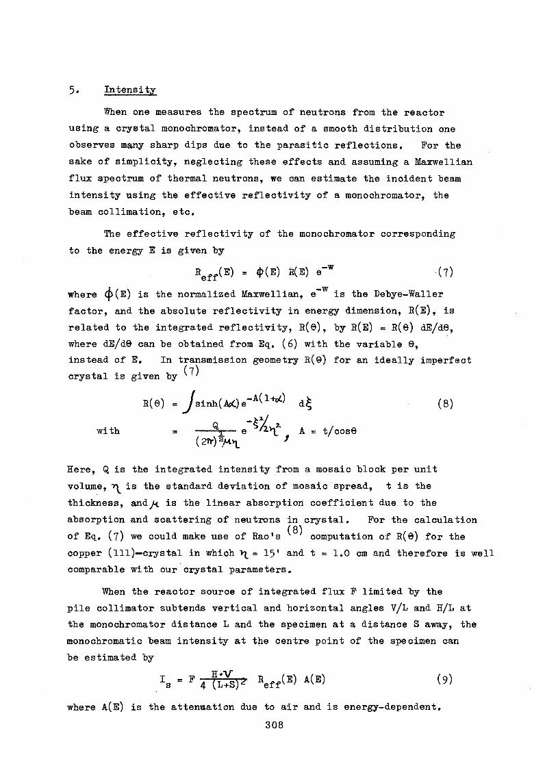
5» Intensity
When one measures the spectrum of neutrons from the reactor
using a crystal monochromator, instead of a smooth distribution one
observes many sharp dips due to the parasitic reflections. Por the
sake of simplicity, neglecting these effects and assuming a Maxwellian
flux spectrum of thermal neutrons, we can estimate the incident beam
intensity using the effective reflectivity of a monochromator, the
beam collimation, etc.
The effective reflectivity of the monochromator corresponding
to the energy E is given by
Reff(E) = 4>(E) R(E) e"w (7)
where (j>(E) is the normalized Maxwellian, e~W is the Debye-Waller
factor, and the absolute reflectivity in energy dimension, RÍE), is
related to the integrated reflectivity, R(ö), by RÍE) = R(©) dE/d0,
where dE/d© can be obtained from Eq. (6) with the variable 9,
instead of E. In transmission geometry R(0) for an ideally imperfect( 7)
crystal is given by
R(0) = 8inh(AoCj e ~ ^ ^ +c d^ (8)
_ wwith = --- — e A = t/cos0
( 2 * ) V l *
Here, Q is the integrated intensity from a mosaic block per unit
volume, is the standard deviation of mosaic spread, t is the
thickness, andy<. is the linear absorption coefficient due to the
absorption and scattering of neutrons in crystal. Por the calculation( 8)
of Eq. (7 ) we could make use of Rao's ' ' computation of R(ö) for the
copper (ill)— crystal in which \ = 1 5' and t = 1.0 cm and therefore is well
comparable with our crystal parameters.
When the reactor source of integrated flux P limited by the
pile collimator subtends vertical and horizontal angles V/L and H/L at
the monochromator distance L and the specimen at a distance S away, the
monochromatic beam intensity at the centre point of the specimen can
be estimated by
P Eeff(E> A 'B > (5)
where Ais) is the attemsation due to air and is energy-dependent.
308

The source flux of the radiating surface is rather difficult to
estimate. Since the radial beam hole of the TRIGA MARK III reactor
extends up to the graphite dummy elements (the outmost array of the
core assembly) with a light water moderator layer of less than 10 cm,
the source flux at the moderator-beam tube boundary may be approximated
by the flux at the rotary specimen rack for which a maximum unperturbed1 ^ 2 (9 ^
thermal flux of 1 x 10 n/cm /sec is predicted ' ' at 1 MW power level
(3.2 x 10 J n/cm /sec at the central thimble). We therefore estimate12 2
the source flux to be about 5 x 10 n/cm /sec at 2 MW power level.
With the effective source surface area (6.5 cm x 6.5 cm) limited
by 40' beam divergence, the flux obtained at the centre point of the6 2
specimen position is, for example, 1.4 x 10 n/cm /sec at Eq = 0.04 eV,
neglecting attenuation to air. In practice, however, when the Soller
exit collimator (50') is used the average flux over the specimen
area will fall down by a factor of 2-3 at least, due to the shading
effect of the cadmium sheets. Taking the lower limit, the predicted
average flux at the specimen position is shown as a curve (i) in
Pig. 5.
The curve (il) in Pig. 5 is the flux ratio of the second
order (4Eq) to the first order (Eq) obtained by Eq. (7 ) and (9). As
this ratio increases rapidly at lower energies we expect a serious
problem of the second order contamination below Eq = O.O4 eV. In
actual measurement the order contamination due to l/E spectrum will
also arise. Because of the light water moderation and radial beam
tube geometry, the curve (il) in Pig. 5 will extend to the higher energy
region with considerable content.
In order to suppress fast neutron and gamma backgrounds and also
to improve the ratio of order contents, we are planning to insert a
synthetic quartz crystal filter in the pile collimator. In case a
10 cm long filter is used, according to the absorption coefficient
measured at room temperature by Brockhouse and Rustad et al
we estimate, for example, transmissions of ~ 0.63 at 0.02 eV and
~ 0.3 at 0.08 eV and therefore the second order content ratio improved
by a factor of ~ 2. Further improvement of this ratio with increased
filter length brings very rapid decrease of the incident beam
intensities at higher energies and therefore the optimum filter length

will have to be compromised with these effects. On the effects of
the higher order and fast neutron background some more discussion will
be given in Section 7.
6. Analyzing Filter
Because of the various conditions which must be satisfied by the
analyzing filter, beryllium and beryllium oxide have been used in almost
all inverted filter spectrometers, and the grain size of these materials
is preferable to the order of 0.01 mm or less to obtain the sharp
cut-off edge.
As pointed out in Section 2, in many experiments with inverted
filter spectrometer it is desirable to use a short filter with a wide
collimation, say 2-4°» to improve the counting rate. Therefore, in
designing the analyzing filter the first consideration should be on
the effective discrimination against thermal neutrons with an optimum
filter dimension. If the elimination of neutrons with energies
higher than the upper cut-off of the filter is not effective, the back
ground will be high in the observed spectra, and even spurious peaks
may appear due to the leakage of Bragg reflections from the specimen.
Those leaking neutrons can reach the detector by direct transmission or
after undergoing multiple scattering in the filter material. The multiple
scattering can be reduced by interleaving the filter blocks with cadmium
sheets and also by covering cadmium around the longer sides of the filter.
In this case some of the signal neutrons (cold neutrons) will be also lost
due to reduction of the effective solid transmission angle and thus
proper compromise on these two competitive effects is necessary.
Several workers employed about 10 cm-long
rectangular beryllium filter with various thicknesses of interleaved
blocks from 0.6 to 2.5 cm. However, very little experimental evaluations
on these effects have been reported.
Using the Monte Carlo method under some simplified approximations ( 15)Webb calculated the leakage of the thermal neutrons for a wide variety
of geometrical arrangements of the beryllium filter. According to his
work, the direct transmission is 0 .09$ in a 10 cm-long filter, and when
the filter is 5 cm high an interleaved block thickness of about 5 is
necessary in order to suppress the multiple scattering transmission from
the amount of direct leakage. By extrapolating Webb's calculation we
estimate about 1.5% of the total thermal leakage when using a beryllium
filter of 5 x 5 x 10 cm without interleaving. This leakage seems too high
to be tolerated if the specimen produces strong Bragg reflections.
( 16 )Using an inverted filter spectrometer Thaper et al ' studied the
interleaving effect on the total thermal neutron transmission by measuring
the scattered neutrons from vanadium with differently interleaved block
thicknesses of a beryllium filter. A similar measurement was also done for
the beryllium oxide filter using Bragg reflected neutrons by nickel. All the
measured total transmissions showed considerably low values compared to
Webb's calculation and even with a 5 x 5 x 10 cm beryllium filter without
interleaving it was less than 0.3%.
The interleaving effect on the net signal intensity was also studied.
When the beryllium filter of 5 x 5 x 10 °m is replaced by
8 blocks of 10 x 5 x 0.5 cm interleaved with cadmium, the
signal-to-multiple scattering background-ratio was improved from
1.88 to 2.38. However, due to high room background (6 cpm) and
accompanied loss of 38% signal intensity, the signal-to-total
background-ratio decreased from 0.92 to 0.66. Therefore they reached
the conclusion that the interleaving would be useful from the point
of view of signal-to-background-ratio only when the room background
could be brought down to about 1 cpm.
Taking account of these works, the filter lengths of 10 cm or
more are adequate* proper choice of the interleaved block thickness,
however, seems to be attainable only through the pilot experiment
after fabrication of the instrument. In order to show the problem
more explicitly it will be useful to point out as a model case that
the multiply-scattered neutron background is as much large as the room
background in Thaper's instrument when the filter is not interleaved.
Therefore we will have to take some precautions for (l) proper shielding
for the detector, (2) choice of a detector which has low inherent
detector background, and (3) enough space of detector arm for the
accommodation of a collimator, or for the adjustment of the detector
distance so that the detection angle can be easily changeable when
necessary, according to the nature of the experiment- The preferable
method to improve the signal transmission is cooling the filter with
liquid nitrogen, but at present we have some technical difficulties in
aluminium welding for vacuum.

7. Higher Order Contamination
We have discussed the second order content in the monochromatic
incident "beam in section 5» When the experiment is concerned only with
the measurement of frequencies of well-localized levels, as is often the
case with the study of molecular motions in solids, the effect of second
order neutrons is of little significance. On the other hand, for the
frequency distribution measurements it is useful to relate the observed
energy transfer distribution directly to the Van Hove scattering
functions S(Q,w) with automatic elimination of the k/kQ factor, when
a l/v sensitive monitor is used. Accordingly, it is extremely important
to make the measurements independent of the order contamination as well
as the distribution of the incident beam intensity and the reactor power
fluctuation.
The second order component (also higher order components) affects
the measurement of energy transfer distribution in two ways, that is,
firstly it affects the monitor counting rate and secondly the
measured distribution may also contain scattered neutrons by the
second order satisfying Eq. (l). Even though the use of a quartz
filter and a l/v sensitive detector mitigates these two effects to
some extent, the order contamination will still give serious problems
at lower energies.
With a 10-cm quartz filter and a l/v sensitive counter we
estimate, for example, about 8% of monitor counting rate comes from
the second order at 0.02 eV. Similar effects may also come from the
other background such as fast neutrons and inelastically scattered
neutrons by the monochromator. For the correction of these effects(2)
a formula was given by Wood et al to be
(10)
where ID : the recorded intensityK
I p , : the recorded intensity obtained with cadmium inC/dthe incident beam
C : the low neutron contamination in the beam, measured
by recording the intensity with the monochromator
turned out of the Bragg position
M : the monitor counting rate for the monochromating beam
Cjj : the monitor counting rate for the contamination in
the incident beam, therefore (M + Cjj) is the total
monitor counting rate
: the ratio of the efficiency of the monitor counter
. assuming a l/v characteristic, to the actual efficiency
of the counter.
In this formula the corrections (except for the diffuse background
from the monochromator) are made by introducing a cadmium shutter.
Therefore this formula can be used readily only when the higher order* /
components are negligible—' or cadmium transparent as the fast neutron
component. In fact, the second order is not cadmium transparent up
to 0.12 eV and its content is not negligible, especially at low
energies. As pointed out earlier the calculation of the second order
content is also not accurate due to inaccurate pile spectrum and
parasitic reflections.
In order to attain to the tolerable corrections, therefore, it
will be essential to measure the intensity ratios of the first and
second components at low energies. An appropriate method for this
purpose will be to measure the transmission for two absorbers of the( 17)
same material but of different thickness . In view of significant
variation of cross-section with energy and easiness for the accurate
specimen preparation, Au, In and Ag will be the adequate absorbers.
Once we know the ratio of the order content as a function of the incident
beam energy, then it is possible to separate M and with known monitor
efficiency. It is also possible to estimate roughly the corrective
amounts of the signal intensities affected by the scattering of the
second order components (cadmium opaque) to apply additionally on
(lg - Iq¿ - C) from measured signal count rates at the corresponding
incident beam energies.
Non l/v correction,¿ , which depends on counter construction, gas
filling and deviation of absorption cross-section from l/v can be checked
Wood et al could largely eliminate higher order components at low energies Eq< 0.05 èV by putting six-inch quartz crystal filter in the pile beam.

theoretically over the interested energy range for any monitor counter
such as a thin fission counter or a small BF^ counter. It is also
desirable to place another monitor in the pile beam to normalize the
corrected intensity, I, to the reactor power fluctuation.
A cknowle dgemen t
The authors are grateful to Dr. P.K. Iyengar for his
suggestion and much advice which resulted in the project for the
construction of this instrument.
References
1. Brockhouse, B.N., Sakamoto, M., Sinclair, R.N., and Woods, A.D.B.,
Bull, Amer. Phys. Soc. ¿ 375 (i960).
2. Woods, A.D.B., Brockhouse, B.N., Sakamoto, M. and Sinclair, R.N.,
Inelastic Scattering of Neutrons in Solids and Liquids, IAEA,
Vienna 487 (l96l).
3. Iyengar, P.K., Nucl. Instrum. Methods 367 (1964).
4. Dahlbolg, U., Friberg, B., Larsson, K.E. and Pirkmajer, E.,
Inelastic Scattering of Neutrons in Solids and Liquids, IAEA,
Vienna 1_ 58I (1968).
5. Stiller, H.H. and Danner, H.R., Inelastic Scattering of Neutrons
in Solids and Liquids, IAEA, Vienna 363 (l96l).
6. Caglioti, G., Advanced Course on Neutron Crystal Spectrometry,
Kjeller ¿ (1962).
7. Bacon, G.E. and Lowde, R.D., Acta. Cryst, ¿ 303 (1948).
8. Rao, K.A., B.A.R C. report A.E.E.T. - 259 (1966).
9. Graff, A.P., McMain, Jr. A.T., Schnvrer, G T. and Zeitlin, H.R.,
General Atomic Report GA-7259 (l966).
10. Brockhouse, B.N., Inelastic Scattering of Neutrons in Solids
and Liquids, IAEA, Vienna 113 (196I),
11. Quoted from the reference 10.
12. Iyengar, P.K., Nucl. Instr. and Meth. 2¿ 367 (1964).
13. Saunderson, H.H. and Cocking, S.J., Inelastic Scattering of
Neutrons in Solids and Lqiuids, IAEA, Vienna, 2 265 (1963)«
314
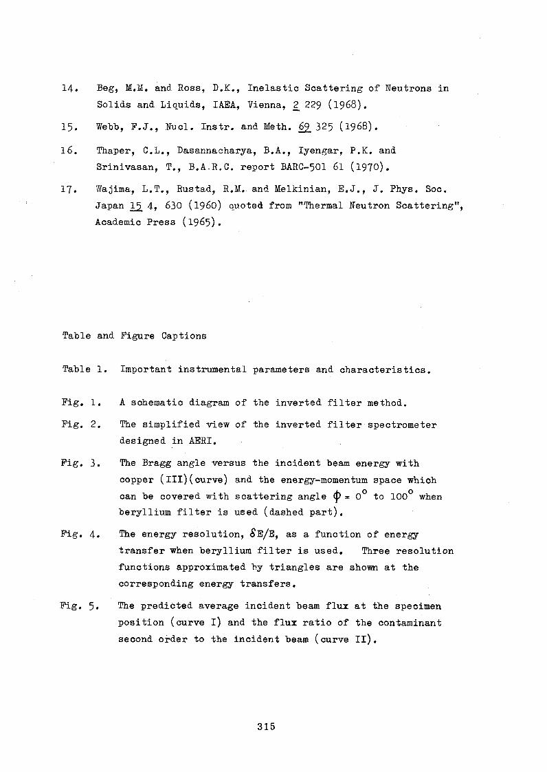
14. Beg, M.M. and Ross, D.K., Inelastic Scattering of Neutrons in
Solids and Liquids, IAEA, Vienna, 2_ 229 (1968) .
15. Webb, F.J,, Nucl. Instr. and Meth. 62.325 (1968).
16. Thaper, C.L., Dasannacharya, B.A., Iyengar, P.K. and
Srinivasan, T., B.A.R.C. report BARC-501 6l (l970).
1 7 . Wajima, L.T., Rustad, R.M. and Melkinian, E.J., J. Phys. Soc.
Japan 1¿ 4» 630 (i960) quoted from "Thermal Neutron Scattering",
Academic Press (1965).
Table and Figure Captions
Table 1. Important instrumental parameters and characteristics.
Fig. 1. A schematic diagram of the inverted filter method.
Fig, 2. The simplified view of the inverted filter spectrometer
designed in AERI,
Fig. 3. The Bragg angle versus the incident beam energy with
copper (ill)(curve) and the energy-momenturn space which
can be covered with scattering angle <j) = 0° to 100° when
beryllium filter is used (dashed part).
Fig. 4. The energy resolution, 8 E/E, as a function of energy
transfer when beryllium filter is used. Three resolution
functions approximated by triangles are shown at the
corresponding energy transfers.
Fig. 5. The predicted average incident beam flux at the specimen
position (curve i) and the flux ratio of the contaminant
second order to the incident beam (curve II).

Important instrumental parameters and characteristics
Spectrometer location
Source flux (moderator-beam tube boundary)
Source to monochromator
Beam cross-section
Incident beam energy range
Monochromator
Mosaic spread
Monochromator dimension
Monochromator goniometer
Pile collimator divergence
Exite collimator divergence
Monochromator scanning step
Half angling
Angle encoding
Monochromator to specimen
Scattering angle
4>, scanning step
Inpile filter
Analyzing filter
Main counter
First and Second monitor
Energy resolution (SE/E)
Intensity at specimen position
Contaminant second order content
* See text.
: To be installed at the radial beam portof the TRIGA MARK III reactor (2 MW)
s 5 x 1 0 ^ n/cm^/sec*
: 5000 mm
: 55 x 55 mm
: 0.02-0.2 eV
: Cu (ill), transmission geometry
s 30 minutes (FWHM)
: 150 x 63 x 12.5 mm
* ±lO®m translation, +_ 20 degrees tilt
: 40 minutes
s 50 minutes
s O.O5 degrees
s Worm gear system
: Electromechanical shaft position encoder
s IO5O mm
î 100 degrees (max)
: 0.1 degrees
: Synthetic quartz crystal
: Beryllium (50 x 50 x 100 mm)
: BF^ counter 50 mm dia. x 90 mm active length
: 8-14%
î 4.7 x 10^ n/cm^/sec at 0.04 eV*
: 8fo at 0.02 eV*
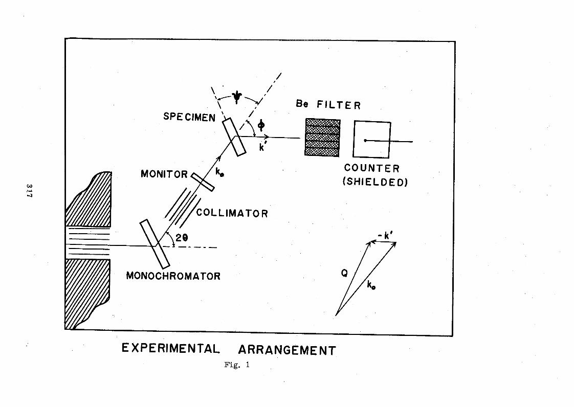
/
\\ t v
/
SPECIMEN >v / .' M
Be F IL T E R
MONITOR COUNTER(SHIELDED)
COLLIMATOR
MONOCHROMATOR
EXPERIMENTAL ARRANGEMENT

318
S O L L E RCOLLIMAOR
m o n o c h r o m a t o r a g o n i o m e t e r
COUNTER SHIELD
G R A D U A T E R C IR C LE a VE R N IE R
30 cmWORMWHEEL.
H A L F A N G L I N G WORM S H A F T
a S H A F T A N G L E E N C O D E R
Fig. 2

MONOCHROMATOR ANGLE (degree)
Olrocn
CMUl
Fig. 3

320
I________________ I100 150
T R A N S F E R , ' f j w ( m e V )Fig. 4

AVE
RAG
E FL
UX
(IO
1* nv
.
Fig. 5
FLU
X
RA
TIO
by: B. A. Dasannacharya
Nuclear Physics Division
Bhabha Atomic Research Centre
Bombay, India
ABSTRACT
Neutron beam experiment work done at the CIRUS reactor
for a decade and future plans are described. Solid state and
fission physics research is discussed. Spectrometer modifica
tions and construction of a 100 MW reactor at Trombay and a
pulsed reactor at Madras are mentioned as part of the major
effort put towards materials irradiation for fast reactor
design.
Introduction -
The programme of research in Physics at Trombay generally
concerns itself with problems in low energy nuclear physics,
solid state physics and applied or technical physics. Apart
from requirements for individual experiments the two major
facilities which exist at Trombay are the 5* 5 MeV Van-de-Graaff
generator and the 40 MW Cirus reactor. The Van-de-Graaff
machine is used mainly for experiments on nuclear spectroscopy,
nuclear reactions and fission physics whereas the physics
research at Cirus is concentrated on solid state physics and
fission physics. Some neutron beam experiments are also done
at the Apsara reactor which was extensively used in the earlier
stages. This paper describes the work done at the Cirus reactor.
The Cirus reactor has now been operating successfully for
a decade and this study group meeting provides a proper occa
sion to review the work done with this reactor and to present
a plan for the future. This does not mean that I wish to
catalogue all the experiments that have been done during these
years. I would rather like to only classify the broad areas of
work which we have tackeled at Trombay and mention certain experi
ments as typical examples of our work.
Experiments with Ciras
The experiments at the Cirus reactor fall broadly into the
categories of solid state physics and fission physics. The
foundations for both of these were laid at the 1 MW Apsara
reactor and indeed some of the basic work was done using this
smaller reactor. For example, the initial work showing the
anisotropy of ^-emission and neutron emission from fission
fragments was established first by experiments done at A p s a r a ^ \
and it has been highly gratifying for the scientists at Trombay
to see that all the essential features of these early experi
ments have later been verified with more sophisticated techniques
and bigger reactors. Similarly, the initial work on neutron
scattering was also started at the Apsara reactor (2).
Needless to say, the techniques to experimentation at Trombay
have advanced considerably during the last ten years and I hope
that at least in certain respects I shall be able to convey a
feeling of this program to this gathering.Now coming to the experiments done at the Cirus reactor,
let us concentrate first on the solid state physics experiments
which utilize most of the neutrons from this reactor.
(a) Solid State Physics
The programme of solid state physics can be grouped into
three main classes: (a) neutron crystallography leading to
information on hydrogen bonding (b) magnetic scattering leading
to structure and dynamics of spins and (c) inelastic scattering
leading to studies in lattice-, molecular- and liquid-dynamics.
Before I describe some of the experiments I would like to point
out a certain important event in the development of the spectro
meters for this work at Trombay - an event which is almost
fourteen years old now.
When we were just starting on this programme we bought a
diffraction spectrometer which cost more than $35,000 without
electronics, monochromator or the counter. This huge cost made
us decide at that time to develop all our spectrometers at
Trombay itself. Thanks to this policy we are now having the
required number of spectrometers^^ without having to spend
even half as much as we would have if we had depended upon
buying then. Even more importantly we now have the know-how to

tailor our spectrometers exactly to our needs. This, I believe,
is a development whose importance cannot be overemphasized.
Coming back to the experiments on crystallography, it was
initially decided to start the programme by looking at substances
which will provide simple examples of hydrogen bonds. To this
end, a number of hydrated salts were examined and accurate(4)
determination of hydrogen position in these was carried through .
These experiments have resulted in a systematic study of
the various types of Hydrogen bonding shown by water molecules
in these crystals. This programme has now been successfully
completed and the crystallographers hope now to look at more
complicated and also much more interesting amino acids. Some
work on D, L-Glutamic acid hydrocholoride, asparigine monohydrate
and cysteic acid monohydrate has already been done in this direc-
tion^^* While the original work on hydrates was done on spectro
meters which required setting every Bragg reflection, the present
experiments are being done on a fully automatic 3-dimensional
diffractometer developed at Trombay.
The investigations on the elastic magnetic scattering are
carried out on two spectrometers: a conventional powder diffracto
meter and a polarized neutron spectrometer. The main areas of
interest are concerned with a systematic study of Heusler alloys
with a view to understanding the mechanism of magnetic ordering( 5)in this important class of substances , and with an extensive
investigation of single and mixed ferrite systems and other
spinel structures^^. It is known that the use of polarized
neutrons can considerably enhance the accuracy of measurements
in several situations. The Trombay group was the first to
exploit this fact for the magnetic structure analysis of poly
crystalline samples. By combining the data from the unpolarized
and polarized neutron measurements they have been able to get
information on the structure, the cation distribution and their
magnetic moments in single and mixed ferrites of the type
Mg Mn, Feo0. and Zn Ni.. Fe_0.. They were able to show, for °X 1—X ¿ 4 x 1—X 2 4
example, that certain mixed ferrites of Nz--Ni show a non-
collinear Yafet Kittel type of ordering. This was the first evi
dence of non-collinear ordering in any ferrite system.

Some of the experiments now underway in this group include
measurements of magnetic form-factors and also the diffuse
scattering in ferrites using polarized neutrons.
The work on the inelastic scattering from magnetic material
has been concentrated on looking at the scattering in the para
magnetic state. This programme has been systematically followed
and the exchange integrals in several paramagnets have been
determined. The programme is now being continued in order to
evaluate the exchange integrals involved in various ferrite
systems. Another investigation along these lines was the study
of paramagnetic scattering from short range ordered paramagnets
like MnO at room temperature. This study led to the very
interesting conclusion that it is likely that highly damped spin
waves exist in MhO even very much above the Neel temperature.
Similar conclusions have generally been drawn now in several
paramagnets by applying better techniques. These experiments
have been done by close cooperation between the elastic and
inelastic scattering groups.
Finally, coming to non-magnetic inelastic scattering experi
ments they have been mainly of three types: (i) phonon measure
ments, (ii) measurement of hydrogeneous molecules, and (iii)
study of liquids.
Phonon measurements are a particularly difficult kind of
experiment for medium flux reactors. However, we have been
fortunate enough to do a reasonable amount of work in this field.
The investigations at Trombay have been mainly confined to hexa
gonal metals Mg, Zn and Be. In this connection, it is worthwhile
mentioning a recent development. It has been generally thought
that the filter detector spectrometer is not a suitable instru
ment for measuring phonons because of the poor momentum resolu
tion of the analyser system. Detailed measurements on our
filter/specîrometer during the last qne year have shown conclusively
that this so-called difficulty is not that serious. In fact, it
is possible to make quite accurate phonon measurements with this (7)instrument . The intensities of phonons are several times
higher on this spectrometer than on a triple axis spectro
meter or a phased-chopper time-of-flight instrument. Using
this instrument we have been able to make measurements which(8)
are more accurate and extensive than made earlier using a
326

comparatively bigger reactor. We have been extremely satisfied
with the results obtained on this instrument and we plan to
investigate more challenging problems on this spectrometer.
Studies on molecules have concentrated on two systems:
(a) ammonium compounds and (b) water molecules in crystals.
The investigations on the latter have been an outcome of the
close cooperation between the crystallographers and the people
doing inelastic scattering experiments.
Let me digress a little here and explain the reason for
interest in this problem. As I described earlier the crystal
lographers had looked at a number of hydrated crystals and
arrived at a detailed classification of them. Further a poten
tial function for the hydrogen bond was proposed to explain
the equilibrium configuration of these substances. How, the
equilibrium configuration of the solid is determined only by
the minimum in the total potential. It does not give the shape
of the potentials. If one measures the frequency of molecules
moving in this potential one can get some information on the
second derivative of the potential at its minimum. Hence the
interest in measuring the frequencies of water molecules.
The frequencies were measured and identified in a fairly
novel way, in the sense that the polarization dependence of
incoherent scattering from single crystals was utilized to label(9)the different frequencies . These experiments were again made
on the filter detector spectrometer.
I chose the above two examples particularly to illustrate
the fact that, the filter detector spectrometer has proven to
be an extremely useful instrument for use with a medium flux
reactor and also to show that a cooperation between different
experimental groups can result in solutions to interesting
problems. It is my belief that for a useful growth of experi
ments a minimum size is necessary so that interaction between
scientists can produce a self-sustaining group.
Several other interesting experiments have been done on
inelastic scattering from liquids and molecules. I shall not
go into these details here.

(b) Fission Physics
The second major field of activity in physics using the235
reactor neutrons is the study of fission in U . This can
he divided essentially into two parts: (a) the study of the
pre-scission phenomena and (h) the investigations of the scis
sion or the post-scission stage. The former determines things
like the total fission cross-section, the angular distribution
of fragments, etc., whereas the latter determines distributions
of fragment kinetic energies and prompt radiations like the
neutrons,^-rays, electrons and X-rays, and long rangeQ^-particles.
The latter have formed a large part of fission studies in thé
past at Tromhay.
Now it is clear that in the case of any of the radiations
three types of experiments can generally he performed The
first is to measure the total yield of the radiation, the second
is to measure the angular distributions of the radiation with
respect to the fragments direction sind the third is to measure
both the energy and the angular distribution simultaneously.
Obviously, the last is the most general sind hence the most
difficult and also the most informative of all. All the three
types of experiments can, of course, be performed for different
fragment pair energies (that is, for different mass divisions).
A number of these experiments have been done at Trombay,
initially at the Aspara reactor and later at the Cirus reactor.
The early experiments concerned themselves with fragment-neutron
and fragment-gamma angular correlations, together with the energy
spectra of these radiations^ \ The later experiments have
become more sophisticated. For example, in the case of long
range ©^-particles, the investigations have been made not only
on the angular distribution but also on the energy distribution
of the ©(-particles at different angles. It has been found that
the higher energy alphas ( ^ 2 7 MeV) are preferentially emitted
in the forward direction^10
The other radiation which has been studied in detail is
the K-X-rays emitted from the fragments. This study has become
possible by the advent of high resolution Ge(Li) and Si(Li)
detectors, and has given information on the yield, as a function
of mass and charge, the multiplicity and the time of emission
of x-rays . An interesting result of this investigation
was that even though the average number of X-rays emitted, per 235
fission in U is of the order of 0.4 it is possible for
some nuclei to emit more than one X-ray .in cascade while others
do not emit any at all. Several of these nuclei have been
identified.
Future Programmes
As is clear from the earlier description a major programme
is already underway in the fields of solid state and fission
physics. These are going to be continued in the future. Some
of the spectrometers are being updated and in the near future it
should be possible to do experiments in less time with the incor
poration of these improvements. A major change is expected to
be carried out on the rotating crystal spectrometer which will
be made into a multidetector system. Further, the monochromator
and the filter of this spectrometer will also be changed, making
it possible to use both 3 X and 4 2 neutrons. In order to do
some of the experiments which have hitherto not been possible,
the data acquisition system for the fission experiments is
being changed to magnetic tapes.
We also hope to expand our activities considerably with the
construction of the 100 MW reactor at Trombay and the pulsed
reactor at Madras. Major effort will be put into areas hitherto
not explored at Trombay. For example, radiation damage studies
especially in materials required in reactor technology is of
considerable concern to the designers of fast reactors. As we
are beginning to involve ourselves in this area of technology
we hope to carry out extensive arid detailed investigations on
radiation damage on materials required for fast reactors.
In conclusion, we have already established a viable and
well-coordinated programme of physics research largely dependent
on local know-how. In future, we hope to involve ourselves in
new fields of activity after the construction of the two new
reactors.

References
1. S. S. Kapoor, R. Ramanna and P.N. Rama Rao, Phys. Rev. 131,
283 (1963); S.S. Kapoor and R. Ramanna, Phys. Rev. 133,
B 598 (1 9 6 4); R« Ramanna, Presidential address at the Indian
Science Congress (Physics Section) (1 9 6 3)*
2. P.K. Iyengar, N. S. Satya Murthy, B.A. Dasannacharya,
Inelastic Scattering of Neutrons in Solids and Liquids,
IAEA, Vienna (1961), p. 555; P.K. Iyengar, B.A. Dasannacharya,
P.R. Vijayaraghavan and A.P. Roy, J. Phys. Soc. Japan 17,
247 (1962).
3. P.K. Iyengar and U.S. Satya Murthy, Report no. BARG 501t (1970).
4. S.K. Sikka and R. Chidambaram, B25, 310 (1969); A. Sequeira,
S. Srikanta and R. Chidambaram, Acta Cryst. B26, 77 (1970).
5. M.G. Hatera, M.R.L.N. Murthy, R.J. Begum and N.S. Satya Murthy,
Phys. Stat. Sol. 3, 959 (1970).
6. N.S. Satya Murthy, M.G. Natera, S.I. Youssef, R.J. Begum and
C.M. Srivastava, Phys. Rev. l8l, 699 (1969)*
7. C.L. Thaper, Proceedings of the Nuclear Physics and Solid
State Physics Symposium, Department of Atomic Energy, Vol.
Ill (1970), p. 445
8. R. E. Schmunk, Phys. Rev. 149, 450 (1966).
9. C.L. Thaper, B.A. Dasannacharya, A. Sequeira, P.K. Iyengar,
Sol. State. Comm. 8, 497 (197O).
10. D.M. Nadkami, Report No. BARC 362 (1968); D.M. Nadkami,
S.S. Kapoor and P.N. Rama Rao (to be published).
11. S.S. Kapoor, V.S. Ramamurthy and R. Zaghloul, Phys. Rev.
177, 1776 (1969); S.K. Kataria, S.S. Kapoor, S.R.S. Murthy
and P.N. Rama Rao, Nucí. Phys. A154 (1970); S.S. Kapoor et.
al. (to be published).
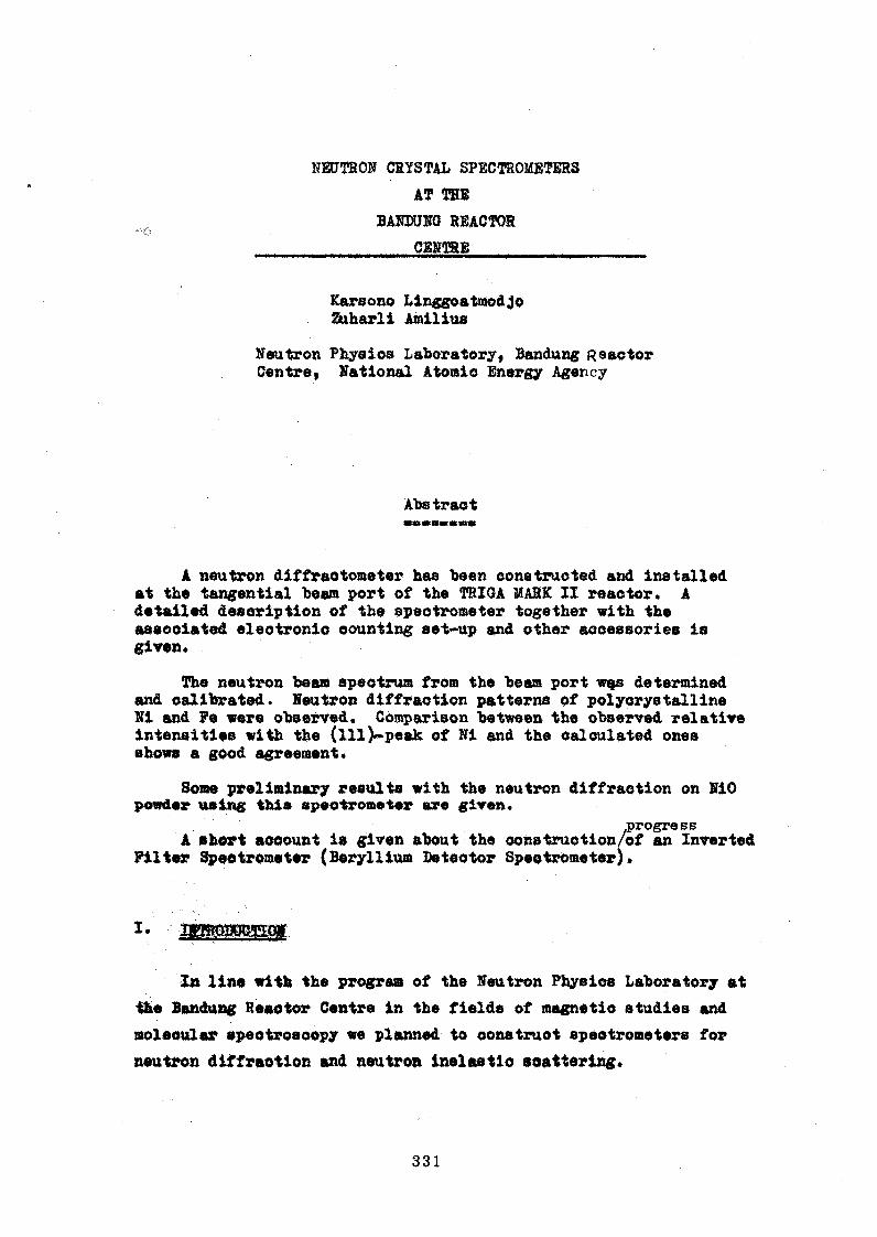
KEtJTRON CRYSTAL SPECTROMETERS
AT THE
BAKDUNQ REACTOR
__________CENTRE_____________
Karsono Linggoatraodjo Zuharli Amilius
Neutron Physios Laboratory, Bandung Reaotor Centre, National Atomic Energy Agency
Abstract
A neutron diffractometer has been constructed and Installed at the tangential beam port of the TRIGA MARK IX reaotor. A detailed description of the spectrometer together with the aaeooiated electronic counting set-up and other accessories is given.
The neutron bean apeotrust from the beam port wçs determined and calibrated. Neutron diffraction patterns of polycrystalline Ni and Fe were observed. Comparison between the observed relative intensities with the (ill)»peak of Hi and the calculated ones shows a good agreement*
Some preliminary results with the neutron diffraction on NiO powder using this spectrometer are given*
progressA short account is given about the construction/of an Inverted
Filter Speotroraeter (Beryllium Detector Spectrometer).
In line with the program of the Neutron Physios Laboratory at
the Bandung Reaotor Centre in the fields of magnetic studies and
molecular spectroscopy we planned to oonstruot spectrometers for
neutron diffraction and neutron inelastio scattering.

Considering the type of reactor we have, the area available
in front of the experimental beam hole, the ability of the loeal
hardware shop personnel and the possibility of a dual purpose
spectrometer, ire decided to construct a Doable Axis Crystal Spectro
meter of the Baoon et al« type /l/ and an Inverted Filter Spectro
meter (Beryllium Detector Spectrometer).
II. DESCRIPTION Ot THE SPECTROMETERS
1. Double Axis Neutron Spectrometer
The construction of this spectrometer started in 196? and it
was in operation two years later.
The plan view of this spectrometer is shown in Figure 1.
It waa Installed at the tangential beam port ot the TRIGA MASK II reactor.
This tangential beam tube terminates at the outer surface of
the reflector, but it is also aligned with a cylindrical void, which
intercepts the piercing tube in the graphite reflector, so as to pro
vide a neutron radiation source with a minimum amount of core gamma
radiation.
The polychromatic neutron beam is extracted from the reactor
through an in-pile 001limator placed inside the beam port tube. The
associated electronic instruments are kept outside the concrete
shielding. Also shown in Figure 1 is a beam catcher to trap
the primary beam from the reactor which has not been completely ab
sorbed by the monochromator shield. Pig 2 shows the wertioftl
view of the spectrometer.
The most important parts of a spectrometer are the in-pile
collimator, the monochromator, the Sol1er collimator, the detector
and associated electronics. A more detailed description will be given
below.

A* Collimating system
In order to increase the resolution of the spectrometer, it is
provided with two oollimators.
The first oollimator is placed between the monochromator and the
sample table. It is made of iron» measuring 60 cm In length and 25 x 5 <® in aperture oross-seotion divided into seven oollimating
channels by oadraiura sheets whioh make the angular divergence = 24*»The second Soller oollimator is located between the sample table and
the detector, placed together in a cylindrical shielding* It is 40 cm in length and has the same aperture oross-seotion, divided into eleven
channels giving the angular divergence of 22*.
The Soller oollimator has been designed and constructed according
to Saabo /if. The collimator has been checked by using a small BF^
counter mounted vertically in front cf the collimator and then scan
ning horizontally. The maximum peaks whioh 00cur at the axis of the collimator show good allignment*
5* Monochromator and Monochromator Housing
At present the monochromator crystal used is a Fb single crystal
of 3* x 2" i 3/8" plaoed in a reflecting position on a crystal table which has a spindle projected downwards» passing through a set of re
ducing gears to a right angle drive* The table can be rotated by turn
ing a small handwheel attached to the right angle drive and secured to
the shield stand. One revolution of the handarheel corresponds to l/6° rotation of the monochromator crystal table*
To reduce the environmental background radiations due to the
neutron scattered by the monochromator whioh would be detrimental to
the experiment to be performed» the monochromator was plaoed inside a
monochromator housing as shown in Pigs* 3 and 4«
A survey of the environmental background radiation showed that at
a reaotor power level of 250 kW the background was high» and an additional shielding of borated paraffine was plaoed around the monochromator
housing*

C. Spectrometer Assembly
The spectrometer is an X-ray spectrometer made by Picker Nuclear
Instruments Co., USA, modified for our purpose in order to be able to
support the BF^ detector with the shield and collimator. It is placed
on a oircular table with three adjustable jack screw legs. The angle
of rotation of the crystal sample table and the spectrometer arm can
be read within an accuracy of 0.01°.
'Hie angular movement of the crystal sample table and the spectro
meter arm can be fixed at 1*2 ratio. On the scan mode there is a
signal which can be used as a diffractometer controller.
the theTable 1 gives angular speeds of/2 8 (spectrometer arm) and/®
(sample table), including the stepping increment of 8 secs.
Table 1
increment of the angle 2 Ö increment of the angle 8gearratio
velocity of ..m s % * 2.Q..
increment .. ansie
gearratio
velocity of ansie 2 9
icrement of ansie
4*1 y8°/min OS o o 4/1 yi6°/min yi20°
2*1 y a y3o 2*1 ye 7601*1 72 i/15 1*1 y a y 301*2 1 2/15 1*2 72 y «
1*4 2 4/15 1*4 1 2/15
D. Detector and Associated Electronic Devices
The detection system consits of two channels, one for detecting
the diffraoted neutrons and the other for monitoring the incident
neutron beam on the sample. An end window B10? proportional counter
of 5 cm diameter and 40 cm length is plaoed on the spectrometer arm. It is covered with oadmium sheet surrounded by a borated paraffine
shield.

To aooount for reaotor power fluctuations a seoond B*°F is
placed in front of the first Soller oollimator. The prooedure
followed for data measurements was to measure the time needed to
oolleot a preset oount number rather than measuring the counts during a preset time*
The blook diagram of the electronics is shown in Fig. 5
2« Inverted Filter Spectrometer (Beryllium Deteetor Spectrometer)
This spectrometer is still under construction. Some parts have
been oompleted and the other are under construction. The neutron
beam will be extracted from the radial piercing beam port. This will
oause a large contamination of gaama radiation, and another problem
will be the appearance of fast neutrons*
The neutron beam catcher has been constructed larger than that
made for the double axis spectrometer*
The in-pile collimator is of the same construction as the pre
vious one except for the aperture sise which is 3” x 3”.
The monochromator housing and the monochromator table is now
being completed. It is designed to allow variable monohromatio
neutron beams to emerge from the monochromator * This can be fulfilled
by allowing the middle part of the monochromator housing, where the
beam tube passes» to rotate on ball bearings. This part will rotate
together with the spectrometer arm on which the Beryllium-filtered de
tector is attached to a smaller arm* If the smaller arm is unfixed
it can be rotated with respect to the first arm so that the spectro
meter could function as a double axis spectrometer*
With the establishment of the IABA Regional Cooperation Programme
on neutron spectrometry this project of the inverted filter speotro
raeter was incorporated into the framework of the Regional Cooperation*
Some parts of this spectrometer are to be designed and oonstruoted at
Trombay. This speotrometer is scheduled to be installed by the end of
m i .

the reactor speotrum at the beam port opening has been determined
and a calibration of the spectrometer has been done. Experiments are
underway on polycrystalline NiO and some alloys.
1* Determination of the reactor speotrum
Before using the first speotrometer as a double axis spectrometer,
in order to be able to make the proper wavelength selection, this
spectrometer was used as a single axis speotrometer to de termine the
energy speotrum of the thermal neutron extraoted from the tangential
beam* This determination was made by means of a copper single crystal
which had a small mosaic spread* Assuming that the neutrons are in
thermal equilibrium with the moderator, the shape of the speotrum
usually follows a Maxwell-Boltzmann distribution.
From the experimental results given in Big. 6 the wavelength at
the maximum of the distribution was 1.08 ♦ 0.01 2, whioh corresponds
to a neutron effective temperature of ? ■ 359° £• A measurement on
the moderator temperature gave ? « 318° £• It was also found that the
experimental curve was lower than the theoretical curve, This difference
could be caused by the detector efficiency, since the refleotivity and
resolution corrections were not taken into aocount. Furthermore, this
speotrum was not a Maxwell-Boltzmann speotrum, but rather more in agree
ment with the spectrum referred to by Larson et al* /3/•
dn - k exp
where k, m, and ^ Q are parameters whioh are determined by curve fitting.
According to Larson et al. the value of m is not equal to 4 as in the
vase of the Maxwel1-Boltzmann distribution*
2* Calibration
As it has also been tha case in the determination of the energy
speotrum, the sero angle of the speotrometer must be known before

determining the monochromator neturon wavelength in order to determine
the aoourate value of 2 6 for any position of the spectrometer arm.
To obtain the zero angle of the spectrometer, nickel was taken
as a standard. A cylindrical aluminium container containing the powder sample was placed on the sample table, and a pattern was obtained for
(hkl)— reflection in both parallel and anti-parallel positions of the
spectrometer. The pattern is given in Fig. 7* It can be seen that
the half value width of the parallel position peaks Is smaller than
tbat of the anti-parallel position ones, which is in agreement with the
theory of the double axis spectrometer /4/ «
Using aQ * (3.5238 ♦_ O .O O O 3) % from /6/ and knowing that nickel
is a faoe-centered cubic crystal, the wavelength of the neutron emerging
from the lead monochromator was found to be 1.318 X. Using this value
of the wavelength we determined the peak positions of the nickel and
iron diffraction patterns.
3* Neutron Dlffraotlon on lickel and Iron Powder
In the case of a cylindrical container or a cylindrical sample
placed vertically on tbs sample table, the number of neutrons diffracted
per minute into the detector is given by*
_ r _ i . <*>3 V i < * *IQ * 811“ r "" ß Sin 9 Sin
* the number of neutron« diffracted into the detector per minute
» the number of neutrons per unit per minute Incident on the sample
* the neutron wavelength
» volume of the sample
■ the height of the detector slit
* the distance from sample to deteotor
* the measured density of the specimen
* tbe theoretioal density
m the number of cooperating planes for the particular reflection being measured
» the number of unit cells per om^
337
where*
*o
y
18ri
?
?i
2 d « ¿hkl

F » structure factor per unit cell**2We ■ Debye-Waller temperature oorreotion factor
^kl ** a^sorP^ion factor© * Bragg angle
The Debye-Waller factor a for Ni «as calculated according
to Blake /?/*
The value of ia a complicated function of yM?8 and 3,
where B is the radius of the cylindrical sample and Ô is the Bragg
angle*
Claasen ¡6/ and TJradly /if gave the value of for Y-rays.
<0*5» *8 practically not dependent on
Ö, especially if Ô » 45° in the case of our experiments * The re»
suits of the measurements on the nickel powder diffraction pattern
are shown in Fig* 8*
Using the value of A « 1.138 % and aQ (Ni) - (3*5238 + 0*0003) Î,
the theoretical Bragg angle can he determined.
Tahle II helow shows a comparison between ©.v _ and 6 _tneor• exp*
fahle II
Por neutrons where M g
Plane (hkl) S 0theor. 2 e
..— .:...«SB*......
111 37.01° 37.70°
200 43.91° 43.00°
220 63.88° 63.71°
311 76.68° 76.62°
222 80*74° 80*51°
It can h» seen that the number of neutrons diffracted into the detector per minute will he proportional to jP^ eT^/Sin Q Sin 2 ©
and can he written as
J t - 3 5°2 ** •-** y ,P * constant x ~ j Sin © Sin 2©
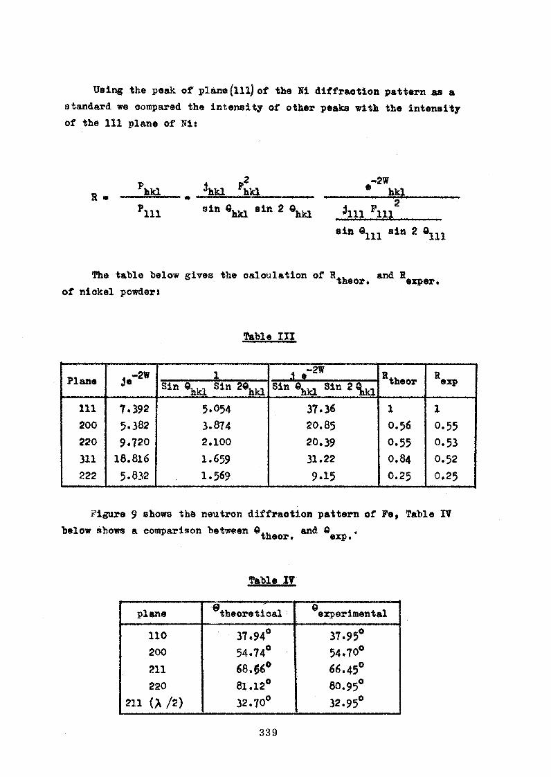
Using the peak of plane (ill) of the Hi diffraotion pattern as a
standard we compared the intensity of other peaks with the intensity
of the 111 plane of Sis
H „ Phkl _ A k l Fhkl____________________ 6 hkl
Plll 8in ehkl sift 2 6hkl 3111 Flllg________
sin ©m sin 2 dm
Th e table below gives the oaloul&tion of H . . „ and R ^theor » exper»of nickel powder*
Table 1X1
Plane áe-2* ..........................1......................... ... i *-2 W ......................... theor RexpSin ehkl Sin 20hkl Sin ©hkl Sin 2 ^
111 1*592 5.054 37.36 1 1200 5.382 3.874 20.85 O .56 O .55220 9*720 2.100 20.39 0.55 O .53311 18.816 1.659 31.22 O .84 O .52222 5.832 1.569 9.15 O .25 O .25
Figure 9 shows the neutron diffraotion pattern of Fe, Table IV
below shows a comparison between and 6 .* theor. exp.
Table IV
planee .....*....theoretioal ^experimental
110 37.94° 37.95°
200 54.74° 54.70°
211 68.$6° 66.45°
220 81.12° 80.95o
211 (A /2) 32.70° 32.95°

The peak at an ahgle equal to 32.95° is probably due to the
seoond order contamination of the plane (211).
4« Neutron Diffraction on Polycrystalline N10
In this experiment the powder sample of NiO was prepared by
heating Merck’s Nig 0^ to 00o C during a time long enough to change the ooolour from gray to greenish and then sealed in a pyrex tube.
The sealed tube containing the NiO was put into a cylindrical aluminium
sample container, measuring 10 mm in diameter and 70 mm in height, with a wall thickness of 2.4 mm. A beam of monochromator neutrons
reflected hy a lead monoohrcmator with a wavelength of 1.081 £ was used as the inoident beam.
With the reactor operating at a power level of 125 kW» & diffraction
pattern was observed at room temperature. The results of observation
*re shown in the following table along with the theoretical values.
hkl 2 « 9 ®theor.
m (111) 12° 38» 6° 19» 6° 24.5*
(4OO/2) 14° 50* 7° 24' 7° 2$«
(311) 24° 21» 12° 12° 19’
(222) « - mm
(222) 24° 52* 12° 26* 12° 51*(400) 29° 50* 14° 55* 14° 55*
(331) - -
(333) 39° 8» 19° 34* 19° 35*
(440) 42° 42' 21° 21* 21° 21 *
(440) 42° 44* 21° 22*
U m - — ....... ...................... .. . ... 122° 22*
Two interfering peaks can be observed, one from the second order
of (400) of NiO and the other from the (ill) plane of aluminium of the sample container*

The results of the experiment show that nickelous oxide is anti
ferromagnetic at room temperature, having magnetic peaks which can he
indexed on a magnetic unit cell with a^agn * 2 *m o j«
Crystal deformation occurs when the NiO passes from the paramagnetic
state to the anti-ferromagnetic state, that is from cubic to rhombohedral,
As a consequence of this deformation the nuclear (222) and (440) peaks
split* hut the (400) remain single. The splitting of the (440) peaks is seen from the non-symmetrioal shape of the peak. By estimating the split
ting we have oafculated a and c( using the Bragg law and the rhombo
hedral
d „ J Ë tl.ÍL .T .,X s o fs L .+ g.,.go|&, J ...... .................. ..........................hkl (h2 ♦ k2 + l2)sii?«< ♦ 2(hk ♦ kl ♦ lh)(ooao< - cos<)
Compared to the values by Hooks by /8/ and Poex /<?/ by thermal
expansion ooeffloient measurements, our estimated values aret
ours looksby Poex
<x 90° 7 » 90° 3*30" 90° 4’ 12« (by X-ray and diffr.resp.)
a 4 . 1 9 9 2 4.177 % 4.177 % (by thermal expansion of ooeff.)
The results stated above are still not conclusive. The experiment
is still in progress* We are planning to carry out experiments in order
to observe the diffraction pattern with the reaotor operating at
250 kW power levelf at much lower temperatures, such as at liquid air and liquid nitrogen temperatures * The recent pattern found with the
reaotor power of 250 kW at room temperature seemed to show the splitting
of the (440) peak of 181.
A cryostat has been constructed. In testing it we found some
leakages whioh need to be oorreoted* This experiment will be continued
according to the programme along with other experiments» e.g* diffraotion
on alloy systems.

Seen from the experimental results our spectrometer seems to be
promising. Up to now the main experimental difficulties are due to
the reactor, and the electronic counting set-up with the accessories.
The reaotor can operate at the full power of 25° kW not longer than
16 hours and the neutron flux received by the sample crystal was low,
i.e. of the order of 10^ beutron/cm^ sec.
The electronic counting devices including the detector have been
used for more than seven years. They always gave many disturbances and
oannot operate longer than five hours , otherwise they would become un
stable.
The spectrometer arm was lately driven manually after the motor
was burned. The collection of data was also done manually.
With the upgrading of the reactor to 1 MW steady state operation
and a better electronic devices, we hope that a higher Intensity and a
better resolution will be reached*
List of References
¡1/ E. W. Wollan and C. G. Shull: Phys. Rev. -73, 830, 1948
/2/ P. Szabo: ffucl. Instr. Methods 5» 184 (1959)
/3/ K. E. Larsson, R. Stedman and H. Palevsky: I. Nucl. en. , 6,222,1958
/4/ Acta. Cryst. 7» 464, 1954
/5/ Blake: Rev. Mod. Phys. 5» 169, 1933
/6/ A. Claasen: Phil. Màgn. (7), 9, 57, 1930
/7/ A. J. Bradley: Proc. Phys. Soc. London, 47, 879, 1935
/8/ H. P. Rooksby: Acta Crystl 1, 226 (194Ö)
/9/ G. Pex: Cont. Rend. 227, 193 (1948)

Fig. 1 Plan view of the Spectrometer
2 Vertical view of the Spectrometer
3 Middle part of monochromator house
4 Monochromator housing and shield
5 Block diagram of the electronic devices
6 Reactor spectrum
7 Calibration with polycrystalline nickel
8 Diffraction pattern of polycrystalline nickel
9 Diffraction pattern of polycrystalline iron

344
© IN P I L E COLLIM ATOR
© MONOCHROMATOR
(D S O L L E R SL IT
© MONITOR COUNTER
© S P E C T R O M E T E R
© S A M P L E
© SO LL E R SLIT
® M A IN DETECTOR
© B EAM CATCHER
® E L E C T R O N IC IN S TR UM E NTS
( f i ) S H IE L D IN G
Í 2 ) R E A C T O R S H IE L D IN G
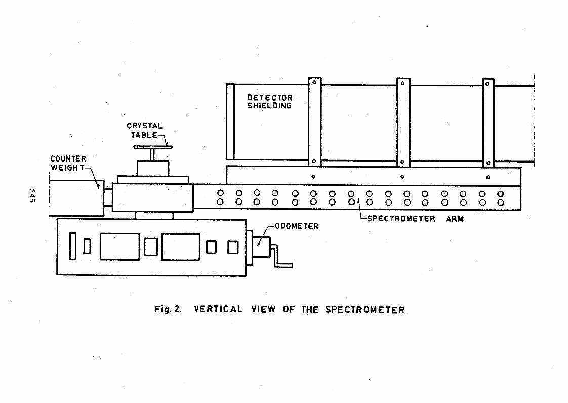
345
COUNTER WEIGH T—v
I--------- ^
o o A
DETECTOR I1
SHIELDING
CRYSTALTABLE-,
0 Ü o
1....... 1 1o o o
G o o o o o o o o o 0 o o o c) oO O O O O o O 04 O O o o o o o o
□ □7C
ODOMETER-SPECTROMETER ARM
Fig. 2. VERTICAL VIEW OF THE SPECTROMETER
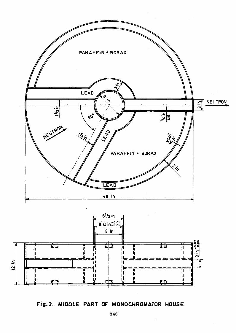
12 in
NEUTRON
8 Va in81/* in- 0)00
8 in
Fig. 3. MIDDLE PART OF MONOCHROMATOR HOUSE
346

28 V»
in___
12 in
. 10
in
COVERPLATE
Fig. 4. MONOCHROMATOR-HOUSING AND SHIELD
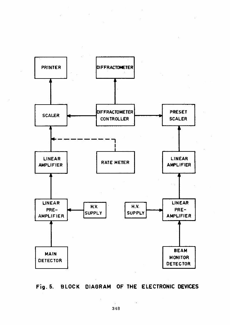
Fig. 5. BLOCK DIAGRAM OF THE ELECTRONIC DEVICES
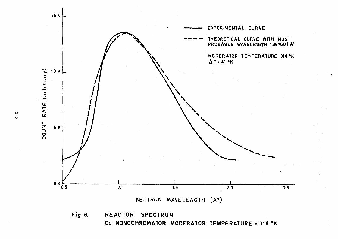
COUN
T RA
TE
(arb
itra
ry)
NEUTRON WA VE LE N GT H ( A ° )
Fig. 6. REACTOR SPECTRUMCu MONOCHROMATOR MODERATOR TEMPERATURE - 318 #K
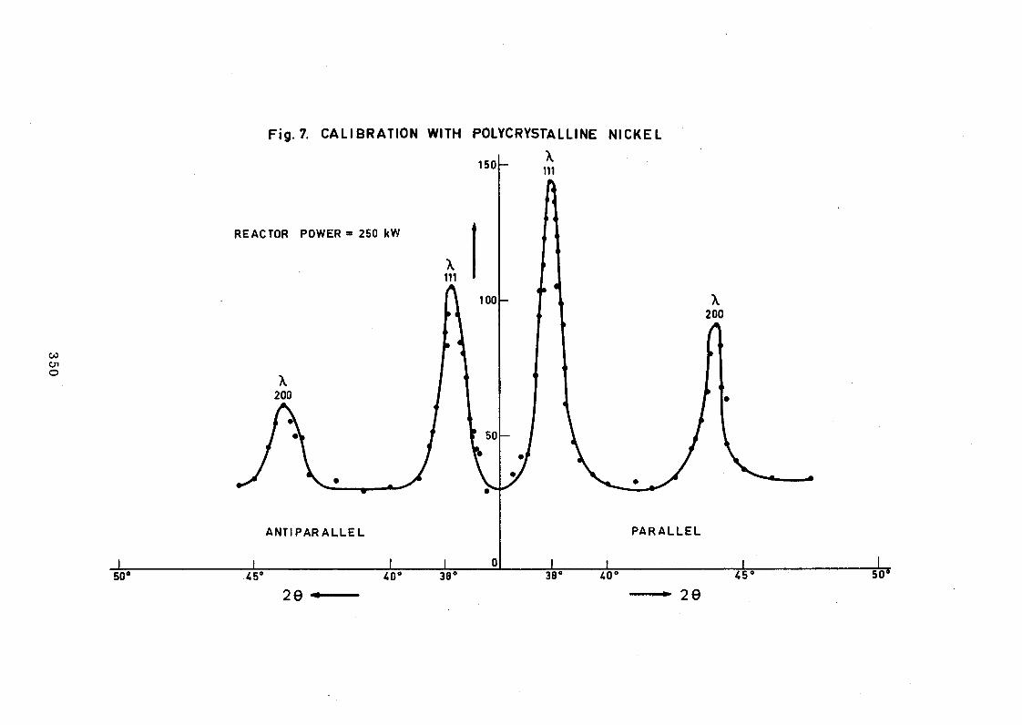
350
Fig. 7. CALIBRATION WITH POLYCRYSTALLINE NICKEL

X111
NEUTRON WAVELENGTH « 1.318 A0
REACTOR POWER = 250 kW
35 45 55 65 2 0
75 85 95
g. 8. DIFFRACTION PATTERN OF POLYCRYSTALLINE NICKEL

352
1 0 0
50
X110
NEUTRON WAVELENGTH » 1.318 A‘
20 30 40 50 60 70 60 90
Fig. 9. DIFFRACTION PATTERN OF POLYCRYSTALLINE IRON

DESIGN AND POSSIBLE UTILIZATION OP A NEUTRON GUIDE TUBE BISMUTH FILTER ON A BEAM HOLE EXPERIMENT ____________AT THE 1 MW TRIGA MARK II REACTOR _______________
*y
S. Jatiman, A. J. Surjadi, S. SupadiBandung Reactor Centre
Indonesia
Abstract
The use of a totally reflecting guide tube for low energy neutrons can produce a high intensity neutron beam with reasonable collimation. Use of a bismuth filter in the biological shielding is needed to attenuate fast neutrons and gamma rays. Moreover,
Thus, a lot of experiments like small angle scattering, studies of crystal properties, total cross section determination and so on can be designed utilizing a bismuth filter neutron guide tube.
1. INTRODUCTION
The refractive neutron index,
are the basic expressions in considering the neutron guide tube as a totally reflecting collimator tube (where: N ■= atomic density,
Using the neutron guide tube, there are two possible methods
(lll)-oriented Bi-single crystal filters have shown good transparency for > 4 X and also reasonable transparency for ^ ^ 4 Î A / *
- - 1 - * 2» a00h / (1)
and the critical angle,
(2)
a , = coherent scattering amplitude, A = neutron wavelength).COIX
for reducing the fast neutron and gamma ray background: i) bent guide
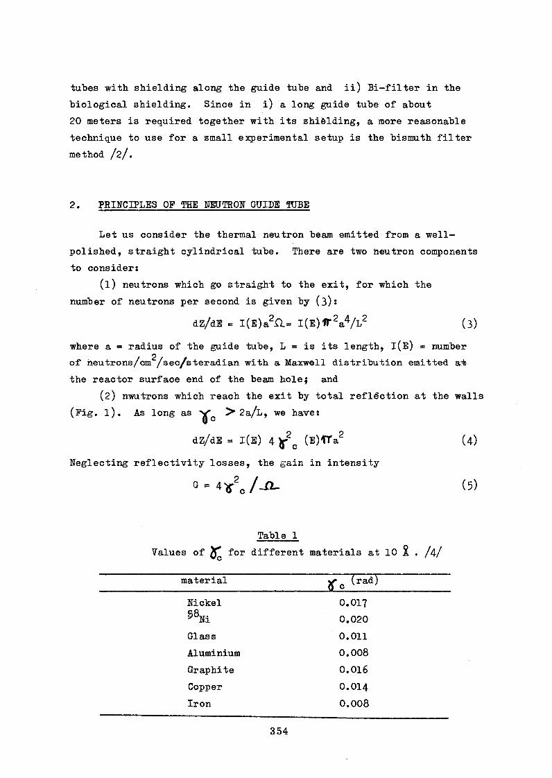
tubes with shielding along the guide tube and ii) Bi-filter in the
biological shielding. Since in i) a long guide tube of about
20 meters is required together with its shièlding, a more reasonable
technique to use for a small experimental setup is the bismuth filter
method /2/.
2. PRINCIPLES OF THE NEUTRON GUIDE TUBE
Let us consider the thermal neutron beam emitted from a well-
polished, straight cylindrical tube. There are two neutron components
to consider*
(1) neutrons which go straight to the exit, for which the
number of neutrons per second is given by (3)s
dZ/dE = l(E)a2r U l(E)1T2a4A'2 (3)
where a *= radius of the guide tube, L = is its length, l(E) = number
of neutrons/cm /sec/steradian with a Maxwell distribution emitted a?fc
the reactor surface end of the beam hole; and
(2) nwutrons which reach the exit by total reflection at the walls
(Fig. l). As long as > 2a/L, we haves
dZ/dE - 1(E) 4 c (E)'TTa2 (4)
Neglecting reflectivity losses, the gain in intensity
0 = 4 >r2o / - Q - (5)
Table 1
Values of X* for different materials at 10 % , /4/
material?fc (rad^
Nickel O.OI7S’8» 0.020
Glass 0.011
Aluminium 0.008
Graphite 0.016
Copper O.OI4
Iron 0.008

Thus, the gain would be about 60 for a 6-meter mirror glass tube
with 3 cm disuneter, using the critical glancing angle of nickel
for a neutron wavelength of 10 %.
^he direct part of the beam can be eliminated by bending the
tube.
3. PHYSICAL LAYOUT OF GUIPE TUBE-BI-FILTER DESIGN
Figure 2 shows the bismuth filter and the neutron guide tube
arrangement designed for the beam hole of the 1 MW Triga Mark II
reactor. The quality of the reflecting surfaces usually is the
most important factor in determining the useful range of applica
tion of the neutron guide tube. So far, very favourable results
have been obtained in KFA Jiilich, Fed. Rep. of Germany /5/* Its
smoothness over a distance around 10 cm, deviations (deviations
from a plane) are smaller than 0.5 x 10
3.1 Apparatus
The beam hole ahead of the bismuth filter must be narrowed with
a graphite collimator to reduce fast neutrons and gamma rays flux
near the outer end of the biological shielding. The neutrons then
arrive at the bismuth single crystal filter, which has (ill) orienta
tion and. a total length of 40 cm and 4 cm diameter. To reduce in
elastic scattering, this filter is cooled with copper tubes surrounding
the filter. Activation of the filter container is reduced using
a cadmium shield. The mean transmission factor for fast and epithermal
neutrons is given 1—
where 0(E) describes the spectral distribution of the neutrons in
the light water reactor core /2/. For the 40 cm bismuth filter we
have a transmission factor T of 1.5 1 10 Thus, for a fast

2.2 2neutron flux in the core of 5 x 10 n/cm (at 1 MW power) the
transmission current density at the exit end of the guide tuhe is i 2
ahout 10 n/cm sec. The gamma rays are much more attenuated hy
the 40 cm Bi filter than are the neutrons.
The maximum intensity of sub-thermal neutrons at the end of8 9 2
the 3-meter guide tube is in the range of 10 - 10 n/cm sec; but
if there is no liquid nitrogen cooling of the bismuth filter, this
value should be decreased by about 50 $ for neutrons with wavelengths
larger than 5 & (see Fig. 3).
3.2 Shielding
With a minimum beam area of /ÎTx (l«5)^ =8 cm^ and a maximum2 2
area of IT x (2.5)c = 20 cm we have a total fast neutron flux at
the beam hole of 1.3 - 3*4 x 10^ fast neutrons/sec. Talking this as
a point source at one meter distances there are 10 to 30 fast neutrons/sec cm . For this, a shield of 10 to 20 cm of water or
paraffin near the end of the beam hole would be sufficient. Also,
along the guide tube there is no appreciable fast neutron dose at a
distance greater than 0.5 meter.
4. FEASIBILITY STUDIES AND EXECUTION
For this project, the following major components must be con
sidered:
(a) liquid-nitrogen-cooled bismuths filter,
(b) neutron guide tube,
(c) counting equipment, and
(d) special equipment for neutron scattering experiments.
The equipment in (d) depends* on the experiment to be done, and
need not be considered until parts (a), (b) and (c) are completed.
Construction of the filter cryostat, shielding, and the guide tube
support wall be done in the workshop of our nuclear centre, while
the bismuth filter and neutron guide tube will be bought elsewhere,

Another problem area involves the electronic equipment. The
system we have used is shown in the schematic diagram of Fig. 4 /6/.
It is desired that this system be provided with about 6 counters,
two of them acting as monitors.
We have estimated approximate prices for the projects
A. - Bi -filter )
- guide tube ) US$ 7>500
- vacuum pump )
- liquid nitrogen container )
B. - electronic equipment )
- 6 counting tubes )
- 6 amplifiers ) US$ 23,000
- high voltages )
- crystal goniometers, chopper etc.)
C. materials for the workshop.
5. POSSIBLE EXPERIMENTS
5«1 Transmission experiment with time-of-flight technique
Pulses, of neutrons can be produced by a chopper and the
energies of the neutrons can be analyzed at a flight distance of
2 meters using a BF^ detector (Fig. 5a)* It will be possible to per
form experiments like total cross sections determination, obtaining
the transmission factor as function of the time-of-flight, this will
measure the total cross section directly. For such experiments a
multi-channel analyzer is needed.
5.2 Neutron diffraction experiments
Using the arrangement shown in Fig. 5^» whereby the azimuthal
position of the detectors can he varied to determine the scattered
neutron intensity distribution, various studies of crystal properties
will be possible. ,
5*3 Small angle scattering experiments
Using the neutron guide tube, a well collimated neutron beam
can be obtained with which it will be possible to perform experiments5
small angle scattering measurements with the set of four BF^ detectors.
The distance between the entrance slit and the outlet slit will be
2 meters and the distance between sample and detector plane about
2 meters (Fig. 5°)• In considering a small angle scattering experiment,
there are certain restrictions on beam geometry which determine the
minimum detectable angle Q . . The energy must be smaller than them m
Bragg cut-off energy of the sample to avoid double Bragg reflection.
A resolution of about A E/E = 0.4 may be expected to be sufficient
for most scattering studies using neutron instead of X—rays methods,
since the scattering law is a rather smooth function of the momentum
tranfer /2/. The required energy resolution can be obtained with a
chopper selector.
6. CONCLUSION
A neutron guide tube-bismuth filter facility can be constructed
and used effectively for experiments involving sub-thermal neutron
beams. This facility will provide for a low background of fast neutron
and gamma radiation. Elimination of shielding for gamma and fast neutrons
in some experiments and the possibilities to perform with one channel
are relatively more economical alternatives.
This is a proposal to prepare a facility for some applications
in research and training of students with a beam hole of the 1 MW Triga
Mark II Research Reactor.

/l/ Rustad. B. M. Rev. of Sei. Instrum., p. 50-51 (1965) 36.
/2/ Schmatz W. private communication, KFA Jülich, West Germany
/3/ Maier Leibnitz H., Springer T., J. of Nuclear Energy 219
(1963) 17.
/4/ Jacrot B., Instrumentation for Neutron Inelastic Scattering
Research (Proc. of a Panel ¥ienna 1969) IAEA Vienna, 226
(197O)/5/ Alefeld B., Christ J., Kukla D., Scherm R., Schmatz W.,
Jülich, Rep. No. 294 NP
/6/ Borer Electronics & Co. Solothurn, Switzerland.
Fig- 1
Schematic representation of a straight guide tube of length L

¿ f /y ,' sS S roaotor shielding /
' ' ^ s S S / Z .
Bi-filter
guide tuhe
3.32 a
Fig. 2
Physical layout of the hi-filter guide tuhe

Fig. 3
Total neutron cross section of a Bismuth single crystal at room and liquid nitrogen temperatures /l/.
4
Counting system with read out logic

d e f e c f o r
FiS» 5a
d e t - e c . ' i 'o r .
Fig. 5~b
p ef e c-hor
F i g » 5 c h , i — ---------------------------------------------------- ---- — B e a m S - f o p

H*G* Notera and Q.O. Navarro Physics Department
Philippine Atonie Research Center Diliman, Quezon City, Philippines
ABSTRACT
Current research activities on neutron spectrometry at the Philippine Atomic Research Center are reported« Several related activities yhich include the construction, installation and improvement of ancilliary facilities are also briefly reported. A list of previous reports on neutron spectrometry research at PARC is given,
INTRODUCTION
The Philippine Atomic Research Center has two types of
neutron spectrometers installed at the Philippine Research
Reactor (PRR-l). These are the Double-Axis Neutron Spectro
meter and the Beryllium Detector Spectrometer. The Double
Axis Neutron Spectrometer was initially loaned by the
Government of India for the five-year IPA (india-Philippines-
IAEA) project which started in January 1965 and was subsequent
ly donated to the PARC upon the termination of the project.
This Neutron Spectrometer has been used mainly for the
investigations of magnetic materials, liquids and crystal
structures. The Beryllium Detector Spectrometer, on the
other hand, was locally fabricated and has been used for

investigations of crystal hydrates and ammonium salts*
The present report gives an outline of the neutron
spectrometry research and related activities currently
being Undertaken at PARC by the Physics Department. The
report also gives the list of previous works that have been
undertaken»
CURRENT RESEARCH ACTIVITIES
1« Investigations on Doped Hematite
The aims of the present study are to determine the
atomic ordering, magnetic structures, sublattice magneti
zations and magnetic transition temperatures of doped hema
tite and to study the systematics of the various structural
and magnetic properties with the concentration of impurities.
Initial investigations are being made on the x AlgO^Cl-x)
Fe2°3 •y®*6®*
2. Atomic and Magnetic Ordering in Ternary Alloys
The project involves the determination of the magnetic
ordering in ternary alloys of transition metals. These
investigations form part of an extensive program on the
study of the behaviour of transition metal atoms in various
crystalline environments. Samples of CoMnGe and CuMnGe are
currently being investigated.

Previous work has been made during the IPA Project on
nanganese-nickel carbide and manganese-zinc carbide* In
continuation of the studies of the behaviour of magnetic
atoms in carbides, samples of (Mn, Co)^C with different
concentration ratios of Mn to Co are being prepared to study
the magnetic properties, particularly the magnetic phase
diagram of the system*
4-, Magnetic Transitions in Ferrous-Zinc Ferrites
Ferrous-zinc ferrites exhibit a spinel structure*
Extensive experimental and theoretical investigations have
been made on this type of ^sffuctures* The aim of the
present study is primarily to determine the magnetic
transitions in ferrous-zinc ferrites using neutron diffract
ion methods* The studies also involve the determination of
magnetic structures, sublattice magnetizations, as well as
structural parameters of the samples. From these studies,
the nature of the Verwey transitions and the magnetic
2+ 3+interactions among Fe and Fe ions above and below the
Vexwey transitions may be elucidated* Similar investigations
will be made using the MSssbauer Spectrometry facility of the
Physics Department to oomplement the Neutron Spectrometry
results*

1. Modification of the Liquid Nitrogen Cryostat
A liquid nitrogen cryostat for use in neutron spectro
metry has been built during the time of the IPA project.
Defects in the design and fabrication exist which prohibit
the cooling of the saaple down to liquid nitrogen temperatures
and the cleaning of the accumulated dirt inside the cryogenic
vessel* To remedy these, a new inner vessel has been made.
The new design will allow the cooling of the sample not only
at liquid nitrogen temperatures but also at intermediate
temperatures from liquid nitrogen temperature to about 500°C.
Another cryostat incorporating the new design of the
inner vessel has been planned for construction so both the
double-axis neutron spectrometer and the beryllium detector
spectrometer can be used simultaneously for low temperature
experiments.
2. Construction of on Arc Furnace for Materials Preparation
Working drawings of an arc furnace for the preparation
of high melting point materials have been made and submitted
to the workshop for fabrication» The first phase of the
project involves the construction of a single arc furnace.
Both the anode and the cathode bodies are water-cooled. A
ball and socket assembly allows for the swinging motion of

the tungsten electrode* The construction materials are
mostly brass; the hearth is made of graphite and is movable
vertically*
The second phase of the project involves the construct
ion of a tri-arc furnace* The anode body remains basically
the same as that of the single-arc furnace* The cathode
body, however, contains three electrodes each mounted in a
ball and socket assembly and a central rod for pulling a
single crystal seed from the melt*
Crystals grown from this facility will be used for
neutron spectrometry, MBssbauer spectrometry and other
physics experiments*
3* Boll Milling Facility for Sample Preparation
A simple stainless steel ball mill has been fabricated
in connection with the preparation of materials for neutron
spectrometry research*
4* Installation and Testing of New Vacuum System
A vacuum system has been installed and successfully
tested for use at low and high temperature experiments on
the Double-Axis Neutron Spectrometer*
The fabrication of vacuum components such as, oil
diffusion pumps, vacuum valves, couplings and various fit
tings have been programmed* The fabrication of these
components will allow the setting-up of another vacuum

system facility for use with the beryllium detector spectro
meter which will become necessary when simultaneous runs of
both the Beryllium Detector Spectrometer and the Double-Axis
Neutron Spectrometer are carried out.
5. Neutron Diffraction Electromagnet
The regulated power supply for the locally built neutron
diffraction electromagnet has been repaired and tested* The
electromagnet will be tested and the magnetic flux will be
mapped for various pole gaps.
The design of a ball-race support for mounting of the
heavy electromagnet on the neutron spectrometer table is
being undertaken.
6. Computer Programs for Neutron Spectrometry
Several computer programs for the analysis of neutron
scattering data are available. The adaption of these
programs for the PES-DND computer is being made for facilit
ating the analysis of neutron diffraction data obtained at
PARC.
7. Installation of Philips X-ray Diffractometer
A Philips X-ray Diffractometer has been purchased and
is currently being installed in the Physics Department
Laboratory. The x-ray diffraction facility will complement
the research work being undertaken on neutron spectrometry.
8. Improvement of the Beryllium Detector Spectroweter
Experimental work using the Beryllium Detector Spectro
meter has temporarily been suspended. Improvements of the
facility are being made. Among those that have been complet
ed are the overhauling of the second axis of the spectrometer
to check the non-smooth movements of the detector arm; the
adjustment of the gear-drive assembly to minimize the back
lash in the main arm movements; improvement of angular scales;
adjustment of the detector shield; and improvement of the
associated electronics and controls.
LIST OF PREVIOUS REPORTS
The following is a list of previous works that have been
made on neutron spéctrometry at PARC.
1. Removal of Second Order Neutrons by Oriented SingleCrystal Filters. Nucl. Instrum. & Meth.. 37 (1965) 121-124. — 7
2. Computer Programs for X-ray and Neutron Diffraction Work. Philippines Nucl. Journal, 1 (1966) 37-41.
3. Neutron Diffraction Studies on MnAl, Mn2Ni2C, and MnZn-.Philippines Nucl. Journal, 1 (1966) 23-27. 3
4. Neutron Diffraction by Liquid Zinc.Physical Review, 173 (1968) 241-248.
5. Neutron Crystal Spectrometry. Instrumentation and Techniques. PAEC(D)PH 671.
6. A Modified Electronics System for the Beryllium Detector Spectrometer. PAEC(D)PH 674.

7. A Quasi-crystalline Model for Liquid Zinc. PAEC-IPA(D)PH 676.
8. A Program to Calculate Data for Two-Dinensional Single Crystal Experiments. PAEC(D) 693.
9. Study of the Static and Dynamic Structure of Solids by Neutron Spectrometry. PA£C(D) 685.
10. A Neutron Diffraction Study of the Crystal Structure of Sodium Thiosulfate Pentahydrate, ^23202.51^0. PAEC(D) 691.
11. Lectures on Crystallography and Neutron Diffraction. PAEC-IPA(D)PH 681.
12. Seminars on Neutron Crystal Spectrometry. PAEC-IPA(D)PH 661.
13. Neutron Diffraction by Liquid Zinc. PAEC(D)PH 675.
14. Removal of Second Order Neutrons by Oriented Single Crystals. PAEC(D)PH 652.
15. Crystallographic D-Space Program PRRI-XNDS» PAEC-IPA(D)PH 664.
16. Structure Factor Program PRRI-NSF. PAEC(D)PH 665.
17o Neutron Diffraction Studies on Manganese Alloys. PAEC-IPA(D)PH 662.
18. Pair Correlation Function of Liquid Zinc. PAEC-IPA(D)PH 673.
19. Study of Liquids Using Thermal Neutrons. PAEC-IPA(D)PH 672.
20. Neutron Diffraction Studies Using Neutron Spectrometer. PAEC(A)AR 651 p .79.
21. Neutron Diffraction Refinement of the Crystal Stvçrcture of Potassium Copper Chloride Dihydrate, «„CuCl..2^0.Acta Crystallographica B26, 827 (1970).

22« Study of the Rotational Behavior of the Ammonium Ion in NH^Cl and NH^Br Crystals. PAEC(A) 6910 p.67.
23. Study of the Vibrational Motion of the Water Molecule in
K2C2°4*H2°* paec(a) 6910 P«67.
24. Study of the Lattice Parameter of Pd«MnGe. PAEC(A) 6910 p . 6 8 .

A REPORT ON THE BEAM PORTS UTILIZATION OP THE TSING HUA OPEN POOL REACTOR
by CHEN-HWA CHENG and CHIO-MIN YANG
Institute of Nuclear Science
NATIONAL TSING HUA UNIVERSITY, HSINCHU,
TAIWAN, REPUBLIC OP CHINA.
ABSTRACT
Experiments utilizing The THOR beam ports are described. These
experiments includes
a) fuel burnup determination by measuring the neutron age
after collaiding with the bombarded elements,
b) determination of the thermal neutron spectrum by the
chopper and time of flight technique,
c) capture gamma measurement,
d) ore analysis by the delayed neutron method and
s 6e) fast neutron spectrum determination using a Li ^
neutron detector and the coincidence counting
technique.
The Tsing Hua Open Pool Research Reactor (THOR) has been established
in I96I in the Republic of China. It has 6 beam ports and one through port.
The beam ports are 6" in diameter and 8 ft in length, they are designated as
E1 , E^, ,!y and W^> respectively.
The W-, port has been used for nondestructive fuel burn up experiments^2
since 1967* A beam of neutrons of about 0.25 Cffl cross section is collimated
through a cement plug filling the port. A tank of water (or waterglass) is
placed just in front of the port opening. A horizontal tube at the same height
of the port is built into the tank so that the beam can be conducted right
through the center of the tank. A rectangular tube is placed along the center
line of the tank vertically. It crosses the horizontal tube at a right angle
and it is lined with cadmium except where the beam meets the fuel element. A
fuel element can be placed into this vertical tube and moved up and down so
that different parts of the element can be exposed to the neutron beam.

, The principle of this experiment is that fast neutrons from the beam
port have a somehow higher Fermi age than those from the fission neutrons
because they have interacted with the graphite reflector and the water. The
thermal neutrons, while bombarding the fuel nuclei, will cause fissions.
These interactions will in turn release fission neutrons which are of lower
age than the neutrons from the beam port and are scattered into the tank medium.
Thermal neutrons from the beam can not enter the tank medium because of the Cd
lining. By comparing the distribution of the neutron slowing down density at
1.4 ev aJid that of the thermal neutron distribution due to a brand new fuel
element and a used element, the fuel burnup can be calculated. The preliminary
results from these experiments are fairly good.
The W-3 beam port has been used for measuring the thermal neutron(2)
spectrum as 3. standard student laboratory experiment '. The neutrons
are conducted from the beam port by a collimator so that the beam cross2 4
section is about 1 cm . A high speed chopper with 10 rpm maximum speed
is placed in front of the beam port, and a BF^ counter is placed about 1 m
away behind the chopper so that the thermal neutron beam is chopped into short
pulses of about widths with about 10000y||s separations. When the chopper
is in operation, a triggering signal is produced each time when the cadmium
sheets in the chopper are exactly parallel to the beam. These triggering signals
are sent to a multichannel analyzer set-up for the time of flight measurement.
The thermal neutrons from the burst made by the chopper consist of neutrons of
various speeds but all flying toward the BF^ counter. The BF^ neutron counting
output is fed into the analyzer thus neutrons with high speed will reach the
counter ea.rlier azid be registered in the first few channels and those with low
speed will be registered in the last ones. The system is set to work when the
reactor is in full power. A collection of neutron counts for half an hour or so
will result in a perfect Maxwell-Boltzmann distribution spectrum.
The E-3 beam port has been utilized in the past for capture gamma(l) 2
measurements . A collimator with a hole about 1 cm was inserted into the
port. Proper shielding with paraffin and lead was placed to prevent stray gamma
rays from interfering with the measurement. The neutron beam passed through a
one meter long tube of 4 and 5 cms inner and outer diameter respectively. The
space between the inner and outer diameter is filled with 6 LiF to prevent the
scattered neutrons from reaching the detector. Fe and Pb targets were placed
in the center of the tube and two 3" x 3" Nal (Tl) detectors were placed at a
right angle 10 cm away from the target for coincidence counting. A TMC 256

channel analyzer was used, to analyze the collected counts. The spectrum obtained
was clear and satisfactory toward the high energy end from 6 Mev and up. Due to
the poor resolution of the Nal(Tl) detector and the high Compton plateau, the
overall data was considered rather poor. This could be improved by using a
detector which has better resolution. The whole experimental system has been
temporarily withheld due to lack of funds. It could be resumed whenever proper
financial support is obtained.
The E„ beam port was set up for analyzing minerals containing fissile( A \
and fissionable material by the delayed neutron method ' '; a pneumatic irra
diation facility was built for this beam port. Containers containing prepared
samples were sent to and withdrawn from the vicinity of the reactor core by a
pneumatic system at the command of the experimenter. After exposing the
sample to the reactor neutron radiation for a certain time, it was withdrawn.
The sample* after the exposure ,emits delayed neutrons if
it contains fissile or fissionable elements. A bank of 6 BF^ counters
placed in a bulk of paraffin was designed for the neutron detection.
For a sample with predetermined weight and a definite period of exposure,
the amount of delayed neutrons detected determines the fissile material
concentration of the mineral. Several years of operation proved that
the system design was successful to accomplish our purpose. It is expected
to obtain a more sophisticated facility, such as multiscaler, which will
enable us not only to determine the concentration of the fissionable material
but also to identify the proportion of existing isotopes. Neutron spectrum(5)
measurements of the beam from the beam port were performed w '. A
surface barrier lithium detector was used for this purpose. The reaction
i 6 4 3n + L i ----------- He + H
o 3 2 1
was used for this measurement. The total energy of the products 4jje
2and 3 was measured by coincidence counting of pulses caused by the
H 1
alpha and the tritium particles in the detector. The energy is the sum
of the energy released from the splitting of the compound nucleus 7Li
that of the neutron. With the energy measurement and coincidence events

collected from a TMC 400 channel analyzer, the spectrum of the neutrons
from the "beam port can be computed from the known cross section of 6 asLi
a function of the neutron energy. Results of this experiment are given in
(5)reference .
REFERENCES
(1) Chia-Shi Lin, Jensan Tsai
Non-Destructive Determination of Reactor Fuel Element Burnup
P.-285, Vol.8, Wo.5 , I97I, Journal of Nuclear Science and Technology.
(2) Wei Hsiang Teng, Jin Bor Sun and Chia Shi Lin
Slow Neutron Chopper Measurement at THOR
p.33* Vol.5, June 1967* Nuclear Science Journal.
(3) Chio Ming Yang, David Ta-Tao Ma and Hsien Chum Meng
The Setup of a r-r Coincidence Spectrometer^Muclear Science Journal.
P. 47, Vol.6, No.3-4, April 1969.
(4) N.K. Lee, S.C. Lin, J.P. Chien and Y.H. Lee,
Ore Analysis for Thorium and Uranium by Delayed Neutrons* Nuclear
Science Journal.
Vol. 5, No. 1-2, December 1966.
(5) Teh-Li Yang, Chen-Shyong Yen
Measurement of Fast Neutron Spectrum Outside Beam Port by
Li-6 Semiconductor Spectrometer.
P. 262, Vol.8, No.5 , I97I
Journal of Nuclear Science and Technology.

1• Introduction
During the Study Group Meeting a subgroup meeting on engineering
was organized to explore relevant activities that the countries of the
region could undertake on a cooperative basis. The subgroup, which met
on 4th and 5th fo August, included«
Australia: A. C. Wood
Chinas Chen Hwa Cheng
France: F. Merchie
India: S. K. Mehta
Indonesia: B. Sudarsono
Korea: B. W. Lee
Pakistan: H. M. Butt
Philippines : L. D. Ibe (Chairman)
S. Vietnam: Ngo Dinh Long
Thailand: R. Pumlek
U.S.A: L . Koch
2. Discussion
The subgroup recognized that the countries of the region who have
or are planning to have nuclear power plants, should initiate possible
cooperative engineering studies as soon as possible. Sach studies should
aim to train the pertinent power plant personnel ons
a) the design features of the nuclear reactor system;
b) the operational problems involved;
c) the changing technology in the various fields;
d) the various development problems involved in maximizing the parti
cipation of indigenous industry and the use of indigenous material
including fuel; and
e) assembling a core of engineers to participate in the design of
future reactors.

Since the development of the nuclear technology is very complex and
expensive, the engineering experimental work should be carefully planned.
It was also recognized that most of the countries in the region have low
flux reactors.
Even though a substantial in-pile experimental programme related to
some aspects of the design of reactor components and systems is not
feasible in these countries at this stage, it was felt that even a very
modest programme of work could be a useful start to fulfilling some of
the above objectives. The engineering subgroup therefore examined various
areas of interest in which an effective regional collaboration could be
achieved. One of such area of importance is thermal-hydraulic analysis
of the reactor. For this case, it was recommended that the first stage
of work should be studies in out-of-pile loops, in particulars
(a) heat tranéfer studies in single-phase and two-phase flows;
(b) pressure drop studies ;
(c) vibration and fretting studies;
(d) sub-channel mixing studies;
(e) äryout (or burnout) studies;
(f) parallel channel flow distribution studies; and
(g) parallel channel flow instability studies.
The above studies are only preliminary to more advanced studies involving
the construction and operation of in-pile loops. It was considered that
where a country might expect an early initiation of its nuclear power pro
gramme, the more advanced studies programme should be started with the
building of in-pile facilities in the country involved, or through access
to facilities existing in other countries of the region.
Other areas of engineering interest discussed included study of
coolant chemistry technology and corrosion behaviour of materials. These
studies would also be initiated firstly in out-of-pile loops and later at an
appropriate time by detailed in-pile studies.
Some of the countries such as India have an existing fuel development
programme, while others such as Korea and Pakistan are in the intitial stages
of developing an indigenous fuel fabrication industry.
It is desirable that access be made available to larger reactors for
fuel development tests in those cases where local in-pile testing facilities
are not adequate- It was noted that there is a 40 MW MX-type reactor
already in the region in India, with another under construction in the
Republic of China. These reactors are suitable for experiments of the
type required for studies in fuel fabrication technology.
3. Conclusions and Recommendations
Regional collaboration in such various areas of interest as
those given above could initially be started by the exchange of experimen
tal data and personnel, and by the training of personnel in other countries
of the region. Later, this could be followed, when required, by assistance
in the design of experimental rigs and by the loan of appropriate in-pile
and out-of-pile facilities. Such an approach could be expected to promote
a better understanding of the development programmes of the countries of
the region.
The subgroup felt that to meet the growing engineering development
needs of the region, some of the existing facilities in the member countries
may have to be augmented. While every effort should be made by the countries
in the region to solve such problems without outside assistance, it was
felt that some limited Agency support in the form of financial and tech
nical assistance could at times be of decisive help to the success of
these efforts.

1. Introduction
The discussions of the first two days of the study group meeting
made it clear that the participants were very favourable to exploring
the possibilities for regional cooperation. A physics subgroup was
therefore formed to study possible new areas for cooperative work of
interest to the countries of the region. The subgroup met with the
background of the 1970 Bangkok meeting available to it.
The subgroup, which met on the 3rd and 5"th August 1971» included
the following participants:
2. Conclusions and Recommendations
The committee felt that the field of nuclear detection and analysis,
which includes neutron activation analysis and neutron radiography, is
of sufficient importance and interest to the countries of the region to
serve as a basis for regional collaboration. Fluorescent X-ray spectroscopic
analysis should also be included in this field for completeness. Collabora
tion among the countries could consist in the establishment, improvement
and standardization of the techniques involved in the above mentioned
areas. Another important feature would be the exchange of scientific
information, samples, etc.
As a first step towards collaboration in this field, it was agreed
that a report containing the following information 'fteomrthe countries in
volved should be developed within the next two months:
a) Personnel and their qualifications,
b) Existing facilities (including technical details)
Australia:
India:
Indonesia:
A. C. Wood
B. A. Dasannacharya
S. Soepadi B. Sudarsono
Korea H. J. Kim
N. M. ButtPakistan
Philippines: M. G. ÎTatëra
Rep. of China: Chio Min Yang
Thailand: S. Chatraphorn

c) Current activities,
d) Future plans,
e) Limitations.
S. Soepadi agreed to act as the coordinator for this report, and
the various members will send their report to him. On the bads of
their reports more concrete proposals may be made.
The members suggested that it would be useful if the IAEA could
distribute abstracts of information available in the above field to the
members of the subgroup.
The other field of activity discussed in which some cooperation already
exists is that of neutron spectrometry. The existing collaboration can be
strengthened by the exchange of data and suitable samples between the
countries of the region.
The subgroup strongly felt that a school on neutron spectrometry
should now be held in the region under the auspices of the IAEA. This
school would discuss the current state of neutron spectrometry methods
and related research.

INDIA
INDONESIA
CHINA Mr. Chio-Min Yang
D r . Chenhwa Cheng
D r . R . Ramanna
Mr. S.K. Mehta
D r . B.A.Dasannacharya
Prof. G .A . Siwabessy
M r . Budi Sudarsono
Dr. k.J. Surjadi
Mr. Soleh Somadiredja
Mr. Suroto Ronodirdjo
Mr. Sutomo Jatiman
Mr. Soetjipto Wijadi
Mr. Soetario Soepadi
Mr. Ijos Subki
Mr. Karsono Linggo- atmodjo
Mr. 3uharli Amilius
Dr. Oei Ban Liang
Institute of Nuclear Engineering National Tsing Hua University Taipei, Taiwan
Institute of Nuclear Science National Tsing Hua University Taipei, Taiwan
Bhabha Atomic Research Centre Trombay, Bombay 85
Bhabha Atomic Research Centre Trombay, Bombay 85
Nuclear Physics Division Bhabha Atomic Research Centre Trombay, Bombay 85
Indonesian National Atomic Energy Agency, Djl.Palatéhanï/é?6 Kebajoran Baru-Djakarta
Indonesian National Atomic Energy Agency (same address as above)
Indonesian National Atomic Energy Agency (same address)
Indonesian National Atomic Energy Agency (same address)
Indonesian National Atomic Energy Agency (same address)
Indonesian National Atomic Energy Agency (same address)
Pasar Djumat Research Centre
Bandung Reactor Centre Djalan Kap.Pattimura No 71 Bandung, Indonesia
Bandung Reactor Centre (same address as above)
Bandung Reactor Centre (same address)
Bandung Reactor Centre (same address)
Bandung Reactor Centre (same address)

Republic of KOREA
PAKISTAN
PHILIPPINES
THAILAND
Republic of VIET-NAM
EXPERT LECTURES
AUSTRALIA
Bandung Reactor Centre (same address)
Gadjah Mada Research Centre
Research & Development Centre
National Institute of Physics, Bandung
Faculty of Science & Mathematics, Univ. of Indonesia
Bandung Institute of Technology
Atomic Energy Research Institute, Seoul
Atomic Research Institute,Seoul
Pakistan Atomic Energy CommissionP.O.Box 3112, Karachi 29
Philippine Atomic "Energy CommissionHerra.n Street, Manila
Philippine Atomic ENergy CommissionHerran Street, Manila
Office of the Atomic Energy for PeaceSrirubsook Road, Bankhen, Bangkok 9
Mr. Somphong Chatraphorn Office of the Atomic Energyfor PeaceSrirubsook Road, Bankhen, Bangkok 9
Mr. Abdurachman
Mr. Prajoto
M r . Subagyo
Mr. Niljardi Kahar
Dr. Parangtopo
M r . Sukardi
M r . Huhn Jun KIM
Mr. Byoung Whie LEE
Dr. Noor Mohammed Butt
Dr. Librado Ibe
Dr. Manolito Natera
Mr. Ratna Pumlek
M r . Ton That Con
Mr. Ngo.Dinh Long
Atomic Energy Office P.O. Box Q-16, Saigon
Atomic Energy Office P.O.Box Q-16, Saigon
(sponsored by their own country)
Mr. A.C. Wood Australian Atomic Energy CommissionResearch Establishment Private Mail Bag Sutherland, N.S.Iff* 2232

FRANCE
USA
SCIENTIFIC
Mr. Francis Herchie
Dr. Leonard J. Koch
SECREfPARIESi
Mr. H. González-Montes
Mr. J. Iljas (acting Scientific Secretary)
Service des Piles du Centre d’Etudes Nucléaires Cedex No. 85 38 Grenoble-Gare
Argonne National Laboratory 9700 South Cass Avenue Argonne, 111. 60439
International Atomic Energy AgencyP. 0. Box 59O Karntner Ring 11 A-1011 Vienna Austria
(same address as above)
Related Documents


![Management of research reactor ageing - Publications | IAEA · 2002-01-08 · to research reactor design [3] and to research reactor operation [4]. This TECDOC is the outcome of the](https://static.cupdf.com/doc/110x72/5f969b2aa609c30eb63690dc/management-of-research-reactor-ageing-publications-iaea-2002-01-08-to-research.jpg)


