1 RIAR CRITICAL ASSEMBLIES: STATUS, UTILIZATION, PROSPECTS A.L. Izhutov, V.V. Kalygin, A.P. Malkov, A.L. Petelin, D.V. Fomin Bariloche, Argentina, November 17-21, 2014

Welcome message from author
This document is posted to help you gain knowledge. Please leave a comment to let me know what you think about it! Share it to your friends and learn new things together.
Transcript

1
RIAR CRITICAL ASSEMBLIES:
STATUS, UTILIZATION, PROSPECTS
A.L. Izhutov, V.V. Kalygin, A.P. Malkov, A.L. Petelin, D.V. Fomin
Bariloche, Argentina, November 17-21, 2014

2
RIAR operates two critical experimental facilities that are
the physical mockups of the most powerful research reactors in
Russia SM and MIR.
The report presents the main physical and design
parameters of the critical experimental facilities , areas of
research and application of the obtained results. The prospects
of continued operation of the existing SM and MIR facilities are
shown. The recent experience and operational issues are
presented.

3
SM Critical Assembly

4
The first critical assembly of SM was assembled in March,
1961. By the reactor startup in November, 1961 the main core
physical parameters had been studied at the critical assembly .
Over the operational period numerous studies have been
performed in support of the SM reactor reconstructions, on
determining the parameters of the core and test rigs.
The geometry and material composition of the critical
assembly core and reflector correspond to the reactor ones.
The core and reflector are accommodated in the experimental
tank filled with water as moderator before bringing the critical
assembly to a critical state. After the test completion the water
is drained from the tank to ensure safety.

5

6
7
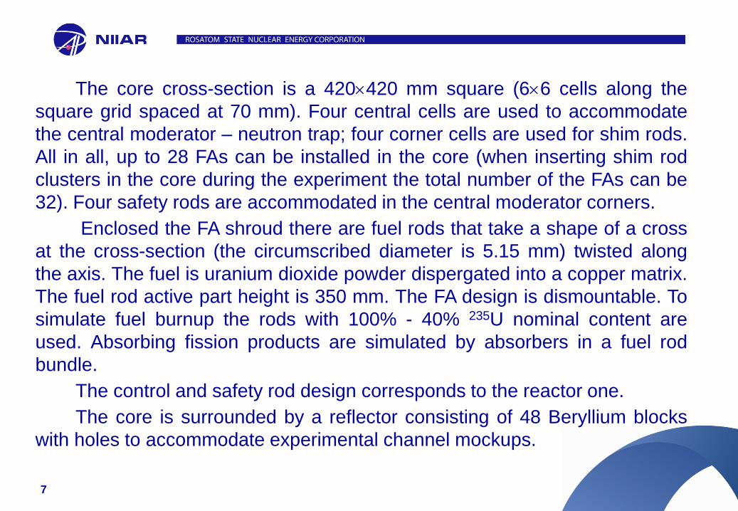
The core cross-section is a 420420 mm square (66 cells along the
square grid spaced at 70 mm). Four central cells are used to accommodate
the central moderator – neutron trap; four corner cells are used for shim rods.
All in all, up to 28 FAs can be installed in the core (when inserting shim rod
clusters in the core during the experiment the total number of the FAs can be
32). Four safety rods are accommodated in the central moderator corners.
Enclosed the FA shroud there are fuel rods that take a shape of a cross
at the cross-section (the circumscribed diameter is 5.15 mm) twisted along
the axis. The fuel is uranium dioxide powder dispergated into a copper matrix.
The fuel rod active part height is 350 mm. The FA design is dismountable. To
simulate fuel burnup the rods with 100% - 40% 235U nominal content are
used. Absorbing fission products are simulated by absorbers in a fuel rod
bundle.
The control and safety rod design corresponds to the reactor one.
The core is surrounded by a reflector consisting of 48 Beryllium blocks
with holes to accommodate experimental channel mockups.

8
MIR Critical Assembly

9
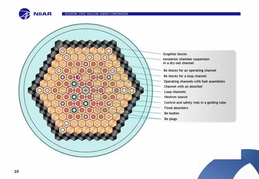
MIR critical assembly was constructed in 1966. Over the forty years
of its operation a large scope of R&D has been conducted on studying the
physics of the MIR reactor and its test rigs.
The critical assembly core and reflector are accommodated in the
experimental tank filled with distilled water.
The core and reflector are made of hexagonal Beryllium blocks with the
width across flats of 148.5 mm and height of 1100 mm. The blocks are
located in the hexagonal grid spaced at 150 mm. The central rows of the
blocks serve as a moderator and medium for neutron diffusion, the external
rows serve as a reflector. In the axial holes of the first four rows of the blocks
the channels with standard FAs and the test rig mockups are installed. Twelve
cells to accommodate test rig mockups are in the second and third stacking
row so that each is surrounded by six cells with operating channels.
10

11
In the experiments performed at the critical
assembly the operating FAs containing six
and four fuel rods are used. Each fuel rod
is a three-layer tube: a fuel layer is
enclosed on the both sides into aluminium
alloy. A fuel rod is 2 mm thick, the gap
between the fuel rods is 2.5 mm, the core
height is 1000 mm, the external fuel rod
outer diameter is 70 mm. Uranium-
aluminium alloy is used as fuel in the FAs
containing six fuel rods and UO2
encapsulated in the aluminium matrix is
used in the FAs containing four fuel rods.
The fuel enrichment in 235U is 90%. The
nominal mass of 235U in the FAs of the both
types is 350 g. The fuel burnup in the
operating FAs is simulated using the
assemblies of the same design but with the
reduced 235U content.

12
calculating neutronic parameters of the experimental channels and rigs of
the SM and MIR reactors;
selecting a means of irradiation mode creation and agreeing the set test
modes of the test rigs that are simultaneously irradiated in the reactor;
feasibility of the SM and MIR safe nuclear operation;
study in support of the core upgrading concepts and design solutions;
testing the methods to calculate the reactor neutronic parameters;
education and training of the staff, students and postgraduates.
Areas of Research

13
Some Results of the Experiments Performed at the SM Critical Assembly
Reactor neutronic parameters have been tested in support of all the
reacor reconstructions. The latest reconstruction was performed in 1991-1992.
During the reconstruction a reactor vessel was replaced, a pattern of the
coolant supply to the reactor was modified, neutron trap arrangement was
changed as well as the number and location of the experimental channels in
the reflector. About 90% of the experiment scope required under the physical
startup programme was completed. The following issues have been studied:
reactivity effects induced by the introduced changes; limits and regularities of
safety and control rod performance change; power density distribution in the
core, the maximum possible values of the power peaking factors both for the
reactor and for the fuel rods of the FAs of different types for similar cells in the
core; neutronic parameters of the experimental channels depending on their
mutual filling and control and safety rod moving.

14
The reactor neutronic parameters were studied
in changing the neutron trap arrangement
Loop channel Transuranium target
central Be-block
Separator
arrangement
15
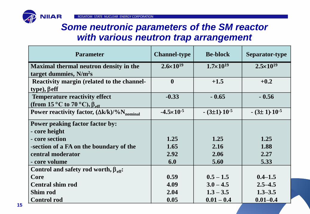
Some neutronic parameters of the SM reactor with various neutron trap arrangement
Parameter Channel-type Be-block Separator-type
Maximal thermal neutron density in the
target dummies, N/m2s
2.61019 1.71019 2.51019
Reactivity margin (related to the channel-
type), eff
0 +1.5 +0.2
Temperature reactivity effect
(from 15 С to 70 С), eff
-0.33 - 0.65 - 0.56
Power reactivity factor, (k/k)/%Nnominal -4.510-5 - (31)10-5 - (3 1)10-5
Power peaking factor factor by:
- core height
- core section
-section of a FA on the boundary of the
central moderator
- core volume
1.25
1.65
2.92
6.0
1.25
2.16
2.06
5.60
1.25
1.88
2.27
5.33
Control and safety rod worth, eff:
Core
Central shim rod
Shim rod
Control rod
0.59
4.09
2.04
0.05
0.5 – 1.5
3.0 – 4.5
1.3 – 3.5
0.01 – 0.4
0.4–1.5
2.5–4.5
1.3–3.5
0.01–0.4

16
Feasibility of SM conversion to a new fuel with the increased loading of U-235
irradiation rig designs were selected and justified to test fuel rods in the
loop facility;
the reactivity effects and power density distribution when testing new
type FAs in the reactor core;
simulating the reactor conversion to a new fuel during the current
reactor operation;
the reactivity effects induced by the introduced changes were
determined;
the limits and regularities of control and safety rod worth variation were
established.

17
Some Results of the Experiments Performed at the MIR Critical Assembly
The studies were conducted on determining a possibility for formation of a
local critical region during the core refueling that resulted in increasing the
number of control and safety rods. In 1990 the reactor was equipped with six
compensators with fuel suspenders (CF) and four shim rods in addition to the
existing ones. At present, the total number of the compensators with fuel
suspenders in the reactor is 12, and the number of shim rods is 27. The limits on
the core loading have been stated.
РК
РК
РК
РК
РК
РК
ПК
КС
КС
КД
КД КД
КС
КС

18
The limiting values and variation ranges for reactor control and safety rod worth
Rods Group No.
(pcs)
Rod No. in a
group (pcs)
Group worth,
eff
Reactivity insertion
rate when cocked,
eff/s
Safety 6 1 0.065 3.2 0.001 0.052
Control 2 1 0.1 0.7 0.007 0.05
Shim 21 1 0.065 3.2 0.001 0.052
CF 12 1 0.08 7.0 0.0002 0.018

19
The regularities of the positive reactivity effect change have been studied when lowering water density in the loop channels
induced by various factors
0,2
0,4
0,6
0,8
1,0
0,6 0,8 235U mass, rel. units
Re
activity e
ffe
ct, r
el. u
nits
1,0
Number of control rods, pcs
Re
activity e
ffe
ct, r
el. u
nits
0
0,2
0,4
0,6
0,8
1,0
0 3 6 9

20
The conditions for safe conducting dynamic experiment in the MIR reactor were determined on simulating accident and transient
conditions of the fuel rod operation: AVR rig, loss of integrity, cycling
AVR
CYCLE

21
Recent Operation Experience and Difficulties
Maintenance of equipment, systems and components of the SM-2 and
MIR.M1 critical assemblies is performed on a scheduled basis (checkups,
repairs, maintenance, audits, calibration) as well as technical inspection,
service lifetime extension and licensing.
The main enhancements of the critical assembly engineering systems in
recent years are related to the area of MPC&A.
The difficulties of the critical assembly operation in recent years are as
follows: operational and research equipment aging and lack of the funds for its
upgrading, lack of qualified staff.
22
Prospects for the SM and MIR Critical Assemblies Usage
Testing neutronic parameters of the new test rigs for the SM and
MIR reactors (fuel and structural components of various-purpose
reactors, research reactor advanced fuel, radionuclide accumulation
rigs);
Feasibility of the SM reactor conversion to new low poisoning fuel
rods and the MIR reactor conversion to low-enriched fuel;
Feasibility of the SM and MIR reactor core arrangements that allow
extending the experimental capabilities and improving the fuel usage
efficiency;
Verification of the calculation codes;
Lab research engaging the students of Dimitrovgrad Engineering
and Technical Institute NRNU MEPhI.

Thank you for your attention!
Related Documents