RESEARCH MEMORANDUM THE EFFECT OF COMPRESSOR-INLET WATER INJECTION ON ENGINE AND AFTERBURNER PERFORMANCE By Joseph N. Sivo, John P. Wanhainen, and William L. Jones Cleveland, Ohio NATIONAL ADVISORY COMMITTEE FOR AERONAUTICS WASHINGTON

Welcome message from author
This document is posted to help you gain knowledge. Please leave a comment to let me know what you think about it! Share it to your friends and learn new things together.
Transcript
RESEARCH MEMORANDUM
THE E F F E C T O F COMPRESSOR-INLET WATER INJECTION ON
ENGINE AND AFTERBURNER PERFORMANCE
B y Joseph N. Sivo, John P. Wanhainen, and William L. Jones
Cleveland, Ohio
NATIONAL ADVISORY COMMITTEE FOR AERONAUTICS
WASHINGTON
A turbojet engine Fncorporating a conventional-type afterburner w a s operated over a range of afterburner pressure levels from 1000 t o 2000 pounds per square foot absolute and a range of engine-inlet water-air ra- t i o s from 0 t o 0.08. A t each pressure level and w a t e r - a i r ra t io , the afterburner fuel flow was varied from lean blowout t o maximum burner- out le t temperature.
.I
.. On the basis of the experimental data obtained, it i s . apparent t ha t
substantial thrust gains w i l l resu l t from the fnjection of water ahead of the engine i n l e t at supersonic flight Mach numbers. However, &6 might be expected, the presence of the w a t e r vapor had an adverse e f fec t on af ter- burner conbustion efficiency and lean blowout limits. There was little i f any effect of w a t e r injection on the afterburner efficiency above a 0.8 equivalence r a t io at a l l pressure levels investigated. However, as the equivalence r a t i o w a s decreased below 0.8, efficiency decreased mark- edly as water-air ratio w a s increased. The s t a b i l i t y of the afterburner w a s adversely affected by water inJection with the equivalence r a t io f o r lean blowout increasing with increasing water-air ra t io . Decreasing the afterburner pressure level m e g n i f i e d %he s t a b i l i t y problem with water in- jection thus narrowing the operable range of the afterburner. For the range of pressure levels studied, the engine internal performance was re- duced s l igh t ly in accordance w i t h the change in gas properties due t o the variation of water-air r a t i o covered U this investigation.
The alrcraf t industry and the military senrices are very interested in the use of precorapressor evagorative cooling using water in jec t ion to boost the performance of current interceptor aircraft . Analyses using
the 2-centUry series which show s&stantial increases in both f l i g h t Mach number and maximum alt i tude capabili ty. These a i r c ra f t performance gsins
- this m e a n s of thrust augmentation have been made for a i rc raf t at least of
"
2 - MACA RM E58D03b
combat time, in view of the increase in rate of climb and cruise, or combat altitude. Precolqpressor cooling would also alleviate the engine temperature problems associated with Mach number Fncreases. Most current turbojet engines encounter a temperature limitation in the compressor at ram temperatures corresponding to speeds in the neighborhod of Mach 2.0.
The full potential of water injection for providing super- performance can be achieved if major detrimental effects on afterburner and engine performasce do sot occur a6 a,resuJt of the presence of the water. The first, and perhaps the foremoet problem area, would deal with the possible deleterious effects of water injection on the afterburner efficiency and opemtional limits. In t h i s category possible detrimental effects on the engine itself are to be canaidered. Previous work in t h i s area reported in references 1 and 2 laas indicated that serious combus- tion problems may be present in the afterburner especially at high water-air ratios and low afterburner pressure levels. The second area deals with the water-injection system itself with its attendant problems of atdzation and vaporization of the iaected water, using hardware suitable for flight application. Some aspects of these problems are covered in reference 3. A bibliography of published reports relating to this field is also included in reference 3.
The investigation reported here determined the effect of various amounts of water vapor on afterburner and engine performance. To simpli- fy the experiment, it was desired that the study of the effects be iso- lated from the problems of providing a water-injection system with a high evaporative effectiveness. Consequently, water vapor was provided by injecting steam into the engine-inlet airflow.
The engine was operated over a range of ccmpressor-inlet t o t a l pressures from 1150 to 550 pounds per square foot absolute. The compressor-irilet temperature was held constant at S O o F as the water- air ratio was varied from 0 to 0 -08. The afterburner operated over a range of inlet total pressures from 2000 to 1000 pounds per square foot absolute. This afterburner pressure range corresponds to operating a typical current turbojet engine at a Mach number of 2.0 over a range of altitudes frm about 55,000 to 70,000 feet or at a Mach number of 3.0 over an altitude range frm 81,000 to 96,000 feet with sufficient water injection to cool the cmpressor-inlet air to 242' F.
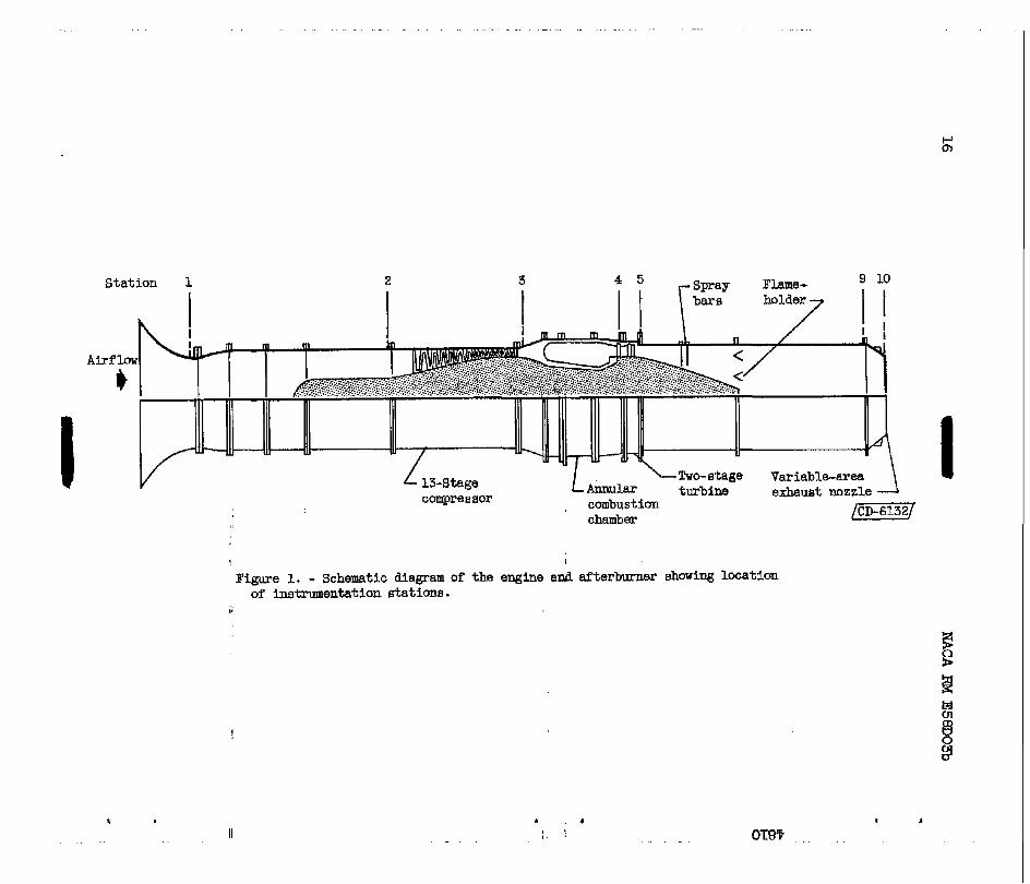
A schematic diagram of the engine used in this investigation is shown in figure 1. The engine consisted of an axial-flow compressor with a moderate pressure ratio, an annular combustor, and a two-stage turbine. The maximum allowable compressor-inlet temperature for this
Ig 0 P
NACA RM E58D03b 3
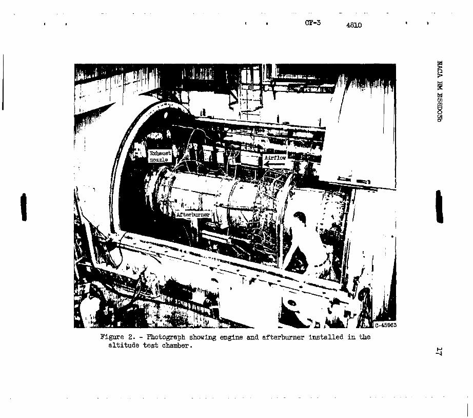
e a n e is 150° F. A photograph of the engine installed in the a l t i tude
having a low heating value of 18,700 Btu per pound. . test m e r is shown in figure 2. The f u e l used was JP-4, MUrF-56-W,
Afterburner
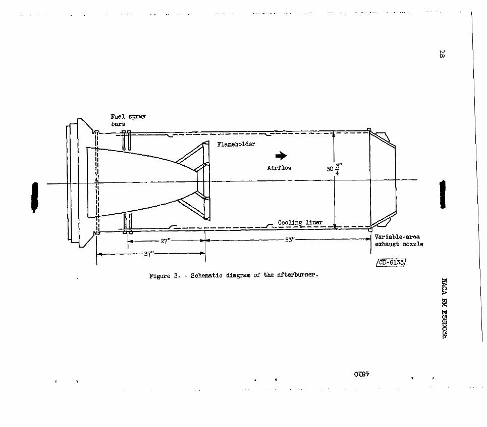
A schematic diagram of the afterburner used i s sham in figure 3. The burner incorporated a corrugated-louvered cooling liner which ex- tended from a paint 4 inches upstream of the f lameholder t o the M e t of
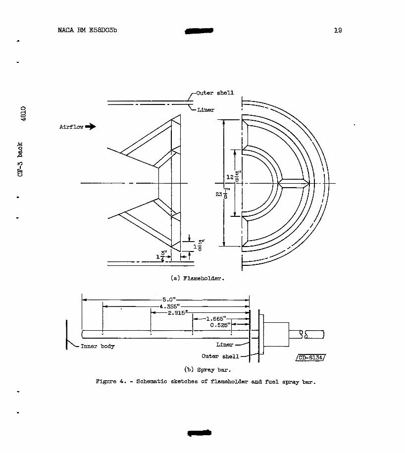
so l id liner extending frm the corrugated-louvered cooling liner t o a point just ahead of the spray bars was used to prevent circulation of fue l in to the cooling-air passage. The flameholder was a conventional two-ring V-gutter ty-pe and i s schematically shown in f igure 4(a). The gut ter width was 18 inches, and the blockage was appr-tely 33 percent of the fu l l passage. 'The ncaninal afterburner-inlet velocity was 480 feet
0 rl
* a3 the automatically-controlled variable-area iris-type exhaust nozzle. A
.!d 0
P a3
5
-t per second. k 0,
Afterburner Fuel System - The afterburner fuel-injection system consisted of 24 equally spaced
radial spray bars. The bars were al ternately axially staggered t o ease ins ta l la t ion problems, with the planes of inject ion being located 26 and 28 inches upstream of the flameholder. The spray bars, shown schemati- cally i n figure 4(b), consisted of eight 0,0225-inch-diameter holes on every bar with four located on each side t o provide uniform fuel-air- ratio distribution. The f u e l was injected normal t o the gas stream. The f u e l system conforms t o the design criteria presented i n reference 4.
\
Steam-Injection System
Steam was metered into the engine-inlet airflow at 8 point approxi- mately 100 feet upstream of the engine inlet through a single fixed coni- cal nozzle operating a t or above the c r i t i c a l pressure ra t io . The quality of the steam was determined with a throttling calorimeter.
Instrumentation
Location of the major instrumentation stations.throughout the engine is shown i n f igure 1. A water-cooled total-pressure rake was ins ta l led a t the exhaust-nozzle inlet. Both the engine and afterburner f u e l flows w e r e measured with vane-type remote-reading flowmeters. Total jet thrust was measured with a null- type thrust cell.
L
4
\
4 NACA RM E58DO3b
Instal la t ion
The engine was i n s t a l l ed i n an a l t i tude test chamber that consisted of a tank 10 feet i n diameter and 60 f e e t long divided In to two compart- ments by a bulkhead. Ram pressure and temperature conditions are main- tained in the front ccfmpartment; the engine was i n s t a l l ed i n the rear compartment where the a l t i tude s ta t ic pressure i s maintained, and the engine-inlet duct extended through a labyrinth seal i n the bulkhead t o provide air a t r a m pressure and temperature t o the engine. A bellmouth cowl and venturi were attached t o the engine i n l e t t o provide a means tp
f o r measuring engine mass flow. The engine yas .mounted on a thrust- measuring platform i n the rear cmpartment.
"
[D P -0
PROCEDURE
The engine was operated a t rated engine speed a t h 8 constant turbine uscharge temperature of 1.200~ F. The compressor-met temperature was maintained canstant a t 150° F. Three pressure levels a t the compressor i n l e t were set t o provide afterburner-inlet total-pressure levels of 2000, 1500, and lOOO..pounds per square foot absolute. A t a given pres- sure level and a t canstant cmpressor-inlet temperature, the canpressor- i n l e t water-air ratio was varied from 0 t o 0.08 by the steam injection. I
At each pressure level and canpressor-inlet water-air ra t io , the af ter- burner fuel-air ratio was varied from. lean blowout t o maximum burner- outlet temperature. The exhaust pressure w&s maintained a t a value suf- f ic ien t t o insure c r i t i ca l flow through the exhaust nozzle.
.
Although the primary objective or the investigation reported herein was t o determine the effects of engine-inlet water injection on af te r - burner performance, engine performace data were also obtained during afterburner operation. The engine performance results are, therefore, included t o give some insight into the effects of water injection on the engine f o r water ccmpletely evaporated before entering the canpressor. m s e results indicate only the effects of water vapor on engine per- formance characterist ics and, therefore, exclude any additional effecte a t t r i bu tab le t o mter droplets entrained in the inlet air.
Effects of Water Vapor .on Engine Perfortn?nce " " . . "
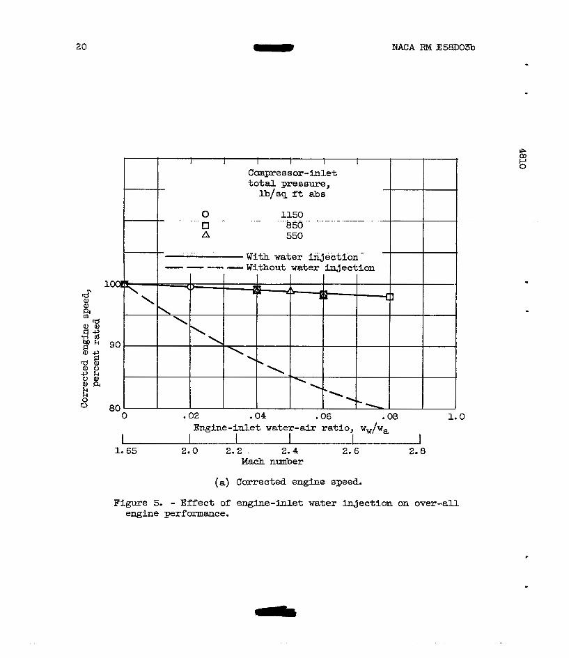
Over-all engine performance. - The effect of water inject ion on over- a l l engine performance is shown i n figure 5. The performance results are shown as a percent of the performance with no mter inJection for an inlet pressure of 1150 po.uids per square. foot. . . . absolute. . . . A Mach number scale. is
. - . --
NACA RM E58D03b 5
indicated on the abscissa of figure 5 which corresponds to the water- air-ratio scale for air cooled to 150° F with 100-percent emporative effectiveness. The dashed curves of figure 5 show the decreases in per- formance for the engbe used that would result if the compressor-inlet temperature were allowed to rise above 150° F in accordance with increas- ing flight Mach number .
-
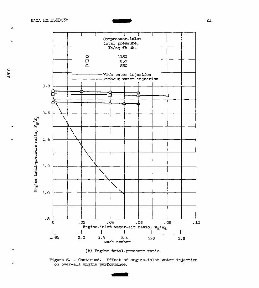
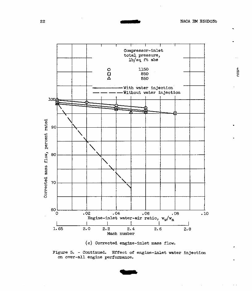
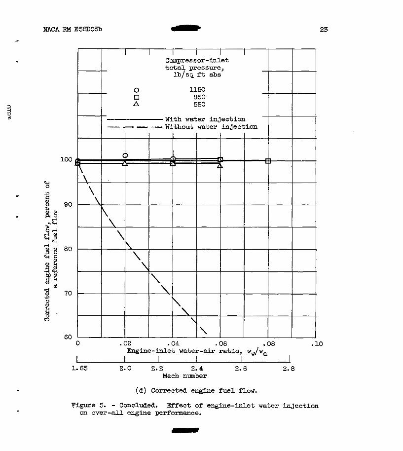
0 At constant mechanical speed and constant cmpressor-inlet tempera- ture, increasing the water-air ratio decreased the corrected speed as shown in figure 5(a). At moderate water-air ratios, the corrected-speed decrease is appr-tely proportional to the square root of the in- crease in the gas constant of the incoming water-air mixture. This de- crease is only a small fraction af the decrease indicated by the dashed curve that would result without water injection. The engine total-pressure ratio (fig. 5(b) ) decreases slightly with increasing water-air ratio. This decrease, although small., primarily results frm the decrease in corrected engine speed. The engine corrected fuel flow (fig. 5(d)) remained very neaxly constant as the water-air ratio was increased. The decreases in pressure ratio and corrected weight flow with decreasing inlet total pres- sure at a constant water-air ratio are attributed to Reynolds number ef- fects. As might be expected, the presence of water vapor had a slightly adverse effect on internal engine performance as indicated by the drop in
with the change in the gas properties of the f lu id passing through the engine. No change in the volume capacity of the w i n e was noted. Al- though the total engine weight flow decreased with increasing water-air ratio, it was necessary to maintain at least constant fuel flow. This was required when the engine total-temperature rise was maintained con- stant to compensate for the rise in specific heat of the working fluid and the drop in combustion efficiency indicated in the next section.
c
d weight flow and engine pressure ratio. The magrdtude of the effect agrees
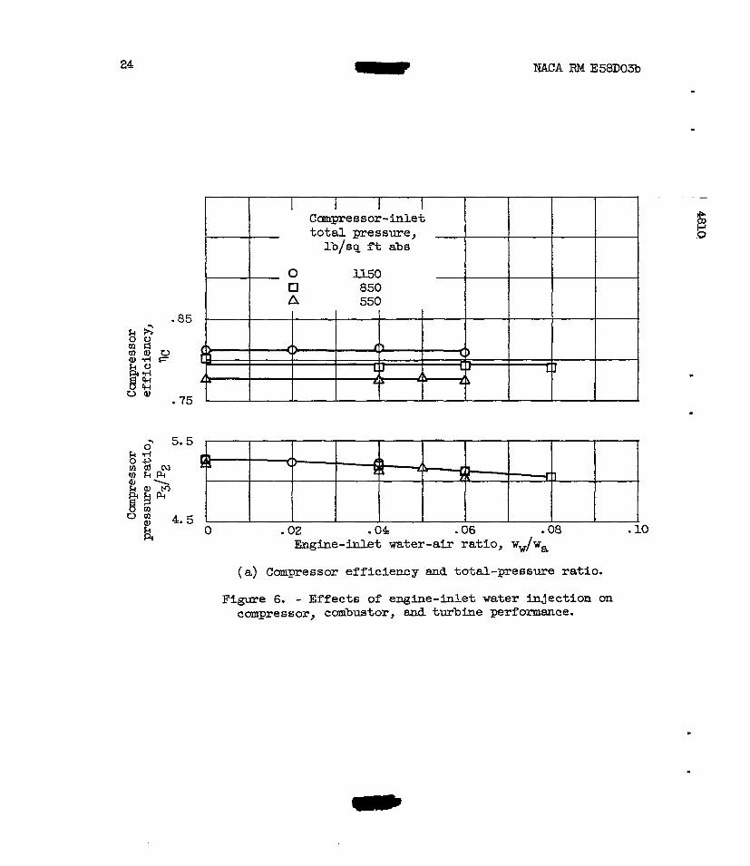
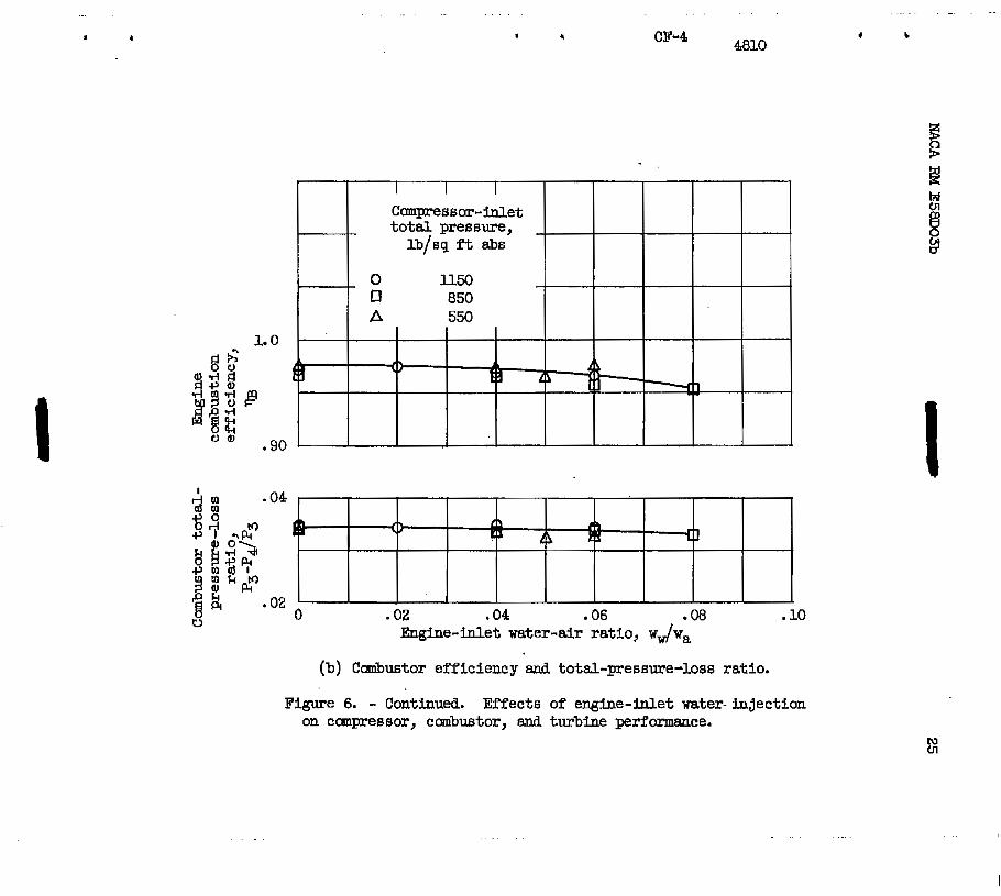
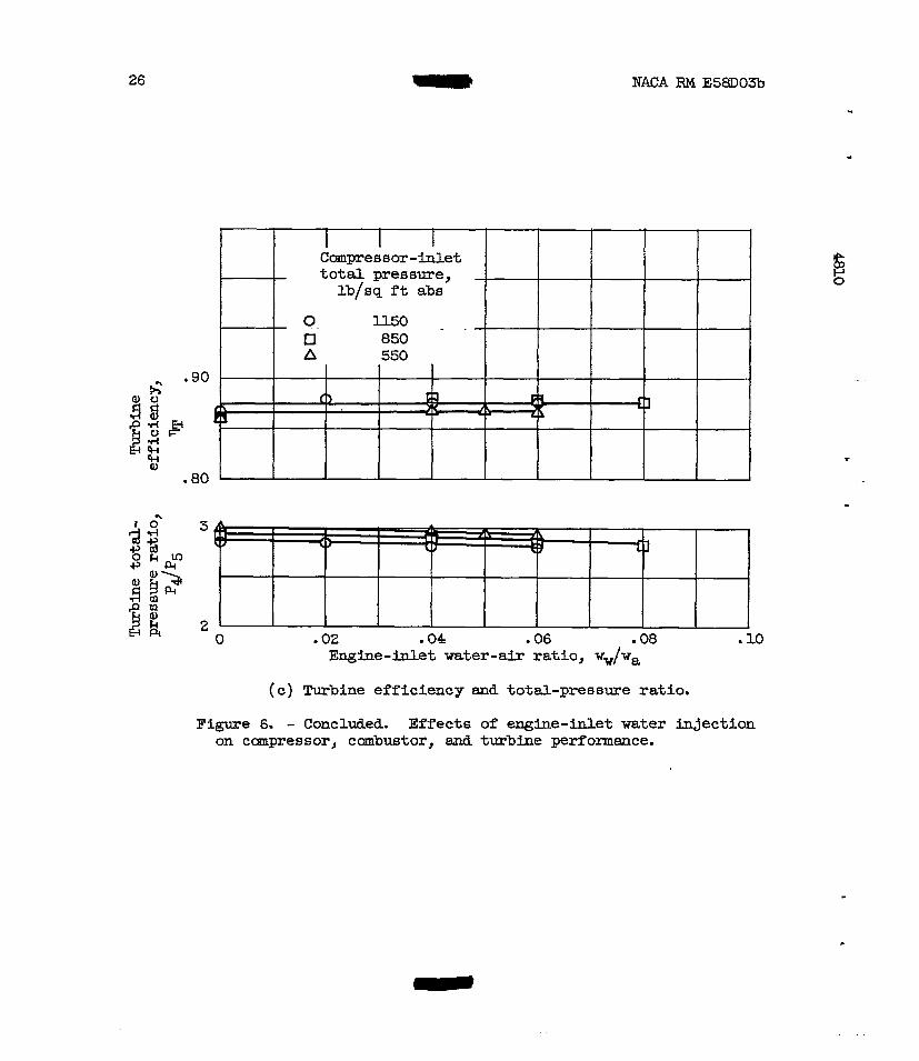
Component performance. - The perfomce of the compressor, combus- tor, and turbhe are shown in figures 6(a), (b), and (c), respectively. There was little if any effect of increasing the water-air ratio f’rm 0 to 0.08 on ccmrpressor and turbine efficiencies; however, there was a slight decrease in combustion efficiency. Ccmpressor and turbine total- pressure ratios changed because of changes in enghe weight flaw and fluid property changes. Canibustor total-pressure loss was not effected by water-air-ratio changes.
Eefects of Water Vapor on Afterburner Performance
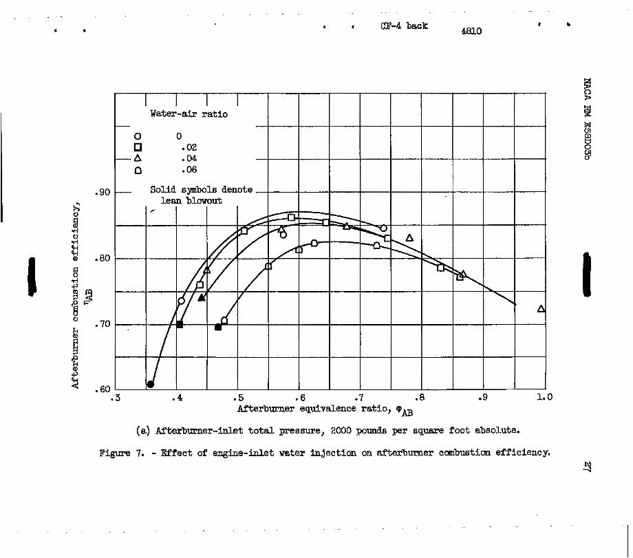
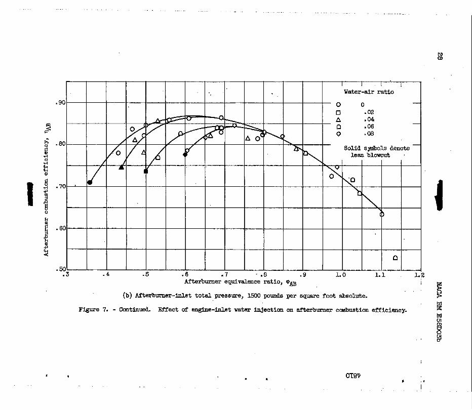
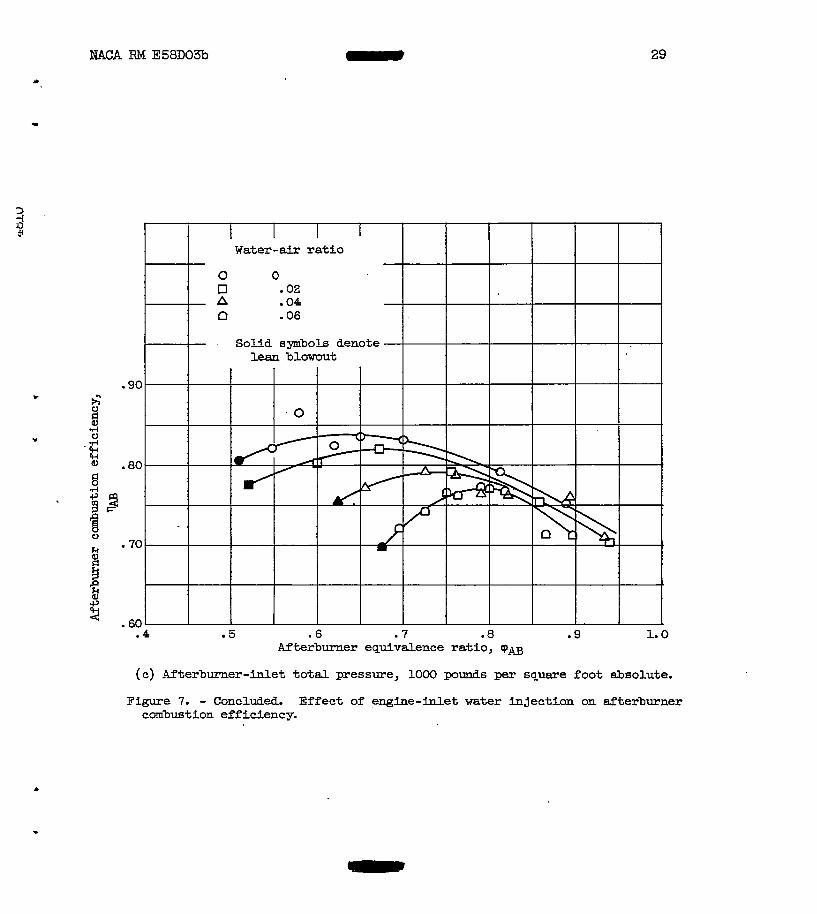
Afterburner cmbustion efficiency. - Afterburner combustion effi- ciency as a function of afterburner equivalence ratio is shown in figure 7 for afterburner-inlet total-pressure levels of 2000, 1500, and loo0 pounds per square foot absolute. The afterburner equivalence ratio q~ -
AB
6 - NACA RM E58Do3b
i s defined as the r a t i o of the actual fuel-air ratio based on unburned air entering the afterburner t o the s toichimetr ic fuel-air ra t io . A t I
the afterburner pressures of Z o o 0 and 1500 pounaS per square foot abso- lute ( f igs . 7(a) and (b) , respectively), the maximum water-air r a t i o was limited by the available steam supply. However, a t 1000 pounds per square foot absolute, stable afterburning could not be obtained a t water- air r a t io s over 0.06 cfig. 7(c) ). Above an equivalence r a t i o of 0.8, water injection had l i t t l e i f any ef fec t an afterburner efficiency a t a l l the pressure levels inve8tigated. However, increasing the water-air r a t i o a t eqavalence ra t ios near lean blowout decreased afterburner r, efficiency substantially. !
-
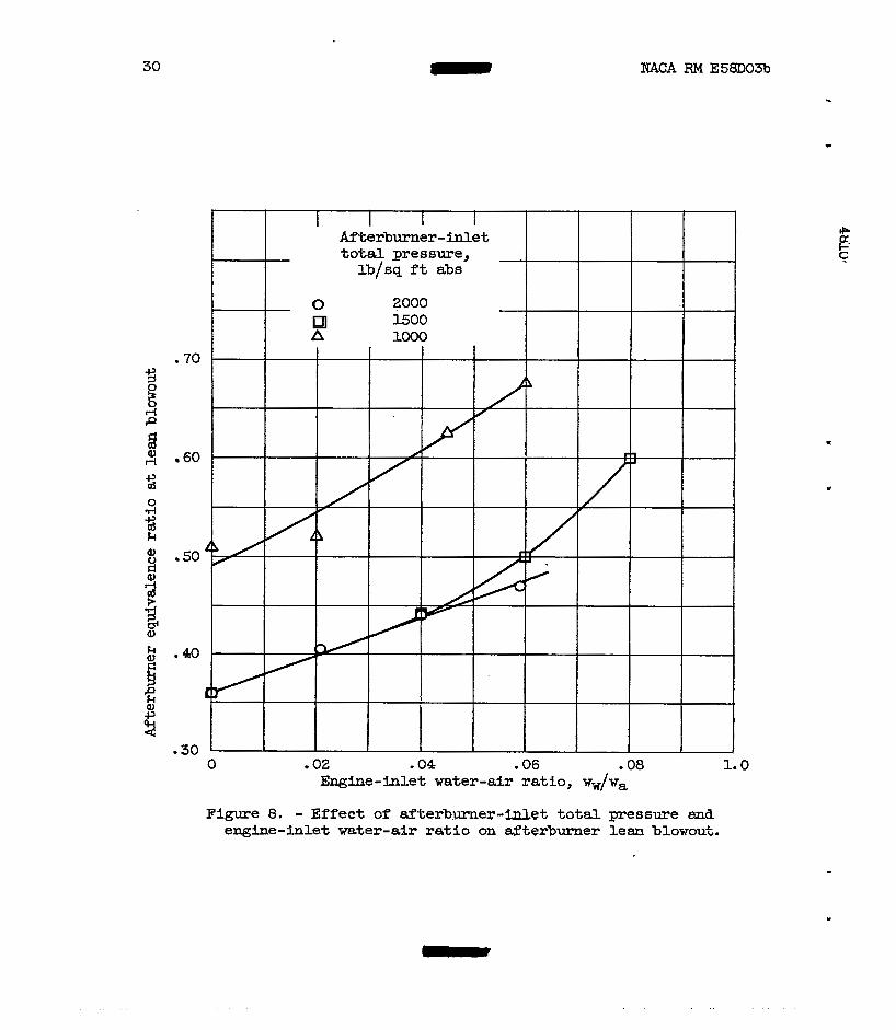
Afterburner stabilitx. - The effects of water-air r a t i o on after- burner s tabi l i ty can be seen in figure 8 f o r the three pressure levels investigated. As the water-air ratio i s increased, the afterburner equivalence r a t i o a t lean blowout i s increased. As the pressure level i s decreased, the effects of water injection became more pronounced. A t 1500 pounds per square foot absolute of afterburner-inlet pressure, satis- factory afterburner operation was obtained a t a water-air r a t i o of 0.08 w h i c h indicated that operation with higher water-air r a t io s would be . possible a t high equivalence ratios. A t loo0 pounds per square foot ab- solute, afterburner operation a t a water-air r a t i o of 0.06 wa8 very marginal requiring care to maintain stable afterburning. The marked de- .#
crease in e f f i c i ency i n the region of lean blowout was probably caused, fo r the most part, by partial blowout of the afterburner and reduced rates of flame propagation as a result of water dilution of the incaning f u e l charge. . ." . -
The decrease in af terburner s tabi l i ty with increasing water-air r a t io s and decreasing pressure could present a serious problem since it may be necessary to t h ro t t l e back the afterburner during cruise a t Mach numbers requiring high rates of water injection. Mthermore, the sub- stantial reductions in cmbustion efficiency at these reduced equlnlence r a t io s and high water-air-ratio conditions m u s t be considered when pre- dic t ing a i rc raf t performance with water injection.
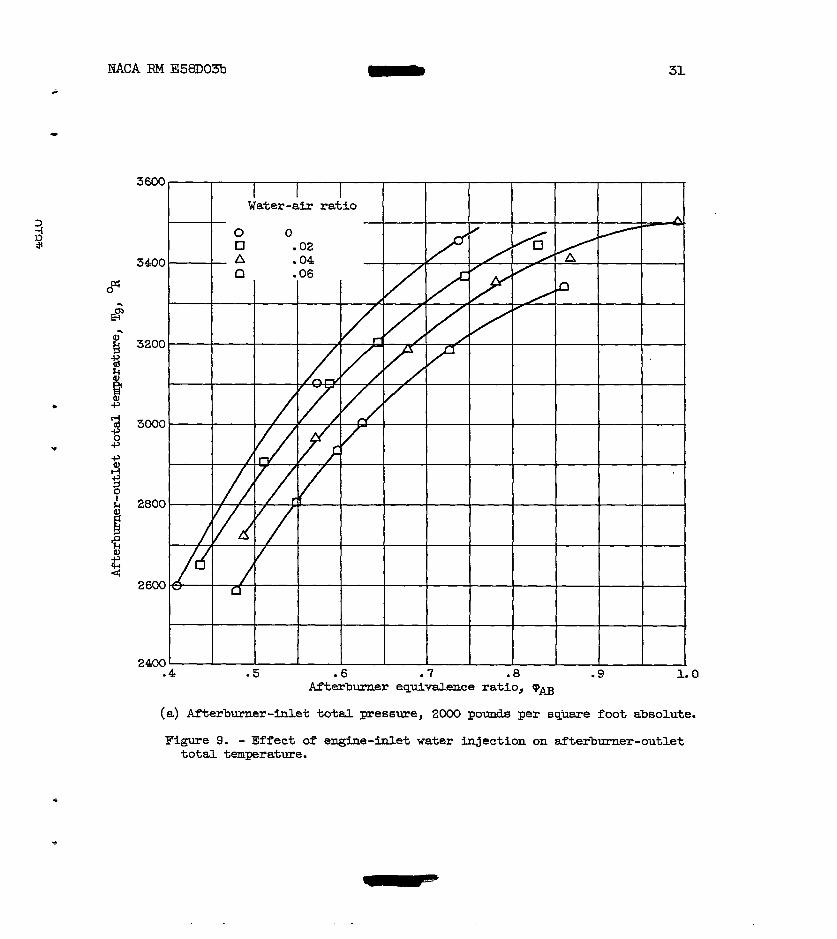
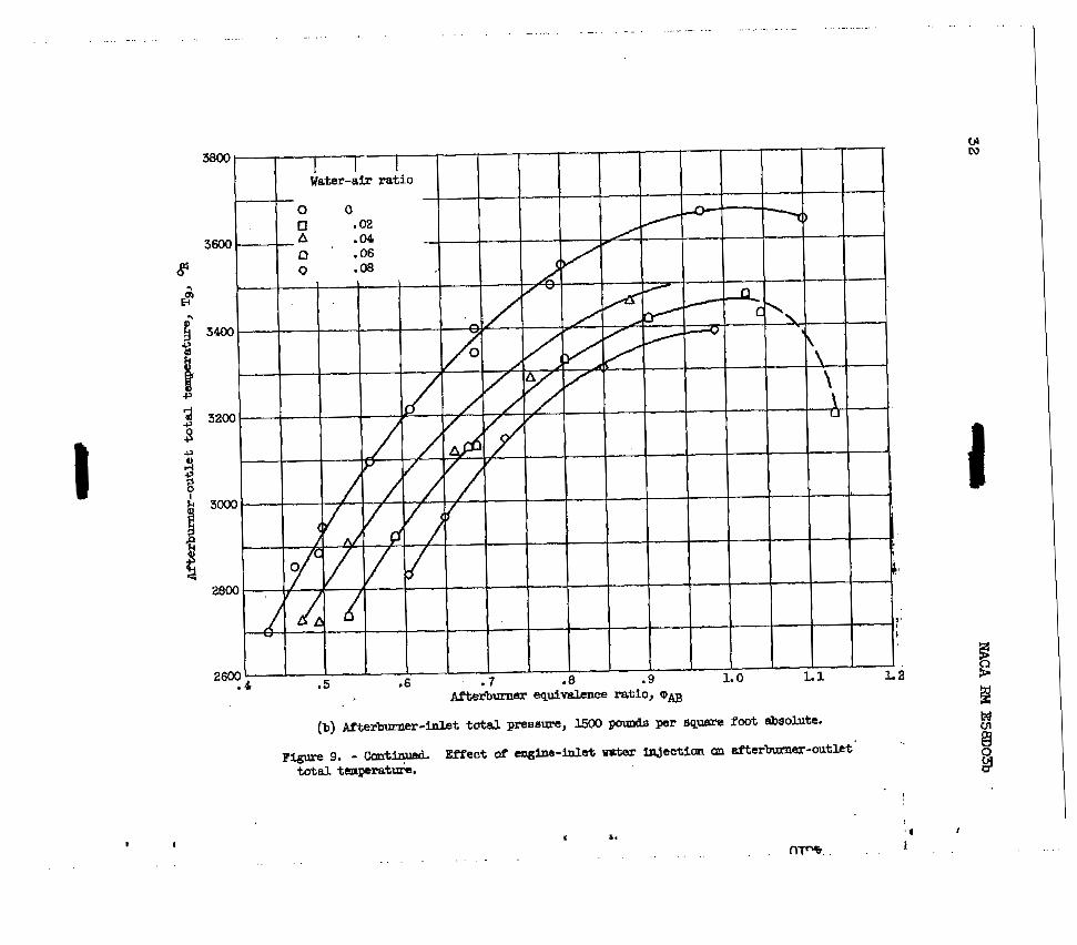
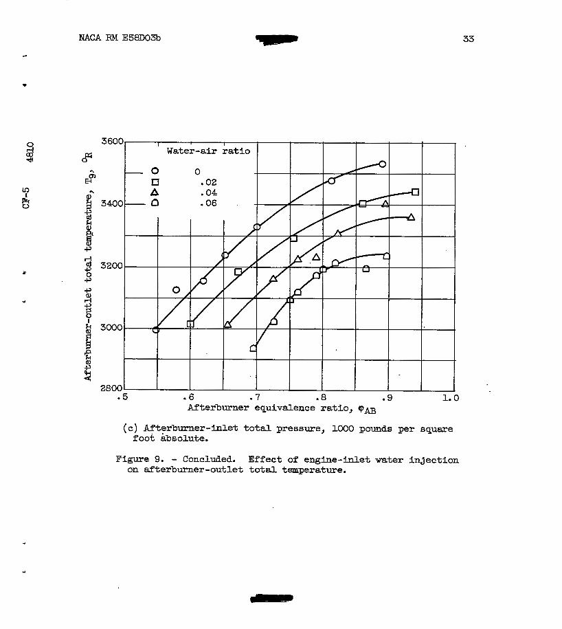
Other afterburner variables. - The effect of water injection on a f te rburner -out le t to ta l twera ture i s shown i n figure 9. I n most cases a t a given afterburner-equivalence ratio, the out le t temperature decreased 40° t o 50° F far each percent i n water-air rat io . This de- crease in temperature occurs because the ra t io of the afterburner fuel flow t o the product of the specific heat of the working f luid and i t a flow rate decreases as the water-air r a t i o i a increased. By neglect- small changes i n the r a t io s of specific heats, the product of specific heat and mass flow remains approximately constant over the range of water-air r a t io s covered. It follows that w i t h engine-inlet and turbine- - outlet temperatures fixed, the afterburner fuel flow a t constant equiva- lence ra t io must decrease as the water-air ratio is increased.
-
"
NAW RM E58D03b 7
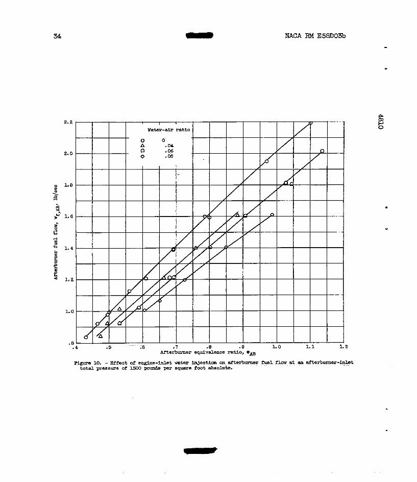
The decrease i n afterburner fuel flow that did occur i s shown i n figuqe I 10 f o r a typical afterburner pressure level of 1500 pounds per square
foot absolute. The var ia t ion in temperature with water-air r a t io r e - sults primarily frm a corresponding variation in afterburner fuel flow.
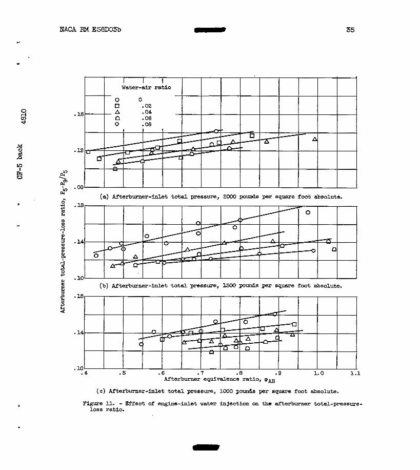
The afterburner total-pressure l o s s for the three pressure levels i s shown in figure ll. A t a constant afterburner equivalence ratio, a water-air-ratio increase caused a total-pressure-loss decrease. The pressure-loss decrease results fram two factors. (1) A decrease in afterburner-inlet velocity, approximately 5 percent at 0.08 water-air rat io , a c c n the decrease in mass flow with increasing water-air rat io; t h i s produces a friction-loss decrease. (2) The decrease i n mo- mentum pressure loss accmpanying the decrease in afterburner tempera- ture rise and decrease i n afterburner-inlet velocity. Each factor ac- counts fo r about 50 percent of the pressure-loss decrease. The burner pressure-loss reduc-f;ion will, of course, vary from one afterburner to another, depending on the inlet veloci ty , f r ic t ion pressure loss, and combustion efficiency.
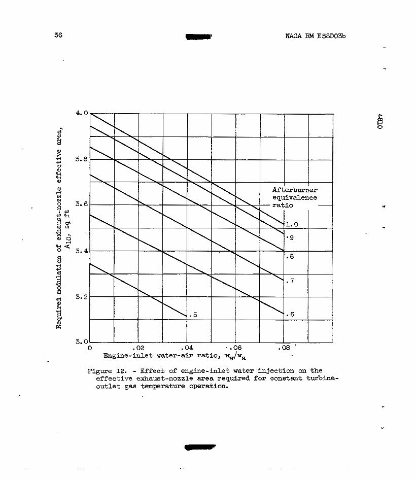
The modulation of exhaust-nozzle effective flow area required to operate at a given turbine-outlet temperature ELnd afterburner equivalence r a t i o ~ t s water-air r a t i o varies is shown i n figure 12. The required
when the water-air ratio increases from 0 t o 0.08. The decrease i n area i s due t o a cmbined effect of lower exhaust gas temperature, higher exhaust-nozzle-inlet t o t a l pressure, and decreased w e i g h t flow. hch factor contributes about equally to area change.
*
- nozzle area a t constant equivalence ratio decreases about 1 2 percent
Comparison of resu l t s wLth previous work. - A general cmparison of the afterburner perforinance results reported herein wa.s made with the performance results reported i n references 1 and 2. In reference 2 where ammonia was used as the engine-inlet injectant, the effects of increasing the injectant flow on afterburner performance were similar to those reported herein. A t low afterburner equivalence ratios the ef fec t of the injectant was marked, and at high equivalence ratios the ef fec t was negligible.
The results of the investigation reported in reference 1, where a mixture of water and alcohol was used as the inJectant, indicate that the effects of l iqu id in j ec t ian on afterburner performance were marked a t high equivalence r a t io s and negligible a t the low equivalence r a t io s , The equivalence ra t io t rend of reference l i s opposite to the trend re- ported herein. Careful study of the data presented in reference 1 did not reveal any definite explanation for the difference. However, the afterburner fuel-air-ratio distribution was varied with l iquid-injectant flow t o eliminate afterburner screech. Although the afterburner per- formance (ref. 1) was checked a t zero injectant flow and indicated no performance changes fo r each fuel-air distribution, it is possible that
-
- 0
0 NACA RM E58D03b
the magnitude of the effects of l iquid injection could change as fuel- a i r - ra t io dis t r ibut ion was altered. I n the data reported herein a uni- form fuel-air distribution was selected and naintained throughout the entire investigation, thereby eliminating any possible effects of chang- ing fuel-air-rat io dis t r ibut ion
High Mach Number Performance With Water Injection
The proposed use of engine-inlet water injection will provI.de both temperature protection for the engine at high Mach numbers and a substan- r t i a l mount of thrust augmentation. This sect ion i l lustrates the per- 5 formance of a typical Mach 2.0 turbojet uti l izing water in jec t ion to ex- tend i t s Mach number limit t o 3.0.
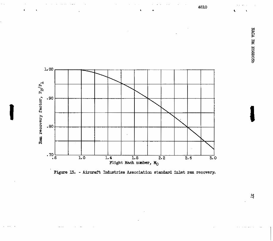
For the purposes of the mlculation, the engine i s held a t constant a l t i tude above the tropopause, and the Mach number is-increased frm 0.7 to 3.0. The maximum allowable cmpressor-inlet temperature wa8 assumed t o be equal to the ram temperature a t a Mach number of 2.0. A t flight Mach nmibers i n excess of 2.0, water i s inJected a t a ra te suf f ic ien t . t o maintain this temperature assuming complete evaporation of the water before entering the compressor. The Aircraft Industries Associatlon standard ram recovery was used for the engine-inlet recovery factor 1
(fig. 13).
" -
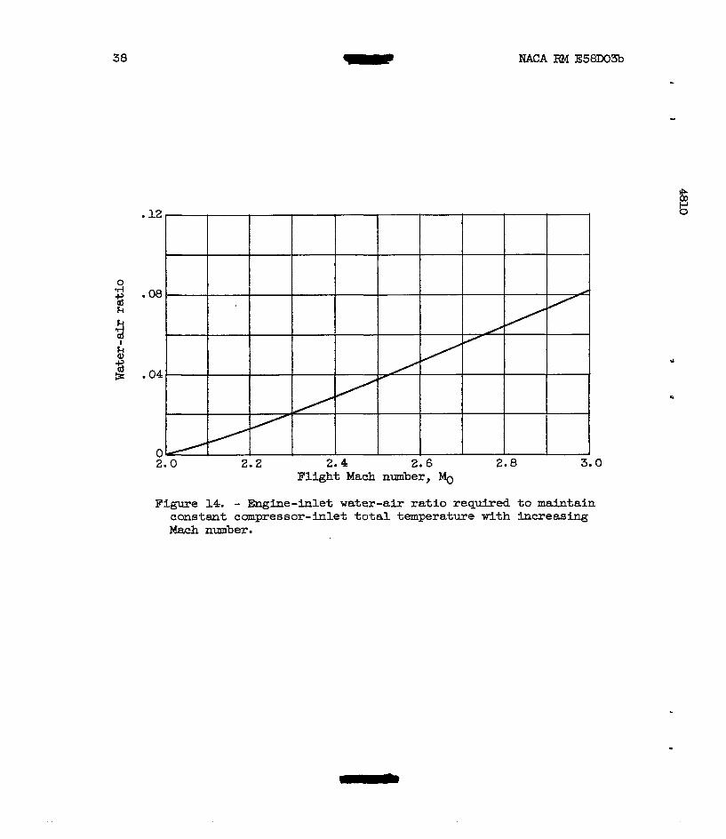
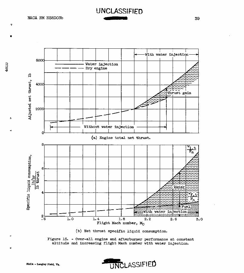
The computed water-air ratio required to cool the engine-inlet air as the Mach number increased i s sham in f igure 14. The net thrust and net thrust specif ic l iquid consumptian are shown in figure 15 as func- t ions of the flight Mach number. The dashed line repres-ents the per- formance of a current engine capable of operation up t o a Mach number of 2.0. The performance of this engine has been extrapolated t o a Mach ..
number of 2.5 t o i l l i i k t r a t e performance trends. An a l t i tude of75,oOO feet was selected for the performance calculations with water injection so that the afterburner pressure level could be acted on by the water; injection performance discussed herein.
The marked increase in the slope of the thrust c u e a t a Mach of 2.0 (fig. 15(a)) indicates that the presence of the water results i n over-all engine-thrust augmentation. Figure 15(b) shows that the l iquid consumption of the engine also Increases very rapidly as the Mach number increases beyond Mach 2.0. The specif ic fuel consumption i n the Mach number range from 2.0 t o 3.0 during wter inject ion i s shown i n figure 15(b) i n order t o indicate the relative co&uinption of water and fue l by the engine. This high l iquid consumption with water injection would limit this type of augmentation to very specific applications, where gains i n performance, increased acceleration, rate-of C m b , and cruise a l t i tude suff ic ient ly offset the increase in t o t a l l i qu id consumption.
NACA RM E58D03b c
9
SUMMARY OF REXULTS
From the results of this investigation, it is apparent t ha t substan- tial thrust gains w i l l r esu l t from the injection of water ahead of the engine i n l e t at supersonic f l i g h t Mach rimers. However, as might be ex- pected, the presence of the water vapor had an adverse effect on after- burner combustion efficiency and lean blowout limits. There was l i t t l e if any ef fec t on the afterburner efficiency from the presence of w a t e r vapor above an afterburner equivalence ratlo of 0.8 f o r afterburner- inlet pressures from 1000 t o 2000 pounds per s q d e foot absolute. How-
t ion became increasingly pronounced result ing in reductions in after- burner efficiency of 10 percent or more near lean blowout. As might be expected, reductions Fn pressure level magnified the detrimental effects of water injection on efficiency a t reduced equivalence ratios.
41 + ever, as the equivalence r a t i o was reduced, the effects of water injec- Q
N 1 e Afterburner s t a b i l i t y was very noticeably affected by the introduc-
t ion of water. This was the case a t a l l pressure levels and was evi- denced by increased equivalence ratios a t lean blowout as the water-air
effects became more pronounced and resul ted in a reduction in the oper- able range of the afterburner. A t a pressure level of 1500 pounds per
possible above an equivalence r a t i o of 0.6, but a t 1000 pounds per square foot absolute , marginal. operation was encountered a t a 0.06 water-air r a t io . The seriousness of ~e adverse s t a b i l i t y limit trend with water- a i r r a t i o i s magnified by the fac t that at high Mach number cruise condi- tions it will be necessary t o t h r o t t l e back the afterburner.
* r a t i o was increased. As the afterburner pressure level was reduced, the
- square f o o t absolute, operation to at least a 0.08 water-air ratio was
The presence of water vapor in the inlet air t o the engine did have a slightly adverse effect on internal-engine performance.. The magnitude of the effec t was consistent with the change Li the p roper t ies of the fluid passing through the engine.
Lewis Fllght Propuliion Laboratory National Advisory Ccmmittee f o r Aeronautics
Cleveland, Ohio, April 7, 1958
10 NACA RM E58Do3b
APPE'XOIX A
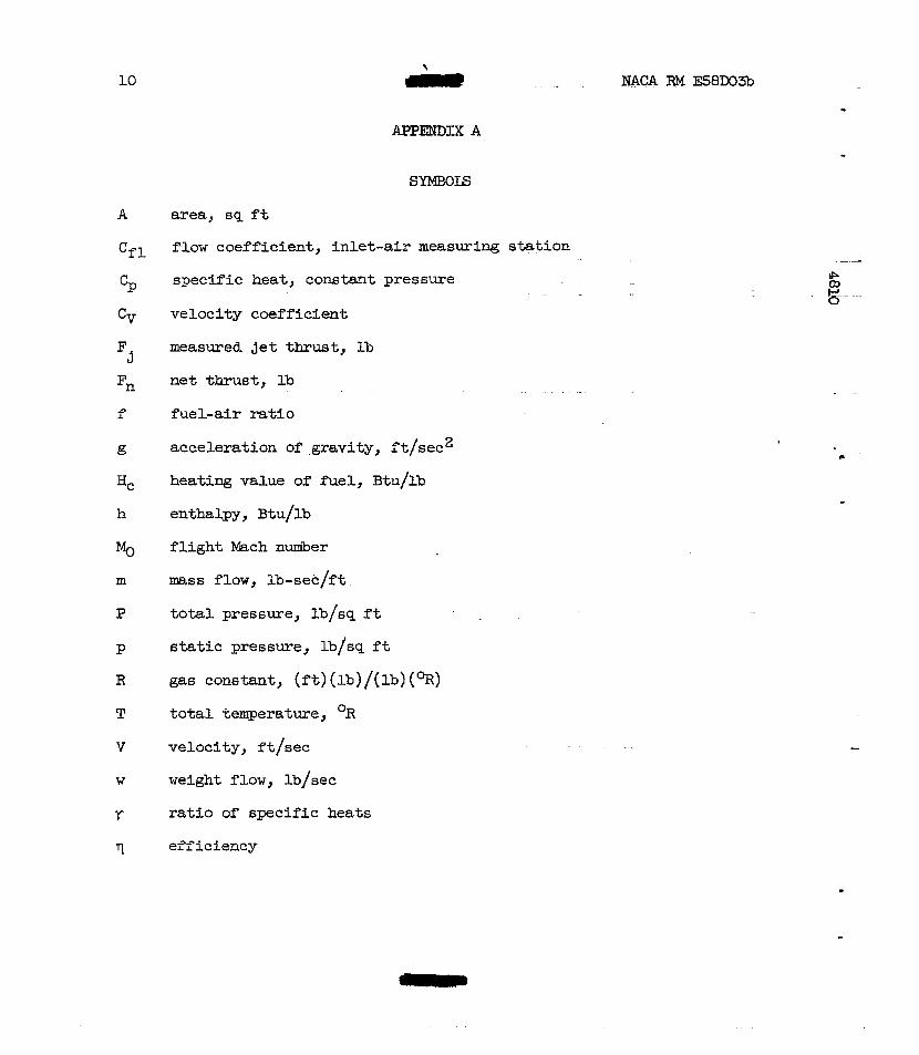
SYMBOLS
A area, sq f t
Cf l flow coefficient, inlet-ais m e a s u r i n g station
% specific heat, constant pressure
Cy velocity coefficient
F measured j e t thrust, Ib J
f
Q
HC
h
% m
P
W
r
II
net thrust , lb
fue l -a i r ra t io
. .
acceleration of .gravity, rt/sec2
heating value of fuel, Btu/lb
enthalpy, Btu/lb
f l i g h t Mach number
mass flow, lb-sec/ft
total pressure, lb/sq f t
static pressure, lb/sq f t
gas constant, ( f t ) (lb)/(lb) (%)
t o t a l temperature, OR
velocity, ft/sec
weight flow, lb/sec
r a t i o of specific heats
efficiency
"
L
NACA RM E56D03B 11
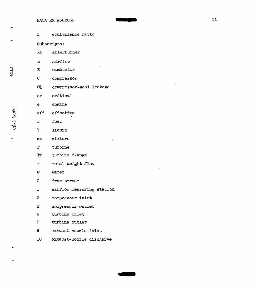
cp equivalence ratio I
Subscripts :
AB
a 0 OJ d rl B
C
CL
cr
e
ef f
N I f
2 2
- mx
T Tf
t
w
3
4
5
9
10
afterburner
airflow
combus tor
compressor
canpressor-seal leakage
critical
engine
effective
fuel
liquid
mixture
turbine
turbine flange
total weight flow
water
free stream
airflow measuring station
compressor W e t
canpressor outlet
turbine inlet
turbine outlet
exhaust-nozzle inlet
exhaust-nozzle discharge
.. . . .
12
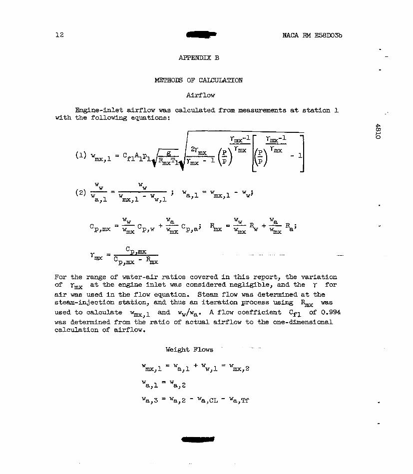
APPENDIX B
Airflow
-ne-inlet airflow was calculated from measurements a t s t s t ion 1 with the follow3ng equations:
For the range of water-air ratios covered i n this report, the variation of r, at the engine i n l e t was considered negligible, and the r for air was used i n the flow equation. S t e m flow was determined a t the steam-injection station, and thus an iteration process using was used to ca lcu la te w mx,l and ww/wa. A flaw coefficient Cfl of 0.994 was determined from the r a t io of actual airflow to the one-dimensional calculation of' airflow.
Weight Flows ." .
13
W = w a,& a,3
0
-=P z!
W a,5 = w a,4 + " a , ~ = w a,9
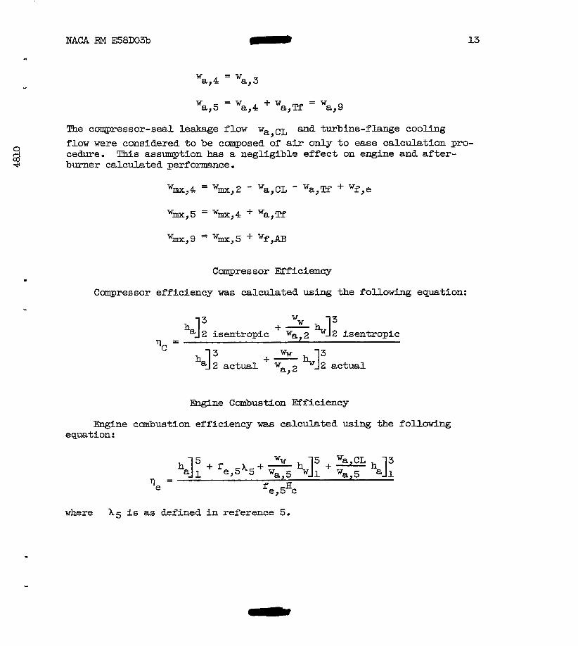
The coqpressor-sea1 leakage flow wa,c-, and turbine-f lange cooling flow were considered t o be cmposed of a i r only t o ease calculation pro- cedure. This assumption has a negligible effect on engine and a f t e r - burner calculated perf omnce .
W mx,9 = W i , 5 + W f , A B
Compressor Efficiency
Campressor efficiency was calculated using the following equation:
Engine Cmbus t i o n mf iciency
Engine cmbustion efficiency was calculated using the following equation:
where Xg i s as defined in reference 5.
14
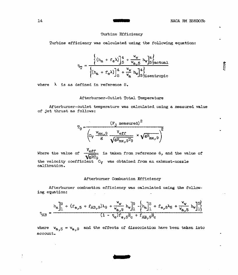
Turbine Efficiency
EACA RM E58DO3b
Turbine efficiency was calculated using the following equation:
where A is as def bed in reference 5.
Afterburner-Outlet Tota l Temperature
Afterburner-outlet temperature was calculated using a measured value of jet thrust as follows:
( FJ measured) 2
Tg =
wmx, 9 Veff -
Where the value of Veff is taken fram reference 6, and the value of d i E
the velocity coeffici&t -Cv was obtained f’ram an exhaust-nozzle calibration.
Afterburner Cmbustion Efficiency
Afterburner combustion efficiency was calculated using the follow- ing equation:
where wa,5 = wa,g and the effects of dissociation have been taken i n t o account.
NACA RM E58D03b 0 15
c
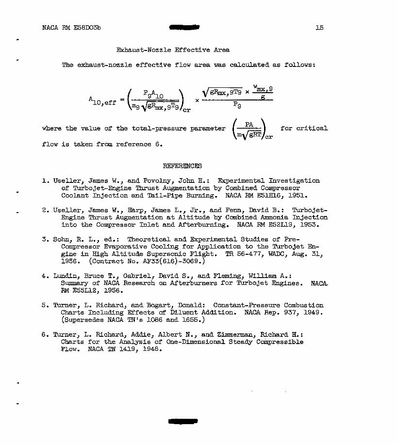
Exhaust-Nozzle Effective Area
The exhaust-nozzle effective f low area was calculated as follows:
where the value of the total-pressure parameter for critical
f l o w is taken f r m reference 6.
1. Useller, James W., and Povolny, John H.: Ekperimental Investigation of Turbojet-Engine Thrust Augmentation by Combined Compressor Coolant Injection and Tail-Pipe Burning. NACA RM E5lHl6, 1951.
2. Useller, James W., Harp, James L., Jr,, and Fenn, David B.: Turbojet- Engine Thrust Augmentation at Altitude by Cmbined Ammonia Injection into the Campressor Inlet and Afterburning. mACA RM E52Ll9, 1953.
3. S o h , R. L., ed,: Theoretical and Ekperimental Studies of Pre- Compressor Evaporative Coo- for Application to the Turbojet En- gine in High Alt i tude Supersonic Flight. TFi 56-477, FlADc, Aug. 31, 1956. (Contract No. AF'33(616)-3069.)
4. Lundin, Bruce T., Gabriel, David S., and Fleming, WiUim A. : Summary of NACA Research on Afterburners for Turbojet Engines. RM E55Ll2, 1956.
5. Turner, L. Richard, and mart, Donald: Constant-Pressure Combustion Charts Including Effects of Mluent Addition. NACA Rep. 937, 1949. (Supersedes NACA TN's 1086 and 1655.)
6. Turner, L. Richard, Addie, Albert N., and Zimmem, Richard H. : Charts for the Analysis of One-Dimensional S t e a d y Coinpressible Flow. NACA 'Dl 1419, 1948.
. .. . . . . . . - . . . . . . . . . . . . . . . . . ".
V \"o-etage Variable-area I L 13-Stage compressor
, combustion chamber
turbim exhaust nozzle 1-1
I
Figure 1. - Schematic diagram of the engine a d afterburner ahawing location of instnrmentation s t a t i m .
!
* . * I : I . ,
I
. . .. . . . .
I 1
. . .... . . - 1 1 m-3
. . .
4810
Figure 2 . - Photograph showing engine and afterburner installed in the a l t i t u d e test chamber.
t;
. ..
. . . . . . . . . . . . . . . .. . . . . . . . . . . . . . . . . . . - . . . . , . . . . . . . . . ., . .
P W
Fuel sprag bars
nn
II II """"""_
" r -
c
Variable-ares e u u s t nozzle
37"
Figure 3. - Schematic diagram of the aftexburner.
.
c
,-Outer shell
19
0 aD d -P
A i r f l o w
/
- “ L i n e r
(a ) Flameholder.
(b) Spray bar.
Figure 4. - Schematic sketches of flameholder and fuel spray bar. .
20 ' NACA RM E58D03b
1.65 2.0 2.2 2.4 2.6 2.8 Mach nmnber
(a) Corrected engine sgeed.
Figure 5. - Effect of engine-met water injection on over-all engine performance.
21
P
. 1 I 1 I I I Cmpressor-inlet total pressure, lb/sq ft abs
0 U50 R 850 A 550
With water injection "" Without water Fnjection
0 .02 .04 .06 .08 .10 Engine-inlet water-air ratio, ww/wa
I I I I I I 1.65 2.0 2.2 2.4 2.6 2.8
Mach number
(b) Engine total-pressure ratio.
Figure 5. - Continued. Effect of engine-inlet water injection on over-all engine performance.
22 NACA RM E58D03b
"
0 .02 .04 a 06 .08 Engine-tnlet water-air ratio, ww/wa
1 I I f I 1.65 2.0 2.2 2.4 2.6 2.8
Mach number
(c) corrected enghe-idet ~ B S B flow.
Figure 5. - Continued. Effect of engine-inlet water injection on over-all engine performance.
MACA RM E58D03b c
.
60
23
0 .02 .04 .06 .08 .10 Engtne-met water-air ratio, wu/wa
I I I I I I 1.65 2.0 2.2 2.4 2.6 2.8
Mach number
(a) Corrected engine fuel flow.
Flgme 5. - Concluded. Effect of engine-inlet water injection on over-all engine performance.
24 W A RM E58D03b
I I I I Cnmpressor-inlet t o t a l pressure,
lb/Sq ft ab6
0 1150 0 850 a 550
0" 5.5 k d o-@
a \ 2 2 bN g &,"
" 4.5 m
b 0 .02 .04 .06 .08 .10 Engine-"t w-ater-air r a t io , wW/wa
(a) Compressor efficiency and total-pressure ratio.
Figure 6. - Effects of engine-inlet water injection on compressor, combustor, and turbine performance.
. . . . . .
cp-4 4alO
. . . . . . -.
# C
LO
d : * 04
5 ; 2;m
f & .02
% A Io
0 1 2 s .PPI
u 0 .02 .04 .06 .Qa .10 Enghe-wet water-ar ratio, wJwa
(b) Cdustor efl iciency and total-pressure-loss ratio.
Flgure 6. - Continued. Eefects of enghe-inlet water- injection on cmpressor, combustor, and turbine performance.
26 NACA RM E58D03b
0 .02 .04 06 08 .10 EngSne-inlet water-air ratio, wW/wa
(c) Turbine efficiency and total-pressure ratio.
Figure 6. - Concluded. Effects of engine-inlet water injection on cmpressor, cambustor, and twbine performance.
. . . . .
L I
c 0 A n .90
' 1 cF-4 back 4810
. 4 .5 -6 .7 .8 .9 1.0 Afterburner equivalence ratio, qAB
(a) Afterburner-inlet total pressure, 2000 pound8 per square foot absolute.
Figure 7. - Effect of engine-inlet mter injecticm on afterburner cmbusticm efficiency.
. .
. . . . . . . . . . . . ....... . . . . . . . . . . . . . . . . . . . . . . . . . . . . . . . . . . . . . . . . . . . . . . . . . . . .."
I I I 1 Water-air ratio
0 .02
(b) A f t e r b m - i a l e t t o t a l pressure, 1500 pounds per square foot absolute.
N 0)
.I 2
Figure 7. - Cantin& EXfect of engine-inlet vater i n j e c t i m on afterblrrner ccanbuetion efflciemcy. z w
. . .
OTBP . . .
P .. I
NACA RM E58D03b 29
. 4 .5 .6 .7 .8 .9 1.0 Afterburner equfvalence ratio, (pm
(c) Afterburner-inlet total pressure, 1000 pounds per square foot absolute.
Figure 7. - Concluded. Effect of engine-inlet water injection on afterburner combustion efficiency.
.
30
Y
% 0 d
k
1 I I 1 Afterburner-inlet total pressure,
~ b / s q ft abs
0 2000 1500
A lo00 .70
60
50
.40
-30 * 0 .02 .04 .06 .08 1.0
Engine-inlet water-atr ratio, ww/wa
Figure 8. - Effect of afterburner-inlet total pressure and engine-inlet water-air ratio on dterburner lean blowout.
NACA RM E58D03b 31
0
(a) Afterburner-wet total pressure, 2000 pounds per s q w e foot absolute.
Figure 9. - Effect of engine-inlet water injection on afterburner-outlet t o t a l temperature.
. . . . - . . . . . . . . . . . . . . . .. .. . . . . . . . . - . . . . . . . - . . . . . . . . . . - . -. . . . . . . . . . . .. . . . . . . . . . . .. .. . . . . . . .
i
. I ‘ s. ‘I I
. . . . . . . . o w . . . . . . . .. I
33
.9 1.0 'PAB
(c) Afterburner-inlet total pressure, 1000 p a a s per squme foot absolute.
Figure 9. - Concluded. Effect of engine-inlet water injection on afterburner-outlet total temgerature.
NACA RM E58D031 35
Y
(a) Afterburner-Met total pressure, Zoo0 polnads per square foot absolute.
i (b) Afterburner-inlet total pressure, pounds per square foot absolute.
Afterburner equivalence ratio, 'pAB
(c) Afterburner-inlet total pressure, 1000 pomds per square foot absolute.
Figure U. - Effect of engine-inlet water injection on the afterburner total-pressure- loss ratio.
36 NACA RM E58D03b
0 .02 .04 . -06 Engine-inlet water-air ratio, .ww/wa
Figure 12. - Effect of engine-inlet water injection on the effective exhauat-nozzle area required for constant turbine- outlet gas temperature operation.
. .. . . . . . . . . . . .
1
. . . . . . . .. . .. . 4810
I &. I I
Flight Mach R U U ~ C ~ , Mc,
Figure 13. - Aircraft Mutries Association standard inlet ram recovery.
. . .. . .. . . . . . . . . - . . . .
38
Fl ight Mach number, MO
Figure 14. - Engine-inlet water-air ratio required t o maintain constant canpressor-inlet total temperature with increasing Mach number.
EACA RM E58D03b UNCLASSiFtFD r- 39
" (a) Engine total net thrust.
8
6
4
2 .6 1.0 1.4 1.8 2.2 2.6 3.0
Flight Mach nmber, %
(b) Net thrust specific l iquid consumption.
Figure 15. - Over-all engine and afterburner performance a t constant altitude and increesing flight Mach nmber with water injection.
*. . . ". . . . ".
DO NOT REMOVE SLIP FROM MATERIAL
Delete your name from this slip when returning material to the library.
4
NASA Langley (Rev. Dec. 1891) RlAD N-75
Related Documents