4 Parallel-Plate Electrostatic Dual-Mass Oscillator Christopher W. Dyck+, James J. Allen, and Robert, J. Huber Intelligent Micromachines Sandia National Laboratories MS 1080, PO BOX 5800 Albuquerque, NM 87185-1080 ABSTMCT REXXWED AU6111999 Cwn A surface-micromachined two-degree-of-freedom system that was driven by parallel-plate actuation at antiresonance was demonstrated. The system consisted of an absorbing mass connected by folded springs to a drive mass. The system demonstrated substantial motion amplification at antiresonance. The absorber mass amplitudes were 0.8-0.85 pm at atmospheric pressure while the drive mass amplitudes were below 0.1 pm. Larger absorber mass amplitudes were not possible because of spring softening in the drive mass springs. Simple theory of the dual-mass oscillator has indicated that the absorber mass may be insensitive to limited variations in strain and damping. This needs experimental verification. Resonant and antiresonant frequencies were measured and compared to the designed values. Resonant frequency measurements were difficult to compare to the design calculations because of time-varying spring softening terms that were caused by the drive configuration. Antiresonant frequency measurements were close to the design value of 5.1 kHz. The antiresonant frequency was not dependent on spring softening. The measured absorber mass displacement at antiresonance was compared to computer simulated results. The measured value was significantly greater, possibly due to neglecting fi-inge fields in the force expression used in the simulation. Keywords: Surface Micromachining, Resonator, Actuator, Vibration Absorber, Motion Amplifier. 1. INTRODUCTION Presently, there is a need in surface micromachining for a resonator that is capable of large motions at low drive voltages. Large, linear displacements are obtained by using comb drive actuation, however the force of a comb drive is low and large drive voltages are needed. Parallel-plate drive actuation generates larger forces over a comparable area, however the displacement is limited because the force is nonlinear. The dual-mass oscillator provides a potential solution to the problem. By forcing a two-degree-of-freedom (2DC)F) system at antiresonance, parallel-plate actuation may be used to obtain displacements that exceed 1/3 of the electrode gap. This system operates on the same principle as the dynamic vibration absorber]. An absorber spring-mass system is connected to a system that is experiencing unwanted oscillations. If the resonant frequency of the absorber spring-mass system matches the frequency of the unwanted oscillations, the absorber mass will act to oppose the force causing the oscillation, rendering the original oscillating system stationary. Bulk micromachined structures have been fabricated to demonstrate this concept in the form of base driven structures, and a torsional resonato~. The objectives of this paper are to demonstrate the operation of the dual mass resonator, and to compare some preliminary results to the design calculations. The theory section presents the design and analysis equations, and some interesting characteristics of the dual-mass oscillator. The oscillation amplitude appears to be insensitive to limited variations in damping and strain. The design section summarizes the calculations of the prototype structure’s parameters. Observations of the functioning dual-mass oscillator were made. Preliminary measurements of resonant and antiresonant frequencies were also recorded to compare the fabricated structure to fie design calculations. Absorber mass displacement measurements were also taken to compare to a computer solution. The results were discussed and summarized in the last two sections of the paper. + Contact Information: Email: [email protected]; Website www.sandia.mdl. sov/Micromachine, Tel: (505) 845-7743, Fax: (505) 844-2991. Undercontractwith the Universityof New Mexico,CHTM -—- --- .—. ~ ..— ,,,— — —.._—

Welcome message from author
This document is posted to help you gain knowledge. Please leave a comment to let me know what you think about it! Share it to your friends and learn new things together.
Transcript
4
Parallel-Plate Electrostatic Dual-Mass Oscillator
Christopher W. Dyck+, James J. Allen, and Robert, J. HuberIntelligent Micromachines
Sandia National LaboratoriesMS 1080, PO BOX 5800
Albuquerque, NM 87185-1080
ABSTMCT
REXXWEDAU6111999
CwnA surface-micromachined two-degree-of-freedom system that was driven by parallel-plate actuation at antiresonance
was demonstrated. The system consisted of an absorbing mass connected by folded springs to a drive mass. The systemdemonstrated substantial motion amplification at antiresonance. The absorber mass amplitudes were 0.8-0.85 pm atatmospheric pressure while the drive mass amplitudes were below 0.1 pm. Larger absorber mass amplitudes were notpossible because of spring softening in the drive mass springs. Simple theory of the dual-mass oscillator has indicated thatthe absorber mass may be insensitive to limited variations in strain and damping. This needs experimental verification.Resonant and antiresonant frequencies were measured and compared to the designed values. Resonant frequencymeasurements were difficult to compare to the design calculations because of time-varying spring softening terms that werecaused by the drive configuration. Antiresonant frequency measurements were close to the design value of 5.1 kHz. Theantiresonant frequency was not dependent on spring softening. The measured absorber mass displacement at antiresonancewas compared to computer simulated results. The measured value was significantly greater, possibly due to neglecting fi-ingefields in the force expression used in the simulation.Keywords: Surface Micromachining, Resonator, Actuator, Vibration Absorber, Motion Amplifier.
1. INTRODUCTION
Presently, there is a need in surface micromachining for a resonator that is capable of large motions at low drivevoltages. Large, linear displacements are obtained by using comb drive actuation, however the force of a comb drive is lowand large drive voltages are needed. Parallel-plate drive actuation generates larger forces over a comparable area, howeverthe displacement is limited because the force is nonlinear.
The dual-mass oscillator provides a potential solution to the problem. By forcing a two-degree-of-freedom (2DC)F)system at antiresonance, parallel-plate actuation may be used to obtain displacements that exceed 1/3 of the electrode gap.This system operates on the same principle as the dynamic vibration absorber]. An absorber spring-mass system is connectedto a system that is experiencing unwanted oscillations. If the resonant frequency of the absorber spring-mass system matchesthe frequency of the unwanted oscillations, the absorber mass will act to oppose the force causing the oscillation, renderingthe original oscillating system stationary. Bulk micromachined structures have been fabricated to demonstrate this concept inthe form of base driven structures, and a torsional resonato~.
The objectives of this paper are to demonstrate the operation of the dual mass resonator, and to compare somepreliminary results to the design calculations. The theory section presents the design and analysis equations, and someinteresting characteristics of the dual-mass oscillator. The oscillation amplitude appears to be insensitive to limited variationsin damping and strain. The design section summarizes the calculations of the prototype structure’s parameters. Observationsof the functioning dual-mass oscillator were made. Preliminary measurements of resonant and antiresonant frequencies werealso recorded to compare the fabricated structure to fie design calculations. Absorber mass displacement measurements werealso taken to compare to a computer solution. The results were discussed and summarized in the last two sections of thepaper.
+ Contact Information: Email: [email protected];Website www.sandia.mdl. sov/Micromachine, Tel: (505) 845-7743, Fax:(505)844-2991. Undercontractwith the Universityof New Mexico,CHTM
-—- --- .—. ~ ..— ,,,— — —.._—

DISCLAIMER
This report was prepared as an account of work sponsoredbyanagency of the United States Government. Neither theUnited States Government nor any agency thereof, nor anyof their employees, make any warranty, express or implied,or assumes any legal liability or responsibility for theaccuracy, completeness, or usefulness of any information,apparatus, product, or process disclosed, or represents thatits use would not infringe privately owned rights. Referenceherein to any specific commercial product, process, orservice by trade name, trademark, manufacturer, orotherwise does not necessarily constitute or imply itsendorsement, recommendation, or favoring by the UnitedStates Government or any agency thereof. The views andopinions of authors expressed herein do not necessarilystate or reflect those of the United States Government orany agency thereof.

DISCLAIMER
Portions of this document may be illegiblein electronic image products. Images areproduced from the best available originaldocument.
—.. —____ ._ ..._ .._____ ——. .-

2. THEORY
The steady-state equations of the dual mass resonator are presented for design and analysis of the system. A lumpedparameter model is assumed. Antiresonance is defined, and the strain and damping insensitivity are discussed.
A diagram of a 2DOF system is shown Fig 1. ml is connected through a spring (k)) to the substrate, and mz isconnected through a spring (k2) to ml. ml and m2 are often referred to in this paper as the drive mass and the absorber mass,respectively, kl and k2 are ofien referred to as the drive mass spring and the absorber mass spring. c1 and cz are viscousdamping coefficients. Damping between the two masses has been neglected because it is easily designed out of the system.xl and x2 are measured relative to the substrate. The equations of dynamics for Fig. 1are
rn,i, +c~i~ +Jk]xl +kz(xl –X2)=F (1)
nz2i2+c2i2 +k2(x2-xl)=o. (2)
Figure : Diagram of a 2DOF system. Damping between ml and m2has been neglected.
The steady-state responses of the 2DOF system to a time-varying sinusoidal input force, F = F. sin tit are
and
where
.,,=./~and.22={~
(3)
(4)
(5)
are the resonant frequencies of the isolated ml-kl and mz-kz systems, and not the 2DOF system resonant frequencies. Thisnotation was borrowed from Thompson4.
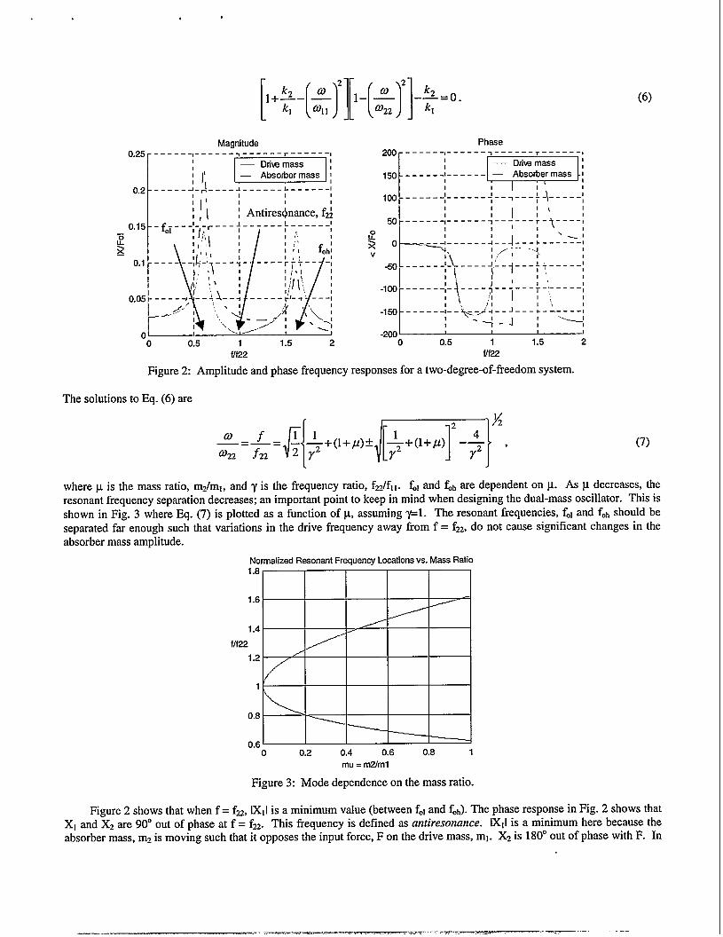
The amplitude and phase of Eq. (3) and Eq. (4) are plotted in Fig. 2. There are three frequencies of interest: tworesonant frequencies, fO1and fOh,and an antiresonant frequency, fz. Figure 2 shows that at f = fol,Xl and X2 are in phase, andat f = fob,Xl and X2 are 180° out of phase. The system resonant frequencies are approximated by equating the denominatorsof the undamped system responses to zero,
[[)k22
I+r– ~1 ~11
Marmitude0.25 ------s-----:, ------ r------,
I
{l’ EzEz=a0.2 ------[-)----:------:------[
lli [*ntj,e,Jnancef2~1, ,
-o 0.5 1 1.5 2flf22
200
150
100
50
v
-50
-1oo
-150
-20(1
(6)
Phase_---__, ------ ~------ ~------ ,
------!------E===!------------ :__1
\i~___+______1I
:1:’~1---— --------
I
~--7_--t-.t-___,
I 1
, , , 1
0.5 1 1.5 2W22
Figure2: Amplitudeand phase ilequency responses foratwo-degree-of-freedomsystem.
ThesolutionstoEq. (6)are
(7)
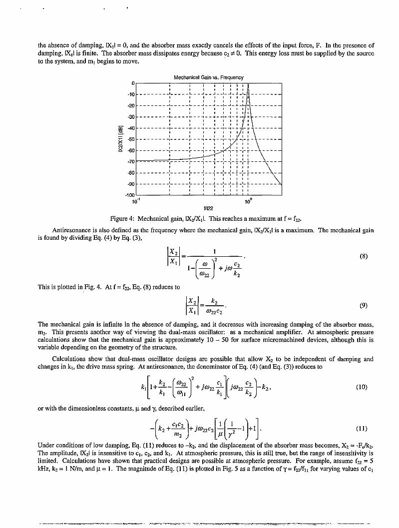
wherep is the mass ratio, m2/ml, andyis the frequency ratio, fzJf]l. fO1andfOhare dependent onp. As pdecreases, theresonant frequency separation decreases; animportantpoint to keep in mind when designing the dual-mass oscillator. Thisisshown in Fig. 3 where Eq. (7) is plotted asa functionof p,assuming~l. The resonant frequencies, folandfOh shouldbeseparated far enough such that variations in the drive frequency away fromf= f~,donotc ause significant changes in theabsorber mass amplitude.
Normalized ResonantFrequency Locations vs. Mass Ratio1.8
1.6
1.4
f/f22
1.2 /
1
0.8
0.60 0.2 0.4 0.6 0.8 1
mu = m2/ml
Figure 3: Mode dependence on the mass ratio.
Figure 2 shows that when f = f22,IXIIis a minimum value (between fOland fob).The phase response in Fig. 2 shows thatXl and X2 are 90° out of phase at f = f22. This frequency is defined as antiresonance. IXll is a minimum here because theabsorber mass, m2 is moving such that it opposes the input force, F on the drive mass, ml. X2 is 180° out of phase with F. In
. ——-— ..-p ...-. .-—
the absence of damping, lX1l= O, and the absorber mass exactly cancels the effects of the input force, F. In the presence ofdamping, lX1lis finite. The absorber mass dissipates energy because C2# O. This energy loss must be supplied by the sourceto the system, and ml begins to move.
Mechanical Gainw. Frequencyo 1 1111111
1 1111111
-in --------l-----~- -J--J--l-J-J-l- -------
-201---------J----- ~---J-- J--l-~-~-d4---
__;-------- , ,/;\------,-1----- l---+---l --l--l -+-l11111
t-40 --------: -----:--4-- 4--:-:-; L:
11111
,7 , ,+-+
I 11 11!11 ‘h-70 ---------,----- ;---+-- + --:--: -+-:-;--- ---
-80 ---------[----- ;--; --; --~--! -;-[-: ----1 111111! 1
-go ---------: -----:; --:-- +--: --_-+ -f-: -------
1 1111111 1
-1oo , I ,
10-’ 10°f/f22
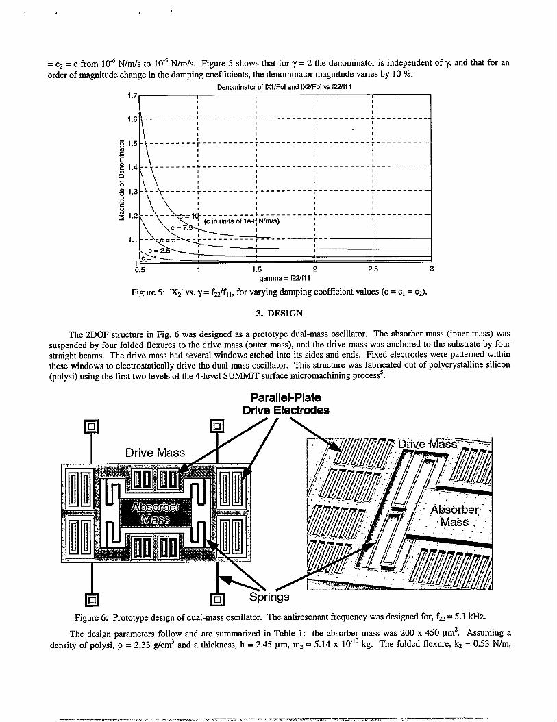
Figure 4: Mechanical gain, lXJX1l. This reaches a maximum at f = fz.
Antiresonance is also defined as the frequency where the mechanical gain, lX2/X11is a maximum. The mechanical gainis found by dividing Eq. (4) by Eq. (3),
i
x 2_ 1
x, – 2
[)
1– ~ +jco~f322 2
This is plotted in Fig. 4. At f = f22,Eq. (8) reduces to
i
x 2_k2
x, 0.2.2C2
(8)
(9)
The mechanical gain is infinite in the absence of damping, and it decreases with increasing damping of the absorber mass,m2. This presents another way of viewing the dual-mass oscillator: as a mechanical amplifier. At atmospheric pressurecalculations show that the mechanical gain is approximately 10 – 50 for surface micromachined devices, although this isvariable depending on the geometry of the structure.
Calculations show that dual-mass oscillator designs are possible that allow X2 to be independent of damping andchanges in kl, the drive mass spring. At antiresonance, the denominator of Eq. (4) (and Eq. (3)) reduces to
kl~+~-[~~+jo22~][joz~]-k2,
or with the dimensionless constants, p and y, described earlier,
-F2+%l+jo22c2[~[+-1
(lo)
(11)
Under conditions of low damping, Eq. (11) reduces to –k2, and the displacement of the absorber mass becomes, X2 = -FJk2.The amplitude, IX21is insensitive to cl, C2,and kl. At atmospheric pressure, this is still true, but the range of insensitivity islimited. Calculations have shown that practical designs are possible at atmospheric pressure. For example, assume fz = 5kHz, k2= 1 N/m, and y = 1. The magnitude of Eq. (11) is plotted in Fig. 5 as a function of y = fz/fl, for varying values of c1
.—. - -, ..-7%-” .- . . -Y -,. — ,...m,s, ,. .k,,,,,,,..,,.,.,,,-... .,\ , ..,,-------———..- -
=C2= c from 106 N/mJs to 10-5N/m/s. Figure 5 shows that for y = 2 the denominator is independent of y, and that for anorder of magnitude change in the damping coefficients, the denominator magnitude varies by 10 Yo.
Denominator of IX1lFOIand lX2/Fol w f2Zfl 11.7 I I I 1
1 1 1 11 1 1 1
--------- ;----------; ---------- ;---------- : -----------t I I 1
1 1 1
1.5
‘\
--------- ;------ ----;-----_----\---------- ;__________1 1 1 I1 1 1 I, 1 1 1
h1.4 -’ --------:----------:----,
N ;
1
1.3 -- ------ ~----_-.--__;---- -II
6 1
Iiigl.2 --’- -\=y--____----L- ---
(c in units of le-~ N/mIs)
----__L ---------- J-----------1 1! 11 1 i1 1
------ r----------T ----------1 11 11 1
------ L___-_____-L ----------1 ! 1
0.5 1 1.5 2 2.5 3
gamma=f22/fll
Figure 5: 1X21vs. y = f2.Jfll, for varying damping coefficient values (c = c1= C2).
3. DESIGN
The 2DOF structure in Fig. 6 was designed as a prototype dual-mass oscillator. The absorber mass (inner mass) wassuspended by four folded flexuresto the drive mass (outer mass), and the drive mass was anchored to the substrate by fourstraight beams. Thedrive mass had several windows etched into its sides and ends. Fixed electrodes were patterned withinthese windows toelecmos@tically drive thedual-mass oscillator. This structure was fabricated outofpolycrystalline silicon(polysi) using the first two levels of the 4-level SUMMiT surface micromachining processs.
Parallel-PlateDrive Electrodes
Figure 6: Prototype design of dual-mass oscillator. The antiresonant frequency was designed for, fz = 5.1 kHz.
The design parameters follow and are summarized in Table 1: the absorber mass was 200 x 450 pm2. Assuming a
density of polysi, p = 2.33 g/cm3 and a thickness, h = 2.45 pm, m2 = 5.14 x 10⁻¹⁰kg. The folded flexure, k2 = 0.53 N/m,
—.. — —.. -.—. m- . . . . —--- ———-
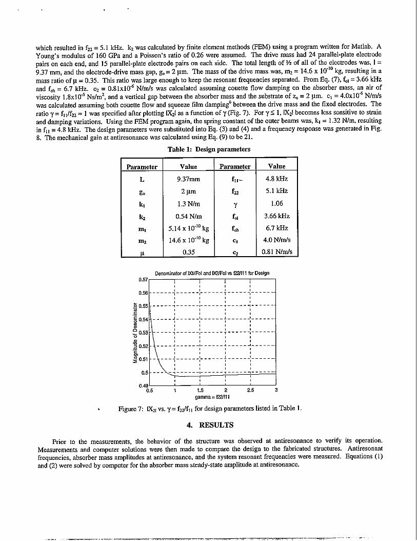
which resulted in f22= 5.1 kHz. k2 was calculated by finite element methods (FEM) using a program written for Matlab. AYoung’s modulus of 160 GPa and a Poisson’s ratio of 0.26 were assumed. The drive mass had 24 parallel-plate electrodepairs on each end, and 15 parallel-plate electrode pairs on each side. The total length of Y2 of all of the electrodes was, 1=9.37 mm, and the electrode-drive mass gap, go= 2 pm. The mass of the drive mass was, mz = 14.6 x 10-]0kg, resulting in amass ratio of p = 0.35. This ratio was large enough to keep the resonant frequencies separated. From Eq. (7), f.l = 3.66 kHzand foh= 6.7 kHz. C2= 0.8 lxIO-GN/m/s was calculated assuming couette flow damping on the absorber mass, an air ofviscosity 1.8x10⁵ Ns/m2, and a vertical gap between the absorber mass and the substrate of% = 2 pm. c1 = 4.OXI0-6N/m/swas calculated assuming both couette flow and squeeze film dampingGbetween the drive mass and the fixed electrodes. Theratio y= fll/f22= 1 was specified after plotting 1X21as a function of y (Fig. 7). For y S 1, 1X21becomes less sensitive to strainand damping variations. Using the FEM program again, the spring constant of the outer beams was, k] = 1.32 N/m, resultingin fl1= 4.8 kHz. The design parameters were substituted into Eq. (3) and (4) and a frequency response was generated in Fig.
8. The mechanical gain atantiresonance was calculated using Eq. (9) to be 21.
Table 1: Design parameters
Parameter Value Parameter Value
L 9.37mm f*,- 4.8 kHZ
go 2pm fn 5.1 kHz
k, 1.3 N/m ‘r 1.06
kz 0.54 N/m fo, 3.66 ~Z
ml 5.14 X 10⁻¹⁰kg foh 6.7 kHZ
mz 14.6 X 10⁻¹⁰kg c1 4.0 N/m/s
P 0.35 C2 0.81 N/m/s
Denominatorof IXIIFOIand IWFOI w fZYfll for Design0.57 I 1 1 I 1 I
11 1 1 1
0.56 ----- ; ------;------ +------:- -----1 1 I I {
L’0.55 ----- ;------[------: ----- +-----
l--__-_L______k___---go.w _----: ------lcal:0.53 ----- ;------;------ +----- +-----
al:0.52 ----4------1- ----- 4------I ------
\
1
0.51 - ---+ ------:------ +------: ------11 ! I :
0.5 ---- _;_--- __;__ --__; ____ -;_______8 1
1 1 1 10.49 ,
0.5 1 1.5 2 2.5 3
gamma = f22/fll
● Figure 7: 1X21vs. y = fz/fll for design parameters listed in Table 1.
4. RESULTS
Prior to the measurements, the behavior of the structure was observed at rmtiresonance to verify its operation.Measurements and computer solutions were then made to compare the design to the fabricated structures. Antiresonantfrequencies, absorber mass amplitudes at antiresonance, and the system resonant frequencies were measured. Equations (1)and (2) were solved by computer for the absorber mass steady-state amplitude at antiresonance.
.— — —. . ~.. ,m,——--. —— .- -- -- ?.-. --
Frequency Respense of Prototype Design!4 .-----r-----l------,-------------,-----
1 1
‘ =;12 ------:---r-[------:---- ,1 /,1 : : ~ [1
10 -----_&--Lm_1__----,----_4----_A_____4
:/,: : : : ;
=8 ------+--A---- -;-----4-----4-----:, 1 1 1 1 1
L i’2
\l 1 t I 1
/
! 1I ,
hlo 300Q 4000 S000 aooo 7@3J 8000Freqency [Hz]
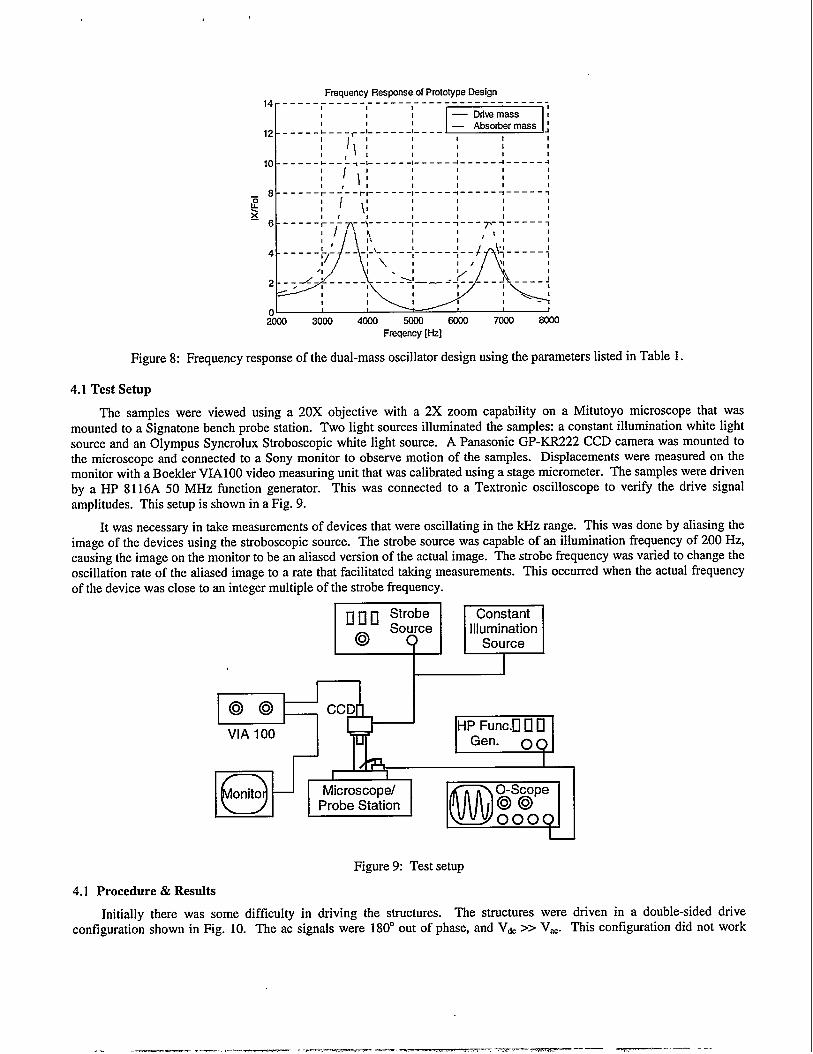
Figure 8: Frequency response of the dual-mass oscillator design using the parameters listed in Table 1.
4.1 Test Setup
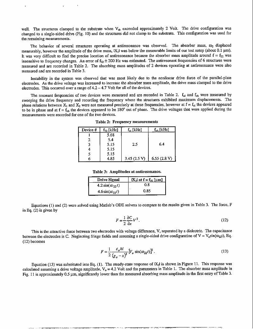
The samples were viewed using a 20X objective with a 2X zoom capability on aMitutoyo microscope that wasmounted to aSignatonebench probe station. Two light sources illuminated the samples: aconstant illumination white lightsource and an Olympus Syncrolux Stroboscopic white light source. A Panasonic GP-KR222 CCD camera was mounted tothe microscope and connected to a Sony monitor to observe motion of the samples. Displacements were measured on themonitor with a Boekler VIA lOOvideo measuring unit that was calibrated using a stage micrometer. The samples were drivenby a HP 8116A 50 MHz function generator. This was connected to a Textronic oscilloscope to veri~ the drive signalamplitudes. This setup is shown in a Fig. 9.
It was necessary in take measurements of devices that were oscillating in the kHz range. This was done by aliasing theimage of the devices using the stroboscopic source. The strobe source was capable of an illumination frequency of 200 Hz,causing the image on the monitor to bean aliased version of the actual image. The strobe frequency was varied to change theoscillation rate of the aliased image to a rate that facilitated taking measurements. This occurred when the actual frequencyof the device was close to an inte~er multiple of the strobe frequency.
c1ClII :::e Constant
@Illumination
o Source
I
@@VIA 100
HP Func.u o DGen. 0 ~
/
o -’7
I
onito Microscope/
@
O-ScopeProbe Station @@
OOOQ
Figure 9: Test setup
4.1 Procedure & Results
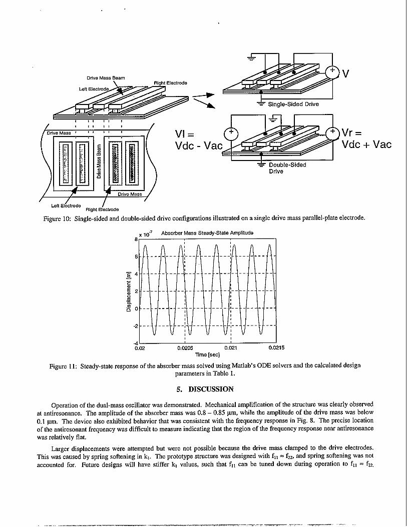
Initially there was some difficulty in driving the structures. The structures were driven in a double-sidedconfiguration shown in Fig. 10. The ac signals were 180° out of phase, and Vdc>> V~C. This configuration did not
drivework
——— . ..———— — .- --— —— —.-.—— . .
well. The structures clamped to the substrate when Vdc exceeded approximately 2 Volt. The drive configuration waschanged to a single-sided drive (Fig. 10) and the structures did not clamp to the substrate. This configuration was used forthe remaining measurements.
The behavior of several structures operating at antiresonance was observed. The absorber mass, mz displacedmeasurably, however the amplitude of the drive mass, lX1lwas below the measurable limits of our test setup (about 0.1 pm).It was very difficult to find the precise location of antiresonance because the absorber mass amplitude around f = f22wasinsensitive to frequency changes. An error of fz + 200 Hz was estimated. The antiresonant frequencies of 6 structures weremeasured and are recorded in Table 2. The absorbing mass amplitudes of 2 devices operating at antiresonance were alsomeasured and are recorded in Table 3.
Instability in the system was observed that was most likely due to the nonlinear drive force of the parallel-plateelectrodes. As the drive voltage was increased to increase the absorber mass amplitude, the drive mass clamped to the driveelectrodes. This occurred over a range of 4.2 – 4.7 Volt for all of the devices.
The resonant frequencies of two devices were measured and are recorded in Table 2. f.l and fohwere measured bysweeping the drive frequency and recording the frequency where the structures exhibited maximum displacements. Thephase relations between Xl and X2 were not measured precisely at these frequencies, however at f = fol the devices appearedto be in phase and at f = fohthe devices appeared to be 180° out of phase. The drive voltages that were applied during themeasurements were recorded for one of the two devices.
Table 2: Frequency measurements
Device # I fzz [kHz] I f., [kHz] f~h[kHz]1 5.682 5.43 5.15 2.5 6.44 5.155 5.156 4.85 3.45 (2.5 V) 6.55 (2.8 V)
Table 3: Amplitudes at antiresonance.
Equations (1) and (2) were solved using Matlab’s ODE solvers to compare to the results given in Table 3. The force, Fin Eq. (2) is given by
~_lacv2
2ax “(12)
This is the attractive force between two electrodes with voltage difference, V, separated by a dialectic. The capacitancebetween the electrodes is C. Neglecting fringe fields and assuming a single-sided drive configuration of V = V.sin(mt), Eq.(12) becomes
~ _ 1 &Ohl[V. sin(comt)~. (13)
-z~o–x)z
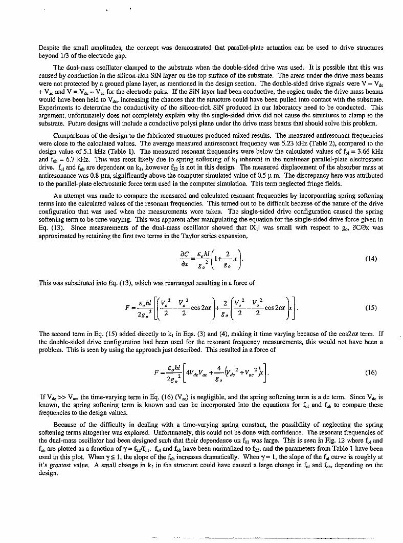
Equation (13) was substituted into Eq. (l). The steady-state response of IXZIis shown in Figure 11. This response wascalculated assuming a drive voltage amplitude, VO= 4.2 Volt and the parameters in Table 1. The absorber mass amplitude inFig. 11 is approximately 0.5 pm, significantly lower than the measured absorbing mass amplitude in the first entry of Table 3.
—— —-—-. .. ——-. —- — .—— -.,-
m—.. .— . ---- m--—unve Mass mxirn
\ R@ht ElectrodeLeft Electrode
i/ J :: :: : /
1[,,~, , ,~11~1I I 1
* Double-SidedDrive
AF r Drive Mass
/ /Left Elbctrode /
Right Electrode
Figure 10: Single-sided and double-sided drive configurations illustrated on a single drive mass parallel-plate electrode.
-7x 10 Absorber Mass Steady-State Amplitude
6
bvk: : ‘!1
1------- --- --- - ---, -------
1 “
~4 ------ --- - ----- ---- - --- - -- -
~
E m _________ ----- - .._-: ---- - ----a0m—g
i
“~ o -- --- - --; - ----- - ---: -- ----- --
-2 -- --- --: --- -- -- --- :- -- --- --
t
J I 1I
0.02 0.0205 0.021 0.0215lime [see]
Figure 11: Steady-state response of the absorber mass solved using Matlab’s ODE solvers and the calculated designparameters in Table 1.
5. DISCUSSION
Operation of the dual-mass oscillator was demonstrated. Mechanical amplification of the structure was clearly observedat antiresonance. The amplitude of the absorber mass was 0.8 – 0.85 pm, while the amplitude of the drive mass was below0.1 ~m. The device also exhibited behavior that was consistent with the frequency response in Fig. 8. The precise locationof the antiresonant tlequency was difficult to measure indicating that the region of the frequency response near antiresonancewas relatively flat.
Larger displacements were attempted but were not possible because the drive mass clamped to the drive electrodes.This was caused by spring softening in kl. The prototype structure was designed with fll = f=, and spring softening was not
accounted for. Future designs will have stiffer kl values, such that fll can be tuned down during operation to fl I = fz.
Vac
— ——. ._. ..—._,-— —-. —— ~ — —.-
Despite the small amplitudes, the concept was demonstrated that parallel-plate actuation can be used to drive structuresbeyond 1/3 of the electrode gap.
The dual-mass oscillator clamped to the substrate when the double-sided drive was used. It is possible that this wascaused by conduction in the silicon-rich SiN layer on the top surface of the substrate. The areas under the drive mass beamswere not protected by a ground plane layer, as mentioned in the design section. The double-sided drive signals were V = Vdc+ VWand V = Vd. – V~Cfor the electrode pairs. If the SiN layer had been conductive, the region under the drive mass beamswould have been held to V&, increasing the chances that the structure could have been pulled into contact with the substrate.Experiments to determine the conductivity of the silicon-rich SiN produced in our laboratory need to be conducted. Thisargument, unfortunately does not completely explain why the single-sided drive did not cause the structures to clamp to thesubstrate. Future designs will include a conductive polysi plane under the drive mass beams that should solve this problem.
Comparisons of the design to the fabricated structures produced mixed results. The measured antiresonant frequencieswere close to the calculated values. The average measured antiresonant frequency was 5.23 kHz (Table 2), compared to thedesign value of 5.1 kHz (Table 1). The measured resonant frequencies were below the calculated values of f., = 3.66 kHzand f.h = 6.7 kHz. This was most likely due to spring softening of kl inherent in the nonlinear parallel-plate electrostaticdrive. fO1and fOhare dependent on kl, however fzz is not in this design. The measured displacement of the absorber mass atantiresonance was 0.8 pm, significantly above the computer simulated value of 0.5 p m. The discrepancy here was attributedto the parallel-plate electrostatic force term used in the computer simulation. This term neglected fringe fields.
An attempt was made to compare the measured and calculated resonant frequencies by incorporating spring softeningterms into the calculated values of the resonant frequencies. This turned out to be difficult because of the nature of the driveconfiguration that was used when the measurements were taken. The single-sided drive configuration caused the springsoftening term to be time varying. This was apparent afler manipulating the equation for the single-sided drive force given inEq. (13). Since measurements of the dual-mass oscillator showed that IXII was small with respect to g., 8C/Zlx wasapproximated by retaining the first two terms in the Taylor series expansion,
[)3C &Ohl ~+ 2—x .
z– ~oz go
This was substituted into Eq. (13), which was rearranged resulting in a force of
[[
E hl V02 V02F=~
H }1
—-—cos2aZ J- ~-~cos2ax .2g02 2 2 go 2 2
(14)
(15)
The second term in Eq, (15) added directly to kl in Eqs. (3) and (4), making it time varying because of the cos2ax term. Ifthe double-sided drive configuration had been used for the resonant frequency measurements, this would not have been aproblem. This is seen by using the approach just described. This resulted in a force of
&ohlF=—
[4v&vac+J!- ( }]v&2+VaC2 .
2g02 /70(16)
If Vd. >> V,., the time-varying term in Eq. (16) (VJ is negligible, and the spring softening term is a dc term. Since Vd. isknown, the spring softening term is known and can be incorporated into the equations for fol and foh to compare thesefrequencies to the design values.
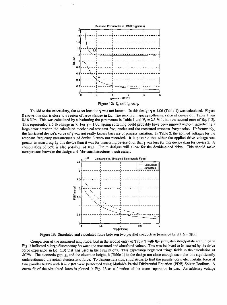
Because of the difficulty in dealing with a time-varying spring constant, the possibility of neglecting the springsoftening terms altogether was explored. Unfortunately, this could not be done with confidence. The resonant frequencies ofthe dual-mass oscillator had been designed such that their dependence on f]1 was large. This is seen in Fig. 12 where fO1andfOhare plotted as a function of y = f2Jf11. f., and f~hhave been norinalized to f22,and the parameters from Table 1 have beenused in this plot. When y S 1, the slope of the fohincreases dramatically. When ‘y= 1, the slope of the folcurve is roughly atit’s greatest value. A small change in kl in the structure could have caused a large change in fOland fob,depending on thedesign.
.-... ————. — ————..
,
Resonant Frequenciesvs. f2Zfl 1 (gamma)2
;------;------4-------;-------
;------;------;-------:-------
~------+------+-------:------–
l-----_l---_---l ______c
--;------;------:------+------~
--:------4------:-------:----- --
OL 4 , J
0 2 4 6 8 10gamma.f22/fll
Figure 12: fOlandfOhvs.y.
To add to the uncertainty, the exact location y was not known. In this design y = 1.06 (Table 1) was calculated. F@re8showsthat this is close to aregion oflarge change inf.h. The maximum spring softening value ofdevice6in Tablel was0.16 N/m. This was calculated by substituting the parameters in Table 1 and V. = 2.5 Volt into the second term of Eq. (15).This represented a6%changeiny. For’y= l.06, spring softening could probably have been ignored without introducinglarge error between thecalcuIated mechanical resonant frequencies and the measured resonant frequencies. Unfortunately,the fabricated device’svalueofy was notreally known because ofprocess variation. In Table 2, the applied voltages fortheresonant frequency measurements of device 3 were not recorded. It is possible that either the applied drive voltage wasgeaterin memuring fOhthisdevice than itw=for memuting device 6,0rtiat ywasless fortiis device tianfordevice3. Acombination of both is also possible, as well. Future designs will allow for the double-sided drive. This should makecomparisons between the design and fabricated structures much easier.
x 10-’0 Calculatedvs. Sfmulated Electrostatic Force3.5 I I
1 1 — Calculated— Simulated
3 ---------:---------:---------,--------,
\ ! I 1
2.5 -:-------;---------:-------- <---------
\;1 1
gI 1
2 -gE
1
I 1 11 1 1
0 , , ,1 1.5 2 2.5 3
Gap [micron]
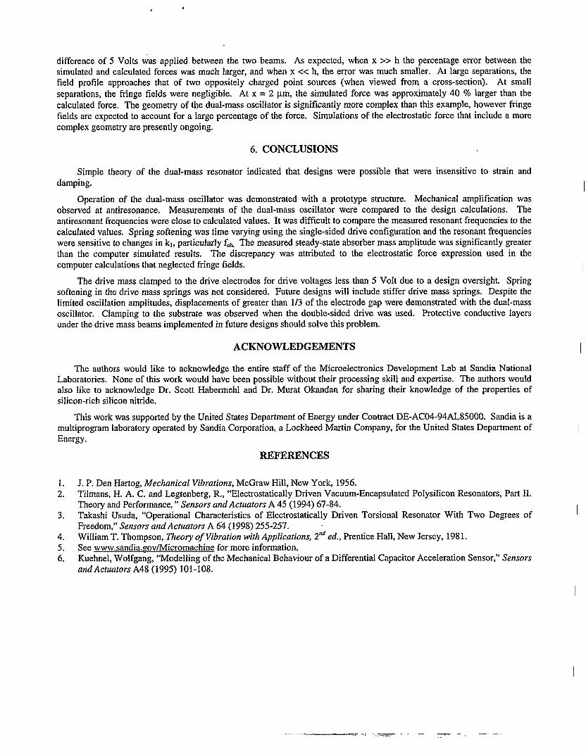
Figure 13: Simulated and calculated force between two parallel conductive beams of height, h = 2pm.
Comparison of the measured amplitude, IXZIin the second entry of Table 3 with the simulated steady-state amplitude inFig. 7 indicated a large discrepancy between the measured and simulated values. This was believed to be caused by the driveforce expression in Eq. (13) that was used in the simulations. This expression neglected fringe fields in the calculation ofi3C/dx. The electrode gap, gOand the electrode height, h (Table 1) in the design are close enough such that this significantlyunderestimated the actual electrostatic force. To demonstrate this, simulations to find the parallel-pIate electrostatic force oftwo parallel beams with h = 2 pm were performed using Matlab’s Partial Differential Equation (PDE) Solver Toolbox. Acurve fit of the simulated force is plotted in Fig. 13 as a function of the beam separation in pm. An arbitrary voltage
, #
difference of 5 Volts was applied between the two beams. As expected, when x >> h the percentage error between thesimulated and calculated forces was much larger, and when x << h, the error was much smaller. At large separations, thefield profile approaches that of two oppositely charged point sources (when viewed from a cross-section). At smallseparations, the frkge fields were negligible. At x = 2 pm, the simulated force was approximately 40 ?lolarger than thecalculated force. The geometry of the dual-mass oscillator is significantly more complex than this example, however fringefields are expected to account for a large percentage of the force. Simulations of the electrostatic force that include a morecomplex geometry are presently ongoing.
6. CONCLUSIONS
Simple theory of the dual-mass resonator indicated that designs weredamping.
possible that were insensitive to strain and
Operation of the dual-mass oscillator was demonstrated with a prototype structure. Mechanical amplification wasobserved at antiresonance. Measurements of the dual-mass oscillator were compared to the design calculations. Theantiresonant frequencies were close to calculated values. It was difficult to compare the measured resonant frequencies to thecalculated values. Spring softening was time varying using the single-sided drive configuration and the resonant frequencieswere sensitive to changes in kl, particularly fOh.The measured steady-state absorber mass amplitude was significantly greaterthan the computer simulated results. The discrepancy was attributed to the electrostatic force expression used in thecomputer calculations that neglected fringe fields.
The drive mass clamped to the drive electrodes for drive voltages less than 5 Volt due to a design oversight. Springsoftening in the drive mass springs was not considered. Future designs will include stiffer drive mass springs. Despite thelimited oscillation amplitudes, displacements of greater than 1/3 of the electrode gap were demonstrated with the dual-massoscillator. Clamping to the substrate was observed when the double-sided drive was used. Protective conductive layersunder the drive mass beams implemented in future designs should solve this problem.
ACKNOWLEDGEMENTS
The authors would like to acknowledge the entire staff of the Microelectronics Development Lab at Sandia NationalLaboratories. None of this work would have been possible without their processing skill and expertise. The authors wouldalso like to acknowledge Dr. Scott Habermehl and Dr. Murat Okandan for sharing their knowledge of the properties ofsilicon-rich silicon nitride.
This work was supported by the United States Department of Energy under Contract DE-AC04-94AL85000. Sandia is amultiprogram laboratory operated by Sandia Corporation, a Lockheed Martin Company, for the United States Department ofEnergy.
REFERENCES
1. J. P. Den Hartog, Mechanical Vibrations, McGraw Hill, New York, 1956.2. Tilmans, H. A. C. and Legtenberg, R., “Electrostatically Driven Vacuum-Encapsulated Polysilicon Resonators, Part 11.
Theory and Performance, ” Sensors and Actuators A 45 (1994) 67-84.3. Takashi Usuda, “Operational Characteristics of Electrostatically Driven Torsional Resonator With Two Degrees of
Freedom,” Sensors and Actuators A 64 (1998) 255-257.4. William T. Thompson, Theory of Vibration with Applications, 2ndcd., Prentice Hall, New Jersey, 1981.5. See www.sandia.zovllvlicromachine for more information.6. Kuehnel, Wolfgang, “Modelling of the Mechanical Behaviour of a Differential Capacitor Acceleration Sensor; Sensors
and Actuators A48 (1995) 101-108.
.. -.,.=.= -.-——~ --—--—.
Related Documents