Journal for Technology of Plasticity, Vol. 34 (2009), Number 1-2 RESEARCH AND ANALYSIS OF FRICTION STIR WELDING PARAMETERS ON ALUMINIUM ALLOYS (6082-T6) Vukčević Milan, Plančak Miroslav, Janjić Mileta, Šibalić Nikola University of Montenegro, Faculty of Mechanical Engineering Podgorica, Montenegro ABSTRACT Research field related to geometrical and mechanical parameters in friction stir welding process is current and insufficiently explored, it is particularly present considering the class of aluminum alloy series 6000 (AlMgSi). The research paper is related to the friction stir welding of aluminum alloy 6082-T6 (AlMgSi1Mn) with the thickness of 7.8 mm. The research paper includes forces measurement: the down force - Fz, which is known as the welding force, traversing force Fx - and side force - Fy, as well as mechanical testing - tensile testing of welded joints and tensile testing of welding zone using standard machines and standard test pieces. The paper includes the drawings of the designed supporting equipment which allows measurement of forces by the friction stir welding process, the analysis and discussion of the process are included, as well as results. The experiment was performed in the laboratory of the Mechanical Engineering Faculty in Podgorica. Keywords: Friction stir welding - FSW, welding force, pin, shoulder, tensile tests. 1. INTRODUCTION During the nineties of the last century a new method of joining similar and dissimilar materials in the solid state without melting of material, known as friction stir welding - FSW is developed. The process is patented by The Welding Institute - TWI in England in 1991, and invented by Wayne M. Thomas who has successfully joined plates of aluminum alloys [1]. It is primarily used to join plates of larger thickness. Tools that are used in the process of welding are cylindrical and consisted of two concentric parts, which are rotating at the great speed. A larger diameter part of the tool is called the shoulder, while the smaller diameter part is called the pin (Fig. 1.). Rotating tool slowly approaches the joint line and plunges into material (Al alloys - sheet metal with of thickness 7.8 mm), which creates heat. Due to that the temperature increases to the heat metal forming where mechanical mixing and joining of materials is performed, enabling the tool to move

Welcome message from author
This document is posted to help you gain knowledge. Please leave a comment to let me know what you think about it! Share it to your friends and learn new things together.
Transcript
Journal for Technology of Plasticity, Vol. 34 (2009), Number 1-2
RESEARCH AND ANALYSIS OF FRICTION STIR WELDING PARAMETERS ON ALUMINIUM ALLOYS
(6082-T6)
Vukčević Milan, Plančak Miroslav, Janjić Mileta, Šibalić Nikola University of Montenegro, Faculty of Mechanical Engineering Podgorica, Montenegro
ABSTRACT
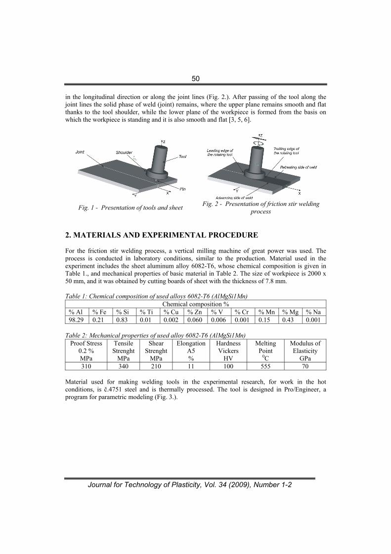
Research field related to geometrical and mechanical parameters in friction stir welding process is current and insufficiently explored, it is particularly present considering the class of aluminum alloy series 6000 (AlMgSi). The research paper is related to the friction stir welding of aluminum alloy 6082-T6 (AlMgSi1Mn) with the thickness of 7.8 mm. The research paper includes forces measurement: the down force - Fz, which is known as the welding force, traversing force Fx - and side force - Fy, as well as mechanical testing - tensile testing of welded joints and tensile testing of welding zone using standard machines and standard test pieces. The paper includes the drawings of the designed supporting equipment which allows measurement of forces by the friction stir welding process, the analysis and discussion of the process are included, as well as results. The experiment was performed in the laboratory of the Mechanical Engineering Faculty in Podgorica. Keywords: Friction stir welding - FSW, welding force, pin, shoulder, tensile tests. 1. INTRODUCTION During the nineties of the last century a new method of joining similar and dissimilar materials in the solid state without melting of material, known as friction stir welding - FSW is developed. The process is patented by The Welding Institute - TWI in England in 1991, and invented by Wayne M. Thomas who has successfully joined plates of aluminum alloys [1]. It is primarily used to join plates of larger thickness. Tools that are used in the process of welding are cylindrical and consisted of two concentric parts, which are rotating at the great speed. A larger diameter part of the tool is called the shoulder, while the smaller diameter part is called the pin (Fig. 1.). Rotating tool slowly approaches the joint line and plunges into material (Al alloys - sheet metal with of thickness 7.8 mm), which creates heat. Due to that the temperature increases to the heat metal forming where mechanical mixing and joining of materials is performed, enabling the tool to move
50
Journal for Technology of Plasticity, Vol. 34 (2009), Number 1-2
in the longitudinal direction or along the joint lines (Fig. 2.). After passing of the tool along the joint lines the solid phase of weld (joint) remains, where the upper plane remains smooth and flat thanks to the tool shoulder, while the lower plane of the workpiece is formed from the basis on which the workpiece is standing and it is also smooth and flat [3, 5, 6].
Fig. 1 - Presentation of tools and sheet Fig. 2 - Presentation of friction stir welding
process 2. MATERIALS AND EXPERIMENTAL PROCEDURE For the friction stir welding process, a vertical milling machine of great power was used. The process is conducted in laboratory conditions, similar to the production. Material used in the experiment includes the sheet aluminum alloy 6082-T6, whose chemical composition is given in Table 1., and mechanical properties of basic material in Table 2. The size of workpiece is 2000 x 50 mm, and it was obtained by cutting boards of sheet with the thickness of 7.8 mm. Table 1: Chemical composition of used alloys 6082-T6 (AlMgSi1Mn)
Chemical composition % % Al % Fe % Si % Ti % Cu % Zn % V % Cr % Mn % Mg % Na 98.29 0.21 0.83 0.01 0.002 0.060 0.006 0.001 0.15 0.43 0.001
Table 2: Mechanical properties of used alloy 6082-T6 (AlMgSi1Mn)
Proof Stress 0.2 % MPa
Tensile Strenght
MPa
Shear Strenght
MPa
Elongation A5 %
Hardness Vickers
HV
Melting Point
0C
Modulus of Elasticity
GPa 310 340 210 11 100 555 70
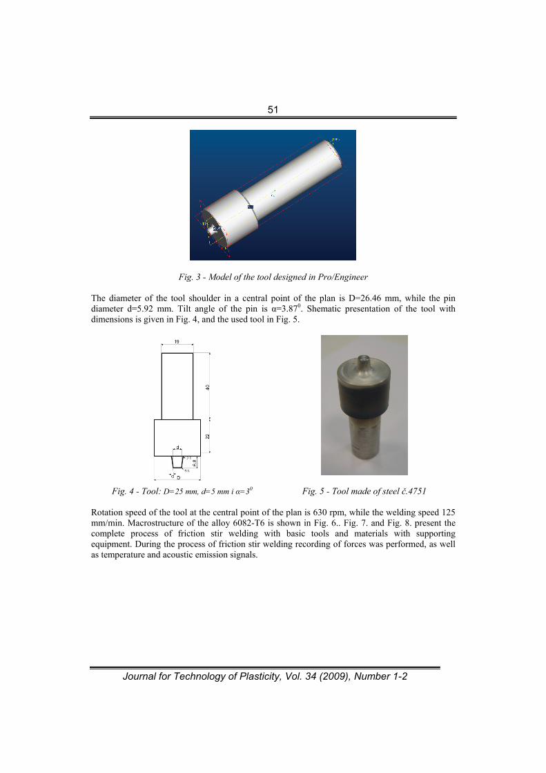
Material used for making welding tools in the experimental research, for work in the hot conditions, is č.4751 steel and is thermally processed. The tool is designed in Pro/Engineer, a program for parametric modeling (Fig. 3.).
51
Journal for Technology of Plasticity, Vol. 34 (2009), Number 1-2
Fig. 3 - Model of the tool designed in Pro/Engineer
The diameter of the tool shoulder in a central point of the plan is D=26.46 mm, while the pin diameter d=5.92 mm. Tilt angle of the pin is α=3.870. Shematic presentation of the tool with dimensions is given in Fig. 4, and the used tool in Fig. 5.
Fig. 4 - Tool: D=25 mm, d=5 mm i α=30 Fig. 5 - Tool made of steel č.4751
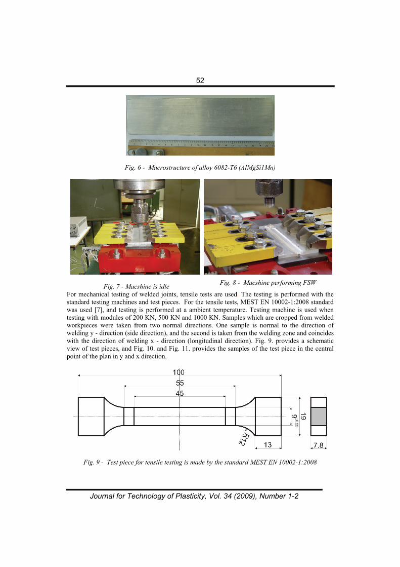
Rotation speed of the tool at the central point of the plan is 630 rpm, while the welding speed 125 mm/min. Macrostructure of the alloy 6082-T6 is shown in Fig. 6.. Fig. 7. and Fig. 8. present the complete process of friction stir welding with basic tools and materials with supporting equipment. During the process of friction stir welding recording of forces was performed, as well as temperature and acoustic emission signals.
52
Journal for Technology of Plasticity, Vol. 34 (2009), Number 1-2
Fig. 6 - Macrostructure of alloy 6082-T6 (AlMgSi1Mn)
Fig. 7 - Macshine is idle
Fig. 8 - Macshine performing FSW
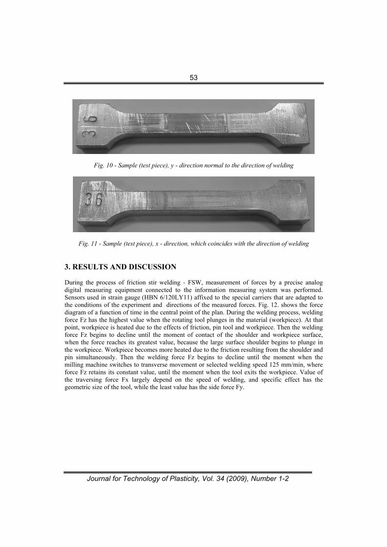
For mechanical testing of welded joints, tensile tests are used. The testing is performed with the standard testing machines and test pieces. For the tensile tests, MEST EN 10002-1:2008 standard was used [7], and testing is performed at a ambient temperature. Testing machine is used when testing with modules of 200 KN, 500 KN and 1000 KN. Samples which are cropped from welded workpieces were taken from two normal directions. One sample is normal to the direction of welding y - direction (side direction), and the second is taken from the welding zone and coincides with the direction of welding x - direction (longitudinal direction). Fig. 9. provides a schematic view of test pieces, and Fig. 10. and Fig. 11. provides the samples of the test piece in the central point of the plan in y and x direction.
Fig. 9 - Test piece for tensile testing is made by the standard MEST EN 10002-1:2008
53
Journal for Technology of Plasticity, Vol. 34 (2009), Number 1-2
Fig. 10 - Sample (test piece), y - direction normal to the direction of welding
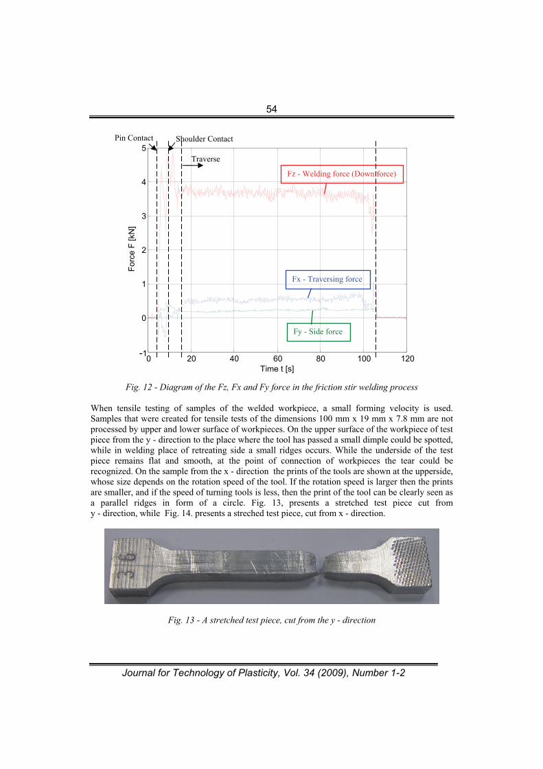
Fig. 11 - Sample (test piece), x - direction, which coincides with the direction of welding 3. RESULTS AND DISCUSSION During the process of friction stir welding - FSW, measurement of forces by a precise analog digital measuring equipment connected to the information measuring system was performed. Sensors used in strain gauge (HBN 6/120LY11) affixed to the special carriers that are adapted to the conditions of the experiment and directions of the measured forces. Fig. 12. shows the force diagram of a function of time in the central point of the plan. During the welding process, welding force Fz has the highest value when the rotating tool plunges in the material (workpiece). At that point, workpiece is heated due to the effects of friction, pin tool and workpiece. Then the welding force Fz begins to decline until the moment of contact of the shoulder and workpiece surface, when the force reaches its greatest value, because the large surface shoulder begins to plunge in the workpiece. Workpiece becomes more heated due to the friction resulting from the shoulder and pin simultaneously. Then the welding force Fz begins to decline until the moment when the milling machine switches to transverse movement or selected welding speed 125 mm/min, where force Fz retains its constant value, until the moment when the tool exits the workpiece. Value of the traversing force Fx largely depend on the speed of welding, and specific effect has the geometric size of the tool, while the least value has the side force Fy.
54
Journal for Technology of Plasticity, Vol. 34 (2009), Number 1-2
Fig. 12 - Diagram of the Fz, Fx and Fy force in the friction stir welding process
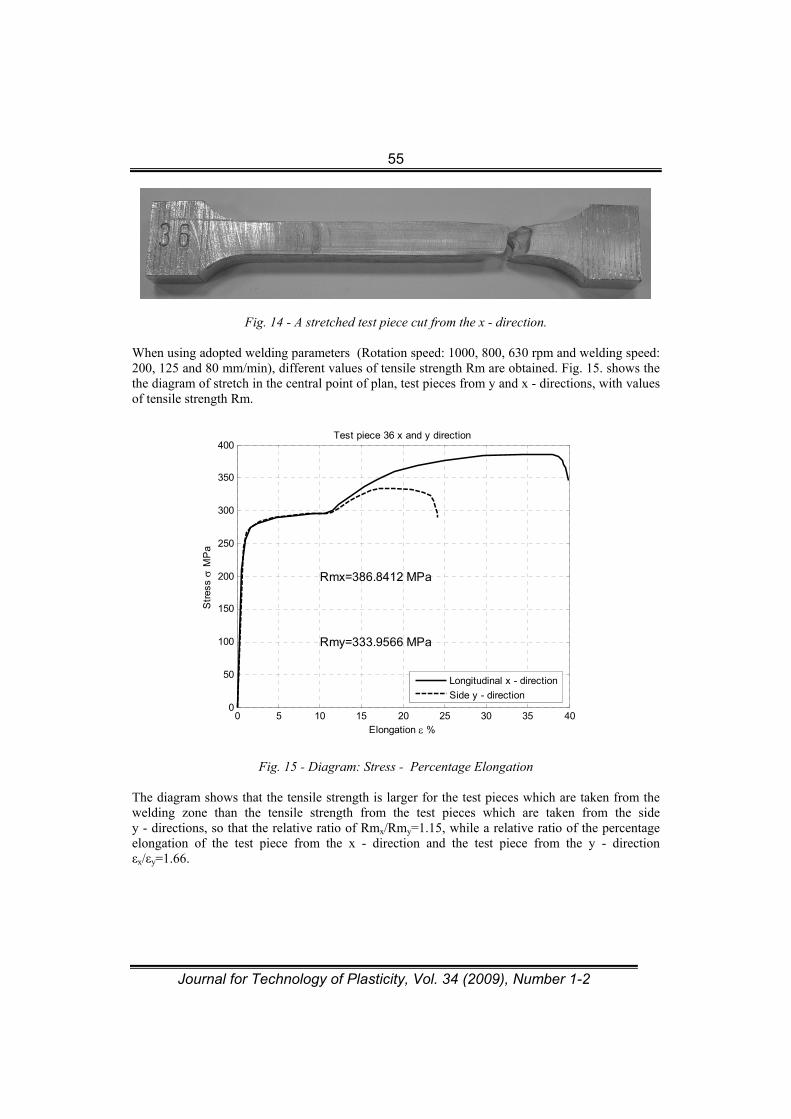
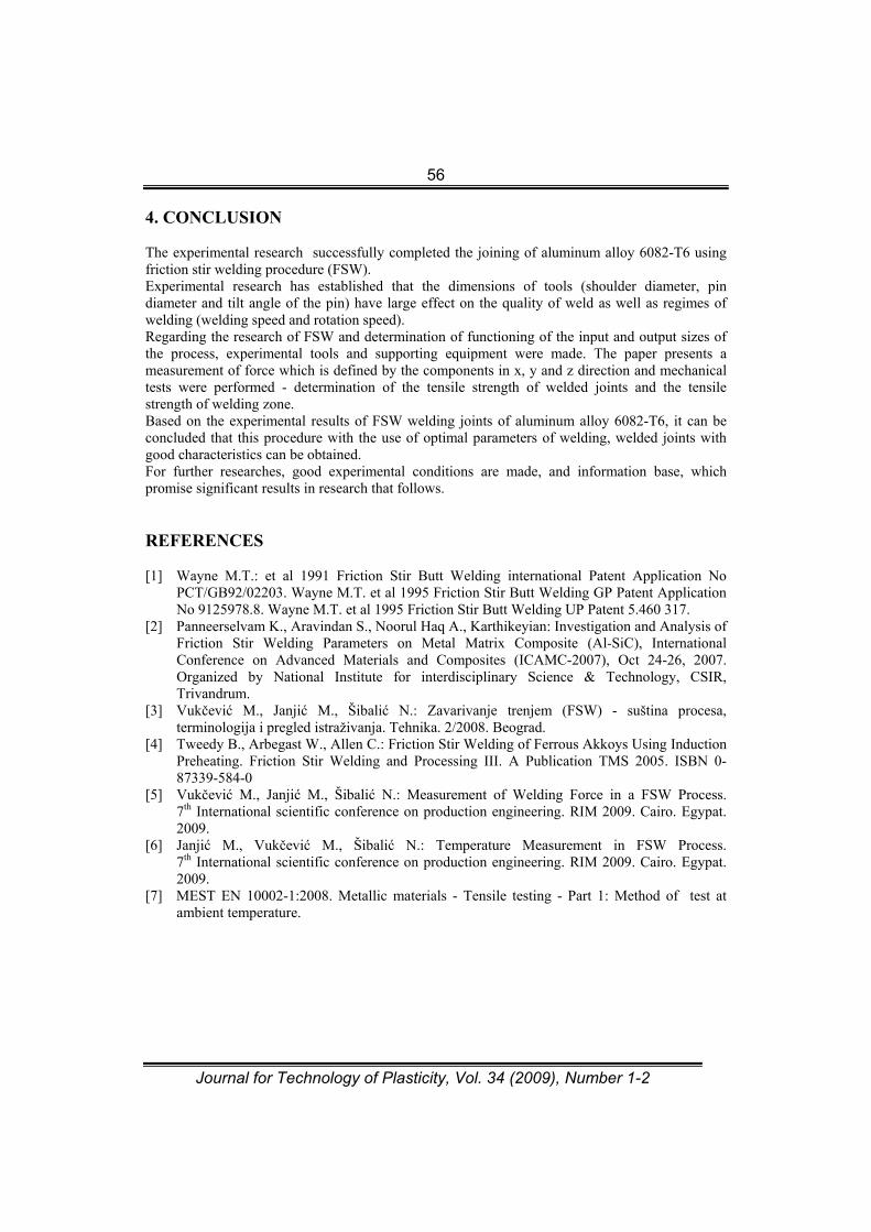
When tensile testing of samples of the welded workpiece, a small forming velocity is used. Samples that were created for tensile tests of the dimensions 100 mm x 19 mm x 7.8 mm are not processed by upper and lower surface of workpieces. On the upper surface of the workpiece of test piece from the y - direction to the place where the tool has passed a small dimple could be spotted, while in welding place of retreating side a small ridges occurs. While the underside of the test piece remains flat and smooth, at the point of connection of workpieces the tear could be recognized. On the sample from the x - direction the prints of the tools are shown at the upperside, whose size depends on the rotation speed of the tool. If the rotation speed is larger then the prints are smaller, and if the speed of turning tools is less, then the print of the tool can be clearly seen as a parallel ridges in form of a circle. Fig. 13, presents a stretched test piece cut from y - direction, while Fig. 14. presents a streched test piece, cut from x - direction.
Fig. 13 - A stretched test piece, cut from the y - direction
0 20 40 60 80 100 120 -1
0
1
2
3
4
5
Time t [s]
For
ce F
[kN
]
Fz - Welding force (Down force)
Fx - Traversing force
Fy - Side force
Traverse
Shoulder Contact Pin Contact
55
Journal for Technology of Plasticity, Vol. 34 (2009), Number 1-2
Fig. 14 - A stretched test piece cut from the x - direction.
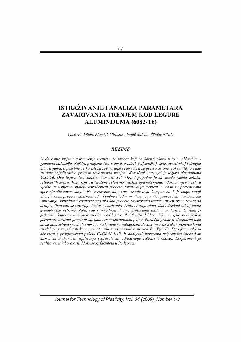
When using adopted welding parameters (Rotation speed: 1000, 800, 630 rpm and welding speed: 200, 125 and 80 mm/min), different values of tensile strength Rm are obtained. Fig. 15. shows the the diagram of stretch in the central point of plan, test pieces from y and x - directions, with values of tensile strength Rm.
0 5 10 15 20 25 30 35 400
50
100
150
200
250
300
350
400
Elongation %
Str
ess
MP
a
Test piece 36 x and y direction
Rmx=386.8412 MPa
Rmy=333.9566 MPa
Longitudinal x - direction
Side y - direction
Fig. 15 - Diagram: Stress - Percentage Elongation The diagram shows that the tensile strength is larger for the test pieces which are taken from the welding zone than the tensile strength from the test pieces which are taken from the side y - directions, so that the relative ratio of Rmx/Rmy=1.15, while a relative ratio of the percentage elongation of the test piece from the x - direction and the test piece from the y - direction εx/εy=1.66.
56
Journal for Technology of Plasticity, Vol. 34 (2009), Number 1-2
4. CONCLUSION The experimental research successfully completed the joining of aluminum alloy 6082-T6 using friction stir welding procedure (FSW). Experimental research has established that the dimensions of tools (shoulder diameter, pin diameter and tilt angle of the pin) have large effect on the quality of weld as well as regimes of welding (welding speed and rotation speed). Regarding the research of FSW and determination of functioning of the input and output sizes of the process, experimental tools and supporting equipment were made. The paper presents a measurement of force which is defined by the components in x, y and z direction and mechanical tests were performed - determination of the tensile strength of welded joints and the tensile strength of welding zone. Based on the experimental results of FSW welding joints of aluminum alloy 6082-T6, it can be concluded that this procedure with the use of optimal parameters of welding, welded joints with good characteristics can be obtained. For further researches, good experimental conditions are made, and information base, which promise significant results in research that follows. REFERENCES [1] Wayne M.T.: et al 1991 Friction Stir Butt Welding international Patent Application No
PCT/GB92/02203. Wayne M.T. et al 1995 Friction Stir Butt Welding GP Patent Application No 9125978.8. Wayne M.T. et al 1995 Friction Stir Butt Welding UP Patent 5.460 317.
[2] Panneerselvam K., Aravindan S., Noorul Haq A., Karthikeyian: Investigation and Analysis of Friction Stir Welding Parameters on Metal Matrix Composite (Al-SiC), International Conference on Advanced Materials and Composites (ICAMC-2007), Oct 24-26, 2007. Organized by National Institute for interdisciplinary Science & Technology, CSIR, Trivandrum.
[3] Vukčević M., Janjić M., Šibalić N.: Zavarivanje trenjem (FSW) - suština procesa, terminologija i pregled istraživanja. Tehnika. 2/2008. Beograd.
[4] Tweedy B., Arbegast W., Allen C.: Friction Stir Welding of Ferrous Akkoys Using Induction Preheating. Friction Stir Welding and Processing III. A Publication TMS 2005. ISBN 0-87339-584-0
[5] Vukčević M., Janjić M., Šibalić N.: Measurement of Welding Force in a FSW Process. 7th International scientific conference on production engineering. RIM 2009. Cairo. Egypat. 2009.
[6] Janjić M., Vukčević M., Šibalić N.: Temperature Measurement in FSW Process. 7th International scientific conference on production engineering. RIM 2009. Cairo. Egypat. 2009.
[7] MEST EN 10002-1:2008. Metallic materials - Tensile testing - Part 1: Method of test at ambient temperature.
57
Journal for Technology of Plasticity, Vol. 34 (2009), Number 1-2
ISTRAŽIVANJE I ANALIZA PARAMETARA ZAVARIVANJA TRENJEM KOD LEGURE
ALUMINIJUMA (6082-T6)
Vukčević Milan, Plančak Miroslav, Janjić Mileta, Šibalić Nikola
REZIME
U današnje vrijeme zavarivanje trenjem, je proces koji se koristi skoro u svim oblastima - granama industrije. Najširu primjenu ima u brodogradnji, željezničkoj, avio, svemirskoj i drugim industrijama, a posebno se koristi za zavarivanje rezervoara za gorivo aviona, raketa itd. U radu su date pojedinosti o procesu zavarivanja trenjem. Korišćeni materijal je legura aluminijuma 6082-T6. Ova legura ima zateznu čvrstoću 340 MPa i pogodna je za izradu raznih držača, rešetkastih konstrukcija koje su izložene relativno velikim opterećenjima, udarima vjetra itd., a ujedno se uspješno spajaju korišćenjem procesa zavarivanja trenjem. U radu su prezentirana mjerenja sile zavarivanja - Fz (vertikalne sile), kao i ostale dvije komponente koje imaju manji uticaj na sam proces: uzdužne sile Fx i bočne sile Fy, urađena je analiza procesa kao i mehanička ispitivanja. Vrijednosti komponenata sila kod procesa zavarivanja trenjem prvenstveno zavise od debljine lima koji se zavaruje, brzine zavarivanja, broja obrtaja alata, dok određani uticaj imaju geometrijske veličine alata, kao i vrijednost dubine prodiranja alata u materijal. U radu je prikazan eksperiment zavarivanja lima od legure Al 6082-T6 debljine 7.8 mm, gdje su navedeni parametri varirani prema usvojenom eksperimentalnom planu. Pomoćni pribor je dizajniran tako da su napravljeni specijalni nosači, na kojima su nalijepljeni davači (mjerne trake), pomoću kojih su dobijene vrijednosti komponenata sila u tri normalna pravca Fx, Fy i Fz. Dijagrami sila su obrađeni u programskom paketu GLOBAL-LAB. Iz dobijenih zavarenih pripremaka isječeni su uzorci za mahanička ispitivanja (epruvete za određivanje zatezne čvrstoće). Eksperiment je realizovan u laboratoriji Mašinskog fakulteta u Podgorici.
Related Documents