Report Overview of biogas technologies for production of liquid transport fuels Carried out by: Danish Technological Institute Laura Bailón Allegue and Jørgen Hinge Kongsvang Allé 29 DK-8000 Aarhus C Date: December 2012

Welcome message from author
This document is posted to help you gain knowledge. Please leave a comment to let me know what you think about it! Share it to your friends and learn new things together.
Transcript

1
Report
Overview of biogas technologies for production
of liquid transport fuels
Carried out by:
Danish Technological Institute
Laura Bailón Allegue and Jørgen Hinge
Kongsvang Allé 29
DK-8000 Aarhus C
Date: December 2012
2
Content
1 INTRODUCTION ................................................................................................................................... 3
2 LIQUEFIED BIOGAS (LBG) ................................................................................................................ 4
2.1 Upgrading and cleaning followed by a liquefaction plant ............................................................... 4
2.2 Conventional upgrading technologies .............................................................................................. 6 2.2.1 Cleaning technologies ................................................................................................................. 10 2.2.2 Liquefaction .................................................................................................................................. 12
2.3 Cryogenic technologies .................................................................................................................... 13 2.3.1 Scandinavian GtS ........................................................................................................................ 14 2.3.2 Prometheus Energy ..................................................................................................................... 15 2.3.3 Terracastus Technologies/Acrion Technologies .......................................................................... 15
3 FUEL PRODUCTION FROM BIO-SYNGAS ................................................................................... 16
3.1 Hydrogen ............................................................................................................................................ 17
3.2 Methanol ............................................................................................................................................. 17
3.3 Dimethyl ether (DME) ........................................................................................................................ 18
3.4 Fisher-Tropsch (FT) fuels ................................................................................................................. 19
4 USE OF BIOGAS AS VEHICLE FUEL IN DENMARK ................................................................... 19
REFERENCES .............................................................................................................................................. 22
ANNEX 1....................................................................................................................................................... 25

3
1 Introduction
The EU Renewable Energy Directive (RED) states that each EU Member State shall ensure that
the share of energy from renewable sources in all forms of transport in 2020 is at least 10%.
Transport is the second biggest greenhouse gas emission sector, being responsible of around a
quarter of EU greenhouse gas emissions. Road transport alone contributes about one-fifth of the
EU´s total emissions of carbon dioxide. While different sectors have been showing positive results
in the previous years on emission reduction, the transport sector has shown an increase of 36%
from 1990 to 2007 (Climate Action, 2011). In Denmark the transport sector accounted for 32.2% of
total CO2 emissions in 2010, the road transport being responsible for 77.5% of the total CO2
emissions of the whole transport sector (Øresund Ecomobility, 2012).
Research and the effective development of new technologies will be the key to lower transport
emissions and oil dependency issues. A priority will be on producing clean, safe, and quiet vehicles
for all transport modes.
Biogas and bio-syngas as transport fuels can play an important role in the change towards a
sustainable transport sector.
By removing carbon dioxide, moisture, hydrogen sulfide and other impurities biogas can be
upgraded to biomethane, a product equivalent to natural gas. Biomethane can be used as
compressed natural gas (CNG) in natural gas vehicles or it can be transform into a liquid energy
carrier like liquefied biomethane (LBM) as well called liquefied biogas (LBG) when coming from
biogas, which is analogous to liquefied natural gas (LNG). Biomethane can also be reformed to
bio-syngas which is the basis for production of various fuels such as methanol, dimethyl ether,
hydrogen and liquid hydrocarbons that can replace gasoline and diesel fuels.
There is considerable interest in the production of renewable liquid fuels which could be used more
directly in the existing transportation fleet and could overcome the volume, range, and weight
limitations imposed by compress biomethane (CBM), also called compress biogas (CBG) when
coming from biogas. The use of biomethane in liquid form has special focus on long road distance
transport, countries with no natural gas infrastructure and even maritime transport.
Biogas leads not only to environmental benefits such as reduced emissions of carbon dioxide and
air pollutants, several additional environmental benefits can be gained (e.g. reduced emissions of
ammonia and methane and nitrogen leaching). Other advantages of biogas as a transport fuel, as
compared with other renewable transport options, are that its production can be localized,
anywhere, urban or rural, it is not dependent on foreign markets, neither on large mono-crop
production, but can be produced locally from a diverse range of organic wastes or energy crops.
The optimum use for biogas is always case specific, depending on the objectives, the feedstock,
the scale and the location of the plant. In most European countries, until now, policy and incentives
have favored the use of biogas to produce renewable electricity. But considering the fact that other
renewable options (such as solar, wave/tidal power and wind) produce electricity directly, biogas
could perhaps be better utilized in contributing to the sustainable production of transport fuel.

4
2 Liquefied Biogas (LBG)
Liquefied biogas has a better energy density compared to compress biogas but still lower
compared to diesel (1.7:1). However, its energy density is still better compared to liquid methanol
and similar to ethanol.
The main advantages of LBG comparatively to the CBG are:
It is a more valuable product since LBG is around 3 times more space efficient compared to
compressed biogas. This means that LBG can be more easily transported on road to remote
refueling stations when there is lack of natural gas grid infrastructure. For the same reason, LBG is
the better option when shipping biogas overseas,
LBG has a higher vehicle driving range, thereby, methane vehicles are getting competitive also
for mid- and long distances; especially if the vehicles are also equipped with the engine technology
dual-fuel, i.e. engines with compression ignition using both methane and diesel as fuel, and
LBG can be dispensed to either LNG vehicles or CNG vehicles. The latter is made possible
through liquid-to-compressed natural gas refueling station equipment which creates CNG from
LNG feedstock.
Liquid natural gas is transported at relatively low pressures (e.g. 1.5 – 10 bar), but because it is a
cryogenic liquid (i.e., temperatures well below -100 °C) it requires special handling.
Liquid biogas can be produced in two main ways and these are by means of cryogenic upgrading
technology and conventional upgrading technologies connected to a liquefaction plant. A third
alternative is to inject biomethane into the gas grid and then liquefy a part-flow at a pressure
letdown station.
According with Johansson (2008), it takes around 0.8 – 1.8 kWh electricity/Nm3 clean biogas to
produce LBG, which correspond to 8 – 18% of the energy content in the product. Johansson
estimated the energy consumption of different alternatives and concluded that the most energy
efficient ways to produce LBG are to use one of the conventional upgrading technologies; water
scrubber, PSA or Cooab (including heat recovery), connected with a mixed refrigerant process or
to use the cryogenic GtS process (described in Chapter 2.3.1). In the last 5 years cryogenic
technologies as well as small size liquefaction plants have been under constant development and it
is now when the first cryogenic plants begin to run and information on commercial system is
available. So Johansson data must be reviewed, but it gives a first general estimation.
2.1 Upgrading and cleaning followed by a liquefaction plant
To be able to use raw biogas as vehicle fuel it must first be cleaned and upgraded to biomethane.
Cleaning means that contaminants like H2O, H2S, and particles and, if present, siloxanes and
halogenated compounds are removed from the gas stream to avoid problems with corrosion,
deposits and mechanical wear. While upgrading means that the biogas energy content is raised
through removal of CO2.
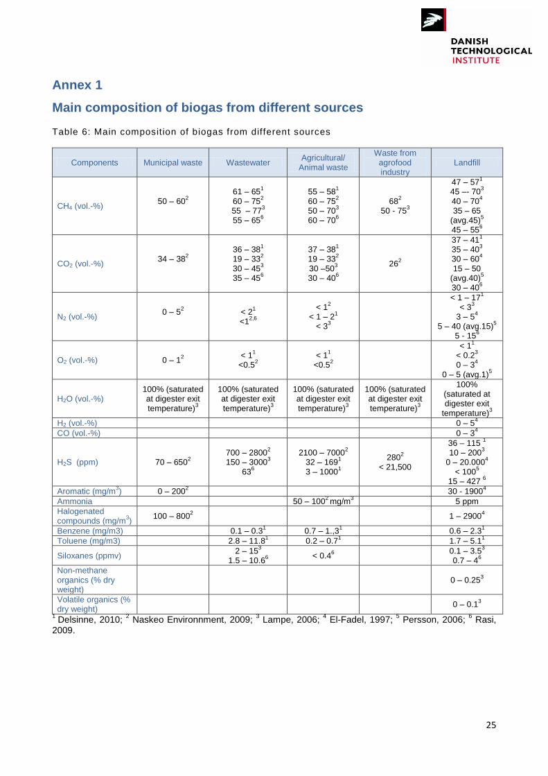
In Annex 1 typical biogas compositions as function of the main biogas sources are given.
After the cleaning and upgrading the biomethane can be transformed in LBG. There are two main
working principles for biogas liquefaction, namely closed-loop or open-loop cycles.
5
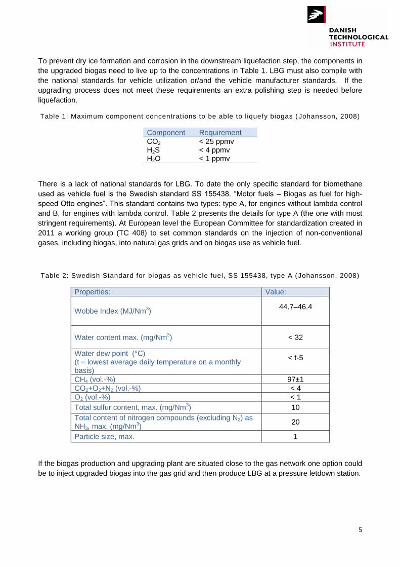
To prevent dry ice formation and corrosion in the downstream liquefaction step, the components in
the upgraded biogas need to live up to the concentrations in Table 1. LBG must also compile with
the national standards for vehicle utilization or/and the vehicle manufacturer standards. If the
upgrading process does not meet these requirements an extra polishing step is needed before
liquefaction.
Table 1: Maximum component concentrations to be able to l iquefy biogas ( Johansson, 2008)
Component Requirement
CO2 < 25 ppmv H2S < 4 ppmv H2O < 1 ppmv
There is a lack of national standards for LBG. To date the only specific standard for biomethane
used as vehicle fuel is the Swedish standard SS 155438. “Motor fuels – Biogas as fuel for high-
speed Otto engines”. This standard contains two types: type A, for engines without lambda control
and B, for engines with lambda control. Table 2 presents the details for type A (the one with most
stringent requirements). At European level the European Committee for standardization created in
2011 a working group (TC 408) to set common standards on the injection of non-conventional
gases, including biogas, into natural gas grids and on biogas use as vehicle fuel.
Table 2: Swedish Standard for biogas as vehicle fuel, SS 155438, type A (Johansson, 2008)
Properties: Value:
Wobbe Index (MJ/Nm3) 44.7–46.4
Water content max. (mg/Nm3) < 32
Water dew point (°C) (t = lowest average daily temperature on a monthly basis)
< t-5
CH4 (vol.-%) 97±1
CO2+O2+N2 (vol.-%) < 4
O2 (vol.-%) < 1
Total sulfur content, max. (mg/Nm3) 10
Total content of nitrogen compounds (excluding N2) as NH3, max. (mg/Nm3)
20
Particle size, max. 1
If the biogas production and upgrading plant are situated close to the gas network one option could
be to inject upgraded biogas into the gas grid and then produce LBG at a pressure letdown station.
6
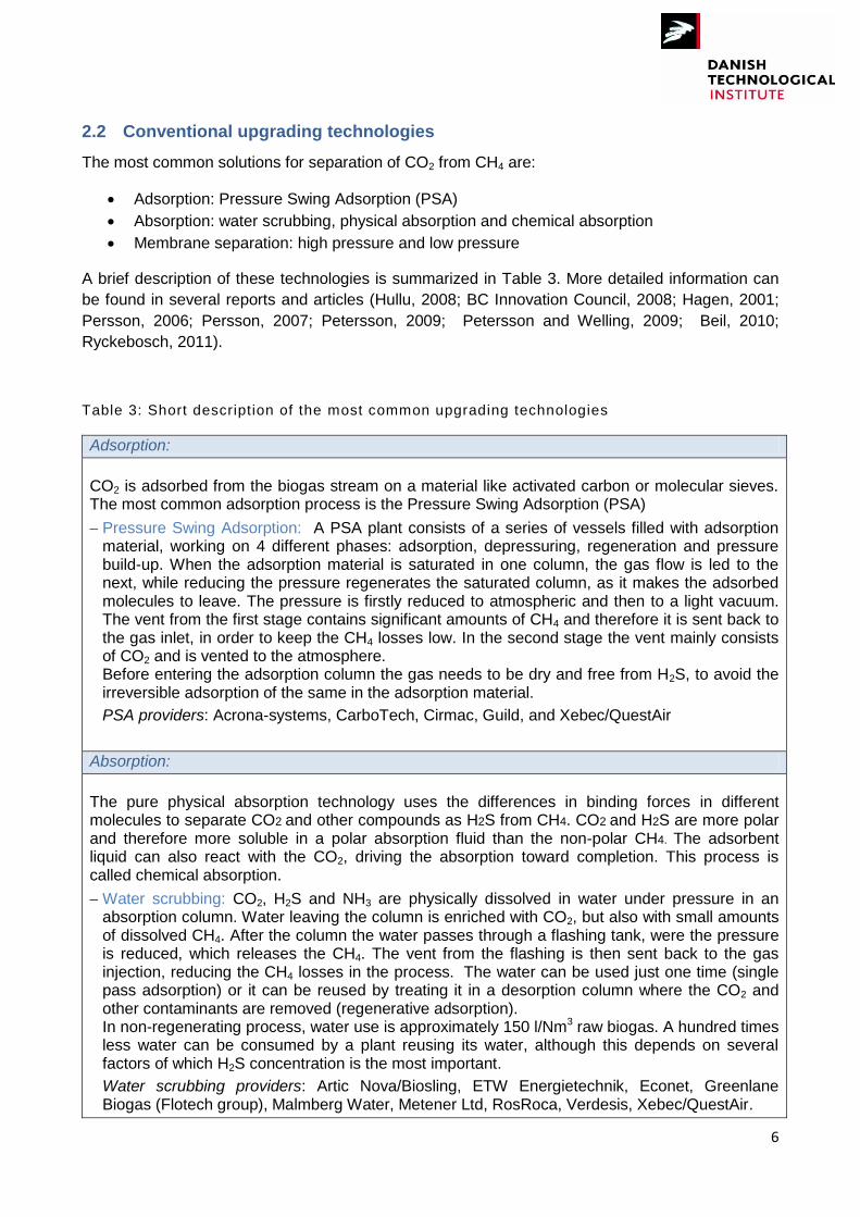
2.2 Conventional upgrading technologies
The most common solutions for separation of CO2 from CH4 are:
Adsorption: Pressure Swing Adsorption (PSA)
Absorption: water scrubbing, physical absorption and chemical absorption
Membrane separation: high pressure and low pressure
A brief description of these technologies is summarized in Table 3. More detailed information can
be found in several reports and articles (Hullu, 2008; BC Innovation Council, 2008; Hagen, 2001;
Persson, 2006; Persson, 2007; Petersson, 2009; Petersson and Welling, 2009; Beil, 2010;
Ryckebosch, 2011).
Table 3: Short description of the most common upgrading technologies
Adsorption:
CO2 is adsorbed from the biogas stream on a material like activated carbon or molecular sieves. The most common adsorption process is the Pressure Swing Adsorption (PSA)
Pressure Swing Adsorption: A PSA plant consists of a series of vessels filled with adsorption material, working on 4 different phases: adsorption, depressuring, regeneration and pressure build-up. When the adsorption material is saturated in one column, the gas flow is led to the next, while reducing the pressure regenerates the saturated column, as it makes the adsorbed molecules to leave. The pressure is firstly reduced to atmospheric and then to a light vacuum. The vent from the first stage contains significant amounts of CH4 and therefore it is sent back to the gas inlet, in order to keep the CH4 losses low. In the second stage the vent mainly consists of CO2 and is vented to the atmosphere. Before entering the adsorption column the gas needs to be dry and free from H2S, to avoid the irreversible adsorption of the same in the adsorption material.
PSA providers: Acrona-systems, CarboTech, Cirmac, Guild, and Xebec/QuestAir
Absorption:
The pure physical absorption technology uses the differences in binding forces in different molecules to separate CO2 and other compounds as H2S from CH4. CO2 and H2S are more polar and therefore more soluble in a polar absorption fluid than the non-polar CH4. The adsorbent liquid can also react with the CO2, driving the absorption toward completion. This process is called chemical absorption.
Water scrubbing: CO2, H2S and NH3 are physically dissolved in water under pressure in an absorption column. Water leaving the column is enriched with CO2, but also with small amounts of dissolved CH4. After the column the water passes through a flashing tank, were the pressure is reduced, which releases the CH4. The vent from the flashing is then sent back to the gas injection, reducing the CH4 losses in the process. The water can be used just one time (single pass adsorption) or it can be reused by treating it in a desorption column where the CO2 and other contaminants are removed (regenerative adsorption). In non-regenerating process, water use is approximately 150 l/Nm3 raw biogas. A hundred times less water can be consumed by a plant reusing its water, although this depends on several factors of which H2S concentration is the most important.
Water scrubbing providers: Artic Nova/Biosling, ETW Energietechnik, Econet, Greenlane Biogas (Flotech group), Malmberg Water, Metener Ltd, RosRoca, Verdesis, Xebec/QuestAir.
7
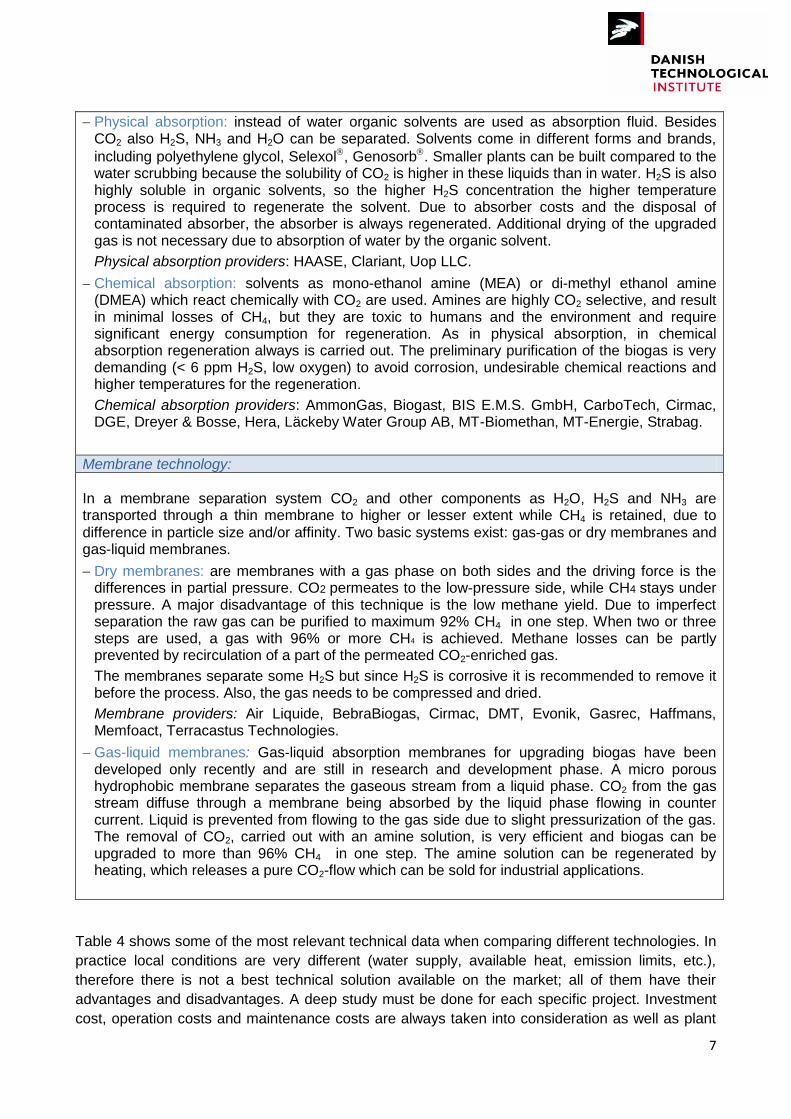
Physical absorption: instead of water organic solvents are used as absorption fluid. Besides CO2 also H2S, NH3 and H2O can be separated. Solvents come in different forms and brands,
including polyethylene glycol, Selexol, Genosorb. Smaller plants can be built compared to the water scrubbing because the solubility of CO2 is higher in these liquids than in water. H2S is also highly soluble in organic solvents, so the higher H2S concentration the higher temperature process is required to regenerate the solvent. Due to absorber costs and the disposal of contaminated absorber, the absorber is always regenerated. Additional drying of the upgraded gas is not necessary due to absorption of water by the organic solvent.
Physical absorption providers: HAASE, Clariant, Uop LLC.
Chemical absorption: solvents as mono-ethanol amine (MEA) or di-methyl ethanol amine (DMEA) which react chemically with CO2 are used. Amines are highly CO2 selective, and result in minimal losses of CH4, but they are toxic to humans and the environment and require significant energy consumption for regeneration. As in physical absorption, in chemical absorption regeneration always is carried out. The preliminary purification of the biogas is very demanding (< 6 ppm H2S, low oxygen) to avoid corrosion, undesirable chemical reactions and higher temperatures for the regeneration.
Chemical absorption providers: AmmonGas, Biogast, BIS E.M.S. GmbH, CarboTech, Cirmac, DGE, Dreyer & Bosse, Hera, Läckeby Water Group AB, MT-Biomethan, MT-Energie, Strabag.
Membrane technology:
In a membrane separation system CO2 and other components as H2O, H2S and NH3 are transported through a thin membrane to higher or lesser extent while CH4 is retained, due to
difference in particle size and/or affinity. Two basic systems exist: gas-gas or dry membranes and gas-liquid membranes.
Dry membranes: are membranes with a gas phase on both sides and the driving force is the differences in partial pressure. CO2 permeates to the low-pressure side, while CH4 stays under pressure. A major disadvantage of this technique is the low methane yield. Due to imperfect separation the raw gas can be purified to maximum 92% CH4 in one step. When two or three steps are used, a gas with 96% or more CH4 is achieved. Methane losses can be partly prevented by recirculation of a part of the permeated CO2-enriched gas.
The membranes separate some H2S but since H2S is corrosive it is recommended to remove it before the process. Also, the gas needs to be compressed and dried.
Membrane providers: Air Liquide, BebraBiogas, Cirmac, DMT, Evonik, Gasrec, Haffmans, Memfoact, Terracastus Technologies.
Gas-liquid membranes: Gas-liquid absorption membranes for upgrading biogas have been developed only recently and are still in research and development phase. A micro porous hydrophobic membrane separates the gaseous stream from a liquid phase. CO2 from the gas stream diffuse through a membrane being absorbed by the liquid phase flowing in counter current. Liquid is prevented from flowing to the gas side due to slight pressurization of the gas. The removal of CO2, carried out with an amine solution, is very efficient and biogas can be upgraded to more than 96% CH4 in one step. The amine solution can be regenerated by heating, which releases a pure CO2-flow which can be sold for industrial applications.
Table 4 shows some of the most relevant technical data when comparing different technologies. In
practice local conditions are very different (water supply, available heat, emission limits, etc.),
therefore there is not a best technical solution available on the market; all of them have their
advantages and disadvantages. A deep study must be done for each specific project. Investment
cost, operation costs and maintenance costs are always taken into consideration as well as plant

8
capacity. The operational costs are determined by the use of chemicals and by the use of
energetic or physical aid streams, like heat or water, while other techniques might require
electricity (pressure and/or cooling). When the installation is located near an entity that has an
excess of heat, a technique that requires heat as the amine gas cleaning can be an economical
relevant choice. A lot of the choices are determined by the presence or the absence of suppliers
for the technology in the particular country. In Sweden, water scrubbers are used mostly. In
Germany they prefer PSA and chemical scrubbing units and in The Netherlands they rather chose
water scrubbers, PSA-units as well as membrane technology.
In order to make a correct comparison of investment and operation cost, the necessary costs for
pre/post treatment also need to be taken into consideration, as well as the savings in useful
utilization of residues. Price comparison of the „basic installation´ usually give a false picture,
because one supplier integrates all process stages into a single installation, and another takes a
different approach. In a report published at the end of 2008 the German Fraunhofer UMSIGT
compared gas scrubbing and PSA techniques of various manufactures (Figure 1) (Petersson,
2009). The investment costs of a 500 Nm3 capacity plant were around one million euro. The scale
advantages are considerable, particularly when scaling up from 250 to 500 Nm3. Today, there are
commercially available plants for capacities lower than 250 Nm3/h, while also plants larger than
2000 Nm3/h are being built (Petersson and Wellinger, 2009).
Table 4: Comparison of different commercial upgrading technologies. Values are depe ndent
on the size of the plant and the specif ic commercial technology
PSA Water scrubbing Physical
scrubbing Amine scrubber
Membrane separation
Electricity consumption (kWh/Nm
3)
kWh/Nm
3 raw
biogas:
0.231
< 0.35
0.256
kWh/Nm3 clean
biogas:
0.29 – 0.439
0.3 – 1.0 suppliers data 4
0.5 – 0.6 Swedish plants data
4
kWh/Nm
3 raw biogas:
0.31
<0.255
kWh/Nm3 clean
biogas:
0.4 (0.3 – 0.6) 2
0.37
0.4 – 0.57
With regeneration4:
0.45 – 0.9 suppliers data
0.3 Swedish plants data
No regeneration4:
0.45 – 0.9 suppliers data
0.4 – 0.6 Swedish plants data
kWh/Nm
3 raw
biogas:
0.2 – 0.31
kWh/Nm3 clean
biogas:
0.4 (Selexol)
Swedish plants data
4
kWh/Nm
3 raw
biogas:
0.1 – 0.15 1
0.05 – 0.126
(Cirmac)
0.2 – 0.256
(DMT)
kWh/Nm3 clean
biogas:
0.12 (LP Cooab)
2
0.15 suppliers data
4
0.187
kWh/Nm
3 raw
biogas:
0.18 1
0.206
kWh/Nm3 clean
biogas:
0.14 2
0.267
Heat consumption (kWh/Nm3) and Heat demand (oC)
None
None
kWh/Nm
3 raw
biogas:
< 0.21
55 – 80 oC
8
kWh/Nm
3 raw
biogas:
0.5 – 0.751
kWh/Nm3 clean
biogas:
0.27
100 – 180 oC
8
None

9
PSA Water scrubbing Physical
scrubbing Amine scrubber
Membrane separation
CH4 losses (%)
2 – 4
1
2 – 102,8
1 – 3
6
2 – 55
27
1 – 2
1,8
< 15
< 2
1
2 – 45
1 – 48
< 0.1
1,5,8
0.1 – 0.26
21,7
3 – 5
8
15 – 206
(without using residue gas)
CH4 recovery (%)
83 – 99
1,3
< 965
> 968
Max. 986
VPSA = 972
< 97
1,5
> 972,8
98.5
5
96 – 989
93 – 97
1
> 97 8
> 995
97.5 – 99.5
1
99.92
>993,5,8
> 99.57
95 – 987
90 – 98
1
822
903,5
90 – 93.5
7
981
96 – 988
Pre-purification
Yes
Recommended roughly
Recommended roughly
Yes
Recommended
H2S co-removal
Possible Yes Possible Contaminant Possible
N2 and O2 co-removal
Possible No No No Partial
Operation pressure (bar)
3 – 5
1
4 – 75
6 – 86
4 – 108
4 – 7
1,5
4 – 108
4 – 7
1,5
4 – 88
Atmosferic
1,5
5 – 71
6 – 8
5,8
Pressure at outlet (bar)
4 – 5
1
7 – 10
1
1.3 – 7.5
1
4 – 5
1
4 – 6
1
1 Different companies data;
2 Bekkering, 2010;
3 BC Innovation Council, 2008;
4 Persson, 2007;
5 Mezei, 2010;
6
Sternovem; 7 Jonsson, 2011,
8 Biomas for Energy, 2012
Figure 1: Common commercial upgrading technology costs (Petersson, 2009)
10
2.2.1 Cleaning technologies
Apart from CH4 and CO2, biogas can also contain H2O, H2S, O2, N2, NH3, siloxanes, and particles.
In those upgrading technologies where CO2 is separated from biogas, some of the other unwanted
compounds are also separated. However, to prevent corrosion and mechanical wear of the
upgrading equipment itself, it can be advantageous to clean the gas before upgrading.
Table 5 indicates the main cleaning technologies for different compounds. A more detailed
description of these technologies can be found elsewhere (Ajha, 2010; Cline, 2002; Environment-
Agency, 2004; Kohl, 1997; Krich, 2005; McKinsey, 2003; Petersson and Wellinger, 2009;
Ryckebosch, 2011; Shareefdeen, 2005; Wellinger, 2000; Zappa, 2001).
Table 5: Short description of the main cleaning technologies for different biogas contaminant
compounds
H2S removal:
Hydrogen sulfide (H2S) is corrosive to most equipment; furthermore its combustion leads to sulfur dioxide emissions, which have harmful environmental effects. It is recommended to remove it early in the process of biogas upgrading. H2S removal is often combined with CO2 removal in water or alkaline scrubbers or by absorption in non-water physical solvents (see Table 3). Other common methods are:
Addition of iron salts/oxides or air/oxygen to the digester. In this way the H2S concentration in the biogas is reduced. In the first case by formation of insoluble iron salts, like FeS, and in the second by biological aerobic oxidation of H2S to elemental sulfur and sulfate in the reactor by Thiobacillus bacteria. These methods can only be regarded as a partial removal process and must be used in conjunction with another technology to go down 100 ppmv.
Adsorption in activate carbon (AC). H2S is removed in a catalytic oxidation reaction on activated carbon, forming elementary sulfur and water. Impregnation of activated carbon using alkaline or oxide coatings, like potassium iodine or sodium hydroxide, optimize H2S abatement with chemical adsorption. If the gas has high levels of H2S (> 3000 ppmv), regeneration is periodically required (Wellinger, 2000). This technology is commonly used when a PSA system is used for the upgrading.
Distributors of impregnated AC include: Calgon Carbon Corporation (FCA, Sulfusorb), US Filter-Westates Carbon, Carmeron Carbon, etc.
Adsorption using iron oxides. Iron oxides remove H2S by forming insoluble iron sulfide. Regeneration of the iron bed can be done with air. Typical iron oxide media are iron sponge and
iron oxide pellets. Recently, proprietary iron-oxide media such as SulfaTreat, Sulphur-Rite,
SOXSIA and Sulfa-Bind have been offered as improved alternatives.
Absorption using chelated-iron salt solutions. H2S is oxidized to elemental sulfur by reduction of a soluble ferric chelated iron [Fe3+] into a ferrous chelated iron [Fe2+]. This can be regenerated
by air stripping. Catalytic scrubbing processes on the market are for example the LO-CAT and
MINI-CAT redox chemistry technology (Gas Technology Products-Merichem), the SulFerox
(Shell), the Sulfothane (Biothane corporation) and the Apollo Scrubber (Apollo Environmental Systems Corp.).
Biological systems (biotrickling filters and bioscrubbers). In these systems H2S is oxidized to sulfate or sulfur in a biological filter or reactor by microorganisms, commonly of the Thiobacillus genus. These bacteria are aerobic, and therefore require oxygen. Several commercial systems
are available: biotrickling filters like the Biopuric process, BioSulfurex, BiogasCleaner and
bioscrubbers and bioscrubbers like the Thiopaq. Normally biological methods are used in
11
cogeneration applications, while a second cleaning step such as activated carbon is usually required to ensure the low H2S concentration allowed in biomethane.
Water removal:
In reaction with CO2 and H2S water forms corrosive acids that can damage equipment if it is not removed. The methods to remove water from biogas are generally based on separation of condensed water or chemical drying:
Water condensation. Water vapor is removed by condensation and separation of the liquid water. This can be done in demisters, cyclones, moisture traps or water traps in the biogas pipe.
Water adsorption in a drying agent. This drying agent can be zeolites, silica gel, aluminum oxide or magnesium oxide. The drying agent is packed in two vessels and while one is in operating mode the other one is regenerated.
Siloxanes removal:
Siloxanes can cause severe damage to engines. During combustion they are oxidized to silicon oxide (a white powder) that deposits in the downstream equipment causing damage by erosion and blockage. Most common removal methods are:
Adsorption on activated carbon (AC). The most common concept is non-regenerative adsorption on fixed beds of AC or graphite. Also on the market there are fixed-bed adsorber/desorbed systems working according to the principle of temperature swing adsorption. Hot air, nitrogen and/or a fraction of the purified biogas can be used for regeneration. Siloxane removal can also be achieved by the use of a fluidized adsorption bed where the media is regenerated continuously. Siloxanes can also be removed while separating hydrogen sulfide, as
with the adsorption iron oxide property formulation SOXSIA.
Cooling the gas and removing water. A 26% and 99% of removal can be achieved by cooling the gas to a temperature of -25 °C and -70 °C respectively. At -25 °C siloxanes do not significantly liquefy however, some dissolve in the condensate. Due to relatively high investment and operation cost, deep chilling is generally regarded as economically suitable only at high flow rates and elevated siloxane load.
Adsorption can also be applied, Selexol being a very promising organic solvent. Biological removal of siloxanes is also being investigated.
Halogenated hydrocarbons (HHC) removal:
Halogens are corrosive and can lead to formation of dioxins and furans. HHC can be removed by adsorption on activate carbon. Regeneration can be carried out by heating the activated carbon to 200 °C, a temperature at which all the adsorbed compounds are evaporated and removed by a flow of inert gas. Removal of HHC by biological methods is a possibility under research.
Oxygen removal:
Small concentration of oxygen (0 – 4%) are harmless, they just dilute the energy content. But higher content can be explosive depending on the temperature. Oxygen can be partially removed by membrane separation and low pressure PSA, but the removal is expensive. Preventing the introduction of air in the biogas by careful monitoring intrusion of air in the digester or landfill gas collector is far cheaper than gas treatment.
12
Nitrogen removal:
Nitrogen is inert, being its only impact the dilution of the biogas energy content. PSA and cryogenic systems can remove nitrogen, but they are generally expensive.
Ammonia (NH3) removal:
Combustion of ammonia leads to formation of nitrogen oxides. Normally NH3 is never a problem as it usually stays below 1ppm. NH3 can be removed with units filled with activated carbon and is also eliminated in some of the CO2-removing units, like adsorption processes and water scrubbing.
Particle removal:
Biogas has to be filtered at 2 to 5 μm. Particles are removed by proven filtration technology by passing the gas through a filter pad made of stainless steel wide or through a ceramic filter pack, or alternatively using cyclone separator.
2.2.2 Liquefaction
The most common liquefaction techniques used are closed closed-loop or opened-loop cycles. In
opened-loop cycles the refrigerant is a part of the feed gas and in closed-loop cycles the biogas
cooling and liquefaction is attained by an external refrigerant that flows continuously in a separated
circuit. These liquefaction techniques are well known and have been in use for several years in the
technical gas industry, for example for the liquefaction of natural gas, but in a much larger scale
than in biogas plants (Johansson, 2008).
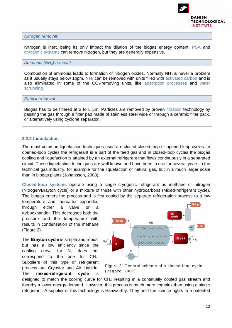
Closed-loop systems operate using a single cryogenic refrigerant as methane or nitrogen
(Nitrogen/Brayton cycle) or a mixture of these with other hydrocarbons (Mixed-refrigerant cycle).
The biogas enters the process and is first cooled by the separate refrigeration process to a low
temperature and thereafter expanded
through either a valve or a
turboexpander. This decreases both the
pressure and the temperature with
results in condensation of the methane
(Figure 2).
The Brayton cycle is simple and robust
but has a low efficiency since the
cooling curve for N2 does not
correspond to the one for CH4.
Suppliers of this type of refrigerant
process are Cryostar and Air Liquide.
The mixed-refrigerant cycle is
designed to match the cooling curve for CH4 resulting in a continually cooled gas stream and
thereby a lower energy demand. However, this process is much more complex than using a single
refrigerant. A supplier of this technology is Hamworthy. They hold the licence rights to a patented
Figure 2: General scheme of a closed-loop cycle
(Begazo, 2007)

13
MiniLNGTM technology developed by SINTEF. Other supplier is Linde BOC that holds the license
of a small-scale mixed refrigerant cycle developed by GTI.
In the Lidköping Biogas plant (Sweden) the majority of the biogas is condensate using Air Liquid
Brayton cycle technology. The design capacity is 12 ton LBG/day and the energy cost of
liquefaction is in the vicinity of 1 kWh/Nm3 upgraded biogas, which equals approximately 10% of
the energy content of the biogas. Previous to the condensation the biogas is upgraded in a water
scrubber (Lidköping Biogas). The plant was inaugurated in October 2012.
Open-loop systems are based mainly on a successive compression-cooling-expansion process of
the biogas. The last expansion stage is usually carried out in a turbo expander (TEX) to obtain
LBG (Figure 3).
Figure 3: General scheme of an open-loop cycle (Begazo, 2007)
If the upgrading plant is situated close to the gas network one option could be to inject upgraded
biogas into the gas grid and then produce LBG at a pressure letdown station in the gas grid with
an open-loop cycle. These stations are situated were the distribution network accesses the
transmission pipeline and have the function to reduce the pressure to match the requested
commercial distribution pressure. Here the expansion of the gas can take place through a
turboexpander. A fraction of the gas stream can then be liquefied with little or no power investment
since the work taken out in the turboexpander drives the compressor (Johansson, 2008). One of
these letdown systems has been developed by Idaho National Engineering and Environmental
Laboratory (Begazo, 2007). This technology is in use in a demonstration plant in Sacramento,
California (Johansson, 2008).
2.3 Cryogenic technologies
The cryogenic method of purification involves the separation of the gas mixtures by fractional
condensation and distillations at low temperature. Because CO2 condenses at lower pressure and
higher temperatures than methane the gases can be separated. This process is of specific value
when the final product is liquid biomethane. In this case, cooling for purification is synergic to
further cooling to produce LBM. Suppliers of cryogenic technology are: Scandinavian GtS, Acrion
Technolgoies/Terracasatus Technologies and Prometheus-Energy.
14
Linde BOC has as well developed a process for the production of LBG. Linde do not sell its
technology but a product, LBG, taking all the responsibility for the production. They use
conventional technology followed by condensation. They have a plant at Albury landfill (U.K)
through the British company Gasrec (Gasrec), commissioned in 2008 with a capacity of around
4000 ton LGB per year, and another in Altamont landfill (California) with a capacity of 1200 Nm3/h
running from 2009.
2.3.1 Scandinavian GtS
The company was founded in 2007 and it is a joint venture between Scandinavian Biogas and
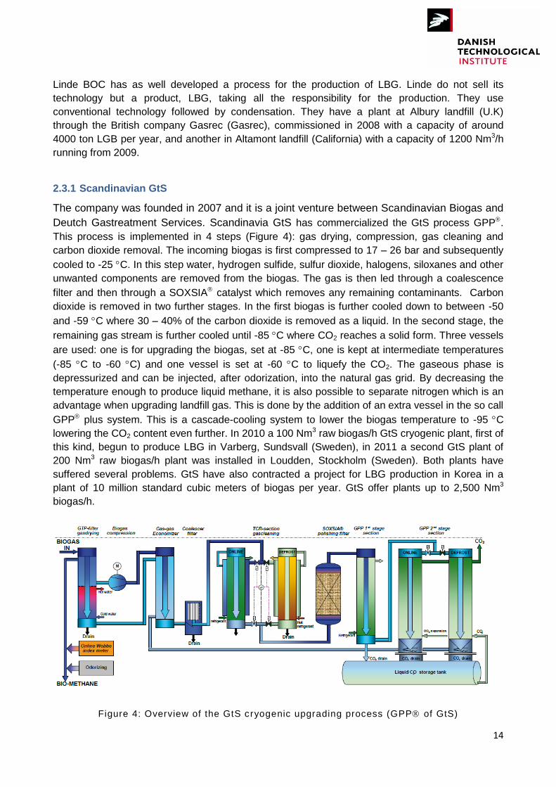
Deutch Gastreatment Services. Scandinavia GtS has commercialized the GtS process GPP.
This process is implemented in 4 steps (Figure 4): gas drying, compression, gas cleaning and
carbon dioxide removal. The incoming biogas is first compressed to 17 – 26 bar and subsequently
cooled to -25 C. In this step water, hydrogen sulfide, sulfur dioxide, halogens, siloxanes and other
unwanted components are removed from the biogas. The gas is then led through a coalescence
filter and then through a SOXSIA catalyst which removes any remaining contaminants. Carbon
dioxide is removed in two further stages. In the first biogas is further cooled down to between -50
and -59 C where 30 – 40% of the carbon dioxide is removed as a liquid. In the second stage, the
remaining gas stream is further cooled until -85 C where CO2 reaches a solid form. Three vessels
are used: one is for upgrading the biogas, set at -85 C, one is kept at intermediate temperatures
(-85 C to -60 C) and one vessel is set at -60 C to liquefy the CO2. The gaseous phase is
depressurized and can be injected, after odorization, into the natural gas grid. By decreasing the
temperature enough to produce liquid methane, it is also possible to separate nitrogen which is an
advantage when upgrading landfill gas. This is done by the addition of an extra vessel in the so call
GPP plus system. This is a cascade-cooling system to lower the biogas temperature to -95 C
lowering the CO2 content even further. In 2010 a 100 Nm3 raw biogas/h GtS cryogenic plant, first of
this kind, begun to produce LBG in Varberg, Sundsvall (Sweden), in 2011 a second GtS plant of
200 Nm3 raw biogas/h plant was installed in Loudden, Stockholm (Sweden). Both plants have
suffered several problems. GtS have also contracted a project for LBG production in Korea in a
plant of 10 million standard cubic meters of biogas per year. GtS offer plants up to 2,500 Nm3
biogas/h.
Figure 4: Overview of the GtS cryogenic upgrading process (GPP of GtS)

15
2.3.2 Prometheus Energy
Prometheus-Energy is an American company founded in 2003, which has a technology from
producing LBG integrating a gas purification and liquefaction system. Their systems are built in a
modular approach as follow:
1. Pre-Purification module: Corrosive sulfur compounds, low concentrations of non-methane-
organic compounds (including siloxanes) and water are removed and the gas is compressed to
around 4.4 bars.
2. Bulk Purification module: Carbon dioxide is removed by freezing it while simultaneously pre-
cooling methane and nitrogen.
3. Liquefaction and Post-Purification module: The purified gas is liquefied and the concentration of
methane is increased by dynamic flash evaporation of the nitrogen.
4. Refrigerant module: Provides the cooling to the process through a closed Brayton N2 cycle.
A pilot-scale plant using this technology was designed in 2000 in Victoria, B.C. Canada. Liquid
methane was produced with a purity of 96%. The first commercial scale plant was built in 2006 at
the Bowerman Landfill, CA, USA, in a cooperation between Prometheus and Montauk Energy
Capital. The plant is designed for production of 19 m3 of liquid methane per day. They sell all the
produced LBG and a part is used for fuelling a fleet of over 200 buses in the Orange County,
California. To date no new Prometheus plants are under development, to the authors´ knowledge.
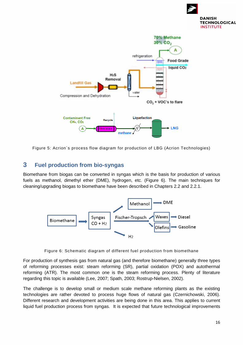
2.3.3 Terracastus Technologies/Acrion Technologies
Terracastus Technologies founded by Volvo Technologies in 2007 holds the licensee of the
cryogenic Acrion´s Technology. Acrion‟s technology is a combination of cryogenic and
conventional technology. They use a distillation column (CO2 Wash) to clean the raw gas followed
by a membranes system and a liquefaction step to produce LBG. Before entering the CO2 Wash
the gas is compressed, desulfurized and dried (Figure 5).
In 2005 Acrion produced LBG from landfill in a demonstration plant at Burlington County, New
Jersey, USA. This project was producing around 650 – 1100 Nm3/day LBG. Acrion has several
projects pending in USA, but no one has been completed yet. A liquefied biogas plant was also
planned to be built on a landfill in Helsingborg, Sweden, but this project has by now been
cancelled.
16
Figure 5: Acrion´s process flow diagram for production of LBG (Acrion Technologies)
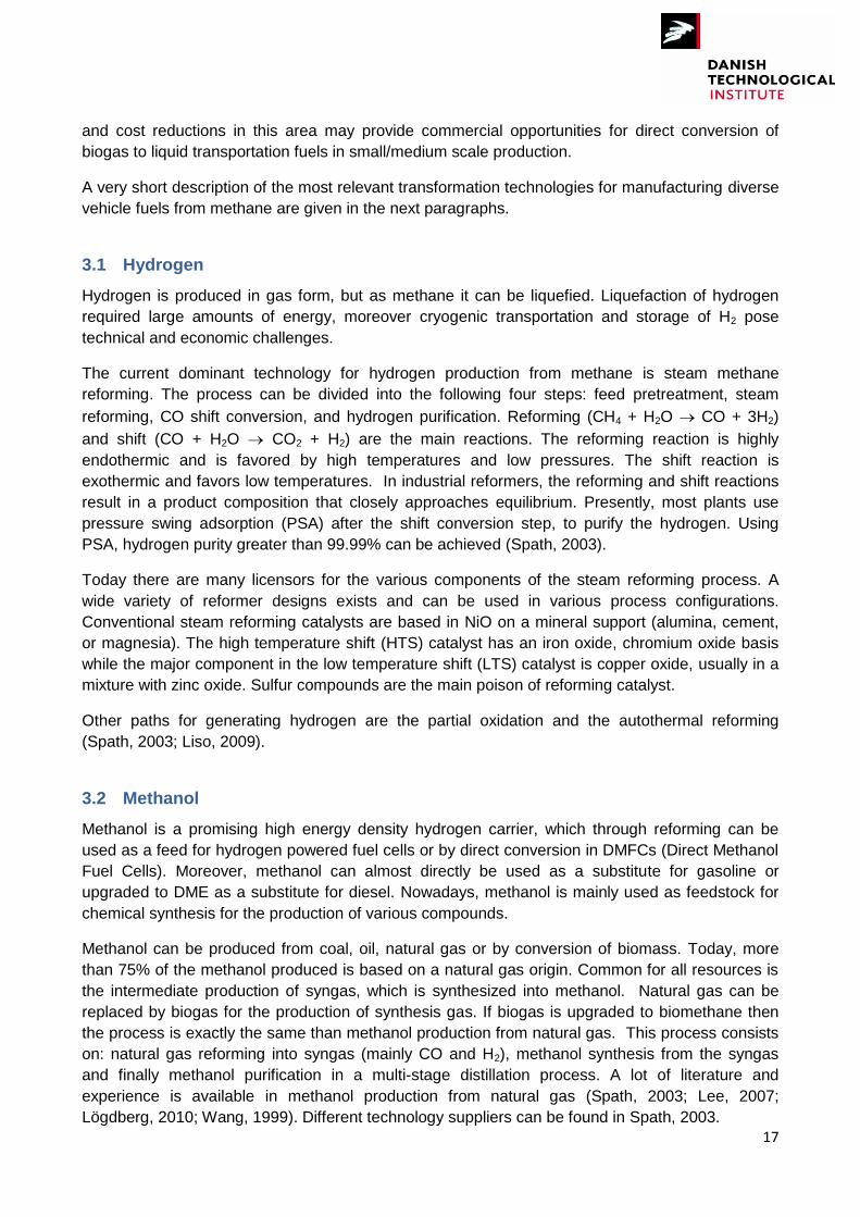
3 Fuel production from bio-syngas
Biomethane from biogas can be converted in syngas which is the basis for production of various
fuels as methanol, dimethyl ether (DME), hydrogen, etc. (Figure 6). The main techniques for
cleaning/upgrading biogas to biomethane have been described in Chapters 2.2 and 2.2.1.
Figure 6: Schematic diagram of different fuel production from biomethane
For production of synthesis gas from natural gas (and therefore biomethane) generally three types
of reforming processes exist: steam reforming (SR), partial oxidation (POX) and autothermal
reforming (ATR). The most common one is the steam reforming process. Plenty of literature
regarding this topic is available (Lee, 2007; Spath, 2003; Rostrup-Nielsen, 2002).
The challenge is to develop small or medium scale methane reforming plants as the existing
technologies are rather devoted to process huge flows of natural gas (Czernichowski, 2006).
Different research and development activities are being done in this area. This applies to current
liquid fuel production process from syngas. It is expected that future technological improvements
17
and cost reductions in this area may provide commercial opportunities for direct conversion of
biogas to liquid transportation fuels in small/medium scale production.
A very short description of the most relevant transformation technologies for manufacturing diverse
vehicle fuels from methane are given in the next paragraphs.
3.1 Hydrogen
Hydrogen is produced in gas form, but as methane it can be liquefied. Liquefaction of hydrogen
required large amounts of energy, moreover cryogenic transportation and storage of H2 pose
technical and economic challenges.
The current dominant technology for hydrogen production from methane is steam methane
reforming. The process can be divided into the following four steps: feed pretreatment, steam
reforming, CO shift conversion, and hydrogen purification. Reforming (CH4 + H2O CO + 3H2)
and shift (CO + H2O CO2 + H2) are the main reactions. The reforming reaction is highly
endothermic and is favored by high temperatures and low pressures. The shift reaction is
exothermic and favors low temperatures. In industrial reformers, the reforming and shift reactions
result in a product composition that closely approaches equilibrium. Presently, most plants use
pressure swing adsorption (PSA) after the shift conversion step, to purify the hydrogen. Using
PSA, hydrogen purity greater than 99.99% can be achieved (Spath, 2003).
Today there are many licensors for the various components of the steam reforming process. A
wide variety of reformer designs exists and can be used in various process configurations.
Conventional steam reforming catalysts are based in NiO on a mineral support (alumina, cement,
or magnesia). The high temperature shift (HTS) catalyst has an iron oxide, chromium oxide basis
while the major component in the low temperature shift (LTS) catalyst is copper oxide, usually in a
mixture with zinc oxide. Sulfur compounds are the main poison of reforming catalyst.
Other paths for generating hydrogen are the partial oxidation and the autothermal reforming
(Spath, 2003; Liso, 2009).
3.2 Methanol
Methanol is a promising high energy density hydrogen carrier, which through reforming can be
used as a feed for hydrogen powered fuel cells or by direct conversion in DMFCs (Direct Methanol
Fuel Cells). Moreover, methanol can almost directly be used as a substitute for gasoline or
upgraded to DME as a substitute for diesel. Nowadays, methanol is mainly used as feedstock for
chemical synthesis for the production of various compounds.
Methanol can be produced from coal, oil, natural gas or by conversion of biomass. Today, more
than 75% of the methanol produced is based on a natural gas origin. Common for all resources is
the intermediate production of syngas, which is synthesized into methanol. Natural gas can be
replaced by biogas for the production of synthesis gas. If biogas is upgraded to biomethane then
the process is exactly the same than methanol production from natural gas. This process consists
on: natural gas reforming into syngas (mainly CO and H2), methanol synthesis from the syngas
and finally methanol purification in a multi-stage distillation process. A lot of literature and
experience is available in methanol production from natural gas (Spath, 2003; Lee, 2007;
Lögdberg, 2010; Wang, 1999). Different technology suppliers can be found in Spath, 2003.
18
The main reactions occurring during methanol synthesis process considering steam methane
reforming are:
Eq. 1 Steam methane reforming
Eq. 2 Inverse water-gas shift reaction
Eq. 3
Eq. 4
Due to the heterogeneity of the kinetics of the biogas reforming and the methanol synthesis the
catalyst selection and the operational conditions are critical. Best results are usually reported when
Ni/Zn/Al catalysts are employed for steam reforming. The methanol synthesis requires lower
temperatures than the biogas reforming (500 – 550 K), however higher pressures are needed (50 -
100 bar). Conventional catalysts for this second stage are Cu-based (Cu/ZnO/Al2O3).
As seen in Eq. 3 and Eq. 4, methanol is produced by the catalytic hydrogenation of carbon
monoxide and/or carbon dioxide and the presence of carbon dioxide in the feed syngas mixture is
essential. Depending on the synthesis conditions (which include reactor temperature, pressure and
catalyst) this process usually aims at a (H2‐CO2):(CO+CO2) ratio of 2.1:1 (Majer, 2010).
Conventional steam methane reforming plants when available from another nearby chemical plant
may employ CO2 injection (Wang, 1999). When CO2 is mixed with methane, such as in the case of
biogas, it can be used as a carbon source in the synthesis of methanol. However, too high CO2
concentrations lead to slow reaction rates. Typically 2 – 8% of CO2 is present in the syngas
mixture for methanol synthesis (Lee, 2007). CO2 can be partially purging from biogas until obtain
the best molar rates (Pedersen, 2012).
Pedersen and Schultz (Pedersen, 2012) found through an equilibrium model that by supplying
additional hydrogen to the methanol reactor a 50% higher CO2 utilization is possible for steam
reforming and a full utilization is possible for partial oxidation.
For syngas production from biogas, the CO2 reforming of CH4 or Dry Reforming of Methane (DRM)
reaction has been proposed as very promising. More information about this technology can be
found in Bereketidou and Goula (Bereketidou, 2012).
Further research and development in production of methanol from biogas is needed.
3.3 Dimethyl ether (DME)
Dimethyl ether (DME) is gaining importance as alternative fuel. DME can be used a substitute of
diesel, having lower NOx and SOx emissions. It can also be utilized in fuel cells. Moreover it can
use the existing LPG (liquefied petroleum gas) infrastructure.
Methanol serves as a direct reactant or as an intermediate in the synthesis of DME, depending on
the reaction routes. In the traditional route, dimethyl ether has been produced in a two-step
process where syngas (typically generated from the steam reforming of methane) is first converted

19
to methanol, followed by methanol dehydration over a catalyst to DME (Eq. 5) This same process
can take place by generating syngas from biogas (see Chapter 3.2).
Eq. 5 (Lee, 2007)
In recent years, single-state synthesis of DME from synthesis gas, in which methanol is an
intermediate in the conversion of syngas to DME, has attracted a great deal of attention (Lee,
2007, Wang, 1999).
3.4 Fisher-Tropsch (FT) fuels
Fisher-Tropsch synthesis is a well-known process where hydrocarbons (CxHy) are synthesized
from syngas. The chemical reaction that takes place under impact of a catalyst is a reaction
between carbon monoxide and hydrogen. About 20% of the chemical energy is released as heat
during the process, written as following (Spath, 2003):
( ) Eq. 6 In general, the product range includes the light hydrocarbons methane, ethane, propane and
butane; naphtha; kerosene diesel fuel; low-molecular-weight wax; and high-molecular-weight wax.
The Fischer-Tropsch process is a very complicated process that requires a well-defined choice of
reactors, catalysts, and operating conditions to synthesize the desired products. Even then, a
mixture of compounds is obtained.
There are four main steps to produce FT products: syngas generation, gas purification, FT
synthesis, and product upgrading. When using natural gas as the feedstock, many authors have
recommended autothermal reforming or autothermal reforming in combination with steam
reforming as the best option for syngas generation (Spath, 2003). Depending on the types and
quantities of FT products desired either low (200 – 240°C) or high temperature (300 – 350°C)
synthesis is used with either an iron or cobalt catalyst. The FT reactors are operated at pressures
ranging from 10 – 40 bar. Low temperatures yield high molecular mass linear waxes that can by
hydrocracking transformed in diesel. High temperatures produce low molecular weight olefins and
by upgrading gasoline.
A comprehensive bibliography of FTS literature, including journal and conference articles, books,
government reports and patents can be found in the Fischer-Tropsch Archive at www.fischer-
topsch.org.
4 Use of biogas as vehicle fuel in Denmark
Nowadays the most widespread use of biogas as vehicle fuel is as compress biomethane (CBM).
But in contrast to our neighboring countries Sweden and Germany, Denmark does not use
methane for vehicle transportation, neither biogas nor natural gas. In fact, today Denmark together
with Albania, Montenegro and Romania are the only countries in Europe that do not have public
services stations for biogas/natural gas (Øresund Ecomobility, 2012). Naturgas Fyn owns the only
gas station in Denmark, together with a fleet of 14 natural gas vehicles.
20
This may change in a very close future as the most recent energy policies in Denmark not only
support the production of biogas but also have made financially more attractive the injection of
biomethane into the natural gas grid, or its use in the transport sector. The new Danish Energy
Agreement 2012 – 2020 introduces a new funding scheme in which, among others, biomethane
injection into the natural gas grid receives the same subsidy as electricity from biogas produced in
CHP plants.
The best way of starting a socio-economic infrastructure for using biogas as fuel is by focusing in
first place on the heavy traffic, as well as for example taxi fleets. Moreover, it is feared that rising oil
prices will cause loss of competitive advantage for the heavy transport sector in Denmark in
relation to Germany, Sweden and Eastern Europe if they have cheaper fuel alternatives. The
heavy transport currently has not, as the light transport sector, alternatives such as electricity or
bioethanol (Øresund Ecomobility, 2012).
In this context not only CBG but also LBG can be relevant. CBG is well suited for bus fleets or
short distance transportation but for heavy duty trucks, in order to be competitive with diesel trucks,
the liquefied fuel is required since its higher energy density (compared to CBM) allows getting
enough driving range.
Dual-fuel technology and LBM/LNG are considered by many players as one of the first solutions
that can truly compete, in the short-middle term, with the conventional diesel engines in the long
distance road transportation sector. However, there are also some concerns as fuel infrastructure,
emission control, and total economy that need to be overcome. In this scenario as LBM production
is very limited and it is expected to continue to be relatively limited, LNG is required to secure
supply of fuel. Currently Denmark has no domestic LNG terminals (Johannesson, 2011). LNG/LBM
has as well a big potential as maritime fuel.
At present, biogas in Denmark is basically used for combined heat and power production and at
the moment there is only one plant upgrading biogas and injecting it into the natural gas grid. This
plant began to run in September 2011 in Fredericia and is producing 180 Nm3/h biomethane from a
sewage plant. Nevertheless there are already several projects for building new biogas plants in the
coming years, with upgrading of biogas and injection into the natural gas grid. In this line, at the
beginning of 2013 the first public gas station will be establish in the Skive municipality and it is
expected that others will follow. Initially the Skive station will provide natural gas but in a few years
it is expected that upgraded biogas will be produced in the municipality and clients should be able
to fill biomethane in their cars.
Until now an important barrier for biogas and natural gas vehicles has been that this type of
vehicles is subject to higher taxes than diesel vehicles. But the Danish Government has
announced that this is going to change in a very near future, which would contribute greatly to the
expansion of natural gas/biogas vehicles.
There are still no plans to produce LBM in Denmark at the moment, but the technology has come
in the last years to commercial stage so, if conditions are favorable from an economical and/or
political point of view, a fast development could take place in this area. In Sweden the first liquefied
biogas production facility was open in Sundsvall in 2010 and two more have followed: Loudden in
2011 and Lidköping in 2012. At the same time a liquid biomethane infrastructure is being created.
In 2010 the first public filling station for liquid methane was open in Goteborg, in 2011 it was
inaugurated another filling station in Stockholm and there are plans to open more.

21
Regarding to the production of other liquid biofuels from biogas they will be most probably
considered only in a middle-long term, as vehicle and production technologies need to be further
developed and improved.
22
References
Acrion Technologies. http://www.acrion.com/
Ajhar M., Melin T. (2006) Siloxane removal with gas permeation membranes. Desalination 200:234e5
Bereketidou O.A. and Goula M.A. (2012). Biogas reforming for syngas production over nickel supported on ceria-alumina catalysts. Catalysis Today 195, pg. 93-100.
Cline, C., Hoksberg, A., et al. (2002). Biological process for H2S removal from gas streams: The Shell-Paques/Thiopaq™ gas desulfurization process. Paper for the LRGCC, 23 –26 February 2003, Norman (Oklahoma)
COWI (2012). http://www.cowi.com/menu/project/IndustryandEnergy/Industry/Pages/COWIwinsFilbornaBioFuelProject.aspx
Begazo D.T. C., Carvalho C. E., Simões-Moreira R.J. (2007). Small-scale LNG plant technologies. Hydrocarbon World.
BC Innovation Council (2008). Feasibility Study – Biogas upgrading and grid injection in the Fraser Valley, British Columbia
Beil M. and Hoffsted U. (2010). Guidelines for the implementation and operation of biogas upgrading systems. Biogasmax. Project suuported by the EU under RTC contract: 019795
Bekkering J., Broekhuis A.A., van Gemert W.J.T (2010). Optimisation of a green gas supply chain – A review. Bioresource Technology 101, pg. 450-456
Biomass for Energy (2012). Focus on Biomethane. Deutsches BiomasseForschungsZentrum gemeinnützige GmbH (DBFZ)
Czernichowski A. and Wesolowska K. (2006). POX reforming of biomethane into synthesis gas for Fischer-Tropsch process. The 232nd ACS National meeting, San Francisco, Sept. 2006. Division of fuel chemistry.
Climate Action (2011). Reducing emissions from transport. EU Directorate-General for Climate Action. http://ec.europa.eu/clima/policies/transport/index_en.htm
Delsinne S. (2010). Biogas Safety and Regulation. Discussion document for the workshop organized on 24 November 2010 in Paris. Project 12055
El-Fadel M., Findikakis A.N., and Leckie J.O. (1997). Environmental Impacts of Solid Waste Landfilling. Journal of Environmental Management 50, pg. 1-25
Environment-Agency (2004). Guidance on Gas treatment Technologies for Landfill Gas Engines
GPP. Gastreatment power package of GtS. http://www.gastreatmentservices.com/index.php?option=com_content&view=article&id=31&Itemid=60&lang=en
Hagen M., Polman, E., Myken A., Jensen J., Jönsson O., AB B. and Dahl A. (2001). Adding gas from biomass to the gas grid. Final report Contract No: XVII/4.1030/Z/99-412
23
Hullu, J., Maassen J.I.W., van Meel P.A., Shazad S., and Vaessen J.M.P (2008). Comparing different biogas upgrading techniques. Final report. Eindhoven University of Technology
Kohl, A. and Neilsen, R. (1997). Gas Purification. Golf Publishing Company, Houston, Texas. Cited in: McKinsey S.Z. (2003). "Removal of Hydrogen Sulphide from Biogas using cow-manure compost." A Thesis Faculty of the Graduate School of Cornell University
Krich, K., Augenstein, D., et al. (2005). Biomethane from Dairy Waste: A Sourcebook for the Production and Use of Renewable Natural Gas in California. Western United Dairymen
Johannesson S. (2011).Alternative fuels in heavy goods vehicle transport – corridor of liquefied biomethane in road transportation. Baltic Sea Region Project #26: Scandinavian-Adriatic corridor for growth and innovation. WP3, action 3.3-2. Concept for optimized heavy goods vehicle traffic
Johansson N. (2008). Production of liquid biogas, LBG, with cryogenic and conventional upgrading technology – Description of systems and evaluations of energy balances. Master thesis. Lunds Tekniska Högskola
Jonsson S. and Johan W. (2011). Cryogenic biogas upgrading using plate heat exchangers. Master´s thesis within the Sustainable Energy System Master´s program. Chalmers University of Technology. Sweden
Lampe S. (2006). Assessment of fuel gas cleanup systems for waste gas fueled power generation. EPRI, Palo Alto, CA. 1012763
Lee S., Speight J.G, Loyalka S.K. (2007) Handbook of Alternative Fuel technologies. CRC Press, 2007.
Lidköping Biogas. http://www.lidkopingbiogas.se/eng/
Liso v., Nielsen M.P., Kær S.K. (2009) Reforming processes for micro combined heat and powersystem based on solid oxide fuel cell. Proceedings of SIMS 50. Scandinavian Simulation Society, 2009.
Lögdberg S. and Jakobsen H.A. (2010). Natural Gas Conversion: The Reforming and Fischer-Tropsch Processes. TKP 4145 Reactor technology. http://www.nt.ntnu.no/users/jakobsen/TKP4145/NaturalGasConversion.doc.
Majer S. and Gröngröft A. (2010). Environmental and economic assessment of biomethanol for the biodiesel production. German Biomass Research Centre (DBFZ).
McKinsey, S. Z. (2003). Removal of Hydrogen Sulfide from Biogas using cow-manure compost. A Thesis Faculty of the Graduate School of Cornell University
Mezei S. (2010). Options for upgrading digester biogas to pipeline quality. Flotech
Naskeo Environnment (2009). Biogas Composition. http://www.biogas-renewable-energy.info/biogas_composition.html
Øresund Ecomobility, Transportens Innovationsnetværk (2012). Potentiale og barrierer for biogas og naturgas til transport i Danmark.
24
Pedersen T.H, Schultz R.H. (2012). Technical and economic assessment of methanol production from biogas. Master´s thesis within Thermal Energy and Process engineering. University of Aalborg, Denmark.
Persson M. (2007). Biogas upgrading and utilization as vehicle fuel. European Biogas Workshop. The future of biogas in Europe III
Persson M., Jönsson O. and Wellinger A. (2006). Biogas Upgrading to Vehicle Fuel Standards and Grid Injection. IEA Bioenergy. Task 37
Petersson A. (2009). Modern technologies of biogas upgrading. Citation from Urban W., Girod K., Lohmann H.(2008) Technologien und kosten der biogasaufbereitung und einspeisung in das erdgasnetz. Ergebnisse der markterhebung 2007-2008. Fraunhofer UMSICH
Petersson A. and Wellinger A. (2009). Biogas upgrading technologies-developments and innovations. IEA Bioenergy. Task 37
Rostrup-Nielsen J.R. (2002). Syngas in perspective. Catalysis Today 71, 243-247.
Ryckebosch E., Drouillon M. and Vervaeren H. (2011). Techniques for transformation of biogas to biomethane. Biomass and Bioenergy 35, pg. 1633-1645
Rasi S. (2009). Biogas composition and upgrading to biomethane. Jyväskylä studies in biological and environmental science 202
Spath P.L. and Dayton D.C. (2003). Preliminary Screening – Technical and Economic assessment of synthesis gas to fuels and chemicals with emphasis on the potential for biomass-derived syngas. National Renewable Energy Laboratory. NREL/TP-510-34929.
Shareefdeen, Z. and Singh, A. (2005). Biotechnology for odor and air pollution control. Springer
Sternovem. Committee for Green Gas. From biogas to green gas. Upgrading techniques and suppliers. 2ETPNG0840
Wang M.Q. and Huang H.S. (1999). A full fuel-cycle analysis of energy and emissions impacts of transportation fuels produced from natural gas. Center for Transportation Research, Argonne National Laboratory.
Wellinger A. and Lindberg A. (2000). Biogas upgrading and utilization. IEA Bioenergy. Task 24
Zappa, L. P. (2001). "Options in Odor Control." Water & Wastewater Products 1(1): 38
25
Annex 1
Main composition of biogas from different sources
Table 6: Main composition of biogas from different sources
Components Municipal waste Wastewater Agricultural/
Animal waste
Waste from agrofood industry
Landfill
CH4 (vol.-%) 50 – 60
2
61 – 651
60 – 752
55 – 773
55 – 656
55 – 581
60 – 752
50 – 703
60 – 706
682
50 - 753
47 – 571
45 –- 703
40 – 704
35 – 65 (avg.45)
5
45 – 556
CO2 (vol.-%) 34 – 38
2
36 – 381
19 – 332
30 – 453
35 – 456
37 – 381
19 – 332
30 –503
30 – 406
262
37 – 411
35 – 403
30 – 604
15 – 50 (avg.40)
5
30 – 406
N2 (vol.-%) 0 – 5
2
< 2
1
<12,6
< 12
< 1 – 21
< 33
< 1 – 171
< 33
3 – 54
5 – 40 (avg.15)5
5 - 156
O2 (vol.-%) 0 – 12
< 11
<0.52
< 11
<0.52
< 11
< 0.23
0 – 34
0 – 5 (avg.1)5
H2O (vol.-%) 100% (saturated at digester exit temperature)
3
100% (saturated at digester exit temperature)
3
100% (saturated at digester exit temperature)
3
100% (saturated at digester exit temperature)
3
100% (saturated at digester exit
temperature)3
H2 (vol.-%) 0 – 54
CO (vol.-%) 0 – 34
H2S (ppm) 70 – 6502
700 – 28002
150 – 30003
636
2100 – 70002
32 – 1691
3 – 10001
2802
< 21,500
36 – 115 1
10 – 2003
0 – 20.0004
< 1005
15 – 427 6
Aromatic (mg/m3) 0 – 200
2 30 - 1900
4
Ammonia 50 – 1002 mg/m
3 5 ppm
Halogenated compounds (mg/m
3)
100 – 8002 1 – 2900
4
Benzene (mg/m3)
0.1 – 0.31 0.7 – 1.,3
1 0.6 – 2.3
1
Toluene (mg/m3) 2.8 – 11.81 0.2 – 0.7
1 1.7 – 5.1
1
Siloxanes (ppmv) 2 – 15
3
1.5 – 10.66
< 0.46
0.1 – 3.53
0.7 – 46
Non-methane organics (% dry weight)
0 – 0.253
Volatile organics (% dry weight)
0 – 0.13
1 Delsinne, 2010;
2 Naskeo Environnment, 2009;
3 Lampe, 2006;
4 El-Fadel, 1997;
5 Persson, 2006;
6 Rasi,
2009.
Related Documents