Repairing LitterMaid Self-Cleaning Litter Box Sergei Bezrukov [email protected] Abstract This repair project involves replacing malfunctioning microcontroller chip in LitterMaid Mega self-cleaning litter box with a Microchip PIC microcontroller and redesigning its firmware. It is shown how to embed a new microcontroller onto the original board and a detailed description of the new firmware algorithm is presented. During the past several years we were using for our cat a self-cleaning litter box manu- factured by LitterMaid. Although this device does not provide a perfect cleaning of the box so that you do not need to touch it any more for a manual cleanup, it made our life somewhat simpler. However, one day it stopped working for an unknown reason: the power LED was steady on but the rake refused to move. Figure 1: My LitterMaid Mega older model 1

Repairing LitterMaid Self-Cleaning Litter Boxmcs.uwsuper.edu/sb/Electronics/LitterMaid/LitterMaid.pdfRepairing LitterMaid Self-Cleaning Litter Box Sergei Bezrukov [email protected]
Mar 10, 2018
Welcome message from author
This document is posted to help you gain knowledge. Please leave a comment to let me know what you think about it! Share it to your friends and learn new things together.
Transcript

Repairing LitterMaid Self-Cleaning Litter Box
Sergei [email protected]
Abstract
This repair project involves replacing malfunctioning microcontroller chip inLitterMaid Mega self-cleaning litter box with a Microchip PIC microcontroller andredesigning its firmware. It is shown how to embed a new microcontroller onto theoriginal board and a detailed description of the new firmware algorithm is presented.
During the past several years we were using for our cat a self-cleaning litter box manu-factured by LitterMaid. Although this device does not provide a perfect cleaning of thebox so that you do not need to touch it any more for a manual cleanup, it made ourlife somewhat simpler. However, one day it stopped working for an unknown reason: thepower LED was steady on but the rake refused to move.
Figure 1: My LitterMaid Mega older model
1

My litter box model (see Fig. 1) is pretty old and is probably not manufactured anymore. The modern ones come with more features like real-time clock which allows youto disable automatic cleaning at some times (e.g., nights), and air ionizer for reducingthe smell. Therefore, the technique described here might not be directly applicable tonewer models. I have never opened newer models yet and am not aware of what is inside.However, I hope that my experience could be applicable anyway.
The device is assembled on a single printed circuit board (PCB) shown in Fig. 2. Aftercareful examination of all components I figured out that two transistors TR6 and TR7 oftype 2N3904 were burned out and the microcontroller IC3 showed no reaction to signalsapplied to its pins. These components are are circled in Fig. 2.
Figure 2: Damaged components: two transistors and microcontroller IC
Note that in other cases the set of damaged components can be different. In my casereplacing transistors was not a problem, but the device still did not work after this, so amicrocontroller replacement was needed. The problem was that I could not identify themicrocontroller (MCU). But even if I could, it won’t help me much, since any MCU mustbe programmed with firmware and I have no development tools for this MCU. Moreover,the manufacturer does not provide any firmware for download. So, I decided to replacethe original MCU with another one that I can handle (Microchip PIC16F684) and developa new firmware for it by myself.
Original Circuit Description
By examining the PCB I came up with the schematic shown in Fig. 3. The numberingof components on the schematic matches the one on the PCB.
2
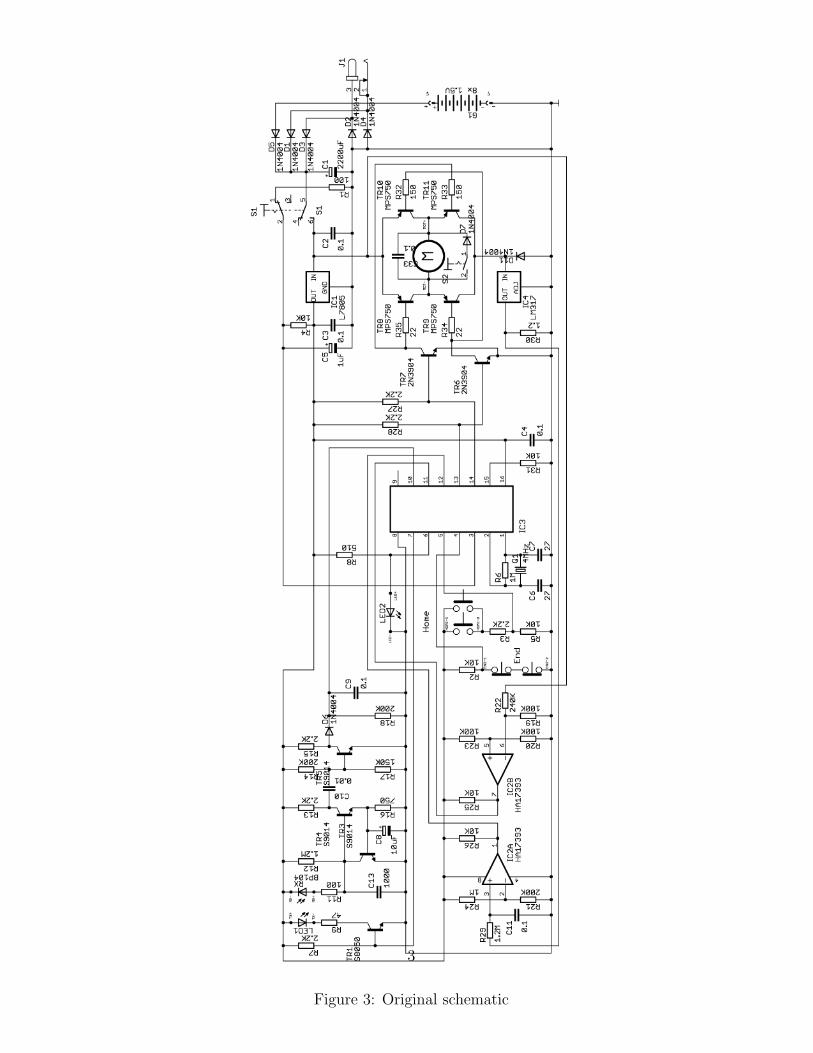
Figure 3: Original schematic
3

As you probably know the device is equipped with a rake that moves from the back sideof the box towards the front side (from left to right in Fig. 1). The litter grabbed by therake is dropped into a plastic container located under the bluish cover at the front. Therake is activated (starts to move) after about 10 minutes as the pet leaves the box.
Checking for pet presence in the box is accomplished by an infrared emitting diode LED1and IR receiving diode RX. The transmitter is switched by transistor TR1, whose baseis driven by a square-shape waveform from pin 7 of MCU IC3. The frequency and dutycycle of this signal is about 10 kHz and 50%, respectively. The receiver’s output signal ispretty weak and needs to be amplified, for which transistors TR3 - TR5 are used. Theamplified signal is forwarded to the peak level detector on components D6, R19, and C9.In case of no blocking obstacle between IR transmitter and receiver (no pet in the box)the voltage at the peak detector output is about 4.5V. It drops down to 0V by blockingthe IR ray.
Transistors TR8 - TR11 form an H-bridge that controls the direction rotation of motorM. Transistors TR6 and TR7 amplify current for driving the H-bridge. When the rake issteady the voltage at MCU pins 13 and 14 is close to 0 and all transistors TR6 - TR11are closed. To move the rake forwards (for cleaning) pin 13 of MCU turns into a high-impedance state, resulting in opening of TR6 which in turn opens TR9 and TR10. Formoving the rake back MCU outputs 0 at pin 13 and drives pin 14 into a high-impedancestate. This results in opening of TR7 and as a consequence of TR8 and TR11. Thevoltage polarity applied to the motor changes to the inverse one resulting in reversing itsrotation direction.
The final position of the rake as it moves forwards is registered by a pair of buttons End(see Fig. 3) located inside the device side panels. At the final position the buttons getopen and the voltage at MCU pin 4 raises up from 0 to 5V. Similarly, the home positionof the rake is registered with another pair of buttons Home. As the rake reaches its homeposition these buttons get close resulting in dropping the voltage at pin 5 from 4.4V downto 0.
The motor moving the rake is equipped with a gearbox, resulting in a pretty high torqueso I can barely stop the rake with my hands. Nevertheless, sometimes even this powerbecomes insufficient for moving the litter out and the rake jams. If this happens, thecurrent through the motor and H-bridge noticeably increases. To protect them fromburning out the designers use voltage regulator LM317 (IC4). Since the adjustmentterminal of LM317 is grounded, the voltage at its output is close to the input one. Asthe current drawing by the motor increases, the one through IC4 and R28 increases too.IC4 limits the current at the level of approx. 1.5A thus protecting the H-bridge and themotor.
At the same time, increasement of motor’s current is registered by comparator IC2awhich monitors the voltage drop on R29. As the current goes above 0.7A this voltagedrop exceeds 0.83V (determined by R21 and R24) the comparator output raises up from 0to 5V. The low-pass filter R29 - C11 prevents the comparator from reporting short peaksof drawing current (below ca. 70 msec) that can be caused by transporting heavy loads
4

by the rake or by reaching the terminal positions. Furthermore, triggering an overload isalso provided by a bumper located at the back of the rake. This way pets incidentallyappeared behind the rake moving to the home position get protected from smashing. Thebumper closes button S2 (mounted inside the rake), which triggers an overflow signal atthe output of IC2a only when the rake moves backwards. This is accomplished by diodeD7 which blocks button S2 when the rake is moving forwards.
The device can be powered from a wal-wart power supply or from batteries. The inputvoltage is rectified by D1 - D5 and stabilized by IC1 of type 7805. The input voltageis monitored by comparator IC2b. If the voltage drops below 8.5V (determined by R19- R20 and R22 - R23) the output of IC2b raises up from 0 to 5V. This information isused by MCU for controlling the rake. Turning the device on is performed by switch S1.Its lower (on schematic) contacts break the input voltage, while the upper ones probablyserve for resetting the MCU.
Modifications in the original schematic
As it is mentioned above I replaced the original MCU with PIC16F684. This part hasonly 14 pins vs. 16 in the original one and has incompatible pinout. To resolve the lastproblem I mounted the new MCU on a small home-made PCB shown in Fig. 4.
Figure 4: Auxiliary board carrying PIC16F684
The right image in Fig. 4 is a detailed view of the PCB traces which are located on itsbottom side. The blue jumper connects the filled (ground) areas on PCB.
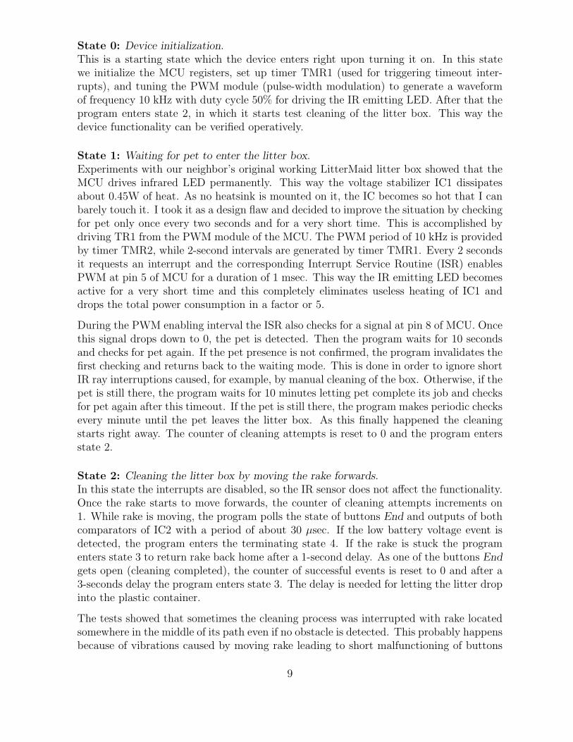
The board size is about 2×3 cm. It has 16 pads corresponding to the ones of the originalMCU. The auxiliary PCB pads are connected by short wires with the corresponding MCUpads on the original PCB (the original MCU has to be removed from PCB, of course).This way the auxiliary PCB is assembled about 1 cm above the main PCB and theconstructions is pretty stable. Fig. 5 and Fig. 6 show the original MCU on PCB and itsreplacement, respectively.
5
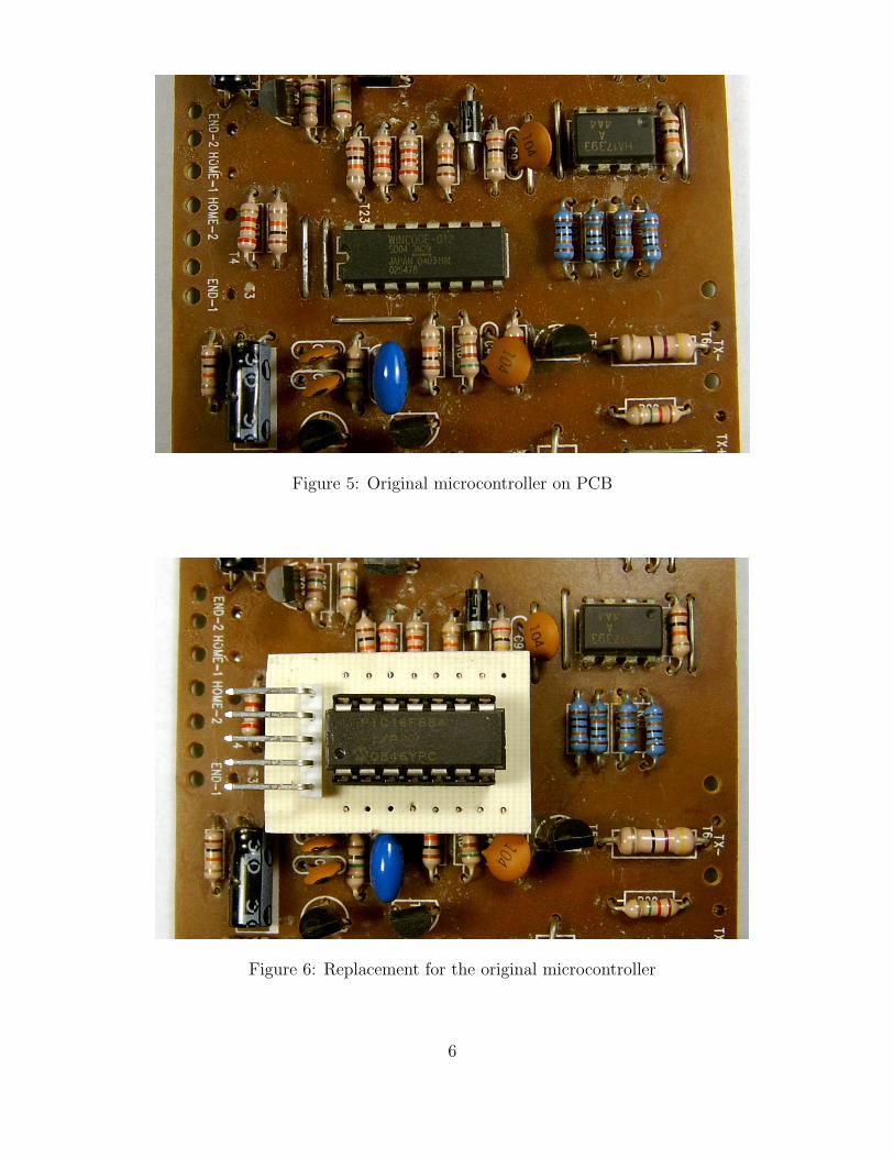
Figure 5: Original microcontroller on PCB
Figure 6: Replacement for the original microcontroller
6

Figure 7: Modified schematic
7

The 5-pin connector on the auxiliary PCB is intended for in-circuit programming ofPIC16F684. This was very handy, since the firmware was reloaded into it many timesduring debugging. By the way, it turns out that my PIC programmer was unable topower the entire circuit during the MCU programming process. I resolved this problemby powering the device from its own power supply during programming. This way themodified schematic becomes as it is shown in Fig. 7.
Since PIC16F684 has pretty stable internal clock oscillator, the elements Q1, C6, C7, andR6 (that served for clocking the original MCU) are not needed and they are not connectedto my board. I also did not use the reset circuitry R1 - C5, relying on the one built inPIC16F684. The broken connections are indicated by crosses (×) in Fig. 7.
The last modification concerns resistor R7. It was disconnected from the base of TR1by cutting off the corresponding trace on the PCB. Instead of it a new current-limitingresistor (R0 in Fig. 7) is added. For this the PCB trace connecting the base of TR1 withMCU was cut off and a small SMD resistor in package 0603 (not shown on photos) wasmounted over the cut. It is possible to use a regular resistor with axial leads.
Firmware design
Since I do not have a detailed description of the original algorithm, I cannot guaranteethat my one exactly matches it. Anyway, by designing my firmware I tried to mimic thefunctionality of the original device as much as I remembered it.
The firmware is implemented as a finite state machine (FSM) with 5 states. One ofthose states in the initial one which the device enters right after powering up. The otherstate is the terminating one, which is used to indicate problems preventing the devicefrom functioning. Examples of such problems are unavoidable obstacles hit by the rake ordropping of input voltage below 8.5V (when being powered from batteries). Exit from theterminating state is only possible by manually turning the device off and then on again.The remaining three states correspond to waiting for pet, moving the rake forwards forcleaning, and moving it back to the home position.
In general, the functionality of the device mostly consists of waiting for pet and activatingthe rake (moving it forwards) 10 minutes after the pet leaves the litter box. The rakegets 3 attempts for cleaning the box. After every unsuccessful attempt (rake is stuck bymoving forwards) the rake is returned back to the home position and the next attempt isperformed after a delay of 1 sec. The delay allows the litter to reconfigure after movingit, which could help to remove it. After 3 failures the rake gives up and stops, and thedevices enters the terminating state. In this state the power LED starts blinking indicatinga problem (normally this LED is steady on). If an unavoidable obstacle is experienced bymoving the rake to the home position (which should normally never happen), the devicegives up right away. In each state monitoring of the power supply voltage is performed.If it drops down below 8.5V threshold, the device enters the terminating state. Below Idescribe each of the states and inter-state transitions in detail.
8
State 0: Device initialization.This is a starting state which the device enters right upon turning it on. In this statewe initialize the MCU registers, set up timer TMR1 (used for triggering timeout inter-rupts), and tuning the PWM module (pulse-width modulation) to generate a waveformof frequency 10 kHz with duty cycle 50% for driving the IR emitting LED. After that theprogram enters state 2, in which it starts test cleaning of the litter box. This way thedevice functionality can be verified operatively.
State 1: Waiting for pet to enter the litter box.Experiments with our neighbor’s original working LitterMaid litter box showed that theMCU drives infrared LED permanently. This way the voltage stabilizer IC1 dissipatesabout 0.45W of heat. As no heatsink is mounted on it, the IC becomes so hot that I canbarely touch it. I took it as a design flaw and decided to improve the situation by checkingfor pet only once every two seconds and for a very short time. This is accomplished bydriving TR1 from the PWM module of the MCU. The PWM period of 10 kHz is providedby timer TMR2, while 2-second intervals are generated by timer TMR1. Every 2 secondsit requests an interrupt and the corresponding Interrupt Service Routine (ISR) enablesPWM at pin 5 of MCU for a duration of 1 msec. This way the IR emitting LED becomesactive for a very short time and this completely eliminates useless heating of IC1 anddrops the total power consumption in a factor or 5.
During the PWM enabling interval the ISR also checks for a signal at pin 8 of MCU. Oncethis signal drops down to 0, the pet is detected. Then the program waits for 10 secondsand checks for pet again. If the pet presence is not confirmed, the program invalidates thefirst checking and returns back to the waiting mode. This is done in order to ignore shortIR ray interruptions caused, for example, by manual cleaning of the box. Otherwise, if thepet is still there, the program waits for 10 minutes letting pet complete its job and checksfor pet again after this timeout. If the pet is still there, the program makes periodic checksevery minute until the pet leaves the litter box. As this finally happened the cleaningstarts right away. The counter of cleaning attempts is reset to 0 and the program entersstate 2.
State 2: Cleaning the litter box by moving the rake forwards.In this state the interrupts are disabled, so the IR sensor does not affect the functionality.Once the rake starts to move forwards, the counter of cleaning attempts increments on1. While rake is moving, the program polls the state of buttons End and outputs of bothcomparators of IC2 with a period of about 30 µsec. If the low battery voltage event isdetected, the program enters the terminating state 4. If the rake is stuck the programenters state 3 to return rake back home after a 1-second delay. As one of the buttons Endgets open (cleaning completed), the counter of successful events is reset to 0 and after a3-seconds delay the program enters state 3. The delay is needed for letting the litter dropinto the plastic container.
The tests showed that sometimes the cleaning process was interrupted with rake locatedsomewhere in the middle of its path even if no obstacle is detected. This probably happensbecause of vibrations caused by moving rake leading to short malfunctioning of buttons
9
(my unit is too old). To resolve this problem, debouncing of switches was added, so thenow rake does not take the button states into account before they are confirmed for 128times.
State 3: Returning rake to the home position.This state is similar to state 2. The motor direction is reversed and the program monitorsthe state of buttons Home and the outputs of both comparators of IC2. If one of themgoes up (low battery voltage or unavoidable obstacle), the program enters the terminatingstate 4. As one of buttons Home gets close the program checks the value of the cleaningattempts counter. If this value is non-zero, then the cleaning is not completed and therake was returned back because of an obstacle. In this case if the counter value does notexceed 3 the program is moved to state 2 again without cleaning the counter and thecleaning process repeats. If the counter value is 3, the rake gives up to move an obstacleand the program enters terminating state 4. Finally, if the counter value is 0 (cleaning iscompleted successfully), the program enters state 1 for waiting of a new pet visit.
State 4: Terminating state.This state is used to indicate a problem by blinking the power LED (normally it is steadyon). Exit form this state is only possible by a manual reset of the unit by turning thepower switch off. Possible reasons for entering this state are restricted to the presenceof an unavoidable obstacle in the litter box and low power voltage. It is impossible todistinguish between them just by observing the power LED. However, presence of anobstacle in the litter box is usually easy to detect visually (I have never had problemswith it).
Concerning the low input voltage, if the litter box is powered from batteries, the devicewill most likely detect low battery voltage again right upon reset, so the reason of LEDblinking becomes obvious. In case of power outage the program will be restarted fromstate 0 and perform cleaning as soon as power becomes available.
The program is written in assembly language and intended for compilation with MPLABIDE, which can be downloaded from microchip.com website. The source code of theembedded program is attached.
If I would do it again
My primary goal in this project was to reanimate the broken device as soon as possiblerather than to optimize it. Anyway, the first thing I would do is eliminate the pull-upresistors R27 and R28 and insert current-limiting resistors of 2.2K between the bases ofTR6 and TR7 and pins 11 and 2 of MCU respectively (similarly as it is done with TR1and pin 5 now). This way the MCU would not sink the current through R27 and R28to keep the motor in the stop position. The motor is in this is the state for most of thetime, so currently 10 mA of current are sinking my MCU for nothing.
10

Next, I would reroute the auxiliary PCB so that the buttons and outputs of comparatorsIC2 would be connected to pins of PORTA of MCU. This way one could use interrupts onchange on PORTA and the MCU could be put on sleep for most of the time. To enablethis feature, pin 4 should be pulled up to +5V via R31.
Also, the comparators do not need to be on all the time. The battery voltage monitoringcould be accomplished ones in a while as the device is in the pet waiting mode. This wayCPU can be kept on sleep and awaken for a short time to perform voltage checks, forexample every 2 seconds which the pet presence is checking.
Finally, I would power the amplifier on TR3 - TR5 from a CPU pin and turn it on onlywhen it is used (1 millisecond interval every 2 seconds). By implementing all this, thepower consumption could be dropped down in another factor of 5 as minimum. Well, thiswould probably save you at most a couple of bucks on you electricity bill in a year, butwhy not.
As I mentioned, the device is pretty old. Modern MCU are more beefy and many of themcontain built-in comparators. So, IC2 could be eliminated by using a bigger MCU. Butfor this probably a new PCB must be designed.
11
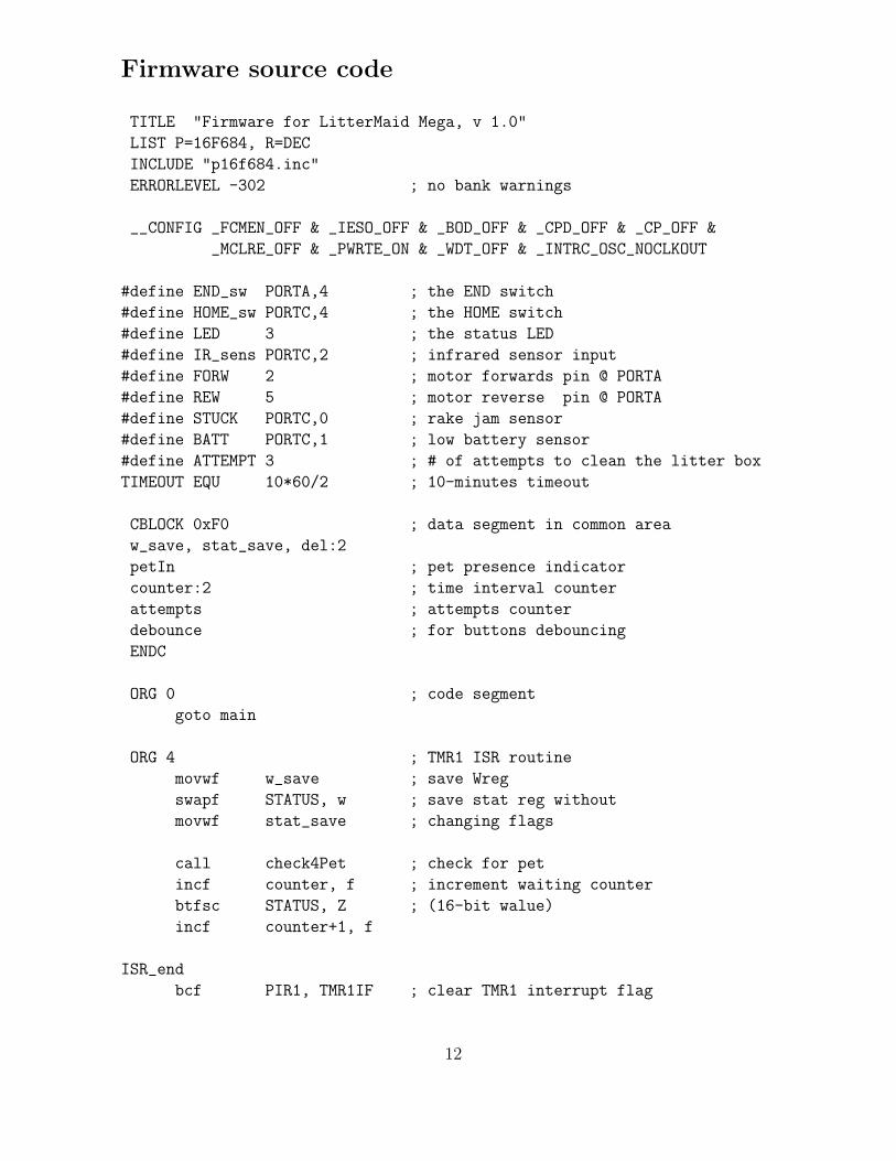
Firmware source code
TITLE "Firmware for LitterMaid Mega, v 1.0"
LIST P=16F684, R=DEC
INCLUDE "p16f684.inc"
ERRORLEVEL -302 ; no bank warnings
__CONFIG _FCMEN_OFF & _IESO_OFF & _BOD_OFF & _CPD_OFF & _CP_OFF &
_MCLRE_OFF & _PWRTE_ON & _WDT_OFF & _INTRC_OSC_NOCLKOUT
#define END_sw PORTA,4 ; the END switch
#define HOME_sw PORTC,4 ; the HOME switch
#define LED 3 ; the status LED
#define IR_sens PORTC,2 ; infrared sensor input
#define FORW 2 ; motor forwards pin @ PORTA
#define REW 5 ; motor reverse pin @ PORTA
#define STUCK PORTC,0 ; rake jam sensor
#define BATT PORTC,1 ; low battery sensor
#define ATTEMPT 3 ; # of attempts to clean the litter box
TIMEOUT EQU 10*60/2 ; 10-minutes timeout
CBLOCK 0xF0 ; data segment in common area
w_save, stat_save, del:2
petIn ; pet presence indicator
counter:2 ; time interval counter
attempts ; attempts counter
debounce ; for buttons debouncing
ENDC
ORG 0 ; code segment
goto main
ORG 4 ; TMR1 ISR routine
movwf w_save ; save Wreg
swapf STATUS, w ; save stat reg without
movwf stat_save ; changing flags
call check4Pet ; check for pet
incf counter, f ; increment waiting counter
btfsc STATUS, Z ; (16-bit walue)
incf counter+1, f
ISR_end
bcf PIR1, TMR1IF ; clear TMR1 interrupt flag
12
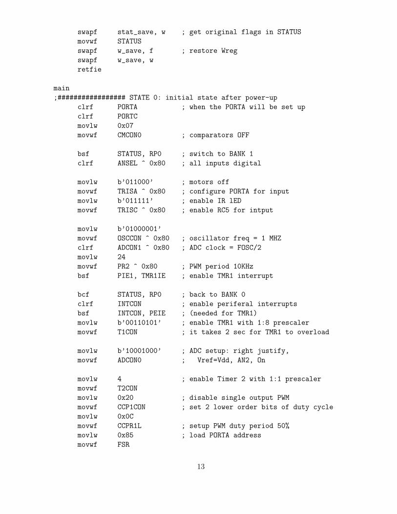
swapf stat_save, w ; get original flags in STATUS
movwf STATUS
swapf w_save, f ; restore Wreg
swapf w_save, w
retfie
main
;################# STATE 0: initial state after power-up
clrf PORTA ; when the PORTA will be set up
clrf PORTC
movlw 0x07
movwf CMCON0 ; comparators OFF
bsf STATUS, RP0 ; switch to BANK 1
clrf ANSEL ^ 0x80 ; all inputs digital
movlw b’011000’ ; motors off
movwf TRISA ^ 0x80 ; configure PORTA for input
movlw b’011111’ ; enable IR lED
movwf TRISC ^ 0x80 ; enable RC5 for intput
movlw b’01000001’
movwf OSCCON ^ 0x80 ; oscillator freq = 1 MHZ
clrf ADCON1 ^ 0x80 ; ADC clock = FOSC/2
movlw 24
movwf PR2 ^ 0x80 ; PWM period 10KHz
bsf PIE1, TMR1IE ; enable TMR1 interrupt
bcf STATUS, RP0 ; back to BANK 0
clrf INTCON ; enable periferal interrupts
bsf INTCON, PEIE ; (needed for TMR1)
movlw b’00110101’ ; enable TMR1 with 1:8 prescaler
movwf T1CON ; it takes 2 sec for TMR1 to overload
movlw b’10001000’ ; ADC setup: right justify,
movwf ADCON0 ; Vref=Vdd, AN2, On
movlw 4 ; enable Timer 2 with 1:1 prescaler
movwf T2CON
movlw 0x20 ; disable single output PWM
movwf CCP1CON ; set 2 lower order bits of duty cycle
movlw 0x0C
movwf CCPR1L ; setup PWM duty period 50%
movlw 0x85 ; load PORTA address
movwf FSR
13
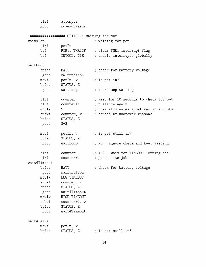
clrf attempts
goto moveForwards
;################# STATE 1: waiting for pet
wait4Pet ; waiting for pet
clrf petIn
bcf PIR1, TMR1IF ; clear TMR1 interrupt flag
bsf INTCON, GIE ; enable interrupts globally
waitLoop
btfsc BATT ; check for battery voltage
goto malfunction
movf petIn, w ; is pet in?
btfsc STATUS, Z
goto waitLoop ; NO - keep waiting
clrf counter ; wait for 10 seconds to check for pet
clrf counter+1 ; presence again
movlw 5 ; this eliminates short ray interrupts
subwf counter, w ; caused by whatever reasons
btfss STATUS, Z
goto $-3
movf petIn, w ; is pet still in?
btfsc STATUS, Z
goto waitLoop ; No - ignore check and keep waiting
clrf counter ; YES - wait for TIMEOUT letting the
clrf counter+1 ; pet do its job
wait4Timeout
btfsc BATT ; check for battery voltage
goto malfunction
movlw LOW TIMEOUT
subwf counter, w
btfss STATUS, Z
goto wait4Timeout
movlw HIGH TIMEOUT
subwf counter+1, w
btfss STATUS, Z
goto wait4Timeout
wait4Leave
movf petIn, w
btfsc STATUS, Z ; is pet still in?
14

goto startCleaning ; NO - start cleanup
movlw LOW 60000
movwf del ; YES - wait another minute for pet
movlw HIGH 60000 ; to leave and check again
movwf del+1
call delay
goto wait4Leave
startCleaning
clrf attempts ; clear the attempts counter
goto moveForwards ; at the beginning of cleaning
;################# STATE 2: move rake forwards to clean the litter box
moveForwards ; move rake towards the litter can
bcf INTCON, GIE ; disable interrupts globally
incf attempts, f ; increment attempts counter
btfsc END_sw ; is rake at its end position?
goto moveBackwards ; YES - move backwards
bcf INDF, REW ; stop rake
bsf INDF, FORW ; move rake forwards
clrf debounce
decf debounce, f ; Z=0 is guaranteed
bcf debounce, 7
forwLoop
btfsc END_sw ; check if the end position is reached
decf debounce, f
btfsc STATUS, Z
goto rakeAtEnd
btfsc BATT ; check for battery voltage
goto malfunction
btfss STUCK ; check if rake is stuck
goto forwLoop ; all OK - keep going
bcf INDF, FORW ; stop the rake
call checkAttempt ; it was not the last one
movlw LOW 1000 ; make another attempt after 1 sec
movwf del
movlw HIGH 1000
movwf del+1
call delay
goto moveBackwards
rakeAtEnd
bcf INDF, FORW ; stop the rake
movlw LOW 3000 ; delay at the rake end position
15
movwf del ; to let the stuff drop into the cab
movlw HIGH 3000
movwf del+1
call delay
clrf attempts ; no more attempts are needed
goto moveBackwards ; move the rake back home
;################# STATE 3: move rake to home position
moveBackwards ; return rake to home position
bcf INTCON, GIE ; disable interrupts globally
bcf INDF, FORW ; stop rake
bsf INDF, REW ; move rake home
clrf debounce
decf debounce, f ; Z=0 is guaranteed
bcf debounce, 7
backLoop
btfsc HOME_sw ; chek if home position is reached
decf debounce, f
btfsc STATUS, Z
goto rakeAtHome
btfsc BATT ; check for battery voltage
goto malfunction
btfss STUCK ; check if rake is stuck
goto backLoop ; all OK - keep going
goto malfunction ; stop service if rake is stuck
rakeAtHome
bcf INDF, REW ; stop the rake
movf attempts, w ; counter is non-zero if rake is stuck
btfsc STATUS, Z ; we give it another chance
goto wait4Pet
movlw LOW 1000 ; make another attempt after 1 sec
movwf del
movlw HIGH 1000
movwf del+1
call delay
goto moveForwards
;################# STATE 4: termina state - blink the LED
malfunction
bcf INTCON, GIE ; disable interrupts globally
bcf INDF, REW ; stop the rake
bcf INDF, FORW
movlw 0x87 ; setup for blinking the LED
16

movwf FSR ; FSR points to TRISC
movlw 1 << LED
xorwf INDF, f ; start blinking LED
movlw LOW 500
movwf del ; THIS IS A FINAL STATE
movlw HIGH 500 ; EXIT FORM IT IS ONLY POSSIBLE
movwf del+1 ; BY RESETTING THE DEVICE
call delay ; BY TURNING IT OFF AND ON
goto $-7
;;;;;;;;;;;;;;;;;;;PROCEDURES
check4Pet ; check for pet presence
movlw 0x0C
iorwf CCP1CON, f ; enable IR transmitter
movlw 1 ; timeout in milliseconds
movwf del
clrf del+1
call delay ; short delay
clrf petIn ; petIn = 1 if pet is in
btfss IR_sens ; and 0 otherwise
incf petIn, f
movlw 0xF0
andwf CCP1CON, f ; disable IR transmitter
return
checkAttempt ; check if the current attempt
movf attempts, w ; number exceeds
sublw ATTEMPT ; the max number of attempts
btfss STATUS, C ; if not, the function returns
goto malfunction ; otherwise, the device enters
return ; the final state
delay ; a delay for del milliseconds
movlw 50 ; delay duration is passed in del
sublw 1 ; this loop takes 20us*50 = 1ms
sublw 0 ; for PIC @ 1 Mhz
btfss STATUS, Z
goto $-3
movf del, w ; decrement delay counter
btfsc STATUS, Z
17

decf del+1, f
decf del, f
movf del, w ; del=0?
iorwf del+1, w
btfss STATUS, Z
goto delay
return
END
18
Related Documents