Owners Manual Head Office: P.O. Box 2018 Hilton Highway, Washdyke Timaru, New Zealand Telephone (03) 688 2029 Facsimile (03) 688 2821 Australian Branch: 4B Silverton Close Laverton North 3026 Melbourne, Australia Telephone (03) 9314-9666 Facsimile (03) 9314-6810 Renovator AS6000 Setup & Calibration ORIGINAL INSTRUCTIONS Pt. No. 67409 Issue 0314

Welcome message from author
This document is posted to help you gain knowledge. Please leave a comment to let me know what you think about it! Share it to your friends and learn new things together.
Transcript
Owners Manual
Head Office:P.O. Box 2018Hilton Highway, WashdykeTimaru, New ZealandTelephone (03) 688 2029Facsimile (03) 688 2821
Australian Branch:4B Silverton CloseLaverton North 3026Melbourne, AustraliaTelephone (03) 9314-9666Facsimile (03) 9314-6810
Renovator AS6000Setup & Calibration
ORIGINAL INSTRUCTIONS
Pt. No. 67409Issue 0314

1
Pt. No. 67409Issue 0314
Introduction . . . . . . . . . . . . . . . . . . . . . . . . . . . . . . . . . . . . . . 2
Acquisition & Warranty . . . . . . . . . . . . . . . . . . . . . . . . . . . . . . . . . . . . . . 2
Disclaimer . . . . . . . . . . . . . . . . . . . . . . . . . . . . . . . . . . . . . . 2
Description of Machine Working Principle. . . . . . . . . . . . . . . . . . . . . . . 3
Specification Dimensions & Capacities . . . . . . . . . . . . . . . . 4, 5
SAFETY - General Safety Symbols on Machine . . . . . . . . . . . . . . 6 Operator Safety . . . . . . . . . . . . . . . . . . . . . . . . 7 Be Prepared for Emergencies. . . . . . . . . . . . . 7 Appropriate Dress . . . . . . . . . . . . . . . . . . . . . . 8 Transport This Machine Safely . . . . . . . . . . . . 8 Handle Agricultural Chemicals Safely . . . . . . . 9 Avoid High Pressure Fluids. . . . . . . . . . . . . . . 9 Safe Work Practices . . . . . . . . . . . . . . . . . . . . 9 Practise Safe Maintenance . . . . . . . . . . . . . . . 10 SAFETY - Machine Specific Hazard Points . . . . . . . . . . . . . . . . . . . . . . . . . 11 Safety Decals & Safety Guards. . . . . . . . . . . . 13 Transport . . . . . . . . . . . . . . . . . . . . . . . . . . . . . . . . . . . . . . 14
Setup, Calibration & Operating Procedure Setting Depth & Levelling . . . . . . . . . . . . . . . . 16 Tyred Roller Operation . . . . . . . . . . . . . . . . . . 17 General Operation. . . . . . . . . . . . . . . . . . . . . . 18 Read Before Operation . . . . . . . . . . . . . . . . . . 20 Pre-Calibration Setup . . . . . . . . . . . . . . . . . . . 25 Calibration . . . . . . . . . . . . . . . . . . . . . . . . . . . . 26 Sowing Chart -NORMAL seed . . . . . . . . . . . . 30 Sowing Chart -FINE seed . . . . . . . . . . . . . . . . 31 Airflow & Fan Speed . . . . . . . . . . . . . . . . . . . . 32 Blank Page for your Calibration Notes . . . . . . 33
Maintenance & Care General . . . . . . . . . . . . . . . . . . . . . . . . . . . . . . 34 Lubrication Instructions . . . . . . . . . . . . . . . . . . 35 Maintenance Schedule . . . . . . . . . . . . . . . . . . 36 Storage . . . . . . . . . . . . . . . . . . . . . . . . . . . . . . 37 ProSeries Head Unit Error Codes . . . . . . . . . . 38
Renovator AS6000 Contents Page
2
Introduction
Acquisition & WarrantyOn delivery of your new Duncan Renovator AS6000 please check that the machine is not damaged. In cases of shipping damage, please ask your dealer to arrange for the appropriate claim to be lodged immediately. Assemble any parts supplied loose and inspect your machine with the aid of this manual to familiarise yourself with its features. If you have any queries ask your dealer straight away. The machine is covered by our 12 month warranty on faulty parts, subject to normal use.
Record below the serial number of your machine and keep it in a secure place to help trace the machine and assist us when you order parts.
The Owner’s ManualYour new Duncan Renovator AS6000 will give long and efficient service if given normal care and operated properly.
This owner’s manual is provided so that you can become thoroughly familiar with the design of the machine and to furnish information on correct operation, adjustment and maintenance. Only persons well acquainted with these guidelines should be allowed to use the equipment.
A separate illustrated parts section has been provided so that if any parts are required your dealer will be able to supply them by reference to part numbers.
The manual is considered as part of your machine and must remain with the machine when it is sold.
Right and left hand references in this manual are determined by standing behind the machine and facing in the direction of travel.
Model: . . . . . . . . . . . . . . . . . . . . . . . . . . . . . . . . . . . . . . Serial No: . . . . . . . . . . . . . . . . . . . . . . . . . . . . . . . . . . .
Owner:. . . . . . . . . . . . . . . . . . . . . . . . . . . . . . . . . . . . . .
. . . . . . . . . . . . . . . . . . . . . . . . . . . . . . . . . . . . . . . . . . . . .
. . . . . . . . . . . . . . . . . . . . . . . . . . . . . . . . . . . . . . . . . . . . .
Delivery Date:. . . . . . . . . . . . . . . . . . . . . . . . . . . . . . . Dealer:. . . . . . . . . . . . . . . . . . . . . . . . . . . . . . . . . . . . . .
. . . . . . . . . . . . . . . . . . . . . . . . . . . . . . . . . . . . . . . . . . . . .
. . . . . . . . . . . . . . . . . . . . . . . . . . . . . . . . . . . . . . . . . . . . .
Disclaimer Every effort has been made to ensure that the information in this manual was accurate and up to date at the time of going to press. Clough Agriculture reserves the right to make subsequent changes to the machine, where necessary, without notification.
The Company will not be responsible for any damage or consequential loss arising out of misinterpretation or failure to follow recommended procedures. Nor will it be liable for any damage caused by or arising out of modification or misuse of its product.
The owner has a responsibility to protect himself and others by observing all safety information and by ensuring all operators are well acquainted with the safety information, trained in the correct use of the machine and applying safe work practices.
This Document contains the Original Operating Instructions for this machine and are verified by the Manufacturer.
Signed:......................................
Product Development Manager
3
Pt. No. 67409Issue 0314
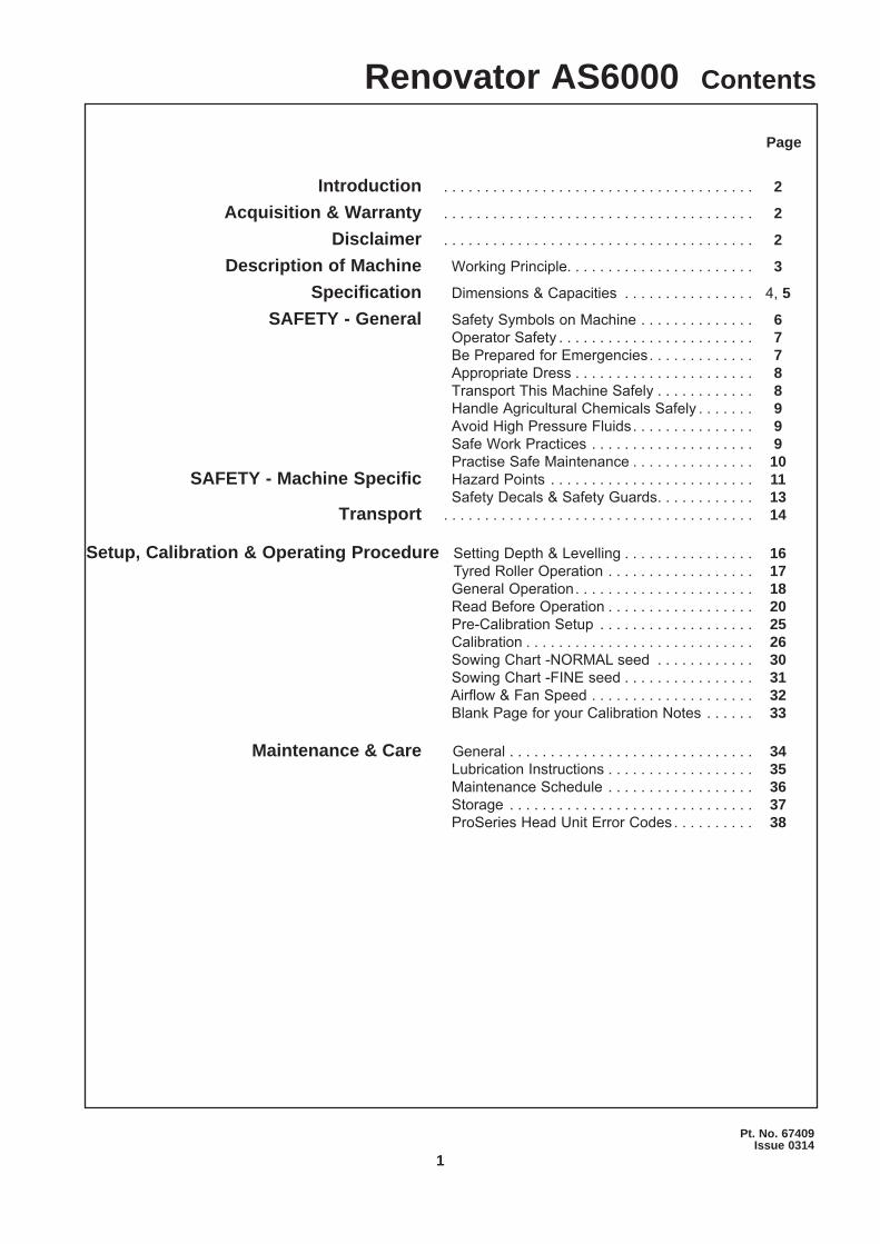
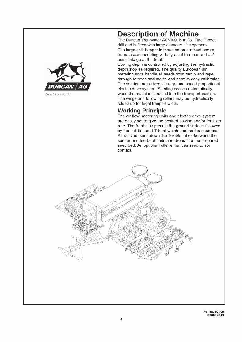
Description of MachineThe Duncan ‘Renovator AS6000’ is a Coil Tine T-boot drill and is fitted with large diameter disc openers.The large split hopper is mounted on a robust centre frame accommodating wide tyres at the rear and a 2 point linkage at the front.Sowing depth is controlled by adjusting the hydraulic depth stop as required. The quality European air metering units handle all seeds from turnip and rape through to peas and maize and permits easy calibration. The seeders are driven via a ground speed proportional electric drive system. Seeding ceases automatically when the machine is raised into the transport postion.The wings and following rollers may be hydraulically folded up for legal tranport width.
Working PrincipleThe air flow, metering units and electric drive system are easily set to give the desired sowing and/or fertilizer rate. The front disc precuts the ground surface followed by the coil tine and T-boot which creates the seed bed. Air delivers seed down the flexible tubes between the seeder and tee-boot units and drops into the prepared seed bed. An optional roller enhances seed to soil contact.
4
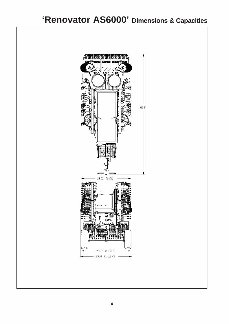
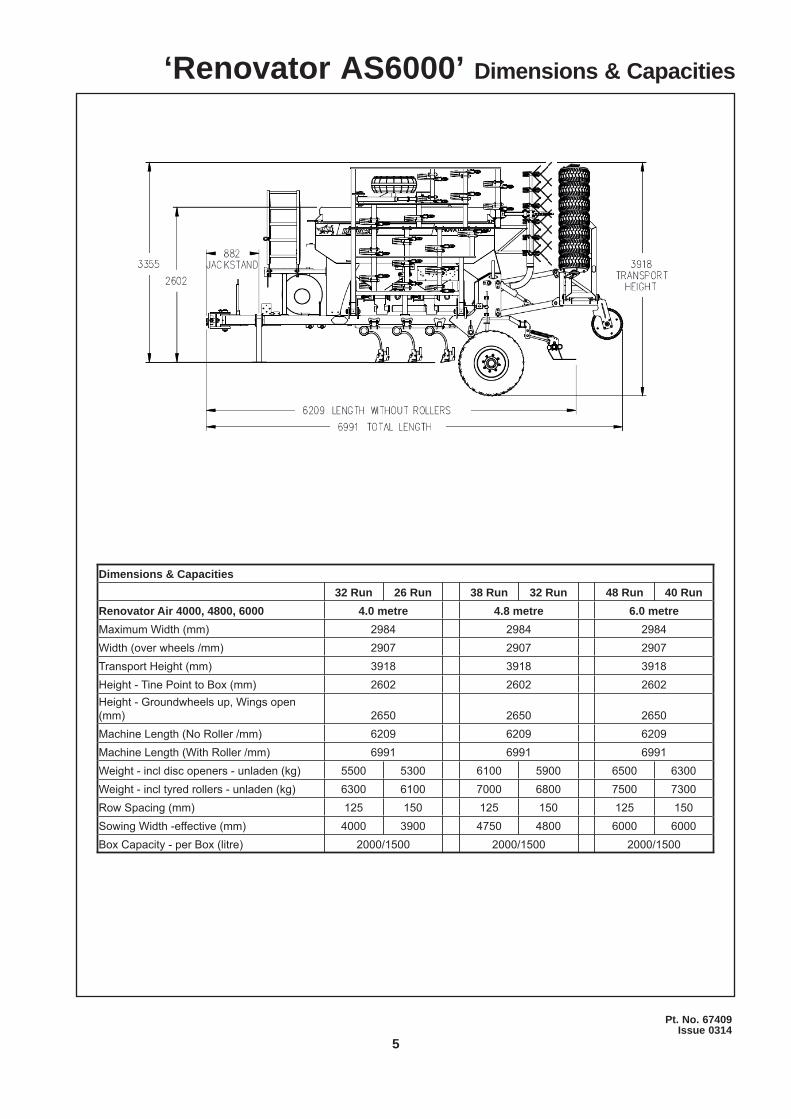
‘Renovator AS6000’ Dimensions & Capacities
5
Pt. No. 67409Issue 0314
Dimensions & Capacities32 Run 26 Run 38 Run 32 Run 48 Run 40 Run
Renovator Air 4000, 4800, 6000 4.0 metre 4.8 metre 6.0 metreMaximum Width (mm) 2984 2984 2984Width (over wheels /mm) 2907 2907 2907Transport Height (mm) 3918 3918 3918Height - Tine Point to Box (mm) 2602 2602 2602Height - Groundwheels up, Wings open (mm) 2650 2650 2650Machine Length (No Roller /mm) 6209 6209 6209Machine Length (With Roller /mm) 6991 6991 6991Weight - incl disc openers - unladen (kg) 5500 5300 6100 5900 6500 6300Weight - incl tyred rollers - unladen (kg) 6300 6100 7000 6800 7500 7300Row Spacing (mm) 125 150 125 150 125 150Sowing Width -effective (mm) 4000 3900 4750 4800 6000 6000Box Capacity - per Box (litre) 2000/1500 2000/1500 2000/1500
‘Renovator AS6000’ Dimensions & Capacities

6
Do not ride or allow passengers on the machine.Under no circumstances are passengers to be permitted on the machine while it is in operation or being transported. Any footboards and/or footsteps are provided solely for the purpose of preparing the machine for use.
Keep clothing and body extremities well clear of pinch points while the machine is operating (seeding or calibrating). Keep well clear of moving parts at all times.These signs typically occur wherever trapping points exist. These include drive chains, sprockets, shafts, wheels, discs, pivot points, etc. Guards are provided with the machine for safety reasons (where practical without compromising machine performance). Ensure these are always fitted during operation.
Always exercise extreme caution in the vicinity of sharp edges and points.Where possible guards are provided with the machine for safety reasons (where practical without compromising machine performance). Ensure these are always fitted during operation.
Footboards, footsteps, drawbars and other machine surfaces may be slippery when wet. Apply extra caution in wet conditions and in the early morning when surfaces are wet.
Keep Clear. (It is dangerous to be in this area when the machine is operating.)
! ATTENTIONOn the machine important safety information is indicated by these symbols.
These highlight general safety aspects in regard to the machine rather than specific hazards.
‘Renovator AS6000’ Safety

7
Pt. No. 67409Issue 0314
SAFETY - GeneralThis section of the manual offers general guidelines for the safe operation of machinery. It does not replace local safety regulations. These guidelines were current at the time of publication, but may be superseded by later regulations.
Clough Agriculture has made every effort to highlight all risks to personnel or property. Owners and operators have a responsibility to exercise care and safe work practices at all times in the vicinity of the machine.
Owners are advised to keep up to date on safety issues and to communicate these to all users of the machine.
Contact the Occupational Safety and Health Service (OSH) for further information about general safety aspects. If you have safety concerns specifically related to this machine, contact your dealer immediately.
Operator SafetyRead this manual carefully before operating new equipment. Learn how to use this machine safely.Be thoroughly familiar with the controls and the proper use of the equipment before using it.
Take careful note of all safety instructions both in this manual and on the machine itself. Failure to comply with instructions could result in personal injury and/or damage to the machine.
Replace missing or damaged safety signs on the machine and ensure that these remain clearly visible.
It is the owner’s responsibility to ensure that anyone who operates, adjusts, lubricates, maintains, cleans or uses the machine in any way has had suitable instruction and is familiar with the information in this manual (particularly with regard to safety aspects).
Operators and other users of the machine should be aware of potential hazards and operating limitations.
Be Prepared for EmergenciesKeep a first aid kit and fire extinguisher handy.
Keep emergency numbers for doctors, ambulance, hospital and fire department near your telephone.
N.B. Throughout this manual important safety information is indicated by these symbols in the margin:
A prohibition should be observed under all circumstances.
A warning indicates a hazard that could cause death or injury if the
warning is ignored.
A caution indicates a hazard that may cause damage to property if
the caution is ignored.
‘Renovator AS6000’ Safety
8
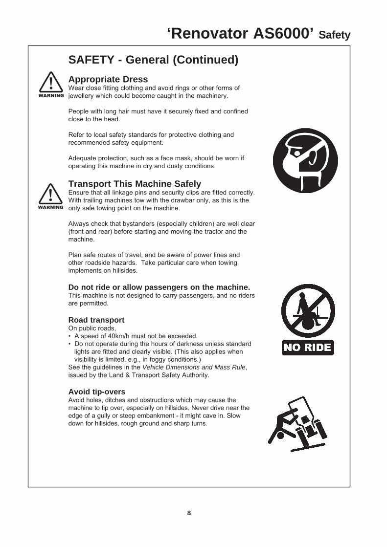
SAFETY - General (Continued)Appropriate DressWear close fitting clothing and avoid rings or other forms of jewellery which could become caught in the machinery.
People with long hair must have it securely fixed and confined close to the head.
Refer to local safety standards for protective clothing and recommended safety equipment.
Adequate protection, such as a face mask, should be worn if operating this machine in dry and dusty conditions.
Transport This Machine SafelyEnsure that all linkage pins and security clips are fitted correctly. With trailing machines tow with the drawbar only, as this is the only safe towing point on the machine.
Always check that bystanders (especially children) are well clear (front and rear) before starting and moving the tractor and the machine.
Plan safe routes of travel, and be aware of power lines and other roadside hazards. Take particular care when towing implements on hillsides.
Do not ride or allow passengers on the machine. This machine is not designed to carry passengers, and no riders are permitted.
Road transportOn public roads,• A speed of 40km/h must not be exceeded.• Do not operate during the hours of darkness unless standard lights are fitted and clearly visible. (This also applies when visibility is limited, e.g., in foggy conditions.)See the guidelines in the Vehicle Dimensions and Mass Rule, issued by the Land & Transport Safety Authority.
Avoid tip-oversAvoid holes, ditches and obstructions which may cause the machine to tip over, especially on hillsides. Never drive near the edge of a gully or steep embankment - it might cave in. Slow down for hillsides, rough ground and sharp turns.
‘Renovator AS6000’ Safety
9
Pt. No. 67409Issue 0314
SAFETY - General (Continued)
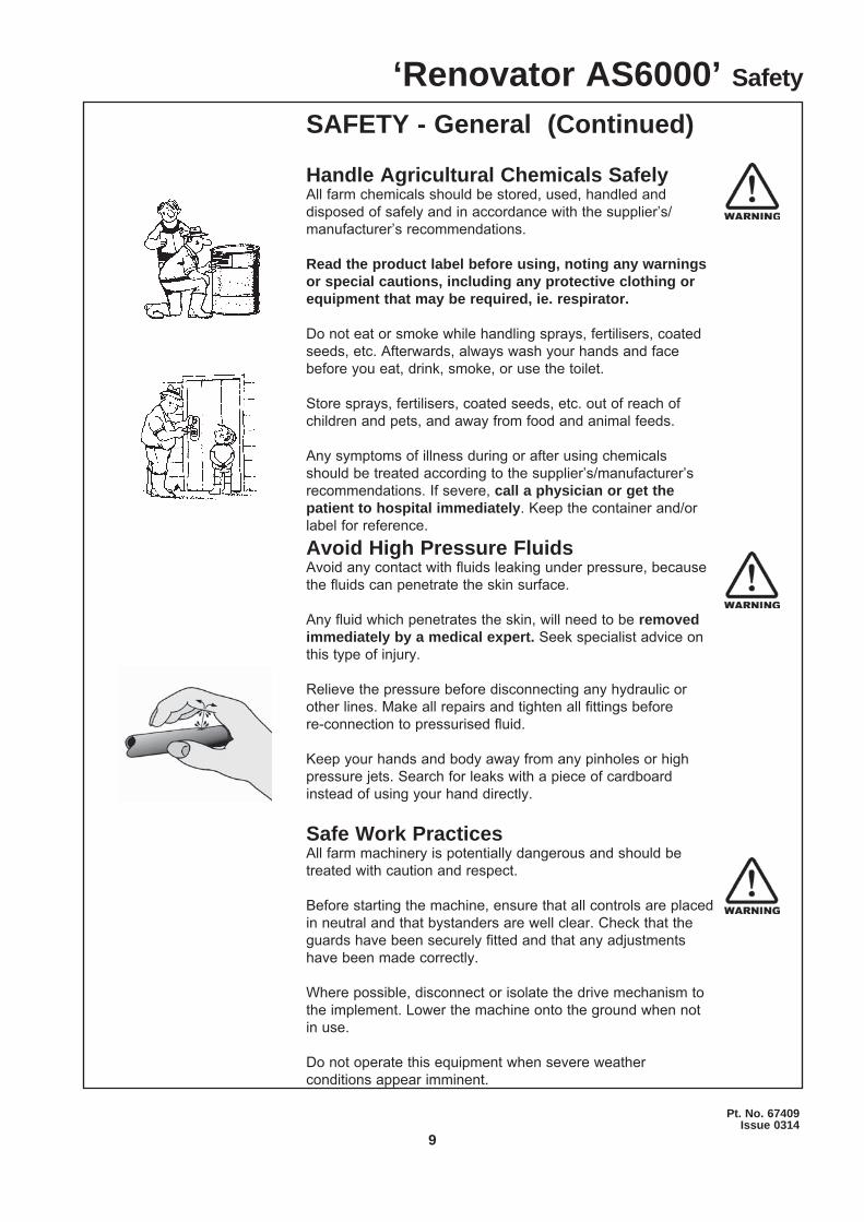
Handle Agricultural Chemicals SafelyAll farm chemicals should be stored, used, handled and disposed of safely and in accordance with the supplier’s/manufacturer’s recommendations.
Read the product label before using, noting any warnings or special cautions, including any protective clothing or equipment that may be required, ie. respirator.
Do not eat or smoke while handling sprays, fertilisers, coated seeds, etc. Afterwards, always wash your hands and face before you eat, drink, smoke, or use the toilet.
Store sprays, fertilisers, coated seeds, etc. out of reach of children and pets, and away from food and animal feeds.
Any symptoms of illness during or after using chemicals should be treated according to the supplier’s/manufacturer’s recommendations. If severe, call a physician or get the patient to hospital immediately. Keep the container and/or label for reference.
Avoid High Pressure FluidsAvoid any contact with fluids leaking under pressure, because the fluids can penetrate the skin surface.
Any fluid which penetrates the skin, will need to be removed immediately by a medical expert. Seek specialist advice on this type of injury.
Relieve the pressure before disconnecting any hydraulic or other lines. Make all repairs and tighten all fittings before re-connection to pressurised fluid.
Keep your hands and body away from any pinholes or high pressure jets. Search for leaks with a piece of cardboard instead of using your hand directly.
Safe Work PracticesAll farm machinery is potentially dangerous and should be treated with caution and respect.
Before starting the machine, ensure that all controls are placed in neutral and that bystanders are well clear. Check that the guards have been securely fitted and that any adjustments have been made correctly.
Where possible, disconnect or isolate the drive mechanism to the implement. Lower the machine onto the ground when not in use.
Do not operate this equipment when severe weather conditions appear imminent.
‘Renovator AS6000’ Safety
10
SAFETY - General (Continued)
Practice Safe MaintenanceKeep the machine in safe working condition. Routine maintenance and regular servicing will help reduce risks and prolong the life of the machine.
General MaintenanceAccidents occur most frequently during servicing and repair. The following general rules must be followed when maintaining or working with machinery:• All operating and maintenance manuals must be read before and referred to while using or servicing any piece ofequipment.• Turn off all machinery power sources and isolate the machine before making adjustments, doing lubrication, repairs or any other maintenance on the machine.• Ensure that the machine hydraulics are disconnected from the power source.• Wear gloves when handling components with cutting edges, such as any ground cutting components.• Beware of hazards created by springs under tension or compression when dismantling or maintaining the machine.• It is recommended that you clean the machine with a water blaster or similar apparatus before commencing maintenance.
Make Sure the Machine is Well SupportedWhen machinery is fitted with hydraulics, do not rely on the hydraulics to support the machine. During maintenance or while making adjustments under the machine, always lock the hydraulics and support the machine securely. Place blocks or other stable supports under elevated parts before working on these.
Electrical MaintenanceDisconnect the electrical supply from the tractor before doing any electrical maintenance.
Welding With electronic equipment in modern tractors it is advisable to disconnect the machine from the tractor, or at least disconnect the alternator and battery before attempting any welding.
Use Only Genuine Spare PartsUnauthorised modifications or non-genuine spare parts may be hazardous and impair the safe operation and working life of the machine.
Excess lubricants must be disposed of safely so as not to become a hazard.
‘Renovator AS6000’ Safety
11
Pt. No. 67409Issue 0314
SAFETY - Machine Specific
This section of the manual gives specific guidelines for the safe operation of the Renovator AS6000. These guidelines were current at the time of publication, but may be superseded by later circumstances. They do not necessarily cover every possible hazard and must be read in conjunction with the SAFETY - General section (Page 7 to 10).
Hazard Points on the Renovator AS6000The lists below are not all-inclusive and serve only to highlight the more obvious areas of risk.
The decals attached to the machine are a general reminder that there are hazardous areas on the machine, rather than specifically highlighting all possible hazards.For decal locations on machine, refer Page 13.
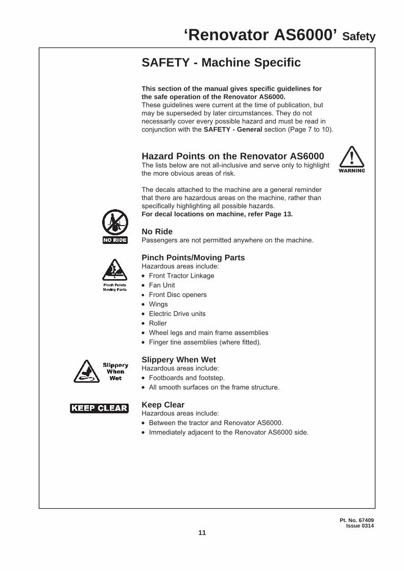
No RidePassengers are not permitted anywhere on the machine.
Pinch Points/Moving PartsHazardous areas include:• Front Tractor Linkage• Fan Unit• Front Disc openers• Wings• Electric Drive units• Roller• Wheel legs and main frame assemblies• Finger tine assemblies (where fitted).
Slippery When WetHazardous areas include:• Footboards and footstep. • All smooth surfaces on the frame structure.
Keep ClearHazardous areas include:• Between the tractor and Renovator AS6000.• Immediately adjacent to the Renovator AS6000 side.
‘Renovator AS6000’ Safety
12
SAFETY - Machine Specific(Continued)
Hazard Points on the Renovator AS6000(Continued)For guard locations on machine, refer Page 13.
TransportThe two wheels located at the rear of the machine are for the purpose of controlling sowing depth. These are also used to support the machine weight.
Important - Refer to safety cautions in the Transport section, page 15 of the manual. Ensure that all linkage pins and security clips are fitted correctly.
MaintenanceRefer Page 34 for reference to the Maintenance and Care section of the manual.
LubricationRefer Page 34 for reference to the Maintenance and Care section of the manual.
‘Renovator AS6000’ Seed Drill Safety
13
Pt. No. 67409Issue 0314
SAFETY - Machine Specific(Continued)
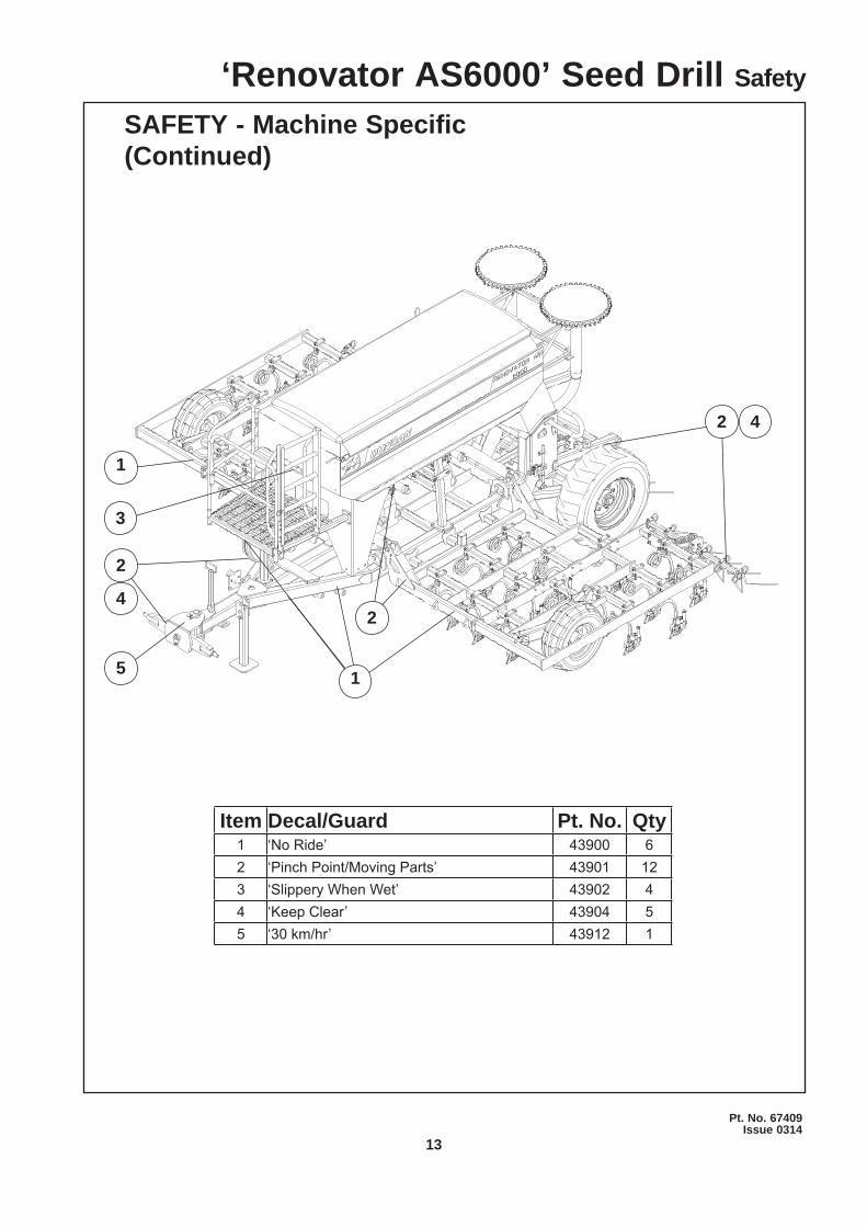
Item Decal/Guard Pt. No. Qty1 ‘No Ride’ 43900 62 ‘Pinch Point/Moving Parts’ 43901 123 ‘Slippery When Wet’ 43902 44 ‘Keep Clear’ 43904 55 ‘30 km/hr’ 43912 1
‘Renovator AS6000’ Seed Drill Safety
4
1
1
2
2
2
3
4
5
14
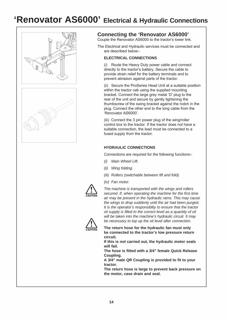
Connecting the ‘Renovator AS6000’Couple the Renovator AS6000 to the tractor’s lower link.
The Electrical and Hydraulic services must be connected and are described below:-
ELECTRICAL CONNECTIONS
(i) Route the Heavy Duty power cable and connect directly to the tractor’s battery. Secure the cable to provide strain relief for the battery terminals and to prevent abrasion against parts of the tractor.
(ii) Secure the ProSeries Head Unit at a suitable position within the tractor cab using the supplied mounting bracket. Connect the large grey metal ‘D’ plug to the rear of the unit and secure by gently tightening the thumbscrew of the swing bracket against the notch in the plug. Connect the other end to the long cable from the ‘Renovator AS6000’.
(iii) Connect the 3 pin power plug of the wing/roller control box to the tractor. If the tractor does not have a suitable connection, the lead must be connected to a fused supply from the tractor.
HYDRAULIC CONNECTIONS
Connections are required for the following functions:-
(i) Main Wheel Lift.
(ii) Wing folding.
(iii) Rollers (switchable between lift and fold).
(iv) Fan motor.
The machine is transported with the wings and rollers secured. If, when operating the machine for the first time air may be present in the hydraulic rams. This may cause the wings to drop suddenly until the air had been purged. It is the operator’s responsiblity to ensure that the tractor oil supply is filled to the correct level as a quantity of oil will be taken into the machine’s hydraulic circuit. It may be necessary to top up the oil level after connection.
The return hose for the hydraulic fan must only be connected to the tractor’s low pressure return circuit.
If this is not carried out, the hydraulic motor seals will fail.
The hose is fitted with a 3/4” female Quick Release Coupling.
A 3/4” male QR Coupling is provided to fit to your tractor.
The return hose is large to prevent back pressure on the motor, case drain and seal.
‘Renovator AS6000’ Electrical & Hydraulic Connections
15
Pt. No. 67409Issue 0314
‘Renovator AS6000’ Transport
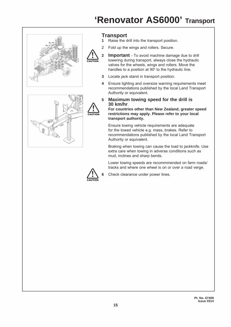
Transport1 Raise the drill into the transport position.
2 Fold up the wings and rollers. Secure.
2 Important - To avoid machine damage due to drill lowering during transport, always close the hydraulic valves for the wheels, wings and rollers. Move the handles to a position at 900 to the hydraulic line.
3 Locate jack stand in transport position.
4 Ensure lighting and oversize warning requirements meet recommendations published by the local Land Transport Authority or equivalent.
5 Maximum towing speed for the drill is 30 km/hr. For countries other than New Zealand, greater speed
restrictions may apply. Please refer to your local transport authority.
Ensure towing vehicle requirements are adequate for the towed vehicle e.g. mass, brakes. Refer to recommendations published by the local Land Transport Authority or equivalent.
Braking when towing can cause the load to jackknife. Use extra care when towing in adverse conditions such as mud, inclines and sharp bends.
Lower towing speeds are recommmended on farm roads/tracks and where one wheel is on or over a road verge.
6 Check clearance under power lines.
16
‘Renovator AS6000’ Setting Depth & Levelling
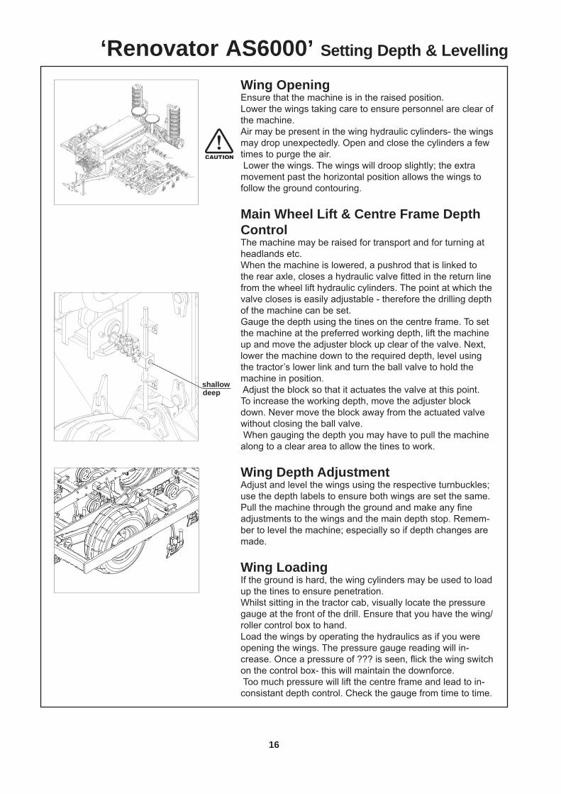
Wing Opening Ensure that the machine is in the raised position. Lower the wings taking care to ensure personnel are clear of the machine.Air may be present in the wing hydraulic cylinders- the wings may drop unexpectedly. Open and close the cylinders a few times to purge the air. Lower the wings. The wings will droop slightly; the extra movement past the horizontal position allows the wings to follow the ground contouring.
Main Wheel Lift & Centre Frame Depth ControlThe machine may be raised for transport and for turning at headlands etc.When the machine is lowered, a pushrod that is linked to the rear axle, closes a hydraulic valve fi tted in the return line from the wheel lift hydraulic cylinders. The point at which the valve closes is easily adjustable - therefore the drilling depth of the machine can be set. Gauge the depth using the tines on the centre frame. To set the machine at the preferred working depth, lift the machine up and move the adjuster block up clear of the valve. Next, lower the machine down to the required depth, level using the tractor’s lower link and turn the ball valve to hold the machine in position. Adjust the block so that it actuates the valve at this point.To increase the working depth, move the adjuster block down. Never move the block away from the actuated valve without closing the ball valve. When gauging the depth you may have to pull the machine along to a clear area to allow the tines to work.
Wing Depth AdjustmentAdjust and level the wings using the respective turnbuckles; use the depth labels to ensure both wings are set the same. Pull the machine through the ground and make any fi ne adjustments to the wings and the main depth stop. Remem-ber to level the machine; especially so if depth changes are made.
Wing LoadingIf the ground is hard, the wing cylinders may be used to load up the tines to ensure penetration.Whilst sitting in the tractor cab, visually locate the pressure gauge at the front of the drill. Ensure that you have the wing/roller control box to hand. Load the wings by operating the hydraulics as if you were opening the wings. The pressure gauge reading will in-crease. Once a pressure of ??? is seen, fl ick the wing switch on the control box- this will maintain the downforce. Too much pressure will lift the centre frame and lead to in-consistant depth control. Check the gauge from time to time.
shallowdeep
17
Pt. No. 67409Issue 0314
‘Renovator AS6000’ Tyred Roller Operation
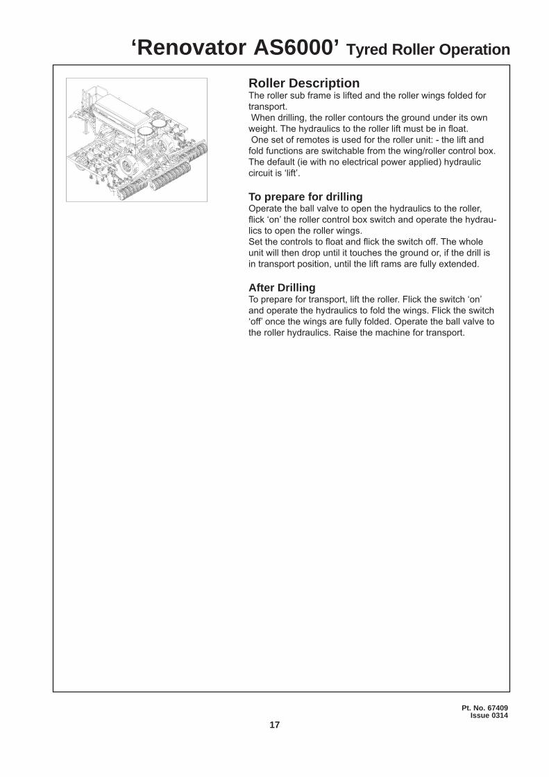
Roller Description The roller sub frame is lifted and the roller wings folded for transport. When drilling, the roller contours the ground under its own weight. The hydraulics to the roller lift must be in fl oat. One set of remotes is used for the roller unit: - the lift and fold functions are switchable from the wing/roller control box.The default (ie with no electrical power applied) hydraulic circuit is ‘lift’.
To prepare for drillingOperate the ball valve to open the hydraulics to the roller, fl ick ‘on’ the roller control box switch and operate the hydrau-lics to open the roller wings.Set the controls to fl oat and fl ick the switch off. The whole unit will then drop until it touches the ground or, if the drill is in transport position, until the lift rams are fully extended.
After DrillingTo prepare for transport, lift the roller. Flick the switch ‘on’ and operate the hydraulics to fold the wings. Flick the switch ‘off’ once the wings are fully folded. Operate the ball valve to the roller hydraulics. Raise the machine for transport.
18
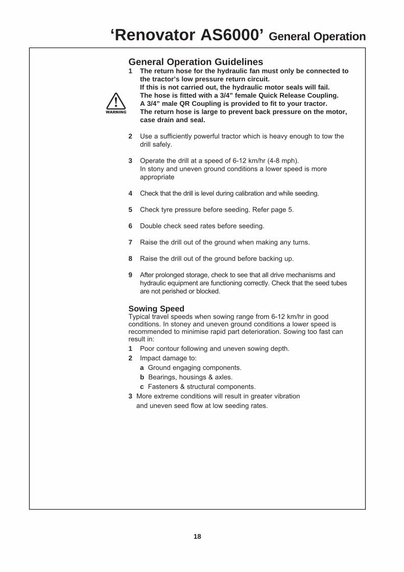
General Operation Guidelines1 The return hose for the hydraulic fan must only be connected to
the tractor’s low pressure return circuit. If this is not carried out, the hydraulic motor seals will fail. The hose is fitted with a 3/4” female Quick Release Coupling. A 3/4” male QR Coupling is provided to fit to your tractor. The return hose is large to prevent back pressure on the motor,
case drain and seal. 2 Use a sufficiently powerful tractor which is heavy enough to tow the
drill safely.
3 Operate the drill at a speed of 6-12 km/hr (4-8 mph). In stony and uneven ground conditions a lower speed is more
appropriate
4 Check that the drill is level during calibration and while seeding.
5 Check tyre pressure before seeding. Refer page 5.
6 Double check seed rates before seeding.
7 Raise the drill out of the ground when making any turns.
8 Raise the drill out of the ground before backing up.
9 After prolonged storage, check to see that all drive mechanisms and hydraulic equipment are functioning correctly. Check that the seed tubes are not perished or blocked.
Sowing SpeedTypical travel speeds when sowing range from 6-12 km/hr in good conditions. In stoney and uneven ground conditions a lower speed is recommended to minimise rapid part deterioration. Sowing too fast can result in:1 Poor contour following and uneven sowing depth.2 Impact damage to: a Ground engaging components. b Bearings, housings & axles. c Fasteners & structural components.3 More extreme conditions will result in greater vibration
and uneven seed flow at low seeding rates.
‘Renovator AS6000’ General Operation
19
Pt. No. 67409Issue 0314
Sowing Depth ControlThe sowing depth is dependent on:1 The wheel height in relation to the chassis2 Tyre pressure3 Ground condition i.e. hard or soft The wheel height in relation to the chassis is controlled using the hydraulic depth stop. With the machine raised up, adjust the position of the depth stop.
Level Drill With the rear depth set, use the tractor hydraulics to level
the machine.
Transport Position It is recommended to raise the drill into the transport
position when turning at headlands to avoid damage to the ground engaging components.
‘Renovator AS6000’ General Operation
20
‘Renovator AS6000’ Read Before Operation
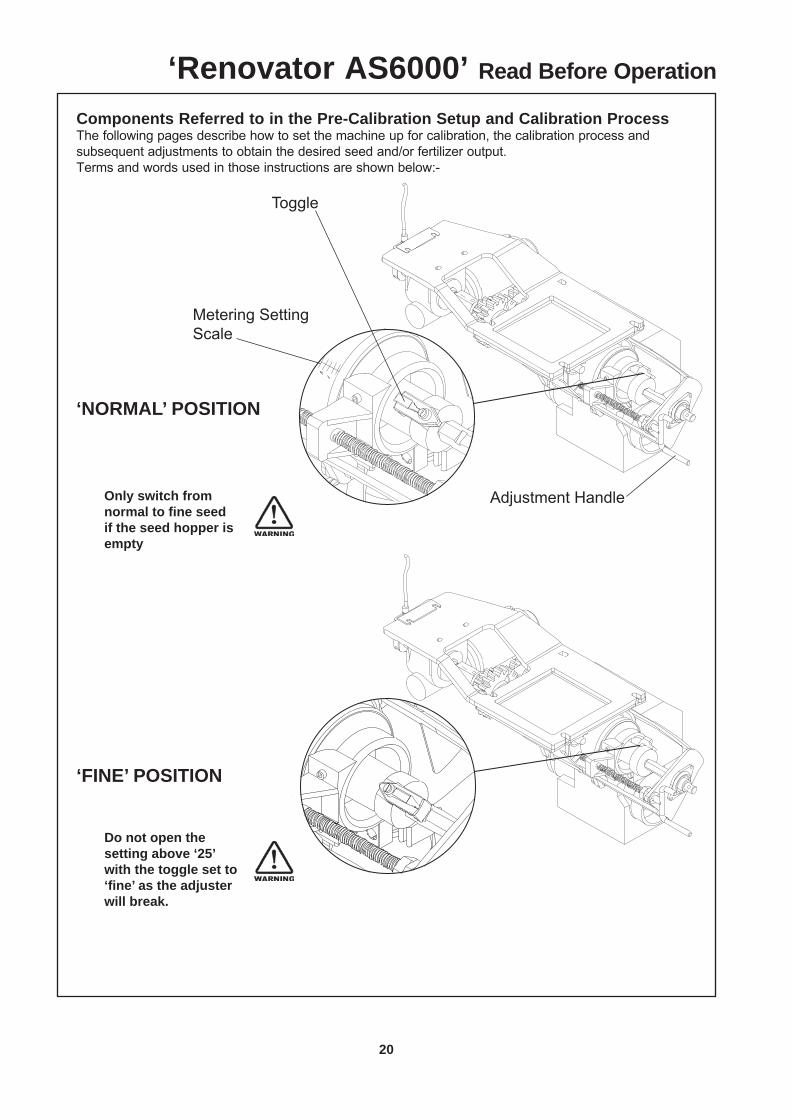
Components Referred to in the Pre-Calibration Setup and Calibration ProcessThe following pages describe how to set the machine up for calibration, the calibration process and subsequent adjustments to obtain the desired seed and/or fertilizer output.Terms and words used in those instructions are shown below:-
Adjustment Handle
Toggle
‘NORMAL’ POSITION
‘FINE’ POSITION
Only switch from normal to fi ne seed if the seed hopper is empty
Do not open the setting above ‘25’ with the toggle set to ‘fi ne’ as the adjuster will break.
Metering Setting Scale
21
Pt. No. 67409Issue 0314
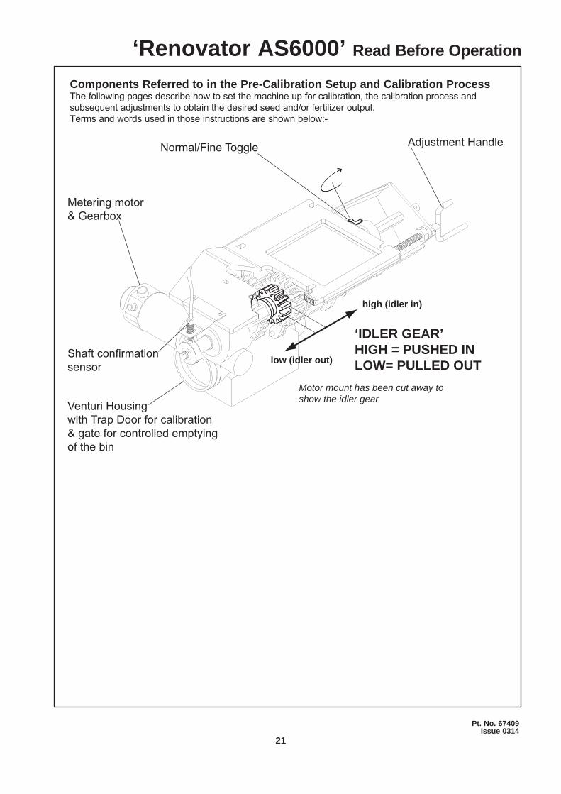
‘IDLER GEAR’HIGH = PUSHED INLOW= PULLED OUT
Adjustment HandleNormal/Fine Toggle
high (idler in)
low (idler out)
Venturi Housingwith Trap Door for calibration& gate for controlled emptying of the bin
Components Referred to in the Pre-Calibration Setup and Calibration ProcessThe following pages describe how to set the machine up for calibration, the calibration process and subsequent adjustments to obtain the desired seed and/or fertilizer output.Terms and words used in those instructions are shown below:-
‘Renovator AS6000’ Read Before Operation
Metering motor & Gearbox
Shaft confi rmation sensor
Motor mount has been cut away to show the idler gear
22
‘Renovator AS6000’ Read Before Operation
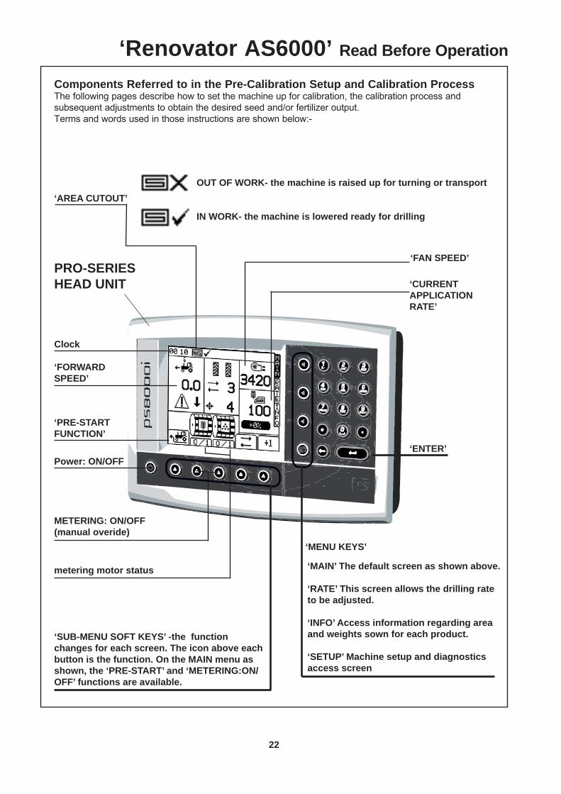
Components Referred to in the Pre-Calibration Setup and Calibration ProcessThe following pages describe how to set the machine up for calibration, the calibration process and subsequent adjustments to obtain the desired seed and/or fertilizer output.Terms and words used in those instructions are shown below:-
Clock
OUT OF WORK- the machine is raised up for turning or transport‘AREA CUTOUT’
IN WORK- the machine is lowered ready for drilling
‘FAN SPEED’
‘CURRENT APPLICATION RATE’
‘MENU KEYS’
‘MAIN’ The default screen as shown above.
‘RATE’ This screen allows the drilling rate to be adjusted.
‘INFO’ Access information regarding area and weights sown for each product.
‘SETUP’ Machine setup and diagnostics access screen
‘FORWARDSPEED’
Power: ON/OFF‘ENTER’
‘PRE-START FUNCTION’
METERING: ON/OFF(manual overide)
metering motor status
‘SUB-MENU SOFT KEYS’ -the function changes for each screen. The icon above each button is the function. On the MAIN menu as shown, the ‘PRE-START’ and ‘METERING:ON/OFF’ functions are available.
PRO-SERIESHEAD UNIT
23
Pt. No. 67409Issue 0314
‘Renovator AS6000’ Read Before Operation
Components Referred to in the Pre-Calibration Setup and Calibration ProcessThe following pages describe how to set the machine up for calibration, the calibration process and subsequent adjustments to obtain the desired seed and/or fertilizer output.Terms and words used in those instructions are shown below.
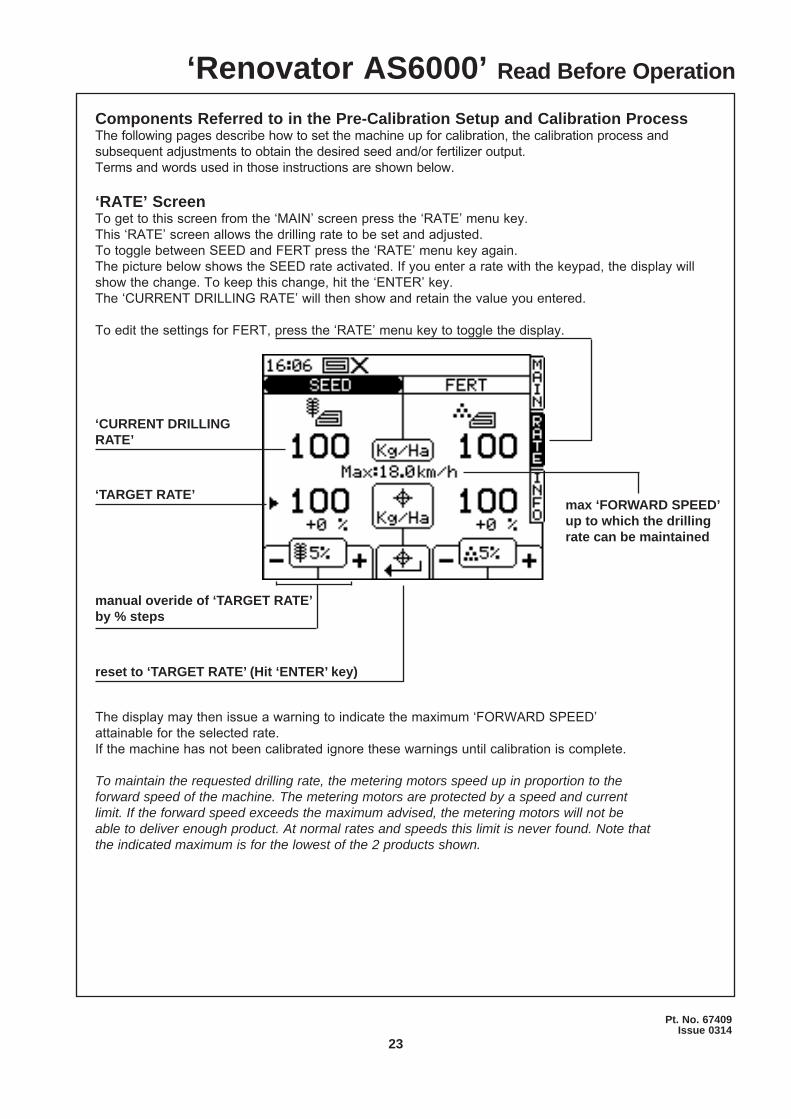
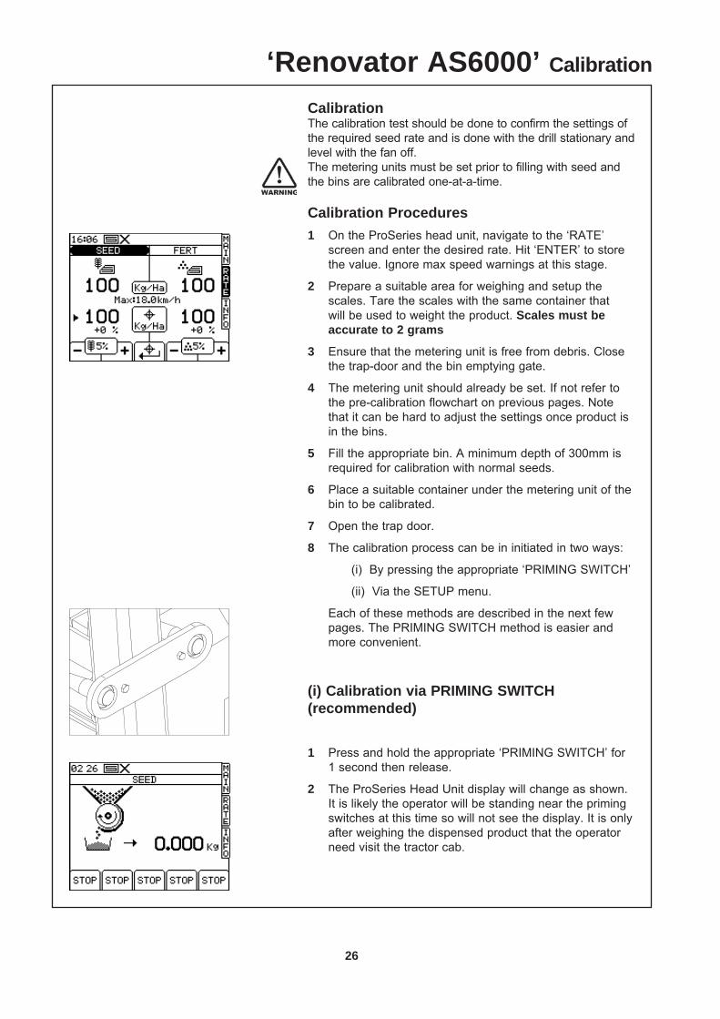
‘RATE’ ScreenTo get to this screen from the ‘MAIN’ screen press the ‘RATE’ menu key.This ‘RATE’ screen allows the drilling rate to be set and adjusted.To toggle between SEED and FERT press the ‘RATE’ menu key again.The picture below shows the SEED rate activated. If you enter a rate with the keypad, the display will show the change. To keep this change, hit the ‘ENTER’ key.The ‘CURRENT DRILLING RATE’ will then show and retain the value you entered.
To edit the settings for FERT, press the ‘RATE’ menu key to toggle the display.
‘CURRENT DRILLING RATE’
‘TARGET RATE’
reset to ‘TARGET RATE’ (Hit ‘ENTER’ key)
manual overide of ‘TARGET RATE’by % steps
The display may then issue a warning to indicate the maximum ‘FORWARD SPEED’ attainable for the selected rate.If the machine has not been calibrated ignore these warnings until calibration is complete.
To maintain the requested drilling rate, the metering motors speed up in proportion to the forward speed of the machine. The metering motors are protected by a speed and current limit. If the forward speed exceeds the maximum advised, the metering motors will not be able to deliver enough product. At normal rates and speeds this limit is never found. Note that the indicated maximum is for the lowest of the 2 products shown.
max ‘FORWARD SPEED’up to which the drilling rate can be maintained
24
‘Renovator AS6000’ Read Before Operation
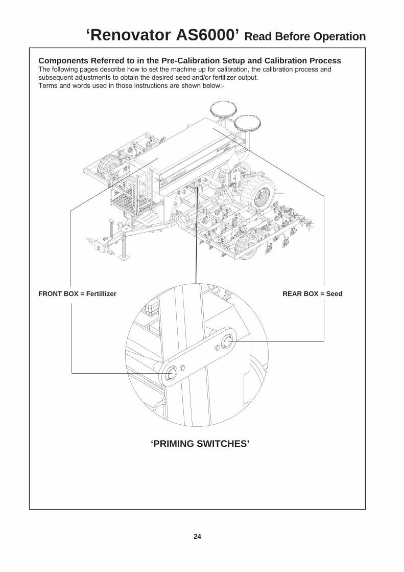
Components Referred to in the Pre-Calibration Setup and Calibration ProcessThe following pages describe how to set the machine up for calibration, the calibration process and subsequent adjustments to obtain the desired seed and/or fertilizer output.Terms and words used in those instructions are shown below:-
‘PRIMING SWITCHES’
FRONT BOX = Fertillizer REAR BOX = Seed
25
Pt. No. 67409Issue 0314
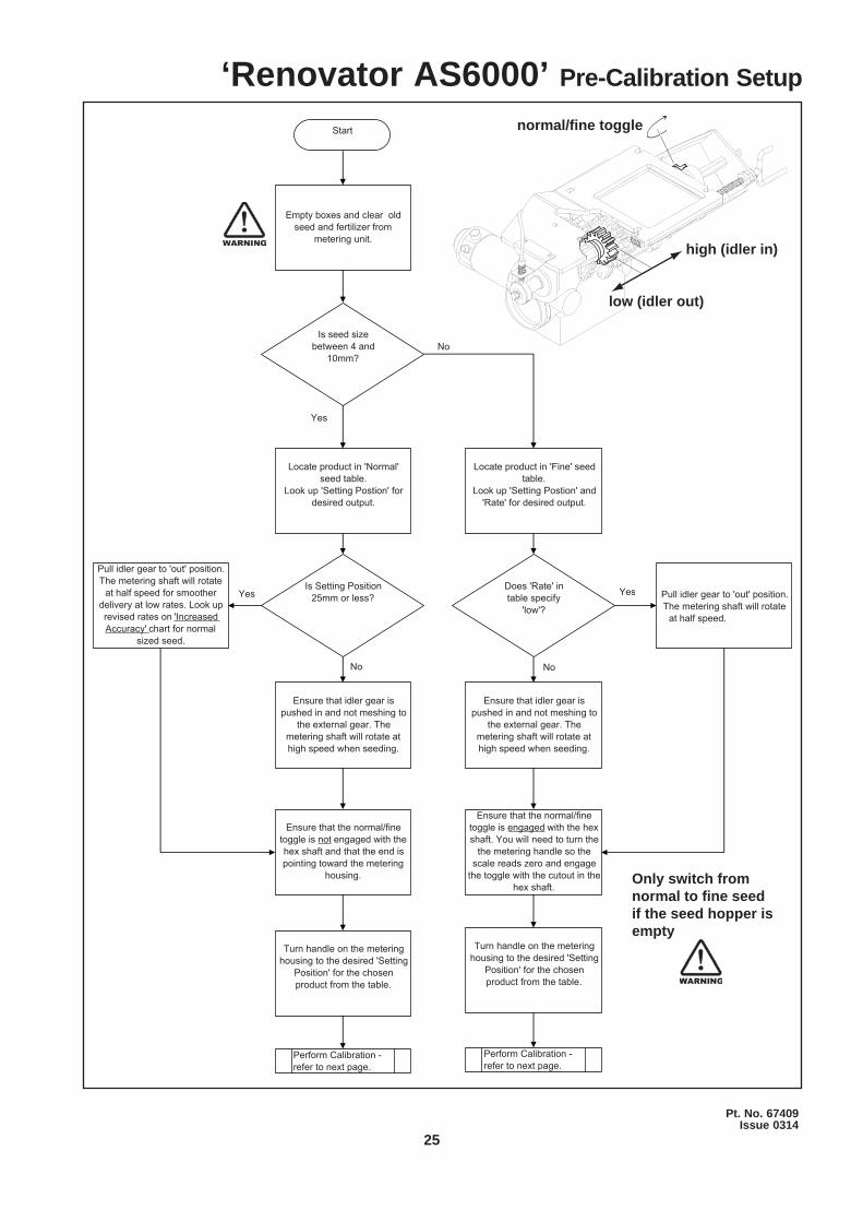
Start
Is seed size between 4 and
10mm?
Locate product in 'Normal' seed table.
Look up 'Setting Postion' for desired output.
No
Yes
Is Setting Position 25mm or less?
No
Yes
Pull idler gear to 'out' position. The metering shaft will rotate
at half speed for smoother delivery at low rates. Look up revised rates on 'Increased Accuracy' chart for normal
sized seed.
Ensure that idler gear is pushed in and not meshing to
the external gear. The metering shaft will rotate at high speed when seeding.
Turn handle on the metering housing to the desired 'Setting
Position' for the chosen product from the table.
Ensure that the normal/fine toggle is not engaged with the hex shaft and that the end is pointing toward the metering
housing.
Locate product in 'Fine' seed table.
Look up 'Setting Postion' and 'Rate' for desired output.
Does 'Rate' in table specify
'low'?
Yes
No
Ensure that idler gear is pushed in and not meshing to
the external gear. The metering shaft will rotate at high speed when seeding.
Ensure that the normal/fine toggle is engaged with the hex shaft. You will need to turn the
the metering handle so the scale reads zero and engage
the toggle with the cutout in thehex shaft.
Turn handle on the metering housing to the desired 'Setting
Position' for the chosen product from the table.
Perform Calibration - refer to next page.
Perform Calibration - refer to next page.
Pull idler gear to 'out' position. The metering shaft will rotate
at half speed.
Empty boxes and clear old seed and fertilizer from
metering unit.high (idler in)
low (idler out)
normal/fi ne toggle
‘Renovator AS6000’ Pre-Calibration Setup
Only switch from normal to fi ne seed if the seed hopper is empty
26
‘Renovator AS6000’ Calibration
CalibrationThe calibration test should be done to confirm the settings of the required seed rate and is done with the drill stationary and level with the fan off.The metering units must be set prior to filling with seed and the bins are calibrated one-at-a-time.
Calibration Procedures1 On the ProSeries head unit, navigate to the ‘RATE’
screen and enter the desired rate. Hit ‘ENTER’ to store the value. Ignore max speed warnings at this stage.
2 Prepare a suitable area for weighing and setup the scales. Tare the scales with the same container that will be used to weight the product. Scales must be accurate to 2 grams
3 Ensure that the metering unit is free from debris. Close the trap-door and the bin emptying gate.
4 The metering unit should already be set. If not refer to the pre-calibration flowchart on previous pages. Note that it can be hard to adjust the settings once product is in the bins.
5 Fill the appropriate bin. A minimum depth of 300mm is required for calibration with normal seeds.
6 Place a suitable container under the metering unit of the bin to be calibrated.
7 Open the trap door.
8 The calibration process can be in initiated in two ways:
(i) By pressing the appropriate ‘PRIMING SWITCH’
(ii) Via the SETUP menu.
Each of these methods are described in the next few pages. The PRIMING SWITCH method is easier and more convenient.
(i) Calibration via PRIMING SWITCH (recommended)
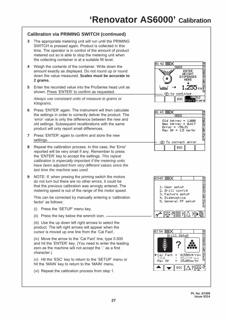
1 Press and hold the appropriate ‘PRIMING SWITCH’ for 1 second then release.
2 The ProSeries Head Unit display will change as shown. It is likely the operator will be standing near the priming switches at this time so will not see the display. It is only after weighing the dispensed product that the operator need visit the tractor cab.
27
Pt. No. 67409Issue 0314
Calibration via PRIMING SWITCH (continued)3 The appropriate metering unit will run until the PRIMING
SWITCH is pressed again. Product is collected in this time. The operator is in control of the amount of product metered out so is able to stop the metering unit when the collecting container is at a suitable fill level.
4 Weigh the contents of the container. Write down the amount exactly as displayed. Do not round up or round down the value measured. Scales must be accurate to 2 grams.
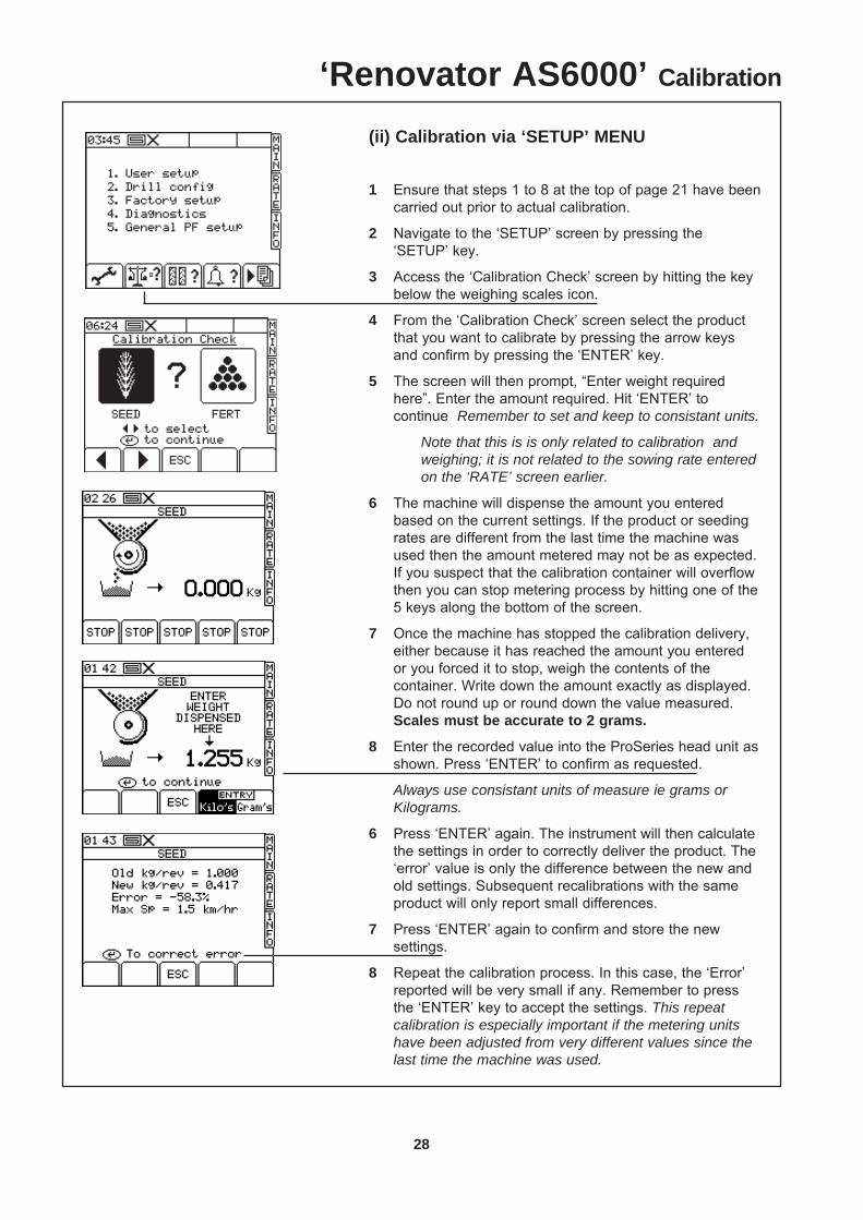
5 Enter the recorded value into the ProSeries head unit as shown. Press ‘ENTER’ to confirm as requested.
Always use consistant units of measure ie grams or Kilograms.
6 Press ‘ENTER’ again. The instrument will then calculate the settings in order to correctly deliver the product. The ‘error’ value is only the difference between the new and old settings. Subsequent recalibrations with the same product will only report small differences.
7 Press ‘ENTER’ again to confirm and store the new settings.
8 Repeat the calibration process. In this case, the ‘Error’ reported will be very small if any. Remember to press the ‘ENTER’ key to accept the settings. This repeat calibration is especially important if the metering units have been adjusted from very different values since the last time the machine was used.
9 NOTE: If, when presing the priming switch the motors do not turn but there are no other errors, it could be that the previous calibration was wrongly entered. The metering speed is out of the range of the motor speed.
This can be corrected by manually entering a ‘calibration factor’ as follows:
(i) Press the ‘SETUP’ menu key.
(ii) Press the key below the wrench icon.
(iii) Use the up down left right arrows to select the product. The left right arrows will appear when the cursor is moved up one line from the ‘Cal Fact’.
(iv) Move the arrow to the ‘Cal Fact’ line, type 0.500 and hit the ‘ENTER’ key. (You need to enter the leading zero as the machine will not accept the ‘.’ as a first character.)
(v) Hit the ‘ESC’ key to return to the ‘SETUP’ menu or hit the ‘MAIN’ key to return to the ‘MAIN’ menu.
(vi) Repeat the calibration process from step 1.
‘Renovator AS6000’ Calibration
28
(ii) Calibration via ‘SETUP’ MENU
1 Ensure that steps 1 to 8 at the top of page 21 have been carried out prior to actual calibration.
2 Navigate to the ‘SETUP’ screen by pressing the ‘SETUP’ key.
3 Access the ‘Calibration Check’ screen by hitting the key below the weighing scales icon.
4 From the ‘Calibration Check’ screen select the product that you want to calibrate by pressing the arrow keys and confirm by pressing the ‘ENTER’ key.
5 The screen will then prompt, “Enter weight required here”. Enter the amount required. Hit ‘ENTER’ to continue Remember to set and keep to consistant units.
Note that this is is only related to calibration and weighing; it is not related to the sowing rate entered on the ‘RATE’ screen earlier.
6 The machine will dispense the amount you entered based on the current settings. If the product or seeding rates are different from the last time the machine was used then the amount metered may not be as expected. If you suspect that the calibration container will overflow then you can stop metering process by hitting one of the 5 keys along the bottom of the screen.
7 Once the machine has stopped the calibration delivery, either because it has reached the amount you entered or you forced it to stop, weigh the contents of the container. Write down the amount exactly as displayed. Do not round up or round down the value measured. Scales must be accurate to 2 grams.
8 Enter the recorded value into the ProSeries head unit as shown. Press ‘ENTER’ to confirm as requested.
Always use consistant units of measure ie grams or Kilograms.
6 Press ‘ENTER’ again. The instrument will then calculate the settings in order to correctly deliver the product. The ‘error’ value is only the difference between the new and old settings. Subsequent recalibrations with the same product will only report small differences.
7 Press ‘ENTER’ again to confirm and store the new settings.
8 Repeat the calibration process. In this case, the ‘Error’ reported will be very small if any. Remember to press the ‘ENTER’ key to accept the settings. This repeat calibration is especially important if the metering units have been adjusted from very different values since the last time the machine was used.
‘Renovator AS6000’ Calibration
29
Pt. No. 67409Issue 0314
(ii) Calibration via ‘SETUP’ MENU continued9 NOTE: If, when presing the priming switch the motors do
not turn but there are no other errors, it could be that the previous calibration was wrongly entered. The metering speed is out of the range of the motor speed.
This can be corrected by manually entering a ‘calibration factor’ as follows:
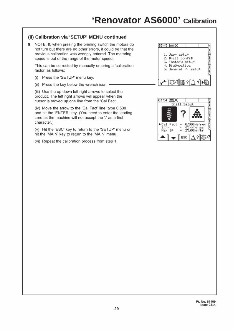
(i) Press the ‘SETUP’ menu key.
(ii) Press the key below the wrench icon.
(iii) Use the up down left right arrows to select the product. The left right arrows will appear when the cursor is moved up one line from the ‘Cal Fact’.
(iv) Move the arrow to the ‘Cal Fact’ line, type 0.500 and hit the ‘ENTER’ key. (You need to enter the leading zero as the machine will not accept the ‘.’ as a first character.)
(v) Hit the ‘ESC’ key to return to the ‘SETUP’ menu or hit the ‘MAIN’ key to return to the ‘MAIN’ menu.
(vi) Repeat the calibration process from step 1.
‘Renovator AS6000’ Calibration
30
‘Renovator AS6000’ Seed Drill Sowing Chart
Box
con
tent
sB
utte
rfl y
Pos
ition
(affe
cts
rear
box
)Fa
n Sp
eed/
rpm
*FR
ON
TR
EAR
seed
(Nor
mal
)se
ed (N
orm
al)
open
- 5
2000
seed
(Nor
mal
)se
ed (F
ine)
clos
ed -
120
00
Ferti
lizer
seed
(Nor
mal
)cl
osed
-220
00 to
250
0Fe
rtiliz
erse
ed (F
ine)
clos
ed -
120
00 to
250
0*
MA
XIM
UM
P
ER
MIS
SA
BLE
FA
N S
PE
ED
40
00 R
PM
1
5
2
34
*MA
XIM
UM
PE
RM
ISS
AB
LE S
PE
ED
400
0 R
PM
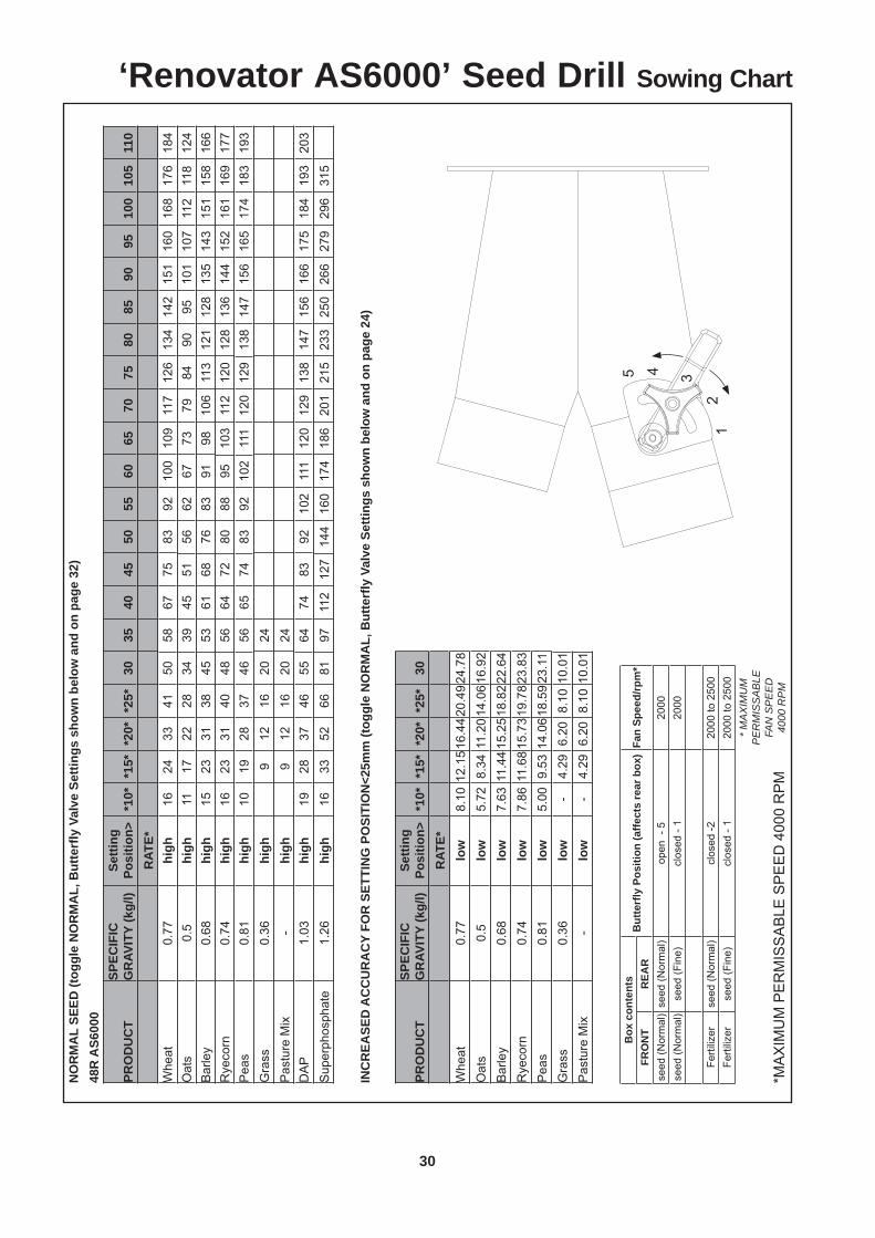
NO
RM
AL
SEED
(tog
gle
NO
RM
AL,
But
terfl
y V
alve
Set
tings
sho
wn
belo
w a
nd o
n pa
ge 3
2)48
R A
S600
0
PRO
DU
CT
SPEC
IFIC
G
RAV
ITY
(kg/
l)Se
tting
Po
sitio
n>*1
0**1
5**2
0**2
5*30
3540
4550
5560
6570
7580
8590
9510
010
511
0R
ATE*
Whe
at
0.77
high
1624
3341
5058
6775
8392
100
109
117
126
134
142
151
160
168
176
184
Oat
s0.
5hi
gh11
1722
2834
3945
5156
6267
7379
8490
9510
110
711
211
812
4B
arle
y0.
68hi
gh15
2331
3845
5361
6876
8391
9810
611
312
112
813
514
315
115
816
6R
yeco
rn
0.74
high
1623
3140
4856
6472
8088
9510
311
212
012
813
614
415
216
116
917
7P
eas
0.81
high
1019
2837
4656
6574
8392
102
111
120
129
138
147
156
165
174
183
193
Gra
ss0.
36hi
gh9
1216
2024
Pas
ture
Mix
-hi
gh9
1216
2024
DA
P1.
03hi
gh19
2837
4655
6474
8392
102
111
120
129
138
147
156
166
175
184
193
203
Sup
erph
osph
ate
1.26
high
1633
5266
8197
112
127
144
160
174
186
201
215
233
250
266
279
296
315
INC
REA
SED
AC
CU
RA
CY
FOR
SET
TIN
G P
OSI
TIO
N<2
5mm
(tog
gle
NO
RM
AL,
But
terfl
y V
alve
Set
tings
sho
wn
belo
w a
nd o
n pa
ge 2
4)
PRO
DU
CT
SPEC
IFIC
G
RAV
ITY
(kg/
l)Se
tting
Po
sitio
n>*1
0**1
5**2
0**2
5*30
RAT
E*W
heat
0.
77lo
w8.
1012
.15
16.4
420
.49
24.7
8O
ats
0.5
low
5.72
8.34
11.2
014
.06
16.9
2B
arle
y0.
68lo
w7.
6311
.44
15.2
518
.82
22.6
4R
yeco
rn
0.74
low
7.86
11.6
815
.73
19.7
823
.83
Pea
s0.
81lo
w5.
009.
5314
.06
18.5
923
.11
Gra
ss0.
36lo
w-
4.29
6.20
8.10
10.0
1P
astu
re M
ix-
low
-4.
296.
208.
1010
.01
31
Pt. No. 67409Issue 0314
‘Renovator AS6000’ Seed Drill Sowing Chart
Box contentsButterfl y Position (affects rear box) Fan Speed/rpm*
FRONT REARseed (Normal) seed (Normal) open - 5 2000seed (Normal) seed (Fine) closed - 1 2000
Fertilizer seed (Normal) closed -2 2000 to 2500Fertilizer seed (Fine) closed - 1 2000 to 2500
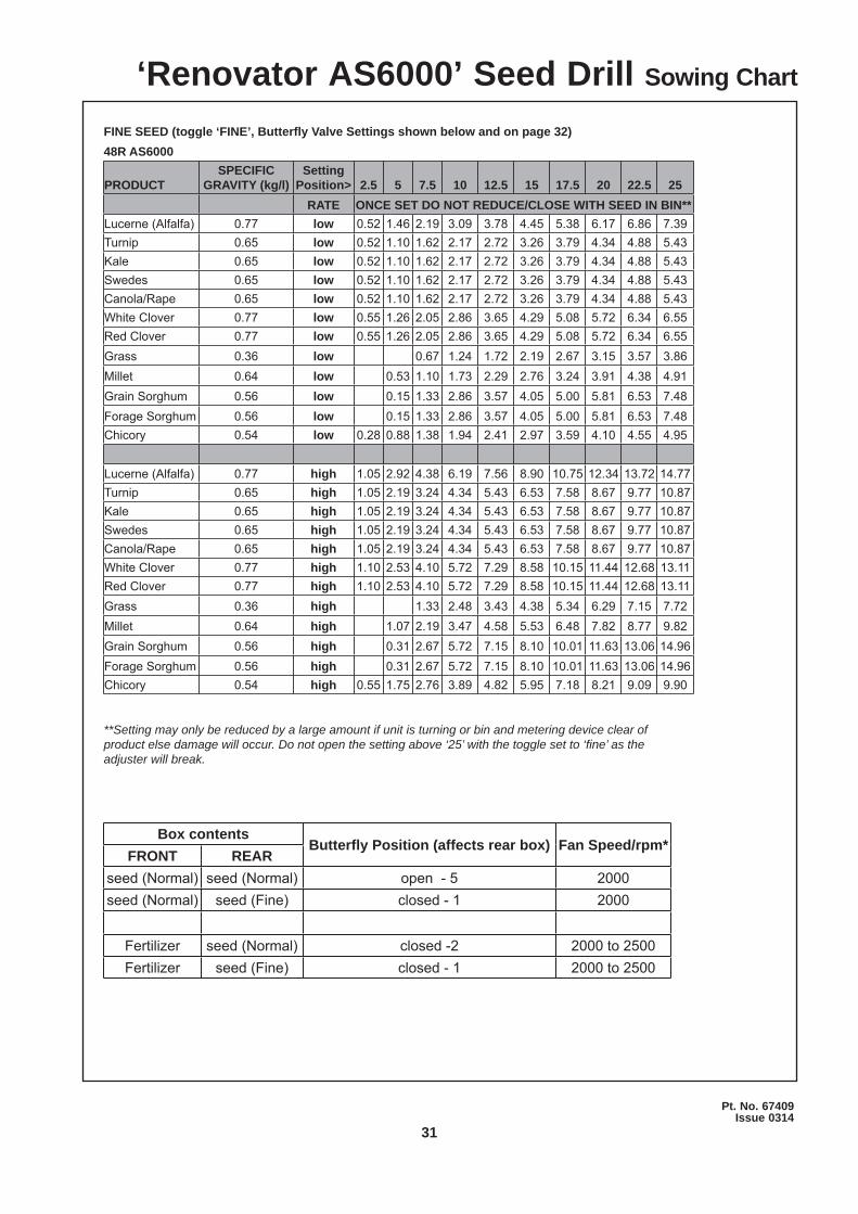
FINE SEED (toggle ‘FINE’, Butterfl y Valve Settings shown below and on page 32)48R AS6000
PRODUCTSPECIFIC
GRAVITY (kg/l)Setting
Position> 2.5 5 7.5 10 12.5 15 17.5 20 22.5 25RATE ONCE SET DO NOT REDUCE/CLOSE WITH SEED IN BIN**
Lucerne (Alfalfa) 0.77 low 0.52 1.46 2.19 3.09 3.78 4.45 5.38 6.17 6.86 7.39Turnip 0.65 low 0.52 1.10 1.62 2.17 2.72 3.26 3.79 4.34 4.88 5.43Kale 0.65 low 0.52 1.10 1.62 2.17 2.72 3.26 3.79 4.34 4.88 5.43Swedes 0.65 low 0.52 1.10 1.62 2.17 2.72 3.26 3.79 4.34 4.88 5.43Canola/Rape 0.65 low 0.52 1.10 1.62 2.17 2.72 3.26 3.79 4.34 4.88 5.43White Clover 0.77 low 0.55 1.26 2.05 2.86 3.65 4.29 5.08 5.72 6.34 6.55Red Clover 0.77 low 0.55 1.26 2.05 2.86 3.65 4.29 5.08 5.72 6.34 6.55Grass 0.36 low 0.67 1.24 1.72 2.19 2.67 3.15 3.57 3.86Millet 0.64 low 0.53 1.10 1.73 2.29 2.76 3.24 3.91 4.38 4.91Grain Sorghum 0.56 low 0.15 1.33 2.86 3.57 4.05 5.00 5.81 6.53 7.48Forage Sorghum 0.56 low 0.15 1.33 2.86 3.57 4.05 5.00 5.81 6.53 7.48Chicory 0.54 low 0.28 0.88 1.38 1.94 2.41 2.97 3.59 4.10 4.55 4.95
Lucerne (Alfalfa) 0.77 high 1.05 2.92 4.38 6.19 7.56 8.90 10.75 12.34 13.72 14.77Turnip 0.65 high 1.05 2.19 3.24 4.34 5.43 6.53 7.58 8.67 9.77 10.87Kale 0.65 high 1.05 2.19 3.24 4.34 5.43 6.53 7.58 8.67 9.77 10.87Swedes 0.65 high 1.05 2.19 3.24 4.34 5.43 6.53 7.58 8.67 9.77 10.87Canola/Rape 0.65 high 1.05 2.19 3.24 4.34 5.43 6.53 7.58 8.67 9.77 10.87White Clover 0.77 high 1.10 2.53 4.10 5.72 7.29 8.58 10.15 11.44 12.68 13.11Red Clover 0.77 high 1.10 2.53 4.10 5.72 7.29 8.58 10.15 11.44 12.68 13.11Grass 0.36 high 1.33 2.48 3.43 4.38 5.34 6.29 7.15 7.72Millet 0.64 high 1.07 2.19 3.47 4.58 5.53 6.48 7.82 8.77 9.82Grain Sorghum 0.56 high 0.31 2.67 5.72 7.15 8.10 10.01 11.63 13.06 14.96Forage Sorghum 0.56 high 0.31 2.67 5.72 7.15 8.10 10.01 11.63 13.06 14.96Chicory 0.54 high 0.55 1.75 2.76 3.89 4.82 5.95 7.18 8.21 9.09 9.90
**Setting may only be reduced by a large amount if unit is turning or bin and metering device clear of product else damage will occur. Do not open the setting above ‘25’ with the toggle set to ‘fi ne’ as the adjuster will break.
32
‘Renovator AS6000’ Airflow & Fan Speed
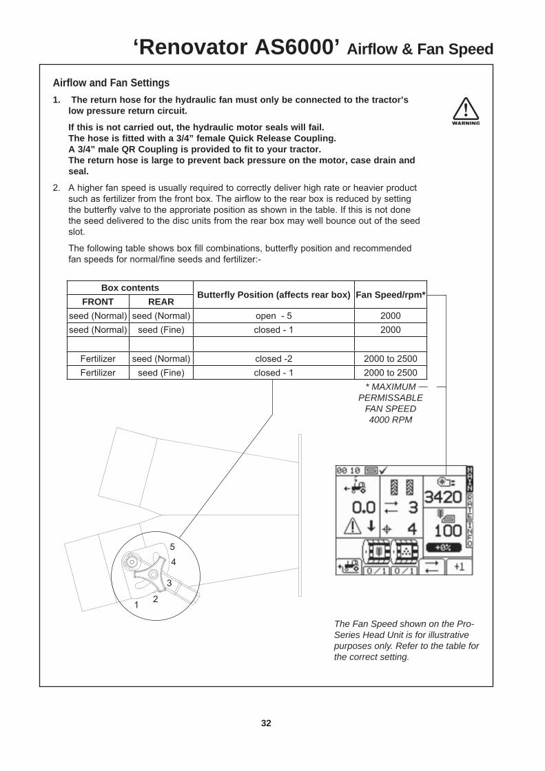
Airflow and Fan Settings1. The return hose for the hydraulic fan must only be connected to the tractor’s
low pressure return circuit.
If this is not carried out, the hydraulic motor seals will fail. The hose is fitted with a 3/4” female Quick Release Coupling. A 3/4” male QR Coupling is provided to fit to your tractor. The return hose is large to prevent back pressure on the motor, case drain and
seal.
2. A higher fan speed is usually required to correctly deliver high rate or heavier product such as fertilizer from the front box. The airflow to the rear box is reduced by setting the butterfly valve to the approriate position as shown in the table. If this is not done the seed delivered to the disc units from the rear box may well bounce out of the seed slot.
The following table shows box fill combinations, butterfly position and recommended fan speeds for normal/fine seeds and fertilizer:-
Box contentsButterfl y Position (affects rear box) Fan Speed/rpm*
FRONT REARseed (Normal) seed (Normal) open - 5 2000seed (Normal) seed (Fine) closed - 1 2000
Fertilizer seed (Normal) closed -2 2000 to 2500Fertilizer seed (Fine) closed - 1 2000 to 2500
* MAXIMUM PERMISSABLE
FAN SPEED 4000 RPM
1
5
2
3
4
The Fan Speed shown on the Pro-Series Head Unit is for illustrative purposes only. Refer to the table for the correct setting.

33
Pt. No. 67409Issue 0314
Renovator AS6000 Calibration Notes
34
Maintenance & CareGeneral Safety and Accident Prevention Advice
1 Make sure that if the tractor remains attached to the drill that the ignition key is removed.
2 During maintenance the drill should be supported in such a manner that if hydraulic failure was to occur the machine would still be adequately supported.
3 Wear gloves when handling components with cutting edges such as worn discs etc...
4 Disconnect the electrical supply from the tractor before doing any electrical maintenance.
5 Refer to safety sections for more safety information.
General Cautionary Maintenance Advice
1 Electric Welding - With the electronic equipment in modern tractors it is advisable to completely disconnect the implement from the tractor, or at the very least disconnect the alternator before attempting any welding.
2 Hydraulics - Ensure hydraulic couplings (male & female) are clean before connecting. Dirty couplings will result in hydraulic oil contamination and hydraulic cylinder seal and valve damage. This in turn will result in oil leakage.
No filter is fitted to the hydraulic system. If hydraulic fittings and oil supply are not going to be kept clean it is recommended that a filter be fitted to prevent hydraulic cylinder damage.
3 Water Blasting - Water blasting, steam cleaning or other pressurised cleaning processes can force dirt etc. into undesirable places that may cause damage or rapid part wear to items such as bearings, seals, chains, bushes and electical items etc.Caution must be exercised.
‘Renovator AS6000’ Maintenance & Care
35
Pt. No. 67409Issue 0314
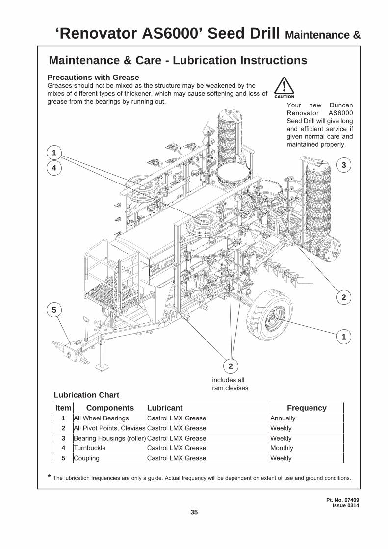
Your new Duncan Renovator AS6000 Seed Drill will give long and efficient service if given normal care and maintained properly.
Lubrication Chart
Maintenance & Care - Lubrication Instructions
* The lubrication frequencies are only a guide. Actual frequency will be dependent on extent of use and ground conditions.
Precautions with GreaseGreases should not be mixed as the structure may be weakened by the mixes of different types of thickener, which may cause softening and loss of grease from the bearings by running out.
Item Components Lubricant Frequency1 All Wheel Bearings Castrol LMX Grease Annually2 All Pivot Points, Clevises Castrol LMX Grease Weekly3 Bearing Housings (roller) Castrol LMX Grease Weekly4 Turnbuckle Castrol LMX Grease Monthly5 Coupling Castrol LMX Grease Weekly
‘Renovator AS6000’ Seed Drill Maintenance &
4
1
13
25
includes all ram clevises
2
36
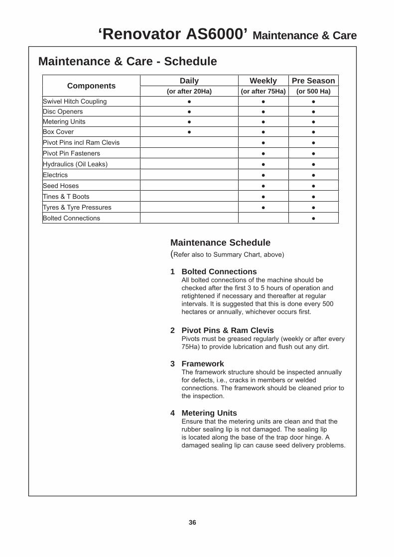
Maintenance Schedule (Refer also to Summary Chart, above)
1 Bolted Connections All bolted connections of the machine should be
checked after the first 3 to 5 hours of operation and retightened if necessary and thereafter at regular intervals. It is suggested that this is done every 500 hectares or annually, whichever occurs first.
2 Pivot Pins & Ram Clevis Pivots must be greased regularly (weekly or after every
75Ha) to provide lubrication and flush out any dirt.
3 Framework The framework structure should be inspected annually
for defects, i.e., cracks in members or welded connections. The framework should be cleaned prior to the inspection.
4 Metering Units Ensure that the metering units are clean and that the
rubber sealing lip is not damaged. The sealing lip is located along the base of the trap door hinge. A damaged sealing lip can cause seed delivery problems.
Maintenance & Care - Schedule
Components Daily Weekly Pre Season(or after 20Ha) (or after 75Ha) (or 500 Ha)
Swivel Hitch Coupling ● ● ●Disc Openers ● ● ●Metering Units ● ● ●Box Cover ● ● ●Pivot Pins incl Ram Clevis ● ●Pivot Pin Fasteners ● ●Hydraulics (Oil Leaks) ● ●Electrics ● ●Seed Hoses ● ●Tines & T Boots ● ●Tyres & Tyre Pressures ● ●Bolted Connections ●
‘Renovator AS6000’ Maintenance & Care
37
Pt. No. 67409Issue 0314
Maintenance Schedule (continued)
5 Fan Hydraulic Motor The return hose for the hydraulic fan must only be
connected to the tractor’s low pressure return circuit. If this is not carried out, the hydraulic motor seals will
fail. The hose is fitted with a 3/4” female Quick Release
Coupling. A 3/4” male QR Coupling is provided to fit to your
tractor. The return hose is large to prevent back pressure on
the motor, case drain and seal.
6 Preparing the Machine for Storage. Locate on a dry level surface. The machine should be stored wherever possible so the rams are not supporting any weight. The drive chains should be lubricated with suitable roller chain lubricant before prolonged periods of storage.
It is recommended that maintenance be carried out at the end of the season, giving sufficient time to obtain spare parts and/or carry out repairs if required. The seed and fertilizer bins must be completely emptied and cleaned.
Leave the metering unit trap doors open.
Fit the cover to the bin.
‘Renovator AS6000’ Maintenance & Care
38
•
•
•
•
•
•
•
•
•
•
•
•
•
•
•
•
•
•
•
•
39
Pt. No. 67409Issue 0314
•
•
•
•
•
•
•
•
•
•
•
•
•
•
•
•
•
•
•
•
40
•
•
•
•
•
•
•
•
•
•
•
•
•
•
•
•
41
Pt. No. 67409Issue 0314
•
•
•
•
•
•
•
•
•
•
•
•
•
•
•
•
•
•
•
•
•
•
•
•
•
42
•
•
•
•
•
•
•
•
•
•
•
•
•
•
•
•
•
•
•
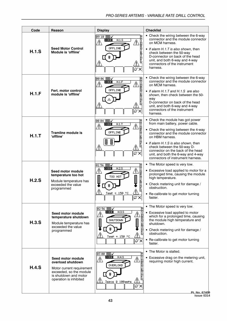
43
Pt. No. 67409Issue 0314
•
•
•
•
•
•
•
•
•
•
•
•
•
•
•
•
•
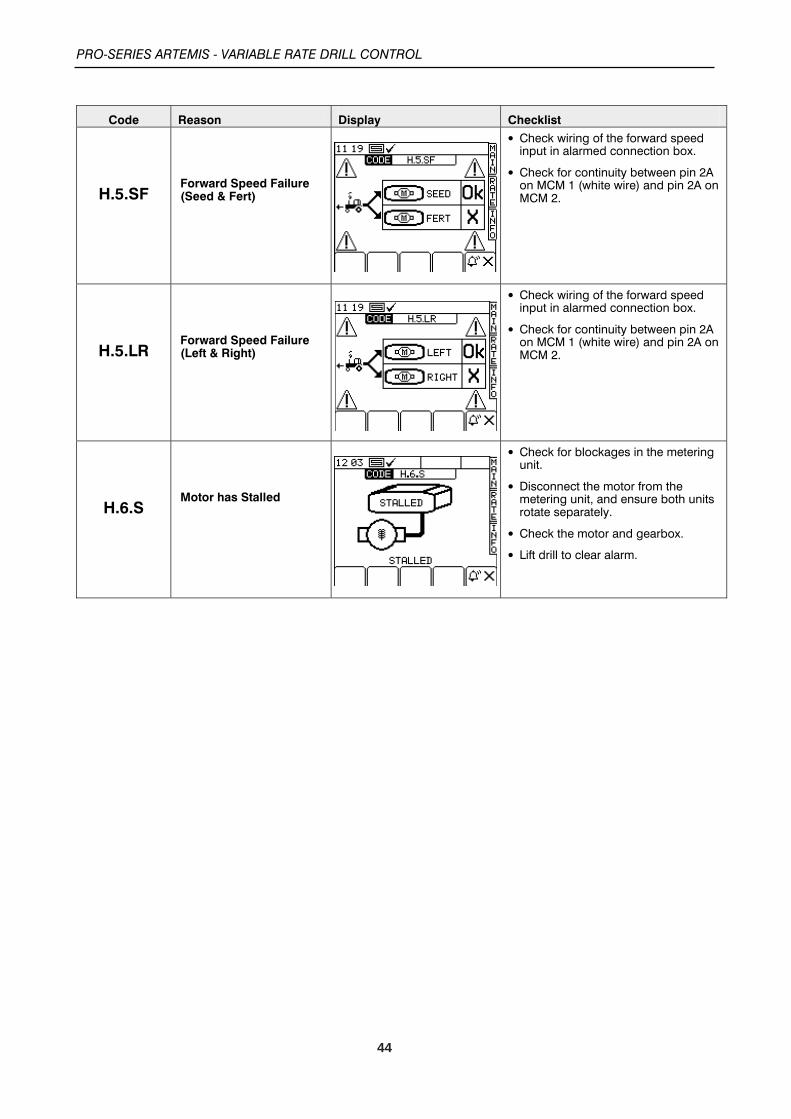
44
•
•
•
•
•
•
•
•

45
Pt. No. 67409Issue 0314
Renovator AS6000 Notes
Related Documents