Contents SK9L2J-19G364-AA © Copyright Ford 2013 FoMoCo 2013 Taurus Remote Access Remote Access System Installation CONTENTS VEHICLE PREPARATION Hood Switch Installation RMST Module Installation RMU Module Installation GENERAL PROCEDURES Remote Start Activation Learn Remote Start System Shock Sensor Sensitivity Adjustment RMU Activation

Welcome message from author
This document is posted to help you gain knowledge. Please leave a comment to let me know what you think about it! Share it to your friends and learn new things together.
Transcript
Contents SK9L2J-19G364-AA © Copyright Ford 2013 FoMoCo
2013 Taurus Remote Access
Remote Access System Installation
CONTENTS
VEHICLE PREPARATION
Hood Switch Installation
*+�,"��",*-+RMST Module InstallationRMU Module Installation
GENERAL PROCEDURES
Remote Start Activation
Learn Remote Start System
Shock Sensor Sensitivity Adjustment
RMU Activation
INSTALLATION
Remote Start — Taurus
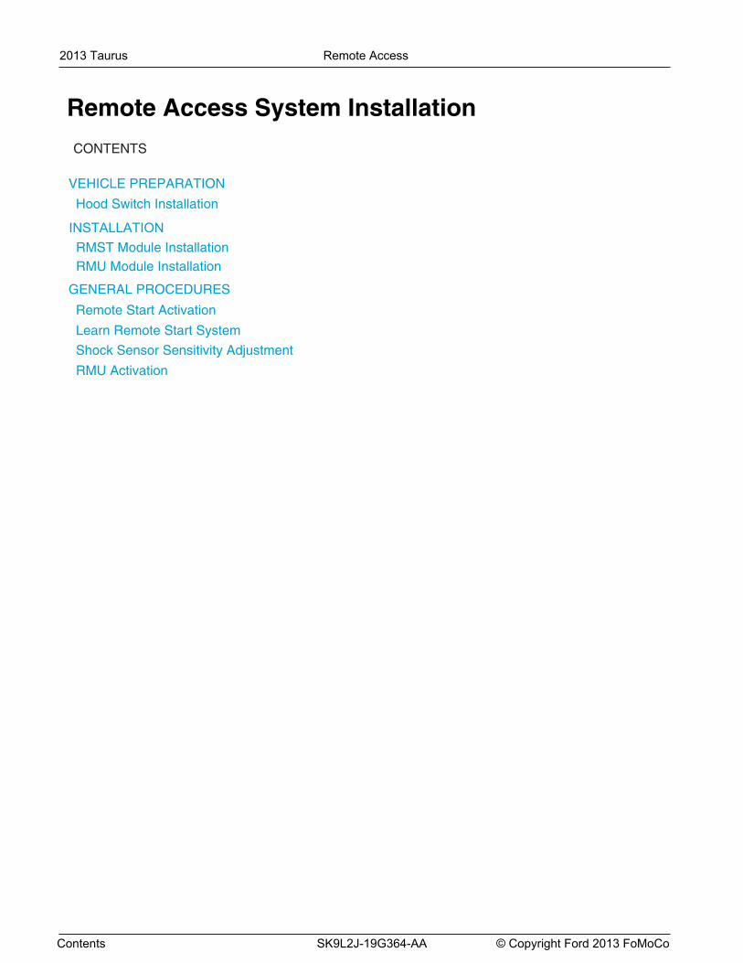
Remote Start System (RMST) Components
Hood Switch Kit - SE Vehicles Only
2013 Taurus Remote Access 1
Page 1 of 17 SK9L2J-19G364-AA © Copyright Ford 2013 FoMoCo
NOTE: RMU must be installed as described in this manual.
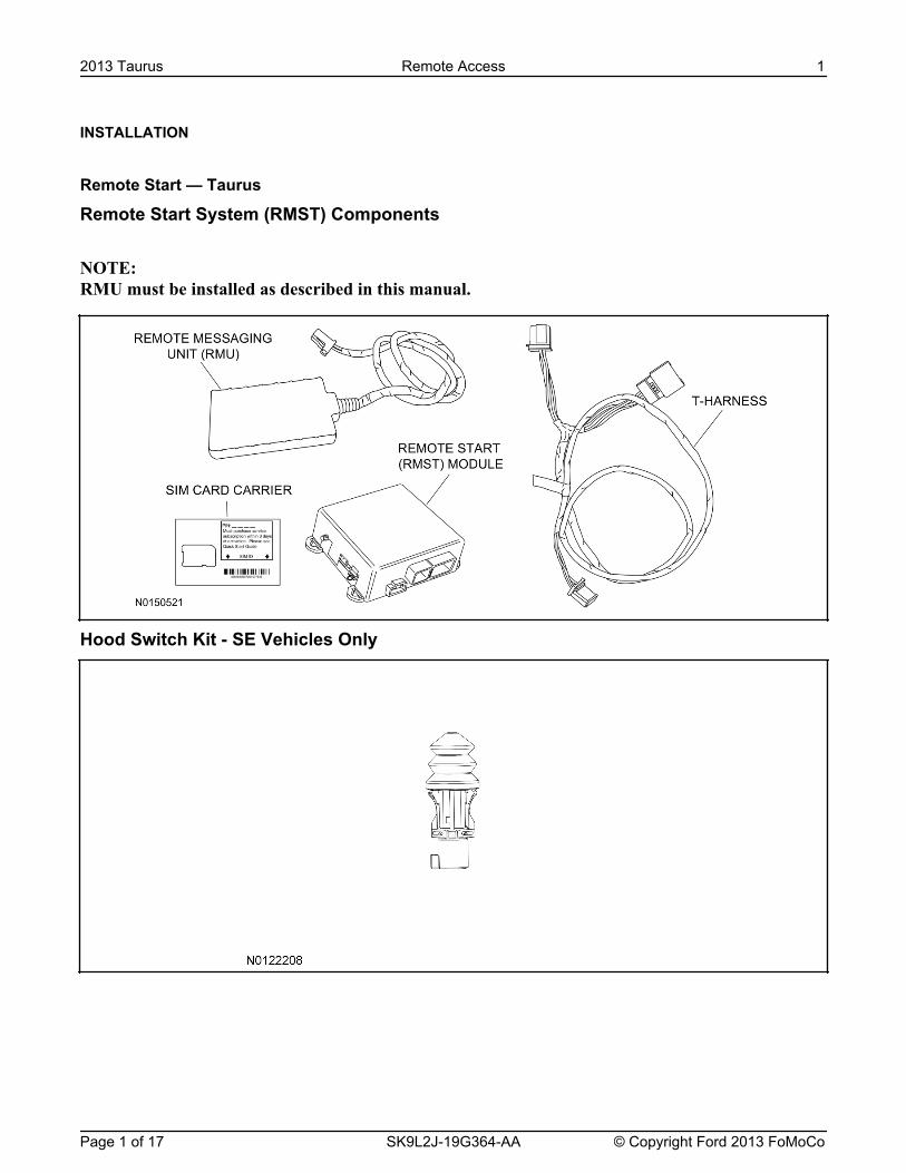
Hood Switch Wire Harness Kit - SE Vehicles Only
Optional Security Indicator LED (19D596)
Taurus - Remote Acess
NOTE: Please note that the Remote Access Application that is used to start the vehicle will only work withiPhone and Android phones.
1. Verify correct kit number.
RMST Kit Contents2. Review the RMST kit contents.
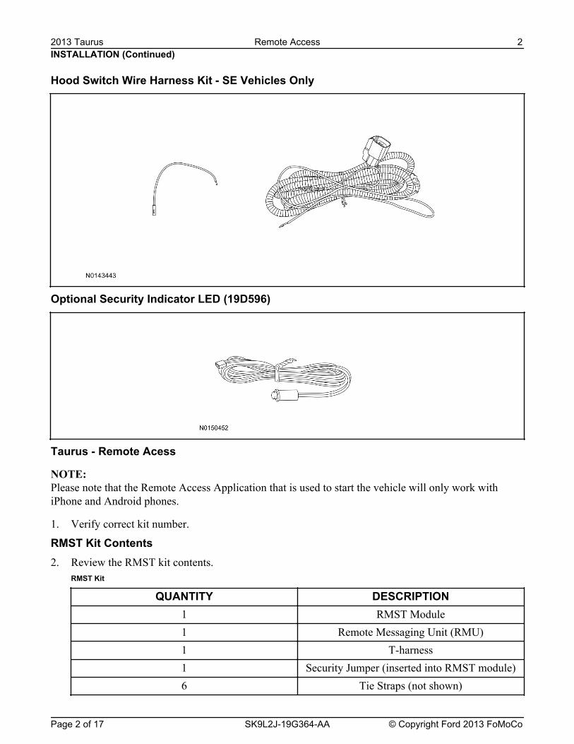
RMST Kit
QUANTITY DESCRIPTION1 RMST Module1 Remote Messaging Unit (RMU)1 T-harness1 Security Jumper (inserted into RMST module)6 Tie Straps (not shown)
INSTALLATION (Continued)2013 Taurus Remote Access 2
Page 2 of 17 SK9L2J-19G364-AA © Copyright Ford 2013 FoMoCo
RMST Kit(Continued)
QUANTITY DESCRIPTION1 Quick Reference Card (not shown)1 Sim Card Carrier
Hood Switch Kit Contents (If required)3. Review the Hood Switch kit contents.
Hood Switch Kit
QUANTITY DESCRIPTION1 Hood Switch Assembly
Review Hood Switch Wire Harness Kit Contents (If required)4. Review the Hood Switch kit contents.
Hood Switch Wire Harness Kit
QUANTITY DESCRIPTION1 Body Control Module (BCM) Terminal Wire1 Hood Switch Wire Harness
Optional Security Indicator LED Kit Contents5. Review the Security Indicator LED kit contents.
Security Indicator LED Kit
QUANTITY DESCRIPTION1 Security Indicator LED
INSTALLATION (Continued)2013 Taurus Remote Access 3
Page 3 of 17 SK9L2J-19G364-AA © Copyright Ford 2013 FoMoCo
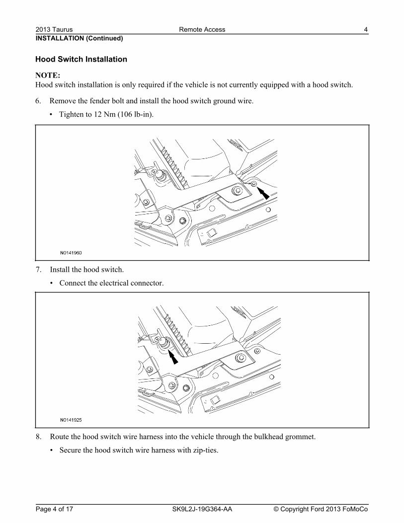
7. Install the hood switch.
• Connect the electrical connector.
8. Route the hood switch wire harness into the vehicle through the bulkhead grommet.
• Secure the hood switch wire harness with zip-ties.
INSTALLATION (Continued)
Hood Switch Installation
NOTE: Hood switch installation is only required if the vehicle is not currently equipped with a hood switch.
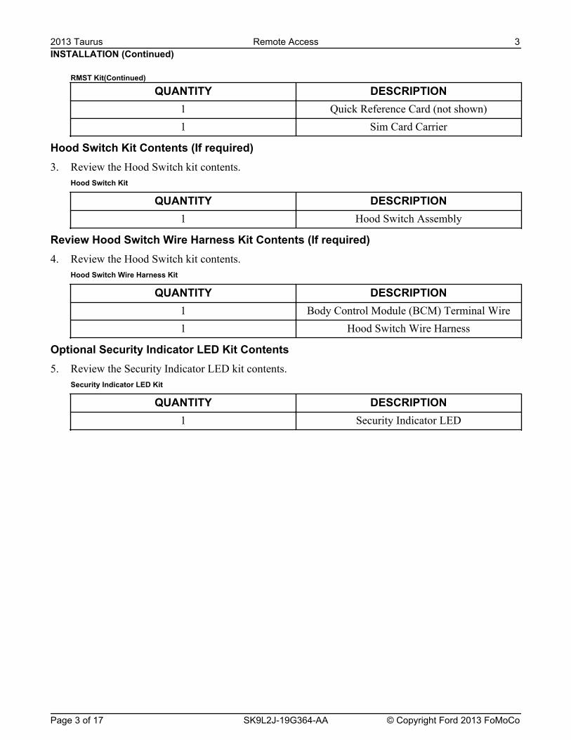
6. Remove the fender bolt and install the hood switch ground wire.
• Tighten to 12 Nm (106 lb-in).
2013 Taurus Remote Access 4
Page 4 of 17 SK9L2J-19G364-AA © Copyright Ford 2013 FoMoCo
10. If equipped, remove the pin plug from BCM connector C2280F Pin 2.
• If the vehicle is not equipped with a hood switch from the factory C2280F will not have a wire atthe Pin 2 location.
11. NOTICE: Check that the all wire pins are attached firmly and properly positioned/secured within theconnector shell, after performing this step.
Insert the BCM terminal wire from the hood switch wire harness kit into BCM connector C2280FPin 2.
• Some disassembly of BCM connector C2280F may be required to perform this step.
12. Connect BCM connector C2280F.
NOTICE: Refer to "Proper Wire Splicing Techniques" before proceeding.
13. Connect the hood switch wire harness wire to the BCM Terminal Wire.
• Secure the wire harness assembly with zip-ties.
Vehicle Preparation14. Verify that an OE hood switch is installed.
• If the vehicle is not equipped with a OE hood switch, refer to Hood Switch Installation in thisprocedure.
15. Remove the passenger side lower B-pillar trim panel. For additional information, refer to WorkshopManual (WSM) Section 501-05.
16. Remove the parcel shelf. For additional information, refer to WSM Section 501-05.
INSTALLATION (Continued)
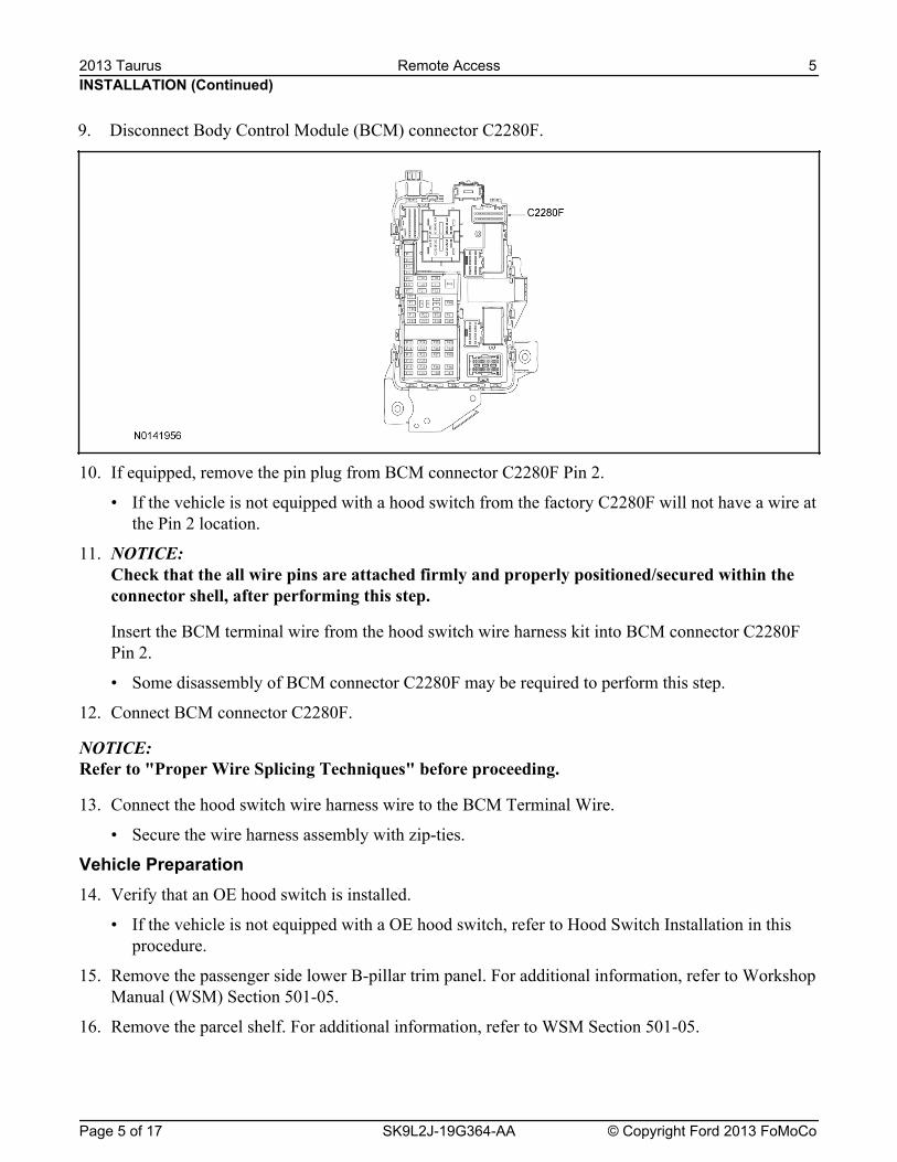
9. Disconnect Body Control Module (BCM) connector C2280F.
2013 Taurus Remote Access 5
Page 5 of 17 SK9L2J-19G364-AA © Copyright Ford 2013 FoMoCo
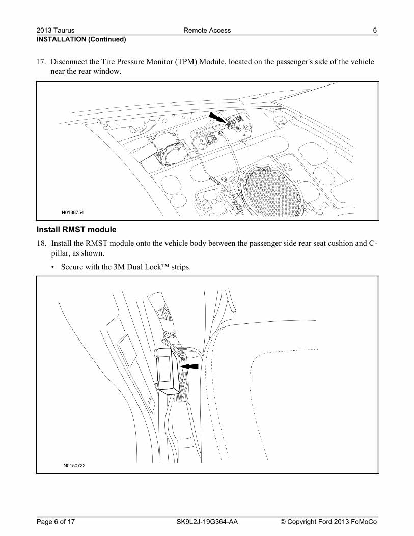
Install RMST module18. Install the RMST module onto the vehicle body between the passenger side rear seat cushion and C-
pillar, as shown.
• Secure with the 3M Dual Lock™ strips.
INSTALLATION (Continued)
17. Disconnect the Tire Pressure Monitor (TPM) Module, located on the passenger's side of the vehiclenear the rear window.
2013 Taurus Remote Access 6
Page 6 of 17 SK9L2J-19G364-AA © Copyright Ford 2013 FoMoCo
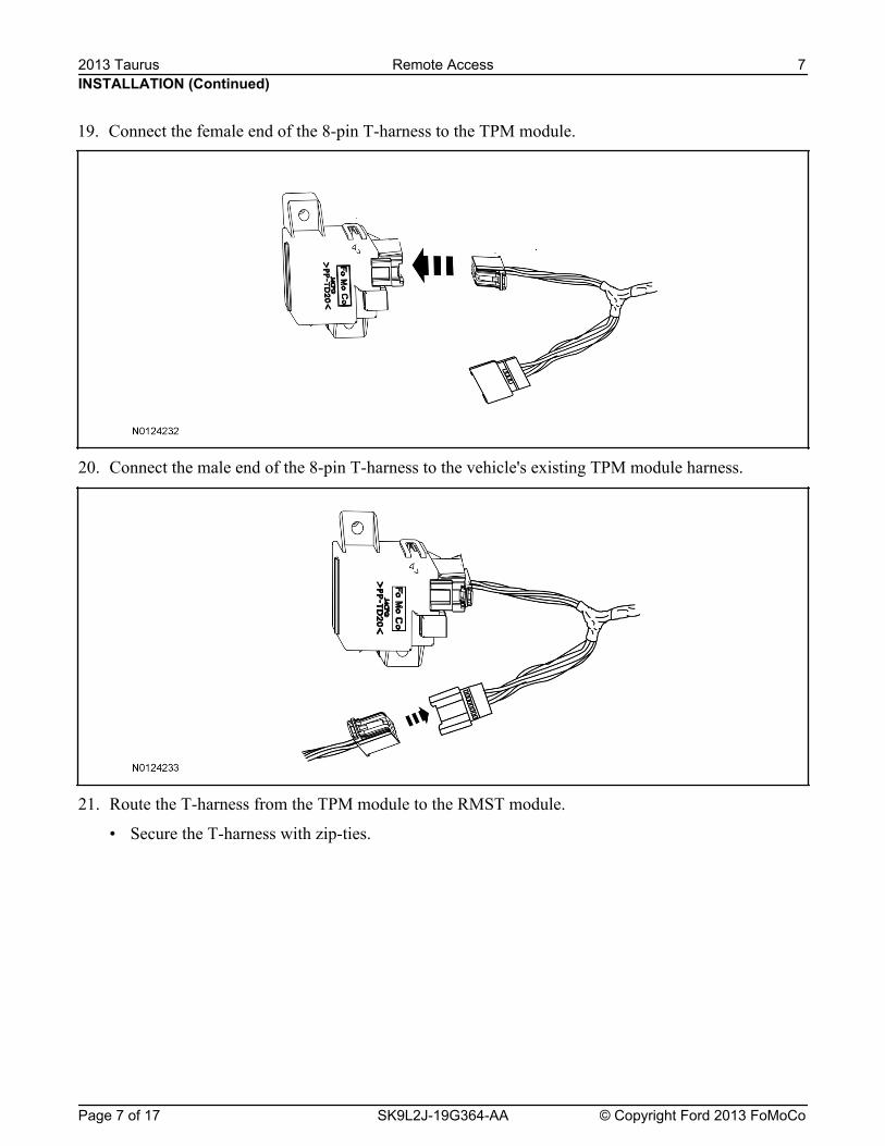
20. Connect the male end of the 8-pin T-harness to the vehicle's existing TPM module harness.
21. Route the T-harness from the TPM module to the RMST module.
• Secure the T-harness with zip-ties.
INSTALLATION (Continued)
19. Connect the female end of the 8-pin T-harness to the TPM module.
2013 Taurus Remote Access 7
Page 7 of 17 SK9L2J-19G364-AA © Copyright Ford 2013 FoMoCo
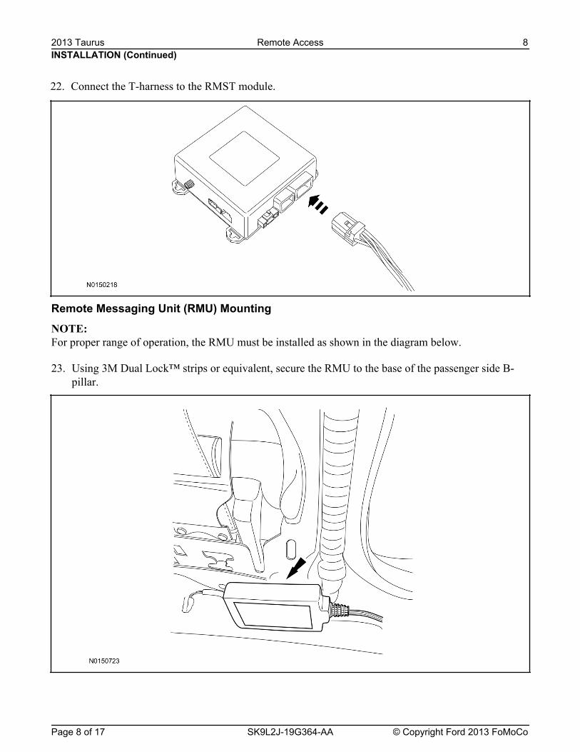
Remote Messaging Unit (RMU) Mounting
23. Using 3M Dual Lock™ strips or equivalent, secure the RMU to the base of the passenger side B-pillar.
INSTALLATION (Continued)
22. Connect the T-harness to the RMST module.
2013 Taurus Remote Access 8
Page 8 of 17 SK9L2J-19G364-AA © Copyright Ford 2013 FoMoCo
NOTE: For proper range of operation, the RMU must be installed as shown in the diagram below.
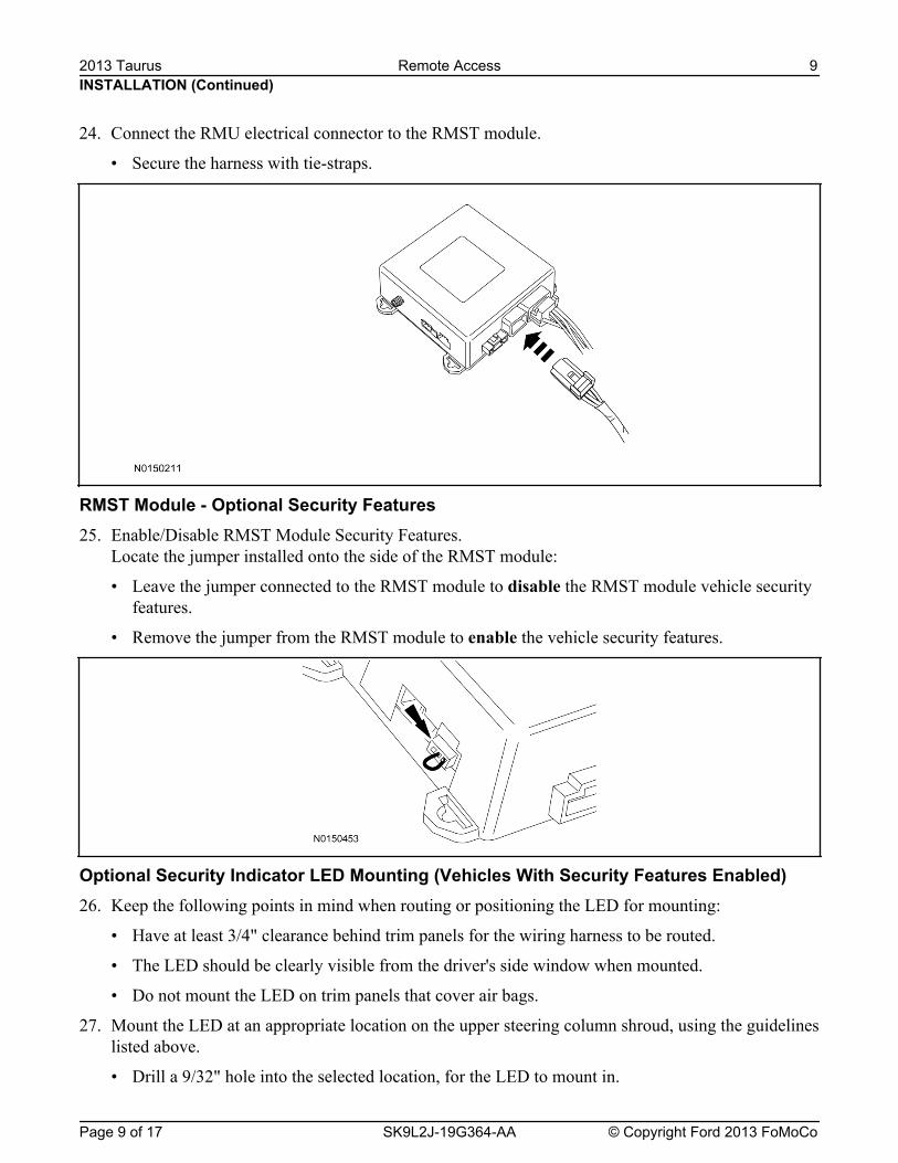
RMST Module - Optional Security Features25. Enable/Disable RMST Module Security Features.
Locate the jumper installed onto the side of the RMST module:
• Leave the jumper connected to the RMST module to disable the RMST module vehicle securityfeatures.
• Remove the jumper from the RMST module to enable the vehicle security features.
Optional Security Indicator LED Mounting (Vehicles With Security Features Enabled)26. Keep the following points in mind when routing or positioning the LED for mounting:
• Have at least 3/4" clearance behind trim panels for the wiring harness to be routed.
• The LED should be clearly visible from the driver's side window when mounted.
• Do not mount the LED on trim panels that cover air bags.
27. Mount the LED at an appropriate location on the upper steering column shroud, using the guidelineslisted above.
• Drill a 9/32" hole into the selected location, for the LED to mount in.
INSTALLATION (Continued)
24. Connect the RMU electrical connector to the RMST module.
• Secure the harness with tie-straps.
2013 Taurus Remote Access 9
Page 9 of 17 SK9L2J-19G364-AA © Copyright Ford 2013 FoMoCo
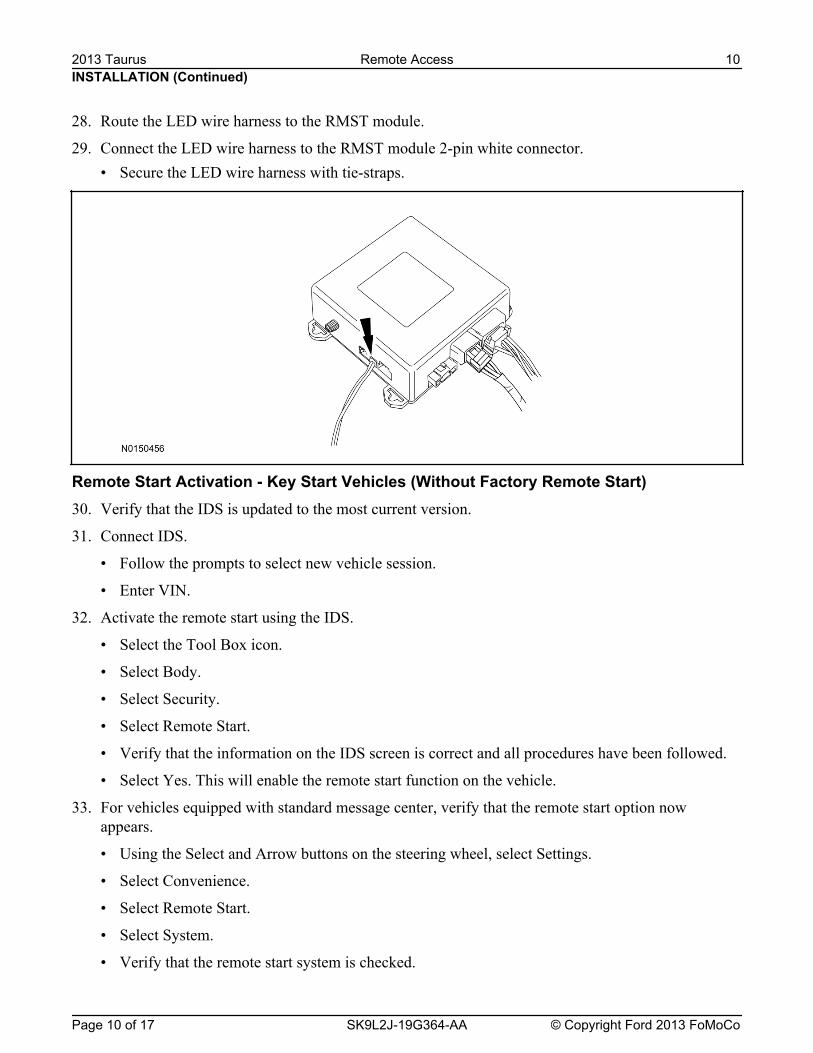
• Secure the LED wire harness with tie-straps.
Remote Start Activation - Key Start Vehicles (Without Factory Remote Start)30. Verify that the IDS is updated to the most current version.
31. Connect IDS.
• Follow the prompts to select new vehicle session.
• Enter VIN.
32. Activate the remote start using the IDS.
• Select the Tool Box icon.
• Select Body.
• Select Security.
• Select Remote Start.
• Verify that the information on the IDS screen is correct and all procedures have been followed.
• Select Yes. This will enable the remote start function on the vehicle.
33. For vehicles equipped with standard message center, verify that the remote start option nowappears.
• Using the Select and Arrow buttons on the steering wheel, select Settings.
• Select Convenience.
• Select Remote Start.
• Select System.
• Verify that the remote start system is checked.
INSTALLATION (Continued)
28. Route the LED wire harness to the RMST module.
29. Connect the LED wire harness to the RMST module 2-pin white connector.
2013 Taurus Remote Access 10
Page 10 of 17 SK9L2J-19G364-AA © Copyright Ford 2013 FoMoCo
• Select Vehicle Settings.
• Select Vehicle.
• Select Remote Start System.
• Verify that the remote start system is enabled.
Learn Remote Start System to Vehicle (Key Start Vehicles Only)
NOTE: Make sure the brake pedal is not depressed during this sequence.
35. Press the vehicle's unlock button located on the driver's door. Make sure all doors are unlocked.
36. Put the key in the ignition.
37. Cycle eight times rapidly (within 10 seconds) between the 1 (OFF/LOCK) position and 3 (ON)position.
• The eighth turn must end in the 3 (ON) position. The doors will lock, then unlock, to confirmthat the programming mode has been activated.
38. Wait for 10 seconds and the remote start module will program itself to the system.
• After 20 seconds, you will automatically exit the programming mode. The doors will lock, thenunlock, to confirm that the programming mode has been exited.
Shock Sensor Sensitivity Adjustment (Vehicles With Security Features Enabled)
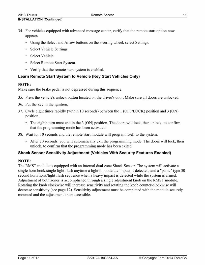
NOTE: The RMST module is equipped with an internal dual zone Shock Sensor. The system will activate asingle horn honk/single light flash anytime a light to moderate impact is detected, and a "panic" type 30second horn honk/light flash sequence when a heavy impact is detected while the system is armed.Adjustment of both zones is accomplished through a single adjustment knob on the RMST module.Rotating the knob clockwise will increase sensitivity and rotating the knob counter-clockwise willdecrease sensitivity (see page 12). Sensitivity adjustment must be completed with the module securelymounted and the adjustment knob accessible.
INSTALLATION (Continued)
34. For vehicles equipped with advanced message center, verify that the remote start option nowappears.
• Using the Select and Arrow buttons on the steering wheel, select Settings.
2013 Taurus Remote Access 11
Page 11 of 17 SK9L2J-19G364-AA © Copyright Ford 2013 FoMoCo
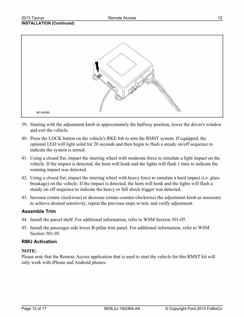
39. Starting with the adjustment knob in approximately the halfway position, lower the driver's windowand exit the vehicle.
40. Press the LOCK button on the vehicle's RKE fob to arm the RMST system. If equipped, theoptional LED will light solid for 20 seconds and then begin to flash a steady on/off sequence toindicate the system is armed.
41. Using a closed fist, impact the steering wheel with moderate force to simulate a light impact on thevehicle. If the impact is detected, the horn will honk and the lights will flash 1 time to indicate thewarning impact was detected.
42. Using a closed fist, impact the steering wheel with heavy force to simulate a hard impact (i.e. glassbreakage) on the vehicle. If the impact is detected, the horn will honk and the lights will flash asteady on off sequence to indicate the heavy or full shock trigger was detected.
43. Increase (rotate clockwise) or decrease (rotate counter-clockwise) the adjustment knob as necessaryto achieve desired sensitivity, repeat the previous steps to test, and verify adjustment.
Assemble Trim44. Install the parcel shelf. For additional information, refer to WSM Section 501-05.
45. Install the passenger side lower B-pillar trim panel. For additional information, refer to WSMSection 501-05.
INSTALLATION (Continued)
RMU Activation
NOTE: Please note that the Remote Access application that is used to start the vehicle for this RMST kit willonly work with iPhone and Android phones.
2013 Taurus Remote Access 12
Page 12 of 17 SK9L2J-19G364-AA © Copyright Ford 2013 FoMoCo
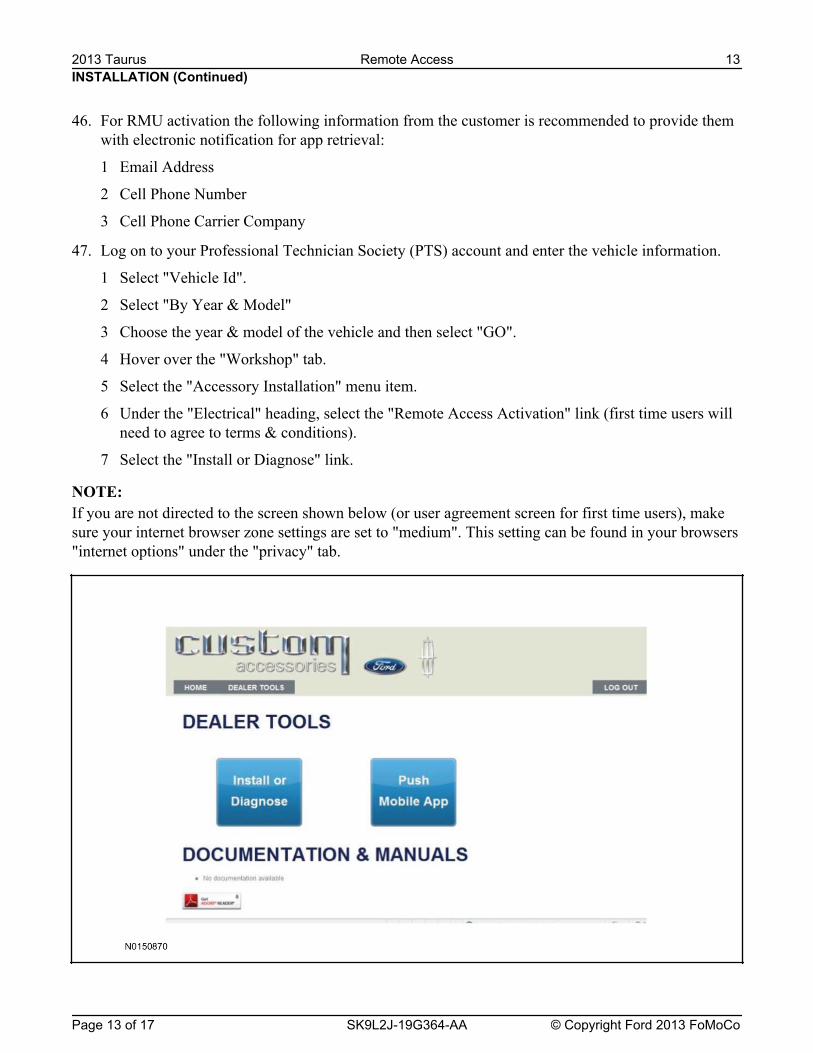
If you are not directed to the screen shown below (or user agreement screen for first time users), makesure your internet browser zone settings are set to "medium". This setting can be found in your browsers"internet options" under the "privacy" tab.
INSTALLATION (Continued)
47. Log on to your Professional Technician Society (PTS) account and enter the vehicle information.
1 Select "Vehicle Id".
2 Select "By Year & Model"
3 Choose the year & model of the vehicle and then select "GO".
4 Hover over the "Workshop" tab.
5 Select the "Accessory Installation" menu item.
6 Under the "Electrical" heading, select the "Remote Access Activation" link (first time users willneed to agree to terms & conditions).
7 Select the "Install or Diagnose" link.
NOTE:
46. For RMU activation the following information from the customer is recommended to provide themwith electronic notification for app retrieval:
1 Email Address
2 Cell Phone Number
3 Cell Phone Carrier Company
2013 Taurus Remote Access 13
Page 13 of 17 SK9L2J-19G364-AA © Copyright Ford 2013 FoMoCo
INSTALLATION (Continued)
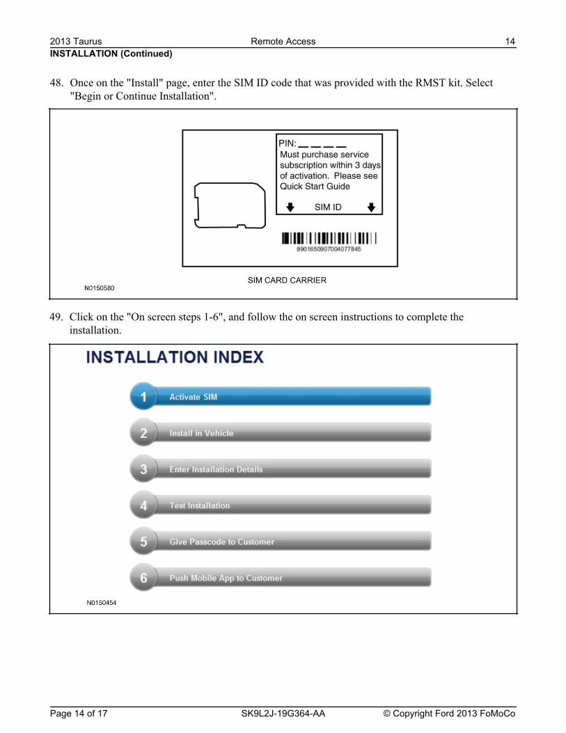
49. Click on the "On screen steps 1-6", and follow the on screen instructions to complete theinstallation.
48. Once on the "Install" page, enter the SIM ID code that was provided with the RMST kit. Select"Begin or Continue Installation".
2013 Taurus Remote Access 14
Page 14 of 17 SK9L2J-19G364-AA © Copyright Ford 2013 FoMoCo
INSTALLATION (Continued)
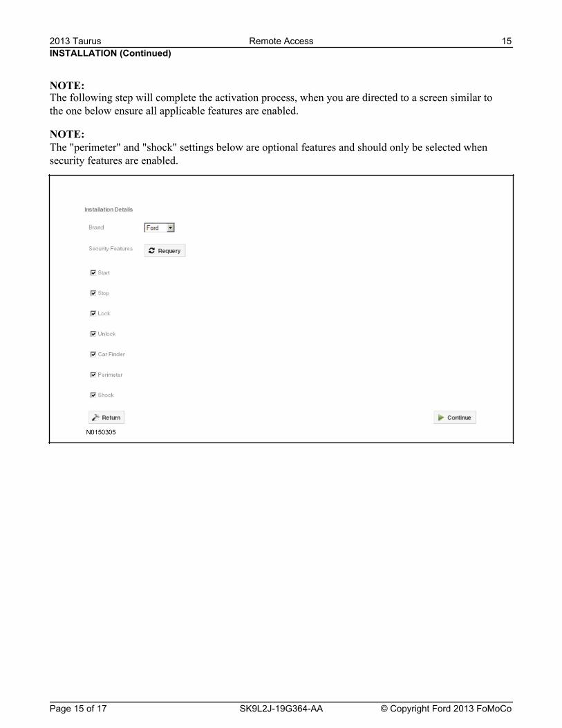
NOTE:
NOTE: The "perimeter" and "shock" settings below are optional features and should only be selected whensecurity features are enabled.
2013 Taurus Remote Access 15
Page 15 of 17 SK9L2J-19G364-AA © Copyright Ford 2013 FoMoCo
The following step will complete the activation process, when you are directed to a screen similar to the one below ensure all applicable features are enabled.
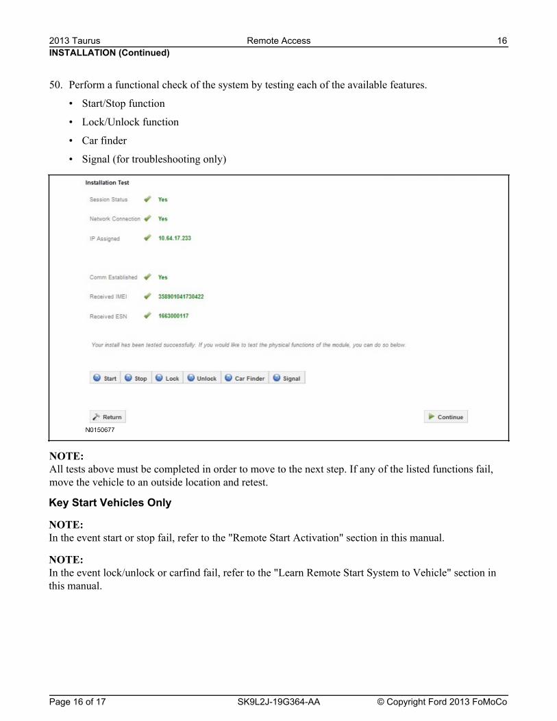
NOTE: All tests above must be completed in order to move to the next step. If any of the listed functions fail,move the vehicle to an outside location and retest.
INSTALLATION (Continued)
50. Perform a functional check of the system by testing each of the available features.
• Start/Stop function
• Lock/Unlock function
• Car finder
• Signal (for troubleshooting only)
2013 Taurus Remote Access 16
Page 16 of 17 SK9L2J-19G364-AA © Copyright Ford 2013 FoMoCo
Key Start Vehicles Only
NOTE: In the event start or stop fail, refer to the "Remote Start Activation" section in this manual.
NOTE: In the event lock/unlock or carfind fail, refer to the "Learn Remote Start System to Vehicle" section inthis manual.
INSTALLATION (Continued)
All Vehicles51. Once the hardware installation and RMU activation process is complete, record the 4-digit PIN on
the SIM card carrier. Provide the SIM card carrier to the customer so they can add this system totheir Remote Access Account. Customer must have both the 4-digit PIN and SIM ID to activate/addtheir vehicle to their Remote Access Account.
52. If the customer agrees, you may push the mobile application to the customer. You will need thecustomer's phone number and cellular carrier. If the customer opts to install the applicationthemselves, they can locate it in their mobile app store.
53. Please contact Ford Hotline with any issues regarding remote access functionality.Please contact 1-800-FORD-KEY with any issues regarding hardware or kit contents.
2013 Taurus Remote Access 17
Page 17 of 17 SK9L2J-19G364-AA © Copyright Ford 2013 FoMoCo
Contents SK9L2J-19G364-AA © Copyright Ford 2013 FoMoCo
2013 MKS Remote Access
Remote Access System Installation
CONTENTS
VEHICLE PREPARATION
*+�,"��",*-+RMST Module InstallationRMU Module Installation
GENERAL PROCEDURES
Shock Sensor Sensitivity Adjustment
RMU Activation
INSTALLATION
Remote Start — MKS
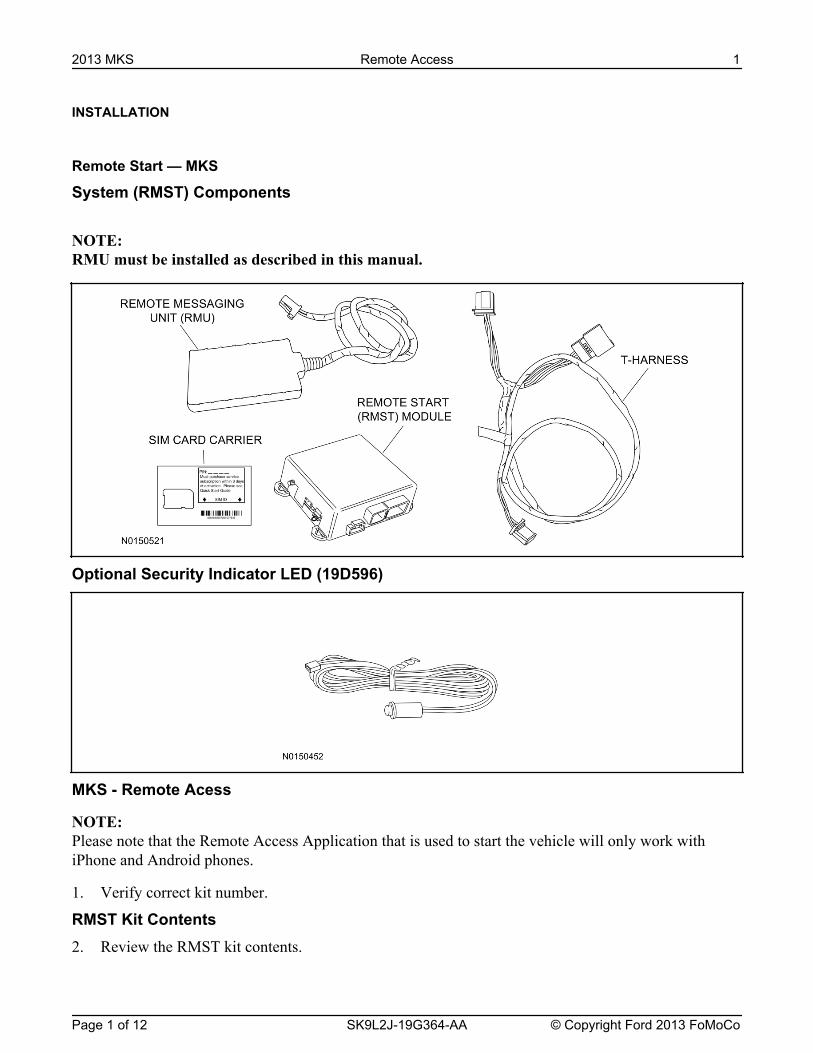
System (RMST) Components
NOTE: RMU must be installed as described in this manual.
Optional Security Indicator LED (19D596)
MKS - Remote Acess
NOTE: Please note that the Remote Access Application that is used to start the vehicle will only work withiPhone and Android phones.
1. Verify correct kit number.
RMST Kit Contents2. Review the RMST kit contents.
2013 MKS Remote Access 1
Page 1 of 12 SK9L2J-19G364-AA © Copyright Ford 2013 FoMoCo

RMST Kit
QUANTITY DESCRIPTION1 RMST Module1 Remote Messaging Unit (RMU)1 T-harness1 Security Jumper (inserted into RMST module)6 Tie Straps (not shown)1 Quick Reference Card (not shown)1 Sim Card Carrier
Optional Security Indicator LED Kit Contents3. Review the Security Indicator LED kit contents.
Security Indicator LED Kit
QUANTITY DESCRIPTION1 Security Indicator LED
Vehicle Preparation4. Remove the rear seat backrest. For additional Information, refer to Workshop Manual (WSM)
Section 501-10.
5. Remove the RH & LH upper C-pillar trim panels. For additional Information, refer to WSM Section501-05.
6. Remove the RH lower B-pillar trim panel. For additional Information, refer to WSM Section501-05.
7. Remove the RH & LH passenger assist handles fom the headliner.
NOTICE: Use caution when lowering headliner. Do not pull down more than necessary to access the TirePressure Monitor (TPM) electrical connector or damage to the headliner may occur.
8. Lower the RH rear corner of the headliner and disconnect the Tire Pressure Monitor (TPM)Module.
INSTALLATION (Continued)2013 MKS Remote Access 2
Page 2 of 12 SK9L2J-19G364-AA © Copyright Ford 2013 FoMoCo
10. Connect the female end of the 8-pin T-harness to the TPM module.
INSTALLATION (Continued)
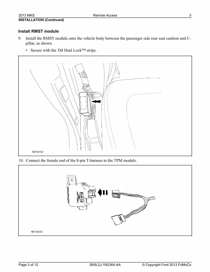
Install RMST module9. Install the RMST module onto the vehicle body between the passenger side rear seat cushion and C-
pillar, as shown.
• Secure with the 3M Dual Lock™ strips.
2013 MKS Remote Access 3
Page 3 of 12 SK9L2J-19G364-AA © Copyright Ford 2013 FoMoCo
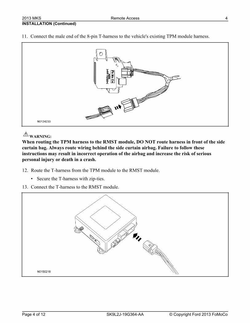
12. Route the T-harness from the TPM module to the RMST module.
• Secure the T-harness with zip-ties.
13. Connect the T-harness to the RMST module.
INSTALLATION (Continued)
WARNING:When routing the TPM harness to the RMST module, DO NOT route harness in front of the sidecurtain bag. Always route wiring behind the side curtain airbag. Failure to follow theseinstructions may result in incorrect operation of the airbag and increase the risk of seriouspersonal injury or death in a crash.
11. Connect the male end of the 8-pin T-harness to the vehicle's existing TPM module harness.
2013 MKS Remote Access 4
Page 4 of 12 SK9L2J-19G364-AA © Copyright Ford 2013 FoMoCo
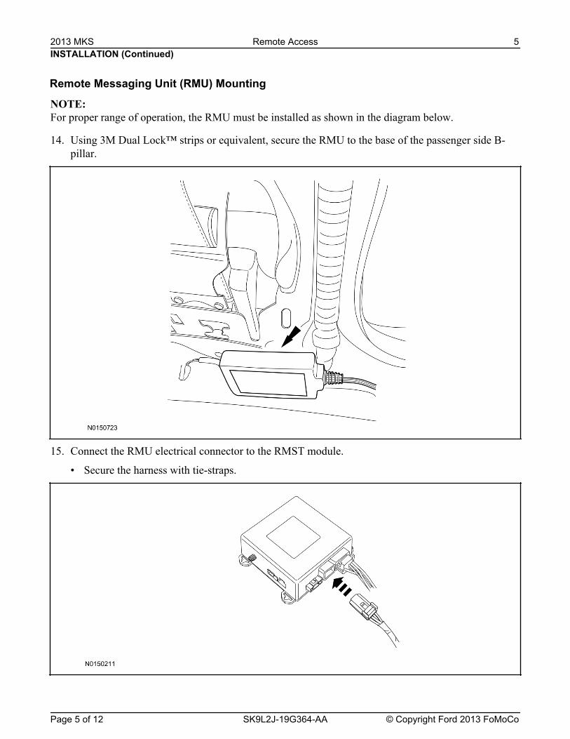
NOTE: For proper range of operation, the RMU must be installed as shown in the diagram below.
14. Using 3M Dual Lock™ strips or equivalent, secure the RMU to the base of the passenger side B-pillar.
15. Connect the RMU electrical connector to the RMST module.
• Secure the harness with tie-straps.
INSTALLATION (Continued)
Remote Messaging Unit (RMU) Mounting
2013 MKS Remote Access 5
Page 5 of 12 SK9L2J-19G364-AA © Copyright Ford 2013 FoMoCo

• Leave the jumper connected to the RMST module to disable the RMST module vehicle securityfeatures.
• Remove the jumper from the RMST module to enable the vehicle security features.
Optional Security Indicator LED Mounting (Vehicles With Security Features Enabled)17. Keep the following points in mind when routing or positioning the LED for mounting:
• Have at least 3/4" clearance behind trim panels for the wiring harness to be routed.
• The LED should be clearly visible from the driver's side window when mounted.
• Do not mount the LED on trim panels that cover air bags.
18. Mount the LED at an appropriate location on the upper steering column shroud, using the guidelineslisted above.
• Drill a 9/32" hole into the selected location, for the LED to mount in.
19. Route the LED wire harness to the RMST module.
INSTALLATION (Continued)
RMST Module - Optional Security Features16. Enable/Disable RMST Module Security Features.
Locate the jumper installed onto the side of the RMST module:
2013 MKS Remote Access 6
Page 6 of 12 SK9L2J-19G364-AA © Copyright Ford 2013 FoMoCo
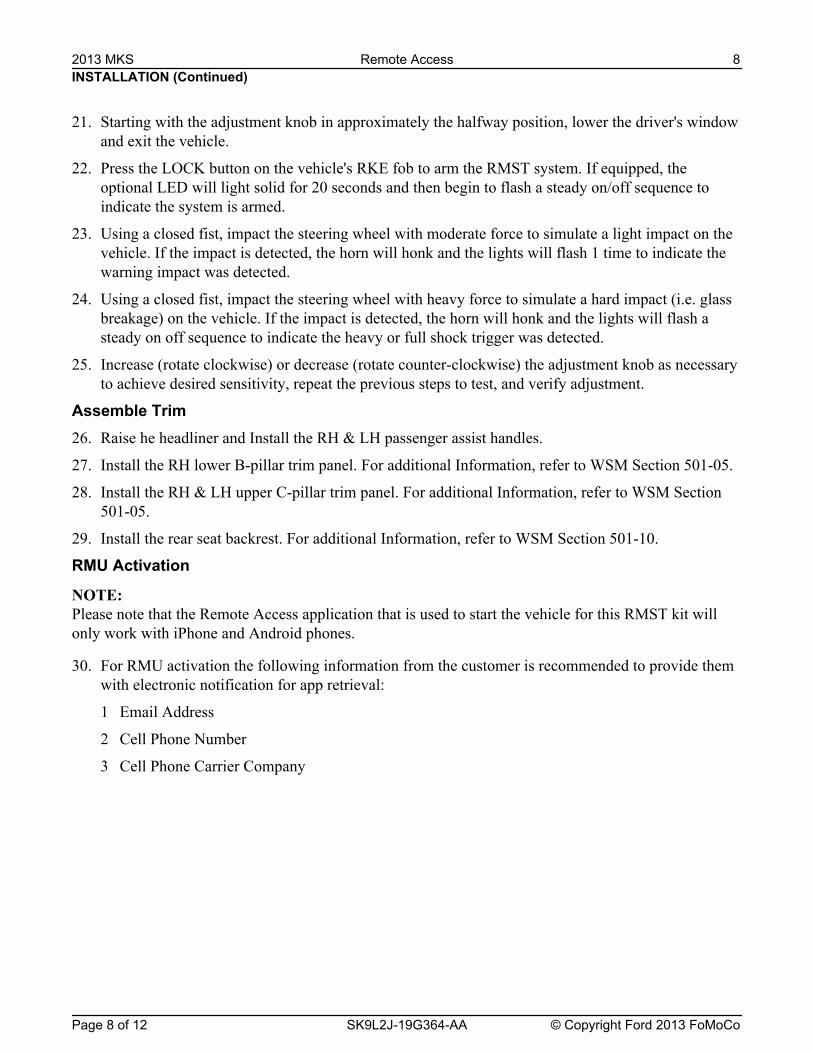
The RMST module is equipped with an internal dual zone Shock Sensor. The system will activate asingle horn honk/single light flash anytime a light to moderate impact is detected, and a "panic" type 30second horn honk/light flash sequence when a heavy impact is detected while the system is armed.Adjustment of both zones is accomplished through a single adjustment knob on the RMST module.Rotating the knob clockwise will increase sensitivity and rotating the knob counter-clockwise willdecrease sensitivity. Sensitivity adjustment must be completed with the module securely mounted andthe adjustment knob accessible.
INSTALLATION (Continued)
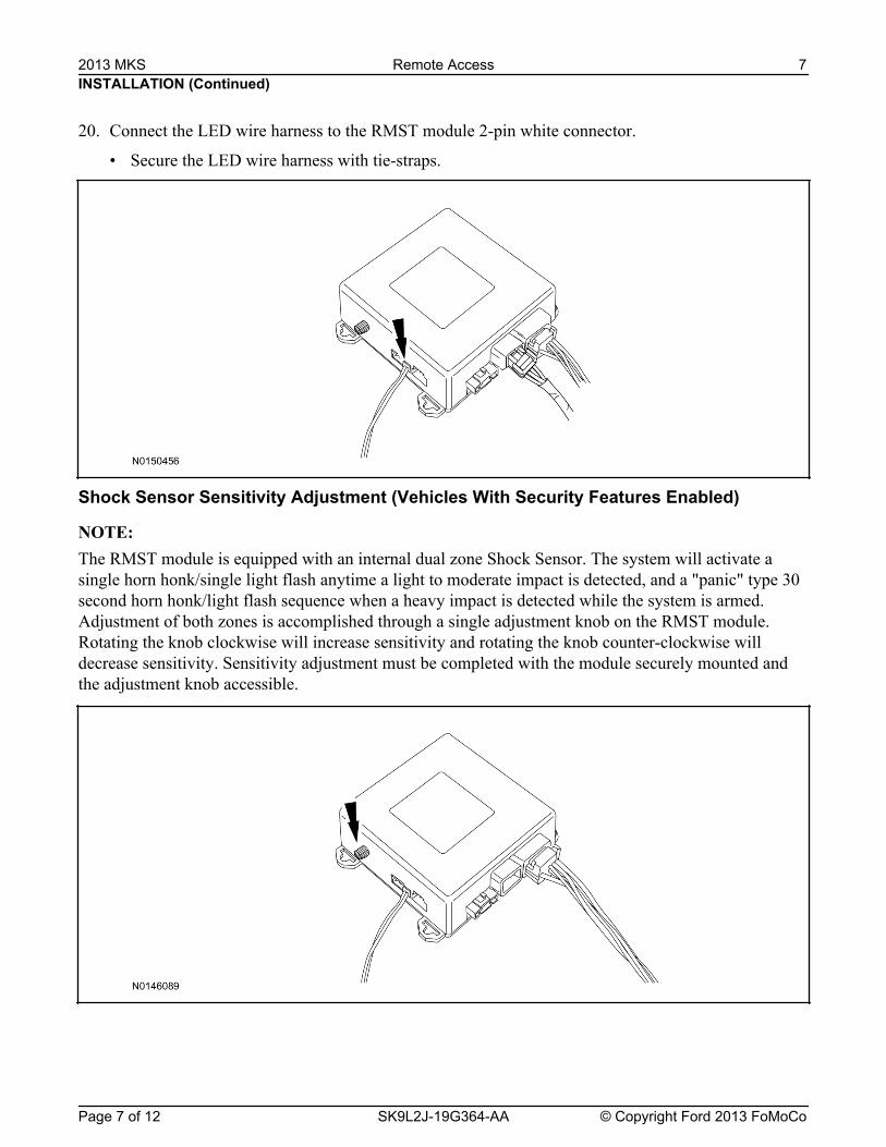
20. Connect the LED wire harness to the RMST module 2-pin white connector.
• Secure the LED wire harness with tie-straps.
Shock Sensor Sensitivity Adjustment (Vehicles With Security Features Enabled)
NOTE:
2013 MKS Remote Access 7
Page 7 of 12 SK9L2J-19G364-AA © Copyright Ford 2013 FoMoCo
INSTALLATION (Continued)
Assemble Trim26. Raise he headliner and Install the RH & LH passenger assist handles.
27. Install the RH lower B-pillar trim panel. For additional Information, refer to WSM Section 501-05.
28. Install the RH & LH upper C-pillar trim panel. For additional Information, refer to WSM Section501-05.
29. Install the rear seat backrest. For additional Information, refer to WSM Section 501-10.
RMU Activation
NOTE: Please note that the Remote Access application that is used to start the vehicle for this RMST kit willonly work with iPhone and Android phones.
30. For RMU activation the following information from the customer is recommended to provide themwith electronic notification for app retrieval:
1 Email Address
2 Cell Phone Number
3 Cell Phone Carrier Company
21. Starting with the adjustment knob in approximately the halfway position, lower the driver's windowand exit the vehicle.
22. Press the LOCK button on the vehicle's RKE fob to arm the RMST system. If equipped, theoptional LED will light solid for 20 seconds and then begin to flash a steady on/off sequence toindicate the system is armed.
23. Using a closed fist, impact the steering wheel with moderate force to simulate a light impact on thevehicle. If the impact is detected, the horn will honk and the lights will flash 1 time to indicate thewarning impact was detected.
24. Using a closed fist, impact the steering wheel with heavy force to simulate a hard impact (i.e. glassbreakage) on the vehicle. If the impact is detected, the horn will honk and the lights will flash asteady on off sequence to indicate the heavy or full shock trigger was detected.
25. Increase (rotate clockwise) or decrease (rotate counter-clockwise) the adjustment knob as necessaryto achieve desired sensitivity, repeat the previous steps to test, and verify adjustment.
2013 MKS Remote Access 8
Page 8 of 12 SK9L2J-19G364-AA © Copyright Ford 2013 FoMoCo
INSTALLATION (Continued)
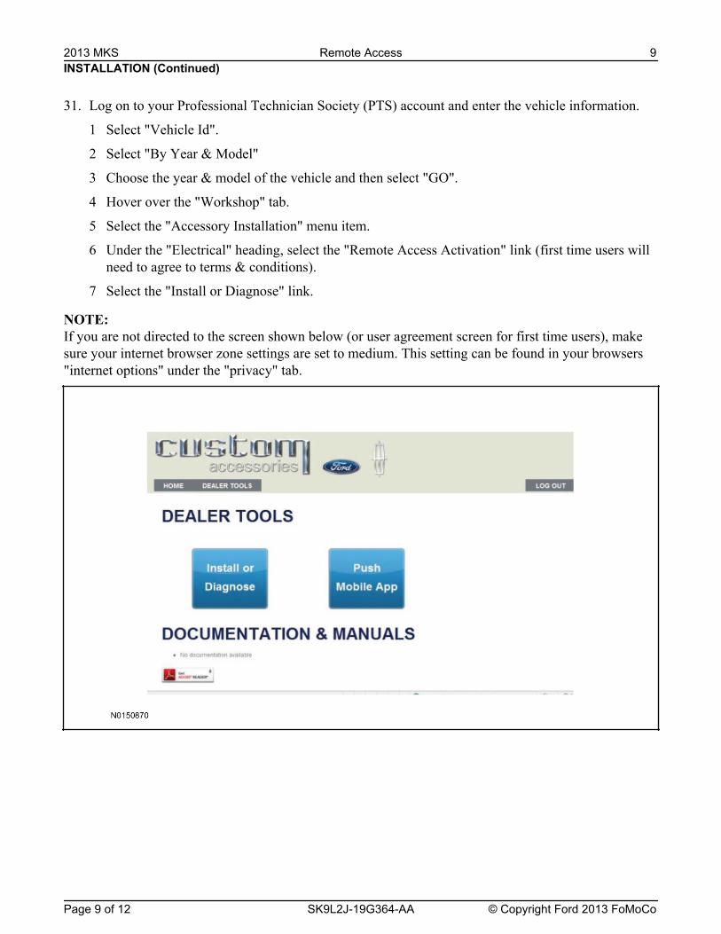
31. Log on to your Professional Technician Society (PTS) account and enter the vehicle information.
1 Select "Vehicle Id".
2 Select "By Year & Model"
3 Choose the year & model of the vehicle and then select "GO".
4 Hover over the "Workshop" tab.
5 Select the "Accessory Installation" menu item.
6 Under the "Electrical" heading, select the "Remote Access Activation" link (first time users willneed to agree to terms & conditions).
7 Select the "Install or Diagnose" link.
NOTE: If you are not directed to the screen shown below (or user agreement screen for first time users), makesure your internet browser zone settings are set to medium. This setting can be found in your browsers"internet options" under the "privacy" tab.
2013 MKS Remote Access 9
Page 9 of 12 SK9L2J-19G364-AA © Copyright Ford 2013 FoMoCo
INSTALLATION (Continued)
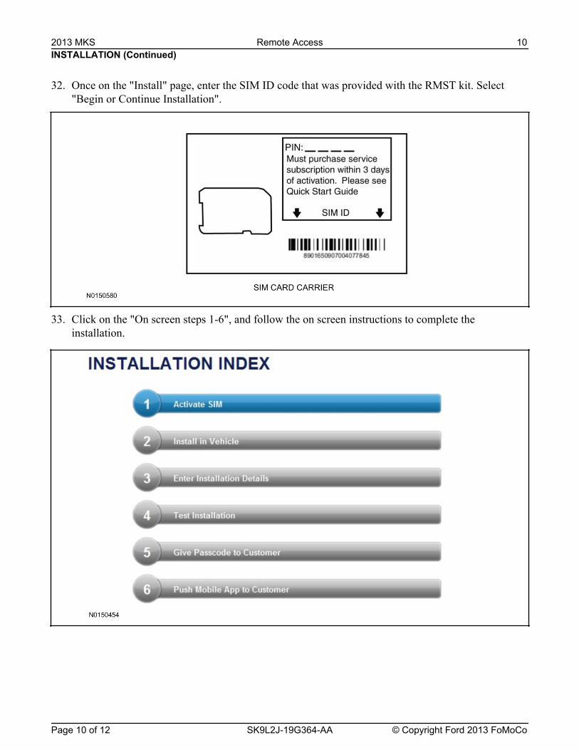
32. Once on the "Install" page, enter the SIM ID code that was provided with the RMST kit. Select"Begin or Continue Installation".
33. Click on the "On screen steps 1-6", and follow the on screen instructions to complete theinstallation.
2013 MKS Remote Access 10
Page 10 of 12 SK9L2J-19G364-AA © Copyright Ford 2013 FoMoCo

INSTALLATION (Continued)
NOTE:
NOTE: The "perimeter" and "shock" settings below are optional features and should only be selected whensecurity features are enabled.
2013 MKS Remote Access 11
Page 11 of 12 SK9L2J-19G364-AA © Copyright Ford 2013 FoMoCo
The following step will complete the activation process, when you are directed to a screen similar to the one below ensure all applicable features are enabled.
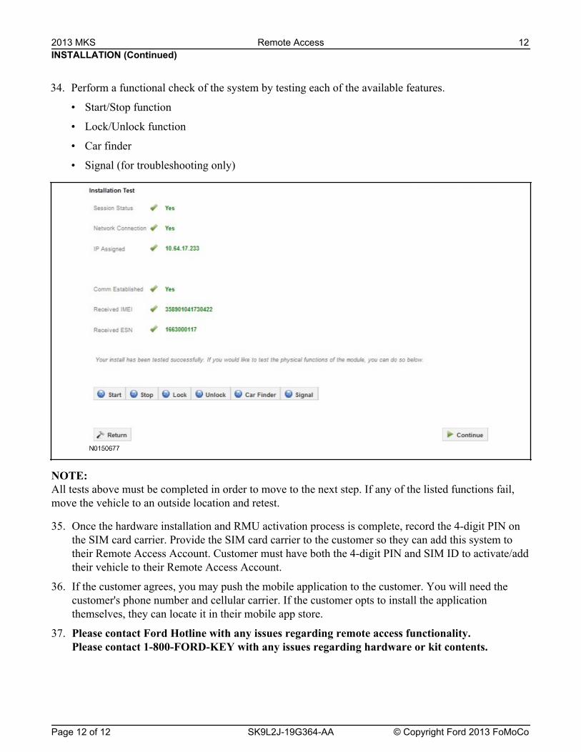
NOTE: All tests above must be completed in order to move to the next step. If any of the listed functions fail,move the vehicle to an outside location and retest.
35. Once the hardware installation and RMU activation process is complete, record the 4-digit PIN onthe SIM card carrier. Provide the SIM card carrier to the customer so they can add this system totheir Remote Access Account. Customer must have both the 4-digit PIN and SIM ID to activate/addtheir vehicle to their Remote Access Account.
36. If the customer agrees, you may push the mobile application to the customer. You will need thecustomer's phone number and cellular carrier. If the customer opts to install the applicationthemselves, they can locate it in their mobile app store.
37. Please contact Ford Hotline with any issues regarding remote access functionality.Please contact 1-800-FORD-KEY with any issues regarding hardware or kit contents.
INSTALLATION (Continued)
34. Perform a functional check of the system by testing each of the available features.
• Start/Stop function
• Lock/Unlock function
• Car finder
• Signal (for troubleshooting only)
2013 MKS Remote Access 12
Page 12 of 12 SK9L2J-19G364-AA © Copyright Ford 2013 FoMoCo
Related Documents