1 SPF-001 (Rev.D1) DOCUMENT RELEASE AND CHANGE FORM Prepared For the U.S. Department of Energy, Assistant Secretary for Environmental Management By Washington River Protection Solutions, LLC., PO Box 850, Richland, WA 99352 Contractor For U.S. Department of Energy, Office of River Protection, under Contract DE-AC27-08RV14800 TRADEMARK DISCLAIMER: Reference herein to any specific commercial product, process, or service by trade name, trademark, manufacturer, or otherwise, does not necessarily constitute or imply its endorsement, recommendation, or favoring by the United States government or any agency thereof or its contractors or subcontractors. Printed in the United States of America. Release Stamp 1. Doc No: RPP-SPEC-60023 Rev. 04 2. Title: Construction Specification for A/AX-Farm Waste Retrieval Project 3. Project Number: T2R02 ☐ N/A 4. Design Verification Required: ☐ Yes ☒ No 5. USQ Number: ☒ N/A N/A-8 6. PrHA Number Rev. ☐ N/A PRHA-02038 00 PRHA-02039 00 PRHA-02040 00 PRHA-02041 00 PRHA-02042 00 PRHA-02043 00 PRHA-02044 00 PRHA-02045 00 PRHA-02046 00 PRHA-02047 00 Clearance Review Restriction Type: public 7. Approvals Title Name Signature Date Clearance Review BRATTON, GAYLA E BRATTON, GAYLA E 03/30/2017 Design Authority SNYDER, JOSHUA J SNYDER, JOSHUA J 03/29/2017 Checker HAGENSEN, ALAN R HAGENSEN, ALAN R 03/06/2017 Document Control Approval WASHINGTON, MARGUERITE WASHINGTON, MARGUERITE 03/30/2017 Originator QUAM, PAUL R QUAM, PAUL R 03/03/2017 Other Approver CAMPBELL, RICHARD B CAMPBELL, RICHARD B 03/06/2017 Other Approver WITHERSPOON, JP P WITHERSPOON, JP P 03/25/2017 Other Approver BRYDEN, MICHAEL J BRYDEN, MICHAEL J 03/23/2017 Other Approver PARKMAN, DAVID B PARKMAN, DAVID B 03/28/2017 PrHA Lead SMITH, RYAN D SMITH, RYAN D 03/29/2017 Responsible Engineering Manager HANSON, CARL E HANSON, CARL E 03/29/2017 USQ Evaluator SMITH, RYAN D SMITH, RYAN D 03/29/2017 8. Description of Change and Justification Problem: RPP-SPEC-60023 requires updating new A/AX Infrastructure designs. Solution: Update RPP-SPEC-60023 from Revision 3 to Revision 4 to address necessary updates. See continuation page for a summary of the changes. This revision does not change any requirements for safety significant systems. 9. TBDs or Holds ☒ N/A 10. Related Structures, Systems, and Components a. Related Building/Facilities ☐ N/A b. Related Systems ☐ N/A c. Related Equipment ID Nos. (EIN) ☐ N/A 241-A 241-A-285 241-AX 241-EDS 241-PA 241-RC 241-RW 241-WT A285-RW-BFP-001 11. Impacted Documents – Engineering ☒ N/A Document Number Rev. Title 12. Impacted Documents (Outside SPF): N/A 13. Related Documents ☐ N/A Document Number Rev. Title 58776-005-RFI-006 00 RFI - Lead Times: Aloyco Valves (Eng Review Nec, RPP-SPEC-60023 R3, DCN-TBD & Clarif Only) DCN-713162 00 Change Valve from Aloyco to Powell for A285 Water System RPP-CALC-60167 01 241-AX Farm Buried & Above Grade Water and Chemical Piping ASME B31.3 and B31.9 Analysis RPP-CALC-60217 00 241-A-285 Air and Water Service Building ASME Piping Analysis RPP-SPEC-60023 Rev.04 3/30/2017 - 8:14 AM 1 of 315 Mar 30, 2017 DATE:

Welcome message from author
This document is posted to help you gain knowledge. Please leave a comment to let me know what you think about it! Share it to your friends and learn new things together.
Transcript
1 SPF-001 (Rev.D1)
DOCUMENT RELEASE AND CHANGE FORMPrepared For the U.S. Department of Energy, Assistant Secretary for Environmental ManagementBy Washington River Protection Solutions, LLC., PO Box 850, Richland, WA 99352Contractor For U.S. Department of Energy, Office of River Protection, under Contract DE-AC27-08RV14800
TRADEMARK DISCLAIMER: Reference herein to any specific commercial product, process, or service by trade name, trademark, manufacturer, or otherwise, does not necessarily constitute or imply its endorsement, recommendation, or favoring by the United States government or any agency thereof or its contractors or subcontractors. Printed in the United States of America.
Release Stamp
1. Doc No: RPP-SPEC-60023 Rev. 04
2. Title:Construction Specification for A/AX-Farm Waste Retrieval Project
3. Project Number:T2R02
☐ N/A 4. Design Verification Required:
☐ Yes ☒ No
5. USQ Number: ☒ N/A
N/A-8
6. PrHA Number Rev. ☐ N/A
PRHA-02038 00PRHA-02039 00PRHA-02040 00PRHA-02041 00PRHA-02042 00PRHA-02043 00PRHA-02044 00PRHA-02045 00PRHA-02046 00PRHA-02047 00
Clearance Review Restriction Type:public
7. Approvals
Title Name Signature Date
Clearance Review BRATTON, GAYLA E BRATTON, GAYLA E 03/30/2017
Design Authority SNYDER, JOSHUA J SNYDER, JOSHUA J 03/29/2017
Checker HAGENSEN, ALAN R HAGENSEN, ALAN R 03/06/2017
Document Control Approval WASHINGTON, MARGUERITE WASHINGTON, MARGUERITE 03/30/2017
Originator QUAM, PAUL R QUAM, PAUL R 03/03/2017
Other Approver CAMPBELL, RICHARD B CAMPBELL, RICHARD B 03/06/2017
Other Approver WITHERSPOON, JP P WITHERSPOON, JP P 03/25/2017
Other Approver BRYDEN, MICHAEL J BRYDEN, MICHAEL J 03/23/2017
Other Approver PARKMAN, DAVID B PARKMAN, DAVID B 03/28/2017
PrHA Lead SMITH, RYAN D SMITH, RYAN D 03/29/2017
Responsible Engineering Manager HANSON, CARL E HANSON, CARL E 03/29/2017
USQ Evaluator SMITH, RYAN D SMITH, RYAN D 03/29/2017
8. Description of Change and Justification
Problem: RPP-SPEC-60023 requires updating new A/AX Infrastructure designs.
Solution: Update RPP-SPEC-60023 from Revision 3 to Revision 4 to address necessary updates. See continuation page for a summary of the changes.
This revision does not change any requirements for safety significant systems.
9. TBDs or Holds ☒ N/A
10. Related Structures, Systems, and Components
a. Related Building/Facilities ☐ N/A b. Related Systems ☐ N/A c. Related Equipment ID Nos. (EIN) ☐ N/A
241-A
241-A-285
241-AX
241-EDS
241-PA
241-RC
241-RW241-WT
A285-RW-BFP-001
11. Impacted Documents – Engineering ☒ N/A
Document Number Rev. Title
12. Impacted Documents (Outside SPF):
N/A
13. Related Documents ☐ N/A
Document Number Rev. Title
58776-005-RFI-006 00 RFI - Lead Times: Aloyco Valves (Eng Review Nec, RPP-SPEC-60023 R3, DCN-TBD & Clarif Only)
DCN-713162 00 Change Valve from Aloyco to Powell for A285 Water System
RPP-CALC-60167 01 241-AX Farm Buried & Above Grade Water and Chemical Piping ASME B31.3 and B31.9 Analysis
RPP-CALC-60217 00 241-A-285 Air and Water Service Building ASME Piping Analysis
RPP-SPEC-60023 Rev.04 3/30/2017 - 8:14 AM 1 of 315
Mar 30, 2017
DATE:
DOCUMENT RELEASE AND CHANGE FORM Doc No: RPP-SPEC-60023 Rev. 04
2 SPF-001 (Rev.D1)
14. Distribution
Name Organization
ATKINS, LARRY B CONSTRUCTION & COMMISSIONING
BRYDEN, MICHAEL J C-FARM RETRIEVAL ENGRNG
COOK, SHAUN M
DEBUIGNE, PAUL B A/AX RETRIEVAL ENGRNG
HOPKINS, GARY P R&C CONSTRUCTION
HULL, KEVIN J ELECTRICAL/AREA/242A-EVAP ENG
PARKMAN, DAVID B MARS-BASED RETRIEVAL ENGRNG
SPOONER, TRACY L CONSTRUCTION & COMMISSIONING
STEPHENS, RANDALL F
WHITE, JEREMEY C PROJECTS WORK PACKAGE PLANNING
WIKSTRAND, CHRIS B CONSTRUCTION & COMMISSIONING
WITHERSPOON, JP P A/AX RETRIEVAL ENGRNG
RPP-SPEC-60023 Rev.04 3/30/2017 - 8:14 AM 2 of 315
CONTINUATION SHEET
Continuation of block 7 from sheet 1:
Update Sections 40 05 13, 40 41 00, and 40 42 00 with changes per new design of above grade piping and pipe spools.
Update Section 40 05 13 per RFI 61800-000-RFI-029 to call out ASTM A403 fittings for 6 inch and larger.
Update Section 40 05 22 (HIHTL System Installation) to add reference to RPP-14859 and remove coating requirements from Section 2.2.D and heat tracing from what was Section 2.2.F. Also clarified Paragraphs 3.2.A & K, 3.3.C, and 3.4.5(now 4) and deleted Paragraph 3.4.A.4.
Add new Section 40 24 10 Chemical Piping to support fabrication of the A/AX Chemical Addition System (as depicted on H¬-14-022209, H-14-110574, etc).
Changes for option of installing RNC conduit in Electrical sections:Revised Section 26 05 19 to add information for using mechanical tugger. Also update Paragraph 3.3.D to include stranded wire and deleted Paragraphs 3.8.B and 3.8.C.2.b.
Revised Section 26 05 26 Paragraph 2.3.B to include stranded wire.
Revised Section 26 05 33 Paragraph 1.2 to revise title of NEMA TC 2 and to add NEMA TC 6 & 8, NEMA TC 7, NEMA TC 9, and UL 651A.
Revised Section 26 05 33 Paragraph 2.4 to remove subsection “D”.
Revised Section 26 05 33 Paragraph 2.5.A to add UL 651A, NEMA TC 3, NEMA TC 6 & 8, and NEMA TC 7.
Revised Section 26 05 33 Paragraph 2.5.B to remove UL 514C and add UL 651 and NEMA TC 9.
Revised Section 26 05 33 Paragraph 2.16.G.2.b to Tier 22.
Revised Section 26 05 33 to add new Paragraphs to 3.4 “Outdoors – underground not in Tank Farm” and “Indoors – exposed outside of designated electrical rooms”.
Revised Section 26 05 33 Paragraph 3.4.4(now 5).a to add “or RNC type EB”.
Revised Section 26 05 33 Paragraph 3.4.4(now 5).b to add “or RNC type DB or EB” and to change to “0 in. below the bottom of the concrete slab”.
Removed Section 26 05 33 Paragraph 3.4.I.M. “Do not use RNC 90 degree elbows large thatn 2 in. trade size; use plastic-coatedRMC, tape-wrappped RMC.”
Revised Section 26 05 33 Paragraph 3.6.A.3 to locate thermostats 60” high.
Revised Section 26 05 53 Paragraph 3.9.A to delete 12” minimum requirement.
Revised Section 26 10 00 Paragraph 1.2.F to remove superceded document FS W-C-1094.
Revised Section 26 10 00 Paragraph 1.2 to add New G Title “Institute of Electrical and Electronics Engineers (IEEE)”.
Revised Section 26 10 00 Paragraph 1.2.H(now I) to add NEMA TC 2, NEMA TC 3, NEMA TC 6 & 8, NEMA TC 7 and NEMA TC 9.
Revised Section 26 10 00 Paragraph 1.2.J(now K) to revise title of UL 651, and add UL 514B, 514C, and 651A.
Revised Section 26 10 00 Paragraph 2.1.C.2 to remove superceded document FS W-C-1094, and add NEMA TC 9, UL 514B, 514C, 651 and 651A.
Revised Section 26 10 00 Paragraph 2.1.C.3 to read “Type DB PVC RNC EPC 40 (Schedule 40) & EPC 80 (Schedule 80), NEMA TC 6 & 8, UL 514B, UL 514C, UL 651, UL 651A.”
Added Section 26 10 00 Paragraph 2.1.C.4 “Type HDPE RNC EPEC NEMA TC 7, UL 514B, UL 514C, UL 651, UL 651A”.
Revised Section 26 22 13 Paragraph 3.1.B to delete “Clean and repair existing dry-type transformers that are to remain.”
Revised Section 26 24 16 Paragraph 1.6 to not require multiple keys or extra touch up paint.
RPP-SPEC-60023 Rev.04 3/30/2017 - 8:14 AM 3 of 315
A-6002-767 (REV 3)
RPP-SPEC-60023, Rev. 4
CONSTRUCTION SPECIFICATION FOR A/AX-FARMS WASTE RETRIEVAL PROJECT
Author Name:
PR Quam
Prepared by ARES Corporation for Washington River Protection Solutions, LLC
Richland, WA 99352 U.S. Department of Energy Contract DE-AC27-08RV14800
EDT/ECN: DRCF UC: N/A
Cost Center: N/A Charge Code:
B&R Code: N/A Total Pages: See page count
Key Words: 241-AX, 241-A, Construction, Specification, single-shell tank, retrieval, testing, inspection,
equipment
Abstract: This specification provides the technical requirements for fabrication, materials, installation,
inspection, testing, and handling for equipment and systems required for A/AX-Farms single-shell tank
waste retrieval.
TRADEMARK DISCLAIMER. Reference herein to any specific commercial product, process, or service by trade name, trademark, manufacturer, or otherwise, does not necessarily constitute or imply its endorsement, recommendation, or favoring by the United States Government or any agency thereof or its contractors or subcontractors.
Release Approval Date Release Stamp
Approved For Public Release
RPP-SPEC-60023 Rev.04 3/30/2017 - 8:14 AM 4 of 315
By G. E. Bratton at 8:39 am, Mar 30, 2017
Mar 30, 2017
DATE:
RPP-SPEC-60023, Rev. 4
CONSTRUCTION SPECIFICATION FOR
A/AX-FARMS WASTE RETRIEVAL PROJECT
March 2017
prepared by
ARES Corporation
Energy Services Division
1100 Jadwin Avenue, Suite 400
Richland, Washington 99352
(509) 946-3300
prepared for
Washington River Protection Solutions, LLC
RPP-SPEC-60023 Rev.04 3/30/2017 - 8:14 AM 5 of 315
RPP-SPEC-60023, Rev. 4
ii
TABLE OF CONTENTS
Section No. of
Pages
Title Pages 2
Table of Contents 2
DIVISION 01 – GENERAL REQUIREMENTS
Division 01 Sections are under separate cover – see WRPS Statement of Work (SOW)
DIVISION 02 – EXISTING CONDITIONS
Section 02 41 00 Demolition 3
DIVISION 03 – CONCRETE
Section 03 15 00 Post-Installed Concrete Anchor Bolts 3
Section 03 30 00 Concrete 17
DIVISION 05 – METALS
Section 05 50 00 Metal Fabrications 7
Section 05 53 00 Metal Gratings 5
DIVISION 06 – WOOD, PLASTICS, AND COMPOSITES
Section 06 10 00 Carpentry 10
DIVISION 07 – THERMAL AND MOISTURE PROTECTION
Section 07 92 00 Joint Sealants 5
DIVISION 09 – FINISHES
Section 09 91 00 Painting 6
Section 09 96 00 High-Performance Coatings 7
DIVISION 13 – SPECIAL CONSTRUCTION
Section 13 34 19 Metal Building Systems 39
Section 13 47 13.13 Cathodic Protection for Underground and Submerged Piping 9
DIVISION 22 – PLUMBING
Section 22 15 00 Compressed Air Piping 10
DIVISION 23 – HVAC
Section 23 31 01 Tank Ventilation Ducting 3
Section 23 31 13 Air Compressor Metal Ducts 4
RPP-SPEC-60023 Rev.04 3/30/2017 - 8:14 AM 6 of 315
RPP-SPEC-60023, Rev. 4
iii
Section No. of
Pages
DIVISION 26 – ELECTRICAL
Section 26 05 19 Low Voltage Electrical Power Conductors and Cables 15
Section 26 05 26 Grounding and Bonding for Electrical Systems 9
Section 26 05 29 Hangers and Supports for Electrical Systems 6
Section 26 05 33 Raceways and Boxes for Electrical Systems 13
Section 26 05 53 Identification for Electrical Systems 8
Section 26 10 00 Medium Voltage Electrical Distribution 12
Section 26 22 13 Low Voltage Distribution Transformers 5
Section 26 24 13 Switchboards 4
Section 26 24 16 Panelboards 5
Section 26 27 26 Wiring Devices 5
Section 26 28 16 Enclosed Switches and Circuit Breakers 4
Section 26 51 00 Interior Lighting 3
Section 26 56 00 Exterior Lighting 6
DIVISION 31 – EARTHWORK Section 31 23 00 Excavation and Fill 17
DIVISION 33 – UTILITIES
Section 33 10 00 Water Utilities 15
DIVISION 40 – PROCESS INTEGRATION
Section 40 05 13 Process Piping 17
Section 40 05 22 Hose-in-Hose Transfer Line System Installation 8
Section 40 24 10 Chemical Piping 15
Section 40 41 00 Process Piping and Equipment Heat Tracing 5
Section 40 42 00 Process Piping and Equipment Insulation 7
RPP-SPEC-60023 Rev.04 3/30/2017 - 8:14 AM 7 of 315
RPP-SPEC-60023 Rev.04 3/30/2017 - 8:14 AM 8 of 315
RPP-SPEC-60023, Rev. 4
02 41 00 – 1
SECTION 02 41 00
DEMOLITION
PART 1 GENERAL
1.1 RELATED DOCUMENTS / CODES AND STANDARDS
Drawings and general provisions of the Contract Statement of Work, including
Division 01 Specification Sections, apply to this Section.
The following documents and others referenced therein, form part of the Contract to the
extent designated in this Section. Referenced documents are those current as of the date
of this Section unless otherwise indicated.
A. Code of Federal Regulations (CFR)
29 CFR Part 1910.94 Occupational Health and Environmental Control,
Subpart G, U.S. Department of Labor, Occupational
Safety and Health Administration (OSHA)
29 CFR Part 1926 Safety and Health Regulations for Construction
B. Hanford Documents
TFC-ESHQ-S-STD-30 Implementation of DOE-0344, Excavating,
Trenching, and Shoring
C. National Fire Protection Association (NFPA)
NFPA 70, 2014®1
National Electrical Code®1
(NEC
®1)
NFPA 70E®1
Standard for Electrical Safety in the Workplace
D. Washington Administrative Code (WAC)
Title 173, Department of Ecology, Chapter 173-303, Dangerous Waste
Regulations.
1.2 SUBMITTALS
Not Used.
1 NFPA 70, National Electrical Code, NEC, and NFPA 70E are registered trademarks of the National Fire Protection
Association, Quincy, Massachusetts.
RPP-SPEC-60023 Rev.04 3/30/2017 - 8:14 AM 9 of 315
RPP-SPEC-60023, Rev. 4
02 41 00 – 2
1.3 PERMITS
A. Permits are addressed by TOC work control process.
1. Deleted.
2. Deleted.
PART 2 PRODUCTS
Not Used.
PART 3 EXECUTION
3.1 EXAMINATION
A. Before beginning cutting or demolition, survey existing work and examine the
Drawings and Specifications to determine extent of work. Coordinate work of
this Section with other work.
B. Determine if any type of chemicals, gases, flammable materials, or other
dangerous materials have been used in pipes or other equipment based on job
hazard evaluation or Excavation Permit. Control hazards associated with these
materials prior to demolition per the work control process.
3.2 PREPARATION
A. Personnel Protection: Provide safeguards, including warning signs, barricades,
and temporary closures required for protection of construction personnel and
others during demolition and removal operations.
B. Ensure that structural elements are not overloaded as a result of cutting, removal,
or demolition. Construct and maintain shoring, bracing, and supports as required.
C. Disconnect existing utility services specified by Washington River Protection
Solutions (WRPS) Engineering Change Notice (ECN) or Mission Support
Alliance Engineering Change Request (ECR). If no direction is included in an
ECN or ECR, proceed as directed by the work control process.
3.3 PERFORMANCE
A. Control amount of dust resulting from demolition to prevent spread of dust and to
avoid creation of dust in surrounding area. Do not use water if ice, flooding, or
pollution could occur. Follow requirements of state Waste Discharge Permit
ST4511.
RPP-SPEC-60023 Rev.04 3/30/2017 - 8:14 AM 10 of 315
RPP-SPEC-60023, Rev. 4
02 41 00 – 3
B. Demolition Operations.
1. Remove equipment from tanks in accordance with applicable Work
Packages, ECNs, and required work controls, such as Radiological Work
Permit (RWP).
2. Dispose of debris in accordance with Contract Statement of Work
requirements.
END OF SECTION 02 41 00
RPP-SPEC-60023 Rev.04 3/30/2017 - 8:14 AM 11 of 315
RPP-SPEC-60023, Rev. 4
03 15 00 – 1
SECTION 03 15 00
POST-INSTALLED CONCRETE ANCHOR BOLTS
PART 1 GENERAL
1.1 RELATED DOCUMENTS / CODES AND STANDARDS
Drawings and general provisions of the Contract Statement of Work, including
Division 01 Specification Sections, apply to this Section.
The following documents and others referenced therein, form part of the Contract to the
extent designated in this Section. Referenced documents are those current as of the date
of this Section unless otherwise indicated.
A. Hanford Documents
TFC-ENG-STD-06 Design Loads for Tank Farm Facilities
B. International Code Council (ICC)
ESR-1917 Hilti®2 Kwik Bolt TZ Carbon and Stainless Steel
Anchors in Concrete
ESR-1546 Hilti HDA Carbon Steel and Stainless Steel
Undercut Anchors for Cracked and Uncracked
Concrete
IBC International Building Code
1.2 SUBMITTALS
A. See the Contract Statement of Work for the submittal process.
B. Approval Required
1. Training Records (Paragraph 1.3.A): 5 days before installation.
2. Special Inspection Qualifications (Paragraph 1.3.C): 5 days before start of
installation.
3. Deleted.
C. Deleted.
1. Deleted.
2 Hilti is a registered trademark of Hilti Corporation, Schaan, Liechtenstein.
RPP-SPEC-60023 Rev.04 3/30/2017 - 8:14 AM 12 of 315
RPP-SPEC-60023, Rev. 4
03 15 00 – 2
1.3 QUALITY ASSURANCE
A. Contractor shall train post-installed anchor installers. Installers shall be trained to
the anchor manufacturer’s installation instructions, design document
requirements, and the anchor installation report. Contractor shall deliver installer
training records to the Company.
B. Misrepresented Products: See the Contract Statement of Work for required
measures to prevent use of misrepresented products.
C. Post-Installed Anchor Special Inspector Qualifications.
1. Two years’ experience in concrete inspection and/or certification from
American Concrete Institute, ICC, International Conference of Building
Officials, or other recognized concrete inspection agency to be provided
by the Tank Operations Contractor (TOC).
1.4 DELIVERY, STORAGE, AND HANDLING
A. See Contract Statement of Work for general requirements.
PART 2 PRODUCTS
2.1 SUBSTITUTES
A. See Contract Statement of Work for substitution approvals.
2.2 MATERIALS
A. Post-installed anchors (PC-2, PC-1, and PC-0): Industry standard wedge-type
having a published evaluation report (by ICC Evaluation Services, Inc.), with
anchor descriptions, tables of allowable tension and shear loads (including
seismic and wind qualifications), and test findings.
B. Hilti Corporation or approved equal:
1. Kwik Bolt TZ Expansion Anchor.
2. HDA Metric Undercut Anchor.
C. Anchors located in dry, interior locations may be carbon steel. Anchors located in
wet or potentially wet interior locations (e.g., water building installations) and
exterior locations shall be stainless steel.
D. Anchorage must be designed to TFC-ENG-STD-06.
RPP-SPEC-60023 Rev.04 3/30/2017 - 8:14 AM 13 of 315
RPP-SPEC-60023, Rev. 4
03 15 00 – 3
PART 3 EXECUTION
3.1 EXAMINATION
A. Examine areas where expansion anchors are to be installed and notify the
Company, in writing, of conditions detrimental to proper and timely completion
of work. Do not proceed with work until unsatisfactory conditions have been
corrected.
3.2 PREPARATION
A. For expansion anchors larger than 3/8 in., locate rebar by scanning before drilling.
For expansion anchors 3/8 in. or smaller, avoid cutting rebar by using a drill with
a concealed-metal detector shutoff.
B. Do not install anchors in concrete prior to 28 days after concrete placement unless
it can be shown by testing that the concrete design strength has been obtained.
3.3 INSTALLATION
A. Expansion Anchor Installation
1. Install anchors shown on the Drawings in accordance with training.
2. Notify the TOC Construction Representative if reinforcing steel is
encountered when drilling.
3.4 FIELD INSPECTIONS AND TESTS
A. Special Inspection is required for all anchor bolt installations. This shall be done
in accordance with Section 4 of the applicable ICC Evaluation Report. The
special inspector shall be on the jobsite during anchor installation to verify anchor
type, anchor dimensions, hole dimensions, hole cleaning procedures, anchor
spacing, edge distances, drill bit size, anchor embedment and tightening torque.
Complete inspections shall be documented by the inspector on Expansion Anchor
Installation Report (Form A-6004-239) (or Company-approved equivalent) and
documented in the work package.
B. Installation Reports (Paragraph 3.4.A): Within 10 days after work is complete
(Expansion Anchor Installation Report [Form A-6004-239]).
END OF SECTION 03 15 00
RPP-SPEC-60023 Rev.04 3/30/2017 - 8:14 AM 14 of 315
RPP-SPEC-60023, Rev. 4
03 30 00 – 1
SECTION 03 30 00
CONCRETE
PART 1 GENERAL
1.1 SCOPE OF WORK
A. Formwork.
B. Reinforcement.
C. Cast-In-Place Items.
D. Mixture Design.
E. Placement Procedures.
F. Cast-in-Place Concrete.
G. Pre-Cast Concrete.
H. Finishes for pre-engineered metal buildings.
I. Concrete Test Cylinders.
J. Grout Test Blocks.
1.2 RELATED SECTIONS
A. Section 05 53 00, “Metal Gratings.”
B. Section 09 96 00, “High-Performance Coatings.”
C. Section 13 34 19, “Metal Building Systems.”
D. Section 31 23 00, “Excavation and Fill.”
1.3 RELATED DOCUMENTS, CODES, AND STANDARDS
Drawings and general provisions of the Contract Statement of Work, including Division
01 Specification Sections, apply to this Section.
The following documents and others referenced therein, form part of the Contract to the
extent designated in this Section. Referenced documents are those current as of the date
of this Section unless otherwise indicated.
RPP-SPEC-60023 Rev.04 3/30/2017 - 8:14 AM 15 of 315
RPP-SPEC-60023, Rev. 4
03 30 00 – 2
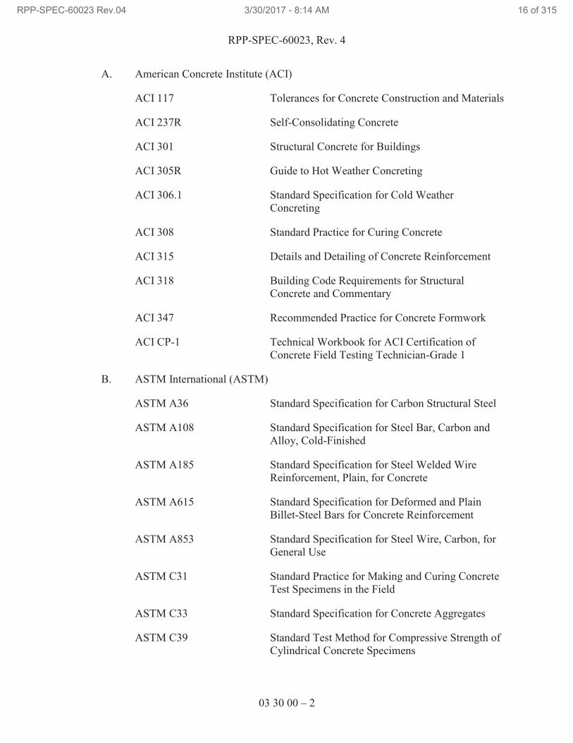
A. American Concrete Institute (ACI)
ACI 117 Tolerances for Concrete Construction and Materials
ACI 237R Self-Consolidating Concrete
ACI 301 Structural Concrete for Buildings
ACI 305R Guide to Hot Weather Concreting
ACI 306.1 Standard Specification for Cold Weather
Concreting
ACI 308 Standard Practice for Curing Concrete
ACI 315 Details and Detailing of Concrete Reinforcement
ACI 318 Building Code Requirements for Structural
Concrete and Commentary
ACI 347 Recommended Practice for Concrete Formwork
ACI CP-1 Technical Workbook for ACI Certification of
Concrete Field Testing Technician-Grade 1
B. ASTM International (ASTM)
ASTM A36 Standard Specification for Carbon Structural Steel
ASTM A108 Standard Specification for Steel Bar, Carbon and
Alloy, Cold-Finished
ASTM A185 Standard Specification for Steel Welded Wire
Reinforcement, Plain, for Concrete
ASTM A615 Standard Specification for Deformed and Plain
Billet-Steel Bars for Concrete Reinforcement
ASTM A853 Standard Specification for Steel Wire, Carbon, for
General Use
ASTM C31 Standard Practice for Making and Curing Concrete
Test Specimens in the Field
ASTM C33 Standard Specification for Concrete Aggregates
ASTM C39 Standard Test Method for Compressive Strength of
Cylindrical Concrete Specimens
RPP-SPEC-60023 Rev.04 3/30/2017 - 8:14 AM 16 of 315
RPP-SPEC-60023, Rev. 4
03 30 00 – 3
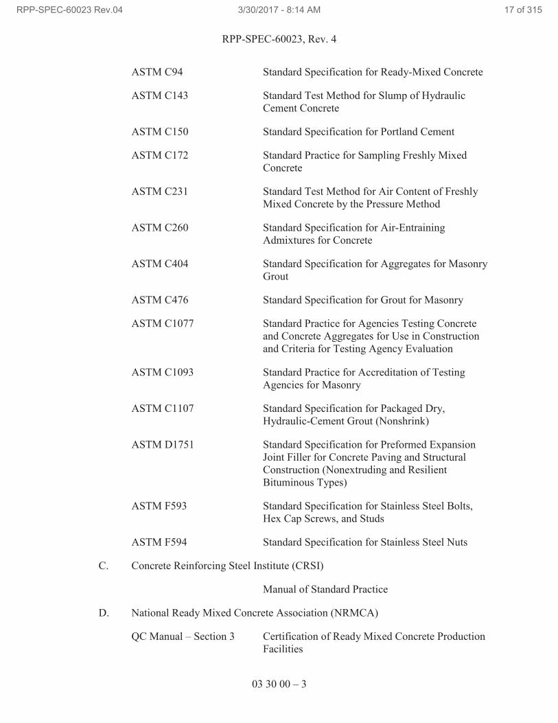
ASTM C94 Standard Specification for Ready-Mixed Concrete
ASTM C143 Standard Test Method for Slump of Hydraulic
Cement Concrete
ASTM C150 Standard Specification for Portland Cement
ASTM C172 Standard Practice for Sampling Freshly Mixed
Concrete
ASTM C231 Standard Test Method for Air Content of Freshly
Mixed Concrete by the Pressure Method
ASTM C260 Standard Specification for Air-Entraining
Admixtures for Concrete
ASTM C404 Standard Specification for Aggregates for Masonry
Grout
ASTM C476 Standard Specification for Grout for Masonry
ASTM C1077 Standard Practice for Agencies Testing Concrete
and Concrete Aggregates for Use in Construction
and Criteria for Testing Agency Evaluation
ASTM C1093 Standard Practice for Accreditation of Testing
Agencies for Masonry
ASTM C1107 Standard Specification for Packaged Dry,
Hydraulic-Cement Grout (Nonshrink)
ASTM D1751 Standard Specification for Preformed Expansion
Joint Filler for Concrete Paving and Structural
Construction (Nonextruding and Resilient
Bituminous Types)
ASTM F593 Standard Specification for Stainless Steel Bolts,
Hex Cap Screws, and Studs
ASTM F594 Standard Specification for Stainless Steel Nuts
C. Concrete Reinforcing Steel Institute (CRSI)
Manual of Standard Practice
D. National Ready Mixed Concrete Association (NRMCA)
QC Manual – Section 3 Certification of Ready Mixed Concrete Production
Facilities
RPP-SPEC-60023 Rev.04 3/30/2017 - 8:14 AM 17 of 315
RPP-SPEC-60023, Rev. 4
03 30 00 – 4
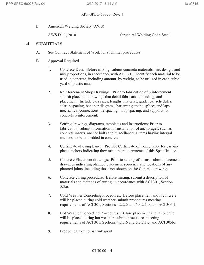
E. American Welding Society (AWS)
AWS D1.1, 2010 Structural Welding Code-Steel
1.4 SUBMITTALS
A. See Contract Statement of Work for submittal procedures.
B. Approval Required.
1. Concrete Data: Before mixing, submit concrete materials, mix design, and
mix proportions, in accordance with ACI 301. Identify each material to be
used in concrete, including amount, by weight, to be utilized in each cubic
yard of plastic mix.
2. Reinforcement Shop Drawings: Prior to fabrication of reinforcement,
submit placement drawings that detail fabrication, bending, and
placement. Include bars sizes, lengths, material, grade, bar schedules,
stirrup spacing, bent bar diagrams, bar arrangement, splices and laps,
mechanical connections, tie spacing, hoop spacing, and supports for
concrete reinforcement.
3. Setting drawings, diagrams, templates and instructions: Prior to
fabrication, submit information for installation of anchorages, such as
concrete inserts, anchor bolts and miscellaneous items having integral
anchors, to be embedded in concrete.
4. Certificate of Compliance: Provide Certificate of Compliance for cast-in-
place anchors indicating they meet the requirements of this Specification.
5. Concrete Placement drawings: Prior to setting of forms, submit placement
drawings indicating planned placement sequence and locations of any
planned joints, including those not shown on the Contract drawings.
6. Concrete curing procedure: Before mixing, submit a description of
materials and methods of curing, in accordance with ACI 301, Section
5.3.6.
7. Cold Weather Concreting Procedures: Before placement and if concrete
will be placed during cold weather, submit procedures meeting
requirements of ACI 301, Sections 4.2.2.6 and 5.3.2.1.b, and ACI 306.1.
8. Hot Weather Concreting Procedures: Before placement and if concrete
will be placed during hot weather, submit procedures meeting
requirements of ACI 301, Sections 4.2.2.6 and 5.3.2.1.c, and ACI 305R.
9. Product data of non-shrink grout.
RPP-SPEC-60023 Rev.04 3/30/2017 - 8:14 AM 18 of 315
RPP-SPEC-60023, Rev. 4
03 30 00 – 5
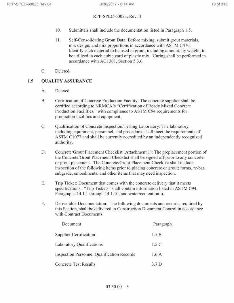
10. Submittals shall include the documentation listed in Paragraph 1.5.
11. Self-Consolidating Grout Data: Before mixing, submit grout materials,
mix design, and mix proportions in accordance with ASTM C476.
Identify each material to be used in grout, including amount, by weight, to
be utilized in each cubic yard of plastic mix. Curing shall be performed in
accordance with ACI 301, Section 5.3.6.
C. Deleted.
1.5 QUALITY ASSURANCE
A. Deleted.
B. Certification of Concrete Production Facility: The concrete supplier shall be
certified according to NRMCA’s “Certification of Ready Mixed Concrete
Production Facilities,” with compliance to ASTM C94 requirements for
production facilities and equipment.
C. Qualification of Concrete Inspection/Testing Laboratory: The laboratory
including equipment, personnel, and procedures shall meet the requirements of
ASTM C1077 and shall be currently accredited by an independently recognized
authority.
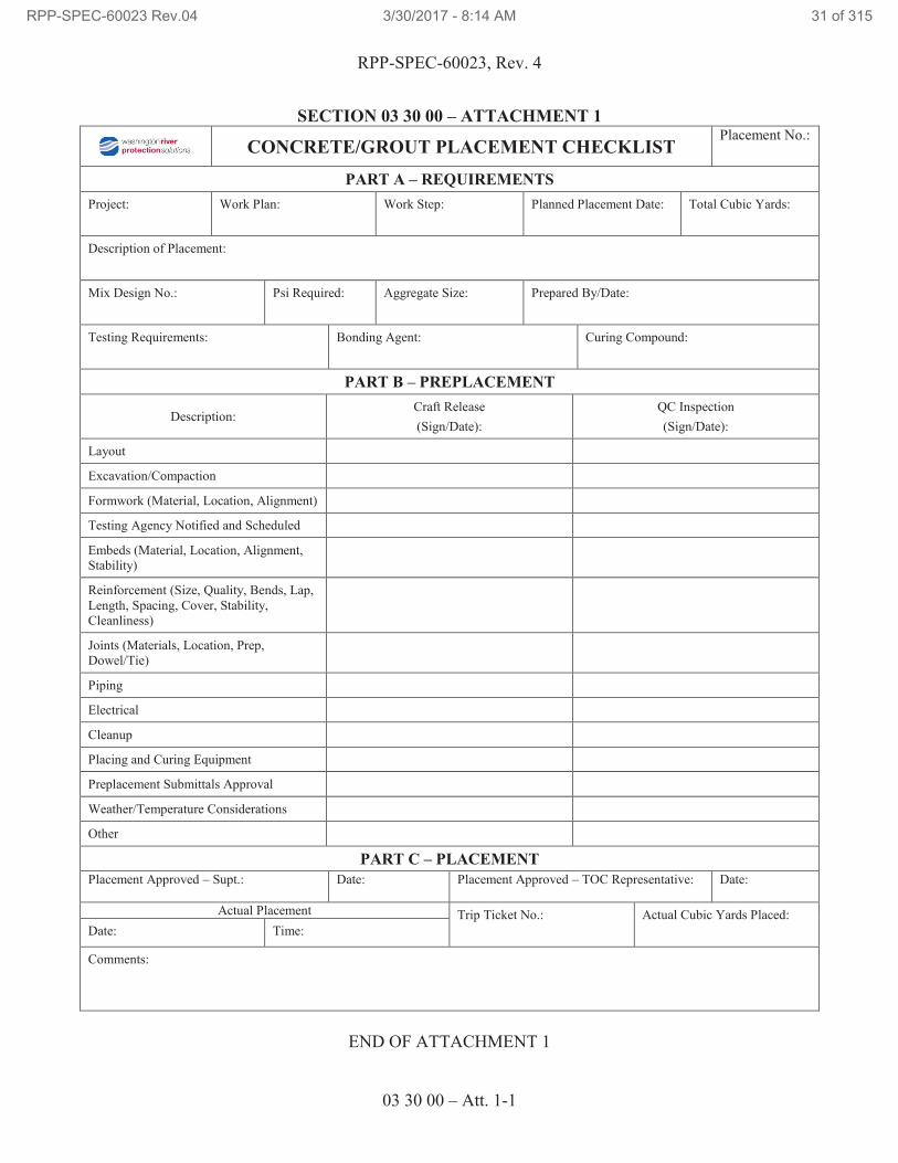
D. Concrete/Grout Placement Checklist (Attachment 1): The preplacement portion of
the Concrete/Grout Placement Checklist shall be signed off prior to any concrete
or grout placement. The Concrete/Grout Placement Checklist shall include
inspection of the following items prior to placing concrete or grout; forms, re-bar,
subgrade, embedments, and other items that may need inspection.
E. Trip Ticket: Document that comes with the concrete delivery that it meets
specifications. “Trip Tickets” shall contain information listed in ASTM C94,
Paragraphs 14.1.1 through 14.1.10, and water/cement ratio.
F. Deliverable Documentation: The following documents and records, required by
this Section, shall be delivered to Construction Document Control in accordance
with Contract Documents.
Document Paragraph
Supplier Certification 1.5.B
Laboratory Qualifications 1.5.C
Inspection Personnel Qualification Records 1.6.A
Concrete Test Results 3.7.D
RPP-SPEC-60023 Rev.04 3/30/2017 - 8:14 AM 19 of 315
RPP-SPEC-60023, Rev. 4
03 30 00 – 6
Grout Test Results 3.7.F
G. Perform work in accordance with the applicable sections of ACI 117, ACI 301,
ACI 318, and ASTM C476.
H. Suspect and Misrepresented Products: See Contract Statement of Work for
required measures to prevent use of misrepresented products.
I. Trip Ticket: The Trip Ticket is provided with the concrete delivery and shall
contain information listed in ASTM C94, Paragraphs 14.1.1 through 14.1.10, and
water/cement ratio.
J. Qualification of Grout Inspection/Testing Laboratory: The laboratory including
equipment, personnel, and procedures shall meet the requirements of ASTM
C1093 and shall be currently accredited by an independently recognized
authority.
1.6 QUALIFICATION OF CONCRETE/GROUT INSPECTORS
A. Personnel performing field testing of concrete shall be ACI Concrete Field
Testing Technicians, Grade 1, who have received formal certification in
accordance with ACI CP-1 or equivalent. Equivalent certification programs shall
include requirements for written and performance examination as stipulated in
ACI 301, Section 1.6.2.
B. Deleted.
1.7 DELIVERY, STORAGE, AND HANDLING
A. See the Contract Statement of Work for general requirements.
B. Steel reinforcement: Deliver, store, and handle steel reinforcement to prevent
bending and damage.
C. Waterstops: Store waterstops under cover to protect from moisture dirt, oil,
sunlight, and other contaminants.
PART 2 PRODUCTS
2.1 SUBSTITUTION
A. See the Contract Statement of Work for substitution approvals.
2.2 MATERIALS
A. Cast-In-Place Concrete
1. Cement: ASTM C150, Type II (low alkali).
RPP-SPEC-60023 Rev.04 3/30/2017 - 8:14 AM 20 of 315
RPP-SPEC-60023, Rev. 4
03 30 00 – 7
2. Aggregates: ASTM C33, 3/4-in. maximum size. Fine aggregate: free of
materials with deleterious reactivity to alkali in cement.
3. Air-entraining admixture: ASTM C260.
4. Properties (if not specified by design):
a. Minimum allowable compressive strength: 4500 lb/in2 at 28 days,
or as required by design documents.
b. Slump: In accordance with ACI 301, Section 4.2.2.2.
c. Air content: In accordance with ACI 301, Section 4.2.2.4.
d. Proportions: In accordance with ACI 301, Section 4.2.3, and
ASTM C94.
e. Time of discharge: In accordance with ASTM C94, Section 12
and ACI 301, Section 4.1.2.10.
5. Measuring, Mixing, and Delivery: In accordance with ASTM C94.
B. Pre-Cast Concrete
1. Cement: ASTM C150, Type II (low alkali).
2. Aggregates: ASTM C33, 3/4-in. maximum size. Fine aggregate: free of
materials with deleterious reactivity to alkali in cement.
3. Air-entraining admixture: ASTM C260.
4. Properties (if not specified by design):
a. Minimum allowable compressive strength: 4,500 lb/in2 at 28 days,
or as required by design documents.
b. Slump: In accordance with ACI 237R.
c. Air content: In accordance with ACI 237R.
d. Proportions: In accordance with ACI 237R, and ASTM C94.
e. Time of discharge: In accordance with ASTM C94, Section 12
and ACI 237R.
5. Measuring, Mixing, and Delivery: In accordance with ASTM C94.
RPP-SPEC-60023 Rev.04 3/30/2017 - 8:14 AM 21 of 315
RPP-SPEC-60023, Rev. 4
03 30 00 – 8
C. Controlled Density Fill (CDF): Portland cement based, minimum compressive
strength of 100 psi at 28 days, maximum compressive strength of 300 psi at 28
days.
D. Reinforcing Steel
1. Steel bars: ASTM A615, deformed, Grade 60.
2. Tie wire: ASTM A853 carbon steel, 16-gage minimum, annealed.
3. Welded Steel Wire Fabric: ASTM A185 plain type in flat sheets.
E. Joint Dowel Bars: ASTM A615, Grade 60, plain-steel bars, cut true to length
with ends square and free of burrs.
F. Non-shrink Grout
1. In accordance with ASTM C1107.
2. Minimum strength of fluid grout, 4,000 psi at 1 day, 5,000 psi at 3 days,
and 9,000 psi at 28 days.
G. Embedded Plates: See Section 05 50 00, “Metal Fabrications.”
H. Headed Weld Stud Anchors: ASTM A108, Grades 1015 through 1020, headed-
stud type, cold-finished carbon steel; AWS D1.1/D1.1M, Type B.
I. Cast-In-Place Anchors: ASTM F593 CW2 threaded rods with ASTM F594 nuts.
J. Post-Installed Anchors: See Section 03 15 00, “Post-Installed Concrete Anchor
Bolts.”
K. Expansion joint filler: ASTM D1751; asphalt impregnated fiberboard or felt,
1/2-in. thick.
L. Joint sealants: See Section 07 92 00, “Joint Sealants.”
M. Forms: Wood, steel, plywood or Masonite Corporation “Concrete Form
Presdwood,” as required for various specified finishes.
1. Form facing panels shall provide continuous, true, and smooth concrete
surfaces.
2. Form release agent: Commercially formulated form-release agent that will
not bond with, stain, or adversely affect concrete surfaces and will not
impair subsequent treatments of concrete surfaces.
N. Bonding Agent: Polymer resin emulsion appropriate for bonding fresh concrete
to existing set concrete.
RPP-SPEC-60023 Rev.04 3/30/2017 - 8:14 AM 22 of 315
RPP-SPEC-60023, Rev. 4
03 30 00 – 9
O. Special Coatings: See Section 09 96 00, “High-Performance Coatings,” for
concrete coating. Extent of coating shall be as shown on Drawings.
P. Waterstops: Self-expanding Butyl Strip, manufactured rectangular or trapezoidal
strip, butyl rubber with sodium bentonite or other hydrophilic polymers, for
adhesive bonding to concrete, 3/4 by 1 in.
Q. Self-Consolidating Grout for use in Grout Boxes
1. In accordance with ASTM C476.
2. Aggregate: ASTM C404, Fine, Size No. 2, Natural or Manufactured.
3. Properties (if not specified by design):
a. Minimum strength of grout, 3,000 psi at 28 days.
b. Maximum unit weight of grout, 140 pcf (Ref. RPP-CALC-61007).
2.3 FABRICATING REINFORCEMENT
A. Fabricate steel reinforcement according to CRSI’s “Manual of Standard Practice.”
PART 3 EXECUTION
3.1 PREPARATION
A. Form Construction
1. Install formwork in accordance with ACI 301, Section 2.3 to support
vertical, lateral, and construction loads that might be applied, until
structure can support such loads.
2. Construct formwork such that interior shape and rigidity of finished
concrete will meet requirements of the Drawings and approved shop
drawings within tolerances specified in ACI 117, Section 4.
3. Prepare form surfaces in accordance with ACI 301, Section 2 using
specified form coating materials, or as described below.
4. Forms for surfaces which will be permanently concealed from view may
be saturated with water, before placing concrete, instead of other
treatment. In freezing weather, forms shall be treated with oil or stearate.
5. Clean forms of foreign material before placing concrete.
B. Prepare setting drawings, diagrams, templates, and instructions for installation of
anchorages, such as concrete inserts, anchor bolts and miscellaneous items having
integral anchors, to be embedded in concrete.
RPP-SPEC-60023 Rev.04 3/30/2017 - 8:14 AM 23 of 315
RPP-SPEC-60023, Rev. 4
03 30 00 – 10
C. Clean grout boxes of foreign material and remove free liquids within grout box
prior to placement of contaminated equipment. Maintain cleanliness until self-
consolidating grout placement.
3.2 EMBEDDED ITEMS
A. Prepare setting drawings, diagrams, templates, and instructions for installation of
anchorages, such as concrete inserts, anchor bolts, and miscellaneous items
having integral anchors, to be embedded in concrete.
B. Place and secure anchorage devices and other embedded items as required for
adjoining work that is attached to or supported by cast-in-place concrete. All
embedded items shall be securely supported to prevent displacement during
concrete placement and finishing.
C. Verify that anchors, plates, reinforcement, and other items to be cast into concrete
are accurately placed, positioned securely, and will not cause hardship in placing
concrete. Document inspection on Concrete/Grout Placement Checklist.
3.3 INSTALLATION
A. Reinforcing Steel
1. Fabricate and place bars to dimensions shown on Contract drawings,
within tolerances shown in ACI 117, Sections 2.1 and 2.2.
2. Place as shown on Drawings, within tolerances specified in ACI 117,
Section 2.2 and ACI 301, Section 3.3.2.
3. Tie to prevent displacement during placement of concrete.
4. Do not force into concrete after initial set has started.
5. Provide concrete cover for reinforcement protection per dimensions given
in ACI 301, Section 3.3, except where shown otherwise on Contract
drawings or approved shop drawings.
6. Reinforcement shall be supported and fastened together to prevent
displacement by construction loads, or placement of concrete beyond
specified tolerances. Reinforcement supported from ground shall rest on
precast, square concrete blocks, with a minimum surface area of 4 in2 and
having a compressive strength equal to specified compressive strength of
concrete being placed.
B. Concrete
1. Concrete Placing:
RPP-SPEC-60023 Rev.04 3/30/2017 - 8:14 AM 24 of 315
RPP-SPEC-60023, Rev. 4
03 30 00 – 11
a. Contractor shall use a Concrete/Grout Placement Checklist.
Checklist shall be reviewed with the TOC Construction
Representative prior to placing concrete. At a minimum, the
checklist shall include:
i. Formwork placement.
ii. Earth compaction.
iii. Reinforcement placement.
iv. Embedded items.
v. Bonding electrode.
vi. Concrete Mix.
vii. Testing Requirements.
viii. Weather conditions including proper weather mitigation
requirements.
ix. Approval of all preplacement submittals prior to placment.
x. Availability of associated materials and labor.
xi. Identification of sections of structure to be placed.
Note: Use separate checklist for each day and each concrete mix.
b. Verify that anchors, plates, reinforcement, and other items to be
cast into concrete are accurately placed, positioned securely, and
will not cause hardship in placing concrete, and that required
inspections have been performed. Document inspection on a
Concrete/Grout Placement Checklist.
c. Deleted.
d. For each truck load, collect Trip Ticket.
e. Discharge concrete rinsate at Company-approved location.
f. Place in accordance with ACI 301, Section 5.3. Do not drop more
than 5 ft.
g. Temper only as permitted in ACI 301, Section 4.3.
2. Before test sampling and placing concrete, water may be added at Project
site, subject to limitations of ACI 301, Section 4.3.
RPP-SPEC-60023 Rev.04 3/30/2017 - 8:14 AM 25 of 315
RPP-SPEC-60023, Rev. 4
03 30 00 – 12
a. Addition of water shall be in accordance with ASTM C94.
b. Do not add water to concrete after adding high-range, water-
reducing admixtures to mixture.
3. Before test sampling and placing concrete, trip ticket shall be reviewed by
the Testing Agency’s field inspector. After depositing concrete, trip ticket
shall be retained in the work package or fabrication plan.
4. Cold Weather Placement: Comply with ACI 301 and ACI 306.1 and as
follows.
a. Protect concrete work from physical damage or reduced strength
that could be caused by frost, freezing actions, or low
temperatures.
b. When average high and low temperature is expected to fall below
40°F, maintain delivered concrete mixture temperature within the
temperature range required by ACI 301.
c. Do not use frozen materials containing ice or snow. Do not place
concrete on frozen subgrade or on subgrade containing frozen
materials.
5. Hot Weather Placement: Comply with ACI 301 and ACI 305R and as
follows:
a. Maintain concrete temperature below 90°F at time of placement.
Chilled mixing water or chopped ice may be used to control
temperature, provided water equivalent of ice is calculated to total
amount of mixing water. Using liquid nitrogen to cool concrete is
Contractor’s option.
b. Fog-spray forms, steel reinforcement, and subgrade just before
placing concrete. Keep subgrade uniformly moist without standing
water, soft spots, or dry areas.
6. Place nonshrink grout where shown on Contract drawings, in accordance
with manufacturer’s recommendations.
7. Placing concrete against subgrade/base material: Place on or against firm,
damp surfaces free of frost, ice, and free water. Obtain required earth
compaction in accordance with Section 31 23 00, “Excavation and Fill,”
before concrete placement. Dampen earth surfaces to receive fresh
concrete.
8. Consolidation: Consolidate concrete in accordance with ACI 301,
Section 5.3.2.5.
RPP-SPEC-60023 Rev.04 3/30/2017 - 8:14 AM 26 of 315
RPP-SPEC-60023, Rev. 4
03 30 00 – 13
a. Consolidate concrete during placement operations so concrete is
thoroughly worked around reinforcement and other embedded
items and into corners.
b. Maintain reinforcement in position on chairs during concrete
placement.
c. Screed slab surfaces with a straightedge and strike off to correct
elevations.
d. Slope surfaces uniformly to drains/trenches where required.
9. Form Removal and Concrete Repair
a. Form removal: Remove in accordance with ACI 301, Sections
2.3.2 and 2.3.4.
b. Cut back form ties and examine concrete surfaces for defects.
Repair only after permission for patching is given by the TOC
Construction Representative.
c. Place concrete repair mortar within 1 hour after mixing. Do not re-
temper mortar.
d. Repair surface defects in accordance with ACI 301, Section 5.3.7.
Cure concrete repairs same as new concrete.
10. Concrete Finishes and Tolerances
a. Measuring for tolerances shall be performed in accordance with
ACI 301, Section 5.3.4.3.
b. Formed surfaces: Start finishing following concrete repair and
complete within 96 hours after forms have been removed. Finish
in accordance with ACI 301 Section 5.3.3.
i. Surfaces exposed to earth backfill; Rough form finish.
ii. Exterior surfaces exposed to weather.
iii. Repair and patch tie holes and defects.
iv. Remove fins and other projections that exceed specified
limits on formed-surface irregularities.
v. Surfaces to receive special protective coating (ACI 301,
Section 5.3.3.4.b).
RPP-SPEC-60023 Rev.04 3/30/2017 - 8:14 AM 27 of 315
RPP-SPEC-60023, Rev. 4
03 30 00 – 14
c. Unformed surfaces: Finish in accordance with
ACI 301, Section 5.3.4.
i. Exterior equipment slabs subject to foot traffic.
C. Self-Consolidating Grout for use in Grout Boxes to be placed in accordance with
ASTM C476, using the Concrete/Grout Placement Checklist.
3.4 FINISHING FLOORS AND SLABS
A. General: Comply with ACI 302.1R recommendations for screeding,
re-straightening, and finishing operations for concrete surfaces. Do not wet
concrete surfaces.
B. Float Finish: Consolidate surface with power-driven floats or by hand floating if
area is small or inaccessible to power-driven floats. Re-straighten, cut down high
spots, and fill low spots.
1. Apply float finish to surfaces to receive trowel finish.
C. Trowel Finish: After applying float finish, apply first troweling and consolidate
concrete by hand- or power-driven trowel. Continue troweling passes and re-
straighten until surface is free of trowel marks and is uniform in texture and
appearance. Grind smooth any surface defects that would telegraph through
applied coatings.
D. Broom Finish: Apply a broom finish to exterior concrete platforms, steps, ramps,
and elsewhere as indicated.
3.5 JOINTS
A. Contraction Joints in Slabs-on-Grade: Form weakened-plane contraction joints,
sectioning concrete into areas as indicated. Construction contraction joints for a
depth equal to at least one-fourth of concrete thickness as follows:
1. Sawed Joints: Form contraction joints with power saws equipped with
shatter-proof abrasive or diamond-rimmed blades. Cut 1/8-in. wide joints
into concrete when cutting action will not tear, abrade, or otherwise
damage surface and before concrete develops random contraction cracks.
Maximum 12 hours after placement.
3.6 CONCRETE PROTECTION AND CURING
A. General: Protect freshly placed concrete from premature drying and excessive
cold or hot temperatures. Comply with ACI 306.1 for cold-weather and ACI 301
for hot-weather protection during curing.
RPP-SPEC-60023 Rev.04 3/30/2017 - 8:14 AM 28 of 315
RPP-SPEC-60023, Rev. 4
03 30 00 – 15
B. Cure concrete in accordance with ACI 301, Section 5.3.6. Clear curing
compounds shall be tinted or applied to surfaces marked to show extent of
spraying.
C. Do not use curing compound on surfaces to receive special protective coating.
D. Protect concrete during adverse weather conditions in accordance with ACI 301,
Section 1.8.
E. Protect concrete from mechanical damage in accordance with ACI 301,
Section 1.8.
F. Making and curing of field test cylinders shall be performed in accordance with
ASTM C31. Test cylinders shall be stored in or on the structure as near to the
point of deposit of the concrete represented as possible. Protect all surfaces of the
test cylinders from the elements as near as possible the same way as the formed
work. Provide the test cylinders with the same temperature and moisture
environment as the structural work.
3.7 FIELD INSPECTIONS AND TESTS
A. Sample and test concrete in accordance with ACI 301, Sections 1.6.4.2 (d), (e),
and (f), (g), and (h). Record results. Engage a qualified independent testing
agency to perform material evaluation tests.
B. Engage a special inspector and qualified independent testing agency to perform
field material evaluation tests and inspections, and prepare testing and inspection
reports.
C. Inspections:
1. Steel reinforcement placement.
2. Headed bolts and studs.
3. Verification of use of required concrete design mixture.
4. Concrete placement, including conveying and depositing.
5. Curing procedures and maintenance of curing temperature.
D. Concrete Tests:
1. Testing of concrete samples of fresh concrete shall be obtained according
to ACI 301, Section 1.6.4.2.d and ASTM C172.
2. Testing shall be performed according to ACI 301, Sections 1.6.4.2.(e), (f),
(g), and (h). Record results.
RPP-SPEC-60023 Rev.04 3/30/2017 - 8:14 AM 29 of 315
RPP-SPEC-60023, Rev. 4
03 30 00 – 16
E. Provide nonshrink grout block molds onsite. Non-shrink grout blocks shall test
equal to or greater than minimum strength specified.
F. Provide self-consolidating grout block molds onsite. Self-consolidating grout
blocks shall test equal to or greater than minimum strength specified.
END OF SECTION 03 30 00
RPP-SPEC-60023 Rev.04 3/30/2017 - 8:14 AM 30 of 315
RPP-SPEC-60023, Rev. 4
03 30 00 – Att. 1-1
SECTION 03 30 00 – ATTACHMENT 1
CONCRETE/GROUT PLACEMENT CHECKLIST
Placement No.:
PART A – REQUIREMENTS
Project: Work Plan: Work Step: Planned Placement Date:
Total Cubic Yards:
Description of Placement:
Mix Design No.:
Psi Required: Aggregate Size: Prepared By/Date:
Testing Requirements: Bonding Agent:
Curing Compound:
PART B – PREPLACEMENT
Description: Craft Release
(Sign/Date):
QC Inspection
(Sign/Date):
Layout
Excavation/Compaction
Formwork (Material, Location, Alignment)
Testing Agency Notified and Scheduled
Embeds (Material, Location, Alignment,
Stability)
Reinforcement (Size, Quality, Bends, Lap,
Length, Spacing, Cover, Stability,
Cleanliness)
Joints (Materials, Location, Prep,
Dowel/Tie)
Piping
Electrical
Cleanup
Placing and Curing Equipment
Preplacement Submittals Approval
Weather/Temperature Considerations
Other
PART C – PLACEMENT
Placement Approved – Supt.:
Date: Placement Approved – TOC Representative:
Date:
Actual Placement Trip Ticket No.: Actual Cubic Yards Placed:
Date: Time:
Comments:
END OF ATTACHMENT 1
RPP-SPEC-60023 Rev.04 3/30/2017 - 8:14 AM 31 of 315
RPP-SPEC-60023, Rev. 4
05 50 00 – 1
SECTION 05 50 00
METAL FABRICATIONS
PART 1 GENERAL
1.1 RELATED DOCUMENTS / CODES AND STANDARDS
Drawings and general provisions of the Contract Statement of Work, including
Division 01 Specification Sections, apply to this Section.
The following documents and others referenced therein, form part of the Contract to the
extent designated in this Section. Referenced documents are those current as of the date
of this Section unless otherwise indicated.
A. American Society of Mechanical Engineers (ASME)
B&PVC, 2013 Boiler and Pressure Vessel Code
Section IX Qualification Standard for Welding and Brazing
Procedures, Welders, Brazers, and Welding and
Brazing Operations
B. American Society for Nondestructive Testing (ASNT)
ASNT SNT-TC-1A Personnel Qualifications and Certification in
Nondestructive Testing
C. ASTM International (ASTM)
ASTM A36 Standard Specification for Carbon Structural Steel
ASTM A53 Standard Specification for Pipe, Steel, Black and
Hot-Dipped, Zinc-Coated, Welded and Seamless
ASTM A106 Standard Specification for Seamless Carbon Steel
Pipe for High-Temperature Service
ASTM A240 Standard Specification for Chromium and
Chromium-Nickel Stainless Steel Plate, Sheet, and
Strip for Pressure Vessels and for General
Applications
ASTM A276 Standard Specification for Stainless Steel Bars and
Shapes
RPP-SPEC-60023 Rev.04 3/30/2017 - 8:14 AM 32 of 315
RPP-SPEC-60023, Rev. 4
05 50 00 – 2
ASTM A312 Standard Specification for Seamless, Welded, and
Heavily Cold Worked Austenitic Stainless Steel
Pipes
ASTM A325 Standard Specification for Structural Bolts, Steel,
Heat Treated, 120/105 ksi Minimum Tensile
Strength
ASTM A500 Standard Specification for Cold-Formed Welded
and Seamless Carbon Steel Structural Tubing in
Rounds and Shapes
ASTM A563 Standard Specification for Carbon and Alloy Steel
Nuts
ASTM A653 Standard Specification for Steel Sheet, Zinc-Coated
(Galvanized) or Zinc-Iron Alloy-Coated
(Galvannealed) by the Hot-Dip Process
ASTM A992 Standard Specification for Structural Steel Shapes
ASTM F844 Standard Specification for Washers, Steel, Plain
(Flat), Unhardened for General Use
D. American Welding Society (AWS)
AWS D1.1, 2010 Structural Welding Code – Steel
AWS D1.3, 2008 Structural Welding Code – Sheet Steel
AWS D1.6, 2007 Structural Welding Code – Stainless Steel
AWS QC1 Certification of Welding Inspectors
E. Hanford Documents
TFC-ENG-STD-06 Design Loads for Tank Farm Facilities
TFC-ENG-STD-22 Piping, Jumpers, and Valves
1.2 SUBMITTALS
A. See the Contract Statement of Work for submittal procedures.
B. Approval Required
1. Welding personnel qualifications: 5 days before start of fabrication,
submit welder qualification as required by Paragraph 1.3.B.1.
RPP-SPEC-60023 Rev.04 3/30/2017 - 8:14 AM 33 of 315
RPP-SPEC-60023, Rev. 4
05 50 00 – 3
2. Welding procedure qualifications: 5 days before first use, submit welding
procedures as required by Paragraph 1.3.B.1.
3. Examination personnel qualifications: 5 days before first use, submit
examination personnel qualification as required by Paragraph 1.3.B.2.
4. Examination procedures: 5 days before start of fabrication, submit
examination procedures as required by Paragraph 1.3.B.3.
5. Carbon Steel Weld Examination as required by Paragraph 3.5.A.1.
6. Sheet Steel Weld Examination as required by Paragraph 3.5.A.2.
7. Stainless Steel Weld Examination as required by Paragraph 3.5.A.3.
8. Weld Examinations (PT, MT) as required by Paragraph 3.5.A.4.
C. Approval Not Required: None.
1.3 QUALITY ASSURANCE
A. Misrepresented Products: See the Contract Statement of Work for required
measures to prevent use of misrepresented products.
B. Qualifications of Welding Personnel and Procedures
1. Personnel and procedures for welding structural steel shall be qualified in
accordance with AWS D1.1 for steel structures, AWS D1.3 for sheet steel,
and AWS D1.6 for stainless steel before welding. Qualification of
welding personnel and procedures in accordance with ASME B&PVC,
Section IX may be substituted for components welded in accordance with
AWS D1.1, D1.3, and D1.6. Maintain copy of welding procedure
specifications, procedure qualification records, and welder performance
qualification test results and renewal of qualification documentation at
jobsite. Where stainless steel materials are welded to carbon steel,
AWS D1.1 procedures shall govern, unless ASME B&PVC, Section IX
was substituted.
2. Qualification of examination personnel: Maintain copies of examination
personnel certifications and written examination performance procedures
at jobsite.
a. Personnel performing visual examinations shall be Certified
Welding Inspectors (CWIs) who have received certification
(current or previous certification) in accordance with AWS QC1.
b. Personnel performing other nondestructive examinations (NDE)
shall be certified in accordance with approved procedure, which
RPP-SPEC-60023 Rev.04 3/30/2017 - 8:14 AM 34 of 315
RPP-SPEC-60023, Rev. 4
05 50 00 – 4
shall meet the requirements of ASNT SNT-TC-1A. Use Level II
or III personnel to interpret results.
3. Examination procedures: Examination procedures shall be in accordance
with AWS D1.1, AWS D1.3, AWS D1.6, as applicable, and this
Specification. Maintain copies of examination procedures at jobsite.
1.4 PERMITS
A. Permits are addressed by TOC work control process.
B. Deleted.
1.5 DELIVERY, STORAGE, AND HANDLING
A. See the Contract Statement of Work for general requirements.
PART 2 PRODUCTS
2.1 SUBSTITUTES
A. See the Contract Statement of Work for substitution approvals.
2.2 MATERIALS
Use the following materials unless otherwise shown on Contract drawings:
A. Rolled Steel Shapes, Plates, and Bars: ASTM A36 or ASTM A992, Gr. 50.
B. Stainless Steel Shapes and Bars: ASTM A276, Type 304L.
C. Stainless Steel Plate, Sheet: ASTM A240, Type 304, 304L.
D. Stainless Steel Pipe: ASTM A312, Grade TP 304L (SMLS).
E. Steel Pipe: ASTM A53 (black) Type E or S, Grade B or ASTM A106 Grade B,
standard weight, Schedule 40.
F. Steel Tubing: ASTM A500, Grade B.
G. Sheet Steel: ASTM A653
H. Fasteners
1. Bolts
a. ASTM A325.
RPP-SPEC-60023 Rev.04 3/30/2017 - 8:14 AM 35 of 315
RPP-SPEC-60023, Rev. 4
05 50 00 – 5
2. Nuts
a. ASTM A563, Grade C, plain, heavy hex.
3. Washers: ASTM F436 Type 1, plain.
4. Expansion Anchor Installations: See Section 03 15 00, “Post-Installed
Concrete Anchor Bolts.”
5. Weld studs: Nelson Stud Welding Co. Type H4L or approved substitute.
I. Welding Electrodes/Filler Metal:
1. Carbon steel – Matching filler metal with Fu = 70,000 psi.
2. Stainless steel – E308/ER308 or E309/ER309.
J. Nonshrink Grout: See Section 03 30 00, “Concrete.”
K. Special Protective Coating: See Section 09 91 00, “Painting.”
L. Zinc-rich Coating: Sherwin Williams®3 “Zinc Clad®
3 200,” or ZRC Products
Company “Z.R.C.®4“
M. Supports: Channels, channel spring nuts, bolts, and fittings for any one support
type shall be galvanized and from the same manufacturer. Cooper B-Line®5
channels and fittings, or approved substitute.
1. Channels: 1 5/8-in. wide by 1 5/8-in. deep, or as shown on Drawings.
2. Channel spring nuts: Manufacturer’s standard.
3. Bolts (for use with channel spring nuts): Manufacturer’s standard.
4. Support Clamps (for rigid steel conduit): Manufacturer’s standard.
2.3 FABRICATION
A. General
1. Verify measurements, including field measurements, before fabrication.
Provide miscellaneous bolts and anchors, supports, braces, and
connections necessary for completion of metal fabrications. Cut,
reinforce, drill, and tap metal fabrications shown to receive finish
hardware and similar items. Weld or bolt connections as shown on the
Drawings.
3 Sherwin-Williams and Zinc Clad are registered trademarks of Swimc, Inc., Newark, Delaware.
4 Z.R.C. is a registered trademark of Norfolk Corporation, Marshfield, Massachusetts.
5 B-Line is a registered trademark of Cooper Technologies Company, Houston, Texas.
RPP-SPEC-60023 Rev.04 3/30/2017 - 8:14 AM 36 of 315
RPP-SPEC-60023, Rev. 4
05 50 00 – 6
2. Perform welding of steel connections in accordance with AWS D1.1, sheet
steel in accordance with AWS D1.3, and stainless steel in accordance with
AWS D1.6.
B. Miscellaneous Steel Items: Supply required clips, frames, equipment supports,
and other fabrications not shown on the Drawings. Fabricate parts from standard
structural sections or shapes, to sizes required. Wherever miscellaneous parts are
exposed, grind edges, corners, and rough cuts smooth and free of snags. Shop
paint parts except those to be embedded in concrete, or those that require other
specific finishes.
C. Finishes
1. Prime ferrous metal in accordance with Section 09 91 00, “Painting.” Do
not coat members to be embedded in concrete, surfaces and edges to be
field welded, or items to be galvanized. Shop paint may extend into
embedded areas where impractical to remove.
2. Touch up damaged zinc surfaces with zinc-rich coating. Apply in
accordance with manufacturer’s instructions.
PART 3 EXECUTION
3.1 EXAMINATION
A. Examine areas where metal fabrications are to be installed and notify TOC
Construction Representative in writing of conditions detrimental to proper and
timely completion of work. Do not proceed with work until unsatisfactory
conditions have been corrected.
3.2 PREPARATION
A. Prepare setting drawings, diagrams, templates, and instructions for installation of
anchorages, such as concrete inserts, anchor bolts, and miscellaneous items
having integral anchors, to be embedded in concrete. Coordinate with TOC
Construction Representative for delivery of items to Site.
3.3 INSTALLATION
A. Expansion Anchor Installation: See Section 03 15 00, “Post-Installed Concrete
Anchor Bolts.”
B. Install metal fabrications plumb, level, or as shown on the Drawings.
C. Make field connections as neatly as possible with joints flush and smooth. Grind
smooth exposed field welds, as required per design, before field painting. Repair
welds in galvanized work with 2 coats of zinc-rich coating.
RPP-SPEC-60023 Rev.04 3/30/2017 - 8:14 AM 37 of 315
RPP-SPEC-60023, Rev. 4
05 50 00 – 7
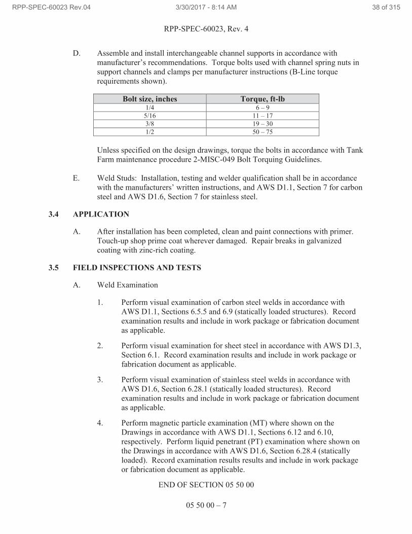
D. Assemble and install interchangeable channel supports in accordance with
manufacturer’s recommendations. Torque bolts used with channel spring nuts in
support channels and clamps per manufacturer instructions (B-Line torque
requirements shown).
Bolt size, inches Torque, ft-lb 1/4 6 – 9
5/16 11 – 17
3/8 19 – 30
1/2 50 – 75
Unless specified on the design drawings, torque the bolts in accordance with Tank
Farm maintenance procedure 2-MISC-049 Bolt Torquing Guidelines.
E. Weld Studs: Installation, testing and welder qualification shall be in accordance
with the manufacturers’ written instructions, and AWS D1.1, Section 7 for carbon
steel and AWS D1.6, Section 7 for stainless steel.
3.4 APPLICATION
A. After installation has been completed, clean and paint connections with primer.
Touch-up shop prime coat wherever damaged. Repair breaks in galvanized
coating with zinc-rich coating.
3.5 FIELD INSPECTIONS AND TESTS
A. Weld Examination
1. Perform visual examination of carbon steel welds in accordance with
AWS D1.1, Sections 6.5.5 and 6.9 (statically loaded structures). Record
examination results and include in work package or fabrication document
as applicable.
2. Perform visual examination for sheet steel in accordance with AWS D1.3,
Section 6.1. Record examination results and include in work package or
fabrication document as applicable.
3. Perform visual examination of stainless steel welds in accordance with
AWS D1.6, Section 6.28.1 (statically loaded structures). Record
examination results and include in work package or fabrication document
as applicable.
4. Perform magnetic particle examination (MT) where shown on the
Drawings in accordance with AWS D1.1, Sections 6.12 and 6.10,
respectively. Perform liquid penetrant (PT) examination where shown on
the Drawings in accordance with AWS D1.6, Section 6.28.4 (statically
loaded). Record examination results results and include in work package
or fabrication document as applicable.
END OF SECTION 05 50 00
RPP-SPEC-60023 Rev.04 3/30/2017 - 8:14 AM 38 of 315
RPP-SPEC-60023, Rev. 4
05 53 00 – 1
SECTION 05 53 00
METAL GRATINGS
PART 1 GENERAL
1.1 SUMMARY OF WORK
A. Section Includes:
1. Labor, materials, equipment as shown on the Drawings, and specified
herein, to furnish and install metal bar gratings.
1.2 REFERENCES
Drawings and general provisions of the Contract Statement of Work, including
Division 01 Specification Sections, apply to this Section.
The following documents and others referenced therein, form part of the Contract to the
extent designated in this Section. Referenced documents are those current as of the date
of this Section unless otherwise indicated.
A. American National Standards Institute (ANSI)/National Association of
Architectural Metal Manufacturers (NAAMM)
ANSI/NAAMM MBG 531 Metal Bar Grating Manual
ANSI/NAAMM MBG 532 Heavy-Duty Metal Bar Grating Manual
ANSI/NAAMM MBG 531 Steel, Stainless Steel and Aluminum Gratings and
Stair Treads
B. American Society of Testing and Materials (ASTM)
ASTM A36 Standard Specification for Carbon Structural Steel
ASTM A510 Standard Specification for General Requirements
for Wire Rods and Coarse Round Wire, Carbon
Steel, and Alloy Steel
ASTM A653 Standard Specification for Steel Sheet, Zinc-Coated
(Galvanized) or Zinc-Iron Alloy-Coated
(Galvannealed) by the Hot-Dip Process
ASTM A780 Standard Practice for Repair of Damages and
Uncoated Areas of Hot-Dip Galvanized Coatings
RPP-SPEC-60023 Rev.04 3/30/2017 - 8:14 AM 39 of 315
RPP-SPEC-60023, Rev. 4
05 53 00 – 2
ASTM A1011 Standard Specification for Steel, Sheet and Strip,
Hot-Rolled, Carbon, Structural, High-Strength
Low-Alloy, High-Strength Low-Alloy with
Improved Formability, and Ultra-High Strength
ASTM A1018 Standard Specification for Steel, Sheet and Strip,
Heavy-Thickness Coils, Hot-Rolled, Carbon,
Commercial, Drawing, Structural, High-Strength
Low-Alloy, High-Strength Low-Alloy with
Improved Formability, and Ultra-High Strength
ASTM B633 Standard Specification for Electrodeposited
Coatings of Zinc on Iron and Steel
ASTM F1941 Standard Specification for Electrodeposited
Coatings on Threaded Fasteners [Unified Inch
Screw Threads (UN/UNR)]
C. Master Painters Institute (MPI)
Architectural Painting Specification Manual
D. Steel Structures Painting Council (SSPC)
Paint Specification No. 20 Zinc-Rich Primers (Type I, “Inorganic,” and
Type II,”Organic”)
1.3 SUBMITTALS
A. See Contract Statement of Work for submittal procedures.
B. Product Data for approval: For the following:
1. Manufacturer’s specifications, load tables, anchor details, and standard
installation details.
1.4 DEFINITIONS
Not used.
1.5 QUALITY ASSURANCE
A. Metal Bar Grating Standards: Comply with ANSI/NAAMM MBG 531 and
ANSI/NAAMM MBG 532 (or ANSI/NAAMM MBG 531) or as specified in
design.
1.6 DELIVERY, STORAGE AND HANDLING
A. See the Contract Statement of Work for additional general requirements.
RPP-SPEC-60023 Rev.04 3/30/2017 - 8:14 AM 40 of 315
RPP-SPEC-60023, Rev. 4
05 53 00 – 3
1.7 PERMITS
A. Permits are addressed by TOC work control process.
1.8 SITE CONDITIONS
Not used.
PART 2 PRODUCTS
2.1 FERROUS METALS
A. Recycled Content of Steel Products: Provide products with average recycled
content of steel products so post-consumer recycled content plus one-half of pre-
consumer recycled content is not less than 25 percent.
Note: No documentation is required since the U.S. Green Building Council
allows a default value of 25 percent to be used for steel without documentation.
B. Steel Plates, Shapes, and Bars: ASTM A36.
C. Steel Bars for Bar Gratings: ASTM A36 or Steel Strip, ASTM A1011 or ASTM
A1018.
D. Wire Rod for Bar Grating Crossbars: ASTM A510.
E. Uncoated Steel Sheet: ASTM A1011, Structural Steel, Grade 30.
F. Galvanized-Steel Sheet: ASTM A653, Structural Quality, Grade 33, with G90
coating.
2.2 FASTENERS
A. General: Unless otherwise indicated by design, provide zinc-plated fasteners with
coating complying with ASTM B633 or ASTM F1941, Class Fe/Zn 5. Fasteners
shall be self-drilling, self-tapping structural fasteners.
2.3 MISCELLANEOUS MATERIALS
A. Universal Shop Primer5: Fast-curing, lead- and chromate-free, universal
modified-alkyd primer complying with MPI #79 and compatible with topcoat.
Primer is not to be used for galvanized steel.
B. Galvanizing Repair Paint: High-zinc-dust-content paint complying with SSPC-
Paint 20.
RPP-SPEC-60023 Rev.04 3/30/2017 - 8:14 AM 41 of 315

RPP-SPEC-60023, Rev. 4
05 53 00 – 4
2.4 FABRICATION
A. Cut, drill, and punch material cleanly and accurately. Remove burrs and ease
edges to a radius of approximately 1/32 in. unless otherwise indicated by design.
Remove sharp or rough areas on exposed surfaces.
B. Form from materials of size, thickness, and shapes indicated, but not less than that
needed to support indicated loads.
C. Fit exposed connections accurately together to form hairline joints.
2.5 METAL BAR GRATINGS
A. Welded Steel Grating:
1. Bearing Bar Spacing, Depth, and Thickness: As Shown.
2. Crossbar Spacing: As Shown.
3. Traffic Surface: Plain.
4. Loading: At a uniform load of 100 pounds per square foot, deflection
shall not exceed 1/4 in. over the required span.
5. Steel Finish: Hot-dip galvanized.
B. Grating Sections: All grating shall be banded. Fabricate with banding bars
attached by welding to entire perimeter of each section. Include anchors and
fasteners of type indicated or, if not indicated, as recommended by manufacturer
for attaching to supports.
C. Fabricate cutouts in grating sections for penetrations indicated. Arrange cutouts
to permit grating removal without disturbing items penetrating grating.
1. Edge-band openings in grating that interrupt four or more bearing bars
with bars of same size and material as bearing bars.
D. Do not notch bearing bars at supports to maintain elevation.
2.6 STEEL FINISHES
A. The finish galvanizing of gratings, frames, and supports shall be applied after the
required fabrication of assembly is complete.
RPP-SPEC-60023 Rev.04 3/30/2017 - 8:14 AM 42 of 315
RPP-SPEC-60023, Rev. 4
05 53 00 – 5
PART 3 EXECUTION
3.1 INSTALLATION
A. The grating shall be received at the job site by the Contractor, unloaded, and
protected from damage prior to the requirement for it to be installed.
B. Cutting, fitting, and placement: Perform cutting, drilling, and fitting as required
for installing gratings. Set units accurately in location, alignment, and elevation;
measured from established lines and levels.
C. Install gratings to comply with recommendations of referenced metal bar grating
standards that apply to grating types and bar sizes indicated, including installation
clearances and standard anchoring details.
D. All grating shall be removable. Attach removable units to supporting members
with type and size of clips and fasteners indicated.
E. Fit exposed connections accurately together to form hairline joints.
3.2 ADJUSTING AND CLEANING
A. Galvanized surfaces: Clean field welds, bolted connections, and abraded areas
and repair galvanizing to comply with ASTM A780.
END OF SECTION 05 53 00
RPP-SPEC-60023 Rev.04 3/30/2017 - 8:14 AM 43 of 315
RPP-SPEC-60023, Rev. 4
06 10 00 – 1
SECTION 06 10 00
CARPENTRY
PART 1 GENERAL
1.1 SCOPE OF WORK
A. Material and fabrication requirements for temporary work platforms for use in
Tank Farms.
1.2 RELATED DOCUMENTS / CODES AND STANDARDS
Drawings and general provisions of the Contract Statement of Work, including
Division 01 Specification Sections, apply to this Section.
The following documents and others referenced therein, form part of the Contract to the
extent designated in this Section. Referenced documents are those current as of the date
of this Section unless otherwise indicated.
A. American Society of Mechanical Engineers (ASME)
ASME B18.2.1 Square and Hex Bolts and Screws – Inch Series
ASME B18.6.1 Wood Screws (Inch Series)
B. ASTM International (ASTM)
ASTM A53 Standard Specification for Pipe, Steel, Black and
Hot-Dipped, Zinc Coated, Welded and Seamless
ASTM A153 Standard Specification for Zinc-Coating (Hot-Dip)
on Iron and Steel Hardware
ASTM A307 Standard Specification for Carbon Steel Bolts and
Studs, 60,000 PSI Tensile Strength
ASTM A563 Standard Specification for Carbon and Alloy Steel
Nuts
ASTM D5055 Standard Specification for Establishing and
Monitoring Structural Capacities of Prefabricated
Wood I-Joists
ASTM E84 Standard Test Method for Surface Burning
Characteristics of Building Materials
RPP-SPEC-60023 Rev.04 3/30/2017 - 8:14 AM 44 of 315
RPP-SPEC-60023, Rev. 4
06 10 00 – 2
ASTM F1667 Standard Specification for Driven Fasteners: Nails,
Spikes, and Staples
C. APA-The Engineered Wood Association
Engineered Wood Construction Guide
D. Hanford Documents
DOE/RL-92-36 Hanford Site Hoisting and Rigging Manual
RPP-RPT-47003 Temporary Structures Wind Tie-Down Guide
E. International Code Council (ICC)
IBC Table 1607.1 and Chapter 23, Wood
1.3 SUBMITTALS
Not Used.
1.4 DELIVERY, STORAGE, AND HANDLING
A. Deliver products bundled or crated to provide adequate protection during transit
and job storage, with required grade marks clearly identifiable. Inspect wood
products for damage upon delivery. Remove and replace damaged materials.
B. Keep materials under cover and dry. Protect from weather and contact with damp
or wet surfaces. Stack lumber, plywood, and other panels. Provide for air
circulation within and around stacks, and under temporary coverings.
C. Protect sheet materials during handling to prevent breaking of corners and
damage to surfaces.
PART 2 PRODUCTS
2.1 LUMBER
A. Lumber shall consist of Douglas fir No. 2 (or better) structural joists and planks.
B. Lumber shall be exterior type for use in exterior locations.
C. All wood shall be fire-retardant-treated per IBC, Section 2303.2 or shall be treated
with post treatment, exterior, clear drying, Class A fire retardant.
RPP-SPEC-60023 Rev.04 3/30/2017 - 8:14 AM 45 of 315
RPP-SPEC-60023, Rev. 4
06 10 00 – 3
2.2 FASTENERS
A. Provide fasteners of size and type indicated (Paragraph 3.1.D) that comply with
requirements specified in this specification or manufacturer’s instructions.
B. Provide fasteners with hot-dip, zinc-coating per ASTM A153.
C. Nails, Wire, Brads, and Staples: ASTM F1667.
D. Wood Screws: ASME B18.6.1.
E. Lag Bolts: ASME B18.2.1.
F. Bolts: Steel bolts complying with ASTM A307, Grade A, with ASTM A563 hex
nuts and, where indicated, flat washers.
G. Metal framing fittings: Simpson Strong-Tie®6 or similar. Fittings shall have a
minimum G90 zinc galvanized coating.
H. Post bases: Simpson Strong-Tie AB/ABA/ABE/ABU Adjustable and Standoff
Post Bases or similar. Post bases shall have a minimum G90 zinc galvanized
coating.
2.3 PLATFORM GRATING AND STAIR TREADS
A. Platform decking and stair treads shall be pultruded fiberglass reinforced plastic
(FRP) with slip resistant walking surface, size I-6010 minimum. Color shall be
gray or yellow.
B. FRP grating and stair treads shall be flame retardant in accordance ASTM E84
with a Class 1 flame spread index of less than 25.
C. Clips shall be stainless steel and of appropriate type for use with pultruded FRP
grating and stair treads.
2.4 PIPE
A. Pipe shall be ASTM A53, Grade B.
2.5 CONCRETE BLOCKS
A. Concrete blocks in this section must meet the requirements of DOE/RL-92-36.
B. Pier blocks shall be standard concrete precast type.
C. Ecology blocks shall be standard concrete precast type, minimum 2 ft x 2 ft x 3 ft
(~1800 lb).
6 Simpson Strong-Tie is a registered trademark of Simpson Strong-Tie Company, Inc. Pleasanton, California.
RPP-SPEC-60023 Rev.04 3/30/2017 - 8:14 AM 46 of 315
RPP-SPEC-60023, Rev. 4
06 10 00 – 4
2.6 WIRE ROPE AND HARDWARE
A. Wire rope and hardware in this section must meet the requirements of
DOE/RL-92-36.
B. Wire rope shall be 3/8-in. IPS independent wire rope core (IWRC).
C. Turnbuckle shall be drop forged, hot dipped galvanized, jaw & jaw type, with a
minimum allowable working load limit of 2,000 lbs.
D. Anchor shackles shall be screw pin type, galvanized, forged heat treated with
allow pin, with a minimum allowable working load limit of 2,000 lbs.
E. Thimbles shall be heavy duty, galvanized thimbles, sized to fit wire rope.
F. Eye bolts shall be forged steel, hot dipped galvanized after threading (UNC), with
hot dipped galvanized, heavy-hex nuts, with a minimum allowable load limit of
2,000 lbs. Use 3/4-in. diameter shaft maximum.
PART 3 EXECUTION
3.1 INSTALLATION, GENERAL
A. Platform must be erected, altered, and dismantled by, or under the supervision of
qualified personnel.
B. Discard units of material with defects that impair quality of rough carpentry and
that are too small to use.
C. Set rough carpentry to required levels and lines, with members plumb, true to line,
cut, and fitted.
D. Securely assemble rough carpentry work and attach to substrate by anchoring and
fastening in accordance with IBC Table 2304.9.1, Fastening Schedule.
E. Install framing members of size and at spacing indicated.
F. Do not splice structural members between supports.
G. The spacing between uprights must not exceed 8 ft.
H. Each upright must be continuous (no butt joints with splice plates).
I. Adjacent uprights must be connected with horizontal bearers/ledgers to ensure
that the unbraced vertical length of an upright does not exceed 8 ft.
J. For two story platforms or platforms with floor heights greater than 4 ft, the
platform must be supported in two directions by a system of diagonal cross braces
secured to the upright as close to the bearers/ledgers as possible.
RPP-SPEC-60023 Rev.04 3/30/2017 - 8:14 AM 47 of 315
RPP-SPEC-60023, Rev. 4
06 10 00 – 5
K. The maximum floor height for any platform is 16 ft above grade.
L. Install/apply all materials and equipment per manufacturer’s instructions.
M. The overall length or width of any single level on a platform may not exceed
16 ft.
3.2 DIMENSIONS
A. Member must have minimum nominal dimensions as follows:
1. Uprights:
a. 4 in. x 4 in. for uprights up to 8-ft maximum floor height.
b. 6 in. x 6 in. for uprights between 8-ft and 16-ft maximum floor
height.
2. Ledgers/Bearers: 2 in. x 12 in., 8-ft maximum span.
3. Joists:
a. 2 in. x 6 in., 8-ft maximum unsupported length.
b. 2 in. x 10 in., 12-ft maximum unsupported length.
c. 2 in. x 12 in.:
i. With 16-in. spacing or less, 16-ft maximum unsupported
length.
ii. With spacing up to 24”, 14-ft maximum unsupported
length.
4. Braces: 1 in. x 6 in. or 2 in. x 4 in.
5. Guardrail (top rail): The top rail shall consist of two members.
2 in. x 4 in. member, flush with the top of the vertical posts, 2 in. side up,
with 2 in. x 6 in. member fastened to the top of each perimeter post and
resting on the 2 in. x 4 in. top rail member, 6 in. side up.
6. Guardrail (intermediate rail): 2 in. x 4 in. Intermediate rail shall be
fastened to posts on interior side of deck such that the platform worker
loads will not create pullout loading on the fasteners.
7. Handrail: See STAIR FRAMING, Paragraph 3.4.
8. Toeboards: 1 in. x 4 in. (minimum).
RPP-SPEC-60023 Rev.04 3/30/2017 - 8:14 AM 48 of 315
RPP-SPEC-60023, Rev. 4
06 10 00 – 6
3.3 FLOOR JOIST FRAMING
A. Install floor joists with crown edge up and support ends of each member with not
less than 1 1/2 in. of bearing on wood. Attach floor joists as follows:
1. Where supported on wood members, by toe nailing or by using metal
framing anchors/hangers.
2. Where framed into wood supporting members, by using wood ledgers or,
by using metal joist hangers.
B. Do not notch in middle third of joists; limit notches to 1/6 depth of joist, 1/3 at
ends. Do not bore holes larger than 1/3 depth of joist; do not locate closer than 2
in. from top or bottom.
C. Provide solid blocking of 2-in. nominal thickness by depth of joist at ends of
joists unless nailed to header or band.
D. Lap members framing from opposite sides of beams, girders, or partitions not less
than 4 in. or securely tie opposing members together. Provide solid blocking of
2-in. nominal thickness by depth of joist over supports.
E. Provide bridging between joists of type indicated below, at intervals of 96-in. o.c.
1. Form diagonal wood bridging from bevel cut 1 by 3-in. nominal size
lumber, double-crossed and nailed both ends to joists.
F. Joists shall be spaced a maximum of 24-in. o.c.
3.4 STAIR FRAMING
A. Construct stairs as opposed to ladders or ramps for worker safety, decreased wind
loading, and to minimize interference with surrounding equipment.
B. Provide stair framing members of size, space, and configuration indicated or, if
not otherwise indicated, to comply with the following requirements:
1. Stringer Size: 2 by 12-in. nominal size minimum.
2. Notching: Notch stringers to receive treads, risers, and supports; leave at
least 3 1/2 in. of effective depth.
3. Stringer Spacing: Two stringers for stair widths up to 24 in. Three
stringers for stair width between 24 in. and 36 in. Four stringers for stair
width between 36 in. and 48 in.
RPP-SPEC-60023 Rev.04 3/30/2017 - 8:14 AM 49 of 315

RPP-SPEC-60023, Rev. 4
06 10 00 – 7
C. Provide stair framing that does not exceed the following variations between treads
and risers within each flight:
1. Adjacent treads and risers: 3/16 in.
2. Between largest and smallest treads and risers: 3/8 in.
D. Stair treads shall be a minimum of 10 in. deep.
E. Stairways shall have a minimum clear width of 22 in.
F. Stairs shall be installed at angles to the horizontal of between 30 and 50 degrees.
Any uniform combination of rise/tread dimensions may be used that will result in
a stairway at an angle to the horizontal within the permissible range.
G. All treads shall be reasonably slip-resistant and the nosings shall be of non-slip
finish. Rise height and tread width shall be uniform (within tolerances provided
above) throughout any flight of stairs including any foundation structure used as
one or more treads of the stairs.
H. Stairway platforms shall be no less than the width of a stairway and a minimum of
30 in. in length measured in the direction of travel.
I. Vertical clearance above any stair tread to an overhead obstruction shall be at
least 7 ft measured from the leading edge of the tread.
J. Handrails
1. Standard handrails shall be provided on the open sides of all exposed
stairways and stair platforms. Handrails shall be provided on at least one
side of closed stairways preferably on the right side descending.
2. Handrail shall consist of a lengthwise member mounted directly on a wall
or partition by means of brackets attached to the lower side of the handrail
so as to offer no obstruction to a smooth surface along the top and both
sides of the handrail.
3. The handrail members shall be of rounded or other section that will
furnish an adequate handhold for anyone grasping it to avoid falling.
Handrails shall be graspable and shall have a diameter of at least 1.25 in.
and not greater than 2 in. If the handrail is not circular, it shall have a
perimeter dimension of at least 4 in and not greater than 6.25 in. with a
maximum cross section dimension of 2.25 in. Edges shall have a
minimum radius of 0.01 in.
4. The ends of the handrail should be turned in to the supporting frame or
otherwise arranged so as not to constitute a projection hazard.
RPP-SPEC-60023 Rev.04 3/30/2017 - 8:14 AM 50 of 315
RPP-SPEC-60023, Rev. 4
06 10 00 – 8
5. The height of handrails shall not be more than 34 in. nor less than 30 in.
from upper surface of handrail to surface of tread in line with face of riser
or to surface of ramp.
6. The mounting of handrails shall be such that the completed structure is
capable of withstanding a load of at least 200 lbs applied in any direction
at any point on the rail.
7. All handrails shall be provided with a clearance of not less than 1.5 in.
between the handrail and any other object.
3.5 GUARDRAILS
A. A work platform 30 in. or more above grade level must have 42-in. guardrails
around all parts of the platform (except stair opening).
B. Regardless of height, open-sided platforms above or adjacent to dangerous
equipment shall be guarded with a standard railing and toe board.
C. A standard guardrail shall consist of top rail, intermediate rail, and posts, and shall
have a vertical height of 42-in. nominal from upper surface of top rail to top of
platform walking surface. The top rail shall be smooth-surfaced throughout the
length of the railing. The intermediate rail shall be approximately halfway
between the top rail and the platform. The ends of the rails shall not overhang the
terminal posts except where such overhang does not constitute a projection
hazard. The perimeter upright posts shall be incorporated into the guardrail.
D. The guardrail members shall be of rounded or other section that will furnish an
adequate handhold for anyone grasping it to avoid falling.
E. Toe boards shall be provided wherever, beneath the open sides,
1. Person can pass,
2. There is moving machinery, or
3. There is equipment with which falling materials could create a hazard.
F. A standard toe board shall be 4-in. minimum in vertical height from its top edge
to the platform walking surface. It shall be securely fastened in place and with
not more than 1/4-in. clearance above floor level.
RPP-SPEC-60023 Rev.04 3/30/2017 - 8:14 AM 51 of 315
RPP-SPEC-60023, Rev. 4
06 10 00 – 9
3.6 OPENINGS IN THE WORK PLATFORM AREA
A. Openings in the work platform area may not exceed a diameter greater than 6 in.
more than the diameter of the riser which protrudes through the platform area.
B. All other openings may not exceed 11 in. x 17 in. unless fall protection (gated if
necessary) is constructed to surround the hole.
C. Openings in the floor which are not in use shall be covered with grating (I-6010)
or board sufficient to support the designated live loads. The temporary floor
cover must be conspicuously covered and shall not exceed 3/4 in. over the
surrounding floor height in order to prevent a tripping hazard.
3.7 MISCELLANEOUS COMPONENTS
A. The structure base must consist of gravel (min. 3-in. deep) which extends at least
12 in. beyond the perimeter of the structure in all directions.
B. All upright posts must be set on a pier block (12-in. x 12-in. min. base) using a
post base.
C. Install fiberglass reinforced plastic (FRP) materials in accordance with the
manufacturer’s instructions using recommended clips. Hold-down clips shall be
provided and spaced at a maximum of 4 ft apart with a minimum of four per piece
of grating, or as recommended by the manufacturer. After fabrication, all cut
ends, holes, and abrasions of FRP grating shall be sealed in accordance with
manufacturer’s instructions, using a resin comparable to the grating resin.
D. Existing equipment.
1. Install the platform such that there is sufficient clearance between the
platform and the equipment such that the equipment is accessible for
modification, repair, adjustment, etc.
2. Existing equipment insulation may be removed provided that after the
platform structure is installed, the insulation is reinstalled or an equivalent
form of insulation is provided by the platform structure.
3. Care shall be taken to ensure that installation, removal, or regular use of
the platform structure will not interfere or cause damage to the existing
equipment.
E. Tie-Downs
1. Tie-downs shall be used at a minimum of four opposite corners of all
structures that have a total height to width ratio (overall width – short side)
greater than 1.
RPP-SPEC-60023 Rev.04 3/30/2017 - 8:14 AM 52 of 315
RPP-SPEC-60023, Rev. 4
06 10 00 – 10
2. Tie-downs for temporary structures should follow RPP-RPT-47003.
3. Tie-downs shall consist of wire rope, turnbuckles, and anchor shackles.
4. Tie-downs shall be connected to corner post eye-bolts and to ecology
blocks.
5. Eye-bolts shall be located as close as possible to, but lower than, the top
floor rim joist.
6. Eye-bolts shall be placed through the center of the post, using washers and
nuts as recommended by manufacturer.
7. Ecology blocks shall be placed:
a. Minimizing interference with surrounding equipment.
b. Minimizing interference with facility activities.
c. As close to the platform as possible.
d. Using one ecology block per tie-down.
3.8 ALLOWABLE LIVE LOADS
A. The allowable live loads are as follows:
1. Platform floor live load – 60 psf. On every platform assembly the
allowable floor live load shall be applied in a conspicuous place. Such
markings shall not be removed or defaced.
2. Stair live load.
a. 100 psf.
b. 300 lb concentrated load at center of tread.
3. Handrail live load
a. 50 plf applied at any direction at the top handrail.
b. 200 lb at any point at top of rail or stanchion.
END OF SECTION 06 10 00
RPP-SPEC-60023 Rev.04 3/30/2017 - 8:14 AM 53 of 315
RPP-SPEC-60023, Rev. 4
07 92 00 – 1
SECTION 07 92 00
JOINT SEALANTS
PART 1 GENERAL
1.1 SCOPE OF WORK
A. Clean and prepare joint surfaces.
B. Sealant and backing materials.
1.2 REFERENCES
The following documents and others referenced therein, form part of the Contract to the
extent designated in this Section. Referenced documents are those current as of the date
of this Section unless otherwise indicated.
A. Code of Federal Regulations (CFR)
Title 40, Protection of
Environment – Part 59
National Volatile Organic Compound Emission
Standards for Consumer and Commercial Products
B. ASTM International (ASTM)
ASTM C920 Elastomeric Joint Sealants
ASTM C1330 Standard Specification for Cylindrical Sealant
Backing Use with Cold Liquid Applied Sealants
ASTM D6690 Standard Specification for Joint and Crack Sealants,
Hot Applied for Concrete and Asphalt Pavements
ASTM D994 Standard Specification for Preformed Expansion
Joint Filler for Concrete (Bituminous Type)
1.3 SUBMITTALS
A. Submit the following in accordance with the Contract Statement of Work.
B. Approval Required
1. Catalog Data: Unless specified on the design media, submit
Manufacturer’s data sheets on each product to be used, including,
preparation instructions and recommendations, storage and handling
requirements and recommendations, as well as installation methods.
RPP-SPEC-60023 Rev.04 3/30/2017 - 8:14 AM 54 of 315
RPP-SPEC-60023, Rev. 4
07 92 00 – 2
1.4 QUALITY ASSURANCE
A. Installer qualifications: Trained and/or experienced in the application of the use
of sealants to be used.
B. Source limitations: Obtain each type of joint sealant through one source from a
single manufacturer.
1.5 DELIVERY, STORAGE, AND HANDLING
A. Comply with the Contract Statement of Work.
B. Store products in manufacturer’s unopened packaging, with labels intact, until
ready for installation.
C. Store products off ground; if stored on roof, do not exceed structural capacity of
deck.
D. Store materials at minimum of 68°F for at least 24 hours prior to installation,
regardless of temperature at location.
E. Do not allow materials to freeze prior to application.
PART 2 PRODUCTS
2.1 PRODUCT OPTIONS AND SUBSTITUTIONS
A. See the Contract Statement of Work for substitution approvals.
2.2 MATERIALS
A. General: – Provide interior sealants and sealant primers that comply with the
following limits for volatile organic compound content when calculated according
to 40 CFR 59, Subpart D (EPA Method 24):
1. Sealants: 250 g/L.
2. Sealant Primers for Nonporous Substrates: 250 g/L.
3. Sealant Primers for Porous Substrates: 775 g/L.
B. Sealant: Polysulphide base, single component, chemical curing; capable of being
continuously immersed in water, withstand movement up to 20 percent of joint
width and being satisfactorily applied throughout a temperature range to 40 –
80°F; Shore A hardness of 15 minimum and 50 maximum; nonstaining and
nonbleeding.
C. Sealant: Polysulphide base, two component, chemical curing; self-leveling type
for application in horizontal joints or nonsagging type for application in vertical
RPP-SPEC-60023 Rev.04 3/30/2017 - 8:14 AM 55 of 315
RPP-SPEC-60023, Rev. 4
07 92 00 – 3
joints; uniform, homogeneous, and free from lumps, skins, and coarse particles
when mixed; capable of being continuously immersed in water, withstanding
movement up to 25 percent of joint width and being satisfactorily applied
throughout a temperature range of 40 – 80°F; shore A hardness of 15 minimum
and 50 maximum; nonstaining and nonbleeding.
D. Sealant: Silicone base, single component, solvent curing; capable of withstanding
movement of up to 25 percent of joint width and being satisfactorily applied
throughout a temperature range of 40 – 80°F; shore A hardness of 50 maximum;
nonstaining.
E. Sealant: Silicone base, single component, chemical curing; capable of
withstanding movement of up to 50 percent of joint width and being satisfactorily
applied throughout a temperature range of 40 – 80°F; shore A hardness of 50
maximum; nonstaining.
F. Sealant: Polyurethane base, multi-component, chemical curing; self-leveling type
for application in horizontal joints or nonsagging type for application in vertical
joints; capable of being continuously immersed in water, withstanding movement
of up to 25 percent of joint width and being satisfactorily applied throughout a
temperature range of 40 – 80°F; uniform, homogeneous, and free from lumps,
skins, and coarse particles when mixed; shore A hardness of 15 minimum and 50
maximum; nonstaining; nonbleeding.
G. Sealant: Polyurethane base, single component, chemical curing; self-leveling
type for application in horizontal joints or nonsagging type for application in
vertical joints; capable of being continuously immersed in water, withstanding
movement of up to 25 percent of joint width and being satisfactorily applied
throughout a temperature range of 40 – 80°F; shore A hardness of 15 minimum
and 50 maximum; nonstaining; nonbleeding of up to 25 percent of joint width and
being satisfactorily applied throughout a temperature range of 40 – 80°F; shore A
hardness of 50 maximum; nonstaining.
H. Use either of the following for a concrete sealant.
1. Sealant: Hot poured, synthetic rubber or polymer-based asphalt, in
accordance with ASTM D6690 or equal.
2. Sealant: Cold-applied, two-part liquid neoprene, or equal.
2.3 ACCESSORIES
A. Primer: Non-staining type, recommended by sealant manufacturer to suit
application.
B. Joint Cleaner: Noncorrosive and non-staining type, recommended by sealant
manufacturer; compatible with joint-forming materials.
RPP-SPEC-60023 Rev.04 3/30/2017 - 8:14 AM 56 of 315
RPP-SPEC-60023, Rev. 4
07 92 00 – 4
C. Joint Filler: ASTM C1330 or ASTM D994; round, type as recommended by
sealant manufacturer; oversized 30 to 50 percent.
D. Bond Breaker: Pressure-sensitive tape recommended by sealant manufacturer to
suit application.
PART 3 EXECUTION
3.1 EXAMINATION
A. Prior to installation, ensure that joint dimensions and physical and environmental
conditions are suitable for application of joint sealers.
B. By beginning the Work of this Section, Subcontractor warrants it has examined
and verified that existing conditions are in accordance with provisions of
Paragraph 3.1.A.
3.2 PREPARATION
A. Clean, prepare, and size joints in accordance with manufacturer’s instructions.
Remove any loose materials and other foreign matter that might impair adhesion
of sealant.
B. Verify that joint-shaping materials and release tapes are compatible with sealant.
C. Examine joint dimensions and size materials to achieve required width/depth
ratios.
D. To allow sealants to perform properly, use joint filler to achieve required joint
depths.
E. Use bond breaker where required.
F. Before applying coating system or filler to concrete surfaces, perform a plastic
sheet test in accordance with Section 09 91 00, “Painting.”
3.3 INSTALLATION
A. Install sealant per manufacturer’s instructions within specified shelf life.
B. Apply sealant within recommended temperature ranges. Consult manufacturer
when sealant cannot be applied within recommended temperature ranges.
C. Tool Joints as indicated on Drawings.
D. Joints: Free of air pockets, foreign embedded matter, ridges, and sags.
E. Coverage: Replace sealants that fail because of loss of cohesion or adhesion onto
surfaces applied or that do not cure. If the sealant can be detached from a surface
RPP-SPEC-60023 Rev.04 3/30/2017 - 8:14 AM 57 of 315
RPP-SPEC-60023, Rev. 4
07 92 00 – 5
by rubbing the surface contact point with a finger, than the surface adhesion is
inadequate.
F. Follow manufacturer’s recommended cure time before painting or overcoating.
END OF SECTION 07 92 00
RPP-SPEC-60023 Rev.04 3/30/2017 - 8:14 AM 58 of 315
RPP-SPEC-60023, Rev. 4
09 91 00 – 1
SECTION 09 91 00
PAINTING
PART 1 GENERAL
1.1 RELATED DOCUMENTS / CODES AND STANDARDS
Drawings and general provisions of the Contract Statement of Work, including Division
01 Specification Sections, apply to this Section.
The following documents and others referenced therein, form part of the Contract to the
extent designated in this Section. Referenced documents are those current as of the date
of this Section unless otherwise indicated.
A. ASTM International (ASTM)
ASTM D4258 Surface Cleaning Concrete for Coating
ASTM D4263 Test Method for Indicating Moisture Content in
Concrete by the Plastic Sheet Method
B. Sherwin-Williams®7
MACROPOXY® 646Fast Cure Epoxy Product
Sheet 4.5.3.
Zinc Clad®7 II Plus Inorganic Zine-Rich Coating
Product Sheet 6.13.
SEAGUARD®7 MP Multi-Purpose Epoxy Primer
Product Sheet 9.36.
C. Steel Structures Painting Council (SSPC)
SSPC SP 3 Power Tool Cleaning
SSPC-SP 7/NACE No. 4 Brush-Off Blast Off Cleaning
SSPC-SP 10/NACE No. 2 Near White Blast Cleaning
1.2 SUBMITTALS
A. See the Contract Statement of Work for submittal procedures.
B. Approval Required
7 Sherwin-Williams, MACRPOXY, SEAGUARD, and Zinc Clad are registered trademarks of Swimc, Inc., Newark,
Delaware.
RPP-SPEC-60023 Rev.04 3/30/2017 - 8:14 AM 59 of 315
RPP-SPEC-60023, Rev. 4
09 91 00 – 2
1. List of materials: Unless specified on the design media, before delivery,
submit complete list of materials, colors, and location to be used. List
shall enumerate percentage of volatile and nonvolatile materials and
percentage of component parts of each type of material and the conversion
factors to determine dry film thickness from applied wet film thickness.
2. Dry film thickness test results as required by Paragraph 3.6.A.
C. Approval Not Required: None.
1.3 QUALITY ASSURANCE
A. See Division 01 – General Requirements.
1.4 DELIVERY, STORAGE, AND HANDLING
A. See the Contract Statement of Work for general requirements. Store materials
indoors.
1.5 PROJECT CONDITIONS
A. General: Ensure that surfaces are dry and have attained required temperatures and
conditions before starting work or continuing previously started work.
B. Weather: No exterior work shall be performed on unprotected surfaces if rain or
moisture from other sources is present or expected before applied finishes can dry
or attain proper cure.
C. Dust: No finishes shall be applied if dust is being generated at worksite.
D. Temperature
1. Unless recommended otherwise by paint manufacturer, apply coatings
when the following temperatures exist.
Ambient Surface
Coating Temperature Temperature
Epoxy As recommended by manufacturer
2. If necessary, provide temporary heat until specified temperatures exist for
required time periods. Maintain temporary heat for 24 hours after paint
application.
E. Humidity: Follow manufacturer’s directions for extremes.
F. Ventilation: Provide ventilation recommended for extremes.
RPP-SPEC-60023 Rev.04 3/30/2017 - 8:14 AM 60 of 315
RPP-SPEC-60023, Rev. 4
09 91 00 – 3
PART 2 PRODUCTS
2.1 SUBSTITUTIONS
A. See the Contract Statement of Work for substitution approvals.
2.2 MATERIALS
A. Deleted.
B. Deleted.
C. Furnish Sherwin-Williams MACROPOXY 646 Fast Cure Epoxy, Part A
(B58-600) and Part B (B58V600).
D. Furnish Sherwin-Williams ZINC CLAD II Plus Inorganic Zine-Rich Coating,
Part A (B69VZ12), Part B (B69VZ15), and Part F (B69D11).
E. Furnish Sherwin-Williams SEAGUARD MP Multi-Purpose Epoxy Primer, Part A
(N12Y200) and Part B (N12V200).
F. Furnish appropriate applicators per manufacturer’s recommendations.
PART 3 EXECUTION
3.1 EXAMINATION
A. Examine surfaces scheduled to receive coatings for conditions that will adversely
affect execution, permanence, and quality of work, and which cannot be corrected
through specified preparation.
B. Report in writing to TOC Construction Representative conditions that may affect
proper application of finish. Correct unsuitable conditions before beginning
surface preparation or coating application.
3.2 PREPARATION
A. Protection
1. Provide and install drop cloths, shields, and other protective devices to
protect surfaces adjacent to areas being painted. Keep spatter, smears,
droppings, and over-run of paint materials to a minimum and remove as
painting work progresses.
2. Promptly remove spills, splashes and splatter. Use removal methods
which do not damage surfaces being cleaned/painted.
3. Repair or replace surfaces damaged by painting work as directed by TOC
Construction Representative.
RPP-SPEC-60023 Rev.04 3/30/2017 - 8:14 AM 61 of 315

RPP-SPEC-60023, Rev. 4
09 91 00 – 4
4. Remove electrical outlet and switch plates, mechanical diffusers,
escutcheons, registers, surface hardware, fittings, fastening, and similar
items before starting work.
B. New Surface Preparation
1. Deleted.
2. Carbon Steel
a. Prepare surfaces for scheduled finish sytems in accordance with
SSPC-SP 10/NACE No. 2.
3. Stainless Steel
a. Prepare surfaces for scheduled finish sytems in accordance with
SSPC-SP 7/ NACE No. 4
4. Obtain written approval from TOC Construction Representative before
using dry or liquid abrasive blasting.
C. Deleted.
D. Old Surface Prepration
1. Prepare touch up area for scheduled touch-up system in accordance with
SSPC-SP 3.
3.3 APPLICATION
A. Perform work in accordance with manufacturer’s instructions and this Section.
3.4 CLEANING
A. Furnish and maintain at Site, closed metal containers for disposal of waste
materials. Collect materials spotted or soaked with paint, oil, or solvents and
place in containers.
B. At completion of coating work, remove materials, containers, rags, cloths,
brushes, tools, and equipment from site.
3.5 SCHEDULES
A. Paint and Finish
1. Carbon Steel: Light and ordinary exposures (not galvanized)
RPP-SPEC-60023 Rev.04 3/30/2017 - 8:14 AM 62 of 315
RPP-SPEC-60023, Rev. 4
09 91 00 – 5
a. Primer: Sherwin-Williams ZINC CLAD Plus. Shop apply 1 coat.
Coat should be 3 mils in thickness. Apply per manufacturer’s
instuctions.
b. Top Coat: Sherwin-Williams MACROPOXY 646. Field apply 2
coats. Coats should be 5-6 mils in thickness. Apply per
manufacturer’s instructions.
2. Stainless Steel indoors
a. Primer: Sherwin-Williams SEAGUARD MP. Shop apply 1 coat.
Coat should be 2-3 mils in thickness. Apply per manufacturer’s
instuctions.
b. Top Coat: Sherwin-Williams MACROPOXY 646. Field apply 2
coats. Coats should be 5-6 mils in thickness. Apply per
manufacturer’s instructions.
3. Touch-Up
a. Sherwin-Williams MACROPOXY 646. Field apply 2 coats.
Coats should be 5-6 mils in thickness. Apply per manufacturer’s
instructions.
4. Stainless Steel Pre-fabricated Heat-Traced and Insulated Pipe Spools for
Above Grade Piping Runs as Specified on the Drawings
a. Sherwin-Williams SEAGUARD MP. Shop apply 2 coats. Coats
should be 5-6 mils in thickness.
5. Stainless Steel outdoors, above and below grade
a. Sherwin-Williams SEAGUARD MP. Field apply 2 coats. Coats
should be 5-6 mils in thickness.
3.6 DELETED.
3.7 DELETED.
3.8 DELETED.
3.9 FIELD INSPECTIONS AND TESTS
A. Measure the Wet Film Thickness (WFT) of each coat of material with a notched
WFT gage (Nordson®8 790-015) at a minimum of five evenly spaced points for
each 100 ft2 of surface area or portion thereof to verify the application will
8 Nordson is a registered trademark of Nordson Corporation, Westlake, Ohio.
RPP-SPEC-60023 Rev.04 3/30/2017 - 8:14 AM 63 of 315
RPP-SPEC-60023, Rev. 4
09 91 00 – 6
provide the specified minimum dry film thickness. Document results in work
package or fabrication documentation.
B. Inspection and testing will be performed by Quality Control Inspector.
C. Deleted.
END OF SECTION 09 91 00
RPP-SPEC-60023 Rev.04 3/30/2017 - 8:14 AM 64 of 315
RPP-SPEC-60023, Rev. 4
09 96 00 – 1
SECTION 09 96 00
HIGH-PERFORMANCE COATINGS
PART 1 GENERAL
1.1 SUMMARY OF WORK
A. Section includes surface preparation and application of high-performance coating
systems on interior concrete substrates, vertical and horizontal surfaces.
1.2 REFERENCES
Drawings and general provisions of the Contract Statement of Work, including
Division 01 Specification Sections, apply to this Section.
The following documents and others referenced therein, form part of the Contract to the
extent designated in this Section. Referenced documents are those current as of the date
of this Section unless otherwise indicated.
A. American Standard for Testing and Materials (ASTM)
ASTM D4258 Surface Cleaning Concrete for Coating
B. Master Painters Institute (MPI)
Architectural Painting Specification Manual
C. Steel Structures Painting Council (SSPC)
SSPC SP 3 Power Tool Cleaning
SSPC SP 6 Commercial Blast Cleaning
1.3 SUBMITTALS
A. See Contract Statement of Work for submittal procedures.
B. Approval Required
1. Product Data: Before delivery, for each type of product indicated.
Include preparation requirements and application instructions.
2. Deleted.
3. Unless specified by design media, submit complete list of colors.
4. Deleted.
RPP-SPEC-60023 Rev.04 3/30/2017 - 8:14 AM 65 of 315
RPP-SPEC-60023, Rev. 4
09 96 00 – 2
C. Informational Submittals:
1. Field Quality Control inspection and test reports. See Paragraph 1.5.B.
1.4 DEFINITIONS
Not used.
1.5 QUALITY ASSURANCE
A. Use manufacturers and products listed in MPI Architectural Painting
Specification Manual, approved product list.
B. Deliverable Documentation: The following documents and records, required by
this Section, shall be included in the work package or fabrication document as
applicapable.
Document Paragraph
Container Inspection Results 3.5.A
Film Thickness Results 3.5.B
1.6 DELIVERY, STORAGE, AND HANDLING
A. See the Contract Statement of Work for additional general requirements
B. Deliver materials in manufacturer’s original, unopened containers.
C. Storage: Maintain materials in clean and dry condition. Follow manufacturer’s
instructions.
D. Remove rags and waste from storage areas daily.
E. Obtain inspection and acceptance by Quality Control Inspection before opening
containers or removing labels. See Paragraph 3.5.A.
1.7 PERMITS
A. Permits are addressed by TOC work control process.
1.8 PROJECT CONDITIONS
A. Apply coatings only when temperature of surfaces to be coated and surrounding
air temperatures are between 50°F and 95°F, and in accordance with
manufacturer’s instructions.
B. Ventilation: Provide during and after application to meet applicable safety and
health regulations.
RPP-SPEC-60023 Rev.04 3/30/2017 - 8:14 AM 66 of 315
RPP-SPEC-60023, Rev. 4
09 96 00 – 3
1.9 EXTRA MATERIAL
Not used.
PART 2 PRODUCTS
2.1 SUBSTITUTES
See the Contract Statement of Work for substitution approvals.
2.2 MANUFACTURERS
A. Subject to compliance with requirements, available manufacturers offering
products that may be incorporated into the Work include, but are not limited to,
the following:
1. Cloverdale Paint.
2. PPG Architectural Finishes, Inc.
3. Sherwin-Williams®9 Company (The).
2.3 HIGH-PERFORMANCE COATINGS, GENERAL
A. MPI Standards: Provide products that comply with MPI standards indicated and
are listed in “MPI Approved Products List.”
B. Material Compatibility:
1. Provide materials for use within each coating system that are compatible
with one another and substrates indicated.
2. Provide products of same manufacturer for each coat in a coating system.
C. Coating Chemistry: Provide materials that are chloride and PCB free.
2.4 BLOCK FILLERS/SEALER
A. Concrete filler/sealer, Epoxy: MPI #116.
1. Cloverdale Paint; High Performance, Epoxy block Filler, 83065.
2. PPG; Aquapon®10
, Epoxy Block Filler, 97-685.
3. Sherwin-Williams; KEM CATI-COAT®9 HS Epoxy Filler/Sealer, B42
Series.
9 Sherwin-Williams, KEM CATI-COAT, and Tile Clad are registered trademarks of Swimc, Inc., Newark,
Delaware. 10
Aquapon is a registered trademark of PPG Architectural Finishes, Inc., Pittsburgh, Pennsylvania.
RPP-SPEC-60023 Rev.04 3/30/2017 - 8:14 AM 67 of 315
RPP-SPEC-60023, Rev. 4
09 96 00 – 4
2.5 EPOXY COATINGS
A. Epoxy, Gloss: MPI #77.
1. Cloverdale Paint; High Performance, ClovaCoat 300, 83300.
2. PPG; Aquapon 35, Aquapon 35 Polyamide-Epoxy Gloss, 95 Series.
3. Sherwin-Williams; Tile-Clad®9 HS Epoxy, B62WZ111/B60VX70.
B. Chemical Unloading Concrete Pad Coating.
1. KCC Containment Linings; Elasti-Liner V.
2. KCC Containment Linings; E 3.3 Epoxy Based Primer.
3. Epoxy Scratch Coat.
2.6 SLIP RESISTANT SURFACE ADDITIVE
A. Paint Finish Coat Admixture.
1. Rust-Oleum; Epoxy Shield, Aluminum Oxide Powder.
PART 3 EXECUTION
3.1 EXAMINATION
A. Examine surfaces scheduled to receive coatings and conditions, with Applicator
present, for compliance with requirements and for conditions that will adversely
affect execution, permanence, and quality of Work, and which cannot be
corrected through specified preparation.
3.2 PREPARATION
A. Before application, sweep and dust space or area to receive coating.
B. Comply with manufacturer’s written instructions and recommendations in “MPI
Architectural Painting Specification Manual” applicable to substrates indicated.
C. Fill holes, cracks, recessed pockets, in concrete with manufacturer’s
recommended materials compatible with concrete substrate to produce even
surface for application of systems and to prevent entrapment of process-related
contaminates; fill material(s) shall be cementitious-based unless otherwise
approved.
1. A polymer concrete consisting of a mixture of specified filler and concrete
surfacers formulated in accordance with manufacturer’s recommendations
or a similar premixed product may be used to repair gravel pockets, large
RPP-SPEC-60023 Rev.04 3/30/2017 - 8:14 AM 68 of 315
RPP-SPEC-60023, Rev. 4
09 96 00 – 5
shrinkage cracks, etc. Coating system application may be initiated after
polymer concrete manufacturer’s recommended curing time. Polymer
concrete shall be compatible with coating system being applied.
2. Apply specified filler and concrete surfacers in accordance with
manufacturer’s recommendations.
D. Remove or protect hardware, covers, plates, and similar items already in place
that are not to be painted.
1. After completing painting operations, use workers skilled in the trades
involved to reinstall items that were removed. Remove surface-applied
protection.
E. Concrete Substrates:
1. Remove release agents, curing compounds, efflorescence, and chalk.
2. Do not coat surfaces if moisture content or alkalinity of surfaces to be
coated exceeds that permitted in manufacturer’s written instructions.
3. Concrete shall be allowed to cure at least 14 days before coating is
applied; maximum moisture content of concrete, when measured with an
electronic moisture meter shall be in accordance with manufacturer’s
written instructions.
F. Clean concrete surfaces of laitance, oil, stains, dust, and other foreign material.
1. Where laitance has not been removed, treat concrete with uniform
application of 1 part 10% solution muriatic acid and 3 parts water or
5% solution of trisodium phosphate.
2. When solution ceases to foam, rinse concrete surface thoroughly with
clean water while scrubbing with stiff bristle brush. Remove and dispose
of waste solution in accordance Contract Statement of Work. Allow
treated area to thoroughly dry.
3. As an alternative to 1. and 2. above, remove laitance and prepare surface
in accordance with SSPC SP 3 or SP 6. Clean surfaces in accordance with
ASTM D4258.
G. Protection
1. Provide and install drop cloths, shields, and other protective devices to
protect surfaces adjacent to areas being coated. Keep spatter, smears,
droppings, and over-run of coating materials to minimum and remove as
coating work progresses.
RPP-SPEC-60023 Rev.04 3/30/2017 - 8:14 AM 69 of 315
RPP-SPEC-60023, Rev. 4
09 96 00 – 6
3.3 APPLICATION
A. Apply coating materials in accordance with manufacturer’s written instructions
and recommendations in “MPI Architectural Painting Specification Manual.”
1. Use applicators and equipment recommended by manufacturer using
techniques suited for coating and substrate indicated.
B. If undercoats or other conditions show through final coat, apply additional coats
until cured film has a uniform coating finish, color, and appearance.
C. Apply coatings to produce surface films without cloudiness, spotting, holidays,
laps, brush marks, runs, sags, or other surface imperfections.
D. Chemical Unloading Concrete Pad Coating:
1. Prepare concrete surface with brush blast.
2. Apply E3.3 Primer, 3 – 5 wet mils.
3. Apply Epoxy Scratch Coat to imperfections and defects for smooth
surface.
4. Apply Elasti-Liner V.
a. Apply Elasti-Liner V basecoat, 20 wet mils.
b. Apply Elasti-Liner V topcoat, 2-40 wet mil coats.
c. Allow for a tack free cure between coats.
5. Final dry film thickness is 40 mils dry.
3.4 SLIP RESISTANT SURFACE ADDITIVE
A. Mix slip-resistive surface additive into the final topcoat at rate recommended by
the additive manufacturer.
1. Install at location indicated on Drawings to receive surface treatment.
3.5 FIELD QUALITY CONTROL
A. Inspect special protective coating containers to ensure material complies with
Specification requirements and manufacturer’s recommendations. Document
container inspection results in work package or fabrication document as
applicable.
RPP-SPEC-60023 Rev.04 3/30/2017 - 8:14 AM 70 of 315

RPP-SPEC-60023, Rev. 4
09 96 00 – 7
B. Dry Film Thickness Testing: Inspect and test coatings for dry film thickness.
1. Contractor shall touch up and restore coated surfaces damaged by testing.
2. If test results show that dry film thickness of applied coating does not
comply with coating manufacturer’s written recommendations, Contractor
shall pay for additional coats as needed to provide dry film thickness that
complies with coating manufacturer’s written recommendations.
3. Document dry film thickness measurements in work package or
fabrication document as applicable.
3.6 CLEANING
A. Furnish and maintain at Site, closed metal containers for disposal of waste
materials. Place materials spotted or soaked with paint, oil, or solvents in
containers. Remove flammable waste from jobsite daily.
B. Thoroughly clean brushes, rollers, spatulas, other tools, and spray equipment after
each use. Cleaned tools and equipment shall contain no oils, thinners, and other
residue.
C. Remove empty cans from site at end of each shift.
D. At completion of coating work, remove materials, containers, rags, cloths,
brushes, tools, and equipment from site. Report all spills immediately.
E. After completing coating application, clean spattered surfaces. Remove spattered
coating by washing, scraping, or other methods. Do not scratch or damage
adjacent finished surfaces.
F. Protect work of other trades against damage from coating application.
G. At completion of construction activities of other trades, touch up and restore
damaged or defaced coated surfaces.
3.7 INTERIOR HIGH-PERFORMANCE COATING SCHEDULE
A. Concrete Substrates: Vertical and Horizontal Surfaces:
1. Epoxy System:
a. Prime Coat: Epoxy Filler/Sealer, MPI #116.
b. Intermediate Coat: Epoxy, gloss, MPI #77.
c. Topcoat: Epoxy gloss, MPI #77.
END OF SECTION 09 96 00
RPP-SPEC-60023 Rev.04 3/30/2017 - 8:14 AM 71 of 315
RPP-SPEC-60023, Rev. 4
13 34 19 – 1
SECTION 13 34 19
METAL BUILDING SYSTEMS
PART 1 GENERAL
1.1 SUMMARY OF WORK
A. The Contractor shall furnish all necessary labor, materials, equipment, and
services to furnish and erect pre-engineered metal buildings, including
foundation, electrical, and ventilation as indicated on the drawings and described
herein. The intent of this Specification is to provide a single source responsibility
for the design, manufacture, erecting, warrant, and testing of the complete
building systems. The building will house miscellaneous process heating and
compressed air equipment. Work under this Section includes the following:
1. Pre-engineered structural steel framework.
2. Wall framing and girts.
3. Roof framing and purlins.
4. Exterior roof panels.
5. Miscellaneous roof-mounted supports for Buyers Equipment.
6. Exterior metal wall panels.
7. Gutters and downspouts.
8. Partial height interior liner panels.
9. Standard accessories and trim for pre-engineered metal building including
eave trim, ridge trim, door trim, corner trim, sealants, weather stripping,
etc.
10. HVAC system design.
11. Insulation system for pre-engineered metal building (walls and roof).
12. Exterior doors (3).
13. Overhead doors (2).
14. Foundation design.
15. Duct supporting elements.
RPP-SPEC-60023 Rev.04 3/30/2017 - 8:14 AM 72 of 315
RPP-SPEC-60023, Rev. 4
13 34 19 – 2
16. Wall-Mounted Louvers.
17. Certified Material Test Reports.
B. Engineering Certification: The building foundation and building design and
analysis shall be stamped by a Professional Engineer licensed in the State of
Washington. The stamped work shall include complete calculations for the
building, its components, erection drawings and details, and building column
reaction loads for foundation design. Calculations shall account for concentrated
loads, equipment, and fixtures shown on the drawings and specified herein.
C. Conflicts:
1. Identification of Conflicts: Should conflicts exist between this
Specification, attached drawings, and other referenced documents, they
shall be brought to the attention of the Buyer, in writing, prior to
proceeding with any work. The Buyer shall issue confirming
documentation if needed for clarification.
D. Related Sections:
1. Section 03 30 00, “Concrete.”
2. Section 05 53 00, “Metal Gratings.”
3. Section 06 10 00, “Carpentry.”
4. Section 09 96 00, “High-Performance Coatings.”
5. Section 31 23 00, “Excavation and Fill.”
E. Building Drawings:
1. H-14-110019, Sh. 2, Rev. 0, “A/AX Retrieval Grading Plan.”
2. H-14-110022, Sh. 1, Rev. 0, “A/AX Retrieval General Elevations.”
3. H-14-110022, Sh. 2, Rev. 0, “A/AX Retrieval General Elevations.”
4. H-14-110022, Sh. 3, Rev. 0, “A/AX Retrieval General Elevations.”
5. H-14-110024, Sh. 1, Rev. 0, “A/AX Infrastructure Civil/Structural
Foundation Plan.”
6. H-14-110024, Sh. 2, Rev. 0, “A/AX Retrieval Civil/Structural Conc. Slab
Details.”
7. H-14-110024, Sh. 3, Rev. 0, “A/AX Infrastructure Civil/Structural
Foundation Details.”
RPP-SPEC-60023 Rev.04 3/30/2017 - 8:14 AM 73 of 315
RPP-SPEC-60023, Rev. 4
13 34 19 – 3
8. H-14-110024, Sh. 4, Rev. 0, “A/AX Retrieval Civil/Structural Sump
Details.”
9. H-14-110024, Sh. 5, Rev. 0, “A/AX Retrieval Civil/Structural Details.”
1.2 REFERENCES
Drawings and general provisions of the Contract Statement of Work, including
Division 01 Specification Sections, apply to this Section.
The following documents and others referenced therein, form part of the Contract to the
extent designated in this Section. Referenced documents are those current as of the date
of this Section unless otherwise indicated.
A. American Institute of Steel Construction (AISC)
Specification for Structural Joints Using High-
Strength Bolts – August 1, 2014
AISC 360 Specification for Structural Steel Buildings
AISC Steel Design Guide Serviceability Design Considerations for Low-Rise
Series 3 Steel Buildings
B. American Iron and Steel Institute (AISI)
AISI S100 North American Specification for the Design of
Cold-Formed Steel Structural Members
C. American Society of Civil Engineers (ASCE)
ASCE 7 Minimum Design Loads for Buildings and Other
Structures
D. American National Standards Institute (ANSI)/Air Movement and Control
Association International, Inc. (AMCA)
AMCA 99 Standards Handbook
AMCA Publication 204 Balance Quality and Vibration Levels for Fans
AMCA Standard 210 Laboratory Methods of Testing Fans for Certified
Aerodynamic Performance Rating
E. American Welding Society (AWS)
AWS QC1 Standard for AWS Certification of Welding
Inspectors
RPP-SPEC-60023 Rev.04 3/30/2017 - 8:14 AM 74 of 315
RPP-SPEC-60023, Rev. 4
13 34 19 – 4
F. American Society of Heating, Refrigeration, and Air Conditioning Engineers
(ASHRAE)
Handbook—Fundamentals
ASHRAE Standard 52.2- Method of Testing General Ventilation Air-
2010 Cleaning Devices for Removal Efficiency by
Particle Size
ASHRAE Standard 62.1 Ventilation for Acceptable Indoor Air Quality
G. ASTM International (ASTM)
ASTM A36 Standard Specification for Carbon Structural Steel
ASTM A307 Standard Specification for Carbon Steel Bolts and
Studs, 60 000 PSI Tensile Strength
ASTM A325 Standard Specification for Structural Bolts, Steel,
Heat Treated, 120/105 ksi Minimum Tensile
Strength
ASTM A490 Standard Specification for Heat-Treated Steel
Structural Bolts, 150 ksi Minimum Tensile Strength
ASTM A500 Standard Specification for Cold-Formed Welded
and Seamless Carbon Steel Structural Tubing in
Rounds and Shapes
ASTM A529 Standard Specification for High-Strength Carbon-
Manganese Steel of Structural Quality
ASTM A563 Standard Specification for Carbon and Alloy Steel
Nuts
ASTM A572 Standard Specification for High-Strength Low-
Alloy Columbium-Vanadium Structural Steel
ASTM A653 Standard Specification for Steel Sheet, Zinc-Coated
(Galvanized) or Zinc-Iron Alloy-Coated
(Galvannealed) by the Hot-Dip Process
ASTM A792 Standard Specification for Steel Sheet, 55 %
Aluminum-Zinc Alloy-Coated by the Hot-Dip
Process
ASTM A992 Specification for Steel for Structural Shapes for Use
in Building Framing
RPP-SPEC-60023 Rev.04 3/30/2017 - 8:14 AM 75 of 315
RPP-SPEC-60023, Rev. 4
13 34 19 – 5
ASTM A1008 Standard Specification for Steel, Sheet, Cold-
Rolled, Carbon, Structural, High-Strength Low-
Alloy and High-Strength Low-Alloy with Improved
Formability, Solution-Hardened, and Bake
Hardenable
ASTM C991 Standard Specification for Flexible Fibrous Glass
Insulation for Metal Buildings
ASTM E84 Standard Test Method for Surface Burning
Characteristics of Building Materials
ASTM F436 Standard Specification for Hardened Steel Washers
ASTM F844 Standard Specification for Washers, Steel, Plain
(Flat), Unhardened for General Use
ASTM F1554 Standard Specification for Anchor Bolts, Steel, 36,
55, and 105 ksi Yield Strength
ASTM F1852 Standard Specification for “Twist off” Type
Tension Control Structural Bolt/Nut/Washer
Assemblies
H. American Welding Society (AWS)
AWS A2.4 Standard Symbols for Welding, Brazing, and
Nondestructive Examination
AWS D1.1, 2010 Structural Welding Code – Steel
AWS D1.3, 2008 Structural Welding Code – Sheet Steel
AWS D9.1 Sheet Metal Welding Code
I. International Accreditation Service, Inc. (IAS)
Quality Certification Program
J. International Code Council (ICC)
IBC International Building Code
K. Metal Building Manufacturers Association (MBMA)
Metal Building Systems Manual, 2010 Edition
L. National Fire Protection Association (NFPA)
RPP-SPEC-60023 Rev.04 3/30/2017 - 8:14 AM 76 of 315
RPP-SPEC-60023, Rev. 4
13 34 19 – 6
NFPA 70, 2014 National Electrical Code
M. Sheet Metal and Air Conditioning Contractors’ National Association (SMACNA)
HVACMF HVAC Duct Construction Standards Metal and
Flexible
N. Steel Door Institute (SDI)
SDI 100 Recommended Specifications, Standard Steel Doors
and Frames
O. Underwriters Laboratories Inc. (UL)
UL 580 Tests for Uplift Resistance of Roof Assemblies
P. U.S. Department of Energy (DOE)
DOE G 414.1-3 Suspect/Counterfeit Items Guide for Use with
10 CFR 830 Subpart A – Quality Assurance
Requirements, and DOE O 414.1C – Quality
Assurance
1.3 SUBMITTALS
A. See the Contract Statement of Work for the submittal process.
B. Proposal Submittals
1. Manufacturer’s descriptive literature and technical data.
2. Product Data: For each type of Metal Building System component.
Include construction details, material descriptions, dimensions of
individual components and profiles, and finished for the following:
a. Structural wall panels.
b. Metal roof panels.
c. Metal wall panels.
d. Metal liner panels.
e. Insulation System.
f. Heating, Ventilation and Air Conditioning: Description of
proposed approach to HVAC design and proposed equipment.
g. Overhead roll-up doors.
RPP-SPEC-60023 Rev.04 3/30/2017 - 8:14 AM 77 of 315
RPP-SPEC-60023, Rev. 4
13 34 19 – 7
h. Selection Samples: For each finish product specified, provide
complete set of color chips representing manufacturer’s full range
of available colors and patterns.
3. Certificates
a. Manufacturer: IAS Quality Certification:
i. IAS certificate showing name and address of manufacturer,
effective date, and category of certification. (See
Paragraph 1.5.A.1.)
b. Erector: IAS Quality Certification:
i. IAS certificate showing name and address of erector,
effective date, and category of certification, or, in lieu of
IAS certification, documentation of past 5 years’
experience record to include project name, location, date of
completion, building manufacturer, and contact name and
phone number. (See Paragraph 1.5.A.2.)
c. HVAC Contractor:
i. Documentation of current Associated Air Balance Council
(AABC) or National Environmental Balancing Bureau
(NEBB) certifications for those engineers/technicians in
responsible charge of the work under this scope.
C. Approvals Required Prior to Work Submittals
1. Structural Design Analysis Calculation(s) for the metal building including
design loads and design criteria. Design calculation shall be signed and
sealed by a Registered Professional Engineer.
2. Submit anchor bolt placement plan and column reactions and base plate
details in advance of erection drawings.
3. Structural foundation analysis and design calculation, signed and sealed by
a Registered Professional Engineer.
4. HVAC system equipment and duct design calculations and drawings
bearing the seal and signature of a Registered Professional Engineer
responsible for the system design.
5. Shop Drawings:
a. Bear seal and signature of Registered Professional Engineer
responsible for system design.
RPP-SPEC-60023 Rev.04 3/30/2017 - 8:14 AM 78 of 315
RPP-SPEC-60023, Rev. 4
13 34 19 – 8
b. Complete erection drawings with identification and assembly of
building components indicating: assembly dimensions, locations of
structural members, connections, attachments, openings, cambers,
and loads wall and roof system dimensions, panel layout, general
construction details, anchorages and method of anchorage
installation, and include details of edge conditions, joints, panel
profiles, corners, trim, flashings, closures and special details,
distinguishing between factory- and field-assembled work; framing
anchor bolt settings, and locations from datum, indicate welded
connections with AWS A2.4 welding symbols, distinguishing
between shop and field applications; indicate net weld lengths.
c. Show structural design basis information, and materials
specification information.
d. Show wall-mounted items including doors and louvers.
e. Accessory Drawings and installation details: Include details of the
following items:
i. Flashing and Trim.
ii. Gutters.
iii. Downspouts.
iv. Details to be used around piping penetrations.
v. Louvers, ducting, HVAC equipment, duct supporting
elements.
f. Door Schedule: For doors and frames. Include details of
reinforcement.
g. Structural foundation drawings and details showing reinforcement
footing and stem wall details.
6. Material Certification
a. Submit Certified Material Test Reports (CMTRs): covering the
chemical and physical properties for the following materials:
i. Structural Steel.
ii. High-strength bolts, including nuts and washers.
iii. Unfinished bolts and nuts.
iv. Weld material.
RPP-SPEC-60023 Rev.04 3/30/2017 - 8:14 AM 79 of 315
RPP-SPEC-60023, Rev. 4
13 34 19 – 9
7. Submit detailed HVAC test and balance procedures, including test
conditions for systems to be tested, prior to beginning the work.
8. Balancing and test report following completion of system adjustments
including test results, adjustments, and rebalancing procedures.
D. Information Only Submittals
1. Instructions and Maintenance Manuals:
a. Manufacturer’s written instructions for shipping, handling, storage,
and protection.
b. Manufacturer’s erection or installation instructions for building
and components. Indicate preparation requirements and proper
sequence of installation.
c. Maintenance Data: for metal panel finishes, to include in
maintenance manual.
1.4 DEFINITIONS
A. Buyer: The party who awards the contract to the Contractor.
B. Installation Contractor: The party responsible for the labor, equipment, testing,
and building erection.
C. Manufacturer: The party responsible for the complete and integrated pre-
engineered metal building system including: labor, equipment, design, furnishing
of components and accessories, fabrication, examination, testing, and warrant of a
complete building system.
D. Primary Structural Framing or Members: Refers to any built-up, hot-rolled, or
cold-form columns or framing systems which transfer their loads directly to the
structure’s foundation.
E. Secondary Structural Framing or Members: Refers to any cold-form, hot-rolled,
or built-up purlins, girts, struts, bracing, or beams which transfer their loads from
the cladding to the primary structural framing or members to which they attach.
1.5 QUALITY ASSURANCE
A. Qualifications
1. Manufacturer’s Qualifications:
a. The Company manufacturing the products specified in this Section
shall have a minimum of 5 years documented experience in the
manufacture of Metal Building Systems of similar to that specified.
RPP-SPEC-60023 Rev.04 3/30/2017 - 8:14 AM 80 of 315
RPP-SPEC-60023, Rev. 4
13 34 19 – 10
b. As a manufactured product, the design, detailing, and fabrication
of the pre-engineered metal building shall be performed by or
under the direct supervision of a Registered Professional Engineer
in the state of Washington, who is a permanent full-time employee
of the manufacturer of the pre-engineered metal building.
c. The metal building systems manufacturer shall be accredited under
the International Accreditation Service, (IAS) “Accreditation
Criteria for Inspection Programs for Manufacturers of Metal
Building Systems (AC472).”
d. Member of the MBMA.
2. Installation Contractor Qualifications:
a. Acceptable to and approved by manufacturer.
b. All workmen and their supervisors shall have specialized
experience in the erection of Metal Building Systems similar to
that specified, for a period of at least 5 years documented, and
approved by the manufacturer.
c. Erector shall employ persons trained for installations of metal
buildings.
3. Certificate of design and manufacture conformance:
a. Metal building system manufacturer shall submit written
certification prepared and signed by a Professional Engineer,
registered to practice in the state of Washington verifying that
building system design and metal roof system design (including
panels, clips, and support system components) meet indicated
loading requirements and codes of authorities having jurisdiction.
b. Certification shall reference specific dead loads, live loads, snow
loads, wind loads/speeds, tributary area load reductions (if
applicable), concentrated loads, collateral loads, seismic loads,
end-use categories, governing code bodies, including year, and
load applications.
c. Certificate shall be on metal building system manufacturer’s
letterhead.
4. HVAC Contractor
a. Employer of engineers and technicians regularly engaged in testing
adjusting and balancing of HVAC equipment and systems.
RPP-SPEC-60023 Rev.04 3/30/2017 - 8:14 AM 81 of 315
RPP-SPEC-60023, Rev. 4
13 34 19 – 11
b. Certification by AABC of NEBB for testing, adjusting, and
balancing of HVAC systems.
c. Perform work under supervision of AABC Certified Test and
Balance Engineer or NEBB Certified Testing, Balancing and
Adjusting Supervisor.
5. Qualification of Welding Personnel and Procedures
a. Personnel and procedures for welding structural steel shall have
been qualified in accordance with AWS D1.1 prior to welding.
Maintain copy of welding procedure specifications (WPSs),
procedure qualification records (PQRs), and welder performance
qualification test results at jobsite.
b. Visual welding inspection methods shall be used for verification of
weld quality as outlined by AWS D1.1, Paragraph 6.9, with Visual
Inspection Acceptance Criteria, in Table 6.1.
c. Qualification of Welding Inspectors: Welding inspectors shall be
AWS Certified Welding Inspectors qualified and certified in
accordance with AWS QC1.
6. Materials
a. The manufacturer shall ensure that no suspect or counterfeit parts
or components are provided in conjunction with this procurement.
Suspect/counterfeit items are described in Appendices 4 and 5 of
DOE G 414.1-3.
b. CMTRs in accordance with Paragraphs 2.2.A.3, 2.2.A.5, and
2.2.C.4.
1.6 DELIVERY, STORAGE, AND HANDLING
A. See Contract Statement of Work for additional general requirements.
B. Protect building components and accessories from corrosion, deformation, and
other damage during delivery, storage, and handling.
C. Deliver to project site in manufacturer’s original, unopened containers or bundles,
fully identified with product name, manufacturer, type, and grade.
D. Store off the ground (e.g., on wood blocking or pallets) and protect with
impervious covering. Protect from rusting and damage or permanent distortion.
E. Protect finish of metal panels during storage, handling, and installation by
application of removable plastic film or other suitable material placed between
RPP-SPEC-60023 Rev.04 3/30/2017 - 8:14 AM 82 of 315
RPP-SPEC-60023, Rev. 4
13 34 19 – 12
panels. Do not allow panels to come in contact with other material that would
result in scratching, denting, staining, or other damage to the panel finish.
1.7 PERMITS
A. Permits are addressed by TOC work control process.
1.8 SITE CONDITIONS
A. The following site features and adjacent structures shall be considered in the
design/construction as appropriate:
1. This Building is approximately 40 ft away from Building 242A-BA and
approximately 15 ft from the associated diesel storage tank, to the south of
the Building, as shown on Drawing H-14-110019, Sheet 1.
2. Electrical transformer equipment will be located to the east of the
building. See Drawing H-14-110019, Sheet 1.
1.9 SYSTEM DESCRIPTION
A. The metal building shall be clear span, rigid frame steel structure with tapered
columns and roof beams, gable roof, without interior columns.
B. Minimum Roof Slope: 1 in. in 12 in. (1:12)
C. Building Dimensions/Bay Spacing/Eave Height: As indicated on the Drawings.
D. The building shall be designed by the manufacturer as a complete system. All
components of the system shall be supplied by the same manufacturer.
1. Primary Framing System: Primary framing shall consist of transverse
rigid frames of rafters and columns with solid webs. The rigid frame shall
be fabricated of shop-welded steel plate sections, tapered columns, and
roof beams, complete with necessary splice plates, factory drilled for
bolted field assembly as specified in this Section.
2. Beam and Post Endwall Frames: Endwall corner posts and endwall roof
beams, manufacturer’s standard, as required by design criteria (building
will not be expandable).
3. Secondary framing shall consist of purlins, girts, eave struts, flange braces,
and sag angles as required by design.
4. Lateral Bracing: manufacturer’s standard to accommodate horizontal loads
not resisted by main frame action in the sidewall, endwall, and roof.
Cables and/or wire rope bracing shall not be used.
RPP-SPEC-60023 Rev.04 3/30/2017 - 8:14 AM 83 of 315
RPP-SPEC-60023, Rev. 4
13 34 19 – 13
5. Wall System: Preformed steel panels, trim and accessories, with insulation
as specified in this Section.
6. Roof Purlins: manufacturer’s standard zee purlins mounted on top of
structural frame members.
7. Roof System: Standing-seam roof panels with insulation, as specified in
this Section, Paragraph 2.3.
8. Interior liner panels.
9. Soffit panels.
10. Accessories: Building louvers, overhead doors, walk-in doors, hardware,
sealers, gutters, and downspouts.
1.10 DESIGN REQUIREMENTS
A. Structural Performance
1. Provide metal building system capable of withstanding the effects of
gravity loads and the following loads within the limits and conditions
indicated.
2. Size and fabricate wall and roof system free of distortion or defects
detrimental to appearance or performance.
B. Building Design Requirements
1. Applicable Building Code: The IBC, as amended by DOE, the State of
Washington, and local agencies. The occupancy category is IV (seismic
design category D) as defined in IBC and shall be designed as
performance category 2 (PC-2) structure for safety significant service.
2. Architectural/Code Data:
a. The occupancy of the building as defined in IBC is: F-1, Factory
Industrial.
b. Construction Classification: Type IIB, Non-combustible.
c. Required Fire Resistance Ratings: None.
d. Fire Protection: None/Not Required.
e. Fire Extinguishers: Provided by others.
f. Exit Lighting: Provided by others.
RPP-SPEC-60023 Rev.04 3/30/2017 - 8:14 AM 84 of 315
RPP-SPEC-60023, Rev. 4
13 34 19 – 14
3. Fabrication of structural members shall be in accordance with MBMA,
and for items not covered therein, AISC 360.
4. Snow Load:
a. Ground Snow Load (Pg): 15 pounds per square foot.
b. Exposure Coefficient (Ce): C.
c. Importance Factor (I): 1.00.
5. Minimum Roof Live Load: 20 pounds per square foot. Live load
reduction not permitted.
6. Building System Dead Load: Shall be the weight of the Metal Building
System and as determined by the building system manufacturer.
7. Collateral Loads: The Contractor shall state the allowable collateral loads
for roof purlins and secondary framing, and primary rigid frames (the
weight of any non-moving equipment or material, such as ceilings,
electrical or mechanical equipment, sprinkler, conduit, etc.).
a. Metal building design shall include the Buyers Pipe/Conduit
Support Beams as shown in Figure 9. See Paragraph 1.10.B.15.
8. Wind Load:
a. IBC/ASCE 7:
i. Basic Wind Speed: 115 miles per hour (3-second gust).
ii. Exposure Category (Ce): C.
iii. Project-Specific Importance Factor (I): 1.0.
iv. Enclosed building.
b. All Members, including secondary roof and wall members, shall be
designed for component and cladding net wind pressures as
determined by ASCE 7.
i. Secondary roof members shall be designed for a minimum
20 psf net component and cladding uplift pressure.
RPP-SPEC-60023 Rev.04 3/30/2017 - 8:14 AM 85 of 315
RPP-SPEC-60023, Rev. 4
13 34 19 – 15
9. Earthquake Load:
a. IBC:
i. Occupancy Classification: Category IV
ii. IBC Site Class: C.
iii. Seismic Design Category: D.
iv. Project Specific Importance factor: 1.5 per ASCE 7.
v. Spectral Response Factors:
· Horizontal: SD1 = 0.192g and SDS = 0.588g
· Vertical: SD1 = 0.098 and SDS = 0.346g
10. Load Combinations:
a. Design metal building system to withstand the most critical effects
of load factors and load combinations (dead, live, snow,
earthquake, wind, etc.) in accordance with ASCE 7 or IBC.
11. Deflection Criteria:
a. In accordance with the applicable provisions of the AISC Steel
Design Guide Series 3 – Serviceability Design Considerations for
Low-Rise Steel Buildings.
b. Applies to primary and secondary framing members, bracing
members, roof panels, and wall cladding.
12. Drift Provisions:
a. Maximum horizontal deflection, or drift, at the roof level of a
structure as measured at the eave in relation to the concrete floor
slab, shall be the lesser of 1 in. or H/250 based on a 50-year wind
storm.
13. Thermal Effects: Standing Seam roof panels shall be free to move in
response to the expansion and contraction forces resulting from a
temperature variation. Provide metal panel systems that allow for thermal
movements resulting from change in ambient and surface temperatures by
preventing buckling, failure of joint seals, failure of connections, and other
detrimental effects.
RPP-SPEC-60023 Rev.04 3/30/2017 - 8:14 AM 86 of 315
RPP-SPEC-60023, Rev. 4
13 34 19 – 16
14. Structural Steel Design Standards:
a. All structural steel sections and welded plate members shall be
designed in accordance with the AISC Manual of Steel
Construction and AWS D1.1.
b. MBMA, Metal Building Systems Manual.
c. AISC 360.
d. Cold-Formed Steel Structural Members: Design in accordance
with AISI S100.
e. Structural System: Design in accordance with specified building
Code. (Refer to Building Design Requirements, Paragraph
1.10.B.)
15. Roof Mounted Supports for Buyers Equipment
a. Provide pipe/conduit support beams as shown on the Drawings
(Figure 9) for support of the Buyers piping, conduit and cable runs.
16. Each beam shall be designed to support a distributed load of 175 lb/ft.
a. Metal framing systems attached to purlins in accordance with
Building Manufacturer recommendations, where shown on
Drawings:
i. B-Line Systems, Inc.; a division of Cooper Industries.
ii. Tolco®11
, Inc.
iii. Unistrut®12
Corp.; Unistrut International
b. Repair insulation liner, as required, in accordance with
manufacturer’s instructions.
C. Building Anchorage and Foundation Design:
1. The scope for the building foundation design will be by the Contractor.
Foundation design will support the building reactions and other loads that
may be imposed by the building use developed and provided by the
building manufacturer.
2. Foundation shall comply with IBC and ACI 318.
11
Tolco is a registered trademark of Cooper B-Line, Inc., Highland, Illinois. 12
Unistrut is a registered trademark of Unistrut International Corporation, Wayne, Michigan.
RPP-SPEC-60023 Rev.04 3/30/2017 - 8:14 AM 87 of 315
RPP-SPEC-60023, Rev. 4
13 34 19 – 17
D. Anchor Bolts:
1. Provide the design for anchor bolts (including size, length and
embedment), which shall be designed to resist all column reactions.
2. The building anchor bolts shall be designed to resist the maximum column
reactions resulting from the specified combinations of loadings. The
column reactions will be provided by the building manufacturer.
3. Anchor bolts will be supplied by the Contractor and not by the building
manufacturer.
4. Anchor bolts/rods shall meet ASTM F1554.
E. Electrical requirements for HVAC Equipment
1. Provide the work in accordance with NFPA 70. Electrical material and
equipment shall be accepted, certified, listed, labeled, or otherwise
determined safe by a Nationally Recognized Testing Laboratory (NRTL).
Materials and equipment manufactured within the scope of standards
published by Underwriters Laboratories, Inc., shall conform to those
standards and shall have an applied UL listing mark.
2. Each major load (e.g., each electric unit heater, fan, etc.) will be provided
with a local disconnect switch provided by Buyer. The Buyer will be
responsible for providing conductors and conduit from equipment to
disconnect switch. Connection of building supply power to disconnect
switch will be Buyer.
3. The AREA is electrically unclassified.
4. Enclosures shall be NEMA 4.
5. Building power to equipment will be 480 VAC/ 3 ph / 60 Hz.
F. Heating and Ventilation
1. Contractor shall provide the design for building heating, ventilation and
air-conditioning. The system shall be a ducted system. The HVAC design
shall be such that the total heating and cooling load be divided into two
50% systems to afford some degree of conditioning and ventilation should
one unit be taken out of service. Design to preclude accidental excessive
negative pressure in the building.
2. Design Criteria:
a. The site meteorological pressure shall be measured at an elevation
of 733 ft.
RPP-SPEC-60023 Rev.04 3/30/2017 - 8:14 AM 88 of 315
RPP-SPEC-60023, Rev. 4
13 34 19 – 18
b. For equipment sizing and building heating or cooling load
calculations, design conditions for Hanford shall be used, which
are:
i. Annual Heating Design Conditions @ 99%
· Temperature 12.6 °F DB
· Dew Point 4.6 °F
· Humidity Ratio 7.2 grains water/lb. dry air
· Mean coincident DB 15.1 °F
c. Annual Cooling Design Conditions @ 2%
i. Temperature 93.3°F DB
ii. Mean coincident WB 64.1°F
iii. Dew Point 53.4°F
d. HVAC equipment located outdoor shall be designed for the
extreme bounding temperatures of:
i. Summer: 115°F
ii. Winter: -25°F
e. Blowing Dust: Concentration of 0.177 g/m3, with wind speeds of
18 m/s at a height of 3 m. Particle size will be less than 150 µm in
size.
f. Solar Radiation: Solar radiation environment of 900 Langleys.
g. Equipment Heat Loads: (Basis: See Attachment 1)
i. Electrical equipment heat load: 3,300 watt
ii. Water heater heat load: 26.4 kW
iii. Electric motor heat load: 4,350 watt
iv. Personnel Load: 5 people; 1,500 Btu/hr per person
(assume: heavy work load)
RPP-SPEC-60023 Rev.04 3/30/2017 - 8:14 AM 89 of 315
RPP-SPEC-60023, Rev. 4
13 34 19 – 19
3. Indoor Design Conditions
a. Heating Load Calculation:
i. The winter outdoor dry bulb design temperature listed
above shall apply.
ii. The indoor design temperature shall be no higher than 70°F
for personnel and no less than 60°F to provide adequate
equipment protection. The design basis shall be based on
personnel comfort.
iii. No credit shall be taken for heat gain from equipment or
personnel as equipment may or may not be running, and
personnel numbers vary.
b. Cooling Load Calculation:
i. The indoor design temperature shall be no less than 78°F
and no higher than 104°F to provide adequate equipment
protection. The design basis shall be for personnel
comfort.
4. Air System Design
a. The maximum flow rate shall be determined based on the loads
expected to achieve design conditions. Ventilation system
ductwork system shall be designed by the constant velocity method
and pre-balanced through duct sizing; however, ducting shall
incorporate manually adjustable dampers into the design.
b. Air distribution system shall be designed in accordance with
ASHRAE Fundamentals, “Duct Design” section.
c. All ductwork and fittings shall be fabricated in accordance with the
latest edition of the SMACNA “HVAC Duct Construction
Standards Metal and Flexible,” and according to the static pressure
expected to be encountered in the system. Flexible duct shall not
be used for return or exhaust systems.
d. Manufacturer’s standard diffusers, registers, and grills shall be
used.
e. Manually adjustable volume dampers shall be provided ahead of
flexible ducts serving supply grills, registers, and diffusers.
RPP-SPEC-60023 Rev.04 3/30/2017 - 8:14 AM 90 of 315
RPP-SPEC-60023, Rev. 4
13 34 19 – 20
f. Welding shall be in accordance with AWS D1.1, for structural
carbon steel, or AWS D9.1 for stainless and carbon steel sheet
metal
5. Control System
a. HVAC system shall be designed and installed using commercially
available equipment and techniques to control the temperature,
pressure and air quality. All thermostats shall be manually
adjustable over the operating range.
6. Piping and Coils
a. HVAC equipment shall be located outdoors. (See Paragraph
1.10.F.15.) The location of air-conditioning equipment
components shall account for piping and equipment pressure drop,
and equipment clearance and maintenance requirements. Access
shall be provided for the removal of any coil or other equipment
component, in accordance with the manufacturer’s
recommendation.
7. Ventilation and Exhaust
a. Building shall be provided with fresh ventilation air. Minimum
ventilation shall be in accordance with ASHRAE Standard 62.1-
2010 using the Ventilation Rate Procedure.
8. Materials
a. Metallic parts shall be of corrosion resistant metal, or suitably
finished to resist corrosion.
b. Materials shall be free from defects or imperfections that my affect
performance. The use of rebuilt or refurbished components is
prohibited for initial construction.
9. Noise Level
a. The mechanical equipment noise emissions at the maximum flow
rate condition shall be less than 85 dBA, 8-hour time weighted
average or equivalent noise dose when measured by a calibrated
noise meter at 1 meter from the source.
10. Maintainability
a. Equipment, instrumentation, and items requiring maintenance shall
be accessible for ease of inspection and removal/replacement.
RPP-SPEC-60023 Rev.04 3/30/2017 - 8:14 AM 91 of 315
RPP-SPEC-60023, Rev. 4
13 34 19 – 21
11. Filters
a. Filters for dust removal shall be provided and shall be designed for
ease of replacement. Filters shall have a minimum efficiency of
80% in accordance with ASHRAE Standard 52.2.
12. Fans
a. Fans shall be industrial grade and shall be sized to provide the
required HVAC system, required by this Specification. Fan shall
meet, as a minimum, ANSI/AMCA Publication 204 (Balance and
Quality), ANSI/AMCA Standard 210, (Laboratory Methods of
Testing Fans for Certified Aerodynamic Performance Rating), and
ANSI/AMCA 99 (Standards Handbook).
b. Fan assembly shall be constructed of material that is compatible
with the interconnected ducting. Machine guards shall be provided
to protect personnel from rotating shafts.
13. Hangers and Supports for HVAC Piping and Ductwork
a. Hangers for piping and ductwork shall be designed to
accommodate the IBC earthquake loads specified in Paragraph
1.10.B.9.
b. Metal framing systems:
i. B-Line Systems, Inc.; a division of Cooper Industries.
ii. Tolco, Inc.
iii. Unistrut Corp.; Tyco International, Ltd.
c. Structural Steel: ASTM A36, steel plates, shapes, and bars;
galvanized.
d. Install lateral bracing and supports to prevent swaying.
14. Louvers
a. Louvers shall be automatic intake dual combination louver
damper. Stationary blades with extruded vinyl seals and automatic
backdraft blades contained within an aluminum frame. Louver
shall include a bird screen and filter rack.
b. Louvers shall be sized and designed to accommodate the design
conditions.
RPP-SPEC-60023 Rev.04 3/30/2017 - 8:14 AM 92 of 315
RPP-SPEC-60023, Rev. 4
13 34 19 – 22
c. Louver design and structure shall withstand a minimum wind load
of 20 lbs per sq. ft. (equivalent to a 90 mph wind).
d. Paint and prime to match wall panels.
15. Constraints to HVAC Design:
a. The Buyer has performed an electrical lighting analysis and has
located light fixtures as shown in the attached drawings. The
Contractor shall design and locate the duct system and associated
duct support hangers to avoid interference with the lighting.
b. An area for the equipment pad for HVAC equipment has been
designated/located as shown on the Drawings. Seller shall identify
equipment footprint necessary for anchoring the equipment.
Equipment weights (operating) shall be provided to the Buyer for
substantiating the pad design by the Seller.
G. Performance Requirements
1. Thermal Performance
a. Provide insulated metal panel assemblies for roof and wall with the
following minimum R-Values, and as required to accommodate
building heating and ventilation requirements:
i. R-Value Metal Roof Panel Assemblies: 30.
ii. R-Value Metal Wall Panel Assemblies: 19.
iii. R-Value Metal Man-Doors: 5.
iv. R-Value Metal Roll-up Doors: 5.
H. Warranty
1. The manufacturer for the pre-engineered metal building shall be warrant in
writing against defects in materials and workmanship, and that after
erection is completed, system shall be weather tight. The warranty period
shall be 5 years from date of completion erection.
PART 2 PRODUCTS
2.1 BUILDING SYSTEM MANUFACTURERS
A. Products manufactured or supplied by the following, and meeting these
Specifications may be used on this Project:
1. American Buildings Company, Columbus, GA.
RPP-SPEC-60023 Rev.04 3/30/2017 - 8:14 AM 93 of 315
RPP-SPEC-60023, Rev. 4
13 34 19 – 23
2. Butler Manufacturing Co., Kansas City, MO.
3. Garco Building Systems, West Houston, TX.
4. HCI Steel Buildings, Arlington, WA.
5. Kirby Building Systems, Inc., Columbus, GA.
6. Nucor Building Systems, Waterloo, IN.
2.2 STRUCTURAL STEEL FRAMING
A. Primary Framing
1. Primary Framing: manufacturer’s standard primary-framing system,
designed to withstand required loads and specified requirements and that
provides the configuration shown on the Drawings. Column and rafter
type shall be tapered. Interior columns are not permitted.
2. All framing members shall carry an easily visible identifying mark to aid
the installation Contractor in the erection of the building.
3. The manufacturer shall submit CMTRs that verify that the material
strength requirements have been met, and chemical requirements are in
accordance with the applicable ASTM.
4. Plates, Stiffeners, etc.: All base plates, splice plates, cap plates, and
stiffeners shall be factory welded into place on the structural members and
factory drilled/punched for bolted field assembly.
5. All welded shop connections shall be in accordance with AWS D1.1.
Provide CMTRs for weld materials for primary framing weldments.
6. Hot-rolled shapes and flat bar shall conform to ASTM A1011, ASTM
A992, ASTM A572, or ASTM A529, Grade 55, having a minimum yield
strength of 55,000 psi.
7. Round Tube shapes: ASTM A500, Grade B, with minimum yield strength
of 42,000 psi.
8. Cold formed shapes: ASTM A1011, Grade 55 or ASTM A653, Grade 55.
9. X-Bracing: ASTM A529, A572, or A36. Do not use wire rope or cable
for permanent bracing. Angles: fabricated from structural-steel shapes to
match primary framing.
10. All field connections shall be bolted. Bolts shall be ASTM F1852 “twist-
off” type tension control bolt, nut, and washer assemblies. Bolts shall
conform to ASTM A325.
RPP-SPEC-60023 Rev.04 3/30/2017 - 8:14 AM 94 of 315
RPP-SPEC-60023, Rev. 4
13 34 19 – 24
11. Shop Primer of Structural Steel Framing System:
a. Clean surfaces to be primed of loose mill scale, rust, dirt, oil,
grease, and other matter precluding paint bond. Follow, as
appropriate, one or more specifications of the Steel Structures
Painting Council.
b. Apply one coat of rust inhibitive alkyd zinc chromate, red oxide, or
waterborne primer, 1.0 mil dry thickness.
B. Secondary Framing
1. Secondary Framing: Manufacturer’s standard secondary framing,
including purlins, girts, eave struts, flange bracing, base members, gable
angles, clips, headers, jambs, and other miscellaneous structural members.
Unless otherwise indicated by design, fabricate framing from either cold-
formed, structural-steel sheet or roll-formed, metallic-coated steel sheet, to
comply with the following:
a. Roof Purlins, Sidewall, and Endwall Girts: Z-shaped sections of
adequate size and thickness as determined by the design criteria.
b. Steel for cold-formed galvanized channel and Z-sections shall be
ASTM A1011, Grade 55 (55,000 psi minimum yield stress), with
G60 galvanized coating.
c. Base or Sill Angles: zinc-coated (galvanized) steel sheet.
d. Framing for Openings: Channel shapes; fabricated from cold-
formed, structural-steel sheet or structural-steel shapes. Frame
head and jamb of door openings and head, jamb, and sill of other
openings.
e. Miscellaneous Structural Members: Manufacturer’s standard
sections fabricated from cold-formed, structural-steel sheet; built-
up steel plates; or zinc-coated (galvanized) steel sheet; designed to
withstand required loads.
C. Bolted Connections
1. Primary Framing: ASTM A325 or ASTM A490 high-strength bolted
connections.
2. Secondary Framing: ASTM A307 or ASTM A325.
3. ASTM A563 heavy-hex carbon steel nuts; and ASTM F436 hardened
carbon-steel washers.
RPP-SPEC-60023 Rev.04 3/30/2017 - 8:14 AM 95 of 315
RPP-SPEC-60023, Rev. 4
13 34 19 – 25
4. Provide CMTRs for high-strength bolts, including nuts and washers, and
CMTRs for unfinished bolts and nuts.
2.3 METAL ROOF AND WALL PANELS
A. Provide roofing, siding, interior metal liner, and soffit sheets formed to the
general profile or configuration customarily utilized by the metal building system
manufacturer to meet the Specification requirements.
1. Metal Roof System: Standing seam roof panels; manufacturer’s factory-
formed standing seam roof panel system designed for mechanical
attachment of panels to roof purlins using a concealed clip. Roof system
shall meet UL Wind Uplift Classification Rating, UL 580: Class 90. Form
panels from 24 gauge, 50,000 psi minimum yield Galvalume®13
sheet
steel, ASTM A792, grade 50, with a color coating. Perimeter trim,
start/finish panels, ridge cover, and transition flashing shall be provided
and shall be designed to accommodate the roof’s expansion/contraction.
Closures, sealants, and fasteners shall be provided as required for a
weather-tight installation.
2. Wall Panels: Manufacturer’s standard factory-formed panel system
designed for mechanical attachment of panels to girts using exposed
fasteners. Form panels of a minimum of 24-gauge, zinc-coated steel
sheets. Panel Profile: PBR, 1 1/4-in. deep ribs which are trapezoidal in
shape and are spaced on 12-in. centers; one piece, extending from sill to
eave, with base trim at sill and eave trim. Closures, sealants, and fasteners
shall be provided as required for a weather-tight installation.
3. Interior Liner Panels: Manufacturer’s standard factory-formed panel
system designed for mechanical attachment of panels to girts using
exposed fasteners. Form panels of minimum of 24-gauge, zinc-coated
steel sheets, ASTM A653. Finish shall be: shop-applied baked enamel
finish, to liner panels, and related trim and accessory elements. Apply
finish coat on the exposed face and manufacturer’s standard wash coat on
the reverse face; color shall be manufacturer’s standard white. Liner
height shall be 8 ft from finished floor. Provide matching cap trim and
trim around walk doors.
4. Soffit Panels: Manufacturer’s standard factory-formed, soffit panel
system designed for mechanical attachment of panels using exposed
fasteners. Form panels of minimum 26-gauge, zinc-coated steel sheet,
ASTM A653.
5. Panel Coatings: Exterior side of roof, soffit, and siding panels shall be
finished with an extended life, fluoropolymer coating utilizing
13
Galvalume is a registered trademark of BIEC International, Inc., Vancouver, Washington.
RPP-SPEC-60023 Rev.04 3/30/2017 - 8:14 AM 96 of 315
RPP-SPEC-60023, Rev. 4
13 34 19 – 26
Kynar®14
500/Hylar®15
5000 resin. Reverse side of panels shall receive
manufacturer’s standard wash coat. Surfaces shall be properly prepared
and primed, then coated and oven-baked to cure. Top coating shall have a
dry film thickness of 0.75-0.90 mils on the exterior surface, over 0.2 mils
nominal dry film thickness of epoxy type primer over galvanized or
Galvalume sheet. The interior surface shall be protected by
manufacturer’s standard wash coat system of 0.6 ± 0.05 mils thickness.
B. Flashing, Trim & Closures
1. Flashing and/or trim shall be furnished at eaves, rake, corners, base,
framed openings, and wherever necessary to seal against the weather and
provide a finished appearance. Coatings shall match associated roofing,
liner and siding panels.
C. Sealant, Sealing Tape, Weather-strips:
1. Concealed Joint Sealants: Non-shrinking, non-drying butyl-based sealant
specifically formulated for factory application in standing seams.
2. Elastomeric Joint Sealant: Elastomeric polyurethane, polysulfide, or
silicon rubber sealant as recommended by the manufacturer.
3. Tape Sealers: Manufacturer’s standard pressure-sensitive, non-corrosive,
non-curing butyl tape.
4. Weather strips: Door manufacturer’s standard approved products; closed
cell neoprene or extruded vinyl.
2.4 INSULATION AND VAPOR BARRIERS
A. Fiberglass banded blanket or batt insulation system:
1. Insulation: ASTM C991, Type 1 fiberglass blanket insulation.
2. Manufacturer’s standard continuous polyethylene film vapor retarder liner,
white in color.
3. The composite product shall have a fire hazard classification of
25 (maximum) flame spread index and 50 (maximum) smoke developed
index, when used in accordance with ASTM E84.
4. Accessories: Include all insulation hangers, sealants, and fasteners as
required by the manufacturer for a complete system.
14
Kynar is a registered trademark of Arkema, Inc., Prussia, Pennsylvania. 15
Hylar is a registered trademark of Solvay Solexis, Inc., Thorofare, New Jersey.
RPP-SPEC-60023 Rev.04 3/30/2017 - 8:14 AM 97 of 315
RPP-SPEC-60023, Rev. 4
13 34 19 – 27
5. Manufacturer: Simple Saver System®16
, Thermal Design, Madison, NE;
or equal.
2.5 ACCESSORIES
A. Metal Personnel Doors, Frames, and Hardware:
1. Provide where shown on the attached Drawings.
2. Insulated metal doors and frames shall comply with IBC, SDI-100, Level
3, extra heavy duty, Model 2 (seamless), minimum 16-gauge faces.
3. Standard 3-ft wide by 7-ft high by 1 3/4-in. thick.
4. Glazing: Narrow lite glass (N) panel with trim and flexible polycarbonate
panel.
5. Manufacturer’s standard zinc-coated galvanized steel, and finish painted,
with closure at top of doors.
6. Furnish manufacturer’s standard hardware: Lockset, strike plate, weather-
stripping and threshold, kick plate.
7. Doors and frames shall be designed by their manufacturer to withstand the
wind loads specified in paragraph “Wind Loads” in Part 26 (i.e., for
ASCE 7, Wind Loads – Components and Cladding).
B. Overhead Coiling (Rollup) Doors:
1. Doors shall be overhead, coiling type, with interlocking slats, complete
with anchoring and door hardware, guides, hood, and operating
mechanisms, and designed for use on openings as indicated and designed
to withstand wind loading indicated. Slats shall be continuous length for
width of door indicated, without splices. Use grease-sealed or self-
lubricating bearings for rotating members.
2. Manual Chain Hoist: Provide chain hoist operator with endless steel chain,
chain pocket wheel and guard, geared reduction unit, and chain keeper
secured to guide.
3. Door Curtain and Hood Material: Galvanized steel.
4. Insulation: Fill slats with manufacturer’s standard thermal insulation
complying with maximum flame-spread and smoke-developed indexes of
25 and 50, respectively, in accordance with ASTM E84. Enclose
insulation completely within slate faces.
16
Simple Saver System is a registered trademark of Harkins, Daniel J., Port Charlotte, Florida.
RPP-SPEC-60023 Rev.04 3/30/2017 - 8:14 AM 98 of 315
RPP-SPEC-60023, Rev. 4
13 34 19 – 28
5. Locking Devices: Fabricate with side-locking bolts to engage through
slots in tracks for locking by padlock (provided by Buyer), located on both
left and right jamb sides, operable from coil side.
6. Door-Finish: Manufacturer’s standard Baked-Enamel or Powder-Coated
corrosion-resistant finish: Gray color as selected from manufacturer’s full
range for both interior curtain slat and exterior curtain slat faces.
7. Accessories:
a. Weather seals: Equip each door with weather-striping gaskets
fitted to entire perimeter of door for a weather-tight installation.
b. Push/Pull Handles: Equip the door with emergency-operated
lifting handles on each side of door, finished to match door.
C. Trim: Factory-formed and factory-painted ridge cap, rake trim, simple eave trim,
panel side trim, corner trim, door trim, and other trim as necessary.
D. Gutter Fascia and Downspouts:
1. Material: ASTM A653, galvanized steel.
2. Gutter Fascia:
a. Prefinished to match wall panels.
b. Furnish hangers with factory-applied paint.
3. Preformed Corner Closures: Furnish to match configuration of gable
fascia.
4. Downspouts:
a. Configuration: Nominal 4-in. corrugated rectangular box with
minimum 11 sq. in. of cross-section area.
b. Factory finish to match wall panels.
E. Miscellaneous: Manufacturer’s standard fasteners, self-tapping screws, metal-
backed neoprene washers, weather stripping, sealants, closure strips, gaskets, and
other items as required for a complete installation.
2.6 FABRICATION
A. Factory Fabricate: To manufacturer’s written standards, MBMA Low Rise
Building Systems Manual, and, for items not covered, AISC Load and Resistance
Factor Design Specification for Structural Steel Buildings.
RPP-SPEC-60023 Rev.04 3/30/2017 - 8:14 AM 99 of 315
RPP-SPEC-60023, Rev. 4
13 34 19 – 29
B. Building Parts:
1. Accurate and true to dimension to facilitate building erection and proper
fit without cutting, fitting or other field alterations.
2. Mark each piece and part of the assembly to correspond with previously
prepared erection drawings, diagrams, and instruction manuals.
3. Fabricate structural framing to produce clean, smooth cuts and bends.
Punch holes of proper size, shape, and location. Members shall be free of
cracks, tears, ruptures, and sharp edges.
C. Tolerances: Comply with MBMA for fabrication and erection tolerances.
D. Welded Connections: In accordance with AWS D1.1.
E. Sheet Steel: Welding in accordance with AWS D1.3.
PART 3 EXECUTION
3.1 COORDINATION
A. Building will be erected around operating facilities.
3.2 EXAMINATION
A. Verify concrete foundation, floor slab, mechanical and electrical utilities, and
placed anchors are in correct position and properly squared.
B. Proceed with erection only after unsatisfactory conditions have been corrected.
3.3 ERECTION OF STRUCTURAL FRAMING
A. Erect metal building system according to manufacturer’s written erection
instructions and erection drawings.
B. Use templates for accurate setting of anchor rods, as required.
C. Provide temporary bracing in accordance with MBMA standards and as required
for safe installation.
D. Ream holes requiring enlargement to admit bolts. Burned holes for bolted
connections are not permitted without written approval by the Metal Building
System manufacturer’s professional engineer.
E. Do not field cut, drill, or alter structural members without written approval from
metal building system manufacturer’s professional engineer.
RPP-SPEC-60023 Rev.04 3/30/2017 - 8:14 AM 100 of 315
RPP-SPEC-60023, Rev. 4
13 34 19 – 30
F. Set structural framing accurately in locations and to elevations indicated. Erect
building frame true and level with vertical members plumb and bracing properly
installed. Maintain structural stability of frame during erection.
G. Align and adjust structural framing before permanently fastening. Before
assembly, clean bearing surfaces and other surfaces that will be in permanent
contact with framing. Perform necessary adjustments to compensate for
discrepancies in elevations and alignment.
1. Level and plumb individual members of structure.
2. Make allowances for difference between temperature at time of erection
and mean temperature when structure will be completed and in service.
H. Provide temporary guys and bracing where needed for squaring and plumbing,
and securing the structural framing against loads such as wind loads acting on the
exposed framing.
I. Primary Framing and End Walls: Erect framing level, plumb, rigid, secure, and
true to line. Level baseplates to a true even plane with full bearing to supporting
structures.
1. Make field connections using high-strength bolts installed according to
RCSC for bolt type and joint type specified.
J. Secondary Framing: Erect framing level, plumb, rigid, secure, and true to line.
Field bolt secondary framing to clips attached to primary framing as required to
satisfy design loads and as shown on Drawings.
1. Locate and space wall girts to suit openings such as doors and windows.
2. Provide supplemental framing at entire perimeter of openings, including
doors, louvers, fans, and other penetrations of roof and walls.
K. Framing for Openings: Provide shapes of proper design and size to reinforce
openings and to carry loads and vibrations imposed, including equipment
furnished under mechanical and electrical work. Securely attach to structural
framing.
L. Erection Tolerances: Maintain erection tolerances of structural framing within
those permitted by MBMA.
3.4 ROOF AND WALL PANELS
A. Install all wall and roofing systems in accordance with manufacturer’s instruction
and details.
B. Field Cutting of panels by torch is not permitted.
RPP-SPEC-60023 Rev.04 3/30/2017 - 8:14 AM 101 of 315
RPP-SPEC-60023, Rev. 4
13 34 19 – 31
C. Attach panels to structural supports to maintain a weather tight seal while
allowing for thermal and structural movement.
1. Install exposed fasteners in true vertical and horizontal alignment.
2. Field seam side laps of standing seam roof panels using electrically-
operated seaming machine.
3. Use proper tools to install screw fasteners to compress neoprene washer
without damaging washer or stripping metal.
D. Install manufacturer’s standard joint sealants, gaskets, and closure strips as
required for weather-tight installation.
E. Field Cutting and Patching: Perform in a manner not to impair appearance,
weathertightness, or structural capacity of panel system.
3.5 DOORS AND FRAME INSTALLATION
A. General: Install doors and frames plumb, rigid, properly aligned, and securely
fastened in place according to manufacturers’ written instructions. Coordinate
installation with wall flashings and other components. Seal perimeter of each
door frame with elastomeric sealant used for metal wall panels.
B. Adjust hardware and moving parts to function smoothly so that doors operate
easily, free of warp, twist, or distortion. Lubricate bearings and sliding parts as
recommended by manufacturer.
3.6 ACCESSORY INSTALLATION
A. General: Install accessories with positive anchorage to building and weathertight
mounting, and provide for thermal expansion. Coordinate installation with
flashings and other components.
1. Install components required for a complete metal roof panel assembly,
including trim, copings, ridge closures, seams covers, flashings, sealants,
gaskets, fillers, closure strips, and similar items.
2. Install components for a complete metal wall panel assembly, including
trim, copings, corners, seam covers, flashings, sealants, gaskets, fillers,
closure strips, and similar items.
3. Where dissimilar metal surfaces contact each other or corrosive substrates,
protect against galvanic action by painting contact surfaces with
corrosion-resistant coating, by applying rubberized-asphalt underlayment
to each contact surface, or by other permanent separation as recommended
by manufacturer.
RPP-SPEC-60023 Rev.04 3/30/2017 - 8:14 AM 102 of 315
RPP-SPEC-60023, Rev. 4
13 34 19 – 32
B. Gutters/Downspouts:
1. Install in accordance with manufacturer’s written installation instructions.
Join sections with riveted-and-soldered or lapped-and-sealed joints.
Attach gutters to eaves with gutter hangers spaced as required for gutter
size, but not more than 36 in. o.c., using manufacturer’s standard
fasteners. Provide end closures and seal watertight with sealant. Provide
for thermal expansion.
2. Downspouts: Join sections with 1 1/2-in. telescoping joints. Provide
fasteners designed to hold downspouts securely 1 in. away from walls;
locate fasteners at top and bottom and at approximately 60 in. o.c. in
between. Provide elbows at base of downspouts to direct water away from
building. Install splash pads under each downspout.
C. Louvers: Locate and place louver units level, plumb, and at indicated alignment
with adjacent work.
D. Pipe Flashing: Form flashing around pipe penetrations. Fasten and seal to panel
as recommended by manufacturer.
3.7 TESTING
A. After installation, perform electrical continuity check and functionally check fans
and heaters. Document testing and submit test report.
B. HVAC Testing, Adjusting, and Balancing: Collect the following data and include
in final report:
1. Title Page:
a. Name of Testing, Adjusting, and Balancing Agency.
b. Address of Testing, Adjusting, and Balancing Agency.
c. Telephone and facsimile numbers of Testing, Adjusting, and
Balancing Agency.
d. Project name.
e. Project location.
f. Name of TOC Construction Representative.
g. Project Subcontractor.
h. Project altitude.
i. Report date.
RPP-SPEC-60023 Rev.04 3/30/2017 - 8:14 AM 103 of 315
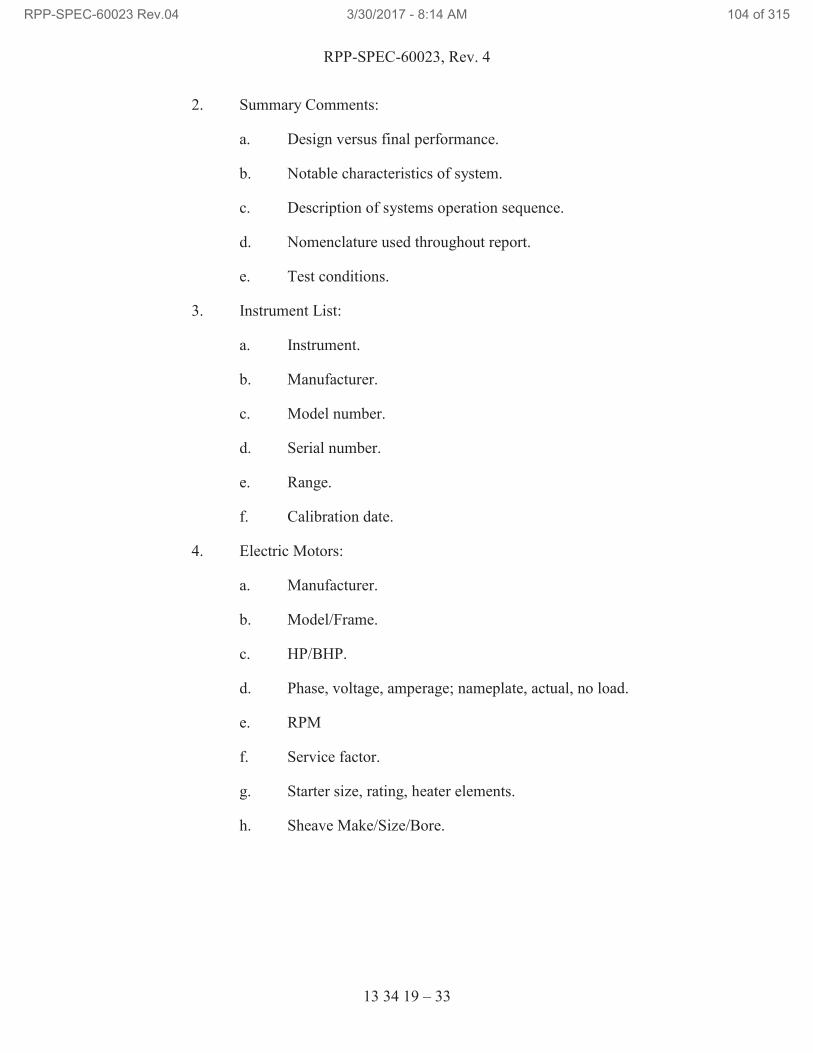
RPP-SPEC-60023, Rev. 4
13 34 19 – 33
2. Summary Comments:
a. Design versus final performance.
b. Notable characteristics of system.
c. Description of systems operation sequence.
d. Nomenclature used throughout report.
e. Test conditions.
3. Instrument List:
a. Instrument.
b. Manufacturer.
c. Model number.
d. Serial number.
e. Range.
f. Calibration date.
4. Electric Motors:
a. Manufacturer.
b. Model/Frame.
c. HP/BHP.
d. Phase, voltage, amperage; nameplate, actual, no load.
e. RPM
f. Service factor.
g. Starter size, rating, heater elements.
h. Sheave Make/Size/Bore.
RPP-SPEC-60023 Rev.04 3/30/2017 - 8:14 AM 104 of 315
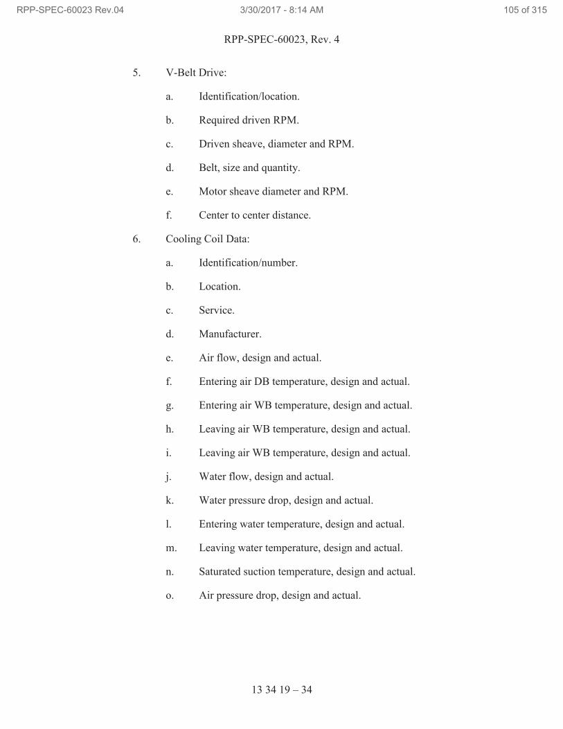
RPP-SPEC-60023, Rev. 4
13 34 19 – 34
5. V-Belt Drive:
a. Identification/location.
b. Required driven RPM.
c. Driven sheave, diameter and RPM.
d. Belt, size and quantity.
e. Motor sheave diameter and RPM.
f. Center to center distance.
6. Cooling Coil Data:
a. Identification/number.
b. Location.
c. Service.
d. Manufacturer.
e. Air flow, design and actual.
f. Entering air DB temperature, design and actual.
g. Entering air WB temperature, design and actual.
h. Leaving air WB temperature, design and actual.
i. Leaving air WB temperature, design and actual.
j. Water flow, design and actual.
k. Water pressure drop, design and actual.
l. Entering water temperature, design and actual.
m. Leaving water temperature, design and actual.
n. Saturated suction temperature, design and actual.
o. Air pressure drop, design and actual.
RPP-SPEC-60023 Rev.04 3/30/2017 - 8:14 AM 105 of 315
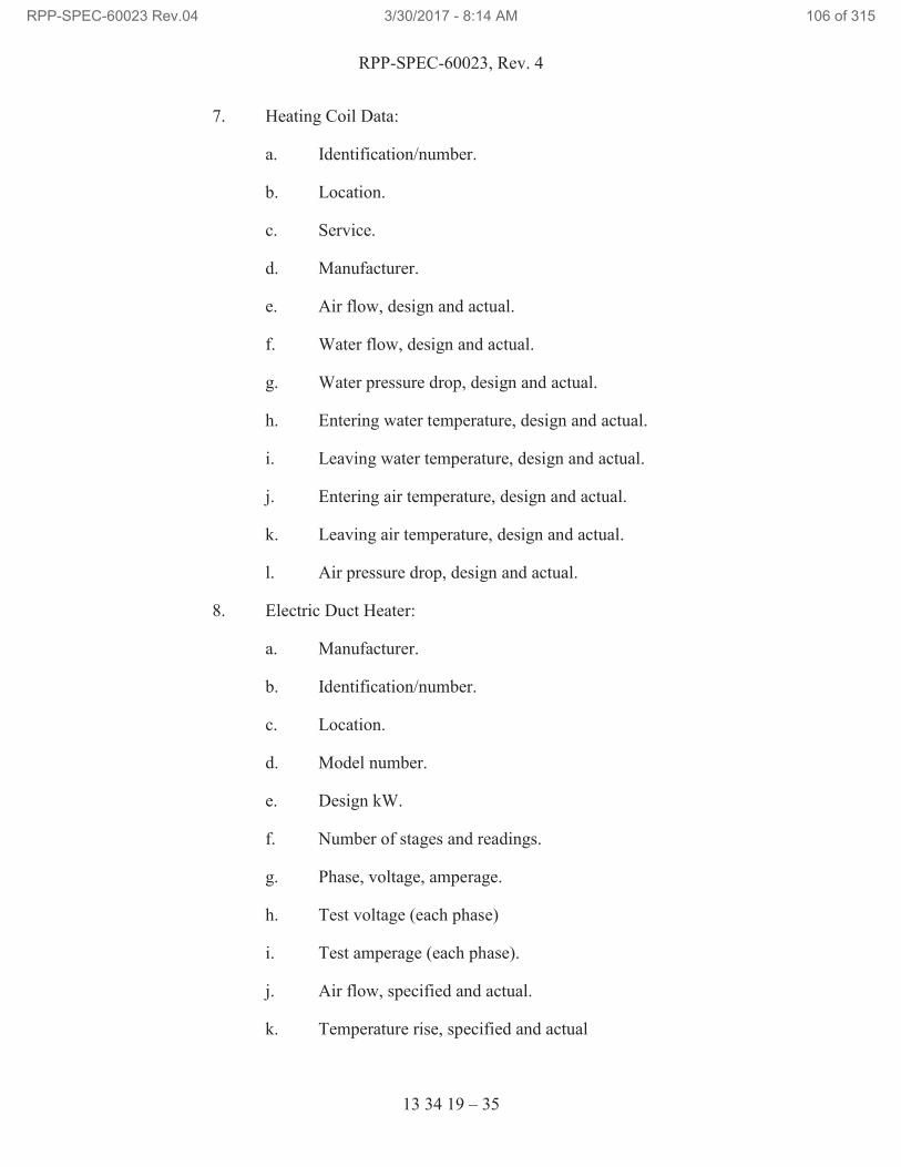
RPP-SPEC-60023, Rev. 4
13 34 19 – 35
7. Heating Coil Data:
a. Identification/number.
b. Location.
c. Service.
d. Manufacturer.
e. Air flow, design and actual.
f. Water flow, design and actual.
g. Water pressure drop, design and actual.
h. Entering water temperature, design and actual.
i. Leaving water temperature, design and actual.
j. Entering air temperature, design and actual.
k. Leaving air temperature, design and actual.
l. Air pressure drop, design and actual.
8. Electric Duct Heater:
a. Manufacturer.
b. Identification/number.
c. Location.
d. Model number.
e. Design kW.
f. Number of stages and readings.
g. Phase, voltage, amperage.
h. Test voltage (each phase)
i. Test amperage (each phase).
j. Air flow, specified and actual.
k. Temperature rise, specified and actual
RPP-SPEC-60023 Rev.04 3/30/2017 - 8:14 AM 106 of 315
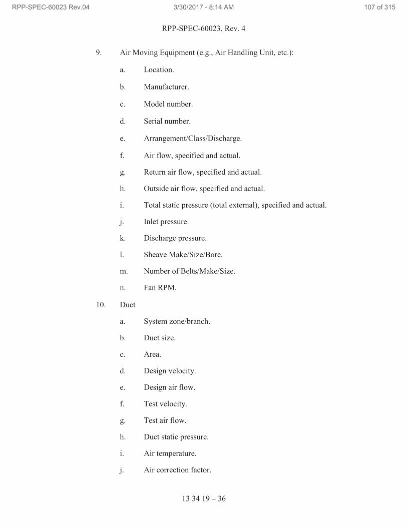
RPP-SPEC-60023, Rev. 4
13 34 19 – 36
9. Air Moving Equipment (e.g., Air Handling Unit, etc.):
a. Location.
b. Manufacturer.
c. Model number.
d. Serial number.
e. Arrangement/Class/Discharge.
f. Air flow, specified and actual.
g. Return air flow, specified and actual.
h. Outside air flow, specified and actual.
i. Total static pressure (total external), specified and actual.
j. Inlet pressure.
k. Discharge pressure.
l. Sheave Make/Size/Bore.
m. Number of Belts/Make/Size.
n. Fan RPM.
10. Duct
a. System zone/branch.
b. Duct size.
c. Area.
d. Design velocity.
e. Design air flow.
f. Test velocity.
g. Test air flow.
h. Duct static pressure.
i. Air temperature.
j. Air correction factor.
RPP-SPEC-60023 Rev.04 3/30/2017 - 8:14 AM 107 of 315
RPP-SPEC-60023, Rev. 4
13 34 19 – 37
11. Vibration Test:
a. Location of points:
i. Fan bearing, drive end.
ii. Fan bearing, opposite end.
iii. Motor bearing, center (when applicable).
iv. Motor bearing, drive end.
v. Motor bearing, opposite end.
vi. Casing (bottom or top).
vii. Casing (side).
12. Final Design Document Package.
a. Final (as-built) drawings.
b. Final (as-built) calculations.
c. Final Test Report.
13. Normally accepted readings, velocity and accelerations.
14. Unusual conditions at time of test.
3.8 REPAIR, CLEANING, AND PAINTING
A. Following erection, remove all unused material, screws, fasteners, and other
debris from completed installation. Use caution when removing metal cuttings
from surface of prefinished metal panels.
B. Replace damaged, dented, buckled, or discolored metal panels.
C. Repair damaged, painted, and galvanized surfaces.
3.9 MANUFACTURER’S SERVICES
A. Provide manufacturer’s representative at Site, for installation assistance,
inspection, and certification of proper installation.
END OF SECTION 13 34 19
RPP-SPEC-60023 Rev.04 3/30/2017 - 8:14 AM 108 of 315
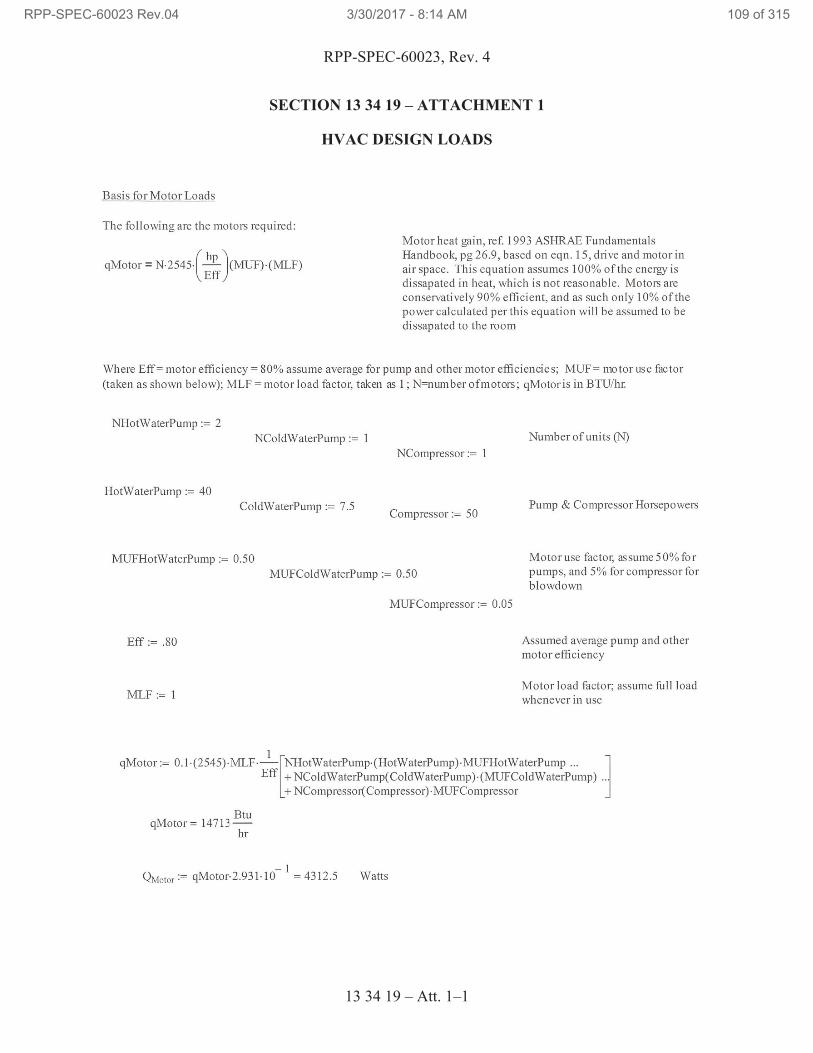
RPP-SPEC-60023, Rev. 4
13 34 19 – Att. 1–1
SECTION 13 34 19 – ATTACHMENT 1
HVAC DESIGN LOADS
RPP-SPEC-60023 Rev.04 3/30/2017 - 8:14 AM 109 of 315
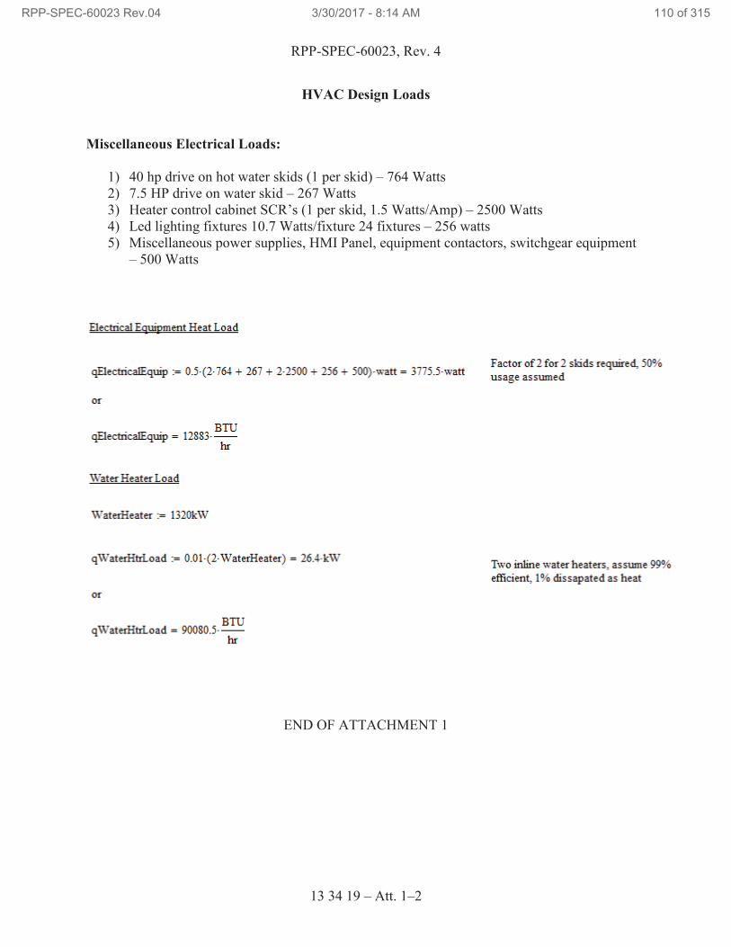
RPP-SPEC-60023, Rev. 4
13 34 19 – Att. 1–2
HVAC Design Loads
Miscellaneous Electrical Loads:
1) 40 hp drive on hot water skids (1 per skid) – 764 Watts
2) 7.5 HP drive on water skid – 267 Watts
3) Heater control cabinet SCR’s (1 per skid, 1.5 Watts/Amp) – 2500 Watts
4) Led lighting fixtures 10.7 Watts/fixture 24 fixtures – 256 watts
5) Miscellaneous power supplies, HMI Panel, equipment contactors, switchgear equipment
– 500 Watts
END OF ATTACHMENT 1
RPP-SPEC-60023 Rev.04 3/30/2017 - 8:14 AM 110 of 315
RPP-SPEC-60023, Rev. 4
13 47 13.13 – 1
SECTION 13 47 13.13
CATHODIC PROTECTION FOR UNDERGROUND AND SUBMERGED PIPING
PART 1 GENERAL
1.1 SCOPE OF WORK
A. This Section includes requirements for materials, installation, and repair to
underground cathodic protection systems.
1.2 RELATED DOCUMENTS/CODES AND STANDARDS
Drawings and general provisions of the contract, including General and Supplementary
Conditions and Division 01 Specification Sections apply to this section.
The following documents and other referenced therein, form part of the Contract to the
extent designated in this Section. Referenced documents are those current as of the date
of this Section, unless otherwise indicated.
A. American Society for Testing and Materials (ASTM)
ASTM B8-11 Standard Specification for Concentric-Lay-Stranded
Copper Conductors, Hard, Medium-Hard, or Soft
ASTM D1248-12 Standard Specifications for Polyethylene Plastics
Extrusion Materials for Wire and Cable, Type 1,
Class A, Category 5, Grades E4 & E5
B. Hanford Documents
H-2-94086, Rev. 2 Cathodic Protection Details, Cables, Boxes &
Jumpers
H-14-011500 Tank Farm Cathodic Protection General Notes &
Details
C. NACE International (NACE)
SP0169-2013 Control of External Corrosion on Underground or
Submerged Metallic Piping Systems
SP0285-2011 Corrosion Control of Underground Storage Tank
Systems by Cathodic ProtectionSP0286-2007
Electrical Isolation of Cathodically
Protected Pipelines
RPP-SPEC-60023 Rev.04 3/30/2017 - 8:14 AM 111 of 315
RPP-SPEC-60023, Rev. 4
13 47 13.13 – 2
D. National Fire Protection Association (NFPA)
NFPA 70, 2014 National Electrical Code
E. Underwriters Laboratories (UL)
UL 486C Splicing Wire Connectors
UL 510 Standard for Polyvinyl Chloride, Polyethylene, and
Rubber Insulating Tape
1.3 SUBMITTALS
Not Used.
1.4 QUALITY ASSURANCE
A. The installation shall conform to the National Electrical Code, applicable local
codes, and Standard Practices (SP) of NACE, SP0285, SP0286, and SP0169.
B. Electrical/Electronic Product Acceptability: Provide labeling and documentation
in accordance with the Statement of Work and Section 26 05 53, “Identification
for Electrical Systems.”
C. Misrepresented Products: See the Statement of Work for required measures to
prevent use of misrepresented products.
1.5 PERMITS
A. Permits are addressed by TOC work control process.
1.6 DELIVERY, STORAGE, AND HANDLING
A. See the Contract Statement of Work for general requirements.
PART 2 PRODUCTS
2.1 SUBSTITUTES
A. See the Contract Statement of Work for substitution approvals.
2.2 MATERIALS
A. 3M™17
Scotchkote™17
Electrical coating or equivalent.
17
3M, Schotch, Scotchcast, Scotchfil, Scotchkote, Skotchlok, and Scotchrap are trademarks of 3M Company,
St. Paul, Minnesota.
RPP-SPEC-60023 Rev.04 3/30/2017 - 8:14 AM 112 of 315
RPP-SPEC-60023, Rev. 4
13 47 13.13 – 3
B. Test Station Boxes: Gerome 2007 Box, or equivalent as required, as depicted on
H-14-011500.
C. Anode Junction Boxes: 16” x 16” NEMA 4 Enclosure per H-14-011500.
D. Plastic Warning Tape:
1. Plastic warning tape for horizontal runs of buried leads in cable trenches
shall be a minimum of 4-mils thick and 6-inches wide inert, yellow, plastic
film designed for prolonged use underground. The tape shall have the
words, “CAUTION CATHODIC PROTECTION CABLE BELOW,” or
similar, clearly visible in repeating patterns along its entire length.
2. Plastic warning tape for anodes shall be buried according to H-14-011500.
E. Conductors:
1. Direct buried: High Molecular Weight Polyethylene (HMWPE) Cathodic
Protection Cables: 600 Volts, Single Conductor, Stranded Copper cable
for direct burial, No. 2-AWG. Conductor shall conform to ASTM B8-11.
Insulation shall conform to ASTM D1248-12. Size specified on the
Drawings
2. Conduit run: No. 2-AWG stranded THHN wire.
3. Bonding: Type “CP” wire, No. 4 AWG, or as shown on drawings.
4. Anode header and loop: Type “CP” wire, No. 2 AWG, or as shown on
drawings.
F. Anode
1. Canistered Wire Anode: De Nora LIDA®18
Pack canistered wire anode,
Model LP 3 X 40H with at least 1.4 amp output or equivalent.
G. Conductor Pin Brazing
1. For New and Old Pipe: Follow manufacturer’s instructions. See
H-14-011500 for applicable detail.
a. Pin Brazing Power and Control Unit.
b. Pin Brazing Consumables per manufacturer’s instructions.
2. Brazing Coating
18
LIDA is registered trademark of De Nora Tech, Inc., Chardon, Ohio.
RPP-SPEC-60023 Rev.04 3/30/2017 - 8:14 AM 113 of 315
RPP-SPEC-60023, Rev. 4
13 47 13.13 – 4
a. Royston®19
Handy Cap IP, Integrated primer or approved
substitute per manufacturer’s instructions.
H. Repair Coating: Sherwin Williams SEAGUARD MP (see Section 09 91 00,
“Painting,” for product details).
1. Power tool clean the area per manufacturer’s recommendations before
coating application.
2. Brush or roll application is acceptable for repairs.
I. Splice Kit, Conductor:
1. Cadweld®20
CASS Type cable splice kit, by Erico Products, or approved
substitute. Suffix based on conductor size.
2. Cadweld CATA Type cable splice kit, by Erico Products, or approved
substitute. Suffix based on conductor size.
3. Epoxy potting compound for encapsulating electrical wire splices or
terminated wires buried underground (for use as required), 3M Company,
Scotchcast™17
Multi-Mold Resin Splicing Kit, 85-10, or approved
substitute.
J. Tape, Electrical Insulating
1. Scotch™17
rubber splicing tape #23
2. Scotch electrical tape #33
a. Plastic: UL 510, 3/4-inch wide.
b. Self-vulcanizing: UL 510, 3/4-inch wide.
K. 3M Scotchkote Electrical Coating FD.
L. Touch-up compound for PVC Conduit Coating: Material of Contractor’s choice.
M. Wire marker: Tubular plastic, imprinted or typed with indelible ink, or plastic tag
typed with indelible ink, fastened securely to wire with plastic wire tie.
19
Royston is a registered trademark of Chase Corporation, Bridgewater, Massachusetts. 20
Cadweld is a registered trademark of Erico International Corporation, Solon, Ohio.
RPP-SPEC-60023 Rev.04 3/30/2017 - 8:14 AM 114 of 315
RPP-SPEC-60023, Rev. 4
13 47 13.13 – 5
PART 3 EXECUTION
3.1 PREPARATION
A. Field Measurements: Scale dimensions on the drawings show desired and
approximate location of equipment, actual locations, distances, and levels shall be
governed by field conditions.
3.2 INSTALLATION
A. General
1. The Contractor shall furnish all tools, equipment, materials and supplies,
and shall perform all labor required to provide complete corrosion control
systems in accordance with the requirements of the Contract Documents.
2. Perform work in accordance with NFPA 70, the Specifications, and the
Drawings.
3. Use appropriate calibrated special tools when installing devices for which
manufacturer recommends special installation tools.
4. Refer to Section 31 23 00, “Excavation and Fill,” for excavation or
backfill of soil.
B. Test Station: Install below grade test stations per design.
C. Junction boxes
1. Install junction boxes according to design. Junction box details located on
H-14-011500.
2. Label boxes according to design.
3. Conductor labels should indicate where the cables originate from (e.g.,
A241-CATH-RECT-015, J 42-5, etc.)
D. Wire pull box
1. Install junction boxes according to design. Wire pull box detail located on
H-14-011500.
E. Conductors
1. Test Stations
a. Wire brush to remove surface contaminants and mechanically
grind or file pipe at connection location to bare metal surface, free
of oil and dirt. Note: Enough pipe surface should be prepared to
RPP-SPEC-60023 Rev.04 3/30/2017 - 8:14 AM 115 of 315
RPP-SPEC-60023, Rev. 4
13 47 13.13 – 6
accommodate the corrosion protection product to be applied after
the connection is complete. Make pin brazing of conductors to
pipe in accordance with approved manufacturer’s instructions.
b. Where two or more wires are brazed to the metallic structure, the
minimum spacing between the connections shall be 6 inches.
c. Inspect pin brazing connections for mechanical integrity in
accordance with manufacturer’s instructions.
d. Install the cables with sufficient slack so that the cable insulation
and conductors will not be damaged during backfill operations or
ground or structure movement. As required, cables should be
secured with duct tape or tie wraps during pipe trench activity and
backfill operations to prevent stress on the brazed area.
e. Apply approved coatings on all exposed copper wire, connector
material, and bared pipe. Overlap approved coating on copper
wire insulation on pipe coating or on bared surface a minimum of
1 inch.
f. Use conductors as specified on H-14-011500, Table 1, Test Station
Conductors.
g. Repair damaged pipe test conductor wires by cleaning and
removing any fraying insulation. Roughen up outer insulation for
approximately 4” each side of the defect with utility knife to
prepare for application of tapes. Using two (2) half-lapped layers
of Scotch rubber splicing # 23 tape and two (2) half-lapped layers
of Scotch electrical #33 plus tape, start from the center of the
defect to ensure a double wrap of each layer. Apply 3M
Scotchkote Electrical Coating FD over taped repair prior to
backfill.
h. Make connections to existing conductor wires using a Cadweld
CASS type connector, Burndy®21
Type mechanical connector, or
appropriately sized copper split bolt per manufacturer’s
instructions, and encase splice point in a 3M Company, Scotchcast
Multi-Mold Resin Splicing Kit, Model 85-10 (or equivalent).
Note: ALL buried wire splices must be completely encased in a
3M Company, Scotchcast Multi-Mold Resin Splicing Kit, Model
85-10 (or equivalent) prior to burial.
i. New conductor wires shall be sufficient length to extend from the
point of installation on the pipeline (or the severed cable
connection), to the new test station.
21
Burndy is a registered trademark of Hubbell Incorporated, Shelton, Connecticut.
RPP-SPEC-60023 Rev.04 3/30/2017 - 8:14 AM 116 of 315
RPP-SPEC-60023, Rev. 4
13 47 13.13 – 7
j. Wires to be direct buried in the ground shall be laid straight
without kinks.
k. Identify end of each conductor using specified wire marker with
typewritten or imprinted pipe number to which conductor is
connected.
l. Newly installed test station(s): Identify the end of each pipe test
conductor using specified wiremarker with typewritten or
imprinted pipe number to which conductor is connected.
m. Terminate conductors on specified terminals and locations in test
station as directed in H-14-011500, Detail 2, and the test station
matrices located on the appropriate cathodic protection farm
drawings. (Note test station matrices are located on drawings
starting with H-14-0315XX).
n. Backfill in accordance with Section 31 23 00, “Excavation and
Fill.”
2. Jumpers
a. Wire brush to remove surface containments and mechanically
grind or file pipe at connection location to white metal surface, free
of oil and dirt. Note: Enough pipe surface should be prepared to
accommodate the corrosion protection product to be applied after
the connection is complete. Make pin brazing connection of
jumpers to pipe in accordance with approved manufacturer’s
instructions.
b. Where two or more wires are connected to the metallic structure,
the minimum spacing between the connections shall be 6 inches.
c. Inspect pin brazing connections for mechanical integrity in
accordance with manufacturer’s instructions.
d. Install the cables with sufficient slack so that the cable insulation
and conductors will not be damaged during backfill operations or
ground or structure movement. As required, cables should be
secured with duct tape or tie wraps during pipe trench activity and
backfill operations to prevent stress on the weld area.
e. Apply approved coating on all exposed copper wire, connection
material, and bared pipe. Overlap approved coating on copper
wire insulation on pipe coating or on bared surface a minimum of
1 inch. Smooth weld coating manually with brush.
RPP-SPEC-60023 Rev.04 3/30/2017 - 8:14 AM 117 of 315
RPP-SPEC-60023, Rev. 4
13 47 13.13 – 8
f. Repair damaged bonding conductor wires by cleaning and
removing any fraying insulation. Roughen up outer insulation for
approximately 4” each side of the defect with utility knife to
prepare for application of tapes. Using two (2) half-lapped layers
of Scotch rubber splicing # 23 tape and two (2) half-lapped layers
of Scotch electrical #33 plus tape, start from the center of the
defect to ensure a double wrap of each layer. Apply 3M
Scotchkote Electrical Coating FD over taped repair prior to
backfill.
g. New conductor wires shall be sufficient length to extend from the
points of installation on the pipelines. Splices, if required, shall be
made using a Cadweld CASS type connector, Burndy Type
mechanical connector, or appropriately sized copper split bolt per
manufacturer’s instructions, and encase splice point in a 3M
Company, Scotchcast Multi-Mold Resin Splicing Kit, Model 85-10
(or equivalent). Note: ALL buried wire splices must be completely
encased in a 3M Company, Scotchcast Multi-Mold Resin Splicing
Kit, Model 85-10 (or equivalent) prior to burial.
h. Wires buried in the ground shall be laid straight without kinks.
i. Bond per H-2-94086, Details 3 and 5.
3. Anode header, loop, and lead cables
a. Anode header cables located in above ground conduit will be a
single cable, i.e., no loop, routed in two directions towards anode
junction boxes. Cables will run through wire pull box, and will
terminate at anode junction boxes on either end of the conduit rack.
Direct buried UHMWPE wires will land in junction boxes, and
continue below grade for anode connections.
b. If damaged, repair or replace per drawing H-14-011500.
c. Terminate new header at rectifier 241A-CATH-RECT-015 positive
output terminals. The header loop cables will terminate at final
anode junction boxes per design.
d. Terminate new negative return cables at rectifier 241A-CATH-
RECT-015 negative output terminal. Use solderless terminal lugs
for conductor terminations. Identify cables using specified wire
markers.
F. Existing Anodes
1. Replace existing anodes if damaged or depleted.
2. Repair damaged head, leader, or loop cables according to H-14-011500.
RPP-SPEC-60023 Rev.04 3/30/2017 - 8:14 AM 118 of 315
RPP-SPEC-60023, Rev. 4
13 47 13.13 – 9
3. If the anode is required to be removed and does not need to be replaced,
ensure that terminated anode leader cable is fully encapsulated in the 85-
14-CP splice kit.
G. New Anodes: Install per manufactures instructions and drawing H-14-011500.
Run anode lead cable in field as required. Specify anode and lead wire
installation locations.
1. Vertical.
2. Horizontal.
3.3 FINAL TESTING
A. Construction Acceptance Testing will be directed as required by the cathodic
protection Design Authorities (DAs), Rick Nelson or Ryler Adams.
B. Start-Up Testing will be directed as required by the cathodic protection DAs,
Rick Nelson or Ryler Adams.
3.4 FIELD QUALITY CONTROL
A. Continuity Testing
1. Testing will be directed by the cathodic protection DAs, Rick Nelson or
Ryler Adams.
B. Connections
1. Document connection of conductors to new and existing pipe. Include the
following:
a. Bonding jumper: Identification of each pipe to which connected
and general location of jumper and splice connection as applicable.
b. Verification that connections complies with manufacturer’s
installation and inspection requirements.
END OF SECTION 13 47 13.13
RPP-SPEC-60023 Rev.04 3/30/2017 - 8:14 AM 119 of 315
RPP-SPEC-60023, Rev. 4
22 15 00 – 1
SECTION 22 15 00
COMPRESSED AIR PIPING
PART 1 GENERAL
1.1 SUMMARY
A. Material, fabrication, installation, and testing of compressed air service piping
inside the Air and Water Service Building.
1.2 RELATED DOCUMENTS, CODES, AND STANDARDS
Drawings and general provisions of the Contract Statement of Work, including
Division 01 Specification Sections, apply to this Section.
The following documents and others referenced therein, form part of the Contract to the
extent designated in this Section. Referenced documents are those current as of the date
of this Section unless otherwise indicated.
A. American National Standards Institute/American Society of Mechanical
Engineers (ANSI/ASME)
ANSI/ASME B13.1 Scheme for the Identification of Piping Systems
B. American Society of Mechanical Engineers (ASME)
ASME B&PVC, 2013 Boiler and Pressure Vessel Code
Section IX Welding and Brazing Qualification
ASME B1.20.1 Pipe Threads, General Purpose, Inch
ASME B16.3 Malleable Iron and Threaded Fittings
ASME B16.9 Factory-Made Wrought Buttwelding Fittings
ASME B16.34 Valves -Flanged, Threaded, and Welding End
ASME B31.9, 2014 Building Services Piping
C. American Society for Nondestructive Testing (ASNT)
ASNT SNT-TC-1A Personnel Qualifications and Certification in
Nondestructive Testing
RPP-SPEC-60023 Rev.04 3/30/2017 - 8:14 AM 120 of 315
RPP-SPEC-60023, Rev. 4
22 15 00 – 2
D. ASTM International (ASTM)
ASTM A182 Standard Specification for Forged or Rolled Alloy
and Stainless Steel Pipe Flanges, Forged Fittings,
and Valves and Parts for High-Temperature Service
ASTM A312 Standard Specification for Seamless, Welded, and
Heavily Cold Worked Austenitic Stainless Steel
Pipes
ASTM A351 Standard Specification for Castings, Austenitic, for
Pressure-Containing Parts
E. American Welding Society (AWS)
AWS D1.1, 2010 Structural Welding Code
AWS D1.6, 2007 Structural Welding Code – Stainless
AWS QC1 Certification of Welding Inspectors
F. Manufacturer’s Standardization Society (MSS)
MSS SP-58 Pipe Hangers and Supports – Materials, Design,
Manufacture, Selection, Application, and
Installation
MSS SP-97 Integrally Reinforced Forged Branch Outlet Fittings
– Socket Welding, Threaded and Buttwelding Ends
G. Hanford Documents
TFC-ENG-STD-06 Design Loads for Tank Farm Facilities
TFC-ENG-STD-12 Tank Farm Equipment Identification Numbering
and Labeling Standard
TFC-ENG-STD-22 Piping, Jumpers, and Valves
1.3 SUBMITTALS
A. See the Contract Statement of Work for the submittal process.
B. Approval Required.
1. Welding Procedure Specifications (WPSs) and or Standard Welding
Procedure Specifications (SWPSs): Five days before first use submit
WPSs and/or SWPSs in accordance with Paragraph 1.4.B.
RPP-SPEC-60023 Rev.04 3/30/2017 - 8:14 AM 121 of 315
RPP-SPEC-60023, Rev. 4
22 15 00 – 3
2. Welding Personnel Qualifications: Five days before start of fabrication
submit welder qualification as required by Paragraph 1.4.B.
3. Examination Documentation: Five days before start of fabrication submit
documentation in accordance with Paragraph 3.4.A for information/record.
4. Mechanical Cleaning Verification: Submit documentation in accordance
with Paragraph 3.3.B for information/record.
5. Weld Examinations: Submit documentation in accordance with Paragraph
3.5.A.
6. Pressure and Leak Testing and Certification: Five days before pressure
testing submit testing procedure in accordance with Paragraphs 1.4.C and
3.4.B.
1.4 QUALITY ASSURANCE
A. Misrepresented Products: See the Contract Statement of Work for required
measures to prevent use of misrepresented products.
B. Qualifications
1. Structural Welding Personnel and Procedures shall be in accordance with
Section 05 50 00, “Metal Fabrications.”
2. Welding Personnel and Procedures for Pressure-Retaining Components
(along with attachment thereto and pipe supports) shall be qualified in
accordance with ASME B31.9, Paragraph 927.6 before welding. Maintain
copies of welding procedure, specification, and procedure qualification
records at jobsite.
C. Pressure Testing Procedures shall be in accordance with ASME B31.9 and this
Specification. Maintain copies of procedures at jobsite.
D. Personnel performing visual examinations shall be Certified Welding Inspectors
(CWIs) who have received certification (current or previous certification) in
accordance with AWS QC1.
E. Personnel performing other nondestructive examinations (NDE) shall be certified
in accordance with approved procedure, which shall meet the requirements of
ASNT SNT-TC-1A. Use Level II or III personnel to interpret results.
F. Examination Procedures: Examination procedures shall be in accordance with
ASME B31.9 and this Specification. Maintain copies of procedures at the jobsite.
RPP-SPEC-60023 Rev.04 3/30/2017 - 8:14 AM 122 of 315
RPP-SPEC-60023, Rev. 4
22 15 00 – 4
1.5 PERMITS
A. Permits are addressed by TOC work control process.
1.6 DELIVERY, STORAGE, AND HANDLING
A. See the Contract Statement of Work for general requirements.
PART 2 PRODUCTS
2.1 PRODUCT OPTIONS AND SUBSTITUTIONS
A. See the Contract Statement of Work for substitution approvals.
2.2 MATERIALS
A. Piping and Fittings: See details specified on the Drawings and in the individual
components list below.
B. Overhead Pipe Supports: B-Line B3100C (plastic coated standard clevis hangers)
or equivalent. Hanger Rods shall be threaded both ends, or continuous threaded
rods of circular cross section. Use adjusting locknuts at upper attachments and
hangers. No wire, chain, or perforated straps are allowed. See location specified
in the Drawings. Add ceiling cross beams as necessary.
C. Close nipples are not permitted unless shown on the Drawings.
D. Pipe Joint Sealant (Lubricant) for Threaded Joints: Use anaerobic acrylic sealer.
Henkel Corporation: Loctite®22
5452 or 567 or engineering approved equivalent.
Clean threads and apply according to manufacturer’s specification.
E. Valves: Specified in individual components list section below, unless otherwise
shown on the Drawings.
F. Expansion Anchors: See Section 03 15 00, “Post-Installed Concrete Anchor
Bolts.” Anchorage must be designed to TFC-ENG-STD-06.
G. Paint: See Section 09 91 00, “Painting” and as specified on the Drawings.
H. Deleted.
22
Loctite is a registered trademark of Henkel Corporation.
RPP-SPEC-60023 Rev.04 3/30/2017 - 8:14 AM 123 of 315
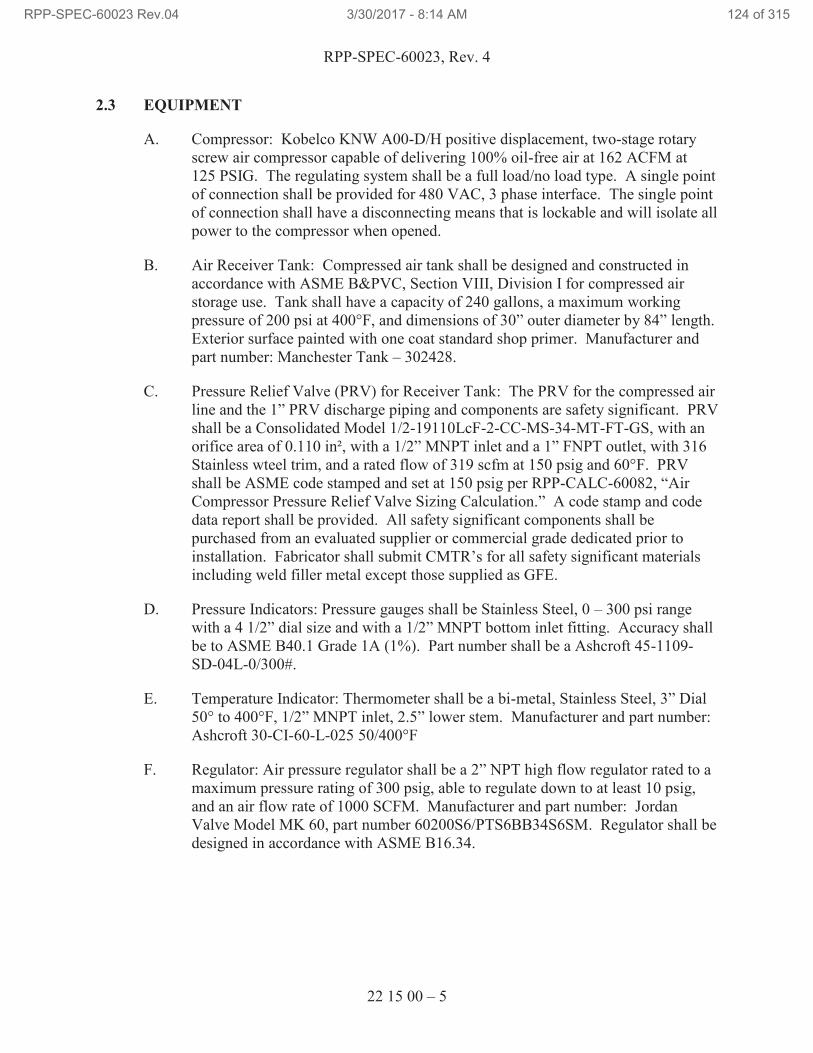
RPP-SPEC-60023, Rev. 4
22 15 00 – 5
2.3 EQUIPMENT
A. Compressor: Kobelco KNW A00-D/H positive displacement, two-stage rotary
screw air compressor capable of delivering 100% oil-free air at 162 ACFM at
125 PSIG. The regulating system shall be a full load/no load type. A single point
of connection shall be provided for 480 VAC, 3 phase interface. The single point
of connection shall have a disconnecting means that is lockable and will isolate all
power to the compressor when opened.
B. Air Receiver Tank: Compressed air tank shall be designed and constructed in
accordance with ASME B&PVC, Section VIII, Division I for compressed air
storage use. Tank shall have a capacity of 240 gallons, a maximum working
pressure of 200 psi at 400°F, and dimensions of 30” outer diameter by 84” length.
Exterior surface painted with one coat standard shop primer. Manufacturer and
part number: Manchester Tank – 302428.
C. Pressure Relief Valve (PRV) for Receiver Tank: The PRV for the compressed air
line and the 1” PRV discharge piping and components are safety significant. PRV
shall be a Consolidated Model 1/2-19110LcF-2-CC-MS-34-MT-FT-GS, with an
orifice area of 0.110 in², with a 1/2” MNPT inlet and a 1” FNPT outlet, with 316
Stainless wteel trim, and a rated flow of 319 scfm at 150 psig and 60°F. PRV
shall be ASME code stamped and set at 150 psig per RPP-CALC-60082, “Air
Compressor Pressure Relief Valve Sizing Calculation.” A code stamp and code
data report shall be provided. All safety significant components shall be
purchased from an evaluated supplier or commercial grade dedicated prior to
installation. Fabricator shall submit CMTR’s for all safety significant materials
including weld filler metal except those supplied as GFE.
D. Pressure Indicators: Pressure gauges shall be Stainless Steel, 0 – 300 psi range
with a 4 1/2” dial size and with a 1/2” MNPT bottom inlet fitting. Accuracy shall
be to ASME B40.1 Grade 1A (1%). Part number shall be a Ashcroft 45-1109-
SD-04L-0/300#.
E. Temperature Indicator: Thermometer shall be a bi-metal, Stainless Steel, 3” Dial
50° to 400°F, 1/2” MNPT inlet, 2.5” lower stem. Manufacturer and part number:
Ashcroft 30-CI-60-L-025 50/400°F
F. Regulator: Air pressure regulator shall be a 2” NPT high flow regulator rated to a
maximum pressure rating of 300 psig, able to regulate down to at least 10 psig,
and an air flow rate of 1000 SCFM. Manufacturer and part number: Jordan
Valve Model MK 60, part number 60200S6/PTS6BB34S6SM. Regulator shall be
designed in accordance with ASME B16.34.
RPP-SPEC-60023 Rev.04 3/30/2017 - 8:14 AM 124 of 315
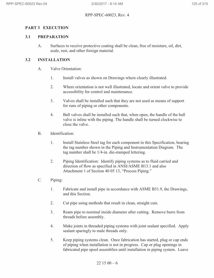
RPP-SPEC-60023, Rev. 4
22 15 00 – 6
PART 3 EXECUTION
3.1 PREPARATION
A. Surfaces to receive protective coating shall be clean, free of moisture, oil, dirt,
scale, rust, and other foreign material.
3.2 INSTALLATION
A. Valve Orientation:
1. Install valves as shown on Drawings where clearly illustrated.
2. Where orientation is not well illustrated, locate and orient valve to provide
accessibility for control and maintenance.
3. Valves shall be installed such that they are not used as means of support
for runs of piping or other components.
4. Ball valves shall be installed such that, when open, the handle of the ball
valve is inline with the piping. The handle shall be turned clockwise to
close the valve.
B. Identification:
1. Install Stainless Steel tag for each component in this Specification, bearing
the tag number shown in the Piping and Instrumentation Diagram. The
tag number shall be 1/4-in. die-stamped lettering.
2. Piping Identification: Identify piping systems as to fluid carried and
direction of flow as specified in ANSI/ASME B13.1 and also
Attachment 1 of Section 40 05 13, “Process Piping.”
C. Piping:
1. Fabricate and install pipe in accordance with ASME B31.9, the Drawings,
and this Section.
2. Cut pipe using methods that result in clean, straight cuts.
3. Ream pipe to nominal inside diameter after cutting. Remove burrs from
threads before assembly.
4. Make joints in threaded piping systems with joint sealant specified. Apply
sealant sparingly to male threads only.
5. Keep piping systems clean. Once fabrication has started, plug or cap ends
of piping when installation is not in progress. Cap or plug openings in
fabricated pipe spool assemblies until installation in piping system. Leave
RPP-SPEC-60023 Rev.04 3/30/2017 - 8:14 AM 125 of 315
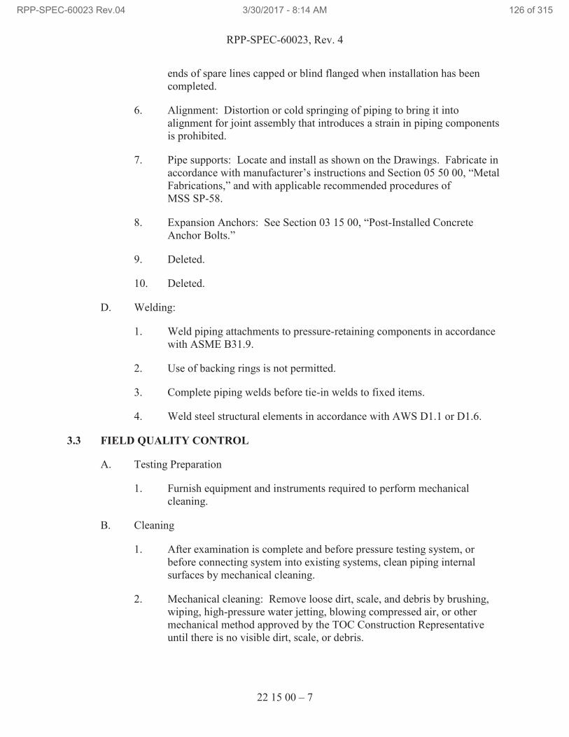
RPP-SPEC-60023, Rev. 4
22 15 00 – 7
ends of spare lines capped or blind flanged when installation has been
completed.
6. Alignment: Distortion or cold springing of piping to bring it into
alignment for joint assembly that introduces a strain in piping components
is prohibited.
7. Pipe supports: Locate and install as shown on the Drawings. Fabricate in
accordance with manufacturer’s instructions and Section 05 50 00, “Metal
Fabrications,” and with applicable recommended procedures of
MSS SP-58.
8. Expansion Anchors: See Section 03 15 00, “Post-Installed Concrete
Anchor Bolts.”
9. Deleted.
10. Deleted.
D. Welding:
1. Weld piping attachments to pressure-retaining components in accordance
with ASME B31.9.
2. Use of backing rings is not permitted.
3. Complete piping welds before tie-in welds to fixed items.
4. Weld steel structural elements in accordance with AWS D1.1 or D1.6.
3.3 FIELD QUALITY CONTROL
A. Testing Preparation
1. Furnish equipment and instruments required to perform mechanical
cleaning.
B. Cleaning
1. After examination is complete and before pressure testing system, or
before connecting system into existing systems, clean piping internal
surfaces by mechanical cleaning.
2. Mechanical cleaning: Remove loose dirt, scale, and debris by brushing,
wiping, high-pressure water jetting, blowing compressed air, or other
mechanical method approved by the TOC Construction Representative
until there is no visible dirt, scale, or debris.
RPP-SPEC-60023 Rev.04 3/30/2017 - 8:14 AM 126 of 315
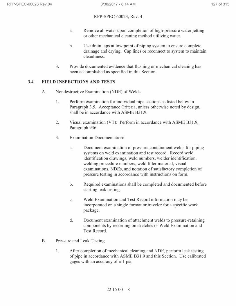
RPP-SPEC-60023, Rev. 4
22 15 00 – 8
a. Remove all water upon completion of high-pressure water jetting
or other mechanical cleaning method utilizing water.
b. Use drain taps at low point of piping system to ensure complete
drainage and drying. Cap lines or reconnect to system to maintain
cleanliness.
3. Provide documented evidence that flushing or mechanical cleaning has
been accomplished as specified in this Section.
3.4 FIELD INSPECTIONS AND TESTS
A. Nondestructive Examination (NDE) of Welds
1. Perform examination for individual pipe sections as listed below in
Paragraph 3.5. Acceptance Criteria, unless otherwise noted by design,
shall be in accordance with ASME B31.9.
2. Visual examination (VT): Perform in accordance with ASME B31.9,
Paragraph 936.
3. Examination Documentation:
a. Document examination of pressure containment welds for piping
systems on weld examination and test record. Record weld
identification drawings, weld numbers, welder identification,
welding procedure numbers, weld filler material, visual
examinations, NDEs, and notation of satisfactory completion of
pressure testing in accordance with instructions on form.
b. Required examinations shall be completed and documented before
starting leak testing.
c. Weld Examination and Test Record information may be
incorporated on a single format or traveler for a specific work
package.
d. Document examination of attachment welds to pressure-retaining
components by recording on sketches or Weld Examination and
Test Record.
B. Pressure and Leak Testing
1. After completion of mechanical cleaning and NDE, perform leak testing
of pipe in accordance with ASME B31.9 and this Section. Use calibrated
gages with an accuracy of ± 1 psi.
RPP-SPEC-60023 Rev.04 3/30/2017 - 8:14 AM 127 of 315
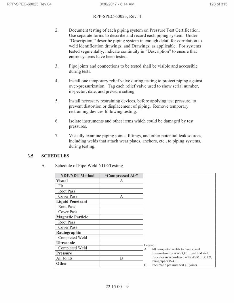
RPP-SPEC-60023, Rev. 4
22 15 00 – 9
2. Document testing of each piping system on Pressure Test Certification.
Use separate forms to describe and record each piping system. Under
“Description,” describe piping system in enough detail for correlation to
weld identification drawings, and Drawings, as applicable. For systems
tested segmentally, indicate continuity in “Description” to ensure that
entire systems have been tested.
3. Pipe joints and connections to be tested shall be visible and accessible
during tests.
4. Install one temporary relief valve during testing to protect piping against
over-pressurization. Tag each relief valve used to show serial number,
inspector, date, and pressure setting.
5. Install necessary restraining devices, before applying test pressure, to
prevent distortion or displacement of piping. Remove temporary
restraining devices following testing.
6. Isolate instruments and other items which could be damaged by test
pressures.
7. Visually examine piping joints, fittings, and other potential leak sources,
including welds that attach wear plates, anchors, etc., to piping systems,
during testing.
3.5 SCHEDULES
A. Schedule of Pipe Weld NDE/Testing
NDE/NDT Method “Compressed Air”
Legend:
A. All completed welds to have visual
examination by AWS QC1 qualified weld
inspector in accordance with ASME B31.9,
Paragraph 936.4.1.
B. Pneumatic pressure test all joints.
Visual A
Fit
Root Pass
Cover Pass A
Liquid Penetrant
Root Pass
Cover Pass
Magnetic Particle
Root Pass
Cover Pass
Radiographic
Completed Weld
Ultrasonic
Completed Weld
Pressure
All Joints B
Other
RPP-SPEC-60023 Rev.04 3/30/2017 - 8:14 AM 128 of 315
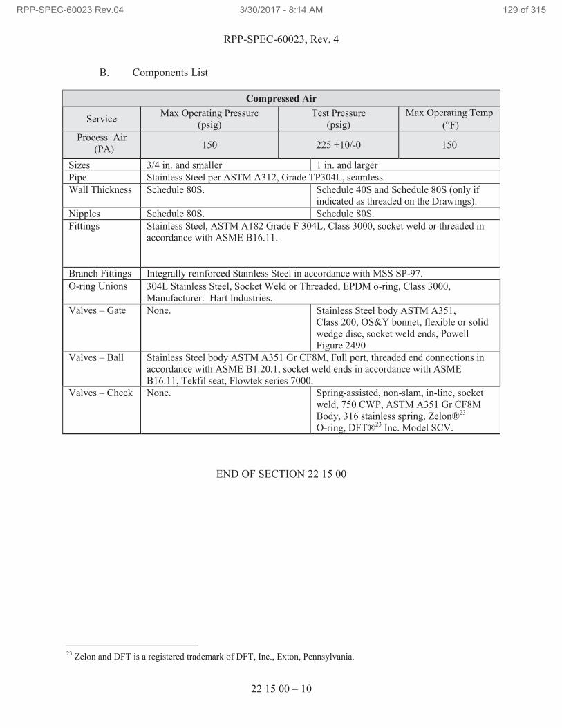
RPP-SPEC-60023, Rev. 4
22 15 00 – 10
B. Components List
Compressed Air
Service Max Operating Pressure
(psig)
Test Pressure
(psig)
Max Operating Temp
(°F)
Process Air
(PA) 150 225 +10/-0 150
Sizes 3/4 in. and smaller 1 in. and larger
Pipe Stainless Steel per ASTM A312, Grade TP304L, seamless
Wall Thickness Schedule 80S. Schedule 40S and Schedule 80S (only if
indicated as threaded on the Drawings).
Nipples Schedule 80S. Schedule 80S.
Fittings Stainless Steel, ASTM A182 Grade F 304L, Class 3000, socket weld or threaded in
accordance with ASME B16.11.
Branch Fittings Integrally reinforced Stainless Steel in accordance with MSS SP-97.
O-ring Unions 304L Stainless Steel, Socket Weld or Threaded, EPDM o-ring, Class 3000,
Manufacturer: Hart Industries.
Valves – Gate None. Stainless Steel body ASTM A351, Class 200, OS&Y bonnet, flexible or solid
wedge disc, socket weld ends, Powell
Figure 2490
Valves – Ball Stainless Steel body ASTM A351 Gr CF8M, Full port, threaded end connections in
accordance with ASME B1.20.1, socket weld ends in accordance with ASME
B16.11, Tekfil seat, Flowtek series 7000.
Valves – Check None. Spring-assisted, non-slam, in-line, socket
weld, 750 CWP, ASTM A351 Gr CF8M
Body, 316 stainless spring, Zelon®23
O-ring, DFT®23
Inc. Model SCV.
END OF SECTION 22 15 00
23
Zelon and DFT is a registered trademark of DFT, Inc., Exton, Pennsylvania.
RPP-SPEC-60023 Rev.04 3/30/2017 - 8:14 AM 129 of 315
RPP-SPEC-60023, Rev. 4
23 31 01 – 1
SECTION 23 31 01
TANK VENTILATION DUCTING
PART 1 GENERAL
1.1 SCOPE OF WORK
A. Section includes waste retrieval tank ventilation ductwork and housing assembly
installation, cleaning, inspection, and testing.
1.2 RELATED DOCUMENTS, CODES, AND STANDARDS
Drawings and general provisions of the Contract Statement of Work, including Division
01 Specification Sections, apply to this Section.
The following documents and others referenced therein, form part of the Contract to the
extent designated in this Section. Referenced documents are those current as of the date
of this Section unless otherwise indicated.
A. American Society of Mechanical Engineers (ASME)
ASME AG-1, 2012 Code on Nuclear Air and Gas Treatment
B. American Society for Nondestructive Testing (ASNT)
ASNT SNT-TC-1A Recommended Practice No. SNT-TC-1A and
ASNT Standard Topical Outlines for Qualification
of Nondestructive Testing Personnel
C. Hanford Documents
H-14-109924 241-AX Ventilation Site Plan
OSD-T151-00013 Operating Specifications for Single-Shell Waste
Storage Tanks
TFC-ENG-STD-07 Ventilation System Design Standard
RPP-CALC-57515 AX-Farm Tank Exhaust System Duct Loss and
Performance Curve
RPP-CALC-57516 AG-1 Duct Volume, Pressure Test Criteria
Calculation
RPP-SPEC-60023 Rev.04 3/30/2017 - 8:14 AM 130 of 315
RPP-SPEC-60023, Rev. 4
23 31 01 – 2
1.3 PERFORMANCE REQUIREMENTS
A. No variation of duct configuration is permitted except by the approved design
documents.
1.4 SUBMITTALS
A. See the Contract Statement of Work for the submittal process.
B. Approval Required
1. Documented in work package or fabrication document as applicable.
1.5 QUALITY ASSURANCE
A. Construct ductwork in accordance with design documentation.
1.6 QUALIFICATIONS
A. Installer: Company specializing in performing work of this section with
minimum 3 years’ ASME AG-1 experience.
1.7 FIELD MEASUREMENTS
A. Verify field measurements prior to installation.
PART 2 PRODUCTS
2.1 PRODUCT OPTIONS AND SUBSTITUTIONS
A. Comply with Contract Statement of Work.
2.2 DUCT MATERIAL
A. Duct and housing materials must be in accordance with design documentation.
PART 3 EXECUTION
3.1 INSTALLATION
A. Install and support ductwork and housing assemblies in accordance with design
documents and Contract Statement of Work.
B. During construction, install temporary closures of metal and taped polyethylene
over open ductwork and housings to prevent foreign matter from entering
ductwork system.
C. Install flexible connection with minimum 1-in. slack immediately adjacent to
equipment in ducts associated with fans and motorized equipment.
RPP-SPEC-60023 Rev.04 3/30/2017 - 8:14 AM 131 of 315
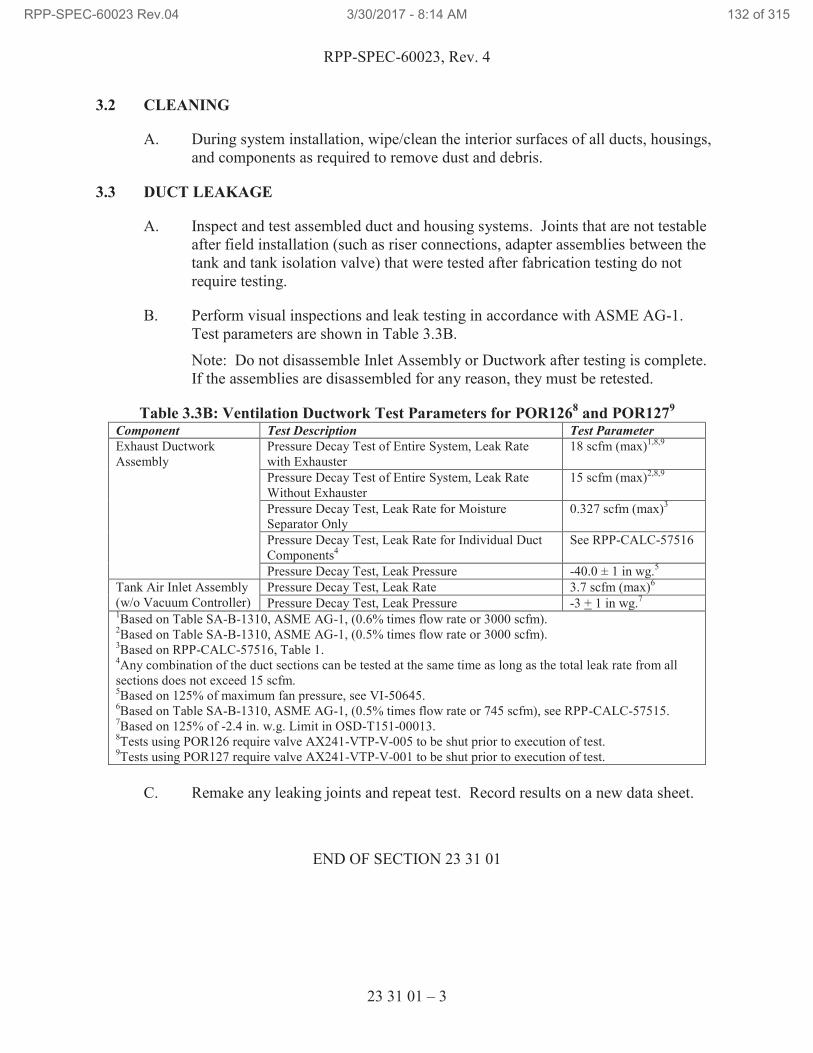
RPP-SPEC-60023, Rev. 4
23 31 01 – 3
3.2 CLEANING
A. During system installation, wipe/clean the interior surfaces of all ducts, housings,
and components as required to remove dust and debris.
3.3 DUCT LEAKAGE
A. Inspect and test assembled duct and housing systems. Joints that are not testable
after field installation (such as riser connections, adapter assemblies between the
tank and tank isolation valve) that were tested after fabrication testing do not
require testing.
B. Perform visual inspections and leak testing in accordance with ASME AG-1.
Test parameters are shown in Table 3.3B.
Note: Do not disassemble Inlet Assembly or Ductwork after testing is complete.
If the assemblies are disassembled for any reason, they must be retested.
Table 3.3B: Ventilation Ductwork Test Parameters for POR1268 and POR127
9
Component Test Description Test Parameter
Exhaust Ductwork
Assembly
Pressure Decay Test of Entire System, Leak Rate
with Exhauster
18 scfm (max)1,8,9
Pressure Decay Test of Entire System, Leak Rate
Without Exhauster
15 scfm (max)2,8,9
Pressure Decay Test, Leak Rate for Moisture
Separator Only
0.327 scfm (max)3
Pressure Decay Test, Leak Rate for Individual Duct
Components4
See RPP-CALC-57516
Pressure Decay Test, Leak Pressure -40.0 ± 1 in wg.5
Tank Air Inlet Assembly
(w/o Vacuum Controller)
Pressure Decay Test, Leak Rate 3.7 scfm (max)6
Pressure Decay Test, Leak Pressure -3 + 1 in wg.7
1Based on Table SA-B-1310, ASME AG-1, (0.6% times flow rate or 3000 scfm).
2Based on Table SA-B-1310, ASME AG-1, (0.5% times flow rate or 3000 scfm).
3Based on RPP-CALC-57516, Table 1.
4Any combination of the duct sections can be tested at the same time as long as the total leak rate from all
sections does not exceed 15 scfm. 5Based on 125% of maximum fan pressure, see VI-50645.
6Based on Table SA-B-1310, ASME AG-1, (0.5% times flow rate or 745 scfm), see RPP-CALC-57515.
7Based on 125% of -2.4 in. w.g. Limit in OSD-T151-00013.
8Tests using POR126 require valve AX241-VTP-V-005 to be shut prior to execution of test.
9Tests using POR127 require valve AX241-VTP-V-001 to be shut prior to execution of test.
C. Remake any leaking joints and repeat test. Record results on a new data sheet.
END OF SECTION 23 31 01
RPP-SPEC-60023 Rev.04 3/30/2017 - 8:14 AM 132 of 315
RPP-SPEC-60023, Rev. 4
23 31 13 – 1
SECTION 23 31 13
AIR COMPRESSOR METAL DUCTS
PART 1 GENERAL
1.1 SCOPE OF WORK
A. Section includes ventilation ductwork and duct sealing for the exhaust cooling air
of the Air and Water Service Building 241-A-285 air compressor unit.
1.2 RELATED DOCUMENTS / CODES AND STANDARDS
Drawings and general provisions of the contract, including General and Supplementary
Conditions and Division 01 Specification Sections apply to this Section.
The following documents and others referenced therein, form part of the Contract to the
extent designated in this Section. Referenced documents are those current as of the date
of this Section unless otherwise indicated.
A. American Society for Testing and Materials (ASTM)
ASTM A36 Standard Specification for Carbon Structural Steel
ASTM A90 Standard Test Method for Weight [Mass] of
Coating on Iron and Steel Articles with Zinc or
Zinc-Alloy Coatings
ASTM A653 Standard Specification for Steel Sheet, Zinc-Coated
(Galvanized) or Zinc-Iron Alloy-Coated
(Galvannealed) by the Hot-Dip Process
B. American Welding Society (AWS)
AWS D1.1, 2010 Structural Welding Code – Steel
AWS D1.3, 2008 Structural Welding Code-Sheet Steel
AWS D9.1 Sheet Metal Welding Code
C. Manufacturer’s Standardization Society of the Valve and Fitting Industry (MSS)
MSS SP-58 Pipe Hangers and Supports – Materials, Design, Manufacture, Selection, Application, and Installation
MSS SP-69 Pipe Hangers and Supports – Selection and Application
RPP-SPEC-60023 Rev.04 3/30/2017 - 8:14 AM 133 of 315
RPP-SPEC-60023, Rev. 4
23 31 13 – 2
D. National Fire Protection Association (NFPA)
NFPA 90A Standard for the Installation of Air-Conditioning
and Ventilating Systems
E. Sheet Metal and Air Conditioning Contractors National Association (SMACNA)
SMACNA 1520 Round Industrial Duct Construction Standards
SMACNA 1922 Rectangular Industrial Duct Construction Standards
HVAC Duct Construction Standards – Metal and
Flexible
F. Underwriters Laboratories (UL)
UL 181A Closure Systems for Use with Rigid Air Ducts
1.3 QUALITY ASSURANCE
A. Construct ductwork in accordance with SMACNA – HVAC Duct Construction
Standards – Metal and Flexible, and NFPA 90A.
1.4 FIELD MEASUREMENTS
A. Verify field measurements prior to fabrication.
PART 2 PRODUCTS
2.1 DUCT MATERIALS
A. Galvanized Steel Ducts: ASTM A653 galvanized steel sheet, lock-forming
quality, having G90 zinc coating in conformance with ASTM A90.
B. Fasteners: Rivets, bolts, or sheet metal screws.
C. Structural Steel Members: ASTM A36 steel.
2.2 WALL LOUVER
A. The exhaust louver shall be of corrosion resistant metal, or suitably finished to
resist corrosion.
B. Size, and location shall be as shown on drawings.
RPP-SPEC-60023 Rev.04 3/30/2017 - 8:14 AM 134 of 315
RPP-SPEC-60023, Rev. 4
23 31 13 – 3
2.3 DUCTWORK FABRICATION
A. Fabricate ductwork, duct access doors, and support in accordance with SMACNA
HVAC Duct Construction Standards – Metal and Flexible. Furnish duct material,
gages, reinforcing, and sealing for design pressure class indicated.
B. Construct T’s, bends, and elbows with minimum radius 1 1/2 times centerline
duct width.
C. Provide, at minimum, rectangular 45 degree entry fittings for rectangular ducts.
D. Duct sizes noted are inside clear dimensions. No variation of duct configuration
or sizes other than those of equivalent or lower loss coefficient is permitted except
by written permission from the Buyer’s Technical Representative. Round ducts
installed in place of rectangular ducts shall be sized in accordance with ASHRAE
table of equivalent rectangular and round ducts.
E. Increase duct size gradually, not exceeding 15 degree divergence wherever
possible. Do not exceed 30-degree divergence upstream of equipment. Do not
exceed 45-degree convergence downstream of equipment.
2.4 HANGERS AND SUPPORTS
A. Install hangers and supports for ducting as necessary.
PART 3 EXECUTION
3.1 EXAMINATION
A. Verify sizes of equipment connection before fabricating transitions.
3.2 INSTALLATION
A. Install, seal, and support ductwork in accordance with SMACNA HVAC Duct
Construction Standards-Metal and Flexible.
B. During construction, install temporary closures of metal or taped polyethylene on
open ductwork to prevent construction dust from entering ductwork system.
C. Use double nuts and lock washers on threaded rod supports.
D. Locate ducts with sufficient space around equipment to allow normal operating
and maintenance activities.
E. Repair damaged galvanized ductwork surfaces (welds, scratches, etc.) by applying
minimum 2 coats of a zinc base paint.
F. Install wall louver as shown on drawings and according to manufacturer’s
instructions.
RPP-SPEC-60023 Rev.04 3/30/2017 - 8:14 AM 135 of 315
RPP-SPEC-60023, Rev. 4
23 31 13 – 4
3.3 PERFORMANCE REQUIREMENTS
A. No variation of duct configuration or sizes is permitted except by written
permission from engineering.
B. The ductwork provided per this Specification shall interface with the HVAC
Systems procured via the design drawings.
C. Any proposed changes to existing equipment to facilitate installation of the
ductwork shall be discussed with and approved by the Owner prior to proceeding.
D. All indoor supply ductwork shall be flanged in spool piece sizes, as determined by
installation contractor, to accommodate field obstructions and installation
limitations.
E. No welding is allowed within the facility or to existing structures within the
facility. All ductwork and supports shall accommodate this requirement in the
design.
F. As much as field conditions allow, slope all horizontal duct runs away from the
air compressor unit. Slope shall be a minimum of 1/16” per foot.
3.4 DUCTWORK PRESSURE CLASSIFICATION
A. Construct ducting for a minimum pressure classification of 1.5 in. w.g.
3.5 DUCT SEALING
A. Seal duct seams and joints in accordance to the duct pressure classification as
described in SMACNA HVAC Duct Construction Standards-Metal and Flexible.
B. Seal joints between duct sections and duct seams with welds, gaskets, mastic
adhesives, mastic plus embedded fabric systems, or tape.
1. Sealants, Mastics and Tapes: Conform to UL 181A. Provide products
bearing appropriate UL 181A markings.
2. Do not use sealing products not bearing UL approval markings.
C. Do not use pressure-sensitive sealant on ducts with a pressure class of 1 in. w.g.
or greater.
END OF SECTION 23 31 13
RPP-SPEC-60023 Rev.04 3/30/2017 - 8:14 AM 136 of 315
RPP-SPEC-60023, Rev. 4
26 05 19 – 1
SECTION 26 05 19
LOW VOLTAGE ELECTRICAL POWER CONDUCTORS AND CABLES
PART 1 GENERAL
1.1 SUMMARY OF WORK
A. Building wire (600V).
B. TC cable (2000V and 600V).
C. Wire and cable connectors.
D. Insulating tape and tubing.
E. Wire pulling lubricant.
1.2 REFERENCES
Drawings and general provisions of the contract, including General and Supplementary
Conditions and Division 01 Specification Sections apply to this Section.
The following documents and others referenced therein, form part of the Contract to the
extent designated in this Section. Referenced documents are those current as of the date
of this Section unless otherwise indicated.
A. American Standards for Testing and materials (ASTM)
ASTM B3 Standard Specification for Soft or Annealed Copper
Wire
ASTM D3005 Standard Specification for Low-Temperature
Resistant Vinyl Chloride Plastic Pressure-Sensitive
Electrical Insulating Tape
B. National Fire Protection Association (NFPA)
NFPA 70, 2014 National Electrical Code (NEC)
C. Institute of Electrical and Electronics Engineers (IEEE)
IEEE 422 IEEE Guide for the Design and Installation of Cable
Systems in Power Generating Stations
IEEE 1210 Standard Tests for Determining Compatibility of
Cable-Pulling Lubricants with Wire and Cable
RPP-SPEC-60023 Rev.04 3/30/2017 - 8:14 AM 137 of 315
RPP-SPEC-60023, Rev. 4
26 05 19 – 2
D. Underwriters Laboratories (UL)
UL 44 Thermoset-Insulated Wires and Cables
UL 83 Thermoplastic-Insulated Wires and Cables
UL 486A-486B Wire Connectors
UL 486C Splicing Wire Connectors
UL 486D Sealed Wire Connector Systems
UL 510 Polyvinyl Chloride Polyethylene and Rubber
Insulating Tape
UL 1277 Standard for Electrical Power and Control Tray
Cables with Optional Optical-Fiber Members
1.3 SUBMITTALS
A. See the Contract Statement of Work for the submittal process.
B. Approval Required
1. Documented in work package or fabrication document as applicable.
2. Deleted.
C. Approval Not Required
1. Deleted.
1.4 DEFINITIONS
Not used.
1.5 QUALITY ASSURANCE
A. Comply with the NEC for components and installation.
B. Provide products that are listed and labeled by a Nationally Recognized Testing
Laboratory (NRTL) for the application and environment in which installed.
1.6 DELIVERY, STORAGE AND HANDLING
A. Deliver, store, protect, and handle products according to manufacturer’s
instructions.
RPP-SPEC-60023 Rev.04 3/30/2017 - 8:14 AM 138 of 315
RPP-SPEC-60023, Rev. 4
26 05 19 – 3
1.7 PERMITS
A. Permits are addressed by TOC work control process.
1.8 SITE CONDITIONS
Not used.
PART 2 PRODUCTS
2.1 PRODUCT OPTIONS AND SUBSTITUTIONS
Refer to the Contract Statement of Work.
2.2 WIRE
A. Provide NRTL-listed building wire as shown on the Drawings with the following
characteristics:
1. Description: Single conductor 600V, 90°C insulated wire.
2. Conductor:
a. 98% conductivity, annealed, uncoated copper (per ASTM B3)
solid or stranded as specified in Part 3 of this Section.
3. Insulation: The following types, rated 600V:
a. Unless otherwise indicated on the Drawings: 1 AWG and smaller,
Type THHN/THWN-2 per UL 83.
b. 1/0 AWG and larger, Type XHHW per UL 44.
B. Multi-conductor portable power cables shall be 600V rated for extra hard usage
Type G or W per NEC Article 400 Table 400.4, Note 4 and shall be rated for sun
light, damp, and wet locations and contain a green insulated equipment-grounding
conductor.
C. Multi-conductor portable control cables shall be 600V extra hard usage such as
Type SOW per NEC Article 400 Table 400.4, Note 4 and be rated for sun light,
damp, and wet locations and contain a green insulated equipment-grounding
conductor.
D. Signal cables shall be 600V Type SOOW per NEC Article 400 Table 400.4,
Note 4 and be rated for sun light and wet locations and contain a braid shield or
drain wire.
E. Heat trace cable shall be the self-regulating type as shown on the drawings.
RPP-SPEC-60023 Rev.04 3/30/2017 - 8:14 AM 139 of 315
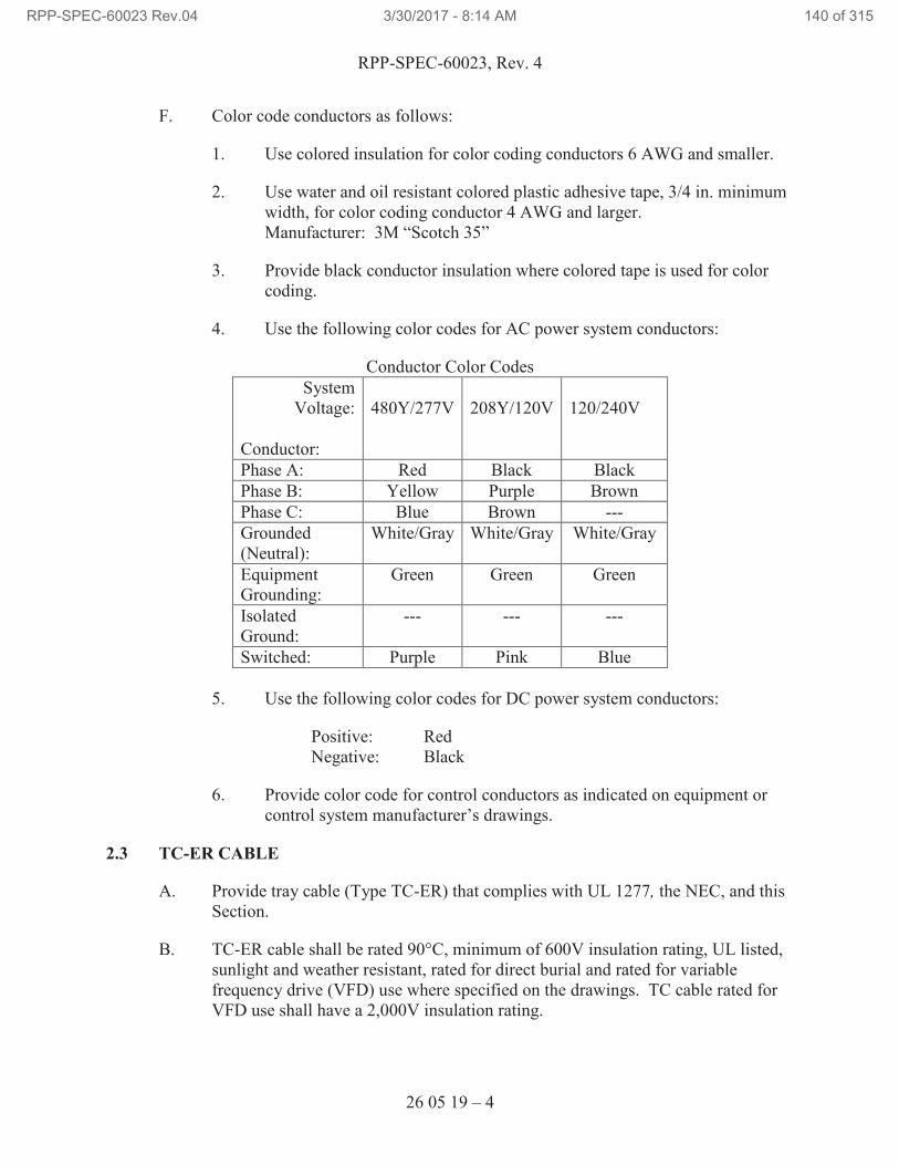
RPP-SPEC-60023, Rev. 4
26 05 19 – 4
F. Color code conductors as follows:
1. Use colored insulation for color coding conductors 6 AWG and smaller.
2. Use water and oil resistant colored plastic adhesive tape, 3/4 in. minimum
width, for color coding conductor 4 AWG and larger.
Manufacturer: 3M “Scotch 35”
3. Provide black conductor insulation where colored tape is used for color
coding.
4. Use the following color codes for AC power system conductors:
Conductor Color Codes
System
Voltage:
Conductor:
480Y/277V
208Y/120V
120/240V
Phase A: Red Black Black
Phase B: Yellow Purple Brown
Phase C: Blue Brown ---
Grounded
(Neutral):
White/Gray White/Gray White/Gray
Equipment
Grounding:
Green Green Green
Isolated
Ground:
--- --- ---
Switched: Purple Pink Blue
5. Use the following color codes for DC power system conductors:
Positive: Red
Negative: Black
6. Provide color code for control conductors as indicated on equipment or
control system manufacturer’s drawings.
2.3 TC-ER CABLE
A. Provide tray cable (Type TC-ER) that complies with UL 1277, the NEC, and this
Section.
B. TC-ER cable shall be rated 90°C, minimum of 600V insulation rating, UL listed,
sunlight and weather resistant, rated for direct burial and rated for variable
frequency drive (VFD) use where specified on the drawings. TC cable rated for
VFD use shall have a 2,000V insulation rating.
RPP-SPEC-60023 Rev.04 3/30/2017 - 8:14 AM 140 of 315
RPP-SPEC-60023, Rev. 4
26 05 19 – 5
C. Provide TC-ER cables with quantities and sizes (minimum 12 AWG) of
conductors as indicated on the Drawings.
D. Provide TC-ER cable rated for VFD as shown on the Drawings.
E. TC-ER cable manufacturer: General Cable or equal.
2.4 CABLE PROTECTORS
A. Cable Protectors: Where cables require protection from vehicle or pedestrian
traffic, use a cable protector such as Yellow Jacket®24
, Bumblebee®24
, or Cable
Guard®24
. Cable Guard or other engineering approved protection shall be used at
vehicle and crane crossings.
2.5 WIRING CONNECTORS
A. For splices and taps on copper wire, sizes 8 AWG and smaller, use Pressure type,
or spring type rated for use with copper conductors with insulating caps or covers
rated for 600V and 105°C that are NRTL-listed to UL 486C. Thomas and Betts
Corporation “Sta-Kon®25
,” 3M Company “Scotchlok™17
,” or approved
substitute, where required by the NEC.
B. For splices and taps on copper wire, sizes 6 AWG through 1 AWG, use the
following materials:
1. Tin-plated copper split-bolt connectors that meet the requirements in
UL 486A-486B; provide with matching 600V snap-on insulating cover.
Manufacturer: FCI Burndy “Type KSA” with “Type SC” insulating
cover.
2. Multi-tap connectors that meet the requirements of UL 486A-486B that
have two or more range-taking mechanical lugs and matching 600V
insulated cover. Manufacturers: Burndy ‘POLYTAP” or “UNITAP,”
Ilsco “Type PCT,” Blackburn “AMT.”
C. For copper wire, sizes 1/0 AWG and larger, use UL 486A-486B listed
circumferential or hexagonal crimp compression terminals, splices, or adapters.
1. Provide compression terminals and splices made from electro-tin plated
seamless copper tubing and marked with wire size, die index/color code,
and number/locations of crimps. Manufacturers: FCI Burndy Types
“YA,” “YA-L,” “YA-L-NT,” “YS,” and “YC-C.” Thomas & Betts
“Color-Keyed.”
24
Yellow Jacket, Bumblebee, Cable Guard are registered trademarks of Peterson Systems International, Inc. 25
Sta-Kon is a registered trademark of Thomas and Betts Corporation.
RPP-SPEC-60023 Rev.04 3/30/2017 - 8:14 AM 141 of 315
RPP-SPEC-60023, Rev. 4
26 05 19 – 6
2. Provide straight and offset compression adapters made from electro-tin
plated aluminum, NRTL listed for use on copper conductors, and marked
with wire size, die index / color code, and number / locations of crimps.
Each adapter shall include a 600V, 90°C rated insulating cover.
Manufacturer: FCI Burndy Types “AYP” and “AYPO.”
3. Range-taking, die-less, or indenter-applied terminals are not acceptable for
control wiring. Use nylon insulated crimp-on terminals with insulation
grip that meet the requirements of UL 486A-486B. Manufacturer:
3M “Scotchlok MNG,” Thomas & Betts “Sta-Kon.”
4. Use ring tongue terminals for nutted studs.
5. Use flanged fork terminals for barrier terminal blocks.
D. Insulation-piercing type connectors are not acceptable for power or control
wiring.
2.6 INSULATING TAPE AND TUBING
A. For making re-enterable tape-insulated splices and connections, provide varnished
cambric electrical insulating tape made of cotton cambric fabric that is oil primed
and coated with electrical insulating varnish. Manufacturer: 3M “Scotch 2510”
(no adhesive) and “Scotch 2520” (pressure-sensitive adhesive).
B. Insulate taped splices and connections using ethylene propylene rubber (EPR)
tape that meets the requirements of UL 510 and is rated for 90°C continuous
operation and 130°C short-term overload service. Manufacturer: 3M “Scotch
130C.”
C. For the outer covering of tape-insulated splices and connections use vinyl plastic
tape that meets the requirements of UL 510 and has the following characteristics:
1. 8.5 mil minimum thickness.
2. ASTM D3005, Rated 600V and 105°C, suitable for indoor and outdoor
applications.
3. Retains flexibility, adhesion, and applicable at temperature ranges from
0 through 100°F without loss of physical or electrical properties.
4. Resistant to abrasion, moisture, alkalis, acid, corrosion, and sunlight.
5. Manufacturer: 3M “Scotch Super 88.”
RPP-SPEC-60023 Rev.04 3/30/2017 - 8:14 AM 142 of 315
RPP-SPEC-60023, Rev. 4
26 05 19 – 7
D. Provide heat shrinkable tubing that meets the requirements of UL 486D and has
the following characteristics:
1. Rated 600V.
2. Factory applied adhesive/sealant.
3. Split resistant.
4. Manufacturer: 3M “ITCSN.”
E. Use motor lead splicing kits to insulate and seal connections to leads for motors
rated 480V and less. Manufacturer: 3M “5300 Series.”
2.7 WIRE PULLING LUBRICANT
A. Provide NRTL-listed wire pulling lubricant that is compatible with the conductor
insulation or jacket, has a maximum coefficient of dynamic friction of 0.25, and
leaves no flammable residue. For cold weather installations, provide wire pulling
lubricant suitable for conduit temperature.
B. Compatibility with conductor insulation shall be determined in accordance with
IEEE 1210.
C. Manufacturer:
1. For conduit temperature above freezing: American Polywater
Corporation, “Polywater®26
” “Lubricant J.”
2. For conduit temperature below freezing: American Polywater
Corporation, “Polywater” “Lubricant WJ.”
PART 3 EXECUTION
3.1 EXAMINATION
A. Verify interior of building has been protected from weather.
B. Verify that work of other trades likely to damage wire and cable is completed.
C. Verify raceway installation is complete and supported.
D. Verify that field measurements are as shown on Drawings.
26
Polywater is a registered trademark of American Polywater Corporation.
RPP-SPEC-60023 Rev.04 3/30/2017 - 8:14 AM 143 of 315
RPP-SPEC-60023, Rev. 4
26 05 19 – 8
E. Wire and cable routing shown on Drawings is approximate unless dimensioned.
1. Route wire and cable as required meeting project conditions.
2. Where cable routing is not shown, and destination only is indicated,
determine exact routing and lengths required to meet field conditions.
3.2 PREPARATION
A. Examine raceways and building finishes that are to receive wires and cables for
compliance with installation tolerances and other conditions. Do not proceed with
installation until unsatisfactory conditions have been corrected.
B. Swab raceway before installing wire.
C. Do not handle or pull cables that are colder than +15°F. Store cold cables for at
least 24 hours in a heated building prior to installation.
3.3 WIRE INSTALLATION
A. Install wire according to, the NEC, the requirements in this Section.
B. Do not bend cables installed in raceways to less than manufacturer’s
recommended bending radii. Lay cables in raceways in straight, parallel lines,
and avoid crossing.
1. Use lubricant recommended by wire or cable manufacturer, or wire-
pulling compound specified when pulling wire and cable through conduit.
2. Do not install or handle wires with thermoplastic insulation or jacket when
ambient temperature is 15°F or lower.
3. Identify conductors, by wire numbers shown on the Drawings, with
wiremarkers. Attach wiremarkers at termination points within 2-in. of
wire terminations. Marker nomenclature shall be visible without moving
wires or markers.
C. Do not damage conductor, insulation, or jacket by excessive installation pulling
tension or sidewall bearing pressure.
1. No tension monitoring devices are required where hand pull techniques
are used.
2. Calculate expected cable pulling tension and sidewall bearing pressures
for each set of conductors being pulled into a conduit run where any of the
following combinations of bends and raceway length is exceeded between
accessible pull points:
RPP-SPEC-60023 Rev.04 3/30/2017 - 8:14 AM 144 of 315
RPP-SPEC-60023, Rev. 4
26 05 19 – 9
a. 4 equivalent 90-degree bends and 10 ft of raceway.
b. 3 equivalent 90-degree bends and 40 ft of raceway.
c. 2 equivalent 90-degree bends and 80 ft of raceway.
d. 1 equivalent 90-degree bend and 150 ft of raceway.
e. Straight pull with more than 250 ft of raceway.
3. For cable pulling tension and sidewall bearing pressure calculations use
formulas and factors described in IEEE 422.
4. Obtain recommended maximum conductor or cable pulling tension and
sidewall bearing pressure values from the manufacturer, or use the
following maximum allowable values:
a. Maximum sidewall bearing pressure: 500 lb/ft.
b. Maximum tension, pulling directly on conductor: 0.008 lb/cmil
c. Maximum tension, pulling on basket grip over insulation jacket:
2000 lb, not to exceed 0.008 lb/cmil of conductor.
5. Use a tension measuring device to monitor pulling force on each pull of
conductors where a pulling winch is used.
a. Record the maximum measured pulling tension for each monitored
cable pull.
b. Place the recorded cable pulling tension for each monitored cable
pull and the corresponding calculated allowable pulling tension in
the work package or fabrication document.
6. Deleted.
7. Deleted.
D. Use solid or stranded copper conductors not smaller than 12 AWG for outlets and
lighting branch circuits. Do not “through-pull” conductors at boxes, fittings, or
cabinets where a change of raceway alignment occurs.
3.4 TYPE TC CABLE INSTALLATION
A. Install TC cables according to the NEC and requirements in this Section.
B. Install and support Type TC cables as required in Article 336 of the NEC.
RPP-SPEC-60023 Rev.04 3/30/2017 - 8:14 AM 145 of 315
RPP-SPEC-60023, Rev. 4
26 05 19 – 10
3.5 CONNECTOR INSTALLATION
A. Install conductors in terminals, splices, adapters, and connectors in accordance
with the manufacturer’s instructions. Have the manufacturer’s installation
instructions available at the construction site.
B. Make splices, taps, and terminations to carry full ampacity of conductors with no
perceptible temperature rise above the conductor temperature.
C. Do not nick conductors when removing insulation.
D. Do not cut conductor strands to fit into connectors, splices, adapters, or terminals.
E. Make connections using clean connection surfaces. Wire brush conductors
immediately before installing lugs, terminals, splices, or adapters.
F. Connect conductors 1/0 AWG and larger using compression terminals at the
locations described below. Compression terminals shall be installed where there
is adequate wire bending space to accommodate compression terminals. Select
compression terminals suitable for the conductor sizes, materials, and termination
point configurations. Install compression terminals using the manufacturer’s
recommended dies and minimum 12-ton force compression tools.
1. Circuit breakers with frame size greater than 100 amperes that are NRTL
listed for with compression terminals.
2. Safety switches and fused switches rated more than 100 amperes.
3. Transformers; refer to Section 26 22 13, “Low Voltage Distribution
Transformers.”
4. Switchboards, panelboards, motor control centers, and similar service and
distribution equipment.
5. Utilization equipment connections that are NRTL listed for with
compression terminals.
G. For conductors sized 1/0 AWG and larger, and where compression lugs cannot be
installed, connect using mechanical lugs, in the locations or conditions described
below.
1. Connection points not NRTL-listed for either compression terminals or
compression adapters.
2. Where there is insufficient wire bending space to accommodate either
compression terminals or compression adapters.
RPP-SPEC-60023 Rev.04 3/30/2017 - 8:14 AM 146 of 315
RPP-SPEC-60023, Rev. 4
26 05 19 – 11
H. Connect outlets and components to wiring and to ground as indicated and
instructed by manufacturer. Tighten connectors and terminals, including screws
and bolts, according to equipment manufacturer’s published torque-tightening
values for equipment connectors.
3.6 INSULATING TAPE AND TUBING INSTALLATION
A. Install insulating tape and tubing in accordance with the manufacturer’s
instructions. Have the manufacturer’s installation instructions available at the
construction site.
B. Insulate splices and taps of irregular shapes with manufactured insulating covers
or insulating tape built up to not less than 150% of insulation rating of conductor.
1. Apply varnished cambric tape over connections where re-entry is likely,
such as motor lead connections.
2. Use rubber insulating tape in half-lapped layers to develop the basic
insulation over splices and taps.
3. Use vinyl plastic tape in half-lapped layers to provide the outer protective
covering over splices and taps.
C. Insulate cylinder shaped splices and taps, connector barrels and adapter barrels
using heat shrinkable insulating tubing, insulating covers manufactured for the
connector, or tape insulation as described above.
3.7 IDENTIFICATION
A. Identify wire and cable under provisions of Section 26 05 53, “Identification for
Electrical Systems.”
B. Identify each conductor with its circuit number or other designation indicated on
Drawings.
C. Apply color coding tape on conductors at each termination, splice, junction, and
pull box.
3.8 FIELD QUALITY CONTROL
A. Observe conductors and cables during the installation process.
1. Reject and replace entire reels, rolls, or boxes containing conductors or
cables with material or manufacturing defects.
2. Reject and replace cable or conductor segments that have been kinked,
dented, or otherwise damaged during handling or installation.
B. Deleted.
RPP-SPEC-60023 Rev.04 3/30/2017 - 8:14 AM 147 of 315
RPP-SPEC-60023, Rev. 4
26 05 19 – 12
C. Perform the following inspections:
1. Inspect conductors and cables for:
a. Freedom from material defect or physical damage.
b. Correct conductor size, material, and insulation type.
c. Correct color coding and identification.
2. Inspect connections for:
a. Correct connector size and type according to the Specifications.
b. Deleted.
D. Perform the following tests:
1. Before connecting conductors to equipment, use a megohmmeter in a
1-minute test to verify the insulation integrity of each service conductor
and feeder conductor with respect to ground and other conductors in the
same raceway.
a. Use 1000VDC to test conductors rated 600V and 2000V, and
500VDC for conductors rated 300V or less.
b. Insulation test values shall be in accordance with the following:
i. Conductors with 300V insulation rating and insulation
resistances over 25 megohms are acceptable.
ii. Conductors with 600V insulation rating and insulation
resistances over 100 megohms are acceptable.
iii. Conductors with 2000V insulation rating and insulation
resistances over 500 megohms are acceptable.
c. Conductors with insulation resistances less than indicated above
shall be investigated.
2. Prior to connecting conductors to equipment, test continuity to ensure
proper circuit is identified to facilitate correct connection of each power
circuit conductor and each control circuit conductor.
3. Test the equipment and wiring for continuity and unintentional grounds,
and verify proper phase sequence and voltage at equipment served before
attempt is made to operate equipment.
RPP-SPEC-60023 Rev.04 3/30/2017 - 8:14 AM 148 of 315
RPP-SPEC-60023, Rev. 4
26 05 19 – 13
4. Perform insulation (megger) test on electric heat trace cable at installation
before and after insulation is installed per manufacturer’s instructions.
5. Measure and record in the work package or fabrication document the
tightness of not less than 10% of each size and type of mechanical or
bolted connection using a calibrated torque wrench or torque screwdriver.
Additionally, verify proper crimping method, as applicable.
a. Compare measured torque with torque recommended by the
connector manufacturer or as shown in Attachment 1,
“Recommended Tightening Torque per UL 486A-486B.”
b. If any connection is found to be less than 90% of the recommended
torque, notify the Buyer’s Technical Representative and re-torque
all bolted connections on the Project.
E. Remove and replace defective, incorrect, or improperly installed conductors and
connectors. Re-inspect and re-test replacement conductors and connectors.
F. Place test and inspection records in the work package or fabrication document.
G. Verify inspections and tests required by other sections are completed before
conductors may be energized.
END OF SECTION 26 05 19
RPP-SPEC-60023 Rev.04 3/30/2017 - 8:14 AM 149 of 315
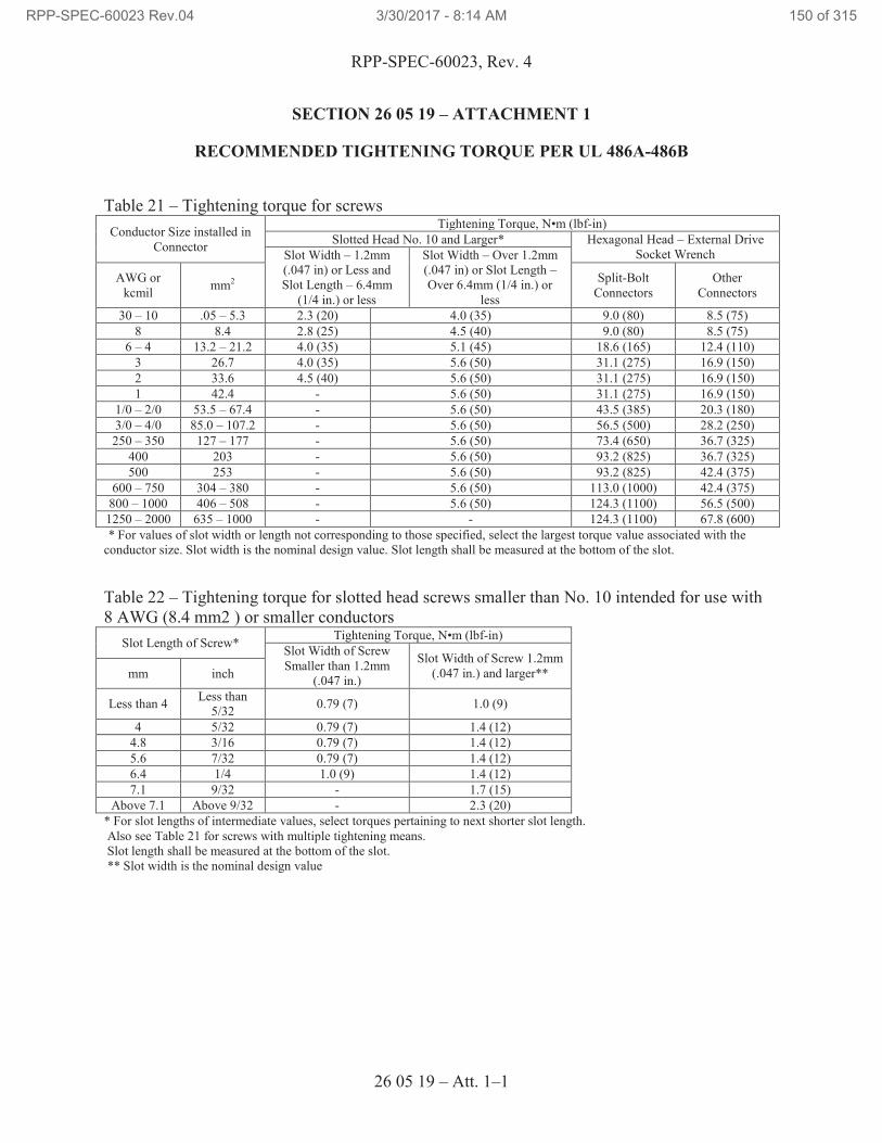
RPP-SPEC-60023, Rev. 4
26 05 19 – Att. 1–1
SECTION 26 05 19 – ATTACHMENT 1
RECOMMENDED TIGHTENING TORQUE PER UL 486A-486B
Table 21 – Tightening torque for screws
Conductor Size installed in
Connector
Tightening Torque, N•m (lbf-in)
Slotted Head No. 10 and Larger* Hexagonal Head – External Drive
Socket Wrench Slot Width – 1.2mm
(.047 in) or Less and
Slot Length – 6.4mm
(1/4 in.) or less
Slot Width – Over 1.2mm
(.047 in) or Slot Length –
Over 6.4mm (1/4 in.) or
less
AWG or
kcmil mm2
Split-Bolt
Connectors
Other
Connectors
30 – 10 .05 – 5.3 2.3 (20) 4.0 (35) 9.0 (80) 8.5 (75)
8 8.4 2.8 (25) 4.5 (40) 9.0 (80) 8.5 (75)
6 – 4 13.2 – 21.2 4.0 (35) 5.1 (45) 18.6 (165) 12.4 (110)
3 26.7 4.0 (35) 5.6 (50) 31.1 (275) 16.9 (150)
2 33.6 4.5 (40) 5.6 (50) 31.1 (275) 16.9 (150)
1 42.4 - 5.6 (50) 31.1 (275) 16.9 (150)
1/0 – 2/0 53.5 – 67.4 - 5.6 (50) 43.5 (385) 20.3 (180)
3/0 – 4/0 85.0 – 107.2 - 5.6 (50) 56.5 (500) 28.2 (250)
250 – 350 127 – 177 - 5.6 (50) 73.4 (650) 36.7 (325)
400 203 - 5.6 (50) 93.2 (825) 36.7 (325)
500 253 - 5.6 (50) 93.2 (825) 42.4 (375)
600 – 750 304 – 380 - 5.6 (50) 113.0 (1000) 42.4 (375)
800 – 1000 406 – 508 - 5.6 (50) 124.3 (1100) 56.5 (500)
1250 – 2000 635 – 1000 - - 124.3 (1100) 67.8 (600)
* For values of slot width or length not corresponding to those specified, select the largest torque value associated with the
conductor size. Slot width is the nominal design value. Slot length shall be measured at the bottom of the slot.
Table 22 – Tightening torque for slotted head screws smaller than No. 10 intended for use with
8 AWG (8.4 mm2 ) or smaller conductors
Slot Length of Screw* Tightening Torque, N•m (lbf-in)
Slot Width of Screw
Smaller than 1.2mm
(.047 in.)
Slot Width of Screw 1.2mm
(.047 in.) and larger** mm inch
Less than 4 Less than
5/32 0.79 (7) 1.0 (9)
4 5/32 0.79 (7) 1.4 (12)
4.8 3/16 0.79 (7) 1.4 (12)
5.6 7/32 0.79 (7) 1.4 (12)
6.4 1/4 1.0 (9) 1.4 (12)
7.1 9/32 - 1.7 (15)
Above 7.1 Above 9/32 - 2.3 (20)
* For slot lengths of intermediate values, select torques pertaining to next shorter slot length.
Also see Table 21 for screws with multiple tightening means.
Slot length shall be measured at the bottom of the slot.
** Slot width is the nominal design value
RPP-SPEC-60023 Rev.04 3/30/2017 - 8:14 AM 150 of 315
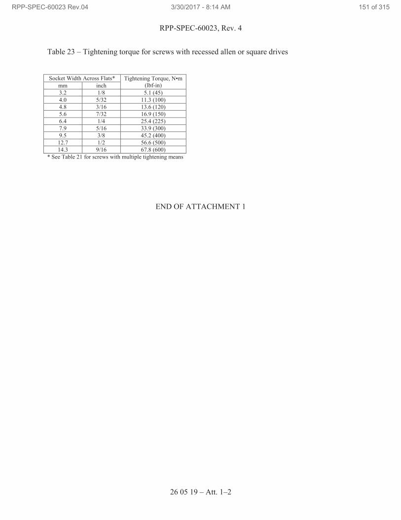
RPP-SPEC-60023, Rev. 4
26 05 19 – Att. 1–2
Table 23 – Tightening torque for screws with recessed allen or square drives
Socket Width Across Flats* Tightening Torque, N•m
(lbf-in) mm inch
3.2 1/8 5.1 (45)
4.0 5/32 11.3 (100)
4.8 3/16 13.6 (120)
5.6 7/32 16.9 (150)
6.4 1/4 25.4 (225)
7.9 5/16 33.9 (300)
9.5 3/8 45.2 (400)
12.7 1/2 56.6 (500)
14.3 9/16 67.8 (600)
* See Table 21 for screws with multiple tightening means
END OF ATTACHMENT 1
RPP-SPEC-60023 Rev.04 3/30/2017 - 8:14 AM 151 of 315
RPP-SPEC-60023, Rev. 4
26 05 26 – 1
SECTION 26 05 26
GROUNDING AND BONDING FOR ELECTRICAL SYSTEMS
PART 1 GENERAL
1.1 SCOPE OF WORK
A. Connection to Main Grounding Electrode System.
B. Circuit and System Grounding.
C. Enclosure and Equipment Grounding System.
1.2 RELATED DOCUMENTS / CODES AND STANDARDS
Drawings and general provisions of the contract, including General and Supplementary
Conditions and Division 01 Specification Sections apply to this Section.
The following documents and others referenced therein, form part of the Contract to the
extent designated in this Section. Referenced documents are those current as of the date
of this Section unless otherwise indicated.
A. American Standards for Testing and Materials (ASTM)
ASTM B8 Standard Specification for Concentric-Lay Stranded
Copper Conductors
B. Institute of Electrical and Electronics Engineers (IEEE)
IEEE 81 Guide for Measuring Earth Resistivity, Ground
Impedance and Earth Surface Potentials of a
Grounding System
IEEE 142 Recommended Practice for Grounding of Industrial
and Commercial Power Systems
IEEE 837 IEEE Standard for Qualifying Permanent
Connections used in Substation Grounding
C. National Fire Protection Association (NFPA)
NFPA 70, 2014 National Electrical Code (NEC)
RPP-SPEC-60023 Rev.04 3/30/2017 - 8:14 AM 152 of 315
RPP-SPEC-60023, Rev. 4
26 05 26 – 2
D. Underwriters Laboratories (UL)
UL 467 Grounding and Bonding Equipment
UL 486A-486B Wire Connectors and Soldering Lugs for Use with
Copper Conductors
UL 486C Splicing Wire Connectors
1.3 SUBMITTALS
A. See the Contract Statement of Work for the submittal process.
B. Approval Required
1. Documented in work package or fabrication document as applicable.
1.4 QUALITY ASSURANCE
A. Comply with the NEC for components and installation.
B. Verify products that are listed and labeled by a Nationally Recognized Testing
Laboratory (NRTL) for the application and environment in which installed.
1.5 RECEIVING, STORING, AND PROTECTING
A. Receive, store, protect, and handle products according to manufacturer’s
instructions.
PART 2 PRODUCTS
2.1 PRODUCT OPTIONS AND SUBSTITUTIONS
A. Alternate products may be accepted; in accordance with the requirements of the
Contract Statement of Work.
2.2 GROUNDING ELECTRODE CONDUCTOR
A. Provide bare stranded, soft temper copper cable that conforms to ASTM B8.
B. Provide ground electrode conductor for separately derived systems and equipment
in the Tank Farm and bond to nearest tank riser.
2.3 EQUIPMENT GROUNDING CONDUCTORS
A. Provide NRTL-listed THHN/THWN insulated copper wire.
B. Use solid or stranded grounding conductors 12 AWG and smaller where not
subject to vibration or repeated flexing.
RPP-SPEC-60023 Rev.04 3/30/2017 - 8:14 AM 153 of 315
RPP-SPEC-60023, Rev. 4
26 05 26 – 3
C. Use stranded grounding conductors for 10 AWG and larger.
D. Use stranded grounding conductors where subject to vibration or repeated flexing.
E. Color code grounding conductors as follows:
1. Equipment ground:
a. Conductors 6 AWG and smaller: Green colored insulation.
b. Conductors 4 AWG and larger: Green colored insulation or black
colored insulation with 3/4 in. wide band of water and oil-resistant
green plastic adhesive tape.
2.4 GROUND PLATES
A. Provide ground plates designed for flush mounting in concrete structures.
B. Furnish copper alloy castings with four 1/2 in. x 13 in. threaded holes at
1.75 in. x 1.75 in. NEMA spacing and a welding stud or compression connection
suitable for 2 AWG to 250 kcmil copper conductor.
C. Manufacturer: Burndy “YGF.”
2.5 CONDUIT GROUNDING BUSHINGS
A. Provide NRTL-listed, galvanized malleable iron, 150°C rated insulated throat
grounding bushings with lay-in type ground cable lugs.
B. Manufacturers: O-Z/Gedney Type “BLG.”
2.6 EXOTHERMIC WELD GROUNDING CONNECTIONS
A. Provide molds and welding material for making exothermic weld connections.
B. In interior locations and in vaults, use low smoke emission type welding material.
C. Match mold and weld material-to-material types, shapes, and sizes to be joined.
D. Manufacturer: ERICO Cadweld.
2.7 COMPRESSION GROUNDING CONNECTIONS
A. Provide wrought copper connectors, terminals, taps, and splices for making
irreversible compression grounding connections.
B. Furnish NRTL-listed grounding connectors that are suitable for direct burial and
have been tested successfully according to the requirements of IEEE 837.
RPP-SPEC-60023 Rev.04 3/30/2017 - 8:14 AM 154 of 315
RPP-SPEC-60023, Rev. 4
26 05 26 – 4
C. Provide connector manufacturer’s hydraulic compression tools and dies that
match the connectors.
D. Match connector and die size to material shapes and conductor sizes to be joined.
E. Use two-hole heavy-duty compression lugs for bolted connections to ground bars,
ground plates, and equipment ground pads.
F. Manufacturer: Burndy “Hyground®27
.”
PART 3 EXECUTION
3.1 EXAMINATION
A. Verify that work of other trades likely to damage grounding and bonding material
has been completed.
B. Verify that field measurements are as shown on Drawings.
C. Grounding cable routing shown on Drawings is approximate unless dimensioned.
1. Install and route cable as required meeting project conditions.
2. Where cable routing is not shown, and destination only is indicated,
determine exact locations, routing, and lengths required to meet project
conditions.
3.2 PREPARATION
A. Examine equipment and building finishes that are to receive grounding and
bonding material for compliance with installation tolerances and other conditions.
Do not proceed with installation until unsatisfactory conditions have been
corrected.
3.3 GENERAL
A. Comply with the requirements of the NEC, this Section, and the Drawings.
B. Install grounding and bonding material according to manufacturer’s instructions.
Have the manufacturer’s installation instructions available at the construction site.
C. Use the following connection methods unless otherwise specified or indicated on
the Drawings. Use compression or bolted grounding connection methods in the
Tank Farm areas:
1. Use exothermic weld grounding connections for underground or concealed
connections of dissimilar materials.
27
Hyground is a registered trademark of Hubbell Incorporated, Shelton, Connecticut.
RPP-SPEC-60023 Rev.04 3/30/2017 - 8:14 AM 155 of 315
RPP-SPEC-60023, Rev. 4
26 05 26 – 5
2. Use exothermic weld or compression grounding connections for
underground or concealed connections of like materials.
3. Use exothermic weld, compression, or bolted grounding connections for
accessible connections.
4. Make bolted connections using bolts, nuts, flat washers, and toothed lock
washers suitable for the connector and the installation environment;
acceptable materials include high strength silicon bronze and 18-8 alloy
stainless steel.
5. Make irreversible bolted connections using 18-8 alloy stainless steel
tamper-resistant bolts and tamper-resistant nuts along with flat washers,
and toothed lock washers. Tamper-resistant nuts and bolts must resist
loosening with common tools; acceptable tamper-resistant fasteners
include penta-head, break-away, and oval designs.
D. Tighten grounding and bonding connectors and terminals, including screws and
bolts, in accordance with manufacturer’s published torque tightening values for
connectors and bolts. Where manufacturer’s torquing requirements are not
indicated, tighten connections to comply with torque tightening values specified
in Section 26 05 19, “Low Voltage Electrical Power Conductors and Cables,”
Attachment 1, “Recommended Tightening Torque per UL 486A-486B.” Use a
calibrated torque wrench.
E. Use hydraulic compression tools to provide the correct circumferential pressure
for compression connectors. Follow connector manufacturer’s installation
instructions and use tools and dies recommended by the manufacturer of the
connectors. Provide embossing die code or other standard method to make a
visible indication that a connector has been adequately compressed.
F. Install exothermic welds in accordance with manufacturer’s instructions and
recommendations. Welds that are puffed up or that show convex surfaces
indicating improper cleaning are not acceptable.
G. Make connections in such a manner as to minimize possibility of galvanic action
or electrolysis. Select connectors, connection hardware, conductors, and
connection methods so metals in direct contact will be galvanically compatible.
1. Use electroplated or hot-tin-coated materials to assure high conductivity
and make contact points closer in order of galvanic series.
2. Make connections with clean bare metal at points of contact.
3. Make aluminum to steel connections with stainless steel separators and
mechanical clamps.
RPP-SPEC-60023 Rev.04 3/30/2017 - 8:14 AM 156 of 315
RPP-SPEC-60023, Rev. 4
26 05 26 – 6
4. Make aluminum to galvanized steel connections with tin-plated copper
jumpers and mechanical clamps.
5. Coat and seal connections involving dissimilar metals with inert material
to prevent future penetration of moisture to contact surfaces.
3.4 MAIN GROUNDING ELECTRODE SYSTEM
A. Install in accordance with the NEC and the Drawings.
B. Concrete encased ground electrode and ground plates are provide in accordance
with Specifications below and Drawings.
1. Install a concrete-encased main grounding electrode in the lower part of
the perimeter strip footing or grade beam to form a complete and
continuous loop around the structure. Encase the electrode with at least
2 in. of concrete from the bottom of the foundation or footing. Use one of
the following materials for the electrode:
a. Bare or zinc galvanized or other electrically conductive coated
steel reinforcing bars, minimum 1/2-in. diameter. Bond
reinforcing rods together using steel wire ties or other effective
means.
b. Bare #2 copper conductor. Space cable from the bottom and sides
of the grade beam so it has at least 2 in. of concrete coverage.
Bond to the rebar in one place.
c. Perform NEC inspection of main grounding electrode prior to
pouring concrete.
C. Install ground plates flush with the concrete slab. Locate ground plates adjacent
to switchboard. Bond ground electrode to ground plates with #2 AWG pigtail
using UL-listed compression fittings.
D. Bond building perimeter structural steel column to the main grounding electrode
via ground plates and ground cables sized as indicated on the Drawings.
3.5 CIRCUIT AND SYSTEM GROUNDING
A. Connect the service entrance equipment ground bus to the ground plate; use
ground cable as indicated on the Drawings, or not smaller than the grounding
electrode conductor required by the NEC and not smaller than 4 AWG.
B. In the service entrance equipment, connect the neutral bus to the ground bus using
a bonding jumper not smaller than the grounding electrode conductor required by
the NEC; do not use a bonding screw for this purpose. Make no other neutral-to-
ground connections on the load side of the service entrance disconnect.
RPP-SPEC-60023 Rev.04 3/30/2017 - 8:14 AM 157 of 315
RPP-SPEC-60023, Rev. 4
26 05 26 – 7
C. Separately Derived Systems:
1. Connect ground bus of first disconnecting means for separately derived
systems (e.g., dry type transformers) to the nearest ground plate
(preferred) or building structural steel column; use grounding conductor
sized as shown on the Drawings or as required by the NEC.
2. At the first system overcurrent device or disconnecting means, connect the
neutral bus to the ground bus using a bonding jumper sized as required by
the NEC. For systems in the Tank Farm, provide grounding electrode
conductor to nearest tank riser. Sized grounding electrode conductor in
accordance with the NEC and use UL Listed pipe grounding clamp or to
an existing ground tap on riser with the approval of the TOC Construction
Representative.
3.6 ENCLOSURE AND EQUIPMENT GROUNDING
A. Provide permanent and effective equipment, enclosure, and raceway grounding in
accordance with NEC requirements, and as further specified or shown on the
Drawings.
B. Provide an equipment ground bar, separate from any neutral bar, in all switchgear,
switchboards, panelboards, transformers, motor control centers, starters,
disconnect switches, cabinets, etc., for grounding the enclosure and for connecting
other equipment and raceway ground conductors. Make connections to the
ground bar using mechanical lugs or compression lugs.
C. Make connections and couplings on metallic conduit systems wrench tight.
D. Grounding Bushings:
1. Install grounding bushings on metallic conduit containing circuits rated
480 VAC or 100 amperes and higher.
2. Install grounding bushings on metallic conduits entering enclosures
through concentric, eccentric, or oversize knockouts.
3. Install grounding bushings on metallic conduits that terminate to a metallic
enclosure without effective electrical connection such as locknuts or
threaded bushings.
4. Bond conduit grounding bushing lug to the equipment ground bar or
ground lug in switchboard, panelboards, transformers, starters, disconnect
switches, cabinets, etc. Size bonding jumpers in accordance with the
NEC.
E. Provide an insulated equipment grounding conductor for each feeder and branch
circuit.
RPP-SPEC-60023 Rev.04 3/30/2017 - 8:14 AM 158 of 315
RPP-SPEC-60023, Rev. 4
26 05 26 – 8
1. Install the grounding conductor within the common conduit or raceway
with the related phase and neutral conductors and connect to the
grounding terminal or grounding bus in each box or cabinet.
2. Size equipment ground conductor in accordance with the NEC or as
shown on the Drawings.
F. In each 15 or 20 ampere branch circuit outlet box and junction box, install a green
colored washer head grounding screw with a 12 AWG equipment grounding
conductor pigtail.
G. Connect receptacle grounding terminals to the equipment ground system using
minimum 12 AWG equipment grounding conductor. Do not use a “self-
grounding” receptacle strap as the only equipment grounding path.
3.7 FIELD QUALITY CONTROL
A. General: Perform on-site verification, certification, and acceptance testing of the
grounding installation during construction if required by the design media.
B. Notify the TOC Construction Representative ten working days in advance of the
expected completion of a grounding system installation specified in Part C.
Verification and testing can be scheduled in parts or by area depending on the
system and construction schedule.
C. Before work is concealed, verify and certify that the following grounding
installations have been made correctly:
1. The building grounding electrode system. This includes the bonding of
the structural steel columns and bonding of other metallic systems.
2. Ground plates and grounding bars.
3. All other underground grounding installations.
D. Acceptance Testing: Perform acceptance testing for building/transformer area
grounding electrode system and place test results in work package or fabrication
document. Tests may be witnessed by designated representatives.
1. Perform ground-impedance measurements using the “fall-of-potential”
method in accordance with IEEE 81. Use instrumentation specifically
designed for ground impedance testing. Provide sufficient spacing of test
electrodes so that the plotted curves flatten in the 62% area of the distance
between the item under test and the current electrode. When sufficient
spacing of electrodes is impractical for the “fall-of-potential” method,
perform ground-impedance measurements using either the “intersecting
curves method” or the “slope method,” referenced in IEEE 81. Investigate
and correct ground resistances that exceed the following values:
RPP-SPEC-60023 Rev.04 3/30/2017 - 8:14 AM 159 of 315
RPP-SPEC-60023, Rev. 4
26 05 26 – 9
a. Service rated more than 50 kVA but less than 2500 kVA: 5 ohms.
2. Test equipment ground resistances for the following items. Measure
resistance between the equipment item and the Electrode Ground Plate.
Use the “two-point method” of IEEE 81. Investigate and correct
equipment ground resistances that exceed 0.5 ohm.
a. Switchboards
E. Prepare test reports of the ground resistance at each test location. Include
observations of weather and other phenomena that may affect test results.
Describe any measures taken to improve test results. Place reports in work
package or fabrication document.
END OF SECTION 26 05 26
RPP-SPEC-60023 Rev.04 3/30/2017 - 8:14 AM 160 of 315
RPP-SPEC-60023, Rev. 4
26 05 29 – 1
SECTION 26 05 29
HANGERS AND SUPPORTS FOR ELECTRICAL SYSTEMS
PART 1 GENERAL
1.1 SCOPE OF WORK
A. Furnish and install, hangers, supports, anchors, concrete bases, and other positive
fastenings for non-structural electrical components such that gravity loads are
safely transferred to the structure.
1.2 RELATED DOCUMENTS / CODES AND STANDARDS
Drawings and general provisions of the contract, including General and Supplementary
Conditions and Division 01 Specification Sections apply to this Section.
The following documents and others referenced therein, form part of the Contract to the
extent designated in this Section. Referenced documents are those current as of the date
of this Section unless otherwise indicated.
A. American Society for Testing and Materials (ASTM)
ASTM A307 Standard Specification for Carbon Steel Bolts and
Studs, 60,000 PSI Tensile Strength
B. Code of Federal Regulations (CFR)
Title 29 Labor
Part 1910 Occupational Safety and Health Standards
C. Federal Specification (FS)
FS WW-H-171E Hangers and Supports, Pipe
D. International Code Council (ICC)
IBC International Building Code
E. Manufacturers’ Standardization Society (MSS)
MSS SP-58 Pipe Hangers and Supports – Materials, Design,
Manufacture, Selection, Application, and
Installation
MSS SP-69 Pipe Hangers and Supports – Selection and
Application
RPP-SPEC-60023 Rev.04 3/30/2017 - 8:14 AM 161 of 315
RPP-SPEC-60023, Rev. 4
26 05 29 – 2
F. Metal Framing Manufacturers Association (MFMA)
MFMA-4 Metal Framing Standards Publication
MFMA-102 Guidelines for the Use of Metal Framing
MFMA-103 Guidelines for the Use of Metal Framing
G. National Fire Protection Association (NFPA)
NFPA 70, 2014 National Electrical Code (NEC)
H. Underwriters Laboratories (UL)
UL 486A-486B Wire Connectors
1.3 SUBMITTALS
A. See the Contract Statement of Work for the submittal process.
B. Approval Required
1. Documented in work package or fabrication document as applicable.
1.4 QUALITY ASSURANCE
A. Furnish and install hangers and supports that conform to the drawings and
requirements of the following codes and standards:
1. NEC.
B. Where a Nationally Recognized Testing Laboratory (NRTL) has requirements for
such products, provide products that are NRTL listed and labeled for the
application, installation condition, and the environment in which installed.
1.5 RECEIVING, STORING AND PROTECTING
A. Receive, store, protect, and handle products according to manufacturer’s
instructions.
PART 2 PRODUCTS
2.1 SUBSTITUTIONS
A. Alternate products may be accepted; in accordance with the requirements of the
Contract Statement of Work
RPP-SPEC-60023 Rev.04 3/30/2017 - 8:14 AM 162 of 315
RPP-SPEC-60023, Rev. 4
26 05 29 – 3
2.2 COATINGS AND MATERIALS
A. Furnish products for use indoors protected with zinc coating or with treatment of
equivalent corrosion resistance using approved alternative treatment, finish, or
inherent material characteristic.
B. Furnish products for use outdoors or in damp or corrosive indoor locations with
hot-dip galvanized coating or with treatment of equivalent corrosion resistance
using approved alternative treatment, finish, or material such as stainless steel
with inherent corrosion resistant characteristics.
2.3 RACEWAY SUPPORTING DEVICES
A. Furnish supports as described below for the installation of raceway systems.
B. Use pressed steel, single bolt hangers to support individual RGS, IMC, or EMT
conduits from threaded rods or beam clamps. Manufacturer: Steel City “6H
Series.”
C. Use malleable iron conduit clamps to secure individual RGS, IMC, or EMT
conduit runs across, parallel, or perpendicular to beams, channels, and angle
supports. Manufacturer: Steel City “RC, EC, and PC Series.”
D. Support multiple parallel horizontal conduits with trapeze hangers fabricated from
framing channel materials specified below.
2.4 HANGER RODS
A. Furnish mild steel rods that conform to ASTM A307.
B. Furnish rods that are threaded on both ends, threaded on one end, or continuous
threaded with UNC (coarse) thread pitch.
2.5 FASTENERS
A. Post-Installed Concrete Anchors:
1. Furnish post-installed concrete anchors as shown on the Drawings.
2. Each post-installed anchor shall have an ICC-ES evaluation report stating
that the product is compliant with the current edition of the IBC and the
intended conditions of use.
3. For applications in outdoor, damp, or corrosive locations, furnish stainless
steel post-installed anchors.
4. Furnish post-installed expansion, adhesive, and undercut anchors specified
in the Contract Statement of Work
RPP-SPEC-60023 Rev.04 3/30/2017 - 8:14 AM 163 of 315
RPP-SPEC-60023, Rev. 4
26 05 29 – 4
5. Powder-actuated threaded studs: Use zinc-plated carbon steel or stainless
steel suitable for the intended service:
a. 1/4-20 threaded stud: Manufacturer: Hilti X-W6.
b. 3/8-16 threaded stud: Manufacturer: Hilti W10.
6. Concrete and masonry screw anchors: Heat-treated carbon steel.
Manufacturer: Simpson Strong-Tie “Titen HD.”
B. Beam Clamps: NRTL-listed, or compliant with Federal Specification
WW-H-171E, or compliant with MSS SP-69 and SP-58.
2.6 FRAMING CHANNEL SYSTEMS
A. Furnish U-channel framing systems that conform to MFMA-4 and are fabricated
using minimum 12-gage steel.
B. Furnish fittings and accessories that mate and match with U-channel and are of
the same manufacturer.
C. Manufacturers: B-Line.
2.7 FABRICATED SUPPORTING DEVICES
A. Furnish shop- or field-fabricated supports or manufactured supports assembled
from U-channel components.
B. Furnish steel brackets fabricated from angles, channels, and other standard
structural shapes. Connect with welds and machine bolts to form rigid supports.
PART 3 EXECUTION
3.1 GENERAL
A. Install hangers and supports according to the NEC, the requirements in this
Section, and specific supporting requirements in other Sections and drawings.
B. Conform to manufacturer’s instructions and recommendations for selection and
installation of hangers and supports.
C. Do not use wire or perforated strap for permanent supports.
D. Install flexible sections in electrical conduits and raceways where they cross
expansion joints. Do not support conduits, boxes, raceways, etc., from ceiling
suspension wires.
E. Use appropriate, calibrated, special tools when installing devices for which
special installation tools are recommended by the manufacturer.
RPP-SPEC-60023 Rev.04 3/30/2017 - 8:14 AM 164 of 315
RPP-SPEC-60023, Rev. 4
26 05 29 – 5
3.2 EXAMINATION
A. Examine surfaces to receive hangers and supports for compliance with installation
tolerances and other conditions affecting performance of the system. Do not
proceed with installation until unsatisfactory conditions have been corrected.
3.3 FASTENERS
A. Post-installed concrete expansion anchors: Install in accordance with Section
03 15 00, “Post-Installed Concrete Anchor Bolts,” and the product’s ICC-ES
report conditions of use.
B. Use beam clamps or machine bolts, nuts, and washers for fastening to metal.
1. When clamping is impractical, obtain approval from the TOC
Construction Representative before drilling, punching, cutting, or welding
to building structural steel members for support attachments.
C. Fasten equipment to concrete or masonry with expansion anchors.
D. The use of lead-cinch drop in anchors is not allowed.
E. Torque threaded fasteners as recommended by the manufacturer’s instructions.
3.4 RACEWAY SUPPORTS
A. Install individual and multiple (trapeze) raceway hangers and riser clamps as
necessary to support raceways. Provide U-bolts, clamps, attachments, and other
hardware necessary for hanger assembly and for securing hanger rods and
conduits.
B. Support three or more parallel runs of horizontal raceways together on trapeze
hangers.
C. Support individual horizontal raceways by separate pipe hangers.
3.5 BOXES AND CABINETS
A. Support sheet metal boxes directly from the building structure, or by approved
brackets or bar hangers, as shown on the Drawings or as required. Where bar
hangers are used, attach the bar to structure on opposite sides of the box.
B. In open overhead spaces, cast boxes threaded to raceways need not be supported
separately except where used for fixture support.
C. Install surface-mounted cabinets and panelboards as shown on the Drawings or as
required.
RPP-SPEC-60023 Rev.04 3/30/2017 - 8:14 AM 165 of 315
RPP-SPEC-60023, Rev. 4
26 05 29 – 6
3.6 FRAMING CHANNEL SYSTEMS
A. Select and install framing channel systems in accordance with MFMA-103.
B. Use framing channel to support electrical equipment that is mounted free of walls.
C. Use framing channel to support equipment mounted on walls that do not have
sufficient strength to resist pull-out or wallowing out of equipment mounting
bolts.
3.7 HANGER RODS
A. Use minimum 3/8-in. diameter threaded rod; use larger diameter rod as indicated
on the Drawings, in other Sections, or in the supported equipment manufacturer’s
installation instructions.
END OF SECTION 26 05 29
RPP-SPEC-60023 Rev.04 3/30/2017 - 8:14 AM 166 of 315
RPP-SPEC-60023, Rev. 4
26 05 33 – 1
SECTION 26 05 33
RACEWAYS AND BOXES FOR ELECTRICAL SYSTEMS
PART 1 GENERAL
1.1 SCOPE OF WORK
A. Conduits and fittings.
B. Outlet boxes and handholes.
C. Pull and junction boxes.
D. Wireway.
1.2 RELATED DOCUMENTS / CODES AND STANDARDS
Drawings and general provisions of the contract, including General and Supplementary
Conditions and Division 01 Specification Sections apply to this Section.
The following documents and others referenced therein, form part of the Contract to the
extent designated in this Section. Referenced documents are those current as of the date
of this Section unless otherwise indicated.
A. Hanford Documents
TFC-ENG-STD-15 Raceway Systems Standard
B. National Electrical Manufacturers Association (NEMA)
NEMA C80.1 Electrical Rigid Steel Conduit (ERSC)
NEMA C80.3 Steel Electrical Metallic Tubing (EMT)
NEMA FB1 Fittings, Cast Metal Boxes, and Conduit Bodies for
Conduit and Cable Assemblies
NEMA ICS 4 Industrial Control and Systems Terminal Blocks
NEMA ICS 6 Enclosures for Industrial Controls and Systems
NEMA RN 1 PVC Externally Coated Galvanized Rigid Steel
Conduit and Intermediate Metal Conduit
NEMA OS 1 Sheet-Steel Outlet Boxes, Device Boxes, Covers,
and Box Supports
RPP-SPEC-60023 Rev.04 3/30/2017 - 8:14 AM 167 of 315
RPP-SPEC-60023, Rev. 4
26 05 33 – 2
NEMA OS 3 Selection and Installation Guidelines for Electrical
Outlet Boxes
NEMA TC 2 Electrical Polyvinyl Chloride (PVC) Tubing and
Conduit
NEMA TC 3 PVC Fittings for Use with Rigid PVC Conduit and
Tubing
NEMA TC 6 and 8 Polyvinyl Chloride (PVC) Plastic Utilities Duct for
Underground Installations
NEMA TC 7 Smooth wall Coilable Electrical Polyethylene
Conduit
NEMA TC 9 Fitting for Polyvinyl Chloride (PVC) Plastic
Utilities Duct for Underground Installation
C. National Fire Protection Association (NFPA)
NFPA 70, 2014 National Electrical Code (NEC)
D. Society of Cable Telecommunications Engineers (SCTE)
SCTE 77 Specification for Underground Enclosure Integrity
E. Underwriters Laboratories (UL)
Electrical Appliance and Utilization Equipment
Directory
Electrical Construction Materials Directory
UL 1 Flexible Metal Electrical Conduit
UL 6 Rigid Metal Electrical Conduit
UL 50 Enclosures for Electrical Equipment, Non-
Environmental Considerations
UL 360 Liquid-Tight Flexible Steel Conduit, Electrical
UL 467 Grounding and bonding Equipment
UL 498 Attachment Plugs and Receptacles
UL 508A, 2014 Industrial Control Panels
RPP-SPEC-60023 Rev.04 3/30/2017 - 8:14 AM 168 of 315
RPP-SPEC-60023, Rev. 4
26 05 33 – 3
UL 510 Polyvinyl Chloride Polyethylene and Rubber
Insulating Tape
UL 514A Metallic Outlet Boxes
UL 514B Fittings for Conduit and Outlet Boxes
UL 514C Non-Metallic Fittings for Conduit and Outlet Boxes
UL 651 Schedule 40 and 80 Rigid PVC Conduit
UL 651A Schedule 40 and 80 High Density Polyethene
(HDPE) Conduit
UL 797 Electrical Metallic Tubing
1.3 SUBMITTALS
A. See the Contract Statement of Work for the submittal process.
B. Approval Required
Not Used.
1.4 QUALITY ASSURANCE
A. Comply with the NEC for components and installation.
B. Rigid steel conduit. Verify the following:
1. Each length is marked with manufacturer’s name, UL label, and “Rigid
Metal Conduit” or “Rigid Steel Conduit.”
C. Conduit fittings/metallic outlet boxes/terminal boxes (rigid, stainless steel).
Verify the following:
1. Check one lot or container and verify each item has, at a minimum, the UL
symbol and that the shipping label or the container for which the items are
shipped contains the manufacturers name, the UL listing, and the type of
items shipped. If the item is not marked with the UL symbol or
manufacturer’s name, visually inspect the shipping carton of the item to
ensure it is in accordance with the UL and manufacturer’s published data.
2. Check one lot or container and verify item size is in accordance with
product description.
3. Verify external coating for each item is uniform (rigid steel only) and no
damage exists.
RPP-SPEC-60023 Rev.04 3/30/2017 - 8:14 AM 169 of 315
RPP-SPEC-60023, Rev. 4
26 05 33 – 4
4. Verify material used is ferrous metal (rigid or malleable iron only) by
performing magnetic test.
D. Provide products that are listed and labeled by a Nationally Recognized Testing
Laboratory (NRTL) for the application, installation condition, and the
environment in which installed.
E. Cabinets containing assembled control systems shall be designed, constructed,
and listed or labeled to the UL 508A Standard, as applicable.
1.5 RECEIVING, STORING, AND PROTECTING
A. Receive, store, protect, and handle products according to manufacturer’s
instructions.
PART 2 PRODUCTS
2.1 PRODUCT OPTIONS AND SUBSTITUTIONS
A. Alternate products may be accepted; in accordance with the requirements of the
Contract Statement of Work.
2.2 COATINGS
A. Provide products with zinc coating or with treatment of equivalent corrosion
resistance using approved alternative treatment, finish, or inherent material
characteristic that is suitable for the environment in which the product will be
installed and used.
2.3 RIGID METAL CONDUIT (RMC) AND FITTINGS
A. Furnish RMC that meets the requirements of UL 6 and NEMA C80.1.
B. Furnish zinc-plated, threaded, malleable iron fittings and conduit bodies that meet
the requirements of UL 514B and NEMA FB1.
2.4 PLASTIC-COATED STEEL CONDUIT AND FITTINGS
A. Furnish polyvinyl chloride (PVC) exterior coated, urethane interior coated, RMC
that meets the requirements of NEMA RN 1.
B. Use factory-fabricated elbows.
C. Furnish 40 mils PVC exterior coated, urethane interior coated, zinc-plated,
threaded, malleable iron fittings and conduit bodies meeting the requirements of
UL 514B.
RPP-SPEC-60023 Rev.04 3/30/2017 - 8:14 AM 170 of 315
RPP-SPEC-60023, Rev. 4
26 05 33 – 5
2.5 RIGID NON-METALLIC CONDUIT (RNC) AND FITTINGS
A. Furnish RNC that conforms to UL 651, UL 651A, NEMA TC 2, NEMA TC 3,
NEMA TC 6 & 8, and NEMA TC 7.
B. Furnish non-metallic, solvent-welded socket fittings that meet the requirements of
UL 651, NEMA TC 3, and NEMA TC 9.
2.6 ELECTRICAL METALLIC TUBING (EMT) AND FITTINGS
A. Furnish galvanized EMT that conforms to UL 797 and NEMA C80.3.
B. Furnish compression type fittings that meet the requirements of UL 514B and
NEMA FB1. Furnish insulated throat connectors.
2.7 FLEXIBLE METAL CONDUIT AND FITTINGS
A. Furnish galvanized steel flexible metal conduit that meets the requirements of
UL 1.
B. Furnish zinc-plated malleable iron fittings that meet the requirements of UL 514B
and NEMA FB1. Furnish insulated throat connectors.
2.8 LIQUID-TIGHT FLEXIBLE METAL CONDUIT AND FITTINGS
A. Furnish liquid-tight flexible metal conduit that meets the requirements of UL 360.
B. Furnish zinc-plated malleable iron or zinc-plated steel liquid-tight fittings that
meet the requirements of UL 514B and NEMA FB1. Furnish insulated throat
connectors.
C. Furnish galvanized steel flexible metal conduit that meets the requirements of
UL 1 and the NEC.
2.9 INSULATING BUSHINGS
A. Provide NRTL listed insulating bushings with 105°C rated insulation.
B. Manufacturer: O-Z/Gedney, Type IB.
2.10 GROUNDING BUSHINGS
A. Provide NRTL listed, galvanized malleable iron, 150°C rated insulated throat
grounding bushings with lay-in type ground cable lugs.
B. Manufacturer: O-Z/Gedney, Type BLG.
RPP-SPEC-60023 Rev.04 3/30/2017 - 8:14 AM 171 of 315
RPP-SPEC-60023, Rev. 4
26 05 33 – 6
2.11 EXPANSION FITTINGS
A. Furnish NRTL listed expansion fittings with hot dipped galvanized malleable iron
body, factory-installed packing and a bonding jumper.
B. Manufacturer: O-Z/Gedney, Type AX, TX, or EXE with Type BJ bonding
jumper.
C. Lubricant and Sealant
1. Lubricant and Sealant for Conduit Thread: Conductive compound
providing anti-seize and corrosion protection. Thomas and Betts
Corporation “KOPR-SHIELD®28
,” or approved substitute.
2.12 PROTECTION TAPE AND CONDUIT SEALANT
A. Furnish pressure-sensitive, 10 mil thick. PVC based tape for corrosion protection
of metal conduit and fittings. Manufacturer: 3M, Type 50.
B. Furnish plastic insulating tape that complies with UL 510.
C. Furnish electrical color-coding tape that complies with UL 510.
D. Furnish sealing compound for conduit: “Sealex®29
” by Porcelain Products
Company or “Duct Seal®30
” by Gardner-Bender.
2.13 RACEWAY MEASURING TAPE
A. Furnish raceway measuring tape with permanently printed measurements in 1-ft
increments and minimum 1200 lb average breaking strength.
2.14 WIREWAY
A. Provide NRTL listed, wireway with covers, elbows, tees, hangers, and fittings
required for a complete system. Wireway shall be rated for environment to be
installed.
2.15 OUTLET BOXES
A. Provide outlet boxes selected for specific installations using the guidance in
NEMA OS 3 and the requirements of this Section.
B. Exterior Mounted Enclosures (terminal boxes) shall be: NEMA ICS 6, NEMA
Type 4 unless shown otherwise on the Drawings.
28
KOPR-SHIELD is a registered trademark of Jet-Lube, Inc., Houston, Texas. 29
Sealex is a registered trademark of Porcelain Products Company. 30
Duct Seal is a registered trademark of Gardner-Bender, Inc.
RPP-SPEC-60023 Rev.04 3/30/2017 - 8:14 AM 172 of 315
RPP-SPEC-60023, Rev. 4
26 05 33 – 7
C. For dry locations provide galvanized steel outlet boxes that comply with
UL 514A.
1. For luminaire outlets use 4 in. x 1 1/2-in. deep (min.) boxes with fixture
stud attachment as required to support luminaires.
2. For surface outlet boxes in EMT raceway systems, use 4 in. x 2 1/8-in.
deep square boxes. Provide deeper boxes or multiple gang boxes as
required to fit devices. Provide square surface covers that match the
installed device and have not less than two holes for securing the device to
the cover.
D. For damp or wet locations and for surface-mounted RMC or IMC raceway
systems, provide outlet boxes that comply with UL 498, UL 514A, UL 514B, and
NEMA FB1.
1. For lighting fixture outlets use 4 in. x 2 1/16-in. deep (min.) round cast
malleable iron boxes with threaded hubs.
2. For surface wall-mounted outlets, use 4 11/16 square, 2 11/16-in. deep
cast malleable iron boxes with threaded hubs. Provide multiple gang
boxes as required to fit devices. Provide gasketed cast malleable iron or
cast copper-free aluminum covers that match the installed device and have
not less than two holes for securing the device to the cover.
E. For all entries into NEMA ICS 6, Type 4 enclosures: Type CGB for exposed
cable, and Myers type watertight fittings or sealing-type locknuts for conduits.
2.16 PULL AND JUNCTION BOXES
A. Metallic boxes (junction boxes) shall be NEMA ICS 6, Type 3R, 16 or 14 gage
steel.
B. For dry locations in clean, non-contamination environments, use galvanized sheet
steel pull and junction boxes that comply with UL 50 Type 1 and the NEC as to
size and construction. Use boxes not less than 4-in. square x 1 1/2-in. deep with
screw-secured covers. Provide larger boxes as required by the number and size of
conduits and conductors.
C. For dry locations in dusty environments, use galvanized steel pull and junction
boxes that comply with UL 50 Type 12 and the NEC as to size and construction.
Use boxes not less than 6-in. square x 4-in. deep with gasketed covers. Provide
larger boxes as required by the number and size of conduits and conductors.
D. For damp or wet, non-corrosive locations, in conduit runs up to 3/4 in. trade size,
provide 4 11/16-in. square, 2 11/16-in. deep (min.) cast malleable iron pull and
junction boxes with threaded hubs and gasketed cast malleable iron or cast
copper-free aluminum covers.
RPP-SPEC-60023 Rev.04 3/30/2017 - 8:14 AM 173 of 315
RPP-SPEC-60023, Rev. 4
26 05 33 – 8
E. For damp or wet, non-corrosive locations, in conduit runs 1 in. trade size and
larger, provide galvanized sheet-steel pull and junction boxes and covers that
comply with UL 50 Type 3R.
F. For damp or wet, non-corrosive locations that are subject to hose-directed water,
provide pull and junction boxes and covers that comply with UL 50 Type 4.
G. For in-ground, non-metallic, open-bottom handholes, provide products that are
NRTL-listed to SCTE 77.
1. Material: Polymer concrete.
2. Minimum SCTE 77 load rating:
a. Located in sidewalks: Tier 8.
b. Located in driveways, parking lots, and off-roadway locations:
Tier 22.
3. Size: As shown on drawings.
4. Cover: Non-skid cover with stainless steel cover bolts.
5. Identification: Permanent mark or logo on cover prominently identifying
the function of the enclosure in accordance with NEC requirements.
6. Manufacturer: Quazite®31
“Style PC, PG, or PT.” or as shown on
drawings.
H. Provide connection points for equipment grounding conductors in each box.
I. For all entries into NEMA ICS 6, Type 3R enclosures: Type CGB for exposed
cable, and Myers type watertight fittings or sealing-type locknuts for conduits.
PART 3 EXECUTION
3.1 EXAMINATION
A. Examine surfaces to receive raceways and boxes for compliance with installation
tolerances and other conditions affecting performance of the raceway system. Do
not proceed with installation until unsatisfactory conditions have been corrected.
3.2 PREPARATION
A. Scale dimensions on the Drawings show desired and approximate locations of
equipment. Actual locations, distances, and levels shall be governed by field
conditions.
31
Quazite is a registered trademark of Hubbell Incorporated, Orange, Connecticut.
RPP-SPEC-60023 Rev.04 3/30/2017 - 8:14 AM 174 of 315
RPP-SPEC-60023, Rev. 4
26 05 33 – 9
3.3 GENERAL
A. Perform work in accordance with NFPA 70, the Specifications, and the Drawings.
Fasten equipment to structural members or metal supports attached to structure or
to concrete surfaces
B. Install complete systems of raceways and boxes for wiring systems.
C. Install raceways and boxes according to the NEC, the manufacturer’s instructions,
and requirements in this Section.
D. Raceway termination points and box locations shown on the Drawings are in
approximate locations unless dimensioned.
E. Raceway routing is shown on the Drawings in approximate locations unless
dimensioned. Coordinate routing with structure and with work of other trades.
Route as required for a complete wiring system.
F. Ground and bond raceways and boxes as required in Section 26 05 26,
“Grounding and Bonding for Electrical Systems.”
G. Support raceways and boxes in accordance with the requirements the National
Electrical Code, Section 26 05 29, “Hangers and Supports for Electrical Systems.”
H. Identify raceways and boxes as required in Section 26 05 53, “Identification for
Electrical Systems.”
I. Arrange raceway and boxes to maintain headroom and present neat appearance.
J. Install knockout closures in unused openings in boxes or raceways.
3.4 CONDUIT INSTALLATION
A. For low-voltage wiring systems (less than 1000 volts) use conduit materials
according to the NEC and the following:
1. Outdoors – in Tank Farm:
a. Direct buried: Use plastic-coated RMC, minimum 1” diameter.
Install with 12-in. minimum cover from top of conduit to finished
grade for in-farm traffic areas or a minimum depth of 6 in. in non-
traffic areas.
2. Outdoors – exposed: Use RMC.
3. Outdoors – concealed: Use RMC for concealed outdoor work. Do not use
bare RMC or IMC in direct contact with earth.
RPP-SPEC-60023 Rev.04 3/30/2017 - 8:14 AM 175 of 315
RPP-SPEC-60023, Rev. 4
26 05 33 – 10
4. Outdoors – underground not in Tank Farm:
a. Direct buried: Use plastic-coated RMC or RNC Schedule 40 or 80
listed and marked for direct burial, 18-in. minimum cover from top
of conduit to finished grade.
b. All 90º Bends shall be PVC coated RMC or tape wrapped RMC.
5. Indoors – exposed outside of designated electrical rooms or
telecommunications rooms:
a. Exposed to severe physical damage during or after installation:
Use RMC.
b. Not exposed to deteriorating agents and not subject to severe
physical damage during or after installation: Use RMC or EMT.
6. Indoors – concealed:
a. Within concrete floors: Use RMC or RNC type EB.
b. Direct-buried under building floor slabs on grade: PVC-coated
rigid or RNC type DB or EB. Locate top of conduits not less than
0 in. below the bottom of the concrete slab
7. Connection to vibrating equipment (including hydraulic, pneumatic, or
electric solenoid or motor-driven equipment) – Use a minimum of 24 in.;
maximum length as determined by the NEC:
a. Outdoors: Use liquidtight flexible metal conduit.
b. Wet, damp, or corrosive indoor locations: Use liquidtight flexible
metal conduit.
c. Dry indoor locations: Use flexible metal conduit.
B. For medium-voltage wiring systems (1 kV or greater but less than 100 kV) use
conduit materials in accordance with Section 26 10 00, “Medium Voltage
Electrical Distribution.”
C. Use 3/4-in. above ground or larger conduit to enclose multiple conductors larger
than 12 AWG.
D. Install conduits with a minimum of bends in the shortest practical distance
considering the type of building construction and obstructions.
E. Use specified fitting for conduit except that threaded hubs and sealing type
locknuts shall be used outdoors and locations where moisture is present. Use
couplings where required. Do not use running threads.
RPP-SPEC-60023 Rev.04 3/30/2017 - 8:14 AM 176 of 315
RPP-SPEC-60023, Rev. 4
26 05 33 – 11
F. Use conduit hubs to fasten conduit to boxes in damp and wet locations.
G. Use galvanized steel locknuts and insulated bushings for attachment to
enclosures, except threaded hubs or sealing type locknuts shall be used outdoors
or where moisture is present. Use watertight fittings for entries into NEMA 4
enclosures. Use sealing locknuts into bottoms of NEMA 4 or 3R enclosures.
H. Install insulating bushings or connectors with an insulated throat to protect
conductors or cables at conduit terminations.
I. Stub-Up Connections:
1. Extend conduits through concrete floor for connection to freestanding
equipment with an adjustable top or coupling threaded inside for plugs,
and set flush with the finished floor or equipment pad.
2. Extend conductors to equipment with rigid steel conduit; flexible metal
conduit may be used 6 in. above the floor.
3. Where equipment connections are not made under this Subcontract, install
threaded insert plugs set flush with the floor.
J. Join nonmetallic conduit using cement as recommended by manufacturer. Wipe
nonmetallic conduits dry and clean before joining. Apply full even coat of
cement to entire area inserted in fitting. Allow joint to cure for 20 minutes,
minimum.
K. Install plastic-coated RMC and fittings according to the NEC and manufacturer’s
instructions. Use only fittings approved for use with that material. Patch all nicks
and scrapes in PVC coating after installing conduits.
L. Make elbows, offsets, and bends uniform and symmetrical. Bend conduit with
approved bending devices.
M. Do not use RNC 90 degree elbows larger than 2 in. trade size; use plastic-coated
RMC, tape-wrapped RMC.
N. Maintain the following minimum clearances between conduit and surfaces with
temperatures exceeding 104°F (40°C):
1. 6 in. at perpendicular crossings.
2. 12 in. between parallel runs.
O. Cut ends square, ream, and remove burrs. Conduit shall be clean, dry, and free of
debris. Immediately after installation, plug or cap exposed ends with standard
accessories until wires are installed.
RPP-SPEC-60023 Rev.04 3/30/2017 - 8:14 AM 177 of 315
RPP-SPEC-60023, Rev. 4
26 05 33 – 12
P. Avoid moisture traps in conduit system; provide junction boxes with drain fitting
at low points in conduit system.
Q. Install corrosion protection tape on metal conduits and fittings in contact with soil
using half-lapped wrappings.
R. Install grounding bushings at the following locations:
1. At every entry to enclosures on metallic conduits containing circuits rated
100 amperes and higher.
2. On metallic conduits entering enclosures through concentric, eccentric, or
oversize knockouts.
3. On metallic conduits that terminate to a metallic enclosure without
effective electrical connection such as locknuts or threaded bushings.
S. Install conduit measuring tape in empty raceways. Leave not less than 12 in. of
slack at each end of the tape. Secure each end of tape.
3.5 FIRESTOPPING
A. Install an NRTL approved firestop system at each electrical penetration in a fire-
rated wall, floor, or partition.
B. At least two days prior to firestopping installation, notify TOC Construction
Representative so that arrangements can be made for inspection during
installation.
3.6 OUTLET BOX INSTALLATION
A. Install outlet boxes with centers at the following heights unless noted otherwise
on the Drawings:
1. Receptacle, telephone and data outlets:
a. 48-in. above finished floor unless otherwise noted.
b. Outside 18-in. above grade, unless otherwise noted.
2. Light switches: Center 48-in. above finished floor and within 6 in. of door
frame.
3. Thermostats: Center 60-in. above finished floor.
B. Where the Drawings show outlets as adjacent, align outlet boxes with each other
and group them symmetrically.
C. Orient boxes to accommodate wiring devices oriented as specified in Section
26 27 26, “Wiring Devices.”
RPP-SPEC-60023 Rev.04 3/30/2017 - 8:14 AM 178 of 315
RPP-SPEC-60023, Rev. 4
26 05 33 – 13
D. Install a multi-gang box where more than one device is mounted together. Do not
use sectional type boxes.
E. Install adjustable steel channel fasteners for hung ceiling outlet box.
F. Do not fasten boxes to ceiling support wires or other piping systems.
G. Support boxes independently of conduit.
H. Install a blank cover plate on each outlet box in which no device is installed.
3.7 PULL AND JUNCTION BOX INSTALLATION
A. Install pull and junction boxes as shown on the Drawings and as required for
splices, taps, wire pulling, and compliance with regulatory requirements.
B. Install pull boxes as required to comply with limits on conduit bends and distance
between pull points in the CONDUIT INSTALLATION article of this Section.
C. Install indoor pull and junction boxes in accessible locations. Position boxes so
covers can be removed. Place boxes to maintain headroom.
3.8 WIREWAY INSTALLATION
A. Install wireways at locations indicated on the Drawings.
B. Mount plumb and level.
3.9 CLEANING
A. Clean interior of boxes to remove dust, debris, and other material.
B. Repair damage to galvanized finishes with zinc-rich paint recommended by
manufacturer.
C. Repair damage to paint finishes with matching touch-up coating recommended by
the manufacturer.
3.10 FIELD QUALITY CONTROL
A. For conduits, junction boxes, associated fittings and supports, verify appropriate
torque values are in accordance with manufacturer’s recommendations.
B. Provide final protection and maintain conditions to ensure that coatings and
finishes are without damage or deterioration at final inspection.
END OF SECTION 26 05 33
RPP-SPEC-60023 Rev.04 3/30/2017 - 8:14 AM 179 of 315
RPP-SPEC-60023, Rev. 4
26 05 53 – 1
SECTION 26 05 53
IDENTIFICATION FOR ELECTRICAL SYSTEMS
PART 1 GENERAL
1.1 SCOPE OF WORK
A. Component identification tags.
B. Equipment nameplates.
C. Wire markers.
D. Voltage markers.
E. Warning signs.
F. Working space labels.
G. Underground warning tape.
H. Arc Flash labels.
I. Conduit labels.
1.2 RELATED DOCUMENTS / CODES AND STANDARDS
Drawings and general provisions of the contract, including General and Supplementary
Conditions and Division 01 Specification Sections apply to this Section.
The following documents and others referenced therein, form part of the Contract to the
extent designated in this Section. Referenced documents are those current as of the date
of this Section unless otherwise indicated.
A. American National Standards Institute (ANSI)
ANSI Z535.1 Safety Color Code
ANSI Z535.2 Environmental and Facility Safety Signs
ANSI Z535.3 Criteria for Safety Symbols and Labels
ANSI Z535.4 Product Safety Signs and Labels
ANSI Z535.5 Safety Tags and Barricade Tapes (for Temporary
Hazards)
RPP-SPEC-60023 Rev.04 3/30/2017 - 8:14 AM 180 of 315
RPP-SPEC-60023, Rev. 4
26 05 53 – 2
B. Code of Federal Regulations (CFR)
29 CFR 1910.145 Danger and Caution Specifications
C. International Standards Organization (ISO)
ISO 3864 Graphical Symbols Package
D. National Fire Protection Association (NFPA)
NFPA 70, 2014 National Electrical Code (NEC)
NFPA 70E Standard for Electrical Safety in the Workplace
E. Underwriters Laboratories (UL)
UL 969 Marking and Labeling Systems
F. Washington River Protection Solutions, LLC
TFC-ENG-STD-012 Tank Farm Equipment Identification Numbering
and Labeling Standard
1.3 SUBMITTALS
A. See the Contract Statement of Work for the submittal process.
B. Approval Required
Not used.
1.4 REGULATORY REQUIREMENTS
A. Conform to requirements of the NEC, NFPA 70E, and 29 CFR 1910.145.
B. Conform to applicable requirements of ANSI Z535.1, Z535.2, Z535.3, Z535.4,
and Z535.5.
1.5 COORDINATION
A. Coordinate identification names, abbreviations, colors, and other features with
requirements in the Subcontract Documents, Shop Drawings, and manufacturer’s
wiring diagrams, with those required by codes, standards, and 29 CFR 1910.145.
Use consistent designations throughout Project
B. Deleted.
RPP-SPEC-60023 Rev.04 3/30/2017 - 8:14 AM 181 of 315
RPP-SPEC-60023, Rev. 4
26 05 53 – 3
PART 2 PRODUCTS
2.1 PRODUCT OPTIONS AND SUBSTITUTIONS
A. Alternate products may be accepted; as identified in the SOW.
2.2 COMPONENT IDENTIFICATION TAGS
A. Furnish component identification tags as specified and scheduled on the
Drawings.
B. Provide tags made of materials shown on the drawings.
2.3 EQUIPMENT NAMEPLATES
A. Furnish equipment nameplates at each switchboard, disconnect switches,
distribution panel, transformer, and variable frequency drive (VFD) as specified
on the Drawings.
B. Equipment nameplates: Laminated plastic, as shown on Drawings. Engraved
nomenclature sharp and clear. Engraved manufacturer’s standard nameplates may
be used if equal in quality and legibility.
C. Post conductor color code on each panelboard, switchboard, switchgear assembly,
motor control center. Use type-written, adhesive-backed labels.
D. Coordinate equipment nameplate schedule with equipment numbering scheme
provided by TOC Construction Representative.
2.4 WIRE MARKERS
A. Provide wire markers for power circuit wires.
B. Furnish split sleeve or heat-shrinkable sleeve, wire markers.
C. Locate a wire marker on each conductor at each switchboard, disconnect
switches, terminal box, distribution panel, transformer, VFD, and each load
connection.
D. Provide typewritten lettering on wire markers for as-built branch circuit or feeder
circuit number.
E. Manufacturer: LEM Products, Inc., Brady, Panduit.
2.5 VOLTAGE MARKERS
A. Furnish voltage markers for each switchboard, disconnect switches, terminal box,
distribution panel, transformer, VFD, and cabinets.
RPP-SPEC-60023 Rev.04 3/30/2017 - 8:14 AM 182 of 315
RPP-SPEC-60023, Rev. 4
26 05 53 – 4
B. Provide flexible pressure sensitive vinyl markers with minimum 1-in. x 4-in.
orange background and black letters.
C. Provide voltage markers with lettering indicating the highest voltage present:
1. 480Y/277 and 480 V system: 480 V.
D. Manufacturer: Electromark, LEM Products, Inc.
2.6 WARNING SIGNS
A. Furnish warning signs for each switchboard, disconnect switches, terminal box,
distribution panel, transformer, VFD, and cabinets.
B. Use warning signs that conform to ANSI Z535.4 and 29 CFR 1910.145.
C. Provide minimum 2-in. x 4-in. warning signs.
D. Provide warning signs with format and lettering as follows:
1. Signal word: DANGER
2. Signal word panel color: red with safety alert symbol.
3. Word message:
Keep Out!
Hazardous voltage inside
Will shock, burn, or cause death.
4. Safety symbol: ISO 3864 “lightning bolt” in yellow triangle.
E. Materials:
1. Use flexible, pressure sensitive, polyester base with polyester
overlaminate.
F. Manufacturer: Seton Name Plate Co., Safety Label Solutions, Hazard
Communication Systems, Electromark.
2.7 WORKING SPACE LABELS
A. Provide labels indicating required working clearance at electrical equipment that
is likely to require examination, adjustment, servicing, or maintenance while
energized.
B. Material:
1. Use polyester label stock that is NRTL-recognized to UL 969 and has a
high-adhesion adhesive back.
RPP-SPEC-60023 Rev.04 3/30/2017 - 8:14 AM 183 of 315
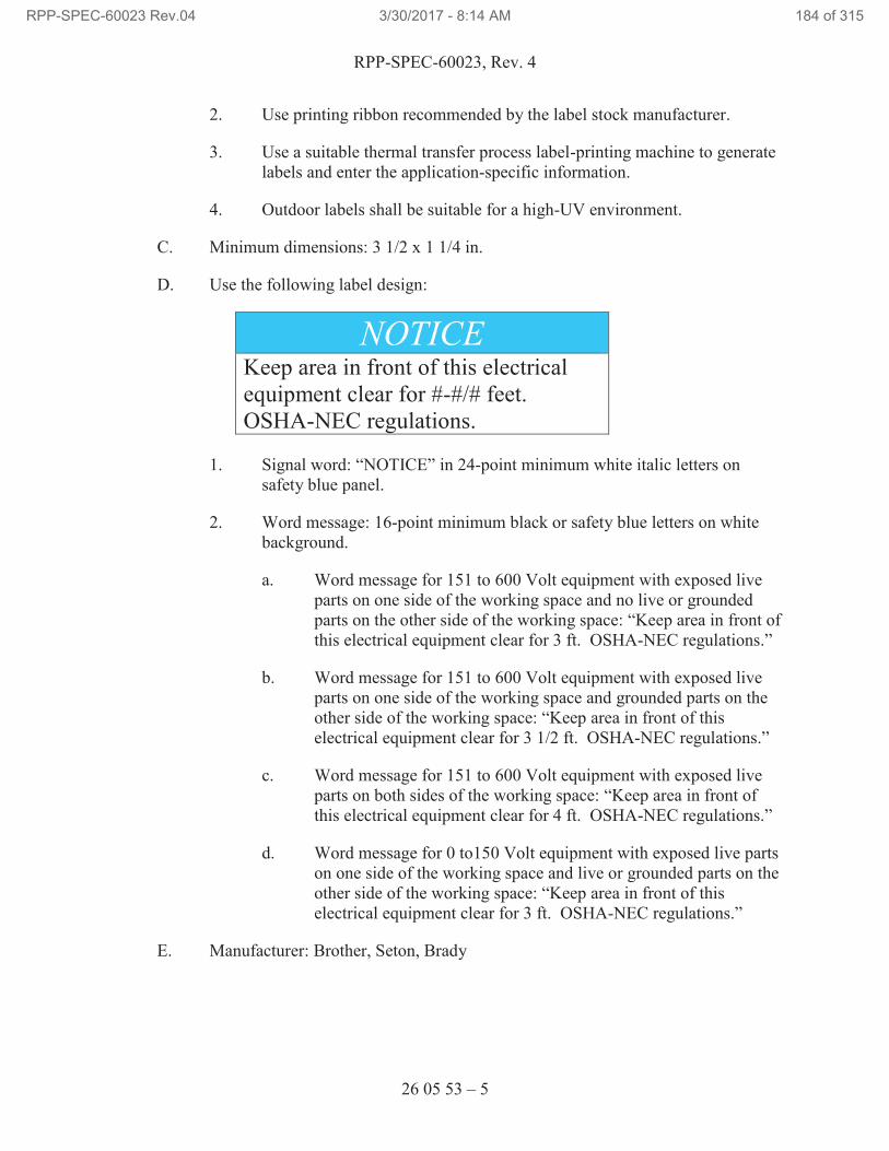
RPP-SPEC-60023, Rev. 4
26 05 53 – 5
2. Use printing ribbon recommended by the label stock manufacturer.
3. Use a suitable thermal transfer process label-printing machine to generate
labels and enter the application-specific information.
4. Outdoor labels shall be suitable for a high-UV environment.
C. Minimum dimensions: 3 1/2 x 1 1/4 in.
D. Use the following label design:
NOTICE Keep area in front of this electrical
equipment clear for #-#/# feet.
OSHA-NEC regulations.
1. Signal word: “NOTICE” in 24-point minimum white italic letters on
safety blue panel.
2. Word message: 16-point minimum black or safety blue letters on white
background.
a. Word message for 151 to 600 Volt equipment with exposed live
parts on one side of the working space and no live or grounded
parts on the other side of the working space: “Keep area in front of
this electrical equipment clear for 3 ft. OSHA-NEC regulations.”
b. Word message for 151 to 600 Volt equipment with exposed live
parts on one side of the working space and grounded parts on the
other side of the working space: “Keep area in front of this
electrical equipment clear for 3 1/2 ft. OSHA-NEC regulations.”
c. Word message for 151 to 600 Volt equipment with exposed live
parts on both sides of the working space: “Keep area in front of
this electrical equipment clear for 4 ft. OSHA-NEC regulations.”
d. Word message for 0 to150 Volt equipment with exposed live parts
on one side of the working space and live or grounded parts on the
other side of the working space: “Keep area in front of this
electrical equipment clear for 3 ft. OSHA-NEC regulations.”
E. Manufacturer: Brother, Seton, Brady
RPP-SPEC-60023 Rev.04 3/30/2017 - 8:14 AM 184 of 315
RPP-SPEC-60023, Rev. 4
26 05 53 – 6
2.8 UNDERGROUND WARNING TAPE
A. Furnish underground warning tape for underground cables, conduits and duct
banks.
B. Use 6-in. wide, 0.004-in. thick, polyethylene detectable underground warning tape
black lettering and the following background colors:
1. Electric: Red
C. Provide lettering that indicates the type service buried below.
1. Electric: “CAUTION ELECTRIC LINE BURIED BELOW”
D. Manufacturer: Utility Safeguard, LLC, Detectable Terra Tape, Reef Industries,
Inc.
2.9 ARC FLASH LABELS
A. Install arc flash labels on electrical equipment as required by NEC.
2.10 CONDUIT LABELING
A. Conduit metal tags shall be affixed to all numbered conduit. Conduit numbers are
shown on Drawings.
PART 3 EXECUTION
3.1 EXAMINATION
A. Examine surfaces to receive identification products for compliance with
installation tolerances and other conditions affecting performance of the
identification products. Do not proceed with installation until unsatisfactory
conditions have been corrected.
3.2 INSTALLATION – GENERAL
A. Where identification is to be applied to surfaces that require finish, install
identification after completion of finish work.
B. Install labels where indicated and at locations for best convenience of viewing
without interference with operation and maintenance of equipment.
C. Coordinate installation of identifying devices with location of access panels and
doors.
D. Install electrical identification products only when ambient temperature and
humidity conditions for adhesive are within range recommended by manufacturer.
RPP-SPEC-60023 Rev.04 3/30/2017 - 8:14 AM 185 of 315
RPP-SPEC-60023, Rev. 4
26 05 53 – 7
E. Clean surface where electrical identification product is to be placed.
F. Use manufacturer’s recommended adhesive for engraved tags and nameplates.
G. Place electrical identification products centered and parallel to equipment lines.
3.3 COMPONENT IDENTIFICATION TAGS
A. Install component identification tag as indicated on the Drawings on the front of
each piece of electrical equipment including switchboards, MCCs, distribution
panels, transformers, and VFDs.
B. Position tags so they can be read from floor or ground.
3.4 EQUIPMENT NAMEPLATES
A. Install equipment nameplate or nameplates as indicated on the Drawings on the
front of each piece of electrical equipment including switchboards, MCCs,
distribution panels, transformers, and VFDs.
B. Position nameplates so they can be read from floor or ground.
3.5 WIRE MARKERS
A. Install wire markers on power conductors at each appearance in locations such as
switchboards, MCCs, distribution panels, transformers, and VFDs, and load
connections.
B. Position markers so they can be read from the front of the enclosure.
3.6 VOLTAGE MARKERS
A. Install voltage markers at the following locations and position markers so they can
be read from floor or ground:
1. Front of each free-standing low-voltage switchboard section.
2. Front of each switchboard, MCC, distribution panel, transformer, and
VFD.
3. Cover of each pull box containing low-voltage conductors.
3.7 WARNING SIGNS
A. Install warning signs at the following locations and position signs so they can be
read from floor or ground:
1. Front of each switchboard disconnect switches, terminal box, distribution
panel, transformer, VFD, pull boxes, and cabinets.
RPP-SPEC-60023 Rev.04 3/30/2017 - 8:14 AM 186 of 315
RPP-SPEC-60023, Rev. 4
26 05 53 – 8
3.8 WORKING SPACE LABELS
A. Install working space labels in front of switchboards, MCCs, distribution panels,
transformers, and VFDs.
B. Any other equipment likely to require examination, adjustment, servicing, or
maintenance while energized.
3.9 UNDERGROUND WARNING TAPE
A. Install underground warning tape in trench above underground conduit.
END OF SECTION 26 05 53
RPP-SPEC-60023 Rev.04 3/30/2017 - 8:14 AM 187 of 315
RPP-SPEC-60023, Rev. 4
26 10 00 – 1
SECTION 26 10 00
MEDIUM VOLTAGE ELECTRICAL DISTRIBUTION
PART 1 GENERAL
1.1 SCOPE OF WORK
A. This Section includes requirements for material and installation of equipment for
the 13.8 kV medium voltage systems.
1.2 RELATED DOCUMENTS / CODES AND STANDARDS
Drawings and general provisions of the contract, including General and Supplementary
Conditions and Division 01 Specification Sections apply to this Section.
The following documents and others referenced therein, form part of the Contract to the
extent designated in this Section. Referenced documents are those current as of the date
of this Section unless otherwise indicated.
A. Association of Edison Illuminating Companies (AEIC)
AEIC C56 Specification for Ethylene Propylene Rubber
Insulated Shielded Power Cables Rated for 5kV
through 69kV
B. American National Standards Institute (ANSI)
ANSI C2, 2012 National Electrical Safety Code (NESC)
ANSI C37.47 High Voltage Current-Limiting Type Distribution
Class Fuses and Fuse Disconnect Switches
C. ASTM International (ASTM)
ASTM B502 Standard Specification for Aluminum-Clad Steel
Core Wire for Aluminum Conductors, Aluminum-
Clad Steel Reinforced
ASTM B549 Standard Specification for Concentric-Lay-Stranded
Aluminum Conductors, Aluminum-Clad Steel
Reinforced (ACSR/AW)
ASTM D1535 Method for Specifying Color by Munsell System
RPP-SPEC-60023 Rev.04 3/30/2017 - 8:14 AM 188 of 315
RPP-SPEC-60023, Rev. 4
26 10 00 – 2
D. American Wood Protection Association (AWPA)
AWPA C7 Western red cedar, northern white cedar and Alaska
yellow cedar poles – preservative treatment of
incised pole butts by the thermal process (no s/s
document
AWPA P Standard for field cuts, creosote for brush or spray
treatment
E. Factory Mutual (FM)
FM 3990 Less or Nonflammable Liquid-Insulated
Transformers
F. Federal Specification (FS)
TT-S-00230C AMD 2 Sealing Compound: Elastomeric Type, Single
Component (for Caulking, Sealing and Glazing in
Buildings and Other Structures)
G. Institute of Electrical and Electronics Engineers (IEEE)
C57.12.00 General Requirements for Liquid-Immersed
Distribution, Power and Regulating Transformers
H. Insulated Cable Engineers Association (ICEA)
ICEA S-68-516 Ethylene-Propylene Insulated Wire & Cable for the
Transmission & Distribution
ICEA S-93-639 5-46kV Shielded Power Cable for Use in the
Transmission and Distribution of Electric Energy
I. National Electrical Manufacturers Association (NEMA)
NEMA RN 1 PVC Externally Coated Galvanized Rigid Steel
Conduit and Intermediate Metal Conduit
NEMA C80.1 Electrical Rigid Steel Conduit (ERSC)
NEMA ICS 6 Enclosures for Industrial Controls and Systems
NEMA TC 2 Electrical Polyvinyl Chloride (PVC) Conduit
NEMA TC 3 Polyvinyl Chloride (PVC) Fittings for Use with
Rigid PVC Conduti and Tubing
RPP-SPEC-60023 Rev.04 3/30/2017 - 8:14 AM 189 of 315
RPP-SPEC-60023, Rev. 4
26 10 00 – 3
NEMA TC 6 & 8 Polyvinyl Chloride (PVC) Plastics Utilities Duct for
Underground Installations
NEMA TC 7 Smoothwall Coilable Electrical Polyethylene
Conduit
NEMA TC 9 Fittings for Polyvinyl Chloride (PVC) Plastic
Utilities Duct for Underground Installation
NEMA WC 74 5-46kV Shielded Power Cable for Use in the
Transmission and Distribution of Electric Energy
J. National Fire Protection Association (NFPA)
NFPA 70, 2014 National Electrical Code (NEC)
K. Underwriters Laboratories (UL)
UL 6 Rigid Steel Conduit
UL 508A, 2014 Industrial Control Panels
UL 514B Conduit, Tubing and able Fittings
UL 514C Standard for Nonmetallic Outlet Boxes, Flush-
Device Boxes, and Covers
UL 651 Standard for Schedule 40, 80 Type EB and A Rigid
PVC Conduit and Fittings
UL 651A Schedule 40 and 80 High Density Polyethelene
(HDPE) Conduit
UL 1072 Medium-Voltage Power Cables
L. Hanford Documents
TFC-ENG-STD-15 Raceway System Standard
TFC-PRJ-P-C-02 NEC Compliance Inspection
1.3 SUBMITTALS
A. See the Contract Statement of Work for the submittal process.
B. Approval Required
1. Shop Drawings: Submit Shop Drawings for each enclosure, including
dimensioned plans and elevations and component lists. Include front and
RPP-SPEC-60023 Rev.04 3/30/2017 - 8:14 AM 190 of 315
RPP-SPEC-60023, Rev. 4
26 10 00 – 4
side views of enclosure showing overall dimensions, enclosure type,
enclosure finish, unit locations, and conduit entrances. Include the
following:
a. Configuration and current ratings of equipment.
b. Short-circuit current rating of equipment.
c. Rated Voltage and BIL.
d. Features, characteristics, ratings, and factory settings of individual
protective devices and auxiliary components.
2. Project Record Documents: Submit project record documents to include
specified certifications and all field test reports.
1.4 QUALITY ASSURANCE
A. Inspections: The electrical installation shall meet the requirements of the NEC, as
administered by the NEC electrical inspector and the MSA Electrical Utilities
Group for the NESC portion.
B. Electrical Product Acceptability: Electrical equipment shall be listed or labeled
by a Nationally Recognized Testing Laboratory (NRTL), such as UL, when a
category exists.
Note: NRTLs are listed on the Occupational Safety and Health Administration
web site at http://www.osha.gov/dts/otpca/nrtl/index.html#nrtls.
1. It is the Contractor’s responsibility to ensure the listing is appropriate for
the equipment specified. For equipment without a listing or label by a
NRTL, it shall be the Contractor’s responsibility to obtain a listing or
label. Any component, equipment, assembly, or system without a NRTL
listing or label shall be subject to the approval of the NEC electrical
inspector.
2. The Seller shall arrange for a WRPS Hanford NEC inspection to occur at
Seller’s facility prior to shipping any assembly not covered in whole by a
NRTL listing or label.
3. Cabinets containing assembled control systems shall be designed,
constructed, and listed or labeled to the UL 508A Standard, as applicable.
C. Obtain EIPs (Electrical Installation Permit) (Form A-6005-707) prior to
performing any electrical installation or modification. See TFC-PRJ-P-C-02,
NEC Compliance Inspection.
RPP-SPEC-60023 Rev.04 3/30/2017 - 8:14 AM 191 of 315
RPP-SPEC-60023, Rev. 4
26 10 00 – 5
PART 2 PRODUCTS
2.1 PRODUCT OPTIONS AND SUBSTITUTIONS
A. Alternate products may be substituted if approved by the TOC Construction
Representative.
B. Materials
1. Solderless terminals for insulated aerial conductors: circumferential
compression type: Burndy Corporation HYLUG Type YA for copper
conductors and Type YA-A for aluminum conductors.
C. Conduit:
1. Rigid Steel NEMA C80.1 and UL 6.
2. Conduit and Conduit Fittings Plastic, Rigid NEMA TC 9, UL 514B,
UL 514C, UL 651, UL 651A.
3. Type DB PVC RNC EPC 40 (Schedule 40) & EPC 80 (Schedule 80)
NEMA TC 6 & 8, UL 514B, UL 514C, UL 651, UL 651A.
4. Type HDPE RNC EPEC NEMA TC 7, UL 514B, UL 514C, UL 651,
UL 651A.
D. PVC coating on rigid steel conduit: NEMA RN 1, Type A-40, factory applied.
E. Wood Poles: ANSI 05.1, western red cedar, or Douglas fir cut from live timber.
Pole shall be butt-treated by manufacture in accordance with AWPA C7, using
AWPA P preservatives. Each pole shall be given single top cut at 30-degree
angle with normal to axis of pole and at right angle to sweep. Gains shall be cut
so roof will be at right angles to the line and sweep of the pole will be in line.
Roofs and gains shall be brush treated by manufacture with specified preservative.
Each gain shall fit crossarm tightly. Bolt holes shall not be more than 1/16 in.
oversize.
F. Crossarms: Straight-grained Douglas fir, free from twists to within 0.1 in. per
foot of length, with bends and twists in only one direction. Apply preservatives to
crossarms in accordance with AWPA C25, with retention of 8 pounds per cubic
foot.
G. Line Conductors: #4 ACSR (Swanate) in accordance with ASTM B-230,
ASTM B-502, and ASTM B-549.
H. Pole line materials: See Attachment A, “Hanford Electrical Utilities Distribution
Guide Specifications & Standard Details.”
RPP-SPEC-60023 Rev.04 3/30/2017 - 8:14 AM 192 of 315
RPP-SPEC-60023, Rev. 4
26 10 00 – 6
I. Load Break Elbows: 15 kV Cooper Power Systems 500-10 Series.
J. The cables specified on Drawings as 15 kV shall be single-conductor, shielded,
solid-dielectric type rated for 105°C normal operation. The cables shall be listed
by UL as Type MV-150 and have a 15,000-V rating. All cables shall be “sunlight
resistant.”
K. The conductor shall be stranded copper, sized in accordance with the drawings.
The insulation level shall be 133% of rated voltage with a minimum thickness of
220 mils per requirements of ICEA S-68-516, UL 1072, and AEIC C56.
L. The cables shall conform to the following:
1. Cables shall be suitable for use in wet and dry locations, underground duct
systems.
2. Conductors shall be Class B Compact Copper, per ICEA S-68-516, Part 2
and UL 1072.
3. Each conductor shall be covered with an extruded semi-conducting
polymeric material applied over the surface of the conductor that is
compatible with the insulation.
4. The insulation applied over the extruded strand screen shall be high-
quality ethylene propylene blended and compounded within the cable
manufacturer’s facilities under optimum conditions of cleanliness.
5. The type of insulation shielding – copper tape shielding: each conductor
shall have a bare 5-mil minimum thick copper shielding tape helically
applied over the insulation shield with a minimum 25% overlap of the tape
width.
6. Wire pulling compound: Electro Compound Company “Y-er Eas,” or
American Polywater Corporation “Polywater.”
M. Tape
1. Plastic insulating tape: 3M Company “Scotch No. 33+;”
2. Conduit protection tape: 3M Company “Scotchrap™17
No. 50;” and
3. Silicon rubber termination tape: 3M Company “Scotch No. 70.”
N. Insulating putty: 3M Company “Scotchfil™17
,” General Electric Company No.
8389, or Kearney Company “Airseal.”
O. Provide medium voltage equipment as shown on the Drawings. Transformers are
provided by others.
RPP-SPEC-60023 Rev.04 3/30/2017 - 8:14 AM 193 of 315
RPP-SPEC-60023, Rev. 4
26 10 00 – 7
P. Provide Load Break Elbows complete with inserts, on the transformer primary
connection: 15 kV, 200A load break connector, Cooper 500-10 series.
Q. Lightning arrestors for transformer: Metal oxide, elbow shaped, with metal oxide
varistor, rated at 18 kV (15.3 MCOV), in premolded insulating elbow designed
for use with the RTE 200 A 8.3/14.4 kV loadbreak bushings that are on the
transformer.
R. Lightning arresters: Pole mounted, distributed valve type, rated at 18 kV
(15.3 MCOV)
S. Provide cable terminations rated at 15 kV, heat shrink type with anti-tracking for
shielded cable, Raychem HVT Series as shown on the Drawings.
2.2 DELIVERY, STORAGE, AND HANDLING
A. Cable inspection: Upon delivery to the worksite, inspect cable and reels for
shipping damage such as the following:
1. Marks caused by improper lifting equipment or techniques;
2. Breaks or cuts in outer covering;
3. Damaged jacket or insulation;
4. Reel damage from mishandling; and
5. Damaged or missing high voltage cable and seals.
B. Cable testing: Upon installation at the worksite, perform direct current (dc)
over – potential tests on new cable. The specifics of how to perform the tests will
be provided by the MSA Electrical Utilities Group.
C. Cable Reel Storage
1. Store reels with flanges resting on hard surface or pallet to prevent sinking
into the ground;
2. Reel flanges shall not touch cable on other reels;
3. Do not store reels on sides. Store with reel axis horizontal; and
4. Cap or tape cable ends to prevent entrance of moisture.
RPP-SPEC-60023 Rev.04 3/30/2017 - 8:14 AM 194 of 315
RPP-SPEC-60023, Rev. 4
26 10 00 – 8
D. Cable Reel Handling
1. Slings and forklifts shall not contact cable or protective covering;
2. Use spreader bars when lifting reels with bar and sling; and
3. Do not drop reels.
PART 3 EXECUTION
3.1 INSTALLATION
A. General
1. Perform work in accordance with TFC-ENG-STD-15, the NEC, and
ANSI C2.
2. Install products as shown on the drawings, specifications and per the
manufacturer’s recommendation for the pad mounted transformer. Use
appropriate calibrated special tools when installing devices for which
special installation tools are recommended by manufacturers.
3. Conduit excavation and backfill shall be as specified on the Drawings and
Division 31.
4. Watthour/VAR meters: Before installation, have meters electrically
calibrated by the MSA Electrical Utilities Group. All meter wiring to the
current transformers will be by the MSA Electrical Utilities Group.
5. Provide all necessary final field adjustments for a complete installation
B. Setting Poles
1. Excavate holes large enough to admit tamping bar around pole at butt. Do
not use explosives to excavate holes.
2. Use backfill materials that can be solidly compacted by hand tamping in
6 in. lifts. Compact surplus earth around pole in cone 1 ft high above
grade. Add additional backfill where backfill has settled, and tamp before
completion of work.
3. Minimum pole depth is 10% of pole height, plus 2’-0”, i.e., set 40-ft poles
6 ft, 0 in. in earth. Measure depth from lowest side, on moderately sloping
ground and from point 2 ft, 6 in. from center of pole toward low side on
steep slopes, cuts, embankments, or where soil is likely to be washed away
from pole.
RPP-SPEC-60023 Rev.04 3/30/2017 - 8:14 AM 195 of 315
RPP-SPEC-60023, Rev. 4
26 10 00 – 9
4. Set poles plumb and in line, except that corners and other strain points that
are guyed shall have butts displaced to keep tops in line where feasible.
At such locations, rake against strain shall be approximately 3 in. for each
10 ft of height.
5. Backfill holes created by removal of poles and other underground
structures to finish grade and solidly compact by hand tamping. Where
backfill has settled, place additional backfill and tamp before completion
of work.
C. Crossarms
1. Mount at right angles to axis of poles or as shown on the drawings.
2. Bolts shall be of sufficient length for full-thread engagement of nut, but
not protrude through poles or arms in excess of 2 in. Bolt ends shall not
be cut off. Use square washers with each through-bolt and double-arming
bolt to protect pole and crossarms.
D. Guys and Anchors
1. Install anchors to bear against undisturbed earth. Tamp backfill around
anchors entire depth of hole. Provide temporary guying required during
stringing of conductors. Remove at completion of work.
2. Set guy rods in earth in line with strand and install at least 6 in. above
grade.
E. Insulators: Tighten pin insulators on pin threads and adjust top groove so it is
parallel with line. Secure hold nuts with palnuts.
F. Aerial Conductors
1. Clearances shall be maintained for cables and conductors in accordance
with the Drawings, and ANSI C2.
2. String conductors from rotating reels and do not drag along ground nor
permit conductors to lie where they may be run over by vehicles. Pull
conductors through stringing sheaves or stringing blocks hung on
messenger cable, but do not pull around sharp corners. Inspect conductors
as they leave reels and cut out weak or damaged sections and splice ends.
Do not make splices in adjacent spans, dead end spans, or within 4 ft of
support. Install conductors to proper stringing tensions in accordance with
manufacturer’s recommendations.
RPP-SPEC-60023 Rev.04 3/30/2017 - 8:14 AM 196 of 315
RPP-SPEC-60023, Rev. 4
26 10 00 – 10
3. Make splices under tension mechanically, and electrically secure by
compression fittings. Do not use self-gripping or automatic-tension
splicing sleeves. Make taps between primary wires, jumpers, etc., with
mechanical connectors.
4. Install hot-line stirrups on existing conductors where new feeder taps are
made.
5. Sag conductors in accordance with ANSI C2 for medium loading district.
G. Aerial Equipment Grounding
1. Ground fused switches and lightning arresters in accordance with the
Drawings. Bond together pole line hardware separated by less than 2 in.
2. Ground systems: Use stranded copper conductors for ground conductors
installed in earth. Use solid copper conductors above grade. Make joints
connecting copper and galvanized steel above grade and in dry location.
Connections may be made with ground rod clamps or exothermic welds.
H. Conduits
1. Use galvanized rigid steel unless specified otherwise on the drawings.
2. Use PVC conduit in contact with earth. Install in accordance with
manufacturer’s recommendations.
3. Install concealed conduits as directed with PVC-coated rigid steel elbows
with bend radii as long as possible.
4. Make elbows, offsets, and bends uniform and symmetrical. Bend conduit
with approved bending devices.
5. Cut conduit ends square, ream, and remove burrs. Conduit shall be clean,
dry, and free of debris. Immediately after installation, plug or cap exposed
ends with standard accessories until wires are installed.
6. Use one hole clamp equipped with clampbacks or framing strut with
clamps to secure conduits as shown on drawings.
7. Set up joints in conduit installed exposed to weather, with high
temperature, anti-seize, conduit thread lubricant and sealant.
8. Install exposed conduit stubbing up, straight and plumb, lined up, and
uniformly spaced.
RPP-SPEC-60023 Rev.04 3/30/2017 - 8:14 AM 197 of 315
RPP-SPEC-60023, Rev. 4
26 10 00 – 11
9. Install warning tape for underground conduit as shown on the drawings
and with materials specified in Section 26 05 53, “Identification for
Electrical Systems.”
I. Cable Pulling and Terminations
1. Use lubricant recommended by cable manufacturer, or wire-pulling
compound specified, when pulling wire and cable through conduit.
2. Do not install or handle wires with thermoplastic insulation or jacket when
ambient temperature is 15°F or below.
3. Make terminations with solderless connectors. Use connectors in
accordance with the manufacturer’s instructions.
4. Follow manufacturer’s instructions and directions for stress cones, and
cable terminations. Final terminations to power source will be performed
by Mission Support Alliance Electric Utilities.
5. Ground pad mounted transformers to ground grid with 4/0 cable.
3.2 FIELD QUALITY CONTROL
A. Testing
1. Furnish equipment and instruments required to perform testing.
2. Use instruments which bear calibration stamps showing dates of
calibration and expiration dates of stamps. Calibration and accuracy of
instruments shall be certified by an independent testing laboratory having
standards traceable to the National Institute of Standards and Technology.
3. Test the equipment and wiring for continuity and unintentional grounds,
and verify proper phase sequence and voltage at equipment served before
attempt is made to operate equipment. Notify the NEC electrical inspector
and the Mission Support Alliance Electrical Utilities Group before start of
tests. Record the results.
4. Reconnect devices disconnected during testing
B. Acceptance testing: After installation, and prior to energizing, coordinate with
MSA Electrical Utilities to perform tests on cable to verify installation
acceptability.
RPP-SPEC-60023 Rev.04 3/30/2017 - 8:14 AM 198 of 315
RPP-SPEC-60023, Rev. 4
26 10 00 – 12
C. Verification Points
1. Provide 24-hour notice and hold for release by MSA Electrical Utilities
Group.
2. Prior to energizing, perform NEC inspection.
D. Deleted.
END OF SECTION 26 10 00
RPP-SPEC-60023 Rev.04 3/30/2017 - 8:14 AM 199 of 315
RPP-SPEC-60023, Rev. 4
26 22 13 – 1
SECTION 26 22 13
LOW VOLTAGE DISTRIBUTION TRANSFORMERS
PART 1 GENERAL
1.1 SCOPE OF WORK
A. General-purpose dry-type low-voltage transformers
1.2 RELATED DOCUMENTS / CODES AND STANDARDS
Drawings and general provisions of the contract, including General and Supplementary
Conditions and Division 01 Specification Sections apply to this Section.
The following documents and others referenced therein, form part of the Contract to the
extent designated in this Section. Referenced documents are those current as of the date
of this Section unless otherwise indicated.
A. National Electrical Manufacturers Association (NEMA)
NEMA TP 1 Guide for Determining Energy Efficiency for
Distribution Transformers
NEMA TP 2 Standard Test Method for Measuring the Energy
Consumption of Distribution Transformers
NEMA TP 3 Standard for the Labeling of Distribution
Transformer Efficiency
B. National Fire Protection Association (NFPA)
NFPA 70, 2014 National Electrical Code (NEC)
C. Underwriters Laboratories (UL)
Electrical Appliance and Utilization Equipment
Directory
UL 486A-486B Wire Connectors
UL 1561 Dry-Type General Purpose and Power Transformers
RPP-SPEC-60023 Rev.04 3/30/2017 - 8:14 AM 200 of 315
RPP-SPEC-60023, Rev. 4
26 22 13 – 2
1.3 SUBMITTALS
A. Submit the following in accordance with the provisions of the Contract Statement
of Work and the Project submittal procedures.
Not Used.
B. Submit the following for WRPS review/approval:
Not Used.
1.4 QUALITY ASSURANCE
A. Comply with the NEC for components and installation.
B. Provide products that are listed and labeled by a Nationally Recognized Testing
Laboratory (NRTL) for the application, installation condition, and the
environment in which installed.
C. Provide products that comply with the following industry standards:
1. NEMA TP 1.
2. NEMA TP 2.
3. NEMA TP 3.
4. UL 1561.
1.5 RECEIVING, STORING AND PROTECTING
A. Receive, store, protect, and handle products according to manufacturer’s
instructions.
PART 2 PRODUCTS
2.1 PRODUCT OPTIONS AND SUBSTITUTIONS
A. Alternate products may be accepted in accordance with the requirements of the
Contract Statement of Work
2.2 GENERAL
A. Transformers shall be NRTL listed to UL 1561 and shall be tested and labeled
according to NEMA TP 1, NEMA TP 2, and NEMA TP 3.
B. The efficiency of each transformer shall be NEMA TP 1 Class I when tested in
accordance with NEMA TP 2. Transformer efficiency shall be indicated on a
label that conforms to NEMA TP 3.
RPP-SPEC-60023 Rev.04 3/30/2017 - 8:14 AM 201 of 315
RPP-SPEC-60023, Rev. 4
26 22 13 – 3
C. Transformer coils may be aluminum or copper with continuous wound
construction and shall be impregnated with non-hygroscopic, thermosetting
varnish. Terminations shall be brazed or welded to the coil conductor.
D. Transformer cores shall be constructed of a high grade, non-aging silicon steel
with high magnetic permeability and low hysteresis and eddy current losses.
Magnetic flux densities shall be kept well below the saturation point.
2.3 GENERAL-PURPOSE DRY-TYPE TRANSFORMERS
A. The core and coil shall be bolted to the base of the enclosure, isolated by means of
rubber vibration-absorbing mounts. There shall be no metal-to-metal contact
between the core and the enclosure. Sound isolation systems requiring the
complete removal of all fastening devices will not be acceptable.
B. The core of the transformer shall be visibly grounded to the enclosure by a
flexible grounding conductor sized following applicable UL and NEC Standards.
C. The transformer enclosure shall be ventilated and shall be fabricated of a heavy
gauge, sheet steel construction. The entire enclosure shall be finished using a
process consisting of degreasing, cleaning and phosphatizing followed by
electrostatic deposition of polymer polyester powder and baking cycle to provide
a uniform coating of all edges and surfaces. The coating shall be UL recognized
for outdoor use. The coating color shall be light or medium grey.
D. Transformers shall be suitable for rack or floor mounting. Provide mounting
accessories required for installation.
E. Provide weather shields for transformers installed outdoors.
F. Provide transformer manufacturer’s transformer lug kits with compression type
equipment lugs and hardware for connecting conductors to transformer terminals.
G. Provide factory assembled and tested, energy-efficient, general-purpose, air
cooled, two-winding, dry-type transformers with voltage and kVA ratings as
indicated on the Drawings.
H. General-purpose transformers 15 kVA and larger shall be 150°C temperature rise
above 40°C ambient. The maximum temperature of the top of the enclosure shall
not exceed 50°C rise above a 40°C ambient.
I. Transformers 15 kVA and larger shall have a minimum of two 2.5 percent full
capacity above normal and four 2.5 percent full capacity below normal primary
taps.
J. Manufacturers:
1. Square D Class 7400 Type “EE.”
RPP-SPEC-60023 Rev.04 3/30/2017 - 8:14 AM 202 of 315
RPP-SPEC-60023, Rev. 4
26 22 13 – 4
2. Eaton/Cutler-Hammer “DS-3”and “DT-3.”
2.4 MINI-POWER ZONE
A. Provide mini-power zone, 480-120/240V, single phase transformer and
120/240V, panelboard in a weather-resistant enclosure. Minipower zone shall be
UL listed, surface mounted and sized as shown on the Drawings. Branch and
secondary main circuit breakers shall be provided as shown on the panel schedule.
Locking mechanisms permanently affixed to the panel board to prevent casual
operation of breakers shall be provided.
B. General-purpose transformers 15 kVA and larger shall be 150°C temperature rise
above 40°C ambient.
C. Mini-power zone units shall have a minimum of two 2.5 percent full capacity
below normal primary taps.
D. Manufacturers:
1. Square D, Class 7440 “MiniPower Zone”
PART 3 EXECUTION
3.1 EXISTING WORK
A. Disconnect and remove abandoned dry-type transformers as shown on design
media.
B. Maintain access to existing dry-type transformers and other installations that are
to remain active.
3.2 EXAMINATION
A. Examine surfaces to receive transformers for compliance with installation
tolerances and other conditions affecting performance of the control system. Do
not proceed with installation until unsatisfactory conditions have been corrected.
3.3 INSTALLATION
A. Install dry-type transformers where indicated on the Drawings and according to
manufacturer’s instructions. Manufacturer’s installation instructions shall be
available at the construction site.
B. Arrange equipment to provide adequate spacing for access, replacement, and for
cooling air circulation. Locate the front and rear of each ventilated transformer at
least 6 in. from the wall or any obstruction to allow proper air circulation.
C. Make conduit connections to transformer enclosure only at locations designated
by the manufacturer’s installation instructions.
RPP-SPEC-60023 Rev.04 3/30/2017 - 8:14 AM 203 of 315
RPP-SPEC-60023, Rev. 4
26 22 13 – 5
D. Connect conductors to transformer terminals using transformer manufacturer’s
lug kits. Tighten electrical connectors and terminals according to manufacturer’s
published torque-tightening values. Where manufacturer’s torque values are not
furnished, use those specified Section 26 05 19, “Low Voltage Electrical Power
Conductors and Cables,” Attachment 1, “Recommended Tightening Torque per
UL 486A-486B.”
E. Bond transformers and ground systems served by transformers according to
Section 26 05 26, “Grounding and Bonding for Electrical Systems.”
F. Identify transformers and install warning signs according to Section 26 05 53,
“Identification for Electrical Systems.”
3.4 FIELD QUALITY CONTROL
A. Clean, inspect, test, adjust, and energize transformers in accordance with
manufacturer’s instructions.
1. Inspect each transformer for physical damage, proper connection and
grounding, and proper anchorage.
2. Place records of inspections, tests, and adjustments in the work package or
fabrication document.
B. Coordinate inspections and tests with those required by other Sections.
C. After completing installation, cleaning, and testing, touch-up scratches and mars
on finish to match original finish.
D. Measure primary and secondary voltages and phase rotation, and make
preliminary tap adjustments. After normal operating loads have been energized
adjust taps to provide the following voltage at points of use; record voltages and
tap settings.
System Nominal Voltage Minimum Load Voltage
480Y/277 460Y/265
208Y/120 200Y/115
120/240 115/230
END OF SECTION 26 22 13
RPP-SPEC-60023 Rev.04 3/30/2017 - 8:14 AM 204 of 315
RPP-SPEC-60023, Rev. 4
26 24 13 – 1
SECTION 26 24 13
SWITCHBOARDS
PART 1 GENERAL
1.1 SCOPE OF WORK
A. Section covers installation of floor-mounted deadfront low-voltage switchboards
which consist of an enclosure, circuit breakers, instruments and metering
equipment, monitoring equipment or control equipment, with associated
interconnections and supporting structures. Uses on Project include:
1. Main Switchboard and Distribution Switchboard – are shown on the
Drawings and provided by RPP-SPEC-60125.
1.2 RELATED DOCUMENTS / CODES AND STANDARDS
Drawings and general provisions of the contract, including General and Supplementary
Conditions and Division 01 Specification Sections apply to this section.
The following documents and others referenced therein, form part of the Contract to the
extent designated in this section. Referenced documents are those current as of the date
of this section unless otherwise indicated.
A. Factory Mutual (FM) Research Corporation
Approval Guide
B. Hanford Documents
RPP-CALC-60221 Electrical Power Distribution Study for A/AX
Retrieval Infrastructure
RPP-CALC-60222 Electrical Power Distribution Study for A/AX
Retrieval Water Building
RPP-SPEC-60125 Procurement Specification for A/AX Retrieval
Project Switchboards
C. Institute of Electrical and Electronics Engineers (IEEE)
IEEE 100 The Authoritative Dictionary of IEEE Standards
Terms
D. National Electrical Manufacturer’s Association (NEMA)
NEMA PB 2 Deadfront Distribution Switchboards
RPP-SPEC-60023 Rev.04 3/30/2017 - 8:14 AM 205 of 315
RPP-SPEC-60023, Rev. 4
26 24 13 – 2
NEMA PB 2.1 Proper Handling, Installation, Operation and
Maintenance of Deadfront Switchboards Rated
600 Volts or Less
E. National Fire Protection Association (NFPA)
7 NFPA 0 National Electrical Code (NEC)
F. Underwriters Laboratories (UL)
UL 67 Panelboards
UL 486A-486B Wire Connectors
1.3 DEFINITIONS
A. Unless otherwise specified or indicated, electrical and electronics terms used in
this Section are as defined in IEEE 100.
1.4 QUALITY ASSURANCE
A. Comply with the NEC for components and installation.
B. Provide products that are listed and labeled by a Nationally Recognized Testing
Laboratory (NRTL) for the application, installation condition, and the
environment in which installed.
1.5 RECEIVING, STORING AND PROTECTING
A. Receive, inspect, handle, and store switchboard(s) according to the following:
1. Manufacturer’s written instructions.
1.6 SERVICE CONDITIONS
A. Conform to NEMA PB 2 service conditions during and after installation of
switchboards.
1.7 FIELD MEASUREMENTS
A. Verify field measurements against manufacturer’s shop drawings prior to
fabrication.
PART 2 PRODUCTS
A. Switchboards are provided by Procurement Specification RPP-SPEC-60125.
RPP-SPEC-60023 Rev.04 3/30/2017 - 8:14 AM 206 of 315
RPP-SPEC-60023, Rev. 4
26 24 13 – 3
PART 3 EXECUTION
3.1 EXAMINATION
A. Examine surfaces to receive switchboard(s) for compliance with installation
tolerances and other conditions affecting performance of the product. Do not
proceed with installation until unsatisfactory conditions have been corrected.
3.2 INSTALLATION
A. Install switchboard(s) where indicated on the Drawings and according to
manufacturer’s instructions, NEMA PB-2, and the NEC. Have the
manufacturer’s installation instructions available at the construction site.
B. Remove temporary lifting eyes, channels, brackets, and temporary blocking of
moving parts from switchboard enclosure and components.
C. Ground and bond switchboards as required in Section 26 05 26, “Grounding and
Bonding for Electrical Systems.”
D. Install conduits as required in Section 26 05 33, “Raceways and Boxes for
Electrical Systems.”
1. Terminate conduits in the switchboard section containing the
corresponding device.
2. Install plugged couplings set flush with the top of the concrete pad. After
switchboard is set in place, extend conduits to 1 1/4-in. above the pad and
terminate with insulated grounding bushings.
E. Install conductors as required in Section 26 05 19, “Low Voltage Electrical Power
Conductors and Cables.”
1. Train conductors neatly in groups; bundle and secure as recommended by
manufacturer to withstand fault current.
2. Use compression type lugs to connect all service, feeder, and branch
circuit cables greater than 100 amperes.
3. Tighten electrical connectors and terminals, including bus bar and
grounding connections, according to the manufacturer’s published
torque-tightening values. Where manufacturer’s torque values are not
indicated, use those specified in UL 486A-486B.
3.3 IDENTIFICATION
A. Identify switchboard and install warning signs and arc-flash warning labels as
required in Section 26 05 53, “Identification for Electrical Systems.”
RPP-SPEC-60023 Rev.04 3/30/2017 - 8:14 AM 207 of 315
RPP-SPEC-60023, Rev. 4
26 24 13 – 4
3.4 FIELD QUALITY CONTROL
A. Clean, inspect, test, and energize switchboards in accordance with manufacturer’s
instructions.
B. Verify that circuit breakers are in the proper locations and that setting of solid
state trip devices and current sensor taps match values scheduled on the
Drawings.
C. Exercise each circuit breaker three times to verify smooth mechanical operation.
D. Verify proper torque of accessible bus connections and mechanical fasteners after
installing switchboard.
E. Coordinate inspections and tests with those required by other Sections in this
Specification.
F. After completing installation, cleaning, and testing, touch-up scratches and mars
on finish to match original finish.
G. Perform field adjustments of the protective devices as required to place the
equipment in final operating condition. The settings shall be in accordance with
the approved short-circuit study, protective device evaluation study and protective
device coordination studies, RPP-CALC-60221 and RPP-CALC-60222.
H. Necessary field settings of devices, adjustments, and minor modifications to
equipment to accomplish conformance with an approved short circuit and
protective device coordination study shall be carried out by the Contractor at no
additional cost to the owner.
3.5 MANUFACTURER’S FIELD SERVICE
A. Provide the services of a factory trained representative from the manufacturer to
inspect and certify the installation and to oversee energizing and testing as
directed by TOC Engineering Representative.
B. Manufacturer’s representative shall certify in writing that the equipment has been
installed, adjusted, and tested in accordance with the manufacturer’s
recommendations.
END OF SECTION 26 24 13
RPP-SPEC-60023 Rev.04 3/30/2017 - 8:14 AM 208 of 315
RPP-SPEC-60023, Rev. 4
26 24 16 – 1
SECTION 26 24 16
PANELBOARDS
PART 1 GENERAL
1.1 SCOPE OF WORK
A. Panelboards for feeder and branch circuit loads.
1.2 RELATED DOCUMENTS / CODES AND STANDARDS
Drawings and general provisions of the contract, including General and Supplementary
Conditions and Division 01 Specification Sections apply to this Section.
The following documents and others referenced therein, form part of the Contract to the
extent designated in this Section. Referenced documents are those current as of the date
of this Section unless otherwise indicated.
A. International Organization for Standardization (ISO)
ISO 9001 Quality management systems – Requirements
B. National Electrical Manufacturer’s Association (NEMA)
NEMA AB 3 Molded Case Circuit Breakers and their Application
NEMA PB 1 Panelboards
NEMA PB 1.1 General Instructions for Proper Installation,
Operation, and Maintenance of Panelboards Rated
600 volts or less
NEMA PB 2 Deadfront Distribution Switchboards
C. National Fire Protection Association (NFPA)
NFPA 70, 2014 National electrical Code (NEC)
D. Underwriters Laboratories (UL)
UL 50 Enclosures for Electrical Equipment, Non-
Environmental Considerations
UL 67 Panelboards
UL 489 Molded Case Circuit Breakers
RPP-SPEC-60023 Rev.04 3/30/2017 - 8:14 AM 209 of 315
RPP-SPEC-60023, Rev. 4
26 24 16 – 2
1.3 SUBMITTALS
A. See the Contract Statement of Work for the submittal process.
B. Approval Required.
Not Used.
1.4 QUALITY ASSURANCE
A. Comply with the NEC for components and installation.
B. Furnish products that are listed and labeled by a Nationally Recognized Testing
Laboratory (NRTL) for the application, installation condition, and the
environment in which installed.
C. Comply with NEMA PB 1, NEMA PB 1.1, and NEMA AB 3.
D. Comply with UL 67, UL 50, and UL 489.
1.5 RECEIVING, STORING AND PROTECTING
A. Receive, inspect, handle, and store panelboards according to manufacturer’s
instructions.
1.6 EXTRA MATERIALS
A. Furnish spare keys of each type for panelboard cabinet locks.
B. Deleted.
PART 2 PRODUCTS
2.1 PRODUCT OPTIONS AND SUBSTITUTIONS
A. Alternate products may be accepted in accordance with the requirements of the
Contract Statement of Work.
2.2 DISTRIBUTION PANELBOARDS
A. Furnish panelboards as indicated on the Drawings and specified in this Section.
B. Panelboards shall be UL 67 listed and shall conform to NEMA PB1.
C. Furnish panelboard cabinets for surface mounting as indicted on the Drawings.
1. Furnish enclosures as indicated below:
a. Outdoor – NEMA 3R: rated raintight minimum.
RPP-SPEC-60023 Rev.04 3/30/2017 - 8:14 AM 210 of 315
RPP-SPEC-60023, Rev. 4
26 24 16 – 3
b. Indoor – NEMA 12: Dust tight.
2. Cabinets shall be not less than 20-in. wide.
3. Furnish steel cabinets constructed according to UL 50 requirements.
4. NEMA 12, and 4 boxes shall have end walls welded and sealed.
D. Furnish trim fronts that meet the strength and rigidity requirements of UL 50.
1. Each panelboard trim front shall include a door.
2. Fronts shall have ANSI 49 medium gray enamel electro-deposited over
cleaned, phosphatized steel.
3. Furnish a panelboard circuit directory card in a metal frame mounted
inside the panelboard door. The directory card shall include spaces for
circuit numbers and sufficient spaces to allow each circuit to be described
in sufficient detail to be distinguished from all others.
a. Furnish cylindrical tumbler type locks for doors. Furnish sliding
vault locks with 3-point latching for enclosures more than 48-in.
high. Key all lock assemblies alike. Furnish two keys with each
lock plus spares as required in the Extra Materials paragraph
above.
E. Equip panelboards with mounting brackets, bus connections, and necessary
appurtenances, for the future installation of circuit breakers in the “spaces”
scheduled on the Drawings.
F. Furnish panelboards having NRTL-listed short circuit current ratings not less than
the available fault current indicated on the Drawings.
G. Furnish thermal-magnetic circuit breakers that meet the requirements of UL 489
and NEMA AB 3.
1. Furnish circuit breakers of the type, rating, and features as indicated on the
Drawings.
2. Do not use tandem circuit breakers.
3. Furnish multi-pole breakers with a common trip.
4. Furnish bolt-on type circuit breakers or circuit breakers that connect to the
panel bus through positive gripping connector jaws and are secured by an
independent mechanical locking device.
RPP-SPEC-60023 Rev.04 3/30/2017 - 8:14 AM 211 of 315
RPP-SPEC-60023, Rev. 4
26 24 16 – 4
5. Furnish UL Class A ground fault interrupter circuit breakers or UL
Class B equipment protection circuit breakers where scheduled on
Drawings.
6. Furnish circuit breakers with provisions for connecting the size and
number of conductors indicated on the Drawings. Refer to
Section 26 05 19, “Low Voltage Electrical Power Conductors and
Cables,” for conductor connection requirements.
H. Furnish a permanently-installed handle lock-off device for each circuit breaker.
1. Furnish handle lock-off device that will accept a 1/4-in. padlock shackle.
2. Securely attach the device to the circuit breaker case; the attachment shall
not depending on a friction fit or the presence of the panelboard front for
the handle lock-off device to remain in place and be functional.
I. Manufacturers:
1. Eaton:
a. 480 V and 480Y/277 V: “PRL3a” and “PRL4”
b. 208Y/120 V and 120/240 V: “PRL1a” and “PRL2a”
2. Square D:
a. 480 V and 480Y/277 V: “NF” and “I-LINE”
b. 208Y/120 V and 120/240 V: “NQ” and “I-Line”
PART 3 EXECUTION
3.1 EXAMINATION
A. Examine surfaces to receive panelboards for compliance with installation
tolerances and other conditions affecting performance. Do not proceed with
installation until unsatisfactory conditions have been corrected.
3.2 INSTALLATION
A. Install panelboards where indicated on the Drawings and according to
manufacturer’s instructions, NEMA PB 1.1, and the NEC. Have the
manufacturer’s installation instructions available at the construction site.
B. Furnish supports in accordance with the requirements of Section 26 05 29,
“Hangers and Supports for Electrical Systems.”
RPP-SPEC-60023 Rev.04 3/30/2017 - 8:14 AM 212 of 315
RPP-SPEC-60023, Rev. 4
26 24 16 – 5
C. Position panelboards so the top circuit breaker handle is not more than 6 ft – 7 in.
above the surface of the working space in front of the panelboard.
D. Ground and bond panelboards as required in Section 26 05 26, “Grounding and
Bonding for Electrical Systems.”
3.3 IDENTIFICATION
A. Furnish typed circuit directories for each branch circuit panelboard.
1. Install a plastic-laminated copy of the panel schedule drawing on the inner
side of the panelboard door.
B. Identify panelboards and install warning signs and arc-flash warning labels as
required in Section 26 05 53, “Identification for Electrical Systems.”
3.4 FIELD QUALITY CONTROL
A. Clean, inspect, test, and energize panelboards in accordance with manufacturer’s
instructions. Exercise each circuit breaker three times to verify smooth
mechanical operation.
B. Coordinate inspections and tests with those required by other Sections.
C. After completing installation, cleaning, and testing, touch-up scratches and mars
on finish to match original finish.
END OF SECTION 26 24 16
RPP-SPEC-60023 Rev.04 3/30/2017 - 8:14 AM 213 of 315
RPP-SPEC-60023, Rev. 4
26 27 26 – 1
SECTION 26 27 26
WIRING DEVICES
PART 1 GENERAL
1.1 SCOPE OF WORK
A. Receptacles.
B. Snap switches.
C. Wall plates.
1.2 RELATED DOCUMENTS / CODES AND STANDARDS
Drawings and general provisions of the contract, including General and Supplementary
Conditions and Division 01 Specification Sections apply to this Section.
The following documents and others referenced therein, form part of the Contract to the
extent designated in this Section. Referenced documents are those current as of the date
of this Section unless otherwise indicated.
A. Federal Specifications (FS)
FS W-C-596 G/GEN Connector, Electrical, Power, General Specification
for
FS W-P-455A Plate, Wall, Electrical
FS W-S-896 Switches, Toggle (Toggle and Lock), Flush
Mounted (General Specification)
B. International Organization for Standardization (ISO)
ISO 9001 Quality Management Systems -- Requirements
C. National Electrical Manufacturers Association (NEMA)
NEMA WD 1 General Requirements for Wiring Devices
NEMA WD 6 Wiring Devices—Dimensional Specifications
D. National Fire Protection Association (NFPA)
NFPA 70, 2014 National Electrical Code (NEC)
RPP-SPEC-60023 Rev.04 3/30/2017 - 8:14 AM 214 of 315
RPP-SPEC-60023, Rev. 4
26 27 26 – 2
E. Underwriters Laboratories (UL)
UL 20 General Use Snap Switches
UL 498 Electrical Attachment Plugs and Receptacles
UL 943 Ground Fault Circuit Interrupters
UL 1492 Solid-State Dimming Controls
1.3 SUBMITTALS
A. See the Contract Statement of Work for the submittal process.
B. Approval Required
Not Used.
1.4 QUALITY ASSURANCE
A. Comply with the NEC.
B. Furnish products listed and labeled by a Nationally Recognized Testing
Laboratory (NRTL) for the application, installation condition, and the
environments in which installed.
1.5 RECEIVING, STORING, AND PROTECTING
A. Receive, store, protect, and handle products according to manufacturer’s
instructions.
PART 2 PRODUCTS
2.1 PRODUCT OPTIONS AND SUBSTITUTIONS
A. Alternate products may be accepted in accordance with the requirements of the
Contract Statement of Work.
2.2 RECEPTACLES
A. Provide back and side wired, screw pressure terminal, straight-blade, and locking
type, receptacles as indicated on the drawings. Receptacles shall meet the
performance and design requirements of Federal Specification W-C-596G/GEN
and UL 498. Receptacle configurations shall be in accordance with
NEMA WD 6.
B. For 120 volt receptacles connected to individual branch circuits provide straight-
blade NEMA 5-20R, 20 amperes, 125 volts, grounding duplex receptacles.
RPP-SPEC-60023 Rev.04 3/30/2017 - 8:14 AM 215 of 315
RPP-SPEC-60023, Rev. 4
26 27 26 – 3
Receptacle mounting strap, ground terminal, and ground contacts shall be formed
from one piece of brass alloy. Manufacturer: Hubbell “HBL5362” or equal.
C. For GFCI receptacles connected to individual branch circuits provide straight-
blade NEMA 5-20R, 20 amperes, 125 volts, grounding, “feed through” type, self-
testing GFCI, duplex receptacle that meet the requirements of UL 943. Provide
units that can be installed in a 2 3/4-in. deep outlet box without an adapter.
Manufacturer: Hubbell “GFR5362ST” or equal.
D. Provide straight-blade and twist lock receptacles for special applications as
indicated on the Drawings.
E. Provide 480 VAC, 3 wire, 4 pole, receptacles, amperage as shown on drawings.
Manufacturer: Crouse Hinds.
2.3 SNAP SWITCHES
A. Provide single pole, double pole, three-way, four-way and illuminated handle
snap switches as indicated on the Drawings.
B. Switches shall be rated 20 amperes, 120-277 volts AC, back and side wired, screw
pressure terminal, quiet type AC switch with yoke grounding screw. Switches
shall meet the performance and design requirements of UL 20 and Federal
Specification WS896.
C. Manufacturer: Hubbell “HBL1220” series.
2.4 WALL PLATES
A. For surface mounted interior receptacles and switches, furnish galvanized steel
4-in. square raised surface covers. Receptacles installed in raised covers shall be
secured by more than one screw. Manufacturer: RACO “800” series.
B. For GFCI receptacles in damp or wet locations provide weatherproof, in use
covers. Manufacturer: Hubbell “WP26E”
C. Provide single, multi-gang, and combination type wall plates that mate and match
with corresponding wiring devices.
D. Use metal plate-securing screws to match plate finish.
E. Terminal Blocks
1. Terminal Blocks shall meet the requirements of UL 1059 or NEMA ICS 4.
RPP-SPEC-60023 Rev.04 3/30/2017 - 8:14 AM 216 of 315
RPP-SPEC-60023, Rev. 4
26 27 26 – 4
PART 3 EXECUTION
3.1 PREPARATION
A. Verify outlet boxes are installed at proper locations and heights.
B. Verify branch circuit wiring installation is completed, tested, and ready for
connection to wiring devices.
C. Clean debris from outlet boxes before installing devices.
3.2 INSTALLATION
A. Install products following manufacturer’s instructions. Have the manufacturer’s
installation instructions available at the construction site.
B. Install devices plumb, level, and secure.
C. Except as otherwise indicated on the Drawings, mount devices with long
dimension vertical, and grounding point of receptacles on top. Group adjacent
switches and receptacles under single, multi-gang wall plates.
D. Do not use the duplex/split-wire break-off tabs in receptacles as circuit conductors
for connecting downstream devices.
E. Install galvanized steel plates on outlet boxes and junction boxes on surface
mounted outlets.
3.3 GROUNDING
A. Connect wiring device grounding terminal to branch circuit equipment grounding
conductor.
3.4 IDENTIFICATION
A. Identify wiring devices with circuit number as required in Section 26 05 53,
“Identification for Electrical Systems.”
3.5 FIELD QUALITY CONTROL
A. Inspect each wiring device for defects before installing.
B. Operate each operable device with circuit energized; verify proper operation.
C. Test 20 ampere receptacles for proper polarity and ground continuity using an
NRTL listed test device that impresses a momentary current of at least
15 amperes on the branch circuit conductors and equipment grounding path.
RPP-SPEC-60023 Rev.04 3/30/2017 - 8:14 AM 217 of 315
RPP-SPEC-60023, Rev. 4
26 27 26 – 5
D. Test ground-fault circuit interrupter receptacle operation according to
manufacturer recommendations.
E. Replace damaged or defective wiring devices.
3.6 CLEANING AND ADJUSTING
A. Clean devices and wall plates. Replace stained or damaged wall plates or devices.
B. Adjust devices and wall plates to be flush and level.
END OF SECTION 26 27 26
RPP-SPEC-60023 Rev.04 3/30/2017 - 8:14 AM 218 of 315
RPP-SPEC-60023, Rev. 4
26 28 16 – 1
SECTION 26 28 16
ENCLOSED SWITCHES AND CIRCUIT BREAKERS
PART 1 GENERAL
1.1 SCOPE OF WORK
A. Safety switches.
B. Fuses.
1.2 RELATED DOCUMENTS / CODES AND STANDARDS
Drawings and general provisions of the contract, including General and Supplementary
Conditions and Division 01 Specification Sections apply to this Section.
The following documents and others referenced therein, form part of the Contract to the
extent designated in this Section. Referenced documents are those current as of the date
of this Section unless otherwise indicated.
A. National Electrical Manufacturers Association (NEMA)
NEMA FU 1 Low Voltage Cartridge Fuses
NEMA KS 1 Enclosed and Miscellaneous Distribution
Equipment Switches (600 Volts Maximum)
NEMA WD 1 General Requirements for Wiring Devices
B. National Fire Protection Association (NFPA)
NFPA 70, 2014 National Electrical Code (NEC)
C. Underwriters Laboratories (UL)
UL 50 Enclosures for Electrical Equipment
UL 248 Low-Voltage Fuses
UL 486A-486B Wire Connectors
RPP-SPEC-60023 Rev.04 3/30/2017 - 8:14 AM 219 of 315
RPP-SPEC-60023, Rev. 4
26 28 16 – 2
1.3 SUBMITTALS
A. See the Contract Statement of Work for the submittal process.
B. Approval Required
Not Used.
1.4 QUALITY ASSURANCE
A. Comply with the NEC for components and installation.
B. Provide safety switches that are listed and labeled by a Nationally Recognized
Testing Laboratory (NRTL) for the application, installation condition, and the
environment in which installed.
C. Comply with the following standards as applicable:
1. NEMA KS 1.
2. UL 50.
3. NEMA FU 1.
4. UL 248.
1.5 RECEIVING, STORING AND PROTECTING
A. Receive, inspect, handle, and store safety switches, enclosed circuit breakers, and
fuses according to the manufacturer’s written instructions.
1.6 EXTRA MATERIALS
A. Provide one spray can of touch-up paint that matches finish of switches.
PART 2 PRODUCTS
2.1 PRODUCT OPTIONS AND SUBSTITUTIONS
A. Alternate products may be accepted; follow the guidelines set forth in the
Contract Statement of Work.
2.2 SAFETY SWITCHES
A. Provide NRTL-listed, NEMA Type 1, 3R, 3R/12 or 4 Heavy Duty safety switches
with ratings and number of poles as indicated on the Drawings or as required by
the NEC suitable for the environment into which it is being installed.
B. Each safety switch shall have an equipment ground bar.
RPP-SPEC-60023 Rev.04 3/30/2017 - 8:14 AM 220 of 315
RPP-SPEC-60023, Rev. 4
26 28 16 – 3
C. Each safety switch shall have provisions for padlocking in the OFF position.
D. Manufacturer: Square D “Class 3110” or Cutler Hammer “DH” Series.
2.3 FUSES
A. Provide NEMA FU 1 and UL 248 fuses with type, voltage, and current ratings as
indicated on drawings.
B. Manufacturer: Cooper/Bussmann or Mersen/Ferraz Shawmut.
PART 3 EXECUTION
3.1 INSTALLATION
A. Install safety switches and fuses where indicated on the Drawings, according to
manufacturer’s instructions, and the NEC.
B. Ground and bond safety switches as required in Section 26 05 26, “Grounding and
Bonding for Electrical Systems.”
C. Install conduits as required in Section 26 05 33, “Raceways and Boxes for
Electrical Systems.”
D. Install conductors as required in Section 26 05 19, “Low Voltage Electrical Power
Conductors and Cables.”
1. Tighten electrical connectors and terminals to the manufacturer’s
published torque-tightening values.
3.2 IDENTIFICATION
A. Identify safety switches and install warning signs and arc-flash warning labels as
required in Section 26 05 53, “Identification for Electrical Systems.”
B. Mark floor in front of safety switches to show NEC required working space
according to Section 26 05 53, “Identification for Electrical Systems.”
3.3 FIELD QUALITY CONTROL
A. Clean interior and exterior of safety switches.
B. Verify that ratings of fuses and safety switches match values indicated on the
Drawings.
C. Verify proper torque of accessible bus connections and mechanical fasteners after
installing safety switches, document in work package or fabrication document.
After completing installation, cleaning, and testing, touch-up scratches and mars
on finish to match original finish.
RPP-SPEC-60023 Rev.04 3/30/2017 - 8:14 AM 221 of 315
RPP-SPEC-60023, Rev. 4
26 28 16 – 4
END OF SECTION 26 28 16
RPP-SPEC-60023 Rev.04 3/30/2017 - 8:14 AM 222 of 315
RPP-SPEC-60023, Rev. 4
26 51 00 – 1
SECTION 26 51 00
INTERIOR LIGHTING
PART 1 GENERAL
1.1 SCOPE OF WORK
A. Interior luminaires and accessories.
1.2 RELATED DOCUMENTS / CODES AND STANDARDS
Drawings and general provisions of the contract, including General and Supplementary
Conditions and Division 01 Specification Sections apply to this Section.
The following documents and others referenced therein, form part of the Contract to the
extent designated in this Section. Referenced documents are those current as of the date
of this Section unless otherwise indicated.
A. International Code Council
IBC International Building Code (IBC)
B. National Electrical Contractors Association (NECA)/Illuminating Engineering
Society of North America (IESNA)
NECA/IESNA 500 Recommended Practice for Installing Indoor
Commercial Lighting Systems (ANSI)
NECA/IESNA 502 Recommended Practice for Installing Industrial
Lighting Systems (ANSI)
C. National Fire Protection Association (NFPA)
NFPA 70, 2014 National Electrical Code (NEC)
1.3 SUBMITTALS
A. See the Contract Statement of Work for the submittal process.
B. Approval Required.
Not Used.
RPP-SPEC-60023 Rev.04 3/30/2017 - 8:14 AM 223 of 315
RPP-SPEC-60023, Rev. 4
26 51 00 – 2
1.4 QUALITY ASSURANCE
A. Comply with the NEC and the IBC for components and installation.
B. Provide luminaires listed and labeled by a Nationally Recognized Testing
Laboratory (NRTL) for the application, installation condition, and the
environments in which installed.
C. Use manufacturers that are experienced in manufacturing luminaires, lamps and
ballasts similar to those indicated for this Project and have a record of successful
in-service performance.
D. Coordinate luminaires, mounting hardware and trim with the ceiling system.
1.5 DEFINITIONS
A. Luminaire: A luminaire is a complete lighting unit and parts required to distribute
the light, and connection of the lighting unit to the power supply.
1. Average Life: The time after which 50 percent will have failed and 50
percent will have survived under specified operating and starting
condition.
2. Total harmonic distortion (THD): The root mean square (RMS) of all the
harmonic components divided by the fundamental current.
1.6 SERVICE CONDITIONS
A. Luminaires, shall perform satisfactorily in the following service conditions:
1. Ambient temperature limits: 32 to 104°F unless indicated otherwise for
specific products in Part 2.
1.7 RECEIVING, STORING AND PROTECTING
A. Receive, store, protect, and handle products according to the following NECA
National Electrical Installation Standards:
1. NECA/IESNA 500.
2. NECA/IESNA 502.
PART 2 PRODUCTS
2.1 PRODUCT OPTIONS AND SUBSTITUTIONS
A. Refer to the Contract Statement of Work.
RPP-SPEC-60023 Rev.04 3/30/2017 - 8:14 AM 224 of 315
RPP-SPEC-60023, Rev. 4
26 51 00 – 3
2.2 INTERIOR LUMINAIRES
A. Furnish interior luminaires that comply with requirements specified below,
indicated on the Drawings, and as required to meet conditions of installation.
B. Metal parts shall be free from burrs and sharp corners and edges.
C. Metal components shall be formed and supported to prevent sagging and warping.
D. Steel parts shall be finished with manufacturer’s standard finish applied over a
corrosion-resistant primer. Finish shall be free from runs, streaks, stains or
defects.
E. Doors and frames shall be smooth operating and free from light leakage under
operating conditions.
2.3 LUMINAIRE ACCESSORIES
A. Provide supports, mounting brackets, frames, and other accessories required for
luminaire installation.
B. Furnish hangers as specified below and as required by conditions of installation:
1. Stem hangers shall be made of steel tubing with swivel ball hanger fitting
and ceiling canopy. Finish the same as the luminaire.
2. Rod hangers shall be made of 1/4-in. threaded zinc-plated steel rod.
PART 3 EXECUTION
3.1 INSTALLATION
A. Install interior lighting system in accordance with the NEC, manufacturer’s
installation instructions and approved shop drawings.
B. Have the manufacturer’s installation instructions available at the Project site.
C. Mounting heights specified or indicated on the Drawings are to the bottom of the
luminaire for ceiling-mounted fixtures and to the center of the luminaire for wall-
mounted fixtures.
3.2 FIELD QUALITY CONTROL
A. Make electrical connections, clean interiors and exteriors of luminaires, install
lamps, energize and test luminaires, inspect interior lighting system, and deliver
spare parts in accordance with manufacturer’s instructions.
END OF SECTION 26 51 00
RPP-SPEC-60023 Rev.04 3/30/2017 - 8:14 AM 225 of 315
RPP-SPEC-60023, Rev. 4
26 56 00 – 1
SECTION 26 56 00
EXTERIOR LIGHTING
PART 1 GENERAL
1.1 SCOPE OF WORK
A. Exterior luminaires and accessories.
B. Grounding.
C. Conduit and wiring.
D. Lighting controls.
E. Wood lighting poles
1.2 RELATED DOCUMENTS / CODES AND STANDARDS
Drawings and general provisions of the contract, including General and Supplementary
Conditions and Division 01 Specification Sections apply to this Section.
The following documents and others referenced therein, form part of the Contract to the
extent designated in this Section. Referenced documents are those current as of the date
of this Section unless otherwise indicated.
A. American National Standards Institute (ANSI)
ANSI 05.1 Wood Pole – Specifications and Dimensions
B. American Society of Civil Engineers (ASCE)
ASCE 7 Minimum Design Loads for Buildings and Other
Structures
C. ASTM International (ASTM)
ASTM A123/A123M Standard Specification for Zinc (Hot-Dip
Galvanized) Coatings on Iron and Steel Products
D. American Wood Protection Association (AWPA)
AWPA C7 Western red cedar, northern white cedar and Alaska
yellow cedar poles – preservative treatment of
incised pole butts by the thermal process (no s/s
document
RPP-SPEC-60023 Rev.04 3/30/2017 - 8:14 AM 226 of 315
RPP-SPEC-60023, Rev. 4
26 56 00 – 2
AWPA P Standard for field cuts, creosote for brush or spray
treatment
E. Illuminating Engineering Society of North America (IESNA)
Lighting Handbook
F. International Code Council
International Building Code
G. National Fire Protection Association (NFPA)
NFPA 70, 2014 National Electrical Code (NEC)
H. Underwriters Laboratories (UL)
UL 1598 Luminaires
1.3 SUBMITTALS
A. See the Contract Statement of Work for the submittal process.
B. Approval Not Required.
Not Used.
1.4 QUALITY ASSURANCE
A. Comply with the following codes and standards:
1. NEC for components and installation.
2. International Building Code.
3. ASCE-7.
B. Provide luminaires listed and labeled by a Nationally Recognized Testing
Laboratory (NRTL) for the application, installation condition, and the
environments in which installed.
C. Use manufacturers that are experienced in manufacturing, luminaires, lamps,
similar to those indicated for this Project and have a record of successful in-
service performance.
RPP-SPEC-60023 Rev.04 3/30/2017 - 8:14 AM 227 of 315
RPP-SPEC-60023, Rev. 4
26 56 00 – 3
1.5 SERVICE CONDITIONS
A. International Building Code and ASCE 7 design wind conditions:
1. Exposure Category: C
2. Basic Wind Speed: 90 mph (3-second gust at 33-ft above ground, mean
recurrence interval of 50 years)
3. Importance Factor: 1.15
B. Ambient temperatures, °C (°F)
1. -25°F to 115°F
1.6 DEFINITIONS
A. Unless otherwise specified or indicated, terms used in this Section are as defined
in the NEC or the IESNA Lighting Handbook.
1.7 RECEIVING, STORING AND PROTECTING
A. Receive, inspect, handle, and store products according to the manufacturer’s
written instructions.
PART 2 PRODUCTS
2.1 PRODUCT OPTIONS AND SUBSTITUTIONS
A. Alternate products may be accepted; in accordance with the requirements of the
Contract Statement of Work.
2.2 FINISHES
A. Furnish luminaires and accessories with finishes as scheduled that are resistant to
fading, chalking, and other changes due to aging and exposure to heat and
ultraviolet light. Acceptable finishes for metals are:
1. Hot-dipped galvanized steel: ASTM A123/A123M.
2. Brushed natural aluminum.
3. Anodized aluminum: AAMA 611, Class I.
4. Powder coated aluminum: Fluorocarbon polymer powder coating per
AAMA 2605, over chrome phosphate conversion coated aluminum.
5. Powder coated steel: Fluorocarbon polymer powder coating per
AAMA 2605 over zinc phosphate conversion coated shot-blasted steel.
RPP-SPEC-60023 Rev.04 3/30/2017 - 8:14 AM 228 of 315
RPP-SPEC-60023, Rev. 4
26 56 00 – 4
B. Reject luminaires and accessories with finish having runs, streaks, stains, and
defects.
C. Replace luminaires and accessories showing evidence of yellowing, fading,
chalking, and other changes indicating failure during warranty period.
D. Use stainless steel for exposed hardware.
2.3 WOOD POLES
A. Wood Poles: ANSI 05.1, western red cedar, or Douglas fir cut from live timber.
Pole shall be butt-treated by manufacture in accordance with AWPA C7, using
AWPA P preservatives. Each pole shall be given single top cut at 30 degree angle
with normal to axis of pole and at right angle to sweep. Gains shall be cut so roof
will be at right angles to the line and sweep of the pole will be in line. Roofs and
gains shall be brush treated by manufacture with specified preservative. Each
gain shall fit crossarm tightly. Bolt holes shall not be more than 1/16 in. oversize.
2.4 EXTERIOR LUMINAIRES – GENERAL
A. Furnish exterior luminaires that comply with requirements specified on the
Drawings.
B. Luminaires shall be NRTL-listed as conforming to UL 1598.
C. Luminaire photometric characteristics shall be based on IESNA-approved
methods for photometric measurements performed by a recognized photometric
laboratory.
D. Luminaire housing shall be primarily metal.
1. Metal parts shall be free from burrs and sharp corners and edges.
2. Sheet metal components shall be fabricated from corrosion-resistant
aluminum, formed and supported to prevent sagging and warping.
3. Exposed fasteners shall be stainless steel.
E. Provide lenses, fabricated from materials that are UV stabilized to be resistant to
yellowing and other changes due to aging or exposure to heat and ultraviolet
radiation.
F. Doors shall have resilient gaskets that are heat-resistant and aging-resistant to seal
and cushion lens and refractor.
2.5 LIGHTING CONTROL EQUIPMENT
A. Furnish photoelectric relays or timers to control exterior lighting as indicated on
the Drawings.
RPP-SPEC-60023 Rev.04 3/30/2017 - 8:14 AM 229 of 315
RPP-SPEC-60023, Rev. 4
26 56 00 – 5
B. Furnish a “HAND-OFF-AUTO” control switch and enclosure to facilitate testing
of the lighting system.
PART 3 EXECUTION
3.1 EXAMINATION
A. Examine areas, spaces, and surfaces to receive exterior luminaires and poles for
compliance with installation tolerances and other conditions affecting
performance of the product. Do not proceed with installation until unsatisfactory
conditions have been corrected.
3.2 INSTALLATION
A. Install products in accordance with manufacturer’s instructions and approved
drawings.
B. Locations of luminaires and poles shown on the Drawings are diagrammatic.
Coordinate luminaire locations with building finishes and building structure.
Obtain approval for location changes through TOC Construction Representative.
C. Set luminaires plumb, square, level and secure.
D. Install surface mounted luminaires directly to exterior wall, building structural
steel, or an outlet box which is supported from structure.
E. Install luminaires in accordance with manufacturer’s instructions.
3.3 GROUNDING
A. Install grounding for exterior lighting using materials and methods specified in
Section 26 05 26, “Grounding and Bonding for Electrical Systems.”
3.4 LIGHTING CONTROL SYSTEM
A. Install exterior lighting control system components in accordance with the
manufacturers’ instructions. Have installation instructions available at the
construction site.
B. Install a HAND-OFF-AUTO selector switch in the control system to allow for
testing of luminaires.
C. Provide separate control of exterior lighting system as follows:
1. Safety, security, and pedestrian walkway: “ON” at dusk, “OFF” at dawn.
RPP-SPEC-60023 Rev.04 3/30/2017 - 8:14 AM 230 of 315
RPP-SPEC-60023, Rev. 4
26 56 00 – 6
3.5 RACEWAYS AND BOXES
A. Install conduit system for exterior lighting using materials and methods specified
in Section 26 05 33, “Raceways and Boxes for Electrical Systems.”
3.6 BUILDING WIRE
A. Install wiring for exterior lighting using materials and methods specified in
Section 26 05 19, “Low Voltage Electrical Power Conductors and Cables.”
3.7 FIELD QUALITY CONTROL
A. Inspect each installed lighting unit for damage. Replace damaged luminaires and
components.
B. Verify proper voltage at equipment served.
C. Test installed luminaires for proper operation.
1. Provide instruments to make and record test results.
2. Replace or repair malfunctioning luminaires and components then re-test.
3. Repeat procedure until all luminaires operate properly.
D. Replace inoperative luminaires.
3.8 ADJUSTING AND CLEANING
A. Clean each luminaire inside and out, including plastics and glassware. Use
methods and materials recommended by manufacturer.
B. Aim adjustable luminaires to provide required light intensities as indicated on the
Drawings or as directed by the TOC Construction Representative.
C. Adjust exterior lighting controls to obtain the following performance unless
otherwise indicated on the Drawings or directed by the TOC Construction
Representative:
1. “ON” at sunset “OFF” sunrise.
END OF SECTION 26 56 00
RPP-SPEC-60023 Rev.04 3/30/2017 - 8:14 AM 231 of 315
RPP-SPEC-60023, Rev. 4
31 23 00 – 1
SECTION 31 23 00
EXCAVATION AND FILL
PART 1 GENERAL
1.1 SUMMARY OF WORK
A. Section Includes:
1. Preparing subgrades for slabs-on-grade pavements.
2. Excavating and backfilling for buildings and structures.
3. Drainage course for concrete slabs-on-grade.
1.2 RELATED DOCUMENTS, CODES, AND STANDARDS
Drawings and general provisions of the Contract Statement of Work, including
Division 01 Specification Sections, apply to this Section.
The following documents and others referenced therein, form part of the Contract to the
extent designated in this Section. Referenced documents are those current as of the date
of this Section unless otherwise indicated.
A. ASTM International (ASTM)
ASTM D653 Standard Terminology Relating to Soil, Rock, and
Contained Fluids
ASTM D1557 Test Method for Laboratory Compaction
Characteristics of Soil Using Modified Effort
ASTM D2922 Test Methods for Density of Soil and
Soil-Aggregate in Place by Nuclear Methods
(Shallow Depth)
ASTM D4491 Test Methods for Water Permeability of Geotextiles
by Permittivity
ASTM D4632 Test Method for Grab Breaking Load and
Elongation of Geotextiles
ASTM D6938 Standard Test Method for In-Place Density and
Water Content of Soil and Soil-Aggregate by
Nuclear Methods (Shallow Depth)
RPP-SPEC-60023 Rev.04 3/30/2017 - 8:14 AM 232 of 315
RPP-SPEC-60023, Rev. 4
31 23 00 – 2
B. Code of Federal Regulations (CFR)
29 CFR 1926 Safety and Health Regulations for Construction
C. Hanford Documents
TFC-ENG-STD-06 Design Loads for Tank Farm Facilities
TFC-ESHQ-S-STD-30 Implementation of DOE-0344, Excavating,
Trenching, and Shoring
D. Washington State Department of Transportation (WSDOT)
WSDOT M41-10 Standard Specifications for Road, Bridge, and
Municipal Construction, Section 9-03.9, Aggregates
for Ballast and Crushed Surfacing
1.3 DEFINITIONS
A. Backfill: Soil material used to fill an excavation.
1. Initial Backfill: Backfill placed beside and over pipe in a trench, including
haunches to support sides of pipe.
2. Final Backfill: Backfill placed over initial backfill to fill a trench.
B. Bedding Course: Aggregate layer placed over the excavated subgrade in a trench
before laying pipe.
C. Borrow Material: Material from required excavations or from designated borrow
areas on or near site.
D. Completed Course: A course or layer that is ready for next layer or next phase of
Work.
E. Drainage Course: Aggregate layer supporting the slab-on-grade that also
minimized upward capillary flow of pore water.
F. Fill: Soil materials used to raise existing grades.
G. Lift: Loose (un-compacted) layer of material.
H. Prepared Ground Surface: Ground surface after completion of required
demolition, clearing and grubbing, scalping of sod, stripping of topsoil,
excavation to grade, and subgrade preparation.
I. Selected backfill material: Materials available on-site that WRPS Construction
Engineer determines to be suitable for specific use.
RPP-SPEC-60023 Rev.04 3/30/2017 - 8:14 AM 233 of 315
RPP-SPEC-60023, Rev. 4
31 23 00 – 3
J. Structures: Buildings, footings, foundations, retaining walls, slabs, curbs, or other
man-made stationary features constructed above or below the ground surface.
K. Structural Fill: Fill materials as required under structures, pavements, and other
facilities.
L. Utilities: On-site underground pipes, conduits, ducts, and cables, as well as
underground services within buildings.
1.4 SUBMITTALS
A. See the Contract Statement of Work for submittal procedures.
B. Approval Required
1. Qualifications for Soils Technician (field inspector).
2. Shoring Plan (if required): Design of shoring shall be sealed by a
professional engineer registered in the State of Washington.
C. Approval Not Required
1. Competent person: Before excavation and in writing, submit identity of
individual designated Competent Person as defined in 29 CFR 1926.650
and as required by the approved safety and health program.
1.5 QUALITY ASSURANCE
A. Provide survey control to avoid unauthorized over-excavation.
B. Deliverable Documentation: The following documents and records, required by
this Section, shall be delivered to Construction Document Control.
Document Paragraph
Backfill Permit 1.6.A
Excavation Permit 1.6.B
In-Place Density Tests 3.13.C
Soil Compaction Test Report 3.12.C
Utility Location Marker Verification 3.12.D
RPP-SPEC-60023 Rev.04 3/30/2017 - 8:14 AM 234 of 315
RPP-SPEC-60023, Rev. 4
31 23 00 – 4
1.6 PERMITS
A. Permits are addressed by TOC work control process.
B. Deleted.
1. Deleted.
2. Deleted.
1.7 SITE CONDITIONS
A. Do not place backfill or fill on frozen ground.
B. Material excavated during inclement weather shall not be used as fill or backfill
until after material drains and dries sufficiently for proper compaction.
C. Do not place backfill or fill on frozen ground.
PART 2 PRODUCTS
2.1 MATERIALS
A. Use materials free of frozen particles, lumps, organic matter, and trash for backfill
and fill, bedding, and stabilization.
B. Satisfactory Soils: Soil Classification Groups GW, GP, GM, SW, SP, and SM
according to ASTM D2487, or a combination of these groups; free of rock or
gravel larger than 3 in. in any dimension, debris, waste, frozen materials,
vegetation, and other deleterious matter.
C. Unsatisfactory Soils: Soil Classification Groups GC, SC, CL, ML, OL, CH, MH,
OH, and PT according to ASTM D2487, or a combination of these groups.
1. Unsatisfactory soils also include satisfactory soils not maintained within
two percent of optimum moisture content at time of compaction.
D. Base Course: Top course conforming to WSDOT M41-10, Section 9-03.9(3),
Crushed Surfacing Base Course.
E. Backfill and Fill: Obtain from excavation or locations designated by the
Company.
1. Backfill within the Tank Farm using excavation (in-situ) material or 5/8
minus crushed rock.
2. Use of any other imported material will require TOC Construction
Representative’s approval.
3. Controlled Density Fill (CDF): See Section 03 30 00, “Concrete.”
RPP-SPEC-60023 Rev.04 3/30/2017 - 8:14 AM 235 of 315
RPP-SPEC-60023, Rev. 4
31 23 00 – 5
F. Bedding for Underground Piping, Tubing, Conduit, and Utility Lines: Sand as
defined in ASTM D653 or excavated sandy material having less than 20% gravel
particles. Gravel particles shall have a maximum dimension of 1/2 in.
G. Location Marker: 3-in. wide, detectable plastic tape imprinted with warning such
as “CAUTION – BURIED INSTALLATION BELOW” at maximum 4-ft
intervals. “Terra Tape Sentry Line 620” with “Terra Clips,” both by Reef
Industries, or approved substitute.
H. Geotextile Filter Fabric: Polypropylene, non-woven geotextile with grab tensile
strength (ASTM D4632) of 90 lb/ft and water flow rate (ASTM D4491) of
150 gallons per minute per square foot. US Fabric Type US 90NW or similar.
I. Slope Stabilization: Ballast in accordance with WSDOT M 41-10, Section
9-03.9(1) or 9-03.9(2).
J. General Stabilization: Crushed rock with maximum fragment size of 3/4 in.
PART 3 EXECUTION
3.1 PREPARATION
A. Protect structures, utilities sidewalks, and other facilities from damage caused by
settlement, lateral movement, undermining, washout, and other hazards created by
earth moving.
B. Protect and maintain erosion and sedimentation controls during earth moving
operations.
C. Protect subgrades and foundation soils from freezing temperature and frost.
Remove temporary protection before placing subsequent materials.
3.2 EXCAVATION
A. Excavation work shall comply with TFC-ESHQ-S-STD-30.
B. Excavation shall be defined to mean any hand digging or machine digging below
original grade. These requirements constitute the need for an “Excavation
Permit” (Form A-7400-373). If an excavation permit is not required, this section
does not apply.
C. Notify TOC Construction Representative before excavation.
D. Locate and expose underground utilities using subsurface scanning and hand
tools, or other methods if approved by the TOC Construction Representative.
E. If cultural properties (e.g., bones and artifacts) are encountered, stop excavation
and notify the Company. Obtain approval before resuming excavation.
RPP-SPEC-60023 Rev.04 3/30/2017 - 8:14 AM 236 of 315
RPP-SPEC-60023, Rev. 4
31 23 00 – 6
F. If unexpected debris is encountered, stop excavation and notify the TOC
Construction Representative. Obtain approval before resuming excavation.
G. Excavation of contaminated soil will be administered in accordance with
contractor procedures and programs.
H. Excavate earth and establish protective systems in accordance with the approved
safety and health program.
3.3 EXCAVATION FOR STRUCTURES
A. Excavate to indicated elevations and dimensions within a tolerance of plus or
minus 2 in. If applicable, extend excavations a sufficient distance from structures
for placing and removing concrete formwork, for installing services and other
construction, and for inspections. Trim to neat lines where concrete is to be
deposited against earth.
1. Excavations for Footings and Foundations: Minimize disturbance to
bottom of excavation. Some over-excavation will likely be needed.
Excavation shall be trimmed out with crushed rock fill and compacted
before placing foundations.
2. Make excavation bottom compact, level, true and free of loose material.
Correct over-excavation by extending concrete down to undisturbed earth
at time of concrete placement or by placing and compacting structural
backfill and fill.
B. In-Situ Soils
1. If not contaminated, salvage excavated soil for use as backfill and fill
material.
2. Using nuclear density gauge, conduct in-place density tests or use existing
testing laboratory reports (proctors) if backfill and compaction is to be
completed via approved control procedure. Record results for use as
standard density during backfill compaction. (See Paragraph 3.12.)
3. Dispose of contaminated and excess soil in accordance with Construction
Waste Management Plan.
4. If stabilization is required because of excavation, finish subgrade 3 in.
below elevations shown on Drawings.
RPP-SPEC-60023 Rev.04 3/30/2017 - 8:14 AM 237 of 315
RPP-SPEC-60023, Rev. 4
31 23 00 – 7
3.4 CONTOURS AND ELEVATIONS
A. Excavation for Hose-in-Hose Transfer Line (HIHTL):
1. Excavate deep enough to allow laying HIHTL at line and grade shown on
Drawings. Two inches of compacted bedding is required under HIHTL.
Correct over-excavation by placing and compacting backfill and fill. Pare
holes in trench bottoms for pipe couplings so pipe will bear full length of
pipe barrel or pipe section.
2. The TOC Construction Representative or designee must review the trench
for compliance with design requirements prior to backfilling.
B. Excavation for Conduit Trenches: Excavate to contours and elevations shown on
Drawings.
C. Excavation for Common Earthwork: Excavate as needed for general purpose, or
as shown on Drawings.
D. Trench bottoms. Excavate and shape trench bottoms to be uniform and even.
Remove projecting stones and sharp objects along trench subgrade. Allow for
pipe or conduit bedding as indicated.
1. Excavate trenches for HIHTL installation 2-in. deeper than elevation
required to allow for bedding course. Over excavation for conduit
bedding is not required if soil is free of projecting stones and sharp
objects.
E. In-Situ Soils
1. Salvage excavated soil for use as backfill and fill material.
2. Using nuclear density gauge, conduct in-place density tests or use existing
testing laboratory reports (proctors) if backfill and compaction is to be
completed via approved control procedure. Record results for use as
standard density during backfill compaction. (See Paragraph 3.7.)
3. Dispose of contaminated and excess soil in accordance with Construction
Waste Management Plan.
4. If stabilization is required because of excavation, finish subgrade 3-in.
below elevations shown on Drawings.
F. Shoring
1. If conditions require shoring, a Shoring Plan shall be submitted to WRPS
for approval. Reference TFC-ESHQ-S-STD-30 for responsibilities and
implementation requirements.
RPP-SPEC-60023 Rev.04 3/30/2017 - 8:14 AM 238 of 315
RPP-SPEC-60023, Rev. 4
31 23 00 – 8
2. Design of shoring shall be in accordance with TFC-ENG-STD-06,
Section 3.7.
3.5 SUBGRADE INSPECTION
A. Proof-roll subgrade below the building slab and pavements to identify soft
pockets and areas of excess yielding. Do not proof-roll when subgrade is wet or
saturated.
B. Reconstruct subgrades damaged by freezing temperatures, frost, rain,
accumulated water, or construction activities, as directed by WRPS Construction
Engineer.
C. Test or inspect subgrade materials as required for compaction requirements as
applicable.
3.6 STORAGE OF SOIL MATERIALS
A. Stockpile excavated material that is suitable for use as fill or backfill until
material is needed.
B. Stockpile borrow soil materials and excavated soil materials without intermixing.
Place, grade, and shape stockpiles to drain surface water.
C. Do not stockpile excavated soil materials adjacent to trenches and other
excavations, unless excavation side slopes and excavation support systems are
designed, constructed, and maintained for stockpile loads.
D. Do not stockpile excavated materials near or over existing facilities, adjacent
property, if weight of stockpiled material could induce excessive settlement.
3.7 BACKFILL AND FILL PREPARATION
A. Remove debris and organic material from area to be backfilled or filled.
B. Do not backfill by sluicing or flooding unless written approval is obtained from
TOC Construction Representative.
C. Allow concrete to cure before placing backfill against concrete.
D. Keep placement surfaces free of water, debris, and foreign material during
placement and compaction of fill and backfill materials.
E. Do not place fill or backfill, if fill or backfill material is frozen or if surface upon
which fill or backfill is to be placed is frozen.
RPP-SPEC-60023 Rev.04 3/30/2017 - 8:14 AM 239 of 315
RPP-SPEC-60023, Rev. 4
31 23 00 – 9
3.8 BACKFILL AND FILL
A. Perform backfilling and filling in accordance with an approved soil/gravel
compaction procedure (for example Attachment 2 or Attachment 3).
B. Place specified common or native backfill in even, loose layers not more than
8-in. deep if using Attachment 2, or not more than 6-in. deep if using
Attachment 3, in a manner that avoids segregation, and compact each lift to
specified densities prior to placing succeeding lifts. Slope lifts only where
necessary to conform to final grades or as necessary to keep placement surfaces
drained of water.
C. Perform initial backfilling and filling in presence of TOC Construction
Representative/Engineering Representative.
D. Obtain test results (as applicable) and adjust compaction method, if required.
E. Obtain TOC Construction Representative approval before proceeding with
backfilling and filling.
3.9 CONTROLLED DENSITY FILL
A. The Controlled Density Fill (CDF) shall be placed in a uniform manner that will
prevent voids or segregation of the bedding and filling materials. If required, the
CDF shall be consolidated with internal vibrators.
B. The CDF shall not be subjected to load and shall remain undisturbed by
construction activities for a minimum of 24 hours after placement.
3.10 BACKFILL AND FILL – FOUNDATIONS AND SLABS
A. Under Structures: Within influence area beneath structures, slabs, curbs, backfill
with structural fill, unless otherwise indicated by design. A minimum of 6 in. of
granular fill is required immediately below concrete footings, slabs and other
concrete structures.
B. Place loose layers of specified structural backfill and fill evenly up sides of wall
to avoid unbalanced loading. Limit each layer that is 24-in. below finish grade to
8-in. depth. Limit each layer in top 24 in. to 4-in. depth.
C. Compact each layer uniformly to 95% of maximum density as determined by
specified compaction tests in Paragraph 3.12.
3.11 FINISH GRADING AND STABILIZATION
A. Grade each area disturbed by work to blend into existing contours. Slope area to
drain away from structures. Comply with compaction requirements and grade to
cross sections, lines, and elevations indicated.
RPP-SPEC-60023 Rev.04 3/30/2017 - 8:14 AM 240 of 315
RPP-SPEC-60023, Rev. 4
31 23 00 – 10
B. Rake each area to remove surface cobbles larger than 6 in. Dispose of excess
material and debris as directed by the Company.
C. Stabilize area with minimum of 1-in. and maximum of a 3-in. course of specified
stabilization material.
D. After finish grading and stabilization, remove surface markers and flags.
3.12 FIELD INSPECTIONS AND TESTS
A. Testing Agency: Contractor shall engage a qualified geotechnical/soils
engineering testing agency to perform tests and inspections.
B. Allow testing agency to inspect and test subgrades and each fill or backfill lift.
Proceed with subsequent earth moving only after test results for previously
complete work comply with requirements.
C. Compaction Testing (not required if using Attachment 2, “Procedure for Backfill
and Compaction of Existing Soils within Tank Farms” or Attachment 3,
“Procedure for Backfill and Compaction of 5/8 Minus Crushed Rock”)
1. Test compacted backfill and fill at the following intervals.
a. Backfill and fill: one test of each layer, each layer shall not exceed
8 in.
2. Perform compaction testing in accordance with the following standards.
Provide report required by each standard.
a. Compaction control: ASTM D1557.
i. In-place density: ASTM D6938. Each layer shall be as
dense as the existing soil density (Paragraph 3.1.H.2) and
compacted uniformly to 95% of maximum density as
established by compaction tests (per ASTM D1557).
ii. Prior to completion of backfill, perform random
surveillance to verify buried utility marker tape has been
installed and record results.
D. Buried Pipe and Utility Location Marker Verification
1. Prior to completion of backfill, perform random surveillance to verify
buried utility marker tape has been installed and record results.
END OF SECTION 31 23 00
RPP-SPEC-60023 Rev.04 3/30/2017 - 8:14 AM 241 of 315
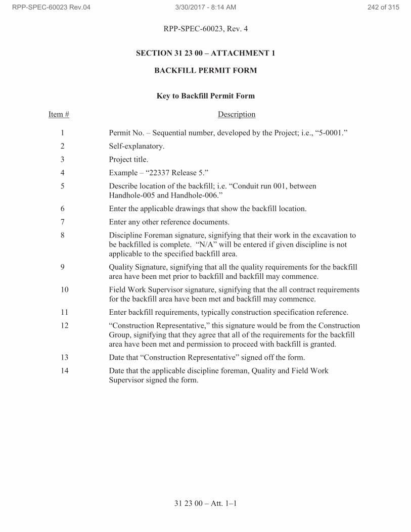
RPP-SPEC-60023, Rev. 4
31 23 00 – Att. 1–1
SECTION 31 23 00 – ATTACHMENT 1
BACKFILL PERMIT FORM
Key to Backfill Permit Form
Item # Description
1 Permit No. – Sequential number, developed by the Project; i.e., “5-0001.”
2 Self-explanatory.
3 Project title.
4 Example – “22337 Release 5.”
5 Describe location of the backfill; i.e. “Conduit run 001, between
Handhole-005 and Handhole-006.”
6 Enter the applicable drawings that show the backfill location.
7 Enter any other reference documents.
8 Discipline Foreman signature, signifying that their work in the excavation to
be backfilled is complete. “N/A” will be entered if given discipline is not
applicable to the specified backfill area.
9 Quality Signature, signifying that all the quality requirements for the backfill
area have been met prior to backfill and backfill may commence.
10 Field Work Supervisor signature, signifying that the all contract requirements
for the backfill area have been met and backfill may commence.
11 Enter backfill requirements, typically construction specification reference.
12 “Construction Representative,” this signature would be from the Construction
Group, signifying that they agree that all of the requirements for the backfill
area have been met and permission to proceed with backfill is granted.
13 Date that “Construction Representative” signed off the form.
14 Date that the applicable discipline foreman, Quality and Field Work
Supervisor signed the form.
RPP-SPEC-60023 Rev.04 3/30/2017 - 8:14 AM 242 of 315
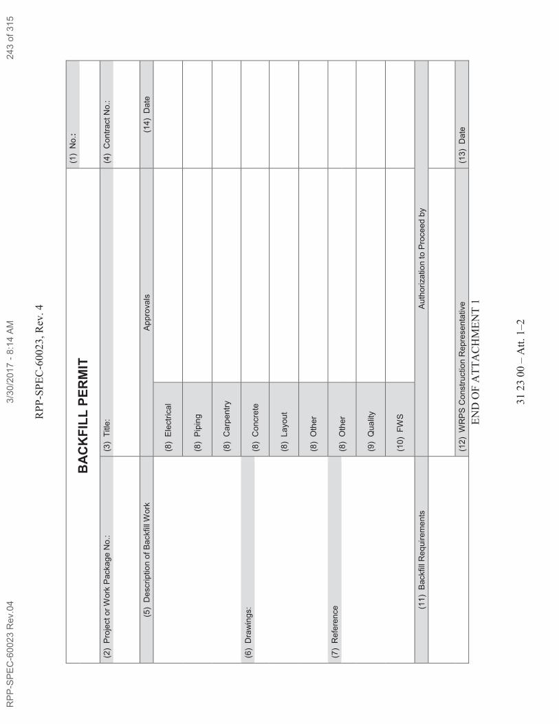
RP
P-S
PE
C-6
0023
, R
ev. 4
31 2
3 0
0 –
Att
. 1
–2
BA
CK
FIL
L P
ER
MIT
(1
) N
o.:
(2)
Pro
ject o
r W
ork
Packa
ge
No.:
(3
) T
itle
: (4
) C
on
tra
ct
No.:
(5)
Descri
ptio
n o
f B
ackfill
Work
A
pp
rova
ls
(14
) D
ate
(8
) E
lectr
ica
l
(8)
Pip
ing
(8)
Carp
en
try
(6)
Dra
win
gs:
(8)
Concre
te
(8)
La
yo
ut
(8)
Oth
er
(7)
Refe
ren
ce
(8)
Oth
er
(9)
Qu
alit
y
(10
) F
WS
(11
) B
ackfill
Re
quir
em
en
ts
Au
tho
riza
tio
n to
Pro
ce
ed
by
(12
) W
RP
S C
onstr
uctio
n R
epre
se
nta
tive
(1
3)
Date
EN
D O
F A
TT
AC
HM
EN
T 1
RP
P-S
PE
C-6
0023 R
ev.0
43/3
0/2
017 -
8:1
4 A
M243 o
f 315
RPP-SPEC-60023, Rev. 4
31 23 00 – Att. 2-1
SECTION 31 23 00 – ATTACHMENT 2
PROCEDURE FOR BACKFILL AND COMPACTION OF
EXISTING SOILS WITHIN TANK FARMS
PURPOSE
This procedure identifies a process for placement and compaction of soil backfill by a controlled
method. This procedure also defines the degree of compactive effort required to produce
acceptable in-place densities as an alternative to performing density tests with a nuclear density
gauge.
SCOPE
This procedure defines the requirements for placement and compaction of soil backfill including
inspection methods to verify the acceptability of the compacted backfill within Tank Farm areas
defined on project drawings. The compaction details in this were taken from Fluor Federal
Services Job Bulletin No. JB-RPP-041, Rev. 1, which has been accepted standard practice in the
Tank Farms.
In-place testing of compacted backfill including sand bedding by use of the nuclear density
gauge is not required for this procedure. Random periodic visual observation and monitoring of
the backfill operation and compactive effort shall be the basis for acceptance.
PROCEDURE
Compaction of backfill within the Tank Farms shall be controlled by adherence to this procedure
and defined compactive effort within established variables as defined below. Determination of
maximum standard density, from testing laboratory reports (proctors) or in situ values obtained
from nuclear gauge testing of undisturbed ground is not covered by this procedure.
Only materials as defined by the project specifications will be used for backfill. Keep materials
free of frozen particles, lumps, organic matter, and debris. Ensure that the area to be backfilled
is not frozen and the backfill material does not contain frozen material.
If sand is encountered during excavation perform the following for installation and compaction.
A. Excavate to proper installation depth. Use trench box if necessary.
B. Install pipe on stone free earth. Rake native soil or sand bed if required.
C. Cover pipe with 6” of 5/8” minus top course material.
Backfilling by means of sluicing or flooding with water is not permitted.
Backfill material shall be placed in loose uniform lifts not to exceed 8 in. in depth.
If needed, water shall be added and mixed with the backfill material before it is compacted to
achieve optimum moisture content.
Optimum moisture content shall be approximately 8.5% and may vary as much as plus or minus
2.5% depending on different soil types and gradations. The addition of water to cohesive soil
RPP-SPEC-60023 Rev.04 3/30/2017 - 8:14 AM 244 of 315
RPP-SPEC-60023, Rev. 4
31 23 00 – Att. 2-2
types shall be such that the material is easily compactable by mechanical manipulation as defined
in this procedure.
Backfill shall be brought up in layers. Each layer shall be compacted full width and length by
use of either pneumatic or gas powered compaction equipment such as a Wacker®32,
model
BS-600 manufactured by Wacker Corporation or equivalent. Alternatively, a pneumatic “Pogo
Stick” such as that manufactured by Jet Equipment or equivalent may be used. The use of “Pogo
Stick” compaction equipment shall be limited to use in small confined areas such as that found in
and around pipes and conduits and small excavations. Alternative compaction equipment may
be used if acceptable to the TOC Construction Representative. All equipment used shall be in
good working order capable of performing to manufacturer’s standards.
The compactive effort for each layer of backfill shall be as follows:
· If a Wacker or equivalent is used, a minimum of three complete passes shall be made.
· If a “Pogo Stick” type device is used, a minimum of eight complete passes is made.
One complete pass shall be defined as full rotation over the area being compacted. As a
minimum, a rotation shall be once over and once back across the area being compacted. The rate
of equipment travel shall be approximately 15 lineal feet per minute.
Water shall be added as necessary between individual passes to maintain the moisture content
within the optimum range.
Bring up backfill material evenly on each side of walls, structures, and pipeline in order to avoid
damaging or displacing them by unbalanced loading. Obtain written approval from the Tank
Operations Contractor, Washington River Protections Solutions, LLC, for variations from this
process that may result in uneven load distribution.
If backfill material is to be placed against or on top of newly poured concrete, ensure that the
concrete curing period has been achieved and concrete design strength achieved as required by
ACI 301. Backfill material shall not be placed against foundation walls before the curing period
is completed, unless written approval from the design engineer is obtained on the Backfill
Permit.
INSPECTION
Control of backfill placement, optimum moisture content, and compactive effort shall be
accomplished by visual surveillance. Surveillances shall be performed by a trained and qualified
soils technician.
Personnel performing oversight and surveillance of the backfill operations shall possess a
thorough working knowledge of earthwork and soils relative to material types and classification,
excavation methods and procedures, material gradation, fill and backfill operations, compaction
equipment and methods and moisture control. Oversight personnel shall have received training
to perform visual surveillances of backfill operations.
32
Wacker is a registered trademark of Wacker Neuson Production Americas, LLC, Menomonee Falls, Wisconsin.
RPP-SPEC-60023 Rev.04 3/30/2017 - 8:14 AM 245 of 315
RPP-SPEC-60023, Rev. 4
31 23 00 – Att. 2-3
Verification that soil moisture content is within the specified range shall be accomplished by
visual and physical examination of the wetted material. Cohesive soil containing the correct
optimum moisture content shall exhibit no evidence of saturation yet shall have enough moisture
to maintain shape when deformed. Physical examination of soil cohesion and plasticity shall be
the basis for determining proper moisture content.
The oversight person shall visually observe the backfill and compaction operation to verify
adherence to this procedure. Type of compaction equipment, use of equipment, depth of lifts,
number of passes and rate of travel shall be observed. Surveillances shall be documented on
surveillance reports.
The frequency of surveillances for backfill operations shall as a minimum be at the beginning of
backfilling for a project or job and at least daily thereafter while work is in progress.
END OF ATTACHMENT 2
RPP-SPEC-60023 Rev.04 3/30/2017 - 8:14 AM 246 of 315
RPP-SPEC-60023, Rev. 4
31 23 00 – Att. 3-1
SECTION 31 23 00 – ATTACHMENT 3
PROCEDURE FOR BACKFILL AND COMPACTION
OF 5/8 MINUS CRUSHED ROCK
PURPOSE
This procedure identifies a process for placement and compaction of 5/8 minus crushed rock
backfill by a controlled method. This procedure also defines the degree of compactive effort
required to produce acceptable in-place densities as an alternative to performing density tests
with a nuclear density gauge.
SCOPE
This procedure defines the requirements for placement and compaction of 5/8 minus crushed
rock backfill including inspection methods to verify the acceptability of the compacted backfill
within Tank Farm areas defined on project drawings. The compaction details in this were taken
from American Electric test plan 54891-006-TP-001.
In-place testing of compacted backfill by use of the nuclear density gauge is not required for this
procedure. Random periodic visual observation and monitoring of the backfill operation and
compactive effort shall be the basis for acceptance.
PROCEDURE
Compaction of 5/8 minus crushed rock backfill shall be controlled by adherence to this
procedure and defined compactive effort within established variables as defined below.
Keep materials free of frozen particles, lumps, organic matter, and debris. Ensure that the area to
be backfilled is not frozen and the backfill material does not contain frozen material.
Backfilling by means of sluicing or flooding with water is not permitted.
Backfill material shall be placed in loose uniform lifts not to exceed 6 in. in depth.
If needed, water shall be added and mixed with the backfill material before it is compacted to
achieve optimum moisture content.
Optimum moisture content shall be approximately 9.5 percent and may vary as much as plus or
minus 1.5 percent. The addition of water shall be such that the material is easily compactable by
mechanical manipulation as defined in this procedure.
Backfill shall be brought up in layers. Each layer shall be compacted full width and length by
use of a Wacker, model BS 50-2 or model WP 1550 AW manufactured by Wacker Corporation
or equivalent. All equipment used shall be in good working order capable of performing to
manufacturer’s standards.
The compactive effort for each layer of backfill shall be as follows:
RPP-SPEC-60023 Rev.04 3/30/2017 - 8:14 AM 247 of 315
RPP-SPEC-60023, Rev. 4
31 23 00 – Att. 3-2
If a Wacker BS 50-2 or equivalent is used, a minimum of 4 complete passes shall be made.
If a Wacker WP 1550 or equivalent is used, a minimum of 2 complete passes shall be made.
One complete pass shall be defined as full rotation over the area being compacted. As a
minimum, a rotation shall be once over and once back across the area being compacted. The rate
of equipment travel shall be approximately 15 lineal feet per minute.
Water shall be added as necessary between individual passes to maintain the moisture content
within the optimum range.
Bring up backfill material evenly on each side of walls, structures, and pipeline in order to avoid
damaging or displacing them by unbalanced loading. Obtain written approval from the TOC
Construction Representative for variations from this process that may result in uneven load
distribution.
If backfill material is to be placed against or on top of newly poured concrete, ensure that the
concrete curing period has been achieved and concrete design strength achieved as required by
ACI 301. Backfill material shall not be placed against foundation walls before the curing period
is completed, unless written approval from the design engineer is obtained on the Backfill
Permit.
INSPECTION
Control of backfill placement, optimum moisture content and compactive effort shall be
accomplished by visual surveillance. Surveillances shall be performed by a trained and qualified
soils technician.
Personnel performing oversight and surveillance of the backfill operations shall possess a
thorough working knowledge of earthwork and soils relative to material types and classification,
excavation methods and procedures, material gradation, fill and backfill operations, compaction
equipment and methods, and moisture control. Oversight personnel shall have received training
to perform visual surveillances of backfill operations.
Verification that soil moisture content is within the specified range shall be accomplished by
visual and physical examination of the wetted material.
The oversight person shall visually observe the backfill and compaction operation to verify
adherence to this procedure. Type of compaction equipment, use of equipment, depth of lifts,
number of passes, and rate of travel shall be observed. Surveillances shall be documented on
surveillance reports.
The frequency of surveillances for backfill operations shall as a minimum be at the beginning of
backfilling for a project or job and at least daily thereafter while work is in progress.
END OF ATTACHMENT 3
RPP-SPEC-60023 Rev.04 3/30/2017 - 8:14 AM 248 of 315
RPP-SPEC-60023, Rev. 4
33 10 00 – 1
SECTION 33 10 00
WATER UTILITIES
PART 1 GENERAL
1.1 SUMMARY
A. Material, fabrication, installation, and testing of below grade piping from the raw
water main line to the backflow preventer in the Air and Water Service Building
and of sewer piping to tie into the existing chemical drain line.
1.2 RELATED DOCUMENTS, CODES, AND STANDARDS
Drawings and general provisions of the Contract Statement of Work, including Division
01 Specification Sections, apply to this Section.
The following documents and others referenced therein form part of Contract to the
extent designated in this Section. Referenced documents are those current as of the date
of this Section unless otherwise indicated.
A. American Society of Mechanical Engineers (ASME)
ASME B16.11 Forged Fittings, Socket-Welding and Threaded
ASME B16.5 Pipe Flanges and Flanged Fittings NPS 1/2 through
NPS 24 Metric/ Inch Standard
ASME B31.9, 2014 Building Services Piping
ASME B40.1 Gauges: Pressure Indicating Dial Type — Elastic
Element
ASME B&PVC, 2013 Boiler and Pressure Vessel Code
Section VIII Rules for Construction of Pressure Vessels
Section IX Qualification Standard for Welding and Brazing
Procedures, Welders, Brazers, and Welding and
Brazing Operations
B. American Society for Nondestructive Testing (ASNT)
ASNT SNT-TC-1A Personnel Qualifications and Certification in
Nondestructive Testing
RPP-SPEC-60023 Rev.04 3/30/2017 - 8:14 AM 249 of 315
RPP-SPEC-60023, Rev. 4
33 10 00 – 2
C. American Society of Safety Engineers®33
(ASSE®33
)
ASSE 1013 Reduced Pressure Principle Backflow Preventers
and Reduced Pressure Principle Fire Protection
Backflow Preventers
D. ASTM International (ASTM)
ASTM A53 Standard Specification for Pipe, Steel, Black and
Hot-Dipped, Zinc-Coated, Welded and Seamless
ASTM A193 Standard Specification for Alloy-Steel and Stainless
Steel Bolting
ASTM A194 Standard Specification for Carbon and Alloy Steel
Nuts for Bolts for High Pressure
ASTM A865 Standard Specification for Threaded Couplings,
Steel, Black or Zinc-Coated (Galvanized) Welded
or Seamless, for use in Steel Pipe Joints
ASTM A536 Standard Specification for Ductile Iron Castings
ASTM A234 Standard Specification for Piping Fittings of
Wrought Carbon Steel and Alloy Steel for Moderate
and High Temperature Service
ASTM C547 Standard Specification for Mineral Fiber Pipe
Insulation
ASTM C552 Specifications for Cellular Glass Block and Pipe
Thermal Insulation
ASTM D2321 Standard Practice for Underground Installation of
Thermoplastic Pipe for Sewers and Other Gravity
Flow Applications
ASTM D2661 Standard Specification for Acrylonitrile-Butadiene-
Styrene (ABS) Schedule 40 Plastic Drain, Waste,
and Vent Pipe and Fittings
33
ASSE is a registered trademark of American Society of Safety Engineers, Des Plaines, Illinois.
RPP-SPEC-60023 Rev.04 3/30/2017 - 8:14 AM 250 of 315
RPP-SPEC-60023, Rev. 4
33 10 00 – 3
E. American Water Works Association (AWWA)
AWWA C104 Cement-Mortar Lining for Ductile-Iron Pipe and
Fitting for Water
AWWA C110 Ductile-Iron and Gray-Iron Fittings, 3 in. Through
48 in., for Water and Other Liquids
AWWA C111 Rubber-Gasket Joints for Ductile-Iron Pressure Pipe
and Fittings
AWWA C151 American National Standard for Ductile-Iron Pipe,
Centrifugally Cast, for Water
AWWA C153 Ductile-Iron Compact Fittings for Water Service
AWWA C223 Fabricated Steel and Stainless Steel Tapping
Sleeves
AWWA C509 Resilient-Seated Gate Valves for Water-Supply
Service
AWWA C511 Reduced-Pressure Principle Backflow Prevention
Assembly
AWWA C600 Standard for Installation of Ductile-Iron Water
Mains and Their Appurtenances
AWWA C800 Underground Service Line Valves and Fittings
AWWA M14 Recommended Practice for Backflow Prevention
and Cross-Connection Control
F. AWWA Pacific Northwest Section
Cross-Connection Control Manual Accepted
Procedures and Practices
G. International Association of Plumbing and Mechanical Officials (IAPMO)
UPC Uniform Plumbing Code (UPC)
H. National Fire Protection Association (NFPA)
NFPA 24 Standard for the Installation of Private Fire Service
Mains and Their Appurtenances
I. University of Southern California Foundation for Cross-Connection Control and
Hydraulic Research
RPP-SPEC-60023 Rev.04 3/30/2017 - 8:14 AM 251 of 315
RPP-SPEC-60023, Rev. 4
33 10 00 – 4
Manual of Cross-Connection Control
J. Washington Administrative Code (WAC)
WAC 246-290 Cross Connection Control
K. American Society for Nondestructive Testing (ASNT)
ASNT SNT-TC-1A Personnel Qualifications and Certification in
Nondestructive Testing
L. American Welding Society (AWS)
AWS QC1 Certification of Welding Inspectors
1.3 SUBMITTALS
A. See the Contract Statement of Work for the submittal process.
B. Approval Required
1. Gauges: After testing submit for approval vendor information showing
that gauges used in testing are calibrated and capable of measuring at least
1.5 times test pressure, but no more than 4 times test pressure.
2. Flushing: After testing submit for approval verification showing that the
flushing operations were performed for a sufficient time to ensure
thorough cleaning.
3. Mainline: After testing submit for approval verification showing that the
mainline is capable of sustaining a 200 psi load for 2 hours or at 50 psi in
excess of the maximum static pressure. Measure leakage in accordance
with NFPA 24, Article 8.9 for underground piping.
4. Welding Procedure Specifications and or Standard Welding Procedure
Specifications: Five days before first use or start of fabrication, submit
each in accordance with Paragraph 1.4.B.
5. Welding Personnel Qualifications: Five days before start of fabrication,
submit welder qualification as required by Paragraph 1.4.B.
6. Examination Documentation: Five days before start of fabrication submit
documentation in accordance with Paragraph 3.4.A.4 for
information/record.
7. Weld Examinations as required by Paragraph 3.4.A.
RPP-SPEC-60023 Rev.04 3/30/2017 - 8:14 AM 252 of 315
RPP-SPEC-60023, Rev. 4
33 10 00 – 5
C. Approval Not Required
1. Filter Vendor information: Submit two copies: Dimensional drawings;
Specifications; Installation, Operation, and Maintenance Instructions;
Spare Parts List.
1.4 QUALITY ASSURANCE
A. Misrepresented Products: See the Contract Statement of Work for required
measures to prevent use of misrepresented products.
B. Qualifications
1. Contractor’s Material and Test Certificate for Aboveground and
Underground Piping in accordance with Paragraph 3.4.B.3.
2. Qualification of Inspectors: A certified independent testing agency shall
perform all required inspections and testing.
3. Personnel performing visual examinations shall be Certified Welding
Inspectors (CWIs) who have received certification (current or previous
certification) in accordance with AWS QC1.
4. Personnel performing other nondestructive examinations (NDE) shall be
certified in accordance with approved procedure, which shall meet the
requirements of ASNT SNT-TC-1A. Use Level II or III personnel to
interpret results.
5. Examination Procedures: Examination procedures shall be in accordance
with ASME B31.9 and this Specification. Maintain copies of procedures
at the jobsite.
6. Pressure Testing Procedures: Pressure testing procedures shall be in
accordance with ASME B31.9 and this Specification. Maintain copies of
procedures at jobsite.
1.5 PERMITS
A. Permits are addressed by TOC work control process.
1.6 DELIVERY, STORAGE, AND HANDLING
A. See the Contract Statement of Work for general requirements.
PART 2 PRODUCTS
2.1 PRODUCT OPTIONS AND SUBSTITUTIONS
A. See the Contract Statement of Work for substitution approvals.
RPP-SPEC-60023 Rev.04 3/30/2017 - 8:14 AM 253 of 315
RPP-SPEC-60023, Rev. 4
33 10 00 – 6
2.2 MATERIALS
A. Sewer Pipe and Fittings: Materials shall be ABS plastic sewer pipe conforming to
the requirements of ASTM D2661.
B. Raw Water Pipe and Fittings Below Grade
1. Ductile Iron Pipe: AWWA C151, Class 150.
a. Joints: Push-on joints, AWWA C111 rubber gaskets.
b. Fittings: AWWA C110, Ductile-Iron or Gray-Iron, Class 250 or
AWWA C153, Ductile-Iron Compact Fittings, Class 250 or
XTRA FLEX®34
restrained joint high-deflection fittings.
c. Pipe and Fittings: Cement-mortar lining in accordance with
AWWA C104.
2. Galvanized Steel Pipe and Fittings: ASTM A53, type E or S, galvanized,
standard weight, Schedule 40.
a. Joints: Threaded.
b. Fittings: ASTM A865, threaded and galvanized
C. Valves
1. Gate Valves over 2 in.: AWWA C509, Underwriters Laboratories (UL)
listed or FM approved, Class 250, non-rising stem, open left, mechanical
joint inlet and outlet with mechanical joint unassembled accessories or
Mueller AquaGrip®35
System.
D. Tapping Sleeve: AWWA C223, fabricated steel, suitable for PVC, steel, ductile
iron, and cast iron pipe, outlet flange size and sleeve O.D. to suit piping system.
E. Valve Boxes: Cast-iron with top section and cover with lettering “WATER”
stamped on the cover, bottom section with base of size to fit over valve, barrel
approximately 5 in. in diameter, adjustable cast-iron extension of length required.
F. Gaskets: Gaskets containing asbestos are not permitted.
G. Tracer Wire: #10 AWG THHN/THWN, yellow, solid copper.
34
XTRA FLEX is a registered trademark of United States Pipe and Foundry Company, LLC, Birmingham,
Alabama. 35
AquaGrip is a trademark of Mueller International, LLC, Atlanta, Georgia.
RPP-SPEC-60023 Rev.04 3/30/2017 - 8:14 AM 254 of 315
RPP-SPEC-60023, Rev. 4
33 10 00 – 7
H. Flanges, Unions, and Couplings
1. Copper Tubing: AWWA C800.
2. Dielectric: Watts Series 3003.
3. Mechanical or Push-On Type Pipe, and Fittings Below Grade.
a. UL listed or FM approved.
b. Megalug®36
malleable iron retainer/restraint gland with epoxy or
bituminous outside coating and 1/2-in. minimum diameter asphalt
coated tie rods.
c. For PVC, use a compression connection and restraint system,
Mueller AquaGrip System.
I. Raw Water Pipe and Fittings from the Inlet to the Backflow Preventor
36
Megalug is a trademark of EBAA Iron Inc., Eastland, Texas.
RPP-SPEC-60023 Rev.04 3/30/2017 - 8:14 AM 255 of 315
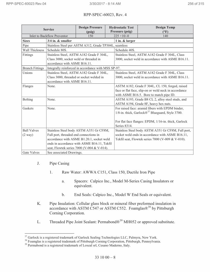
RPP-SPEC-60023, Rev. 4
33 10 00 – 8
Service Design Pressure
(psig)
Hydrostatic Test
Pressure (psig)
Design Temp
(°F)
Inlet to Backflow Preventor 150 225 +10/-0 140
Sizes 3/4 in. & smaller 1 in. & larger
Pipe Stainless Steel per ASTM A312, Grade TP304L, seamless
Wall Thickness Schedule 80S. Schedule 40S.
Fittings Stainless Steel, ASTM A182 Grade F 304L,
Class 3000, socket weld or threaded in
accordance with ASME B16.11.
Stainless Steel, ASTM A182 Grade F 304L, Class
3000, socket weld in accordance with ASME B16.11.
Branch Fittings Integrally reinforced in accordance with MSS SP-97.
Unions Stainless Steel, ASTM A182 Grade F 304L,
Class 3000, threaded or socket welded in
accordance with ASME B16.11.
Stainless Steel, ASTM A182 Grade F 304L, Class
3000, socket weld in accordance with ASME B16.11.
Flanges None. ASTM A182, Grade F 304L, CL 150, forged, raised
face or flat face, slip-on or weld neck in accordance
with ASME B16.5. Bore to match pipe ID.
Bolting None. ASTM A193, Grade B8 CL 2, alloy steel studs, and
ASTM A194, Grade 8F, heavy hex nuts.
Gaskets None. For raised face: aramid fibers with EPDM binder,
1/8-in. thick, Garlock®37
Blueguard, Style 3700.
For flat face flanges: EPDM, 1/16-in. thick, Garlock
Series 8314.
Ball Valves
(2 way)
Stainless Steel body ASTM A351 Gr CF8M,
Full port, threaded end connections in
accordance with ASME B1.20.1, socket weld
ends in accordance with ASME B16.11, Tekfil
seat, Flowtek series 7000 (V-004 & V-014).
Stainless Steel body ASTM A351 Gr CF8M, Full port,
socket weld ends in accordance with ASME B16.11,
Tekfil seat, Flowtek series 7000 (V-009 & V-010).
Gate Valves See associated Drawings.
J. Pipe Casing
1. Raw Water: AWWA C151, Class 150, Ductile Iron Pipe
a. Spacers: Calpico Inc., Model M-Series Casing Insulators or
equivalent.
b. End Seals: Calpico Inc., Model W End Seals or equivalent.
K. Pipe Insulation: Cellular glass block or mineral fiber preformed insulation in
accordance with ASTM C547 or ASTM C552. Foamglas®38
by Pittsburgh
Corning Corporation.
L. Threaded Pipe Joint Sealant: Permabond®39
MH052 or approved substitute.
37
Garlock is a registered trademark of Garlock Sealing Technologies LLC, Palmyra, New York. 38
Foamglas is a registered trademark of Pittsburgh Corning Corporation, Pittsburgh, Pennsylvania. 39
Permabond is a registered trademark of Loxeal srl, Cesano Maderno, Italy.
RPP-SPEC-60023 Rev.04 3/30/2017 - 8:14 AM 256 of 315
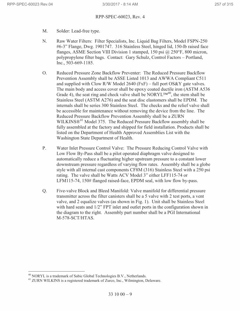
RPP-SPEC-60023, Rev. 4
33 10 00 – 9
M. Solder: Lead-free type.
N. Raw Water Filters: Filter Specialists, Inc. Liquid Bag Filters, Model FSPN-250
#6-3” Flange, Dwg. 1901747. 316 Stainless Steel, hinged lid, 150-lb raised face
flanges, ASME Section VIII Division 1 stamped, 150 psi @ 250°F, 800 micron,
polypropylene filter bags. Contact: Gary Schulz, Control Factors – Portland,
Inc., 503-669-1185.
O. Reduced Pressure Zone Backflow Preventer: The Reduced Pressure Backflow
Prevention Assembly shall be ASSE Listed 1013 and AWWA Compliant C511
and supplied with Clow R/W Model 2640 (FxF) – full port OS&Y gate valves.
The main body and access cover shall be epoxy coated ductile iron (ASTM A536
Grade 4), the seat ring and check valve shall be NORYL™40
, the stem shall be
Stainless Steel (ASTM A276) and the seat disc elastomers shall be EPDM. The
internals shall be series 300 Stainless Steel. The checks and the relief valve shall
be accessible for maintenance without removing the device from the line. The
Reduced Pressure Backflow Prevention Assembly shall be a ZURN
WILKINS®41
Model 375. The Reduced Pressure Backflow assembly shall be
fully assembled at the factory and shipped for field installation. Products shall be
listed on the Department of Health Approved Assemblies List with the
Washington State Department of Health.
P. Water Inlet Pressure Control Valve: The Pressure Reducing Control Valve with
Low Flow By-Pass shall be a pilot operated diaphragm valve designed to
automatically reduce a fluctuating higher upstream pressure to a constant lower
downstream pressure regardless of varying flow rates. Assembly shall be a globe
style with all internal cast components CF8M (316) Stainless Steel with a 250 psi
rating. The valve shall be Watts ACV Model 3” either LFF115-74 or
LFM115-74, 150# flanged raised-face, EPDM seal, with low flow by-pass.
Q. Five-valve Block and Bleed Manifold: Valve manifold for differential pressure
transmitter across the filter canisters shall be a 5 valve with 2 test ports, a vent
valve, and 2 equalize valves (as shown in Fig. 1). Unit shall be Stainless Steel
with hard seats and 1/2” FPT inlet and outlet ports in the configuration shown in
the diagram to the right. Assembly part number shall be a PGI International
M-578-SCT/HTAS.
40
NORYL is a trademark of Sabic Global Technologies B.V., Netherlands. 41
ZURN WILKINS is a registered trademark of Zurco, Inc., Wilmington, Delaware.
RPP-SPEC-60023 Rev.04 3/30/2017 - 8:14 AM 257 of 315
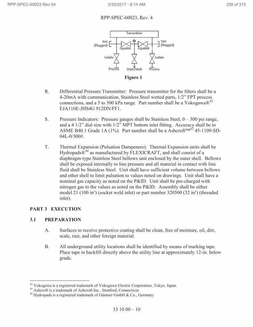
RPP-SPEC-60023, Rev. 4
33 10 00 – 10
R. Differential Pressure Transmitter: Pressure transmitter for the filters shall be a
4-20mA with communication, Stainless Steel wetted parts, 1/2” FPT process
connections, and a 5 to 500 kPa range. Part number shall be a Yokogawa®42
EJA110E-JHS4G 912DN/FF1.
S. Pressure Indicators: Pressure gauges shall be Stainless Steel, 0 – 300 psi range,
and a 4 1/2” dial size with 1/2” MPT bottom inlet fitting. Accuracy shall be to
ASME B40.1 Grade 1A (1%). Part number shall be a Ashcroft™43
45-1109-SD-
04L-0/300#.
T. Thermal Expansion (Pulsation Dampeners): Thermal Expansion units shall be
Hydropads®44
as manufactured by FLEXICRAFT, and shall consist of a
diaphragm-type Stainless Steel bellows unit enclosed by the outer shell. Bellows
shall be exposed internally to line pressure and all material in contact with line
fluid shall be Stainless Steel. Unit shall have sufficient volume between bellows
and other shell to limit pulsation to values noted on drawings. Unit shall have a
nominal gas capacity as noted on the P&ID. Unit shall be pre-charged with
nitrogen gas to the values as noted on the P&ID. Assembly shall be either
model 21 (100 in³) (socket weld inlet) or part number 320500 (32 in³) (threaded
inlet).
PART 3 EXECUTION
3.1 PREPARATION
A. Surfaces to receive protective coating shall be clean, free of moisture, oil, dirt,
scale, rust, and other foreign material.
B. All underground utility locations shall be identified by means of marking tape.
Place tape in backfill directly above the utility line at approximately 12-in. below
grade.
42
Yokogawa is a registered trademark of Yokogawa Electric Corporation, Tokyo, Japan. 43
Ashcroft is a trademark of Ashcroft Inc., Stratford, Connecticut. 44
Hydropads is a registered trademark of Güntner GmbH & Co., Germany.
Figure 1
RPP-SPEC-60023 Rev.04 3/30/2017 - 8:14 AM 258 of 315
RPP-SPEC-60023, Rev. 4
33 10 00 – 11
3.2 INSTALLATION
A. Raw Water Pipe and Fittings
1. Install pipe and pipe accessories in accordance with AWWA C600
(Ductile Iron), ASTM A234 (Steel), manufacturer’s instructions,
NFPA 24, UPC, the drawings, and this Section.
2. Install thrust restraint at all bends, tees, plugs, and caps in accordance with
NFPA 24, Article 8-6. If concrete thrust blocks are used, size in
accordance with details shown on the contract drawings.
3. Fabricate and install Stainless Steel welded pipe and fittings and
components in accordance with ASME B31.9, the Drawings, and this
Section.
4. Make joints in threaded piping system with specified joint sealant. Apply
sealant to male threads only.
5. Coat buried carbon steel accessories, such as tie-rods and clamps, with
16.0 mils of Bitumastic in one or two coats (10-24 hours between coats).
Allow 8 hours for Bitumastic to dry before backfilling.
6. Painting and Markings: See Section 09 91 00, “Painting,” for preparation
and painting.
B. Valve Orientation
1. Install valves as shown on Drawings where clearly illustrated.
2. Where orientation is not well illustrated, locate and orient valve to provide
accessibility for control and maintenance.
3. Valves shall be installed such that they are not used as means of support
for runs of piping or other components.
C. Sewer Drain Piping
1. Slope line 1/8 in. per ft (minimum) or as specified on drawings.
2. Install ABS or PVC pipeline in accordance with ASTM D2321 and the
drawings. In-line service testing of sewer pipe is permitted.
D. Reduced Pressure Zone Backflow Preventer
1. Install in accordance with WAC 246-290 recognized cross-connection
control manual installation specifications including but not limited to the
specifications found in “Cross Connection Control Manual, Accepted
RPP-SPEC-60023 Rev.04 3/30/2017 - 8:14 AM 259 of 315
RPP-SPEC-60023, Rev. 4
33 10 00 – 12
Procedures and Practices,” “Manual of Cross-Connection Control” or
AWWA M14.
E. Flanged Joints
1. Install flanges in accordance with manufacturer’s instructions.
2. Clean joint surfaces of the pipe, fittings and valves being joined.
3. Align flange of pipe, fitting, or valve to be installed with flange of
receiving pipe, fitting, or valve.
4. Support pipe, fittings, and valves being joined so that flanges are properly
aligned.
5. Lubricate bolts/studs and nuts prior to installation of bolts and nuts.
6. Clean gasket of sand, dirt, and other foreign matter. Inspect gasket for
damage/defects.
F. Pipe supports: Fabricate and install as shown on the Drawings, in accordance
with manufacturer’s instructions, Section 05 50 00, “Metal Fabrications,” and
applicable recommended procedures of MSS SP-58.
G. Weld Identification
1. Prepare weld identification drawings, isometric or spool, using existing
project Drawings as applicable which show relative positions of pressure-
containing welds and attachment welds to pressure-retaining components.
2. Assign weld numbers to pressure containing welds and attachment welds
to pressure-retaining components as made. Record weld number on weld
identification drawings as welds are made.
3. Do not reuse weld numbers. If a weld is completely replaced, assign a
new number.
3.3 FIELD QUALITY CONTROL
A. Flushing/Testing Preparation
1. Furnish equipment and instruments required to perform mechanical
cleaning.
2. Obtain direction for disposal of flushing water from TOC Construction
Representative. See the Contract Statement of Work.
B. Raw Water Line Flushing
RPP-SPEC-60023 Rev.04 3/30/2017 - 8:14 AM 260 of 315
RPP-SPEC-60023, Rev. 4
33 10 00 – 13
1. Flush raw water in accordance with NFPA 24, as applicable, for below
ground piping.
a. The underground pipe trench shall be partially backfilled between
joints before testing to prevent movement of pipe.
b. Notify Project Engineer at least five working days before flushing
of piping system for witnessing flush. Flushing to verify that new
lines are clean and acceptable.
c. Flush piping with water for five minutes minimum, and until
effluent is clean and contains no visible particulate matter.
Flushing pressure shall not exceed maximum operating pressure
specified for the system. Flushing water supply shall have
sufficient capacity to produce a full pipe (largest pipe size) flush.
d. Document flushing of each piping system on NFPA Form
“Contractor’s Material and Test Certificate for Aboveground and
Underground Piping,” in accordance with NFPA 24, as applicable,
and submit in accordance with Paragraph 1.3.
3.4 FIELD INSPECTIONS AND TESTS
A. Nondestructive Examination (NDE) of Welds
1. Perform examination for individual pipe sections. Acceptance Criteria,
unless otherwise noted by design, shall be in accordance with ASME
B31.9.
2. Perform visual examination (VT) on all completed welds in accordance
with ASME B31.9, Paragraph 936.
3. Perform random examination of piping support welds in accordance with
Section 05 50 00, “Metal Fabrications.”
4. Examination Documentation
a. Document examination of pressure containment welds for piping
systems on weld examination and test record. Record weld
identification drawings, weld numbers, welder identification,
welding procedure numbers, weld filler material, visual
examinations and notation of satisfactory completion of pressure
testing in accordance with instructions on form.
b. Required examinations shall be completed and documented before
starting leak testing.
RPP-SPEC-60023 Rev.04 3/30/2017 - 8:14 AM 261 of 315
RPP-SPEC-60023, Rev. 4
33 10 00 – 14
c. Weld Examination and Test Record information may be
incorporated on a single format or traveler for a specific work
package.
d. Document examination of attachment welds to pressure-retaining
components by recording on sketches or Weld Examination and
Test Record.
5. Final closure welds that cannot be isolated for testing shall be examined
in-process.
B. Raw Water Line Testing
1. Furnish instruments, facilities, and labor required to conduct tests.
2. Test gauges shall be calibrated and capable of measuring at least 1.5 times
test pressure, but no more than 4 times test pressure.
3. Document leak/pressure testing of each piping system on NFPA Form
“Contractor’s Material and Test Certificate for Aboveground or
Underground Piping,” in accordance with NFPA 24, as applicable, and
submit in accordance with 1.3.
4. Perform tests after lines have been flushed and before joints have been
backfilled for underground piping.
5. Remove all air from piping and adequately restrain pipe prior to
hydrostatic test for underground piping. The last thrust block poured shall
have cured a minimum of 7 days prior to test.
6. Test mainline at 200 psi for two hours or at 50 psi in excess of the
maximum static pressure and measure leakage of raw water lines in
accordance with NFPA 24, Article 8.9, for underground piping. Service
test trailer piping less than 3 in., use full mainline pressure for at least 30
minutes with no visible leaks or loss of test water. Repair any
unsatisfactory joints and retest.
7. Install a temporary relief valve during pressure test. Relief valve shall
have a discharge capacity of at least 125 percent of the pressurizing device
and be set to not more than 110 percent of the test pressure. Demonstrate
proper operation of relief valve before relief valve is attached to system
for leak test and whenever there is cause to question operating accuracy of
valve.
C. Sewer Line Testing
1. Before connecting to existing manhole, perform leak testing of pipe in
accordance with the Uniform Plumbing Code. Document test results.
RPP-SPEC-60023 Rev.04 3/30/2017 - 8:14 AM 262 of 315
RPP-SPEC-60023, Rev. 4
33 10 00 – 15
D. For Reduced Pressure Zone Backflow Preventer, verify and document the
following characteristics by visual inspection:
1. Device is installed in its proper orientation.
2. Device has been installed in accordance with the manufacturer’s
instructions.
END OF SECTION 33 10 00
RPP-SPEC-60023 Rev.04 3/30/2017 - 8:14 AM 263 of 315
RPP-SPEC-60023, Rev. 4
40 05 13 – 1
SECTION 40 05 13
PROCESS PIPING
PART 1 GENERAL
1.1 SUMMARY
A. Material, fabrication, installation, and testing of inside water piping beginning
after the backflow preventer and of outdoor below and above grade water piping
from the Air and Water Service Building to the Tank Farm Process Piping
manifolds.
1.2 RELATED DOCUMENTS, CODES, AND STANDARDS
Drawings and general provisions of the Contract Statement of Work, including Division
01 Specification Sections, apply to this Section.
The following documents and others referenced therein form part of Contract to the
extent designated in this Section. Referenced documents are those current as of the date
of this Section unless otherwise indicated.
A. American National Standards Institute (ANSI)
ANSI/ASME A13.1 Scheme for the Identification of Piping Systems
B. American Society of Mechanical Engineers (ASME)
ASME B&PVC, 2013 Boiler and Pressure Vessel Code
Section IX Qualification Standard for Welding and Brazing
Procedures, Welders, Brazers, and Welding and
Brazing Operations
ASME B16.9 Factory-Made Wrought Buttwelding Fittings
ASME B16.11 Forged Steel Fittings, Socket-Welding and
Threaded
ASME B31.9, 2014 Building Service Piping
C. American Society for Nondestructive Testing (ASNT)
ASNT SNT-TC-1A Personnel Qualifications and Certification in
Nondestructive Testing
RPP-SPEC-60023 Rev.04 3/30/2017 - 8:14 AM 264 of 315
RPP-SPEC-60023, Rev. 4
40 05 13 – 2
D. ASTM International (ASTM)
ASTM A182 Standard Specification for Forged or Rolled Alloy
and Stainless Steel Pipe Flanges
ASTM A194 Carbon and Alloy Steel Nuts for Bolts for High-Pressure and High-Temperature Service
ASTM A276 Standard Specification for Stainless Steel Bars and
Shapes
ASTM A312 Standard Specification for Seamless, Welded, and
Heavily Cold Worked Austenitic Stainless Steel
Pipes
ASTM A351 Standard Specification for Castings, Austenitic, for
Pressure-Containing Parts
ASTM A403 Wrought Austenitic Stainless Steel Piping Fittings
E. American Welding Society (AWS)
AWS D1.1, 2010 Structural Welding Code – Steel
AWS D1.3, 2008 Structural Welding Code – Sheet Steel
AWS D1.6, 2007 Structural Welding Code – Stainless Steel
AWS QC1 Certification of Welding Inspectors
F. Manufacturer’s Standardization Society (MSS)
MSS SP-58 Pipe Hangers and Supports – Materials, Design,
Manufacture, Selection, Application, and
Installation
MSS SP-69 Pipe Hangers and Supports – Selection and
Application
MSS SP-97 Integrally Reinforced Forged Branch Outlet Fittings
– Socket Welding, Threaded and Buttwelding Ends
G. Hanford Documents
TFC-ENG-STD-06 Design Loads for Tank Farm Facilities
TFC-ENG-STD-12 Tank Farm Equipment Identification Numbering
and Labeling Standard
TFC-ENG-STD-22 Piping, Jumpers, and Valves
RPP-SPEC-60023 Rev.04 3/30/2017 - 8:14 AM 265 of 315
RPP-SPEC-60023, Rev. 4
40 05 13 – 3
1.3 SUBMITTALS
A. See the Contract Statement of Work for the submittal process.
B. Approval Required
1. Welding Procedure Specifications and or Standard Welding Procedure
Specifications: Five days before first use or start of fabrication, submit
each in accordance with Paragraph 1.4.B.
2. Welding Personnel Qualifications: Five days before start of fabrication,
submit welder qualification as required by Paragraph 1.4.B.
3. Examination Documentation: Five days before start of fabrication submit
documentation in accordance with Paragraph 3.4.A.4 for
information/record.
4. Mechanical Cleaning Verification: Submit documentation in accordance
with Paragraph 3.3.B for information/record.
5. Weld Examinations as required by Paragraph 3.5.A.
6. Pressure and Leak Testing and Certification: Five days before pressure
testing, submit testing procedure in accordance with Paragraphs 1.4.C and
3.4.B.
C. Approval Not Required
1. O&M manuals for equipment.
1.4 QUALITY ASSURANCE
A. Misrepresented Products: See Contract Statement of Work for required measures
to prevent use of misrepresented products.
B. Qualifications of Structural Welding Personnel and Procedures.
1. Personnel and procedures for welding structural steel shall be in
accordance with Section 05 50 00, “Metal Fabrications.”
2. Qualification of Examination Personnel: Maintain copies of examination
personnel certifications and written examination performance procedures
at jobsite.
a. Personnel performing visual examinations shall be Certified
Welding Inspectors (CWIs) who have received certification
(current or previous certification) in accordance with AWS QC1.
RPP-SPEC-60023 Rev.04 3/30/2017 - 8:14 AM 266 of 315
RPP-SPEC-60023, Rev. 4
40 05 13 – 4
b. Personnel performing other nondestructive examinations (NDE)
shall be certified in accordance with approved procedure, which
shall meet the requirements of ASNT SNT-TC-1A. Use Level II
or III personnel to interpret results.
C. Qualification of Pressure Boundary Welders
1. For low-pressure systems, personnel and procedures for welding pressure-
retaining components, along with attachments hereto, shall be qualified in
accordance with ASME Section IX, except as modified by ASME B31.9,
Chapter V, Section 927.6.
D. Examination Procedures: Examination procedures shall be in accordance with
AWS D1.1, AWS D1.3, AWS D1.6, ASME Sec V as applicable, and this
Specification. Maintain copies of examination procedures at jobsite.
1. Qualification of Nondestructive Examination (NDE) personnel:
a. Visual weld examinations shall be performed and appropriate
documentation prepared by CWIs who have received certification
in accordance with AWS QC1. Certified Associate Welding
Inspections (CAWIs), certified in accordance with above standard,
may perform examinations when under immediate direction of
CWIs.
b. Personnel performing other NDE of welds shall be certified in
accordance with written practice, which shall meet requirements of
ASNT SNT-TC-1A. Use Level II or III personnel to interpret test
results.
2. Welding-related examination documentation shall be signed or stamped by
individuals performing examinations.
E. Pressure and Leak Testing Procedures: Pressure testing procedures shall be in
accordance with ASME B31.9 and this Specification. Maintain copies of
procedures at jobsite.
1.5 PERMITS
A. Permits are addressed by TOC work control process.
1.6 DELIVERY, STORAGE, AND HANDLING
A. See Contract Statement of Work for general requirements.
RPP-SPEC-60023 Rev.04 3/30/2017 - 8:14 AM 267 of 315
RPP-SPEC-60023, Rev. 4
40 05 13 – 5
PART 2 PRODUCTS
2.1 SUBSTITUTES
A. See Contract Statement of Work for substitution approvals.
2.2 MATERIALS
A. Piping and Fittings: See details specified on the Drawings and Components List
section below.
B. Pipe Supports: See details specified on the Drawings and in Section 05 50 00
“Metal Fabrications.” U-bolts to be Stainless Steel or plastic coated.
C. Pipe Joint Sealant (Lubricant) for Threaded Joints. Use anaerobic acrylic sealer.
Henkel Corporation: Loctite 5452 or 567 or engineering approved equivalent.
Clean threads and apply according to manufacturer’s specification.
D. Pipe covering protection saddle: B-Line B3160 and B3162, Stainless Steel, plain.
Diameter to match pipe diameter and insulation thickness as specified in Section
40 42 00, “Process Piping and Equipment Insulation.”
E. Protective Coating for above and below grade Stainless Steel Piping: Exterior
epoxy protection system, SEAGUARD MP, 5-6 mil thick, per Section 09 91 00,
“Painting,” and per manufacturer’s instructions.
F. Valves: Specified in the Components List section below, unless otherwise shown
on the Drawings.
G. Hoses: UFBX1 T316L hose, with series 300 SS braid, and with T304L Schedule
40S pipe ends for socket welding. Lengths, reducers, and 90° long and short
radius elbows, as shown on the Drawings, and within the specifications of B31.9.
Each hose description in the Bill of Materials on the Drawings is described in
order of hose assembly. All lengths shall be ±1/4” of the indicated dimension on
the Drawings. Hose braid collars shall be 3/4” long for 1” hose and 1” long for
1.5”, 2”, and 3” hose. Long and short radius elbows shall be according to ASME
B16.9 dimensions. Pipe end dimensions called out on the Drawings are
intentionally long. Field verify dimensions, and cut to length during installation
as required. Follow all manufacturers’ specifications, especially the minimum
live length for vibration, minimum static bend radius, and maximum offset.
H. Pipe Flanges and Gaskets: Specified in the Components List section below.
I. Heat Tracing: As shown on the Drawings and per Section 40 41 00, “Process
Piping and Equipment Heat Tracing.”
J. Pipe Insulation System: See Section 40 42 00, “Process Piping and Equipment
Insulation.”
RPP-SPEC-60023 Rev.04 3/30/2017 - 8:14 AM 268 of 315
RPP-SPEC-60023, Rev. 4
40 05 13 – 6
K. Cathodic Protection: See Section 13 47 13.13, “Cathodic Protection for
Underground and Submerged Piping.”
L. Buried Pipe Marker Tape: See Section 31 23 00, “Excavation and Fill.”
M. Penetration Sealants: RTV Silicone.
N. Anchors:
1. Concrete Anchor Blocks: See Section 03 30 00, “Concrete.”
2. Expansion Anchors: See Section 03 15 00, “Post-Installed Concrete
Anchor Bolts.”
3. Anchorage must be designed to TFC-ENG-STD-06.
2.3 EQUIPMENT
A. Thermal Expansion (Pulsation Dampeners): Thermal Expansion units shall be
Hydropads as manufactured by FLEXICRAFT, and shall consist of a diaphragm-
type Stainless Steel bellows unit enclosed by the outer shell. Bellows shall be
exposed internally to line pressure and all material in contact with line fluid shall
be Stainless Steel. Unit shall have sufficient volume between bellows and other
shell to limit pulsation to values noted on drawings. Unit shall have a nominal
gas capacity as noted on the P&ID. Unit shall be pre-charged with nitrogen gas to
the values as noted on the P&ID. Assembly shall be either model 22 (200 in³)
(socket weld inlet), model 21 (100 in³) (socket weld inlet), or part number 320500
(32 in³) (threaded inlet).
B. Pressure Indicators: Pressure gauges shall be Stainless Steel, 0 – 300 psi range,
and a 4 1/2” dial size with 1/2” MPT bottom inlet fitting. Accuracy shall be to
ASME B40.1 Grade 1A (1%). Part number shall be a Ashcroft 45-1109-SD-04L-
0/300#.
C. Flow Orifice: Flow orifices for outside building accessory lines shall be a 2”
O-ring union with orifice insert sized to approximately 5/8 in., Class 3000, socket
weld and Stainless Steel. Hart Industries, p/n O-3333-8-E-304L. Orifice shall be
sized for the flow specified on the P&ID and adjusted accordingly.
D. Leak detector elements as indicated in the Drawings.
2.4 FABRICATION
A. General
1. Verify measurements, including field measurements, before fabrication.
Provide miscellaneous bolts and anchors, supports, braces, and
connections necessary for completion of metal fabrications. Cut,
RPP-SPEC-60023 Rev.04 3/30/2017 - 8:14 AM 269 of 315
RPP-SPEC-60023, Rev. 4
40 05 13 – 7
reinforce, drill, and tap metal fabrications shown to receive finish
hardware and similar items. Weld or bolt connections as shown on the
Drawings.
2. Perform welding of steel connections in accordance with AWS D1.1, sheet
steel in accordance with AWS D1.3, and Stainless Steel in accordance
with AWS D1.6 and ASME B31.9.
B. Miscellaneous Steel Items: Supply required clips, frames, equipment supports,
and other fabrications not shown on the Drawings. Fabricate parts from standard
structural sections or shapes, to sizes required. Wherever miscellaneous parts are
exposed, grind edges, corners, and rough cuts smooth and free of snags. Shop
paint parts except those to be embedded in concrete, or those that require other
specific finishes.
C. Finishes
1. Prime ferrous metal (except Stainless Steel pipe) in accordance with
Section 09 91 00, “Painting.” Do not coat members to be embedded in
concrete, surfaces and edges to be field welded, or items to be galvanized.
Shop paint may extend into embedded areas where impractical to remove.
2. Stainless Steel piping shall not come in contact with galvanized surfaces.
PART 3 EXECUTION
3.1 PREPARATION
A. Surfaces to receive protective coating shall be clean, free of moisture, oil, dirt,
scale, rust, and other foreign material.
B. Prepare setting drawings, diagrams, templates, and instructions for installation of
anchorages, such as concrete inserts, anchor bolts, and miscellaneous items
having integral anchors, to be embedded in concrete. Coordinate with TOC
Construction Representative for delivery of items to Site.
3.2 INSTALLATION
A. General
1. Fabricate and install pipe and fittings and components in accordance with
ASME B31.9, the Drawings, and this Section.
RPP-SPEC-60023 Rev.04 3/30/2017 - 8:14 AM 270 of 315
RPP-SPEC-60023, Rev. 4
40 05 13 – 8
B. Valve Orientation
1. Install valves as shown on Drawings where clearly illustrated.
2. Where orientation is not well illustrated, locate and orient valve to provide
accessibility for control and maintenance.
3. Valves shall be installed such that they are not used as means of support
for runs of piping or other components.
4. Ball valves shall be installed such that, when open, the handle of the ball
valve is inline with the piping. The handle shall be turned clockwise to
close the valve.
C. Identification
1. An identification tag shall be supplied and attached to the equipment,
valves, and components. 1/4” stamped or engraved characters shall be
used on a Stainless Steel tag. The tag shall include the equipment
identification number (EIN) as identified on the P&ID.
2. Piping Identification: Identify in-building and above grade piping systems
as to fluid carried and direction of flow as specified in ANSI/ASME B13.1
and also Attachment 1.
D. Pipe
1. Cut pipe using methods that result in clean, straight cuts.
2. Ream pipe to nominal inside diameter after cutting. Remove burrs before
assembly.
3. Keep piping systems clean. Once fabrication has started, plug or cap ends
of piping when installation is not in progress. Cap or plug openings in
fabricated pipe spool assemblies until installation in piping system.
4. Install piping with slope specified on the Drawings.
5. Alignment: Distortion or cold springing of piping to bring it into
alignment for joint assembly that introduces a strain in piping components
is prohibited.
6. Field verify lengths of make-up spool pipe sections as called out on the
Drawings. Cut and weld to fit after all other spools are in place.
E. Make joints in threaded piping systems with joint sealant specified. Apply sealant
sparingly to male threads only.
RPP-SPEC-60023 Rev.04 3/30/2017 - 8:14 AM 271 of 315
RPP-SPEC-60023, Rev. 4
40 05 13 – 9
F. Flanged Joints
1. Install flanges in accordance with manufacturer’s instructions.
2. Clean joint surfaces of the pipe, fittings and valves being joined.
3. Align flange of pipe, fitting, or valve to be installed with flange of
receiving pipe, fitting, or valve.
4. Support pipe, fittings, and valves being joined so that flanges are properly
aligned.
5. Lubricate bolts/studs and nuts prior to installation of bolts and nuts.
6. Clean gasket of sand, dirt, and other foreign matter. Inspect gasket for
damage/defects.
7. Install flange isolation kits per manufacturer instructions on every flange
adjacent to a below grade section of piping.
G. Pipe covering protection saddles: Pressure boundary weld to pipe in accordance
with manufacturer’s instructions and located per drawings. Locate one centered
on bottom of pipe for all piping roller support locations. Locate one centered on
top of pipe for all piping roller support locations, except vertical expansion loops
as called out on the Drawings.
H. Pipe supports: Fabricate and install as shown on the Drawings, in accordance
with manufacturer’s instructions, Section 05 50 00, “Metal Fabrications,” and
applicable recommended procedures of MSS SP-58.
I. Expansion Anchors: See Section 03 15 00, “Post-Installed Concrete Anchor
Bolts.”
J. Tools marked for Stainless Steel shall be used on Stainless Steel only. Tools
previously used on carbon steel shall not be used on Stainless Steel. Areas on
Stainless Steel pipe that show signs of coming in contact with carbon steel (rust
marks or streaks) shall be cleaned of all free iron.
K. Below Grade Piping:
1. Trenches: Excavate, backfill, and compact in accordance with Section
31 23 00, “Excavation and Fill.”
2. Install insulation using temporary supports on undisturbed soil, or on
backfill placed and compacted in accordance with Section 31 23 00
“Excavation and Fill.” Install below grade insulation system prior to
backfilling trench in accordance with Section 40 42 00, “Process Piping
and Equipment Insulation.”
3. At piping bends provide cushions for thermal expansion according to
Section 40 42 00, Paragraph 2.2.D.
RPP-SPEC-60023 Rev.04 3/30/2017 - 8:14 AM 272 of 315
RPP-SPEC-60023, Rev. 4
40 05 13 – 10
L. Exterior Protective Coating for all Outside Above and Below Grade Piping:
1. Before coating application over joints, perform NDE, flushing, and
leak/pressure testing specified in this Section.
2. Protect Stainless Steel pipe, fittings, and pipe covering protection saddles
with coating specified above in Paragraph 2.2, “Materials,” in accordance
with Section 09 91 00, “Painting,” and manufacturer’s instructions.
3. After installation, examine pipe, joints, and fittings with electrical holiday
detector in accordance with manufacturer’s instructions.
4. Repair damage to coating in accordance with manufacturer’s
recommendations.
5. Do not install insulation system or backfill until coating has cured in
accordance with manufacturer’s recommendations.
M. Welding
1. Weld piping and attachments to pressure-retaining components in
accordance with ASME B31.9.
2. Use of backing rings is not permitted.
3. Complete piping welds before tie-in welds to fixed items.
4. Weld steel structural elements in accordance with AWS D1.1 or D1.6.
N. Weld Identification
1. Prepare weld identification drawings, isometric or spool, using existing
project Drawings as applicable which show relative positions of pressure-
containing welds and attachment welds to pressure-retaining components.
2. Assign weld numbers to pressure containing welds and attachment welds
to pressure-retaining components as made. Record weld number on weld
identification drawings as welds are made.
3. Do not reuse weld numbers. If a weld is completely replaced, assign a
new number.
4. Show heat/lot numbers on weld identification drawings for materials
requiring Certified Material Test Reports (CMTRs).
O. Perform examination, flushing, and leak/pressure testing, and connecting of heat
tracing before application of insulation and jacketing over joints and other
materials and components.
RPP-SPEC-60023 Rev.04 3/30/2017 - 8:14 AM 273 of 315
RPP-SPEC-60023, Rev. 4
40 05 13 – 11
P. Heat Trace: Install per Section 40 41 00, “Process Piping and Equipment Heat
Tracing.”
Q. Piping Insulation System: Install per Section 40 42 00, “Process Piping and
Equipment Insulation.”
3.3 FIELD QUALITY CONTROL
A. Flushing/Testing Preparation
1. Furnish equipment and instruments required to perform mechanical
cleaning.
2. Obtain direction for disposal of flushing water from TOC Construction
Representative. See the Contract Statement of Work.
B. Cleaning and Flushing
1. After examination is complete and before pressure testing system, or
before connecting system into existing systems, clean piping internal
surfaces by mechanical cleaning.
2. Mechanical cleaning: Remove loose dirt, scale, and debris by brushing,
wiping, high-pressure water jetting, blowing compressed air, or other
mechanical method approved by the TOC Construction Representative
until there is no visible dirt, scale, or debris.
a. When high-pressure water jetting or other mechanical cleaning
method utilizing water is used, and leak/pressure testing will not be
performed immediately after cleaning, remove all water.
b. Use drain taps at low point of piping system to ensure complete
drainage and drying. Cap lines or reconnect to system to maintain
cleanliness.
3. Provide documented evidence that flushing or mechanical cleaning has
been accomplished as specified in this Section.
3.4 FIELD INSPECTIONS AND TESTS
A. Nondestructive Examination (NDE) of Welds
1. Perform examination for individual pipe sections listed below in
Paragraph 3.5. Acceptance Criteria, unless otherwise noted by design,
shall be in accordance with ASME B31.9.
2. Visual examination (VT): Perform in accordance with ASME B31.9,
Paragraph 936.
RPP-SPEC-60023 Rev.04 3/30/2017 - 8:14 AM 274 of 315
RPP-SPEC-60023, Rev. 4
40 05 13 – 12
3. Perform random examination of piping support welds in accordance with
Section 05 50 00, “Metal Fabrications.”
4. Examination Documentation
a. Document examination of pressure containment welds for piping
systems on weld examination and test record. Record weld
identification drawings, weld numbers, welder identification,
welding procedure numbers, weld filler material, visual
examinations and notation of satisfactory completion of pressure
testing in accordance with instructions on form.
b. Required examinations shall be completed and documented before
starting leak testing.
c. Weld Examination and Test Record information may be
incorporated on a single format or traveler for a specific work
package.
d. Document examination of attachment welds to pressure-retaining
components by recording on sketches or Weld Examination and
Test Record.
5. Final closure welds that cannot be isolated for testing shall be examined
in-process.
B. Pressure and Leak Testing
1. After completion of mechanical cleaning and NDE, perform leak testing
of pipe in accordance with ASME B31.9 and this Section. Use calibrated
gages with an accuracy of ± 1 psi and with ranges 1-1/2 to 4 times test
pressure.
2. Document testing of each piping system on Pressure Test Certification.
Use separate forms to describe and record each piping system. Under
“Description” describe piping system in enough detail for correlation to
weld identification drawings, and Drawings, as applicable. For systems
tested segmentally, indicate continuity in “Description” to ensure that
entire systems have been tested.
3. Pipe joints and connections to be tested shall be visible and accessible
during tests.
4. Install one temporary relief valve during testing to protect piping against
over-pressurization. Tag each relief valve used to show serial number,
inspector, date, and pressure setting.
RPP-SPEC-60023 Rev.04 3/30/2017 - 8:14 AM 275 of 315
RPP-SPEC-60023, Rev. 4
40 05 13 – 13
5. Install necessary restraining devices, before applying test pressure, to
prevent distortion or displacement of piping. Remove temporary
restraining devices following testing.
6. Isolate instruments and other items which could be damaged by test
pressures.
7. Visually examine piping joints, fittings, and other potential leak sources,
including welds that attach wear plates, anchors, etc., to piping systems,
during testing.
8. Complete testing of piping before field application of insulation.
9. Purge air from piping systems during filling, before applying pressure.
10. Continuously maintain test pressure for 10 minutes minimum. Examine
joints and connections. Piping system, exclusive of possible localized
instances at pump or valve packing, shall show no visual evidence of
weeping or leaking.
11. Remove water from piping systems after testing using low point drains or
by applying low air pressure at connection points and blowing down the
lines.
12. Perform leak/pressure testing in accordance with ASME B31.9, Chapter
VI, Section 937, and this Section.
13. Support the final in-service leak test of the whole system to the extent
directed by the TOC Construction Representative.
3.5 SCHEDULES
A. Schedule of Pipe Weld NDE/Testing
RPP-SPEC-60023 Rev.04 3/30/2017 - 8:14 AM 276 of 315
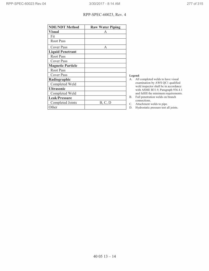
RPP-SPEC-60023, Rev. 4
40 05 13 – 14
NDE/NDT Method Raw Water Piping
Legend:
A. All completed welds to have visual
examination by AWS QC1 qualified
weld inspector shall be in accordance
with ASME B31.9, Paragraph 936.4.1
and fulfill the minimum requirements.
B. Full penetration welds on branch
connections.
C. Attachment welds to pipe.
D. Hydrostatic pressure test all joints.
Visual A
Fit
Root Pass
Cover Pass A
Liquid Penetrant
Root Pass
Cover Pass
Magnetic Particle
Root Pass
Cover Pass
Radiographic
Completed Weld
Ultrasonic
Completed Weld
Leak/Pressure
Completed Joints B, C, D
Other
RPP-SPEC-60023 Rev.04 3/30/2017 - 8:14 AM 277 of 315
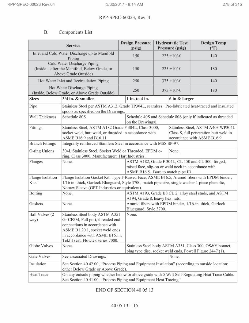
RPP-SPEC-60023, Rev. 4
40 05 13 – 15
B. Components List
Service Design Pressure
(psig)
Hydrostatic Test
Pressure (psig)
Design Temp
(°F)
Inlet and Cold Water Discharge up to Manifold
Piping 150 225 +10/-0 140
Cold Water Discharge Piping
(Inside – after the Manifold, Below Grade, or
Above Grade Outside)
150 225 +10/-0 180
Hot Water Inlet and Recirculation Piping 250 375 +10/-0 140
Hot Water Discharge Piping
(Inside, Below Grade, or Above Grade Outside) 250 375 +10/-0 180
Sizes 3/4 in. & smaller 1 in. to 4 in. 6 in & larger
Pipe Stainless Steel per ASTM A312, Grade TP304L, seamless. Pre-fabricated heat-traced and insulated
spools as specified on the Drawings.
Wall Thickness Schedule 80S. Schedule 40S and Schedule 80S (only if indicated as threaded
on the Drawings).
Fittings Stainless Steel, ASTM A182 Grade F 304L, Class 3000,
socket weld, butt weld, or threaded in accordance with
ASME B16.9 and B16.11.
Stainless Steel, ASTM A403 WP304L
Class S, full penetration butt weld in
accordance with ASME B16.9
Branch Fittings Integrally reinforced Stainless Steel in accordance with MSS SP-97.
O-ring Unions 304L Stainless Steel, Socket Weld or Threaded, EPDM o-
ring, Class 3000, Manufacturer: Hart Industries.
None.
Flanges None. ASTM A182, Grade F 304L, CL 150 and CL 300, forged,
raised face, slip-on or weld neck in accordance with
ASME B16.5. Bore to match pipe ID.
Flange Isolation
Kits
Flange Isolation Gasket Kit, Type F Raised Face, ASME B16.5, Aramid fibers with EPDM binder,
1/16 in. thick, Garlock Blueguard, Style 3700, match pipe size, single washer 1 piece phenolic,
Nomex Sleeve (GPT Industries or equivalent).
Bolting None. ASTM A193, Grade B8 CL 2, alloy steel studs, and ASTM
A194, Grade 8, heavy hex nuts.
Gaskets None. Aramid fibers with EPDM binder, 1/16-in. thick, Garlock
Blueguard, Style 3700.
Ball Valves (2
way)
Stainless Steel body ASTM A351
Gr CF8M, Full port, threaded end
connections in accordance with
ASME B1.20.1, socket weld ends
in accordance with ASME B16.11,
Tekfil seat, Flowtek series 7000.
None.
Globe Valves None. Stainless Steel body ASTM A351, Class 300, OS&Y bonnet,
plug type disc, socket weld ends, Powell Figure 2447 (1).
Gate Valves See associated Drawings. None.
Insulation See Section 40 42 00, “Process Piping and Equipment Insulation” (according to outside location:
either Below Grade or Above Grade).
Heat Trace On any outside piping whether below or above grade with 5 W/ft Self-Regulating Heat Trace Cable.
See Section 40 41 00, “Process Piping and Equipment Heat Tracing.”
END OF SECTION 40 05 13
RPP-SPEC-60023 Rev.04 3/30/2017 - 8:14 AM 278 of 315
RPP-SPEC-60023, Rev. 4
40 05 13 – Att. 1-1
SECTION 40 05 13 – ATTACHMENT 1
IDENTIFICATION OF PIPING SYSTEMS
1. GENERAL
Identification of piping systems shall be in accordance with the American Standard
Scheme for Identification of Piping Systems, ANSI/ASME A13.1, as supplemented
herein, and with TFC-ENG-STD-12, “Tank Farm Equipment Identification
Numbering and Labeling Standard.”
2. LOCATION
a. Except as provided below, identification shall be located adjacent to outlets,
valves, flanges, unions, changes-in-direction, where pipes through walls, floors,
or ceilings, and along an uninterrupted length of pipe at maximum intervals of
50 ft. Each line or branch in shall have a least one identification.
b. Where a number of outlets, valves, flanges, unions, or changes of direction make
identification at each item impracticable, they may be spaced at approximate 6-ft
intervals, preferably adjacent to valves.
c. Legend shall be located on pipe so that it can be read easily from operator’s
normal viewing position. Labels shall be placed on readily visible lower quadrant
of overhead pipes, an on an upper quadrant of pipes below normal eye level.
3. LEGEND
a. Positive identification of piping system content shall be by lettered legend giving
name of content in full or abbreviated form. Legends may also be as specified on
the Drawings or in other specifications.
b. Abbreviation of words in legend may be used only where unavoidable due to
space limitations.
c. Legend shall include nominal operating pressure and/or temperature when
specified.
d. An arrow indicating direction of flow shall be placed near legend on pipes
normally having a flow in 1 direction only. Color and size of arrow shall be
consistent with color and size of legend letters.
e. Legend shall be located on or adjacent to classification color band.
RPP-SPEC-60023 Rev.04 3/30/2017 - 8:14 AM 279 of 315
RPP-SPEC-60023, Rev. 4
40 05 13 – Att. 1-2
4. APPROVED LABELS
a. Legend and color classification may be accomplished by use of approved labels
that conform to this Standard and are suitable for temperature of surface to which
they are applied. Approved labels include the following:
Stock System #4 Pipe Markers
www.pipemarker.com
Brimar Industries
P.O. Box 467 / 64 Outwater Lane
Garfield NJ 07026
Ph: 800-274-6271
High Performance Pipe Markers
www.bradyid.com
Brady WORLDWIDE
6555 W. Good Hope Rd
Milwaukee, WI 53223
b. Single-word labels may be combined to form complete legends. Individual-letter
labels shall not be combined.
c. Labels shall be installed after painting is complete.
5. CLASSIFICATION COLOR shall conform to ANSI/ASME A13.1
END OF ATTACHMENT 1
RPP-SPEC-60023 Rev.04 3/30/2017 - 8:14 AM 280 of 315
RPP-SPEC-60023, Rev. 4
40 05 22 – 1
SECTION 40 05 22
HOSE-IN-HOSE TRANSFER LINE SYSTEM INSTALLATION
PART 1 GENERAL
1.1 SUMMARY
A. The hose-in-hose transfer line (HIHTL) will be located within the 241-AX Tank
Farm, 241-AZ Tank Farm, and the intra-farm area between the two tank farms.
The HIHTL system will connect the 241-AX waste retrieval equipment to a
portable above ground valve box assembly within the 241-AX Tank Farm and
from the valve box to designated connections in the 241-AZ tank farm. The
furnished HIHTL assemblies will consist of a flexible primary hose installed
within a secondary encasement hose. The primary hose will be wrapped with heat
tape and the secondary hose with insulation to prevent significant cooling of the
conveyed fluid as it flows through the assembly, minimizing the risk of plugging.
1.2 RELATED DOCUMENTS, CODES, AND STANDARDS
Drawings and general provisions of the Contract Statement of Work, including
Division 01 Specification Sections, apply to this Section.
The following documents and others referenced therein form part of Contract to the
extent designated in this Section. Referenced documents are those current as of the date
of this Section unless otherwise indicated.
A. American Society of Mechanical Engineers (ASME)
ASME B31.3, 2012 Process Piping
B. ASTM International (ASTM)
ASTM D380 Standard Test Methods for Rubber Hose
C. Hanford Documents
TFC-ENG-STD-21 Hose-in-Hose Transfer Line
RPP-14859 Specification for Hose-in-Hose Transfer Lines
D. Rubber Manufacturers Association (RMA)
RMA IP-2 Hose Handbook, Washington D.C.
E. Washington Administrative Code (WAC)
WAC 173-303 Dangerous Waste Regulations
RPP-SPEC-60023 Rev.04 3/30/2017 - 8:14 AM 281 of 315
RPP-SPEC-60023, Rev. 4
40 05 22 – 2
1.3 SUBMITTALS
A. See the Contract Statement of Work for the submittal process.
B. Approval Required
1. Pressure and Leak Testing and Certification: Five days before pressure
testing, submit two copies of testing procedure in accordance with
Paragraphs 1.4.B and 3.4.A.
C. Approval Not Required
1. Certified Material Test Reports (CMTRs): With delivery, submit two
copies of legible reports, certified by responsible manufacturer of
materials used in fabrication of pipe, fittings, flanges, and weld filler
material for the individual pipe sections listed below. Reports shall
present results of chemical analysis and physical tests specified in ASME,
ASTM, or AWS Codes or Standards as applicable and Standard
Specifications for production lots and heats of materials. Submit separate
reports for the individual pipe sections.
2. Material traceability shall be maintained through fabrication for material
requiring CMTRs.
1.4 QUALITY ASSURANCE
A. Misrepresented Products: See Contract Statement of Work for required measures
to prevent use of misrepresented products.
B. Pressure and Leak Testing Procedures: Pressure testing procedures shall be in
accordance with ASME B31.3 and this Specification. Maintain copies of
procedures at jobsite.
C. Assigned personnel to perform work have reviewed and are familiar with the
HIHTL system, associated handling recommendations, and the connection
methods for HIHTL assemblies.
D. Deleted.
1.5 DELIVERY, STORAGE, AND HANDLING
A. See Contract Statement of Work for general requirements.
B. Storage of the HIHTL materials shall be in accordance with the following:
1. Hose assembly shall be stored as shipped, on reel, in either vertical or
horizontal position.
RPP-SPEC-60023 Rev.04 3/30/2017 - 8:14 AM 282 of 315
RPP-SPEC-60023, Rev. 4
40 05 22 – 3
2. Hose assembly should be stored in its original shipping/packing materials
so that plastic wrapping and cardboard covering will provide some
protection against possible deteriorating elements. Additionally, if stored
outside, the material shall be covered with a tarpaulin or other protective
covering.
3. Hose ends shall be kept covered by wrapping in plastic and securing.
4. Exposure to direct and reflected sunlight should be avoided. If the hose is
exposed to the sun for a prolonged period, a section of hose should be
inspected for deterioration every two years. Inspect hose for any damage
to or holes in insulation and inspect fittings for visible damage.
5. Optimum storage area is in a covered area that is cool and dark, and free
of dampness and mildew.
6. Maximum shelf life is 7 years.
PART 2 PRODUCTS
2.1 SUBSTITUTES
A. See Contract Statement of Work for substitution approvals.
2.2 MATERIALS
A. Unless otherwise noted on drawings, HIHTL system materials, including the
portable valve box, will be Government Furnished Equipment (GFE).
1. The HIHTL is classified as Safety Significant.
2. HIHTLs shall be in accordance with TFC-ENG-STD-21.
B. Bolt thread lubricant (high stress compound, anti-seize).
C. Calibrated torque wrenches.
D. Deleted.
E. Shielding materials as indicated on Drawings.
F. Deleted.
PART 3 EXECUTION
3.1 PREPARATION
A. Examine designated routing for the HIHTL systems and notify TOC Construction
Representative in writing of conditions detrimental to proper and timely
completion of work. Do not proceed with work until unsatisfactory conditions
have been addressed and/or corrected.
RPP-SPEC-60023 Rev.04 3/30/2017 - 8:14 AM 283 of 315
RPP-SPEC-60023, Rev. 4
40 05 22 – 4
B. Assigned personnel to perform work have reviewed and are familiar with the
HIHTL system, associated handling recommendations, and the connection
methods for HIHTL assemblies.
C. Prepare routing path and tie-in connections for installation of HIHTL assemblies.
Coordinate with TOC Construction Representative for delivery of materials to the
site.
3.2 INSTALLATION
A. Install HIHTL assemblies as shown on the Drawings.
B. Use care in unwrapping plastic and cardboard to avoid damage to hose, fittings,
and heat trace.
C. If a spindle is used to unroll hose, provisions must be in place to slow the reel as it
unwinds to control the roll off of the hose.
D. Never pull on HIHTL assemblies by the ends alone. Use a choker strap at some
point along the hose length.
E. If temperatures have been below 32ºF, the hose may be stiff and require warming
before installation. Notify TOC Construction Representative for instructions if
warming is required.
F. Leave assembly connections covered and protected until in place to actually
connect assembly to equipment.
G. Connect primary hose joints using a qualified quality controlled procedure per
manufacturer’s directions.
1. Primary hose connections are male to female ChemJoint.
2. The male and female threads have been treated with Everlube, a dry film
lubricant. No additional lubricant or anti-seize material should be applied.
3. The o-ring should have one white and two yellow dots visible indicating it
is the specified material, EPDM.
4. Verify cleanliness, correct o-ring, and then join the hose assembly.
5. Torque for the ChemJoint fitting is 200 ft-lbs or hand tight plus 1 to 1-1/2
notches of the nut. Contact TOC Construction Representative for
clarification on turn of the nut torque method from vendor information.
6. Apply set screws and tighten with 1/8-inch Allen wrench to the point that
the ChemJoint nut cannot turn.
H. Test primary hose in accordance with Paragraph 3.4.A.
RPP-SPEC-60023 Rev.04 3/30/2017 - 8:14 AM 284 of 315
RPP-SPEC-60023, Rev. 4
40 05 22 – 5
I. Prior to final joining of secondary hose connections, verify heat trace is spliced
and/or heat trace lead is clear of the joint and available for termination.
J. Connect secondary hose joints using a qualified quality controlled procedure per
manufacturer’s directions.
1. Secondary hose connections will be one of two types. One joint will be
flange connector consisting of 6 inch, 150 lb raised face flange that would
bolt directly to a mating flange on equipment/valve box. The other joint
will be a threaded union end connector consisting of a 6 inch, 150 lb
raised face flange that would connect to another hose assembly and/or
equipment.
2. Make both of these connections in accordance with details shown on the
Drawings.
3. Verify cleanliness of the visible area of hose and connection.
4. Apply approved lubricant to flange bolt threads and tighten in sequence
that uniformly loads the gasket. For connections using raised face flanges
with EPDM gaskets, final torque bolts to 40 ft-lbs.
K. Below Grade HIHTL
1. Trenches: Excavate in accordance with Section 31 23 00, “Excavation
and Fill.”
2. Deleted.
3. Deleted.
4. Backfill and compact in accordance with the drawings.
L. Deleted.
1. Deleted.
2. Deleted.
3. Deleted.
4. Deleted.
5. Deleted.
M. Deleted.
RPP-SPEC-60023 Rev.04 3/30/2017 - 8:14 AM 285 of 315
RPP-SPEC-60023, Rev. 4
40 05 22 – 6
3.3 FIELD QUALITY CONTROL
A. Notify TOC Construction Representative prior to installation of HIHTL for
witnessing of activities by Independent Qualified Registered Professional
Engineer (IQRPE), as required by WAC 173-303.
B. Perform visual inspection of encasement hose for damage. Minor cosmetic
damage to the insulation is acceptable. If visible damage is present, inspect for
potential leak paths and notify TOC Construction Representative. If suspect,
remove hose from service and retest.
C. Inspect the HIHTL assembly end connections and ensure they are clean and free
of debris.
D. Inspect the hose assemblies and connections described in Paragraph 3.2. Verify
final connections have been properly assembled and torqued.
E. Refer to Section 40 41 00, “Process Piping and Equipment Heat Tracing,” for heat
trace testing requirements.
F. Perform visual inspection of equipment insulation for excessive damage. Minor
cosmetic damage to the insulation is acceptable. Record results.
G. Verify a minimum of 2 inch of soil cover is in place above the hose assembly
prior to installation of cover plates.
3.4 FIELD INSPECTIONS AND TESTS
A. Pressure and Leak Testing
1. Install one temporary relief valve during testing to protect HIHTL against
over-pressurization. Tag each relief valve used to show serial number,
inspector, date, and pressure setting.
2. Joints and connections to be tested shall be visible and accessible during
tests.
3. Isolate instruments and other items which could be damaged by test
pressures.
4. Deleted.
5. Deleted.
a. Deleted.
i. Deleted.
ii. Deleted.
RPP-SPEC-60023 Rev.04 3/30/2017 - 8:14 AM 286 of 315
RPP-SPEC-60023, Rev. 4
40 05 22 – 7
b. Deleted.
6. Perform leak test for primary hose connection per TFC-ENG-STD-21.
Note: Leak testing per this section will be performed on components that
have already been hydrostatically tested as subassemblies per ASME
B31.3.
a. Leak testing of the HIHTL primary hose assembly connections
shall be performed by visual observation. The connection leak
testing shall be performed with water at the interfacing water
system pressure except when (a) there is no waste transfer system
valve downstream of the connection; or (b) closing the valve with
water flowing causes a flow transient (water hammer) that could
damage safety-significant waste transfer system structures,
systems, or components (SSCs). For this leak test, the interfacing
water system pressure is maintained at the connection for at least
10 min. If there is no valve downstream of the connection or
closing the valve causes an unacceptable water hammer, leak
testing is allowed with water flowing through the connection. This
leak test requires a minimum water flow of 200 gal through the
connection after flow is established in the line. If leak testing with
water is not practical (i.e., no available water source), leak testing
may be performed at the beginning of the initial waste transfer
through the connection. This leak test also requires a minimum
waste flow of 200 gal through the connection after flow is
established in the line.
Leakage observed at the HIHTL primary hose assembly
connections during the leak test shall be eliminated. Subsequent
leak testing of HIHTL primary hose assembly connections is not
required unless the connection is unmade and remade.
7. Secondary Hose
a. Perform pneumatic pressure test of the encasement hose at 10 +/- 2
psig. Maintain pressure for 10 minutes. Apply soap bubble
solution to ensure no leakage at connections and any other location
specified by the TOC Construction Representative. Where
isolation of a connection is not possible, perform a final visual
examination of the joint configuration/makeup to verify it
conforms to the Drawings. Record results. The PRV shall be set
at ≤ 50 psig. The secondary hoses have a minimum design
pressure of 60 psig (or greater) and therefore a PRV setting of 50
psig does not pose a safety concern.
RPP-SPEC-60023 Rev.04 3/30/2017 - 8:14 AM 287 of 315
RPP-SPEC-60023, Rev. 4
40 05 22 – 8
8. Document testing of each HIHTL system on Pressure Test Certification.
Use separate forms to describe and record each system. Under
“Description” describe HIHTL system in enough detail for correlation to
Drawings, as applicable. For systems tested segmentally, indicate
continuity in “Description” to ensure that entire systems have been tested.
END OF SECTION 40 05 22
RPP-SPEC-60023 Rev.04 3/30/2017 - 8:14 AM 288 of 315
RPP-SPEC-60023, Rev. 4
40 24 10 – 1
SECTION 40 24 10
CHEMICAL PIPING
PART 1 GENERAL
1.1 SUMMARY
A. Material, fabrication, installation, and testing of above and below grade chemical
piping, equipment, and fittings for transferring sodium hydroxide (up to 50%
solution) and oxalic acid (up to 8%).
1.2 RELATED DOCUMENTS, CODES, AND STANDARDS
Drawings and general provisions of the Contract Statement of Work, including
Division 01 Specification Sections, apply to this Section.
The following documents and others referenced therein form part of Contract to the
extent designated in this Section. Referenced documents are those current as of the date
of this Section unless otherwise indicated.
A. American National Standards Institute (ANSI)
ANSI/ASME A13.1 Scheme for the Identification of Piping Systems
B. American Society of Mechanical Engineers (ASME)
ASME B&PVC, 2013 Boiler and Pressure Vessel Code
Section V Nondestructive Examination
Section IX Qualification Standard for Welding and
Brazing Procedures, Welders, Brazers, and
Welding and Brazing Operations
ASME B16.5 Pipe Flanges and Flanged Fittings
ASME B16.9 Factory-Made Wrought Buttwelding Fittings
ASME B31.3, 2012 Process Piping
C. American Society for Nondestructive Testing (ASNT)
ASNT SNT-TC-1A Personnel Qualifications and Certification in
Nondestructive Testing
RPP-SPEC-60023 Rev.04 3/30/2017 - 8:14 AM 289 of 315
RPP-SPEC-60023, Rev. 4
40 24 10 – 2
D. ASTM International (ASTM)
ASTM A182 Standard Specification for Forged or Rolled Alloy
and Stainless Steel Pipe Flanges
ASTM A193 Standard Specification for Alloy-Steel and Stainless Steel Bolting for High Temperature or High Pressure Service and Other Special Purpose Applications
ASTM A194 Carbon and Alloy Steel Nuts for Bolts for High-Pressure and High-Temperature Service
ASTM A276 Standard Specification for Stainless Steel Bars and
Shapes
ASTM A312 Standard Specification for Seamless, Welded, and
Heavily Cold Worked Austenitic Stainless Steel
Pipes
ASTM A351 Standard Specification for Castings, Austenitic, for
Pressure-Containing Parts
ASTM A403 Wrought Austenitic Stainless Steel Piping Fittings
E. American Welding Society (AWS)
AWS D1.1, 2010 Structural Welding Code – Steel
AWS D1.3, 2008 Structural Welding Code – Sheet Steel
AWS D1.6, 2007 Structural Welding Code – Stainless Steel
AWS QC1 Certification of Welding Inspectors
F. Manufacturer’s Standardization Society (MSS)
MSS SP-58 Pipe Hangers and Supports – Materials, Design,
Manufacture, Selection, Application, and
Installation
MSS SP-69 Pipe Hangers and Supports – Selection and
Application
MSS-SP-97 Integrally Reinforced Forged Branch Outlet Fittings
– Socket Welding, Threaded and Buttwelding Ends
G. Hanford Documents
RPP-SPEC-60023 Rev.04 3/30/2017 - 8:14 AM 290 of 315
RPP-SPEC-60023, Rev. 4
40 24 10 – 3
TFC-ENG-STD-06 Design Loads for Tank Farm Facilities
TFC-ENG-STD-12 Tank Farm Equipment Identification Numbering
and Labeling Standard
TFC-ENG-STD-22 Piping, Jumpers, and Valves
1.3 SUBMITTALS
A. See the Contract Statement of Work for the submittal process.
B. Approval Required
1. Welding Procedure Specifications and/or Standard Welding Procedure
Specifications: Five days before first use or start of fabrication, submit
procedures as required by Paragraph 1.4.B.
2. Welding Personnel Qualifications: Five days before start of fabrication,
submit welder qualification as required by Paragraph 1.4.B.
3. Examination Documentation: Five days before start of fabrication, submit
documentation in accordance with Paragraph 3.4.A.6 for
information/record.
4. Mechanical Cleaning Verification: Submit documentation in accordance
with Paragraph 3.3.B for information/record.
5. Weld Examinations as required by Paragraph 3.5.A.
6. Pressure and Leak Testing and Certification: Five days before pressure
testing, submit testing procedure in accordance with Paragraphs 1.4.C and
3.4.B.
C. Approval Not Required
1. O&M manuals for equipment.
2. Vendor information: Before installation, submit the following
information.
a. For Filter, submit: Dimensional drawings; Specifications;
Installation, Operation, and Maintenance Instructions; Spare Parts
List.
b. For Flow Meter, submit: Dimensional drawings; Specifications;
Installation, Operation, and Maintenance Instructions; Spare Parts
List.
RPP-SPEC-60023 Rev.04 3/30/2017 - 8:14 AM 291 of 315
RPP-SPEC-60023, Rev. 4
40 24 10 – 4
1.4 QUALITY ASSURANCE
A. Misrepresented Products: See Contract Statement of Work for required measures
to prevent use of misrepresented products.
B. Qualifications of Structural Welding Personnel and Procedures.
1. Personnel and procedures for welding structural steel shall be in
accordance with Section 05 50 00, “Metal Fabrications.”
2. Qualification of Examination Personnel: Maintain copies of examination
personnel certifications and written examination performance procedures
at jobsite.
a. Personnel performing visual examinations shall be Certified
Welding Inspectors (CWIs) who have received certification
(current or previous certification) in accordance with AWS QC1.
b. Personnel performing other nondestructive examinations (NDEs)
shall be certified in accordance with approved procedure, which
shall meet the requirements of ASNT SNT-TC-1A. Use Level II
or III personnel to interpret results.
C. Qualification of Pressure Boundary Welders
1. For low-pressure systems, personnel and procedures for welding pressure-
retaining components, along with attachments hereto, shall be qualified in
accordance with ASME Section IX, except as modified by ASME B31.3,
Chapter V, Paragraph 328.2.
D. Examination Procedures: Examination procedures shall be in accordance with
AWS D1.1, AWS D1.3, AWS D1.6, ASME Section V, and ASME B31.3 as
applicable, and this Specification. Maintain copies of examination procedures at
jobsite.
1. Qualification of NDE personnel:
a. Visual weld examinations shall be performed and appropriate
documentation prepared by CWIs who have received certification
in accordance with AWS QC1. Certified Associate Welding
Inspections (CAWIs), certified in accordance with above standard,
may perform examinations when under immediate direction of
CWIs.
b. Personnel performing other NDE of welds shall be certified in
accordance with written practice, which shall meet requirements of
ASNT SNT-TC-1A. Use Level II or III personnel to interpret test
results.
RPP-SPEC-60023 Rev.04 3/30/2017 - 8:14 AM 292 of 315
RPP-SPEC-60023, Rev. 4
40 24 10 – 5
2. Welding-related examination documentation shall be signed or stamped by
individuals performing examinations.
E. Pressure and Leak Testing Procedures: Pressure testing procedures shall be in
accordance with ASME B31.3 and this Specification. Maintain copies of
procedures at jobsite.
1.5 PERMITS
A. Permits are addressed by TOC work control process.
1.6 DELIVERY, STORAGE, AND HANDLING
A. See Contract Statement of Work for general requirements.
PART 2 PRODUCTS
2.1 SUBSTITUTES
A. See Contract Statement of Work for substitution approvals.
2.2 MATERIALS
A. Piping and Fittings: See details specified on the Drawings and in Paragraph
3.5.B, “Components List.”
B. Pipe Supports: Unless otherwise specified in the details on the Drawings and in
Section 05 50 00 “Metal Fabrications,” use standard components in accordance
with MSS SP-69 that satisfy the criteria of MSS SP-58. U-bolts to be Stainless
Steel or plastic coated.
C. Pipe Joint Sealant (Lubricant) for Threaded Joints. Use anaerobic acrylic sealer.
Henkel Corporation: Loctite 5452 or 567 or engineering approved equivalent.
Clean threads and apply according to manufacturer’s specification.
D. Pipe covering protection saddle: B-Line B3162, Stainless Steel, plain. Diameter
to match pipe diameter and insulation thickness as specified in Section 40 42 00,
“Process Piping and Equipment Insulation.”
E. Protective Coating for above and below grade Stainless Steel Piping: Exterior
epoxy protection system, SEAGUARD MP, 5-6 mil thick, per Section 09 91 00,
“Painting,” and per manufacturer’s instructions.
F. Valves: As shown on the Drawings.
G. Pipe Flanges and Gaskets: Specified on the Drawings and in Paragraph 3.5.B,
“Components List.”
RPP-SPEC-60023 Rev.04 3/30/2017 - 8:14 AM 293 of 315
RPP-SPEC-60023, Rev. 4
40 24 10 – 6
H. Heat Tracing: As shown on the Drawings and per Section 40 41 00, “Process
Piping and Equipment Heat Tracing.”
I. Pipe Insulation System: See Section 40 42 00, “Process Piping and Equipment
Insulation.”
J. Cathodic Protection: See Section 13 47 13.13, “Cathodic Protection for
Underground and Submerged Piping.”
K. Flange and Valve Safety Spray Shields: TFE Spra-Gard®45
(Ramco
Manufacturing Company, Inc) or equivalent.
L. Buried Pipe Marker Tape: See Section 31 23 00, “Excavation and Fill.”
M. Penetration Sealants: RTV Silicone.
N. Anchors:
1. Concrete Anchor Blocks: See Section 03 30 00, “Concrete.”
2. Expansion Anchors: See Section 03 15 00, “Post-Installed Concrete
Anchor Bolts.”
3. Anchorage must be designed to TFC-ENG-STD-06.
2.3 EQUIPMENT
A. As specified on the Drawings.
2.4 FABRICATION
A. General
1. Verify measurements, including field measurements, before fabrication.
Provide miscellaneous bolts and anchors, supports, braces, and
connections necessary for completion of metal fabrications. Cut,
reinforce, drill, and tap metal fabrications shown to receive finish
hardware and similar items. Weld or bolt connections as shown on the
Drawings.
2. Perform welding of steel connections in accordance with AWS D1.1, sheet
steel in accordance with AWS D1.3, and Stainless Steel in accordance
with AWS D1.6 and ASME B31.3.
B. Miscellaneous Steel Items: Supply required clips, frames, equipment supports,
and other fabrications not shown on the Drawings. Fabricate parts from standard
structural sections or shapes, to sizes required. Wherever miscellaneous parts are
45
Spra-Gard is a registered trademark of Ramco Manufacturing Company, Inc., Kenilworth, New Jersey.
RPP-SPEC-60023 Rev.04 3/30/2017 - 8:14 AM 294 of 315
RPP-SPEC-60023, Rev. 4
40 24 10 – 7
exposed, grind edges, corners, and rough cuts smooth and free of snags. Shop
paint parts except those to be embedded in concrete, or those that require other
specific finishes.
C. Finishes
1. Prime ferrous metal (except Stainless Steel Piping) in accordance with
Section 09 91 00, “Painting.” Do not coat members to be embedded in
concrete, surfaces and edges to be field welded, or items to be galvanized.
Shop paint may extend into embedded areas where impractical to remove.
2. Stainless Steel piping shall not come in contact with galvanized surfaces.
PART 3 EXECUTION
3.1 PREPARATION
A. Surfaces to receive protective coating shall be clean, free of moisture, oil, dirt,
scale, rust, and other foreign material.
B. Prepare setting drawings, diagrams, templates, and instructions for installation of
anchorages, such as concrete inserts, anchor bolts, and miscellaneous items
having integral anchors, to be embedded in concrete. Coordinate with TOC
Construction Representative for delivery of items to Site.
3.2 INSTALLATION
A. General
1. Fabricate and install pipe, fittings, and components in accordance with
ASME B31.3, the Drawings and this Section.
B. Valves
1. Install valves orientated as shown on Drawings where clearly illustrated.
2. Valves shall be installed such that they are not used as means of support
for runs of piping or other components.
3. Ball valves shall be installed such that, when open, the handle of the ball
valve is inline with the piping. The handle shall be turned clockwise to
close the valve.
C. Identification
1. An identification tag shall be supplied and attached to the equipment,
valves, and components. 1/4” stamped or engraved characters shall be
used on a Stainless Steel tag. The tag shall include the equipment
identification number (EIN) as identified on the P&ID.
RPP-SPEC-60023 Rev.04 3/30/2017 - 8:14 AM 295 of 315
RPP-SPEC-60023, Rev. 4
40 24 10 – 8
2. Piping Identification: Identify above grade piping systems as to fluid
carried and direction of flow as specified in ANSI/ASME B13.1 and also
Section 40 05 13, “Process Piping,” Attachment 1, “Identification of
Piping Systems.”
D. Pipe
1. Cut pipe using methods that result in clean, straight cuts.
2. Ream pipe to nominal inside diameter after cutting. Remove burrs before
assembly.
3. Keep piping systems clean. Once fabrication has started, plug or cap ends
of piping when installation is not in progress. Cap or plug openings in
fabricated pipe spool assemblies until installation in piping system.
4. Alignment: Distortion or cold springing of piping to bring it into
alignment for joint assembly that introduces a strain in piping components
is prohibited.
5. Field verify lengths of make-up spool pipe sections as called out on the
Drawings. Cut and weld to fit after all other spools are in place.
E. Make joints in threaded piping systems with joint sealant specified. Apply sealant
sparingly to male threads only.
F. Flanged Joints
1. Install flanges in accordance with manufacturer’s instructions.
2. Clean joint surfaces of the pipe, fittings and valves being joined.
3. Align flange of pipe, fitting, or valve to be installed with flange of
receiving pipe, fitting, or valve.
4. Support pipe, fittings, and valves being joined so that flanges are properly
aligned.
5. Lubricate bolts/studs and nuts prior to installation of bolts and nuts.
6. Clean gasket of sand, dirt, and other foreign matter. Inspect gasket for
damage/defects.
7. Install flange isolation kits per manufacturer instructions on every flange
adjacent to a below grade section of piping.
8. Field install flange safety spray shields at all temporary hose connections
per manufacturer’s instructions.
RPP-SPEC-60023 Rev.04 3/30/2017 - 8:14 AM 296 of 315
RPP-SPEC-60023, Rev. 4
40 24 10 – 9
G. Pipe covering protection saddles: Pressure boundary weld to pipe in accordance
with manufacturer’s instructions and located per drawings. Locate one centered
on bottom of pipe for all piping roller support locations. Locate one centered on
top of pipe for all piping roller support locations, except vertical expansion loops
as called out on the Drawings.
H. Pipe supports: Fabricate and install as shown on the Drawings, in accordance
with manufacturer’s instructions, Section 05 50 00, “Metal Fabrications,” and
applicable recommended procedures of MSS SP-58.
I. Expansion Anchors: See Section 03 15 00, “Post-Installed Concrete Anchor
Bolts.”
J. Tools marked for Stainless Steel shall be used on Stainless Steel only. Tools
previously used on carbon steel shall not be used on Stainless Steel. Areas on
Stainless Steel pipe that show signs of coming in contact with carbon steel (rust
marks or streaks) shall be cleaned of all free iron.
K. Below Grade Piping:
1. Trenches: Excavate, backfill, and compact in accordance with
Section 31 23 00, “Excavation and Fill.”
2. Install insulation using temporary supports on undisturbed soil, or on
backfill placed and compacted in accordance with Section 31 23 00,
“Excavation and Fill.” Install below grade insulation system prior to
backfilling trench in accordance with Section 40 42 00, “Process Piping
and Equipment Insulation.”
3. At piping bends, provide cushions for thermal expansion according to
Section 40 42 00, “Process Piping and Equipment Insulation,”
Paragraph 2.2.D.
L. Exterior Protective Coating for all Outside Above and Below Grade Piping:
1. Before coating application over joints, perform NDE, flushing, and
leak/pressure testing specified in this Section.
2. Protect Stainless Steel pipe, fittings, and pipe covering protection saddles
with coating specified in Paragraph 2.2, “Materials,” in accordance with
Section 09 91 00, “Painting,” and manufacturer’s instructions.
3. After installation, examine pipe, joints, and fittings with electrical holiday
detector in accordance with manufacturer’s instructions.
4. Repair damage to coating in accordance with manufacturer’s
recommendations.
RPP-SPEC-60023 Rev.04 3/30/2017 - 8:14 AM 297 of 315
RPP-SPEC-60023, Rev. 4
40 24 10 – 10
5. Do not install insulation system or backfill until coating has cured in
accordance with manufacturer’s recommendations.
M. Welding
1. Weld piping and attachments to pressure-retaining components in
accordance with ASME B31.3.
2. Use of backing rings is not permitted.
3. Complete piping welds before tie-in welds to fixed items.
4. Weld steel structural elements in accordance with AWS D1.1 or D1.6.
N. Weld Identification
1. Prepare weld identification drawings, isometric or spool, using existing
project Drawings as applicable which show relative positions of pressure-
containing welds and attachment welds to pressure-retaining components.
2. Assign weld numbers to pressure-containing welds and attachment welds
to pressure-retaining components as made. Record weld number on weld
identification drawings as welds are made.
3. Do not reuse weld numbers. If a weld is completely replaced, assign a
new number.
4. Show heat/lot numbers on weld identification drawings for materials
requiring Certified Material Test Reports (CMTRs).
O. Perform examination, flushing, and leak/pressure testing, and connecting of heat
tracing before application of insulation and jacketing over joints and other
materials and components.
P. Heat Trace: Install per Section 40 41 00, “Process Piping and Equipment Heat
Tracing.”
Q. Piping Insulation System: Install per Section 40 42 00, “Process Piping and
Equipment Insulation.”
3.3 FIELD QUALITY CONTROL
A. Flushing/Testing Preparation
1. Furnish equipment and instruments required to perform mechanical
cleaning.
2. Obtain direction for disposal of flushing water from TOC Construction
Representative. See the Contract Statement of Work.
RPP-SPEC-60023 Rev.04 3/30/2017 - 8:14 AM 298 of 315
RPP-SPEC-60023, Rev. 4
40 24 10 – 11
B. Cleaning and Flushing
1. After examination is complete and before pressure testing system, or
before connecting system into existing systems, clean piping internal
surfaces by mechanical cleaning.
2. Mechanical cleaning: Remove loose dirt, scale, and debris by brushing,
wiping, high-pressure water jetting, blowing compressed air, or other
mechanical method approved by the TOC Construction Representative
until there is no visible dirt, scale, or debris.
a. When high-pressure water jetting or other mechanical cleaning
method utilizing water is used, and leak/pressure testing will not be
performed immediately after cleaning, remove all water.
b. Use drain taps at low point of piping system to ensure complete
drainage and drying. Cap lines or reconnect to system to maintain
cleanliness.
3. Provide documented evidence that flushing or mechanical cleaning has
been accomplished as specified in this Section.
3.4 FIELD INSPECTIONS AND TESTS
A. Nondestructive Examination (NDE) of Welds
1. Perform examination for individual pipe sections listed below in
Paragraph 3.5. Acceptance Criteria, unless otherwise noted by design,
shall be in accordance with ASME B31.3, “Normal Service.”
2. Visual examination (VT): Perform in accordance with ASME B31.3,
Paragraph 341.4.1(a). Acceptance criteria shall be in accordance with
Table 341.3.2.
3. Perform in-process examination in accordance with ASME B31.3,
Paragraph 344.7. Liquid penetrant inspection shall be performed in
accordance with ASME B&PVC, Section V, Article 7 on root and final
weld surfaces when in-process examination is performed.
4. Radiographic examination (RT): Perform in accordance with ASME
B&PVC, Section V, Article 2 and ASME B31.3, Paragraph 344.5.2.
Acceptance criteria shall be in accordance with ASME B31.3, Table
341.3.2.
a. Identify radiographic film with weld identification number, weld
spool identification and project or work order number assigned to
work covered by this Section.
RPP-SPEC-60023 Rev.04 3/30/2017 - 8:14 AM 299 of 315
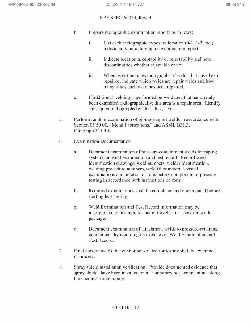
RPP-SPEC-60023, Rev. 4
40 24 10 – 12
b. Prepare radiographic examination reports as follows:
i. List each radiographic exposure location (0-1, 1-2, etc.)
individually on radiographic examination report.
ii. Indicate location acceptability or rejectability and note
discontinuities whether rejectable or not.
iii. When report includes radiographs of welds that have been
repaired, indicate which welds are repair welds and how
many times each weld has been repaired.
c. If additional welding is performed on weld area that has already
been examined radiographically; this area is a repair area. Identify
subsequent radiographs by “R-1, R-2,” etc.
5. Perform random examination of piping support welds in accordance with
Section 05 50 00, “Metal Fabrications,” and ASME B31.3,
Paragraph 341.4.1.
6. Examination Documentation
a. Document examination of pressure containment welds for piping
systems on weld examination and test record. Record weld
identification drawings, weld numbers, welder identification,
welding procedure numbers, weld filler material, visual
examinations and notation of satisfactory completion of pressure
testing in accordance with instructions on form.
b. Required examinations shall be completed and documented before
starting leak testing.
c. Weld Examination and Test Record information may be
incorporated on a single format or traveler for a specific work
package.
d. Document examination of attachment welds to pressure-retaining
components by recording on sketches or Weld Examination and
Test Record.
7. Final closure welds that cannot be isolated for testing shall be examined
in-process.
8. Spray shield installation verification: Provide documented evidence that
spray shields have been installed on all temporary hose connections along
the chemical route piping.
RPP-SPEC-60023 Rev.04 3/30/2017 - 8:14 AM 300 of 315
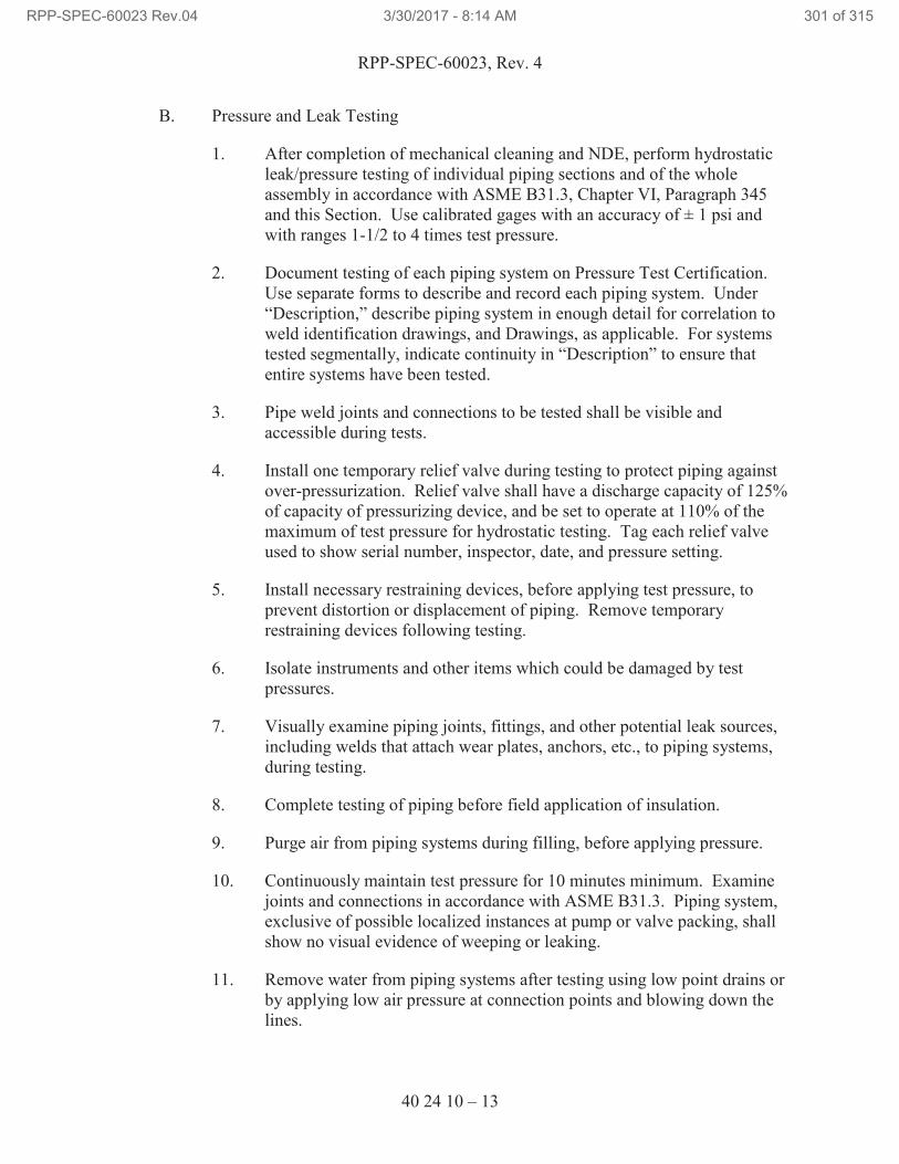
RPP-SPEC-60023, Rev. 4
40 24 10 – 13
B. Pressure and Leak Testing
1. After completion of mechanical cleaning and NDE, perform hydrostatic
leak/pressure testing of individual piping sections and of the whole
assembly in accordance with ASME B31.3, Chapter VI, Paragraph 345
and this Section. Use calibrated gages with an accuracy of ± 1 psi and
with ranges 1-1/2 to 4 times test pressure.
2. Document testing of each piping system on Pressure Test Certification.
Use separate forms to describe and record each piping system. Under
“Description,” describe piping system in enough detail for correlation to
weld identification drawings, and Drawings, as applicable. For systems
tested segmentally, indicate continuity in “Description” to ensure that
entire systems have been tested.
3. Pipe weld joints and connections to be tested shall be visible and
accessible during tests.
4. Install one temporary relief valve during testing to protect piping against
over-pressurization. Relief valve shall have a discharge capacity of 125%
of capacity of pressurizing device, and be set to operate at 110% of the
maximum of test pressure for hydrostatic testing. Tag each relief valve
used to show serial number, inspector, date, and pressure setting.
5. Install necessary restraining devices, before applying test pressure, to
prevent distortion or displacement of piping. Remove temporary
restraining devices following testing.
6. Isolate instruments and other items which could be damaged by test
pressures.
7. Visually examine piping joints, fittings, and other potential leak sources,
including welds that attach wear plates, anchors, etc., to piping systems,
during testing.
8. Complete testing of piping before field application of insulation.
9. Purge air from piping systems during filling, before applying pressure.
10. Continuously maintain test pressure for 10 minutes minimum. Examine
joints and connections in accordance with ASME B31.3. Piping system,
exclusive of possible localized instances at pump or valve packing, shall
show no visual evidence of weeping or leaking.
11. Remove water from piping systems after testing using low point drains or
by applying low air pressure at connection points and blowing down the
lines.
RPP-SPEC-60023 Rev.04 3/30/2017 - 8:14 AM 301 of 315
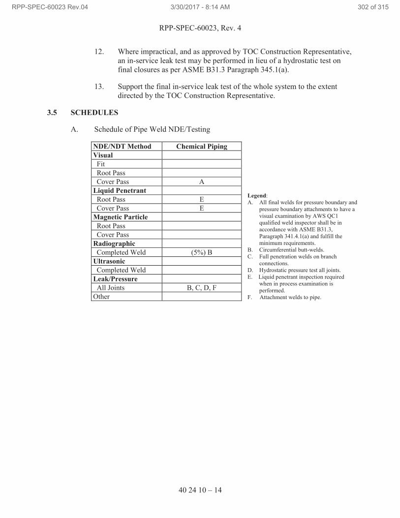
RPP-SPEC-60023, Rev. 4
40 24 10 – 14
12. Where impractical, and as approved by TOC Construction Representative,
an in-service leak test may be performed in lieu of a hydrostatic test on
final closures as per ASME B31.3 Paragraph 345.1(a).
13. Support the final in-service leak test of the whole system to the extent
directed by the TOC Construction Representative.
3.5 SCHEDULES
A. Schedule of Pipe Weld NDE/Testing
NDE/NDT Method Chemical Piping
Legend:
A. All final welds for pressure boundary and
pressure boundary attachments to have a
visual examination by AWS QC1
qualified weld inspector shall be in
accordance with ASME B31.3,
Paragraph 341.4.1(a) and fulfill the
minimum requirements.
B. Circumferential butt-welds.
C. Full penetration welds on branch
connections.
D. Hydrostatic pressure test all joints.
E. Liquid penetrant inspection required
when in process examination is
performed.
F. Attachment welds to pipe.
Visual
Fit
Root Pass
Cover Pass A
Liquid Penetrant
Root Pass E
Cover Pass E
Magnetic Particle
Root Pass
Cover Pass
Radiographic
Completed Weld (5%) B
Ultrasonic
Completed Weld
Leak/Pressure
All Joints B, C, D, F
Other
RPP-SPEC-60023 Rev.04 3/30/2017 - 8:14 AM 302 of 315
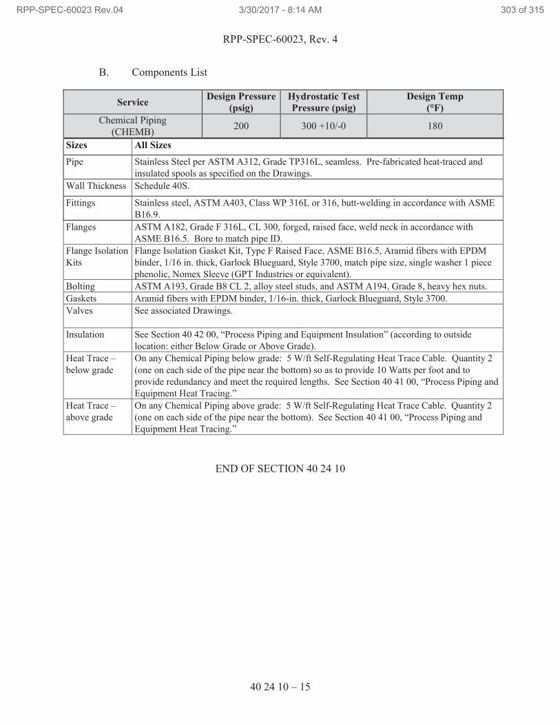
RPP-SPEC-60023, Rev. 4
40 24 10 – 15
B. Components List
Service Design Pressure
(psig)
Hydrostatic Test
Pressure (psig)
Design Temp
(°F)
Chemical Piping
(CHEMB) 200 300 +10/-0 180
Sizes All Sizes
Pipe Stainless Steel per ASTM A312, Grade TP316L, seamless. Pre-fabricated heat-traced and
insulated spools as specified on the Drawings.
Wall Thickness Schedule 40S.
Fittings Stainless steel, ASTM A403, Class WP 316L or 316, butt-welding in accordance with ASME
B16.9.
Flanges ASTM A182, Grade F 316L, CL 300, forged, raised face, weld neck in accordance with
ASME B16.5. Bore to match pipe ID.
Flange Isolation
Kits
Flange Isolation Gasket Kit, Type F Raised Face, ASME B16.5, Aramid fibers with EPDM
binder, 1/16 in. thick, Garlock Blueguard, Style 3700, match pipe size, single washer 1 piece
phenolic, Nomex Sleeve (GPT Industries or equivalent).
Bolting ASTM A193, Grade B8 CL 2, alloy steel studs, and ASTM A194, Grade 8, heavy hex nuts.
Gaskets Aramid fibers with EPDM binder, 1/16-in. thick, Garlock Blueguard, Style 3700.
Valves
See associated Drawings.
Insulation See Section 40 42 00, “Process Piping and Equipment Insulation” (according to outside
location: either Below Grade or Above Grade).
Heat Trace –
below grade
On any Chemical Piping below grade: 5 W/ft Self-Regulating Heat Trace Cable. Quantity 2
(one on each side of the pipe near the bottom) so as to provide 10 Watts per foot and to
provide redundancy and meet the required lengths. See Section 40 41 00, “Process Piping and
Equipment Heat Tracing.”
Heat Trace –
above grade
On any Chemical Piping above grade: 5 W/ft Self-Regulating Heat Trace Cable. Quantity 2
(one on each side of the pipe near the bottom). See Section 40 41 00, “Process Piping and
Equipment Heat Tracing.”
END OF SECTION 40 24 10
RPP-SPEC-60023 Rev.04 3/30/2017 - 8:14 AM 303 of 315
RPP-SPEC-60023, Rev. 4
40 41 00 – 1
SECTION 40 41 00
PROCESS PIPING AND EQUIPMENT HEAT TRACING
PART 1 GENERAL
1.1 SCOPE OF WORK
A. Installation and testing of above and below grade water and process piping and
hoses heat tracing.
1.2 RELATED DOCUMENTS / CODES AND STANDARDS
Drawings and general provisions of the contract, including General and Supplementary
Conditions and Division 01 Specification Sections apply to this Section.
The following documents and others referenced therein, form part of the Contract to the
extent designated in this Section. Referenced documents are those current as of the date
of this Section unless otherwise indicated.
A. American National Standards Institute (ANSI)
ANSI A13.1 Scheme for the Identification of Piping Systems
B. National Fire Protection Association (NFPA)
NFPA 70, 2014 National Electrical Code (NEC)
C. Hanford Documents
TFC-ENG-STD-02 Environmental and Seasonal Requirements for TOC
Systems, Structures, and Components
1.3 SUBMITTALS
A. See the Contract Statement of Work for the submittal process.
B. Approval Required
1. Submit test procedures to be used with acceptance criteria prior to testing.
2. Submit records of inspections, tests, and adjustments described in 3.3.
C. Approval Not Required
1. Catalog Data: With delivery, submit two copies of catalog data for heater
cable, thermostat, controls, fittings, indicator lights, and pipe markers.
RPP-SPEC-60023 Rev.04 3/30/2017 - 8:14 AM 304 of 315
RPP-SPEC-60023, Rev. 4
40 41 00 – 2
2. Includes rated capacities, operating characteristics, specialties, and
accessories.
3. Operation and Maintenance Data: With delivery, submit two copies of
operation and maintenance instructions.
4. Warranty: Manufacturer agreement for replacement of electric heating
cable due to failure in materials or workmanship.
1.4 QUALITY ASSURANCE
A. Misrepresented Products: See the Statement of Work or required measures to
prevent use of misrepresented products.
B. Products shall be obtained from qualified suppliers, meeting NEC requirements,
or be commercial grade items (CGI) meeting acceptance criteria specified in this
Section. Commercial grade dedication will be performed by Buyer.
1.5 DELIVERY, STORAGE, AND HANDLING
A. See the Contract Statement of Work for general requirements.
B. Receive, store, protect, and handle products according to manufacturer’s
instructions.
PART 2 PRODUCTS
2.1 SUBSTITUTES
A. See the Statement of Work for substitution approvals.
2.2 MATERIALS
A. General
1. Furnish electric heat tracing system(s) as shown on the Drawings with all
components, controls, and accessories required for a complete and
operating system.
2. Self-Regulating, Parallel-Resistance Heating Cable System
3. 5 W/ft Self-Regulating Heat Trace Cable, 120V. Raychem 5BTV1-CT
(for truck fill piping on the northwest corner of the 241-A-285 building,
and where specified on the drawings).
4. 5 W/ft Self-Regulating Heat Trace Cable, 240V. Raychem 5BTV2-CT.
5. 8 W/ft Self-Regulating Heat Trace Cable, 240V. Raychem 8BTV2-CT.
RPP-SPEC-60023 Rev.04 3/30/2017 - 8:14 AM 305 of 315
RPP-SPEC-60023, Rev. 4
40 41 00 – 3
6. End Seal Kit. Raychem E-150.
7. Power Connection box with Red Indicating Light. Raychem
JBM-100-L-A.
8. Splice Kit. Raychem S-150. For all below grade splices.
9. Above Insulation Splice Kit Tee. Raychem T-100. For all above grade
splices.
10. Above Insulation End Seal Kit with Light. Raychem E-100-L-A.
11. Glass Tape. Raychem GS-54.
B. Pipe Markers: Furnish pipe markers with the words “ELECTRIC TRACED”
printed with UV-stable black ink on a durable yellow background. Meet the
requirements of the ASME (ANSI) A13.1, Scheme for the Identification of Piping
Systems and also Section 40 05 13, “Process Piping” Attachment 1,
“Identification of Piping Systems.” Provide materials and styles that are suitable
for outdoor environments.
C. Piping: See Section 40 05 13, “Process Piping,” and Section 40 24 10, “Chemical
Piping.”
D. Insulation: See Section 40 42 00, “Process Piping and Equipment Insulation.”
PART 3 EXECUTION
3.1 PREPARATION
A. Examine surfaces and substrates to receive electric heating cables for compliance
with requirements for installation tolerances and other conditions affecting
performance.
1. Surfaces to receive heat tracing shall be cleaned of all dirt, oil, scale, rust,
and other foreign matter, and shall be dry and free of frost during
installation of heat trace cable.
2. Ensure surfaces and pipe in contact with electric heating cables are free of
burrs and sharp protrusions.
B. Heat tracing cabling shall fit within the piping insulation as shown on the
Drawings and as described in Section 40 42 00, “Process Piping and Equipment
Insulation.”
C. Proceed with installation only after unsatisfactory conditions have been corrected.
RPP-SPEC-60023 Rev.04 3/30/2017 - 8:14 AM 306 of 315
RPP-SPEC-60023, Rev. 4
40 41 00 – 4
3.2 INSTALLATION
A. General
1. Heat trace piping and hoses in accordance with individual pipe sections
listed in Paragraph 3.5 of Section 40 05 13, “Process Piping,”
Section 40 24 10, “Chemical Piping,” the Drawings, and
TFC-ENG-STD-02.
2. Install electric heating cable according to the manufacturer’s instructions,
and in accordance with NECA 202.
3. Install electric heating cables after piping has been tested and before
insulation is installed.
4. Wrap ratio for hoses shall be 1.3.
5. For hoses and for pre-fabricated heat-traced and insulated pipe spools 5 ft
of extra heating cable shall extend on each side of every hose or pipe
spool. Coil extra heating cables and protect during shipping.
6. During field installation of pre-fabricated heat-traced and insulated pipe
spools, wrap flanges on both ends with extra heat trace wire as provided.
Trim extra length and splice each connection with splice kit strapped to
the pipe in close proximity to the flanges.
7. Install heater cable to allow easy removal on maintenance items such as
pumps, valves, strainers, or filters.
8. Waterproof all terminations and electrical connections.
9. Attach heater cable directly to the pipe using the heating cable
manufacturer’s adhesive backed glass fiber tape at 1-ft intervals.
10. Connect wiring in accordance with the Drawings and Section 26 05 19,
“Low Voltage Electrical Power Conductors and Cables.”
11. Ground equipment in accordance with the Drawings and Section 26 05 26,
“Grounding and Bonding for Electrical Systems.”
12. Notify Buyer after heat trace cabling has been applied, and prior to
backfilling or installing insulation on the piping (with the exception of
pre-fabricated heat-traced and insulated pipe spools). Obtain approval
from Buyer prior to beginning backfill or covering piping.
13. Perform examination on connection of heat tracing before application of
insulation and jacketing over joints and other materials and components.
RPP-SPEC-60023 Rev.04 3/30/2017 - 8:14 AM 307 of 315
RPP-SPEC-60023, Rev. 4
40 41 00 – 5
14. Install insulation over piping or hoses with electric heating cables in
accordance with Section 40 42 00, “Process Piping and Equipment
Insulation.”
15. Install signs at maximum 20-ft intervals along pipe insulation reading:
“ELECTRIC TRACED.” Install labels so they will be visible during
normal operations.
3.3 FIELD INSPECTIONS AND TESTS
A. Perform the following tests and inspections:
1. Perform tests after cable installation but before application of insulation or
covering, with the exception of pre-fabricated heat-traced and insulated
pipe spools (see next line).
2. Heat-traced hoses and Pre-fabricated heat-traced and insulated pipe spools
shall be tested and show compliance before shipping.
3. Test cable for electrical continuity and insulation integrity before
energizing.
4. Test cables to verify rating and power input. Energize and measure
voltage and current simultaneously.
B. Repeat tests for continuity, insulation resistance, and input power after applying
thermal insulation on pipe mounted cables.
C. Cables will be considered defective if they do not pass tests and inspections.
D. Prepare test and inspection reports.
E. Remove and replace damaged heat trace cables.
F. Protect installed heat trace cables from damage during construction and
transportation.
END OF SECTION 40 41 00
RPP-SPEC-60023 Rev.04 3/30/2017 - 8:14 AM 308 of 315
RPP-SPEC-60023, Rev. 4
40 42 00 – 1
SECTION 40 42 00
PROCESS PIPING AND EQUIPMENT INSULATION
PART 1 GENERAL
1.1 SCOPE OF WORK
A. Installation of above and below grade insulation and jacketing systems.
1.2 RELATED DOCUMENTS / CODES AND STANDARDS
Drawings and general provisions of the contract, including General and Supplementary
Conditions and Division 01 Specification Sections apply to this Section.
The following documents and others referenced therein, form part of the Contract to the
extent designated in this Section. Referenced documents are those current as of the date
of this Section unless otherwise indicated.
A. American Society of Mechanical Engineers (ASME)
ASME NQA-1, 2008 with 2009 Addenda Quality Assurance Requirements for Nuclear Facility Applications
B. ASTM International (ASTM)
ASTM C534 Standard Specification for Preformed Flexible
Elastomeric Cellular Thermal Insulation in Sheet
and Tubular Form
ASTM C547 Standard Specification for Mineral Fiber Pipe
Insulation
ASTM C795 Standard Specification for Thermal Insulation for
Use in Contact with Austenitic Stainless Steel
1.3 SUBMITTALS
A. See the Contract Statement of Work for the submittal process.
B. Approval Required
1. None.
RPP-SPEC-60023 Rev.04 3/30/2017 - 8:14 AM 309 of 315
RPP-SPEC-60023, Rev. 4
40 42 00 – 2
C. Approval Not Required
1. Certificate of Conformance: With delivery, submit a legible certificate
stating that the insulation materials meet the requirements of the Drawings
and this Section.
1.4 QUALITY ASSURANCE
A. Misrepresented Products: See the Statement of Work or required measures to
prevent use of misrepresented products.
B. Documents and records for the insulation jacket examinations as described in
3.4.B.1 shall be delivered to Construction Document Control in accordance with
the Contract Statement of Work.
1.5 PERMITS
A. Permits are addressed by TOC work control process.
1.6 DELIVERY, STORAGE, AND HANDLING
A. See the Contract Statement of Work for general requirements.
B. Deliver insulation and associated adhesives to site in manufacturer’s containers
with manufacturer’s stamp or label clearly shown.
C. Protect insulation and associated components against dirt, water, and chemical
damage.
PART 2 PRODUCTS
2.1 SUBSTITUTES
A. See the Statement of Work for substitution approvals.
2.2 MATERIALS
A. Inside Piping Insulation System:
1. Armaflex NH flexible expanded closed-cell elastomeric thermal insulation
in accordance with ASTM C534 Grade 1. Thermal conductivity of 0.27
BTU-in/hr-ft2-°F at 75°F. Insulation thickness shall be in accordance with
Table 1.
a. Products that come in contact with Stainless Steel pressurized pipe
shall be in accordance with ASTM C795.
2. Outer covering: Fiberglass fabric impregnated with silicone rubber (min
temp resistance 500° F), secured with Hook and Loop fasteners or similar
RPP-SPEC-60023 Rev.04 3/30/2017 - 8:14 AM 310 of 315
RPP-SPEC-60023, Rev. 4
40 42 00 – 3
(do not use aluminum wire) according to manufacturer’s specifications.
All horizontal joints to be on the bottom.
3. Flashing compound: Non-shrinking, flexible, clear, 94% non-volatile, for
service temperatures of -30°F through 250°F, RTV silicone.
B. Pre-fabricated Heat-traced and Insulated Pipe Spools:
1. Armaflex NH flexible expanded closed-cell elastomeric thermal insulation
in accordance with ASTM C534 Grade 1. Thermal conductivity of 0.27
BTU-in/hr-ft2-°F at 75°F. Insulation thickness shall be in accordance with
Table 1.
a. Products that come in contact with Stainless Steel pressurized pipe
shall be in accordance with ASTM C795.
2. Pipe Spool Outer covering: Stainless Steel roll jacketing in compliance
with ASTM C1767 at least 0.016” thick with a 3 mil integrally bonded
moisture retarder over the surface for contact with the insulation (ITW
Insulation Systems, or equivalent).
3. Flashing compound: Non-shrinking, flexible, clear, 94% non-volatile, for
service temperatures of -30°F through 250°F, RTV silicone.
C. Outside Above Grade Piping, Hoses, and Pipe Spool Field Joints Insulation
System:
1. Armaflex NH flexible expanded closed-cell elastomeric thermal insulation
in accordance with ASTM C534 Grade 1. Thermal conductivity of 0.27
BTU-in/hr-ft2-°F at 75°F. Insulation thickness shall be in accordance with
Table 1.
a. Products that come in contact with Stainless Steel pressurized pipe
shall be in accordance with ASTM C795.
2. Armaflex WB water-based latex enamel insulation coating.
3. Field Piping Outer Covering: Fiberglass fabric impregnated with silicone
rubber (min temp resistance 350° F), color to be white, secured with Hook
and Loop fasteners or similar (do not use aluminum wire) according to
manufacturer’s specifications.
4. Flashing compound: Non-shrinking, flexible, clear, 94% non-volatile, for
service temperatures of -30°F through 250°F, RTV silicone.
RPP-SPEC-60023 Rev.04 3/30/2017 - 8:14 AM 311 of 315
RPP-SPEC-60023, Rev. 4
40 42 00 – 4
D. Below Grade Pipe Insulation System:
1. Insulation shall be Foamglas insulation, ASTM C 552, “Specification for
Cellular Glass Thermal Insulation,” by Pittsburgh Corning Corporation.
Thermal conductivity of 0.28 BTU-in/hr-ft2-°F at 50°F. Insulation
thickness shall be in accordance with Table 1.
a. Products that come in contact with Stainless Steel pressurized pipe
shall be in accordance with ASTM C795.
2. The pipe and fittings outer covering insulation jacket shall be
PITTWRAP®46
SS jacketing (FI-179A) with sealant PITTSEAL®46
727
(FI-255) by Pittsburgh Corning Corporation.
3. Oversized insulation shall be at least 2” thick, of the same material as
described in 2.2.D.1 above, per Pittsburgh Corning Corporation
specifications and as detailed on the Drawings.
4. Support blocks within oversized insulation shall be procured/fabricated as
specified in Pittsburgh Corning Corporation specifications and as detailed
on the Drawings.
2.3 MATERIAL QUALITY ASSURANCE
A. Products shall be obtained from qualified suppliers, or be commercial grade items
(CGIs) meeting acceptance criteria specified in this Section. Commercial grade
dedication will be performed by Buyer.
PART 3 EXECUTION
3.1 PREPARATION
A. Surfaces to receive insulation shall be cleaned of all dirt, oil, scale, rust, and
foreign matter, and shall be dry and free of frost during application of insulation.
B. Verify that examination and leak/pressure testing of line or pipe spools have been
completed, and installation of heat tracing has been completed, as applicable.
C. Verify that insulation is configured to accommodate the heat trace as shown on
the Drawings.
D. All standing water shall be removed from underground trenches prior to installing
insulation.
46
PITTWRAP and PITTSEAL are registered trademarks of Pittsburgh Corning Corporation, Pittsburgh,
Pennsylvania.
RPP-SPEC-60023 Rev.04 3/30/2017 - 8:14 AM 312 of 315
RPP-SPEC-60023, Rev. 4
40 42 00 – 5
3.2 INSTALLATION
A. General
1. The adhesives of self-adhesive labels, tape, and marking materials used for
temporary marking of Stainless Steel shall contain less than 210 ppm total
halogens (free and chemically combined).
2. Warning tape should be applied on piping insulation where piping is
equipped with electric heating cables.
B. Cracked or broken insulation shall be replaced or repaired as required in
accordance with manufacturer’s instructions. Inspect to be certain there are no
openings or pinholes in the jacketing.
C. Apply insulation over welds after weld examination and satisfactory leak testing,
and after application of epoxy coating.
D. Heat Tracing: Ensure heat trace is installed as specified on the Drawings and per
Section 40 41 00, “Process Piping and Equipment Heat Tracing.”
E. Insulation shall be applied over the electrical heat tracing and secured using glass
fiber reinforced tape. Pipe insulation shall accommodate the heat trace cable
shown on Drawings.
F. Pre-fabricated Heat-traced and Insulated Pipe Spools for Above Grade Piping
Runs as Specified on the Drawings
1. Install insulation and roll covering. Maintain a 6” setback to all flange
locations.
2. Fill voids inside pipe covering protection saddle with insulation.
3. Install Stainless Steel roll jacketing over insulation with minimum
overlaps per manufacturer’s instructions. Seam to be located on the
bottom. Install directly over pipe covering protection saddles. Use
Stainless Steel banding, installation and spacing per manufacturer’s
specifications. Also locate banding at both edges of every pipe covering
protection saddle.
4. Permanently mark all the way around jacketing, with paint or otherwise,
the center location of each pipe covering protection saddle that is hidden
directly below the roll jacketing.
5. Install two piece Stainless Steel jacketing elbows with minimum overlaps
and banding per manufacturer’s instructions.
6. Seal all gaps to be watertight.
RPP-SPEC-60023 Rev.04 3/30/2017 - 8:14 AM 313 of 315
RPP-SPEC-60023, Rev. 4
40 42 00 – 6
G. Above Grade Field Piping Insulation System
1. Install insulation over joints only after NDE and leak/pressure testing of
line has been completed.
2. After heat trace and heat trace splice kit installation, and before insulation,
all field joints and below grade to above grade transitions are to be
wrapped with petrolatum, composite, or wax adhesive sealing tape,
installed per manufacturer’s instructions.
3. Insulate valves using removable insulation pads, and any fittings not
accommodated with straight jacketed pipe insulation.
4. Coat insulation with Armaflex WB finish per manufacturer’s instructions.
5. Install fiberglass fabric outer coating over Armaflex WB finish. Overlap
distance of the fibergrlass fabric installed over flanged joints or valves
shall be at least 2 inches over the edge of the pipe spool Stainless Steel roll
jacketing. All horizontal joints to be on the bottom. Cut jacketing to fit
tightly around heat trace splice kit protrusions.
6. Seal jacketing and any protrusions with flashing compound so as to be
watertight.
H. Hose Insulation System
1. Install Armaflex insulation, covered with silicon impregnated fiberglass
fabric.
I. Below Grade Piping Insulation System
1. Install insulation and jacketing per the manufacturer’s instructions.
Ensure that the all joints and seams are properly sealed.
2. Verify piping is supported, anchored, and guided as specified in the
manufacturer’s instructions and on the Drawings.
3. Backfill insulation in accordance with the manufacturer’s instructions and
the Drawings.
4. Expansion loops, piping supports, and fill in the bends and expansion
loops shall be as specified in the manufacturer’s instructions and on the
Drawings.
J. Transition from Below Grade to Above Grade Piping Insulation
1. Extend below grade insulation and PITTWRAP jacketing with PITTSEAL
a minimum of 4” above grade.
2. Overlap with above grade fiberglass fabric covering down to within 1” of
grade.
RPP-SPEC-60023 Rev.04 3/30/2017 - 8:14 AM 314 of 315
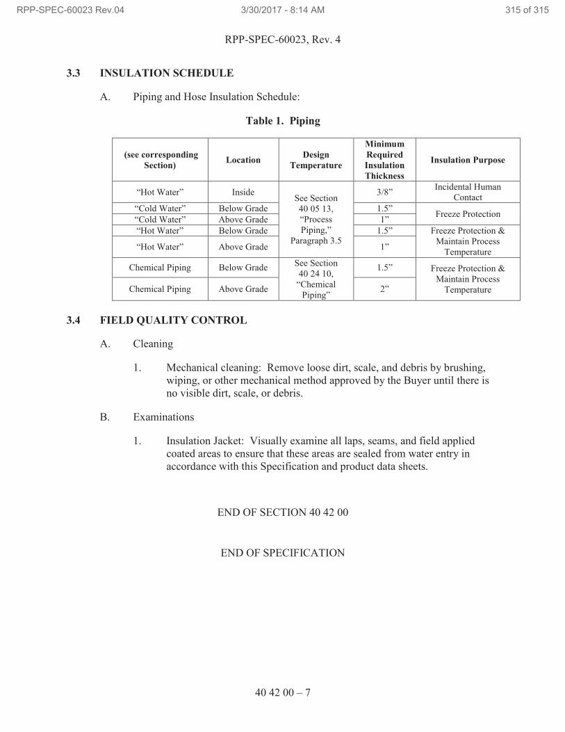
RPP-SPEC-60023, Rev. 4
40 42 00 – 7
3.3 INSULATION SCHEDULE
A. Piping and Hose Insulation Schedule:
Table 1. Piping
(see corresponding
Section) Location
Design
Temperature
Minimum
Required
Insulation
Thickness
Insulation Purpose
“Hot Water” Inside See Section
40 05 13,
“Process
Piping,”
Paragraph 3.5
3/8” Incidental Human
Contact
“Cold Water” Below Grade 1.5” Freeze Protection
“Cold Water” Above Grade 1”
“Hot Water” Below Grade 1.5” Freeze Protection &
Maintain Process
Temperature “Hot Water” Above Grade 1”
Chemical Piping Below Grade See Section
40 24 10,
“Chemical
Piping”
1.5” Freeze Protection &
Maintain Process
Temperature Chemical Piping Above Grade 2”
3.4 FIELD QUALITY CONTROL
A. Cleaning
1. Mechanical cleaning: Remove loose dirt, scale, and debris by brushing,
wiping, or other mechanical method approved by the Buyer until there is
no visible dirt, scale, or debris.
B. Examinations
1. Insulation Jacket: Visually examine all laps, seams, and field applied
coated areas to ensure that these areas are sealed from water entry in
accordance with this Specification and product data sheets.
END OF SECTION 40 42 00
END OF SPECIFICATION
RPP-SPEC-60023 Rev.04 3/30/2017 - 8:14 AM 315 of 315
Related Documents